JP2017091013A - Driving support device - Google Patents
Driving support deviceDownload PDFInfo
- Publication number
- JP2017091013A JP2017091013AJP2015216930AJP2015216930AJP2017091013AJP 2017091013 AJP2017091013 AJP 2017091013AJP 2015216930 AJP2015216930 AJP 2015216930AJP 2015216930 AJP2015216930 AJP 2015216930AJP 2017091013 AJP2017091013 AJP 2017091013A
- Authority
- JP
- Japan
- Prior art keywords
- driver
- image
- display device
- display
- vehicle
- Prior art date
- Legal status (The legal status is an assumption and is not a legal conclusion. Google has not performed a legal analysis and makes no representation as to the accuracy of the status listed.)
- Pending
Links
- 238000001514detection methodMethods0.000claimsabstractdescription34
- 238000012545processingMethods0.000claimsdescription15
- 238000013459approachMethods0.000claimsdescription11
- 238000004458analytical methodMethods0.000claimsdescription10
- 238000010191image analysisMethods0.000claimsdescription8
- 206010041349SomnolenceDiseases0.000claimsdescription6
- 210000001508eyeAnatomy0.000claimsdescription6
- 238000005457optimizationMethods0.000claimsdescription6
- 208000032140SleepinessDiseases0.000claimsdescription4
- 230000037321sleepinessEffects0.000claimsdescription4
- 230000004397blinkingEffects0.000claimsdescription3
- 238000000034methodMethods0.000description57
- 238000010586diagramMethods0.000description10
- 238000003384imaging methodMethods0.000description10
- 238000004891communicationMethods0.000description7
- 238000005516engineering processMethods0.000description6
- 230000002093peripheral effectEffects0.000description6
- 230000001133accelerationEffects0.000description4
- 230000036760body temperatureEffects0.000description3
- 210000004087corneaAnatomy0.000description3
- 210000005252bulbus oculiAnatomy0.000description2
- 238000006243chemical reactionMethods0.000description2
- 239000000284extractSubstances0.000description2
- 230000006870functionEffects0.000description2
- 238000001028reflection methodMethods0.000description2
- 240000004050Pentaglottis sempervirensSpecies0.000description1
- 235000004522Pentaglottis sempervirensNutrition0.000description1
- 230000005540biological transmissionEffects0.000description1
- 230000015572biosynthetic processEffects0.000description1
- 239000002131composite materialSubstances0.000description1
- 239000012141concentrateSubstances0.000description1
- 238000012790confirmationMethods0.000description1
- 230000008921facial expressionEffects0.000description1
- 230000005484gravityEffects0.000description1
- 230000001678irradiating effectEffects0.000description1
- 239000004973liquid crystal related substanceSubstances0.000description1
- 239000000203mixtureSubstances0.000description1
- 230000003287optical effectEffects0.000description1
- 210000001747pupilAnatomy0.000description1
- 238000012827research and developmentMethods0.000description1
- 230000029058respiratory gaseous exchangeEffects0.000description1
- 210000001525retinaAnatomy0.000description1
- 210000003786scleraAnatomy0.000description1
- 239000007787solidSubstances0.000description1
- 238000003786synthesis reactionMethods0.000description1
Images


Landscapes
- Traffic Control Systems (AREA)
Abstract
Description
Translated fromJapanese本発明は、運転支援装置に関する。 The present invention relates to a driving support device.
従来、車両の周囲を撮影した画像を車内の表示装置に表示して乗員に視認させる技術が提案されている。また、車両内の乗員の視点から、車両の後方を確認するための車載用ミラーを見たときに視認される車載用ミラーの映像を示す画像を、車両の周囲における予め設定された所定撮影領域を繰り返し撮影した画像である周囲撮影画像を座標変換することにより生成する技術も提案されている(例えば、特許文献1)。 Conventionally, a technique has been proposed in which an image obtained by photographing the periphery of a vehicle is displayed on a display device in the vehicle so that the occupant can visually recognize the image. In addition, an image showing the image of the in-vehicle mirror that is visually recognized when viewing the in-vehicle mirror for confirming the rear of the vehicle from the viewpoint of the passenger in the vehicle is displayed in a predetermined predetermined shooting area around the vehicle. There has also been proposed a technique for generating a surrounding photographed image, which is an image obtained by repeatedly photographing the image, by performing coordinate conversion (for example, Patent Document 1).
また、例えば車両周囲の俯瞰画像のような視点変換画像の一部を切り出す技術(例えば、特許文献2及び3)、運転者の視点から見た仮想カメラ画像と、半透明化した車室内画像とを重ね合わせて表現する技術(例えば、特許文献4)、仮想的なカメラ位置から見た複数のカメラの画像の合成画像を、仮想カメラの位置或いは画像合成時のブレンド率を変化させながら作成し、仮想的な周囲空間に投射する技術(例えば、特許文献5)、走行シーンに基づいて周囲映像に関する視点位置を調整する技術(例えば、特許文献6)等も提案されている。 In addition, for example, a technique (for example,
従来、車両の周囲の画像を合成して表示装置に出力したり、走行シーン等に応じて表示を変更する技術が提案されていた。しかしながら、運転者が見たがっているものを表示するような技術は存在していなかった。 Conventionally, a technique has been proposed in which images around a vehicle are combined and output to a display device, or the display is changed according to a traveling scene or the like. However, there has been no technique for displaying what the driver wants to see.
そこで、本発明は、車両に搭載する表示装置において、運転者が意図したものを表示できるようにすることを目的とする。 Therefore, an object of the present invention is to enable a display device mounted on a vehicle to display what the driver intended.
本発明に係る運転支援装置は、車両の後方を撮影する後方撮影装置と、運転者の目を撮影範囲に含む車内撮影装置と、運転者から視認できる位置に設けられ、後方撮影装置が撮影した後方画像を表示する表示装置とに接続される。また、運転支援装置は、車内撮影装置が撮影した画像に基づいて、表示装置上に表示された後方画像における、運転者の注視点を求める視線検知部と、表示装置において、後方画像を、当初の拡大率よりも注視点を拡大して表示させる表示制御部とを有する。 The driving support device according to the present invention is provided in a rear photographing device that photographs the rear of the vehicle, an in-vehicle photographing device that includes the eyes of the driver in the photographing range, and a position that can be visually recognized by the driver, and the rear photographing device takes a picture. It is connected to a display device that displays a rear image. In addition, the driving support device, based on the image captured by the in-vehicle imaging device, in the rear image displayed on the display device, the line-of-sight detection unit for obtaining the driver's gaze point, And a display control unit that displays an enlarged gazing point rather than the enlargement ratio.
また、視線検知部が、所定期間、運転者の注視点が表示装置から外れたと判断した場合、表示制御部は、後方画像を当初の拡大率に戻すようにしてもよい。 Further, when the line-of-sight detection unit determines that the driver's gazing point has deviated from the display device for a predetermined period, the display control unit may return the rear image to the original enlargement ratio.
また、後方画像に撮影された動体のうち、車両に対する相対速度が所定値よりも高い接近動体を検知する接近検知部をさらに有し、視線検知部が、運転者の注視点が、表示装置上の接近動体から外れていると判断した場合、表示制御部は、表示装置上に接近動体を強調表示するようにしてもよい。 Further, among the moving objects photographed in the rear image, the vehicle further includes an approach detecting unit that detects an approaching moving body having a relative speed with respect to the vehicle that is higher than a predetermined value. The display control unit may highlight the approaching moving body on the display device when it is determined that the approaching moving body is out of the approaching moving body.
また、視線検知部が、運転者の注視点が接近動体から外れており、且つ運転者の注視点が表示装置から外れていると判断した場合において、運転者の注視点が表示装置上に移動したとき、点滅による強調表示を点灯状態から開始するようにしてもよい。 Further, when the gaze detection unit determines that the driver's gazing point is out of the approaching moving body and the driver's gazing point is out of the display device, the driver's gazing point moves on the display device. When this is done, the blinking highlighting may be started from the lighting state.
また、運転者の生体情報を取得し、取得した生体情報に基づいて運転者の集中力、緊張感、疲労又は眠気を示す第1の指標値を求める生体情報解析部をさらに備え、表示制御部は、第1の指標値が所定の閾値を超える場合に、表示装置上に接近動体の強調表示を行うようにしてもよい。 The display control unit further includes a biological information analysis unit that acquires the driver's biological information and obtains a first index value indicating the driver's concentration, tension, fatigue, or sleepiness based on the acquired biological information. If the first index value exceeds a predetermined threshold, the approaching moving body may be highlighted on the display device.
また、運転支援装置は音声入力手段と、車両の後部座席を撮影する後部座席撮影装置とにさらに接続され、音声入力手段を介して入力された音声から、所定の単語を検知する音声認識部をさらに有し、音声認識部が、所定の単語を検知し、且つ視線検知部が、運転者の注視点が表示装置上にあると判断した場合、表示制御部は、後部座席撮影装置が撮影した後部座席の画像を表示装置に表示するようにしてもよい。 The driving support device is further connected to a voice input unit and a rear seat photographing device for photographing the rear seat of the vehicle, and includes a voice recognition unit that detects a predetermined word from the voice input through the voice input unit. In addition, when the voice recognition unit detects a predetermined word and the gaze detection unit determines that the driver's gaze point is on the display device, the display control unit captures the rear seat photographing device. You may make it display the image of a backseat on a display apparatus.
また、音声入力手段を介して入力される音声に基づいて、運転者が会話を継続していると判断された場合、表示制御部は、後部座席の画像の表示を継続するようにしてもよい。 In addition, when it is determined that the driver continues the conversation based on the voice input through the voice input unit, the display control unit may continue to display the rear seat image. .
車内撮影装置が撮影した画像に基づいて、運転者の疲労又は眠気を示す第2の指標値を求める画像解析部をさらに備え、表示制御部は、第2の指標値が所定の閾値を超える場合、表示装置において、後方画像を、当初の拡大率よりも注視点を拡大して表示させるようにしてもよい。 When the display control unit further includes an image analysis unit for obtaining a second index value indicating fatigue or sleepiness of the driver based on an image captured by the in-vehicle imaging device, and the display control unit exceeds the predetermined threshold value In the display device, the rear image may be displayed with the gazing point enlarged than the original enlargement rate.
また、運転支援装置は、音声出力部とさらに接続されており、視線検知部が、運転者の注視点が所定時間以上、表示装置上にないと判断した場合、音声出力部に、音声による警告を出力させるようにしてもよい。 In addition, the driving support device is further connected to the audio output unit, and when the gaze detection unit determines that the driver's gazing point is not on the display device for a predetermined time or longer, the audio output unit is alerted by voice. May be output.
また、車両は自動運転を行うシステムを備え、表示制御装置は、自動運転時において、表示装置に後方画像をズームアウトした状態で表示するようにしてもよい。 Further, the vehicle may include a system that performs automatic driving, and the display control device may display the rear image on the display device in a zoomed-out state during automatic driving.
また、運転支援装置は、運転者の生体情報を取得するウェアラブル装置とさらに接続され、生体情報解析部は、ウェアラブル装置から取得した生体情報に基づいて運転者の体調が良好でないと判断した場合、表示装置は、平面鏡と略同一の視野角で後方画像を表示するようにしてもよい。 In addition, the driving support device is further connected to a wearable device that acquires the driver's biological information, and the biological information analysis unit determines that the physical condition of the driver is not good based on the biological information acquired from the wearable device, The display device may display the rear image at substantially the same viewing angle as the plane mirror.
また、表示装置が表示装置に表示する画像を変更した後、車内撮影装置が撮影した運転者の画像のフィードバックを受け、表示装置による制御を調整する最適化部をさらに備えるようにしてもよい。 In addition, after changing the image displayed on the display device by the display device, an optimization unit that receives feedback of the driver image captured by the in-vehicle image capturing device and adjusts the control by the display device may be further provided.
運転支援装置は、表示制御装置が表示装置に表示する画像を変更する条件、又は当該条件を満たした場合に表示する画像の設定を記憶する記憶部をさらに備え、当該記憶部に条件又は画像の設定が記憶されている場合、当該条件又は画像の設定に基づいて制御を行うようにしてもよい。 The driving support device further includes a storage unit that stores a condition for changing an image displayed on the display device by the display control device, or a setting of an image to be displayed when the condition is satisfied, and the storage unit stores the condition or the image. When the setting is stored, the control may be performed based on the condition or the image setting.
なお、課題を解決するための手段に記載の内容は、本発明の課題や技術的思想を逸脱し
ない範囲で可能な限り組み合わせることができる。また、課題を解決するための手段の内容は、回路が実行する方法として提供するようにしてもよい。The contents described in the means for solving the problems can be combined as much as possible without departing from the problems and technical ideas of the present invention. Further, the contents of the means for solving the problem may be provided as a method executed by the circuit.
車両に搭載する表示装置において、運転者が意図したものを表示できるようになる。 The display device mounted on the vehicle can display what the driver intended.
以下、添付図面を参照して説明する。図面に本発明の好ましい実施形態を示すが、本発明は多くの異なる形態で実施することが可能であり、本明細書に記載する実施形態には限定されない。 Hereinafter, description will be given with reference to the accompanying drawings. While the preferred embodiments of the invention are shown in the drawings, the invention can be embodied in many different forms and is not limited to the embodiments described herein.
<車両の構成>
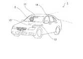
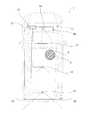
図1は、本実施形態に係る運転支援装置を搭載した車両の主な構成を示す図である。図2は、本実施形態に係る運転支援装置を搭載した車両の構成を模式的に示す図である。図2では、破線で車両1を表し、実線で車両1が備える構成及びこれらの接続関係、並びに各構成を設けるおおよその位置を示している。車両1は、表示装置11と、運転支援装置12と、車内撮影装置13と、後方撮影装置14と、後部座席撮影装置15と、音声入力装置16と、音声出力装置17と、周辺センサ18とを備えている。<Vehicle configuration>
FIG. 1 is a diagram illustrating a main configuration of a vehicle equipped with a driving support apparatus according to the present embodiment. FIG. 2 is a diagram schematically illustrating a configuration of a vehicle on which the driving support device according to the present embodiment is mounted. In FIG. 2, the
表示装置11は、運転者2が視認できる位置に設けられたモニターである。具体的には、いわゆるルームミラー(バックミラー)の鏡面の代わりに液晶モニターを搭載した装置であり、任意の画像又は映像を表示することができる。後述するように、本実施形態では、例えば、車両の外部後方をカメラで撮影した画像を左右反転させて鏡像を生成し、表示装置11に表示させることができる。このように、表示装置11はルームミラーのようにも機能するものであり、本実施形態では表示装置11をスマートミラーとも呼ぶ。また、いわゆる映像も時系列的に更新される複数の画像によって表されるものであり、本実施形態では画像と呼ぶものとする。 The
運転支援装置12は、いわゆるコンピュータであり、表示装置11が行う画像の表示を制御する。図3は、コンピュータの一例を示す装置構成図である。運転支援装置12は、例えば図3に示すようなコンピュータである。図3に示すコンピュータ1000は、CPU(Central Processing Unit)1001、主記憶装置1002、補助記憶装置1003
、通信IF(Interface)1004、入出力IF(Interface)1005、通信バス1006を備えている。CPU1001は、プログラム(「ソフトウェア」又は「アプリケーション」とも呼ぶ)を実行することにより本実施の形態に係る処理等を行う。主記憶装置1002は、CPU1001が読み出したプログラムやデータをキャッシュしたり、CPUの作業領域を確保したりする。主記憶装置は、具体的には、RAM(Random Access Memo
ry)やROM(Read Only Memory)等である。補助記憶装置1003は、CPU1001により実行されるプログラムや、動作の設定情報などを記憶する。補助記憶装置1003は、具体的には、HDD(Hard-disk Drive)やSSD(Solid State Drive)、eMMC(embedded Multi-Media Card)、フラッシュメモリ等である。通信IF1004は、例
えば運転者2が身に着けているウェアラブル装置3等との間でデータを送受信する。通信IF1004は、具体的には、無線通信チップ等である。入出力IF1005は、表示装置11、各撮影装置、音声入出力装置等と接続され、ユーザから入力を受け付けたり、ユーザへ情報を出力したりする。そして、以上のような構成要素が、通信バス1006で接続されている。なお、これらの構成要素はそれぞれ複数設けられていてもよいし、一部の構成要素を設けないようにしてもよい。そして、CPU1001がプログラムを実行することにより、図3のコンピュータを運転支援装置12として働かせる。The
A communication IF (Interface) 1004, an input / output IF (Interface) 1005, and a
ry) and ROM (Read Only Memory). The
また、車内撮影装置13、後方撮影装置14及び後部座席撮影装置15は、いわゆるカメラであり、撮影した画像を継続的に出力する。また、図1及び図2に示した一点鎖線は、各撮影装置のおおよその撮影範囲(すなわち、視野角)を示している。車内撮影装置13は、運転者2(少なくとも運転者2の目)を撮影範囲に含み、運転支援装置12は、例えば撮影された運転者2の状態に応じて表示装置11に表示させる画像を変更する。後方撮影装置14は、車両1の車外後方を撮影範囲とし、運転支援装置12は、例えば後方撮影装置14が撮影した画像を表示装置11に表示させる。後部座席撮影装置15は、車両1の後部座席を撮影範囲とし、運転支援装置12は、所定の状況においては、後部座席撮影装置15が撮影した画像を表示装置11に表示させるようにしてもよい。 The in-vehicle
音声入力部16は、マイクロフォン等の入力装置であり、例えば運転者2の声を取得して運転支援装置12に出力する。音声出力部17は、スピーカー等の出力装置であり、運転支援装置12は、音声出力部17を介して運転者2に音声による警告等を出力してもよい。 The
周辺センサ18は、超音波センサやミリ波レーダ等の装置であり、車両1の周囲に接近する物体を検知することができる。 The
また、運転者2は、運転者2の様々な状態を測定して運転支援装置12へ送信するウェアラブル装置3を身に着けていてもよい。ウェアラブル装置3は、例えば、腕時計型、眼鏡型等の装置であり、運転者の脈拍、体温等を測定して運転支援装置12に送信する。なお、データの送受信には、既存の様々な無線通信規格を利用することができる。 In addition, the
<機能構成>
図4は、運転支援装置12の一例を示す機能ブロック図である。運転支援装置12は、視線検知部121と、表示制御部122と、接近検知部123と、生体情報解析部124と、音声認識部125と、画像解析部126と、最適化部127と、記憶部128とを備えている。なお、運転支援装置12の上述したCPU1001が所定のプログラムを実行することにより、運転支援装置12を図4に示した各機能部として働かせることができる。<Functional configuration>
FIG. 4 is a functional block diagram illustrating an example of the driving
視線検知部121は、車内カメラ13が撮影した運転者2の顔の画像に基づいて、運転者2の視線の先にある注視点が、表示装置11上であるか否か、表示装置11上のいずれの位置であるか等を判断する。なお、注視点の特定には、既存の様々な技術を適用することができる。例えば、車内撮影装置13が撮影した画像において、運転者2の目頭を基準とした虹彩の位置関係に基づいて、注視点を求めるようにしてもよい。また、眼球表面の角膜側と網膜側との電位差を利用するECQ法、コイルを備えるコンタクトレンズを磁界の中で用いて電流を計測するサーチコイル法、角膜と強膜との光の反射率の差を利用する
強膜反射法、眼球に近赤外線を照射し、角膜表面に生じる輝点(プルキニエ像)と瞳孔との位置関係を利用する各膜反射法等を用いるようにしてもよい。また、車内撮影装置13は、車両1に設けられていてもよいし、運転者2が装着するものであってもよい。The line-of-
表示制御部122は、表示装置11に出力する画像を変更する。例えば、後方撮影装置13が撮影した画像の一部を拡大(デジタルズーム)するようにしてもよいし、後方撮影装置13の画像に代えて後部座席撮影装置14が撮影した画像を表示させるようにしてもよい。また、撮影された人や物体を強調するための文字、図形又は記号等を、画像に重畳表示したり、表示装置11の画面を2以上に分割して複数の画像を表示するようにしてもよい。 The
接近検知部123は、所定の基準よりも大きな相対速度で車両1に接近する物体が存在するか判断する。接近検知部123は、例えば、後方撮影装置14が継続的に撮影した複数の画像に基づいて、撮影された物体の大きさが、所定の閾値よりも大きな割合で変化している物体を抽出する。また、接近検知部123は、車両1が備える超音波センサやミリ波レーダ等のような周辺センサ18によって接近する物体を検知するようにしてもよい。 The
生体情報解析部124は、運転者2が装着するウェアラブル装置3が測定したデータに基づき、運転者2の状態を判断する。なお、状態の判断には、既存の様々な技術を適用することができる。例えば、運転者2の心拍数に基づいて眠気を判断することができる。 The biological
音声認識部125は、運転者2が発する音声を認識する処理を行う。音声認識処理についても、既存の様々な技術を適用することができる。音声認識部125は、運転者2が会話中であるか、例えば子供の名前等、予め記憶部128に登録された単語を発したか等を判断する。 The
画像解析部126は、車内撮影装置13が撮影した画像に基づき、運転者2の状態を判断する。なお、状態の判断には、既存の様々な技術を適用することができる。例えば、運転者2の注視点が前方から外れている割合が所定の基準以上であったり、表示装置11を確認する頻度が所定の基準以下である場合に、漫然と運転している状態であると判断する。 The
最適化部127は、表示制御部122が表示装置11に出力する画像を変更した後の運転者2の動作に基づいて、画像変更処理の制御を最適化する。すなわち、表示制御部122が表示装置11に出力する画像を変更した後の、車内撮影装置13が撮影した運転者2の画像に基づいて、例えば画像を拡大する際の拡大率やズームアップする速さ等を変更し、設定を記憶部128に記憶させる。なお、このような設定は運転者2等が明示的に設定できるようにしてもよい。 The
このような運転支援装置12によれば、表示装置11に表示された後方画像のうち、運転者が注視している部分を拡大する等のように、運転者が見たい画像を推定して表示することができるようになる。すなわち、運転者が意図したものを表示できるようにする技術を提供できる。 According to such a
特に、車両がいわゆる自動運転の機能を有する場合、運転者は従来ほど運転に集中する必要がなくなる。ここで、例えば内閣府の「自動走行システム研究開発計画」によれば、自動運転をレベル1からレベル4に区分して説明している。「安全運転支援システム」であるレベル1は、加速・操舵・制動のいずれかをシステムが行う状態と定義されている。また、「自動走行システム」のうち「準自動走行システム」であるレベル2は、加速・操舵・制動のうち複数の操作をシステムが行う状態と定義されている。同様に「自動走行シ
ステム」のうち「準自動走行システム」であるレベル3は、加速・操舵・制動を全てシステムが行い、システムが要請したときはドライバーが対応する状態と定義されている。また、「完全自動走行システム」であるレベル4は、加速・操舵・制動を全てドライバー以外が行い、ドライバーが全く関与しない状態と定義されている。本実施形態では、レベル1からレベル4を含めて、自動運転と呼ぶものとする。このような自動運転を行う車両の場合、運転者には、スマートミラーを注視したり、後部座席の同乗者を見て会話する余裕が生まれる。したがって、本実施形態に係る運転支援装置12は、自動運転を行う車両に、特に好適に用いることができる。In particular, when the vehicle has a so-called automatic driving function, the driver does not need to concentrate on driving as conventionally. Here, for example, according to the “Automated Driving System Research and Development Plan” of the Cabinet Office, automatic driving is classified into
<画像拡大処理>
図5は、本実施形態に係る画像拡大処理の一例を示す処理フロー図である。運転支援装置12の表示制御部122は、通常の状態において、後方撮影装置14が撮影した画像を所定の倍率で表示装置11に表示させる(図5:S101)。本ステップでは、例えば等倍のように、比較的広範囲が確認できるような画像を表示させる。例えば、図6に示すような後方画像が、表示装置11に表示されるものとする。<Image enlargement processing>
FIG. 5 is a process flow diagram illustrating an example of the image enlargement process according to the present embodiment. In a normal state, the
また、運転支援装置12の視線検知部121は、運転者2が表示装置11上の一か所を注視しているか判断する(S102)。本ステップでは、視線検知部121は、まず、車内撮影装置13が継続的に撮影する、運転者2の目を含む画像を取得する。そして、既存の注視点特定技術に基づいて、取得した画像に撮影された運転者2が、所定期間以上、注視点が一か所に留まっているか判断する。ここで、一か所とは所定の範囲内をいうものとする。例えば、ある時点から所定期間、ある時点における注視点から所定の距離内に注視点が留まっている場合、運転者2が表示装置11上の一か所を注視していると判断する。そして、視線検知部121が、運転者2は表示装置11上の一か所を注視していないと判断した場合(S102:No)、S101に戻り処理を繰り返す。 Further, the line-of-
一方、S102において、視線検知部121が、運転者2は表示装置11上の一か所を注視していると判断した場合(S102:Yes)、表示制御部122は、表示装置11において、後方画像撮影装置14が撮影した画像のうち注視点の周囲を拡大表示する(S103)。本ステップでは、運転者2が注視点をよく見たいという意図をもっているものと推定し、当該部分を拡大表示する。具体的には、ある時点の注視点を中心に画像を拡大してもよいし、所定期間における注視点の重心等を中心に画像を拡大してもよい。例えば、S102において、図6に表された後続の車両111を運転者2が注視していたと判断された場合、S103では、図7に示すような、拡大された後方画像が、表示装置11に表示される。 On the other hand, when the line-of-
その後、視線検知部121は、運転者2が所定期間、注視点から視線を外したか否か判断する(S104)。本ステップでも、視線検知部121は、車内撮影装置13が継続的に撮影する、運転者2の目を含む画像を取得する。そして、既存の注視点特定技術に基づいて、取得した画像に撮影された運転者2の注視点が、所定期間、S102で注視していた一か所から外れたか判断する。そして、運転者2が所定期間、注視点から視線を外していないと判断された場合(S104:No)、S103に戻り処理を繰り返す。S103における画像の拡大は、例えば、徐々に拡大されるように、予め定められた単位時間あたりの拡大率等に従って実行するようにしてもよい。また、拡大率の上限を予め定めておくようにしてもよいし、運転者2が一か所を注視し続ける間は拡大し続けるようにしてもよい。 Thereafter, the
一方、S104において、視線検知部121が、運転者2は所定期間、注視点から視線を外したと判断した場合(S104:Yes)、S101の処理に戻る。すなわち、運転者2に注視点をよく見たいという意図はなくなったものと判断し、画像の拡大率を通常通
りに戻す。On the other hand, when the
画像拡大処理によれば、運転者が意図した部分を拡大表示することができ、運転者は当該部分の詳細な確認ができるようになる。 According to the image enlargement process, the part intended by the driver can be enlarged and displayed, and the driver can check the part in detail.
<危険車両強調処理>
図8は、本実施形態に係る危険車両強調処理の一例を示す処理フロー図である。本実施形態では、図5に示した画像拡大処理と並行して、又は画像拡大処理に代えて、図8に示す危険車両強調処理を行うようにしてもよい。なお、初期状態において、表示装置11には後方画像が表示されているものとする。<Dangerous vehicle enhancement processing>
FIG. 8 is a process flowchart showing an example of the dangerous vehicle enhancement process according to the present embodiment. In the present embodiment, the dangerous vehicle enhancement process shown in FIG. 8 may be performed in parallel with the image enlargement process shown in FIG. 5 or instead of the image enlargement process. In the initial state, it is assumed that a rear image is displayed on the
まず、運転支援装置12の接近検知部123は、車両1の周囲に接近する危険車両が存在するか判断する(図8:S201)。本ステップでは、接近検知部123は、例えば、後方撮影装置14が継続的に撮影した複数の画像に基づいて、撮影された物体の大きさが、所定の閾値よりも大きな割合で変化している物体を抽出する。また、接近検知部123は、周辺センサ18によって接近する物体を検知するようにしてもよい。危険車両が存在しないと判断された場合(S201:No)、S201の処理に戻り判断を繰り返す。 First, the
一方、危険車両が存在すると判断された場合(S201:Yes)、視線検知部121は、運転者2が危険車両を確認したか判断する(S202)。本ステップでは、視線検知部121は、表示装置11に表示された後方画像における運転者2の注視点が、S201で検知された危険車両と重なったか判断する。なお、S201において周辺センサによって接近する物体を検知した場合、予めセンサが検知した物体と後方画像上に撮影された物体とのマッチングを行うものとする。運転者2が危険車両を確認したと判断された場合(S202:Yes)、S201の処理に戻り判断を繰り返す。 On the other hand, when it is determined that a dangerous vehicle exists (S201: Yes), the line-of-
一方、運転者2が危険車両を確認していないと判断された場合(S202:No)、運転者2が表示装置11を見ているか判断する(S203)。本ステップでは、運転者2の注視点が表示装置11上にあるか否か判断するようにしてもよいし、運転者2の注視点が表示装置11の周囲にあれば(すなわち、表示装置11が運転者2の視界に入っていれば)運転者2が表示装置11を見ていると判断するようにしてもよい。そして、運転者2が表示装置11を見ていないと判断された場合(S203:No)、S201の処理に戻り判断を繰り返す。 On the other hand, when it is determined that the
一方、運転者2が表示装置11を見ていると判断された場合(S203:Yes)、表示制御部122は、表示装置11において、後方画像上の危険車両を強調表示する(S204)。本ステップでは、S201で検知された危険車両の周囲に、例えば文字、図形又は記号等を重畳表示する。文字、図形又は記号等は、点滅させたり色を変化させたり、所定の動きをさせたりしてもよい。図9は、強調表示の一例を示す図である。なお、図9では、後方画像撮影装置14が撮影する複数の画像において、後続の車両111が所定の閾値よりも大きな割合で拡大されており、S201で急接近する危険車両と判断されたものとする。図9の例では、後続の車両111の周囲に、破線の円が重畳表示されている。また、運転者2の注意を引くように、破線の円を点滅させるようにしてもよい。その後、S201の処理に戻り、運転者2が危険車両を確認するまでS204の強調表示が継続される。なお、S203で運転者2が表示装置11を見ていないと判断された後に、繰り返し実行されるS203において運転者2が表示装置11を見たと判断された場合、S204において例えば点滅による強調表示を「点灯」の状態から開始することで、運転者2が速やかに危険車両に気づくようにすることができる。 On the other hand, when it is determined that the
危険車両強調処理によれば、運転者が気づいていない可能性のある危険車両を確認する
よう促すことができる。また、運転者がすでに見て認識していると推定される車両については強調表示を行わないため、運転者にとって煩わしさが軽減される。According to the dangerous vehicle emphasis process, it is possible to prompt the driver to confirm a dangerous vehicle that may not be noticed by the driver. Further, since the vehicle that is estimated to be recognized by the driver is not highlighted, the troublesomeness for the driver is reduced.
<後部座席表示処理>
図10は、本実施形態に係る後部座席処理の一例を示す処理フロー図である。本実施形態では、図5に示した画像拡大処理もしくは図8に示した危険車両強調処理と並行して、又は画像拡大処理及び危険車両強調処理に代えて、図10に示す後部座席表示処理を行うようにしてもよい。なお、初期状態において、表示装置11には後方画像が表示されているものとする。<Rear seat display processing>
FIG. 10 is a process flow diagram showing an example of the rear seat process according to the present embodiment. In the present embodiment, the rear seat display process shown in FIG. 10 is performed in parallel with the image enlargement process shown in FIG. 5 or the dangerous vehicle enhancement process shown in FIG. 8, or instead of the image enlargement process and the dangerous vehicle enhancement process. You may make it perform. In the initial state, it is assumed that a rear image is displayed on the
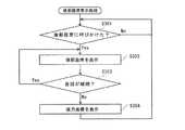
まず、運転支援装置12の音声認識部125は、運転者2が後部座席に向かって呼びかけたか判断する(図10:S301)。本ステップでは、音声認識部125は、音声入力部16から取得した音声に対して既存の音声認識技術を適用し、例えば予め記憶部128に登録された単語(例えば、子供等の名前)を運転者2が呼んだか判断する。併せて、視線検知部121は、運転者2が表示装置11を見たか判断する。運転者2が後部座席に向かって呼びかけていないと判断された場合(S301:No)、S301の処理に戻って判断を繰り返す。 First, the
一方、運転者2が所定の名前を呼び、且つ表示装置11を見たと判断された場合(S301:Yes)、表示制御部122は、後部座席撮影装置14が撮影する後部座席の画像を表示装置11に表示させる。 On the other hand, when it is determined that the
その後、音声認識部125は、会話が継続しているか判断する(S303)。本ステップでは、音声入力部16に入力された音声に基づいて、例えば前回の発言から所定時間内に、運転者2が、又は運転者2及び後部座席の同乗者のいずれかが発言した場合、会話が継続していると判断する。そして、会話が継続していると判断された場合(S303:Yes)、S302の処理に戻り、後部座席の表示を継続する。 Thereafter, the
一方、会話が継続していないと判断された場合(S303:No)、表示制御部122は、後方画像撮影装置14が撮影した後方画像を、表示装置11に表示させる(S304)。 On the other hand, when it is determined that the conversation is not continuing (S303: No), the
後部座席表示処理によれば、スマートミラーである表示装置11を介して後部座席の確認ができる。特に小さい子供を載せている場合等には、後部座席の状態を目で見て確認できると安心でき便利である。 According to the rear seat display process, the rear seat can be confirmed via the
<状態判定処理>
図11は、本実施形態に係る状態判定処理の一例を示す処理フロー図である。本実施形態では、図5に示した画像拡大処理、図8に示した危険車両強調処理もしくは図10に示した後部座席表示処理と並行して、又は画像拡大処理、危険車両強調処理及び後部座席表示処理に代えて、図11に示す状態判定処理を行うようにしてもよい。なお、初期状態において、表示装置11には後方画像が表示されているものとする。<State determination processing>
FIG. 11 is a process flow diagram illustrating an example of a state determination process according to the present embodiment. In the present embodiment, in parallel with the image enlargement process shown in FIG. 5, the dangerous vehicle enhancement process shown in FIG. 8 or the rear seat display process shown in FIG. 10, or the image enlargement process, the dangerous vehicle enhancement process and the rear seat Instead of the display process, the state determination process shown in FIG. 11 may be performed. In the initial state, it is assumed that a rear image is displayed on the
まず、運転支援装置12の生体情報解析部124又は画像解析部126は、ウェアラブル装置3又は車内撮影装置13からデータを取得する(図11:S401)。本ステップでは、生体情報解析部124が、運転者2の体温や脈拍、呼吸等を示すデータを取得するようにしてもよいし、画像解析部126が運転者2の表情がわかる画像を取得するようにしてもよい。また、生体情報解析部124又は画像解析部126は、取得したデータに基づいて、運転者2の状態を判定する。例えば、運転者2の体温が所定の閾値を超える場合、運転者2の体調が悪いと判定するようにしてもよい。また、運転者2の脈拍に基づいて
、運転者2の眠気の有無を判定するようにしてもよい。また、運転者2の画像に基づいて注視点を特定し、例えば表示装置11や左右(周囲)の確認の頻度が所定の閾値よりも少ない場合、運転者2が疲労状態又は漫然状態にあると判定するようにしてもよい。First, the biological
その後、表示制御部122は、状態に応じて表示を制御する(S402)。例えば、運転者2が漫然状態であると判定された場合、図8に示した危険車両強調処理を行うようにしてもよい。また、運転者2が疲労状態であると判定された場合、図8に示した危険車両強調処理を行うと共に、表示装置11に表示する後方画像を、通常よりも狭い範囲の拡大表示に切り替えるようにしてもよい。このようにすれば、少なくとも近い範囲を見やすく表示することができる。 Thereafter, the
また、運転者2の体調が悪いと判定された場合、表示装置11の表示を変更させず、所定の拡大率に固定した後方画像の表示を継続するようにしてもよい。例えば、従来のルームミラーと同様に、一般的な平面鏡と同程度の拡大率で後方画像を表示する。このようにすれば、表示装置11の画像を認識する際の運転者2の負担を軽減することができる。 Further, when it is determined that the
特に、運転者2が表示装置11を長時間(所定時間)にわたって見ていない場合、表示制御部122は、音声出力部17を介して警告を出力し、運転者2に対して表示装置11を確認するよう促すようにしてもよい。 In particular, when the
状態判定処理によれば、様々な状況に応じて好ましい表示制御を行うことができる。 According to the state determination processing, preferable display control can be performed according to various situations.
<その他>
特に自動運転時においては、運転者2は常に周囲に気を配っているわけではないため、表示装置11には比較的広範囲を撮影した後方画像を表示するようにしてもよい。このようにすれば、運転者2は表示装置11を見る動作によってできるだけ広範囲の情報を得られるようになる。<Others>
In particular, during automatic driving, the
また、表示制御部122が表示装置11の表示を変更した後に、車内撮影装置13が撮影した運転者2の動作や、車両1に設けられたセンサが検知した信号をフィードバック情報として、最適化部127が表示制御を最適化するようにしてもよい。例えば、画像拡大処理において、一定の拡大率を超えると運転者2が表示装置11から目をそらしたり目標を見失って注視点が定まらなくなるような場合、一定値を超えないように拡大率の上限を変更するようにしてもよいし、当該一定値まで画像を拡大する速さを挙げるように変更してもよい。また、ABS作動中信号、ペダルストロークセンサを介して検知した緊急ブレーキ等に基づいて、画像を拡大する速さや拡大率の上限を下げるようにしてもよい。これらの設定は、記憶部128に記憶されるものとする。 Further, after the
このようなフィードバック制御によれば、運転者が設定を変更する手間をかけずに、運転者に適した設定に変更することができる。 According to such feedback control, it is possible to change to a setting suitable for the driver without taking the effort of the driver to change the setting.
なお、画像の拡大率の上限や、画像を拡大する速さの設定は、明示的に運転者2等が設定して記憶部128に記憶させておくようにしてもよい。 Note that the upper limit of the image enlargement ratio and the setting of the image enlargement speed may be explicitly set by the
また、運転者2等は、図11のS401で判定される状態と、S402で行われる表示の制御の組み合わせを設定し、記憶部128に記憶させるようにしてもよい。このようにすれば、様々な状況において、運転者2の意図したものを適切に表示できるようになる。 Further, the
後方撮影装置13、又は後部座席撮影装置14は、複数のレンズの位置を制御して光学ズームの拡大率を変更したり、撮影する方向を変更できる1軸以上のアクチュエータを備
えていてもよい。この場合、例えば図5に示した画像拡大処理においては、注視点の周囲をズームアップにより拡大するものとする。The
本発明は、上述した実施の形態に限定されるものではなく、本発明の趣旨を逸脱しない範囲内において変更したり組み合わせたりすることができる。 The present invention is not limited to the above-described embodiments, and can be changed or combined within a range not departing from the gist of the present invention.
1 車両
11 表示装置(スマートミラー)
12 運転支援装置
121 視線検知部
122 表示制御部
123 接近検知部
124 生体情報解析部
125 音声認識部
126 画像解析部
127 最適化部
128 記憶部
13 車内撮影装置
14 後方撮影装置
15 後部座席撮影装置
16 音声入力部
17 音声出力部
18 周辺センサ1
DESCRIPTION OF
Claims (13)
Translated fromJapanese前記車内撮影装置が撮影した画像に基づいて、前記表示装置上に表示された前記後方画像における、前記運転者の注視点を求める視線検知部と、
前記表示装置において、前記後方画像を、当初の拡大率よりも前記注視点を拡大して表示させる表示制御部と、
を有する運転支援装置。A rear photographing device for photographing the rear of the vehicle, an in-vehicle photographing device including a driver's eyes in a photographing range, and a display device provided at a position where the driver can visually recognize the rear image taken by the rear photographing device. A driving support device connected to
Based on the image captured by the in-vehicle image capturing device, a line-of-sight detection unit that obtains the driver's gaze point in the rear image displayed on the display device;
In the display device, a display control unit that displays the rear image with the gazing point enlarged than the original enlargement ratio;
A driving support device having
請求項1に記載の運転支援装置。The driving according to claim 1, wherein when the line-of-sight detection unit determines that the driver's gazing point has deviated from the display device for a predetermined period, the display control unit returns the rear image to the original enlargement ratio. Support device.
前記視線検知部が、前記運転者の注視点が、前記表示装置上の前記接近動体から外れていると判断した場合、前記表示制御部は、前記表示装置上に前記接近動体を強調表示する
請求項1又は2に記載の運転支援装置。Among the moving objects photographed in the rear image, further includes an approach detection unit that detects an approaching moving object whose relative speed with respect to the vehicle is higher than a predetermined value,
The display control unit highlights the approaching moving body on the display device when the line-of-sight detection unit determines that the driver's gazing point is out of the approaching moving body on the display device. Item 3. The driving support device according to Item 1 or 2.
請求項3に記載の運転支援装置。When the gaze detection unit determines that the driver's gaze point is out of the approaching moving body and the driver's gaze point is out of the display device, the driver's gaze point is the The driving support device according to claim 3, wherein when the display device moves on the display device, the highlighting display by blinking is started from a lighting state.
前記表示制御部は、前記第1の指標値が所定の閾値を超える場合に、前記表示装置上に前記接近動体の強調表示を行う
請求項3又は4に記載の運転支援装置。A biometric information analysis unit that obtains the driver's biometric information and obtains a first index value indicating the driver's concentration, tension, fatigue, or sleepiness based on the obtained biometric information;
The driving support device according to claim 3 or 4, wherein the display control unit performs highlighting of the approaching moving body on the display device when the first index value exceeds a predetermined threshold value.
前記音声入力手段を介して入力された音声から、所定の単語を検知する音声認識部をさらに有し、
前記音声認識部が、前記所定の単語を検知し、且つ前記視線検知部が、前記運転者の注視点が前記表示装置上にあると判断した場合、前記表示制御部は、前記後部座席撮影装置が撮影した後部座席の画像を前記表示装置に表示する
請求項1から5のいずれか一項に記載の運転支援装置。The driving support device is further connected to voice input means and a rear seat photographing device for photographing the rear seat of the vehicle,
A voice recognition unit that detects a predetermined word from the voice input through the voice input unit;
When the voice recognition unit detects the predetermined word and the line-of-sight detection unit determines that the driver's gaze point is on the display device, the display control unit includes the rear seat photographing device. The driving support device according to any one of claims 1 to 5, wherein an image of a rear seat taken by is displayed on the display device.
請求項6に記載の運転支援装置。The display control unit continues to display the image of the rear seat when it is determined that the driver continues the conversation based on the voice input through the voice input unit. The driving assistance apparatus as described.
前記表示制御部は、前記第2の指標値が所定の閾値を超える場合、前記表示装置において、前記後方画像を、前記当初の拡大率よりも前記注視点を拡大して表示させる
請求項1から7のいずれか一項に記載の運転支援装置。Further comprising an image analysis unit for obtaining a second index value indicating fatigue or drowsiness of the driver based on an image taken by the in-vehicle photographing device;
The display control unit, when the second index value exceeds a predetermined threshold value, causes the display device to display the rear image with the gazing point enlarged than the original enlargement rate. The driving assistance device according to any one of 7.
前記視線検知部が、運転者の注視点が所定時間以上、表示装置上にないと判断した場合、前記音声出力部に、音声による警告を出力させる
請求項1から8のいずれか一項に記載の運転支援装置。The driving support device is further connected to an audio output unit,
9. The voice output unit outputs a warning by voice when the gaze detection unit determines that the driver's gazing point is not on the display device for a predetermined time or longer. Driving assistance device.
前記表示制御装置は、自動運転時において、前記表示装置に前記後方画像をズームアウトした状態で表示する
請求項1から9のいずれか一項に記載の運転支援装置。The vehicle includes a system for automatic driving,
The driving support device according to any one of claims 1 to 9, wherein the display control device displays the rear image on the display device in a zoomed-out state during automatic driving.
前記生体情報解析部は、前記ウェアラブル装置から取得した生体情報に基づいて前記運転者の体調が良好でないと判断した場合、前記表示装置は、平面鏡と略同一の視野角で前記後方画像を表示する
請求項1から10のいずれか一項に記載の運転支援装置。The driving support device is further connected to a wearable device that acquires biological information of the driver,
When the biological information analysis unit determines that the driver's physical condition is not good based on the biological information acquired from the wearable device, the display device displays the rear image at substantially the same viewing angle as the plane mirror. The driving assistance device according to any one of claims 1 to 10.
請求項1から11のいずれか一項に記載の運転支援装置。The image processing apparatus further includes an optimization unit that receives feedback of the driver's image captured by the in-vehicle image capturing device and adjusts control by the display device after the image displayed on the display device is changed by the display device. The driving support device according to any one of 11 to 11.
当該記憶部に前記条件又は前記画像の設定が記憶されている場合、当該条件又は画像の設定に基づいて制御を行う
請求項1から12のいずれか一項に記載の運転支援装置。The driving support device further includes a storage unit that stores a condition for changing an image displayed on the display device by the display control device, or an image setting to be displayed when the condition is satisfied,
The driving support device according to any one of claims 1 to 12, wherein when the condition or the image setting is stored in the storage unit, control is performed based on the condition or the image setting.
Priority Applications (1)
| Application Number | Priority Date | Filing Date | Title |
|---|---|---|---|
| JP2015216930AJP2017091013A (en) | 2015-11-04 | 2015-11-04 | Driving support device |
Applications Claiming Priority (1)
| Application Number | Priority Date | Filing Date | Title |
|---|---|---|---|
| JP2015216930AJP2017091013A (en) | 2015-11-04 | 2015-11-04 | Driving support device |
Publications (1)
| Publication Number | Publication Date |
|---|---|
| JP2017091013Atrue JP2017091013A (en) | 2017-05-25 |
Family
ID=58770602
Family Applications (1)
| Application Number | Title | Priority Date | Filing Date |
|---|---|---|---|
| JP2015216930APendingJP2017091013A (en) | 2015-11-04 | 2015-11-04 | Driving support device |
Country Status (1)
| Country | Link |
|---|---|
| JP (1) | JP2017091013A (en) |
Cited By (6)
| Publication number | Priority date | Publication date | Assignee | Title |
|---|---|---|---|---|
| JP2018203227A (en)* | 2017-06-05 | 2018-12-27 | 株式会社デンソー | Car compartment system |
| JP2019021034A (en)* | 2017-07-18 | 2019-02-07 | パイオニア株式会社 | Display system |
| JP2020030689A (en)* | 2018-08-23 | 2020-02-27 | トヨタ自動車株式会社 | Information system, information processing method, and program |
| WO2021033516A1 (en)* | 2019-08-22 | 2021-02-25 | 株式会社デンソー | Seat control device |
| US11208108B2 (en) | 2019-08-09 | 2021-12-28 | Toyota Jidosha Kabushiki Kaisha | Monitoring biological information of a passenger in a vehicle |
| CN116249442A (en)* | 2020-10-02 | 2023-06-09 | 株式会社久保田 | Combine harvester, image display system, image display method, image display program, and recording medium recording image display program |
- 2015
- 2015-11-04JPJP2015216930Apatent/JP2017091013A/enactivePending
Cited By (9)
| Publication number | Priority date | Publication date | Assignee | Title |
|---|---|---|---|---|
| JP2018203227A (en)* | 2017-06-05 | 2018-12-27 | 株式会社デンソー | Car compartment system |
| JP2019021034A (en)* | 2017-07-18 | 2019-02-07 | パイオニア株式会社 | Display system |
| JP2022117991A (en)* | 2017-07-18 | 2022-08-12 | パイオニア株式会社 | Display device |
| JP2020030689A (en)* | 2018-08-23 | 2020-02-27 | トヨタ自動車株式会社 | Information system, information processing method, and program |
| JP7155750B2 (en) | 2018-08-23 | 2022-10-19 | トヨタ自動車株式会社 | Information systems and programs |
| US11208108B2 (en) | 2019-08-09 | 2021-12-28 | Toyota Jidosha Kabushiki Kaisha | Monitoring biological information of a passenger in a vehicle |
| WO2021033516A1 (en)* | 2019-08-22 | 2021-02-25 | 株式会社デンソー | Seat control device |
| JP2021030842A (en)* | 2019-08-22 | 2021-03-01 | 株式会社デンソー | Seat control device |
| CN116249442A (en)* | 2020-10-02 | 2023-06-09 | 株式会社久保田 | Combine harvester, image display system, image display method, image display program, and recording medium recording image display program |
Similar Documents
| Publication | Publication Date | Title |
|---|---|---|
| US12293762B2 (en) | Multi-mode guard for voice commands | |
| JP2017091013A (en) | Driving support device | |
| US12198399B2 (en) | Display system and display method | |
| CN111886564B (en) | Information processing device, information processing method, and program | |
| JP6047318B2 (en) | Driver state detection device and driver state notification device | |
| KR101867915B1 (en) | Method for executing vehicle function using wearable device and vehicle for carrying out the same | |
| US10288882B2 (en) | Head mounted display device | |
| US9865258B2 (en) | Method for recognizing a voice context for a voice control function, method for ascertaining a voice control signal for a voice control function, and apparatus for executing the method | |
| US9678337B2 (en) | Viewer with multifocal lens and method for changing focal length of viewer | |
| US20120169582A1 (en) | System ready switch for eye tracking human machine interaction control system | |
| JP2020080485A (en) | Driving support device, driving support system, driving support method, and program | |
| JP2015231828A (en) | Display device, moving body | |
| US10061995B2 (en) | Imaging system to detect a trigger and select an imaging area | |
| JP2016103249A (en) | Driving support device and driving support method | |
| JP2009244959A (en) | Driving support device and driving support method | |
| CN107010077B (en) | Method and adaptive driver assistance system for transmitting information to a driver of a motor vehicle | |
| JP2017039373A (en) | Video display system for vehicles | |
| JP2018055264A (en) | Gesture detection device | |
| JP7046748B2 (en) | Driver status determination device and driver status determination method | |
| JP2018148530A (en) | Vehicle display controller, vehicle display system, vehicle display control method, and program | |
| US9533614B2 (en) | Vehicle collision avoidance modification | |
| US12248147B2 (en) | Information processing device and information processing method | |
| JP6415968B2 (en) | COMMUNICATION DEVICE, WARNING DEVICE, DISPLAY DEVICE, CONTROL METHOD, PROGRAM, AND STORAGE MEDIUM | |
| JP2023006970A (en) | Driving support control device and driving support control method | |
| KR20130068943A (en) | A imaging system of the vehicle around image using the motion recognition |