Movatterモバイル変換


[0]ホーム

URL:


JP2017089803A - Sealing device - Google Patents

Sealing device
Download PDF

Info

Publication number
JP2017089803A
JP2017089803AJP2015222368AJP2015222368AJP2017089803AJP 2017089803 AJP2017089803 AJP 2017089803AJP 2015222368 AJP2015222368 AJP 2015222368AJP 2015222368 AJP2015222368 AJP 2015222368AJP 2017089803 AJP2017089803 AJP 2017089803A
Authority
JP
Japan
Prior art keywords
deflector
outside
drive shaft
base end
lip portion
Prior art date
Legal status (The legal status is an assumption and is not a legal conclusion. Google has not performed a legal analysis and makes no representation as to the accuracy of the status listed.)
Pending
Application number
JP2015222368A
Other languages
Japanese (ja)
Inventor
亮二 竹内
Ryoji Takeuchi
亮二 竹内
健太郎 松田
Kentaro Matsuda
健太郎 松田
Current Assignee (The listed assignees may be inaccurate. Google has not performed a legal analysis and makes no representation or warranty as to the accuracy of the list.)
Koyo Sealing Techno Co Ltd
Original Assignee
Koyo Sealing Techno Co Ltd
Priority date (The priority date is an assumption and is not a legal conclusion. Google has not performed a legal analysis and makes no representation as to the accuracy of the date listed.)
Filing date
Publication date
Application filed by Koyo Sealing Techno Co LtdfiledCriticalKoyo Sealing Techno Co Ltd
Priority to JP2015222368ApriorityCriticalpatent/JP2017089803A/en
Publication of JP2017089803ApublicationCriticalpatent/JP2017089803A/en
Pendinglegal-statusCriticalCurrent

Links

Images

Landscapes

Abstract

PROBLEM TO BE SOLVED: To provide a sealing device for a differential side which can maintain the contact surface pressure of a tip of a side lip with respect to a deflector irrespective of a magnitude of a fastening margin.SOLUTION: A sealing device comprises: a seal main body 14 having a side lip part 34 which is attached into an axial hole 11a for inserting a drive shaft 12 therein, and extends toward the outside B of a housing 11; and a deflector 15 which is attached to the drive shaft 12 at a position closer to the outside B of the housing 11 than the seal main body 14, and with which the side lip part 34 contacts. The side lip part 34 comprises: a base end part 41; intermediate parts 42, 43 extending to the outside of a radial direction at the outside B from the base end part 41; and a tip 44 which extends to the outside of the radial direction at the outside B from the intermediate parts 42, 43, and contacts with the deflector 15 at an internal peripheral face. Internal peripheral faces of the intermediate parts 42, 43 are recessively formed so as not to contact with the deflector.SELECTED DRAWING: Figure 1

Description

Translated fromJapanese

本発明は、自動車のデフサイドに用いられる密封装置に関する。  The present invention relates to a sealing device used for a differential side of an automobile.

一般に、自動車のディファレンシャル装置は、デフピニオンギヤ及びデフサイドギヤを収容するデフケースと、デフケースを回転自在に支持するハウジングと、デフサイドギヤに連結されるとともに、ハウジングの軸孔に挿通されるドライブシャフトとを備えている。ハウジングの軸孔とドライブシャフトとの間の環状空間には、ハウジング内(密封空間内)の潤滑油の漏洩防止と、ハウジングの外部側からの異物の侵入防止とを兼ねたデフサイド用の密封装置が設けられる(例えば、特許文献1参照)。  Generally, a differential device for an automobile includes a differential case that houses a differential pinion gear and a differential side gear, a housing that rotatably supports the differential case, and a drive shaft that is connected to the differential side gear and that is inserted through a shaft hole of the housing. ing. In the annular space between the shaft hole of the housing and the drive shaft, a sealing device for the differential side that prevents leakage of the lubricating oil in the housing (in the sealed space) and prevents foreign matter from entering from the outside of the housing. (For example, refer to Patent Document 1).

特許文献1記載の密封装置は、図6に示すように、ハウジング111の軸孔111aに装着されるシール本体114と、ドライブシャフト112の外周面に装着されるディフレクタ115とを備えている。シール本体114は、ドライブシャフト112に接触する主リップ部132と、この主リップ部132よりもハウジング111の外部側Bにおいてドライブシャフト112に接触するダストリップ部(補助リップ部)133と、このダストリップ部133よりも外部側Bに設けられ且つ外部側Bでかつ径方向外側へ斜め方向に延びるサイドリップ部134とを有する。ディフレクタ115は、径方向に沿って配置された円環状の環状板部115bを有しており、サイドリップ部134は、ディフレクタ115の環状板部115bに接触することによって、外部側Bからの異物の侵入を防止する。  As shown in FIG. 6, the sealing device described inPatent Document 1 includes aseal body 114 attached to theshaft hole 111 a of thehousing 111 and adeflector 115 attached to the outer peripheral surface of thedrive shaft 112. Theseal body 114 includes amain lip portion 132 that contacts thedrive shaft 112, a dust lip portion (auxiliary lip portion) 133 that contacts thedrive shaft 112 on the outer side B of thehousing 111 relative to themain lip portion 132, and Aside lip portion 134 is provided on the outer side B of thestrip portion 133 and extends obliquely outwardly in the outer side B and in the radial direction. Thedeflector 115 has an annularannular plate portion 115b disposed along the radial direction, and theside lip portion 134 is in contact with theannular plate portion 115b of thedeflector 115, so that foreign matter from the outside side B can be obtained. Prevent the intrusion.

特開2007−225064号公報JP 2007-225064 A

密封装置のサイドリップ部134は、ディフレクタ115に対する締め代が設けられるが、その締め代は、ハウジング111に対するシール本体114の組み付け位置や、ドライブシャフト112に対するディフレクタ115の組み付け位置等の要因で変化する。また、運転中にドライブシャフト112が軸方向にスライドすることによっても締め代が変化する。図6に示す従来のシール本体114は、負荷のかかっていない自然状態で、サイドリップ部134が、基端部から先端部にかけて外部側Bでかつ径方向外側へむけてほぼ一直線上に延びている。そのため、締め代が小さいときはサイドリップ部134の先端部のみがディフレクタ115に接触するが、図7に示すように、締め代が大きくなると、次第に先端部だけでなくその径方向内側部分もディフレクタ115に接触し、接触面圧のピークが径方向内側(基部側)へ移動する。そのため、先端部における接触面圧が低下し、密封性が低下する可能性がある。  Theside lip part 134 of the sealing device is provided with a fastening margin with respect to thedeflector 115, and the fastening margin varies depending on factors such as an assembly position of theseal body 114 with respect to thehousing 111 and an assembly position of thedeflector 115 with respect to thedrive shaft 112. . The tightening allowance also changes when thedrive shaft 112 slides in the axial direction during operation. Theconventional seal body 114 shown in FIG. 6 has aside lip portion 134 extending in a substantially straight line from the proximal end portion to the distal end portion toward the outer side B and radially outward in a natural state where no load is applied. Yes. Therefore, when the tightening margin is small, only the tip of theside lip portion 134 comes into contact with thedeflector 115. However, as shown in FIG. 7, when the tightening margin increases, not only the tip but also the radially inner portion of thedeflector 115 gradually increases. 115, the contact surface pressure peak moves radially inward (base side). Therefore, the contact surface pressure at the tip portion may be reduced, and the sealing performance may be reduced.

したがって、本発明は、締め代の大きさに関わらず、ディフレクタに対するサイドリップの先端部の接触面圧を維持することができるデフサイド用の密封装置を提供することを目的とする。  Therefore, an object of the present invention is to provide a differential side sealing device that can maintain the contact surface pressure of the tip of the side lip with respect to the deflector regardless of the size of the tightening allowance.

本発明の密封装置は、
ドライブシャフトを挿入するための軸孔が形成されたハウジングの内部の密封空間と前記ハウジングの外部との間を封止するデフサイド用の密封装置であって、
前記軸孔に装着され、前記ハウジングの外部側へ向けて延びるサイドリップ部を有するシール本体と、
前記シール本体よりも前記外部側において前記ドライブシャフトに装着され、前記サイドリップ部が接触するディフレクタとを備え、
前記サイドリップ部は、基端部と、この基端部から前記外部側でかつ径方向外側へ延びる中間部と、前記中間部から前記外部側でかつ径方向外側へ延び、内周面が前記ディフレクタに接触する先端部とを備えており、
前記中間部の内周面が、前記ディフレクタに接触しないように凹状に形成されている。
The sealing device of the present invention comprises:
A sealing device for a differential side that seals between a sealed space inside a housing in which a shaft hole for inserting a drive shaft is formed and the outside of the housing,
A seal main body having a side lip portion attached to the shaft hole and extending toward the outside of the housing;
A deflector that is attached to the drive shaft on the outer side of the seal body and that contacts the side lip portion;
The side lip portion includes a base end portion, an intermediate portion extending from the base end portion to the outer side and radially outward, and extending from the intermediate portion to the outer side and radially outer side, and an inner peripheral surface thereof A tip that contacts the deflector,
An inner peripheral surface of the intermediate portion is formed in a concave shape so as not to contact the deflector.

上記構成の密封装置によれば、サイドリップ部の中間部の内周面が凹状に形成されているので、サイドリップ部の締め代が大きくなることによって、サイドリップ部が径方向外側へ変形したとしても中間部がディフレクタに接触せず、ディフレクタに対するサイドリップ部の先端部の接触面圧を維持することができる。  According to the sealing device having the above configuration, since the inner peripheral surface of the intermediate portion of the side lip portion is formed in a concave shape, the side lip portion is deformed radially outward by increasing the tightening margin of the side lip portion. In this case, the intermediate portion does not contact the deflector, and the contact surface pressure of the tip of the side lip portion with respect to the deflector can be maintained.

前記中間部は、前記基端部から前記外部側でかつ径方向外側へ傾斜状に延びる基端部側中間部と、前記基端部側中間部から前記外部側でかつ前記径方向外側へ傾斜状に延び、前記ドライブシャフトの軸心に対する傾斜角度が、前記基端部側中間部における傾斜角度よりも小さく設定された先端部側中間部と、を有していることが好ましい。
このような構成によって、中間部の内周面を凹状に形成することができる。
The intermediate portion is inclined from the base end portion to the outside side and radially outwardly in a slanting manner, and the intermediate portion is inclined from the base end side intermediate portion to the outside side and the radially outer side. It is preferable to have a distal end side intermediate portion that extends in a shape and has an inclination angle with respect to the axis of the drive shaft set to be smaller than an inclination angle in the proximal end side intermediate portion.
With such a configuration, the inner peripheral surface of the intermediate portion can be formed in a concave shape.

前記基端部は、前記外部側でかつ径方向内側へ向けて延びていることが好ましい。
このような構成によって、サイドリップの締め代が大きくなったときに中間部の外周面がシール本体の他の部分(例えば、図1における本体部31の側面部31b)に干渉するのを防ぐことができる。
It is preferable that the base end portion extends outward and radially inward.
Such a configuration prevents the outer peripheral surface of the intermediate portion from interfering with other portions of the seal body (for example, theside surface portion 31b of thebody portion 31 in FIG. 1) when the side lip tightening margin is increased. Can do.

本発明によれば、締め代の大きさに関わらず、ディフレクタに対するサイドリップの先端部の接触面圧を維持することができる。  According to the present invention, it is possible to maintain the contact surface pressure of the tip portion of the side lip with respect to the deflector regardless of the size of the tightening allowance.

一実施形態に係る密封装置を示す断面図である。It is sectional drawing which shows the sealing device which concerns on one Embodiment.密封装置のシール本体の要部を拡大して示す断面図である。It is sectional drawing which expands and shows the principal part of the seal | sticker main body of a sealing device.締め代が最大のときのシール部材のサイドリップ部を示す断面図である。It is sectional drawing which shows the side lip | rip part of a sealing member when a fastening margin is the largest.強く圧接されたときのシール部材の主リップ部及び補助リップ部を示す断面図である。It is sectional drawing which shows the main lip | rip part and auxiliary | assistant lip | rip part of a sealing member when it press-contacts strongly.シール部材のサイドリップの締め代と反力との関係を示すグラフである。It is a graph which shows the relationship between the interference of the side lip of a sealing member, and reaction force.従来の密封装置を示す断面図である。It is sectional drawing which shows the conventional sealing device.従来のシール部材において、締め代が最大のときのサイドリップ部を示す断面図である。In the conventional sealing member, it is sectional drawing which shows a side lip part when a fastening allowance is the largest.従来のシール部材において、ドライブシャフトに強く圧接されたときの主リップ及び補助リップを示す断面図である。In the conventional sealing member, it is sectional drawing which shows the main lip and the auxiliary | assistant lip when it press-contacts strongly with a drive shaft.

以下、密封装置の実施の形態について図面を参照しながら説明する。
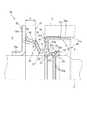
図1は、本発明の一実施形態に係る密封装置を示す断面図である。この密封装置10は、自動車のディファレンシャル装置において、デフピニオンギヤ及びデフサイドギヤを収容するデフケースを回転自在に支持するハウジング11と、デフサイドギヤに連結され、このハウジング11に形成された軸孔11aに挿通されたドライブシャフト(回転軸)12との間に用いられるデフサイド用の密封装置である。
Hereinafter, embodiments of the sealing device will be described with reference to the drawings.
FIG. 1 is a cross-sectional view showing a sealing device according to an embodiment of the present invention. Thesealing device 10 is inserted into ahousing 11 that rotatably supports a differential case that houses a differential pinion gear and a differential side gear, and a differential side gear, and is inserted into ashaft hole 11a formed in thehousing 11 in a differential device of an automobile. This is a differential side sealing device used between the drive shaft (rotating shaft) 12.

密封装置10は、互いに相対回転するドライブシャフト12とハウジング11との間に形成される環状空間に装着されて、ハウジング11の内部である密封空間A内に密封された潤滑油等の密封流体がハウジング11の外部側Bへ漏洩するのを防止する。
密封装置10は、シール本体14と、ディフレクタ(当接部材)15とを備えている。
シール本体14は、断面略L字形の環状の芯金21と、芯金21に固定されているシール部材22と、環状のバネリング23とで構成されている。
Thesealing device 10 is mounted in an annular space formed between thedrive shaft 12 and thehousing 11 that rotate relative to each other, and a sealing fluid such as lubricating oil sealed in the sealed space A that is the inside of thehousing 11 is received. Leakage to the outer side B of thehousing 11 is prevented.
Thesealing device 10 includes aseal body 14 and a deflector (contact member) 15.
Theseal body 14 includes anannular core bar 21 having a substantially L-shaped cross section, aseal member 22 fixed to thecore bar 21, and anannular spring ring 23.

芯金21は、金属(例えば、SPCC)製の環状部材であり、ドライブシャフト12と同軸心状に配置された円筒形状の円筒部21aと、この円筒部21aの軸方向の一端部から径方向内方へ屈曲した円環状の環状板部21bとで構成されている。  Thecored bar 21 is an annular member made of metal (for example, SPCC), and has a cylindricalcylindrical part 21a disposed coaxially with thedrive shaft 12, and a radial direction from one axial end of thecylindrical part 21a. It is comprised with the annular | circular shapedannular plate part 21b bent inward.

シール部材22は、合成ゴム(例えば、アクリロニトリル−ブタジエンゴム(NBR)、アクリルゴム(ACM))等の弾性部材からなり、加硫による接着、焼き付けなどにより芯金21に固定されている。シール部材22は、環状に形成されており、本体部31と、主リップ部32と、補助リップ部33と、サイドリップ部34とを有している。  Theseal member 22 is made of an elastic member such as synthetic rubber (for example, acrylonitrile-butadiene rubber (NBR), acrylic rubber (ACM)), and is fixed to thecore metal 21 by adhesion or baking by vulcanization. Theseal member 22 is formed in an annular shape and includes amain body portion 31, amain lip portion 32, anauxiliary lip portion 33, and aside lip portion 34.

本体部31は、芯金21の円筒部21aの外周面に設けられ且つハウジング11の軸孔11aに固定される外周部31aと、環状板部21bの外部側Bの側面に設けられている側面部31bと、環状板部21bの内周部を覆う内周部31cとを備えている。外周部31a、側面部31b、内周部31cは、一体的に形成されている。外周部31aは軸方向に沿って配置され、側面部31bは径方向に沿って配置されている。  Themain body portion 31 is provided on the outer peripheral surface of thecylindrical portion 21a of thecore metal 21 and is fixed to theshaft hole 11a of thehousing 11, and the side surface provided on the side surface of the outer side B of theannular plate portion 21b. Thepart 31b and the innerperipheral part 31c which covers the inner peripheral part of theannular plate part 21b are provided. The outerperipheral part 31a, theside part 31b, and the innerperipheral part 31c are integrally formed. The outerperipheral part 31a is arrange | positioned along an axial direction, and theside part 31b is arrange | positioned along the radial direction.

<主リップ部32の構成>
主リップ部32は、本体部31の内周部31cの径方向内側において密封空間A側へ延びている。主リップ部32の外周面には周溝32aが形成されている。そして、この周溝32aには、ガータスプリングと呼ばれるバネリング23が装着されている。バネリング23は、主リップ部32を径方向内方へ締め付けている。
<Configuration ofmain lip portion 32>
Themain lip portion 32 extends toward the sealed space A on the radially inner side of the innerperipheral portion 31 c of themain body portion 31. Acircumferential groove 32 a is formed on the outer peripheral surface of themain lip portion 32. Aspring ring 23 called a garter spring is attached to thecircumferential groove 32a. Thespring ring 23 clamps themain lip portion 32 inward in the radial direction.

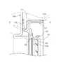
図2は、密封装置10のシール本体14の要部を拡大して示す断面図である。図2においては、外部から負荷を受けていない自然状態のシール本体14が示されている。
図1及び図2に示すように、主リップ部32は、ドライブシャフト12の外周面に締め代をもって接触して密封空間A内の密封流体が外部側Bへ漏れるのを防止している。主リップ部32は、その径方向内側の断面形状が径方向内方に向けて細くなる(軸方向幅寸法が小さくなる)ほぼV字形とされている。したがって、主リップ部32の内周面は、外部側Bの第1傾斜面32bと、密封空間A側の第2傾斜面32cとを有している。
FIG. 2 is an enlarged cross-sectional view showing a main part of theseal body 14 of thesealing device 10. FIG. 2 shows theseal body 14 in a natural state in which no load is applied from the outside.
As shown in FIGS. 1 and 2, themain lip portion 32 contacts the outer peripheral surface of thedrive shaft 12 with a margin to prevent the sealed fluid in the sealed space A from leaking to the outside B. Themain lip portion 32 is substantially V-shaped with a radially inner cross-sectional shape becoming narrower inward in the radial direction (the axial width dimension becomes smaller). Therefore, the inner peripheral surface of themain lip portion 32 has the firstinclined surface 32b on the outer side B and the secondinclined surface 32c on the sealed space A side.

第1傾斜面32bは、外部側Bほど内径が大きくなるように傾斜し、第2傾斜面32cは、密封空間A側ほど内径が大きくなるように傾斜している。第1傾斜面32bと第2傾斜面32cとの境界部であって主リップ部32の最小径部(頂部)を第1リップ先端部32dという。また、第1傾斜面32bよりも外部側Bには、軸心方向Cに略沿った方向に形成された円筒形状の円筒面32eが形成されている。第1傾斜面32bと円筒面32eとは鈍角をなして交差している。円筒面32eは、後述するようにドライブシャフト12の外周面に接触可能な接触面(第2の内周面)を構成している。  The firstinclined surface 32b is inclined so that the inner diameter increases toward the outer side B, and the secondinclined surface 32c is inclined so that the inner diameter increases toward the sealed space A side. A minimum diameter portion (top portion) of themain lip portion 32 that is a boundary portion between the firstinclined surface 32b and the secondinclined surface 32c is referred to as a firstlip tip portion 32d. Further, acylindrical surface 32e having a cylindrical shape formed in a direction substantially along the axial direction C is formed on the outer side B from the firstinclined surface 32b. The firstinclined surface 32b and thecylindrical surface 32e intersect at an obtuse angle. Thecylindrical surface 32e constitutes a contact surface (second inner peripheral surface) that can contact the outer peripheral surface of thedrive shaft 12 as will be described later.

第1傾斜面32bと第2傾斜面32cとの内角の角度θ1は、鈍角をなしており、例えば約122°とされる。θ1は、例えば95°〜140°の範囲で設定することができる。
また、第1傾斜面32bと円筒面32eとの間の角度θ2は、例えば、約157°とされる。θ2は、例えば130°〜170°の範囲で設定することができる。
The internal angle θ1 between the firstinclined surface 32b and the secondinclined surface 32c is an obtuse angle, for example, about 122 °. For example, θ1 can be set in the range of 95 ° to 140 °.
Further, the angle θ2 between the firstinclined surface 32b and thecylindrical surface 32e is, for example, about 157 °. For example, θ2 can be set in a range of 130 ° to 170 °.

円筒面32eよりも外部側Bには、凹溝37が形成されている。円筒面32eに隣接する凹溝37の内側面37aと、円筒面32eとの間の内角の角度θ3は、鈍角をなしており、例えば約140°とされる。θ3は、例えば100°〜170°の範囲で設定することができる。  Aconcave groove 37 is formed on the outer side B from thecylindrical surface 32e. An internal angle θ3 between theinner surface 37a of theconcave groove 37 adjacent to thecylindrical surface 32e and thecylindrical surface 32e is an obtuse angle, for example, about 140 °. For example, θ3 can be set in the range of 100 ° to 170 °.

主リップ部32の第1傾斜面(第1の内周面)32bは、ドライブシャフト12の外周面に接触するシール面として機能する。この第1傾斜面32bには、図1に示すように、軸方向に対して周方向へ所要角度傾斜する複数の突起条32gが形成されている。第1傾斜面32bに突起条32gを形成することによって、シール部材22とドライブシャフト12との相対的な回転に伴い、主リップ部32とドライブシャフト12との接触部分から外部側Bへ漏洩しようとする密封空間A内の密封流体を、密封空間A内へ戻すポンプ作用が発揮される。  The first inclined surface (first inner peripheral surface) 32 b of themain lip portion 32 functions as a seal surface that contacts the outer peripheral surface of thedrive shaft 12. As shown in FIG. 1, the firstinclined surface 32b is formed with a plurality ofprotrusions 32g inclined at a required angle in the circumferential direction with respect to the axial direction. By forming theprotrusion 32g on the firstinclined surface 32b, it is likely to leak from the contact portion between themain lip portion 32 and thedrive shaft 12 to the outer side B as theseal member 22 and thedrive shaft 12 rotate relative to each other. The pumping action of returning the sealed fluid in the sealed space A into the sealed space A is exhibited.

図2(b)に拡大して示すように、円筒面32eと凹溝37の内側面37aは、第1傾斜面32bに垂直な方向aに関して当該第1傾斜面32bよりも径方向内側に突出する突部38を形成している。そして、この突部38は、第1傾斜面32bの全面がドライブシャフト12の外周面に接触するのを規制する規制部を構成する。  2B, thecylindrical surface 32e and theinner surface 37a of theconcave groove 37 protrude radially inward from the firstinclined surface 32b with respect to the direction a perpendicular to the firstinclined surface 32b. A protrudingportion 38 is formed. And thisprotrusion 38 comprises the control part which controls that the whole surface of the 1stinclined surface 32b contacts the outer peripheral surface of thedrive shaft 12. FIG.

<補助リップ部33の構成>
図1及び図2に示すように、補助リップ部33は、ドライブシャフト12の外周面に締め代をもって接触し、主に外部側Bから密封空間A内への異物の侵入を防止している。補助リップ部33は、その径方向内側の断面形状が径方向内方に向けて細くなる(軸方向幅寸法が小さくなる)ほぼV字形とされている。したがって、補助リップ部33の内周面は、密封空間A側の第3傾斜面33aと、外部側Bの第4傾斜面33bとを有している。
<Configuration ofauxiliary lip portion 33>
As shown in FIGS. 1 and 2, theauxiliary lip portion 33 is in contact with the outer peripheral surface of thedrive shaft 12 with a tightening margin, and mainly prevents foreign matter from entering the sealed space A from the outer side B. Theauxiliary lip portion 33 is substantially V-shaped with a radially inner cross-sectional shape becoming narrower inward in the radial direction (the axial width dimension becomes smaller). Therefore, the inner peripheral surface of theauxiliary lip portion 33 has the thirdinclined surface 33a on the sealed space A side and the fourth inclined surface 33b on the outer side B.

第3傾斜面33aと第4傾斜面33bとの境界部であって補助リップ部33の最小径部(頂部)を第2リップ先端部33cという。補助リップ部33の第3傾斜面33aがドライブシャフト12の外周面に接触するシール面として機能する。
第3傾斜面33aと第4傾斜面33bとの間の内角の角度θ4は、鈍角をなしており、例えば約111°とされる。角度θ4は、例えば95°〜150°の範囲で設定することができる。
A minimum diameter portion (top portion) of theauxiliary lip portion 33 that is a boundary portion between the thirdinclined surface 33a and the fourth inclined surface 33b is referred to as a secondlip tip portion 33c. The thirdinclined surface 33 a of theauxiliary lip portion 33 functions as a seal surface that contacts the outer peripheral surface of thedrive shaft 12.
The internal angle θ4 between the thirdinclined surface 33a and the fourth inclined surface 33b is an obtuse angle, for example, about 111 °. The angle θ4 can be set in the range of 95 ° to 150 °, for example.

<主リップ部32の作用>
主リップ部32と補助リップ部33との間には、凹溝37が形成されているので、補助リップ部33と、主リップ部32と、これらが接触するドライブシャフト12の外周面との間には、環状の第1空間部S1(図1参照)が形成される。
主リップ部32の第1傾斜面32bには、突起条32gが形成されているので、この突起条32gによるポンプ作用によって第1空間部S1内のエアが密封空間A側へ排出され、第1空間部S1内が負圧になりやすくなる。そして、第1空間部S1内が負圧になると、主リップ部32及び補助リップ部33がドライブシャフト12の外周面に強く押し付けられる。この状態を図4に示す。
<Operation of themain lip portion 32>
Since aconcave groove 37 is formed between themain lip portion 32 and theauxiliary lip portion 33, the space between theauxiliary lip portion 33, themain lip portion 32, and the outer peripheral surface of thedrive shaft 12 with which these contact. An annular first space S1 (see FIG. 1) is formed.
Since theprotrusion 32g is formed on the firstinclined surface 32b of themain lip portion 32, the air in the first space S1 is discharged to the sealed space A side by the pump action by theprotrusion 32g, and the first The inside of the space S1 tends to be negative pressure. And when the inside of 1st space part S1 becomes a negative pressure, themain lip part 32 and the auxiliary |assistant lip part 33 will be strongly pressed on the outer peripheral surface of thedrive shaft 12. FIG. This state is shown in FIG.

図4に示すように、主リップ部32は、第1傾斜面32bがドライブシャフト12の外周面に接触するが、第1傾斜面32bの外部側Bには突部(規制部)38が隣接して形成されているので、第1傾斜面32bは全体がドライブシャフト12の外周面に接触せず、一部が浮いた状態となる。したがって、主リップ部32とドライブシャフト12との間には、隙間cが形成される。  As shown in FIG. 4, themain lip portion 32 has a firstinclined surface 32 b in contact with the outer peripheral surface of thedrive shaft 12, but a protrusion (regulating portion) 38 is adjacent to the outer side B of the firstinclined surface 32 b. Thus, the entire firstinclined surface 32b does not contact the outer peripheral surface of thedrive shaft 12, and a part thereof is in a floating state. Accordingly, a gap c is formed between themain lip portion 32 and thedrive shaft 12.

図8に示すように、従来のシール本体114の場合、主リップ部132には本実施形態のような突部38が形成されていないので、第1傾斜面132bの全面がドライブシャフト12に接触している。そのため、第1傾斜面132b全体の摩耗や発熱が大きくなる。
これに対して、本実施形態では、図4に示すように、ドライブシャフト12に対する主リップ部32の接触部位が分散し、主リップ部32の第1傾斜面32bの全面がドライブシャフト12に接触するのを抑制することができる。そのため、主リップ部32の第1傾斜面32bの摩耗や発熱を抑制することができる。
As shown in FIG. 8, in the case of theconventional seal body 114, themain lip portion 132 is not formed with theprotrusion 38 as in the present embodiment, so that the entire surface of the firstinclined surface 132b contacts thedrive shaft 12. doing. Therefore, wear and heat generation of the entire firstinclined surface 132b are increased.
On the other hand, in this embodiment, as shown in FIG. 4, the contact portions of themain lip portion 32 with respect to thedrive shaft 12 are dispersed, and the entire firstinclined surface 32 b of themain lip portion 32 is in contact with thedrive shaft 12. Can be suppressed. Therefore, wear and heat generation of the firstinclined surface 32b of themain lip portion 32 can be suppressed.

<サイドリップ部34の構成>
図1に示すように、シール部材22のサイドリップ部34は、本体部31の側面部31bと内周部31cとの境界部分から外部側Bへ延びている。サイドリップ部34は、多段階に屈曲した形状に形成されている。具体的に、サイドリップ部34は、密封空間A側から順に、基端部41、中間部42、43、先端部44を備えている。そして、基端部41と中間部42との間、及び中間部43と先端部44との間は、それぞれ屈曲されている。
<Configuration ofside lip 34>
As shown in FIG. 1, theside lip portion 34 of theseal member 22 extends from the boundary portion between theside surface portion 31 b and the innerperipheral portion 31 c of themain body portion 31 to the outer side B. Theside lip portion 34 is formed in a shape bent in multiple stages. Specifically, theside lip portion 34 includes aproximal end portion 41,intermediate portions 42 and 43, and adistal end portion 44 in order from the sealed space A side. And between thebase end part 41 and theintermediate part 42, and between theintermediate part 43 and the front-end | tippart 44 are each bent.

図2に示すように、本実施形態のサイドリップ部34は、シール部材22の本体部31における側面部31bからの長さ(軸心方向Cに関する幅)L1が、例えば約12.1mmとされている。
基端部41は、シール部材22の側面部31bから外部側Bでかつ径方向内側へ向けて斜めに延びている。基端部41と側面部31bとの間の角度θ5は鈍角をなし、例えば、約106°とされる。角度θ5は、例えば95°〜150°の範囲で設定することができる。本実施形態の基端部41は、本体部31における側面部31bからの長さ(軸心方向Cに関する幅)L2が、例えば約2.4mmとされている。基端部41の長さL2は、サイドリップ部34全体の長さL1に対して約20%となる。
As shown in FIG. 2, theside lip portion 34 of the present embodiment has a length L1 (width in the axial direction C) L1 from theside surface portion 31b of themain body portion 31 of theseal member 22, for example, about 12.1 mm. ing.
Thebase end portion 41 extends obliquely from theside surface portion 31b of theseal member 22 to the outer side B and radially inward. The angle θ5 between thebase end portion 41 and theside surface portion 31b is an obtuse angle, for example, about 106 °. The angle θ5 can be set in the range of 95 ° to 150 °, for example. In thebase end portion 41 of the present embodiment, a length (width in the axial direction C) L2 from theside surface portion 31b in themain body portion 31 is, for example, about 2.4 mm. The length L2 of thebase end portion 41 is about 20% with respect to the length L1 of the entireside lip portion 34.

中間部42,43は、基端部側中間部42と、先端部側中間部43とを有する。基端部側中間部42は、基端部41の先端から外部側Bでかつ径方向外側へ向けて斜めに延びている。基端部41と基端部側中間部42との間の角度θ6は鈍角をなし、例えば、約97°とされる。角度θ6は、角度θ5よりも小さい値とされている。また、角度θ6は、例えば95°〜150°の範囲で設定することができる。サイドリップ部34は、基端部41及び基端部側中間部42の部分において、径方向内側に凸となる形状に形成されている。  Theintermediate portions 42 and 43 have a proximal end sideintermediate portion 42 and a distal end sideintermediate portion 43. The proximal end sideintermediate portion 42 extends obliquely from the distal end of theproximal end portion 41 toward the outer side B and radially outward. The angle θ6 between thebase end portion 41 and the base end sideintermediate portion 42 is an obtuse angle, for example, about 97 °. The angle θ6 is a value smaller than the angle θ5. Further, the angle θ6 can be set in the range of 95 ° to 150 °, for example. Theside lip portion 34 is formed in a shape that protrudes radially inward at thebase end portion 41 and the base end portion sideintermediate portion 42.

先端部側中間部43は、基端部側中間部42の先端から外部側Bでかつ径方向外側へ向けて斜めに延びている。基端部側中間部42と先端部側中間部43との間の角度θ7は鈍角をなし、例えば、約120°とされる。角度θ7は、角度θ5及びθ6よりも大きい値とされている。また、角度θ7は、例えば95°〜150°の範囲で設定することができる。また、先端部側中間部43は、軸心方向Cに対する傾斜角度θ10が、基端部側中間部42における傾斜角度θ9よりも小さく設定されている。  The distal end sideintermediate portion 43 extends obliquely from the distal end of the proximal end sideintermediate portion 42 toward the outer side B and radially outward. An angle θ7 between the base end sideintermediate portion 42 and the distal end sideintermediate portion 43 is an obtuse angle, for example, about 120 °. The angle θ7 is larger than the angles θ5 and θ6. Further, the angle θ7 can be set in a range of 95 ° to 150 °, for example. Further, in the distal end sideintermediate portion 43, the inclination angle θ10 with respect to the axial direction C is set smaller than the inclination angle θ9 in the proximal end side intermediate portion.

本実施形態の中間部42,43は、軸心方向Cに関する長さ(幅)L3が、約7.2mmとされている。このうち基端部側中間部42の長さL4は、約2.2mm、先端部側中間部43の長さL5が、約5.0mmとされている。中間部42,43の長さL3は、サイドリップ部34全体の長さL1に対して、約60%となり、基端部側中間部42と先端部側中間部43との長さL4,L5の比率は、概ね3:7とされている。  Theintermediate portions 42 and 43 of the present embodiment have a length (width) L3 in the axial direction C of about 7.2 mm. Among these, the length L4 of the base end sideintermediate part 42 is about 2.2 mm, and the length L5 of the tip end sideintermediate part 43 is about 5.0 mm. The length L3 of theintermediate portions 42 and 43 is about 60% of the entire length L1 of theside lip portion 34, and the lengths L4 and L5 of the proximal end sideintermediate portion 42 and the distal end sideintermediate portion 43 are as follows. The ratio is approximately 3: 7.

サイドリップ部34は、基端部側中間部42及び先端部側中間部43の部分において、径方向外側に凸となる形状に形成されている。したがって、サイドリップ部34の中間部42,43の内周面は凹状に形成されている。そして、中間部42,43の内周面が凹状に形成されることによって、サイドリップ部34は、先端部44と基端部41との間に、空所Dを有している。  Theside lip portion 34 is formed in a shape that protrudes radially outward in the base end portion sideintermediate portion 42 and the distal end portion sideintermediate portion 43. Therefore, the inner peripheral surfaces of theintermediate portions 42 and 43 of theside lip portion 34 are formed in a concave shape. And theside lip part 34 has the space D between the front-end | tippart 44 and thebase end part 41 by the inner peripheral surface of theintermediate parts 42 and 43 being formed in concave shape.

先端部44は、先端部側中間部43の先端から外部側Bでかつ径方向外側へ向けて斜めに延びている。先端部側中間部43と先端部44との間の角度θ8は鈍角をなし、例えば、約154°とされる。角度θ8は、角度θ7よりも大きい値とされている。また、角度θ8は、例えば100°〜170°の範囲で設定することができる。本実施形態の先端部44は、軸心方向Cに関する長さ(幅)L6が、約2.5mmとされている。先端部44の長さL6は、サイドリップ部34全体の長さL1の約20%となる。
サイドリップ部34は、先端部側中間部43及び先端部44の部分において径方向内側に凸となる形状に形成されている。
Thedistal end portion 44 extends obliquely from the distal end of the distal end sideintermediate portion 43 toward the outer side B and radially outward. The angle θ8 between the distal end sideintermediate portion 43 and thedistal end portion 44 is an obtuse angle, for example, about 154 °. The angle θ8 is larger than the angle θ7. Further, the angle θ8 can be set in a range of 100 ° to 170 °, for example. Thetip portion 44 of the present embodiment has a length (width) L6 in the axial direction C of about 2.5 mm. The length L6 of thedistal end portion 44 is about 20% of the entire length L1 of theside lip portion 34.
Theside lip portion 34 is formed in a shape that protrudes radially inward at the tip portion sideintermediate portion 43 and thetip portion 44.

先端部44は、ドライブシャフト12に取り付けられたディフレクタ15に接触するシール部として機能する。先端部44の内周面44aには、周方向に延びる溝44bが形成されている。この溝44bは、油を保持するために機能する。したがって、先端部44における発熱や摩耗を抑制することができる。  Thedistal end portion 44 functions as a seal portion that contacts thedeflector 15 attached to thedrive shaft 12. Agroove 44b extending in the circumferential direction is formed on the innerperipheral surface 44a of thedistal end portion 44. Thegroove 44b functions to hold oil. Therefore, heat generation and wear at thetip 44 can be suppressed.

図1に示すように、ディフレクタ15は、ドライブシャフト12の外周面に嵌合される円筒形状の円筒部15aと、円筒部15aの軸方向の一端部から径方向外方へ屈曲された円環状の環状板部15bとを有している。ディフレクタ15は、環状板部15bが、シール本体14のサイドリップ部34の外部側Bに対向するようにドライブシャフト12に固定される。  As shown in FIG. 1, thedeflector 15 includes a cylindricalcylindrical portion 15a fitted to the outer peripheral surface of thedrive shaft 12, and an annular shape bent radially outward from one axial end portion of thecylindrical portion 15a. And anannular plate portion 15b. Thedeflector 15 is fixed to thedrive shaft 12 so that theannular plate portion 15 b faces the outer side B of theside lip portion 34 of theseal body 14.

シール本体14のサイドリップ部34は、その内周面が締め代を有してディフレクタ15と接触し、サイドリップ部34の内周面と、ディフレクタ15の環状板部15bと、ドライブシャフト12の外周面と、補助リップ部33の外周面との間には、第2空間部S2が形成されている。  Theside lip portion 34 of the sealmain body 14 has an inner circumferential surface that is in contact with thedeflector 15 with a tightening margin, the inner circumferential surface of theside lip portion 34, theannular plate portion 15 b of thedeflector 15, and thedrive shaft 12. A second space S <b> 2 is formed between the outer peripheral surface and the outer peripheral surface of theauxiliary lip portion 33.

サイドリップ部34の締め代は、ハウジング11、ドライブシャフト12、シール本体14、ディフレクタ15の組み付けの際の相対位置や、運転時のドライブシャフト12の軸方向のスライド量等によって大きく異なる。例えば、運転時のドライブシャフト12のスライド量は約3mmであり、このスライド量も加味したサイドリップ部34の締め代の範囲Eは、約1mm〜7mm程度になる。サイドリップ部34は、締め代の大きさに関わらず、適切にディフレクタ15に接触することができるように、その形状が設計されている。  The tightening margin of theside lip 34 greatly varies depending on the relative position when thehousing 11, thedrive shaft 12, theseal body 14, and thedeflector 15 are assembled, the amount of sliding in the axial direction of thedrive shaft 12 during operation, and the like. For example, the slide amount of thedrive shaft 12 during operation is about 3 mm, and the tightening margin range E of theside lip portion 34 in consideration of this slide amount is about 1 mm to 7 mm. The shape of theside lip portion 34 is designed so that it can properly contact thedeflector 15 regardless of the size of the tightening allowance.

具体的に、サイドリップ部34は、常にその先端部44がディフレクタ15に接触するように構成されている。図1は、サイドリップ部34の締め代が最小となるときのディフレクタ15の位置を実線で示し、サイドリップ部34の締め代が最大となるときのディフレクタ15の位置を2点鎖線で示している。また、図3には、締め代が最大の時のサイドリップ部34の状態を示している。  Specifically, theside lip portion 34 is configured such that thetip end portion 44 always contacts thedeflector 15. FIG. 1 shows the position of thedeflector 15 when the tightening allowance of theside lip portion 34 is minimized by a solid line, and shows the position of thedeflector 15 when the allowance of theside lip portion 34 is maximized by a two-dot chain line. Yes. FIG. 3 shows a state of theside lip portion 34 when the tightening margin is maximum.

サイドリップ部34は、基端部41と先端部44との間に中間部42,43を備え、中間部42,43は、内周面が凹状に形成され、先端部44と基端部41との間には空所Dが存在している。そのため、図3に示すように、サイドリップ部34の締め代が最大となり、サイドリップ部34が径方向外側へ大きく屈曲した場合においても、先端部44がディフレクタ15に接触し、その他の部分(中間部42,43及び基端部41)はディフレクタ15に接触しない。そのため、先端部44をディフレクタ15に接触させた状態に維持することができるとともに、先端部44とディフレクタ15との接触面圧を十分に確保することができ、外部側Bからの異物の侵入を確実に防止することができる。  Theside lip portion 34 includesintermediate portions 42 and 43 between aproximal end portion 41 and adistal end portion 44, and theintermediate portions 42 and 43 are formed with a concave inner peripheral surface, and thedistal end portion 44 and theproximal end portion 41 are formed. A void D exists between the two. Therefore, as shown in FIG. 3, even when theside lip portion 34 has the largest tightening margin and theside lip portion 34 is greatly bent radially outward, thetip end portion 44 contacts thedeflector 15 and other portions ( Theintermediate portions 42 and 43 and the base end portion 41) do not contact thedeflector 15. Therefore, thefront end portion 44 can be maintained in contact with thedeflector 15, and the contact surface pressure between thefront end portion 44 and thedeflector 15 can be sufficiently secured, so that foreign matter can be prevented from entering from the external side B. It can be surely prevented.

また、サイドリップ部34の基端部41は、シール部材22の側面部31b及び内周部31cから径方向内側へ向けて延び、基端部側中間部42は、基端部41の先端から径方向外側へ向けて延びている。このような構造によって、図3に示すように、締め代が拡大したとしても、基端部41は径方向外側へそれほど大きく弾性変形せず、基端部41と基端部側中間部42との間の弾性変形が大きくなっている。これにより、ディフレクタ15と先端部44の接触状態に影響を与えることなく、サイドリップ部34の締め代の変化に追従することができる。  Further, thebase end portion 41 of theside lip portion 34 extends radially inward from theside surface portion 31 b and the innerperipheral portion 31 c of theseal member 22, and the base end portion sideintermediate portion 42 extends from the tip end of thebase end portion 41. It extends outward in the radial direction. With such a structure, as shown in FIG. 3, even if the tightening margin is increased, thebase end portion 41 does not elastically deform so much outward in the radial direction, and thebase end portion 41 and the base end sideintermediate portion 42 The elastic deformation between is large. Thereby, it is possible to follow the change in the tightening allowance of theside lip portion 34 without affecting the contact state between thedeflector 15 and thetip portion 44.

図5は、サイドリップ部34の締め代とサイドリップ部34の反力との関係を示すグラフである。図5では、上記実施形態の形状のシール本体14と、従来技術(図6参照)のシール本体114とを比較して示す。また、図7は、従来技術のシール本体114において、締め代が最大となったときのサイドリップ部134の形状を示す。  FIG. 5 is a graph showing the relationship between the tightening allowance of theside lip portion 34 and the reaction force of theside lip portion 34. FIG. 5 shows a comparison between theseal body 14 having the shape of the above embodiment and theseal body 114 of the prior art (see FIG. 6). FIG. 7 shows the shape of theside lip portion 134 when the tightening margin is maximized in theconventional seal body 114.

従来技術のシール本体114においては、図6に示すように、サイドリップ部134の略全体がテーパー状に傾斜した形状となっているため、図7に示すように、締め代が大きくなると、サイドリップ部134はディフレクタ115への接触面積を拡大しながら径方向外側へ曲がっていく。これと同時に、接触面圧のピークが、先端部から徐々に径方向内側へ移動し、サイドリップ部134の先端部はディフレクタ15から浮き上がる傾向となる。そのため、異物の侵入を防止する効果が低下するという問題がある。  In theseal body 114 of the prior art, as shown in FIG. 6, since the substantially entireside lip portion 134 is inclined in a tapered shape, as shown in FIG. Thelip 134 bends radially outward while increasing the contact area with thedeflector 115. At the same time, the peak of the contact surface pressure gradually moves radially inward from the tip, and the tip of theside lip 134 tends to rise from thedeflector 15. Therefore, there is a problem that the effect of preventing the intrusion of foreign matters is reduced.

また、図5に示すように、従来技術のシール本体114は、締め代が増えるにしたがってサイドリップ部134の反力も増大するが、締め代がある値(例えば3mm)を超えると、点線で示すように反力が急激に大きくなる。そのため、上述したようにサイドリップ部134の摩耗や発熱が大きくなる。  As shown in FIG. 5, theseal body 114 of the prior art also increases the reaction force of theside lip portion 134 as the tightening margin increases, but when the tightening margin exceeds a certain value (for example, 3 mm), it is indicated by a dotted line. The reaction force increases rapidly. Therefore, as described above, wear and heat generation of theside lip portion 134 increase.

これに対して、本実施形態のシール本体14の場合、図3に示すように、締め代が大きくなったとしても、先端部44がディフレクタ15に接触した状態を維持することができ、しかも、中間部42,43はディフレクタ15には接触しない。そのため、異物の侵入を防止する効果を好適に維持することができる。  On the other hand, in the case of the sealmain body 14 of the present embodiment, as shown in FIG. 3, even when the tightening margin is increased, the state where thetip end portion 44 is in contact with thedeflector 15 can be maintained, Theintermediate portions 42 and 43 do not contact thedeflector 15. Therefore, the effect of preventing the entry of foreign matter can be suitably maintained.

また、図5に示すように、サイドリップ部34の反力は、締め代が拡大し始めてから所定の値となるまで(例えば、1.6mmまで)は、比較的急激に上昇するが、当該所定値を超えた後は減少に転じ、その後は締め代が大きくなるに従い徐々に反力は減少する。したがって、上述したような締め代の範囲(例えば1.0〜7.0mm)の間で締め代が変化したとしても、密封性を維持しながら過度な摩耗や発熱を抑制することができる。  Further, as shown in FIG. 5, the reaction force of theside lip portion 34 rises relatively abruptly until the tightening margin starts to increase to a predetermined value (for example, up to 1.6 mm). After exceeding the predetermined value, it starts to decrease, and thereafter, the reaction force gradually decreases as the tightening margin increases. Therefore, even if the tightening margin varies between the above-described tightening margin ranges (for example, 1.0 to 7.0 mm), excessive wear and heat generation can be suppressed while maintaining the sealing performance.

本発明の密封装置は、上記実施の形態に限られるものではなく、この発明の範囲内において、構成部品の寸法、材質、形状、その相対配置等について適宜変更することができる。
例えば、上記実施形態の突部(規制部)38は、円筒面32eと内側面37aとによって山形状に形成されていたが、これに限定されず、主リップ部32の第1傾斜面32bのドライブシャフト12に対する接触面積を低減させることができる限りにおいて、種々の形状を採用することができる。
The sealing device of the present invention is not limited to the above-described embodiment, and within the scope of the present invention, the size, material, shape, relative arrangement, and the like of the component parts can be appropriately changed.
For example, the protrusion (regulator) 38 of the above embodiment is formed in a mountain shape by thecylindrical surface 32e and theinner surface 37a, but is not limited to this, and the firstinclined surface 32b of themain lip portion 32 is not limited to this. As long as the contact area with respect to thedrive shaft 12 can be reduced, various shapes can be adopted.

上記実施形態では、サイドリップ部34の中間部42,43が、基端部側中間部42と先端部側中間部43との境界で屈曲させることによって内周面が凹状に形成されていたが、中間部の内周面を湾曲させることによって凹状に形成してもよい。
サイドリップ部34の基端部41は、外部側Bでかつ径方向外側へ向けて斜めに延びていてもよい。
In the above-described embodiment, the innerperipheral surfaces 42 and 43 of theside lip portion 34 are bent at the boundary between the proximal end sideintermediate portion 42 and the distal end sideintermediate portion 43 so that the inner peripheral surface is formed in a concave shape. The inner peripheral surface of the intermediate portion may be curved to form a concave shape.
Thebase end portion 41 of theside lip portion 34 may extend obliquely toward the outer side B and radially outward.

10:密封装置
11:ハウジング
11a:軸孔
12:ドライブシャフト
14:シール本体
15:ディフレクタ
34:サイドリップ部
41:基端部
42:中間部
42:基端部側中間部
43:先端部側中間部
43:中間部
44:先端部
44a:内周面
A:密封空間
B:外部側
10: Sealing device 11:Housing 11a: Shaft hole 12: Drive shaft 14: Seal body 15: Deflector 34: Side lip portion 41: Base end portion 42: Intermediate portion 42: Base end portion side intermediate portion 43: Tip portion side intermediate Part 43: Intermediate part 44:Tip part 44a: Inner peripheral surface A: Sealed space B: External side

Claims (3)

Translated fromJapanese
ドライブシャフトを挿入するための軸孔が形成されたハウジングの内部の密封空間と前記ハウジングの外部との間を封止するデフサイド用の密封装置であって、
前記軸孔に装着され、前記ハウジングの外部側へ向けて延びるサイドリップ部を有するシール本体と、
前記シール本体よりも前記外部側において前記ドライブシャフトに装着され、前記サイドリップ部が接触するディフレクタとを備え、
前記サイドリップ部は、基端部と、この基端部から前記外部側でかつ径方向外側へ延びる中間部と、前記中間部から前記外部側でかつ径方向外側へ延び、内周面が前記ディフレクタに接触する先端部とを備えており、
前記中間部の内周面が、前記ディフレクタに接触しないように凹状に形成されている、デフサイド用の密封装置。
A sealing device for a differential side that seals between a sealed space inside a housing in which a shaft hole for inserting a drive shaft is formed and the outside of the housing,
A seal main body having a side lip portion attached to the shaft hole and extending toward the outside of the housing;
A deflector that is attached to the drive shaft on the outer side of the seal body and that contacts the side lip portion;
The side lip portion includes a base end portion, an intermediate portion extending from the base end portion to the outer side and radially outward, and extending from the intermediate portion to the outer side and radially outer side, and an inner peripheral surface thereof A tip that contacts the deflector,
A sealing device for a differential side, wherein an inner peripheral surface of the intermediate portion is formed in a concave shape so as not to contact the deflector.
前記中間部は、前記基端部から前記外部側でかつ径方向外側へ傾斜状に延びる基端部側中間部と、前記基端部側中間部から前記外部側でかつ前記径方向外側へ傾斜状に延び、前記ドライブシャフトの軸心に対する傾斜角度が、前記基端部側中間部における傾斜角度よりも小さく設定された先端部側中間部と、を有している、請求項1に記載のデフサイド用の密封装置。  The intermediate portion is inclined from the base end portion to the outside side and radially outward, and is inclined to the outside side, and from the base end side intermediate portion to the outside side and the radially outside side The tip end side intermediate portion that extends in a shape and has an inclination angle with respect to the axis of the drive shaft set smaller than an inclination angle in the base end side intermediate portion. Sealing device for differential side. 前記基端部は、前記外部側でかつ径方向内側へ向けて延びている、請求項1又は2に記載のデフサイド用の密封装置。  The sealing device for a differential side according to claim 1, wherein the base end portion extends toward the outside in the radial direction.
JP2015222368A2015-11-122015-11-12Sealing devicePendingJP2017089803A (en)

Priority Applications (1)

Application NumberPriority DateFiling DateTitle
JP2015222368AJP2017089803A (en)2015-11-122015-11-12Sealing device

Applications Claiming Priority (1)

Application NumberPriority DateFiling DateTitle
JP2015222368AJP2017089803A (en)2015-11-122015-11-12Sealing device

Publications (1)

Publication NumberPublication Date
JP2017089803Atrue JP2017089803A (en)2017-05-25

Family

ID=58767733

Family Applications (1)

Application NumberTitlePriority DateFiling Date
JP2015222368APendingJP2017089803A (en)2015-11-122015-11-12Sealing device

Country Status (1)

CountryLink
JP (1)JP2017089803A (en)

Cited By (1)

* Cited by examiner, † Cited by third party
Publication numberPriority datePublication dateAssigneeTitle
JPWO2019239891A1 (en)*2018-06-132021-01-14Nok株式会社 Sealing device and sealing method using a sealing device

Cited By (2)

* Cited by examiner, † Cited by third party
Publication numberPriority datePublication dateAssigneeTitle
JPWO2019239891A1 (en)*2018-06-132021-01-14Nok株式会社 Sealing device and sealing method using a sealing device
JP7042909B2 (en)2018-06-132022-03-28Nok株式会社 Sealing device and sealing method using a sealing device

Similar Documents

PublicationPublication DateTitle
US8066287B2 (en)Dynamic seal
US8590903B2 (en)Lip seal with inversion prevention feature
JP6208665B2 (en) Sealing device
EP2128501B1 (en)Hermetic sealing device
EP3244100B1 (en)Sealing device
JP6033996B1 (en) Sealing device
JP2007225063A (en)Sealing device
JP6378548B2 (en) Sealing device
JP6775295B2 (en) Sealing device for differential side
JP7182948B2 (en) sealing device
JP2017089803A (en)Sealing device
JP6163293B2 (en) Sealing device
JP2010048284A (en)Oil seal and seal structure of rotary shaft using the same
US20060186603A1 (en)Dynamic seal
JP6921491B2 (en) Sealing device
JP2021167641A (en)Sealing device
JP2010025137A (en)Oil seal for rotation
JP2010060120A (en)Sealing device
JP2007225064A (en)Sealing device
JP6426828B2 (en) Sealing device
JP7164335B2 (en) sealing device
JP7118782B2 (en) sealing device
JP2008240993A (en) Sealing device
JP6116877B2 (en) Sealing device
JP6106888B2 (en) Oil seal

[8]ページ先頭

©2009-2025 Movatter.jp