JP2017087937A - Brake hydraulic pressure control unit, brake system for motorcycle, and motorcycle - Google Patents
Brake hydraulic pressure control unit, brake system for motorcycle, and motorcycleDownload PDFInfo
- Publication number
- JP2017087937A JP2017087937AJP2015219681AJP2015219681AJP2017087937AJP 2017087937 AJP2017087937 AJP 2017087937AJP 2015219681 AJP2015219681 AJP 2015219681AJP 2015219681 AJP2015219681 AJP 2015219681AJP 2017087937 AJP2017087937 AJP 2017087937A
- Authority
- JP
- Japan
- Prior art keywords
- motorcycle
- pressure control
- brake fluid
- control unit
- hydraulic circuit
- Prior art date
- Legal status (The legal status is an assumption and is not a legal conclusion. Google has not performed a legal analysis and makes no representation as to the accuracy of the status listed.)
- Pending
Links
- 230000007246mechanismEffects0.000claimsabstractdescription177
- 239000012530fluidSubstances0.000claimsabstractdescription100
- 230000005540biological transmissionEffects0.000claimsdescription63
- 239000000725suspensionSubstances0.000claimsdescription13
- 239000007858starting materialSubstances0.000claimsdescription2
- 239000000758substrateSubstances0.000claimsdescription2
- 230000006835compressionEffects0.000abstract2
- 238000007906compressionMethods0.000abstract2
- 230000002708enhancing effectEffects0.000abstract1
- 238000010586diagramMethods0.000description8
- 230000000694effectsEffects0.000description8
- 238000001514detection methodMethods0.000description1
- 239000007788liquidSubstances0.000description1
- 238000000034methodMethods0.000description1
- 230000002093peripheral effectEffects0.000description1
- 238000011144upstream manufacturingMethods0.000description1
Images


Classifications
- B—PERFORMING OPERATIONS; TRANSPORTING
- B60—VEHICLES IN GENERAL
- B60T—VEHICLE BRAKE CONTROL SYSTEMS OR PARTS THEREOF; BRAKE CONTROL SYSTEMS OR PARTS THEREOF, IN GENERAL; ARRANGEMENT OF BRAKING ELEMENTS ON VEHICLES IN GENERAL; PORTABLE DEVICES FOR PREVENTING UNWANTED MOVEMENT OF VEHICLES; VEHICLE MODIFICATIONS TO FACILITATE COOLING OF BRAKES
- B60T8/00—Arrangements for adjusting wheel-braking force to meet varying vehicular or ground-surface conditions, e.g. limiting or varying distribution of braking force
- B60T8/32—Arrangements for adjusting wheel-braking force to meet varying vehicular or ground-surface conditions, e.g. limiting or varying distribution of braking force responsive to a speed condition, e.g. acceleration or deceleration
- B60T8/321—Arrangements for adjusting wheel-braking force to meet varying vehicular or ground-surface conditions, e.g. limiting or varying distribution of braking force responsive to a speed condition, e.g. acceleration or deceleration deceleration
- B60T8/328—Systems sharing components with other fluid systems onboard the vehicle
- B—PERFORMING OPERATIONS; TRANSPORTING
- B60—VEHICLES IN GENERAL
- B60T—VEHICLE BRAKE CONTROL SYSTEMS OR PARTS THEREOF; BRAKE CONTROL SYSTEMS OR PARTS THEREOF, IN GENERAL; ARRANGEMENT OF BRAKING ELEMENTS ON VEHICLES IN GENERAL; PORTABLE DEVICES FOR PREVENTING UNWANTED MOVEMENT OF VEHICLES; VEHICLE MODIFICATIONS TO FACILITATE COOLING OF BRAKES
- B60T8/00—Arrangements for adjusting wheel-braking force to meet varying vehicular or ground-surface conditions, e.g. limiting or varying distribution of braking force
- B60T8/32—Arrangements for adjusting wheel-braking force to meet varying vehicular or ground-surface conditions, e.g. limiting or varying distribution of braking force responsive to a speed condition, e.g. acceleration or deceleration
- B60T8/34—Arrangements for adjusting wheel-braking force to meet varying vehicular or ground-surface conditions, e.g. limiting or varying distribution of braking force responsive to a speed condition, e.g. acceleration or deceleration having a fluid pressure regulator responsive to a speed condition
- B60T8/40—Arrangements for adjusting wheel-braking force to meet varying vehicular or ground-surface conditions, e.g. limiting or varying distribution of braking force responsive to a speed condition, e.g. acceleration or deceleration having a fluid pressure regulator responsive to a speed condition comprising an additional fluid circuit including fluid pressurising means for modifying the pressure of the braking fluid, e.g. including wheel driven pumps for detecting a speed condition, or pumps which are controlled by means independent of the braking system
- B60T8/4018—Pump units characterised by their drive mechanisms
- B60T8/4027—Pump units driven by (parts of) the vehicle propulsion unit
- B—PERFORMING OPERATIONS; TRANSPORTING
- B60—VEHICLES IN GENERAL
- B60T—VEHICLE BRAKE CONTROL SYSTEMS OR PARTS THEREOF; BRAKE CONTROL SYSTEMS OR PARTS THEREOF, IN GENERAL; ARRANGEMENT OF BRAKING ELEMENTS ON VEHICLES IN GENERAL; PORTABLE DEVICES FOR PREVENTING UNWANTED MOVEMENT OF VEHICLES; VEHICLE MODIFICATIONS TO FACILITATE COOLING OF BRAKES
- B60T8/00—Arrangements for adjusting wheel-braking force to meet varying vehicular or ground-surface conditions, e.g. limiting or varying distribution of braking force
- B60T8/32—Arrangements for adjusting wheel-braking force to meet varying vehicular or ground-surface conditions, e.g. limiting or varying distribution of braking force responsive to a speed condition, e.g. acceleration or deceleration
- B60T8/321—Arrangements for adjusting wheel-braking force to meet varying vehicular or ground-surface conditions, e.g. limiting or varying distribution of braking force responsive to a speed condition, e.g. acceleration or deceleration deceleration
- B60T8/3225—Systems specially adapted for single-track vehicles, e.g. motorcycles
- B—PERFORMING OPERATIONS; TRANSPORTING
- B60—VEHICLES IN GENERAL
- B60T—VEHICLE BRAKE CONTROL SYSTEMS OR PARTS THEREOF; BRAKE CONTROL SYSTEMS OR PARTS THEREOF, IN GENERAL; ARRANGEMENT OF BRAKING ELEMENTS ON VEHICLES IN GENERAL; PORTABLE DEVICES FOR PREVENTING UNWANTED MOVEMENT OF VEHICLES; VEHICLE MODIFICATIONS TO FACILITATE COOLING OF BRAKES
- B60T8/00—Arrangements for adjusting wheel-braking force to meet varying vehicular or ground-surface conditions, e.g. limiting or varying distribution of braking force
- B60T8/32—Arrangements for adjusting wheel-braking force to meet varying vehicular or ground-surface conditions, e.g. limiting or varying distribution of braking force responsive to a speed condition, e.g. acceleration or deceleration
- B60T8/34—Arrangements for adjusting wheel-braking force to meet varying vehicular or ground-surface conditions, e.g. limiting or varying distribution of braking force responsive to a speed condition, e.g. acceleration or deceleration having a fluid pressure regulator responsive to a speed condition
- B60T8/36—Arrangements for adjusting wheel-braking force to meet varying vehicular or ground-surface conditions, e.g. limiting or varying distribution of braking force responsive to a speed condition, e.g. acceleration or deceleration having a fluid pressure regulator responsive to a speed condition including a pilot valve responding to an electromagnetic force
- B60T8/3615—Electromagnetic valves specially adapted for anti-lock brake and traction control systems
- B60T8/3675—Electromagnetic valves specially adapted for anti-lock brake and traction control systems integrated in modulator units
- B60T8/368—Electromagnetic valves specially adapted for anti-lock brake and traction control systems integrated in modulator units combined with other mechanical components, e.g. pump units, master cylinders
- B60T8/3685—Electromagnetic valves specially adapted for anti-lock brake and traction control systems integrated in modulator units combined with other mechanical components, e.g. pump units, master cylinders characterised by the mounting of the modulator unit onto the vehicle
- B—PERFORMING OPERATIONS; TRANSPORTING
- B60—VEHICLES IN GENERAL
- B60T—VEHICLE BRAKE CONTROL SYSTEMS OR PARTS THEREOF; BRAKE CONTROL SYSTEMS OR PARTS THEREOF, IN GENERAL; ARRANGEMENT OF BRAKING ELEMENTS ON VEHICLES IN GENERAL; PORTABLE DEVICES FOR PREVENTING UNWANTED MOVEMENT OF VEHICLES; VEHICLE MODIFICATIONS TO FACILITATE COOLING OF BRAKES
- B60T8/00—Arrangements for adjusting wheel-braking force to meet varying vehicular or ground-surface conditions, e.g. limiting or varying distribution of braking force
- B60T8/32—Arrangements for adjusting wheel-braking force to meet varying vehicular or ground-surface conditions, e.g. limiting or varying distribution of braking force responsive to a speed condition, e.g. acceleration or deceleration
- B60T8/34—Arrangements for adjusting wheel-braking force to meet varying vehicular or ground-surface conditions, e.g. limiting or varying distribution of braking force responsive to a speed condition, e.g. acceleration or deceleration having a fluid pressure regulator responsive to a speed condition
- B60T8/42—Arrangements for adjusting wheel-braking force to meet varying vehicular or ground-surface conditions, e.g. limiting or varying distribution of braking force responsive to a speed condition, e.g. acceleration or deceleration having a fluid pressure regulator responsive to a speed condition having expanding chambers for controlling pressure, i.e. closed systems
- B60T8/4275—Pump-back systems
Landscapes
- Engineering & Computer Science (AREA)
- Physics & Mathematics (AREA)
- Fluid Mechanics (AREA)
- Transportation (AREA)
- Mechanical Engineering (AREA)
- Chemical & Material Sciences (AREA)
- Combustion & Propulsion (AREA)
- Regulating Braking Force (AREA)
- Hydraulic Control Valves For Brake Systems (AREA)
- Braking Systems And Boosters (AREA)
Abstract
Description
Translated fromJapanese本発明は、モータサイクル用のブレーキシステムのブレーキ液圧制御ユニットと、そのブレーキ液圧制御ユニットを備えているモータサイクル用のブレーキシステムと、そのブレーキシステムを備えているモータサイクルと、に関する。 The present invention relates to a brake fluid pressure control unit of a motorcycle brake system, a motorcycle brake system including the brake fluid pressure control unit, and a motorcycle including the brake system.
従来のモータサイクル(自動二輪車又は自動三輪車)として、液圧回路を含むブレーキシステムを備えているものがある。液圧回路は、マスタシリンダとホイールシリンダとを連通させる主流路と、主流路のブレーキ液を逃がす副流路と、を含む。主流路には、込め弁が設けられ、副流路には、弛め弁が設けられる。また、副流路の弛め弁の下流側には、加圧移送機構が設けられる。加圧移送機構は、副流路のブレーキ液を加圧して移送する。 Some conventional motorcycles (motorcycles or motorcycles) include a brake system including a hydraulic circuit. The hydraulic circuit includes a main flow path that allows the master cylinder and the wheel cylinder to communicate with each other, and a sub flow path that allows the brake fluid in the main flow path to escape. The main channel is provided with a filling valve, and the sub-channel is provided with a relaxation valve. In addition, a pressure transfer mechanism is provided on the downstream side of the loosening valve of the sub flow path. The pressure transfer mechanism pressurizes and transfers the brake fluid in the sub-flow path.
例えば、込め弁と、弛め弁と、加圧移送機構と、それらが組み込まれている基体と、制御器と、によって、ブレーキ液圧制御ユニットが構成される。ブレーキ液圧制御ユニットにおいて、込め弁及び弛め弁の動作と加圧移送機構の動作とが制御されることで、ホイールシリンダのブレーキ液の液圧制御動作が実施される(例えば、特許文献1を参照。)。 For example, a brake hydraulic pressure control unit is constituted by a filling valve, a relaxation valve, a pressure transfer mechanism, a base body in which they are incorporated, and a controller. In the brake hydraulic pressure control unit, the hydraulic pressure control operation of the brake fluid of the wheel cylinder is performed by controlling the operation of the intake valve and the release valve and the operation of the pressure transfer mechanism (for example, Patent Document 1). See).
上述のブレーキ液圧制御ユニットでは、加圧移送機構の動力源としてのモータが、専ら、ホイールシリンダのブレーキ液の液圧制御動作の実施のために用いられる。そのため、液圧制御動作の実施のためにモータがブレーキシステムに追加されることとなって、ブレーキシステムが高コスト化されてしまう。つまり、上述の液圧制御ユニットでは、ブレーキシステムのコスト性が低くなってしまうという問題点がある。 In the above-described brake fluid pressure control unit, a motor as a power source for the pressure transfer mechanism is used exclusively for performing the fluid pressure control operation of the brake fluid in the wheel cylinder. Therefore, a motor is added to the brake system for performing the hydraulic pressure control operation, and the cost of the brake system is increased. That is, the above-described hydraulic pressure control unit has a problem that the cost performance of the brake system is lowered.
本発明は、上述の課題を背景としてなされたものであり、ブレーキシステムのコスト性を向上することができるブレーキ液圧制御ユニットを得るものである。また、そのようなブレーキ液圧制御ユニットを備えているモータサイクル用のブレーキシステムを得るものである。また、そのようなブレーキシステムを備えているモータサイクルを得るものである。 The present invention has been made against the background of the above-described problems, and provides a brake fluid pressure control unit capable of improving the cost performance of a brake system. Moreover, the brake system for motorcycles provided with such a brake fluid pressure control unit is obtained. Moreover, the motorcycle provided with such a brake system is obtained.
本発明に係るブレーキ液圧制御ユニットは、モータサイクル用のブレーキシステムのブレーキ液圧制御ユニットであって、前記ブレーキシステムは、マスタシリンダとホイールシリンダとを連通する主流路と、該主流路のブレーキ液を逃がす副流路と、を有する少なくとも1つの液圧回路を含み、前記ブレーキ液圧制御ユニットは、前記主流路に設けられている込め弁と、前記副流路に設けられている弛め弁と、前記副流路の前記弛め弁の下流側に設けられており、該副流路のブレーキ液を加圧して移送する加圧移送機構と、前記ホイールシリンダのブレーキ液の液圧制御動作を実施する制御器と、を備えており、前記加圧移送機構の動力源は、モータサイクルの、前記制御器による前記液圧制御動作が実施されていない状態で駆動される駆動機構である。 A brake fluid pressure control unit according to the present invention is a brake fluid pressure control unit of a brake system for a motorcycle, and the brake system includes a main passage that communicates a master cylinder and a wheel cylinder, and a brake for the main passage. The brake fluid pressure control unit includes an intake valve provided in the main flow path and a slack provided in the sub flow path. A pressure transfer mechanism that is provided on the downstream side of the loosening valve of the auxiliary flow path, pressurizes and transfers the brake fluid in the auxiliary flow path, and hydraulic pressure control of the brake fluid in the wheel cylinder A controller that performs the operation, and the power source of the pressure transfer mechanism is a drive that is driven in a state where the hydraulic pressure control operation by the controller is not performed in the motorcycle. It is a mechanism.
また、本発明に係るモータサイクル用のブレーキシステムは、上記のようなブレーキ液圧制御ユニットを備えているものである。 The motorcycle brake system according to the present invention includes the brake fluid pressure control unit as described above.
また、本発明に係るモータサイクルは、上記のようなブレーキシステムを備えているものである。 Moreover, the motorcycle according to the present invention includes the brake system as described above.
本発明に係るブレーキ液圧制御ユニットでは、加圧移送機構の動力源が、モータサイクルの、制御器によるホイールシリンダのブレーキ液の液圧制御動作が実施されていない状態で駆動される駆動機構である。つまり、モータサイクルの、ホイールシリンダのブレーキ液の液圧制御動作以外のために設けられている駆動機構が、加圧移送機構の動力源として兼用される。そのため、液圧制御動作の実施のためにモータがブレーキシステムに追加されなくてもよくなって、ブレーキシステムのコスト性が向上される。 In the brake fluid pressure control unit according to the present invention, the power source of the pressure transfer mechanism is a drive mechanism that is driven in a state where the fluid pressure control operation of the brake fluid of the wheel cylinder by the controller is not performed in the motorcycle. is there. In other words, the drive mechanism provided for other than the hydraulic pressure control operation of the brake fluid of the wheel cylinder in the motorcycle is also used as the power source of the pressure transfer mechanism. Therefore, a motor need not be added to the brake system for performing the hydraulic pressure control operation, and the cost of the brake system is improved.
以下に、本発明に係るブレーキ液圧制御ユニット、ブレーキシステム、及びモータサイクルについて、図面を用いて説明する。
なお、以下で説明する構成、動作等は、一例であり、本発明に係るブレーキ液圧制御ユニット、ブレーキシステム、及びモータサイクルは、そのような構成、動作等である場合に限定されない。また、各図においては、同一の又は類似する部材又は部分に同一の符号を付している場合がある。また、細かい構造については、適宜図示を簡略化又は省略している。Hereinafter, a brake fluid pressure control unit, a brake system, and a motorcycle according to the present invention will be described with reference to the drawings.
The configuration, operation, and the like described below are examples, and the brake fluid pressure control unit, the brake system, and the motorcycle according to the present invention are not limited to the configuration, operation, and the like. Moreover, in each figure, the same code | symbol may be attached | subjected to the same or similar member or part. Further, the illustration of the fine structure is simplified or omitted as appropriate.
実施の形態1.
以下に、実施の形態1に係るブレーキシステムを説明する。
<ブレーキシステムの構成及び動作>
実施の形態1に係るブレーキシステムの構成及び動作について説明する。
図1は、本発明の実施の形態1に係るブレーキシステムの、システム構成を示す図である。
Below, the brake system which concerns on
<Configuration and operation of brake system>
The configuration and operation of the brake system according to
FIG. 1 is a diagram showing a system configuration of a brake system according to
図1に示されるように、ブレーキシステム1は、モータサイクル100(自動二輪車又は自動三輪車)に搭載され、モータサイクル100の前輪101に作用する第1液圧回路2と、モータサイクル100の後輪102に作用する第2液圧回路3と、を含んでいる。第1液圧回路2及び第2液圧回路3には、ブレーキ液が充填されている。 As shown in FIG. 1, the
第1液圧回路2のマスタシリンダ11には、ハンドルレバー4と連動して往復動するピストン(図示省略)が内蔵されている。マスタシリンダ11には、リザーバ12が付設されている。第1液圧回路2のホイールシリンダ13は、フロントブレーキキャリパ5に設けられている。ホイールシリンダ13のブレーキ液の液圧が増加すると、フロントブレーキキャリパ5のブレーキパッド(図示省略)が、前輪101と共に回転するフロントロータ6に押し付けられて、前輪101が制動される。 The
第2液圧回路3のマスタシリンダ11には、フットペダル7と連動して往復動するピストン(図示省略)が内蔵されている。マスタシリンダ11には、リザーバ12が付設されている。第2液圧回路3のホイールシリンダ13は、リアブレーキキャリパ8に設けられている。ホイールシリンダ13のブレーキ液の液圧が増加すると、リアブレーキキャリパ8のブレーキパッド(図示省略)が、後輪102と共に回転するリアロータ9に押し付けられて、後輪102が制動される。 The
第1液圧回路2及び第2液圧回路3のそれぞれは、マスタシリンダ11とホイールシリンダ13とを連通させる主流路14と、主流路14のブレーキ液を逃がす副流路15と、を含む。主流路14の途中部に込め弁21が設けられている。副流路15は、主流路14の込め弁21のホイールシリンダ13側とマスタシリンダ11側とを、弛め弁22を介して連通させる。込め弁21は、例えば、非通電状態で開き、通電状態で閉じる電磁弁である。弛め弁22は、例えば、非通電状態で閉じ、通電状態で開く電磁弁である。 Each of the first
副流路15の弛め弁22の下流側には、アキュムレータ23と逆止弁24と加圧移送機構25と逆止弁26とリストリクタ27とが、その順に設けられている。逆止弁24は、加圧移送機構25からアキュムレータ23へ向かうブレーキ液の流動を制限する。加圧移送機構25は、シリンダ25aと、一端がシリンダ25a内に挿入されているピストン25bと、ピストン25bの他端が挿入されているシリンダ25cと、を含む。第1液圧回路2のピストン25bの他端と第2液圧回路3のピストン25bの他端とが、1つのシリンダ25cに挿入されていてもよく、また、別々のシリンダ25cに挿入されていてもよい。逆止弁26は、主流路14の込め弁21のマスタシリンダ11側から加圧移送機構25へ向かうブレーキ液の流動を制限する。リストリクタ27は、マスタシリンダ11のブレーキ液の急激な圧力上昇を抑制する。 An
加圧移送機構25の動力源は、モータサイクル100の、ホイールシリンダ13のブレーキ液の液圧制御動作が実施されていない状態で駆動される駆動機構103である。つまり、モータサイクル100の、ホイールシリンダ13のブレーキ液の液圧制御動作以外のために設けられている駆動機構103が、加圧移送機構25のピストン25bの往復動作の動力源として兼用される。駆動機構103は、モータサイクル100の稼動状態で、常時駆動されるものであってもよく、また、モータサイクル100の稼動開始時又は稼動状態で、一時的に駆動されるものであってもよい。 The power source of the
駆動機構103の動力は、伝達機構104を介して加圧移送機構25に伝達される。伝達機構104は、例えば、駆動機構103に連結されているカム104aと、シリンダ104bと、一端がカム104aの外周面に当接し、他端がシリンダ104bに挿入されているピストン104cと、シリンダ104bと加圧移送機構25のシリンダ25cとの間を連通させる伝達管104dと、を含む。シリンダ104bと伝達管104dとシリンダ25cとには、伝達流体(例えば液体)が充填されている。 The power of the
伝達機構104によって伝達される動力は、伝達動力制御機構28によって制御される。伝達動力制御機構28は、例えば、非通電状態で閉じ、通電状態で開く電磁弁である。つまり、伝達動力制御機構28は、例えば、伝達流体の流通を制御する弁である。伝達機構104によって伝達される動力が伝達動力制御機構28によって制御されず(つまり、伝達動力制御機構28が設けられておらず、)、駆動機構103の動力が常時加圧移送機構25に伝達されてもよい。また、伝達機構104によって伝達される動力が伝達動力制御機構28によって制御されず(つまり、伝達動力制御機構28が設けられておらず、)、駆動機構103の稼動状態が制御されてもよい。 The power transmitted by the
シリンダ104bと加圧移送機構25のシリンダ25cとの間が連通している状態で、且つ、駆動機構103が駆動状態であると、カム104aの回転に伴って加圧移送機構25のシリンダ25c内の伝達流体の圧力が変動する。伝達流体の圧力の変動に伴うピストン25bの往復動によって、ブレーキ液が加圧されて移送される。なお、駆動機構103とカム104aとの連結部に、変速機(ギヤ)が介在していてもよい。 When the
第1液圧回路2及び第2液圧回路3の、込め弁21と弛め弁22とアキュムレータ23と逆止弁24と加圧移送機構25と逆止弁26とリストリクタ27とは、主流路14の一部を構成する部分流路31aと、副流路15を構成する部分流路31bと、が内部に形成されている基体31に設けられている。基体31の部分流路31aの一端には、マスタシリンダ11からのブレーキ液管41が接続され、その他端には、ホイールシリンダ13からのブレーキ液管42が接続される。基体31の部分流路31bの両端は、部分流路31aの途中部に連通する。 In the first
伝達動力制御機構28は、基体31に設けられ、例えば、基体31に形成されている伝達流路31cの開閉、開度等を制御する。伝達流路31cの一端は、伝達管104dに接続され、その他端は、加圧移送機構25のシリンダ25cに連通する。伝達動力制御機構28が、基体31以外の他の部材に設けられていてもよい。 The transmission
少なくとも、基体31と、ホイールシリンダ13の液圧を制御するために用いられる各部材と、制御器51(ECU)と、によって、ブレーキ液圧制御ユニット50が構成される。ブレーキ液圧制御ユニット50において、少なくとも込め弁21及び弛め弁22の動作が制御器51によって制御されることで、ホイールシリンダ13のブレーキ液の液圧が制御される。 A brake fluid
制御器51は、1つであってもよく、また、複数に分かれていてもよい。例えば、制御器51は、第1液圧回路2のブレーキ液の液圧を制御する部分と、第2液圧回路3の液圧を制御する部分と、に分かれていてもよい。また、制御器51は、基体31に取り付けられていてもよく、また、他の部材に取り付けられていてもよい。制御器51の一部又は全ては、例えば、マイコン、マイクロプロセッサユニット等で構成されてもよく、また、ファームウェア等の更新可能なもので構成されてもよく、また、CPU等からの指令によって実行されるプログラムモジュール等であってもよい。 There may be one
制御器51は、例えば、以下の液圧制御動作を実施する。
モータサイクル100のハンドルレバー4又はフットペダル7が操作されている際に、例えば、車輪回転センサ(図示省略)の検出信号から、モータサイクル100の車輪(前輪101、後輪102)のロック又はロックの可能性が検知されると、制御器51は、その車輪のアンチロックブレーキ制御を開始する。For example, the
When the
アンチロックブレーキ制御が開始されると、制御器51は、込め弁21を通電状態にして主流路14を遮断することで、マスタシリンダ11からホイールシリンダ13へのブレーキ液の流動を制限する。また、制御器51は、弛め弁22を通電状態にして副流路15を開放することで、ホイールシリンダ13からアキュムレータ23へのブレーキ液の流動を可能にする。また、制御器51は、伝達動力制御機構28が伝達機構104によって伝達される動力を制限している場合にはその制限を解除させ、且つ、駆動機構103が駆動状態ではない場合にはそれを駆動させることで、アキュムレータ23に貯留されたブレーキ液の主流路14への還流を可能にする。 When the anti-lock brake control is started, the
モータサイクル100の車輪(前輪101、後輪102)のロックの解除又はロックの回避が検知されると、制御器51は、込め弁21及び弛め弁22を非通電状態にし、且つ、アンチロックブレーキ制御のために伝達機構104によって伝達される動力の制限が解除された場合には伝達動力制御機構28にそれを制限させ、且つ、アンチロックブレーキ制御のために駆動機構103が駆動された場合には駆動機構103の駆動を停止することで、アンチロックブレーキ制御を終了する。 When it is detected that the wheels (
なお、図1では、伝達機構104が、伝達流体の圧力によって駆動機構103の動力を伝達しているが、他の方法によって駆動機構103の動力を伝達してもよい。例えば、加圧移送機構25のピストン25bの、シリンダ25aに挿入されない側の端部が、カムに当接し、ピストン25bが、そのカムによって往復動作し、駆動機構103に連結されているプーリーと、そのカムと、が、ベルトを介して連結されていてもよい。また、そもそも、駆動機構103と、そのカムと、が、伝達機構104を介さずに、直接連結されていてもよい。 In FIG. 1, the
<ブレーキ液圧制御ユニットのモータサイクルへの搭載例>
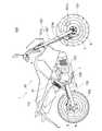
実施の形態1に係るブレーキシステムのブレーキ液圧制御ユニットのモータサイクルへの搭載例について説明する。
図2は、本発明の実施の形態1に係るブレーキシステムの、ブレーキ液圧制御ユニットのモータサイクルへの搭載例を示す図である。<Example of mounting the brake fluid pressure control unit on a motorcycle>
An example of mounting the brake fluid pressure control unit of the brake system according to
FIG. 2 is a diagram showing an example of mounting the brake fluid pressure control unit on the motorcycle of the brake system according to
図2に示されるように、モータサイクル100は、胴体部110と、胴体部110に旋回可能に保持され、前輪101を保持する旋回部120と、胴体部110と後輪102とを連結する連結部130と、を備えている。 As shown in FIG. 2, the
旋回部120は、胴体部110に軸支されたフロントフォーク121を含む。フロントフォーク121は、フロントフォーク上端部121aと、フロントサスペンション121bと、フロントフォーク下端部121cと、を含む。フロントフォーク上端部121aとフロントフォーク下端部121cとがフロントサスペンション121bを介して連結されることで、フロントフォーク121が、その軸線に沿って伸縮可能になっている。前輪101は、フロントフォーク下端部121cに回動可能に軸支されている。また、フロントフォーク下端部121cには、フロントブレーキキャリパ5が取り付けられている。フロントブレーキキャリパ5のブレーキパッド(図示省略)は、前輪101と共に回転するフロントロータ6に摩擦力を付与する。 The
連結部130は、胴体部110に揺動可能に軸支されたスイングアーム131を含む。スイングアーム131の途中部には、一端が胴体部110に連結されているリアサスペンション105の他端が連結されている。また、スイングアーム131の後端にはリアブレーキキャリパ8が取り付けられている。リアブレーキキャリパ8のブレーキパッド(図示省略)は、後輪102と共に回転するリアロータ9に摩擦力を付与する。 The connecting
つまり、旋回部120は、モータサイクル100のうちの、前輪101と共に旋回する部分として定義され、フロントフォーク121を含む。また、連結部130は、モータサイクル100のうちの、胴体部110と後輪102とを連結する部分と定義され、スイングアーム131を含む。また、旋回部120のうちの、フロントサスペンション121bを基準とする胴体部110側がバネ上と定義され、前輪101側がバネ下と定義される。また、連結部130のうちの、リアサスペンション105の他端(つまり、胴体部110に連結されない側の端部)が連結されている箇所を基準とする胴体部110側がバネ上と定義され、後輪102側がバネ下と定義される。 That is, the
例えば、図2に示されるように、基体31は、胴体部110の一部を構成する部材に取り付けられ、加圧移送機構25の動力源となる駆動機構103は、モータサイクル100のエンジンである。加圧移送機構25の動力源となる駆動機構103として、モータサイクル100の、車輪(前輪101、後輪102)、サスペンション(フロントサスペンション121b、リアサスペンション105)の動力源、スタータモータ等が用いられてもよい。また、基体31は、胴体部110以外に配設されてもよい。 For example, as shown in FIG. 2, the
<ブレーキシステムの効果>
実施の形態1に係るブレーキシステムの効果について説明する。
ブレーキシステム1のブレーキ液圧制御ユニット50では、加圧移送機構25の動力源が、モータサイクル100の、制御器51による液圧制御動作が実施されていない状態で駆動される駆動機構103である。つまり、モータサイクル100の、制御器51による液圧制御動作以外のために設けられている駆動機構103が、加圧移送機構25の動力源として兼用される。そのため、液圧制御動作の実施のためにモータがブレーキシステム1に追加されなくてもよくなって、ブレーキシステム1のコスト性が向上される。<Effect of brake system>
The effect of the brake system according to the first embodiment will be described.
In the brake fluid
好ましくは、ブレーキシステム1のブレーキ液圧制御ユニット50では、駆動機構103の動力が、伝達機構104を介して加圧移送機構25に伝達され、伝達機構104によって伝達される動力を制御する伝達動力制御機構28を備えている。このように構成されることで、駆動機構103が、ホイールシリンダ13のブレーキ液の液圧制御動作の実施状態に関係なく駆動されるもの(例えば、モータサイクル100の稼動状態で常時駆動されるもの等)である場合において、必要な時のみ加圧移送機構25を駆動させることが可能となって、加圧移送機構25の耐久性等が向上される。 Preferably, in the brake hydraulic
好ましくは、ブレーキシステム1のブレーキ液圧制御ユニット50では、伝達機構104が、伝達流体が充填されている伝達管104dを含み、伝達動力制御機構28が、伝達流体の流通を制御する弁である。このように構成されることで、伝達機構104が、ベルトを介して駆動機構103の動力を伝達する場合等と比較して、駆動機構103の近くに基体31を配設する必要性が低減されることとなって、駆動機構103の選択の自由度が向上される。 Preferably, in the brake hydraulic
実施の形態2.
以下に、実施の形態2に係るブレーキシステムについて説明する。
なお、実施の形態1に係るブレーキシステムと重複又は類似する説明は、適宜簡略化又は省略している。
Below, the brake system which concerns on
In addition, the description which overlaps or resembles the brake system which concerns on
<ブレーキシステムの構成及び動作>
実施の形態2に係るブレーキシステムの構成及び動作について説明する。
図3は、本発明の実施の形態2に係るブレーキシステムの、システム構成を示す図である。<Configuration and operation of brake system>
The configuration and operation of the brake system according to
FIG. 3 is a diagram showing a system configuration of a brake system according to
図3に示されるように、第1液圧回路2の込め弁21と弛め弁22とアキュムレータ23と逆止弁24と加圧移送機構25Aと逆止弁26とリストリクタ27とは、主流路14の一部を構成する部分流路32aと、副流路15を構成する部分流路32bと、が内部に形成されている基体32に設けられている。また、第2液圧回路3の込め弁21と弛め弁22とアキュムレータ23と逆止弁24と加圧移送機構25Bと逆止弁26とリストリクタ27とは、主流路14の一部を構成する部分流路33aと、副流路15を構成する部分流路33bと、が内部に形成されている基体33に設けられている。つまり、第1液圧回路2を構成する部材と第2液圧回路3を構成する部材とは、基体32と基体33とに分かれて設けられている。 As shown in FIG. 3, the
加圧移送機構25Aのシリンダ25cは、伝達管104dを介して、駆動機構103Aの動力を伝達する伝達機構104Aのシリンダ104bに連通している。加圧移送機構25Bのシリンダ25cは、伝達管104dを介して、駆動機構103Bの動力を伝達する伝達機構104Bのシリンダ104bに連通している。つまり、加圧移送機構25Aと、加圧移送機構25Bと、は、別々の駆動機構103A、103Bを動力源としている。なお、第1液圧回路2の加圧移送機構25Aと、第2液圧回路3の加圧移送機構25Bと、が、同一の駆動機構を動力源としてもよい。 The
<ブレーキ液圧制御ユニットのモータサイクルへの搭載例>
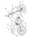
実施の形態2に係るブレーキシステムのブレーキ液圧制御ユニットのモータサイクルへの搭載例について説明する。
図4は、本発明の実施の形態2に係るブレーキシステムの、ブレーキ液圧制御ユニットのモータサイクルへの搭載例を示す図である。<Example of mounting the brake fluid pressure control unit on a motorcycle>
An example of mounting the brake fluid pressure control unit of the brake system according to the second embodiment on a motorcycle will be described.
FIG. 4 is a diagram showing an example of mounting the brake fluid pressure control unit on the motorcycle of the brake system according to the second embodiment of the present invention.
例えば、図4に示されるように、基体32は、旋回部120の一部(例えば、ハンドルレバー4の周辺、フロントフォーク121等)を構成する部材に取り付けられている。また、基体33は、胴体部110の下部(例えば、フットペダル7の周辺、エンジンとスイングアーム131との間の領域等)又は連結部130の一部(例えば、スイングアーム131等)を構成する部材に取り付けられている。つまり、基体32が、基体33と比較して、モータサイクル100の前側に配設されている。また、基体32が、モータサイクル100の旋回部120に配設されている。また、基体33が、胴体部110の下部又は連結部130に配設されている。 For example, as shown in FIG. 4, the
例えば、第1液圧回路2の加圧移送機構25Aの動力源である駆動機構103Aは、旋回部120の一部を構成する駆動機構(例えば、フロントサスペンション121bの動力源、前輪101等)である。また、第2液圧回路3の加圧移送機構25Bの動力源である駆動機構103Bは、胴体部110の下部を構成する駆動機構(例えば、エンジン等)又は後輪102である。つまり、第1液圧回路2の加圧移送機構25Aの動力源である駆動機構103Aは、第2液圧回路3の加圧移送機構25Bの動力源である駆動機構103Bと比較して、モータサイクル100の前側に配設されている。 For example, the
<ブレーキシステムの効果>
実施の形態2に係るブレーキシステムの効果について説明する。
好ましくは、ブレーキシステム1のブレーキ液圧制御ユニット50では、第1液圧回路2を構成する部材と、第2液圧回路3を構成する部材と、が、基体32と基体33とに分かれて設けられている。つまり、第1液圧回路2を構成する部材が設けられている基体32と、第2液圧回路3を構成する部材が設けられている基体33と、が、互いに分離されて小型化されていることで、基体32、33の配設箇所の自由度が向上されて、駆動機構103の選択の自由度が向上される。<Effect of brake system>
The effect of the brake system according to the second embodiment will be described.
Preferably, in the brake hydraulic
また、それに伴って、基体32を、基体33と比較して、モータサイクル100の前側に配設することが可能である。そのように構成されると、第1液圧回路2のブレーキ液管41、42の配管長さを短くすると共に、第2液圧回路3のブレーキ液管41、42の配管長さを短くすることが可能となって、モータサイクル100の本体側において確保されるべき配管のためのスペースが低減される。 Accordingly, the
また、それに伴って、基体32を、モータサイクル100の旋回部120に配設することが可能である。そのように構成されると、第1液圧回路2のブレーキ液管41、42を最短ルートで配管することが可能となって、モータサイクル100の本体側において確保されるべき配管のためのスペースが更に低減される。 Along with this, the
また、それに伴って、基体33を、モータサイクル100の胴体部110の下部に配設することが可能である。そのように構成されると、第2液圧回路3のブレーキ液管41、42を最短ルートで配管することが可能となって、モータサイクル100の本体側において確保されるべき配管のためのスペースが更に低減される。 Along with this, it is possible to dispose the
また、それに伴って、第1液圧回路2の加圧移送機構25Aの動力源として、モータサイクル100の前側に配設されている駆動機構103Aを選択し、第2液圧回路3の加圧移送機構25Bの動力源として、モータサイクル100の後側に配設されている駆動機構103Bを選択することが可能である。そのように構成されると、伝達管104dの配管長さ等を短くすることが可能となって、モータサイクル100の本体側において確保されるべきスペースが低減される。 Accordingly, the
実施の形態3.
以下に、実施の形態3に係るブレーキシステムについて説明する。
なお、実施の形態1及び実施の形態2に係るブレーキシステムと重複又は類似する説明は、適宜簡略化又は省略している。
Below, the brake system which concerns on
In addition, the description which overlaps or resembles the brake system which concerns on
<ブレーキシステムの構成及び動作>
実施の形態3に係るブレーキシステムの構成及び動作について説明する。
図5は、本発明の実施の形態3に係るブレーキシステムの、システム構成を示す図である。<Configuration and operation of brake system>
The configuration and operation of the brake system according to
FIG. 5 is a diagram showing a system configuration of a brake system according to
図5に示されるように、第1液圧回路2の込め弁21と弛め弁22とは、主流路14の一部を構成する部分流路34aと、副流路15の一部を構成する部分流路34bと、が内部に形成されている基体34に設けられている。また、第2液圧回路3の込め弁21と弛め弁22とは、主流路14の一部を構成する部分流路35aと、副流路15の一部を構成する部分流路35bと、が内部に形成されている基体35に設けられている。また、第1液圧回路2及び第2液圧回路3のアキュムレータ23と逆止弁24と加圧移送機構25と逆止弁26とリストリクタ27とは、副流路15の一部を構成する部分流路36bが内部に形成されている基体36に設けられている。つまり、第1液圧回路2の込め弁21及び弛め弁22と第2液圧回路3の込め弁21及び弛め弁22と加圧移送機構25とは、基体34と基体35と基体36とに分かれて設けられている。 As shown in FIG. 5, the
基体34、35の部分流路34a、35aの一端には、マスタシリンダ11からのブレーキ液管41が接続され、その他端には、ホイールシリンダ13からのブレーキ液管42が接続される。基体34、35の部分流路34b、35bの一端は、部分流路34a、35aの途中部に連通し、その他端には、ブレーキ液管43の上流側端部が接続される。基体36の部分流路36bの一端には、ブレーキ液管43の下流側端部が接続され、その他端には、ブレーキ液管41の途中部に連通するブレーキ液管44が接続される。 A
加圧移送機構25のシリンダ25cは、伝達管104dを介して、シリンダ104bに連通している。第1液圧回路2のピストン25bの他端と第2液圧回路3のピストン25bの他端とが、1つのシリンダ25cに挿入されていてもよく、また、別々のシリンダ25cに挿入されていてもよい。 The
<ブレーキ液圧制御ユニットのモータサイクルへの搭載例>
実施の形態3に係るブレーキシステムのブレーキ液圧制御ユニットのモータサイクルへの搭載例について説明する。
図6は、本発明の実施の形態3に係るブレーキシステムの、ブレーキ液圧制御ユニットのモータサイクルへの搭載例を示す図である。<Example of mounting the brake fluid pressure control unit on a motorcycle>
An example of mounting the brake fluid pressure control unit of the brake system according to the third embodiment on a motorcycle will be described.
FIG. 6 is a diagram showing an example of mounting a brake fluid pressure control unit on a motorcycle of a brake system according to
例えば、図6に示されるように、基体34が、フロントブレーキキャリパ5に取り付けられ、基体35が、リアブレーキキャリパ8に取り付けられている。また、基体36が、胴体部110の一部を構成する部材に取り付けられている。つまり、基体34及び基体35は、モータサイクル100のバネ下に配設されている。 For example, as shown in FIG. 6, the
<ブレーキシステムの効果>
実施の形態3に係るブレーキシステムの効果について説明する。
好ましくは、ブレーキシステム1のブレーキ液圧制御ユニット50では、込め弁21及び弛め弁22と加圧移送機構25とが、基体34、35と基体36とに分かれて設けられている。つまり、込め弁21及び弛め弁22が設けられている基体34、35と、加圧移送機構25が設けられている基体36と、が、互いに分離されて小型化されていることで、基体36の配設箇所の自由度が向上されて、駆動機構103の選択の自由度が向上される。<Effect of brake system>
The effect of the brake system according to
Preferably, in the brake hydraulic
また、それに伴って、込め弁21及び弛め弁22が設けられている基体34、35を、モータサイクル100のバネ下に配設することが可能である。そのように構成されると、モータサイクル100の胴体部110に確保されるべき基体の配設のためのスペースが低減される。 Along with this, it is possible to dispose the
実施の形態4.
以下に、実施の形態4に係るブレーキシステムについて説明する。
なお、実施の形態1〜実施の形態3に係るブレーキシステムと重複又は類似する説明は、適宜簡略化又は省略している。
The brake system according to the fourth embodiment will be described below.
In addition, the description which overlaps or resembles the brake system which concerns on Embodiment 1-
<ブレーキシステムの構成及び動作>
実施の形態4に係るブレーキシステムの構成及び動作について説明する。
図7は、本発明の実施の形態4に係るブレーキシステムの、システム構成を示す図である。<Configuration and operation of brake system>
The configuration and operation of the brake system according to
FIG. 7 is a diagram showing a system configuration of a brake system according to
図7に示されるように、第1液圧回路2のアキュムレータ23と逆止弁24と加圧移送機構25Aと逆止弁26とリストリクタ27とは、副流路15の一部を構成する部分流路37bが内部に形成されている基体37に設けられている。また、第2液圧回路3のアキュムレータ23と逆止弁24と加圧移送機構25Bと逆止弁26とリストリクタ27とは、副流路15の一部を構成する部分流路38bが内部に形成されている基体38に設けられている。つまり、第1液圧回路2を構成する部材と第2液圧回路3を構成する部材とは、基体34、37と基体35、38とに分かれて設けられており、且つ、込め弁21及び弛め弁22と加圧移送機構25A、25Bとが、基体34、35と基体37、38に分かれて設けられている。 As shown in FIG. 7, the
加圧移送機構25Aのシリンダ25cは、伝達管104dを介して、駆動機構103Aの動力を伝達する伝達機構104Aのシリンダ104bに連通している。加圧移送機構25Bのシリンダ25cは、伝達管104dを介して、駆動機構103Bの動力を伝達する伝達機構104Bのシリンダ104bに連通している。つまり、加圧移送機構25Aと、加圧移送機構25Bと、は、別々の駆動機構103A、103Bを動力源としている。なお、第1液圧回路2の加圧移送機構25Aと、第2液圧回路3の加圧移送機構25Bと、が、同一の駆動機構を動力源としてもよい。 The
<ブレーキ液圧制御ユニットのモータサイクルへの搭載例>
実施の形態4に係るブレーキシステムのブレーキ液圧制御ユニットのモータサイクルへの搭載例について説明する。
図8は、本発明の実施の形態4に係るブレーキシステムの、ブレーキ液圧制御ユニットのモータサイクルへの搭載例を示す図である。<Example of mounting the brake fluid pressure control unit on a motorcycle>
An example of mounting a brake fluid pressure control unit of a brake system according to
FIG. 8 is a diagram showing an example of mounting a brake fluid pressure control unit on a motorcycle of a brake system according to
例えば、図8に示されるように、基体34が、フロントブレーキキャリパ5に取り付けられ、基体35が、リアブレーキキャリパ8に取り付けられている。また、基体37が、旋回部120の一部(例えば、ハンドルレバー4の周辺、フロントフォーク121等)を構成する部材に取り付けられている。また、基体38が、胴体部110の下部(例えば、フットペダル7の周辺、エンジンとスイングアーム131との間の領域等)を構成する部材に取り付けられている。つまり、基体34及び基体35は、モータサイクル100のバネ下に配設されている。また、第1液圧回路2を構成する部材が設けられている基体34、37が、モータサイクル100の旋回部120に配設されている。また、第2液圧回路3を構成する部材が設けられている基体35、38が、モータサイクル100の連結部130、又は、モータサイクル100の胴体部110の下部に配設されている。 For example, as shown in FIG. 8, the
例えば、第1液圧回路2の加圧移送機構25Aの動力源である駆動機構103Aは、旋回部120の一部を構成する駆動機構(例えば、フロントサスペンション121bの動力源、前輪101等)である。また、第2液圧回路3の加圧移送機構25Bの動力源である駆動機構103Bは、胴体部110の下部を構成する駆動機構(例えば、エンジン等)又は後輪102である。つまり、第1液圧回路2の加圧移送機構25Aの動力源である駆動機構103Aは、第2液圧回路3の加圧移送機構25Bの動力源である駆動機構103Bと比較して、モータサイクル100の前側に配設されている。 For example, the
<ブレーキシステムの効果>
実施の形態4に係るブレーキシステムの効果について説明する。
好ましくは、ブレーキシステム1のブレーキ液圧制御ユニット50では、第1液圧回路2を構成する部材と第2液圧回路3を構成する部材とが、基体34、37と基体35、38に分かれて設けられていると共に、込め弁21及び弛め弁22と加圧移送機構25A、25Bとが、基体34、35と基体37、38とに分かれて設けられている。つまり、第1液圧回路2の込め弁21及び弛め弁22が設けられている基体34と、第2液圧回路3の込め弁21及び弛め弁22が設けられている基体35と、加圧移送機構25Aが設けられている基体37と、加圧移送機構25Bが設けられている基体38と、が、互いに分離されて小型化されていることで、基体37、38の配設箇所の自由度が向上されて、駆動機構103の選択の自由度が向上される。<Effect of brake system>
The effect of the brake system according to the fourth embodiment will be described.
Preferably, in the brake hydraulic
また、それに伴って、基体37と基体38を、モータサイクル100の胴体部110の互いに異なる箇所に配設すると共に、込め弁21及び弛め弁22が設けられている基体34、35を、モータサイクル100のバネ下に配設することが可能である。そのように構成されると、モータサイクル100に確保されるべき配管のためのスペースが低減されると共に、モータサイクル100の胴体部110に確保されるべき基体の配設のためのスペースが低減される。 Along with this, the
また、それに伴って、第1液圧回路2の加圧移送機構25Aの動力源として、モータサイクル100の前側に配設されている駆動機構103Aを選択し、第2液圧回路3の加圧移送機構25Bの動力源として、モータサイクル100の後側に配設されている駆動機構103Bを選択することが可能である。そのように構成されると、伝達管104dの配管長さ等を短くすることが可能となって、モータサイクル100の本体側において確保されるべきスペースが低減される。 Accordingly, the
以上、実施の形態1〜実施の形態4について説明したが、本発明は各実施の形態の説明に限定されない。例えば、各実施の形態の一部のみが実施されてもよく、また、各実施の形態の全て又は一部が組み合わされてもよい。 As mentioned above, although Embodiment 1-
1 ブレーキシステム、2 第1液圧回路、3 第2液圧回路、4 ハンドルレバー、5 フロントブレーキキャリパ、6 フロントロータ、7 フットペダル、8 リアブレーキキャリパ、9 リアロータ、11 マスタシリンダ、12 リザーバ、13 ホイールシリンダ、14 主流路、15 副流路、21 込め弁、22 弛め弁、23 アキュムレータ、24 逆止弁、25、25A、25B 加圧移送機構、25a シリンダ、25b ピストン、25c シリンダ、26 逆止弁、27 リストリクタ、28、28A、28B 伝達動力制御機構、31〜38 基体、31a〜35a、31b〜38b 部分流路、31c〜33c、36c〜38c 伝達流路、41〜44 ブレーキ液管、50 ブレーキ液圧制御ユニット、51 制御器、100 モータサイクル、101 前輪、102 後輪、103、103A、103B 駆動機構、104、104A、104B 伝達機構、104a カム、104b シリンダ、104c ピストン、104d 伝達管、105 リアサスペンション、110 胴体部、120 旋回部、121 フロントフォーク、121a フロントフォーク上端部、121b フロントサスペンション、121c フロントフォーク下端部、130 連結部、131 スイングアーム。 1
Claims (13)
Translated fromJapanese前記ブレーキシステムは、マスタシリンダとホイールシリンダとを連通する主流路と、該主流路のブレーキ液を逃がす副流路と、を有する少なくとも1つの液圧回路を含み、
前記ブレーキ液圧制御ユニットは、
前記主流路に設けられている込め弁と、
前記副流路に設けられている弛め弁と、
前記副流路の前記弛め弁の下流側に設けられており、該副流路のブレーキ液を加圧して移送する加圧移送機構と、
前記ホイールシリンダのブレーキ液の液圧制御動作を実施する制御器と、
を備えており、
前記加圧移送機構の動力源は、モータサイクルの、前記制御器による前記液圧制御動作が実施されていない状態で駆動される駆動機構である、
ブレーキ液圧制御ユニット。A brake fluid pressure control unit for a motorcycle brake system,
The brake system includes at least one hydraulic circuit having a main flow path communicating with the master cylinder and the wheel cylinder, and a sub flow path for releasing the brake fluid in the main flow path,
The brake fluid pressure control unit is
A dovetail valve provided in the main flow path;
A relaxation valve provided in the sub-flow path;
A pressure transfer mechanism that is provided on the downstream side of the loosening valve of the sub flow path, pressurizes and transfers the brake fluid of the sub flow path, and
A controller for performing a hydraulic pressure control operation of the brake fluid of the wheel cylinder;
With
The power source of the pressure transfer mechanism is a drive mechanism that is driven in a state in which the hydraulic pressure control operation by the controller is not performed in a motorcycle.
Brake fluid pressure control unit.
モータサイクルの前輪に作用する前記液圧回路である第1液圧回路と、
モータサイクルの後輪に作用する前記液圧回路である第2液圧回路と、を含み、
前記第1液圧回路を構成する部材と、前記第2液圧回路を構成する部材と、は、別々の基体に設けられている、
請求項1に記載のブレーキ液圧制御ユニット。The brake system includes:
A first hydraulic circuit that is the hydraulic circuit acting on the front wheels of the motorcycle;
A second hydraulic circuit that is the hydraulic circuit acting on the rear wheel of the motorcycle,
The member constituting the first hydraulic circuit and the member constituting the second hydraulic circuit are provided on separate bases,
The brake fluid pressure control unit according to claim 1.
請求項2に記載のブレーキ液圧制御ユニット。The base provided with the member constituting the first hydraulic circuit is disposed on the front side of the motorcycle as compared with the base provided with the member constituting the second hydraulic circuit. Yes,
The brake fluid pressure control unit according to claim 2.
請求項3に記載のブレーキ液圧制御ユニット。The base body on which members constituting the first hydraulic circuit are provided is disposed in a turning portion that turns together with a front wheel of the motorcycle.
The brake fluid pressure control unit according to claim 3.
請求項3又は4に記載のブレーキ液圧制御ユニット。The base body on which the member constituting the second hydraulic circuit is provided is disposed at a lower part of the motorcycle body part or a connecting part that connects the motorcycle body part and the rear wheel.
The brake fluid pressure control unit according to claim 3 or 4.
請求項2〜5の何れか一項に記載のブレーキ液圧制御ユニット。The drive mechanism that is a power source of the pressurization transfer mechanism of the first hydraulic circuit is compared with the drive mechanism that is a power source of the pressurization transfer mechanism of the second hydraulic circuit. Arranged on the front side,
The brake fluid pressure control unit according to any one of claims 2 to 5.
請求項1〜6の何れか一項に記載のブレーキ液圧制御ユニット。In the at least one hydraulic circuit, the intake valve and the relaxation valve, and the pressurization transfer mechanism are provided on separate substrates.
The brake fluid pressure control unit according to any one of claims 1 to 6.
請求項7に記載のブレーキ液圧制御ユニット。The base body provided with the storage valve and the release valve is disposed under a spring of the motorcycle.
The brake fluid pressure control unit according to claim 7.
更に、前記伝達機構によって伝達される動力を制御する伝達動力制御機構を備えている、
請求項1〜8の何れか一項に記載のブレーキ液圧制御ユニット。The power of the drive mechanism is transmitted to the pressure transfer mechanism through a transmission mechanism,
And a transmission power control mechanism for controlling the power transmitted by the transmission mechanism.
The brake fluid pressure control unit according to any one of claims 1 to 8.
前記伝達動力制御機構は、前記伝達流体の流通を制御する弁である、
請求項9に記載のブレーキ液圧制御ユニット。The transmission mechanism includes a transmission tube filled with a transmission fluid;
The transmission power control mechanism is a valve that controls the flow of the transmission fluid.
The brake fluid pressure control unit according to claim 9.
請求項1〜10の何れか一項に記載のブレーキ液圧制御ユニット。The drive mechanism is at least one of an engine, wheels, a suspension power source, and a starter motor of a motorcycle.
The brake fluid pressure control unit according to any one of claims 1 to 10.
モータサイクル用のブレーキシステム。The brake fluid pressure control unit according to any one of claims 1 to 11 is provided.
Brake system for motorcycles.
前記駆動機構と、を備えている、
モータサイクル。
A brake system for a motorcycle according to claim 12,
The drive mechanism,
Motorcycle.
Priority Applications (7)
| Application Number | Priority Date | Filing Date | Title |
|---|---|---|---|
| JP2015219681AJP2017087937A (en) | 2015-11-09 | 2015-11-09 | Brake hydraulic pressure control unit, brake system for motorcycle, and motorcycle |
| TW105129980ATW201716276A (en) | 2015-11-09 | 2016-09-14 | Brake fluid pressure control unit, brake system for motorcycle, and motorcycle |
| CN201680065229.0ACN108349476A (en) | 2015-11-09 | 2016-11-03 | Brake hydraulic control unit, brake system for motorcycle and motorcycle |
| US15/770,494US10576954B2 (en) | 2015-11-09 | 2016-11-03 | Brake fluid pressure control unit, brake system for motorcycle, and motorcycle |
| PCT/IB2016/056608WO2017081582A1 (en) | 2015-11-09 | 2016-11-03 | Brake fluid pressure control unit, brake system for motorcycle, and motorcycle |
| EP16801585.7AEP3375677B1 (en) | 2015-11-09 | 2016-11-03 | Brake fluid pressure control unit, brake system for motorcycle, and motorcycle |
| JP2017549866AJP6620166B2 (en) | 2015-11-09 | 2016-11-03 | Brake fluid pressure control unit, motorcycle brake system, and motorcycle |
Applications Claiming Priority (1)
| Application Number | Priority Date | Filing Date | Title |
|---|---|---|---|
| JP2015219681AJP2017087937A (en) | 2015-11-09 | 2015-11-09 | Brake hydraulic pressure control unit, brake system for motorcycle, and motorcycle |
Publications (1)
| Publication Number | Publication Date |
|---|---|
| JP2017087937Atrue JP2017087937A (en) | 2017-05-25 |
Family
ID=57396767
Family Applications (2)
| Application Number | Title | Priority Date | Filing Date |
|---|---|---|---|
| JP2015219681APendingJP2017087937A (en) | 2015-11-09 | 2015-11-09 | Brake hydraulic pressure control unit, brake system for motorcycle, and motorcycle |
| JP2017549866AActiveJP6620166B2 (en) | 2015-11-09 | 2016-11-03 | Brake fluid pressure control unit, motorcycle brake system, and motorcycle |
Family Applications After (1)
| Application Number | Title | Priority Date | Filing Date |
|---|---|---|---|
| JP2017549866AActiveJP6620166B2 (en) | 2015-11-09 | 2016-11-03 | Brake fluid pressure control unit, motorcycle brake system, and motorcycle |
Country Status (6)
| Country | Link |
|---|---|
| US (1) | US10576954B2 (en) |
| EP (1) | EP3375677B1 (en) |
| JP (2) | JP2017087937A (en) |
| CN (1) | CN108349476A (en) |
| TW (1) | TW201716276A (en) |
| WO (1) | WO2017081582A1 (en) |
Cited By (3)
| Publication number | Priority date | Publication date | Assignee | Title |
|---|---|---|---|---|
| US11564110B2 (en) | 2011-11-07 | 2023-01-24 | Dali Wireless, Inc. | Soft hand-off and routing data in a virtualized distributed antenna system |
| US11563492B2 (en)* | 2013-12-23 | 2023-01-24 | Dali Wireless, Inc. | Virtual radio access network using software-defined network of remotes and digital multiplexing switches |
| WO2025182365A1 (en)* | 2024-02-27 | 2025-09-04 | Astemo株式会社 | Brake control system for saddled vehicle |
Family Cites Families (21)
| Publication number | Priority date | Publication date | Assignee | Title |
|---|---|---|---|---|
| JPS5850903B2 (en)* | 1975-08-14 | 1983-11-12 | ヤマハハツドウキ カブシキガイシヤ | anti-skid saw |
| DE3119982C2 (en)* | 1981-05-20 | 1983-09-15 | Daimler-Benz Ag, 7000 Stuttgart | "Return pumping device for an anti-lock vehicle brake system" |
| JPS5873461A (en)* | 1981-07-06 | 1983-05-02 | Nippon Air Brake Co Ltd | Antiskid device for vehicle |
| DE3611932A1 (en)* | 1986-04-09 | 1987-10-22 | Teves Gmbh Alfred | HYDRAULIC BRAKE SYSTEM |
| JPH0781545A (en) | 1993-09-16 | 1995-03-28 | Nissin Kogyo Kk | Vehicle braking system |
| JP3539585B2 (en)* | 1995-01-13 | 2004-07-07 | 株式会社ボッシュオートモーティブシステム | Brake system with automatic braking device |
| DE19538794A1 (en)* | 1995-10-18 | 1997-04-24 | Teves Gmbh Alfred | Electronically controllable brake actuation system |
| JP4169948B2 (en) | 2000-05-11 | 2008-10-22 | ボッシュ株式会社 | Method for detecting rear wheel lift of motorcycle and brake control method |
| DE60229185D1 (en)* | 2001-07-19 | 2008-11-20 | Bayerische Motoren Werke Ag | Brake control method and device for motorcycles |
| CA2528903C (en)* | 2004-12-20 | 2008-01-15 | Honda Motor Co., Ltd. | Braking device for motorcycle |
| EP1839977B1 (en)* | 2006-03-31 | 2016-05-04 | Honda Motor Co., Ltd. | Brake system for motorcycle |
| JP4749950B2 (en)* | 2006-06-27 | 2011-08-17 | 本田技研工業株式会社 | Brake device for vehicle |
| JP5203771B2 (en)* | 2008-03-31 | 2013-06-05 | 本田技研工業株式会社 | Brake equipment for motorcycles |
| JPWO2010023985A1 (en) | 2008-08-29 | 2012-01-26 | ボッシュ株式会社 | Brake hydraulic pressure control device |
| US8328295B2 (en)* | 2008-10-24 | 2012-12-11 | Bosch Corporation | Motorcycle braking device |
| US9033429B2 (en)* | 2009-10-13 | 2015-05-19 | Bosch Corporation | Brake control device |
| DE102010001542A1 (en)* | 2010-02-03 | 2011-08-04 | Continental Teves AG & Co. OHG, 60488 | Hydraulic brake system i.e. pump-less anti-lock braking sub system, for use in e.g. front wheel of motor bike, has bypass line surrounding normally open valve, and decentralized unit connected with central unit and wheel speed sensor |
| JP5656677B2 (en)* | 2011-02-14 | 2015-01-21 | 本田技研工業株式会社 | Brake equipment for motorcycles |
| JP5882137B2 (en)* | 2012-05-31 | 2016-03-09 | ボッシュ株式会社 | ABS hydraulic unit |
| JP5873461B2 (en) | 2013-07-03 | 2016-03-01 | 本田技研工業株式会社 | Vehicle control object determination device, vehicle control object determination method, and vehicle control object determination program |
| EP3205538B1 (en)* | 2014-10-09 | 2021-03-17 | Robert Bosch GmbH | Method and device for controlling motorcycle brake for assisting motorcycle departure |
- 2015
- 2015-11-09JPJP2015219681Apatent/JP2017087937A/enactivePending
- 2016
- 2016-09-14TWTW105129980Apatent/TW201716276A/enunknown
- 2016-11-03USUS15/770,494patent/US10576954B2/ennot_activeExpired - Fee Related
- 2016-11-03CNCN201680065229.0Apatent/CN108349476A/enactivePending
- 2016-11-03JPJP2017549866Apatent/JP6620166B2/enactiveActive
- 2016-11-03EPEP16801585.7Apatent/EP3375677B1/enactiveActive
- 2016-11-03WOPCT/IB2016/056608patent/WO2017081582A1/ennot_activeCeased
Cited By (3)
| Publication number | Priority date | Publication date | Assignee | Title |
|---|---|---|---|---|
| US11564110B2 (en) | 2011-11-07 | 2023-01-24 | Dali Wireless, Inc. | Soft hand-off and routing data in a virtualized distributed antenna system |
| US11563492B2 (en)* | 2013-12-23 | 2023-01-24 | Dali Wireless, Inc. | Virtual radio access network using software-defined network of remotes and digital multiplexing switches |
| WO2025182365A1 (en)* | 2024-02-27 | 2025-09-04 | Astemo株式会社 | Brake control system for saddled vehicle |
Also Published As
| Publication number | Publication date |
|---|---|
| US10576954B2 (en) | 2020-03-03 |
| TW201716276A (en) | 2017-05-16 |
| EP3375677A1 (en) | 2018-09-19 |
| US20190054908A1 (en) | 2019-02-21 |
| WO2017081582A1 (en) | 2017-05-18 |
| CN108349476A (en) | 2018-07-31 |
| JP6620166B2 (en) | 2019-12-11 |
| JPWO2017081582A1 (en) | 2018-08-16 |
| EP3375677B1 (en) | 2019-10-09 |
Similar Documents
| Publication | Publication Date | Title |
|---|---|---|
| JP6620165B2 (en) | Brake fluid pressure control unit and motorcycle brake system | |
| JP6620166B2 (en) | Brake fluid pressure control unit, motorcycle brake system, and motorcycle | |
| JP6877635B2 (en) | Hydraulic control unit for saddle-type vehicle brake system and saddle-type vehicle brake system | |
| JP2008179313A (en) | Brake control device for motorcycle | |
| CN107531226B (en) | Brake hydraulic pressure control device and anti-lock brake system | |
| JP2007253931A (en) | Motorcycle brake equipment | |
| JPWO2009050961A1 (en) | Brake hydraulic pressure control device | |
| EP3786014B1 (en) | Hydraulic pressure control unit for straddle-type vehicle brake system and straddle-type vehicle brake system | |
| JP2009179260A (en) | Interlocking brake device for motorcycles | |
| CN1070135C (en) | Bar handle vehicle brake system | |
| US2115071A (en) | Hydraulic brake | |
| JP2003512239A (en) | Operating unit for vehicle wheel brakes | |
| TWI860292B (en) | Hydraulic device for hydraulic system of human-powered vehicle and hydraulic system for human-powered vehicle | |
| CN109843668B (en) | Brake hydraulic control unit, brake system for motorcycle and motorcycle | |
| CN1448312A (en) | Motorcycle braking system | |
| JP6351166B2 (en) | Brake fluid pressure control unit | |
| JP6461678B2 (en) | Brake hydraulic pressure control device for vehicles | |
| JP2003112684A (en) | Braking device for motorcycle | |
| JP4132986B2 (en) | Swing type vehicle | |
| JP2019196030A (en) | Fluid pressure control unit | |
| JP2022096450A (en) | Brake system and saddle-riding type vehicle | |
| JP3881756B2 (en) | Vehicle disc brake device and manufacturing method thereof | |
| JP7150154B2 (en) | Brake fluid pressure controller | |
| JP2004217211A (en) | Disc brakes for vehicles | |
| KR102166552B1 (en) | Initialization method of electro mechanical brake |