JP2017085849A - Vibration motor - Google Patents
Vibration motorDownload PDFInfo
- Publication number
- JP2017085849A JP2017085849AJP2015214645AJP2015214645AJP2017085849AJP 2017085849 AJP2017085849 AJP 2017085849AJP 2015214645 AJP2015214645 AJP 2015214645AJP 2015214645 AJP2015214645 AJP 2015214645AJP 2017085849 AJP2017085849 AJP 2017085849A
- Authority
- JP
- Japan
- Prior art keywords
- adhesive layer
- vibration motor
- magnet
- jacket
- disposed
- Prior art date
- Legal status (The legal status is an assumption and is not a legal conclusion. Google has not performed a legal analysis and makes no representation as to the accuracy of the status listed.)
- Pending
Links
- 239000012790adhesive layerSubstances0.000claimsabstractdescription130
- 125000006850spacer groupChemical group0.000claimsdescription18
- 238000000034methodMethods0.000abstractdescription3
- 239000000463materialSubstances0.000description6
- 239000011248coating agentSubstances0.000description4
- 238000000576coating methodMethods0.000description4
- 239000010410layerSubstances0.000description3
- 230000008602contractionEffects0.000description2
- 230000003993interactionEffects0.000description2
- 239000002184metalSubstances0.000description2
- 230000004048modificationEffects0.000description2
- 238000012986modificationMethods0.000description2
- 239000011347resinSubstances0.000description2
- 229920005989resinPolymers0.000description2
- 230000004907fluxEffects0.000description1
- 230000005484gravityEffects0.000description1
- 230000007774longtermEffects0.000description1
- 238000004519manufacturing processMethods0.000description1
- 230000007246mechanismEffects0.000description1
- 238000000465mouldingMethods0.000description1
- 238000003466weldingMethods0.000description1
Images


Classifications
- H—ELECTRICITY
- H02—GENERATION; CONVERSION OR DISTRIBUTION OF ELECTRIC POWER
- H02K—DYNAMO-ELECTRIC MACHINES
- H02K33/00—Motors with reciprocating, oscillating or vibrating magnet, armature or coil system
- H—ELECTRICITY
- H02—GENERATION; CONVERSION OR DISTRIBUTION OF ELECTRIC POWER
- H02K—DYNAMO-ELECTRIC MACHINES
- H02K33/00—Motors with reciprocating, oscillating or vibrating magnet, armature or coil system
- H02K33/16—Motors with reciprocating, oscillating or vibrating magnet, armature or coil system with polarised armatures moving in alternate directions by reversal or energisation of a single coil system
Landscapes
- Engineering & Computer Science (AREA)
- Power Engineering (AREA)
- Apparatuses For Generation Of Mechanical Vibrations (AREA)
- Reciprocating, Oscillating Or Vibrating Motors (AREA)
Abstract
Description
Translated fromJapanese本発明は、振動モータに関する。 The present invention relates to a vibration motor.
従来、磁界を用いて振動を発生させる振動発生装置が知られている。振動発生装置は、例えば、携帯電話機等の携帯端末、ゲーム機、玩具などに用いられる。現在までに、様々な仕組みの振動発生装置が開発されている。一例として、モータの回転軸に偏心錘を取り付け、モータを駆動させることで振動を生じさせる回転駆動型の振動モータや、コイルとマグネットが形成する磁界を利用して振動体を往復振動させるリニア駆動型の振動モータが知られている。 Conventionally, a vibration generator that generates vibration using a magnetic field is known. The vibration generator is used for portable terminals such as mobile phones, game machines, toys and the like, for example. To date, vibration generators with various mechanisms have been developed. As an example, an eccentric weight is attached to the rotating shaft of the motor, and a rotational drive type vibration motor that generates vibration by driving the motor, or a linear drive that reciprocally vibrates a vibrating body using a magnetic field formed by a coil and a magnet. A type of vibration motor is known.
回転駆動型の振動モータでは、装置を薄く形成することが困難であるとともに、耐久性が低く、長時間の使用に伴いノイズが発生する虞がある。一方、リニア駆動型の振動モータでは、前述の振動発生装置と比べて薄型化が可能である。従来のリニア駆動型の振動モータについては、例えば、中国特許出願公開第102611272号明細書に記載されている。
しかしながら、中国特許出願公開第102611272号明細書に記載の振動モータでは、マグネットが質量体に囲まれているため、マグネットを含む可動子の剛性が向上する反面、小型化が困難となる。仮に質量体を省略すると、振動モータの小型化は可能であるが、振動モータに外部衝撃等の荷重が加わった場合に、マグネットを含む可動子が破損しやすい。 However, in the vibration motor described in Chinese Patent Application No. 10261272, since the magnet is surrounded by the mass body, the rigidity of the mover including the magnet is improved, but it is difficult to reduce the size. If the mass body is omitted, the vibration motor can be reduced in size, but when a load such as an external impact is applied to the vibration motor, the mover including the magnet is easily damaged.
本発明の目的は、振動モータの大型化を抑制し、可動子の破損を抑制できる技術を提供することである。 The objective of this invention is providing the technique which can suppress the enlargement of a vibration motor and can suppress the failure | damage of a needle | mover.
本願の例示的な第1発明は、ハウジングおよびコイルを有する静止部と、前記静止部に対して、揺動方向に揺動可能に支持される可動部と、前記静止部と前記可動部との間に配置される弾性部材と、を有する振動モータである。前記ハウジングの内部に、前記コイル、前記可動部および前記弾性部材が収容される。前記可動部は、前記コイルと対向して配置されるマグネットと、前記マグネットの前記揺動方向の両端に配置されるブラケットと、前記揺動方向に隣り合う部材同士を接着固定する、少なくとも1つの接着層と、を有する。前記可動部は、前記接着層の側面の少なくとも一部を覆うジャケットをさらに有する。 An exemplary first invention of the present application includes a stationary part having a housing and a coil, a movable part supported so as to be swingable in a swinging direction with respect to the stationary part, and the stationary part and the movable part. And an elastic member disposed therebetween. The coil, the movable part, and the elastic member are accommodated in the housing. The movable portion includes at least one magnet that is disposed opposite to the coil, brackets that are disposed at both ends of the magnet in the swing direction, and a member that is adjacent to the swing direction. And an adhesive layer. The movable part further includes a jacket that covers at least a part of a side surface of the adhesive layer.
本願の例示的な第1発明によれば、可動部に負荷がかかった場合に、マグネットを含む可動部が破損するのが抑制される。 According to the exemplary first invention of the present application, when a load is applied to the movable portion, the movable portion including the magnet is prevented from being damaged.
以下に、振動モータの例を開示する。なお、本開示では、可動部が揺動される方向を「揺動方向」と称する。また、本開示では、ハウジングの本体部に対してカバー部側を上として、上下方向を定める。なお、揺動方向は、上下方向に対して垂直な水平方向となる。また、上下方向および揺動方向に対して垂直な方向を、横方向と称する。ただし、これらの方向の定義により、振動モータの製造時および使用時の向きを限定する意図はない。 An example of a vibration motor will be disclosed below. In the present disclosure, the direction in which the movable part is swung is referred to as a “swinging direction”. Further, in the present disclosure, the vertical direction is determined with the cover portion side facing up with respect to the main body portion of the housing. The swing direction is a horizontal direction perpendicular to the vertical direction. A direction perpendicular to the vertical direction and the swinging direction is referred to as a lateral direction. However, these directions are not intended to limit the orientation of the vibration motor during manufacture and use.
<1.第1実施形態>
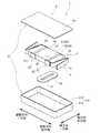
図1は、第1実施形態に係る振動モータ1の分解斜視図である。図2は、カバー部211を除いた振動モータ1の上面図である。この振動モータ1は、携帯電話機等の携帯端末に組み込まれ、振動を発生させる装置である。図1および図2に示すように、振動モータ1は、静止部2、可動部3および弾性部材4を有する。<1. First Embodiment>
FIG. 1 is an exploded perspective view of the
静止部2は、ハウジング21、コイル22および回路基板(図示省略)を有する。可動部3は、マグネット31と、一対のブラケット32と、2つの錘33と、ジャケット34とを有する。弾性部材4は、静止部2と可動部3との間に配置される。これにより、可動部3は、静止部2に対して揺動方向に揺動可能に支持される。 The
ハウジング21は、本体部210およびカバー部211の2つの部材から構成される。本体部210は、水平方向に拡がる底部212と、底部212から上方へ向かって筒状に延びる壁部213とを有する。カバー部211は、本体部210の上部の開口を覆う。 The
ハウジング21の内部には、底部212に取り付けられたコイル22と、コイル22の上方に配置された可動部3と、可動部3をハウジングの壁部213に対して支持する弾性部材4とが収容されている。 Housed in the
コイル22は、中央部に空間が形成されるように、導線が平面状かつ渦巻き状に巻かれた空芯スパイラルコイルである。コイル22から延びる導線は、回路基板に接続される。コイル22は、揺動方向に対して略直交する上下方向に延びる軸9を中心として巻き回される。コイル22は、マグネット31の下方に配置される。すなわち、コイル22は、マグネット31に対して、軸方向一方側に配置される。 The
マグネット31は、略直方形に成形され、揺動方向に着磁されている。すなわち、マグネット31は、揺動方向の2つの端面のうち、一方がN極の磁極面であり、他方がS極の磁極面である。マグネット31は、その下面がコイル22の上面と対向するように配置される。 The
一対のブラケット32は、マグネット31の揺動方向の両端に配置される。本実施形態のブラケット32は、揺動方向に対して略垂直に拡がる板状の部材である。また、一対のブラケット32は、マグネット31の揺動方向の両端面の全体を覆う。 The pair of
錘33は、それぞれ、ブラケット32と揺動方向に隣り合って配置される。錘33は、マグネット、ブラケット32および錘33により構成される可動子30の揺動方向の両端に配置される。錘33の材料には、例えば、ブラケット32よりも比重の大きい金属が用いられる。錘33を可動子30の揺動方向端部に配置することにより、可動子30の振動エネルギーを大きくできる。 The
図2に示すように、揺動方向に隣り合うマグネット31およびブラケット32と、揺動方向に隣り合うブラケット32および錘33とは、それぞれ、接着層50を介して接着固定される。すなわち、接着層50は、揺動方向に隣り合う部材同士を接着固定する。接着層50は、第1接着層51と、第2接着層52とを含む。第1接着層51は、揺動方向に隣り合うマグネット31とブラケット32との間に配置され、マグネット31とブラケット32とを固定する。第2接着層52は、揺動方向に隣り合うブラケット32と錘33との間に配置され、ブラケット32と錘33とを固定する。 As shown in FIG. 2, the
ジャケット34は、接着層50の側面の少なくとも一部を覆う部材である。ここで、接着層50の側面とは、接着層50の上下方向および横方向の端面を指す。ジャケット34は、例えば、板状の金属部材により形成される。ジャケット34の材料には、マグネット31よりも剛性の高い材料が用いられる。なお、ジャケット34の材料に、樹脂等の他の材料が用いられてもよい。また、ジャケット34の材料には、マグネット31、ブラケット32および錘33よりも剛性の高い材料が用いられることが好ましい。 The
各部材が接着層50により固定される可動子30では、揺動方向に対して垂直な方向から負荷がかかると、各接着層50付近に特に応力がかかる。このため、可動部3がジャケット34を有していない場合、マグネット31の揺動方向端部付近および接着層50が破損しやすい。しかしながら、この揺動モータ1では、接着層50の側面の少なくとも一部をジャケット34で覆うことにより、接着層50が破損するのが抑制される。ジャケット34の詳細な構成については、後述する。 In the
弾性部材4は、静止部2と可動部3との間に配置され、静止部2に対して可動部3を揺動可能に支持する。本実施形態の弾性部材4は、一対の板ばね41である。板ばね41は、上下方向に延びる板状の部材により形成される。板ばね41はそれぞれ、第1固定部411、第2固定部412および伸縮部413を有する。 The
第1固定部411は、上下方向から見て略L字状の部位である。第1固定部は、可動子30の揺動方向の端面および横方向側面に固定される。第2固定部412は、横方向に延びる部位である。第2固定部412は、ハウジング21の壁部213の内面に固定される。伸縮部413は、上下方向から見て略V字状の部位である。伸縮部413は、揺動方向に伸縮可能である。 The first fixing portion 411 is a substantially L-shaped portion when viewed from the up-down direction. The first fixed portion is fixed to the end surface and the lateral side surface of the
このような振動モータ1において、コイル22に駆動電流が供給されると、コイル22が形成する磁界と、マグネット31が形成する磁界との相互作用によって、マグネット31にローレンツ力が働く。これにより、可動部3が揺動方向に揺動する。 In such a
図1および図2に示すように、本実施形態のジャケット34は、第1接着層51および第2接着層52の側面の一部を覆う。このように、接着層51,52の側面の一部をジャケット34で覆うことにより、ジャケット34で覆われた面と略直交する方向から可動子30に負荷がかかった場合に、マグネット31および接着層50が破損するのが抑制される。 As shown in FIGS. 1 and 2, the
ジャケット34は、2組の横面被覆部61を有する。横面被覆部61はそれぞれ、揺動方向に延び、かつ、接着層50を介して向かい合う一対の第1板状部611を有する。第1板状部611はそれぞれ、接着層50と、接着層50と隣り合う部材の揺動方向の少なくとも一部とを覆う。 The
第1板状部611はそれぞれ、可動子30の横方向の一側面のうち、マグネット31の揺動方向の一部と、第1接着層51と、ブラケット32と、第2接着層52と、錘33の揺動方向の一部とを覆う。これにより、横面被覆部61は、第1接着層51および第2接着層52の横方向の両側面を覆う。したがって、上下方向または横方向から可動子30に負荷がかかった場合に、マグネット31、第1接着層51および第2接着層52が破損するのがより抑制される。したがって、マグネット31を含む可動子30の破損を抑制できる。なお、本実施形態では、可動子30の横方向の側面がジャケット34で覆われているため、横方向から可動子30に負荷がかかった場合に、より効果的に可動子30の破損を抑制できる。 Each of the first plate-
本実施形態の第1板状部611はそれぞれ、可動子30の側面に対して接着により固定されている。第1板状部611は、接着層50および接着層50に隣り合う2つの部材に対して接着固定される。このように、ジャケット34は、接着層50を挟む2つの部材の両方に対して固定されることが好ましい。なお、ジャケット34は、接着以外の方法によって可動子30に固定されてもよい。例えば、ジャケット34は、溶接、ネジ止め、かしめ、樹脂成型等の手段により可動子30に固定されていてもよい。 Each of the first plate-
また、本実施形態のジャケット34は、揺動方向に間隔をあけて配置される複数の横面被覆部61を有するが、本発明はこの限りではない。ジャケットが単一組の横面被覆部を有していてもよい。この場合、当該横面被覆部の有する一対の第1板状部のそれぞれは、マグネット31の揺動方向の全体と、2つの第1接着層と、一対のブラケットと、2つの第2接着層と、2つの錘の揺動方向の一部とを覆う。すなわち、当該ジャケットは、マグネット、第1接着層および第2接着層の横方向の全側面を覆う。このようにすれば、ジャケットがマグネットの横方向の側面について、揺動方向の全体を覆うことにより、マグネットの破損をさらに抑制できる。 Moreover, although the
<2.第2実施形態>
図3は、第2実施形態に係る振動モータ1Aの分解斜視図である。この振動モータ1Aは、ジャケットの形状のみが、第1実施形態に係る振動モータ1と異なる。<2. Second Embodiment>
FIG. 3 is an exploded perspective view of the
振動モータ1Aのジャケット34Aは、接着層50Aの側面の少なくとも一部を覆う部材である。ジャケット34Aは、2組の上下面被覆部62Aを有する。上下面被覆部62Aはそれぞれ、揺動方向に延び、かつ、接着層50Aを介して向かい合う一対の第2板状部621Aを有する。第2板状部621Aはそれぞれ、接着層50Aと、接着層50Aと隣り合う部材の揺動方向の少なくとも一部とを覆う。 The
第2板状部621Aはそれぞれ、可動子30Aの上下方向の一側面のうち、マグネット31Aの揺動方向の一部と、第1接着層51Aと、ブラケット32Aと、第2接着層52Aと、錘33Aの揺動方向の一部とを覆う。すなわち、上下面被覆部62Aは、第1接着層51Aおよび第2接着層52Aの上下方向の両側面を覆う。これにより、上下方向または横方向から可動子30Aに負荷がかかった場合に、マグネット31A、第1接着層51Aおよび第2接着層52Aが破損するのがより抑制される。したがって、マグネット31Aを含む可動子30Aの破損を抑制できる。なお、本実施形態では、可動子30Aの上下方向の側面がジャケット34Aで覆われているため、上下方向から可動子30Aに負荷がかかった場合に、より効果的に可動子30Aの破損を抑制できる。 Each of the second plate-
また、本実施形態のジャケット34Aは、揺動方向に間隔をあけて配置される複数の上下面被覆部62Aを有するが、本発明はこの限りではない。ジャケットが単一組の上下面被覆部を有していてもよい。この場合、当該上下面被覆部の有する一対の第2板状部のそれぞれは、マグネット31の揺動方向の全体と、2つの第1接着層と、一対のブラケットと、2つの第2接着層と、2つの錘の揺動方向の一部とを覆う。すなわち、当該ジャケットは、マグネット、第1接着層および第2接着層の上下方向の全側面を覆う。このようにすれば、ジャケットがマグネットの上下方向の側面について、揺動方向の全体を覆うことにより、マグネットの破損をさらに抑制できる。 Further, the
<3.第3実施形態>
図4は、第3実施形態に係る振動モータ1Bの分解斜視図である。この振動モータ1Bは、ジャケットの形状のみが、第1実施形態に係る振動モータ1と異なる。<3. Third Embodiment>
FIG. 4 is an exploded perspective view of the
振動モータ1Bのジャケット34Bは、接着層50Bの側面を覆う部材である。ジャケット34Bは、2つの筒状部63Bを有する。筒状部63Bは、揺動方向に延び、接着層50Bの側面を環状に覆う。筒状部63Bはそれぞれ、マグネット31Bの揺動方向の一部と、第1接着層51Bと、ブラケット32Bと、第2接着層52Bと、錘33Bの揺動方向の一部とを覆う。すなわち、筒状部63Bは、第1接着層51Bおよび第2接着層52Bの上下方向および横方向の全側面を覆う。 The
したがって、図4の振動モータ1Bでは、上下方向および横方向のいずれの方向から可動子30Bに負荷がかかった場合であっても、マグネット31B、第1接着層51Bおよび第2接着層52Bが破損するのがより抑制される。したがって、マグネット31Bを含む可動子30Bの破損をより抑制できる。 Therefore, in the
<4.第4実施形態>
図5は、第4実施形態に係る振動モータ1Cの分解斜視図である。この振動モータ1Cは、ジャケットの形状のみが、第1実施形態にかかる振動モータ1と異なる。<4. Fourth Embodiment>
FIG. 5 is an exploded perspective view of a
振動モータ1Cのジャケット34Cは、接着層50Cの側面を覆う部材である。ジャケット34Cは、1つの筒状部63Cを有する。筒状部63Cは、揺動方向に延び、接着層50Cの側面を環状に覆う。筒状部63Cは、マグネット31Bの揺動方向の全体と、2つの第1接着層51Cと、一対のブラケット32Cと、2つの第2接着層52Cと、2つの錘33Cの揺動方向の一部とを覆う。すなわち、筒状部63Cは、マグネット31C、第1接着層51Cおよび第2接着層52Cの上下方向および横方向の全側面を覆う。 The
これにより、上下方向および横方向のいずれの方向から可動子30Cに負荷がかかった場合であっても、マグネット31C、第1接着層51Cおよび第2接着層52Cが破損するのがより抑制される。したがって、マグネット31Cを含む可動子30Cの破損をより抑制できる。また、ジャケット34Cがマグネット31Cの揺動方向の全体を覆うことにより、マグネット31Cの破損をさらに抑制できる。 Thereby, even when a load is applied to the
<5.第5実施形態>
図6は、第5実施形態に係る振動モータ1Dの、カバー部を除いた上面図である。この振動モータ1Dでは、可動子30Dが、2つのマグネット31Dと、一対のブラケット32Dとを有する。<5. Fifth Embodiment>
FIG. 6 is a top view of the
2つのマグネット31Dは、揺動方向に隣り合うように配置される。また、一対のブラケット32Dは、2つのマグネット31Dの揺動方向の両端に配置される。この可動子30Dは、錘を有していない。 The two
揺動方向に隣り合うマグネット31Dおよびブラケット32Dと、揺動方向に隣り合う2つのマグネット31Dとは、接着層50Dを介して接着固定される。接着層50Dは、第1接着層51Dと第3接着層53Dとを含む。第1接着層51Dは、マグネット31Dとブラケット32Dとの間に配置され、マグネット31Dとブラケット32Dとを固定する。第3接着層53Dは、揺動方向に隣り合う2つのマグネット31Dの間に配置され、2つのマグネット31D同士を固定する。 The
ジャケット34Dは、接着層50Dの側面の少なくとも一部を覆う部材である。本実施形態のジャケット34Dは、第1接着層51Dおよび第3接着層53Dの側面の一部を覆う。具体的には、ジャケット34Dは、3組の横面被覆部61Dを有する。横面被覆部61Dはそれぞれ、揺動方向に延び、かつ、接着層50Dを介して向かい合う一対の第1板状部611Dを有する。第1板状部611Dはそれぞれ、接着層50Dと、接着層50Dと隣り合う部材の揺動方向の少なくとも一部とを覆う。 The
3組の横面被覆部61Dのうちの2組において、第1板状部611Dはそれぞれ、可動子30Dの横方向の一側面のうち、マグネット31Dの揺動方向の一部と、第1接着層51Dと、ブラケット32Dの揺動方向の一部とを覆う。すなわち、当該2組の横面被覆部61Dは、第1接着層51Dの横方向の両側面を覆う。 In two sets of the three sets of horizontal
また、3組の横面被覆部61Dのうち、残りの1組において、第1板状部611Dはそれぞれ、可動子30Dの横方向の一側面のうち、2つのマグネット31Dの揺動方向の一部と、第3接着層53Dとを覆う。すなわち、当該1組の横面被覆部61Dは、第3接着層53Dの横方向の両側面を覆う。 Further, in the remaining one set of the three sets of horizontal
これにより、上下方向または横方向から可動子30Dに負荷がかかった場合に、マグネット31D、第1接着層51Dおよび第3接着層53Dが破損するのが抑制される。したがって、マグネット31Dを含む可動子30Dの破損を抑制できる。また、本実施形態のジャケット34Dは、揺動方向に間隔をあけて配置される複数の横面被覆部61Dを有するが、本発明はこの限りではない。ジャケットが揺動方向に長い単一組の横面被覆部を有していてもよい。 Accordingly, the
なお、複数のマグネット31Dを有する可動子30Dを覆うジャケット34Dは、可動子30Dの横方向の側面を覆う横面被覆部61Dのみにより構成されたが、本発明はこの限りではない。複数のマグネットを有する可動子を覆うジャケットは、可動子の上下方向の側面を覆う上下面被覆部のみにより構成されてもよいし、可動子の側面を環状に覆う筒状部を有していてもよい。また、複数のマグネットを有する可動子を覆うジャケットは、可動子の横方向の側面を覆う横面被覆部と、上下方向の側面を覆う上下面被覆部との双方を有していてもよい。 Note that the
本実施形態のように、可動子が複数のマグネットを有していてもよい。可動子が複数のマグネットを有していることにより、マグネットに働くローレンツ力を高めることができる。したがって、可動子の振動量を大きくできる。 As in this embodiment, the mover may have a plurality of magnets. Since the mover has a plurality of magnets, the Lorentz force acting on the magnets can be increased. Therefore, the amount of vibration of the mover can be increased.
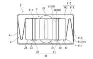
<6.第6実施形態>
図7は、第6実施形態に係る振動モータ1Eの、カバー部を除いた上面図である。この振動モータ1Eでは、可動子30Eが、2つのマグネット31Eと、一対のブラケット32Eと、1つのスペーサ35Eとを有する。<6. Sixth Embodiment>
FIG. 7 is a top view of the
2つのマグネット31Eは、揺動方向に並んで配置される。2つのマグネット31Eの間には、スペーサ35Eが配置される。また、一対のブラケット32Eは、2つのマグネット31Eおよびスペーサ35Eの揺動方向の両端に配置される。 The two
揺動方向に隣り合うマグネット31Eおよびブラケット32Eと、揺動方向に隣り合うマグネット31Eおよびスペーサ35Eとは、接着層50Eを介して接着固定される。接着層50Eは、第1接着層51Eと第4接着層54Eとを含む。第1接着層51Eは、揺動方向に隣り合うマグネット31Eとブラケット32Eとの間に配置され、マグネット31Eとブラケット32Eとを固定する。第4接着層54Eは、揺動方向に隣り合うマグネット31Eとスペーサ35Eとの間に配置され、マグネット31Eとスペーサ35Eとを固定する。 The
ジャケット34Eは、接着層50Eの側面の少なくとも一部を覆う部材である。本実施形態のジャケット34Eは、第1接着層51Eおよび第4接着層54Eの側面の一部を覆う。具体的には、ジャケット34Eは、3組の横面被覆部61Eを有する。横面被覆部61Eはそれぞれ、揺動方向に延び、かつ、接着層50Eを介して向かい合う一対の第1板状部611Eを有する。第1板状部611Eはそれぞれ、接着層50Eと、接着層50Eと隣り合う部材の揺動方向の少なくとも一部とを覆う。 The
3組の横面被覆部61Eのうちの2組において、第1板状部611Eはそれぞれ、可動子30Eの横方向の一側面のうち、マグネット31Eの揺動方向の一部と、第1接着層51Eと、ブラケット32Eの揺動方向の一部とを覆う。すなわち、当該2組の横面被覆部61Eは、第1接着層51Eの横方向の両側面を覆う。 In two sets of the three sets of horizontal
また、3組の横面被覆部61Eのうち、残りの1組において、第1板状部611Eはそれぞれ、可動子30Eの横方向の一側面のうち、2つのマグネット31Eの揺動方向の一部と、2つの第4接着層54Eと、スペーサ35Eとを覆う。すなわち、当該1組の横面被覆部61Eは、2つの第4接着層54Eの横方向の両側面を覆う。 Further, in the remaining one set of the three sets of the horizontal
これにより、上下方向または横方向から可動子30Eに負荷がかかった場合に、マグネット31E、第1接着層51Eおよび第4接着層54Eが破損するのが抑制される。したがって、マグネット31Eを含む可動子30Eの破損を抑制できる。また、本実施形態のジャケット34Eは、揺動方向に間隔をあけて配置される複数の横面被覆部61Eを有するが、本発明はこの限りではない。ジャケットが揺動方向に長い単一組の横面被覆部を有していてもよい。 This suppresses the
なお、複数のマグネット31Eおよびスペーサ35Eを有する可動子30Eを覆うジャケット34Eは、可動子30Eの横方向の側面を覆う横面被覆部61Eのみにより構成されたが、本発明はこの限りではない。複数のマグネットおよびスペーサを有する可動子を覆うジャケットは、可動子の上下方向の側面を覆う上下面被覆部のみにより構成されても良いし、可動子の側面を環状に覆う筒状部を有していてもよい。また、複数のマグネットおよびスペーサを有する可動子を覆うジャケットは、可動子の横方向の側面を覆う横面被覆部と、上下方向の側面を覆う上下面被覆部との双方を有していてもよい。 The
本実施形態のように、可動子が複数のマグネットを有し、マグネット間にスペーサを有していてもよい。マグネット間にスペーサを配置することにより、スペーサを経由した磁束路を形成できる。これにより、マグネットに働くローレンツ力を高めることができる。したがって、可動子の振動量をより大きくできる。 As in this embodiment, the mover may have a plurality of magnets, and may have a spacer between the magnets. By arranging the spacer between the magnets, a magnetic flux path via the spacer can be formed. Thereby, the Lorentz force which acts on a magnet can be raised. Therefore, the amount of vibration of the mover can be further increased.
なお、第5実施形態の振動モータ1Dおよび第6実施形態の振動モータ1Eでは、マグネットの数が2つであったが、マグネットの数は3つ以上であってもよい。 In the
<7.第7実施形態>
図8は、第7実施形態に係る振動モータ1Fの分解斜視図である。この振動モータ1Fは、2つのコイル221F,222Fを有する。<7. Seventh Embodiment>
FIG. 8 is an exploded perspective view of a vibration motor 1F according to the seventh embodiment. This vibration motor 1F has two
コイル221F,222Fは、中央部に空間が形成されるように、導線が平面状かつ渦巻き状に巻かれた空芯スパイラルコイルである。コイル221F,222Fは、揺動方向に対して略直交する上下方向に延びる軸9Fを中心として巻き回される。 The
2つのコイル221F,222Fのうち第1コイル221Fは、マグネット31Fの下方に配置される。すなわち、第1コイル221Fは、マグネット31Fに対して、軸方向一方側に配置される。2つのコイル221F,222Fのうち第2コイル222Fは、マグネット31Fの上方に配置される。すなわち、第2コイル222Fは、マグネット31Fに対して、軸方向他方側に配置される。 Of the two
本実施形態のように、振動モータが複数のコイルを有していてもよい。コイルを複数とすることにより、マグネットに働くローレンツ力を高めることができる。したがって、可動子の振動量をより大きくできる。 As in this embodiment, the vibration motor may have a plurality of coils. By using a plurality of coils, the Lorentz force acting on the magnet can be increased. Therefore, the amount of vibration of the mover can be further increased.
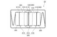
<8.第8実施形態>
図9は、第8実施形態に係る振動モータ1Gの分解斜視図である。図10は、振動モータ1Gの、カバー部を除いた上面図である。図9および図10に示すように、この振動モータ1Gは、マグネット31Gの少なくとも一部を内部に収容するコイル22Gを有する。<8. Eighth Embodiment>
FIG. 9 is an exploded perspective view of a
図9に示すように、コイル22Gは、中央部に空間が形成されるように、導線が四角柱状に巻き回された空芯ソレノイドコイルである。コイル22Gは、揺動方向に延びる軸9Gを中心として巻き回される。図10に示すように、マグネット31Gの少なくとも一部は、コイル22Gの内部に配置される。 As shown in FIG. 9, the
本実施形態のように、コイルがマグネットの少なくとも一部を内部に収容するソレノイドコイルであってもよい。本実施形態において、コイル22Gに駆動電流が供給されると、コイル22Gが形成する磁界と、マグネット31Gが形成する磁界との相互作用によって、マグネット31Gにローレンツ力が働く。これにより、可動部3Gが揺動方向に揺動する。 As in the present embodiment, the coil may be a solenoid coil that houses at least a part of the magnet therein. In the present embodiment, when a drive current is supplied to the
<9.変形例>
上記の実施形態では、静止部と可動部との間に配置される弾性部材が板ばねであったが、本発明はこれに限られない。静止部と可動部との間に配置される弾性部材は、コイルばね、ゴム等の他の種類の弾性部材であってもよい。<9. Modification>
In said embodiment, although the elastic member arrange | positioned between a stationary part and a movable part was a leaf | plate spring, this invention is not limited to this. The elastic member disposed between the stationary part and the movable part may be another type of elastic member such as a coil spring or rubber.
また、上記の実施形態では、静止部と可動部との間に配置される弾性部材が、静止部および可動部の双方と固定されていたが、本発明はこれに限られない。弾性部材は、静止部に対して可動部を揺動可能に支持する構造であれば、静止部および可動部の一方のみと固定されてもよいし、静止部および可動部のいずれとも固定されていなくてもよい。 In the above embodiment, the elastic member arranged between the stationary part and the movable part is fixed to both the stationary part and the movable part, but the present invention is not limited to this. The elastic member may be fixed to only one of the stationary part and the movable part, or may be fixed to both the stationary part and the movable part, as long as the elastic member supports the movable part so as to be swingable with respect to the stationary part. It does not have to be.
また、上記の実施形態では、可動部の構成要素として、マグネット、ブラケット、錘およびスペーサのみが含まれていたが、本発明はこれに限られない。可動部は、マグネット、ブラケット、錘およびスペーサ以外の部材を有していてもよい。例えば、ブラケットと錘とが、他の部材を介して間接的に固定されていてもよい。 In the above embodiment, only the magnet, the bracket, the weight, and the spacer are included as the components of the movable part, but the present invention is not limited to this. The movable part may have a member other than the magnet, the bracket, the weight, and the spacer. For example, the bracket and the weight may be indirectly fixed via other members.
また、上記の実施形態では、錘が可動子の揺動方向端部に配置されたが、本発明はこれに限られない。錘は、マグネットとブラケットとの間に配置されてもよいし、その他の位置に配置されてもよい。 In the above embodiment, the weight is arranged at the end of the movable element in the swing direction, but the present invention is not limited to this. The weight may be disposed between the magnet and the bracket, or may be disposed at other positions.
また、ジャケットが可動子の上下方向および横方向の双方を覆う場合に、上記の第3実施形態および第4実施形態では、ジャケットが環状の筒状部を有していたが、本発明はこれに限られない。ジャケットは、複数の部材を組み合わせることにより、可動子を環状に覆うものであってもよい。 Further, when the jacket covers both the vertical and lateral directions of the mover, the jacket has an annular cylindrical portion in the third embodiment and the fourth embodiment described above. Not limited to. The jacket may cover the mover in a ring shape by combining a plurality of members.
また、各部材の細部の形状については、本願の各図に示された形状と、相違していてもよい。また、上記の各実施形態および変形例に登場した要素を、矛盾が生じない範囲で、適宜に組み合わせてもよい。例えば、第5〜第8実施形態の構造において、第2実施形態または第3実施形態のように、ジャケットを環状にしてもよい。 Moreover, about the detailed shape of each member, you may differ from the shape shown by each figure of this application. Moreover, you may combine suitably the element which appeared in said each embodiment and modification in the range which does not produce inconsistency. For example, in the structures of the fifth to eighth embodiments, the jacket may be annular as in the second embodiment or the third embodiment.
本発明は、振動モータに利用できる。 The present invention can be used for a vibration motor.
1,1A,1B,1C,1D,1E,1F,1G 振動モータ
2 静止部
3,3G 可動部
4 弾性部材
9,9F,9G 軸
21 ハウジング
22,22G,221F,222F コイル
30,30A,30B,30C,30D,30E 可動子
31,31A,31B,31C,31D,31E,31F,31G マグネット
32,32A,32B,32C,32D,32E ブラケット
33,33A,33B,33C 錘
34,34A,34B,34C,34D,34E ジャケット
35E スペーサ
41 板ばね
50,50A,50B,50C,50D,50E 接着層
51,51A,51B,51C,51D,51E 第1接着層
52,52A,52B,52C 第2接着層
53D 第3接着層
54E 第4接着層
63B,63C 筒状部1, 1A, 1B, 1C, 1D, 1E, 1F,
Claims (11)
Translated fromJapanese前記静止部に対して、揺動方向に揺動可能に支持される可動部と、
前記静止部と前記可動部との間に配置される弾性部材と、
を有し、
前記ハウジングの内部に、前記コイル、前記可動部および前記弾性部材が収容され、
前記可動部は、
前記コイルと対向して配置されるマグネットと、
前記マグネットの前記揺動方向の両端に配置されるブラケットと、
前記揺動方向に隣り合う部材同士を接着固定する、少なくとも1つの接着層と、
を有し、
前記可動部は、
前記接着層の側面の少なくとも一部を覆うジャケット
をさらに有する、振動モータ。A stationary part having a housing and a coil;
A movable part supported so as to be swingable in a swinging direction with respect to the stationary part;
An elastic member disposed between the stationary part and the movable part;
Have
The coil, the movable part, and the elastic member are accommodated inside the housing,
The movable part is
A magnet disposed opposite to the coil;
Brackets disposed at both ends of the swing direction of the magnet;
At least one adhesive layer for adhering and fixing members adjacent to each other in the swing direction;
Have
The movable part is
The vibration motor further includes a jacket that covers at least a part of a side surface of the adhesive layer.
前記ジャケットは、
前記揺動方向に延び、かつ、前記接着層を介して向かい合う一対の板状部
を有し、
前記一対の板状部は、
前記接着層と、
前記接着層と隣り合う部材の前記揺動方向の少なくとも一部と、
を覆う、振動モータ。The vibration motor according to claim 1,
The jacket is
A pair of plate-like portions extending in the swinging direction and facing each other through the adhesive layer;
The pair of plate-like portions are
The adhesive layer;
At least a part of the swinging direction of the member adjacent to the adhesive layer;
Covering the vibration motor.
前記ジャケットは、
前記揺動方向に延び、前記接着層の側面を環状に覆う筒状部
を有し、
前記筒状部は、
前記接着層と、
前記接着層と隣り合う部材の前記揺動方向の少なくとも一部と、
を覆う、振動モータ。The vibration motor according to claim 1,
The jacket is
A cylindrical portion extending in the swinging direction and covering the side surface of the adhesive layer in an annular shape;
The cylindrical part is
The adhesive layer;
At least a part of the swinging direction of the member adjacent to the adhesive layer;
Covering the vibration motor.
前記接着層は、
前記マグネットと前記ブラケットとの間に配置され、前記マグネットと前記ブラケットとを固定する第1接着層
を含み、
前記ジャケットは、前記第1接着層の少なくとも一部を覆う、振動モータ。A vibration motor according to any one of claims 1 to 3,
The adhesive layer is
A first adhesive layer disposed between the magnet and the bracket and fixing the magnet and the bracket;
The jacket is a vibration motor that covers at least a part of the first adhesive layer.
前記可動部は、
前記ブラケットに対して直接または間接的に固定される錘
を有する、振動モータ。A vibration motor according to any one of claims 1 to 4,
The movable part is
A vibration motor having a weight fixed directly or indirectly to the bracket.
前記錘と前記ブラケットとは、前記揺動方向に隣り合って配置され、
前記接着層は、
前記錘と前記ブラケットとの間に配置され、前記錘と前記ブラケットとを固定する第2接着層
を含み、
前記ジャケットは、前記第2接着層の少なくとも一部を覆う、振動モータ。The vibration motor according to claim 5,
The weight and the bracket are arranged adjacent to each other in the swing direction,
The adhesive layer is
A second adhesive layer disposed between the weight and the bracket and fixing the weight and the bracket;
The jacket is a vibration motor that covers at least a part of the second adhesive layer.
前記可動部は、前記揺動方向に並ぶ複数の前記マグネットを有し、
前記接着層は、
前記揺動方向に隣り合う2つの前記マグネットの間に配置され、前記マグネット同士を接着固定する第3接着層
を含み、
前記ジャケットは、前記第3接着層の少なくとも一部を覆う、振動モータ。A vibration motor according to any one of claims 1 to 6,
The movable part has a plurality of the magnets arranged in the swing direction,
The adhesive layer is
A third adhesive layer that is disposed between the two magnets adjacent to each other in the swinging direction and bonds and fixes the magnets;
The jacket is a vibration motor that covers at least a part of the third adhesive layer.
前記可動部は、
前記揺動方向に並ぶ複数の前記マグネットと、
前記揺動方向において隣り合う2つの前記マグネットの間に配置されるスペーサと、
を有し、
前記接着層は、
前記揺動方向に隣り合う前記マグネットおよび前記スペーサの間に配置され、前記マグネットおよび前記スペーサを接着固定する第4接着層
を含み、
前記ジャケットは、前記第4接着層の少なくとも一部を覆う、振動モータ。A vibration motor according to any one of claims 1 to 6,
The movable part is
A plurality of the magnets arranged in the swing direction;
A spacer disposed between two magnets adjacent to each other in the swing direction;
Have
The adhesive layer is
A fourth adhesive layer that is disposed between the magnet and the spacer adjacent to each other in the swing direction, and bonds and fixes the magnet and the spacer;
The jacket is a vibration motor that covers at least a part of the fourth adhesive layer.
前記コイルは、
前記揺動方向に対して略直交する軸を中心として巻き回され、前記マグネットの軸方向一方側に配置される第1コイル
を含む、振動モータ。A vibration motor according to any one of claims 1 to 8,
The coil is
A vibration motor including a first coil wound around an axis substantially orthogonal to the swinging direction and disposed on one axial side of the magnet.
前記コイルは、
前記軸を中心として巻き回され、前記マグネットの軸方向他方側に配置される第2コイル
をさらに含む、振動モータ。The vibration motor according to claim 9,
The coil is
The vibration motor further comprising a second coil wound around the shaft and disposed on the other axial side of the magnet.
前記コイルは、前記揺動方向に延びる軸を中心として巻き回された空芯コイルであり、
前記マグネットは、前記空芯コイルの内部に配置される、振動モータ。A vibration motor according to any one of claims 1 to 8,
The coil is an air-core coil wound around an axis extending in the swing direction,
The magnet is a vibration motor disposed inside the air-core coil.
Priority Applications (2)
| Application Number | Priority Date | Filing Date | Title |
|---|---|---|---|
| JP2015214645AJP2017085849A (en) | 2015-10-30 | 2015-10-30 | Vibration motor |
| US15/335,478US20170126109A1 (en) | 2015-10-30 | 2016-10-27 | Vibration motor |
Applications Claiming Priority (1)
| Application Number | Priority Date | Filing Date | Title |
|---|---|---|---|
| JP2015214645AJP2017085849A (en) | 2015-10-30 | 2015-10-30 | Vibration motor |
Publications (1)
| Publication Number | Publication Date |
|---|---|
| JP2017085849Atrue JP2017085849A (en) | 2017-05-18 |
Family
ID=58637929
Family Applications (1)
| Application Number | Title | Priority Date | Filing Date |
|---|---|---|---|
| JP2015214645APendingJP2017085849A (en) | 2015-10-30 | 2015-10-30 | Vibration motor |
Country Status (2)
| Country | Link |
|---|---|
| US (1) | US20170126109A1 (en) |
| JP (1) | JP2017085849A (en) |
Cited By (2)
| Publication number | Priority date | Publication date | Assignee | Title |
|---|---|---|---|---|
| WO2019003870A1 (en)* | 2017-06-30 | 2019-01-03 | 日本電産サンキョー株式会社 | Input device |
| US10486196B2 (en)* | 2017-04-14 | 2019-11-26 | AAC Technologies Pte. Ltd. | Linear vibrator |
Families Citing this family (5)
| Publication number | Priority date | Publication date | Assignee | Title |
|---|---|---|---|---|
| JP2017108595A (en)* | 2015-12-11 | 2017-06-15 | 日本電産株式会社 | Vibration motor |
| CN206834956U (en)* | 2017-04-14 | 2018-01-02 | 瑞声科技(新加坡)有限公司 | Linear vibration electric motor |
| US20220368206A1 (en)* | 2021-05-11 | 2022-11-17 | Aac Microtech (Changzhou) Co., Ltd. | Linear vibration motor |
| US11641151B2 (en)* | 2021-05-11 | 2023-05-02 | Aac Microtech (Changzhou) Co., Ltd. | Linear vibration motor with elastic members with brackets, foams and damping glue |
| WO2024168648A1 (en)* | 2023-02-16 | 2024-08-22 | 瑞声光电科技(常州)有限公司 | Linear vibration motor |
Family Cites Families (12)
| Publication number | Priority date | Publication date | Assignee | Title |
|---|---|---|---|---|
| US5237737A (en)* | 1988-06-08 | 1993-08-24 | General Electric Company | Method of making a permanent magnet rotor |
| US7561015B2 (en)* | 2003-12-02 | 2009-07-14 | Applied Materials, Inc. | Magnet secured in a two part shell |
| JP4803525B2 (en)* | 2004-04-12 | 2011-10-26 | 株式会社一宮電機 | Brushless motor rotor and brushless motor |
| US7859144B1 (en)* | 2006-08-31 | 2010-12-28 | Joseph Y Sahyoun | Low frequency electromagnetic motor to create or cancel a low frequency vibration |
| DE102009060438A1 (en)* | 2009-12-22 | 2011-06-30 | KSB Aktiengesellschaft, 67227 | Rotor with short-circuit cage |
| KR101146371B1 (en)* | 2010-07-12 | 2012-05-17 | 엘지이노텍 주식회사 | Vibration motor |
| KR101171602B1 (en)* | 2010-11-30 | 2012-08-06 | 삼성전기주식회사 | Apparatus for generating vibration |
| KR101255914B1 (en)* | 2010-12-31 | 2013-04-23 | 삼성전기주식회사 | Linear Vibration Motor |
| US8872394B2 (en)* | 2011-06-16 | 2014-10-28 | Jahwa Electronics Co., Ltd. | Linear vibration generating apparatus |
| FR2984634B1 (en)* | 2011-12-19 | 2014-11-07 | Univ Pierre Et Marie Curie Paris 6 | LINEAR MINIATURE VITROTACTILE ACTUATOR |
| JP5486036B2 (en)* | 2012-04-11 | 2014-05-07 | ファナック株式会社 | Electric motor having a rotor structure for preventing problems due to distortion caused by temperature change and method for manufacturing the same |
| JP5622808B2 (en)* | 2012-07-31 | 2014-11-12 | 日本電産コパル株式会社 | Vibration actuator |
- 2015
- 2015-10-30JPJP2015214645Apatent/JP2017085849A/enactivePending
- 2016
- 2016-10-27USUS15/335,478patent/US20170126109A1/ennot_activeAbandoned
Cited By (4)
| Publication number | Priority date | Publication date | Assignee | Title |
|---|---|---|---|---|
| US10486196B2 (en)* | 2017-04-14 | 2019-11-26 | AAC Technologies Pte. Ltd. | Linear vibrator |
| WO2019003870A1 (en)* | 2017-06-30 | 2019-01-03 | 日本電産サンキョー株式会社 | Input device |
| JP2019012409A (en)* | 2017-06-30 | 2019-01-24 | 日本電産サンキョー株式会社 | Input device |
| CN110869893A (en)* | 2017-06-30 | 2020-03-06 | 日本电产三协株式会社 | Input device |
Also Published As
| Publication number | Publication date |
|---|---|
| US20170126109A1 (en) | 2017-05-04 |
Similar Documents
| Publication | Publication Date | Title |
|---|---|---|
| JP2017085849A (en) | Vibration motor | |
| KR101354744B1 (en) | Linear vibration device | |
| US10610893B2 (en) | Vibration actuator and portable device | |
| US11025149B2 (en) | Linear vibration motor and electronic device | |
| US10447129B2 (en) | Vibration motor | |
| JP4827993B2 (en) | Drive device | |
| US10610892B2 (en) | Vibration actuator and portable device | |
| KR100967033B1 (en) | Horizontal linear vibrator | |
| KR101055508B1 (en) | Linear vibration motor | |
| JP6010080B2 (en) | Linear vibration motor | |
| JP2017034962A (en) | Micro vibration motor | |
| KR100992264B1 (en) | Linear vibration motor | |
| WO2018058809A1 (en) | Linear vibration motor | |
| US20130049491A1 (en) | Linear vibration motor | |
| US20170354992A1 (en) | Linear vibration motor | |
| US20190207501A1 (en) | Mover, vibration actuator, and electronic device | |
| WO2020134378A1 (en) | Linear vibration motor | |
| JP2016182569A (en) | Vibration actuator | |
| TWI382879B (en) | Flat vibrating drive | |
| KR102468399B1 (en) | Linear Vibrator and Manufacturing Method Therefor | |
| JP6333186B2 (en) | Linear vibration motor | |
| KR20120101800A (en) | Linear vibrator and manufacturing of thereof | |
| JP4958195B2 (en) | Drive device | |
| KR20170035464A (en) | Linear Actuator | |
| KR101914530B1 (en) | Vibrator |