JP2017080887A - Application of force feedback at the input device that prompts the operator of the input device to command the joint device to take a suitable posture - Google Patents
Application of force feedback at the input device that prompts the operator of the input device to command the joint device to take a suitable postureDownload PDFInfo
- Publication number
- JP2017080887A JP2017080887AJP2017016583AJP2017016583AJP2017080887AJP 2017080887 AJP2017080887 AJP 2017080887AJP 2017016583 AJP2017016583 AJP 2017016583AJP 2017016583 AJP2017016583 AJP 2017016583AJP 2017080887 AJP2017080887 AJP 2017080887A
- Authority
- JP
- Japan
- Prior art keywords
- posture
- input device
- force command
- commanded
- activation signal
- Prior art date
- Legal status (The legal status is an assumption and is not a legal conclusion. Google has not performed a legal analysis and makes no representation as to the accuracy of the status listed.)
- Granted
Links
- 230000004888barrier functionEffects0.000claimsabstractdescription20
- 230000004044responseEffects0.000claimsabstractdescription6
- 238000000034methodMethods0.000claimsdescription56
- 230000004913activationEffects0.000claimsdescription34
- 238000012545processingMethods0.000claimsdescription16
- 230000004048modificationEffects0.000claimsdescription4
- 238000012986modificationMethods0.000claimsdescription4
- 230000000295complement effectEffects0.000claims2
- 230000036544postureEffects0.000abstractdescription140
- 230000007704transitionEffects0.000abstractdescription7
- 238000010586diagramMethods0.000description28
- 230000033001locomotionEffects0.000description26
- 239000012636effectorSubstances0.000description19
- 210000000707wristAnatomy0.000description15
- 230000008569processEffects0.000description12
- 238000013459approachMethods0.000description7
- 230000008859changeEffects0.000description7
- 230000006870functionEffects0.000description7
- 230000007246mechanismEffects0.000description7
- 230000009471actionEffects0.000description6
- 230000000712assemblyEffects0.000description6
- 238000000429assemblyMethods0.000description6
- 238000006243chemical reactionMethods0.000description6
- 230000008878couplingEffects0.000description4
- 238000010168coupling processMethods0.000description4
- 238000005859coupling reactionMethods0.000description4
- 238000003384imaging methodMethods0.000description4
- 241000270295SerpentesSpecies0.000description3
- 230000007274generation of a signal involved in cell-cell signalingEffects0.000description3
- 230000009466transformationEffects0.000description3
- 238000013519translationMethods0.000description3
- 206010044565TremorDiseases0.000description2
- 230000008901benefitEffects0.000description2
- 230000005540biological transmissionEffects0.000description2
- 210000003857wrist jointAnatomy0.000description2
- 101100512532Mus musculus Atf7ip2 geneProteins0.000description1
- 108700031620S-acetylthiorphanProteins0.000description1
- 101100408036Saccharomyces cerevisiae (strain ATCC 204508 / S288c) PGU1 geneProteins0.000description1
- 101100042789Schizosaccharomyces pombe (strain 972 / ATCC 24843) psm1 geneProteins0.000description1
- 230000003213activating effectEffects0.000description1
- 230000002411adverseEffects0.000description1
- 210000003484anatomyAnatomy0.000description1
- 230000001010compromised effectEffects0.000description1
- 238000007796conventional methodMethods0.000description1
- 230000000694effectsEffects0.000description1
- 238000003780insertionMethods0.000description1
- 230000037431insertionEffects0.000description1
- 230000003993interactionEffects0.000description1
- 239000011159matrix materialSubstances0.000description1
- 238000002324minimally invasive surgeryMethods0.000description1
- 239000013307optical fiberSubstances0.000description1
- 238000011084recoveryMethods0.000description1
- 238000005070samplingMethods0.000description1
- 230000037390scarringEffects0.000description1
- 230000001953sensory effectEffects0.000description1
- 238000001356surgical procedureMethods0.000description1
- 230000000007visual effectEffects0.000description1
Images


Classifications
- A—HUMAN NECESSITIES
- A61—MEDICAL OR VETERINARY SCIENCE; HYGIENE
- A61B—DIAGNOSIS; SURGERY; IDENTIFICATION
- A61B34/00—Computer-aided surgery; Manipulators or robots specially adapted for use in surgery
- A61B34/70—Manipulators specially adapted for use in surgery
- A61B34/76—Manipulators having means for providing feel, e.g. force or tactile feedback
- A—HUMAN NECESSITIES
- A61—MEDICAL OR VETERINARY SCIENCE; HYGIENE
- A61B—DIAGNOSIS; SURGERY; IDENTIFICATION
- A61B34/00—Computer-aided surgery; Manipulators or robots specially adapted for use in surgery
- A61B34/10—Computer-aided planning, simulation or modelling of surgical operations
- A—HUMAN NECESSITIES
- A61—MEDICAL OR VETERINARY SCIENCE; HYGIENE
- A61B—DIAGNOSIS; SURGERY; IDENTIFICATION
- A61B34/00—Computer-aided surgery; Manipulators or robots specially adapted for use in surgery
- A61B34/30—Surgical robots
- A—HUMAN NECESSITIES
- A61—MEDICAL OR VETERINARY SCIENCE; HYGIENE
- A61B—DIAGNOSIS; SURGERY; IDENTIFICATION
- A61B34/00—Computer-aided surgery; Manipulators or robots specially adapted for use in surgery
- A61B34/30—Surgical robots
- A61B34/35—Surgical robots for telesurgery
- A—HUMAN NECESSITIES
- A61—MEDICAL OR VETERINARY SCIENCE; HYGIENE
- A61B—DIAGNOSIS; SURGERY; IDENTIFICATION
- A61B34/00—Computer-aided surgery; Manipulators or robots specially adapted for use in surgery
- A61B34/30—Surgical robots
- A61B34/37—Leader-follower robots
- A—HUMAN NECESSITIES
- A61—MEDICAL OR VETERINARY SCIENCE; HYGIENE
- A61B—DIAGNOSIS; SURGERY; IDENTIFICATION
- A61B34/00—Computer-aided surgery; Manipulators or robots specially adapted for use in surgery
- A61B34/70—Manipulators specially adapted for use in surgery
- A61B34/77—Manipulators with motion or force scaling
- A—HUMAN NECESSITIES
- A61—MEDICAL OR VETERINARY SCIENCE; HYGIENE
- A61B—DIAGNOSIS; SURGERY; IDENTIFICATION
- A61B90/00—Instruments, implements or accessories specially adapted for surgery or diagnosis and not covered by any of the groups A61B1/00 - A61B50/00, e.g. for luxation treatment or for protecting wound edges
- A61B90/30—Devices for illuminating a surgical field, the devices having an interrelation with other surgical devices or with a surgical procedure
- B—PERFORMING OPERATIONS; TRANSPORTING
- B25—HAND TOOLS; PORTABLE POWER-DRIVEN TOOLS; MANIPULATORS
- B25J—MANIPULATORS; CHAMBERS PROVIDED WITH MANIPULATION DEVICES
- B25J13/00—Controls for manipulators
- B25J13/02—Hand grip control means
- B25J13/025—Hand grip control means comprising haptic means
- B—PERFORMING OPERATIONS; TRANSPORTING
- B25—HAND TOOLS; PORTABLE POWER-DRIVEN TOOLS; MANIPULATORS
- B25J—MANIPULATORS; CHAMBERS PROVIDED WITH MANIPULATION DEVICES
- B25J9/00—Programme-controlled manipulators
- B25J9/16—Programme controls
- B25J9/1679—Programme controls characterised by the tasks executed
- B25J9/1689—Teleoperation
- A—HUMAN NECESSITIES
- A61—MEDICAL OR VETERINARY SCIENCE; HYGIENE
- A61B—DIAGNOSIS; SURGERY; IDENTIFICATION
- A61B34/00—Computer-aided surgery; Manipulators or robots specially adapted for use in surgery
- A61B34/10—Computer-aided planning, simulation or modelling of surgical operations
- A61B2034/101—Computer-aided simulation of surgical operations
- A61B2034/102—Modelling of surgical devices, implants or prosthesis
- A—HUMAN NECESSITIES
- A61—MEDICAL OR VETERINARY SCIENCE; HYGIENE
- A61B—DIAGNOSIS; SURGERY; IDENTIFICATION
- A61B34/00—Computer-aided surgery; Manipulators or robots specially adapted for use in surgery
- A61B34/30—Surgical robots
- A61B2034/305—Details of wrist mechanisms at distal ends of robotic arms
- A61B2034/306—Wrists with multiple vertebrae
- A—HUMAN NECESSITIES
- A61—MEDICAL OR VETERINARY SCIENCE; HYGIENE
- A61B—DIAGNOSIS; SURGERY; IDENTIFICATION
- A61B90/00—Instruments, implements or accessories specially adapted for surgery or diagnosis and not covered by any of the groups A61B1/00 - A61B50/00, e.g. for luxation treatment or for protecting wound edges
- A61B90/30—Devices for illuminating a surgical field, the devices having an interrelation with other surgical devices or with a surgical procedure
- A61B2090/306—Devices for illuminating a surgical field, the devices having an interrelation with other surgical devices or with a surgical procedure using optical fibres
- A—HUMAN NECESSITIES
- A61—MEDICAL OR VETERINARY SCIENCE; HYGIENE
- A61B—DIAGNOSIS; SURGERY; IDENTIFICATION
- A61B34/00—Computer-aided surgery; Manipulators or robots specially adapted for use in surgery
- A61B34/25—User interfaces for surgical systems
- A—HUMAN NECESSITIES
- A61—MEDICAL OR VETERINARY SCIENCE; HYGIENE
- A61B—DIAGNOSIS; SURGERY; IDENTIFICATION
- A61B90/00—Instruments, implements or accessories specially adapted for surgery or diagnosis and not covered by any of the groups A61B1/00 - A61B50/00, e.g. for luxation treatment or for protecting wound edges
- A61B90/36—Image-producing devices or illumination devices not otherwise provided for
- A61B90/361—Image-producing devices, e.g. surgical cameras
- F—MECHANICAL ENGINEERING; LIGHTING; HEATING; WEAPONS; BLASTING
- F04—POSITIVE - DISPLACEMENT MACHINES FOR LIQUIDS; PUMPS FOR LIQUIDS OR ELASTIC FLUIDS
- F04C—ROTARY-PISTON, OR OSCILLATING-PISTON, POSITIVE-DISPLACEMENT MACHINES FOR LIQUIDS; ROTARY-PISTON, OR OSCILLATING-PISTON, POSITIVE-DISPLACEMENT PUMPS
- F04C2270/00—Control; Monitoring or safety arrangements
- F04C2270/04—Force
- F04C2270/041—Controlled or regulated
- G—PHYSICS
- G05—CONTROLLING; REGULATING
- G05B—CONTROL OR REGULATING SYSTEMS IN GENERAL; FUNCTIONAL ELEMENTS OF SUCH SYSTEMS; MONITORING OR TESTING ARRANGEMENTS FOR SUCH SYSTEMS OR ELEMENTS
- G05B2219/00—Program-control systems
- G05B2219/30—Nc systems
- G05B2219/45—Nc applications
- G05B2219/45117—Medical, radio surgery manipulator
Landscapes
- Health & Medical Sciences (AREA)
- Engineering & Computer Science (AREA)
- Life Sciences & Earth Sciences (AREA)
- Surgery (AREA)
- Robotics (AREA)
- Medical Informatics (AREA)
- Public Health (AREA)
- Heart & Thoracic Surgery (AREA)
- Nuclear Medicine, Radiotherapy & Molecular Imaging (AREA)
- Molecular Biology (AREA)
- Animal Behavior & Ethology (AREA)
- General Health & Medical Sciences (AREA)
- Biomedical Technology (AREA)
- Veterinary Medicine (AREA)
- Mechanical Engineering (AREA)
- Human Computer Interaction (AREA)
- Oral & Maxillofacial Surgery (AREA)
- Pathology (AREA)
- Manipulator (AREA)
Abstract
Description
Translated fromJapanese 関連出願の相互参照
本願は、2010年2月12日に出願された”Medical Robotic System Providing Sensory Feedback Indicating a Difference Between a Commanded State and a Preferred Pose of an Articulated Instrument”という表題の米国特許出願第12/704,669号の一部継続出願であり、この文献は参照することにより本願に組み込まれる。CROSS REFERENCE TO RELATED APPLICATIONS This application is filed on Feb. 12, 2010, entitled “Medical Robotic System Providing Sensory Feedback Indicating a Difference Between a Commanded State and a Preferred Pose of an Articulated Instrument”. No. 704,669, which is a continuation-in-part application, which is incorporated herein by reference.
本願は、2009年11月5日に出願された”Controller Assisted Reconfiguration of an Articulated Instrument During Movement Into and Out of an Entry Guide”という表題の米国特許出願第12/613,328号の一部継続出願であり、この出願は、2009年8月15日に出願された”Smooth Control of an Articulated Instrument Across Areas with Different Work Space Conditions”という表題の米国特許出願第12/541,913号の一部継続出願であり、これらの文献は参照することにより本願に組み込まれる。 This application is a continuation-in-part of US patent application Ser. No. 12 / 613,328 filed Nov. 5, 2009 entitled “Controller Assisted Reconfiguration of an Articulated Instrument During Movement Into and Out of an Entry Guide”. This application is a continuation-in-part of US patent application Ser. No. 12 / 541,913, filed Aug. 15, 2009, entitled “Smooth Control of an Articulated Instrument Across Areas with Different Work Space Conditions”. Yes, these documents are incorporated herein by reference.
本発明は、概して医療用ロボットシステムに関し、具体的には関節器具に好適な姿勢を取らせるような命令を入力装置のオペレータに促すような、入力装置での力フィードバックを適用する方法及びシステムに関する。 The present invention relates generally to medical robotic systems, and more particularly to a method and system for applying force feedback at an input device that prompts an operator of the input device to command the joint device to assume a suitable posture. .
最小侵襲性外科手術を実施する際に用いられる遠隔手術システム等の医療用ロボットシステムは、従来の切開手術技術に比べて、痛みが少なく、入院期間の短縮が図れ、日常の活動により速く復帰させ、瘢痕を最小限に留め、回復時間を短縮し、そして組織へのより少ない損傷を含むような多くの利点を提供する。その結果、このような医療用ロボットシステムの必要性が強く、且つこの必要性は増大している。 Medical robot systems such as telesurgery systems used to perform minimally invasive surgery have less pain and shorten hospitalization compared to conventional open surgery techniques, and can be returned more quickly to daily activities. It offers many benefits, such as minimizing scarring, reducing recovery time, and including less damage to tissue. As a result, there is a strong need for such a medical robot system, and this need is increasing.
このような医療用ロボットシステムの一例としては、カリフォルニア州サニーベールのIntuitive Surgical社から販売されているDA VINCI(登録商標)手術システムがあり、この手術システムは、最小侵襲性ロボット手術システムである。DA VINCI(登録商標)手術システムは、手術部位の撮像装置によって撮影された外科用視覚画像による入力装置の運動に応答して、撮像装置や、外科用器具を関節駆動させるIntuitive Surgical社のENDOWRIST(登録商標)手術システム等の取り付けられた医療装置を移動させるような多数のロボットアームを有している。各医療装置は、最小侵襲性切開部を通して患者に挿入され、手術部位で医療処置を行うように位置付けされる。この切開部は、患者の身体の周りに配置されており、それによって、複数の外科用器具を協働して使用して医療処置を実施することができ、撮像装置は、処置中にそれらロボットアームと衝突することなく、その手術部位を視認することができる。 An example of such a medical robotic system is the DA VINCI® surgical system sold by Intuitive Surgical, Inc., Sunnyvale, Calif., Which is a minimally invasive robotic surgical system. DA VINCI (registered trademark) surgical system is an Intuitive Surgical's ENDOWRIST (joint drive of the imaging device and surgical instrument in response to the movement of the input device by the surgical visual image taken by the imaging device of the surgical site. It has a number of robotic arms that move attached medical devices such as a surgical system. Each medical device is inserted into a patient through a minimally invasive incision and positioned to perform a medical procedure at the surgical site. The incision is placed around the patient's body so that multiple surgical instruments can be used in concert to perform a medical procedure, and the imaging device can move the robots during the procedure. The surgical site can be visually recognized without colliding with the arm.
特定の医療処置を行うために、医療装置は、最小侵襲性切開部又は自然な身体開口部等の単一の進入開口部を使用して、患者内に入れて医療処置を実施することが有利である。例えば、まず進入ガイドを挿入して位置付けし、且つこの進入開口を所定の位置に保持させる。関節式カメラ機器や、医療処置を実施するために用いられる複数の関節式外科処置具等の関節器具は、その進入ガイドの先端を超えて延びるように、進入ガイドの基端に挿入される。こうして、進入ガイドは、単一の進入開口で複数の器具を収容しつつ、作業部位に向けてそれら器具を案内するように束ねられた器具を保持する。 To perform a particular medical procedure, it is advantageous for the medical device to perform a medical procedure within a patient using a single entry opening, such as a minimally invasive incision or a natural body opening. It is. For example, first, an approach guide is inserted and positioned, and the entrance opening is held at a predetermined position. Articulated instruments such as an articulated camera device and a plurality of articulated surgical instruments used to perform a medical procedure are inserted into the proximal end of the entry guide so as to extend beyond the distal end of the entry guide. Thus, the entry guide holds a plurality of instruments in a single entry opening, while holding the instruments bundled to guide the instruments toward the work site.
しかしながら、関節式カメラや処置具の近接によって、このような束ねられたユニットを用いる医療用ロボットシステムで多くの課題が生じる。例えば、カメラ機器は、先端のカメラビューから見えないような基端側関節(例えば、継手)を有しているため、外科医は、カメラを移動させると、つまり利用可能な運動範囲で移動させる際に、このような関節の現在の状態を追跡することができなくなる。また、カメラや処置具の関節部が、カメラの視野の外にある場合に、従ってその撮影した画像を通して外科医には見えない場合に、外科医は、医療処置を実施するために関節器具を遠隔ロボット操作によって移動させる際に、ツール及び/又はカメラ機器のリンク機構を誤って駆動させて互いに衝突させてしまうことがある。いずれかのケースでは、患者の安全性が危険にさらされることがあり、医療処置の成功及び/又は予定通りの完了に、悪影響が及ぶこともある。 However, due to the proximity of the articulated camera and the treatment tool, many problems arise in the medical robot system using such bundled units. For example, since the camera device has a proximal joint (eg, a joint) that is not visible from the distal camera view, the surgeon moves the camera, ie, within the available range of motion. In addition, the current state of such a joint cannot be tracked. In addition, when the joint of the camera or treatment tool is outside the field of view of the camera, and therefore is not visible to the surgeon through the captured image, the surgeon can remove the joint instrument from the remote robot to perform the medical procedure. When moving by operation, the link mechanism of a tool and / or a camera device may be erroneously driven and collide with each other. In either case, patient safety may be compromised, and the success and / or scheduled completion of the medical procedure may be adversely affected.
従って、本発明の1つ又は複数の態様に係る一つの目的は、関節器具の通常操作モードでの好適な姿勢を取らせるような命令をオペレータに促すような医療用ロボットシステムや、このシステムで実施されるような方法を提供することであり、このシステムは、関節器具の通常の動作中に関節器具が命令された移動を行うようにオペレータに付勢力を与えるように機能する。 Accordingly, one object according to one or more aspects of the present invention is to provide a medical robot system that prompts an operator to command a suitable posture in a normal operation mode of an articulating instrument, or the system. It is to provide a method as implemented, and the system functions to provide an urging force to the operator so that the articulating instrument performs a commanded movement during normal operation of the articulating instrument.
本発明の1つ又は複数の態様の別の目的は、力フィードバックを入力装置に適用して、関節器具の姿勢を好適な姿勢にスムーズに移行させるような命令をするようにその入力装置のオペレータを促すような医療用ロボットシステムや、このシステムで実施されるような方法を提供することである。 Another object of one or more aspects of the present invention is to apply force feedback to the input device so that the operator of the input device is instructed to smoothly transition the posture of the articulating instrument to a preferred posture. A medical robot system that encourages the use of the system, and a method that is implemented in the system.
本発明の1つ又は複数の態様の別の目的は、力フィードバックを入力装置に適用して、関節器具の姿勢が第1の好適な姿勢を取り、次に起動信号に従って第2の好適な姿勢にスムーズに移行させるような命令をするようにその入力装置のオペレータを促すような医療用ロボットシステムや、このシステムで実施されるような方法を提供することである。 Another object of one or more aspects of the present invention is to apply force feedback to the input device so that the posture of the articulator takes a first preferred posture and then a second preferred posture according to the activation signal. It is to provide a medical robot system that prompts an operator of the input device to give a command to make a smooth transition, and a method as implemented in this system.
これら及び追加の目的は、本発明の様々な態様によって達成される。簡潔に述べると、一態様は、関節器具に好適な姿勢を取らせるような命令をするように入力装置のオペレータ操作を促すための方法であって、当該方法は、入力装置のオペレータ操作に応答して、関節器具に命令された姿勢を取らせるステップと;第1の好適な姿勢と命令された姿勢との間の差の指標となるように、入力装置の複数の自由度について第1力命令を生成するステップと;第1起動信号に従った適用を段階的に入力することによって入力装置の複数の自由度に第1力命令を適用するステップと;を含む。 These and additional objectives are achieved by various aspects of the present invention. Briefly stated, one aspect is a method for prompting an operator operation of an input device to instruct a joint instrument to assume a suitable posture, the method being responsive to the operator operation of the input device. And causing the articulator to take a commanded posture; and a first force with respect to the plurality of degrees of freedom of the input device to provide an indication of a difference between the first preferred posture and the commanded posture. Generating a command; applying a first force command to a plurality of degrees of freedom of the input device by stepwise inputting an application according to the first activation signal.
別の態様は、医療用ロボットシステムであって、当該システムは、入力装置と;関節器具と;入力装置のオペレータ操作に応答して、関節器具が命令された姿勢を取り、第1の好適な姿勢と修正後の命令された姿勢との間の差の指標となるように、入力装置の複数の自由度について第1力命令を生成し、第1起動信号に従った適用を段階的に入力するように、入力装置の複数の自由度に第1力命令の適用を命令するように構成された、プロセッサと;を備える。 Another aspect is a medical robot system, the system comprising: an input device; an articulating instrument; and in response to an operator operation of the input device, the articulating instrument assumes a commanded posture, the first preferred A first force command is generated for a plurality of degrees of freedom of the input device to be an indicator of the difference between the posture and the corrected commanded posture, and the application according to the first activation signal is input stepwise And a processor configured to command the application of the first force command to a plurality of degrees of freedom of the input device.
本発明の様々な態様のさらなる目的、特徴及び利点は、添付図面と併せて説明される以下の好適な実施形態の詳細な説明から明らかになるであろう。 Further objects, features and advantages of various aspects of the present invention will become apparent from the following detailed description of the preferred embodiments, taken in conjunction with the accompanying drawings.
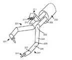
図1には、医療用ロボットシステム100のブロック図が示されている。進入ガイド(EG)200は、最小侵襲性切開部又は自然な身体開口部等の進入開口を通じて患者に挿入されるように構成されている。第1の関節式外科用ツール(TOOL1)231や、第2の関節式外科用ツール(TOOL2)241、及び関節式ステレオカメラ(CAM)211等の関節器具が、進入ガイド200の先端を通して挿入され、且つこの先端を超えて延びている。図2に示されるように、カメラ211は、その先端に収められた撮像装置311,312と、(基端で光源に連結される)光ファイバケーブル313とのステレオペアを有している。外科用ツール231,241は、エンドエフェクタ331,341を有する。2つのツール231,241のみが示されているが、進入ガイド200は、患者の作業部位で医療処置を行うために必要とされる追加のツールを案内してもよい。関節器具211,231,241についての更なる詳細が、以下で図3及び図4を参照して説明される。A block diagram of a
各装置231,241,211,200は、それ自体のマニピュレータやコントローラによって操作され、且つ制御される。具体的には、関節式カメラ機器211は、カメラ機器コントローラ(CTRLC)213によって制御されるカメラマニピュレータ(ECM)212によって操作され、第1の関節式外科用ツール231は、器具コントローラ(CTRL1)233によって制御される第1ツールマニピュレータ(PSM1)232によって操作され、第2の関節式外科用ツール241は、器具コントローラ(CTRL2)243によって制御される第2のツールマニピュレータ(PSM2)242によって操作され、進入ガイド200は、進入ガイドコントローラ(CTRLG)203によって制御される進入ガイドマニピュレータ(EGM)202によって操作される。コントローラ203,233,243,213は、以下で図6を参照して説明するようにマスタ/スレーブ制御システムとしてプロセッサ102に実装されている。 Each
各関節器具マニピュレータ232,242,212は、アクチュエータを担持するとともに、それぞれの関節器具に運動を伝達するような機械的な、無菌性インターフェイスを提供するような機械的アセンブリである。各関節器具231,241,211は、そのマニピュレータから運動を受け取り、ケーブル伝達により、その運動を先端関節(例えば、継手)に伝えるような機械的アセンブリである。このような継手は、直動(例えば、直線運動)又は回転(例えば、機械軸線を中心に旋回する)してもよい。さらに、器具は、力を複数の継手に加えて所定の態様で一緒に移動させるような機械式内部拘束(例えば、ケーブル、ギヤ、カム、ベルト等)を有してもよい。機械的に拘束された継手の各セットは、特定の運動軸を有しており、拘束部は、ペアの回転継手(例えば、段付継手)となるように考案することができる。このように、器具は、利用可能なアクチュエータよりも多く継手を有していることに留意されたい。 Each
進入ガイドマニピュレータ(EGM)202を使用して、ロボット制御によって、進入開口の内外に進入ガイド200を挿入及び後退させることができる。このマニピュレータを使用して、ロボット制御によって、旋回点(すなわち、遠隔中心(RC)とも称される)の周りの進入ガイド200の長手方向軸線に対してピッチ、ロール及びヨー方向に進入ガイド200を旋回させることができる。セットアップアームを使用して進入ガイド200を保持し且つ位置付けすることによって、その遠隔中心RCは進入開口に位置付けすることができる。 Using the entry guide manipulator (EGM) 202, the
2つの入力装置108,109が、外科医による操作のために提供されている。各入力装置108,109は、装置211,231,241,200のうちの1つに選択的に関連付けることができ、それによって、関連付けられた装置は、そのコントローラ及びマニピュレータを介して入力装置によって制御することができる。外科医(又はアシスタント)は、グラフィカルユーザインターフェイス(GUI)上のメニューと相互作用させ、音声認識システムによって認識された音声命令を提供し、タッチパッド等の入力装置を使用してこのような関連付けをシステム100に入力し、入力装置108,109に設けられた特殊目的ボタンとの相互作用させる等の従来の方法でこのような選択を行う。このような関連する機構のいずれかを使用して、選択入力が生成され、プロセッサ102に実装されるマルチプレクサ(MUX)280に提供される。選択入力の値(例えば、1と0との組合せ)が、関連性(すなわち、クロススイッチング)を示すように選択される。 Two
例えば、マルチプレクサ280に対する選択入力の第1の値が、「ツール追従モード」において左右の入力装置108,109に配置され、ここで、それら左右の入力装置は、それぞれ第1及び第2の手術用ツール241,231に関連付けられ、それによって、外科医は、進入ガイド200を所定の位置に固定させながら、患者に医療処置を行うことができる。この構成では、マルチプレクサ280は、入力装置108の出力及び入力251,252をツールコントローラ243の入力及び出力260,261にそれぞれ接続し、且つ入力装置109の出力及び入力253,254をツールコントローラ233の入力及び出力268,269にそれぞれ接続するようにクロススイッチを制御する。 For example, the first value of the selection input to the
カメラ211が外科医によって再配置される場合に、左右の入力装置108,109の一方又は両方を、選択入力のための第2の値を使用してカメラ211に関連付けることができ、それによって、外科医は、そのコントローラ213及びマニピュレータ212を介してカメラ211を移動させることができる。同様に、進入ガイド200が外科医によって再配置される場合に、左右の入力装置108,109の一方又は両方を、選択入力のための第3の値を使用して進入ガイド200に関連付けることができ、それによって、外科医は、そのコントローラ203及びマニピュレータ202を介して進入ガイド200を移動させることができる。いずれの場合でも、関連付けが切られた装置は、それぞれのコントローラによって所定の位置に仮固定(soft-lock)される。 When the
カメラ211で撮影した画像は、”Camera Referenced Control in a Minimally Invasive Surgical Apparatus”という表題の米国特許第6,671,581号に説明される(この文献は参照として本願に組み込まれる)ように、画像プロセッサ214によって処理され、ディスプレイ画面104に表示される。こうして、外科医は、ディスプレイ画面104上の作業部位の画像を視ながら、医療用ロボットシステム100を使用する外科医は、操作入力装置108,109によって患者に医療処置を行うことができ、関連する外科用ツール231,241の対応する移動を生じさせることができる。 Images taken with
プロセッサとして説明されているが、プロセッサ102は、ハードウェア、ソフトウェア及びファームウェアの任意の組み合わせによって実際に実装することができることを認識されたい。また、本明細書で説明されるようにその機能は、一つのユニットにより実行される、又は異なるコンポーネント間で分割されてもよい。名機能は、システム全体を通して分散されるハードウェア、ソフトウェア、及びファームウェアの任意の組み合わせによって実装されてもよい。 Although described as a processor, it should be appreciated that the
本明細書で説明するような医療用ロボットシステムの一般的な態様の構造及び操作に関する更なる詳細については、例えば、”Aspects of a Control System of a Minimally Invasive Surgical Apparatus”という表題の米国特許第6,493,608号、及び”Minimally Invasive Surgical System”という表題の米国特許出願公開第2008/007,129を参照されたい。これらの文献は、参照することにより本明細書に組み込まれる。 For further details regarding the structure and operation of the general aspects of a medical robotic system as described herein, see, eg, US Pat. No. 6, entitled “Aspects of a Control System of a Minimally Invasive Surgical Apparatus”. , 493,608, and US Patent Application Publication No. 2008 / 007,129, entitled “Minimally Invasive Surgical System”. These documents are incorporated herein by reference.
図3及び図4には、例として、外向きに延びる関節式カメラ機器211や関節式外科用ツール231,241を含む進入ガイド200の先端の上面図及び右側面図がそれぞれ示されている。関節式カメラ211は、通路321を通じて延びており、関節式外科用ツール231,241は、それぞれ進入ガイド200の通路431,441を通じて延びている。カメラ211は、先端部311と、第1、第2及び第3リンク322,324,326と、第1及び第2継手アセンブリ(単に「継手」としても参照される)323,325と、手首アセンブリ327とを含む。第1継手アセンブリ323は、第1及び第2リンク322,324を連結し、第2継手アセンブリ325は、第2及び第3リンク324,326を連結し、それによって、第1及び第3リンク322,326が互いに平行でありながら、第2リンク324は、第1継手アセンブリ323の周りでピッチ及びヨー方向に旋回する。 3 and 4 show, as an example, a top view and a right side view of the distal end of the
第1及び第2継手323,325は、第2リンク324が第1継手323の周りでピッチ及び/又はヨー方向に旋回するときに、第3リンク326は相補的な態様で第2継手325の周りを旋回し、それによって、第1及び第3リンク322,326が常に互いに平行な状態に留まるので、「段付継手(joggle joints)」と称される。第1リンク322は、その長手方向軸線の周りでロール方向に回転するだけでなく、通路321を通って出入りする(例えば、作業部位に向けて挿入され作業部位から後退される)ように移動する。手首アセンブリ327は、ピッチ及びヨー方向の角運動能力も有しており、それによってカメラ先端311が、上下方向や、左右方向及びこれらの組み合わせで向き合わせされる。 The first and
ツール231,241の継手やリンクは、カメラ211の継手やリンクと同様の構造及び動作を有している。具体的には、ツール231は、図5を参照して説明されるようなアクチュエータによって駆動される(エンドエフェクタ331を作動させるための追加アクチュエータを付け加える)ような、(顎部338,339を有する)エンドエフェクタ331と、第1、第2及び第3リンク332,334,336と、第1及び第2継手アセンブリ333,335と、手首アセンブリ337とを含む。同様に、ツール241は、図5を参照して説明されるようなアクチュエータによっても駆動される(エンドエフェクタ341を作動させるための追加のアクチュエータを付け加える)ような、(顎部348,349を有する)エンドエフェクタ341と、第1、第2及び第3リンク342,344,346と、第1及び第2継手アセンブリ343,345と、手首アセンブリ347とを含む。 The joints and links of the
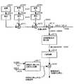
図5には、例えば、(関節式カメラ211や関節式外科用ツール231,241等の)関節器具、及び(カメラマニピュレータ212やツールマニピュレータ232,242等の)対応する器具マニピュレータの相互作用部分の図が示されている。各器具は、(そのエンドエフェクタを含む)器具の移動を生じさせるような多数のアクチュエータ・アセンブリ521〜523,531〜533,570を含んでおり、対応するマニピュレータは、アクチュエータ・アセンブリを作動させるような多数のアクチュエータ501〜503,511〜513,560を含んでいる。 FIG. 5 shows, for example, the interaction parts of joint instruments (such as articulated
また、多数のインターフェイス機構を設けてもよい。例えば、(それぞれ、ピッチ/ヨー方向段付継手及びピッチ/ヨー方向手首のための)ピッチ/ヨー連結機構540,550、及び(それぞれ、ロール方向の器具作動及びエンドエフェクタ作動のための)ギヤ比545,555が、無菌のマニピュレータ/器具インターフェイスに提供されており、マニピュレータ・アクチュエータ空間でコンパクトな拘束を充足するとともに、インタフェイスに亘って正確な動作伝達を維持しながら、器具継手空間の器具継手の必要な動作範囲を達成する。単一のブロック540として示されているが、段付継手アクチュエータ501,502(#1及び#2として区別される)とピッチ/ヨー方向段付継手アセンブリ521,522との間の連結は、無菌インターフェイスの各側に1つずつ(すなわち、インターフェイスのマニピュレータ側に1つとインターフェイスの器具側に1つとを含む)連結機構のペアを含んでもよい。同様に、単一のブロック550として示されているが、手首アクチュエータ512,513(#1と#2として区別される)とピッチ/ヨー方向手首継手アセンブリ532,533との間の連結は、(無菌インターフェイスの両側に1つずつ含む)連結機構のペアを含んでもよい。 A number of interface mechanisms may be provided. For example, pitch /
ピッチ方向段付継手アセンブリ521及びヨー方向段付継手アセンブリ522の両方は、第1、第2、第3リンク(例えば、関節式カメラ211のリンク322,324,326)と、第1及び第2継手(例えば、関節式カメラ211の継手323,325)とを共有する。これらの共有された構成部品に加えて、ピッチ及びヨー方向段付継手アセンブリ521,522は、第1及び第2継手を(段付連結540を介して)ピッチ及びヨー方向段付継手アクチュエータ501,502に連結するような機械的連結も含んでおり、それによって、第2リンクは、第1継手を通過するラインの周りで、第1リンク(例えば、関節式カメラ211のリンク322)の長手方向軸線に対して緯度方向である軸線に沿って制御可能に旋回し、第2リンクは、第1継手を通過するラインの周りで、第1リンクの緯度方向方及び経度方向軸線の両方に直交する軸線に沿って制御可能に旋回する。 Both pitch direction stepped
入力/出力(I/O)アセンブリ523は、第1リンク(例えば、関節式カメラ211のリンク322)を含むとともに、入力/出力(I/O)アクチュエータ503を第1リンクに連結する駆動トレイン(train)を介して相互接続されており、それによって、第1リンクは、I/Oアクチュエータ503の作動によってその経度方向軸線に沿って直線状に制御可能に移動する。ロール方向アセンブリ531は、第1リンクを含んでおり、(モータのロータ等の)ロール方向アクチュエータ511の回転要素を第1のリンクに連結するような1つ以上のギヤ(すなわち、ギヤ比545を有する)を介して相互接続しており、それによって、第1リンクは、ロール方向アクチュエータ511の作動によってその経度方向軸線周りに制御可能に回転される。 The input / output (I / O)
器具マニピュレータ(例えば、カメラマニピュレータ212)は、手首連結550を介して作動する手首アクチュエータ512,513と、手首アセンブリ(例えば、関節式カメラ211の手首アセンブリ327)のピッチ及びヨー方向継手532,533とを含んでおり、それによって、器具先端(例えば、カメラ先端311)を、手首アセンブリに対して上下方向(すなわち、ピッチ方向)や左右方向(すなわち、ヨー方向)に制御可能に旋回させる。把持アセンブリ570は、エンドエフェクタ(例えば、外科用ツール231のエンドエフェクタ331)を含んでおり、把持アクチュエータ560をこのエンドエフェクタに連結するような1つ以上のギヤ(すなわち、ギヤ比555を有する)を介して相互接続し、それによって、エンドエフェクタを制御可能に作動させる。 Instrument manipulators (eg, camera manipulator 212) include
器具継手500のグループは、これら継手の組み合わせを作動させることによって、器具の手首アセンブリが、必要に応じて円弧補間を用いた3次元空間内で平行移動するように位置付けすることができるので、「並継手(translational joints)」と称される。器具継手510のグループは、これらの継手を作動させることによって、器具の先端が、手首アセンブリの周りに向き合せされるので、「向合せ継手(orientational joints)」と称される。 A group of
様々な段階において、医療処置の実施前に、実施中に、及び実施後に、関節器具211,231,241が、その時点で実施されるタスを最も良く達成するための好適な姿勢が存在する。例えば、図3及び図4に示されるように、通常動作中に、各外科用ツール231,241の好適な姿勢は、他の器具との不注意の衝突の可能性を最小限に留めながら、良好な動作範囲を提供するような「肘を外側に向け(elbow out)、手首を内側に向ける(wrist in)」姿勢とすることができる。同様に、図3及び図4に示されるように、通常動作中に、カメラ機器211の好適な姿勢は、外科用器具231,241のエンドエフェクタ331,341の良好なビューが、カメラの撮像端部に提供されるような「コブラ形状」の姿勢を取ってもよい。別の例として、器具を進入ガイド200内に再び後退させてツール交換を行う場合(すなわち、器具やそのエンドエフェクタを別の器具やエンドエフェクタに交換する)や、或いは遠隔中心周りにその進入ガイドを旋回させることにより、進入ガイド200を再向き合せすることが所望される場合に、進入ガイド200内へ器具を後退させる前のその器具の好適な姿勢は、器具のリンクが図8に示されるように直線状に整列するような「真っ直ぐな」姿勢である。 At various stages, there is a suitable posture for the articulating
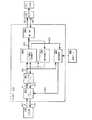
図6には、例として、カメラ機器コントローラ(CTRLC)213のブロック図が示されており、このコントローラ213は、入力装置108が、図1を参照して以前説明したように、マルチプレクサ280を介してカメラ機器211に選択的に関連付けられるときに、外科医による入力装置108の移動について命令されるように関節式カメラ機器211の姿勢(すなわち、並進及び向合せの両方)を制御する。入力装置108は、複数の自由度の運動を容易にするように、継手によって接続された多数のリンクを含む。例えば、外科医/オペレータが、ある位置から別の位置に入力装置108を移動させる際に、入力装置108の継手に関連付けられたセンサは、サンプリング間隔におけるこのような移動を検知し(プロセッサ102の処理速度及びカメラ制御目的を最適にする)、継手空間でのこのようなサンプリングされた移動を示すデジタル情報631を入力処理ブロック610に提供する。 FIG. 6 shows, by way of example, a block diagram of a camera equipment controller (CTRLC) 213 that is connected to the
入力処理ブロック610は、入力装置108の継手センサから受信した情報631を処理して、継手位置情報から継手速度を計算するとともに、ヤコビ行列及び周知の変換技術を使用する眼に関連する情報を使用して変換を実行することにより、外科医の目の位置に関連した基準フレーム(「眼基準フレーム」)に対する直交座標空間のカメラ機器211について、この受信した情報を対応する所望の位置及び速度に変換する。 The
スケール及びオフセット処理ブロック601は、入力処理610から処理された情報611を受信し、スケール及びオフセット調整をこの情報に適用して、それによって、カメラ機器211の得られた移動、つまり、ディスプレイ画面104上に表示される画像が、自然に、入力装置108のオペレータによって予想されるように表示される。このスケール調整は、作業部位をビュー(視認する)ときにカメラ機器211のより正確な移動を可能にするために、カメラ機器211の小さな移動が、入力装置108のより大きな移動に対して所望される場合に有用である。また、オフセット調整は、外科医が入力装置108を操作してカメラ機器211に移動を命令し、その結果、その撮影された画像がディスプレイ画面104上にその時点で表示されるように、外科医の目に対して入力装置108を整列させるように適用される。 The scale and offset
シミュレート器具ブロック604は、命令された継手位置及び速度を制限する、逆運動学を用いて、カメラ機器211の命令された姿勢621を、直交座標空間からその継手空間に変換して、患者の組織又は他の部分との有害な接触を避けるように、物理的な制限やその他の拘束を回避し、且つ医療用ロボットシステム100を用いて外科医によってその時点で実施される医療処置時のパフォーマンスを改善するために規定される仮想の拘束を適用する。具体的には、図9に示されるように、命令された姿勢621は、命令された姿勢621で仮想的拘束を実行して、修正後の命令された姿勢623を生成するような仮想障壁ロジック901(以下で図15を参照してより詳細に説明する)によって修正される。逆運動学及び制限ブロック902は、次に、修正後の命令された姿勢623を器具直交座標空間から器具継手空間に変換し、継手位置及び/又は速度を、関節式カメラ機器211の継手に関連付けらた又は置かれた物理的な制限やその他の拘束に制限する。 The
(カメラ機器211の各継手について命令された値を含む)シミュレートされた器具ブロック604の出力622は、継手制御ブロック605及び順方向運動学ブロック606に提供される。継手制御ブロック605は、カメラ機器211の各制御された継手(又は「段付継手」等の動作可能に連結された継手)についての継手制御システムを含む。フィードバック制御を目的として、カメラ機器211の各制御された継手に関連するセンサは、カメラ機器211の各継手の現在の位置及び/又は速度を示す継手制御ブロック605にセンサデータ632を再び提供する。センサは、直接的に(例えば、カメラ機器211上の継手から)又は間接的に(例えば、継手を駆動するカメラマニピュレータ212のアクチュエータから)継手情報を感知する。継手制御ブロック605内の各継手制御システムは、次に、従来のフィードバック制御システムのように、命令された継手の値と感知された継手の値との間の差をゼロになるように駆動させるために、カメラマニピュレータ212のそれぞれのアクチュエータについてトルク命令633を生成する。 The
順方向運動学ブロック606は、シミュレートされた器具ブロック604の出力622を、カメラ機器の継手空間から、カメラ機器211の順方向運動学を使用して眼基準フレームに対する直交座標空間に再び変換する。順方向運動学ブロック606の出力641を、スケール及びオフセット処理ブロック601に提供するだけでなく、その内部計算の目的のためにシミュレートされた器具ブロック604にも再び提供する。 The forward kinematics block 606 transforms the
スケール及びオフセット処理ブロック601は、エラー値がその出力611と入力612との間で計算される場合に、その出力612を入力処理ブロック610に渡す前に、順方向運動学ブロック606の出力641で逆スケール及びオフセット関数を実行する。制限又は他の拘束がシミュレートされた器具ブロック604に対して入力621に与えられない場合に、次に、計算されるエラー値は、ゼロとなる。これに対して、制限又は拘束が与えられた場合には、このエラー値はゼロではなく、その出力は、外科医の手によって感じ取られる力フィードバックを提供するように入力装置108内のアクチュエータを駆動させるトルク命令634に変換される。こうして、外科医は、入力装置108の移動がその移動方向で抵抗を受けるように感じる力によって与えられる制限又は拘束を認識するようになる。 The scale and offset
姿勢微調整ブロック625は、コントローラ213に含められ、入力処理ブロック610に提供される微調整力命令627を生成する。この力命令は、入力処理ブロック610は、次に微調整力命令627をモータトルクに変換し、それによって、命令された微調整力は、カメラ機器211の姿勢が、姿勢データ626に提供された好適な姿勢を取るような命令をするように外科医に促す態様で、入力装置108の外科医によって感じ取られる。 The attitude
カメラ機器211について、少なくとも2つの好適な姿勢が存在する。通常動作モード中に、例えば外科医が患者に医療処置を実施しているときに、カメラ機器211の好適な姿勢は、図3及び図4に示されるような「コブラ形状」の姿勢である。図3の「コブラ形状」の姿勢を見下ろすと、カメラ機器211の全てのリンク322,324,326は、第1のリンク322の長手方向軸線401に整列されており、それによって、それらリンクは、横方向運動の可能な最大範囲を有しており、カメラ機器211の主挿入方向に対する基準を提供する。さらに、段付継手323,325は、図4に示されるように「上方に揃え(joggle up)」られ、それによって、第3リンク326が、長手方向軸線401の上方のある距離に変位され、手首アセンブリ327は、カメラ先端311が、ある角度で下方に向き合せされるように負のピッチ角で回転され、それによって、カメラは、好適には、その時点で進入ガイド200の先端を超えて延びるような器具231及び241のエンドエフェクタ331及び341について、作業空間の中心をビューする。この場合には、外科医は、好適には、長手方向軸線401に沿った入力/出力(I/O)方向において、カメラ211を前後に自由に移動させることができ、それによって、カメラ211は、それらエンドエフェクタが、使用中に進入ガイド200の先端から離れて再び先端に向けて移動するときに、エンドエフェクタ331,341の良好なビューを得る。 There are at least two preferred orientations for the
後退モードの際に、カメラ機器211の好適な姿勢は、「真っ直ぐな」姿勢である。図7及び図8には、それぞれ、「コブラ形状」姿勢及び「真っ直ぐな」姿勢のカメラ機器211の簡略化した側面図が示されている。「コブラ形状」姿勢から「真っ直ぐな」姿勢を変化するには、段付継手323,325は、リンク324が第1のリンク322の長手方向軸線401と整列するまで、そのリンク324を回転させる。リンク326は、段付継手322,325の動作によって第1リンクに対して常に平行であることから、リンク324が長手方向軸線401と整列する場合に、リンク326も、長手方向軸線401と整列される。なお、手首継手327は、カメラ先端の中心軸線が長手方向軸線401と整列するまで、そのカメラ先端311も回転させる。 In the reverse mode, the preferred posture of the
図10には、例として、姿勢微調整ブロック625とこれに連結される姿勢データブロック626とのブロック図が示されている。この例では、姿勢データブロック626は、プロセッサ102にアクセス可能な不揮発性メモリに記憶されたデータを含む。カメラ機器211の記憶されたデータは、カメラ機器211の後退のために使用される「真っ直ぐな」姿勢1001のデータと、カメラ機器211の通常動作モード運転中に使用される「コブラ形状」姿勢1002のデータとを含む。 FIG. 10 shows, as an example, a block diagram of a posture
姿勢微調整ブロック625は、後退モードの微調整ブロック1003と、通常モードの微調整ブロック1004と、加算ノード1005とを有している。後退モードの微調整ブロック1003及び通常モードの微調整ブロック1004の主な特徴は、移行期間中に、一方からの微調整力命令が段階的に入力される間に、他方からの微調整力命令が段階的に停止されることである。後退モードの微調整ブロック1003のより詳細な説明は、以下で図12を参照して説明し、通常モードの微調整ブロック1004のより詳細な説明は、図13を参照して説明する。 The attitude
図12には、例として、受信データを継続的に処理する後退モードの微調整ブロック1003のブロック図が示されている。加算ノード1201は、好適な「真っ直ぐな」姿勢1001(すなわち、カメラ機器211の後退構成)と、機器コントローラ213のシミュレートされた器具608ブロックの仮想障壁ロジック901によって生成された修正後の命令された姿勢(XSLV, VSLV)623との間の差(XERR, VERR)を計算する。本明細書で使用される場合に、用語「姿勢」は、器具の位置及び向きだけでなくそれらの位置及び回転速度の両方を意味する。そのため、命令された姿勢は、位置(XCMD)及び速度(VCMD)成分を両方とも含み、修正後の命令された姿勢は、位置(XSLV)及び速度(VSLV)成分を両方とも含み、好適な姿勢は、位置(XPP)及び速度(VPP)成分を両方とも含み、好適な姿勢と修正後の命令された姿勢との間の計算された差は、位置(XERR)及び速度(VERR)成分を両方とも含む。しかしながら、加算ノード1201で実行される計算では、好適な姿勢(VPP)の速度(VPP)成分は、全てゼロであると推定される。 FIG. 12 shows, as an example, a block diagram of a
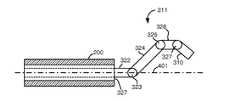
修正後の命令された姿勢(XSLV, VSLV)がどのように生成されるかを説明するために、仮想障壁ロジック901の例を、図15を参照して説明する。ブロック1501では、ロジック901は、スケール及びオフセットブロック621から命令された姿勢(XCMD)を受信し、ブロック1502では、ロジック901は、この例では、カメラ機器211の第1リンク322の長手方向軸線401に沿った器具後退方向である第1方向における命令された姿勢621の投影を決定する。ブロック1503では、第1方向に沿った投影によって、カメラ機器211が仮想障壁位置を越えて移動するような命令がされたか否かの判定が行われる。この場合に、仮想障壁位置は、進入ガイド200の先端から閾値距離にある、或いは安全マージンを含んだ距離にあるような長手方向軸線401に沿った位置にある。米国特許出願公開第2011/0040305号A1に説明されるように、安全マージンを取る目的は、その時点で物理的に収まらない構成になっている間に、強制的に関節器具211を再び進入ガイド200内に押し込む場合に、進入ガイド200及び関節器具211のいずれか又は両方に発生する損傷を防止することである。ブロック1503での判定がいいえ(NO)ならば、次に、仮想障壁ロジック901は、ブロック1501にジャンプして戻り、次の処理サイクルのデータを処理する。これに対して、ブロック1503の判定がはい(YES)であれば、次にブロック1504では、カメラ機器211の現在の姿勢が、その継手位置を感知し且つ順方向運動学を適用しているかを判定して、それらの対応する直交座標姿勢を決定する。ブロック1505では、次に、カメラ機器211の現在の姿勢が好適な姿勢(すなわち、この場合には「真っ直ぐな」姿勢)であるかどうかの判定が行われる。ブロック1505での判定がはい(YES)であれば、次に、仮想障壁ロジック901は、命令された姿勢(XCMD)を修正せず、ブロック1501にジャンプして戻って、次の処理サイクルのデータを処理する。これに対して、ブロック1505での判定がいいえ(NO)であれば、次に、命令された姿勢(XCMD)は、拘束として仮想障壁を適用することによって修正され、それによって、カメラ機器211は、第1方向への更なる移動が防止される。次に、この方法は、ブロック1501に戻って、次の処理サイクルのデータを処理するようにループする。こうして、カメラ機器211は、現在の姿勢が、カメラ機器211の好適な後退姿勢になるまで、このように、仮想障壁位置を越えて移動することを防止することができる。 In order to explain how the modified commanded posture (XSLV, VSLV) is generated, an example of the
再び図12すると、ブロック1202では、計算された差(XERR,VERR)の非微調整成分が除去される。具体的には、第1方向に沿った並進成分と先端310の周りのロール方向回転成分が除去される。それは、これらの成分のいずれも、好適な姿勢に影響を及ぼさないからである(すなわち、それらの成分の値に拘わらず、カメラ機器は図8に示されるような「真っ直ぐな」姿勢で配置される)。ブロック1203では、ブロック1202で生成された修正後の差(XERR’, VERR’)を変換して、入力装置108に適用される1つ又は複数の力をもたらすような力命令を生成し、それによって、カメラ器具211に好適な姿勢を取らせるような命令をするように外科医を促す。好ましくは、このような力命令は、入力装置108の対応する自由度に適用されるような6自由度の粘弾性の力である。 Referring again to FIG. 12, at
力変換ブロック1203の例を、比例−微分(PD)開ループシステムのブロック図で14に示す。このPDシステムでは、修正後の位置の差(XERR’)を位置ゲイン(KP)1401によって乗算し、リミッタ1402によって第1の飽和値(SATP)に制限して、第1力命令の寄与を生成する。同時に、修正後の速度差(VERR’)を微分ゲイン(KD)1403によって乗算し、第2力命令の寄与を生成する。加算ノード1404は、第2及び第1力命令の寄与の間の差を計算し、リミッタ1405が、この差を第2の飽和値(SATF)に制限する。こうして、第2及び第1力命令の寄与の間の制限された差によって、好適な姿勢を取らせるような命令をするために、入力装置108を移動させるように外科医を微調整するような6自由度の直交座標の粘弾性の力が得られる。入力装置108のモータ上の命令されたモータトルクが最大定格値を超えないことを保証するように、第1及び第2の飽和値の値が選択される。 An example of a
再び図12を参照すると、振幅変調器1207は、力変換ブロック1203によって生成された6自由度の直交座標の粘弾性の力を、図11の曲線1101に類似する後退起動信号で変調する。後退起動信号を生成するために、加算ノード1204は、命令された姿勢(XCMD)と修正後の命令された姿勢(XSLV)の差を計算する、速度の寄与を無視して、変調係数生成器1205は、計算された差を使用して変調係数のストリームを生成し、及びローパスフィルタ1206は、変調係数のストリームをフィルタ処理する。 Referring again to FIG. 12, the
後退モードの起動信号の生成の例が、図16に示されるフロー図に提供されている。ブロック1601及び1602は、加算ノード1204によって実行される動作(アクション)を説明する。具体的には、ブロック1601では、命令された姿勢(XCMD)と修正後の命令された姿勢(XSLV)とが受信され、ブロック1602では、命令された姿勢(XCMD)と修正後の命令された姿勢(XSLV)との間の差が計算される。ブロック1603〜1607は、次に、変調係数生成器1205によって実行される動作を説明する。ブロック1603では、第1方向(すなわち、長手方向軸線401に沿った後退方向)の計算された差の投影が決定され、ブロック1604では、投影が閾値を超えるかどうかの判定が行われる。この場合に、閾値は、外科医が、実際にカメラ機器211を後退させるのを意図しており且つそれが手の震えからもたらされるような不注意アクションではないことを保証するのに十分な大きさとすべきである。ブロック1604の判定がはい(YES)である場合に、次にブロック1605では、現在の変調係数を整数値「1」に設定する。これに対して、ブロック1604の判定がいいえ(NO)である場合には、次にブロック1606では、現在の変調係数を整数値「0」に設定する。ブロック1607では、現在の変調係数は、次に、以前のプロセス期間で生成された変調係数のストリームに付加される。ブロック1608は、ローパスフィルタ1206によって実行される動作を説明する。具体的には、ブロック1608では、後退作動信号は、ローパスフィルタ1206を介して変調係数のストリームを通過させることによって生成され、プロセスは、次にブロック1601にジャンプして戻り、次の処理サイクルのデータを処理する。 An example of the generation of the reverse mode activation signal is provided in the flow diagram shown in FIG.
図13には、例として、受信データを継続的に処理する通常モードの微調整ブロック1004のブロック図が示されている。加算ノード1301は、好適な「コブラ形状」姿勢1002(すなわち、カメラ機器211の通常モード構成)と、機器コントローラ213のシミュレートされた器具ブロック608の仮想障壁ロジック901によって生成される修正後の命令された姿勢623(XSLV, VSLV)との間の差(XERR, VERR)を計算する。 FIG. 13 shows, as an example, a block diagram of a
ブロック1302では、計算された差(XERR, VERR)の非微調整成分が除去される。具体的には、第1方向に沿った並進成分と先端311周りのロール方向回転成分が除去される。これは、これらの成分のいずれも好適な姿勢に影響を及ぼさないからである(つまり、これら成分の値に拘わらず、カメラ機器は、図7に示されるような「コブラ形状」姿勢で配置される)。ブロック1303では、ブロック1302で生成された修正後の差(XERR’, VERR’)を変換して、入力装置108に適用される1つ以上の力をもたらすような力命令を生成し、それによって、カメラ器具211に好適な姿勢を取らせるような命令をするように外科医を促す。好ましくは、このような力命令は、入力装置108の対応する自由度に適用されるような6自由度の粘弾性の力であり、図14を参照して以前説明したのと同様に生成される。 At
振幅変調器1307は、力変換ブロック1303によって生成された6自由度の直交座標の粘弾性の力を、図11の曲線1102に類似するような通常モードの解除信号を用いて変調する。通常モードの解除信号を生成するために、加算ノード1304は、命令された姿勢(XCMD)と修正後の命令された姿勢(XSLV)との差を計算し、速度の寄与を無視して、変調係数生成器1305は、この計算された差を用いて変調係数のストリームを生成し、及びローパスフィルタ1306は、変調係数のストリームをフィルタ処理する。 The
通常モードの解除信号の生成の例が、図17に示されるフロー図に提供される。ブロック1701及び1702は、加算ノード1304によって実行される動作(アクション)を説明する。具体的には、ブロック1701では、命令された姿勢(XCMD)と修正後の命令され姿勢(XSLV)とが受信され、ブロック1702では、命令された姿勢(XCMD)と修正後の命令された姿勢(XSLV)との間の差が計算される。ブロック1703〜1707は、次に、変調係数生成器1305によって実行される動作を説明する。ブロック1703では、第1方向(すなわち、長手方向軸線401に沿った後退方向)における計算された差の投影が決定され、ブロック1704では、投影が閾値を超えたか否かの判定が行われる。この場合に、閾値は、外科医がカメラ機器211を後退させるのを実際に意図しており且つ手の震えによる不注意アクションでないことを保証するように十分な大きさにすべきである。ブロック1704での判定がはい(YES)である場合に、次にブロック1705では、現在の変調係数を整数値「0」に設定する。これに対して、ブロック1704での判定がいいえ(NO)である場合に、次にブロック1706では、現在の変調係数を整数値「1」に設定する。変調係数値の割り当ては、後退起動信号の生成に用いられる割り当てとは反対であることに留意されたい。つまり、後退及び通常モードの起動信号の一方が段階的に入力される間に、他方が段階的に停止される。ブロック1707では、現在の変調係数が、その後、以前のプロセス期間で生成された変調係数のストリームに付加される。ブロック1708は、最終的に、ローパスフィルタ1306によって実行される動作を説明する。具体的に、ブロック1708では、通常動作の解除信号が、変調係数のストリームをローパスフィルタ1306に通過させることによって生成される。プロセスは、次にブロック1701にジャンプして戻り、次の処理サイクルのためのデータを処理する。 An example of normal mode release signal generation is provided in the flow diagram shown in FIG.
後退モードの微調整ブロック1003におけるローパスフィルタ1206及び通常モードの微調整ブロック1004におけるローパスフィルタ1306の時定数は、好ましくは、図11に示されるような移行期間中に、段階的な入力と段階的な停止とが一致するように同じにされる。ここで、時間「t(k)」は、ブロック1804及び1704における閾値の決定が、最初にはい(YES)の判定がもたらされる時間を表しており、時間「t(k - m)」は、ブロック1804及び1704における閾値の決定が、いいえ(NO)の判定が得られ場合の「t(k)」以前の時間を表しており、時間「t(k + m)」は、ブロック1804及び1704における閾値の決定が、依然としてはい(YES)の判定が得られる場合の「t(k)」後の時間を表している。 The time constants of the
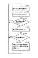
図18には、上記に詳細に説明したように、本発明の第1実施形態を要約するフロー図が示されている。ブロック1801では、その時点で、命令された姿勢(XCMD)が、この命令された姿勢を取るような関節器具に関連した入力装置から受信される。ブロック1802では、命令された姿勢は、(図15を参照して説明されるように)仮想拘束を使用して修正される。ブロック1803〜1807では、入力装置のオペレータを微調整するように段階的に入力される第1力命令を生成して、(図12を参照して説明したような)第1の(新しい)好適な姿勢を取らせるような命令をする一方、ブロック1808〜1812でも同時に、入力装置のオペレータを微調整するように段階的に停止される第2力命令を生成して、(図13を参照して説明したような)第2の(現在の)好適な姿勢を取らせるような命令をする。ブロック1813では、第1及び第2力命令が入力装置に適用されて、それによって、最初に、入力装置のオペレータは、第2の好適な姿勢を取らせるような命令をするように促され、段階的な入力及び段階的な停止の移行期間の後に、そのオペレータは、第1の好適な姿勢を取らせるような命令をするように促される。 FIG. 18 shows a flow diagram summarizing the first embodiment of the present invention as described in detail above. In
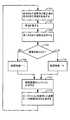
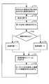
図19〜21には、図18を参照して説明する全てのブロックを含まないが、いくつかの様々な組み合わせを含む本発明の更なる実施形態が示されている。具体的に、図19には、第1実施態様の変形である第2実施形態が示されている。ここで、命令された姿勢は、第1実施形態の他の全てのブロックを実行するが、ブロック1802を削除することによって、仮想拘束を用いて修正されない。図20には、第1実施形態の変形である第3実施形態が示されている。ここで、第2の(現在の)好適な姿勢は、段階的に停止される力命令が存在しないので、修正後のブロック813を含む第1実施形態の他の全てのブロックを実行するが、ブロック808〜812を削除することによって、アクティブでなくなる。図21には、第3実施形態の変形である第4実施形態が示されている。ここで、命令された姿勢は、第3実施形態の他の全てのブロックを実行するが、ブロック1802を削除することによって、仮想拘束を使用して修正されない。 19-21 illustrate further embodiments of the present invention that do not include all the blocks described with reference to FIG. 18, but that include several different combinations. Specifically, FIG. 19 shows a second embodiment which is a modification of the first embodiment. Here, the commanded posture executes all other blocks of the first embodiment, but is not modified using virtual constraints by deleting
図22〜24には、以前説明した実施形態のいくつかを発展させた本発明のさらに他の実施形態が示されている。具体的には、以前の実施形態は、単一好適な姿勢が(移行期間外で)同時にアクティブであることを開示しているのに対し、図22〜24に示されている実施形態では、複数の好適な姿勢の実現性が、同時にアクティブにされ、アクティブな好適な姿勢は、1つ又はいくつかの姿勢が他の姿勢よりも支配的となるように重み付けされる。さらに、重み付けは、それぞれの重みを動的に変更することによって好適な姿勢が内外に移行することができるような追加の機構を提供する(例えば、「0」の重みから「1」の重みに徐々に変化させて対応する好適な姿勢を取るように段階的に入力する、その逆に、「1」の重みから「0」の重みに徐々に変化させて対応する好適な姿勢を取るように段階的に停止させる)。また、従来の実施形態は、異なる動作モード用の固定された好適な姿勢を開示しているのに対して、図22〜24に示した実施形態は、現在の又は命令された姿勢を取るような他の関節器具等のシステムデータに基づいて好適な姿勢を動的に変化させる実現性を企図している。例えば、カメラ機器211の好適な姿勢は、器具231,241のエンドエフェクタ331,341の姿勢が変化するように、動的に変更され、それによって、エンドエフェクタ331,341は、カメラ機器211の視野内に十分に位置付けされるように維持される。別の例として、各関節器具211,231,241の好適な姿勢は、関節器具211,231,241を用いる医療処置の実施中に、他の関節器具211,231,241との衝突を避けるために動的に変化する。 22-24 show yet another embodiment of the present invention that is an extension of some of the previously described embodiments. Specifically, the previous embodiment discloses that a single preferred posture is active at the same time (outside the transition period), whereas in the embodiment shown in FIGS. The feasibility of multiple preferred postures is activated at the same time, and the active preferred postures are weighted so that one or several postures are more dominant than others. In addition, weighting provides an additional mechanism that allows the preferred posture to move in and out by dynamically changing each weight (eg, from a weight of “0” to a weight of “1”). Stepwise input to gradually change and take a suitable posture, and conversely, gradually change from a weight of “1” to a weight of “0” to take a suitable posture Stop in steps). Also, conventional embodiments disclose a fixed preferred posture for different modes of operation, whereas the embodiments shown in FIGS. 22-24 are intended to take a current or commanded posture. The possibility of dynamically changing a suitable posture based on system data of other articulated instruments is contemplated. For example, the preferred posture of the
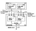
図22には、例えば、オペレータが命令して関節器具を移動させるような代替器具コントローラのブロック図が示されている。これはカメラコントローラ213についての例であるが、同じ一般構造を、医療用ロボットシステム100の他の装置コントローラ203,233,243に用いることができることを理解されたい。機能ブロック610,601,605,606は、図6を参照して以前に説明したものと同様である。シミュレートされた器具の機能ブロック2204は、逆運動学及び制限に関して図6のブロック604と略同一であるが、異なる動作モード及び/又は好適な姿勢によって、修正後の命令された姿勢2205を生成するために、命令された姿勢621に与えられる仮想拘束に関して異なっていてもよい。同様に、姿勢微調整機能ブロック2201は、2つの姿勢微調整の寄与を加算することに関するブロック625と略同一であり、それぞれの起動信号に従って、第1の(新しい)好適な姿勢が段階的に入力される一方、第2の(現在の)好適な姿勢が、段階的に停止される。 FIG. 22 shows a block diagram of an alternative instrument controller that may be moved, for example, by an operator commanding an articulated instrument. While this is an example for a
姿勢生成ブロック2202は、コントローラ213に含まれており、それによって、姿勢微調整ブロック2201に提供される1つ以上の好適な姿勢を動的に生成するだけでなく、適切なときに静止した好適な姿勢を通過させる。具体的に、姿勢データブロック626によって提供される静止した好適な姿勢は、通常通過するが、関節式カメラ機器211の好適な姿勢は、他の器具231,241の姿勢をその周りで変化させる条件として、静止した好適な姿勢から動的に変化させることができる。一例として、カメラ機器211の好適な姿勢は、器具231,241との衝突を回避するために、通常動作モード中に動的に変化しており、器具231,241が使用されて、こうして、その時点で移動して患者の解剖学的構造で医療処置を実施する。段階的に入力すべき1つ以上の好適な姿勢(図23の好適な姿勢2301,2303,2305)及び段階的に停止すべき1つ以上の好適な姿勢(好適な姿勢2401,2403,2405)を動的に生成するために、姿勢生成器ブロック2202は、各好適な姿勢を動的に変更するために、システムの1つ以上の異なる状態関数を使用してもよい。この場合に、システム状態情報は、システムデータ2203によって提供される。一例として、システムデータ2203は、システム100の他の器具231,241の命令された姿勢を含んでもよい。別の例として、システムデータ2203は、順方向運動学をそれらの感知された関節位置に適用することで決定されるような他の器具231,241の実際の姿勢を含んでもよい。 The
姿勢微調整ブロック2201は、それぞれ微調整力を発生させるような「段階的な入力」及び「段階的な停止」微調整ブロックを含んでおり、これらは、図10の後退モード及び通常モードの微調整ブロック1003及び1004に関して以前説明したような同様な方法で、入力装置108で段階的に入力され且つ段階的に停止されるようにされている。 The posture
図23には、例えば、「段階的な入力」微調整ブロックのブロック図が示されている。好適な姿勢は、複数の好適な姿勢(例えば、好適な姿勢2301,2303,2305)の加重平均によって生成されており、それによって、各好適な姿勢2320は、対応する重み(例えば、重み2302,2304,2306)によって乗算されて、「1」に等しい重み付けの合計を有する。重みは、固定値であってもよく、又は好適な姿勢の1つ以上が、異なる時間で、異なる動作モードで、又は別のシステム条件下で支配的となるような動的な値であってもよい。好適な姿勢2320と修正後の命令された姿勢2205との間の差が、加算ノード2314によって計算される。非微調整成分の差が、ブロック2315で除去され、この結果が、図12のブロック1203を参照して説明したような力命令を生成するような力変換ブロック2316に提供される。段階的に入力される起動信号が、図11の後退モードの起動信号1101に類似するように、段階的な入力信号生成ブロック2317によって生成される。入力装置108に段階的に入力されるような振幅変調された力命令は、振幅変調器2318によって、次に力変換ブロック2316によって生成された力命令を段階的に入力される起動信号で振幅変調することによって生成される。 FIG. 23 shows a block diagram of a “gradual input” fine adjustment block, for example. The preferred posture is generated by a weighted average of a plurality of preferred postures (eg,
同様の構成を用いて、図24には、例えば、「段階的な停止」微調整ブロックのブロック図が示されている。この場合に、好適な姿勢2420は、複数の好適な姿勢(例えば、好適な姿勢2401,2403,2405)の加重平均によって生成され、それによって、各好適な姿勢は、対応する重み(例えば、重み2402,2404,2406)によって乗算されて、「1」に等しい重み付けの合計を有する。重みは、固定値であってもよく、又は好適な姿勢の1つ以上が、異なる時間で、異なる動作モードで、又は別のシステム条件下で支配的となるような好適な動的な値であってもよい。好適な姿勢2420と修正後の命令された姿勢2205との間の差が、加算ノード2414によって計算される。非微調整成分の差が、ブロック2415で除去され、この結果が、図12のブロック1203を参照して説明したような力命令を生成する力変換ブロック2416に提供される。段階的に停止させる起動信号が、図11の通常モードの起動信号1102に類似するように、段階的な停止信号生成ブロック2417によって生成される。入力装置108に提供され且つ段階的に停止されるような振幅変調された力命令は、振幅変調器2418によって、次に力変換ブロック2416によって生成された力命令を段階的に停止される起動信号で振幅変調することによって生成される。 Using a similar configuration, FIG. 24 shows, for example, a block diagram of a “stepwise stop” fine tuning block. In this case, the
本明細書で説明した実施形態に加えて、他の実施形態は、種々の実施形態の教示の様々な組合せを介して、本発明の範囲内にあることが完全に企図され且つそのように考えられると理解すべきである。具体的には、本発明の様々な態様を、好適な実施形態及び代替実施形態に関して説明してきたが、本発明は、添付の特許請求の範囲の全範囲内の完全な保護を受ける権利を有することを理解されたい。
In addition to the embodiments described herein, other embodiments are fully contemplated and considered to be within the scope of the present invention through various combinations of the teachings of the various embodiments. Should be understood. In particular, while various aspects of the invention have been described with reference to preferred and alternative embodiments, the invention is entitled to full protection within the full scope of the appended claims. Please understand that.
Claims (14)
Translated fromJapanese入力装置のオペレータ操作に応答して、前記関節器具に命令された姿勢を取らせるステップと、
仮想拘束に従って前記命令された姿勢を修正することによって修正後の命令された姿勢を取らせるステップと、
前記命令された姿勢と前記修正後の命令された姿勢との間の差を示す変調係数のストリームを生成するステップと、
該変調係数のストリームをローパスフィルタに通過させることによって第1起動信号を生成するステップと、
前記修正後の命令された姿勢と第1の好適な姿勢との間の差を示すように、前記入力装置の複数の自由度について第1力命令を生成するステップと、
第1起動信号に従った適用を段階的に入力することによって、前記入力装置の複数の自由度について第1力命令を適用するステップと、を含む、
方法。A method of prompting an operator operation of the input device to instruct the joint device to take a suitable posture, the method comprising:
In response to an operator operation of the input device, causing the joint instrument to take a commanded posture;
Taking a modified commanded posture by modifying the commanded posture according to a virtual constraint;
Generating a stream of modulation coefficients indicative of a difference between the commanded posture and the modified commanded posture;
Generating a first activation signal by passing the stream of modulation coefficients through a low pass filter;
Generating a first force command for a plurality of degrees of freedom of the input device to indicate a difference between the modified commanded posture and a first preferred posture;
Applying a first force command for a plurality of degrees of freedom of the input device by stepwise inputting an application according to a first activation signal.
Method.
仮想拘束として仮想障壁を適用し、前記仮想障壁に最近接するが該仮想障壁に衝突しないような前記関節器具の少なくとも一部が第1の好適な姿勢に一致するまで、前記関節器具が、第1の方向の前記仮想障壁を越えて移動するような命令を受けることを防止するステップを含む、請求項1に記載の方法。The step of taking the commanded posture after the correction includes
Applying a virtual barrier as a virtual constraint, the articulating instrument is in a first position until at least a portion of the articulating instrument that is closest to the virtual barrier but does not collide with the virtual barrier matches a first preferred posture. The method of claim 1, comprising preventing receiving an instruction to move beyond the virtual barrier in a direction.
前記命令された姿勢と前記修正後の命令された姿勢との間の差を決定するステップと、
第1の方向に沿って前記差を投影するステップと、
該投影された差が閾値より大きい場合に、現在の変調係数を第1の値に設定し、前記投影された差が前記閾値以下である場合に、現在の変調係数を第2の値に設定することによって、前記投影された差を2進コード化するステップと、を含む、
請求項1に記載の方法。Generating the stream of modulation coefficients comprises:
Determining a difference between the commanded posture and the modified commanded posture;
Projecting the difference along a first direction;
If the projected difference is greater than a threshold, the current modulation factor is set to a first value, and if the projected difference is less than or equal to the threshold, the current modulation factor is set to a second value. Binary encoding the projected difference by:
The method of claim 1.
第1の好適な姿勢と前記修正後の命令された姿勢と比較して、直交座標位置及び速度誤差を生成するステップと、
第1の方向に沿った成分及び前記関節器具の旋回可能な先端部の軸線の周りの成分を除去することによって、前記直交座標位置及び前記速度誤差を修正するステップと、
該修正後の直交座標位置及び速度誤差を用いて、6自由度の粘弾性の力命令を生成するステップと、を含む、
請求項3に記載の方法。The step of generating the first force command is:
Generating a Cartesian coordinate position and velocity error by comparing the first preferred posture and the modified commanded posture;
Correcting the Cartesian coordinate position and the velocity error by removing a component along a first direction and a component around an axis of the pivotable tip of the articulating instrument;
Generating a 6-DOF viscoelastic force command using the corrected Cartesian coordinate position and velocity error;
The method of claim 3.
第1起動信号に従って第1力命令の適用を段階的に入力する前に、前記入力装置の複数の自由度について第2力命令を適用するステップと、
第2起動信号に従って第2力命令の適用を段階的に停止するステップと、をさらに含む、
請求項1に記載の方法。Generating a second force command for a plurality of degrees of freedom of the input device to be indicative of a difference between a second preferred posture and the commanded posture;
Applying a second force command for a plurality of degrees of freedom of the input device before stepwise inputting the application of the first force command according to a first activation signal;
Further stopping stepwise application of the second force command in accordance with the second activation signal;
The method of claim 1.
入力装置と、
関節器具と、
プロセッサ、を備えており、
該プロセッサは、
入力装置のオペレータ操作に応答して、前記関節器具に命令された姿勢を取らせ、
仮想拘束に従って前記命令された姿勢を修正することによって修正後の命令された姿勢を取らせ、
前記命令された姿勢と前記修正後の命令された姿勢との間の差を示す変調係数のストリームを生成し、
前記変調係数のストリームを処理することによって第1起動信号を生成し、
前記修正後の命令された姿勢と第1の好適な姿勢との間の差を示すように、前記入力装置の複数の自由度について第1力命令を生成し、
第1起動信号に従った適用を段階的に入力するように、前記入力装置の複数の自由度について第1力命令の適用を命令する、ように構成される、
システム。A robot system, which is
An input device;
Articulating instruments,
Processor,
The processor
In response to an operator operation of the input device, the joint instrument is instructed to take a posture,
By taking the revised commanded posture by modifying the commanded posture according to a virtual constraint,
Generating a stream of modulation coefficients indicating a difference between the commanded posture and the modified commanded posture;
Generating a first activation signal by processing the stream of modulation coefficients;
Generating a first force command for a plurality of degrees of freedom of the input device to indicate a difference between the corrected commanded posture and a first preferred posture;
Instructing the application of a first force command for a plurality of degrees of freedom of the input device to input the application according to the first activation signal in stages;
system.
The system according to claim 13, wherein the first activation signal and the second activation signal are complementary signals, and the first activation signal is input in stages when the second activation signal is stopped in stages. .
Applications Claiming Priority (2)
| Application Number | Priority Date | Filing Date | Title |
|---|---|---|---|
| US13/292,760 | 2011-11-09 | ||
| US13/292,760US9492927B2 (en) | 2009-08-15 | 2011-11-09 | Application of force feedback on an input device to urge its operator to command an articulated instrument to a preferred pose |
Related Parent Applications (1)
| Application Number | Title | Priority Date | Filing Date |
|---|---|---|---|
| JP2014541317ADivisionJP6087368B2 (en) | 2011-11-09 | 2012-11-09 | Application of force feedback at the input device that prompts the operator of the input device to command the joint device to take a suitable posture |
Publications (2)
| Publication Number | Publication Date |
|---|---|
| JP2017080887Atrue JP2017080887A (en) | 2017-05-18 |
| JP6617114B2 JP6617114B2 (en) | 2019-12-04 |
Family
ID=48290591
Family Applications (2)
| Application Number | Title | Priority Date | Filing Date |
|---|---|---|---|
| JP2014541317AActiveJP6087368B2 (en) | 2011-11-09 | 2012-11-09 | Application of force feedback at the input device that prompts the operator of the input device to command the joint device to take a suitable posture |
| JP2017016583AActiveJP6617114B2 (en) | 2011-11-09 | 2017-02-01 | Application of force feedback at the input device that prompts the operator of the input device to command the joint device to take a suitable posture |
Family Applications Before (1)
| Application Number | Title | Priority Date | Filing Date |
|---|---|---|---|
| JP2014541317AActiveJP6087368B2 (en) | 2011-11-09 | 2012-11-09 | Application of force feedback at the input device that prompts the operator of the input device to command the joint device to take a suitable posture |
Country Status (6)
| Country | Link |
|---|---|
| US (4) | US9492927B2 (en) |
| EP (2) | EP3636197B1 (en) |
| JP (2) | JP6087368B2 (en) |
| KR (2) | KR102047038B1 (en) |
| CN (2) | CN103930063B (en) |
| WO (1) | WO2013071071A1 (en) |
Cited By (2)
| Publication number | Priority date | Publication date | Assignee | Title |
|---|---|---|---|---|
| JP2022502187A (en)* | 2018-10-03 | 2022-01-11 | シーエムアール サージカル リミテッドCmr Surgical Limited | Methods and systems for providing assistance to users of surgical robotic systems |
| JP2023034692A (en)* | 2021-08-31 | 2023-03-13 | 川崎重工業株式会社 | Surgery support system and surgery support system control method |
Families Citing this family (116)
| Publication number | Priority date | Publication date | Assignee | Title |
|---|---|---|---|---|
| US8944070B2 (en) | 1999-04-07 | 2015-02-03 | Intuitive Surgical Operations, Inc. | Non-force reflecting method for providing tool force information to a user of a telesurgical system |
| US9789608B2 (en) | 2006-06-29 | 2017-10-17 | Intuitive Surgical Operations, Inc. | Synthetic representation of a surgical robot |
| US9266239B2 (en)* | 2005-12-27 | 2016-02-23 | Intuitive Surgical Operations, Inc. | Constraint based control in a minimally invasive surgical apparatus |
| KR101477133B1 (en) | 2006-06-13 | 2014-12-29 | 인튜어티브 서지컬 인코포레이티드 | Minimally invasive surgical system |
| US20090192523A1 (en) | 2006-06-29 | 2009-07-30 | Intuitive Surgical, Inc. | Synthetic representation of a surgical instrument |
| US12357400B2 (en) | 2006-06-29 | 2025-07-15 | Intuitive Surgical Operations, Inc. | Synthetic representation of a surgical robot |
| US9718190B2 (en) | 2006-06-29 | 2017-08-01 | Intuitive Surgical Operations, Inc. | Tool position and identification indicator displayed in a boundary area of a computer display screen |
| US10008017B2 (en) | 2006-06-29 | 2018-06-26 | Intuitive Surgical Operations, Inc. | Rendering tool information as graphic overlays on displayed images of tools |
| US10258425B2 (en) | 2008-06-27 | 2019-04-16 | Intuitive Surgical Operations, Inc. | Medical robotic system providing an auxiliary view of articulatable instruments extending out of a distal end of an entry guide |
| US9469034B2 (en) | 2007-06-13 | 2016-10-18 | Intuitive Surgical Operations, Inc. | Method and system for switching modes of a robotic system |
| US9089256B2 (en)* | 2008-06-27 | 2015-07-28 | Intuitive Surgical Operations, Inc. | Medical robotic system providing an auxiliary view including range of motion limitations for articulatable instruments extending out of a distal end of an entry guide |
| US8903546B2 (en) | 2009-08-15 | 2014-12-02 | Intuitive Surgical Operations, Inc. | Smooth control of an articulated instrument across areas with different work space conditions |
| US9138129B2 (en) | 2007-06-13 | 2015-09-22 | Intuitive Surgical Operations, Inc. | Method and system for moving a plurality of articulated instruments in tandem back towards an entry guide |
| US8620473B2 (en) | 2007-06-13 | 2013-12-31 | Intuitive Surgical Operations, Inc. | Medical robotic system with coupled control modes |
| US9084623B2 (en)* | 2009-08-15 | 2015-07-21 | Intuitive Surgical Operations, Inc. | Controller assisted reconfiguration of an articulated instrument during movement into and out of an entry guide |
| US8864652B2 (en)* | 2008-06-27 | 2014-10-21 | Intuitive Surgical Operations, Inc. | Medical robotic system providing computer generated auxiliary views of a camera instrument for controlling the positioning and orienting of its tip |
| US12239396B2 (en) | 2008-06-27 | 2025-03-04 | Intuitive Surgical Operations, Inc. | Medical robotic system providing an auxiliary view including range of motion limitations for articulatable instruments extending out of a distal end of an entry guide |
| US12266040B2 (en) | 2009-03-31 | 2025-04-01 | Intuitive Surgical Operations, Inc. | Rendering tool information as graphic overlays on displayed images of tools |
| US9254123B2 (en) | 2009-04-29 | 2016-02-09 | Hansen Medical, Inc. | Flexible and steerable elongate instruments with shape control and support elements |
| US8918211B2 (en) | 2010-02-12 | 2014-12-23 | Intuitive Surgical Operations, Inc. | Medical robotic system providing sensory feedback indicating a difference between a commanded state and a preferred pose of an articulated instrument |
| US9492927B2 (en) | 2009-08-15 | 2016-11-15 | Intuitive Surgical Operations, Inc. | Application of force feedback on an input device to urge its operator to command an articulated instrument to a preferred pose |
| US20120071752A1 (en) | 2010-09-17 | 2012-03-22 | Sewell Christopher M | User interface and method for operating a robotic medical system |
| US20130030363A1 (en) | 2011-07-29 | 2013-01-31 | Hansen Medical, Inc. | Systems and methods utilizing shape sensing fibers |
| US10507066B2 (en) | 2013-02-15 | 2019-12-17 | Intuitive Surgical Operations, Inc. | Providing information of tools by filtering image areas adjacent to or on displayed images of the tools |
| US10149720B2 (en) | 2013-03-08 | 2018-12-11 | Auris Health, Inc. | Method, apparatus, and a system for facilitating bending of an instrument in a surgical or medical robotic environment |
| US10376672B2 (en) | 2013-03-15 | 2019-08-13 | Auris Health, Inc. | Catheter insertion system and method of fabrication |
| US11747895B2 (en)* | 2013-03-15 | 2023-09-05 | Intuitive Surgical Operations, Inc. | Robotic system providing user selectable actions associated with gaze tracking |
| JP6093850B2 (en)* | 2013-03-29 | 2017-03-08 | 富士フイルム株式会社 | Endoscopic surgical device |
| EP2979615B1 (en)* | 2013-03-29 | 2019-11-27 | FUJIFILM Corporation | Device for endoscopic surgery |
| WO2015113203A1 (en)* | 2014-01-28 | 2015-08-06 | Abb Technology Ltd | Method and apparatus for optimizing performance of robotic cell |
| JP6218631B2 (en)* | 2014-02-18 | 2017-10-25 | オリンパス株式会社 | Method of operating a manipulator device |
| CN106061427B (en)* | 2014-02-28 | 2020-10-27 | 索尼公司 | Robot arm apparatus, robot arm control method, and program |
| US10556345B2 (en)* | 2014-02-28 | 2020-02-11 | Sony Corporation | Robot arm apparatus and calibration method |
| KR102470468B1 (en) | 2014-03-17 | 2022-11-25 | 인튜어티브 서지컬 오퍼레이션즈 인코포레이티드 | System and method for aligning with a reference target |
| EP3243476B1 (en) | 2014-03-24 | 2019-11-06 | Auris Health, Inc. | Systems and devices for catheter driving instinctiveness |
| AU2015259635B2 (en)* | 2014-05-15 | 2019-04-18 | Covidien Lp | Systems and methods for controlling a camera position in a surgical robotic system |
| US9561083B2 (en) | 2014-07-01 | 2017-02-07 | Auris Surgical Robotics, Inc. | Articulating flexible endoscopic tool with roll capabilities |
| US10792464B2 (en) | 2014-07-01 | 2020-10-06 | Auris Health, Inc. | Tool and method for using surgical endoscope with spiral lumens |
| US9744335B2 (en) | 2014-07-01 | 2017-08-29 | Auris Surgical Robotics, Inc. | Apparatuses and methods for monitoring tendons of steerable catheters |
| KR102620057B1 (en)* | 2014-08-22 | 2024-01-03 | 인튜어티브 서지컬 오퍼레이션즈 인코포레이티드 | Systems and methods for adaptive input mapping |
| EP3200718A4 (en) | 2014-09-30 | 2018-04-25 | Auris Surgical Robotics, Inc | Configurable robotic surgical system with virtual rail and flexible endoscope |
| US10314463B2 (en) | 2014-10-24 | 2019-06-11 | Auris Health, Inc. | Automated endoscope calibration |
| KR102545930B1 (en) | 2014-10-27 | 2023-06-22 | 인튜어티브 서지컬 오퍼레이션즈 인코포레이티드 | System and method for integrated surgical table |
| WO2016069663A1 (en)* | 2014-10-27 | 2016-05-06 | Intuitive Surgical Operations, Inc. | System and method for integrated surgical table motion |
| CN110236853B (en) | 2014-10-27 | 2021-06-04 | 直观外科手术操作公司 | System and method for registration to an operating table |
| US10624807B2 (en) | 2014-10-27 | 2020-04-21 | Intuitive Surgical Operations, Inc. | System and method for integrated surgical table icons |
| EP3212107B1 (en) | 2014-10-27 | 2025-04-09 | Intuitive Surgical Operations, Inc. | Medical device with active brake release control |
| EP4082466B1 (en) | 2014-10-27 | 2025-07-30 | Intuitive Surgical Operations, Inc. | System for instrument disturbance compensation |
| KR102479287B1 (en) | 2014-10-27 | 2022-12-20 | 인튜어티브 서지컬 오퍼레이션즈 인코포레이티드 | System and method for monitoring control points during reactive motion |
| EP3261574B1 (en)* | 2015-02-26 | 2024-12-18 | Covidien LP | Robotically controlling remote center of motion with software and guide tube |
| US11819636B2 (en) | 2015-03-30 | 2023-11-21 | Auris Health, Inc. | Endoscope pull wire electrical circuit |
| WO2017033365A1 (en)* | 2015-08-25 | 2017-03-02 | 川崎重工業株式会社 | Remote control robot system |
| US10441371B2 (en)* | 2015-10-02 | 2019-10-15 | Vanderbilt University | Concentric tube robot |
| ITUB20155057A1 (en) | 2015-10-16 | 2017-04-16 | Medical Microinstruments S R L | Robotic surgery set |
| WO2017103984A1 (en)* | 2015-12-15 | 2017-06-22 | オリンパス株式会社 | Medical manipulator system and operation method therefor |
| JP7590072B2 (en) | 2016-01-12 | 2024-11-26 | インテュイティブ サージカル オペレーションズ, インコーポレイテッド | Gradual force-feedback transitions between control states |
| EP3422990A4 (en)* | 2016-03-04 | 2019-11-13 | Covidien LP | REVERSE KINEMATIC CONTROL SYSTEMS FOR SURGICAL ROBOTIC SYSTEM |
| JP6430986B2 (en)* | 2016-03-25 | 2018-11-28 | ファナック株式会社 | Positioning device using robot |
| JP6857649B2 (en)* | 2016-04-15 | 2021-04-14 | 川崎重工業株式会社 | Surgical system control method and surgical system |
| KR102764208B1 (en) | 2016-07-14 | 2025-02-07 | 인튜어티브 서지컬 오퍼레이션즈 인코포레이티드 | Secondary instrument control in a computer-assisted teleoperated system |
| US10463439B2 (en) | 2016-08-26 | 2019-11-05 | Auris Health, Inc. | Steerable catheter with shaft load distributions |
| US9931025B1 (en) | 2016-09-30 | 2018-04-03 | Auris Surgical Robotics, Inc. | Automated calibration of endoscopes with pull wires |
| US10251716B2 (en)* | 2016-12-19 | 2019-04-09 | Ethicon Llc | Robotic surgical system with selective motion control decoupling |
| US10244926B2 (en) | 2016-12-28 | 2019-04-02 | Auris Health, Inc. | Detecting endolumenal buckling of flexible instruments |
| US10973592B2 (en)* | 2017-03-09 | 2021-04-13 | Memie Innovative Surgery Ltd. | Control console for surgical device with mechanical arms |
| KR102643758B1 (en) | 2017-05-12 | 2024-03-08 | 아우리스 헬스, 인코포레이티드 | Biopsy devices and systems |
| KR102576296B1 (en) | 2017-05-17 | 2023-09-08 | 아우리스 헬스, 인코포레이티드 | Interchangeable working channels |
| EP3634696A1 (en) | 2017-06-09 | 2020-04-15 | MAKO Surgical Corp. | Robotic system and method for producing reactive forces to implement virtual boundaries |
| US10299870B2 (en) | 2017-06-28 | 2019-05-28 | Auris Health, Inc. | Instrument insertion compensation |
| US10426559B2 (en) | 2017-06-30 | 2019-10-01 | Auris Health, Inc. | Systems and methods for medical instrument compression compensation |
| EP3431025B1 (en)* | 2017-07-18 | 2023-06-21 | Globus Medical, Inc. | System for surgical tool insertion using multiaxis force and moment feedback |
| WO2019023014A1 (en) | 2017-07-27 | 2019-01-31 | Intuitive Surgical Operations, Inc. | Association processes and related systems for manipulators |
| WO2019023020A1 (en) | 2017-07-27 | 2019-01-31 | Intuitive Surgical Operations, Inc. | Association processes and related systems for manipulators |
| US10772703B2 (en)* | 2017-08-25 | 2020-09-15 | Titan Medical Inc. | Methods and apparatuses for positioning a camera of a surgical robotic system to capture images inside a body cavity of a patient during a medical procedure |
| WO2019050829A1 (en)* | 2017-09-05 | 2019-03-14 | Covidien Lp | Collision handling algorithms for robotic surgical systems |
| US10145747B1 (en) | 2017-10-10 | 2018-12-04 | Auris Health, Inc. | Detection of undesirable forces on a surgical robotic arm |
| EP3684282B1 (en) | 2017-12-06 | 2024-02-21 | Auris Health, Inc. | Systems to correct for uncommanded instrument roll |
| US11510736B2 (en) | 2017-12-14 | 2022-11-29 | Auris Health, Inc. | System and method for estimating instrument location |
| US10507070B2 (en)* | 2017-12-28 | 2019-12-17 | Ifeanyi Ugochuku | Single port multi-instrument surgical robot |
| US20200367984A1 (en)* | 2018-01-04 | 2020-11-26 | Covidien Lp | Robotic surgical systems including torque sensors |
| KR20240118200A (en) | 2018-02-13 | 2024-08-02 | 아우리스 헬스, 인코포레이티드 | System and method for driving medical instrument |
| WO2019176809A1 (en)* | 2018-03-14 | 2019-09-19 | 日本電産株式会社 | Robot hand and robot |
| CN117017505A (en) | 2018-03-28 | 2023-11-10 | 奥瑞斯健康公司 | Composite instrument and robotic system |
| WO2019191561A1 (en) | 2018-03-29 | 2019-10-03 | Intuitive Surgical Operations, Inc. | Dual brake setup joint |
| JP7085400B2 (en)* | 2018-04-27 | 2022-06-16 | 川崎重工業株式会社 | Surgical system |
| WO2020033318A1 (en) | 2018-08-07 | 2020-02-13 | Auris Health, Inc. | Combining strain-based shape sensing with catheter control |
| CN112804933B (en) | 2018-09-26 | 2024-10-18 | 奥瑞斯健康公司 | Articulating medical device |
| CN112804959B (en) | 2018-09-28 | 2025-01-28 | 奥瑞斯健康公司 | Robotic systems and methods for accompanying endoscopic and percutaneous medical procedures |
| KR102852843B1 (en) | 2018-09-28 | 2025-09-03 | 아우리스 헬스, 인코포레이티드 | System and method for docking medical devices |
| CN113165161B (en)* | 2018-12-21 | 2024-02-06 | 川崎重工业株式会社 | Robot system and control method for robot system |
| WO2020139973A1 (en) | 2018-12-28 | 2020-07-02 | Auris Health, Inc. | Medical instrument with articulable segment |
| CN113453642B (en) | 2019-02-22 | 2025-06-03 | 奥瑞斯健康公司 | Surgical platform with motorized arm for adjustable arm support |
| US20200281675A1 (en)* | 2019-03-04 | 2020-09-10 | Covidien Lp | Low cost dual console training system for robotic surgical system or robotic surgical simulator |
| US11617627B2 (en) | 2019-03-29 | 2023-04-04 | Auris Health, Inc. | Systems and methods for optical strain sensing in medical instruments |
| US11628020B2 (en) | 2019-06-19 | 2023-04-18 | Virtuoso Surgical, Inc. | Insertable robot for minimally invasive surgery |
| US11625107B2 (en)* | 2019-06-27 | 2023-04-11 | Intuitive Surgical Operations, Inc. | System and method for motion mode management |
| US11179214B2 (en) | 2019-07-16 | 2021-11-23 | Asensus Surgical Us, Inc. | Haptic user interface for robotically controlled surgical instruments |
| WO2021028883A1 (en) | 2019-08-15 | 2021-02-18 | Auris Health, Inc. | Medical device having multiple bending sections |
| FR3100970B1 (en)* | 2019-09-24 | 2021-08-27 | Collin | Robotic surgical intervention device with articulated arm carrying an instrument |
| WO2021137108A1 (en) | 2019-12-31 | 2021-07-08 | Auris Health, Inc. | Alignment interfaces for percutaneous access |
| EP4084721B1 (en) | 2019-12-31 | 2025-10-01 | Auris Health, Inc. | Anatomical feature identification and targeting |
| WO2021137109A1 (en) | 2019-12-31 | 2021-07-08 | Auris Health, Inc. | Alignment techniques for percutaneous access |
| CN114901188A (en) | 2019-12-31 | 2022-08-12 | 奥瑞斯健康公司 | Dynamic pulley system |
| US11737663B2 (en) | 2020-03-30 | 2023-08-29 | Auris Health, Inc. | Target anatomical feature localization |
| US20230210613A1 (en)* | 2020-06-12 | 2023-07-06 | Covidien Lp | Surgical robotic system with motion integration |
| JP7392590B2 (en) | 2020-06-25 | 2023-12-06 | オムロン株式会社 | Robot control system, control program and control method |
| CN115153852B (en)* | 2020-11-05 | 2025-08-12 | 苏州微创畅行机器人有限公司 | Surgical robot, control method, system, and readable storage medium |
| EP4243721A1 (en)* | 2020-11-16 | 2023-09-20 | Intuitive Surgical Operations, Inc. | Systems and methods for remote mentoring |
| US12347100B2 (en) | 2020-11-19 | 2025-07-01 | Mazor Robotics Ltd. | Systems and methods for generating virtual images |
| US11650670B2 (en) | 2020-11-30 | 2023-05-16 | Logitech Europe S.A. | Combining electropermanent magnets and magnetorheological fluid to modify an operation of an input device |
| EP4259032A1 (en)* | 2020-12-10 | 2023-10-18 | Intuitive Surgical Operations, Inc. | Imaging device control in viewing systems |
| DE102020134626A1 (en)* | 2020-12-22 | 2022-06-23 | avateramedical GmBH | Robotic operating system and method for its control |
| EP4277564A1 (en)* | 2021-01-15 | 2023-11-22 | Covidien LP | Surgical robotic system with velocity limits |
| US20220241032A1 (en)* | 2021-02-01 | 2022-08-04 | Mazor Robotics Ltd. | Multi-arm robotic systems and methods for identifying a target |
| IT202200006332A1 (en)* | 2022-03-31 | 2023-10-01 | Medical Microinstruments Inc | Method for controlling, by decreasing speed or imparted power, a slave device controlled by a master device in a robotic system for medical or surgical teleoperation, and related robotic system |
| WO2025199115A1 (en)* | 2024-03-18 | 2025-09-25 | Intuitive Surgical Operations, Inc. | System and method for teleoperation based on an input device and controlling position of the input device |
Citations (7)
| Publication number | Priority date | Publication date | Assignee | Title |
|---|---|---|---|---|
| JPH09141580A (en)* | 1995-11-22 | 1997-06-03 | Yaskawa Electric Corp | Direct teaching robot movement range limiting device |
| US20030135203A1 (en)* | 2002-01-16 | 2003-07-17 | Yulun Wang | Minimally invasive surgical training using robotics and tele-collaboration |
| US20070270685A1 (en)* | 2006-05-19 | 2007-11-22 | Mako Surgical Corp. | Method and apparatus for controlling a haptic device |
| JP2009039814A (en)* | 2007-08-08 | 2009-02-26 | Toyota Motor Corp | Power assist device and control method thereof |
| JP2009539573A (en)* | 2006-06-13 | 2009-11-19 | インテュイティブ サージカル インコーポレイテッド | Minimally invasive surgical system |
| US20110040305A1 (en)* | 2009-08-15 | 2011-02-17 | Intuitive Surgical, Inc. | Controller assisted reconfiguration of an articulated instrument during movement into and out of an entry guide |
| JP2011525845A (en)* | 2008-06-27 | 2011-09-29 | インテュイティブ サージカル オペレーションズ, インコーポレイテッド | Medical robotic system providing an auxiliary view of an articulatable instrument extending from an entry guide distal end |
Family Cites Families (433)
| Publication number | Priority date | Publication date | Assignee | Title |
|---|---|---|---|---|
| US3628535A (en) | 1969-11-12 | 1971-12-21 | Nibot Corp | Surgical instrument for implanting a prosthetic heart valve or the like |
| US3818284A (en) | 1972-12-07 | 1974-06-18 | Marotta Scientific Controls | Valve control with pulse width modulation |
| US3890552A (en) | 1972-12-29 | 1975-06-17 | George C Devol | Dual-armed multi-axes program controlled manipulators |
| US3923166A (en) | 1973-10-11 | 1975-12-02 | Nasa | Remote manipulator system |
| US3905215A (en) | 1974-06-26 | 1975-09-16 | John R Wright | Ultrasensitive force measuring instrument employing torsion balance |
| US4150326A (en) | 1977-09-19 | 1979-04-17 | Unimation, Inc. | Trajectory correlation and error detection method and apparatus |
| US4349837A (en) | 1979-07-03 | 1982-09-14 | Spar Aerospace Limited | Satellite servicing |
| US5493595A (en) | 1982-02-24 | 1996-02-20 | Schoolman Scientific Corp. | Stereoscopically displayed three dimensional medical imaging |
| US4588348A (en) | 1983-05-27 | 1986-05-13 | At&T Bell Laboratories | Robotic system utilizing a tactile sensor array |
| US4577621A (en) | 1984-12-03 | 1986-03-25 | Patel Jayendrakumar I | Endoscope having novel proximate and distal portions |
| JPS61230895A (en) | 1985-04-04 | 1986-10-15 | 三菱重工業株式会社 | Manipulator interference preventive device |
| US4673988A (en) | 1985-04-22 | 1987-06-16 | E.I. Du Pont De Nemours And Company | Electronic mosaic imaging process |
| US4672963A (en) | 1985-06-07 | 1987-06-16 | Israel Barken | Apparatus and method for computer controlled laser surgery |
| US4644237A (en) | 1985-10-17 | 1987-02-17 | International Business Machines Corp. | Collision avoidance system |
| US4722056A (en) | 1986-02-18 | 1988-01-26 | Trustees Of Dartmouth College | Reference display systems for superimposing a tomagraphic image onto the focal plane of an operating microscope |
| JPH085018B2 (en) | 1986-02-26 | 1996-01-24 | 株式会社日立製作所 | Remote manipulation method and apparatus |
| US4762456A (en) | 1986-06-11 | 1988-08-09 | Nelson Arthur J | Accommodations to exchange containers between vessels |
| JPH0766290B2 (en) | 1986-06-26 | 1995-07-19 | 東芝機械株式会社 | Tool path generation method |
| US4791934A (en) | 1986-08-07 | 1988-12-20 | Picker International, Inc. | Computer tomography assisted stereotactic surgery system and method |
| GB2194656B (en) | 1986-09-03 | 1991-10-09 | Ibm | Method and system for solid modelling |
| US4759074A (en) | 1986-10-28 | 1988-07-19 | General Motors Corporation | Method for automatically inspecting parts utilizing machine vision and system utilizing same |
| JPH0829509B2 (en) | 1986-12-12 | 1996-03-27 | 株式会社日立製作所 | Control device for manipulator |
| US4839838A (en) | 1987-03-30 | 1989-06-13 | Labiche Mitchell | Spatial input apparatus |
| US4860215A (en) | 1987-04-06 | 1989-08-22 | California Institute Of Technology | Method and apparatus for adaptive force and position control of manipulators |
| US4863133A (en) | 1987-05-26 | 1989-09-05 | Leonard Medical | Arm device for adjustable positioning of a medical instrument or the like |
| US4762455A (en) | 1987-06-01 | 1988-08-09 | Remote Technology Corporation | Remote manipulator |
| US4831549A (en) | 1987-07-28 | 1989-05-16 | Brigham Young University | Device and method for correction of robot inaccuracy |
| US4833383A (en) | 1987-08-13 | 1989-05-23 | Iowa State University Research Foundation, Inc. | Means and method of camera space manipulation |
| US5079699A (en) | 1987-11-27 | 1992-01-07 | Picker International, Inc. | Quick three-dimensional display |
| US5170347A (en) | 1987-11-27 | 1992-12-08 | Picker International, Inc. | System to reformat images for three-dimensional display using unique spatial encoding and non-planar bisectioning |
| US5251127A (en) | 1988-02-01 | 1993-10-05 | Faro Medical Technologies Inc. | Computer-aided surgery apparatus |
| US4815450A (en) | 1988-02-01 | 1989-03-28 | Patel Jayendra I | Endoscope having variable flexibility |
| EP0326768A3 (en) | 1988-02-01 | 1991-01-23 | Faro Medical Technologies Inc. | Computer-aided surgery apparatus |
| US5046022A (en) | 1988-03-10 | 1991-09-03 | The Regents Of The University Of Michigan | Tele-autonomous system and method employing time/position synchrony/desynchrony |
| DE3808777A1 (en) | 1988-03-16 | 1989-10-05 | Wangner Gmbh Co Kg Hermann | DEVICE FOR SELECTIVELY FEEDING ONE OF SEVERAL Weft Threads TO A GRIPPER PROJECTILE |
| US5187796A (en) | 1988-03-29 | 1993-02-16 | Computer Motion, Inc. | Three-dimensional vector co-processor having I, J, and K register files and I, J, and K execution units |
| US4989253A (en) | 1988-04-15 | 1991-01-29 | The Montefiore Hospital Association Of Western Pennsylvania | Voice activated microscope |
| US4979949A (en) | 1988-04-26 | 1990-12-25 | The Board Of Regents Of The University Of Washington | Robot-aided system for surgery |
| US4891767A (en) | 1988-06-02 | 1990-01-02 | Combustion Engineering, Inc. | Machine vision system for position sensing |
| JPH01310875A (en) | 1988-06-07 | 1989-12-14 | Fujitsu Ltd | Remote control method for dual-arm manipulator |
| US4984157A (en) | 1988-09-21 | 1991-01-08 | General Electric Company | System and method for displaying oblique planar cross sections of a solid body using tri-linear interpolation to determine pixel position dataes |
| GB2226245A (en) | 1988-11-18 | 1990-06-27 | Alan Crockard | Endoscope, remote actuator and aneurysm clip applicator. |
| US4942539A (en) | 1988-12-21 | 1990-07-17 | Gmf Robotics Corporation | Method and system for automatically determining the position and orientation of an object in 3-D space |
| US5099846A (en) | 1988-12-23 | 1992-03-31 | Hardy Tyrone L | Method and apparatus for video presentation from a variety of scanner imaging sources |
| US5098426A (en) | 1989-02-06 | 1992-03-24 | Phoenix Laser Systems, Inc. | Method and apparatus for precision laser surgery |
| US5184009A (en) | 1989-04-10 | 1993-02-02 | Wright Scott M | Optical attenuator movement detection system |
| US5053976A (en) | 1989-05-22 | 1991-10-01 | Honda Giken Kogyo Kabushiki Kaisha | Method of teaching a robot |
| US5257203A (en) | 1989-06-09 | 1993-10-26 | Regents Of The University Of Minnesota | Method and apparatus for manipulating computer-based representations of objects of complex and unique geometry |
| DE3935256C1 (en) | 1989-10-23 | 1991-01-03 | Bauerfeind, Peter, Dr., 8264 Waldkraiburg, De | |
| US5181823A (en) | 1989-10-27 | 1993-01-26 | Grumman Aerospace Corporation | Apparatus and method for producing a video display |
| DE69026196T2 (en) | 1989-11-08 | 1996-09-05 | George S Allen | Mechanical arm for an interactive, image-controlled, surgical system |
| US5086401A (en) | 1990-05-11 | 1992-02-04 | International Business Machines Corporation | Image-directed robotic system for precise robotic surgery including redundant consistency checking |
| JP3083606B2 (en) | 1990-11-22 | 2000-09-04 | 株式会社東芝 | Medical diagnosis support system |
| US5217453A (en) | 1991-03-18 | 1993-06-08 | Wilk Peter J | Automated surgical system and apparatus |
| US5217003A (en) | 1991-03-18 | 1993-06-08 | Wilk Peter J | Automated surgical system and apparatus |
| US5176702A (en) | 1991-04-04 | 1993-01-05 | Symbiosis Corporation | Ratchet locking mechanism for surgical instruments |
| US5251611A (en) | 1991-05-07 | 1993-10-12 | Zehel Wendell E | Method and apparatus for conducting exploratory procedures |
| US5313306A (en) | 1991-05-13 | 1994-05-17 | Telerobotics International, Inc. | Omniview motionless camera endoscopy system |
| US5181514A (en) | 1991-05-21 | 1993-01-26 | Hewlett-Packard Company | Transducer positioning system |
| US5266875A (en) | 1991-05-23 | 1993-11-30 | Massachusetts Institute Of Technology | Telerobotic system |
| US5417210A (en) | 1992-05-27 | 1995-05-23 | International Business Machines Corporation | System and method for augmentation of endoscopic surgery |
| US5279309A (en) | 1991-06-13 | 1994-01-18 | International Business Machines Corporation | Signaling device and method for monitoring positions in a surgical operation |
| US5182641A (en) | 1991-06-17 | 1993-01-26 | The United States Of America As Represented By The Administrator Of The National Aeronautics And Space Administration | Composite video and graphics display for camera viewing systems in robotics and teleoperation |
| US5261404A (en) | 1991-07-08 | 1993-11-16 | Mick Peter R | Three-dimensional mammal anatomy imaging system and method |
| US5184601A (en) | 1991-08-05 | 1993-02-09 | Putman John M | Endoscope stabilizer |
| US5889670A (en) | 1991-10-24 | 1999-03-30 | Immersion Corporation | Method and apparatus for tactilely responsive user interface |
| US5230623A (en) | 1991-12-10 | 1993-07-27 | Radionics, Inc. | Operating pointer with interactive computergraphics |
| US5531742A (en) | 1992-01-15 | 1996-07-02 | Barken; Israel | Apparatus and method for computer controlled cryosurgery |
| US6963792B1 (en) | 1992-01-21 | 2005-11-08 | Sri International | Surgical method |
| US5631973A (en) | 1994-05-05 | 1997-05-20 | Sri International | Method for telemanipulation with telepresence |
| CA2128606C (en) | 1992-01-21 | 2008-07-22 | Philip S. Green | Teleoperator system and method with telepresence |
| DE4204397C2 (en) | 1992-02-14 | 2001-08-30 | Sinz Dirk Peter | Shipping container |
| US5430643A (en) | 1992-03-11 | 1995-07-04 | The United States Of America As Represented By The Administrator Of The National Aeronautics And Space Administration | Configuration control of seven degree of freedom arms |
| US5737500A (en) | 1992-03-11 | 1998-04-07 | California Institute Of Technology | Mobile dexterous siren degree of freedom robot arm with real-time control system |
| US5321353A (en) | 1992-05-13 | 1994-06-14 | Storage Technolgy Corporation | System and method for precisely positioning a robotic tool |
| US5482029A (en) | 1992-06-26 | 1996-01-09 | Kabushiki Kaisha Toshiba | Variable flexibility endoscope system |
| US5361768A (en) | 1992-06-30 | 1994-11-08 | Cardiovascular Imaging Systems, Inc. | Automated longitudinal position translator for ultrasonic imaging probes, and methods of using same |
| US5239246A (en) | 1992-07-08 | 1993-08-24 | The United States Of America As Represented By The Administrator Of The National Aeronautics And Space Administration | Force reflection with compliance control |
| AT399647B (en) | 1992-07-31 | 1995-06-26 | Truppe Michael | ARRANGEMENT FOR DISPLAYING THE INTERIOR OF BODIES |
| US5515478A (en) | 1992-08-10 | 1996-05-07 | Computer Motion, Inc. | Automated endoscope system for optimal positioning |
| US5657429A (en) | 1992-08-10 | 1997-08-12 | Computer Motion, Inc. | Automated endoscope system optimal positioning |
| US5754741A (en) | 1992-08-10 | 1998-05-19 | Computer Motion, Inc. | Automated endoscope for optimal positioning |
| US5762458A (en) | 1996-02-20 | 1998-06-09 | Computer Motion, Inc. | Method and apparatus for performing minimally invasive cardiac procedures |
| US5524180A (en) | 1992-08-10 | 1996-06-04 | Computer Motion, Inc. | Automated endoscope system for optimal positioning |
| US5397323A (en) | 1992-10-30 | 1995-03-14 | International Business Machines Corporation | Remote center-of-motion robot for surgery |
| US5788688A (en) | 1992-11-05 | 1998-08-04 | Bauer Laboratories, Inc. | Surgeon's command and control |
| US5629594A (en) | 1992-12-02 | 1997-05-13 | Cybernet Systems Corporation | Force feedback system |
| DE9302650U1 (en) | 1993-02-24 | 1993-04-15 | Karl Storz GmbH & Co, 7200 Tuttlingen | Medical forceps |
| DE69431518D1 (en) | 1993-03-31 | 2002-11-14 | Luma Corp | INFORMATION MANAGEMENT IN AN ENDOSCOPY SYSTEM |
| EP0699053B1 (en) | 1993-05-14 | 1999-03-17 | Sri International | Surgical apparatus |
| US5791231A (en) | 1993-05-17 | 1998-08-11 | Endorobotics Corporation | Surgical robotic system and hydraulic actuator therefor |
| AU7468494A (en) | 1993-07-07 | 1995-02-06 | Cornelius Borst | Robotic system for close inspection and remote treatment of moving parts |
| CA2103626A1 (en) | 1993-08-09 | 1995-02-10 | Septimiu Edmund Salcudean | Motion scaling tele-operating system with force feedback suitable for microsurgery |
| US5343385A (en) | 1993-08-17 | 1994-08-30 | International Business Machines Corporation | Interference-free insertion of a solid body into a cavity |
| US5503320A (en) | 1993-08-19 | 1996-04-02 | United States Surgical Corporation | Surgical apparatus with indicator |
| FR2709656B1 (en) | 1993-09-07 | 1995-12-01 | Deemed Int Sa | Installation for computer-assisted microsurgery operation and methods implemented by said installation. |
| SE9303253D0 (en) | 1993-10-05 | 1993-10-05 | Siemens Elema Ab | Instruments for peephole surgery |
| US6059718A (en) | 1993-10-18 | 2000-05-09 | Olympus Optical Co., Ltd. | Endoscope form detecting apparatus in which coil is fixedly mounted by insulating member so that form is not deformed within endoscope |
| JPH08107875A (en) | 1994-08-18 | 1996-04-30 | Olympus Optical Co Ltd | Endoscope shape detector |
| US5876325A (en) | 1993-11-02 | 1999-03-02 | Olympus Optical Co., Ltd. | Surgical manipulation system |
| US5842473A (en) | 1993-11-29 | 1998-12-01 | Life Imaging Systems | Three-dimensional imaging system |
| US6241725B1 (en) | 1993-12-15 | 2001-06-05 | Sherwood Services Ag | High frequency thermal ablation of cancerous tumors and functional targets with image data assistance |
| AU7601094A (en) | 1993-12-15 | 1995-07-03 | Computer Motion, Inc. | Automated endoscope system for optimal positioning |
| JPH07184923A (en) | 1993-12-28 | 1995-07-25 | Hitachi Ltd | Remote microsurgery support device |
| US5454827A (en) | 1994-05-24 | 1995-10-03 | Aust; Gilbert M. | Surgical instrument |
| US5835693A (en) | 1994-07-22 | 1998-11-10 | Lynch; James D. | Interactive system for simulation and display of multi-body systems in three dimensions |
| US6115053A (en) | 1994-08-02 | 2000-09-05 | New York University | Computer animation method and system for synthesizing human-like gestures and actions |
| NO300407B1 (en) | 1994-08-30 | 1997-05-26 | Vingmed Sound As | Apparatus for endoscope or gastroscope examination of patients |
| US6120433A (en) | 1994-09-01 | 2000-09-19 | Olympus Optical Co., Ltd. | Surgical manipulator system |
| US5528955A (en) | 1994-09-08 | 1996-06-25 | Hannaford; Blake | Five axis direct-drive mini-robot having fifth actuator located at non-adjacent joint |
| JP3695779B2 (en) | 1994-09-27 | 2005-09-14 | オリンパス株式会社 | Manipulator system |
| US5765561A (en) | 1994-10-07 | 1998-06-16 | Medical Media Systems | Video-based surgical targeting system |
| JPH08132372A (en) | 1994-11-08 | 1996-05-28 | Toshiba Corp | Robot control method |
| US5649032A (en) | 1994-11-14 | 1997-07-15 | David Sarnoff Research Center, Inc. | System for automatically aligning images to form a mosaic image |
| JP3642812B2 (en) | 1994-11-17 | 2005-04-27 | 株式会社町田製作所 | Medical observation device |
| JPH08154321A (en) | 1994-11-29 | 1996-06-11 | Tokyo Electric Power Co Inc:The | Remote controlled robot |
| JP3640087B2 (en) | 1994-11-29 | 2005-04-20 | 豊田工機株式会社 | Machine Tools |
| JPH08164148A (en) | 1994-12-13 | 1996-06-25 | Olympus Optical Co Ltd | Surgical operation device under endoscope |
| US5575764A (en) | 1994-12-14 | 1996-11-19 | Van Dyne; Leonard A. | Prosthetic joint with dynamic torque compensator |
| JP3539645B2 (en) | 1995-02-16 | 2004-07-07 | 株式会社日立製作所 | Remote surgery support device |
| JPH08224241A (en) | 1995-02-22 | 1996-09-03 | Olympus Optical Co Ltd | Medical manipulator |
| US6019724A (en) | 1995-02-22 | 2000-02-01 | Gronningsaeter; Aage | Method for ultrasound guidance during clinical procedures |
| US5836880A (en) | 1995-02-27 | 1998-11-17 | Micro Chemical, Inc. | Automated system for measuring internal tissue characteristics in feed animals |
| US5797849A (en) | 1995-03-28 | 1998-08-25 | Sonometrics Corporation | Method for carrying out a medical procedure using a three-dimensional tracking and imaging system |
| US5817022A (en) | 1995-03-28 | 1998-10-06 | Sonometrics Corporation | System for displaying a 2-D ultrasound image within a 3-D viewing environment |
| JPH08275958A (en) | 1995-04-07 | 1996-10-22 | Olympus Optical Co Ltd | Manipulator device for operation |
| US5887121A (en) | 1995-04-21 | 1999-03-23 | International Business Machines Corporation | Method of constrained Cartesian control of robotic mechanisms with active and passive joints |
| JP3986099B2 (en) | 1995-05-02 | 2007-10-03 | オリンパス株式会社 | Surgical manipulator system |
| US5649956A (en) | 1995-06-07 | 1997-07-22 | Sri International | System and method for releasably holding a surgical instrument |
| US5759151A (en) | 1995-06-07 | 1998-06-02 | Carnegie Mellon University | Flexible steerable device for conducting exploratory procedures |
| US5814038A (en) | 1995-06-07 | 1998-09-29 | Sri International | Surgical manipulator for a telerobotic system |
| US5551432A (en) | 1995-06-19 | 1996-09-03 | New York Eye & Ear Infirmary | Scanning control system for ultrasound biomicroscopy |
| JPH10505286A (en) | 1995-06-20 | 1998-05-26 | シン ング、ワン | Articulated arm for medical procedures |
| US6702736B2 (en) | 1995-07-24 | 2004-03-09 | David T. Chen | Anatomical visualization system |
| US6256529B1 (en) | 1995-07-26 | 2001-07-03 | Burdette Medical Systems, Inc. | Virtual reality 3D visualization for surgical procedures |
| DE19529950C1 (en) | 1995-08-14 | 1996-11-14 | Deutsche Forsch Luft Raumfahrt | Guiding method for stereo laparoscope in minimal invasive surgery |
| US5638819A (en) | 1995-08-29 | 1997-06-17 | Manwaring; Kim H. | Method and apparatus for guiding an instrument to a target |
| US5784542A (en) | 1995-09-07 | 1998-07-21 | California Institute Of Technology | Decoupled six degree-of-freedom teleoperated robot system |
| US5825982A (en) | 1995-09-15 | 1998-10-20 | Wright; James | Head cursor control interface for an automated endoscope system for optimal positioning |
| US5601085A (en) | 1995-10-02 | 1997-02-11 | Nycomed Imaging As | Ultrasound imaging |
| DE69637413T2 (en) | 1995-12-27 | 2009-01-22 | Fanuc Ltd. | COMPOSITE DETECTION SYSTEM FOR ROBOTS |
| US5624398A (en) | 1996-02-08 | 1997-04-29 | Symbiosis Corporation | Endoscopic robotic surgical tools and methods |
| US5971976A (en) | 1996-02-20 | 1999-10-26 | Computer Motion, Inc. | Motion minimization and compensation system for use in surgical procedures |
| US6063095A (en) | 1996-02-20 | 2000-05-16 | Computer Motion, Inc. | Method and apparatus for performing minimally invasive surgical procedures |
| US6699177B1 (en) | 1996-02-20 | 2004-03-02 | Computer Motion, Inc. | Method and apparatus for performing minimally invasive surgical procedures |
| US5855583A (en) | 1996-02-20 | 1999-01-05 | Computer Motion, Inc. | Method and apparatus for performing minimally invasive cardiac procedures |
| US6436107B1 (en) | 1996-02-20 | 2002-08-20 | Computer Motion, Inc. | Method and apparatus for performing minimally invasive surgical procedures |
| WO1997044089A1 (en) | 1996-05-17 | 1997-11-27 | Biosense Inc. | Self-aligning catheter |
| US5797900A (en) | 1996-05-20 | 1998-08-25 | Intuitive Surgical, Inc. | Wrist mechanism for surgical instrument for performing minimally invasive surgery with enhanced dexterity and sensitivity |
| US5807377A (en) | 1996-05-20 | 1998-09-15 | Intuitive Surgical, Inc. | Force-reflecting surgical instrument and positioning mechanism for performing minimally invasive surgery with enhanced dexterity and sensitivity |
| US5792135A (en) | 1996-05-20 | 1998-08-11 | Intuitive Surgical, Inc. | Articulated surgical instrument for performing minimally invasive surgery with enhanced dexterity and sensitivity |
| US6167296A (en) | 1996-06-28 | 2000-12-26 | The Board Of Trustees Of The Leland Stanford Junior University | Method for volumetric image navigation |
| GB9616261D0 (en) | 1996-08-02 | 1996-09-11 | Philips Electronics Nv | Virtual environment manipulation device modelling and control |
| US6642836B1 (en) | 1996-08-06 | 2003-11-04 | Computer Motion, Inc. | General purpose distributed operating room control system |
| JP3550966B2 (en) | 1996-09-18 | 2004-08-04 | 株式会社日立製作所 | Surgical equipment |
| US7302288B1 (en) | 1996-11-25 | 2007-11-27 | Z-Kat, Inc. | Tool position indicator |
| DE19649082C1 (en) | 1996-11-27 | 1998-01-08 | Fraunhofer Ges Forschung | Remote control unit for implement with holder and two hexapods |
| US5810008A (en) | 1996-12-03 | 1998-09-22 | Isg Technologies Inc. | Apparatus and method for visualizing ultrasonic images |
| US6331181B1 (en) | 1998-12-08 | 2001-12-18 | Intuitive Surgical, Inc. | Surgical robotic tools, data architecture, and use |
| US7666191B2 (en) | 1996-12-12 | 2010-02-23 | Intuitive Surgical, Inc. | Robotic surgical system with sterile surgical adaptor |
| US5853367A (en) | 1997-03-17 | 1998-12-29 | General Electric Company | Task-interface and communications system and method for ultrasound imager control |
| DE19880445D2 (en) | 1997-04-16 | 2002-08-14 | Storz Karl Gmbh & Co Kg | Endoscopic system |
| KR100223601B1 (en) | 1997-05-29 | 1999-10-15 | 윤종용 | Lcd device |
| US5938678A (en) | 1997-06-11 | 1999-08-17 | Endius Incorporated | Surgical instrument |
| JPH11309A (en) | 1997-06-12 | 1999-01-06 | Hitachi Ltd | Image processing device |
| US6231565B1 (en) | 1997-06-18 | 2001-05-15 | United States Surgical Corporation | Robotic arm DLUs for performing surgical tasks |
| AU9036098A (en) | 1997-08-28 | 1999-03-16 | Microdexterity Systems | Parallel mechanism |
| US6002184A (en) | 1997-09-17 | 1999-12-14 | Coactive Drive Corporation | Actuator with opposing repulsive magnetic forces |
| US6714839B2 (en) | 1998-12-08 | 2004-03-30 | Intuitive Surgical, Inc. | Master having redundant degrees of freedom |
| EP2362286B1 (en) | 1997-09-19 | 2015-09-02 | Massachusetts Institute Of Technology | Robotic apparatus |
| US5993391A (en) | 1997-09-25 | 1999-11-30 | Kabushiki Kaisha Toshiba | Ultrasound diagnostic apparatus |
| EP1028683B1 (en) | 1997-11-07 | 2003-07-16 | Hill-Rom, Inc. | Mobile surgical support apparatus |
| US6129670A (en) | 1997-11-24 | 2000-10-10 | Burdette Medical Systems | Real time brachytherapy spatial registration and visualization system |
| US6358749B1 (en) | 1997-12-02 | 2002-03-19 | Ozo Diversified Automation, Inc. | Automated system for chromosome microdissection and method of using same |
| US5842993A (en) | 1997-12-10 | 1998-12-01 | The Whitaker Corporation | Navigable ultrasonic imaging probe assembly |
| US6292712B1 (en) | 1998-01-29 | 2001-09-18 | Northrop Grumman Corporation | Computer interface system for a robotic system |
| EP1053071A1 (en) | 1998-02-03 | 2000-11-22 | Hexel Corporation | Systems and methods employing a rotary track for machining and manufacturing |
| EP1056388B1 (en) | 1998-02-19 | 2004-12-22 | California Institute Of Technology | Apparatus for providing spherical viewing during endoscopic procedures |
| US6810281B2 (en) | 2000-12-21 | 2004-10-26 | Endovia Medical, Inc. | Medical mapping system |
| US7297142B2 (en) | 1998-02-24 | 2007-11-20 | Hansen Medical, Inc. | Interchangeable surgical instrument |
| JP3582348B2 (en) | 1998-03-19 | 2004-10-27 | 株式会社日立製作所 | Surgical equipment |
| US5980461A (en) | 1998-05-01 | 1999-11-09 | Rajan; Subramaniam D. | Ultrasound imaging apparatus for medical diagnostics |
| EP2289423A1 (en) | 1998-05-14 | 2011-03-02 | David N. Krag | System for bracketing tissue |
| US6425865B1 (en) | 1998-06-12 | 2002-07-30 | The University Of British Columbia | Robotically assisted medical ultrasound |
| US6184868B1 (en) | 1998-09-17 | 2001-02-06 | Immersion Corp. | Haptic feedback control devices |
| WO2000007503A1 (en) | 1998-08-04 | 2000-02-17 | Intuitive Surgical, Inc. | Manipulator positioning linkage for robotic surgery |
| US6383951B1 (en) | 1998-09-03 | 2002-05-07 | Micron Technology, Inc. | Low dielectric constant material for integrated circuit fabrication |
| US5993390A (en) | 1998-09-18 | 1999-11-30 | Hewlett- Packard Company | Segmented 3-D cardiac ultrasound imaging method and apparatus |
| JP4101951B2 (en) | 1998-11-10 | 2008-06-18 | オリンパス株式会社 | Surgical microscope |
| AU1525400A (en) | 1998-11-18 | 2000-06-05 | Microdexterity Systems, Inc. | Medical manipulator for use with an imaging device |
| US6468265B1 (en) | 1998-11-20 | 2002-10-22 | Intuitive Surgical, Inc. | Performing cardiac surgery without cardioplegia |
| US6398726B1 (en) | 1998-11-20 | 2002-06-04 | Intuitive Surgical, Inc. | Stabilizer for robotic beating-heart surgery |
| US6951535B2 (en) | 2002-01-16 | 2005-10-04 | Intuitive Surgical, Inc. | Tele-medicine system that transmits an entire state of a subsystem |
| US6659939B2 (en) | 1998-11-20 | 2003-12-09 | Intuitive Surgical, Inc. | Cooperative minimally invasive telesurgical system |
| US8527094B2 (en) | 1998-11-20 | 2013-09-03 | Intuitive Surgical Operations, Inc. | Multi-user medical robotic system for collaboration or training in minimally invasive surgical procedures |
| US6459926B1 (en) | 1998-11-20 | 2002-10-01 | Intuitive Surgical, Inc. | Repositioning and reorientation of master/slave relationship in minimally invasive telesurgery |
| US6342889B1 (en) | 1998-11-27 | 2002-01-29 | Dicomit Dicom Information Technologies Corp. | Method and system for selecting at least one optimal view of a three dimensional image |
| US6325808B1 (en) | 1998-12-08 | 2001-12-04 | Advanced Realtime Control Systems, Inc. | Robotic system, docking station, and surgical tool for collaborative control in minimally invasive surgery |
| US6493608B1 (en) | 1999-04-07 | 2002-12-10 | Intuitive Surgical, Inc. | Aspects of a control system of a minimally invasive surgical apparatus |
| US6522906B1 (en) | 1998-12-08 | 2003-02-18 | Intuitive Surgical, Inc. | Devices and methods for presenting and regulating auxiliary information on an image display of a telesurgical system to assist an operator in performing a surgical procedure |
| US6799065B1 (en) | 1998-12-08 | 2004-09-28 | Intuitive Surgical, Inc. | Image shifting apparatus and method for a telerobotic system |
| US6620173B2 (en) | 1998-12-08 | 2003-09-16 | Intuitive Surgical, Inc. | Method for introducing an end effector to a surgical site in minimally invasive surgery |
| US6770081B1 (en) | 2000-01-07 | 2004-08-03 | Intuitive Surgical, Inc. | In vivo accessories for minimally invasive robotic surgery and methods |
| JP2000193893A (en) | 1998-12-28 | 2000-07-14 | Suzuki Motor Corp | Bending device of insertion tube for inspection |
| US6224542B1 (en) | 1999-01-04 | 2001-05-01 | Stryker Corporation | Endoscopic camera system with non-mechanical zoom |
| US6394998B1 (en) | 1999-01-22 | 2002-05-28 | Intuitive Surgical, Inc. | Surgical tools for use in minimally invasive telesurgical applications |
| US6602185B1 (en) | 1999-02-18 | 2003-08-05 | Olympus Optical Co., Ltd. | Remote surgery support system |
| US6084371A (en) | 1999-02-19 | 2000-07-04 | Lockheed Martin Energy Research Corporation | Apparatus and methods for a human de-amplifier system |
| KR100555391B1 (en) | 1999-02-25 | 2006-03-03 | 테쯔야 코레나가 | Electrotherapy |
| US7324081B2 (en) | 1999-03-02 | 2008-01-29 | Siemens Aktiengesellschaft | Augmented-reality system for situation-related support of the interaction between a user and an engineering apparatus |
| US6243624B1 (en) | 1999-03-19 | 2001-06-05 | Northwestern University | Non-Linear muscle-like compliant controller |
| US6569084B1 (en) | 1999-03-31 | 2003-05-27 | Olympus Optical Co., Ltd. | Endoscope holder and endoscope device |
| US6594552B1 (en) | 1999-04-07 | 2003-07-15 | Intuitive Surgical, Inc. | Grip strength with tactile feedback for robotic surgery |
| US6424885B1 (en) | 1999-04-07 | 2002-07-23 | Intuitive Surgical, Inc. | Camera referenced control in a minimally invasive surgical apparatus |
| US8944070B2 (en) | 1999-04-07 | 2015-02-03 | Intuitive Surgical Operations, Inc. | Non-force reflecting method for providing tool force information to a user of a telesurgical system |
| JP2000300579A (en) | 1999-04-26 | 2000-10-31 | Olympus Optical Co Ltd | Multifunctional manipulator |
| JP3668865B2 (en) | 1999-06-21 | 2005-07-06 | 株式会社日立製作所 | Surgical device |
| US7637905B2 (en) | 2003-01-15 | 2009-12-29 | Usgi Medical, Inc. | Endoluminal tool deployment system |
| US7744613B2 (en) | 1999-06-25 | 2010-06-29 | Usgi Medical, Inc. | Apparatus and methods for forming and securing gastrointestinal tissue folds |
| JP4302246B2 (en) | 1999-08-25 | 2009-07-22 | 住友ベークライト株式会社 | Medical treatment instrument insertion tool |
| US7594912B2 (en) | 2004-09-30 | 2009-09-29 | Intuitive Surgical, Inc. | Offset remote center manipulator for robotic surgery |
| US8768516B2 (en) | 2009-06-30 | 2014-07-01 | Intuitive Surgical Operations, Inc. | Control of medical robotic system manipulator about kinematic singularities |
| US8004229B2 (en) | 2005-05-19 | 2011-08-23 | Intuitive Surgical Operations, Inc. | Software center and highly configurable robotic systems for surgery and other uses |
| JP3454235B2 (en) | 1999-10-06 | 2003-10-06 | 株式会社日立製作所 | Biomagnetic field measurement device |
| JP2001104333A (en) | 1999-10-07 | 2001-04-17 | Hitachi Ltd | Surgery support device |
| US6312435B1 (en) | 1999-10-08 | 2001-11-06 | Intuitive Surgical, Inc. | Surgical instrument with extended reach for use in minimally invasive surgery |
| JP2001202531A (en) | 1999-10-15 | 2001-07-27 | Hitachi Kokusai Electric Inc | Moving image editing method |
| US6654031B1 (en) | 1999-10-15 | 2003-11-25 | Hitachi Kokusai Electric Inc. | Method of editing a video program with variable view point of picked-up image and computer program product for displaying video program |
| US6442417B1 (en) | 1999-11-29 | 2002-08-27 | The Board Of Trustees Of The Leland Stanford Junior University | Method and apparatus for transforming view orientations in image-guided surgery |
| US6204620B1 (en)* | 1999-12-10 | 2001-03-20 | Fanuc Robotics North America | Method of controlling an intelligent assist device |
| US20190090967A1 (en) | 1999-12-14 | 2019-03-28 | Intuitive Surgical Operations, Inc. | Display of computer generated image of an out-of-view portion of a medical device adjacent a real-time image of an in-view portion of the medical device |
| DE19961971B4 (en) | 1999-12-22 | 2009-10-22 | Forschungszentrum Karlsruhe Gmbh | Device for safely automatically tracking an endoscope and tracking an instrument |
| US6847922B1 (en) | 2000-01-06 | 2005-01-25 | General Motors Corporation | Method for computer-aided layout of manufacturing cells |
| JP2001287183A (en) | 2000-01-31 | 2001-10-16 | Matsushita Electric Works Ltd | Automatic conveyance robot |
| DE10004264C2 (en) | 2000-02-01 | 2002-06-13 | Storz Karl Gmbh & Co Kg | Device for the intracorporeal, minimally invasive treatment of a patient |
| US7819799B2 (en) | 2000-03-16 | 2010-10-26 | Immersion Medical, Inc. | System and method for controlling force applied to and manipulation of medical instruments |
| US6817973B2 (en) | 2000-03-16 | 2004-11-16 | Immersion Medical, Inc. | Apparatus for controlling force for manipulation of medical instruments |
| DE10015826A1 (en) | 2000-03-30 | 2001-10-11 | Siemens Ag | Image generating system for medical surgery |
| US6984203B2 (en) | 2000-04-03 | 2006-01-10 | Neoguide Systems, Inc. | Endoscope with adjacently positioned guiding apparatus |
| US20010055062A1 (en) | 2000-04-20 | 2001-12-27 | Keiji Shioda | Operation microscope |
| DE10025285A1 (en) | 2000-05-22 | 2001-12-06 | Siemens Ag | Fully automatic, robot-assisted camera guidance using position sensors for laparoscopic interventions |
| US6645196B1 (en) | 2000-06-16 | 2003-11-11 | Intuitive Surgical, Inc. | Guided tool change |
| US6599247B1 (en) | 2000-07-07 | 2003-07-29 | University Of Pittsburgh | System and method for location-merging of real-time tomographic slice images with human vision |
| EP1182541A3 (en) | 2000-08-22 | 2005-11-30 | Siemens Aktiengesellschaft | System and method for combined use of different display/apparatus types with system controlled context dependant information representation |
| JP4765155B2 (en) | 2000-09-28 | 2011-09-07 | ソニー株式会社 | Authoring system, authoring method, and storage medium |
| US7194118B1 (en) | 2000-11-10 | 2007-03-20 | Lucid, Inc. | System for optically sectioning and mapping surgically excised tissue |
| US6718194B2 (en) | 2000-11-17 | 2004-04-06 | Ge Medical Systems Global Technology Company, Llc | Computer assisted intramedullary rod surgery system with enhanced features |
| DE10063089C1 (en) | 2000-12-18 | 2002-07-25 | Siemens Ag | User-controlled linking of information within an augmented reality system |
| US6676669B2 (en) | 2001-01-16 | 2004-01-13 | Microdexterity Systems, Inc. | Surgical manipulator |
| US7766894B2 (en) | 2001-02-15 | 2010-08-03 | Hansen Medical, Inc. | Coaxial catheter system |
| US6765569B2 (en) | 2001-03-07 | 2004-07-20 | University Of Southern California | Augmented-reality tool employing scene-feature autocalibration during camera motion |
| JP3769469B2 (en) | 2001-03-28 | 2006-04-26 | 株式会社東芝 | Operation training equipment |
| US6456901B1 (en) | 2001-04-20 | 2002-09-24 | Univ Michigan | Hybrid robot motion task level control system |
| US6862561B2 (en) | 2001-05-29 | 2005-03-01 | Entelos, Inc. | Method and apparatus for computer modeling a joint |
| US7607440B2 (en) | 2001-06-07 | 2009-10-27 | Intuitive Surgical, Inc. | Methods and apparatus for surgical planning |
| US6887245B2 (en) | 2001-06-11 | 2005-05-03 | Ge Medical Systems Global Technology Company, Llc | Surgical drill for use with a computer assisted surgery system |
| ES2292593T3 (en) | 2001-06-13 | 2008-03-16 | Volume Interactions Pte. Ltd. | GUIDING SYSTEM |
| US20040254454A1 (en) | 2001-06-13 | 2004-12-16 | Kockro Ralf Alfons | Guide system and a probe therefor |
| US6817974B2 (en) | 2001-06-29 | 2004-11-16 | Intuitive Surgical, Inc. | Surgical tool having positively positionable tendon-actuated multi-disk wrist joint |
| US20040243147A1 (en) | 2001-07-03 | 2004-12-02 | Lipow Kenneth I. | Surgical robot and robotic controller |
| WO2003007129A2 (en) | 2001-07-13 | 2003-01-23 | Broks Automation, Inc. | Trajectory planning and motion control strategies for a planar three-degree-of-freedom robotic arm |
| US6550757B2 (en) | 2001-08-07 | 2003-04-22 | Hewlett-Packard Company | Stapler having selectable staple size |
| JP3579379B2 (en) | 2001-08-10 | 2004-10-20 | 株式会社東芝 | Medical manipulator system |
| US6587750B2 (en) | 2001-09-25 | 2003-07-01 | Intuitive Surgical, Inc. | Removable infinite roll master grip handle and touch sensor for robotic surgery |
| AU2002361572A1 (en) | 2001-10-19 | 2003-04-28 | University Of North Carolina At Chape Hill | Methods and systems for dynamic virtual convergence and head mountable display |
| JP3529373B2 (en) | 2001-11-09 | 2004-05-24 | ファナック株式会社 | Work machine simulation equipment |
| US6663559B2 (en) | 2001-12-14 | 2003-12-16 | Endactive, Inc. | Interface for a variable direction of view endoscope |
| US6941192B2 (en) | 2002-01-31 | 2005-09-06 | Abb Research Ltd. | Robot machining tool position and orientation calibration |
| TW200304608A (en) | 2002-03-06 | 2003-10-01 | Z Kat Inc | System and method for using a haptic device in combination with a computer-assisted surgery system |
| US8010180B2 (en) | 2002-03-06 | 2011-08-30 | Mako Surgical Corp. | Haptic guidance system and method |
| US7831292B2 (en) | 2002-03-06 | 2010-11-09 | Mako Surgical Corp. | Guidance system and method for surgical procedures with improved feedback |
| JP2003300444A (en) | 2002-04-11 | 2003-10-21 | Hitachi Ltd | Driving support system for moving objects |
| JP4056791B2 (en) | 2002-05-22 | 2008-03-05 | 策雄 米延 | Fracture reduction guidance device |
| US6678582B2 (en) | 2002-05-30 | 2004-01-13 | Kuka Roboter Gmbh | Method and control device for avoiding collisions between cooperating robots |
| US6790173B2 (en) | 2002-06-13 | 2004-09-14 | Usgi Medical, Inc. | Shape lockable apparatus and method for advancing an instrument through unsupported anatomy |
| AU2003257309A1 (en) | 2002-08-13 | 2004-02-25 | Microbotics Corporation | Microsurgical robot system |
| US20040176751A1 (en) | 2002-08-14 | 2004-09-09 | Endovia Medical, Inc. | Robotic medical instrument system |
| US20040044295A1 (en) | 2002-08-19 | 2004-03-04 | Orthosoft Inc. | Graphical user interface for computer-assisted surgery |
| JP4169549B2 (en) | 2002-09-06 | 2008-10-22 | オリンパス株式会社 | Endoscope |
| US7331967B2 (en) | 2002-09-09 | 2008-02-19 | Hansen Medical, Inc. | Surgical instrument coupling mechanism |
| JP2004105638A (en) | 2002-09-20 | 2004-04-08 | Shimadzu Corp | Ultrasound diagnostic equipment |
| US20040077940A1 (en) | 2002-10-11 | 2004-04-22 | Kienzle Thomas C. | Instrument guide for use with a tracking system |
| US6899672B2 (en) | 2002-11-08 | 2005-05-31 | Scimed Life Systems, Inc. | Endoscopic imaging system including removable deflection device |
| JP2004174662A (en) | 2002-11-27 | 2004-06-24 | Fanuc Ltd | Operation state analysis device for robot |
| KR101087996B1 (en) | 2002-12-06 | 2011-12-01 | 인튜어티브 서지컬 인코포레이티드 | Minimally invasive surgical instruments |
| SE0203908D0 (en) | 2002-12-30 | 2002-12-30 | Abb Research Ltd | An augmented reality system and method |
| JP2004223128A (en) | 2003-01-27 | 2004-08-12 | Hitachi Ltd | Medical practice support apparatus and method |
| FR2850775B1 (en) | 2003-01-30 | 2005-07-22 | Ge Med Sys Global Tech Co Llc | MEDICAL IMAGING DEVICE WITH SEMIAUTOMATIC REORIENTATION OF RADIOLOGICAL OBJECT |
| JP3972854B2 (en) | 2003-04-10 | 2007-09-05 | ソニー株式会社 | Robot motion control device |
| US7381183B2 (en) | 2003-04-21 | 2008-06-03 | Karl Storz Development Corp. | Method for capturing and displaying endoscopic maps |
| JP3975959B2 (en) | 2003-04-23 | 2007-09-12 | トヨタ自動車株式会社 | Robot operation regulating method and apparatus, and robot equipped with the same |
| CA2522097C (en) | 2003-04-28 | 2012-09-25 | Stephen James Crampton | Cmm arm with exoskeleton |
| CA2523727A1 (en) | 2003-04-28 | 2005-01-06 | Bracco Imaging Spa | Surgical navigation imaging system |
| EP2591820B1 (en) | 2003-05-21 | 2015-02-18 | The Johns Hopkins University | Devices and systems for minimally invasive surgery of the throat and other portions of mammalian body |
| JP2007523757A (en) | 2003-06-20 | 2007-08-23 | ファナック ロボティクス アメリカ,インコーポレイティド | Tracking and mirroring of multiple robot arms |
| US8753262B2 (en) | 2003-07-29 | 2014-06-17 | Hoya Corporation | Internal treatment apparatus having circumferential side holes |
| US20050054895A1 (en) | 2003-09-09 | 2005-03-10 | Hoeg Hans David | Method for using variable direction of view endoscopy in conjunction with image guided surgical systems |
| DE202004014857U1 (en) | 2003-09-29 | 2005-04-21 | Fraunhofer-Gesellschaft zur Förderung der angewandten Forschung e.V. | Device for the virtual situation analysis of at least one intracorporeally introduced into a body medical instrument |
| JP2005110878A (en) | 2003-10-06 | 2005-04-28 | Olympus Corp | Operation supporting system |
| JP3708097B2 (en) | 2003-10-08 | 2005-10-19 | ファナック株式会社 | Robot manual feeder |
| WO2005039391A2 (en) | 2003-10-21 | 2005-05-06 | The Board Of Trustees Of The Leland Stanford Junior University | Systems and methods for intraoperative targetting |
| US20050096502A1 (en) | 2003-10-29 | 2005-05-05 | Khalili Theodore M. | Robotic surgical device |
| JP3732494B2 (en) | 2003-10-31 | 2006-01-05 | ファナック株式会社 | Simulation device |
| US20050107680A1 (en) | 2003-11-18 | 2005-05-19 | Kopf J. D. | Stereotaxic instrument with linear coordinate scales coupled to split-image microscopic image display system |
| US7774044B2 (en) | 2004-02-17 | 2010-08-10 | Siemens Medical Solutions Usa, Inc. | System and method for augmented reality navigation in a medical intervention procedure |
| US20050267359A1 (en) | 2004-05-27 | 2005-12-01 | General Electric Company | System, method, and article of manufacture for guiding an end effector to a target position within a person |
| DE102004026813A1 (en) | 2004-06-02 | 2005-12-29 | Kuka Roboter Gmbh | Method and device for controlling handling devices |
| US20060013523A1 (en) | 2004-07-16 | 2006-01-19 | Luna Innovations Incorporated | Fiber optic position and shape sensing device and method relating thereto |
| CA2513202C (en) | 2004-07-23 | 2015-03-31 | Mehran Anvari | Multi-purpose robotic operating system and method |
| US8480566B2 (en) | 2004-09-24 | 2013-07-09 | Vivid Medical, Inc. | Solid state illumination for endoscopy |
| US7238056B2 (en) | 2004-10-12 | 2007-07-03 | Dekko Technologies, Inc. | Electrical connector |
| US7904202B2 (en) | 2004-10-25 | 2011-03-08 | University Of Dayton | Method and system to provide improved accuracies in multi-jointed robots through kinematic robot model parameters determination |
| US20060149129A1 (en) | 2005-01-05 | 2006-07-06 | Watts H D | Catheter with multiple visual elements |
| US8872906B2 (en) | 2005-01-05 | 2014-10-28 | Avantis Medical Systems, Inc. | Endoscope assembly with a polarizing filter |
| US7837674B2 (en) | 2005-01-24 | 2010-11-23 | Intuitive Surgical Operations, Inc. | Compact counter balance for robotic surgical systems |
| US7763015B2 (en) | 2005-01-24 | 2010-07-27 | Intuitive Surgical Operations, Inc. | Modular manipulator support for robotic surgery |
| WO2006091494A1 (en) | 2005-02-22 | 2006-08-31 | Mako Surgical Corp. | Haptic guidance system and method |
| EP1876942A4 (en) | 2005-04-18 | 2009-04-08 | M S T Medical Surgery Technolo | Means and methods of improving laparoscopic surgery |
| US8208988B2 (en) | 2005-05-13 | 2012-06-26 | General Electric Company | System and method for controlling a medical imaging device |
| US9492240B2 (en) | 2009-06-16 | 2016-11-15 | Intuitive Surgical Operations, Inc. | Virtual measurement tool for minimally invasive surgery |
| US9789608B2 (en) | 2006-06-29 | 2017-10-17 | Intuitive Surgical Operations, Inc. | Synthetic representation of a surgical robot |
| US10555775B2 (en) | 2005-05-16 | 2020-02-11 | Intuitive Surgical Operations, Inc. | Methods and system for performing 3-D tool tracking by fusion of sensor and/or camera derived data during minimally invasive robotic surgery |
| US8073528B2 (en) | 2007-09-30 | 2011-12-06 | Intuitive Surgical Operations, Inc. | Tool tracking systems, methods and computer products for image guided surgery |
| US8971597B2 (en) | 2005-05-16 | 2015-03-03 | Intuitive Surgical Operations, Inc. | Efficient vision and kinematic data fusion for robotic surgical instruments and other applications |
| US8108072B2 (en) | 2007-09-30 | 2012-01-31 | Intuitive Surgical Operations, Inc. | Methods and systems for robotic instrument tool tracking with adaptive fusion of kinematics information and image information |
| JP2006321027A (en) | 2005-05-20 | 2006-11-30 | Hitachi Ltd | Master / slave manipulator system and its operation input device |
| US8398541B2 (en) | 2006-06-06 | 2013-03-19 | Intuitive Surgical Operations, Inc. | Interactive user interfaces for robotic minimally invasive surgical systems |
| JP4999012B2 (en) | 2005-06-06 | 2012-08-15 | インチュイティブ サージカル,インコーポレイテッド | Laparoscopic ultrasonic robotic surgical system |
| US20070005002A1 (en) | 2005-06-30 | 2007-01-04 | Intuitive Surgical Inc. | Robotic surgical instruments for irrigation, aspiration, and blowing |
| EP1901884B1 (en) | 2005-06-30 | 2019-02-13 | Intuitive Surgical Operations Inc. | Indicator for tool state communication in multi-arm telesurgery |
| EP1909904B1 (en) | 2005-07-25 | 2013-09-04 | Karl Otto | Methods and apparatus for the planning of radiation treatments |
| JP2007029232A (en) | 2005-07-25 | 2007-02-08 | Hitachi Medical Corp | System for supporting endoscopic operation |
| JP2009507617A (en) | 2005-09-14 | 2009-02-26 | ネオガイド システムズ, インコーポレイテッド | Method and apparatus for performing transluminal and other operations |
| JP2007090481A (en) | 2005-09-28 | 2007-04-12 | Fanuc Ltd | Robot simulation device |
| JP4728075B2 (en) | 2005-09-28 | 2011-07-20 | オリンパスメディカルシステムズ株式会社 | Endoscope system |
| US20070106307A1 (en) | 2005-09-30 | 2007-05-10 | Restoration Robotics, Inc. | Methods for implanting follicular units using an automated system |
| US8111904B2 (en) | 2005-10-07 | 2012-02-07 | Cognex Technology And Investment Corp. | Methods and apparatus for practical 3D vision system |
| WO2007047782A2 (en) | 2005-10-20 | 2007-04-26 | Intuitive Surgical, Inc | Auxiliary image display and manipulation on a computer display in a medical robotic system |
| US8303505B2 (en) | 2005-12-02 | 2012-11-06 | Abbott Cardiovascular Systems Inc. | Methods and apparatuses for image guided medical procedures |
| US8190238B2 (en) | 2005-12-09 | 2012-05-29 | Hansen Medical, Inc. | Robotic catheter system and methods |
| US7689320B2 (en) | 2005-12-20 | 2010-03-30 | Intuitive Surgical Operations, Inc. | Robotic surgical system with joint motion controller adapted to reduce instrument tip vibrations |
| US7819859B2 (en) | 2005-12-20 | 2010-10-26 | Intuitive Surgical Operations, Inc. | Control system for reducing internally generated frictional and inertial resistance to manual positioning of a surgical manipulator |
| KR101337278B1 (en) | 2005-12-20 | 2013-12-09 | 인튜어티브 서지컬 인코포레이티드 | Instrument interface of a robotic surgical system |
| US9241767B2 (en) | 2005-12-20 | 2016-01-26 | Intuitive Surgical Operations, Inc. | Method for handling an operator command exceeding a medical device state limitation in a medical robotic system |
| US7741802B2 (en)* | 2005-12-20 | 2010-06-22 | Intuitive Surgical Operations, Inc. | Medical robotic system with programmably controlled constraints on error dynamics |
| US7453227B2 (en) | 2005-12-20 | 2008-11-18 | Intuitive Surgical, Inc. | Medical robotic system with sliding mode control |
| US9266239B2 (en) | 2005-12-27 | 2016-02-23 | Intuitive Surgical Operations, Inc. | Constraint based control in a minimally invasive surgical apparatus |
| US9962066B2 (en) | 2005-12-30 | 2018-05-08 | Intuitive Surgical Operations, Inc. | Methods and apparatus to shape flexible entry guides for minimally invasive surgery |
| US7930065B2 (en) | 2005-12-30 | 2011-04-19 | Intuitive Surgical Operations, Inc. | Robotic surgery system including position sensors using fiber bragg gratings |
| US7835823B2 (en) | 2006-01-05 | 2010-11-16 | Intuitive Surgical Operations, Inc. | Method for tracking and reporting usage events to determine when preventive maintenance is due for a medical robotic system |
| US20110295295A1 (en) | 2006-01-31 | 2011-12-01 | Ethicon Endo-Surgery, Inc. | Robotically-controlled surgical instrument having recording capabilities |
| EP1815950A1 (en) | 2006-02-03 | 2007-08-08 | The European Atomic Energy Community (EURATOM), represented by the European Commission | Robotic surgical system for performing minimally invasive medical procedures |
| EP1815949A1 (en) | 2006-02-03 | 2007-08-08 | The European Atomic Energy Community (EURATOM), represented by the European Commission | Medical robotic system with manipulator arm of the cylindrical coordinate type |
| US8167823B2 (en) | 2009-03-24 | 2012-05-01 | Biomet Manufacturing Corp. | Method and apparatus for aligning and securing an implant relative to a patient |
| ITMI20060443A1 (en) | 2006-03-13 | 2007-09-14 | Ethicon Endo Surgery Inc | DEVICE FOR THE MANIPULATION OF BODY TEXTILE |
| US8016749B2 (en) | 2006-03-21 | 2011-09-13 | Boston Scientific Scimed, Inc. | Vision catheter having electromechanical navigation |
| JP4382052B2 (en) | 2006-03-28 | 2009-12-09 | 川崎重工業株式会社 | Drive body control device and control method |
| US8518024B2 (en) | 2006-04-24 | 2013-08-27 | Transenterix, Inc. | System and method for multi-instrument surgical access using a single access port |
| JP4883563B2 (en) | 2006-04-27 | 2012-02-22 | 学校法人慶應義塾 | Manipulator device |
| US8924021B2 (en) | 2006-04-27 | 2014-12-30 | Honda Motor Co., Ltd. | Control of robots from human motion descriptors |
| CN101102061A (en) | 2006-05-15 | 2008-01-09 | 桑尼奥霍森斯公司 | Miniature electro-dynamic motor |
| ATE472980T1 (en) | 2006-05-17 | 2010-07-15 | Hansen Medical Inc | ROBOTIC INSTRUMENT SYSTEM |
| WO2007136739A2 (en) | 2006-05-19 | 2007-11-29 | Mako Surgical Corp. | A method and apparatus for controlling a haptic device |
| US8568299B2 (en) | 2006-05-19 | 2013-10-29 | Intuitive Surgical Operations, Inc. | Methods and apparatus for displaying three-dimensional orientation of a steerable distal tip of an endoscope |
| US8517933B2 (en) | 2006-06-13 | 2013-08-27 | Intuitive Surgical Operations, Inc. | Retraction of tissue for single port entry, robotically assisted medical procedures |
| WO2007146984A2 (en) | 2006-06-13 | 2007-12-21 | Intuitive Surgical, Inc. | Control system configured to compensate for non-ideal actuator-to-joint linkage characteristics in a medical robotic system |
| US8597280B2 (en) | 2006-06-13 | 2013-12-03 | Intuitive Surgical Operations, Inc. | Surgical instrument actuator |
| US8377045B2 (en) | 2006-06-13 | 2013-02-19 | Intuitive Surgical Operations, Inc. | Extendable suction surface for bracing medial devices during robotically assisted medical procedures |
| US8029516B2 (en) | 2006-06-13 | 2011-10-04 | Intuitive Surgical Operations, Inc. | Bracing of bundled medical devices for single port entry, robotically assisted medical procedures |
| US20090192523A1 (en) | 2006-06-29 | 2009-07-30 | Intuitive Surgical, Inc. | Synthetic representation of a surgical instrument |
| US10008017B2 (en) | 2006-06-29 | 2018-06-26 | Intuitive Surgical Operations, Inc. | Rendering tool information as graphic overlays on displayed images of tools |
| US9718190B2 (en) | 2006-06-29 | 2017-08-01 | Intuitive Surgical Operations, Inc. | Tool position and identification indicator displayed in a boundary area of a computer display screen |
| DE102006046689A1 (en) | 2006-09-29 | 2008-04-10 | Siemens Ag | Medical technical treatment system |
| US7831096B2 (en) | 2006-11-17 | 2010-11-09 | General Electric Company | Medical navigation system with tool and/or implant integration into fluoroscopic image projections and method of use |
| ATE548987T1 (en) | 2006-11-28 | 2012-03-15 | Koninkl Philips Electronics Nv | DEVICE FOR DETERMINING A POSITION OF A FIRST OBJECT WITHIN A SECOND OBJECT |
| US9456877B2 (en) | 2006-12-01 | 2016-10-04 | Boston Scientific Scimed, Inc. | Direct drive instruments and methods of use |
| US8814779B2 (en) | 2006-12-21 | 2014-08-26 | Intuitive Surgical Operations, Inc. | Stereoscopic endoscope |
| DE102006061178A1 (en) | 2006-12-22 | 2008-06-26 | Siemens Ag | Medical system for carrying out and monitoring a minimal invasive intrusion, especially for treating electro-physiological diseases, has X-ray equipment and a control/evaluation unit |
| WO2008103383A1 (en) | 2007-02-20 | 2008-08-28 | Gildenberg Philip L | Videotactic and audiotactic assisted surgical methods and procedures |
| JP4891823B2 (en) | 2007-03-29 | 2012-03-07 | オリンパスメディカルシステムズ株式会社 | Endoscope device |
| JP5030639B2 (en) | 2007-03-29 | 2012-09-19 | オリンパスメディカルシステムズ株式会社 | Endoscope device treatment instrument position control device |
| EP2148629B1 (en) | 2007-04-16 | 2012-06-06 | NeuroArm Surgical, Ltd. | Frame mapping and force feedback methods, devices and systems |
| WO2009044287A2 (en) | 2007-04-16 | 2009-04-09 | The Governors Of The University Of Calgary | Methods, devices, and systems for automated movements involving medical robots |
| JP5543331B2 (en) | 2007-04-16 | 2014-07-09 | ニューロアーム サージカル リミテッド | Method, apparatus, and system for non-mechanically limiting and / or programming movement along one axis of a manipulator tool |
| US8931682B2 (en) | 2007-06-04 | 2015-01-13 | Ethicon Endo-Surgery, Inc. | Robotically-controlled shaft based rotary drive systems for surgical instruments |
| US8620473B2 (en) | 2007-06-13 | 2013-12-31 | Intuitive Surgical Operations, Inc. | Medical robotic system with coupled control modes |
| US8903546B2 (en) | 2009-08-15 | 2014-12-02 | Intuitive Surgical Operations, Inc. | Smooth control of an articulated instrument across areas with different work space conditions |
| US9469034B2 (en) | 2007-06-13 | 2016-10-18 | Intuitive Surgical Operations, Inc. | Method and system for switching modes of a robotic system |
| US9089256B2 (en) | 2008-06-27 | 2015-07-28 | Intuitive Surgical Operations, Inc. | Medical robotic system providing an auxiliary view including range of motion limitations for articulatable instruments extending out of a distal end of an entry guide |
| US9138129B2 (en) | 2007-06-13 | 2015-09-22 | Intuitive Surgical Operations, Inc. | Method and system for moving a plurality of articulated instruments in tandem back towards an entry guide |
| JP2009006410A (en) | 2007-06-26 | 2009-01-15 | Fuji Electric Systems Co Ltd | Remote operation support device and remote operation support program |
| DE102007029884A1 (en) | 2007-06-28 | 2009-01-15 | Siemens Ag | A method and apparatus for generating an overall image composed of a plurality of endoscopic frames from an interior surface of a body cavity |
| JP2009012106A (en) | 2007-07-03 | 2009-01-22 | Fuji Electric Systems Co Ltd | Remote operation support device and remote operation support program |
| EP2217157A2 (en) | 2007-10-05 | 2010-08-18 | Ethicon Endo-Surgery, Inc. | Ergonomic surgical instruments |
| US9037295B2 (en) | 2008-03-07 | 2015-05-19 | Perception Raisonnement Action En Medecine | Dynamic physical constraint for hard surface emulation |
| GB0804633D0 (en) | 2008-03-12 | 2008-04-16 | Prosurgics Ltd | a telescopic support |
| US8155479B2 (en) | 2008-03-28 | 2012-04-10 | Intuitive Surgical Operations Inc. | Automated panning and digital zooming for robotic surgical systems |
| US8808164B2 (en) | 2008-03-28 | 2014-08-19 | Intuitive Surgical Operations, Inc. | Controlling a robotic surgical tool with a display monitor |
| US20090259105A1 (en) | 2008-04-10 | 2009-10-15 | Miyano Hiromichi | Medical treatment system and suturing method |
| JP5384178B2 (en) | 2008-04-21 | 2014-01-08 | 株式会社森精機製作所 | Machining simulation method and machining simulation apparatus |
| US8315738B2 (en) | 2008-05-21 | 2012-11-20 | Fanuc Robotics America, Inc. | Multi-arm robot system interference check via three dimensional automatic zones |
| EP2138366B1 (en) | 2008-06-26 | 2013-03-20 | Kawasaki Jukogyo Kabushiki Kaisha | Slip suppression control system for vehicle |
| US8864652B2 (en) | 2008-06-27 | 2014-10-21 | Intuitive Surgical Operations, Inc. | Medical robotic system providing computer generated auxiliary views of a camera instrument for controlling the positioning and orienting of its tip |
| US9179832B2 (en)* | 2008-06-27 | 2015-11-10 | Intuitive Surgical Operations, Inc. | Medical robotic system with image referenced camera control using partitionable orientational and translational modes |
| US8414469B2 (en)* | 2008-06-27 | 2013-04-09 | Intuitive Surgical Operations, Inc. | Medical robotic system having entry guide controller with instrument tip velocity limiting |
| JP5500890B2 (en)* | 2008-08-20 | 2014-05-21 | Ntn株式会社 | Remote control type actuator |
| WO2010030397A1 (en) | 2008-09-12 | 2010-03-18 | Accuray Incorporated | Controlling x-ray imaging based on target motion |
| US8315720B2 (en) | 2008-09-26 | 2012-11-20 | Intuitive Surgical Operations, Inc. | Method for graphically providing continuous change of state directions to a user of a medical robotic system |
| US8126642B2 (en) | 2008-10-24 | 2012-02-28 | Gray & Company, Inc. | Control and systems for autonomously driven vehicles |
| US20100331856A1 (en) | 2008-12-12 | 2010-12-30 | Hansen Medical Inc. | Multiple flexible and steerable elongate instruments for minimally invasive operations |
| EP2212753B1 (en) | 2008-12-17 | 2011-05-04 | KUKA Laboratories GmbH | Method for allowing a manipulator to cover a predetermined trajectory, and control device for carrying out said method |
| US8335590B2 (en) | 2008-12-23 | 2012-12-18 | Intuitive Surgical Operations, Inc. | System and method for adjusting an image capturing device attribute using an unused degree-of-freedom of a master control device |
| US8594841B2 (en) | 2008-12-31 | 2013-11-26 | Intuitive Surgical Operations, Inc. | Visual force feedback in a minimally invasive surgical procedure |
| US8306656B1 (en) | 2009-01-12 | 2012-11-06 | Titan Medical Inc. | Method and system for performing medical procedure |
| US8120301B2 (en) | 2009-03-09 | 2012-02-21 | Intuitive Surgical Operations, Inc. | Ergonomic surgeon control console in robotic surgical systems |
| US8423182B2 (en) | 2009-03-09 | 2013-04-16 | Intuitive Surgical Operations, Inc. | Adaptable integrated energy control system for electrosurgical tools in robotic surgical systems |
| US8337397B2 (en) | 2009-03-26 | 2012-12-25 | Intuitive Surgical Operations, Inc. | Method and system for providing visual guidance to an operator for steering a tip of an endoscopic device toward one or more landmarks in a patient |
| JP2011013294A (en) | 2009-06-30 | 2011-01-20 | Toshiba Corp | Information processing apparatus and luminance control method |
| US9492927B2 (en) | 2009-08-15 | 2016-11-15 | Intuitive Surgical Operations, Inc. | Application of force feedback on an input device to urge its operator to command an articulated instrument to a preferred pose |
| US8918211B2 (en) | 2010-02-12 | 2014-12-23 | Intuitive Surgical Operations, Inc. | Medical robotic system providing sensory feedback indicating a difference between a commanded state and a preferred pose of an articulated instrument |
| US8244402B2 (en) | 2009-09-22 | 2012-08-14 | GM Global Technology Operations LLC | Visual perception system and method for a humanoid robot |
| CN102711586B (en) | 2010-02-11 | 2015-06-17 | 直观外科手术操作公司 | Method and system for automatically maintaining an operator selected roll orientation at a distal tip of a robotic endoscope |
| US8589814B2 (en) | 2010-04-16 | 2013-11-19 | Honeywell International Inc. | System and method for visual presentation of information in a process control system |
| EP2600813B1 (en) | 2010-08-02 | 2021-01-20 | The Johns Hopkins University | Surgical system using cooperativ manual/robot-control and audio feedback |
| CN103607971B (en) | 2011-07-07 | 2016-08-31 | 奥林巴斯株式会社 | Medical master-slave operator |
| US9387048B2 (en) | 2011-10-14 | 2016-07-12 | Intuitive Surgical Operations, Inc. | Catheter sensor systems |
| KR20130080909A (en) | 2012-01-06 | 2013-07-16 | 삼성전자주식회사 | Surgical robot and method for controlling the same |
| US8891924B2 (en) | 2012-04-26 | 2014-11-18 | Bio-Medical Engineering (HK) Limited | Magnetic-anchored robotic system |
| KR101800189B1 (en) | 2012-04-30 | 2017-11-23 | 삼성전자주식회사 | Apparatus and method for controlling power of surgical robot |
| US10507066B2 (en) | 2013-02-15 | 2019-12-17 | Intuitive Surgical Operations, Inc. | Providing information of tools by filtering image areas adjacent to or on displayed images of the tools |
| KR102115447B1 (en) | 2013-03-27 | 2020-05-27 | 한양대학교 에리카산학협력단 | Endoscope apparatus |
| US9949798B2 (en) | 2016-01-06 | 2018-04-24 | Ethicon Endo-Surgery, Llc | Methods, systems, and devices for controlling movement of a robotic surgical system |
| CA3087094A1 (en) | 2017-12-28 | 2019-07-04 | Orbsurgical Ltd. | Microsurgery-specific haptic hand controller |
- 2011
- 2011-11-09USUS13/292,760patent/US9492927B2/enactiveActive
- 2012
- 2012-11-09KRKR1020147015247Apatent/KR102047038B1/enactiveActive
- 2012-11-09EPEP19203802.4Apatent/EP3636197B1/enactiveActive
- 2012-11-09JPJP2014541317Apatent/JP6087368B2/enactiveActive
- 2012-11-09CNCN201280055123.4Apatent/CN103930063B/enactiveActive
- 2012-11-09WOPCT/US2012/064400patent/WO2013071071A1/enactiveApplication Filing
- 2012-11-09CNCN201610899462.0Apatent/CN106236277B/enactiveActive
- 2012-11-09KRKR1020197033712Apatent/KR102144799B1/enactiveActive
- 2012-11-09EPEP12847686.8Apatent/EP2775950B1/enactiveActive
- 2016
- 2016-10-18USUS15/296,488patent/US10271915B2/enactiveActive
- 2017
- 2017-02-01JPJP2017016583Apatent/JP6617114B2/enactiveActive
- 2019
- 2019-03-06USUS16/294,463patent/US10959798B2/enactiveActive
- 2021
- 2021-02-04USUS17/168,125patent/US11596490B2/enactiveActive
Patent Citations (9)
| Publication number | Priority date | Publication date | Assignee | Title |
|---|---|---|---|---|
| JPH09141580A (en)* | 1995-11-22 | 1997-06-03 | Yaskawa Electric Corp | Direct teaching robot movement range limiting device |
| US20030135203A1 (en)* | 2002-01-16 | 2003-07-17 | Yulun Wang | Minimally invasive surgical training using robotics and tele-collaboration |
| JP2005515012A (en)* | 2002-01-16 | 2005-05-26 | コンピュータ・モーション・インコーポレーテッド | Minimally invasive surgical training using robotics and telecollaboration |
| US20070270685A1 (en)* | 2006-05-19 | 2007-11-22 | Mako Surgical Corp. | Method and apparatus for controlling a haptic device |
| JP2009537229A (en)* | 2006-05-19 | 2009-10-29 | マコ サージカル コーポレーション | Method and apparatus for controlling a haptic device |
| JP2009539573A (en)* | 2006-06-13 | 2009-11-19 | インテュイティブ サージカル インコーポレイテッド | Minimally invasive surgical system |
| JP2009039814A (en)* | 2007-08-08 | 2009-02-26 | Toyota Motor Corp | Power assist device and control method thereof |
| JP2011525845A (en)* | 2008-06-27 | 2011-09-29 | インテュイティブ サージカル オペレーションズ, インコーポレイテッド | Medical robotic system providing an auxiliary view of an articulatable instrument extending from an entry guide distal end |
| US20110040305A1 (en)* | 2009-08-15 | 2011-02-17 | Intuitive Surgical, Inc. | Controller assisted reconfiguration of an articulated instrument during movement into and out of an entry guide |
Cited By (4)
| Publication number | Priority date | Publication date | Assignee | Title |
|---|---|---|---|---|
| JP2022502187A (en)* | 2018-10-03 | 2022-01-11 | シーエムアール サージカル リミテッドCmr Surgical Limited | Methods and systems for providing assistance to users of surgical robotic systems |
| US12150724B2 (en) | 2018-10-03 | 2024-11-26 | Cmr Surgical Limited | Methods and systems for providing assistance to a user of a surgical robot system |
| JP2023034692A (en)* | 2021-08-31 | 2023-03-13 | 川崎重工業株式会社 | Surgery support system and surgery support system control method |
| JP7746073B2 (en) | 2021-08-31 | 2025-09-30 | 川崎重工業株式会社 | Surgery support system and method for controlling the surgery support system |
Also Published As
| Publication number | Publication date |
|---|---|
| JP6087368B2 (en) | 2017-03-01 |
| EP2775950A1 (en) | 2014-09-17 |
| EP3636197B1 (en) | 2024-01-03 |
| US10271915B2 (en) | 2019-04-30 |
| JP2015506850A (en) | 2015-03-05 |
| EP2775950A4 (en) | 2015-08-26 |
| US20120059391A1 (en) | 2012-03-08 |
| CN103930063A (en) | 2014-07-16 |
| CN103930063B (en) | 2016-11-16 |
| CN106236277A (en) | 2016-12-21 |
| KR102047038B1 (en) | 2019-11-20 |
| US11596490B2 (en) | 2023-03-07 |
| US10959798B2 (en) | 2021-03-30 |
| CN106236277B (en) | 2019-05-31 |
| KR102144799B1 (en) | 2020-08-18 |
| JP6617114B2 (en) | 2019-12-04 |
| US20170035521A1 (en) | 2017-02-09 |
| EP3636197A1 (en) | 2020-04-15 |
| US9492927B2 (en) | 2016-11-15 |
| WO2013071071A1 (en) | 2013-05-16 |
| US20210153964A1 (en) | 2021-05-27 |
| KR20140091039A (en) | 2014-07-18 |
| EP2775950B1 (en) | 2020-01-08 |
| US20190201152A1 (en) | 2019-07-04 |
| KR20190133270A (en) | 2019-12-02 |
Similar Documents
| Publication | Publication Date | Title |
|---|---|---|
| JP6617114B2 (en) | Application of force feedback at the input device that prompts the operator of the input device to command the joint device to take a suitable posture | |
| US10828774B2 (en) | Medical robotic system providing sensory feedback indicating a difference between a commanded state and a preferred pose of an articulated instrument | |
| US11969147B2 (en) | System and method for multi-mode imaging device control | |
| US8892224B2 (en) | Method for graphically providing continuous change of state directions to a user of a medical robotic system | |
| US8961399B2 (en) | Medical robotic system having entry guide controller with instrument tip velocity limiting | |
| KR20150023273A (en) | Systems and methods for avoiding collisions between manipulator arms using a null-space | |
| WO2021050683A1 (en) | System and method of dithering to maintain grasp force | |
| Shin et al. | Design of a dexterous and compact laparoscopic assistant robot | |
| US12440196B2 (en) | Systems and methods for confirming disc engagement |
Legal Events
| Date | Code | Title | Description |
|---|---|---|---|
| A521 | Request for written amendment filed | Free format text:JAPANESE INTERMEDIATE CODE: A523 Effective date:20170201 | |
| A621 | Written request for application examination | Free format text:JAPANESE INTERMEDIATE CODE: A621 Effective date:20170208 | |
| A131 | Notification of reasons for refusal | Free format text:JAPANESE INTERMEDIATE CODE: A131 Effective date:20180424 | |
| A521 | Request for written amendment filed | Free format text:JAPANESE INTERMEDIATE CODE: A523 Effective date:20180703 | |
| A131 | Notification of reasons for refusal | Free format text:JAPANESE INTERMEDIATE CODE: A131 Effective date:20181211 | |
| A521 | Request for written amendment filed | Free format text:JAPANESE INTERMEDIATE CODE: A523 Effective date:20190220 | |
| A131 | Notification of reasons for refusal | Free format text:JAPANESE INTERMEDIATE CODE: A131 Effective date:20190709 | |
| A521 | Request for written amendment filed | Free format text:JAPANESE INTERMEDIATE CODE: A523 Effective date:20190926 | |
| TRDD | Decision of grant or rejection written | ||
| A01 | Written decision to grant a patent or to grant a registration (utility model) | Free format text:JAPANESE INTERMEDIATE CODE: A01 Effective date:20191023 | |
| A61 | First payment of annual fees (during grant procedure) | Free format text:JAPANESE INTERMEDIATE CODE: A61 Effective date:20191111 | |
| R150 | Certificate of patent or registration of utility model | Ref document number:6617114 Country of ref document:JP Free format text:JAPANESE INTERMEDIATE CODE: R150 | |
| R250 | Receipt of annual fees | Free format text:JAPANESE INTERMEDIATE CODE: R250 | |
| R250 | Receipt of annual fees | Free format text:JAPANESE INTERMEDIATE CODE: R250 | |
| R250 | Receipt of annual fees | Free format text:JAPANESE INTERMEDIATE CODE: R250 |