JP2017080141A - Respiration analysis device, respiration analysis method, and program - Google Patents
Respiration analysis device, respiration analysis method, and programDownload PDFInfo
- Publication number
- JP2017080141A JP2017080141AJP2015212782AJP2015212782AJP2017080141AJP 2017080141 AJP2017080141 AJP 2017080141AJP 2015212782 AJP2015212782 AJP 2015212782AJP 2015212782 AJP2015212782 AJP 2015212782AJP 2017080141 AJP2017080141 AJP 2017080141A
- Authority
- JP
- Japan
- Prior art keywords
- movement
- acceleration
- caused
- human body
- waveform
- Prior art date
- Legal status (The legal status is an assumption and is not a legal conclusion. Google has not performed a legal analysis and makes no representation as to the accuracy of the status listed.)
- Granted
Links
- 238000004458analytical methodMethods0.000titleclaimsabstractdescription74
- 230000029058respiratory gaseous exchangeEffects0.000titleclaimsabstractdescription64
- 230000001133accelerationEffects0.000claimsabstractdescription215
- 238000001514detection methodMethods0.000claimsabstractdescription25
- 201000002859sleep apneaDiseases0.000claimsabstractdescription15
- 230000000241respiratory effectEffects0.000claimsdescription74
- 208000008784apneaDiseases0.000claimsdescription39
- 206010021079HypopnoeaDiseases0.000claimsdescription35
- 230000004622sleep timeEffects0.000claimsdescription21
- 238000005096rolling processMethods0.000claimsdescription13
- 208000024891symptomDiseases0.000claimsdescription12
- 230000002123temporal effectEffects0.000claimsdescription11
- 206010036790Productive coughDiseases0.000claimsdescription6
- 208000024794sputumDiseases0.000claimsdescription6
- 210000003802sputumAnatomy0.000claimsdescription6
- 206010015037epilepsyDiseases0.000claimsdescription5
- 238000005259measurementMethods0.000abstract1
- 238000000034methodMethods0.000description76
- 230000008569processEffects0.000description62
- 230000036544postureEffects0.000description40
- 230000008859changeEffects0.000description25
- 238000004364calculation methodMethods0.000description22
- 238000001914filtrationMethods0.000description21
- 238000012545processingMethods0.000description19
- 230000006870functionEffects0.000description16
- 230000036391respiratory frequencyEffects0.000description13
- 210000000038chestAnatomy0.000description7
- 238000010586diagramMethods0.000description5
- 208000037265diseases, disorders, signs and symptomsDiseases0.000description4
- 238000005516engineering processMethods0.000description4
- WHXSMMKQMYFTQS-UHFFFAOYSA-NLithiumChemical compound[Li]WHXSMMKQMYFTQS-UHFFFAOYSA-N0.000description3
- 238000004590computer programMethods0.000description3
- 201000010099diseaseDiseases0.000description3
- 239000000284extractSubstances0.000description3
- 229910052744lithiumInorganic materials0.000description3
- 230000037303wrinklesEffects0.000description3
- 238000013528artificial neural networkMethods0.000description2
- 238000004891communicationMethods0.000description2
- 238000011161developmentMethods0.000description2
- 230000000694effectsEffects0.000description2
- 230000006872improvementEffects0.000description2
- 238000007689inspectionMethods0.000description2
- 238000007726management methodMethods0.000description2
- 210000000214mouthAnatomy0.000description2
- 238000011084recoveryMethods0.000description2
- 238000005070samplingMethods0.000description2
- 230000001755vocal effectEffects0.000description2
- 208000024172Cardiovascular diseaseDiseases0.000description1
- 125000002066L-histidyl groupChemical group[H]N1C([H])=NC(C([H])([H])[C@](C(=O)[*])([H])N([H])[H])=C1[H]0.000description1
- 239000000853adhesiveSubstances0.000description1
- 230000001070adhesive effectEffects0.000description1
- 239000002390adhesive tapeSubstances0.000description1
- 210000000467autonomic pathwayAnatomy0.000description1
- 238000001574biopsyMethods0.000description1
- 230000017531blood circulationEffects0.000description1
- 230000036772blood pressureEffects0.000description1
- 230000036760body temperatureEffects0.000description1
- 210000004556brainAnatomy0.000description1
- 238000013461designMethods0.000description1
- 206010012601diabetes mellitusDiseases0.000description1
- 238000003745diagnosisMethods0.000description1
- 208000035475disorderDiseases0.000description1
- 238000002513implantationMethods0.000description1
- 210000002500microbodyAnatomy0.000description1
- 238000012986modificationMethods0.000description1
- 230000004048modificationEffects0.000description1
- 230000008035nerve activityEffects0.000description1
- 230000002093peripheral effectEffects0.000description1
- 230000004044responseEffects0.000description1
- 230000000284resting effectEffects0.000description1
- 238000005549size reductionMethods0.000description1
- 230000036578sleeping timeEffects0.000description1
- 210000001562sternumAnatomy0.000description1
- 238000012706support-vector machineMethods0.000description1
- 210000001519tissueAnatomy0.000description1
- 239000012780transparent materialSubstances0.000description1
Images


Landscapes
- Measurement Of The Respiration, Hearing Ability, Form, And Blood Characteristics Of Living Organisms (AREA)
Abstract
Description
Translated fromJapanese本発明の実施形態は、呼吸解析装置、呼吸解析方法及びプログラムに関する。 Embodiments described herein relate generally to a respiratory analysis device, a respiratory analysis method, and a program.
睡眠時無呼吸症候群は、無呼吸状態から呼吸を再開した時に脳を覚醒させ、睡眠深度を浅くしてしまうので、日中の疲労感増加や集中力低下の原因となり、ひいては、交通事故等を引き起こす可能性を増加させてしまう病気である。また、近年では、睡眠時無呼吸症候群は、循環器系疾患や糖尿病等、様々な生活習慣病の合併を招く病気として知られ、早期治療及び生活習慣や睡眠環境の改善が推奨される病気である。 Sleep apnea syndrome awakens the brain when resuming breathing from an apnea state and reduces the depth of sleep, causing increased daytime fatigue and reduced concentration. It is a disease that increases the possibility of causing it. In recent years, sleep apnea syndrome has been known as a disease that causes a combination of various lifestyle-related diseases such as cardiovascular disease and diabetes, and is recommended for early treatment and improvement of lifestyle and sleep environment. is there.
現在、自発的にあるいは他者の指摘により睡眠時無呼吸症候群ではないかと感じて病院を訪れる患者に対しては、検査入院中に睡眠時無呼吸症候群検査装置を用いて、睡眠時の生体情報を計測し、当該計測された生体情報を解析して、呼吸障害の発症傾向や寝姿勢の変化、体動及び鼾の発生パターン等を明確にすることで、診察及び適切な治療が行われている。 For patients who visit the hospital voluntarily or who feel that there is sleep apnea syndrome by other people's indications, use the sleep apnea syndrome inspection device during the hospitalization, and use the sleep biopsy information By analyzing the measured biological information and clarifying the onset tendency of breathing disorders, changes in sleeping posture, body movement and wrinkle occurrence pattern, etc., diagnosis and appropriate treatment are performed Yes.
しかしながら、睡眠時無呼吸症候群は、自覚症状が少なく、患者の顕在化が十分にできていないという不都合がある。このため、近年、簡易型の睡眠時無呼吸症候群検査装置の開発が進められているが、例えば鼻カニューレ等を装着する必要がある等、患者にかかる負担が大きいという不都合がある。このため、患者にかかる負担が小さく、睡眠時無呼吸症候群の患者の顕在化を十分に行うことができる新たな技術の開発が望まれている。 However, sleep apnea syndrome has the disadvantage that there are few subjective symptoms and patients are not sufficiently manifested. For this reason, in recent years, development of a simple sleep apnea syndrome inspection apparatus has been promoted, but there is a disadvantage that the burden on the patient is large, for example, it is necessary to wear a nasal cannula or the like. For this reason, development of the new technique which the burden on a patient is small and can fully realize the patient of sleep apnea syndrome is desired.
本発明が解決しようとする課題は、患者にかかる負担が小さく、睡眠時無呼吸症候群の患者の顕在化を実現し得る呼吸解析装置、呼吸解析方法及びプログラムを提供することにある。 The problem to be solved by the present invention is to provide a respiratory analysis device, a respiratory analysis method, and a program that can reduce the burden on a patient and can realize the manifestation of a patient with sleep apnea syndrome.
実施形態によれば、呼吸解析装置は、人体に装着可能である。この呼吸解析装置は、装着者の加速度を計測する計測手段と、前記計測された加速度の時間的な変化を示す波形のうち、第1の周波数帯の波形における外れ値に基づいて、人体の動きを検出する検出手段と、前記検出された人体の動きが呼吸に起因した動きであるかどうかを判別する判別手段とを具備する。 According to the embodiment, the respiratory analysis device can be attached to a human body. The respiratory analysis apparatus includes a measuring unit that measures the wearer's acceleration, and a human body motion based on an outlier in a waveform in a first frequency band among waveforms indicating temporal changes in the measured acceleration. And detecting means for determining whether or not the detected movement of the human body is caused by breathing.
以下、実施の形態について図面を参照して説明する。
<第1の実施形態>
図1は、各実施形態に共通して係る呼吸解析システムの概略構成例を示す。この呼吸解析システム1は、図1に示すように、生体センサ装置10及び電子機器11を含み、当該生体センサ装置10と当該電子機器11とは通信可能に接続されている。なお、生体センサ装置10が有する各種機能の一部は、電子機器11によって実現されてもよい。生体センサ装置10は、生体情報を常時計測可能とするために、例えば、接着テープ(粘着部材)等により着脱可能に人体(の胸骨上)に貼り付けられる。人体への装着法は貼り付けによる装着以外にも、バンドによる装着やベルトによる装着、服による埋め込み等であってもよい。生体センサ装置10は、例えば脈波、心電図、温度、加速度等の複数の生体情報を同時に計測し、計測した生体情報を解析し、当該解析の結果として得られる解析結果情報を無線で電子機器11に送出する機能も有する。更に、生体センサ装置10は、電子機器11からの制御信号等を無線で受信する機能も有する。Hereinafter, embodiments will be described with reference to the drawings.
<First Embodiment>
FIG. 1 shows a schematic configuration example of a respiratory analysis system common to the embodiments. As shown in FIG. 1, the
電子機器11は、通信部12及び出力部13等を備え、生体センサ装置10から送出される生体情報や解析結果情報を受信し、画面上に表示出力可能なモジュールであり、例えばスマートフォンやタブレットコンピュータ、時計やイヤホン等のウェアラブル端末等がこれに該当する。この電子機器11には、生体センサ装置10から送出される生体情報や解析結果情報を表示するためのアプリケーションが予めインストールされる。 The
なお、生体センサ装置10と電子機器11とは無線ではなく、有線で通信可能に接続されてもよい。 Note that the
ここで、図2を参照しながら、生体センサ装置10のハードウェア構成について説明する。
生体センサ装置10は複数のセンサを有するが、各センサのアナログフロントエンドは、センサ毎に仕様が異なるために、柔軟性と高性能の両立が要求され、大型化してしまうことがある。しかしながら、ここでは、擬似SoC技術を用いて複数のアナログフロントエンドと、CPU等をシングルチップ上に集積することにより、数ミリメートル四方のセンサモジュールが実現される。擬似SoC技術とは、ウエハ上に部品を集積することにより、SoC相当の小型化と、SiP相当の設計自由度とを両立した技術である。このモジュールにアンテナと電池等のわずかな周辺部品を接続することにより、小型・軽量(10数グラム程度)・薄型(数mm程度)の生体センサ装置10が実現される。なお、部品内蔵技術や専用LSIを用いた構成により小型化を実現することも可能である。Here, the hardware configuration of the
Although the
生体センサ装置10は、例えば、長軸が数cm程度の楕円形状であり、図2に示すように、人体への接着面には心電図電極(R)20a、心電図電極(L)20b、光電ユニット22、温度センサ24、充電用の端子26が配置される。心電図電極20a,20bは心臓の左右に位置することが必要であるので、長軸に沿って間隔を空けて配置される。光電ユニット22は光学的に脈波を検出するものであり、その前面には光を透過する透明な材質の窓部が設けられている。 The
図3は、生体センサ装置10の回路構成を示すブロック図である。生体センサ装置10は、上記した心電図電極20a,20b、光電ユニット22、温度センサ24、充電用の端子26に加えて、心電計30、加速度センサ32、脈波計34、ブルーツース(登録商標)モジュール36、システムコントローラ38、エンベデッドコントローラ(EC)40、リチウム2次電池42、CPU44、主メモリ46、BIOS−ROM48、フラッシュメモリ50等を含む。 FIG. 3 is a block diagram illustrating a circuit configuration of the
心電図電極(R)20a、心電図電極(L)20bが心電図用のアナログフロントエンドである心電計30に接続される。心電計30は心電図電極(R)20a、心電図電極(L)20b間の電位差をサンプリングした時系列信号を解析することにより心電図を得る。 The electrocardiogram electrode (R) 20a and the electrocardiogram electrode (L) 20b are connected to an
光電ユニット22は容積脈波を検知するためのものであり、光源である発光素子(例えば、青色LED)22aと、受光部であるフォトダイオード(PD)22bを含む。光電ユニット22の前面には透明な窓部が設けられ、窓部を通して青色LED22aからの光が皮膚表面に照射され、反射光が窓部を通してPD22bに入射される。青色LED22aと、PD22bが脈波用のアナログフロントエンドである脈波計34に接続される。脈波計34は毛細血管内の血流変化により変化する反射光の変動を検知し、この検知信号を解析することにより脈波を求める。 The
心電計30、加速度センサ32、脈波計34、温度センサ24がシステムコントローラ38に接続される。温度センサ24は人体の体表面の温度を測定し、加速度センサ32は人体の動きを測定する。なお、ここでは、加速度センサ32は、サンプリング周波数が1KHzの3軸加速度センサであるものとする。 An
CPU44は生体センサ装置10の各モジュール、各コンポーネントの動作を制御するプロセッサである。上記したように、生体センサ装置10は各センサの出力、あるいは複数のセンサの出力の組み合わせを解析することにより、種々の生体情報(例、体温、皮膚温、脈拍数、心拍数、自律神経活動指標、血圧、睡眠時間等)を連続的に計測することができる。 The
システムコントローラ38は、CPU44と各モジュール、各コンポーネントとの間を接続するブリッジデバイスである。システムコントローラ38は、ブルーツースモジュール36、エンベデッドコントローラ(EC)40、CPU44、主メモリ46、BIOS−ROM48、フラッシュメモリ50も接続される。 The
エンベデッドコントローラ40は、生体センサ装置10の電力管理を実行するための電力管理コントローラであり、内蔵の2次電池、例えばリチウム2次電池42の充電を制御する。生体センサ装置10が充電器52に装着されると、充電端子26が充電器52の端子に接触し、充電端子26を介して充電器52からの充電電流が生体センサ装置10に供給され、リチウム2次電池42が充電される。エンベデッドコントローラ40はリチウム2次電池42からの電力に基づいて各モジュール、各コンポーネントへ動作電源を供給する。 The embedded
CPU44は、生体センサ装置10内の各モジュール、各コンポーネントの動作を制御するプロセッサである。CPU44は、フラッシュメモリ50から主メモリ46にロードされる各種ソフトウェアを実行する。これらソフトウェアには、オペレーティングシステム(OS)や、各種アプリケーションプログラムが含まれている。アプリケーションプログラムには、呼吸解析アプリケーションプログラム(以下、単に、呼吸解析アプリケーションと表記)100が含まれている。 The
なお、本実施形態では、図2及び図3を参照して、生体センサ装置10のハードウェア構成について説明したが、生体センサ装置10のハードウェア構成はこれに限られるものでない。後述にて説明する呼吸解析アプリケーション100をCPU44に実行させることにより実現する各種機能は、少なくとも生体センサ装置10内に加速度センサ32が内蔵されていれば動作可能であるので、例えば生体センサ装置10から温度センサ24や心電計30、脈波計34等が省略された構成であっても構わない。また、生体センサ装置10は、解析結果情報を表示可能なディスプレイを更に備えた構成であっても構わない。 In the present embodiment, the hardware configuration of the
一般的に、加速度信号の波形は、無呼吸症状または低呼吸症状からの呼吸復帰時、鼾発生時、寝返り運動時、睡眠中に発生する微小体動(四肢運動や上半身運動)時等、種々様々な場合において変動する。一般的な呼吸解析方法としては、加速度信号の波形において、呼吸変動に関連するピーク値を検出し、ピーク強度差を呼吸の強度として捉え、無呼吸症状が発生しているかどうかを推定する手法が提案されている。しかしながら、この呼吸解析方法では、無呼吸症状の発生しか推定することができず、低呼吸症状や鼾の発生、寝返り運動や微小体動の発生等を推定することができないという不都合があった(すなわち、無呼吸症状の発生と、他の事象の発生とを識別することができないという不都合があった)。本実施形態に係る呼吸解析アプリケーション100は、加速度センサ32によって取得される加速度信号に基づいて装着者の動きを検知すると共に、当該装着者の動きが何に起因した動きであるかを判別(識別)・決定する機能を有している。以下、呼吸解析アプリケーション100について詳しく説明する。 In general, the waveform of the acceleration signal is various, such as during respiratory recovery from apnea symptoms or hypopnea symptoms, when wrinkles occur, during rolling exercises, during small body movements (limb movements or upper body movements) that occur during sleep, etc. Varies in various cases. As a general respiratory analysis method, there is a method for detecting whether or not apnea symptoms occur by detecting the peak value related to respiratory fluctuations in the waveform of the acceleration signal and capturing the difference in peak intensity as the respiratory intensity. Proposed. However, this respiratory analysis method can only estimate the occurrence of apnea symptoms, and has the inconvenience that it cannot estimate the occurrence of hypopnea symptoms, epilepsy, rollover exercises, micro body movements, etc. ( That is, there was a disadvantage that it was impossible to distinguish between the occurrence of apnea symptoms and the occurrence of other events). The
図4は、呼吸解析アプリケーション100の機能構成の一例を示すブロック図である。呼吸解析アプリケーション100は、図4に示すように、加速度イベント検出部101及びイベント種別判定部102等を備えている。また、イベント種別判定部102は、体動呼吸イベント判定部103、体動イベント属性判定部104及び呼吸イベント属性判定部105等を含む。なお、本実施形態では、呼吸解析アプリケーション100は、生体センサ装置10内の主メモリ46に格納され、当該生体センサ装置10内のCPU44によって実行されるものとするが、例えば、呼吸解析アプリケーション100は、電子機器11の図示しないメモリに格納され、当該電子機器11内の図示しないCPUによって実行されてもよい。この場合、加速度センサ32によって計測される加速度信号は電子機器11に出力される。また、呼吸解析アプリケーション100に含まれる各機能部のうちの一部を、電子機器11に実装するとしてもよい。 FIG. 4 is a block diagram illustrating an example of a functional configuration of the
以下、各部101〜105が有している機能の詳細について説明する。
加速度イベント検出部101は、加速度センサ32から出力された加速度信号の入力を受け付けると(加速度センサ32から加速度信号を取得すると)、当該加速度信号から加速度イベントを検出する。具体的には、加速度イベント検出部101は、入力を受け付けた加速度信号により示される加速度の時間的な変化波形に対してフィルタリング処理を実行し、当該フィルタリング処理後の波形から、周波数が予め設定された第1の閾値未満になる外れ値時刻T1を加速度イベントが生じた時刻として検出する。なお、加速度イベントとは、非安静状態、つまり、生体センサ装置10の装着者に動きがあったことを示す。また、外れ値時刻T1とは、加速度イベントが生じた時刻、つまり、生体センサ装置10の装着者に動きがあった時刻を示す。更に、ここでのフィルタリング処理とは、第1のカットオフ周波数にてハイパスフィルタを実装して、ノイズを除去する処理である。第1のカットオフ周波数は呼吸運動の周波数以上である2[Hz]以上である方が好ましい。ここでのフィルタリング処理においては、ハイパスフィルタを実装するのではなく、第1のカットオフ周波数よりも高い第2のカットオフ周波数にてバンドパスフィルタを実装するとしてもよい。これによれば、加速度イベントの発生とは関係なく、定常的に重畳されているノイズを除去することができる。この場合、第2のカットオフ周波数は、例えば鼾等といった呼吸関連の基本周波数に近い100[Hz]〜150[Hz]であることが好ましい。Hereinafter, the details of the functions of the
When the acceleration
ここで、図5及び図6を参照して、加速度イベントを検出する処理(外れ値時刻T1を検出する処理)について、より詳しく説明する。
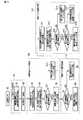
図5は、加速度センサ32から出力された加速度信号の波形(生波形)の一例を示す。なお、図5に示す加速度信号の波形は、生体センサ装置10の装着者の胸部表面に対して垂直方向の軸の加速度の時間的な変化を示している。図5(a)は、睡眠中に装着者の足の筋電に活動が見られ、装着者が四肢運動を行っている場合の加速度信号の波形を示す。図5(b)は、装着者が睡眠の途中で覚醒し、上半身を動かした場合の加速度信号の波形を示す。図5(c)は、装着者が寝返り運動を行っている場合の加速度信号の波形を示す。図5(d)は、装着者が鼾を発している場合の加速度信号の波形を示す。図5(e)は、装着者が無呼吸状態である場合の加速度信号の波形を示す。図5(f)は、装着者が低呼吸状態である場合の加速度信号の波形を示す。Here, with reference to FIG. 5 and FIG. 6, the process of detecting the acceleration event (the process of detecting the outlier time T1) will be described in more detail.
FIG. 5 shows an example of a waveform (raw waveform) of the acceleration signal output from the
一般的に、睡眠中の微小体動(四肢運動や上半身運動)及び寝返り運動に伴い、加速度信号には、図5(a)〜(c)に示すように、高周波数振動が重畳する。また、鼾発生時、及び、無呼吸状態または低呼吸状態からの呼吸復帰時には、声道や口腔付近が振動し、呼吸周波数以上の高い周波数の大きな気道音が発せられ、これが胸部表面に伝達するので、図5(d)〜(f)に示すような加速度信号の波形が得られる。 In general, as shown in FIGS. 5A to 5C, high-frequency vibrations are superimposed on the acceleration signal along with minute body movements (limb movements and upper body movements) and rolling movements during sleep. In addition, when sputum occurs and when breathing is resumed from apnea or hypopnea, the vocal tract and the vicinity of the oral cavity vibrate and a large airway sound with a frequency higher than the respiratory frequency is emitted and transmitted to the chest surface. Therefore, waveforms of acceleration signals as shown in FIGS. 5 (d) to (f) are obtained.
図6は、図5に示す各種波形に対してフィルタリング処理を実行した後の加速度信号の波形の一例を示す。図6(a)〜(f)は、図5(a)〜(f)に示す加速度信号の波形に対して第1のカットオフ周波数にてハイパスフィルタを実装してフィルタリング処理を実行した後の(第1の周波数帯の)加速度信号の波形を各々示している。加速度イベント検出部101は、図6(a)〜(f)の×印に示されるように、周波数が予め設定された第1の閾値未満になる時刻を外れ値時刻T1として、つまり、加速度イベントが発生した時刻として、各々検出する。なお、上記したフィルタリング処理により抽出された高周波数帯の波形において、周波数が第1の閾値未満になる全ての時刻が外れ値時刻T1として検出されてもよいし、連続的な所定の長さの区間における移動標準偏差値σ1及び移動平均値M1を算出し、統計的にM1±α1*σ1(但し、α1は定数)の範囲外の値となった時刻が外れ値時刻T1として検出されてもよい。図6では、後者の手法を利用して、外れ値時刻T1が検出された場合を示している。具体的には、後者の手法により、図6(a)では3つの外れ値時刻T1が検出され、図6(b)では4つの外れ値時刻T1が検出され、図6(c)では5つの外れ値時刻T1が検出され、図6(d)では規則的に24つの外れ値時刻T1が検出され、図6(e),(f)では共に2つの外れ値時刻T1が検出された場合を示している。 FIG. 6 shows an example of the waveform of the acceleration signal after performing the filtering process on the various waveforms shown in FIG. FIGS. 6A to 6F show a state after the high pass filter is mounted on the acceleration signal waveforms shown in FIGS. 5A to 5F at the first cutoff frequency and the filtering process is executed. Each shows the waveform of the acceleration signal (in the first frequency band). As shown by the crosses in FIGS. 6A to 6F, the acceleration
なお、検出された外れ値時刻T1を示す情報は、イベント種別判定部102に送出される。 Information indicating the detected outlier time T1 is sent to the event type determination unit 102.
再び、図4の説明に戻る。イベント種別判定部102内の体動呼吸イベント判定部103は、加速度イベント検出部101によって検出された加速度イベント(換言すると、外れ値時刻T1において生じた生体センサ装置10の装着者の動き)が、体動に起因した加速度イベント(動き)であるのか、または呼吸に起因した加速度イベント(動き)であるのかを判定する処理を実行する。 Returning to the description of FIG. The body movement / respiration
一般的に、微小体動や寝返り運動等、体動に起因した加速度イベントが発生した場合には、生体センサ装置10の姿勢は大きく変化する、つまり、生体センサ装置10の姿勢変化量は大きくなる傾向がある。一方で、呼吸に起因した加速度イベントが発生した場合には、(当該加速度イベントに伴う動きは、胸が上下動する等であるので)生体センサ装置10の姿勢はあまり変化しない、つまり、生体センサ装置10の姿勢変化量は小さくなる傾向がある。体動呼吸イベント判定部103は、この傾向を利用して、上記した姿勢変化量を第1の特徴量として算出し、当該算出された第1の特徴量が予め設定された第2の閾値以上であるかどうかを判定することで、加速度イベント検出部101によって検出された加速度イベントが、体動に起因した加速度イベントであるのか、または呼吸に起因した加速度イベントであるのかを判定する処理を実行する。 In general, when an acceleration event caused by body movement such as minute body movement or rolling motion occurs, the posture of the
ここで、図7を参照して、生体センサ装置10の姿勢変化量(第1の特徴量)を算出する処理について、より詳しく説明する。
図7は、図5に示す各種波形に対してフィルタリング処理を実行した後の加速度信号の波形の一例を示す。図7(a)〜(f)は、図5(a)〜(f)に示す加速度信号の波形に対して第3のカットオフ周波数にてローパスフィルタを実装して、ノイズを除去した後の(つまり、フィルタリング処理を実行した後の)(第2の周波数帯の)加速度信号の波形を各々示している。なお、第3のカットオフ周波数は、呼吸運動の周波数未満の値であり、0.02[Hz]以上0.1[Hz]未満であることが好ましい。Here, with reference to FIG. 7, the process of calculating the posture change amount (first feature amount) of the
FIG. 7 shows an example of the waveform of the acceleration signal after performing the filtering process on the various waveforms shown in FIG. FIGS. 7A to 7F show a state after the noise is removed by mounting a low-pass filter at the third cutoff frequency on the waveforms of the acceleration signals shown in FIGS. 5A to 5F. Each shows a waveform of the acceleration signal (in the second frequency band) (after performing the filtering process). The third cut-off frequency is a value less than the respiratory motion frequency, and is preferably 0.02 [Hz] or more and less than 0.1 [Hz].
体動呼吸イベント判定部103は、図7(a)〜(f)に示す各種波形y(t)において、外れ値時刻T1を含む所定区間T2における姿勢変化量を第1の特徴量として算出する。具体的には、体動呼吸イベント判定部103は、y{T1−(T2/2)}からy(T1)の範囲における中央値と、y(T1)からy{T1+(T2/2)}の範囲における中央値との差分を第1の特徴量として求める。なお、所定区間T2とは、例えば外れ値時刻T1を中心にして前後に所定間隔だけ設けた区間であり、本実施形態では120秒(つまり、外れ値時刻T1から前後60秒の区間)を所定区間T2と想定している。また、第1の特徴量は、上記した手法に限らず、例えば、y{T1−(T2/2)}からy(T1)の範囲における平均値と、y(T1)からy{T1+(T2/2)}の範囲における平均値との差分として求められてもよいし、y{T1−(T2/2)}からy{T1+(T2/2)}の範囲における最大値と最小値との差分として求められてもよいし、y{T1−(T2/2)}からy{T1+(T2/2)}の範囲における分散値や標準偏差値として求められてもよい。 The body motion respiratory
再び、図4の説明に戻る。体動イベント属性判定部104は、加速度イベント検出部101によって検出された加速度イベントが、体動呼吸イベント判定部103によって体動に起因した加速度イベントであると判定された場合に、当該体動に起因した加速度イベントが、微小体動に起因した加速度イベントであるのか、または寝返り運動に起因した加速度イベントであるのかを判定する処理を実行する。 Returning to the description of FIG. The body motion event
一般的に、微小体動(四肢運動や上半身運動)に起因した加速度イベントが発生した場合の特徴量(姿勢変化量)と、寝返り運動に起因した加速度イベントが発生した場合の特徴量(姿勢変化量)とを比較すると、寝返り運動に起因した加速度イベントが発生した場合の特徴量の方が微小体動に起因した加速度イベントが発生した場合の特徴量よりも大きくなる傾向がある。体動イベント属性判定部104は、この傾向を利用して、体動呼吸イベント判定部103によって算出された第1の特徴量(姿勢変化量)が予め設定された第3の閾値以上であるかどうかを判定することで、体動呼吸イベント判定部103によって体動に起因した加速度イベントであると判定された加速度イベントが、微小体動に起因した加速度イベントであるのか、または寝返り運動に起因した加速度イベントであるのかを判定する処理を実行する。 In general, the feature amount (posture change amount) when an acceleration event due to minute body movement (limb movement or upper body movement) occurs, and the feature amount (posture change) when an acceleration event due to rolling motion occurs When the acceleration event due to the rolling motion occurs, the feature amount tends to be larger than the feature amount when the acceleration event due to the minute body motion occurs. The body motion event
なお、ここでは、体動イベント属性判定部104が、体動呼吸イベント判定部103によって算出された第1の特徴量(姿勢変化量)を利用して、上記した判定処理を実行するとしたが、例えば、体動呼吸イベント判定部103によって算出された第1の特徴量を利用せずに、自身で特徴量を算出して、上記した判定処理を実行するとしてもよい。この場合、特徴量を算出するにあたって加速度信号の波形にローパスフィルタを実装する際のカットオフ周波数は、上記した第3のカットオフ周波数に限られず、体動の周波数以下であれば構わない。 Here, the body motion event
呼吸イベント属性判定部105は、加速度イベント検出部101によって検出された加速度イベントが、体動呼吸イベント判定部103によって呼吸に起因した加速度イベントであると判定された場合に、当該呼吸に起因した加速度イベントが、鼾に起因した加速度イベント、無呼吸状態に起因した加速度イベント及び低呼吸状態に起因した加速度イベントのいずれであるのかを判定する処理を実行する。 The breathing event
ここで、図8を参照して、鼾に起因した加速度イベントと、無呼吸状態に起因した加速度イベントと、低呼吸状態に起因した加速度イベントとの違いについて説明する。図8は、図5に示す各種波形に対してフィルタリング処理を実行した後の加速度信号の波形の一例を示す。図8(a)〜(f)は、図5(a)〜(f)に示す加速度信号の波形に対して第4のカットオフ周波数にてローパスフィルタを実装して、ノイズを除去した後の(つまり、フィルタリング処理を実行した後の)(第3の周波数帯の)加速度信号の波形を各々示している。なお、第4のカットオフ周波数は、呼吸運動の周波数帯であることが好ましく、例えば0.1[Hz]以上1.0[Hz]未満であることが好ましい。 Here, with reference to FIG. 8, the difference between the acceleration event caused by the epilepsy, the acceleration event caused by the apnea state, and the acceleration event caused by the hypopnea state will be described. FIG. 8 shows an example of the waveform of the acceleration signal after performing the filtering process on the various waveforms shown in FIG. FIGS. 8A to 8F show a state in which a low-pass filter is mounted at the fourth cutoff frequency on the waveform of the acceleration signal shown in FIGS. 5A to 5F and noise is removed. Each shows a waveform of an acceleration signal (in the third frequency band) (after performing the filtering process). The fourth cut-off frequency is preferably a respiratory motion frequency band, for example, preferably 0.1 [Hz] or more and less than 1.0 [Hz].
一般的に、鼾に起因した加速度イベントが発生した場合に加速度信号の波形にみられる変化と、無呼吸状態(無呼吸症状)または低呼吸状態(低呼吸症状)からの呼吸復帰に起因した加速度イベントが発生した場合に加速度信号の波形にみられる変化とを比較すると、次のような傾向がみられる。つまり、鼾に起因した加速度イベントが発生した場合には、図8(d)に示すように、波形特徴に大きな変化がみられないのに対し、無呼吸状態または低呼吸状態からの呼吸復帰に起因した加速度イベントが発生した場合には、図8(e),(f)に示すように、外れ値時刻T1の前後において波形特徴に大きな変化がみられる傾向がある。これは、鼾に起因した加速度イベントの場合、呼吸運動自体は定常的であるため、波形特徴に大きな変化はみられないが、無呼吸状態または低呼吸状態からの呼吸復帰に起因した加速度イベントの場合、呼吸復帰時に声道や口腔付近の組織が振動し、その前後で胸部運動が行われるので、波形特徴に大きな変化がみられる傾向がある。呼吸イベント属性判定部105は、この傾向を利用して、図8に示す加速度信号の波形y2(t)において、外れ値時刻T1を含む所定区間T3における第2の特徴量を算出し、当該算出された第2の特徴量が予め設定された第4の閾値以上であるかどうかを判定することで、体動呼吸イベント判定部103によって呼吸に起因した加速度イベントであると判定された加速度イベントが、鼾に起因した加速度イベントであるのか、または無呼吸状態あるいは低呼吸状態に起因した加速度イベントであるのかを判定する処理を実行する。 In general, when an acceleration event due to sputum occurs, the change in the waveform of the acceleration signal and the acceleration due to respiration from an apnea (apnea condition) or hypopnea (hypopnea condition) A comparison of the change seen in the waveform of the acceleration signal when an event occurs shows the following tendency. In other words, when an acceleration event caused by epilepsy occurs, as shown in FIG. 8 (d), no significant change is observed in the waveform characteristics, whereas the respiratory recovery from the apnea state or the hypopnea state occurs. When the resulting acceleration event occurs, as shown in FIGS. 8 (e) and 8 (f), there is a tendency that a large change is observed in the waveform characteristics before and after the outlier time T1. This is because, in the case of an acceleration event due to sputum, the respiratory motion itself is stationary, so there is no significant change in the waveform characteristics, but the acceleration event due to the return of breath from an apnea or hypopnea state In this case, the tissue near the vocal tract and the oral cavity vibrates at the time of respiration, and the chest motion is performed before and after that, so that there is a tendency that a large change is observed in the waveform characteristics. Using this tendency, the respiratory event
更に、図8(e),(f)に示されるように、無呼吸状態からの呼吸復帰に起因した加速度イベントが発生した場合と、低呼吸状態からの呼吸復帰に起因した加速度イベントが発生した場合とでは、無呼吸状態からの呼吸復帰に起因した加速度イベントが発生した場合の方が、低呼吸状態からの呼吸復帰に起因した加速度イベントが発生した場合に比べて、波形特徴に大きな変化がみられることがわかる。このため、呼吸イベント属性判定部105は、無呼吸状態または低呼吸状態に起因した加速度イベントであると判定された加速度イベントに関し、上記したようにして算出された第2の特徴量が予め設定された第5の閾値以上であるかどうかを判定することで、無呼吸状態または低呼吸状態に起因した加速度イベントであると判定された加速度イベントが、無呼吸状態に起因した加速度イベントであるのか、または低呼吸状態に起因した加速度イベントであるのかを判定する処理を実行する。 Further, as shown in FIGS. 8 (e) and 8 (f), an acceleration event caused by respiration from an apnea state and an acceleration event caused by respiration from a hypopnea state occurred. In some cases, there is a greater change in waveform characteristics when an acceleration event occurs due to respiration from an apneic state than when an acceleration event occurs due to respiration from a hypopnea state. I can see that. Therefore, the respiratory event
なお、上記した外れ値時刻T1を含む所定区間T3における第2の特徴量(ここでは、加速度イベント前後での胸部運動の変動比)は、以下の(1)式に基づいて算出される。このとき、所定区間T3は、外れ値時刻T1を含むように設定された区間であればよく、例えば本実施形態では所定区間T3は20秒(つまり、外れ値時刻T1から前後10秒の区間)に設定されているものとする。なお、以下の(1)式では、標準偏差値が利用されている場合を例示しているが、標準偏差値の代わりに、分散値が利用されるとしてもよい。
また、本実施形態では、加速度イベント前後での胸部運動の変動比(第2の特徴量)を算出するにあたって、上記(1)式を利用するとしたが、当該第2の特徴量は、加速度イベント前後における呼吸周波数帯の波形y2(t)の振幅値の平均値から算出されるとしてもよい。具体的には、以下に示す(2)式を利用して算出するとしてもよい。
なお、ここでの振幅値とは、図9に示すように、加速度信号の波形y2(t)の極大値(図9中の○印)とその直前の極小値(図9中の△印)との差分を示す。 The amplitude value here is, as shown in FIG. 9, the maximum value of the acceleration signal waveform y2 (t) (marked with a circle in FIG. 9) and the minimum value just before it (marked with a triangle in FIG. 9). And the difference.
上記した各部101〜105における各種処理の結果として得られる解析結果情報は、フラッシュメモリ50に格納されると共に、ブルーツースモジュール36を介して電子機器11に出力される。解析結果情報とは、少なくとも、加速度イベント検出部101によって検出された外れ値時刻T1と、当該外れ値時刻T1の装着者の動きが何に起因した動きであるかを示す情報とが対応づけられた情報である。電子機器11は、生体センサ装置10から出力された解析結果情報の入力を受け付けると、例えば図10に示すような画面を表示することができる。これによれば、装着者(ユーザ)は、いつ、何に起因して自身が動いたかを把握することができる。 The analysis result information obtained as a result of various processes in the above-described
次に、図11のフローチャートを参照して、呼吸解析アプリケーション100によって実行される一連の処理手順の一例について説明する。
まず、加速度イベント検出部101は、加速度センサ32によって計測された加速度信号の入力を受け付けると、当該入力を受け付けた加速度信号により示される加速度の時間的な変化を示す波形に対して、第1のカットオフ周波数にてハイパスフィルタを実装してノイズを除去するフィルタリング処理を実行し、呼吸周波数帯以上の加速度信号の波形を抽出する(ステップS1)。つまり、加速度イベント検出部101は、図5に示す加速度信号の生波形に対してフィルタリング処理を実行し、図6に示す呼吸周波数帯以上の加速度信号の波形を抽出する。Next, an example of a series of processing procedures executed by the
First, when the acceleration
続いて、加速度イベント検出部101は、ステップS1の処理により抽出された呼吸周波数帯以上の加速度信号の波形から、周波数が予め設定された第1の閾値未満になる外れ値時刻T1を検出する(ステップS2)。つまり、加速度イベント検出部101は、図6に示す加速度信号の波形から、周波数が第1の閾値未満になる時刻を図6の×印にて示されるように外れ値時刻T1として検出する。 Subsequently, the acceleration
次に、体動呼吸イベント判定部103は、加速度イベント検出部101に入力された加速度信号を加速度センサ32から取得すると、当該取得された加速度信号により示される加速度の時間的な変化を示す波形に対して、第3のカットオフ周波数にてローパスフィルタを実装してノイズを除去するフィルタリング処理を実行し、呼吸周波数帯以下の加速度信号の波形y(t)を抽出する(ステップS3)。つまり、体動呼吸イベント判定部103は、図5に示す加速度信号の生波形に対してフィルタリング処理を実行し、図7に示す呼吸周波数帯以下の加速度信号の波形y(t)を抽出する。 Next, when the body movement / respiration
続いて、体動呼吸イベント判定部103は、ステップS3の処理により抽出された呼吸周波数帯以下の加速度信号の波形y(t)において、ステップS2の処理により検出された外れ値時刻T1を含む所定区間T2における第1の特徴量を算出する。具体的には、体動呼吸イベント判定部103は、呼吸周波数帯以下の加速度信号の波形y(t)において、y{T1−(T2/2)}からy(T1)の範囲における中央値と、y(T1)からy{T1+(T2/2)}の範囲における中央値との差分を、外れ値時刻T1を含む所定区間T2の第1の特徴量として算出する(ステップS4)。 Subsequently, the body motion respiratory
次に、体動呼吸イベント判定部103は、ステップS4の処理により算出された第1の特徴量が予め設定された第2の閾値以上であるかどうかを判定する(ステップS5)。 Next, the body motion breathing
ステップS5の処理において、第1の特徴量が第2の閾値以上であると判定された場合(ステップS5のYES)、体動呼吸イベント判定部103は、外れ値時刻T1において発生した加速度イベントは体動に起因した加速度イベントであると判別する(ステップS6)。 In the process of step S5, when it is determined that the first feature amount is equal to or greater than the second threshold (YES in step S5), the body motion breathing
続いて、体動イベント属性判定部104は、体動呼吸イベント判定部103によって外れ値時刻T1にて発生した加速度イベントが体動に起因した加速度イベントであると判別された場合に、ステップS4の処理により算出された第1の特徴量が予め設定された第3の閾値以上であるかどうかを判定する(ステップS7)。 Subsequently, the body motion event
ステップS7の処理において、第1の特徴量が第3の閾値以上であると判定された場合(ステップS7のYES)、体動イベント属性判定部104は、外れ値時刻T1において発生した加速度イベントは寝返り運動に起因した加速度イベントであると判別し、当該一連の処理の結果を示す解析結果情報を電子機器11に出力して(ステップS8)、ここでの処理を終了させる。 In the process of step S7, when it is determined that the first feature amount is equal to or greater than the third threshold (YES in step S7), the body motion event
一方、ステップS7の処理において、第1の特徴量が第3の閾値未満であると判定された場合(ステップS7のNO)、体動イベント属性判定部104は、外れ値時刻T1において発生した加速度イベントは微小体動に起因した加速度イベントであると判別し、当該一連の処理の結果を示す解析結果情報を電子機器11に出力して(ステップS9)、ここでの処理を終了させる。 On the other hand, when it is determined in the process of step S7 that the first feature amount is less than the third threshold (NO in step S7), the body motion event
上記したステップS5の処理において、第1の特徴量が第2の閾値未満であると判定された場合(ステップS5のNO)、体動呼吸イベント判定部103は、外れ値時刻T1において発生した加速度イベントは呼吸に起因した加速度イベントであると判別する(ステップS10)。 When it is determined in the process of step S5 described above that the first feature amount is less than the second threshold (NO in step S5), the body motion breathing
次に、呼吸イベント属性判定部105は、加速度イベント検出部101に入力された加速度信号を加速度センサ32から取得すると、当該取得された加速度信号により示される加速度の時間的な変化波形に対して、第4のカットオフ周波数にてローパスフィルタを実装してノイズを除去するフィルタリング処理を実行し、呼吸周波数帯の加速度信号の波形y2(t)を抽出する(ステップS11)。つまり、呼吸イベント属性判定部105は、図5に示す加速度信号の生波形に対してフィルタリング処理を実行し、図8に示す呼吸周波数帯の加速度信号の波形y2(t)を抽出する。 Next, when the respiratory event
続いて、呼吸イベント属性判定部105は、ステップS11の処理により抽出された呼吸周波数帯の加速度信号の波形y2(t)において、ステップS2の処理により検出された外れ値時刻T1を含む所定区間T3における第2の特徴量を算出する。具体的には、呼吸イベント属性判定部105は、呼吸周波数帯の加速度信号の波形y2(t)において、y2(T1)からy2{T1+(T3/2)}の範囲における標準偏差値を、y2{T1−(T3/2)}からy2(T1)の範囲における標準偏差値で除算することで得られる商を、外れ値時刻T1を含む所定区間T3の第2の特徴量として算出する(ステップS12)。 Subsequently, the respiratory event
次に、呼吸イベント属性判定部105は、ステップS12の処理により算出された第2の特徴量が予め設定された第4の閾値以上であるかどうかを判定する(ステップS13)。なお、ステップS13の処理において、第2の特徴量が第4の閾値未満であると判定された場合(ステップS13のNO)、呼吸イベント属性判定部105は、外れ値時刻T1において発生した加速度イベントは鼾に起因した加速度イベントであると判別し、当該一連の処理の結果を示す解析結果情報を電子機器11に出力して(ステップS14)、ここでの処理を終了させる。 Next, the respiratory event
一方、ステップS13の処理において、第2の特徴量が第4の閾値以上であると判定された場合(ステップS13のYES)、呼吸イベント属性判定部105は、第2の特徴量が予め設定された第5の閾値以上であるかどうかを判定する(ステップS15)。 On the other hand, if it is determined in step S13 that the second feature amount is equal to or greater than the fourth threshold (YES in step S13), the respiratory event
ステップS15の処理において、第2の特徴量が第5の閾値以上であると判定された場合(ステップS15のYES)、呼吸イベント属性判定部105は、外れ値時刻T1において発生した加速度イベントは無呼吸状態に起因した加速度イベントであると判別し、当該一連の処理の結果を示す解析結果情報を電子機器11に出力して(ステップS16)、ここでの処理を終了させる。 If it is determined in step S15 that the second feature amount is equal to or greater than the fifth threshold value (YES in step S15), the respiratory event
一方、ステップS15の処理において、第2の特徴量が第5の閾値未満であると判定された場合(ステップS15のNO)、呼吸イベント属性判定部105は、外れ値時刻T1において発生した加速度イベントは低呼吸状態に起因した加速度イベントであると判別し、当該一連の処理の結果を示す解析結果情報を電子機器11に出力して(ステップS17)、ここでの処理を終了させる。 On the other hand, when it is determined in step S15 that the second feature amount is less than the fifth threshold (NO in step S15), the respiratory event
以上説明した第1の実施形態によれば、生体センサ装置10は、加速度センサ32により計測された加速度に基づいて装着者の動きを検知し、当該装着者の動きが何に起因した動きであるかを詳細まで判別可能な呼吸解析アプリケーション100を備えているので、装着者(ユーザ)は、自身の睡眠時の動きを把握することができる。つまり、ユーザは、自身が睡眠時無呼吸症候群を発症している恐れがあるかどうかを容易に把握することができる。 According to the first embodiment described above, the
<第2の実施形態>
次に、第2の実施形態について説明する。本実施形態においては、呼吸解析アプリケーション100が、上記した各部101〜105に加えて、図12に示すように、寝姿勢判定部(寝姿勢推定部)106を更に備えている場合について説明する。なお、本実施形態においては、上記した第1の実施形態と同様な機能を有する各部に対しては同一の符号を付し、その詳しい説明は省略するものとする。<Second Embodiment>
Next, a second embodiment will be described. In the present embodiment, a case where the
寝姿勢判定部106は、加速度イベント検出部101によって検出された加速度イベントが、イベント種別判定部102内の体動イベント属性判定部104により寝返り運動に起因した加速度イベントであると判定された場合に、生体センサ装置10の装着者の寝姿勢を推定(判別)する処理を実行する。なお、推定された寝姿勢を示す情報は、加速度イベント検出部101によって検出された外れ値時刻T1と、当該外れ値時刻T1の装着者の動きが寝返り運動に起因した動きであることを示す情報とに対応づけられて、フラッシュメモリ50に格納されると共に、ブルーツースモジュール36を介して電子機器11に出力される。 The sleeping
ここで、図13のフローチャートを参照して、寝姿勢判定部106によって実行される処理手順の一例について説明する。なお、ここでは、体動イベント属性判定部104によって、外れ値時刻T1に発生した加速度イベントが寝返り運動に起因した加速度イベントであると判別されたものとして、つまり、図11に示すステップS1〜S8の処理が既に実行されているものとして説明する。 Here, an example of a processing procedure executed by the sleeping
まず、寝姿勢判定部106は、体動イベント属性判定部104によって抽出された加速度信号の波形y(t)から、外れ値時刻T1から所定の時間T4が経過するまでの区間データを取得する(ステップS21)。なお、ここでは、所定の時間T4が60秒である場合を想定して説明するが、これに限らず、所定の時間T4は任意の時間であって構わない。 First, the sleeping
続いて、寝姿勢判定部106は、外れ値時刻T1から所定の時間T4が経過する間に計測された加速度信号であって、胸部表面に対して水平であり、かつ体軸と垂直である軸成分の加速度信号を加速度センサ32から取得する(ステップS22)。 Subsequently, the sleeping
次に、寝姿勢判定部106は、ステップS22の処理により取得された加速度信号の時間的な変化を示す波形に対して、上記した波形y(t)と同様に、第3のカットオフ周波数にてローパスフィルタを実装してノイズを除去するフィルタリング処理を実行し、低周波数帯の加速度信号の波形y3(t)を抽出する(ステップS23)。 Next, similarly to the waveform y (t) described above, the sleeping
続いて、寝姿勢判定部106は、ステップS23の処理により抽出された低周波数帯の加速度信号の波形y3(t)から、外れ値時刻T1から所定の時間T4が経過するまでの区間データを取得する(ステップS24)。 Subsequently, the sleeping
その後、寝姿勢判定部106は、ステップS21の処理により取得された区間データに基づき第3の特徴量を、ステップS24の処理により取得された区間データに基づき第4の特徴量を各々算出する。具体的には、寝姿勢判定部106は、y(T1)からy(T1+T4)までの中央値または平均値を第3の特徴量として算出し、y3(T1)からy3(T1+T4)までの中央値または平均値を第4の特徴量として算出する(ステップS25)。 Thereafter, the sleeping
しかる後、寝姿勢判定部106は、算出された第3及び第4の特徴量に基づいて、寝姿勢が仰臥位、左側臥位、右側臥位及び腹臥位のうちのいずれに該当するのかを判別する処理を実行して、寝姿勢を推定し、当該一連の処理の結果を示す解析結果情報を電子機器11に出力して(ステップS26)、ここでの処理を終了させる。 Thereafter, based on the calculated third and fourth feature values, the sleeping
なお、第3及び第4の特徴量に基づいて寝姿勢が仰臥位、左側臥位、右側臥位及び腹臥位のいずれに該当するのかを判別する際には、例えば、ニューラルネットワークの1つである誤差逆伝播法等が利用されてもよい。この誤差逆伝播法を利用する際に使用される重みは、予め学習され、フラッシュメモリ50等に予め記録されているものとする。また、寝姿勢が上記した体位のいずれに該当するかを判別する際には、例えば、サポートベクタマシン等、他のニューラルネットワークが利用されてもよい。更に、体位毎に2つの特徴量の平均値を予め各々求めておき、算出された第3及び第4の特徴量がどの体位の平均値に最も近いかを検索することで、寝姿勢のクラスタリングが行われるとしてもよい。また、第3及び第4の特徴量にそれぞれ対応した閾値に基づいて、寝姿勢が上記した体位のいずれに該当するのかを判別するとしてもよい。 Note that when determining whether the sleeping posture corresponds to the supine position, the left side prone position, the right side prone position, or the prone position based on the third and fourth feature amounts, for example, one of the neural networks. An error back-propagation method or the like may be used. It is assumed that the weight used when using the error back propagation method is learned in advance and recorded in advance in the
以上説明した第2の実施形態によれば、生体センサ装置10は、装着者の動きが寝返り運動に起因した動きであると判別した場合に、寝姿勢を推定する機能を更に備えているので、装着者(ユーザ)は、この推定結果を、睡眠環境の改善方針策定に役立てることができる。 According to the second embodiment described above, the
<第3の実施形態>
次に、第3の実施形態について説明する。本実施形態においては、呼吸解析アプリケーション100が、上記した各部101〜105に加えて、図14に示すように、睡眠時間算出部107及び重症度算出部108を更に備えている場合について説明する。なお、本実施形態においては、上記した第1及び第2の実施形態と同様な機能を有する各部に対しては同一の符号を付し、その詳しい説明は省略するものとする。また、図14では、説明の便宜上、第2の実施形態にて説明した寝姿勢判定部106を省略しているが、呼吸解析アプリケーション100は、図14に示す構成に加えて、寝姿勢判定部106を更に備えていても構わない。<Third Embodiment>
Next, a third embodiment will be described. In the present embodiment, a case where the
睡眠時間算出部107は、生体センサ装置10の装着者の就寝時刻及び起床時刻に基づいて睡眠時間を算出する。なお、就寝時刻及び起床時刻は、生体センサ装置10に設けられる図示しない入力部を介して装着者自身により入力されてもよいし、外部機器(例えば、電子機器11等)から取得されてもよいし(具体的には、外部機器に設けられている目覚まし機能から就寝時刻や起床時刻を取得する)、外部機器の操作履歴から推定されてもよい(具体的には、外部機器の操作が途切れた時刻を就寝時刻として推定し、外部機器の操作が再開された時刻を起床時刻として推定する)。 The sleep
また、就寝時刻及び起床時刻は、寝姿勢判定部106に、仰臥位、左側臥位、右側臥位及び腹臥位に加えて、上半身が傾いている姿勢を推定(判別)可能な機能を追加し、当該機能を利用して推定されるとしてもよい。具体的には、上半身が傾いている姿勢からその他の寝姿勢に移行した時刻を就寝時刻とし、仰臥位、左側臥位、右側臥位及び腹臥位のいずれかの寝姿勢から上半身が傾いている姿勢に移行した時刻を起床時刻としてもよい。 In addition to the supine position, left-side-down position, right-side-down position, and prone position, a function that can estimate (determine) the posture with the upper body tilted is added to the sleeping
重症度算出部108は、睡眠時間算出部107から就寝時刻、起床時刻及び睡眠時間を示す情報を取得する。また、重症度算出部108は、呼吸イベント属性判定部105によって所定の加速度イベントが無呼吸状態または低呼吸状態に起因した加速度イベントであると判別された場合に、加速度イベント検出部101から当該所定の加速度イベントが発生した外れ値時刻T1を示す情報を取得する。更に、重症度算出部108は、取得した外れ値時刻T1が就寝時刻から起床時刻までの間の時刻であった場合、無呼吸低呼吸回数に1を加算し、起床時刻までにカウントされた無呼吸低呼吸回数と、睡眠時間とに基づいて、無呼吸低呼吸指数(AHI:Apnea Hypopnea Index)を算出する。AHIは、以下の(3)式に示されるように、睡眠中の1時間あたりに発生した無呼吸低呼吸回数を示しており、一般的に睡眠時無呼吸症候群の重症度の指標としてスクリーニングや治療方針立案に利用されている。 The
AHI=無呼吸低呼吸回数の総和/睡眠時間 ・・・(3)
なお、上記では、外れ値時刻T1に発生した加速度イベントが、無呼吸状態に起因した加速度イベントまたは低呼吸状態に起因した加速度イベントのどちらであっても、無呼吸低呼吸回数として加算されるとしたが、例えば、無呼吸回数と低呼吸回数とを別々にカウントするとしてもよい。つまり、外れ値時刻T1に発生した加速度イベントが無呼吸状態に起因した加速度イベントであり、かつ当該外れ値時刻T1が就寝時刻から起床時刻までの間に含まれる場合、重症度算出部108は、無呼吸回数に1を加算するとしてもよい。同様に、外れ値時刻T1に発生した加速度イベントが低呼吸状態に起因した加速度イベントであり、かつ当該外れ値時刻T1が就寝時刻から起床時刻までの間に含まれる場合、重症度算出部108は、低呼吸回数に1を加算するとしてもよい。AHI = sum of apnea / hypopnea / sleep time (3)
In the above description, when the acceleration event generated at the outlier time T1 is either an acceleration event caused by an apnea state or an acceleration event caused by a hypopnea state, it is added as the number of apnea / hypopneas. However, for example, the number of apneas and the number of hypopneas may be counted separately. That is, when the acceleration event generated at the outlier time T1 is an acceleration event due to the apnea state, and the outlier time T1 is included between the bedtime and the wake-up time, the
この場合、睡眠時無呼吸症候群の重症度の指標は、以下の(4)式及び(5)式に示されるように、無呼吸回数に関する重症度の指標と、低呼吸回数に関する重症度の指標とのように別々に算出されてもよい。 In this case, as shown in the following formulas (4) and (5), the severity index of sleep apnea syndrome is an index of severity related to the number of apneas and an index of severity related to the number of hypopneas. And may be calculated separately.
無呼吸回数に関する重症度の指標=無呼吸回数の総和/睡眠時間 ・・・(4)
低呼吸回数に関する重症度の指標=低呼吸回数の総和/睡眠時間 ・・・(5)
なお、算出されたAHIを示す情報は、フラッシュメモリ50に格納されると共に、ブルーツースモジュール36を介して電子機器11に出力される。Severity index related to apnea frequency = sum of apnea frequency / sleep time (4)
Severity index related to the number of low breaths = total number of low breaths / sleep time (5)
The information indicating the calculated AHI is stored in the
ここで、図15に示すフローチャートを参照して、睡眠時間算出部107及び重症度算出部108によって実行される処理手順の一例について説明する。なお、ここでは、就寝時刻及び起床時刻は生体センサ装置10の装着者の操作によりそれぞれ就寝直前及び起床直後に入力されるものとする。 Here, an example of a processing procedure executed by the sleep
まず、睡眠時間算出部107は、装着者の操作に応じて、当該装着者の就寝時刻の入力を受け付ける(ステップS31)。 First, the sleep
その後、加速度イベント検出部101、体動呼吸イベント判別部103、体動イベント属性判定部104及び呼吸イベント属性判定部105によって、上述したステップS1〜S17の処理が繰り返し実行され、所定の加速度イベントが、無呼吸状態または低呼吸状態に起因した加速度イベントであると判別された場合、重症度算出部108は、無呼吸低呼吸回数に1を加算する(ステップS32)。 After that, the acceleration
続いて、睡眠時間算出部107は、装着者の操作に応じて、当該装着者の起床時刻の入力を受け付けたかどうかを判定する(ステップS33)。なお、ステップS33の処理において、起床時刻の入力をまだ受け付けていないと判定された場合(ステップS33のNO)、上記したステップS32の処理に戻るものとする。 Subsequently, the sleep
一方、ステップS33の処理において、起床時刻の入力を受け付けたと判定された場合(ステップS33のYES)、睡眠時間算出部107は、ステップS31の処理により入力を受け付けた就寝時刻と、当該入力を受け付けた起床時刻とに基づいて、睡眠時間を算出する(ステップS34)。なお、算出された睡眠時間を示す情報は、重症度算出部108に送られる。 On the other hand, when it is determined in step S33 that the input of the wake-up time has been received (YES in step S33), the sleep
しかる後、重症度算出部108は、ステップS34の処理により算出された睡眠時間と、就寝時刻から起床時刻の間にステップS32の処理によりカウントされた無呼吸低呼吸回数とに基づいて、AHIを算出し、当該一連の処理の結果を示す解析結果情報を電子機器11に出力して(ステップS35)、ここでの処理を終了させる。 Thereafter, the
以上説明した第3の実施形態によれば、生体センサ装置10は、睡眠時間を算出すると共に、無呼吸低呼吸回数をカウントして、無呼吸低呼吸指数を算出する構成を更に備えているので、装着者(ユーザ)は、自身が睡眠時無呼吸症候群を発症している恐れがあるかをより明確に把握することができる。 According to the third embodiment described above, the
なお、上記した第1〜第3の実施形態においては、呼吸解析システムが、生体センサ装置10と電子機器11とを含む構成を例にとって説明したが、例えば図16に示すように、呼吸解析システムは、1以上のサーバ装置を含むクラウドサービス14をさらに含んでいてもよい。つまり、呼吸解析システムは、クラウドコンピューティングを利用したシステムとして実装されてもよい。この場合、呼吸解析アプリケーション100の各種機能の一部または全てをクラウドサービス14内のサーバ装置に持たせることが可能である。例えば、クラウドサービス14内のサーバ装置は、電子機器11からのリクエストに応じて、生体センサ装置10によって計測された加速度信号を取得し、上記した第1〜第3の実施形態に示した各種処理を実行することができる。これによれば、生体センサ装置10において実行されるとした各種処理をクラウドサービス14内のサーバ装置において実行することができるので、処理負荷の分散化を実現させることができる。 In the first to third embodiments described above, the respiratory analysis system has been described by taking an example of a configuration including the
以上説明した少なくとも1つの実施形態によれば、鼻カニューレ等を装着することがないため、患者にかかる負担が小さく、睡眠時無呼吸症候群の患者の顕在化を十分に実現させることができる。 According to at least one embodiment described above, since a nasal cannula or the like is not attached, the burden on the patient is small, and the manifestation of a patient with sleep apnea syndrome can be sufficiently realized.
なお、本実施形態の処理は、コンピュータプログラムによって実現することができるので、このコンピュータプログラムを格納したコンピュータ読み取り可能な記憶媒体を通じてこのコンピュータプログラムをコンピュータにインストールして実行するだけで、本実施形態と同様の効果を容易に実現することができる。 Note that the processing of the present embodiment can be realized by a computer program. Therefore, the computer program can be installed and executed on a computer through a computer-readable storage medium storing the computer program. Similar effects can be easily realized.
なお、本発明のいくつかの実施形態を説明したが、これらの実施形態は、例として提示したものであり、発明の範囲を限定することは意図していない。これら新規な実施形態は、その他の様々な形態で実施されることが可能であり、発明の要旨を逸脱しない範囲で、種々の省略、置き換え、変更を行うことができる。これら実施形態やその変形は、発明の範囲や要旨に含まれるとともに、特許請求の範囲に記載された発明とその均等の範囲に含まれる。 In addition, although some embodiment of this invention was described, these embodiment is shown as an example and is not intending limiting the range of invention. These novel embodiments can be implemented in various other forms, and various omissions, replacements, and changes can be made without departing from the scope of the invention. These embodiments and modifications thereof are included in the scope and gist of the invention, and are included in the invention described in the claims and the equivalents thereof.
1…呼吸解析システム、10…生体センサ装置、11…電子機器、12…通信部、13…出力部、100…呼吸解析アプリケーションプログラム、101…加速度イベント検出部、102…イベント種別判定部、103…体動呼吸イベント判別部、104…体動イベント属性判定部、105…呼吸イベント属性判定部、106…寝姿勢判定部、107…睡眠時間算出部、108…重症度算出部。 DESCRIPTION OF
Claims (13)
Translated fromJapanese装着者の加速度を計測する計測手段と、
前記計測された加速度の時間的な変化を示す波形のうち、第1の周波数帯の波形における外れ値に基づいて、人体の動きを検出する検出手段と、
前記検出された人体の動きが呼吸に起因した動きであるかどうかを判別する判別手段と
を具備する呼吸解析装置。A respiratory analysis device that can be worn on a human body,
A measuring means for measuring the acceleration of the wearer;
Detecting means for detecting the movement of the human body based on an outlier in the waveform of the first frequency band among the waveforms indicating temporal changes in the measured acceleration;
A respiratory analysis apparatus comprising: a determination unit configured to determine whether the detected movement of the human body is a movement caused by respiration.
前記検出された人体の動きが呼吸に起因した動きであるか、または体動に起因した動きであるかを判別する、請求項1に記載の呼吸解析装置。The discrimination means includes
The respiratory analysis device according to claim 1, wherein the detected movement of the human body is determined to be a movement caused by breathing or a movement caused by body movement.
前記呼吸に起因した動きが鼾、無呼吸症状及び低呼吸症状のうちのいずれに伴う動きであるかを判別し、前記体動に起因した動きが寝返り運動または微小体動のどちらに伴う動きであるかを判別する、請求項2に記載の呼吸解析装置。The discrimination means includes
It is determined whether the movement caused by respiration is a movement accompanied by epilepsy, apnea symptoms or hypopnea symptoms, and the movement caused by the body movement is a movement accompanied by a rollover movement or a minute body movement. The respiratory analysis device according to claim 2, wherein it is determined whether or not there is.
前記第1の周波数帯の波形において、周波数が第1の閾値未満となる時刻を前記外れ値として検出し、
前記判別手段は、
前記計測された加速度の波形のうち第2の周波数帯において、前記外れ値として検出された時刻を含む第1の区間の波形の特徴を示す第1の特徴量に基づいて、前記検出された人体の動きが呼吸に起因した動きであるか、または体動に起因した動きであるかを判別する、請求項1に記載の呼吸解析装置。The detection means includes
In the waveform of the first frequency band, a time at which the frequency is less than a first threshold is detected as the outlier,
The discrimination means includes
The detected human body based on a first feature amount indicating a waveform characteristic of a first section including a time detected as the outlier in a second frequency band of the measured acceleration waveform. The respiratory analysis device according to claim 1, wherein the movement analysis device determines whether the movement is movement caused by respiration or movement caused by body movement.
前記第1の特徴量が第2の閾値未満である場合、前記検出された人体の動きは呼吸に起因した動きであると判別し、前記第1の特徴量が前記第2の閾値以上である場合、前記検出された人体の動きは体動に起因した動きであると判別する、請求項4に記載の呼吸解析装置。The discrimination means includes
When the first feature amount is less than a second threshold value, it is determined that the detected movement of the human body is caused by breathing, and the first feature amount is equal to or greater than the second threshold value. In this case, the respiratory analysis device according to claim 4, wherein the detected movement of the human body is determined to be movement caused by body movement.
前記体動に起因した動きであると判別された人体の動きに関し、前記第1の特徴量が第3の閾値以上である場合、前記体動に起因した動きは寝返り運動に伴う動きであると判別し、前記第1の特徴量が前記第3の閾値未満である場合、前記体動に起因した動きは微小体動に伴う動きであると判別する、請求項5に記載の呼吸解析装置。The discrimination means includes
Regarding the movement of the human body determined to be a movement caused by the body movement, when the first feature amount is equal to or greater than a third threshold, the movement caused by the body movement is a movement accompanying a rolling exercise. The respiratory analysis device according to claim 5, wherein when the first feature value is less than the third threshold value, it is determined that the movement caused by the body movement is a movement accompanying a minute body movement.
前記呼吸に起因した動きであると判別された人体の動きに関し、前記計測された加速度の波形のうち第3の周波数帯の波形において、前記外れ値として検出された時刻を含む第2の区間の波形の特徴を示す第2の特徴量が第4の閾値未満である場合、前記呼吸に起因した動きは鼾に伴う動きであると判別し、前記第2の特徴量が前記第4の閾値以上でありかつ第5の閾値未満である場合、前記呼吸に起因した動きは低呼吸症状に伴う動きであると判別し、前記第2の特徴量が前記第5の閾値以上である場合、前記呼吸に起因した動きは無呼吸症状に伴う動きであると判別する、請求項5に記載の呼吸解析装置。The discrimination means includes
Regarding the movement of the human body determined to be the movement caused by the respiration, the second interval including the time detected as the outlier in the waveform of the third frequency band among the measured acceleration waveforms. When the second feature amount indicating the waveform feature is less than a fourth threshold value, it is determined that the movement caused by the breathing is a motion associated with a sputum, and the second feature amount is equal to or greater than the fourth threshold value. And is less than the fifth threshold, it is determined that the movement caused by respiration is movement accompanied by hypopnea symptoms, and if the second feature amount is greater than or equal to the fifth threshold, The respiratory analysis apparatus according to claim 5, wherein the movement caused by the movement is determined to be movement accompanying an apnea symptom.
前記就寝時刻から前記起床時刻までの間に、前記呼吸に起因した動きが無呼吸症状または低呼吸症状に伴う動きであると判別された回数と、前記算出された睡眠時間とに基づいて、睡眠時無呼吸症候群の重症度を算出する第2の算出手段と
を更に具備する、請求項3に記載の呼吸解析装置。First calculating means for calculating sleep time based on the bedtime and wake-up time of the wearer;
Based on the number of times that the movement caused by breathing is determined to be movement accompanied by apnea or hypopnea symptoms between the bedtime and the wake-up time, and the calculated sleep time, The respiratory analysis device according to claim 3, further comprising: a second calculating unit that calculates the severity of temporal apnea syndrome.
装着者の加速度を計測することと、
前記計測された加速度の時間的な変化を示す波形のうち、第1の周波数帯の波形における外れ値に基づいて、人体の動きを検出することと、
前記検出された人体の動きが呼吸に起因した動きであるかどうかを判別することと
を具備する呼吸解析方法。A respiratory analysis method applied to a respiratory analysis device that can be worn on a human body,
Measuring the wearer's acceleration;
Detecting a movement of the human body based on an outlier in the waveform of the first frequency band among the waveforms indicating temporal changes in the measured acceleration;
Determining whether the detected movement of the human body is a movement caused by respiration.
前記呼吸解析装置を、
装着者の加速度を計測する計測手段と、
前記計測された加速度の時間的な変化を示す波形のうち、第1の周波数帯の波形における外れ値に基づいて、人体の動きを検出する検出手段と、
前記検出された人体の動きが呼吸に起因した動きであるかどうかを判別する判別手段として動作させるためのプログラム。A respiratory analyzer program that can be worn on a human body,
The respiratory analysis device;
A measuring means for measuring the acceleration of the wearer;
Detecting means for detecting the movement of the human body based on an outlier in the waveform of the first frequency band among the waveforms indicating temporal changes in the measured acceleration;
The program for making it operate | move as a discrimination | determination means which discriminate | determines whether the detected motion of the human body is a motion resulting from respiration.
Priority Applications (1)
| Application Number | Priority Date | Filing Date | Title |
|---|---|---|---|
| JP2015212782AJP6716888B2 (en) | 2015-10-29 | 2015-10-29 | Respiratory analysis device, respiratory analysis method and program |
Applications Claiming Priority (1)
| Application Number | Priority Date | Filing Date | Title |
|---|---|---|---|
| JP2015212782AJP6716888B2 (en) | 2015-10-29 | 2015-10-29 | Respiratory analysis device, respiratory analysis method and program |
Publications (2)
| Publication Number | Publication Date |
|---|---|
| JP2017080141Atrue JP2017080141A (en) | 2017-05-18 |
| JP6716888B2 JP6716888B2 (en) | 2020-07-01 |
Family
ID=58713791
Family Applications (1)
| Application Number | Title | Priority Date | Filing Date |
|---|---|---|---|
| JP2015212782AExpired - Fee RelatedJP6716888B2 (en) | 2015-10-29 | 2015-10-29 | Respiratory analysis device, respiratory analysis method and program |
Country Status (1)
| Country | Link |
|---|---|
| JP (1) | JP6716888B2 (en) |
Cited By (3)
| Publication number | Priority date | Publication date | Assignee | Title |
|---|---|---|---|---|
| WO2019177080A1 (en)* | 2018-03-14 | 2019-09-19 | ミネベアミツミ株式会社 | Body motion determination system |
| US11423298B2 (en)* | 2017-12-08 | 2022-08-23 | Fujitsu Limited | Computer-readable recording medium, determination method, and determination apparatus |
| CN116643507A (en)* | 2023-03-31 | 2023-08-25 | 中国科学院合肥物质科学研究院 | Respiratory motion simulation system, simulation method and simulation die body |
Citations (5)
| Publication number | Priority date | Publication date | Assignee | Title |
|---|---|---|---|---|
| JP3121782U (en)* | 2005-08-23 | 2006-06-01 | 山崎 房一 | Body motion sensor |
| JP2006247374A (en)* | 2005-05-18 | 2006-09-21 | Matsushita Electric Works Ltd | Sleep diagnosis apparatus and sleep apnea inspection apparatus |
| JP2006271894A (en)* | 2005-03-30 | 2006-10-12 | Toshiba Corp | Alarm device, alarm method and alarm program |
| JP2012187162A (en)* | 2011-03-09 | 2012-10-04 | Hitachi Ltd | Device, system and method for estimating recumbent position |
| JP2014516681A (en)* | 2011-05-18 | 2014-07-17 | ヴィー−ウォッチ ソシエテ・アノニム | System and apparatus for determining a person's sleep and sleep stage |
- 2015
- 2015-10-29JPJP2015212782Apatent/JP6716888B2/ennot_activeExpired - Fee Related
Patent Citations (5)
| Publication number | Priority date | Publication date | Assignee | Title |
|---|---|---|---|---|
| JP2006271894A (en)* | 2005-03-30 | 2006-10-12 | Toshiba Corp | Alarm device, alarm method and alarm program |
| JP2006247374A (en)* | 2005-05-18 | 2006-09-21 | Matsushita Electric Works Ltd | Sleep diagnosis apparatus and sleep apnea inspection apparatus |
| JP3121782U (en)* | 2005-08-23 | 2006-06-01 | 山崎 房一 | Body motion sensor |
| JP2012187162A (en)* | 2011-03-09 | 2012-10-04 | Hitachi Ltd | Device, system and method for estimating recumbent position |
| JP2014516681A (en)* | 2011-05-18 | 2014-07-17 | ヴィー−ウォッチ ソシエテ・アノニム | System and apparatus for determining a person's sleep and sleep stage |
Cited By (4)
| Publication number | Priority date | Publication date | Assignee | Title |
|---|---|---|---|---|
| US11423298B2 (en)* | 2017-12-08 | 2022-08-23 | Fujitsu Limited | Computer-readable recording medium, determination method, and determination apparatus |
| WO2019177080A1 (en)* | 2018-03-14 | 2019-09-19 | ミネベアミツミ株式会社 | Body motion determination system |
| JP2019154856A (en)* | 2018-03-14 | 2019-09-19 | ミネベアミツミ株式会社 | Body motion determination system |
| CN116643507A (en)* | 2023-03-31 | 2023-08-25 | 中国科学院合肥物质科学研究院 | Respiratory motion simulation system, simulation method and simulation die body |
Also Published As
| Publication number | Publication date |
|---|---|
| JP6716888B2 (en) | 2020-07-01 |
Similar Documents
| Publication | Publication Date | Title |
|---|---|---|
| CN212521748U (en) | Sleep physiological system | |
| JP6688793B2 (en) | Method of operating a device and system for assessing the severity of chronic obstructive pulmonary disease (COPD) in a subject | |
| US11317857B2 (en) | Patient monitoring | |
| KR101656611B1 (en) | Method for obtaining oxygen desaturation index using unconstrained measurement of bio-signals | |
| JP6216439B2 (en) | Method for determining a person's sleep stage suitable for awakening | |
| EP3927234B1 (en) | A sleep monitoring system and method | |
| EP3849407B1 (en) | System and method for monitoring respiratory rate and oxygen saturation | |
| US20220218293A1 (en) | Sleep physiological system and sleep alarm method | |
| US20150031964A1 (en) | Physiological signal detecting device and system | |
| US10631739B2 (en) | Monitoring vital signs | |
| TW202041194A (en) | Sleep physiological system capable of evaluating and alleviating the snoring and sleep apnea | |
| CN117412705A (en) | Wearable loop device and method for monitoring sleep apnea event | |
| JP6716888B2 (en) | Respiratory analysis device, respiratory analysis method and program | |
| CA3100475C (en) | Apparatus and a method for monitoring a patient during his sleep | |
| EP4081102B1 (en) | Unobtrusive symptoms monitoring for allergic asthma patients | |
| EP3854299A1 (en) | Unobtrusive symptoms monitoring for allergic asthma patients | |
| US20240000396A1 (en) | Sleep physiological system and sleep alarm method | |
| WO2024106544A1 (en) | Respiration count measurement device, respiration count measurement method, program, and system |
Legal Events
| Date | Code | Title | Description |
|---|---|---|---|
| A711 | Notification of change in applicant | Free format text:JAPANESE INTERMEDIATE CODE: A711 Effective date:20160720 | |
| A621 | Written request for application examination | Free format text:JAPANESE INTERMEDIATE CODE: A621 Effective date:20180706 | |
| A977 | Report on retrieval | Free format text:JAPANESE INTERMEDIATE CODE: A971007 Effective date:20190315 | |
| A131 | Notification of reasons for refusal | Free format text:JAPANESE INTERMEDIATE CODE: A131 Effective date:20190402 | |
| A521 | Request for written amendment filed | Free format text:JAPANESE INTERMEDIATE CODE: A523 Effective date:20190528 | |
| A131 | Notification of reasons for refusal | Free format text:JAPANESE INTERMEDIATE CODE: A131 Effective date:20191105 | |
| A521 | Request for written amendment filed | Free format text:JAPANESE INTERMEDIATE CODE: A523 Effective date:20191219 | |
| TRDD | Decision of grant or rejection written | ||
| A01 | Written decision to grant a patent or to grant a registration (utility model) | Free format text:JAPANESE INTERMEDIATE CODE: A01 Effective date:20200512 | |
| A61 | First payment of annual fees (during grant procedure) | Free format text:JAPANESE INTERMEDIATE CODE: A61 Effective date:20200525 | |
| R150 | Certificate of patent or registration of utility model | Ref document number:6716888 Country of ref document:JP Free format text:JAPANESE INTERMEDIATE CODE: R150 | |
| LAPS | Cancellation because of no payment of annual fees |