JP2017060758A - Ablation current measurement - Google Patents
Ablation current measurementDownload PDFInfo
- Publication number
- JP2017060758A JP2017060758AJP2016182762AJP2016182762AJP2017060758AJP 2017060758 AJP2017060758 AJP 2017060758AJP 2016182762 AJP2016182762 AJP 2016182762AJP 2016182762 AJP2016182762 AJP 2016182762AJP 2017060758 AJP2017060758 AJP 2017060758A
- Authority
- JP
- Japan
- Prior art keywords
- ablation
- tube
- amplitude
- ablation current
- current
- Prior art date
- Legal status (The legal status is an assumption and is not a legal conclusion. Google has not performed a legal analysis and makes no representation as to the accuracy of the status listed.)
- Granted
Links
- 238000002679ablationMethods0.000titleclaimsabstractdescription167
- 238000005259measurementMethods0.000titledescription9
- 238000003780insertionMethods0.000claimsabstractdescription25
- 230000037431insertionEffects0.000claimsabstractdescription25
- 230000005291magnetic effectEffects0.000claimsdescription53
- 238000000034methodMethods0.000claimsdescription42
- 239000012530fluidSubstances0.000claimsdescription19
- 239000004020conductorSubstances0.000claimsdescription4
- 238000004519manufacturing processMethods0.000claimsdescription4
- 238000004804windingMethods0.000claimsdescription3
- 210000001519tissueAnatomy0.000description12
- 238000003973irrigationMethods0.000description7
- 230000002262irrigationEffects0.000description7
- 230000003902lesionEffects0.000description6
- 238000010586diagramMethods0.000description4
- 239000000523sampleSubstances0.000description4
- 239000002826coolantSubstances0.000description3
- 230000008878couplingEffects0.000description3
- 238000010168coupling processMethods0.000description3
- 238000005859coupling reactionMethods0.000description3
- 238000010521absorption reactionMethods0.000description2
- 239000003990capacitorSubstances0.000description2
- 238000013153catheter ablationMethods0.000description2
- 238000003306harvestingMethods0.000description2
- 238000012544monitoring processMethods0.000description2
- 230000002107myocardial effectEffects0.000description2
- 230000003071parasitic effectEffects0.000description2
- 238000003860storageMethods0.000description2
- 238000002560therapeutic procedureMethods0.000description2
- 206010003658Atrial FibrillationDiseases0.000description1
- FAPWRFPIFSIZLT-UHFFFAOYSA-MSodium chlorideChemical compound[Na+].[Cl-]FAPWRFPIFSIZLT-UHFFFAOYSA-M0.000description1
- 230000002159abnormal effectEffects0.000description1
- 206010003119arrhythmiaDiseases0.000description1
- 230000006793arrhythmiaEffects0.000description1
- 230000015572biosynthetic processEffects0.000description1
- 239000008280bloodSubstances0.000description1
- 210000004369bloodAnatomy0.000description1
- 238000004891communicationMethods0.000description1
- 230000003247decreasing effectEffects0.000description1
- REQPQFUJGGOFQL-UHFFFAOYSA-Ndimethylcarbamothioyl n,n-dimethylcarbamodithioateChemical compoundCN(C)C(=S)SC(=S)N(C)CREQPQFUJGGOFQL-UHFFFAOYSA-N0.000description1
- 230000000694effectsEffects0.000description1
- 238000005516engineering processMethods0.000description1
- 239000003302ferromagnetic materialSubstances0.000description1
- 210000005003heart tissueAnatomy0.000description1
- 210000005246left atriumAnatomy0.000description1
- 238000012986modificationMethods0.000description1
- 230000004048modificationEffects0.000description1
- 230000017074necrotic cell deathEffects0.000description1
- 238000007493shaping processMethods0.000description1
- 239000011780sodium chlorideSubstances0.000description1
- 230000002792vascularEffects0.000description1
- 210000005166vasculatureAnatomy0.000description1
- 229910000859α-FeInorganic materials0.000description1
Images


Classifications
- A—HUMAN NECESSITIES
- A61—MEDICAL OR VETERINARY SCIENCE; HYGIENE
- A61B—DIAGNOSIS; SURGERY; IDENTIFICATION
- A61B18/00—Surgical instruments, devices or methods for transferring non-mechanical forms of energy to or from the body
- A61B18/04—Surgical instruments, devices or methods for transferring non-mechanical forms of energy to or from the body by heating
- A61B18/12—Surgical instruments, devices or methods for transferring non-mechanical forms of energy to or from the body by heating by passing a current through the tissue to be heated, e.g. high-frequency current
- A61B18/14—Probes or electrodes therefor
- A61B18/1482—Probes or electrodes therefor having a long rigid shaft for accessing the inner body transcutaneously in minimal invasive surgery, e.g. laparoscopy
- A—HUMAN NECESSITIES
- A61—MEDICAL OR VETERINARY SCIENCE; HYGIENE
- A61B—DIAGNOSIS; SURGERY; IDENTIFICATION
- A61B18/00—Surgical instruments, devices or methods for transferring non-mechanical forms of energy to or from the body
- A61B18/04—Surgical instruments, devices or methods for transferring non-mechanical forms of energy to or from the body by heating
- A61B18/12—Surgical instruments, devices or methods for transferring non-mechanical forms of energy to or from the body by heating by passing a current through the tissue to be heated, e.g. high-frequency current
- A61B18/14—Probes or electrodes therefor
- A61B18/1492—Probes or electrodes therefor having a flexible, catheter-like structure, e.g. for heart ablation
- A—HUMAN NECESSITIES
- A61—MEDICAL OR VETERINARY SCIENCE; HYGIENE
- A61B—DIAGNOSIS; SURGERY; IDENTIFICATION
- A61B18/00—Surgical instruments, devices or methods for transferring non-mechanical forms of energy to or from the body
- A61B18/04—Surgical instruments, devices or methods for transferring non-mechanical forms of energy to or from the body by heating
- A61B18/12—Surgical instruments, devices or methods for transferring non-mechanical forms of energy to or from the body by heating by passing a current through the tissue to be heated, e.g. high-frequency current
- A61B18/14—Probes or electrodes therefor
- A—HUMAN NECESSITIES
- A61—MEDICAL OR VETERINARY SCIENCE; HYGIENE
- A61B—DIAGNOSIS; SURGERY; IDENTIFICATION
- A61B18/00—Surgical instruments, devices or methods for transferring non-mechanical forms of energy to or from the body
- A61B2018/00053—Mechanical features of the instrument of device
- A61B2018/00166—Multiple lumina
- A—HUMAN NECESSITIES
- A61—MEDICAL OR VETERINARY SCIENCE; HYGIENE
- A61B—DIAGNOSIS; SURGERY; IDENTIFICATION
- A61B18/00—Surgical instruments, devices or methods for transferring non-mechanical forms of energy to or from the body
- A61B2018/00315—Surgical instruments, devices or methods for transferring non-mechanical forms of energy to or from the body for treatment of particular body parts
- A61B2018/00345—Vascular system
- A61B2018/00351—Heart
- A61B2018/00357—Endocardium
- A—HUMAN NECESSITIES
- A61—MEDICAL OR VETERINARY SCIENCE; HYGIENE
- A61B—DIAGNOSIS; SURGERY; IDENTIFICATION
- A61B18/00—Surgical instruments, devices or methods for transferring non-mechanical forms of energy to or from the body
- A61B2018/00571—Surgical instruments, devices or methods for transferring non-mechanical forms of energy to or from the body for achieving a particular surgical effect
- A61B2018/00577—Ablation
- A—HUMAN NECESSITIES
- A61—MEDICAL OR VETERINARY SCIENCE; HYGIENE
- A61B—DIAGNOSIS; SURGERY; IDENTIFICATION
- A61B18/00—Surgical instruments, devices or methods for transferring non-mechanical forms of energy to or from the body
- A61B2018/00571—Surgical instruments, devices or methods for transferring non-mechanical forms of energy to or from the body for achieving a particular surgical effect
- A61B2018/00595—Cauterization
- A—HUMAN NECESSITIES
- A61—MEDICAL OR VETERINARY SCIENCE; HYGIENE
- A61B—DIAGNOSIS; SURGERY; IDENTIFICATION
- A61B18/00—Surgical instruments, devices or methods for transferring non-mechanical forms of energy to or from the body
- A61B2018/00636—Sensing and controlling the application of energy
- A61B2018/00642—Sensing and controlling the application of energy with feedback, i.e. closed loop control
- A—HUMAN NECESSITIES
- A61—MEDICAL OR VETERINARY SCIENCE; HYGIENE
- A61B—DIAGNOSIS; SURGERY; IDENTIFICATION
- A61B18/00—Surgical instruments, devices or methods for transferring non-mechanical forms of energy to or from the body
- A61B2018/00636—Sensing and controlling the application of energy
- A61B2018/00696—Controlled or regulated parameters
- A61B2018/0072—Current
- A—HUMAN NECESSITIES
- A61—MEDICAL OR VETERINARY SCIENCE; HYGIENE
- A61B—DIAGNOSIS; SURGERY; IDENTIFICATION
- A61B18/00—Surgical instruments, devices or methods for transferring non-mechanical forms of energy to or from the body
- A61B2018/00636—Sensing and controlling the application of energy
- A61B2018/00773—Sensed parameters
- A61B2018/00827—Current
- A—HUMAN NECESSITIES
- A61—MEDICAL OR VETERINARY SCIENCE; HYGIENE
- A61B—DIAGNOSIS; SURGERY; IDENTIFICATION
- A61B18/00—Surgical instruments, devices or methods for transferring non-mechanical forms of energy to or from the body
- A61B2018/00636—Sensing and controlling the application of energy
- A61B2018/00773—Sensed parameters
- A61B2018/00839—Bioelectrical parameters, e.g. ECG, EEG
- A—HUMAN NECESSITIES
- A61—MEDICAL OR VETERINARY SCIENCE; HYGIENE
- A61B—DIAGNOSIS; SURGERY; IDENTIFICATION
- A61B18/00—Surgical instruments, devices or methods for transferring non-mechanical forms of energy to or from the body
- A61B2018/00964—Features of probes
- A—HUMAN NECESSITIES
- A61—MEDICAL OR VETERINARY SCIENCE; HYGIENE
- A61B—DIAGNOSIS; SURGERY; IDENTIFICATION
- A61B2218/00—Details of surgical instruments, devices or methods for transferring non-mechanical forms of energy to or from the body
- A61B2218/001—Details of surgical instruments, devices or methods for transferring non-mechanical forms of energy to or from the body having means for irrigation and/or aspiration of substances to and/or from the surgical site
- A61B2218/002—Irrigation
Landscapes
- Health & Medical Sciences (AREA)
- Life Sciences & Earth Sciences (AREA)
- Surgery (AREA)
- Engineering & Computer Science (AREA)
- Plasma & Fusion (AREA)
- General Health & Medical Sciences (AREA)
- Otolaryngology (AREA)
- Physics & Mathematics (AREA)
- Veterinary Medicine (AREA)
- Biomedical Technology (AREA)
- Heart & Thoracic Surgery (AREA)
- Medical Informatics (AREA)
- Molecular Biology (AREA)
- Animal Behavior & Ethology (AREA)
- Nuclear Medicine, Radiotherapy & Molecular Imaging (AREA)
- Public Health (AREA)
- Cardiology (AREA)
- Surgical Instruments (AREA)
- Media Introduction/Drainage Providing Device (AREA)
Abstract
Description
Translated fromJapanese本発明の実施形態は、心臓内アブレーション処置などのアブレーション処置、並びに関連システム及び装置に関する。 Embodiments of the invention relate to ablation procedures, such as intracardiac ablation procedures, and related systems and devices.
心臓内の低侵襲的なアブレーションは、各種不整脈の治療選択肢である。このような治療を実施するために、医師は、典型的には、血管系を介して心臓にカテーテルを挿入し、異常な電気的活動の区域においてカテーテルの遠位端を心筋組織と接触させ、続いて、組織壊死を生じさせるために、遠位端で又は遠位端の近傍で1つ若しくは2つ以上の電極に通電する。 Minimally invasive ablation in the heart is a treatment option for various arrhythmias. To perform such treatment, a physician typically inserts a catheter into the heart via the vasculature, contacting the distal end of the catheter with myocardial tissue in the area of abnormal electrical activity, Subsequently, one or more electrodes are energized at or near the distal end to cause tissue necrosis.
その開示が、参照によって本明細書に組み込まれる、米国特許第6,059,780号は、ハンドピース、ハンドピース遠位端から延在する電極、プローブ、熱センサ、及びエネルギー源を含むアブレーション装置について記載している。電極は、遠位端並びにルーメン、冷却媒体流入導管、及び冷却媒体流出導管を含む。両方の導管は、電極ルーメンを通って、電極遠位端まで延在する。流入及び流出導管内を流れる冷却媒体から隔絶された側壁ポートが、電極に形成されている。プローブは、少なくとも一部が電極ルーメン内に配置可能であり、側壁開口内に進められ、側壁開口から引き戻されるように構成されている。熱センサは、プローブによって支持されている。電極は、エネルギー源に連結している。 No. 6,059,780, the disclosure of which is incorporated herein by reference, is an ablation device that includes a handpiece, an electrode extending from the handpiece distal end, a probe, a thermal sensor, and an energy source. Is described. The electrode includes a distal end and a lumen, a cooling medium inflow conduit, and a cooling medium outflow conduit. Both conduits extend through the electrode lumen to the electrode distal end. Side wall ports are formed in the electrodes that are isolated from the cooling medium flowing in the inflow and outflow conduits. The probe can be positioned at least partially within the electrode lumen and is configured to be advanced into and retracted from the sidewall opening. The thermal sensor is supported by a probe. The electrode is connected to an energy source.
その開示が、参照によって本明細書に組み込まれる、欧州特許出願第0566726号は、関連する電極アセンブリに送達された電流及び電圧を測定し、測定された電流及び電圧の信号を生成する、組織をアブレーションするためのシステムについて記載している。このシステムは、測定された電圧の信号を、測定された電流の信号によって除算し、測定された組織のインピーダンス信号を導出する。このシステムは、測定された組織のインピーダンス信号に基づいて、制御機能を実施する。 European Patent Application No. 0567726, the disclosure of which is incorporated herein by reference, describes a tissue that measures the current and voltage delivered to the associated electrode assembly and generates a signal of the measured current and voltage. Describes a system for ablation. The system divides the measured voltage signal by the measured current signal to derive a measured tissue impedance signal. The system performs a control function based on the measured tissue impedance signal.
その開示が、参照によって本明細書に組み込まれる、国際特許出願第2013/156896号は、エネルギーを物体に印加するためのエネルギー印加装置について記載している。エネルギー印加部は、物体にエネルギーを印加し、このエネルギー印加部は、エネルギーを印加するために、電流を使用するよう適合されている。電流測定部は、エネルギー印加部によって使用された電流を測定し、測定された電流に基づいて、エネルギーが物体に印加されているかを示す信号を提供する。この信号は、エネルギー印加部と監視及び/又は表示部との間の直接通信を必要とすることなく、例えば、エネルギーが実際に印加されているかどうかの情報を使用する及び/又は指示するための監視部及び/又は表示部によって用いられ得る。 International patent application 2013/156896, the disclosure of which is incorporated herein by reference, describes an energy application device for applying energy to an object. The energy applicator applies energy to the object, and the energy applier is adapted to use a current to apply the energy. The current measurement unit measures the current used by the energy application unit, and provides a signal indicating whether energy is applied to the object based on the measured current. This signal does not require direct communication between the energy application unit and the monitoring and / or display unit, for example to use and / or indicate information about whether energy is actually applied. It can be used by the monitoring unit and / or the display unit.
その開示が、参照によって本明細書に組み込まれる、米国特許出願第2003/0187430号は、電極と、負荷が電極と基準装置との間に概ね位置するように、組織負荷に対して位置付けられるよう適合された電圧測定基準装置とについて記載する。第1のワイヤと第2のワイヤとが、電極に電気的に接続されている。電力制御システムは、RF電流を第1のワイヤを通して負荷に送達し、第2のワイヤと基準装置との間の負荷の両端の電圧を測定する。電力制御システムは、第1のワイヤを通してRF電流を測定し、測定された電流及び電圧を用いて、負荷に送達された電力を決定する。第1及び第2のワイヤは、それらが取り付けられている電極と組み合わせて熱電対を形成する、熱電対導線として機能する。電力制御システムは、導線全体の電圧を監視し、電流の送達中に、あるいは電流が送達されていない場合のいずれかで、電極において温度を決定する。 US patent application 2003/0187430, the disclosure of which is incorporated herein by reference, is intended to be positioned relative to a tissue load such that the electrode and the load are generally positioned between the electrode and the reference device. Describes the adapted voltage metric device. The first wire and the second wire are electrically connected to the electrode. The power control system delivers RF current through the first wire to the load and measures the voltage across the load between the second wire and the reference device. The power control system measures the RF current through the first wire and uses the measured current and voltage to determine the power delivered to the load. The first and second wires function as thermocouple conductors that combine with the electrodes to which they are attached to form a thermocouple. The power control system monitors the voltage across the conductor and determines the temperature at the electrode either during the delivery of current or when no current is delivered.
その開示が、参照によって本明細書に組み込まれる、米国特許出願第2014/0243813号は、病変形成に関するフィードバックを実時間で提供するためのアブレーションシステム及び方法について記載する。この方法及びシステムは、アブレーション電極と組織との間の電気的結合又は接触の程度に基づいて、組織の吸収率を評価する。吸収率は、続いて、生じている病変に関する実時間フィードバックを提供するために、電力レベル及び興奮時間を含む他の情報と共に用いられ得る。フィードバックは、例えば、推定された病変体積及び他の病変特性の形態で、提供されてもよい。この方法及びシステムは、所定の接触の程度、並びに生じている病変の深さについて、所望の病変特性を達成するために推定される処置時間を提供することができる。接触の程度は、位相角技術及び結合指数を含む種々の技術を用いて測定されてもよい。 US Patent Application No. 2014/0243813, whose disclosure is incorporated herein by reference, describes an ablation system and method for providing feedback regarding lesion formation in real time. The method and system evaluates tissue absorption based on the degree of electrical coupling or contact between the ablation electrode and the tissue. The absorption rate can subsequently be used along with other information, including power level and excitement time, to provide real-time feedback regarding the lesion that is occurring. Feedback may be provided, for example, in the form of estimated lesion volume and other lesion characteristics. The method and system can provide an estimated treatment time to achieve the desired lesion characteristics for a given degree of contact, as well as the depth of the lesion that is occurring. The degree of contact may be measured using various techniques including phase angle techniques and coupling indices.
本発明のいくつかの実施形態によって、アブレーション装置が提供される。この装置は、挿入管、該管の遠位端に配設されたアブレーション電極、導電素子、及びセンサを含む。導電素子は、アブレーション電流を、管の近位端からアブレーション電極まで伝達し、センサは、アブレーション電流の振幅を管の遠位端において測定する。 In accordance with some embodiments of the present invention, an ablation device is provided. The device includes an insertion tube, an ablation electrode disposed at the distal end of the tube, a conductive element, and a sensor. The conductive element transmits an ablation current from the proximal end of the tube to the ablation electrode, and a sensor measures the amplitude of the ablation current at the distal end of the tube.
いくつかの実施形態では、センサは、アブレーション電流からエネルギーを採取するように更に構成されている。 In some embodiments, the sensor is further configured to extract energy from the ablation current.
いくつかの実施形態では、センサは、管の内部に配設されている。 In some embodiments, the sensor is disposed within the tube.
いくつかの実施形態では、センサは、管の近位端に配設されている。 In some embodiments, the sensor is disposed at the proximal end of the tube.
いくつかの実施形態では、管の外径は、4mm未満である。 In some embodiments, the outer diameter of the tube is less than 4 mm.
いくつかの実施形態では、センサは、アブレーション電流によって生成される磁界により誘起された電圧の振幅を測定することによって、アブレーション電流の振幅を測定するように構成されている。 In some embodiments, the sensor is configured to measure the amplitude of the ablation current by measuring the amplitude of the voltage induced by the magnetic field generated by the ablation current.
いくつかの実施形態では、このセンサは、
導電素子が中を通る磁気コアと、
コアの周りに巻かれたコイルと、
コイルに連結された回路であって、アブレーション電流によって生成されるコア内の磁界によってコイル内で誘起された電圧の振幅を測定することによって、アブレーション電流の振幅を測定するように構成されている、回路と、を含む。In some embodiments, the sensor is
A magnetic core through which a conductive element passes;
A coil wound around the core,
A circuit coupled to the coil and configured to measure the amplitude of the ablation current by measuring the amplitude of the voltage induced in the coil by the magnetic field in the core generated by the ablation current; A circuit.
いくつかの実施形態では、この装置は、磁気コアを通る、挿入管の近位端からアブレーション電極まで流体を送達するように構成された、流体送達管を更に含む。 In some embodiments, the apparatus further includes a fluid delivery tube configured to deliver fluid through the magnetic core from the proximal end of the insertion tube to the ablation electrode.
いくつかの実施形態では、コアの外径は、2mm未満である。 In some embodiments, the outer diameter of the core is less than 2 mm.
いくつかの実施形態では、導電素子は、磁気コアの周りに1回又は2回以上巻かれている。 In some embodiments, the conductive element is wound one or more times around the magnetic core.
いくつかの実施形態では、センサは、誘起された電圧の測定された振幅を示すフィードバック信号を、導電素子で変調するように更に構成されている。 In some embodiments, the sensor is further configured to modulate with a conductive element a feedback signal indicative of the measured amplitude of the induced voltage.
いくつかの実施形態では、この装置は、フィードバック信号から、誘起された電圧の振幅を確認するように構成された受信回路を更に含む。 In some embodiments, the apparatus further includes a receiving circuit configured to confirm the amplitude of the induced voltage from the feedback signal.
いくつかの実施形態では、この装置は、誘起された電圧の振幅に基づいて、アブレーション電流の振幅を推定するように構成されたプロセッサを更に含む。 In some embodiments, the apparatus further includes a processor configured to estimate the amplitude of the ablation current based on the amplitude of the induced voltage.
いくつかの実施形態では、このプロセッサは、この推定に応じて、アブレーション電流の発生器を制御するように更に構成されている。 In some embodiments, the processor is further configured to control an ablation current generator in response to the estimation.
更に、本発明のいくつかの実施形態によって、アブレーション電流の振幅を推定するための方法が提供される。挿入管、該管の遠位端に配設されたアブレーション電極、及びアブレーション電流を管の近位端からアブレーション電極まで伝達するように構成された導電素子が提供される。アブレーション電流が、導電素子に通され、管の遠位端位おいてアブレーション電流の振幅が測定される。 Furthermore, some embodiments of the present invention provide a method for estimating the amplitude of an ablation current. An insertion tube, an ablation electrode disposed at the distal end of the tube, and a conductive element configured to transmit an ablation current from the proximal end of the tube to the ablation electrode are provided. Ablation current is passed through the conductive element and the amplitude of the ablation current is measured at the distal end of the tube.
いくつかの実施形態では、この方法は、アブレーション電流を導電素子に通す前に、管を患者の心臓に挿入することを更に含む。 In some embodiments, the method further includes inserting a tube into the patient's heart prior to passing the ablation current through the conductive element.
いくつかの実施形態では、アブレーション電流の振幅を測定することは、管の内部に配設されたセンサを用いて、振幅を測定することを含む。 In some embodiments, measuring the amplitude of the ablation current includes measuring the amplitude using a sensor disposed within the tube.
いくつかの実施形態では、アブレーション電流の振幅を測定することは、アブレーション電流によって生成される磁界により誘起された電圧の振幅を測定することによって、アブレーション電流の振幅を測定することを含む。 In some embodiments, measuring the amplitude of the ablation current includes measuring the amplitude of the ablation current by measuring the amplitude of the voltage induced by the magnetic field generated by the ablation current.
いくつかの実施形態では、アブレーション電流を導電素子に通すことは、アブレーション電流を磁気コアに通し、アブレーション電流によって生成されるコア内の磁界により誘起された電圧の振幅を測定することによって、アブレーション電流の振幅を測定することを含む。 In some embodiments, passing the ablation current through the conductive element includes passing the ablation current through the magnetic core and measuring the amplitude of the voltage induced by the magnetic field in the core generated by the ablation current. Measuring the amplitude of.
この方法は、いくつかの実施形態では、誘起された電圧の測定された振幅を示しているフィードバック信号を、導電素子で変調することを更に含む。 The method, in some embodiments, further includes modulating a feedback signal indicative of the measured amplitude of the induced voltage with the conductive element.
いくつかの実施形態では、この方法は、アブレーション電流の振幅を測定することに応じて、アブレーション電流の発生器を制御することを更に含む。 In some embodiments, the method further includes controlling the ablation current generator in response to measuring the amplitude of the ablation current.
更に、本発明のいくつかの実施形態によって、アブレーション装置を製造するための方法が提供される。挿入管が提供され、アブレーション電極が該管の遠位端に配設されている。導電素子が、管の近位端とアブレーション電極との間に通され、導電素子は、アブレーション電流を管の近位端からアブレーション電極まで伝達するように構成されている。センサは、管の内部に置かれ、このセンサは、管の遠位端においてアブレーション電流の振幅を測定するように構成されている。 In addition, some embodiments of the present invention provide a method for manufacturing an ablation device. An insertion tube is provided and an ablation electrode is disposed at the distal end of the tube. A conductive element is passed between the proximal end of the tube and the ablation electrode, and the conductive element is configured to transmit an ablation current from the proximal end of the tube to the ablation electrode. A sensor is placed inside the tube, and the sensor is configured to measure the amplitude of the ablation current at the distal end of the tube.
いくつかの実施形態では、センサは、磁気コアを含み、導電素子を、管の近位端とアブレーション電極との間に通すことは、導電素子を磁気コアに通すことを含む。 In some embodiments, the sensor includes a magnetic core, and passing the conductive element between the proximal end of the tube and the ablation electrode includes passing the conductive element through the magnetic core.
いくつかの実施形態では、この方法は、導電素子を、磁気コアの周りに1回又は2回以上巻き付けることを更に含む。 In some embodiments, the method further includes winding the conductive element around the magnetic core one or more times.
いくつかの実施形態では、この方法は、挿入管の近位端からアブレーション電極まで流体を送達するように構成された流体供給管を、磁気コアに通すことを更に含む。 In some embodiments, the method further includes passing a fluid supply tube configured to deliver fluid from the proximal end of the insertion tube to the ablation electrode through the magnetic core.
本発明は、その実施形態の以下の詳細な説明を図面と併せ読むことによって、更に十分に理解されるであろう。 The invention will be more fully understood from the following detailed description of the embodiments thereof, taken together with the drawings in which:
概観
アブレーション処置を実施する場合、挿入管を備えるカテーテルが患者の心臓に挿入され、管の遠位端に配設されたアブレーション電極を、患者の心組織と接触させる。組織をアブレーションするために、続いて、アブレーション電流を、管の近位端における高周波(RF)発生器からアブレーション電極まで通す。Overview When performing an ablation procedure, a catheter with an insertion tube is inserted into the patient's heart and an ablation electrode disposed at the distal end of the tube is brought into contact with the patient's heart tissue. To ablate the tissue, an ablation current is then passed from a radio frequency (RF) generator at the proximal end of the tube to the ablation electrode.
処置が安全かつ効果的に実施されるために、処置を行う医師が、アブレーション電流の振幅を監視することが有利である。1つの解決策は、センサを管の近位端に配置することであって、例えば、このようなセンサをRF発生器に組み込むことによって配置する。しかしながら、この解決策は、アブレーション電流が管の遠位端に向かって通ると、アブレーション電流の一部が寄生容量となって失われる可能性があり、これによって組織に実際に送達されるアブレーション電流の振幅が、管の近位端で測定される振幅よりも小さくなる場合があるという点で、準最適であり得る。 In order for the procedure to be performed safely and effectively, it is advantageous for the practitioner to monitor the amplitude of the ablation current. One solution is to place the sensor at the proximal end of the tube, for example by incorporating such a sensor into an RF generator. However, this solution has the potential that some of the ablation current may be lost as a parasitic capacitance when the ablation current passes toward the distal end of the tube, thereby causing the ablation current that is actually delivered to the tissue. May be suboptimal in that the amplitude may be less than the amplitude measured at the proximal end of the tube.
本発明の実施形態は、管の遠位端においてアブレーション電流の振幅が測定されることによる、異なる解決策を提供する。このような実施形態では、センサは、管の遠位端又はその近傍に、通常は、管の内部に配置されてもよい。このセンサは、例えば、磁気コア、コアの周りに巻かれたコイル、及びコイルに連結した回路を備えることができる。アブレーション電流をアブレーション電極に送達する導電素子(例えば、ワイヤ)が、磁気コアを通り、これにより、アブレーション電流によって、磁界がコア内に生成される。磁界がコイル内で電圧を誘起し、回路が誘起された電圧の振幅を測定する。続いて、アブレーション電流の振幅が、誘起された電圧の振幅に基づいて、推定され得る。 Embodiments of the present invention provide a different solution by measuring the amplitude of the ablation current at the distal end of the tube. In such embodiments, the sensor may be located at or near the distal end of the tube, typically within the tube. The sensor can include, for example, a magnetic core, a coil wound around the core, and a circuit coupled to the coil. A conductive element (eg, a wire) that delivers an ablation current to the ablation electrode passes through the magnetic core, thereby generating a magnetic field in the core by the ablation current. The magnetic field induces a voltage in the coil and the circuit measures the amplitude of the induced voltage. Subsequently, the amplitude of the ablation current can be estimated based on the amplitude of the induced voltage.
一般に、特許請求の範囲内及び本出願の説明で用いられるとき、アブレーション電流の測定に対するいかなる言及にも、直接又は間接測定のあらゆる形態がその範囲内に含まれ得る。例えば、上述の誘起された電圧の振幅に基づくアブレーション電流の振幅の推定は、アブレーション電流の測定と称されてもよい。 In general, as used in the claims and in the description of this application, any reference to measurement of ablation current may include within its scope any form of direct or indirect measurement. For example, estimation of the amplitude of the ablation current based on the amplitude of the induced voltage described above may be referred to as measurement of the ablation current.
システムの説明
図1を参照すると、図1は、本発明の実施形態による、心臓アブレーション療法のためのシステム20の概略的な図である。手術者28(インターベンショナル心臓内科医など)は、患者26の脈管系を経由して患者の心臓24の室にカテーテル22などの体内プローブを挿入する。例えば、心房細動を治療するために、手術者はカテーテルを左心房に前進させて、カテーテルの遠位端におけるアブレーション電極30を、監視及び/又はアブレーションされる心筋組織と接触させてもよい。System Description Referring to FIG. 1, FIG. 1 is a schematic diagram of a
カテーテル22は、ハンドル31にその近位端で接続され、ハンドル31は、次にコンソール32に接続される。コンソール32は、標的組織をアブレーションするために、アブレーション電極30に電力を供給する、高周波(RF)発生器34を備える。灌注ポンプ38は、カテーテル22を介してアブレーション電極30に、食塩水など灌注流体を供給する。(灌注流体は、続いて、血餅が形成することを防止することを補助するために、アブレーション処置中に、血液に送られる)。プロセッサ36は、RFエネルギー発生器34を、自動的に又は手術者28からの入力に応じてのいずれかで制御することによって、アブレーション電流を監視する及び/又はこの電流を制御するために用いられ得る。処置の前、処置中、及び/又は処置後に、心電図(ECG)記録装置60が、患者のECGを記録してもよい。
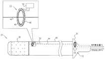
ここで図2A〜Bを参照すると、同図は本発明のいくつかの実施形態によるカテーテル22の概略図である。カテーテル22は、近位端及び遠位端を有する挿入管40を備える。アブレーション電極30は、管の遠位端に配設され、導電素子(例えば、ワイヤ)44は、アブレーション電流52を管の近位端からアブレーション電極まで伝達するように構成されている。例えば、図2Bに示されるように、挿入管は、ルーメン42を画定するように形作られてもよく、導電素子44は、ルーメン42の内部を近位遠位方向に走ってもよい。センサ23は、管の遠位端においてアブレーション電流52の振幅を測定するように構成されている。通常、センサ23は、管の遠位端又はその近傍に、通常は、管の内部に配設されている。センサ23は、図に示され、以降に説明されるように具体化されてもよい。あるいは、センサ23は、任意の他の適切な電流測定センサを含んでもよい。 Reference is now made to FIGS. 2A-B, which are schematic illustrations of a
図2A〜Bに示された特定の実施形態では、センサ23は、磁気コア46(例えば、フェライトなどの強磁性材料を含む)を備える。磁気コア46は、通常、管の遠位端の近傍で、管の内部に(例えば、ルーメン42の内部に)配設されており、導電素子44は、磁気コア46を通る。図2A〜Bに更に示されるように、センサ23は、コアの周りに巻かれているコイル48を更に備える。(通常、コイルは、コイルのインダクタンス及び寄生容量によって形成される共振回路の共振周波数が、アブレーション電流52の周波数よりも大幅に高いように巻かれる。)アブレーション電流52が、磁気コアを通ると、アブレーション電流は、コア内に磁界を生成し、これが、次には、コイル48内に電圧を誘起する。通常、コイルに連結している回路50が、誘起された電圧を測定する。 In the particular embodiment shown in FIGS. 2A-B, the
通常、管40の外径OD1は、4mm未満である。例えば、OD1は、2〜4mm、例えば約3mmであってもよい。本発明の実施形態は、コア46、コイル48、及び回路50を製造するための技術で、上記要素が、管内に嵌合するのに十分に小さいように製造する技術を提供する。例えば、コアの外径OD2は、2mm未満、例えば、1〜1.5mmであってもよい。本発明の範囲は、コアを円形、楕円形、又は任意の他の好適な形状に形作ること、及びコアを、管の長手方向軸に対して任意の好適な配向で整列させることを含む。 Usually, the outer diameter OD1 of the
いくつかの実施形態では、挿入管40は、ルーメン42に加えて、1つ又は2つ以上のルーメンを画定するよう更に形作られる。例えば、挿入管は、潅注流体をポンプ38(図1)からアブレーション電極まで送達するように構成された、灌注流体ルーメン45を画定するよう形作られてもよい。挿入管は、1つ又は2つ以上の制御ワイヤ49がそれに沿って走行する、制御ワイヤルーメン43を画定するよう形作られてもよい。制御ワイヤ49は、ハンドル31を介して、カテーテルを操縦するよう、及び/又はそうでなければカテーテルを制御するように操作されてもよい。いくつかの実施形態では、カテーテルは、カテーテルの遠位端において、磁気式位置センサを更に備える。このような実施形態では、挿入管は、磁気式ナビゲーションセンサに接続されている、それに沿ってワイヤ51を走らす磁気式センサワイヤルーメン47を画定するように更に形作られてもよい。通常、磁気コア46は、位置センサから十分に遠く離れて、例えば、位置センサから少なくとも10mm離れて置かれ、これにより、磁気コア及び位置センサは、互いに妨害することはない。 In some embodiments, the
いくつかの実施形態では、管は、専用の灌注流体ルーメンを画定するように形作られない。その代わりとして、灌注流体をポンプ38から送達する流体送達管が、磁気コアを通る。このような実施形態は、挿入管内の空間が、より効率的に用いられることを可能にする。 In some embodiments, the tube is not shaped to define a dedicated irrigation fluid lumen. Instead, a fluid delivery tube that delivers irrigation fluid from the pump 38 passes through the magnetic core. Such an embodiment allows the space in the insertion tube to be used more efficiently.
一般に、本発明の範囲は、任意の適切な数若しくはタイプのルーメン内に配設されたワイヤ、管、又は他の要素と共に、挿入管内に任意の適切な数の別個のルーメンを有することを含むことが留意される。 In general, the scope of the present invention includes having any suitable number of separate lumens within the insertion tube, with wires, tubes, or other elements disposed within any suitable number or type of lumens. It is noted that.
いくつかの実施形態では、導電素子44は、磁気コア46の周りに1回又は2回以上巻かれている。アブレーション電流の振幅を推定するために、誘起電圧の測定された振幅は、少なくとも(i)コアの周りの導電素子の巻き数と、(ii)コアの周りのコイル48の巻き数との関数である係数を掛けることができる。(導電素子44が、磁気コアの周りに巻かれない場合、用いられる(i)の値は、2分の1である。) In some embodiments, the
ここで図3を更に参照すると、同図は本発明のいくつかの実施形態による回路50の概略図である。回路50は、図2A〜Bで示されるように、コイル48の2つの端部を受容するように構成された、入力部70a及び70bを備える。回路50は、コイル内の誘起された電圧を測定するように構成された、測定部62を更に備える。例えば、測定部62は、抵抗器64の両端の誘起された電圧を測定するように構成された電圧計を備えてもよい。(測定部内の回路の精密な構成は、図3には示されていない。) Still referring to FIG. 3, this is a schematic diagram of a
通常、測定部62は、ST(商標)からのSTM32L151RE(商標)マイクロコントローラなどの、コントローラ(CTRL)66を更に備える。スイッチ68(例えば、バイポーラMOSFETスイッチ)を制御することによって、コントローラ66は、誘起された電圧の測定された振幅を表示するために、導電素子44上で電流を、アブレーション電流の周波数とは異なる周波数で変調する。このようにして、センサは、誘起された電圧の測定された振幅を示しているフィードバック信号を、導電素子で変調する。 Typically, the
通常、この変調は、受信回路72によって検出される。受信回路72は、図2Aに示す、ハンドル31内、又はコンソール32内(図1)などの、カテーテルの近位端に配設され得る。受信回路は、フィードバック信号から、誘起された電圧の振幅を確認する。通常、受信回路72は、次いで、誘起された電圧の振幅をプロセッサ36(図1)に通信し、プロセッサ36は、誘起された電圧の振幅に基づいて、アブレーション電流の振幅を推定する。この推定に応じて、プロセッサは、次いで、例えば、発生器によって供給される電力を増加又は減少させることによって、RF発生器34を制御してもよい。代替的に又は付加的に、プロセッサは、推定を示す出力を生成してもよく、手術者28(図1)は、それに応じて、発生器を制御してもよい。 Usually, this modulation is detected by the receiving
通常、回路50は、例えば、Linear Technology(商標)からのLTC3330(商標)ユニット、又はMAXTM(商標)からのMAX17710(商標)などのエネルギー採取部56を更に備える。エネルギー採取部56は、誘起された交流(AC)電圧を整流し、整流された直流(DC)電圧を用いて蓄積キャパシター58を充電し、蓄積キャパシターが、続いて測定部62に電力を供給することによって、アブレーション電流からエネルギーを採取する。このような実施形態では、アブレーション電流から採取されたエネルギーが、センサに電力を供給するのに十分であり得るために、センサに電池又は他の専用の電源を必ずしも供給しなくてもよい。(アブレーション電流から採取されたエネルギーは、通常、アブレーション電流によって供給される総エネルギーの一部分に過ぎず、これにより、アブレーション電流からのエネルギーの採取は、アブレーション処置の効力を低下させることはない。) Typically, the
通常、受信回路は、例えば、前置増幅器、復調器、デコーダー、及び/又は他の電子部品を含む回路74を備えている交流器を備える。前置増幅器は、復調器用に受信信号を増幅し、復調器は、続いて、受信信号からアブレーション電流周波数をフィルター処理する。通常、前述のSTM32L151RE(商標)コントローラなどのマイクロコントローラを備えるデコーダーは、続いて、誘起された電圧の振幅を確認し、頭書に記載したプロセッサと通信する。 Typically, the receiving circuit comprises an alternator comprising a circuit 74 that includes, for example, a preamplifier, demodulator, decoder, and / or other electronic components. The preamplifier amplifies the received signal for the demodulator, which then filters the ablation current frequency from the received signal. Typically, a decoder comprising a microcontroller such as the aforementioned STM32L151RE ™ controller will then verify the amplitude of the induced voltage and communicate with the processor described in the introductory note.
代替実施形態では、受信回路よりはむしろプロセッサが、フィードバック信号から誘起された電圧の振幅を確認する。 In an alternative embodiment, rather than the receiver circuit, the processor checks the amplitude of the voltage induced from the feedback signal.
いくつかの実施形態では、センサは、受信回路にフィードバックを提供するために、上述の方法とは異なる方法を用いる。例えば、センサは、別々の導電素子上にフィードバック信号を送信するために静電結合を用いてもよい。 In some embodiments, the sensor uses a different method than that described above to provide feedback to the receiving circuit. For example, the sensor may use capacitive coupling to transmit a feedback signal on separate conductive elements.
当業者であれば、本発明が上記で具体的に図示及び記載されたものに限定されない点を理解するであろう。それよりもむしろ、本発明の範囲は、上述した様々な特徴の組み合わせ及び部分的組み合わせ、並びに上述の説明を読むことで当業者が想到するであろう、従来技術にはない特徴の変形及び修正を含む。参照により本特許出願に組み込まれた文書は、本出願の一体部分と見なされるべきであるが、但し、これらの組み込まれた文書におけるいずれかの用語が、本明細書において明示的又は暗示的になされた定義と相反するように定義されている限りにおいて、本明細書における定義のみが検討されるべきである。 Those skilled in the art will appreciate that the present invention is not limited to what has been particularly shown and described hereinabove. Rather, the scope of the present invention covers the various feature combinations and subcombinations described above, as well as variations and modifications of features not found in the prior art that would occur to those skilled in the art upon reading the above description. including. Documents incorporated into this patent application by reference should be considered as an integral part of this application, provided that any term in these incorporated documents is expressly or implicitly set forth herein. As long as it is defined to be contrary to the definition made, only the definition in this specification should be considered.
〔実施の態様〕
(1) アブレーション装置であって、
挿入管と、
前記管の遠位端に配設されたアブレーション電極と、
アブレーション電流を、前記管の近位端から前記アブレーション電極まで伝達するように構成された、導電素子と、
前記管の前記遠位端において前記アブレーション電流の振幅を測定するように構成された、センサと、を備えるアブレーション装置。
(2) 前記センサが、前記アブレーション電流からエネルギーを採取するように更に構成されている、実施態様1に記載の装置。
(3) 前記センサが、前記管の内部に配設されている、実施態様1に記載の装置。
(4) 前記センサが、前記管の前記遠位端に配設されている、実施態様3に記載の装置。
(5) 前記管の外径が4mm未満である、実施態様3に記載の装置。Embodiment
(1) An ablation device,
An insertion tube;
An ablation electrode disposed at a distal end of the tube;
A conductive element configured to transmit an ablation current from a proximal end of the tube to the ablation electrode;
An ablation device comprising: a sensor configured to measure an amplitude of the ablation current at the distal end of the tube.
The apparatus of claim 1, wherein the sensor is further configured to extract energy from the ablation current.
(3) The device according to embodiment 1, wherein the sensor is disposed inside the tube.
4. The apparatus of embodiment 3, wherein the sensor is disposed at the distal end of the tube.
(5) The apparatus according to embodiment 3, wherein the outer diameter of the tube is less than 4 mm.
(6) 前記センサが、前記アブレーション電流によって生成される磁界により誘起された電圧の振幅を測定することによって、前記アブレーション電流の前記振幅を測定するように構成されている、実施態様1に記載の装置。
(7) 前記センサが、
前記導電素子が中を通る磁気コアと、
前記コアの周りに巻かれたコイルと、
前記コイルに連結された回路であって、前記アブレーション電流によって生成される前記コア内の磁界により、前記コイル内で誘起された電圧の振幅を測定することによって、前記アブレーション電流の前記振幅を測定するように構成されている、回路と、を備える、実施態様6に記載の装置。
(8) 前記挿入管の前記近位端から前記アブレーション電極まで流体を送達するように構成され、前記磁気コアを通る、流体送達管を更に備える、実施態様7に記載の装置。
(9) 前記コアの外径が、2mm未満である、実施態様7に記載の装置。
(10) 前記導電素子が、前記磁気コアの周りに1回又は2回以上巻かれている、実施態様7に記載の装置。6. The embodiment of claim 1, wherein the sensor is configured to measure the amplitude of the ablation current by measuring the amplitude of a voltage induced by a magnetic field generated by the ablation current. apparatus.
(7) The sensor is
A magnetic core through which the conductive element passes;
A coil wound around the core;
A circuit coupled to the coil, wherein the amplitude of the ablation current is measured by measuring an amplitude of a voltage induced in the coil by a magnetic field in the core generated by the ablation current. An apparatus according to embodiment 6, comprising a circuit configured as described above.
The apparatus of claim 7, further comprising a fluid delivery tube configured to deliver fluid from the proximal end of the insertion tube to the ablation electrode and through the magnetic core.
(9) The apparatus according to embodiment 7, wherein the outer diameter of the core is less than 2 mm.
(10) The apparatus according to embodiment 7, wherein the conductive element is wound around the magnetic core one or more times.
(11) 前記センサが、前記誘起された電圧の前記測定された振幅を示しているフィードバック信号を、前記導電素子で変調するように更に構成されている、実施態様6に記載の装置。
(12) 前記フィードバック信号から、前記誘起された電圧の前記振幅を確認するように構成された受信回路を更に備える、実施態様11に記載の装置。
(13) 前記誘起された電圧の前記振幅に基づいて、前記アブレーション電流の前記振幅を推定するように構成されたプロセッサを更に備える、実施態様6に記載の装置。
(14) 前記プロセッサが、前記推定に応じて、前記アブレーション電流の発生器を制御するように更に構成されている、実施態様13に記載の装置。
(15) アブレーション電流の振幅を推定するための方法であって、
(i)挿入管と、(ii)前記管の遠位端に配設されたアブレーション電極と、(iii)アブレーション電流を前記管の近位端から前記アブレーション電極まで伝達するように構成された導電素子と、を提供することと、
前記アブレーション電流を前記導電素子に通すことと、
前記管の前記遠位端において前記アブレーション電流の振幅を測定することと、を含む、方法。11. The apparatus of embodiment 6, wherein the sensor is further configured to modulate a feedback signal indicative of the measured amplitude of the induced voltage with the conductive element.
12. The apparatus of embodiment 11, further comprising a receiver circuit configured to verify the amplitude of the induced voltage from the feedback signal.
The apparatus of claim 6, further comprising a processor configured to estimate the amplitude of the ablation current based on the amplitude of the induced voltage.
The apparatus of claim 13, wherein the processor is further configured to control the ablation current generator in response to the estimation.
(15) A method for estimating the amplitude of an ablation current,
(I) an insertion tube; (ii) an ablation electrode disposed at the distal end of the tube; and (iii) a conductive material configured to transmit an ablation current from the proximal end of the tube to the ablation electrode. Providing an element;
Passing the ablation current through the conductive element;
Measuring the amplitude of the ablation current at the distal end of the tube.
(16) 前記アブレーション電流を前記導電素子に通す前に、前記管を患者の心臓に挿入することを更に含む、実施態様15に記載の方法。
(17) 前記アブレーション電流の前記振幅を測定することが、前記管の内部に配設されたセンサを用いて、前記振幅を測定することを含む、実施態様15に記載の方法。
(18) 前記アブレーション電流の前記振幅を測定することが、前記アブレーション電流により生成される磁界によって誘起された電圧の振幅を測定することによって、前記アブレーション電流の前記振幅を測定することを含む、実施態様15に記載の方法。
(19) 前記アブレーション電流を前記導電素子に通すことが、前記アブレーション電流を磁気コアに通すことを含み、前記アブレーション電流の前記振幅を測定することが、前記アブレーション電流によって生成される前記コア内の磁界により誘起された電圧の振幅を測定することによって、前記アブレーション電流の前記振幅を測定することを含む、実施態様18に記載の方法。
(20) 前記誘起された電圧の前記測定された振幅を示しているフィードバック信号を、前記導電素子で変調することを更に含む、実施態様18に記載の方法。16. The method of embodiment 15, further comprising inserting the tube into a patient's heart before passing the ablation current through the conductive element.
17. The method of embodiment 15, wherein measuring the amplitude of the ablation current comprises measuring the amplitude using a sensor disposed within the tube.
(18) Measuring the amplitude of the ablation current comprises measuring the amplitude of the ablation current by measuring the amplitude of a voltage induced by a magnetic field generated by the ablation current. The method according to embodiment 15.
(19) Passing the ablation current through the conductive element includes passing the ablation current through a magnetic core, and measuring the amplitude of the ablation current in the core generated by the ablation current 19. The method of embodiment 18, comprising measuring the amplitude of the ablation current by measuring the amplitude of a voltage induced by a magnetic field.
20. The method of embodiment 18, further comprising modulating a feedback signal indicative of the measured amplitude of the induced voltage with the conductive element.
(21) 前記アブレーション電流の前記振幅を測定することに応じて、前記アブレーション電流の発生器を制御することを更に含む、実施態様15に記載の方法。
(22) アブレーション装置を製造する方法であって、
挿入管を提供することであって、アブレーション電極が前記管の遠位端に配設されている、提供することと、
導電素子を、前記管の近位端と前記アブレーション電極との間に通すことであって、前記導電素子が、アブレーション電流を前記管の前記近位端から前記アブレーション電極まで伝達するように構成される、通すことと、
センサを前記管の内部に置くことであって、前記センサが、前記管の前記遠位端において前記アブレーション電流の振幅を測定するように構成される、置くことと、を含む、方法。
(23) 前記センサが、磁気コアを含み、前記導電素子を、前記管の前記近位端と前記アブレーション電極との間に通すことが、前記導電素子を前記磁気コアに通すことを含む、実施態様22に記載の方法。
(24) 前記導電素子を、前記磁気コアの周りに1回又は2回以上巻き付けることを更に含む、実施態様23に記載の方法。
(25) 前記挿入管の前記近位端から前記アブレーション電極まで流体を送達するように構成された流体送達管を、前記磁気コアに通すことを更に含む、実施態様23に記載の方法。21. The method of embodiment 15, further comprising controlling the ablation current generator in response to measuring the amplitude of the ablation current.
(22) A method of manufacturing an ablation apparatus,
Providing an insertion tube, wherein an ablation electrode is disposed at a distal end of the tube;
Passing a conductive element between the proximal end of the tube and the ablation electrode, the conductive element configured to transmit an ablation current from the proximal end of the tube to the ablation electrode. Passing,
Placing a sensor inside the tube, the sensor being configured to measure an amplitude of the ablation current at the distal end of the tube.
(23) The sensor includes a magnetic core, and passing the conductive element between the proximal end of the tube and the ablation electrode includes passing the conductive element through the magnetic core. 23. A method according to
24. The method of
25. The method of
Claims (25)
Translated fromJapanese挿入管と、
前記管の遠位端に配設されたアブレーション電極と、
アブレーション電流を、前記管の近位端から前記アブレーション電極まで伝達するように構成された、導電素子と、
前記管の前記遠位端において前記アブレーション電流の振幅を測定するように構成された、センサと、を備えるアブレーション装置。An ablation device,
An insertion tube;
An ablation electrode disposed at a distal end of the tube;
A conductive element configured to transmit an ablation current from a proximal end of the tube to the ablation electrode;
An ablation device comprising: a sensor configured to measure an amplitude of the ablation current at the distal end of the tube.
前記導電素子が中を通る磁気コアと、
前記コアの周りに巻かれたコイルと、
前記コイルに連結された回路であって、前記アブレーション電流によって生成される前記コア内の磁界により、前記コイル内で誘起された電圧の振幅を測定することによって、前記アブレーション電流の前記振幅を測定するように構成されている、回路と、を備える、請求項6に記載の装置。The sensor is
A magnetic core through which the conductive element passes;
A coil wound around the core;
A circuit coupled to the coil, wherein the amplitude of the ablation current is measured by measuring an amplitude of a voltage induced in the coil by a magnetic field in the core generated by the ablation current. The apparatus of claim 6, comprising: a circuit configured as follows:
(i)挿入管と、(ii)前記管の遠位端に配設されたアブレーション電極と、(iii)アブレーション電流を前記管の近位端から前記アブレーション電極まで伝達するように構成された導電素子と、を提供することと、
前記アブレーション電流を前記導電素子に通すことと、
前記管の前記遠位端において前記アブレーション電流の振幅を測定することと、を含む、方法。A method for estimating the amplitude of an ablation current,
(I) an insertion tube; (ii) an ablation electrode disposed at the distal end of the tube; and (iii) a conductive material configured to transmit an ablation current from the proximal end of the tube to the ablation electrode. Providing an element;
Passing the ablation current through the conductive element;
Measuring the amplitude of the ablation current at the distal end of the tube.
挿入管を提供することであって、アブレーション電極が前記管の遠位端に配設されている、提供することと、
導電素子を、前記管の近位端と前記アブレーション電極との間に通すことであって、前記導電素子が、アブレーション電流を前記管の前記近位端から前記アブレーション電極まで伝達するように構成される、通すことと、
センサを前記管の内部に置くことであって、前記センサが、前記管の前記遠位端において前記アブレーション電流の振幅を測定するように構成される、置くことと、を含む、方法。A method of manufacturing an ablation device comprising:
Providing an insertion tube, wherein an ablation electrode is disposed at a distal end of the tube;
Passing a conductive element between the proximal end of the tube and the ablation electrode, the conductive element configured to transmit an ablation current from the proximal end of the tube to the ablation electrode. Passing,
Placing a sensor inside the tube, the sensor being configured to measure an amplitude of the ablation current at the distal end of the tube.
Applications Claiming Priority (2)
| Application Number | Priority Date | Filing Date | Title |
|---|---|---|---|
| US14/860,034US10357309B2 (en) | 2015-09-21 | 2015-09-21 | Ablation current measurement |
| US14/860,034 | 2015-09-21 |
Publications (2)
| Publication Number | Publication Date |
|---|---|
| JP2017060758Atrue JP2017060758A (en) | 2017-03-30 |
| JP6887774B2 JP6887774B2 (en) | 2021-06-16 |
Family
ID=56979427
Family Applications (1)
| Application Number | Title | Priority Date | Filing Date |
|---|---|---|---|
| JP2016182762AExpired - Fee RelatedJP6887774B2 (en) | 2015-09-21 | 2016-09-20 | Ablation current measurement |
Country Status (7)
| Country | Link |
|---|---|
| US (1) | US10357309B2 (en) |
| EP (1) | EP3143957B1 (en) |
| JP (1) | JP6887774B2 (en) |
| CN (1) | CN106821491B (en) |
| AU (1) | AU2016216555A1 (en) |
| CA (1) | CA2940949A1 (en) |
| IL (1) | IL247434B (en) |
Cited By (1)
| Publication number | Priority date | Publication date | Assignee | Title |
|---|---|---|---|---|
| WO2018164179A1 (en) | 2017-03-08 | 2018-09-13 | 株式会社小糸製作所 | Lamp for vehicle |
Families Citing this family (8)
| Publication number | Priority date | Publication date | Assignee | Title |
|---|---|---|---|---|
| US9119633B2 (en) | 2006-06-28 | 2015-09-01 | Kardium Inc. | Apparatus and method for intra-cardiac mapping and ablation |
| US11389232B2 (en) | 2006-06-28 | 2022-07-19 | Kardium Inc. | Apparatus and method for intra-cardiac mapping and ablation |
| US8906011B2 (en) | 2007-11-16 | 2014-12-09 | Kardium Inc. | Medical device for use in bodily lumens, for example an atrium |
| US10827977B2 (en) | 2012-05-21 | 2020-11-10 | Kardium Inc. | Systems and methods for activating transducers |
| US9198592B2 (en) | 2012-05-21 | 2015-12-01 | Kardium Inc. | Systems and methods for activating transducers |
| US9017321B2 (en) | 2012-05-21 | 2015-04-28 | Kardium, Inc. | Systems and methods for activating transducers |
| US10722184B2 (en) | 2014-11-17 | 2020-07-28 | Kardium Inc. | Systems and methods for selecting, activating, or selecting and activating transducers |
| US10368936B2 (en) | 2014-11-17 | 2019-08-06 | Kardium Inc. | Systems and methods for selecting, activating, or selecting and activating transducers |
Citations (3)
| Publication number | Priority date | Publication date | Assignee | Title |
|---|---|---|---|---|
| JPS5977844A (en)* | 1982-10-28 | 1984-05-04 | 持田製薬株式会社 | Safety device for electric scalpel |
| US20120123408A1 (en)* | 2008-03-27 | 2012-05-17 | Bovie Medical Corporation | Laparoscopic electrosurgical electrical leakage detection |
| WO2015069887A1 (en)* | 2013-11-07 | 2015-05-14 | St. Jude Medical, Cardiology Division, Inc. | Medical device with contact force sensing tip |
Family Cites Families (16)
| Publication number | Priority date | Publication date | Assignee | Title |
|---|---|---|---|---|
| EP0566726A1 (en) | 1991-11-08 | 1993-10-27 | Ep Technologies, Inc. | Systems and methods for ablating tissue while monitoring tissue impedance |
| US6161543A (en)* | 1993-02-22 | 2000-12-19 | Epicor, Inc. | Methods of epicardial ablation for creating a lesion around the pulmonary veins |
| US6059780A (en) | 1995-08-15 | 2000-05-09 | Rita Medical Systems, Inc. | Multiple antenna ablation apparatus and method with cooling element |
| US20030187430A1 (en) | 2002-03-15 | 2003-10-02 | Vorisek James C. | System and method for measuring power at tissue during RF ablation |
| US8702690B2 (en) | 2007-11-16 | 2014-04-22 | St. Jude Medical, Atrial Fibrillation Division, Inc. | Device and method for real-time lesion estimation during ablation |
| US8979834B2 (en)* | 2008-03-27 | 2015-03-17 | Bovie Medical Corporation | Laparoscopic electrosurgical electrical leakage detection |
| WO2011029018A2 (en)* | 2009-09-03 | 2011-03-10 | Verivolt, Llc | Voltage conversion and/or electrical measurements from 400 volts upwards |
| CN101969720B (en)* | 2010-09-15 | 2013-09-18 | 成都芯源系统有限公司 | LED bypass control circuit and control method |
| GB201021032D0 (en)* | 2010-12-10 | 2011-01-26 | Creo Medical Ltd | Electrosurgical apparatus |
| US9044244B2 (en)* | 2010-12-10 | 2015-06-02 | Biosense Webster (Israel), Ltd. | System and method for detection of metal disturbance based on mutual inductance measurement |
| EP2604121A1 (en) | 2011-12-14 | 2013-06-19 | CaseTech GmbH | Food casing on the basis of cellulose with fungicidal characteristics and method for protecting food casings on the basis of cellulose from mould |
| US9084539B2 (en)* | 2012-02-02 | 2015-07-21 | Volcano Corporation | Wireless pressure wire system with integrated power |
| CN103326393B (en)* | 2012-03-22 | 2016-03-30 | 张家港智电柔性输配电技术研究所有限公司 | A kind of redundant power supply power supply of H bridge cascade converter |
| US10874449B2 (en) | 2012-04-19 | 2020-12-29 | Koninklijke Philips N.V. | Energy application apparatus |
| US9116179B2 (en)* | 2012-12-17 | 2015-08-25 | Covidien Lp | System and method for voltage and current sensing |
| US20140276755A1 (en) | 2013-03-12 | 2014-09-18 | Boston Scientific Scimed, Inc. | Medical systems and methods for modulating nerves |
- 2015
- 2015-09-21USUS14/860,034patent/US10357309B2/ennot_activeExpired - Fee Related
- 2016
- 2016-08-16AUAU2016216555Apatent/AU2016216555A1/ennot_activeAbandoned
- 2016-08-23ILIL247434Apatent/IL247434B/enactiveIP Right Grant
- 2016-09-01CACA2940949Apatent/CA2940949A1/ennot_activeAbandoned
- 2016-09-20EPEP16189715.2Apatent/EP3143957B1/enactiveActive
- 2016-09-20JPJP2016182762Apatent/JP6887774B2/ennot_activeExpired - Fee Related
- 2016-09-21CNCN201610839918.4Apatent/CN106821491B/ennot_activeExpired - Fee Related
Patent Citations (3)
| Publication number | Priority date | Publication date | Assignee | Title |
|---|---|---|---|---|
| JPS5977844A (en)* | 1982-10-28 | 1984-05-04 | 持田製薬株式会社 | Safety device for electric scalpel |
| US20120123408A1 (en)* | 2008-03-27 | 2012-05-17 | Bovie Medical Corporation | Laparoscopic electrosurgical electrical leakage detection |
| WO2015069887A1 (en)* | 2013-11-07 | 2015-05-14 | St. Jude Medical, Cardiology Division, Inc. | Medical device with contact force sensing tip |
Cited By (1)
| Publication number | Priority date | Publication date | Assignee | Title |
|---|---|---|---|---|
| WO2018164179A1 (en) | 2017-03-08 | 2018-09-13 | 株式会社小糸製作所 | Lamp for vehicle |
Also Published As
| Publication number | Publication date |
|---|---|
| CA2940949A1 (en) | 2017-03-21 |
| US10357309B2 (en) | 2019-07-23 |
| US20170079712A1 (en) | 2017-03-23 |
| EP3143957B1 (en) | 2021-05-12 |
| EP3143957A1 (en) | 2017-03-22 |
| JP6887774B2 (en) | 2021-06-16 |
| AU2016216555A1 (en) | 2017-04-06 |
| CN106821491B (en) | 2021-06-11 |
| IL247434A0 (en) | 2016-12-29 |
| CN106821491A (en) | 2017-06-13 |
| IL247434B (en) | 2020-04-30 |
Similar Documents
| Publication | Publication Date | Title |
|---|---|---|
| JP6887774B2 (en) | Ablation current measurement | |
| EP4294301B1 (en) | Contact quality system | |
| CN103190951B (en) | Contact evaluation based on phase measurement | |
| US8403925B2 (en) | System and method for assessing lesions in tissue | |
| US20130172878A1 (en) | Device and methods for renal nerve modulation monitoring | |
| US20110264000A1 (en) | System and method for determining tissue type and mapping tissue morphology | |
| US20130296839A1 (en) | Detection of microbubble formation during catheter ablation | |
| JP2019076731A (en) | Esophageal probe with transmitting coils | |
| US10413212B2 (en) | Methods and systems for enhanced mapping of tissue | |
| US10166062B2 (en) | High-resolution mapping of tissue with pacing | |
| EP3434214A1 (en) | Tissue thickness using pulsed power | |
| US20250177055A1 (en) | Medical probe for navigating small diameter blood vessels | |
| US20250195133A1 (en) | Mapping and ablation catheter | |
| US20250120653A1 (en) | Flexible circuit electrodes for lasso catheter | |
| WO2025067860A1 (en) | A system for denervation of nerves of a blood vessel | |
| WO2024200141A1 (en) | Focused ultrasound stimulation for renal denervation | |
| WO2025176669A1 (en) | Renal nerve stimulation to guide rf renal denervation | |
| WO2025067943A1 (en) | Irrigated ablated catheter temperature estimates using impedance data |
Legal Events
| Date | Code | Title | Description |
|---|---|---|---|
| A621 | Written request for application examination | Free format text:JAPANESE INTERMEDIATE CODE: A621 Effective date:20190730 | |
| A977 | Report on retrieval | Free format text:JAPANESE INTERMEDIATE CODE: A971007 Effective date:20200710 | |
| A131 | Notification of reasons for refusal | Free format text:JAPANESE INTERMEDIATE CODE: A131 Effective date:20200804 | |
| A521 | Request for written amendment filed | Free format text:JAPANESE INTERMEDIATE CODE: A523 Effective date:20201027 | |
| A131 | Notification of reasons for refusal | Free format text:JAPANESE INTERMEDIATE CODE: A131 Effective date:20210112 | |
| A521 | Request for written amendment filed | Free format text:JAPANESE INTERMEDIATE CODE: A523 Effective date:20210407 | |
| TRDD | Decision of grant or rejection written | ||
| A01 | Written decision to grant a patent or to grant a registration (utility model) | Free format text:JAPANESE INTERMEDIATE CODE: A01 Effective date:20210511 | |
| A61 | First payment of annual fees (during grant procedure) | Free format text:JAPANESE INTERMEDIATE CODE: A61 Effective date:20210519 | |
| R150 | Certificate of patent or registration of utility model | Ref document number:6887774 Country of ref document:JP Free format text:JAPANESE INTERMEDIATE CODE: R150 | |
| LAPS | Cancellation because of no payment of annual fees |