JP2017056197A - Vacuum cleaner - Google Patents
Vacuum cleanerDownload PDFInfo
- Publication number
- JP2017056197A JP2017056197AJP2016175409AJP2016175409AJP2017056197AJP 2017056197 AJP2017056197 AJP 2017056197AJP 2016175409 AJP2016175409 AJP 2016175409AJP 2016175409 AJP2016175409 AJP 2016175409AJP 2017056197 AJP2017056197 AJP 2017056197A
- Authority
- JP
- Japan
- Prior art keywords
- vacuum cleaner
- separation unit
- cyclonic separation
- handle
- portable vacuum
- Prior art date
- Legal status (The legal status is an assumption and is not a legal conclusion. Google has not performed a legal analysis and makes no representation as to the accuracy of the status listed.)
- Granted
Links
Images


Classifications
- A—HUMAN NECESSITIES
- A47—FURNITURE; DOMESTIC ARTICLES OR APPLIANCES; COFFEE MILLS; SPICE MILLS; SUCTION CLEANERS IN GENERAL
- A47L—DOMESTIC WASHING OR CLEANING; SUCTION CLEANERS IN GENERAL
- A47L5/00—Structural features of suction cleaners
- A47L5/12—Structural features of suction cleaners with power-driven air-pumps or air-compressors, e.g. driven by motor vehicle engine vacuum
- A47L5/22—Structural features of suction cleaners with power-driven air-pumps or air-compressors, e.g. driven by motor vehicle engine vacuum with rotary fans
- A47L5/24—Hand-supported suction cleaners
- A—HUMAN NECESSITIES
- A47—FURNITURE; DOMESTIC ARTICLES OR APPLIANCES; COFFEE MILLS; SPICE MILLS; SUCTION CLEANERS IN GENERAL
- A47L—DOMESTIC WASHING OR CLEANING; SUCTION CLEANERS IN GENERAL
- A47L5/00—Structural features of suction cleaners
- A47L5/12—Structural features of suction cleaners with power-driven air-pumps or air-compressors, e.g. driven by motor vehicle engine vacuum
- A47L5/22—Structural features of suction cleaners with power-driven air-pumps or air-compressors, e.g. driven by motor vehicle engine vacuum with rotary fans
- A47L5/28—Suction cleaners with handles and nozzles fixed on the casings, e.g. wheeled suction cleaners with steering handle
- A—HUMAN NECESSITIES
- A47—FURNITURE; DOMESTIC ARTICLES OR APPLIANCES; COFFEE MILLS; SPICE MILLS; SUCTION CLEANERS IN GENERAL
- A47L—DOMESTIC WASHING OR CLEANING; SUCTION CLEANERS IN GENERAL
- A47L9/00—Details or accessories of suction cleaners, e.g. mechanical means for controlling the suction or for effecting pulsating action; Storing devices specially adapted to suction cleaners or parts thereof; Carrying-vehicles specially adapted for suction cleaners
- A47L9/10—Filters; Dust separators; Dust removal; Automatic exchange of filters
- A47L9/16—Arrangement or disposition of cyclones or other devices with centrifugal action
- A47L9/1608—Cyclonic chamber constructions
- A—HUMAN NECESSITIES
- A47—FURNITURE; DOMESTIC ARTICLES OR APPLIANCES; COFFEE MILLS; SPICE MILLS; SUCTION CLEANERS IN GENERAL
- A47L—DOMESTIC WASHING OR CLEANING; SUCTION CLEANERS IN GENERAL
- A47L9/00—Details or accessories of suction cleaners, e.g. mechanical means for controlling the suction or for effecting pulsating action; Storing devices specially adapted to suction cleaners or parts thereof; Carrying-vehicles specially adapted for suction cleaners
- A47L9/10—Filters; Dust separators; Dust removal; Automatic exchange of filters
- A47L9/16—Arrangement or disposition of cyclones or other devices with centrifugal action
- A47L9/1616—Multiple arrangement thereof
- A—HUMAN NECESSITIES
- A47—FURNITURE; DOMESTIC ARTICLES OR APPLIANCES; COFFEE MILLS; SPICE MILLS; SUCTION CLEANERS IN GENERAL
- A47L—DOMESTIC WASHING OR CLEANING; SUCTION CLEANERS IN GENERAL
- A47L9/00—Details or accessories of suction cleaners, e.g. mechanical means for controlling the suction or for effecting pulsating action; Storing devices specially adapted to suction cleaners or parts thereof; Carrying-vehicles specially adapted for suction cleaners
- A47L9/10—Filters; Dust separators; Dust removal; Automatic exchange of filters
- A47L9/16—Arrangement or disposition of cyclones or other devices with centrifugal action
- A47L9/1683—Dust collecting chambers; Dust collecting receptacles
- A—HUMAN NECESSITIES
- A47—FURNITURE; DOMESTIC ARTICLES OR APPLIANCES; COFFEE MILLS; SPICE MILLS; SUCTION CLEANERS IN GENERAL
- A47L—DOMESTIC WASHING OR CLEANING; SUCTION CLEANERS IN GENERAL
- A47L9/00—Details or accessories of suction cleaners, e.g. mechanical means for controlling the suction or for effecting pulsating action; Storing devices specially adapted to suction cleaners or parts thereof; Carrying-vehicles specially adapted for suction cleaners
- A47L9/24—Hoses or pipes; Hose or pipe couplings
- A—HUMAN NECESSITIES
- A47—FURNITURE; DOMESTIC ARTICLES OR APPLIANCES; COFFEE MILLS; SPICE MILLS; SUCTION CLEANERS IN GENERAL
- A47L—DOMESTIC WASHING OR CLEANING; SUCTION CLEANERS IN GENERAL
- A47L9/00—Details or accessories of suction cleaners, e.g. mechanical means for controlling the suction or for effecting pulsating action; Storing devices specially adapted to suction cleaners or parts thereof; Carrying-vehicles specially adapted for suction cleaners
- A47L9/32—Handles
- A47L9/322—Handles for hand-supported suction cleaners
- B—PERFORMING OPERATIONS; TRANSPORTING
- B04—CENTRIFUGAL APPARATUS OR MACHINES FOR CARRYING-OUT PHYSICAL OR CHEMICAL PROCESSES
- B04C—APPARATUS USING FREE VORTEX FLOW, e.g. CYCLONES
- B04C5/00—Apparatus in which the axial direction of the vortex is reversed
- B04C5/08—Vortex chamber constructions
- B—PERFORMING OPERATIONS; TRANSPORTING
- B04—CENTRIFUGAL APPARATUS OR MACHINES FOR CARRYING-OUT PHYSICAL OR CHEMICAL PROCESSES
- B04C—APPARATUS USING FREE VORTEX FLOW, e.g. CYCLONES
- B04C5/00—Apparatus in which the axial direction of the vortex is reversed
- B04C5/14—Construction of the underflow ducting; Apex constructions; Discharge arrangements ; discharge through sidewall provided with a few slits or perforations
- B04C5/185—Dust collectors
Landscapes
- Engineering & Computer Science (AREA)
- Mechanical Engineering (AREA)
- Filters For Electric Vacuum Cleaners (AREA)
- Electric Vacuum Cleaner (AREA)
Abstract
Translated fromJapaneseDescription
Translated fromJapanese本発明は、サイクロン式分離ユニットを備えている携行式真空掃除機に関する。 The present invention relates to a portable vacuum cleaner provided with a cyclone type separation unit.
特許文献1は、ハンドルとハンドルに沿って延在するように配置されているサイクロン式分離器とを有している本体を備えている携行式真空掃除機を開示している。サイクロン式分離器は、サイクロン式分離器によって分離された塵埃を収集するための収集器を備えている。収集器は、収集器の外壁に回動可能に取り付けられているベースであって、閉位置においてキャッチによって保持されるベースを有している。キャッチを解放することによって、ベースが搖動して開くので、収集器が空になる。 Patent document 1 is disclosing the portable vacuum cleaner provided with the main body which has a handle and the cyclonic separator arrange | positioned so that it may extend along a handle. The cyclonic separator includes a collector for collecting the dust separated by the cyclonic separator. The collector has a base that is pivotally attached to the outer wall of the collector and is held by a catch in the closed position. By releasing the catch, the base swings open and the collector is emptied.
利用者は、収集器を空にするために、ベースを塵箱の上方に位置決めした後に、キャッチを解放する。ベースが搖動して開き、収集された塵埃が、収集器から塵箱の内部に落下する。このような構成は、収集器を空にするための単純な方法を提供するが、若干の注意を要求する。一般に、利用者は、自身から離れた塵埃を塵箱の内部に向けるために、自身の手を一方又は上方に捻らなくてはならないからである。従って、構成の改善が望まれている。 The user releases the catch after positioning the base above the dust bin to empty the collector. The base swings open and the collected dust falls from the collector into the dust box. Such an arrangement provides a simple way to empty the collector, but requires some attention. This is because, in general, a user must twist his / her hand upward or downward in order to direct dust away from the user toward the inside of the dust box. Therefore, an improvement in configuration is desired.
本発明は、携行式真空掃除機であって、通常の利用の際に携行式真空掃除機を支持するためのハンドルと、長手方向軸線とサイクロン式分離ユニットの一方の端部に配置された塵埃収集器とを有しているサイクロン式分離ユニットであって、サイクロン式分離ユニットが、端部分を備えており、端部分が、端部分によって塵埃が塵埃収集器の内部に保持される閉構成と、塵埃収集器から塵埃を除去するための開構成とを備えている、サイクロン式分離ユニットと、を備えている携行式真空掃除機において、ハンドルが、ハンドルがハンドルとサイクロン式分離ユニットの長手方向軸線との間に85°以上140°以下の角度を形成するようにサイクロン式分離ユニットに対して傾斜しているピストルグリップ構成を有していることを特徴とする携行式真空掃除機を提供する。 The present invention relates to a portable vacuum cleaner, a handle for supporting the portable vacuum cleaner in normal use, dust disposed at one end of a longitudinal axis and a cyclonic separation unit A cyclonic separation unit having a collector, wherein the cyclonic separation unit includes an end portion, and the end portion has a closed configuration in which dust is held inside the dust collector by the end portion; A cyclonic separation unit having an open configuration for removing dust from the dust collector, wherein the handle is a longitudinal direction of the handle and the cyclone separation unit It has a pistol grip configuration that is inclined with respect to the cyclonic separation unit so as to form an angle of 85 ° to 140 ° with the axis. Provide a portable vacuum cleaner.
本発明における携行式真空掃除機は、ハンドルの把持を自然な状態で維持しつつ、サイクロン式分離ユニットを利用者から離隔するように向け、端部分を開くことによって空にすることができる。塵埃収集器を空にする工程は、従って、人間工学的且つ直観的なものである。さらに、塵埃収集器が利用者から離隔した位置で開くので、塵埃収集器を空にする際に塵埃が利用者に付着するリスクが低い。 The portable vacuum cleaner according to the present invention can be emptied by opening the end portion while keeping the handle gripped in a natural state and directing the cyclonic separation unit away from the user. The process of emptying the dust collector is therefore ergonomic and intuitive. Furthermore, since the dust collector opens at a position separated from the user, the risk of dust adhering to the user when emptying the dust collector is low.
ハンドルが、ハンドルとサイクロン式分離ユニットの長手方向軸線との間に100°以上125°以下の角度を形成するようにサイクロン式分離ユニットに対して傾斜している。 The handle is inclined with respect to the cyclonic separation unit so as to form an angle between 100 ° and 125 ° between the handle and the longitudinal axis of the cyclonic separation unit.
端部分は、サイクロン式分離ユニットの端部壁を備えている。端部分は、閉構成と開構成との間において回動するように配置されている。 The end portion comprises the end wall of the cyclonic separation unit. The end portion is arranged to rotate between a closed configuration and an open configuration.
サイクロン式分離ユニットは、端部分を貫通している汚染空気入口を備えている。携行式真空掃除機が、コネクタと、コネクタに接続可能とされる清掃ツールとを備えており、清掃ツールが、端部分が閉構成に位置しており、且つ、清掃ツールがコネクタに接続されている場合に、端部分が閉構成から開構成に移動することが防止されるように構成されている。 The cyclonic separation unit has a contaminated air inlet passing through the end portion. The portable vacuum cleaner includes a connector and a cleaning tool that can be connected to the connector, the cleaning tool has an end portion in a closed configuration, and the cleaning tool is connected to the connector. The end portion is prevented from moving from the closed configuration to the open configuration.
清掃ツールは、閉構成において端部分を保持するために端部分に当接する、カラーを備えている。塵埃収集器は、ハンドルの前方に配置されている。 The cleaning tool includes a collar that abuts the end portion to hold the end portion in the closed configuration. The dust collector is disposed in front of the handle.
サイクロン式分離ユニットの長手方向軸線は、ハンドルの上方に配置されている平面内において延在している。 The longitudinal axis of the cyclonic separating unit extends in a plane located above the handle.
サイクロン式分離ユニットは、サイクロン式分離ユニットの長手方向軸線を規定している軸線を有している、サイクロン式分離器を備えている。 The cyclonic separation unit includes a cyclonic separator having an axis that defines a longitudinal axis of the cyclonic separation unit.
本発明を良好に理解するために、及び、本発明の実施を明確に表わすために、本発明について、添付図面を参照しつつ例示的に説明する。 For a better understanding of the present invention and to clearly illustrate the practice of the present invention, the invention will be described by way of example with reference to the accompanying drawings.
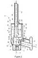
図1及び図2は、桿体状のハンドル6を有している本体4と、長手方向軸線Xを有しているサイクロン式分離ユニット8と、サイクロン式分離ユニット8に固定されているノズルの形態をした清掃ツール10と、を備えている携行式真空掃除機2を表わす。サイクロン式分離ユニット8は、ハンドル6から離隔するように延在しており、清掃ツール10が、ハンドル6から最も離隔しているサイクロン式分離ユニット8の端部に配置されている。清掃ツール10は、サイクロン式分離ユニット8から離隔するようにサイクロン式分離ユニット8の長手方向軸線Xに沿って延在している。 1 and 2 show a
さらに、本体4は、吸引発生器11を備えており、吸引発生器11は、モータ12と、ハンドル6の上方に且つハンドル6の後方に向かって配置されている羽根車13と、ハンドル6の直下に配置されているバッテリ14とを備えている。指で操作可能とされるトリガー16の形態をしたアクチュエータが、ハンドル6の上側部分に設けられている。トリガーガード17は、トリガー16の下方においてハンドル6から前方に延在している。ハンドル6は、サイクロン式分離ユニット8の長手方向軸線Xに対して角度θ1で配置されているので、ハンドル6が拳銃のグリップ部分のように構成されている。図示の実施例では、ハンドル軸線Hは、サイクロン式分離ユニット8の長手方向軸線Xに対して110°の角度で配置されている。角度θ1は、ハンドル6の前方に延在している長手方向軸線Xとハンドル6を貫通して延在しているハンドル軸線Hの一部とが成すネジ山の角度である。Further, the
サイクロン式分離ユニット8は、一次サイクロン式分離器18と、一次サイクロン式分離器18の下流に位置決めされている複数の二次サイクロン式分離器20とを備えている。一次サイクロン式分離器18は、サイクロン式分離ユニット8の第1の端部に隣接しており、二次サイクロン式分離器20は、第1の端部の反対側に位置するサイクロン式分離ユニット8の第2の端部に隣接している。二次サイクロン式分離器20は、サイクロン式分離ユニット8の長手方向軸線Xを中心として延在している円状配列に配置されている。 The
一次サイクロン式分離器18は、容器の形態をした分離器本体22を備えており、分離器本体22は、円筒状の外壁24と端部壁26とを有している。円筒状の外壁24は、サイクロン式分離チャンバ28を形成している。図示の実施例では、サイクロン式分離チャンバ28の軸線は、サイクロン式分離ユニット8の長手方向軸線Xを形成している。中央ダクト30は、端部壁26からサイクロン式分離チャンバ28の入口32に至るまで延在している。 The primary
清掃ツール10は、接続部分33と、ダクト36を清掃ツール10に沿って形成しているノズル部分34とを備えている。接続部分33は、端部壁26に隣接している中央ダクト30の一部分の内径より小さい外径を有しているので、(図示の如く)接続部分33を中央ダクト30に挿入することによって、清掃ツール10とサイクロン式分離ユニット8とを確実に且つ堅固に接続することができる。 The
中央ダクト30と清掃ツール10を貫通しているダクト36とが共に、長手方向軸線Xと同軸に且つハンドル6から最も離隔しているサイクロン式分離ユニット8の端部を貫通して延在している入口ダクト30を形成している。サイクロン式分離チャンバ28の入口32は、端部壁26から離隔しており、サイクロン式分離チャンバ28の入口32は、清掃ツール10に接続するためのサイクロン式分離ユニット8の端部の反対側に位置する、一次サイクロン式分離器18の端部に向かって配置されている。従って、サイクロン式分離チャンバ28は、中央ダクト30によって形成されている入口ダクトの一部分を囲んでいる。端部壁26から通じている中央ダクト30の第1の部分は、サイクロン式分離チャンバ28の長手方向軸線Xに沿って延在している。中央ダクト30の第2の部分は、第1の部分からサイクロン式分離チャンバ28の入口32に至るまで延在している。第2の部分は、利用の際にサイクロン式分離チャンバ28の内部における回転流れが促進されるように、サイクロン式分離チャンバ28に関するラジアル方向成分及び周方向成分の両方を有する方向に延在している。 Both the
端部壁26と端部壁26に隣接している円筒状の外壁24の一部分とが、一次サイクロン式分離器18によって流入流れから分離された塵埃を収集するための塵埃収集容器の形態とされる、塵埃収集器38を形成している。 The
端部壁26は、ピボット40を介して、円筒状の外壁24に接続されており、利用者が操作可能とされるキャッチ42によって、閉位置に保持されている。端部壁26は、キャッチ42を解除し、円筒状の外壁24の端部から離隔するように端部壁26を回動させることによって、塵埃が塵埃収集器38の内部に保持される閉位置から、塵埃が塵埃収集器38から排除可能とされる開位置に至るまで移動可能とされる。清掃ツール10は、清掃ツール10を中央ダクト30に固定するように中央ダクト30と係合する保持機能部(図示しない)を備えている。さらに、清掃ツール10は、端部壁26に当接することによって閉位置において端部壁26を保持する、環状カラー43を備えているので、清掃ツール10が取付られた状態において端部壁26が偶発的に開くことを防止することができる。清掃ツール10は、清掃ツール10をサイクロン式分離ユニット8から取り外すために保持機能部を中央ダクト24から係合解除するように動作する、手動で操作可能なキャッチ44を有している。 The
円筒状のシュラウド45は、サイクロン式分離チャンバ28の内部の中央に配置されており、サイクロン式分離チャンバ28の軸線と同軸に延在している。シュラウド45を貫通して設けられている開口部46は、サイクロン式分離チャンバ28からの流体出口を形成している。 The
ダクト48は、シュラウド45によって部分的に形成されており、開口部46によって形成されているサイクロン式分離チャンバからの出口と二次サイクロン式分離器20の入口49との間を流通させている。二次サイクロン式分離器20それぞれは、一次サイクロン式分離器18の側面に沿って延在している微小塵埃収集器51と連通している一方の端部に、固形物用出口50を有している。流体用出口52は、固形物用出口50の反対側に位置する二次サイクロン式分離器20の端部それぞれに配置されている。 The
サイクロン式分離ユニット8と吸引発生器11とバッテリ14とは、真空掃除機2の構成部品の中で最も重い構成部品であると思われる。サイクロン式分離ユニット8の重心は、トリガーガード17の前方に位置しているので、サイクロン式分離ユニット8は、トリガー16及びトリガーガード17を中心として時計回り方向のモーメントを発生させる(図2参照)。バッテリ14の重心は、トリガーガード17の後方に位置している。従って、バッテリ14は、トリガー16及びトリガーガード17を中心として反時計回り方向のモーメントを作用させる。また、吸引発生器11の重心は、トリガーガード17の後方に位置している。サイクロン式分離ユニット8と吸引発生器11とバッテリ14とは、ハンドル6及びサイクロン式分離ユニット8の長手方向軸線Xに対して垂直に延在している軸線であって、トリガーガード17の直下の領域を貫通している軸線を中心とする、真空掃除機2のすべての構成部品の正味のモーメントが零となるように位置決めされている。従って、真空掃除機2の重心は、トリガー16が利用者によって解除された場合に携行式真空掃除機2がトリガーガード17の下方の点を中心とする平衡状態となり、これによりトリガーガード17に接している人差し指と利用者のハンドル6に掛かった残りの指とによって、携行式真空掃除機2が前後に傾くことなく容易に支持可能とされるように、トリガーガード17の下方の領域内に配置されている。さらに、真空掃除機2は、倒れることなく、真空掃除機2の基部を形成しているバッテリ14に支持可能とされる。 The
図3は、真空掃除機2の正面図である。清掃ツール10は、比較的直線状に形成されており、細長く、長手方向軸線Xに沿って延在している。従って、清掃ツール10は、真空掃除機2の前方から長手方向軸線Xに沿って見ると、サイクロン式分離ユニット8の外側輪郭の内部において延在している。 FIG. 3 is a front view of the
利用時には、携行式真空掃除機2は、利用者が人差し指でトリガー16を押すことによって作動する。塵埃を含む空気は、吸引発生器11によって、入口ダクト30,36及び入口32を通じて、サイクロン式分離チャンバ28の内部に引き込まれる。サイクロン式分離チャンバ28の内部において中央ダクト30の第2の部分によって促進される回転流れが、比較的重い又は大きい塵埃を当該空気から分離するサイクロン作用を生成する。一般に、真空掃除機2は、サイクロン式分離ユニット8がハンドル6から下方に向いているように保持される。従って、サイクロン式分離チャンバ28において分離された塵埃は、重力の影響によって塵埃収集器38の内部に向かって落下する。部分的に清浄された空気は、シュラウド45の開口部46を通過して、ダクト48に沿って二次サイクロン20に引き込まれる。比較的小さく軽量な塵埃粒子は、二次サイクロン式分離器20によって当該空気から分離され、固形物用出口50それぞれを通じて微小塵埃収集器51の内部に吐出される。清浄された空気は、吸引発生器11を通じて二次サイクロン20の流体用出口52それぞれを介して、二次サイクロン20から排出され、本体4の後方においてベント(図示しない)から流出する。 At the time of use, the
サイクロン式分離ユニット8の長手方向軸線Xを清掃ツール10と位置合わせすることによって、真空掃除機2を小型化し、図4に表わすように、清掃の際にサイクロン式分離ユニット8の端部を密閉空間に挿入することができる。従って、真空掃除機2は、例えば家具同士、壁同士、及び電化製品同士の間の間隙のように到達困難とされる清掃箇所に特に適している。さらに、サイクロン式分離ユニット8は、清掃の際に自身の輪郭の内部において概略的に回転可能とされる。すなわち、サイクロン式分離ユニット8が自身の長手方向軸線Xを中心として回転された場合に、サイクロン式分離ユニット8によって掃き出される領域は、(長手方向軸線Xに沿って見ると)サイクロン式分離ユニット8によって占有される実際の領域より著しく大きい訳ではない。図5bは、ハンドル6が垂直姿勢になっている状態における真空掃除機2の概略図である。図5a及び図5cは、図5bに表わす姿勢から時計回りに又は反時計回りに45°回転された真空掃除機2を表わす。従って、サイクロン式分離ユニット8は、密閉空間の表面に衝突することなく、密閉空間の内部において時計回りに又は反時計回りに回転可能とされるので、到達困難な表面を清掃するために容易に操作可能とされる。 By aligning the longitudinal axis X of the
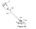
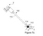
上述の利点に加えて、清掃ツール10を長手方向軸線Xと位置合わせすることによって、真空掃除機2が長手方向軸線Xを中心として回転しても、サイクロン式分離ユニット8の傾斜角度が変化しないことが確実になるので、一次サイクロン式分離器18及び二次サイクロン式分離器20の分離効率を利用時に略一定を保つことができる。このことは、図6に表わすようなスティック型真空掃除機102を形成するために、清掃ツール10がワンド110及び掃除機ヘッド112に交換された場合に特に優位である。 In addition to the advantages described above, by aligning the
ワンド110は、サイクロン式分離ユニット8の長手方向軸線Xと同軸に延在している。掃除機ヘッド112は、互いに対して垂直に配置されている第1の回転軸線Y及び第2の回転軸線Zを有している、関節式頸部114を備えている。第1の回転軸線Y及び第2の回転軸線Zは、掃除機ヘッド112がワンド110が表面に対して傾斜している状態において当該表面に載置されている場合に、スティック型真空掃除機102をサイクロン式分離ユニット8の長手方向軸線Xを中心として回転させることによって(ひいては、ワンド110をワンド軸線を中心として回転させることによって)、図7a〜図7cに表わすように、掃除機ヘッド112は左右に方向転換することができるように配置されている。 The
上述のように、掃除機ヘッド114が清掃面に沿って方向転換されるので、サイクロン式分離ユニット8の長手方向軸線Xの傾斜が略一定に維持される。結論として、既知のスティック型真空掃除機とは異なり、サイクロン方式に基づく分離効率は略一定を保たれ、再び塵埃が混入する恐れが低い。 As described above, since the
さらなる利点は、サイクロン式分離ユニット8の重心がワンド110の軸線に又はその近傍に配置されていることである。結論として、ワンド110の軸線を中心とするサイクロン式分離ユニット8の重量バランスは、サイクロン式分離ユニット8が清掃の際に回転された場合であっても、略一定に維持される。従って、真空掃除機2は、容易に操縦可能とされる。 A further advantage is that the center of gravity of the
図8を参照すると、上述の実施例のいずれかについての塵埃収集器38及び微小塵埃収集器51を空にするために、利用者は、最初に清掃ツール10又はワンド110を接続解除する。その後に、利用者は、ハンドル6を把持した状態において、真空掃除機2を適切な容器(例えばごみ箱やごみ袋)に向け、塵埃を当該容器に入れ空にする。その後に、キャッチ42は、利用者によって解除され、端部壁26は、閉位置から開位置に回動される。サイクロン式分離ユニット8が利用者から離隔するように向いているので、利用者は通常の清掃の際に行われる把持や姿勢を実施する必要がない。結論として、塵埃収集器38及び微小塵埃収集器51を空にするためのプロセスは、非常に直観的であり且つ人間工学に基づくものである。さらに、塵埃は、ハンドル6から最も離隔しているサイクロン式分離ユニット8の端部を介して、塵埃収集器38/微小塵埃収集器51から排出される。従って、空にする際に、塵埃が塵埃収集器38/微小塵埃収集器51から利用者にこぼされる危険性がほとんど解消される。 Referring to FIG. 8, in order to empty the
代替的な構成では、入口ダクトが、サイクロン式分離ユニット8の軸線から離隔している。それにも関わらず、サイクロン式分離ユニットは、入口ダクトの一部分の周りに部分的に延在するように、又は、入口ダクトの一部分を完全に囲むように配置されている場合がある。例えば、入口ダクトは、サイクロン式分離ユニットの軸線に沿って見た場合に、ダクトがサイクロン式分離ユニットの輪郭の内側に延在しているように、サイクロン式分離ユニットの側面に窪んで形成されている場合がある。 In an alternative configuration, the inlet duct is spaced from the axis of the
2 携行式真空掃除機
4 本体
6 ハンドル
8 サイクロン式分離ユニット
10 清掃ツール
11 吸引発生器
12 モータ
13 羽根車
14 バッテリ
16 トリガー
17 トリガーガード
18 一次サイクロン式分離器
20 二次サイクロン式分離器
22 分離器本体
24 (分離器本体22の)外壁
26 (分離器本体22の)端部壁
28 サイクロン式分離チャンバ
30 中央ダクト
32 (サイクロン式分離チャンバ28の)入口
33 (清掃ツール10の)接続部分
34 (清掃ツール10の)ノズル部分
36 ダクト
38 塵埃収集器
40 ピボット
42 キャッチ
43 環状カラー
44 キャッチ
45 シュラウド
46 開口部
48 ダクト
49 (二次サイクロン式分離器20の)入口
50 固形物用出口
51 微小塵埃収集器
52 流体用出口
102 スティック型真空掃除機
110 ワンド
112 掃除機ヘッド
H ハンドル軸線
X (サイクロン式分離ユニット8の)長手方向軸線DESCRIPTION OF
Claims (10)
Translated fromJapanese通常の利用の際に前記携行式真空掃除機を支持するためのハンドルと、
長手方向軸線とサイクロン式分離ユニットの一方の端部に配置された塵埃収集器とを有している前記サイクロン式分離ユニットであって、前記サイクロン式分離ユニットが、端部分を備えており、前記端部分が、前記端部分によって塵埃が前記塵埃収集器の内部に保持される閉構成と、前記塵埃収集器から塵埃を除去するための開構成とを備えている、前記サイクロン式分離ユニットと、
を備えている前記携行式真空掃除機において、
前記ハンドルが、前記ハンドルが前記ハンドルと前記サイクロン式分離ユニットの長手方向軸線との間に85°以上140°以下の角度を形成するように前記サイクロン式分離ユニットに対して傾斜しているピストルグリップ構成を有していることを特徴とする携行式真空掃除機。A portable vacuum cleaner,
A handle for supporting the portable vacuum cleaner during normal use;
A cyclonic separation unit having a longitudinal axis and a dust collector disposed at one end of the cyclonic separation unit, wherein the cyclonic separation unit comprises an end portion; The cyclonic separation unit, wherein an end portion includes a closed configuration in which dust is held inside the dust collector by the end portion, and an open configuration for removing dust from the dust collector;
In the portable vacuum cleaner comprising:
The pistol grip in which the handle is inclined with respect to the cyclonic separation unit so that the handle forms an angle of 85 ° or more and 140 ° or less between the handle and the longitudinal axis of the cyclonic separation unit A portable vacuum cleaner characterized by having a configuration.
前記清掃ツールが、前記端部分が前記閉構成に位置しており、且つ、前記清掃ツールが前記コネクタに接続されている場合に、前記端部分が前記閉構成から前記開構成に移動することが防止されるように構成されていることを特徴とする請求項1〜5のいずれか一項に記載の携行式真空掃除機。The portable vacuum cleaner includes a connector and a cleaning tool that can be connected to the connector.
The cleaning tool may move from the closed configuration to the open configuration when the end portion is in the closed configuration and the cleaning tool is connected to the connector. It is comprised so that it may be prevented, The portable vacuum cleaner as described in any one of Claims 1-5 characterized by the above-mentioned.
Applications Claiming Priority (2)
| Application Number | Priority Date | Filing Date | Title |
|---|---|---|---|
| GB1516499.9AGB2542387B (en) | 2015-09-17 | 2015-09-17 | Vacuum cleaner |
| GB1516499.9 | 2015-09-17 |
Publications (2)
| Publication Number | Publication Date |
|---|---|
| JP2017056197Atrue JP2017056197A (en) | 2017-03-23 |
| JP6464123B2 JP6464123B2 (en) | 2019-02-06 |
Family
ID=54544413
Family Applications (1)
| Application Number | Title | Priority Date | Filing Date |
|---|---|---|---|
| JP2016175409AActiveJP6464123B2 (en) | 2015-09-17 | 2016-09-08 | Vacuum cleaner |
Country Status (11)
| Country | Link |
|---|---|
| US (1) | US10433687B2 (en) |
| EP (2) | EP4374758A1 (en) |
| JP (1) | JP6464123B2 (en) |
| KR (1) | KR102158113B1 (en) |
| CN (1) | CN106859485B (en) |
| AU (1) | AU2016322686B2 (en) |
| BR (1) | BR112018004450A2 (en) |
| CA (1) | CA2998702A1 (en) |
| GB (1) | GB2542387B (en) |
| RU (1) | RU2704561C2 (en) |
| WO (1) | WO2017046559A1 (en) |
Cited By (2)
| Publication number | Priority date | Publication date | Assignee | Title |
|---|---|---|---|---|
| JP2019111335A (en)* | 2017-12-20 | 2019-07-11 | ダイソン・テクノロジー・リミテッド | Vacuum cleaner |
| JP2021168905A (en)* | 2018-06-27 | 2021-10-28 | ビッセル インク. | Surface cleaning device |
Families Citing this family (72)
| Publication number | Priority date | Publication date | Assignee | Title |
|---|---|---|---|---|
| US11819178B2 (en) | 2018-11-26 | 2023-11-21 | Omachron Intellectual Property Inc. | Surface cleaning apparatus |
| US10258208B2 (en) | 2016-04-11 | 2019-04-16 | Omachron Intellectual Property Inc. | Surface cleaning apparatus |
| US9888817B2 (en) | 2014-12-17 | 2018-02-13 | Omachron Intellectual Property Inc. | Surface cleaning apparatus |
| US20210401246A1 (en) | 2016-04-11 | 2021-12-30 | Omachron Intellectual Property Inc. | Surface cleaning apparatus |
| US11751733B2 (en) | 2007-08-29 | 2023-09-12 | Omachron Intellectual Property Inc. | Portable surface cleaning apparatus |
| US9591952B2 (en) | 2009-03-11 | 2017-03-14 | Omachron Intellectual Property Inc. | Hand vacuum cleaner with removable dirt chamber |
| US10722086B2 (en) | 2017-07-06 | 2020-07-28 | Omachron Intellectual Property Inc. | Handheld surface cleaning apparatus |
| US12156626B2 (en) | 2009-03-13 | 2024-12-03 | Omachron Intellectual Property Inc. | Surface cleaning apparatus |
| US10674884B2 (en) | 2013-02-28 | 2020-06-09 | Omachron Intellectual Property Inc. | Hand carryable surface cleaning apparatus |
| US10729294B2 (en) | 2013-02-28 | 2020-08-04 | Omachron Intellectual Property Inc. | Hand carryable surface cleaning apparatus |
| US10791889B2 (en) | 2016-01-08 | 2020-10-06 | Omachron Intellectual Property Inc. | Hand carryable surface cleaning apparatus |
| US10251519B2 (en) | 2014-12-17 | 2019-04-09 | Omachron Intellectual Property Inc. | Surface cleaning apparatus |
| US10136778B2 (en) | 2014-12-17 | 2018-11-27 | Omachron Intellectual Property Inc. | Surface cleaning apparatus |
| US10022027B2 (en) | 2014-12-17 | 2018-07-17 | Omachron Intellectual Property Inc. | All in the head surface cleaning apparatus |
| US9883781B2 (en) | 2014-12-17 | 2018-02-06 | Omachron Intellectual Property Inc. | All in the head surface cleaning apparatus |
| US11950745B2 (en) | 2014-12-17 | 2024-04-09 | Omachron Intellectual Property Inc. | Surface cleaning apparatus |
| GB2542385B (en)* | 2015-09-17 | 2018-10-10 | Dyson Technology Ltd | Vacuum Cleaner |
| GB2542387B (en) | 2015-09-17 | 2017-11-01 | Dyson Technology Ltd | Vacuum cleaner |
| GB2542386B (en)* | 2015-09-17 | 2018-10-10 | Dyson Technology Ltd | Vacuum Cleaner |
| US9962048B2 (en) | 2016-01-08 | 2018-05-08 | Omachron Intellectual Property | Hand carryable surface cleaning apparatus |
| US9980616B2 (en) | 2016-01-08 | 2018-05-29 | Omachron Intellectual Property Inc. | Hand carryable surface cleaning apparatus |
| WO2017117679A1 (en)* | 2016-01-08 | 2017-07-13 | Omachron Intellectual Property Inc. | Hand carryable surface cleaning apparatus |
| US12390062B2 (en) | 2016-01-08 | 2025-08-19 | Omachron Intellectual Property Inc. | Hand carryable surface cleaning apparatus |
| US10165914B2 (en) | 2016-01-08 | 2019-01-01 | Omachron Intellectual Property Inc. | Hand carryable surface cleaning apparatus |
| US11241129B2 (en) | 2016-04-11 | 2022-02-08 | Omachron Intellectual Property Inc. | Surface cleaning apparatus |
| US10016104B2 (en) | 2016-04-11 | 2018-07-10 | Omachron Intellectual Property Inc. | Surface cleaning apparatus |
| US10568477B2 (en) | 2016-04-11 | 2020-02-25 | Omachron Intellectual Property Inc. | Surface cleaning apparatus |
| US9986880B2 (en) | 2016-04-11 | 2018-06-05 | Omachron Intellectual Property Inc. | Surface cleaning apparatus |
| US10016105B2 (en) | 2016-04-11 | 2018-07-10 | Omachron Intellectual Property Inc. | Surface cleaning apparatus |
| US10258210B2 (en) | 2016-12-27 | 2019-04-16 | Omachron Intellectual Property Inc. | Multistage cyclone and surface cleaning apparatus having same |
| US10405709B2 (en) | 2016-12-27 | 2019-09-10 | Omachron Intellectual Property Inc. | Multistage cyclone and surface cleaning apparatus having same |
| US10299643B2 (en) | 2016-12-27 | 2019-05-28 | Omachron Intellectual Property Inc. | Multistage cyclone and surface cleaning apparatus having same |
| US10271704B2 (en) | 2016-12-27 | 2019-04-30 | Omachron Intellectual Property Inc. | Multistage cyclone and surface cleaning apparatus having same |
| US11285495B2 (en) | 2016-12-27 | 2022-03-29 | Omachron Intellectual Property Inc. | Multistage cyclone and surface cleaning apparatus having same |
| US10827891B2 (en) | 2016-12-27 | 2020-11-10 | Omachron Intellectual Property Inc. | Multistage cyclone and surface cleaning apparatus having same |
| US10016106B1 (en) | 2016-12-27 | 2018-07-10 | Omachron Intellectual Property Inc. | Multistage cyclone and surface cleaning apparatus having same |
| KR102270980B1 (en) | 2017-01-12 | 2021-06-29 | 다이슨 테크놀러지 리미티드 | portable |
| GB2562276B (en) | 2017-05-10 | 2021-04-28 | Dyson Technology Ltd | A heater |
| AU2017420074B2 (en)* | 2017-06-19 | 2024-05-30 | Techtronic Cordless Gp | Surface cleaning apparatus |
| GB2598506B (en)* | 2017-06-19 | 2022-06-08 | Techtronic Floor Care Tech Ltd | A dirt separation device |
| US10702113B2 (en) | 2017-07-06 | 2020-07-07 | Omachron Intellectual Property Inc. | Handheld surface cleaning apparatus |
| US11219906B2 (en) | 2019-01-23 | 2022-01-11 | Omachron Intellectual Property Inc. | Surface cleaning apparatus, cyclonic air treatment member and surface cleaning apparatus including the same |
| US11745190B2 (en) | 2019-01-23 | 2023-09-05 | Omachron Intellectual Property Inc. | Surface cleaning apparatus |
| US10506904B2 (en) | 2017-07-06 | 2019-12-17 | Omachron Intellectual Property Inc. | Handheld surface cleaning apparatus |
| US10750913B2 (en) | 2017-07-06 | 2020-08-25 | Omachron Intellectual Property Inc. | Handheld surface cleaning apparatus |
| US10537216B2 (en) | 2017-07-06 | 2020-01-21 | Omachron Intellectual Property Inc. | Handheld surface cleaning apparatus |
| US10631693B2 (en) | 2017-07-06 | 2020-04-28 | Omachron Intellectual Property Inc. | Handheld surface cleaning apparatus |
| US10842330B2 (en) | 2017-07-06 | 2020-11-24 | Omachron Intellectual Property Inc. | Handheld surface cleaning apparatus |
| GB2565365B (en) | 2017-08-11 | 2020-02-05 | Dyson Technology Ltd | Handheld vacuum cleaner |
| GB2565358B (en)* | 2017-08-11 | 2020-05-20 | Dyson Technology Ltd | Dirt separator for a vacuum cleaner |
| GB2565362B (en) | 2017-08-11 | 2020-03-25 | Dyson Technology Ltd | Dirt separator for a vacuum cleaner |
| GB2565355B (en) | 2017-08-11 | 2020-03-25 | Dyson Technology Ltd | Dirt separator for a vacuum cleaner |
| US10575701B2 (en) | 2017-09-15 | 2020-03-03 | Omachron Intellectual Property Inc. | Surface cleaning apparatus |
| EP3684237B1 (en) | 2017-09-22 | 2023-07-19 | SharkNinja Operating LLC | Hand-held surface cleaning device |
| US11723501B2 (en) | 2018-08-09 | 2023-08-15 | Milwaukee Electric Tool Corporation | Handheld vacuum cleaner |
| US11013384B2 (en) | 2018-08-13 | 2021-05-25 | Omachron Intellectual Property Inc. | Cyclonic air treatment member and surface cleaning apparatus including the same |
| GB2578872B (en) | 2018-11-09 | 2021-04-14 | Dyson Technology Ltd | Vacuum cleaner |
| CN110772166A (en)* | 2019-10-31 | 2020-02-11 | 珠海格力电器股份有限公司 | Handheld Vacuum Cleaner |
| US11751740B2 (en) | 2019-11-18 | 2023-09-12 | Omachron Intellectual Property Inc. | Multi-inlet cyclone |
| US11246462B2 (en) | 2019-11-18 | 2022-02-15 | Omachron Intellectual Property Inc. | Multi-inlet cyclone |
| EP3906831B1 (en) | 2020-05-05 | 2024-06-26 | Miele & Cie. KG | Hand-guided cyclone vacuum cleaner |
| BE1028991B1 (en) | 2021-01-05 | 2022-08-10 | Miele & Cie | Handheld cyclone vacuum cleaner |
| EP3906829B1 (en) | 2020-05-05 | 2024-06-26 | Miele & Cie. KG | Hand-guided cyclone vacuum cleaner |
| DE102020112086A1 (en) | 2020-05-05 | 2021-11-11 | Miele & Cie. Kg | Hand-held cyclone vacuum cleaner |
| CN112617654A (en)* | 2020-12-16 | 2021-04-09 | 苏州图途智能科技有限公司 | Hand-held vacuum cleaner |
| US12108920B2 (en) | 2021-07-13 | 2024-10-08 | Omachron Intellectual Property Inc. | Hand vacuum cleaner |
| GB2635620A (en) | 2022-06-17 | 2025-05-21 | Origyn LLC | Waste receptacle and vacuum cleaner |
| GB2621469A (en)* | 2022-06-29 | 2024-02-14 | Dyson Technology Ltd | Separation system for a vacuum cleaner |
| USD1066837S1 (en)* | 2022-09-15 | 2025-03-11 | Dyson Technology Limited | Vacuum cleaner |
| USD1066836S1 (en)* | 2022-09-15 | 2025-03-11 | Dyson Technology Limited | Vacuum cleaner |
| JP1757642S (en)* | 2022-09-15 | 2023-11-16 | vacuum cleaner body | |
| USD1053483S1 (en)* | 2024-04-18 | 2024-12-03 | Shenzhen Jieqi Technology Innovation Co., Ltd. | Handheld vacuum cleaner |
Citations (8)
| Publication number | Priority date | Publication date | Assignee | Title |
|---|---|---|---|---|
| JPS48107459U (en)* | 1972-03-15 | 1973-12-12 | ||
| JPS5427573U (en)* | 1977-07-27 | 1979-02-22 | ||
| JP2002085297A (en)* | 2000-09-11 | 2002-03-26 | Matsushita Electric Ind Co Ltd | Electric vacuum cleaner |
| JP2005261963A (en)* | 2005-05-09 | 2005-09-29 | Sanyo Electric Co Ltd | Dust collector for cleaner and upright cleaner |
| JP2008206613A (en)* | 2007-02-23 | 2008-09-11 | Twinbird Corp | Vacuum cleaner |
| JP2008272474A (en)* | 2007-05-03 | 2008-11-13 | Dyson Technology Ltd | Dust collection chamber for electric vacuum cleaner |
| JP2009543642A (en)* | 2006-07-18 | 2009-12-10 | ダイソン テクノロジー リミテッド | Handheld cleaning tool |
| JP2014100572A (en)* | 2012-11-20 | 2014-06-05 | Dyson Technology Ltd | Electric appliance for cleaning |
Family Cites Families (120)
| Publication number | Priority date | Publication date | Assignee | Title |
|---|---|---|---|---|
| FR1094603A (en) | 1955-05-23 | |||
| US1420665A (en) | 1920-05-10 | 1922-06-27 | John W Newcombe | Centrifugal dust separator |
| FR553202A (en) | 1922-06-23 | 1923-05-15 | Centrifugal dust separator | |
| DE661573C (en) | 1936-04-02 | 1938-06-22 | Friedrich Buettner | Vacuum cleaner for blower and suction air operation |
| CH203675A (en) | 1938-05-27 | 1939-03-31 | Joerg Peter | Vacuum cleaner. |
| DE1407995A1 (en) | 1964-10-23 | 1969-02-20 | Siemens Elektrogeraete Gmbh | Device for separating solid components from an air flow |
| DE1937005U (en) | 1966-01-13 | 1966-04-21 | Moebes Nachf W | PORTABLE VACUUM CLEANER. |
| SE350905B (en) | 1970-12-21 | 1972-11-13 | Electrolux Ab | |
| JPS4854260A (en) | 1971-11-15 | 1973-07-30 | ||
| JPS559101B2 (en) | 1971-11-18 | 1980-03-07 | ||
| JPS53109379U (en) | 1977-02-08 | 1978-09-01 | ||
| JPS6051472B2 (en) | 1977-08-01 | 1985-11-14 | 大塚製薬株式会社 | 3,4-dihydrocarbostyryl derivative |
| US4199887A (en) | 1977-09-23 | 1980-04-29 | Guy Hogue | One piece hand grip for pistol |
| JPH0365545A (en) | 1989-08-03 | 1991-03-20 | Kenji Yabuta | Production of colored ballast |
| CN2129132Y (en) | 1992-03-12 | 1993-04-07 | 崔永毅 | Mini-size chargeable vacuum cleaner with lighting function |
| KR19980020751U (en) | 1996-10-16 | 1998-07-15 | 문신호 | Pistol type vacuum cleaner |
| EP1135049A1 (en) | 1998-10-07 | 2001-09-26 | Jetfan Australia Pty Ltd. | An apparatus for picking up and collecting particulate material |
| US6131239A (en) | 1999-03-31 | 2000-10-17 | White; Carl Lee | Ground debris vacuum |
| JP3476066B2 (en) | 1999-07-19 | 2003-12-10 | シャープ株式会社 | Electric vacuum cleaner |
| JP2001269294A (en) | 2000-03-23 | 2001-10-02 | Sharp Corp | Electric vacuum cleaner |
| JP2001353110A (en) | 2000-06-14 | 2001-12-25 | Matsushita Electric Ind Co Ltd | Electric vacuum cleaner |
| KR100398684B1 (en)* | 2000-11-27 | 2003-09-19 | 삼성광주전자 주식회사 | Cyclone dust-collecting apparatus for vacuum cleaner |
| JP2003070706A (en) | 2001-08-31 | 2003-03-11 | Sharp Corp | Rechargeable vacuum cleaner |
| KR200257953Y1 (en) | 2001-09-06 | 2001-12-24 | 주식회사 스피드센서전자 | Small sized wireless vacuum cleaner for pet hair |
| CN2529599Y (en) | 2001-12-14 | 2003-01-08 | 潘景良 | Cyclone device of small hand-held household duster |
| US6775882B2 (en) | 2002-01-11 | 2004-08-17 | Royal Appliance Mfg. Co. | Stick vacuum with dirt cup |
| JP2003204903A (en) | 2002-01-11 | 2003-07-22 | Matsushita Electric Ind Co Ltd | Electric vacuum cleaner |
| JP3983055B2 (en) | 2002-01-21 | 2007-09-26 | 三洋電機株式会社 | Electric vacuum cleaner |
| JP2003250729A (en) | 2002-02-28 | 2003-09-09 | Toshiba Tec Corp | Electric vacuum cleaner |
| JP3674039B2 (en) | 2002-04-25 | 2005-07-20 | ツインバード工業株式会社 | Cyclone vacuum cleaner |
| US20040040270A1 (en) | 2002-08-29 | 2004-03-04 | Mineyuki Inoue | Cyclonic vacuum cleaner |
| JP2004089241A (en)* | 2002-08-29 | 2004-03-25 | Matsushita Electric Ind Co Ltd | Electric vacuum cleaner |
| JP3876833B2 (en) | 2002-12-25 | 2007-02-07 | ツインバード工業株式会社 | Cyclone vacuum cleaner |
| US20040134022A1 (en) | 2003-01-10 | 2004-07-15 | Royal Manufacturing Co. | Bagless stick type vacuum cleaner |
| SE0300355D0 (en) | 2003-02-10 | 2003-02-10 | Electrolux Ab | Hand held vacuum cleaner |
| US20050081321A1 (en) | 2003-10-15 | 2005-04-21 | Milligan Michael A. | Hand-held cordless vacuum cleaner |
| JP2005270312A (en) | 2004-03-24 | 2005-10-06 | Sharp Corp | Vertical vacuum cleaner |
| US7565853B2 (en) | 2004-08-26 | 2009-07-28 | Euro-Pro Operating, Llc | Compact cyclonic separation device |
| US20060090290A1 (en) | 2004-11-01 | 2006-05-04 | Lau Ying W | Handheld vacuum with accelerated cyclonic flow and air freshener |
| US20060156508A1 (en) | 2005-01-14 | 2006-07-20 | Royal Appliance Mfg. Co. | Vacuum cleaner with cyclonic separating dirt cup and dirt cup door |
| JP2006230815A (en) | 2005-02-25 | 2006-09-07 | Twinbird Corp | Stick-shaped cleaner |
| JP2006320713A (en) | 2005-05-16 | 2006-11-30 | Samsung Kwangju Electronics Co Ltd | Multi cyclone dust collector |
| CN100341456C (en) | 2005-05-19 | 2007-10-10 | 苏州宝时得电动工具有限公司 | Portable cleaner with no rope |
| CN2812826Y (en) | 2005-08-05 | 2006-09-06 | 苏州金莱克清洁器具有限公司 | Hand-held suction cleaner cyclone separator |
| ATE446040T1 (en)* | 2005-08-11 | 2009-11-15 | Black & Decker Inc | HAND-HELD VACUUM CLEANER |
| DE102005056922A1 (en) | 2005-11-29 | 2007-05-31 | BSH Bosch und Siemens Hausgeräte GmbH | Method for extracting dust particles from the suction air stream of a vacuum cleaner has a centrifugal separator by which the particles enter a dust collection system and the cleaned air is returned to the environment |
| JP2006087961A (en) | 2005-12-22 | 2006-04-06 | Sharp Corp | Vacuum cleaner |
| US20070163075A1 (en) | 2006-01-17 | 2007-07-19 | Butler Dennis C | Stair cleaning vacuum cleaner |
| CN101032384A (en)* | 2006-03-10 | 2007-09-12 | 苏州宝时得电动工具有限公司 | Portable vacuum cleaner |
| US20080040883A1 (en) | 2006-04-10 | 2008-02-21 | Jonas Beskow | Air Flow Losses in a Vacuum Cleaners |
| CN101061932A (en) | 2006-04-28 | 2007-10-31 | 光荣电业有限公司 | Cyclone Handheld Vacuums |
| WO2008009891A1 (en) | 2006-07-18 | 2008-01-24 | Dyson Technology Limited | Handheld cleaning appliance |
| GB2474176A (en) | 2006-07-18 | 2011-04-06 | Dyson Technology Ltd | A hand-held vacuum cleaner with handle and suction pipe relatively angled |
| CN2927961Y (en) | 2006-07-28 | 2007-08-01 | 苏州宝时得电动工具有限公司 | Portable vacuum cleaner |
| GB2441300B (en) | 2006-09-01 | 2011-10-12 | Dyson Technology Ltd | A collecting chamber for a vacuum cleaner |
| JP2008073221A (en) | 2006-09-21 | 2008-04-03 | Toshiba Corp | Electric vacuum cleaner |
| JP2008079920A (en) | 2006-09-28 | 2008-04-10 | Toshiba Corp | Electric vacuum cleaner |
| US10765277B2 (en) | 2006-12-12 | 2020-09-08 | Omachron Intellectual Property Inc. | Configuration of a surface cleaning apparatus |
| CA2599303A1 (en) | 2007-08-29 | 2009-02-28 | Gbd Corp. | Surface cleaning apparatus |
| US9888817B2 (en)* | 2014-12-17 | 2018-02-13 | Omachron Intellectual Property Inc. | Surface cleaning apparatus |
| SE530741C2 (en) | 2007-01-19 | 2008-09-02 | Electrolux Ab | Improvements in air flow losses in a vacuum cleaner |
| ATE514367T1 (en) | 2007-04-04 | 2011-07-15 | Black & Decker Inc | FILTER CLEANING MECHANISMS |
| CN101449948B (en)* | 2007-11-29 | 2011-08-17 | 博西华电器(江苏)有限公司 | Cyclone system for dust collector and dust collector with the same |
| EP2224838A1 (en) | 2007-12-18 | 2010-09-08 | Techtronic Floor Care Technology Limited | Sweepable electric vacuum cleaner |
| JP2009261501A (en) | 2008-04-23 | 2009-11-12 | Yamada Electric Ind Co Ltd | Stick vacuum cleaner |
| JP5190299B2 (en) | 2008-05-24 | 2013-04-24 | ツインバード工業株式会社 | Cyclone vacuum cleaner |
| US8539639B2 (en) | 2008-10-10 | 2013-09-24 | Ab Electrolux | Dustcup |
| KR20080110720A (en) | 2008-12-01 | 2008-12-19 | 최종대 | Electric vacuum cleaner with roller suitable for floor cleaning |
| CN201346180Y (en) | 2008-12-15 | 2009-11-18 | 东莞清溪光荣电业制品厂 | Cyclone type dust collector |
| DE102009041728B4 (en) | 2008-12-22 | 2022-07-07 | Vorwerk & Co. Interholding Gmbh | Method for operating a vacuum cleaner and moveable vacuum cleaning device |
| FR2940901B1 (en) | 2009-01-15 | 2014-12-05 | Seb Sa | DUST SEPARATOR |
| FR2940902B1 (en) | 2009-01-15 | 2011-02-18 | Seb Sa | CYCLONIC SEPARATION DEVICE WITH ACCELERATION RAMP |
| US9173532B2 (en) | 2009-01-16 | 2015-11-03 | Robert W. Casper | Pet vacuum cleaner |
| US8267192B2 (en) | 2009-02-24 | 2012-09-18 | Black & Decker Inc. | Ergonomic handle for power tool |
| GB2468299B (en)* | 2009-03-03 | 2012-06-20 | Dyson Technology Ltd | Noise reduction arrangement for a cleaning appliance. |
| US9591952B2 (en) | 2009-03-11 | 2017-03-14 | Omachron Intellectual Property Inc. | Hand vacuum cleaner with removable dirt chamber |
| WO2010102400A1 (en) | 2009-03-11 | 2010-09-16 | G.B.D. Corp. | Inlet for a vacuum cleaner |
| CA2658019A1 (en) | 2009-03-11 | 2010-09-11 | G.B.D. Corp. | Configuration of a hand vacuum cleaner |
| CA2658008A1 (en) | 2009-03-11 | 2010-09-11 | G.B.D. Corp. | Nozzle construction for a cleaning head |
| CA2658006A1 (en) | 2009-03-11 | 2010-09-11 | G.B.D. Corp. | Cyclonic surface cleaning apparatus |
| CA2658154A1 (en) | 2009-03-13 | 2010-09-13 | G.B.D. Corp. | Filter apparatus |
| CA2967272C (en)* | 2009-03-13 | 2018-01-02 | Omachron Intellectual Property Inc. | Hand vacuum cleaner |
| CA3105266C (en) | 2009-03-20 | 2023-02-07 | Omachron Intellectual Property Inc. | Surface cleaning apparatus |
| US8167964B2 (en) | 2009-04-09 | 2012-05-01 | Lau Ying Wai | Cyclonic chamber for air filtration devices |
| KR101110302B1 (en) | 2009-06-16 | 2012-02-15 | 토비즈 주식회사 | Handy Vacuum Cleaner |
| CN201658325U (en)* | 2009-12-16 | 2010-12-01 | 耀川电子(深圳)有限公司 | Handheld dust collector capable of cleaning dust collection box through operation the front end |
| CN201755193U (en) | 2010-04-14 | 2011-03-09 | 泰怡凯电器(苏州)有限公司 | Hand-held cleaning system |
| CN102217912B (en) | 2010-04-14 | 2013-09-18 | 泰怡凯电器(苏州)有限公司 | Handheld cleaning system |
| KR101090118B1 (en) | 2010-04-27 | 2011-12-08 | 주식회사 세광정밀 | Vacuum cleaner for handy type cleaner |
| US8671510B2 (en) | 2010-05-31 | 2014-03-18 | Samsung Electronics Co., Ltd. | Hand-held and stick vacuum cleaner |
| US8769764B2 (en) | 2010-08-05 | 2014-07-08 | Panasonic Corporation Of North America | Hand-held and conversion vacuum cleaner with adapter |
| GB2484146B (en) | 2010-10-01 | 2013-02-13 | Dyson Technology Ltd | A vacuum cleaner |
| KR101199399B1 (en) | 2010-11-01 | 2012-11-09 | 엘지전자 주식회사 | An upright type vacuum cleaner |
| CN103501673B (en) | 2011-02-22 | 2016-01-13 | 伊莱克斯公司 | For the filter unit of vacuum cleaner |
| DE102011007373A1 (en) | 2011-04-14 | 2012-10-18 | Gerhard Thien | Vacuum cleaner device, has flow guide passage for reconducting airflow into area of cleaning portion after passing airflow through secretion device and arranged between suction and outer housings at outer side of suction housing |
| GB201106455D0 (en) | 2011-04-15 | 2011-06-01 | Dyson Technology Ltd | Cyclonic separator |
| GB2497944B (en) | 2011-12-22 | 2014-04-02 | Dyson Technology Ltd | Vacuum cleaner |
| CN102525349A (en) | 2012-02-01 | 2012-07-04 | 江苏美的春花电器股份有限公司 | Vacuum cleaner |
| CN202776168U (en) | 2012-08-31 | 2013-03-13 | 莱克电气股份有限公司 | Multifunctional dust collector with novel cyclone assembly |
| CN202776167U (en) | 2012-08-31 | 2013-03-13 | 莱克电气股份有限公司 | Multifunctional dust collector with cyclone assembly |
| TR201210114U (en) | 2012-09-05 | 2012-12-21 | Tangüler Adnan | Silent cyclone stick vacuum cleaner. |
| CN202932850U (en) | 2012-11-09 | 2013-05-15 | 苏州普发电器有限公司 | Cyclone dust collector |
| JP2014124443A (en) | 2012-12-27 | 2014-07-07 | Iris Ohyama Inc | Vacuum cleaner |
| DE102013200576A1 (en) | 2013-01-16 | 2014-07-17 | Robert Bosch Gmbh | Hand tool with an ergonomic handle |
| US9027198B2 (en) | 2013-02-27 | 2015-05-12 | G.B.D. Corp. | Surface cleaning apparatus |
| KR101507922B1 (en) | 2013-10-23 | 2015-04-07 | 토비즈 주식회사 | Handy type vacuum cleaner capable of dual stelilization |
| CN203724037U (en)* | 2014-03-13 | 2014-07-23 | 光荣电业(东莞)有限公司 | a dust collection device |
| KR20150125223A (en) | 2014-04-30 | 2015-11-09 | 삼성전자주식회사 | A cleaner |
| KR102274393B1 (en) | 2014-08-11 | 2021-07-08 | 삼성전자주식회사 | Vacuum cleaner |
| EP3209175B1 (en)* | 2014-10-22 | 2023-01-04 | Techtronic Industries Co. Ltd. | Handheld vacuum cleaner |
| US10136778B2 (en) | 2014-12-17 | 2018-11-27 | Omachron Intellectual Property Inc. | Surface cleaning apparatus |
| KR102277144B1 (en) | 2014-12-18 | 2021-07-14 | 삼성전자주식회사 | Cleaning Apparatus |
| JP6488137B2 (en) | 2015-01-28 | 2019-03-20 | 日立アプライアンス株式会社 | Electric vacuum cleaner |
| CN204698456U (en) | 2015-06-09 | 2015-10-14 | 莱克电气股份有限公司 | A kind of hand held cleaner with spiral secondary spout travel fatigue gas separation structure |
| CN104840152A (en) | 2015-06-09 | 2015-08-19 | 莱克电气股份有限公司 | Handheld dust collector with spiral two-level tornado dust-air separation structure |
| US10064530B2 (en)* | 2015-09-16 | 2018-09-04 | Bissell Homecare, Inc. | Handheld vacuum cleaner |
| GB2542385B (en) | 2015-09-17 | 2018-10-10 | Dyson Technology Ltd | Vacuum Cleaner |
| GB2542387B (en) | 2015-09-17 | 2017-11-01 | Dyson Technology Ltd | Vacuum cleaner |
| GB2542386B (en) | 2015-09-17 | 2018-10-10 | Dyson Technology Ltd | Vacuum Cleaner |
| CN105662271B (en) | 2016-02-18 | 2017-11-10 | 宁波海际电器有限公司 | A kind of portable rotoclone collector |
- 2015
- 2015-09-17GBGB1516499.9Apatent/GB2542387B/enactiveActive
- 2016
- 2016-08-23AUAU2016322686Apatent/AU2016322686B2/enactiveActive
- 2016-08-23EPEP24169663.2Apatent/EP4374758A1/enactivePending
- 2016-08-23KRKR1020187007211Apatent/KR102158113B1/enactiveActive
- 2016-08-23CACA2998702Apatent/CA2998702A1/ennot_activeAbandoned
- 2016-08-23WOPCT/GB2016/052611patent/WO2017046559A1/ennot_activeCeased
- 2016-08-23RURU2018113743Apatent/RU2704561C2/enactive
- 2016-08-23BRBR112018004450Apatent/BR112018004450A2/ennot_activeApplication Discontinuation
- 2016-08-23EPEP16756785.8Apatent/EP3349633B1/enactiveActive
- 2016-09-08JPJP2016175409Apatent/JP6464123B2/enactiveActive
- 2016-09-18CNCN201610830364.1Apatent/CN106859485B/enactiveActive
- 2016-09-19USUS15/269,430patent/US10433687B2/enactiveActive
Patent Citations (8)
| Publication number | Priority date | Publication date | Assignee | Title |
|---|---|---|---|---|
| JPS48107459U (en)* | 1972-03-15 | 1973-12-12 | ||
| JPS5427573U (en)* | 1977-07-27 | 1979-02-22 | ||
| JP2002085297A (en)* | 2000-09-11 | 2002-03-26 | Matsushita Electric Ind Co Ltd | Electric vacuum cleaner |
| JP2005261963A (en)* | 2005-05-09 | 2005-09-29 | Sanyo Electric Co Ltd | Dust collector for cleaner and upright cleaner |
| JP2009543642A (en)* | 2006-07-18 | 2009-12-10 | ダイソン テクノロジー リミテッド | Handheld cleaning tool |
| JP2008206613A (en)* | 2007-02-23 | 2008-09-11 | Twinbird Corp | Vacuum cleaner |
| JP2008272474A (en)* | 2007-05-03 | 2008-11-13 | Dyson Technology Ltd | Dust collection chamber for electric vacuum cleaner |
| JP2014100572A (en)* | 2012-11-20 | 2014-06-05 | Dyson Technology Ltd | Electric appliance for cleaning |
Cited By (2)
| Publication number | Priority date | Publication date | Assignee | Title |
|---|---|---|---|---|
| JP2019111335A (en)* | 2017-12-20 | 2019-07-11 | ダイソン・テクノロジー・リミテッド | Vacuum cleaner |
| JP2021168905A (en)* | 2018-06-27 | 2021-10-28 | ビッセル インク. | Surface cleaning device |
Also Published As
| Publication number | Publication date |
|---|---|
| BR112018004450A2 (en) | 2018-09-25 |
| GB2542387B (en) | 2017-11-01 |
| GB2542387A (en) | 2017-03-22 |
| US10433687B2 (en) | 2019-10-08 |
| EP4374758A1 (en) | 2024-05-29 |
| CN106859485A (en) | 2017-06-20 |
| KR20180040660A (en) | 2018-04-20 |
| RU2704561C2 (en) | 2019-10-29 |
| EP3349633B1 (en) | 2024-05-22 |
| AU2016322686A1 (en) | 2018-03-08 |
| KR102158113B1 (en) | 2020-09-21 |
| GB201516499D0 (en) | 2015-11-04 |
| CN106859485B (en) | 2020-11-03 |
| RU2018113743A (en) | 2019-10-17 |
| RU2018113743A3 (en) | 2019-10-17 |
| CA2998702A1 (en) | 2017-03-23 |
| AU2016322686B2 (en) | 2019-02-07 |
| US20170079491A1 (en) | 2017-03-23 |
| EP3349633A1 (en) | 2018-07-25 |
| WO2017046559A1 (en) | 2017-03-23 |
| JP6464123B2 (en) | 2019-02-06 |
Similar Documents
| Publication | Publication Date | Title |
|---|---|---|
| JP6464123B2 (en) | Vacuum cleaner | |
| JP6661755B2 (en) | Vacuum cleaner | |
| JP6513616B2 (en) | Vacuum cleaner | |
| JP2017056202A (en) | Vacuum cleaner |
Legal Events
| Date | Code | Title | Description |
|---|---|---|---|
| A521 | Request for written amendment filed | Free format text:JAPANESE INTERMEDIATE CODE: A821 Effective date:20161209 | |
| A131 | Notification of reasons for refusal | Free format text:JAPANESE INTERMEDIATE CODE: A131 Effective date:20170904 | |
| A601 | Written request for extension of time | Free format text:JAPANESE INTERMEDIATE CODE: A601 Effective date:20171129 | |
| A601 | Written request for extension of time | Free format text:JAPANESE INTERMEDIATE CODE: A601 Effective date:20180205 | |
| A521 | Request for written amendment filed | Free format text:JAPANESE INTERMEDIATE CODE: A523 Effective date:20180302 | |
| A131 | Notification of reasons for refusal | Free format text:JAPANESE INTERMEDIATE CODE: A131 Effective date:20180903 | |
| A521 | Request for written amendment filed | Free format text:JAPANESE INTERMEDIATE CODE: A523 Effective date:20181203 | |
| TRDD | Decision of grant or rejection written | ||
| A01 | Written decision to grant a patent or to grant a registration (utility model) | Free format text:JAPANESE INTERMEDIATE CODE: A01 Effective date:20181221 | |
| A61 | First payment of annual fees (during grant procedure) | Free format text:JAPANESE INTERMEDIATE CODE: A61 Effective date:20190107 | |
| R150 | Certificate of patent or registration of utility model | Ref document number:6464123 Country of ref document:JP Free format text:JAPANESE INTERMEDIATE CODE: R150 | |
| R250 | Receipt of annual fees | Free format text:JAPANESE INTERMEDIATE CODE: R250 | |
| R250 | Receipt of annual fees | Free format text:JAPANESE INTERMEDIATE CODE: R250 | |
| R250 | Receipt of annual fees | Free format text:JAPANESE INTERMEDIATE CODE: R250 | |
| R250 | Receipt of annual fees | Free format text:JAPANESE INTERMEDIATE CODE: R250 |