JP2017050765A - Information processing device and program - Google Patents
Information processing device and programDownload PDFInfo
- Publication number
- JP2017050765A JP2017050765AJP2015173721AJP2015173721AJP2017050765AJP 2017050765 AJP2017050765 AJP 2017050765AJP 2015173721 AJP2015173721 AJP 2015173721AJP 2015173721 AJP2015173721 AJP 2015173721AJP 2017050765 AJP2017050765 AJP 2017050765A
- Authority
- JP
- Japan
- Prior art keywords
- packet
- information
- acquired
- network
- asymmetric
- Prior art date
- Legal status (The legal status is an assumption and is not a legal conclusion. Google has not performed a legal analysis and makes no representation as to the accuracy of the status listed.)
- Pending
Links
- 230000010365information processingEffects0.000titleclaimsabstractdescription15
- 230000005540biological transmissionEffects0.000claimsabstractdescription61
- 230000004044responseEffects0.000claimsabstractdescription21
- 238000004891communicationMethods0.000claimsdescription27
- 238000000034methodMethods0.000description18
- 238000010586diagramMethods0.000description12
- 101100048435Caenorhabditis elegans unc-18 geneProteins0.000description5
- 230000006870functionEffects0.000description5
- 235000008694Humulus lupulusNutrition0.000description2
- 101100043731Caenorhabditis elegans syx-3 geneProteins0.000description1
- 101100535673Drosophila melanogaster Syn geneProteins0.000description1
- 101100368134Mus musculus Syn1 geneProteins0.000description1
- 241000700605VirusesSpecies0.000description1
- 238000001514detection methodMethods0.000description1
- 230000000694effectsEffects0.000description1
- 239000000284extractSubstances0.000description1
- 239000004973liquid crystal related substanceSubstances0.000description1
- 230000004048modificationEffects0.000description1
- 238000012986modificationMethods0.000description1
- 230000003287optical effectEffects0.000description1
- 239000004065semiconductorSubstances0.000description1
Images


Landscapes
- Data Exchanges In Wide-Area Networks (AREA)
Abstract
Description
Translated fromJapanese本発明は、情報処理装置及びプログラムに関する。 The present invention relates to an information processing apparatus and a program.
特許文献1に記載されたネットワークトポロジ推定システムは、ネットワークを流れるパケットを取得し、取得したパケットの発信元のMACアドレス及びIPアドレス、宛先のMACアドレス及びIPアドレスをパケットから取得する。ネットワークトポロジ推定システムは、取得したパケットのうちDHCP応答パケットを抽出し、DHCP応答パケットに含まれるネットワーク情報からネットワークセグメントを判定し、取得したIPアドレス及びMACアドレスの組からネットワークセグメントに含まれるルータを特定する。ネットワークトポロジ推定システムは、判定したネットワークセグメントの間を流れるパケットのMACアドレスから、特定したルータのうちそのネットワークセグメントの間をつなぐルータを特定し、判定したネットワークセグメント及び特定したネットワークセグメントの間をつなぐルータよりネットワークトポロジを推定する。
特許文献2には、サブネットが相互に連結されたネットワークの構成を模擬したトポロジーツリーを作成するトポロジーツリー作成装置が記載されている。このトポロジーツリー作成装置は、ネットワークを流れるパケットを取得し、パケットを送信したサブネットである送信元サブネット毎に、取得したパケットから、そのパケットが経由したノードの数であるホップ数、及びそのパケットの送信上のボトルネックとなっているボトルネック帯域を特定すると共に、そのパケットをロスするロス障害を検出する。トポロジーツリー作成装置は、特定したホップ数、及びボトルネック帯域を基に、ネットワークに存在するサブネットのなかで送信元サブネットとして確認されたサブネットをトポロジーツリー上に配置する。トポロジーツリー作成装置は、ロス障害の検出結果を用いて、トポロジーツリー上に配置したサブネットのなかでその配置が不適切なサブネットを抽出し、抽出したサブネットの配置を変更する。The network topology estimation system described in
複雑かつ大規模なネットワーク構成においては、パケットが送信された旨を示す行き情報を伝送する伝送経路と、パケットの伝送先からパケットを受信した旨を示す戻り情報を伝送する経路が異なる場合があり、そのような場合の伝送経路は非対称ルーティングと呼ばれている。伝送経路が非対称ルーティングである場合、ログの記録やウィルスチェックが正常に実施されなかったり、意図しない経路を使用しているため予期せぬ通信断が発生したり、セキュリティ機能によって不正な通信と判断されてしまう等、様々な問題が発生してしまう恐れがある。そこで、ネットワーク構成においては、非対称ルーティングに対して、非対称ルーティングへの別個の対応や、非対称ルーティングを正常なルーティングに変更する等の対策を講じる必要があるため、非対称ルーティング箇所の特定が求められる。
本発明は、パケットの伝送に関する情報から非対称なルーティングが発生している箇所を特定することを目的とする。In a complicated and large-scale network configuration, the transmission path for transmitting the destination information indicating that the packet has been transmitted may be different from the path for transmitting the return information indicating that the packet has been received from the packet transmission destination. In such a case, the transmission path is called asymmetric routing. When the transmission route is asymmetric routing, log recording and virus check are not performed normally, an unintended route is used, an unexpected communication interruption occurs, or the security function determines that communication is illegal. There is a risk that various problems will occur. Therefore, in the network configuration, since it is necessary to take measures such as separate handling for asymmetric routing and changing asymmetric routing to normal routing, it is necessary to specify the location of the asymmetric routing.
An object of the present invention is to identify a location where asymmetric routing occurs from information related to packet transmission.
請求項1に係る発明は、ネットワークにおいて伝送される情報を伝送経路の途中に設けられた中継装置から取得する取得手段と、前記中継装置を経由して伝送された第1の情報に対する応答を示す第2の情報が前記取得手段によって取得されなかった場合に、非対称な伝送経路が構成されていることを特定する特定手段とを備えた情報処理装置を提供する。
請求項2に係る発明は、請求項1に記載の情報処理装置において、前記特定手段は、前記情報の伝送方向、内容もしくは取得履歴に基づいて、非対称な伝送経路が構成されていることを特定する。
請求項3に係る発明は、請求項2に記載の情報処理装置において、前記特定手段は、通信相手の状況を示す第3の情報が前記取得手段によって取得されたならば、非対称な伝送経路が構成されていることを特定する。
請求項4に係る発明は、請求項2に記載の情報処理装置において、前記特定手段は、再度、前記第1の情報が取得されなかったならば、非対称な伝送経路が構成されていることを特定する。
請求項5に係る発明は、請求項1乃至4のいずれか1項に記載の情報処理装置において、前記特定手段によって特定された非対称な伝送経路に関する情報を表示するように表示手段を制御する表示制御手段を備える。
請求項6に係る発明は、コンピュータを、ネットワークにおいて伝送される情報を伝送経路の途中に設けられた中継装置から取得する取得手段と、前記中継装置を経由して伝送された第1の情報に対する応答を示す第2の情報が前記取得手段によって取得されなかった場合に、非対称な伝送経路が構成されていることを特定する特定手段として機能させるためのプログラムを提供する。The invention according to
The invention according to
According to a third aspect of the present invention, in the information processing apparatus according to the second aspect of the present invention, if the third information indicating the status of the communication partner is acquired by the acquiring unit, the specifying unit has an asymmetric transmission path. Identify that it is configured.
According to a fourth aspect of the present invention, in the information processing apparatus according to the second aspect of the present invention, if the first information is not acquired again, the specifying unit confirms that an asymmetric transmission path is configured. Identify.
According to a fifth aspect of the present invention, in the information processing apparatus according to any one of the first to fourth aspects, the display unit controls the display unit to display information relating to the asymmetric transmission path specified by the specifying unit. Control means are provided.
According to a sixth aspect of the present invention, there is provided an acquisition means for acquiring information transmitted through a network from a relay device provided in the middle of a transmission path, and first information transmitted via the relay device. When the second information indicating a response is not acquired by the acquisition unit, a program for causing the program to function as a specifying unit that specifies that an asymmetric transmission path is configured is provided.
請求項1、6に係る発明によれば、パケットの伝送に関する情報から非対称なルーティングが発生している箇所を特定することができる。
請求項2に係る発明によれば、パケットの伝送方向、内容もしくは取得履歴に基づいて、非対称なルーティングが発生している箇所を特定することができる。
請求項3に係る発明によれば、通信プロトコルがTCPである場合に、非対称なルーティングが発生している箇所を特定することができる。
請求項4に係る発明によれば、通信プロトコルがUDPである場合に、非対称なルーティングが発生している箇所を特定することができる。
請求項5に係る発明によれば、非対称なルーティングが発生している箇所に関する情報を視覚的に伝達することができる。According to the first and sixth aspects of the invention, it is possible to identify a location where asymmetric routing occurs from information related to packet transmission.
According to the invention which concerns on
According to the invention of
According to the fourth aspect of the present invention, when the communication protocol is UDP, it is possible to specify a location where asymmetric routing occurs.
According to the invention which concerns on
本発明の実施形態の一例について説明する。
<基本構成>
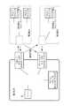
図1は、ネットワーク構成の例を示す図である。このネットワークは、複数の拠点にそれぞれ構築されたLAN(Local Area Network)をVPN(Virtual Private Network)で接続したものである。第1拠点、第2拠点、第3拠点に、それぞれLAN1、LAN2、LAN3が構築されている。各拠点のLANは、パーソナルコンピュータ(パソコン)、レイヤ2スイッチ、ゲートウェイなどの中継装置を接続して構成されている。以下、パーソナルコンピュータをPC、レイヤ2スイッチをL2SW、ゲートウェイをGWと略す。An example of an embodiment of the present invention will be described.
<Basic configuration>
FIG. 1 is a diagram illustrating an example of a network configuration. This network is a LAN (Local Area Network) constructed at each of a plurality of bases connected by a VPN (Virtual Private Network). LAN1, LAN2, and LAN3 are constructed at the first site, the second site, and the third site, respectively. The LAN at each site is configured by connecting relay devices such as personal computers (personal computers),
LAN1は、PC1−1、PC1−2、L2SW1−1、L2SW1−2、GW1−1、GW1−2を備える。L2SW1−2には、サーバ10が接続されている。サーバ10は、本発明に係る情報処理装置の一例である。LAN2は、PC2−1、PC2−2、L2SW2−1、GW2−1、GW2−2を備える。LAN3は、PC3−1、PC3−2、L2SW3−1、GW3−2を備える。これらの中継装置の各々には、IPアドレスとMACアドレスが付与されている。例えば、PC1−2には、IPアドレスとして、10.0.1.10が付与されており、MACアドレスとして、B8:CA:3A:7E:B1:D7が付与されている。なお、実施形態の説明に不要なIPアドレスやMACアドレスは、図示を省略した。 LAN1 includes PC1-1, PC1-2, L2SW1-1, L2SW1-2, GW1-1, and GW1-2. The
LAN1とLAN2は、VPN−Aで接続されており、LAN2とLAN3、LAN3とLAN1は、VPN−Bで接続されている。VPN−AとVPN−Bは、それぞれ通信事業者A、通信事業者Bが提供するVPNである。なお、VPNには、インターネットを利用して複数の拠点のLANを接続するインターネットVPNや、専用IP(Internet Protocol)網で接続するIP−VPNや、IPに限定されないレイヤ2通信(例えば、Ethernet(登録商標))で接続するレイヤ2VPNなど様々な形態があるが、本発明に係るネットワークでは、いかなる形態のVPNが用いられていてもよい。また、図示したネットワーク構成は一例に過ぎず、この例と異なる構成のネットワークに本発明を適用してもよい。例えば、VPNでLANが接続される拠点の数はいくつでもよい。あるいは、LANに接続される中継装置の種類や数がこの例と異なっていてもよい。あるいは、レイヤ2スイッチの代わりにレイヤ3スイッチなどのスイッチングハブが設けられていてもよい。 LAN1 and LAN2 are connected by VPN-A, LAN2 and LAN3, and LAN3 and LAN1 are connected by VPN-B. VPN-A and VPN-B are VPNs provided by carrier A and carrier B, respectively. The VPN includes an Internet VPN that connects the LANs of a plurality of bases using the Internet, an IP-VPN that is connected by a dedicated IP (Internet Protocol) network, and
図2は、サーバ10のハードウェア構成を示す図である。サーバ10は、制御部11、記憶部12、通信部13を備える。制御部11は、CPU(Central Processing Unit)などの演算装置と、ROM(Read Only Memory)やRAM(Random Access Memory)などの記憶装置とを備える。ROMには、ハードウェアやOS(Operating System)の起動の手順を記述したファームウェアが記憶されている。RAMは、CPUが演算を実行する際のデータの記憶に用いられる。記憶部12は、例えばハードディスク装置を備え、OSやアプリケーションプログラムなどが記憶されている。通信部13は、他の中継装置(この例では、L2SW1−2)と通信するための通信I/F(Interface)を備える。制御部11は、L2SW1−1を経由するパケットを通信部13を介して取得する(取得手段の一例)。サーバ10には、表示装置14と受付装置15が接続されている。表示装置14は、例えば液晶表示装置を備え、操作者がサーバ10を操作するための画面などを表示する。受付装置15は、例えばキーボードやマウスなどを備え、操作者が行った操作を受け付けて、その操作に応じた情報を表示装置14と制御部11に出力する。 FIG. 2 is a diagram illustrating a hardware configuration of the
図3は、対称なルーティングの例を示す図である。対称なルーティングとは、第1のパケットが伝送される経路(以下、往路という。)と、第1のパケットに対する応答を示すパケットである第2のパケットが伝送される経路(以下、復路という。)が同一であるルーティングである。この例では、往路では、PC1−2から送信された第1のパケットが、L2SW1−2、L2SW1−1、GW1−1、VPN−A、GW2−1、L2SW2−1の順に中継され、PC2−2に受信される。復路では、第1のパケットに対する応答を示す第2のパケットがPC2−2から送信され、L2SW2−1、GW2−1、VPN−A、GW1−1、L2SW1−1、L2SW1−2の順に中継され、PC1−2に受信される。 FIG. 3 is a diagram illustrating an example of symmetric routing. Symmetric routing refers to a path through which a first packet is transmitted (hereinafter referred to as a forward path) and a path through which a second packet that is a packet indicating a response to the first packet is transmitted (hereinafter referred to as a return path). ) Are the same routing. In this example, in the forward path, the first packet transmitted from PC1-2 is relayed in the order of L2SW1-2, L2SW1-1, GW1-1, VPN-A, GW2-1, L2SW2-1, and PC2- 2 is received. On the return path, a second packet indicating a response to the first packet is transmitted from the PC 2-2 and relayed in the order of L2SW2-1, GW2-1, VPN-A, GW1-1, L2SW1-1, L2SW1-2. , Received by PC1-2.
<非対称なルーティングを特定する原理>
次に、非対称なルーティングを特定する原理について説明する。非対称なルーティングとは、往路と復路が同一でないルーティングである。<Principle to identify asymmetric routing>
Next, the principle of identifying asymmetric routing will be described. Asymmetric routing is routing in which the forward path and the return path are not the same.
<TCPの場合>
最初に、通信プロトコルがTCP(Transmission Control Protocol)の場合について説明する。
図4は、非対称なルーティングの例を示す図である。この例では、往路では、PC1−2から送信された第1のパケットが、L2SW1−2、L2SW1−1、GW1−1、VPN−A、GW2−1、L2SW2−1の順に中継され、PC2−1に受信される。復路では、第1のパケットに対する応答を示す第2のパケットがPC2−1から送信され、L2SW2−1、GW2−1、VPN−A、GW1−1、L2SW1−1、L2SW1−2の順に中継され、PC1−2に受信される。<For TCP>
First, a case where the communication protocol is TCP (Transmission Control Protocol) will be described.
FIG. 4 is a diagram illustrating an example of asymmetric routing. In this example, in the forward path, the first packet transmitted from PC1-2 is relayed in the order of L2SW1-2, L2SW1-1, GW1-1, VPN-A, GW2-1, L2SW2-1, and PC2- 1 is received. On the return path, a second packet indicating a response to the first packet is transmitted from the PC 2-1 and relayed in the order of
図5は、図4に示した非対称なルーティングによって伝送されたパケットを送信順に列挙した図である。「パケットの内容」の欄に記載されているとおり、TCPにおいては、3ウェイハンドシェイクのシーケンスに従って通信が確立される。具体的には、PC1−2がPC2−1にSYNパケット(第1のパケットの一例)を送信し(送信順=1)、このSYNパケットを受信したPC2−1がPC1−2にSYN・ACKパケット(第2のパケットの一例)を返信し(送信順=2)、このSYN・ACKパケットを受信したPC1−2がPC2−1にACKパケット(第3のパケットの一例)を送信する(送信順=3)というシーケンスによって、PC1−2とPC2−1との通信が確立される。これに続いて、PC1−2とPC2−1との間でパケットのやりとりが行われる(送信順=4、5)。 FIG. 5 is a diagram in which packets transmitted by the asymmetric routing shown in FIG. 4 are listed in the order of transmission. As described in the “packet contents” column, in TCP, communication is established according to a three-way handshake sequence. Specifically, the PC 1-2 transmits a SYN packet (an example of the first packet) to the PC 2-1 (transmission order = 1), and the PC 2-1 that has received this SYN packet sends the SYN 1 -ACK to the PC 1-2. A packet (an example of the second packet) is returned (transmission order = 2), and the PC 1-2 that receives the SYN / ACK packet transmits an ACK packet (an example of the third packet) to the PC 2-1 (transmission). Communication between the PC 1-2 and the PC 2-1 is established by the sequence of order = 3). Subsequently, packets are exchanged between PC1-2 and PC2-1 (transmission order = 4, 5).
図6は、サーバ10が取得したパケットを取得順に列挙した図である。図4に示した非対称なルーティングの場合、往路にはL2SW1−1が含まれているが、復路にはL2SW1−1が含まれていない。そのため、サーバ10は、往路のパケット(図5の送信順=1、3、5)は取得するが、復路のパケット(図5の送信順=2、4)は取得することができない。しかし、SYNパケット(取得順=1)の次にACKパケット(取得順=2)が取得され、且つ、シーケンス番号がインクリメントされているということは、3ウェイハンドシェイクによって通信が確立されたことを意味する。この場合、SYNパケットの送信後にPC1−2がSYN・ACKパケットを受信したはずであるが、サーバ10がこのSYN・ACKパケットを取得することができなかったことは、L2SW1−1が復路に存在しない非対称なルーティングが行われた可能性を示している。
以上のように、中継装置においてパケットの行き情報または戻り情報しか取得できず、通信相手の状況を示す情報を取得した場合は、非対称ルーティングが構成されていると特定することができる。FIG. 6 is a diagram in which the packets acquired by the
As described above, in the relay device, only the packet arrival information or return information can be acquired, and when information indicating the status of the communication partner is acquired, it can be specified that asymmetric routing is configured.
<UDPの場合>
次に、通信プロトコルがUDP(User Datagram Protocol)の場合について説明する。
図7は、非対称なルーティングの例を示す図である。この例では、往路では、PC1−2から送信された第1のパケットが、L2SW1−2、L2SW1−1、GW1−1、VPN−A、GW2−1、L2SW2−1、GW2−2、VPN−B、GW3−2、L2SW3−1の順に中継され、PC3−1に受信される。ただし、PC3−1は、DNS(Domain Name System)サーバである。復路では、第1のパケットに対する応答を示す第2のパケットがPC3−1から送信され、L2SW3−1、GW3−2、VPN−B、GW1−2、L2SW1−2の順に中継され、PC1−2に受信される。<For UDP>
Next, a case where the communication protocol is UDP (User Datagram Protocol) will be described.
FIG. 7 is a diagram illustrating an example of asymmetric routing. In this example, in the forward path, the first packet transmitted from the PC 1-2 is L2SW1-2, L2SW1-1, GW1-1, VPN-A, GW2-1, L2SW2-1, GW2-2, VPN- B, GW3-2, and L2SW3-1 are relayed in this order and received by PC3-1. However, the PC 3-1 is a DNS (Domain Name System) server. On the return path, a second packet indicating a response to the first packet is transmitted from the PC 3-1, relayed in the order of
図8は、図7に示した非対称なルーティングによって伝送されたパケットを送信順に列挙した図である。UDPでは、TCPで行われる3ウェイハンドシェイクのようなシーケンスが定められていないため、PC1−2から送信されたパケット(送信順=1)に対して、PC3−1が応答のパケット(送信順=2)を返信する。この例では、DNSサーバであるPC3−1が、ドメイン名(noexist.co.jp)に対応するIPアドレス(10.0.2.10)を特定し、このIPアドレスを含むパケットをPC1−2に返信する。すると、PC1−2が、このIPアドレスに対応するPC2−1にパケット(送信順=3)を送信し、PC1−2とPC2−1との間でパケットのやりとりが行われる(送信順=4、5)。ここで、PC1−2とPC2−1との通信(送信順=3、4、5)は、L2SW1−1を経路に含む対称なルーティングによって行われると仮定する。 FIG. 8 is a diagram in which packets transmitted by the asymmetric routing shown in FIG. 7 are listed in the order of transmission. In UDP, since a sequence such as a 3-way handshake performed in TCP is not defined, a response packet (transmission order) is sent from PC3-1 to a packet (transmission order = 1) transmitted from PC1-2. = 2) is returned. In this example, the PC 3-1 that is a DNS server specifies the IP address (10.2.10) corresponding to the domain name (noexist.co.jp), and the packet including this IP address is transmitted to the PC 1-2. Reply to Then, the PC 1-2 transmits a packet (transmission order = 3) to the PC 2-1 corresponding to the IP address, and the packet is exchanged between the PC 1-2 and the PC 2-1 (transmission order = 4). 5). Here, it is assumed that communication (transmission order = 3, 4, 5) between PC1-2 and PC2-1 is performed by symmetric routing including L2SW1-1 in the route.
図9は、サーバ10が取得したパケットを取得順に列挙した図である。図7に示した非対称なルーティングの場合、送信順=1、3、4、5の経路にはL2SW1−1が含まれているが、送信順=2の経路にはL2SW1−1が含まれていない。そのため、サーバ10は、送信順=1、3、4、5のパケットは取得するが、送信順=2のパケットは取得することができない。ここで、送信順=2のパケットが取得できなかったことから、(1)DNSサーバが応答しなかった、(2)パケットロスにより応答のパケットが消失した、(3)非対称なルーティングが行われた、のいずれかの可能性が考えられる。しかし、一般に(1)と(2)の場合にはPC1−2が問合せをリトライするが、この例ではリトライが行われていない。また、送信順=1のパケットの送信後にPC1−2とPC2−1との間で通信が行われたことは、PC2−1がDNSサーバによって特定されたIPアドレスに対応する中継装置である可能性を示している。また、このIPアドレスを通知する応答パケットがサーバに取得されなかったことは、PC1−2とPC3−1との間で、L2SW1−1が復路に存在しない非対称なルーティングが行われた可能性を示している。つまり、この例では、(1)乃至(3)のうち、(3)の可能性が最も高い。 FIG. 9 is a diagram in which the packets acquired by the
<特定機能>
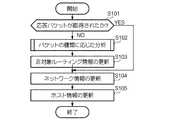
図10は、サーバ10の動作を示す流れ図である。サーバ10には、非対称なルーティングを特定する手順を記述したアプリケーションプログラムである特定プログラムがインストールされている。制御部11が特定プログラムを実行することによって、以下に示す特定機能(特定手段の一例)が実現される。<Specific function>
FIG. 10 is a flowchart showing the operation of the
<ステップS101>
制御部11は、問合せパケット(第1のパケット)に対する応答パケット(第2のパケット)が取得されたか否かを判定する。具体的には、操作者は、サーバ10を操作して制御部11に特定プログラムの実行を開始させた後、PC1−2を送信元とし、LAN2又はLAN3に含まれるPCのいずれかを送信先として、問合せパケットを送信する。制御部11は、問合せパケットの送信から或る期間にわたってL2SW1−1から取得されたパケットのリストを作成する。例えば、図6や図9で例示したリストが作成される。制御部11は、取得されたパケットの送信元IPアドレス、送信先IPアドレス、送信元ポート、送信先ポートなどを対比して、問合せパケットに対応する応答パケットが取得されたか否かを判定する。応答パケットが取得された場合(ステップS101:YES)には、制御部11の処理はステップS104に進み、応答パケットが取得されなかった場合(ステップS101:NO)には、制御部11の処理はステップS102に進む。<Step S101>
The
<ステップS102>
制御部11は、パケットの種類に応じた分析を実行する。
図11は、パケットの種類に応じた分析の詳細な手順を示す流れ図である。
<ステップS201>
制御部11が、パケットの種類を判定する。TCPのパケットである場合(ステップS201:TCP)には、制御部11の処理はステップS202に進む。UDPのパケットである場合(ステップS201:UDP)には、制御部11の処理はステップS204に進む。<Step S102>
The
FIG. 11 is a flowchart showing a detailed analysis procedure according to the type of packet.
<Step S201>
The
<ステップS202>
制御部11が、SYNパケットの後にシーケンスが続いているか否かを判定する。具体的には、前述のとおり、TCPの場合には3ウェイハンドシェイクのシーケンスが定められているため、SYNパケットの次にACKパケットが取得され、且つ、シーケンス番号がインクリメントされていることを確認する。SYNパケットの次にACKパケットが取得され、且つ、シーケンス番号がインクリメントされている場合には、シーケンスが続いていると判定し(ステップS202:YES)、制御部11の処理はステップS203に進む。一方、SYNパケットの次にACKパケットが取得されていない場合には、シーケンスが続いていないと判定し(ステップS202:NO)、制御部11の処理はステップS207に進む。<Step S202>
The
<ステップS203>
制御部11が、非対称なルーティングが行われたと判定する。<Step S203>
The
<ステップS204>
制御部11が、通信内容が名前解決か否かを判定する。通信内容が名前解決である場合(ステップS204:YES)には、制御部11の処理はステップS205に進む。通信内容が名前解決でない場合(ステップS204:NO)には、制御部11は処理を終了する。この場合、非対称なルーティングが行われたか否かの判定は行われない。<Step S204>
The
<ステップS205>
制御部11が、問い合わせたドメインを名前解決する。具体的には、最初にPC1−2から送信したSYNパケットの送信先はDNSサーバである可能性が高いから、制御部11が、この送信先に対してドメインの名前解決を依頼する。あるいは、サーバがDNSキャッシュを備えている場合には、そのDNSキャッシュを用いて名前解決を行ってもよい。<Step S205>
The
<ステップS206>
制御部11が、リトライが無く、且つ、名前解決したIPアドレスへの通信が続いているか否かを判定する。リトライが無く、且つ、名前解決したIPアドレスへの通信が続いている場合(ステップS206:YES)には、制御部11の処理はステップS203に進み、リトライが続いている場合(ステップS206:NO)には、制御部11の処理はステップS207に進む。リトライが無く、且つ、名前解決したIPアドレスへの通信が続いているということは、DNSサーバによる名前解決は成功したが、DNSサーバからの応答パケットが取得されなかったことになり、このことは、非対称なルーティングが行われた可能性を示すものである。一方、リトライが続いている場合、DNSサーバが応答していない可能性がある。<Step S206>
The
<ステップS207>
制御部11が、パケットロス、又は、送信先の中継装置が存在しない(あるいは、応答していない)と判定する。<Step S207>
The
図10の説明に戻る。
<ステップS103>
制御部11が、非対称ルーティング情報を更新する。具体的には、制御部11は、非対称なルーティングの可能性がある中継装置の情報を特定情報DBに格納する。
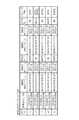
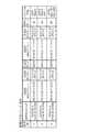
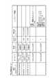
図12は、特定情報DB(TCPの場合)を示す図である。図13は、特定情報DB(UDPの場合)を示す図である。これらは、それぞれ、図6、図9に示したパケットの情報から特定したものである。「端末MACアドレス」は、中継装置のMACアドレスである。「IPアドレス」は、中継装置のIPアドレスである。「所属ネットワーク」は、中継装置が所属するネットワークのIPアドレスである。「GW」は、その中継装置がゲートウェイであるか否かを示す。「接続先ネットワーク」は、その中継装置がゲートウェイである場合の接続先のネットワークのIPアドレスである。「ルーティング情報」は、ルーティングが対称か非対称かの区別、往路のゲートウェイのMACアドレス、復路のゲートウェイのMACアドレスなどである。非対称なルーティングの場合、往路のゲートウェイと復路のゲートウェイが異なる場合がある。Returning to the description of FIG.
<Step S103>
The
FIG. 12 is a diagram showing a specific information DB (in the case of TCP). FIG. 13 is a diagram showing a specific information DB (in the case of UDP). These are specified from the packet information shown in FIGS. 6 and 9, respectively. The “terminal MAC address” is the MAC address of the relay device. “IP address” is the IP address of the relay device. “Affiliation network” is the IP address of the network to which the relay apparatus belongs. “GW” indicates whether or not the relay device is a gateway. The “connection destination network” is an IP address of a connection destination network when the relay device is a gateway. The “routing information” includes whether the routing is symmetric or asymmetric, the MAC address of the forward gateway, the MAC address of the return gateway, and the like. In the case of asymmetric routing, the forward gateway and the return gateway may be different.
<ステップS104>
制御部11は、ネットワーク情報を更新する。具体的には、制御部11は、パケットのMACアドレスとIPアドレスから、サーバ10が存在するサブネット以外のサブネットの情報を判定して特定情報DBに格納する。宛先IPとARP情報から、宛先MACアドレスが宛先IPのものでなく、且つ、宛先IPがサーバ10が存在するサブネットの外のものであるならば、MACアドレスはゲートウェイを示しており、そのゲートウェイの先に宛先IPの中継装置および宛先IPが属するサブネットが存在すると判断する。<Step S104>
The
<ステップS105>
制御部11は、中継装置情報を更新する。具体的には、制御部11は、パケットのIPアドレスから、自拠点の中継装置であるか他拠点の中継装置であるかを判定して特定情報DBに格納する。
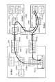
図14は、特定情報DBに格納された情報に基づいて作成されたネットワーク構成を示す図である。この図は、例えば、以下のような手順で作成される。この手順に従ってサーバ10が作図を行うようにしてもよい。
<手順1>
自拠点のネットワークを四角で描き、その中に自拠点に存在するホストを描き、IPアドレスなどの情報を記入する。
<手順2>
自拠点以外のネットワークを四角(破線)で描き、その中に各ネットワークに存在する中継装置を描き、IPアドレスなどの情報を記入する。
<手順3>
接続先ネットワーク情報およびルーティング情報から通信可能な方向を矢印で記入する。
<手順4>
非対称なルーティングが存在する場合、その旨を赤色などで追記する。
なお、図14の例では、第1拠点の各中継装置の情報は予め把握されていることを前提としている。<Step S105>
The
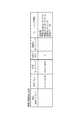
FIG. 14 is a diagram illustrating a network configuration created based on information stored in the specific information DB. This figure is created by the following procedure, for example. The
<
Draw your own network in a box, draw the host that exists at your site, and enter information such as IP address.
<
Draw a network other than your base in a square (broken line), draw a relay device that exists in each network, and enter information such as the IP address.
<
Enter the communicable direction from the connected network information and routing information with arrows.
<
If there is asymmetric routing, add a notice to that effect in red.
In the example of FIG. 14, it is assumed that information on each relay device at the first site is grasped in advance.
非対称なルーティングを検知した場合にそのルーティングによるパケットの伝送を停止する機能を有するスイッチングハブが知られている。非対称なルーティングは、送信したはずのパケットが宛先に届かないという障害の原因になり得る。このような障害を解決するには、ネットワーク構成を把握し、非対称なルーティングが発生する箇所を特定する必要がある。
また、パケットが宛先に届かない場合、宛先の中継装置が応答していない可能性があるが、非対称なルーティングにより通信が確立されたことが確認された場合には、宛先の中継装置が応答していることになるから、本実施形態によれば、宛先の中継装置の応答の有無も確認される。
以上のように、中継装置においてパケットの行き情報または戻り情報しか取得できず、再度パケットの行き情報が取得されなかった場合は、非対称ルーティングを特定することができる。There is known a switching hub having a function of stopping transmission of a packet by routing when asymmetric routing is detected. Asymmetric routing can cause failures where packets that should have been sent do not reach their destination. In order to solve such a failure, it is necessary to grasp the network configuration and specify a location where asymmetric routing occurs.
If the packet does not reach the destination, the destination relay device may not respond, but if it is confirmed that communication has been established by asymmetric routing, the destination relay device responds. Therefore, according to the present embodiment, whether or not there is a response from the destination relay device is also confirmed.
As described above, when only the packet route information or return information can be acquired in the relay device, and the packet route information is not acquired again, asymmetric routing can be specified.
<変形例>
実施形態を次のように変形してもよい。また、複数の変形例を組み合わせてもよい。
<1>
パケットの宛先のポート番号からそのパケットの用途が特定される。例えば、ポート番号から、パケットの宛先がWebサーバやメールサーバであることが特定される。このことを利用して、特定されたネットワーク構成に含まれる構成要素(中継装置や伝送経路など)のうち重要度の高い構成要素を特定し、特定した構成要素の表示の状態を他の構成要素と異ならせるようにしてもよい。<Modification>
The embodiment may be modified as follows. A plurality of modified examples may be combined.
<1>
The use of the packet is specified from the port number of the packet destination. For example, the port number identifies the destination of the packet as a Web server or a mail server. Using this fact, it identifies the components with high importance among the components (relay devices, transmission paths, etc.) included in the specified network configuration, and displays the status of the identified components in the other components You may make it differ.
<2>
図11に示したステップS205の処理を省略してもよい。この場合、取得されたパケット(図9の取得順=2)の送信先IPアドレスがDNSサーバで名前解決されたIPアドレスであることは確認されないが、取得順=2以降の送信先IPアドレスや送信元IPアドレスが特定のIPアドレスであれば、DNSサーバで名前解決されたIPアドレスである可能性がある。従って、ステップS205を省略しても、非対称なルーティングの特定は可能である。<2>
The process of step S205 shown in FIG. 11 may be omitted. In this case, it is not confirmed that the transmission destination IP address of the acquired packet (acquisition order = 2 in FIG. 9) is an IP address whose name has been resolved by the DNS server. If the source IP address is a specific IP address, there is a possibility that the IP address has been resolved by the DNS server. Therefore, even if step S205 is omitted, it is possible to specify asymmetric routing.
<3>
特定プログラムを、光記録媒体、半導体メモリ等、コンピュータで読み取り可能な記録媒体に記録して提供し、この記録媒体からプログラムを読み取ってインストールするようにしてもよい。また、このプログラムを電気通信回線で提供してもよい。<3>
The specific program may be provided by being recorded on a computer-readable recording medium such as an optical recording medium or a semiconductor memory, and the program may be read from the recording medium and installed. In addition, this program may be provided through a telecommunication line.
10…サーバ、11…制御部、12…記憶部、13…通信部、14…表示装置、15…受付装置DESCRIPTION OF
Claims (6)
Translated fromJapanese前記中継装置を経由して伝送された第1の情報に対する応答を示す第2の情報が前記取得手段によって取得されなかった場合に、非対称な伝送経路が構成されていることを特定する特定手段と
を備えた情報処理装置。Obtaining means for obtaining information transmitted in the network from a relay device provided in the middle of the transmission path;
Specifying means for specifying that an asymmetric transmission path is configured when second information indicating a response to the first information transmitted via the relay device is not acquired by the acquisition means; An information processing apparatus comprising:
請求項1に記載の情報処理装置。The information processing apparatus according to claim 1, wherein the specifying unit specifies that an asymmetric transmission path is configured based on a transmission direction, content, or acquisition history of the information.
請求項2に記載の情報処理装置。The information processing apparatus according to claim 2, wherein the specifying unit specifies that an asymmetric transmission path is configured when third information indicating a situation of a communication partner is acquired by the acquiring unit.
請求項2に記載の情報処理装置。The information processing apparatus according to claim 2, wherein the specifying unit specifies that an asymmetric transmission path is configured if the first information is not acquired again.
請求項1乃至4のいずれか1項に記載の情報処理装置。5. The information processing apparatus according to claim 1, further comprising a display control unit configured to control the display unit to display information related to the asymmetric transmission path specified by the specifying unit.
ネットワークにおいて伝送される情報を伝送経路の途中に設けられた中継装置から取得する取得手段と、
前記中継装置を経由して伝送された第1の情報に対する応答を示す第2の情報が前記取得手段によって取得されなかった場合に、非対称な伝送経路が構成されていることを特定する特定手段
として機能させるためのプログラム。Computer
Obtaining means for obtaining information transmitted in the network from a relay device provided in the middle of the transmission path;
As specifying means for specifying that an asymmetric transmission path is configured when second information indicating a response to the first information transmitted via the relay device is not acquired by the acquiring means A program to make it work.
Priority Applications (1)
| Application Number | Priority Date | Filing Date | Title |
|---|---|---|---|
| JP2015173721AJP2017050765A (en) | 2015-09-03 | 2015-09-03 | Information processing device and program |
Applications Claiming Priority (1)
| Application Number | Priority Date | Filing Date | Title |
|---|---|---|---|
| JP2015173721AJP2017050765A (en) | 2015-09-03 | 2015-09-03 | Information processing device and program |
Publications (1)
| Publication Number | Publication Date |
|---|---|
| JP2017050765Atrue JP2017050765A (en) | 2017-03-09 |
Family
ID=58280369
Family Applications (1)
| Application Number | Title | Priority Date | Filing Date |
|---|---|---|---|
| JP2015173721APendingJP2017050765A (en) | 2015-09-03 | 2015-09-03 | Information processing device and program |
Country Status (1)
| Country | Link |
|---|---|
| JP (1) | JP2017050765A (en) |
- 2015
- 2015-09-03JPJP2015173721Apatent/JP2017050765A/enactivePending
Similar Documents
| Publication | Publication Date | Title |
|---|---|---|
| US10469444B2 (en) | System and method for direct connections between previously unconnected network devices across one or more unknown networks | |
| EP2891277B1 (en) | Overlay virtual gateway for overlay networks | |
| CN107317751B (en) | Apparatus and method for providing routing | |
| JP5967173B2 (en) | Network relay device, method for setting operation mode of packet relay processing unit included in network relay device, and computer program | |
| US20050066035A1 (en) | Method and apparatus for connecting privately addressed networks | |
| US9509603B2 (en) | System and method for route health injection using virtual tunnel endpoints | |
| EP3254417A1 (en) | Method and system for supporting port ranging in a software-defined networking (sdn) system | |
| WO2016210196A1 (en) | Media relay server | |
| WO2016210202A1 (en) | Media relay server | |
| CN111064659B (en) | Node protection of BUM traffic for multi-homed node failures | |
| EP3750073B1 (en) | A method for seamless migration of session authentication to a different stateful diameter authenticating peer | |
| JP6290053B2 (en) | COMMUNICATION DEVICE, COMMUNICATION SYSTEM, AND COMMUNICATION METHOD | |
| BR102020014994A2 (en) | METHOD FOR CONFIGURING A WIRELESS COMMUNICATION COVERAGE EXTENSION SYSTEM AND A WIRELESS COMMUNICATION COVERAGE EXTENSION SYSTEM IMPLEMENTING THIS METHOD | |
| CN109218459B (en) | Apparatus and method for converting between internet protocols | |
| WO2020230146A1 (en) | Method and apparatus for layer 2 route calculation in a route reflector network device | |
| WO2014156143A1 (en) | Home gateway device and packet forwarding method | |
| JP5580766B2 (en) | Server apparatus, packet transmission system, packet transmission method and program | |
| JP2017050765A (en) | Information processing device and program | |
| Punithavathani et al. | Performance analysis for wireless networks: An analytical approach by multifarious sym teredo | |
| Horley | Practical IPv6 for Windows Administrators | |
| US20170289099A1 (en) | Method and Device for Managing Internet Protocol Version 6 Address, and Terminal | |
| KR101712922B1 (en) | Virtual Private Network System of Dynamic Tunnel End Type, Manager Apparatus and Virtual Router for the same | |
| JP2020108011A (en) | Malware inspection support program, malware inspection support method, and communication device | |
| Wolinsky et al. | On the design and implementation of structured P2P VPNs | |
| JP5084716B2 (en) | VPN connection apparatus, DNS packet control method, and program |
Legal Events
| Date | Code | Title | Description |
|---|---|---|---|
| A621 | Written request for application examination | Free format text:JAPANESE INTERMEDIATE CODE: A621 Effective date:20180717 | |
| A977 | Report on retrieval | Free format text:JAPANESE INTERMEDIATE CODE: A971007 Effective date:20190521 | |
| A131 | Notification of reasons for refusal | Free format text:JAPANESE INTERMEDIATE CODE: A131 Effective date:20190528 | |
| A521 | Written amendment | Free format text:JAPANESE INTERMEDIATE CODE: A523 Effective date:20190725 | |
| A02 | Decision of refusal | Free format text:JAPANESE INTERMEDIATE CODE: A02 Effective date:20191112 |