JP2017047056A - Subject information acquisition device - Google Patents
Subject information acquisition deviceDownload PDFInfo
- Publication number
- JP2017047056A JP2017047056AJP2015174389AJP2015174389AJP2017047056AJP 2017047056 AJP2017047056 AJP 2017047056AJP 2015174389 AJP2015174389 AJP 2015174389AJP 2015174389 AJP2015174389 AJP 2015174389AJP 2017047056 AJP2017047056 AJP 2017047056A
- Authority
- JP
- Japan
- Prior art keywords
- subject
- light
- wave
- probe
- acoustic
- Prior art date
- Legal status (The legal status is an assumption and is not a legal conclusion. Google has not performed a legal analysis and makes no representation as to the accuracy of the status listed.)
- Pending
Links
Images


Classifications
- A—HUMAN NECESSITIES
- A61—MEDICAL OR VETERINARY SCIENCE; HYGIENE
- A61B—DIAGNOSIS; SURGERY; IDENTIFICATION
- A61B8/00—Diagnosis using ultrasonic, sonic or infrasonic waves
- A61B8/44—Constructional features of the ultrasonic, sonic or infrasonic diagnostic device
- A61B8/4416—Constructional features of the ultrasonic, sonic or infrasonic diagnostic device related to combined acquisition of different diagnostic modalities, e.g. combination of ultrasound and X-ray acquisitions
- A—HUMAN NECESSITIES
- A61—MEDICAL OR VETERINARY SCIENCE; HYGIENE
- A61B—DIAGNOSIS; SURGERY; IDENTIFICATION
- A61B5/00—Measuring for diagnostic purposes; Identification of persons
- A61B5/0033—Features or image-related aspects of imaging apparatus, e.g. for MRI, optical tomography or impedance tomography apparatus; Arrangements of imaging apparatus in a room
- A61B5/0035—Features or image-related aspects of imaging apparatus, e.g. for MRI, optical tomography or impedance tomography apparatus; Arrangements of imaging apparatus in a room adapted for acquisition of images from more than one imaging mode, e.g. combining MRI and optical tomography
- A—HUMAN NECESSITIES
- A61—MEDICAL OR VETERINARY SCIENCE; HYGIENE
- A61B—DIAGNOSIS; SURGERY; IDENTIFICATION
- A61B5/00—Measuring for diagnostic purposes; Identification of persons
- A61B5/0033—Features or image-related aspects of imaging apparatus, e.g. for MRI, optical tomography or impedance tomography apparatus; Arrangements of imaging apparatus in a room
- A61B5/004—Features or image-related aspects of imaging apparatus, e.g. for MRI, optical tomography or impedance tomography apparatus; Arrangements of imaging apparatus in a room adapted for image acquisition of a particular organ or body part
- A—HUMAN NECESSITIES
- A61—MEDICAL OR VETERINARY SCIENCE; HYGIENE
- A61B—DIAGNOSIS; SURGERY; IDENTIFICATION
- A61B5/00—Measuring for diagnostic purposes; Identification of persons
- A61B5/0059—Measuring for diagnostic purposes; Identification of persons using light, e.g. diagnosis by transillumination, diascopy, fluorescence
- A61B5/0082—Measuring for diagnostic purposes; Identification of persons using light, e.g. diagnosis by transillumination, diascopy, fluorescence adapted for particular medical purposes
- A61B5/0091—Measuring for diagnostic purposes; Identification of persons using light, e.g. diagnosis by transillumination, diascopy, fluorescence adapted for particular medical purposes for mammography
- A—HUMAN NECESSITIES
- A61—MEDICAL OR VETERINARY SCIENCE; HYGIENE
- A61B—DIAGNOSIS; SURGERY; IDENTIFICATION
- A61B5/00—Measuring for diagnostic purposes; Identification of persons
- A61B5/0093—Detecting, measuring or recording by applying one single type of energy and measuring its conversion into another type of energy
- A61B5/0095—Detecting, measuring or recording by applying one single type of energy and measuring its conversion into another type of energy by applying light and detecting acoustic waves, i.e. photoacoustic measurements
- A—HUMAN NECESSITIES
- A61—MEDICAL OR VETERINARY SCIENCE; HYGIENE
- A61B—DIAGNOSIS; SURGERY; IDENTIFICATION
- A61B8/00—Diagnosis using ultrasonic, sonic or infrasonic waves
- A61B8/08—Clinical applications
- A—HUMAN NECESSITIES
- A61—MEDICAL OR VETERINARY SCIENCE; HYGIENE
- A61B—DIAGNOSIS; SURGERY; IDENTIFICATION
- A61B8/00—Diagnosis using ultrasonic, sonic or infrasonic waves
- A61B8/13—Tomography
- A61B8/14—Echo-tomography
- A—HUMAN NECESSITIES
- A61—MEDICAL OR VETERINARY SCIENCE; HYGIENE
- A61B—DIAGNOSIS; SURGERY; IDENTIFICATION
- A61B8/00—Diagnosis using ultrasonic, sonic or infrasonic waves
- A61B8/44—Constructional features of the ultrasonic, sonic or infrasonic diagnostic device
- A61B8/4483—Constructional features of the ultrasonic, sonic or infrasonic diagnostic device characterised by features of the ultrasound transducer
- A—HUMAN NECESSITIES
- A61—MEDICAL OR VETERINARY SCIENCE; HYGIENE
- A61B—DIAGNOSIS; SURGERY; IDENTIFICATION
- A61B8/00—Diagnosis using ultrasonic, sonic or infrasonic waves
- A61B8/46—Ultrasonic, sonic or infrasonic diagnostic devices with special arrangements for interfacing with the operator or the patient
- A61B8/461—Displaying means of special interest
- A61B8/463—Displaying means of special interest characterised by displaying multiple images or images and diagnostic data on one display
- A—HUMAN NECESSITIES
- A61—MEDICAL OR VETERINARY SCIENCE; HYGIENE
- A61B—DIAGNOSIS; SURGERY; IDENTIFICATION
- A61B8/00—Diagnosis using ultrasonic, sonic or infrasonic waves
- A61B8/52—Devices using data or image processing specially adapted for diagnosis using ultrasonic, sonic or infrasonic waves
- A61B8/5207—Devices using data or image processing specially adapted for diagnosis using ultrasonic, sonic or infrasonic waves involving processing of raw data to produce diagnostic data, e.g. for generating an image
- A—HUMAN NECESSITIES
- A61—MEDICAL OR VETERINARY SCIENCE; HYGIENE
- A61B—DIAGNOSIS; SURGERY; IDENTIFICATION
- A61B8/00—Diagnosis using ultrasonic, sonic or infrasonic waves
- A61B8/52—Devices using data or image processing specially adapted for diagnosis using ultrasonic, sonic or infrasonic waves
- A61B8/5215—Devices using data or image processing specially adapted for diagnosis using ultrasonic, sonic or infrasonic waves involving processing of medical diagnostic data
- A61B8/5223—Devices using data or image processing specially adapted for diagnosis using ultrasonic, sonic or infrasonic waves involving processing of medical diagnostic data for extracting a diagnostic or physiological parameter from medical diagnostic data
- A—HUMAN NECESSITIES
- A61—MEDICAL OR VETERINARY SCIENCE; HYGIENE
- A61B—DIAGNOSIS; SURGERY; IDENTIFICATION
- A61B8/00—Diagnosis using ultrasonic, sonic or infrasonic waves
- A61B8/52—Devices using data or image processing specially adapted for diagnosis using ultrasonic, sonic or infrasonic waves
- A61B8/5215—Devices using data or image processing specially adapted for diagnosis using ultrasonic, sonic or infrasonic waves involving processing of medical diagnostic data
- A61B8/5238—Devices using data or image processing specially adapted for diagnosis using ultrasonic, sonic or infrasonic waves involving processing of medical diagnostic data for combining image data of patient, e.g. merging several images from different acquisition modes into one image
- A61B8/5261—Devices using data or image processing specially adapted for diagnosis using ultrasonic, sonic or infrasonic waves involving processing of medical diagnostic data for combining image data of patient, e.g. merging several images from different acquisition modes into one image combining images from different diagnostic modalities, e.g. ultrasound and X-ray
- A—HUMAN NECESSITIES
- A61—MEDICAL OR VETERINARY SCIENCE; HYGIENE
- A61B—DIAGNOSIS; SURGERY; IDENTIFICATION
- A61B5/00—Measuring for diagnostic purposes; Identification of persons
- A61B5/43—Detecting, measuring or recording for evaluating the reproductive systems
- A61B5/4306—Detecting, measuring or recording for evaluating the reproductive systems for evaluating the female reproductive systems, e.g. gynaecological evaluations
- A61B5/4312—Breast evaluation or disorder diagnosis
- A—HUMAN NECESSITIES
- A61—MEDICAL OR VETERINARY SCIENCE; HYGIENE
- A61B—DIAGNOSIS; SURGERY; IDENTIFICATION
- A61B8/00—Diagnosis using ultrasonic, sonic or infrasonic waves
- A61B8/08—Clinical applications
- A61B8/0825—Clinical applications for diagnosis of the breast, e.g. mammography
- A—HUMAN NECESSITIES
- A61—MEDICAL OR VETERINARY SCIENCE; HYGIENE
- A61B—DIAGNOSIS; SURGERY; IDENTIFICATION
- A61B8/00—Diagnosis using ultrasonic, sonic or infrasonic waves
- A61B8/08—Clinical applications
- A61B8/0858—Clinical applications involving measuring tissue layers, e.g. skin, interfaces
- A—HUMAN NECESSITIES
- A61—MEDICAL OR VETERINARY SCIENCE; HYGIENE
- A61B—DIAGNOSIS; SURGERY; IDENTIFICATION
- A61B8/00—Diagnosis using ultrasonic, sonic or infrasonic waves
- A61B8/40—Positioning of patients, e.g. means for holding or immobilising parts of the patient's body
- A61B8/406—Positioning of patients, e.g. means for holding or immobilising parts of the patient's body using means for diagnosing suspended breasts
- A—HUMAN NECESSITIES
- A61—MEDICAL OR VETERINARY SCIENCE; HYGIENE
- A61B—DIAGNOSIS; SURGERY; IDENTIFICATION
- A61B8/00—Diagnosis using ultrasonic, sonic or infrasonic waves
- A61B8/42—Details of probe positioning or probe attachment to the patient
- A61B8/4209—Details of probe positioning or probe attachment to the patient by using holders, e.g. positioning frames
- A—HUMAN NECESSITIES
- A61—MEDICAL OR VETERINARY SCIENCE; HYGIENE
- A61B—DIAGNOSIS; SURGERY; IDENTIFICATION
- A61B8/00—Diagnosis using ultrasonic, sonic or infrasonic waves
- A61B8/42—Details of probe positioning or probe attachment to the patient
- A61B8/4272—Details of probe positioning or probe attachment to the patient involving the acoustic interface between the transducer and the tissue
- A61B8/4281—Details of probe positioning or probe attachment to the patient involving the acoustic interface between the transducer and the tissue characterised by sound-transmitting media or devices for coupling the transducer to the tissue
Landscapes
- Health & Medical Sciences (AREA)
- Life Sciences & Earth Sciences (AREA)
- Engineering & Computer Science (AREA)
- Physics & Mathematics (AREA)
- Medical Informatics (AREA)
- Animal Behavior & Ethology (AREA)
- Pathology (AREA)
- Veterinary Medicine (AREA)
- Biomedical Technology (AREA)
- Heart & Thoracic Surgery (AREA)
- Public Health (AREA)
- Molecular Biology (AREA)
- Surgery (AREA)
- Biophysics (AREA)
- General Health & Medical Sciences (AREA)
- Nuclear Medicine, Radiotherapy & Molecular Imaging (AREA)
- Radiology & Medical Imaging (AREA)
- Computer Vision & Pattern Recognition (AREA)
- Acoustics & Sound (AREA)
- Gynecology & Obstetrics (AREA)
- Physiology (AREA)
- Ultra Sonic Daignosis Equipment (AREA)
Abstract
Description
Translated fromJapanese本発明は、被検体内の情報を取得する被検体情報取得装置に関する。 The present invention relates to a subject information acquisition apparatus that acquires information in a subject.
光イメージング技術の一つとして、近年、光音響トモグラフィ(PAT:PhotoAcoustic Tomography)が提案されている。
パルスレーザ光などの計測光を被検体である生体に照射すると、計測光が被検体内の生体組織で吸収される際に音響波が発生する。この現象を光音響効果と呼び、光音響効果により発生した音響波を光音響波と呼ぶ。被検体を構成する組織は、光エネルギーの吸収率がそれぞれ異なるため、発生する光音響波の音圧も異なったものとなる。PATでは、発生した光音響波を探触子で検出し、受信信号を数学的に解析することにより、被検体内の光学的特性に関する情報を画像化することができる(以下、光音響測定と称する)。In recent years, photoacoustic tomography (PAT) has been proposed as one of optical imaging techniques.
When measurement light such as pulsed laser light is irradiated on a living body that is a subject, an acoustic wave is generated when the measurement light is absorbed by a living tissue in the subject. This phenomenon is called a photoacoustic effect, and an acoustic wave generated by the photoacoustic effect is called a photoacoustic wave. Since tissues constituting the subject have different optical energy absorption rates, the sound pressures of the generated photoacoustic waves are also different. In PAT, the generated photoacoustic wave is detected by a probe, and the received signal is mathematically analyzed, whereby information relating to optical characteristics in the subject can be imaged (hereinafter referred to as photoacoustic measurement). Called).
一方、被検体内の構造情報を取得する方法として、超音波イメージングが知られている。超音波イメージングでは、プローブに配置された複数の超音波探触子から被検体に超音波を送信し、当該被検体内の音響インピーダンスの異なる界面で生じる反射波を受信して解析する。これにより、被検体内の音響的特性に関する情報(構造情報)を画像化することができる(以下、超音波測定と称する)。 On the other hand, ultrasonic imaging is known as a method for acquiring structural information in a subject. In ultrasonic imaging, ultrasonic waves are transmitted from a plurality of ultrasonic probes arranged on a probe to a subject, and reflected waves generated at interfaces having different acoustic impedances in the subject are received and analyzed. Thereby, information (structural information) regarding the acoustic characteristics in the subject can be imaged (hereinafter referred to as ultrasonic measurement).
また、これらの技術を組み合わせ、被検体内の光学的特性に関する情報と、音響的特性に関する情報の双方を取得する装置の開発がなされている。
例えば、非特許文献1に記載の光音響装置では、微小球体に光を照射することによって発生する光音響波を被検体に送信し、被検体内で反射・散乱した超音波を受信することで超音波画像を得ている。In addition, by combining these techniques, an apparatus for acquiring both information on the optical characteristics in the subject and information on the acoustic characteristics has been developed.
For example, in the photoacoustic apparatus described in Non-Patent Document 1, a photoacoustic wave generated by irradiating a microsphere with light is transmitted to the subject, and ultrasonic waves reflected and scattered in the subject are received. An ultrasound image is obtained.
非特許文献1に記載の装置のように、球体状の吸収体を利用して超音波を発生させると、球面波が発生する。しかし、球面波は放射状に広がるため、被検体に到達するまでに強度が弱くなってしまう。すなわち、従来技術においては、信号強度の確保という点において改善の余地があった。 When an ultrasonic wave is generated using a spherical absorber as in the device described in Non-Patent Document 1, a spherical wave is generated. However, since the spherical wave spreads radially, the intensity becomes weak before reaching the subject. That is, the prior art has room for improvement in terms of securing signal strength.
本発明はこのような従来技術の課題に鑑みてなされたものであり、低コストで光音響画像と超音波画像の双方を取得可能な被検体情報取得装置を提供することを目的とする。 The present invention has been made in view of the above-described problems of the prior art, and an object thereof is to provide a subject information acquisition apparatus that can acquire both a photoacoustic image and an ultrasonic image at low cost.
上記課題を解決するための、本発明に係る被検体情報取得装置は、
被検体に光を照射する光照射部と、前記被検体と前記光照射部との間に配置され、照射された前記光によって略平面の送信超音波を発生させる音響発生部材と、前記光に起因して前記被検体内で発生した音響波を取得し、第一の電気信号に変換する音響波探触子と、前記第一の電気信号に基づいて、前記被検体内の光学特性に関連した情報を生成する情報
生成手段と、を有し、前記音響発生部材は、前記光照射部から照射された光の一部を前記被検体に透過させることを特徴とする。In order to solve the above problems, a subject information acquisition apparatus according to the present invention includes:
A light irradiating unit that irradiates light to the subject, a sound generating member that is disposed between the subject and the light irradiating unit, and generates a substantially planar transmission ultrasonic wave by the irradiated light; and An acoustic wave probe that acquires an acoustic wave generated in the subject due to the result and converts the acoustic wave into a first electrical signal, and an optical characteristic in the subject based on the first electrical signal Information generating means for generating the information, and the sound generating member transmits a part of the light irradiated from the light irradiation unit to the subject.
本発明によれば、低コストで光音響画像と超音波画像の双方を取得可能な被検体情報取得装置を提供することができる。 According to the present invention, it is possible to provide an object information acquisition apparatus that can acquire both a photoacoustic image and an ultrasonic image at low cost.
以下、図面を参照しながら、本発明の実施形態を詳細に説明する。なお、同一の構成要素には原則として同一の参照番号を付して、説明を省略する。また、実施形態の説明で用いる数値や材料等は、発明の範囲を限定するものではない。
また、本明細書において、被検体内部または表面の光吸収体から発生する音響波を光音響波と称し、光音響波を変換して得られた電気信号を光音響波信号と称する。また、光音響波信号を再構成して得られる画像を光音響画像と称する。
また、音響発生部材から発生し、被検体に送信される光音響波を送信超音波と称し、被検体内部または表面で反射・散乱した送信超音波を反射波と称する。また、反射波を変換して得られた電気信号を超音波信号と称し、超音波信号を再構成して得られる画像を超音波画像と称する。Hereinafter, embodiments of the present invention will be described in detail with reference to the drawings. In principle, the same components are denoted by the same reference numerals, and description thereof is omitted. Further, numerical values, materials, and the like used in the description of the embodiments do not limit the scope of the invention.
Further, in this specification, an acoustic wave generated from a light absorber inside or on the surface of a subject is referred to as a photoacoustic wave, and an electrical signal obtained by converting the photoacoustic wave is referred to as a photoacoustic wave signal. An image obtained by reconstructing the photoacoustic wave signal is referred to as a photoacoustic image.
In addition, a photoacoustic wave generated from the sound generating member and transmitted to the subject is referred to as a transmission ultrasonic wave, and a transmission ultrasonic wave reflected or scattered inside or on the surface of the subject is referred to as a reflected wave. In addition, an electric signal obtained by converting the reflected wave is referred to as an ultrasonic signal, and an image obtained by reconstructing the ultrasonic signal is referred to as an ultrasonic image.
本実施形態に係る被検体情報取得装置は、パルス光を被検体に照射し、当該パルス光に起因して被検体内で発生した光音響波を受信および解析することで、被検体内の光学特性に関連した機能情報を可視化、すなわち画像化する装置である。光学特性に関連した情報とは、一般的には、被検体内の初期音圧分布や、光吸収エネルギー密度分布、吸収係数分布、あるいは、組織を構成する物質の濃度に関連する特性分布である。濃度に関連する特性分布とは、例えば、酸素飽和度、酸素飽和度に吸収係数等の強度を重み付けした値、トータルヘモグロビン濃度、オキシヘモグロビン濃度、あるいは、デオキシヘモグロビン濃度などの分布を含む。さらに、グルコース濃度、コラーゲン濃度、メラニン濃度、脂肪や水の体積分率などの分布であってもよい。本実施形態に係る被検体情報取得装置を、光音響測定装置と称する。 The subject information acquisition apparatus according to the present embodiment irradiates a subject with pulsed light, and receives and analyzes a photoacoustic wave generated in the subject due to the pulsed light. It is a device that visualizes, that is, visualizes functional information related to characteristics. The information related to the optical characteristics is generally the initial sound pressure distribution, the light absorption energy density distribution, the absorption coefficient distribution in the subject, or the characteristic distribution related to the concentration of the substance constituting the tissue. . The characteristic distribution related to the concentration includes, for example, oxygen saturation, a value obtained by weighting the oxygen saturation with an intensity such as an absorption coefficient, a total hemoglobin concentration, an oxyhemoglobin concentration, or a deoxyhemoglobin concentration. Further, it may be a distribution of glucose concentration, collagen concentration, melanin concentration, volume fraction of fat or water, and the like. The subject information acquisition apparatus according to this embodiment is referred to as a photoacoustic measurement apparatus.
<従来技術の課題>
前述したように、光音響測定と超音波測定の双方を行う装置では、球面波を発生させる吸収体を利用するため、信号強度が確保しづらいという課題があった。この問題を解決するためには、平面状の吸収体を用い、平面波を発生させる必要がある。
しかし、平面状の吸収体を利用すると、吸収体が被検体を遮り、被検体に光が到達しなくなってしまうため、光音響測定ができなくなってしまう。つまり、光音響測定を行う際に、平面状の吸収体を光の照射範囲外に移動させなければならず、測定時間が長くなってしまう。また、装置のコストが上昇してしまう。
以下、当該課題を解決するための光音響測定装置について説明する。<Prior art issues>
As described above, an apparatus that performs both photoacoustic measurement and ultrasonic measurement has a problem that it is difficult to ensure signal intensity because an absorber that generates spherical waves is used. In order to solve this problem, it is necessary to generate a plane wave using a planar absorber.
However, when a planar absorber is used, the absorber blocks the subject and light does not reach the subject, so that photoacoustic measurement cannot be performed. That is, when performing photoacoustic measurement, the planar absorber must be moved outside the light irradiation range, resulting in a long measurement time. In addition, the cost of the device increases.
Hereinafter, a photoacoustic measurement apparatus for solving the problem will be described.
<システム構成>
図1を参照しながら、第一の実施形態に係る光音響測定装置の構成を説明する。本実施形態に係る光音響測定装置は、光源10、複数の探触子21を有する探触子ユニット20
、音響発生部材30、保持部材40、信号処理部50、制御部60、入出力部70を有している。以下、本実施形態に係る光音響測定装置を構成する各手段を説明する。<System configuration>
The configuration of the photoacoustic measurement apparatus according to the first embodiment will be described with reference to FIG. The photoacoustic measurement apparatus according to the present embodiment includes a
,
<<光源10>>
光源10は、被検体に照射するパルス光を発生させる装置である。光源は、大出力を得るためレーザ光源であることが望ましいが、レーザの代わりに発光ダイオードやフラッシュランプ等を用いることもできる。光源としてレーザを用いる場合、固体レーザ、ガスレーザ、色素レーザ、半導体レーザなど様々なものが使用できる。照射のタイミング、波形、強度等は不図示の光源制御部によって制御される。この光源制御部は、光源と一体化されていても良い。
また、パルス光の波長は、被検体を構成する成分のうち特定の成分に吸収される特定の波長であって、被検体内部まで光が伝搬する波長であることが望ましい。具体的には、被検体が生体である場合、700nm以上1100nm以下であることが望ましい。
また、光音響波を効果的に発生させるためには、被検体の熱特性に応じて十分短い時間に光を照射させなければならない。被検体が生体である場合、光源から発生するパルス光のパルス幅は10ナノから50ナノ秒程度が好適である。本実施形態では、固体レーザであるチタンサファイアレーザを用い、波長を760nmおよび800nmとする。<< Light source 10 >>
The light source 10 is a device that generates pulsed light that irradiates a subject. The light source is preferably a laser light source in order to obtain a large output, but a light emitting diode, a flash lamp, or the like may be used instead of the laser. When a laser is used as the light source, various lasers such as a solid laser, a gas laser, a dye laser, and a semiconductor laser can be used. The timing, waveform, intensity, etc. of irradiation are controlled by a light source control unit (not shown). The light source control unit may be integrated with the light source.
The wavelength of the pulsed light is preferably a specific wavelength that is absorbed by a specific component among the components constituting the subject, and is a wavelength at which light propagates to the inside of the subject. Specifically, when the subject is a living body, the thickness is desirably 700 nm or more and 1100 nm or less.
In order to effectively generate photoacoustic waves, light must be irradiated in a sufficiently short time according to the thermal characteristics of the subject. When the subject is a living body, the pulse width of the pulsed light generated from the light source is preferably about 10 to 50 nanoseconds. In this embodiment, a titanium sapphire laser that is a solid-state laser is used, and the wavelengths are set to 760 nm and 800 nm.
光源10で発生したパルス光は、レンズやミラー、拡散板、光ファイバ等の光学部材を有する光伝送路11を介して、後述する探触子ユニット20の底部に設けられた光照射部12から被検体に照射される(符号13)。
なお、後述する音響発生部材30で平面波を発生させるためには、音響発生部材30に光を均一に照射させることが望ましい。そのため、光照射部12にフィルター等を設け、光の照射が均質になるようにしてもよい。The pulsed light generated by the light source 10 is transmitted from a
In addition, in order to generate a plane wave with the
<<探触子ユニット20および探触子21>>
探触子21は、被検体内から到来する音響波を検出し、電気信号(光音響波信号)に変換する手段である。探触子は、音響波探触子あるいは音響波検出器、トランスデューサとも呼ばれる。なお、本発明における音響波とは、典型的には超音波であり、音波、超音波、光音響波、光超音波と呼ばれる弾性波を含む。
生体から発生する光音響波は、100KHzから100MHzの超音波であるため、探触子21には、上記の周波数帯を受信できる超音波検出器を用いる。具体的には、圧電セラミックス(PZT)を利用した変換素子や、静電容量型のCMUT(Capacitive Micromachined Ultrasonic Transducer)などを用いることができる。本実施形態では、探触子としてCMUTを用いる。また、探触子21は、感度が高く、周波数帯域が広いものが望ましい。本実施形態では、探触子21として、単素子で3mmの開口を持ち、0.5−5MHzの帯域を持つものを利用する。低周波数帯の感度を確保することで、血管の中抜けなどを防止することができる。また、サンプリング周波数は50MHzであり、サンプリング数は2048とする。また、出力されるデータは符号付きの12ビットとする。<<
The
Since the photoacoustic wave generated from the living body is an ultrasonic wave of 100 KHz to 100 MHz, an ultrasonic detector capable of receiving the above frequency band is used for the
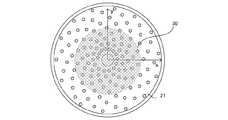
本実施形態では、図示したような半球状の支持部材(探触子ユニット20)を設け、その内面に複数の探触子21を配置する。図2は、本実施形態に係る光音響測定装置を鉛直方向上方(Z軸方向)から観察した図である。図示したように、探触子ユニット20上には、探触子21が半球面に沿う位置でスパイラル状に512個配置されている。
また、探触子ユニット20の底部には、パルス光の出射端(光照射部12)が設けられており、被検体に対してZ軸方向にパルス光(符号13)を照射可能な構成となっている。
また、本実施形態では、探触子ユニット20は、不図示のXYステージによって、X−Y平面に沿って移動可能な構成となっている。このようにすることで、被検体に対して複数の位置で、パルス光の照射および音響波の受信を行うことができるようになり、測定の
精度を向上させることができる。
本実施形態では、保持部材40と探触子ユニット20との間は、音響的な整合層となる液体(以下、音響整合液。本実施形態では水)で満たされている。In this embodiment, a hemispherical support member (probe unit 20) as shown is provided, and a plurality of
Further, the bottom of the
In the present embodiment, the
In the present embodiment, the space between the holding
<<音響発生部材30>>
音響発生部材30は、照射されたパルス光によって、超音波測定を行うための超音波(以下、送信超音波)を発生させる部材である。また、照射されたパルス光を一部透過させる特性を持っている。透過と吸収の比率は、50%と50%、30%と70%、70%と30%など、生体に照射する光量と発生させる送信超音波の大きさによって適宜決定する。音響発生部材30は、探触子ユニット20に取り付けられ、保持部材40と探触子ユニット20との間に固定されている。音響発生部材30は、パルス光の照射を受けると、その一部を被検体側に透過させるとともに、送信超音波を発生させる。<<
The
音響発生部材30は、ポリエチレンテレフタラート、ポリエステル、ポリエチレン、ポリプロピレン、ナイロン、ビニールなどに、光吸収性を有する材料を含有させて作製された薄膜であることが望ましい。光吸収性を有する材料は、例えば、カーボンブラックのような黒色顔料や、銅フタロシアニン等のシアン顔料などを用いることができる。顔料のサイズとしては例えば20−80nmである。樹脂材に対する質量比は例えば0.001−1%である。光吸収体を音響発生部材30に均一に分散させることで、平面波である超音波を発生させることが可能になる。また、光吸収体の濃度を変えることで、透過する光量と発生する送信超音波の比率を変えることができる。光吸収体の特性は、使用するパルス光の波長によって変えてもよい。 The
音響発生部材30の厚みは、音響波(光音響波や反射波)の透過性を良くするため、100μm以下にすることが好ましい。また、音響発生部材30の厚みを変えることで、送信超音波の周波数が変化する。例えば、薄膜の厚みが厚ければ低周波の送信超音波が発生し、薄ければ高周波の送信超音波が発生する。なお、複数種類の音響発生部材(例えば、光吸収体の濃度が異なるものや、厚みが異なるもの)を用意し、被検体に適したものを使用してもよい。 The thickness of the
また、ポリエチレンテレフタラート板、アクリル板、樹脂板などの薄板に、インクジェットプリンタ等によって、顔料インク、染料インク、あるいは樹脂インクを塗布することで音響発生部材30を作製してもよい。点状のインクを等間隔で配置することによって、略平面の超音波を発生させることができる。また、塗布するインクのドット間隔を変えることによって、透過する光量と発生する送信超音波の強度を調整することができる。
本実施形態では、音響発生部材30は、探触子ユニット20と連動してX−Y平面に沿って移動可能な構成になっている。音響発生部材30は、光照射をする領域をカバーする大きさであればよく、それ以外の部分は、光が透過および吸収しないように、反射する部材で構成されていてもよい。また、探触子ユニット20の上部に蓋をするような構成であってもよい。
なお、音響発生部材30を動かない構成としてもよい。この場合、音響発生部材30の大きさを、保持部材40の開口部分と同じ大きさにすればよい。
また、音響発生部材30をアームに取り付け、切り替えまたは交換可能にしてもよい。Further, the
In the present embodiment, the
The
Further, the
<<保持部材40>>
保持部材40は、装置の筐体(符号80)に設けられた開口部に設置された、円弧型のお椀形状をした部材であり、挿入された被検体を保持する手段である。
保持部材40は、被検体に照射する光を透過させるため、光の透過率が高い部材であることが好ましい。また、被検体内から到来する光音響波や反射波を透過させるために、被検体と音響インピーダンスが近い材料を用いることが好ましい。このような材料の例とし
て、例えばポリエチレンテレフタラート、ポリメチルペンテンやポリエチレンなどが挙げられる。<< Holding
The holding
The holding
<<信号処理部50>>
信号処理部50は、増幅器、A/D変換器などからなる手段であり、探触子21によって変換された電気信号を増幅し、デジタル信号に変換する手段である。変換後の信号は、制御部60に送信される。<< Signal processing unit 50 >>
The signal processing unit 50 is a unit including an amplifier, an A / D converter, and the like, and is a unit that amplifies the electric signal converted by the
<<制御部60>>
制御部60は、光音響測定装置が有する各手段を制御する手段である。例えば、光源、XYステージ、探触子の受信制御などを行う。また、制御部60は、取得した電気信号に基づいて、光量分布の算出や、画像再構成などを行うことにより、被検体内部の光学特性および音響特性に関連した情報を取得する情報生成手段でもある。
制御部60は、典型的には、独立したCPUと主記憶装置および補助記憶装置を有するワークステーションであり、あらかじめ記憶されたソフトウェアによって前述した処理が行われる。制御部60は、専用に設計されたハードウェアであってもよいし、他の手段と共用のハードウェアであってもよい。
また、制御部60は、後述する入出力部70を介して、装置のユーザによって入力された情報の取得や、ユーザに対する情報の提示を行うことができる。具体的には、ユーザから入力された指示を元に、測定パラメータの変更、測定の開始・終了、画像の処理方法の選択、患者情報や画像の保存、データの解析などを行うことができる。最終的に、得られた画像は、入出力部70に出力される。<< Control unit 60 >>
The control unit 60 is a unit that controls each unit included in the photoacoustic measurement apparatus. For example, reception control of a light source, an XY stage, and a probe is performed. The control unit 60 is also an information generation unit that acquires information related to the optical characteristics and acoustic characteristics inside the subject by calculating a light amount distribution, image reconstruction, and the like based on the acquired electrical signal. is there.
The control unit 60 is typically a workstation having an independent CPU, a main storage device, and an auxiliary storage device, and the processing described above is performed by software stored in advance. The control unit 60 may be hardware designed exclusively, or may be hardware shared with other means.
In addition, the control unit 60 can acquire information input by the user of the apparatus and present information to the user via the input / output unit 70 described later. Specifically, measurement parameters can be changed, measurement start / end, image processing method selection, patient information and image storage, data analysis, and the like can be performed based on instructions input from the user. Finally, the obtained image is output to the input / output unit 70.
<<入出力部70>>
入出力部70は、ユーザが行った入力操作を受け付け、ユーザに対して情報を提示する手段である。例えば、液晶ディスプレイとキーボード、タッチパネルディスプレイ等である。なお、入出力部70は、本発明に係る被検体情報取得装置の必須構成ではない。<< Input / output unit 70 >>
The input / output unit 70 is means for accepting an input operation performed by the user and presenting information to the user. For example, a liquid crystal display and a keyboard, a touch panel display, or the like. The input / output unit 70 is not an essential component of the subject information acquiring apparatus according to the present invention.
<被検体の測定方法>
次に、被検体の測定方法について説明する。
まず、光源10から発せられたパルス光を被検体に照射する。パルス光は、ファイバやレンズ等の光学部材を介して、光照射部12から被検体に照射される。照射された光は、被検体内を伝搬・拡散し、被検体内に存在する物質において吸収される。生体内部を伝搬した光のエネルギーの一部が血液などの光吸収体に吸収されると、熱膨張により当該光吸収体から音響波が発生する。生体内にがんが存在する場合は、がんの新生血管において他の正常部の血液と同様に光が特異的に吸収され、光音響波が発生する。<Measurement method of specimen>
Next, a method for measuring the subject will be described.
First, the subject is irradiated with pulsed light emitted from the light source 10. The pulsed light is irradiated from the
本実施形態に係る光音響測定装置は、探触子ユニット20の位置をずらしながらパルス光の照射および光音響波の受信を行う。また、受信した光音響波に基づいて、被検体内の光学的特性に関連した情報(例えば、初期音圧や吸収係数の分布)を生成する。
また、光音響波とは別に、被検体内で反射・散乱した反射波を受信する。そして、受信した反射波に基づいて、被検体内の音響特性に関連した情報(例えば、音響インピーダンスが異なる界面の位置を表した情報)を生成する。The photoacoustic measurement apparatus according to the present embodiment performs irradiation with pulsed light and reception of photoacoustic waves while shifting the position of the
In addition to the photoacoustic wave, a reflected wave reflected and scattered in the subject is received. Then, based on the received reflected wave, information related to the acoustic characteristics in the subject (for example, information representing the position of the interface having different acoustic impedance) is generated.
<音響発生部材の位置>
ここで、本発明の原理について、図3を参照しながら説明する。図3(A)は、被検体と装置との空間的配置を示す図であり、図3(B)は、探触子21で受信した音響波の時間変化を示した図である。<Position of sound generating member>
Here, the principle of the present invention will be described with reference to FIG. FIG. 3A is a diagram showing a spatial arrangement of the subject and the apparatus, and FIG. 3B is a diagram showing a time change of the acoustic wave received by the
光照射部から照射されたパルス光13は、まず音響発生部材30に照射される。音響発
生部材30は、パルス光13の一部を透過光201として透過させるとともに、一部を吸収し、光音響効果によって送信超音波202を発生させる。
音響発生部材30を透過した透過光201は、被検体内部にある物質203で吸収され、光音響波を発生させる。なお、ここでは説明の便宜のため、物質203は光の吸収体であると同時に、音の反射・散乱体であるとする。物質203において発生した光音響波は、探触子21で受信される。一方、送信超音波202は、平面波として伝搬し、物質203で反射・散乱され、同様に探触子21で受信される。The pulsed light 13 irradiated from the light irradiation unit is first irradiated to the
The transmitted light 201 transmitted through the
なお、物質203の光の吸収体としての性質が強い場合、光音響波が主に発生し、送信超音波は反射しない。このような物質として血液などが挙げられる。逆に物質203の、音の反射・散乱体としての性質が強い場合、光音響波は発生しない。送信超音波を反射させるような物質として、腫瘍が挙げられる。また、送信超音波を散乱させるような物質として、乳房内の石灰化した組織が挙げられる。 Note that when the property of the
物質203から発せられた光音響波は、第一の信号206として検出される。図3(B)において、パルス光を照射した時刻を原点とすると、物質203から探触子21までの距離(符号205)を光音響波が伝搬する時間の後に、第一の信号206が検出される。
一方、反射波は第二の信号207として検出される。第二の信号207は、音響発生部材30から物質203までの距離(符号204)を送信超音波202が伝搬する時間と、物質203から探触子21までの距離(符号205)を反射波が伝搬する時間を足した時間の後に検出される。A photoacoustic wave emitted from the
On the other hand, the reflected wave is detected as the
物質203のような吸収体あるいは散乱体は、被検体内に多数存在している。一回の光照射で光音響波信号と超音波信号の双方を取得する光音響測定装置においては、被検体内で発生するこれらの信号を分離できる方がより望ましい。特に、微小な物質から発生する光音響波は球面波であり、物質から探触子までの距離が長くなればなるほど、伝搬に伴う減衰によって信号が弱くなるためである。また、探触子から遠い位置で生成された光音響波信号と超音波信号が重畳されると、大きなノイズとなるためである。 A large number of absorbers or scatterers such as the
本実施形態では、光音響波信号と超音波信号を分離できるような位置に音響発生部材30を配置する。具体的な配置位置について、図4を参照しながら説明する。
図4(A)は、2つの物質(物質302および303)が領域301内にある場合の空間的配置を示した図である。また、図4(B)は、探触子21で受信される信号を示した図である。なお、本例では、探触子21の位置をr0、探触子21の位置に最も近い物質
302の位置をrn、最も遠い物質303の位置をrfとする。また、物質302から音響発生部材30に垂線を下ろした際の交点をrsとする。なお、領域301は、装置が被検体内の情報を取得する対象である所定の領域(本発明における注目領域。以下、再構成領域)である。In the present embodiment, the
FIG. 4A is a diagram showing a spatial arrangement in the case where two substances (
探触子21で検出される信号は、物質302から到来する光音響波に対応する信号305、同じく反射波に対応する信号306、物質303から到来する光音響波に対応する信号307、同じく反射波に対応する信号308の4つである。
物質302から到来する反射波を、物質303から到来する光音響波より先に検出することができれば、光音響波信号と超音波信号を分離することができる。すなわち、両信号が時間的に重ならない(間隔309を設けることができる)ためには、式(1)のような関係を満たす位置に音響発生部材30を配置する必要がある。
If the reflected wave coming from the
音響発生部材30は、再構成領域において、すべての探触子21でこのような関係を満たすような位置に配置することが望ましい。
なお、探触子21と画像の再構成を行う位置(以下、再構成位置)との関係で、信号を受信できない探触子がある場合、当該探触子を除外してもよい。例えば、再構成位置が探触子21の信号を受信できる立体角の外にあるとき等である。また、再構成位置と近い位置にある探触子からの信号に強い重みをつけて再構成する場合、有効な範囲にある探触子において、式(1)を満たすようにすればよい。It is desirable that the
If there is a probe that cannot receive a signal due to the relationship between the
ところで、平面波の送信超音波は、音響整合液の中を伝搬する過程においてはほとんど減衰しない。一方、音響発生部材が点音源である場合、球面波の送信超音波が発生する。そのため、音響発生部材と被検体の距離を離すと、送信超音波が放射状に広がっていき、信号強度が弱くなってしまう。すなわち、光音響波信号と超音波信号を同時に取得するためには、送信超音波を平面波としたほうが有利となる。
また、光音響波信号と超音波信号を分離すると、光音響波信号に混入する、超音波信号に起因するノイズを低減できるという利点がある。さらに、被検体に加わる光のエネルギーと超音波のエネルギーを時間的に分離できる。なお、音響発生部材30を、探触子ユニット20の底部に配置すると、探触子21で受信される音響波の音線を音響発生部材が妨害しなくなるため、より好適である。By the way, plane wave transmission ultrasonic waves are hardly attenuated in the process of propagating through the acoustic matching liquid. On the other hand, when the sound generating member is a point sound source, spherical ultrasonic waves are generated. For this reason, when the distance between the sound generating member and the subject is increased, the transmitted ultrasonic waves spread radially and the signal intensity becomes weak. That is, in order to acquire a photoacoustic wave signal and an ultrasonic signal at the same time, it is advantageous to use a transmission ultrasonic wave as a plane wave.
Further, when the photoacoustic wave signal and the ultrasonic signal are separated, there is an advantage that noise caused by the ultrasonic signal mixed in the photoacoustic wave signal can be reduced. Furthermore, the energy of light applied to the subject and the energy of ultrasonic waves can be temporally separated. Note that it is more preferable to arrange the
<画像再構成の方法>
次に、取得した光音響波信号および超音波信号を用いて、画像を再構成する処理について説明する。画像の再構成は、制御部60によって行われる。
まず、光音響波信号に基づいて、被検体内の光学特性に関連する情報を取得する処理について説明する。このような処理には、三次元空間におけるバックプロジェクションアルゴリズムが適用できる。例えば、UBP法(Universal Back−Projection)であれば、初期音圧分布p(r)は、式(2)によって求めることができる。
Next, a process for reconstructing an image using the acquired photoacoustic wave signal and ultrasonic signal will be described. Image reconstruction is performed by the control unit 60.
First, processing for acquiring information related to optical characteristics in the subject based on the photoacoustic wave signal will be described. A back projection algorithm in a three-dimensional space can be applied to such processing. For example, in the case of the UBP method (Universal Back-Projection), the initial sound pressure distribution p (r) can be obtained by Expression (2).
このとき投影データに相当する項b(r0,t)を、式(3)に示す。ここで、pd(r0)は、検出素子で検出される光音響波信号、r0は各検出素子の位置、tは時間、Ω0は超音波探触子の立体角である。
反射波の再構成においても、同様のバックプロジェクションアルゴリズムを用いることができる。ただし、送信超音波が被検体内まで到達する時間を考慮し、tを、式(4)のt’に置き換える。rsは音響発生部材の位置であり、再構成位置rから音響発生部材まで垂線を下ろした際の交点である。また、cは音速である。当然、被検体と音響整合液とで音速が大きく異なる場合はそれらを考慮して補正を行う。
リニアプローブなどを用いる超音波装置においては、例えば128素子の超音波探触子から被検体に超音波を送信し、被検体内部で反射した超音波を受信する。このような超音波装置では、画像の生成に正相加算(Delay and Sum)方式などが用いられる。また、このような超音波装置では、腫瘍界面のような大きな構造物は捉えられるが、石灰化した組織のような小さな構造体をとらえることは難しい。これは、大きな界面の場合、超音波が正反射して超音波探触子に戻ってくるが、小さな構造体の場合、超音波が様々な角度に散乱され、超音波探触子に戻る量が減るためである。しかし、本実施形態に係る光音響測定装置では、探触子ユニット20に探触子21が様々な角度の信号を受信できるように多数配置されているため、散乱した超音波であっても受信することができる。 In an ultrasonic apparatus using a linear probe or the like, for example, an ultrasonic wave is transmitted from a 128-element ultrasonic probe to a subject, and an ultrasonic wave reflected inside the subject is received. In such an ultrasonic apparatus, a positive phase (Delay and Sum) method or the like is used to generate an image. In addition, such an ultrasonic apparatus can capture a large structure such as a tumor interface, but it is difficult to capture a small structure such as a calcified tissue. In the case of a large interface, the ultrasonic wave is regularly reflected back to the ultrasonic probe, but in the case of a small structure, the ultrasonic wave is scattered at various angles and returned to the ultrasonic probe. This is because of the decrease. However, in the photoacoustic measurement apparatus according to the present embodiment, a large number of
<処理フローチャート>
次に、図5を参照しながら、本実施形態に係る光音響測定装置(制御部60)が測定を行う際の処理フローチャートについて説明する。<Process flowchart>
Next, a processing flowchart when the photoacoustic measurement apparatus (control unit 60) according to the present embodiment performs measurement will be described with reference to FIG.
まず、ステップS1で、測定を開始する。この状態で被検者は、乳房を保持部材40に当接させる。保持部材40と乳房の間には空気が入らないように音響整合液である水が充填されている。そして、測定の準備が整ったらユーザが測定を開始する操作を行う。
ステップS2では、探触子ユニット20が所望の位置となるようにXYステージを制御する。パルス光の照射毎にXYステージを動かす場合、同じ位置で複数の光照射を行った後に次の位置にXYステージを動かしてもよい。
次に、ステップS3で、光源10から照射光13を照射する。照射光13の一部は音響発生部材30を透過し、一部は吸収され送信超音波となる。なお、光の波長は、測定内容に合わせて適宜選択すればよい。First, in step S1, measurement is started. In this state, the subject brings the breast into contact with the holding
In step S2, the XY stage is controlled so that the
Next, the
次に、ステップS4で、光音響波を受信する。音響発生部材30を透過した透過光201は、乳房内を拡散して伝搬し、吸収体で吸収されて光音響波を発生させる。発生した光音響波は、探触子21で受信される。
次に、ステップS5で、反射波を受信する。音響発生部材30で発生した送信超音波は、乳房内で反射・散乱される。これらの反射波は探触子21で受信される。受信のタイミングは、光音響波を受信開始後、送信超音波が被検体に到達する時間だけ遅らせて行う。これは、光音響波がパルス光の照射とほぼ同時に発生するのに対し、反射波は往路のぶんだけ時間が余計にかかるためである。Next, a photoacoustic wave is received by step S4. The transmitted light 201 transmitted through the
Next, in step S5, the reflected wave is received. Transmission ultrasonic waves generated by the
なお、本例では、ステップS4とステップS5を分けることによって、一ファイルあたりのデータサイズを小さくしているが、光音響波と反射波を連続して取得し、データを統合してもよい。また、超音波測定を必要としない場合は、音響発生部材30を取り外してもよい。この場合、被検体に照射する光量の調整を適宜行ってもよい。
次に、ステップS6で、所望の測定を完了したか否かを判定する。所望の測定を完了した場合、ステップS7に進む。さらなる測定が必要な場合は、ステップS2に戻り、次の測定を行う。In this example, the data size per file is reduced by separating step S4 and step S5. However, the photoacoustic wave and the reflected wave may be acquired continuously to integrate the data. Moreover, when the ultrasonic measurement is not required, the
Next, in step S6, it is determined whether or not the desired measurement has been completed. When the desired measurement is completed, the process proceeds to step S7. If further measurement is required, the process returns to step S2 to perform the next measurement.
ステップS7では、複数の位置で取得した光音響波信号および超音波信号を用いて、それぞれ光音響画像および超音波画像を生成する。なお、複数の波長を用いる場合、複数の光音響画像を生成する。また、酸素飽和度などの演算を行った画像を生成してもよい。なお、同じ位置で複数の波長で送信超音波を発生させる場合、複数の超音波画像を得ることができる。これらを重ね合わせて一つの超音波画像に統合してもよい。
ステップS8で、処理は終了する。ここでは、取得した画像を確認し、所望の画像であれば測定を終了する。当然、反対側の乳房の測定などを行う場合は、ステップS1に戻って測定を続けてもよい。In step S7, a photoacoustic image and an ultrasonic image are generated using photoacoustic wave signals and ultrasonic signals acquired at a plurality of positions, respectively. When a plurality of wavelengths are used, a plurality of photoacoustic images are generated. Moreover, you may produce | generate the image which performed calculations, such as oxygen saturation. In addition, when transmitting ultrasonic waves with a plurality of wavelengths at the same position, a plurality of ultrasonic images can be obtained. These may be overlapped and integrated into one ultrasonic image.
In step S8, the process ends. Here, the acquired image is confirmed, and if it is a desired image, the measurement is terminated. Of course, when measuring the opposite breast, etc., the measurement may be continued by returning to step S1.
以上説明したように、本実施形態に係る光音響測定装置は、一回の光照射で、光音響波信号と超音波信号の両方を取得することができる。特に、照射されたパルス光の一部を透過する部材を音響発生部材とすることで、測定を行うごとに音響発生部材を移動させる必要がなくなり、測定時間を短くすることができる。すなわち、被険者の負担を和らげることができる。また、測定が短時間で終わるため、体動の影響を小さくすることができ、光音響波画像と超音波画像の位置合わせが容易になる。また、探触子21から超音波の送信機能を省略することができ、装置のコストを抑えることができる。 As described above, the photoacoustic measurement apparatus according to the present embodiment can acquire both the photoacoustic wave signal and the ultrasonic signal with a single light irradiation. In particular, by using a member that transmits part of the irradiated pulsed light as a sound generating member, it is not necessary to move the sound generating member every time measurement is performed, and the measurement time can be shortened. That is, the burden on the insured can be eased. Further, since the measurement is completed in a short time, the influence of body movement can be reduced, and the alignment between the photoacoustic wave image and the ultrasonic image becomes easy. Further, the function of transmitting ultrasonic waves from the
(変形例)
なお、各実施形態の説明は本発明を説明する上での例示であり、本発明は、発明の趣旨を逸脱しない範囲で適宜変更または組み合わせて実施することができる。
例えば、本発明は、上記処理の少なくとも一部を含む光音響測定装置として実施することもできる。また、上記処理の少なくとも一部を含む光音響測定装置の制御方法として実施することもできる。上記処理や手段は、技術的な矛盾が生じない限りにおいて、自由に組み合わせて実施することができる。(Modification)
The description of each embodiment is an exemplification for explaining the present invention, and the present invention can be implemented with appropriate modifications or combinations without departing from the spirit of the invention.
For example, the present invention can be implemented as a photoacoustic measurement apparatus including at least a part of the above processing. Moreover, it can also implement as a control method of the photoacoustic measuring device containing at least one part of the said process. The above processes and means can be freely combined and implemented as long as no technical contradiction occurs.
本発明は、以下の処理を実行することによっても実現される。即ち、上述した各実施形態の1以上の機能を実現するプログラムを、ネットワーク又は各種記憶媒体を介してシステム或いは装置に供給し、そのシステム或いは装置のコンピュータにおける1つ以上のプロセッサがプログラムを読み出して実行する処理でも実現可能である。また、1以上の機能を実現する回路(例えば、FPGAやASIC)によっても実現可能である。 The present invention is also realized by executing the following processing. That is, a program that realizes one or more functions of the above-described embodiments is supplied to a system or apparatus via a network or various storage media, and one or more processors in the computer of the system or apparatus read the program. It can also be realized by processing to be executed. It can also be realized by a circuit (for example, FPGA or ASIC) that realizes one or more functions.
10・・・光源、21・・・探触子、30・・・音響発生部材、50・・・信号処理部、60・・・制御部 DESCRIPTION OF SYMBOLS 10 ... Light source, 21 ... Probe, 30 ... Sound generating member, 50 ... Signal processing part, 60 ... Control part
Claims (8)
Translated fromJapanese前記被検体と前記光照射部との間に配置され、照射された前記光によって略平面の送信超音波を発生させる音響発生部材と、
前記光に起因して前記被検体内で発生した音響波を取得し、第一の電気信号に変換する音響波探触子と、
前記第一の電気信号に基づいて、前記被検体内の光学特性に関連した情報を生成する情報生成手段と、
を有し、
前記音響発生部材は、前記光照射部から照射された光の一部を前記被検体に透過させる
ことを特徴とする、被検体情報取得装置。A light irradiation unit for irradiating the subject with light;
A sound generating member that is disposed between the subject and the light irradiation unit and generates a substantially flat transmission ultrasonic wave by the irradiated light;
An acoustic wave probe for acquiring an acoustic wave generated in the subject due to the light and converting it into a first electrical signal;
Information generating means for generating information related to optical characteristics in the subject based on the first electrical signal;
Have
The object generating apparatus according to claim 1, wherein the sound generation member transmits a part of the light emitted from the light irradiation unit to the subject.
前記情報生成手段は、前記第二の電気信号に基づいて、前記被検体内の音響特性に関連した情報をさらに生成する
ことを特徴とする、請求項1に記載の被検体情報取得装置。The acoustic probe further acquires the transmitted ultrasound reflected in the subject and converts it to a second electrical signal,
The object information acquiring apparatus according to claim 1, wherein the information generation unit further generates information related to acoustic characteristics in the object based on the second electrical signal.
ことを特徴とする、請求項2に記載の被検体情報取得装置。The acoustic generating member causes the acoustic wave probe to generate acoustic waves generated from a region of interest in the subject and the transmitted ultrasonic waves reflected from the region of interest at different times at different times. The object information acquiring apparatus according to claim 2, wherein the object information acquiring apparatus is arranged at a position to reach.
ことを特徴とする、請求項1から3のいずれか1項に記載の被検体情報取得装置。The object information acquiring apparatus according to claim 1, wherein the sound generating member is a thin film containing a light absorber.
ことを特徴とする、請求項4に記載の被検体情報取得装置。The object information acquiring apparatus according to claim 4, wherein the sound generating member is one of polyethylene, polyester, polyethylene terephthalate, polypropylene, nylon, and vinyl.
ことを特徴とする、請求項4または5に記載の被検体情報取得装置。The object information acquiring apparatus according to claim 4, wherein the light absorber is a pigment.
ことを特徴とする、請求項4または5に記載の被検体情報取得装置。The object information acquiring apparatus according to claim 4, wherein the light absorber is a dot-like ink applied at a predetermined interval.
ことを特徴とする、請求項1から7のいずれか1項に記載の被検体情報取得装置。The object information acquiring apparatus according to any one of claims 1 to 7, wherein different types of sound generating members are provided and each of them can be exchanged.
Priority Applications (3)
| Application Number | Priority Date | Filing Date | Title |
|---|---|---|---|
| JP2015174389AJP2017047056A (en) | 2015-09-04 | 2015-09-04 | Subject information acquisition device |
| EP16184894.0AEP3138501A1 (en) | 2015-09-04 | 2016-08-19 | Object information acquiring apparatus |
| US15/245,525US20170065252A1 (en) | 2015-09-04 | 2016-08-24 | Object information acquiring apparatus |
Applications Claiming Priority (1)
| Application Number | Priority Date | Filing Date | Title |
|---|---|---|---|
| JP2015174389AJP2017047056A (en) | 2015-09-04 | 2015-09-04 | Subject information acquisition device |
Publications (1)
| Publication Number | Publication Date |
|---|---|
| JP2017047056Atrue JP2017047056A (en) | 2017-03-09 |
Family
ID=57130135
Family Applications (1)
| Application Number | Title | Priority Date | Filing Date |
|---|---|---|---|
| JP2015174389APendingJP2017047056A (en) | 2015-09-04 | 2015-09-04 | Subject information acquisition device |
Country Status (3)
| Country | Link |
|---|---|
| US (1) | US20170065252A1 (en) |
| EP (1) | EP3138501A1 (en) |
| JP (1) | JP2017047056A (en) |
Families Citing this family (3)
| Publication number | Priority date | Publication date | Assignee | Title |
|---|---|---|---|---|
| JP6946307B2 (en) | 2016-08-30 | 2021-10-06 | キヤノン株式会社 | Information acquisition device and signal processing method |
| JP6776115B2 (en) | 2016-12-22 | 2020-10-28 | キヤノン株式会社 | Processing equipment and processing method |
| CN108392187B (en)* | 2018-04-20 | 2021-08-20 | 四川知周光声医疗科技有限公司 | Water circulation system for photoacoustic breast imager |
Citations (1)
| Publication number | Priority date | Publication date | Assignee | Title |
|---|---|---|---|---|
| JP2014144109A (en)* | 2013-01-29 | 2014-08-14 | Canon Inc | Subject information acquisition device |
Family Cites Families (12)
| Publication number | Priority date | Publication date | Assignee | Title |
|---|---|---|---|---|
| JP4406226B2 (en)* | 2003-07-02 | 2010-01-27 | 株式会社東芝 | Biological information video device |
| US20090005685A1 (en)* | 2007-06-29 | 2009-01-01 | Canon Kabushiki Kaisha | Ultrasonic probe and inspection apparatus equipped with the ultrasonic probe |
| US20110306865A1 (en)* | 2008-09-10 | 2011-12-15 | Endra, Inc. | photoacoustic imaging device |
| JP5675142B2 (en)* | 2010-03-29 | 2015-02-25 | キヤノン株式会社 | Subject information acquisition apparatus, subject information acquisition method, and program for executing subject information acquisition method |
| JP5661451B2 (en)* | 2010-12-27 | 2015-01-28 | キヤノン株式会社 | Subject information acquisition apparatus and subject information acquisition method |
| JP5939786B2 (en)* | 2011-02-10 | 2016-06-22 | キヤノン株式会社 | Acoustic wave acquisition device |
| US9535415B2 (en)* | 2011-07-20 | 2017-01-03 | Rockwell Automation Technologies, Inc. | Software, systems, and methods for mobile visualization of industrial automation environments |
| AU2013212213B2 (en)* | 2012-01-23 | 2018-06-28 | Tomowave Laboratories, Inc. | Laser optoacoustic ultrasonic imaging system (LOUIS) and methods of use |
| JP5840070B2 (en)* | 2012-05-08 | 2016-01-06 | 富士フイルム株式会社 | Photoacoustic measuring device and probe for photoacoustic measuring device |
| KR20160013893A (en)* | 2013-08-01 | 2016-02-05 | 서강대학교산학협력단 | Device and method for acquiring fusion image |
| JP6376938B2 (en)* | 2014-10-17 | 2018-08-22 | キヤノン株式会社 | Subject information acquisition device |
| EP3103396B1 (en)* | 2015-06-10 | 2018-10-24 | Helmholtz Zentrum München Deutsches Forschungszentrum für Gesundheit und Umwelt GmbH | Device and method for hybrid optoacoustic tomography and ultrasonography |
- 2015
- 2015-09-04JPJP2015174389Apatent/JP2017047056A/enactivePending
- 2016
- 2016-08-19EPEP16184894.0Apatent/EP3138501A1/ennot_activeWithdrawn
- 2016-08-24USUS15/245,525patent/US20170065252A1/ennot_activeAbandoned
Patent Citations (1)
| Publication number | Priority date | Publication date | Assignee | Title |
|---|---|---|---|---|
| JP2014144109A (en)* | 2013-01-29 | 2014-08-14 | Canon Inc | Subject information acquisition device |
Non-Patent Citations (3)
| Title |
|---|
| GERHILD WURZINGER, ET AL.: "Simultaneous three-dimensional photoacoustic and laser-ultrasound tomography", BIOMEDICAL OPTICS EXPRESS, JPN7019000800, 2013, US, pages 1380 - 1389* |
| THOMAS FELIX FEHM, ET AL.: "Four dimensional hybrid ultrasound and optoacoustic imagingvia passive element optical excitation in", APPLIED PHYSICS LETTERS, vol. 105, 173505, JPN7019000798, 2014, US, pages 1 - 5* |
| 社団法人日本電子機械工業会, 改定医用超音波機器ハンドブック, JPN7019000799, 20 January 1997 (1997-01-20), JP, pages 15 - 16* |
Also Published As
| Publication number | Publication date |
|---|---|
| EP3138501A1 (en) | 2017-03-08 |
| US20170065252A1 (en) | 2017-03-09 |
Similar Documents
| Publication | Publication Date | Title |
|---|---|---|
| JP6732830B2 (en) | Dual modality image processing system for simultaneous functional and anatomical display mapping | |
| EP2553425B2 (en) | Photoacoustic imaging apparatus and photoacoustic imaging method | |
| CN103458778B (en) | Subject information acquisition equipment | |
| US20100087733A1 (en) | Biological information processing apparatus and biological information processing method | |
| JP5863345B2 (en) | Subject information acquisition apparatus and subject information acquisition method | |
| JP2011005042A (en) | Photoacoustic imaging apparatus and photoacoustic imaging method | |
| JP2010088627A5 (en) | ||
| JP2011160936A (en) | Photoacoustic image forming apparatus and photoacoustic image forming method | |
| JP6452110B2 (en) | Hand-held probe | |
| EP3138481B1 (en) | Object information acquiring apparatus and control method for object information acquiring apparatus | |
| CN106618489A (en) | Apparatus and processing method for acquiring detected object information | |
| KR101899838B1 (en) | Photoacoustic apparatus and information acquisition apparatus | |
| JP2017047056A (en) | Subject information acquisition device | |
| JP2019088346A (en) | Photoacoustic apparatus and object information acquisition method | |
| JP2018061725A (en) | Subject information acquisition device and signal processing method | |
| Thompson et al. | Laser-induced synthetic aperture ultrasound imaging | |
| JP2016077352A (en) | Photoacoustic apparatus and processing method of photoacoustic apparatus | |
| JP6679327B2 (en) | Ultrasonic device | |
| JP2013188489A (en) | Subject information processing apparatus and method for operating the same | |
| US20160206246A1 (en) | Object information acquiring apparatus and object information acquisition method | |
| US20190130553A1 (en) | Information processing apparatus and information processing method | |
| JP2018000305A (en) | Subject information acquisition device and signal processing method | |
| Singh | Identification and elimination of reflection artifacts in biomedical photoacoustic imaging | |
| JP6643108B2 (en) | Subject information acquisition device and subject information acquisition method | |
| Fieramonti | Feasibility, development and characterization of a photoacoustic microscopy system for biomedical applications |
Legal Events
| Date | Code | Title | Description |
|---|---|---|---|
| A621 | Written request for application examination | Free format text:JAPANESE INTERMEDIATE CODE: A621 Effective date:20180801 | |
| RD02 | Notification of acceptance of power of attorney | Free format text:JAPANESE INTERMEDIATE CODE: A7422 Effective date:20181116 | |
| A131 | Notification of reasons for refusal | Free format text:JAPANESE INTERMEDIATE CODE: A131 Effective date:20190319 | |
| A977 | Report on retrieval | Free format text:JAPANESE INTERMEDIATE CODE: A971007 Effective date:20190320 | |
| A02 | Decision of refusal | Free format text:JAPANESE INTERMEDIATE CODE: A02 Effective date:20191001 |