JP2017046796A - Magnetic resonance imaging apparatus - Google Patents
Magnetic resonance imaging apparatusDownload PDFInfo
- Publication number
- JP2017046796A JP2017046796AJP2015171000AJP2015171000AJP2017046796AJP 2017046796 AJP2017046796 AJP 2017046796AJP 2015171000 AJP2015171000 AJP 2015171000AJP 2015171000 AJP2015171000 AJP 2015171000AJP 2017046796 AJP2017046796 AJP 2017046796A
- Authority
- JP
- Japan
- Prior art keywords
- coil
- risk
- magnetic resonance
- imaging
- region
- Prior art date
- Legal status (The legal status is an assumption and is not a legal conclusion. Google has not performed a legal analysis and makes no representation as to the accuracy of the status listed.)
- Pending
Links
Images


Classifications
- G—PHYSICS
- G01—MEASURING; TESTING
- G01R—MEASURING ELECTRIC VARIABLES; MEASURING MAGNETIC VARIABLES
- G01R33/00—Arrangements or instruments for measuring magnetic variables
- G01R33/20—Arrangements or instruments for measuring magnetic variables involving magnetic resonance
- G01R33/28—Details of apparatus provided for in groups G01R33/44 - G01R33/64
- G01R33/32—Excitation or detection systems, e.g. using radio frequency signals
- G01R33/36—Electrical details, e.g. matching or coupling of the coil to the receiver
- G01R33/3664—Switching for purposes other than coil coupling or decoupling, e.g. switching between a phased array mode and a quadrature mode, switching between surface coil modes of different geometrical shapes, switching from a whole body reception coil to a local reception coil or switching for automatic coil selection in moving table MR or for changing the field-of-view
- G—PHYSICS
- G01—MEASURING; TESTING
- G01R—MEASURING ELECTRIC VARIABLES; MEASURING MAGNETIC VARIABLES
- G01R33/00—Arrangements or instruments for measuring magnetic variables
- G01R33/20—Arrangements or instruments for measuring magnetic variables involving magnetic resonance
- G01R33/44—Arrangements or instruments for measuring magnetic variables involving magnetic resonance using nuclear magnetic resonance [NMR]
- G01R33/48—NMR imaging systems
- G01R33/54—Signal processing systems, e.g. using pulse sequences ; Generation or control of pulse sequences; Operator console
- G01R33/543—Control of the operation of the MR system, e.g. setting of acquisition parameters prior to or during MR data acquisition, dynamic shimming, use of one or more scout images for scan plane prescription
- G—PHYSICS
- G01—MEASURING; TESTING
- G01R—MEASURING ELECTRIC VARIABLES; MEASURING MAGNETIC VARIABLES
- G01R33/00—Arrangements or instruments for measuring magnetic variables
- G01R33/20—Arrangements or instruments for measuring magnetic variables involving magnetic resonance
- G01R33/44—Arrangements or instruments for measuring magnetic variables involving magnetic resonance using nuclear magnetic resonance [NMR]
- G01R33/48—NMR imaging systems
- G01R33/54—Signal processing systems, e.g. using pulse sequences ; Generation or control of pulse sequences; Operator console
- G01R33/56—Image enhancement or correction, e.g. subtraction or averaging techniques, e.g. improvement of signal-to-noise ratio and resolution
- G01R33/565—Correction of image distortions, e.g. due to magnetic field inhomogeneities
- G01R33/56572—Correction of image distortions, e.g. due to magnetic field inhomogeneities caused by a distortion of a gradient magnetic field, e.g. non-linearity of a gradient magnetic field
- G—PHYSICS
- G01—MEASURING; TESTING
- G01R—MEASURING ELECTRIC VARIABLES; MEASURING MAGNETIC VARIABLES
- G01R33/00—Arrangements or instruments for measuring magnetic variables
- G01R33/20—Arrangements or instruments for measuring magnetic variables involving magnetic resonance
- G01R33/28—Details of apparatus provided for in groups G01R33/44 - G01R33/64
- G01R33/32—Excitation or detection systems, e.g. using radio frequency signals
- G01R33/34—Constructional details, e.g. resonators, specially adapted to MR
- G01R33/341—Constructional details, e.g. resonators, specially adapted to MR comprising surface coils
- G01R33/3415—Constructional details, e.g. resonators, specially adapted to MR comprising surface coils comprising arrays of sub-coils, i.e. phased-array coils with flexible receiver channels
Landscapes
- Physics & Mathematics (AREA)
- Condensed Matter Physics & Semiconductors (AREA)
- General Physics & Mathematics (AREA)
- Engineering & Computer Science (AREA)
- Signal Processing (AREA)
- High Energy & Nuclear Physics (AREA)
- Health & Medical Sciences (AREA)
- General Health & Medical Sciences (AREA)
- Nuclear Medicine, Radiotherapy & Molecular Imaging (AREA)
- Radiology & Medical Imaging (AREA)
- Nonlinear Science (AREA)
- Magnetic Resonance Imaging Apparatus (AREA)
Abstract
Description
Translated fromJapanese本発明の実施形態は、磁気共鳴イメージング装置に関する。 Embodiments described herein relate generally to a magnetic resonance imaging apparatus.
磁気共鳴イメージング装置は、静磁場中に置かれた患者の原子核スピンをラーモア周波数の高周波(RF:Radio Frequency)信号で励起し、励起に伴って被検体から発生する磁気共鳴信号を再構成して画像を生成する撮像装置である。 A magnetic resonance imaging apparatus excites a patient's nuclear spin placed in a static magnetic field with a radio frequency (RF) signal of Larmor frequency, and reconstructs the magnetic resonance signal generated from the subject upon excitation. An imaging apparatus that generates an image.
磁気共鳴イメージング装置で撮像した画像には、アーティファクトと呼ばれる偽像が混入することがある。磁気共鳴イメージング装置のアーティファクトは、装置の不完全性に起因して発生するもの、撮像パラメータの不適切な設定よって発生するもの、被検体の体動に起因して発生するものなど、種々の要因で発生する。 A false image called an artifact may be mixed in an image picked up by a magnetic resonance imaging apparatus. Artifacts of magnetic resonance imaging devices are caused by various factors such as those caused by imperfections in the device, those caused by improper setting of imaging parameters, and those caused by body movement of the subject. Occurs.
磁気共鳴イメージング装置では、これら各種のアーティファクトを除去、或いは低減するための種々の方策が従来からとられている。 In the magnetic resonance imaging apparatus, various measures have been conventionally taken to remove or reduce these various artifacts.
これら各種のアーティファクトの中には、傾斜磁場の非線形に起因して発生するものがある。 Some of these various artifacts are caused by non-linear gradient magnetic fields.
本発明が解決しようとする課題は、傾斜磁場の非線形性に起因するアーティファクトの発生を回避または抑制することができる磁気共鳴イメージング装置を提供することである。 The problem to be solved by the present invention is to provide a magnetic resonance imaging apparatus that can avoid or suppress the occurrence of artifacts due to the nonlinearity of the gradient magnetic field.
本実施形態の磁気共鳴イメージング装置は、複数のコイル要素を具備するRFコイルと、撮像条件に基づいて、被検体の撮像領域外の信号の混入によるアーティファクトの発生リスクを判定する判定部と、前記判定部の判定結果に応じて、前記複数のコイル要素の中から撮像に用いるコイル要素を選択する選択部と、を備える。 The magnetic resonance imaging apparatus according to the present embodiment includes an RF coil having a plurality of coil elements, a determination unit that determines an occurrence risk of an artifact due to mixing of a signal outside the imaging region of the subject based on imaging conditions, A selection unit that selects a coil element to be used for imaging from the plurality of coil elements according to a determination result of the determination unit.
以下、本発明の実施形態を添付図面に基づいて説明する。 Hereinafter, embodiments of the present invention will be described with reference to the accompanying drawings.
(第1の実施形態)
図1は、第1の実施形態に係る磁気共鳴イメージング装置1の全体構成を示すブロック図である。磁気共鳴イメージング装置1は、磁石架台100、寝台500、制御キャビネット300、コンソール400、及びRF(Radio Frequency)コイル20を備える。(First embodiment)
FIG. 1 is a block diagram showing the overall configuration of a magnetic
磁石架台100は、静磁場磁石10、傾斜磁場コイル11、及びWB(Whole Body)コイル12を有しており、これらの構成品は円筒状の筐体に収納されている。寝台500は、寝台本体50と天板51を有している。 The
制御キャビネット300は、静磁場用電源30、傾斜磁場電源31(X軸用31x、Y軸用31y、Z軸用31z)、コイル選択回路36、RF受信器32、RF送信器33、及びシーケンスコントローラ34を備えている。 The
コンソール400は、処理回路40、記憶回路41、入力デバイス42、及びディスプレイ43を備えている。コンソール400は、ホスト計算機として機能する。 The
磁石架台100の静磁場磁石10は、概略円筒形状をなしており、被検体、例えば患者、が搬送されるボア内に静磁場を発生させる。ボアとは、磁石架台100の円筒内部の空間のことである。静磁場磁石10は超電導コイルを内蔵し、液体ヘリウムによって超電導コイルが極低温に冷却されている。静磁場磁石10は、励磁モードにおいて静磁場用電源30から供給される電流を超電導コイルに印加することで静磁場を発生する。その後、永久電流モードに移行すると、静磁場用電源30は切り離される。一旦永久電流モードに移行すると、静磁場磁石10は長時間、例えば1年以上に亘って、大きな静磁場を発生し続ける。被検体の胸部にある黒丸は、磁場中心を示している。 The static
傾斜磁場コイル11も概略円筒形状をなし、静磁場磁石10の内側に固定されている。この傾斜磁場コイル11は、傾斜磁場電源(31x、31y、31z)から供給される電流によりX軸,Y軸,Z軸の方向に傾斜磁場を被検体に印加する。 The
寝台500の寝台本体50は天板51を上下方向及び水平方向に移動することができる。撮像前に天板51に載置された被検体を所定の高さまで移動させる。その後、撮影時には天板51を水平方向に移動させて被検体をボア内に移動させる。 The
WBコイル12は全身用コイルとも呼ばれ、傾斜磁場コイル11の内側に被検体を取り囲むように概略円筒形状に固定されている。WBコイル12は、RF送信器33から伝送されるRFパルスを被検体に向けて送信する一方、また、水素原子核の励起によって被検体から放出される磁気共鳴信号、即ちMR(Magnetic Resonance)信号を受信する。 The WB
磁気共鳴イメージング装置1は、WBコイル12の他、図1に示すようにRFコイル20を備える。RFコイル20は、被検体の体表面に近接して載置されるコイルである。RFコイル20は、後述するように複数のコイル要素を備えている。これら複数のコイル要素は、RFコイル20の内部でアレイ状に配列されるため、PAC(Phased Array Coil)と呼ばれることもある。RFコイル20には幾つかの種別がある。例えば、RFコイル20として、図1に示すように被検体の胸部や腹部、或いは脚部に設置されるボディコイル(Body Coil)や、被検体の背側に設置されるスパインコイル(Spine Coil)といった種別がある。この他、RFコイル20として、被検体の頭部を撮像するための頭部コイル(Head Coil)や、足を撮像するためのフットコイル(Foot Coil)といった種別もある。また、RFコイル20として、手首を撮像するためのリストコイル(Wrist Coil)、膝を撮像するためのニーコイル(Knee Coil)、肩を撮像するためのショルダーコイル(Shoulder Coil)といった種別もある。RFコイル20の多くは受信専用のコイルであるが、頭部コイルの中には、送信と受信を双方行う種別のものもある。RFコイル20はケーブルを介して天板51と着脱可能に構成されている。 In addition to the WB
RF送信器33は、シーケンスコントローラ34からの指示に基づいてRFパルスを生成する。生成したRFパルスはWBコイル12に伝送され、被検体に印加される。RFパルスの印加によって被検体からMR信号が発生する。このMR信号をRFコイル20又はWBコイル11が受信する。 The
RFコイル20で受信したMR信号、より具体的には、RFコイル20内の各コイル要素で受信したMR信号は、天板51及び寝台本体50に設けられたケーブルを介してコイル選択回路36に伝送される。各コイル要素の出力経路や、WBコイル12の出力経路はチャネルと呼ばれる。このため、各コイル要素やWBコイル12から出力される夫々のMR信号をチャネル信号と呼ぶこともある。WBコイル12で受信したチャネル信号もコイル選択回路36に伝送される。 The MR signal received by the
コイル選択回路36は、RFコイル20から出力されるチャネル信号、或いはWBコイルから出力されるチャネル信号を、シーケンスコントローラ34或いはコンソール400から出力される制御信号に応じて選択する。 The
選択されたチャネル信号はRF受信器32に出力される。RF受信器32は、チャネル信号、即ちMR信号をAD(Analog to Digital)変換して、シーケンスコントローラ34に出力する。デジタルに変化されたMR信号は、生データ(Raw Data)と呼ばれることもある。なお、AD変換は、RFコイル20の内部やコイル選択回路36で行ってもよい。 The selected channel signal is output to the
シーケンスコントローラ34は、コンソール400による制御のもと、傾斜磁場電源31、RF送信器33及びRF受信器32をそれぞれ駆動することによって被検体のスキャンを行う。スキャンによってRF受信器32から生データを受信すると、シーケンスコントローラ34は、その生データをコンソール400に送信する。 The
シーケンスコントローラ34は、処理回路(図示を省略)を具備している。この処理回路は、例えば所定のプログラムを実行するプロセッサや、FPGA(Field Programmable Gate Array)、ASIC(Application Specific Integrated Circuit)等のハードウェアで構成される。 The
コンソール400は、記憶回路41、入力デバイス43、ディスプレイ42、及び処理回路40を備える。記憶回路41は、ROM(Read Only Memory)やRAM(Random Access Memory)の他、HDD(Hard Disk Drive)や光ディスク装置等の外部記憶装置を含む記憶媒体である。記憶回路41は、各種の情報やデータを記憶する他、処理回路40が具備するプロセッサが実行する各種のプログラムを記憶する。 The
入力デバイス43は、例えば、マウス、キーボード、トラックボール、タッチパネル等であり、各種の情報やデータを操作者が入力するための種々のデバイスを含む。ディスプレイ42は、液晶ディスプレイパネル、プラズマディスプレイパネル、有機ELパネル等の表示デバイスである。 The
処理回路40は、例えば、CPUや、専用又は汎用のプロセッサを備える回路である。プロセッサは、記憶回路41に記憶した各種のプログラムを実行することによって、後述する各種の機能を実現する。処理回路40は、FPGAやASIC等のハードウェアで構成してもよい。これらのハードウェアによっても後述する各種の機能を実現することができる。また、処理回路40は、プロセッサとプリグラムによるソフトウェア処理と、ハードウェア処理とを組わせて、各種の機能を実現することもできる。 The
図2は、ボディコイルとして構成されたRFコイル20を例示する図である。ボディコイルとしてのRFコイル20は、図1及び図2(a)に示すように、例えば、被検体の胸部領域をカバーするように設置されるが、被検体の腹部領域や脚部領域をカバーするように設置することもできる。或いは、2つ又は3つのボディコイルを、被検体の頭足方向に並べて配置することもできる。 FIG. 2 is a diagram illustrating an
ボディコイルとしてのRFコイル20は、図2(b)に示すように、複数のコイル要素200、即ち、複数のループコイルを具備している。コイル要素200は、例えば、被検体の頭足方向、即ちZ方向と、被検体の左右方向、即ちX方向に、面アレイ状に配列されている。 As shown in FIG. 2B, the
図2(a)、(b)に示す例では、コイル要素200は、被検体の頭足方向に4列、また、被検体の左右方向に4列配列されている。したがって、図2(a)、(b)に例示するRFコイル20は、16個のコイル要素を有している。 In the example shown in FIGS. 2A and 2B, the
これら複数のコイル要素200は、頭足方向の配列単位に分割することができる。この配列単位を、コイルセクション、或いは単にセクションと呼ぶものとする。1つのコイルセクションは、被検体の左右方向に配列された複数のコイル要素200を有する。 The plurality of
図2(a)、(b)に例示するRFコイル20は、頭足方向に配列された4つのコイルセクション、即ち、コイルセクションA、コイルセクションB、コイルセクションC、及びコイルセクションDを有している。また、各コイルセクションは、被検体の左右方向に配列された4つのコイル要素200を、それぞれ具備している。 The
一方、図3は、スパインコイルとして構成されたRFコイル20を例示する図である。スパインコイルとしてのRFコイル20は、図1及び図3(a)に示すように、被検体の背中と天板51との間に設置される。 On the other hand, FIG. 3 is a diagram illustrating an
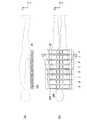
スパインコイルとしてのRFコイル20も、図3(b)に示すように、複数のコイル要素200、即ち、複数のループコイルを具備している。コイル要素200は、例えば、被検体の頭足方向、即ちZ方向と、被検体の左右方向、即ちX方向に、面アレイ状に配列されている。図3(a)、(b)に示す例では、コイル要素200は、被検体の頭足方向に8列、また、被検体の左右方向に4列配列されている。したがって、図3(a)、(b)に例示するRFコイル20は、合計32個のコイル要素を有している。なお、図2(a)、(b)に示したボディコイルとしてのRFコイル20では、全て同じ大きさのコイル要素200が配列されている。これに対して、図3(a)、(b)に示したスパインコイルとしてのRFコイル20では、被検体の左右方向の中央2列のコイル要素200は、外側2列の要素コイル200よりも小さな形状となっている。 The
スパインコイルとしてのRFコイル20も、複数のコイル要素200が、頭足方向の配列単位、即ち、コイルセクションに分割されている。図3(a)、(b)に示す例では、32個のコイル要素200が、コイルセクションAからコイルセクションHまでの8つのコイルセクションに分割されている。 Also in the
実施形態の磁気共鳴イメージング装置1では、傾斜磁場の非線形性に起因するアーティファクトの発生を回避または抑制するために、RFコイル20が具備する複数のコイル要素200の中から、撮像に用いるコイル要素200を選択するという手法をとる。このとき、コイル要素200の選択の単位は、個々の要素コイル200の単位でもよいし、前述したコイルセクションの単位でもよい。以下では、要素コイル200の選択の単位がコイルセクションの単位で選択するケースを例として説明する。 In the magnetic
実施形態の磁気共鳴イメージング装置1の動作について説明する前に、実施形態の磁気共鳴イメージング装置1が対象とするアネファクト(annefact)と呼ばれるアーティファクトについて説明する。 Before describing the operation of the magnetic
アネファクトは、傾斜磁場の非線形性に起因して、より正確には、静磁場と傾斜磁場とが重ね合わせられた合成磁場の非線形性に起因して、撮像領域、即ち、FOV(Field of View)の外側の領域の信号が、FOV内に混入することで発生するアーティファクトである。このアーティファクトは、アネファクトという呼称の他に、アネファクトアーチファクト(annefact artifact)、カスプアーティファクト(cusp artifact)、フォールドオーバアーティファクト(fold-over artifact)、フェザーアーティファクト(feather artifact)、周辺信号アーティファクト(peripheral signal artifact)等の名称で呼ばれることがあるが、いずれも同じ発生メカニズムのアーティファクトである。以下では、アネファクトという用語で統一して説明する。 An effect is caused by the non-linearity of the gradient magnetic field, and more precisely, by the non-linearity of the combined magnetic field in which the static magnetic field and the gradient magnetic field are superimposed, and thus the imaging region, that is, FOV (Field of View). This is an artifact that occurs when the signal in the area outside the signal is mixed in the FOV. This artifact is referred to as an anefact, as well as an anefact artifact, an cusp artifact, a fold-over artifact, a feather artifact, a peripheral signal artifact (peripheral signal artifact) ), Etc., but both are artifacts of the same generation mechanism. In the following, the term “effect” will be used in a unified manner.
図4は、アネファクトの発生メカニズムを、より具体的に説明する図である。図4(a)及び(b)は、Z方向のスライス厚ΔZを小さく設定した状態を示している。今、励起パルスの周波数帯域をΔfexとし、Z方向の傾斜磁場の強度をGzとすると、スライス厚ΔZは、次の(式1)で表される。 FIG. 4 is a diagram for explaining the generation mechanism of the anefact more specifically. 4A and 4B show a state in which the slice thickness ΔZ in the Z direction is set small. Now, assuming that the frequency band of the excitation pulse is Δfex and the intensity of the gradient magnetic field in the Z direction is Gz, the slice thickness ΔZ is expressed by the following (Equation 1).
ΔZ=((2π)/γ)・((Δfex)/Gz) (式1) ΔZ = ((2π) / γ) · ((Δfex) / Gz) (Formula 1)
ここで、γは、磁気回転比(magnetogyric ration)と呼ばれる定数である。(式1)からわかるように、スライス厚ΔZは、傾斜磁場の強度をGzに反比例する。したがって、スライス厚ΔZを小さくするためには、傾斜磁場の強度Gzを大きく設定する必要がある。図4(b)は、大きな傾斜磁場強度Gzに対応して、線形領域、即ち、磁場中心近傍におけるZ方向の傾斜磁場の傾きが大きいことを示している。 Here, γ is a constant called a magnetorotation ratio. As can be seen from (Expression 1), the slice thickness ΔZ is inversely proportional to the intensity of the gradient magnetic field to Gz. Accordingly, in order to reduce the slice thickness ΔZ, it is necessary to set the gradient magnetic field strength Gz to be large. FIG. 4B shows that the gradient of the gradient magnetic field in the Z direction in the linear region, that is, in the vicinity of the magnetic field center, is large corresponding to the large gradient magnetic field strength Gz.
一方、図4(c)、(d)は、Z方向のスライス厚ΔZを大きく設定した状態を示している。スライス厚ΔZを大きくするためには、傾斜磁場強度Gzを小さく設定する必要がある。図4(d)は、小さな傾斜磁場の強度Gzに対応して、線形領域、即ち、磁場中心近傍におけるZ方向の傾斜磁場の傾きが小さいことを示している。 On the other hand, FIGS. 4C and 4D show a state in which the slice thickness ΔZ in the Z direction is set large. In order to increase the slice thickness ΔZ, it is necessary to set the gradient magnetic field strength Gz small. FIG. 4D shows that the gradient of the gradient magnetic field in the Z direction in the linear region, that is, in the vicinity of the magnetic field center, is small corresponding to the strength Gz of the small gradient magnetic field.
磁場Bは、磁場中心近傍の所定の範囲では、B(Z)=B0+Gz*Z、となり、磁場中心からの距離Zに比例して変化する線形性を示す。ここで、B0は静磁場の大きさである。 The magnetic field B is B (Z) = B0 + Gz * Z in a predetermined range in the vicinity of the magnetic field center, and shows linearity that changes in proportion to the distance Z from the magnetic field center. Here, B0 is the magnitude of the static magnetic field.
しかしながら、磁場中心から大きく離れた領域では、傾斜磁場も静磁場も非線形な特性を示す。例えば、図4(b)、(d)に示すように、磁場中心から所定の範囲内では正の傾きをもっていた傾斜磁場が、磁場中心から所定の範囲外では負の傾き、或いは非線形性をもつようになる。また、図4(a)、(c)に示すように、磁場中心から所定の範囲内では一定であった静磁場が、磁場中心から所定の範囲外では減少し、非線形性をもつようになる。今、線形領域内に設定されるFOVのZ方向の位置をZfとし、FOV外の非線形領域のZ方向の位置をZrとする。そして、非線形領域における磁場の大きさを、非線形関数F(Z)で表示するものとする。そうすると、線形領域の磁場B(Zf)と、非線形領域の磁場B(Zr)は、夫々次の(式2)、(式3)で表すことができる。 However, in a region far away from the magnetic field center, both the gradient magnetic field and the static magnetic field exhibit nonlinear characteristics. For example, as shown in FIGS. 4B and 4D, a gradient magnetic field having a positive gradient within a predetermined range from the magnetic field center has a negative gradient or non-linearity outside the predetermined range from the magnetic field center. It becomes like this. Also, as shown in FIGS. 4A and 4C, the static magnetic field that is constant within a predetermined range from the magnetic field center decreases outside the predetermined range from the magnetic field center, and has non-linearity. . Now, the position in the Z direction of the FOV set in the linear region is Zf, and the position in the Z direction of the nonlinear region outside the FOV is Zr. And the magnitude | size of the magnetic field in a nonlinear area | region shall be displayed by the nonlinear function F (Z). Then, the magnetic field B (Zf) in the linear region and the magnetic field B (Zr) in the nonlinear region can be expressed by the following (Expression 2) and (Expression 3), respectively.
B(Zf)=B0+Gz*Zf (線形領域) (式2) B (Zf) = B0 + Gz * Zf (Linear region) (Formula 2)
B(Zr)=F(Zr) (非線形領域) (式3) B (Zr) = F (Zr) (nonlinear region) (Formula 3)
ここで、磁気共鳴周波数、即ち、MR信号の周波数fは、f=(1/2π)・γ・B、であることから、線形領域の磁場B(Zf)の範囲と非線形領域の磁場B(Zr)の範囲とが一致或いは一部重複すると、線形領域からのMR信号の周波数の範囲と、非線形領域からのMR信号の周波数の範囲は、一致或いは一部重複することになる。 Here, since the magnetic resonance frequency, ie, the frequency f of the MR signal is f = (1 / 2π) · γ · B, the range of the magnetic field B (Zf) in the linear region and the magnetic field B (Z When the range of Zr) matches or partially overlaps, the frequency range of the MR signal from the linear region and the frequency range of the MR signal from the non-linear region match or partially overlap.
この場合、撮像領域、即ちFOVを線形領域内に設定したとしても、FOVから離れた位置にある非線形領域の信号が、FOV内の信号と同じ周波数をもつMR信号として、FOVに混入する恐れが生じる。このようなメカニズムによって、FOV外の領域からFOV内に混入するアーティファクトが、アネファクトと呼ばれるアーティファクトである。このように、アネファクトの原因となりうる信号源はFOV外に存在する。FOV外において、アネファクトの原因となりうる信号源の存在領域を、以下、リスク領域と呼ぶものとする。 In this case, even if the imaging region, that is, the FOV is set in the linear region, the signal in the nonlinear region located away from the FOV may be mixed into the FOV as an MR signal having the same frequency as the signal in the FOV. Arise. By such a mechanism, an artifact mixed in the FOV from a region outside the FOV is an artifact called an anefact. As described above, a signal source that can cause an artifact exists outside the FOV. A region where a signal source exists that may cause an anomaly outside the FOV is hereinafter referred to as a risk region.
図4(c)では、リスク領域の範囲を斜線のハッチングで模式的に示している。FOV内の位置Zfとその範囲、及び、非線形関数F(Z)が与えられれば、FOV内の位置ZfからのMR信号の周波数と同じ周波数をもつ、FOV外の信号源の位置Zrとその範囲、即ち、リスク領域を、次の(式4)から求めることができる。 In FIG.4 (c), the range of a risk area | region is typically shown with the hatching of the oblique line. If the position Zf and its range in the FOV and the nonlinear function F (Z) are given, the position Zr and the range of the signal source outside the FOV having the same frequency as the MR signal from the position Zf in the FOV That is, the risk area can be obtained from the following (Equation 4).
B0+Gz*Zf=F(Zr) (式4) B0 + Gz * Zf = F (Zr) (Formula 4)
上記のアネファクト発生のメカニズムからわかるように、スライス厚が厚い、即ち、傾斜磁場の傾斜が緩いと、FOVであるスライス内の磁場の範囲と、非線形領域であるFOV外の領域の磁場の範囲とが重複する可能性が高くなる。つまり、FOV外にリスク領域が存在する可能性が高くなる。言い換えると、図4(c)、(d)のようにスライス厚が厚いと、アネファクトの発生リスクが大きくなり、逆に、図4(a)、(b)のように、スライス厚が薄いと、アネファクトの発生リスクは小さくなる。 As can be seen from the above-described mechanism of the occurrence of an artifact, when the slice thickness is thick, that is, when the gradient of the gradient magnetic field is slow, the range of the magnetic field in the slice that is the FOV, Are more likely to overlap. That is, there is a high possibility that a risk area exists outside the FOV. In other words, if the slice thickness is large as shown in FIGS. 4C and 4D, the risk of occurrence of an artifact increases, and conversely if the slice thickness is thin as shown in FIGS. 4A and 4B. , The risk of occurrence of anefact is reduced.
図5は、第1の実施形態に係る磁気共鳴イメージング装置1の構成の詳細を示すブロック図である。図6は、磁気共鳴イメージング装置1の処理例を示すフローチャートである。また、図7は、第1の実施形態の磁気共鳴イメージング装置1の動作概念を説明する図である。以下、図5乃至図7を用いて、第1の実施形態に係る磁気共鳴イメージング装置1の、より具体的な動作について説明する。 FIG. 5 is a block diagram showing details of the configuration of the magnetic
図5の左上段に示すRFコイル20は、前述したように、複数のコイル要素200を有しており、これらのコイル要素200は、複数のコイルセクションに分割されてグループ化されている。コイル要素200の数や、コイルセクションの数は特に限定するものではないが、例えば、図2で例示したように、RFコイル20は、例えば、4つのコイルセクション(コイルセクションAからコイルセクションD)を有している。 The
RFコイル20からは、それぞれのコイル要素200から、受信したMR信号が出力され、コイル選択回路36を経由しRF受信器32に出力される。RF受信器32では、コイル選択回路36で選択された各MR信号をデジタル信号に変換し、シーケンスコントローラ34に出力する。シーケンスコントローラ34は、デジタルに変換されたMR信号をコンソール400に伝送する。 From the
コンソール400は、前述したように、処理回路40、記憶回路41、ディスプレイ42、及び入力デバイス43を有している。 As described above, the
処理回路40は、撮像条件設定機能401、アネファクト発生リスク判定機能402、コイル選択機能403、再構成機能404、コイル検出機能405、コイル暫定選択機能406、及び表示制御機能407を有している。これらの各機能は、例えば、処理回路40が具備するプロセッサが、記憶回路41に記憶される所定のプログラムを実行することによって実現される。上記の各機能について、図6のフローチャートにしたがって説明する。 The
ステップST100とステップST101は、コイル選択機能403に対応するステップである。コイル選択機能403は、CDS(Coil Detection Scan)と呼ばれるスキャンを実行する。このスキャンは、被検体に載置されているRFコイル20の位置、より具体的には、磁場中心に対するRFコイル20内の、各コイルセクションのZ方向の位置を算出するために行われる。CDSは、例えば、1次元のFE(Field Echo)法によるプロトコルで被検体を撮像する。そして、各コイルセクションからのMR信号を、1次元(Z方向)のフーリエ変換で再構成した信号強度のピーク値に基づいて、磁場中心に対する各コイルセクションのZ方向の位置を算出する。そして、算出した各コイルセクションのZ方向の位置を、記憶回路41に保存する。なお、1次元(Z方向)のフーリエ変換は、再構成機能404によって行われる。 Steps ST100 and ST101 are steps corresponding to the
ステップST102は、コイル暫定選択機能406に対応するステップである。コイル暫定選択機能406は、RFコイル20が具備する複数のコイルセクション、或いは複数のコイル要素200の中から、所定数のコイル要素200、或いは所定数のコイルセクションを磁場中心の位置に基づいて暫定的に選択する。例えば、図7(a)に示すように、RFコイル20が具備する4つのコイルセクションA〜Dの中から、磁場中心に近い3つのコイルセクションA、B、Cを暫定的に選択する。そして、選択結果を、コイル選択回路36に出力する。図7(a)では、コイルセクションAとコイルセクションDが、磁場中心に対してほぼ同じ位置にあるが、前述したCDSの結果、コイルセクションAの信号強度がコイルセクションDの信号強度よりも大きいことがあり、そのような場合には、コイルセクションDが非選択となり、コイルセクションA、B、Cが暫定的に選択されることになる。 Step ST102 corresponds to the coil
ステップST103は、撮像条件設定機能401に対応するステップである。撮像条件設定機能401は、入力デバイス43を介して操作者が入力した情報やデータに基づいて、各種の撮像条件を設定する。設定する撮像条件は、パルスシーケンス、即ち、プロトコルの種別や、FOVの位置や大きさに関する情報、解像度に関する情報を含む。FOVの大きさは、励起するスライス厚に関する情報を含む。撮像条件には、腹部、胸部、脊椎、頭部、足首、手首等の撮像部位(解剖学的撮像部位)に関する情報が含まれる。また、撮像条件には、ボディコイル、スパインコイル、ヘッドコイル、フットコイル、リストコイルなどの、RFコイル20のコイル種別に関する情報を含む。 Step ST103 is a step corresponding to the imaging
ステップST104は、アネファクト発生リスク判定機能402に対応するステップである。アネファクト発生リスク判定機能402は、撮像条件に基づいて、被検体の撮像領域外の信号の混入によるアーティファクト、即ちアネファクトの発生リスクを判定する。ここで、アネファクトの発生リスクの判定には、上記撮像条件のうち、スライス厚、撮像部位及びコイル種別の少なくとも1つを含む。 Step ST104 is a step corresponding to the anefact occurrence
例えば、アネファクト発生リスク判定機能402は、スライス厚が所定値よりも厚いときに、アネファクトの発生リスクがあると判定する。図4で説明したアネファクト発生のメカニズムで説明したように、スライス厚が厚い、即ち、傾斜磁場の傾斜が緩いと、リスク領域が存在する可能性が高くなり、アネファクトの発生リスクが高くなると考えられからである。アネファクトの発生リスクがあると判定した場合、ステップST105へ進む。逆に、スライス厚が所定値よりも薄いときには、アネファクトの発生リスクが少ないと判定し、ステップST109に進み、撮像を開始する。 For example, the anefact occurrence
一方、図4(c)から理解できるように、リスク領域が存在したとしても、そのリスク領域に対してRFコイル20が感度を持たなければ、リスク領域からのMR信号は受信されないため、アネファクトは発生しない。 On the other hand, as can be understood from FIG. 4C, even if a risk region exists, if the
そこで、例えば、アネファクト発生リスク判定機能402は、撮像部位の頭足方向の長さが所定値よりも長いとき、アネファクトの発生リスクがあると判定する。撮像部位の頭足方向の長さが所定値よりも長い場合とは、例えば、撮像部位が、脊椎、腹部、胸部、脚部等の場合である。これらの頭足方向に長い部位を撮像する場合には、これらの撮像部位をカバーするために、頭足方向に広い感度範囲をもつRFコイル20が使用される。このため、RFコイル20が、FOVだけでなく、FOVに隣接するリスク領域に対しても、感度をもつ可能性が高くなる。そこで、撮像部位の頭足方向の長さが所定値よりも長い場合ときには、アネファクトの発生リスクがあると判定し、ステップST105へ進む。逆に、撮像部位の頭足方向の長さが所定値よりも短い場合には、例えば、撮像部位が頭部、足首、手首のような場合には、アネファクトの発生リスクが少ないと判定し、ステップST109へ進み、撮像を開始する。 Thus, for example, the anefact occurrence
リスク領域に対してRFコイル20が感度をもつか否かは、RFコイル20のコイル種別に基づいて判定することもできる。例えば、コイル種別が、スパインコイルやボディコイルの場合には、RFコイル20の感度が頭足方向の広い範囲をカバーするため、アネファクトの発生リスクがあると判定し、ステップST105に進む。逆に、コイル種別が、ヘッドコイル、フットコイル、リストコイルのように頭足方向の限定された範囲のみをカバーする種別の場合には、アネファクトの発生リスクが少ないと判定し、ステップST109へ進み、撮像を開始する。 Whether or not the
アネファクトの発生リスクは、スライス厚、撮像部位、及びコイル種別をそれぞれ別個に用いて判定してもよいが、これらを組み合わせて判定してもよい。 The risk of occurrence of an anefact may be determined using the slice thickness, the imaging region, and the coil type separately, or may be determined by combining these.
アネファクトの発生リスクが有ると判定された場合、アネファクト発生リスク判定機能402は、さらに、ステップST104において、撮像条件に対応する傾斜磁場の傾きと非線形性とを用いて、撮像領域(FOV)内の磁気共鳴周波数と、撮像領域(FOV)外の磁気共鳴周波数が重複するか否かを判定する。例えば(式2)から算出されるB(Zf)に対応する磁気共鳴周波数の範囲と、(式3)から算出されるB(Zr)に対応する磁気共鳴周波数の範囲とを比較することで、撮像領域(FOV)内の磁気共鳴周波数と、撮像領域(FOV)外の磁気共鳴周波数が重複するか否かを判定することができる。重複する場合には、FOV外にリスク領域が存在する、即ち、アネファクトの発生リスクがあると判定する。なお、(式2)におけるB0やGzの値、(式3)における非線形関数F(Z)の形状は、これらの値や形状を事前に計測して記憶回路41に保存しておき、ステップST104の実行時に記憶回路41を参照すればよい。 If it is determined that there is an anefact occurrence risk, the anefact occurrence
次のステップST105、ステップST106も、アネファクト発生リスク判定機能402に対応するステップである。ステップST104で、アネファクトの発生リスクが有り、リスク領域が存在すると判定されると、ネファクト発生リスク判定機能402は、ステップST105において、そのリスク領域の位置や範囲を特定する。具体的には、前述した(式4)から、FOV外のアネファクト源の位置Zrとその範囲を求め、この位置及び範囲を、リスク領域として特定することができる。 The next step ST105 and step ST106 are also steps corresponding to the anefact occurrence
さらに、ステップST106にて、アネファクト発生リスク判定機能402は、暫定的に選択しているコイル要素200或いはコイルセクションと、特定したリスク領域とが重複するか否かを判定する。ここで、コイル要素200或いはコイルセクションと、リスク領域とが重複するとは、コイル要素200或いはコイルセクションがカバーする範囲、例えばZ方向の範囲が、リスク領域の範囲と重複するという意味である。そして、重複している場合は、重複しているコイル要素200、またはコイルセクションを特定する。図7(a)は、暫定的に選択したコイルセクションAと、リスク領域とが重複している例を示している。 Further, in step ST106, the anefact occurrence
ステップST107は、表示制御機能407に対応するステップである。表示制御機能407は、例えば、「現在の撮像条件では、アネファクト発生の可能性があります」等のアラーム表示をディスプレイ42に表示させる。上記のアラーム表示は、ステップST104の直後、或いはステップST105の直後に行ってもよい。 Step ST107 is a step corresponding to the
ステップST108は、コイル選択機能403に対応するステップである。コイル選択機能403は、ステップST106で特定された、リスク領域と重複するコイル要素200またはコイルセクションを非選択とする。例えば、図7(a)に例示するように、コイルセクションAがリスク領域と重複すると判定された場合には、コイルセクションAからのMR信号を非選択とするための制御信号を、コイル選択回路36に対して送信する。これに換えて、コイルセクションAからのMR信号を用いて再構成処理を行わないように、再構成機能404に対して指示信号を与えてもよい。この結果、図7(b)に示すように、コイルセクションAは非選択となり、FOV外のリスク領域からのアーティファクトの混入、即ちアネファクトの発生を回避、或いは抑制することができる。 Step ST108 is a step corresponding to the
なお、ステップST108の実行の後、表示制御機能407は、例えば、「アネファクト発生の可能性があるため、コイルセクションAを非選択にしました」等のアラーム表示をディスプレイ42に表示させてもよい。
その後、ステップST109にて、撮像を開始する。Note that after the execution of step ST108, the
Then, imaging is started in step ST109.
以上説明してきたように、第1の実施形態に係る磁気共鳴イメージング装置1によれば、アネファクト発生のリスクを、撮像条件に基づいて判定することができる。また、アネファクト発生源の領域であるリスク領域を特定し、このリスク領域と重複するコイル要素200、或いはコイルセクションを非選択とすることにより、アネファクトの発生を回避、或いは抑制することができる。 As described above, according to the magnetic
また、撮像条件に基づくアネファクト発生のリスク判定や、コイル要素200或いはコイルセクションを判定結果に基づいて非選択とする処理は、処理回路40によって自動的に行われるため、ユーザに操作負担を強いることがない。 Further, the risk determination of the occurrence of an artifact based on the imaging condition and the process of deselecting the
また、操作者の中には、アネファクトの存在自体、或いは、アネファクトの発生メカニズムを認知していない者もいるが、そのような操作者であっても、アネファクトを特に意識させることなく、アネファクトの発生を回避、或いは抑制することができる。 Some operators are not aware of the existence of an anefact or the mechanism of the occurrence of an anefact. Even such an operator is not aware of the anefact, Occurrence can be avoided or suppressed.
また、アネファクト発生の原因となるコイル要素やコイルセクションが非選択となるため、再構成の対象となるデータサイズも小さくなる。 In addition, since the coil elements and coil sections that cause the anefact are not selected, the data size to be reconfigured is also reduced.
また、アネファクトは、その発生の原理上、パルスシーケンスの種類を問わず発生するが、実施形態の磁気共鳴イメージング装置1は、パルスシーケンスの種類に依存することなく、アネファクトの発生を回避または抑制することができる。 In addition, although the effect is generated regardless of the type of the pulse sequence on the principle of the generation, the magnetic
(第2の実施形態)
図8は、第2の実施形態に係る磁気共鳴イメージング装置1の処理例を示すフローチャートである。また、図9は、第2の実施形態に係る磁気共鳴イメージング装置1の動作概念を説明する図である。第1の実施形態と同じ処理には同じ符号を付し、重複する説明は省略する。第2の実施形態は、第1の実施形態の処理にステップST200乃至ステップST202の処理を追加している。(Second Embodiment)
FIG. 8 is a flowchart illustrating a processing example of the magnetic
ステップST200は、アネファクト発生リスク判定機能402に対応するステップである。アネファクト発生リスク判定機能402は、ステップST106にて、暫定的に選択しているコイル要素200またはコイルセクションと、リスク領域とが重複していると判定された場合、ステップST200にて、リスク領域と重複するコイル要素200またはコイルセクションと、FOVとが重複するか否かをさらに判定する。そして、リスク領域と重複するコイル要素200またはコイルセクションと、FOVとが重複する場合には、重複しているコイル要素200またはコイルセクションを非選択にせず、ステップST201に進む。 Step ST200 is a step corresponding to the anefact occurrence
例えば、図9(a)に示す例では、暫定的に選択されているコイルセクションAがリスク領域と重複しており、さらに、このコイルセクションAの一部は、FOVとも重複している。このような場合、コイルセクションAを非選択にせず、ステップST201に進む。コイルセクションAを非選択にすると、FOVからの信号の一部が受信できなくなる可能性があるからである。 For example, in the example shown in FIG. 9A, the provisionally selected coil section A overlaps the risk region, and a part of the coil section A also overlaps the FOV. In such a case, the coil section A is not deselected and the process proceeds to step ST201. This is because if the coil section A is not selected, a part of the signal from the FOV may not be received.
一方、このような場合であっても、図9(b)に示すように、コイルセクションAの選択を維持したままで寝台500を移動させることにより、より具体的には、寝台500の天板51を頭足方向(Z方向)に移動させることにより、リスク領域からの受信を回避することができる。 On the other hand, even in such a case, as shown in FIG. 9B, more specifically, by moving the
ステップST201は、表示制御機能407に対応するステップである。表示制御機能407は、例えば、「アネファクト発生の可能性が有ります。寝台を移動させてください」等の、アラームや、寝台の移動を促す旨の表示を、ディスプレイ42に表示させる。 Step ST201 is a step corresponding to the
また、例えば、図9(a)や図9(b)に対応する表示を、ディスプレイ42に表示させてもよい。例えば、コイルセクションAが、リスク領域とFOVの双方に重複している場合には、図9(a)に対応する表示において、コイルセクションAを点滅させると共に、「アネファクト発生の可能性が有ります。寝台を移動させてください」等を表示する。 Further, for example, a display corresponding to FIGS. 9A and 9B may be displayed on the
操作者は、これらの表示によって、寝台を移動させる。このとき、寝台の移動に伴って、コイルセクションAを含むRFコイル20の位置は、リスク領域の位置から離れていき、やがて、コイルセクションAとリスク領域は重複しなくなる。寝台の移動期間中、ステップST200の判定を継続して行い、コイルセクションAとリスク領域とが重複しなくなった時点で、コイルセクションAの点滅を停止する。点滅の停止により、操作者は、寝台の移動を停止するタイミングを認識することができる。 The operator moves the bed based on these displays. At this time, with the movement of the bed, the position of the
上述した第2の実施形態に係る磁気共鳴イメージング装置1によれば、第1の実施形態の効果に加えて、コイル要素200またはコイルセクションが、リスク領域とFOVの双方に重複する場合であっても、アネファクトの発生を回避または抑制することができる According to the magnetic
以上説明した少なくとも1つの実施形態の磁気共鳴イメージング装置によれば、傾斜磁場の非線形性に起因するアーティファクトの発生を回避または抑制することができる According to the magnetic resonance imaging apparatus of at least one embodiment described above, it is possible to avoid or suppress the generation of artifacts due to the nonlinearity of the gradient magnetic field.
なお、各実施形態の説明における、アネファクト発生リスク判定機能、コイル選択機能、コイル暫定選択機能、及び表示制御機能は、夫々、特許請求の範囲の記載における判定部、選択部、暫定選択部、及び表示制御部の一例である。各実施形態の説明のおけるコイルセクションは、特許請求の範囲の記載におけるコイル要素、またはセクションの一例である。 In the description of each embodiment, the anefact occurrence risk determination function, the coil selection function, the coil provisional selection function, and the display control function are respectively a determination unit, a selection unit, a provisional selection unit, and a display control function. It is an example of a display control part. The coil section in the description of each embodiment is an example of a coil element or section in the claims.
本発明のいくつかの実施形態を説明したが、これらの実施形態は、例として提示したものであり、発明の範囲を限定することは意図していない。これら実施形態は、その他の様々な形態で実施されることが可能であり、発明の要旨を逸脱しない範囲で、種々の省略、置き換え、変更を行うことができる。これら実施形態やその変形は、発明の範囲や要旨に含まれると同様に、特許請求の範囲に記載された発明とその均等の範囲に含まれるものである。 Although several embodiments of the present invention have been described, these embodiments are presented by way of example and are not intended to limit the scope of the invention. These embodiments can be implemented in various other forms, and various omissions, replacements, and changes can be made without departing from the spirit of the invention. These embodiments and their modifications are included in the scope and gist of the invention, and are also included in the invention described in the claims and the equivalents thereof.
1…磁気共鳴イメージング装置
20…RFコイル
34…シーケンスコントローラ
36…コイル選択回路
40…処理回路
41…記憶回路
42…入力デバイス
43…ディスプレイ
400…コンソール
401…撮像条件設定機能
402…アネファクト発生リスク判定機能
403…コイル選択機能
404…再構成機能
405…コイル検出機能
406…コイル暫定選択機能
407…表示制御機能DESCRIPTION OF
Claims (11)
Translated fromJapanese撮像条件に基づいて、被検体の撮像領域外の信号の混入によるアーティファクトの発生リスクを判定する判定部と、
前記判定部の判定結果に応じて、前記複数のコイル要素の中から撮像に用いるコイル要素を選択する選択部と、
を備える磁気共鳴イメージング装置。An RF coil comprising a plurality of coil elements;
A determination unit that determines the risk of occurrence of artifacts due to mixing of signals outside the imaging region of the subject, based on imaging conditions;
A selection unit that selects a coil element to be used for imaging from the plurality of coil elements according to a determination result of the determination unit;
A magnetic resonance imaging apparatus comprising:
前記判定部は、前記スライス厚、撮像部位及びコイル種別の少なくとも1つに基づいて前記アーティファクトの発生リスクを判定する、
請求項1に記載の磁気共鳴イメージング装置。The imaging condition includes at least one of a slice thickness, an imaging region, and a coil type,
The determination unit determines the risk of occurrence of the artifact based on at least one of the slice thickness, the imaging region, and the coil type.
The magnetic resonance imaging apparatus according to claim 1.
請求項2に記載の磁気共鳴イメージング装置。The determination unit determines that there is a risk of occurrence of the artifact when the slice thickness is thicker than a predetermined value.
The magnetic resonance imaging apparatus according to claim 2.
請求項2に記載の磁気共鳴イメージング装置。The determination unit is of a type that captures an imaging region in which the length in the cranio-foot direction of the imaging region is longer than a predetermined value or the coil type is longer in the cranio-foot direction than the predetermined value. When it is determined that there is a risk of occurrence of the artifact,
The magnetic resonance imaging apparatus according to claim 2.
前記選択部は、前記セクションを選択することによって、前記撮像に用いるコイル要素を選択する、
請求項1に記載の磁気共鳴イメージング装置。The plurality of coil elements are divided into sections defined as arrangement units in the cranio-foot direction,
The selection unit selects a coil element to be used for the imaging by selecting the section.
The magnetic resonance imaging apparatus according to claim 1.
請求項1または2に記載の磁気共鳴イメージング装置。The determination unit determines whether or not the magnetic resonance frequency in the imaging region and the magnetic resonance frequency outside the imaging region overlap using the gradient of the gradient magnetic field corresponding to the imaging condition and nonlinearity. If it overlaps, it is determined that there is a risk of occurrence of the artifact.
The magnetic resonance imaging apparatus according to claim 1 or 2.
前記選択部は、前記リスク領域と重複しないと判定されたコイル要素を、前記撮像に使用するコイル要素として選択する一方、前記リスク領域と重複すると判定されたコイル要素を前記撮像に使用するコイル要素から除外する、
請求項6に記載の磁気共鳴イメージング装置。The determination unit identifies a region outside the imaging region corresponding to the overlapping magnetic resonance signal as a risk region where the artifact signal source may exist, and identifies each of the plurality of coil elements and the identified risk region. And whether or not
The selection unit selects a coil element determined not to overlap with the risk area as a coil element used for the imaging, and uses a coil element determined to overlap with the risk area to the imaging. Exclude from
The magnetic resonance imaging apparatus according to claim 6.
前記選択部は、前記判定部の判定結果に基づいて、前記暫定的な選択を維持するか解除するかを決定する、
請求項1乃至7のいずれか1項に記載の磁気共鳴イメージング装置。A provisional selection unit that provisionally selects a predetermined number of coil elements from the plurality of coil elements based on the position of the magnetic field center before the selection of the coil elements by the selection unit;
The selection unit determines whether to maintain or cancel the provisional selection based on a determination result of the determination unit.
The magnetic resonance imaging apparatus according to claim 1.
前記選択部は、前記暫定的に選択された所定数のコイル要素のうち、前記リスク領域と重複しないコイル要素の選択を維持する一方、前記リスク領域と重複するコイル要素の選択を解除する、
請求項7に記載の磁気共鳴イメージング装置。A provisional selection unit that provisionally selects a predetermined number of coil elements from the plurality of coil elements based on the position of the magnetic field center before the selection of the coil elements by the selection unit;
The selection unit, while maintaining the selection of the coil elements that do not overlap with the risk region, among the predetermined number of the temporarily selected coil elements, cancels the selection of the coil elements that overlap with the risk region,
The magnetic resonance imaging apparatus according to claim 7.
前記選択部は、前記リスク領域と重複すると判定されたコイル要素が前記撮像領域とも重複すると判定された場合は、そのコイル要素を前記撮像に使用するコイル要素から除外しない、
請求項7に記載の磁気共鳴イメージング装置。The determination unit further determines whether or not a coil element determined to overlap with the risk region overlaps with the imaging region,
The selection unit, when it is determined that a coil element determined to overlap with the risk area also overlaps with the imaging area, does not exclude the coil element from the coil element used for the imaging,
The magnetic resonance imaging apparatus according to claim 7.
ディスプレイと、
前記ディスプレイを制御する表示制御部と、
をさらに備え、
前記表示制御部は、前記リスク領域と重複すると判定されたコイル要素が前記撮像領域とも重複すると判定された場合は、前記ディスプレイに、アラームの表示、及び前記寝台の移動を促す旨の表示、の少なくとも一方の表示を表示する、
請求項10に記載の磁気共鳴イメージング装置。A bed on which the subject is placed;
Display,
A display control unit for controlling the display;
Further comprising
The display control unit, when it is determined that a coil element determined to overlap with the risk area also overlaps with the imaging area, an alarm display on the display and a display prompting the bed to move. Display at least one display,
The magnetic resonance imaging apparatus according to claim 10.
Priority Applications (2)
| Application Number | Priority Date | Filing Date | Title |
|---|---|---|---|
| JP2015171000AJP2017046796A (en) | 2015-08-31 | 2015-08-31 | Magnetic resonance imaging apparatus |
| US15/152,685US20170059679A1 (en) | 2015-08-31 | 2016-05-12 | Magnetic resonance imaging apparatus |
Applications Claiming Priority (1)
| Application Number | Priority Date | Filing Date | Title |
|---|---|---|---|
| JP2015171000AJP2017046796A (en) | 2015-08-31 | 2015-08-31 | Magnetic resonance imaging apparatus |
Publications (1)
| Publication Number | Publication Date |
|---|---|
| JP2017046796Atrue JP2017046796A (en) | 2017-03-09 |
Family
ID=58104286
Family Applications (1)
| Application Number | Title | Priority Date | Filing Date |
|---|---|---|---|
| JP2015171000APendingJP2017046796A (en) | 2015-08-31 | 2015-08-31 | Magnetic resonance imaging apparatus |
Country Status (2)
| Country | Link |
|---|---|
| US (1) | US20170059679A1 (en) |
| JP (1) | JP2017046796A (en) |
Families Citing this family (2)
| Publication number | Priority date | Publication date | Assignee | Title |
|---|---|---|---|---|
| CN105476635B (en)* | 2015-12-29 | 2019-02-05 | 沈阳东软医疗系统有限公司 | Method and device for positioning radio frequency coil in nuclear magnetic resonance imaging system |
| AU2019321607A1 (en)* | 2018-08-15 | 2021-02-11 | Hyperfine Operations, Inc. | Deep learning techniques for suppressing artefacts in magnetic resonance images |
Citations (3)
| Publication number | Priority date | Publication date | Assignee | Title |
|---|---|---|---|---|
| JP2000083923A (en)* | 1998-06-12 | 2000-03-28 | General Electric Co <Ge> | Method for reducing artifact in mr image obtained through the use of phased array surface coil |
| JP2003135422A (en)* | 2001-10-31 | 2003-05-13 | Ge Medical Systems Global Technology Co Llc | Rf coil and magnetic resonance photographing device using the same |
| US20120025826A1 (en)* | 2009-04-14 | 2012-02-02 | The Board Of Trustees Of The University Of Illinois | Method For Reducing Artifacts In Magnetic Resonance Imaging |
- 2015
- 2015-08-31JPJP2015171000Apatent/JP2017046796A/enactivePending
- 2016
- 2016-05-12USUS15/152,685patent/US20170059679A1/ennot_activeAbandoned
Patent Citations (3)
| Publication number | Priority date | Publication date | Assignee | Title |
|---|---|---|---|---|
| JP2000083923A (en)* | 1998-06-12 | 2000-03-28 | General Electric Co <Ge> | Method for reducing artifact in mr image obtained through the use of phased array surface coil |
| JP2003135422A (en)* | 2001-10-31 | 2003-05-13 | Ge Medical Systems Global Technology Co Llc | Rf coil and magnetic resonance photographing device using the same |
| US20120025826A1 (en)* | 2009-04-14 | 2012-02-02 | The Board Of Trustees Of The University Of Illinois | Method For Reducing Artifacts In Magnetic Resonance Imaging |
Also Published As
| Publication number | Publication date |
|---|---|
| US20170059679A1 (en) | 2017-03-02 |
Similar Documents
| Publication | Publication Date | Title |
|---|---|---|
| US10191131B2 (en) | Medical imaging apparatus having multiple subsystems, and operating method therefor | |
| US10241175B2 (en) | Medical imaging apparatus having multiple subsystems, and operating method therefor | |
| US20160091586A1 (en) | Medical imaging apparatus having multiple subsystems, and operating method therefor | |
| US10168407B2 (en) | Medical imaging apparatus having multiple subsystems, and operating method therefor | |
| JP2016067937A (en) | Operation of a medical imaging inspection device including multiple subsystems | |
| US11333731B2 (en) | Magnetic resonance imaging apparatus, RF coil, and magnetic resonance imaging method | |
| JP2017070386A (en) | Magnetic resonance imaging apparatus, image processing device, and image processing method | |
| US10598746B2 (en) | Magnetic resonance method and apparatus with reduction of artifacts by a combination of SPAIR pulse and saturation pulse | |
| US20200041600A1 (en) | Magnetic resonance imaging apparatus and magnetic resonance imaging method | |
| US10866294B2 (en) | Magnetic resonance imaging apparatus, multi-slice imaging method, and shimming value calculation apparatus | |
| JP7353735B2 (en) | magnetic resonance imaging device | |
| JP2017046796A (en) | Magnetic resonance imaging apparatus | |
| JP6591208B2 (en) | Magnetic resonance imaging system | |
| JP2019017494A (en) | Magnetic resonance imaging system | |
| US10942236B2 (en) | Magnetic resonance imaging apparatus and magnetic resonance imaging method | |
| JP4901420B2 (en) | Magnetic resonance imaging apparatus and magnetic resonance imaging method | |
| JP5558783B2 (en) | Magnetic resonance imaging system | |
| US20200103482A1 (en) | Magnetic resonance imaging apparatus | |
| KR102429692B1 (en) | Method for providing guide information for artifact and magnetic resonance imaging apparatus thereof | |
| JP5360757B2 (en) | Magnetic resonance imaging and magnetic resonance imaging apparatus | |
| JP6611597B2 (en) | Magnetic resonance imaging apparatus and RF coil apparatus | |
| US20190346520A1 (en) | Magnetic resonance imaging apparatus and multi-slice imaging method | |
| JP7508536B2 (en) | Magnetic resonance imaging apparatus and magnetic resonance imaging method | |
| JP6181374B2 (en) | Magnetic resonance imaging system | |
| JP7291610B2 (en) | MAGNETIC RESONANCE IMAGING DEVICE, IMAGE PROCESSING DEVICE, AND MAGNETIC RESONANCE IMAGING METHOD |
Legal Events
| Date | Code | Title | Description |
|---|---|---|---|
| A711 | Notification of change in applicant | Free format text:JAPANESE INTERMEDIATE CODE: A711 Effective date:20160506 | |
| A621 | Written request for application examination | Free format text:JAPANESE INTERMEDIATE CODE: A621 Effective date:20180607 | |
| A977 | Report on retrieval | Free format text:JAPANESE INTERMEDIATE CODE: A971007 Effective date:20181227 | |
| A131 | Notification of reasons for refusal | Free format text:JAPANESE INTERMEDIATE CODE: A131 Effective date:20190205 | |
| A02 | Decision of refusal | Free format text:JAPANESE INTERMEDIATE CODE: A02 Effective date:20190730 |