JP2017042261A - Electroencephalogram acquisition method and electroencephalogram acquisition device - Google Patents
Electroencephalogram acquisition method and electroencephalogram acquisition deviceDownload PDFInfo
- Publication number
- JP2017042261A JP2017042261AJP2015165476AJP2015165476AJP2017042261AJP 2017042261 AJP2017042261 AJP 2017042261AJP 2015165476 AJP2015165476 AJP 2015165476AJP 2015165476 AJP2015165476 AJP 2015165476AJP 2017042261 AJP2017042261 AJP 2017042261A
- Authority
- JP
- Japan
- Prior art keywords
- electroencephalogram
- biological
- signal
- filter
- artifact
- Prior art date
- Legal status (The legal status is an assumption and is not a legal conclusion. Google has not performed a legal analysis and makes no representation as to the accuracy of the status listed.)
- Granted
Links
- 238000000034methodMethods0.000titleclaimsdescription20
- 210000004556brainAnatomy0.000claimsabstractdescription22
- 238000001514detection methodMethods0.000claimsabstractdescription7
- 238000009499grossingMethods0.000claimsdescription9
- 210000003128headAnatomy0.000description8
- 238000012545processingMethods0.000description8
- 238000005259measurementMethods0.000description7
- 238000012790confirmationMethods0.000description5
- 210000001508eyeAnatomy0.000description5
- 210000003205muscleAnatomy0.000description4
- 230000008569processEffects0.000description4
- 230000000284resting effectEffects0.000description4
- 230000003068static effectEffects0.000description4
- 230000004397blinkingEffects0.000description3
- 230000005611electricityEffects0.000description2
- 230000004424eye movementEffects0.000description2
- 238000001914filtrationMethods0.000description2
- 238000002360preparation methodMethods0.000description2
- 241000282412HomoSpecies0.000description1
- 230000008901benefitEffects0.000description1
- 230000007177brain activityEffects0.000description1
- 210000005252bulbus oculiAnatomy0.000description1
- 230000008859changeEffects0.000description1
- 238000013480data collectionMethods0.000description1
- 238000013461designMethods0.000description1
- 230000000694effectsEffects0.000description1
- 239000005357flat glassSubstances0.000description1
- 238000003384imaging methodMethods0.000description1
- 230000006872improvementEffects0.000description1
- 230000010365information processingEffects0.000description1
- 230000007794irritationEffects0.000description1
- 238000012986modificationMethods0.000description1
- 230000004048modificationEffects0.000description1
- 230000003387muscularEffects0.000description1
Images


Landscapes
- Measurement Of The Respiration, Hearing Ability, Form, And Blood Characteristics Of Living Organisms (AREA)
- Measurement And Recording Of Electrical Phenomena And Electrical Characteristics Of The Living Body (AREA)
- Auxiliary Drives, Propulsion Controls, And Safety Devices (AREA)
Abstract
Description
Translated fromJapanese本発明は、脳波取得方法および脳波取得装置に関するものである。 The present invention relates to an electroencephalogram acquisition method and an electroencephalogram acquisition apparatus.
人間の心理状態等の分析のために、脳波(脳波信号)を利用することが行われている。脳波信号には、眼球運動や首振り等の筋肉の動きに伴う信号がノイズ(生体アーチファクト)として出現してしまうのが実情である。このため、特許文献1には、眼球運動や心臓の動きに伴うノイズを脳波信号から除去する手法が開示されている。 In order to analyze a human psychological state or the like, an electroencephalogram (electroencephalogram signal) is used. In fact, in the electroencephalogram signal, a signal accompanying movement of a muscle such as eye movement and head swing appears as noise (biological artifact). For this reason, Patent Document 1 discloses a technique for removing noise associated with eye movement and heart movement from an electroencephalogram signal.
ところで、脳波信号の取得は、病院や実験室で代表されるように、極力ノイズが混入しないように静かな安定した環境(静的な環境)で行われるのが一般的である。一方、最近では、静的な環境のみならず、動的な環境においても、脳波信号を利用した心理状態を判定することが望まれるようになっている。具体的には、自動車で代表されるような車両の運転者がどのような心理状態にあるのか、例えば運転者の緊張度合、いらいらの度合い、楽しさの度合い等を分析(判定)することが望まれている。将来的には、市販された一般車両を運転する一般の運転者についても、脳波信号に基づく心理状態の分析を行うことも考えられている。 By the way, the acquisition of an electroencephalogram signal is generally performed in a quiet and stable environment (static environment) so that noise is not mixed as much as possible, as represented by hospitals and laboratories. On the other hand, recently, it is desired to determine a psychological state using an electroencephalogram signal not only in a static environment but also in a dynamic environment. Specifically, it is possible to analyze (determine) the psychological state of a driver of a vehicle represented by an automobile, for example, the degree of tension of the driver, the degree of irritation, the degree of fun, etc. It is desired. In the future, it is also considered to analyze a psychological state based on an electroencephalogram signal for a general driver who drives a commercially available general vehicle.
本発明は以上のような事情を勘案してなされたもので、その目的は、車両の走行中という動的な環境下にあっても生体アーチファクトの影響を除去した真性の脳波信号を取得できるようにした脳波取得方法および脳波取得装置を提供することにある。 The present invention has been made in view of the circumstances as described above, and its purpose is to be able to acquire an intrinsic electroencephalogram signal from which the influence of biological artifacts has been removed even in a dynamic environment where the vehicle is running. Another object is to provide an electroencephalogram acquisition method and an electroencephalogram acquisition apparatus.
前記目的を達成するため、本発明にあっては基本的に、あらかじめ生体アーチファクトに対応したフィルタを作成、記憶しておき、このフィルタを利用して真性脳波信号を取得するようにしてある。具体的には、本発明における脳波取得方法にあっては、請求項1に記載のように、
車両の走行中に運転者が発する脳波信号を取得する第1ステップと、
生体アーチファクトの発生を検出する第2ステップと、
前記第2ステップで生体アーチファクトの発生が検出されたときに、記憶手段に記憶さされているフィルタの中から検出した生体アーチファクトに応じたフィルタを選択する第3ステップと、
前記第3ステップで選択されたフィルタを用いて、前記第1ステップで取得された脳波信号から生体アーチファクトの影響を除去した真性脳波信号を得る第4ステップと、
を備えているようにしてある。In order to achieve the above object, in the present invention, a filter corresponding to a biological artifact is created and stored in advance, and an intrinsic electroencephalogram signal is acquired using this filter. Specifically, in the electroencephalogram acquisition method of the present invention, as described in claim 1,
A first step of acquiring an electroencephalogram signal emitted by the driver while the vehicle is traveling;
A second step of detecting the occurrence of biological artifacts;
A third step of selecting a filter according to the detected biological artifact from the filters stored in the storage means when occurrence of the biological artifact is detected in the second step;
A fourth step of obtaining an intrinsic electroencephalogram signal obtained by removing the influence of the biological artifact from the electroencephalogram signal acquired in the first step, using the filter selected in the third step;
It is supposed to be equipped with.
上記解決手法によれば、走行中という脳波信号取得には適さない動的環境下であっても、あらかじめ作成、記憶されている生体アーチファクトに応じたフィルタを用いて、生体アーチファクトが除去された真性の脳波信号を精度よく取得することができる。 According to the above-described solution technique, even in a dynamic environment that is not suitable for acquiring an electroencephalogram signal that is running, an authenticity in which biological artifacts are removed using a filter corresponding to biological artifacts that are created and stored in advance. Can be obtained with high accuracy.
上記解決手法を前提とした好ましい態様は、請求項2以下に記載のとおりである。すなわち、
前記第2ステップでは、運転者の首振りを検出し、
前記第3ステップで選択されるフィルタが、首振りに関するものとされる、
ようにしてある(請求項2対応)。この場合、走行中に安全確認等のためにどうしても避けられない首振りに伴って発生する生体アーチファクトを除去して、真性の脳波信号を取得することができる。A preferred mode based on the above solution is as described in
In the second step, the driver's swing is detected,
The filter selected in the third step is related to swinging.
(Corresponding to claim 2). In this case, an intrinsic electroencephalogram signal can be acquired by removing biological artifacts that occur with a head swing that cannot be avoided for safety confirmation during traveling.
前記第2ステップでは、運転者のステアリング操作を検出し、
前記第3ステップで選択されるフィルタが、ステアリング操作に関するものとされる、
ようにしてある(請求項3対応)。この場合、走行のためにどうしても避けられないステアリング操作に伴って発生する生体アーチファクトを除去して、真性の脳波信号を取得することができる。In the second step, the driver's steering operation is detected,
The filter selected in the third step is related to a steering operation.
(Corresponding to claim 3). In this case, an intrinsic electroencephalogram signal can be acquired by removing biological artifacts that occur in association with a steering operation that cannot be avoided for traveling.
前記フィルタは、運転していない状態で生体アーチファクトを発生させたときの脳波パワーとされ、
前記第1ステップでは、脳波信号を時間波形の形態で取得し、
前記第4ステップでは、前記第1ステップで取得された時間波形の脳波信号から実測脳波パワーを算出して、該実測脳波パワーと前記フィルタとして記憶されている記憶脳波パワーと前記第1ステップで取得された時間波形の脳波信号とに基づいて、前記真性脳波信号を時間波形の形態で算出する、
ようにしてある(請求項4対応)。この場合、生体アーチファクトを除去するより具体的な手法が提供される。特に、脳波パワーを利用するという簡単な手法でもってフィルタの作成や生体アーチファクトの除去を行うことができる。The filter is an electroencephalogram power when a biological artifact is generated in a state of not driving,
In the first step, an electroencephalogram signal is acquired in the form of a time waveform,
In the fourth step, the measured electroencephalogram power is calculated from the electroencephalogram signal having the time waveform obtained in the first step, and the measured electroencephalogram power and the stored electroencephalogram power stored as the filter are obtained in the first step. The true brain wave signal is calculated in the form of a time waveform based on the electroencephalogram signal of the time waveform that has been
(Corresponding to claim 4). In this case, a more specific method for removing biological artifacts is provided. In particular, it is possible to create a filter and remove biological artifacts with a simple method of using electroencephalogram power.
前記第4ステップでは、前記実測脳波パワーから前記記憶脳波パワーを差し引いた減算脳波パワーを該実測脳波パワーで除したパワー割合を算出して、該パワー割合と前記第1ステップで取得された時間波形の脳波信号とに基づいて、時間波形の形態とされた前記真性脳波信号を算出する、ようにしてある(請求項5対応)。この場合、パワー割合を用いて、簡単かつ精度(再現性)よく真性の脳波信号を取得することができる。 In the fourth step, a power ratio obtained by dividing the subtracted electroencephalogram power obtained by subtracting the memorized electroencephalogram power from the measured electroencephalogram power is divided by the actually measured electroencephalogram power, and the power ratio and the time waveform acquired in the first step The true electroencephalogram signal in the form of a time waveform is calculated based on the electroencephalogram signal (corresponding to claim 5). In this case, an intrinsic electroencephalogram signal can be acquired easily and accurately (reproducible) using the power ratio.
前記第4ステップでは、所定周波数毎に平滑化処理しつつ前記時間波形とされた真性脳波信号を算出する、ようにしてある(請求項6対応)。この場合、所定周波数単位毎に真性脳波信号を取得するので、制御系の負担を軽減しつつ、最終的に取得される真性の脳波信号を全体的に精度のよいものとすることができる。 In the fourth step, an intrinsic electroencephalogram signal having the time waveform is calculated while being smoothed for each predetermined frequency (corresponding to claim 6). In this case, since an intrinsic electroencephalogram signal is acquired for each predetermined frequency unit, the intrinsic electroencephalogram signal finally obtained can be made highly accurate overall while reducing the burden on the control system.
前記平滑化処理の時間が、周波数が大きいほど短くされる、ようにしてある(請求項7対応)。この場合、周波数が高い領域での真性の脳波信号の精度を十分に確保しつつ、周波数が低い領域での制御系の負担を低減することができる。 The smoothing time is shortened as the frequency increases (corresponding to claim 7). In this case, it is possible to reduce the burden on the control system in the low frequency region while sufficiently ensuring the accuracy of the intrinsic brain wave signal in the high frequency region.
前記目的を達成するため、本発明における脳波取得装置にあっては次のような解決手法を採択してある。すなわち、請求項9に記載のように、
車両の走行中に運転者が発する脳波信号を取得する脳波信号検出手段と、
生体アーチファクトの発生を検出する生体アーチファクト検出手段と、
生体アーチファクトに応じたフィルタを記憶した記憶手段と、
前記生体アーチファクト検出手段によって生体アーチファクトの発生が検出されたときに、前記記憶手段に記憶されているフィルタの中から検出した生体アーチファクトに応じたフィルタを選択するフィルタ選択手段と、
前記フィルタ選択手段で選択されたフィルタを用いて、前記脳波信号検出手段で取得された脳波信号から生体アーチファクトの影響を除去した真性脳波信号を得る生体アーチファクト除去手段と、
を備えているようにしてある。上記解決手法によれば、請求項1に記載の脳波取得方法を実行するための脳波取得装置が提供される。In order to achieve the above object, the following solution is adopted in the electroencephalogram acquisition apparatus of the present invention. That is, as described in
An electroencephalogram signal detecting means for acquiring an electroencephalogram signal emitted by the driver while the vehicle is running;
Biological artifact detection means for detecting the occurrence of biological artifacts;
Storage means for storing a filter corresponding to the biological artifact;
A filter selection unit that selects a filter corresponding to the detected biological artifact from the filters stored in the storage unit when the generation of the biological artifact is detected by the biological artifact detection unit;
Using a filter selected by the filter selection means, a biological artifact removal means for obtaining an intrinsic brain wave signal obtained by removing the influence of the biological artifact from the brain wave signal acquired by the brain wave signal detection means;
It is supposed to be equipped with. According to the above solution, an electroencephalogram acquisition apparatus for executing the electroencephalogram acquisition method according to claim 1 is provided.
本発明によれば、車両の走行中にあっても、生体アーチファクトが除去された真性の脳波信号を取得することができる。 According to the present invention, an intrinsic electroencephalogram signal from which biological artifacts are removed can be acquired even while the vehicle is running.
図1に示す車両Vにおいて、SSは運転席、Jは運転席SSに着座された分析対象者としての運転者である。また、1はステアリングハンドル、2はインストルメントパネル、3はフロントウインドガラスである。 In the vehicle V shown in FIG. 1, SS is a driver's seat, and J is a driver as an analysis subject seated in the driver's seat SS. Further, 1 is a steering handle, 2 is an instrument panel, and 3 is a front window glass.
運転者Jは、その頭部に、脳波を計測するためのヘルメット式の脳波計測器10が装着されている。この脳波計測器10には、運転者Jの眼球の動きを撮像するための左右一対のアイカメラ11設けられている。また、例えばインストルメントパネル2には、運転者の上半身を撮像するカメラ12が配設されている。このカメラ12は、特に、生体アーチファクトとなる運転者Jの瞬目(まばたき)や左右の首振りを検出するものとなっている。すなわち、走行中においては、瞬目や左右の安全確認等のために左右の首振りがどうしても避けられないものとなるが、このような生体アーチファクトを生じていることを検出するものとなっている。 The driver J is equipped with a helmet-
図2には、上述した脳波計測器10に装着された多数の電極10aの位置設定例が示される。電極10aの数は、実施形態では、「GND」で示すGRAND電極と、「Cpz」で示すReference電極とを含めて、合計32個設けられている。後述する首振りによる生体アーチファクトは、左右側頭部に位置する電極T7、T8において発生することとなる。また、瞬目による生体アーチファクトは、電極Fp1、Fp2、Fpzで発生することとなる。 FIG. 2 shows an example of position setting of a large number of
次に、生体アーチファクトとその除去について説明するが、以下の説明では、運転者Jが右方向に首振りしたときに生体アーチファクトが発生する電極T8(で検出される脳波信号とその脳波パワー)に着目したものとなっている。 Next, biological artifacts and their removal will be described. In the following description, when the driver J swings in the right direction, the electrode T8 that generates biological artifacts (the electroencephalogram signal and its electroencephalogram power detected by the electrode T8) is described. It has become a focus of attention.
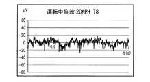
まず、図3は、20km/hで走行しているときで、生体アーチファクトが生じていない状態でのでの脳波信号(時間波形の脳波信号)を示す。図4は、図3の脳波パワーであり、所定周波数単位(実施形態では10Hz単位)毎の脳波パワーを棒グラフ式(平均値形式)でもって示してある。 First, FIG. 3 shows an electroencephalogram signal (time waveform electroencephalogram signal) when the vehicle is traveling at 20 km / h and no biological artifact is generated. FIG. 4 shows the electroencephalogram power of FIG. 3 and shows the electroencephalogram power for each predetermined frequency unit (in the embodiment, 10 Hz unit) in a bar graph format (average value format).
図5は、図3の脳波信号が得られたときと同様の運転条件で、右方向に首振りしたときの脳波信号を示す。また、図6は、図5に対応した脳波パワーを示す。この図5、図6で示すデータは、図3、図4で示すデータに対して、右方向への首振りに伴う生体アーチファクトが重畳されたものとなっている。 FIG. 5 shows an electroencephalogram signal when the head is swung rightward under the same operating conditions as when the electroencephalogram signal of FIG. 3 is obtained. FIG. 6 shows the electroencephalogram power corresponding to FIG. The data shown in FIGS. 5 and 6 are obtained by superimposing biological artifacts accompanying the swing in the right direction on the data shown in FIGS. 3 and 4.
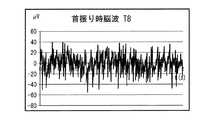
図7は、非走行状態での安静状態において、右方向に首振りしたときの脳波信号を示し、図8はその脳波パワーを示す。この図7、図8のデータは、走行によって生じる脳波信号は含まれていないものとなる。そして、図8に示す脳波パワーのデータは、後述する生体アーチファクト除去のためのフィルタとして使用するために、あらかじめ作成されてメモリ(記憶手段)に記憶されている。 FIG. 7 shows an electroencephalogram signal when the head is swung to the right in a resting state in a non-running state, and FIG. 8 shows the electroencephalogram power. The data in FIGS. 7 and 8 do not include an electroencephalogram signal generated by running. The electroencephalogram power data shown in FIG. 8 is created in advance and stored in a memory (storage means) for use as a filter for biological artifact removal described later.
次に、右方向への首振りに伴う生体アーチファクトを除去する点について説明する。生体アーチファクトの除去処理は、走行中に右方向に首振りしたときの図5、図6に示す実測データと、図8に示す記憶データとに基づいて算出(演算)される。 Next, a description will be given of the removal of biological artifacts associated with swinging in the right direction. The biological artifact removal processing is calculated (calculated) based on the measured data shown in FIGS. 5 and 6 and the stored data shown in FIG. 8 when the head is swung to the right during traveling.
生体アーチファクトの除去のために、まず、所定周波数単位毎(実施形態では10Hz単位毎)に、次のような処理が行われる。すなわち、例えば、もっとも低い周波数域となる0〜10Hzについての周波数単位について、図6に示す首振り運転時に実測された実測脳波パワーから、フィルタとして記憶されている図8のデータを差し引くことにより、減算脳波パワーが算出される。そして、この減算脳波パワーを、図6に示す実測脳波パワーで除することにより、パワー割合が算出される。 In order to remove the biological artifact, first, the following processing is performed for each predetermined frequency unit (in the embodiment, every 10 Hz). That is, for example, by subtracting the data of FIG. 8 stored as a filter from the actually measured electroencephalogram power measured during the swing operation shown in FIG. 6 for the frequency unit of 0 to 10 Hz that is the lowest frequency range, Subtracted electroencephalogram power is calculated. Then, the power ratio is calculated by dividing the subtracted electroencephalogram power by the actually measured electroencephalogram power shown in FIG.
次いで、図5のように実測された実測脳波信号に基づいて、0〜10Hzについての時間波形を切り出し、この切り出された時間波形に対して上記パワー割合を乗算することにより、右方向への首振りによる生体アーチファクトが除去された真性の脳波信号(時間波形の形態)が取得される。 Next, based on the actually measured electroencephalogram signal actually measured as shown in FIG. 5, a time waveform for 0 to 10 Hz is cut out, and this cut out time waveform is multiplied by the power ratio, so that the head in the right direction is cut. An intrinsic electroencephalogram signal (form of time waveform) from which biological artifacts due to shaking have been removed is acquired.
以上と同様にして、次に10〜20Hzの周波数域について、生体アーチファクトが除去された真性の脳波信号を取得し、以下同様にして、全ての周波数域について生体アーチファクトが除去された脳波信号を取得することにより、最終的に、図5に示す脳波信号から右方向への首振りに伴う生体アーチファクトが除去された真性の脳波信号が取得されることになる。 In the same manner as described above, an intrinsic electroencephalogram signal from which biological artifacts are removed is acquired for the frequency range of 10 to 20 Hz, and thereafter, an electroencephalogram signal from which biological artifacts are removed is obtained in the same manner. As a result, an intrinsic brain wave signal from which the biological artifacts associated with the swing in the right direction are removed from the brain wave signal shown in FIG. 5 is finally obtained.
ここで、時間波形の真性の脳波信号を取得する場合に、あらかじめ平滑化処理を行うことが好ましい。そして、平滑化の時間を、周波数が高くなる領域ほど短くする(周波数が高くなるほど時間波形が細かくなるのに対応)のが好ましい。例えば、0〜10Hz周波数域では平滑化の時間を例えば0.1秒とし、10〜20Hzの周波数域では例えば0.005秒とする等、周波数域が一段階高くなる毎に、直前の周波数域での平滑化時間に比して例えば半分の時間の平滑化時間にすればよい。このような平滑化処理によって最終的に取得された時間波形の形態での真性の脳波信号が、図9に示され、その脳波パワーが図10に示される。図9に示す真性の脳波信号は、図3の脳波信号を再現するものとなるが、上述した平滑化処理によって、目視によって波形の変化がより理解しやすい形態となっている。 Here, when acquiring an intrinsic electroencephalogram signal of a time waveform, it is preferable to perform smoothing processing in advance. The smoothing time is preferably shortened as the frequency increases (corresponding to the time waveform becoming finer as the frequency increases). For example, in the frequency range of 0 to 10 Hz, the smoothing time is set to 0.1 seconds, for example, in the frequency range of 10 to 20 Hz, for example, 0.005 seconds. For example, the smoothing time may be half that of the smoothing time in FIG. An intrinsic electroencephalogram signal in the form of a time waveform finally obtained by such smoothing processing is shown in FIG. 9, and its electroencephalogram power is shown in FIG. The true electroencephalogram signal shown in FIG. 9 reproduces the electroencephalogram signal of FIG. 3, but has a form in which the change in the waveform can be more easily understood visually by the smoothing process described above.
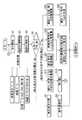
車両を運転する際に生じる生体アーチファクトを除去する点について、図11に示す前準備と共に説明する。この前準備は、図11のQ(ステップ−以下同じ)1において、乗員Jに対して、脳波計測装置が装着することから開始される。脳波計測装置は、図1、2に示す脳波計測器10の他、脳波計測器10に接続された乗員Jが背負う本体部を有する。Q2では、乗員Jが車両Vに乗り込む。Q3では、乗員Jが背負っていた上記本体部が車両に固定される(脳波計測器10の検出脳波信号は、この本体部を経てコントローラUに出力される)。コントローラUは、前述した右方向への首振り運動に生体アーチファクト除去のためのフィルタ(脳波パワー)を記憶しているが、この他、左方向への首振りや、左右のステアリング操作等々、走行中に発生しえる各種の筋肉運動に伴う生体アーチファクトに対応したフィルタを数多く記憶しているものである。 The point which removes the living body artifact which arises when driving a vehicle is explained with preparations shown in FIG. This preparation is started when the electroencephalogram measuring apparatus is attached to the occupant J in Q (step—the same applies hereinafter) 1 in FIG. The electroencephalogram measurement apparatus has a main body portion carried by an occupant J connected to the
Q4では、エンジンが始動される。この後Q5において、脳波計測器10で検出される脳波信号に対して、電磁ノイズの重畳状況が確認される(例えば上記本体部での確認あるいはコントローラUによる確認)。なお、Q5においては、運転者Jは、閉眼の安静状態とされる。 In Q4, the engine is started. Thereafter, in Q5, the superposition state of electromagnetic noise is confirmed for the electroencephalogram signal detected by the electroencephalogram measuring instrument 10 (for example, confirmation by the main body or confirmation by the controller U). In Q5, the driver J is in a resting state with his eyes closed.
Q5の後、Q6において、Q5での確認に基づいて、電磁ノイズが大きいか否かが判別される。このQ6の判別でYESのときは、Q7において、ノイズ要因が確認された後、Q8において、電磁対策が行われる。電磁ノイズとしては、車内電磁波、車外電磁波、車両電磁波の他、人体が静電容量体であることから人(乗員J)由来の電磁波について対策が行われる。人由来の電磁波は、例えば乗員Jからの静電気除去処理により対策され、その他の車内電磁波等については、適宜シールド処理によって対策される。 After Q5, at Q6, it is determined based on the confirmation at Q5 whether the electromagnetic noise is large. If YES in Q6, an electromagnetic countermeasure is taken in Q8 after a noise factor is confirmed in Q7. As electromagnetic noise, in addition to in-vehicle electromagnetic waves, external electromagnetic waves, and vehicle electromagnetic waves, countermeasures are taken against electromagnetic waves derived from humans (occupant J) because the human body is a capacitive body. For example, human-derived electromagnetic waves are treated by removing static electricity from the passenger J, and other in-vehicle electromagnetic waves are appropriately shielded.
以上のようにして、脳波信号に電磁ノイズが重畳しないことが確認された状態(Q6の判別でNOのとき)で、コントローラUによる制御が図12に示すフローチャートに示すように実行される。以下、このフローチャートについて説明するが、以下の説明でSはステップを示す。なお、このコントローラUは、実験段階では、車両に装備することなく、脳波計測装置の本体部に組み込むこともできる。また、本発明を適用して市販する車両においては、前記電磁シールドは十分に行われたものとして、運転者Jの静電気除去用のアース部を設けるだけでよいものである。 As described above, the control by the controller U is executed as shown in the flowchart shown in FIG. 12 in a state where it is confirmed that no electromagnetic noise is superimposed on the electroencephalogram signal (when NO is determined in Q6). Hereinafter, this flowchart will be described. In the following description, S represents a step. In the experimental stage, the controller U can be incorporated in the main body of the electroencephalogram measurement apparatus without being equipped in the vehicle. Moreover, in the vehicle marketed by applying the present invention, it is only necessary to provide a ground portion for removing static electricity from the driver J, assuming that the electromagnetic shielding is sufficiently performed.
まず、S1において走行が開始が確認される。この後、S2において脳波の計測が開始され、このとき、脳波計測に同期して、車両の走行データ(例えば車速、舵角、横G、前後G、エンジン回転数等)、カメラ12での映像データ、運転者Jの各種生理データ、アイカメラ11による視線データ等が合わせて計測(検出)される。 First, the start of traveling is confirmed in S1. Thereafter, measurement of the electroencephalogram is started in S2, and at this time, in synchronism with the electroencephalogram measurement, vehicle travel data (for example, vehicle speed, rudder angle, lateral G, front and rear G, engine speed, etc.), video on the
所定時間脳波の計測が行われると、S3において脳波の計測が終了される。この後、S4において、脳波計測器10における各電極毎10a毎に、生体アーチファクトの発生があるか否かが判別される。このS4での判別は、例えば、通常の脳活動では発生しないような大きな脳波電圧が生じているとき、あるいはカメラ12やアイカメラ11等によって運転者Jが生体アーチファクトを生じさせる大きな筋肉活動を行っていることが確認されたときに、生体アーチファクトが発生していると判断される。 When the electroencephalogram is measured for a predetermined time, the electroencephalogram measurement is terminated in S3. Thereafter, in S4, it is determined for each
上記S4の判別でNOのときは、S5において、個々の電極10aについて、脳波信号が分析され、この後S6において、分析された個々の電極10aについての信号源が推定される。このS5での分析結果とS6で推定結果とは、2次解析のためのデータとして用いられることになる。 If the determination in S4 is NO, the electroencephalogram signal is analyzed for each
前記S4の判別でYESのとき、つまり生体アーチファクトが発生している電極10aが存在しているときは、S11、S21、S22、S31のように複数種に場合分けして順次処理が行われる(図12では処理を並列に描いてあるが、実際には直列に処理される)。すなわち、S11で噛みしめによる大きな筋肉電位が重畳しているとき確認されたときは、S12において、脳波信号の取り直しが行われる(S1への復帰)。 When the determination in S4 is YES, that is, when there is an
S21は瞬目による生体アーチファクト発生が確認された場合であり、S22は情報処理負荷が大きいことに伴う心電重畳が確認された場合であり、これらの場合はそれぞれ、S23の処理が行われる。すなわち、生体アーチファクトが発生している特定の電極の近傍に位置する他の電極との間での電位差に基づいて、ノイズ除去(生体アーチファクトの除去)が行われる。具体的には、生体アーチファクトが発生していない状態での上記特定の電極と上記他の電極との電位差を基準電位差としてあらかじめ検出、記憶しておく。そして、生体アーチファクトが発生したときの上記特定の電極における真性脳波信号を、上記他の電極での脳波信号に対して上記基準電位差を加算したものとして算出すればよい。このような手法により、フィルタ処理に比してより簡単に真性の脳波信号を取得することができる。勿論、このような場合でも、フィルタ処理によって真性の脳波信号を算出することもできる。 S21 is a case where the occurrence of biological artifacts due to blinking is confirmed, and S22 is a case where electrocardiographic superposition accompanying a large information processing load is confirmed. In these cases, the process of S23 is performed. That is, noise removal (removal of biological artifacts) is performed based on a potential difference with another electrode located in the vicinity of a specific electrode where the biological artifact is generated. Specifically, a potential difference between the specific electrode and the other electrode in a state where no biological artifact is generated is detected and stored in advance as a reference potential difference. Then, the intrinsic electroencephalogram signal at the specific electrode when the biological artifact occurs may be calculated as the above-described reference potential difference added to the electroencephalogram signal at the other electrode. By such a method, an intrinsic electroencephalogram signal can be acquired more easily than the filtering process. Of course, even in such a case, an intrinsic electroencephalogram signal can be calculated by filtering.
S31は、運転に伴う筋肉運動による生体アーチファクトの重畳であると確認されたときである。このときは、S32において、前述した右方向の首振りによる生体アーチファクトの除去処理と同様の処理が行われる。すなわち、運転シーンに応じて、多数記憶されているフィルタの中から、運転シーンに対応したフィルタが選択されて、このフィルタを用いた生体アーチファクトの除去処理が行われる。例えば、右方向の首振りが確認されたときは、電極10aのうちT8に相当する電極が検出した脳波信号について、図8のようなフィルタが選択される。また、左方向の首振りが確認されたときは、電極T7に相当する電極が検出した脳波信号について、左方向首振り用のフィルタが選択される。このようにして、例えば右方向へのステアリング操作、左方向へのステアリング操作、シフト操作等、運転に際して乗員Jが行う各種の運転シーン毎に、生体アーチファクトが生じる電極についてのフィルタが選択される。なお、各種の運転シーンに応じて生体アーチファクトが生じる電極とそのフィルタとは、あらかじめ対応づけて記憶されているものである。 S31 is when it is confirmed that the biological artifact is superimposed due to the muscular motion accompanying the driving. At this time, in S32, the same processing as the biological artifact removal processing by the above-described swinging in the right direction is performed. That is, according to the driving scene, a filter corresponding to the driving scene is selected from a large number of stored filters, and biological artifact removal processing using this filter is performed. For example, when a right-hand swing is confirmed, a filter as shown in FIG. 8 is selected for the electroencephalogram signal detected by the electrode corresponding to T8 among the
以上実施形態について説明したが、本発明は、実施形態に限定されるものではなく、特許請求の範囲の記載された範囲において適宜の変更が可能である。脳波計測器10は、無接触式のものを用いることもできる。判定された運転者の心理状態をどのように利用するかは適宜選択できるものである。例えば、運転者の心理状態の分析(判定)を、車両製造者によるデータ収集用として利用することもできる。すなわち、例えば、脳波信号を用いて得られた運転者の心理状態を、各種の走行シーンと対応づけて記憶させたデータベースとして作成、記憶させておき、市販の車両では、このデータベースを搭載して、ある走行シーンでは運転者がどのような心理状態になるかを推定するために用いる等のことができる。また、運転者の心理状態が好ましい状態となるように車両の設計、改善等に役立てるために、車両製造者のみが利用するものとすることもできる。また、市販の車両を運転する一般の運転者の脳波信号を取得することにも利用できる。勿論、本発明の目的は、明記されたものに限らず、実質的に好ましいあるいは利点として表現されたものを提供することをも暗黙的に含むものである。 Although the embodiments have been described above, the present invention is not limited to the embodiments, and appropriate modifications can be made within the scope of the claims. The
本発明は、走行中という動的環境下においても、運転者の脳波信号を生体アーチファクトを除去した状態で取得することができる。 The present invention can acquire a driver's brain wave signal in a state where biological artifacts are removed even in a dynamic environment of traveling.
V:車両
SS:運転席
J:運転者
U:コントローラ
10:脳波計測器
10a:電極
11:アイカメラ
12:カメラV: vehicle SS: driver's seat J: driver U: controller 10:
Claims (8)
Translated fromJapanese生体アーチファクトの発生を検出する第2ステップと、
前記第2ステップで生体アーチファクトの発生が検出されたときに、記憶手段に記憶さされているフィルタの中から検出した生体アーチファクトに応じたフィルタを選択する第3ステップと、
前記第3ステップで選択されたフィルタを用いて、前記第1ステップで取得された脳波信号から生体アーチファクトの影響を除去した真性脳波信号を得る第4ステップと、
を備えていることを特徴とする脳波取得方法。A first step of acquiring an electroencephalogram signal emitted by the driver while the vehicle is traveling;
A second step of detecting the occurrence of biological artifacts;
A third step of selecting a filter according to the detected biological artifact from the filters stored in the storage means when occurrence of the biological artifact is detected in the second step;
A fourth step of obtaining an intrinsic electroencephalogram signal obtained by removing the influence of the biological artifact from the electroencephalogram signal acquired in the first step, using the filter selected in the third step;
An electroencephalogram acquisition method comprising:
前記第2ステップでは、運転者の首振りを検出し、
前記第3ステップで選択されるフィルタが、首振りに関するものとされる、
ことを特徴とする脳波取得方法。In claim 1,
In the second step, the driver's swing is detected,
The filter selected in the third step is related to swinging.
A method for acquiring an electroencephalogram characterized by that.
前記第2ステップでは、運転者のステアリング操作を検出し、
前記第3ステップで選択されるフィルタが、ステアリング操作に関するものとされる、
ことを特徴とする脳波取得方法。In claim 1 or claim 2,
In the second step, the driver's steering operation is detected,
The filter selected in the third step is related to a steering operation.
A method for acquiring an electroencephalogram characterized by that.
前記フィルタは、運転していない状態で生体アーチファクトを発生させたときの脳波パワーとされ、
前記第1ステップでは、脳波信号を時間波形の形態で取得し、
前記第4ステップでは、前記第1ステップで取得された時間波形の脳波信号から実測脳波パワーを算出して、該実測脳波パワーと前記フィルタとして記憶されている記憶脳波パワーと前記第1ステップで取得された時間波形の脳波信号とに基づいて、前記真性脳波信号を時間波形の形態で算出する、
ことを特徴とする脳波取得方法。In any one of Claims 1 thru | or 3,
The filter is an electroencephalogram power when a biological artifact is generated in a state of not driving,
In the first step, an electroencephalogram signal is acquired in the form of a time waveform,
In the fourth step, the measured electroencephalogram power is calculated from the electroencephalogram signal having the time waveform obtained in the first step, and the measured electroencephalogram power and the stored electroencephalogram power stored as the filter are obtained in the first step. The true brain wave signal is calculated in the form of a time waveform based on the electroencephalogram signal of the time waveform that has been
A method for acquiring an electroencephalogram characterized by that.
前記第4ステップでは、前記実測脳波パワーから前記記憶脳波パワーを差し引いた減算脳波パワーを該実測脳波パワーで除したパワー割合を算出して、該パワー割合と前記第1ステップで取得された時間波形の脳波信号とに基づいて、時間波形の形態とされた前記真性脳波信号を算出する、ことを特徴とする脳波取得方法。In claim 4,
In the fourth step, a power ratio obtained by dividing the subtracted electroencephalogram power obtained by subtracting the memorized electroencephalogram power from the actually measured electroencephalogram power is divided by the actually measured electroencephalogram power. A method for acquiring an electroencephalogram, comprising: calculating the true electroencephalogram signal in the form of a time waveform based on the electroencephalogram signal.
前記第4ステップでは、所定周波数毎に平滑化処理しつつ前記時間波形とされた真性脳波信号を算出する、ことを特徴とする脳波取得方法。In claim 5,
In the fourth step, an intrinsic electroencephalogram signal having the time waveform is calculated while being smoothed for each predetermined frequency.
前記平滑化処理の時間が、周波数が大きいほど短くされる、ことを特徴とする脳波取得方法。In claim 6,
The method for acquiring an electroencephalogram, wherein the smoothing time is shortened as the frequency increases.
生体アーチファクトの発生を検出する生体アーチファクト検出手段と、
生体アーチファクトに応じたフィルタを記憶した記憶手段と、
前記生体アーチファクト検出手段によって生体アーチファクトの発生が検出されたときに、前記記憶手段に記憶されているフィルタの中から検出した生体アーチファクトに応じたフィルタを選択するフィルタ選択手段と、
前記フィルタ選択手段で選択されたフィルタを用いて、前記脳波信号検出手段で取得された脳波信号から生体アーチファクトの影響を除去した真性脳波信号を得る生体アーチファクト除去手段と、
を備えていることを特徴とする脳波取得装置。An electroencephalogram signal detecting means for acquiring an electroencephalogram signal emitted by the driver while the vehicle is running;
Biological artifact detection means for detecting the occurrence of biological artifacts;
Storage means for storing a filter corresponding to the biological artifact;
A filter selection unit that selects a filter corresponding to the detected biological artifact from the filters stored in the storage unit when the generation of the biological artifact is detected by the biological artifact detection unit;
Using a filter selected by the filter selection means, a biological artifact removal means for obtaining an intrinsic brain wave signal obtained by removing the influence of the biological artifact from the brain wave signal acquired by the brain wave signal detection means;
An electroencephalogram acquisition apparatus comprising:
Priority Applications (1)
| Application Number | Priority Date | Filing Date | Title |
|---|---|---|---|
| JP2015165476AJP6409712B2 (en) | 2015-08-25 | 2015-08-25 | EEG acquisition method and EEG acquisition apparatus |
Applications Claiming Priority (1)
| Application Number | Priority Date | Filing Date | Title |
|---|---|---|---|
| JP2015165476AJP6409712B2 (en) | 2015-08-25 | 2015-08-25 | EEG acquisition method and EEG acquisition apparatus |
Publications (2)
| Publication Number | Publication Date |
|---|---|
| JP2017042261Atrue JP2017042261A (en) | 2017-03-02 |
| JP6409712B2 JP6409712B2 (en) | 2018-10-24 |
Family
ID=58211091
Family Applications (1)
| Application Number | Title | Priority Date | Filing Date |
|---|---|---|---|
| JP2015165476AActiveJP6409712B2 (en) | 2015-08-25 | 2015-08-25 | EEG acquisition method and EEG acquisition apparatus |
Country Status (1)
| Country | Link |
|---|---|
| JP (1) | JP6409712B2 (en) |
Cited By (3)
| Publication number | Priority date | Publication date | Assignee | Title |
|---|---|---|---|---|
| WO2018179346A1 (en)* | 2017-03-31 | 2018-10-04 | 本田技研工業株式会社 | Manipulation system, server, control method in manipulation system, and program |
| JP2019022626A (en)* | 2017-07-25 | 2019-02-14 | マツダ株式会社 | Brain information measuring device |
| JP2022159914A (en)* | 2021-04-05 | 2022-10-18 | 日本発條株式会社 | Brain wave signal processing method, device, program, and vehicle seat |
Citations (3)
| Publication number | Priority date | Publication date | Assignee | Title |
|---|---|---|---|---|
| JP2000014653A (en)* | 1998-06-30 | 2000-01-18 | Nissan Motor Co Ltd | Driver electrocardiographic signal measuring device |
| JP2012000280A (en)* | 2010-06-17 | 2012-01-05 | Panasonic Corp | Brain wave estimating device, brain wave estimation method and program |
| WO2014128273A1 (en)* | 2013-02-21 | 2014-08-28 | Iee International Electronics & Engineering S.A. | Imaging device based occupant monitoring system supporting multiple functions |
- 2015
- 2015-08-25JPJP2015165476Apatent/JP6409712B2/enactiveActive
Patent Citations (3)
| Publication number | Priority date | Publication date | Assignee | Title |
|---|---|---|---|---|
| JP2000014653A (en)* | 1998-06-30 | 2000-01-18 | Nissan Motor Co Ltd | Driver electrocardiographic signal measuring device |
| JP2012000280A (en)* | 2010-06-17 | 2012-01-05 | Panasonic Corp | Brain wave estimating device, brain wave estimation method and program |
| WO2014128273A1 (en)* | 2013-02-21 | 2014-08-28 | Iee International Electronics & Engineering S.A. | Imaging device based occupant monitoring system supporting multiple functions |
Cited By (4)
| Publication number | Priority date | Publication date | Assignee | Title |
|---|---|---|---|---|
| WO2018179346A1 (en)* | 2017-03-31 | 2018-10-04 | 本田技研工業株式会社 | Manipulation system, server, control method in manipulation system, and program |
| JP2019022626A (en)* | 2017-07-25 | 2019-02-14 | マツダ株式会社 | Brain information measuring device |
| JP2022159914A (en)* | 2021-04-05 | 2022-10-18 | 日本発條株式会社 | Brain wave signal processing method, device, program, and vehicle seat |
| JP7660416B2 (en) | 2021-04-05 | 2025-04-11 | 日本発條株式会社 | Electroencephalogram signal processing method, device, program, and vehicle seat |
Also Published As
| Publication number | Publication date |
|---|---|
| JP6409712B2 (en) | 2018-10-24 |
Similar Documents
| Publication | Publication Date | Title |
|---|---|---|
| JP6435104B2 (en) | System and method for determining changes in physical condition | |
| US9272689B2 (en) | System and method for biometric identification in a vehicle | |
| US20110152709A1 (en) | Mobile body control device and mobile body control method | |
| JP2014180543A5 (en) | ||
| JP4772935B2 (en) | Attention state determination apparatus, method and program | |
| JP6409712B2 (en) | EEG acquisition method and EEG acquisition apparatus | |
| US11179082B2 (en) | Driving assistance device | |
| JP2011024902A (en) | Electrocardiographic device for vehicle | |
| JP2009297382A (en) | Brain activity information output device and brain activity information power output method | |
| US20160370774A1 (en) | Process for controlling a mobile device | |
| JP2012000280A (en) | Brain wave estimating device, brain wave estimation method and program | |
| JP5343790B2 (en) | Brain activity information output device, brain activity information output method, and program | |
| JP4385576B2 (en) | Object control apparatus, object control method, object control program, and computer-readable recording medium | |
| WO2019069910A1 (en) | Emotion determination device, emotion determination method, and program | |
| Jang et al. | Workers’ Physiological/Psychological Responses during Human-Robot Collaboration in an Immersive Virtual Reality Environment | |
| JP2010091955A (en) | Image processing apparatus | |
| JP2009106675A (en) | Biological information acquisition device | |
| DE102015203676A1 (en) | Device and method for monitoring a condition of a driver of a means of locomotion | |
| JP2016115119A (en) | Eye opening/closing determination device and eye opening/closing determination method | |
| Takada et al. | Evaluation of driver’s cognitive load when presented information on the windshield using p300 latency in eye-fixation related potentials | |
| KR20190023423A (en) | Apparatus correcting hand vibration using anelectromyogram and using method thereof | |
| JP2020028430A (en) | EEG analysis system, visibility evaluation system, EEG analysis method and program | |
| US20210386962A1 (en) | Wakefulness maintenance device, control device, and program | |
| DE102010060806A1 (en) | Method for displaying medical images of intriguing region of e.g. human body in image processing system during surgical intervention, involves overlapping representations of section of image display and video recording on output device | |
| JP2017000649A (en) | EEG analysis method and analyzer |
Legal Events
| Date | Code | Title | Description |
|---|---|---|---|
| A621 | Written request for application examination | Free format text:JAPANESE INTERMEDIATE CODE: A621 Effective date:20170323 | |
| A977 | Report on retrieval | Free format text:JAPANESE INTERMEDIATE CODE: A971007 Effective date:20180219 | |
| A131 | Notification of reasons for refusal | Free format text:JAPANESE INTERMEDIATE CODE: A131 Effective date:20180227 | |
| A521 | Request for written amendment filed | Free format text:JAPANESE INTERMEDIATE CODE: A523 Effective date:20180419 | |
| TRDD | Decision of grant or rejection written | ||
| A01 | Written decision to grant a patent or to grant a registration (utility model) | Free format text:JAPANESE INTERMEDIATE CODE: A01 Effective date:20180828 | |
| A61 | First payment of annual fees (during grant procedure) | Free format text:JAPANESE INTERMEDIATE CODE: A61 Effective date:20180910 | |
| R150 | Certificate of patent or registration of utility model | Ref document number:6409712 Country of ref document:JP Free format text:JAPANESE INTERMEDIATE CODE: R150 |