JP2017038947A - Flexible list for surgical operation tool - Google Patents
Flexible list for surgical operation toolDownload PDFInfo
- Publication number
- JP2017038947A JP2017038947AJP2016201465AJP2016201465AJP2017038947AJP 2017038947 AJP2017038947 AJP 2017038947AJP 2016201465 AJP2016201465 AJP 2016201465AJP 2016201465 AJP2016201465 AJP 2016201465AJP 2017038947 AJP2017038947 AJP 2017038947A
- Authority
- JP
- Japan
- Prior art keywords
- wrist
- cable
- item
- spring
- flexible tube
- Prior art date
- Legal status (The legal status is an assumption and is not a legal conclusion. Google has not performed a legal analysis and makes no representation as to the accuracy of the status listed.)
- Withdrawn
Links
- 210000000707wristAnatomy0.000abstractdescription142
- 239000012636effectorSubstances0.000abstractdescription49
- 230000013011matingEffects0.000description23
- 239000000463materialSubstances0.000description13
- 230000007246mechanismEffects0.000description12
- 238000001356surgical procedureMethods0.000description9
- 238000000034methodMethods0.000description8
- 238000002324minimally invasive surgeryMethods0.000description8
- 238000010618wire wrapMethods0.000description6
- HLXZNVUGXRDIFK-UHFFFAOYSA-Nnickel titaniumChemical compound[Ti].[Ti].[Ti].[Ti].[Ti].[Ti].[Ti].[Ti].[Ti].[Ti].[Ti].[Ni].[Ni].[Ni].[Ni].[Ni].[Ni].[Ni].[Ni].[Ni].[Ni].[Ni].[Ni].[Ni].[Ni]HLXZNVUGXRDIFK-UHFFFAOYSA-N0.000description5
- 229910001000nickel titaniumInorganic materials0.000description5
- 239000004033plasticSubstances0.000description5
- 229920003023plasticPolymers0.000description5
- 238000004804windingMethods0.000description5
- XUIMIQQOPSSXEZ-UHFFFAOYSA-NSiliconChemical compound[Si]XUIMIQQOPSSXEZ-UHFFFAOYSA-N0.000description4
- 229910052710siliconInorganic materials0.000description4
- 239000010703siliconSubstances0.000description4
- 230000006835compressionEffects0.000description3
- 238000007906compressionMethods0.000description3
- 229920001971elastomerPolymers0.000description3
- 229910052751metalInorganic materials0.000description3
- 239000002184metalSubstances0.000description3
- 239000012811non-conductive materialSubstances0.000description3
- 210000001015abdomenAnatomy0.000description2
- 238000002679ablationMethods0.000description2
- 239000011324beadSubstances0.000description2
- 210000004204blood vesselAnatomy0.000description2
- 239000000919ceramicSubstances0.000description2
- 230000000694effectsEffects0.000description2
- 239000000806elastomerSubstances0.000description2
- 239000012530fluidSubstances0.000description2
- 239000012212insulatorSubstances0.000description2
- 238000002350laparotomyMethods0.000description2
- 238000012978minimally invasive surgical procedureMethods0.000description2
- 238000000465mouldingMethods0.000description2
- 230000007935neutral effectEffects0.000description2
- 230000002093peripheral effectEffects0.000description2
- BASFCYQUMIYNBI-UHFFFAOYSA-NplatinumChemical compound[Pt]BASFCYQUMIYNBI-UHFFFAOYSA-N0.000description2
- 230000008569processEffects0.000description2
- 238000011084recoveryMethods0.000description2
- 229920002379silicone rubberPolymers0.000description2
- 239000007787solidSubstances0.000description2
- 238000009941weavingMethods0.000description2
- 229910000831SteelInorganic materials0.000description1
- 210000000683abdominal cavityAnatomy0.000description1
- 230000009471actionEffects0.000description1
- 230000002411adverseEffects0.000description1
- WYTGDNHDOZPMIW-RCBQFDQVSA-NalstonineNatural productsC1=CC2=C3C=CC=CC3=NC2=C2N1C[C@H]1[C@H](C)OC=C(C(=O)OC)[C@H]1C2WYTGDNHDOZPMIW-RCBQFDQVSA-N0.000description1
- 229910052782aluminiumInorganic materials0.000description1
- XAGFODPZIPBFFR-UHFFFAOYSA-NaluminiumChemical compound[Al]XAGFODPZIPBFFR-UHFFFAOYSA-N0.000description1
- 230000008901benefitEffects0.000description1
- 238000001574biopsyMethods0.000description1
- 238000009954braidingMethods0.000description1
- 239000004020conductorSubstances0.000description1
- 238000002405diagnostic procedureMethods0.000description1
- 238000010292electrical insulationMethods0.000description1
- 238000005516engineering processMethods0.000description1
- 238000005530etchingMethods0.000description1
- 238000000605extractionMethods0.000description1
- 238000001125extrusionMethods0.000description1
- 239000000835fiberSubstances0.000description1
- 229920002457flexible plasticPolymers0.000description1
- 239000007789gasSubstances0.000description1
- 238000003384imaging methodMethods0.000description1
- 238000009413insulationMethods0.000description1
- 230000002262irrigationEffects0.000description1
- 238000003973irrigationMethods0.000description1
- 230000009191jumpingEffects0.000description1
- 238000002357laparoscopic surgeryMethods0.000description1
- 230000014759maintenance of locationEffects0.000description1
- 238000004519manufacturing processMethods0.000description1
- 210000000056organAnatomy0.000description1
- 230000037361pathwayEffects0.000description1
- 229910052697platinumInorganic materials0.000description1
- 229920003223poly(pyromellitimide-1,4-diphenyl ether)Polymers0.000description1
- 229920000642polymerPolymers0.000description1
- 229920001296polysiloxanePolymers0.000description1
- 230000004044responseEffects0.000description1
- 238000002432robotic surgeryMethods0.000description1
- 238000005096rolling processMethods0.000description1
- 238000007665saggingMethods0.000description1
- 230000035945sensitivityEffects0.000description1
- 239000002210silicon-based materialSubstances0.000description1
- 239000004945silicone rubberSubstances0.000description1
- 125000006850spacer groupChemical group0.000description1
- 239000003381stabilizerSubstances0.000description1
- 229910001220stainless steelInorganic materials0.000description1
- 239000010935stainless steelSubstances0.000description1
- 239000010959steelSubstances0.000description1
- 239000003351stiffenerSubstances0.000description1
- 230000001225therapeutic effectEffects0.000description1
- 230000007306turnoverEffects0.000description1
- 238000003466weldingMethods0.000description1
- 210000003857wrist jointAnatomy0.000description1
Images


Classifications
- A—HUMAN NECESSITIES
- A61—MEDICAL OR VETERINARY SCIENCE; HYGIENE
- A61B—DIAGNOSIS; SURGERY; IDENTIFICATION
- A61B34/00—Computer-aided surgery; Manipulators or robots specially adapted for use in surgery
- A61B34/30—Surgical robots
- A—HUMAN NECESSITIES
- A61—MEDICAL OR VETERINARY SCIENCE; HYGIENE
- A61B—DIAGNOSIS; SURGERY; IDENTIFICATION
- A61B1/00—Instruments for performing medical examinations of the interior of cavities or tubes of the body by visual or photographical inspection, e.g. endoscopes; Illuminating arrangements therefor
- A61B1/00147—Holding or positioning arrangements
- A61B1/00149—Holding or positioning arrangements using articulated arms
- A—HUMAN NECESSITIES
- A61—MEDICAL OR VETERINARY SCIENCE; HYGIENE
- A61B—DIAGNOSIS; SURGERY; IDENTIFICATION
- A61B1/00—Instruments for performing medical examinations of the interior of cavities or tubes of the body by visual or photographical inspection, e.g. endoscopes; Illuminating arrangements therefor
- A61B1/005—Flexible endoscopes
- A61B1/008—Articulations
- A—HUMAN NECESSITIES
- A61—MEDICAL OR VETERINARY SCIENCE; HYGIENE
- A61B—DIAGNOSIS; SURGERY; IDENTIFICATION
- A61B17/00—Surgical instruments, devices or methods
- A—HUMAN NECESSITIES
- A61—MEDICAL OR VETERINARY SCIENCE; HYGIENE
- A61B—DIAGNOSIS; SURGERY; IDENTIFICATION
- A61B17/00—Surgical instruments, devices or methods
- A61B17/04—Surgical instruments, devices or methods for suturing wounds; Holders or packages for needles or suture materials
- A61B17/06—Needles ; Sutures; Needle-suture combinations; Holders or packages for needles or suture materials
- A61B17/062—Needle manipulators
- A—HUMAN NECESSITIES
- A61—MEDICAL OR VETERINARY SCIENCE; HYGIENE
- A61B—DIAGNOSIS; SURGERY; IDENTIFICATION
- A61B17/00—Surgical instruments, devices or methods
- A61B17/28—Surgical forceps
- A61B17/29—Forceps for use in minimally invasive surgery
- A—HUMAN NECESSITIES
- A61—MEDICAL OR VETERINARY SCIENCE; HYGIENE
- A61B—DIAGNOSIS; SURGERY; IDENTIFICATION
- A61B17/00—Surgical instruments, devices or methods
- A61B17/42—Gynaecological or obstetrical instruments or methods
- A—HUMAN NECESSITIES
- A61—MEDICAL OR VETERINARY SCIENCE; HYGIENE
- A61B—DIAGNOSIS; SURGERY; IDENTIFICATION
- A61B34/00—Computer-aided surgery; Manipulators or robots specially adapted for use in surgery
- A61B34/70—Manipulators specially adapted for use in surgery
- A61B34/71—Manipulators operated by drive cable mechanisms
- A—HUMAN NECESSITIES
- A61—MEDICAL OR VETERINARY SCIENCE; HYGIENE
- A61B—DIAGNOSIS; SURGERY; IDENTIFICATION
- A61B1/00—Instruments for performing medical examinations of the interior of cavities or tubes of the body by visual or photographical inspection, e.g. endoscopes; Illuminating arrangements therefor
- A61B1/00142—Instruments for performing medical examinations of the interior of cavities or tubes of the body by visual or photographical inspection, e.g. endoscopes; Illuminating arrangements therefor with means for preventing contamination, e.g. by using a sanitary sheath
- A—HUMAN NECESSITIES
- A61—MEDICAL OR VETERINARY SCIENCE; HYGIENE
- A61B—DIAGNOSIS; SURGERY; IDENTIFICATION
- A61B1/00—Instruments for performing medical examinations of the interior of cavities or tubes of the body by visual or photographical inspection, e.g. endoscopes; Illuminating arrangements therefor
- A61B1/005—Flexible endoscopes
- A61B1/0058—Flexible endoscopes using shape-memory elements
- A—HUMAN NECESSITIES
- A61—MEDICAL OR VETERINARY SCIENCE; HYGIENE
- A61B—DIAGNOSIS; SURGERY; IDENTIFICATION
- A61B1/00—Instruments for performing medical examinations of the interior of cavities or tubes of the body by visual or photographical inspection, e.g. endoscopes; Illuminating arrangements therefor
- A61B1/012—Instruments for performing medical examinations of the interior of cavities or tubes of the body by visual or photographical inspection, e.g. endoscopes; Illuminating arrangements therefor characterised by internal passages or accessories therefor
- A61B1/018—Instruments for performing medical examinations of the interior of cavities or tubes of the body by visual or photographical inspection, e.g. endoscopes; Illuminating arrangements therefor characterised by internal passages or accessories therefor for receiving instruments
- A—HUMAN NECESSITIES
- A61—MEDICAL OR VETERINARY SCIENCE; HYGIENE
- A61B—DIAGNOSIS; SURGERY; IDENTIFICATION
- A61B17/00—Surgical instruments, devices or methods
- A61B17/068—Surgical staplers, e.g. containing multiple staples or clamps
- A—HUMAN NECESSITIES
- A61—MEDICAL OR VETERINARY SCIENCE; HYGIENE
- A61B—DIAGNOSIS; SURGERY; IDENTIFICATION
- A61B17/00—Surgical instruments, devices or methods
- A61B17/12—Surgical instruments, devices or methods for ligaturing or otherwise compressing tubular parts of the body, e.g. blood vessels or umbilical cord
- A61B17/128—Surgical instruments, devices or methods for ligaturing or otherwise compressing tubular parts of the body, e.g. blood vessels or umbilical cord for applying or removing clamps or clips
- A61B17/1285—Surgical instruments, devices or methods for ligaturing or otherwise compressing tubular parts of the body, e.g. blood vessels or umbilical cord for applying or removing clamps or clips for minimally invasive surgery
- A—HUMAN NECESSITIES
- A61—MEDICAL OR VETERINARY SCIENCE; HYGIENE
- A61B—DIAGNOSIS; SURGERY; IDENTIFICATION
- A61B18/00—Surgical instruments, devices or methods for transferring non-mechanical forms of energy to or from the body
- A61B18/04—Surgical instruments, devices or methods for transferring non-mechanical forms of energy to or from the body by heating
- A61B18/12—Surgical instruments, devices or methods for transferring non-mechanical forms of energy to or from the body by heating by passing a current through the tissue to be heated, e.g. high-frequency current
- A61B18/14—Probes or electrodes therefor
- A61B18/1442—Probes having pivoting end effectors, e.g. forceps
- A—HUMAN NECESSITIES
- A61—MEDICAL OR VETERINARY SCIENCE; HYGIENE
- A61B—DIAGNOSIS; SURGERY; IDENTIFICATION
- A61B17/00—Surgical instruments, devices or methods
- A61B17/00234—Surgical instruments, devices or methods for minimally invasive surgery
- A61B2017/00292—Surgical instruments, devices or methods for minimally invasive surgery mounted on or guided by flexible, e.g. catheter-like, means
- A61B2017/003—Steerable
- A61B2017/00305—Constructional details of the flexible means
- A61B2017/00309—Cut-outs or slits
- A—HUMAN NECESSITIES
- A61—MEDICAL OR VETERINARY SCIENCE; HYGIENE
- A61B—DIAGNOSIS; SURGERY; IDENTIFICATION
- A61B17/00—Surgical instruments, devices or methods
- A61B17/28—Surgical forceps
- A61B17/29—Forceps for use in minimally invasive surgery
- A61B2017/2901—Details of shaft
- A—HUMAN NECESSITIES
- A61—MEDICAL OR VETERINARY SCIENCE; HYGIENE
- A61B—DIAGNOSIS; SURGERY; IDENTIFICATION
- A61B34/00—Computer-aided surgery; Manipulators or robots specially adapted for use in surgery
- A61B34/30—Surgical robots
- A61B2034/305—Details of wrist mechanisms at distal ends of robotic arms
- A61B2034/306—Wrists with multiple vertebrae
Landscapes
- Health & Medical Sciences (AREA)
- Life Sciences & Earth Sciences (AREA)
- Surgery (AREA)
- Engineering & Computer Science (AREA)
- Heart & Thoracic Surgery (AREA)
- Biomedical Technology (AREA)
- Nuclear Medicine, Radiotherapy & Molecular Imaging (AREA)
- Medical Informatics (AREA)
- Molecular Biology (AREA)
- Animal Behavior & Ethology (AREA)
- General Health & Medical Sciences (AREA)
- Public Health (AREA)
- Veterinary Medicine (AREA)
- Physics & Mathematics (AREA)
- Biophysics (AREA)
- Optics & Photonics (AREA)
- Pathology (AREA)
- Radiology & Medical Imaging (AREA)
- Robotics (AREA)
- Rehabilitation Therapy (AREA)
- Ophthalmology & Optometry (AREA)
- Reproductive Health (AREA)
- Plasma & Fusion (AREA)
- Otolaryngology (AREA)
- Vascular Medicine (AREA)
- Gynecology & Obstetrics (AREA)
- Pregnancy & Childbirth (AREA)
- Surgical Instruments (AREA)
- Manipulator (AREA)
Abstract
Translated fromJapaneseDescription
Translated fromJapanese (関連出願の参照)
[02]本出願は、2002年12月6日に出願された米国仮特許出願第60/431,636号の利益に基づき、これを主張し、その開示全体は参照として本明細書に組み込まれる。本出願は、以下の特許および特許出願に関連し、その全開示は参照として本明細書に組み込まれる。(Refer to related applications)
[02] This application claims and claims the benefit of US Provisional Patent Application No. 60 / 431,636, filed Dec. 6, 2002, the entire disclosure of which is incorporated herein by reference. . This application is related to the following patents and patent applications, the entire disclosures of which are incorporated herein by reference.
2002年6月28日に出願された“Surgical Tool Having Positively Positionable Tendon−Actuated Multi−Disk Wrist Joint”という名称の米国特許出願第10/187,248号と、
2002年6月28日に出願された“Platform Link Wrist Mechanism”という名称の米国特許出願第10/186,176号と、
1998年9月18日に出願され、W099/50721号として公開された“Robotic Apparatus”という名称のPCT国際出願第PCT/US98/19508号と、
1999年10月15日に出願された“Surgical Robotic Tools,Data Architecture,and Use”という名称の米国特許出願第09/418,726号と、
1998年12月8日に出願された“Image Shifting for a Telerobotic System”という名称の米国特許出願第60/111,711号と、
1999年8月20日に出願された“Stereo Imaging System for Use in Telerobotic System”という名称の米国特許出願第09/378,173号と、
1999年9月17日に出願された“Master Having Redundant Degrees of Freedom”という名称の米国特許出願第09/398,507号と、
1999年9月17日に出願された“Cooperative Mnimally Invasive Telesurgery System”という名称の米国特許出願第09/399,457号と、
1999年8月13日に出願された“Camera Referenced Control in a Minimally Invasive Surgical Apparatus”という名称の米国特許出願第09/373,678号と、
1999年9月17日に出願された“Surgical Tools for Use
in Minimally Invasive Telesurgical Applications”という名称の米国特許出願第09/398,958号と、
1998年9月15日に発行された“Endoscopic Surgical Instrument and Method for Use”という名称の米国特許5,808,665号。US patent application Ser. No. 10 / 187,248, filed Jun. 28, 2002, entitled “Surgical Tool Having Positively Positionable Tendon-Actuated Multi-Disk Wrist Joint”;
US patent application Ser. No. 10 / 186,176, filed Jun. 28, 2002, entitled “Platform Link Wrist Machinery”;
PCT International Application No. PCT / US98 / 19508 entitled “Robotic Apparatus” filed on September 18, 1998 and published as W099 / 50721;
US patent application Ser. No. 09 / 418,726, filed Oct. 15, 1999, entitled “Surgical Robotic Tools, Data Architecture, and Use”;
US Patent Application No. 60 / 111,711, filed December 8, 1998, entitled “Image Shifting for a Telerobotic System”;
US patent application Ser. No. 09 / 378,173, filed Aug. 20, 1999, entitled “Stereo Imaging System for Use in Telebotic System”;
US patent application Ser. No. 09 / 398,507, filed Sep. 17, 1999, entitled “Master Having Redundant Degrees of Freedom”;
US patent application Ser. No. 09 / 399,457, filed Sep. 17, 1999, entitled “Cooperative Minimally Inverse Telesuration System”;
US patent application Ser. No. 09 / 373,678, filed Aug. 13, 1999, entitled “Camera Referenced Control in a Minimal Inverse Surgical Apparatus”;
"Surgical Tools for Use" filed on September 17, 1999
US patent application Ser. No. 09 / 398,958, entitled “In Minimally Inverse Telescopic Applications”;
US Pat. No. 5,808,665 entitled “Endoscopic Surgical Instrument and Method for Use” issued September 15, 1998.
(発明の背景)
本発明は概ね手術用具に関し、より詳細にはロボット手術を行うための手術用具におけるフレキシブルリスト機構に関する。(Background of the Invention)
The present invention relates generally to surgical tools, and more particularly to a flexible wrist mechanism in surgical tools for performing robotic surgery.
低侵襲手術技術の進歩により、低侵襲的な方法で行われる手術の数は劇的に増加し得る
。低侵襲手術手技は、診断的処置または外科的処置時に損傷を受ける外部組織の量を低減し、それにより患者の回復時間、不快感および有害な副作用を低減することを目的とする。標準手術の入院の平均的な長さも、低侵襲手術手技を使用して著しく短縮し得る。従って、低侵襲手技の採用の増加により、多くの入院日数が節約でき、入院費用だけでも年間何百万ドルが節約し得るであろう。患者の回復時間、患者の不快感、手術の副作用および離職時間も低侵襲手術で低減し得る。Advances in minimally invasive surgical techniques can dramatically increase the number of surgeries performed in a minimally invasive manner. Minimally invasive surgical procedures aim to reduce the amount of external tissue that is damaged during diagnostic or surgical procedures, thereby reducing patient recovery time, discomfort and adverse side effects. The average length of hospital stay for standard surgery can also be significantly shortened using minimally invasive surgical procedures. Thus, the increased adoption of minimally invasive procedures can save many hospitalization days and hospitalization costs alone can save millions of dollars per year. Patient recovery time, patient discomfort, surgical side effects and turnover time can also be reduced with minimally invasive surgery.
最も一般的な形態の低侵襲手術は内視鏡であろう。おそらく、最も一般的な形態の内視鏡は、腹腔内部の低侵襲検査および手術である腹腔鏡である。標準の腹腔鏡手術においては、患者の腹部にガスを注入して、カニューレスリーブを小さい(およそ1/2インチ)切り口に通し、腹腔鏡手術器具の入口を提供する。腹腔鏡手術器具は概ね、腹腔鏡(手術領域を見るため)および作業用具を含む。作業用具は、各用具の作業端部またはエンドエフェクタが延長チューブにより、そのハンドルから離れている以外は、従来の(開腹)手術において使用されるものと同様である。本明細書で使用されるように、「エンドエフェクタ」という用語は、手術器具の実際の作業部分を意味し、例えばクランプ、捕捉器具、はさみ、ホッチキス、持針器を含み得る。外科的処置を行うために、外科医はこれらの作業用具または器具をカニューレスリーブを介して内部の手術部位に通して、腹部の外側からそれらを操作する。外科医は腹腔鏡から撮る手術部位の画像を表示するモニターで、処置を観察する。同様の内視鏡手技は、例えば、関節鏡、腹膜後腔鏡、骨盤鏡(Pelviscopy)、腎盂鏡、膀胱鏡、脳槽鏡(cisternoscopy)、洞房鏡(sinoscopy)、子宮鏡、および尿道鏡などにおいて採用される。 The most common form of minimally invasive surgery would be an endoscope. Perhaps the most common form of endoscope is the laparoscope, which is a minimally invasive examination and operation inside the abdominal cavity. In standard laparoscopic surgery, gas is infused into the patient's abdomen and the cannula sleeve is passed through a small (approximately ½ inch) incision to provide the entrance to the laparoscopic surgical instrument. Laparoscopic surgical instruments generally include a laparoscope (to view the surgical area) and a work implement. The working tools are similar to those used in conventional (laparotomy) surgery, except that the working end or end effector of each tool is separated from its handle by an extension tube. As used herein, the term “end effector” refers to the actual working part of a surgical instrument and may include, for example, clamps, capture instruments, scissors, staples, needle holders. To perform the surgical procedure, the surgeon passes these working tools or instruments through the cannula sleeve to the internal surgical site and manipulates them from the outside of the abdomen. The surgeon observes the procedure on a monitor that displays an image of the surgical site taken from the laparoscope. Similar endoscopic procedures include, for example, arthroscopes, retroperitoneoscopes, pelvisscopes, nephroscopes, cystoscopes, cisternoscopes, sinoscopy, hysteroscopy, and urethroscopes Adopted.
現在の低侵襲手術(MIS)技術に関して多くの不都合がある。例えば、既存のMIS器具は、開腹手術において見られる用具設置の柔軟性を外科医に与えない。最新の腹腔鏡用具は堅いシャフトを有しており、小さい切り口を通って作業部位に近づくことは困難である。加えて、多数の内視鏡器具の長さおよび構成は、関連用具のエンドエフェクタ上において組織および器官が及ぼす力を感知する外科医の能力を低減する。内視鏡用具が巧妙性および敏感性に欠けるということが、低侵襲手術の普及の大きな妨げとなっている。 There are many disadvantages associated with current minimally invasive surgery (MIS) technology. For example, existing MIS instruments do not give surgeons the flexibility of tool placement found in laparotomy. Modern laparoscopic tools have a rigid shaft and it is difficult to access the work site through a small incision. In addition, the length and configuration of multiple endoscopic instruments reduces the surgeon's ability to sense the forces exerted by tissues and organs on the associated instrument end effector. The lack of ingenuity and sensitivity of endoscopic tools has been a major impediment to the spread of minimally invasive surgery.
低侵襲遠隔手術ロボットシステムが、内部の手術部位内で作業を行う際に外科医の機敏性を高め、また外科医が遠隔位置から患者を手術できるように開発されている。遠隔手術システムでは、外科医はしばしばコンピュータワークステーションで手術部位の画像を与えられる。適切なビュアーまたはディスプレイ上で手術部位の三次元画像を見ながら、外科医は、ワークステーションのマスター入力または制御装置を操作することにより、患者の外科的処置を行う。マスターは自動制御的に操作される手術器具の動きを制御する。外科的処置の間は、遠隔手術システムは、手術のための種々の機能、例えば、マスター制御装置の操作に応答して、針を保持または駆動する、血管を捕捉する、または組織を切開するなどを行う、例えば組織捕捉器具、針ドライバなどのエンドエフェクタを有する種々の手術器具または用具の機械的作動および制御を提供することができる。 Minimally invasive telesurgical robotic systems have been developed to increase surgeon agility when working within an internal surgical site and allow the surgeon to operate on a patient from a remote location. In telesurgical systems, surgeons are often given images of the surgical site at a computer workstation. While viewing a three-dimensional image of the surgical site on an appropriate viewer or display, the surgeon performs a surgical procedure on the patient by manipulating the master input or controller of the workstation. The master controls the movement of the surgical instrument that is operated automatically. During a surgical procedure, the telesurgical system performs various functions for surgery, such as holding or driving a needle, capturing a blood vessel, or incising tissue in response to operation of a master controller. Can provide mechanical actuation and control of various surgical instruments or tools having end effectors such as tissue capture instruments, needle drivers, and the like.
手術用具によっては、3つの垂直軸周りのエンドエフェクタに3度の回転運動を提供するためのロール−ピッチ−ヨー機構を採用するものもある。ピッチおよびヨー回転は、典型的には用具のシャフトとエンドエフェクタとの間で連結されるリスト機構により提供され、ロール回転は典型的にはシャフトの回転により提供される。約90度ピッチで、ヨーおよびロール回転運動が重なり、特異点と称される1度の回転運動の損失となる。 Some surgical tools employ a roll-pitch-yaw mechanism to provide a three degree rotational motion to the end effector about three vertical axes. Pitch and yaw rotation are typically provided by a wrist mechanism coupled between the tool shaft and the end effector, and roll rotation is typically provided by shaft rotation. At a pitch of about 90 degrees, the yaw and roll rotational movements overlap, resulting in a loss of one degree of rotational movement called the singularity.
(発明の開示)
本発明は、用具がロール、ピッチおよびヨーにおいて一切の特異点を有さないように、
ピッチおよびヨー回転を提供するリスト機構を有する用具の代替的実施形態に向けられている。リスト機構はフレキシブルチューブまたはバネもしくは同様のフレキシブル構成要素に接続される一連のディスクにより形成され得る、フレキシブルチューブ状構造を有する。作動ケーブルまたはフレキシブルワイヤー(例えば、ニチノールによって構成される)が、リスト機構を通って延び、ピッチおよびヨー回転においてフレキシブルリストを屈折させるのに使用される。ロールの回転は、リスト機構が取り付けられる用具シャフトを回転させることにより提供される。(Disclosure of the Invention)
The present invention ensures that the tool does not have any singularities in roll, pitch and yaw,
It is directed to an alternative embodiment of a device having a wrist mechanism that provides pitch and yaw rotation. The wrist mechanism has a flexible tubular structure that can be formed by a flexible tube or a series of disks connected to a spring or similar flexible component. An actuating cable or flexible wire (eg, constituted by Nitinol) extends through the wrist mechanism and is used to refract the flexible wrist in pitch and yaw rotation. Roll rotation is provided by rotating a tool shaft to which the wrist mechanism is attached.
本発明の1つの態様によると、低侵襲手術器具は、作業端部と近接端部と、この作業端部と近接端部との間のシャフト軸とを有する細長いシャフトと、エンドエフェクタとを含む。リスト部材は、細長いシャフトの作業端部に接続される近接部分とエンドエフェクタに接続される遠位端部分とを含む、フレキシブルチューブと内バネとを有する。内バネはフレキシブルチューブの内部空洞内に配置され、フレキシブルチューブの軸に平行な軸を有する。複数の作動ケーブル(またはワイヤー)は、エンドエフェクタに接続される遠位端部分を有し、遠位端部分からリスト部材を通って細長いシャフトに向かって、ピッチ回転およびヨー回転でリスト部材を屈折させるように作動可能な近接部分まで延びる。作動ワイヤーが使用される場合、作動ワイヤーはまたエンドエフェクタを支持するのを助け得る。 According to one aspect of the invention, a minimally invasive surgical instrument includes an elongate shaft having a working end and a proximal end, a shaft axis between the working end and the proximal end, and an end effector. . The wrist member has a flexible tube and an inner spring including a proximal portion connected to the working end of the elongate shaft and a distal end portion connected to the end effector. The inner spring is disposed within the inner cavity of the flexible tube and has an axis parallel to the axis of the flexible tube. The plurality of actuation cables (or wires) have a distal end portion connected to the end effector and refract the wrist member with pitch and yaw rotation from the distal end portion through the wrist member toward the elongated shaft. Extending to a proximate portion operable. If an actuation wire is used, the actuation wire may also help support the end effector.
いくつかの実施形態では、作動ケーブルは内バネの中空内部に配置される。少なくとも3本の作動ケーブルがエンドエフェクタに接続される。作動ケーブルの近接部分は、作動ケーブルを作動するように構成されるジンバルプレートに接続され、ジンバルプレートは細長いシャフトの近接端部に近接して配置される。作動ケーブルは内バネとフレキシブルチューブとの間に配置され得る。フレキシブルチューブは、作動ケーブルを受けるための内腔を形成するように内バネの外面により閉じられる内部軸スロットを含み得る。フレキシブルチューブは、フレキシブルチューブの軸に対して概ね横断する複数の横切込みを含み得る。 In some embodiments, the actuation cable is disposed within the hollow interior of the inner spring. At least three actuation cables are connected to the end effector. A proximal portion of the actuation cable is connected to a gimbal plate configured to actuate the actuation cable, the gimbal plate being disposed proximate to the proximal end of the elongate shaft. The actuation cable can be disposed between the inner spring and the flexible tube. The flexible tube may include an inner shaft slot that is closed by the outer surface of the inner spring to form a lumen for receiving the actuation cable. The flexible tube may include a plurality of transverse cuts that are generally transverse to the axis of the flexible tube.
本発明の別の態様によると、低侵襲手術器具は、作業端部と近接端部と、この作業端部と近接端部との間のシャフト軸とを有する細長いシャフトと、エンドエフェクタとを含む。リスト部材は、壁に囲まれた内部を通って延びる軸を含むフレキシブルチューブを有する。フレキシブルチューブの壁は、フレキシブルチューブの軸に概ね平行するように方向付けられた複数の内腔を含む。リスト部材は、細長いシャフトの作業端部に接続される近接部分とエンドエフェクタに接続される遠位端部分とを有する。複数の作動ケーブルはエンドエフェクタに接続される遠位端部分を有し、遠位端部分からリスト部材の壁の内腔を通って細長いシャフトに向かって、ピッチ回転およびヨー回転でリスト部材を屈折させるように作動可能な近接部分まで延びる。 According to another aspect of the invention, a minimally invasive surgical instrument includes an elongated shaft having a working end and a proximal end, and a shaft axis between the working end and the proximal end, and an end effector. . The wrist member has a flexible tube including an axis extending through a walled interior. The wall of the flexible tube includes a plurality of lumens oriented generally parallel to the axis of the flexible tube. The wrist member has a proximal portion connected to the working end of the elongate shaft and a distal end portion connected to the end effector. The plurality of actuation cables have a distal end portion connected to the end effector and refract the wrist member with pitch and yaw rotation from the distal end portion through the lumen of the wrist member wall toward the elongated shaft Extending to a proximate portion operable.
いくつかの実施形態では、フレキシブルチューブの壁は12個の内腔を含む。各作動ケーブルは、2つの隣接する内腔を通って延びるように、フレキシブルチューブの壁の遠位部分の周りで輪にされる。フレキシブルチューブは、フレキシブルチューブの軸に対して概ね横断する複数の横切込みを含む。外側カバーがフレキシブルチューブの外面の周囲に巻かれる。横切込みは、各々が互いに対向して配置される1対の切込みを有する切込みの交互の層を含む。各層の切込みは、隣接する層の切込みから約90度ずつ離間される方向に向けられる。横切込みは、リブの上下のディスク部分の間でリブを接続したままにする。概ねフレキシブルチューブの軸に沿って、ディスク部分内に延びるスリットがリブの両側に設けられ得る。 In some embodiments, the wall of the flexible tube includes 12 lumens. Each actuation cable is looped around the distal portion of the flexible tube wall so that it extends through two adjacent lumens. The flexible tube includes a plurality of transverse cuts that are generally transverse to the axis of the flexible tube. An outer cover is wrapped around the outer surface of the flexible tube. A transverse cut includes alternating layers of cuts, each having a pair of cuts disposed opposite each other. The cuts in each layer are oriented in a direction about 90 degrees apart from the cuts in adjacent layers. The transverse cut keeps the rib connected between the upper and lower disk portions of the rib. Slits can be provided on both sides of the rib, extending generally along the axis of the flexible tube and into the disk portion.
特定の実施形態では、フレキシブルチューブは、フレキシブルチューブの軸に概ね平行するように方向付けられた複数のスロットを有する内側チューブと、スロットで内腔を形
成するように内側チューブの周囲に巻かれた外側カバーとを含む。外側カバーは外バネを含む。フレキシブルチューブは、各々が複数のスロットの1つの周囲に配置される複数のバネを含む。内バネはフレキシブルチューブの内部の周囲に配置され得る。編組カバーがフレキシブルチューブの外面上に形成され得る。編組カバーは、フレキシブルチューブの近接端部と遠位端部との間で時計回りの方向に巻かれる第1のセットのワイヤーと、フレキシブルチューブの近接端部と遠位端部との間で反時計回りの方向に巻かれ、第1のセットのワイヤーとともに織り込まれる第2のセットのワイヤーとを有する。In certain embodiments, the flexible tube is wrapped around the inner tube to form a lumen with the inner tube having a plurality of slots oriented generally parallel to the axis of the flexible tube. An outer cover. The outer cover includes an outer spring. The flexible tube includes a plurality of springs each disposed around one of the plurality of slots. The inner spring can be arranged around the inside of the flexible tube. A braided cover may be formed on the outer surface of the flexible tube. The braided cover has a first set of wires wound in a clockwise direction between the proximal end and the distal end of the flexible tube, and is disposed between the proximal end and the distal end of the flexible tube. With a second set of wires wound in a clockwise direction and woven together with the first set of wires.
いくつかの実施形態において、フレキシブルチューブは、フレキシブルチューブの軸に概ね平行に、軸接続部により摺動可能に互いに接続される複数の軸方向摺動部材を含む。軸接続部はタングおよび溝接続部を含む。各軸方向摺動部材は、別のバージョンにおいて作動ケーブルの1つを受けるための内腔を含む。フレキシブルチューブは、互いに連結される、フレキシブルチューブの円周の周りに配置される複数の軸バネを含む。各軸バネは、作動ケーブルの1つを受けるための内腔の1つを提供するように隣接する軸バネのコイルと重なり合うコイルを有する。フレキシブルチューブは、フレキシブルチューブの軸に沿って連続して接続される高点および低点を含む複数の波形バネセグメントを有する波形バネを含み得る。1つの波形バネセグメントの高点は、隣接する波形バネセグメントの低点に接続される。 In some embodiments, the flexible tube includes a plurality of axial sliding members that are slidably connected to each other by a shaft connection generally parallel to the axis of the flexible tube. The shaft connection includes a tongue and a groove connection. Each axial sliding member includes a lumen for receiving one of the actuation cables in another version. The flexible tube includes a plurality of axial springs arranged around the circumference of the flexible tube that are connected to each other. Each axial spring has a coil that overlaps with the coil of an adjacent axial spring to provide one of the lumens for receiving one of the actuation cables. The flexible tube may include a wave spring having a plurality of wave spring segments including a high point and a low point connected in series along the axis of the flexible tube. The high point of one wave spring segment is connected to the low point of an adjacent wave spring segment.
本発明の別の態様によると、低侵襲手術器具は、作業端部と近接端部と、この作業端部と近接端部との間のシャフト軸とを有する細長いシャフトと、エンドエフェクタとを含む。リスト部材は、細長いシャフトの作業端部に接続される近接部分とエンドエフェクタに接続される遠位端部分とを含む内バネを有する。リスト部材は内バネの軸に沿って分布される複数の環状ディスクを有する。環状ディスクはそれぞれ、内バネと接続される内縁を有する。複数の作動ケーブルは、エンドエフェクタに接続される遠位端部分を有し、遠位端部分からリスト部材を通って細長いシャフトに向かって、ピッチ回転およびヨー回転でリスト部材を屈折させるように作動可能な近接部分まで延びる。 According to another aspect of the invention, a minimally invasive surgical instrument includes an elongated shaft having a working end and a proximal end, and a shaft axis between the working end and the proximal end, and an end effector. . The wrist member has an inner spring that includes a proximal portion connected to the working end of the elongate shaft and a distal end portion connected to the end effector. The wrist member has a plurality of annular disks distributed along the axis of the inner spring. Each annular disk has an inner edge connected to the inner spring. The plurality of actuation cables have a distal end portion connected to the end effector and actuate to refract the wrist member with pitch and yaw rotation from the distal end portion through the wrist member toward the elongated shaft Extends to possible proximity.
いくつかの実施形態では、ディスクは、作動ケーブルがその中を通って延びる複数の穴を含む。ディスクはそれぞれ、互いに対向して配置される、内縁から内バネのコイル間の間隙に延びる1対の内側タブを含む。隣接するディスクは、隣接するディスクの内側タブから約90度離間して配置される、一方のディスクの内側タブで方向付けられる。ディスクはそれぞれ、隣接するディスク間を合わせるための外側合わせ面と内側合わせ面とを含み、一方のディスクの外側合わせ面は、隣接するディスクの内側合わせ面と合わさる。外側合わせ面と内側合わせ面の形状は概ね球面である。複数のエラストマー部材はそれぞれ、隣接するディスク間に配置され、接続される。リストカバーが、内バネと環状ディスクの外側に配置される。リストカバーは非導電体材料の平らな螺旋を含む。平らな螺旋は、螺旋の隣接する層間で重なり合う、丸められた縁を含む。平らの螺旋は、内バネの軸に概ね平行するように方向付けられた溝を含む。 In some embodiments, the disk includes a plurality of holes through which the actuation cable extends. Each of the disks includes a pair of inner tabs that are disposed opposite each other and extend from the inner edge to the gap between the coils of the inner spring. Adjacent discs are oriented with the inner tabs of one disc located about 90 degrees apart from the inner tabs of the adjacent discs. Each disc includes an outer mating surface and an inner mating surface for matching adjacent discs, and the outer mating surface of one disc is mated with the inner mating surface of the adjacent disc. The outer and inner mating surfaces are generally spherical in shape. Each of the plurality of elastomer members is disposed and connected between adjacent disks. A wrist cover is disposed outside the inner spring and the annular disk. The wrist cover includes a flat helix of non-conductive material. A flat helix includes rounded edges that overlap between adjacent layers of the helix. The flat helix includes a groove that is oriented to be generally parallel to the axis of the inner spring.
本発明は、例えば以下を提供する。
(項目1)
作業端部と近接端部と、該作業端部と該近接端部との間のシャフト軸とを有する細長いシャフトと、
エンドエフェクタと、
細長いシャフトの作業端部に接続される近接部分とエンドエフェクタに接続される遠位端部分とを含む、フレキシブルチューブと内バネとを有するリスト部材であって、該内バネはフレキシブルチューブの内部空洞内に配置され、該内バネはフレキシブルチューブの軸に平行な軸を有するリスト部材と、
エンドエフェクタに接続される遠位端部分を有し、該遠位端部分からリスト部材を通っ
て細長いシャフトに向かって近接部分まで延びており、ピッチ回転およびヨー回転でリスト部材を屈折させるように作動可能な複数の作動ケーブルと、
を含む低侵襲手術器具。
(項目2)
前記作動ケーブルは前記内バネの中空内部に配置される、項目1に記載の器具。
(項目3)
少なくとも3本の作動ケーブルが前記エンドエフェクタに接続される、項目1に記載の器具。
(項目4)
前記作動ケーブルの近接部分は、作動ケーブルを作動するように構成されるジンバルプレートに接続され、該ジンバルプレートは細長いシャフトの近接端部に近接して配置される、項目1に記載の器具。
(項目5)
作動ケーブルは内バネとフレキシブルチューブとの間に配置される、項目1に記載の器具。
(項目6)
前記フレキシブルチューブは、作動ケーブルを受けるための内腔を形成するように、内バネの外面により閉じられる内部軸スロットを含む、項目5に記載の器具。
(項目7)
前記フレキシブルチューブは、フレキシブルチューブの軸に対して概ね横断する複数の横切込みを含む、項目1に記載の器具。
(項目8)
作業端部と近接端部と、該作業端部と該近接端部との間のシャフト軸とを有する細長いシャフトと、
エンドエフェクタと、
壁に囲まれた内部を通って延びる軸を含むフレキシブルチューブを有するリスト部材であって、フレキシブルチューブの壁はフレキシブルチューブの軸に概ね平行するように方向付けられた複数の内腔を含み、リスト部材は細長いシャフトの作業端部に接続される近接部分とエンドエフェクタに接続される遠位端部分とを有するリスト部材と、
エンドエフェクタに接続される遠位端部分を有し、該遠位端部分からリスト部材の壁の内腔を通って細長いシャフトに向かって近接部分まで延びており、ピッチ回転およびヨー回転でリスト部材を屈折させるように作動可能な複数の作動ケーブルと、
を含む低侵襲手術器具。
(項目9)
前記フレキシブルチューブの壁は12個の内腔を含む、項目8に記載の器具。
(項目10)
各作動ケーブルは、2つの隣接する内腔を通って延びるように、フレキシブルチューブの壁の遠位端部分の周りで輪状にされる、項目8に記載の器具。
(項目11)
前記フレキシブルチューブは、フレキシブルチューブの軸に対して概ね横断する複数の横切込みを含む、項目8に記載の器具。
(項目12)
フレキシブルチューブの外面の周囲に巻かれた外側カバーをさらに含む、項目11に記載の器具。
(項目13)
前記横切込みは、各々が互いに対向して配置される1対の切込みを有する切込みの交互の層を含み、各層の切込みは、隣接する層の切込みから約90度ずつ離間される方向に向けられた、項目11に記載の器具。
(項目14)
前記横切込みは、リブの上下のディスク部分の間でリブを接続したままにして、概ねフ
レキシブルチューブの軸に沿って、ディスク部分内に延びるスリットがリブの両側に設けられる、項目13に記載の器具。
(項目15)
前記フレキシブルチューブは、フレキシブルチューブの軸に概ね平行するように方向付けられた複数のスロットを有する内側チューブと、スロットで内腔を形成するように内側チューブの周囲に巻かれた外側カバーとを含む、項目8に記載の器具。
(項目16)
前記外側カバーは外バネを含む、項目15に記載の器具。
(項目17)
前記フレキシブルチューブは、各々が複数のスロットの1つの周囲に配置される複数のバネを含む、項目8に記載の器具。
(項目18)
前記フレキシブルチューブの内部の周囲に配置される内バネをさらに含む、項目8に記載の器具。
(項目19)
フレキシブルチューブの外面上に編組カバーをさらに含み、該編組カバーはフレキシブルチューブの近接端部と遠位端部との間で時計回りの方向に巻かれる第1のセットのワイヤーと、フレキシブルチューブの近接端部と遠位端部との間で反時計回りの方向に巻かれ、第1のセットのワイヤーとともに織り込まれる第2のセットのワイヤーとを有する、項目8に記載の器具。
(項目20)
前記フレキシブルチューブの壁は、フレキシブルチューブの軸に概ね平行に、軸接続部により摺動可能に互いに接続される複数の軸方向摺動部材を含む、項目8に記載の器具。(項目21)
前記軸接続部はタングおよび溝接続部を含む、項目20に記載の器具。
(項目22)
各軸方向摺動部材は作動ケーブルの1つを受けるための内腔を含む、項目20に記載の器具。
(項目23)
各軸方向摺動部材は、一体化された摺動要素として作動ケーブルの1つと一体的に形成される、項目20に記載の器具。
(項目24)
前記フレキシブルチューブは、互いに連結される、フレキシブルチューブの円周の周りに配置される複数の軸バネを含み、各軸バネは、作動ケーブルの1つを受けるための内腔の1つを提供するように隣接する軸バネのコイルと重なり合うコイルを有する、項目8に記載の器具。
(項目25)
前記フレキシブルチューブは、フレキシブルチューブの軸に沿って連続して接続される高点と低点とを含む複数の波形バネセグメントを有する波形バネを含み、1つの波形バネセグメントの高点は隣接する波形バネセグメントの低点に接続される、項目8に記載の器具。
(項目26)
前記リストは、フレキシブルチューブの遠位端部に接続される遠位終端ディスクを含み、前記遠位終端ディスクはフレキシブルチューブより実質的に堅い、項目8に記載の器具。
(項目27)
作業端部と近接端部と、該作業端部と該近接端部との間のシャフト軸とを有する細長いシャフトと、
エンドエフェクタと、
細長いシャフトの作業端部に接続される近接部分とエンドエフェクタに接続される遠位
端部分とを含む内バネを有するリスト部材であって、リスト部材は内バネの軸に沿って分布される複数の環状ディスクを有し、該環状ディスクはそれぞれ、内バネと接続される内縁を有するリスト部材と、
エンドエフェクタに接続される遠位端部分を有し、該遠位端部分からリスト部材を通って細長いシャフトに向かって近接部分まで延びており、ピッチ回転およびヨー回転でリスト部材を屈折させるように作動可能な複数の作動ケーブルと、
を含む低侵襲手術器具。
(項目28)
前記ディスクは、作動ケーブルがその中を通って延びる複数の穴を含む、項目27に記載の器具。
(項目29)
前記ディスクはそれぞれ、互いに対向して配置される、内縁から内バネのコイル間の間隙に延びる1対の内側タブを含む、項目27に記載の器具。
(項目30)
隣接するディスクは、隣接するディスクの内側タブから約90度離間して配置される、一方のディスクの内側タブで方向付けられる、項目28に記載の器具。
(項目31)
前記ディスクはそれぞれ、隣接するディスク間を合わせるための外側合わせ面と内側合わせ面とを含み、一方のディスクの外側合わせ面は、隣接するディスクの内側合わせ面と合わさる、項目27に記載の器具。
(項目32)
前記外側合わせ面と内側合わせ面の形状は概ね球面である、項目31に記載の器具。
(項目33)
各々が隣接するディスク間に配置され接続される、複数のエラストマー部材をさらに含む、項目27に記載の器具。
(項目34)
内バネと環状ディスクの外側に配置されるリストカバーをさらに含む、項目27に記載の器具。
(項目35)
前記リストカバーは非導電体材料の平らな螺旋を含む、項目34に記載の器具。
(項目36)
前記平らな螺旋は、該螺旋の隣接する層間で重なり合う、湾曲した縁を含む、項目35に記載の器具。
(項目37)
前記平らな螺旋は、内バネの軸に概ね平行するように方向付けられた溝を含む、項目35に記載の器具。For example, the present invention provides the following.
(Item 1)
An elongate shaft having a working end, a proximal end, and a shaft axis between the working end and the proximal end;
An end effector;
A wrist member having a flexible tube and an inner spring including a proximal portion connected to a working end of an elongated shaft and a distal end portion connected to an end effector, the inner spring being an inner cavity of the flexible tube A wrist member having an axis parallel to the axis of the flexible tube;
A distal end portion connected to the end effector, extending from the distal end portion through the wrist member toward the elongated shaft to a proximal portion so as to refract the wrist member with pitch and yaw rotations A plurality of actuable cables operable;
Including minimally invasive surgical instruments.
(Item 2)
(Item 3)
The instrument of
(Item 4)
The instrument of
(Item 5)
The instrument of
(Item 6)
Item 6. The instrument of item 5, wherein the flexible tube includes an inner axial slot that is closed by an outer surface of an inner spring to form a lumen for receiving an actuation cable.
(Item 7)
The instrument of
(Item 8)
An elongate shaft having a working end, a proximal end, and a shaft axis between the working end and the proximal end;
An end effector;
A wrist member having a flexible tube including an axis extending through an interior surrounded by a wall, the wall of the flexible tube including a plurality of lumens oriented generally parallel to the axis of the flexible tube; A wrist member having a proximal portion connected to the working end of the elongate shaft and a distal end portion connected to the end effector;
A distal end portion connected to the end effector, extending from the distal end portion through a lumen in the wall of the wrist member to a proximal portion toward the elongate shaft, with pitch and yaw rotation A plurality of actuating cables operable to refract the
Including minimally invasive surgical instruments.
(Item 9)
Item 9. The device of item 8, wherein the wall of the flexible tube includes 12 lumens.
(Item 10)
Item 9. The instrument of item 8, wherein each actuation cable is looped around the distal end portion of the wall of the flexible tube so as to extend through two adjacent lumens.
(Item 11)
The instrument of claim 8, wherein the flexible tube includes a plurality of transverse cuts generally transverse to the axis of the flexible tube.
(Item 12)
(Item 13)
The transverse cuts include alternating layers of cuts each having a pair of cuts disposed opposite each other, with the cuts in each layer being oriented in a direction that is spaced approximately 90 degrees from the cuts in adjacent layers. The instrument according to item 11.
(Item 14)
14. The item of item 13, wherein the transverse cut is provided with slits extending into the disk portion, generally along the axis of the flexible tube, on both sides of the rib, leaving the rib connected between the upper and lower disk portions of the rib. Instruments.
(Item 15)
The flexible tube includes an inner tube having a plurality of slots oriented generally parallel to the axis of the flexible tube, and an outer cover wrapped around the inner tube to form a lumen in the slots. The instrument according to item 8.
(Item 16)
16. The instrument of item 15, wherein the outer cover includes an outer spring.
(Item 17)
The instrument of claim 8, wherein the flexible tube includes a plurality of springs each disposed around one of a plurality of slots.
(Item 18)
Item 9. The instrument of item 8, further comprising an inner spring disposed around the interior of the flexible tube.
(Item 19)
A braided cover is further included on the outer surface of the flexible tube, the braided cover being in proximity to the flexible tube and a first set of wires wound in a clockwise direction between the proximal and distal ends of the flexible tube. 9. A device according to item 8, comprising a second set of wires wound in a counterclockwise direction between the end and the distal end and interwoven with the first set of wires.
(Item 20)
Item 9. The instrument of item 8, wherein the wall of the flexible tube includes a plurality of axially slidable members that are slidably connected to each other by a shaft connection, generally parallel to the axis of the flexible tube. (Item 21)
(Item 22)
(Item 23)
(Item 24)
The flexible tube includes a plurality of axial springs disposed around the circumference of the flexible tube that are coupled together, each axial spring providing one of the lumens for receiving one of the actuation cables. 9. A device according to item 8, comprising a coil that overlaps with a coil of an adjacent axial spring.
(Item 25)
The flexible tube includes a wave spring having a plurality of wave spring segments including a high point and a low point that are continuously connected along the axis of the flexible tube, and the high point of one wave spring segment is an adjacent wave shape. Item 9. The instrument of item 8, connected to the low point of the spring segment.
(Item 26)
The instrument of claim 8, wherein the list includes a distal termination disk connected to a distal end of a flexible tube, the distal termination disk being substantially stiffer than the flexible tube.
(Item 27)
An elongate shaft having a working end, a proximal end, and a shaft axis between the working end and the proximal end;
An end effector;
A wrist member having an inner spring including a proximal portion connected to a working end of an elongate shaft and a distal end portion connected to an end effector, wherein the wrist member is distributed along an axis of the inner spring. Each of the annular discs, each of the annular discs having an inner edge connected to the inner spring;
A distal end portion connected to the end effector, extending from the distal end portion through the wrist member toward the elongated shaft to a proximal portion so as to refract the wrist member with pitch and yaw rotations A plurality of actuable cables operable;
Including minimally invasive surgical instruments.
(Item 28)
28. The instrument of item 27, wherein the disk includes a plurality of holes through which an actuation cable extends.
(Item 29)
28. The appliance of item 27, wherein each of the disks includes a pair of inner tabs that are disposed opposite each other and extend from an inner edge to a gap between the coils of the inner spring.
(Item 30)
29. The instrument of
(Item 31)
28. The apparatus of item 27, wherein each of the disks includes an outer mating surface and an inner mating surface for mating between adjacent disks, the outer mating surface of one disk mating with the inner mating surface of an adjacent disk.
(Item 32)
Item 32. The appliance of item 31, wherein the outer mating surface and the inner mating surface are generally spherical in shape.
(Item 33)
28. The instrument of item 27, further comprising a plurality of elastomeric members, each disposed and connected between adjacent disks.
(Item 34)
28. The appliance of item 27, further comprising a wrist cover disposed on the outside of the inner spring and the annular disk.
(Item 35)
35. The appliance of
(Item 36)
36. The device of item 35, wherein the flat helix includes curved edges that overlap between adjacent layers of the helix.
(Item 37)
36. The instrument of item 35, wherein the flat helix includes a groove oriented generally parallel to the axis of the inner spring.
(発明の詳細な説明)
本明細書で説明されるように、「エンドエフェクタ」は、医療機能のための、例えば対象組織の所定治療を達成するための、リスト部材を介して操作可能である事実上の作業遠位端部を指す。例えば、エンドエフェクタによっては外科用メス、ブレードまたは電極などの単一作業部材を有するものもある。また、例えば鉗子、捕捉用具、はさみまたはクリップアプライヤーなどの1対または複数の作業部材を有するエンドエフェクタもある。ある実施形態では、ディスクまたは背柱が、集合的に長手方向内腔またはリストに沿った空間を画定し、エンドエフェクタの操作に関連する多数の代替要素または手段のうちのいずれか1つに、導管を提供する開口部を有するように構成される。その例としては、電気的に起動されるエンドエフェクタ(例えば、電気外科電極、変換器、センサーなど)用の導体、流動体、ガスまたは固体用導管(例えば、吸引、吸入、灌注、治療流動体、付属品導入、生検抽出用など)、移動するエンドエフェクタ部材を作動するための機械的要素(例えば、ケーブル、フレキシブル要素、またはグリップ、鉗子、はさみを操作するための連接要素)、導波管、音伝道性要素、光ファイバー要素などを含む。このような長手方向導管は、弾性高分子チューブもしくはスパイラルワイヤ巻きチューブなどのライナ、絶縁体、またはガイド要素を備え得る。(Detailed description of the invention)
As described herein, an “end effector” is a virtual working distal end that is operable via a wrist member for medical function, eg, to achieve a predetermined treatment of a target tissue Refers to the part. For example, some end effectors have a single working member such as a scalpel, blade or electrode. There are also end effectors having one or more working members such as forceps, capture devices, scissors or clip appliers. In certain embodiments, the disk or spine collectively defines a space along the longitudinal lumen or wrist, and any one of a number of alternative elements or means associated with the operation of the end effector, It is configured to have an opening that provides a conduit. Examples include conductors, fluids, gas or solid conduits (eg, suction, inhalation, irrigation, therapeutic fluids) for electrically activated end effectors (eg, electrosurgical electrodes, transducers, sensors, etc.) , Accessories introduction, biopsy extraction, etc.), mechanical elements for actuating moving end effector members (eg cables, flexible elements or articulating elements for manipulating grips, forceps, scissors), wave guides Includes tubes, sono-conductive elements, fiber optic elements, and the like. Such a longitudinal conduit may comprise a liner such as an elastic polymer tube or a spiral wire wound tube, an insulator, or a guide element.
本明細書で使用されるように、「手術器具」「器具」「手術用具」または「用具」という用語は、患者の腔における手術部位に導入される1つ以上のエンドエフェクタを担持する作業端部を有し、手術部位における対象組織の所望の治療または医療機能を達成するためのエンドエフェクタ(単数、複数)を操作するように、その腔の外部から作動可能である部材を指す。器具または用具は典型的には、遠位端部にエンドエフェクタ(単数、複数)を担持するシャフトを含み、好適には、針を保持または駆動する、血管を捕捉する、および組織を切開するなどの機能を行うための遠隔手術システムにより自動制御的に作動される。 As used herein, the terms “surgical instrument”, “instrument”, “surgical tool” or “tool” refer to a working end carrying one or more end effectors that are introduced into a surgical site in a patient's cavity. Refers to a member having a section and operable from outside the cavity to manipulate the end effector (s) to achieve the desired treatment or medical function of the target tissue at the surgical site. The instrument or tool typically includes a shaft carrying the end effector (s) at the distal end, preferably holding or driving a needle, capturing a blood vessel, incising tissue, etc. It is automatically controlled by a telesurgical system for performing the functions.
本明細書に記載されるフレキシブルリストの種々の実施形態は、製造するのに比較的安価で、焼灼法に使用できる(但し、焼灼法の使用に限定されない)ように意図される。MIS用途では、用具の挿入可能部分の直径は小さく、小さい切開を可能とするように典型的には約12mm以下、好適には約5mm以下である。詳述される例はこのサイズの範囲を図示するが、実施形態はより大きい、またはより小さい器具を含むように拡大縮小され得ることを理解すべきである。 The various embodiments of the flexible list described herein are intended to be relatively inexpensive to manufacture and can be used in a cautery process (but not limited to the use of a cautery process). For MIS applications, the diameter of the insertable portion of the tool is small and is typically about 12 mm or less, preferably about 5 mm or less to allow for a small incision. Although the detailed examples illustrate this size range, it should be understood that embodiments may be scaled to include larger or smaller instruments.
リスト実施形態のいくつかは、ピッチおよびヨーに屈折される場合、蛇状に動く一連のディスクまたは同様の要素を採用する(例えば、図14および図22)。ディスクは環状ディスクであり、円形の内径および外径を有し得る。典型的にはそれらのリストはそれぞれ、一連のディスク、例えば約0.005インチから約0.030インチの厚さで、エッチングされるステンレス鋼ディスクであり得る、約13個のディスクを含む。より薄いディスクは真ん中で使用され得、一方、より厚いディスクはエンドディスクの周りのケーブルUターンで適用されるもののように、ケーブルの力を吸収するようにさらなる力に対して端領域が望ましい。エンドディスクは、ケーブルからの負荷を中央バネの圧縮に転移させるために中央バネが嵌合するカウンターボア(例えば、約0.015インチの深さ)を含み得る。ディスクは、グリッパ、焼灼接続、先端を保持するテザーなどのエンドエフェクタ用のケーブルを引っ張るための内腔として作用する内バネ上にはめ込まれる。内バネはまた、グリッパやテザーの力がリストを歪めないように軸方向の剛性を提供する。いくつかの実施形態では、ディスクは内バネにより捉えられる、対向して配置される一対の内側タブまたはタングを含む。内バネは、ディスクのタブがバネに間隙を作るように挿入される場所以外は、密着高さである(バネが屈折しない場合、連続的な螺旋ピッチのワイヤーは互いに接触している)。ディスクは、ピッチおよびヨー回転を交互に行うことを可能とするために、タブの方向が交互になる。典型的な内バネは、直径0.01インチのワイヤーで構成され、隣接するディスクは互いに4つのバネコイルで互いに離間される。バネが縁巻フラットワイヤ(スリンキーのような)で構成される場合は、周辺のコイルが互いを飛び越すことなく高い軸方向の力がケーブルにより加えられ得る。 Some of the list embodiments employ a series of disks or similar elements that move in a serpentine manner when refracted into pitch and yaw (eg, FIGS. 14 and 22). The disc is an annular disc and may have a circular inner and outer diameter. Typically, each of these lists includes a series of discs, for example, about 13 discs, which can be etched stainless steel discs with a thickness of about 0.005 inches to about 0.030 inches. Thinner disks can be used in the middle, while thicker disks, such as those applied with cable U-turns around the end disk, end regions are desired for additional forces to absorb cable forces. The end disk may include a counterbore (eg, about 0.015 inch deep) with which the central spring fits to transfer the load from the cable to the compression of the central spring. The disc fits over an inner spring that acts as a lumen for pulling cables for end effectors such as grippers, cautery connections, and tethers that hold the tip. The inner spring also provides axial stiffness so that gripper and tether forces do not distort the wrist. In some embodiments, the disc includes a pair of opposed inner tabs or tangs that are captured by an inner spring. The inner spring is of close contact height except where the disc tabs are inserted to create a gap in the spring (if the spring is not refracted, the continuous spiral pitch wires are in contact with each other). The disc has alternating tab directions to allow alternate pitch and yaw rotation. A typical inner spring consists of a 0.01 inch diameter wire and adjacent disks are separated from each other by four spring coils. If the spring is comprised of an edge-wrapped flat wire (such as a slinky), high axial forces can be applied by the cable without the surrounding coils jumping over each other.
いくつかの実施形態では、各ディスクは作動ケーブルを受けるための12個の均等に離間した穴を有する。3本のケーブルは任意の所望の方向にリストを屈折するのに十分なものであり、個々のケーブル上の張力は所望の屈折動作を生成するように調整されている。小さいリストの直径と外科的な力によりリスト上で発揮されるモーメントゆえに、3本のケーブルにおける応力はかなり大きいものとなるであろう。典型的には、3本を超えるケーブルが使用されて各ケーブル(制御の目的で重複するさらなるケーブルを含む)における応力を低減する。下記に示すいくつかの例のおいて、12本以上のケーブルが使用される(下記の図4の考察を参照)。ケーブルを駆動するために、ジンバルプレートまたはロッキングプレートが使用され得る。ジンバルプレートは2つの標準入力を利用して、ピッチおよびヨー軸に対して任意の角度でリストを屈折するようにケーブルを操作する。 In some embodiments, each disk has 12 evenly spaced holes for receiving actuation cables. The three cables are sufficient to refract the wrist in any desired direction, and the tension on the individual cables is adjusted to produce the desired refracting action. Due to the small wrist diameter and the moment exerted on the wrist by the surgical force, the stress in the three cables will be quite large. Typically, more than three cables are used to reduce stress on each cable (including additional cables that overlap for control purposes). In some examples shown below, more than 12 cables are used (see discussion in FIG. 4 below). A gimbal plate or a locking plate can be used to drive the cable. The gimbal plate utilizes two standard inputs to manipulate the cable to refract the wrist at any angle with respect to the pitch and yaw axes.
リストによっては、ピッチおよびヨーに屈折するのに十分フレキシブルであるチューブ状部材から形成される(例えば、図2および図4)。内バネが含まれ得る。屈折を促進するために構造的剛性を低減するために、チューブ状部材は切込みを含み得る(例えば、図5および図19)。リストを作る1つの方法は、中央の穴と作動ワイヤーの穴にワイヤーおよびハイポチューブマンドレルを挿入することである。型を作ることができ、アセンブリを、オーブンで硬化された(例えば、約165°Cで)二液型プラチナ硬化シリコンゴム(two−part platinum cure silicone rubber)でオーバーモールドすることができる。マンドレルはモールド成形の後引き抜かれて、引っ張りケーブルのための中央内腔および周辺内腔を形成する経路を作製する。このように、リストは露出した金属部分を有さない。ゴムはオートクレーブに耐えることができ、
典型的には約30%のひずみであるリスト屈折時の伸長に耐えることができる。Some lists are formed from a tubular member that is flexible enough to refract to pitch and yaw (eg, FIGS. 2 and 4). An inner spring may be included. To reduce structural rigidity to promote refraction, the tubular member may include a cut (eg, FIGS. 5 and 19). One way to make the wrist is to insert a wire and hypotube mandrel into the center hole and the hole in the working wire. A mold can be made and the assembly can be overmolded with a two-part platinum cure silicone rubber that has been oven cured (eg, at about 165 ° C.). The mandrel is withdrawn after molding to create a pathway that forms the central and peripheral lumens for the pull cable. Thus, the wrist has no exposed metal parts. Rubber can withstand autoclave and
It can withstand elongation during wrist refraction, which is typically about 30% strain.
特定実施形態では、チューブ状部材は、各々が作動ケーブルを受けるための内腔を有する複数の軸方向摺動部材を含む(例えば図8)。チューブ状部材は、作動ケーブルを受けるための内腔を提供するように、隣接するバネのコイルと重なり合うコイルを有する複数の軸バネにより形成される(例えば、図10)。チューブ状部材は、波形バネの積み重ねにより形成され得る(例えば、図12)。チューブ状部材における内腔は、軸バネの内側で形成され得る(例えば、図16)。チューブ状部材の外側はねじれ剛性を提供するように編み込まれ得る(例えば、図27)。 In certain embodiments, the tubular member includes a plurality of axial sliding members each having a lumen for receiving an actuation cable (eg, FIG. 8). The tubular member is formed by a plurality of axial springs having coils that overlap with coils of adjacent springs to provide a lumen for receiving the actuation cable (eg, FIG. 10). The tubular member can be formed by stacking wave springs (eg, FIG. 12). The lumen in the tubular member can be formed inside the axial spring (eg, FIG. 16). The outside of the tubular member can be knitted to provide torsional rigidity (eg, FIG. 27).
(A.ワイヤーラップにより支持されるワイヤーを有するリスト)
図1は、手術用具用の遠位端エンドエフェクタ12と近接用具シャフトまたは主チューブ14との間に接続されるリスト10を示す。図示されるエンドエフェクタ12は、図2において最もよくわかるように、遠位クレビス18上に搭載されるグリップ16を含む。遠位クレビス18は、近接位置でハイポチューブ26に接続する複数のワイヤーまたはケーブル24の遠位クリンプ22を収納する側面アクセススロット20を含む。また、ハイポチューブ26は、プラットフォームまたはガイド30と用具シャフト14の内部とを通って延びる。ガイド30は、ハイポチューブ26およびワイヤーアセンブリを方向付けさせ、器具の用具シャフト14に取り付けられる。ガイド30はまた、用具シャフト14がロールに動くと、リスト10のローリング動作を開始する。側面アクセススロット20により、従来技術でクリンプ22を所定位置に圧入することができる。当然、レーザー溶接などワイヤー24を遠位クレビス18に取り付けるという他の方法が、他の実施形態で採用され得る。(A. List with wires supported by wire wrap)
FIG. 1 shows a
図2および図3では4本のワイヤー24を示すが、別の実施形態では異なる数のワイヤーを使用され得る。ワイヤー24はニチノールまたは他の適切な材料で構成され得る。ワイヤー24は、リスト10の接合部を作製し、遠位クレビス18およびハイポチューブ26の間に堅固に取り付けられる。ワイヤーラップ34はコイルバネと同様にワイヤー24の周囲に巻きつけられ、遠位クレビス18とハイポチューブ26との間に延びる。収縮チューブ36は、ワイヤーラップ34および遠位クレビス18とガイド30の一部を覆う。ワイヤーラップ34および収縮チューブ36は、リスト10をピッチおよびヨーに動くようにハイポチューブ26が押されたり、引っ張られたりすると、ワイヤー24を互いに一定の距離で保つ。それらはまた、用具シャフト14と共にロールに動き、外部の力に抵抗することができるように、リスト10に対してねじれおよび一般的な剛性を提供する。ワイヤーラップおよび収縮チューブは、他の実施形態では異なるように構成できる(1つの好適な実施形態が図27に示され、下記の項Jで説明される)。例えば、それらは内部の一部分として、ワイヤー24を備える5つの内腔の押し出し成形に変え得る。ワイヤーラップまたは均等の構造の機能は、リスト10がロール、ピッチおよび/またはヨーに動くと、中心線から一定の距離でワイヤー24を保つことである。収縮チューブはまた、電気的絶縁を提供できる。 Although four
(B.作動ケーブルにより屈折されるフレキシブルチューブを有するリスト)
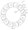
図4は、ニチノールで構成され得る作動ケーブルまたはワイヤー44を受ける、円周に分布される穴または内腔43を有するチューブ42を含むリスト40を示す。チューブ42はフレキシブルで、ケーブル44を引っ張ることによりピッチおよびヨーの屈折を可能とする。リスト40は好適には、フレキシブルチューブ42にケーブルの力を均等に配分するように、堅い遠位終端ディスク41(図4Bの代替実施形態で示すように)、またはフレキシブルチューブ42よりも実質的に堅い他の補強材を含む。チューブ42の中空は、グリップケーブルなどのエンドエフェクタケーブルのための空間を提供する。典型的には少なくとも4つの内腔がある。内バネ47が設けられ得る。(B. List with flexible tube refracted by working cable)
FIG. 4 shows a
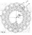
図4は、チューブ42の遠位端部でUターン45を成す6本のケーブル44を収容するための、特定実施形態の12個の内腔を示す。使用される多数のケーブルにより、チューブ42は、ピッチおよびヨーの同じ屈折を得る同一のケーブル引っ張り力に対して、より高い剛性を有することができる。例えば、4本のケーブルの代わりに12本のケーブルを使用することは、チューブ42は同じケーブル引っ張り力に対して3倍の剛性を有すことができることを意味する。代替的に、チューブ42の剛性が同じ場合は、4本のケーブルの代わりに12本のケーブルの使用により、必要とされるケーブル引っ張り力を3分の1低減することができることになる。材料特性およびケーブル応力レベルによりUターン45がチューブ42の端部に直接かかり得るが、チューブ42上をよりスムーズにケーブルの力を分布させるために、補強された遠位終端プレート41が含まれ得る。ケーブル44の近接端部は、2002年6月27日に出願された米国特許出願第10/187,248号で開示され、その全開示が参照により本明細書に組み込まれる、ジンバルプレート46を含むアセンブリなどの作動機構に接続され得る。この機構は、フレキシブルリスト屈折角度および方向を制御するなど、屈折可能または操縦可能な部材の制御のために、選択された複数のケーブルを調整して作動するように促進する。出願第10/187,248号の作動機構の例は、バランスよく多数の周辺ケーブルを作動するように適応され、比較的多数の直線作動装置を必要とせずにフレキシブル部材の調整された操縦を提供することができる。代替的には、個々に制御される直線作動機構を使用して、各ケーブルまたは滑車に巻きつけられ、回転作動装置で動かされるケーブル対をピンと張り、操縦はその直線作動装置を調整することにより制御され得る。 FIG. 4 shows twelve lumens of a particular embodiment for accommodating six
チューブ42は典型的には、ピッチおよびヨーに十分屈折できる低い弾性係数を有する、プラスチック材またはエラストマーで構成され得、複数の内腔、例えば12個の内腔を含むように、複数内腔押出し成形により製造され得る。S字形屈折などの不必要な撓みを制限するために、チューブが高い屈折剛性を有することが望ましいが、これはピッチおよびヨーの望ましい屈折に必要とされるケーブルの力を増加させる。下記で述べるように、チューブの高い屈折剛性を克服するのに十分に高いケーブルの力を提供するために、リストをピッチおよびヨーに操作するのに必要とするよりも、多くのケーブル(すなわち3本を越えるケーブル)を使用することができる。 The
図4Aおよび図4Bは、図4に示すものと同じリスト実施形態における2つの異なるケーブル配置の例を概略的に示す。一定の総ケーブル断面積に対して、2本1組になるケーブルを含み、多数の、それに比例してより小さいケーブルを含むことにより、リスト中心線に対してより大きい側方オフセットで終結することが可能であることに注意する。図4Aおよび図4Bは、各図の右側がリスト例1を示し、各図の左側はリスト例2を示すように境界線により分けられた、リスト実施形態の平面図および立面図をそれぞれ示す。各例では、チューブ42は同じ外半径Rおよび中央内腔を画定する同じ内半径rを有する。 4A and 4B schematically show examples of two different cable arrangements in the same list embodiment as shown in FIG. For a given total cable cross-section, include two pairs of cables and terminate with a larger lateral offset with respect to the wrist centerline by including multiple, proportionally smaller cables Note that is possible. 4A and 4B show a plan view and an elevation, respectively, of the list embodiment, separated by a boundary line so that the right side of each figure shows list example 1 and the left side of each figure shows list example 2. . In each example, the
例1では、リスト40.1におけるケーブル44の数は4に等しく(n1=4),各ケーブルは遠位アンカー44.5により個々に終結されており、遠位終端プレート41における皿ボアにはめ込まれて、さらに各ケーブルは遠位終端プレート41における各側方ケーブル内腔43およびフレキシブルチューブ42を通って延びる。アンカー44.5は、スエージビーズまたは他の従来のケーブルアンカーであり得る。 In Example 1, the number of
例2では、リスト40.2におけるケーブル44’の数は16に等しく(n2=16)、ケーブルは8本の対称的に離間された対の部分44’として配置され、各対は、隣接するケーブル内腔43’間で遠位終端プレート41’にかかる遠位「Uターン」エンドループ45により終結される。内腔43’での遠位終端プレート41’の縁は、応力集中を低減するように丸くされ得、ループ45は部分的または全体的に遠位終端プレート41の皿
穴に埋められ得る。16本のケーブル44’の直径は4本のケーブルの直径の1/2であるので、ケーブル総断面積は各例では同じである。In Example 2, the number of cables 44 'in list 40.2 is equal to 16 (n2 = 16), and the cables are arranged as eight symmetrically spaced pairs 44', each pair being adjacent It is terminated by a distal “U-turn”
図1と図2を比較すると、終了ループ45の採用により、ケーブルアンカー44.5に当てる遠位の体積分をなくなり、ケーブル内腔43’はケーブル内腔43よりもチューブ42の半径R寄りになる傾向にある。加えて、各ケーブル44’のより小さい直径のために、ケーブル中心線はケーブル内腔43’の外縁寄りになる。これらの特性の両方により、例2のケーブルは、チューブ42の中心に対して例1の対応モーメントアームL1より大きいモーメントアームL2の周りで作用できる。このより大きいモーメントアームL2は、チューブ42上の同じ全屈折モーメントに対してより低いケーブル応力が可能となり(より長いケーブル寿命またはより広範囲の選択ケーブル材料が可能となる)、または代替的には、同じケーブル応力に対してより大きい屈折モーメントが可能となる(より大きいリスト位置づけ剛性が可能となる)。加えて、より小径ケーブルは、比較的太いケーブルよりフレキシブルであり得る。従って、リスト40の好適な実施形態は、3本を越えるケーブル、好適には少なくとも6本(例えば、3対のループケーブル)、より好適には12本以上のケーブルを含む。 Comparing FIG. 1 and FIG. 2, the adoption of the
遠位終端プレート41で示されるアンカーまたは終点は例示であり、選択された材料特性が加えられる応力に適している場合は、ケーブルがチューブ42の材料に直接かかるように終結され得る(アンカーまたはループにより)ことに注意する。代替的には、ケーブルはチューブ42および/または遠位終端プレート41を超えて遠位に延び、それより遠位のエンドエフェクタ部材(図示せず)への接続により終結しており、ケーブル張力は、リスト40にしっかりと接続されたエンドエフェクタ部材をリスト動作の作用範囲内に維持するように、十分付勢され得る。 The anchor or end point shown by the
チューブの剛性を構造的に低減する1つの方法は、図5で示すように、切込みを設けることである。チューブ50は2つの側面上に、2つの直行する方向に互い違いに、それぞれピッチおよびヨーの屈折を促進する複数の切込み52を含む。複数の内腔54は、作動ケーブルを収容するために円周に分布される。 One way to structurally reduce the stiffness of the tube is to provide an incision, as shown in FIG. The
図6に図示する別の実施形態において、チューブ60は、チューブ60より高い剛性材料で形成される内部バネ62の周囲に巻きつけられる外側ブーツとして形成される。チューブ60は、作動ケーブルを受ける内部スロット64を含む。別個に形成されるフレキシブルチューブを設けることにより、アセンブリが簡素化できる。このようなチューブは、ケーブルを通す穴を有するチューブよりも、押し出し成形または別の方法で形成するのにより簡単である。このチューブはまた、ケーブルが中央内腔から設置され、その後ケーブルの間隔及び保持を維持するためにケーブルの内側に挿入された内バネを設置することができるので、予め形成される終点構造またはアンカーを備える作動ケーブルを使用するのにも役立つ。場合によっては、チューブ60は消毒しているが、必ずしもオートクレーブで処理可能ではない単一使用構成要素であり得る。 In another embodiment illustrated in FIG. 6, the tube 60 is formed as an outer boot that is wrapped around an
図7は、図5のチューブ50における切込み52と同様であり得る切込み72を有するチューブ70を示す。チューブ70は、プラスチックまたは金属で構成され得る。外側カバー74がチューブ50の周囲に取り付けられる。外側カバー74は、カプトンカバーなどであり得、典型的には切込み72に嵌合する皺を有する高引っ張り応力材料である。 FIG. 7 shows a tube 70 having a
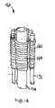
(C.軸タングおよび溝摺動部材を有するリスト)
図8および図9は、チューブ状リスト80を形成するために軸タングおよび溝接続部84により互いに接続または連結される、複数のフレキシブル軸方向摺動部材82を有するリスト80を示す。各摺動部材82はチューブ80の長手方向セグメントを形成する。軸
接続部84により、摺動部材82はリスト長手方向中心線に対して各部材の側方の位置を保ちつつ、互いに軸方向に摺動することができる。各摺動部材82は、作動ケーブルを受けるための穴または内腔86を含み、この穴または内腔86はリスト80の遠位端部に隣接して終結される。図9は、摺動部材82の摺動動作により促進される、ケーブル90のケーブル引っ張り力のもとでのリスト80の屈折を図示する。ケーブル90は用具シャフト92を通って延び、近接位置で作動用のジンバルプレート94などの作動機構に接続される。リスト80の屈折時において、摺動部材82の曲率半径が異なるので、摺動部材82は異なる量で屈折する。代替的には、軸方向摺動部材を有するリストの実施形態は、一体化されたケーブルおよび摺動部材を有し得、例えばこれにより摺動部材は一体化された摺動要素としてケーブルの周囲に一体的に形成される(例えば、押出し成形により)、またはこれにより、作動機構は摺動部材の近接端部に連結され、摺動部材は力をリストの遠位端部に直接伝える。(C. List with shaft tongue and groove sliding member)
FIGS. 8 and 9 show a
図13では、典型的にはフレキシブルなプラスチック材料で構成される複数の軸部材132を有するリスト130を示す。軸部材132はケーブル134上に同時押し出し成形され得るので、ケーブルが金属でなお絶縁可能である。軸部材132は軸タングおよび溝接続部136により互いに接続され、チューブ状リスト130を形成し得る。軸部材132は、ピッチおよびヨーのリスト130の屈折時に、互いに対して摺動することが可能であり得る。リスト130は図8のリスト80と同様であるが、わずかに異なる構成を有し、構成要素は異なる形状を有する。 FIG. 13 shows a wrist 130 having a plurality of
(D.重なり合う軸バネ部材を有するリスト)
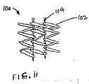
図10および図11は、チューブ状リスト100を形成するために円周の周りに配置される複数の軸バネ102により形成されるリスト100を示す。バネ102は同じ方向または、よりありがちな反対方向に巻かれたコイルバネである。図11でより明確にわかるように、ケーブル104は隣接するバネ102の各対の重なり領域を通って延びる。重なりにより、リスト100がケーブル張力のもとで十分圧縮されている場合、リスト100の密着高さは、個々のバネ102の密着高さの2倍となるであろう。バネ102は典型的には、ケーブルがたるまないように、またリスト安定性を高めるために圧縮状態で予め負荷される。(D. List with overlapping axial spring members)
FIGS. 10 and 11 show a
1つの代替において、リストが中立または屈折していない状態にあるとき、ケーブル初荷重によって、バネは完全に圧縮された密着高さ状態に付勢される。リストの一方の側でケーブル張力を制御調整しながら減少させる、またはケーブルレリースすることによって、一方の側が伸び、その結果リスト100の一方の側のバネが伸びて、屈折したリスト100の外側半径を形成することができる。外側ケーブル引っ張り力を再び加えると、リストは直立した構成に戻る。 In one alternative, when the wrist is in a neutral or non-refracted state, the cable initial load biases the spring into a fully compressed contact height state. By controlling or reducing cable tension on one side of the wrist, or by releasing the cable, one side is stretched, resulting in the spring on one side of the
別の代替では、リストが中立または屈折していない状態にあるとき、ケーブル初荷重によって、バネは部分的に圧縮された状態に付勢される。リストの一方の側でケーブル張力またはケーブル引っ張りを制御調整しながら増加させることによって、その一方の側が収縮して、その結果リスト100の一方の側のバネが短くなり、屈折したリスト100の内側半径を形成することができる。選択的に、これは上記の第1の代替と同様に、外側半径上の張力の解除と組み合わせ得る。元のケーブル引っ張り力を復元すると、リストは直立した構成に戻る。 In another alternative, when the wrist is in a neutral or non-refracted state, the cable initial load biases the spring into a partially compressed state. By controlling and increasing cable tension or cable tension on one side of the wrist, one side contracts, resulting in a shortened spring on one side of the
(E.波形バネ部材を有するリスト)
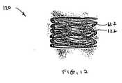
図12は、チューブ状の波形バネリスト120を形成するように積み重ねられる、または巻かれる複数の波形バネセグメントまたは構成要素122を有する波形バネ120の形態のリストを示す。1つの実施形態では、波形バネは、擬似螺旋状の連続した1片の平ら
なワイヤーから形成され、これを巻いたものであり、波形は各サイクル毎に変化し、1つのサイクルの高点は次のサイクルの低点に接する。このようなバネは市販のもので、例えば、Smalley Spring Companyから入手可能である。穴が波形バネリスト120に形成され、作動ケーブルを受ける。代替的に、複数の別個のディスク状波形バネセグメントが作動ケーブル上にビーズ状に並べられ得る(ケーブルにより保持されるか、または互いに接着される)。(E. List with wave spring members)
FIG. 12 shows a list in the form of a
図示されるように波形バネ122はそれぞれ、90度で離間される2つの対向する高点および2つの対向する低点を有する。この構成により、ピッチおよびローの屈折を促進する。当然、波形バネセグメント122は、さらなる高点および低点を備えてより密集した波形パターンのような他の構成を、リスト120の円周に有し得る。 As shown, each
(F. 球面の合わせ面を備えるディスクを有するリスト)
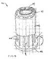
図14はリスト140のいくつかのセグメントまたはディスク142を示す。内部バネ144はディスク142の内部空間に設けられ、一方、複数のケーブルまたはワイヤー145がピッチおよびヨーにリスト140を屈折するために使用される。ディスク142は、内バネ144上にはめ込まれるか連結され、エンドエフェクタ用の引っ張りケーブルの内腔として作用する。引っ張りケーブルを介してエンドエフェクタに加わる力がリスト140をゆがめないように、内バネ144は軸方向剛性を提供する。代替の実施形態では、バネ144の代わりに積み重ねられた固体スペーサを使用して、この機能を達成することができる。ディスク142はそれぞれ、隣接したディスクの湾曲した内側あわせ面148と合わさる湾曲した外側合わせ面146を含む。図15は、ディスク142間の関連付けられた相対的回転に伴うリスト140の屈折を図示する。ディスク142は、例えばプラスチックまたはセラミックで構成され得る。球面の合わせ面146、148間の摩擦は、好適にはリスト140の動きを妨害するほど強くない。この潜在的な問題を軽減する1つの方法は、リスト140を屈折させるようにケーブル145を作動している間、何らかの圧縮負荷に耐え、ディスク142上の過度の圧縮負荷を防ぐであろう適切な内部バネ144を選択することである。内部バネ144はシリコンゴムなどで構成され得る。さらなるシリコン部材150も、作動ケーブルを囲み得る。代替実施形態では、個々のディスク142は1つの連続した螺旋状の細長い一片に置き換えられている。(F. List with disks with spherical mating surfaces)
FIG. 14 shows several segments or
代替実施形態では、リスト160の各ケーブルは図16および図17で図示されるように、バネの巻き162に収納され得る。内バネ164も設けられる。ディスク170は、ケーブルを受けるための環状フランジおよび穴なしで作ることができる(図14および図15のディスク142と同様)。バネの巻き162の内側の固いマンドレルワイヤーは、ディスク170の周囲に沿って所定の位置に配置することができる。中心ワイヤーマンドレル174は内部バネ164を巻くために真ん中に設けられる。アセンブリはシリコンなどの入った容器に入れ(potted in silicon)、その後マンドレルワイヤー172、174を取り除くことができる。なんらかの形態のカバーなどを使用して、シリコンがディスク170の球面の合わせ面に付着することを防ぐ。小さいマンドレル弁172は、リスト160が屈折したときに縮小するための空間を提供する小さな間隙を残して巻きつけられる。シリコンは望ましくは、ディスク170に対して十分接着され、ディスク170およびバネ172、174の接合されたアセンブリにねじれ剛性を提供する。断熱性のシリコン材は、リスト160を組み込む焼灼用具に対して焼灼断熱材として機能し得る。 In an alternative embodiment, each cable of the
(G.エラストマー部材により分離されたディスクを有するリスト)
図18は、エラストマー部材184により分離された複数のディスク182を有するリスト180を示す。エラストマー部材184は環状の部材であり得るか、ディスク182の円周に分布された複数のブロックを含み得る。図14のリスト140と同様に、内部バ
ネ186がディスク182およびエラストマー部材184の内部空間に設けられ、一方、複数のケーブルまたはワイヤー188が使用されてピッチおよびヨーにリスト180を屈折する。ディスク182は、内バネ184上にはめ込まれるか連結され、エンドエフェクタ用の引っ張りケーブルの内腔として作用する。引っ張りケーブルを介してエンドエフェクタに加わる力がリスト180をゆがめないように、内バネ184は軸方向剛性を提供する。このリスト180の構成は、リスト140よりヒトの脊椎によく似ている。エラストマー部材184は、弾性的に変形してピッチおよびヨーのリスト180の屈折を可能とする。エラストマー部材184を使用することで、ディスク182間のあわせ面の必要性がなくなり、また関連摩擦力がなくなる。(G. List with discs separated by elastomeric members)
FIG. 18 shows a
(H.ピッチおよびヨー屈折のためにディスクを支持する、交互性リブを有するリスト)
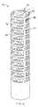
図19は、垂直方向に方向付けられ、リスト190のピッチおよびヨー屈折を促進する、交互のけたまたはリブ194に支持される複数のディスク192を含むリスト190を示す。隣接するディスク192間の切込みを除去して、隣接するディスク192間の概ね垂直なリブ194、196の交互の層を残しておくことにより、リスト190がチューブから形成され得る。ディスク192は作動ケーブルがその中を通る穴198を有する。ディスク192およびリブ194、196は、スチール、アルミニウム、ニチノール、プラスチックなどの種々の材料で構成され得る。図20に図示されるようにリスト200の代替実施形態では、ディスク202はケーブルを受けるための穴の代わりにスロット204を含む。このようなチューブは、ケーブルを通すための穴を有するチューブよりも押出し形成しやすい。バネ206は、ディスク202に巻かれてケーブルを支持する。(H. List with alternating ribs supporting the disk for pitch and yaw refraction)
FIG. 19 shows a
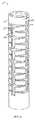
図21では、リスト210は、リブ214、216をディスク212間の間隔よりも長くするためにリブの両側にディスク212への切り込みまたはスリット217を有する、交互のけたまたはリブ214、216で支持されるディスク212を含む。この構成により、同じリストの長さに対して、図19のリスト190よりも小さい曲率半径での屈折が促進されるか、より短いリストを用いて同じ曲率半径を達成し得る。隣接するディスク212間の約15度の屈折角度は、これらの実施形態では典型的である。ディスク212は、作動ケーブルを受けるための穴218を有する。 In FIG. 21, the
(I.コイルバネに沿って分布される薄いディスクを採用するリスト)
図22は、複数の薄いディスク224がバネ222の長さに亘って分布される、コイルバネ222を含むリスト220の一部を示す。図22のリスト部分には2つのディスク224しか見えず、図23と図24で図示される互いに直交するタブ226で方向付けられる224Aおよび224Bを含む。バネ222は、ディスク224を挿入するために設けられる間隙を除いて密着高さで巻かれる。バネ222は内縁およびディスク224のタブ226の近くでディスク224に接続される。ディスク224は、エッチングにより形成され得、作動ケーブルを受けるための穴228を含み得る。タブ226は、ピッチおよびヨーのリスト220の屈折時において、バネ222を一定ポイントで屈折させる支点として作用する。ディスク224は、いくつかの実施形態によっては比較的堅いが、他の実施形態では、リスト220の屈折時にバネ要素として屈折及び作用するのに十分フレキシブルであり得る。シリコーン外側カバーは、誘電絶縁体としてコイルバネ222とディスク224の周囲に設けられ得る。加えて、バネ222とディスク224アセンブリは、例えば、図25および図26における外側ピースまたは外装ピース250から形成される外側構造により保護され得る。各外装ピース250は、外側合わせ面252および内側合わせ面254を含む。1つの外装ピース250の外側合わせ面252は、隣接する外装ピース250の内側合わせ面254と合わさる。外装ピース250はバネ222の長さに沿って積み重ねられ、リスト220の屈折から回転しながら、接触を維持する。(I. List employing thin disks distributed along coil springs)
FIG. 22 shows a portion of a
(J.外側編組ワイヤーを有するリスト)
フレキシブルなリストは、加えられた負荷に対する種々の材料の剛性に正確に依存する。すなわち、使用される材料が堅ければ堅いほど、および/またはリストの長さが短ければ短いほど、および/またはリストが大きい直径を有していればいるほど、発揮される所定の外科的な力のもとでのリストに関しては、横へのたわみはより小さくなるであろう。引っ張りケーブルが無視しうるコンプライアンスを有する場合、リストの端部の角度は正確に決定することができるが、ケーブルによるこれに対抗する力のもとでは、移動性または横へのたわみがあり得る。リストがまっすぐで、このような力が働いた場合、例えば、リストはS字形のたわみを呈す。これに対抗する1つの方法は、十分な剛性の適切な材料とリストに適した形状を有することである。別の方法は、米国特許出願第10/187,248号で説明されるように、引っ張りケーブルの半分をリストの長さに沿って途中で終結させ、これらを残りのケーブルの半分まで引っ張ることである。S字形のたわみに対するより大きな抵抗は、モーメントに耐える能力を犠牲にして得られる。S字形のたわみを避けるさらに別の方法は、リストの外側に編組カバーを設けることである。(J. List with outer braided wire)
The flexible list depends exactly on the stiffness of the various materials to the applied load. That is, the stiffer material used and / or the shorter the length of the wrist and / or the more the wrist has a larger diameter, For lists under force, the lateral deflection will be smaller. If the pull cable has negligible compliance, the angle at the end of the wrist can be accurately determined, but under the opposing force by the cable, there can be mobility or lateral deflection. If the list is straight and such a force is applied, for example, the list will exhibit an S-shaped deflection. One way to counter this is to have a suitable material with sufficient rigidity and a suitable shape for the wrist. Another method is to terminate half of the pull cables halfway along the length of the wrist and pull them to half of the remaining cables as described in US patent application Ser. No. 10 / 187,248. is there. Greater resistance to S-shaped deflection is obtained at the expense of ability to withstand moments. Yet another way to avoid S-shaped deflection is to provide a braided cover outside the wrist.
図27は、外側ワイヤー274にくるまれたチューブ272を有するリスト270を示す。ワイヤー274はそれぞれ、チューブ272の端部間で約360度回転で覆うようにに巻かれる。リスト270のねじれ剛性を高め、リスト270のS字形たわみを避けるために、外側ワイヤー274は、チューブ272上を覆う編組カバーリングを形成するように巻くことができる。編組カバーリングを形成するために、右回りのセット及び左回りセット(すなわち、一方は時計回りで他方は反時計回り)を含む2つのセットのワイヤーが織り合わせられる。織りまたは編み込みにより、時計回り及び反時計回りのワイヤーが互いに対して半径方向に動くことを防ぐ。例えば、ねじりのもとで、一方のセットのワイヤーの直径が大きくなろうとしても他方が縮まるので、ねじれ剛性が生じる。編組することにより、一方のセットが他方と異なることを防ぎ、ねじれによるたわみが抵抗を受ける。リスト270が円弧状に屈折するにつれて外側ワイヤー274は軸方向に摺動する必要があるが、編組の個々のワイヤーの長さを長くする必要がないように、外側ワイヤー274のよりの長さはリスト270の長さと等しくすることが望ましい。S字形たわみは外側ワイヤー274の長さが長くなるのを求めるので、編組はリスト270のS字形たわみに抵抗するになる。さらに、編組はまた外装として作用して、リストが削り取られたり、切断されたりするのを防ぎ得る。編組カバーが非導体である場合、最も外側の層で、リスト270の外装として作用し得る。リストのねじれ剛性を高め、S字形たわみを避けることはまた、右回りの巻きで始まり左回りの巻きにより覆われ、その後また別の右回り巻きで覆われる層状のバネによって達成されることができる。 FIG. 27 shows a
(K.リストカバー)
上記はいくつかのリスト用外装またはカバーを開示する。図28および図29は、リストカバーのさらなる例を示す。図28では、リストカバー280はプラスチックまたはセラミックなどの非導体材料の平らな螺旋により形成される。リストが屈折されると、螺旋状カバー280の異なるコイルは互いに摺動する。図29は、屈折または湾曲した縁292を含み、螺旋の隣接する層間の重なりを確実にする。リストにねじれ剛性を提供するために、リストカバー300は、リストの軸に平行して方向付けられたうねまたは溝302を含み得る。うね302は、1つの螺旋状の層から次の層へのスプラインとして作用し、リスト用のねじれスタビライザーを構成する。ステントのように構成されたニチノールレーザカバーの考察を付け足す。(K. Wrist cover)
The above discloses several wrist coverings or covers. 28 and 29 show further examples of wrist covers. In FIG. 28, the wrist cover 280 is formed by a flat spiral of non-conductive material such as plastic or ceramic. When the wrist is refracted, the different coils of the spiral cover 280 slide on each other. FIG. 29 includes a refracted or
装置および方法の上記配置は、本発明の原則の適用の単に例示であり、請求項で定義されるように、本発明の精神および範囲から逸脱することなく他の多くの実施形態および変形が行われ得る。それゆえに本発明の範囲は、上記の説明を参照せずに決定されるべきであり、代わりに均等物の全範囲と共に、添付された請求項を参照して決定されるべきであ
る。The above arrangements of apparatus and methods are merely illustrative of the application of the principles of the present invention and many other embodiments and variations may be made without departing from the spirit and scope of the invention as defined in the claims. Can be broken. The scope of the invention should, therefore, be determined without reference to the above description, but instead should be determined with reference to the appended claims along with their full scope of equivalents.
Claims (1)
Translated fromJapaneseApplications Claiming Priority (2)
| Application Number | Priority Date | Filing Date | Title |
|---|---|---|---|
| US43163602P | 2002-12-06 | 2002-12-06 | |
| US60/431,636 | 2002-12-06 |
Related Parent Applications (1)
| Application Number | Title | Priority Date | Filing Date |
|---|---|---|---|
| JP2013013947ADivisionJP6097085B2 (en) | 2002-12-06 | 2013-01-29 | Flexible list for surgical tools |
Related Child Applications (2)
| Application Number | Title | Priority Date | Filing Date |
|---|---|---|---|
| JP2018114594ADivisionJP2018140241A (en) | 2002-12-06 | 2018-06-15 | Flexible list for surgical tools |
| JP2018114595ADivisionJP2018140242A (en) | 2002-12-06 | 2018-06-15 | Flexible list for surgical tools |
Publications (1)
| Publication Number | Publication Date |
|---|---|
| JP2017038947Atrue JP2017038947A (en) | 2017-02-23 |
Family
ID=32507770
Family Applications (12)
| Application Number | Title | Priority Date | Filing Date |
|---|---|---|---|
| JP2004559257AExpired - LifetimeJP4486503B2 (en) | 2002-12-06 | 2003-12-02 | Flexible list for surgical tools |
| JP2010026006AExpired - LifetimeJP5455171B2 (en) | 2002-12-06 | 2010-02-08 | Flexible list for surgical tools |
| JP2011025457AExpired - LifetimeJP5339472B2 (en) | 2002-12-06 | 2011-02-08 | Flexible list for surgical tools |
| JP2011025456AExpired - LifetimeJP5437288B2 (en) | 2002-12-06 | 2011-02-08 | Flexible list for surgical tools |
| JP2013013947AExpired - LifetimeJP6097085B2 (en) | 2002-12-06 | 2013-01-29 | Flexible list for surgical tools |
| JP2015033633APendingJP2015126892A (en) | 2002-12-06 | 2015-02-24 | Flexible wrist for surgical instrument |
| JP2015033632AExpired - LifetimeJP6155292B2 (en) | 2002-12-06 | 2015-02-24 | Flexible list for surgical tools |
| JP2016201464AExpired - LifetimeJP6305489B2 (en) | 2002-12-06 | 2016-10-13 | Flexible list for surgical tools |
| JP2016201465AWithdrawnJP2017038947A (en) | 2002-12-06 | 2016-10-13 | Flexible list for surgical operation tool |
| JP2018114594APendingJP2018140241A (en) | 2002-12-06 | 2018-06-15 | Flexible list for surgical tools |
| JP2018114595APendingJP2018140242A (en) | 2002-12-06 | 2018-06-15 | Flexible list for surgical tools |
| JP2019225732APendingJP2020044376A (en) | 2002-12-06 | 2019-12-13 | Flexible list for surgical tools |
Family Applications Before (8)
| Application Number | Title | Priority Date | Filing Date |
|---|---|---|---|
| JP2004559257AExpired - LifetimeJP4486503B2 (en) | 2002-12-06 | 2003-12-02 | Flexible list for surgical tools |
| JP2010026006AExpired - LifetimeJP5455171B2 (en) | 2002-12-06 | 2010-02-08 | Flexible list for surgical tools |
| JP2011025457AExpired - LifetimeJP5339472B2 (en) | 2002-12-06 | 2011-02-08 | Flexible list for surgical tools |
| JP2011025456AExpired - LifetimeJP5437288B2 (en) | 2002-12-06 | 2011-02-08 | Flexible list for surgical tools |
| JP2013013947AExpired - LifetimeJP6097085B2 (en) | 2002-12-06 | 2013-01-29 | Flexible list for surgical tools |
| JP2015033633APendingJP2015126892A (en) | 2002-12-06 | 2015-02-24 | Flexible wrist for surgical instrument |
| JP2015033632AExpired - LifetimeJP6155292B2 (en) | 2002-12-06 | 2015-02-24 | Flexible list for surgical tools |
| JP2016201464AExpired - LifetimeJP6305489B2 (en) | 2002-12-06 | 2016-10-13 | Flexible list for surgical tools |
Family Applications After (3)
| Application Number | Title | Priority Date | Filing Date |
|---|---|---|---|
| JP2018114594APendingJP2018140241A (en) | 2002-12-06 | 2018-06-15 | Flexible list for surgical tools |
| JP2018114595APendingJP2018140242A (en) | 2002-12-06 | 2018-06-15 | Flexible list for surgical tools |
| JP2019225732APendingJP2020044376A (en) | 2002-12-06 | 2019-12-13 | Flexible list for surgical tools |
Country Status (8)
| Country | Link |
|---|---|
| US (9) | US7320700B2 (en) |
| EP (7) | EP1575439B1 (en) |
| JP (12) | JP4486503B2 (en) |
| KR (4) | KR101087996B1 (en) |
| CN (2) | CN100389730C (en) |
| AT (1) | ATE551964T1 (en) |
| AU (1) | AU2003293353A1 (en) |
| WO (1) | WO2004052171A2 (en) |
Families Citing this family (385)
| Publication number | Priority date | Publication date | Assignee | Title |
|---|---|---|---|---|
| US7713190B2 (en)* | 1998-02-24 | 2010-05-11 | Hansen Medical, Inc. | Flexible instrument |
| US6626899B2 (en) | 1999-06-25 | 2003-09-30 | Nidus Medical, Llc | Apparatus and methods for treating tissue |
| US8768516B2 (en) | 2009-06-30 | 2014-07-01 | Intuitive Surgical Operations, Inc. | Control of medical robotic system manipulator about kinematic singularities |
| EP2005914B1 (en)* | 2000-07-20 | 2012-04-04 | CareFusion 2200, Inc. | Hand-actuated articulating surgical tool |
| US7766894B2 (en) | 2001-02-15 | 2010-08-03 | Hansen Medical, Inc. | Coaxial catheter system |
| US8414505B1 (en) | 2001-02-15 | 2013-04-09 | Hansen Medical, Inc. | Catheter driver system |
| US6817974B2 (en) | 2001-06-29 | 2004-11-16 | Intuitive Surgical, Inc. | Surgical tool having positively positionable tendon-actuated multi-disk wrist joint |
| US20060178556A1 (en) | 2001-06-29 | 2006-08-10 | Intuitive Surgical, Inc. | Articulate and swapable endoscope for a surgical robot |
| US7331967B2 (en)* | 2002-09-09 | 2008-02-19 | Hansen Medical, Inc. | Surgical instrument coupling mechanism |
| JP4384439B2 (en) | 2002-11-21 | 2009-12-16 | 富士機械製造株式会社 | Anti-substrate work machine, anti-substrate work system, and work head use preparation processing program for anti-substrate work machine |
| KR101087996B1 (en) | 2002-12-06 | 2011-12-01 | 인튜어티브 서지컬 인코포레이티드 | Minimally invasive surgical instruments |
| US8182417B2 (en)* | 2004-11-24 | 2012-05-22 | Intuitive Surgical Operations, Inc. | Articulating mechanism components and system for easy assembly and disassembly |
| US8562640B2 (en)* | 2007-04-16 | 2013-10-22 | Intuitive Surgical Operations, Inc. | Tool with multi-state ratcheted end effector |
| US7090637B2 (en)* | 2003-05-23 | 2006-08-15 | Novare Surgical Systems, Inc. | Articulating mechanism for remote manipulation of a surgical or diagnostic tool |
| US7410483B2 (en) | 2003-05-23 | 2008-08-12 | Novare Surgical Systems, Inc. | Hand-actuated device for remote manipulation of a grasping tool |
| US8100824B2 (en) | 2003-05-23 | 2012-01-24 | Intuitive Surgical Operations, Inc. | Tool with articulation lock |
| US8007511B2 (en) | 2003-06-06 | 2011-08-30 | Hansen Medical, Inc. | Surgical instrument design |
| US9002518B2 (en) | 2003-06-30 | 2015-04-07 | Intuitive Surgical Operations, Inc. | Maximum torque driving of robotic surgical tools in robotic surgical systems |
| US7976539B2 (en)* | 2004-03-05 | 2011-07-12 | Hansen Medical, Inc. | System and method for denaturing and fixing collagenous tissue |
| WO2005087128A1 (en) | 2004-03-05 | 2005-09-22 | Hansen Medical, Inc. | Robotic catheter system |
| US7828808B2 (en)* | 2004-06-07 | 2010-11-09 | Novare Surgical Systems, Inc. | Link systems and articulation mechanisms for remote manipulation of surgical or diagnostic tools |
| US7678117B2 (en) | 2004-06-07 | 2010-03-16 | Novare Surgical Systems, Inc. | Articulating mechanism with flex-hinged links |
| US7241290B2 (en) | 2004-06-16 | 2007-07-10 | Kinetic Surgical, Llc | Surgical tool kit |
| US8353897B2 (en)* | 2004-06-16 | 2013-01-15 | Carefusion 2200, Inc. | Surgical tool kit |
| US8075476B2 (en)* | 2004-07-27 | 2011-12-13 | Intuitive Surgical Operations, Inc. | Cannula system and method of use |
| US8057508B2 (en)* | 2004-07-28 | 2011-11-15 | Ethicon Endo-Surgery, Inc. | Surgical instrument incorporating an electrically actuated articulation locking mechanism |
| US7857183B2 (en)* | 2004-07-28 | 2010-12-28 | Ethicon Endo-Surgery, Inc. | Surgical instrument incorporating an electrically actuated articulation mechanism |
| US7410086B2 (en) | 2004-07-28 | 2008-08-12 | Ethicon Endo-Surgery, Inc. | Electroactive polymer-based actuation mechanism for circular stapler |
| US8905977B2 (en)* | 2004-07-28 | 2014-12-09 | Ethicon Endo-Surgery, Inc. | Surgical stapling instrument having an electroactive polymer actuated medical substance dispenser |
| US7879070B2 (en) | 2004-07-28 | 2011-02-01 | Ethicon Endo-Surgery, Inc. | Electroactive polymer-based actuation mechanism for grasper |
| US7407074B2 (en) | 2004-07-28 | 2008-08-05 | Ethicon Endo-Surgery, Inc. | Electroactive polymer-based actuation mechanism for multi-fire surgical fastening instrument |
| US9700334B2 (en) | 2004-11-23 | 2017-07-11 | Intuitive Surgical Operations, Inc. | Articulating mechanisms and link systems with torque transmission in remote manipulation of instruments and tools |
| US7785252B2 (en) | 2004-11-23 | 2010-08-31 | Novare Surgical Systems, Inc. | Articulating sheath for flexible instruments |
| US20060116697A1 (en)* | 2004-11-30 | 2006-06-01 | Esophyx, Inc. | Flexible transoral endoscopic gastroesophageal flap valve restoration device and method |
| US20060201130A1 (en)* | 2005-01-31 | 2006-09-14 | Danitz David J | Articulating mechanisms with joint assembly and manual handle for remote manipulation of instruments and tools |
| US7784663B2 (en)* | 2005-03-17 | 2010-08-31 | Ethicon Endo-Surgery, Inc. | Surgical stapling instrument having load sensing control circuitry |
| US9789608B2 (en) | 2006-06-29 | 2017-10-17 | Intuitive Surgical Operations, Inc. | Synthetic representation of a surgical robot |
| JP2009500086A (en) | 2005-07-01 | 2009-01-08 | ハンセン メディカル,インク. | Robotic guide catheter system |
| US8535217B2 (en)* | 2005-07-26 | 2013-09-17 | Ams Research Corporation | Methods and systems for treatment of prolapse |
| US20070066985A1 (en)* | 2005-09-16 | 2007-03-22 | Boston Scientific Scimed, Inc. | Tissue cutting devices having hemostasis capability and related methods |
| JP5072850B2 (en)* | 2005-11-02 | 2012-11-14 | インジェクティカ アーゲー | Implantable injection device |
| US9931108B2 (en)* | 2005-11-18 | 2018-04-03 | Steven Miller | System and method for influencing an anatomical structure |
| US9962066B2 (en) | 2005-12-30 | 2018-05-08 | Intuitive Surgical Operations, Inc. | Methods and apparatus to shape flexible entry guides for minimally invasive surgery |
| US7930065B2 (en) | 2005-12-30 | 2011-04-19 | Intuitive Surgical Operations, Inc. | Robotic surgery system including position sensors using fiber bragg gratings |
| GB0600170D0 (en)* | 2006-01-06 | 2006-02-15 | Oliver Crispin Robotics Ltd | Improvements in and relating to robotic arms |
| USD581050S1 (en)* | 2006-03-10 | 2008-11-18 | Medical Device Innovations Limited | Surgical instrument tip |
| USD623739S1 (en) | 2006-03-10 | 2010-09-14 | Medical Device Innovations Limited | Surgical instrument handle |
| USD622380S1 (en) | 2006-03-10 | 2010-08-24 | Medical Device Innovations Limited | Surgical instrument |
| US8105350B2 (en) | 2006-05-23 | 2012-01-31 | Cambridge Endoscopic Devices, Inc. | Surgical instrument |
| KR101477133B1 (en) | 2006-06-13 | 2014-12-29 | 인튜어티브 서지컬 인코포레이티드 | Minimally invasive surgical system |
| US7862554B2 (en) | 2007-04-16 | 2011-01-04 | Intuitive Surgical Operations, Inc. | Articulating tool with improved tension member system |
| US9561045B2 (en)* | 2006-06-13 | 2017-02-07 | Intuitive Surgical Operations, Inc. | Tool with rotation lock |
| US8409244B2 (en)* | 2007-04-16 | 2013-04-02 | Intuitive Surgical Operations, Inc. | Tool with end effector force limiter |
| US10008017B2 (en) | 2006-06-29 | 2018-06-26 | Intuitive Surgical Operations, Inc. | Rendering tool information as graphic overlays on displayed images of tools |
| US9718190B2 (en) | 2006-06-29 | 2017-08-01 | Intuitive Surgical Operations, Inc. | Tool position and identification indicator displayed in a boundary area of a computer display screen |
| US12357400B2 (en) | 2006-06-29 | 2025-07-15 | Intuitive Surgical Operations, Inc. | Synthetic representation of a surgical robot |
| US10258425B2 (en) | 2008-06-27 | 2019-04-16 | Intuitive Surgical Operations, Inc. | Medical robotic system providing an auxiliary view of articulatable instruments extending out of a distal end of an entry guide |
| ATE545374T1 (en)* | 2006-06-30 | 2012-03-15 | Bovie Medical Corp | SURGICAL INSTRUMENT WITH REMOVABLE TOOL ARRANGEMENT |
| US8029531B2 (en)* | 2006-07-11 | 2011-10-04 | Cambridge Endoscopic Devices, Inc. | Surgical instrument |
| US8973461B2 (en)* | 2006-07-31 | 2015-03-10 | Commissariat A L'energie Atomique | Jointed limb comprising fibres, and jointed structure and robot or haptic interface comprising such a jointed limb |
| US7708758B2 (en)* | 2006-08-16 | 2010-05-04 | Cambridge Endoscopic Devices, Inc. | Surgical instrument |
| US20100241136A1 (en)* | 2006-12-05 | 2010-09-23 | Mark Doyle | Instrument positioning/holding devices |
| WO2008076330A1 (en)* | 2006-12-15 | 2008-06-26 | Soteira, Inc. | Drills and methods for vertebrostenting |
| US20080249536A1 (en)* | 2007-02-15 | 2008-10-09 | Hansen Medical, Inc. | Interface assembly for controlling orientation of robotically controlled medical instrument |
| JP4975494B2 (en) | 2007-03-23 | 2012-07-11 | 富士通株式会社 | Imaging device |
| WO2008131303A2 (en) | 2007-04-20 | 2008-10-30 | Hansen Medical, Inc. | Optical fiber shape sensing systems |
| US20090138025A1 (en)* | 2007-05-04 | 2009-05-28 | Hansen Medical, Inc. | Apparatus systems and methods for forming a working platform of a robotic instrument system by manipulation of components having controllably rigidity |
| US9096033B2 (en) | 2007-06-13 | 2015-08-04 | Intuitive Surgical Operations, Inc. | Surgical system instrument sterile adapter |
| US9469034B2 (en) | 2007-06-13 | 2016-10-18 | Intuitive Surgical Operations, Inc. | Method and system for switching modes of a robotic system |
| US8620473B2 (en) | 2007-06-13 | 2013-12-31 | Intuitive Surgical Operations, Inc. | Medical robotic system with coupled control modes |
| US9869339B2 (en) | 2008-04-11 | 2018-01-16 | Flexdex, Inc. | End-effector jaw closure transmission systems for remote access tools |
| WO2009126955A2 (en) | 2008-04-11 | 2009-10-15 | The Regents Of The University Of Michigan | Minimal access tool |
| US10405936B2 (en) | 2008-04-11 | 2019-09-10 | The Regents Of The University Of Michigan | Parallel kinematic mechanisms with decoupled rotational motions |
| WO2009127236A1 (en)* | 2008-04-18 | 2009-10-22 | Fortimedix B.V. | An instrument for endoscopic applications or the like |
| RU2011102169A (en)* | 2008-06-27 | 2012-08-10 | Эллидженс Корпарейшен (Us) | FLEXIBLE Wrist ELEMENT, METHODS FOR ITS MANUFACTURE AND USE |
| US12239396B2 (en) | 2008-06-27 | 2025-03-04 | Intuitive Surgical Operations, Inc. | Medical robotic system providing an auxiliary view including range of motion limitations for articulatable instruments extending out of a distal end of an entry guide |
| US9204923B2 (en) | 2008-07-16 | 2015-12-08 | Intuitive Surgical Operations, Inc. | Medical instrument electronically energized using drive cables |
| US8968355B2 (en)* | 2008-08-04 | 2015-03-03 | Covidien Lp | Articulating surgical device |
| US8465475B2 (en) | 2008-08-18 | 2013-06-18 | Intuitive Surgical Operations, Inc. | Instrument with multiple articulation locks |
| US8161838B2 (en) | 2008-12-22 | 2012-04-24 | Intuitive Surgical Operations, Inc. | Method and apparatus for reducing at least one friction force opposing an axial force exerted through an actuator element |
| US8245594B2 (en)* | 2008-12-23 | 2012-08-21 | Intuitive Surgical Operations, Inc. | Roll joint and method for a surgical apparatus |
| US8858547B2 (en) | 2009-03-05 | 2014-10-14 | Intuitive Surgical Operations, Inc. | Cut and seal instrument |
| US8423182B2 (en) | 2009-03-09 | 2013-04-16 | Intuitive Surgical Operations, Inc. | Adaptable integrated energy control system for electrosurgical tools in robotic surgical systems |
| US12266040B2 (en) | 2009-03-31 | 2025-04-01 | Intuitive Surgical Operations, Inc. | Rendering tool information as graphic overlays on displayed images of tools |
| US9254123B2 (en) | 2009-04-29 | 2016-02-09 | Hansen Medical, Inc. | Flexible and steerable elongate instruments with shape control and support elements |
| US10080482B2 (en) | 2009-06-30 | 2018-09-25 | Intuitive Surgical Operations, Inc. | Compliant surgical device |
| US20110022078A1 (en) | 2009-07-23 | 2011-01-27 | Cameron Dale Hinman | Articulating mechanism |
| US9492927B2 (en) | 2009-08-15 | 2016-11-15 | Intuitive Surgical Operations, Inc. | Application of force feedback on an input device to urge its operator to command an articulated instrument to a preferred pose |
| ES2388867B1 (en)* | 2009-10-27 | 2013-09-18 | Universitat Politècnica De Catalunya | MINIMALLY INVASIVE LAPAROSCOPIC SURGERY CLAMPS. |
| KR102152042B1 (en) | 2009-11-13 | 2020-09-04 | 인튜어티브 서지컬 오퍼레이션즈 인코포레이티드 | Surgical tool with a compact wrist |
| EP2467065B1 (en) | 2009-11-13 | 2020-01-08 | Intuitive Surgical Operations, Inc. | End effector with redundant closing mechanisms |
| US20110118708A1 (en) | 2009-11-13 | 2011-05-19 | Intuitive Surgical Operations, Inc. | Double universal joint |
| EP2498710B1 (en) | 2009-11-13 | 2018-05-16 | Intuitive Surgical Operations, Inc. | Motor interface for parallel drive shafts within an independently rotating member |
| CN104188710B (en)* | 2009-12-10 | 2017-04-12 | 奥林巴斯株式会社 | Medical manipulator |
| US8887595B2 (en) | 2009-12-22 | 2014-11-18 | Intuitive Surgical Operations, Inc. | Instrument wrist with cycloidal surfaces |
| US10376331B2 (en)* | 2010-02-12 | 2019-08-13 | Intuitive Surgical Operations, Inc. | Sheaths for jointed instruments |
| US9089351B2 (en) | 2010-02-12 | 2015-07-28 | Intuitive Surgical Operations, Inc. | Sheath for surgical instrument |
| US20110213360A1 (en)* | 2010-02-26 | 2011-09-01 | Tyco Healthcare Group Lp | Tensioning Mechanism for Articulation Drive Cables |
| US8439912B2 (en) | 2010-02-26 | 2013-05-14 | Covidien Lp | De-tensioning mechanism for articulation drive cables |
| DE102010014435B4 (en)* | 2010-04-09 | 2015-11-19 | Olympus Winter & Ibe Gmbh | Electrosurgical laparoscopic instrument with electrical lead |
| US9033998B1 (en) | 2010-05-13 | 2015-05-19 | Titan Medical Inc. | Independent roll wrist mechanism |
| US8603077B2 (en) | 2010-05-14 | 2013-12-10 | Intuitive Surgical Operations, Inc. | Force transmission for robotic surgical instrument |
| US11278345B2 (en) | 2010-05-25 | 2022-03-22 | Covidien Lp | Accurate jaw closure force in a catheter based instrument |
| US9138284B2 (en) | 2010-07-09 | 2015-09-22 | Intuitive Surgical Operations, Inc. | Electrosurgical tool cover |
| WO2012020386A1 (en) | 2010-08-11 | 2012-02-16 | Ecole Polytechnique Federale De Lausanne (Epfl) | Mechanical positioning system for surgical instruments |
| CN105078524A (en)* | 2010-08-27 | 2015-11-25 | 伊顿株式会社 | Instrument for surgical operation |
| US9737687B2 (en) | 2010-09-22 | 2017-08-22 | The Johns Hopkins University | Cable-driven morphable manipulator |
| WO2013014621A2 (en) | 2011-07-27 | 2013-01-31 | Ecole Polytechnique Federale De Lausanne (Epfl) | Mechanical teleoperated device for remote manipulation |
| US12402960B2 (en) | 2010-10-11 | 2025-09-02 | Ecole Polytechnique Federale De Lausanne (Epfl) | Mechanical manipulator for surgical instruments |
| EP2627278B1 (en) | 2010-10-11 | 2015-03-25 | Ecole Polytechnique Fédérale de Lausanne (EPFL) | Mechanical manipulator for surgical instruments |
| US9060765B2 (en) | 2010-11-08 | 2015-06-23 | Bovie Medical Corporation | Electrosurgical apparatus with retractable blade |
| US9101379B2 (en) | 2010-11-12 | 2015-08-11 | Intuitive Surgical Operations, Inc. | Tension control in actuation of multi-joint medical instruments |
| US9055960B2 (en) | 2010-11-15 | 2015-06-16 | Intuitive Surgical Operations, Inc. | Flexible surgical devices |
| KR101075294B1 (en) | 2011-01-12 | 2011-10-19 | 정창욱 | Minimally invasive surgical instruments |
| US20120191079A1 (en) | 2011-01-20 | 2012-07-26 | Hansen Medical, Inc. | System and method for endoluminal and translumenal therapy |
| US8578810B2 (en) | 2011-02-14 | 2013-11-12 | Intuitive Surgical Operations, Inc. | Jointed link structures exhibiting preferential bending, and related methods |
| JP6518403B2 (en)* | 2011-02-18 | 2019-05-22 | インテュイティブ サージカル オペレーションズ, インコーポレイテッド | Fusion and cutting surgical instruments and related methods |
| KR101259701B1 (en) | 2011-03-24 | 2013-05-06 | 정창욱 | Instrument for Minimally Invasive Surgery Having Curved Shaft |
| EP2706932B1 (en)* | 2011-05-12 | 2018-03-28 | Imperial Innovations Limited | A surgical device |
| US9161771B2 (en) | 2011-05-13 | 2015-10-20 | Intuitive Surgical Operations Inc. | Medical instrument with snake wrist structure |
| KR101336381B1 (en)* | 2011-06-07 | 2013-12-04 | 정창욱 | Instrument for Minimally Invasive Surgery |
| US20130030363A1 (en) | 2011-07-29 | 2013-01-31 | Hansen Medical, Inc. | Systems and methods utilizing shape sensing fibers |
| US8945174B2 (en) | 2011-08-15 | 2015-02-03 | Intuitive Surgical Operations, Inc. | Medical instrument with flexible jaw mechanism |
| US20130046317A1 (en)* | 2011-08-15 | 2013-02-21 | Intuitive Surgical Operations, Inc. | Medical instrument with flexible wrist mechanism |
| KR101322030B1 (en)* | 2011-09-05 | 2013-10-28 | 주식회사 모바수 | Instrument for Minimally Invasive Surgery Having Articulation Unit Including Spherical Parts |
| US20130303944A1 (en) | 2012-05-14 | 2013-11-14 | Intuitive Surgical Operations, Inc. | Off-axis electromagnetic sensor |
| US10238837B2 (en) | 2011-10-14 | 2019-03-26 | Intuitive Surgical Operations, Inc. | Catheters with control modes for interchangeable probes |
| US9452276B2 (en) | 2011-10-14 | 2016-09-27 | Intuitive Surgical Operations, Inc. | Catheter with removable vision probe |
| US9387048B2 (en) | 2011-10-14 | 2016-07-12 | Intuitive Surgical Operations, Inc. | Catheter sensor systems |
| CN102525581B (en)* | 2011-10-25 | 2013-09-11 | 王小军 | Disposable purse-string forceps for laparoscope |
| US9211159B2 (en) | 2011-12-02 | 2015-12-15 | Ethicon Endo-Surgery, Inc. | Surgical devices with intracorporeal elbow joint |
| US9179927B2 (en) | 2011-12-02 | 2015-11-10 | Ethicon Endo-Surgery, Inc. | Surgical methods using a surgical device having a fixed angular orientation |
| US9131987B2 (en) | 2011-12-02 | 2015-09-15 | Ethicon Endo-Surgery, Inc. | Elbow assembly for surgical devices |
| US8617203B2 (en) | 2011-12-02 | 2013-12-31 | Ethicon Endo-Surgery, Inc. | Jaw assembly for surgical devices |
| US20130158525A1 (en)* | 2011-12-09 | 2013-06-20 | Adn International, Llc | Flexible channel surgical instruments |
| US8876806B2 (en) | 2012-01-09 | 2014-11-04 | Covidien Lp | Surgical instrument with articulating assembly |
| US9956042B2 (en) | 2012-01-13 | 2018-05-01 | Vanderbilt University | Systems and methods for robot-assisted transurethral exploration and intervention |
| US8419720B1 (en) | 2012-02-07 | 2013-04-16 | National Advanced Endoscopy Devices, Incorporated | Flexible laparoscopic device |
| US8556883B2 (en)* | 2012-02-27 | 2013-10-15 | Rafic Saleh | Medical surgical navigation sensor mounting system |
| WO2013146310A1 (en)* | 2012-03-28 | 2013-10-03 | テルモ株式会社 | Puncture instrument assembly |
| US9211134B2 (en) | 2012-04-09 | 2015-12-15 | Carefusion 2200, Inc. | Wrist assembly for articulating laparoscopic surgical instruments |
| WO2013158983A1 (en) | 2012-04-20 | 2013-10-24 | Vanderbilt University | Robotic device for establishing access channel |
| US9687303B2 (en) | 2012-04-20 | 2017-06-27 | Vanderbilt University | Dexterous wrists for surgical intervention |
| US9539726B2 (en)* | 2012-04-20 | 2017-01-10 | Vanderbilt University | Systems and methods for safe compliant insertion and hybrid force/motion telemanipulation of continuum robots |
| KR101405087B1 (en)* | 2012-04-27 | 2014-06-10 | 한양대학교 에리카산학협력단 | An articulation for surgical instrument |
| US11135026B2 (en) | 2012-05-11 | 2021-10-05 | Peter L. Bono | Robotic surgical system |
| CN104640514B (en) | 2012-09-17 | 2019-05-07 | 直观外科手术操作公司 | Method and system for assigning input devices to teleoperated surgical instrument functionality |
| US10864048B2 (en) | 2012-11-02 | 2020-12-15 | Intuitive Surgical Operations, Inc. | Flux disambiguation for teleoperated surgical systems |
| US10631939B2 (en) | 2012-11-02 | 2020-04-28 | Intuitive Surgical Operations, Inc. | Systems and methods for mapping flux supply paths |
| US20140148673A1 (en) | 2012-11-28 | 2014-05-29 | Hansen Medical, Inc. | Method of anchoring pullwire directly articulatable region in catheter |
| US10507066B2 (en) | 2013-02-15 | 2019-12-17 | Intuitive Surgical Operations, Inc. | Providing information of tools by filtering image areas adjacent to or on displayed images of the tools |
| US20140296869A1 (en)* | 2013-03-14 | 2014-10-02 | Intuitive Surgical Operations, Inc. | Surgical instrument shaft |
| US20140277334A1 (en) | 2013-03-14 | 2014-09-18 | Hansen Medical, Inc. | Active drives for robotic catheter manipulators |
| US9326822B2 (en) | 2013-03-14 | 2016-05-03 | Hansen Medical, Inc. | Active drives for robotic catheter manipulators |
| US9408669B2 (en) | 2013-03-15 | 2016-08-09 | Hansen Medical, Inc. | Active drive mechanism with finite range of motion |
| US20140276936A1 (en) | 2013-03-15 | 2014-09-18 | Hansen Medical, Inc. | Active drive mechanism for simultaneous rotation and translation |
| WO2014201538A1 (en) | 2013-06-19 | 2014-12-24 | Titan Medical Inc. | Articulated tool positioner and system employing same |
| JP6173089B2 (en) | 2013-07-24 | 2017-08-02 | オリンパス株式会社 | Control method for medical master-slave system |
| CN103340662B (en)* | 2013-08-02 | 2016-02-17 | 苏州天臣国际医疗科技有限公司 | Endo-GIA |
| USD749726S1 (en)* | 2013-08-15 | 2016-02-16 | Intuitive Surgical Operations, Inc. | Surgical instrument shaft with hole pattern |
| WO2015057990A1 (en) | 2013-10-18 | 2015-04-23 | Intuitive Surgical Operations, Inc. | Wrist mechanism for surgical instrument |
| US9295522B2 (en) | 2013-11-08 | 2016-03-29 | Covidien Lp | Medical device adapter with wrist mechanism |
| CN105813582B (en) | 2013-12-11 | 2019-05-28 | 柯惠Lp公司 | Wrist and jaw assemblies for robotic surgical systems |
| CN106659540B (en) | 2014-02-03 | 2019-03-05 | 迪斯塔莫申股份公司 | Mechanical teleoperated devices including interchangeable distal instruments |
| KR20230056068A (en)* | 2014-02-21 | 2023-04-26 | 인튜어티브 서지컬 오퍼레이션즈 인코포레이티드 | Articulatable members having constrained motion, and related devices and methods |
| CN111938820B (en)* | 2014-02-21 | 2024-12-10 | 直观外科手术操作公司 | Mechanical joints and related systems and methods |
| US10280951B2 (en) | 2014-03-02 | 2019-05-07 | Drexel University | Articulating devices |
| US10166061B2 (en) | 2014-03-17 | 2019-01-01 | Intuitive Surgical Operations, Inc. | Teleoperated surgical system equipment with user interface |
| US10285763B2 (en) | 2014-04-02 | 2019-05-14 | Intuitive Surgical Operations, Inc. | Actuation element guide with twisting channels |
| JP6752717B2 (en)* | 2014-04-02 | 2020-09-09 | インテュイティブ サージカル オペレーションズ, インコーポレイテッド | Working element guide with twisted passages |
| US10046140B2 (en) | 2014-04-21 | 2018-08-14 | Hansen Medical, Inc. | Devices, systems, and methods for controlling active drive systems |
| JP2017514608A (en) | 2014-05-05 | 2017-06-08 | バイカリアス サージカル インク. | Virtual reality surgical device |
| US10259129B2 (en)* | 2014-05-06 | 2019-04-16 | The Johns Hopkins University | Adjustable stiffness morphable manipulator |
| CN106659538B (en) | 2014-08-13 | 2019-05-10 | 柯惠Lp公司 | Robot-controlled gripping with mechanical advantages |
| EP3185808B1 (en) | 2014-08-27 | 2022-02-23 | DistalMotion SA | Surgical system for microsurgical techniques |
| ES2848100T3 (en) | 2014-09-04 | 2021-08-05 | Memic Innovative Surgery Ltd | Device control including mechanical arms |
| US11357483B2 (en) | 2014-09-26 | 2022-06-14 | Intuitive Surgical Operations, Inc. | Surgical instrument with flexible shaft and actuation element guide |
| WO2016097873A2 (en) | 2014-12-19 | 2016-06-23 | Distalmotion Sa | Articulated handle for mechanical telemanipulator |
| WO2016097871A1 (en) | 2014-12-19 | 2016-06-23 | Distalmotion Sa | Docking system for mechanical telemanipulator |
| WO2016097861A1 (en) | 2014-12-19 | 2016-06-23 | Distalmotion Sa | Sterile interface for articulated surgical instruments |
| EP3653145B1 (en) | 2014-12-19 | 2024-01-24 | DistalMotion SA | Reusable surgical instrument for minimally invasive procedures |
| EP3232951B1 (en) | 2014-12-19 | 2023-10-25 | DistalMotion SA | Surgical instrument with articulated end-effector |
| WO2016123147A1 (en) | 2015-01-28 | 2016-08-04 | Bovie Medical Corporation | Cold plasma electrosurgical apparatus with bent tip applicator |
| WO2016133633A1 (en) | 2015-02-19 | 2016-08-25 | Covidien Lp | Repositioning method of input device for robotic surgical system |
| WO2016144937A1 (en) | 2015-03-10 | 2016-09-15 | Covidien Lp | Measuring health of a connector member of a robotic surgical system |
| EP3282952B1 (en) | 2015-04-03 | 2019-12-25 | The Regents Of The University Of Michigan | Tension management apparatus for cable-driven transmission |
| EP3280337B1 (en) | 2015-04-09 | 2019-11-13 | DistalMotion SA | Articulated hand-held instrument |
| US10568709B2 (en) | 2015-04-09 | 2020-02-25 | Distalmotion Sa | Mechanical teleoperated device for remote manipulation |
| US10959788B2 (en) | 2015-06-03 | 2021-03-30 | Covidien Lp | Offset instrument drive unit |
| US10806531B2 (en) | 2015-06-12 | 2020-10-20 | Intuitive Surgical Operations, Inc. | User interfaces and displays for flux supply units |
| CA2987637C (en) | 2015-06-16 | 2023-10-03 | Covidien Lp | Robotic surgical system torque transduction sensing |
| EP3313315B1 (en) | 2015-06-23 | 2024-04-10 | Covidien LP | Robotic surgical assemblies |
| WO2017037532A1 (en) | 2015-08-28 | 2017-03-09 | Distalmotion Sa | Surgical instrument with increased actuation force |
| AU2016326371B2 (en) | 2015-09-25 | 2020-07-23 | Covidien Lp | Robotic surgical assemblies and instrument drive connectors thereof |
| CN108712886B (en) | 2015-10-02 | 2021-06-04 | 弗莱克斯德克斯公司 | Handle mechanism providing unlimited roll |
| US11896255B2 (en) | 2015-10-05 | 2024-02-13 | Flexdex, Inc. | End-effector jaw closure transmission systems for remote access tools |
| WO2017062516A1 (en) | 2015-10-05 | 2017-04-13 | Flexdex, Inc. | Medical devices having smoothly articulating multi-cluster joints |
| US10265058B2 (en) | 2015-10-19 | 2019-04-23 | DNP Biomed, LLC | Systems, devices, components and methods for displacing and repositioning the esophagus away from the heart during atrial ablation surgical procedures |
| US9668720B2 (en) | 2015-10-19 | 2017-06-06 | DNP Biomed, LLC | Systems, devices, components and methods for displacing and repositioning the esophagus away from the heart during atrial ablation surgical procedures |
| EP3878396A1 (en) | 2015-10-23 | 2021-09-15 | Covidien LP | Surgical system for detecting gradual changes in perfusion |
| EP3376988B1 (en) | 2015-11-19 | 2023-08-23 | Covidien LP | Optical force sensor for robotic surgical system |
| BR112018009251A2 (en)* | 2016-02-05 | 2019-04-09 | Board Of Regents Of The University Of Texas System | surgical apparatus and customized main controller for a surgical apparatus |
| KR102708262B1 (en) | 2016-02-05 | 2024-09-20 | 보드 오브 리전츠, 더 유니버시티 오브 텍사스 시스템 | The manipulatable intraruminal medical device |
| WO2017147607A1 (en) | 2016-02-25 | 2017-08-31 | Flexdex, Inc. | Parallel kinematic apparatuses |
| EP3422990A4 (en) | 2016-03-04 | 2019-11-13 | Covidien LP | REVERSE KINEMATIC CONTROL SYSTEMS FOR SURGICAL ROBOTIC SYSTEM |
| US10463438B2 (en) | 2016-03-09 | 2019-11-05 | Memic Innovative Surgery Ltd. | Modular device comprising mechanical arms |
| BR112018068122A2 (en) | 2016-03-10 | 2019-01-15 | Human Extensions Ltd | medical instrument and medical device control unit |
| US11576562B2 (en) | 2016-04-07 | 2023-02-14 | Titan Medical Inc. | Camera positioning method and apparatus for capturing images during a medical procedure |
| JP6662690B2 (en)* | 2016-04-11 | 2020-03-11 | ミズホ株式会社 | Endoscopic surgical instruments |
| WO2017181153A1 (en) | 2016-04-14 | 2017-10-19 | Transenterix Surgical, Inc. | Electromechanical surgical system inlcuding linearly driven instrument roll |
| WO2017189272A1 (en) | 2016-04-29 | 2017-11-02 | Intuitive Surgical Operations, Inc. | Compliant mechanisms having inverted tool members |
| US10603047B2 (en) | 2016-05-23 | 2020-03-31 | Mako Surgical Corp. | Medical device for cutting bone |
| EP3463143A4 (en) | 2016-05-26 | 2020-01-22 | Covidien LP | ROBOTIC SURGICAL ARRANGEMENTS |
| EP3463159B1 (en) | 2016-05-26 | 2024-01-03 | Covidien LP | Instrument drive units |
| WO2017210497A1 (en) | 2016-06-03 | 2017-12-07 | Covidien Lp | Systems, methods, and computer-readable program products for controlling a robotically delivered manipulator |
| CN107735040B (en) | 2016-06-03 | 2021-06-18 | 柯惠Lp公司 | Control Arms for Robotic Surgical Systems |
| WO2017210500A1 (en) | 2016-06-03 | 2017-12-07 | Covidien Lp | Robotic surgical system with an embedded imager |
| CN109195543A (en) | 2016-06-03 | 2019-01-11 | 柯惠Lp公司 | Passive Shaft Systems for Robotic Surgical Systems |
| US10463439B2 (en) | 2016-08-26 | 2019-11-05 | Auris Health, Inc. | Steerable catheter with shaft load distributions |
| US11241559B2 (en) | 2016-08-29 | 2022-02-08 | Auris Health, Inc. | Active drive for guidewire manipulation |
| EP3506839B1 (en)* | 2016-08-31 | 2024-07-10 | Smith & Nephew, Inc. | Articulated meniscal repair instrument |
| US10072743B1 (en) | 2016-09-02 | 2018-09-11 | Michael Brian Wittig | Rotary-to-linear transmission system |
| EP3512435B1 (en) | 2016-09-14 | 2023-11-01 | Intuitive Surgical Operations, Inc. | Joint assemblies with cross-axis flexural pivots |
| US11330964B2 (en) | 2016-10-03 | 2022-05-17 | Fortimedix Assets Ii B.V. | Bendable tube with improved elastic hinge |
| US12408984B2 (en) | 2016-11-17 | 2025-09-09 | Globus Medical, Inc. | Surgical image system and method |
| EP3576596A4 (en) | 2016-12-02 | 2021-01-06 | Vanderbilt University | STEERABLE ENDOSCOPE WITH CONTINUOUS MANIPULATOR |
| JP7112100B2 (en) | 2017-01-30 | 2022-08-03 | アピックス メディカル コーポレーション | Electrosurgical device with flexible shaft |
| US10799308B2 (en) | 2017-02-09 | 2020-10-13 | Vicarious Surgical Inc. | Virtual reality surgical tools system |
| CN110139619A (en) | 2017-02-15 | 2019-08-16 | 柯惠Lp公司 | Anti-Crush Systems and Devices for Medical Robotics Applications |
| US11779410B2 (en) | 2017-03-09 | 2023-10-10 | Momentis Surgical Ltd | Control console including an input arm for control of a surgical mechanical arm |
| US10973592B2 (en) | 2017-03-09 | 2021-04-13 | Memie Innovative Surgery Ltd. | Control console for surgical device with mechanical arms |
| US11058503B2 (en) | 2017-05-11 | 2021-07-13 | Distalmotion Sa | Translational instrument interface for surgical robot and surgical robot systems comprising the same |
| EP3629979A4 (en) | 2017-05-24 | 2021-02-17 | Covidien LP | PRESENCE DETECTION FOR ELECTROSURGICAL TOOLS IN A ROBOTIC SYSTEM |
| WO2018217431A1 (en) | 2017-05-25 | 2018-11-29 | Covidien Lp | Robotic surgical system with automated guidance |
| US11510747B2 (en) | 2017-05-25 | 2022-11-29 | Covidien Lp | Robotic surgical systems and drapes for covering components of robotic surgical systems |
| JP7130003B2 (en) | 2017-05-25 | 2022-09-02 | コヴィディエン リミテッド パートナーシップ | Systems and methods for detection of objects within the field of view of an image capture device |
| EP3629968B1 (en) | 2017-05-30 | 2024-11-20 | Apyx Medical Corporation | Electrosurgical apparatus with robotic tip |
| BR112019013585A8 (en)* | 2017-06-29 | 2023-03-07 | Univ Texas | ENDOLUMINAL SURGICAL APPLIANCE, ENDOLUMINAL SURGERY METHOD AND SURGICAL INSTRUMENT |
| CN107263528A (en)* | 2017-07-21 | 2017-10-20 | 清华大学 | The flexible joint structure of flexible arm |
| US10543605B2 (en)* | 2017-08-15 | 2020-01-28 | Avigilon Corporation | Camera on movable arm |
| WO2019036418A1 (en) | 2017-08-16 | 2019-02-21 | Covidien Lp | End effector including wrist assembly and monopolar tool for robotic surgical systems |
| GB201713277D0 (en)* | 2017-08-18 | 2017-10-04 | Rolls Royce Plc | Hyper-redundant manipulators |
| WO2019049506A1 (en)* | 2017-09-05 | 2019-03-14 | オリンパス株式会社 | Insertion section for endoscope |
| WO2019050829A1 (en) | 2017-09-05 | 2019-03-14 | Covidien Lp | Collision handling algorithms for robotic surgical systems |
| US11583358B2 (en) | 2017-09-06 | 2023-02-21 | Covidien Lp | Boundary scaling of surgical robots |
| EP3678579A4 (en) | 2017-09-08 | 2021-06-16 | Covidien LP | Energy disconnect for robotic surgical assemblies |
| US10967504B2 (en) | 2017-09-13 | 2021-04-06 | Vanderbilt University | Continuum robots with multi-scale motion through equilibrium modulation |
| WO2019055681A1 (en) | 2017-09-14 | 2019-03-21 | Vicarious Surgical Inc. | Virtual reality surgical camera system |
| US20210186637A1 (en)* | 2017-10-12 | 2021-06-24 | Nhk Spring Co., Ltd. | Bending structure and flexible tube for medical manipulator |
| CN111212611A (en)* | 2017-10-12 | 2020-05-29 | 日本发条株式会社 | Flexible tube and bending structure of medical manipulator |
| WO2019083983A2 (en) | 2017-10-23 | 2019-05-02 | Bono Peter L | Rotary oscillating/reciprocating surgical tool |
| CN107800937A (en)* | 2017-11-09 | 2018-03-13 | 信利光电股份有限公司 | A kind of multi-cam module and terminal device |
| EP3706657B1 (en) | 2017-11-10 | 2025-03-26 | Intuitive Surgical Operations, Inc. | Tension control in actuation of jointed instruments |
| EP3709908B1 (en) | 2017-11-13 | 2025-06-25 | Vicarious Surgical Inc. | Virtual reality wrist assembly |
| FR3073440B1 (en)* | 2017-11-16 | 2019-10-25 | Warein | INFLATABLE TUBE WITH VARIABLE GEOMETRY AND CONSTANT VOLUME, ROBOTIC ARM AND ROBOT |
| US12029523B2 (en) | 2017-12-01 | 2024-07-09 | Covidien Lp | Drape management assembly for robotic surgical systems |
| WO2019118336A1 (en) | 2017-12-14 | 2019-06-20 | Intuitive Surgical Operations, Inc. | Medical tools having tension bands |
| WO2019133439A1 (en) | 2017-12-29 | 2019-07-04 | The Board Of Regents Of The Unviversity Of Texas | End effector and end effector drive apparatus |
| WO2019136041A1 (en) | 2018-01-04 | 2019-07-11 | Covidien Lp | Robotic surgical instrument including high articulation wrist assembly with torque transmission and mechanical manipulation |
| CN111556735A (en) | 2018-01-04 | 2020-08-18 | 柯惠Lp公司 | Systems and assemblies for mounting surgical accessories to robotic surgical systems and providing access therethrough |
| CN111587095A (en) | 2018-01-10 | 2020-08-25 | 柯惠Lp公司 | Robotic surgical system and method of controlling a robotic surgical system |
| CA3088304A1 (en) | 2018-01-12 | 2019-07-18 | Peter L. BONO | Robotic surgical control system |
| US12102403B2 (en) | 2018-02-02 | 2024-10-01 | Coviden Lp | Robotic surgical systems with user engagement monitoring |
| US12376927B2 (en) | 2018-02-07 | 2025-08-05 | Distalmotion Sa | Surgical robot systems comprising robotic telemanipulators and integrated laparoscopy |
| AU2019218707B2 (en) | 2018-02-07 | 2024-10-24 | Distalmotion Sa | Surgical robot systems comprising robotic telemanipulators and integrated laparoscopy |
| GB201803497D0 (en)* | 2018-03-05 | 2018-04-18 | Univ Cape Town | Endoscopic device |
| US11189379B2 (en) | 2018-03-06 | 2021-11-30 | Digital Surgery Limited | Methods and systems for using multiple data structures to process surgical data |
| US12082900B2 (en) | 2018-03-07 | 2024-09-10 | Intuitive Surgical Operations, Inc. | Low-friction, small profile medical tools having easy-to-assemble components |
| US11992286B2 (en) | 2018-03-07 | 2024-05-28 | Intuitive Surgical Operations, Inc. | Low-friction medical tools having roller-assisted tension members |
| EP3761897A4 (en) | 2018-03-07 | 2021-11-24 | Intuitive Surgical Operations, Inc. | LOW-FRICTION MEDICAL TOOLS WITH SMALL PROFILE AND ASSEMBLY-FRIENDLY COMPONENTS |
| CN111787880A (en) | 2018-03-08 | 2020-10-16 | 柯惠Lp公司 | Surgical robot system |
| EP3781367B1 (en) | 2018-04-20 | 2025-03-05 | Covidien LP | Methods for surgical robotic cart placement |
| US11647888B2 (en) | 2018-04-20 | 2023-05-16 | Covidien Lp | Compensation for observer movement in robotic surgical systems having stereoscopic displays |
| CA3103224A1 (en) | 2018-06-17 | 2019-12-26 | Memic Innovative Surgery Ltd. | Surgical articulated arm |
| WO2020009830A1 (en) | 2018-07-03 | 2020-01-09 | Covidien Lp | Systems, methods, and computer-readable media for detecting image degradation during surgical procedures |
| GB2575675A (en)* | 2018-07-19 | 2020-01-22 | Imperial College Sci Tech & Medicine | A device |
| CN109015612B (en)* | 2018-08-13 | 2021-07-23 | 深圳市金伍源实业有限公司 | Thread swinging type chain robot |
| US11564691B2 (en) | 2018-08-24 | 2023-01-31 | Covidien Lp | Powered circular stapling device |
| US12178528B2 (en) | 2018-09-14 | 2024-12-31 | Covidien Lp | Surgical robotic systems and methods of tracking usage of surgical instruments thereof |
| WO2020060790A1 (en) | 2018-09-17 | 2020-03-26 | Covidien Lp | Surgical robotic systems |
| US12186040B2 (en) | 2018-09-17 | 2025-01-07 | Covidien Lp | Surgical robotic systems |
| CN112770689B (en)* | 2018-09-26 | 2024-07-19 | 奥瑞斯健康公司 | Systems and instruments for suction and irrigation |
| CN112804933B (en)* | 2018-09-26 | 2024-10-18 | 奥瑞斯健康公司 | Articulating medical device |
| US11576738B2 (en) | 2018-10-08 | 2023-02-14 | Auris Health, Inc. | Systems and instruments for tissue sealing |
| US11109746B2 (en) | 2018-10-10 | 2021-09-07 | Titan Medical Inc. | Instrument insertion system, method, and apparatus for performing medical procedures |
| NL2021823B1 (en)* | 2018-10-16 | 2020-05-13 | Fortimedix Assets Ii B V | Steerable instrument comprising a tube element |
| US11857351B2 (en) | 2018-11-06 | 2024-01-02 | Globus Medical, Inc. | Robotic surgical system and method |
| US12419713B2 (en)* | 2018-11-15 | 2025-09-23 | Intuitive Surgical Operations, Inc. | Surgical instrument with sensor aligned cable guide |
| CN109498147B (en)* | 2018-12-12 | 2021-08-06 | 上海魅丽纬叶医疗科技有限公司 | Radiofrequency ablation catheter with shape-stabilized mesh-like stent structure and its manufacturing process |
| US11586106B2 (en) | 2018-12-28 | 2023-02-21 | Titan Medical Inc. | Imaging apparatus having configurable stereoscopic perspective |
| WO2020139973A1 (en)* | 2018-12-28 | 2020-07-02 | Auris Health, Inc. | Medical instrument with articulable segment |
| US11234783B2 (en) | 2018-12-28 | 2022-02-01 | Titan Medical Inc. | Articulated tool positioner for robotic surgery system |
| US11717355B2 (en) | 2019-01-29 | 2023-08-08 | Covidien Lp | Drive mechanisms for surgical instruments such as for use in robotic surgical systems |
| US11576733B2 (en) | 2019-02-06 | 2023-02-14 | Covidien Lp | Robotic surgical assemblies including electrosurgical instruments having articulatable wrist assemblies |
| US11484372B2 (en) | 2019-02-15 | 2022-11-01 | Covidien Lp | Articulation mechanisms for surgical instruments such as for use in robotic surgical systems |
| JP7055766B2 (en) | 2019-04-11 | 2022-04-18 | 日本発條株式会社 | Flexible member |
| EP3968837B1 (en) | 2019-05-15 | 2025-02-26 | Boston Scientific Scimed, Inc. | Medical device having asymmetric bending |
| US12042209B2 (en) | 2019-05-16 | 2024-07-23 | Intuitive Surgical Operations, Inc. | Insert guide members for surgical instruments, and related devices, systems, and methods |
| US12376934B2 (en) | 2019-05-22 | 2025-08-05 | Covidien Lp | Surgical robotic arm storage assemblies and methods of replacing surgical robotic arms using the storage assemblies |
| US11123146B2 (en) | 2019-05-30 | 2021-09-21 | Titan Medical Inc. | Surgical instrument apparatus, actuator, and drive |
| CA3139541A1 (en) | 2019-05-31 | 2020-12-03 | Covidien Lp | Circular stapling device |
| DE102019121088A1 (en) | 2019-08-05 | 2021-02-11 | Karl Storz Se & Co. Kg | MEDICAL INSTRUMENT |
| WO2021044386A1 (en)* | 2019-09-07 | 2021-03-11 | Memic Innovative Surgery Ltd. | Cable and wire routing in a mechanical arm of a surgical apparatus |
| WO2021046752A1 (en) | 2019-09-11 | 2021-03-18 | Covidien Lp | Systems and methods for neural-network based color restoration |
| US12223629B2 (en) | 2019-09-11 | 2025-02-11 | Covidien Lp | Systems and methods for smoke-reduction in images |
| KR102336979B1 (en)* | 2019-09-24 | 2021-12-09 | 한국과학기술연구원 | Articulating structure having elastic member and Tube inserting device having the same |
| WO2021076765A1 (en)* | 2019-10-17 | 2021-04-22 | Intuitive Surgical Operations, Inc. | Surgical tool with nested shaft tubes |
| WO2021081184A1 (en)* | 2019-10-23 | 2021-04-29 | Canon U.S.A., Inc. | Medical apparatus with segmented bendable sections |
| US12350828B2 (en) | 2019-12-16 | 2025-07-08 | Covidien Lp | Surgical robotic systems including surgical instruments with articulation |
| EP4081152A1 (en) | 2019-12-23 | 2022-11-02 | Covidien LP | System for guiding surgical procedures |
| US11730481B2 (en) | 2020-01-06 | 2023-08-22 | Covidien Lp | Assemblies for retaining a trocar assembly |
| US11911038B2 (en) | 2020-01-13 | 2024-02-27 | Covidien Lp | Cut optimization for excessive tissue conditions |
| US11523828B2 (en) | 2020-01-28 | 2022-12-13 | Covidien Lp | Sealed reload assembly for stapling device |
| US11622767B2 (en) | 2020-02-19 | 2023-04-11 | Covidien Lp | Sealed trocar assembly for stapling device |
| EP4110221A1 (en) | 2020-02-26 | 2023-01-04 | Covidien LP | Robotic surgical instrument including linear encoders for measuring cable displacement |
| US11779343B2 (en) | 2020-02-26 | 2023-10-10 | Covidien Lp | Staple reload assembly with releasable knife |
| CN111544197B (en)* | 2020-04-20 | 2021-05-28 | 西安交通大学 | A flexible force-sensitive operating mechanism for an ophthalmic surgical robot |
| WO2021231508A1 (en) | 2020-05-12 | 2021-11-18 | Covidien Lp | Systems and methods for image mapping and fusion during surgical procedures |
| US11653925B2 (en) | 2020-05-21 | 2023-05-23 | Covidien Lp | Tissue relaxation monitoring for optimized tissue stapling |
| US11547405B2 (en) | 2020-05-22 | 2023-01-10 | Covidien Lp | Surgical stapling device |
| US12030195B2 (en) | 2020-05-27 | 2024-07-09 | Covidien Lp | Tensioning mechanisms and methods for articulating surgical instruments such as for use in robotic surgical systems |
| KR20230018456A (en) | 2020-06-02 | 2023-02-07 | 플렉스덱스 인코포레이티드 | Surgical tools and assemblies |
| WO2021257520A1 (en)* | 2020-06-16 | 2021-12-23 | Grena Usa Llc | Grip force attenuator |
| US11951026B2 (en)* | 2020-06-30 | 2024-04-09 | DePuy Synthes Products, Inc. | Implantable medical device detachment system with flexible braid section |
| USD963851S1 (en) | 2020-07-10 | 2022-09-13 | Covidien Lp | Port apparatus |
| US12123470B1 (en)* | 2020-07-15 | 2024-10-22 | United States Of America As Represented By Secretary Of The Air Force | Flexible multi-material structures |
| US11553921B2 (en) | 2020-07-15 | 2023-01-17 | Covidien Lp | Surgical stapling device with flexible shaft |
| US12338872B2 (en) | 2020-07-15 | 2025-06-24 | United States Of America As Represented By The Secretary Of The Air Force | Flexible multi-material structures |
| US11871925B2 (en)* | 2020-07-28 | 2024-01-16 | Cilag Gmbh International | Surgical instruments with dual spherical articulation joint arrangements |
| US11627966B2 (en) | 2020-08-26 | 2023-04-18 | Covidien Lp | Surgical stapling device |
| US11801054B2 (en) | 2020-09-22 | 2023-10-31 | Covidien Lp | Surgical stapler with oval tool assembly |
| CN112171700B (en)* | 2020-09-25 | 2022-03-08 | 江苏科技大学 | Self-adaptive manipulator for curved surface laminating of flexible material |
| US11712509B2 (en) | 2020-10-02 | 2023-08-01 | Covidien Lp | Seal assembly for circular stapling instrument |
| US11627967B2 (en) | 2020-11-23 | 2023-04-18 | Covidien Lp | Trans-anastomotic insertion device |
| US11685058B2 (en)* | 2020-11-23 | 2023-06-27 | Mitsubishi Electric Research Laboratories Inc. | Soft robotic tentacle gripper |
| DE102020130953A1 (en) | 2020-11-23 | 2022-05-25 | Ambu A/S | Bending section endoscope with disk for attaching a control wire |
| CN116634959B (en)* | 2020-12-08 | 2024-02-20 | 瑞德医疗机器股份有限公司 | Pliers device and base member |
| EP4262580B1 (en) | 2020-12-15 | 2025-10-08 | Covidien LP | Surgical stapling device rotatable camming element |
| US11877750B2 (en) | 2021-01-21 | 2024-01-23 | Covidien Lp | Surgical stapler with powered and manual functions |
| GB2637663A (en)* | 2021-01-26 | 2025-07-30 | Versitech Ltd | A steerable arm for use in endoscopic surgical procedures |
| US11986187B2 (en) | 2021-01-29 | 2024-05-21 | Covidien Lp | Circular stapling device with integrated visualization device |
| US11786241B2 (en) | 2021-02-16 | 2023-10-17 | Covidien Lp | Surgical stapling device including a hydraulic staple formation mechanism |
| US11885601B1 (en) | 2021-03-09 | 2024-01-30 | United States Of America As Represented By The Secretary Of The Air Force | Variable angle load transfer device |
| CN113197667B (en)* | 2021-04-22 | 2022-07-12 | 浙江大学 | A dexterous manipulator arm driven by time-sharing switching of modular joints |
| US11553920B2 (en) | 2021-05-03 | 2023-01-17 | Covidien Lp | Trocar retainer assembly for surgical stapler |
| WO2022235625A1 (en) | 2021-05-03 | 2022-11-10 | Covidien Lp | Motor position control and methods for robotic assisted sealing instrument |
| US11490894B1 (en) | 2021-05-12 | 2022-11-08 | Covidien Lp | Surgical device with grease filter |
| US12409003B2 (en) | 2021-05-14 | 2025-09-09 | Covidien Lp | Instrument cassette assemblies for robotic surgical instruments |
| US11642131B2 (en) | 2021-05-17 | 2023-05-09 | Covidien Lp | Devices and methods for shortening a rectal stump during a lower anterior resection procedure |
| US11612400B2 (en) | 2021-05-24 | 2023-03-28 | Covidien Lp | Trocar assembly with bearing assembly for load sharing |
| CN117715596A (en) | 2021-05-24 | 2024-03-15 | 柯惠有限合伙公司 | Anvil and delivery system components with automatic holding suture release |
| US11948226B2 (en) | 2021-05-28 | 2024-04-02 | Covidien Lp | Systems and methods for clinical workspace simulation |
| US12369998B2 (en) | 2021-05-28 | 2025-07-29 | Covidien Lp | Real time monitoring of a robotic drive module |
| CN113305827B (en)* | 2021-06-21 | 2021-11-30 | 西南科技大学 | Line-driven flexible mechanical arm suitable for underwater operation |
| US11737759B2 (en) | 2021-08-05 | 2023-08-29 | Covidien Lp | Surgical stapling device accommodating prolapsed tissue |
| US11883028B2 (en) | 2021-09-08 | 2024-01-30 | Covidien Lp | Systems and methods for post-operative anastomotic leak detection |
| WO2023037273A1 (en) | 2021-09-13 | 2023-03-16 | Distalmotion Sa | Instruments for surgical robotic system and interfaces for the same |
| US11717299B2 (en) | 2021-10-12 | 2023-08-08 | Covidien Lp | Surgical stapling device with probiotics |
| CN113729955A (en)* | 2021-10-18 | 2021-12-03 | 天津大学 | Drivable flexible device |
| US11787069B2 (en)* | 2021-11-01 | 2023-10-17 | Oliver Crispin Robotics Limited | Insertion tool with flexible spine |
| WO2023101974A1 (en) | 2021-11-30 | 2023-06-08 | Endoquest Robotics, Inc. | Force transmission systems for robotically controlled medical devices |
| TWI838986B (en) | 2021-11-30 | 2024-04-11 | 美商安督奎斯特機器人公司 | Patient console, robotic surgical system having the same, and method for performing the same |
| TWI850880B (en) | 2021-11-30 | 2024-08-01 | 美商安督奎斯特機器人公司 | Disposable end effectors, medical device, and operating method thereof |
| TWI835436B (en) | 2021-11-30 | 2024-03-11 | 美商安督奎斯特機器人公司 | Steerable overtube assemblies for robotic surgical systems, control assemblies and method thereof |
| WO2023101948A1 (en) | 2021-11-30 | 2023-06-08 | Endoquest, Inc. | Master control systems for robotic surgical systems |
| EP4440481A1 (en) | 2021-11-30 | 2024-10-09 | Endoquest Robotics, Inc. | Barrier drape adapters for robotic surgical systems |
| US12213674B2 (en) | 2021-12-08 | 2025-02-04 | Covidien Lp | Determination of premature staple ejection |
| US12390294B2 (en) | 2021-12-14 | 2025-08-19 | Covidien Lp | Robotic surgical assemblies including surgical instruments having articulatable wrist assemblies |
| US20250161632A1 (en)* | 2022-02-09 | 2025-05-22 | Canon U.S.A., Inc. | Medical apparatus with wire anchors and method of use thereof |
| US12433699B2 (en) | 2022-02-10 | 2025-10-07 | Covidien Lp | Surgical robotic systems and robotic arm carts thereof |
| CN114533159B (en)* | 2022-03-15 | 2025-06-27 | 海南维智博威鑫科技有限公司 | Buffer driving device and electric suture device |
| EP4302677A1 (en)* | 2022-07-08 | 2024-01-10 | Ambu A/S | A bending section for an endoscope |
| CN115778293B (en)* | 2022-11-30 | 2024-05-07 | 湖南省华芯医疗器械有限公司 | Active bending section, insertion section and endoscope |
| USD1066382S1 (en) | 2023-01-13 | 2025-03-11 | Covidien Lp | Display screen with graphical user interface |
| USD1066383S1 (en) | 2023-01-13 | 2025-03-11 | Covidien Lp | Display screen with graphical user interface |
| USD1066404S1 (en) | 2023-01-13 | 2025-03-11 | Covidien Lp | Display screen with graphical user interface |
| USD1066380S1 (en) | 2023-01-13 | 2025-03-11 | Covidien Lp | Display screen with graphical user interface |
| USD1066378S1 (en) | 2023-01-13 | 2025-03-11 | Covidien Lp | Display screen with graphical user interface |
| USD1066381S1 (en) | 2023-01-13 | 2025-03-11 | Covidien Lp | Display screen with graphical user interface |
| USD1066379S1 (en) | 2023-01-13 | 2025-03-11 | Covidien Lp | Display screen with graphical user interface |
| USD1066405S1 (en) | 2023-01-13 | 2025-03-11 | Covidien Lp | Display screen with graphical user interface |
| US11844585B1 (en) | 2023-02-10 | 2023-12-19 | Distalmotion Sa | Surgical robotics systems and devices having a sterile restart, and methods thereof |
| CN116442268A (en)* | 2023-02-24 | 2023-07-18 | 中国科学院西安光学精密机械研究所 | Self-telescopic rope-driven continuous robot |
| USD1087135S1 (en) | 2023-08-02 | 2025-08-05 | Covidien Lp | Surgeon display screen with a graphical user interface having spent staple icon |
| USD1087995S1 (en) | 2023-08-02 | 2025-08-12 | Covidien Lp | Surgeon display screen with a transitional graphical user interface having staple firing icon |
Family Cites Families (339)
| Publication number | Priority date | Publication date | Assignee | Title |
|---|---|---|---|---|
| US1418184A (en)* | 1920-08-12 | 1922-05-30 | Trunick Charles | Screw driver |
| US2815697A (en) | 1950-06-06 | 1957-12-10 | Saunders-Singer Arthur Edward | Microscope manipulators or dissection manipulators |
| US2681991A (en) | 1951-04-24 | 1954-06-22 | Houston Fearless Corp | Radar antenna equipment |
| US3060972A (en)* | 1957-08-22 | 1962-10-30 | Bausch & Lomb | Flexible tube structures |
| US2901258A (en) | 1957-09-30 | 1959-08-25 | Brandafi Gabriel | Drill press spindle |
| US3190286A (en)* | 1961-10-31 | 1965-06-22 | Bausch & Lomb | Flexible viewing probe for endoscopic use |
| US3145333A (en) | 1962-10-29 | 1964-08-18 | Pardini John Anthony | Force limiting device for motor control |
| US3266059A (en) | 1963-06-19 | 1966-08-16 | North American Aviation Inc | Prestressed flexible joint for mechanical arms and the like |
| US3268059A (en) | 1964-11-17 | 1966-08-23 | Hill William | Conveyor apparatus |
| US3288059A (en) | 1965-10-20 | 1966-11-29 | Edward R Atkinson | Color reproduction |
| US3557780A (en) | 1967-04-20 | 1971-01-26 | Olympus Optical Co | Mechanism for controlling flexure of endoscope |
| US3463329A (en) | 1967-05-18 | 1969-08-26 | Sylvania Electric Prod | Material transfer device with parallel link frame |
| US3610231A (en)* | 1967-07-21 | 1971-10-05 | Olympus Optical Co | Endoscope |
| CH482439A (en) | 1968-02-20 | 1969-12-15 | Contraves Ag | Observation device |
| US3628535A (en) | 1969-11-12 | 1971-12-21 | Nibot Corp | Surgical instrument for implanting a prosthetic heart valve or the like |
| US3818125A (en)* | 1971-10-26 | 1974-06-18 | J Butterfield | Stereo television microscope |
| US3788303A (en) | 1972-01-24 | 1974-01-29 | American Cystoscope Makers Inc | Orthogonally deflectable endoscope |
| US3923166A (en) | 1973-10-11 | 1975-12-02 | Nasa | Remote manipulator system |
| US3921445A (en) | 1973-10-15 | 1975-11-25 | Stanford Research Inst | Force and torque sensing method and means for manipulators and the like |
| JPS552966Y2 (en) | 1974-02-08 | 1980-01-24 | ||
| US3934201A (en)* | 1974-03-22 | 1976-01-20 | Majefski Richard L | Low power consumption stereo transmitter and receiver system |
| JPS52155765A (en) | 1976-06-18 | 1977-12-24 | Yachiyo Kougiyou Kenkiyuushiyo | Industrial robot |
| US4203430A (en) | 1976-12-16 | 1980-05-20 | Nagashige Takahashi | Device for controlling curvature of an end section in an endoscope |
| CH614069A5 (en)* | 1977-03-31 | 1979-10-31 | Weber Ag Fab Elektro | |
| US5133727A (en) | 1990-05-10 | 1992-07-28 | Symbiosis Corporation | Radial jaw biopsy forceps |
| US4150326A (en)* | 1977-09-19 | 1979-04-17 | Unimation, Inc. | Trajectory correlation and error detection method and apparatus |
| US4149278A (en)* | 1977-09-27 | 1979-04-17 | Nasa | Compact artificial hand |
| DE2819976C2 (en) | 1978-05-08 | 1984-03-08 | Fritz 5882 Meinerzhagen Sträter | Articulated arm with wrapped parallelogram function |
| JPS594266B2 (en)* | 1978-07-28 | 1984-01-28 | 元田電子工業株式会社 | Advanced control robot |
| ATE1489T1 (en) | 1978-09-20 | 1982-09-15 | Association Des Ouvriers En Instruments De Precision | JOINT FOR A MANIPULATOR ARM. |
| FR2462607A2 (en) | 1978-09-20 | 1981-02-13 | Ass Ouvriers Instr Precision | ARTICULATION FOR A MANIPULATOR ARM |
| GB2040134A (en) | 1978-11-09 | 1980-08-20 | Marconi Co Ltd | Stereoscopic television systems |
| US4281447A (en) | 1979-03-01 | 1981-08-04 | Mcdonnell Douglas Corporation | Detachable tool interface system for a robot |
| US4329980A (en)* | 1979-03-06 | 1982-05-18 | Olympus Optical Co., Ltd. | Flexible sheath for an endoscope |
| US4264266A (en)* | 1979-04-20 | 1981-04-28 | Tl Systems Corporation | Manipulator apparatus |
| US4349837A (en) | 1979-07-03 | 1982-09-14 | Spar Aerospace Limited | Satellite servicing |
| FR2460762A1 (en) | 1979-07-12 | 1981-01-30 | Technigaz | Tool orienting control system - effects positioning by deforming articulated parallelogram on carriage supporting tool |
| US4367998A (en)* | 1979-09-13 | 1983-01-11 | United Kingdom Atomic Energy Authority | Manipulators |
| US4332066A (en)* | 1980-01-07 | 1982-06-01 | General Dynamics Corporation | Compliance mechanism |
| DE3214615C2 (en) | 1981-04-21 | 1985-04-25 | Kabushiki Kaisha Medos Kenkyusho, Tokio/Tokyo | Curvature control arrangement for an endoscope |
| US4562463A (en) | 1981-05-15 | 1985-12-31 | Stereographics Corp. | Stereoscopic television system with field storage for sequential display of right and left images |
| US4419041A (en) | 1981-06-26 | 1983-12-06 | Rose Stanley E | Spacial mechanism and method |
| US4486928A (en) | 1981-07-09 | 1984-12-11 | Magnavox Government And Industrial Electronics Company | Apparatus for tool storage and selection |
| FR2512570A1 (en)* | 1981-09-09 | 1983-03-11 | Commissariat Energie Atomique | POST-EFFORT RETURN POSITIONING SYSTEM WITH DELAY IN TRANSMISSION AND ITS APPLICATION TO A TELEMANIPULATOR |
| JPS58126091A (en)* | 1982-01-16 | 1983-07-27 | 株式会社明電舎 | Power manipulator |
| US4636138A (en)* | 1982-02-05 | 1987-01-13 | American Robot Corporation | Industrial robot |
| US4500065A (en)* | 1982-03-01 | 1985-02-19 | Cincinnati Milacron Inc. | Releasable tool mount for manipulator |
| DE3211688C2 (en) | 1982-03-30 | 1986-10-09 | Binder, Karl-Franz, 8077 Reichertshofen | Industrial robots for manufacturing and / or assembly purposes |
| US4582067A (en)* | 1983-02-14 | 1986-04-15 | Washington Research Foundation | Method for endoscopic blood flow detection by the use of ultrasonic energy |
| DE3309737A1 (en) | 1983-03-18 | 1984-09-20 | Erno Raumfahrttechnik Gmbh, 2800 Bremen | DEVICE FOR EXACTLY POSITIONING AN OBJECT IN SPACE |
| JPS609676A (en) | 1983-06-30 | 1985-01-18 | 株式会社東芝 | Manipulator structure |
| US4512709A (en)* | 1983-07-25 | 1985-04-23 | Cincinnati Milacron Inc. | Robot toolchanger system |
| US4611888A (en) | 1983-10-17 | 1986-09-16 | Mp Video, Inc. | Coupler for surgical endoscope and video camera |
| US4622954A (en) | 1984-05-15 | 1986-11-18 | Fuji Photo Optical Co., Ltd. | Endoscope having a plate-like image sensor for forming images |
| JPS60253428A (en) | 1984-05-30 | 1985-12-14 | 住友電気工業株式会社 | Fiberscope with bending mechanism |
| US4651201A (en)* | 1984-06-01 | 1987-03-17 | Arnold Schoolman | Stereoscopic endoscope arrangement |
| DE3421452C2 (en) | 1984-06-08 | 1986-05-22 | Kuka Schweissanlagen + Roboter Gmbh, 8900 Augsburg | Device for the automatic gripping or releasing of a tool carrier in a manipulator |
| US4583117A (en)* | 1984-07-17 | 1986-04-15 | Stereographics Corporation | Stereoscopic video camera |
| US4580551A (en)* | 1984-11-02 | 1986-04-08 | Warner-Lambert Technologies, Inc. | Flexible plastic tube for endoscopes and the like |
| DE3447769A1 (en)* | 1984-12-28 | 1986-07-10 | Medicon eG, Chirurgiemechaniker-Genossenschaft, 7200 Tuttlingen | HANDLE FOR SURGICAL PURPOSES |
| IT1185800B (en) | 1985-06-11 | 1987-11-18 | D B A Spa | DEVICE TO AUTOMATICALLY CHANGE THE MEASURING TOOL INTO A MACHINE OR MEASURING ROBOT |
| JPS6233801U (en)* | 1985-08-14 | 1987-02-27 | ||
| JPS62122650A (en) | 1985-11-25 | 1987-06-03 | 富士写真光機株式会社 | Endoscope |
| FR2593106B1 (en) | 1986-01-22 | 1990-03-30 | Royer Jacques | DEVICE FOR MOVING A TOOL OR THE LIKE OVERHEAD, ESPECIALLY AROUND AN OBJECT. |
| JPS62192134A (en) | 1986-02-17 | 1987-08-22 | オリンパス光学工業株式会社 | Curved part device for endoscope |
| US4722056A (en)* | 1986-02-18 | 1988-01-26 | Trustees Of Dartmouth College | Reference display systems for superimposing a tomagraphic image onto the focal plane of an operating microscope |
| JPH085018B2 (en)* | 1986-02-26 | 1996-01-24 | 株式会社日立製作所 | Remote manipulation method and apparatus |
| EP0239409A1 (en) | 1986-03-28 | 1987-09-30 | Life Technology Research Foundation | Robot for surgical operation |
| US4766775A (en) | 1986-05-02 | 1988-08-30 | Hodge Steven W | Modular robot manipulator |
| US5078140A (en)* | 1986-05-08 | 1992-01-07 | Kwoh Yik S | Imaging device - aided robotic stereotaxis system |
| US4697577A (en) | 1986-05-22 | 1987-10-06 | Baxter Travenol Laboratories, Inc. | Scanning microtelescope for surgical applications |
| JPH0766290B2 (en)* | 1986-06-26 | 1995-07-19 | 東芝機械株式会社 | Tool path generation method |
| US4744363A (en)* | 1986-07-07 | 1988-05-17 | Hasson Harrith M | Intra-abdominal organ stabilizer, retractor and tissue manipulator |
| US4806068A (en) | 1986-09-30 | 1989-02-21 | Dilip Kohli | Rotary linear actuator for use in robotic manipulators |
| JPH0829509B2 (en) | 1986-12-12 | 1996-03-27 | 株式会社日立製作所 | Control device for manipulator |
| JPH0336331Y2 (en) | 1987-01-13 | 1991-08-01 | ||
| US5302343A (en) | 1987-02-25 | 1994-04-12 | Adir Jacob | Process for dry sterilization of medical devices and materials |
| US4873572A (en) | 1987-02-27 | 1989-10-10 | Olympus Optical Co., Ltd. | Electronic endoscope apparatus |
| SE462645B (en)* | 1987-03-31 | 1990-08-06 | Asea Ab | DEVICE FOR INDUSTRIAL ROBOTS WITH REGARD TO TOOLS |
| US4860215A (en) | 1987-04-06 | 1989-08-22 | California Institute Of Technology | Method and apparatus for adaptive force and position control of manipulators |
| US4793053A (en) | 1987-04-16 | 1988-12-27 | General Motors Corporation | Quick disconnect device |
| JPS63278674A (en) | 1987-05-11 | 1988-11-16 | Shinko Electric Co Ltd | Offset mechanism for rotating center |
| US4863133A (en) | 1987-05-26 | 1989-09-05 | Leonard Medical | Arm device for adjustable positioning of a medical instrument or the like |
| JPS63294509A (en) | 1987-05-27 | 1988-12-01 | Olympus Optical Co Ltd | Stereoscopic endoscope device |
| US4762455A (en) | 1987-06-01 | 1988-08-09 | Remote Technology Corporation | Remote manipulator |
| CA1239379A (en)* | 1987-06-15 | 1988-07-19 | Raza Alikhan | Container for packaging and counting surgical sponges |
| JPS63315026A (en)* | 1987-06-19 | 1988-12-22 | Olympus Optical Co Ltd | Curved tube for endoscope |
| US4809747A (en)* | 1987-07-31 | 1989-03-07 | General Motors Corporation | Quick disconnect device |
| US4833383A (en)* | 1987-08-13 | 1989-05-23 | Iowa State University Research Foundation, Inc. | Means and method of camera space manipulation |
| JPH045126Y2 (en)* | 1987-09-03 | 1992-02-14 | ||
| FR2620961B1 (en) | 1987-09-30 | 1990-01-19 | Euritech | TELESCOPIC HANDLING ARM |
| US4808898A (en)* | 1987-09-30 | 1989-02-28 | Keith Pearson | Gripper assembly for robot arm |
| DE3741632A1 (en) | 1987-12-05 | 1989-06-22 | Noell Gmbh | METHOD AND DEVICE FOR DETECTING AND CONTROLLING A SPACE TARGET |
| US5018266A (en)* | 1987-12-07 | 1991-05-28 | Megamation Incorporated | Novel means for mounting a tool to a robot arm |
| DE3742053C1 (en)* | 1987-12-11 | 1989-03-16 | Wolf Gmbh Richard | Holder for medical instruments |
| US4942538A (en) | 1988-01-05 | 1990-07-17 | Spar Aerospace Limited | Telerobotic tracker |
| CA1331032C (en)* | 1988-01-25 | 1994-07-26 | Thony, Franz | Apparatus for detachably connecting two parts |
| US4855822A (en) | 1988-01-26 | 1989-08-08 | Honeywell, Inc. | Human engineered remote driving system |
| US5251127A (en) | 1988-02-01 | 1993-10-05 | Faro Medical Technologies Inc. | Computer-aided surgery apparatus |
| EP0326768A3 (en)* | 1988-02-01 | 1991-01-23 | Faro Medical Technologies Inc. | Computer-aided surgery apparatus |
| US5046022A (en) | 1988-03-10 | 1991-09-03 | The Regents Of The University Of Michigan | Tele-autonomous system and method employing time/position synchrony/desynchrony |
| FR2628670B1 (en)* | 1988-03-21 | 1990-08-17 | Inst Nat Rech Inf Automat | ARTICULATED DEVICE, IN PARTICULAR FOR USE IN THE FIELD OF ROBOTICS |
| US5187796A (en)* | 1988-03-29 | 1993-02-16 | Computer Motion, Inc. | Three-dimensional vector co-processor having I, J, and K register files and I, J, and K execution units |
| US4979496A (en) | 1988-04-05 | 1990-12-25 | Fuji Photo Optical Co., Ltd. | Endoscope for bile duct and pancreatic duct |
| US5029574A (en) | 1988-04-14 | 1991-07-09 | Okamoto Industries, Inc. | Endoscopic balloon with a protective film thereon |
| US4989253A (en)* | 1988-04-15 | 1991-01-29 | The Montefiore Hospital Association Of Western Pennsylvania | Voice activated microscope |
| US4903536A (en) | 1988-04-21 | 1990-02-27 | Massachusetts Institute Of Technology | Compact cable transmission with cable differential |
| US4979949A (en) | 1988-04-26 | 1990-12-25 | The Board Of Regents Of The University Of Washington | Robot-aided system for surgery |
| US5005558A (en) | 1988-05-16 | 1991-04-09 | Kabushiki Kaisha Toshiba | Endoscope |
| JPH01316184A (en) | 1988-06-14 | 1989-12-21 | Mitsubishi Electric Corp | Industrial robot |
| GB8817672D0 (en) | 1988-07-25 | 1988-09-01 | Sira Ltd | Optical apparatus |
| US4928546A (en)* | 1988-08-17 | 1990-05-29 | Walters David A | Robotic devices |
| US4943939A (en) | 1988-08-29 | 1990-07-24 | Rocklin Hoover | Surgical instrument accounting apparatus and method |
| US4919382A (en) | 1988-09-14 | 1990-04-24 | The United States Of America As Represented By The Secretary Of The Navy | Multi-post yoke gimbal |
| FR2637370B1 (en) | 1988-10-04 | 1991-04-12 | Gir | DEVICE FOR CONTROLLING TEMPERATURES CONTAINING AT LEAST ONE SHAPE MEMORY ALLOY ELEMENT |
| US5002418A (en)* | 1988-12-09 | 1991-03-26 | Vsi Corporation | Hold down device with extended capture pawl mechanism |
| US4942539A (en) | 1988-12-21 | 1990-07-17 | Gmf Robotics Corporation | Method and system for automatically determining the position and orientation of an object in 3-D space |
| US5354314A (en) | 1988-12-23 | 1994-10-11 | Medical Instrumentation And Diagnostics Corporation | Three-dimensional beam localization apparatus and microscope for stereotactic diagnoses or surgery mounted on robotic type arm |
| US4911033A (en) | 1989-01-03 | 1990-03-27 | Ross-Hime Designs, Incorporated | Robotic manipulator |
| US4922338A (en)* | 1989-03-02 | 1990-05-01 | Arpino Ronald G | Line-of-sight inspection system |
| US4919112B1 (en) | 1989-04-07 | 1993-12-28 | Low-cost semi-disposable endoscope | |
| JPH034831A (en)* | 1989-06-01 | 1991-01-10 | Toshiba Corp | endoscope equipment |
| US5020933A (en)* | 1989-09-01 | 1991-06-04 | Andronic Devices, Ltd. | Locking mechanism for medical devices |
| US5271384A (en) | 1989-09-01 | 1993-12-21 | Mcewen James A | Powered surgical retractor |
| US5257998A (en) | 1989-09-20 | 1993-11-02 | Mitaka Kohki Co., Ltd. | Medical three-dimensional locating apparatus |
| US5273039A (en) | 1989-10-16 | 1993-12-28 | Olympus Optical Co., Ltd. | Surgical microscope apparatus having a function to display coordinates of observation point |
| DE69026196T2 (en) | 1989-11-08 | 1996-09-05 | George S Allen | Mechanical arm for an interactive, image-controlled, surgical system |
| US5260319A (en) | 1989-12-26 | 1993-11-09 | Hoechst-Roussel Pharmaceuticals Incorporated | Thienobenzoxepins and naphthothiophenes |
| US5086401A (en)* | 1990-05-11 | 1992-02-04 | International Business Machines Corporation | Image-directed robotic system for precise robotic surgery including redundant consistency checking |
| JP2987452B2 (en) | 1990-05-17 | 1999-12-06 | オリンパス光学工業株式会社 | Endoscope |
| US5018256A (en) | 1990-06-29 | 1991-05-28 | Texas Instruments Incorporated | Architecture and process for integrating DMD with control circuit substrates |
| US5060532A (en) | 1990-08-23 | 1991-10-29 | Barker Sidney L | Universal joint boom |
| JP2642776B2 (en) | 1990-09-10 | 1997-08-20 | 三田工業株式会社 | Information recording medium and information recording method |
| FR2668359B1 (en)* | 1990-10-24 | 1998-02-20 | Gen Electric Cgr | MAMMOGRAPH PROVIDED WITH A PERFECTED NEEDLE HOLDER. |
| US5209747A (en)* | 1990-12-13 | 1993-05-11 | Knoepfler Dennis J | Adjustable angle medical forceps |
| GB9028185D0 (en) | 1990-12-29 | 1991-02-13 | Well Equip Ltd | A release mechanism |
| US5217003A (en)* | 1991-03-18 | 1993-06-08 | Wilk Peter J | Automated surgical system and apparatus |
| US5217453A (en) | 1991-03-18 | 1993-06-08 | Wilk Peter J | Automated surgical system and apparatus |
| US5174300A (en) | 1991-04-04 | 1992-12-29 | Symbiosis Corporation | Endoscopic surgical instruments having rotatable end effectors |
| US5359993A (en) | 1992-12-31 | 1994-11-01 | Symbiosis Corporation | Apparatus for counting the number of times a medical instrument has been used |
| JP3058708B2 (en) | 1991-04-09 | 2000-07-04 | 松下電器産業株式会社 | Component mounting machine |
| US5339799A (en) | 1991-04-23 | 1994-08-23 | Olympus Optical Co., Ltd. | Medical system for reproducing a state of contact of the treatment section in the operation unit |
| US5251611A (en)* | 1991-05-07 | 1993-10-12 | Zehel Wendell E | Method and apparatus for conducting exploratory procedures |
| US5313306A (en)* | 1991-05-13 | 1994-05-17 | Telerobotics International, Inc. | Omniview motionless camera endoscopy system |
| US5503616A (en) | 1991-06-10 | 1996-04-02 | Endomedical Technologies, Inc. | Collapsible access channel system |
| US5279309A (en)* | 1991-06-13 | 1994-01-18 | International Business Machines Corporation | Signaling device and method for monitoring positions in a surgical operation |
| US5417210A (en)* | 1992-05-27 | 1995-05-23 | International Business Machines Corporation | System and method for augmentation of endoscopic surgery |
| US5182641A (en)* | 1991-06-17 | 1993-01-26 | The United States Of America As Represented By The Administrator Of The National Aeronautics And Space Administration | Composite video and graphics display for camera viewing systems in robotics and teleoperation |
| US5294209A (en)* | 1991-07-25 | 1994-03-15 | Yamaha Hatsudoki Kabushiki Kaisha | Tool attaching device |
| US5184601A (en)* | 1991-08-05 | 1993-02-09 | Putman John M | Endoscope stabilizer |
| CA2078295C (en) | 1991-08-05 | 1995-11-21 | John Michael Putman | Endoscope stabilizer |
| US5383888A (en) | 1992-02-12 | 1995-01-24 | United States Surgical Corporation | Articulating endoscopic surgical apparatus |
| JP3233953B2 (en) | 1991-08-07 | 2001-12-04 | オリンパス光学工業株式会社 | Catheter device |
| CA2117088A1 (en)* | 1991-09-05 | 1993-03-18 | David R. Holmes | Flexible tubular device for use in medical applications |
| US5239883A (en) | 1991-09-26 | 1993-08-31 | Rosheim Mark E | Modular robot wrist |
| JP3149219B2 (en)* | 1991-10-15 | 2001-03-26 | 旭光学工業株式会社 | Covering structure of curved part of endoscope |
| US5188610A (en) | 1991-10-18 | 1993-02-23 | Vetrisystems, Inc. | Fluid dispensing apparatus |
| DE4136861C2 (en) | 1991-11-11 | 1994-12-15 | Kernforschungsz Karlsruhe | Controllable surgical instrument |
| US5271381A (en) | 1991-11-18 | 1993-12-21 | Vision Sciences, Inc. | Vertebrae for a bending section of an endoscope |
| DE4138861A1 (en) | 1991-11-26 | 1992-10-01 | Siemens Nixdorf Inf Syst | METHOD FOR MUTUAL AUTHENTICATION OF AN ELECTRONIC PARTNER WITH A COMMUNICATION SYSTEM |
| US5235964A (en)* | 1991-12-05 | 1993-08-17 | Analogic Corporation | Flexible probe apparatus |
| US5355743A (en) | 1991-12-19 | 1994-10-18 | The University Of Texas At Austin | Robot and robot actuator module therefor |
| US5182841A (en) | 1992-01-07 | 1993-02-02 | Park James M | Hydraulic wheel cylinder tool |
| US5281220A (en)* | 1992-01-13 | 1994-01-25 | Blake Joseph W Iii | Endoscopic instrument |
| JPH05184525A (en)* | 1992-01-14 | 1993-07-27 | Olympus Optical Co Ltd | Endoscope |
| US5423648A (en) | 1992-01-21 | 1995-06-13 | Fanuc Robotics North America, Inc. | Method and system for quickly and efficiently transferring a workpiece from a first station to a second station |
| US5631973A (en) | 1994-05-05 | 1997-05-20 | Sri International | Method for telemanipulation with telepresence |
| CA2128606C (en) | 1992-01-21 | 2008-07-22 | Philip S. Green | Teleoperator system and method with telepresence |
| DE4204397C2 (en) | 1992-02-14 | 2001-08-30 | Sinz Dirk Peter | Shipping container |
| US5430643A (en) | 1992-03-11 | 1995-07-04 | The United States Of America As Represented By The Administrator Of The National Aeronautics And Space Administration | Configuration control of seven degree of freedom arms |
| US5737500A (en)* | 1992-03-11 | 1998-04-07 | California Institute Of Technology | Mobile dexterous siren degree of freedom robot arm with real-time control system |
| US5299559A (en) | 1992-03-13 | 1994-04-05 | Acuson Corporation | Endoscope with overload protective device |
| US5254130A (en)* | 1992-04-13 | 1993-10-19 | Raychem Corporation | Surgical device |
| US5620459A (en)* | 1992-04-15 | 1997-04-15 | Microsurge, Inc. | Surgical instrument |
| JPH05305052A (en)* | 1992-04-30 | 1993-11-19 | Toshiba Corp | Endoscope |
| FR2691093B1 (en)* | 1992-05-12 | 1996-06-14 | Univ Joseph Fourier | ROBOT FOR GUIDANCE OF GESTURES AND CONTROL METHOD. |
| US5321353A (en) | 1992-05-13 | 1994-06-14 | Storage Technolgy Corporation | System and method for precisely positioning a robotic tool |
| US5221283A (en)* | 1992-05-15 | 1993-06-22 | General Electric Company | Apparatus and method for stereotactic surgery |
| US5284130A (en)* | 1992-06-03 | 1994-02-08 | Ratliff Jack L | Surgical instrument positioning and securing apparatus |
| JP3257640B2 (en) | 1992-06-09 | 2002-02-18 | オリンパス光学工業株式会社 | Stereoscopic endoscope device |
| US5372147A (en) | 1992-06-16 | 1994-12-13 | Origin Medsystems, Inc. | Peritoneal distension robotic arm |
| US5657429A (en) | 1992-08-10 | 1997-08-12 | Computer Motion, Inc. | Automated endoscope system optimal positioning |
| US5515478A (en)* | 1992-08-10 | 1996-05-07 | Computer Motion, Inc. | Automated endoscope system for optimal positioning |
| US5762458A (en) | 1996-02-20 | 1998-06-09 | Computer Motion, Inc. | Method and apparatus for performing minimally invasive cardiac procedures |
| US5524180A (en) | 1992-08-10 | 1996-06-04 | Computer Motion, Inc. | Automated endoscope system for optimal positioning |
| US5754741A (en)* | 1992-08-10 | 1998-05-19 | Computer Motion, Inc. | Automated endoscope for optimal positioning |
| JP3273084B2 (en) | 1992-08-20 | 2002-04-08 | オリンパス光学工業株式会社 | Medical device holder device |
| US5312212A (en)* | 1992-09-28 | 1994-05-17 | United Technologies Corporation | Axially compliant tool holder |
| US5582576A (en) | 1992-10-28 | 1996-12-10 | Oktas General Partnership | Electronic endoscope with zoom lens system |
| US5397323A (en) | 1992-10-30 | 1995-03-14 | International Business Machines Corporation | Remote center-of-motion robot for surgery |
| US5400267A (en)* | 1992-12-08 | 1995-03-21 | Hemostatix Corporation | Local in-device memory feature for electrically powered medical equipment |
| US5427097A (en) | 1992-12-10 | 1995-06-27 | Accuray, Inc. | Apparatus for and method of carrying out stereotaxic radiosurgery and radiotherapy |
| JP3220538B2 (en) | 1992-12-24 | 2001-10-22 | オリンパス光学工業株式会社 | Stereoscopic endoscope and stereoscopic endoscope device |
| US5460168A (en) | 1992-12-25 | 1995-10-24 | Olympus Optical Co., Ltd. | Endoscope cover assembly and cover-system endoscope |
| CA2102855A1 (en) | 1992-12-29 | 1994-06-30 | Albon E. Gilbert | Jumper cable selection and routing system |
| US5313935A (en)* | 1992-12-31 | 1994-05-24 | Symbiosis Corporation | Apparatus for counting the number of times a surgical instrument has been used |
| JPH06209998A (en)* | 1993-01-21 | 1994-08-02 | Olympus Optical Co Ltd | Flexible pipe having multiple degree of freedom |
| JP2648274B2 (en) | 1993-01-28 | 1997-08-27 | 三鷹光器株式会社 | Medical position detection device |
| DE4305376C1 (en) | 1993-02-22 | 1994-09-29 | Wolf Gmbh Richard | Medical instrument shaft |
| DE9302650U1 (en) | 1993-02-24 | 1993-04-15 | Karl Storz GmbH & Co, 7200 Tuttlingen | Medical forceps |
| US5499320A (en)* | 1993-03-24 | 1996-03-12 | The United States Of America As Represented By The Administrator Of The National Aeronautics And Space Administration | Extended task space control for robotic manipulators |
| US5325886A (en) | 1993-04-05 | 1994-07-05 | Klink James E | Inflation and pressure indicator apparatus for tires |
| JPH06285010A (en) | 1993-04-07 | 1994-10-11 | Toshiba Corp | Endoscope device |
| US5325866A (en) | 1993-04-20 | 1994-07-05 | Jacek Krzyzanowski | Flexible biopsy forceps |
| GB9309142D0 (en) | 1993-05-04 | 1993-06-16 | Gyrus Medical Ltd | Laparoscopic instrument |
| EP0699053B1 (en) | 1993-05-14 | 1999-03-17 | Sri International | Surgical apparatus |
| US5791231A (en) | 1993-05-17 | 1998-08-11 | Endorobotics Corporation | Surgical robotic system and hydraulic actuator therefor |
| DE4317914A1 (en) | 1993-05-28 | 1994-12-01 | Haas Carl Gmbh & Co | Flexible endoscope tube |
| US5410944A (en)* | 1993-06-03 | 1995-05-02 | Cushman; William B. | Telescoping robot arm with spherical joints |
| AU7468494A (en) | 1993-07-07 | 1995-02-06 | Cornelius Borst | Robotic system for close inspection and remote treatment of moving parts |
| CA2103626A1 (en)* | 1993-08-09 | 1995-02-10 | Septimiu Edmund Salcudean | Motion scaling tele-operating system with force feedback suitable for microsurgery |
| US5343385A (en) | 1993-08-17 | 1994-08-30 | International Business Machines Corporation | Interference-free insertion of a solid body into a cavity |
| US5503320A (en)* | 1993-08-19 | 1996-04-02 | United States Surgical Corporation | Surgical apparatus with indicator |
| US5405344A (en) | 1993-09-30 | 1995-04-11 | Ethicon, Inc. | Articulable socket joint assembly for an endoscopic instrument for surgical fastner track therefor |
| US5625576A (en)* | 1993-10-01 | 1997-04-29 | Massachusetts Institute Of Technology | Force reflecting haptic interface |
| US5876325A (en)* | 1993-11-02 | 1999-03-02 | Olympus Optical Co., Ltd. | Surgical manipulation system |
| JP3540362B2 (en) | 1994-06-14 | 2004-07-07 | オリンパス株式会社 | Surgical manipulator control system and control method |
| US5402793A (en) | 1993-11-19 | 1995-04-04 | Advanced Technology Laboratories, Inc. | Ultrasonic transesophageal probe for the imaging and diagnosis of multiple scan planes |
| DE4340707C2 (en)* | 1993-11-30 | 1997-03-27 | Wolf Gmbh Richard | manipulator |
| AU7601094A (en) | 1993-12-15 | 1995-07-03 | Computer Motion, Inc. | Automated endoscope system for optimal positioning |
| CA2144211C (en) | 1994-03-16 | 2005-05-24 | David T. Green | Surgical instruments useful for endoscopic spinal procedures |
| JP3490135B2 (en)* | 1994-03-17 | 2004-01-26 | テルモ株式会社 | Surgical instruments |
| EP0677276B1 (en)* | 1994-04-15 | 2000-06-14 | Smith & Nephew, Inc. | Curved surgical instrument with segmented inner member |
| US5656011A (en)* | 1994-04-28 | 1997-08-12 | Epflex Feinwerktechnik Gmbh | Endoscope tube system |
| US5474566A (en) | 1994-05-05 | 1995-12-12 | United States Surgical Corporation | Self-contained powered surgical apparatus |
| US5480409A (en)* | 1994-05-10 | 1996-01-02 | Riza; Erol D. | Laparoscopic surgical instrument |
| US5454827A (en) | 1994-05-24 | 1995-10-03 | Aust; Gilbert M. | Surgical instrument |
| US5885288A (en)* | 1994-05-24 | 1999-03-23 | Endius Incorporated | Surgical instrument |
| JPH0829701A (en)* | 1994-07-18 | 1996-02-02 | Olympus Optical Co Ltd | Stereoscopic viewing endoscope system |
| US6120433A (en) | 1994-09-01 | 2000-09-19 | Olympus Optical Co., Ltd. | Surgical manipulator system |
| JPH0871072A (en) | 1994-09-01 | 1996-03-19 | Olympus Optical Co Ltd | Manipulator system for operation |
| US5742330A (en)* | 1994-11-03 | 1998-04-21 | Synthonics Incorporated | Methods and apparatus for the creation and transmission of 3-dimensional images |
| DE4442185C2 (en)* | 1994-11-26 | 2003-06-18 | Wolf Gmbh Richard | guide |
| JP3640087B2 (en)* | 1994-11-29 | 2005-04-20 | 豊田工機株式会社 | Machine Tools |
| JPH08160315A (en) | 1994-12-05 | 1996-06-21 | Asahi Optical Co Ltd | Curved part of the endoscope |
| US5868760A (en)* | 1994-12-07 | 1999-02-09 | Mcguckin, Jr.; James F. | Method and apparatus for endolumenally resectioning tissue |
| JPH08164141A (en)* | 1994-12-13 | 1996-06-25 | Olympus Optical Co Ltd | Treating tool |
| JP3539645B2 (en)* | 1995-02-16 | 2004-07-07 | 株式会社日立製作所 | Remote surgery support device |
| JP3679440B2 (en)* | 1995-02-22 | 2005-08-03 | オリンパス株式会社 | Medical manipulator |
| JPH08224241A (en)* | 1995-02-22 | 1996-09-03 | Olympus Optical Co Ltd | Medical manipulator |
| US5740699A (en)* | 1995-04-06 | 1998-04-21 | Spar Aerospace Limited | Wrist joint which is longitudinally extendible |
| US5864359A (en)* | 1995-05-30 | 1999-01-26 | Smith & Nephew, Inc. | Stereoscopic autofocusing based on comparing the left and right eye images |
| DE69637531D1 (en) | 1995-06-07 | 2008-06-26 | Stanford Res Inst Int | Surgical manipulator for a remote-controlled robot system |
| US5814038A (en) | 1995-06-07 | 1998-09-29 | Sri International | Surgical manipulator for a telerobotic system |
| US5649956A (en) | 1995-06-07 | 1997-07-22 | Sri International | System and method for releasably holding a surgical instrument |
| DE19529950C1 (en) | 1995-08-14 | 1996-11-14 | Deutsche Forsch Luft Raumfahrt | Guiding method for stereo laparoscope in minimal invasive surgery |
| US5784542A (en) | 1995-09-07 | 1998-07-21 | California Institute Of Technology | Decoupled six degree-of-freedom teleoperated robot system |
| US5747767A (en)* | 1995-09-13 | 1998-05-05 | The Esab Group, Inc. | Extended water-injection nozzle assembly with improved centering |
| US5825982A (en) | 1995-09-15 | 1998-10-20 | Wright; James | Head cursor control interface for an automated endoscope system for optimal positioning |
| DE19535179A1 (en)* | 1995-09-22 | 1997-03-27 | Wolf Gmbh Richard | Angled pipe and process for its manufacture |
| US5810715A (en)* | 1995-09-29 | 1998-09-22 | Olympus Optical Co., Ltd. | Endoscope provided with function of being locked to flexibility of insertion part which is set by flexibility modifying operation member |
| IT1277690B1 (en)* | 1995-12-22 | 1997-11-11 | Bieffe Medital Spa | VERTEBRAL SUPPORT AND IMPLEMENTATION SYSTEM IN PARTICULAR FOR SURGICAL AND DIAGNOSTIC INSTRUMENTS |
| US5619195A (en) | 1995-12-29 | 1997-04-08 | Charles D. Hayes | Multi-axial position sensing apparatus |
| US5624398A (en)* | 1996-02-08 | 1997-04-29 | Symbiosis Corporation | Endoscopic robotic surgical tools and methods |
| US5855583A (en)* | 1996-02-20 | 1999-01-05 | Computer Motion, Inc. | Method and apparatus for performing minimally invasive cardiac procedures |
| US5971976A (en) | 1996-02-20 | 1999-10-26 | Computer Motion, Inc. | Motion minimization and compensation system for use in surgical procedures |
| US6436107B1 (en) | 1996-02-20 | 2002-08-20 | Computer Motion, Inc. | Method and apparatus for performing minimally invasive surgical procedures |
| US5987726A (en) | 1996-03-11 | 1999-11-23 | Fanuc Robotics North America, Inc. | Programmable positioner for the stress-free assembly of components |
| JP3818693B2 (en)* | 1996-04-22 | 2006-09-06 | オリンパス株式会社 | Endoscope bending tube |
| US5699695A (en) | 1996-05-01 | 1997-12-23 | Virginia Tech Intellectual Properties, Inc. | Spatial, parallel-architecture robotic carpal wrist |
| US5792135A (en) | 1996-05-20 | 1998-08-11 | Intuitive Surgical, Inc. | Articulated surgical instrument for performing minimally invasive surgery with enhanced dexterity and sensitivity |
| US5797900A (en) | 1996-05-20 | 1998-08-25 | Intuitive Surgical, Inc. | Wrist mechanism for surgical instrument for performing minimally invasive surgery with enhanced dexterity and sensitivity |
| JPH10109285A (en) | 1996-10-02 | 1998-04-28 | Toshiba Mach Co Ltd | Manipulator |
| US5960125A (en) | 1996-11-21 | 1999-09-28 | Cognex Corporation | Nonfeedback-based machine vision method for determining a calibration relationship between a camera and a moveable object |
| US6331181B1 (en) | 1998-12-08 | 2001-12-18 | Intuitive Surgical, Inc. | Surgical robotic tools, data architecture, and use |
| US6132368A (en) | 1996-12-12 | 2000-10-17 | Intuitive Surgical, Inc. | Multi-component telepresence system and method |
| DE19652792C2 (en) | 1996-12-18 | 1999-05-27 | Storz Karl Gmbh & Co | Medical handling device, in particular for endoscopic applications |
| JPH10277985A (en) | 1997-01-30 | 1998-10-20 | Ntn Corp | Positioning device |
| JPH10258024A (en) | 1997-03-21 | 1998-09-29 | Olympus Optical Co Ltd | Bending tube |
| FR2762763B1 (en)* | 1997-05-05 | 1999-07-09 | Oreal | DEVICE FOR PACKAGING AND APPLYING A DELITABLE PRODUCT |
| US5899914A (en)* | 1997-06-11 | 1999-05-04 | Endius Incorporated | Surgical instrument |
| US5938678A (en) | 1997-06-11 | 1999-08-17 | Endius Incorporated | Surgical instrument |
| US5851212A (en)* | 1997-06-11 | 1998-12-22 | Endius Incorporated | Surgical instrument |
| JPH1110575A (en) | 1997-06-26 | 1999-01-19 | Toshiba Mach Co Ltd | Parallel link mechanism |
| AU9036098A (en) | 1997-08-28 | 1999-03-16 | Microdexterity Systems | Parallel mechanism |
| US6002184A (en) | 1997-09-17 | 1999-12-14 | Coactive Drive Corporation | Actuator with opposing repulsive magnetic forces |
| EP2362286B1 (en) | 1997-09-19 | 2015-09-02 | Massachusetts Institute Of Technology | Robotic apparatus |
| US6714839B2 (en) | 1998-12-08 | 2004-03-30 | Intuitive Surgical, Inc. | Master having redundant degrees of freedom |
| JP4121615B2 (en) | 1997-10-31 | 2008-07-23 | オリンパス株式会社 | Endoscope |
| US6191809B1 (en)* | 1998-01-15 | 2001-02-20 | Vista Medical Technologies, Inc. | Method and apparatus for aligning stereo images |
| EP1053071A1 (en)* | 1998-02-03 | 2000-11-22 | Hexel Corporation | Systems and methods employing a rotary track for machining and manufacturing |
| US20020087048A1 (en) | 1998-02-24 | 2002-07-04 | Brock David L. | Flexible instrument |
| JP4231568B2 (en) | 1998-03-20 | 2009-03-04 | オリンパス株式会社 | Tubular insert |
| DE19813781C2 (en) | 1998-03-27 | 2000-06-29 | Storz Karl Gmbh & Co Kg | Surgical instrument with a continuous hollow channel for a second instrument |
| JPH11299725A (en) | 1998-04-21 | 1999-11-02 | Olympus Optical Co Ltd | Hood for endoscope |
| US6053907A (en)* | 1998-08-13 | 2000-04-25 | Endius Incorporated | Surgical instruments with flexible drive shaft |
| CN2348771Y (en)* | 1998-10-21 | 1999-11-17 | 杨春华 | Flexible endoscope |
| US6174280B1 (en) | 1998-11-19 | 2001-01-16 | Vision Sciences, Inc. | Sheath for protecting and altering the bending characteristics of a flexible endoscope |
| US6398726B1 (en)* | 1998-11-20 | 2002-06-04 | Intuitive Surgical, Inc. | Stabilizer for robotic beating-heart surgery |
| US6468265B1 (en) | 1998-11-20 | 2002-10-22 | Intuitive Surgical, Inc. | Performing cardiac surgery without cardioplegia |
| US6522906B1 (en) | 1998-12-08 | 2003-02-18 | Intuitive Surgical, Inc. | Devices and methods for presenting and regulating auxiliary information on an image display of a telesurgical system to assist an operator in performing a surgical procedure |
| US6451027B1 (en)* | 1998-12-16 | 2002-09-17 | Intuitive Surgical, Inc. | Devices and methods for moving an image capture device in telesurgical systems |
| JP2000193893A (en)* | 1998-12-28 | 2000-07-14 | Suzuki Motor Corp | Bending device of insertion tube for inspection |
| US6394998B1 (en) | 1999-01-22 | 2002-05-28 | Intuitive Surgical, Inc. | Surgical tools for use in minimally invasive telesurgical applications |
| US6424885B1 (en) | 1999-04-07 | 2002-07-23 | Intuitive Surgical, Inc. | Camera referenced control in a minimally invasive surgical apparatus |
| EP1224918A3 (en)* | 1999-05-10 | 2002-12-18 | endoVia Medical Inc. | Surgical instrument |
| US6807295B1 (en) | 1999-06-29 | 2004-10-19 | Fuji Photo Film Co., Ltd. | Stereoscopic imaging apparatus and method |
| JP3806273B2 (en) | 1999-09-17 | 2006-08-09 | 株式会社ジェイテクト | 4-DOF parallel robot |
| JP4422262B2 (en) | 1999-12-14 | 2010-02-24 | オリンパス株式会社 | Endoscopic surgery system |
| US6471637B1 (en) | 1999-09-24 | 2002-10-29 | Karl Storz Imaging, Inc. | Image orientation for endoscopic video displays |
| US6312435B1 (en) | 1999-10-08 | 2001-11-06 | Intuitive Surgical, Inc. | Surgical instrument with extended reach for use in minimally invasive surgery |
| US6749560B1 (en)* | 1999-10-26 | 2004-06-15 | Circon Corporation | Endoscope shaft with slotted tube |
| US6450948B1 (en)* | 1999-11-02 | 2002-09-17 | Vista Medical Technologies, Inc. | Deflecting tip for surgical cannula |
| JP3564022B2 (en) | 1999-11-22 | 2004-09-08 | オリンパス株式会社 | Surgical surgery device |
| US6592572B1 (en) | 1999-11-22 | 2003-07-15 | Olympus Optical Co., Ltd. | Surgical operation apparatus |
| JP3765218B2 (en) | 2000-02-03 | 2006-04-12 | フジノン株式会社 | Endoscope operation wire guide device |
| JP2001276091A (en)* | 2000-03-29 | 2001-10-09 | Toshiba Corp | Medical manipulator |
| JP2001281523A (en) | 2000-03-31 | 2001-10-10 | Fuji Photo Optical Co Ltd | Controller |
| US6800056B2 (en)* | 2000-04-03 | 2004-10-05 | Neoguide Systems, Inc. | Endoscope with guiding apparatus |
| US6743239B1 (en) | 2000-05-25 | 2004-06-01 | St. Jude Medical, Inc. | Devices with a bendable tip for medical procedures |
| US6418811B1 (en) | 2000-05-26 | 2002-07-16 | Ross-Hime Designs, Inc. | Robotic manipulator |
| AU2002224519A1 (en) | 2000-07-21 | 2002-02-05 | Atropos Limited | A surgical instrument |
| JP4624572B2 (en) | 2001-01-30 | 2011-02-02 | オリンパス株式会社 | Endoscope |
| US6997931B2 (en) | 2001-02-02 | 2006-02-14 | Lsi Solutions, Inc. | System for endoscopic suturing |
| JP2002282265A (en) | 2001-03-26 | 2002-10-02 | Asahi Optical Co Ltd | Endoscope forceps |
| US6685715B2 (en) | 2001-05-02 | 2004-02-03 | Novare Surgical Systems | Clamp having bendable shaft |
| US6817974B2 (en) | 2001-06-29 | 2004-11-16 | Intuitive Surgical, Inc. | Surgical tool having positively positionable tendon-actuated multi-disk wrist joint |
| US20050182298A1 (en) | 2002-12-06 | 2005-08-18 | Intuitive Surgical Inc. | Cardiac tissue ablation instrument with flexible wrist |
| US20060199999A1 (en) | 2001-06-29 | 2006-09-07 | Intuitive Surgical Inc. | Cardiac tissue ablation instrument with flexible wrist |
| US20060178556A1 (en) | 2001-06-29 | 2006-08-10 | Intuitive Surgical, Inc. | Articulate and swapable endoscope for a surgical robot |
| AU2002322374B2 (en) | 2001-06-29 | 2006-10-26 | Intuitive Surgical, Inc. | Platform link wrist mechanism |
| JP3646163B2 (en)* | 2001-07-31 | 2005-05-11 | 国立大学法人 東京大学 | Active forceps |
| US6676684B1 (en)* | 2001-09-04 | 2004-01-13 | Intuitive Surgical, Inc. | Roll-pitch-roll-yaw surgical tool |
| US6658962B1 (en) | 2001-10-31 | 2003-12-09 | Ross-Hime Designs, Incorporated | Robotic manipulator |
| JP3831273B2 (en) | 2002-02-05 | 2006-10-11 | オリンパス株式会社 | Electronic endoscope |
| JP3766805B2 (en) | 2002-03-15 | 2006-04-19 | 株式会社日立製作所 | Surgery support device |
| KR101087996B1 (en) | 2002-12-06 | 2011-12-01 | 인튜어티브 서지컬 인코포레이티드 | Minimally invasive surgical instruments |
| JP3686947B2 (en) | 2002-12-09 | 2005-08-24 | 国立大学法人 東京大学 | High-rigid forceps tip structure for active forceps and active forceps including the same |
| US6923542B2 (en) | 2003-03-11 | 2005-08-02 | Thomas H. S. Harris | Operator supported remote camera positioning and control system with longeron based beam |
| US7090637B2 (en) | 2003-05-23 | 2006-08-15 | Novare Surgical Systems, Inc. | Articulating mechanism for remote manipulation of a surgical or diagnostic tool |
| US7432949B2 (en) | 2003-08-20 | 2008-10-07 | Christophe Remy | Mobile videoimaging, videocommunication, video production (VCVP) system |
| JP3793203B2 (en)* | 2004-02-12 | 2006-07-05 | シーレックス株式会社 | Shooting prevention security seal and shooting prevention security seal supply sheet |
| JP4365860B2 (en) | 2004-04-12 | 2009-11-18 | オリンパス株式会社 | Endoscope device |
| WO2007146984A2 (en) | 2006-06-13 | 2007-12-21 | Intuitive Surgical, Inc. | Control system configured to compensate for non-ideal actuator-to-joint linkage characteristics in a medical robotic system |
| US8527048B2 (en) | 2006-06-29 | 2013-09-03 | Cardiac Pacemakers, Inc. | Local and non-local sensing for cardiac pacing |
| CA2832243C (en) | 2011-05-16 | 2021-07-06 | Osram Sylvania Inc. | Remote configuration of lighting power supply |
| CN110268578A (en) | 2017-02-14 | 2019-09-20 | 索尼互动娱乐股份有限公司 | Electronic equipment |
| JP2019020463A (en) | 2017-07-12 | 2019-02-07 | 株式会社ジャパンディスプレイ | Display device and method of manufacturing display device |
| WO2019191144A1 (en) | 2018-03-28 | 2019-10-03 | Auris Health, Inc. | Systems and methods for registration of location sensors |
- 2003
- 2003-12-02KRKR1020107027330Apatent/KR101087996B1/ennot_activeExpired - Lifetime
- 2003-12-02CNCNB2003801033445Apatent/CN100389730C/ennot_activeExpired - Lifetime
- 2003-12-02EPEP03790301Apatent/EP1575439B1/ennot_activeRevoked
- 2003-12-02AUAU2003293353Apatent/AU2003293353A1/ennot_activeAbandoned
- 2003-12-02EPEP14193176.6Apatent/EP2901959B1/ennot_activeExpired - Lifetime
- 2003-12-02EPEP14193159.2Apatent/EP2901958B1/ennot_activeExpired - Lifetime
- 2003-12-02EPEP11002838.8Apatent/EP2359768B1/ennot_activeExpired - Lifetime
- 2003-12-02KRKR1020057010257Apatent/KR101057002B1/ennot_activeExpired - Lifetime
- 2003-12-02KRKR1020107027333Apatent/KR101026692B1/ennot_activeExpired - Lifetime
- 2003-12-02USUS10/726,795patent/US7320700B2/ennot_activeExpired - Lifetime
- 2003-12-02JPJP2004559257Apatent/JP4486503B2/ennot_activeExpired - Lifetime
- 2003-12-02EPEP11002837.0Apatent/EP2359767B1/ennot_activeExpired - Lifetime
- 2003-12-02ATAT03790301Tpatent/ATE551964T1/enactive
- 2003-12-02KRKR1020107027331Apatent/KR101118049B1/ennot_activeExpired - Lifetime
- 2003-12-02EPEP14193162.6Apatent/EP2865351B1/ennot_activeExpired - Lifetime
- 2003-12-02CNCN2007101693676Apatent/CN101181167B/ennot_activeExpired - Lifetime
- 2003-12-02WOPCT/US2003/038462patent/WO2004052171A2/enactiveApplication Filing
- 2003-12-02EPEP18203019.7Apatent/EP3498213A3/ennot_activeWithdrawn
- 2007
- 2007-04-11USUS11/733,879patent/US7862580B2/enactiveActive
- 2010
- 2010-02-08JPJP2010026006Apatent/JP5455171B2/ennot_activeExpired - Lifetime
- 2010-11-17USUS12/948,641patent/US8337521B2/ennot_activeExpired - Fee Related
- 2011
- 2011-02-03USUS13/020,625patent/US8790243B2/ennot_activeExpired - Lifetime
- 2011-02-08JPJP2011025457Apatent/JP5339472B2/ennot_activeExpired - Lifetime
- 2011-02-08JPJP2011025456Apatent/JP5437288B2/ennot_activeExpired - Lifetime
- 2012
- 2012-07-02USUS13/539,954patent/US9095317B2/ennot_activeExpired - Lifetime
- 2012-12-03USUS13/692,024patent/US8690908B2/ennot_activeExpired - Lifetime
- 2013
- 2013-01-29JPJP2013013947Apatent/JP6097085B2/ennot_activeExpired - Lifetime
- 2015
- 2015-02-24JPJP2015033633Apatent/JP2015126892A/enactivePending
- 2015-02-24JPJP2015033632Apatent/JP6155292B2/ennot_activeExpired - Lifetime
- 2015-07-06USUS14/792,378patent/US9585641B2/ennot_activeExpired - Fee Related
- 2016
- 2016-10-13JPJP2016201464Apatent/JP6305489B2/ennot_activeExpired - Lifetime
- 2016-10-13JPJP2016201465Apatent/JP2017038947A/ennot_activeWithdrawn
- 2017
- 2017-02-16USUS15/435,254patent/US10524868B2/ennot_activeExpired - Lifetime
- 2018
- 2018-06-15JPJP2018114594Apatent/JP2018140241A/enactivePending
- 2018-06-15JPJP2018114595Apatent/JP2018140242A/enactivePending
- 2019
- 2019-12-04USUS16/703,395patent/US11633241B2/ennot_activeExpired - Lifetime
- 2019-12-13JPJP2019225732Apatent/JP2020044376A/enactivePending
Also Published As
Similar Documents
| Publication | Publication Date | Title |
|---|---|---|
| JP6305489B2 (en) | Flexible list for surgical tools | |
| JP2006508765A5 (en) | ||
| US20150314451A1 (en) | Tool grip calibration for robotic surgery | |
| JP2013198782A (en) | Cardiac tissue ablation instrument with flexible wrist |
Legal Events
| Date | Code | Title | Description |
|---|---|---|---|
| A131 | Notification of reasons for refusal | Free format text:JAPANESE INTERMEDIATE CODE: A131 Effective date:20170809 | |
| A601 | Written request for extension of time | Free format text:JAPANESE INTERMEDIATE CODE: A601 Effective date:20171026 | |
| A02 | Decision of refusal | Free format text:JAPANESE INTERMEDIATE CODE: A02 Effective date:20180312 | |
| A521 | Request for written amendment filed | Free format text:JAPANESE INTERMEDIATE CODE: A523 Effective date:20180615 | |
| A911 | Transfer to examiner for re-examination before appeal (zenchi) | Free format text:JAPANESE INTERMEDIATE CODE: A911 Effective date:20180625 | |
| A761 | Written withdrawal of application | Free format text:JAPANESE INTERMEDIATE CODE: A761 Effective date:20180703 |