JP2017034935A - Wireless power transmission device - Google Patents
Wireless power transmission deviceDownload PDFInfo
- Publication number
- JP2017034935A JP2017034935AJP2015155367AJP2015155367AJP2017034935AJP 2017034935 AJP2017034935 AJP 2017034935AJP 2015155367 AJP2015155367 AJP 2015155367AJP 2015155367 AJP2015155367 AJP 2015155367AJP 2017034935 AJP2017034935 AJP 2017034935A
- Authority
- JP
- Japan
- Prior art keywords
- power transmission
- wireless power
- lcx
- coaxial cable
- transmission device
- Prior art date
- Legal status (The legal status is an assumption and is not a legal conclusion. Google has not performed a legal analysis and makes no representation as to the accuracy of the status listed.)
- Pending
Links
Images


Landscapes
- Near-Field Transmission Systems (AREA)
Abstract
Translated fromJapaneseDescription
Translated fromJapanese本発明は、無線電力伝送装置に関する。 The present invention relates to a wireless power transmission apparatus.
近年、無線電力伝送(ワイヤレス送電(給電)や非接触送電(給電)ともいう。)の分野では、A4WP(Alliance for Wirelss Power)やPMA(Power MattersAlliance)、WPC(Wireless PowerConsortium)などの無線電力伝送に関する規格団体が多数存在しており、無線電力伝送の普及に向けての活動が盛んに行われている。 In recent years, wireless power transmission such as A4WP (Alliance for Wirelss Power), PMA (Power Matters Alliance), and WPC (Wireless Power Consortium) in the field of wireless power transmission (also called wireless power transmission (power feeding) and contactless power transmission (power feeding)). There are a number of standards bodies related to this, and there are many activities aimed at the spread of wireless power transmission.
上記の無線電力伝送技術を応用した電力伝送装置として、特許文献1に記載された無接点(無線)電力伝送装置がある。特許文献1に記載の無線電力伝送装置は、電磁誘導によりコイル間で電力伝送することが可能とされている。さらに、特許文献1に記載の無線電力伝送装置は、データ伝送用コイルを備えており、電力伝送のみならずデータ伝送も可能とされている。 As a power transmission device to which the above wireless power transmission technology is applied, there is a contactless (wireless) power transmission device described in
しかし、上記特許文献1に記載される従来の無線電力伝送装置では、情報伝送用コイルと電力伝送用コイルとをそれぞれ用意する必要がある。このため、無線電力伝送装置の製造コストが増大するといった問題があった。 However, in the conventional wireless power transmission device described in
本発明は、このような従来の事情に鑑みて提案されたものであり、無線電力伝送機能と無線通信機能とを併せ持つ無線電力伝送装置を安価に提供することを目的の一つとする。 The present invention has been proposed in view of such conventional circumstances, and an object of the present invention is to provide a wireless power transmission apparatus having both a wireless power transmission function and a wireless communication function at a low cost.
上記目的を達成するために、本発明の一つの態様に係る無線電力伝送装置は、一端と他端との間においてループ状に保持された漏洩同軸ケーブルと、前記漏洩同軸ケーブルの一端に接続されたアクセスポイントと、前記漏洩同軸ケーブルの他端に接続された終端抵抗と、を備え、前記ループ状に保持された漏洩同軸ケーブルの外部導体は電力伝送コイルを構成し、前記電力伝送コイルには電力伝送回路から高周波電力が供給されることを特徴とする。 In order to achieve the above object, a wireless power transmission device according to one aspect of the present invention is connected to a leaky coaxial cable held in a loop between one end and the other end, and one end of the leaky coaxial cable. An access point and a termination resistor connected to the other end of the leaky coaxial cable, and an outer conductor of the leaky coaxial cable held in the loop form a power transmission coil, and the power transmission coil includes High frequency power is supplied from the power transmission circuit.
前記無線電力伝送装置では、電力伝送コイルを構成するループ状の漏洩同軸ケーブルの外部導体に電力伝送回路から高周波電力が供給されることによって電磁界が発生する。一方、アクセスポイントからのデータ信号が漏洩同軸ケーブルに供給されることによって、漏洩同軸ケーブルのスロットからデータ信号の電波が放射される。これにより、電力伝送機能と情報伝送機能とを併せ持った無線電力伝送装置を安価に構成することができる。 In the wireless power transmission device, an electromagnetic field is generated by supplying high-frequency power from the power transmission circuit to the outer conductor of the loop-shaped leaky coaxial cable constituting the power transmission coil. On the other hand, when the data signal from the access point is supplied to the leaky coaxial cable, the radio wave of the data signal is radiated from the slot of the leaky coaxial cable. Thereby, the wireless power transmission device having both the power transmission function and the information transmission function can be configured at low cost.
また、前記無線電力伝送装置において、前記漏洩同軸ケーブルをループ状の状態で保持する保持具を備える構成であってもよい。 The wireless power transmission device may include a holder that holds the leaky coaxial cable in a looped state.
また、前記無線電力伝送装置において、前記電力伝送回路と前記外部導体との間を電気的に接続するコネクタを有する構成であってもよい。 The wireless power transmission device may include a connector that electrically connects the power transmission circuit and the outer conductor.
また、本発明の一つの態様に係る無線電力伝送装置は、一端から他端に向けて線状に配された漏洩同軸ケーブルと、前記漏洩同軸ケーブルの一端に接続されたアクセスポイントと、前記漏洩同軸ケーブルの他端に接続された終端抵抗と、を備え、前記漏洩同軸ケーブルの外部導体は電力伝送線路を構成し、前記電力線路には電力伝送回路から高周波電力が供給されることを特徴とする。 A wireless power transmission device according to one aspect of the present invention includes a leaky coaxial cable arranged linearly from one end to the other end, an access point connected to one end of the leaky coaxial cable, and the leak A termination resistor connected to the other end of the coaxial cable, and an outer conductor of the leaky coaxial cable constitutes a power transmission line, and high frequency power is supplied to the power line from a power transmission circuit. To do.
前記無線電力伝送装置では、電力伝送線路を構成する線状の漏洩同軸ケーブルの外部導体に電力伝送回路から高周波電力が供給されることによって電磁界が発生する。一方、アクセスポイントからのデータ信号が漏洩同軸ケーブルに供給されることによって、漏洩同軸ケーブルのスロットからデータ信号の電波が放射される。これにより、電力伝送機能と情報伝送機能とを併せ持った無線電力伝送装置を安価に構成することができる。 In the wireless power transmission device, an electromagnetic field is generated by supplying high-frequency power from the power transmission circuit to the outer conductor of the linear leaky coaxial cable constituting the power transmission line. On the other hand, when the data signal from the access point is supplied to the leaky coaxial cable, the radio wave of the data signal is radiated from the slot of the leaky coaxial cable. Thereby, the wireless power transmission device having both the power transmission function and the information transmission function can be configured at low cost.
また、前記無線電力伝送装置において、前記電力伝送回路と前記外部導体との間を電気的に接続する電力線を備え、前記電力伝送線路と前記電力線の少なくとも一部とが平行に並んで配置されている構成であってもよい。 Further, the wireless power transmission device includes a power line that electrically connects the power transmission circuit and the outer conductor, and the power transmission line and at least a part of the power line are arranged in parallel. It may be a configuration.
また、前記無線電力伝送装置において、前記電力伝送線路と前記電力線の少なくとも一部とが平行に並んだ状態で、前記漏洩同軸ケーブル及び前記電力線を保持する保持具を備える構成であってもよい。 The wireless power transmission device may include a holder that holds the leaky coaxial cable and the power line in a state where the power transmission line and at least a part of the power line are arranged in parallel.
また、前記無線電力伝送装置において、前記シースには、前記スロットの位置を示す標識が設けられている構成であってもよい。 In the wireless power transmission device, the sheath may be provided with a mark indicating the position of the slot.
また、前記無線電力伝送装置において、前記漏洩同軸ケーブルは、前記スロットの位置を示す標識となる凸部を有し、前記保持具は、前記凸部と嵌合される凹部を有する構成であってもよい。 In the wireless power transmission device, the leaky coaxial cable has a convex portion that serves as a mark indicating the position of the slot, and the holder has a concave portion that is fitted to the convex portion. Also good.
以上のように、本発明の一つの態様によれば、無線電力伝送機能と無線通信機能とを併せ持つ無線電力伝送装置を安価に提供することが可能である。 As described above, according to one aspect of the present invention, a wireless power transmission device having both a wireless power transmission function and a wireless communication function can be provided at low cost.
以下、本発明の実施の形態について、図面を参照して詳細に説明する。
なお、以下の説明で用いる図面は、特徴をわかりやすくするために、便宜上特徴となる部分を拡大して示している場合があり、各構成要素の寸法比率などが実際と同じであるとは限らない。また、以下の説明において例示される材料、寸法等は一例であって、本発明はそれらに必ずしも限定されるものではなく、その要旨を変更しない範囲で適宜変更して実施することが可能である。Hereinafter, embodiments of the present invention will be described in detail with reference to the drawings.
In addition, in the drawings used in the following description, in order to make the features easy to understand, there are cases where the portions that become the features are enlarged for the sake of convenience, and the dimensional ratios of the respective components are not always the same as the actual ones. Absent. In addition, the materials, dimensions, and the like exemplified in the following description are examples, and the present invention is not necessarily limited thereto, and can be appropriately changed and implemented without departing from the scope of the invention. .
(無線電力伝送装置)
[第1の実施形態]
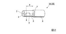
先ず、本発明の第1の実施形態として、例えば図1及び図2に示す無線電力伝送装置100について説明する。なお、図1は、無線電力伝送装置100の構成を示す平面図である。図2は、図1に示す無線電力伝送装置100で用いられる漏洩同軸ケーブル(以下、LCXという。)1Aの一構成例を示す斜視図である。(Wireless power transmission equipment)
[First Embodiment]
First, as a first embodiment of the present invention, for example, a wireless
図1に示す無線電力伝送装置100は、無線電力伝送機能と無線通信機能とを併せ持つものであり、電力伝送コイル101を構成するループ状のLCX1Aと、LCX1Aの一端に接続されるアクセスポイント(以下、APという。)102と、電力伝送コイル101に高周波電力を供給する電力伝送回路103とを備えている。 A wireless
LCX1Aは、図2に示すように、線状の中心導体2と、中心導体2を同心円状に被覆する絶縁体3と、絶縁体3を同心円状に被覆すると共に、このLCX1Aの延長方向に周期的に並ぶ複数のスロット4が開口して設けられた外部導体5と、外部導体5を同心円状に被覆するシース6とを有している。 As shown in FIG. 2, the LCX 1A includes a
中心導体2及び外部導体5には、伝送損失を低く抑えるために電気抵抗の低い銅が一般的に用いられているが、アルミニウムや銀などが用いられることもある。絶縁体3には、高周波帯域での伝送損失の低減を目的に誘電体損失(tanδ)の低いポリエチレンが用いられている。或いは、tanδよりも低くするために、内部に細かな気泡を含む発砲性のポリエチレンが絶縁体3として用いられてもよい。シース6には、一般的にはポリエチレンや塩化ビニルが用いられている。また、防災上の要求から、シース6に難燃性のポリエチレンなどが用いられたり、燃焼しても中心導体2と外部導体5とが直ちに短絡しないように、絶縁体3の周囲にガラス繊維製のテープを巻き付けられたりしてもよい。 For the
複数のスロット4は、LCX1Aの延長方向において一定のピッチPで直線状に並んで配置されると共に、それぞれが同じ方向に向かって開口している。スロット4の形状については、特に限定されるものではなく、例えば丸孔であっても長孔でもよい。本実施形態では、ジグザグ型のスロット4として、延長方向に対して所定の角度γで斜めとなる長孔が、その斜めとなる向きを交互に変えながら並んで配置されている。また、垂直型のスロット4として、LCX1Aの延長方向に対して垂直となる長孔が並んで配置された構成(図示せず。)としてもよい。 The plurality of slots 4 are arranged in a straight line at a constant pitch P in the extending direction of the
LCX1Aの一端には、図1に示すように、AP102のアンテナ端子に接続するためのコネクタ7が取り付けられている。一方、LCX1Aの他端には、終端抵抗8が取り付けられている。なお、本実施形態では、コネクタ7及び終端抵抗8にSMA型を用いている。 A
LCX1Aは、コネクタ7を介してAP102と接続されることで、無線LAN用の通信アンテナ(ケーブル型アンテナ)として機能する。なお、LCX1Aのコネクタ7とAP102のアンテナ端子との間は、直接接続された構成に限らず、接続用ケーブル(同軸ケーブル)を介して接続された構成としてもよい。 The
なお、本実施形態では、無線LANの規格の一つであるWi−Fiの周波数帯域として、2.4GHz帯又は5.2GHz帯を用いる。この場合、LCX1Aには、直径約2mmの銅線からなる中心導体2と、比誘電率1.5、厚さ約2mmの発泡性ポリエチレン製の絶縁体3と、厚さ約0.01mmの銅箔からなる外部導体5と、厚さ約0.5mmのポリエチレン製のシース6とが用いられる。また、LCX1Aの特性インピーダンスは50Ωである。スロット4は、長孔のサイズが長さ12mm、幅2mmであり、LCX1Aの延長方向に対する傾斜角度(γ)が30°であり、隣り合うスロット4同士のピッチ(P)が80mmである。 In the present embodiment, the 2.4 GHz band or the 5.2 GHz band is used as the Wi-Fi frequency band, which is one of the wireless LAN standards. In this case, the
AP102は、図示を省略するものの、通信ケーブルを介して上位回線に接続されている。また、AP102は、通信ケーブルを介してハブ(HUB)又はルータに接続され、更にハブ又はルータから上位回線に接続された構成としてもよい。 Although not shown, the
電力伝送コイル101は、ループ状としたLCX1Aの外部導体5に電力伝送回路103が接続されることによって、無線電力伝送装置100の送電コイルとして機能する。すなわち、電力伝送コイル101は、LCX1Aの外部導体5をループ状とすることにより構成されている。なお、電力伝送コイル101の巻き数については、一巻であってもよく、複数巻きであってもよい。また、電力伝送コイル101の平面視形状については、円形状、楕円形状、矩形状などであってもよい。 The
LCX1Aを一巻きとした場合は、電力伝送コイル101の小型化及び軽量化が容易となる。一方、LCX1Aを複数巻とした場合は、電力伝送コイル(送電コイル)101と受電コイルとの間の電磁結合が強化されるため、効果的に電力伝送することができる。 When the
また、LCX1Aを一巻きとする場合は、ループ状としたLCX1Aを交差させる構成に限らず、ループ状としたLCX1Aを交差させない構成としてもよい。一方、LCX1Aを複数巻とする場合は、同心円の渦巻状に巻回させる構成や、螺旋状に巻回させる構成としてもよい。 Further, when the
無線電力伝送装置100は、例えば受電コイルを備えた携帯電話機等の外部機器(図示せず。)に対して無線電力伝送を行う。無線電力伝送方式としては、例えば、電磁誘導を利用した電磁誘導方式や、電磁界の共鳴現象を利用した電磁界共鳴方式などを用いることができる。 The wireless
電磁誘導方式では、送電側の外部電源(商用電源等)ACから供給された交流電力(50Hz又は60Hz)を整流回路で直流電力に変換し、その直流電力を高周波電源回路で高周波電力に変換した後、その高周波電力を電力伝送コイル101に供給して高周波の電磁界(数kHz〜数百kHz)を発生させる。 In the electromagnetic induction system, AC power (50 Hz or 60 Hz) supplied from an external power source (commercial power source, etc.) AC on the power transmission side is converted to DC power by a rectifier circuit, and the DC power is converted to high frequency power by a high frequency power circuit. Thereafter, the high-frequency power is supplied to the
一方、電磁界共鳴方式では、上述した高周波電源回路から電力伝送コイル101に供給された高周波電力により1次側共振器を駆動して、高周波の電磁界(数MHz〜数十MHz)を発生させる。一方、受電側の外部機器では、その高周波の電磁界を2次側共振器で受けて、電磁結合された受電コイルへと導き、受電コイルに高周波電力が誘起される。 On the other hand, in the electromagnetic field resonance method, the primary side resonator is driven by the high frequency power supplied to the
電磁界共鳴方式では、数十MHz程度の磁界が使用され、5m程度の伝送距離を実現することが可能である。一方、電磁誘導方式では、数百kHz以下の磁界が使用され、伝送距離は10cm以下である。 In the electromagnetic resonance method, a magnetic field of about several tens of MHz is used, and a transmission distance of about 5 m can be realized. On the other hand, in the electromagnetic induction method, a magnetic field of several hundred kHz or less is used, and the transmission distance is 10 cm or less.
電力伝送回路103は、上述した電力伝送コイル101と電気的に接続されている。また、電力伝送回路103は、上述した送電側の外部電源ACと電力伝送コイル101との間で、整流回路や、高周波電源回路、共振器等を含む送電側回路を構成している。 The
無線電力伝送装置100では、電力伝送回路103からLCX1Aの外部導体5に供給された電力によって、電力伝送コイル101に高周波の電磁界を発生させることができ、上述した電磁誘導方式や電磁界共鳴方式を用いた無線電力伝送が可能となっている。 The wireless
以上のように、本実施形態の無線電力伝送装置100では、電力伝送コイル101を構成するループ状のLCX1Aの外部導体5に電力伝送回路103から高周波電力が供給されることによって電磁界が発生する。一方、AP102からのデータ信号がLCX1Aに供給されることによって、LCX1Aのスロット4からデータ信号の電波が放射される。これにより、電力伝送機能と情報伝送機能とを併せ持った無線電力伝送装置100を安価に提供することが可能である。 As described above, in the wireless
なお、本発明は、上記第1の実施形態のものに必ずしも限定されるものではなく、本発明の趣旨を逸脱しない範囲において種々の変更を加えることが可能である。以下、上記無線電力伝送装置100の第1の変形例〜第6の変形例について説明する。 The present invention is not necessarily limited to that of the first embodiment, and various modifications can be made without departing from the spirit of the present invention. Hereinafter, first to sixth modifications of the wireless
(第1の変形例)
無線電力伝送装置100では、第1の変形例として、例えば図3及び図4に示すような保持具50Aを備えた構成としてもよい。なお、図3は、無線電力伝送装置100の第1の変型例を示す平面図である。図4は、図3に示す無線電力伝送装置100の要部を拡大して示す断面図である。(First modification)
In the wireless
保持具50Aは、図3及び図4に示すように、電力伝送コイル101を構成するLCX1Aをループ状の状態で保持している。具体的に、この保持具50Aは、ループ状に一巻きしたLCX1Aの交差部分を保持する絶縁性の樹脂部材からなる。また、保持具50Aは、ループ状としたLCX1A(電力伝送コイル101)の外部導体5と電力伝送回路103との間を電気的に接続するコネクタ51を有している。電力伝送回路103は、このコネクタ51を介して電力伝送コイル101に高周波電力を供給することが可能となっている。 As shown in FIGS. 3 and 4, the holder 50 </ b> A holds the
以上のように、無線電力伝送装置100では、保持具50Aを用いることによって、電力伝送コイル101を構成するループ状のLCX1Aを安定的に保持した状態で、安価に無線電力伝送と無線通信とを行うことが可能である。 As described above, in the wireless
(第2の変形例)
無線電力伝送装置100では、第2の変形例として、例えば図5及び図6に示すような保持具50Bを備えた構成としてもよい。なお、図5は、無線電力伝送装置100の第2の変型例を示す平面図である。図6は、図5に示す無線電力伝送装置100の要部を拡大して示す断面図である。(Second modification)
In the wireless
保持具50Bは、図5及び図6に示すように、電力伝送コイル101を構成するLCX1Aをループ状の状態で保持している。具体的に、この保持具50Bは、絶縁性樹脂からなる十字状のバンド部材52からなる。バンド部材52のそれぞれの先端には、電力伝送コイル101を構成するループ状のLCX1Aを把持する把持部53が設けられている。 As shown in FIGS. 5 and 6, the holder 50 </ b> B holds the
把持部53は、LCX1Aをクランプする構造(クランプ構造)を有し、LCX1Aを着脱自在に把持している。保持具50Bは、LCX1Aの交差部分を含む4箇所を把持部53で把持することによって、電力伝送コイル101を構成するLCX1Aをループ状の状態で保持している。なお、クランプ構造については、LCX1Aを着脱自在に把持する構造であればよく、従来より公知の構造を採用することができる。 The
保持具50Bは、図示を省略するものの、4箇所の把持部53のうち、LCX1Aの交差部分を把持する把持部53に、上記保持具50Aと同様のコネクタ51を有している。電力伝送回路103は、このコネクタ51を介して電力伝送コイル101に高周波電力を供給することが可能となっている。 Although not shown in the figure, the
以上のように、無線電力伝送装置100では、保持具50Bを用いることによって、電力伝送コイル101を構成するループ状のLCX1Aを安定的に保持した状態で、安価に無線電力伝送と無線通信とを行うことが可能である。 As described above, in the wireless
(第3の変形例)
無線電力伝送装置100では、第3の変形例として、例えば図7及び図8に示すような保持具50Cを備えた構成としてもよい。なお、図6は、無線電力伝送装置100の第2の変型例を示す平面図である。図7は、図6に示す無線電力伝送装置100の要部を拡大して示す断面図である。(Third Modification)
In the wireless
保持具50Cは、図7及び図8に示すように、電力伝送コイル101を構成するLCX1Aをループ状の状態で保持している。具体的に、この保持具50Cは、絶縁性樹脂からなる矩形状(正方形状)のシート部材54からなる。シート部材54の4辺の中央部には、電力伝送コイル101を構成するループ状のLCX1Aを把持する把持部53が設けられている。 As shown in FIGS. 7 and 8, the
把持部53は、LCX1Aをクランプする構造(クランプ構造)を有し、LCX1Aを着脱自在に把持している。また、シート部材54には、ループ状に一巻きしたLCX1Aが嵌合されるリング状の溝部55が設けられている。保持具50Cは、LCX1Aの交差部分を含む4箇所を把持部53で把持することによって、電力伝送コイル101を構成するLCX1Aをループ状の状態で保持している。 The
保持具50Cは、図示を省略するものの、4箇所の把持部53のうち、LCX1Aの交差部分を把持する把持部53に、上記保持具50Aと同様のコネクタ51を有している。電力伝送回路103は、このコネクタ51を介して電力伝送コイル101に高周波電力を供給することが可能となっている。 Although not shown in the figure, the
以上のように、無線電力伝送装置100では、保持具50Cを用いることによって、電力伝送コイル101を構成するループ状のLCX1Aを安定的に保持した状態で、安価に無線電力伝送と無線通信とを行うことが可能である。 As described above, in the wireless
(第4の変形例)
無線電力伝送装置100では、第4の変形例として、例えば図9及び図10に示すような保持具50Dを備えた構成としてもよい。なお、図9は、無線電力伝送装置100の第4の変型例を示す平面図である。図10は、図9に示す無線電力伝送装置100の要部を拡大して示す断面図である。(Fourth modification)
In the wireless
保持具50Dは、図9及び図10に示すように、電力伝送コイル101を構成するLCX1Aをループ状の状態で保持している。具体的に、この保持具50Dは、上記保持具50Cと同様の構成を有している。すなわち、この保持具50Dは、絶縁性樹脂からなる矩形状(正方形状)のシート部材54からなる。シート部材54の4辺の中央部には、電力伝送コイル101を把持する把持部53が設けられている。 As shown in FIGS. 9 and 10, the
把持部53は、LCX1Aをクランプする構造(クランプ構造)を有し、LCX1Aを着脱自在に把持している。また、シート部材54には、ループ状に一巻きしたLCX1Aが嵌合されるリング状の溝部55が設けられている。保持具50Dは、LCX1Aの交差部分を含む4箇所を把持部53で把持することによって、電力伝送コイル101を構成するLCX1Aをループ状の状態で保持している。 The
さらに、把持部53は、LCX1Aに設けられた凸部9が嵌合される凹部56を有している。凸部9は、LCX1Aのスロット4の位置を示す標識となるものであり、シース6のスロット4と対向する外周面において、LCX1Aの延長方向に直線状に突出形成されている。凸部9は、シース6を押出成形する際に、所望の成型金型を用いることで形成可能である。 Further, the gripping
凹部56は、把持部53の内周面において、把持部53の長さ方向に直線状に切り欠き形成されている。保持具50Dでは、LCX1Aの凸部9を把持部53の凹部56に嵌合することによって、スロット4の向きをシート部材54とは反対側に向けた状態とすることが可能である。 The
保持具50Dは、図示を省略するものの、4箇所の把持部53のうち、LCX1Aの交差部分を把持する把持部53に、上記保持具50Aと同様のコネクタ51を有している。電力伝送回路103は、このコネクタ51を介して電力伝送コイル101に高周波電力を供給することが可能となっている。 Although not shown, the
以上のように、無線電力伝送装置100では、保持具50Dを用いることによって、電力伝送コイル101を構成するループ状のLCX1Aを安定的に保持した状態で、安価に無線電力伝送と無線通信とを行うことが可能である。 As described above, in the wireless
(第5の変形例)
無線電力伝送装置100では、第5の変形例として、例えば図11に示すような避雷器60を備えた構成としてもよい。なお、図11は、無線電力伝送装置100の第5の変型例を示す平面図である。(Fifth modification)
In the wireless
図11に示す無線電力伝送装置100は、上記図3に示す構成に加えて、LCX1Aの一端に設けられたコネクタ7とAP102との間に避雷器60を配置した構成を有している。避雷器60では、LCX1Aに大電流(サージ電流など。)Iが流れた際に、接地(アース)GNDに大電流Iが流れるようにする。 11 has a configuration in which a
これにより、大電流IがAP102側へと流れることを防ぐことが可能である。すなわち、本実施形態の無線電力伝送装置100では、外部機器に対して無線電力伝送を行うため、LCX1Aの外部導体5に電力伝送回路103を介して高周波電流が供給される。このとき、AP102の接地部分に過電流が流れ、AP102に悪影響を及ぶ可能性がある。これに対して、上述した避雷器60を配置することによって、AP102を保護することが可能である。 Thereby, it is possible to prevent the large current I from flowing to the
なお、送電対象となる外部機器として、スマートフォンやノートパソコンなどの小型の電子機器に対して無線電力伝送を行う場合、LCX1Aの外部導体5に供給される電力は数W〜数十W(例えば5〜15W)程度であり、上述したAP102に悪影響を及ぶ可能性は低いと考えられる。一方、より大きな電力を伝送する場合は、LCX1Aの外部導体5からAP102側へと大電流Iが流れる可能性があるため、上述した避雷器60を配置することが有効となる。 When wireless power transmission is performed as an external device to be transmitted to a small electronic device such as a smartphone or a laptop computer, the power supplied to the
(第6の変形例)
無線電力伝送装置100では、第6の変形例として、例えば図12及び図13(a),(b)に示すような保持具50Eと、コネクタ51Aとを備えた構成としてもよい。なお、図12は、無線電力伝送装置100の第6の変型例を示す平面図である。図13(a)は、図12に示す無線電力伝送装置100の要部を拡大して示す平面図、図13(b)は、図12に示す無線電力伝送装置100の要部を拡大して示す断面図である。(Sixth Modification)
In the wireless
保持具50Eは、図12に示すように、電力伝送コイル101を構成するLCX1Aをループ状の状態で保持している。具体的に、この保持具50Eは、絶縁性樹脂からなるX字状のバンド部材52Aからなる。バンド部材52Aのそれぞれの先端には、電力伝送コイル101を構成するループ状のLCX1Aを把持する把持部53が設けられている。 As shown in FIG. 12, the
把持部53は、LCX1Aをクランプする構造(クランプ構造)を有し、LCX1Aを着脱自在に把持している。保持具50Eは、交差させずにループ状に一巻きしたLCX1Aの括れ部分を除く4箇所を把持部53で把持することによって、電力伝送コイル101を構成するLCX1Aをループ状の状態で保持している。なお、クランプ構造については、LCX1Aを着脱自在に把持する構造であればよく、従来より公知の構造を採用することができる。 The
コネクタ51Aは、図13に示すように、交差させずにループ状としたLCX1Aの括れ部分を保持する絶縁性の樹脂部材からなる。また、コネクタ51Aは、電力伝送回路103と一体に成形されている。LCX1Aの括れ部分では、シース6を剥離することによって、外部導体5が露出した状態となっている。一方、コネクタ51Aは、外部導体5と接触する部分に配置された一対の導体57によって、LCX1Aの一端側及び他端側の外部導体5と電力伝送回路103との間を電気的に接続している。電力伝送回路103は、この導体57を介して電力伝送コイル101に高周波電力を供給することが可能となっている。 As shown in FIG. 13, the
以上のように、無線電力伝送装置100では、保持具50E及びコネクタ50Aを用いることによって、電力伝送コイル101を構成するループ状のLCX1Aを安定的に保持した状態で、安価に無線電力伝送と無線通信とを行うことが可能である。 As described above, in the wireless
(把持部の構造)
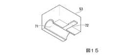
次に、上記コネクタ51を有する把持部53の具体的な構造について、図14及び図15を参照して説明する。なお、図14は、LCX1Aの交差部分を把持する把持部53を示す断面図である。図15は、図14中に示す把持部53を内側から見た斜視図である。(Grip structure)
Next, a specific structure of the
上記コネクタ51を有する把持部53は、図14に示すように、上述した複数の把持部53のうち、LCX1Aの交差部分を把持する把持部53である。図11に示す把持部53は、バンド部材52又はシート部材54を挟んだ両側に、電力伝送コイル101を構成するLCX1Aの一端側と他端側とを把持するようにそれぞれ設けられている。 As shown in FIG. 14, the
上記コネクタ51を有する把持部53は、図15に示すように、LCX1Aの一端側及び他端側の外部導体5と接触する内周面に導体71を有している。また、導体71と接続されたリード端子72が把持部53の外部へと引き出されている。上記コネクタ51は、このリード端子72と接続されることによって、電力伝送回路103との接続が可能となっている。 As shown in FIG. 15, the
一方、電力伝送コイル101を構成するLCX1Aの一端側及び他端側では、把持部53の導体71と接触する部分のシース6を剥離することによって、外部導体5が露出した状態となっている。これにより、LCX1Aの交差部分が把持部53に把持されたときに、LCX1Aの一端側及び他端側の外部導体5と導体71とを接続することが可能である。 On the other hand, at one end side and the other end side of the
なお、コネクタ51については、上述したLCX1Aの交差部分に配置される場合に限らず、この交差部分とLCX1Aのコネクタ7及び終端抵抗8との間に配置することが可能である。さらに、LCX1Aのコネクタ7及び終端抵抗8の外側から電力伝送回路103を接続する構成とすることも可能である。コネクタ7及び終端抵抗8は、外部導体5と電気的に接続されているため、これらコネクタ7及び終端抵抗8を介して電力伝送回路103からの高周波電力を電力伝送コイル101に供給することも可能である。 The
(無線電力伝送装置の使用例)
次に、上記図3に示す無線電力伝送装置100の使用形態の一例として、図16に示すように、テーブルTの上に置かれたスマートフォンなどの受電側の外部機器Kに対して、無線電力伝送と無線通信とを行う場合について説明する。なお、図16は、無線電力伝送装置100の使用例を示す模式図である。(Use example of wireless power transmission equipment)
Next, as an example of a usage pattern of the wireless
図16に示す無線電力伝送装置100の使用形態では、テーブルTの下に、電力伝送コイル101が配置されている。なお、電力伝送コイル101による送電可能な範囲は、送電方式にもよるが、電力伝送コイル101から数mm〜数百mm程度である。 In the usage pattern of the wireless
外部機器Kには、受電コイル(図示せず。)が設けられている。外部機器Kでは、電力伝送コイル101側で発生した高周波の電磁界が通過する範囲に受電コイルを配置することで、電磁誘導の原理によって電力伝送コイル(送電コイル)101と受電コイルとが電磁結合し、受電コイルに高周波電力Qが誘起される。この誘起された高周波電力Qは、必要に応じて整流回路により直流電力に変換されてバッテリ等に充電される、又は、外部機器Kの駆動等に直接利用される。 The external device K is provided with a power receiving coil (not shown). In the external device K, the power transmission coil (power transmission coil) 101 and the power reception coil are electromagnetically coupled by the principle of electromagnetic induction by arranging the power reception coil in a range through which the high-frequency electromagnetic field generated on the
また、外部機器Kには、電磁信号を受信可能なアンテナ(図示せず。)が設けられている。外部機器Kは、無線電力伝送装置100のLCX1Aから放射される電磁信号を送受信する通信エリアB内に位置することで、無線通信によるデータ伝送を行うことが可能である。 The external device K is provided with an antenna (not shown) that can receive electromagnetic signals. The external device K can perform data transmission by wireless communication by being located in the communication area B that transmits and receives electromagnetic signals radiated from the
なお、無線電力伝送装置100では、電磁界共鳴方式で無線電力伝送を行う場合、電力伝送コイル101と外部機器Kの受電コイルとの間に、中継コイル(図示せず。)を設けて電力Qの伝送距離を伸ばすことが可能である。 In the wireless
[第2の実施形態]
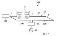
次に、本発明の第2の実施形態として、例えば図17に示す無線電力伝送装置200について説明する。なお、図17は、無線電力伝送装置200の構成を示す模式図である。[Second Embodiment]
Next, for example, a wireless
図17に示す無線電力伝送装置200は、無線電力伝送の機能と無線通信の機能とを併せ持つものであり、電力伝送線路201を構成する線状のLCX1Bと、LCX1Bの一端側に接続されるAP202と、電力伝送線路201に高周波電力を供給する電力伝送回路203と、電力伝送回路203と電力伝送線路201とを接続する電力線204a,204bとを備えている。 A wireless
LCX1Bには、第1の実施形態で説明したLCX1Aと同じものを用いることができる。LCX1Bの一端には、AP202のアンテナ端子に接続するためのコネクタ7が取り付けられている。一方、LCX1Bの他端には、終端抵抗8が取り付けられている。なお、本実施形態では、コネクタ7及び終端抵抗8にSMA型を用いている。LCX1Bは、コネクタ7を介してAP202と接続されることで、無線通信用のアンテナ(ケーブル型アンテナ)として機能する。 As LCX1B, the same LCX1A described in the first embodiment can be used. A
AP202は、図示を省略するものの、通信ケーブルを介して上位回線に接続されている。また、AP202は、通信ケーブルを介してハブ(HUB)又はルータに接続され、更にハブ又はルータから上位回線に接続された構成としてもよい。 Although not shown, the
無線電力伝送装置200では、電力伝送線路201を構成する線状のLCX1Bの一端側の外部導体5に第1の電力線204aの一端が接続され、LCX1Bの他端側の外部導体5に第2の電力線204bの一端が接続されている。また、第1の電力線204aの他端及び第2の電力線204bの他端が電力伝送回路203と接続されている。 In the wireless
さらに、無線電力伝送装置200では、LCX1Bと、第1の電力線204a及び第2の電力線204bとが互いに平行に並ぶ平行2線路を構成している。具体的に、この平行2線路では、同じ長さの第1の電力線204a及び第2の電力線204bがLCX1Bの中央部を挟んで対称に配置されている。また、LCX1Bとの間に一定の間隔を保持した状態で、第1の電力線204a及び第2の電力線204bの一部がLCX1Bと平行に並んで配置されている。 Furthermore, in the wireless
電力伝送回路203は、上述した電力伝送線路201と第1の電力線204a及び第2の電力線204bを介して電気的に接続されている。また、電力伝送回路203は、上述した電力伝送回路103と同様に、外部電源ACと第1の電力線204a及び第2の電力線204bとの間で、整流回路や、高周波電源回路、共振器等を含む送電側回路を構成している。 The
無線電力伝送装置200では、電力伝送回路203からLCX1Bの外部導体5に供給された電力によって、電力伝送線路201から高周波の電磁界を発生させることができる。無線電力伝送装置200は、上述した平行2線路に高周波電力を供給することによって、送電対象となる移動体Mに対して無線電力伝送を行う。無線電力伝送方式としては、上述した電磁誘導方式や電磁界共鳴方式などを用いることができる。 In the wireless
一方、送電対象となる移動体Mは、上記第1の実施形態で説明した外部機器Kと同様に、受電コイルと、整流回路や共振器等を含む受電側回路と、モータ等の駆動機構とを備えている。移動体Mでは、上述した電磁誘導方式や電磁界共鳴方式を用いて、送電側の電力伝送線路201からの高周波磁界を受けて、受電コイルに高周波電力が誘起される。これにより、移動体Mに対して無線電力伝送が行われる。平行2線路型の無線電力伝送の原理等については、例えば特開2014−236409号公報を参照することができる。 On the other hand, similarly to the external device K described in the first embodiment, the moving body M to be transmitted includes a power receiving coil, a power receiving side circuit including a rectifier circuit, a resonator, and the like, and a drive mechanism such as a motor. It has. In the moving body M, high-frequency power is induced in the power receiving coil by receiving the high-frequency magnetic field from the
移動体Mは、無線電力伝送により供給された電力によってモータを駆動し、LCX1Bが配置された方向に沿って移動することが可能である。また、移動体Mでは、AP202に接続されたLCX1Bの通信エリア内に位置することで、無線通信によるデータ伝送を行うことが可能である。 The moving body M can move along the direction in which the
以上のように、本実施形態の無線電力伝送装置200では、電力伝送線路201を構成する線状のLCX1Bの外部導体5に電力伝送回路203から高周波電力が供給されることによって電磁界が発生する。一方、AP202からのデータ信号がLCX1Bに供給されることによって、LCX1Bのスロット4からデータ信号の電波が放射される。これにより、電力伝送機能と情報伝送機能とを併せ持った無線電力伝送装置200を安価に構成することができる。 As described above, in the wireless
なお、本発明は、上記第2の実施形態のものに必ずしも限定されるものではなく、本発明の趣旨を逸脱しない範囲において種々の変更を加えることが可能である。以下、上記無線電力伝送装置200の第1の変形例について説明する。 The present invention is not necessarily limited to that of the second embodiment, and various modifications can be made without departing from the spirit of the present invention. Hereinafter, a first modification of the wireless
(第1の変形例)
無線電力伝送装置200では、第1の変形例として、例えば図18に示すような保持具50Fを備えた構成としてもよい。なお、図18は、無線電力伝送装置200の第1の変型例を示す平面図である。(First modification)
In the wireless
図18に示す無線電力伝送装置200では、LCX1Bと、第1の電力線204aよりも長い第2の電力線204bとが互いに平行に並ぶ平行2線路を構成している。具体的に、この平行2線路では、LCX1Bとの間に一定の間隔を保持した状態で、第2の電力線204bの一部がLCX1Bと平行に並んで配置されている。 In the wireless
保持具50Fは、LCX1B及び第2の電力線204bを把持する一対の把持部81a,81bと、一対の把持部81a,81bの間を連結する連結部82とを有している。保持具50Fは、電力伝送線路201及び第2の電力線204bの延長方向に沿って所定の間隔で複数並んで設けられている。 The
以上のように、無線電力伝送装置200では、保持具50Fを用いることによって、平行2線路を構成するLCX1B及び第2の電力線204bを安定的に保持した状態で、安価に無線電力伝送と無線通信とを行うことが可能である。 As described above, in the wireless
1A,1B…漏洩同軸ケーブル(LCX) 2…中心導体 3…絶縁体 4…スロット 5…外部導体 6…シース 7…コネクタ 8…終端抵抗 9…凸部 50A〜50F…保持具 51,51A…コネクタ 52,52A…バンド部材 53…把持部 54…シート部材 55…溝部 56…凹部 60…避雷器 71…導体 72…リード端子 81a,81b…把持部 82…連結部 100…無線電力伝送装置 101…電力伝送コイル 102…アクセスポイント(AP) 103…電力伝送回路 200…無線電力伝送装置 201…電力伝送線路 202…アクセスポイント(AP) 203…電力伝送回路 204a…第1の電力線 204b…第2の電力線 DESCRIPTION OF
Claims (8)
Translated fromJapanese前記漏洩同軸ケーブルの一端に接続されたアクセスポイントと、
前記漏洩同軸ケーブルの他端に接続された終端抵抗と、を備え、
前記ループ状に保持された漏洩同軸ケーブルの外部導体は電力伝送コイルを構成し、前記電力伝送コイルには電力伝送回路から高周波電力が供給されることを特徴とする無線電力伝送装置。A leaky coaxial cable held in a loop between one end and the other end;
An access point connected to one end of the leaky coaxial cable;
A termination resistor connected to the other end of the leaky coaxial cable,
The wireless power transmission device according to claim 1, wherein an outer conductor of the leaky coaxial cable held in a loop forms a power transmission coil, and high frequency power is supplied to the power transmission coil from a power transmission circuit.
前記漏洩同軸ケーブルの一端に接続されたアクセスポイントと、
前記漏洩同軸ケーブルの他端に接続された終端抵抗と、を備え、
前記漏洩同軸ケーブルの外部導体は電力伝送線路を構成し、前記電力線路には電力伝送回路から高周波電力が供給されることを特徴とする無線電力伝送装置。A leaky coaxial cable arranged linearly from one end to the other,
An access point connected to one end of the leaky coaxial cable;
A termination resistor connected to the other end of the leaky coaxial cable,
A wireless power transmission device, wherein an outer conductor of the leaky coaxial cable constitutes a power transmission line, and high frequency power is supplied to the power line from a power transmission circuit.
前記電力伝送線路と前記電力線の少なくとも一部とが平行に並んで配置されていることを特徴とする請求項4に記載の無線電力伝送装置。A power line for electrically connecting the power transmission circuit and the outer conductor;
The wireless power transmission device according to claim 4, wherein the power transmission line and at least a part of the power line are arranged in parallel.
前記保持具は、前記凸部と嵌合される凹部を有することを特徴とする請求項2又は6に記載の無線電力伝送装置。The leaky coaxial cable has a convex portion serving as a mark indicating the position of the slot,
The wireless power transmission device according to claim 2, wherein the holder has a concave portion fitted to the convex portion.
Priority Applications (1)
| Application Number | Priority Date | Filing Date | Title |
|---|---|---|---|
| JP2015155367AJP2017034935A (en) | 2015-08-05 | 2015-08-05 | Wireless power transmission device |
Applications Claiming Priority (1)
| Application Number | Priority Date | Filing Date | Title |
|---|---|---|---|
| JP2015155367AJP2017034935A (en) | 2015-08-05 | 2015-08-05 | Wireless power transmission device |
Publications (1)
| Publication Number | Publication Date |
|---|---|
| JP2017034935Atrue JP2017034935A (en) | 2017-02-09 |
Family
ID=57989181
Family Applications (1)
| Application Number | Title | Priority Date | Filing Date |
|---|---|---|---|
| JP2015155367APendingJP2017034935A (en) | 2015-08-05 | 2015-08-05 | Wireless power transmission device |
Country Status (1)
| Country | Link |
|---|---|
| JP (1) | JP2017034935A (en) |
Cited By (10)
| Publication number | Priority date | Publication date | Assignee | Title |
|---|---|---|---|---|
| KR20190072874A (en)* | 2017-12-18 | 2019-06-26 | 엘에스전선 주식회사 | Leakage Coaxial Cable And Feeding System Thereof |
| KR102071605B1 (en)* | 2019-09-05 | 2020-01-30 | 양영철 | Protective inductor for protecting damage of high altitude electromagentic pulse and protective inductor network system comprising thereof |
| JP2020526158A (en)* | 2017-06-23 | 2020-08-27 | エナージャス コーポレイション | System, method and device for utilizing wires of a sound producing device as an antenna for receiving power delivered wirelessly |
| US11462949B2 (en) | 2017-05-16 | 2022-10-04 | Wireless electrical Grid LAN, WiGL Inc | Wireless charging method and system |
| US11463179B2 (en) | 2019-02-06 | 2022-10-04 | Energous Corporation | Systems and methods of estimating optimal phases to use for individual antennas in an antenna array |
| US11502551B2 (en) | 2012-07-06 | 2022-11-15 | Energous Corporation | Wirelessly charging multiple wireless-power receivers using different subsets of an antenna array to focus energy at different locations |
| JP2023528912A (en)* | 2020-06-04 | 2023-07-06 | エーテラ テクノロジーズ リミティド | RF power supply with improved galvanic isolation |
| JP2024027448A (en)* | 2022-08-17 | 2024-03-01 | 横河電機株式会社 | Connector grounding structure |
| US12074460B2 (en) | 2017-05-16 | 2024-08-27 | Wireless Electrical Grid Lan, Wigl Inc. | Rechargeable wireless power bank and method of using |
| US12413097B2 (en) | 2021-12-29 | 2025-09-09 | Energous Corporation | Small form-factor devices with integrated and modular harvesting receivers, and shelving-mounted wireless-power transmitters for use therewith |
Citations (3)
| Publication number | Priority date | Publication date | Assignee | Title |
|---|---|---|---|---|
| US5157393A (en)* | 1989-02-28 | 1992-10-20 | Kabushiki Kaisha Toshiba | Communication system for transmitting data between a transmitting antenna utilizing leaky coaxial cable and a receive antenna in relative movement to one another |
| JP2011182380A (en)* | 2010-02-03 | 2011-09-15 | Hitachi Ltd | Low/high frequency shared leakage antenna, base station apparatus and close-range detection system using the antenna |
| JP2015080311A (en)* | 2013-10-16 | 2015-04-23 | 日立金属株式会社 | Composite cable, and coil for non-contact power reception and supply |
- 2015
- 2015-08-05JPJP2015155367Apatent/JP2017034935A/enactivePending
Patent Citations (3)
| Publication number | Priority date | Publication date | Assignee | Title |
|---|---|---|---|---|
| US5157393A (en)* | 1989-02-28 | 1992-10-20 | Kabushiki Kaisha Toshiba | Communication system for transmitting data between a transmitting antenna utilizing leaky coaxial cable and a receive antenna in relative movement to one another |
| JP2011182380A (en)* | 2010-02-03 | 2011-09-15 | Hitachi Ltd | Low/high frequency shared leakage antenna, base station apparatus and close-range detection system using the antenna |
| JP2015080311A (en)* | 2013-10-16 | 2015-04-23 | 日立金属株式会社 | Composite cable, and coil for non-contact power reception and supply |
Cited By (17)
| Publication number | Priority date | Publication date | Assignee | Title |
|---|---|---|---|---|
| US11502551B2 (en) | 2012-07-06 | 2022-11-15 | Energous Corporation | Wirelessly charging multiple wireless-power receivers using different subsets of an antenna array to focus energy at different locations |
| US12166363B2 (en) | 2012-07-06 | 2024-12-10 | Energous Corporation | System and methods of using electromagnetic waves to wirelessly deliver power to security cameras and adjusting wireless delivery of power to the security cameras as they move |
| US11462949B2 (en) | 2017-05-16 | 2022-10-04 | Wireless electrical Grid LAN, WiGL Inc | Wireless charging method and system |
| US12074460B2 (en) | 2017-05-16 | 2024-08-27 | Wireless Electrical Grid Lan, Wigl Inc. | Rechargeable wireless power bank and method of using |
| US11218795B2 (en) | 2017-06-23 | 2022-01-04 | Energous Corporation | Systems, methods, and devices for utilizing a wire of a sound-producing device as an antenna for receipt of wirelessly delivered power |
| JP2020526158A (en)* | 2017-06-23 | 2020-08-27 | エナージャス コーポレイション | System, method and device for utilizing wires of a sound producing device as an antenna for receiving power delivered wirelessly |
| KR20190072874A (en)* | 2017-12-18 | 2019-06-26 | 엘에스전선 주식회사 | Leakage Coaxial Cable And Feeding System Thereof |
| KR102480195B1 (en)* | 2017-12-18 | 2022-12-21 | 엘에스전선 주식회사 | Leakage Coaxial Cable And Feeding System Thereof |
| US11784726B2 (en) | 2019-02-06 | 2023-10-10 | Energous Corporation | Systems and methods of estimating optimal phases to use for individual antennas in an antenna array |
| US11463179B2 (en) | 2019-02-06 | 2022-10-04 | Energous Corporation | Systems and methods of estimating optimal phases to use for individual antennas in an antenna array |
| KR102071605B1 (en)* | 2019-09-05 | 2020-01-30 | 양영철 | Protective inductor for protecting damage of high altitude electromagentic pulse and protective inductor network system comprising thereof |
| JP2023528912A (en)* | 2020-06-04 | 2023-07-06 | エーテラ テクノロジーズ リミティド | RF power supply with improved galvanic isolation |
| JP7675108B2 (en) | 2020-06-04 | 2025-05-12 | エーテラ テクノロジーズ リミティド | RF power supply with improved galvanic isolation - Patents.com |
| IL298727B1 (en)* | 2020-06-04 | 2025-09-01 | Aethera Tech Limited | Rf power source with improved galvanic isolation |
| US12413097B2 (en) | 2021-12-29 | 2025-09-09 | Energous Corporation | Small form-factor devices with integrated and modular harvesting receivers, and shelving-mounted wireless-power transmitters for use therewith |
| JP2024027448A (en)* | 2022-08-17 | 2024-03-01 | 横河電機株式会社 | Connector grounding structure |
| JP7729286B2 (en) | 2022-08-17 | 2025-08-26 | 横河電機株式会社 | Connector grounding structure |
Similar Documents
| Publication | Publication Date | Title |
|---|---|---|
| JP2017034935A (en) | Wireless power transmission device | |
| CN103125082B (en) | For the device and method by dedicated radio link wireless coupling radio | |
| US9906076B2 (en) | Non-contact type power transmitting coil and non-contact type power supplying apparatus | |
| US20150097521A1 (en) | Antenna sheet for non-contact charging device and charging device using the antenna sheet | |
| US11282639B2 (en) | Antenna device and electronic apparatus | |
| US8917216B2 (en) | Antenna device with U-shaped slit | |
| EP3567673A1 (en) | Combination antenna | |
| JP6417474B2 (en) | Antenna device for short range applications and method of using such an antenna device | |
| EP3454415A1 (en) | Wireless device antenna | |
| CN105493344B (en) | Device and method for combined signal transmission or for combined signal and energy transmission | |
| US10148134B2 (en) | Wireless power reception device | |
| JP2016076645A (en) | Planar coil | |
| TWI539668B (en) | Antenna device and communication device | |
| KR20200076304A (en) | Wireless charging coil and wireless charging device | |
| WO2019175031A1 (en) | Wireless power supply equipment | |
| JP6293227B1 (en) | Cable type antenna and wireless communication device | |
| KR20200118993A (en) | Wireless charging coil and wireless charging device | |
| KR101751121B1 (en) | Conductive plate and portable terminal having the same | |
| CN204516878U (en) | Transmission line, transmitting device and phase shifiting device | |
| KR101584551B1 (en) | Reradiation antenna and wireless charger | |
| JPH1155024A (en) | Helical antenna | |
| JP4940842B2 (en) | Antenna device | |
| KR20200020315A (en) | Wireless charging coil and wireless charging device | |
| CN216903356U (en) | Ultra-wideband antenna | |
| WO2019025593A1 (en) | Antenna, transmitting device, receiving device and wireless communication system |
Legal Events
| Date | Code | Title | Description |
|---|---|---|---|
| A621 | Written request for application examination | Free format text:JAPANESE INTERMEDIATE CODE: A621 Effective date:20180620 | |
| RD03 | Notification of appointment of power of attorney | Free format text:JAPANESE INTERMEDIATE CODE: A7423 Effective date:20181019 | |
| A977 | Report on retrieval | Free format text:JAPANESE INTERMEDIATE CODE: A971007 Effective date:20190314 | |
| A131 | Notification of reasons for refusal | Free format text:JAPANESE INTERMEDIATE CODE: A131 Effective date:20190319 | |
| A02 | Decision of refusal | Free format text:JAPANESE INTERMEDIATE CODE: A02 Effective date:20191105 |