JP2017010161A - Control device for unmanned working machine - Google Patents
Control device for unmanned working machineDownload PDFInfo
- Publication number
- JP2017010161A JP2017010161AJP2015122959AJP2015122959AJP2017010161AJP 2017010161 AJP2017010161 AJP 2017010161AJP 2015122959 AJP2015122959 AJP 2015122959AJP 2015122959 AJP2015122959 AJP 2015122959AJP 2017010161 AJP2017010161 AJP 2017010161A
- Authority
- JP
- Japan
- Prior art keywords
- work
- control device
- work machine
- weather
- time
- Prior art date
- Legal status (The legal status is an assumption and is not a legal conclusion. Google has not performed a legal analysis and makes no representation as to the accuracy of the status listed.)
- Pending
Links
Images


Classifications
- G—PHYSICS
- G05—CONTROLLING; REGULATING
- G05D—SYSTEMS FOR CONTROLLING OR REGULATING NON-ELECTRIC VARIABLES
- G05D1/00—Control of position, course, altitude or attitude of land, water, air or space vehicles, e.g. using automatic pilots
- G05D1/02—Control of position or course in two dimensions
- G05D1/021—Control of position or course in two dimensions specially adapted to land vehicles
- G05D1/0259—Control of position or course in two dimensions specially adapted to land vehicles using magnetic or electromagnetic means
- G05D1/0265—Control of position or course in two dimensions specially adapted to land vehicles using magnetic or electromagnetic means using buried wires
- A—HUMAN NECESSITIES
- A01—AGRICULTURE; FORESTRY; ANIMAL HUSBANDRY; HUNTING; TRAPPING; FISHING
- A01B—SOIL WORKING IN AGRICULTURE OR FORESTRY; PARTS, DETAILS, OR ACCESSORIES OF AGRICULTURAL MACHINES OR IMPLEMENTS, IN GENERAL
- A01B69/00—Steering of agricultural machines or implements; Guiding agricultural machines or implements on a desired track
- A01B69/007—Steering or guiding of agricultural vehicles, e.g. steering of the tractor to keep the plough in the furrow
- A01B69/008—Steering or guiding of agricultural vehicles, e.g. steering of the tractor to keep the plough in the furrow automatic
- A—HUMAN NECESSITIES
- A01—AGRICULTURE; FORESTRY; ANIMAL HUSBANDRY; HUNTING; TRAPPING; FISHING
- A01D—HARVESTING; MOWING
- A01D34/00—Mowers; Mowing apparatus of harvesters
- A01D34/006—Control or measuring arrangements
- A01D34/008—Control or measuring arrangements for automated or remotely controlled operation
- A—HUMAN NECESSITIES
- A01—AGRICULTURE; FORESTRY; ANIMAL HUSBANDRY; HUNTING; TRAPPING; FISHING
- A01G—HORTICULTURE; CULTIVATION OF VEGETABLES, FLOWERS, RICE, FRUIT, VINES, HOPS OR SEAWEED; FORESTRY; WATERING
- A01G25/00—Watering gardens, fields, sports grounds or the like
- A01G25/09—Watering arrangements making use of movable installations on wheels or the like
- A—HUMAN NECESSITIES
- A01—AGRICULTURE; FORESTRY; ANIMAL HUSBANDRY; HUNTING; TRAPPING; FISHING
- A01G—HORTICULTURE; CULTIVATION OF VEGETABLES, FLOWERS, RICE, FRUIT, VINES, HOPS OR SEAWEED; FORESTRY; WATERING
- A01G25/00—Watering gardens, fields, sports grounds or the like
- A01G25/16—Control of watering
- G—PHYSICS
- G05—CONTROLLING; REGULATING
- G05D—SYSTEMS FOR CONTROLLING OR REGULATING NON-ELECTRIC VARIABLES
- G05D1/00—Control of position, course, altitude or attitude of land, water, air or space vehicles, e.g. using automatic pilots
- G05D1/0088—Control of position, course, altitude or attitude of land, water, air or space vehicles, e.g. using automatic pilots characterized by the autonomous decision making process, e.g. artificial intelligence, predefined behaviours
- G—PHYSICS
- G05—CONTROLLING; REGULATING
- G05D—SYSTEMS FOR CONTROLLING OR REGULATING NON-ELECTRIC VARIABLES
- G05D1/00—Control of position, course, altitude or attitude of land, water, air or space vehicles, e.g. using automatic pilots
- G05D1/02—Control of position or course in two dimensions
- G05D1/021—Control of position or course in two dimensions specially adapted to land vehicles
- G05D1/0276—Control of position or course in two dimensions specially adapted to land vehicles using signals provided by a source external to the vehicle
Landscapes
- Engineering & Computer Science (AREA)
- Life Sciences & Earth Sciences (AREA)
- Environmental Sciences (AREA)
- Physics & Mathematics (AREA)
- General Physics & Mathematics (AREA)
- Automation & Control Theory (AREA)
- Aviation & Aerospace Engineering (AREA)
- Radar, Positioning & Navigation (AREA)
- Remote Sensing (AREA)
- Water Supply & Treatment (AREA)
- Electromagnetism (AREA)
- Soil Sciences (AREA)
- Mechanical Engineering (AREA)
- Business, Economics & Management (AREA)
- Health & Medical Sciences (AREA)
- Artificial Intelligence (AREA)
- Evolutionary Computation (AREA)
- Game Theory and Decision Science (AREA)
- Medical Informatics (AREA)
- Harvester Elements (AREA)
- Control Of Position, Course, Altitude, Or Attitude Of Moving Bodies (AREA)
Abstract
Description
Translated fromJapanese本発明は、屋外において無人で動作可能な無人作業機の制御装置に関する。 The present invention relates to a control device for an unmanned work machine that can be operated unattended outdoors.
従来より、所定の作業領域を走行して芝刈りなどの作業を行う無人作業機の制御装置が知られている(例えば特許文献1参照)。この特許文献1記載の装置は、作業機に設けられた雨水感測器により現在の気象が降雨状態であるか否かを検知し、降雨状態を検知すると、作業機の作業を中止して作業機を駐車位置に戻す。 2. Description of the Related Art Conventionally, there is known a control device for an unmanned work machine that travels in a predetermined work area and performs work such as lawn mowing (for example, see Patent Document 1). The device described in
しかしながら、上記特許文献1記載の装置は、作業機に雨水感測器を設けて現在の降雨状態を検知するため、作業機に防水構造が必要となり、構成が複雑になってコストの上昇を招く。 However, since the apparatus described in
本発明の一態様は、屋外において無人で動作可能な無人作業機の制御装置であって、作業機に設けられた作業用のアクチュエータと、予め作業機のタイムスケジュールを設定する設定手段と、作業地点またはその近傍における現在および未来の気象情報を取得する情報取得手段と、情報取得手段により取得された気象情報に基づいてタイムスケジュールを修正する修正手段と、修正手段により修正されたタイムスケジュールに従い作業機が作業を行うようにアクチュエータを制御するアクチュエータ制御手段とを備えることを特徴とする。 One aspect of the present invention is a control device for an unmanned work machine that can be operated unattended outdoors, an operation actuator provided in the work machine, a setting unit that sets a time schedule of the work machine in advance, Information acquisition means for acquiring current and future weather information at or near a point, correction means for correcting a time schedule based on weather information acquired by the information acquisition means, and work according to the time schedule corrected by the correction means And an actuator control means for controlling the actuator so that the machine performs work.
本発明によれば、気象情報に基づいて作業機のタイムスケジュールを修正し、修正後のタイムスケジュールに従い作業用のアクチュエータを制御するので、雨水を検知するセンサ等が不要であり、簡易かつ安価な構成により気象条件を考慮して作業を行うことができる。 According to the present invention, the time schedule of the work implement is corrected based on the weather information, and the working actuator is controlled according to the corrected time schedule. Therefore, a sensor or the like for detecting rainwater is unnecessary, and it is simple and inexpensive. Work can be done in consideration of weather conditions depending on the configuration.
−第1の実施形態−
以下、図1〜図6を参照して本発明の第1の実施形態について説明する。図1は、本発明の第1の実施形態に係る無人作業機の制御装置の概略構成を示す図である。本発明の制御装置は、屋外において無人で動作可能な種々の無人作業機(以下、単に作業機と呼ぶ場合もある)に適用することができるが、第1の実施形態では、特に自律走行しながら芝刈り作業を行う移動式芝刈り機1に適用する。-First embodiment-
Hereinafter, a first embodiment of the present invention will be described with reference to FIGS. FIG. 1 is a diagram illustrating a schematic configuration of a control device for an unmanned work machine according to a first embodiment of the present invention. The control device of the present invention can be applied to various unmanned work machines that can operate unattended outdoors (hereinafter may be simply referred to as work machines). However, in the first embodiment, the control apparatus is particularly autonomous. The present invention is applied to the
図1に示すように、芝刈り機1には、中継装置3が通信可能に接続され、中継装置3には、サーバ装置4が通信可能に接続される。芝刈り機1は敷地内の庭に、中継装置3は同一の敷地内の建物にそれぞれ配置され、両者は無線LAN等を介して通信可能である。中継装置3とサーバ装置4とは、インターネット等の通信ネットワークを介して通信可能である。中継装置3は、パーソナルコンピュータや携帯電話端末等により構成することができる。中継装置3は基地局として機能し、中継装置3を介してサーバ装置4と芝刈り機1との間で各種データや制御信号等を含む信号を送受信することができる。 As shown in FIG. 1, a relay device 3 is communicably connected to the
芝刈り機1は、通信ユニット11と、ECU12と、作業用アクチュエータ13と、走行用アクチュエータ14とを有し、予め定められた作業領域内を自律走行可能に構成される。以下、移動式芝刈り機1の構成についてより具体的に説明する。 The
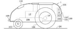
図2は、芝刈り機1の要部構成を示す側面図である。図2に示すように、芝刈り機1は、シャシ101とフレーム102とを有する車体100と、車体100を接地面GRから走行可能に支持する左右一対の前輪103および左右一対の後輪104とを備える。シャシ101とフレーム102とで包囲された芝刈り機1の内部空間105には、通信ユニット11と、ECU12と、作業装置106と、作業装置駆動用の作業用アクチュエータ13(作業モータ)と、後輪駆動用の走行用アクチュエータ14(走行モータ)と、充電ユニット107と、バッテリ108とが配置される。ECU12は、CPU,ROM,RAM、その他の周辺回路などを有する演算処理装置を含んで構成される。 FIG. 2 is a side view showing the main configuration of the
通信ユニット11は、送受信アンテナと、送受信アンテナを介して送受信した信号を処理する信号処理回路とを含み、ECU12は、通信ユニット11を介して中継装置3と通信することができる。作業装置106は、回転可能な芝刈り用のブレードを有する。作業装置106は、ブレードの中央に設けられた回転軸を上下方向に向けて配置され、作業用アクチュエータ13によりブレードが回転する。作業用アクチュエータ13は、電動モータにより構成される。走行用アクチュエータ14は、左右の後輪104の左右内側に配置された一対の電動モータにより構成される。走行用アクチュエータ14の出力軸は、左右の後輪104の回転軸にそれぞれ連結され、走行用アクチュエータ14は、左右の後輪104を互いに独立に回転駆動する。左右の後輪104の回転に速度差を生じさせることで、芝刈り機1は任意の方向に旋回することができる。 The
充電ユニット107は、フレーム102の前端部に設けられた端子109に配線を介して接続されるとともに、バッテリ108に配線を介して接続される。バッテリ108は、端子109が接点を介して充電ステーション6(図3参照)に接続することで、充電される。バッテリ108は、配線を介して作業用アクチュエータ13と走行用アクチュエータ14とに接続され、各アクチュエータ13,14は、バッテリ108から供給される電力により駆動する。芝刈り機1の前部には、互いに左右方向に離間した一対の磁気センサ110が配置される(図3参照)。磁気センサ110は、磁界の大きさ(磁界強度)を示す信号を出力する。 The
なお、図示は省略するが、芝刈り機1には、さらにYawセンサ、Gセンサ、方位センサ、接触センサ、車輪速センサ、および電圧センサ等が設けられる。Yawセンサは、芝刈り機1の高さ方向の軸線(Z軸)回りに生じる角速度(ヨーレート)を示す信号を出力する。Gセンサは、芝刈り機1に作用する直交3軸(X軸、Y軸、Z軸)方向の加速度を示す信号を出力する。方位センサ(地磁気センサ)は、地磁気に応じた信号を出力する。接触センサは、芝刈り機1が障害物等に接近または接触するとオン信号を出力する。車輪速センサは、左右の後輪104の車輪速を示す信号をそれぞれ出力する。電圧センサは、バッテリ108の残電圧を示す信号を出力する。 Although not shown, the
以上のように構成された芝刈り機1は、予め定められた作業領域内を自律走行して作業を行う。図3は、作業領域ARの一例を示す平面図である。作業領域ARは、例えば予め庭に敷設(例えば接地面GRから所定深さに埋設)されたエリアワイヤ7によって画定され、エリアワイヤ7により芝刈り機1の走行範囲が規定される。エリアワイヤ7には電流が流され、これにより作業領域ARに磁界が発生する。作業領域ARの磁界強度は、磁気センサ110により検出される。 The
磁界強度は、エリアワイヤ7からの距離に応じて変化する。ECU12は、磁気センサ110からの信号により、芝刈り機1がエリアワイヤ7に到達したか否かを判定する。そして、エリアワイヤ7に到達したと判定すると、走行用アクチュエータ14に制御信号を出力し、図3の矢印に示すように、芝刈り機1を作業領域ARの内側に向けて旋回させる。このようにECU12は、磁気センサ110からの信号に応じて走行用アクチュエータ14に制御信号を出力し、これにより芝刈り機1が作業領域AR内を自律走行する。このときECU12は、作業用アクチュエータ13にも制御信号を出力し、作業領域AR内で芝刈り作業を行わせる。 The magnetic field strength changes according to the distance from the
エリアワイヤ7上には、バッテリ108を充電するための充電ステーション6が配置される。作業時に、電圧センサによってバッテリ108の電圧不足が検出されると、ECU12は、走行用アクチュエータ14に制御信号を出力し、例えばエリアワイヤ7に沿って芝刈り機1を充電ステーション6まで帰還させ、バッテリ108を充電する。バッテリ108の充電が完了すると、ECU12は、走行用アクチュエータ14に制御信号を出力して芝刈り機1を充電ステーション6から離脱させ、その後、作業用アクチュエータ13を駆動して作業を再開する。ECU12は、作業終了後にも芝刈り機1を充電ステーション6まで帰還させ、作業を開始するまで充電ステーション6で待機させる。充電ステーション6には、充電ステーション6に位置する芝刈り機1を雨風等から防護するためのカバーが設けられる。なお、充電ステーション6が配置された領域にカバーを設けて雨風等から芝刈り機1を防護してもよい。 A charging
中継装置3には、予め芝刈り機1の作業工程を表すタイムスケジュールが設定され、芝刈り機1は、中継装置3からの指令により作業を開始および作業を終了する。すなわち、中継装置3はタイマを有し、タイムスケジュールの作業開始時刻になると、通信ユニットを介して芝刈り機1に作業開始指令を送信し、その後、作業終了時刻になると、作業終了指令を送信する。ECU12は、作業開始指令を受信すると芝刈り作業を開始し、作業終了指令を受信すると芝刈り作業を終了するようアクチュエータ13,14を制御する。これにより、予めユーザがタイムスケジュースを設定しておくだけで、所望の時刻になると、芝刈り機1に無人で作業を行わせることができる。 The relay apparatus 3 is set in advance with a time schedule representing the work process of the
ところで、芝刈り機1は屋外で作業を行うが、機器の損傷を防ぐとともに効率的に作業を行うという観点から、降雨時の芝刈り作業は避けることが好ましい。この点、例えば芝刈り機1に降雨状態を検出するセンサを設け、降雨検出時に作業を終了するように構成すると、芝刈り機1には、ECU12やセンサの周りに、降雨に耐えうる防水構造が必要となる。このため、芝刈り機1の構成が複雑となり、コストが上昇する。一方、ユーザが気象情報を随時確認し、ユーザからの指令によりタイムスケジュールを設定し直す構成は、ユーザにとって煩雑である。そこで、本実施形態では、降雨状態を検出するセンサ等を設けることなく、かつ、タイムスケジュールを設定し直すユーザの手間を省きながら、気象の変化に対応した適切な作業を作業機(芝刈り機1)に行わせるようにするため、以下のように無人作業機の制御装置を構成する。 By the way, although the
図1に示すように、中継装置3は、通信ユニット31と、ECU32と、タイマ33と、入力部34と、表示部35とを有する。通信ユニット31は、無線LAN等の通信方法を介して芝刈り機1と通信可能に接続する通信部と、光通信路等によるインターネット通信を介してサーバ装置4と通信可能に接続する通信部とを含む。ECU32は、CPU,ROM,RAM、その他の周辺回路などを有する演算処理装置を含んで構成される。入力部34は、キーボード、マウス、タッチパネル等の操作部を含み、入力部34を介して中継装置3に各種情報を入力することができる。表示部35は、各種情報を表示可能なディスプレイを含む。 As shown in FIG. 1, the relay device 3 includes a
サーバ装置4は、地域毎の気象情報を格納する気象情報サーバ41と、作業機1の作業データを格納する作業データサーバ42とを有する。気象情報サーバ41は、現在および未来の気象情報、具体的には、現在から所定時間先までの所定時間毎の気象情報を格納する。気象情報サーバ41に格納される気象情報は、降水確率、気温、湿度、日の出時刻、日の入り時刻、風速等を含み、これらの気象情報は所定時間毎(例えば5分毎)に更新される。 The
図4は、気象情報サーバ41に格納される気象情報の一例である。図4は降水確率(%)のデータを示す。現在は月曜日の午前0時であり、気象情報サーバ41には、図4に示すように所定地域における1時間毎の1週間分(現在から1週間先まで)の降水確率のデータが記憶される。作業データサーバ42に格納される作業データは、芝刈り機1が過去に行った作業のデータ(作業履歴データ)と、芝刈り機1を使用するユーザの情報とを含む。作業履歴データは、芝刈り機1の作業終了後に、中継装置3を介してECU12から作業データサーバ42に送信される。 FIG. 4 is an example of weather information stored in the
図1に示すように、中継装置3のECU32は、機能的構成として、設定部321と、情報取得部322と、気象予測部323と、修正部324と、出力部325とを有する。 As shown in FIG. 1, the
設定部321は、予め芝刈り機1のタイムスケジュール(作業工程)を設定する。例えば作業予定日、作業開始時刻、作業終了時刻等を設定する。所定周期で作業を行う場合、その周期を設定してもよい。タイムスケジュールは入力部34を介してユーザが任意に設定することができる。情報取得部322により取得された作業データサーバ42からの情報を参照してタイムスケジュールを設定することもできる。情報取得部322により取得された気象情報サーバ41からの情報(例えば日の出、日の入り時刻等)を用いてタイムスケジュールを自動的に設定してもよい。設定部321は、作業を禁止するための気象条件(作業禁止条件)を設定する。例えば降雨時の作業を禁止する場合、作業禁止条件として降雨を設定する。 The
情報取得部322は、通信ユニット31を介して気象情報サーバ41から作業地点における現在および未来の気象情報、すなわち現在から所定時間先までの気象情報を取得する。気象情報サーバ41が作業地点における気象情報を提供していない場合、作業地点の近傍の地点における気象情報を取得する。気象情報を提供する作業地点の近傍の地点が複数ある場合、複数地点の気象情報を取得してもよい。情報取得部322は、作業データサーバ42から作業データも取得する。 The
気象予測部323は、情報取得部322により取得した気象情報に基づいて、作業地点における現在から所定時間先までの気象を予測する。予測する気象は、設定部321で設定した作業禁止条件に対応した気象であり、例えば降水確率のデータに基づいて作業地点における降雨の有無を予測する。作業地点ではなく、その近傍の地点における気象情報が取得された場合には、その気象情報を用いて作業地点の気象を予測する。 The
修正部324は、気象予測部323により予測された気象に応じてタイムスケジュールを修正する。例えば作業禁止条件として降雨が設定され、気象予測部323により降雨の発生が予測されると、降雨の発生が予測された時間の作業を禁止するようにタイムスケジュールを修正する。 The
図5は、修正前および修正後のタイムスケジュールの一例を示す図である。図5では、タイムスケジュールによる作業実行の作業指令をオン、作業停止の作業指令をオフで示す。また、修正前のタイムスケジュールを点線(TS0)で、修正後のタイムスケジュールを実線(TS1)で示す。図5の点線に示すように、この例では、予め設定部321により時刻t1(日の出)から時刻t2(日の入り)までの時間にわたり作業指令をオンに設定する。すなわち、日の出から日没まで作業を行うようにタイムスケジュール(TS0)を設定する。よって、季節の変化で日の出および日没の時間が変化するのに合わせて、タイムスケジュールも自動的に変更される。 FIG. 5 is a diagram illustrating an example of a time schedule before and after correction. In FIG. 5, the work command for executing work according to the time schedule is turned on, and the work command for stopping work is turned off. The time schedule before correction is indicated by a dotted line (TS0), and the time schedule after correction is indicated by a solid line (TS1). As shown by the dotted line in FIG. 5, in this example, the
このとき、気象予測部323により時刻t10から時刻t20において降雨が予測されると、修正部324は、その時間の作業を禁止するため、実線で示すように作業指令をオン(TS0)からオフ(TS1)に変更する。特に図5の例では、修正部324は、降雨開始予測時刻t10の所定時間Δt1前の時刻t11から降雨終了予測時刻t20の所定時間Δt2後の時刻t21まで、作業指令をオフする。 At this time, if rain is predicted from the time t10 to the time t20 by the
出力部325は、修正部324で修正されたタイムスケジュール(TS1)に従い、通信ユニット31を介して芝刈り機1に作業開始指令および作業終了指令を出力する。すなわち、現在の時刻をタイマ33で計時し、作業指令がオフからオンとなる時刻に作業開始指令を出力し、オンからオフとなる時刻に作業終了指令を出力する。例えば、図5の時刻t1および時刻t21に作業開始指令を、時刻t11および時刻t2に作業終了指令を出力する。出力された作業開始指令および作業終了指令は通信ユニット31を介して芝刈り機1に送信される。 The
芝刈り機1のECU12は、中継装置3(出力部325)から作業開始指令が出力されると、走行用アクチュエータ14に制御信号を出力し、芝刈り機1を充電ステーション6から作業領域ARに移動する。その後、作業用アクチュエータ13および走行用アクチュエータ14に制御信号を出力し、作業領域ARにおいて芝刈り機1を走行させながら作業を行う。中継装置3から作業終了指令が出力されると、作業用アクチュエータ13に制御信号を出力して作業を停止させるとともに、走行用アクチュエータ14に制御信号を出力して芝刈り機1を充電ステーション6に帰還させる。 When a work start command is output from the relay device 3 (output unit 325), the
図6は、中継装置3のECU32で実行される処理の一例を示すフローチャートである。中継装置3は、例えば中継装置3の起動後に制御開始が指令されると、図6の処理を開始する。この処理は、所定時間毎に繰り返し実行される。 FIG. 6 is a flowchart illustrating an example of processing executed by the
まず、ステップS1で、予め設定部321で設定されたタイムスケジュール(TS0)を読み込む。次いで、ステップS2で、芝刈り機1のグローバル座標系のX座標およびY座標の位置(自位置)、すなわち作業地点を検出する。例えば芝刈り機1と中継装置3とが同一の敷地内にある場合には、中継装置3が存在する位置(住所)を芝刈り機1の位置として、作業地点を検出する。芝刈り機1にGPSセンサ等の位置検出センサを設け、位置検出センサからの信号により作業地点を検出してもよい。 First, in step S1, the time schedule (TS0) set in advance by the
次いで、ステップS3で、情報取得部322での処理により、サーバ装置4(気象情報サーバ41)から作業地点またはその近傍の気象情報を取得する。ステップS3では、全ての気象情報でなく、図4に示すように作業禁止条件(降雨)に対応した所定時間先(1週間先)までの気象情報(降水確率データ)を取得してもよい。取得した気象情報は、随時更新されて中継装置3のメモリに記憶される。 Next, in step S <b> 3, the work information at the work point or its vicinity is acquired from the server device 4 (the weather information server 41) by the processing in the
次いで、ステップS4で、気象予測部323での処理により、作業地点における気象(降雨の有無)を予測する。例えば降水確率が40%以上のとき、降雨であると予測する。次いで、ステップS5で、修正部324での処理により、ステップS4で予測された気象に基づき、タイムスケジュールの修正の要否を判定する。例えば、作業指令がオンの時間に降雨が予測されると、降雨時の作業を禁止するために、タイムスケジュールを修正する必要があると判定する。 Next, in step S4, the weather (presence / absence of rainfall) at the work point is predicted by the process in the
ステップS5で肯定されるとステップS6に進み、否定されるとステップS6をパスしてステップS7に進む。ステップS6では、修正部324での処理により、例えば図5の実線TS1に示すようにタイムスケジュールを修正する。すなわち、降雨開始予測時刻t10の所定時間Δt1前の時刻t11から降雨終了予測時刻t20の所定時間Δt2後の時刻t21までの作業指令をオフする。 If the determination in step S5 is affirmative, the process proceeds to step S6. If the determination is negative, step S6 is passed and the process proceeds to step S7. In step S6, the time schedule is corrected, for example, as shown by the solid line TS1 in FIG. That is, the work command from the time t11 before the predetermined time Δt1 of the predicted rainfall start time t10 to the time t21 after the predetermined time Δt2 of the predicted rainfall end time t20 is turned off.
ステップS7では、出力部325での処理により、タイマ33によって経時される現在の時刻が、作業指令がオフからオンに変化する時刻(図5の時刻t1、t21)になったか否かを判定する。この場合、ステップS6でタイムスケジュールが修正された場合には、修正後のタイムスケジュール(TS1)を用いて作業指令のオンを判定し、タイムスケジュールが修正されない場合には、初期のタイムスケジュール(TS0)を用いて作業指令のオンを判定する。ステップS7で肯定されるとステップS8に進み、出力部325での処理により作業開始指令を出力する。この作業開始指令は、通信ユニット31を介して芝刈り機1のECU12に送信され、これにより芝刈り機1が作業を開始する。 In step S7, it is determined by the processing in the
一方、ステップS7で否定されるとステップS9に進み、出力部325での処理により、タイマ33によって経時される現在の時刻が、作業指令がオンからオフに変化する時刻(図5の時刻t11、t2)になったか否かを判定する。この場合、ステップS6でタイムスケジュールが修正された場合には、修正後のタイムスケジュール(TS1)を用いて作業指令のオフを判定し、タイムスケジュールが修正されない場合には、初期のタイムスケジュール(TS0)を用いて作業指令のオフを判定する。ステップS9で肯定されるとステップS10に進み、出力部325での処理により作業終了指令を出力する。この作業終了指令は、通信ユニット31を介して芝刈り機1のECU12に送信され、これにより芝刈り機1が作業を終了する。ステップS9で否定されると処理を終了する。 On the other hand, if the result is negative in step S7, the process proceeds to step S9, and the processing in the
第1の実施形態によれば以下のような作用効果を奏することができる。
(1)第1の実施形態に係る無人作業機の制御装置は、屋外において無人で動作可能な無人作業機の制御装置であって、芝刈り機1(作業機の一例)に設けられた作業用のアクチュエータ13と、予め芝刈り機1のタイムスケジュール(TS0)を設定する設定部321(設定手段の一例)と、作業地点またはその近傍における現在および未来の気象情報を取得する情報取得部322(情報取得手段の一例)と、情報取得部322により取得された気象情報に基づいてタイムスケジュール(TS0)を修正する修正部324(修正手段の一例)と、修正部324により修正されたタイムスケジュール(TS1)に従い芝刈り機1が作業を行うようにアクチュエータ13を制御する出力部325およびECU12(アクチュエータ制御手段の一例)とを備える。According to 1st Embodiment, there can exist the following effects.
(1) The unmanned work machine control device according to the first embodiment is a control device for an unmanned work machine that can be operated unattended outdoors, and is provided in the lawn mower 1 (an example of a work machine).
これにより芝刈り機1に降雨状態を検出するセンサ等を設けることなく、かつ、タイムスケジュールを設定し直すユーザの手間を省きながら、気象の変化に対応した適切な作業を芝刈り機1に行わせることができる。したがって、芝刈り機1が防水構造等、特別な気候に耐えうる構造を備える必要がなく、簡易かつ安価な構成により気象条件を考慮した作業を行うことができる。 As a result, the
(2)情報取得部322は、ネットワーク通信を介して気象情報サーバ41(サーバの一例)から気象情報を取得するので(ステップS3)、時々刻々と変化する気象を精度よく予測することができる。したがって、気象情報に応じて芝刈り機1のタイムスケジュールを良好に修正することができ、降雨等の作業禁止条件での作業を確実に禁止することができる。(2) Since the
(3)本実施形態に係る無人作業機の制御装置は、情報取得部322により取得された気象情報に基づいて作業地点における現在および未来の気象を予測する気象予測部323(気象予測手段の一例)をさらに備え、修正部324は、気象予測部323により予測された気象に応じてタイムスケジュールを修正する(ステップS6)。これにより、例えば気象情報サーバ41から気象情報として降水確率を取得するのに対し作業禁止条件として降雨を設定する場合、すなわち、取得した気象情報(降水確率)から作業禁止条件に対応した気象(降雨)が直接得られない場合であっても、作業禁止条件に対応した気象を予測できるため、所望の気象に応じたタイムスケジュールの修正が可能である。(3) The control device for an unmanned work machine according to the present embodiment includes a weather prediction unit 323 (an example of a weather prediction unit) that predicts current and future weather at a work point based on weather information acquired by the
(4)気象予測部323は、作業地点における降雨の有無を予測し、修正部324は、気象予測部323により降雨であると予測された時間の芝刈り機1による作業を禁止するようにタイムスケジュールを修正する(ステップS6)。したがって、降雨時の芝刈り作業が禁止され、機器の損傷を防ぐとともに、効率的な作業を行うことができる。(4) The
(5)気象予測部323は、作業地点における降雨開始予測時刻t10を予測し、修正部324は、気象予測部323により予測された降雨開始予測時刻t10の所定時間Δt1前から芝刈り機1による作業を禁止するようにタイムスケジュールを修正する(図5)。このため、降雨の前に作業が終了され、降雨時の作業を確実に防止することができる。(5) The
(6)気象予測部323は、作業地点における降雨の終了時刻t20を予測し、修正部324は、気象予測部323により予測された降雨の終了時刻t20から所定時間Δt2経過後まで芝刈り機1による作業を禁止するようにタイムスケジュールを修正する(図5)。このため、降雨が終了して芝が刈りやすい状態となったときに作業を行うようになり、作業効率を高めることができる。(6) The
(7)上記実施形態の制御装置は、予め定められた作業領域AR内を自律走行して芝刈り作業を行う芝刈り機1に適用したので、非作業時に芝刈り機1を雨風の当たらない場所に退避させることができ、機器の損傷を防ぐことができる。(7) Since the control device of the above embodiment is applied to the
−第2の実施形態−
図7〜9を参照して本発明の第2の実施形態について説明する。第1の実施形態では、無人作業機として芝刈り機1を用いたが、第2の実施形態では、芝刈り機と散水機とを用いる。図7は、第2の実施形態に係る無人作業機の制御装置の概略構成を示す図である。なお、図1と同一の箇所には同一の符号を付し、以下では第1の実施形態との相違点を主に説明する。-Second Embodiment-
A second embodiment of the present invention will be described with reference to FIGS. In the first embodiment, the
図7に示すように、散水機2は、通信ユニット21と、ECU22と、作業用アクチュエータ23とを有する。散水機2は、芝刈り機1および中継装置3と同一の敷地内、例えば作業領域AR内またはその近傍に配置される。 As shown in FIG. 7, the
散水機2は、配管を介して給水源に接続され、散水機2の先端のノズルから屋外の所定領域に散水することができる。作業用アクチュエータ23は、給水源とノズルとを連通または遮断する電磁バルブであり、電磁バルブの開放時(オン時)に散水作業が行われ、電磁バルブの遮断時(オフ時)に散水作業が停止する。電磁バルブの開閉はECU22により制御される。ECU22は、中継装置3から作業開始指令が出力されると電磁バルブを開放し、作業終了指令が出力されると電磁バルブを閉鎖する。 The
中継装置3は、散水機2に対しても図6と同様の処理を実行する。すなわち、中継装置3は、気象情報サーバ41から取得した気象情報により作業地点の気象を予測し、その予測結果に基づきタイムスケジュールを修正し、修正後のタイムスケジュールに従い作業開始指令および作業終了指令を出力する。 The relay apparatus 3 performs the same process as that of FIG. That is, the relay device 3 predicts the weather at the work point based on the weather information acquired from the
図8は、散水機2のタイムスケジュールの一例を示す図である。図8においても、図5と同様、修正前のタイムスケジールを点線(TS0)で、修正後のタイムスケジュールを実線(TS1)で示す。図8の点線に示すように、設定部321は、時刻t1(日の出)から時刻t2(日の入り)まで作業指令がオンとなるように散水機2の初期のタイムスケジュールを設定する。 FIG. 8 is a diagram illustrating an example of a time schedule of the watering
このとき、気象予測部323により時刻t10から時刻t20において降雨が予測されると、修正部324は、図8の実線に示すようにその日の作業指令を全てオフにする。すなわち、降雨時には一日を通して散水の必要性が低いため、その日の散水作業を行わないようにタイムスケジュールを修正する。なお、降雨開始から終了までの予測時間が所定時間以上のときに、その日の散水作業を全て禁止し、所定時間未満のときは、降雨時以外に散水作業を行うようにタイムスケジュールを修正してもよい。出力部325は、修正後のタイムスケジュールに従い散水機2に作業開始指令または作業終了指令を出力し、これにより散水作業が自動的に行われる。 At this time, if rain is predicted from the time t10 to the time t20 by the
このように第2の実施形態に係る無人作業機の制御装置は、散水機2(作業機の一例)に設けられた作業用のアクチュエータ23と、予め散水機2のタイムスケジュール(TS0)を設定する設定部321と、作業地点またはその近傍における現在および未来の気象情報を取得する情報取得部322と、情報取得部322により取得された気象情報に基づいてタイムスケジュール(TS0)を修正する修正部324と、修正部324により修正されたタイムスケジュール(TS1)に従い散水機2が作業を行うようにアクチュエータ23を制御する出力部325およびECU22とを備える。 As described above, the control device for the unmanned work machine according to the second embodiment sets the
これにより第1の実施形態と同様、散水機2に降雨状態を検出するセンサ等を設けることなく、かつ、タイムスケジュールを設定し直すユーザの手間を省きながら、気象の変化に対応した適切な作業を散水機2に行わせることができる。降雨状態を検出するセンサを設けると、少なくともそのセンサ周りを防水構造にする必要があるが、第2の実施形態では、その必要がなく、簡易かつ安価な構成により気象条件を考慮した作業を行うことができる。 As a result, as in the first embodiment, an appropriate work corresponding to a change in weather is provided without providing a sensor or the like for detecting the rainfall state in the
なお、第2の実施形態では、中継装置3からの指令により芝刈り機1と散水機2の動作を制御するが、芝刈り機1と散水機2を同時に動作させる場合、いずれか一方のタイムスケジュールに応じて他方のタイムスケジュールを修正するようにしてもよい。例えば、芝刈り機1の作業指令がオンのときに散水機2の作業指令がオフするように、芝刈り機1のタイムスケジュールに応じて散水機2のタイムスケジュールを修正してもよい。または、散水機2の作業指令がオンのときに芝刈り機1の作業指令がオフするように、散水機2のタイムスケジュールに応じて芝刈り機1のタイムスケジュールを修正してもよい。これにより散水作業時に芝刈り作業を行うこと、あるいは芝刈り作業時に散水作業を行うことを防止できる。 In addition, in 2nd Embodiment, although the operation | movement of the
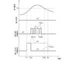
上記実施形態では、予め設定されたタイムスケジュールの作業指令を、気象情報を用いてオンからオフに変更することで、タイムスケジュールを修正したが、これとは逆に、作業指令をオフからオンに変更することでタイムスケジュールを修正してもよい。図9は、そのように設定された散水機2のタイムスケジュールの一例を示す図である。なお、図9には、芝刈り機1のタイムスケジュールの一例を併せて示す。 In the above embodiment, the time schedule is corrected by changing the work command of the preset time schedule from on to off using weather information. On the contrary, the work command is changed from off to on. You may correct a time schedule by changing. FIG. 9 is a diagram showing an example of the time schedule of the
図9では、予め作業指令がオフ(点線TS20)となるように散水機2のタイムスケジュールが設定されるとともに、日の出時刻t1から日の入り時刻t2までの作業指令がオン(点線TS10)となるように芝刈り機1のタイムスケジュールが設定される。降雨予測がオフの状態で、気象情報サーバ41から取得した作業地点の気温の予測値が時刻t12で所定温度Ta(例えば10℃)以上になると、図の実線TS21に示すように、散水機2の作業指令をオンする。 In FIG. 9, the time schedule of the
この場合、作業指令をオンし続けるのではなく、作業指令を所定のタイミングで繰り返しオンおよびオフする。例えば、所定時間毎(例えば30分毎)に最大所定時間(例えば4時間)だけ交互にオンおよびオフする。なお、最大所定時間が経過する前に気温予測値が所定温度Ta未満になるときは、その時点t22で散水機2の作業指令をオフしてもよい。このように気温予測値が所定温度Ta以上になると散水機2の作業指令をオンするようにタイムスケジュールを修正することで、散水作業をより効率的に行うことができる。例えば、高温状態かつ降雨のない状態が所定時間続いた場合に、散水タイムスケジュールを変更し、積極的に散水させることができる。なお、気温ではなく湿度に応じて作業指令をオンするようにしてもよい。 In this case, the work command is not continuously turned on, but the work command is repeatedly turned on and off at a predetermined timing. For example, it is turned on and off alternately for a maximum predetermined time (for example, 4 hours) every predetermined time (for example, every 30 minutes). In addition, when the temperature predicted value becomes lower than the predetermined temperature Ta before the maximum predetermined time elapses, the work command for the
−変形例−
上記実施形態では、気象予測部323での処理により、気象情報サーバ41から得られた降水確率が所定値(40%)以上のときに降雨と予測するようにしたが、気象予測の手法はこれに限らない。図10は、気象予測の他の手法を説明するためのXY平面図である。なお、図10では、領域の中央に作業機(例えば芝刈り機1)が存在し、この自位置を中心にして所定距離間隔(例えば10km間隔)の格子状のマップが形成される。-Modification-
In the above embodiment, the process of the
この変形例においても、中継装置3は図6と同様の処理を行うが、とくにステップS3では、自位置の周囲所定距離内(例えば50km内)の雨雲情報を取得し、図10のマップにおいて、雨雲ありの領域にN=1を、雨雲なしの領域にN=0を割り当てる。また、ステップS4では、自位置から所定範囲(例えば15km)内の第1領域AR1、およびそれよりも広い所定範囲(例えば25km)内の第2領域AR2において、それぞれ降雨の有無を判定する。降雨の判定は、第1領域AR1および第2領域AR2における所定時間(例えば1時間)内のNの総和をそれぞれ算出し、第1領域のNの総和が所定値(例えば3)以上、あるいは第2領域のNの総和が所定値(例えば6)以上のときに降雨と判定する。 Also in this modified example, the relay device 3 performs the same processing as in FIG. 6, but in step S3 in particular, rain cloud information within a predetermined distance (for example, within 50 km) around its own position is acquired, and in the map of FIG. N = 1 is assigned to the area with rain clouds and N = 0 is assigned to the area without rain clouds. In step S4, it is determined whether or not there is rainfall in the first area AR1 within a predetermined range (for example, 15 km) and the second area AR2 within a predetermined range (for example, 25 km) wider than the own position. For the determination of rainfall, the total sum of N within a predetermined time (for example, 1 hour) in each of the first area AR1 and the second area AR2 is calculated, and the total sum of N in the first area is greater than or equal to a predetermined value (for example, 3), or It is determined that it is raining when the sum of N in the two areas is a predetermined value (for example, 6) or more.
なお、上記第2の実施形態では、芝刈り機1と散水機2にECU12,22を設け、中継装置3からの指令に応じてECU12,22が作業用アクチュエータ13,23の駆動を制御するようにしたが、ECU12,22の機能を中継装置3に設け、芝刈り機1および散水機2からECU12,22を省略してもよい。芝刈り機1および散水機2のいずれか一方からECU12,22を省略してもよい。 In the second embodiment, the
上記第2の実施形態では、芝刈り機1と散水機2を作業機として用いたが、芝刈り機1と散水機2のいずれ一方のみを作業機として用いてもよい。また、芝刈り機1と散水機2に限らず、気象によって作業を許可または禁止する他の作業機についても本発明を同様に適用することができる。したがって、作業機に設けられる作業用のアクチュエータは上述したものに限らない。上記実施形態で中継装置3に設けたタイマ33や設定部321を、芝刈り機1や散水機2などの作業機に設けてもよい。この場合には、中継装置3からタイマ33や設定部321を省略することができる。 In the second embodiment, the
上記実施形態では、中継装置3の設定部321が作業機1,2のタイムスケジュールを設定するようにしたが、作業機1,2のECU12,22で設定してもよく、設定手段の構成は上述したものに限らない。上記実施形態では、サーバ装置4に気象情報サーバ41と作業データサーバ42を設けたが、サーバの構成はこれに限らない。上記実施形態では、作業地点またはその近傍における所定時間先までの気象情報を情報取得部322が気象情報サーバ41から取得した。すなわち、ネットワーク通信を介してサーバから気象情報を取得するようにしたが、情報取得手段の構成はこれに限らない。例えば情報取得手段としての情報取得部322が現在および未来の気象情報だけでなく過去の気象情報も取得し、これら取得された過去、現在および未来の気象情報に基づいて修正部324がタイムスケジュールを修正してもよい。これにより、過去の降雨の程度(例えば1時間当たりの降雨量)を考慮してタイムスケジュールを適宜修正することができ、より効率的な作業が可能である。 In the above embodiment, the
上記実施形態では、情報取得部322により取得された気象情報に基づいて気象予測部323が作業地点における所定時間先までの気象を予測し、気象予測部323により予測された気象に応じて修正部324がタイムスケジュールを修正するようにしたが、情報取得部322により取得された気象情報に基づいて修正部324がタイムスケジュールを修正してもよい。したがって、気象予測手段としての気象予測部323を省略してもよく、修正手段の構成は上述したものに限らない。 In the above embodiment, the
上記実施形態では、修正部324により修正されたタイムスケジュールに従い出力部325が作業開始指令および作業終了指令を出力し、その出力を作業機1,2に送信してアクチュエータ13,23を制御するようにした。すなわち作業機1,2と通信する通信部(通信ユニット31)を介して作業機1,2に制御信号を出力するようにしたが、修正されたタイムスケジュールに従い作業機が作業を行うようにアクチュエータを制御するであれば、アクチュエータ制御手段の構成はいかなるものでもよい。例えば、作業機1,2自体がアクチュエータ制御手段を有してもよい。この場合、アクチュエータ制御手段が通信部を有する必要はない。 In the above embodiment, the
上記実施形態(図5)では、気象予測部323により予測された降雨開始予測時刻t10の所定時間Δt1前から芝刈り機1による作業を禁止するとともに、降雨終了予測時刻t20から所定時間Δt2経過後まで芝刈り機1による作業を禁止するようにタイムスケジュールを修正したが、気象条件に応じたタイムスケジュールの修正のパターンは上述したものに限定されない。 In the above embodiment (FIG. 5), the operation by the
以上の説明はあくまで一例であり、本発明の特徴を損なわない限り、上述した実施形態および変形例により本発明が限定されるものではない。上記実施形態および変形例の構成要素には、発明の同一性を維持しつつ置換可能かつ置換自明なものが含まれる。すなわち、本発明の技術的思想の範囲内で考えられる他の形態についても、本発明の範囲内に含まれる。また、上記実施形態と変形例の1つまたは複数を任意に組み合わせることも可能である。 The above description is merely an example, and the present invention is not limited to the above-described embodiments and modifications unless the features of the present invention are impaired. The constituent elements of the embodiment and the modified examples include those that can be replaced while maintaining the identity of the invention and that are obvious for replacement. That is, other forms conceivable within the scope of the technical idea of the present invention are also included in the scope of the present invention. Moreover, it is also possible to arbitrarily combine one or more of the above-described embodiments and modified examples.
1 芝刈り機、2 散水機、3 中継装置、4 サーバ装置、11 通信ユニット、12 ECU、13 作業用アクチュエータ、31 通信ユニット、321 設定部、322 情報取得部、323 気象予測部、324 修正部、325 出力部
DESCRIPTION OF
Claims (9)
Translated fromJapanese前記作業機に設けられた作業用のアクチュエータと、
予め前記作業機のタイムスケジュールを設定する設定手段と、
作業地点またはその近傍における現在および未来の気象情報を取得する情報取得手段と、
前記情報取得手段により取得された気象情報に基づいて前記タイムスケジュールを修正する修正手段と、
前記修正手段により修正されたタイムスケジュールに従い前記作業機が作業を行うように前記アクチュエータを制御するアクチュエータ制御手段と、を備えることを特徴とする無人作業機の制御装置。A control device for an unmanned work machine that can be operated unattended outdoors.
A working actuator provided in the working machine;
Setting means for setting the time schedule of the work implement in advance;
Information acquisition means for acquiring current and future weather information at or near the work point;
Correction means for correcting the time schedule based on weather information acquired by the information acquisition means;
And an actuator control means for controlling the actuator so that the work machine performs work according to the time schedule corrected by the correction means.
前記情報取得手段は、ネットワーク通信を介してサーバから前記気象情報を取得することを特徴とする無人作業機の制御装置。In the control device for an unmanned work machine according to claim 1,
The control device for an unmanned work machine, wherein the information acquisition unit acquires the weather information from a server via network communication.
前記情報取得手段により取得された気象情報に基づいて前記作業地点における現在および未来の気象を予測する気象予測手段をさらに備え、
前記修正手段は、前記気象予測手段により予測された気象に応じて前記タイムスケジュールを修正することを特徴とする無人作業機の制御装置。In the control device for an unmanned work machine according to claim 1 or 2,
Further comprising weather prediction means for predicting current and future weather at the work point based on weather information acquired by the information acquisition means;
The control device for an unmanned work machine, wherein the correction unit corrects the time schedule according to the weather predicted by the weather prediction unit.
前記気象予測手段は、前記作業地点における降雨の有無を予測し、
前記修正手段は、前記気象予測手段により降雨であると予測された時間の前記作業機による作業を禁止するように前記タイムスケジュールを修正することを特徴とする無人作業機の制御装置。In the control device of the unmanned work machine according to claim 3,
The weather prediction means predicts the presence or absence of rainfall at the work point;
The control device for an unmanned work machine, wherein the correction means corrects the time schedule so as to prohibit work by the work machine during a time predicted to be rain by the weather prediction means.
前記気象予測手段は、前記作業地点における降雨の開始時刻を予測し、
前記修正手段は、前記気象予測手段により予測された降雨の開始時刻の所定時間前から前記作業機による作業を禁止するように前記タイムスケジュールを修正することを特徴とする無人作業機の制御装置。In the control device of the unmanned work machine according to claim 4,
The weather prediction means predicts the start time of rainfall at the work point,
The control device for an unmanned work machine, wherein the correction means corrects the time schedule so as to prohibit the work by the work machine from a predetermined time before the start time of the rain predicted by the weather prediction means.
前記気象予測手段は、前記作業地点における降雨の終了時刻を予測し、
前記修正手段は、前記気象予測手段により予測された降雨の終了時刻から所定時間経過後まで前記作業機による作業を禁止するように前記タイムスケジュールを修正することを特徴とする無人作業機の制御装置。In the control device for an unmanned work machine according to claim 4 or 5,
The weather prediction means predicts an end time of rainfall at the work point;
The control device for an unmanned work machine, wherein the correction means corrects the time schedule so as to prohibit work by the work machine from a rain end time predicted by the weather prediction means until a predetermined time has elapsed. .
前記作業機は、予め定められた作業領域内を自律走行して芝刈り作業を行う芝刈り機および散水機の少なくともいずれかであることを特徴とする無人作業機の制御装置。In the control device of the unmanned work machine according to any one of claims 1 to 6,
The control device for an unmanned work machine, wherein the work machine is at least one of a lawn mower and a watering machine that autonomously travels in a predetermined work area to perform lawn mowing work.
前記アクチュエータ制御手段は、前記作業機と通信する通信部を有し、該通信部を介して前記アクチュエータに制御信号を出力することを特徴とする無人作業機の制御装置。In the control device of the unmanned work machine according to any one of claims 1 to 7,
The actuator control unit includes a communication unit that communicates with the work machine, and outputs a control signal to the actuator via the communication unit.
前記情報取得手段は、前記作業地点またはその近傍における現在および未来の気象情報とともに過去の気象情報を取得し、
前記修正手段は、前記情報取得手段により取得された過去、現在および未来の気象情報に基づいて前記タイムスケジュールを修正することを特徴とする無人作業機の制御装置。
In the control device of the unmanned work machine according to any one of claims 1 to 8,
The information acquisition means acquires past weather information together with current and future weather information at or near the work point,
The control device for an unmanned work machine, wherein the correction unit corrects the time schedule based on past, present and future weather information acquired by the information acquisition unit.
Priority Applications (3)
| Application Number | Priority Date | Filing Date | Title |
|---|---|---|---|
| JP2015122959AJP2017010161A (en) | 2015-06-18 | 2015-06-18 | Control device for unmanned working machine |
| EP16173065.0AEP3106013B1 (en) | 2015-06-18 | 2016-06-06 | Control apparatus for utility machine |
| US15/174,340US9968024B2 (en) | 2015-06-18 | 2016-06-06 | Control apparatus for utility machine |
Applications Claiming Priority (1)
| Application Number | Priority Date | Filing Date | Title |
|---|---|---|---|
| JP2015122959AJP2017010161A (en) | 2015-06-18 | 2015-06-18 | Control device for unmanned working machine |
Publications (1)
| Publication Number | Publication Date |
|---|---|
| JP2017010161Atrue JP2017010161A (en) | 2017-01-12 |
Family
ID=56557450
Family Applications (1)
| Application Number | Title | Priority Date | Filing Date |
|---|---|---|---|
| JP2015122959APendingJP2017010161A (en) | 2015-06-18 | 2015-06-18 | Control device for unmanned working machine |
Country Status (3)
| Country | Link |
|---|---|
| US (1) | US9968024B2 (en) |
| EP (1) | EP3106013B1 (en) |
| JP (1) | JP2017010161A (en) |
Cited By (16)
| Publication number | Priority date | Publication date | Assignee | Title |
|---|---|---|---|---|
| WO2018142791A1 (en)* | 2017-01-31 | 2018-08-09 | 本田技研工業株式会社 | Unmanned working system, server computer, and unmanned working machine |
| JP2019000080A (en)* | 2017-06-19 | 2019-01-10 | 井関農機株式会社 | Work vehicle, and combine as work vehicle |
| WO2019187122A1 (en)* | 2018-03-30 | 2019-10-03 | 本田技研工業株式会社 | Autonomous running working machine and control system |
| WO2020136811A1 (en)* | 2018-12-27 | 2020-07-02 | 本田技研工業株式会社 | Information processing device and information processing method |
| WO2020194383A1 (en)* | 2019-03-22 | 2020-10-01 | 本田技研工業株式会社 | Charging control system, charging station, autonomous traveling work machine, and charging control system control method |
| EP3751700A1 (en) | 2019-06-14 | 2020-12-16 | Honda Motor Co., Ltd. | Autonomous running working machine and wireless power feeding system |
| JP2021040654A (en)* | 2020-12-03 | 2021-03-18 | ヤンマーパワーテクノロジー株式会社 | Autonomous traveling system of farm work vehicle |
| JP2021090246A (en)* | 2019-12-02 | 2021-06-10 | トヨタ自動車株式会社 | Vehicle power source device and remote travel system |
| JPWO2022130482A1 (en)* | 2020-12-15 | 2022-06-23 | ||
| JP2022104377A (en)* | 2020-12-28 | 2022-07-08 | 株式会社クボタ | Mowing planning equipment |
| JP2022109133A (en)* | 2021-01-14 | 2022-07-27 | 本田技研工業株式会社 | Work system, control method and program |
| WO2022190381A1 (en) | 2021-03-12 | 2022-09-15 | 本田技研工業株式会社 | Server device |
| WO2022190382A1 (en) | 2021-03-12 | 2022-09-15 | 本田技研工業株式会社 | Server device |
| DE102022105174A1 (en) | 2021-03-16 | 2022-09-22 | Honda Motor Co., Ltd. | Autonomous working machine |
| US11576302B2 (en) | 2019-03-22 | 2023-02-14 | Honda Motor Co., Ltd. | Charging control system, charging station, autonomous traveling working machine and control method for charging control system |
| US11631979B2 (en) | 2019-09-04 | 2023-04-18 | Honda Motor Co., Ltd. | Charging control system, autonomous traveling work machine, and charging station |
Families Citing this family (25)
| Publication number | Priority date | Publication date | Assignee | Title |
|---|---|---|---|---|
| US11470814B2 (en) | 2011-12-05 | 2022-10-18 | Radio Systems Corporation | Piezoelectric detection coupling of a bark collar |
| US11553692B2 (en) | 2011-12-05 | 2023-01-17 | Radio Systems Corporation | Piezoelectric detection coupling of a bark collar |
| US10228447B2 (en) | 2013-03-15 | 2019-03-12 | Radio Systems Corporation | Integrated apparatus and method to combine a wireless fence collar with GPS tracking capability |
| US10231440B2 (en) | 2015-06-16 | 2019-03-19 | Radio Systems Corporation | RF beacon proximity determination enhancement |
| DE102015121972A1 (en)* | 2015-12-16 | 2017-06-22 | Vorwerk & Co. Interholding Gmbh | System and method for working a floor with a mobile robot unit |
| US10152891B2 (en)* | 2016-05-02 | 2018-12-11 | Cnh Industrial America Llc | System for avoiding collisions between autonomous vehicles conducting agricultural operations |
| EP3452880A1 (en)* | 2016-05-06 | 2019-03-13 | MTD Products Inc. | Autonomous mower navigation system and method |
| WO2018157111A1 (en) | 2017-02-27 | 2018-08-30 | Radio Systems Corporation | Threshold barrier system |
| EP3412130B1 (en) | 2017-06-09 | 2020-08-12 | Andreas Stihl AG & Co. KG | Method for operating an autonomous mobile mower robot and mowing system |
| US11394196B2 (en)* | 2017-11-10 | 2022-07-19 | Radio Systems Corporation | Interactive application to protect pet containment systems from external surge damage |
| US11372077B2 (en) | 2017-12-15 | 2022-06-28 | Radio Systems Corporation | Location based wireless pet containment system using single base unit |
| WO2019185929A1 (en)* | 2018-03-30 | 2019-10-03 | Positec Power Tools (Suzhou) Co., Ltd | Automatic lawnmower |
| DE102018108513A1 (en)* | 2018-04-10 | 2019-10-10 | Alfred Kärcher SE & Co. KG | System for irrigation of green areas |
| CH715393A1 (en)* | 2018-09-28 | 2020-03-31 | Mediterranea Giardini Di Orizio Davide | Robotic machine with automatic perimeter hedge maintenance system. |
| JP7122452B2 (en)* | 2019-02-26 | 2022-08-19 | 本田技研工業株式会社 | automatic work system |
| US11238889B2 (en) | 2019-07-25 | 2022-02-01 | Radio Systems Corporation | Systems and methods for remote multi-directional bark deterrence |
| US11828904B2 (en)* | 2019-10-21 | 2023-11-28 | Deere & Company | Mobile work machine control system with weather-based model |
| US11490597B2 (en) | 2020-07-04 | 2022-11-08 | Radio Systems Corporation | Systems, methods, and apparatus for establishing keep out zones within wireless containment regions |
| CN112262634B (en)* | 2020-09-01 | 2022-07-19 | 青岛农业大学 | Device based on irrigate improvement saline and alkaline land |
| US12030182B2 (en)* | 2020-12-14 | 2024-07-09 | Honda Research Institute Europe Gmbh | Controlling an autonomous working device based on physical interaction |
| US12296694B2 (en) | 2021-03-10 | 2025-05-13 | Techtronic Cordless Gp | Lawnmowers |
| DE102021116229A1 (en)* | 2021-06-23 | 2022-12-29 | Einhell Germany Ag | Coupled operation of electrically operated garden tools |
| IL313660A (en) | 2021-12-22 | 2024-08-01 | Camp4 Therapeutics Corp | Modulation of gene transcription using antisense oligonucleotides targeting regulatory rnas |
| EP4310621B1 (en) | 2022-07-19 | 2025-02-12 | Techtronic Cordless GP | Display for controlling robotic tool |
| EP4340296B1 (en) | 2022-07-29 | 2025-04-09 | Techtronic Cordless GP | Generation of a cryptography key for a robotic garden tool |
Citations (12)
| Publication number | Priority date | Publication date | Assignee | Title |
|---|---|---|---|---|
| JPH11299351A (en)* | 1998-04-20 | 1999-11-02 | Omron Corp | Supporting apparatus for determining operation, determination and recording medium |
| JPH11313594A (en)* | 1998-04-30 | 1999-11-16 | Omron Corp | Support system for determining farm work and method therefor, and storage medium |
| US20030023356A1 (en)* | 2000-02-02 | 2003-01-30 | Keable Stephen J. | Autonomous mobile apparatus for performing work within a predefined area |
| JP2004229509A (en)* | 2003-01-28 | 2004-08-19 | Sato Kogyo Co Ltd | Method for controlling temperature of vegetation soil foundation |
| US20050034437A1 (en)* | 2002-03-26 | 2005-02-17 | Mcmurtry Richard | Environmentally responsive autonomous ground maintenance equipment |
| JP2005215742A (en)* | 2004-01-27 | 2005-08-11 | Yanmar Co Ltd | Agricultural work car |
| EP2342964A1 (en)* | 2010-01-06 | 2011-07-13 | Deere & Company | Adaptive scheduling of a service robot |
| US20110234153A1 (en)* | 2010-03-29 | 2011-09-29 | F Robotics Acquisitions Ltd. | Robotic Lawnmower and Charging and Control Systems Therefor |
| US20120158915A1 (en)* | 2010-12-21 | 2012-06-21 | Samsung Electronics Co., Ltd. | Apparatus and method of controlling operation of cleaner |
| JP2013196051A (en)* | 2012-03-15 | 2013-09-30 | Komatsu Ltd | Service management system of mining machine and service management method of mining machine |
| DE102013107492A1 (en)* | 2013-07-15 | 2015-01-15 | Koubachi AG | System for monitoring and controlling activities of at least one gardening tool within at least one activity area |
| WO2015022672A2 (en)* | 2013-08-16 | 2015-02-19 | Husqvarna Ab | Intelligent grounds management system integrating robotic rover |
Family Cites Families (15)
| Publication number | Priority date | Publication date | Assignee | Title |
|---|---|---|---|---|
| JPH0346009A (en) | 1989-07-11 | 1991-02-27 | Ind Technol Res Inst | Path control type fully automatic traveling work machine |
| KR20020026279A (en)* | 2000-03-31 | 2002-04-09 | 세구치 류이치 | Work managing method suited to work site, managing system, and managine apparatus |
| US7362439B2 (en)* | 2003-08-01 | 2008-04-22 | Li-Cor, Inc. | Method of detecting the condition of a turf grass |
| US20070179640A1 (en)* | 2006-01-31 | 2007-08-02 | Caterpillar Inc. | Environmental monitoring system for a machine environment |
| US20070260400A1 (en)* | 2006-05-04 | 2007-11-08 | Omry Morag | Computerized crop growing management system and method |
| EP2353353A1 (en)* | 2010-02-05 | 2011-08-10 | Flander's Mechatronics Technology Centre v.z.w. | In use adaptation of schedule for multi-vehicle ground processing operations |
| US20110295636A1 (en)* | 2010-05-27 | 2011-12-01 | Noel Wayne Anderson | Autonomous machine selective consultation |
| US8504234B2 (en)* | 2010-08-20 | 2013-08-06 | Deere & Company | Robotic pesticide application |
| US20120072322A1 (en)* | 2010-09-20 | 2012-03-22 | Agco Corporation | Self-provisioning by a machine owner |
| US9692644B2 (en)* | 2013-06-18 | 2017-06-27 | Cisco Technology, Inc. | Dynamically adjusting network parameters using weather forecasts |
| US20140277905A1 (en)* | 2013-03-15 | 2014-09-18 | Deere & Company | Methods and apparatus to manage a fleet of work machines |
| EP2894532B1 (en)* | 2014-01-10 | 2018-12-26 | Honda Research Institute Europe GmbH | Sensor cleaning system for an autonomous robot device, base station and corresponding method |
| US10109024B2 (en)* | 2014-09-05 | 2018-10-23 | The Climate Corporation | Collecting data to generate an agricultural prescription |
| US9886016B2 (en)* | 2015-01-08 | 2018-02-06 | International Business Machines Corporation | Automated irrigation control system |
| US10034421B2 (en)* | 2015-07-24 | 2018-07-31 | Irobot Corporation | Controlling robotic lawnmowers |
- 2015
- 2015-06-18JPJP2015122959Apatent/JP2017010161A/enactivePending
- 2016
- 2016-06-06EPEP16173065.0Apatent/EP3106013B1/enactiveActive
- 2016-06-06USUS15/174,340patent/US9968024B2/enactiveActive
Patent Citations (12)
| Publication number | Priority date | Publication date | Assignee | Title |
|---|---|---|---|---|
| JPH11299351A (en)* | 1998-04-20 | 1999-11-02 | Omron Corp | Supporting apparatus for determining operation, determination and recording medium |
| JPH11313594A (en)* | 1998-04-30 | 1999-11-16 | Omron Corp | Support system for determining farm work and method therefor, and storage medium |
| US20030023356A1 (en)* | 2000-02-02 | 2003-01-30 | Keable Stephen J. | Autonomous mobile apparatus for performing work within a predefined area |
| US20050034437A1 (en)* | 2002-03-26 | 2005-02-17 | Mcmurtry Richard | Environmentally responsive autonomous ground maintenance equipment |
| JP2004229509A (en)* | 2003-01-28 | 2004-08-19 | Sato Kogyo Co Ltd | Method for controlling temperature of vegetation soil foundation |
| JP2005215742A (en)* | 2004-01-27 | 2005-08-11 | Yanmar Co Ltd | Agricultural work car |
| EP2342964A1 (en)* | 2010-01-06 | 2011-07-13 | Deere & Company | Adaptive scheduling of a service robot |
| US20110234153A1 (en)* | 2010-03-29 | 2011-09-29 | F Robotics Acquisitions Ltd. | Robotic Lawnmower and Charging and Control Systems Therefor |
| US20120158915A1 (en)* | 2010-12-21 | 2012-06-21 | Samsung Electronics Co., Ltd. | Apparatus and method of controlling operation of cleaner |
| JP2013196051A (en)* | 2012-03-15 | 2013-09-30 | Komatsu Ltd | Service management system of mining machine and service management method of mining machine |
| DE102013107492A1 (en)* | 2013-07-15 | 2015-01-15 | Koubachi AG | System for monitoring and controlling activities of at least one gardening tool within at least one activity area |
| WO2015022672A2 (en)* | 2013-08-16 | 2015-02-19 | Husqvarna Ab | Intelligent grounds management system integrating robotic rover |
Cited By (29)
| Publication number | Priority date | Publication date | Assignee | Title |
|---|---|---|---|---|
| JPWO2018142791A1 (en)* | 2017-01-31 | 2019-11-07 | 本田技研工業株式会社 | Unmanned work system, server computer, and unmanned work machine |
| WO2018142791A1 (en)* | 2017-01-31 | 2018-08-09 | 本田技研工業株式会社 | Unmanned working system, server computer, and unmanned working machine |
| JP2019000080A (en)* | 2017-06-19 | 2019-01-10 | 井関農機株式会社 | Work vehicle, and combine as work vehicle |
| JPWO2019187122A1 (en)* | 2018-03-30 | 2021-01-14 | 本田技研工業株式会社 | Autonomous traveling work machine and control system |
| WO2019187122A1 (en)* | 2018-03-30 | 2019-10-03 | 本田技研工業株式会社 | Autonomous running working machine and control system |
| JP6997293B2 (en) | 2018-03-30 | 2022-01-17 | 本田技研工業株式会社 | Autonomous traveling work equipment and control system |
| WO2020136811A1 (en)* | 2018-12-27 | 2020-07-02 | 本田技研工業株式会社 | Information processing device and information processing method |
| US11576302B2 (en) | 2019-03-22 | 2023-02-14 | Honda Motor Co., Ltd. | Charging control system, charging station, autonomous traveling working machine and control method for charging control system |
| WO2020194383A1 (en)* | 2019-03-22 | 2020-10-01 | 本田技研工業株式会社 | Charging control system, charging station, autonomous traveling work machine, and charging control system control method |
| JPWO2020194383A1 (en)* | 2019-03-22 | 2021-12-02 | 本田技研工業株式会社 | How to control a charge control system, a charging station, an autonomous driving machine, and a charge control system |
| US11934195B2 (en) | 2019-03-22 | 2024-03-19 | Honda Motor Co., Ltd. | Charging control system, charging station, autonomous traveling work machine, and charging control system control method |
| US11205925B2 (en) | 2019-06-14 | 2021-12-21 | Honda Motor Co., Ltd. | Wireless power feeding structure including a power transmission coil, power reception coil, and a core of a magnetic substance |
| EP3751700A1 (en) | 2019-06-14 | 2020-12-16 | Honda Motor Co., Ltd. | Autonomous running working machine and wireless power feeding system |
| US11631979B2 (en) | 2019-09-04 | 2023-04-18 | Honda Motor Co., Ltd. | Charging control system, autonomous traveling work machine, and charging station |
| JP2021090246A (en)* | 2019-12-02 | 2021-06-10 | トヨタ自動車株式会社 | Vehicle power source device and remote travel system |
| JP7247871B2 (en) | 2019-12-02 | 2023-03-29 | トヨタ自動車株式会社 | remote travel system |
| JP2021040654A (en)* | 2020-12-03 | 2021-03-18 | ヤンマーパワーテクノロジー株式会社 | Autonomous traveling system of farm work vehicle |
| JP7100688B2 (en) | 2020-12-03 | 2022-07-13 | ヤンマーパワーテクノロジー株式会社 | Autonomous driving system for agricultural work vehicles |
| JPWO2022130482A1 (en)* | 2020-12-15 | 2022-06-23 | ||
| WO2022130482A1 (en)* | 2020-12-15 | 2022-06-23 | 株式会社やまびこ | Management system for mobile object, program, and management method for mobile object |
| JP7600266B2 (en) | 2020-12-15 | 2024-12-16 | 株式会社やまびこ | MOBILE BODY MANAGEMENT SYSTEM, PROGRAM, AND MOBILE BODY MANAGEMENT METHOD |
| JP2022104377A (en)* | 2020-12-28 | 2022-07-08 | 株式会社クボタ | Mowing planning equipment |
| JP7608158B2 (en) | 2020-12-28 | 2025-01-06 | 株式会社クボタ | Harvesting planning device |
| JP2022109133A (en)* | 2021-01-14 | 2022-07-27 | 本田技研工業株式会社 | Work system, control method and program |
| WO2022190382A1 (en) | 2021-03-12 | 2022-09-15 | 本田技研工業株式会社 | Server device |
| WO2022190381A1 (en) | 2021-03-12 | 2022-09-15 | 本田技研工業株式会社 | Server device |
| US12405616B2 (en) | 2021-03-12 | 2025-09-02 | Honda Motor Co., Ltd. | Server device |
| DE102022105174A1 (en) | 2021-03-16 | 2022-09-22 | Honda Motor Co., Ltd. | Autonomous working machine |
| US12124281B2 (en) | 2021-03-16 | 2024-10-22 | Honda Motor Co., Ltd. | Autonomous working machine |
Also Published As
| Publication number | Publication date |
|---|---|
| EP3106013B1 (en) | 2020-02-26 |
| US9968024B2 (en) | 2018-05-15 |
| US20160366813A1 (en) | 2016-12-22 |
| EP3106013A1 (en) | 2016-12-21 |
Similar Documents
| Publication | Publication Date | Title |
|---|---|---|
| JP2017010161A (en) | Control device for unmanned working machine | |
| US11442448B2 (en) | Self-moving device, method for providing alarm about positioning fault in same, self-moving device, and automatic working system | |
| EP3084541B1 (en) | Navigation for a robotic working tool | |
| EP3236733B1 (en) | Improved navigation for a robotic lawnmower | |
| EP2906032B1 (en) | System for enhancing a coverage distribution of a robotic garden tool | |
| US12179737B2 (en) | Unmanned ground vehicle and method for operating unmanned ground vehicle | |
| EP3324261B1 (en) | Automatic lawn mower robot and controlling method associated | |
| EP3661352B1 (en) | System and method for variable rate irrigation wind control and compensation | |
| US20110135189A1 (en) | Swarm intelligence-based mobile robot, method for controlling the same, and surveillance robot system | |
| EP3084542B1 (en) | System and method for navigating a robotic working tool. | |
| EP3731053B1 (en) | Management device, management system, moving body and program | |
| EP3729945B1 (en) | Control device, work machine and program | |
| EP3237927A1 (en) | Improved navigation for a robotic work tool | |
| US11582903B1 (en) | Vision based guidance system and method for lawn mowing devices | |
| JP2013031389A (en) | Automated lawn mower and control method therefor | |
| CN116088533A (en) | Information determination method, remote terminal, device, lawn mower and storage medium | |
| AU2023201680B2 (en) | Method for controlling autonomous mobile device, autonomous mobile device, and computer storage medium | |
| EP4098116A1 (en) | Spraying work method, spraying work system, and spraying work program | |
| JP7016081B2 (en) | A storage medium that stores systems, methods, programs, and programs for modifying flight planning routes for unmanned aerial vehicles. | |
| US20240176350A1 (en) | Definition of boundary for a robotic work tool | |
| SE546034C2 (en) | Improved navigation for a robotic work tool system | |
| SE2151613A1 (en) | Improved navigation for a robotic work tool system |
Legal Events
| Date | Code | Title | Description |
|---|---|---|---|
| A521 | Request for written amendment filed | Free format text:JAPANESE INTERMEDIATE CODE: A523 Effective date:20150624 | |
| A621 | Written request for application examination | Free format text:JAPANESE INTERMEDIATE CODE: A621 Effective date:20171129 | |
| A131 | Notification of reasons for refusal | Free format text:JAPANESE INTERMEDIATE CODE: A131 Effective date:20180918 | |
| A521 | Request for written amendment filed | Free format text:JAPANESE INTERMEDIATE CODE: A523 Effective date:20181114 | |
| A131 | Notification of reasons for refusal | Free format text:JAPANESE INTERMEDIATE CODE: A131 Effective date:20190122 | |
| A521 | Request for written amendment filed | Free format text:JAPANESE INTERMEDIATE CODE: A523 Effective date:20190325 | |
| A131 | Notification of reasons for refusal | Free format text:JAPANESE INTERMEDIATE CODE: A131 Effective date:20190521 | |
| A521 | Request for written amendment filed | Free format text:JAPANESE INTERMEDIATE CODE: A523 Effective date:20190626 | |
| A02 | Decision of refusal | Free format text:JAPANESE INTERMEDIATE CODE: A02 Effective date:20191023 |