JP2017010149A - Medium processing apparatus and automatic transaction apparatus - Google Patents
Medium processing apparatus and automatic transaction apparatusDownload PDFInfo
- Publication number
- JP2017010149A JP2017010149AJP2015122690AJP2015122690AJP2017010149AJP 2017010149 AJP2017010149 AJP 2017010149AJP 2015122690 AJP2015122690 AJP 2015122690AJP 2015122690 AJP2015122690 AJP 2015122690AJP 2017010149 AJP2017010149 AJP 2017010149A
- Authority
- JP
- Japan
- Prior art keywords
- sensor
- control unit
- unit
- processing apparatus
- transport
- Prior art date
- Legal status (The legal status is an assumption and is not a legal conclusion. Google has not performed a legal analysis and makes no representation as to the accuracy of the status listed.)
- Pending
Links
Images


Classifications
- G—PHYSICS
- G06—COMPUTING OR CALCULATING; COUNTING
- G06T—IMAGE DATA PROCESSING OR GENERATION, IN GENERAL
- G06T1/00—General purpose image data processing
- G—PHYSICS
- G07—CHECKING-DEVICES
- G07D—HANDLING OF COINS OR VALUABLE PAPERS, e.g. TESTING, SORTING BY DENOMINATIONS, COUNTING, DISPENSING, CHANGING OR DEPOSITING
- G07D7/00—Testing specially adapted to determine the identity or genuineness of valuable papers or for segregating those which are unacceptable, e.g. banknotes that are alien to a currency
- G07D7/04—Testing magnetic properties of the materials thereof, e.g. by detection of magnetic imprint
- G—PHYSICS
- G07—CHECKING-DEVICES
- G07D—HANDLING OF COINS OR VALUABLE PAPERS, e.g. TESTING, SORTING BY DENOMINATIONS, COUNTING, DISPENSING, CHANGING OR DEPOSITING
- G07D7/00—Testing specially adapted to determine the identity or genuineness of valuable papers or for segregating those which are unacceptable, e.g. banknotes that are alien to a currency
- G07D7/06—Testing specially adapted to determine the identity or genuineness of valuable papers or for segregating those which are unacceptable, e.g. banknotes that are alien to a currency using wave or particle radiation
- G07D7/12—Visible light, infrared or ultraviolet radiation
Landscapes
- Physics & Mathematics (AREA)
- General Physics & Mathematics (AREA)
- Health & Medical Sciences (AREA)
- General Health & Medical Sciences (AREA)
- Toxicology (AREA)
- Engineering & Computer Science (AREA)
- Theoretical Computer Science (AREA)
- Inspection Of Paper Currency And Valuable Securities (AREA)
- Image Input (AREA)
Abstract
Description
Translated fromJapanese本発明は、媒体処理装置および自動取引装置に関する。 The present invention relates to a medium processing apparatus and an automatic transaction apparatus.
偽造券を利用した高度化する犯罪に対応する形で、紙幣や硬貨等の媒体に採用されるセキュリティ技術(例えば、特殊な光にしか反応しない特徴、特殊なセンサでしか検出できない特徴等を有する媒体の技術)は年々進化してきている。紙幣や硬貨等の媒体に採用されるセキュリティ技術としては、様々な技術が開示されている(例えば、特許文献1および特許文献2参照。)。 Security technology (for example, features that react only to special light, features that can only be detected by special sensors, etc.) used in media such as banknotes and coins in response to sophisticated crimes using counterfeit tickets Media technology is evolving year by year. Various techniques have been disclosed as security techniques employed for media such as banknotes and coins (see, for example,
媒体の鑑別機能を有する装置(例えば、一般の人によって入金可能なために犯罪者に狙われやすい現金自動預け払い機等)は、進化したセキュリティ技術を最大限活用するため、鑑別部に媒体から情報を読み取ることが可能なセンサを搭載している。そして、媒体の鑑別機能を有する装置は、センサから得られるセンサデータを処理能力の高いCPU(Central Processing Unit)等といった演算処理回路を使って高速に大量の演算処理を行うことによって真券と偽造券とを見分け、偽造券を排除している。 Devices that have a media discrimination function (for example, an automated teller machine that is easy to be targeted by criminals because it can be deposited by ordinary people, etc.), make the best use of advanced security technology. It is equipped with a sensor that can read information. And a device having a medium discrimination function can perform authentic processing and counterfeiting by performing a large amount of arithmetic processing on the sensor data obtained from the sensor at high speed using an arithmetic processing circuit such as a CPU (Central Processing Unit) having high processing capability. Distinguishes tickets from counterfeit tickets.
しかし、演算処理回路の発熱量が増えてくると、その熱がセンサに伝わってしまうことによって、センサから出力されるセンサデータが安定しなくなってしまう場合があり得る。かかる場合には、センサデータに基づいて真券と偽造券とを見分けることも困難となり得る。そこで、鑑別部の内部に存在するセンサから出力されるセンサデータを安定させることが可能な技術の提供が望まれる。 However, when the calorific value of the arithmetic processing circuit increases, the heat transmitted to the sensor may cause sensor data output from the sensor to become unstable. In such a case, it may be difficult to distinguish between genuine and counterfeit tickets based on sensor data. Therefore, it is desired to provide a technique capable of stabilizing sensor data output from a sensor existing inside the discrimination unit.
上記問題を解決するために、本発明のある観点によれば、媒体から所定の情報を読み取るセンサを内部に有する鑑別部と、前記センサが読み取った情報に基づいて前記媒体を識別するセンサ制御部と、を備え、前記センサ制御部は、前記鑑別部の外部に配置されている、媒体処理装置が提供される。 In order to solve the above problem, according to an aspect of the present invention, a discrimination unit having a sensor that reads predetermined information from a medium inside, and a sensor control unit that identifies the medium based on information read by the sensor And the sensor control unit is provided outside the discrimination unit.
前記媒体処理装置は、前記センサ制御部および前記センサの少なくともいずれか一方を覆うカバー部材をさらに備えてもよい。 The medium processing apparatus may further include a cover member that covers at least one of the sensor control unit and the sensor.
前記センサ制御部は、前記鑑別部の側面に配置されていてよい。 The sensor control unit may be disposed on a side surface of the discrimination unit.
前記センサ制御部は、前記鑑別部とは物理的に離れた位置に配置されていてよい。 The sensor control unit may be disposed at a position physically separated from the discrimination unit.
前記センサ制御部は、前記センサ制御部が搭載された基板面と前記鑑別部の内部に存在する前記媒体の搬送面とが垂直になるように配置されていてよい。 The sensor control unit may be arranged such that a substrate surface on which the sensor control unit is mounted and a transport surface of the medium existing inside the discrimination unit are perpendicular to each other.
前記媒体処理装置は、上部ブロックと下部ブロックとを有し、前記センサ制御部と前記センサとの双方は、前記上部ブロックおよび前記下部ブロックのいずれか一方に備わっていてよい。 The medium processing apparatus may include an upper block and a lower block, and both the sensor control unit and the sensor may be provided in one of the upper block and the lower block.
前記センサ制御部と前記センサとの双方は、前記上部ブロックに設けられ、該上部ブロックは引き出し可能に構成されていてよい。 Both the sensor control unit and the sensor may be provided in the upper block, and the upper block may be configured to be drawable.
前記媒体処理装置は、前記媒体の搬送を制御する搬送制御部を備え、前記センサ制御部と前記搬送制御部とは、同一基板上に搭載されていてよい。 The medium processing apparatus may include a transport control unit that controls transport of the medium, and the sensor control unit and the transport control unit may be mounted on the same substrate.
前記センサ制御部と前記搬送制御部とは、一つに統合されることによって統合制御部を構成してよい。 The sensor control unit and the transport control unit may be integrated into a single integrated control unit.
前記鑑別部は、上側搬送部と下側搬送部と前記上側搬送部および前記下側搬送部のいずれか一方を開閉可能に支持する支点とを有し、前記センサ制御部と前記センサとは、前記支点を通して配置される信号線を介して接続されてよい。 The discrimination unit includes an upper conveyance unit, a lower conveyance unit, a fulcrum that supports any one of the upper conveyance unit and the lower conveyance unit so as to be openable and closable, and the sensor control unit and the sensor are: You may connect via the signal wire | line arrange | positioned through the said fulcrum.
前記媒体処理装置は、前記センサから出力されるセンサデータを調整するための調整値と前記センサデータに対して影響を与える部品とを有するセンサ基板を備えてよい。 The medium processing apparatus may include a sensor substrate having an adjustment value for adjusting sensor data output from the sensor and a component that affects the sensor data.
また、本発明の他の観点によれば、媒体から所定の情報を読み取るセンサを内部に有する鑑別部と、前記センサが読み取った情報に基づいて前記媒体を識別するセンサ制御部と、を備え、前記センサ制御部は、前記鑑別部の外部に配置されている、自動取引装置が提供される。 According to another aspect of the present invention, a discrimination unit having a sensor that reads predetermined information from a medium inside, and a sensor control unit that identifies the medium based on information read by the sensor, The sensor control unit is provided with an automatic transaction apparatus disposed outside the discrimination unit.
以上説明したように本発明によれば、鑑別部の内部に存在するセンサから出力されるセンサデータを安定させることが可能となる。 As described above, according to the present invention, it is possible to stabilize sensor data output from a sensor existing inside the discrimination unit.
以下に添付図面を参照しながら、本発明の好適な実施の形態について詳細に説明する。なお、本明細書および図面において、実質的に同一の機能構成を有する構成要素については、同一の符号を付することにより重複説明を省略する。 Exemplary embodiments of the present invention will be described below in detail with reference to the accompanying drawings. In the present specification and drawings, components having substantially the same functional configuration are denoted by the same reference numerals, and redundant description is omitted.
また、本明細書および図面において、実質的に同一の機能構成を有する複数の構成要素を、同一の符号の後に異なる数字を付して区別する。また、異なる実施形態の類似する構成要素については、同一の符号の後に異なるアルファベットを付して区別する。ただし、実質的に同一の機能構成を有する複数の構成要素等の各々を特に区別する必要がない場合、同一符号のみを付する。 In the present specification and drawings, a plurality of constituent elements having substantially the same functional configuration are distinguished by attaching different numerals to the same reference numerals. Further, similar constituent elements of different embodiments are distinguished by attaching different alphabets after the same reference numerals. However, when there is no need to particularly distinguish each of a plurality of constituent elements having substantially the same functional configuration, only the same reference numerals are given.
[1.各実施形態の概要]
[1−1.自動取引装置の構成]
まず、本発明の各実施形態の概要について説明する。本発明の各実施形態の概要として自動取引装置の構成について説明する。図1は、自動取引装置の外観構成を示す略線的斜視図である。図1に外観を示すように、自動取引装置1は、箱状の筐体2を中心に構成されており、例えば、金融機関等に設置され、顧客との間で入金処理や出金処理等の現金に関する取引を行うようになっている。[1. Overview of each embodiment]
[1-1. Configuration of automatic transaction equipment]
First, an overview of each embodiment of the present invention will be described. The configuration of an automatic transaction apparatus will be described as an overview of each embodiment of the present invention. FIG. 1 is a schematic perspective view showing an external configuration of an automatic transaction apparatus. As shown in FIG. 1, the
筐体2は、その前側に顧客が対峙した状態で紙幣の投入やタッチパネルによる操作等をしやすい箇所に顧客応対部3が設けられている。顧客応対部3は、顧客との間で、例えば、現金やカード等を直接やり取りすると共に、取引に関する情報の通知や操作指示の受付を行うようになされており、カード入出口4、入出金口5、操作表示部6、テンキー7、およびレシート発行口8を備えている。 The
カード入出口4は、キャッシュカード等の各種カードが挿入または排出される部分である。カード入出口4の奥側には、各種カードに磁気記録された口座番号等の読み取りを行うカード処理部(図示せず)が設けられている。入出金口5には顧客によって入金される紙幣が投入されると共に、入出金口5からは顧客へ出金する紙幣が排出される。また、入出金口5は、シャッタを駆動することにより開放または閉塞するようになっている。因みに紙幣は、例えば、長方形の紙で構成されている。 The card entry /
操作表示部6は、取引に際して操作画面を表示するLCD(Liquid Crystal Display)と、取引の種類の選択、暗証番号や取引金額等を入力するタッチセンサとが一体化されたタッチパネルとなっている。テンキー7は、「0」〜「9」の数字等の入力を受け付ける物理キーであり、暗証番号や取引金額等の入力操作時に用いられる。レシート発行口8は、取引処理の終了時に取引内容等を印字したレシートを発行する部分である。因みにレシート発行口8の奥側には、レシートに取引内容等を印字するレシート処理部(図示せず)が設けられている。 The operation display unit 6 is a touch panel in which an LCD (Liquid Crystal Display) for displaying an operation screen at the time of a transaction and a touch sensor for inputting a transaction type, a password, a transaction amount, and the like are integrated. The
以下では、自動取引装置1のうち顧客が対峙する側を前側とし、その反対を後側とし、当該前側に対峙した顧客から見て左および右をそれぞれ左側および右側とし、さらに上側および下側を定義して説明する。 In the following, in the
筐体2の内部には、自動取引装置1の全体を統括制御する主制御部9や、紙幣に関する種々の処理を行う紙幣入出金機10等が設けられている。主制御部9は、図示しないCPU(Central Processing Unit)を中心に構成されており、図示しないROM(Read Only Memory)やフラッシュメモリ等から所定のプログラムを読み出して実行することにより、入金処理や出金処理等の種々の処理を行う。また、主制御部9は、内部にRAM(Random Access Memory)、ハードディスクドライブやフラッシュメモリ等でなる記憶部を有しており、この記憶部に種々の情報を記憶させる。 Inside the
[1−2.紙幣入出金機の構成]
図2は、紙幣入出金機(紙幣処理装置)の構成を示す略線図である。図2に側面図を示すように、紙幣入出金機10は、内部に媒体としての紙幣に関する種々の処理を行う複数の部分が組み込まれている。紙幣入出金機10は、大きく分けて、上下方向のほぼ中央よりも上側部分を占める上部ブロック10Uと、その下側部分を占める下部ブロック10Lとにより構成されている。上部ブロック10Uと下部ブロック10Lとは、筐体19の内部に収納されている。[1-2. Configuration of banknote deposit and withdrawal machine]
FIG. 2 is a schematic diagram illustrating a configuration of a banknote deposit and withdrawal machine (banknote processing apparatus). As shown in a side view in FIG. 2, the banknote depositing / dispensing
[1−2−1.上部ブロックの構成]
上部ブロック10Uには、全体を統括制御する紙幣制御部11、顧客との間で紙幣を授受する入出金部12、紙幣を各部へ搬送する搬送部13、紙幣を鑑別する鑑別部14、紙幣を一時的に収納する一時保留部15、および偽券と鑑別された紙幣を収納する偽券庫18が設けられている。[1-2-1. Configuration of upper block]
The
紙幣制御部11は、主制御部9と同様、図示しないCPUを中心に構成されており、図示しないROMやフラッシュメモリ等から所定のプログラムを読み出して実行することにより、紙幣の搬送先を決定する処理や各部の動作を制御する処理等、種々の処理を行う。また、紙幣制御部11は、内部にRAMおよびフラッシュメモリ等でなる記憶部を有しており、この記憶部に種々の情報を記憶させる。 The
入出金部12は、上部ブロック10Uの内部における前上部に位置している。この入出金部12は、顧客から入金された紙幣および顧客へ出金すべき紙幣を収容する収容器12Aを内部に有しており、その上方をシャッタ12Bにより開閉し得るようになっている。収容器12Aの内部には、複数の紙幣が紙面を前後方向に向けて集積された状態で、すなわち前後方向に沿って整列された状態で収容される。 The deposit /
また、入出金部12の前下方には、取込放出口12Cおよび入出金搬送部12Dが設けられている。取込放出口12Cは、紙幣制御部11の制御に基づき、取込モードおよび放出モードといった2種類の動作モードを切り替えて動作する。 Further, an intake /
すなわち取込放出口12Cは、取込モードにおいて、収容器12Aの内部の紙幣を1枚ずつに分離して所定の時間間隔毎に下方へ送り出し、入出金搬送部12Dを介して搬送部13に受け渡す。また、取込放出口12Cは、放出モードにおいて、搬送部13から入出金搬送部12Dを介して受け渡された紙幣を収容器12Aの内部へ放出して集積させる。 That is, in the take-in mode, the take-in and discharge
搬送部13は、上部ブロック10Uの内部における下端部分に、すなわち紙幣入出金機10全体における上下のほぼ中央を前後方向に横切るように位置しており、全体的に上下方向に薄く前後方向に細長い形状となっている。この搬送部13の内部には、多数の回転するローラや紙幣を案内する搬送ガイド等が適宜配置されており、紙幣の短手方向を進行方向として、主に前後方向に沿って紙幣を搬送させるような直線状の搬送路が形成されている。 The
また、搬送部13の内部には、複数の切替部が配置されている。各切替部は、ブレードと呼ばれる部材(図中三角形で示す)およびその周囲に配置された複数のローラにより構成されている。ブレードは、左右方向に長く、且つ左右方向から見て楔形に形成されており、所定のアクチュエータにより駆動され、回動して傾斜方向を変化させることで、紙幣の搬送方向を2通りに切り替える。各ローラは、紙幣の搬送路を挟んで互いに対向するように配置されている。 In addition, a plurality of switching units are arranged inside the
この切替部は、紙幣制御部11の制御に従い、各紙幣の搬送先に応じてブレードの傾斜方向を変化させると共に各ローラを所定の回転方向へ回転させることにより、紙幣の搬送方向を適宜切り替えて所望の搬送先へ搬送する。 According to the control of the
図3は、搬送部13の構成を示す略線図である。搬送部13は、図3に拡大図を示すように、大きく分けて前側の第1搬送部21と、後側の第2搬送部22と、両者を接続する一時保留切替部20とにより構成されている。一時保留切替部20は、中心に位置するブレードと、当該ブレードの前側、後側および上側にそれぞれ位置するローラとにより、いわゆる3ウェイブレードとして構成されている。 FIG. 3 is a schematic diagram illustrating the configuration of the
第1搬送部21の内部には、前方から順に、リジェクト切替部23、鑑別部14(詳しくは後述する)および第1切替部24が直列に配置されると共に、これらの間が比較的短い搬送短路によりそれぞれ接続されており、全体として前後方向に沿った直線状の搬送経路が形成されている。また、説明の都合上、第1搬送部21のうち鑑別部14の前側および後側の各部分をそれぞれ第1搬送前部21Aおよび第1搬送後部21Bと呼ぶ。 A
第2搬送部22の内部には、前方から順に、第2切替部25、第3切替部26、第4切替部27および偽券切替部28が直列に配置されており、第1搬送部21と同様、これらの間が比較的短い搬送短路によりそれぞれ接続されることで、全体として前後方向に沿った直線状の搬送経路が形成されている。また、第2搬送部22の内部の搬送経路は、数枚程度の紙幣を一時的に貯留する搬送経路貯留部としても機能する。 In the inside of the 2nd conveyance part 22, the 2nd switching
鑑別部14は、内部に複数種類のセンサが組み込まれており、後に説明するセンサ制御部202(図7)がセンサデータに基づいて、搬送される紙幣の金種、真偽、正損(損傷しているか否か)等を認識し、その認識結果を紙幣制御部11へ送出する(詳しくは後述する)。 The
一時保留部15は、いわゆるテープエスクロ方式を採用しており、円筒状のドラムの周側面に紙幣をテープと共に巻き付けることで当該紙幣を収納し、またこの周側面から当該テープを引き剥がすことで紙幣を繰り出す。 The
偽券庫18は、上部ブロック10Uの内部における後端近傍であって、搬送部13の真上に隣接する位置に設けられており、内部に紙幣を収納する空間を有している。この偽券庫18は、後述するセンサ制御部202(図7)により偽造紙幣(以下、偽券と呼ぶ)と判断された紙幣が搬送部13により搬送されてくると、これを内部に収納する。 The
このように、搬送部13は、第1搬送部21、一時保留切替部20および第2搬送部22により、前後方向に沿った直線状の搬送経路を形成し、この搬送経路に沿って紙幣を主に前後方向へ搬送すると共に、複数の切替部によりその搬送経路を切り替えるようになっている。 As described above, the
[1−2−2.下部ブロックの構成]
下部ブロック10Lは、その全ての周側面が頑強な金庫筐体10Sにより覆われている。この金庫筐体10Sの内部には、再使用すべきでない紙幣を収納するリジェクト庫16および再利用可能な紙幣を収納する5個の紙幣収納庫17(17A、17B、17C、17Dおよび17E)が設けられている。因みにリジェクト庫16および紙幣収納庫17は、金庫筐体10Sに対し着脱可能に構成されている。[1-2-2. Configuration of lower block]
The
リジェクト庫16は、下部ブロック10Lの内部における最も前側に位置しており、上下方向に長い直方体状に形成されると共に内部に紙幣を集積して収納する空間を有している。このリジェクト庫16は、センサ制御部202(図7)により損傷の程度が大きく再利用すべきで無いと判断された紙幣が搬送部13により搬送されて来ると、当該紙幣を内部に収納する。 The
下部ブロック10Lの内部におけるリジェクト庫16の後方には、前側から後側へ向けて順に紙幣収納庫17A、17B、17C、17Dおよび17Eが設けられている。各紙幣収納庫17は、何れも同様に構成されており、上下方向に長い直方体状に形成されると共に内部に紙幣を集積して収納する空間を有している。
各紙幣収納庫17は、それぞれ収納すべき紙幣の金種が予め設定されている。この紙幣収納庫17は、センサ制御部202(図7)により損傷の程度が小さく再利用が可能であると判断された紙幣が、その金種に応じて搬送部13により搬送されてくると、当該紙幣を内部に集積して収納する。また紙幣収納庫17は、紙幣制御部11から紙幣を繰り出す指示を受け付けると、集積している紙幣を1枚ずつに分離して繰り出し、搬送部13に受け渡す。 In each
[1−3.鑑別部の構成]
[1−3−1.識別搬送ローラおよび各センサの構成]
図4は、鑑別部14の構成を示す左側面図である。搬送ガイド30の近傍における鑑別部14の範囲内には、図4に示したように、搬送経路U1に沿って、後側から順に識別搬送ローラ32、厚みセンサ33、識別搬送ローラ34、画像センサ35、識別搬送ローラ36、磁気センサ37および識別搬送ローラ38が配置されている。[1-3. Configuration of the identification section]
[1-3-1. Configuration of identification transport roller and each sensor]
FIG. 4 is a left side view illustrating the configuration of the
このうち、識別搬送ローラ32、34、36および38は、何れも同様に構成されている。以下では、識別搬送ローラ32について説明し、識別搬送ローラ34、36および38についての説明を省略する。 Among these, the
識別搬送ローラ32は、複数のローラにより構成されるローラ群を、搬送経路U1の上下に1群ずつ配置している。各ローラ群は、中心軸を左右方向に向けた短い円柱状ないし円板状のローラが、左右方向に離散した複数箇所(図5では、2箇所)に配置されている(図5)。また、各ローラ群は、互いに対向するローラ32Aおよび32Bの周側面同士を搬送経路U1のほぼ中心で当接させるように、すなわち搬送経路U1を前後方向から挟むように、それぞれ配置されている。 The
因みに下側のローラ32Bは、鑑別部14の外部に設けられたモータ(図示せず)等の動力源から駆動力が供給されることにより、図の時計回りまたはその反対回りに回転駆動される。上側のローラ32Aは、これに従動して回転する。搬送ガイド30の近傍における鑑別部14の範囲外、すなわち第1搬送前部21Aおよび第1搬送後部21Bの範囲内には、搬送ローラ41および42がそれぞれ設けられている。 Incidentally, the
搬送ローラ42は、識別搬送ローラ32と類似した構成となっているものの、各ローラ群に属するローラ42Aまたは42Bが左右方向に離れた2箇所に配置されている。また各ローラ42Aおよび42Bは、識別搬送ローラ32の各ローラ32Aおよび32Bよりも半径が大きくなっている。なお、搬送ローラ41は、搬送ローラ42とほぼ前後対称に構成されている。 The
ところで、搬送ローラ42および識別搬送ローラ32の間、識別搬送ローラ32および34の間、識別搬送ローラ34および36の間、識別搬送ローラ36および38の間、並びに識別搬送ローラ38および搬送ローラ41の間における搬送経路U1に沿った距離は、何れも紙幣における進行方向に沿った長さ、すなわち短辺の長さよりも短くなっている。 By the way, between the
このため、鑑別部14、第1搬送前部21Aおよび第1搬送後部21Bは、搬送ローラ41、識別搬送ローラ32、34、36および38並びに搬送ローラ41をそれぞれ回転駆動させることにより、紙幣を常に何れかの搬送ローラまたは識別搬送ローラにより挟持しながら互いに受け渡し、搬送経路U1に沿って前方向または後方向へ搬送することができる。 For this reason, the
[1−3−2.各センサの構成]
厚みセンサ33(図4)は、上搬送ガイド30Aに対し回動可能または上下方向へ移動可能に支持された複数の可動ホルダ33Aと、当該可動ホルダ33Aにより回転可能に支持された可動ローラ33Bと、下搬送ガイド30Bに取り付けられ上下方向に移動しない固定ローラ33Cとにより構成されている。[1-3-2. Configuration of each sensor]
The thickness sensor 33 (FIG. 4) includes a plurality of
可動ホルダ33Aは、図示しない付勢手段により可動ローラ33Bを固定ローラ33Cに押し付けている。また可動ホルダ33Aは、図示しない位置センサにより、可動ローラ33Bの上下方向への移動量を検出し、この検出結果をセンサ制御部202(図7)へ通知する。 The
厚みセンサ33は、識別搬送ローラ32または34により紙幣が搬送されてくると、この紙幣を可動ローラ33Bおよび固定ローラ33Cの間に挟み込む。このとき可動ローラ33Bは、挟み込んだ紙幣の厚みに応じた移動量だけ上方へ移動する。そこで厚みセンサ33は、上述した位置センサにより可動ローラ33Bの移動量を検出し、この検出結果を紙幣の厚みとしてセンサ制御部202(図7)へ通知する。 When the bill is transported by the
センサ制御部202(図7)は、厚みセンサから供給された検知結果を基に、搬送経路U1上を搬送されている紙幣の厚みが0枚分に相当するか、1枚分に相当するか、或いは2枚以上に相当するかを判断する。これによりセンサ制御部202(図7)は、紙幣を搬送していないか、1枚の紙幣のみを正常に搬送しているか、或いは2枚以上の紙幣を重ねて搬送しているか(すなわち重送しているか)を認識することができる。センサ制御部202については、後に詳細に説明する。 Based on the detection result supplied from the thickness sensor, the sensor control unit 202 (FIG. 7) determines whether the thickness of the banknote transported on the transport path U1 corresponds to 0 or 1 sheet. Or whether it corresponds to two or more sheets. Thereby, the sensor control unit 202 (FIG. 7) is not transporting banknotes, is normally transporting only one banknote, or is transporting two or more banknotes in a stacked manner (that is, double feeding). Can be recognized). The
画像センサ35は、上搬送ガイド30Aおよび下搬送ガイド30Bにそれぞれ取り付けられた画像モジュール35Aおよび35Bにより構成されている。画像モジュール35Aおよび35Bには、例えば、LED(Light Emitting Diode)のように光を発光する発光素子と、この光を受光する受光素子とが組み込まれている。また、画像モジュール35Aおよび35Bは、互いに回転対称となるように、すなわち左右方向から見て互いに180度回転させたように構成されており、搬送経路U1を上下方向から挟んで、一方の発光素子と他方の受光素子とを互いに対向させるように配置されている。因みに受光素子は、左右方向に沿って直線状に形成された撮像素子となっている。 The
この画像センサ35は、画像モジュール35Aおよび35Bの双方において光の発光および受光を同時にまたは順次行うことにより、搬送経路U1を搬送される紙幣の両面について透過光および反射光をそれぞれ検出し、その検出結果をセンサ制御部202(図7)へ送出する。因みにこの検出結果は、紙幣を左右方向に沿って直線状に撮像したものであり、これらを搬送方向に沿って連結することで、紙幣を撮像した平面画像を得ることができる。 The
磁気センサ37は、搬送経路U1の上側に磁気モジュール37Aが配置されると共に、搬送経路U1の下側に当接ローラ37Bが配置されている。磁気モジュール37Aは、鑑別搬送ローラ群により搬送経路U1に沿って搬送される紙幣が当接ローラ37Bにより押し付けられると、当該紙幣から磁気を検出し、その検出結果をセンサ制御部202(図7)へ送出する。 In the
センサ制御部202(図7)は、画像センサ35および磁気センサ37からそれぞれ供給された検出結果を基に、紙幣が真正なもの(いわゆる真券)または偽造されたもの(いわゆる偽券)の何れであるか、およびその金種や損傷の程度等を判断する。 The sensor control unit 202 (FIG. 7) determines whether the bill is genuine (so-called genuine note) or forged (so-called counterfeit note) based on the detection results respectively supplied from the
[2.第1の実施形態の説明]
[2−1.鑑別部の構成]
以上、本発明の各実施形態の概要について説明した。ここで、一般的に、偽造券の排除に際しては、各種センサから得られるセンサデータを処理能力の高いCPU等といった演算処理回路を使って高速に大量の演算処理を行うことによって真券と偽造券とを見分けている。しかし、演算処理回路の発熱量が増えてくると、その熱がセンサに伝わってしまうことによって、センサから出力されるセンサデータが安定しなくなってしまう場合があり得る。[2. Description of First Embodiment]
[2-1. Configuration of the identification section]
The outline of each embodiment of the present invention has been described above. Here, in general, when eliminating counterfeit tickets, genuine data and counterfeit tickets are obtained by performing a large amount of arithmetic processing on sensor data obtained from various sensors using an arithmetic processing circuit such as a CPU having high processing capability. Are distinguished. However, when the calorific value of the arithmetic processing circuit increases, the heat transmitted to the sensor may cause sensor data output from the sensor to become unstable.
かかる場合には、センサデータに基づいて真券と偽造券とを見分けることも困難となり得る。そこで、以下においては、鑑別部14の内部に存在する各種センサから出力されるセンサデータを安定させることが可能な技術を主に説明する。以下、本発明の第1の実施形態について説明する。まず、本発明の第1の実施形態に係る鑑別部14の構成について説明する。 In such a case, it may be difficult to distinguish between genuine and counterfeit tickets based on sensor data. Therefore, in the following, a technique that can stabilize sensor data output from various sensors existing in the
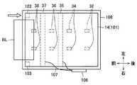
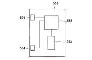
図5は、鑑別部14およびその周辺の平面図であり、図6は、鑑別部14およびその周辺の右側面図である。図5には、鑑別部14が有する各種センサを代表して、画像センサ35および磁気センサ37が示されており、図5からは、厚みセンサ33の図示が省略されている。以下では、画像センサ35および磁気センサ37をセンサの例として説明するが、センサの数および種類は限定されない。また、センサが設けられる位置も限定されない。また、図6からは、画像モジュール35Aおよび当接ローラ37Bの図示が省略されている。 FIG. 5 is a plan view of the
図6を参照すると、鑑別部14は、上側搬送部101および下側搬送部102を有している。上側搬送部101の下面と下側搬送部102の上面とは対向しており、上側搬送部101および下側搬送部102の間に紙幣BLの通過する空間が形成されている。また、図6に示すように、上側搬送部101と下側搬送部102とは支点103によって連結されている。画像センサ35および磁気センサ37それぞれは、信号線107によって基板106に接続されている。 Referring to FIG. 6, the
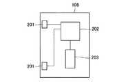
図7は、基板106の内部構成例を示す図である。図7に示すように、基板106は、画像センサ35および磁気センサ37それぞれと信号線107を介して接続する接続部201を有する。また、基板106は、センサ制御部202および記憶部203を有する。記憶部203は、画像センサ35および磁気センサ37といった各種センサに個体ばらつきによらず安定したセンサデータを出力させるために必要な調整値等を記憶する。例えば、記憶部203は、フラッシュメモリ等によって構成される。 FIG. 7 is a diagram illustrating an internal configuration example of the
センサ制御部202は、画像センサ35および磁気センサ37それぞれから得られるセンサデータを取得し、センサデータに基づいて紙幣を識別する。より具体的には、センサ制御部202は、これらのセンサデータに基づいて、紙幣の金種、真偽、正損(損傷しているか否か)等を認識する。例えば、センサ制御部202は、CPU、FPGA(field−programmable gate array)などによって構成される。 The
図5に示すように、基板106は、鑑別部14の外部に配置されている。したがって、基板106のセンサ制御部202から画像センサ35および磁気センサ37への熱の伝達を抑制することが可能となるため、鑑別部14の内部に存在する画像センサ35および磁気センサ37それぞれから出力されるセンサデータを安定させることが可能となる。そのため、センサデータに基づいて真券と偽造券とをより高精度に見分けることが可能となる。例えば、基板106は、鑑別部14とは物理的に離れた位置に配置されていてよい。 As shown in FIG. 5, the
また、図5および図6に示すように、基板106はカバー部材108によって覆われているのがよい。例えば、基板106の全体がカバー部材108によって覆われていてもよいし、基板106の一部(例えば、信号線107が通過する空間を除いた部分等)がカバー部材108によって覆われていてもよい。かかる構成によれば、基板106のセンサ制御部202から画像センサ35および磁気センサ37への熱の伝達をより効率良く抑制することが可能となる。 In addition, as shown in FIGS. 5 and 6, the
また、図8に示すように、基板106の代わりに鑑別部14(あるいは、画像センサ35および磁気センサ37)がカバー部材108によって覆われていてもよい。あるいは、基板106および鑑別部14(あるいは、画像センサ35および磁気センサ37)それぞれがカバー部材108によって覆われていてもよい。かかる構成によれば、基板106のセンサ制御部202から画像センサ35および磁気センサ37への熱の伝達をさらに効率良く抑制することが可能となる。 Further, as shown in FIG. 8, the discrimination unit 14 (or the
また、図5および図6に示すように、基板106の面と鑑別部14の内部に存在する紙幣の搬送面(上側搬送部101の下面、あるいは、下側搬送部102の上面)とは、垂直になるように配置されているのがよい。かかる構成によれば、紙幣入出金機10の内部の空間をより効率よく利用することが可能となる。 Further, as shown in FIGS. 5 and 6, the surface of the
また、基板106と画像センサ35および磁気センサ37との位置関係は限定されないが、基板106と画像センサ35および磁気センサ37との双方は、上部ブロック10U(図2)および下部ブロック10L(図2)のいずれか一方に備わっているのがよい(集められているのがよい)。かかる構成によれば、基板106とセンサと画像センサ35および磁気センサ37との距離が短くなり、基板106とセンサと画像センサ35および磁気センサ37とを接続する信号線107がより短くなるため、紙幣入出金機10の内部の空間をより効率よく利用することが可能となる。 Further, the positional relationship between the
[2−2.鑑別部の利用例]
続いて、図5〜図7を参照しながら、本発明の第1の実施形態に係る鑑別部14の利用例について説明する。まず、製品出荷時等に、画像センサ35および磁気センサ37に個体ばらつきによらず安定したセンサデータを出力させるために必要な調整値(例えば、LEDの発光電流値)等を記憶部203に記憶させておく。そして、運用時には、紙幣BLが鑑別部14に搬送されてくる前に、記憶部203に記憶された調整値に基づいて、センサ制御部202により調整が行われる。[2-2. Example of use of discrimination section]
Then, the usage example of the
鑑別部14の上流(図5および図6の左方)から搬送されてきた紙幣BLは、鑑別部14において、図示しないモータ等によって直接的または間接的に駆動された識別搬送ローラ32、34、36および38によって、次々に把持されて送り出されることで、鑑別部14の下流(図5および図6の右方)に搬送される。このように紙幣BLが鑑別部14の内部を搬送される間に、画像センサ35および磁気センサ37は、センサ制御部202の制御に従って、それぞれ紙幣BLに対するセンシングを行ってセンサデータを得る。 The banknotes BL conveyed from the upstream of the discrimination unit 14 (the left side in FIGS. 5 and 6) are identified and conveyed at the
画像センサ35および磁気センサ37それぞれによって得られたセンサデータは、センサ制御部202に出力される。センサ制御部202は、画像センサ35および磁気センサ37それぞれによって得られたセンサデータに基づいて、紙幣BLの金種、真偽、正損(損傷しているか否か)等を認識する。 Sensor data obtained by the
このとき、上記したように、基板106が鑑別部14の外部に存在すれば、センサ制御部202から画像センサ35および磁気センサ37への熱伝達が抑制される。また、上記したように、基板106がカバー部材108で覆われていれば、センサ制御部202から画像センサ35および磁気センサ37への熱伝達がさらに抑制される。 At this time, as described above, if the
[3.第2の実施形態の説明]
以上、本発明の第1の実施形態について説明した。続いて、本発明の第2の実施形態について説明する。ここで、本発明の第2の実施形態において、本発明の第1の実施形態と共通する部分に対しては、本発明の第1の実施形態に係る符号と同一の符号を付して、かかる共通部分の説明を省略する。また、本発明の第2の実施形態において、本発明の第1の実施形態と異なる部分について主に説明する。[3. Description of Second Embodiment]
The first embodiment of the present invention has been described above. Subsequently, a second embodiment of the present invention will be described. Here, in the second embodiment of the present invention, parts common to the first embodiment of the present invention are denoted by the same reference numerals as those in the first embodiment of the present invention, Description of such common parts is omitted. In the second embodiment of the present invention, parts different from the first embodiment of the present invention will be mainly described.
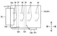
図9は、鑑別部14およびその周辺の平面図であり、図10は、鑑別部14およびその周辺の右側面図である。本発明の第2の実施形態においては、図9および図10に示すように、基板106は、鑑別部14の側面に配置されている。このように、鑑別部14の側面に基板106を配置するようにすれば、基板106の取り付けや信号線107の接続を容易に行うことができるため、組み立て性が向上する。 FIG. 9 is a plan view of the
支点103は、上側搬送部101および下側搬送部102のいずれか一方を開閉可能に支持する。図11は、上側搬送部101が下側搬送部102に対して開かれた状態を示す図である。図11に示した例では、支点103は、上側搬送部101を開閉可能に支持している。 The
また、基板106と磁気センサ37とは、支点103を通して配置される信号線107を介して接続されている。かかる構成によれば、信号線107を抜き差しする必要なく、上側搬送部101を開閉することが可能となるため、上側搬送部101の開閉を容易に行うことが可能となる。したがって、上側搬送部101の下面と下側搬送部102の上面との間の空間に紙幣が詰まった場合(ジャムが発生した場合)に、その紙幣を容易に除去することが可能となる。 The
さらに、基板106は上部ブロック10Uに設けられ、上部ブロック10Uと共に引き出し可能に構成されるとよい。図12は、基板106が上部ユニット10と共に引き出された状態を示す図である。図12に示したように、基板106は、上部ブロック10U(例えば、鑑別部14の側面)に備えられ、紙幣入出金機10の筐体19から引き出し可能に構成されるとよい。かかる構成によれば、製品出荷後に基板106が故障した場合等に、保守員は、筐体19から上部ブロック10Uを引き出すことによって、容易に基板106を交換することが可能となる。 Further, the
[4.第3の実施形態の説明]
[4−1.鑑別部の構成]
以上、本発明の第2の実施形態について説明した。続いて、本発明の第3の実施形態について説明する。ここで、本発明の第3の実施形態において、本発明の第2の実施形態と共通する部分に対しては、本発明の第2の実施形態に係る符号と同一の符号を付して、かかる共通部分の説明を省略する。また、本発明の第3の実施形態において、本発明の第2の実施形態と異なる部分について主に説明する。[4. Description of Third Embodiment]
[4-1. Configuration of the identification section]
The second embodiment of the present invention has been described above. Subsequently, a third embodiment of the present invention will be described. Here, in the third embodiment of the present invention, parts common to the second embodiment of the present invention are denoted by the same reference numerals as those according to the second embodiment of the present invention, Description of such common parts is omitted. In the third embodiment of the present invention, parts different from the second embodiment of the present invention will be mainly described.
図13は、本発明の第3の実施形態に係る鑑別部14およびその周辺の平面図であり、図14は、本発明の第3の実施形態に係る鑑別部14およびその周辺の右側面図である。磁気センサ37は、センサ基板501に接続されている。図15は、センサ基板501の内部構成例を示す図である。センサ基板501は、センサ基板側制御部502、センサ基板側記憶部503、センサ基板側接続部504およびセンサ接続部505を有している。 FIG. 13 is a plan view of the
センサ接続部505は、磁気センサ37およびセンサ基板側制御部502と接続されている。また、センサ基板側制御部502は、センサ基板側記憶部503およびセンサ基板側接続部504と接続されている。また、センサ基板側接続部504は、制御基板551の2つの制御基板側接続部554(図16)の一方と接続されている。制御基板551の2つの制御基板側接続部554(図16)の他方は、画像センサ35と接続されている。 The
図16は、制御基板551の内部構成例を示す図である。制御基板551は、本発明の第1の実施形態および本発明の第2の実施形態における基板106と同様の構成を有しているが、センサ基板501と区別されるように、内部の各構成の名称および符号が付されている。具体的に、制御基板551は、制御基板側センサ制御部552、制御基板側記憶部553および2つの制御基板側接続部554を有している。 FIG. 16 is a diagram illustrating an internal configuration example of the
ここで、本発明の第3の実施形態では、センサ基板501のセンサ基板側記憶部503は、磁気センサ37に個体ばらつきによらず安定したセンサデータを出力させるために必要な調整値を記憶させる。また、磁気センサ37によって検出されるセンサデータに対して影響を与える部品をセンサ基板501に設けるようにする。磁気センサ37から出力されるセンサデータに対して影響を与える部品としては、磁気センサ37からのアナログ出力に影響を与えるA/Dコンバータ、センサ電源等が挙げられる。 Here, in the third embodiment of the present invention, the sensor board-
一方、磁気センサ37に個体ばらつきによらず安定したセンサデータを出力させるために必要な調整値以外のデータは、制御基板551の制御基板側記憶部553に記憶させてよい。また、磁気センサ37から出力されるセンサデータに対して影響を与える部品以外の部品は、制御基板551に設けてよい。 On the other hand, data other than adjustment values necessary for causing the
以上に説明したように、本発明の第3の実施形態においては、鑑別部14は、センサデータを調整するための調整値とセンサデータに対して影響を与える部品とを有するセンサ基板501を備えている。かかる構成によれば、製品出荷後に、磁気センサ37またはセンサ基板501が故障した場合に、保守員が磁気センサ37とあらかじめ調整されたセンサ基板501とのセットを持参すれば、容易に磁気センサ37およびセンサ基板501を交換することが可能となる。 As described above, in the third embodiment of the present invention, the
また、これによって、磁気センサ37およびセンサ基板501の交換作業に要する時間も短縮される。さらに、磁気センサ37およびセンサ基板501を交換した後にセンサデータを調整する必要がなくなるため、装置復旧までの時間を短縮し、顧客を待たせてしまう時間を短縮することが可能となる。 This also shortens the time required to replace the
[4−2.鑑別部の利用例]
続いて、図13〜図16を参照しながら、本発明の第3の実施形態に係る鑑別部14の利用例について説明する。本発明の第1の実施形態と同様に、製品出荷時等に、磁気センサ37によって検出されるセンサデータに対して影響を与える部品を有するセンサ基板501と磁気センサ37とを用いて、磁気センサ37に個体ばらつきによらず安定したセンサデータを出力させるために必要な調整値を測定する。そして、かかる測定値を記憶部203に記憶させておく。[4-2. Example of use of discrimination section]
Then, the usage example of the
かかる調整値の測定は、紙幣入出金機10の全体を用いて行ってもよいが、センサ基板501と磁気センサ37とを用いて行えばよい。あるいは、紙幣入出金機10の動作と同様の動作をする出荷試験用の設備を準備し、その設備にセンサ基板501と磁気センサ37とを適用した上で調整値の測定を行い、測定が終わったら、センサ基板501と磁気センサ37とを出荷試験用の設備とは別の装置に搭載して出荷してもよい。そうすれば、流れ作業により生産性を向上させることが可能となる。 The adjustment value may be measured using the entire banknote depositing / dispensing
[5.第4の実施形態の説明]
以上、本発明の第3の実施形態について説明した。続いて、本発明の第4の実施形態について説明する。ここで、本発明の第4の実施形態において、本発明の第1の実施形態と共通する部分に対しては、本発明の第1の実施形態に係る符号と同一の符号を付して、かかる共通部分の説明を省略する。また、本発明の第4の実施形態において、本発明の第1の実施形態と異なる部分について主に説明する。[5. Description of Fourth Embodiment]
Heretofore, the third embodiment of the present invention has been described. Subsequently, a fourth embodiment of the present invention will be described. Here, in the fourth embodiment of the present invention, parts common to the first embodiment of the present invention are denoted by the same reference numerals as those according to the first embodiment of the present invention, Description of such common parts is omitted. In the fourth embodiment of the present invention, parts different from the first embodiment of the present invention will be mainly described.
図170は、本発明の第4の実施形態に係る基板の内部構成例を示す図である。図17に示すように、本発明の第4の実施形態に係る基板は、鑑別部14に関連する基板(2つの接続部201、センサ制御部202および記憶部203を有する基板)と、搬送制御に関する基板300とが同一基板上に設けられている。基板300は、搬送制御部301と、搬送監視センサ制御回路302と、搬送監視センサ303と、搬送モータ制御回路304と、搬送モータ305と、接続部306と、接続部307とを備えている。 FIG. 170 is a diagram showing an internal configuration example of a substrate according to the fourth embodiment of the present invention. As shown in FIG. 17, the substrate according to the fourth embodiment of the present invention includes a substrate related to the discrimination unit 14 (a substrate having two
搬送監視センサ303は、紙幣の搬送状態(紙幣BLの位置)を監視する。搬送監視センサ制御回路302は、搬送監視センサ303によって監視された紙幣の搬送状態を得る。また、搬送制御部301は、搬送監視センサ制御回路302から得られた紙幣の搬送状態に基づいて、搬送モータ制御回路304に搬送指示を出す。搬送モータ制御回路304は、搬送指示に基づいて、搬送モータ305を制御する。搬送モータ305は、搬送モータ制御回路304による搬送制御に従って、紙幣の搬送を駆動する。 The
また、搬送制御部301は、センサ制御部202から得られた紙幣の認識結果に基づいて、搬送モータ制御回路304に搬送の変更指示を出す。搬送モータ制御回路304は、搬送の変更指示に基づいて、搬送モータ305を制御する。搬送モータ305は、搬送モータ制御回路304による搬送制御に従って、紙幣の搬送を駆動する。例えば、紙幣の認識結果が「偽造券」であると認識された場合には、その紙幣は、入出金口5に搬送される。 Further, the
以上に説明したように、本発明の第4の実施形態においては、紙幣の搬送を制御する搬送制御部301とセンサ制御部202とを同一基板上に搭載される。これによって、基板に要するコストが低減されるとともに、紙幣入出金機10の内部の空間をより効率よく利用することが可能となる。また、搬送制御部301とセンサ制御部202との間は、同一基板上で通信可能であるため、ケーブルおよびコネクタが削減され、処理が高速化するとともに通信の安定性が向上する。 As described above, in the fourth embodiment of the present invention, the
[6.第5の実施形態の説明]
以上、本発明の第4の実施形態について説明した。続いて、本発明の第5の実施形態について説明する。ここで、本発明の第5の実施形態において、本発明の第4の実施形態と共通する部分に対しては、本発明の第4の実施形態に係る符号と同一の符号を付して、かかる共通部分の説明を省略する。また、本発明の第5の実施形態において、本発明の第4の実施形態と異なる部分について主に説明する。[6. Description of Fifth Embodiment]
Heretofore, the fourth embodiment of the present invention has been described. Subsequently, a fifth embodiment of the present invention will be described. Here, in the fifth embodiment of the present invention, parts common to the fourth embodiment of the present invention are denoted by the same reference numerals as those in the fourth embodiment of the present invention, Description of such common parts is omitted. In the fifth embodiment of the present invention, parts different from the fourth embodiment of the present invention will be mainly described.
図18は、本発明の第5の実施形態に係る基板の内部構成例を示す図である。本発明の第4の実施形態においては、搬送制御部301(図17)とセンサ制御部202(図17)とが別々に基板上に存在していたが、図18に示すように、本発明の第5の実施形態においては、図17に示した搬送制御部301およびセンサ制御部202に相当する構成が統合制御部401として基板上に存在している。具体的には、搬送制御部301およびセンサ制御部202に相当する構成を同一のCPUおよびメモリによって実現する。 FIG. 18 is a diagram illustrating an internal configuration example of a substrate according to the fifth embodiment of the present invention. In the fourth embodiment of the present invention, the transport control unit 301 (FIG. 17) and the sensor control unit 202 (FIG. 17) exist separately on the substrate. However, as shown in FIG. In the fifth embodiment, a configuration corresponding to the
以上に説明したように、本発明の第5の実施形態においては、図17に示した搬送制御部301およびセンサ制御部202に相当する構成が統合制御部401として基板上に形成される。これによって、搬送制御部301(図17)およびセンサ制御部202(図17)それぞれのリソース余剰分(例えば、CPUがオーバスペックである場合におけるCPUリソースの余剰分、メモリの不使用領域に相当するメモリリソースの余剰分など)を統合して考慮することによって、リソースを効率よく利用することが可能となる。 As described above, in the fifth embodiment of the present invention, the configuration corresponding to the
これによって、図17に示した搬送制御部301およびセンサ制御部202に相当する構成のトータルコストを低減することが可能となる。また、本発明の第5の実施形態においても、搬送制御部301とセンサ制御部202とが同一基板上に搭載されているため、本発明の第4の実施形態が奏する効果と同様の効果を奏し得る。 As a result, it is possible to reduce the total cost of the configuration corresponding to the
以上、添付図面を参照しながら本発明の好適な実施形態について詳細に説明したが、本発明はかかる例に限定されない。本発明の属する技術の分野における通常の知識を有する者であれば、特許請求の範囲に記載された技術的思想の範疇内において、各種の変更例または修正例に想到し得ることは明らかであり、これらについても、当然に本発明の技術的範囲に属するものと了解される。 The preferred embodiments of the present invention have been described in detail above with reference to the accompanying drawings, but the present invention is not limited to such examples. It is obvious that a person having ordinary knowledge in the technical field to which the present invention pertains can come up with various changes or modifications within the scope of the technical idea described in the claims. Of course, it is understood that these also belong to the technical scope of the present invention.
例えば、本発明の第1の実施形態から第5の実施形態までにおいては、紙幣入出金機(紙幣処理装置)10によって扱われる媒体の例として紙幣を取り上げた。しかし、紙幣入出金機(紙幣処理装置)10によって扱われる媒体は、紙幣に限定されない。例えば、紙幣入出金機(紙幣処理装置)10によって扱われる媒体は、硬貨であってもよいし、他の媒体であってもよい。 For example, in the first to fifth embodiments of the present invention, banknotes are taken up as examples of media handled by the banknote depositing / dispensing machine (banknote processing apparatus) 10. However, the medium handled by the banknote depositing / dispensing machine (banknote processing apparatus) 10 is not limited to banknotes. For example, the medium handled by the banknote depositing and dispensing machine (banknote processing apparatus) 10 may be a coin or another medium.
また、上記においては、本発明の第1の実施形態から第5の実施形態までを順に説明したが、本発明の第1の実施形態から第5の実施形態までのいずれかは適宜に組み合わされてよい。例えば、本発明の第4の実施形態または第5の実施形態のように、搬送制御部とセンサ制御部とを同一の基板に搭載することと、本発明の第1の実施形態または第2の実施形態のように、基板をカバー部材で覆うこととを組み合わせてもよい。 In the above description, the first to fifth embodiments of the present invention have been described in order. However, any of the first to fifth embodiments of the present invention is appropriately combined. It's okay. For example, as in the fourth embodiment or the fifth embodiment of the present invention, the conveyance control unit and the sensor control unit are mounted on the same substrate, and the first or second embodiment of the present invention. It may be combined with covering the substrate with a cover member as in the embodiment.
1 自動取引装置
10 紙幣入出金機
10U 上部ブロック
10L 下部ブロック
11 紙幣制御部
12 入出金部
13 搬送部
14 鑑別部
30 搬送ガイド
30A 上搬送ガイド
30B 下搬送ガイド
33 厚みセンサ
35 画像センサ
37 磁気センサ
101 上側搬送部
102 下側搬送部
103 支点
106 基板
107 信号線
108 カバー部材
202 センサ制御部
300 基板
301 搬送制御部
401 統合制御部
501 センサ基板
502 センサ基板側制御部
503 センサ基板側記憶部
504 センサ基板側接続部
505 センサ接続部
551 制御基板
552 制御基板側センサ制御部
553 制御基板側記憶部
554 制御基板側接続部
BL 紙幣
DESCRIPTION OF
Claims (12)
Translated fromJapanese前記センサが読み取った情報に基づいて前記媒体を識別するセンサ制御部と、を備え、
前記センサ制御部は、前記鑑別部の外部に配置されている、
媒体処理装置。A discrimination unit having a sensor for reading predetermined information from a medium inside;
A sensor control unit that identifies the medium based on information read by the sensor,
The sensor control unit is disposed outside the discrimination unit,
Media processing device.
請求項1に記載の媒体処理装置。The medium processing apparatus further includes a cover member that covers at least one of the sensor control unit and the sensor,
The medium processing apparatus according to claim 1.
請求項1に記載の媒体処理装置。The sensor control unit is disposed on a side surface of the discrimination unit.
The medium processing apparatus according to claim 1.
請求項1に記載の媒体処理装置。The sensor control unit is disposed at a position physically separated from the discrimination unit,
The medium processing apparatus according to claim 1.
請求項1に記載の媒体処理装置。The sensor control unit is arranged such that a substrate surface on which the sensor control unit is mounted and a conveyance surface of the medium existing inside the discrimination unit are perpendicular to each other.
The medium processing apparatus according to claim 1.
前記センサ制御部と前記センサとの双方は、前記上部ブロックおよび前記下部ブロックのいずれか一方に備わっている、
請求項1に記載の媒体処理装置。The medium processing apparatus has an upper block and a lower block,
Both the sensor control unit and the sensor are provided in either the upper block or the lower block.
The medium processing apparatus according to claim 1.
請求項6に記載の媒体処理装置。Both the sensor control unit and the sensor are provided in the upper block, and the upper block is configured to be drawable.
The medium processing apparatus according to claim 6.
前記センサ制御部と前記搬送制御部とは、同一基板上に搭載されている、
請求項1に記載の媒体処理装置。The medium processing apparatus includes a transport control unit that controls transport of the medium,
The sensor control unit and the transport control unit are mounted on the same substrate.
The medium processing apparatus according to claim 1.
請求項8に記載の媒体処理装置。The sensor control unit and the transport control unit constitute an integrated control unit by being integrated into one,
The medium processing apparatus according to claim 8.
前記センサ制御部と前記センサとは、前記支点を通して配置される信号線を介して接続される、
請求項1に記載の媒体処理装置。The discrimination unit has an upper conveyance unit, a lower conveyance unit, and a fulcrum that supports one of the upper conveyance unit and the lower conveyance unit so as to be openable and closable,
The sensor control unit and the sensor are connected via a signal line arranged through the fulcrum.
The medium processing apparatus according to claim 1.
前記センサから出力されるセンサデータを調整するための調整値と前記センサデータに対して影響を与える部品とを有するセンサ基板を備える、
請求項1に記載の媒体処理装置。The medium processing apparatus includes:
A sensor board having an adjustment value for adjusting sensor data output from the sensor and a part that affects the sensor data;
The medium processing apparatus according to claim 1.
前記センサが読み取った情報に基づいて前記媒体を識別するセンサ制御部と、を備え、
前記センサ制御部は、前記鑑別部の外部に配置されている、
自動取引装置。
A discrimination unit having a sensor for reading predetermined information from a medium inside;
A sensor control unit that identifies the medium based on information read by the sensor,
The sensor control unit is disposed outside the discrimination unit,
Automatic transaction device.
Priority Applications (2)
| Application Number | Priority Date | Filing Date | Title |
|---|---|---|---|
| JP2015122690AJP2017010149A (en) | 2015-06-18 | 2015-06-18 | Medium processing apparatus and automatic transaction apparatus |
| PCT/JP2016/064133WO2016203876A1 (en) | 2015-06-18 | 2016-05-12 | Medium processing device and automatic transaction device |
Applications Claiming Priority (1)
| Application Number | Priority Date | Filing Date | Title |
|---|---|---|---|
| JP2015122690AJP2017010149A (en) | 2015-06-18 | 2015-06-18 | Medium processing apparatus and automatic transaction apparatus |
Publications (1)
| Publication Number | Publication Date |
|---|---|
| JP2017010149Atrue JP2017010149A (en) | 2017-01-12 |
Family
ID=57545141
Family Applications (1)
| Application Number | Title | Priority Date | Filing Date |
|---|---|---|---|
| JP2015122690APendingJP2017010149A (en) | 2015-06-18 | 2015-06-18 | Medium processing apparatus and automatic transaction apparatus |
Country Status (2)
| Country | Link |
|---|---|
| JP (1) | JP2017010149A (en) |
| WO (1) | WO2016203876A1 (en) |
Citations (9)
| Publication number | Priority date | Publication date | Assignee | Title |
|---|---|---|---|---|
| JPH03127968U (en)* | 1990-04-09 | 1991-12-24 | ||
| JPH05128343A (en)* | 1984-10-10 | 1993-05-25 | Mars Inc | Method and apparatus for confirming currency |
| JPH07157998A (en)* | 1993-12-02 | 1995-06-20 | Nhk Spring Co Ltd | Material to be analyzed, capable of check of trueness and its production |
| JP2004265104A (en)* | 2003-02-28 | 2004-09-24 | Nidec Copal Corp | Inspection device |
| JP2006268484A (en)* | 2005-03-24 | 2006-10-05 | Glory Ltd | Coin discriminating device |
| JP2008020983A (en)* | 2006-07-11 | 2008-01-31 | Oki Electric Ind Co Ltd | Automatic transaction device equipped with restoration navigation function |
| JP2014044682A (en)* | 2012-08-28 | 2014-03-13 | Univ Of Ryukyus | Paper sheet fatigue determination device, paper money processor and paper sheet fatigue determination method |
| JP2014169164A (en)* | 2013-03-05 | 2014-09-18 | Hitachi Omron Terminal Solutions Corp | Thickness detection device of paper sheet, bill determination device, and bill handling device |
| JP2014235577A (en)* | 2013-06-03 | 2014-12-15 | 日立オムロンターミナルソリューションズ株式会社 | Identification device for paper sheets and optical sensor device |
- 2015
- 2015-06-18JPJP2015122690Apatent/JP2017010149A/enactivePending
- 2016
- 2016-05-12WOPCT/JP2016/064133patent/WO2016203876A1/ennot_activeCeased
Patent Citations (9)
| Publication number | Priority date | Publication date | Assignee | Title |
|---|---|---|---|---|
| JPH05128343A (en)* | 1984-10-10 | 1993-05-25 | Mars Inc | Method and apparatus for confirming currency |
| JPH03127968U (en)* | 1990-04-09 | 1991-12-24 | ||
| JPH07157998A (en)* | 1993-12-02 | 1995-06-20 | Nhk Spring Co Ltd | Material to be analyzed, capable of check of trueness and its production |
| JP2004265104A (en)* | 2003-02-28 | 2004-09-24 | Nidec Copal Corp | Inspection device |
| JP2006268484A (en)* | 2005-03-24 | 2006-10-05 | Glory Ltd | Coin discriminating device |
| JP2008020983A (en)* | 2006-07-11 | 2008-01-31 | Oki Electric Ind Co Ltd | Automatic transaction device equipped with restoration navigation function |
| JP2014044682A (en)* | 2012-08-28 | 2014-03-13 | Univ Of Ryukyus | Paper sheet fatigue determination device, paper money processor and paper sheet fatigue determination method |
| JP2014169164A (en)* | 2013-03-05 | 2014-09-18 | Hitachi Omron Terminal Solutions Corp | Thickness detection device of paper sheet, bill determination device, and bill handling device |
| JP2014235577A (en)* | 2013-06-03 | 2014-12-15 | 日立オムロンターミナルソリューションズ株式会社 | Identification device for paper sheets and optical sensor device |
Also Published As
| Publication number | Publication date |
|---|---|
| WO2016203876A1 (en) | 2016-12-22 |
Similar Documents
| Publication | Publication Date | Title |
|---|---|---|
| US20160335614A1 (en) | Medium processing device and medium transaction device | |
| JP6303921B2 (en) | Media transaction equipment | |
| WO2016013324A1 (en) | Medium processing device and medium transaction device | |
| JP7196768B2 (en) | Media processing device and media trading device | |
| JP2008084164A (en) | Bill handling device | |
| JP6031792B2 (en) | Automatic teller machine | |
| JP2010231263A (en) | Paper sheet processing apparatus and automatic transaction apparatus | |
| JP6561657B2 (en) | Paper sheet processing apparatus and paper sheet discrimination apparatus | |
| JP4887554B2 (en) | Automatic transaction equipment | |
| JP6237911B2 (en) | Medium transport identification apparatus and medium transaction apparatus | |
| US20240273962A1 (en) | Medium processing device and medium transaction device | |
| WO2015107730A1 (en) | Paper currency processing device and paper currency transaction device | |
| JP6303898B2 (en) | Medium discrimination apparatus and medium processing apparatus | |
| US20060244193A1 (en) | Apparatus of withdrawing cash from cash transaction machine | |
| JPH05266299A (en) | Automatic teller machine | |
| KR20130138510A (en) | An apparatus for receving and dispensing banknotes/checks in atm and the operating method thereof | |
| JP2010231262A (en) | Paper sheet handling device | |
| JP2017010149A (en) | Medium processing apparatus and automatic transaction apparatus | |
| JP6409525B2 (en) | Antistatic mechanism and medium transaction device | |
| KR101385878B1 (en) | Financial device having apparatus for billing storage and control method thereof | |
| JP6861467B2 (en) | Money management system, money processing device and money management method | |
| JP2016223499A (en) | Power transmission device | |
| JP2019169041A (en) | Valuable medium processing system, valuable medium processing device, program, recording medium, and valuable medium processing method | |
| JP2014016717A (en) | Medium processing device, and medium processing program | |
| WO2019159433A1 (en) | Automatic transaction device |
Legal Events
| Date | Code | Title | Description |
|---|---|---|---|
| A621 | Written request for application examination | Free format text:JAPANESE INTERMEDIATE CODE: A621 Effective date:20180215 | |
| RD03 | Notification of appointment of power of attorney | Free format text:JAPANESE INTERMEDIATE CODE: A7423 Effective date:20190327 | |
| RD04 | Notification of resignation of power of attorney | Free format text:JAPANESE INTERMEDIATE CODE: A7424 Effective date:20190328 | |
| A131 | Notification of reasons for refusal | Free format text:JAPANESE INTERMEDIATE CODE: A131 Effective date:20190507 | |
| A02 | Decision of refusal | Free format text:JAPANESE INTERMEDIATE CODE: A02 Effective date:20191112 |