JP2017004259A - Microcontroller - Google Patents
MicrocontrollerDownload PDFInfo
- Publication number
- JP2017004259A JP2017004259AJP2015117632AJP2015117632AJP2017004259AJP 2017004259 AJP2017004259 AJP 2017004259AJP 2015117632 AJP2015117632 AJP 2015117632AJP 2015117632 AJP2015117632 AJP 2015117632AJP 2017004259 AJP2017004259 AJP 2017004259A
- Authority
- JP
- Japan
- Prior art keywords
- microcontroller
- mcu
- component
- abnormal
- self
- Prior art date
- Legal status (The legal status is an assumption and is not a legal conclusion. Google has not performed a legal analysis and makes no representation as to the accuracy of the status listed.)
- Pending
Links
- 230000005856abnormalityEffects0.000claimsabstractdescription38
- 238000004092self-diagnosisMethods0.000claimsabstractdescription29
- 230000002159abnormal effectEffects0.000claimsabstractdescription25
- 238000005259measurementMethods0.000claimsdescription7
- 230000002093peripheral effectEffects0.000claimsdescription7
- 238000001514detection methodMethods0.000abstractdescription9
- 238000000034methodMethods0.000description62
- 238000003745diagnosisMethods0.000description33
- 230000006870functionEffects0.000description15
- 238000012545processingMethods0.000description9
- 238000006243chemical reactionMethods0.000description7
- 238000012544monitoring processMethods0.000description5
- 238000005286illuminationMethods0.000description4
- 238000002405diagnostic procedureMethods0.000description3
- 238000012790confirmationMethods0.000description2
- 239000000470constituentSubstances0.000description2
- 230000003247decreasing effectEffects0.000description1
- 238000010586diagramMethods0.000description1
- 230000009191jumpingEffects0.000description1
- 238000013021overheatingMethods0.000description1
- 238000011084recoveryMethods0.000description1
- 238000012360testing methodMethods0.000description1
- 230000007704transitionEffects0.000description1
- 238000004804windingMethods0.000description1
Images

Classifications
- Y—GENERAL TAGGING OF NEW TECHNOLOGICAL DEVELOPMENTS; GENERAL TAGGING OF CROSS-SECTIONAL TECHNOLOGIES SPANNING OVER SEVERAL SECTIONS OF THE IPC; TECHNICAL SUBJECTS COVERED BY FORMER USPC CROSS-REFERENCE ART COLLECTIONS [XRACs] AND DIGESTS
- Y02—TECHNOLOGIES OR APPLICATIONS FOR MITIGATION OR ADAPTATION AGAINST CLIMATE CHANGE
- Y02D—CLIMATE CHANGE MITIGATION TECHNOLOGIES IN INFORMATION AND COMMUNICATION TECHNOLOGIES [ICT], I.E. INFORMATION AND COMMUNICATION TECHNOLOGIES AIMING AT THE REDUCTION OF THEIR OWN ENERGY USE
- Y02D10/00—Energy efficient computing, e.g. low power processors, power management or thermal management
Landscapes
- Test And Diagnosis Of Digital Computers (AREA)
- Microcomputers (AREA)
Abstract
Description
Translated fromJapanese本発明は、自己診断機能を有するマイクロコントローラに関する。 The present invention relates to a microcontroller having a self-diagnosis function.
一般に、マイクロコントローラは、自己診断機能により異常を検出すると、実行中のプログラムを無限ループに移行させることで、他のプログラムを実行しないように構成されている(例えば、非特許文献1参照)。 In general, when an abnormality is detected by the self-diagnosis function, the microcontroller is configured not to execute another program by shifting the program being executed to an infinite loop (see, for example, Non-Patent Document 1).
また、マイクロコントローラには、通常、ウォッチドッグタイマが設けられており、マイクロコントローラが正常動作しているときには、ウォッチドッグタイマを定期的にリセットするようにされている。 The microcontroller is usually provided with a watchdog timer. When the microcontroller is operating normally, the watchdog timer is periodically reset.
ウォッチドッグタイマは、時間を計時し、計時時間が所定の監視時間に達するまでの間にリセットされないと(つまり計時時間が監視時間に達すると)、マイクロコントローラの動作が異常であると判断して、マイクロコントローラをリセット(再起動)させる。 The watchdog timer counts the time, and if it is not reset before the time reaches the specified monitoring time (that is, when the time reaches the monitoring time), it determines that the microcontroller is operating abnormally. , Reset (restart) the microcontroller.
このため、自己診断機能によって、マイクロコントローラが実行するプログラムが無限ループに入ると、ウォッチドッグタイマがリセットされなくなるので、ウォッチドッグタイマがマイクロコントローラを再起動させることになる。 For this reason, when the program executed by the microcontroller enters an infinite loop by the self-diagnosis function, the watchdog timer is not reset, and the watchdog timer restarts the microcontroller.
そして、その再起動によってマイクロコントローラが正常状態に復帰すれば、制御を継続して実行することができるようになる。
なお、このようにマイクロコントローラが実行中のプログラムを無限ループに移行させて、ウォッチドッグタイマの機能によりマイクロコントローラを再起動させることは、特許文献1に記載されている。If the microcontroller returns to the normal state by the restart, the control can be continuously executed.
Patent Document 1 discloses that the program being executed by the microcontroller is shifted to an infinite loop and the microcontroller is restarted by the function of the watchdog timer.
しかし、自己診断機能によって異常を検出した際、マイクロコントローラのプログラムが必ず無限ループに移行させると、マイクロコントローラや周辺回路(ウォッチドッグタイマ等)には、電力を供給し続けるという問題があった。 However, when an abnormality is detected by the self-diagnosis function, there is a problem that if the program of the microcontroller always shifts to an infinite loop, power is continuously supplied to the microcontroller and peripheral circuits (such as a watchdog timer).
特に、バッテリから電力供給を受けて動作するマイクロコントローラの場合、無限ループに入りウォッチドッグタイマによる再起動によって正常復帰できないときには、自己診断−再起動が繰り返されるため、バッテリが過放電されてしまうという問題がある。 In particular, in the case of a microcontroller that operates by receiving power supply from a battery, when normal recovery cannot be achieved by restart by a watchdog timer, the self-diagnosis and restart are repeated, so that the battery is overdischarged. There's a problem.
本発明は、こうした問題に鑑みなされたものであり、自己診断機能による異常検出後の動作を異常内容に応じて切り替え、消費電力を低減することのできるマイクロコントローラを提供することを目的とする。 The present invention has been made in view of these problems, and an object of the present invention is to provide a microcontroller that can switch the operation after abnormality detection by the self-diagnosis function according to the abnormality content and reduce power consumption.
本発明のマイクロコントローラは、自己診断部と、ウォッチドッグタイマと、異常時動作切替部と、を備える。
ここで、自己診断部は、マイクロコントローラを構成している複数の構成要素が正常であるか否かを、構成要素毎に診断する。The microcontroller of the present invention includes a self-diagnosis unit, a watchdog timer, and an abnormal operation switching unit.
Here, the self-diagnosis unit diagnoses for each component whether or not the plurality of components constituting the microcontroller are normal.
また、ウォッチドッグタイマは、時間を計測し、マイクロコントローラがプログラムを実行することにより周期的に発生するタイミングで計測時間がクリアされ、その計測時間が設定時間に達するとマイクロコントローラをリセットする。 The watchdog timer measures time, and the measurement time is cleared at a timing periodically generated when the microcontroller executes the program. When the measurement time reaches the set time, the microcontroller is reset.
そして、異常時動作切替部は、自己診断部にて構成要素の異常が診断されると、異常診断された構成要素の種類に応じて、マイクロコントローラの動作を、正常時とは異なる動作に切り替える。 Then, when the abnormality of the component is diagnosed by the self-diagnosis unit, the operation switching unit at the time of abnormality switches the operation of the microcontroller to an operation different from that at the normal time according to the type of the component diagnosed abnormally. .
具体的には、異常時動作切替部は、異常診断された構成要素の種類に応じて、マイクロコントローラの動作モードを正常時よりも消費電力が少ない省電力モードに切り替えるか、或いは、マイクロコントローラが実行中のプログラムを無限ループに移行させる。 Specifically, the abnormal operation switching unit switches the operation mode of the microcontroller to a power saving mode that consumes less power than normal according to the type of component diagnosed abnormally, or the microcontroller Move the running program into an infinite loop.
このため、異常時動作切替部が、マイクロコントローラが実行中のプログラムを無限ループに移行させたときには、ウォッチドッグタイマの計測時間がクリアされなくなって、その計測時間が設定時間に達したときにマイクロコントローラがリセットされることになる。 For this reason, when the abnormal operation switching unit shifts the program being executed by the microcontroller to an infinite loop, the measurement time of the watchdog timer is not cleared, and the micro time is reached when the measurement time reaches the set time. The controller will be reset.
また、異常時動作切替部が、マイクロコントローラの動作モードを省電力モードに切り替えた際には、マイクロコントローラによる消費電力が低減される。
従って、本発明のマイクロコントローラによれば、自己診断機能による異常検出後の動作を、検出した異常内容に応じて、無限ループプログラムの実行と、省電力モードへの移行と、の何れかに切り換えることができる。Further, when the abnormal operation switching unit switches the operation mode of the microcontroller to the power saving mode, power consumption by the microcontroller is reduced.
Therefore, according to the microcontroller of the present invention, the operation after the abnormality detection by the self-diagnosis function is switched between the execution of the infinite loop program and the transition to the power saving mode according to the detected abnormality content. be able to.
そして、自己診断機能による異常検出時にマイクロコントローラが省電力モードへ移行した際には、マイクロコントローラによる消費電力が減少するので、マイクロコントローラの省電力化を図ることができる。 When the microcontroller shifts to the power saving mode when an abnormality is detected by the self-diagnosis function, the power consumption by the microcontroller is reduced, so that the power consumption of the microcontroller can be reduced.
このため、マイクロコントローラが、バッテリからの電力供給により動作するものである場合には、バッテリからの放電を抑制して、バッテリが過放電状態となる確率を低減することができる。 For this reason, when the microcontroller operates by supplying power from the battery, it is possible to suppress the discharge from the battery and reduce the probability that the battery is in an overdischarged state.
ところで、自己診断部にて診断される複数の構成要素は、異常時にプログラムの実行により制御対象を異常動作させてしまう第1の構成要素と、異常時にプログラムを正常に実行できなくなる第2の構成要素とに分類されていてもよい。 By the way, the plurality of constituent elements diagnosed by the self-diagnosis unit are a first constituent element that causes the control target to operate abnormally by executing the program in the event of an abnormality, and a second configuration in which the program cannot be executed normally in the event of an abnormality. It may be classified as an element.
また、この場合、異常時動作切替部は、第1の構成要素の異常診断時には、マイクロコントローラの動作モードを省電力モードに切り替え、第2の構成要素の異常診断時には、マイクロコントローラが実行中のプログラムを無限ループに移行させる、ように構成されていてもよい。 Further, in this case, the operation switching unit at the time of abnormality switches the operation mode of the microcontroller to the power saving mode at the time of abnormality diagnosis of the first component, and the microcontroller is executing at the time of abnormality diagnosis of the second component. The program may be configured to shift to an infinite loop.
そして、異常時動作切替部をこのように構成した場合、第1の構成要素の異常診断時には、マイクロコントローラを省電力モードに移行させて、マイクロコントローラでの消費電力を抑えることができると共に、プログラムの実行を制限することができる。このため、マイクロコントローラがプログラムを実行することにより制御対象が異常動作するのを防止できる。 When the abnormal operation switching unit is configured in this way, when the abnormality diagnosis of the first component is performed, the microcontroller can be shifted to the power saving mode, and the power consumption in the microcontroller can be suppressed. Execution can be restricted. For this reason, it is possible to prevent the controlled object from operating abnormally when the microcontroller executes the program.
また、第2の構成要素の異常診断時には、マイクロコントローラが実行中のプログラムを無限ループへ移行させることで、プログラムを正常に実行できなくなって、制御対象が誤制御されるのを防止することができる。また、この場合、ウォッチドッグタイマによりマイクロコントローラをリセットさせて、正常状態への自動復帰を図ることもできる。 In addition, when the abnormality diagnosis of the second component is performed, the program being executed by the microcontroller is shifted to an infinite loop, thereby preventing the program from being executed normally and preventing the control target from being erroneously controlled. it can. In this case, the microcontroller can be reset by the watchdog timer to automatically return to the normal state.
なお、第1の構成要素としては、マイクロコントローラの信号入出力系、クロック入力系、及び、割り込み入力系の少なくとも一つを含むようにしてもよい。また、第2の構成要素としては、プログラムカウンタ、レジスタ、及び、メモリの少なくとも一つを含むようにしてもよい。 Note that the first component may include at least one of a signal input / output system, a clock input system, and an interrupt input system of the microcontroller. Further, the second component may include at least one of a program counter, a register, and a memory.
次に、異常時動作切替部は、マイクロコントローラの動作モードを省電力モードに切り替えるときには、制御対象の駆動を停止させるように構成されていてもよい。
この場合、マイクロコントローラが省電力モードとなって、プログラムの実行を制限されているときに、制御対象が駆動回路を介して駆動されるのを防止できる。Next, the abnormal-time operation switching unit may be configured to stop the drive of the controlled object when the operation mode of the microcontroller is switched to the power saving mode.
In this case, it is possible to prevent the controlled object from being driven via the drive circuit when the microcontroller is in the power saving mode and execution of the program is restricted.
また、異常時動作切替部は、マイクロコントローラの動作モードを省電力モードに切り替えるときには、当該マイクロコントローラにより制御対象とは別に駆動制御される周辺回路の駆動を停止又は制限するように構成されていてもよい。 The abnormal operation switching unit is configured to stop or limit the driving of peripheral circuits that are driven and controlled separately from the control target by the microcontroller when the operation mode of the microcontroller is switched to the power saving mode. Also good.
この場合、マイクロコントローラ自体の動作によって生じる消費電力だけでなく、周辺回路による消費電力をも低減することができるので、周辺回路を含むマイクロコントローラ全体を省電力化することができる。 In this case, not only the power consumption caused by the operation of the microcontroller itself but also the power consumption by the peripheral circuit can be reduced, so that the entire microcontroller including the peripheral circuit can be saved in power.
また、異常時動作切替部は、マイクロコントローラの動作モードを省電力モードに切り替えるときには、制御対象を駆動する駆動回路への電力供給を遮断するように構成されていてもよい。 The abnormal-time operation switching unit may be configured to shut off the power supply to the drive circuit that drives the controlled object when the operation mode of the microcontroller is switched to the power saving mode.
この場合、マイクロコントローラが省電力モードとなって、プログラムの実行を制限されているときに、駆動回路にて電力が消費されるのを防止できる。
また、異常時動作切替部は、マイクロコントローラの動作モードを省電力モードに切り替えると、外部操作によってマイクロコントローラが再起動されるまで省電力モードを保持するように構成されていてもよい。In this case, it is possible to prevent power consumption in the drive circuit when the microcontroller is in the power saving mode and execution of the program is restricted.
In addition, when the operation mode of the microcontroller is switched to the power saving mode, the abnormal operation switching unit may be configured to hold the power saving mode until the microcontroller is restarted by an external operation.
つまり、マイクロコントローラは、通常、省電力モードにあるときにはウェイクアップ回路により定期的に起動されて各種信号入力を確認するように構成されるが、こうしたウェイクアップ機能をなくすのである。 That is, the microcontroller is normally configured to be periodically activated by the wake-up circuit to confirm various signal inputs when in the power saving mode, but eliminates such a wake-up function.
この場合、マイクロコントローラの省電力モードからの復帰は、マイクロコントローラへの電源供給が一旦遮断され、その後、使用者の操作によってマイクロコントローラへの電源供給が再開されて、マイクロコンピュータが再起動したときに制限されることになる。 In this case, when the microcontroller is restarted from the power saving mode, the power supply to the microcontroller is temporarily interrupted, then the power supply to the microcontroller is restarted by the user's operation, and the microcomputer is restarted. Will be limited.
この結果、制御対象が誤制御されて異常動作するのをより良好に防止することができる。また、ウェイクアップ機能による電力消費を抑制することもできる。 As a result, it is possible to better prevent the control target from being erroneously controlled and operating abnormally. In addition, power consumption by the wake-up function can be suppressed.
以下に本発明の実施形態を図面と共に説明する。
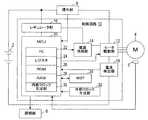
図1に示すように、本実施形態の制御回路10は、電動工具、電動作業機等の電気機器に、充放電可能なバッテリ2と共に搭載されて、その動力源であるモータ(本実施形態ではブラシレスモータ)4を駆動制御するためのものである。Embodiments of the present invention will be described below with reference to the drawings.
As shown in FIG. 1, the control circuit 10 of the present embodiment is mounted on an electric device such as an electric tool or an electric working machine together with a chargeable / dischargeable battery 2, and a motor that is a power source (in this embodiment). This is for driving and controlling the
制御回路10は、モータ4の各相巻線へ通電することによりモータ4を駆動するモータ駆動部12、その駆動時にモータ4に流れる電流を検出する電流検出部18、及び、MCU(Micro Control Unit)20を備える。 The control circuit 10 includes a
MCU20は、本発明のマイクロコントローラに相当するものであり、モータ4に設けられた回転センサ5及び電流検出部18からの検出信号に基づき、モータ4が操作部6からの指令に応じた回転状態となるよう、モータ駆動部12を介してモータ4を制御する。 The
また、制御回路10には、バッテリ2から電力供給を受けて、MUC20等の内部回路を駆動するための電源電圧(直流定電圧)を生成するレギュレータ部16が備えられている。 Further, the control circuit 10 includes a
モータ駆動部12は、所謂インバータ回路であり、レギュレータ部16にて生成された電源電圧が、電源供給部14を介して供給される。
従って、モータ駆動部12は、電源供給部14から電源電圧が供給されているときに、バッテリ2からモータ4への通電経路を形成できるようになり、電源供給部14から電源電圧が供給されていないときには、バッテリ2からモータ4への通電経路が遮断される。The
Therefore, when the power supply voltage is supplied from the
このため、電源供給部14からモータ駆動部12に電源電圧が供給されていないときには、モータ駆動部12は動作停止状態となり、MCU20からモータ駆動部12にモータ4駆動用の信号が入力されても、モータ4が通電により駆動されることはない。 Therefore, when the power supply voltage is not supplied from the
次に、MCU20は、一般的なマイクロコントローラと同様、プログラムカウンタ(以下、PCという)22、レジスタ24、ROM26、RAM28、及び、内部クロック生成部30を備えている。 Next, the
また、MCU20には、外部クロック生成部32、及び、ウォッチドッグタイマ(以下、WDTという)34、が接続されている。
外部クロック生成部32は、内部クロック生成部30とは異なる発振器を備え、内部クロック生成部30とは別に、独立してクロック信号を生成するものである。Further, an external
The external
そして、MCU20は、内部クロック生成部30及び外部クロック生成部32の何れかで生成されたクロック信号に同期して動作する。また、MCU20は、各クロック生成部30、32からのクロック信号をカウントすることで得られる経過時間のずれが正常範囲内にあるか否かを判断することで、自身の動作クロックが正常であるか否かを判定(診断)する。 The
また、WDT34は、MCU20から定期的に出力される信号によりリセットされる計時用タイマであり、その計時時間が予め設定された監視時間に達すると、MCU20が異常動作していると判断して、MCU20をリセット(再起動)させるものである。 The
また、制御回路10には、モータ4の駆動時に電気機器周囲(例えば、電動工具や電動作業機による作業対象物)を照らしたり、電気機器の状態(例えば、バッテリ残量等)を表示したりするための照明部8が設けられている。そして、MCU20は、この照明部8の点灯状態等も制御する。 In addition, the control circuit 10 illuminates the surroundings of the electric device (for example, a work object by an electric tool or an electric working machine) when the
このように構成された本実施形態の制御回路10においては、MCU20がROM26に記憶されたプログラムを実行することにより、操作部6からの指令(操作量)に応じてモータ4を駆動制御すると共に、必要に応じて照明部8の点灯状態を制御する。 In the control circuit 10 of the present embodiment configured as described above, the
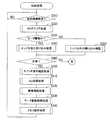
また、MCU20は、レギュレータ部16から電源電圧が供給される(パワーオンリセット)か、WDT34等によりリセットされることにより起動するが、起動直後には、図2に示す起動時診断処理を実行することにより、MCU20各部の自己診断を行う。 Further, the
そして、その自己診断の結果、異常を検出すると、実行中のプログラムを無限ループに移行させるか、制御回路10の動作モードを通常の動作モードから省電力モードに切り換える。 If an abnormality is detected as a result of the self-diagnosis, the program being executed is shifted to an infinite loop, or the operation mode of the control circuit 10 is switched from the normal operation mode to the power saving mode.
以下、このようにMCU20にて実行される起動時診断処理、及び、起動時診断処理にて異常が検出されなかったときにMCU20にて実行されるモータ4の制御処理、について説明する。 Hereinafter, the startup diagnosis process executed by the
図2に示すように、MCU20の起動時に実行される起動時診断処理においては、まず、S110(Sはステップを表す)にて、PC22が正常であるか否かを診断する。この診断は、例えば、所定のサブルーチンにジャンプして、アドレスを取得し、その取得したアドレスが正しいか否かをチェックすることにより行われる。 As shown in FIG. 2, in the startup diagnosis process executed when the
次に、S120では、S110にてPC22が正常であると診断されたか否かを判断する。そして、PC22が正常であると診断されていれば、S130に移行し、PC22が正常であると診断されていなければ、S300の無限ループに移行する。 Next, in S120, it is determined whether or not the
なお、MCU20がS300の無限ループに入ると、MCU20からWDT34に信号が出力されなくなり、WDT34による計時時間が所定の監視時間に達したタイミングでMCU20がリセットされて、再起動されることになる。 When the
S130では、レジスタ24内の汎用レジスタが正常であるか否かを診断する。この診断には、例えば、チェッカーボード法が使用され、汎用レジスタに、所定パターンのデータ、及び、そのパターンを反転させた反転パターンのデータを、順次書き込み、読み出すことにより行われる。 In S130, it is diagnosed whether the general-purpose register in the
つまり、S130では、各ビット値が反転したパターンデータ毎に、汎用レジスタから読み出したデータが、書き込んだデータと一致しているか否かを判断することにより、汎用レジスタが正常であるか否かを判断する。 That is, in S130, whether or not the general-purpose register is normal is determined by determining whether or not the data read from the general-purpose register matches the written data for each pattern data in which each bit value is inverted. to decide.
次に、S140では、S130にて汎用レジスタが正常であると診断されたか否かを判断する。そして、汎用レジスタが正常であると診断されていれば、S150に移行し、汎用レジスタが正常であると診断されていなければ、S300の無限ループに移行する。 Next, in S140, it is determined whether or not the general-purpose register is diagnosed as normal in S130. If the general-purpose register is diagnosed as normal, the process proceeds to S150. If the general-purpose register is not diagnosed as normal, the process proceeds to an infinite loop of S300.
S150では、RAM28を構成している揮発性メモリが正常であるか否かを診断する。この診断には、例えば、汎用レジスタの診断と同様、チェッカーボード法が使用され、揮発性メモリに各ビットの値が反転した2種類のデータ(例えば、「0x55」と「0xAA」)を順次書き込み、読み出すことにより行われる。 In S150, it is diagnosed whether or not the volatile memory constituting the
つまり、S150では、上記2種類のデータ毎に、揮発性メモリから読み出したデータが、書き込んだデータと一致しているか否かを判断することにより、揮発性メモリが正常であるか否かを判断する。 That is, in S150, it is determined whether the volatile memory is normal by determining whether the data read from the volatile memory matches the written data for each of the two types of data. To do.
次に、S160では、S150にて揮発性メモリが正常であると診断されたか否かを判断する。そして、揮発性メモリが正常であると診断されていれば、S170に移行し、揮発性メモリが正常であると診断されていなければ、S300の無限ループに移行する。 Next, in S160, it is determined whether or not the volatile memory is diagnosed in S150. If the volatile memory is diagnosed as normal, the process proceeds to S170, and if the volatile memory is not diagnosed as normal, the process proceeds to an infinite loop of S300.
S170では、上記一連の処理にて、プログラムカウンタ、汎用レジスタ、揮発性メモリが正常であると診断されているので、これら各部を初期設定する初期設定処理を実行し、S180に移行する。 In S170, it is diagnosed that the program counter, the general-purpose register, and the volatile memory are normal in the above-described series of processing. Therefore, initial setting processing for initializing these units is executed, and the process proceeds to S180.
S180では、ROM26を構成する不揮発性メモリが正常であるか否かを診断する。この診断は、例えば、不揮発性メモリに記憶されているデータのCRCコードを計算し、その計算結果と、予め不揮発性メモリに記憶されているCRCコードとを比較することにより行われる。 In S180, it is diagnosed whether or not the nonvolatile memory constituting the
つまり、S180では、計算したCRCコードと不揮発性メモリに記憶されているCRCコードを比較し、これらが一致しているときに、不揮発性メモリは正常であると判断する。 That is, in S180, the calculated CRC code is compared with the CRC code stored in the nonvolatile memory, and when these match, it is determined that the nonvolatile memory is normal.
次に、S190では、S180にて不揮発性メモリが正常であると診断されたか否かを判断する。そして、不揮発性メモリは正常であると診断されていれば、S200に移行し、不揮発性メモリは正常であると診断されていなければ、S300の無限ループに移行する。 Next, in S190, it is determined whether or not the non-volatile memory is diagnosed in S180. If the non-volatile memory is diagnosed as normal, the process proceeds to S200. If the non-volatile memory is not diagnosed as normal, the process proceeds to an infinite loop of S300.
S200では、MCU20においてアナログ信号をAD変換して取り込むのに用いられるADポートが、正常であるか否かを診断し、S210に移行する。
S200での診断は、例えば、ADポートに設けられたAD変換モジュールを実際に動作させ、その動作によって得られるAD変換値を読み込むことにより行われ、S210では、そのAD変換値に基づき、ADポートが正常であるか否かを判断する。In S200, it is diagnosed whether or not the AD port used for AD conversion of the analog signal in the
The diagnosis in S200 is performed, for example, by actually operating an AD conversion module provided in the AD port and reading an AD conversion value obtained by the operation, and in S210, based on the AD conversion value, the AD port It is determined whether or not is normal.
S210では、AD変換値が所定の正常範囲内にあれば、ADポートは正常であると判断して、S250に移行し、AD変換値が正常範囲内になければ、ADポートは正常ではないと判断して、S220に移行する。 In S210, if the AD conversion value is within a predetermined normal range, it is determined that the AD port is normal, and the process proceeds to S250. If the AD conversion value is not within the normal range, the AD port is not normal. Determination is made and the process proceeds to S220.
ADポートが正常でない場合(つまり、ADポートの異常時)には、ADポートからモータ制御のためのパラメータ(例えば、バッテリ電圧、モータ温度等)を正常に読み込むことができず、モータ制御を正常に実施することができない。 When the AD port is not normal (that is, when the AD port is abnormal), parameters for motor control (for example, battery voltage, motor temperature, etc.) cannot be read normally from the AD port, and motor control is normal. Can not be implemented.
このため、S220では、モータ駆動部12への制御信号の出力を停止する。また、続くS230では、電源供給部14からモータ駆動部12へのモータ駆動用電源の供給を停止させることで、モータ4の駆動を停止させ、更に続くS240では、MCU20の動作モードを省電力モードに設定する。 For this reason, in S220, the output of the control signal to the
省電力モードは、MCU20の動作(モータ制御処理の実行)を停止させて、消費電力を低減するモードであり、例えば、動作クロックを停止させるスリープモード、動作クロックは停止させずにWDT34を周期的にクリアさせるアイドルモード等が知られている。 The power saving mode is a mode in which the operation of the MCU 20 (execution of motor control processing) is stopped to reduce power consumption. For example, the sleep mode in which the operation clock is stopped, and the
そして、本実施形態では、こうした従来から知られている省電力モードの一つを、異常診断時に移行する省電力モードとして利用する。
なお、省電力モードからの復帰条件は、使用者が操作部6を操作することにより、MCU20が再起動されたとき、に設定されており、MCU20は、WDT34からの出力では省電力モードから復帰できない。In the present embodiment, one of the conventionally known power saving modes is used as a power saving mode to be shifted at the time of abnormality diagnosis.
The return condition from the power saving mode is set when the
つまり、レギュレータ部16は、操作部6が操作(オン)されると、MCU20への電源供給を開始する。すると、MCU20が起動し、プログラムを実行する。また、MCU20は、起動後、レギュレータ部16がMCU20への電源供給を継続するように、レギュレータ部16に信号を出す。そして、その後、操作部6の操作が停止(オフ)され、規定時間が経過すると、その信号の出力を停止して、レギュレータ部16からMCU20への電源供給を遮断させ、MCU20自身の動作を停止させる。 That is, the
そして、本実施形態では、MCU20が省電力モードに移行すると、レギュレータ部16からの電源供給が停止し、その後操作部6が操作されてレギュレータ部10からの電源供給が再開され、MCU20が再起動するまで、通常の動作モードに復帰できないようにされている。 In this embodiment, when the
次に、S250では、MCU20においてデータを入出力するのに用いられるIOポートが、正常であるか否かを診断する。この診断は、例えば、出力端子のレベルを設定し、入力端子による読み出し値が期待値と一致しているか否かを判断することにより行われる。 Next, in S250, it is diagnosed whether the IO port used to input / output data in the
S260では、S250での診断の結果、読み出し値が期待値と一致していて、IOポートが正常であると診断されたか否かを判断する。そして、IOポートが正常であると診断されていればS270に移行し、そうでなければ、上述したS220〜S240の処理を実行する。 In S260, as a result of the diagnosis in S250, it is determined whether or not the read value matches the expected value and the IO port is diagnosed as normal. If it is diagnosed that the IO port is normal, the process proceeds to S270, and if not, the processes of S220 to S240 described above are executed.
次に、S270では、MCU20の動作クロックが正常であるか否かを診断する。この診断には、内部クロック生成部30からのクロック信号と、外部クロック生成部32からのクロック信号との、2系統のクロック信号が用いられる。そして、S270では、これら各クロック信号による割り込み回数等で規定時間をそれぞれ計時し、その計時時間ずれが正常範囲から外れているときに、自身の動作クロックに異常があると診断する。 Next, in S270, it is diagnosed whether the operation clock of the
S280では、S270での診断の結果、MCU20の動作クロックが正常であると診断されたか否かを判断する。そして、動作クロックが正常であると診断されていれば、起動時診断処理を終了して、図3に示すモータ4の制御処理へ移行し、そうでなければ、上述したS220〜S240の処理を実行する。 In S280, it is determined whether or not the operation clock of the
このように、起動時診断処理では、MCU20自身のPC22、汎用レジスタ、揮発性メモリ、不揮発性メモリ、ADポート、IOポート、及び、動作クロックが、正常であるか否かが自己診断される。 As described above, in the startup diagnosis process, it is self-diagnosed whether the
そして、これらの何れかに異常があると自己診断すると、MCU20は、その異常内容に応じて、実行中のプログラムを無限ループに移行させるか、或いは、自身の動作モードを省電力モードに移行させることで、図3に示すモータ4の制御処理の実行を禁止する。 Then, when self-diagnosis that any of these is abnormal, the
次に、モータ4の制御処理について説明する。
図3に示すように、モータ4の制御処理が開始されると、MCU20は、S310にて所定の制御周期が経過したか否かを判断し、所定の制御周期が経過していなければ、再度S310の判定処理を実行することで、所定の制御周期が経過するのを待つ。Next, the control process of the
As shown in FIG. 3, when the control process of the
そして、所定の制御周期が経過すると、S320以降の処理を実行する。つまり、MCU20は、所定の制御周期で、S320以降の制御処理を周期的に実行する。
S320では、WDT34をクリアするWDTクリア処理を実行し、続くS330にて、現在、モータ4を駆動中であるか否かを判断する。And if a predetermined control period passes, the process after S320 will be performed. That is, the
In S320, WDT clear processing for clearing the
S330にて、現在、モータ4を駆動中であると判断されると、モータ4の回転センサ5からモータ4の所定の回転角度毎に入力されるパルス信号のエッジによるエッジ割り込みを含む、各種割り込み動作を確認し、S360に移行する。 If it is determined in S330 that the
また、S330にて、現在、モータ4は駆動していないと判断されると、回転センサ5からのエッジ割り込みはないので、エッジ割り込み以外の割り込み動作(タイマ割り込み等)を確認し、S360に移行する。 If it is determined in S330 that the
S360では、S340又はS350の確認処理にて、各種割り込み動作は正常になされていると診断されたか否かを判断する。そして、割り込み動作が正常になされていれば、S400以降の一連の制御処理を実行し、割り込み動作が正常になされていなければ、上述したS220〜S240の処理を実行する。 In S360, it is determined in the confirmation processing in S340 or S350 whether or not it is diagnosed that various interrupt operations are performed normally. If the interrupt operation is normal, a series of control processes after S400 are executed, and if the interrupt operation is not normal, the processes of S220 to S240 described above are executed.
S400以降の処理は、モータ4を駆動するための処理である。
すなわち、S400では、操作部6に設けられた操作スイッチからの信号を確認する。また、続くS410では、操作部6の操作量、電流検出部18にて検出される電流やバッテリ電圧、モータ4に設けられた温度センサ(図示せず)からの検出信号をAD変換して取り込む。The processes after S400 are processes for driving the
That is, in S400, the signal from the operation switch provided in the
そして、続くS420では、S410でのAD変換結果に基づき、バッテリ電圧の低下、モータ4の過熱、といった異常を確認し、続くS430に移行して、モータ4を駆動制御するモータ駆動制御処理を実行する。 In the subsequent S420, abnormalities such as a decrease in battery voltage and overheating of the
なお、モータ駆動制御処理では、異常確認処理にて異常が検出されているときには、モータ4の駆動を停止し、その後、使用者による操作部6の操作(換言すれば駆動指令の入力)が終了するまで駆動停止状態を保持する。 In the motor drive control process, when an abnormality is detected in the abnormality confirmation process, the drive of the
また、S440では、S400以降の制御処理で得られた各種データの不揮発性メモリへの書き込み、不揮発性メモリからのデータの読み出し等を行う、メモリ操作処理を実行する。そして、その後は、S310に移行し、上記一連の処理を再度実行する。 In S440, a memory operation process is performed to write various data obtained in the control process after S400 to the nonvolatile memory, to read data from the nonvolatile memory, and the like. And after that, it transfers to S310 and performs a series of above-mentioned processing again.
以上説明したように、本実施形態の制御回路10によれば、MCU20は、起動時診断処理において、PC22、汎用レジスタ、揮発性メモリ、不揮発性メモリ、ADポート、IOポート、及び、動作クロックが正常であるか否かを自己診断する。 As described above, according to the control circuit 10 of the present embodiment, the
また、起動時診断処理にて異常が検出されなかったときには、MCU20は、モータ4の制御処理を実行するが、この制御処理実行中には、回転センサ5からのエッジ割り込みやタイマ割り込み等の各種割り込み動作が正常であるか否かを自己診断する。 Further, when no abnormality is detected in the startup diagnosis process, the
そして、MCU20は、これらの自己診断により異常があると診断すると、その診断内容に応じて、実行中のプログラムを無限ループに移行させるか、或いは、自身の動作モードを省電力モードに移行させることで、モータ4の駆動制御を停止する。 When the
具体的には、PC22、汎用レジスタ、揮発性メモリ、及び、不揮発性メモリの何れか(本発明の第2の構成要素に相当)が異常である場合、MCU20は、無限ループに移行する。 Specifically, if any of the
これは、これら各部(第2の構成要素)に異常が生じた場合、MCU20は、再起動により正常復帰できる可能性はあるものの、プログラムを正常に実行できず、予期しない誤制御を実施してしまうことがあるためである。 This is because, if an abnormality occurs in each of these parts (second component), the
そして、このようにMCU20が実行中のプログラムが無限ループに入ると、モータ4の駆動が停止され、WDT34がクリアされなくなる。この結果、MCU20は、WDT34の機能により、WDT34による監視時間経過後にリセットされ、再起動される。 When the program being executed by the
そして、その再起動により、異常診断された部分が正常状態に復帰しなければ、MCU20は、前回の起動時と同様、無限ループに入ることになるが、再起動により正常復帰して、モータ4を正常に駆動制御できるようになることもある。 If the part diagnosed abnormally does not return to the normal state by the restart, the
一方、ADポート、IOポート、動作クロック、若しくは、割り込み(本発明の第1の構成要素に相当)に異常があると自己診断した場合、MCU20は、プログラム自体は実行できるものの、制御パラメータや制御タイミングに異常が生じる。 On the other hand, when self-diagnosed that there is an abnormality in the AD port, IO port, operation clock, or interrupt (corresponding to the first component of the present invention), the
このため、これら各部(第1の構成要素)に異常が生じた場合、制御対象(モータ4)を正常に駆動することができない。また、これら各部に異常が生じたときには、WDT34等によってMCU20をリセットしても、正常復帰し得る確率は極めて低い。 For this reason, when abnormality occurs in each of these parts (first component), the control target (motor 4) cannot be driven normally. Further, when an abnormality occurs in each of these parts, even if the
そこで、本実施形態では、MCU20が自己診断によりこれら各部の異常を検出すると、省電力モードに入るようにしている。そして、省電力モードでは、MCU20がスリープ状態或いはアイドル状態に入り、MCU20での消費電力が抑制されることから、バッテリ2の放電を抑制して、バッテリ2の残容量が低下するのを防止できる。 Therefore, in the present embodiment, when the
また、本実施形態では、MCU20が一旦省電力モードに入ると、その後は、使用者が操作部6を操作して、レギュレータ部16からの電源供給によりMCU20が再起動されるまで、省電力モードを保持するようにされている。 In the present embodiment, once the
このため、本実施形態によれば、MCU20が省電力モードにあるとき、WDT34の機能によって、MCU20が定期的に起動されるようなことはなく、これによっても、バッテリ2の電力消費を抑えることができる。 Therefore, according to the present embodiment, when the
また、MCU20が省電力モードにあるときに、WDT34の機能によってMCU20が起動されるようにすると、制御対象であるモータ4を誤って駆動してしまうことも考えられるが、本実施形態によれば、このような問題も防止することができる。 In addition, when the
また更に、本実施形態では、ADポート、IOポート、動作クロック、若しくは、割り込みに異常があると自己診断した場合、MCU20の動作モードを省電力モードに切り換えるだけでなく、モータ駆動部12への制御信号の出力を停止させ、電源供給部14からモータ駆動部12への電力供給を遮断する。 Furthermore, in this embodiment, when self-diagnosis is detected that there is an abnormality in the AD port, the IO port, the operation clock, or the interrupt, not only the operation mode of the
従って、これらの異常検出時には、モータ駆動部12を介してモータ4が誤って駆動される確率を、より低減することが可能となる。
ここで、本実施形態では、MCU20にて実行される処理のうち、図2の起動時診断処理におけるS110〜S210、S230、S240、S270、S280の処理、及び、図3の制御処理におけるS330〜S360の処理が、本発明の自己診断部として機能する。また、図2の起動時診断処理におけるS220、S250、S260、S290の処理、及び、図3の制御処理におけるS370〜S390の処理が、本発明の異常時動作切替部として機能する。Therefore, when these abnormalities are detected, the probability that the
Here, in this embodiment, among the processes executed by the
以上、本発明の一実施形態について説明したが、本発明は、上記実施形態に限定されるものではなく、本発明の要旨を逸脱しない範囲内にて、種々の態様をとることができる。
例えば、MCU20は、S220、S260、S290、若しくは、S390にて、自身の動作モードを省電力モードに切り換える際には、制御対象であるモータ4とは別に駆動制御される周辺回路(例えば照明部8)の駆動を停止若しくは制限するようにしてもよい。このようにすれば、MCU20(延いては制御回路10)だけでなく、その周辺回路での電力消費も抑えることができ、装置全体を良好に省電力化することができる。As mentioned above, although one Embodiment of this invention was described, this invention is not limited to the said embodiment, A various aspect can be taken in the range which does not deviate from the summary of this invention.
For example, when the
また、上記実施形態では、図3に示す制御処理にて、割り込みに関する自己診断を実施し、他の診断は、図2に示す起動時診断処理にて、MCU20の起動時に実施するものとして説明した。しかし、起動時診断処理にて実施される各部の診断についても、図3に示す制御処理にて、制御周期に影響しない範囲内で適宜実施するようにしてもよい。 In the above-described embodiment, the self-diagnosis related to the interrupt is performed in the control process shown in FIG. 3, and the other diagnosis is performed at the startup of the
例えば、図3のS440の後に、ADポート、IOポート、及び、動作クロックの診断及び省電力モードへの移行を行う処理(図2のS200〜S280)を実施するようにしてもよい。また、例えば、図3のメモリ操作処理にて、図2に示すメモリ診断(S150、S180)を実施するようにしてもよいし、PC診断(S110)、汎用レジスタ診断(S130)についても、図3の制御処理実行時に適宜実施するようにしてもよい。 For example, after S440 in FIG. 3, processing (S200 to S280 in FIG. 2) for performing diagnosis of the AD port, IO port, and operation clock and shifting to the power saving mode may be performed. Further, for example, the memory diagnosis (S150, S180) shown in FIG. 2 may be performed in the memory operation process of FIG. 3, and the PC diagnosis (S110) and the general-purpose register diagnosis (S130) are also shown in FIG. It may be implemented as appropriate when the control process 3 is executed.
また、上記実施形態では、MCU20が自己診断する構成要素は、PC22、汎用レジスタ、揮発性メモリ、不揮発性メモリ、ADポート、IOポート、動作クロック、及び、各種割り込みの入力系、であるものとして説明した。しかし、これらの構成要素は、一例であり、更に多くても、少なくてもよい。 In the above embodiment, the components self-diagnosed by the
また、上記実施形態では、MCU20は、バッテリ2から電力供給を受けて動作するものとして説明したが、MCU20の電源は、ACアダプタ等、バッテリ以外の直流電源であってもよい。 In the above-described embodiment, the
2…バッテリ、4…モータ、5…回転センサ、6…操作部、8…照明部、10…制御回路、12…モータ駆動部、14…電源供給部、16…レギュレータ部、18…電流検出部、22…PC(プログラムカウンタ)、24…レジスタ、26…ROM、28…RAM、30…内部クロック生成部、32…外部クロック生成部。 DESCRIPTION OF SYMBOLS 2 ... Battery, 4 ... Motor, 5 ... Rotation sensor, 6 ... Operation part, 8 ... Illumination part, 10 ... Control circuit, 12 ... Motor drive part, 14 ... Power supply part, 16 ... Regulator part, 18 ...
Claims (8)
Translated fromJapanese当該マイクロコントローラを構成している複数の構成要素が正常であるか否かを、構成要素毎に診断する自己診断部と、
時間を計測し、当該マイクロコントローラが前記プログラムを実行することにより周期的に発生するタイミングで計測時間がクリアされ、該計測時間が設定時間に達すると当該マイクロコントローラをリセットするウォッチドッグタイマと、
前記自己診断部にて前記構成要素の異常が診断されると、当該マイクロコントローラの動作を正常時とは異なる動作に切り替える異常時動作切替部と、
を備え、
前記異常時動作切替部は、
前記自己診断部にて異常であると診断された構成要素の種類に応じて、当該マイクロコントローラの動作モードを正常時よりも消費電力が少ない省電力モードに切り替えるか、或いは、当該マイクロコントローラが実行中のプログラムを無限ループに移行させて前記ウォッチドッグタイマの計測時間がクリアされるのを禁止する、ように構成されているマイクロコントローラ。A microcontroller that drives and controls a controlled object by executing a program,
A self-diagnosis unit that diagnoses, for each component, whether or not a plurality of components constituting the microcontroller are normal;
The time is measured, the measurement time is cleared at a timing that is periodically generated by the microcontroller executing the program, and a watchdog timer that resets the microcontroller when the measurement time reaches a set time;
When the abnormality of the component is diagnosed by the self-diagnosis unit, an abnormal-time operation switching unit that switches the operation of the microcontroller to an operation different from normal operation;
With
The abnormal operation switching unit is
Depending on the type of component diagnosed as abnormal by the self-diagnosis unit, the operation mode of the microcontroller is switched to a power saving mode that consumes less power than normal, or the microcontroller executes A microcontroller configured to shift a program therein to an infinite loop and prohibit the measurement time of the watchdog timer from being cleared.
異常時に前記プログラムの実行により前記制御対象を異常動作させてしまう第1の構成要素と、
異常時に前記プログラムを正常に実行できなくなる第2の構成要素と、
に分類されており、
前記異常時動作切替部は、
前記自己診断部にて異常と診断された構成要素が前記第1の構成要素である場合に、当該マイクロコントローラの動作モードを前記省電力モードに切り替え、
前記自己診断部にて異常と診断された構成要素が前記第2の構成要素である場合に、当該マイクロコントローラが実行中のプログラムを無限ループに移行させる、
ように構成されている請求項1に記載のマイクロコントローラ。The plurality of components diagnosed by the self-diagnosis unit are:
A first component that causes the controlled object to operate abnormally by executing the program in the event of an abnormality;
A second component that makes it impossible to execute the program normally at the time of abnormality;
Classified into
The abnormal operation switching unit is
When the component diagnosed as abnormal by the self-diagnosis unit is the first component, the operation mode of the microcontroller is switched to the power saving mode,
When the component diagnosed as abnormal by the self-diagnosis unit is the second component, the program being executed by the microcontroller is shifted to an infinite loop.
The microcontroller according to claim 1, configured as described above.
当該マイクロコントローラの動作モードを前記省電力モードに切り替えるときには、前記制御対象の駆動を停止させるように構成されている、請求項1〜請求項4の何れか1項に記載のマイクロコントローラ。The abnormal operation switching unit is
The microcontroller according to any one of claims 1 to 4, wherein when the operation mode of the microcontroller is switched to the power saving mode, the driving of the control target is stopped.
当該マイクロコントローラの動作モードを前記省電力モードに切り替えるときには、当該マイクロコントローラにより前記制御対象とは別に駆動制御される周辺回路の駆動を停止又は制限するように構成されている、請求項1〜請求項5の何れか1項に記載のマイクロコントローラ。The abnormal operation switching unit is
When the operation mode of the microcontroller is switched to the power saving mode, the microcontroller is configured to stop or limit driving of peripheral circuits that are driven and controlled separately from the control target by the microcontroller. 6. The microcontroller according to any one of items 5.
当該マイクロコントローラの動作モードを前記省電力モードに切り替えるときには、前記制御対象を駆動する駆動回路への電力供給を遮断するように構成されている、請求項1〜請求項6の何れか1項に記載のマイクロコントローラ。The abnormal operation switching unit is
The power supply to the drive circuit which drives the said control object is interrupted | blocked when switching the operation mode of the said microcontroller to the said power saving mode, The structure of any one of Claims 1-6 The described microcontroller.
当該マイクロコントローラの動作モードを前記省電力モードに切り替えると、当該マイクロコントローラが外部操作によって再起動されるまで前記省電力モードを保持するように構成されている、請求項1〜請求項7の何れか1項に記載のマイクロコントローラ。The abnormal operation switching unit is
Any one of claims 1 to 7, wherein when the operation mode of the microcontroller is switched to the power saving mode, the microcontroller maintains the power saving mode until the microcontroller is restarted by an external operation. The microcontroller according to claim 1.
Priority Applications (1)
| Application Number | Priority Date | Filing Date | Title |
|---|---|---|---|
| JP2015117632AJP2017004259A (en) | 2015-06-10 | 2015-06-10 | Microcontroller |
Applications Claiming Priority (1)
| Application Number | Priority Date | Filing Date | Title |
|---|---|---|---|
| JP2015117632AJP2017004259A (en) | 2015-06-10 | 2015-06-10 | Microcontroller |
Publications (1)
| Publication Number | Publication Date |
|---|---|
| JP2017004259Atrue JP2017004259A (en) | 2017-01-05 |
Family
ID=57754725
Family Applications (1)
| Application Number | Title | Priority Date | Filing Date |
|---|---|---|---|
| JP2015117632APendingJP2017004259A (en) | 2015-06-10 | 2015-06-10 | Microcontroller |
Country Status (1)
| Country | Link |
|---|---|
| JP (1) | JP2017004259A (en) |
Cited By (1)
| Publication number | Priority date | Publication date | Assignee | Title |
|---|---|---|---|---|
| WO2023007974A1 (en)* | 2021-07-30 | 2023-02-02 | ローム株式会社 | Semiconductor device, in-vehicle device, and consumer equipment |
- 2015
- 2015-06-10JPJP2015117632Apatent/JP2017004259A/enactivePending
Cited By (1)
| Publication number | Priority date | Publication date | Assignee | Title |
|---|---|---|---|---|
| WO2023007974A1 (en)* | 2021-07-30 | 2023-02-02 | ローム株式会社 | Semiconductor device, in-vehicle device, and consumer equipment |
Similar Documents
| Publication | Publication Date | Title |
|---|---|---|
| JP4750564B2 (en) | Reset signal generation circuit | |
| JP4535170B2 (en) | Microcomputer system | |
| JP4665846B2 (en) | Microcomputer and electronic control device | |
| JP2015217911A (en) | Electronic control apparatus | |
| JP2007323631A (en) | Cpu runaway determination circuit | |
| JP6323296B2 (en) | Control device | |
| JPH1115569A (en) | System resetting system | |
| JP5465799B2 (en) | Control device | |
| JP2004212601A (en) | Image forming apparatus | |
| JP2017004259A (en) | Microcontroller | |
| US7986168B2 (en) | Semiconductor apparatus and anomaly detection method of the same | |
| JP7261543B2 (en) | Control device and control method | |
| US20030140261A1 (en) | Control apparatus | |
| JP3214469B2 (en) | Method and apparatus for controlling writing of flash EEPROM by microcomputer | |
| JP5983588B2 (en) | Abnormality judgment device for vehicle microcomputer | |
| JP2002041493A (en) | Microcomputer | |
| JP3901230B2 (en) | Pachinko game machine | |
| JP2002236503A (en) | Electronic controller for vehicle | |
| JP6172040B2 (en) | Electronic control unit | |
| JPH11259340A (en) | Reactivation control circuit for computer | |
| JP2002202830A (en) | Microcomputer | |
| JP6477535B2 (en) | Electronic control unit | |
| JP7067152B2 (en) | Power conditioner | |
| CN108205480B (en) | Abnormity processing method and device, intelligent rearview mirror and storage medium | |
| JPH08263177A (en) | Method and circuit for resetting cpu |