JP2016538822A - Method for forming and operating a multi-terminal power system - Google Patents
Method for forming and operating a multi-terminal power systemDownload PDFInfo
- Publication number
- JP2016538822A JP2016538822AJP2016554308AJP2016554308AJP2016538822AJP 2016538822 AJP2016538822 AJP 2016538822AJP 2016554308 AJP2016554308 AJP 2016554308AJP 2016554308 AJP2016554308 AJP 2016554308AJP 2016538822 AJP2016538822 AJP 2016538822A
- Authority
- JP
- Japan
- Prior art keywords
- power
- output
- power transmission
- voltage
- current
- Prior art date
- Legal status (The legal status is an assumption and is not a legal conclusion. Google has not performed a legal analysis and makes no representation as to the accuracy of the status listed.)
- Pending
Links
- 238000000034methodMethods0.000titleclaimsabstractdescription38
- 230000005540biological transmissionEffects0.000claimsabstractdescription139
- 239000003990capacitorSubstances0.000claimsabstractdescription24
- 230000001939inductive effectEffects0.000claimsabstractdescription19
- 230000008859changeEffects0.000claimsabstractdescription14
- 230000003750conditioning effectEffects0.000claimsdescription19
- 239000011159matrix materialSubstances0.000claimsdescription12
- 230000009467reductionEffects0.000claimsdescription7
- 238000002955isolationMethods0.000claimsdescription5
- 230000033228biological regulationEffects0.000claimsdescription2
- 230000004044responseEffects0.000description10
- 230000001052transient effectEffects0.000description9
- 238000004458analytical methodMethods0.000description8
- 238000004891communicationMethods0.000description5
- 230000009977dual effectEffects0.000description5
- 230000001965increasing effectEffects0.000description5
- 230000001276controlling effectEffects0.000description4
- 238000013461designMethods0.000description4
- 230000007423decreaseEffects0.000description3
- 238000006243chemical reactionMethods0.000description2
- 230000008878couplingEffects0.000description2
- 238000010168coupling processMethods0.000description2
- 238000005859coupling reactionMethods0.000description2
- 238000010586diagramMethods0.000description2
- 238000004088simulationMethods0.000description2
- 230000007704transitionEffects0.000description2
- 230000001960triggered effectEffects0.000description2
- 238000013459approachMethods0.000description1
- 238000012937correctionMethods0.000description1
- 230000001066destructive effectEffects0.000description1
- 238000011161developmentMethods0.000description1
- 230000000694effectsEffects0.000description1
- 238000001914filtrationMethods0.000description1
- 238000009434installationMethods0.000description1
- 230000010354integrationEffects0.000description1
- 230000007257malfunctionEffects0.000description1
- 238000005259measurementMethods0.000description1
- 230000007246mechanismEffects0.000description1
- 238000010248power generationMethods0.000description1
- 230000001105regulatory effectEffects0.000description1
- 230000000630rising effectEffects0.000description1
- 239000004065semiconductorSubstances0.000description1
- 230000001360synchronised effectEffects0.000description1
Images


Classifications
- H—ELECTRICITY
- H02—GENERATION; CONVERSION OR DISTRIBUTION OF ELECTRIC POWER
- H02J—CIRCUIT ARRANGEMENTS OR SYSTEMS FOR SUPPLYING OR DISTRIBUTING ELECTRIC POWER; SYSTEMS FOR STORING ELECTRIC ENERGY
- H02J3/00—Circuit arrangements for AC mains or AC distribution networks
- H—ELECTRICITY
- H02—GENERATION; CONVERSION OR DISTRIBUTION OF ELECTRIC POWER
- H02J—CIRCUIT ARRANGEMENTS OR SYSTEMS FOR SUPPLYING OR DISTRIBUTING ELECTRIC POWER; SYSTEMS FOR STORING ELECTRIC ENERGY
- H02J3/00—Circuit arrangements for AC mains or AC distribution networks
- H02J3/38—Arrangements for parallely feeding a single network by two or more generators, converters or transformers
- H—ELECTRICITY
- H02—GENERATION; CONVERSION OR DISTRIBUTION OF ELECTRIC POWER
- H02M—APPARATUS FOR CONVERSION BETWEEN AC AND AC, BETWEEN AC AND DC, OR BETWEEN DC AND DC, AND FOR USE WITH MAINS OR SIMILAR POWER SUPPLY SYSTEMS; CONVERSION OF DC OR AC INPUT POWER INTO SURGE OUTPUT POWER; CONTROL OR REGULATION THEREOF
- H02M7/00—Conversion of AC power input into DC power output; Conversion of DC power input into AC power output
- H02M7/02—Conversion of AC power input into DC power output without possibility of reversal
- H02M7/04—Conversion of AC power input into DC power output without possibility of reversal by static converters
- H—ELECTRICITY
- H02—GENERATION; CONVERSION OR DISTRIBUTION OF ELECTRIC POWER
- H02M—APPARATUS FOR CONVERSION BETWEEN AC AND AC, BETWEEN AC AND DC, OR BETWEEN DC AND DC, AND FOR USE WITH MAINS OR SIMILAR POWER SUPPLY SYSTEMS; CONVERSION OF DC OR AC INPUT POWER INTO SURGE OUTPUT POWER; CONTROL OR REGULATION THEREOF
- H02M7/00—Conversion of AC power input into DC power output; Conversion of DC power input into AC power output
- H02M7/42—Conversion of DC power input into AC power output without possibility of reversal
- H02M7/44—Conversion of DC power input into AC power output without possibility of reversal by static converters
- Y—GENERAL TAGGING OF NEW TECHNOLOGICAL DEVELOPMENTS; GENERAL TAGGING OF CROSS-SECTIONAL TECHNOLOGIES SPANNING OVER SEVERAL SECTIONS OF THE IPC; TECHNICAL SUBJECTS COVERED BY FORMER USPC CROSS-REFERENCE ART COLLECTIONS [XRACs] AND DIGESTS
- Y02—TECHNOLOGIES OR APPLICATIONS FOR MITIGATION OR ADAPTATION AGAINST CLIMATE CHANGE
- Y02E—REDUCTION OF GREENHOUSE GAS [GHG] EMISSIONS, RELATED TO ENERGY GENERATION, TRANSMISSION OR DISTRIBUTION
- Y02E10/00—Energy generation through renewable energy sources
- Y02E10/50—Photovoltaic [PV] energy
- Y02E10/56—Power conversion systems, e.g. maximum power point trackers
- Y—GENERAL TAGGING OF NEW TECHNOLOGICAL DEVELOPMENTS; GENERAL TAGGING OF CROSS-SECTIONAL TECHNOLOGIES SPANNING OVER SEVERAL SECTIONS OF THE IPC; TECHNICAL SUBJECTS COVERED BY FORMER USPC CROSS-REFERENCE ART COLLECTIONS [XRACs] AND DIGESTS
- Y02—TECHNOLOGIES OR APPLICATIONS FOR MITIGATION OR ADAPTATION AGAINST CLIMATE CHANGE
- Y02E—REDUCTION OF GREENHOUSE GAS [GHG] EMISSIONS, RELATED TO ENERGY GENERATION, TRANSMISSION OR DISTRIBUTION
- Y02E10/00—Energy generation through renewable energy sources
- Y02E10/70—Wind energy
- Y02E10/76—Power conversion electric or electronic aspects
Landscapes
- Engineering & Computer Science (AREA)
- Power Engineering (AREA)
- Control Of Eletrric Generators (AREA)
- Inverter Devices (AREA)
- Supply And Distribution Of Alternating Current (AREA)
- Rectifiers (AREA)
- Direct Current Feeding And Distribution (AREA)
- Dc-Dc Converters (AREA)
Abstract
Translated fromJapaneseDescription
Translated fromJapanese 関連出願の相互参照
本出願は、2013年11月18日に出願した米国仮出願第61/905,424号および米国仮出願第61/905,428号の優先権を主張するものであり、それらの全体の内容が参照によってここで本明細書に組み込まれる。CROSS REFERENCE TO RELATED APPLICATIONS This application claims priority to US Provisional Application Nos. 61 / 905,424 and 61 / 905,428 filed Nov. 18, 2013. The entire contents of are hereby incorporated herein by reference.
電力は、通常は電圧源の形態で供給され、供給電圧が一定に維持される一方で、供給電流が負荷条件に応じて変動する。高い供給電圧をもたらすために、図1aに示されるように、2つ以上の電圧源(v1、v2…vn)を直列に接続することができる。一方、電圧源の並列接続は、電圧のわずかな不一致が並列電源の間に大きな電流不平衡をもたらす可能性があるので困難である。 Power is usually supplied in the form of a voltage source, and the supply voltage is kept constant while the supply current varies depending on load conditions. In order to provide a high supply voltage, two or more voltage sources (v1, v2,...) Can be connected in series as shown in FIG. On the other hand, parallel connection of voltage sources is difficult because small voltage mismatches can result in large current imbalances between parallel power supplies.
時には、供給電流を一定に維持する必要がある一方で、負荷条件に応じて供給電圧が変動し得る特定の負荷によって、電流源の挙動が必要とされること、または好まれることがある。より高い供給電流を供給するために、図1bに示されるように、2つ以上の電流源(i1、i2…、in)を並列に接続することができるが、電流源の直列接続は、電流を正確に一致させることが必要なため困難である。 Sometimes the supply current needs to be kept constant, while the behavior of the current source may be required or preferred depending on the particular load whose supply voltage can vary depending on the load conditions. In order to provide a higher supply current, two or more current sources (i1, i2,..., In) can be connected in parallel as shown in FIG. Is difficult because it is necessary to accurately match.
再生可能エネルギー(風力エネルギーおよびソーラーエネルギーなど)および他の分散された発電(DG)源は、通常は、未処理の電源出力の電力調節および制御をもたらすパワーエレクトロニクスインターフェースを介して電力網に組み込まれる。一般的なやり方では、インターフェースは、電源が生成可能な電力量または生成することを要求された電力量に応じて、電力網に特定の量の電流を注入する電流源のように振る舞うように制御される。この場合、電流源の挙動は、電圧源である電力網との競合が回避されるので望ましいものである。 Renewable energy (such as wind energy and solar energy) and other distributed generation (DG) sources are typically incorporated into the power grid through a power electronics interface that provides power regulation and control of the raw power output. In a general manner, the interface is controlled to behave like a current source that injects a specific amount of current into the power grid, depending on the amount of power that the power supply can generate or is required to generate. The In this case, the behavior of the current source is desirable because it avoids contention with the power network that is the voltage source.
実際には、電力網は、電線、変圧器、および発電機の直列インピーダンスのために、理想的な電圧源ではない。同様に、インターフェースは、定義によれば無限の出力インピーダンスを有する完全な電流源ではあり得ない。そのような非理想の効果が存在するので、DG網システムの安定性は、電力網のインピーダンスとインターフェースの出力インピーダンスの比がナイキスト基準を満たすことを必要とする。J.Sun、「Impedance−based stability criterion for grid−connected inverters」、IEEE Transactions on Power Electronics、vol.27、no.11、3075〜3078頁、2011年11月を参照。 In practice, the power grid is not an ideal voltage source because of the series impedance of wires, transformers, and generators. Similarly, an interface cannot by definition be a complete current source with infinite output impedance. Because of such non-ideal effects, the stability of the DG network system requires that the ratio of the power network impedance to the interface output impedance satisfy the Nyquist criterion. J. et al. Sun, “Impedance-based stability criteria for grid-connected inverters”, IEEE Transactions on Power Electronics, vol. 27, no. 11, pp. 3075-3078, November 2011.
複数のソーラー電源または風力電源が、それ自体の電力網インターフェースを介して電力網に接続され得、電流源として互いに並列で効率よく動作する。電力調節インターフェースのコスト低減および効率向上のやり方として、そのような電源を直列で作動させることの必要性が増大している。そのような用途に関して、以下のようにいくつかの例がある。
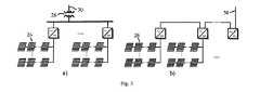
1)洋上風のための多端末DC送電:DC送電は、海底の長いACケーブルを通じて電力を運ぶことに関する困難のために、洋上風に関してAC送電よりも好まれる。この用途については、図2aに示されるように、各風車(12)がDC出力を生成するように制御され、複数のそのようなDC端末(14)が直列に接続されて陸の電力網に送電するための十分に高いDC電圧を確立する直列DC構造(10)は、図2bに示されるように、沖合のAC収集バス(24)を使用するときに必要となる余剰のDC−AC変換段(16)およびAC−DC変換段(18)が不要になるので有利である。
2)中間電圧の配電線に対するソーラーインバータの直接接続:商用の(大規模な)ソーラー設備は、通常は中間電圧(たとえば15kVまたは33kV)の配電線に接続することによって電力網に組み込まれる。図3aに示されるように、高電圧の電子装置が必要になるのを回避するために、各ソーラーインバータ(26)の出力は低電圧レベル(たとえば480V)に保たれ、配電網すなわち配電ネットワーク(30)に接続するために電圧を逓昇するのに中間電圧変圧器(28)が使用される。図3bに示される代替構造は、大きな逓昇変圧器なしで中間電圧の配電ネットワーク(30)に直接接続することができるように、複数のソーラーインバータ(26)を直列に接続するものである。
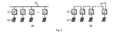
3)モジュール式低電圧マイクロインバータ:図4aに示されるように、マイクロインバータ(32)は、単一ソーラーパネル(34)のDC出力から50/60HzのACを生成する。パネルの出力電圧は、通常は、たとえば住宅の建屋における160Vといった電力網(36)のピーク電圧の小部分であるため、マイクロインバータは、電圧を逓昇するための変圧器を必要とするばかりでなく、電力網のピーク電圧に耐えることができる高電圧デバイスを使用する必要もある。変圧器および高電圧デバイスの使用は、各マイクロインバータを、パネルの出力電圧よりもより低い電圧を生成するように設計し、図4bに示されるように、複数のマイクロインバータ(32)を単一電力網(36)に接続するように直列で作動させることによって回避することができる。この方式は図3bに示されたものに類似しており、マイクロインバータのコストを低減するとともに効率を向上する。Multiple solar or wind power sources can be connected to the power grid via their own power grid interface and operate efficiently in parallel with each other as current sources. There is an increasing need to operate such power supplies in series as a way to reduce cost and improve efficiency of power conditioning interfaces. There are several examples of such applications as follows.
1) Multi-terminal DC transmission for offshore wind: DC transmission is preferred over AC transmission for offshore wind due to difficulties associated with carrying power through long undersea AC cables. For this application, as shown in FIG. 2a, each windmill (12) is controlled to produce a DC output, and a plurality of such DC terminals (14) are connected in series to transmit power to the land power grid. The series DC structure (10) that establishes a sufficiently high DC voltage to achieve the extra DC-AC conversion stage required when using the offshore AC collection bus (24), as shown in FIG. 2b. Advantageously, (16) and the AC-DC conversion stage (18) are not required.
2) Direct connection of solar inverters to intermediate voltage distribution lines: Commercial (large-scale) solar installations are usually integrated into the power grid by connecting to distribution lines of intermediate voltage (eg 15 kV or 33 kV). As shown in FIG. 3a, in order to avoid the need for high voltage electronics, the output of each solar inverter (26) is kept at a low voltage level (eg, 480V) and the distribution or distribution network ( An intermediate voltage transformer (28) is used to step up the voltage to connect to 30). An alternative structure shown in FIG. 3b is to connect a plurality of solar inverters (26) in series so that they can be directly connected to an intermediate voltage distribution network (30) without a large step-up transformer.
3) Modular low voltage micro-inverter: As shown in FIG. 4a, the micro-inverter (32) generates 50/60 Hz AC from the DC output of a single solar panel (34). Since the output voltage of the panel is usually a small part of the peak voltage of the power grid (36), eg 160V in a residential building, the microinverter not only requires a transformer to boost the voltage. There is also a need to use high voltage devices that can withstand the peak voltage of the power grid. The use of transformers and high voltage devices designed each microinverter to produce a voltage lower than the output voltage of the panel, as shown in FIG. It can be avoided by operating in series to connect to the power grid (36). This scheme is similar to that shown in FIG. 3b, reducing the cost of the microinverter and increasing efficiency.
これらの3つの例には、a)複数の電源(以下で送電端末と称される)がストリングを形成するように直列に接続されて、および、b)ストリングは、電圧源と見なされ得るDCまたはACの電力網に並列に接続されることが共通している。直列接続を容易にするために、個々の送電端末は電圧源として働くべきであり、一方、ストリングは、電圧源である電力網と並列に動作するために電流源のように振る舞うべきである。 These three examples include: a) a plurality of power sources (hereinafter referred to as power transmission terminals) connected in series to form a string, and b) a DC that can be considered a voltage source Or, it is common to be connected in parallel to an AC power grid. In order to facilitate series connection, each power transmission terminal should act as a voltage source, while the string should behave like a current source to operate in parallel with the voltage source power grid.
個々の送電端末と全体のストリングの間のそのような混合された電圧源と電流源の挙動は、すべての送電端末がたとえば同一ハウジングの中に近接近で配置されているとき、中央制御装置によって達成され得るはずである。その場合、図5に示されるように、中央制御装置(40)は、個々の送電端末(42、42’)の出力電圧を調節することによって全体のストリング電圧を制御することになり、ストリングと電力網の間の瞬時電圧差を吸収するためにインダクタ(L、L’)が直列に挿入され得、ストリングを、制御された電流源に効率よく変える。 The behavior of such mixed voltage and current sources between individual power transmission terminals and the entire string is determined by the central controller when all power transmission terminals are placed in close proximity, for example in the same housing. Should be able to be achieved. In that case, as shown in FIG. 5, the central controller (40) will control the overall string voltage by adjusting the output voltage of the individual power transmission terminals (42, 42 '), Inductors (L, L ′) can be inserted in series to absorb the instantaneous voltage difference between the power grids, effectively turning the string into a controlled current source.
この集中制御方式は、DCネットワークとACネットワークの両方において機能することができるが、コントローラと各送電端末の間に高速の通信リンクを必要とし、これは、上記で論じられた3つの例のように送電端末が分散されているとき、ストリングの物理的寸法が、屋上マイクロインバータに関する数メートルから洋上風車に関する数キロメートルの範囲であり得、実施するのが困難である。集中制御の速度は、それぞれの風車またはソーラーコンバータに使用される半導体デバイスのスイッチング周波数と同等でなければならず、制御信号が数ミリ秒失われただけでも、破壊的な損傷をもたらして全体のストリングを破壊する恐れがある。集中制御は、モジュール化するのが困難であり、維持するのも困難である。したがって、再生可能電源の、電力網へのそのような直列接続を可能にするためには別の手法が必要とされる。 This centralized control scheme can work in both DC and AC networks, but requires a high-speed communication link between the controller and each power transmission terminal, as in the three examples discussed above. When the power transmission terminals are distributed across the board, the physical dimensions of the string can range from a few meters for the rooftop microinverter to a few kilometers for the offshore wind turbine, which is difficult to implement. The speed of centralized control must be equivalent to the switching frequency of the semiconductor devices used in each windmill or solar converter, and even if the control signal is lost for a few milliseconds, it can cause destructive damage and There is a risk of destroying the string. Centralized control is difficult to modularize and difficult to maintain. Therefore, another approach is required to allow such a series connection of renewable power sources to the power grid.
本発明が提供する、多端末電力システムを形成および作動させる方法は、多数の送電端末を電力システムのネットワークに接続し、送電端末の出力電圧および出力電流の両方が、送電端末の出力電圧と出力電流の積を一定に維持する一方で、外部回路の状態に応じて同時に変動しうるように定電力電源として振る舞う各送電端末の局所制御を備える。 The method provided by the present invention for forming and operating a multi-terminal power system connects a number of power transmission terminals to a network of power systems, and both the output voltage and output current of the power transmission terminals are the output voltage and output of the power transmission terminals. While maintaining the current product constant, it has local control of each power transmission terminal that behaves as a constant power source so that it can be varied simultaneously according to the state of the external circuit.
外部回路の状態の変化は、多数の送電端末電力システムが接続されるネットワークの電圧および電流が変動することまたは送電端末の電力レベルが変動すること、および、複数の送電端末が、直列、並列、またはマトリクス構成に接続されることを含み得る。 The change in the state of the external circuit means that the voltage and current of a network to which a large number of power transmission terminal power systems are connected or the power level of the power transmission terminal varies, and that a plurality of power transmission terminals are connected in series, in parallel, Or it may include being connected to a matrix configuration.
本発明の一態様によれば、多数の送電端末のうち少なくともいくつかは、ストリングを形成するように直列に接続され、ストリングは、ネットワークのバスに並列に接続され、バスが電圧源として振る舞うものであってもよい。 According to one aspect of the present invention, at least some of a number of power transmission terminals are connected in series to form a string, the string is connected in parallel to a network bus, and the bus behaves as a voltage source. It may be.
ストリングは、有利には、配電ネットワークもしくは配電網に直接接続するソーラーインバータもしくはマイクロインバータ、または、陸の電力網にDC送電するためのDC出力を伴う洋上風車の直列接続を備え得る。 The string may advantageously comprise a solar inverter or micro-inverter directly connected to the distribution network or distribution network, or a series connection of offshore wind turbines with a DC output for DC transmission to the land power grid.
本発明の別の態様によれば、多数の送電端末の少なくともいくつかは列を形成するように並列に接続され、列は、ネットワークのバスと直列に接続され、バスは電流源として振る舞う。 According to another aspect of the present invention, at least some of the multiple power transmission terminals are connected in parallel to form a column, the column is connected in series with the network bus, and the bus behaves as a current source.
各送電端末は、有利には、再生可能エネルギー源および対応する電力調節回路を備えてもよく、局所制御では、電力調節回路の出力端子で定電力電源の挙動が生成される。 Each power transmission terminal may advantageously be equipped with a renewable energy source and a corresponding power conditioning circuit, with local control generating a constant power source behavior at the output terminal of the power conditioning circuit.
この方法は、出力電圧または出力電流のうち少なくとも1つが、前もって指定された水準を超えたとき、送電端末の電力出力を低減することにより送電端末の定電力電源の挙動を修正することをさらに含み得る。 The method further includes modifying the behavior of the power terminal's constant power source by reducing the power output of the power transmission terminal when at least one of the output voltage or output current exceeds a pre-specified level. obtain.
送電端末がAC電源を備える場合、定電力電源の電力は、基本サイクルにわたる平均電力を意味する。 When the power transmission terminal includes an AC power supply, the power of the constant power supply means the average power over the basic cycle.
本発明の一態様では、少なくとも1つの送電端末は、2つの出力端子の間に接続されたキャパシタを有する容量性出力コンバータを備える電力調節回路を含むことができ、電力調節回路の残りの部分は、キャパシタに並列に接続されている制御された電流源として働き、局所制御は、P/vに基準として追従する電流源の制御を備えることができ、前記Pはコンバータの所望の出力電力であり、vは出力キャパシタの両端電圧である。 In one aspect of the invention, the at least one power transmission terminal can include a power conditioning circuit comprising a capacitive output converter having a capacitor connected between the two output terminals, the remaining portion of the power conditioning circuit being Acting as a controlled current source connected in parallel to the capacitor, the local control can comprise a current source control that follows P / v as a reference, where P is the desired output power of the converter , V is the voltage across the output capacitor.
本発明の別の態様では、少なくとも1つの送電端末は、出力端子に接続されたインダクタを有する誘導性出力コンバータを備える電力調節回路を含むことができ、電力調節回路の残りの部分は、インダクタに直列に接続されている制御された電圧源として働き、局所制御は、P/iに追従する電圧源の制御を備えことができ、前記Pはコンバータの所望の出力電力であり、iはインダクタを通る電流である。 In another aspect of the invention, the at least one power transmission terminal can include a power conditioning circuit comprising an inductive output converter having an inductor connected to the output terminal, with the remainder of the power conditioning circuit being connected to the inductor. Acting as a controlled voltage source connected in series, the local control can comprise a voltage source control that follows P / i, where P is the desired output power of the converter and i is the inductor It is the current that passes through.
障害分離をもたらすために、電力調節回路の出力端子にバイパスダイオードが並列に接続されてもよく、出力端子とバイパスダイオードの間に断路器が直列に接続されてもよい。 In order to provide fault isolation, a bypass diode may be connected in parallel to the output terminal of the power conditioning circuit, and a disconnector may be connected in series between the output terminal and the bypass diode.
本発明の一実施形態では、送電端末に給電する再生可能電源は発電機を駆動する風車を備えてもよく、対応する電力調節回路が発電機のAC出力をDCに変換する。局所制御は、発電機側の制御およびネットワーク側の制御を含み、発電機側の制御が、最大の電力量が抽出されるように再生可能エネルギー電源を調節し、ネットワーク側の制御が、定電力電源の挙動を生成する役割を担っている。 In one embodiment of the present invention, the renewable power source that feeds the power transmission terminal may include a windmill that drives the generator, and a corresponding power conditioning circuit converts the AC output of the generator to DC. Local control includes generator-side control and network-side control, where the generator-side control adjusts the renewable energy power source so that the maximum amount of power is extracted, and the network-side control is constant power. It plays a role in generating the behavior of the power supply.
発電機側の制御は、ネットワーク側の制御にネットワークに送り込むために利用可能な総電力量を示す電力信号を供給してもよく、ネットワーク側の制御が、この信号を、出力電力を制御するための指令として用いてもよく、ネットワーク側の制御は、起動、停止、または出力電力を低減するかもしくは制限する必要があるときの電力削減の期間中、発電機側の制御に所望の電力レベルを伝達してよい。 The generator side control may supply a power signal indicating the total amount of power available to be fed into the network to the network side control, and the network side control controls this signal to control the output power. The network side control can be used to set the desired power level to the generator side control during start-up, stop, or power reduction when output power needs to be reduced or limited. May be communicated.
この実施形態の電力調節回路は、発電器出力をDCに変換する整流器を含む整流回路と、整流器の出力を高電圧へと逓昇し、高周波変圧器を使用したガルバニック絶縁ももたらすDC−DCコンバータとをさらに備え得る。DC−DCコンバータは、容量性出力コンバータまたは誘導性出力コンバータであり得る。発電機側の制御が整流器を制御し、ネットワーク側の制御がDC−DCコンバータを制御する。 The power conditioning circuit of this embodiment includes a rectifier circuit including a rectifier that converts a generator output to DC, and a DC-DC converter that boosts the output of the rectifier to a high voltage and also provides galvanic isolation using a high-frequency transformer. And may be further provided. The DC-DC converter may be a capacitive output converter or an inductive output converter. Control on the generator side controls the rectifier, and control on the network side controls the DC-DC converter.
添付図面とともに理解される様々な実施形態の以下の詳細な説明から、本発明の特徴、利点および態様が容易に理解されるであろう。 The features, advantages and aspects of the present invention will be readily understood from the following detailed description of various embodiments, taken together with the accompanying drawings.
ストリングにおける個々の送電端末の電圧源の挙動と、全体のストリング電流源の挙動との、相反する要求を解消するために本発明によって提供される解決策は、各送電端末を定電力電源(CPS)として振る舞わせることである。供給電流または供給電圧のみが外部条件に伴って変動する電圧源または電流源と異なり、CPSの出力電圧と出力電流の両方が外部条件に応じて変動する一方で出力電圧と出力電流の積は一定のままである。これは、数学的にはp=v・i=一定、と記述され得、前記vとiはそれぞれ出力電圧および出力電流である。この表記法はDC電源に関して適切である。 The solution provided by the present invention to overcome the conflicting requirements of the voltage source behavior of the individual power transmission terminals in the string and the overall string current source behavior is that each power transmission terminal is connected to a constant power source (CPS). ). Unlike a voltage source or current source in which only the supply current or supply voltage varies with external conditions, both the output voltage and output current of the CPS vary according to external conditions, while the product of output voltage and output current is constant. Remains. This can be described mathematically as p = v · i = constant, where v and i are the output voltage and output current, respectively. This notation is appropriate for DC power supplies.
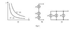
AC電源については、電力は、基本サイクルにわたる平均電力として理解されたい。さらに、定電力電源の出力電力は、利用可能な電力量または必要とされる電力量のいずれかにおける変化のために、時間とともに変動する可能性があることに留意されたい。図6aは、そのような定電力電源のi−v特性を示す。 For AC power sources, power should be understood as the average power over the basic cycle. Furthermore, it should be noted that the output power of a constant power supply may vary over time due to changes in either the amount of power available or the amount of power required. FIG. 6a shows the iv characteristic of such a constant power supply.
定電力電源は、互いに、図6bおよび図6cにそれぞれ示されるように互いに並列または直列で動作することができ、図ではCPS(48)を表すために新規のシンボルが導入されている。どちらの構成でも、各CPSの出力電圧と出力電流の両方が外部回路に依存する。CPSが、その出力電圧および出力電流を、外部回路の条件に調整する様子を説明するために、出力電力がそれぞれp1およびp2である2つのDCのCPSの直列接続を考える。図7は、各CPSのi−v特性ならびにそれらの組合せを示す。 The constant power sources can operate in parallel or in series with each other as shown in FIGS. 6b and 6c, respectively, where a new symbol is introduced to represent CPS (48). In either configuration, both the output voltage and output current of each CPS depend on the external circuit. To illustrate how the CPS adjusts its output voltage and output current to the conditions of the external circuit, consider a series connection of two DC CPSs with output powers p1 and p2, respectively. FIG. 7 shows the iv characteristics of each CPS as well as their combinations.
以下の2つの場合を考える。
1)抵抗性負荷を伴うスタンドアロン動作(図7a):負荷のi−v特性は、原点から始まる直線(v=Ri)によって表される。このラインの、組み合わされた電力一定のグラフ(vi=p1+p2)に対する交点Aは、2つのCPSの組み合わされた出力電圧(V)と、負荷を通る電流(I)とを定義する。ポイントAを通過する水平ラインは、各CPSのi−vグラフと交差し、交点(A1およびA2)は、対応するCPSの動作点を表す。
2)電圧源を伴う並列運転(図7b):並列の電圧源のi−v特性は、垂直ラインv=Vによって表される。このラインが、組み合わされた電力一定のグラフ(vi=p1+p2)に交差し、交点Bは、各CPSによって供給される電流(I)を定義する。ポイントBを通過する水平ラインは、各CPSのi−vグラフと交差し、交点(B1およびB2)は、対応するCPSの動作点を表す。Consider the following two cases.
1) Stand-alone operation with a resistive load (FIG. 7a): The iv characteristic of the load is represented by a straight line (v = Ri) starting from the origin. The intersection A of this line for the combined constant power graph (vi = p1 + p2) defines the combined output voltage (V) of the two CPSs and the current (I) through the load. The horizontal line passing through point A intersects the iv graph of each CPS, and the intersections (A1 and A2) represent the corresponding CPS operating point.
2) Parallel operation with voltage source (FIG. 7b): The iv characteristic of the parallel voltage source is represented by the vertical line v = V. This line intersects the combined constant power graph (vi = p1 + p2), and intersection B defines the current (I) supplied by each CPS. A horizontal line passing through point B intersects the iv graph of each CPS, and the intersection points (B1 and B2) represent the operating point of the corresponding CPS.
上記の解析は特定のCPSおよび負荷条件に関するものであったが、直列接続されたCPSは、変動する負荷条件ならびに各CPSの電力レベルに応じて適合し得ることが明白であろう。同じ解析が、並列のCPSに実施され得る。一例として、2つの異なるタイプの負荷と並列の2つのCPSを考える。
1)抵抗性負荷を伴うスタンドアロン動作(図8a):負荷のi−v特性は、これも、原点から始まる直線(v=Ri)によって表される。このラインの、組み合わされた電力一定のグラフ(vi=p1+p2)に対する交点Aは、両方のCPSの出力電圧(V)と、それらの組み合わされた出力電流(I)とを定義する。ポイントAを通過する垂直ラインは、各CPSのi−vグラフと交差し、交点(A1およびA2)は、対応するCPSの出力電流(I1およびI2)を定義する。
2)電圧源を伴う並列運転(図8b):並列の電圧源のi−v特性は、これも、垂直ラインv=Vによって表される。このラインが、組み合わされた電力一定のグラフ(vi=p1+p2)に交差し、交点Bは、両方のCPSの出力電圧(V)を定義する。同じ垂直ラインが各CPSのi−vグラフと交差し、交点(B1およびB2)は、対応するCPSの出力電流(I1およびI2)を定義する。Although the above analysis was for specific CPS and load conditions, it will be apparent that CPSs connected in series can be adapted depending on the varying load conditions and the power level of each CPS. The same analysis can be performed on parallel CPS. As an example, consider two CPSs in parallel with two different types of loads.
1) Stand-alone operation with a resistive load (FIG. 8a): The iv characteristic of the load is also represented by a straight line (v = Ri) starting from the origin. The intersection A of this line for the combined constant power graph (vi = p1 + p2) defines the output voltage (V) of both CPSs and their combined output current (I). The vertical line passing through point A intersects the iv graph of each CPS, and the intersections (A1 and A2) define the corresponding CPS output currents (I1 and I2).
2) Parallel operation with voltage source (FIG. 8b): The iv characteristic of the parallel voltage source is also represented by the vertical line v = V. This line intersects the combined constant power graph (vi = p1 + p2), and intersection B defines the output voltage (V) of both CPSs. The same vertical line intersects the iv graph of each CPS, and the intersection points (B1 and B2) define the corresponding CPS output currents (I1 and I2).
上記の解析は、直列もしくは並列または両方の組合せに接続されたCPSの任意数に拡張され得る。 The above analysis can be extended to any number of CPSs connected in series or parallel or a combination of both.
ここで、図2aに示されるような、洋上風の多端末DC送電における本発明の適用を特に考える。各タービン発電機の出力が、DC出力端子においてCPSと同様に振る舞うように調節された整流器によって調節されると想定する。すべての機械的電力損失および電気的電力損失を無視すれば、DC出力電力は、タービン翼が風から抽出する電力に等しい。 Now consider particularly the application of the present invention in offshore wind multi-terminal DC power transmission, as shown in FIG. 2a. Assume that the output of each turbine generator is regulated by a rectifier that is tuned to behave like a CPS at the DC output terminal. If all mechanical and electrical power losses are ignored, the DC output power is equal to the power that the turbine blades extract from the wind.
風車によって抽出される電力が所与の風況の下で一定であるという事実と、電力調節回路の、その出力端子において測定される定電力電源の挙動とを混同しないようにされたい。電圧源または電流源によっても一定量の電力が伝達され得る。ここで定義されたCPSの挙動は、その端子電圧と端子電流の両方が負荷に応じて同時に変動し得るという事実を意味するものである。外部回路の状態に応じて出力電圧と出力電流の両方を同時に調整する一方で、送電端末の出力電圧と出力電流の積を一定に維持するこの特有の能力が、定電力電源を電圧源または電流源から区別する。 Do not confuse the fact that the power extracted by the windmill is constant under a given wind condition and the behavior of the constant power supply measured at its output terminal of the power conditioning circuit. A certain amount of power can also be transmitted by a voltage source or a current source. The behavior of the CPS defined here implies the fact that both its terminal voltage and terminal current can fluctuate simultaneously depending on the load. This unique ability to adjust both the output voltage and output current simultaneously according to the state of the external circuit while maintaining the product of the output voltage and output current of the power transmission terminal constant makes the constant power supply a voltage source or current. Distinguish from the source.
一般性を失うことなく、図9aに示されるように、ストリング(50)を形成して20kVのDCバス(52)に接続された5つの風車(12)を考える。タービンの出力電力が(上から)それぞれ2MW、2.5MW、1MW、2.2MW、および1.5MWであって、各タービンの出力がCPS(48)のように振る舞うように調節されていると想定する。各CPSの出力電力が、対応するタービン出力に等しくなるように、すべての電力損失を無視する。この場合、ストリング電流は次式で計算され得る。 Without loss of generality, consider five wind turbines (12) that form a string (50) and are connected to a 20 kV DC bus (52), as shown in FIG. 9a. The turbine output power is 2 MW, 2.5 MW, 1 MW, 2.2 MW, and 1.5 MW, respectively (from above), and the output of each turbine is adjusted to behave like CPS (48) Suppose. Ignore all power losses so that the output power of each CPS is equal to the corresponding turbine output. In this case, the string current can be calculated as:

各タービンの出力電力の下での各端末の電圧が図9aに示されている。 The voltage at each end under the output power of each turbine is shown in FIG. 9a.
ここで、上から3番目のタービンの状態が変化して、出力電力が1.8MWまで増加すると想定する。すると、以下のことが直ちに起こるはずである。
1)第3のCPSの出力電圧は、その出力電力が1.8MWに向かって増加するように増加する。
2)他のCPSの出力電圧は、全体のストリング電圧を、DCバスによって与えられている20kVに保つように低下する。
3)ストリング電流は、他のCPSの電圧低下を補うように増加する。Here, it is assumed that the state of the third turbine from the top changes and the output power increases to 1.8 MW. Then the following should happen immediately:
1) The output voltage of the third CPS increases so that its output power increases towards 1.8 MW.
2) The output voltage of the other CPS drops to keep the overall string voltage at 20 kV provided by the DC bus.
3) The string current increases to compensate for the voltage drop of other CPSs.
最終結果が図9bに示されており、ストリング電流が500Aまで増加し、各CPSの出力電圧が、CPSならびに全体のストリング電圧の制約の両方を満たす新規の水準に調整されている。理想的なCPSおよびDCバス電圧(インピーダンスがない)では、これらの調整が同時かつ即座に生じるはずであることに留意されたい。複数のストリングが、DCバスに同時に接続され得、(接続ケーブルを伴う)DCバスが(インピーダンスがない)理想的な電圧源と考えられ得る限り、互いから独立して動作するはずであることも明らかであろう。バスおよびケーブルのインピーダンスがあるので、並列の各ストリングの動作は、わずかに結合されることになる。 The final result is shown in FIG. 9b, where the string current has been increased to 500A and the output voltage of each CPS has been adjusted to a new level that satisfies both the CPS as well as the overall string voltage constraints. Note that for an ideal CPS and DC bus voltage (no impedance), these adjustments should occur simultaneously and immediately. It is also possible that multiple strings can be connected to the DC bus simultaneously and operate independently of each other as long as the DC bus (with connecting cables) can be considered an ideal voltage source (without impedance). It will be clear. Due to the bus and cable impedance, the operation of each string in parallel will be slightly coupled.
一例として、図9cは、並列に接続された2つのストリングを示す。各ストリングを接続しているケーブルは、R=0.1Ωの抵抗を有すると想定される。比較のために、図9a)および図9b)で使用されているものと同一のタービン出力の電力レベルを想定する。2つのストリング電流はI1およびI2で示され(図9cを参照)、次の式から解くことができる。 As an example, FIG. 9c shows two strings connected in parallel. The cable connecting each string is assumed to have a resistance of R = 0.1Ω. For comparison, assume the same turbine power level as used in FIGS. 9a) and 9b). The two string currents are denoted I1 and I2 (see FIG. 9c) and can be solved from the following equation:
これらの式は、2組の複素数の解と2組の実数の解とを有する。実際の解がI1=463.3AおよびI2=502.4Aであることを確認するのは容易であり、これらの解は、抵抗がないときのものよりもわずかに大きい。対応するタービン電圧が図9cに示されている。 These equations have two sets of complex solutions and two sets of real solutions. It is easy to confirm that the actual solution is I1 = 463.3A and I2 = 502.4A, and these solutions are slightly larger than those without resistance. The corresponding turbine voltage is shown in FIG. 9c.
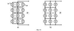
図9cに示される並列ストリングの構成に加えて、ひとつには、風車の端末(48)と、一般的にCPS送電端末を並列に接続して列(54)を最初に形成し、次いで、図10aに示されるように複数の列を直列に接続することも可能である。相互接続ケーブルのインピーダンスが無視されるとき、そのような直列の列の構成(56)は、図10bに示される網目状の(マトリクス)構成(58)と等価である。 In addition to the parallel string configuration shown in FIG. 9c, in part, the wind turbine terminal (48) and generally the CPS power transmission terminal are connected in parallel to form the row (54) first, then the figure It is also possible to connect a plurality of columns in series as shown in 10a. When the impedance of the interconnect cable is ignored, such a series row configuration (56) is equivalent to the mesh (matrix) configuration (58) shown in FIG. 10b.
図9の例によって示されるように、並列ストリング構造では、1つの送電端末における電力変動が、すべての送電端末の出力電圧に大きな変動をもたらす可能性がある。一方、ストリング電流は、ストリング全体の電力および電圧によって駆動されるので、個々の送電端末の電力変動にそれほど敏感ではなない。それと対照的に、直列の列構造における列電圧は、列の個々の送電端末の電力出力にそれほど敏感ではないが、列の内部の各送電端末の電流は、他の送電端末の電力が変化するときにかなり変化する可能性がある。 As shown by the example in FIG. 9, in the parallel string structure, power fluctuations in one power transmission terminal may cause large fluctuations in output voltages of all power transmission terminals. On the other hand, since the string current is driven by the power and voltage of the entire string, it is not very sensitive to power fluctuations of individual power transmission terminals. In contrast, the column voltage in a series column structure is not very sensitive to the power output of the individual transmission terminals in the column, but the current of each transmission terminal inside the column varies with the power of the other transmission terminals. Sometimes it can change considerably.
送電端末の電圧および電流の変動は、適切な構造を選択することに加えて、送電端末の電圧および電流が特定の水準を超えたときに電力出力が低下するようにCPS特性を変更することによっても低減され得る。これは、以下のことを含む別の方法で実施され得る。
1)電圧および電流の制限(図11a)。電圧と電流の両方が最大値(VmaxおよびImax)によって制限され、送電端末は、これらの限界を過ぎると定電圧(Vmax)または定電流(Imax)の電源として効率よく動作する。
2)電力の削減(図11b)。送電端末の出力電力は、送電端末の出力電圧または出力電流が、前もって指定された水準(VsまたはIs)を超えるにつれて徐々に低減される。これは別の方法で実施され得、それらのうちのいくつかが図11bの破線によって示されている。In addition to selecting the appropriate structure, the voltage and current fluctuations of the power transmission terminal can be changed by changing the CPS characteristics so that the power output decreases when the voltage and current of the power transmission terminal exceed a certain level. Can also be reduced. This can be done in other ways, including:
1) Voltage and current limitations (Figure 11a). Both voltage and current are limited by the maximum values (Vmax and Imax), and the power transmission terminal efficiently operates as a constant voltage (Vmax) or constant current (Imax) power source when these limits are exceeded.
2) Reduction of power (FIG. 11b). The output power of the power transmission terminal is gradually reduced as the output voltage or output current of the power transmission terminal exceeds a predetermined level (Vs or Is). This can be done in other ways, some of which are indicated by the dashed lines in FIG. 11b.
これらの特徴は、個々のCPS送電端末の制御へとプログラムされ得、入力電力と出力電力の間で電力バランスを維持するために、主要な電源(風車)の制御と連携して働くべきである。性能をさらに改善するために、1つの送電端末のi−v特性の他の送電端末に対する依存性も導入されてよい。そのような互いに依存する送電端末の特性は、他の送電端末の予測された動作状態に基づいて、または送電端末間の通信によって、各送電端末の内部で自発的に実施され得る。そのような通信を実施するために必要とされる帯域幅は、変動が遅い電力信号を伝えるだけでよいので低く、システムは通信障害に耐性があるものとされ得る。 These features can be programmed into the control of individual CPS power transmission terminals and should work in conjunction with the main power supply (windmill) control to maintain a power balance between input and output power . In order to further improve the performance, the dependency of the iv characteristics of one power transmission terminal on other power transmission terminals may also be introduced. Such characteristics of the power transmission terminals depending on each other can be spontaneously implemented inside each power transmission terminal based on the predicted operation state of other power transmission terminals or by communication between the power transmission terminals. The bandwidth required to implement such communication is low because it only needs to carry a slowly varying power signal, and the system can be made tolerant of communication failures.
これまでに提示された解析は、理想的なCPSおよびDCバス挙動を想定するものである。これらの条件下では(しかもケーブルの抵抗のみが考えられるとき)、システムは、あらゆる変化に瞬時に応答するはずであり、すなわち、システムがそれ自体を調整して、新規の動作ポイントへと即座に整定することになる。実際には、ケーブルは、抵抗に加えてキャパシタンスおよびインダクタンスを有する。離岸風風力基地のDCバスは、通常は陸のインバータステーションによって確立され、それ自体のダイナミクスを有する。各CPSも、その物理(タービン、発電機、およびパワーエレクトロニクス)設計ならびに制御設計に依存するダイナミクスを有する。 The analysis presented so far assumes ideal CPS and DC bus behavior. Under these conditions (and only the resistance of the cable is considered), the system should respond instantly to any change, i.e. the system adjusts itself and immediately to a new operating point Will settle. In practice, cables have capacitance and inductance in addition to resistance. Offshore wind farm DC buses are usually established by land inverter stations and have their own dynamics. Each CPS also has dynamics that depend on its physical (turbine, generator, and power electronics) design and control design.
これらのダイナミクスのために、システム動作の1つのポイントから別のポイントへの瞬時の移行は不可能であり、代わりに、CPSの電力および他のパラメータのそれぞれの変化は、システムのすべての電圧および電流に影響を及ぼす過渡現象を誘起することになる。そのような過渡現象中のシステムの挙動、ならびにシステムが新規の動作点に整定する能力(安定性)は、システムの動的モデルによって解析され得る。そのような動的モデルは、過渡現象中の安定的および十分な応答を保証するようにCPS制御を設計するのにも用いられ得る。これらの目的を達成するためのCPSの設計および動的制御が以下で説明される。 Because of these dynamics, an instantaneous transition from one point of system operation to another is not possible; instead, each change in the CPS power and other parameters will result in all voltages and It will induce a transient that affects the current. The behavior of the system during such transients as well as the ability of the system to settle to a new operating point (stability) can be analyzed by a dynamic model of the system. Such a dynamic model can also be used to design a CPS control to ensure a stable and sufficient response during transients. The design and dynamic control of CPS to achieve these objectives is described below.
定電力電源(CPS)を使用して多端末電力システムを形成する方法が上記で説明されてきた。CPSは、その出力電圧と出力電流の両方を外部回路の状態に応じて変動させることができ、したがって、他のCPSと直列または並列で接続され得る。網目状の(マトリクス)構成も可能である。それと対照的に、従来型の電圧源は直列にしか接続することができず、電流源は並列にしか接続することができない。より重要なのは、CPSの(直列接続された)ストリングまたは(並列接続された)列は、別の電圧源または電流源と並列または直列で動作可能なことである。 A method for forming a multi-terminal power system using a constant power source (CPS) has been described above. A CPS can vary both its output voltage and output current depending on the state of an external circuit, and therefore can be connected in series or in parallel with other CPSs. A mesh (matrix) configuration is also possible. In contrast, conventional voltage sources can only be connected in series, and current sources can only be connected in parallel. More importantly, a (series connected) string or (parallel connected) string of CPSs can operate in parallel or in series with another voltage or current source.
電圧源に並列に動作することができる能力は、再生可能エネルギーの電力網への統合において特に有用である。可能な用途には、上記で論じられたように、洋上風力発電地帯のための多端末DC送電と、中間電圧配電線に対する低電圧ソーラーインバータの直接接続と、モジュール式低電圧マイクロインバータとが含まれる。 The ability to operate in parallel with a voltage source is particularly useful in integrating renewable energy into the power grid. Possible applications include multi-terminal DC transmission for offshore wind farms, direct connection of low voltage solar inverters to intermediate voltage distribution lines, and modular low voltage micro inverters as discussed above. It is.
次に、そのようなCPS挙動を実現するために再生可能電源を制御する方法が提示される。この方法を説明するために、洋上風のための多端末DC送電を一例として用いる。 Next, a method for controlling a renewable power source to achieve such CPS behavior is presented. To illustrate this method, multi-terminal DC power transmission for offshore wind is used as an example.
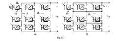
図12aに示される、そのような用途向けにありうる構造(10)では、各風車(12)がDC送電端末(14)として働き、複数の端末が直列に接続されて中間電圧または高電圧のDCバスを構築する。直列接続されたタービンの各組がストリング(15)と称されることになり、電流容量を増加させるために複数のストリングが並列で動作することができる。あるいは、複数のタービン(12)が、電流を増加させるために列(17)を形成するように、まず並列に接続され得、次いで複数の列が電圧を増加させるために直列に接続される。後者は、図12bに示されるマトリクス構造(19)と等価であって、より多くのケーブルを必要とする可能性があるが、各端末の電圧変動を低減させるのに役立ち得る。 In the possible structure (10) shown in FIG. 12a for such an application, each windmill (12) acts as a DC power transmission terminal (14), and a plurality of terminals are connected in series to provide an intermediate voltage or high voltage. Build a DC bus. Each set of turbines connected in series will be referred to as a string (15), and multiple strings can operate in parallel to increase current capacity. Alternatively, multiple turbines (12) may be connected in parallel first to form a column (17) to increase current, and then multiple columns are connected in series to increase voltage. The latter is equivalent to the matrix structure (19) shown in FIG. 12b and may require more cables, but may help to reduce voltage fluctuations at each terminal.
制御方法は、最初に並列ストリング構造向けに開発され、次いで直列の列(マトリクス)構造へと拡張されることになる。すべての場合において、DCバス電圧vdcは、陸のインバータステーションによって確立され、かつ制御されるものと想定される。 The control method will first be developed for parallel string structures and then extended to a serial column (matrix) structure. In all cases, the DC bus voltage vdc is assumed to be established and controlled by a land inverter station.
多端末ネットワークにおける送電端末として働く各タービンの電気システムは、図13aに示されるように、同期発電機(60)と、パワーエレクトロニクスコンバータ(16)(本明細書では電力調節回路と称されることもある)とから成るものと想定される。コンバータは、発電機の可変周波数AC出力からDC出力を生成する。この機能を実施するために異なったパワーエレクトロニクス回路が使用され得る。ここでの開発は特定のコンバータ回路を想定するのではなく、回路のDC出力部の、一般的な以下の2つの電気的デュアル構成に基づくものになる。
1)容量性出力コンバータ(65):DC出力から見えるコンバータへの最初の要素は、図13bに示されるように、2つの出力端子(64)の間に接続されたキャパシタ(C)である。コンバータの他の部分は、(バックコンバータまたはバック由来コンバータが使用される場合などの)連続的であり得る並列の電流源(66)、または(バックブースト型コンバータまたはブースト型コンバータが使用される場合などの)パルス幅変調された電流源(66)として扱われることになる。いずれの場合も、図13bで定義される電流iは、出力キャパシタを充電するように送られる電流の、コンバータのスイッチング周期にわたる平均値を表す。
2)誘導性出力コンバータ(67):DC出力から見えるコンバータへの最初の要素は、DC出力(64)のプラス端子またはマイナス端子に接続されたインダクタ(L)である。図13cはインダクタがプラス端子にある場合を示しており、この回路は、インダクタがマイナス端子に配置されている場合も機能的に同等である。コンバータの他の部分は、インダクタ(L)の直列の電圧源(68)として扱われることになる。そのような誘導性出力を実現するには、(a)出力キャパシタなしでバックコンバータもしくはバック由来コンバータを使用すること、または(b)容量性出力コンバータの直列にインダクタを追加すること、の2つの異なるやり方がある。電圧源は、(a)の場合はパルス幅変調されるものであり、(b)の場合は連続的なものである。いずれの場合も、vは、出力の方へ電流iを駆動する電圧の平均値を表す。The electrical system of each turbine acting as a power transmission terminal in a multi-terminal network, as shown in FIG. 13a, is a synchronous generator (60) and a power electronics converter (16) (referred to herein as a power conditioning circuit). Is also assumed to consist of. The converter generates a DC output from the variable frequency AC output of the generator. Different power electronics circuits can be used to perform this function. The development here does not assume a specific converter circuit, but is based on the following two general electrical dual configurations of the DC output of the circuit.
1) Capacitive output converter (65): The first element from the DC output to the converter visible is the capacitor (C) connected between the two output terminals (64), as shown in FIG. 13b. The other part of the converter is a parallel current source (66), which can be continuous (such as when a buck converter or buck-derived converter is used), or when a buck-boost or boost converter is used To be treated as a pulse width modulated current source (66). In either case, the current i defined in FIG. 13b represents the average value of the current sent to charge the output capacitor over the switching period of the converter.
2) Inductive output converter (67): The first element from the DC output to the converter visible is the inductor (L) connected to the positive or negative terminal of the DC output (64). FIG. 13c shows the case where the inductor is at the positive terminal, and this circuit is functionally equivalent when the inductor is located at the negative terminal. The other part of the converter will be treated as a voltage source (68) in series with the inductor (L). To achieve such an inductive output, there are two ways: (a) using a buck converter or a buck-derived converter without an output capacitor, or (b) adding an inductor in series with a capacitive output converter. There are different ways. The voltage source is pulse width modulated in the case of (a) and continuous in the case of (b). In either case, v represents the average value of the voltage that drives the current i towards the output.
以下で説明される制御方法は、各タイプのコンバータにv・iを一定化しようとするものになる。これは、基本的に、それぞれの場合における制御された電源の電力出力であって、コンバータの実際の出力電力とは異なるものであり、容量性出力コンバータについては、 The control method described below attempts to make v · i constant for each type of converter. This is basically the power output of the controlled power supply in each case, which is different from the actual output power of the converter, and for capacitive output converters,
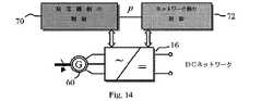
図14はタービンの全体の制御方式を示し、発電機側の制御(70)と、(DC)ネットワーク側の制御(72)とからなるものである。発電機側の制御の主要な機能は、最大の電力量が抽出されるようにタービン速度を調整することである。発電機側の制御(70)の他の機能には、発電機の効率を最大化し、より安定した電圧を維持するように、発電機の出力電流の波形および力率を調整することが含まれ得る。これらの要件を満たすために、別の既存の制御方法が適用され得る。 FIG. 14 shows the overall control system of the turbine, which comprises a generator-side control (70) and a (DC) network-side control (72). The main function of the generator side control is to adjust the turbine speed so that the maximum amount of power is extracted. Other functions on the generator side control (70) include adjusting the generator output current waveform and power factor to maximize generator efficiency and maintain a more stable voltage. obtain. Other existing control methods can be applied to meet these requirements.
本発明の中心は、所望の定電力電源の挙動を生成する役割を担うネットワーク側の制御(72)である。いくつかある信号の中で特に、電力信号(p)が、制御の2つの部分の間でやりとりされることになる。発電機側の制御(70)が、ネットワークに送り込むために利用可能な総電力量を示すために、測定または推定のいずれかに基づいてこの信号を供給し、ネットワーク側の制御(72)が、その出力電力を制御するための指令として、この信号を用いることになる。反対に、ネットワーク側の制御(72)は、起動、停止、またはタービンの出力電力を低減するかもしくは制限する必要があるときの電力削減の期間中、発電機側の制御(70)に所望の電力レベルの水準を伝達することになる。 The heart of the present invention is network side control (72) responsible for generating the desired constant power supply behavior. Among other signals, the power signal (p) will be exchanged between the two parts of the control. Generator-side control (70) provides this signal based on either measurements or estimates to indicate the total amount of power available to feed into the network, and network-side control (72) This signal is used as a command for controlling the output power. Conversely, the network-side control (72) may be desired for the generator-side control (70) during startup, shutdown, or during power reduction when the turbine output power needs to be reduced or limited. It communicates the level of power level.
容量性出力コンバータの制御
前述のように、容量性出力コンバータ(62)のネットワーク側の制御(72)の目的は、vi=Pとなるように電流iを調整することであり(図13bを参照)、前記Pは、タービンから利用可能な総電力量に基づいて発電機側の制御によって、あるいはネットワークの動作状態と、コンバータの電圧許容値および/または電流許容値とに基づいてネットワーク側の制御(72)によって、決定された所望の出力電力である。これは、P/vを基準として用い、図13bに示される等価な制御された電流源をこの基準に追従するように調整する電流コントローラによって達成され得る。Capacitive Output Converter Control As mentioned above, the purpose of the network side control (72) of the capacitive output converter (62) is to adjust the current i so that vi = P (see FIG. 13b). ), P is controlled by the generator side based on the total amount of power available from the turbine, or based on the network operating state and the converter voltage tolerance and / or current tolerance. The desired output power determined by (72). This can be achieved by a current controller that uses P / v as a reference and adjusts the equivalent controlled current source shown in FIG. 13b to follow this reference.
この電流制御機能を実施するために、多くの既存の電流制御方法が用いられ得る。動作の安全性のために、電流の基準レベルおよびそのスルーレートを制限するように、追加の制御機能が含まれ得る。実電流は、基準の形態ならびにコンバータおよび制御のダイナミクスに応じて、基準に正確に、かつ即座に追従するわけではない可能性がある。そのような非線形かつ動的な挙動を解析するために、詳細な回路および制御のモデルが用いられ得る。制御方法の原理について説明するために、以下では、別段の定めがない限り、電流基準がP/vに等しく、実際の制御された電流iがこの基準に完全に追従すると想定される。さらに、DCバスが理想的な電圧源のように振る舞うと想定される。 Many existing current control methods can be used to implement this current control function. For operational safety, additional control functions may be included to limit the current reference level and its slew rate. The actual current may not accurately and immediately follow the reference, depending on the reference configuration and the converter and control dynamics. Detailed circuit and control models can be used to analyze such non-linear and dynamic behavior. In order to explain the principle of the control method, it will be assumed in the following that the current reference is equal to P / v and the actual controlled current i follows this reference, unless otherwise specified. Furthermore, it is assumed that the DC bus behaves like an ideal voltage source.
ストリングの始動
並列のストリングは、ケーブルインピーダンスによるいくらかの小さい結合を除けば独立して動作するので、最初に単一ストリングの動作を検討する。n台のタービン(12)のストリング(15)が、以下のステップで多端末DCネットワークに接続され得る。
1)陸の電力(インバータ)ステーションを使用することによってDCバス電圧を確立して安定化する。
2)図15aに示されるように、タービンのDC出力を、電力出力なしで、DCバスに接続することなく直列に接続する。
3)ストリングの回路遮断器(13)を閉じてストリング(15)をDCバス(11)に接続する一方で、それぞれのタービンの出力電力をゼロに保つ。図15bに示されるようにDCバスの電圧vdcがストリングに印加されて、コンバータ(16)の出力キャパシタ(C1、C2…Cn)の間で分割される。それぞれのコンバータの出力キャパシタがvdc/nに充電されるように、コンバータ(16)は、理想的にはすべて同一であるべきである。実際的な容量値の不一致および電流漏れにより、わずかに不均衡な電圧がもたらされることがあるが、通常、そのような不平衡は小さく、原理解析において無視され得る。
4)各タービンコンバータ(16)のネットワーク側の制御(72)が、出力キャパシタの安定した電圧を検知して、その電流出力が立ち上がり始める。この立ち上がりは、動作の安全性を保証するために、十分に遅い速度で制御されるべきである。理想的な条件下では、すべてのタービンの電力出力は、同一の割合で同一の値に立ち上がる出力電流に等しい。この場合、電流が立ち上がる間、すべてのキャパシタ電圧は、プレチャージレベル(vdc/n)で一定に保たれる。異なるタービンからの不均等な電力出力により、キャパシタ電圧の変動を引き起こし、これは以下の解析に基づいて理解され得る。Starting Strings Since parallel strings work independently except for some small coupling due to cable impedance, consider single string operation first. A string (15) of n turbines (12) may be connected to the multi-terminal DC network in the following steps.
1) Establish and stabilize the DC bus voltage by using a land power (inverter) station.
2) As shown in FIG. 15a, connect the turbine DC output in series without power output and without connecting to the DC bus.
3) Close the string circuit breaker (13) and connect the string (15) to the DC bus (11) while keeping the output power of each turbine at zero. As shown in FIG. 15b, the DC bus voltage vdc is applied to the string and is divided among the output capacitors (C1, C2,... Cn) of the converter (16). The converters (16) should ideally all be identical so that the output capacitor of each converter is charged to vdc / n. Practical capacitance value mismatches and current leakage may result in slightly unbalanced voltages, but such unbalances are usually small and can be ignored in principle analysis.
4) The control (72) on the network side of each turbine converter (16) detects a stable voltage of the output capacitor, and its current output starts to rise. This rise should be controlled at a sufficiently slow rate to ensure operational safety. Under ideal conditions, the power output of all turbines is equal to the output current rising to the same value at the same rate. In this case, all the capacitor voltages are kept constant at the precharge level (vdc / n) while the current rises. Uneven power output from different turbines causes variations in capacitor voltage, which can be understood based on the following analysis.
いずれの場合においても、始動の最終結果(定常状態)は、a)すべてのタービン出力電流が(各キャパシタの正味の充電電流がゼロになるように)全体のストリング電流isに等しく、また、b)各タービンの出力キャパシタ電圧がPk/isに整定することになり、前記Pkはタービンの出力電力である。図15cおよび図15dは、3つのタービンストリングについての2つのケースを示す。DCバス電圧は30kVに想定される。図15cの場合、各タービンは、バス電圧が3つの端末間で均等に分割されるように2MWの電力を出力する。図15dの場合、タービン出力は、上から下へそれぞれ1MW、1.5MW、および0.5MWであり、電圧が不均等になる。いずれの場合(一般的に1つのストリングにn台のタービンがあるとき)も、定常状態のストリング電流は次式で定義され得、 In any case, the final start-up result (steady state) is: a) all turbine output currents are equal to the total string current is (so that the net charging current of each capacitor is zero), and b ) The output capacitor voltage of each turbine will settle to Pk / is, where Pk is the output power of the turbine. Figures 15c and 15d show two cases for three turbine strings. The DC bus voltage is assumed to be 30 kV. In the case of FIG. 15c, each turbine outputs 2 MW of power so that the bus voltage is evenly divided among the three terminals. In the case of FIG. 15d, the turbine output is 1 MW, 1.5 MW, and 0.5 MW, respectively, from top to bottom, and the voltages are uneven. In either case (typically when there are n turbines in a string), the steady state string current can be defined by:
これらの定常電圧がタービンの電力出力によって定義され、コンバータの出力キャパシタンスとは独立していることに留意されたい。言い換えれば、コンバータ出力キャパシタンスにおける不一致は、タービンの初期電圧に影響を及ぼし得るが、タービンが一旦動作すれば定常電圧には影響がない。 Note that these steady state voltages are defined by the power output of the turbine and are independent of the converter output capacitance. In other words, discrepancies in converter output capacitance can affect the initial voltage of the turbine, but do not affect the steady state voltage once the turbine is operating.
電圧のリバランスおよび過渡現象
個々のセルの出力電圧を自動的に調整し、またはタービンの出力電力が不均衡になるかもしくは変化するときに電圧を再調整する提案された制御の能力を理解するために、図15cから図15dへの遷移を考える。このために、ストリングが、当初は図15cによって示された条件の下で動作していると仮定する。t=0において、送電端末の出力電力が、P1=P2=P3=2MWからP1=1MW、P2=1.5MW、およびP3=0.5MWへと変化する。各送電端末の出力キャパシタンスは、100μFであると想定される。上記の想定の下で、各送電端末の出力電圧の応答は以下の式から解くことができる。Voltage rebalance and transients Understand the ability of the proposed control to automatically adjust the output voltage of individual cells or readjust the voltage when the turbine output power becomes unbalanced or changes Therefore, consider the transition from FIG. 15c to FIG. 15d. For this, assume that the string is initially operating under the conditions illustrated by FIG. 15c. At t = 0, the output power of the power transmission terminal changes from P1 = P2 = P3 = 2 MW to P1 = 1 MW, P2 = 1.5 MW, and P3 = 0.5 MW. The output capacitance of each power transmission terminal is assumed to be 100 μF. Under the above assumption, the response of the output voltage of each power transmission terminal can be solved from the following equation.
3つの微分方程式は、必要次第で2つのみであることに留意されたい。図16は、過渡現象中のセルの電圧および電流の再現された応答を示すものである。 Note that there are only three differential equations, as required. FIG. 16 shows the reproducible response of the cell voltage and current during the transient.
見てのとおりすべての電圧および電流は、それらの目標値に向かって滑らかに整定する。t=0において、図16の電流の各々が段階的に変化していることに留意されたい。これは、電力の段階的変化と、解析において仮定された理想的な電流制御特性との結果である。 As you can see, all voltages and currents settle smoothly toward their target values. Note that at t = 0, each of the currents in FIG. 16 changes stepwise. This is a result of the step change in power and the ideal current control characteristics assumed in the analysis.
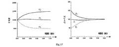
前述したように、送電端末が一旦活動状態になると、送電端末の出力キャパシタンスは電圧分布に影響を及ぼさない。これは図17に示されたシミュレーションから理解され得、その条件は、送電端末のキャパシタンスがC1=C2=C3=100μFからC1=150μF、C2=2.5μF、およびC3=2μFへと変更されていることを除けば、図16においてシミュレーションに用いられたものと同一である。見てのとおりすべての電圧および電流は、図16および図15dのものと同一の定常値へと整定するが、キャパシタンスの増加のため、過渡現象により長くかかかる。 As described above, once the power transmission terminal becomes active, the output capacitance of the power transmission terminal does not affect the voltage distribution. This can be understood from the simulation shown in FIG. 17, with the condition that the capacitance of the transmission terminal is changed from C1 = C2 = C3 = 100 μF to C1 = 150 μF, C2 = 2.5 μF, and C3 = 2 μF. Except for this, it is the same as that used in the simulation in FIG. As can be seen, all voltages and currents settle to steady values identical to those of FIGS. 16 and 15d, but take longer due to transients due to increased capacitance.
一般に、n台のタービンのストリングの過渡応答は、以下の式を用いて再現され得る。 In general, the transient response of a string of n turbines can be reproduced using the following equation:
式(10)の各電流を各コンバータ送電端末の実電流によって置換する一方で式(11)を電流コントローラの基準として扱うことにより、コンバータおよび制御のダイナミクスを組み込まれ得る。ケーブル抵抗を含むDCバスおよびケーブルのダイナミクスも、式(12)を変形することによって組み込まれ得る。 By replacing each current in equation (10) with the actual current of each converter power transmission terminal while treating equation (11) as a reference for the current controller, converter and control dynamics can be incorporated. DC bus and cable dynamics including cable resistance may also be incorporated by modifying equation (12).
保護、動作不良、および停止
式(5)は次のように並べ変えることができ、前記Pavはタービン出力電力の平均値である。Protection, malfunction, and shutdown Equation (5) can be reordered as follows, where Pav is the average value of turbine output power.
これに基づいて、送電端末の出力電力がストリングにおけるすべてのタービンの平均出力電力よりも大きければ、送電端末の定常出力電圧がDCバス電圧の1/nを超えることになる。したがって、送電端末の電力が他の送電端末よりも著しく大きければ、送電端末にわたって過電圧が増加する可能性がある。送電端末の電圧を制限することによって、ありうる損傷を避けるために、送電端末の出力電圧が特定の水準に到達したとき、その出力電力が低減され得、または削減され得る。 Based on this, if the output power of the power transmission terminal is larger than the average output power of all the turbines in the string, the steady output voltage of the power transmission terminal will exceed 1 / n of the DC bus voltage. Therefore, if the power of the power transmission terminal is significantly larger than other power transmission terminals, the overvoltage may increase across the power transmission terminals. In order to avoid possible damage by limiting the voltage of the power transmission terminal, when the output voltage of the power transmission terminal reaches a certain level, its output power can be reduced or reduced.
そのような削減の制御は、上記で論じられた方法を用いて実施され得る。電力削減が発動されたとき、入出力の電力不均衡のためにコンバータの内部で高電圧が増加することのないように発電機の出力電力を低減するために、ネットワーク側の制御(72)は、発電機側の制御(70)にも信号を送信することになる。 Such reduction control can be implemented using the methods discussed above. In order to reduce the generator output power so that the high voltage does not increase inside the converter due to input / output power imbalance when power reduction is triggered, the network side control (72) is A signal is also transmitted to the control (70) on the generator side.
式(4)に基づいてストリングの全体の電力によって定義されるストリング電流は、並列ストリング構造では、保護に関してあまり問題にならない。それにもかかわらず、(すべてのタービンの)電力削減は、必要とされるときにストリング電流を低減するために用いられ得る。 The string current defined by the overall power of the string based on equation (4) is less of an issue with respect to protection in the parallel string structure. Nevertheless, power reduction (of all turbines) can be used to reduce string current when needed.
図18に示されるように、断路器(74)およびバイパスダイオード(76)が、障害分離能力をもたらすために各送電端末の出力に追加され得る。コンバータ送電端末が故障した場合には、断路器が開かれ得、ストリング電流によってバイパスダイオードが強制的に導通させられることになる。同じ断路器(74)が、正常状態の下でストリングから送電端末を接続したり切り離したりするのに使用され得る。 As shown in FIG. 18, a disconnector (74) and bypass diode (76) may be added to the output of each power transmission terminal to provide fault isolation capability. When the converter power transmission terminal fails, the disconnector can be opened, and the bypass diode is forced to be conducted by the string current. The same disconnector (74) can be used to connect and disconnect the power transmission terminal from the string under normal conditions.
バイパスダイオード(76)のために、1つの送電端末が取り除かれたときのストリングの動作は、その送電端末の出力電力がゼロに設定されたのと等価であり、このことは、他のすべての送電端末の電圧が、失われた送電端末を補うために増加しなければならないことを意味する。したがって、送電端末上に残る電圧が過大になってストリングを運転停止しなければならなくなる前に、故障した送電端末の数に関する限界値がある。 Due to the bypass diode (76), the operation of the string when one power transmission terminal is removed is equivalent to the output power of that power transmission terminal being set to zero, This means that the voltage of the power transmission terminal must increase to make up for the lost power transmission terminal. Thus, there is a limit on the number of failed power transmission terminals before the voltage remaining on the power transmission terminals becomes excessive and the string must be shut down.
ストリングを運転停止するには、以下の2つのやり方がある。
1)制御された停止:この場合、すべての送電端末の出力電力は、徐々にゼロへと低減される(一定割合の減少)。一旦、ストリング電流がゼロになると、ストリングの遮断器(13)は、DCバスからストリングを取り除くために開かれ得る。これは、たとえば一定数の送電端末が故障して、残りの送電端末が、与えられたバス電圧で安全に動作することができないときに発動され得る。
2)非常停止:ストリングの内部またはDCバスの上の障害のためにストリングの遮断器(13)が突然開く一方で、個々の送電端末が依然として「生きている」、すなわち依然として電流を出力している場合、生きている送電端末の電圧が上昇して、送電端末の出力電流の減少を起動することになり、出力電流は、送電端末の電圧が上昇し続けるにつれて、最終的にはゼロに到達するはずである。一旦、電流がゼロになると、図18に示された断路器(74)は、ストリングから送電端末を取り除かれるために開かれ得る。There are two ways to shut down a string:
1) Controlled stop: In this case, the output power of all power transmission terminals is gradually reduced to zero (a constant rate decrease). Once the string current is zero, the string breaker (13) can be opened to remove the string from the DC bus. This can be triggered, for example, when a certain number of power transmission terminals fail and the remaining power transmission terminals cannot operate safely with a given bus voltage.
2) Emergency stop: While the string breaker (13) suddenly opens due to a fault inside the string or on the DC bus, the individual power transmission terminals are still “alive”, ie still outputting current The live power terminal voltage will rise and will trigger a decrease in the power terminal output current, and the output current will eventually reach zero as the power terminal voltage continues to rise Should do. Once the current is zero, the disconnector (74) shown in FIG. 18 can be opened to remove the power transmission terminal from the string.
直列の列およびマトリクス構成の動作
容量性出力送電端末は、並列にも動作することができる。実際、m台の並列の送電端末を、次式で表される出力電力を有する単一のCPSと等価であると見なすのは容易なことであり、Operation in series column and matrix configuration Capacitive output power transmission terminals can also operate in parallel. In fact, it is easy to consider m parallel power transmission terminals as equivalent to a single CPS with output power expressed by the following equation:
誘導性出力コンバータの制御
誘導性出力送電端末は、図19aに示されるように並列に接続して、次いで電流源バス(80)に直列に接続され得る。このトポロジおよびその等価回路(図19b)は、電圧源バス(図15aおよび図15b)に並列の送電端末のストリングとデュアルである。したがって、システムを作動させるために、各送電端末にデュアル制御方法を適用することができる。具体的には、インダクタ(L)の背後の電圧源(vk)は、vkikが、k番目のセルの所望の電力出力Pkと等しくなるように制御される。この電圧制御が理想的であるという想定の下では、電流源idc(80)に直列のn台の並列の誘導性出力送電端末の動作を支配する式は、式(9)〜(11)に双対原理を適用することによって次のように展開させることができる。Inductive Output Converter Control Inductive output power transmission terminals can be connected in parallel as shown in FIG. 19a and then connected in series to the current source bus (80). This topology and its equivalent circuit (FIG. 19b) are dual with a string of power transmission terminals in parallel with the voltage source bus (FIGS. 15a and 15b). Therefore, to operate the system, the dual control method can be applied to each power transmission terminal. Specifically, the voltage source (vk) behind the inductor (L) is controlled so that vkik is equal to the desired power output Pk of the kth cell. Under the assumption that this voltage control is ideal, the equations governing the operation of n parallel inductive output power transmission terminals in series with the current source idc (80) are expressed by equations (9) to (11). By applying the dual principle, it can be expanded as follows.
直列接続された容量性出力送電端末に関して以前に論じられた動作原理および手順は、この構成にも同様に適用され得る。たとえば、システムを始動するために、n台の送電端末は、電力出力なしで、最初は並列に接続されることになる。次いで、バスの電流源(80)に並列の回路遮断器(82)が開かれる。次いで、電力を徐々に増加するために、各送電端末の出力電圧が一定割合で上昇される。送電端末の出力電力の変化に応答して電流のリバランスおよび過渡現象も、式(14)〜(16)を解くことによって再現され得る。 The operating principles and procedures previously discussed for series connected capacitive output power transmission terminals can be applied to this configuration as well. For example, to start the system, n power transmission terminals will initially be connected in parallel without power output. The circuit breaker (82) in parallel with the bus current source (80) is then opened. Next, in order to gradually increase the power, the output voltage of each power transmission terminal is increased at a constant rate. Current rebalancing and transients in response to changes in the output power of the power transmission terminal can also be reproduced by solving equations (14)-(16).
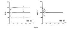
一例として、図20は、3kAのバスに接続された3台の端末の列の過渡応答を示す。送電端末の出力インダクタンスはL1=L2=L3=5mHである。最初は、送電端末の出力電力は、P1=P2=P3=2MWである。対応するバス電圧は2kVである。t=0において、送電端末の出力電力が、P1=1MW、P2=1.5MW、およびP3=0.5MW変更される。図20は、バス電圧が新規の水準1kVに整定して、送電端末の電流が、各送電端末の新規の電力出力と整合するように自動的に適応することを示す。過渡現象の挙動は、図16に示されたものに類似している。 As an example, FIG. 20 shows the transient response of a sequence of three terminals connected to a 3 kA bus. The output inductance of the power transmission terminal is L1 = L2 = L3 = 5 mH. Initially, the output power of the power transmission terminal is P1 = P2 = P3 = 2 MW. The corresponding bus voltage is 2 kV. At t = 0, the output power of the power transmission terminal is changed by P1 = 1 MW, P2 = 1.5 MW, and P3 = 0.5 MW. FIG. 20 shows that the bus voltage settles to a new level of 1 kV and the current of the power transmission terminals automatically adapts to match the new power output of each power transmission terminal. The transient behavior is similar to that shown in FIG.
誘導性出力送電端末の電流源に対する直列接続は、容量性出力送電端末の電圧源に対する並列接続とデュアルであることに留意されたい。それぞれのそのような構成における個々の送電端末の動作は、他の送電端末と(ネットワークインピーダンスによる小さな結合を除けば)独立している。したがって、それぞれの送電端末は、従来型の電圧および電流制御方法を用いて制御され得る。容量性出力送電端末の出力キャパシタおよび誘導性出力セルのインダクタも、これらの構成では、機能に影響を及ぼすことなく取り除かれ得る。しかしながら、それらは、通常はスイッチングのリップルをフィルタリングするために維持される。これまでに論じられた各々の構成において高周波リップルをさらに減衰させるために、送電端末の出力にフィルタリング素子(インダクタおよびキャパシタ)が追加され得る。これらの素子は、通常、定常状態運転に影響を及ぼすことがなく、それらの折点周波数が制御帯域幅の外にあれば、動的挙動に対するそれらの影響は無視され得る。 Note that the series connection to the current source of the inductive output power transmission terminal is dual with the parallel connection to the voltage source of the capacitive output power transmission terminal. The operation of an individual power transmission terminal in each such configuration is independent of the other power transmission terminals (except for small couplings due to network impedance). Thus, each power transmission terminal can be controlled using conventional voltage and current control methods. The output capacitors of capacitive output power transmission terminals and inductors of inductive output cells can also be removed in these configurations without affecting functionality. However, they are usually maintained to filter switching ripples. Filtering elements (inductors and capacitors) may be added to the output of the power transmission terminal to further attenuate high frequency ripple in each of the configurations discussed so far. These elements typically do not affect steady state operation and their impact on dynamic behavior can be ignored if their corner frequency is outside the control bandwidth.
要約すると、それぞれの端末を定電力電源として振る舞うように制御することによって(直列、並列、および網目状の)多端末電力システムを形成する方法が、本発明によって提供される。この文脈における定電力電源は、外部回路の状態が変化するのに応答してその出力電圧と出力電流を同時に調整する一方で、出力電圧と出力電流の積を一定に維持する電源の能力を意味する。本発明により、以下のことが促進される。
・従来型の電圧源または電流源の代わりにCPSを使用して多端末電力ネットワークを形成する。
・CPS挙動によって、直列、並列、並列のストリング、直列の列、およびマトリクスといった別のシステム構成が可能になる。
・システムの動作状態が変化するとき、個々のCPS送電端末の電圧および電流の変動を低減するためにCPSのi−v特性を変更する。
・多端末DC送電において、中間電圧配電線と直接接続するための、低電圧ソーラーインバータの直列接続と、モジュール式低電圧マイクロインバータとを適用する。In summary, a method is provided by the present invention to form a multi-terminal power system (series, parallel, and mesh) by controlling each terminal to behave as a constant power source. Constant power supply in this context means the ability of a power supply to keep its product of output voltage and output current constant while simultaneously adjusting its output voltage and output current in response to changing external circuit conditions To do. The following is promoted by the present invention.
• Form a multi-terminal power network using CPS instead of conventional voltage or current sources.
CPS behavior allows for other system configurations such as series, parallel, parallel strings, series columns, and matrices.
Change the iv characteristics of the CPS to reduce fluctuations in the voltage and current of individual CPS power transmission terminals when the operating state of the system changes.
-In multi-terminal DC power transmission, a series connection of low voltage solar inverters and a modular low voltage micro inverter for direct connection with an intermediate voltage distribution line are applied.
現在の方法は、本質的に、より効率的であってそれほど高価でなくより高信頼の新規のモジュール式システム構造を可能にすることにより、別の用途の中で特に、再生可能エネルギーの電力網への統合に役立つだろう。 Current methods are inherently more efficient, less expensive, and more reliable by enabling new modular system structures, especially among other applications, to renewable energy grids. Will help to integrate.
さらに、再生可能電源を多端末DCネットワークに統合するように制御する方法は2つの異なるタイプのコンバータ回路に提供される。
・容量性出力コンバータは、その出力におけるキャパシタと、その他のコンバータを表す、その背後の並列電流源とを有する。キャパシタの両端電圧はシステムの動作によって決定されたままになり、一方、電流源は送電端末によって局所的に制御される。
・容量性出力コンバータの電流源制御は、i=p/vを基準として用いることによって局所的に実施され、前記pはコンバータの所望の出力電力であり、vは出力キャパシタの両端電圧である。
・誘導性出力コンバータは、その出力におけるインダクタと、その他のコンバータを表す、その背後の直列電圧源とを有する。インダクタを通る電流はシステムの動作によって決定されたままになり、一方、電圧源は送電端末によって局所的に制御される。
・誘導性出力コンバータの電圧源制御は、v=p/iを基準として用いることによって局所的に実施され、前記pはコンバータの所望の出力電力であり、iは出力インダクタを通る電流である。
・容量性出力コンバータの送電端末は、多端末コンバータのネットワークを形成するために、直列、並列、または直列接続と並列接続の両方を用いて網目状(マトリクス)の形態に接続され得る。
・容量性出力セルの多端末ネットワークは、外部電圧源と並列に動作するとき、各送電端末の所望の出力電力を達成する一方でネットワーク動作の制約を満たすために、個々の送電端末の出力電圧および出力電流を自動的に調整することができる。
・誘導性出力コンバータの送電端末も、多端末コンバータのネットワークを形成するために、直列、並列、または直列接続と並列接続の両方を用いて網目状(マトリクス)の形態に接続され得る。
・誘導性出力送電端末の多端末ネットワークは、外部電流源と直列に動作するとき、各送電端末の所望の出力電力を達成する一方でネットワーク動作の制約を満たすために、個々の送電端末の出力電圧および出力電流を自動的に調整することができる。
・開示された制御方法は、各送電端末に局所的に実施され、ネットワークにおける他の送電端末との通信を必要とせず、それにもかかわらず、定常状態運転ならびに過渡的安定性の点から、所望の全体のネットワーク挙動を達成することができる。
・始動、保護、障害条件下の動作、およびシステムの運転停止方法も、それぞれのシステム構成に提供される。
Furthermore, a method for controlling the renewable power supply to be integrated into a multi-terminal DC network is provided for two different types of converter circuits.
A capacitive output converter has a capacitor at its output and a parallel current source behind it that represents the other converter. The voltage across the capacitor remains determined by the operation of the system, while the current source is controlled locally by the power transmission terminal.
The current source control of the capacitive output converter is performed locally by using i = p / v as a reference, where p is the desired output power of the converter and v is the voltage across the output capacitor.
An inductive output converter has an inductor at its output and a series voltage source behind it that represents the other converter. The current through the inductor remains determined by the operation of the system, while the voltage source is controlled locally by the power transmission terminal.
The voltage source control of the inductive output converter is performed locally by using v = p / i as a reference, where p is the desired output power of the converter and i is the current through the output inductor.
The power output terminals of the capacitive output converter can be connected in a network (matrix) form using series, parallel, or both series and parallel connections to form a network of multi-terminal converters.
• When a multi-terminal network of capacitive output cells operates in parallel with an external voltage source, it achieves the desired output power of each power transmission terminal while satisfying the network operation constraints while maintaining the output voltage of the individual power transmission terminals. And the output current can be adjusted automatically.
The power transmission terminals of the inductive output converter can also be connected in the form of a network (matrix) using series, parallel, or both series and parallel connections to form a network of multi-terminal converters.
• When a multi-terminal network of inductive output power transmission terminals operates in series with an external current source, the output of each power transmission terminal is used to achieve the desired output power of each power transmission terminal while satisfying network operation constraints. Voltage and output current can be adjusted automatically.
The disclosed control method is implemented locally at each power transmission terminal and does not require communication with other power transmission terminals in the network, nevertheless desired from the standpoints of steady state operation and transient stability Overall network behavior can be achieved.
Start, protection, operation under fault conditions, and system shutdown methods are also provided for each system configuration.
Claims (15)
Translated fromJapanese多数の送電端末(14)を電力システムのネットワークに接続し、前記送電端末の出力電圧(v)および出力電流(i)の両方が、送電端末の出力電圧と出力電流の積を一定に維持する一方で、外部回路の変化に応じて同時に変動しうるように定電力源(48)として振る舞う各送電端末(14)の局所制御を備えることを特徴とする方法。A method of forming and operating a multi-terminal power system (10, 19), comprising:
A number of power transmission terminals (14) are connected to the network of the power system, and both the output voltage (v) and the output current (i) of the power transmission terminal keep the product of the output voltage and output current of the power transmission terminal constant. On the other hand, a method comprising local control of each power transmission terminal (14) acting as a constant power source (48) so as to be able to fluctuate simultaneously in accordance with changes in an external circuit.
前記局所制御は、P/vを基準として追従する電流源の制御を備え、
前記Pは、前記コンバータの所望の出力電力であり、vは、出力キャパシタの両端電圧であることを特徴とする請求項1に記載の方法。Capacitive output converter having a capacitor (C) connected between two output terminals (64) and the rest of a power regulation circuit acting as a controlled current source (66) connected in parallel with said capacitor 65) at least one power transmission terminal (14) including a power conditioning circuit comprising:
The local control includes control of a current source that follows P / v as a reference,
The method of claim 1, wherein P is a desired output power of the converter and v is a voltage across an output capacitor.
前記局所制御は、P/iに追従する前記電圧源の制御を備え、前記Pは、前記コンバータの所望の主力電力であり、iは、前記インダクタを通る電流であることを特徴とする請求項1に記載の方法。An inductive output converter (67) having an inductor (L) connected to an output terminal (64) and the remainder of a power conditioning circuit acting as a controlled voltage source (68) connected in series with said inductor; Comprising at least one power transmission terminal (14) comprising a power conditioning circuit comprising:
The local control comprises control of the voltage source following P / i, wherein P is a desired main power of the converter and i is a current through the inductor. The method according to 1.
前記発電機側の制御が、整流器および前記風車から最大の総電力量が抽出されるように前記発電機を調整し、
前記ネットワーク側の制御が、定電力源の挙動を生成するために前記DC−DCコンバータを調整することを特徴とする請求項13に記載の方法。The local control includes generator side control (70) and network side control (72),
The control on the generator side adjusts the generator so that the maximum total power is extracted from the rectifier and the windmill,
The method of claim 13, wherein the network side control adjusts the DC-DC converter to generate a constant power source behavior.
前記ネットワーク側の制御が出力電力を制御するための指令として前記信号を使用し、
前記ネットワーク側の制御が、起動、停止、または前記出力電力を低減するかもしくは制限する必要があるときの電力削減の期間中、前記発電機側の制御に所望の電力レベルの水準を伝達する
ことを特徴とする請求項14に記載の方法。
The generator-side control (70) provides a power signal to the network-side control (72) indicating the total amount of power available for feeding into the network;
Using the signal as a command for the network side control to control the output power,
Communicating the desired power level level to the generator-side control during the period of power reduction when the network-side control needs to start, stop, or reduce or limit the output power The method of claim 14, wherein:
Applications Claiming Priority (5)
| Application Number | Priority Date | Filing Date | Title |
|---|---|---|---|
| US201361905424P | 2013-11-18 | 2013-11-18 | |
| US201361905428P | 2013-11-18 | 2013-11-18 | |
| US61/905,428 | 2013-11-18 | ||
| US61/905,424 | 2013-11-18 | ||
| PCT/US2014/063288WO2015073224A2 (en) | 2013-11-18 | 2014-10-31 | Methods to form and operate multi-terminal power systems |
Publications (1)
| Publication Number | Publication Date |
|---|---|
| JP2016538822Atrue JP2016538822A (en) | 2016-12-08 |
Family
ID=51946025
Family Applications (1)
| Application Number | Title | Priority Date | Filing Date |
|---|---|---|---|
| JP2016554308APendingJP2016538822A (en) | 2013-11-18 | 2014-10-31 | Method for forming and operating a multi-terminal power system |
Country Status (5)
| Country | Link |
|---|---|
| US (1) | US10014689B2 (en) |
| EP (1) | EP3072199B1 (en) |
| JP (1) | JP2016538822A (en) |
| CN (1) | CN105960746B (en) |
| WO (1) | WO2015073224A2 (en) |
Families Citing this family (5)
| Publication number | Priority date | Publication date | Assignee | Title |
|---|---|---|---|---|
| CN107276125B (en)* | 2017-07-06 | 2023-06-27 | 南京南瑞继保电气有限公司 | Chained multi-port grid-connected interface device and control method |
| CN111293713B (en)* | 2018-12-05 | 2023-02-03 | 西安许继电力电子技术有限公司 | A method for establishing a simulation model of a wind turbine converter in a wind farm and a simulation method |
| CN111725834B (en)* | 2019-03-22 | 2022-05-20 | 国家电网有限公司 | Method for establishing simulation model of doubly-fed fan converter of wind power plant |
| US10975847B1 (en)* | 2019-11-08 | 2021-04-13 | General Electric Company | System and method for farm-level control of transient power boost during frequency events |
| WO2022011476A1 (en)* | 2020-07-15 | 2022-01-20 | Ururaki Inc. | Power transmission method and system |
Family Cites Families (19)
| Publication number | Priority date | Publication date | Assignee | Title |
|---|---|---|---|---|
| JPS5746634A (en) | 1980-09-04 | 1982-03-17 | Tokyo Electric Power Co | Controlling device for dc multiterminal transmission system |
| EP0609101B1 (en) | 1993-01-29 | 2002-06-26 | Canon Kabushiki Kaisha | Electric power accumulating apparatus and electric power system |
| US6118678A (en) | 1999-06-10 | 2000-09-12 | Limpaecher; Rudolf | Charge transfer apparatus and method therefore |
| JP3989731B2 (en) | 1999-09-17 | 2007-10-10 | 株式会社エヌ・ティ・ティ・ドコモ | Feedforward multi-terminal power combining type power amplifier |
| US6670721B2 (en) | 2001-07-10 | 2003-12-30 | Abb Ab | System, method, rotating machine and computer program product for enhancing electric power produced by renewable facilities |
| DK174755B1 (en) | 2002-01-14 | 2003-10-20 | Vestas Wind Sys As | System for connecting a wind turbine generator to the electrical supply network |
| US8963369B2 (en)* | 2007-12-04 | 2015-02-24 | Solaredge Technologies Ltd. | Distributed power harvesting systems using DC power sources |
| JP4949902B2 (en) | 2007-03-16 | 2012-06-13 | 日本碍子株式会社 | Secondary battery power control method |
| JP5211861B2 (en)* | 2008-05-30 | 2013-06-12 | 富士電機株式会社 | Power generator system control method and power generator system |
| WO2010071855A2 (en)* | 2008-12-20 | 2010-06-24 | Azuray Technologies, Inc. | Energy conversion systems with power control |
| WO2010081746A2 (en) | 2009-01-19 | 2010-07-22 | Hubert Berger | Power control of serially connected cells |
| JP4783453B2 (en) | 2009-09-10 | 2011-09-28 | 力也 阿部 | Multi-terminal type asynchronous interconnection device, power equipment control terminal device, power network system and control method therefor |
| US8288892B2 (en) | 2009-10-29 | 2012-10-16 | Intersil Americas Inc. | Series/parallel power supply switching |
| US9197068B2 (en)* | 2010-09-30 | 2015-11-24 | Abb Research Ltd. | Coordinated control of multi-terminal HVDC systems |
| US20120175962A1 (en) | 2011-01-11 | 2012-07-12 | Converteam Technology Ltd. | Power Collection and Transmission Systems |
| GB2483317B (en)* | 2011-01-12 | 2012-08-22 | Solaredge Technologies Ltd | Serially connected inverters |
| US20120319489A1 (en)* | 2011-06-15 | 2012-12-20 | Mccaslin Shawn R | Power Shuffling Solar String Equalization System |
| US9048694B2 (en)* | 2012-02-01 | 2015-06-02 | Abb Research Ltd | DC connection scheme for windfarm with internal MVDC collection grid |
| US9000615B2 (en)* | 2012-02-04 | 2015-04-07 | Sunfield Semiconductor Inc. | Solar power module with safety features and related method of operation |
- 2014
- 2014-10-31JPJP2016554308Apatent/JP2016538822A/enactivePending
- 2014-10-31EPEP14802264.3Apatent/EP3072199B1/ennot_activeNot-in-force
- 2014-10-31USUS15/035,788patent/US10014689B2/ennot_activeCeased
- 2014-10-31CNCN201480062095.8Apatent/CN105960746B/ennot_activeExpired - Fee Related
- 2014-10-31WOPCT/US2014/063288patent/WO2015073224A2/enactiveApplication Filing
Also Published As
| Publication number | Publication date |
|---|---|
| US10014689B2 (en) | 2018-07-03 |
| US20160285270A1 (en) | 2016-09-29 |
| CN105960746A (en) | 2016-09-21 |
| WO2015073224A2 (en) | 2015-05-21 |
| EP3072199A2 (en) | 2016-09-28 |
| WO2015073224A3 (en) | 2015-07-09 |
| CN105960746B (en) | 2018-12-25 |
| EP3072199B1 (en) | 2018-07-11 |
Similar Documents
| Publication | Publication Date | Title |
|---|---|---|
| US11275398B2 (en) | DC microgrid for interconnecting distributed electricity generation, loads, and storage | |
| Dahale et al. | An overview of DC-DC converter topologies and controls in DC microgrid | |
| Bryan et al. | Decentralized generator scheduling in a nanogrid using DC bus signaling | |
| Kumar et al. | Control strategies of a DC microgrid for grid connected and islanded operations | |
| Gu et al. | Frequency-coordinating virtual impedance for autonomous power management of DC microgrid | |
| CN102163851B (en) | Control method for power source converter | |
| EP2220734B1 (en) | Electrical energy and distribution system | |
| CN107005057B (en) | Method and controller for coordinating control of wind farm during disconnection from utility grid | |
| JP2016538822A (en) | Method for forming and operating a multi-terminal power system | |
| EP2962377A2 (en) | Multi-terminal dc power systems employing autonomous local control methods | |
| Adhikari et al. | Decentralized control of two DC microgrids interconnected with tie-line | |
| Zakaria et al. | A hybrid interleaved DC-DC converter based on buck-boost topologies for medium voltage applications | |
| Zhou et al. | Static state power smoothing and transient power quality enhancement of a DC microgrid based on multi-function SMES/battery distributed hybrid energy storage system | |
| Che et al. | Resilience enhancement with DC microgrids | |
| Latha et al. | Centralized power control strategy for 25 kw nano grid for rustic electrification | |
| CN112398161A (en) | Inverter device, regenerative energy generation facility, and control method thereof | |
| CN106712113A (en) | Droop control method of voltage source inverter for photovoltaic energy storage independent microgrid | |
| KR101281079B1 (en) | Photoelectric cell system with improved power quality and operating method of it | |
| Siwakoti et al. | Performance of distributed DC power system using quasi Z-Source Inverter based DC/DC converters | |
| Harirchi et al. | Short transient recovery of low voltage-grid-tied DC distributed generation | |
| Wandhare et al. | Novel control scheme for high power centralized PV-grid system to realize functionalities of AVR and governor as in conventional generators | |
| Zhang et al. | Control and coordination of hybrid ac/dc microgrid | |
| Tironi et al. | A novel approach in multi-port DC/DC converter control | |
| Elfeqy et al. | Design of a low voltage DC grid interfacing PV and energy storage systems | |
| Alsharif et al. | Photovoltaic generators interfacing a DC micro-grid: Design considerations for a double-stage boost power converter system |