JP2016538056A - Boot remover - Google Patents
Boot removerDownload PDFInfo
- Publication number
- JP2016538056A JP2016538056AJP2016533007AJP2016533007AJP2016538056AJP 2016538056 AJP2016538056 AJP 2016538056AJP 2016533007 AJP2016533007 AJP 2016533007AJP 2016533007 AJP2016533007 AJP 2016533007AJP 2016538056 AJP2016538056 AJP 2016538056A
- Authority
- JP
- Japan
- Prior art keywords
- boot
- delivery device
- drug delivery
- needle
- support
- Prior art date
- Legal status (The legal status is an assumption and is not a legal conclusion. Google has not performed a legal analysis and makes no representation as to the accuracy of the status listed.)
- Pending
Links
Images


Classifications
- A—HUMAN NECESSITIES
- A61—MEDICAL OR VETERINARY SCIENCE; HYGIENE
- A61M—DEVICES FOR INTRODUCING MEDIA INTO, OR ONTO, THE BODY; DEVICES FOR TRANSDUCING BODY MEDIA OR FOR TAKING MEDIA FROM THE BODY; DEVICES FOR PRODUCING OR ENDING SLEEP OR STUPOR
- A61M5/00—Devices for bringing media into the body in a subcutaneous, intra-vascular or intramuscular way; Accessories therefor, e.g. filling or cleaning devices, arm-rests
- A61M5/178—Syringes
- A61M5/31—Details
- A61M5/32—Needles; Details of needles pertaining to their connection with syringe or hub; Accessories for bringing the needle into, or holding the needle on, the body; Devices for protection of needles
- A61M5/3202—Devices for protection of the needle before use, e.g. caps
- A61M5/3204—Needle cap remover, i.e. devices to dislodge protection cover from needle or needle hub, e.g. deshielding devices
- A—HUMAN NECESSITIES
- A61—MEDICAL OR VETERINARY SCIENCE; HYGIENE
- A61M—DEVICES FOR INTRODUCING MEDIA INTO, OR ONTO, THE BODY; DEVICES FOR TRANSDUCING BODY MEDIA OR FOR TAKING MEDIA FROM THE BODY; DEVICES FOR PRODUCING OR ENDING SLEEP OR STUPOR
- A61M5/00—Devices for bringing media into the body in a subcutaneous, intra-vascular or intramuscular way; Accessories therefor, e.g. filling or cleaning devices, arm-rests
- A61M5/002—Packages specially adapted therefor, e.g. for syringes or needles, kits for diabetics
- A—HUMAN NECESSITIES
- A61—MEDICAL OR VETERINARY SCIENCE; HYGIENE
- A61M—DEVICES FOR INTRODUCING MEDIA INTO, OR ONTO, THE BODY; DEVICES FOR TRANSDUCING BODY MEDIA OR FOR TAKING MEDIA FROM THE BODY; DEVICES FOR PRODUCING OR ENDING SLEEP OR STUPOR
- A61M5/00—Devices for bringing media into the body in a subcutaneous, intra-vascular or intramuscular way; Accessories therefor, e.g. filling or cleaning devices, arm-rests
- A61M5/178—Syringes
- A61M5/31—Details
- A61M5/32—Needles; Details of needles pertaining to their connection with syringe or hub; Accessories for bringing the needle into, or holding the needle on, the body; Devices for protection of needles
- A61M5/3205—Apparatus for removing or disposing of used needles or syringes, e.g. containers; Means for protection against accidental injuries from used needles
- A61M5/321—Means for protection against accidental injuries by used needles
- A61M5/3243—Means for protection against accidental injuries by used needles being axially-extensible, e.g. protective sleeves coaxially slidable on the syringe barrel
- A61M5/3257—Semi-automatic sleeve extension, i.e. in which triggering of the sleeve extension requires a deliberate action by the user, e.g. manual release of spring-biased extension means
- A—HUMAN NECESSITIES
- A61—MEDICAL OR VETERINARY SCIENCE; HYGIENE
- A61M—DEVICES FOR INTRODUCING MEDIA INTO, OR ONTO, THE BODY; DEVICES FOR TRANSDUCING BODY MEDIA OR FOR TAKING MEDIA FROM THE BODY; DEVICES FOR PRODUCING OR ENDING SLEEP OR STUPOR
- A61M5/00—Devices for bringing media into the body in a subcutaneous, intra-vascular or intramuscular way; Accessories therefor, e.g. filling or cleaning devices, arm-rests
- A61M5/178—Syringes
- A61M5/31—Details
- A61M5/32—Needles; Details of needles pertaining to their connection with syringe or hub; Accessories for bringing the needle into, or holding the needle on, the body; Devices for protection of needles
- A61M5/3205—Apparatus for removing or disposing of used needles or syringes, e.g. containers; Means for protection against accidental injuries from used needles
- A61M5/321—Means for protection against accidental injuries by used needles
- A61M5/3243—Means for protection against accidental injuries by used needles being axially-extensible, e.g. protective sleeves coaxially slidable on the syringe barrel
- A61M5/326—Fully automatic sleeve extension, i.e. in which triggering of the sleeve does not require a deliberate action by the user
- A—HUMAN NECESSITIES
- A61—MEDICAL OR VETERINARY SCIENCE; HYGIENE
- A61M—DEVICES FOR INTRODUCING MEDIA INTO, OR ONTO, THE BODY; DEVICES FOR TRANSDUCING BODY MEDIA OR FOR TAKING MEDIA FROM THE BODY; DEVICES FOR PRODUCING OR ENDING SLEEP OR STUPOR
- A61M5/00—Devices for bringing media into the body in a subcutaneous, intra-vascular or intramuscular way; Accessories therefor, e.g. filling or cleaning devices, arm-rests
- A61M5/178—Syringes
- A61M5/31—Details
- A61M2005/3125—Details specific display means, e.g. to indicate dose setting
- A—HUMAN NECESSITIES
- A61—MEDICAL OR VETERINARY SCIENCE; HYGIENE
- A61M—DEVICES FOR INTRODUCING MEDIA INTO, OR ONTO, THE BODY; DEVICES FOR TRANSDUCING BODY MEDIA OR FOR TAKING MEDIA FROM THE BODY; DEVICES FOR PRODUCING OR ENDING SLEEP OR STUPOR
- A61M5/00—Devices for bringing media into the body in a subcutaneous, intra-vascular or intramuscular way; Accessories therefor, e.g. filling or cleaning devices, arm-rests
- A61M5/178—Syringes
- A61M5/31—Details
- A61M5/32—Needles; Details of needles pertaining to their connection with syringe or hub; Accessories for bringing the needle into, or holding the needle on, the body; Devices for protection of needles
- A61M5/3205—Apparatus for removing or disposing of used needles or syringes, e.g. containers; Means for protection against accidental injuries from used needles
- A61M5/321—Means for protection against accidental injuries by used needles
- A61M5/3243—Means for protection against accidental injuries by used needles being axially-extensible, e.g. protective sleeves coaxially slidable on the syringe barrel
- A61M5/3245—Constructional features thereof, e.g. to improve manipulation or functioning
- A61M2005/3247—Means to impede repositioning of protection sleeve from needle covering to needle uncovering position
- A—HUMAN NECESSITIES
- A61—MEDICAL OR VETERINARY SCIENCE; HYGIENE
- A61M—DEVICES FOR INTRODUCING MEDIA INTO, OR ONTO, THE BODY; DEVICES FOR TRANSDUCING BODY MEDIA OR FOR TAKING MEDIA FROM THE BODY; DEVICES FOR PRODUCING OR ENDING SLEEP OR STUPOR
- A61M5/00—Devices for bringing media into the body in a subcutaneous, intra-vascular or intramuscular way; Accessories therefor, e.g. filling or cleaning devices, arm-rests
- A61M5/178—Syringes
- A61M5/31—Details
- A61M5/32—Needles; Details of needles pertaining to their connection with syringe or hub; Accessories for bringing the needle into, or holding the needle on, the body; Devices for protection of needles
- A61M5/3205—Apparatus for removing or disposing of used needles or syringes, e.g. containers; Means for protection against accidental injuries from used needles
- A61M5/321—Means for protection against accidental injuries by used needles
- A61M5/3243—Means for protection against accidental injuries by used needles being axially-extensible, e.g. protective sleeves coaxially slidable on the syringe barrel
- A61M5/326—Fully automatic sleeve extension, i.e. in which triggering of the sleeve does not require a deliberate action by the user
- A61M2005/3267—Biased sleeves where the needle is uncovered by insertion of the needle into a patient's body
- A—HUMAN NECESSITIES
- A61—MEDICAL OR VETERINARY SCIENCE; HYGIENE
- A61M—DEVICES FOR INTRODUCING MEDIA INTO, OR ONTO, THE BODY; DEVICES FOR TRANSDUCING BODY MEDIA OR FOR TAKING MEDIA FROM THE BODY; DEVICES FOR PRODUCING OR ENDING SLEEP OR STUPOR
- A61M5/00—Devices for bringing media into the body in a subcutaneous, intra-vascular or intramuscular way; Accessories therefor, e.g. filling or cleaning devices, arm-rests
- A61M5/178—Syringes
- A61M5/31—Details
- A61M5/32—Needles; Details of needles pertaining to their connection with syringe or hub; Accessories for bringing the needle into, or holding the needle on, the body; Devices for protection of needles
- A61M5/3202—Devices for protection of the needle before use, e.g. caps
Landscapes
- Health & Medical Sciences (AREA)
- Engineering & Computer Science (AREA)
- Heart & Thoracic Surgery (AREA)
- Vascular Medicine (AREA)
- Anesthesiology (AREA)
- Biomedical Technology (AREA)
- Hematology (AREA)
- Life Sciences & Earth Sciences (AREA)
- Animal Behavior & Ethology (AREA)
- General Health & Medical Sciences (AREA)
- Public Health (AREA)
- Veterinary Medicine (AREA)
- Environmental & Geological Engineering (AREA)
- Diabetes (AREA)
- Infusion, Injection, And Reservoir Apparatuses (AREA)
Abstract
Translated fromJapaneseDescription
Translated fromJapanese本発明は、保護用ニードルブーツを薬物送達デバイスから取り外すためのブーツリムーバに関する。さらに、本発明は、ブーツリムーバを含む薬物送達デバイスに関する。 The present invention relates to a boot remover for removing a protective needle boot from a drug delivery device. The present invention further relates to a drug delivery device comprising a boot remover.
薬剤の選択された用量が充填された充填済みシリンジは、薬剤を患者に投与するための周知の注射デバイスである。使用前後に充填済みシリンジの針を覆うためのニードルシールドを含む薬物送達デバイスも周知である。一般的に、ニードルシールドを、手で動かすか、または弛緩ばねの作用によって動かして、針を取り囲む。 A pre-filled syringe filled with a selected dose of drug is a well-known injection device for administering a drug to a patient. Drug delivery devices that include a needle shield for covering a filled syringe needle before and after use are also well known. Generally, the needle shield is moved by hand or by the action of a relaxation spring to surround the needle.
現在の技術で公知の異なるタイプの薬物送達デバイスは、充填済みシリンジを本体に対して可動に配置し、一方、注射後に充填済みシリンジを本体内へ引き込むことによって、針の安全性を提供するという目的を解決する。 Different types of drug delivery devices known in the state of the art provide needle safety by placing a filled syringe movably relative to the body, while retracting the filled syringe into the body after injection. Solve the purpose.
本発明の目的は、保護用ニードルブーツを薬物送達デバイスから取り外すための改良された手段を提供すること、および改良された薬物送達デバイスを提供することである。 It is an object of the present invention to provide an improved means for removing a protective needle boot from a drug delivery device, and to provide an improved drug delivery device.
この目的は、請求項1に記載のブーツリムーバおよび請求項10に記載の薬物送達デバイスによって達成される。 This object is achieved by a boot remover according to claim 1 and a drug delivery device according to
本発明の好ましい実施形態は従属請求項において与えられる。 Preferred embodiments of the invention are given in the dependent claims.
本明細書の文脈では、遠位および近位という用語は、注射を行う人の視点から見て定義される。したがって、遠位方向は、注射を受ける患者の身体の方を向く方向を指し、遠位端は、患者の身体の方に向けられた要素の端部を定義する。または、要素の近位端もしくは近位方向は、注射を受ける患者の身体から離れる方に向けられ、遠位端もしくは遠位方向の反対である。 In the context of this specification, the terms distal and proximal are defined from the perspective of the person performing the injection. Thus, the distal direction refers to the direction facing the patient's body receiving the injection, and the distal end defines the end of the element directed towards the patient's body. Alternatively, the proximal end or proximal direction of the element is directed away from the body of the patient receiving the injection and is opposite the distal end or distal direction.
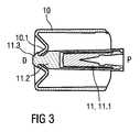
本発明によれば、保護用ニードルブーツを薬物送達デバイスから取り外すためのブーツリムーバであって、ニードルシールドを受けて実質的に覆うように適用された内径および長さを有する略スリーブ状であり、薬物送達デバイスに取り付けられたときに保護用ニードルブーツに係合するように配置されたブーツリムーバが提供される。 In accordance with the present invention, a boot remover for removing a protective needle boot from a drug delivery device, having a generally sleeve shape having an inner diameter and a length adapted to receive and substantially cover a needle shield, A boot remover is provided that is arranged to engage a protective needle boot when attached to a drug delivery device.
ブーツリムーバは、薬物の用量を投薬するための薬物送達デバイスと共に適用され、薬物送達デバイスは、第1の開口部を画成する第1の端部および第2の開口部を画成する第2の端部を有する支持体と、軸方向に沿って摺動可能に内部に配設されたストッパによって封止され、一体型の針を有するように、または針を含むニードルアセンブリと連結されるように適用され、支持体内に位置するシリンジバレルと、シリンジバレル上で針の上に配置可能な保護用ニードルブーツと、支持体の端部の一方に連結され、針を覆うかまたは露出させるために支持体に摺動可能に配設されるように適用されたニードルシールドと、ニードルシールドを受けて実質的に覆うようにニードルシールド上に配置可能であり、保護用ニードルブーツに係合するように配置されるブーツリムーバとを含む。 The boot remover is applied with a drug delivery device for dispensing a dose of the drug, the drug delivery device defining a first end defining a first opening and a second defining a second opening. And a stopper that is slidably disposed along the axial direction and has an integral needle, or is connected to a needle assembly including the needle. Applied to the syringe barrel located within the support body, a protective needle boot positionable over the needle on the syringe barrel, and connected to one of the ends of the support body to cover or expose the needle A needle shield adapted to be slidably disposed on the support, and can be disposed on the needle shield so as to receive and substantially cover the needle shield and engages a protective needle boot And a boot remover, which is sea urchin placed.
ブーツリムーバは、ユーザがニードルシールドを保持することを防止して、ブーツリムーバおよび保護用ニードルブーツの取外し前に、支持体がニードルシールドに対して遠位方向に動くことができないようにする。したがって、ユーザは支持体を保持しなければならないため、シリンジバレルおよび支持体はニードルシールドに対して所定の位置に残る。これにより、針を早まって露出させることなく保護用ニードルブーツが取り外される。 The boot remover prevents the user from holding the needle shield so that the support cannot move distally with respect to the needle shield prior to removal of the boot remover and the protective needle boot. Thus, since the user must hold the support, the syringe barrel and support remain in place with respect to the needle shield. This removes the protective needle boot without exposing the needle prematurely.
例示的な実施形態では、ブーツリムーバは、保護用ニードルブーツの連結突起に係合するように配置されたクランピングカラーを含み、保護用ニードルブーツがブーツリムーバに軸方向に連結されるようにする。クランピングカラーを、ブーツリムーバに対する保護用ニードルブーツの回転を可能にするように配置してもよい。したがって、保護用ニードルブーツは、取外しの際にシリンジおよび針に対して回転することが防止され、これにより、針の歪みおよびその他の針の損傷を回避する。このような針の歪みまたは損傷があると、注射のための使用時に患者に痛みを生じさせるおそれがある。 In an exemplary embodiment, the boot remover includes a clamping collar disposed to engage the connecting protrusion of the protective needle boot so that the protective needle boot is axially connected to the boot remover. . The clamping collar may be arranged to allow rotation of the protective needle boot relative to the boot remover. Thus, the protective needle boot is prevented from rotating relative to the syringe and needle upon removal, thereby avoiding needle distortion and other needle damage. Such needle distortion or damage can cause pain to the patient when used for injection.
保護用ニードルブーツの連結突起は、クランピングカラー内の穴に係合するためにキノコ状であってよい。これにより、保護用ニードルブーツへのブーツリムーバの組付けが容易になり、2つの部品間の相対回転が可能になる。 The connecting protrusions of the protective needle boot may be mushroom shaped to engage a hole in the clamping collar. This facilitates the assembly of the boot remover to the protective needle boot and allows relative rotation between the two parts.
代替実施形態では、ブーツリムーバを、摩擦により、および/または保護用ニードルブーツの凹部内もしくは肩部の後方に係合可能な少なくとも1つのバーブにより、保護用ニードルブーツに係合するように配置してもよい。同様に、ブーツリムーバを、保護用ニードルブーツと一体に形成されたハンドルとして配置してもよい。 In an alternative embodiment, the boot remover is arranged to engage the protective needle boot by friction and / or by at least one barb engageable in the recess of the protective needle boot or behind the shoulder. May be. Similarly, the boot remover may be arranged as a handle formed integrally with the protective needle boot.
例示的な実施形態では、ブーツリムーバは、保護用ニードルブーツを取り外すためにユーザがブーツリムーバを動かさなければならない方向を示すための矢印などの方向インジケータを含むことができる。 In an exemplary embodiment, the boot remover can include a direction indicator such as an arrow to indicate the direction in which the user must move the boot remover to remove the protective needle boot.
例示的な実施形態では、ブーツリムーバは、ブーツリムーバの取扱いを容易にする少なくとも1つのグリップ機能を含む。 In an exemplary embodiment, the boot remover includes at least one grip feature that facilitates handling of the boot remover.
クランピングカラーは、連結突起が中央に位置する凹部を形成することにより、鋭利な針が後方にあることをユーザに伝えることができる。これにより、ユーザが薬物送達デバイス1の遠位端と近位端とをより良好に区別できるようになる。 The clamping collar can inform the user that the sharp needle is behind by forming a recess in which the connecting protrusion is located in the center. This allows the user to better distinguish between the distal and proximal ends of the drug delivery device 1.
例示的な実施形態では、薬物送達デバイスは、支持体の他方の端部に連結され、支持体に摺動可能に配設された外側本体を含むことができる。薬物送達デバイスを注射部位に当てるために、ユーザが外側本体をつかむことができる。 In an exemplary embodiment, the drug delivery device can include an outer body coupled to the other end of the support and slidably disposed on the support. The user can grasp the outer body to apply the drug delivery device to the injection site.
プランジャロッドをストッパに連結することができ、プランジャロッドの近位部分は、外側本体に連結されるように適用される。これにより、外側本体に力を加えることによって、シリンジバレル内のキャビティから薬物を変位させることが可能になる。 The plunger rod can be coupled to the stopper, and the proximal portion of the plunger rod is adapted to be coupled to the outer body. This allows the drug to be displaced from the cavity in the syringe barrel by applying force to the outer body.
戻り止め機構を、支持体に対する外側本体の動きを抑制するように配置してもよい。これにより、薬物送達デバイスを注射部位に当てる際、ニードルシールドは、支持体に対して外側本体よりも先に動くため、針が挿入深さに達する前に針の先端から薬物が漏れる、いわゆる注射漏れを防止する。 The detent mechanism may be arranged to suppress movement of the outer body relative to the support. Thus, when the drug delivery device is applied to the injection site, the needle shield moves before the outer body with respect to the support, so that the drug leaks from the tip of the needle before the needle reaches the insertion depth. Prevent leakage.
例示的な実施形態では、スリーブは、支持体上、および該当する場合には外側本体上に配置可能であるか、または配置される。スリーブは、その遠位端で開き、ブーツリムーバに当接することができる。製造時にスリーブを支持体および外側本体上に設置し、構造的な外部パッケージを形成する。薬物送達デバイスの本実施形態を使用するために、ユーザは、ブーツリムーバを一方の手で保持し、スリーブを他方の手で保持して、2つの部材を引き離し、これにより、スリーブを近位方向に取り外す。 In an exemplary embodiment, the sleeve is or can be placed on the support and, if applicable, on the outer body. The sleeve can open at its distal end and abut the boot remover. During manufacture, a sleeve is placed on the support and outer body to form a structural external package. To use this embodiment of the drug delivery device, the user holds the boot remover with one hand and the sleeve with the other hand, pulling the two members apart, thereby causing the sleeve to move proximally Remove it.
例示的な実施形態では、スリーブが透明であってよい。 In an exemplary embodiment, the sleeve may be transparent.
本発明の適用可能性のさらなる範囲が、以下に示す詳細な説明から明らかになろう。しかしながら、本発明の精神および範囲内の様々な変更ならびに修正がこの詳細な説明から当業者に明らかになるため、詳細な説明および具体的な例は、本発明の好ましい実施形態を示すとともに単なる例示として示されることを理解すべきである。 Further scope of the applicability of the present invention will become apparent from the detailed description given below. However, since various changes and modifications within the spirit and scope of the invention will become apparent to those skilled in the art from this detailed description, the detailed description and specific examples illustrate the preferred embodiments of the invention and are merely exemplary It should be understood that
本発明は、以下に示す詳細な説明、および単なる例示として示される添付図面から、より完全に理解されるものであり、したがって、本発明を限定するものではない。 The invention will be more fully understood from the following detailed description and the accompanying drawings, which are given by way of illustration only, and thus are not intended to limit the invention.
すべての図面において、対応する部材には同じ参照符号を付している。 Corresponding parts are marked with the same reference symbols in all figures.
図1は、すべて基本的に管状の形状を有する、支持体2、外側本体3、およびニードルシールド4を含む、薬物送達デバイス1の斜視図である。図2は、薬物送達デバイス1の詳細の縦断面図である。支持体2の近位端は外側本体3に嵌め込み式にされ、支持体2の遠位端はニードルシールド4に嵌め込み式にされる。シリンジバレル5は、支持体2内に摺動可能に配置され、薬物の用量のための内部キャビティを画成する。中空注射針6は、シリンジバレル5の遠位端に配置される。ストッパ(図示せず)は、近位端を封止するために、かつシリンジバレル5から注射針6を通して薬物を変位させるために、シリンジバレル5内に摺動可能に配置される。プランジャロッド(図示せず)は、ストッパに係合するために外側本体2内に配置される。プランジャロッドを、ストッパに螺着またはスナップ留めしてもよい。ニードルシールドばね9は、支持体2に対して遠位方向Dへニードルシールド4を付勢するために配置される。 FIG. 1 is a perspective view of a drug delivery device 1 including a
外側本体3は、支持体2に対して遠位方向Dおよび近位方向Pへ可動である。 The
シリンジバレル5は、支持体2に挿入され、支持体2に対して軸方向位置で遠位方向Dに向かって固定される。 The
支持体2は、半径方向外方に突出し、基本的に周方向のリブの形状のインジケータリング2.2を含む。インジケータリング2.2は、支持体2の一部または全周を覆うことができる。インジケータリング2.2は、ニードルシールド4と相互に作用して、ニードルシールド4に対する支持体2の遠位運動を制限するように配置される。さらに、支持体2は、ロッキング機構と、支持体2、外側本体3、およびニードルシールド4の間に段階的な動きをもたらすために軸方向に延びる直線ガイドレール(図示せず)とを含む。 The
ニードルシールド4は、管状本体セクション4.1と中央開口部4.3を有するキャップ部材4.2とを含む。キャップ部材4.2は、スナップ嵌め(図示せず)により本体セクション4.1に係合されることにより、相対的な軸方向運動を防止する。保護用ニードルブーツ11は、注射の前後に、キャップ部材4.2の中央開口部4.3内で、および/または中央開口部4.3を通ってシリンジバレル5の針6の上に位置する。キャップ部材4.2は、本体セクション4.1に回転ロックされる。これは、非円形、例えば楕円形の横断面を有するキャップ部材4.2が本体セクション4.1の対応する開口部に係合することによって達成することができる。 Needle shield 4 includes a tubular body section 4.1 and a cap member 4.2 having a central opening 4.3. The cap member 4.2 is engaged with the body section 4.1 by a snap fit (not shown) to prevent relative axial movement. The protective needle boot 11 is located on the
保護用ニードルブーツ11は、弾性材料を含むかまたは弾性材料からなる内側ブーツ11.1と、内側ブーツ11.1上に配置された、より剛性の高い外側ブーツ11.2とを含み、内側ブーツ11.1と外側ブーツ11.2とはポジティブおよび/または非ポジティブに互いに連結される。外側ブーツ11.2の遠位端に、連結突起11.3が配置される。例示的な実施形態では、連結突起11.3はキノコ状である。キノコ状の連結突起11.3および/またはクランピングカラー10.1は、組立て中にこれらが偏向できるようにするための1つまたはそれ以上の長手方向スロットを含んでよい。 The protective needle boot 11 comprises an inner boot 11.1 comprising or consisting of an elastic material and a stiffer outer boot 11.2 arranged on the inner boot 11.1, 11.1 and outer boot 11.2 are connected to each other positively and / or non-positively. At the distal end of the outer boot 11.2, a connecting projection 11.3 is arranged. In the exemplary embodiment, the connecting protrusion 11.3 is mushroom shaped. The mushroom-like connecting projection 11.3 and / or the clamping collar 10.1 may include one or more longitudinal slots to allow them to deflect during assembly.
ブーツリムーバ10は、注射前に保護用ニードルブーツ11を取り外すために配置される。ブーツリムーバ10は、ニードルシールド4を受けてニードルシールド4を実質的に覆うように適用された内径および長さを有する略スリーブ状であり、ニードルシールド4は、ブーツリムーバ10内に配置されたときにユーザがつかむことができないようになっている。ブーツリムーバ10の遠位端のクランピングカラー10.1は、保護用ニードルブーツ11の連結突起11.3に係合するように配置されて、保護用ニードルブーツ11がブーツリムーバ10に軸方向に連結するが、ブーツリムーバ10に対して自由に回転できるようにする。図3は、保護用ニードルブーツ11を有するブーツリムーバ10の縦断面図である。 The
代替実施形態では、ブーツリムーバ10を、摩擦により、および/またはバーブを用いることにより、保護用ニードルブーツ11に係合するように配置してもよい。保護用ニードルブーツ11を取り外すためにユーザがブーツリムーバ10を動かさなければならない方向を示すための方向インジケータを、ブーツリムーバ10に設けてもよい。同様に、ブーツリムーバ10を、保護用ニードルブーツ11と一体に形成されたハンドルとして配置してもよい。 In an alternative embodiment, the
図1および図2は、注射前の薬物送達デバイス1を示す。外側本体3は、支持体2から近位方向Pへ完全に延びる。ニードルシールド4は、支持体2から遠位方向Dへ完全に延びる。注射針6は、ニードルシールド4内の後退位置にある。ニードルシールドばね9は弛緩している。 1 and 2 show a drug delivery device 1 prior to injection. The
ユーザは、保護用ニードルブーツ11を取り外すために、外側本体3または支持体2をつかんで、ブーツリムーバ10を遠位方向Dに引くことができる。 The user can pull the
その結果、ブーツリムーバ10はニードルシールド4から引き離され、保護用ニードルブーツ11はニードルシールド4の中心開口部4.3から引き出される。 As a result, the
ユーザがニードルシールド4を保持し、かつブーツリムーバ10を引く場合には、保護用ニードルブーツ11とシリンジバレル5との間の摩擦によって、シリンジバレル5およびしたがって支持体2をニードルシールド4に対して遠位方向Dに引く傾向があり、これにより針6が早まって露出される。しかしながら、ブーツリムーバ10はユーザがニードルシールド4を保持することを防止するため、支持体2はニードルシールド4に対して遠位方向Dに動くことができない。したがって、ユーザは支持体2または外側本体3を保持しなければならないため、シリンジバレル5および支持体2は所定の位置に残る。これにより、図4および図5に示すように、針6を露出させることなく保護用ニードルブーツ11が取り外される。 When the user holds the needle shield 4 and pulls the
ユーザはここで、ニードルシールド4の遠位端を注射部位、例えば患者の皮膚に押し付けることができる。ユーザの手による力は、外側本体3、支持体2を通して、ニードルシールド4内へと消散される。ユーザが十分に大きい力を加えると、ニードルシールド4は、支持体2および薬物送達デバイス1の他のすべての部材に対して近位方向Pに動き、それによりニードルシールドばね9も圧縮する。 The user can now press the distal end of the needle shield 4 against the injection site, for example the patient's skin. The force by the user's hand is dissipated into the needle shield 4 through the
薬物送達デバイス1を患者の皮膚に当てる際、ニードルシールド4は、支持体2と外側本体3との間のロッキング機構または戻り止め(図示なし)によって、支持体2に対して外側本体3よりも先に動く。この動きには、皮膚に貫入するときの注射針6の摩擦力が対抗する。挿入深さに達する前の針挿入中に針の先端から薬物が漏れる、いわゆる注射漏れ(wet injection)を回避するために、針6の摩擦力は、ストッパ7とシリンジ5の内壁との間の摩擦と、中空針6を通して変位予定の薬物の静水圧抵抗とによるストッパ7の反作用力よりも小さくなければならず、この静水圧抵抗は、針6の内径および薬物の粘性に応じて決まる。針の挿入深さは、ニードルシールド4がインジケータリング2.2に当接することによって規定される。インジケータリング2.2とニードルシールド4との嵌合面は、薬物送達デバイス1を正しく適用するために、これらが完全に一緒に押されることが意図されていることを、ユーザに対して視覚的および触覚的に示す。 When the drug delivery device 1 is applied to the patient's skin, the needle shield 4 is more than the
挿入深さに達すると、外側本体3にさらに力を加えることによって戻り止めを乗り越えるため、外側本体3は支持体2からデカップリングし、支持体2に対して遠位方向Dに動き、したがってシリンジバレル5内のストッパ7も、薬物が注射針6を通してキャビティから変位されるように動く。注射の終わり近くに、ストッパ7はシリンジバレル5内で最も低い位置になる。同時に、外側本体3はインジケータリング2.2に当接する。インジケータリング2.2と外側本体3との嵌合面は、薬物送達デバイス1を正しく適用するために、これらが完全に一緒に押されることが意図されていることを、ユーザに対して視覚的および触覚的に示す。 When the insertion depth is reached, the
ユーザが薬物送達デバイス1を注射部位から取り外すと、ニードルシールド4は皮膚に押し付けられなくなり、したがってニードルシールドばね9により薬物送達デバイス1の他の部材に対して遠位方向Dに延びて、注射針6が完全にニードルシールド4の内部に到達する。ニードルシールド4が再び引き込まれることを防ぐために、ロッキング機構をニードルシールド4と支持体2との間に設けてもよい。 When the user removes the drug delivery device 1 from the injection site, the needle shield 4 is no longer pressed against the skin and thus extends in the distal direction D with respect to the other members of the drug delivery device 1 by the needle shield spring 9 so that the
支持体2に連結された外側本体3の端部は、半径方向外向きのフランジ3.6を含むことができ、これによって薬物送達デバイス1を適用するときの人間工学が改善される。 The end of the
例示的な実施形態では、外側本体3の表面におけるプロファイルドキャビティまたは凹面として設計された方向インジケータ3.7が、フランジ3.6の範囲に配置される。 In the exemplary embodiment, a direction indicator 3.7 designed as a profiled cavity or concave surface on the surface of the
ニードルシールド4は、同様に方向インジケータ4.6を含んでもよい。 The needle shield 4 may also include a direction indicator 4.6 as well.
送達予定の薬物および/または薬物の提供者に合わせてカスタマイズ可能なラベルを受けるために、ラベル保持凹部を外側本体3に配置してもよい。 A label retaining recess may be disposed in the
図6は、ブーツリムーバ10の例示的な実施形態の斜視図である。ブーツリムーバ10は、ブーツリムーバ10の取扱いを容易にするグリップ機能10.2を含む。クランピングカラー10.1は、中央に連結突起11.3を有する凹部を形成することにより、鋭利な針6が後方にあることをユーザに伝える。これにより、ユーザが薬物送達デバイス1の遠位端と近位端とをより良好に区別できるようになる。 FIG. 6 is a perspective view of an exemplary embodiment of a
図7は、追加の透明スリーブ12が支持体2および外側本体3上に配置された、薬物送達デバイス1の例示的な実施形態の斜視図である。スリーブ12は、その遠位端で開き、ブーツリムーバ10に当接する。製造時にスリーブ12を支持体2および外側本体3上に設置し、構造的な外部パッケージを形成する。薬物送達デバイス1の本実施形態を使用するために、ユーザは、ブーツリムーバ10を一方の手で保持し、スリーブ12を他方の手で保持して、2つの部材を引き離し、これにより、透明スリーブ12を近位方向Pに取り外す。図8は、透明スリーブ12の取外し中の、薬物送達デバイス1の本実施形態の斜視図である。 FIG. 7 is a perspective view of an exemplary embodiment of the drug delivery device 1 with an additional
本明細書で使用する用語「薬物」または「薬剤」は、少なくとも1つの薬学的に活性な化合物を含む医薬製剤を意味し、
ここで、一実施形態において、薬学的に活性な化合物は、最大1500Daまでの分子量を有し、および/または、ペプチド、タンパク質、多糖類、ワクチン、DNA、RNA、酵素、抗体もしくはそのフラグメント、ホルモンもしくはオリゴヌクレオチド、または上述の薬学的に活性な化合物の混合物であり、
ここで、さらなる実施形態において、薬学的に活性な化合物は、糖尿病、または糖尿病性網膜症などの糖尿病関連の合併症、深部静脈血栓塞栓症または肺血栓塞栓症などの血栓塞栓症、急性冠症候群(ACS)、狭心症、心筋梗塞、がん、黄斑変性症、炎症、枯草熱、アテローム性動脈硬化症および/または関節リウマチの処置および/または予防に有用であり、
ここで、さらなる実施形態において、薬学的に活性な化合物は、糖尿病または糖尿病性網膜症などの糖尿病に関連する合併症の処置および/または予防のための少なくとも1つのペプチドを含み、
ここで、さらなる実施形態において、薬学的に活性な化合物は、少なくとも1つのヒトインスリンもしくはヒトインスリン類似体もしくは誘導体、グルカゴン様ペプチド(GLP−1)もしくはその類似体もしくは誘導体、またはエキセンジン−3もしくはエキセンジン−4もしくはエキセンジン−3もしくはエキセンジン−4の類似体もしくは誘導体を含む。The term “drug” or “agent” as used herein means a pharmaceutical formulation comprising at least one pharmaceutically active compound,
Here, in one embodiment, the pharmaceutically active compound has a molecular weight of up to 1500 Da and / or a peptide, protein, polysaccharide, vaccine, DNA, RNA, enzyme, antibody or fragment thereof, hormone Or an oligonucleotide, or a mixture of the above-mentioned pharmaceutically active compounds,
Here, in a further embodiment, the pharmaceutically active compound is diabetic or diabetes related complications such as diabetic retinopathy, thromboembolism such as deep vein thromboembolism or pulmonary thromboembolism, acute coronary syndrome (ACS), useful for the treatment and / or prevention of angina pectoris, myocardial infarction, cancer, macular degeneration, inflammation, hay fever, atherosclerosis and / or rheumatoid arthritis,
Here, in a further embodiment, the pharmaceutically active compound comprises at least one peptide for the treatment and / or prevention of diabetes-related complications such as diabetes or diabetic retinopathy,
Here, in a further embodiment, the pharmaceutically active compound is at least one human insulin or human insulin analogue or derivative, glucagon-like peptide (GLP-1) or analogue or derivative thereof, or exendin-3 or exendin -4 or exendin-3 or analogs or derivatives of exendin-4.
インスリン類似体は、例えば、Gly(A21),Arg(B31),Arg(B32)ヒトインスリン;Lys(B3),Glu(B29)ヒトインスリン;Lys(B28),Pro(B29)ヒトインスリン;Asp(B28)ヒトインスリン;B28位におけるプロリンがAsp、Lys、Leu、Val、またはAlaで置き換えられており、B29位において、LysがProで置き換えられていてもよいヒトインスリン;Ala(B26)ヒトインスリン;Des(B28−B30)ヒトインスリン;Des(B27)ヒトインスリン、およびDes(B30)ヒトインスリンである。 Insulin analogues include, for example, Gly (A21), Arg (B31), Arg (B32) human insulin; Lys (B3), Glu (B29) human insulin; Lys (B28), Pro (B29) human insulin; Asp ( B28) human insulin; proline at position B28 is replaced with Asp, Lys, Leu, Val, or Ala, and at position B29, human insulin where Lys may be replaced with Pro; Ala (B26) human insulin; Des (B28-B30) human insulin; Des (B27) human insulin, and Des (B30) human insulin.
インスリン誘導体は、例えば、B29−N−ミリストイル−des(B30)ヒトインスリン;B29−N−パルミトイル−des(B30)ヒトインスリン;B29−N−ミリストイルヒトインスリン;B29−N−パルミトイルヒトインスリン;B28−N−ミリストイルLysB28ProB29ヒトインスリン;B28−N−パルミトイル−LysB28ProB29ヒトインスリン;B30−N−ミリストイル−ThrB29LysB30ヒトインスリン;B30−N−パルミトイル−ThrB29LysB30ヒトインスリン;B29−N−(N−パルミトイル−γ−グルタミル)−des(B30)ヒトインスリン;B29−N−(N−リトコリル−γ−グルタミル)−des(B30)ヒトインスリン;B29−N−(ω−カルボキシヘプタデカノイル)−des(B30)ヒトインスリン、およびB29−N−(ω−カルボキシヘプタデカノイル)ヒトインスリンである。 Insulin derivatives include, for example, B29-N-myristoyl-des (B30) human insulin; B29-N-palmitoyl-des (B30) human insulin; B29-N-myristoyl human insulin; B29-N-palmitoyl human insulin; B28- N-myristoyl LysB28ProB29 human insulin; B28-N-palmitoyl-LysB28ProB29 human insulin; B30-N-myristoyl-ThrB29LysB30 human insulin; B30-N-palmitoyl-ThrB29LysB30 human insulin; B29-N- (N-palmitoyl) -Des (B30) human insulin; B29-N- (N-ritocryl-γ-glutamyl) -des (B30) human insulin; B29-N- (ω-ca Bo carboxymethyl hepta decanoyl) -des (B30) human insulin, and B29-N- (ω- carboxyheptadecanoyl) human insulin.
エキセンジン−4は、例えば、H−His−Gly−Glu−Gly−Thr−Phe−Thr−Ser−Asp−Leu−Ser−Lys−Gln−Met−Glu−Glu−Glu−Ala−Val−Arg−Leu−Phe−Ile−Glu−Trp−Leu−Lys−Asn−Gly−Gly−Pro−Ser−Ser−Gly−Ala−Pro−Pro−Pro−Ser−NH2配列のペプチドであるエキセンジン−4(1−39)を意味する。 Exendin-4 is, for example, H-His-Gly-Glu-Gly-Thr-Phe-Thr-Ser-Asp-Leu-Ser-Lys-Gln-Met-Glu-Glu-Glu-Ala-Val-Arg-Leu Exendin-4 (1-39, which is a peptide of the sequence -Phe-Ile-Glu-Trp-Leu-Lys-Asn-Gly-Gly-Pro-Ser-Ser-Gly-Ala-Pro-Pro-Pro-Ser-NH2 ).
エキセンジン−4誘導体は、例えば、以下のリストの化合物:
H−(Lys)4−desPro36,desPro37エキセンジン−4(1−39)−NH2、
H−(Lys)5−desPro36,desPro37エキセンジン−4(1−39)−NH2、
desPro36エキセンジン−4(1−39)、
desPro36[Asp28]エキセンジン−4(1−39)、
desPro36[IsoAsp28]エキセンジン−4(1−39)、
desPro36[Met(O)14,Asp28]エキセンジン−4(1−39)、
desPro36[Met(O)14,IsoAsp28]エキセンジン−(1−39)、
desPro36[Trp(O2)25,Asp28]エキセンジン−4(1−39)、
desPro36[Trp(O2)25,IsoAsp28]エキセンジン−4(1−39)、
desPro36[Met(O)14,Trp(O2)25,Asp28]エキセンジン−4(1−39)、
desPro36[Met(O)14Trp(O2)25,IsoAsp28]エキセンジン−4(1−39);または
desPro36[Asp28]エキセンジン−4(1−39)、
desPro36[IsoAsp28]エキセンジン−4(1−39)、
desPro36[Met(O)14,Asp28]エキセンジン−4(1−39)、
desPro36[Met(O)14,IsoAsp28]エキセンジン−(1−39)、
desPro36[Trp(O2)25,Asp28]エキセンジン−4(1−39)、
desPro36[Trp(O2)25,IsoAsp28]エキセンジン−4(1−39)、
desPro36[Met(O)14,Trp(O2)25,Asp28]エキセンジン−4(1−39)、
desPro36[Met(O)14,Trp(O2)25,IsoAsp28]エキセンジン−4(1−39)、
(ここで、基−Lys6−NH2が、エキセンジン−4誘導体のC−末端に結合していてもよい);Exendin-4 derivatives are, for example, compounds of the following list:
H- (Lys) 4-desPro36, desPro37 exendin-4 (1-39) -NH2,
H- (Lys) 5-desPro36, desPro37 exendin-4 (1-39) -NH2,
desPro36 exendin-4 (1-39),
desPro36 [Asp28] exendin-4 (1-39),
desPro36 [IsoAsp28] exendin-4 (1-39),
desPro36 [Met (O) 14, Asp28] exendin-4 (1-39),
desPro36 [Met (O) 14, IsoAsp28] Exendin- (1-39),
desPro36 [Trp (O2) 25, Asp28] exendin-4 (1-39),
desPro36 [Trp (O2) 25, IsoAsp28] exendin-4 (1-39),
desPro36 [Met (O) 14, Trp (O2) 25, Asp28] exendin-4 (1-39),
desPro36 [Met (O) 14Trp (O2) 25, IsoAsp28] Exendin-4 (1-39); or desPro36 [Asp28] Exendin-4 (1-39),
desPro36 [IsoAsp28] exendin-4 (1-39),
desPro36 [Met (O) 14, Asp28] exendin-4 (1-39),
desPro36 [Met (O) 14, IsoAsp28] Exendin- (1-39),
desPro36 [Trp (O2) 25, Asp28] exendin-4 (1-39),
desPro36 [Trp (O2) 25, IsoAsp28] exendin-4 (1-39),
desPro36 [Met (O) 14, Trp (O2) 25, Asp28] exendin-4 (1-39),
desPro36 [Met (O) 14, Trp (O 2) 25, IsoAsp 28] Exendin-4 (1-39),
(Wherein the group -Lys6-NH2 may be attached to the C-terminus of the exendin-4 derivative);
または、以下の配列のエキセンジン−4誘導体:
desPro36エキセンジン−4(1−39)−Lys6−NH2(AVE0010)、
H−(Lys)6−desPro36[Asp28]エキセンジン−4(1−39)−Lys6−NH2、
desAsp28Pro36,Pro37,Pro38エキセンジン−4(1−39)−NH2、
H−(Lys)6−desPro36,Pro38[Asp28]エキセンジン−4(1−39)−NH2、
H−Asn−(Glu)5desPro36,Pro37,Pro38[Asp28]エキセンジン−4(1−39)−NH2、
desPro36,Pro37,Pro38[Asp28]エキセンジン−4(1−39)−(Lys)6−NH2、
H−(Lys)6−desPro36,Pro37,Pro38[Asp28]エキセンジン−4(1−39)−(Lys)6−NH2、
H−Asn−(Glu)5−desPro36,Pro37,Pro38[Asp28]エキセンジン−4(1−39)−(Lys)6−NH2、
H−(Lys)6−desPro36[Trp(O2)25,Asp28]エキセンジン−4(1−39)−Lys6−NH2、
H−desAsp28Pro36,Pro37,Pro38[Trp(O2)25]エキセンジン−4(1−39)−NH2、
H−(Lys)6−desPro36,Pro37,Pro38[Trp(O2)25,Asp28]エキセンジン−4(1−39)−NH2、
H−Asn−(Glu)5−desPro36,Pro37,Pro38[Trp(O2)25,Asp28]エキセンジン−4(1−39)−NH2、
desPro36,Pro37,Pro38[Trp(O2)25,Asp28]エキセンジン−4(1−39)−(Lys)6−NH2、
H−(Lys)6−desPro36,Pro37,Pro38[Trp(O2)25,Asp28]エキセンジン−4(1−39)−(Lys)6−NH2、
H−Asn−(Glu)5−desPro36,Pro37,Pro38[Trp(O2)25,Asp28]エキセンジン−4(1−39)−(Lys)6−NH2、
H−(Lys)6−desPro36[Met(O)14,Asp28]エキセンジン−4(1−39)−Lys6−NH2、
desMet(O)14,Asp28Pro36,Pro37,Pro38エキセンジン−4(1−39)−NH2、
H−(Lys)6−desPro36,Pro37,Pro38[Met(O)14,Asp28]エキセンジン−4(1−39)−NH2、
H−Asn−(Glu)5−desPro36,Pro37,Pro38[Met(O)14,Asp28]エキセンジン−4(1−39)−NH2;
desPro36,Pro37,Pro38[Met(O)14,Asp28]エキセンジン−4(1−39)−(Lys)6−NH2、
H−(Lys)6−desPro36,Pro37,Pro38[Met(O)14,Asp28]エキセンジン−4(1−39)−(Lys)6−NH2、
H−Asn−(Glu)5desPro36,Pro37,Pro38[Met(O)14,Asp28]エキセンジン−4(1−39)−(Lys)6−NH2、
H−Lys6−desPro36[Met(O)14,Trp(O2)25,Asp28]エキセンジン−4(1−39)−Lys6−NH2、
H−desAsp28,Pro36,Pro37,Pro38[Met(O)14,Trp(O2)25]エキセンジン−4(1−39)−NH2、
H−(Lys)6−desPro36,Pro37,Pro38[Met(O)14,Asp28]エキセンジン−4(1−39)−NH2、
H−Asn−(Glu)5−desPro36,Pro37,Pro38[Met(O)14,Trp(O2)25,Asp28]エキセンジン−4(1−39)−NH2、
desPro36,Pro37,Pro38[Met(O)14,Trp(O2)25,Asp28]エキセンジン−4(1−39)−(Lys)6−NH2、
H−(Lys)6−desPro36,Pro37,Pro38[Met(O)14,Trp(O2)25,Asp28]エキセンジン−4(S1−39)−(Lys)6−NH2、
H−Asn−(Glu)5−desPro36,Pro37,Pro38[Met(O)14,Trp(O2)25,Asp28]エキセンジン−4(1−39)−(Lys)6−NH2;
または前述のいずれか1つのエキセンジン−4誘導体の薬学的に許容される塩もしくは溶媒和化合物
から選択される。Or an exendin-4 derivative of the following sequence:
desPro36 exendin-4 (1-39) -Lys6-NH2 (AVE0010),
H- (Lys) 6-desPro36 [Asp28] Exendin-4 (1-39) -Lys6-NH2,
desAsp28Pro36, Pro37, Pro38 exendin-4 (1-39) -NH2,
H- (Lys) 6-desPro36, Pro38 [Asp28] Exendin-4 (1-39) -NH2,
H-Asn- (Glu) 5desPro36, Pro37, Pro38 [Asp28] Exendin-4 (1-39) -NH2,
desPro36, Pro37, Pro38 [Asp28] Exendin-4 (1-39)-(Lys) 6-NH2,
H- (Lys) 6-desPro36, Pro37, Pro38 [Asp28] Exendin-4 (1-39)-(Lys) 6-NH2,
H-Asn- (Glu) 5-desPro36, Pro37, Pro38 [Asp28] Exendin-4 (1-39)-(Lys) 6-NH2,
H- (Lys) 6-desPro36 [Trp (O2) 25, Asp28] exendin-4 (1-39) -Lys6-NH2,
H-desAsp28Pro36, Pro37, Pro38 [Trp (O2) 25] exendin-4 (1-39) -NH2,
H- (Lys) 6-desPro36, Pro37, Pro38 [Trp (O2) 25, Asp28] exendin-4 (1-39) -NH2,
H-Asn- (Glu) 5-desPro36, Pro37, Pro38 [Trp (O2) 25, Asp28] exendin-4 (1-39) -NH2,
desPro36, Pro37, Pro38 [Trp (O2) 25, Asp28] exendin-4 (1-39)-(Lys) 6-NH2,
H- (Lys) 6-desPro36, Pro37, Pro38 [Trp (O2) 25, Asp28] exendin-4 (1-39)-(Lys) 6-NH2,
H-Asn- (Glu) 5-desPro36, Pro37, Pro38 [Trp (O2) 25, Asp28] exendin-4 (1-39)-(Lys) 6-NH2,
H- (Lys) 6-desPro36 [Met (O) 14, Asp28] exendin-4 (1-39) -Lys6-NH2,
desMet (O) 14, Asp28Pro36, Pro37, Pro38 exendin-4 (1-39) -NH2,
H- (Lys) 6-desPro36, Pro37, Pro38 [Met (O) 14, Asp28] exendin-4 (1-39) -NH2,
H-Asn- (Glu) 5-desPro36, Pro37, Pro38 [Met (O) 14, Asp28] exendin-4 (1-39) -NH2;
desPro36, Pro37, Pro38 [Met (O) 14, Asp28] Exendin-4 (1-39)-(Lys) 6-NH2,
H- (Lys) 6-desPro36, Pro37, Pro38 [Met (O) 14, Asp28] exendin-4 (1-39)-(Lys) 6-NH2,
H-Asn- (Glu) 5desPro36, Pro37, Pro38 [Met (O) 14, Asp28] Exendin-4 (1-39)-(Lys) 6-NH2,
H-Lys6-desPro36 [Met (O) 14, Trp (O2) 25, Asp28] Exendin-4 (1-39) -Lys6-NH2,
H-desAsp28, Pro36, Pro37, Pro38 [Met (O) 14, Trp (O2) 25] exendin-4 (1-39) -NH2,
H- (Lys) 6-desPro36, Pro37, Pro38 [Met (O) 14, Asp28] exendin-4 (1-39) -NH2,
H-Asn- (Glu) 5-desPro36, Pro37, Pro38 [Met (O) 14, Trp (O2) 25, Asp28] Exendin-4 (1-39) -NH2,
desPro36, Pro37, Pro38 [Met (O) 14, Trp (O2) 25, Asp28] Exendin-4 (1-39)-(Lys) 6-NH2,
H- (Lys) 6-desPro36, Pro37, Pro38 [Met (O) 14, Trp (O2) 25, Asp28] Exendin-4 (S1-39)-(Lys) 6-NH2,
H-Asn- (Glu) 5-desPro36, Pro37, Pro38 [Met (O) 14, Trp (O2) 25, Asp28] Exendin-4 (1-39)-(Lys) 6-NH2;
Or a pharmaceutically acceptable salt or solvate of any one of the aforementioned exendin-4 derivatives.
ホルモンは、例えば、ゴナドトロピン(フォリトロピン、ルトロピン、コリオンゴナドトロピン、メノトロピン)、ソマトロピン(ソマトロピン)、デスモプレシン、テルリプレシン、ゴナドレリン、トリプトレリン、ロイプロレリン、ブセレリン、ナファレリン、ゴセレリンなどの、Rote Liste、2008年版、50章に列挙されている脳下垂体ホルモンまたは視床下部ホルモンまたは調節性活性ペプチドおよびそれらのアンタゴニストである。 The hormones include, for example, gonadotropin (folytropin, lutropin, corion gonadotropin, menotropin), somatropin (somatropin), desmopressin, telluripressin, gonadorelin, triptorelin, leuprorelin, buserelin, nafarelin, goserelin, etc. Rote Liste, 2008 Pituitary hormones or hypothalamic hormones or regulatory active peptides and antagonists thereof.
多糖類としては、例えば、グルコサミノグリカン、ヒアルロン酸、ヘパリン、低分子量ヘパリン、もしくは超低分子量ヘパリン、またはそれらの誘導体、または上述の多糖類の硫酸化形態、例えば、ポリ硫酸化形態、および/または、薬学的に許容されるそれらの塩がある。ポリ硫酸化低分子量ヘパリンの薬学的に許容される塩の例としては、エノキサパリンナトリウムがある。 Polysaccharides include, for example, glucosaminoglycan, hyaluronic acid, heparin, low molecular weight heparin, or ultra low molecular weight heparin, or derivatives thereof, or sulfated forms of the above-mentioned polysaccharides, such as polysulfated forms, and Or a pharmaceutically acceptable salt thereof. An example of a pharmaceutically acceptable salt of polysulfated low molecular weight heparin is sodium enoxaparin.
抗体は、基本構造を共有する免疫グロブリンとしても知られている球状血漿タンパク質(約150kDa)である。これらは、アミノ酸残基に付加された糖鎖を有するので、糖タンパク質である。各抗体の基本的な機能単位は免疫グロブリン(Ig)単量体(1つのIg単位のみを含む)であり、分泌型抗体はまた、IgAなどの2つのIg単位を有する二量体、硬骨魚のIgMのような4つのIg単位を有する四量体、または哺乳動物のIgMのように5つのIg単位を有する五量体でもあり得る。 Antibodies are globular plasma proteins (about 150 kDa), also known as immunoglobulins that share a basic structure. These are glycoproteins because they have sugar chains attached to amino acid residues. The basic functional unit of each antibody is an immunoglobulin (Ig) monomer (including only one Ig unit), and the secretory antibody is also a dimer having two Ig units such as IgA, teleost It can also be a tetramer with 4 Ig units, such as IgM, or a pentamer with 5 Ig units, like mammalian IgM.
Ig単量体は、4つのポリペプチド鎖、すなわち、システイン残基間のジスルフィド結合によって結合された2つの同一の重鎖および2本の同一の軽鎖から構成される「Y」字型の分子である。それぞれの重鎖は約440アミノ酸長であり、それぞれの軽鎖は約220アミノ酸長である。重鎖および軽鎖はそれぞれ、これらの折り畳み構造を安定化させる鎖内ジスルフィド結合を含む。それぞれの鎖は、Igドメインと呼ばれる構造ドメインから構成される。これらのドメインは約70〜110個のアミノ酸を含み、そのサイズおよび機能に基づいて異なるカテゴリー(例えば、可変すなわちV、および定常すなわちC)に分類される。これらは、2つのβシートが、保存されたシステインと他の荷電アミノ酸との間の相互作用によって一緒に保持される「サンドイッチ」形状を作り出す特徴的な免疫グロブリン折り畳み構造を有する。 An Ig monomer is a “Y” -shaped molecule composed of four polypeptide chains, two identical heavy chains and two identical light chains joined by a disulfide bond between cysteine residues. It is. Each heavy chain is about 440 amino acids long and each light chain is about 220 amino acids long. Each heavy and light chain contains intrachain disulfide bonds that stabilize these folded structures. Each chain is composed of structural domains called Ig domains. These domains contain about 70-110 amino acids and are classified into different categories (eg, variable or V, and constant or C) based on their size and function. They have a characteristic immunoglobulin fold that creates a “sandwich” shape in which two β-sheets are held together by the interaction between conserved cysteines and other charged amino acids.
α、δ、ε、γおよびμで表される5種類の哺乳類Ig重鎖が存在する。存在する重鎖の種類により抗体のアイソタイプが定義され、これらの鎖はそれぞれ、IgA、IgD、IgE、IgGおよびIgM抗体中に見出される。 There are five types of mammalian Ig heavy chains represented by α, δ, ε, γ and μ. The type of heavy chain present defines the isotype of the antibody, and these chains are found in IgA, IgD, IgE, IgG, and IgM antibodies, respectively.
異なる重鎖はサイズおよび組成が異なり、αおよびγは約450個のアミノ酸を含み、δは約500個のアミノ酸を含み、μおよびεは約550個のアミノ酸を有する。各重鎖は、2つの領域、すなわち定常領域(CH)と可変領域(VH)を有する。1つの種において、定常領域は、同じアイソタイプのすべての抗体で本質的に同一であるが、異なるアイソタイプの抗体では異なる。重鎖γ、α、およびδは、3つのタンデム型のIgドメインと、可撓性を加えるためのヒンジ領域とから構成される定常領域を有し、重鎖μおよびεは、4つの免疫グロブリン・ドメインから構成される定常領域を有する。重鎖の可変領域は、異なるB細胞によって産生された抗体では異なるが、単一B細胞またはB細胞クローンによって産生された抗体すべてについては同じである。各重鎖の可変領域は、約110アミノ酸長であり、単一のIgドメインから構成される。Different heavy chains differ in size and composition, α and γ contain about 450 amino acids, δ contain about 500 amino acids, and μ and ε have about 550 amino acids. Each heavy chain has two regions: a constant region (CH ) and a variable region (VH ). In one species, the constant region is essentially the same for all antibodies of the same isotype, but different for antibodies of different isotypes. Heavy chains γ, α, and δ have a constant region composed of three tandem Ig domains and a hinge region to add flexibility, and heavy chains μ and ε are four immunoglobulins -It has a constant region composed of domains. The variable region of the heavy chain is different for antibodies produced by different B cells, but is the same for all antibodies produced by a single B cell or B cell clone. The variable region of each heavy chain is approximately 110 amino acids long and is composed of a single Ig domain.
哺乳類では、λおよびκで表される2種類の免疫グロブリン軽鎖がある。軽鎖は2つの連続するドメイン、すなわち1つの定常ドメイン(CL)および1つの可変ドメイン(VL)を有する。軽鎖のおおよその長さは、211〜217個のアミノ酸である。各抗体は、常に同一である2本の軽鎖を有し、哺乳類の各抗体につき、軽鎖κまたはλの1つのタイプのみが存在する。 In mammals, there are two types of immunoglobulin light chains, denoted λ and κ. The light chain has two consecutive domains, one constant domain (CL) and one variable domain (VL). The approximate length of the light chain is 211-217 amino acids. Each antibody has two light chains that are always identical, and there is only one type of light chain κ or λ for each mammalian antibody.
すべての抗体の一般的な構造は非常に類似しているが、所与の抗体の固有の特性は、上記で詳述したように、可変(V)領域によって決定される。より具体的には、各軽鎖(VL)について3つおよび重鎖(HV)に3つの可変ループが、抗原との結合、すなわちその抗原特異性に関与する。これらのループは、相補性決定領域(CDR)と呼ばれる。VHドメインおよびVLドメインの両方からのCDRが抗原結合部位に寄与するので、最終的な抗原特異性を決定するのは重鎖と軽鎖の組合せであり、どちらか単独ではない。 Although the general structure of all antibodies is very similar, the unique properties of a given antibody are determined by the variable (V) region, as detailed above. More specifically, three variable loops for each light chain (VL) and three variable loops in the heavy chain (HV) are involved in antigen binding, ie its antigen specificity. These loops are called complementarity determining regions (CDRs). Since CDRs from both the VH and VL domains contribute to the antigen binding site, it is the combination of heavy and light chains that determines the final antigen specificity, not either alone.
「抗体フラグメント」は、上記で定義した少なくとも1つの抗原結合フラグメントを含み、そのフラグメントが由来する完全抗体と本質的に同じ機能および特異性を示す。パパインによる限定的なタンパク質消化は、Igプロトタイプを3つのフラグメントに切断する。1つの完全なL鎖および約半分のH鎖をそれぞれが含む2つの同一のアミノ末端フラグメントが、抗原結合フラグメント(Fab)である。サイズが同等であるが、鎖間ジスルフィド結合を有する両方の重鎖の半分の位置でカルボキシル末端を含む第3のフラグメントは、結晶可能なフラグメント(Fc)である。Fcは、炭水化物、相補結合部位、およびFcR結合部位を含む。限定的なペプシン消化により、Fab片とH−H鎖間ジスルフィド結合を含むヒンジ領域の両方を含む単一のF(ab’)2フラグメントが得られる。F(ab’)2は、抗原結合に対して二価である。F(ab’)2のジスルフィド結合は、Fab’を得るために切断することができる。さらに、重鎖および軽鎖の可変領域は、縮合して単鎖可変フラグメント(scFv)を形成することもできる。 “Antibody fragments” comprise at least one antigen-binding fragment as defined above and exhibit essentially the same function and specificity as the complete antibody from which the fragment is derived. Limited protein digestion with papain cleaves the Ig prototype into three fragments. Two identical amino terminal fragments, each containing one complete light chain and about half the heavy chain, are antigen-binding fragments (Fabs). A third fragment that is equivalent in size but contains a carboxyl terminus at half the positions of both heavy chains with interchain disulfide bonds is a crystallizable fragment (Fc). Fc includes a carbohydrate, a complementary binding site, and an FcR binding site. Limited pepsin digestion yields a single F (ab ') 2 fragment containing both the Fab piece and the hinge region containing the H-H interchain disulfide bond. F (ab ') 2 is divalent for antigen binding. The disulfide bond of F (ab ') 2 can be cleaved to obtain Fab'. In addition, the variable regions of the heavy and light chains can be condensed to form a single chain variable fragment (scFv).
薬学的に許容される塩は、例えば、酸付加塩および塩基性塩である。酸付加塩としては、例えば、HClまたはHBr塩がある。塩基性塩は、例えば、アルカリまたはアルカリ土類、例えば、Na+、またはK+、またはCa2+から選択されるカチオン、または、アンモニウムイオンN+(R1)(R2)(R3)(R4)(式中、R1〜R4は互いに独立に:水素、場合により置換されたC1〜C6アルキル基、場合により置換されたC2〜C6アルケニル基、場合により置換されたC6〜C10アリール基、または場合により置換されたC6〜C10ヘテロアリール基を意味する)を有する塩である。薬学的に許容される塩のさらなる例は、「Remington’s Pharmaceutical Sciences」17版、Alfonso R.Gennaro(編)、Mark Publishing Company、Easton、Pa.、U.S.A.、1985およびEncyclopedia of Pharmaceutical Technologyに記載されている。 Pharmaceutically acceptable salts are, for example, acid addition salts and basic salts. Acid addition salts include, for example, HCl or HBr salts. The basic salt is, for example, a cation selected from alkali or alkaline earth, for example, Na +, or K +, or Ca2 +, or ammonium ions N + (R1) (R2) (R3) (R4) (where R1 ~ R4 are independently of each other: hydrogen, optionally substituted C1-C6 alkyl group, optionally substituted C2-C6 alkenyl group, optionally substituted C6-C10 aryl group, or optionally substituted C6- Meaning a C10 heteroaryl group). Additional examples of pharmaceutically acceptable salts can be found in “Remington's Pharmaceutical Sciences” 17th edition, Alfonso R. et al. Gennaro (eds.), Mark Publishing Company, Easton, Pa. U. S. A. 1985, and Encyclopedia of Pharmaceutical Technology.
薬学的に許容される溶媒和物は、例えば、水和物である。 A pharmaceutically acceptable solvate is, for example, a hydrate.
本明細書に記載の装置、方法、および/またはシステムの様々な構成要素、ならびに実施形態の修正(追加および/または除去)を、そのような修正およびそれらのあらゆる等価物を包含する本発明の全範囲および精神から逸脱することなく行ってもよいことを当業者は理解するだろう。 Modifications (additions and / or removals) of the various components of the devices, methods and / or systems described herein, and embodiments, including such modifications and all equivalents thereof, Those skilled in the art will appreciate that this may be done without departing from the full scope and spirit.
1 薬物送達デバイス
2 支持体
2.2 インジケータリング
2.4 内部リブ
3 外側本体
3.6 フランジ
3.7 方向インジケータ
4 ニードルシールド
4.1 本体セクション
4.2 キャップ部材
4.3 中央開口部
4.6 方向インジケータ
5 シリンジバレル
5.1 バレルカラー
6 針
9 ニードルシールドばね
10 ブーツリムーバ
10.1 クランピングカラー
10.2 グリップ機能
11 保護用ニードルブーツ
11.1 内側ブーツ
11.2 外側ブーツ
11.3 連結突起
12 スリーブ
D 遠位方向
P 近位方向1
Claims (14)
Translated fromJapanese第1の開口部を画成する第1の端部および第2の開口部を画成する第2の端部を有する支持体(2)と、
軸方向に沿って摺動可能に内部に配設されたストッパ(7)によって封止され、一体型の針(6)を有するように、または針(6)を含むニードルアセンブリと連結されるように適用され、支持体(2)内に位置するシリンジバレル(5)と、
該シリンジバレル(5)上で針(6)の上に配置可能な保護用ニードルブーツ(11)と、
支持体(2)の端部の一方に連結され、針(6)を覆うかまたは露出させるために支持体に摺動可能に配設されるように適用されたニードルシールド(4)と、
支持体(2)の他方の端部に連結され、支持体に摺動可能に配設された外側本体(3)と、
保護用ニードルブーツ(11)をシリンジバレル(5)から取り外すためのブーツリムーバ(10)であって、ニードルシールド(4)を受けて実質的に覆うように適用された内径および長さを有する略スリーブ状であり、薬物送達デバイス(1)に取り付けられたときに保護用ニードルブーツ(11)に係合するように配置されるブーツリムーバ(10)とを含む前記薬物送達デバイス。A drug delivery device (1) for dispensing a drug dose comprising:
A support (2) having a first end defining a first opening and a second end defining a second opening;
Sealed by a stopper (7) disposed slidably along the axial direction and having an integral needle (6) or connected to a needle assembly comprising a needle (6) A syringe barrel (5) applied to the support (2);
A protective needle boot (11) positionable on the needle (6) on the syringe barrel (5);
A needle shield (4) connected to one of the ends of the support (2) and adapted to be slidably disposed on the support to cover or expose the needle (6);
An outer body (3) connected to the other end of the support (2) and slidably disposed on the support;
A boot remover (10) for removing a protective needle boot (11) from a syringe barrel (5) having an inner diameter and a length adapted to receive and substantially cover a needle shield (4) Said drug delivery device comprising a boot remover (10) which is sleeve-shaped and arranged to engage the protective needle boot (11) when attached to the drug delivery device (1).
Applications Claiming Priority (3)
| Application Number | Priority Date | Filing Date | Title |
|---|---|---|---|
| EP13194891.1AEP2878319A1 (en) | 2013-11-28 | 2013-11-28 | Boot remover |
| EP13194891.1 | 2013-11-28 | ||
| PCT/EP2014/075555WO2015078866A1 (en) | 2013-11-28 | 2014-11-25 | Boot remover |
Publications (1)
| Publication Number | Publication Date |
|---|---|
| JP2016538056Atrue JP2016538056A (en) | 2016-12-08 |
Family
ID=49680860
Family Applications (1)
| Application Number | Title | Priority Date | Filing Date |
|---|---|---|---|
| JP2016533007APendingJP2016538056A (en) | 2013-11-28 | 2014-11-25 | Boot remover |
Country Status (4)
| Country | Link |
|---|---|
| US (2) | US10406294B2 (en) |
| EP (2) | EP2878319A1 (en) |
| JP (1) | JP2016538056A (en) |
| WO (1) | WO2015078866A1 (en) |
Cited By (3)
| Publication number | Priority date | Publication date | Assignee | Title |
|---|---|---|---|---|
| KR20210016554A (en)* | 2018-05-24 | 2021-02-16 | 노파르티스 아게 | Automatic drug delivery device |
| US12251542B2 (en) | 2015-11-27 | 2025-03-18 | Sanofi-Aventis Deutschland Gmbh | Medicament delivery device |
| JP7755931B2 (en) | 2018-05-24 | 2025-10-17 | ノバルティス アーゲー | automated drug delivery device |
Families Citing this family (18)
| Publication number | Priority date | Publication date | Assignee | Title |
|---|---|---|---|---|
| CN113181477B (en) | 2015-06-04 | 2023-07-14 | 麦迪麦珀医疗工程有限公司 | Cartridge insertion for drug delivery device |
| HK1248625A1 (en) | 2015-06-18 | 2018-10-19 | Sanofi-Aventis Deutschland Gmbh | Cap assembly for covering a needle shield and method for assembling the cap assembly |
| KR101589006B1 (en)* | 2015-10-17 | 2016-02-12 | 주식회사 메덱셀 | Safety protection system for pen needles |
| US10881810B2 (en)* | 2015-11-27 | 2021-01-05 | Sanofi-Aventis Deutschland Gmbh | Drug delivery device with a cap |
| JP2019516490A (en) | 2016-05-18 | 2019-06-20 | サノフィ−アベンティス・ドイチュラント・ゲゼルシャフト・ミット・ベシュレンクテル・ハフツング | SEASLIMBA and its assembling method |
| EP3474928A4 (en) | 2016-06-22 | 2020-02-26 | Antares Pharma, Inc. | NADELSCHUTZENTFERNER |
| WO2018011254A1 (en)* | 2016-07-14 | 2018-01-18 | Sanofi-Aventis Deutschland Gmbh | Body arrangement for a drug delivery device |
| CH712753A2 (en) | 2016-07-28 | 2018-01-31 | Tecpharma Licensing Ag | Separating a needle cap from a product container and method of mounting an injection device. |
| WO2018061948A1 (en)* | 2016-09-30 | 2018-04-05 | テルモ株式会社 | Cap, syringe assembly, and prefilled syringe |
| KR102359218B1 (en)* | 2017-05-01 | 2022-02-07 | 에스에이치엘 메디컬 아게 | needle shield remover |
| CH714489A2 (en)* | 2017-12-21 | 2019-06-28 | Tecpharma Licensing Ag | Injection device with a cap for removing a needle cap from a product container and method for preparing such an injection device. |
| JP7402799B2 (en) | 2017-12-22 | 2023-12-21 | ウェスト ファーマ サービシーズ イスラエル リミテッド | Syringes available with different cartridge sizes |
| CH714525A2 (en)* | 2019-03-28 | 2019-06-28 | Tecpharma Licensing Ag | Injection device with a cap for removing a needle cap from a product container and method for mounting an injection device. |
| EP3958936B1 (en) | 2019-04-26 | 2024-12-18 | Becton Dickinson France | Needle cover with undercut |
| US12005244B2 (en) | 2020-03-27 | 2024-06-11 | Medivena Sp. Z O.O. | Needle-based device based on direct wing-based coupling of a needle shield to a barrel thereof and safety mechanism implemented therein |
| USD948715S1 (en) | 2020-11-06 | 2022-04-12 | West Pharmaceutical Services, Inc. | Injection needle shield puller |
| USD998788S1 (en)* | 2021-04-08 | 2023-09-12 | Medivena Sp. Z O.O. | Safety mechanism for hypodermic needle |
| WO2025180828A1 (en)* | 2024-03-01 | 2025-09-04 | Shl Medical Ag | A cap for a medicament delivery device |
Citations (4)
| Publication number | Priority date | Publication date | Assignee | Title |
|---|---|---|---|---|
| JPH08507239A (en)* | 1993-05-27 | 1996-08-06 | ワシントン・バイオテック・コーポレーション | Reloadable automatic or manual emergency injection device |
| US7771397B1 (en)* | 2009-05-26 | 2010-08-10 | Shl Group Ab | Needle cover assembly |
| JP2013508032A (en)* | 2009-10-16 | 2013-03-07 | ヤンセン バイオテツク,インコーポレーテツド | Palm-operated drug delivery device |
| JP2013524916A (en)* | 2010-04-23 | 2013-06-20 | リバーシッジ、バリー・ピーター | Safety needle device |
Family Cites Families (6)
| Publication number | Priority date | Publication date | Assignee | Title |
|---|---|---|---|---|
| EP0518416A1 (en)* | 1991-06-13 | 1992-12-16 | Duphar International Research B.V | Injection device |
| GB2410188B (en)* | 2004-01-23 | 2006-01-25 | Medical House Plc | Injection device |
| US8266349B2 (en)* | 2009-08-21 | 2012-09-11 | Mindray Ds Usa, Inc. | Systems and methods for selecting parameters used in a portable patient monitor |
| US9233213B2 (en)* | 2009-10-16 | 2016-01-12 | Janssen Biotech, Inc. | Palm activated drug delivery device |
| GB201020472D0 (en)* | 2010-12-02 | 2011-01-19 | Oval Medical Technologies Ltd | A drive assembly for an autoinjector |
| GB201021767D0 (en)* | 2010-12-22 | 2011-02-02 | Owen Mumford Ltd | Autoinjectors |
- 2013
- 2013-11-28EPEP13194891.1Apatent/EP2878319A1/ennot_activeCeased
- 2014
- 2014-11-25EPEP14803103.2Apatent/EP3074068A1/ennot_activeWithdrawn
- 2014-11-25JPJP2016533007Apatent/JP2016538056A/enactivePending
- 2014-11-25USUS15/037,901patent/US10406294B2/ennot_activeExpired - Fee Related
- 2014-11-25WOPCT/EP2014/075555patent/WO2015078866A1/enactiveApplication Filing
- 2019
- 2019-07-31USUS16/528,094patent/US20190351149A1/ennot_activeAbandoned
Patent Citations (4)
| Publication number | Priority date | Publication date | Assignee | Title |
|---|---|---|---|---|
| JPH08507239A (en)* | 1993-05-27 | 1996-08-06 | ワシントン・バイオテック・コーポレーション | Reloadable automatic or manual emergency injection device |
| US7771397B1 (en)* | 2009-05-26 | 2010-08-10 | Shl Group Ab | Needle cover assembly |
| JP2013508032A (en)* | 2009-10-16 | 2013-03-07 | ヤンセン バイオテツク,インコーポレーテツド | Palm-operated drug delivery device |
| JP2013524916A (en)* | 2010-04-23 | 2013-06-20 | リバーシッジ、バリー・ピーター | Safety needle device |
Cited By (9)
| Publication number | Priority date | Publication date | Assignee | Title |
|---|---|---|---|---|
| US12251542B2 (en) | 2015-11-27 | 2025-03-18 | Sanofi-Aventis Deutschland Gmbh | Medicament delivery device |
| KR20210016554A (en)* | 2018-05-24 | 2021-02-16 | 노파르티스 아게 | Automatic drug delivery device |
| JP2021524318A (en)* | 2018-05-24 | 2021-09-13 | ノバルティス アーゲー | Automatic drug delivery device |
| JP2021525128A (en)* | 2018-05-24 | 2021-09-24 | ノバルティス アーゲー | Automatic drug delivery device |
| JP7465818B2 (en) | 2018-05-24 | 2024-04-11 | ノバルティス アーゲー | Automated Drug Delivery Device |
| JP2024085424A (en)* | 2018-05-24 | 2024-06-26 | ノバルティス アーゲー | Automated Drug Delivery Device |
| IL278782B2 (en)* | 2018-05-24 | 2025-04-01 | Novartis Ag | Automatic drug delivery device |
| KR102798346B1 (en)* | 2018-05-24 | 2025-04-23 | 노파르티스 아게 | Automatic drug delivery device |
| JP7755931B2 (en) | 2018-05-24 | 2025-10-17 | ノバルティス アーゲー | automated drug delivery device |
Also Published As
| Publication number | Publication date |
|---|---|
| US20190351149A1 (en) | 2019-11-21 |
| US20160354550A1 (en) | 2016-12-08 |
| WO2015078866A1 (en) | 2015-06-04 |
| EP3074068A1 (en) | 2016-10-05 |
| EP2878319A1 (en) | 2015-06-03 |
| US10406294B2 (en) | 2019-09-10 |
Similar Documents
| Publication | Publication Date | Title |
|---|---|---|
| JP6595992B2 (en) | Boot remover | |
| JP2016538056A (en) | Boot remover | |
| JP6367796B2 (en) | Drug delivery device | |
| JP6008872B2 (en) | Safety devices for prefilled syringes and injection devices | |
| JP6618466B2 (en) | Drug delivery device | |
| JP6577942B2 (en) | Injection device | |
| JP6616770B2 (en) | Cap for medicine container | |
| US9724480B2 (en) | Drug delivery device | |
| JP6878005B2 (en) | Drug delivery device | |
| JP6043805B2 (en) | Auto-injector with inner plunger that disengages the outer plunger and retracts the syringe carrier | |
| JP2016538058A (en) | Needle safety device and drug delivery device | |
| JP6727138B2 (en) | Actuation mechanism for drug delivery device and drug delivery device | |
| JP6165747B2 (en) | Automatic syringe | |
| JP2016540584A (en) | Drug delivery device | |
| JP2014503302A (en) | Safety devices for prefilled syringes and injection devices | |
| JP2017515585A (en) | Drug delivery device with activation mechanism | |
| JP6377643B2 (en) | Drug delivery device with needle protection | |
| JP2014503300A (en) | Safety devices for prefilled syringes and injection devices | |
| JP6499178B2 (en) | Safety device for drug containers | |
| JP2015536772A (en) | Drug delivery device | |
| JP6553627B2 (en) | Drug delivery device | |
| JP6516749B2 (en) | Safety devices for drug delivery devices | |
| JP2018506378A (en) | Sealed needle assembly for a drug delivery device |
Legal Events
| Date | Code | Title | Description |
|---|---|---|---|
| A621 | Written request for application examination | Free format text:JAPANESE INTERMEDIATE CODE: A621 Effective date:20171116 | |
| A977 | Report on retrieval | Free format text:JAPANESE INTERMEDIATE CODE: A971007 Effective date:20181012 | |
| A131 | Notification of reasons for refusal | Free format text:JAPANESE INTERMEDIATE CODE: A131 Effective date:20181023 | |
| A521 | Request for written amendment filed | Free format text:JAPANESE INTERMEDIATE CODE: A523 Effective date:20190118 | |
| A02 | Decision of refusal | Free format text:JAPANESE INTERMEDIATE CODE: A02 Effective date:20190219 | |
| A521 | Request for written amendment filed | Free format text:JAPANESE INTERMEDIATE CODE: A523 Effective date:20190614 | |
| C60 | Trial request (containing other claim documents, opposition documents) | Free format text:JAPANESE INTERMEDIATE CODE: C60 Effective date:20190614 | |
| A911 | Transfer to examiner for re-examination before appeal (zenchi) | Free format text:JAPANESE INTERMEDIATE CODE: A911 Effective date:20190624 | |
| C21 | Notice of transfer of a case for reconsideration by examiners before appeal proceedings | Free format text:JAPANESE INTERMEDIATE CODE: C21 Effective date:20190625 | |
| A912 | Re-examination (zenchi) completed and case transferred to appeal board | Free format text:JAPANESE INTERMEDIATE CODE: A912 Effective date:20190712 | |
| C211 | Notice of termination of reconsideration by examiners before appeal proceedings | Free format text:JAPANESE INTERMEDIATE CODE: C211 Effective date:20190723 | |
| C22 | Notice of designation (change) of administrative judge | Free format text:JAPANESE INTERMEDIATE CODE: C22 Effective date:20200317 | |
| C22 | Notice of designation (change) of administrative judge | Free format text:JAPANESE INTERMEDIATE CODE: C22 Effective date:20200519 | |
| C13 | Notice of reasons for refusal | Free format text:JAPANESE INTERMEDIATE CODE: C13 Effective date:20200526 | |
| C23 | Notice of termination of proceedings | Free format text:JAPANESE INTERMEDIATE CODE: C23 Effective date:20201006 | |
| C03 | Trial/appeal decision taken | Free format text:JAPANESE INTERMEDIATE CODE: C03 Effective date:20201110 | |
| C30A | Notification sent | Free format text:JAPANESE INTERMEDIATE CODE: C3012 Effective date:20201110 |