JP2016537122A - Ultrasonic surgical instrument having features for forming bubbles and enhancing cavitation - Google Patents
Ultrasonic surgical instrument having features for forming bubbles and enhancing cavitationDownload PDFInfo
- Publication number
- JP2016537122A JP2016537122AJP2016532573AJP2016532573AJP2016537122AJP 2016537122 AJP2016537122 AJP 2016537122AJP 2016532573 AJP2016532573 AJP 2016532573AJP 2016532573 AJP2016532573 AJP 2016532573AJP 2016537122 AJP2016537122 AJP 2016537122A
- Authority
- JP
- Japan
- Prior art keywords
- ultrasonic
- blade
- distal surface
- vibrations
- instrument
- Prior art date
- Legal status (The legal status is an assumption and is not a legal conclusion. Google has not performed a legal analysis and makes no representation as to the accuracy of the status listed.)
- Pending
Links
- 230000002708enhancing effectEffects0.000titledescription2
- 239000012530fluidSubstances0.000claimsabstractdescription81
- 238000004891communicationMethods0.000claimsabstractdescription14
- 230000002262irrigationEffects0.000claimsdescription20
- 238000003973irrigationMethods0.000claimsdescription20
- 238000002604ultrasonographyMethods0.000claimsdescription12
- 210000001519tissueAnatomy0.000description43
- 238000000034methodMethods0.000description32
- 230000007704transitionEffects0.000description20
- 230000000694effectsEffects0.000description16
- 239000007788liquidSubstances0.000description16
- 238000005520cutting processMethods0.000description13
- 230000004048modificationEffects0.000description13
- 238000012986modificationMethods0.000description13
- 239000000463materialSubstances0.000description12
- 238000005516engineering processMethods0.000description11
- 230000010355oscillationEffects0.000description9
- 230000008569processEffects0.000description9
- 230000004913activationEffects0.000description8
- 210000003484anatomyAnatomy0.000description8
- 238000001356surgical procedureMethods0.000description8
- 230000005540biological transmissionEffects0.000description5
- 230000006870functionEffects0.000description5
- 230000006872improvementEffects0.000description5
- FAPWRFPIFSIZLT-UHFFFAOYSA-MSodium chlorideChemical compound[Na+].[Cl-]FAPWRFPIFSIZLT-UHFFFAOYSA-M0.000description4
- 230000015271coagulationEffects0.000description4
- 238000005345coagulationMethods0.000description4
- 239000012636effectorSubstances0.000description4
- 230000003628erosive effectEffects0.000description4
- 239000004033plasticSubstances0.000description4
- 229920003023plasticPolymers0.000description4
- 230000005855radiationEffects0.000description4
- 239000011780sodium chlorideSubstances0.000description4
- 239000004094surface-active agentSubstances0.000description4
- 238000012546transferMethods0.000description4
- 210000000988bone and boneAnatomy0.000description3
- 238000004140cleaningMethods0.000description3
- 230000001112coagulating effectEffects0.000description3
- 239000004020conductorSubstances0.000description3
- 238000013461designMethods0.000description3
- 238000009826distributionMethods0.000description3
- 239000013536elastomeric materialSubstances0.000description3
- 230000014509gene expressionEffects0.000description3
- 230000001965increasing effectEffects0.000description3
- 230000007246mechanismEffects0.000description3
- 238000010899nucleationMethods0.000description3
- 238000002560therapeutic procedureMethods0.000description3
- OKTJSMMVPCPJKN-UHFFFAOYSA-NCarbonChemical compound[C]OKTJSMMVPCPJKN-UHFFFAOYSA-N0.000description2
- 229920000106Liquid crystal polymerPolymers0.000description2
- 239000004977Liquid-crystal polymers (LCPs)Substances0.000description2
- FYYHWMGAXLPEAU-UHFFFAOYSA-NMagnesiumChemical compound[Mg]FYYHWMGAXLPEAU-UHFFFAOYSA-N0.000description2
- 230000009471actionEffects0.000description2
- 230000015572biosynthetic processEffects0.000description2
- 229910052799carbonInorganic materials0.000description2
- 210000000845cartilageAnatomy0.000description2
- 239000003795chemical substances by applicationSubstances0.000description2
- 230000006835compressionEffects0.000description2
- 238000007906compressionMethods0.000description2
- 230000008878couplingEffects0.000description2
- 238000010168coupling processMethods0.000description2
- 238000005859coupling reactionMethods0.000description2
- 238000010586diagramMethods0.000description2
- 238000006073displacement reactionMethods0.000description2
- 210000003811fingerAnatomy0.000description2
- 230000001939inductive effectEffects0.000description2
- 230000002045lasting effectEffects0.000description2
- 229910052749magnesiumInorganic materials0.000description2
- 239000011777magnesiumSubstances0.000description2
- 229910052751metalInorganic materials0.000description2
- 239000002184metalSubstances0.000description2
- 239000004417polycarbonateSubstances0.000description2
- 229920000515polycarbonatePolymers0.000description2
- 238000003825pressingMethods0.000description2
- 102000004169proteins and genesHuman genes0.000description2
- 108090000623proteins and genesProteins0.000description2
- 230000035939shockEffects0.000description2
- 210000004872soft tissueAnatomy0.000description2
- 238000007711solidificationMethods0.000description2
- 230000008023solidificationEffects0.000description2
- 239000010935stainless steelSubstances0.000description2
- 229910001220stainless steelInorganic materials0.000description2
- 210000003813thumbAnatomy0.000description2
- XLYOFNOQVPJJNP-UHFFFAOYSA-NwaterSubstancesOXLYOFNOQVPJJNP-UHFFFAOYSA-N0.000description2
- 229910000838Al alloyInorganic materials0.000description1
- 241000894006BacteriaSpecies0.000description1
- IAYPIBMASNFSPL-UHFFFAOYSA-NEthylene oxideChemical compoundC1CO1IAYPIBMASNFSPL-UHFFFAOYSA-N0.000description1
- 206010016654FibrosisDiseases0.000description1
- 206010061246Intervertebral disc degenerationDiseases0.000description1
- 208000000913Kidney CalculiDiseases0.000description1
- 206010029148NephrolithiasisDiseases0.000description1
- 229910001069Ti alloyInorganic materials0.000description1
- 229910000883Ti6Al4VInorganic materials0.000description1
- RTAQQCXQSZGOHL-UHFFFAOYSA-NTitaniumChemical compound[Ti]RTAQQCXQSZGOHL-UHFFFAOYSA-N0.000description1
- 239000004775TyvekSubstances0.000description1
- 229920000690TyvekPolymers0.000description1
- 230000006978adaptationEffects0.000description1
- 210000001188articular cartilageAnatomy0.000description1
- 230000002238attenuated effectEffects0.000description1
- 230000008901benefitEffects0.000description1
- 210000004204blood vesselAnatomy0.000description1
- 239000000919ceramicSubstances0.000description1
- 238000010276constructionMethods0.000description1
- 238000011443conventional therapyMethods0.000description1
- 208000018180degenerative disc diseaseDiseases0.000description1
- 230000000881depressing effectEffects0.000description1
- 238000009792diffusion processMethods0.000description1
- 238000010790dilutionMethods0.000description1
- 239000012895dilutionSubstances0.000description1
- 230000004761fibrosisEffects0.000description1
- 210000004247handAnatomy0.000description1
- 230000002706hydrostatic effectEffects0.000description1
- 230000003116impacting effectEffects0.000description1
- 238000010348incorporationMethods0.000description1
- 239000000411inducerSubstances0.000description1
- 238000003780insertionMethods0.000description1
- 230000037431insertionEffects0.000description1
- 208000021600intervertebral disc degenerative diseaseDiseases0.000description1
- 230000013011matingEffects0.000description1
- 150000002739metalsChemical class0.000description1
- 210000003205muscleAnatomy0.000description1
- 230000000399orthopedic effectEffects0.000description1
- 238000013021overheatingMethods0.000description1
- 229920001296polysiloxanePolymers0.000description1
- 206010037844rashDiseases0.000description1
- 230000009467reductionEffects0.000description1
- 239000010980sapphireSubstances0.000description1
- 229910052594sapphireInorganic materials0.000description1
- 239000007787solidSubstances0.000description1
- 230000001954sterilising effectEffects0.000description1
- 238000004659sterilization and disinfectionMethods0.000description1
- 230000001225therapeutic effectEffects0.000description1
- 239000010936titaniumSubstances0.000description1
- 229910052719titaniumInorganic materials0.000description1
Images


Classifications
- A—HUMAN NECESSITIES
- A61—MEDICAL OR VETERINARY SCIENCE; HYGIENE
- A61B—DIAGNOSIS; SURGERY; IDENTIFICATION
- A61B17/00—Surgical instruments, devices or methods
- A61B17/32—Surgical cutting instruments
- A61B17/320068—Surgical cutting instruments using mechanical vibrations, e.g. ultrasonic
- A—HUMAN NECESSITIES
- A61—MEDICAL OR VETERINARY SCIENCE; HYGIENE
- A61B—DIAGNOSIS; SURGERY; IDENTIFICATION
- A61B17/00—Surgical instruments, devices or methods
- A61B2017/00017—Electrical control of surgical instruments
- A61B2017/00137—Details of operation mode
- A61B2017/00154—Details of operation mode pulsed
- A61B2017/00172—Pulse trains, bursts, intermittent continuous operation
- A61B2017/00176—Two pulses, e.g. second pulse having an effect different from the first one
- A—HUMAN NECESSITIES
- A61—MEDICAL OR VETERINARY SCIENCE; HYGIENE
- A61B—DIAGNOSIS; SURGERY; IDENTIFICATION
- A61B17/00—Surgical instruments, devices or methods
- A61B17/22—Implements for squeezing-off ulcers or the like on inner organs of the body; Implements for scraping-out cavities of body organs, e.g. bones; for invasive removal or destruction of calculus using mechanical vibrations; for removing obstructions in blood vessels, not otherwise provided for
- A61B17/22004—Implements for squeezing-off ulcers or the like on inner organs of the body; Implements for scraping-out cavities of body organs, e.g. bones; for invasive removal or destruction of calculus using mechanical vibrations; for removing obstructions in blood vessels, not otherwise provided for using mechanical vibrations, e.g. ultrasonic shock waves
- A61B2017/22005—Effects, e.g. on tissue
- A61B2017/22007—Cavitation or pseudocavitation, i.e. creation of gas bubbles generating a secondary shock wave when collapsing
- A61B2017/22008—Cavitation or pseudocavitation, i.e. creation of gas bubbles generating a secondary shock wave when collapsing used or promoted
- A—HUMAN NECESSITIES
- A61—MEDICAL OR VETERINARY SCIENCE; HYGIENE
- A61B—DIAGNOSIS; SURGERY; IDENTIFICATION
- A61B17/00—Surgical instruments, devices or methods
- A61B17/22—Implements for squeezing-off ulcers or the like on inner organs of the body; Implements for scraping-out cavities of body organs, e.g. bones; for invasive removal or destruction of calculus using mechanical vibrations; for removing obstructions in blood vessels, not otherwise provided for
- A61B17/22004—Implements for squeezing-off ulcers or the like on inner organs of the body; Implements for scraping-out cavities of body organs, e.g. bones; for invasive removal or destruction of calculus using mechanical vibrations; for removing obstructions in blood vessels, not otherwise provided for using mechanical vibrations, e.g. ultrasonic shock waves
- A61B17/22012—Implements for squeezing-off ulcers or the like on inner organs of the body; Implements for scraping-out cavities of body organs, e.g. bones; for invasive removal or destruction of calculus using mechanical vibrations; for removing obstructions in blood vessels, not otherwise provided for using mechanical vibrations, e.g. ultrasonic shock waves in direct contact with, or very close to, the obstruction or concrement
- A61B2017/22024—Implements for squeezing-off ulcers or the like on inner organs of the body; Implements for scraping-out cavities of body organs, e.g. bones; for invasive removal or destruction of calculus using mechanical vibrations; for removing obstructions in blood vessels, not otherwise provided for using mechanical vibrations, e.g. ultrasonic shock waves in direct contact with, or very close to, the obstruction or concrement with a part reflecting mechanical vibrations, e.g. for focusing
- A—HUMAN NECESSITIES
- A61—MEDICAL OR VETERINARY SCIENCE; HYGIENE
- A61B—DIAGNOSIS; SURGERY; IDENTIFICATION
- A61B17/00—Surgical instruments, devices or methods
- A61B17/32—Surgical cutting instruments
- A61B17/320068—Surgical cutting instruments using mechanical vibrations, e.g. ultrasonic
- A61B2017/320071—Surgical cutting instruments using mechanical vibrations, e.g. ultrasonic with articulating means for working tip
- A—HUMAN NECESSITIES
- A61—MEDICAL OR VETERINARY SCIENCE; HYGIENE
- A61B—DIAGNOSIS; SURGERY; IDENTIFICATION
- A61B17/00—Surgical instruments, devices or methods
- A61B17/32—Surgical cutting instruments
- A61B17/320068—Surgical cutting instruments using mechanical vibrations, e.g. ultrasonic
- A61B2017/320072—Working tips with special features, e.g. extending parts
- A61B2017/320074—Working tips with special features, e.g. extending parts blade
- A—HUMAN NECESSITIES
- A61—MEDICAL OR VETERINARY SCIENCE; HYGIENE
- A61B—DIAGNOSIS; SURGERY; IDENTIFICATION
- A61B17/00—Surgical instruments, devices or methods
- A61B17/32—Surgical cutting instruments
- A61B17/320068—Surgical cutting instruments using mechanical vibrations, e.g. ultrasonic
- A61B2017/320084—Irrigation sleeves
- A—HUMAN NECESSITIES
- A61—MEDICAL OR VETERINARY SCIENCE; HYGIENE
- A61B—DIAGNOSIS; SURGERY; IDENTIFICATION
- A61B17/00—Surgical instruments, devices or methods
- A61B17/32—Surgical cutting instruments
- A61B17/320068—Surgical cutting instruments using mechanical vibrations, e.g. ultrasonic
- A61B2017/320089—Surgical cutting instruments using mechanical vibrations, e.g. ultrasonic node location
- A—HUMAN NECESSITIES
- A61—MEDICAL OR VETERINARY SCIENCE; HYGIENE
- A61B—DIAGNOSIS; SURGERY; IDENTIFICATION
- A61B2217/00—General characteristics of surgical instruments
- A61B2217/002—Auxiliary appliance
- A61B2217/007—Auxiliary appliance with irrigation system
Landscapes
- Health & Medical Sciences (AREA)
- Surgery (AREA)
- Engineering & Computer Science (AREA)
- Life Sciences & Earth Sciences (AREA)
- Heart & Thoracic Surgery (AREA)
- Nuclear Medicine, Radiotherapy & Molecular Imaging (AREA)
- Mechanical Engineering (AREA)
- Biomedical Technology (AREA)
- Dentistry (AREA)
- Medical Informatics (AREA)
- Molecular Biology (AREA)
- Animal Behavior & Ethology (AREA)
- General Health & Medical Sciences (AREA)
- Public Health (AREA)
- Veterinary Medicine (AREA)
- Surgical Instruments (AREA)
Abstract
Translated fromJapaneseDescription
Translated fromJapanese組織を(例えば、組織細胞内のタンパク質を変性させることにより)切断及び/又は封着するために超音波周波数で振動するブレード要素を有するエンドエフェクタが様々な手術器具に含まれている。これらの器具は、電力を超音波振動に変換する1つ又は2つ以上の圧電素子を含んでおり、それらの振動は音響導波管に沿ってブレード要素に伝達される。切断及び凝固の精度は、手術者の技術によって、かつ電力レベル、ブレードエッジ角度、組織引張、及びブレード圧力を調節することによって制御され得る。 Various surgical instruments include end effectors having blade elements that vibrate at ultrasonic frequencies to cut and / or seal tissue (eg, by denaturing proteins in tissue cells). These instruments include one or more piezoelectric elements that convert electrical power into ultrasonic vibrations that are transmitted along the acoustic waveguide to the blade element. Cutting and coagulation accuracy can be controlled by the operator's technique and by adjusting the power level, blade edge angle, tissue tension, and blade pressure.
超音波手術器具の例としては、HARMONIC ACE(登録商標)Ultrasonic Shears、HARMONIC WAVE(登録商標)Ultrasonic Shears、HARMONIC FOCUS(登録商標)Ultrasonic Shears、及びHARMONIC SYNERGY(登録商標)Ultrasonic Bladesが挙げられ、これらはいずれもEthicon Endo−Surgery,Inc.(Cincinnati,Ohio)製である。かかる装置及び関連概念の更なる例は、開示内容が参照により本明細書に組み込まれる、1994年6月21日発行の米国特許第5,322,055号、表題「Clamp Coagulator/Cutting System for Ultrasonic Surgical Instruments」、開示内容が参照により本明細書に組み込まれる、1999年2月23日発行の同第5,873,873号、表題「Ultrasonic Clamp Coagulator Apparatus Having Improved Clamp Mechanism」、開示内容が参照により本明細書に組み込まれる、1997年10月10日出願の同第5,980,510号、表題「Ultrasonic Clamp Coagulator Apparatus Having Improved Clamp Arm Pivot Mount」、開示内容が参照により本明細書に組み込まれる、2001年12月4日発行の同第6,325,811号、表題「Blades with Functional Balance Asymmetries for use with Ultrasonic Surgical Instruments」、開示内容が参照により本明細書に組み込まれる、2004年8月10日発行の同第6,773,444号、表題「Blades with Functional Balance Asymmetries for Use with Ultrasonic Surgical Instruments」、及び開示内容が参照により本明細書に組み込まれる、2004年8月31日発行の同第6,783,524号、表題「Robotic Surgical Tool with Ultrasound Cauterizing and Cutting Instrument」に開示されている。 Examples of ultrasonic surgical instruments include HARMONIC ACE (R) Ultrasonic Shears, HARMONIC WAVE (R) Ultrasonic Shears, HARMONIC FOCUS (R) Ultrasonic Shears, and HARMONIC (R). Are both Ethicon Endo-Surgery, Inc. (Cincinnati, Ohio). Further examples of such devices and related concepts are disclosed in US Pat. No. 5,322,055, entitled “Clamp Coagulator / Cutting System for Ultrasonic,” issued June 21, 1994, the disclosure of which is incorporated herein by reference. Surgical Instruments ”, the disclosure of which is incorporated herein by reference, the disclosure of which is incorporated herein by reference, No. 5,873,873, issued February 23, 1999, entitled“ Ultrasonic Clumping Apparatus Apparatus Clamped Apparatus ”, the disclosure of which is incorporated herein by reference. No. 5,980,510, filed Oct. 10, 1997, entitled “Ultrasonic Clamp Coagul, incorporated herein by reference. Tor Appratus Having Improved Clamp Arm Pivot Mount ", the disclosure of which is incorporated herein by reference, No. 6,325,811, issued December 4, 2001, entitled" Blades with Functional Balance Asymmetrical Asymmetrical Asymmetrical Asymmetrical Asymmetrical Asymmetrical Amount. " Surgical Instruments, No. 6,773,444, published on August 10, 2004, the disclosure of which is incorporated herein by reference, the title “Blades with Functional Balance Asymmetrical Instruments Ultrastruth”. The contents are Is incorporated herein by, the same No. 6,783,524 issued August 31, 2004, are disclosed in the title "Robotic Surgical Tool with Ultrasound Cauterizing and Cutting Instrument".
超音波手術器具のまた更なる例は、開示内容が参照により本明細書に組み込まれる、2006年4月13日発行の米国公開第2006/0079874号、表題「Tissue Pad for Use with an Ultrasonic Surgical Instrument」、開示内容が参照により本明細書に組み込まれる、2007年8月16日発行の同第2007/0191713号、表題「Ultrasonic Device for Cutting and Coagulating」、開示内容が参照により本明細書に組み込まれる、2007年12月6日発行の同第2007/0282333号、表題「Ultrasonic Waveguide and Blade」、開示内容が参照により本明細書に組み込まれる、2008年8月21日発行の同第2008/0200940号、表題「Ultrasonic Device for Cutting and Coagulating」、開示内容が参照により本明細書に組み込まれる、2009年4月23日発行の同第2009/0105750号、表題「Ergonomic Surgical Instruments」、開示内容が参照により本明細書に組み込まれる、2010年3月18日発行の同第2010/0069940号、表題「Ultrasonic Device for Fingertip Control」、及び開示内容が参照により本明細書に組み込まれる、2011年1月20日発行の同第2011/0015660号、表題「Rotating Transducer Mount for Ultrasonic Surgical Instruments」、及び開示内容が参照により本明細書に組み込まれる、2012年2月2日発行の同第2012/0029546号、表題「Ultrasonic Surgical Instrument Blades」に開示されている。 Still further examples of ultrasonic surgical instruments are disclosed in US Publication No. 2006/0079874, issued April 13, 2006, entitled “Tissue Pad for Use with Ultrasonic Instrument”, the disclosure of which is incorporated herein by reference. No. 2007/0191713, Aug. 16, 2007, the disclosure of which is incorporated herein by reference, the title “Ultrasonic Device for Cutting and Coagulating”, the disclosure of which is incorporated herein by reference. No. 2007/0282333, issued Dec. 6, 2007, titled “Ultrasonic Waveguide and Blade”, the disclosure of which is incorporated herein by reference No. 2008/0200940, issued on August 21, 2008, titled “Ultrasonic Device for Cutting and Coagulating”, the disclosure of which is incorporated herein by reference, the same as the above published on April 23, 2009. No. 0105750, the title “Ergonomic Surgical Instruments”, the disclosure of which is hereby incorporated by reference, 2010/0069940, issued 18 March 2010, the title “Ultrasonic Device for Fingertip Control”, and the disclosure content. No. 2011/0015660, issued Jan. 20, 2011, entitled “Rotating Transducer”, which is incorporated herein by reference. Mount for Ultrasonic Surgical Instruments, and 2012/0029546, entitled “Ultrasonic Surgical Instrument Blades”, issued February 2, 2012, the disclosure of which is incorporated herein by reference.
いくつかの超音波手術器具は、開示内容が参照により本明細書に組み込まれる、2012年5月10日発行の米国公開第2012/0112687号、表題「Recharge System for Medical Devices」、開示内容が参照により本明細書に組み込まれる、2012年5月10日発行の米国公開第2012/0116265号、表題「Surgical Instrument with Charging Devices」、及び/又は開示内容が参照により本明細書に組み込まれる、2010年11月5日出願の米国特許出願第61/410,603号、表題「Energy−Based Surgical Instruments」に開示されているコードレストランスデューサなどのコードレストランスデューサを含んでもよい。 Some ultrasonic surgical instruments are disclosed in US Publication No. 2012/0112687, entitled “Recharge System for Medical Devices,” issued May 10, 2012, the disclosure of which is incorporated herein by reference. US Publication No. 2012/0116265, May 10, 2012, entitled “Surgical Instrument with Charging Devices”, and / or the disclosure of which is incorporated herein by reference, 2010, which is incorporated herein by reference. Code restaurants such as cordless transducers disclosed in US Patent Application No. 61 / 410,603, filed Nov. 5, entitled "Energy-Based Surgical Instruments" Inducer may include a.
更に、いくつかの超音波手術器具は、関節運動シャフト部分を含んでもよい。かかる超音波手術器具の例は、開示内容が参照により本明細書に組み込まれる、2012年6月29日出願の米国特許出願第13/538,588号、表題「Surgical Instruments with Articulating Shafts」、及び開示内容が参照により本明細書に組み込まれる、2012年10月22日出願の同第13/657,553号、表題「Flexible Harmonic Waveguides/Blades for Surgical Instruments」に開示されている。 In addition, some ultrasonic surgical instruments may include an articulating shaft portion. Examples of such ultrasonic surgical instruments include US patent application Ser. No. 13 / 538,588, filed Jun. 29, 2012, entitled “Surgical Instruments with Articulating Shafts”, the disclosure of which is incorporated herein by reference, and No. 13 / 657,553, filed Oct. 22, 2012, entitled “Flexible Harmonic Waveguides / Blades for Surgical Instruments”, the disclosure of which is incorporated herein by reference.
いくつかの超音波手術器具は、エンドエフェクタの超音波ブレードに組織を押し付けるためのクランプ機構を含んでもよい。かかる構成(クランプ凝固剪断装置又は超音波離断装置とも称され得る)の例は、開示内容が参照により本明細書に組み込まれる、1994年6月21日発行の米国特許第5,322,055号、表題「Clamp Coagulator/Cutting System for Ultrasonic Surgical Instruments」、開示内容が参照により本明細書に組み込まれる、1999年2月23日発行の同第5,873,873号、表題「Ultrasonic Clamp Coagulator Apparatus Having Improved Clamp Mechanism」、及び開示内容が参照により本明細書に組み込まれる、2001年12月4日発行の同第6,325,811号、表題「Blades with Functional Balance Asymmetries for use with Ultrasonic Surgical Instruments」に開示されている。クランプ凝固剪断装置のいくつかの変形例は、ピストルグリップ又ははさみグリップ設計のいずれかであるハンドルを用いる。はさみグリップ設計は、ハウジングに固定された不動の1つの親指又は指グリップと、1つの可動の親指又は指グリップとを有する場合がある。いくつかの設計は、グリップから延びるアームを有する場合もあり、アームの一方は、作業要素の長手方向軸線に対して垂直な固定された旋回点又は回転点を中心に回転する。よって、手術者は、ハンドグリップ又は他の機構を握り締めてクランプアームを駆動させ、それによりクランプパッドをブレードに向けて押圧することができる。 Some ultrasonic surgical instruments may include a clamping mechanism for pressing tissue against the ultrasonic blade of the end effector. An example of such a configuration (which may also be referred to as a clamp coagulation shear device or an ultrasonic breaker) is disclosed in US Pat. No. 5,322,055 issued June 21, 1994, the disclosure of which is incorporated herein by reference. No., title “Clamp Coagulator / Cutting System for Ultrasonic Surgical Instruments”, the disclosure of which is incorporated herein by reference, No. 5,873,873 issued on Feb. 23, 1999, title “Ultrasonic Clamp Coa ulamp Coampl Corp Agula Cop ul. "Having Improved Clamp Mechanism", and 6,325,811 issued Dec. 4, 2001, entitled "Bl", the disclosure of which is incorporated herein by reference. It is disclosed in des with Functional Balance Asymmetries for use with Ultrasonic Surgical Instruments ". Some variations of clamp solidification shear devices use a handle that is either a pistol grip or a scissor grip design. The scissor grip design may have one stationary thumb or finger grip fixed to the housing and one movable thumb or finger grip. Some designs may have arms extending from the grip, with one of the arms rotating about a fixed pivot or rotation point perpendicular to the longitudinal axis of the working element. Thus, the surgeon can squeeze the handgrip or other mechanism to drive the clamp arm and thereby press the clamp pad toward the blade.
いくつかの超音波デバイスを使用して、音響キャビテーションをもたらすことができる。音響キャビテーションは、蒸気/気体微小気泡が、ホスト液体(例えば、水、生理食塩水など)中で成長するプロセスである。微小気泡の半径は、音圧によって上昇及び降下する場合があり、音圧のピーク振幅でピーク半径に到達し、ゼロ圧力点で最小半径に到達する。各微小気泡の半径は、液体密度、音の液体速度、静水圧、音圧、熱容量の比率、表面張力、液体粘度、微小気泡のハードコア半径、及び/又は他の要因を含む、様々な要因に依存し得る。液体中の超音波音響振幅(具体的に希薄化圧)が十分に高い場合、これらの微小気泡は激しく崩壊する。この微小気泡の激しい崩壊は、小さいが非常に強力な液体噴出を引き起こし得る。患者において行われる場合、かかる噴出は、組織及び/又は他の解剖学的構造の隣接面を破壊し得る。ほんの一例として、脂肪内でのかかる噴出の速度は、およそ980メートル/秒であり得る。筋肉内でのかかる噴出の速度は、およそ24メートル/秒であり得る。軟骨内でのかかる噴出の速度は、およそ37メートル/秒であり得る。骨内でのかかる噴出の速度は、およそ83メートル/秒であり得る。これらの値が単に例示的であることを理解されたい。 Several ultrasonic devices can be used to provide acoustic cavitation. Acoustic cavitation is a process in which vapor / gas microbubbles grow in a host liquid (eg, water, saline, etc.). The radius of the microbubbles may rise and fall depending on the sound pressure, reaches the peak radius at the peak amplitude of the sound pressure, and reaches the minimum radius at the zero pressure point. The radius of each microbubble depends on a variety of factors, including liquid density, sound liquid velocity, hydrostatic pressure, sound pressure, heat capacity ratio, surface tension, liquid viscosity, microbubble hard core radius, and / or other factors. Can depend. If the ultrasonic acoustic amplitude in the liquid (specifically the dilution pressure) is sufficiently high, these microbubbles collapse violently. This intense collapse of the microbubbles can cause a small but very powerful liquid ejection. When performed in a patient, such eruptions can destroy adjacent surfaces of tissue and / or other anatomical structures. By way of example only, the speed of such ejection in fat can be approximately 980 meters / second. The speed of such ejection within the muscle can be approximately 24 meters / second. The speed of such ejection within the cartilage can be approximately 37 meters / second. The speed of such ejection in the bone can be approximately 83 meters / second. It should be understood that these values are merely exemplary.
音響キャビテーションを使用して軟組織を破壊する場合、このプロセスは、「組織破砕」と称され得る。組織破砕技法及び関連技術の例は、開示内容が参照により本明細書に組み込まれる、2007年4月12日発行の米国公開第2007/0083120号、表題「Pulsed Cavitational Ultrasound Therapy」、開示内容が参照により本明細書に組み込まれる、2013年7月25日発行の同第2013/0190623号、表題「Histotripsy Therapy Transducer」、及び開示内容が参照により本明細書に組み込まれる、2011年11月15日発行の米国特許第8,057,408号、表題「Pulsed Cavitational Ultrasound Therapy」に記載されている。ある程度類似している手順は砕石術として知られており、衝撃波を使用して腎臓結石を粉砕する。かかる衝撃波は、超音波トランスデューサによって発生し得る。 If acoustic cavitation is used to break soft tissue, this process may be referred to as “tissue disruption”. Examples of tissue disruption techniques and related techniques are disclosed in US Publication No. 2007/0083120, issued April 12, 2007, titled “Pulsed Cavity Ultrasound Therapy”, the disclosure of which is incorporated herein by reference. No. 2013/0190623, issued July 25, 2013, titled “Histotripsy Therapeutic Transducer”, and the disclosure of which is incorporated herein by reference, which is incorporated herein by reference. U.S. Pat. No. 8,057,408, entitled “Pulsed Cavitation Ultrasound Therapy”. A procedure that is somewhat similar is known as lithotripsy and uses shock waves to grind kidney stones. Such shock waves can be generated by an ultrasonic transducer.
いくつかの手術器具及びシステムが製作及び使用されているが、本発明者らに先立って添付の特許請求の範囲に記載される本発明を製作又は使用した者はいないと考えられる。 Although several surgical instruments and systems have been made and used, it is believed that no one has made or used the present invention as set forth in the appended claims prior to the inventors.
本明細書が本技術を具体的に指摘し、かつ明確に特許請求する特許請求の範囲で完結するが、本技術が以下のある特定の例の説明を添付の図面と併せて読むことによりより良く理解されると考えられ、それらの図面では、同様の参照符号は同じ要素を特定する。
これらの図面は、決して限定することを意図するものではなく、本技術の様々な実施形態は、必ずしも図面に示されないものも含む、様々な他の方法で実施し得ることが企図される。本明細書に組み込まれ、かつ本明細書の一部をなす添付の図面は、本技術のいくつかの態様を例示しており、その説明と共に本技術の原理を説明するのに役立つものであるが、本技術が示される厳密な配置に限定されないことが理解される。 These drawings are not intended to be limiting in any way, and it is contemplated that various embodiments of the technology may be implemented in a variety of other ways, including not necessarily shown in the drawings. The accompanying drawings, which are incorporated in and constitute a part of this specification, illustrate several aspects of the technology and together with the description serve to explain the principles of the technology. However, it is understood that the technology is not limited to the exact arrangement shown.
本技術のある特定の実施例に関する以下の記述は、その範囲を制限するために使用されるべきではない。本技術の他の例、特徴、態様、実施形態、及び利点は、実例として、本技術を実施するために企図される最良の形態のうちの1つである以下の記述から、当業者には明らかとなるであろう。理解されるように、本明細書に記載の本技術は、全て本技術から逸脱することなく、他の種々の明白な態様が可能である。したがって、これらの図面及び記述は、制限的なものではなく、実際には例示的なものと見なされるべきである。 The following description of certain embodiments of the technology should not be used to limit its scope. Other examples, features, aspects, embodiments, and advantages of the technology will become apparent to those skilled in the art from the following description, which is illustrative of one of the best modes contemplated for carrying out the technology. It will be clear. As will be appreciated, the technology described herein is capable of various other obvious aspects, all without departing from the technology. Accordingly, these drawings and descriptions are to be regarded as illustrative rather than restrictive.
本明細書に記載の教示、表現、実施形態、実施例などのうちのいずれか1つ又は2つ以上が、本明細書に記載の他の教示、表現、実施形態、実施例などのうちのいずれか1つ又は2つ以上と組み合わされてもよいことが更に理解される。したがって、以下に記載の教示、表現、実施形態、実施例などは、互いに孤立したものと見なされるべきではない。本明細書の教示に照らして、本明細書の教示が組み合わされ得る様々な好適な方法が、当業者には容易に明らかとなるであろう。かかる改良例及び変更例は、特許請求の範囲内に含まれるよう意図されている。 Any one or more of the teachings, expressions, embodiments, examples, etc. described herein may be among the other teachings, expressions, embodiments, examples, etc. described herein. It is further understood that any one or more than two may be combined. Accordingly, the teachings, expressions, embodiments, examples and the like described below should not be considered as isolated from one another. Various suitable ways in which the teachings herein can be combined will be readily apparent to those skilled in the art in light of the teachings herein. Such improvements and modifications are intended to be included within the scope of the claims.
本開示の明瞭さのために、「近位」及び「遠位」という用語は、遠位手術エンドエフェクタを有する手術器具を握持する手術者又は他の手術者に対して本明細書で定義される。「近位」という用語は、手術者又は他の手術者により近い要素の位置を指し、「遠位」という用語は、手術器具の手術エンドエフェクタにより近く、かつ手術者又は他の手術者から更に離れた要素の位置を指す。 For clarity of this disclosure, the terms “proximal” and “distal” are defined herein for an operator or other operator holding a surgical instrument having a distal surgical end effector. Is done. The term “proximal” refers to the position of the element closer to the operator or other operator, and the term “distal” is closer to the surgical end effector of the surgical instrument and further from the operator or other operator. Refers to the position of a distant element.
I.例示の超音波外科システムの概要
図1は、例示の外科システム(10)の構成要素をブロック図で示したものである。図に示されるように、システム(10)は、超音波発生器(12)及び超音波外科器具(20)を備える。以下により詳細に記載されるように、器具(20)は、超音波振動エネルギーを使用して、実質的に同時に、組織(例えば、血管など)を切開し、組織を封着又は接合するように動作可能である。発生器(12)及び器具(20)は、ケーブル(14)を介して一緒に連結される。ケーブル(14)は、複数の線を備えてもよく、発生器(12)から器具(20)への一方向電気通信、及び/又は発生器(12)と器具(20)との間の双方向電気通信を提供することができる。ほんの一例として、ケーブル(14)は、外科器具(20)に電力供給するための「熱」線、アース線、及び外科器具(20)から超音波発生器(12)に信号を伝送する信号線を備えてもよく、これら3本の線をシールドが包囲している。いくつかの変形例では、別個の作動電圧用の別個の「熱」線が使用される(例えば、第1の作動電圧用の1本の「熱」線、第2の作動電圧用の別の「熱」線、要求された電力に比例するこれらの線間の可変電圧など)。任意の他の好適な数又は構成の線を使用することもできることは言うまでもない。ケーブル(14)が単に省略され得るように、システム(10)のいくつかの変形例が発生器(12)を器具(20)に組み込むことができることも理解されたい。I. Overview of Exemplary Ultrasonic Surgical System FIG. 1 illustrates in block diagram form the components of an exemplary surgical system (10). As shown in the figure, the system (10) comprises an ultrasonic generator (12) and an ultrasonic surgical instrument (20). As described in more detail below, the instrument (20) uses ultrasonic vibrational energy to incise tissue (eg, blood vessels, etc.) and seal or join tissue substantially simultaneously. It is possible to operate. Generator (12) and instrument (20) are connected together via cable (14). The cable (14) may comprise a plurality of wires, both one-way telecommunications from the generator (12) to the instrument (20) and / or between the generator (12) and the instrument (20). Telecommunication can be provided. By way of example only, cable (14) includes a "heat" wire for powering surgical instrument (20), a ground wire, and a signal line that transmits signals from surgical instrument (20) to ultrasound generator (12). The shield surrounds these three lines. In some variations, separate “heat” lines for separate operating voltages are used (eg, one “heat” line for the first operating voltage, another for the second operating voltage, "Heat" lines, variable voltage between these lines proportional to the required power, etc.). Of course, any other suitable number or configuration of lines may be used. It should also be understood that several variations of the system (10) can incorporate the generator (12) into the instrument (20) so that the cable (14) can simply be omitted.
ほんの一例として、発生器(12)は、Ethicon Endo−Surgery,Inc.(Cincinnati,Ohio)により販売されているGEN04又はGEN300を備えてもよい。加えて、又はあるいは、発生器(16)は、開示内容が参照により本明細書に組み込まれる、2011年4月14日発行の米国公開第2011/0087212号、表題「Surgical Generator for Ultrasonic and Electrosurgical Devices」の教示の少なくとも一部に従って構築され得る。あるいは、任意の他の好適な発生器(12)を使用することもできる。以下により詳細に記載されるように、発生器(12)は、超音波手術を行うための電力を器具(20)に供給するように動作可能である。 By way of example only, generator (12) is available from Ethicon Endo-Surgery, Inc. GEN04 or GEN300 sold by (Cincinnati, Ohio) may be provided. In addition, or alternatively, the generator (16) may be incorporated by reference herein, US Publication No. 2011/0087212, issued April 14, 2011, entitled “Surgent General for Ultrasonic and Electrosurgical Devices”. Can be constructed according to at least part of the teachings of Alternatively, any other suitable generator (12) can be used. As described in more detail below, the generator (12) is operable to provide power to the instrument (20) for performing ultrasonic surgery.
器具(20)は、手術処置中に手術者が片手に握って片手(又は両手)で操作することができるように構成されたハンドピース(22)を備える。例えば、いくつかの変形例では、ハンドピース(22)は、手術者によって鉛筆のように握られ得る。いくつかの他の変形例では、ハンドピース(22)は、手術者によってハサミのように握られ得るハサミグリップを含んでもよい。いくつかの他の変形例では、ハンドピース(22)は、手術者によってピストルのように握られ得るピストルグリップを含んでもよい。ハンドピース(22)は、任意の他の好適な様式で握られ得るように構成されてもよいことは言うまでもない。更に、器具(20)のいくつかの変形例は、ハンドピース(22)を、器具を(例えば、遠隔制御などを介して)動作させるように構成されたロボット外科システムに連結される本体と置き換えてもよい。本実施例では、ブレード(24)は、ハンドピース(22)から遠位に延びる。ハンドピース(22)は、超音波トランスデューサ(26)及び超音波トランスデューサ(26)とブレード(24)を連結する超音波導波管(28)を含む。超音波トランスデューサ(26)は、ケーブル(14)を介して発生器(12)から電力を受け取る。超音波トランスデューサ(26)は、その圧電特性により、この電力を超音波振動エネルギーに変換するように動作可能である。 The instrument (20) comprises a handpiece (22) configured to allow an operator to operate with one hand (or both hands) during a surgical procedure. For example, in some variations, the handpiece (22) may be gripped like a pencil by the operator. In some other variations, the handpiece (22) may include a scissor grip that can be gripped like a scissors by the operator. In some other variations, the handpiece (22) may include a pistol grip that can be gripped like a pistol by an operator. Of course, the handpiece (22) may be configured to be grasped in any other suitable manner. Further, some variations of the instrument (20) replace the handpiece (22) with a body coupled to a robotic surgical system configured to operate the instrument (eg, via remote control or the like). May be. In this example, the blade (24) extends distally from the handpiece (22). The handpiece (22) includes an ultrasonic transducer (26) and an ultrasonic waveguide (28) connecting the ultrasonic transducer (26) and the blade (24). The ultrasonic transducer (26) receives power from the generator (12) via the cable (14). The ultrasonic transducer (26) is operable to convert this power into ultrasonic vibration energy due to its piezoelectric properties.
超音波導波管(28)は、可撓性、半可撓性、剛性であってもよく、任意の他の好適な特性を有してもよい。上述のように、超音波トランスデューサ(26)は、超音波導波管(28)を介してブレード(24)と一体的に連結される。具体的には、超音波トランスデューサ(26)が超音波周波数で振動するように作動している場合、この振動が導波管(28)を介してブレード(24)に伝達されることにより、ブレード(24)も超音波周波数で振動することになる。ブレード(24)が作動状態にあるとき(すなわち、超音波振動しているとき)、ブレード(24)は、有効に組織を切断し、組織を封着するように動作可能である。したがって、超音波トランスデューサ(26)、超音波導波管(28)、及びブレード(24)は、発生器(12)によって電力供給される際に外科手術を行うための超音波エネルギーを供給する音響アセンブリを一緒に形成する。ハンドピース(22)は、トランスデューサ(26)、超音波導波管(28)、及びブレード(24)によって形成された音響アセンブリの振動から手術者を実質的に隔離するように構成されている。 The ultrasonic waveguide (28) may be flexible, semi-flexible, rigid and may have any other suitable characteristics. As described above, the ultrasonic transducer (26) is integrally connected to the blade (24) via the ultrasonic waveguide (28). Specifically, when the ultrasonic transducer (26) is operating so as to vibrate at an ultrasonic frequency, the vibration is transmitted to the blade (24) via the waveguide (28), whereby the blade (24) also vibrates at the ultrasonic frequency. When the blade (24) is in an actuated state (i.e., ultrasonically oscillating), the blade (24) is operable to effectively cut tissue and seal tissue. Accordingly, the ultrasonic transducer (26), the ultrasonic waveguide (28), and the blade (24) are acoustically supplying ultrasonic energy for performing surgery when powered by the generator (12). Form the assembly together. The handpiece (22) is configured to substantially isolate the operator from vibrations of the acoustic assembly formed by the transducer (26), the ultrasonic waveguide (28), and the blade (24).
いくつかの変形例では、超音波導波管(28)は、超音波導波管(28)を介してブレード(24)に伝達される機械的振動を増幅してもよい。超音波導波管(28)は、超音波導波管(28)に沿った長手方向の振動の利得を制御するための特徴部、及び/又は超音波導波管(28)をシステム(10)の共振周波数と同調させるための特徴部を更に有してもよい。例えば、超音波導波管(28)は、実質的に均一な断面などの任意の好適な断面寸法/構成を有してもよく、様々な部分においてテーパ状であってもよく、その全長に沿ってテーパ状であってもよく、又は任意の他の好適な構成を有してもよい。超音波導波管(28)は、例えば、システムの波長の1/2の整数に実質的に等しい長さ(nλ/2)を有してもよい。超音波導波管(28)及びブレード(24)は、チタン合金(すなわち、Ti−6Al−4V)、アルミニウム合金、サファイア、ステンレス鋼、又は任意の他の音響に適合した材料又は材料の組み合わせなどの超音波エネルギーを効率的に伝達する材料又は材料の組み合わせで構築されたソリッドコアシャフトから製作されてもよい。 In some variations, the ultrasonic waveguide (28) may amplify mechanical vibrations transmitted to the blade (24) via the ultrasonic waveguide (28). The ultrasonic waveguide (28) is a feature for controlling the gain of longitudinal vibration along the ultrasonic waveguide (28) and / or the ultrasonic waveguide (28) is a system (10). ) May be further included for tuning to the resonance frequency. For example, the ultrasonic waveguide (28) may have any suitable cross-sectional dimension / configuration, such as a substantially uniform cross-section, may be tapered in various portions, May be tapered along, or have any other suitable configuration. The ultrasonic waveguide (28) may have, for example, a length (nλ / 2) substantially equal to an integer half of the wavelength of the system. Ultrasonic waveguide (28) and blade (24) may be titanium alloy (ie, Ti-6Al-4V), aluminum alloy, sapphire, stainless steel, or any other acoustically compatible material or combination of materials, etc. It may be fabricated from a solid core shaft constructed of a material or combination of materials that efficiently transmits the ultrasonic energy of.
本実施例では、組織による負荷が音響アセンブリに加えられていないとき、好ましい共振周波数foに音響アセンブリを同調させるために、ブレード(24)の遠位端は、導波管(28)を通じて伝達される共振超音波振動に関連するアンチノードに対応する位置に配置される。トランスデューサ(26)が通電されたとき、ブレード(24)の遠位端は、例えば、ピーク間で約10〜500マイクロメートルの範囲、場合によっては、例えば、55.5kHzの所定の振動周波数foで約20〜約200マイクロメートルの範囲で長手方向に移動するように構成されている。本実施例のトランスデューサ(26)が作動すると、これらの機械的な振動が導波管(28)を通じてブレード(24)に到達するように伝達され、それにより共鳴超音波周波数でブレード(24)の振動をもたらす。したがって、ブレード(24)の超音波振動は、組織を切断すると同時に隣接した組織細胞内のタンパク質を変性させることができ、それにより比較的小さい熱拡散で凝固作用をもたらす。いくつかの変形例では、組織を焼灼するためにも、ブレード(24)を通じて電流がもたらされる場合もある。In this embodiment, when the load by the tissue is not applied to the acoustic assembly, in order to tune the acoustic assembly to a preferred resonant frequency fo, the distal end of the blade (24) is transmitted through the waveguide (28) It is arranged at a position corresponding to the antinode related to the resonance ultrasonic vibration. When the transducer (26) is energized, the distal end of the blade (24), for example, range from about 10 to 500 microns peak-to-peak, in some cases, for example, a predetermined oscillation frequencyf o of 55.5kHz In the range of about 20 to about 200 micrometers. When the transducer (26) of the present example is activated, these mechanical vibrations are transmitted through the waveguide (28) to reach the blade (24), thereby causing the blade (24) to resonate at the resonant ultrasonic frequency. Brings vibration. Thus, the ultrasonic vibration of the blade (24) can denature proteins in adjacent tissue cells at the same time as cutting the tissue, thereby providing a coagulation effect with relatively little heat diffusion. In some variations, current may also be provided through the blade (24) to cauterize the tissue.
ほんの一例として、超音波導波管(28)及びブレード(24)は、Ethicon Endo−Surgery,Inc.(Cincinnati,Ohio)により製品コードHF105及びDH105として販売されている構成要素を備えてもよい。更なるほんの一例として、超音波導波管(28)及び/又はブレード(24)は、開示内容が参照により本明細書に組み込まれる、2002年7月23日発行の米国特許第6,423,082号、表題「Ultrasonic Surgical Blade with Improved Cutting and Coagulation Features」の教示に従って構築されており、動作可能であり得る。別の単に説明的な一例として、超音波導波管(28)及び/又はブレード(24)は、開示内容が参照により本明細書に組み込まれる、1994年6月28日発行の米国特許第5,324,299号、表題「Ultrasonic Scalpel Blade and Methods of Application」の教示に従って構築されており、動作可能であり得る。超音波導波管(28)及びブレード(24)の他の好適な特性及び構成が、本明細書の教示を考慮することで当業者には明らかとなるであろう。 By way of example only, ultrasonic waveguides (28) and blades (24) are available from Ethicon Endo-Surgery, Inc. (Cincinnati, Ohio) may include components sold as product codes HF105 and DH105. By way of further example only, ultrasonic waveguide (28) and / or blade (24) is disclosed in US Pat. No. 6,423, issued July 23, 2002, the disclosure of which is incorporated herein by reference. 082, constructed in accordance with the teachings of the title “Ultrasonic Surgical Blade with Improved Cutting and Coagulation Features” and may be operable. As another merely illustrative example, ultrasonic waveguide (28) and / or blade (24) are disclosed in US Pat. No. 5, issued June 28, 1994, the disclosure of which is incorporated herein by reference. , 324, 299, entitled “Ultrasonic Scalpel Blade and Methods of Application” and may be operable. Other suitable properties and configurations of the ultrasonic waveguide (28) and blade (24) will be apparent to those skilled in the art in view of the teachings herein.
本実施例のハンドピース(22)は、制御セレクタ(30)及び作動スイッチ(32)も含み、これらはそれぞれ回路基板(34)と通信している。ほんの一例として、回路基板(34)は、従来の回路基板、フレックス回路、リジッドフレックス回路を備えてもよく、又は任意の他の好適な構成を有してもよい。制御セレクタ(30)及び作動スイッチ(32)は、1つ又は2つ以上の線、回路基板又はフレックス回路に形成されたトレース、及び/又は任意の他の好適な形態によって回路基板(34)と通信することができる。回路基板(34)は、ケーブル(14)と連結され、ケーブル(14)は、次いで、発生器(12)内部の制御回路(16)と連結される。作動スイッチ(32)は、超音波トランスデューサ(26)への電力供給を選択的に作動させるように動作可能である。具体的には、スイッチ(32)が作動されると、この作動によってケーブル(14)を介して超音波トランスデューサ(26)に適切な電力が供給される。ほんの一例として、作動スイッチ(32)は、本明細書で引用される様々な参考文献の教示のうちのいずれかに従って構築されていてもよい。作動スイッチ(32)がとり得る他の様々な形態は、本明細書の教示を考慮することで当業者には明らかとなるであろう。 The handpiece (22) of the present example also includes a control selector (30) and an activation switch (32), each in communication with a circuit board (34). By way of example only, circuit board (34) may comprise a conventional circuit board, a flex circuit, a rigid flex circuit, or may have any other suitable configuration. The control selector (30) and the activation switch (32) are connected to the circuit board (34) by one or more lines, traces formed on the circuit board or flex circuit, and / or any other suitable form. Can communicate. The circuit board (34) is connected to the cable (14), which is then connected to the control circuit (16) inside the generator (12). The activation switch (32) is operable to selectively activate the power supply to the ultrasonic transducer (26). Specifically, when the switch (32) is actuated, appropriate power is supplied to the ultrasonic transducer (26) via the cable (14) by this actuation. By way of example only, the activation switch (32) may be constructed in accordance with any of the various reference teachings cited herein. Various other forms that the activation switch (32) may take will be apparent to those skilled in the art in view of the teachings herein.
本実施例では、外科システム(10)は、少なくとも2つの異なるレベル又は種類の超音波エネルギー(例えば、異なる周波数及び/又は振幅など)をブレード(24)に供給するように動作可能である。そのために、制御セレクタ(30)は、手術者が所望のレベル/振幅の超音波エネルギーを選択することができるように動作可能である。ほんの一例として、制御セレクタ(30)は、本明細書で引用される様々な参考文献の教示のうちのいずれかに従って構築されていてもよい。制御セレクタ(30)がとり得る他の様々な形態は、本明細書の教示を考慮することで当業者には明らかとなるであろう。いくつかの変形例では、手術者が制御セレクタ(30)によって選択を行う場合、手術者の選択はケーブル(14)を介して発生器(12)の制御回路(16)に送り返され、制御回路(16)が発生器(12)から送られる電力を調節し、したがって、次回手術者は、作動スイッチ(32)を作動させる。 In this example, the surgical system (10) is operable to deliver at least two different levels or types of ultrasonic energy (eg, different frequencies and / or amplitudes, etc.) to the blade (24). To that end, the control selector (30) is operable so that the operator can select the desired level / amplitude of ultrasonic energy. By way of example only, the control selector (30) may be constructed in accordance with any of the various reference teachings cited herein. Various other forms that the control selector (30) may take will be apparent to those skilled in the art in view of the teachings herein. In some variations, when the operator makes a selection with the control selector (30), the operator's selection is sent back to the control circuit (16) of the generator (12) via the cable (14), and the control circuit (16) regulates the power delivered from the generator (12), so the next time the operator activates the activation switch (32).
ブレード(24)に供給される超音波エネルギーのレベル/振幅が、発生器(12)からケーブル(14)を介して器具(20)に送られる電力の特性の関数であり得ることを理解されたい。したがって、発生器(12)の制御回路(16)は、制御セレクタ(30)によって選択された超音波エネルギーのレベル/振幅又は種類に関連した特性を有する電力を(ケーブル(14)を介して)供給することができる。したがって、発生器(12)は、制御セレクタ(30)を介して手術者によって行われる選択に従って異なる種類又は大きさの電力を超音波トランスデューサ(26)に伝達するように動作可能である。具体的には、ほんの一例として、発生器(12)は、印加される信号の電圧及び/又は電流を増大させて、音響アセンブリの長手方向の振幅を増大させることができる。単に説明的な一例として、発生器(12)は、それぞれ、約50マイクロメートル及び約90マイクロメートルのブレード(24)の振動の共振振幅に対応し得る「レベル1」と「レベル5」との間の選択性を提供し得る。制御回路(16)が構成され得る様々な方法が本明細書の教示を考慮することによって当業者には明らかとなるであろう。制御セレクタ(30)及び作動スイッチ(32)が、2つ又はそれ以上の作動スイッチ(32)と置き換えられてもよいことも理解されたい。いくつかのかかる変形例では、ある作動スイッチ(32)が、ある電力レベル/種類でブレード(24)を作動させるように動作可能である一方で、別の作動スイッチ(32)は、別の電力レベル/種類などでブレード(24)を作動させるように動作可能である。 It should be understood that the level / amplitude of the ultrasonic energy supplied to the blade (24) may be a function of the characteristics of the power sent from the generator (12) via the cable (14) to the instrument (20). . Thus, the control circuit (16) of the generator (12) generates power (via cable (14)) having characteristics related to the level / amplitude or type of ultrasonic energy selected by the control selector (30). Can be supplied. Thus, the generator (12) is operable to transmit different types or magnitudes of power to the ultrasonic transducer (26) according to the selection made by the operator via the control selector (30). Specifically, by way of example only, the generator (12) can increase the voltage and / or current of the applied signal to increase the longitudinal amplitude of the acoustic assembly. By way of example only, the generator (12) has "level 1" and "level 5" that can correspond to the resonant amplitudes of the vibrations of the blades (24) of about 50 micrometers and about 90 micrometers, respectively. Can provide selectivity between. Various ways in which the control circuit (16) can be constructed will be apparent to those skilled in the art in view of the teachings herein. It should also be understood that the control selector (30) and the activation switch (32) may be replaced with two or more activation switches (32). In some such variations, one actuation switch (32) is operable to actuate the blade (24) at a certain power level / type, while another actuation switch (32) has a different power It is operable to actuate the blade (24) at level / type, etc.
いくつかの代替的な変形例では、制御回路(16)はハンドピース(22)内部に配置される。例えば、いくつかのかかる変形例では、発生器(12)は1つのタイプの電力のみ(例えば利用可能な1つの電圧及び/又は電流のみ)をハンドピース(22)に伝達し、ハンドピース(22)内部の制御回路(16)は、電力が超音波トランスデューサ(26)に到達する前に、制御セレクタ(30)を介して使用者によって行われる選択に従って電力(例えば、電力の電圧)を改良するように動作可能である。更に、発生器(12)は、外科システム(10)の他の全ての構成要素と共にハンドピース(22)に組み込まれてもよい。例えば、1つ又は2つ以上の電池(図示せず)又は他の携帯型電源をハンドピース(22)内に提供されてもよい。図1に示される構成要素が再配列又はさもなければ再構成若しくは改良され得る更なる他の好適な方法が、本明細書の教示を考慮することで当業者には明らかとなるであろう。 In some alternative variations, the control circuit (16) is located inside the handpiece (22). For example, in some such variations, the generator (12) transmits only one type of power (eg, only one available voltage and / or current) to the handpiece (22) and the handpiece (22 ) The internal control circuit (16) improves the power (eg, the voltage of the power) according to the selection made by the user via the control selector (30) before the power reaches the ultrasonic transducer (26). Is operable. Further, the generator (12) may be incorporated into the handpiece (22) along with all other components of the surgical system (10). For example, one or more batteries (not shown) or other portable power source may be provided in the handpiece (22). Still other suitable ways in which the components shown in FIG. 1 can be rearranged or otherwise rearranged or improved will be apparent to those skilled in the art in view of the teachings herein.
II.例示の超音波手術器具の概要
以下の考察は、器具(20)及びその構成要素の様々な例示の構成要素及び構成に関するものである。以下に記載の器具(20)の様々な実施例が上述の外科システム(10)に容易に組み込まれ得ることを理解されたい。また、上述の器具(20)の様々な構成要素及び動作性が以下に記載の例示の変形例に容易に組み込まれ得ることも理解されたい。上述及び以下の教示を組み合わせ得る様々な好適な方法が、本明細書の教示を考慮することで当業者には明らかとなるであろう。下記の教示が、本明細書で引用される参考文献の様々な教示と容易に組み合わせられ得ることも理解されたい。II. Overview of Exemplary Ultrasound Surgical Instrument The following discussion relates to various exemplary components and configurations of instrument (20) and its components. It should be understood that various embodiments of the instrument (20) described below can be readily incorporated into the surgical system (10) described above. It should also be understood that the various components and operability of the instrument (20) described above can be readily incorporated into the exemplary variations described below. Various suitable methods that can combine the above and following teachings will be apparent to those of skill in the art in view of the teachings herein. It should also be understood that the following teachings can be readily combined with the various teachings of the references cited herein.
図2〜3は、ケーブル(114)を介して超音波発生器(112)と連結された超音波トランスデューサ(126)を含む超音波外科システム(100)の一部である例示の超音波手術器具(120)を示している。器具(120)は、超音波トランスデューサ(126)と機械的かつ音響的に連結された超音波伝送アセンブリ(127)も含む。いくつかの変形例では、超音波伝送アセンブリ(127)が超音波トランスデューサ(126)とネジ接続によって連結されるが、任意の他の好適な種類の連結を使用することもできる。超音波伝送アセンブリ(127)は、超音波導波管(128)及びブレード(130)を備える。当業者に明らかであるように、超音波トランスデューサ(126)が発生器(112)によって電力供給されている場合、超音波トランスデューサ(126)は超音波振動を発生させ、この超音波振動が超音波導波管(128)を介してブレード(130)に伝達される。これは、ブレード(130)の先端(132)を超音波周波数で振動させ、例えば、使用されるブレード(130)が組織を切断して凝固させることを可能にする。したがって、発生器(112)、トランスデューサ(126)、導波管(128)、及びブレード(130)は、上述の発生器(12)、トランスデューサ(26)、導波管(28)、及びブレード(24)のように動作する。 2-3 illustrate an exemplary ultrasonic surgical instrument that is part of an ultrasonic surgical system (100) that includes an ultrasonic transducer (126) coupled to an ultrasonic generator (112) via a cable (114). (120) is shown. The instrument (120) also includes an ultrasonic transmission assembly (127) mechanically and acoustically coupled to the ultrasonic transducer (126). In some variations, the ultrasonic transmission assembly (127) is coupled to the ultrasonic transducer (126) by a threaded connection, although any other suitable type of coupling may be used. The ultrasonic transmission assembly (127) comprises an ultrasonic waveguide (128) and a blade (130). As will be apparent to those skilled in the art, when the ultrasonic transducer (126) is powered by the generator (112), the ultrasonic transducer (126) generates ultrasonic vibrations that are ultrasonic waves. It is transmitted to the blade (130) via the waveguide (128). This causes the tip (132) of the blade (130) to vibrate at ultrasonic frequencies, for example, allowing the used blade (130) to cut and coagulate tissue. Thus, the generator (112), transducer (126), waveguide (128), and blade (130) described above are the generator (12), transducer (26), waveguide (28), and blade ( 24).
本実施例の器具(120)は、トランスデューサ(126)内に収容された圧電アセンブリの振動から手術者を実質的に隔離するように構成された複数部品からなるハンドルアセンブリ(140)を更に備える。ほんの一例として、ハンドルアセンブリ(140)は、鉛筆のような配置で握られ、かつ操作されるように成形されてもよい。本実施例のハンドルアセンブリ(140)は、嵌合ハウジング部分(142)及び(144)を備える。複数部品からなるハンドルアセンブリ(140)が例示されているが、ハンドルアセンブリ(140)は、代替として、単一の構成要素又は一体構成要素を備えてもよい。ハンドルアセンブリ(140)は、ポリカーボネート又は液晶ポリマーのような耐久性のあるプラスチックで構築されてもよい。ハンドルアセンブリ(140)は、代替として、他のプラスチック、セラミック、及び/若しくは金属などを含むが、それらに限定されない様々な材料又は材料の組み合わせから製作され得ることも企図される。いくつかの変形例では、器具(120)の近位端は、ハンドルアセンブリ(140)への超音波トランスデューサ(126)の挿入によって超音波トランスデューサ(126)を受容し、嵌合される。器具(120)は、ユニットとして超音波トランスデューサ(126)に着脱することができる。器具(120)の細長い伝送アセンブリ(127)は、器具のハンドルアセンブリ(140)から直角に延びる。 The instrument (120) of this example further comprises a multi-part handle assembly (140) configured to substantially isolate the operator from vibrations of the piezoelectric assembly housed within the transducer (126). By way of example only, handle assembly (140) may be shaped to be grasped and manipulated in a pencil-like arrangement. The handle assembly (140) of this example includes mating housing portions (142) and (144). Although a multi-piece handle assembly (140) is illustrated, the handle assembly (140) may alternatively comprise a single component or a single component. The handle assembly (140) may be constructed of a durable plastic such as polycarbonate or liquid crystal polymer. It is also contemplated that the handle assembly (140) may alternatively be made from various materials or combinations of materials, including but not limited to other plastics, ceramics, and / or metals. In some variations, the proximal end of the instrument (120) receives and mates with the ultrasonic transducer (126) by insertion of the ultrasonic transducer (126) into the handle assembly (140). The instrument (120) can be attached to and detached from the ultrasonic transducer (126) as a unit. The elongated transmission assembly (127) of the instrument (120) extends perpendicularly from the instrument handle assembly (140).
トランスデューサ(126)からブレード(130)の先端部(132)へと超音波エネルギーを伝達するように構成された超音波導波管(128)は、可撓性、半可撓性、又は剛性であってもよい。超音波導波管(128)は、超音波導波管(128)を介してブレード(130)に伝達される機械的振動を増幅するようにも構成されてもよい。超音波導波管(128)は、超音波導波管(128)の長手方向軸に実質的に直角に内部を通じて延びる少なくとも1つの径方向の小孔(150)を更に含み得る。小孔(150)は、導波管(128)に沿って伝達される超音波振動に関連するノードに対応する長手方向位置に配置される。小孔(150)は、超音波導波管(128)を外側シース(154)に接続する以下で論じられるコネクタピン(152)を受容するように構成されている。本実施例では、近位Oリング(156)及び遠位Oリング(158)は、導波管(128)に沿って伝達される超音波振動に関連するノードに対応する長手方向位置の近くの伝送アセンブリ(127)の上に組み立てられるが、他の様々な構成要素又は構成も使用されてもよい。 An ultrasonic waveguide (128) configured to transmit ultrasonic energy from the transducer (126) to the tip (132) of the blade (130) is flexible, semi-flexible, or rigid. There may be. The ultrasonic waveguide (128) may also be configured to amplify mechanical vibrations transmitted to the blade (130) via the ultrasonic waveguide (128). The ultrasonic waveguide (128) may further include at least one radial stoma (150) extending therethrough substantially perpendicular to the longitudinal axis of the ultrasonic waveguide (128). The stoma (150) is located at a longitudinal position corresponding to a node associated with ultrasonic vibrations transmitted along the waveguide (128). The stoma (150) is configured to receive a connector pin (152), discussed below, that connects the ultrasonic waveguide (128) to the outer sheath (154). In this example, the proximal O-ring (156) and the distal O-ring (158) are near a longitudinal position corresponding to a node associated with ultrasonic vibration transmitted along the waveguide (128). Although assembled on top of the transmission assembly (127), various other components or configurations may also be used.
ブレード(130)は、超音波導波管(128)と一体化して単一のユニットとして形成されてもよい。いくつかの変形例では、ブレード(130)は、ネジ接続、溶接継ぎ手、及び/又はいくつかの他の連結特徴部によって接続されてもよい。ブレード(130)の遠位端又はブレード先端(132)は、組織による負荷が音響アセンブリに加えられていないとき、好ましい共鳴周波数foに音響アセンブリを同調させるために、導波管(128)及びブレード(130)に沿って伝達される超音波振動に関連するアンチノードに対応する長手方向位置に、又はその近くに配置される。ブレード先端部(132)は、超音波トランスデューサ(126)への通電時に、例えば55,500Hzの所定の振動周波数foにおいて、ピーク間が例えば約10〜500マイクロメートルの範囲、恐らく約20〜約200マイクロメートルの範囲で実質的に長手方向(x軸に沿って)に移動するように構成されている。ブレード先端部(132)は、x軸方向の運動の約1〜約10%だけy軸方向にも振動し得る。ブレード先端部(132)の移動が代替として任意の他の特性も有し得ることは言うまでもない。ほんの一例として、ブレード先端(132)は、x軸方向よりもy軸方向により多くの移動を伴って振動し得る。別の単なる例示的実施例として、ブレード先端(132)は、x軸方向の運動の最大約50パーセントでy軸方向に振動し得る。本明細書の教示を考慮することで、他の好適な振動特性が当業者には明らかとなるであろう。The blade (130) may be integrated with the ultrasonic waveguide (128) and formed as a single unit. In some variations, the blades (130) may be connected by screw connections, weld joints, and / or some other interlocking features. The distal end or blade tip of the blade (130) (132), when the load by the tissue is not applied to the acoustic assembly, in order to tune the acoustic assembly to a preferred resonant frequency fo, the waveguide (128) and Located at or near a longitudinal position corresponding to an antinode associated with ultrasonic vibrations transmitted along the blade (130). Blade tip (132), upon energization of the ultrasonic transducer (126), for example at a predetermined vibrational frequencyf o of 55,500Hz, ranging between the peaks, for example, about 10 to 500 microns, possibly from about 20 to about It is configured to move substantially in the longitudinal direction (along the x-axis) in the range of 200 micrometers. The blade tip (132) may also vibrate in the y-axis direction by about 1 to about 10% of the x-axis movement. Of course, movement of the blade tip (132) may alternatively have any other characteristic. By way of example only, the blade tip (132) may oscillate with more movement in the y-axis direction than in the x-axis direction. As another merely illustrative example, blade tip (132) may oscillate in the y-axis direction up to about 50 percent of the x-axis movement. Other suitable vibration characteristics will be apparent to those skilled in the art in view of the teachings herein.
超音波導波管(128)は外側シース(154)の内部に配置され、ピン(152)によって定位置に固定されている。ピン(152)は、ステンレス鋼若しくはチタンなどの任意の適合性金属、又はポリカーボネート若しくは液晶ポリマーなどの耐久性を有するプラスチックで形成されてもよい。あるいは、任意の他の好適な材料又は材料の組み合わせを使用することもできる。いくつかの変形例では、ピン(152)は、ピン(152)の超音波導波管(128)を通じて延びる部分(153)においてシリコーンなどのエラストマー材料で部分的にコーティングされる。エラストマー材料は、孔(152)の全長にわたって振動するブレードから隔離されてもよい。一部の状況において、これは、高効率の動作を可能にし得、それにより切断及び凝固等のために、最小の過熱が生成され、最大の超音波出力電力が、ブレード先端部(132)において利用可能となる。かかるエラストマー材料が、単に任意追加的であることは言うまでもない。 The ultrasonic waveguide (128) is disposed inside the outer sheath (154) and is fixed in place by a pin (152). The pin (152) may be formed of any compatible metal such as stainless steel or titanium, or a durable plastic such as polycarbonate or liquid crystal polymer. Alternatively, any other suitable material or combination of materials can be used. In some variations, the pin (152) is partially coated with an elastomeric material, such as silicone, in a portion (153) that extends through the ultrasonic waveguide (128) of the pin (152). The elastomeric material may be isolated from the blade that vibrates over the entire length of the hole (152). In some situations, this may allow for highly efficient operation, whereby minimal overheating is generated, such as for cutting and solidification, and the maximum ultrasonic output power is at the blade tip (132). Be available. It goes without saying that such an elastomeric material is merely optional.
外側シース(154)は、解除ボタン(160)の小孔(162)を通る。バネ(164)は、解除ボタン(160)の下に位置付けられており、解除ボタン(160)を上向きに弾性的に付勢する。バネ(164)によって加えられたこの上向きの力により、小孔(162)の外周が外側シース(154)に確実に圧力を作用させることにより、外側シース(154)、超音波導波管(128)、及びブレード(130)がハンドル(140)内部で回転するか、又はハンドル(140)に対して軸方向に並進することが選択的に防止される。手術者が解除ボタン(160)に下向きの力を加えると、バネ(164)が圧縮され、外側シース(154)に保持力を作用させなくなる。その後、手術者はハンドル(140)に対して軸方向に外側シース(154)、超音波導波管(128)、及びブレード(130)を並進させ、かつ/又はハンドル(140)に対して外側シース(154)、超音波導波管(128)、及びブレード(130)を回転させることができる。したがって、ハンドル(140)に対するブレード(130)の長手方向及び/又は回転方向の位置は、手術者が解除ボタン(160)を押し込みながら選択的に調節することができ、同時にかかる選択された位置でブレード(130)を超音波振動させ、かかる選択された位置でブレード(130)を様々な手術処置に使用することが可能であることを理解されたい。かかるブレード(130)の超音波動作を開始するには、手術者は、フットスイッチ(図示せず)を動作させるか、下記のように押しボタン(174、176)を作動させるか、発生器(112)上のボタンを作動させるか、又はシステム(100)の他の構成要素に他の何らかの行為を行うことができる。 The outer sheath (154) passes through the small hole (162) of the release button (160). The spring (164) is positioned below the release button (160) and elastically biases the release button (160) upward. This upward force applied by the spring (164) ensures that the outer periphery of the small hole (162) exerts pressure on the outer sheath (154), thereby causing the outer sheath (154) and the ultrasonic waveguide (128). ), And the blade (130) is selectively prevented from rotating within the handle (140) or being translated axially relative to the handle (140). When the surgeon applies a downward force to the release button (160), the spring (164) is compressed and no holding force is applied to the outer sheath (154). Thereafter, the operator translates the outer sheath (154), ultrasonic waveguide (128), and blade (130) axially relative to the handle (140) and / or outward relative to the handle (140). The sheath (154), ultrasonic waveguide (128), and blade (130) can be rotated. Accordingly, the longitudinal and / or rotational position of the blade (130) relative to the handle (140) can be selectively adjusted while the operator presses the release button (160), at the same time at the selected position. It should be understood that the blade (130) can be ultrasonically vibrated and the blade (130) can be used in various surgical procedures at such selected locations. To initiate ultrasonic operation of such a blade (130), the surgeon operates a foot switch (not shown), activates push buttons (174, 176) as described below, or generates a generator ( 112) The top button can be activated, or some other action can be performed on other components of the system (100).
本実施例では、ハンドル(140)のハウジングは、近位端、遠位端、及び内部に長手方向に延びる空洞(141)を含む。空洞(141)は、スイッチアセンブリ(170)及び超音波トランスデューサアセンブリ(126)の少なくとも一部を受容するように構成されている。ある一変形例では、超音波トランスデューサアセンブリ(126)の遠位端は、超音波導波管(128)の近位端にネジ接続によって取り付けられているが、任意の他の好適な種類の連結を使用することもできる。超音波トランスデューサ(126)の電気接点はまた、スイッチアセンブリ(170)とインターフェースして、手術者に手術器具(120)上の指作動式制御を提供する。本実施例の超音波トランスデューサ(126)は、2つの導電リング(図示せず)を含み、これらは、開示内容が参照により本明細書に組み込まれる、2007年5月10日発行の米国公開第2007/0106158号、表題「Medical Ultrasound System and Handpiece and Methods for Making and Tuning」に記載されるように、超音波トランスデューサ(126)の本体内に固定して配設される。本実施例のスイッチアセンブリ(170)は、押しボタンアセンブリ(172)、回路アセンブリ(180)、スイッチハウジング(182)、第1のピン導電体(184)、及び第2のピン導電体(図示せず)を備える。スイッチハウジング(182)は環状の形状であり、スイッチハウジング(182)及びハウジング部分(142,144)上の対応する支持マウントによってハンドルアセンブリ(140)内部で支持される。 In this example, the housing of the handle (140) includes a proximal end, a distal end, and a cavity (141) extending longitudinally therein. The cavity (141) is configured to receive at least a portion of the switch assembly (170) and the ultrasonic transducer assembly (126). In one variation, the distal end of the ultrasonic transducer assembly (126) is attached by a threaded connection to the proximal end of the ultrasonic waveguide (128), although any other suitable type of coupling. Can also be used. The electrical contacts of the ultrasonic transducer (126) also interface with the switch assembly (170) to provide the operator with finger-operated control on the surgical instrument (120). The ultrasonic transducer (126) of this example includes two conductive rings (not shown), which are disclosed in US Publication No. 10 May 2007, the disclosure of which is incorporated herein by reference. As described in 2007/0106158, titled “Medical Ultrasound System and Handicraft and Methods for Making and Tuning”, it is fixedly disposed within the body of the ultrasonic transducer (126). The switch assembly (170) of this example includes a push button assembly (172), a circuit assembly (180), a switch housing (182), a first pin conductor (184), and a second pin conductor (not shown). Prepared). The switch housing (182) is annular in shape and is supported within the handle assembly (140) by corresponding support mounts on the switch housing (182) and housing portions (142, 144).
本実施例の押しボタンアセンブリ(172)は、押しボタン(174,176)を備える。回路アセンブリ(180)は、超音波トランスデューサ(126)を介した押しボタン(174,176)と発生器(112)との間の電気機械的インターフェースを提供する。回路アセンブリ(180)は、押しボタン(174,176)をそれぞれ押し込むことによって作動される2個のドームスイッチ(194,196)を備える。ドームスイッチ(194,196)は、押し込まれる際に発生器(112)に電気信号を提供する電気接点スイッチである。ピン(図示せず)がドームスイッチ(194,196)に電気的に接続されている。具体的には、各ピンの一端が、対応するドームスイッチ(194,196)に電気的に接続されている。各ピンの他端は、超音波トランスデューサ(126)の遠位端において対応するリング状導電体に電気的に接続されている。すなわち、各ピンは、上述の様式と同様の様式で超音波トランスデューサ(126)とインターフェースするバネ仕掛けの先端部を有している。回路アセンブリ(180)は、それぞれピンに接続するダイオードパッケージ(図示せず)内に2個のダイオードも備える。各ピンは超音波トランスデューサのリング状導電体に電気接点を提供し、リング状導電体は発生器(112)に接続するケーブル(114)に接続される。様々な代替的な構成を使用することもできることは言うまでもない。 The push button assembly (172) of the present embodiment includes push buttons (174, 176). Circuit assembly (180) provides an electromechanical interface between pushbuttons (174, 176) and generator (112) via ultrasonic transducer (126). The circuit assembly (180) includes two dome switches (194, 196) that are actuated by pressing the push buttons (174, 176), respectively. The dome switches (194, 196) are electrical contact switches that provide an electrical signal to the generator (112) when pushed in. A pin (not shown) is electrically connected to the dome switch (194, 196). Specifically, one end of each pin is electrically connected to the corresponding dome switch (194, 196). The other end of each pin is electrically connected to a corresponding ring conductor at the distal end of the ultrasonic transducer (126). That is, each pin has a spring-loaded tip that interfaces with the ultrasonic transducer (126) in a manner similar to that described above. The circuit assembly (180) also includes two diodes in a diode package (not shown) each connected to a pin. Each pin provides an electrical contact to the ring transducer of the ultrasonic transducer, which is connected to a cable (114) that connects to the generator (112). Of course, various alternative configurations may be used.
押しボタン(174、176)を押し込むことにより、対応する接触面が対応するドームスイッチ(194、196)を押し込んで回路(180)を選択的に作動させる。例えば、手術者が押しボタン(174)を押し込むと、発生器(112)は、最大(max)出力設定など、ある特定のエネルギーレベルで応答することができる。手術者が押しボタン(176)を押し込むと、発生器(112)は、最小(min)出力設定など、押しボタンの位置及び対応する出力設定について許容される業界慣行に準拠するある特定のエネルギーレベルで応答することができる。器具(120)は、開示内容が参照により本明細書に組み込まれる、2008年8月21日公開の米国公開第2008/0200940号、表題「Ultrasonic Energy Device for Cutting and Coagulating」の教示に従って更に構成されており、動作可能であり得る。あるいは、器具(120)には、様々な他の構成要素、他の構成、及び/又は他の種類の動作性を提供することもできる。 By depressing the push button (174, 176), the corresponding contact surface depresses the corresponding dome switch (194, 196) to selectively activate the circuit (180). For example, when the surgeon presses the push button (174), the generator (112) can respond with a certain energy level, such as a maximum (max) power setting. When the surgeon presses the push button (176), the generator (112) causes the energy level to comply with certain industry practices that are acceptable for the push button position and the corresponding power setting, such as the minimum (min) power setting. Can respond. The instrument (120) is further configured in accordance with the teachings of US Publication No. 2008/0200940, titled “Ultrasonic Energy for Cutting and Coagulating,” published August 21, 2008, the disclosure of which is incorporated herein by reference. And may be operable. Alternatively, the instrument (120) may be provided with various other components, other configurations, and / or other types of operability.
上述の教示に従って構築されることに加えて、又はその代わりに、器具(120)の少なくとも一部は、米国特許第5,322,055号、米国特許第5,873,873号、米国特許第5,980,510号、米国特許第6,325,811号、米国特許第6,783,524号、米国公開第2006/0079874号、米国公開第2007/0191713号、米国公開第2007/0282333号、米国公開第2008/0200940号、米国公開第2010/0069940号、米国公開第2011/0015660号、米国公開第2012/0112687号、米国公開第2012/0116265号、米国特許出願第13/538,588号、米国特許出願第13/657,553号、及び/又は米国特許出願第61/410,603号の教示の少なくとも一部に従って構築されており、動作可能であり得る。前述の特許、刊行物、及び出願のそれぞれの開示内容は、参照により本明細書に組み込まれる。また、器具(120)がHARMONIC ACE(登録商標)Ultrasonic Shears、HARMONIC WAVE(登録商標)Ultrasonic Shears、HARMONIC FOCUS(登録商標)Ultrasonic Shears、及び/又はHARMONIC SYNERGY(登録商標)Ultrasonic Bladesとの様々な構造的及び機能的な類似点を有し得ることを理解されたい。更に、器具(120)は、本明細書で引用され、かつ参照により本明細書に組み込まれる他の参考文献のうちのいずれかに教示される装置と、様々な構造的かつ機能的類似点を有してもよい。器具(120)の追加の単なる例示的変更例は、本明細書の教示を考慮して当業者には明らかとなるであろう。以下に記載される変更例が、とりわけ、上述の器具(120)及び本明細書に引用した参照のいずれかで言及される任意の器具にそのまま適用され得ることを理解されたい。 In addition to or in lieu of being constructed in accordance with the above teachings, at least a portion of the instrument (120) is disclosed in US Pat. No. 5,322,055, US Pat. No. 5,873,873, US Pat. No. 5,980,510, U.S. Patent No. 6,325,811, U.S. Patent No. 6,783,524, U.S. Publication No. 2006/0079874, U.S. Publication No. 2007/0191713, U.S. Publication No. 2007/0282333. U.S. Publication No. 2008/0200940, U.S. Publication No. 2010/0069940, U.S. Publication No. 2011/0015660, U.S. Publication No. 2012/0112687, U.S. Publication No. 2012/0116265, U.S. Publication No. 13 / 538,588. U.S. Patent Application No. 13 / 657,553 and / or U.S. Patent Application No. 61/4. Built in accordance with at least some of the teachings of US 0,603, it can be operable. The disclosures of each of the aforementioned patents, publications, and applications are incorporated herein by reference. Also, the instrument (120) is a HARMONIC ACE (R) Ultrasonic Shears, a HARMONIC WAVE (R) Ultrasonic Shears, a HARMONIC FOCUS (R) Ultrasonic Shears, and / or a HARMONIC (R) structural trademark. It should be understood that there may be general and functional similarities. Further, the instrument (120) has various structural and functional similarities to the apparatus taught in any of the other references cited herein and incorporated herein by reference. You may have. Additional merely exemplary modifications of instrument (120) will be apparent to those skilled in the art in view of the teachings herein. It should be understood that the modifications described below may be applied as such to any instrument mentioned, among other things, the instrument (120) described above and any of the references cited herein.
本明細書に引用される参照の教示と、HARMONIC ACE(登録商標)Ultrasonic Shears、HARMONIC WAVE(登録商標)Ultrasonic Shears、HARMONIC FOCUS(登録商標)Ultrasonic Shears、及び/又はHARMONIC SYNERGY(登録商標)Ultrasonic Bladesの教示と、器具(20)に関する以下の教示との間に何らかの重複が存在する範囲で、本明細書の任意の記述を、認められた従来技術と見なす意図はない。本明細書のいくつかの教示は、事実、本明細書に引用した参照及びHARMONIC ACE(登録商標)Ultrasonic Shears、HARMONIC WAVE(登録商標)Ultrasonic Shears、HARMONIC FOCUS(登録商標)Ultrasonic Shears、及び/又はHARMONIC SYNERGY(登録商標)Ultrasonic Bladesの教示の範囲を超える。 The teachings of references cited herein and the HARMONIC ACE (R) Ultrasonic Shears, HARMONIC WAVE (R) Ultrasonic Shears, HARMONIC FOCUS (R) Ultrasonic Shears, and / or the HARON® GAR (S) To the extent that there is some overlap between the present teachings and the following teachings regarding the instrument (20), any description herein is not intended to be considered an accepted prior art. Some teachings herein may in fact refer to the references cited herein and HARMONIC ACE® Ultrasonic Shears, HARMONIC WAVE® Ultrasonic Shears, HARMONIC FOCUS® and Ultrasonic Sha / Beyond the teachings of HARMONIC SYNERGY (R) Ultrasonic Blades.
III.例示の超音波ブレードの変更例
上述のように、超音波デバイスを使用して、音響キャビテーションをもたらすことができ、それにより組織破砕プロセスなどにおいて組織を破壊する。かかるプロセスは、開示内容が参照により本明細書に組み込まれる、米国公開第2007/0083120号、米国公開第2013/0190623号、及び/又は米国特許第8,057,408号の教示の少なくとも一部に従って実行され得る。超音波振動が、ほんの数回の超音波周期内で、微小気泡又は蒸気空洞を十分に成長させてそれらを崩壊することができることを理解されたい。場合によっては、音響キャビテーションは、整形外科的状況において、軟組織以外の組織上で使用されてもよい。具体的には、音響キャビテーションを使用して、繊維組織(例えば、椎間板の環の少なくとも一部)、軟骨(例えば、接合部の関節軟骨)、及び/又は骨(例えば、人工関節置換術の準備のために関節を切断する、椎骨の板を切断するなど)を厳密に除去することができる。単なる例示として、音響キャビテーションを使用して、変性椎間板症に応じるか、又は任意の他の臨床的理由で、隣接した骨に著しい衝撃を加えることなく、椎間板の繊維環を侵食又は除去することができる。音響キャビテーションが使用され得る更に他の方法及び臨床設定は、本明細書の教示を考慮することで当業者には明らかとなるであろう。III. Exemplary Ultrasonic Blade Modifications As described above, an ultrasonic device can be used to provide acoustic cavitation, thereby destroying tissue, such as in a tissue disruption process. Such a process is at least part of the teachings of US Publication No. 2007/0083120, US Publication No. 2013/0190623, and / or US Pat. No. 8,057,408, the disclosures of which are incorporated herein by reference. Can be performed according to It should be understood that ultrasonic vibrations can sufficiently grow microbubbles or vapor cavities and collapse them within only a few ultrasonic cycles. In some cases, acoustic cavitation may be used on tissues other than soft tissue in orthopedic situations. Specifically, acoustic cavitation is used to prepare fibrous tissue (eg, at least a portion of the disc annulus), cartilage (eg, joint articular cartilage), and / or bone (eg, prosthetic joint replacement). For example, cutting joints, cutting vertebral plates, etc.). Merely by way of example, acoustic cavitation may be used to erode or remove the annulus fibrosis without responding to degenerative disc disease or for any other clinical reason without significantly impacting adjacent bone. it can. Still other methods and clinical settings in which acoustic cavitation can be used will be apparent to those skilled in the art in view of the teachings herein.
以下に記載される実施例は、音響キャビテーションをもたらすために使用され得る超音波ブレードの変更例を含む。以下に記載されるブレードが、上述のブレード(24、130)の代替として使用され得ることを理解されたい。言い換えれば、以下に記載されるブレードは、上述の器具(10、120)に容易に組み込まれ得る。以下に記載されるブレードのかかる組み込みが器具(10、120)に対する更なる改良を保証し得る程度に、かかる改良の例は、本明細書の教示を考慮することで当業者には明らかとなるであろう。ほんの一例として、発生器(12、112)を同調させて、音響振動を生じさせる電力プロファイルを有するトランスデューサ(26、126)を駆動することができ、ブレードを通じて適切に高い機械指数及び熱指数をもたらす。場合によっては、熱指数は、従来の高強度集束超音波(HIFU)動作において遭遇するであろう熱指数よりも低い。キャビテーション効果は、超音波振動の周波数を増加させること、種微小気泡を導入すること、流体内の表面張力を増加させること、及び/又は他の方法によって増大し得る。以下に記載されるブレードが、音響キャビテーションが組織を侵食する組織表面と接触する必要がないことも理解されたい。言い換えれば、音響キャビテーション効果は、ブレードの表面から離間される組織表面又は組織領域で起こり得る。したがって、以下に記載されるブレードは、トランスデューサヘッドを有効に構成するものと見なされ得る。言い換えれば、「ブレード」という用語の使用は、ブレード構造と、ブレードがキャビテーション効果をもたらす組織表面又は領域との間の直接接触を必要とすることと理解されてはならない。 Examples described below include variations of ultrasonic blades that can be used to provide acoustic cavitation. It should be understood that the blades described below can be used as an alternative to the blades (24, 130) described above. In other words, the blade described below can be easily incorporated into the instrument (10, 120) described above. Examples of such improvements will be apparent to those skilled in the art in view of the teachings herein, to the extent that such incorporation of the blades described below can assure further improvements to the instrument (10, 120). Will. By way of example only, the generator (12, 112) can be tuned to drive a transducer (26, 126) having a power profile that produces acoustic vibrations, resulting in a suitably high mechanical and thermal index through the blade. . In some cases, the thermal index is lower than the thermal index that would be encountered in conventional high intensity focused ultrasound (HIFU) operation. The cavitation effect may be increased by increasing the frequency of ultrasonic vibrations, introducing seed microbubbles, increasing the surface tension in the fluid, and / or other methods. It should also be understood that the blades described below do not require acoustic cavitation to contact tissue surfaces that erode tissue. In other words, acoustic cavitation effects can occur at a tissue surface or tissue region that is spaced from the surface of the blade. Thus, the blade described below can be considered as effectively constituting a transducer head. In other words, the use of the term “blade” should not be understood as requiring direct contact between the blade structure and the tissue surface or region where the blade provides a cavitation effect.
以下の実施例のうちのいずれかを使用して、侵食が意図される組織若しくは他の解剖学的構造に関して実質的に定常である液体内でキャビテーション微小気泡をもたらし、かつ/又は駆動することができる。加えて、又はあるいは、移動流体源を使用して、流体を駆動させることができ、それにより流体中の運動が微小気泡を運び、侵食が意図される組織又は他の解剖学的構造と係合させる。場合によっては、流体は、高速で駆動されることがあり、それにより流体自体の駆動動作が、組織又は他の解剖学的構造を更に侵食するのを支援し得る。流体の流れがどのように超音波キャビテーションブレードと併せて導入され得るかに関するいくつかの単なる例示的実施例は、以下で更に詳細に説明されるが、他の実施例は、本明細書の教示を考慮することで当業者には明らかとなるであろう。 Any of the following examples can be used to provide and / or drive cavitation microbubbles in a liquid that is substantially stationary with respect to the tissue or other anatomy intended for erosion. it can. In addition or alternatively, a moving fluid source can be used to drive the fluid so that movement in the fluid carries microbubbles and engages tissue or other anatomical structure intended to erode Let In some cases, the fluid may be driven at high speed, so that the driving action of the fluid itself may assist in further eroding the tissue or other anatomy. Some merely exemplary examples of how fluid flow may be introduced in conjunction with an ultrasonic cavitation blade are described in more detail below, while other examples are described in the teachings herein. Will be apparent to those skilled in the art.
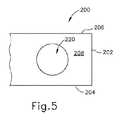
A.横断開口を有する例示の超音波ブレード
図4及び図5は、器具(20、120)に容易に組み込まれ得る例示の代替超音波ブレード(200)を示す。具体的には、ブレード(200)は、ブレード(24、132)の代わりに導波管(28、128)と機械的かつ音響的に連結されてもよい。この実施例のブレード(200)は、平坦遠位面(202)、平坦側面(204、206)、平坦上面(208)、及び平坦下面(210)を備える。上面(208)及び下面(210)はいずれも側面(204、206)よりも広い。したがって、この実施例のブレード(200)は、矩形断面輪郭を有する。しかしながら、表面(202、204、206、208、210)のうちのいずれか1つ又は2つ以上が、代わりに湾曲されてもよく、かつ/又は他の特性を有してもよいことを理解されたい。A. Exemplary Ultrasonic Blade with Transverse Opening FIGS. 4 and 5 illustrate an exemplary alternative ultrasonic blade (200) that can be readily incorporated into an instrument (20, 120). Specifically, the blade (200) may be mechanically and acoustically coupled to the waveguide (28, 128) instead of the blade (24, 132). The blade (200) of this example comprises a flat distal surface (202), flat side surfaces (204, 206), a flat top surface (208), and a flat bottom surface (210). Both the upper surface (208) and the lower surface (210) are wider than the side surfaces (204, 206). Thus, the blade (200) of this example has a rectangular cross-sectional profile. However, it is understood that any one or more of the surfaces (202, 204, 206, 208, 210) may instead be curved and / or have other properties. I want to be.
この実施例のブレード(200)は、面(208)から面(210)まで延びる開口(220)を更に含む。開口(220)は、遠位面(202)に対して近位に位置する。液体(例えば、生理食塩水など)のカラムは、開口(220)を介して駆動されてもよく、それにより液体のカラムは、ブレード(200)を通じて発生させた超音波の媒体として機能する。ブレード(200)が超音波周波数で振動するように作動されるとき、ブレード(200)は、開口(220)内で内向きに放射状に配向される圧縮/圧力波を発生させることができる。これらの内向きに配向された波が、開口(200)内に配設された液体にキャビテーション効果をもたらし得ることを理解されたい。かかるキャビテーション効果は、開口(200)内に配設されるか、又は開口(200)を通過する液体が遭遇する組織又は他の解剖学的構造を侵食し得る。場合によっては、追加の特徴部を使用して、ブレード(200)に対して略横断する経路に沿って開口(200)を介して液体を駆動する。液体中のかかる運動は、開口(220)内の圧縮波によって拡大された微小気泡を開口(220)から離れて運ぶことができ、それにより拡大された微小気泡が破裂して、微小気泡が開口(220)を出た後にキャビテーション効果をもたらす。流体を開口(220)を介して駆動するための様々な好適な流量は、本明細書の教示を考慮することで当業者には明らかとなるであろう。 The blade (200) of this example further includes an opening (220) that extends from surface (208) to surface (210). The opening (220) is located proximal to the distal surface (202). A column of liquid (e.g., saline) may be driven through the opening (220) so that the liquid column functions as an ultrasonic medium generated through the blade (200). When the blade (200) is actuated to vibrate at an ultrasonic frequency, the blade (200) can generate compression / pressure waves that are radially oriented inwardly within the aperture (220). It should be understood that these inwardly oriented waves can have a cavitation effect on the liquid disposed in the opening (200). Such cavitation effects can be eroded of tissue or other anatomical structures that are disposed within the aperture (200) or encountered by fluid passing through the aperture (200). In some cases, additional features are used to drive liquid through the opening (200) along a path that is generally transverse to the blade (200). Such movement in the liquid can carry the microbubbles enlarged by the compression wave in the opening (220) away from the opening (220), thereby rupturing the enlarged microbubbles and opening the microbubbles. Cavitation effect is achieved after exiting (220). Various suitable flow rates for driving fluid through opening (220) will be apparent to those skilled in the art in view of the teachings herein.
本実施例の開口(220)は、円形状を有する。しかしながら、開口(220)が代わりにいくつかの他の形状を有してもよいことを理解されたい。ブレード(200)が、一体化流体導管(例えば、ブレード(200)の本体を通って延びる穴として形成される流体経路)を含んでもよいことも理解されたい。かかる流体導管は、開口(220)で終結し得る。かかる流体導管を使用して、種微小気泡を開口(220)内に導入することができる。加えて、又はあるいは、かかる流体導管を使用して、開口(220)を通る流体の流れを提供し、開口(220)内で拡大された微小気泡の、開口(220)から出る移動を促進することができる。本明細書の教示を考慮することで、ブレード(200)の他の変更例が当業者には明らかとなるであろう。 The opening (220) of the present embodiment has a circular shape. However, it should be understood that the aperture (220) may instead have several other shapes. It should also be understood that the blade (200) may include an integrated fluid conduit (eg, a fluid path formed as a hole extending through the body of the blade (200)). Such a fluid conduit may terminate at an opening (220). Such fluid conduits can be used to introduce seed microbubbles into the opening (220). In addition or alternatively, such fluid conduits may be used to provide fluid flow through opening (220) to facilitate movement of microbubbles expanded within opening (220) out of opening (220). be able to. Other variations of the blade (200) will be apparent to those skilled in the art in view of the teachings herein.
B.湾曲遠位面を有する例示の超音波ブレード
図6及び図7は、器具(20、120)に容易に組み込まれ得る別の例示の代替超音波ブレード(300)を示す。具体的には、ブレード(300)は、ブレード(24、132)の代わりに、導波管(28、128)と機械的かつ音響的に連結されてもよい。この実施例のブレード(300)は、湾曲遠位面(302)、平坦側面(304、306)、平坦上面(308)、及び平坦下面(310)を備える。表面(304、306、308、310)のうちのいずれか1つ又は2つ以上が、代わりに湾曲されてもよく、かつ/又は他の特性を有してもよいことを理解されたい。B. Exemplary Ultrasonic Blade with Curved Distal Surface FIGS. 6 and 7 illustrate another exemplary alternative ultrasonic blade (300) that can be easily incorporated into the instrument (20, 120). Specifically, the blade (300) may be mechanically and acoustically coupled to the waveguide (28, 128) instead of the blade (24, 132). The blade (300) of this example comprises a curved distal surface (302), flat side surfaces (304, 306), a flat top surface (308), and a flat bottom surface (310). It should be understood that any one or more of the surfaces (304, 306, 308, 310) may instead be curved and / or have other properties.
超音波ブレード(300)の本体は、長手方向中心軸を画定する。この軸は、湾曲遠位面(302)上の最近位中心点を通って延びる。本実施例では、遠位面(302)の曲率は、遠位面(302)と上面(308)との間の移行で湾曲上縁部(320)をもたらす。遠位面(302)の曲率は、遠位面(302)と下面(310)との間の移行で湾曲下縁部(322)ももたらす。しかしながら、直線縁部(324、326)は、遠位面(302)とそれぞれの側面(304、306)との間の移行でもたらされる。遠位面(302)が、この実施例では、1つの平面(すなわち、上面及び下面(308、310)に対して平行な平面)に沿って湾曲することが、前述から理解されるはずである。いくつかの変形例では、遠位面(302)の曲率は、一定の長さの単一半径によって画定され、それにより遠位面(302)は、円弧状輪郭を有する。いくつかの他の変形例では、遠位面(302)の曲率は、放物線型である。更に他の変形例では、遠位面(302)の曲率は、双曲線型である。遠位面(302)の他の好適な構成は、本明細書の教示を考慮することで当業者には明らかとなるであろう。 The body of the ultrasonic blade (300) defines a central longitudinal axis. This axis extends through the proximal center point on the curved distal surface (302). In this example, the curvature of the distal surface (302) results in a curved upper edge (320) at the transition between the distal surface (302) and the top surface (308). The curvature of the distal surface (302) also provides a curved lower edge (322) at the transition between the distal surface (302) and the lower surface (310). However, straight edges (324, 326) are provided at the transition between the distal surface (302) and the respective side surfaces (304, 306). It should be understood from the foregoing that the distal surface (302), in this example, curves along one plane (ie, a plane parallel to the upper and lower surfaces (308, 310)). . In some variations, the curvature of the distal surface (302) is defined by a single radius of constant length so that the distal surface (302) has an arcuate profile. In some other variations, the curvature of the distal surface (302) is parabolic. In yet another variation, the curvature of the distal surface (302) is hyperbolic. Other suitable configurations of the distal surface (302) will be apparent to those skilled in the art in view of the teachings herein.
ブレード(300)が超音波振動で作動されたとき、遠位面(302)の曲率は、遠位面(302)から遠位方向に離間された特定の点又は領域でキャビテーション効果をもたらし得る。例えば、遠位面(302)が円弧状輪郭を有する変形例では、作動されたブレード(300)によって発生するキャビテーション効果は、遠位面(302)の円弧状輪郭を画定する半径の起点で集束され得る。遠位面(302)が放物線型輪郭を有する変形例では、作動されたブレード(300)によって発生するキャビテーション効果は、遠位面(302)の放物線型輪郭を画定する放物線の焦点で集束され得る。遠位面(302)が双曲線型輪郭を有する変形例では、作動されたブレード(300)によって発生するキャビテーション効果は、遠位面(302)の双曲線型輪郭を画定する双曲線の焦点で集束され得る。作動されたブレード(300)によって発生したキャビテーション効果が集束され得る他の好適な位置は、本明細書の教示を考慮することで当業者には明らかとなるであろう。 When the blade (300) is actuated with ultrasonic vibrations, the curvature of the distal surface (302) may provide a cavitation effect at a particular point or region spaced distally from the distal surface (302). For example, in a variation where the distal surface (302) has an arcuate profile, the cavitation effect produced by the actuated blade (300) is focused at the origin of the radius defining the arcuate profile of the distal surface (302). Can be done. In variations where the distal surface (302) has a parabolic profile, the cavitation effect produced by the actuated blade (300) may be focused at the parabolic focus that defines the parabolic profile of the distal surface (302). . In a variation where the distal surface (302) has a hyperbolic profile, the cavitation effect produced by the actuated blade (300) may be focused at the hyperbolic focus that defines the hyperbolic profile of the distal surface (302). . Other suitable locations where the cavitation effect generated by the actuated blade (300) can be focused will be apparent to those skilled in the art in view of the teachings herein.
ブレード(200)に関して上述のように、この実施例のブレード(300)は、一体化流体導管(例えば、ブレード(300)の本体を通って延びる穴として形成された流体経路)を含んでもよい。かかる流体導管は、遠位面(302)で終結し得る。かかる流体導管を使用して、遠位面(302)の前に種微小気泡を導入することができる。加えて、又はあるいは、かかる流体導管を使用して、遠位面(302)から遠位方向に流体の流れを提供し、ブレード(300)によって拡大された微小気泡の移行を、遠位面(302)から遠位方向に離間された組織又は他の解剖学的構造に向かって遠位方向に促進することができる。本明細書の教示を考慮することで、ブレード(300)の他の変更例が当業者には明らかとなるであろう。 As described above with respect to blade (200), blade (300) of this example may include an integrated fluid conduit (eg, a fluid path formed as a hole extending through the body of blade (300)). Such a fluid conduit may terminate at the distal surface (302). Such fluid conduits can be used to introduce seed microbubbles in front of the distal surface (302). In addition or alternatively, such fluid conduits may be used to provide fluid flow distally from the distal surface (302) and expand microbubble transitions expanded by the blade (300) to the distal surface (302). 302) from the distally spaced tissue or other anatomical structure. Other variations of the blade (300) will be apparent to those skilled in the art in view of the teachings herein.
C.湾曲遠位面及び焦点を有する例示の超音波ブレード
図8〜11は、器具(20、120)に容易に組み込まれ得る別の例示の代替超音波ブレード(400)を示す。具体的には、ブレード(400)は、ブレード(24、132)の代わりに導波管(28、128)と機械的かつ音響的に連結されてもよい。この実施例のブレード(400)は、尖った遠位面(402)、平坦側面(404、406)、平坦上面(408)、及び平坦下面(410)を備える。表面(404、406、408、410)のうちのいずれか1つ又は2つ以上が、代わりに湾曲されてもよく、かつ/又は他の特性を有してもよいことを理解されたい。本実施例では、遠位面(402)の曲率は、遠位面(402)と上面(408)との間の移行で湾曲上縁部(420)をもたらす。遠位面(402)の曲率は、遠位面(402)と下面(410)との間の移行で湾曲下縁部(422)ももたらす。しかしながら、直線縁部(424、426)は、遠位面(402)とそれぞれの側面(404、406)との間の移行でもたらされる。C. Exemplary Ultrasonic Blade with Curved Distal Surface and Focal Point FIGS. 8-11 illustrate another exemplary alternative ultrasonic blade (400) that can be readily incorporated into the instrument (20, 120). Specifically, the blade (400) may be mechanically and acoustically coupled to the waveguide (28, 128) instead of the blade (24, 132). The blade (400) of this example includes a pointed distal surface (402), flat side surfaces (404, 406), a flat top surface (408), and a flat bottom surface (410). It should be understood that any one or more of the surfaces (404, 406, 408, 410) may instead be curved and / or have other properties. In this example, the curvature of the distal surface (402) results in a curved upper edge (420) at the transition between the distal surface (402) and the top surface (408). The curvature of the distal surface (402) also provides a curved lower edge (422) at the transition between the distal surface (402) and the lower surface (410). However, straight edges (424, 426) are provided at the transition between the distal surface (402) and the respective side surfaces (404, 406).
この実施例の尖った遠位面(402)は、尖った遠位面(402)の中心に位置する尖った領域(430)を含む。尖った領域は、鋭く尖った先(434)で終結する鋭く湾曲した表面(432)を備える。超音波ブレード(400)の本体は、長手方向中心軸を画定する。この軸は、鋭く尖った先(434)を通って延びる。図9〜11に最も良く見られるように、ブレード(400)の縁部(424、426)は、第1の横断平面(P1)に位置付けられている一方で、鋭く尖った先(434)は、第2の横断平面(P2)に位置付けられている。第2の横断平面(P2)は、第1の横断平面(P1)から距離(d1)だけ遠位方向に離間される。いくつかの変形例では、第2の横断平面(P2)は、第1の横断平面(P1)から遠位方向に離間され、それにより鋭く尖った先(434)は、縁部(424、426)に対して後ろにある。更に他の変形例では、鋭く尖った先(434)及び縁部(424、426)は、同じ横断平面(P1)上に位置する。The pointed distal surface (402) of this example includes a pointed region (430) located in the center of the pointed distal surface (402). The pointed region comprises a sharply curved surface (432) that terminates in a sharp point (434). The body of the ultrasonic blade (400) defines a central longitudinal axis. This axis extends through a sharp point (434). As best seen in FIGS. 9-11, the edge (424, 426) of the blade (400) is positioned in thefirst transverse plane (P1 ) while being sharply pointed (434). Is located in the second transverse plane (P2 ). The second transverse plane (P2 ) is spaced distally from the first transverse plane (P1 ) by a distance (d1 ). In some variations, the second transverse plane (P2 ) is spaced distally from the first transverse plane (P1 ) such that the sharp pointed tip (434) is at the edge (424). 426) behind. In yet another variation, the sharp point (434) and edges (424, 426) are located on the same transverse plane (P1 ).
図10及び図11に最も良く見られるように、尖った領域(430)の湾曲表面(432)は、遠位面(402)の残りの曲率とは異なる曲率を有する。具体的には、この実施例では、尖った領域(430)の外側にある遠位面(402)の領域は、1つの平面(すなわち、上面及び下面(408、410)に対して平行な平面)に沿って湾曲する。いくつかの変形例では、遠位面(402)のこの特定領域の曲率は、一定の長さの単一半径によって画定され、それにより遠位面(402)は、円弧状輪郭を有する。いくつかの他の変形例では、遠位面(402)のこの特定領域の曲率は、放物線型である。更に他の変形例では、遠位面(402)のこの特定領域の曲率は、双曲線型である。遠位面(402)のこの特定領域の他の好適な構成は、本明細書の教示を考慮することで当業者には明らかとなるであろう。 As best seen in FIGS. 10 and 11, the curved surface (432) of the pointed region (430) has a different curvature than the remaining curvature of the distal surface (402). Specifically, in this example, the region of the distal surface (402) that is outside the pointed region (430) is a plane parallel to one plane (ie, the top and bottom surfaces (408, 410)). ) Curve along. In some variations, the curvature of this particular region of the distal surface (402) is defined by a single radius of constant length, whereby the distal surface (402) has an arcuate profile. In some other variations, the curvature of this particular region of the distal surface (402) is parabolic. In yet another variation, the curvature of this particular region of the distal surface (402) is hyperbolic. Other suitable configurations for this particular region of the distal surface (402) will be apparent to those skilled in the art in view of the teachings herein.
この実施例において、尖った領域(430)の湾曲表面(432)は、2つの平面(すなわち、上面及び下面(408、410)に対して平行な平面、並びに側面(404、406)に対して平行な平面)に沿って湾曲する。それらの平面のうちの1つに沿った湾曲表面(432)の曲率は、それらの平面のうちの他の1つに沿った湾曲表面(432)の曲率と類似し得る。例えば、上面及び下面(408、410)に対して平行な平面に沿った湾曲表面(432)の曲率は、円弧状輪郭を有し得る一方で、側面(404、406)に対して平行な平面に沿った湾曲表面(432)の曲率も、円弧状輪郭を有し得る。かかる変形例では、同じ半径の長さを使用して、これら2つの平面に沿った湾曲部を画定することができる。あるいは、半径の長さは、各平面に対して異なってもよい。同様に、上面及び下面(408、410)に対して平行な平面に沿った湾曲表面(432)の曲率は、放物線型輪郭を有し得る一方で、側面(404、406)に対して平行な平面に沿った湾曲表面(432)の曲率も、放物線型輪郭を有し得る。これらの湾曲部を画定する放物線の特性は、互いに同じであっても異なっていてもよい。更に別の単なる例示的実施例として、上面及び下面(408、410)に対して平行な平面に沿った湾曲表面(432)の曲率は、双曲線型輪郭を有し得る一方で、側面(404、406)に対して平行な平面に沿った湾曲表面(432)の曲率も、双曲線型輪郭を有し得る。これらの湾曲部を画定する双曲線の特性は、互いに同じであっても異なっていてもよい。 In this example, the curved surface (432) of the pointed region (430) is parallel to the two planes (ie, the plane parallel to the top and bottom surfaces (408, 410) and the side (404, 406). Bend along a parallel plane. The curvature of the curved surface (432) along one of those planes may be similar to the curvature of the curved surface (432) along the other one of those planes. For example, the curvature of the curved surface (432) along a plane parallel to the top and bottom surfaces (408, 410) may have an arcuate profile while the plane parallel to the side surfaces (404, 406). The curvature of the curved surface (432) along can also have an arcuate profile. In such variations, the same radius length can be used to define a curvature along these two planes. Alternatively, the length of the radius may be different for each plane. Similarly, the curvature of the curved surface (432) along a plane parallel to the top and bottom surfaces (408, 410) may have a parabolic profile while parallel to the side surfaces (404, 406). The curvature of the curved surface (432) along the plane may also have a parabolic contour. The characteristics of the parabola that define these bends may be the same or different. As yet another exemplary embodiment, the curvature of the curved surface (432) along a plane parallel to the top and bottom surfaces (408, 410) may have a hyperbolic profile while the side surfaces (404, The curvature of the curved surface (432) along a plane parallel to 406) may also have a hyperbolic profile. The characteristics of the hyperbola that define these bends may be the same or different.
当然のことながら、上面及び下面(408、410)に対して平行な平面に沿った湾曲表面(432)の曲率は、代替として、側面(404、406)に対して平行な平面に沿った湾曲表面(432)の曲率とは完全に異なる特性のものであってもよい。例えば、上面及び下面(408、410)に対して平行な平面に沿った湾曲表面(432)の曲率は、円弧状輪郭を有し得る一方で、側面(404、406)に対して平行な平面に沿った湾曲表面(432)の曲率は、放物線型輪郭又は双曲線型輪郭を有する。別の単なる例示的実施例として、上面及び下面(408、410)に対して平行な平面に沿った湾曲表面(432)の曲率は、放物線型輪郭を有し得る一方で、側面(404、406)に対して平行な平面に沿った湾曲表面(432)の曲率は、円弧状輪郭又は双曲線型輪郭を有する。更に別の単なる例示的実施例として、上面及び下面(408、410)に対して平行な平面に沿った湾曲表面(432)の曲率は、双曲線型輪郭を有し得る一方で、側面(404、406)に対して平行な平面に沿った湾曲表面(432)の曲率は、円弧状輪郭又は放物線型輪郭を有する。湾曲表面(432)の他の好適な変更例及び構成は、本明細書の教示を考慮することで当業者には明らかとなるであろう。 Of course, the curvature of the curved surface (432) along a plane parallel to the top and bottom surfaces (408, 410) may alternatively be curved along a plane parallel to the sides (404, 406). It may have completely different characteristics from the curvature of the surface (432). For example, the curvature of the curved surface (432) along a plane parallel to the top and bottom surfaces (408, 410) may have an arcuate profile while the plane parallel to the side surfaces (404, 406). The curvature of the curved surface (432) along has a parabolic or hyperbolic contour. As another merely illustrative example, the curvature of the curved surface (432) along a plane parallel to the top and bottom surfaces (408, 410) may have a parabolic profile while the side surfaces (404, 406). The curvature of the curved surface (432) along a plane parallel to) has an arcuate contour or a hyperbolic contour. As yet another exemplary embodiment, the curvature of the curved surface (432) along a plane parallel to the top and bottom surfaces (408, 410) may have a hyperbolic profile while the side surfaces (404, The curvature of the curved surface (432) along a plane parallel to 406) has an arcuate contour or a parabolic contour. Other suitable modifications and configurations of the curved surface (432) will be apparent to those skilled in the art in view of the teachings herein.
本実施例では、尖った領域(430)の構成は、先端(434)で非常に強力な音圧をもたらすことができ、これが強化されたキャビテーションのための微小気泡形成を開始させることができる。言い換えれば、先端(434)は、「種」微小気泡を発生させることができ、その後、先端(434)で集束される周囲圧力場によって拡大される。いくつかの変形例では、先端(434)、湾曲表面(432)、及び/又は遠位面(402)の残りは、炭素、マグネシウム、及び/又は界面活性剤などの人工剤を含み、これらがキャビテーションの発生を助け得る。いくつかの変形例では、(434)は、平坦な遠位表面を提示するように形成される。いくつかの他の変形例では、先端(434)は丸い。更に他の変形例では、先端(434)は犠牲的である。更に他の変形例では、先端(434)は、実質的に鋭く、湾曲表面(432)の自然収束によって形成される。更に別の単なる例示的変更例として、先端(434)は、ブレード(400)の長さに沿って伸びる導管と流体連通する開口部を含んでもよい。この導管及び開口部を使用して、先端(434)を通じてガスを伝達して、微小気泡播種を支援することができる。加えて、又はあるいは、導管及び開口部を使用して、先端(434)を通じて液体を伝達して、微小気泡を先端(434)から離れて遠位方向に駆動するのを支援することができる。先端(434)が形成され、かつ使用することができる他の好適な方法は、本明細書の教示を考慮することで当業者には明らかとなるであろう。 In this example, the pointed region (430) configuration can provide very strong sound pressure at the tip (434), which can initiate microbubble formation for enhanced cavitation. In other words, the tip (434) can generate “seed” microbubbles, which are then expanded by the ambient pressure field focused at the tip (434). In some variations, the remainder of the tip (434), curved surface (432), and / or distal surface (402) includes artificial agents such as carbon, magnesium, and / or surfactants, which are Can help generate cavitation. In some variations, (434) is formed to present a flat distal surface. In some other variations, the tip (434) is round. In yet another variation, the tip (434) is sacrificial. In yet another variation, the tip (434) is substantially sharp and is formed by the natural convergence of the curved surface (432). As yet another merely exemplary modification, tip (434) may include an opening in fluid communication with a conduit extending along the length of blade (400). This conduit and opening can be used to transfer gas through tip (434) to assist in microbubble seeding. Additionally or alternatively, conduits and openings can be used to transfer liquid through tip (434) to assist in driving the microbubbles away from tip (434). Other suitable methods by which the tip (434) can be formed and used will be apparent to those skilled in the art in view of the teachings herein.
図12及び図13は、器具(20、120)に容易に組み込まれ得る別の例示の代替超音波ブレード(500)を示す。具体的には、ブレード(500)は、ブレード(24、132)の代わりに導波管(28、128)と機械的かつ音響的に連結されてもよい。ブレード(500)は、上述のブレード(400)と実質的に同様である。この実施例のブレード(500)は、尖った遠位面(502)、平坦側面(504、506)、平坦上面(508)、及び平坦下面(510)を備える。表面(504、506、508、510)のうちのいずれか1つ又は2つ以上が、代わりに湾曲されてもよく、かつ/又は他の特性を有してもよいことを理解されたい。本実施例では、遠位面(502)の曲率は、遠位面(502)と上面(508)との間の移行で湾曲上縁部(520)をもたらす。遠位面(502)の曲率は、遠位面(502)と下面(510)との間の移行で湾曲下縁部(522)ももたらす。しかしながら、直線縁部(524、526)は、遠位面(502)とそれぞれの側面(504、506)との間の移行でもたらされる。 12 and 13 illustrate another exemplary alternative ultrasonic blade (500) that can be easily incorporated into the instrument (20, 120). Specifically, the blade (500) may be mechanically and acoustically coupled to the waveguide (28, 128) instead of the blade (24, 132). The blade (500) is substantially similar to the blade (400) described above. The blade (500) of this example comprises a pointed distal surface (502), flat side surfaces (504, 506), a flat top surface (508), and a flat bottom surface (510). It should be understood that any one or more of the surfaces (504, 506, 508, 510) may instead be curved and / or have other properties. In this example, the curvature of the distal surface (502) results in a curved upper edge (520) at the transition between the distal surface (502) and the top surface (508). The curvature of the distal surface (502) also provides a curved lower edge (522) at the transition between the distal surface (502) and the lower surface (510). However, the straight edges (524, 526) are provided at the transition between the distal surface (502) and the respective side surfaces (504, 506).
この実施例の尖った遠位面(502)は、尖った遠位面(502)の中心に位置する尖った領域(530)を含む。尖った領域は、鋭く尖った先(534)で終結する鋭く湾曲した表面(532)を備える。超音波ブレード(500)の本体は、長手方向中心軸を画定する。この軸は、鋭く尖った先(534)を通って延びる。図13に最も良く見られるように、ブレード(500)の縁部(524、526)は、第1の横断平面(P3)に位置付けられている一方で、鋭く尖った先(534)は、第2の横断平面(P4)に位置付けられている。第2の横断平面(P4)は、第1の横断平面(P3)から距離(d2)だけ遠位方向に離間される。いくつかの変形例では、第2の横断平面(P4)は、第1の横断平面(P3)から遠位方向に離間され、それにより鋭く尖った先(534)は、縁部(524、526)に対して後ろにある。更に他の変形例では、鋭く尖った先(534)及び縁部(524、526)は、同じ横断平面(P3)上に位置する。The pointed distal surface (502) of this example includes a pointed region (530) located in the center of the pointed distal surface (502). The pointed region comprises a sharply curved surface (532) that terminates at a sharp point (534). The body of the ultrasonic blade (500) defines a central longitudinal axis. This axis extends through a sharp point (534). As best seen in FIG. 13, the edge (524, 526) of the blade (500) is positioned in the first transverse plane (P3 ), while the sharp point (534) is Located in the second transverse plane (P4 ). The second transverse plane (P4 ) is spaced distally from the first transverse plane (P3 ) by a distance (d2 ). In some variations, the second transverse plane (P4 ) is spaced distally from the first transverse plane (P3 ) such that the sharply pointed tip (534) has an edge (524). 526) behind. In yet another variation, the sharp point (534) and edges (524, 526) are located on the same transverse plane (P3 ).
尖った領域(530)の湾曲表面(532)は、遠位面(502)の残りの曲率とは異なる曲率を有する。具体的には、尖った領域(530)の外側にある遠位面(502)の領域は、2つの平面(すなわち、上面及び下面(508、510)に対して平行な平面、並びに側面(504、506)に対して平行な平面)に沿って湾曲する。それらの平面のうちの1つに沿った遠位面(502)のこの特定領域の曲率は、それらの平面のうちの他の1つに沿った遠位面(502)のこの特定領域の曲率と類似し得る。例えば、上面及び下面(508、510)に対して平行な平面に沿った遠位面(502)のこの特定領域の曲率は、円弧状輪郭を有し得る一方で、側面(504、506)に対して平行な平面に沿った遠位面(502)のこの特定領域の曲率も、円弧状輪郭を有し得る。かかる変形例では、同じ半径の長さを使用して、これら2つの平面に沿った湾曲部を画定することができる。あるいは、半径の長さは、各平面に対して異なってもよい。同様に、上面及び下面(508、510)に対して平行な平面に沿った遠位面(502)のこの特定領域の曲率は、放物線型輪郭を有し得る一方で、側面(504、506)に対して平行な平面に沿った遠位面(502)のこの特定領域の曲率も、放物線型輪郭を有し得る。これらの湾曲部を画定する放物線の特性は、互いに同じであっても異なっていてもよい。更に別の単なる例示的実施例として、上面及び下面(508、510)に対して平行な平面に沿った遠位面(502)のこの特定領域の曲率は、双曲線型輪郭を有し得る一方で、側面(504、506)に対して平行な平面に沿った遠位面(502)のこの特定領域の曲率も、双曲線型輪郭を有し得る。これらの湾曲部を画定する双曲線の特性は、互いに同じであっても異なっていてもよい。 The curved surface (532) of the pointed region (530) has a different curvature than the remaining curvature of the distal surface (502). Specifically, the region of the distal surface (502) outside the pointed region (530) is a plane parallel to the two planes (ie, the top and bottom surfaces (508, 510)) and the side surface (504). , 506) along a plane parallel to 506). The curvature of this particular area of the distal surface (502) along one of those planes is the curvature of this particular area of the distal face (502) along the other one of those planes. Can be similar. For example, the curvature of this particular region of the distal surface (502) along a plane parallel to the top and bottom surfaces (508, 510) may have an arcuate profile while the side surface (504, 506) The curvature of this particular region of the distal surface (502) along a plane parallel to it may also have an arcuate profile. In such variations, the same radius length can be used to define a curvature along these two planes. Alternatively, the length of the radius may be different for each plane. Similarly, the curvature of this particular region of the distal surface (502) along a plane parallel to the top and bottom surfaces (508, 510) may have a parabolic profile while the side surfaces (504, 506). The curvature of this particular region of the distal surface (502) along a plane parallel to can also have a parabolic contour. The characteristics of the parabola that define these bends may be the same or different. As yet another merely illustrative example, the curvature of this particular region of the distal surface (502) along a plane parallel to the upper and lower surfaces (508, 510) may have a hyperbolic profile. The curvature of this particular region of the distal surface (502) along a plane parallel to the side surfaces (504, 506) may also have a hyperbolic profile. The characteristics of the hyperbola that define these bends may be the same or different.
当然のことながら、上面及び下面(508、510)に対して平行な平面に沿った遠位面(502)の曲率は、代替として、側面(504、506)に対して平行な平面に沿った遠位面(502)のこの特定領域の曲率とは完全に異なる特性のものであってもよい。例えば、上面及び下面(508、510)に対して平行な平面に沿った遠位面(502)のこの特定領域の曲率は、円弧状輪郭を有し得る一方で、側面(504、506)に対して平行な平面に沿った遠位面(502)のこの特定領域の曲率は、放物線型輪郭又は双曲線型輪郭を有する。別の単なる例示的実施例として、上面及び下面(508、510)に対して平行な平面に沿った遠位面(502)のこの特定領域の曲率は、放物線型輪郭を有し得る一方で、側面(504、506)に対して平行な平面に沿った遠位面(502)のこの特定領域の曲率は、円弧状輪郭又は双曲線型輪郭を有する。更に別の単なる例示的実施例として、上面及び下面(508、510)に対して平行な平面に沿った遠位面(502)のこの特定領域の曲率は、双曲線型輪郭を有し得る一方で、側面(504、506)に対して平行な平面に沿った遠位面(502)のこの特定領域の曲率は、円弧状輪郭又は放物線型輪郭を有する。遠位面(502)のこの特定領域の他の好適な変更例及び構成は、本明細書の教示を考慮することで当業者には明らかとなるであろう。 Of course, the curvature of the distal surface (502) along a plane parallel to the top and bottom surfaces (508, 510) may alternatively be along a plane parallel to the side surfaces (504, 506). It may have completely different characteristics than the curvature of this particular region of the distal surface (502). For example, the curvature of this particular region of the distal surface (502) along a plane parallel to the top and bottom surfaces (508, 510) may have an arcuate profile while the side surface (504, 506) The curvature of this particular region of the distal surface (502) along a plane parallel to it has a parabolic or hyperbolic contour. As another merely illustrative example, the curvature of this particular region of the distal surface (502) along a plane parallel to the upper and lower surfaces (508, 510) may have a parabolic profile, while The curvature of this particular region of the distal surface (502) along a plane parallel to the side surfaces (504, 506) has an arcuate or hyperbolic profile. As yet another merely illustrative example, the curvature of this particular region of the distal surface (502) along a plane parallel to the upper and lower surfaces (508, 510) may have a hyperbolic profile. The curvature of this particular region of the distal surface (502) along a plane parallel to the side surfaces (504, 506) has an arcuate or parabolic contour. Other suitable modifications and configurations of this particular region of the distal surface (502) will be apparent to those skilled in the art in view of the teachings herein.
この実施例において、尖った領域(530)の湾曲表面(532)も、2つの平面(すなわち、上面及び下面(508、510)に対して平行な平面、並びに側面(504、506)に対して平行な平面)に沿って湾曲する。それらの平面のうちの1つに沿った湾曲表面(532)の曲率は、それらの平面のうちの他の1つに沿った湾曲表面(532)の曲率と類似し得る。例えば、上面及び下面(508、510)に対して平行な平面に沿った湾曲表面(532)の曲率は、円弧状輪郭を有し得る一方で、側面(504、506)に対して平行な平面に沿った湾曲表面(532)の曲率も、円弧状輪郭を有し得る。かかる変形例では、同じ半径の長さを使用して、これら2つの平面に沿った湾曲部を画定することができる。あるいは、半径の長さは、各平面に対して異なってもよい。同様に、上面及び下面(508、510)に対して平行な平面に沿った湾曲表面(532)の曲率は、放物線型輪郭を有し得る一方で、側面(504、506)に対して平行な平面に沿った湾曲表面(532)の曲率も、放物線型輪郭を有し得る。これらの湾曲部を画定する放物線の特性は、互いに同じであっても異なっていてもよい。更に別の単なる例示的実施例として、上面及び下面(508、510)に対して平行な平面に沿った湾曲表面(532)の曲率は、双曲線型輪郭を有し得る一方で、側面(504、506)に対して平行な平面に沿った湾曲表面(532)の曲率も、双曲線型輪郭を有し得る。これらの湾曲部を画定する双曲線の特性は、互いに同じであっても異なっていてもよい。 In this example, the curved surface (532) of the pointed region (530) is also parallel to the two planes (ie, the plane parallel to the top and bottom surfaces (508, 510) and the side (504, 506). Bend along a parallel plane. The curvature of the curved surface (532) along one of those planes may be similar to the curvature of the curved surface (532) along the other one of those planes. For example, the curvature of the curved surface (532) along a plane parallel to the top and bottom surfaces (508, 510) may have an arcuate contour while the plane parallel to the side surfaces (504, 506). The curvature of the curved surface (532) along can also have an arcuate profile. In such variations, the same radius length can be used to define a curvature along these two planes. Alternatively, the length of the radius may be different for each plane. Similarly, the curvature of the curved surface (532) along a plane parallel to the top and bottom surfaces (508, 510) may have a parabolic profile while parallel to the side surfaces (504, 506). The curvature of the curved surface (532) along the plane may also have a parabolic contour. The characteristics of the parabola that define these bends may be the same or different. As yet another merely illustrative example, the curvature of the curved surface (532) along a plane parallel to the top and bottom surfaces (508, 510) may have a hyperbolic profile while the side surfaces (504, The curvature of the curved surface (532) along a plane parallel to 506) may also have a hyperbolic profile. The characteristics of the hyperbola that define these bends may be the same or different.
当然のことながら、上面及び下面(508、510)に対して平行な平面に沿った湾曲表面(532)の曲率は、代替として、側面(504、506)に対して平行な平面に沿った湾曲表面(532)の曲率とは完全に異なる特性のものであってもよい。例えば、上面及び下面(508、510)に対して平行な平面に沿った湾曲表面(532)の曲率は、円弧状輪郭を有し得る一方で、側面(504、506)に対して平行な平面に沿った湾曲表面(532)の曲率は、放物線型輪郭又は双曲線型輪郭を有する。別の単なる例示的実施例として、上面及び下面(508、510)に対して平行な平面に沿った湾曲表面(532)の曲率は、放物線型輪郭を有し得る一方で、側面(504、506)に対して平行な平面に沿った湾曲表面(532)の曲率は、円弧状輪郭又は双曲線型輪郭を有する。更に別の単なる例示的実施例として、上面及び下面(508、510)に対して平行な平面に沿った湾曲表面(532)の曲率は、双曲線型輪郭を有し得る一方で、側面(504、506)に対して平行な平面に沿った湾曲表面(532)の曲率は、円弧状輪郭又は放物線型輪郭を有する。湾曲表面(532)の他の好適な変更例及び構成は、本明細書の教示を考慮することで当業者には明らかとなるであろう。 Of course, the curvature of the curved surface (532) along a plane parallel to the top and bottom surfaces (508, 510) may alternatively be curved along a plane parallel to the side surfaces (504, 506). It may have completely different characteristics from the curvature of the surface (532). For example, the curvature of the curved surface (532) along a plane parallel to the top and bottom surfaces (508, 510) may have an arcuate contour while the plane parallel to the side surfaces (504, 506). The curvature of the curved surface (532) along has a parabolic or hyperbolic contour. As another merely illustrative example, the curvature of the curved surface (532) along a plane parallel to the top and bottom surfaces (508, 510) may have a parabolic profile while the side surfaces (504, 506). The curvature of the curved surface (532) along a plane parallel to) has an arcuate contour or a hyperbolic contour. As yet another merely illustrative example, the curvature of the curved surface (532) along a plane parallel to the top and bottom surfaces (508, 510) may have a hyperbolic profile while the side surfaces (504, The curvature of the curved surface (532) along a plane parallel to 506) has an arcuate contour or a parabolic contour. Other suitable modifications and configurations of the curved surface (532) will be apparent to those skilled in the art in view of the teachings herein.
本実施例では、尖った領域(530)の構成は、先端(534)で非常に強力な音圧をもたらすことができ、これが強化されたキャビテーションのための微小気泡形成を開始させることができる。言い換えれば、先端(534)は、「種」微小気泡を発生させることができ、その後、先端(534)で集束される周囲圧力場によって拡大される。いくつかの変形例では、先端(534)、湾曲表面(532)、及び/又は遠位面(502)の残りは、炭素、マグネシウム、及び/又は界面活性剤などの人工剤を含み、これらがキャビテーションの発生を助け得る。いくつかの変形例では、(534)は、平坦な遠位表面を提示するように形成される。いくつかの他の変形例では、先端(534)は丸い。更に他の変形例では、先端(534)は犠牲的である。更に他の変形例では、先端(534)は、実質的に鋭く、湾曲表面(532)の自然収束によって形成される。更に別の単なる例示的変更例として、先端(534)は、ブレード(500)の長さに沿って伸びる導管と流体連通する開口部を含んでもよい。この導管及び開口部を使用して、先端(534)を通じてガスを伝達して、微小気泡播種を支援することができる。加えて、又はあるいは、導管及び開口部を使用して、先端(534)を通じて液体を伝達して、微小気泡を先端(534)から遠位方向に駆動するのを支援することができる。先端(534)が形成され、かつ使用することができる他の好適な方法は、本明細書の教示を考慮することで当業者には明らかとなるであろう。 In this example, the configuration of the pointed region (530) can provide a very strong sound pressure at the tip (534), which can initiate microbubble formation for enhanced cavitation. In other words, the tip (534) can generate "seed" microbubbles, which are then expanded by the ambient pressure field focused at the tip (534). In some variations, the rest of the tip (534), curved surface (532), and / or distal surface (502) includes artificial agents such as carbon, magnesium, and / or surfactants, which are Can help generate cavitation. In some variations, (534) is formed to present a flat distal surface. In some other variations, the tip (534) is round. In yet another variation, the tip (534) is sacrificial. In yet another variation, the tip (534) is substantially sharp and is formed by the natural convergence of the curved surface (532). As yet another merely exemplary modification, the tip (534) may include an opening in fluid communication with a conduit extending along the length of the blade (500). This conduit and opening can be used to transfer gas through the tip (534) to assist in microbubble seeding. Additionally or alternatively, conduits and openings can be used to transfer liquid through tip (534) to assist in driving microbubbles distally from tip (534). Other suitable methods by which the tip (534) can be formed and used will be apparent to those skilled in the art in view of the teachings herein.
D.湾曲遠位面及び流体導管を有する例示の超音波ブレード
図14は、器具(20、120)に容易に組み込まれ得る別の例示の代替超音波ブレード(600)を示す。具体的には、ブレード(600)は、ブレード(24、132)の代わりに、導波管(28、128)と機械的かつ音響的に連結されてもよい。この実施例のブレード(600)は、湾曲遠位面(602)、平坦側面(604、606)、平坦上面(608)、及び平坦下面(610)を備える。表面(604、606、608、610)のうちのいずれか1つ又は2つ以上が、代わりに湾曲されてもよく、かつ/又は他の特性を有してもよいことを理解されたい。D. Exemplary Ultrasonic Blade with Curved Distal Surface and Fluid Conduit FIG. 14 shows another exemplary alternative ultrasonic blade (600) that can be easily incorporated into the instrument (20, 120). Specifically, the blade (600) may be mechanically and acoustically coupled to the waveguide (28, 128) instead of the blade (24, 132). The blade (600) of this example includes a curved distal surface (602), flat side surfaces (604, 606), a flat top surface (608), and a flat bottom surface (610). It should be understood that any one or more of the surfaces (604, 606, 608, 610) may instead be curved and / or have other properties.
超音波ブレード(600)の本体は、長手方向中心軸を画定する。この軸は、湾曲遠位面(602)上の最近位中心点を通って延びる。本実施例では、遠位面(602)の曲率は、遠位面(602)と上面(608)との間の移行で湾曲上縁部(620)をもたらす。遠位面(602)の曲率は、遠位面(602)と下面(610)との間の移行で湾曲下縁部(622)ももたらす。遠位面(602)の曲率は、遠位面(602)と下面(604)との間の移行で湾曲下縁部(624)、並びに遠位面(602)と側面(606)との間の移行で湾曲側縁部(626)をもたらす。縁部(620、622)は、鋭く尖った先(640)で縁部(624、626)と接する。いくつかの変形例では、鋭く尖った先(640)は、組織又は他の構造上のかぎ裂きを避けるように、円形、平坦、又は他の形状である。 The body of the ultrasonic blade (600) defines a central longitudinal axis. This axis extends through the proximal center point on the curved distal surface (602). In this example, the curvature of the distal surface (602) results in a curved upper edge (620) at the transition between the distal surface (602) and the top surface (608). The curvature of the distal surface (602) also provides a curved lower edge (622) at the transition between the distal surface (602) and the lower surface (610). The curvature of the distal surface (602) is between the curved lower edge (624) and the distal surface (602) and side surface (606) at the transition between the distal surface (602) and the lower surface (604). This transition results in a curved side edge (626). The edges (620, 622) touch the edges (624, 626) at a sharp point (640). In some variations, the sharp pointed tip (640) is circular, flat, or other shape to avoid tearing on tissue or other structures.
遠位面(602)が、この実施例では、2つの平面(すなわち、上面及び下面(608、610)に対して平行な平面、並びに側面(604、606)に対して平行な平面)に沿って湾曲することが、前述から理解されるはずである。それらの平面のうちの1つに沿った遠位面(602)の曲率は、それらの平面のうちの他の1つに沿った遠位面(602)の曲率と類似し得る。例えば、上面及び下面(608、610)に対して平行な平面に沿った遠位面(602)の曲率は、円弧状輪郭を有し得る一方で、側面(604、606)に対して平行な平面に沿った遠位面(602)の曲率も、円弧状輪郭を有し得る。かかる変形例では、同じ半径の長さを使用して、これら2つの平面に沿った湾曲部を画定することができる。あるいは、半径の長さは、各平面に対して異なってもよい。同様に、上面及び下面(608、610)に対して平行な平面に沿った遠位面(602)の曲率は、放物線型輪郭を有し得る一方で、側面(604、606)に対して平行な平面に沿った遠位面(602)の曲率も、放物線型輪郭を有し得る。これらの湾曲部を画定する放物線の特性は、互いに同じであっても異なっていてもよい。更に別の単なる例示的実施例として、上面及び下面(608、610)に対して平行な平面に沿った遠位面(602)の曲率は、双曲線型輪郭を有し得る一方で、側面(604、606)に対して平行な平面に沿った遠位面(602)の曲率も、双曲線型輪郭を有し得る。これらの湾曲部を画定する双曲線の特性は、互いに同じであっても異なっていてもよい。 The distal surface (602) in this example is along two planes (ie, a plane parallel to the top and bottom surfaces (608, 610) and a plane parallel to the side surfaces (604, 606)). Should be understood from the foregoing. The curvature of the distal surface (602) along one of those planes may be similar to the curvature of the distal surface (602) along the other one of those planes. For example, the curvature of the distal surface (602) along a plane parallel to the top and bottom surfaces (608, 610) may have an arcuate profile while being parallel to the side surfaces (604, 606). The curvature of the distal surface (602) along the plane may also have an arcuate profile. In such variations, the same radius length can be used to define a curvature along these two planes. Alternatively, the length of the radius may be different for each plane. Similarly, the curvature of the distal surface (602) along a plane parallel to the top and bottom surfaces (608, 610) may have a parabolic profile while parallel to the side surfaces (604, 606). The curvature of the distal surface (602) along a smooth plane may also have a parabolic profile. The characteristics of the parabola that define these bends may be the same or different. As yet another merely illustrative example, the curvature of the distal surface (602) along a plane parallel to the top and bottom surfaces (608, 610) may have a hyperbolic profile while the side surface (604). , 606), the curvature of the distal surface (602) along a plane parallel to it may also have a hyperbolic profile. The characteristics of the hyperbola that define these bends may be the same or different.
当然のことながら、上面及び下面(608、610)に対して平行な平面に沿った遠位面(602)の曲率は、代替として、側面(604、606)に対して平行な平面に沿った遠位面(602)の曲率とは完全に異なる特性のものであってもよい。例えば、上面及び下面(608、610)に対して平行な平面に沿った遠位面(602)の曲率は、円弧状輪郭を有し得る一方で、側面(604、606)に対して平行な平面に沿った遠位面(602)の曲率は、放物線型輪郭又は双曲線型輪郭を有する。別の単なる例示的実施例として、上面及び下面(608、610)に対して平行な平面に沿った遠位面(602)の曲率は、放物線型輪郭を有し得る一方で、側面(604、606)に対して平行な平面に沿った遠位面(602)の曲率は、円弧状輪郭又は双曲線型輪郭を有する。更に別の単なる例示的実施例として、上面及び下面(608、610)に対して平行な平面に沿った遠位面(602)の曲率は、双曲線型輪郭を有し得る一方で、側面(604、606)に対して平行な平面に沿った遠位面(602)の曲率は、円弧状輪郭又は放物線型輪郭を有する。遠位面(602)の他の好適な変更例及び構成は、本明細書の教示を考慮することで当業者には明らかとなるであろう。 Of course, the curvature of the distal surface (602) along a plane parallel to the top and bottom surfaces (608, 610) may alternatively be along a plane parallel to the side surfaces (604, 606). It may have completely different characteristics than the curvature of the distal surface (602). For example, the curvature of the distal surface (602) along a plane parallel to the top and bottom surfaces (608, 610) may have an arcuate profile while being parallel to the side surfaces (604, 606). The curvature of the distal surface (602) along the plane has a parabolic or hyperbolic profile. As another merely illustrative example, the curvature of the distal surface (602) along a plane parallel to the top and bottom surfaces (608, 610) may have a parabolic profile while the side surface (604, The curvature of the distal surface (602) along a plane parallel to 606) has an arcuate or hyperbolic profile. As yet another merely illustrative example, the curvature of the distal surface (602) along a plane parallel to the top and bottom surfaces (608, 610) may have a hyperbolic profile while the side surface (604). , 606) the curvature of the distal surface (602) along a plane parallel to it has an arcuate or parabolic profile. Other suitable modifications and configurations of the distal surface (602) will be apparent to those skilled in the art in view of the teachings herein.
この実施例のブレード(600)は、遠位面(602)の中心に位置する開口部(652)で終結する内部導管(650)も画定する。内部導管(650)は、流体源(660)と流体連通している。流体源(660)及び導管(650)を使用してガスを伝達し、それにより開口部(652)を介して遠位面(602)で「種」微小気泡を導入することができる。その後、このように播種された微小気泡は、ブレード(600)によって発生した圧力場によって拡張され得る。加えて、又はあるいは、流体源(660)及び導管(650)を使用して、流体を遠位面(602)を通じて開口部(652)を介して伝達することができる。このように伝達された流体を使用して、微小気泡を遠位面(602)から離れて遠位方向に駆動するのを支援することができる。加えて、ブレード(600)が超音波ポンプとして機能して、流体を、ブレード(600)の超音波振動によって導管(650)及び開口部(652)を通じて遠位方向に駆動することができることを理解されたい。例えば、導管(650)の少なくとも一部は、テーパ状の環を備えてもよく、開口部(652)に向かって開く/拡張する。別の単なる例示的実施例として、ポンプを使用して、流体を導管(650)を通じて駆動することができる。かかるポンプは、流体源(660)と導管(650)との間に置かれてもよい。場合によっては、流体は、生理食塩水を含む。流体が、気泡の有無にかかわらず、高表面張力の流体を含んでもよいことも理解されたい。加えて、又はあるいは、流体は、キャビテーションの閾値を下回り得る界面活性剤などの材料を含んでもよい(例えば、それにより液体中のキャビテーションがより容易になる)。流体源(660)からの流体に組み込まれ得る他の好適な特性は、本明細書の教示を考慮することで当業者には明らかとなるであろう。同様に、ブレード(600)の他の好適な特徴部、構成、及び動作性が、本明細書の教示を考慮することで当業者には明らかとなるであろう。 The blade (600) of this example also defines an internal conduit (650) that terminates in an opening (652) located in the center of the distal surface (602). The internal conduit (650) is in fluid communication with the fluid source (660). The fluid source (660) and conduit (650) can be used to communicate gas, thereby introducing “seed” microbubbles at the distal surface (602) through the opening (652). The microbubbles so seeded can then be expanded by the pressure field generated by the blade (600). Additionally or alternatively, fluid source (660) and conduit (650) can be used to communicate fluid through distal surface (602) and through opening (652). The fluid thus transferred can be used to assist in driving the microbubble away from the distal surface (602) in the distal direction. In addition, it is understood that the blade (600) can function as an ultrasonic pump to drive fluid distally through the conduit (650) and the opening (652) by ultrasonic vibration of the blade (600). I want to be. For example, at least a portion of the conduit (650) may comprise a tapered ring that opens / expands toward the opening (652). As another merely illustrative example, a pump can be used to drive fluid through conduit (650). Such a pump may be placed between the fluid source (660) and the conduit (650). In some cases, the fluid includes saline. It should also be understood that the fluid may include high surface tension fluid with or without bubbles. In addition or alternatively, the fluid may include materials such as surfactants that may be below the cavitation threshold (eg, thereby making cavitation easier in the liquid). Other suitable properties that may be incorporated into fluid from the fluid source (660) will be apparent to those skilled in the art in view of the teachings herein. Similarly, other suitable features, configurations, and operability of the blade (600) will be apparent to those skilled in the art in view of the teachings herein.
E.湾曲遠位面及び流体分配特徴部を有する例示の超音波ブレード
図15は、器具(20、120)に容易に組み込まれ得る別の例示の代替超音波ブレードアセンブリ(700)を示す。この実施例のブレードアセンブリ(700)は、超音波ブレード(710)及び流体分配特徴部(750)を備える。ブレード(710)は、ブレード(24、132)の代わりに、導波管(28、128)と機械的かつ音響的に連結されてもよい。この実施例のブレード(710)は、上述のブレード(600)と実質的に類似している。具体的には、ブレード(710)は、湾曲遠位面(712)、平坦側面(714、716)、平坦上面(718)、及び平坦下面(719)を備える。表面(714、716、718、719)のうちのいずれか1つ又は2つ以上が、代わりに湾曲されてもよく、かつ/又は他の特性を有してもよいことを理解されたい。E. Exemplary Ultrasonic Blade with Curved Distal Surface and Fluid Distributing Features FIG. 15 illustrates another exemplary alternative ultrasonic blade assembly (700) that can be readily incorporated into the instrument (20, 120). The blade assembly (700) of this example includes an ultrasonic blade (710) and a fluid distribution feature (750). The blade (710) may be mechanically and acoustically coupled to the waveguide (28, 128) instead of the blade (24, 132). The blade (710) of this embodiment is substantially similar to the blade (600) described above. Specifically, the blade (710) comprises a curved distal surface (712), flat side surfaces (714, 716), a flat top surface (718), and a flat bottom surface (719). It should be understood that any one or more of the surfaces (714, 716, 718, 719) may instead be curved and / or have other properties.
超音波ブレード(710)の本体は、長手方向中心軸を画定する。この軸は、湾曲遠位面(712)上の最近位中心点を通って延びる。本実施例では、遠位面(712)の曲率は、遠位面(712)と上面(718)との間の移行で湾曲上縁部(720)をもたらす。遠位面(712)の曲率は、遠位面(712)と下面(710)との間の移行で湾曲下縁部(722)ももたらす。遠位面(712)の曲率は、遠位面(712)と下面(714)との間の移行で湾曲下縁部(724)、並びに遠位面(712)と側面(716)との間の移行で湾曲側縁部(726)をもたらす。縁部(720、722)は、鋭く尖った先(740)で縁部(724、726)と接する。いくつかの変形例では、鋭く尖った先(740)は、組織又は他の構造上のかぎ裂きを避けるように、円形、平坦、又は他の形状である。 The body of the ultrasonic blade (710) defines a longitudinal central axis. This axis extends through the proximal center point on the curved distal surface (712). In this example, the curvature of the distal surface (712) results in a curved upper edge (720) at the transition between the distal surface (712) and the top surface (718). The curvature of the distal surface (712) also provides a curved lower edge (722) at the transition between the distal surface (712) and the lower surface (710). The curvature of the distal surface (712) is between the curved lower edge (724) and the distal surface (712) and side surface (716) at the transition between the distal surface (712) and the lower surface (714). Transition provides a curved side edge (726). The edge (720, 722) contacts the edge (724, 726) at a sharp point (740). In some variations, the sharp pointed tip (740) is circular, flat, or other shape to avoid tearing on tissue or other structures.
遠位面(712)が、この実施例では、2つの平面(すなわち、上面及び下面(718、719)に対して平行な平面、並びに側面(714、716)に対して平行な平面)に沿って湾曲することが、前述から理解されるはずである。それらの平面のうちの1つに沿った遠位面(712)の曲率は、それらの平面のうちの他の1つに沿った遠位面(712)の曲率と類似し得る。例えば、上面及び下面(718、719)に対して平行な平面に沿った遠位面(712)の曲率は、円弧状輪郭を有し得る一方で、側面(714、716)に対して平行な平面に沿った遠位面(712)の曲率も、円弧状輪郭を有し得る。かかる変形例では、同じ半径の長さを使用して、これら2つの平面に沿った湾曲部を画定することができる。あるいは、半径の長さは、各平面に対して異なってもよい。同様に、上面及び下面(718、719)に対して平行な平面に沿った遠位面(712)の曲率は、放物線型輪郭を有し得る一方で、側面(714、716)に対して平行な平面に沿った遠位面(712)の曲率も、放物線型輪郭を有し得る。これらの湾曲部を画定する放物線の特性は、互いに同じであっても異なっていてもよい。更に別の単なる例示的実施例として、上面及び下面(718、719)に対して平行な平面に沿った遠位面(712)の曲率は、双曲線型輪郭を有し得る一方で、側面(714、716)に対して平行な平面に沿った遠位面(712)の曲率も、双曲線型輪郭を有し得る。これらの湾曲部を画定する双曲線の特性は、互いに同じであっても異なっていてもよい。 The distal surface (712) in this example is along two planes (ie, a plane parallel to the top and bottom surfaces (718, 719) and a plane parallel to the side surfaces (714, 716)). Should be understood from the foregoing. The curvature of the distal surface (712) along one of the planes may be similar to the curvature of the distal surface (712) along the other one of the planes. For example, the curvature of the distal surface (712) along a plane parallel to the top and bottom surfaces (718, 719) may have an arcuate profile while parallel to the side surfaces (714, 716). The curvature of the distal surface (712) along the plane can also have an arcuate profile. In such variations, the same radius length can be used to define a curvature along these two planes. Alternatively, the length of the radius may be different for each plane. Similarly, the curvature of the distal surface (712) along a plane parallel to the top and bottom surfaces (718, 719) may have a parabolic profile while parallel to the side surfaces (714, 716). The curvature of the distal surface (712) along a smooth plane may also have a parabolic profile. The characteristics of the parabola that define these bends may be the same or different. As yet another exemplary example, the curvature of the distal surface (712) along a plane parallel to the top and bottom surfaces (718, 719) may have a hyperbolic profile while the side surface (714). , 716), the curvature of the distal surface (712) along a plane parallel to it may also have a hyperbolic profile. The characteristics of the hyperbola that define these bends may be the same or different.
当然のことながら、上面及び下面(718、719)に対して平行な平面に沿った遠位面(712)の曲率は、代替として、側面(714、716)に対して平行な平面に沿った遠位面(712)の曲率とは完全に異なる特性のものであってもよい。例えば、上面及び下面(718、719)に対して平行な平面に沿った遠位面(712)の曲率は、円弧状輪郭を有し得る一方で、側面(714、716)に対して平行な平面に沿った遠位面(712)の曲率は、放物線型輪郭又は双曲線型輪郭を有する。別の単なる例示的実施例として、上面及び下面(718、719)に対して平行な平面に沿った遠位面(712)の曲率は、放物線型輪郭を有し得る一方で、側面(714、716)に対して平行な平面に沿った遠位面(712)の曲率は、円弧状輪郭又は双曲線型輪郭を有する。更に別の単なる例示的実施例として、上面及び下面(718、719)に対して平行な平面に沿った遠位面(712)の曲率は、双曲線型輪郭を有し得る一方で、側面(714、716)に対して平行な平面に沿った遠位面(712)の曲率は、円弧状輪郭又は放物線型輪郭を有する。遠位面(712)の他の好適な変更例及び構成は、本明細書の教示を考慮することで当業者には明らかとなるであろう。 Of course, the curvature of the distal surface (712) along a plane parallel to the top and bottom surfaces (718, 719) may alternatively be along a plane parallel to the side surfaces (714, 716). It may have completely different characteristics than the curvature of the distal surface (712). For example, the curvature of the distal surface (712) along a plane parallel to the top and bottom surfaces (718, 719) may have an arcuate profile while parallel to the side surfaces (714, 716). The curvature of the distal surface (712) along the plane has a parabolic or hyperbolic profile. As another merely illustrative example, the curvature of the distal surface (712) along a plane parallel to the top and bottom surfaces (718, 719) may have a parabolic profile while the side surface (714, The curvature of the distal surface (712) along a plane parallel to 716) has an arcuate contour or a hyperbolic contour. As yet another exemplary example, the curvature of the distal surface (712) along a plane parallel to the top and bottom surfaces (718, 719) may have a hyperbolic profile while the side surface (714). , 716), the curvature of the distal surface (712) along a plane parallel to it has an arcuate or parabolic profile. Other suitable modifications and configurations of the distal surface (712) will be apparent to those skilled in the art in view of the teachings herein.
流体分配特徴部(750)は、ブレード(710)の周りに配設されるシース(752)を備える。本実施例では、シース(752)は、円形断面輪郭を有する。あるいは、シース(752)の断面輪郭は、楕円形、矩形、又は他の形状であってもよい。流体分配特徴部(750)は、シース(752)から遠位方向に延びる潅注ビーム(754)を更に備える。この実施例では、潅注ビーム(754)はU形であり、「U」の曲がり部は、遠位面(712)に対して遠位に位置付けられている。内部導管(760)は、シース(752)を通って潅注ビーム(754)の中に延びる。導管(760)は、「U」の曲がり部の中心に位置する開口部(762)で終結する。この実施例では、導管(760)が潅注ビーム(754)に対して内部に位置するが、導管(760)が代わりに潅注ビーム(754)に対して外部に位置していてもよいことを理解されたい。ほんの一例として、導管(760)は、潅注ビーム(754)の外側に固定された管を備えてもよい。 The fluid distribution feature (750) comprises a sheath (752) disposed about the blade (710). In this example, the sheath (752) has a circular cross-sectional profile. Alternatively, the cross-sectional profile of the sheath (752) may be oval, rectangular, or other shape. The fluid distribution feature (750) further comprises an irrigation beam (754) extending distally from the sheath (752). In this example, the irrigation beam (754) is U-shaped and the “U” bend is located distal to the distal surface (712). Inner conduit (760) extends through sheath (752) and into irrigation beam (754). The conduit (760) terminates at an opening (762) located in the center of the “U” bend. In this example, the conduit (760) is located internal to the irrigation beam (754), but it is understood that the conduit (760) may instead be external to the irrigation beam (754). I want to be. By way of example only, the conduit (760) may comprise a tube secured outside the irrigation beam (754).
本実施例では、開口部(762)は、潅注ビーム(754)上に位置付けられており、上向きに配向されている。いくつかの他の変形例では、開口部(762)は、潅注ビーム(754)上に位置付けられており、遠位方向に配向されている。更に他の変形例では、開口部(762)は、潅注ビーム(754)上に位置付けられており、近位方向に配向されている。潅注ビーム(754)が複数の開口部(762)を含んでもよいことも理解されたい。かかる複数の開口部(762)は、「U」の曲がり部の中心で異なる配向で位置していてもよい(例えば、1つは遠位方向に配向されており、1つは上向きに配向されているなど)。加えて、又はあるいは、複数の開口部(762)は、潅注ビーム(754)の長さに沿って異なる位置に位置していてもよい。1つ又は2つ以上の開口部(762)の他の好適な構成、位置、及び配向は、本明細書の教示を考慮することで当業者には明らかとなるであろう。潅注ビーム(754)が必ずしも「U」形である必要はないことも理解されたい。ほんの一例として、潅注ビーム(754)は、「V」形、部分的矩形のような形状、又は他の形状であってもよい。潅注ビーム(754)の他の好適な構成は、本明細書の教示を考慮することで当業者には明らかとなるであろう。 In this example, the opening (762) is positioned on the irrigation beam (754) and is oriented upwards. In some other variations, the opening (762) is positioned on the irrigation beam (754) and oriented distally. In yet another variation, the opening (762) is positioned on the irrigation beam (754) and is oriented proximally. It should also be understood that the irrigation beam (754) may include a plurality of openings (762). The plurality of openings (762) may be located in different orientations at the center of the “U” bend (eg, one is oriented distally and one is oriented upwards. Etc.) In addition or alternatively, the plurality of openings (762) may be located at different locations along the length of the irrigation beam (754). Other suitable configurations, positions, and orientations of one or more openings (762) will be apparent to those skilled in the art in view of the teachings herein. It should also be understood that the irrigation beam (754) need not be “U” shaped. By way of example only, irrigation beam (754) may be “V” shaped, partially rectangular shaped, or other shapes. Other suitable configurations for the irrigation beam (754) will be apparent to those skilled in the art in view of the teachings herein.
内部導管(760)は、流体源(770)と流体連通している。流体源(770)及び導管(760)を使用してガスを伝達し、それにより開口部(762)を介して遠位面(712)で「種」微小気泡を導入することができる。その後、このように播種された微小気泡は、ブレード(710)によって発生した圧力場によって拡張され得る。加えて、又はあるいは、流体源(770)及び導管(760)を使用して、流体を遠位面(754)を通じて開口部(762)を介して伝達することができる。このように伝達された流体を使用して、微小気泡を遠位面(712)から離れて遠位方向に駆動するのを支援することができる。場合によっては、流体は、生理食塩水を含む。流体が、気泡の有無にかかわらず、高表面張力の流体を含んでもよいことも理解されたい。加えて、又はあるいは、流体は、キャビテーションの閾値を下回り得る界面活性剤などの材料を含んでもよい(例えば、それにより液体中のキャビテーションがより容易になる)。流体源(770)からの流体に組み込まれ得る他の好適な特性は、本明細書の教示を考慮することで当業者には明らかとなるであろう。同様に、ブレードアセンブリ(700)についての他の好適な特徴部、構成、及び動作性が、本明細書の教示を考慮することで当業者には明らかとなるであろう。 The internal conduit (760) is in fluid communication with the fluid source (770). The fluid source (770) and conduit (760) can be used to communicate gas, thereby introducing “seed” microbubbles at the distal surface (712) via the opening (762). The microbubbles so seeded can then be expanded by the pressure field generated by the blade (710). Additionally or alternatively, fluid source (770) and conduit (760) can be used to communicate fluid through distal surface (754) through opening (762). The fluid thus transferred can be used to assist in driving the microbubbles away from the distal surface (712) in the distal direction. In some cases, the fluid includes saline. It should also be understood that the fluid may include high surface tension fluid with or without bubbles. In addition or alternatively, the fluid may include materials such as surfactants that may be below the cavitation threshold (eg, thereby making cavitation easier in the liquid). Other suitable properties that may be incorporated into fluid from the fluid source (770) will be apparent to those skilled in the art in view of the teachings herein. Similarly, other suitable features, configurations, and operability for the blade assembly (700) will be apparent to those skilled in the art in view of the teachings herein.
IV.キャビテーションを強化するための例示の制御アルゴリズム
上述のように、発生器(12)を使用して、超音波トランスデューサ(26)に電力供給することができ、次いで、超音波ブレード(24)を駆動して超音波振動させる。発生器(12)によって伝達される電力プロファイルがブレード(24)の超音波振動を選択的に変動させるように制御され得ることを理解されたい。例えば、ブレード(200、300、400、500、600、710)のうちの1つが使用される外科システム(10)の変形例では、発生器(12)は、最終的にブレード(200、300、400、500、600、710)を、所望のキャビテーション効果を促進する方法で振動させる電力プロファイルを提供することができる。言い換えれば、所望のキャビテーション効果は、ブレード(200、300、400、500、600、710)の構造的構成と、ブレード(200、300、400、500、600、710)を駆動する超音波トランスデューサ(26)に電力供給するために使用される電力プロファイルとの組み合わせによってもたらされ得る。かかる電力プロファイルは、「種」微小気泡を創出するように構成された特徴部、及びそれらの微小気泡を、微小気泡が標的組織上で崩壊して所望のキャビテーション効果をもたらすまで成長させるように構成された特徴部を含んでもよい。かかる電力プロファイルは、発生器(12)内の制御論理に従い提供されてもよい。かかる制御論理が発生器(12)内で提供され得る様々な好適な方法は、本明細書の教示を考慮することで当業者には明らかとなるであろう。IV. Exemplary Control Algorithm for Enhancing Cavitation As described above, generator (12) can be used to power ultrasonic transducer (26) and then drive ultrasonic blade (24). And ultrasonically vibrate. It should be understood that the power profile transmitted by the generator (12) can be controlled to selectively vary the ultrasonic vibration of the blade (24). For example, in a variation of the surgical system (10) in which one of the blades (200, 300, 400, 500, 600, 710) is used, the generator (12) will eventually end up with the blade (200, 300, 400, 500, 600, 710) can be provided to vibrate in a manner that promotes the desired cavitation effect. In other words, the desired cavitation effect depends on the structural configuration of the blades (200, 300, 400, 500, 600, 710) and the ultrasonic transducers (200, 300, 400, 500, 600, 710) that drive the blades (200, 300, 400, 500, 600, 710). 26) in combination with the power profile used to power 26). Such power profiles are configured to create “seed” microbubbles, and grow those microbubbles until they collapse on the target tissue to provide the desired cavitation effect. Featured features may be included. Such a power profile may be provided according to control logic within the generator (12). Various suitable ways in which such control logic can be provided in the generator (12) will be apparent to those skilled in the art in view of the teachings herein.
図16は、キャビテーションを促進するように構成された発生器(12)からの電力プロファイルに基づいて、トランスデューサ(26)及びブレード(200、300、400、500、600、710)を通じてもたらされ得る例示の超音波振動プロファイル(800)を示す。この実施例では、第1の振動の組(802)は、第1の期間中にもたらされる。この振動の組(802)は、比較的高い振幅を有し、比較的短期間にわたって継続するだけである。第1の振動の組(802)における振動の振幅は、第1の期間を通して実質的に一定である。この第1の振動の組(802)は、ブレード(200、300、400、500、600、710)によって作用される流体中の「種」微小気泡を発生させるように構成されている。第1の振動の組(802)の後に第1の振動休止(804)が続き、第2の期間にわたって継続する。この第1の振動休止(804)は、発生した微小気泡を安定させることができる。この第1の振動休止(804)の後に、第2の振動の組(806)が続き、第3の期間にわたって継続する。この第2の振動の組(806)は、第1の振動の組(802)よりも低い振幅を有する。加えて、又はあるいは、第2の振動の組(806)は、第1の振動の組(802)とは異なる周波数を有し得る(例えば、第1の振動の組(802)よりも高い周波数又は低い周波数)。第2の振動の組(806)における振動の振幅は、第3の期間を通して実質的に一定である。第2の振動の組(806)は、ブレード(200、300、400、500、600、710)によって作用される流体中の微小気泡を発生させるように構成されている。いくつかの変形例では、第3の期間は、第1の期間よりも長く、それにより第2の振動の組(806)は、第1の振動の組(802)よりも長い持続時間を有する。 FIG. 16 can be provided through the transducer (26) and blades (200, 300, 400, 500, 600, 710) based on the power profile from the generator (12) configured to promote cavitation. An exemplary ultrasonic vibration profile (800) is shown. In this example, the first set of vibrations (802) is provided during the first period. This set of vibrations (802) has a relatively high amplitude and only lasts for a relatively short period of time. The amplitude of vibration in the first set of vibrations (802) is substantially constant throughout the first period. This first set of vibrations (802) is configured to generate “seed” microbubbles in the fluid acted upon by the blades (200, 300, 400, 500, 600, 710). The first set of vibrations (802) is followed by a first vibration pause (804) that continues for a second period. This first vibration pause (804) can stabilize the generated microbubbles. This first vibration pause (804) is followed by a second set of vibrations (806) that continues for a third period. This second set of vibrations (806) has a lower amplitude than the first set of vibrations (802). Additionally or alternatively, the second set of vibrations (806) may have a different frequency than the first set of vibrations (802) (eg, a higher frequency than the first set of vibrations (802). Or low frequency). The amplitude of vibration in the second set of vibrations (806) is substantially constant throughout the third period. The second set of vibrations (806) is configured to generate microbubbles in the fluid acted on by the blades (200, 300, 400, 500, 600, 710). In some variations, the third period is longer than the first period, so that the second set of vibrations (806) has a longer duration than the first set of vibrations (802). .
第2の振動の組(806)の後に、第2の振動休止(808)が続き、第4の期間にわたって継続する。この第2の振動休止(808)は、ブレード(200、300、400、500、600、710)によって作用される流体のグロスサーキュレーションの減少をもたらすことができ、微小気泡が他の方法で標的組織から流されるのを防ぐことができる。この実施例では、第2の振動休止(808)は、第1の振動休止(804)よりも長い持続時間を有する。あるいは、休止(804、806)は、同じ持続時間を有し得るか、又は第2の振動休止(808)が、第1の振動休止(804)よりも短い持続時間を有し得る。休止(804、806)のうちのいずれか又は両方の持続時間を調節して、いかなる望ましくない熱効果も低減することができる。 The second set of vibrations (806) is followed by a second vibration pause (808) that continues for a fourth period. This second vibration pause (808) can result in a reduction in the gross circulation of the fluid acted on by the blades (200, 300, 400, 500, 600, 710) and the microbubbles are otherwise targeted. It can be prevented from flowing away from the tissue. In this example, the second vibration pause (808) has a longer duration than the first vibration pause (804). Alternatively, the pauses (804, 806) may have the same duration, or the second vibration pause (808) may have a shorter duration than the first vibration pause (804). The duration of either or both of the pauses (804, 806) can be adjusted to reduce any undesirable thermal effects.
第2の振動休止(808)の後、上述のプロセスが繰り返されてもよい。あるいは、第2の振動の組(806)のような別の振動の組を適用して、微小気泡を更に成長させてもよい。更に別の単なる例示的代替例として、第2の振動の組(806)のような振幅を有するが、より長期間にわたって継続する第3の振動の組(図示せず)を提供して、微小気泡の破裂を更に確実にすることができる。かかる気泡成長振動の組は、第1の振動の組(802)のような播種振動の組でプロセスを再度開始する前に、気泡成長振動の組の間に任意の好適な期間の休止を伴って、必要に応じて何度も繰り返されてもよい。 After the second vibration pause (808), the above process may be repeated. Alternatively, another set of vibrations such as the second set of vibrations (806) may be applied to further grow the microbubbles. As yet another exemplary alternative, a third set of vibrations (not shown) having an amplitude such as the second set of vibrations (806) but lasting for a longer period of time is provided to provide a micro Bubble rupture can be further ensured. Such a set of bubble growth oscillations may involve any suitable period of pause between the set of bubble growth oscillations before starting the process again with a set of seeding oscillations such as the first oscillation set (802). And may be repeated as many times as necessary.
図17は、キャビテーションを促進するように構成された発生器(12)からの電力プロファイルに基づいて、トランスデューサ(26)及びブレード(200、300、400、500、600、710)を通じてもたらされ得る別の例示の超音波振動プロファイル(900)を示す。この実施例では、第1の振動の組(902)は、第1の期間中にもたらされる。この振動の組(902)は、比較的高い振幅で開始して、より低い振幅に減衰し、最終的にゼロ振幅に減衰する。場合によっては、振動周波数も、振動の組(902)の寿命中に減衰するか、又は降下するかのいずれかである。振動の組(902)の高振幅段階の間、振動の組(902)は、ブレード(200、300、400、500、600、710)によって作用される流体中で「種」微小気泡を発生させることができる。振動の組(902)の低振幅段階の間、振動の組(902)は、ブレード(200、300、400、500、600、710)によって作用される流体中の微小気泡を成長させることができる。したがって、振動の組(902)の高振幅段階は、上述の第1の振動の組(802)と類似し得るが、振動の組(902)の低振幅段階は、上述の第2の振動の組(806)と類似し得る。高振幅から低振幅への移行が振動の組(902)において非常に段階的であり得るため、境界の明瞭な移行点は存在しないことを理解されたい。高い又は低い振幅が、第1の期間の任意の一部を通じて延び得ることも理解されたい。例えば、播種微小気泡に関連する振幅値は、成長する微小気泡に関連する振幅値よりも短い期間にわたって継続し得る。 FIG. 17 can be provided through the transducer (26) and blades (200, 300, 400, 500, 600, 710) based on the power profile from the generator (12) configured to promote cavitation. Another exemplary ultrasonic vibration profile (900) is shown. In this example, the first set of vibrations (902) is provided during the first period. This set of vibrations (902) starts at a relatively high amplitude, decays to a lower amplitude, and eventually decays to zero amplitude. In some cases, the vibration frequency is either attenuated or lowered during the life of the vibration set (902). During the high amplitude phase of the vibration set (902), the vibration set (902) generates "seed" microbubbles in the fluid acted upon by the blades (200, 300, 400, 500, 600, 710). be able to. During the low amplitude phase of the vibration set (902), the vibration set (902) can grow microbubbles in the fluid acted on by the blades (200, 300, 400, 500, 600, 710). . Thus, the high amplitude stage of the vibration set (902) may be similar to the first vibration set (802) described above, but the low amplitude stage of the vibration set (902) may be similar to the second vibration set described above. Similar to set (806). It should be understood that there is no clear transition point at the boundary, as the transition from high amplitude to low amplitude can be very gradual in the vibration set (902). It should also be understood that the high or low amplitude can extend through any portion of the first period. For example, the amplitude value associated with seeded microbubbles may continue for a shorter period of time than the amplitude value associated with growing microbubbles.
振動の組(902)の振幅が、第1の期間の終了時にゼロに到達したとき、ブレード(200、300、400、500、600、710)によって作用される流体中のグロスサーキュレーションを減少させるために、振動休止(904)がもたらされ、微小気泡が他の方法で標的組織から流されるのを防ぐことができる。振動休止(904)は、第2の期間にわたって継続する。振動休止(904)の後、上述のプロセスが繰り返されてもよい。あるいは、低振幅振動の組(例えば、第2の振動の組(806)と類似する)を適用して、微小気泡を更に成長させてもよい。更に別の単なる例示的代替例として、第2の振動の組(806)のような振幅を有するが、より長期間にわたって継続する第3の振動の組(図示せず)を提供して、微小気泡の破裂を更に確実にすることができる。かかる気泡成長振動の組は、振動の組(902)のような振動の組でプロセスを再度開始する前に、気泡成長振動の組の間に任意の好適な期間の休止を伴って、必要に応じて何度も繰り返されてもよい。超音波振動プロファイル(800、900)の他の好適な変更例が、本明細書の教示を考慮することで当業者には明らかとなるであろう。 When the amplitude of the vibration set (902) reaches zero at the end of the first period, it reduces the gross circulation in the fluid acted on by the blade (200, 300, 400, 500, 600, 710) Thus, a vibration pause (904) is provided and microbubbles can be prevented from flowing out of the target tissue in other ways. The vibration pause (904) continues for a second period. After the vibration pause (904), the above process may be repeated. Alternatively, a set of low amplitude vibrations (eg, similar to the second set of vibrations (806)) may be applied to further grow the microbubbles. As yet another exemplary alternative, a third set of vibrations (not shown) having an amplitude such as the second set of vibrations (806) but lasting for a longer period of time is provided to provide a micro Bubble rupture can be further ensured. Such a set of bubble growth oscillations may be needed with any suitable period of pause between the set of bubble growth oscillations before restarting the process with a set of oscillations such as oscillation set (902). It may be repeated many times accordingly. Other suitable modifications of the ultrasonic vibration profile (800, 900) will be apparent to those skilled in the art in view of the teachings herein.
V.その他
明細書に記載される器具のいずれの変形例も、本明細書で上述されるものに加えて、又はそれらの代わりに、様々な他の特徴部を含んでもよいことを理解されたい。ほんの一例として、本明細書に記載のいずれの器械も、参照により本明細書に組み込まれる種々の参考文献のいずれかに開示される種々の特徴部のうちの1つ又は2つ以上を含むことができる。本明細書の教示は、本明細書の引用文献のいずれかの教示と多数の方法で容易に組み合わせ得るため、本明細書の教示は、本明細書の他の引用文献のいずれかに記載される器具のいずれにも容易に適用され得ることが理解されよう。本明細書の教示が組み込まれ得る他の種類の器具が、当業者には明らかであろう。V. Others It should be understood that any of the variations of the instrument described herein may include various other features in addition to or in place of those described herein above. By way of example only, any instrument described herein includes one or more of the various features disclosed in any of the various references incorporated herein by reference. Can do. Since the teachings herein can be easily combined in any number of ways with any of the teachings of the references cited herein, the teachings of this specification are described in any of the other cited references herein. It will be appreciated that it can be readily applied to any of the instruments that are described. Other types of devices that can incorporate the teachings herein will be apparent to those skilled in the art.
本明細書に参照により組み込まれると言及されたいかなる特許、刊行物、又は他の開示内容も、その全体又は一部において、組み込まれた内容が現行の定義、見解、又は本開示に記載された他の開示内容と矛盾しない範囲でのみ本明細書に組み込まれることが認識されるべきである。このように、また必要な範囲で、本明細書に明瞭に記載されている開示は、参照により本明細書に組み込まれる任意の矛盾する事物に取って代わるものとする。本明細書に参照により組み込まれるものとされているが、既存の定義、記載、又は本明細書に記載の他の開示内容と矛盾する全ての内容、又はそれらの部分は、組み込まれた内容と既存の開示内容との間に矛盾が生じない範囲でのみ組み込まれるものとする。 Any patents, publications, or other disclosures referenced to be incorporated herein by reference are, in whole or in part, incorporated into the current definition, opinion, or disclosure. It should be recognized that the present disclosure is incorporated only to the extent it does not conflict with other disclosures. Thus, to the extent necessary, the disclosure expressly set forth herein shall supersede any inconsistent material that is incorporated herein by reference. All contents, or portions thereof, which are hereby incorporated by reference but which contradict existing definitions, descriptions, or other disclosures contained herein are incorporated herein by reference. It shall be incorporated only to the extent that no contradiction arises with the existing disclosure.
上述の装置の変形例は、医療専門家によって行われる従来の治療及び処置での用途だけでなく、ロボット支援された治療及び処置での用途も有することができる。ほんの一例として、本明細書の様々な教示は、ロボットによる外科システム、例えばIntuitive Surgical,Inc.(Sunnyvale,California)によるDAVINCI(商標)システムに容易に組み込まれ得る。同様に、当業者には明らかとなることであるが、本明細書の様々な教示は、開示内容が参照により本明細書に組み込まれる、2004年8月31日公開の米国特許第6,783,524号、表題「Robotic Surgical Tool with Ultrasound Cauterizing and Cutting Instrument」の様々な教示と容易に組み合わされ得る。 Variations of the devices described above can have applications in robotic assisted therapy and procedures as well as applications in conventional therapy and procedures performed by medical professionals. By way of example only, the various teachings herein are based on robotic surgical systems such as Intuit Surgical, Inc. (Sunnyvale, California) can be easily integrated into the DAVINCI ™ system. Similarly, as will be apparent to those skilled in the art, the various teachings herein are disclosed in US Pat. No. 6,783, published Aug. 31, 2004, the disclosure of which is incorporated herein by reference. , No. 524, and can be readily combined with various teachings of the title “Robotic Surgical Tool with Ultrasound Catering and Cutting Instrument”.
上述の変形は、1回の使用後に廃棄されるように設計されてもよく、又は複数回使用されるような設計としてもよい。一方の場合、又は両方の場合で、各形態は、少なくとも1回の使用後に再利用のために再調整を行うことができる。かかる再調整には、装置の分解工程、それに続く特定の部品の洗浄又は交換工程、並びにその後の再組み立て工程の任意の組み合わせが含まれ得る。具体的には、装置のいくつかの変形例は分解することができ、また、装置の任意の数の特定の部材又は部品を、任意の組み合わせで選択的に交換するか取り外してもよい。特定の部品の洗浄及び/又は交換の際、デバイスのいくつかの変形例は、再調整用の施設で、又は処置の直前に手術者によって、その後の使用のために再組み立てされてもよい。当業者であれば、デバイスの再調整において、分解、洗浄/交換、及び再組み立てのための様々な技術を使用できる点は理解されるであろう。このような技術の使用、及びその結果として得られる再調整された装置は、全て本出願の範囲内にある。 The variants described above may be designed to be discarded after a single use, or may be designed to be used multiple times. In one or both cases, each form can be reconditioned for reuse after at least one use. Such readjustment may include any combination of equipment disassembly steps, followed by cleaning or replacement of specific parts, and subsequent reassembly steps. In particular, some variations of the device can be disassembled, and any number of the particular members or parts of the device may be selectively replaced or removed in any combination. Upon cleaning and / or replacement of particular parts, some variations of the device may be reassembled for subsequent use either at a reconditioning facility or by the operator immediately prior to the procedure. One skilled in the art will appreciate that various techniques for disassembly, cleaning / replacement, and reassembly can be used in device reconditioning. The use of such techniques and the resulting reconditioned device are all within the scope of this application.
ほんの一例として、本明細書に記載の変形例は、手術前及び/又は後に滅菌されてもよい。ある滅菌技術において、デバイスは、プラスチック製又はタイベック(TYVEK)製のバックなど、閉じられ密封された容器に入れられる。次いで、容器及びデバイスは、γ放射線、X線、又は高エネルギー電子など、容器を透過し得る放射線場に置かれてもよい。放射線により、デバイス上及び容器内の細菌を死滅させることができる。次に、滅菌されたデバイスは、後の使用のために、滅菌した容器内に保管してもよい。デバイスはまた、β若しくはγ放射線、エチレンオキシド、又は水蒸気を含むが、これらに限定されない、当該技術分野で既知の任意の他の技術を使用して滅菌することもできる。 By way of example only, the variations described herein may be sterilized before and / or after surgery. In one sterilization technique, the device is placed in a closed and sealed container, such as a plastic or TYVEK bag. The container and device may then be placed in a radiation field that can penetrate the container, such as gamma radiation, x-rays, or high energy electrons. Radiation can kill bacteria on the device and in the container. The sterilized device may then be stored in a sterilized container for later use. The device can also be sterilized using any other technique known in the art including, but not limited to, beta or gamma radiation, ethylene oxide, or water vapor.
本発明の様々な実施形態が示され、かつ説明されているが、本発明の範囲から逸脱することなく、当業者による適切な改良によって、本明細書に記載の方法及びシステムの更なる適合化を達成することができる。そのような可能な改良例のうちのいくつかについて述べたが、他の改良例も当業者には明らかであろう。例えば、上述の実施例、実施形態、幾何形状、材料、寸法、比率、工程などは例示的なものであり、必須のものではない。したがって、本発明の範囲は以下の特許請求の範囲の観点から考慮されるべきであり、本明細書及び図面に示され、かつ記載される構造及び動作の詳細に限定されないものと理解される。 While various embodiments of the invention have been shown and described, further adaptations of the methods and systems described herein may be made by appropriate modifications by those skilled in the art without departing from the scope of the invention. Can be achieved. Although some of such possible improvements have been described, other improvements will be apparent to those skilled in the art. For example, the above-described examples, embodiments, geometric shapes, materials, dimensions, ratios, processes, and the like are illustrative and not essential. Accordingly, the scope of the present invention should be considered in terms of the following claims, and is understood not to be limited to the details of construction and operation shown and described herein and in the drawings.
〔実施の態様〕
(1) 超音波器具であって、
(a)超音波トランスデューサであって、電力を超音波振動に変換するように動作可能である、超音波トランスデューサと、
(b)超音波ブレードであって、前記超音波トランスデューサが前記超音波ブレードを駆動して超音波振動させるように動作可能であるように前記超音波トランスデューサと音響通信している、超音波ブレードと、を備え、
前記超音波ブレードが、湾曲遠位面を有し、前記湾曲遠位面が、第1の平面に沿って湾曲しており、
前記湾曲遠位面が、近位方向に延びる凹状湾曲部を画定する、超音波器具。
(2) 前記湾曲遠位面が、第2の平面に沿って更に湾曲している、実施態様1に記載の超音波器具。
(3) 前記超音波ブレードが、長手方向中心軸を画定し、前記長手方向中心軸が、前記湾曲遠位面上の最近位中心点を通って延びる、実施態様1に記載の超音波器具。
(4) 前記湾曲遠位面が、前記近位方向に延びる凹状湾曲部から遠位方向に突出する尖った領域を更に含む、実施態様1に記載の超音波器具。
(5) 前記尖った領域が、鋭利な遠位先端で終結する、実施態様4に記載の超音波器具。Embodiment
(1) An ultrasonic instrument,
(A) an ultrasonic transducer, operable to convert electrical power into ultrasonic vibrations;
(B) an ultrasonic blade, wherein the ultrasonic transducer is in acoustic communication with the ultrasonic transducer such that the ultrasonic transducer is operable to drive the ultrasonic blade to vibrate ultrasonically; With
The ultrasonic blade has a curved distal surface, and the curved distal surface is curved along a first plane;
The ultrasonic instrument, wherein the curved distal surface defines a concave curve extending in a proximal direction.
(2) The ultrasonic instrument according to embodiment 1, wherein the curved distal surface is further curved along a second plane.
3. The ultrasonic instrument of embodiment 1, wherein the ultrasonic blade defines a longitudinal central axis, and the longitudinal central axis extends through a proximal central point on the curved distal surface.
(4) The ultrasonic instrument according to embodiment 1, wherein the curved distal surface further includes a pointed region protruding in a distal direction from a concave curved portion extending in the proximal direction.
(5) The ultrasonic instrument of embodiment 4, wherein the pointed region terminates with a sharp distal tip.
(6) 前記超音波ブレードが、第1の横断面上に位置付けられた側縁部を更に備え、前記鋭利な遠位先端が、第2の横断面上に位置付けられ、前記第2の横断面が、前記第1の横断面からずらされている、実施態様5に記載の超音波器具。
(7) 前記第2の横断面が、前記第1の横断面に対して遠位にある、実施態様6に記載の超音波器具。
(8) 前記尖った領域が、前記近位方向に延びる凹状湾曲部の曲率とは異なる曲率を有する湾曲部分を含む、実施態様4に記載の超音波器具。
(9) 流体を伝達するように構成された流体導管を更に備える、実施態様1に記載の超音波器具。
(10) 前記湾曲遠位面が、前記流体導管と流体連通する開口部を画定する、実施態様9に記載の超音波器具。(6) The ultrasonic blade further comprises a side edge positioned on the first cross section, and the sharp distal tip is positioned on the second cross section, and the second cross section Embodiment 6. The ultrasonic instrument of embodiment 5, wherein is offset from the first cross section.
7. The ultrasound instrument of embodiment 6, wherein the second cross section is distal to the first cross section.
(8) The ultrasonic instrument according to embodiment 4, wherein the pointed region includes a curved portion having a curvature different from a curvature of the concave curved portion extending in the proximal direction.
9. The ultrasonic instrument of embodiment 1, further comprising a fluid conduit configured to transmit fluid.
The ultrasonic instrument of claim 9, wherein the curved distal surface defines an opening in fluid communication with the fluid conduit.
(11) 前記超音波ブレードの周りに配設されたシースを更に備え、前記流体導管が、前記シースを通って延びる、実施態様9に記載の超音波器具。
(12) 前記シースから遠位方向に延びる潅注ビームを更に備え、前記潅注ビームが、前記超音波ブレードに対して遠位に延び、前記潅注ビームが、前記流体導管と流体連通する開口部を画定し、前記開口部が、前記超音波ブレードに対して遠位に位置付けられている、実施態様11に記載の超音波器具。
(13) 前記超音波トランスデューサと通信する電源と、前記超音波トランスデューサによって発生した振動を制御するように構成された制御論理と、を更に備え、前記制御論理が、前記超音波トランスデューサに第1の振動の組に続いて第2の振動の組を発生させるように構成され、前記第1の振動の組が、流体中に微小気泡を発生させるように構成され、前記第2の振動の組が、前記第1の振動の組によって発生した微小気泡を成長させるように構成されている、実施態様1に記載の超音波器具。
(14) 前記制御論理が、前記第1の振動の組と前記第2の振動の組との間に休止を提供するように更に構成されている、実施態様13に記載の超音波器具。
(15) 前記近位方向に延びる凹状湾曲部が、弓形輪郭を有する、実施態様1に記載の超音波器具。The ultrasonic instrument of claim 9, further comprising a sheath disposed about the ultrasonic blade, wherein the fluid conduit extends through the sheath.
(12) further comprising an irrigation beam extending distally from the sheath, the irrigation beam extending distally with respect to the ultrasonic blade, the irrigation beam defining an opening in fluid communication with the fluid conduit; 12. The ultrasonic instrument of
(13) a power source in communication with the ultrasonic transducer; and control logic configured to control vibrations generated by the ultrasonic transducer, the control logic having a first on the ultrasonic transducer. A second vibration set is generated subsequent to the vibration set, the first vibration set is configured to generate microbubbles in the fluid, and the second vibration set is 2. The ultrasonic instrument of embodiment 1, wherein the ultrasonic instrument is configured to grow microbubbles generated by the first set of vibrations.
14. The ultrasonic instrument of embodiment 13, wherein the control logic is further configured to provide a pause between the first set of vibrations and the second set of vibrations.
(15) The ultrasonic instrument according to embodiment 1, wherein the concave curved portion extending in the proximal direction has an arcuate profile.
(16) 前記近位方向に延びる凹状湾曲部が、放物線型輪郭を有する、実施態様1に記載の超音波器具。
(17) 前記近位方向に延びる凹状湾曲部が、双曲線型輪郭を有する、実施態様1に記載の超音波器具。
(18) 患者の手術部位にある組織又は他の解剖学的構造内にキャビテーションを提供する方法であって、
(a)第1の振動プロファイルで超音波素子を作動させて、患者の手術部位で流体中に微小気泡を発生させることと、
(b)第2の振動プロファイルで前記超音波素子を作動させて、前記微小気泡を成長させ、前記微小気泡を破裂させて、それにより前記手術部位にある前記組織又は他の解剖学的構造内のキャビテーションによる侵食を誘発させることと、を含み、
前記第1の振動プロファイルが、第1の振幅での超音波振動を含み、
前記第2の振動プロファイルが、第2の振幅での超音波振動を含み、
前記第1の振幅が、前記第2の振幅よりも大きい、方法。
(19) 前記流体を外部流体源から前記手術部位に導入することを更に含む、実施態様18に記載の方法。
(20) 患者の脊柱内の椎骨間にある椎間板組織を除去する方法であって、
(a)患者の脊柱内の椎骨間にある椎間板組織に関して超音波素子を位置付けることと、
(b)第1の振動プロファイルで超音波素子を作動させて、前記椎間板組織内又はその近くで微小気泡を発生させることと、
(c)第2の振動プロファイルで前記超音波素子を作動させて、前記微小気泡を成長させ、前記微小気泡を破裂させて、それにより前記椎間板組織内のキャビテーションによる侵食を誘導することと、を含む、方法。(16) The ultrasonic instrument according to embodiment 1, wherein the concave curved portion extending in the proximal direction has a parabolic contour.
(17) The ultrasonic instrument according to embodiment 1, wherein the concave curved portion extending in the proximal direction has a hyperbolic contour.
(18) A method for providing cavitation in tissue or other anatomical structure at a surgical site of a patient,
(A) actuating the ultrasonic element with a first vibration profile to generate microbubbles in the fluid at the surgical site of the patient;
(B) actuating the ultrasonic element with a second vibration profile to grow the microbubbles and rupture the microbubbles, thereby within the tissue or other anatomical structure at the surgical site; Inducing erosion by cavitation of
The first vibration profile includes ultrasonic vibration at a first amplitude;
The second vibration profile comprises ultrasonic vibrations at a second amplitude;
The method wherein the first amplitude is greater than the second amplitude.
19. The method of embodiment 18, further comprising introducing the fluid from an external fluid source to the surgical site.
(20) A method of removing intervertebral disc tissue between vertebrae in a patient's spine, comprising:
(A) positioning the ultrasound element with respect to intervertebral disc tissue between vertebrae in the patient's spine;
(B) actuating an ultrasonic element with a first vibration profile to generate microbubbles in or near the disc tissue;
(C) actuating the ultrasonic element with a second vibration profile to grow the microbubbles and rupture the microbubbles, thereby inducing erosion due to cavitation in the disc tissue; Including.
Claims (17)
Translated fromJapanese(a)超音波トランスデューサであって、電力を超音波振動に変換するように動作可能である、超音波トランスデューサと、
(b)超音波ブレードであって、前記超音波トランスデューサが前記超音波ブレードを駆動して超音波振動させるように動作可能であるように前記超音波トランスデューサと音響通信している、超音波ブレードと、を備え、
前記超音波ブレードが、湾曲遠位面を有し、前記湾曲遠位面が、第1の平面に沿って湾曲しており、
前記湾曲遠位面が、近位方向に延びる凹状湾曲部を画定する、超音波器具。An ultrasonic instrument,
(A) an ultrasonic transducer, operable to convert electrical power into ultrasonic vibrations;
(B) an ultrasonic blade, wherein the ultrasonic transducer is in acoustic communication with the ultrasonic transducer such that the ultrasonic transducer is operable to drive the ultrasonic blade to vibrate ultrasonically; With
The ultrasonic blade has a curved distal surface, and the curved distal surface is curved along a first plane;
The ultrasonic instrument, wherein the curved distal surface defines a concave curve extending in a proximal direction.
Applications Claiming Priority (3)
| Application Number | Priority Date | Filing Date | Title |
|---|---|---|---|
| US14/084,882 | 2013-11-20 | ||
| US14/084,882US9763688B2 (en) | 2013-11-20 | 2013-11-20 | Ultrasonic surgical instrument with features for forming bubbles to enhance cavitation |
| PCT/US2014/065411WO2015077115A1 (en) | 2013-11-20 | 2014-11-13 | Ultrasonic surgical instrument with features for forming bubbles to enhance cavitation |
Publications (1)
| Publication Number | Publication Date |
|---|---|
| JP2016537122Atrue JP2016537122A (en) | 2016-12-01 |
Family
ID=52101578
Family Applications (1)
| Application Number | Title | Priority Date | Filing Date |
|---|---|---|---|
| JP2016532573APendingJP2016537122A (en) | 2013-11-20 | 2014-11-13 | Ultrasonic surgical instrument having features for forming bubbles and enhancing cavitation |
Country Status (5)
| Country | Link |
|---|---|
| US (2) | US9763688B2 (en) |
| EP (1) | EP3071128A1 (en) |
| JP (1) | JP2016537122A (en) |
| CN (1) | CN105744903A (en) |
| WO (1) | WO2015077115A1 (en) |
Cited By (2)
| Publication number | Priority date | Publication date | Assignee | Title |
|---|---|---|---|---|
| KR102079542B1 (en)* | 2018-11-02 | 2020-02-20 | 단국대학교 산학협력단 | Apparatus for ultrasonic peening |
| WO2020091124A1 (en)* | 2018-11-02 | 2020-05-07 | 단국대학교 산학협력단 | Ultrasonic peening device |
Families Citing this family (21)
| Publication number | Priority date | Publication date | Assignee | Title |
|---|---|---|---|---|
| WO2015003154A1 (en) | 2013-07-03 | 2015-01-08 | Histosonics, Inc. | Articulating arm limiter for cavitational ultrasound therapy system |
| US10780298B2 (en) | 2013-08-22 | 2020-09-22 | The Regents Of The University Of Michigan | Histotripsy using very short monopolar ultrasound pulses |
| EP3050525A4 (en) | 2013-09-27 | 2017-05-17 | Olympus Corporation | Probe unit, treatment tool and treatment system |
| EP3050528A4 (en)* | 2013-09-27 | 2017-06-21 | Olympus Corporation | Probe unit, treatment tool, and treatment system |
| US9763688B2 (en)* | 2013-11-20 | 2017-09-19 | Ethicon Llc | Ultrasonic surgical instrument with features for forming bubbles to enhance cavitation |
| US10588641B2 (en)* | 2015-04-21 | 2020-03-17 | Think Surgical, Inc. | Chip free high speed bone cutting system |
| JP6979882B2 (en) | 2015-06-24 | 2021-12-15 | ザ リージェンツ オブ ザ ユニヴァシティ オブ ミシガン | Tissue disruption therapy systems and methods for the treatment of brain tissue |
| US10238413B2 (en)* | 2015-12-16 | 2019-03-26 | Ethicon Llc | Surgical instrument with multi-function button |
| WO2017149613A1 (en)* | 2016-02-29 | 2017-09-08 | オリンパス株式会社 | Ultrasonic treatment tool for joints and ultrasonic treatment system for joints |
| WO2018078828A1 (en) | 2016-10-28 | 2018-05-03 | オリンパス株式会社 | Ultrasonic probe |
| WO2018078825A1 (en)* | 2016-10-28 | 2018-05-03 | オリンパス株式会社 | Ultrasonic probe |
| US10599222B2 (en)* | 2018-07-12 | 2020-03-24 | International Business Machines Corporation | Haptic feedback in networked components |
| AU2019389001B2 (en) | 2018-11-28 | 2025-08-14 | Histosonics, Inc. | Histotripsy systems and methods |
| EP3698735A1 (en)* | 2019-02-21 | 2020-08-26 | Orthofix S.R.L. | Handset for an ultrasonic device |
| US11813485B2 (en) | 2020-01-28 | 2023-11-14 | The Regents Of The University Of Michigan | Systems and methods for histotripsy immunosensitization |
| JP2023540482A (en) | 2020-08-27 | 2023-09-25 | ザ リージェンツ オブ ザ ユニバーシティー オブ ミシガン | Ultrasonic transducer with transmitting and receiving functions for histotripsy |
| US11672558B2 (en)* | 2021-05-21 | 2023-06-13 | Misonix, Llc | Ultrasonic spinal surgery method |
| CN113334499B (en)* | 2021-06-29 | 2023-06-13 | 长江智能科技(广东)股份有限公司 | High-efficient ultrasonic cutting device and ultrasonic cutter thereof |
| CN115070072A (en)* | 2022-07-13 | 2022-09-20 | 中国科学院宁波材料技术与工程研究所 | Ultrasonic vibration cutting tool for surface processing |
| EP4608504A1 (en) | 2022-10-28 | 2025-09-03 | Histosonics, Inc. | Histotripsy systems and methods |
| CN118000832A (en)* | 2024-02-22 | 2024-05-10 | 上海市闵行区中心医院 | Ultrasonic joint cavity cleaning gun used under arthroscope |
Family Cites Families (57)
| Publication number | Priority date | Publication date | Assignee | Title |
|---|---|---|---|---|
| NL106732C (en)* | 1955-03-08 | |||
| CA2052844A1 (en) | 1990-10-26 | 1992-04-27 | Charles E. Beuchat | Method and apparatus for selectively removing body tissue |
| US5916192A (en) | 1991-01-11 | 1999-06-29 | Advanced Cardiovascular Systems, Inc. | Ultrasonic angioplasty-atherectomy catheter and method of use |
| US5324299A (en) | 1992-02-03 | 1994-06-28 | Ultracision, Inc. | Ultrasonic scalpel blade and methods of application |
| US5322055B1 (en) | 1993-01-27 | 1997-10-14 | Ultracision Inc | Clamp coagulator/cutting system for ultrasonic surgical instruments |
| US5807285A (en) | 1994-08-18 | 1998-09-15 | Ethicon-Endo Surgery, Inc. | Medical applications of ultrasonic energy |
| US5873873A (en) | 1997-10-10 | 1999-02-23 | Ethicon Endo-Surgery, Inc. | Ultrasonic clamp coagulator apparatus having improved clamp mechanism |
| US5980510A (en) | 1997-10-10 | 1999-11-09 | Ethicon Endo-Surgery, Inc. | Ultrasonic clamp coagulator apparatus having improved clamp arm pivot mount |
| CA2276313C (en)* | 1998-06-29 | 2008-01-29 | Ethicon Endo-Surgery, Inc. | Balanced ultrasonic blade including a plurality of balance asymmetries |
| US6726698B2 (en)* | 1999-03-02 | 2004-04-27 | Sound Surgical Technologies Llc | Pulsed ultrasonic device and method |
| US6325811B1 (en) | 1999-10-05 | 2001-12-04 | Ethicon Endo-Surgery, Inc. | Blades with functional balance asymmetries for use with ultrasonic surgical instruments |
| US6443969B1 (en)* | 2000-08-15 | 2002-09-03 | Misonix, Inc. | Ultrasonic cutting blade with cooling |
| US6423082B1 (en) | 2000-03-31 | 2002-07-23 | Ethicon Endo-Surgery, Inc. | Ultrasonic surgical blade with improved cutting and coagulation features |
| US6783524B2 (en) | 2001-04-19 | 2004-08-31 | Intuitive Surgical, Inc. | Robotic surgical tool with ultrasound cauterizing and cutting instrument |
| DE20113290U1 (en) | 2001-08-09 | 2002-01-17 | Khmelev, Wladimir, 10711 Berlin | Cooled handpiece for ultrasound-controlled liposuction |
| DE10158725A1 (en) | 2001-11-30 | 2003-06-12 | Tometric Ag Schweiz Zuerich | Handpiece for ultrasound-controlled liposuction |
| US6942904B2 (en)* | 2001-12-11 | 2005-09-13 | Ultra Technology Europe Ab | Dry end surface treatment using ultrasonic transducers |
| US7316664B2 (en) | 2002-10-21 | 2008-01-08 | Advanced Medical Optics, Inc. | Modulated pulsed ultrasonic power delivery system and method |
| CN100584285C (en) | 2004-09-14 | 2010-01-27 | 奥林巴斯株式会社 | Ultrasonic treatment instrument and probe for ultrasonic treatment instrument |
| US20060079879A1 (en) | 2004-10-08 | 2006-04-13 | Faller Craig N | Actuation mechanism for use with an ultrasonic surgical instrument |
| WO2006110773A2 (en) | 2005-04-12 | 2006-10-19 | Ekos Corporation | Ultrasound catheter with cavitation promoting surface |
| US20070083120A1 (en) | 2005-09-22 | 2007-04-12 | Cain Charles A | Pulsed cavitational ultrasound therapy |
| US8057408B2 (en) | 2005-09-22 | 2011-11-15 | The Regents Of The University Of Michigan | Pulsed cavitational ultrasound therapy |
| US20070191713A1 (en) | 2005-10-14 | 2007-08-16 | Eichmann Stephen E | Ultrasonic device for cutting and coagulating |
| US8152825B2 (en) | 2005-10-14 | 2012-04-10 | Ethicon Endo-Surgery, Inc. | Medical ultrasound system and handpiece and methods for making and tuning |
| US7744616B2 (en)* | 2005-10-15 | 2010-06-29 | Stryker Ireland, Ltd. | Surgical sagittal saw blade with angled teeth and chip catchment and reciprocating saw blade with broached teeth |
| US7645278B2 (en)* | 2006-02-22 | 2010-01-12 | Olympus Corporation | Coagulating cutter |
| US8366727B2 (en) | 2006-06-01 | 2013-02-05 | Ethicon Endo-Surgery, Inc. | Tissue pad ultrasonic surgical instrument |
| JP2010501287A (en)* | 2006-08-25 | 2010-01-21 | ババエヴ,エイラズ | Portable ultrasound device for wound treatment |
| JP5165696B2 (en) | 2007-01-16 | 2013-03-21 | エシコン・エンド−サージェリィ・インコーポレイテッド | Ultrasonic device for cutting and coagulation |
| US8911460B2 (en)* | 2007-03-22 | 2014-12-16 | Ethicon Endo-Surgery, Inc. | Ultrasonic surgical instruments |
| US20080234709A1 (en)* | 2007-03-22 | 2008-09-25 | Houser Kevin L | Ultrasonic surgical instrument and cartilage and bone shaping blades therefor |
| US8057498B2 (en) | 2007-11-30 | 2011-11-15 | Ethicon Endo-Surgery, Inc. | Ultrasonic surgical instrument blades |
| US9271751B2 (en)* | 2007-05-29 | 2016-03-01 | Ethicon Endo-Surgery, Llc | Ultrasonic surgical system |
| US8348967B2 (en)* | 2007-07-27 | 2013-01-08 | Ethicon Endo-Surgery, Inc. | Ultrasonic surgical instruments |
| US8257377B2 (en)* | 2007-07-27 | 2012-09-04 | Ethicon Endo-Surgery, Inc. | Multiple end effectors ultrasonic surgical instruments |
| US8882791B2 (en)* | 2007-07-27 | 2014-11-11 | Ethicon Endo-Surgery, Inc. | Ultrasonic surgical instruments |
| US9044261B2 (en) | 2007-07-31 | 2015-06-02 | Ethicon Endo-Surgery, Inc. | Temperature controlled ultrasonic surgical instruments |
| EP2217157A2 (en) | 2007-10-05 | 2010-08-18 | Ethicon Endo-Surgery, Inc. | Ergonomic surgical instruments |
| US8361152B2 (en)* | 2008-06-06 | 2013-01-29 | Providence Medical Technology, Inc. | Facet joint implants and delivery tools |
| WO2010030850A2 (en) | 2008-09-12 | 2010-03-18 | Ethicon Endo-Surgery, Inc. | Ultrasonic device for fingertip control |
| US8461744B2 (en) | 2009-07-15 | 2013-06-11 | Ethicon Endo-Surgery, Inc. | Rotating transducer mount for ultrasonic surgical instruments |
| US9050093B2 (en) | 2009-10-09 | 2015-06-09 | Ethicon Endo-Surgery, Inc. | Surgical generator for ultrasonic and electrosurgical devices |
| US8531064B2 (en)* | 2010-02-11 | 2013-09-10 | Ethicon Endo-Surgery, Inc. | Ultrasonically powered surgical instruments with rotating cutting implement |
| US8469981B2 (en)* | 2010-02-11 | 2013-06-25 | Ethicon Endo-Surgery, Inc. | Rotatable cutting implement arrangements for ultrasonic surgical instruments |
| US9381058B2 (en) | 2010-11-05 | 2016-07-05 | Ethicon Endo-Surgery, Llc | Recharge system for medical devices |
| US20120116265A1 (en) | 2010-11-05 | 2012-05-10 | Houser Kevin L | Surgical instrument with charging devices |
| CN103596510A (en)* | 2011-04-28 | 2014-02-19 | 伊西康内外科公司 | Ultrasonic device for cutting and coagulation |
| WO2012149837A1 (en) | 2011-05-03 | 2012-11-08 | 江苏水木天蓬科技有限公司 | Piezosurgery tool bit |
| JP6068503B2 (en) | 2012-01-06 | 2017-01-25 | ヒストソニックス,インコーポレーテッド | Histotripsy treatment transducer |
| DE102012200666B4 (en)* | 2012-01-18 | 2014-09-11 | Söring GmbH | Sonotrode, surgical instrument with a sonotrode and production method for a sonotrode |
| US9125722B2 (en) | 2012-02-09 | 2015-09-08 | Donald N. Schwartz | Device for the ultrasonic treatment of glaucoma having a concave tip |
| US9393037B2 (en) | 2012-06-29 | 2016-07-19 | Ethicon Endo-Surgery, Llc | Surgical instruments with articulating shafts |
| US9095367B2 (en) | 2012-10-22 | 2015-08-04 | Ethicon Endo-Surgery, Inc. | Flexible harmonic waveguides/blades for surgical instruments |
| US9320528B2 (en)* | 2013-06-26 | 2016-04-26 | Misonix, Incorporated | Ultrasonic cutting blade with cooling liquid conduction |
| US9655641B2 (en)* | 2013-09-11 | 2017-05-23 | Covidien Lp | Ultrasonic surgical instrument with cooling system |
| US9763688B2 (en)* | 2013-11-20 | 2017-09-19 | Ethicon Llc | Ultrasonic surgical instrument with features for forming bubbles to enhance cavitation |
- 2013
- 2013-11-20USUS14/084,882patent/US9763688B2/enactiveActive
- 2014
- 2014-11-13JPJP2016532573Apatent/JP2016537122A/enactivePending
- 2014-11-13WOPCT/US2014/065411patent/WO2015077115A1/enactiveApplication Filing
- 2014-11-13CNCN201480063565.2Apatent/CN105744903A/enactivePending
- 2014-11-13EPEP14812332.6Apatent/EP3071128A1/ennot_activeWithdrawn
- 2017
- 2017-09-01USUS15/693,630patent/US10639058B2/enactiveActive
Cited By (2)
| Publication number | Priority date | Publication date | Assignee | Title |
|---|---|---|---|---|
| KR102079542B1 (en)* | 2018-11-02 | 2020-02-20 | 단국대학교 산학협력단 | Apparatus for ultrasonic peening |
| WO2020091124A1 (en)* | 2018-11-02 | 2020-05-07 | 단국대학교 산학협력단 | Ultrasonic peening device |
Also Published As
| Publication number | Publication date |
|---|---|
| WO2015077115A1 (en) | 2015-05-28 |
| EP3071128A1 (en) | 2016-09-28 |
| US10639058B2 (en) | 2020-05-05 |
| CN105744903A (en) | 2016-07-06 |
| US20150142033A1 (en) | 2015-05-21 |
| US9763688B2 (en) | 2017-09-19 |
| US20180070974A1 (en) | 2018-03-15 |
Similar Documents
| Publication | Publication Date | Title |
|---|---|---|
| US10639058B2 (en) | Ultrasonic surgical instrument with features for forming bubbles to enhance cavitation | |
| US11826069B2 (en) | Ultrasonic surgical blade | |
| US10932803B2 (en) | Features for communication of fluid through shaft assembly of ultrasonic surgical instrument | |
| EP2131758B1 (en) | Ultrasonic surgical instrument and cartilage and bone shaping blades therefor | |
| JP5372931B2 (en) | Improved surgical instrument | |
| EP3448281B1 (en) | Ultrasonic cleaning of surgical instrument | |
| Schafer et al. | Ultrasonic surgical devices and procedures | |
| JP6965263B2 (en) | Ultrasonic surgical instrument with tubular acoustic waveguide segment |