JP2016534963A - Apparatus and method for forming glass sheet - Google Patents
Apparatus and method for forming glass sheetDownload PDFInfo
- Publication number
- JP2016534963A JP2016534963AJP2016526855AJP2016526855AJP2016534963AJP 2016534963 AJP2016534963 AJP 2016534963AJP 2016526855 AJP2016526855 AJP 2016526855AJP 2016526855 AJP2016526855 AJP 2016526855AJP 2016534963 AJP2016534963 AJP 2016534963A
- Authority
- JP
- Japan
- Prior art keywords
- continuous ribbon
- edge region
- patterning
- patterning member
- ribbon
- Prior art date
- Legal status (The legal status is an assumption and is not a legal conclusion. Google has not performed a legal analysis and makes no representation as to the accuracy of the status listed.)
- Pending
Links
Images


Classifications
- C—CHEMISTRY; METALLURGY
- C03—GLASS; MINERAL OR SLAG WOOL
- C03B—MANUFACTURE, SHAPING, OR SUPPLEMENTARY PROCESSES
- C03B17/00—Forming molten glass by flowing-out, pushing-out, extruding or drawing downwardly or laterally from forming slits or by overflowing over lips
- C03B17/06—Forming glass sheets
- C03B17/065—Forming profiled, patterned or corrugated sheets
- C—CHEMISTRY; METALLURGY
- C03—GLASS; MINERAL OR SLAG WOOL
- C03B—MANUFACTURE, SHAPING, OR SUPPLEMENTARY PROCESSES
- C03B17/00—Forming molten glass by flowing-out, pushing-out, extruding or drawing downwardly or laterally from forming slits or by overflowing over lips
- C03B17/02—Forming molten glass coated with coloured layers; Forming molten glass of different compositions or layers; Forming molten glass comprising reinforcements or inserts
- C—CHEMISTRY; METALLURGY
- C03—GLASS; MINERAL OR SLAG WOOL
- C03B—MANUFACTURE, SHAPING, OR SUPPLEMENTARY PROCESSES
- C03B17/00—Forming molten glass by flowing-out, pushing-out, extruding or drawing downwardly or laterally from forming slits or by overflowing over lips
- C03B17/06—Forming glass sheets
- C03B17/064—Forming glass sheets by the overflow downdraw fusion process; Isopipes therefor
- C—CHEMISTRY; METALLURGY
- C03—GLASS; MINERAL OR SLAG WOOL
- C03B—MANUFACTURE, SHAPING, OR SUPPLEMENTARY PROCESSES
- C03B17/00—Forming molten glass by flowing-out, pushing-out, extruding or drawing downwardly or laterally from forming slits or by overflowing over lips
- C03B17/06—Forming glass sheets
- C03B17/068—Means for providing the drawing force, e.g. traction or draw rollers
- C—CHEMISTRY; METALLURGY
- C03—GLASS; MINERAL OR SLAG WOOL
- C03B—MANUFACTURE, SHAPING, OR SUPPLEMENTARY PROCESSES
- C03B33/00—Severing cooled glass
- C03B33/02—Cutting or splitting sheet glass or ribbons; Apparatus or machines therefor
- C03B33/0215—Cutting or splitting sheet glass or ribbons; Apparatus or machines therefor the ribbon being in a substantially vertical plane
- Y—GENERAL TAGGING OF NEW TECHNOLOGICAL DEVELOPMENTS; GENERAL TAGGING OF CROSS-SECTIONAL TECHNOLOGIES SPANNING OVER SEVERAL SECTIONS OF THE IPC; TECHNICAL SUBJECTS COVERED BY FORMER USPC CROSS-REFERENCE ART COLLECTIONS [XRACs] AND DIGESTS
- Y02—TECHNOLOGIES OR APPLICATIONS FOR MITIGATION OR ADAPTATION AGAINST CLIMATE CHANGE
- Y02P—CLIMATE CHANGE MITIGATION TECHNOLOGIES IN THE PRODUCTION OR PROCESSING OF GOODS
- Y02P40/00—Technologies relating to the processing of minerals
- Y02P40/50—Glass production, e.g. reusing waste heat during processing or shaping
Landscapes
- Chemical & Material Sciences (AREA)
- Engineering & Computer Science (AREA)
- Materials Engineering (AREA)
- Organic Chemistry (AREA)
- Making Paper Articles (AREA)
- Re-Forming, After-Treatment, Cutting And Transporting Of Glass Products (AREA)
- Absorbent Articles And Supports Therefor (AREA)
- Laminated Bodies (AREA)
Abstract
Translated fromJapaneseDescription
Translated fromJapanese本出願は、その内容がその全体を参照することにより本書に組み込まれる、2013年11月1日に出願された米国仮特許出願第61/898859号の優先権の利益を主張するものである。 This application claims the benefit of priority of US Provisional Patent Application No. 61/888859, filed Nov. 1, 2013, the contents of which are incorporated herein by reference in their entirety.
本開示は、ガラスシートに関し、より具体的にはガラスシートを成形する装置および方法に関する。 The present disclosure relates to glass sheets, and more specifically to an apparatus and method for forming glass sheets.
移動するガラスリボンは、様々な異なるプロセスを用いて成形され得る。この移動するガラスリボンを分断して、ガラスシートを形成することができる。このガラスシートを(例えば切断または成形プロセスの際に)さらに処理して、ガラス物品を形成することができる。 The moving glass ribbon can be formed using a variety of different processes. A glass sheet can be formed by dividing the moving glass ribbon. This glass sheet can be further processed (eg, during a cutting or forming process) to form a glass article.
一実施の形態では方法が、ガラスの連続リボンを成形するステップを含む。この連続リボンは、第1の表面、第1の表面の反対側の第2の表面、第1のエッジ領域、第1のエッジ領域の反対側の第2のエッジ領域、および第1のエッジ領域と第2のエッジ領域との間に延在する中心領域、を備えている。第1のエッジ領域および第2のエッジ領域の夫々は、連続リボンの中心領域よりも厚い厚さを有している。連続リボンの第1のエッジ領域に沿って縦方向に、連続リボンの第1の表面に第1の一連の凹みを形成しかつ連続リボンの第2の表面に第2の一連の凹みを形成することによって、凹凸パターンを形成する。凹凸パターンは、ウェブによって互いに相互接続されている中間セグメントを含む。各中間セグメントは、隣接するウェブよりも厚い。 In one embodiment, the method includes forming a continuous ribbon of glass. The continuous ribbon includes a first surface, a second surface opposite the first surface, a first edge region, a second edge region opposite the first edge region, and a first edge region. And a central region extending between the first edge region and the second edge region. Each of the first edge region and the second edge region has a greater thickness than the central region of the continuous ribbon. Forming a first series of indentations in the first surface of the continuous ribbon and a second series of indentations in the second surface of the continuous ribbon longitudinally along the first edge region of the continuous ribbon Thus, a concavo-convex pattern is formed. The relief pattern includes intermediate segments that are interconnected to each other by a web. Each intermediate segment is thicker than the adjacent web.
別の実施形態では方法が、ガラスの連続リボンを成形するステップを含む。この連続リボンは、第1のクラッド層と第2のクラッド層との間にコア層を配置して備えた、積層構造を有している。連続リボンの第1のエッジ領域を、第1のパターニングローラと第2のパターニングローラとの間に通過させる。第1のパターニングローラおよび第2のパターニングローラの夫々は、連続リボンを第1のパターニングローラと第2のパターニングローラとの間に通過させると連続リボンに連続して係合する、一連の突出部を備えている。第1のパターニングローラの各突出部が連続リボンの第1のクラッド層に係合するとき、第2のパターニングローラの対応する突出部が連続リボンの第2のクラッド層に係合するのと実質的に同じ連続リボン縦方向位置で、第1のパターニングローラの各突出部が係合するように、第1のパターニングローラおよび第2のパターニングローラは同期化されて、連続リボンの第1のエッジ領域に沿って縦方向に一連の薄化領域を形成する。 In another embodiment, the method includes forming a continuous ribbon of glass. This continuous ribbon has a laminated structure in which a core layer is disposed between a first cladding layer and a second cladding layer. A first edge region of the continuous ribbon is passed between the first patterning roller and the second patterning roller. Each of the first patterning roller and the second patterning roller has a series of protrusions that continuously engage the continuous ribbon when the continuous ribbon is passed between the first patterning roller and the second patterning roller. It has. When each protrusion of the first patterning roller engages the first cladding layer of the continuous ribbon, it is substantially the same as the corresponding protrusion of the second patterning roller engages the second cladding layer of the continuous ribbon. The first patterning roller and the second patterning roller are synchronized so that the protrusions of the first patterning roller engage at the same continuous ribbon longitudinal position so that the first edge of the continuous ribbon A series of thinned regions are formed in the vertical direction along the region.
別の実施形態では装置が、成形ユニットおよびパターニングユニットを備えている。成形ユニットは、ガラスの連続リボンを成形するように構成されている。パターニングユニットは、第1のパターニング部材および第2のパターニング部材を備えている。連続リボンが第1のパターニング部材と第2のパターニング部材との間の空間を通って通過すると第1のパターニング部材が連続リボンの第1の表面に係合でき、かつ第2のパターニング部材が第1の表面の反対側の連続リボンの第2の表面に係合できるように、第1のパターニング部材および第2のパターニング部材は位置付けられる。第1のパターニング部材および第2のパターニング部材は夫々、突出部を備えている。第1のパターニング部材および第2のパターニング部材は、第1のパターニング部材の突出部および第2のパターニング部材の突出部が連続リボン上の実質的に同じ横方向および縦方向の位置で連続リボンの夫々第1の表面および第2の表面に同時に係合できるように同期化される。 In another embodiment, the apparatus comprises a forming unit and a patterning unit. The forming unit is configured to form a continuous ribbon of glass. The patterning unit includes a first patterning member and a second patterning member. As the continuous ribbon passes through the space between the first patterning member and the second patterning member, the first patterning member can engage the first surface of the continuous ribbon and the second patterning member is The first patterning member and the second patterning member are positioned so that they can engage the second surface of the continuous ribbon opposite the one surface. Each of the first patterning member and the second patterning member includes a protrusion. The first patterning member and the second patterning member have a protrusion of the first patterning member and a protrusion of the second patterning member at substantially the same lateral and vertical positions on the continuous ribbon. Each is synchronized so that it can simultaneously engage the first surface and the second surface.
さらなる特徴および利点は以下の詳細な説明の中に明記され、ある程度は、その説明から当業者には容易に明らかになるであろうし、あるいは、以下の詳細な説明、請求項、並びに添付の図面を含め、本書で説明された実施形態を実施することにより認識されるであろう。 Additional features and advantages will be set forth in the detailed description which follows, and in part will be readily apparent to those skilled in the art from the description, or may be apparent from the following detailed description, claims, and accompanying drawings. Will be recognized by implementing the embodiments described herein.
前述の一般的な説明および以下の詳細な説明は単なる例示であり、請求項の本質および特徴を理解するための概要または構成を提供することを意図したものであることを理解されたい。添付の図面はさらなる理解を提供するために含まれ、本明細書に組み込まれかつその一部を構成する。図面は1以上の実施形態を示し、その説明とともに、種々の実施形態の原理および動作の説明に役立つ。 It should be understood that the foregoing general description and the following detailed description are exemplary only and are intended to provide an overview or configuration for understanding the nature and characteristics of the claims. The accompanying drawings are included to provide a further understanding, and are incorporated in and constitute a part of this specification. The drawings illustrate one or more embodiments and, together with the description, serve to explain the principles and operations of the various embodiments.
ここで、添付の図面に示されている例示的な実施形態を詳細に参照する。可能な限り、図面を通じて同じまたは同様の部分の参照に同じ参照番号を使用する。図面の構成要素は必ずしも原寸に比例したものではなく、むしろ例示的な実施形態の原理を説明することに重点を置く。 Reference will now be made in detail to the exemplary embodiments illustrated in the accompanying drawings. Wherever possible, the same reference numbers will be used throughout the drawings to refer to the same or like parts. The components in the drawings are not necessarily to scale, emphasis instead being placed upon illustrating the principles of the exemplary embodiments.
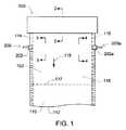
図1は、例えばガラスリボンなどの連続リボンを成形するシステムを概略的に示している。リボンを分断して、リボンからシートを切り取ることができる。シートは実質的に平面的なもの(例えば、フラットガラスシート)でもよいし、あるいは非平面的なもの(例えば、湾曲したガラスシート)でもよい。このシステムは、成形ユニット100およびパターニングユニット200を備えている。いくつかの実施形態において成形ユニット100は、図1に示されているように連続リボンを成形するように構成されている。いくつかの実施形態においてパターニングユニット200は、連続リボンの一部分の厚さを選択的に減少させ、連続リボンを分断して連続リボンからシートを分離するのを助けるように構成されている。 FIG. 1 schematically illustrates a system for forming a continuous ribbon, such as a glass ribbon. The ribbon can be cut and a sheet can be cut from the ribbon. The sheet may be substantially planar (eg, a flat glass sheet) or non-planar (eg, a curved glass sheet). This system includes a
本書で説明される実施形態のいずれにおいても、連続リボンおよびシートは、1以上のガラス材料、1以上のガラスセラミック材料、またはこれらの組合せを含み得る。連続リボンは、例えば、フュージョンドロー、ダウンドロー、アップドロー、スロットドロー、またはフロートプロセスなどの、任意の適切なプロセスを用いて成形することができる。図2は、図1の線2−2に沿った、成形ユニット100の1つの例示的な実施形態の断面図を示している。いくつかの実施形態において成形ユニット100は、図2に示されているように、フュージョンドロープロセスを用いて積層ガラスの連続リボン102を成形するために使用される。そのためにこのような実施形態のいくつかにおいて、装置100は概して、その全体が参照することにより本書に組み込まれる米国特許第4,214,886号明細書に記載されているように構成される。例えば装置100は、下方オーバーフロー分配器140の上方に位置付けられた、上方オーバーフロー分配器120を備えている。上方オーバーフロー分配器120はトラフ122を備え、ガラス組成物124が溶解されて、粘性状態でトラフ122内に供給される。下方オーバーフロー分配器140はトラフ142を備え、ガラス組成物144が溶解されて、粘性状態でトラフ142内に供給される。 In any of the embodiments described herein, continuous ribbons and sheets can include one or more glass materials, one or more glass ceramic materials, or combinations thereof. The continuous ribbon can be formed using any suitable process such as, for example, a fusion draw, down draw, up draw, slot draw, or float process. FIG. 2 shows a cross-sectional view of one exemplary embodiment of the forming
ガラス組成物144はトラフ142から溢れ出て、下方オーバーフロー分配器140の対向する外側成形表面146および148を流れ落ちる。外側成形表面146および148は延伸ライン150で合流する。下方オーバーフロー分配器140の夫々の外側成形表面146および148を流れ落ちたガラス組成物144の分離流は、延伸ライン150で合流し、ここで融合して連続リボン102のコア層104を形成する。 The
ガラス組成物124はトラフ122から溢れ出て、上方オーバーフロー分配器120の対向する外側成形表面126および128を流れ落ちる。ガラス組成物124は、ガラス組成物124が下方オーバーフロー分配器140の周りを流れて、下方オーバーフロー分配器の外側成形表面146および148上を流れているガラス組成物144に接触するように、上方オーバーフロー分配器120によって外側へと逸らされる。ガラス組成物124の分離流は、下方オーバーフロー分配器140の夫々の外側成形表面146および148で下方へと流れている、ガラス組成物144の夫々の分離流に融合する。延伸ライン150でガラス組成物144の流れが合流すると、ガラス組成物124は、連続リボン102の第1のクラッド層106および第2のクラッド層108を形成する。連続リボン102は図2に示されているように、下方オーバーフロー分配器140の延伸ライン150から離れていく。いくつかの実施形態において連続リボン102は、下方オーバーフロー分配器140から離れていくときに冷え、冷えると連続リボン102は脆性になる。いくつかの実施形態において連続リボン102は、分断されて連続リボンからガラスシートが分離される前に冷えて、および/または脆性になる。 The
コア層104は、クラッド層106および108の間に配置される。いくつかの実施形態においてクラッド層106および108は、図2に示されているように外側層である。コア層104は、第1の主表面と、第1の主表面の反対側の第2の主表面とを有する。いくつかの実施形態において第1のクラッド層106は、コア層104の第1の主表面に融合する。さらに、または代わりに、第2のクラッド層108は、コア層104の第2の主表面に融合する。いくつかの実施形態において、第1のクラッド層106とコア層104との間、および/または第2のクラッド層108とコア層104との間の境界面は、各クラッド層をコア層に付着させるよう加えられた、または構成された、例えば接着剤、コーティング層、または任意の他の材料などの、任意の結合材料を実質的に含んでいない。この形では、クラッド層106および108の一方または両方は、コア層104に直接融合される。 The
いくつかの実施形態において連続リボン102は、強化ガラスの連続リボンを含む。このような実施形態のいくつかでは、さらに以下で説明するように連続リボン102を分断して、強化ガラスのシートを形成する。いくつかの実施形態においてクラッド層106および108は、コア層104とは異なる平均熱膨張係数(CTE)を有するガラス組成物から形成される。例えば、クラッド層106および108を形成するガラス組成物124は、コア層104を形成するガラス組成物144よりも低いCTEを有する。CTEが一致していないと(すなわち、クラッド層106および108のCTEとコア層104のCTEとが異なると)、連続リボン102が冷えたとき、クラッド層内に圧縮応力が、および/またはコア層104内に引張応力が形成される。 In some embodiments,
図2に示されている連続リボン102は3つの層を備えているが、本開示の範囲内には他の実施形態が含まれる。他の実施形態において連続リボンは、例えば2層、4層、またはこれを超える層など、複数の層を含む。連続リボンが4以上の層を含む実施形態では、コア層と1つのクラッド層との間に1以上の中間層が配置される。従って、いくつかの実施形態においてクラッド層は、連続リボンに含まれる層の総数に拘わらず外側層である。他の実施形態において連続リボンは単一の層を含み、すなわち連続リボンは積層されたものではない。 The
図1に戻ると、連続リボン102は第1の表面110と第1の表面の反対側の第2の表面112とを有している。第1のエッジ領域114が、連続リボンの第1の側部エッジに隣接して、連続リボン102の長さに沿って縦方向に延在している。第2のエッジ領域116は、第1の側部エッジの反対側の連続リボンの第2の側部エッジに隣接して、連続リボン102の長さに沿って縦方向に延在している。第1のエッジ領域114と第2のエッジ領域116との間には、連続リボン102の中心領域118が配置されている。いくつかの実施形態において中心領域118は、第1のエッジ領域114および/または第2のエッジ領域116よりも薄い。例えばこのような実施形態のいくつかにおいて、第1のエッジ領域114および/または第2のエッジ領域116は、連続リボン102の長さに沿って延在する夫々のビードを含む。ビードは、連続リボン102の側部エッジ付近に形成される、比較的厚い領域とすることができる。いくつかの実施形態においてこれらのビードは、連続リボン102の中心領域118よりも厚い。いくつかの実施形態において連続リボン102は、移動方向119に移動速度vで移動する。このような実施形態のいくつかにおいて、移動方向119は下向き方向である。連続リボン102は、成形ユニット100から離れて下向きに動く(例えば、重力および/または1以上の牽引ロールの力を受けて)。 Returning to FIG. 1,
ビードの厚さのため、連続リボン102の第1のエッジ領域114および/または第2のエッジ領域116を(例えば、リボンからシートを切り取るために)分断することは困難になり得る。いくつかの実施形態においてパターニングユニット200は、連続リボン102の一部分の厚さを選択的に減少させて、連続リボンの分断を助ける。例えばいくつかの実施形態において、パターニングユニット200は、第1のエッジ領域114で連続リボン102に係合して第1のエッジ領域に沿って凹凸パターンを形成することによって、第1のエッジ領域に沿って延在するビードの厚さを選択的に減少させる。さらに、または代わりに、パターニングユニット200は、第2のエッジ領域116で連続リボン102に係合して第2のエッジ領域に沿って凹凸パターンを形成することによって、第2のエッジ領域に沿って延在するビードの厚さを選択的に減少させる。 Due to the thickness of the bead, it may be difficult to sever the
図3は、図1の線3−3に沿った、パターニングユニット200の1つの例示的な実施形態の断面図を示している。パターニングユニット200は、図1および3に示されているように、第1のパターニング部材202および第2のパターニング部材212を備えている。第1のパターニング部材202と第2のパターニング部材212との間の空間220に連続リボン102を通過させて、さらに以下で説明するように連続リボンに凹凸パターンを形成する。 FIG. 3 shows a cross-sectional view of one exemplary embodiment of the
いくつかの実施形態において第1のパターニング部材202は、パターニングローラ(例えば、鋸歯状またはリブ状のローラ)を備えている。例えば第1のパターニング部材202は、ローラ本体204および外側突出部206を有する。突出部206は連続リボン102に係合して、連続リボンに凹みを形成する。いくつかの実施形態においてローラ本体204は、図1および3に示されているように、実質的に円筒状の形状を有している。他の実施形態においてローラ本体は、任意の他の適切な形状(例えば、三角形状プリズム、長方形状プリズム、または任意の他の3次元形状)を有し得る。いくつかの実施形態において突出部206は、ローラ本体204の長さに沿って、ローラ本体の外側表面から外向きに延在している。いくつかの実施形態において突出部206は、ローラ本体の第1の端部と第2の端部との間にローラ本体204の長さに沿って延在する、隆起を含む。いくつかの実施形態において突出部206は、図1および3に示されているように、外側表面から外向きに延在する、ローラ本体204の外側表面の周りに周方向に配置された複数の突出部を含む。 In some embodiments, the
いくつかの実施形態において第2のパターニング部材212は、パターニングローラ(例えば、鋸歯状またはリブ状のローラ)を備えている。例えば第2のパターニング部材212は、ローラ本体214および外側突出部216を有する。突出部216は連続リボン102に係合して、連続リボンに凹みを形成する。いくつかの実施形態においてローラ本体214は、図1および3に示されているように、実質的に円筒状の形状を有している。他の実施形態においてローラ本体は、第1のパターニング部材202を参照して上述したような、任意の他の適切な形状を有し得る。いくつかの実施形態において突出部216は、ローラ本体214の長さに沿って、ローラ本体の外側表面から外向きに延在している。いくつかの実施形態において突出部216は、ローラ本体の第1の端部と第2の端部との間にローラ本体214の長さに沿って延在する、隆起を含む。いくつかの実施形態において突出部216は、図1および3に示されているように、外側表面から外向きに延在する、ローラ本体214の外側表面の周りに周方向に配置された複数の突出部を含む。 In some embodiments, the
いくつかの実施形態において第1のパターニング部材202および第2のパターニング部材212は、連続リボン102の対向する表面に係合するように位置付けられる。例えば第1のパターニング部材202は、連続リボン102の第1の表面110に係合するように位置付けられ、第2のパターニング部材212は、連続リボンの第2の表面112に係合するように位置付けられる。いくつかの実施形態において第1のパターニング部材202および第2のパターニング部材212は、縦方向に互いに位置合わせされている(例えば、鉛直に整列)。言い換えれば、第1のパターニング部材202および第2のパターニング部材212は、連続リボン102の幅に沿った実質的に同じ横方向の位置にある。いくつかの実施形態において第1のパターニング部材202および第2のパターニング部材212の夫々は、図1に示されているように、連続リボン102の第1のエッジ領域114と位置合わせされている。さらに、または代わりに、第1のパターニング部材202および第2のパターニング部材212は、横方向に互いに位置合わせされている(例えば、水平に整列)。言い換えれば、第1のパターニング部材202および第2のパターニング部材212は、図3に示されているように、連続リボン102の長さに沿った実質的に同じ縦方向位置にある。いくつかの実施形態において第1のパターニング部材202および第2のパターニング部材212は、例えば図1および3に示されているように、連続リボン102の幅および長さに沿って縦方向および横方向に互いに位置合わせされている。いくつかの実施形態において第1のパターニング部材202および第2のパターニング部材212は、互いに鉛直かつ水平に位置合わせされている。このように第1のパターニング部材202および第2のパターニング部材212は、連続リボンの幅および長さに沿った実質的に同じ横方向および縦方向の位置で、連続リボン102の夫々第1の表面110および第2の表面112に係合できる。 In some embodiments, the
図3に示されている実施形態において、第1のパターニング部材202および第2のパターニング部材212は、その間に空間220を設けて互いに直接相対して位置付けられている。連続リボン102は空間220を通過する。例えば連続リボン102は、空間220を通って移動方向119に動く。連続リボン102が空間220を通過すると、第1のパターニング部材202は連続リボンの第1の表面110に係合し、第2のパターニング部材212は連続リボンの第2の表面112に係合する。いくつかの実施形態においてパターニングユニット200は、第1のパターニング部材202および第2のパターニング部材212が連続リボンに凹みを形成するべく連続リボンに係合するときに連続リボン102が粘性状態にあるよう、十分に成形ユニットに近接して成形ユニット100の下流(例えば、下方)に位置付けられる。例えば、連続リボンが変形して連続リボンに凹みを形成することができるほど連続リボンが十分に高い温度であり、かつ連続リボンの全体形状を維持できるほど連続リボンが十分に低い温度(例えば、連続リボンの軟化温度未満)であるような領域内で、パターニングユニット200が連続リボン102に係合するように位置付けられる。 In the embodiment shown in FIG. 3, the
図3に示されている実施形態において、第1のパターニング部材202は、回転軸に関して第1の回転方向208に回転可能である。いくつかの実施形態において第1のパターニング部材202は、第1の回転方向208に回転するように駆動される(例えば、電気モータによって)。第1のパターニング部材202は、連続リボン102を成形ユニット100から離れる方向119に牽引することができ、これは連続リボンに所望の特性(例えば、厚さ、幅、および/または形状)を付与する助けになり得る。あるいは第1のパターニング部材が連続リボンを方向119に実質的に牽引しないよう、パターニング部材の外側表面の速さが移動しているリボンの速度vと第1のパターニング部材の縦方向位置で実質的に同じになるように、第1のパターニング部材202を駆動してもよい。他の実施形態では、このような回転を、空間220を通って動いている連続リボン102との係合によって生じさせる。連続リボンが空間220を通過すると、第1のパターニング部材202の突出部206は連続リボン102の第1の表面110に連続して係合する。例えばいくつかの実施形態では、第1突出部206aが、第1の縦方向位置で連続リボン102の第1の表面110に係合する。第1のパターニング部材202の第1突出部206aが連続リボン102に係合すると、第1の縦方向位置で連続リボンの第1の表面110に第1の凹みが形成される。凹みのサイズおよび形状は、突出部206のサイズおよび形状に対応し得る。 In the embodiment shown in FIG. 3, the
連続リボン102が移動方向119に動くと、第1のパターニング部材202は、第1突出部206aに隣接する第2突出部206bが連続リボンの第1の表面110に第2の縦方向位置で係合するまで、第1の回転方向208に回転する。第1のパターニング部材202の第2突出部206bが連続リボン102に係合すると、第2の縦方向位置で連続リボンの第1の表面110に第2の凹みが形成される。第2の縦方向位置は、第1の縦方向位置の上流(例えば、上方)である。第2の凹みは、第1の凹みに隣接している。連続リボン102が移動方向119に継続的に動き、かつ第1のパターニング部材202が第1の回転方向208に継続的に回転すると、第1のパターニング部材の突出部206が連続リボンの第1の表面110に連続して係合して、連続リボンの第1の表面に第1の一連の凹みを形成する。いくつかの実施形態において第1の一連の凹みは、連続リボン102の第1のエッジ領域114の長さに沿って縦方向に延在する。 When the
同様に、第2のパターニング部材212は、回転軸に関して第2の回転方向218に回転可能である。第2のパターニング部材212は、回転するように駆動させることができ、および/または空間220を通って動いている連続リボン102との係合によって回転させることができる。連続リボンが空間220を通過すると、第2のパターニング部材212の突出部216は連続リボン102の第2の表面112に連続して係合する。従って、第1突出部216aが第1の縦方向位置で連続リボン102の第2の表面112に係合する。第2のパターニング部材212の第1突出部216aが連続リボン102に係合すると、第1の縦方向位置で連続リボンの第2の表面112に第1の凹みが形成される。 Similarly, the
連続リボン102が移動方向119に動くと、第2のパターニング部材212は、第1突出部216aに隣接する第2突出部216bが連続リボンの第2の表面112に第2の縦方向位置で係合するまで、第2の回転方向218に回転する。第2のパターニング部材212の第2突出部216bが連続リボン102に係合すると、第2の縦方向位置で連続リボンの第2の表面112に第2の凹みが形成される。連続リボン102が移動方向119に継続的に動き、かつ第2のパターニング部材212が第2の回転方向218に継続的に回転すると、第2のパターニング部材の突出部216が連続リボンの第2の表面112に連続して係合して、連続リボンの第2の表面に第2の一連の凹みを形成する。いくつかの実施形態において第2の一連の凹みは、連続リボン102の第1のエッジ領域114の長さに沿って縦方向に延在する。 As the
いくつかの実施形態において、第1のパターニング部材202および/または第2のパターニング部材212は、連続リボン102の縦軸に実質的に垂直に(例えば、移動方向119に実質的に垂直に)延在する。この形では、第1および/または第2の一連の凹みの中の凹みは、連続リボンの縦軸に実質的に垂直に延在する。他の実施形態において、第1および/または第2のパターニング部材は、連続リボンの縦軸に垂直ではない方向に延在する。このような実施形態では、第1および/または第2のパターニング部材は、縦軸に垂直な方向に対して傾斜している。この形では、第1および/または第2の一連の凹みの中の凹みは、連続リボンの縦軸に垂直ではない方向に延在する。これは、(例えば、連続リボンの幅を制御するために)連続リボンをパターニング部材で横方向に牽引する助けになり得る。 In some embodiments, the
いくつかの実施形態において、第1のパターニング部材202および/または第2のパターニング部材212の突出部は、図1に示されているように、パターニング部材の縦軸に実質的に平行に延在している。他の実施形態において第1のパターニング部材および/または第2のパターニング部材の突出部は、パターニング部材の縦軸に平行ではない方向に延在する。例えばいくつかの実施形態において、第1のパターニング部材および/または第2のパターニング部材の突出部は、パターニング部材の周り(例えば、ローラ本体の周り)に渦巻状または螺旋状のパターンで延在したものである。このようなパターニング部材で形成された凹みは、横かつ縦方向(対角線方向)に、連続リボンの夫々のエッジ領域に沿って延在する。凹みの向きに拘わらず、連続リボンの第1の表面および第2の表面の対応する凹みは互いに位置合わせされて、それらの間に薄化領域またはウェブが形成され得る。渦巻状パターンは、パターニング部材が回転すると、連続リボンを(例えば、連続リボンの幅を制御するために)横方向に牽引する助けとなり得る。 In some embodiments, the protrusions of the
いくつかの実施形態では、第1のパターニング部材の突出部206が、第2のパターニング部材の対応する突出部216が連続リボンの第2の表面112に係合するのと実質的に同じ時間に、および/またはその位置にちょうど相対して、連続リボン102の第1の表面110に係合するように、第1のパターニング部材202および第2のパターニング部材212は互いに同期化される。いくつかの実施形態において、第1のパターニング部材202の突出部206および第2のパターニング部材212の対応する突出部216は、互いに同時に連続リボン102の夫々第1の表面110および第2の表面112に係合する。いくつかの実施形態において、第1のパターニング部材202の突出部206および第2のパターニング部材212の対応する突出部216は、(例えば、リボンの幅および長さに沿った)実質的に同じ横方向および縦方向の位置で連続リボン102に係合する。この形では、連続リボン102の第1の表面110に(例えば、第1のパターニング部材202の突出部206によって)形成された第1の一連の凹みは、連続リボンの第2の表面112に(例えば、第2のパターニング部材212の突出部216によって)形成された第2の一連の凹みと位置合わせされる。いくつかの実施形態において、連続リボン102の第1の表面110の各凹みは、連続リボンの第2の表面112の対応する凹みのちょうど反対側に配置される。薄化領域またはウェブは、連続リボン102の第1の表面110の各凹みと連続リボンの第2の表面112の対応する凹みとによりもたらされる。このような構造は、連続リボンの第1のエッジ領域114を分断するのを助けることができる。 In some embodiments, the first patterning member protrusions 206 are at substantially the same time that the corresponding
図3は、連続リボン102の第1の表面110に形成された第1の一連の凹みと、連続リボンの第2の表面112に形成された第2の一連の凹みとを示している。いくつかの実施形態において第1の一連の凹みは、上述したように第2の一連の凹みと位置合わせされている。第1の一連の凹みの中の凹み160が、第2の一連の凹みの対応する凹み170のちょうど反対側に配置されている。いくつかの実施形態において凹み160は、連続リボン102の第1の表面110に形成されたチャネルまたは溝を含む。このような実施形態のいくつかにおいて、凹み160は、移動方向119に実質的に垂直な横の方向に延在している。凹み160は、第1のエッジ領域114の幅の少なくとも一部分に沿って延在する。例えば凹み160は、第1のエッジ領域114のビードを少なくとも部分的に横切って延在する。同様に、対応する凹み170は、連続リボン102の第2の表面112に形成されたチャネルまたは溝を含む。いくつかの実施形態において、対応する凹み170は、移動方向119に実質的に垂直な横の方向に延在している。対応する凹み170は、第1のエッジ領域114の幅の少なくとも一部分に沿って延在する。例えば対応する凹み170は、第1のエッジ領域114のビードを少なくとも部分的に横切って延在する。 FIG. 3 shows a first series of indentations formed on the
いくつかの実施形態において凹み160および対応する凹み170は、連続リボン102の対向する表面上に互いに反対側にかつ互いに位置合わせされて(例えば、水平および鉛直に位置合わせされて)配置される。第1のエッジ領域114に凹み160および対応する凹み170を形成することにより、第1のエッジ領域114は、凹み160と対応する凹み170との間に形成された薄化領域を有する。いくつかの実施形態において、第1のエッジ領域114の長さに沿って延在するビードの厚さは、凹み160および対応する凹み170の位置(例えば、横方向位置および/または縦方向位置)で選択的に減少する。得られるウェブ180は、凹み160と対応する凹み170との間に配置されたものである。ウェブ180は、凹み160および対応する凹み170と位置合わせ(例えば、水平および鉛直に位置合わせ)されている。ウェブ180は、連続リボン102の第1のエッジ領域114の中間セグメント182よりも薄い。中間セグメントはウェブ間に、ウェブとは異なる縦方向位置に配置されている。例えば中間セグメント182は、凹みと横方向に位置合わせされていない(水平に整列していない)。いくつかの実施形態において中間セグメントは、ウェブと実質的に同じ横方向位置に配置されている。例えば中間セグメント182は、凹みと縦方向に位置合わせされている(例えば、鉛直に整列している)。中間セグメント182は、第1のエッジ領域114の、隣接する凹み間のウェブ180の上流および下流に位置付けられた部分を含む。 In some embodiments, the
いくつかの実施形態においてウェブ180の厚さは、パターニングユニット200上流の縦方向位置での連続リボン102の中心領域118の最初の厚さ以下である。さらに、または代わりに、中間セグメント182の厚さは、パターニングユニット200上流の縦方向位置での第1のエッジ領域114の最初の厚さを上回る。いくつかの実施形態においてパターニングユニット200は、ウェブ180の位置で第1のエッジ領域114を薄化し、かつ中間セグメント182の位置で第1のエッジ領域を肉厚化する(例えば、ウェブの位置から移動した材料が中間セグメントに押し出されるため)。 In some embodiments, the thickness of the
いくつかの実施形態では、連続リボン102が第1のパターニング部材202と第2のパターニング部材212との間を通過すると、第1の一連の凹みが連続リボンの第1の表面110に形成され、第2の一連の凹みが連続リボンの第2の表面112に形成される。このように、凹凸パターンが連続リボン102の長さに沿って第1のエッジ領域114に形成される。凹凸パターンは、図3に示されているように、一連の中間セグメントによって互いに分離された一連のウェブを含む。一連のウェブは、ウェブよりも厚い中間セグメントによって互いから分離された、一連の薄化領域を含む。各ウェブは、隣接する中間セグメントよりも薄い。このように、連続リボン102の第1のエッジ領域114の厚さは、ウェブの位置で選択的に減少する。従っていくつかの実施形態において、連続リボン102の第1のエッジ領域114の長さに沿って延在しているビードの厚さは、選択的に減少される。第1のエッジ領域114の厚さを選択的に減少させると、連続リボン102を分断して連続リボンからシートを分離する助けになり得る。例えばいくつかの実施形態において、連続リボン102の第1のエッジ領域114を比較的薄いウェブの位置で破断するのに必要な力は、比較的厚い中間セグメントで第1のエッジ領域を破断するのに必要な力、または凹凸パターンのない第1のエッジ領域を破断するのに必要となる力よりも小さい。 In some embodiments, as the
いくつかの実施形態において第1の一連の凹みは、連続リボン102の第1のクラッド層106に形成され、第2の一連の凹みは連続リボンの第2のクラッド層108に形成される。いくつかの実施形態において、第1の一連の凹みの中の凹みの深さは、凹みが連続リボン102のコア層104内へと延在しないほど十分に小さいものである。さらに、または代わりに、第2の一連の凹みの中の凹みの深さは、凹みが連続リボン102のコア層104内へと延在しないほど十分に小さいものである。このようにコア層104は、連続リボン102の第1のエッジ領域114の長さに沿って実質的に凹んでいない。このような実施形態のいくつかにおいて、コア層104は、第1のエッジ領域の長さに沿った凹凸パターンの形成後に、連続リボン102の第1の表面110および/または第2の表面112で、第1のエッジ領域114の長さに沿って露出されないままである。言い換えればコア層104は、第1のエッジ領域の長さに沿った凹凸パターンの形成後に、第1のエッジ領域114の長さに沿って連続リボン102の第1の表面110および/または第2の表面112で、夫々第1のクラッド層106および/または第2のクラッド層108によって被覆されたままである。上述したように引張状態にある可能性のあるコア層104の被覆が維持されると、処理中に、連続リボン102の完全性を保つ、および/または連続リボンの意図されていない破断を回避する、助けになり得る。 In some embodiments, a first series of depressions is formed in the
他の実施形態において凹みの深さは、凹みが連続リボン102のコア層104内へと延在するほど十分に大きいものである。さらに、または代わりに、第2の一連の凹みの中の凹みの深さは、凹みが連続リボン102のコア層104内へと延在するほど十分に大きいものである。このようにコア層104は、連続リボン102の第1のエッジ領域114の長さに沿って凹んでいる。このような実施形態のいくつかにおいて、コア層104は、第1のエッジ領域の長さに沿った凹凸パターンの形成後に、連続リボン102の第1の表面110および/または第2の表面112で、第1のエッジ領域114の長さに沿って露出される。言い換えればコア層104は、第1のエッジ領域の長さに沿った凹凸パターンの形成後に、第1のエッジ領域114の長さに沿って連続リボン102の第1の表面110および/または第2の表面112で、夫々第1のクラッド層106および/または第2のクラッド層108によって被覆されない。このような実施形態のいくつかでは、上述したように引張状態にある可能性のあるコア層104のいくつかの部分が第1のエッジ領域114に沿って露出される。ウェブはこの露出された部分を含み得、これがウェブをさらに弱化させて、第1のエッジ領域に沿って延在するビードを、連続リボン102を分断するために分断するのを助けることができる。 In other embodiments, the depth of the recess is sufficiently large that the recess extends into the
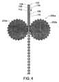
いくつかの実施形態においてパターニングユニット200は、図1および4に示されているように、第3のパターニング部材202aおよび第4のパターニング部材212aを備えている。第3のパターニング部材202aおよび第4のパターニング部材212aは、夫々第1のパターニング部材202および第2のパターニング部材212と同様に構成および配置される。第3のパターニング部材202aおよび第4のパターニング部材212aは、連続リボン102の第2のエッジ領域116に係合するように位置付けられる。連続リボン102が第3のパターニング部材202aと第4のパターニング部材212aとの間を通過すると、第3のパターニング部材が連続リボンの第1の表面110に係合して連続リボンの長さに沿って第2のエッジ領域116に縦方向に第3の一連の凹みを形成し、第4のパターニング部材が連続リボンの第2の表面112に係合して連続リボンの長さに沿って第2のエッジ領域に縦方向に第4の一連の凹みを形成する。 In some embodiments, the
いくつかの実施形態において第3のパターニング部材202aおよび第4のパターニング部材212aは、第3の一連の凹みおよび第4の一連の凹みが互いに(例えば、縦および/または横方向において)位置合わせされるように同期化される。連続リボン102を第3のパターニング部材202aと第4のパターニング部材212aとの間に通過させると、連続リボン102の第2のエッジ領域116の長さに沿って凹凸パターンが形成される。いくつかの実施形態において凹凸パターンは、一連の中間セグメントによって互いに分離された一連のウェブを含む。連続リボン102の第2のエッジ領域116の厚さは、第1のパターニング部材202および第2のパターニング部材212を参照して同様に説明したように選択的に減少する。 In some embodiments, the
いくつかの実施形態において第1および第2の一連の凹みは、第3および第4の一連の凹みと横方向に位置合わせされる(例えば、水平に整列)。言い換えれば、第1および第2の一連の凹みは、第3および第4の一連の凹みと実質的に同じ縦方向位置にある。このように、第1のエッジ領域114に形成された凹凸パターンの各ウェブは、第2のエッジ領域116に形成された凹凸パターンの対応するウェブと実質的に同じ縦方向位置にある(例えば、水平に整列)。これは、連続リボン102を分断してシートを分離させる助けになり得る。 In some embodiments, the first and second series of recesses are laterally aligned (eg, aligned horizontally) with the third and fourth series of recesses. In other words, the first and second series of recesses are in substantially the same longitudinal position as the third and fourth series of recesses. In this way, each web of the concavo-convex pattern formed in the
いくつかの実施形態において、連続リボン102をパターニングユニット200に通すステップは、図1に示されているように、連続リボンを、第1のパターニング部材202と第2のパターニング部材212との間、および第3のパターニング部材202aと第4のパターニング部材212aとの間に通すステップを含む。第1のパターニング部材202および第2のパターニング部材212は、第1のエッジ領域114に沿って連続リボン102に係合し、第1のエッジ領域の長さに沿って凹凸パターンを形成する。従って、連続リボン102の第1のエッジ領域114の厚さは、パターニングユニット200によって選択的に減少される。第3のパターニング部材202aおよび第4のパターニング部材212aは、第2のエッジ領域116に沿って連続リボン102に係合し、第2のエッジ領域の長さに沿って凹凸パターンを形成する。従って、連続リボン102の第2のエッジ領域116の厚さは、パターニングユニット200によって選択的に減少される。いくつかの実施形態において凹凸パターンは、連続リボン102の第1のエッジ領域114および第2のエッジ領域116に、図1に示されているように実質的に同時に形成される。 In some embodiments, passing the
いくつかの実施形態において連続リボン102の中心領域118は、実質的にパターニングユニット200が係合しないままである。例えば中心領域118は、第1のパターニング部材202、第2のパターニング部材212、第3のパターニング部材202a、および/または第4のパターニング部材212aが、実質的に係合しないままである。このように、第1のエッジ領域114および第2のエッジ領域116に凹凸パターンが形成される間、中心領域118はパターニングユニット200で実質的に凹むことはない。これは、連続リボン102の第1の表面110および第2の表面112を、ガラス物品の作製に使用される中心領域118に沿って清浄な状態で維持する助けになり得る。 In some embodiments, the
いくつかの実施形態において連続リボン102は、連続リボンからシートを分離するよう分断される。例えば連続リボン102は、パターニングユニット200よりも下流の位置で分断される。いくつかの実施形態では、応力領域(例えば、切込み線)が連続リボンに形成される。切込み線117を連続リボン102に形成してもよく、この切込み線117は横方向に延在するものでもよい。例えばいくつかの実施形態では、図1に示されているように、切込み線117は連続リボン102の中心領域118の実質的に全幅に沿って延在する。切込み線117は実質的に直線状の(すなわち、真っ直ぐな)ものでもよいし、あるいは非直線状の(すなわち、湾曲した)ものでもよい。切込み線117は任意の適切な罫書き技術(例えば、機械的罫書きまたはレーザ罫書き)を用いて形成することができる。 In some embodiments, the
いくつかの実施形態において切込み線117は、図1に示されているように、連続リボン102の第1のエッジ領域114と第2のエッジ領域116との間に延在し、罫書き領域を形成する。例えば、罫書き領域のすぐ近くで連続リボンに曲げ力を加えることによって、連続リボンの罫書き領域を冷却することによって、連続リボンの罫書き領域を加熱することによって、または任意の他の適切な方法によって、罫書き領域付近で連続リボン102に応力を加えてもよい。連続リボン102に応力が加えられると、連続リボンの中心領域118は切込み線117に沿って分断される。例えば連続リボン102は、応力の印加に応えて罫書き領域に沿って折れる、または割れる。 In some embodiments, the
いくつかの実施形態において、連続リボン102の第1のエッジ領域114は、切込み線117付近に配置されたウェブの位置で分断される(例えば、第1のエッジ領域をウェブの位置で折ることによって)。さらに、または代わりに、連続リボン102の第2のエッジ領域116は、切込み線117付近に配置されたウェブの位置で分断される(例えば、第2のエッジ領域をウェブの位置で折ることによって)。いくつかの実施形態において第1のエッジ領域114および/または第2のエッジ領域116は、隣接するウェブ間に配置された中間セグメントの位置で割れる代わりに、ウェブの位置で割れる傾向にある(例えばウェブは隣接する中間セグメントよりも薄いため)。第1のエッジ領域114および/または第2のエッジ領域116の厚さを選択的に減少させると、連続リボン102の分断時にこの割れを、夫々のビードを横方向に横切って導く助けになり得る。これは、連続リボン102の幅を横切って実質的に真っ直ぐな切断を形成すること、および/または、方向付けされていない、または方向性のない割れが、エッジ領域の長さおよび幅に沿って生じるのを防ぐこと、の助けになり得る。第1のエッジ領域114および/または第2のエッジ領域116の厚さを選択的に減少させると、連続リボン102の分断時に夫々のビードを破断するのに必要な力を減少させる助けになり得る。例えばいくつかの実施形態において、第1のエッジ領域114および/または第2のエッジ領域116に形成された凹凸パターンのウェブは、凹凸パターンが形成されていない夫々のビードよりも薄い。第1のエッジ領域114および/または第2のエッジ領域116の厚さが減少していることで、夫々のエッジ領域を破断するのに必要な力をウェブの位置で減少させることができる。ビードを破断するのに必要な力が減少すると、力を加えることによって生じる連続リボン102の動きを低減することができる。これは、分断プロセス中に連続リボンの動きによって生じ得る欠陥を防ぐ助けになり得る。 In some embodiments, the
いくつかの実施形態では、連続リボン102を上述したように分断して、連続リボンからシートを分離する。第1のエッジ領域114および/または第2のエッジ領域116を、シートから取り除いてもよい。例えばいくつかの実施形態では、第1のエッジ領域114および第2のエッジ領域116がシートから取り除かれて中心領域118が残される。第1および/または第2のエッジ領域は、例えばシートに沿って縦方向に延在する応力領域を夫々のエッジ領域と中心領域との間に形成して、シートをこの応力領域に沿って分断するなど、任意の適切な方法によって取り除くことができる。 In some embodiments, the
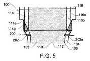
いくつかの実施形態では、図5に示されているように、コア層104は部分的に、連続リボン102の第1のクラッド層106および/または第2のクラッド層108で被覆されていない。例えばこのような実施形態のいくつかでは、コア層が第1のエッジ領域114および/または第2のエッジ領域116で連続リボン102の第1の表面110および/または第2の表面112に沿って被覆されないよう、コア層104は第1のクラッド層106および/または第2のクラッド層108よりも幅広である。このような実施形態のいくつかにおいて、第1のエッジ領域114は複数のビードを含む。例えば図5に示されているように、第1のビード114aがコア層104のエッジに沿って延在し、かつ第2のビード114bが第1のクラッド層106および第2のクラッド層108のエッジに沿って延在する。このように、第1のビード114aは第1のエッジ領域114の外側エッジの長さに沿って縦方向に延在し、第2のビード114bは第1のエッジ領域の内側エッジの長さに沿って縦方向に延在する。さらに、または代わりに、第2のエッジ領域116は複数のビードを含む。例えば図5に示されているように、第1のビード116aがコア層104のエッジに沿って延在し、かつ第2のビード116bが第1のクラッド層106および第2のクラッド層108のエッジに沿って延在する。このように、第1のビード116aは第2のエッジ領域116の外側エッジの長さに沿って縦方向に延在し、第2のビード116bは第2のエッジ領域の内側エッジの長さに沿って縦方向に延在する。他の実施形態において連続リボンは、第1のエッジ領域内のコア層の被覆されていない領域に沿って縦方向に(例えば、第1のエッジ領域の外側エッジまたは内側エッジの長さに沿って縦方向に)延在する単一のビード、および/または、第2のエッジ領域内のコア層の被覆されていない領域に沿って縦方向に(例えば、第2のエッジ領域の外側エッジまたは内側エッジの長さに沿って縦方向に)延在する単一のビードを含んでいる。 In some embodiments, the
他の実施形態において第1のエッジ領域および/または第2のエッジ領域は、より多くのビードを含み得る。例えばいくつかの実施形態では、第1のエッジ領域および/または第2のエッジ領域がコア層、第1のクラッド層、第2のクラッド層、の夫々のエッジに沿って延在するビードを含むよう、第1のクラッド層および第2のクラッド層が異なる幅を有する。他の実施形態において連続リボンは、コア層、第1のクラッド層、および第2のクラッド層とは異なる幅を有する1以上の中間層を、第1のエッジ領域および/または第2のエッジ領域がこの中間層のエッジに沿って延在するビードを含むように備えている。 In other embodiments, the first edge region and / or the second edge region may include more beads. For example, in some embodiments, the first edge region and / or the second edge region includes beads that extend along respective edges of the core layer, the first cladding layer, and the second cladding layer. Thus, the first cladding layer and the second cladding layer have different widths. In other embodiments, the continuous ribbon comprises one or more intermediate layers having different widths than the core layer, the first cladding layer, and the second cladding layer, the first edge region and / or the second edge region. Includes a bead extending along the edge of the intermediate layer.
いくつかの実施形態においてパターニングユニット200は、図5に示されているように、連続リボン102の第1のエッジ領域114および第2のエッジ領域116に係合する。パターニングユニット200は、第1のエッジ領域114および/または第2のエッジ領域116において、コア層102の被覆されていない領域の実質的に全幅に係合する。例えばパターニングユニット200は、第1のエッジ領域の実質的に全幅に沿って第1のエッジ領域114に係合する。そのために、第1のパターニング部材202および第2のパターニング部材212の夫々の長さは、少なくとも第1のエッジ領域114の幅と同じ長さである。第1のエッジ領域114が2以上のビードを含むいくつかの実施形態では、連続リボン102が第1のパターニング部材202と第2のパターニング部材212との間を通過すると、第1のパターニング部材および第2のパターニング部材の夫々は、第1のエッジ領域114の第1のビード114aおよび第2のビード114bの両方に係合する。この形では、第1のビード114aおよび第2のビード114bの両方の厚さが(例えば、凹凸パターンを形成することによって)パターニングユニット200によって選択的に減少される。同様に、第2のエッジ領域116が2以上のビードを含むいくつかの実施形態では、パターニングユニット200は第2のエッジ領域の実質的に全幅に沿って第2のエッジ領域116に係合する。そのために、第3のパターニング部材202aおよび第4のパターニング部材212aの夫々の長さは、少なくとも第2のエッジ領域116の幅と同じ長さである。連続リボン102が第3のパターニング部材202aと第4のパターニング部材212aとの間を通過すると、第3のパターニング部材および第4のパターニング部材の夫々が第2のエッジ領域116の第1のビード116aおよび第2のビード116bの両方に係合して、第1のビードおよび第2のビードの両方の厚さを選択的に減少させる。 In some embodiments, the
本書で説明される任意の実施形態において、パターニング部材の突起は、所望のサイズおよび形状を有する凹みを形成するようなサイズおよび形状とされ得る。例えばいくつかの実施形態において突起は、第1のパターニング部材202および第2のパターニング部材212に関連して図3に示されているように、実質的にV字状である。連続リボン102にこのようなV字状の突起が係合すると、連続リボンの表面に実質的にV字状の凹みが形成される。言い換えれば、凹みは、V字状の断面形状を有するチャネルまたは溝として構成される。V字状の凹みは、先端で合流する2つの傾斜した側壁を含む。いくつかの実施形態において、この先端は丸みを帯びている。ウェブは1つの凹みの先端と対応する凹みの先端との間に配置される。他の実施形態において、突起、およびこの突起によって形成される凹みの断面は、例えばU字状または長方形状などの、任意の他の適切な形状を有し得る。 In any embodiment described herein, the patterning member protrusions may be sized and shaped to form a recess having a desired size and shape. For example, in some embodiments, the protrusions are substantially V-shaped, as shown in FIG. 3 in connection with the
本書で説明される実施形態のいずれにおいても、パターニング部材の突起および/または連続リボンに形成された凹みは、任意の適切な距離だけ互いに間隔を空けて配置され得る。例えば、いくつかの実施形態においてパターニング部材は、1インチ(2.54cm)当たり約4から約12個の突起、または1インチ(2.54cm)当たり約6から約10個の突起を含む。同様に、いくつかの実施形態において凹凸パターンは、1インチ(2.54cm)当たり約4から約12個の凹み、または1インチ(2.54cm)当たり約6から約10個の凹みを含む。間隔は、エッジ領域の薄化量(すなわち、ウェブの厚さとエッジ領域の最初の厚さとの差)に依存し得る。例えば薄化量が大きくなると、移動される材料のためにウェブ間に十分な空間を残すよう、間隔は広くなり得る。 In any of the embodiments described herein, the protrusions of the patterning member and / or the recesses formed in the continuous ribbon can be spaced apart from each other by any suitable distance. For example, in some embodiments, the patterning member includes about 4 to about 12 protrusions per inch (2.54 cm), or about 6 to about 10 protrusions per inch (2.54 cm). Similarly, in some embodiments, the relief pattern comprises about 4 to about 12 depressions per inch (2.54 cm), or about 6 to about 10 depressions per inch (2.54 cm). The spacing may depend on the amount of thinning of the edge region (ie, the difference between the web thickness and the initial thickness of the edge region). For example, as the amount of thinning increases, the spacing can increase to leave enough space between the webs for the material to be moved.
図1および3〜5に示されているパターニング部材は、ローラ本体の外側表面から延在する複数の突出部を含んでいるが、本開示の範囲内には他の実施形態が含まれる。他の実施形態においてパターニング部材は、連続リボンに係合して連続リボンの一部分を選択的に薄化させるように構成された、任意の種類の突出部を含み得る。例えばパターニング部材は、前方および後方の方向へと動いて連続リボンとの係合および解除を繰り返すことで連続リボンの一連の凹みを形成するように構成された、実質的に平坦な細長い部材(例えば、パドル部材)として構成され得る。いくつかの実施形態においてパターニング部材は、連続リボンとともに縦方向に可動である(例えば、方向119に速度vで)。これにより、連続リボンに凹みを形成するパターニング部材間に挟まれることによる連続リボンの動きを最小限に抑えることができる。 The patterning member shown in FIGS. 1 and 3-5 includes a plurality of protrusions extending from the outer surface of the roller body, but other embodiments are within the scope of the present disclosure. In other embodiments, the patterning member may include any type of protrusion configured to engage the continuous ribbon and selectively thin a portion of the continuous ribbon. For example, the patterning member may move in a forward and backward direction to repeatedly engage and disengage with the continuous ribbon to form a series of recesses in the continuous ribbon (e.g., , A paddle member). In some embodiments, the patterning member is movable longitudinally with the continuous ribbon (eg, at a velocity v in direction 119). Thereby, the movement of a continuous ribbon by being pinched | interposed between the patterning members which form a dent in a continuous ribbon can be suppressed to the minimum.
本発明の精神および範囲から逸脱することなく、種々の改変および変形が作製可能であることは当業者には明らかであろう。従って本発明は、添付の請求項およびその同等物を考慮すること以外は制限されない。 It will be apparent to those skilled in the art that various modifications and variations can be made without departing from the spirit and scope of the invention. Accordingly, the invention is not limited except in light of the attached claims and their equivalents.
102 連続リボン
104 コア層
106 第1のクラッド層
108 第2のクラッド層
110 第1の表面
112 第2の表面
114 第1のエッジ領域
116 第2のエッジ領域
118 中心領域
160、170 凹み
180 ウェブ
182 中間セグメント
200 パターニングユニット
202 第1のパターニング部材
206、216 突出部
212 第2のパターニング部材
220 空間102
Claims (10)
Translated fromJapanese第1の表面、該第1の表面の反対側の第2の表面、第1のエッジ領域、該第1のエッジ領域の反対側の第2のエッジ領域、および、前記第1のエッジ領域と前記第2のエッジ領域との間に延在する中心領域、を備え、前記第1のエッジ領域および前記第2のエッジ領域の夫々が前記中心領域よりも厚い厚さを有している、ガラスの連続リボンであって、第1のクラッド層と第2のクラッド層との間にコア層を配置して備えた積層構造を有している、前記ガラスの連続リボンを成形するステップ、
前記連続リボンの前記第1のエッジ領域に縦方向に、前記連続リボンの前記第1の表面に第1の一連の凹みを形成しかつ前記連続リボンの前記第2の表面に第2の一連の凹みを形成することにより、ウェブによって互いに相互接続されている、夫々の厚さが隣接する前記ウェブよりも厚い中間セグメント、を含む、凹凸パターンを形成するステップ、
を有してなることを特徴とする方法。In the method
A first surface, a second surface opposite the first surface, a first edge region, a second edge region opposite the first edge region, and the first edge region; A central region extending between the second edge region and each of the first edge region and the second edge region having a thickness greater than that of the central region. Forming a continuous ribbon of glass, wherein the continuous ribbon is a laminated ribbon comprising a core layer disposed between a first clad layer and a second clad layer,
Forming a first series of recesses in the first surface of the continuous ribbon in a longitudinal direction in the first edge region of the continuous ribbon and a second series of the second surface of the continuous ribbon; Forming a concavo-convex pattern by forming recesses, each including an intermediate segment that is interconnected to each other by webs and that is thicker than each adjacent web;
A method comprising the steps of:
前記連続リボンの前記応力領域を分断するために、前記連続リボンに応力を加えるステップ、
をさらに含み、前記連続リボンに応力を加えるステップが、前記第1のエッジ領域に形成された前記凹凸パターンの前記ウェブを折ることによって、前記連続リボンの前記第1のエッジ領域を分断することを特徴とする請求項1から8いずれか1項記載の方法。Forming a stress region extending at least partially across the central region of the continuous ribbon; and
Applying stress to the continuous ribbon to sever the stress region of the continuous ribbon;
The step of applying stress to the continuous ribbon includes dividing the first edge region of the continuous ribbon by folding the web of the concavo-convex pattern formed in the first edge region. 9. A method according to any one of claims 1 to 8, characterized in that it is characterized in that
Applications Claiming Priority (3)
| Application Number | Priority Date | Filing Date | Title |
|---|---|---|---|
| US201361898859P | 2013-11-01 | 2013-11-01 | |
| US61/898,859 | 2013-11-01 | ||
| PCT/US2014/062802WO2015066120A1 (en) | 2013-11-01 | 2014-10-29 | Apparatus and method for producing a glass sheet |
Publications (1)
| Publication Number | Publication Date |
|---|---|
| JP2016534963Atrue JP2016534963A (en) | 2016-11-10 |
Family
ID=51904254
Family Applications (1)
| Application Number | Title | Priority Date | Filing Date |
|---|---|---|---|
| JP2016526855APendingJP2016534963A (en) | 2013-11-01 | 2014-10-29 | Apparatus and method for forming glass sheet |
Country Status (7)
| Country | Link |
|---|---|
| US (1) | US9969643B2 (en) |
| EP (1) | EP3063098A1 (en) |
| JP (1) | JP2016534963A (en) |
| KR (1) | KR20160082516A (en) |
| CN (1) | CN105849054B (en) |
| TW (1) | TW201520177A (en) |
| WO (1) | WO2015066120A1 (en) |
Families Citing this family (4)
| Publication number | Priority date | Publication date | Assignee | Title |
|---|---|---|---|---|
| US9346699B2 (en)* | 2008-10-06 | 2016-05-24 | Corning Incorporated | Method of making a glass laminate having controlled strength |
| WO2017007868A1 (en)* | 2015-07-07 | 2017-01-12 | Corning Incorporated | Apparatuses and methods for heating moving glass ribbons at separation lines and/or for separating glass sheets from glass ribbons |
| US20230136691A1 (en)* | 2020-03-31 | 2023-05-04 | Corning Incorporated | Method and apparatus to produce thin, perforated glass sheet |
| WO2024054383A1 (en)* | 2022-09-08 | 2024-03-14 | Corning Incorporated | Methods and apparatus for manufacturing a ribbon |
Citations (5)
| Publication number | Priority date | Publication date | Assignee | Title |
|---|---|---|---|---|
| JP2008522950A (en)* | 2004-12-13 | 2008-07-03 | コーニング インコーポレイテッド | Glass laminated substrate with increased impact / static load strength |
| JP2009542567A (en)* | 2006-06-30 | 2009-12-03 | コーニング インコーポレイテッド | Method and apparatus for reducing stress deviations in glass sheets made from strip glass |
| JP2011162413A (en)* | 2010-02-12 | 2011-08-25 | Nippon Electric Glass Co Ltd | Reinforced glass plate and method for producing the same |
| JP2012131661A (en)* | 2010-12-21 | 2012-07-12 | Nippon Electric Glass Co Ltd | Method for manufacturing glass plate, device for manufacturing glass plate, and glass roll |
| WO2012158232A2 (en)* | 2011-02-28 | 2012-11-22 | Corning Incorporated | Fusion draw apparatus and methods |
Family Cites Families (25)
| Publication number | Priority date | Publication date | Assignee | Title |
|---|---|---|---|---|
| US1934798A (en)* | 1933-01-27 | 1933-11-14 | Pittsburgh Plate Glass Co | Process and apparatus for making insulating glass |
| US3737294A (en) | 1970-08-28 | 1973-06-05 | Corning Glass Works | Method for making multi-layer laminated bodies |
| US3931438A (en) | 1971-11-08 | 1976-01-06 | Corning Glass Works | Differential densification strengthening of glass-ceramics |
| US4102664A (en) | 1977-05-18 | 1978-07-25 | Corning Glass Works | Method for making glass articles with defect-free surfaces |
| US4157908A (en)* | 1978-09-01 | 1979-06-12 | Ppg Industries, Inc. | Method and apparatus for thickness control of float glass with toothed cylindrical member that has axis extended in the direction of glass flow |
| US4214886A (en) | 1979-04-05 | 1980-07-29 | Corning Glass Works | Forming laminated sheet glass |
| US5559060A (en) | 1992-05-22 | 1996-09-24 | Corning Incorporated | Glass for laminated glass articles |
| US5342426A (en) | 1993-07-16 | 1994-08-30 | Corning Incorporated | Making glass sheet with defect-free surfaces and alkali metal-free soluble glasses therefor |
| ES2085225B1 (en) | 1993-10-28 | 1998-03-16 | Majorica Sa | SYNCHRONIZED ROTATING MACHINE FOR DRILLING AND FINISHING ARTIFICIAL PEARLS, BEADS AND ANALOGS. |
| DE19918936A1 (en)* | 1999-04-27 | 2000-11-02 | Schott Glas | Method and device for producing single glass panes |
| US7514149B2 (en)* | 2003-04-04 | 2009-04-07 | Corning Incorporated | High-strength laminated sheet for optical applications |
| EP1710212A1 (en)* | 2005-04-06 | 2006-10-11 | Corning Incorporated | process and device for manufacturing flat sheets of a glass-based material |
| US8007913B2 (en) | 2006-02-10 | 2011-08-30 | Corning Incorporated | Laminated glass articles and methods of making thereof |
| RU2363755C2 (en) | 2006-12-08 | 2009-08-10 | Открытое акционерное общество "Каменск-Уральский металлургический завод" | Method of making sheet products from aluminium alloys |
| JP2010143800A (en)* | 2008-12-19 | 2010-07-01 | Nippon Electric Glass Co Ltd | Apparatus for producing glass plate |
| US8245540B2 (en) | 2009-02-24 | 2012-08-21 | Corning Incorporated | Method for scoring a sheet of brittle material |
| WO2011004876A1 (en) | 2009-07-09 | 2011-01-13 | 旭硝子株式会社 | Plate glass manufacturing device and plate glass manufacturing method |
| US20110100057A1 (en) | 2009-10-29 | 2011-05-05 | Gaylo Keith R | Method and apparatus for reducing heat loss from edge directors in a glass making process |
| US8528364B2 (en)* | 2010-01-08 | 2013-09-10 | Corning Incorporated | Active edge roll control in a glass drawings process |
| CN201746443U (en) | 2010-05-11 | 2011-02-16 | 荆门市楚大机电有限公司 | Numerical control multi-station glass bead product forming press machine with drilling unit |
| TW201338640A (en)* | 2012-03-02 | 2013-09-16 | Hon Hai Prec Ind Co Ltd | Optical printed circuit board, manufacturing device thereof, and making method thereof |
| WO2015016935A1 (en)* | 2013-08-02 | 2015-02-05 | Corning Incorporated | Apparatus and method for producing laminated glass sheet |
| US9796616B2 (en)* | 2012-05-24 | 2017-10-24 | Corning Incorporated | Apparatus and method for producing laminated glass sheet |
| US9556052B2 (en)* | 2012-05-24 | 2017-01-31 | Corning Incorporated | Laminate fusion draw apparatus and method of use thereof |
| JP6339180B2 (en)* | 2013-05-13 | 2018-06-06 | コーニング インコーポレイテッド | Lamination melt drawing apparatus and method of use thereof |
- 2014
- 2014-10-29JPJP2016526855Apatent/JP2016534963A/enactivePending
- 2014-10-29USUS15/033,259patent/US9969643B2/ennot_activeExpired - Fee Related
- 2014-10-29KRKR1020167013795Apatent/KR20160082516A/ennot_activeWithdrawn
- 2014-10-29EPEP14799606.0Apatent/EP3063098A1/ennot_activeWithdrawn
- 2014-10-29CNCN201480070690.6Apatent/CN105849054B/ennot_activeExpired - Fee Related
- 2014-10-29TWTW103137457Apatent/TW201520177A/enunknown
- 2014-10-29WOPCT/US2014/062802patent/WO2015066120A1/enactiveApplication Filing
Patent Citations (5)
| Publication number | Priority date | Publication date | Assignee | Title |
|---|---|---|---|---|
| JP2008522950A (en)* | 2004-12-13 | 2008-07-03 | コーニング インコーポレイテッド | Glass laminated substrate with increased impact / static load strength |
| JP2009542567A (en)* | 2006-06-30 | 2009-12-03 | コーニング インコーポレイテッド | Method and apparatus for reducing stress deviations in glass sheets made from strip glass |
| JP2011162413A (en)* | 2010-02-12 | 2011-08-25 | Nippon Electric Glass Co Ltd | Reinforced glass plate and method for producing the same |
| JP2012131661A (en)* | 2010-12-21 | 2012-07-12 | Nippon Electric Glass Co Ltd | Method for manufacturing glass plate, device for manufacturing glass plate, and glass roll |
| WO2012158232A2 (en)* | 2011-02-28 | 2012-11-22 | Corning Incorporated | Fusion draw apparatus and methods |
Also Published As
| Publication number | Publication date |
|---|---|
| KR20160082516A (en) | 2016-07-08 |
| US9969643B2 (en) | 2018-05-15 |
| CN105849054B (en) | 2019-10-18 |
| US20160272528A1 (en) | 2016-09-22 |
| CN105849054A (en) | 2016-08-10 |
| EP3063098A1 (en) | 2016-09-07 |
| TW201520177A (en) | 2015-06-01 |
| WO2015066120A1 (en) | 2015-05-07 |
Similar Documents
| Publication | Publication Date | Title |
|---|---|---|
| JP6108234B2 (en) | Sheet glass manufacturing method and manufacturing apparatus | |
| KR102647478B1 (en) | Method and apparatus for manufacturing thin glass, and thin glass ribbon | |
| CN107207312B (en) | Manufacturing method of flat glass, manufacturing method of flat glass, laminated glass | |
| KR20130023128A (en) | Apparatus and method for separating a glass sheet from a moving ribbon of glass | |
| JP2016534963A (en) | Apparatus and method for forming glass sheet | |
| CN105939973B (en) | Apparatus and method for cutting glass sheets | |
| EP2900609B1 (en) | Methods of processing a continuous glass ribbon | |
| KR20120121877A (en) | Method for manufacturing a glass film | |
| TWI712566B (en) | Glass web separating devices and methods | |
| JP6851966B2 (en) | Methods and devices for reducing sheet width attenuation of sheet glass | |
| KR101833809B1 (en) | Method for producing glass plate | |
| KR20190022671A (en) | Multi-lifting drive for a glass manufacturing apparatus with tension control at the draw bottom | |
| CN104803593A (en) | Glass plate manufacturing method and glass plate | |
| KR20170105615A (en) | METHOD AND APPARATUS FOR MANUFACTURING SIZE FROM A GLASS WEB | |
| TW201206846A (en) | Apparatus and method for continuous shaping of a glass ribbon | |
| US20170174549A1 (en) | Method and system for scoring glass sheet | |
| JP6568542B2 (en) | Apparatus and method for producing composite glass products | |
| CN105228963A (en) | From the method for continuous glass ribbon separation of glasses sheet | |
| JPWO2023032849A5 (en) | ||
| WO2014024641A1 (en) | Thin sheet glass manufacturing method | |
| JPWO2021113132A5 (en) |
Legal Events
| Date | Code | Title | Description |
|---|---|---|---|
| A621 | Written request for application examination | Free format text:JAPANESE INTERMEDIATE CODE: A621 Effective date:20171026 | |
| A977 | Report on retrieval | Free format text:JAPANESE INTERMEDIATE CODE: A971007 Effective date:20181025 | |
| A131 | Notification of reasons for refusal | Free format text:JAPANESE INTERMEDIATE CODE: A131 Effective date:20181031 | |
| A02 | Decision of refusal | Free format text:JAPANESE INTERMEDIATE CODE: A02 Effective date:20190529 |