JP2016534517A - Illumination unit having light diffusing optical fiber - Google Patents
Illumination unit having light diffusing optical fiberDownload PDFInfo
- Publication number
- JP2016534517A JP2016534517AJP2016537833AJP2016537833AJP2016534517AJP 2016534517 AJP2016534517 AJP 2016534517AJP 2016537833 AJP2016537833 AJP 2016537833AJP 2016537833 AJP2016537833 AJP 2016537833AJP 2016534517 AJP2016534517 AJP 2016534517A
- Authority
- JP
- Japan
- Prior art keywords
- light
- diffusing optical
- light diffusing
- optical fiber
- support substrate
- Prior art date
- Legal status (The legal status is an assumption and is not a legal conclusion. Google has not performed a legal analysis and makes no representation as to the accuracy of the status listed.)
- Pending
Links
Images


Classifications
- G—PHYSICS
- G02—OPTICS
- G02B—OPTICAL ELEMENTS, SYSTEMS OR APPARATUS
- G02B6/00—Light guides; Structural details of arrangements comprising light guides and other optical elements, e.g. couplings
- G02B6/0001—Light guides; Structural details of arrangements comprising light guides and other optical elements, e.g. couplings specially adapted for lighting devices or systems
- G02B6/0005—Light guides; Structural details of arrangements comprising light guides and other optical elements, e.g. couplings specially adapted for lighting devices or systems the light guides being of the fibre type
- G02B6/0006—Coupling light into the fibre
- G—PHYSICS
- G02—OPTICS
- G02B—OPTICAL ELEMENTS, SYSTEMS OR APPARATUS
- G02B6/00—Light guides; Structural details of arrangements comprising light guides and other optical elements, e.g. couplings
- G02B6/0001—Light guides; Structural details of arrangements comprising light guides and other optical elements, e.g. couplings specially adapted for lighting devices or systems
- G02B6/0005—Light guides; Structural details of arrangements comprising light guides and other optical elements, e.g. couplings specially adapted for lighting devices or systems the light guides being of the fibre type
- G02B6/001—Light guides; Structural details of arrangements comprising light guides and other optical elements, e.g. couplings specially adapted for lighting devices or systems the light guides being of the fibre type the light being emitted along at least a portion of the lateral surface of the fibre
- G—PHYSICS
- G02—OPTICS
- G02B—OPTICAL ELEMENTS, SYSTEMS OR APPARATUS
- G02B6/00—Light guides; Structural details of arrangements comprising light guides and other optical elements, e.g. couplings
- G02B6/0001—Light guides; Structural details of arrangements comprising light guides and other optical elements, e.g. couplings specially adapted for lighting devices or systems
- G02B6/0005—Light guides; Structural details of arrangements comprising light guides and other optical elements, e.g. couplings specially adapted for lighting devices or systems the light guides being of the fibre type
- G02B6/0008—Light guides; Structural details of arrangements comprising light guides and other optical elements, e.g. couplings specially adapted for lighting devices or systems the light guides being of the fibre type the light being emitted at the end of the fibre
- G—PHYSICS
- G02—OPTICS
- G02B—OPTICAL ELEMENTS, SYSTEMS OR APPARATUS
- G02B6/00—Light guides; Structural details of arrangements comprising light guides and other optical elements, e.g. couplings
- G02B6/04—Light guides; Structural details of arrangements comprising light guides and other optical elements, e.g. couplings formed by bundles of fibres
- G—PHYSICS
- G02—OPTICS
- G02B—OPTICAL ELEMENTS, SYSTEMS OR APPARATUS
- G02B6/00—Light guides; Structural details of arrangements comprising light guides and other optical elements, e.g. couplings
- G02B6/24—Coupling light guides
- G02B6/36—Mechanical coupling means
- G02B6/3628—Mechanical coupling means for mounting fibres to supporting carriers
- G02B6/3632—Mechanical coupling means for mounting fibres to supporting carriers characterised by the cross-sectional shape of the mechanical coupling means
- G02B6/3636—Mechanical coupling means for mounting fibres to supporting carriers characterised by the cross-sectional shape of the mechanical coupling means the mechanical coupling means being grooves
Landscapes
- Physics & Mathematics (AREA)
- General Physics & Mathematics (AREA)
- Optics & Photonics (AREA)
- Optical Elements Other Than Lenses (AREA)
- Non-Portable Lighting Devices Or Systems Thereof (AREA)
- Light Guides In General And Applications Therefor (AREA)
Abstract
Translated fromJapaneseDescription
Translated fromJapanese本願は、2013年8月28日に出願された米国特許出願第14/012013号明細書の優先権を享受し、その内容全体が、依処され且つ参照によって本明細書に組み込まれる。 This application enjoys the priority of US patent application Ser. No. 14/012013, filed Aug. 28, 2013, the entire contents of which are hereby incorporated by reference and incorporated herein by reference.
本明細書は、概して、光拡散光ファイバを有する照明ユニットに関する。 The present description relates generally to lighting units having light diffusing optical fibers.
照明器具は、従来、例えば、照明器具内に位置されて照明光源を提供する白熱電球、ハロゲン電球、コンパクト形蛍光灯、及び発光ダイオード(LED)を含む、光源を組み込んでいる。照明器具の幾つかのエンドユーザの用途では、光源は、望ましい品質の光を提供できない可能性がある。例えば、LEDを光源として組み込む照明器具にとって、LEDは、放射された光に高い指向性を有し、シールドなしに見られるとグレアを生じ得る。指向性とグレアとを減少するために、一つのLED当りより低い輝度で動作するより多くの数のLEDが光源内に配置され得る。或いは、又はそれに加えて、光拡散要素が、LEDに近接して配置されて発光された光を拡散し、それによって、個々のLEDの強度が減少され得る。しかしながら、かかる追加物は、光源のコストを増加し及び/又は光源の機械的ならびに熱的な複雑さを増加する可能性がある。 Luminaires conventionally incorporate light sources, including, for example, incandescent bulbs, halogen bulbs, compact fluorescent lamps, and light emitting diodes (LEDs) that are located within the luminaire to provide an illumination light source. In some end user applications of luminaires, the light source may not be able to provide the desired quality of light. For example, for a luminaire that incorporates an LED as a light source, the LED is highly directional to the emitted light and may cause glare when viewed without a shield. In order to reduce directivity and glare, a greater number of LEDs operating at lower brightness per LED can be placed in the light source. Alternatively, or in addition, a light diffusing element may be disposed proximate to the LED to diffuse the emitted light, thereby reducing the intensity of the individual LED. However, such addenda may increase the cost of the light source and / or increase the mechanical and thermal complexity of the light source.
しかしながら、かかる追加物は、光源のコストを増加し及び/又は光源の機械的ならびに熱的な複雑さを増加する可能性がある。 However, such addenda may increase the cost of the light source and / or increase the mechanical and thermal complexity of the light source.
従って、代替の照明ユニットが望まれる。 Therefore, an alternative lighting unit is desired.
一実施形態では、照明ユニットは、光源、光拡散光ファイバアセンブリ、及び支持基板を含む。光拡散光ファイバアセンブリは、ジャケットによって囲まれた束になった部分と、ジャケットが無い広がった部分とに構成される、複数の光拡散光ファイバを含む。前記広がった部分の前記複数の光拡散光ファイバは、前記複数の光拡散光ファイバに光結合された前記光源からの光を散乱する。前記広がった部分内の前記複数の光拡散光ファイバは、前記支持基板に構造的に結合される。 In one embodiment, the lighting unit includes a light source, a light diffusing optical fiber assembly, and a support substrate. The light diffusing optical fiber assembly includes a plurality of light diffusing optical fibers configured into a bundled portion surrounded by a jacket and a widened portion without the jacket. The plurality of light diffusing optical fibers in the spread portion scatter light from the light source optically coupled to the plurality of light diffusing optical fibers. The plurality of light diffusing optical fibers in the spread portion are structurally coupled to the support substrate.
他の一実施形態では、照明ユニットは、光源、光拡散光ファイバアセンブリ、及び支持基板を含む。光拡散光ファイバアセンブリは、束になった部分と広がった部分とに構成される複数の光拡散光ファイバを含む。前記広がった部分の前記複数の光拡散光ファイバは、前記複数の光拡散光ファイバに光結合された前記光源からの光を散乱する。前記広がった部分内の前記複数の光拡散光ファイバの少なくとも一部は、前記支持基板内に埋め込まれる。 In another embodiment, the lighting unit includes a light source, a light diffusing optical fiber assembly, and a support substrate. The light diffusing optical fiber assembly includes a plurality of light diffusing optical fibers configured in a bundled portion and a spread portion. The plurality of light diffusing optical fibers in the spread portion scatter light from the light source optically coupled to the plurality of light diffusing optical fibers. At least a part of the plurality of light diffusion optical fibers in the spread portion is embedded in the support substrate.
更に他の一実施形態では、照明ユニットは、光源、及び束になった部分と広がった部分とに構成される複数の光拡散光ファイバを含む、光拡散光ファイバアセンブリを含む。前記広がった部分における前記複数の光拡散光ファイバは、前記複数の光拡散光ファイバに光結合された前記光源からの光を散乱する。前記広がった部分の前記光拡散光ファイバを囲む囲み径の面積に対して、光拡散光ファイバの集合的な面積を比較する、前記囲み径において評価される広がった詰め込み率は、前記束になった部分の前記光拡散光ファイバを囲む直径において評価される束になった詰め込み率よりも大きい。 In yet another embodiment, the lighting unit includes a light diffusing optical fiber assembly that includes a light source and a plurality of light diffusing optical fibers configured in a bundled portion and a spread portion. The plurality of light diffusing optical fibers in the spread portion scatter light from the light source optically coupled to the plurality of light diffusing optical fibers. Comparing the collective area of the light diffusing optical fiber against the area of the surrounding diameter of the light diffusing optical fiber in the expanded portion, the expanded packing ratio evaluated at the surrounding diameter is the bundle. This is larger than the bundle packing rate evaluated at the diameter surrounding the light diffusing optical fiber.
本明細書で記述される実施形態の更なる特徴と利点は、続く詳細な記述で述べられており、それらは部分的にはその記述から当業者にとって容易に明らかになり、あるいは、続く詳細な記述、請求項並びに添付の図面を含む、本明細書で記述された実施形態を実施することによって認識される。 Additional features and advantages of the embodiments described herein will be set forth in the detailed description that follows, and in part will be readily apparent to those skilled in the art from the description, or may be It will be appreciated by implementing the embodiments described herein, including the description, the claims and the accompanying drawings.
前述の一般的な記述及び以下の詳細な記述の両方は、種々の実施形態を述べており、請求項の主題の性質及び特徴を理解するための概略又はフレームワークを提供することが意図されていることが理解されるべきである。添付の図面は、種々の実施形態の更なる理解を提供するために含まれ、本明細書に組み込まれその一部を構成する。図面は、本明細書に記述される種々の実施形態を描いており、その記述と共に請求項の主題の原理と動作を説明するように機能する。 Both the foregoing general description and the following detailed description set forth various embodiments and are intended to provide an overview or framework for understanding the nature and characteristics of the claimed subject matter. It should be understood that The accompanying drawings are included to provide a further understanding of the various embodiments, and are incorporated in and constitute a part of this specification. The drawings illustrate the various embodiments described herein, and together with the description serve to explain the principles and operations of the claimed subject matter.
図面に示される実施形態は、本質的に図解および例示のためのものであり、請求項によって定義される主題を制限することを意図してはいない。例示的実施形態の以下の詳細な記述は、同様な構造は同様の参照番号で示される以下の図面と共に読むことにより、理解されることができる。 The embodiments shown in the drawings are for illustration and illustration in nature and are not intended to limit the subject matter defined by the claims. The following detailed description of exemplary embodiments can be understood when read in conjunction with the following drawings, wherein like structure is indicated with like reference numerals and in which:
以下、照明ユニットと、光を周囲環境に散乱する光拡散光ファイバを有する照明ユニットを組み込む照明器具との、実施形態を詳細に参照する。光拡散ファイバを組み込む照明ユニットの一実施形態は、図1に概略的に示されている。この照明ユニットは、全体として、光拡散光ファイバアセンブリに光結合された光源を含む。光拡散光ファイバアセンブリは、ジャケットに囲まれる束になった部分と、このジャケットが無い広がった部分とに構成される、複数の光拡散光ファイバを含む。広がった部分に位置される光拡散光ファイバの部分同士は、互いから離間されて光源によって提供される光を周囲環境に向ける。広がった部分内の光拡散光ファイバの部分は、望ましい形状及び位置で周囲環境に光を提供するように配置されることができる。広がった部分に位置される光拡散光ファイバの部分は、光拡散光ファイバの弾性的位置決めを提供するために支持表面に構造的に結合されることができる。これら及び他の実施形態は、添付の図面を参照してより詳細に記述される。 Reference will now be made in detail to embodiments of a lighting unit and a lighting fixture incorporating a lighting unit having a light diffusing optical fiber that scatters light into the surrounding environment. One embodiment of a lighting unit incorporating a light diffusing fiber is schematically illustrated in FIG. The lighting unit generally includes a light source optically coupled to the light diffusing optical fiber assembly. The light diffusing optical fiber assembly includes a plurality of light diffusing optical fibers configured into a bundled portion surrounded by a jacket and a widened portion without the jacket. The portions of the light diffusing optical fiber located in the spread portion are spaced apart from each other and direct the light provided by the light source to the surrounding environment. The portion of the light diffusing optical fiber within the extended portion can be arranged to provide light to the surrounding environment in a desired shape and location. The portion of the light diffusing optical fiber that is located in the spread portion can be structurally coupled to the support surface to provide elastic positioning of the light diffusing optical fiber. These and other embodiments are described in more detail with reference to the accompanying drawings.
図1を詳細に参照すると、照明ユニット100が示されている。この実施形態では、照明ユニット100は、光源110、光拡散光ファイバアセンブリ120、及び支持基板140を含む。光拡散光ファイバアセンブリ120は、光源110に光結合される複数の光拡散光ファイバ122を含む。光源110によって射出される光は、光拡散光ファイバ122に導入される。光は、光拡散光ファイバ122に沿って光ファイバの軸方向124に沿って伝送され、且つ軸方向124に対して横切る方向に光ファイバ122から拡散される。 Referring to FIG. 1 in detail, a
複数の光拡散光ファイバ122は、光拡散光ファイバ122を囲む環境に光源110によって射出される光を導入するために、様々な構成に配置されることができる。光拡散光ファイバ122は、複数の光拡散光ファイバ122が互いに対して近接離間される束になった部分130と、複数の光拡散光ファイバ122が互いに対して広く離間される広がった部分132とに位置されることができる。図1に示される実施形態では、複数の光拡散光ファイバ122の束になった部分130は、ジャケット126によって囲まれる。束になった部分130から離間された位置では、複数の光拡散光ファイバ122はジャケット126を有さなくてよい。ジャケット126の無い位置では、複数の光拡散光ファイバ122は互いから離間されることができる。複数の光拡散光ファイバ122は、広がった部分132に位置されることができ、そこでは、複数の光拡散光ファイバ122によって射出された光が所望の強度と形状で周囲環境へ投射されることができるように、複数の光拡散光ファイバ122が、全体として互いに対して広く離間される。図1に示される実施形態では、光拡散光ファイバ122の広がった部分132は、支持基板140に構造的に結合される。支持基板140は、予め決定された構成に光拡散光ファイバ122の位置を維持する。支持基板140、従って、広がった部分132の複数の光拡散光ファイバ122は、所望の位置に光を射出するために周囲環境内に位置されることができる。 The plurality of light diffusing
ここで使用される用語「光」は、電磁放射を指す。様々な実施形態において、本開示に従って射出される、捕捉される、伝送される及び拡散される光は、紫外線範囲、可視光範囲、及び/又は赤外線範囲内になることを含む、様々な波長内にあることができる。上で論じられたように、照明ユニット100は、複数の光拡散光ファイバ122を含む。用語「光拡散」は、光散乱が、光拡散光ファイバ122の長さの少なくとも一部に沿って実質的に空間的に連続すること、即ち、離散(例えば、点)散乱に関連するものように実質的ジャンプや不連続が無いことを意味する。このように、本開示でいうところの、実質的に連続する光放射や実質的に連続する光散乱の概念は、空間的な連続性を指す。 The term “light” as used herein refers to electromagnetic radiation. In various embodiments, light emitted, captured, transmitted, and diffused in accordance with the present disclosure is within various wavelengths, including being in the ultraviolet range, visible range, and / or infrared range. Can be in As discussed above, the
図2は、中央コアセクション(「コア」)150CSと外側クラディング156とを有し、且つそのコアのための例示の構成を詳細に示す、例示の光拡散光ファイバ122の断面図である。光拡散光ファイバ122は、直径D150を有する中心(又は内側)コア領域150と、中心コア領域150を少なくとも部分的に囲む外側コア領域152を含む。中心コア領域150は、図2の下側の挿入図に示されるように、ランダムに配置され且つランダムなサイズのボイド154を含む環状ボイド領域150Vによって囲まれる、中央透明(中実)領域150Cを含む。他の実施形態では、光を周囲環境に散乱する光拡散光ファイバの複数の部分は、完全に充填されることができる(図示せず)。光拡散光ファイバ122はまた、コア150CSを囲むクラディング領域156を含む。一例において、クラディング領域156は、低屈折率ポリマーから作られるが、コア150CSは、シリカを含む。光拡散光ファイバ122はまた、クラディング領域156の周りに位置される光散乱層160を含むことができる。光散乱層160は、以下で詳細に論じられるように、光拡散光ファイバ122によって散乱される光と相互作用して光を変更する様々な蛍光材料を含むことができる。 FIG. 2 is a cross-sectional view of an exemplary light diffusing
ランダムに配置され且つランダムなサイズのボイド154(「ランダム空気ライン」又は「ナノ構造体」又は「ナノサイズ構造体」とも呼ばれる)を有する光拡散光ファイバの例は、米国特許第7,450,806号明細書及び米国特許出願公開第2011/0122646号明細書に開示されており、これらの特許及び特許出願公開は、参照によって本明細書に組み込まれる。 Examples of light diffusing optical fibers with randomly arranged and randomly sized voids 154 (also referred to as “random air lines” or “nanostructures” or “nanosize structures”) are described in US Pat. No. 7,450, No. 806 and U.S. Patent Application Publication No. 2011/0122646, which are hereby incorporated by reference.
一例では、光拡散光ファイバ122の中央透明領域150Cは、550nmの波長で約1.46の公称屈折率n122を有する。また、一例では、コア直径DCSは、約125マイクロメートルから300マイクロメートルまでの範囲内にある。更に、一例では、光拡散光ファイバ122の直径D122は、0.2mm(200マイクロメートル)から0.6mm(600マイクロメートル)までの範囲内にある。In one example, the central transparent region 150C of the light diffusing
光拡散光ファイバ122は、中央コア領域150及び外側コア領域152の特定の構造に依存して、0.2から60dB/mまで変化する散乱に起因する損失を有し得る。しかしながら、以下でより詳細に記述されるように、本開示に係る実施形態は、例えば約60dB/mまでのより大きな損失を得るために、光拡散光ファイバ122を変更することを含む。このように、一例では、光拡散光ファイバ122は、約0.2dB/mから約60dB/mまでの範囲内の損失を有することができ、そこでは、その損失は250nmから2,000nmまでの波長範囲内で実質的にスペクトル的に均一であり、また他の一例では、その損失は、可視光波長又は「白色光」スペクトル範囲(例えば、公称上380nmから750nmまで)にわたって実質的にスペクトル的に均一である。 The light diffusing
光拡散光ファイバ122は、更に、クラディング156を囲む、アクリレートポリマー材料のようなコーティング層を含むことができる。光拡散光ファイバ122はまた、そのコーティング層を囲む光拡散層160を含むことができる。光拡散層160は、光を散乱するサイズにされた、例えば、任意の固体粒子、液滴又はガスの泡、又はそれらの組合せのような、光拡散材料を含むことができる。光拡散材料の特定の例は、角度空間における効率的散乱(即ち、均一な角度散乱)のための、リン含有物、TiO2粒子、及び白色アクリレートインクのようなドープされたポリマーを含む。The light diffusing
ここで、図3を参照すると、光拡散光ファイバ122の各々は、スキン342によって囲まれる光拡散光ファイバ122を含む光ファイバラン340に組み込まれることができる。幾つかの実施形態では、スキン342は、透明或いは半透明であることができ、それによって、光拡散光ファイバ122によって放射された光の実質的な部分が、スキン342を介して透過される。幾つかの実施形態では、スキン342は、光拡散光ファイバ122と接触することができる。幾つかの他の実施形態では、スキン342は、ギャップ344がスキン342と光拡散光ファイバ122との間に維持されるように、半径方向に光拡散光ファイバ122から離間されることができる。幾つかの実施形態では、スキン342は、光拡散光ファイバ122によって周囲環境に拡散された光が光源110によって放射された光とは異なる色合いを有するように、光拡散光ファイバ122によって放射された光の色温度を変更する蛍光物質を含むことができる。 Referring now to FIG. 3, each of the light diffusing
ここでは、図4を参照すると、一実施形態に係る照明ユニット100の束になった部分130が示されている。この実施形態では、束になった部分130は、ジャケット126によって囲まれる複数の光拡散光ファイバ122を含む。光拡散光ファイバ122の端部123は、光源110によって放射された光が光拡散光ファイバ122によって少なくとも部分的に捕捉されるように、光源110に近接して位置されることができる。光拡散光ファイバ122によって捕捉された放射光は、光拡散光ファイバ122の長さに沿って、束になった部分130から離れるように広がった部分132に向かって少なくとも部分的に伝送されることができる(図1に示されるように)。図示の実施形態では、光拡散光ファイバ122の端部123は、光源110によって放射された光が光拡散光ファイバによって効率的に捕捉されることができるように、光源110に対して略直交するように位置される。 Here, with reference to FIG. 4, a
光源110の例は、例えば、制限されないが、レーザダイオード、発光ダイオード(LED)、蛍光灯、白熱電球等を含む。光源110を囲む束になった部分130に光拡散光ファイバ122を配置することによって、光拡散光ファイバ122によって捕捉される光と光源110によって放射される光とを比較することによって計算される光拡散光ファイバ122の捕捉性能が、向上されることができる。光拡散光ファイバ122の捕捉性能を向上させることによって、光源110から放射されるより多くの割合の光が、遠くの位置への伝送及び拡散のために光拡散光ファイバ122によって捕捉される。また、光拡散光ファイバ122の捕捉性能の向上は、光源110を光拡散光ファイバ122により近接して光結合する必要性を減少させる。代わりに、光は、相対的に拡散するように放射されることができ、それでもなお、光拡散光ファイバ122によって捕捉されることができる。従って、向上された捕捉性能を示すように位置された光拡散光ファイバ122を有する照明ユニット100の実施形態は、例えばLEDを含む、よりコヒーレント性の低い光を放射する光源110と共に使用されることができる。これらの光源110は、よりコヒーレント性の高い光を放射する光源110、例えばレーザダイオードに比較して、より低いコストであることができる。 Examples of the
照明ユニット100の様々な実施形態では、ジャケット126は、可視スペクトルにおける光に対して及び/又は光源110によって放射される光に対して、不透明、半透明、又は透明であることができる。ジャケット126が光源110によって放射される光に対して透明である一実施形態では、光は、束になった部分130に近接した位置及び広げられた位置に近接した位置で、光拡散光ファイバ122によって拡散されることができる。ジャケット126が光源110によって放射される光に対して全体的に不透明である他の一実施形態では、光は、広がった部分における複数の光拡散光ファイバ122によって拡散されるが、複数の光拡散光ファイバ122の束になった部分130を囲む部分で環境に概ね放出されないように、光拡散光ファイバ122によって運ばれる。更に他の一実施形態では、ジャケット126は、束になった部分130内の位置で複数の光拡散光ファイバ122から放射された光を反射する、ジャケット126の内側に沿う反射表面129を含むことができる。光を複数の光拡散光ファイバ122に反射して戻すことによって、最大強度の光が広がった部分における光拡散光ファイバ122によって拡散されることができるように、束になった部分130の長さに沿って求められる光の伝送損失が、最小化されることができる。 In various embodiments of the
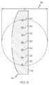
ここで、図5を参照すると、束になった部分130内の複数の光拡散光ファイバ122の束にされた詰め込み率は、複数の光拡散光ファイバ122の横断面積の合計を、複数の光拡散光ファイバ122の全ての周囲を囲む束にされた囲み直径180によって除算することによって計算されることができる。束にされた周囲を囲む直径180は、束になった部分130における複数の光拡散光ファイバ122の最小直径において評価され得る。図3に示される実施形態では、束にされた周囲を囲む直径180は、ジャケット128の内径に概ね対応する。図5に示されるように、束になった部分130内の複数の光拡散光ファイバ122は、互いに離間されるように位置されることができる。他の実施形態(図示せず)において、複数の光拡散光ファイバ122は、束になった部分130内で互いに接触してもよい。一実施形態では、照明ユニット100は、7本の光拡散光ファイバ122を含むことができ、その内の6本は、中心の光拡散光ファイバ122の周りに略配列され得る。光拡散光ファイバ122の各々は、直径が略均一であり、約150マイクロメートルから約200マイクロメートルまでの範囲内の直径を有する。光拡散光ファイバ122は、束になった部分130における束にされた周囲を囲む直径180が、約1mmから約4mmまでの範囲内にあるように配置されることができる。 Here, referring to FIG. 5, the packing ratio of the plurality of light diffusing
一例では、照明ユニット100は、7本の光拡散光ファイバ122を含むことができ、その内の6本は、中心の光拡散光ファイバ122の周りに略配列される。光拡散光ファイバ122の各々は、直径が略均一であり、約150マイクロメートルから約200マイクロメートルまでの範囲内の直径を有する。光拡散光ファイバ122は、束になった部分130における束にされた周囲を囲む直径180が、約1mmから約4mmまでの範囲内にあるように配置されることができる。他の一例では、照明ユニット100は、約2本から約50本の範囲内の複数の光拡散光ファイバ122を含むことができ、たとえば、約7本から約37本までの範囲内の光拡散光ファイバ122を含む形態や、約19本から37本までの範囲内の光拡散光ファイバ122を含む形態があり得る。幾つかの実施形態では、照明ユニット100は、隣り合う光拡散光ファイバ122同士の離間距離131が、隣り合う光拡散光ファイバ122の最大直径未満であるような、束になった部分130内に位置される複数の光拡散光ファイバ122を含むことができる。 In one example, the
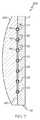
ここで、図6を参照すると、広がった部分132内に位置される複数の光拡散光ファイバ122は、支持基板140に構造的に結合される。複数の光拡散光ファイバ122を支持基板140に構造的に結合することによって、支持基板140は、光拡散光ファイバ122の位置と向きを維持する。従って、支持基板140は、光を周囲環境に提供するために光拡散光ファイバ122の位置を維持することを助ける。 Referring now to FIG. 6, a plurality of light diffusing
支持基板140は、複数の光拡散光ファイバ122のために構造的支持を提供する様々な材料から作られることができる。そのような材料の例は、例えば、制限されないが、ガラス、ガラス−セラミックス、セラミックス、結晶、プラスチック、金属、複合物、木のような天然材料、及びそれらの組合せを含む。幾つかの実施形態では、支持基板140は、所定の波長で複数の光拡散光ファイバ122によって拡散された光に対して半透明又は透明であることができ、それによって、広がった部分132において拡散された光は、周囲の環境内に投げかけられる。幾つかの実施形態では、光拡散光ファイバ122から拡散された光は、支持基板140の一つ以上の表面によって反射される。幾つかの実施形態では、光は、支持基板140内で内部反射され、それによって、支持基板140を照明し、この支持基板140が光を周囲環境に向ける。他の実施形態では、光拡散光ファイバ122から拡散された光は、支持基板140に取り付けられる少なくとも一つの反射部材141によって反射され、それによって、支持基板140を照明し且つ光を周囲環境に向ける。 The
幾つかの実施形態では、支持基板140は、全体的に剛性であり、それによって、光拡散光ファイバ122の互いに対する位置決めを維持する。そのような支持基板140は、図1に示されるように、光源によって放射される光が光源から遠くに離れた位置で周囲環境内に拡散されるように、光源から遠くの位置に取り付けられることができる。他の実施形態では、支持基板140は、支持基板140が力の印加に倣うように可撓性であってもよい。支持基板140は、支持基板が取り付けられる取付け表面に一致するように形状が変更されてもよい。 In some embodiments, the
広がった部分132内の複数の光拡散光ファイバ122の広げられた詰め込み率は、複数の光拡散光ファイバ122の横断面積の合計を、広がった部分132内の複数の光拡散光ファイバ122の全ての周囲を囲む広げられた周囲を囲む直径182によって除算することにより、計算することができる。広げられた周囲を囲む直径182は、広がった部分132における光拡散光ファイバ122の最大直径において評価され得る。図6に示されるように、広がった部分132内の複数の光拡散光ファイバ122は、互いから離間されるように位置されることができる。他の実施形態(図示せず)では、複数の光拡散光ファイバ122は、広がった部分132内で互いに接触してもよい。 The spread packing ratio of the plurality of light diffusion
幾つかの実施形態では、照明ユニット100は、約0.333未満の広げられた詰め込み率を有する広がった部分132に位置される、複数の光拡散光ファイバ122を含むことができる。幾つかの実施形態では、照明ユニット100は、約0.5よりも大きな束にされた詰め込み率を有する束になった部分130に位置される、複数の光拡散光ファイバ122を含むことができる。 In some embodiments, the
照明ユニット100の実施形態は、上で論じられたように、束になった部分130における詰め込み率に比較して、広がった部分132においてより低い詰め込み率で配置された、複数の光拡散光ファイバ122で構成されることができる。一実施形態では、広げられた詰め込み率は、束にされた詰め込み率の少なくとも7倍とされてもよく、これには、広げられた詰め込み率が束にされた詰め込み率の少なくとも19倍である場合や、広げられた詰め込み率が束にされた詰め込み率の少なくとも37倍である場合が含まれる。 An embodiment of the
ここで、図7を参照すると、複数の光拡散光ファイバ122、支持基板140、及びカバープレート250を含む、照明ユニット200の一実施形態が示されている。支持基板140及び/又はカバープレート250は、支持基板140及び/又はカバープレート250の第1の表面143内に凹設された複数の保持溝142を含むことができる。図7の実施形態は、概して、光拡散光ファイバ122の長さに沿って連続するように保持溝142を示しているが、中断する保持溝(図示せず)を有する支持基板及び/又はカバープレートの実施形態が、本開示の範囲から逸脱することなく、照明ユニットに組み込まれることができることが理解されるべきである。 Referring now to FIG. 7, one embodiment of a
図8を参照すると、複数の光拡散光ファイバ122は、夫々の保持溝142を介して支持基板140及び/又はカバープレート250に結合されることができる。幾つかの実施形態では、複数の光拡散光ファイバ122は、接着剤144で保持溝142に結合されることができる。接着剤144の例は、ポリマーベースの接着剤、光硬化性ポリマー、及びエポキシ系接着剤を含む。接着剤144は、光拡散光ファイバ122が支持基板140から分離することなく、支持基板140及び/又はカバープレート250が、様々な位置及び向きに配置されることができるように、支持基板140及び/又はカバープレート250の保持溝142に光拡散光ファイバ122を弾性的に結合できる。 Referring to FIG. 8, the plurality of light diffusing
接着材144は、光拡散光ファイバ122から支持基板140及び/又はカバープレート250への光伝送を最大にするために、光拡散光ファイバ122と支持基板140及び/又はカバープレート250とに対して屈折率整合され得る。接着剤144は、光拡散光ファイバ122の屈折率n122、又は支持基板140もしくはカバープレート250の屈折率n140の少なくとも一方と同様な、屈折率n144を有することができる。一実施形態では、接着剤144の屈折率n144は、n122<n144<n140のように、光拡散光ファイバ122の屈折率n122と支持基板140の屈折率n140との間であってもよい。The adhesive 144 is applied to the light diffusing
上で論じられたように、照明ユニット100の実施形態は、拡散光ファイバ122から支持基板140とは反対に位置されるカバープレート250を組み込むことができる。カバープレート250は、照明ユニット100によって放射される光の質を変更するために、拡散光ファイバ122から散乱される光を発散してもよいし又は集光してもよい。カバープレートの様々な実施形態は、光拡散光ファイバ122によって放射される光を変更する光整形要素80を含んでいてもよい。光整形要素80を有するカバープレートの様々な構成が照明ユニット100に組み込まれることができ、その例が図9乃至図14に示される。 As discussed above, embodiments of the
カバープレート250の実施形態は、透明、半透明、不透明、又はそれらの組合せであることができる。カバープレート250の不透明度は、カバープレート250に入る光のルーメンと、カバープレート250によって散乱される光のルーメンとを測定することによって決定されることができる。一実施形態では、カバープレート250は、カバープレート250に沿う任意の位置での不透明度が、カバープレート250に亘るメジアン不透明度の約10%以下で変化するように、略均一な不透明度を有することができる。幾つかの実施形態では、カバープレート250は、光拡散光ファイバ122から散乱される光を更にぼかす発散レンズを含むことができる。幾つかの実施形態では、カバープレート250は、光拡散光ファイバ122から散乱される光を集光する集光レンズを含むことができる。 Embodiments of the
ここで、図10を参照すると、複数のコリメーティング要素380を有するカバープレート350の一例が示されている。図10に示される実施形態では、コリメーティング要素380は、光拡散光ファイバ122から離れるように突出する向きに、カバープレート350から離れるように延在している(図9参照)。他の実施形態では、コリメーティング要素380は、カバープレート内に凹設されることができる(図示せず)。コリメーティング要素380は、特定のエンドユーザの用途に基づいて様々な向きと構成に位置されることができることが理解されるべきである。コリメーティング要素380は、光の複数の高強度領域(複数のコリメーティング要素380に対応する)が照明ユニットから周囲環境に向けられるように、光拡散光ファイバから散乱される光を狭くすることができる。コリメーティング要素380によって放射される光は、特定のエンドユーザの用途に対して適するパターンに放射されることができる。 Referring now to FIG. 10, an example of a
ここで、図11を参照すると、集光レンズ480を組み込むカバープレート450の他の一例が示されている。この実施形態では、光拡散光ファイバから散乱される光は、カバープレート450を出る光がカバープレート450から離間される位置に集束されるように、集光レンズ480によって集束されることができる。 Referring now to FIG. 11, another example of a
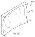
ここで、図12を参照すると、発散レンズ580を含むカバープレート550の他の一例が示されている。この実施形態では、光拡散光ファイバから散乱される光は、カバープレート550から出る光がカバープレートから離れる位置でぼかされるように、発散レンズ580によって発散されることができる。 Referring now to FIG. 12, another example of a
ここで、図13を参照すると、複数のフレネル要素680を含むカバープレート650の他の一例が示されている。フレネル要素680は、カバープレート650から出る光を集束してもよいし又はぼやかしてもよい。複数のフレネル要素680を組み込むカバープレート650は、図11及び図12に各々示されるカバープレート450及び550に対して、同様な量だけ光拡散光ファイバからの光を集光又は発散してもよい。しかしながら、複数のフレネル要素680を有するカバープレート650は、図11及び図12に示されるカバープレート450及び550よりも、より薄いプロファイルを有することができる。 Referring now to FIG. 13, another example of a
ここで、図14を参照すると、カバープレート750は、高不透明性の複数の領域780と、高不透明性の領域780に隣接する低不透明性の複数の領域782とを、含むことができる。カバープレート750の高不透明性の領域780と低不透明性の領域782は、光拡散光ファイバから散乱される光をより高い強度領域とより低い強度領域に変更できる、又は光拡散光ファイバから散乱される光の色を変更できる。加えて、カバープレート750の高不透明性の領域780と低不透明性の領域782は、カバープレート750が結合される照明ユニットの美観を向上させることができる。 Referring now to FIG. 14, the
本開示に係る照明ユニット100は、様々な製造プロセスに従って製造されることができる。ここで、図15と図16を参照すると、照明ユニット100を製造することに使用される製造装置800及び802が概略的に示されている。図示の実施形態では、照明ユニット100に組み込まれるべき複数の光拡散光ファイバ122は、供給ホイール810に個別的に配置される。光拡散光ファイバ122は、予め決定された構成に配置され且つ射出成形機820内に引き込まれることができ、そこでは、ポリマーが光拡散光ファイバ122の周りに射出される。ポリマーが冷却されると、ポリマーは固化し、それによってジャケット126を形成する。複数の光拡散光ファイバ122は、連続的に供給ホイール810から引き出されて、射出成形機820に入れられる。図示の実施形態では、ジャケット126は、複数の光拡散光ファイバ122の周りに連続的に形成され、それによって被覆されたファイバアセンブリ170を形成する。被覆されたファイバアセンブリ170は、ジャケット除去装置830内に導入され、そこでは、ジャケット126の一部が被覆されたファイバアセンブリ170の特定の領域から除去される。これらの領域におけるジャケット126を除去することによって、光拡散光ファイバ122は、ジャケット126から露出されることができ、それによって、以下で論じられるように、光拡散光ファイバ122が広がった部分内に向けられることができる。 The
ここで、図16を参照すると、ジャケット126が周りに存在する束になった部分130と、被覆されたファイバアセンブリ170からジャケットが除去されそれによって複数の光拡散光ファイバ122が露出されている部分とを含む、被覆されたファイバアセンブリ170は、次に、成形機840内に導入される。成形機は、支持基板を形成できる射出成形装置を含むことができる。被覆されたファイバアセンブリ170のジャケット126から露出された光拡散光ファイバ122の夫々の部分は、互いに対して且つ射出成形装置に対して予め決定された向きに保持されることができる。予め決定された向きに保持された光拡散光ファイバ122の露出部分では、射出成形装置は、液体プラスチック材料が光拡散光ファイバ122の一部を少なくとも部分的に包むように、液体プラスチック材料をモールド内に射出することができる。射出成形装置によって射出された液体プラスチック材料が冷えると、液体プラスチック材料が固化し、それによって、支持基板140を形成する。ジャケット126によって囲まれる束になった部分130及び支持基板140内に埋め込まれた広がった部分132に配置される光拡散光ファイバ122を含む、光拡散光ファイバアセンブリ120は、その後、射出成形装置から除去される。 Referring now to FIG. 16, the bundled
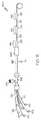
ここで、図17を参照すると、製造装置806の他の一つの実施形態に組み込まれた他の一つの製造プロセスが示されている。この実施形態では、複数の光拡散光ファイバ122は、各々が供給ホイール810上に位置される。複数の光拡散光ファイバ122は、供給ホイール810から引き出されて成形機840内に導入される。光拡散光ファイバ122は、互いに対して及び成形機840に対して予め決定された向きに保持される。光拡散光ファイバ122が予め決定された向きに保持された状態において、成形機840は、液体プラスチック材料が光拡散光ファイバ122の一部を少なくとも部分的に囲むように、液体プラスチック材料をモールド内に射出することができる。成形機840によって射出された液体プラスチック材料が冷えると、液体プラスチック材料が固化し、それによって、支持基板140を形成する。支持基板140内に位置される光拡散光ファイバ122は、光拡散光ファイバアセンブリの広がった部分132を画定する。 Referring now to FIG. 17, another manufacturing process incorporated in another embodiment of the manufacturing apparatus 806 is shown. In this embodiment, the plurality of light diffusing
支持基板140の形成に続いて、光拡散光ファイバ122の夫々の部分は、互いに対して位置決めされ、且つ射出成形機820内においてジャケット126を形成するプラスチック材料822で覆われることができる。ジャケット126によって被包される光拡散光ファイバ122の部分は、光拡散光ファイバ122の束になった部分130を画定する。 Following formation of the
製造プロセスの上記議論は、光拡散光ファイバの広がった部分の周りに支持基板を一体的に形成するための射出成形機の使用を開示しているが、特定の製造プロセスは、射出成形機無しで光拡散光ファイバを支持基板に対して位置決めし且つ取り付けることを含むことができることが、理解されるべきである。 Although the above discussion of the manufacturing process discloses the use of an injection molding machine to integrally form a support substrate around an extended portion of a light diffusing optical fiber, a specific manufacturing process is not required for an injection molding machine. It should be understood that can include positioning and attaching the light diffusing optical fiber to the support substrate.
本開示に係る照明ユニットは、光源、及び束になった部分と広がった部分とに構成される複数の光拡散光ファイバを含む光拡散光ファイバアセンブリを含むことができると理解されよう。束になった部分は、ジャケットによって囲まれる。広がった部分は、ジャケットが無い。広がった部分の光拡散光ファイバは、光拡散光ファイバの位置決めを維持する支持基板によって支持される。光源によって放射された光は、光拡散光ファイバによって捕捉され、束になった部分に沿って広がった部分に伝送され、そこでは、光は、周囲環境に散乱される。本開示に係る照明ユニットは、光源から離れた位置で光が周囲環境に送出されることを可能とする。 It will be appreciated that a lighting unit according to the present disclosure can include a light diffusing optical fiber assembly including a light source and a plurality of light diffusing optical fibers configured in a bundled portion and a spread portion. The bundled part is surrounded by a jacket. The extended part has no jacket. The spread portion of the light diffusing optical fiber is supported by a support substrate that maintains the positioning of the light diffusing optical fiber. The light emitted by the light source is captured by a light diffusing optical fiber and transmitted to a part that extends along the bundled part, where the light is scattered to the surrounding environment. The lighting unit according to the present disclosure enables light to be sent to the surrounding environment at a position away from the light source.
第1の態様に従って、本開示は、光源;ジャケットによって囲まれた束になった部分とジャケットが無い広がった部分とに構成される、複数の光拡散光ファイバを備える光拡散光ファイバアセンブリであって、前記広がった部分の前記複数の光拡散光ファイバは、前記複数の光拡散光ファイバに光結合される前記光源からの光を散乱する光拡散光ファイバアセンブリ;及び支持基板を備え;前記広がった部分の前記複数の光拡散光ファイバは、前記支持基板に構造的に結合されている、照明ユニットを提供する。 In accordance with a first aspect, the present disclosure is a light diffusing optical fiber assembly comprising a plurality of light diffusing optical fibers configured into a light source; a bundled portion surrounded by a jacket and a widened portion without the jacket. The plurality of light diffusing optical fibers of the spread portion comprises a light diffusing optical fiber assembly for scattering light from the light source optically coupled to the plurality of light diffusing optical fibers; and a support substrate; The plurality of light diffusing optical fibers in a portion provide an illumination unit that is structurally coupled to the support substrate.
第2の態様に従って、本開示は、光源;束になった部分と広がった部分とに構成される複数の光拡散光ファイバを備える光拡散光ファイバアセンブリであって、前記広がった部分の前記複数の光拡散光ファイバは、前記複数の光拡散光ファイバに光結合される前記光源からの光を散乱する光拡散光ファイバアセンブリ;及び支持基板を備え;前記広がった部分内の前記複数の光拡散光ファイバの少なくとも一部は、前記支持基板内に埋め込まれている、照明ユニットを提供する。 In accordance with a second aspect, the present disclosure provides a light diffusing optical fiber assembly comprising a plurality of light diffusing optical fibers configured in a light source; a bundled portion and a spread portion, wherein the plurality of the spread portions. A light diffusing optical fiber comprising: a light diffusing optical fiber assembly that scatters light from the light source that is optically coupled to the plurality of light diffusing optical fibers; and a support substrate; At least a portion of the optical fiber provides an illumination unit embedded in the support substrate.
第3の態様に従って、本開示は、光源;及び束になった部分と広がった部分とに構成される複数の光拡散光ファイバを備える光拡散光ファイバアセンブリであって、前記広がった部分の前記複数の光拡散光ファイバは、前記複数の光拡散光ファイバに光結合される前記光源からの光を散乱する光拡散光ファイバアセンブリを備え;前記広がった部分の前記光拡散光ファイバを囲む広がった囲み径の面積に対して、光拡散光ファイバの集合的な面積を比較する、前記広がった囲み径において評価される広がった詰め込み率は、前記束になった部分の前記光拡散光ファイバを囲む束になった囲み径の面積に対して、前記光拡散光ファイバの集合的面積を比較する、前記束になった径において評価される束になった詰め込み率よりも大きい、照明ユニットを提供する。 In accordance with a third aspect, the present disclosure provides a light diffusing optical fiber assembly comprising a light source; and a plurality of light diffusing optical fibers configured in a bundled portion and a spread portion, wherein the light spread optical fiber assembly includes: A plurality of light diffusing optical fibers comprising a light diffusing optical fiber assembly that scatters light from the light source optically coupled to the plurality of light diffusing optical fibers; Comparing the collective area of the light diffusing optical fiber against the area of the surrounding diameter, the expanded packing rate evaluated at the expanded surrounding diameter surrounds the light diffusing optical fiber in the bundled portion. The collective area of the light diffusing optical fibers is compared with the area of the bundled enclosure diameter, and the illumination unit is larger than the bundled packing rate evaluated at the bundled diameter. To provide a Tsu door.
第4の態様に従って、本開示は、前記広がった部分内の前記複数の光拡散光ファイバが、前記支持基板内に埋め込まれている前記第1乃至第3の態様の前記照明ユニットを提供する。 According to a fourth aspect, the present disclosure provides the illumination unit of the first to third aspects, wherein the plurality of light diffusing optical fibers in the spread portion are embedded in the support substrate.
第5の態様に従って、本開示は、前記光拡散光ファイバが、前記支持基板の屈折率と前記光拡散光ファイバの屈折率との間の屈折率を有する屈折率整合材料を含む接着剤で、前記支持基板に接着されている前記第4の態様の前記照明ユニットを提供する。 According to a fifth aspect, the present disclosure is an adhesive, wherein the light diffusing optical fiber includes a refractive index matching material having a refractive index between the refractive index of the support substrate and the refractive index of the light diffusing optical fiber, The lighting unit according to the fourth aspect is bonded to the support substrate.
第6の態様に従って、本開示は、前記支持基板が、第1の表面に凹設された複数の保持溝を備え、前記光拡散光ファイバの少なくとも一部は、前記保持溝に結合されている前記第1乃至第5の態様の前記照明ユニットを提供する。 According to a sixth aspect, in the present disclosure, the support substrate includes a plurality of holding grooves recessed in the first surface, and at least a part of the light diffusion optical fiber is coupled to the holding grooves. The lighting unit according to the first to fifth aspects is provided.
第7の態様に従って、本開示は、前記支持基板が、前記支持基板内で前記複数の光拡散光ファイバによって内部的に散乱された光を反射する、反射表面を備える前記第1乃至第6の態様の前記照明ユニットを提供する。 According to a seventh aspect, the present disclosure provides the first to sixth aspects, wherein the support substrate includes a reflective surface that reflects light scattered internally by the plurality of light diffusing optical fibers in the support substrate. An illumination unit of the aspect is provided.
第8の態様に従って、本開示は、前記光拡散光ファイバアセンブリの前記広がった部分から見て前記支持基板の反対側に位置される、カバープレートを更に備える前記第1乃至第7の態様の前記照明ユニットを提供する。 According to an eighth aspect, the present disclosure relates to the first to seventh aspects, further comprising a cover plate positioned on the opposite side of the support substrate from the widened portion of the light diffusing optical fiber assembly. Provide a lighting unit.
第9の態様に従って、本開示は、光整形要素を更に備える前記第1乃至第8の態様の前記照明ユニットを提供する。 According to a ninth aspect, the present disclosure provides the illumination unit of the first to eighth aspects further comprising a light shaping element.
第10の態様に従って、本開示は、前記光整形要素が、コリメーティング要素を備える前記第9の態様の前記照明ユニットを提供する。 According to a tenth aspect, the present disclosure provides the illumination unit of the ninth aspect, wherein the light shaping element comprises a collimating element.
第11の態様に従って、本開示は、前記光整形要素が、発散レンズを含む前記第9の態様の前記照明ユニットを提供する。 According to an eleventh aspect, the present disclosure provides the illumination unit of the ninth aspect, wherein the light shaping element includes a diverging lens.
第12の態様に従って、本開示は、前記光整形要素が、集光レンズを含む前記第9の態様の前記照明ユニットを提供する。 According to a twelfth aspect, the present disclosure provides the illumination unit of the ninth aspect, wherein the light shaping element includes a condenser lens.
第13の態様に従って、本開示は、前記光整形要素が、拡散レンズを含む前記第9の態様の前記照明ユニットを提供する。 According to a thirteenth aspect, the present disclosure provides the illumination unit of the ninth aspect, wherein the light shaping element includes a diffusing lens.
第14の態様に従って、本開示は、前記光整形要素が、低不透明度の領域に近接する高不透明度の領域を有するカバープレートを備える、前記第9の態様の前記照明ユニットを提供する。 According to a fourteenth aspect, the present disclosure provides the lighting unit of the ninth aspect, wherein the light shaping element comprises a cover plate having a high opacity region proximate to a low opacity region.
第15の態様に従って、本開示は、前記支持基板が、該当する波長範囲で前記光拡散光ファイバから散乱される光に対して透過性である材料を含む、前記第1乃至第14の態様の前記照明ユニットを提供する。 According to a fifteenth aspect, the present disclosure relates to the first to fourteenth aspects, wherein the support substrate includes a material that is transmissive to light scattered from the light-diffusing optical fiber in a corresponding wavelength range. The lighting unit is provided.
第16の態様に従って、本開示は、前記支持基板が、前記支持基板の屈折率とは異なる屈折率を有する光変更材料を含む、前記第1乃至第15の態様の前記照明ユニットを提供する。 According to a sixteenth aspect, the present disclosure provides the illumination unit according to the first to fifteenth aspects, wherein the support substrate includes a light changing material having a refractive index different from a refractive index of the support substrate.
第17の態様に従って、本開示は、前記支持基板が、前記光拡散光ファイバから散乱される光を前記支持基板に対して内部反射する光変更材料を含む、前記第1乃至第16の態様の前記照明ユニットを提供する。 According to a seventeenth aspect, the present disclosure relates to the first to sixteenth aspects, in which the support substrate includes a light changing material that internally reflects light scattered from the light diffusing optical fiber to the support substrate. The lighting unit is provided.
第18の態様に従って、本開示は、前記広げられた詰め込み率が、前記束にされた詰め込み率の少なくとも7倍である前記第1乃至第17の態様の前記照明ユニットを提供する。 According to an eighteenth aspect, the present disclosure provides the lighting unit of the first to seventeenth aspects, wherein the spread stuffing rate is at least seven times the bundled stuffing rate.
第19の態様に従って、本開示は、前記広げられた詰め込み率が、0.333未満である前記第1乃至第18の態様の前記照明ユニットを提供する。 According to a nineteenth aspect, the present disclosure provides the lighting unit according to any one of the first to eighteenth aspects, wherein the spread stuffing rate is less than 0.333.
第20の態様に従って、本開示は、前記束にされた詰め込み率が、0.5を越える前記第1乃至第19の態様の前記照明ユニットを提供する。 According to a twentieth aspect, the present disclosure provides the lighting unit according to the first to nineteenth aspects, wherein the bundled packing rate exceeds 0.5.
第21の態様に従って、本開示は、前記束になった部分の隣り合う光拡散光ファイバ同士の離間距離が、前記隣り合う光拡散光ファイバの最大直径未満である前記第1乃至第20の態様の前記照明ユニットを提供する。 According to a twenty-first aspect, the present disclosure provides the first to twentieth aspects, wherein a distance between adjacent light diffusion optical fibers in the bundled portion is less than a maximum diameter of the adjacent light diffusion optical fibers. The lighting unit is provided.
第22の態様に従って、本開示は、支持基板を更に備え、前記広がった部分内の前記光拡散光ファイバの一部が、前記支持基板に埋め込まれている前記第1乃至第21の態様の前記照明ユニットを提供する。 According to a twenty-second aspect, the present disclosure further includes a support substrate, and a part of the light diffusing optical fiber in the spread portion is embedded in the support substrate, according to the first to twenty-first aspects. Provide a lighting unit.
用語「実質的に」は、本明細書では、任意の量の比較、値、測定、又は他の表現に与えられ得る内在的な不確実度合いを表すために利用されることができる。この用語はまた、量的表現が、本主題の基本的機能における変化をもたらすことなく、述べられた基準から変化し得る度合いを表すために利用される。 The term “substantially” can be used herein to denote an inherent degree of uncertainty that can be given to any amount of comparison, value, measurement, or other representation. The term is also used to describe the degree to which a quantitative expression can vary from the stated criteria without causing a change in the basic function of the present subject matter.
本明細書では、特定の実施形態が示され且つ記述されたが、様々な他の変化及び変更が請求項の主題の精神と範囲から逸脱することなく行われ得ることが理解されるべきである。更に、請求項の主題の様々な態様が本明細書で記述されたが、そのような態様は、組合せで利用される必要はない。従って、添付の請求項は、請求項の主題の範囲内にあるそのような変化と変更の全てをカバーすることが意図されている。 Although specific embodiments have been shown and described herein, it should be understood that various other changes and modifications can be made without departing from the spirit and scope of the claimed subject matter. . Moreover, although various aspects of the claimed subject matter have been described herein, such aspects need not be utilized in combination. Accordingly, the appended claims are intended to cover all such changes and modifications that are within the scope of the claimed subject matter.
100 照明ユニット
110 光源
120 光拡散光ファイバアセンブリ
122 光拡散光ファイバ
123 光拡散光ファイバの端部
126 ジャケット
130 束になった部分
132 広がった部分
140 支持基板
142 保持溝
143 第1の表面
150 中心コア領域
152 外側コア領域
150CS 中央コアセクション
150C 中央透明領域
154 ボイド
150V 環状ボイド領域
156 クラディング領域
160 光散乱層
170 被覆されたファイバアセンブリ
180 束にされた周囲を囲む直径
250、350、450、550、650、750 カバープレート
342 スキン
800、802 製造装置
810 供給ホイール
822 プラスチック材料
840 成形機100 lighting unit
DESCRIPTION OF
Claims (10)
Translated fromJapaneseジャケットによって囲まれた束になった部分と、前記ジャケットが無い広がった部分とに構成された、複数の光拡散光ファイバを備える光拡散光ファイバアセンブリであって、前記広がった部分の前記複数の光拡散光ファイバは、前記複数の光拡散光ファイバに光結合される前記光源からの光を散乱する、光拡散光ファイバアセンブリ;及び
支持基板;
を備える照明ユニットであって、
前記広がった部分の前記複数の光拡散光ファイバは、前記支持基板に構造的に結合されている照明ユニット。light source;
A light diffusing optical fiber assembly comprising a plurality of light diffusing optical fibers configured in a bundled portion surrounded by a jacket and a widened portion without the jacket, wherein A light diffusing optical fiber that scatters light from the light source optically coupled to the plurality of light diffusing optical fibers; and a support substrate;
A lighting unit comprising:
The plurality of light diffusing optical fibers in the spread portion are structurally coupled to the support substrate.
(i)第1の表面に凹設された複数の保持溝であって、前記光拡散光ファイバの少なくとも一部が該保持溝に結合された複数の保持溝;及び/又は
(ii)前記複数の光拡散光ファイバによって散乱される光を、前記支持基板内で内部反射する反射表面、
を備える請求項1に記載の照明ユニット。The support substrate is
(I) a plurality of holding grooves recessed in the first surface, wherein at least a part of the light diffusion optical fiber is coupled to the holding grooves; and / or (ii) the plurality of holding grooves. A reflective surface that internally reflects light scattered by the light diffusing optical fiber within the support substrate;
The lighting unit according to claim 1, comprising:
束になった部分及び広がった部分に構成された複数の光拡散光ファイバを備える光拡散光ファイバアセンブリであって、前記広がった部分の前記複数の光拡散光ファイバは、前記複数の光拡散光ファイバに光結合される前記光源からの光を散乱する、光拡散光ファイバアセンブリ;及び
支持基板;
を備える照明ユニットであって、
前記広がった部分内の前記複数の光拡散光ファイバの少なくとも一部は、前記支持基板内に埋め込まれている照明ユニット。light source;
A light diffusing optical fiber assembly comprising a plurality of light diffusing optical fibers configured in a bundled portion and a widened portion, wherein the plurality of light diffusing optical fibers in the widened portion includes the plurality of light diffusing lights. A light diffusing optical fiber assembly that scatters light from the light source optically coupled to a fiber; and a support substrate;
A lighting unit comprising:
An illumination unit in which at least a part of the plurality of light diffusion optical fibers in the spread portion is embedded in the support substrate.
(i)光整形要素;
(ii)前記支持基板の屈折率とは異なる屈折率を有する光変更材料;
(iii)前記光拡散光ファイバから散乱された光を前記支持基板に内部反射する光変更材料;
の内の少なくとも一つを備える請求項1、2、3、4、又は6に記載の照明ユニット。The support substrate is
(I) a light shaping element;
(Ii) a light changing material having a refractive index different from the refractive index of the support substrate;
(Iii) a light changing material that internally reflects light scattered from the light diffusing optical fiber to the support substrate;
The illumination unit according to claim 1, 2, 3, 4, or 6, comprising at least one of the following.
束になった部分及び広がった部分に構成された複数の光拡散光ファイバを備える光拡散光ファイバアセンブリであって、前記広がった部分の前記複数の光拡散光ファイバは、前記複数の光拡散光ファイバに光結合される前記光源からの光を散乱する、光拡散光ファイバアセンブリ;
備える照明ユニットであって;
前記広がった部分の前記光拡散光ファイバを囲む広がった囲み径の面積に対して、前記光拡散光ファイバの集合的な面積を比較する、前記広がった囲み径において評価される広がった詰め込み率は、前記束になった部分の前記光拡散光ファイバを囲む束になった囲み径の面積に対して、前記光拡散光ファイバの前記集合的な面積を比較する、前記束になった径において評価される束になった詰め込み率よりも大きい、照明ユニット。A light diffusing optical fiber assembly comprising: a light source; and a plurality of light diffusing optical fibers configured in a bundled portion and a widened portion, wherein the plurality of light diffusing optical fibers in the widened portion include the plurality of light diffusing optical fibers. A light diffusing optical fiber assembly that scatters light from the light source optically coupled to a light diffusing optical fiber;
A lighting unit comprising:
Comparing the collective area of the light diffusing optical fiber against the area of the expanded wrap diameter surrounding the light diffusing optical fiber in the expanded portion, the expanded packing ratio evaluated at the expanded wrap diameter is And comparing the collective area of the light diffusing optical fiber against the area of the bundled diameter surrounding the light diffusing optical fiber of the bundled portion, and evaluating the bundled diameter A lighting unit that is larger than the bundled packing rate.
(ii)前記広がった詰め込み率は、0.333未満である;もしくは、前記束になった詰め込み率は、0.5を越える;及び/又は
(iii)前記束になった部分内の隣り合う光拡散光ファイバ同士の離間距離は、前記隣り合う光拡散光ファイバの最大直径未満である;
請求項9に記載の照明ユニット。(I) the spread stuffing rate is at least 7 times the bundled stuffing rate; and / or (ii) the spread stuffing rate is less than 0.333; or the bundle. And / or (iii) the distance between adjacent light diffusing optical fibers in the bundled portion is less than the maximum diameter of the adjacent light diffusing optical fibers. ;
The lighting unit according to claim 9.
Applications Claiming Priority (3)
| Application Number | Priority Date | Filing Date | Title |
|---|---|---|---|
| US14/012,013US8998471B2 (en) | 2013-08-28 | 2013-08-28 | Lighting units having light-diffusing optical fiber |
| US14/012,013 | 2013-08-28 | ||
| PCT/US2014/053037WO2015031551A1 (en) | 2013-08-28 | 2014-08-28 | Lighting units having light-diffusing optical fiber |
Publications (1)
| Publication Number | Publication Date |
|---|---|
| JP2016534517Atrue JP2016534517A (en) | 2016-11-04 |
Family
ID=51493116
Family Applications (1)
| Application Number | Title | Priority Date | Filing Date |
|---|---|---|---|
| JP2016537833APendingJP2016534517A (en) | 2013-08-28 | 2014-08-28 | Illumination unit having light diffusing optical fiber |
Country Status (5)
| Country | Link |
|---|---|
| US (1) | US8998471B2 (en) |
| EP (1) | EP3039464A1 (en) |
| JP (1) | JP2016534517A (en) |
| CN (1) | CN105683792A (en) |
| WO (1) | WO2015031551A1 (en) |
Families Citing this family (17)
| Publication number | Priority date | Publication date | Assignee | Title |
|---|---|---|---|---|
| JP6228110B2 (en) | 2011-04-28 | 2017-11-08 | エル イー エス エス・リミテッド | Waveguide device for illumination system |
| WO2015008211A1 (en) | 2013-07-15 | 2015-01-22 | Tissot Yann | Coherent light waveguide illumination system with speckle noise reducer |
| WO2015056220A1 (en) | 2013-10-18 | 2015-04-23 | Tissot Yann | Holder and systems for waveguide-based illumination |
| CN106287579A (en)* | 2015-05-26 | 2017-01-04 | 鸿富锦精密工业(深圳)有限公司 | Slim light guide unit and backlight module |
| CN108291183A (en)* | 2015-11-20 | 2018-07-17 | 康宁股份有限公司 | Illumination container for biological entities growth |
| JP6642136B2 (en) | 2016-03-09 | 2020-02-05 | トヨタ紡織株式会社 | Lighting equipment |
| JP6811584B2 (en)* | 2016-10-28 | 2021-01-13 | 林テレンプ株式会社 | Lighting equipment and vehicle parts equipped with the lighting equipment |
| WO2018191220A1 (en) | 2017-04-11 | 2018-10-18 | Corning Incorporated | Illumination systems for light diffusing optical fibers |
| CN109061797B (en)* | 2017-06-13 | 2020-03-27 | 京东方科技集团股份有限公司 | Light guide structure, display device and viewing angle adjustment method |
| CN109425923A (en)* | 2017-06-26 | 2019-03-05 | 嘉兴海拉灯具有限公司 | A kind of light guide with beam-splitting structure and the car light with the light guide |
| US10222022B2 (en)* | 2017-07-06 | 2019-03-05 | Valeo North America, Inc. | Covered fiber bundle for lighting modules |
| CN108107643B (en)* | 2017-12-14 | 2021-02-12 | 中国水产科学研究院南海水产研究所 | Marine fish real-time image monitoring and statistics system |
| US10620356B1 (en)* | 2018-10-03 | 2020-04-14 | Valeo North America, Inc. | Fiber optic panel having extended abrasion |
| US12369660B2 (en)* | 2020-01-22 | 2025-07-29 | Opnago B.V. | Garment assembly for the transmission of external light |
| WO2021157150A1 (en)* | 2020-02-07 | 2021-08-12 | 株式会社フジクラ | Optical fiber pitch conversion jig, optical connector, pitch conversion code, optical conversion box, and pitch conversion method for optical fiber |
| US11550092B1 (en)* | 2022-01-28 | 2023-01-10 | The Boeing Company | System and method for extracting light using fibers |
| US11614608B1 (en) | 2022-01-28 | 2023-03-28 | The Boeing Company | System and method for extracting light using monochromatic aberration-corrected lenses |
Citations (6)
| Publication number | Priority date | Publication date | Assignee | Title |
|---|---|---|---|---|
| JPH07301712A (en)* | 1994-04-28 | 1995-11-14 | Japan Storage Battery Co Ltd | Surface light emitting element |
| JPH0862433A (en)* | 1994-08-23 | 1996-03-08 | Kyocera Corp | Optical fiber alignment |
| JP2003187607A (en)* | 2001-12-21 | 2003-07-04 | Keiji Iimura | Plane light source using optical fiber |
| US20080025039A1 (en)* | 2006-07-20 | 2008-01-31 | Int America, Llc | Fiber optic auxilliary lighting system |
| US20090003013A1 (en)* | 2007-06-28 | 2009-01-01 | Kumho Electric, Inc. | Overspeed prevention structure using plastic optical fiber |
| JP2013511749A (en)* | 2009-11-20 | 2013-04-04 | コーニング インコーポレイテッド | Illumination system with side-emitting photonic optical fiber and method for manufacturing the same |
Family Cites Families (17)
| Publication number | Priority date | Publication date | Assignee | Title |
|---|---|---|---|---|
| GB2046466B (en) | 1979-01-24 | 1983-02-16 | Bicc Ltd | Joining optical fibres using magnifier |
| US4885663A (en) | 1988-03-22 | 1989-12-05 | Lumitex, Inc. | Fiber optic light emitting panel and method of making same |
| US6846098B2 (en) | 2002-05-16 | 2005-01-25 | Eastman Kodak Company | Light diffuser with variable diffusion |
| US6874925B2 (en)* | 2003-03-06 | 2005-04-05 | Lumitex, Inc. | Fiber optic light panel assemblies and method of manufacture |
| JP2007505337A (en)* | 2003-09-08 | 2007-03-08 | コニンクリユケ フィリップス エレクトロニクス エヌ.ブイ. | Light guide system having a plurality of light transmitting rods |
| EP2067067A1 (en)* | 2006-09-19 | 2009-06-10 | Prismaflex International | Illuminating textile web, conversion process, and luminous device comprising a plurality of illuminating regions |
| US20080180971A1 (en) | 2007-01-26 | 2008-07-31 | Carl Stephen Booth | Illumination fiber optic ribbon |
| US20090010019A1 (en)* | 2007-05-16 | 2009-01-08 | Ashoff Richard D | Method and apparatus for illuminating tile |
| WO2009034737A1 (en) | 2007-09-14 | 2009-03-19 | Sharp Kabushiki Kaisha | Optical member, display illuminating device, display and television receiver |
| US7654717B2 (en)* | 2007-09-27 | 2010-02-02 | Michael Trujillo | Fiber optically illuminated surface |
| US20090122560A1 (en) | 2007-11-08 | 2009-05-14 | Bingham Craig E | LED Mat Light |
| JP5480822B2 (en)* | 2008-02-14 | 2014-04-23 | ショット アクチエンゲゼルシャフト | Side radiating step index fiber |
| DE102008034791B4 (en) | 2008-07-25 | 2022-01-20 | Schott Ag | Preforms and processes for the production of side-emitting step-index fibers |
| WO2010011299A2 (en)* | 2008-07-25 | 2010-01-28 | Corning Incorporated | Nanostructured optical fiber illumination systems and methods for biological applications |
| US8724942B2 (en) | 2011-04-26 | 2014-05-13 | Corning Incorporated | Light-coupling optical systems and methods employing light-diffusing optical fiber |
| FR2979412B1 (en) | 2011-08-23 | 2017-05-05 | Faurecia Interieur Ind | LIGHTING DEVICE COMPRISING OPTICAL FIBERS, INTERIOR TRIM AND VEHICLE COMPRISING SUCH A LIGHTING DEVICE |
| WO2013095981A1 (en) | 2011-12-19 | 2013-06-27 | Corning Incorporated | Uniform uv efficient light diffusing fiber |
- 2013
- 2013-08-28USUS14/012,013patent/US8998471B2/ennot_activeExpired - Fee Related
- 2014
- 2014-08-28WOPCT/US2014/053037patent/WO2015031551A1/enactiveApplication Filing
- 2014-08-28CNCN201480059007.9Apatent/CN105683792A/enactivePending
- 2014-08-28EPEP14761543.9Apatent/EP3039464A1/ennot_activeWithdrawn
- 2014-08-28JPJP2016537833Apatent/JP2016534517A/enactivePending
Patent Citations (6)
| Publication number | Priority date | Publication date | Assignee | Title |
|---|---|---|---|---|
| JPH07301712A (en)* | 1994-04-28 | 1995-11-14 | Japan Storage Battery Co Ltd | Surface light emitting element |
| JPH0862433A (en)* | 1994-08-23 | 1996-03-08 | Kyocera Corp | Optical fiber alignment |
| JP2003187607A (en)* | 2001-12-21 | 2003-07-04 | Keiji Iimura | Plane light source using optical fiber |
| US20080025039A1 (en)* | 2006-07-20 | 2008-01-31 | Int America, Llc | Fiber optic auxilliary lighting system |
| US20090003013A1 (en)* | 2007-06-28 | 2009-01-01 | Kumho Electric, Inc. | Overspeed prevention structure using plastic optical fiber |
| JP2013511749A (en)* | 2009-11-20 | 2013-04-04 | コーニング インコーポレイテッド | Illumination system with side-emitting photonic optical fiber and method for manufacturing the same |
Also Published As
| Publication number | Publication date |
|---|---|
| CN105683792A (en) | 2016-06-15 |
| EP3039464A1 (en) | 2016-07-06 |
| US8998471B2 (en) | 2015-04-07 |
| US20150062956A1 (en) | 2015-03-05 |
| WO2015031551A1 (en) | 2015-03-05 |
Similar Documents
| Publication | Publication Date | Title |
|---|---|---|
| JP2016534517A (en) | Illumination unit having light diffusing optical fiber | |
| US9534766B2 (en) | Lighting units having light-diffusing optical fiber | |
| KR101857776B1 (en) | Light source with leds, light guide and reflector | |
| JP5734204B2 (en) | Optical element and light source having the optical element | |
| KR101839417B1 (en) | Light source with leds, light guide and reflector | |
| JP6450686B2 (en) | Light diffusing optical fiber bundle, illumination system including light diffusing optical fiber bundle, and method for attaching light diffusing optical fiber bundle to polymer optical fiber | |
| JP5888999B2 (en) | Lighting device | |
| US20170052305A1 (en) | Light Guide Illumination Device With Light Divergence Modifier | |
| US9442241B2 (en) | Optics for illumination devices | |
| KR20110134512A (en) | Light emitting devices and lighting fixtures | |
| JP2012514844A5 (en) | ||
| JP5340385B2 (en) | Luminous equipment | |
| US10649126B2 (en) | Holder and systems for waveguide-based illumination | |
| JP6890287B2 (en) | lighting equipment | |
| JP2016524309A5 (en) | ||
| US20140355292A1 (en) | Fiber Optic Filament Lamp | |
| JP6339092B2 (en) | Luminous arrangement using light guide | |
| JP6486926B2 (en) | Light emitting device | |
| TWM455137U (en) | Luminous device | |
| JP5119379B2 (en) | Surface illumination light source device and surface illumination device | |
| JP2012089367A (en) | Led lighting device, led lighting fixture and lens for led lighting device | |
| JP6188611B2 (en) | Lighting device | |
| JPWO2012141029A1 (en) | Lens and lighting device | |
| KR101389979B1 (en) | Led lamp | |
| TW201541020A (en) | Lighting fixture |
Legal Events
| Date | Code | Title | Description |
|---|---|---|---|
| A621 | Written request for application examination | Free format text:JAPANESE INTERMEDIATE CODE: A621 Effective date:20170825 | |
| A521 | Request for written amendment filed | Free format text:JAPANESE INTERMEDIATE CODE: A523 Effective date:20171012 | |
| A977 | Report on retrieval | Free format text:JAPANESE INTERMEDIATE CODE: A971007 Effective date:20180612 | |
| A131 | Notification of reasons for refusal | Free format text:JAPANESE INTERMEDIATE CODE: A131 Effective date:20180619 | |
| A521 | Request for written amendment filed | Free format text:JAPANESE INTERMEDIATE CODE: A523 Effective date:20180919 | |
| A131 | Notification of reasons for refusal | Free format text:JAPANESE INTERMEDIATE CODE: A131 Effective date:20190306 | |
| A601 | Written request for extension of time | Free format text:JAPANESE INTERMEDIATE CODE: A601 Effective date:20190604 | |
| A601 | Written request for extension of time | Free format text:JAPANESE INTERMEDIATE CODE: A601 Effective date:20190806 | |
| A521 | Request for written amendment filed | Free format text:JAPANESE INTERMEDIATE CODE: A523 Effective date:20190905 | |
| A02 | Decision of refusal | Free format text:JAPANESE INTERMEDIATE CODE: A02 Effective date:20200226 |