JP2016531722A - Devices and methods for treating mitral regurgitation - Google Patents
Devices and methods for treating mitral regurgitationDownload PDFInfo
- Publication number
- JP2016531722A JP2016531722AJP2016546888AJP2016546888AJP2016531722AJP 2016531722 AJP2016531722 AJP 2016531722AJP 2016546888 AJP2016546888 AJP 2016546888AJP 2016546888 AJP2016546888 AJP 2016546888AJP 2016531722 AJP2016531722 AJP 2016531722A
- Authority
- JP
- Japan
- Prior art keywords
- atrial
- ridge
- annulus
- mitral valve
- leaflet
- Prior art date
- Legal status (The legal status is an assumption and is not a legal conclusion. Google has not performed a legal analysis and makes no representation as to the accuracy of the status listed.)
- Granted
Links
Images


Classifications
- A—HUMAN NECESSITIES
- A61—MEDICAL OR VETERINARY SCIENCE; HYGIENE
- A61F—FILTERS IMPLANTABLE INTO BLOOD VESSELS; PROSTHESES; DEVICES PROVIDING PATENCY TO, OR PREVENTING COLLAPSING OF, TUBULAR STRUCTURES OF THE BODY, e.g. STENTS; ORTHOPAEDIC, NURSING OR CONTRACEPTIVE DEVICES; FOMENTATION; TREATMENT OR PROTECTION OF EYES OR EARS; BANDAGES, DRESSINGS OR ABSORBENT PADS; FIRST-AID KITS
- A61F2/00—Filters implantable into blood vessels; Prostheses, i.e. artificial substitutes or replacements for parts of the body; Appliances for connecting them with the body; Devices providing patency to, or preventing collapsing of, tubular structures of the body, e.g. stents
- A61F2/02—Prostheses implantable into the body
- A61F2/24—Heart valves ; Vascular valves, e.g. venous valves; Heart implants, e.g. passive devices for improving the function of the native valve or the heart muscle; Transmyocardial revascularisation [TMR] devices; Valves implantable in the body
- A61F2/2412—Heart valves ; Vascular valves, e.g. venous valves; Heart implants, e.g. passive devices for improving the function of the native valve or the heart muscle; Transmyocardial revascularisation [TMR] devices; Valves implantable in the body with soft flexible valve members, e.g. tissue valves shaped like natural valves
- A61F2/2418—Scaffolds therefor, e.g. support stents
- A—HUMAN NECESSITIES
- A61—MEDICAL OR VETERINARY SCIENCE; HYGIENE
- A61F—FILTERS IMPLANTABLE INTO BLOOD VESSELS; PROSTHESES; DEVICES PROVIDING PATENCY TO, OR PREVENTING COLLAPSING OF, TUBULAR STRUCTURES OF THE BODY, e.g. STENTS; ORTHOPAEDIC, NURSING OR CONTRACEPTIVE DEVICES; FOMENTATION; TREATMENT OR PROTECTION OF EYES OR EARS; BANDAGES, DRESSINGS OR ABSORBENT PADS; FIRST-AID KITS
- A61F2/00—Filters implantable into blood vessels; Prostheses, i.e. artificial substitutes or replacements for parts of the body; Appliances for connecting them with the body; Devices providing patency to, or preventing collapsing of, tubular structures of the body, e.g. stents
- A61F2/02—Prostheses implantable into the body
- A61F2/24—Heart valves ; Vascular valves, e.g. venous valves; Heart implants, e.g. passive devices for improving the function of the native valve or the heart muscle; Transmyocardial revascularisation [TMR] devices; Valves implantable in the body
- A61F2/2409—Support rings therefor, e.g. for connecting valves to tissue
- A—HUMAN NECESSITIES
- A61—MEDICAL OR VETERINARY SCIENCE; HYGIENE
- A61F—FILTERS IMPLANTABLE INTO BLOOD VESSELS; PROSTHESES; DEVICES PROVIDING PATENCY TO, OR PREVENTING COLLAPSING OF, TUBULAR STRUCTURES OF THE BODY, e.g. STENTS; ORTHOPAEDIC, NURSING OR CONTRACEPTIVE DEVICES; FOMENTATION; TREATMENT OR PROTECTION OF EYES OR EARS; BANDAGES, DRESSINGS OR ABSORBENT PADS; FIRST-AID KITS
- A61F2210/00—Particular material properties of prostheses classified in groups A61F2/00 - A61F2/26 or A61F2/82 or A61F9/00 or A61F11/00 or subgroups thereof
- A61F2210/0014—Particular material properties of prostheses classified in groups A61F2/00 - A61F2/26 or A61F2/82 or A61F9/00 or A61F11/00 or subgroups thereof using shape memory or superelastic materials, e.g. nitinol
- A—HUMAN NECESSITIES
- A61—MEDICAL OR VETERINARY SCIENCE; HYGIENE
- A61F—FILTERS IMPLANTABLE INTO BLOOD VESSELS; PROSTHESES; DEVICES PROVIDING PATENCY TO, OR PREVENTING COLLAPSING OF, TUBULAR STRUCTURES OF THE BODY, e.g. STENTS; ORTHOPAEDIC, NURSING OR CONTRACEPTIVE DEVICES; FOMENTATION; TREATMENT OR PROTECTION OF EYES OR EARS; BANDAGES, DRESSINGS OR ABSORBENT PADS; FIRST-AID KITS
- A61F2230/00—Geometry of prostheses classified in groups A61F2/00 - A61F2/26 or A61F2/82 or A61F9/00 or A61F11/00 or subgroups thereof
- A61F2230/0002—Two-dimensional shapes, e.g. cross-sections
- A61F2230/0028—Shapes in the form of latin or greek characters
- A61F2230/005—Rosette-shaped, e.g. star-shaped
- A—HUMAN NECESSITIES
- A61—MEDICAL OR VETERINARY SCIENCE; HYGIENE
- A61F—FILTERS IMPLANTABLE INTO BLOOD VESSELS; PROSTHESES; DEVICES PROVIDING PATENCY TO, OR PREVENTING COLLAPSING OF, TUBULAR STRUCTURES OF THE BODY, e.g. STENTS; ORTHOPAEDIC, NURSING OR CONTRACEPTIVE DEVICES; FOMENTATION; TREATMENT OR PROTECTION OF EYES OR EARS; BANDAGES, DRESSINGS OR ABSORBENT PADS; FIRST-AID KITS
- A61F2230/00—Geometry of prostheses classified in groups A61F2/00 - A61F2/26 or A61F2/82 or A61F9/00 or A61F11/00 or subgroups thereof
- A61F2230/0063—Three-dimensional shapes
- A61F2230/0073—Quadric-shaped
- A61F2230/0078—Quadric-shaped hyperboloidal
Landscapes
- Health & Medical Sciences (AREA)
- Engineering & Computer Science (AREA)
- Biomedical Technology (AREA)
- Cardiology (AREA)
- Oral & Maxillofacial Surgery (AREA)
- Transplantation (AREA)
- Heart & Thoracic Surgery (AREA)
- Vascular Medicine (AREA)
- Life Sciences & Earth Sciences (AREA)
- Animal Behavior & Ethology (AREA)
- General Health & Medical Sciences (AREA)
- Public Health (AREA)
- Veterinary Medicine (AREA)
- Prostheses (AREA)
Abstract
Translated fromJapaneseDescription
Translated fromJapanese関連出願
本出願は、2014年7月14日に出願された米国特許仮出願第62/024,097号、2014年1月15日に出願された米国特許仮出願第61/927,490号、および2013年10月5日に出願された米国特許仮出願第61/887,343号の関連出願である。本出願は、2014年5月16日に出願された米国特許出願第14/279,511号の一部継続出願であり、その全開示内容は参照によって本明細書に完全に記載されているものとして、本明細書に組み込まれる。
技術分野
本発明は、一般に人の僧帽弁機能の修復および/または再建に有用な医療機器および方法に関する。特に、本発明は、生来の心臓弁の機能を置換することによって僧帽弁逆流症を処置するのに使用することができる医療機器に関する。Related Applications This application includes US Provisional Patent Application No. 62 / 024,097 filed on July 14, 2014, US Provisional Patent Application No. 61 / 927,490 filed on January 15, 2014, And a related application of US Provisional Patent Application No. 61 / 887,343, filed October 5, 2013. This application is a continuation-in-part of US patent application Ser. No. 14 / 279,511, filed May 16, 2014, the entire disclosure of which is fully incorporated herein by reference. As incorporated herein.
TECHNICAL FIELD The present invention relates generally to medical devices and methods useful for the repair and / or reconstruction of human mitral valve function. In particular, the present invention relates to a medical device that can be used to treat mitral regurgitation by replacing the function of the native heart valve.
人の心臓は、4つの室および4つの弁を有する。心臓弁は、血流の方向を制御する。完全に機能する心臓弁は、適切な血液循環が心周期の間、維持されることを確保する。心臓弁の逆流または漏出は、心臓弁の弁尖が疾病、たとえば先天性の腱索断裂、腱索伸長、拡大左心室、損傷した乳頭筋、感染により損傷した弁構造、退行変性過程、弁尖の石灰化、弁輪の延伸、増加した乳頭筋間距離等が原因で、完全に接触(接合)しない場合に生じる。 The human heart has four chambers and four valves. The heart valve controls the direction of blood flow. A fully functioning heart valve ensures that proper blood circulation is maintained during the cardiac cycle. Heart valve regurgitation or leakage is caused by a disease in the valve leaflet, such as congenital rupture of the chordae, extension of the chordae, enlarged left ventricle, damaged papillary muscle, valve structure damaged by infection, degenerative process, valve leaflet Occurs when it does not contact (join) completely due to calcification of the annulus, extension of the annulus, increased papillary muscle distance, etc.
原因がなんであれ、逆流症は、血液が誤った方向に弁を通って逆流することを可能にするので、心臓の機能を妨げる。逆流症の程度に応じて、この逆流は心臓の機能だけでなく心臓の形状にも自己破壊的な影響を与えることがある。あるいは、異常な心臓形状は、逆流症の原因にもなることがあり、これらの2つの過程は、「協同して」心臓機能の異常を速めることがある。心臓逆流症の直接の結果は、前方心拍出量の減少である。漏出の深刻さに応じて、他の身体各部に適切な血流を送り込む心臓の有効性が、危険にさらされることがある。 Whatever the cause, reflux disease prevents the heart from functioning because it allows blood to flow back through the valve in the wrong direction. Depending on the degree of reflux disease, this reflux can have a self-destructive effect not only on heart function but also on heart shape. Alternatively, an abnormal heart shape can also cause reflux disease, and these two processes can “cooperate” to speed up abnormal heart function. The direct result of cardiac reflux is a decrease in anterior cardiac output. Depending on the severity of the leak, the effectiveness of the heart to deliver proper blood flow to other parts of the body can be compromised.
僧帽弁は、心臓の中の左心房(LA)と左心室(LV)との間にある2葉の(2尖の)弁である。心臓拡張期の間、正常に機能する僧帽弁は、左心房が血液で膨らむと左心房からの増加した圧力(前負荷)の結果として開く。左心房の圧力が左心室の圧力よりも高くなると、僧帽弁が開き、血液の左心室への受動的流れを促進する。心臓拡張期は心房収縮で終了し、心房収縮は血液の残部を排出し、それは左心房から左心室に移動する。僧帽弁は心房収縮の最後に閉じて、左心室から左心房への血流の逆行を防ぐ。人の僧帽弁は、典型的には開口面積が4〜6cm2である。2つの弁尖、すなわち前尖および後尖があり、これらは僧帽弁の開口部を覆う。僧帽弁の開口部は、僧帽弁弁輪と呼ばれる線維輪で囲まれている。2つの弁尖は僧帽弁弁輪の円周上に取り付けられており、心周期の間、この弁輪から蝶番によって開閉することができる。正常に機能する僧帽弁では、弁尖は腱索によって左心室内の乳頭筋に結合している。左心室が収縮すると、心室内圧が僧帽弁を閉じさせ、その間、腱索が2つの弁尖の接合を保持し(2つの弁尖が左心房内に逸脱し僧帽弁逆流症が生じるのを防ぎ)、僧帽弁が誤った方向に開くのを防ぐ(それによって、血液が左心房内に逆流するのを防ぐ)。The mitral valve is a bilobal (bicuspid) valve between the left atrium (LA) and the left ventricle (LV) in the heart. During diastole, a normally functioning mitral valve opens as a result of increased pressure (preload) from the left atrium when the left atrium inflates with blood. When the left atrial pressure becomes higher than the left ventricular pressure, the mitral valve opens, facilitating passive flow of blood into the left ventricle. The diastole ends with an atrial contraction that drains the rest of the blood, which travels from the left atrium to the left ventricle. The mitral valve closes at the end of the atrial contraction to prevent retrograde blood flow from the left ventricle to the left atrium. A human mitral valve typically has an open area of 4-6 cm2 . There are two leaflets, an anterior leaflet and a posterior leaflet, which cover the mitral valve opening. The opening of the mitral valve is surrounded by an annulus called a mitral valve annulus. Two leaflets are mounted on the circumference of the mitral valve annulus and can be opened and closed by hinges from this annulus during the cardiac cycle. In a normally functioning mitral valve, the leaflet is connected to the papillary muscle in the left ventricle by a chord. When the left ventricle contracts, intraventricular pressure causes the mitral valve to close, while the chords hold the junction of the two leaflets (the two leaflets escape into the left atrium and cause mitral regurgitation) And prevent the mitral valve from opening in the wrong direction (thus preventing blood from flowing back into the left atrium).
現在、標準的な心臓弁逆流症の処置の選択肢として、外科的修復/処置および血管内クリップ留めが挙げられる。標準的な外科的修復または置換の手順は、心臓切開手術、心肺バイパスの使用および心臓停止を必要とする。外科的手順の侵襲的性質の故に、死亡の危険性、脳卒中、出血、呼吸困難、腎障害およびその他の合併症が、多くの患者を外科的処置から排除するほどに顕著に見られる。 Currently, standard cardiac regurgitation treatment options include surgical repair / treatment and endovascular clipping. Standard surgical repair or replacement procedures require open heart surgery, use of cardiopulmonary bypass and cardiac arrest. Due to the invasive nature of surgical procedures, death risks, stroke, bleeding, dyspnea, kidney damage and other complications are so prominent that many patients are excluded from surgical procedures.
近年、血管内クリップ留め技術がいくつかのデバイス会社によって開発されている。この方法では、生体適合性材料からつくられたインプラント可能なクリップが心臓弁内の2つの弁尖間に挿入されて、2つの弁尖の中央部(主にA2およびP2弁尖)を一緒にクリップ留めして弁尖の逸脱を防止する。しかしながら、いくつかの欠点、たとえば位置決めの困難、誤ってインプラントされたときの除去の困難、心臓弁逆流症の再発、1つの処置に複数のクリップが必要なこと、患者の厳格な選択等が、血管内クリップ留め術の実際の適用において明らかになった。 In recent years, endovascular clipping techniques have been developed by several device companies. In this method, an implantable clip made of a biocompatible material is inserted between two leaflets in a heart valve so that the central parts of the two leaflets (mainly A2 and P2 leaflets) together Clip to prevent valve leaflet deviation. However, some drawbacks such as positioning difficulties, removal when mis-implanted, recurrence of heart valve reflux disease, the need for multiple clips for one procedure, strict patient selection, etc. It became clear in the actual application of endovascular clipping.
結論として、僧帽弁逆流症を処置するための新規な医療機器を開発する大きい必要性が存在する。これまでに存在する医療機器のいずれもこの必要性に十分には対処していない。本発明は、外傷性外科的手順を回避することができ、代わりにカテーテルに基づく、より侵襲性の低い手順によってインプラントされることができる医療機器を提供する、僧帽弁逆流症の処置のためのデバイスおよび方法を医師に提供することを目的とする。 In conclusion, there is a great need to develop new medical devices for treating mitral regurgitation. None of the medical devices that exist so far address this need adequately. The present invention is for the treatment of mitral regurgitation that provides a medical device that can avoid traumatic surgical procedures and can instead be implanted by catheter-based, less invasive procedures. It is an object of the present invention to provide doctors with devices and methods.
本発明の目的は、生来の組織に穴を開けることなく人の僧帽弁弁輪の位置に有効に固定されることができる僧帽弁置換デバイスを提供することである。 It is an object of the present invention to provide a mitral valve replacement device that can be effectively secured to the position of a human mitral valve annulus without puncturing the native tissue.
本発明の別の目的は、人の僧帽弁弁輪の位置に僧帽弁置換デバイスを展開させる方法であって、該デバイスの最終開放が完了する前に該デバイスの位置が調節されることができる方法を提供することである。 Another object of the present invention is a method of deploying a mitral valve replacement device at the position of a person's mitral valve annulus, wherein the position of the device is adjusted before the final opening of the device is completed. Is to provide a way to do this.
本発明のさらに別の目的は、より効率的な弁の制御および流れを提供する新規な弁尖構造を提供することである。 Yet another object of the present invention is to provide a novel leaflet structure that provides more efficient valve control and flow.
本発明の目的を達成するために、本発明は、人の心臓の僧帽弁の位置に配置されるように適合化された僧帽弁置換デバイスを提供する。このデバイスは、該デバイスの心房端を画定する心房突縁と、該デバイスの心室端を画定する心室部分であって2mm〜15mmの範囲の高さを有する心室部分と、心房突縁と心室部分との間に位置する弁輪支持体と、を有する。弁輪支持体は、弁輪支持体から半径方向状に延在するアンカーの輪を含み、環状のクリップ留めするスペースが心房突縁とアンカーの輪との間に画定される。このデバイスはさらに、心房突縁の心房端に位置する複数の弁尖保持具と、弁尖保持具に固定され、生来の弁輪の上の位置で前記心房突縁の内側に配置された複数の弁尖と、を有する。 To achieve the objects of the present invention, the present invention provides a mitral valve replacement device adapted to be placed at the position of a mitral valve in a human heart. The device includes an atrial apex that defines an atrial end of the device, a ventricular portion that defines a ventricular end of the device, the ventricular portion having a height ranging from 2 mm to 15 mm, an atrial prosthesis and a ventricular portion And an annulus support located between the two. The annulus support includes a ring of anchors extending radially from the annulus support, and an annular clip space is defined between the atrial ridge and the anchor ring. The device further includes a plurality of leaflet holders positioned at the atrial end of the atrial ridge, and a plurality of leaflet holders fixed to the valve leaflet holder and disposed inside the atrial ridge at a position above the native annulus. And a leaflet of the same.
以下の詳細な記載は、本発明を実施するための、現在意図されているベストモードに係るものである。この記載は、限定された意味で解釈されてはならず、単に本発明の実施形態の一般的原理を例示する目的でなされている。本発明の範囲は、添付された特許請求の範囲によって最も良く定義される。 The following detailed description relates to the best mode currently contemplated for carrying out the present invention. This description should not be construed in a limiting sense, but merely as an illustration of the general principles of embodiments of the invention. The scope of the invention is best defined by the appended claims.
本発明の主題技術は全般に、僧帽弁逆流症処置デバイスに、および該デバイスを人の心臓の中に位置決めし固定する様式に関する。このデバイスは、心房部分および心室部分を含んでいる。このデバイスの心房部分は、僧帽弁弁輪のエリアに「据えられ」、本デバイスを取り囲むエリアからの漏出(左心室から左心房への血液の逆流)を防ぐための「シール」を形成する。本デバイスの心室部分は、弁本体および固定化要素を含む。固定化要素は、織物または組織によって部分的にもしくは全体が覆われて、漏出を防ぐ「シール」を形成することができる。弁本体は、組織弁尖および弁尖支持構造を含む。正常な心周期の間、弁および弁尖は開閉して、左心房と左心室との間の血流の方向および量を制御する。固定化要素の機能は、本デバイスの適切な位置を維持して心臓周期の間の潜在的な移動を防ぐことである。固定化要素は、生来の弁尖および/または弁輪および/または他の弁下構造と相互作用することによる固定効果を提供する。固定化要素の一つの構造は、生体適合性接着剤/膠を使用し、本デバイスと生来の弁および/または心臓構造との間に結合を形成して、人工弁の位置を維持することである。 The subject technology generally relates to a mitral regurgitation device and to the manner in which the device is positioned and secured within a human heart. The device includes an atrial portion and a ventricular portion. The atrial portion of the device is “placed” in the area of the mitral valve annulus and forms a “seal” to prevent leakage from the area surrounding the device (backflow of blood from the left ventricle to the left atrium) . The ventricular portion of the device includes a valve body and an immobilization element. The anchoring element can be partially or wholly covered by the fabric or tissue to form a “seal” that prevents leakage. The valve body includes a tissue leaflet and a leaflet support structure. During the normal cardiac cycle, the valves and leaflets open and close to control the direction and amount of blood flow between the left atrium and the left ventricle. The function of the immobilization element is to maintain the proper position of the device to prevent potential movement during the cardiac cycle. The fixation element provides a fixation effect by interacting with the native leaflets and / or annulus and / or other subvalvular structures. One structure of the anchoring element is to use a biocompatible adhesive / glue to form a bond between the device and the native valve and / or heart structure to maintain the position of the prosthetic valve. is there.
使用の際には、本デバイスは経カテーテル法を使用して僧帽弁のスペースに送達され、内部弁構造および弁下の構造と相互作用して、僧帽弁の機能を回復する。さらに、このデバイスは、外科的または他の最小限に侵襲性の手順によってインプラントされることができる。本デバイスは心臓または人の脈管構造の内腔の内部にインプラントされることができ、これは生来の僧帽弁弁尖および僧帽弁の機能を改善し、置換しおよび/または再建するのに役立つ。 In use, the device is delivered to the mitral valve space using transcatheter techniques and interacts with the internal and subvalve structures to restore mitral valve function. In addition, the device can be implanted surgically or by other minimally invasive procedures. The device can be implanted inside the lumen of the heart or human vasculature, which improves, replaces and / or reconstructs the function of the native mitral valve leaflet and mitral valve To help.
本発明は、また生来の弁尖、および/または弁輪、および/または他の弁輪下構造を利用する固定化要素(クリップ構造)を含み、心周期の間本デバイスを適所に保持する固定効果を提供する。本デバイスが僧帽弁の位置に配置されると、デバイス上の固定化要素は、生来の弁尖、および/または弁輪、および/または他の弁下構造と係合し/相互作用して、デバイスが心周期の間移動するのを防止する。デバイスの心房部分は、弁輪およびデバイスの心房の部分に接している弁輪の上の心臓の心房部分と相互作用することによって、いくらかの追加の固定効果を提供することができる。 The present invention also includes an anchoring element (clip structure) that utilizes the native leaflets and / or annulus and / or other sub-annular structures to secure the device in place during the cardiac cycle. Providing an effect. When the device is placed in the position of the mitral valve, the anchoring element on the device engages / interacts with the native leaflets and / or annulus and / or other subvalvular structures. Prevent the device from moving during the cardiac cycle. The atrial portion of the device can provide some additional fixation effect by interacting with the annulus of the heart over the annulus and the annulus that is in contact with the atrial portion of the device.
本発明は、さらに新規な弁尖構造を提供する。この弁尖の立体構造は1〜6個の弁尖を含むことができ、これは弁尖支持構造の内側に綴じ合わされ、心周期の間、開閉することができる雨傘形状の外形を形成して、血流を制御することができる。心収縮(心臓の収縮)の間、雨傘形状の弁尖は、より大きい外形へと開き、左心室から左心房へ戻る血流がないように僧帽弁を閉じることができる。心臓拡張(心臓の弛緩)の間、雨傘形状の弁尖は、より小さい外形へと閉じ、左心房から左心室へ血液が流れることができるように僧帽弁を開くことができる。この新規な弁尖構造の利点は以下のものを含む:(i)心周期の間、弁尖による弁尖支持構造の軸方向の収縮/絞りがなく、それによって該支持構造の耐疲労性が改善されること、(ii)弁尖と支持構造上のスカートとの間の、より良好な弁尖の接合によって中央の漏出の可能性が最小になること、および(iii)弁尖の中央の部分に「自由端がない」こと。複数の弁尖の間に接合は生じない。この特徴は重要である。というのは、弁支持構造の何らかの変形またはねじれは最低限の中央漏出をもたらしてしまうからである。 The present invention further provides a novel leaflet structure. The leaflet three-dimensional structure can include 1 to 6 leaflets, which are bound inside the leaflet support structure to form an umbrella-shaped outer shape that can be opened and closed during the cardiac cycle. Can control blood flow. During cardiac contraction (heart contraction), the umbrella-shaped leaflets open to a larger profile and can close the mitral valve so that there is no blood flow back from the left ventricle to the left atrium. During diastole (heart relaxation), the umbrella-shaped leaflet closes to a smaller profile and can open the mitral valve so that blood can flow from the left atrium to the left ventricle. The advantages of this novel leaflet structure include: (i) There is no axial contraction / restriction of the leaflet support structure by the leaflet during the cardiac cycle, thereby reducing the fatigue resistance of the support structure. Improved, (ii) a better joint of the leaflets between the leaflets and the skirt on the support structure minimizes the possibility of central leakage, and (iii) the middle of the leaflets “There is no free end” in the part. There is no joint between the leaflets. This feature is important. This is because any deformation or twisting of the valve support structure will result in minimal central leakage.
本発明の僧帽弁置換デバイスは、小さい外形に圧縮され送達システムに載せられ、次に非侵襲性の医療手順、たとえば経心尖または経大腿または経中隔手順による送達カテーテルの使用によって標的位置に送達されることができる。僧帽弁置換デバイスは、それが標的インプラント場所に到着し、(バルーンで拡張可能な支持構造の場合の)バルーンの膨張によって、あるいは該デバイスに格納された(自己拡張可能な支持構造を備えたデバイスの場合の)弾性エネルギーによって、その正常な(拡張された)外形に拡張することができる状態になると、送達システムから解放されることができる。 The mitral valve replacement device of the present invention can be compressed to a small profile and placed on a delivery system, and then brought to a target location by use of a delivery catheter with a non-invasive medical procedure, such as a transapical or transfemoral or transseptal procedure. Can be delivered. The mitral valve replacement device comprises a self-expandable support structure that arrives at the target implant location, either by inflation of the balloon (in the case of a balloon expandable support structure) or stored in the device When the elastic energy (in the case of a device) is ready to expand to its normal (expanded) profile, it can be released from the delivery system.
本発明の僧帽弁置換デバイスの弁尖は、処理済の動物組織/心膜から、薄肉の生体適合性金属元素(たとえば、ステンレス鋼、Co−Cr系合金、ニチノール、Ta、Ti等)から、または生体適合性ポリマー材料(たとえば、ポリイソプレン、ポリブタジエンおよびこれらのコポリマー、ネオプレンおよびニトリルゴム、ポリウレタンエラストマー、シリコーンゴム、フルオロエラストマーおよびフルオロシリコーンゴム、ポリエステルならびにPTFE等)からつくられることができる。弁尖は、薬剤または生物剤を施されて、性能が改善され、血栓の形成を防ぎ、および内皮化を促進することもできる。僧帽弁デバイスの弁尖は、表面層/コーティングで処理されるか、またはこれらを施されて、石灰化を防ぐことができる。必要に応じて、弁本体および弁尖支持構造のカバーは、織物と組織との組み合わされた層であることもできる。たとえば、カバーの上部は織物からつくられることができ、他方、下部は組織からつくられることができ、またはその逆でもよい。デバイスの心房部分および弁尖支持構造の本体は、完全にまたは部分的に織物もしくは組織で覆われて、改善された密閉効果および治癒効果を提供することができる。デバイスに設けられた固定化要素は、完全にまたは部分的に織物もしくは組織で覆われて、組織成長を促進し、弁周囲漏出(PVL)を防ぎ、および周囲の心臓内部構造への潜在的な損傷を低減することができる。 The leaflet of the mitral valve replacement device of the present invention is made from a processed animal tissue / pericardium, from a thin-walled biocompatible metal element (eg, stainless steel, Co—Cr alloy, nitinol, Ta, Ti, etc.). Or made from biocompatible polymer materials such as polyisoprene, polybutadiene and copolymers thereof, neoprene and nitrile rubber, polyurethane elastomer, silicone rubber, fluoroelastomer and fluorosilicone rubber, polyester and PTFE and the like. The leaflets can also be given drugs or biologics to improve performance, prevent thrombus formation, and promote endothelialization. The leaflets of the mitral valve device can be treated with or applied with a surface layer / coating to prevent calcification. If desired, the cover of the valve body and leaflet support structure can be a combined layer of fabric and tissue. For example, the upper part of the cover can be made from fabric, while the lower part can be made from tissue, or vice versa. The atrial portion of the device and the body of the leaflet support structure can be completely or partially covered with fabric or tissue to provide improved sealing and healing effects. Immobilization elements provided on the device are completely or partially covered with fabric or tissue to promote tissue growth, prevent peri-valvular leakage (PVL), and potential to the surrounding heart internal structures Damage can be reduced.
弁尖は、機械的な織り交ぜ、縫合、および化学的、物理的または接着剤による接合の方法によって弁尖支持構造に一体化されることができる。弁尖は、支持構造の要素から形成されることもできる。たとえば、弁尖支持構造および弁尖は一緒に、ポリマー材料または金属材料から直接成型され、形成されることができる。弁尖は、2種以上の材料を一緒に結合するための、蒸着、スパッタリング、リフロー、薬浴、成型、押出のプロセスまたは他の機構によって形成されることもできる。 The leaflets can be integrated into the leaflet support structure by mechanical interweaving, stitching, and chemical, physical or adhesive bonding methods. The leaflets can also be formed from elements of the support structure. For example, the leaflet support structure and the leaflet can be molded and formed directly from a polymeric material or a metallic material together. The leaflets can also be formed by vapor deposition, sputtering, reflow, chemical bath, molding, extrusion processes or other mechanisms for bonding two or more materials together.
組織弁尖は、薬剤または他の生物剤でコーティングされて、心臓内での血栓の形成を防ぐこともできる。抗石灰化材料が、その表面の上にコーティングされまたは付与されて、石灰化を防ぐこともできる。 Tissue leaflets can also be coated with drugs or other biological agents to prevent thrombus formation in the heart. An anti-calcification material can also be coated or applied on the surface to prevent calcification.
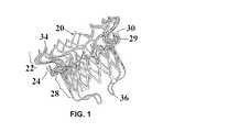
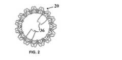
図1〜5は、本発明による僧帽弁デバイス20の第1の実施形態を示す。デバイス20は、心房突縁22、弁輪支持体24、心房突縁22を弁輪支持体24に接続するネック26、および弁尖支持構造として機能する弁本体28を有する。これらの要素のそれぞれはストラットによって画定され、ストラットはセルを画定し、次にセルがセル状マトリクスを構成する。 1-5 show a first embodiment of a
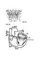
心房突縁22、弁輪支持体24および弁本体28は、ニチノール超弾性材料か、またはステンレス鋼、Co−Cr系合金、チタンおよびその合金ならびに他のバルーン膨張可能な生体適合性材料のいずれかからつくられることができる。他のポリマー生体適合性材料が使用されて、デバイス20のこれらの要素が製作されることもできる。使用に際しては、デバイス20は、送達システム内に折り畳まれまたは圧縮され、経カテーテル送達(たとえば、経大腿または経中隔)によって僧帽弁の位置に送達されることができる。僧帽弁の場所に着くと、デバイス20は送達システムから解放され、僧帽弁弁輪エリアに配置されることができる。心房突縁22は、僧帽弁の生来の弁輪の位置にまたはその上に、心房突縁22の一部が左心房の内部に延在して配置されることができる。図5Bを参照せよ。心房突縁22は、僧帽弁弁輪面積に等しいかまたはそれより大きい表面積を有する。使用に際しては、心房突縁22は生体適合性ポリマー織物、組織または他の生体適合性材料によって覆われて、デバイス20の周りの密閉効果を提供し、かつ組織の成長を促進し治癒効果を速めることができる。 The
弁輪支持体24は固定化要素として機能し、弁輪、生来の弁尖および他の心臓内部構造、弁下構造と相互作用して、所望の固定結果を提供することができる。図5Bを参照せよ。弁輪支持体24によって提供される固定効果に加えて、心房突縁22と弁輪支持体24とによって形成される「クリップ留め効果」もまた、デバイス20が位置を自己調整し、また心周期の間の潜在的な移動に抗するのを支援することができる。送達システムからデバイス20が開放される際に、デバイス20の諸要素は、送達システムから順番に開放されることになる。たとえば、経心尖送達の際には、心房突縁22は、送達システムから最初に展開され、次に弁輪支持体24が展開される。対照的に、経大腿(経中隔)送達の際には、弁輪支持体24が最初に展開され、次に心房突縁22が展開される。これらの手順は、X線、TEE、ICE等によるガイダンスに従って実施されることができる。 The annulus support 24 functions as an immobilization element and can interact with the annulus, native leaflets and other internal heart structures, subvalvular structures to provide the desired fixation results. See FIG. 5B. In addition to the locking effect provided by the annulus support 24, the “clip effect” formed by the
図4および5Aは、デバイス20の各要素の典型的な寸法または形状の範囲を示す。心房突縁22は円形の外形を有するか、あるいは完全な円とは異なる外形を有することができる。心房突縁22が円形の外形を有する場合には、その心房部分の直径は20mm〜70mmの範囲であることができる。心房突縁22が完全な円とは異なる外形を有する場合には、その長軸は20〜70mmの範囲であることができ、短軸は15〜65mmの範囲であることができる。さらに、心房突縁22の高さH1は0.5mm〜20mmの範囲であることができる。心房突縁22の上部心房端において、心房突縁22を画定する各セルは頂部および谷部を有し、それらの各頂部に丸みを帯びた非外傷性の端部34を有する。 4 and 5A show typical size or shape ranges for each element of the
弁本体28の軸に対する心房突縁22の角度Θ1は、0〜150度の範囲であることができる。心房突縁22は、完全に、あるいは部分的に織物材料もしくは組織材料、または組織材料と織物材料との組み合わせによって覆われることができる。心房突縁22は心房の床に面する側面に鉤状毛またはスパイクを有して、心房の組織および/または弁輪と係合するのを助けることができる。弁本体28は2mm〜30mmの範囲にある高さH3を有することができる。心房側に近い方の弁本体28の端部は、心房突縁22より高くそれよりも延在して、心室の内部にある弁本体28の長さを低減することができる。弁本体28の断面形状は、完全な円であるか、あるいは円形状とは異なる外形であることができる。弁本体28が完全な円の外形を有する場合には、その直径は15mm〜50mmの範囲であることができる。弁本体28が円形とは異なる外形を有する場合には、その長軸は15〜50mmの範囲であることができ、短軸は10〜45mmの範囲であることができる。弁本体28は、その高さに沿って変化する外形を有することもできる。たとえば、心房突縁22の近くの弁本体28の部分は、長円形状の外形、または完全な円とは異なる別の何らかの外形を有することができる。その一方で、心房突縁22から遠くに離れている弁本体28の部分は、完全な円の外形を有することができる。組織弁尖は、弁本体28内にその円形の部分内に完全に一体化されるか、あるいはその円形および非円形の部分の両方を包含して一体化されることができる。 The angle Θ1 of the
弁本体28は、織物材料もしくは組織材料または組織材料と織物材料との組み合わせによって、完全に、あるいは部分的に覆われることができる。たとえば、弁本体28の上方の部分は織物によって覆われることができ、弁本体28の下方の部分は組織によって覆われることができ、またはその逆であることもできる。使用に際しては、織物材料および組織は、弁本体28に最初に一緒に縫合され/結合されるか、あるいは個々に縫合され/結合されることができる。弁本体28は、1つの表面(すなわち、内表面または外表面)を、あるいは両方の表面(すなわち、内表面および外表面)を覆われることができる。弁本体28の底端では、弁本体28を画定する各セルは頂部および谷部を有し、それらの各底部には丸みを帯びた非外傷性の端部38を有する。 The
任意的な、より小さい直径のネック26は、心房突縁22から弁輪支持体24への移行をもたらす。デバイス20が展開された立体構造にあるときは、ネック26は心房突縁22から半径方向内側に向かって延在して、U字形のネック26を形成する。ネック26の断面形状は、完全な円形か、あるいは円形とは異なる形状であることができる。ネック26が完全な円形の外形を有する場合には、その直径は15mm〜50mmの範囲であることができる。ネック26が円形とは異なる外形を有する場合には、その長軸は15mm〜50mmの範囲であることができ、短軸は10mm〜45mmの範囲であることができる。 An optional,
ネック26は次に、半径方向外側に向かって弁輪支持体24へと移行し、弁輪支持体24は、間隔を置いて配置された逆V字形のタブ30の輪と交互に入れ替わるU字形区画29の輪を含む。ネック26は、実際には半径方向外側に向かってU字形区画29の輪に移行し、U字形区画29の輪は半径方向外側に向かって延在し、次に半径方向内側に向かって延在して、弁本体28に移行する。タブ30は、弁本体28から半径方向外側に向かって延在し、該して垂直上向きのベンドを有してネック26を取り囲む輪を画定する。タブ30の個数は1〜20の範囲である。タブ30の輪の断面の外形は、完全な円形か、あるいは円形とは異なる外形であることができる。タブ30の輪が完全な円形の外形を有する場合には、その直径は15mm〜70mmの範囲であることができる。タブ30の輪が円形とは異なる外形を有する場合には、その長軸は15mm〜70mmの範囲であることができ、短軸は10mm〜65mmの範囲であることができる。 The
タブ30の逆V形の結合点は、拡大された点32であり、その機能は心臓の僧帽弁部位の弁輪または生来の弁尖に接触しまたはそれ自体を押し付けて弁輪エリアにおいてデバイス20を固定すること、つまり固定化要素として機能することである。各タブ30は、0.5mm〜10mmの範囲にある高さH4を有する。タブ30は、組織または織物によって完全に、あるいは部分的に覆われることができる。たとえば、拡大された点32は織物/組織から露出していることができ、他方、弁輪支持体24の残りの部分は織物/組織によって覆われることができる。織物の使用は、組織の成長を促進させ、また弁輪におけるデバイス20のより良好な固定をもたらし、さらに加えて弁周囲漏出(PVL)を防ぐ付加的な密閉効果を与えることができる。 The inverted V-shaped connection point of
このように、U字形区画29の輪は、弁本体28およびネック26の直径より大きいが、心房突縁22の直径より小さい直径を有する。同様に、タブ30の輪は、弁本体28およびネック26の直径より大きいが、心房突縁22の直径より小さい直径を有する。タブ30およびU字形区画29は、同じ大まかな輪の中で交互に並ぶように配置されることができ、互いにほぼ同じ直径を有することができる。 Thus, the ring of
2個のU字形尾部36が、弁本体28の端において弁本体28から延在することができる。尾部36が2個示されているけれども、1個のみの尾部36または3個以上の尾部36を備えたデバイス20を提供することも可能である。図5Aに最もよく示されているように、各尾部36は、弁本体28の2個の底部先端38から延在することによって形成されてU字形の底部となるように連結され、縫合糸または他の糸がそこに繋がれることが可能となるように使用されることができ、それによって、デバイス20が展開されている間、その縫合糸または糸はデバイス20の位置を調節するために使用されることができる。尾部36はまた、送達システム中のいくつかの要素と繋がれて、(1)弁の搭載(すなわち、送達システムの鞘の中に弁を搭載すること)および(2)心臓の弁輪部位に弁の位置を合わせることを支援することもできる。弁の位置合わせに関しては、展開の際に送達システムからデバイス20が最終的に放出される前に、尾部36はデバイス20の位置および/または角度の調節を助ける。 Two
尾部36を有することの他の利点は、送達システムからデバイス20が完全に展開され開放される前に、デバイス20は通常既に(部分的にまたは完全に)機能し始めているので、尾部36があると、デバイス20が送達システムから最終的に分離される前に医師がデバイス20の位置を調節しそれをそこに吊り下げるためのより多くの時間的余裕が与えられるということである。各尾部36の長さは5mm〜25mmの範囲であることができる。尾部36は、所望であれば弁本体28によって画定される円形の外形の外に延在することができるように、該尾部は形状設定されて、ある形状のベンドとされることができる。たとえば、尾部36は弁本体28の遠位端から吊り下げられ、弁本体28の内腔に向かって内側に曲げられることができる。 Another advantage of having a
図5Bを参照すると、デバイス20が生来の僧帽弁部位の位置で使用されるように展開されると、タブ30が展開され、弁輪のところに/弁輪の上に「据わり」、心房突縁22の一部は左心房の内側に延在する。心房突縁22(による上から)およびタブ30(による下から)のこの相互作用は、「クリップ留め効果」をもたらし、これはデバイス20を所望の位置に固定するのに有効である。デバイス20が展開されると、U字形区画29は弁輪の直ぐ下の位置に配置されて、追加の密閉効果を与えることができる。心房内のストラット/セルのスペースは、織物および/もしくは組織によって完全にもしくは部分的に覆われる、または覆われないことができる。部分的に覆われたまたは全く覆われていない手筈をされた心房突縁22を心房の内側に配備することによって、順方向の血流に対する妨げを最小にすることができる。デバイス20の組織弁尖48は、弁本体28に一体化されて、生来の僧帽弁の弁尖の機能を置き換える。図7Aおよび7Bに示されるように、生来の弁尖は、弁本体28に隣接してその外側表面に配置される。 Referring to FIG. 5B, when the
図6A、6Bは、デバイス20の典型的なレーザーカットされた形態を示す。デバイス20は、金属またはポリマーのチューブからレーザーカットされて、図6Aに示された形態にされることができる。カットされた構造は次に、図1〜5Bに示されたように、形状設定、マイクロブラスト加工および電解研磨の各工程を経て、所望の外形/形状を得ることになる。各ストラット50の幅は0.2mm〜1.5mmの範囲であることができ、各ストラット50の厚さは0.2mm〜0.75mmの範囲であることができる。各セルの長さは2mm〜20mmの範囲であることができる。デバイス20の長さに沿った輪の数は、2〜20の範囲であることができる。デバイス20の外周に沿ったセルの数は、2〜20の範囲であることができる。選択肢として、デバイス20は平らなシートから製作され、次に所望の形状にロール圧延されることもできる。 6A and 6B show a typical laser cut form of the
デバイス20は2つ以上の送達方法によって送達されることができる。たとえば、経心尖送達が使用されることができ、その場合には心房突縁22が最初に展開されることができ、送達手順の間、経心尖送達は触覚フィードバックを提供することができる。弁輪支持体24(すなわち、タブ30)が最後に開放され展開されて、デバイス20のインプラントが完了する。経大腿/経中隔送達の際には、タブ30が最初に展開され、送達手順の間、触覚フィードバックを提供することができる。心房突縁22が最後に開放され展開されて、デバイス20のインプラントが完了する。送達の間、タブ30は、弁本体28に向かって内側に(上向き内側にあるいは下向き内側に)曲げられることができる。タブ30が開放され/展開されると、これは拡張し、弁輪または生来の弁尖にそれ自体を押し付けることができる。
使用に際しては、デバイス20は、容易な送達のためにより小さい外形へ圧縮されることができ、それが標的インプラント部位に到達すると、送達され展開されることができる。圧縮されたデバイスの外形は48Fr(15.8mm)未満であることができ、15Fr〜40Fr(5.0mm〜13.2mm)がこのような用途において典型的な範囲である。 In use,
図7Aは、組み立てられた僧帽弁置換デバイスの上面図を示し、これは上記のように僧帽弁デバイス20に取り込まれた弁尖48を含む。図7Bは、図7Aの組み立て体の底面図を示す。図7Aおよび7Bは、左心室から左心房への血流が防止されるように開かれた態勢にある弁尖48を示す。接合エリアは、弁尖48とスカートとの間にあり、該スカートは弁本体28内においてデバイス20の内腔に沿ってデバイス20によって画定される。同様に、図8Aおよび8Bは、図7Aおよび7Bの組み立てられた僧帽弁デバイスのそれぞれ上面図および底面図であり、これらは、左心房から左心室へ血液が流れることができるように閉じられた位置にある弁尖48を示す。図7A〜8Bおよび同様に図9A〜11に最もよく示されるように、本発明はさらに新規な弁尖の立体構造を提供する。弁尖48は、弁尖48が内側に向かって開き外側に拡張して弁本体28の内表面と接触することによって閉じるように、生来の弁尖の立体構造とは本質的に逆となる立体構造を有する。弁尖48は、該弁尖が自由に内側に閉じることを可能にして弁デバイスを通る順方向の血流を可能にする様式で、デバイス20に取り付けられている。組織弁尖の高さ〈深さ〉は、心臓の解剖学的大きさに応じて2〜30mmの範囲で様々であることができる。 FIG. 7A shows a top view of the assembled mitral valve replacement device, which includes the
弁尖の構造は図7A〜11に最もよく示されており、この実施形態は、3個の長手方向の縫合部、すなわち縫合線72、74および76に沿って一緒に縫合された3個の弁尖48A、48Bおよび48Cの使用を示す。縫合線72、74、76は、弁尖48A、48Bおよび48Cの外側端に沿って延在し、また弁尖構造が弁本体28に取り付けられる結合線を形成する。弁尖48A、48Bおよび48Cは、それらの端に沿って弁本体28を構成するストラット50に縫合される。弁尖48A、48Bおよび48Cの上(心房)端には、半径方向の縫合部、すなわち縫合線82、84および86が、それぞれ長手方向の縫合線72、74および76から中心点88に向かって伸びており、中心点88には平らな先端60が配置されている。3個の内部縫合部、すなわち縫合線52、54および56が頂点58から形成され、縫合線52、54、56の出発点が縫合線82、84、86から位置がずれるように、弁尖48A、48B、48Cの心房端が一緒に圧着されて中心の平らな先端60を形成する。各縫合線52、54、56は、それぞれ縫合線72、74および76に向かって短い距離だけ伸び、それぞれ縫合線72、74および76と融合する。縫合部、すなわち縫合線のこの配置は、3個の弁尖48A、48Aおよび48Cがその弁構造の故に雨傘形状の立体構造を形成することを可能にし、その立体構造では、弁尖48A、48B、48Cは、心室の圧力の下でも上(心房)端の縫合線82、84、86までずっとは開かないで、弁尖がめくれ返るのを防ぎ、漏出を最小にする。弁尖48A、48B、48Cによって画定されるドーム状の天井と上(心房)端の縫合線82、84、86との間の距離は、0.25mm〜10mmである。デバイス20の内部の弁尖構造は、(上に示され説明されたような)多数の弁尖48または単一の弁尖48を使用してつくられることができる。単一の弁尖の場合には、単品の弁尖48が折り畳まれ縫合されて、上記の図7A〜11に示された形状にされることができる。 The structure of the leaflets is best shown in FIGS. 7A-11, and this embodiment includes three longitudinal sutures, ie three sutures stitched together along
このように、本発明の新規な弁尖構造は、逆の弁尖動作を使用して左心房と左心室との間の血流を制御する。逆の、または「雨傘様」もしくは「バルーン様」のこの弁尖構造は、より良好な密閉作用/接合作用を提供し、また従来の弁尖構造を使用する弁本体28に典型的に作用する収縮/絞り力/変形を排除することによって、弁本体28の疲労性能を改善する。 Thus, the novel leaflet structure of the present invention controls blood flow between the left atrium and the left ventricle using the reverse leaflet motion. This reverse or “umbrella-like” or “balloon-like” leaflet structure provides a better sealing / joining action and typically acts on the
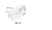
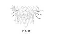
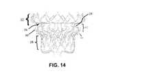
図12〜14は、本発明による僧帽弁デバイス20の第2の実施形態を例示し、これはクリップ80の追加を含む。図12〜14のデバイス20はまた、心房突縁22、弁輪支持体24、ネック26および弁本体28を有し、ネック26は心房突縁22に弁輪支持体24を接続し、弁本体28は弁尖支持構造として機能する。これらのすべては図1〜5の対応する要素と同じであることができる。これらの要素のそれぞれも、ストラットによって画定され、ストラットはセルを画定し、次にセルがセル状マトリクスを構成する。 FIGS. 12-14 illustrate a second embodiment of a
上記の2つの実施形態の間の違いはクリップ80の輪の追加であり、クリップ80の輪は、弁輪支持体24の下に垂直方向に間隔を置いて配置された位置で弁本体28のまわりに間隔を置いて配置された様式で設けられる。これらのクリップ80は、各クリップ80が弁本体28のストラットのいずれかから垂直に延在し、次に半径方向に水平に延在し、最後にその先端が短いベンドになって終わることができるという点で、いくぶんL字形である。クリップ80は、図15に最もよく示されるように、デバイス20が展開された後、生来の弁尖の一部をクリップ留めまたは保持するように機能する。このクリップ留め機能は、僧帽弁エリアの弁輪部位にデバイス20を固定することに資する。心房突縁22およびタブ30によって提供されるクリップ留め効果はここでも同様に働いているが、クリップ80は改善された固定をもたらす。高さH2は、ネック26および弁輪支持体24を合計した高さを画定し、またクリップ80を含めるように変化することもでき、0mm〜10mmの範囲であることができる。 The difference between the above two embodiments is the addition of a ring of
デバイス20がインプラントされると、心房突縁22、弁本体28、およびデバイス20の中に組み込まれたまたはデバイス20と生来の弁尖および他の心臓内部構造(または他の弁下構造)との相互作用によって作り出された固定機構(たとえば、心房突縁とタブ30とによるクリップ留め効果、クリップ80の追加)は、デバイス20を所望の位置に維持することになる。心室収縮期には、弁尖48および弁本体28によって形成された弁が閉じると、左心室からの圧力は揚圧力を生み出し、デバイス20を心房に向かって押し上げようとすることになる。これが、デバイス20がインプラントされた後、デバイス20を適所に維持するために、信頼性があり適切な固定機構が必要とされる理由の1つである。たとえば、心収縮の間、血液が大動脈につながる大動脈弁の方に送り出されるように、組織弁尖48は弁内腔を閉じることになる。その間、生来の弁尖は、弁本体28の外側表面に向かって(内側に)持ち上げられ(弁本体28を包み込み)、僧帽弁を密閉/閉鎖してPVLを防ごうとする。デバイス20に組み込まれた固定化要素は、生来の弁尖および他の心臓内部構造と係合して、デバイス20が押し上げられるのを防ぐことができる。心臓弛緩の間は、デバイス20の組織弁尖48はより小さい外形に変形して、血液がその中を流れて左心室を満たすことを可能にすることになる。組織弁尖48は、心周期の間、血流、心臓圧力および支持構造の周期的な脈動運動の組み合わされた効果によって作動(開閉)することができる。 When the
固定機構(弁輪支持体24およびタブ30)の固定効果に加えて、心室収縮期に生来の弁尖によって弁本体28に加えられた圧力はまた、デバイス20に締め付け力を加えることによって、デバイス20が心房に向かって持ち上げられないようにするのを支援することができる。これは動的な固定機構であり、これは心室収縮期にのみ効果が現れ、この段階では、デバイス20は、デバイス20を心房方向に押し上げようとする最大の揚力下にある。この追加の動的な固定効果は、デバイス20の適切な位置が維持されるのを助け、生来の心臓の解剖学的構造に作用する固定力とその持続時間を低減する。時間の経過とともに、組織の成長/治癒は、生来の弁尖を弁本体28に結合し/融合させることになろう。 In addition to the locking effect of the locking mechanism (annular support 24 and tab 30), the pressure applied to the
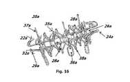
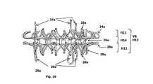
図16〜22は、本発明による僧帽弁デバイス20aの第3の実施形態を例示する。図16〜22のデバイス20aはまた、心房突縁22a、弁輪支持体24aおよびネック区画26aを有し、該ネック区画26aは心房突縁22aを弁輪支持体24aに接続する。弁本体VBはここでは、心房突縁22a、弁輪支持体24aおよび心室部分によって画定され、該心室部分はV字形のタブ28aによって画定される。 16-22 illustrate a third embodiment of a
心房突縁22aは、心房突縁22aがより低い外形を有してもよいこと以外は、心房突縁22に類似している。間隔を置いて配置された逆V字形のタブ34aの輪は、心房突縁22aのための頂部および谷部を画定し、タブ34aの各先端に丸みを帯びた非外傷性の端部35aを有する。複数の弁尖保持具すなわちポスト37aは、選択された端部35aから延在し、そのそれぞれが弁尖の一部を支持し保持するように機能する。各ポスト37aは直線状または湾曲していることができる。 The
心房突縁22aは、僧帽弁の生来の弁輪のところにまたはその上に置かれ、心房突縁22aの一部は左心房の内部にまで延在することができる。図20を参照せよ。心房突縁22aは、僧帽弁弁輪エリアに等しいかまたはそれより大きい表面積を有する。使用に際しては、心房突縁22aは、生体適合性ポリマーの織物、組織または他の生体適合性材料によって覆われて、デバイス20aの外まわりの密閉効果を付与し、組織の成長を促進し、治癒結果を速めることができる。 The
心房突縁22aは、円形の外形か、あるいは完全な円形とは異なる外形(すなわち、D字形または長円形)であることができる。心房突縁22aが円形の外形を有する場合には、その心房部分の直径は12mm〜75mmの範囲であることができる。心房突縁22aが完全な円形とは異なる外形を有する場合には、その長軸は12〜75mmの範囲であることができ、短軸は6〜70mmの範囲であることができる。さらに、心房突縁22aの高さH11は0.5mm〜30mmの範囲であることができる。心房突縁22aは、織物材料もしくは組織材料または組織材料と織物材料との組み合わせによって、完全に、あるいは部分的に覆われることができる。 The
弁輪支持体24aは、固定化要素として機能し、生来の弁尖および他の心臓内部構造または弁下構造と相互作用して、所望の固定効果をもたらすことができる。弁輪支持体24aによって付与される固定効果に加えて、心房突縁22aとアンカー29a(以下で説明される)とによって生み出される「クリップ留め効果」もまた、デバイス20aが自己の位置を調整し、また心周期の間の潜在的な移動に抵抗するのを支援することができる。送達システムからのデバイス20aの開放の際に、デバイス20aの諸要素は、送達システムから順番に開放されることになる。たとえば、経心尖送達の際には、送達システムから心房突縁22aが最初に展開され、次に弁輪支持体24aが展開され、またはその逆で展開される。対照的に、経大腿(経中隔)送達の際には、弁輪支持体24aが最初に展開され、次に心房突縁22aが展開される。これらの手順は、X線、TEE、ICE等からのガイダンスに従って実施されることができる。 The
ネック26aは、突縁22aから半径方向外側に向かって弁輪支持体24aに移行し、弁輪支持体24aはアンカー29aの輪を含む。ネック26aは、実際には半径方向外側に向かってアンカー29aの輪に移行し、アンカー29aは半径方向外側に向かって延在し、次に半径方向内側に向かって延在してV字形のタブ28aに移行し、タブ28aは心室部分内に延在する。アンカー29aの数は1〜20の範囲である。アンカー29aの輪の断面の外形は、完全な円形か、あるいは円形とは異なる外形(たとえば、長円形またはD字形)であることができる。アンカー29aが完全な円形の外形を有する場合には、その直径は10mm〜75mmの範囲であることができる。アンカー29aが完全な円形とは異なる外形を有する場合には、その長軸は10〜75mmの範囲であることができ、短軸は5〜70mmの範囲であることができる。 The
環状のクリップ留めスペースは、アンカー29aの輪と心房突縁22aとの間に画定され、このクリップ留めスペースは高さH14を有し(図19を参照せよ)、この高さH14は0.5mm〜30mmの範囲であることができる。各アンカー29aは、丸められた端部32aで終わり、端部32aの機能は心臓の僧帽弁部位の弁輪または生来の弁尖に接触しまたはそれらに自体を押し付けて、デバイス20aを弁輪エリアに固定することであり、したがって固定化要素として機能する。各アンカー29aは、組織または織物によって完全に、あるいは部分的に覆われることができる。したがって、アンカー29aの輪は、弁本体VBおよびネック26aの直径より大きい直径を有するが、心房突縁22aの直径より小さい、それに等しいまたはそれより大きくさえあることができる。 An annular clipping space is defined between the ring of
複数の閉じられた弁保持具36aは、心室部分の端部においてV字形のタブ28aから延在することができる。特定の数の保持具36aが示されているけれども、任意の数の、1個以上の範囲の数の保持具36aを備えたデバイス20aを提供することが可能である。図16、19および21に最もよく示されているように、各保持具36aはV字形の対応するタブ28aの端部38aに結合されている。保持具36aは、尾部36と同じ機能を実行するために提供される。各保持具36aの長さは5mm〜25mmの範囲であることができる。 A plurality of
心室部分は2mm〜15mmの範囲にある高さH12を有することができる。したがって、一体とされた弁本体VBは、4mm〜30mmの、好ましくは8mm〜20mmの範囲にある高さH13を有することができる。心室部分の断面外形は、完全な円形の外形か、あるいは円形とは異なる外形(すなわち、D字形または長円形)であることができる。心室部分が完全な円形の外形を有する場合には、その直径は10mm〜75mmの範囲であることができる。心室部分が円形とは異なる外形を有する場合には、その長軸は10〜75mmの範囲であることができ、短軸は5〜70mmの範囲であることができる。心室部分は、その高さに沿って変化する外形を有することもできる。たとえば、弁輪支持体24aの近くの心室部分の一部は、長円形の外形または完全な円形とは異なるある他の外形を有することができ、その一方で弁輪支持体24aからもっと離れた心室部分の一部は、完全な円形の外形を有することもできる。またインプラントされると、心室部分は、左心室のみに、左心房のみに、または左心房と左心室との両方に配置されることができる。 The ventricular portion can have a height H12 in the range of 2 mm to 15 mm. Therefore, the integrated valve body VB can have a height H13 in the range of 4 mm to 30 mm, preferably 8 mm to 20 mm. The cross-sectional profile of the ventricular portion can be a completely circular profile or a profile that is different from a circle (ie, D-shaped or oval). If the ventricular portion has a perfect circular profile, its diameter can range from 10 mm to 75 mm. If the ventricle portion has an outer shape different from a circle, its major axis can range from 10 to 75 mm and its minor axis can range from 5 to 70 mm. The ventricular portion can also have a contour that varies along its height. For example, a portion of the ventricular portion near the
この実施形態の重要な様相は、心室部分の長さ(すなわち、高さH12)が短縮されて、従来の弁置換デバイスよりも短い外形を有するデバイス20aが提供されることである。より短い外形は、それが潜在的なLVOT閉鎖を最低減にして、より良好な心拍出量を促すという点で有益である。さらに、より短い外形は、左心室内の心臓構造、たとえばとりわけ腱索および乳頭筋との干渉を最小化する。 An important aspect of this embodiment is that the length (i.e., height H12) of the ventricular portion is shortened to provide a
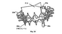
短くされた外形の結果、組織弁尖は、ポスト37aが弁尖の上部の部分を保持するまたはそれに取り付けられるために使用されることができるように、主として心房突縁22の内部および心房突縁22の上に配置される(図23を参照せよ)。弁尖はまた、円形の部分において完全に、あるいは円形および非円形の両方の部分を包含して、弁本体VB中に一体化されることもできる。弁本体VBは、織物材料もしくは組織材料または組織材料と織物材料との組み合わせによって、完全にまたは部分的に覆われることができる。たとえば、弁本体VBの内表面は織物によって覆われ、外表面は組織によって覆われることができ、またはその逆であることもできる。使用に際しては、織物材料および組織は、最初に弁本体VBに一緒に縫合され/結合されるか、あるいは個々に縫合され/結合されることができる。弁本体VBは片方の表面(すなわち、内表面または外表面)に沿って、あるいは両方の表面(すなわち、内表面および外表面)に沿って覆われることができる。 As a result of the shortened profile, the tissue leaflets are primarily inside the
経心尖送達の際、心室部分および保持具36aは真っすぐに引き込まれ、送達システム中に挿入されることができる。展開されると、弁輪支持体24aは、生来の弁輪のレベルにおいて、あるいは生来の弁輪より下のレベルにおいて展開され、そして心房突縁22aとアンカー29aとの間で生来の弁輪および/または生来の弁尖をクリップ留めすることによって生み出されるクリップ留め効果によって、生来の弁構造と係合する。図20を参照せよ。デバイス20aを展開するためには、デバイス20aとその弁尖との組み立て体が、部分的な、あるいは完全な弁尖機能を発揮することができるように、心房突縁22aが最初に左心房中で展開され、次に心室部分が左心室中で展開される(またはその逆で展開される)。次に、保持具36aのないタブ38aが、弁輪24aが生来の弁輪の位置でしっかりと保持されることができるように、開放され/展開される。最後に、デバイス20aが操作されてその位置が調節され、それから保持具36aを備えたタブ38aが開放され/展開される。この段階的な展開動作は、より正確な弁の位置決めおよび改善された固定効果をもたらす。 During transapical delivery, the ventricular portion and
デバイス20aは、僧帽弁置換または大動脈弁置換のために使用されることができる。僧帽弁置換の場合、弁尖は、生来の弁輪の上に、その位置にまたはその下に配置されることができる。大動脈弁置換の場合、弁尖は、生来の弁輪の位置にまたはその上に配置されることができる。
デバイス20aが僧帽弁の位置で心臓の内部に完全に展開されると、弁尖は、主として生来の弁輪の位置の上に配置されることになる。図23を参照せよ。わずかに高い弁尖の位置は、左心室の内部に延在する弁本体VBの長さを低減することを可能にする。 When the
本発明のデバイス20の重要な利点/新規性として、以下のものが挙げられる。
(1)生来の弁尖ならびに他の内部弁構造および弁下構造が保存されている。
(2)デバイス20は、心臓の生来構造の機能、たとえば腱索、乳頭筋、左心室、LVOT、大動脈弁への衝突等への干渉/閉塞を最小限にして、心臓逆流症を処置する。
(3)デバイス20の構造は、心臓弁の生来の表面形状および解剖学的構造を考慮して、生来の心臓弁、弁輪の外形、周囲の構造および弁下構造への最小限の修正となるようにしている。
(4)デバイス20は、心臓の解剖学的形態の生来の輪郭に自己順応する構造を有し、また弁輪における密閉部分は正常な生来の弁輪のように収縮し拡大することができる。
(5)デバイス20の外形は、完全な円形のほかに、たとえば「D」字形、「裏返しC」字形または長円形のような形状に設定されて、生来の弁輪の外形に対応することができ、また弁輪の近くに接触するデバイス20の部分は、「V」字形の外形を有して、生来の僧帽弁の解剖学的輪郭を模倣することができる。
(6)デバイス20の固定化要素は、生来の弁尖および他の内部弁構造または弁下構造を利用する。Important advantages / novelty of the
(1) The native leaflets and other internal and subvalve structures are preserved.
(2) The
(3) The structure of
(4) The
(5) In addition to a perfect circle, the outer shape of the
(6) The fixation element of the
(7)デバイス20は、サイズ/外形を自動的に調節して、インプラント後の左心室のサイズ/体積の変化に適応することができる。
(8)デバイス20は、変化可能な外形を有して、心室収縮期に密閉効果を生み出すのを支援することができ、また生来の弁尖との相互作用による締め付け効果を提供して、心室収縮期のデバイスの位置を維持するのを支援することができる。たとえば、デバイス20は,心房突縁22と弁本体28との間の「移行帯」を有することができる。「移行帯」は、デバイス20の他の部分とは異なる外形を有することができる。1つの例は、「移行帯」が完全な円形の外形の代わりに長円形の外形を有することができることである。「移行帯」には長軸および短軸があり、長軸は「接合部から接合部へ」沿った方向に決められることができ、他方、もう一方の軸は長軸よりも短い。「移行帯」における長円形の外形は移行エリアにおける改善された密閉効果を生み出すのを支援することができる。移行帯はまた、ネック26を含んで「密閉する」表面積を増加させることができる。これはまた、デバイス20に動的な固定化効果を付与し、これは、デバイス20に作用する揚力が最も高くなる心室収縮期に効果を現す。
(9)デバイス20は、生来の弁尖および腱索を利用する構造を有することによって、密閉効果および固定化効果の両方を提供する。(7) The
(8) The
(9) The
(10)デバイス20は、外科的に、または最小限に侵襲性の手順、たとえば経心尖、経中隔および経大腿の手順によってインプラントされることができる。
(11)弁本体28の尾部36は医師に、展開中における理想的な弁性能のための弁の位置/角度を調節するための十分な時間的余裕を与える、および
(12)送達システム内の内側軸は、それが弁の展開中に移動可能であるような様式で設計されつくられることができる。たとえば、送達中に、デバイス20のほとんどが送達システムから解放され/展開されると、デバイス20の弁尖48は心拍として機能し始めることになる。この時に、送達システムの内側軸は、デバイス20の内腔の内側に依然としてあることができ、デバイス20の弁尖のうちの1つの動きに影響を与えることができる。この状況では、内側軸がデバイスの内腔の内側ではなくなるように、送達システムの内側軸は、送達システムの近位ハンドル端から解き放され、近位方向に引き戻されてもよい。したがって、デバイス20の弁尖48はすべて自由に移動することができる。これは、尾部36が送達システムにまだ繋がれているときに、デバイス20がよりよい弁機能を発揮することができることを意味する。言いかえれば、デバイス20の弁尖48が展開中に機能しているという事実は、医師に、弁の位置/角度を最適な性能に調節するためのより多くの時間を与えることになる。(10)
(11) The
上記の固定化機構に加えて、接着剤による結合/インターフェースが、生来の僧帽弁の位置にデバイス20を固定するために使用されることもできる。1つの例は、生体適合性の膠/接着剤を使用して、僧帽弁の位置にデバイス20を結合し/固定し/確保することである。使用に際しては、生体適合性の接着剤/膠は、デバイス20の外表面、たとえば弁本体28、心房突縁22の外表面に沿って、またはいずれかの生来の僧帽弁構造、たとえば弁輪、弁輪のレベルより上または弁輪のレベルの心房表面、生来の弁尖、心臓筋肉ならびに他の弁構造および/または弁下構造と接触する可能性のあるデバイス20の任意の表面に施与されて、インプラント後のデバイス20の位置を維持することができる。生物剤もまた、生体適合性の接着剤/膠の中に添加されて、治癒および組織成長を促進することができる。 In addition to the fixation mechanism described above, an adhesive bond / interface can also be used to secure the
接着剤/膠は、その性質上反応性が速く、血液と接触すると瞬時に生来の僧帽弁構造と結合を形成することができる。これらはまた、熱または温度によって反応開始されることができ、この熱または温度は、デバイス20の部分または全体の構造を通す、電解加熱またはFR加熱または超音波エネルギーまたは磁気エネルギーまたはマイクロ波エネルギーまたは血液温度自体または化学反応によって生成され/調節されることができる。 The adhesive / glue is fast in nature and can instantly form a bond with the native mitral valve structure upon contact with blood. They can also be initiated by heat or temperature, which heat or temperature passes through part or the whole structure of the
接着剤/膠はまた、その性質上反応性が遅く、血液と接触した後ある時間後に生来の僧帽弁構造と結合を形成することができる。結合を形成するのに必要とされる時間は、1秒〜2時間、1秒〜28時間等様々であることができる。 The adhesive / glue is also slow in nature and can form a bond with the native mitral valve structure some time after contact with blood. The time required to form a bond can vary from 1 second to 2 hours, 1 second to 28 hours, and so forth.
接着剤/膠はまた、その性質上制御された反応をし、血液と接触した後制御された様式で生来の僧帽弁構造と結合を形成することができる。この構想の1つの例は、デバイス20上の接着剤/膠層/材料の上に他の生体適合性材料の最上層(または複数の最上層)を施与することである。生体適合性材料のこの最上層(または複数の最上層)は、エネルギー、加熱、化学反応の使用によって、あるいは機械的にまたは磁気的に制御された様式で除去され/溶解されることができ、該最上層の下の接着剤/膠が、生来の僧帽弁構造との結合を有効に形成することを確実にすることができる。ここで使用される「制御された様式」とは、結合を形成するのに必要とされる時間が1秒〜48時間で様々であることを意味する。 The adhesive / glue can also react in a controlled manner in nature and form a bond with the native mitral valve structure in a controlled manner after contact with blood. One example of this concept is to apply the top layer (or layers) of other biocompatible materials on the adhesive / glue layer / material on the
以上の記載は本発明の特定の実施形態に言及しているけれども、本発明の精神から逸脱することなく多くの修正がなされてもよいことが理解されるだろう。添付された特許請求の範囲は、本発明の真の範囲および精神に属するような修正を包含することが意図されている。 Although the foregoing description refers to specific embodiments of the invention, it will be understood that many modifications may be made without departing from the spirit of the invention. The appended claims are intended to cover such modifications as would fall within the true scope and spirit of the present invention.
Claims (11)
Translated fromJapanese前記デバイスの心房端を画定する心房突縁、
前記デバイスの心室端を画定する心室部分であって、2mm〜15mmの範囲の高さを有する心室部分、
前記心房突縁と前記心室部分との間に配置される弁輪支持体であって、前記弁輪支持体が前記弁輪支持体から半径方向に延在するアンカーの輪を含み、環状のクリップ留めするスペースが前記心房突縁と前記アンカーの輪との間に画定される、弁輪支持体、
前記心房突縁の前記心房端に配置された複数の弁尖保持具、および
前記弁尖保持具に固定され、生来の弁輪の上の位置で前記心房突縁の内側に配置された複数の弁尖
を含む、僧帽弁置換デバイス。A mitral valve replacement device adapted to be deployed at the position of a mitral valve in a person's heart,
An atrial ridge that defines the atrial end of the device;
A ventricular portion defining a ventricular end of the device, the ventricular portion having a height in the range of 2 mm to 15 mm;
An annulus clip disposed between the atrial ridge and the ventricular portion, the annulus support including a ring of anchors extending radially from the annulus support, and an annular clip An annulus support in which a space to be clamped is defined between the atrial ridge and the ring of the anchor;
A plurality of leaflet holders disposed at the atrial end of the atrial protrusion, and a plurality of leaflet holders fixed to the valve leaflet holder and disposed inside the atrial protrusion at a position on the native annulus A mitral valve replacement device including a leaflet.
以下のものを含む僧帽弁置換デバイスを準備する工程であって、前記の以下のものが、
人の心臓内の僧帽弁の位置で展開されるように適合化された僧帽弁置換デバイスであって、
前記デバイスの心房端を画定する心房突縁、
前記デバイスの心室端を画定する心室部分であって、2mm〜15mmの範囲の高さを有する心室部分、
前記心房突縁と前記心室部分との間に配置される弁輪支持体であって、前記弁輪支持体が前記弁輪支持体から半径方向に延在するアンカーの輪を含み、環状のクリップ留めするスペースが前記心房突縁と前記アンカーの輪との間に画定される、弁輪支持体、
前記心房突縁の前記心房端に配置された複数の弁尖保持具、および
前記弁尖保持具に固定され、前記心房突縁の内側に配置された複数の弁尖
である工程、
前記心房突縁を、人の心臓内の生来の僧帽弁弁輪の上の心房内に、前記複数の弁尖が前記生来の僧帽弁弁輪の上に配置されるように据える工程、および
前記生来の僧帽弁弁輪および/または前記生来の僧帽弁弁尖を前記クリップ留めするスペースに配置する工程
を含む、方法。A method of deploying a mitral valve replacement device at the location of a native mitral valve in a person's heart, comprising:
Providing a mitral valve replacement device comprising:
A mitral valve replacement device adapted to be deployed at the position of a mitral valve in a person's heart,
An atrial ridge that defines the atrial end of the device;
A ventricular portion defining a ventricular end of the device, the ventricular portion having a height in the range of 2 mm to 15 mm;
An annulus clip disposed between the atrial ridge and the ventricular portion, the annulus support including a ring of anchors extending radially from the annulus support, and an annular clip An annulus support in which a space to be clamped is defined between the atrial ridge and the ring of the anchor;
A plurality of leaflet holders disposed at the atrial end of the atrial ridge, and a plurality of leaflets fixed to the leaflet holder and disposed inside the atrial ridge;
Placing the atrial prosthesis in the atrium above the native mitral valve annulus in a person's heart such that the plurality of leaflets are positioned on the native mitral valve annulus; And placing the native mitral valve annulus and / or the native mitral valve leaflet in the clipping space.
前記少なくとも1個の尾部にワイヤまたはラインを取り付ける工程、および
前記ワイヤまたはラインを操作して、前記僧帽弁置換デバイスの位置を前記生来の僧帽弁の位置に調整する工程
をさらに含む、請求項9に記載の方法。The mitral valve replacement device includes at least one tail extending from the ventricular end of the valve body;
Attaching a wire or line to the at least one tail; and manipulating the wire or line to adjust the position of the mitral valve replacement device to the position of the native mitral valve; Item 10. The method according to Item 9.
前記生来の僧帽弁弁尖を前記少なくとも1個のクリップでクリップ留めする工程
をさらに含む、請求項9に記載の方法。10. The method of claim 9, further comprising: providing at least one clip extending from the annulus support; and clipping the native mitral valve leaflet with the at least one clip. Method.
Applications Claiming Priority (9)
| Application Number | Priority Date | Filing Date | Title |
|---|---|---|---|
| US201361887343P | 2013-10-05 | 2013-10-05 | |
| US61/887,343 | 2013-10-05 | ||
| US201461927490P | 2014-01-15 | 2014-01-15 | |
| US61/927,490 | 2014-01-15 | ||
| US14/279,511 | 2014-05-16 | ||
| US14/279,511US9393111B2 (en) | 2014-01-15 | 2014-05-16 | Device and method for mitral valve regurgitation treatment |
| US201462024097P | 2014-07-14 | 2014-07-14 | |
| US62/024,097 | 2014-07-14 | ||
| PCT/US2014/059076WO2015057407A1 (en) | 2013-10-05 | 2014-10-03 | Device and method for mitral valve regurgitation method |
Related Child Applications (1)
| Application Number | Title | Priority Date | Filing Date |
|---|---|---|---|
| JP2019133540ADivisionJP6869294B2 (en) | 2013-10-05 | 2019-07-19 | Devices and methods for the treatment of mitral regurgitation |
Publications (2)
| Publication Number | Publication Date |
|---|---|
| JP2016531722Atrue JP2016531722A (en) | 2016-10-13 |
| JP6814042B2 JP6814042B2 (en) | 2021-01-13 |
Family
ID=55411834
Family Applications (2)
| Application Number | Title | Priority Date | Filing Date |
|---|---|---|---|
| JP2016546888AActiveJP6814042B2 (en) | 2013-10-05 | 2014-10-03 | Devices and methods for the treatment of mitral regurgitation |
| JP2019133540AActiveJP6869294B2 (en) | 2013-10-05 | 2019-07-19 | Devices and methods for the treatment of mitral regurgitation |
Family Applications After (1)
| Application Number | Title | Priority Date | Filing Date |
|---|---|---|---|
| JP2019133540AActiveJP6869294B2 (en) | 2013-10-05 | 2019-07-19 | Devices and methods for the treatment of mitral regurgitation |
Country Status (8)
| Country | Link |
|---|---|
| JP (2) | JP6814042B2 (en) |
| KR (1) | KR102256192B1 (en) |
| CN (1) | CN105658179B (en) |
| AU (1) | AU2014334772B2 (en) |
| BR (1) | BR112016007555B1 (en) |
| CA (1) | CA2922123C (en) |
| IL (1) | IL244279B (en) |
| SG (1) | SG11201601674WA (en) |
Cited By (12)
| Publication number | Priority date | Publication date | Assignee | Title |
|---|---|---|---|---|
| JP2021521940A (en)* | 2018-04-26 | 2021-08-30 | シノ メディカル サイエンシス テクノロジー,インク | Indwelling mitral valve device for transapical approach |
| US11857441B2 (en) | 2018-09-04 | 2024-01-02 | 4C Medical Technologies, Inc. | Stent loading device |
| JP2024502934A (en)* | 2020-12-04 | 2024-01-24 | ハンチョウ セコイア メディカル デバイス カンパニー リミテッド | Artificial heart valve devices, systems and methods |
| US11931253B2 (en) | 2020-01-31 | 2024-03-19 | 4C Medical Technologies, Inc. | Prosthetic heart valve delivery system: ball-slide attachment |
| US11944537B2 (en) | 2017-01-24 | 2024-04-02 | 4C Medical Technologies, Inc. | Systems, methods and devices for two-step delivery and implantation of prosthetic heart valve |
| US11957577B2 (en) | 2017-01-19 | 2024-04-16 | 4C Medical Technologies, Inc. | Systems, methods and devices for delivery systems, methods and devices for implanting prosthetic heart valves |
| US11992403B2 (en) | 2020-03-06 | 2024-05-28 | 4C Medical Technologies, Inc. | Devices, systems and methods for improving recapture of prosthetic heart valve device with stent frame having valve support with inwardly stent cells |
| US12029647B2 (en) | 2017-03-07 | 2024-07-09 | 4C Medical Technologies, Inc. | Systems, methods and devices for prosthetic heart valve with single valve leaflet |
| US12036113B2 (en) | 2017-06-14 | 2024-07-16 | 4C Medical Technologies, Inc. | Delivery of heart chamber prosthetic valve implant |
| US12053375B2 (en) | 2020-03-05 | 2024-08-06 | 4C Medical Technologies, Inc. | Prosthetic mitral valve with improved atrial and/or annular apposition and paravalvular leakage mitigation |
| US12133797B2 (en) | 2020-01-31 | 2024-11-05 | 4C Medical Technologies, Inc. | Prosthetic heart valve delivery system: paddle attachment feature |
| US12232991B2 (en) | 2019-04-15 | 2025-02-25 | 4C Medical Technologies, Inc. | Loading systems for collapsible prosthetic heart valve devices and methods thereof |
Families Citing this family (22)
| Publication number | Priority date | Publication date | Assignee | Title |
|---|---|---|---|---|
| US9782256B2 (en)* | 2015-04-27 | 2017-10-10 | Venus Medtech (Hangzhou) Inc | Heart valve assembly |
| WO2019195860A2 (en) | 2018-04-04 | 2019-10-10 | Vdyne, Llc | Devices and methods for anchoring transcatheter heart valve |
| US11071627B2 (en) | 2018-10-18 | 2021-07-27 | Vdyne, Inc. | Orthogonally delivered transcatheter heart valve frame for valve in valve prosthesis |
| US10321995B1 (en) | 2018-09-20 | 2019-06-18 | Vdyne, Llc | Orthogonally delivered transcatheter heart valve replacement |
| US10595994B1 (en) | 2018-09-20 | 2020-03-24 | Vdyne, Llc | Side-delivered transcatheter heart valve replacement |
| US11278437B2 (en) | 2018-12-08 | 2022-03-22 | Vdyne, Inc. | Compression capable annular frames for side delivery of transcatheter heart valve replacement |
| US12186187B2 (en) | 2018-09-20 | 2025-01-07 | Vdyne, Inc. | Transcatheter deliverable prosthetic heart valves and methods of delivery |
| US11344413B2 (en) | 2018-09-20 | 2022-05-31 | Vdyne, Inc. | Transcatheter deliverable prosthetic heart valves and methods of delivery |
| US11109969B2 (en) | 2018-10-22 | 2021-09-07 | Vdyne, Inc. | Guidewire delivery of transcatheter heart valve |
| US11253359B2 (en) | 2018-12-20 | 2022-02-22 | Vdyne, Inc. | Proximal tab for side-delivered transcatheter heart valves and methods of delivery |
| WO2020146842A1 (en) | 2019-01-10 | 2020-07-16 | Vdyne, Llc | Anchor hook for side-delivery transcatheter heart valve prosthesis |
| JP2022523456A (en)* | 2019-01-14 | 2022-04-25 | エムテックス カーディオ アーゲー | Heart valve apex coapter |
| US11185409B2 (en) | 2019-01-26 | 2021-11-30 | Vdyne, Inc. | Collapsible inner flow control component for side-delivered transcatheter heart valve prosthesis |
| US11273032B2 (en) | 2019-01-26 | 2022-03-15 | Vdyne, Inc. | Collapsible inner flow control component for side-deliverable transcatheter heart valve prosthesis |
| WO2020181154A2 (en) | 2019-03-05 | 2020-09-10 | Vdyne, Inc. | Tricuspid regurgitation control devices for orthogonal transcatheter heart valve prosthesis |
| US11076956B2 (en) | 2019-03-14 | 2021-08-03 | Vdyne, Inc. | Proximal, distal, and anterior anchoring tabs for side-delivered transcatheter mitral valve prosthesis |
| US11173027B2 (en) | 2019-03-14 | 2021-11-16 | Vdyne, Inc. | Side-deliverable transcatheter prosthetic valves and methods for delivering and anchoring the same |
| CA3138875A1 (en) | 2019-05-04 | 2020-11-12 | Vdyne, Inc. | Cinch device and method for deployment of a side-delivered prosthetic heart valve in a native annulus |
| EP4480458A3 (en) | 2019-08-20 | 2025-04-09 | Vdyne, Inc. | Delivery devices for side-deliverable transcatheter prosthetic valves |
| CN120531525A (en) | 2019-08-26 | 2025-08-26 | 维迪内股份有限公司 | Laterally deliverable transcatheter prosthetic valve and method for its delivery and anchoring |
| CN112641536A (en)* | 2019-10-12 | 2021-04-13 | 上海微创心通医疗科技有限公司 | Heart valve support and prosthesis thereof |
| US11234813B2 (en) | 2020-01-17 | 2022-02-01 | Vdyne, Inc. | Ventricular stability elements for side-deliverable prosthetic heart valves and methods of delivery |
Citations (2)
| Publication number | Priority date | Publication date | Assignee | Title |
|---|---|---|---|---|
| US20110264191A1 (en)* | 2010-04-23 | 2011-10-27 | Medtronic, Inc. | Delivery Systems and Methods of Implantation for Prosthetic Heart Valves |
| WO2013059747A1 (en)* | 2011-10-19 | 2013-04-25 | Foundry Newco Xii, Inc. | Prosthetic heart valve devices, prosthetic mitral valves and associated systems and methods |
Family Cites Families (18)
| Publication number | Priority date | Publication date | Assignee | Title |
|---|---|---|---|---|
| US6790229B1 (en)* | 1999-05-25 | 2004-09-14 | Eric Berreklouw | Fixing device, in particular for fixing to vascular wall tissue |
| US7201772B2 (en) | 2003-07-08 | 2007-04-10 | Ventor Technologies, Ltd. | Fluid flow prosthetic device |
| AU2003299404A1 (en)* | 2003-12-23 | 2005-08-11 | Laboratoires Perouse | Kit which is intended to be implanted in a conduit |
| EP2529699B1 (en)* | 2003-12-23 | 2014-01-29 | Sadra Medical, Inc. | Repositionable heart valve |
| US7311730B2 (en)* | 2004-02-13 | 2007-12-25 | Shlomo Gabbay | Support apparatus and heart valve prosthesis for sutureless implantation |
| DE102005052628B4 (en)* | 2005-11-04 | 2014-06-05 | Jenavalve Technology Inc. | Self-expanding, flexible wire mesh with integrated valvular prosthesis for the transvascular heart valve replacement and a system with such a device and a delivery catheter |
| US8876894B2 (en)* | 2006-09-19 | 2014-11-04 | Medtronic Ventor Technologies Ltd. | Leaflet-sensitive valve fixation member |
| WO2009132187A1 (en)* | 2008-04-23 | 2009-10-29 | Medtronic, Inc. | Stented heart valve devices |
| CN102292053A (en)* | 2008-09-29 | 2011-12-21 | 卡迪尔克阀门技术公司 | Heart valve |
| US20100217382A1 (en)* | 2009-02-25 | 2010-08-26 | Edwards Lifesciences | Mitral valve replacement with atrial anchoring |
| CA2961053C (en)* | 2009-04-15 | 2019-04-30 | Edwards Lifesciences Cardiaq Llc | Vascular implant and delivery system |
| US8652203B2 (en)* | 2010-09-23 | 2014-02-18 | Cardiaq Valve Technologies, Inc. | Replacement heart valves, delivery devices and methods |
| CN102665612B (en)* | 2009-11-05 | 2015-04-08 | 宾夕法尼亚大学理事会 | Valve prosthesis |
| US8657872B2 (en)* | 2010-07-19 | 2014-02-25 | Jacques Seguin | Cardiac valve repair system and methods of use |
| EP2444030A1 (en)* | 2010-08-31 | 2012-04-25 | Biotronik AG | Medical valve implant for implantation in an animal body and/or human body |
| EP2629699B1 (en)* | 2010-10-21 | 2017-01-04 | Medtronic, Inc. | Mitral bioprosthesis with low ventricular profile |
| EP4289398A3 (en)* | 2011-08-11 | 2024-03-13 | Tendyne Holdings, Inc. | Improvements for prosthetic valves and related inventions |
| EA201400478A1 (en)* | 2011-10-19 | 2014-10-30 | Твелв, Инк. | DEVICES, SYSTEMS AND METHODS OF PROTESIZING THE HEART VALVE |
- 2014
- 2014-10-03CACA2922123Apatent/CA2922123C/enactiveActive
- 2014-10-03SGSG11201601674WApatent/SG11201601674WA/enunknown
- 2014-10-03CNCN201480053938.8Apatent/CN105658179B/enactiveActive
- 2014-10-03KRKR1020167012077Apatent/KR102256192B1/enactiveActive
- 2014-10-03BRBR112016007555-2Apatent/BR112016007555B1/enactiveIP Right Grant
- 2014-10-03JPJP2016546888Apatent/JP6814042B2/enactiveActive
- 2014-10-03AUAU2014334772Apatent/AU2014334772B2/enactiveActive
- 2016
- 2016-02-24ILIL244279Apatent/IL244279B/enactiveIP Right Grant
- 2019
- 2019-07-19JPJP2019133540Apatent/JP6869294B2/enactiveActive
Patent Citations (2)
| Publication number | Priority date | Publication date | Assignee | Title |
|---|---|---|---|---|
| US20110264191A1 (en)* | 2010-04-23 | 2011-10-27 | Medtronic, Inc. | Delivery Systems and Methods of Implantation for Prosthetic Heart Valves |
| WO2013059747A1 (en)* | 2011-10-19 | 2013-04-25 | Foundry Newco Xii, Inc. | Prosthetic heart valve devices, prosthetic mitral valves and associated systems and methods |
Cited By (13)
| Publication number | Priority date | Publication date | Assignee | Title |
|---|---|---|---|---|
| US11957577B2 (en) | 2017-01-19 | 2024-04-16 | 4C Medical Technologies, Inc. | Systems, methods and devices for delivery systems, methods and devices for implanting prosthetic heart valves |
| US11944537B2 (en) | 2017-01-24 | 2024-04-02 | 4C Medical Technologies, Inc. | Systems, methods and devices for two-step delivery and implantation of prosthetic heart valve |
| US12029647B2 (en) | 2017-03-07 | 2024-07-09 | 4C Medical Technologies, Inc. | Systems, methods and devices for prosthetic heart valve with single valve leaflet |
| US12036113B2 (en) | 2017-06-14 | 2024-07-16 | 4C Medical Technologies, Inc. | Delivery of heart chamber prosthetic valve implant |
| JP7417539B2 (en) | 2018-04-26 | 2024-01-18 | シノメッド カーディオヴィタ テクノロジー インコーポレイテッド | Indwelling mitral valve device for transapical approach |
| JP2021521940A (en)* | 2018-04-26 | 2021-08-30 | シノ メディカル サイエンシス テクノロジー,インク | Indwelling mitral valve device for transapical approach |
| US11857441B2 (en) | 2018-09-04 | 2024-01-02 | 4C Medical Technologies, Inc. | Stent loading device |
| US12232991B2 (en) | 2019-04-15 | 2025-02-25 | 4C Medical Technologies, Inc. | Loading systems for collapsible prosthetic heart valve devices and methods thereof |
| US11931253B2 (en) | 2020-01-31 | 2024-03-19 | 4C Medical Technologies, Inc. | Prosthetic heart valve delivery system: ball-slide attachment |
| US12133797B2 (en) | 2020-01-31 | 2024-11-05 | 4C Medical Technologies, Inc. | Prosthetic heart valve delivery system: paddle attachment feature |
| US12053375B2 (en) | 2020-03-05 | 2024-08-06 | 4C Medical Technologies, Inc. | Prosthetic mitral valve with improved atrial and/or annular apposition and paravalvular leakage mitigation |
| US11992403B2 (en) | 2020-03-06 | 2024-05-28 | 4C Medical Technologies, Inc. | Devices, systems and methods for improving recapture of prosthetic heart valve device with stent frame having valve support with inwardly stent cells |
| JP2024502934A (en)* | 2020-12-04 | 2024-01-24 | ハンチョウ セコイア メディカル デバイス カンパニー リミテッド | Artificial heart valve devices, systems and methods |
Also Published As
| Publication number | Publication date |
|---|---|
| KR20160068875A (en) | 2016-06-15 |
| CN105658179A (en) | 2016-06-08 |
| CA2922123C (en) | 2021-11-02 |
| JP2019193874A (en) | 2019-11-07 |
| SG11201601674WA (en) | 2016-04-28 |
| JP6814042B2 (en) | 2021-01-13 |
| IL244279A0 (en) | 2016-04-21 |
| BR112016007555A2 (en) | 2017-08-01 |
| AU2014334772A1 (en) | 2016-03-24 |
| CN105658179B (en) | 2018-06-12 |
| KR102256192B1 (en) | 2021-05-26 |
| IL244279B (en) | 2020-07-30 |
| JP6869294B2 (en) | 2021-05-12 |
| AU2014334772B2 (en) | 2018-12-13 |
| CA2922123A1 (en) | 2015-04-23 |
| BR112016007555B1 (en) | 2021-05-18 |
Similar Documents
| Publication | Publication Date | Title |
|---|---|---|
| JP6869294B2 (en) | Devices and methods for the treatment of mitral regurgitation | |
| US10426605B2 (en) | Device and method for mitral valve regurgitation treatment | |
| JP7337139B2 (en) | artificial heart valve | |
| EP3052053B1 (en) | Device for mitral valve regurgitation method | |
| US9393111B2 (en) | Device and method for mitral valve regurgitation treatment | |
| US20200360138A1 (en) | Method and Design for a Mitral Regurgitation Treatment Device | |
| JP7149052B2 (en) | A stent for positioning and securing a valvular prosthesis at an implantation site in a patient's heart | |
| JP6157564B2 (en) | Prosthetic heart valve | |
| JP2023184533A (en) | Artificial valve leaflet device | |
| EP2999433B1 (en) | Transcatheter prosthetic valve for mitral or tricuspid valve replacement | |
| JP4458845B2 (en) | Medical device | |
| JP5685183B2 (en) | Heart valve device with stent | |
| JP5795009B2 (en) | Stent for positioning and securing a valve prosthesis at a patient's heart implantation site | |
| US20140296975A1 (en) | Inflatable Annular Sealing Device for Prosthetic Mitral Valve | |
| JP2018528810A (en) | Implantable heart valve device, mitral valve repair device, and related systems and methods | |
| JP2016519973A (en) | Implantable heart valve device, mitral valve repair device, and related systems and methods | |
| WO2025024709A1 (en) | Valve leaflet exoskeleton and related systems and methods |
Legal Events
| Date | Code | Title | Description |
|---|---|---|---|
| A621 | Written request for application examination | Free format text:JAPANESE INTERMEDIATE CODE: A621 Effective date:20170925 | |
| A977 | Report on retrieval | Free format text:JAPANESE INTERMEDIATE CODE: A971007 Effective date:20180622 | |
| A131 | Notification of reasons for refusal | Free format text:JAPANESE INTERMEDIATE CODE: A131 Effective date:20180724 | |
| A521 | Request for written amendment filed | Free format text:JAPANESE INTERMEDIATE CODE: A523 Effective date:20181024 | |
| A02 | Decision of refusal | Free format text:JAPANESE INTERMEDIATE CODE: A02 Effective date:20190319 | |
| A521 | Request for written amendment filed | Free format text:JAPANESE INTERMEDIATE CODE: A523 Effective date:20190719 | |
| C60 | Trial request (containing other claim documents, opposition documents) | Free format text:JAPANESE INTERMEDIATE CODE: C60 Effective date:20190719 | |
| A521 | Request for written amendment filed | Free format text:JAPANESE INTERMEDIATE CODE: A821 Effective date:20190719 | |
| A521 | Request for written amendment filed | Free format text:JAPANESE INTERMEDIATE CODE: A523 Effective date:20190820 | |
| A911 | Transfer to examiner for re-examination before appeal (zenchi) | Free format text:JAPANESE INTERMEDIATE CODE: A911 Effective date:20190820 | |
| C21 | Notice of transfer of a case for reconsideration by examiners before appeal proceedings | Free format text:JAPANESE INTERMEDIATE CODE: C21 Effective date:20190827 | |
| A912 | Re-examination (zenchi) completed and case transferred to appeal board | Free format text:JAPANESE INTERMEDIATE CODE: A912 Effective date:20190913 | |
| C211 | Notice of termination of reconsideration by examiners before appeal proceedings | Free format text:JAPANESE INTERMEDIATE CODE: C211 Effective date:20190924 | |
| C22 | Notice of designation (change) of administrative judge | Free format text:JAPANESE INTERMEDIATE CODE: C22 Effective date:20200407 | |
| C22 | Notice of designation (change) of administrative judge | Free format text:JAPANESE INTERMEDIATE CODE: C22 Effective date:20200609 | |
| C13 | Notice of reasons for refusal | Free format text:JAPANESE INTERMEDIATE CODE: C13 Effective date:20200623 | |
| A521 | Request for written amendment filed | Free format text:JAPANESE INTERMEDIATE CODE: A523 Effective date:20200917 | |
| C23 | Notice of termination of proceedings | Free format text:JAPANESE INTERMEDIATE CODE: C23 Effective date:20201013 | |
| C03 | Trial/appeal decision taken | Free format text:JAPANESE INTERMEDIATE CODE: C03 Effective date:20201124 | |
| C30A | Notification sent | Free format text:JAPANESE INTERMEDIATE CODE: C3012 Effective date:20201124 | |
| A61 | First payment of annual fees (during grant procedure) | Free format text:JAPANESE INTERMEDIATE CODE: A61 Effective date:20201218 | |
| R150 | Certificate of patent or registration of utility model | Ref document number:6814042 Country of ref document:JP Free format text:JAPANESE INTERMEDIATE CODE: R150 | |
| S111 | Request for change of ownership or part of ownership | Free format text:JAPANESE INTERMEDIATE CODE: R313113 | |
| R350 | Written notification of registration of transfer | Free format text:JAPANESE INTERMEDIATE CODE: R350 | |
| R250 | Receipt of annual fees | Free format text:JAPANESE INTERMEDIATE CODE: R250 | |
| S111 | Request for change of ownership or part of ownership | Free format text:JAPANESE INTERMEDIATE CODE: R313113 | |
| R350 | Written notification of registration of transfer | Free format text:JAPANESE INTERMEDIATE CODE: R350 | |
| R250 | Receipt of annual fees | Free format text:JAPANESE INTERMEDIATE CODE: R250 |