JP2016530957A - Firing trigger lockout device for surgical instruments - Google Patents
Firing trigger lockout device for surgical instrumentsDownload PDFInfo
- Publication number
- JP2016530957A JP2016530957AJP2016536369AJP2016536369AJP2016530957AJP 2016530957 AJP2016530957 AJP 2016530957AJP 2016536369 AJP2016536369 AJP 2016536369AJP 2016536369 AJP2016536369 AJP 2016536369AJP 2016530957 AJP2016530957 AJP 2016530957A
- Authority
- JP
- Japan
- Prior art keywords
- surgical instrument
- shaft
- firing
- end effector
- controller
- Prior art date
- Legal status (The legal status is an assumption and is not a legal conclusion. Google has not performed a legal analysis and makes no representation as to the accuracy of the status listed.)
- Granted
Links
- 0CC1=CC*C1Chemical compoundCC1=CC*C10.000description1
Images


Classifications
- A—HUMAN NECESSITIES
- A61—MEDICAL OR VETERINARY SCIENCE; HYGIENE
- A61B—DIAGNOSIS; SURGERY; IDENTIFICATION
- A61B17/00—Surgical instruments, devices or methods
- A61B17/068—Surgical staplers, e.g. containing multiple staples or clamps
- A61B17/072—Surgical staplers, e.g. containing multiple staples or clamps for applying a row of staples in a single action, e.g. the staples being applied simultaneously
- A—HUMAN NECESSITIES
- A61—MEDICAL OR VETERINARY SCIENCE; HYGIENE
- A61B—DIAGNOSIS; SURGERY; IDENTIFICATION
- A61B17/00—Surgical instruments, devices or methods
- A61B17/00234—Surgical instruments, devices or methods for minimally invasive surgery
- A—HUMAN NECESSITIES
- A61—MEDICAL OR VETERINARY SCIENCE; HYGIENE
- A61B—DIAGNOSIS; SURGERY; IDENTIFICATION
- A61B17/00—Surgical instruments, devices or methods
- A61B17/068—Surgical staplers, e.g. containing multiple staples or clamps
- A—HUMAN NECESSITIES
- A61—MEDICAL OR VETERINARY SCIENCE; HYGIENE
- A61B—DIAGNOSIS; SURGERY; IDENTIFICATION
- A61B17/00—Surgical instruments, devices or methods
- A61B17/068—Surgical staplers, e.g. containing multiple staples or clamps
- A61B17/072—Surgical staplers, e.g. containing multiple staples or clamps for applying a row of staples in a single action, e.g. the staples being applied simultaneously
- A61B17/07207—Surgical staplers, e.g. containing multiple staples or clamps for applying a row of staples in a single action, e.g. the staples being applied simultaneously the staples being applied sequentially
- A—HUMAN NECESSITIES
- A61—MEDICAL OR VETERINARY SCIENCE; HYGIENE
- A61B—DIAGNOSIS; SURGERY; IDENTIFICATION
- A61B17/00—Surgical instruments, devices or methods
- A61B17/10—Surgical instruments, devices or methods for applying or removing wound clamps, e.g. containing only one clamp or staple; Wound clamp magazines
- A61B17/105—Wound clamp magazines
- A—HUMAN NECESSITIES
- A61—MEDICAL OR VETERINARY SCIENCE; HYGIENE
- A61B—DIAGNOSIS; SURGERY; IDENTIFICATION
- A61B34/00—Computer-aided surgery; Manipulators or robots specially adapted for use in surgery
- A61B34/10—Computer-aided planning, simulation or modelling of surgical operations
- A—HUMAN NECESSITIES
- A61—MEDICAL OR VETERINARY SCIENCE; HYGIENE
- A61B—DIAGNOSIS; SURGERY; IDENTIFICATION
- A61B34/00—Computer-aided surgery; Manipulators or robots specially adapted for use in surgery
- A61B34/30—Surgical robots
- A—HUMAN NECESSITIES
- A61—MEDICAL OR VETERINARY SCIENCE; HYGIENE
- A61B—DIAGNOSIS; SURGERY; IDENTIFICATION
- A61B34/00—Computer-aided surgery; Manipulators or robots specially adapted for use in surgery
- A61B34/70—Manipulators specially adapted for use in surgery
- A61B34/74—Manipulators with manual electric input means
- A—HUMAN NECESSITIES
- A61—MEDICAL OR VETERINARY SCIENCE; HYGIENE
- A61B—DIAGNOSIS; SURGERY; IDENTIFICATION
- A61B34/00—Computer-aided surgery; Manipulators or robots specially adapted for use in surgery
- A61B34/70—Manipulators specially adapted for use in surgery
- A61B34/76—Manipulators having means for providing feel, e.g. force or tactile feedback
- A—HUMAN NECESSITIES
- A61—MEDICAL OR VETERINARY SCIENCE; HYGIENE
- A61B—DIAGNOSIS; SURGERY; IDENTIFICATION
- A61B90/00—Instruments, implements or accessories specially adapted for surgery or diagnosis and not covered by any of the groups A61B1/00 - A61B50/00, e.g. for luxation treatment or for protecting wound edges
- A61B90/03—Automatic limiting or abutting means, e.g. for safety
- A—HUMAN NECESSITIES
- A61—MEDICAL OR VETERINARY SCIENCE; HYGIENE
- A61B—DIAGNOSIS; SURGERY; IDENTIFICATION
- A61B90/00—Instruments, implements or accessories specially adapted for surgery or diagnosis and not covered by any of the groups A61B1/00 - A61B50/00, e.g. for luxation treatment or for protecting wound edges
- A61B90/36—Image-producing devices or illumination devices not otherwise provided for
- A61B90/37—Surgical systems with images on a monitor during operation
- A—HUMAN NECESSITIES
- A61—MEDICAL OR VETERINARY SCIENCE; HYGIENE
- A61B—DIAGNOSIS; SURGERY; IDENTIFICATION
- A61B90/00—Instruments, implements or accessories specially adapted for surgery or diagnosis and not covered by any of the groups A61B1/00 - A61B50/00, e.g. for luxation treatment or for protecting wound edges
- A61B90/90—Identification means for patients or instruments, e.g. tags
- A61B90/94—Identification means for patients or instruments, e.g. tags coded with symbols, e.g. text
- A61B90/96—Identification means for patients or instruments, e.g. tags coded with symbols, e.g. text using barcodes
- G—PHYSICS
- G06—COMPUTING OR CALCULATING; COUNTING
- G06F—ELECTRIC DIGITAL DATA PROCESSING
- G06F21/00—Security arrangements for protecting computers, components thereof, programs or data against unauthorised activity
- G06F21/60—Protecting data
- G—PHYSICS
- G06—COMPUTING OR CALCULATING; COUNTING
- G06F—ELECTRIC DIGITAL DATA PROCESSING
- G06F3/00—Input arrangements for transferring data to be processed into a form capable of being handled by the computer; Output arrangements for transferring data from processing unit to output unit, e.g. interface arrangements
- G06F3/01—Input arrangements or combined input and output arrangements for interaction between user and computer
- G06F3/016—Input arrangements with force or tactile feedback as computer generated output to the user
- G—PHYSICS
- G06—COMPUTING OR CALCULATING; COUNTING
- G06F—ELECTRIC DIGITAL DATA PROCESSING
- G06F3/00—Input arrangements for transferring data to be processed into a form capable of being handled by the computer; Output arrangements for transferring data from processing unit to output unit, e.g. interface arrangements
- G06F3/01—Input arrangements or combined input and output arrangements for interaction between user and computer
- G06F3/03—Arrangements for converting the position or the displacement of a member into a coded form
- G06F3/041—Digitisers, e.g. for touch screens or touch pads, characterised by the transducing means
- G06F3/0416—Control or interface arrangements specially adapted for digitisers
- G—PHYSICS
- G06—COMPUTING OR CALCULATING; COUNTING
- G06F—ELECTRIC DIGITAL DATA PROCESSING
- G06F3/00—Input arrangements for transferring data to be processed into a form capable of being handled by the computer; Output arrangements for transferring data from processing unit to output unit, e.g. interface arrangements
- G06F3/01—Input arrangements or combined input and output arrangements for interaction between user and computer
- G06F3/048—Interaction techniques based on graphical user interfaces [GUI]
- G06F3/0487—Interaction techniques based on graphical user interfaces [GUI] using specific features provided by the input device, e.g. functions controlled by the rotation of a mouse with dual sensing arrangements, or of the nature of the input device, e.g. tap gestures based on pressure sensed by a digitiser
- G06F3/0488—Interaction techniques based on graphical user interfaces [GUI] using specific features provided by the input device, e.g. functions controlled by the rotation of a mouse with dual sensing arrangements, or of the nature of the input device, e.g. tap gestures based on pressure sensed by a digitiser using a touch-screen or digitiser, e.g. input of commands through traced gestures
- G—PHYSICS
- G06—COMPUTING OR CALCULATING; COUNTING
- G06T—IMAGE DATA PROCESSING OR GENERATION, IN GENERAL
- G06T11/00—2D [Two Dimensional] image generation
- G06T11/60—Editing figures and text; Combining figures or text
- G—PHYSICS
- G09—EDUCATION; CRYPTOGRAPHY; DISPLAY; ADVERTISING; SEALS
- G09G—ARRANGEMENTS OR CIRCUITS FOR CONTROL OF INDICATING DEVICES USING STATIC MEANS TO PRESENT VARIABLE INFORMATION
- G09G5/00—Control arrangements or circuits for visual indicators common to cathode-ray tube indicators and other visual indicators
- G09G5/14—Display of multiple viewports
- G—PHYSICS
- G16—INFORMATION AND COMMUNICATION TECHNOLOGY [ICT] SPECIALLY ADAPTED FOR SPECIFIC APPLICATION FIELDS
- G16H—HEALTHCARE INFORMATICS, i.e. INFORMATION AND COMMUNICATION TECHNOLOGY [ICT] SPECIALLY ADAPTED FOR THE HANDLING OR PROCESSING OF MEDICAL OR HEALTHCARE DATA
- G16H20/00—ICT specially adapted for therapies or health-improving plans, e.g. for handling prescriptions, for steering therapy or for monitoring patient compliance
- G16H20/40—ICT specially adapted for therapies or health-improving plans, e.g. for handling prescriptions, for steering therapy or for monitoring patient compliance relating to mechanical, radiation or invasive therapies, e.g. surgery, laser therapy, dialysis or acupuncture
- G—PHYSICS
- G16—INFORMATION AND COMMUNICATION TECHNOLOGY [ICT] SPECIALLY ADAPTED FOR SPECIFIC APPLICATION FIELDS
- G16H—HEALTHCARE INFORMATICS, i.e. INFORMATION AND COMMUNICATION TECHNOLOGY [ICT] SPECIALLY ADAPTED FOR THE HANDLING OR PROCESSING OF MEDICAL OR HEALTHCARE DATA
- G16H40/00—ICT specially adapted for the management or administration of healthcare resources or facilities; ICT specially adapted for the management or operation of medical equipment or devices
- G16H40/60—ICT specially adapted for the management or administration of healthcare resources or facilities; ICT specially adapted for the management or operation of medical equipment or devices for the operation of medical equipment or devices
- G16H40/63—ICT specially adapted for the management or administration of healthcare resources or facilities; ICT specially adapted for the management or operation of medical equipment or devices for the operation of medical equipment or devices for local operation
- G—PHYSICS
- G16—INFORMATION AND COMMUNICATION TECHNOLOGY [ICT] SPECIALLY ADAPTED FOR SPECIFIC APPLICATION FIELDS
- G16Z—INFORMATION AND COMMUNICATION TECHNOLOGY [ICT] SPECIALLY ADAPTED FOR SPECIFIC APPLICATION FIELDS, NOT OTHERWISE PROVIDED FOR
- G16Z99/00—Subject matter not provided for in other main groups of this subclass
- H—ELECTRICITY
- H01—ELECTRIC ELEMENTS
- H01M—PROCESSES OR MEANS, e.g. BATTERIES, FOR THE DIRECT CONVERSION OF CHEMICAL ENERGY INTO ELECTRICAL ENERGY
- H01M10/00—Secondary cells; Manufacture thereof
- H01M10/42—Methods or arrangements for servicing or maintenance of secondary cells or secondary half-cells
- H01M10/425—Structural combination with electronic components, e.g. electronic circuits integrated to the outside of the casing
- H—ELECTRICITY
- H01—ELECTRIC ELEMENTS
- H01M—PROCESSES OR MEANS, e.g. BATTERIES, FOR THE DIRECT CONVERSION OF CHEMICAL ENERGY INTO ELECTRICAL ENERGY
- H01M10/00—Secondary cells; Manufacture thereof
- H01M10/42—Methods or arrangements for servicing or maintenance of secondary cells or secondary half-cells
- H01M10/48—Accumulators combined with arrangements for measuring, testing or indicating the condition of cells, e.g. the level or density of the electrolyte
- H—ELECTRICITY
- H02—GENERATION; CONVERSION OR DISTRIBUTION OF ELECTRIC POWER
- H02J—CIRCUIT ARRANGEMENTS OR SYSTEMS FOR SUPPLYING OR DISTRIBUTING ELECTRIC POWER; SYSTEMS FOR STORING ELECTRIC ENERGY
- H02J7/00—Circuit arrangements for charging or depolarising batteries or for supplying loads from batteries
- H02J7/0068—Battery or charger load switching, e.g. concurrent charging and load supply
- H—ELECTRICITY
- H02—GENERATION; CONVERSION OR DISTRIBUTION OF ELECTRIC POWER
- H02J—CIRCUIT ARRANGEMENTS OR SYSTEMS FOR SUPPLYING OR DISTRIBUTING ELECTRIC POWER; SYSTEMS FOR STORING ELECTRIC ENERGY
- H02J7/00—Circuit arrangements for charging or depolarising batteries or for supplying loads from batteries
- H02J7/34—Parallel operation in networks using both storage and other DC sources, e.g. providing buffering
- H02J7/342—The other DC source being a battery actively interacting with the first one, i.e. battery to battery charging
- A—HUMAN NECESSITIES
- A61—MEDICAL OR VETERINARY SCIENCE; HYGIENE
- A61B—DIAGNOSIS; SURGERY; IDENTIFICATION
- A61B17/00—Surgical instruments, devices or methods
- A61B2017/00017—Electrical control of surgical instruments
- A—HUMAN NECESSITIES
- A61—MEDICAL OR VETERINARY SCIENCE; HYGIENE
- A61B—DIAGNOSIS; SURGERY; IDENTIFICATION
- A61B17/00—Surgical instruments, devices or methods
- A61B2017/00017—Electrical control of surgical instruments
- A61B2017/00022—Sensing or detecting at the treatment site
- A61B2017/00084—Temperature
- A—HUMAN NECESSITIES
- A61—MEDICAL OR VETERINARY SCIENCE; HYGIENE
- A61B—DIAGNOSIS; SURGERY; IDENTIFICATION
- A61B17/00—Surgical instruments, devices or methods
- A61B2017/00017—Electrical control of surgical instruments
- A61B2017/00115—Electrical control of surgical instruments with audible or visual output
- A61B2017/00119—Electrical control of surgical instruments with audible or visual output alarm; indicating an abnormal situation
- A61B2017/00123—Electrical control of surgical instruments with audible or visual output alarm; indicating an abnormal situation and automatic shutdown
- A—HUMAN NECESSITIES
- A61—MEDICAL OR VETERINARY SCIENCE; HYGIENE
- A61B—DIAGNOSIS; SURGERY; IDENTIFICATION
- A61B17/00—Surgical instruments, devices or methods
- A61B2017/00017—Electrical control of surgical instruments
- A61B2017/00137—Details of operation mode
- A—HUMAN NECESSITIES
- A61—MEDICAL OR VETERINARY SCIENCE; HYGIENE
- A61B—DIAGNOSIS; SURGERY; IDENTIFICATION
- A61B17/00—Surgical instruments, devices or methods
- A61B2017/00017—Electrical control of surgical instruments
- A61B2017/00137—Details of operation mode
- A61B2017/00154—Details of operation mode pulsed
- A61B2017/00181—Means for setting or varying the pulse energy
- A61B2017/0019—Means for setting or varying the pulse width
- A—HUMAN NECESSITIES
- A61—MEDICAL OR VETERINARY SCIENCE; HYGIENE
- A61B—DIAGNOSIS; SURGERY; IDENTIFICATION
- A61B17/00—Surgical instruments, devices or methods
- A61B2017/00017—Electrical control of surgical instruments
- A61B2017/00199—Electrical control of surgical instruments with a console, e.g. a control panel with a display
- A—HUMAN NECESSITIES
- A61—MEDICAL OR VETERINARY SCIENCE; HYGIENE
- A61B—DIAGNOSIS; SURGERY; IDENTIFICATION
- A61B17/00—Surgical instruments, devices or methods
- A61B2017/00017—Electrical control of surgical instruments
- A61B2017/00221—Electrical control of surgical instruments with wireless transmission of data, e.g. by infrared radiation or radiowaves
- A—HUMAN NECESSITIES
- A61—MEDICAL OR VETERINARY SCIENCE; HYGIENE
- A61B—DIAGNOSIS; SURGERY; IDENTIFICATION
- A61B17/00—Surgical instruments, devices or methods
- A61B2017/00367—Details of actuation of instruments, e.g. relations between pushing buttons, or the like, and activation of the tool, working tip, or the like
- A61B2017/00398—Details of actuation of instruments, e.g. relations between pushing buttons, or the like, and activation of the tool, working tip, or the like using powered actuators, e.g. stepper motors, solenoids
- A61B2017/00402—Piezo electric actuators
- A—HUMAN NECESSITIES
- A61—MEDICAL OR VETERINARY SCIENCE; HYGIENE
- A61B—DIAGNOSIS; SURGERY; IDENTIFICATION
- A61B17/00—Surgical instruments, devices or methods
- A61B2017/00367—Details of actuation of instruments, e.g. relations between pushing buttons, or the like, and activation of the tool, working tip, or the like
- A61B2017/00407—Ratchet means
- A—HUMAN NECESSITIES
- A61—MEDICAL OR VETERINARY SCIENCE; HYGIENE
- A61B—DIAGNOSIS; SURGERY; IDENTIFICATION
- A61B17/00—Surgical instruments, devices or methods
- A61B2017/0046—Surgical instruments, devices or methods with a releasable handle; with handle and operating part separable
- A—HUMAN NECESSITIES
- A61—MEDICAL OR VETERINARY SCIENCE; HYGIENE
- A61B—DIAGNOSIS; SURGERY; IDENTIFICATION
- A61B17/00—Surgical instruments, devices or methods
- A61B2017/0046—Surgical instruments, devices or methods with a releasable handle; with handle and operating part separable
- A61B2017/00464—Surgical instruments, devices or methods with a releasable handle; with handle and operating part separable for use with different instruments
- A—HUMAN NECESSITIES
- A61—MEDICAL OR VETERINARY SCIENCE; HYGIENE
- A61B—DIAGNOSIS; SURGERY; IDENTIFICATION
- A61B17/00—Surgical instruments, devices or methods
- A61B2017/0046—Surgical instruments, devices or methods with a releasable handle; with handle and operating part separable
- A61B2017/00473—Distal part, e.g. tip or head
- A—HUMAN NECESSITIES
- A61—MEDICAL OR VETERINARY SCIENCE; HYGIENE
- A61B—DIAGNOSIS; SURGERY; IDENTIFICATION
- A61B17/00—Surgical instruments, devices or methods
- A61B2017/00477—Coupling
- A—HUMAN NECESSITIES
- A61—MEDICAL OR VETERINARY SCIENCE; HYGIENE
- A61B—DIAGNOSIS; SURGERY; IDENTIFICATION
- A61B17/00—Surgical instruments, devices or methods
- A61B2017/00477—Coupling
- A61B2017/00482—Coupling with a code
- A—HUMAN NECESSITIES
- A61—MEDICAL OR VETERINARY SCIENCE; HYGIENE
- A61B—DIAGNOSIS; SURGERY; IDENTIFICATION
- A61B17/00—Surgical instruments, devices or methods
- A61B2017/00477—Coupling
- A61B2017/00486—Adaptors for coupling parts with incompatible geometries
- A—HUMAN NECESSITIES
- A61—MEDICAL OR VETERINARY SCIENCE; HYGIENE
- A61B—DIAGNOSIS; SURGERY; IDENTIFICATION
- A61B17/00—Surgical instruments, devices or methods
- A61B2017/00681—Aspects not otherwise provided for
- A61B2017/00734—Aspects not otherwise provided for battery operated
- A—HUMAN NECESSITIES
- A61—MEDICAL OR VETERINARY SCIENCE; HYGIENE
- A61B—DIAGNOSIS; SURGERY; IDENTIFICATION
- A61B17/00—Surgical instruments, devices or methods
- A61B17/068—Surgical staplers, e.g. containing multiple staples or clamps
- A61B17/072—Surgical staplers, e.g. containing multiple staples or clamps for applying a row of staples in a single action, e.g. the staples being applied simultaneously
- A61B2017/07214—Stapler heads
- A61B2017/07228—Arrangement of the staples
- A—HUMAN NECESSITIES
- A61—MEDICAL OR VETERINARY SCIENCE; HYGIENE
- A61B—DIAGNOSIS; SURGERY; IDENTIFICATION
- A61B17/00—Surgical instruments, devices or methods
- A61B17/068—Surgical staplers, e.g. containing multiple staples or clamps
- A61B17/072—Surgical staplers, e.g. containing multiple staples or clamps for applying a row of staples in a single action, e.g. the staples being applied simultaneously
- A61B2017/07214—Stapler heads
- A61B2017/07257—Stapler heads characterised by its anvil
- A—HUMAN NECESSITIES
- A61—MEDICAL OR VETERINARY SCIENCE; HYGIENE
- A61B—DIAGNOSIS; SURGERY; IDENTIFICATION
- A61B17/00—Surgical instruments, devices or methods
- A61B17/068—Surgical staplers, e.g. containing multiple staples or clamps
- A61B17/072—Surgical staplers, e.g. containing multiple staples or clamps for applying a row of staples in a single action, e.g. the staples being applied simultaneously
- A61B2017/07214—Stapler heads
- A61B2017/07271—Stapler heads characterised by its cartridge
- A—HUMAN NECESSITIES
- A61—MEDICAL OR VETERINARY SCIENCE; HYGIENE
- A61B—DIAGNOSIS; SURGERY; IDENTIFICATION
- A61B17/00—Surgical instruments, devices or methods
- A61B17/068—Surgical staplers, e.g. containing multiple staples or clamps
- A61B17/072—Surgical staplers, e.g. containing multiple staples or clamps for applying a row of staples in a single action, e.g. the staples being applied simultaneously
- A61B2017/07214—Stapler heads
- A61B2017/07278—Stapler heads characterised by its sled or its staple holder
- A—HUMAN NECESSITIES
- A61—MEDICAL OR VETERINARY SCIENCE; HYGIENE
- A61B—DIAGNOSIS; SURGERY; IDENTIFICATION
- A61B17/00—Surgical instruments, devices or methods
- A61B17/068—Surgical staplers, e.g. containing multiple staples or clamps
- A61B17/072—Surgical staplers, e.g. containing multiple staples or clamps for applying a row of staples in a single action, e.g. the staples being applied simultaneously
- A61B2017/07214—Stapler heads
- A61B2017/07285—Stapler heads characterised by its cutter
- A—HUMAN NECESSITIES
- A61—MEDICAL OR VETERINARY SCIENCE; HYGIENE
- A61B—DIAGNOSIS; SURGERY; IDENTIFICATION
- A61B17/00—Surgical instruments, devices or methods
- A61B17/28—Surgical forceps
- A61B17/29—Forceps for use in minimally invasive surgery
- A61B2017/2901—Details of shaft
- A—HUMAN NECESSITIES
- A61—MEDICAL OR VETERINARY SCIENCE; HYGIENE
- A61B—DIAGNOSIS; SURGERY; IDENTIFICATION
- A61B17/00—Surgical instruments, devices or methods
- A61B17/28—Surgical forceps
- A61B17/29—Forceps for use in minimally invasive surgery
- A61B17/2909—Handles
- A61B2017/291—Handles the position of the handle being adjustable with respect to the shaft
- A—HUMAN NECESSITIES
- A61—MEDICAL OR VETERINARY SCIENCE; HYGIENE
- A61B—DIAGNOSIS; SURGERY; IDENTIFICATION
- A61B17/00—Surgical instruments, devices or methods
- A61B17/28—Surgical forceps
- A61B17/29—Forceps for use in minimally invasive surgery
- A61B17/2909—Handles
- A61B2017/2912—Handles transmission of forces to actuating rod or piston
- A61B2017/2923—Toothed members, e.g. rack and pinion
- A—HUMAN NECESSITIES
- A61—MEDICAL OR VETERINARY SCIENCE; HYGIENE
- A61B—DIAGNOSIS; SURGERY; IDENTIFICATION
- A61B17/00—Surgical instruments, devices or methods
- A61B17/28—Surgical forceps
- A61B17/29—Forceps for use in minimally invasive surgery
- A61B2017/2926—Details of heads or jaws
- A61B2017/2927—Details of heads or jaws the angular position of the head being adjustable with respect to the shaft
- A61B2017/2929—Details of heads or jaws the angular position of the head being adjustable with respect to the shaft with a head rotatable about the longitudinal axis of the shaft
- A—HUMAN NECESSITIES
- A61—MEDICAL OR VETERINARY SCIENCE; HYGIENE
- A61B—DIAGNOSIS; SURGERY; IDENTIFICATION
- A61B17/00—Surgical instruments, devices or methods
- A61B17/28—Surgical forceps
- A61B17/29—Forceps for use in minimally invasive surgery
- A61B2017/2926—Details of heads or jaws
- A61B2017/2932—Transmission of forces to jaw members
- A61B2017/2939—Details of linkages or pivot points
- A61B2017/2941—Toggle linkages
- A—HUMAN NECESSITIES
- A61—MEDICAL OR VETERINARY SCIENCE; HYGIENE
- A61B—DIAGNOSIS; SURGERY; IDENTIFICATION
- A61B17/00—Surgical instruments, devices or methods
- A61B17/28—Surgical forceps
- A61B17/29—Forceps for use in minimally invasive surgery
- A61B2017/2946—Locking means
- A—HUMAN NECESSITIES
- A61—MEDICAL OR VETERINARY SCIENCE; HYGIENE
- A61B—DIAGNOSIS; SURGERY; IDENTIFICATION
- A61B34/00—Computer-aided surgery; Manipulators or robots specially adapted for use in surgery
- A61B34/25—User interfaces for surgical systems
- A61B2034/252—User interfaces for surgical systems indicating steps of a surgical procedure
- A—HUMAN NECESSITIES
- A61—MEDICAL OR VETERINARY SCIENCE; HYGIENE
- A61B—DIAGNOSIS; SURGERY; IDENTIFICATION
- A61B34/00—Computer-aided surgery; Manipulators or robots specially adapted for use in surgery
- A61B34/25—User interfaces for surgical systems
- A61B2034/254—User interfaces for surgical systems being adapted depending on the stage of the surgical procedure
- A—HUMAN NECESSITIES
- A61—MEDICAL OR VETERINARY SCIENCE; HYGIENE
- A61B—DIAGNOSIS; SURGERY; IDENTIFICATION
- A61B34/00—Computer-aided surgery; Manipulators or robots specially adapted for use in surgery
- A61B34/25—User interfaces for surgical systems
- A61B2034/256—User interfaces for surgical systems having a database of accessory information, e.g. including context sensitive help or scientific articles
- A—HUMAN NECESSITIES
- A61—MEDICAL OR VETERINARY SCIENCE; HYGIENE
- A61B—DIAGNOSIS; SURGERY; IDENTIFICATION
- A61B90/00—Instruments, implements or accessories specially adapted for surgery or diagnosis and not covered by any of the groups A61B1/00 - A61B50/00, e.g. for luxation treatment or for protecting wound edges
- A61B90/03—Automatic limiting or abutting means, e.g. for safety
- A61B2090/033—Abutting means, stops, e.g. abutting on tissue or skin
- A61B2090/034—Abutting means, stops, e.g. abutting on tissue or skin abutting on parts of the device itself
- A61B2090/035—Abutting means, stops, e.g. abutting on tissue or skin abutting on parts of the device itself preventing further rotation
- A—HUMAN NECESSITIES
- A61—MEDICAL OR VETERINARY SCIENCE; HYGIENE
- A61B—DIAGNOSIS; SURGERY; IDENTIFICATION
- A61B90/00—Instruments, implements or accessories specially adapted for surgery or diagnosis and not covered by any of the groups A61B1/00 - A61B50/00, e.g. for luxation treatment or for protecting wound edges
- A61B90/03—Automatic limiting or abutting means, e.g. for safety
- A61B2090/037—Automatic limiting or abutting means, e.g. for safety with a frangible part, e.g. by reduced diameter
- A—HUMAN NECESSITIES
- A61—MEDICAL OR VETERINARY SCIENCE; HYGIENE
- A61B—DIAGNOSIS; SURGERY; IDENTIFICATION
- A61B90/00—Instruments, implements or accessories specially adapted for surgery or diagnosis and not covered by any of the groups A61B1/00 - A61B50/00, e.g. for luxation treatment or for protecting wound edges
- A61B90/08—Accessories or related features not otherwise provided for
- A61B2090/0803—Counting the number of times an instrument is used
- A—HUMAN NECESSITIES
- A61—MEDICAL OR VETERINARY SCIENCE; HYGIENE
- A61B—DIAGNOSIS; SURGERY; IDENTIFICATION
- A61B90/00—Instruments, implements or accessories specially adapted for surgery or diagnosis and not covered by any of the groups A61B1/00 - A61B50/00, e.g. for luxation treatment or for protecting wound edges
- A61B90/08—Accessories or related features not otherwise provided for
- A61B2090/0804—Counting number of instruments used; Instrument detectors
- A—HUMAN NECESSITIES
- A61—MEDICAL OR VETERINARY SCIENCE; HYGIENE
- A61B—DIAGNOSIS; SURGERY; IDENTIFICATION
- A61B90/00—Instruments, implements or accessories specially adapted for surgery or diagnosis and not covered by any of the groups A61B1/00 - A61B50/00, e.g. for luxation treatment or for protecting wound edges
- A61B90/08—Accessories or related features not otherwise provided for
- A61B2090/0807—Indication means
- A61B2090/0808—Indication means for indicating correct assembly of components, e.g. of the surgical apparatus
- A—HUMAN NECESSITIES
- A61—MEDICAL OR VETERINARY SCIENCE; HYGIENE
- A61B—DIAGNOSIS; SURGERY; IDENTIFICATION
- A61B90/00—Instruments, implements or accessories specially adapted for surgery or diagnosis and not covered by any of the groups A61B1/00 - A61B50/00, e.g. for luxation treatment or for protecting wound edges
- A61B90/08—Accessories or related features not otherwise provided for
- A61B2090/0807—Indication means
- A61B2090/0811—Indication means for the position of a particular part of an instrument with respect to the rest of the instrument, e.g. position of the anvil of a stapling instrument
- A—HUMAN NECESSITIES
- A61—MEDICAL OR VETERINARY SCIENCE; HYGIENE
- A61B—DIAGNOSIS; SURGERY; IDENTIFICATION
- A61B90/00—Instruments, implements or accessories specially adapted for surgery or diagnosis and not covered by any of the groups A61B1/00 - A61B50/00, e.g. for luxation treatment or for protecting wound edges
- A61B90/08—Accessories or related features not otherwise provided for
- A61B2090/0814—Preventing re-use
- A—HUMAN NECESSITIES
- A61—MEDICAL OR VETERINARY SCIENCE; HYGIENE
- A61B—DIAGNOSIS; SURGERY; IDENTIFICATION
- A61B90/00—Instruments, implements or accessories specially adapted for surgery or diagnosis and not covered by any of the groups A61B1/00 - A61B50/00, e.g. for luxation treatment or for protecting wound edges
- A61B90/36—Image-producing devices or illumination devices not otherwise provided for
- A61B90/37—Surgical systems with images on a monitor during operation
- A61B2090/372—Details of monitor hardware
- A—HUMAN NECESSITIES
- A61—MEDICAL OR VETERINARY SCIENCE; HYGIENE
- A61B—DIAGNOSIS; SURGERY; IDENTIFICATION
- A61B2560/00—Constructional details of operational features of apparatus; Accessories for medical measuring apparatus
- A61B2560/02—Operational features
- A61B2560/0204—Operational features of power management
- A61B2560/0214—Operational features of power management of power generation or supply
- A—HUMAN NECESSITIES
- A61—MEDICAL OR VETERINARY SCIENCE; HYGIENE
- A61B—DIAGNOSIS; SURGERY; IDENTIFICATION
- A61B34/00—Computer-aided surgery; Manipulators or robots specially adapted for use in surgery
- A61B34/25—User interfaces for surgical systems
- A—HUMAN NECESSITIES
- A61—MEDICAL OR VETERINARY SCIENCE; HYGIENE
- A61B—DIAGNOSIS; SURGERY; IDENTIFICATION
- A61B90/00—Instruments, implements or accessories specially adapted for surgery or diagnosis and not covered by any of the groups A61B1/00 - A61B50/00, e.g. for luxation treatment or for protecting wound edges
- A61B90/90—Identification means for patients or instruments, e.g. tags
- A61B90/98—Identification means for patients or instruments, e.g. tags using electromagnetic means, e.g. transponders
- G—PHYSICS
- G06—COMPUTING OR CALCULATING; COUNTING
- G06F—ELECTRIC DIGITAL DATA PROCESSING
- G06F3/00—Input arrangements for transferring data to be processed into a form capable of being handled by the computer; Output arrangements for transferring data from processing unit to output unit, e.g. interface arrangements
- G06F3/01—Input arrangements or combined input and output arrangements for interaction between user and computer
- G06F3/048—Interaction techniques based on graphical user interfaces [GUI]
- G06F3/0481—Interaction techniques based on graphical user interfaces [GUI] based on specific properties of the displayed interaction object or a metaphor-based environment, e.g. interaction with desktop elements like windows or icons, or assisted by a cursor's changing behaviour or appearance
- G06F3/04817—Interaction techniques based on graphical user interfaces [GUI] based on specific properties of the displayed interaction object or a metaphor-based environment, e.g. interaction with desktop elements like windows or icons, or assisted by a cursor's changing behaviour or appearance using icons
- G—PHYSICS
- G06—COMPUTING OR CALCULATING; COUNTING
- G06F—ELECTRIC DIGITAL DATA PROCESSING
- G06F3/00—Input arrangements for transferring data to be processed into a form capable of being handled by the computer; Output arrangements for transferring data from processing unit to output unit, e.g. interface arrangements
- G06F3/01—Input arrangements or combined input and output arrangements for interaction between user and computer
- G06F3/048—Interaction techniques based on graphical user interfaces [GUI]
- G06F3/0481—Interaction techniques based on graphical user interfaces [GUI] based on specific properties of the displayed interaction object or a metaphor-based environment, e.g. interaction with desktop elements like windows or icons, or assisted by a cursor's changing behaviour or appearance
- G06F3/0482—Interaction with lists of selectable items, e.g. menus
- G—PHYSICS
- G06—COMPUTING OR CALCULATING; COUNTING
- G06F—ELECTRIC DIGITAL DATA PROCESSING
- G06F3/00—Input arrangements for transferring data to be processed into a form capable of being handled by the computer; Output arrangements for transferring data from processing unit to output unit, e.g. interface arrangements
- G06F3/01—Input arrangements or combined input and output arrangements for interaction between user and computer
- G06F3/048—Interaction techniques based on graphical user interfaces [GUI]
- G06F3/0484—Interaction techniques based on graphical user interfaces [GUI] for the control of specific functions or operations, e.g. selecting or manipulating an object, an image or a displayed text element, setting a parameter value or selecting a range
- G06F3/04845—Interaction techniques based on graphical user interfaces [GUI] for the control of specific functions or operations, e.g. selecting or manipulating an object, an image or a displayed text element, setting a parameter value or selecting a range for image manipulation, e.g. dragging, rotation, expansion or change of colour
- H—ELECTRICITY
- H01—ELECTRIC ELEMENTS
- H01M—PROCESSES OR MEANS, e.g. BATTERIES, FOR THE DIRECT CONVERSION OF CHEMICAL ENERGY INTO ELECTRICAL ENERGY
- H01M2220/00—Batteries for particular applications
- H01M2220/30—Batteries in portable systems, e.g. mobile phone, laptop
- H—ELECTRICITY
- H02—GENERATION; CONVERSION OR DISTRIBUTION OF ELECTRIC POWER
- H02J—CIRCUIT ARRANGEMENTS OR SYSTEMS FOR SUPPLYING OR DISTRIBUTING ELECTRIC POWER; SYSTEMS FOR STORING ELECTRIC ENERGY
- H02J2310/00—The network for supplying or distributing electric power characterised by its spatial reach or by the load
- H02J2310/10—The network having a local or delimited stationary reach
- H02J2310/20—The network being internal to a load
- H02J2310/23—The load being a medical device, a medical implant, or a life supporting device
- H—ELECTRICITY
- H02—GENERATION; CONVERSION OR DISTRIBUTION OF ELECTRIC POWER
- H02J—CIRCUIT ARRANGEMENTS OR SYSTEMS FOR SUPPLYING OR DISTRIBUTING ELECTRIC POWER; SYSTEMS FOR STORING ELECTRIC ENERGY
- H02J9/00—Circuit arrangements for emergency or stand-by power supply, e.g. for emergency lighting
- H02J9/04—Circuit arrangements for emergency or stand-by power supply, e.g. for emergency lighting in which the distribution system is disconnected from the normal source and connected to a standby source
- H02J9/06—Circuit arrangements for emergency or stand-by power supply, e.g. for emergency lighting in which the distribution system is disconnected from the normal source and connected to a standby source with automatic change-over, e.g. UPS systems
- H02J9/061—Circuit arrangements for emergency or stand-by power supply, e.g. for emergency lighting in which the distribution system is disconnected from the normal source and connected to a standby source with automatic change-over, e.g. UPS systems for DC powered loads
- H—ELECTRICITY
- H03—ELECTRONIC CIRCUITRY
- H03K—PULSE TECHNIQUE
- H03K2217/00—Indexing scheme related to electronic switching or gating, i.e. not by contact-making or -breaking covered by H03K17/00
- H03K2217/94—Indexing scheme related to electronic switching or gating, i.e. not by contact-making or -breaking covered by H03K17/00 characterised by the way in which the control signal is generated
- H03K2217/96—Touch switches
- H03K2217/96062—Touch switches with tactile or haptic feedback
- Y—GENERAL TAGGING OF NEW TECHNOLOGICAL DEVELOPMENTS; GENERAL TAGGING OF CROSS-SECTIONAL TECHNOLOGIES SPANNING OVER SEVERAL SECTIONS OF THE IPC; TECHNICAL SUBJECTS COVERED BY FORMER USPC CROSS-REFERENCE ART COLLECTIONS [XRACs] AND DIGESTS
- Y02—TECHNOLOGIES OR APPLICATIONS FOR MITIGATION OR ADAPTATION AGAINST CLIMATE CHANGE
- Y02E—REDUCTION OF GREENHOUSE GAS [GHG] EMISSIONS, RELATED TO ENERGY GENERATION, TRANSMISSION OR DISTRIBUTION
- Y02E60/00—Enabling technologies; Technologies with a potential or indirect contribution to GHG emissions mitigation
- Y02E60/10—Energy storage using batteries
Landscapes
- Health & Medical Sciences (AREA)
- Engineering & Computer Science (AREA)
- Surgery (AREA)
- Life Sciences & Earth Sciences (AREA)
- General Health & Medical Sciences (AREA)
- Medical Informatics (AREA)
- Biomedical Technology (AREA)
- Public Health (AREA)
- Nuclear Medicine, Radiotherapy & Molecular Imaging (AREA)
- Veterinary Medicine (AREA)
- Animal Behavior & Ethology (AREA)
- Molecular Biology (AREA)
- Heart & Thoracic Surgery (AREA)
- Theoretical Computer Science (AREA)
- General Engineering & Computer Science (AREA)
- Robotics (AREA)
- Physics & Mathematics (AREA)
- General Physics & Mathematics (AREA)
- Oral & Maxillofacial Surgery (AREA)
- Pathology (AREA)
- Chemical Kinetics & Catalysis (AREA)
- General Chemical & Material Sciences (AREA)
- Chemical & Material Sciences (AREA)
- Electrochemistry (AREA)
- Manufacturing & Machinery (AREA)
- Epidemiology (AREA)
- Primary Health Care (AREA)
- Human Computer Interaction (AREA)
- Power Engineering (AREA)
- Computer Hardware Design (AREA)
- Business, Economics & Management (AREA)
- Urology & Nephrology (AREA)
- General Business, Economics & Management (AREA)
- Microelectronics & Electronic Packaging (AREA)
- Software Systems (AREA)
- Bioethics (AREA)
- Computer Security & Cryptography (AREA)
- Radiology & Medical Imaging (AREA)
- Gynecology & Obstetrics (AREA)
- Surgical Instruments (AREA)
Abstract
Translated fromJapaneseDescription
Translated fromJapanese本発明は、外科用器具に関し、また様々な構成において、組織の切断及びステープル留めを行うように設計された、動力付き外科用切断及びステープル留め器具並びにそのステープルカートリッジに関する。 The present invention relates to surgical instruments, and to a powered surgical cutting and stapling instrument and its staple cartridge designed to cut and staple tissue in various configurations.
外科用ステープラーは、多くの場合、例えば特に組織が横切開されているときに、ステープルを軟組織内に展開して、軟組織からの出血を低減又は排除するのに使用される。例えばエンドカッターなどの外科用ステープラーは、細長いシャフトアセンブリに対して移動させる、すなわち関節屈曲させることができる、エンドエフェクタを備えることができる。エンドエフェクタは、多くの場合、第1ジョー部材と第2ジョー部材との間で軟組織を固定するように構成され、第1ジョー部材は、ステープルを取外し可能に格納するように構成されたステープルカートリッジを含む場合が多く、第2ジョー部材はアンビルを含む場合が多い。かかる外科用ステープルは、ステープルカートリッジに対してアンビルを枢動させるための閉鎖システムを含むことができる。 Surgical staplers are often used to deploy staples into soft tissue to reduce or eliminate bleeding from the soft tissue, particularly when the tissue is being transected, for example. For example, a surgical stapler, such as an end cutter, can include an end effector that can be moved or articulated relative to the elongated shaft assembly. The end effector is often configured to secure soft tissue between the first jaw member and the second jaw member, and the first jaw member is configured to removably store staples. In many cases, the second jaw member includes an anvil. Such surgical staples can include a closure system for pivoting the anvil relative to the staple cartridge.
上記で概説したように、外科用ステープラーは、それらの間で軟組織を捕捉するために、ステープルカートリッジに対してエンドエフェクタのアンビルを枢動させるように構成することができる。様々な場合において、アンビルは、アンビルとステープルカートリッジとの間で軟組織をしっかりと保持するために、軟組織に対してクランプ力を加えるように構成することができる。しかしながら、外科医がエンドエフェクタの位置に満足していない場合、外科医は一般的に、外科用ステープラーの解放機構を起動して、アンビルを開放位置へと枢動させ、次にエンドエフェクタを再配置しなければならない。その後、一般的に、ステープルはドライバによってステープルカートリッジから展開されるが、そのドライバは、ステープルカートリッジ内のチャネルを横断し、ステープルをアンビルに対して変形させ、軟組織の複数層を共に固定する。多くの場合、当該技術分野において既知であるように、ステープルは、組織の複数層をより正確に共に固定するために、複数のステープルラインの形で、すなわち列の形で展開される。エンドエフェクタはまた、例えばナイフなど、2列のステープルの間を前進させて、軟組織の複数層が共にステープル留めされた後に軟組織を切除する、切断部材を含んでもよい。 As outlined above, the surgical stapler can be configured to pivot the anvil of the end effector relative to the staple cartridge to capture soft tissue therebetween. In various cases, the anvil can be configured to apply a clamping force to the soft tissue to securely hold the soft tissue between the anvil and the staple cartridge. However, if the surgeon is not satisfied with the position of the end effector, the surgeon typically activates the surgical stapler release mechanism to pivot the anvil to the open position and then reposition the end effector. There must be. Thereafter, the staple is typically deployed from the staple cartridge by a driver that traverses a channel in the staple cartridge, deforms the staple relative to the anvil, and secures the soft tissue layers together. In many cases, as is known in the art, staples are deployed in the form of a plurality of staple lines, i.e., in a row, to more accurately secure multiple layers of tissue together. The end effector may also include a cutting member that is advanced between two rows of staples, such as a knife, to cut the soft tissue after the multiple layers of soft tissue are stapled together.
かかる外科用ステープラー及びエフェクタは、トロカール又は他のアクセス開口部を通って体腔に挿入されるように、サイズ決めされ構成されてもよい。エンドエフェクタは、一般的に、トロカール又は開口部を貫通するようにサイズ決めされた、細長いシャフトに連結されている。細長いシャフトアセンブリは、多くの場合、エンドエフェクタの動作を制御する制御システム及び/又はトリガを支持する、ハンドルに動作可能に連結されている。体内でエンドエフェクタを適切に位置づけ方向付けるのを容易にするため、多くの外科用器具は、細長いシャフトの一部分に対するエンドエフェクタの関節屈曲を容易にするように構成されている。 Such surgical staplers and effectors may be sized and configured to be inserted into a body cavity through a trocar or other access opening. The end effector is typically coupled to an elongate shaft that is sized to penetrate the trocar or opening. The elongate shaft assembly is often operably coupled to a handle that supports a control system and / or trigger that controls the operation of the end effector. In order to facilitate proper positioning and orientation of the end effector within the body, many surgical instruments are configured to facilitate articulation of the end effector relative to a portion of the elongate shaft.
動力付き外科用器具は、Zemlokらの「POWERED SURGICAL STAPLING DEVICE」という名称の米国特許出願公開第2009/0090763 A1号(以下、「Zemlok‘763」)に開示されており、この開示全体が参照することにより本明細書に組み込まれる。動力付き外科用器具は、Zemlokらの「POWERED SURGICAL INSTRUMENT」という名称の米国特許出願公開第2011/0278344 A1号(以下、「Zemlok‘344」、現在は米国特許第8,201,721号)にも開示されており、この開示全体が参照することにより本明細書に組み込まれる。 A powered surgical instrument is disclosed in US Patent Application Publication No. 2009/0090763 A1, entitled “POWERED SURGICAL STAPLING DEVICE,” by Zemlok et al. (Hereinafter “Zemloc '763”), the entire disclosure of which is incorporated herein by reference. Are incorporated herein by reference. Powered surgical instruments are disclosed in US Patent Application Publication No. 2011/0278344 A1 (hereinafter “Zemloc '344”, now US Pat. No. 8,201,721) entitled “POWERED SURGICAL INSTRUMENT” by Zemlok et al. Is also disclosed and is incorporated herein by reference in its entirety.
上述の議論は、当時の本発明の分野における関連技術の様々な態様を説明することのみを意図したものであり、特許請求の範囲を否定するものとみなされるべきではない。 The above discussion is intended only to illustrate various aspects of the related art in the field of the present invention at that time and should not be construed as denying the scope of the claims.
本発明の実施形態の以下の説明を添付の図面と併せて参照することで、本発明の特徴及び利点並びにそれらを実現する方法はより明らかとなり、本発明自体もより深く理解されるであろう。
本願出願人は、本願と同日に出願され、それぞれの全内容が参照によって本明細書に組み込まれる、以下の特許出願も所有している。
−米国特許出願、名称「FIRING MEMBER RETRACTION DEVICES FOR POWERED SURGICAL INSTRUMENTS」、代理人整理番号END7293USNP/130016、
−米国特許出願、名称「SECONDARY BATTERY ARRANGEMENTS FOR POWERED SURGICAL INSTRUMENTS」、代理人整理番号END7294USNP/130017、
−米国特許出願、名称「ERROR DETECTION ARRANGEMENTS FOR SURGICAL INSTRUMENT ASSEMBLIES」、代理人整理番号END7295USNP/130018、
−米国特許出願、名称「ATTACHMENT PORTIONS FOR SURGICAL INSTRUMENT ASSEMBLIES」、代理人整理番号END7296USNP/130019、
−米国特許出願、名称「TAMPER PROOF CIRCUIT FOR SURGICAL INSTRUMENT BATTERY PACK」、代理人整理番号END7297USNP/130020、
−米国特許出願、名称「CLOSURE INDICATOR SYSTEMS FOR SURGICAL INSTRUMENTS」、代理人整理番号END7298USNP/130021、
−米国特許出願、名称「TORQUE OPTIMIZATION FOR SURGICAL INSTRUMENTS」、代理人整理番号END7299USNP/130022、
−米国特許出願、名称「SHROUD RETENTION ARRANGEMENT FOR STERILIZABLE SURGICAL INSTRUMENTS」、代理人整理番号END73000USNP/130023、
−米国特許出願、名称「CONDUCTOR ARRANGEMENTS FOR ELECTRICALLY POWERED SURGICAL INSTRUMENTS WITH ROTATABLE END EFFECTORS」、代理人整理番号END7301USNP/130024、
−米国特許出願、名称「END EFFECTOR DETECTION SYSTEMS FOR SURGICAL INSTRUMENTS」、代理人整理番号END7302USNP/130025、
−米国特許出願、名称「INTERACTIVE DISPLAYS」、代理人整理番号END7304USNP/130027、及び
−米国特許出願、名称「MOTOR−POWERED ARTICULATABLE SURGICAL INSTRUMENTS」、代理人整理番号END7305USNP/130028。Applicant also owns the following patent applications filed on the same day as the present application, the entire contents of each of which are incorporated herein by reference.
-US patent application, name "FIRING MEMBER RETRACTION DEVICE FOR POWERED SURGICAL INSTRUMENTS", agent reference number END7293USNP / 130016,
-US patent application, name "SECONDARY BATTERY ARRANGEMENTS FOR POWERED SURGICAL INSTRUMENTS", agent reference number END7294USNP / 130017,
-US patent application, name "ERROR DETECTION ARRANGEMENTS FOR SURGICAL INSTRUMENT ASSEMBLIES", agent reference number END7295USNP / 130018,
-US patent application, name "ATTACHMENT PORTIONS FOR SURGICAL INSTRUMENT ASSEMBLIES", agent serial number END7296USNP / 130019,
-US patent application, name "TAMPER PROOF CIRCUIT FOR SURGICAL INSTRUMENT BATTERY PACK", agent reference number END7297USNP / 130020,
-United States patent application, "CLOSURE INDICATOR SYSTEM FOR SURGIMAL INSTRUMENTS", agent reference number END7298USNP / 130021,
-US patent application, name "TORQUE OPTIMIZATION FOR SURGICAL INSTRUMENTS", agent reference number END7299USNP / 130022,
-US patent application, name "SHROUD RETENTION ARRANGEMENT FOR STERIZABLE SURGICAL INSTRUMENTS", agent reference number END73000USNP / 1300,
-US patent application, name "CONDUCTOR ARRANGEMENTS FOR ELECTRICLY POWERED SURGICAL INSTRUMENTS WITH ROTATABLE END EFFECTORS", Attorney Docket No. END7301USNP / 130024,
-US patent application, name "END EFFECTOR DETECTION SYSTEM FOR SURGICAL INSTRUMENTS", agent reference number END7302USNP / 130025,
-US patent application, name "INTERACTIVE DISPLAYS", agent serial number END7304USNP / 130027;
ここで、本明細書に開示する装置及び方法の構造、機能、製造、及び用途の原理を総合的に理解するために、特定の例示的実施形態について記載する。これらの実施形態の1つ又は2つ以上の実施例が、添付の図面に示されている。当業者は、本明細書で具体的に説明され、添付図面に示される装置及び方法は、非限定的な例示的実施形態であること、並びに、本発明の様々な実施形態の範囲は、特許請求の範囲によってのみ定義されることを理解するであろう。ある例示的実施形態との関連において図示又は記載される特徴は、他の実施形態の特徴と組み合わされてもよい。かかる修正及び変形は本発明の範囲内に含まれるものとする。 Certain exemplary embodiments will now be described to provide a comprehensive understanding of the principles of structure, function, manufacture, and application of the devices and methods disclosed herein. One or more examples of these embodiments are illustrated in the accompanying drawings. Those skilled in the art will appreciate that the devices and methods specifically described herein and shown in the accompanying drawings are non-limiting exemplary embodiments, and that the scope of the various embodiments of the present invention is patentable. It will be understood that this is defined only by the claims. The features illustrated or described in connection with certain exemplary embodiments may be combined with the features of other embodiments. Such modifications and variations are intended to be included within the scope of the present invention.
用語「備える(comprise)」(並びにcomprises及びcomprisingなど、compriseの任意の語形)、「有する(have)」(並びにhas及びhavingなど、haveの任意の語形)、「含む(include)」(並びにincludes及びincludingなど、includeの任意の語形)、「含有する(contain)」(並びにcontains及びcontainingなど、containの任意の語形)は、開放型の連結動詞である。結果として、1つ以上の要素を「備える」か、「有する」か、「含む」か、若しくは「含有する」外科用システム、デバイス、又は装置は、それら1つ以上の要素を有しているが、それら1つ以上の要素のみを有することに限定されない。同様に、1つ以上の構造部を「備える」か、「有する」か、「含む」か、若しくは「含有する」、システム、デバイス、又は装置の要素は、それら1つ以上の構造部を有しているが、それら1つ以上の構造部のみを有することに限定されない。 The terms “comprise” (and any word form of complies, such as complies and comprising), “have” (and any word form of have, such as has and having), “include” (and includes) Any word form of include, such as and including, and “contain” (and any word form of container, such as contains and containing) are open connective verbs. As a result, a surgical system, device, or apparatus that “comprises”, “haves”, “includes”, or “contains” one or more elements has one or more of those elements Is not limited to having only one or more of those elements. Similarly, an element of a system, device, or apparatus that “comprises”, “haves”, “includes”, or “contains” one or more structures has one or more of those structures. However, it is not limited to having only one or more of these structures.
「近位」及び「遠位」という用語は、本明細書において、外科用器具のハンドル部分を操作する臨床医を基準として使用される。「近位」という用語は臨床医に最も近い部分を指し、「遠位」という用語は臨床医から離れて位置する部分を指す。便宜上、及び明瞭にするため、「垂直」、「水平」、「上」、「下」などの空間的用語は、本明細書において、図面に対して使用されることがあることが更に理解されるであろう。しかしながら、外科用器具は、多くの方向及び位置で使用されるものであり、これらの用語は、限定的及び/又は絶対的であることを意図するものではない。 The terms “proximal” and “distal” are used herein with reference to the clinician operating the handle portion of the surgical instrument. The term “proximal” refers to the portion closest to the clinician, and the term “distal” refers to the portion located away from the clinician. For convenience and clarity, it is further understood that spatial terms such as “vertical”, “horizontal”, “top”, “bottom” may be used herein with respect to the drawings. It will be. However, surgical instruments are used in many directions and positions, and these terms are not intended to be limiting and / or absolute.
腹腔鏡下及び低侵襲性の外科的処置を行うための、様々な例示的なデバイス及び方法が提供される。しかしながら、本明細書で開示する様々な方法及びデバイスは、例えば、開放的な外科的処置と関連することを含めて、多数の外科的処置及び用途で使用できることが、当業者には容易に理解されるであろう。この「発明を実施するための形態」を読むにつれ、当業者は、本明細書に開示される様々な器具は、例えば、自然孔を通して、又は組織に形成された切開孔若しくは穿刺穴を通してなど何らかの方法で体内に挿入され得ることを更に理解するであろう。これらの器具の作動部分、すなわちエンドエフェクタ部分は、患者の体内に直接に挿入できる、又は、外科用器具のエンドエフェクタ及び細長いシャフトを通過させることが可能な作業用チャンネルを有するアクセス装置を介して挿入され得る。 Various exemplary devices and methods are provided for performing laparoscopic and minimally invasive surgical procedures. However, one of ordinary skill in the art will readily appreciate that the various methods and devices disclosed herein can be used in numerous surgical procedures and applications, including, for example, in connection with open surgical procedures. Will be done. Upon reading this "Mode for Carrying Out the Invention", those skilled in the art will recognize that the various instruments disclosed herein may be applied through any natural hole or through an incision or puncture hole formed in tissue, for example. It will be further understood that the method can be inserted into the body. The working or end effector portions of these instruments can be inserted directly into the patient's body or via an access device having a working channel that can be passed through the end effector and elongated shaft of the surgical instrument. Can be inserted.
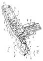
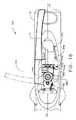
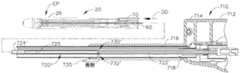
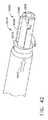
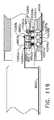
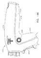
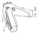
図1は、例えば、Zemlok‘763及び/又はZemlok‘344(それぞれがその全体を参照することによって本明細書に組み込まれている)に開示されている外科用器具(その様々な特徴部、構成部品、及びサブコンポーネントを含む)に多くの点で類似し得る、動力付き外科用器具10を示す。図1に示される外科用器具10は、器具の手動操作及び稼働を容易にするためのハンドル部14を有する、ハウジング12を備える。したがって、本明細書で使用するとき、用語「ハウジング」は、手持ち型、ないしは別の方法で手動操作可能な装置を包含してよい。しかしながら、用語「ハウジング」は、手持ち型であることは意図されないが、システムの様々な構成要素、部分、及び/又は作動装置によって別の方法で操作され、作動可能な、ロボット制御システムなどの自動外科用器具システムの部分も包含してよい。 FIG. 1 illustrates, for example, surgical instruments disclosed in Zemlok '763 and / or Zemlok' 344, each incorporated herein by reference in its entirety (its various features, configurations). 1 shows a powered
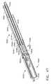
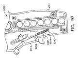
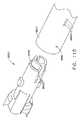
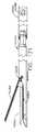
内視鏡部分の形態の細長いシャフトアセンブリ16は、ハウジング12から突出し、それに加えられる発射運動に反応して少なくとも1つの外科的手技を行うように構成されている外科用エンドエフェクタに、動作可能に取り付けられるように構成されている。かかる外科用エンドエフェクタは、例えば、エンドカッター、把持器具、又は、1対のジョーであって、1つのジョーが別のジョーに対して選択的に移動可能であるか、若しくは、いくつかの構成では、両方のジョーが互いに対して移動可能であるジョーを含み得る他の装置を備えてよい。更なる例として、外科用エンドエフェクタは、図2及び3に示されるような「装填ユニット」20などの、組織を切断かつステープル留めするように構成されている装置を備えてよい。装填ユニット20などの外科用エンドエフェクタを、本明細書に詳述されるように、例えば、動力付き外科用器具10の細長いシャフトアセンブリ16に取り外し可能に取り付けることができる。 An
図2及び3は、外科用器具10と共に使用できる装填ユニット20の1つの代表的な形態を示す。かかる装填ユニット20は、上記米国特許出願公開(それぞれがその全体を参照することによって本明細書に組み込まれている)に開示されている装填ユニット、並びに、例えば、「SURGICAL STAPLING INSTRUMENTS WITH ROTATABLE STAPLE DEPLOYMENT ARRANGEMENts」という名称の米国特許出願公開第2012−0298719A1号(この開示はその全体を参照することによって本明細書に組み込まれる)に開示されている装填ユニットに類似し得る。 FIGS. 2 and 3 show one exemplary form of a
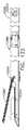
図2に示されるように、装填ユニット20は、内部のステープルカートリッジ26を動作可能に支持するキャリア24に対する旋回移動に対応している、アンビルアセンブリ22を備える。装着アセンブリ28は、カートリッジキャリア24に旋回式に連結し、器具の長手方向軸「LA−LA」に直交する関節屈曲軸「AA−AA」を中心としてキャリア24を旋回可能にする関節屈曲継手27を形成する。図3を参照すると、装着アセンブリ28は、例えば、上側及び下側取り付け部30及び32を備えてよい。各取り付け部30、32は、そのキャリア24の近位端を固定するために、その各側に、ねじ付きボルト(図示せず)を受容するサイズのねじ付き穴34を備えてよい。1対の中央に位置する枢動部材36は、ハウジング部40の遠位端と係合する1対の連結部材38を介して、上側取り付け部と下側取り付け部との間に延在し得る。連結部材38はそれぞれ、ハウジング部40の近位端に形成された溝42内に収容され、装着アセンブリ30及びハウジング部40を長手方向固定位置に保持するように構成されている、インターロック近位部39を備えてよい。 As shown in FIG. 2, the
図3に更に示されるように、装填ユニット20のハウジング部40は、それぞれが外部ケーシング50内に収容されるように構成されている、上側ハウジング半体44と、下側ハウジング半体46と、を備えてよい。ハウジング半体44の近位端は、細長いシャフトアセンブリ16の遠位端を取り外し可能に係合するための係合突起部48を備えてよい。突起部48は、例えば細長いシャフトアセンブリ16の遠位端との「バヨネット型」連結を形成してよい。様々な連結装置が本明細書に詳述される。ハウジング半体44、46は、軸方向に移動可能な駆動梁60を摺動可能に収容するための溝47を画定してよい。第2関節屈曲連結部70は、ハウジング半体44と46との間に形成されたスロット72内に摺動可能に配置されるような寸法であってよい。1対の「ブローアウト」プレート74を、軸方向駆動梁60の遠位端に隣接するハウジング部40の遠位端に隣接して位置づけ、キャリア24の関節屈曲中の駆動梁60の外側への張出しを阻止することができる。 As further shown in FIG. 3, the
駆動梁60は、遠位作動ヘッド62と、近位係合部64と、を備えてよい。駆動梁60は、単一シート材料から、又は好ましくは、複数の積層シートから構成されてよい。係合部64は、駆動部材66内に形成された1対の対応する保持スロットを取り付けるように係合する寸法であり、かつそのように構成されている1対の係合指部を備えてよい。駆動部材66は、装填ユニット20の近位端が外科用器具10の細長いシャフトアセンブリと係合すると、発射ロッドの遠位端を収容するように構成されている近位ポートホール67を備えてよい。遠位作動ヘッド62は、内部に形成された組織切断部63を有してよい。遠位作動ヘッド62は、遠位作動ヘッド62がステープルカートリッジ26を通って遠位に駆動されると、アンビルアセンブリ22を係合し、それをアンビル22とステープルカートリッジ26との間の組織をクランプする閉鎖位置まで枢軸旋回するように構成されている、1対のピン65を更に備えてよい。遠位作動ヘッド62上の組織切断部63は、ステープルカートリッジ26内に支持されている外科用ステープル(図示せず)が、既知の様式でアンビル22との接触部を形成するように駆動されるとき、クランプした組織を切開するのに使用される。例えば、遠位作動ヘッド62は、ステープルカートリッジ26中に移動可能に支持されているスレッド(図示せず)を軸係合し、かつこれを前進させるように構成されている。スレッドが駆動部材66によって遠位方向に駆動されると、スレッドはステープルと関連している押子(図示せず)に接触し、押子によって、装填ユニット20上のアンビル22との係合部を形成するように、カートリッジ26からステープルを送り出す。 The
図1に示されるように、外科用器具10は、例えば以下で更に詳述するような、装填ユニット20に発射運動を与えるために使用され得る回転作動運動を生成するように構成されている、モーター100を備える。少なくとも1つの形態では、例えば、モーター100は、全体を通して82と表記される発射部材アセンブリに、回転作動運動を与えるように構成されている。1つの構成では、例えば、発射部材アセンブリ82は、ハウジング12内に回転可能に支持され、内部に形成された雌ねじ(図示せず)を有する、駆動チューブ102を備える。発射ロッド104の近位ねじ付き部分は、駆動チューブ102の回転によって発射ロッド104の軸方向移動が生じるように、駆動チューブ102と螺合して支持される。発射ロッド104は、装填ユニット20内の駆動梁60の内部をねじ止めにより接続できる。上記の組み込まれたZemlok‘763及びZemlok‘344に更に詳述されるように、第1方向(例えば、反時計方向)への駆動チューブ102の回転により、発射ロッド104が駆動部材60を遠位方向に前進させる。装填ユニット20内の駆動部材60の遠位方向への初期前進により、アンビル22をステープルカートリッジ26に向かって旋回させる。駆動部材60が遠位方向「DD」に初期駆動されると、アンビル22は、アンビル22を閉鎖位置までカム運動させる駆動部材60上のピン65によって作動される。発射ロッド104、最終的には装填ユニット20を通って駆動部材60の更に遠位への移動により、アンビル22上のステープル形成底面との接触を形成するようにステープルを駆動させる。 As shown in FIG. 1, the
図1に更に示されるように、外科用器具10は、全体を通して109と表記される関節屈曲システムを備えてよい。しかしながら、外科用器具10は、本明細書に詳細に開示される様々なその他関節屈曲システム装置を備えてよい。少なくとも1つの形態では、関節屈曲システム109は、関節屈曲モーター112と、手動関節屈曲ノブ114と、を備える関節屈曲機構110を備えてよい。関節屈曲モーター112を、動力付き関節屈曲スイッチ116によって、又は、手動関節屈曲ノブ114を旋回させることによって作動できる。関節屈曲モーター112の作動は、関節屈曲機構110の関節屈曲歯車118の回転につながる。関節屈曲機構110の作動により、エンドエフェクタ(例えば、装填ユニット20のカートリッジ/アンビル部)を、その軸が、細長いシャフトアセンブリ16の器具の長手方向軸「LA−LA」と実質的に一直線である第1位置から、エンドエフェクタの軸が、細長いシャフトアセンブリの器具の長手方向軸「LA−LA」に対して、例えば関節屈曲軸「AA−AA」を中心にある角度で配置される位置まで移動させることができる。関節屈曲機構110の様々な態様に関する更なる説明は、その全体を参照することによって先に本明細書に組み込まれたZemlok‘763において見いだすことができる。加えて、その全体を参照することによって開示全体が本明細書に組み込まれる、「SURGICAL STAPLING APPARATUS WITH POWERED ARTICULATION」という名称の米国特許第7,431,188号は、外科用器具10と共に使用できるモーター動力付きの関節屈曲可能なエンドエフェクタを開示する。 As further shown in FIG. 1, the
様々な実施形態では、外科用器具は少なくとも1つのモーターを備えてよく、これは、別の場所に詳述されるように、装填ユニット20に対する発射運動、及び/又は、関節屈曲システム109に対する関節屈曲をもたらすことができる。モーター100は、例えば、Zemlok‘763において更に詳述されている種類の電源200によって、給電されてよい。例えば、電源200は、再充電可能電池(例えば、鉛系、ニッケル系、リチウムイオン系など)を含んでよい。電源200が少なくとも1つの使い捨て電池を含んでよいことも想定される。使い捨て電池は、例えば、約9ボルト〜約30ボルトであってよい。しかしながら、他の電源も使用できる。図1は、電源200が複数の電池202を備える1つの例を示す。使用される電池202の数は、器具10の電流負荷要件に依存し得る。 In various embodiments, the surgical instrument may comprise at least one motor, which, as detailed elsewhere, is a firing motion for the
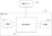
特定の実施形態では、外科用器具10は、外科用器具10の少なくとも1つのモーターに給電するための二次電源を備えてよい。例えば、ここで図129を参照すると、外科用器具10は、外科用器具10を操作するためのエネルギーを供給するように構成できる電力システム2000を備えてよい。図129に示されるように、電力システム2000は、例えば、ハウジング12のハンドル部14内に設置でき、一次電源2002と、二次、つまりバックアップ電源2004を備えてよい。一次電源2002は、通常操作中の外科用器具10の操作用エネルギーを供給するように構成されてよく、二次電源2004は、外科用器具10の操作用エネルギーを供給するのに一次電源2002が使用できないとき、例えば、一次電源2002が消耗したとき、及び/又は、外科用器具10から外されたときに、少なくとも限られた容量で外科用器具10の操作用エネルギーを供給するように構成されてよい。例えば、二次電源2002は、外科的手技中に一次電源2002が消耗した場合、及び/又は、外科用器具10から外された場合に、外科用器具10を初期状態に回復させるためのエネルギーを供給するように構成されてよい。 In certain embodiments, the
図1を参照すると、他の場所に詳述されるように、例えば、電源200などの電源は、外科用器具10の操作のための電力を供給できる。例えば、電源200は、例えば、モーター100などのモーターに電力を供給し、駆動チューブ102の第1方向への回転と、最終的には、装填ユニット20を通して駆動梁60を遠位に駆動する発射ロッド104の軸方向の前進を起こすことができる。別の方法としては、電源200は、モーター100に電力を供給し、駆動チューブ102の第1方向と反対の第2方向への回転と、最終的には、駆動梁60をその最初の及び/又は既定の位置まで近位に移動し得る発射ロッド104の軸方向の後退を起こすことができる。同様に、一次電源2002は、モーター100に電力を供給し、外科用器具10の通常操作中に発射ロッド104を前進及び/又は後退するように構成されてよい。加えて、二次電源2004は、例えば、一次電源2002が消耗したとき、及び/又は、外科用器具10から外されたときなどに、一次電源2002が必要な電力を供給できなくなった場合に、発射ロッド104を既定位置まで後退させるのに要する電力を供給するように構成されてよい。 With reference to FIG. 1, a power source, such as a
上記に加え、他の場所に詳述されるように、外科用器具10は、例えば、エンドエフェクタ20の関節屈曲角度(図2参照)、エンドエフェクタ20の作動状態、センサの測定値、発射数、組織深さ、及び/又は発射ロッド104の位置などの、外科的手技中の外科用器具10の操作に関する様々な情報を記録し、保存するように構成されてよい。特定の例では、かかる情報は、例えば、保存された情報の維持に電力を要し得るランダムアクセスメモリ(RAM)ユニットなどの、揮発性つまり一時メモリに記録され、保存されてよい。外科用器具10の通常操作中、一次電源2002は、他の場所に詳述される他の電源と同様に、外科用器具10の揮発性つまり一時メモリユニット内に保存された情報を維持するのに要する電力を供給できる。加えて、二次電源2004は、例えば、一次電源2002が消耗したとき、及び/又は、外科用器具10から外されたときなど、一次電源2002が必要な電力を供給できなくなった場合に、保存された情報を一時的に維持するのに要する電力を供給できる。 In addition to the above, as described in detail elsewhere, the
特定の態様では、外科用器具10は、その全体を参照することによって本明細書に組み込まれているZemlok‘763に開示されている種類及び構成の制御システム2005を備えてよい。かかる制御システム2005の構成及び操作に関する更なる詳細は、当該公開特許から入手できる。例えば、制御システム2005は、視覚又は聴覚表示などのユーザーインターフェイスを介して、ユーザーに対して警告又は器具の状態などの情報を、生成又は提供するように構成されてよい。制御システム2005によって生成された信号又は入力は、例えば、ユーザー、器具構成要素によって提供される他の信号又は入力に反応してもよく、あるいは器具10と関連付けられる1つ以上の測定値の関数であってもよい。外科用器具10の通常操作中、他の場所に詳述されるように、例えば、一次電源2002(図129参照)などの電源は、制御システム2005が、ユーザーインターフェイスを介したユーザーとの対話などの機能を実行できるのに要する電力を供給できる。加えて、二次電源2004は、例えば、一次電源2002が消耗したとき、及び/又は、外科用器具10から外されたときなどに、一次電源2002が必要な電力を供給できなくなった場合に、ユーザーインターフェイスを介したユーザーとの一時的対話に必要な電力を少なくとも限られた容量で供給できる。 In certain aspects, the
ここで図130を参照すると、電力システム2000は、一次電源2002及び二次電源2004に連結され得る電力管理回路2006を含んでよい。電力管理回路2006は、半導体、コンピュータチップ、又はメモリを含むか、又は、それらと選択的に関連付けられてもよい。電力管理回路2006は、制御システム2005、一次電源2002、及び/又は二次電源2004を含むが、これらに限定されない、外科用器具10の様々な構成要素に、又はそれらから、アナログ又はデジタルの入力又は信号を送信又は受信するように構成されてよい。様々な態様では、電力管理回路2006は、1つ又は2つ以上のアルゴリズムを利用して、一次電源2002及び/又は二次電源2004を含む外科用器具10の様々な構成要素を制御かつ監視するための入力信号を更に組織化できる、ソフトウェアを使用してよい。かかる組織化された入力信号は、電力管理回路2006によって測定及び/若しくは計算される基準の関数であってもよく、又はいくつかの場合、別の器具構成要素、ユーザー、若しくは電力管理回路2006と動作可能に通信する別個のシステムによって、電力管理回路2006に提供されてもよい。 Referring now to FIG. 130, the
再度図129を参照すると、一次電源2002は、器具10の電流負荷必要量に応じた1つ又は2つ以上の電池を備えてよい。様々な態様では、図129に示されるように、一次電源2002は、例えば、互いに直列に接続できる複数の電池2010を含み得る、バッテリーパック2008を備えてよい。バッテリーパック2008は交換可能であってよい。換言すれば、バッテリーパック2008は、外科用器具10から切り離して取り外し、別の同様のバッテリーパックと交換できる。特定の態様では、一次電源2002は、再充電可能電池(例えば、鉛系、ニッケル系、リチウムイオン系など)を含んでよい。電池2008は、例えば、CR 123A電池などの3ボルトのリチウム電池であってよいが、例えば、別の実施形態では、例えば、異なる電圧レベル及び/又は異なる化学的性質を有する電池などの異なる種類の電池を使用できる。ユーザーは、消耗した、つまり使用済みのバッテリーパック2008を外科用器具10から切り離して取り外し、充電したバッテリーパック2008を接続して外科用器具10に電力を供給できる。消耗したバッテリーパック2008は、その後充電され、再利用できる。一次電源2002が少なくとも1つの使い捨て電池を含んでよいことも想定される。様々な態様では、使い捨て電池は、例えば約9ボルト〜約30ボルトであってよい。ユーザーは、消耗した使い捨てバッテリーパック2008を切り離して取り外し、新しい使い捨てバッテリーパック2008を接続して外科用器具10に電力を供給できる。 Referring again to FIG. 129, the
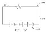
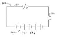
上記のように、バッテリーパック2008は再充電可能電池を備えてよく、例えば、ハウジング12のハンドル部14内に取り外し可能に設置できる。かかる状況では、充電器台を使用してバッテリーパック2008を充電してよい。例えば、図131に示されるように、ハンドル部14内の場所からバッテリーパック2008を取り外し、充電器台2012に接続することによって、充電器台2012をバッテリーパック2008に接続できる。図131に示されるように、充電器台2012は、バッテリーパック2008を充電するための電源2014を備えてよい。充電器台2012の電源2014は、例えば、電池(若しくはいくつかの直列接続した電池)、又は、電源の主管からなどの交流電力を、直流若しくはバッテリーパック2008の充電に好適な任意のその他電源に変換するAC/DC変換器であってよい。充電器台2012は、バッテリーパック2008の充電状態を示す、LED、LCDディスプレイなどのインジケータ装置を備えてもよい。 As described above, the
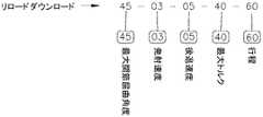
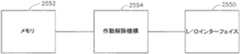
加えて、図131に示されるように、充電器台2012は、例えば、1つ又は2つ以上のプロセッサ2016、1つ又は2つ以上のメモリユニット2018、及びi/oインターフェイス2020、2022を備えてよい。第1のi/oインターフェイス2020によって、充電器台2012は、電源パック2008(電源パックのi/oインターフェイスを介して)と通信し、例えば、充電器台2012のメモリ2020に電源パック2008のメモリに保存されたデータをダウンロード可能にできる。様々な状況では、ダウンロードしたデータは、その後、例えば、器具10が関与する操作が行われる病院システム、外科医の診察室、器具の販売元、器具の製造業者などによって評価及び解析するために、第2のi/oインターフェイス2022を介して別のコンピュータ装置にダウンロードできる。 In addition, as shown in FIG. 131, the
充電器台2012は、バッテリーパック2008の電池全体の充電量を測定する充電メーター2024を備えてもよい。充電メーター2024はプロセッサ2016と通信してよく、そうして、電池が期待通りに機能し得ることを確実にするため、プロセッサ2016がバッテリーパック2008の使用適合性をリアルタイムに判定できる。 The
再度図129を参照すると、二次電源2004は、例えばハンドル部14内に配置できる1つ又は2つ以上の電池2026を備えてよい。電池2026は再充電可能であってよい(例えば、鉛系、ニッケル系、リチウムイオン系など)。例えば、電池2026は、CR 123A電池などの3ボルトのリチウム電池であってよい。加えて、電池2026を、器具10から取り外さずに再充電されるように構成してよい。例えば、一次電源2002が器具10に連結されるとき、一次電源2002を利用して電池2026を充電してよい。 Referring again to FIG. 129, the
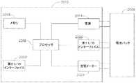
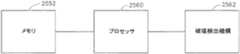
図132を参照すると、電力管理回路2006の代表的な実施形態が示される。特に、電力管理回路2006は、一次電源2002及び/又は二次電源2004の稼働に関連する電気的パラメータを監視するように構成されてよい。例えば、電力管理回路2006は、一次電源2002及び/又は二次電源2004の電力レベルを監視するように構成されてよい。図132に示されるように、電力管理回路2006は、一次電源2002及び/又は二次電源2004全体の充電量を測定するように構成され得る充電メーター2028を備えてよい。電力管理回路2006は、フラッシュ又はROMメモリなどの不揮発性メモリ2030と、例えば、1つ又は2つ以上のプロセッサ2032と、を備えてもよい。プロセッサ2032をメモリ2030に接続し、これを制御してよい。加えて、プロセッサ2032を充電メーター2028に接続して、充電メーター2028の測定値を読み取る、ないしは別の方法で制御してよい。加えて、プロセッサ2032は、例えばLEDなどの電力管理回路2006の出力装置を制御してよい。 Referring to FIG. 132, an exemplary embodiment of the
充電メーター2024及び/又は2028が、電圧、充電量、抵抗及び/又は電流を測定するように構成され得ることを、読者は理解するであろう。特定の例では、充電メーター2024及び/又は2028は、既定の負荷における電圧の状態を測定するよう構成され得る電池容量測定回路を備えてよい。 The reader will appreciate that the
上記に加え、プロセッサ2032は、一次電源2002及び/又は二次電源2004に関する情報をメモリ2030に保存できる。その情報は、特に、使用可能な総充電量、使用回数、及び/又は性能を含んでよい。加えて、メモリ2030に保存された情報は、電力管理回路2006が読み取り、保存することが可能な一次電源2002のID値を含んでよい。かかるIDは、例えば、RFIDトランスポンダ2034を介して電力管理回路2006によって読み取られるRFIDであってよい。RFIDトランスポンダ2034は、RFIDタグを含む電源からRFIDを読み取ることができる。ID値が読み取られ、メモリ2030に保存され、プロセッサ2032によってメモリ2030又は電力管理回路2006に関連する別の保存場所に保存された許容可能なID値リストと比較して、例えば、読み取られたID値に関連する取り外し可能/交換可能な一次電源2002が認証されたもの及び/又は適切なものかどうかを判定できる。かかる状況では、プロセッサ2032が、読み取られたID値に関連する取り外し可能/交換可能な構成要素を認証しないと判定する場合、電力管理回路2006は、電力が器具10に送られるのを防ぐスイッチ(図示せず)を開放することなどによって、器具10の使用を防ぐように構成され得る。構成要素が認証されたもの及び/又は適切なものかどうかを判定するためにプロセッサ2032が評価し得る様々なパラメータとして、例えば、日付コード、構成要素の型式/種類、製造業者、地域情報、及び/又は事前のエラーコードが挙げられる。 In addition to the above, the processor 2032 can store information on the
上記に加え、電力管理回路2006は、例えば、器具10が関与する操作が行われる病院システム、外科医の診察室、器具の販売元、器具の製造業者などによって評価及び解析するために、メモリ2030に保存されたデータが別の装置にダウンロードできるように、別の装置、例えばコンピュータと通信するためのi/oインターフェイス2036を備えてもよい。i/oインターフェイス2036は、例えば、有線又は無線インターフェイスであってよい。 In addition to the above, the
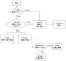
図133に示されるブロック図を参照すると、電力管理回路2006は、一次電源2002及び二次電源2004から、外科用器具10に電力を選択的に送ることができる。例えば、プロセッサ2032は、器具10に電力を供給するのに一次電源2002が使用可能であるときは一次電源2002から、器具10に電力を供給するのに一次電源2002が使用できないときは二次電源2004から、器具10に電力を送ることを可能にするようにプログラムされてよい。 Referring to the block diagram shown in FIG. 133, the
器具10の通常操作中、プロセッサ2032は、上記のような一次電源2002の検出及び認証時に、一次電源2002による器具10への電力供給を可能にすることができる。例えば、一次電源2002が切り離された及び/又は消耗したときなど、一次電源2002が既定の最低充電レベルに達する、又はそのレベルを下回るまで、一次電源2002が器具10に電力供給し続けてよい。電力管理回路2006を利用して、一次電源2002がいつ既定の最低充電レベルに達したが、又はそのレベルを下回ったのかを判定できる。例えば、プロセッサ2032は、一次電源2002の充電レベルを監視し、電力管理回路2006のメモリ2030に保存され得る既定の最低レベルにいつ達したか、又はそのレベルを下回ったのかを検出するために、充電メーター2028又は別の同様の充電メーターを使用するように構成されてよい。このような時点において、プロセッサ2032は、ユーザーに、一次電源2002の交換を警告することができる。電力管理回路2006は、器具10のユーザーに一次電源2002の交換を警告するために作動される、例えば1つ又は2つ以上のLED、LCDディスプレイなどのインジケータを備えてよい。更に、プロセッサ2032は、一次電源2002の充電レベルが既定の最低レベルに達した、又はそのレベルを下回ったことを検出すると、器具10の電力供給を一次電源2002から二次電源2004に切り替えるように構成されてよい。追加のインジケータを利用して、ユーザーに追加のフィードバックを提供できることを読者は理解するであろう。例えば、インジケータを利用して、器具10が一次電源2002から二次電源2004に切り替わっていること、またその逆をユーザーに警告できる。 During normal operation of the
上記に加え、プロセッサ2032をプログラムし、一次電源2002が外科用器具10に接続されると、一次電源2002によって二次電源2004を充電可能にしてよい。特定の例では、二次電源2004は、一次電源2002によって既定の最大電力レベルまで完全に充電されると、器具10の電力供給に一次電源2002が使用可能なままである限り使用されないままであってよい。加えて、電力管理回路2006を利用して、二次電源2004がいつ十分に充電されたのかを判定できる。例えば、プロセッサ2032は、充電レベルが電力管理回路2006のメモリ2030に保存され得る既定の最大レベル(プロセッサ2032が一次電源2002の二次電源2004への充電を止める点)に達するまで、充電メーター2028を利用して二次電源2004の充電レベルを監視するように構成されてよい。電力管理回路2006は、二次電源2004が十分に充電されると、器具10のユーザーに警告するように作動され得るインジケータ、例えば1つ又は2つ以上のLED、LCDディスプレイなどを備えてよい。 In addition to the above, processor 2032 may be programmed to allow
再度図129を参照すると、一次電源2002を、器具10のハンドル部14のチャンバ2038内に収容できる。一次電源2002を交換するため、ハンドル部14の外殻を取り外し、チャンバ2038を露出させてよい。特定の例では、トリガ又はスイッチをハンドル部14の外殻と連携させ、ハンドル部14の外殻を取り外そうとすることが、プロセッサ2032によって、一次電源2002から二次電源2004に切り替えるきっかけとなる事象として理解されるようにしてよい。 Referring again to FIG. 129, the
外科用器具10の一次電源2002を新しい一次電源2002と交換すると、電力管理回路2006は、上記のように新しい一次電源2002の認証を確認し、その認証が確認されると、電力管理回路2006は、新しい一次電源2002による器具10への電力送信を可能にすることができる。加えて、一次電源2002は上記のように二次電源2004を充電することもできる。 When the
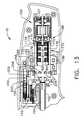
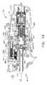
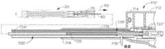
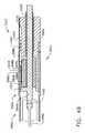
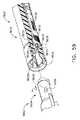
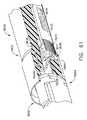
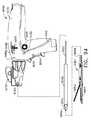
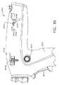
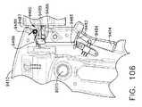
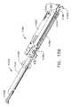
装填ユニット20(図2及び3)などの外科用エンドエフェクタを、例えば、動力付き外科用器具10(図1)の細長いシャフトアセンブリ16に動作可能に連結できる。例えば、ここで図38〜58を参照すると、例えば、使い捨て装填ユニット(DLU)5502などの外科用エンドエフェクタを、例えば、動力付き外科用器具10(図1)などの外科用器具に取り外し可能に取り付けることができる。様々な実施形態では、外科用器具は、例えばDLU 5502に係合できるシャフト5520を備えてよい。様々な実施形態では、回転可能なカラー5580などのカラーは、例えば、シャフト5520に対してDLU 5502を取り外し可能にロックできる。更に、様々な実施形態では、カラー5580の回転により、本明細書に記載される発射アセンブリ及び/又は関節屈曲アセンブリの取り付け及び/又は整列を容易にできる。 A surgical end effector, such as loading unit 20 (FIGS. 2 and 3), can be operably coupled to elongate
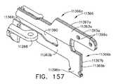
様々な実施形態では、DLU 5502は遠位取り付け部5504を備えてよく、シャフト5520は、外側チューブ5554と、近位取り付け部5522と、を備えてよい。DLU 5502の遠位取り付け部5504は、DLU 5502がシャフト5520に固定されると、シャフト5520の近位取り付け部5522を収容することができる(図39)。更に、回転可能なカラー5580をシャフト5520の近位取り付け部5522の周囲に位置づけ、DLU 5502の遠位取り付け部5504も回転可能なカラー5580内に位置づけられ得るようにしてよい。回転可能なカラー5580をシャフト5502及び/又は近位取り付け部5504に固定してよく、特定の実施形態では、例えば、シャフト5502の近位取り付け部5504に回転可能に固定してもよい。特定の実施形態では、DLU 5502がシャフト5520に固定されるとき、シャフト5520の近位取り付け部はDLU 5502の遠位取り付け部を収容できる。更に、特定の実施形態では、カラー5580をDLU 5502に回転可能に固定してよい。 In various embodiments,
更に図38〜58を参照すると、DLU 5502が外科用器具のシャフト5520に対して非取り付け位置と取り付け位置との間を移動するとき、DLU 5502は、シャフト5520によって画定される長手方向軸に沿って平行移動できる。DLU 5502が非取り付け位置から取り付け位置まで移動するとき、DLU 5502の遠位取り付け部5504をシャフト5520の近位取り付け部5522内に挿入できる。DLU 5502が非取り付け位置と取り付け位置との間を移動するとき、例えば、DLU 5502を方向Aに平行移動してよい(図39)。特定の実施形態では、遠位取り付け部5504と近位取り付け部5522との間の溝−スロット係合により、シャフト5520によって画定される長手方向軸に沿ってDLU 5502を導くことができる。主に図42を参照すると、遠位取り付け部5504はガイドレール5514を備えることができる。更に、主に図44を参照すると、近位取り付け部5522はガイドスロット5534を備えることができる。ガイドスロット5534は、DLU 5502の近位取り付け部5504がシャフト5520の遠位取り付け部5522内に挿入されると、ガイドレール5514を収容し、導くような寸法及び構造であってよい。例えば、ガイドスロット5534は長手方向スロットを備えてよく、ガイドレール5514は、例えば長手方向隆起部を備えてよい。特定の実施形態では、ガイドスロット5534及びガイドレール5514は、シャフト5520によって画定される長手方向軸に対して、DLU 5502がねじれたり、及び/又は回転したりするのを防ぐことができる。 38-58, as the
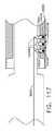
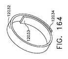
主に図38を参照すると、遠位取り付け部5504に、例えば第1矢印などの第1位置合わせ用しるし5510を含んでよく、シャフト5520及び/又はカラー5580に、例えば第2矢印などの第2位置合わせ用しるし5590を含んでよい。第1及び第2位置合わせ用しるし5510、5590を合わせると、ガイドレール5514とガイドスロット5534を整列させることができ、近位取り付け部5522への遠位取り付け部5504の取り付けを容易にできる。本明細書に記載されるように、シャフト5520に向かって長手方向経路に沿ってDLU 5502を平行移動すると、DLU 5502をシャフト5520に対して取り外し可能にロックできる。かかる実施形態では、シャフト5520に対してDLU 5502を取り付けるのに、シャフト5520に対するDLU 5502の回転は不要であり得る。実際に、本明細書に記載されるような近位取り付け部5522と遠位取り付け部5504との間の溝−スロット係合によって、シャフト5520に対するDLU 5502の回転は、制止及び/又は妨害され得る。様々な実施形態では、カラー5580をDLU 5502及び/又はシャフト5520に対して回転させ、DLU 5502をシャフト5520に取り外し可能にロックしてもよい。例えば、本明細書に記載されるように、カラー5580を、初期方向(図53)から第2の方向(図54)に向けて回転させ、その後初期方向(図57)に向けて戻して、DLU 5502をシャフト5520にロックしてもよい。 Referring primarily to FIG. 38, the
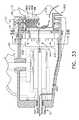
主に図42及び43を参照すると、DLU 5502の近位部5504は、回転キー又はリブ5506を備えることができる。DLU 5502を、非取り付け位置(図38)と取り付け位置(図39)との間を方向Aに移動させると(図39)、回転キー5506がカラー5580の回転に影響を及ぼし得る。例えば、回転キー5506は、カラー5580を初期方向から第2の方向まで、方向B(図39)に回転させる、及び/又は付勢することができる。カラー5580が第2の方向に付勢されるとき、遠位取り付け部5504を近位取り付け部5522内に挿入できる。更に、遠位取り付け部5504が近位取り付け部5522内に完全に挿入されると、回転キー5506は、カラー5580が、第2の方向から初期方向まで、方向C(図39)に回転させることができる。例えば、方向Cは方向Bの反対方向であってよい。本明細書に記載されるように、カラー5580が初期方向まで戻ると、カラー5580は、近位取り付け部5522に対して遠位取り付け部5504をロックできる。更に図42及び43を参照すると、回転キー5506は、その近位端に回転ランプ5508を備えることができる。回転ランプ5508は、シャフト5520の要素と係合し、例えば、回転カラー5580を回転させることができる。 Referring primarily to FIGS. 42 and 43, the
様々な実施形態では、回転ランプ5508は、シャフト5520内に位置する発射シャフト5540の回転に影響を及ぼし得る。例えば、主に図47〜50を参照すると、発射シャフト5540は、発射シャフト5540から半径方向外側に延出し得る発射シャフト回転子5544を備えることができる。DLU 5502がシャフト5520内に挿入されると、回転キー5506の回転ランプ5508は発射シャフト回転子5544を係合できる。様々な実施形態では、回転ランプ5508は発射シャフト回転子5544を回転させ、それによって発射シャフト5540を回転させることができる。例えば、発射シャフト5540及び発射シャフト回転子5544は、第1の向き(図53)と第2の向き(図54)との間を方向B(図54)に回転できる。更に図47〜50を参照すると、発射シャフト5540を回転可能なカラー5580と係合できる。例えば、回転可能なカラー5580は回転子溝5584を備えることができ、これは、発射シャフト回転子5544を収容し、及び/又は保持するような構造であり、寸法であり得る。発射シャフト回転子5544の回転によって回転可能なカラー5580が回転するように、発射シャフト回転子5544を回転子溝5584によって保持できる。かかる実施形態では、DLU 5502をシャフト5520内に挿入すると、発射シャフト回転子5544を例えば方向Bに回転させることによって、回転可能なカラー5580を方向B(図54)の回転に影響を及ぼし得る。 In various embodiments, the
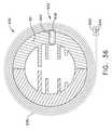
主に図44及び45を参照すると、近位取り付け部5522は回転キースロット5524を備えることができ、これは、遠位取り付け部5504が近位取り付け部5522内に挿入されると、回転キー5506を収容できる。様々な実施形態では、回転キースロット5524は、発射シャフト回転子5544を収容するための間隙ノッチ5526を備えてよい。例えば、回転キー5506の近位端にある回転ランプ5508は、発射シャフト回転子5544を第2の向きに、間隙ノッチ5526内まで回転させることができる(図54)。DLU 5502がシャフト5520内に挿入される際、回転キー5506は、回転キースロット5524に沿って移動し続けることができる。更に、回転キー5506の遠位端5509が発射シャフト回転子5544を過ぎて移動するとき、発射シャフト回転子5544は、第1の向き(図58)に向かって逆回転することができ、これにより、回転可能なカラー5580をその初期方向に向かって対応させて逆回転できる。 Referring primarily to FIGS. 44 and 45, the
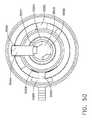
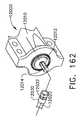
様々な実施形態では、回転可能なカラー5580は、シャフト5520及び/又は近位取り付け部5522に対して初期方向に付勢されていてよい。例えば、ばね5592は、ロックカラー5580を初期方向に付勢できる。ばね5592は、シャフト5520に対して固定できる近位端5594と、カラー5580に対して固定できる遠位端5596とを備えてよい。例えば、ばね5592の近位端5594を、シャフト5520の近位ばねスロット5538(図51)内に保持でき、例えば、ばね5592の遠位端5596を、回転可能なカラー5580の遠位ばねスロット5588(図46)内に保持できる。かかる実施形態では、カラー5580の回転により、ばね5592の遠位端5596をばね5592の近位端5594に対してずらすことができ、ねじり力が生じ得る。したがって、カラー5580は、初期方向から第2の方向への回転に抵抗でき、カラーが第2の方向に回転すると、ばね5592は初期方向に戻る方向にカラー5580を付勢できる。発射シャフト回転子5544はカラー5580と係合されているため、ばね5592は、発射シャフト5540もその第1の向きに付勢できる。 In various embodiments, the
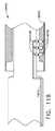
様々な実施形態では、回転可能なカラー5580は、DLU 5502をシャフト5520に取り外し可能にロックするロック移動止め5582を備えてよい。主に図46を参照すると、ロック移動止め5582は、回転可能なカラー5580の内部周辺部から半径方向内側に延出し得る。様々な実施形態では、ロック移動止め5582は、近位取り付け部5522の移動止めスロット5536(図44)内に延出し得る。主に図44を参照すると、移動止めスロット5536は、ガイドスロット5534内にノッチを形成し得る。様々な実施形態では、移動止めスロット5536はガイドスロット5534から延出し得、例えば、ガイドスロット5534に対して垂直又は実質的に垂直であってよい。更に、回転可能なカラー5580が、初期方向と第2の方向との間をシャフト5520に対して回転するとき、ロック移動止め5582は移動止めスロット5536に沿って移動できる。 In various embodiments, the
様々な実施形態では、ロック移動止め5582はDLU 5502の遠位取り付け部5504を係合し、シャフト5520に対してDLU 5502をロックできる。例えば、再度図42を参照すると、遠位取り付け部5504はガイドレール5514を備えてよく、これは、内部に画定されるロックノッチ5516を有することができる。ロックノッチ5516は、DLU 5502が近位取り付け部5522内に完全に挿入されるとき、回転可能なカラー5580のロック移動止め5582を収容する構造かつ寸法であってよい。例えば、遠位取り付け部5504が近位取り付け部5522内に完全に挿入されるとき、遠位取り付け部5504のロックノッチ5516は、近位取り付け部5522の移動止めスロット5536と一直線になってよい。したがって、ロック移動止め5582は、近位取り付け部5522の移動止めスロット5536に沿って、遠位取り付け部のロックノッチ5516内に摺動できる。更に、ロック移動止め5582は、ねじりばね5592によってロックノッチ5516と係合する方向に付勢されてよい。例えば、発射シャフト回転子5544が回転キー5506の遠位端5509を通過した後、発射シャフト5540は第1の向きに向かって再度付勢され得、回転可能なカラー5580は、ねじりばね5592によって初期方向に向かって再度付勢され得る。更に、カラー5580が第2の方向から初期方向に戻るように回転されると、そのロック移動止め5582は、ガイドレール5514中のロックノッチ5516と一直線になって係合され得る。 In various embodiments, the
様々な実施形態では、カラー5580の回転により、発射アセンブリの取り付け及び/又は整列を容易にできる。例えば、発射シャフト5540は、近位端5546と遠位端5542との間を延在できる。近位端5546は回転継手を有してよく、これによって、発射シャフト5540が第1構成と第2構成との間を回転できる。更に、遠位端5542は、DLU 5502の切断要素を取り付けるための連結具を有してよい。発射シャフト5540の回転により、切断要素の取り付けを容易にできる。例えば、発射シャフト5540の遠位端5542にある連結具が回転すると、連結具は、DLU 5502中の切断要素を係合し、連結できる。特定の実施形態では、連結具はバヨネットマウントを備えてよく、これによって、DLU 5502中の切断要素の対応するバヨネット受部に係合できる。主に図40及び41を参照すると、発射アセンブリは、例えば、近位端5546と遠位端5542との間の発射シャフト5540の周囲に位置づけられるスリーブ5550を更に備えてよい。 In various embodiments, rotation of the
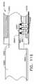
様々な実施形態では、発射シャフト5540がシャフト5520内を回転するとき、発射シャフト5540は、DLU 5502中の発射シャフトスロット5518と一直線になるように回転できる。例えば、DLU 5502がシャフト5520に完全に挿入されて取り付けられると、発射シャフト回転子5544は発射シャフトスロット5518と一直線になり得る。しかしながら、様々な実施形態では、DLU 5502がシャフト5520内に部分的にのみ挿入されるとき、回転キー5506によって発射シャフト回転子5544は、発射シャフトスロット5518と一直線にならないように回転し得る。換言すれば、発射シャフト回転子5544は、発射シャフト5540が第1の向きにあるとき発射シャフトスロット5514と一直線になることができ、発射シャフト5540が第2の向きに向かって回転すると発射シャフトスロット5514とずれ得る。かかる実施形態では、DLU 5502がシャフト5520内に部分的にのみ挿入されるとき、及び/又は、DLU 5502が回転可能なカラー5580によってシャフト5520に取り外し可能にロックされる前は、発射シャフト回転子5544の発射経路は遠位取り付け部5504によって閉鎖され得る。発射シャフト5540及びカラー5580を一体化すると、発射シャフト5540が発射及び/又は前進する前に、DLU 5502をシャフト5520に確実にしっかり取り付けることができる。例えば、外科用器具は、例えば、DLU 5502中の切断要素が発射シャフト5540に連結されるまで、及び/又は、発射シャフト5540がシャフト5520ときちんと一直線になるまで、発射できない。 In various embodiments, when the
特定の実施形態では、カラー5580の回転により、関節屈曲アセンブリ5559の取り付け及び/又は整列を容易にできる。主に図40及び41を参照すると、関節屈曲アセンブリ5559は、近位関節屈曲バー5560と、遠位関節屈曲バー5562と、関節屈曲コネクタ5566と、を備え得る。更に、例えば、シャフト5520は近位関節屈曲バースロット5528を備え得、DLU 5502は遠位関節屈曲バースロット5512を備え得る。特定の実施形態では、近位関節屈曲バー5560は近位関節屈曲バースロット5528と整列でき、遠位関節屈曲バー5562は遠位関節屈曲バースロット5512と整列できる。ここで図46を参照すると、関節屈曲コネクタ5566は回転可能なカラー5580内に収容され得る。例えば、回転可能なカラー5580は関節屈曲コネクタスロット5586を備え得、関節屈曲コネクタ5566はその中に移動可能に配置され得る。 In certain embodiments, rotation of the
様々な実施形態では、再度図40及び41を参照すると、近位関節屈曲バー5560は近位ノッチ5572を有し得、遠位関節屈曲バー5562は遠位ノッチ5574を有し得る。更に、関節屈曲コネクタ5566は、近位関節屈曲ラグ5568と、遠位関節屈曲ラグ5572と、を備え得る。近位関節屈曲ラグ5568は、近位関節屈曲バー5560の近位ノッチ5572内に保持され得る。特定の実施形態では、遠位関節屈曲ラグ5570は、遠位関節屈曲バー5562の遠位ノッチ5574を動作可能に係合し得る。本明細書に記載されるように、回転可能なカラー5580は、初期構成と二次構成との間を回転できる。カラー5580が回転すると、内部に収容される関節屈曲コネクタ5566も、シャフト5520によって画定される長手方向軸に対して回転できる。様々な実施形態では、関節屈曲コネクタ5566が回転するとき、関節屈曲コネクタ5566の近位関節屈曲ラグ5568は、近位関節屈曲バー5560の近位ノッチ5572内に位置づけられたままであってよい。更に、関節屈曲コネクタ5566がカラー5580と共に第2の方向から初期方向に向かって回転すると、関節屈曲コネクタ5566の遠位関節屈曲ラグ5570は、遠位関節屈曲バー5562の遠位ノッチ5574と係合するように移動できる。例えば、DLU 5502がシャフト5508内に完全に挿入されるとき、遠位関節屈曲バー5562の遠位ノッチ5574は、関節屈曲コネクタ5566の遠位関節屈曲ラグ5568と一直線になってよい。かかる実施形態では、回転可能なカラー5580が初期構成に戻るように回転されると、遠位関節屈曲ラグ5568は遠位関節屈曲バー5562の遠位ノッチ5574内に滑り込む。遠位関節屈曲ラグ5568が遠位ノッチ5574内に位置づけられるとき、関節屈曲アセンブリ5559は完全に組み立てられ得る。 In various embodiments, referring again to FIGS. 40 and 41, the
主に図45を参照すると、様々な実施形態では、近位関節屈曲バースロット5528は、第1間隙5530と、第2間隙5532と、を備え得る。関節屈曲コネクタ5566の近位及び遠位関節屈曲ラグ5568、5570は、それぞれ第1及び第2間隙5530、5532内に延出し得る。特定の実施形態では、第1及び第2間隙5530、5532は、例えば、カラー5580が回転するとき、及び/又は、関節屈曲アセンブリ5559が関節屈曲するときの、近位及び遠位関節屈曲ラグ5568、5570が移動する空間を提供できる。 Referring primarily to FIG. 45, in various embodiments, the proximal
ここで図51〜58を参照すると、DLU 5502を外科用器具のシャフト5520に連結するために、ユーザーは、DLU 5502の位置合わせ用しるし5510を、シャフト5520及び/又はカラー5580の位置合わせ用しるし5590(図51)と整列させることができる。位置合わせ用しるし5510、5590の整列を維持しながら、ユーザーは、シャフト5520に対してシャフト5520によって画定される長手方向軸に沿ってDLU 5502を移動できる。ユーザーは、真っ直ぐな又は実質的に真っ直ぐな経路に沿ってDLU 5502を移動でき、様々な実施形態では、例えばシャフト5520に対してDLUを回転させる必要はない。主に図53を参照すると、DLU 5502をシャフト5520に対して平行移動し続け、遠位取り付け部5504のガイドレール5514を、シャフト5520の近位取り付け部5522中のガイドスロット5534(図44)内に嵌めることができる。遠位取り付け部5504が近位取り付け部5522内に移動するとき、ガイドスロット5534はガイドレール5514を導くことができ、例えば、位置合わせ用しるし5510、5590の整列を維持できる。換言すれば、ガイドスロット5534及びガイドレール5514は、シャフト5520の長手方向軸に対してDLU 5502が回転するのを防ぐことができる。主に図52を参照すると、例えば、関節屈曲コネクタ5522の近位関節屈曲ラグ5568は第1間隙5530内に延出でき、近位関節屈曲バー5562の近位ノッチ5572に位置づけられ得、関節屈曲コネクタ5522の遠位関節屈曲ラグ5570は第2間隙5532を通って延出できる。 Referring now to FIGS. 51-58, in order to couple
主に図54を参照すると、遠位取り付け部5504が近位取り付け部5522内に挿入されると、回転キー5506の回転キーランプ5508は発射シャフト回転子5544に当接し得る。回転キーランプ5508は、回転キースロット5524から延在する間隙ノッチ5526内に、発射シャフト回転子5544を導く、及び/又は方向付けることができる。更に、発射シャフト回転子5544が間隙ノッチ5526内に移動すると、発射シャフト5540は方向Bに回転できる。発射シャフト5540は、第1の向きから第2の向きまで回転できる。発射シャフト5540がこのように回転すると、発射シャフト5540の遠位端5542をDLU 5502中の切断要素に容易に取り付けできる。更に、発射シャフト回転子5544の回転により、発射シャフト回転子5544とカラー5580中の発射シャフト回転子溝5584(図46)との間の係合によって、カラー5580を方向Bに回転できる。カラー5580は、例えば、初期方向から第2の方向に回転できる。加えて、カラー5580が回転すると、ロック移動止め5582は、シャフト5520中を移動止めスロット5536に沿って移動できる。加えて、ばね5592の遠位端5596をカラー5580中の遠位ばねスロット5588(図46)に保持できるため、カラー5580の回転により、ばね5592の遠位端5596を回転できる。遠位端5596を近位端5594に対して移動させると、ねじり跳ね戻り力が生じ得、この力は、例えばカラー5580を第2の方向から初期方向に向けて付勢でき、例えば発射シャフト5540を第2の向きから第1の向きに向けて付勢できる。 Referring primarily to FIG. 54, when the
主に図55を参照すると、カラー5580が第2の方向に向かって回転するとき、近位関節屈曲ラグ5568は、近位関節屈曲バー5560中の近位ノッチ5572と係合したままであり得る。更に、遠位関節屈曲ラグ5570がDLU 5502の遠位関節屈曲バー5562のための間隙を提供するように、遠位関節屈曲ラグ5570を回転できる。図56を参照すると、カラー5580及びその内部に位置づけられる関節屈曲コネクタ5566が第2の方向に回転するとき、DLU 5502をシャフト5520内に完全に挿入できる。様々な実施形態では、関節屈曲コネクタ5566が第2の方向に回転するとき、遠位関節屈曲バー5562は関節屈曲コネクタ5566の遠位関節屈曲ラグ5570を通過できる。更に、遠位関節屈曲ラグ5570は、関節屈曲コネクタ5566中の遠位ノッチ5574と回転可能に整列できる。引き続き図56を参照すると、DLU 5502がシャフト5520内に完全に挿入されるとき、発射ロッド回転子5544は、回転キー5506の遠位端5509を通過できる。 Referring primarily to FIG. 55, the
ここで図57を参照すると、回転キー5506の遠位端5509が発射シャフト回転子5544を通過すると、発射シャフト回転子5544は方向Cに回転できる。例えば、発射シャフト回転子5544は、第2の向きから第1の向きに向かって方向Cに回転できる。更に、発射シャフト回転子5544の回転により、第2の方向から初期方向に向かって方向Cへのカラー5580の回転に影響を及ぼし得る。様々な実施形態では、ばね5592は、発射ロッド5540をその第1の向きに向けて、カラー5580をその初期方向に向けて付勢できる。例えば、発射シャフト回転子5544の回転によりカラー5580が回転するように、発射シャフト回転子5544をカラー5580中の発射シャフト回転子溝5584(図46)に配置できる。関節屈曲コネクタ5566の遠位関節屈曲ラグ5570と遠位関節屈曲バー5562の遠位ノッチ5574が整列しているため、カラー5580が回転すると関節屈曲コネクタ5566は回転でき、遠位関節屈曲ラグ5570は遠位ノッチ5574と係合するように回転できる。遠位関節屈曲ラグ5570が遠位ノッチ5574を係合すると、関節屈曲アセンブリ5559を組み立てることができる。更に、発射シャフト回転子5544が方向Cに回転すると、発射シャフト5540の遠位端5542が方向Cに回転でき、これにより、DLU 5502中の切断要素の発射シャフト5540の遠位端5542への取り付けを容易にできる。 Referring now to FIG. 57, the firing
ここで図58を参照すると、カラー5580の回転により、遠位取り付け部5504のガイドレール5514中のロックノッチ5516内にある、カラー5580のロック移動止め5582も回転できる。例えば、DLU 5502がシャフト5520内に完全に挿入されるとき、ロック移動止め5582が移動止めスロット5536を通過して、ロックノッチ5516内まで回転できるように、ロックノッチ5516は移動止めスロット5536と一直線になってよい。本明細書に記載されるように、発射シャフト回転子5544が回転キー5506の遠位端5509を通過した後、ばね5592は、カラー5580を方向C(図57)に回転するように付勢し得る。引き続き図58を参照すると、発射シャフト回転子5544が方向Cに回転するとき、発射シャフト回転子5544は、DLU 5502中の発射シャフトスロット5518と一直線になるように回転できる。発射シャフト回転子5544が発射シャフトスロット5518と整列すると、例えば、発射シャフト5540を、DLU 5502を発射するために遠位に前進させることができる。 Referring now to FIG. 58, the rotation of the
本明細書に記載されるように、回転可能なカラー5580は、シャフト5520に対してDLU 5502を取り外し可能にロックできる。更に、カラー5580の回転により、関節屈曲アセンブリ5559の取り付け及び/又は整列を、並びに、発射シャフト5540の、例えばDLU 5502中の切断要素との取り付け及び/又は整列を容易にできる。更に、カラーの回転により、DLU 5502のシャフトからのロック解除、関節屈曲アセンブリ5559の切り離し、及び/又は、発射シャフト5540のDLU 5502中の切断要素からの切り離しもできる。例えば、カラー5580を初期方向から第2の方向に向かって再度回転すると、ロック移動止め5582は、遠位取り付け部5504中のロックノッチ5516を係合解除できる。したがって、遠位取り付け部5504を、例えば、シャフト5520によって画定される長手方向軸に沿って近位取り付け部5522から引き出すことができる。様々な実施形態では、シャフト5520に対してDLU 5502を回転せずに、シャフト5520からDLU 5502を取り外すことができる。しかしながら、カラー5580をシャフト5520に対して回転でき、それによって、例えば、カラー5580中の関節屈曲コネクタ5566から遠位関節屈曲バー5562を切り離し、DLU 5502中の切断要素から発射シャフト5540を切り離すことができる。 As described herein, the
ここで図59〜62を参照すると、使い捨て装填ユニット(DLU)又はエンドエフェクタ5602を、外科用器具のシャフト5620に取り外し可能に取り付けることができる。様々な実施形態では、例えば、ばね又は複数のばねは、シャフト5620に対してロック位置にDLU 5602を付勢できる。例えば、DLU 5602をバヨネットマウントによってシャフト5620に取り外し可能に取り付けでき、ばねは、DLU 5602を回転し、DLU 5602をバヨネット連結部においてシャフト5620に連結できる。例えば、DLU 5602は遠位取り付け部5604を備えてよく、シャフト5620は近位取り付け部5622を備えてよい。DLU 5602の遠位取り付け部5604は、DLU 5602がシャフト5620に固定されると、シャフト5620の近位取り付け部5622を収容することができる。別の実施形態では、DLU 5602がシャフト5620に固定されるとき、シャフト5620の近位取り付け部はDLU 5602の遠位取り付け部を収容できる。 Referring now to FIGS. 59-62, a disposable loading unit (DLU) or
様々な実施形態では、DLU 5602の遠位取り付け部5604は移動止め5606を備えてよく、これは、遠位取り付け部5604の一部から半径方向外側に延在し得る。更に、移動止め5606は傾斜面5608を備えてよい。本明細書に記載されるように、移動止め5606の傾斜面5608は、ばね5636bなどのばねを係合でき、例えば、遠位取り付け部5604が近位取り付け部5622内に挿入されると、ばね5636bを変形できる。更に、移動止め5606は、近位取り付け部5622によって保持され、DLU 5602をシャフト5622に取り外し可能にロックできる。主に図59を参照すると、シャフト5620の近位取り付け部5622は空洞5624を画定し得る。様々な実施形態では、空洞5624は、DLU 5602の遠位取り付け部5604を収容する構造かつ寸法であってよい。更に、ばね5636a、5636bを空洞5624内に配置できる。例えば、第1のばね5636aを空洞5624の第1側部上に配置でき、第2のばね5636bを空洞5624の第2側部上に配置できる。ばね5636a、5636bは、空洞5624に対して対称又は非対称であってよい。様々な実施形態では、少なくともばね5636a、5636bの一部は空洞5624内に延出し得る。例えば、第2のばね5636bの脚部5637は空洞5624内に延出でき、例えば、第2のばね5636の別の脚部5637は近位取り付け部5622内に保持され得る。 In various embodiments, the
引き続き図59を参照すると、近位取り付け部5622はロックスロット5638も備えてよく、これは例えば、空洞5624内に画定でき、及び/又は、空洞5624を介して接近できる。ロックスロット5638は、例えば、移動止め5606を収容する構造かつ寸法であってよい。様々な実施形態では、ロックスロット5638は移動止め5606を保持し、DLU 5602をシャフト5620に対して取り外し可能にロックできる。更に、様々な実施形態では、近位取り付け部5622はラッチ5630を備えてよい。ラッチ5630は、ラッチ解除位置(図59及び60)とラッチ留め位置(図61及び62)との間を移動可能であってよい。様々な実施形態では、ラッチ5630はばね仕掛けであってよく、ばね5634は、ラッチ5630をラッチ留め位置内まで付勢できる。例えば、ラッチ5630はラッチばね5634を備えてよく、これは、ラッチ5630をラッチ留め位置に向けて及び/又はラッチ留め位置内まで付勢できる。ラッチ留め位置は、例えばラッチ解除位置より遠位であってよい。特定の実施形態では、ラッチ5630は、親指把持部及び/又は隆起部5632を備えて、ラッチ留め位置からラッチ解除位置へのラッチ5630の移動を容易にしてよい。例えば、ユーザーは親指把持部5632を引っかけ、ラッチ5630を近位に引いてラッチ5630をラッチ解除することができる。 With continued reference to FIG. 59, the
様々な実施形態では、ラッチ5630は、ロックスロット5638を動作可能に閉鎖又は少なくとも部分的に閉鎖できる。例えば、ラッチ5630がラッチ留め位置(図61及び62)にあるとき、ラッチ5630のアーム5635は、ロックスロット5638の少なくとも一部を超えて延出し得る。ラッチ5630は、ロックスロット5638を覆う又は部分的に覆うことができ、ロックスロット5638への到達を阻止及び/又は制限できる。特定の実施形態では、ラッチ5630のアーム5635は、移動止め5606がロックスロット5638内に移動及び/又は摺動するのを防ぐことができる。その上、ラッチ5630がラッチ留め位置にあるとき、ラッチ5630は、ばね5636a、5636bを係合できる。例えば、図61及び62を参照すると、ラッチ5630は、ばね5636bの変形が制限される及び/又は阻止されるようにばね5636bを支持できる。更に、ラッチ5630は、空洞5624がDLU 5602の遠位取り付け部5604を収容できないようにばね5636bを支持できる。例えば、ばね5636bの少なくとも一部は空洞5624を閉鎖でき、それによって、遠位取り付け部5604が近位取り付け部5622内に完全に挿入されるのを防ぐことができる。特定の実施形態では、近位取り付け部5622は複数のばねを備えてよく、これらは、遠位取り付け部5604に回転力を及ぼし、近位取り付け部5622に対して遠位取り付け部5604を回転できる。例えば、近位取り付け部5622は、1対のばね又は4つ以上のばねを備えてよい。別の実施形態では、近位取り付け部5622中の1つのばねによって、近位取り付け部5622に対して遠位取り付け部5604を回転しようとしてよい。加えて又は別の方法としては、様々な実施形態では、DLU 5602の遠位取り付け部5602は少なくとも1つのばねを備えてよく、これは、例えば遠位取り付け部5602を近位取り付け部5622に対して回転できる。 In various embodiments, the
様々な実施形態では、ラッチ5630がラッチ解除位置(図59及び60)にあるとき、ロックスロット5638は、ラッチ5630のアーム5635によって閉鎖解除及び/又はわずかに閉鎖されていてよい。例えば、移動止め5606を、ラッチ解除されたラッチ5630を超えてロックスロット5638内に嵌めることができる。更に、本明細書に記載されるように、移動止め5606を、ラッチ解除されたラッチ5630を超えてロックスロット5638内に付勢することができる。その上、様々な実施形態では、ラッチ5630がラッチ解除位置にあるとき、ラッチ5630は、ばね5636a、5636bを係合解除できる。例えば、ラッチ5630がラッチ解除されると、ラッチ5630は、ばね5636a、5636bの変形を防ぐ及び/又は制限することができない。 In various embodiments, the
主に図59を参照すると、ラッチ5630が近位の及び/又はラッチ解除位置に移動され保持されるとき、例えば、ばね5636bはラッチ5630によって支持されていなくてよい。かかる実施形態では、遠位取り付け部5604を近位取り付け部5622に対して移動するように、DLU 5602を方向Aに移動できる。主に図60を参照すると、遠位取り付け部5604の移動止め5606は、ばね5636bを係合でき、例えば、ばね5636bを圧縮及び/又は変形できる。特定の実施形態では、移動止め5606の傾斜面5608は、ばね5636bに沿って摺動でき、ばね5636bの自由脚部5637を移動できる。ばね5636bの変形により、ばね5636bが移動止め5606上に及ぼし得る跳ね戻り力を生じさせることができる。ここで図61を参照すると、跳ね戻り力は移動止め5606の回転に影響を及ぼし得る。例えば、移動止め5606は、方向Bへ、空洞5624中に画定されるロックスロット5638内に回転できる。様々な実施形態では、ユーザーがラッチ5630を解放すると、ラッチばね5634はラッチ5630をラッチ解除位置まで戻すことができる。更に、ラッチ5630がラッチ解除位置まで戻ると、ラッチ5630のアーム5635はロックスロット5638を閉鎖又は部分的に閉鎖できる。かかる実施形態では、移動止め5606がロックスロット5638内に保持されるとき、遠位取り付け部5604の移動止め5606を、近位取り付け部5622に対して取り外し可能にロックできる。更に、特定の実施形態では、ラッチが再度ラッチ解除位置に移動するまで、ラッチ5630は、移動止め5606に対してばね5636bを保持及び/又は支持できる。様々な実施形態では、シャフト5620からDLU 5602を解放するため、ユーザーは、移動止め5606を回転させてロックスロット5638を出るように、ラッチ5630をラッチ留め位置からラッチ解除位置まで再度移動できる。かかる実施形態では、遠位取り付け部5604が近位取り付け部5622から引き出されるまで、移動止め5606の回転により、ばね5636bを再度圧縮及び/又は変形する。 Referring primarily to FIG. 59, for example, the
上記に加え、外科用器具は、外科用器具に組み付けられているエンドエフェクタを識別する、又は少なくとも識別を試みるように構成されてよい。特定の実施形態では、以下で更に詳述されるように、エンドエフェクタは、エンドエフェクタがシャフトに組み付けられるときに外科用器具のシャフト上の対応する電気接点と係合し得る、電気接点を備えてよい。かかる実施形態では、外科用器具のコントローラはエンドエフェクタとの有線接続を確立でき、電気接点を通じてコントローラとエンドエフェクタとの間の信号通信をなすことができる。以下で詳述されるように、エンドエフェクタは、そこに保存された少なくとも1つのデータを含んでよく、これがコントローラによってアクセスされ、エンドエフェクタを識別できる。少なくとも1つのデータは、例えば、1ビット、1ビット超、1バイト、又は1バイト超の情報を含んでよい。特定の別の実施形態では、エンドエフェクタは、外科用器具のコントローラと無線信号通信できる送信機を備えてよい。上記と同様に、エンドエフェクタは、そこに保存された少なくとも1つのデータを含んでよく、これがコントローラに送信され、エンドエフェクタを識別できる。かかる実施形態では、外科用器具のコントローラは、エンドエフェクタからの送信を受信できる受信機を備えてよく、又はその受信機を利用してよい。かかる受信機は、例えば、外科用器具のシャフト及び/又はハンドル内に位置づけられてよい。 In addition to the above, the surgical instrument may be configured to identify, or at least attempt to identify, an end effector that is assembled to the surgical instrument. In certain embodiments, as described in further detail below, the end effector comprises an electrical contact that can engage a corresponding electrical contact on the shaft of the surgical instrument when the end effector is assembled to the shaft. It's okay. In such an embodiment, the controller of the surgical instrument can establish a wired connection with the end effector and can provide signal communication between the controller and the end effector through electrical contacts. As detailed below, the end effector may include at least one data stored therein that can be accessed by the controller to identify the end effector. The at least one data may include, for example, 1 bit, more than 1 bit, 1 byte, or more than 1 byte of information. In certain other embodiments, the end effector may comprise a transmitter capable of wireless signal communication with the controller of the surgical instrument. Similar to above, the end effector may include at least one data stored therein that can be transmitted to the controller to identify the end effector. In such embodiments, the controller of the surgical instrument may comprise or utilize a receiver that can receive transmissions from the end effector. Such a receiver may be located, for example, within the shaft and / or handle of a surgical instrument.
読者には理解されるように、コントローラと無線通信するエンドエフェクタは、例えば、無線信号を発するように構成されてよい。様々な状況では、エンドエフェクタは、この信号を1回、又は2回以上発するように構成されてよい。特定の状況では、エンドエフェクタは、所望の時点で信号を発するように、及び/又は、連続的に繰り返し信号を発するように指示されてよい。いくつかの状況では、エンドエフェクタは、外科用器具のエンドエフェクタが外科用器具に組み付けられる前、その間、及び/又はその後に、外科用器具のユーザーが操作できるスイッチを備えてよい。様々な実施形態では、エンドエフェクタのスイッチは、エンドエフェクタを閉鎖、つまり操作して作動させることができる、オン・オフ、つまり電源スイッチを含んでよい。少なくとも1つのこのような実施形態では、エンドエフェクタは、例えば電池などの少なくとも1つの電源を備えてよく、送信機によってこれを利用して、オン・オフスイッチを入れるときに信号を発することができる。エンドエフェクタを作動すると、様々な状況では、エンドエフェクタのコントローラは、信号を発生し、送信機を介してその信号を発信するように構成されてよい。いくつかの状況では、エンドエフェクタは、エンドエフェクタが作動されるまで信号を発することができない。このような構成によって、例えば電池の電力を節約できる。特定の実施形態では、外科用器具を操作モードにしてよく、このモードは、エンドエフェクタのスイッチが作動される前に、エンドエフェクタからの信号を待つことができる。様々な状況では、外科用器具をスタンバイ、つまり低電力の操作モードにしてよく、このとき、コントローラによって信号が受信されると、コントローラは外科用器具を全出力操作モードにできる。いくつかの実施形態では、エンドエフェクタのスイッチは、外科用器具のコントローラに対して信号を発するようにエンドエフェクタのコントローラに指示できる。かかるスイッチは、電源スイッチを含んでも含まなくてもよいが、かかるスイッチは、所望の時点で、及び/又は、所望の時点から連続的に信号を発することをエンドエフェクタに指示するように、ユーザーによって選択的に作動できる。 As will be appreciated by the reader, an end effector that is in wireless communication with the controller may be configured to emit a wireless signal, for example. In various situations, the end effector may be configured to emit this signal once or more than once. In certain situations, the end effector may be instructed to emit a signal at a desired point in time and / or to continuously and repeatedly emit a signal. In some situations, the end effector may include a switch that can be operated by a user of the surgical instrument before, during, and / or after the end effector of the surgical instrument is assembled to the surgical instrument. In various embodiments, the end effector switch may include an on / off or power switch that can be actuated by closing or manipulating the end effector. In at least one such embodiment, the end effector may comprise at least one power source, such as a battery, which can be utilized by the transmitter to signal when the on / off switch is turned on. . Upon activation of the end effector, in various situations, the end effector controller may be configured to generate a signal and transmit the signal via a transmitter. In some situations, the end effector cannot emit a signal until the end effector is activated. With such a configuration, for example, battery power can be saved. In certain embodiments, the surgical instrument may be in an operating mode, which can wait for a signal from the end effector before the end effector switch is activated. In various situations, the surgical instrument may be in standby, i.e., a low power operating mode, where the controller can place the surgical instrument in full power operating mode when a signal is received by the controller. In some embodiments, the end effector switch can instruct the end effector controller to emit a signal to the surgical instrument controller. Such a switch may or may not include a power switch, but such a switch may instruct the end effector to emit a signal at a desired time and / or continuously from a desired time. Can be selectively operated by.
ここで図114を見ると、エンドエフェクタ9560などのエンドエフェクタは、例えば、エンドエフェクタ9560の作動に利用できる、例えば接点9561などの1つ又は2つ以上の電気接点を備えてよい。例えば、ここで図112を見ると、外科用器具のシャフト9040は、エンドエフェクタ9560がシャフト9040に組み付けられるとき、2つ又はそれ以上の接点9561を短絡する、又は電気的に接続するように構成できる、接点ブリッジ9562を備えてよい。ブリッジ9562は、2つの接点9561と、電池9564と、プリント基板9565上に形成された少なくとも1つの集積回路9566と、を含む回路を閉じることができる。回路が閉じられると、上記に加え、電池9564は、集積回路、つまり回路9566に電力を供給でき、エンドエフェクタ9560を作動することができる。様々な状況では、プリント基板9565に形成された集積回路、つまり回路9566及びアンテナ9567は、上記のコントローラ及び送信機を含むことができる。特定の実施形態では、シャフト9040は、例えば、ばね9563などの付勢部材を備えてよく、これは、ブリッジ9562を電気接点9561に接触するように付勢するよう構成できる。ブリッジ9562を電気接点9561に接続する前、及び/又は、エンドエフェクタ9560がシャフト9040から取り外された後は、回路を開放でき、電池9564からの電力を集積回路9566に供給できず、及び/又は、集積回路9566に供給される電力が低下し得、エンドエフェクタ9560を非作動状態にできる。上記の結果、かかる実施形態では、エンドエフェクタのアセンブリを、エンドエフェクタを外科用器具に組み付けた結果として作動できる。様々な場合では、上記に加え、エンドエフェクタ及び外科用器具を、エンドエフェクタを外科用器具に完全にかつ正しく組み付けたときのみエンドエフェクタが作動するように、構成し、かつ配置できる。 Turning now to FIG. 114, an end effector, such as
上記のように、ここで図111を参照すると、エンドエフェクタを、外科用器具に取り付け(工程9600で示される)、作動し(工程9602で示される)、その後外科用器具によって評価(工程9604で示される)できる。外科用器具が作動したエンドエフェクタからの無線信号の評価を試みるとき、上記に加え、外科用器具を信号が完全かどうかを評価するように構成できる。様々な実施形態では、エンドエフェクタと外科用器具との間の非同期シリアル通信を利用して、外科用器具が受信した信号が完全かどうかを評価できる。例えば、エンドエフェクタは、データフレーム、例えばあるバイトの情報に先行するスタートビット、例えば、及び/又はデータフレームに続くストップビットを含む信号を発することができる。このような場合では、スタートビット、そのバイトのデータ、及びストップビットは、例えば10ビットの文字枠、つまりビットパターンを含んでよい。外科用器具のコントローラがビットパターンのスタートビット及びストップビットを識別できるとき、このような場合では、コントローラは、スタートビットとストップビットとの間に受信したそのバイトのデータ、つまりそのビットのデータが、正しい、及び/又は別の方法で完全であると仮定できる。様々な状況では、スタートビット及び/又はストップビットは、次のバイトの情報が送信される前、及び/又は、これまでのバイトの情報が再度通信される前の、停止期間を含んでよい。 As described above, referring now to FIG. 111, the end effector is attached to the surgical instrument (shown at step 9600), activated (shown at step 9602), and then evaluated by the surgical instrument (at step 9604). Can be shown). In addition to the above, when attempting to evaluate a radio signal from an end effector with a surgical instrument activated, the surgical instrument can be configured to evaluate whether the signal is complete. In various embodiments, asynchronous serial communication between the end effector and the surgical instrument can be utilized to evaluate whether the signal received by the surgical instrument is complete. For example, the end effector may emit a signal that includes a start bit preceding a data frame, eg, a byte of information, and / or a stop bit following the data frame. In such a case, the start bit, the data of the byte, and the stop bit may include, for example, a 10-bit character frame, that is, a bit pattern. When the surgical instrument controller can identify the start bit and stop bit of the bit pattern, in such a case, the controller will receive the data of that byte received between the start bit and the stop bit, ie the data of that bit. Can be assumed to be correct and / or otherwise complete. In various situations, the start bit and / or stop bit may include a stop period before the next byte of information is transmitted and / or before the previous byte of information is communicated again.
上記に加え、ここで図110を見ると、外科用器具のコントローラは、ビットパターン、つまり特定のビットのデータを比較し、受信したデータが正しいか及び/又は別の方法で完全であるかを判定できる。様々な状況では、コントローラがデータを評価し、そのデータを、データの受信が予定されていたビットパターンテンプレート、つまりテンプレートと比較する方法で、データを送信できる。例えば、かかるテンプレートは、例えば左端のビットのデータなどの最上位ビットのデータが、例えば1を含むように構成され、配置されてよい。コントローラが、最上位ビットのデータが1に等しいことを識別できる場合(図110の工程9700参照)、工程9702に示されるように、コントローラは、データにおいてXOR演算を実行し、そのデータをコントローラが利用できるビットパターンテンプレート、つまりテンプレートと比較できる。XOR演算は既知であり、その詳細は、簡潔性のために本明細書に提供されない。外科用器具が受信したビットパターンがコントローラが利用できるビットパターンテンプレートと一致する場合、コントローラはエンドエフェクタを識別する。エンドエフェクタを識別すると、コントローラは、例えば、コントローラがアクセス可能なメモリチップ中の、エンドエフェクタに関する保存情報にアクセスできる。コントローラが、受信したビットパターン中の最上位ビットのデータが1に等しくないと判定する場合、再度工程9700を参照すると、コントローラはビットシフト演算を実行できる。例えば算術シフト、論理シフト、及び/又は循環シフトなどの多くのビットシフト演算は既知であり、これらを利用して、所望のビットパターンに先だって受信された不良データビットを除外できる。ここで図110の工程9704を参照すると、様々な状況では、先頭の、つまり左端の0のデータビットを除外でき、例えば、先頭ビットが1になるまでビットパターンを左にシフトできる。このような時点において、上記に加え、エンドエフェクタを識別するために、シフトされたビットパターンをビットパターンテンプレートと比較できる。シフトされたビットパターンがビットパターンテンプレートと一致しない場合、コントローラは、ビットパターン中の次の1が先頭ビットになるまでビットパターンを再度シフトでき、新たにシフトされたビットパターンをビットパターンテンプレートと比較できる。かかるシフト及び比較演算は、エンドエフェクタが識別される、及び/又は、外科用器具がエンドエフェクタは識別されないと見なすまで、任意の好適な回数実行できる。 In addition to the above, referring now to FIG. 110, the surgical instrument controller compares the bit pattern, ie, the data for a particular bit, to determine whether the received data is correct and / or otherwise complete. Can be judged. In various situations, the controller can evaluate the data and transmit the data in a manner that compares the data to the bit pattern template that was intended to receive the data, ie, the template. For example, such a template may be configured and arranged such that the most significant bit data such as the leftmost bit data includes, for example, 1. If the controller can identify that the most significant bit of data is equal to 1 (see
読者には理解されるように、外科用器具は、任意の好適な数のエンドエフェクタに関する情報を含んでよい。外科用器具によってエンドエフェクタが識別されると、上記に加え、外科用器具はエンドエフェクタに関する保存された情報にアクセスできる。例えば、かかる保存情報は、例えば、(1)発射行程を完了するためにエンドエフェクタ中の発射部材が前進しなくてはならない距離、及び/又は、(2)外科用器具のモーターが発射部材に加える必要がある電力、つまりトルクの最大量について、外科用器具に指示できる。かかる情報又は情報セットは、各エンドエフェクタ特有であり得、したがって、何らかの方法によるエンドエフェクタの識別とは、外科用器具が所望の様式で操作できることである。かかる情報がないと、外科用器具は、エンドエフェクタを十分活用するのに要する行程長さを識別する、及び/又は、発射部材に加えられる電力を適切に制限することができない。様々な状況では、外科用器具は、発射行程が完了した時点、及び/又は、発射部材に加えられている電力が過剰かどうかを検出するよう構成されているセンサに依存してよい。かかるセンサは、外科用器具のモーターが、例えばエンドエフェクタの発射部材に過剰に電力を供給し、損傷させるのを防ぐことができる。 As will be appreciated by the reader, the surgical instrument may include information regarding any suitable number of end effectors. Once the end effector is identified by the surgical instrument, in addition to the above, the surgical instrument can access stored information regarding the end effector. For example, such stored information may include, for example, (1) the distance that the firing member in the end effector must be advanced to complete the firing stroke, and / or (2) the surgical instrument motor on the firing member. The surgical instrument can be instructed as to the maximum amount of power, ie torque, that needs to be applied. Such information or information set may be specific to each end effector, and thus identification of the end effector in any way is that the surgical instrument can be manipulated in the desired manner. Without such information, the surgical instrument cannot identify the stroke length required to fully utilize the end effector and / or properly limit the power applied to the firing member. In various situations, the surgical instrument may rely on a sensor configured to detect when the firing stroke is complete and / or whether the power applied to the firing member is excessive. Such a sensor can prevent a surgical instrument motor from excessively powering and damaging, for example, an end effector firing member.
上記に加え、特定のエンドエフェクタは、別のエンドエフェクタよりも強靱であってよく、結果として、特定のエンドエフェクタは、外科用器具のモーターからのより大きい力に耐えることができる。それに対応して、別のエンドエフェクタは強靱性が低く、結果として、モーターからのより小さい力にのみ耐えることができる。外科用器具が、任意の特定のエンドエフェクタに加える適切な力を判定するために、上記に加え、外科用器具は、外科用器具に取り付けられたエンドエフェクタを識別しなくてはならない。エンドエフェクタがエンドエフェクタを識別できない場合、外科用器具は、既定の操作プログラム又は操作モードを使用できる。既定の操作モードでは、外科用器具のコントローラは、モーターがエンドエフェクタの発射部材にかけることができる電力を、例えば、最小の、つまり既定の電力に制限することができる。最小電力は、使用されているエンドエフェクタに関わらず、モーターがエンドエフェクタを損傷しないように選択することができる。いくつかの状況では、使用されているエンドエフェクタに関わらず、外科用器具がエンドエフェクタに過剰に電力を供給しないように、既定の操作モードによって外科用器具と共に使用できる最も弱い、つまり最も強靱性が低いエンドエフェクタが利用するパラメータを使用できる。様々な場合では、エンドエフェクタに過剰に電力を供給させることができるモーター式外科用器具が出現している。別の言い方をすれば、これまで手動式外科用器具によって使用され、かかる手動式外科用器具では本質的に破壊できないエンドエフェクタは、モーター式外科用器具によって容易に破壊され得る。その上、このようなこれまでのエンドエフェクタは、モーター式外科用器具によって識別される技術を備えることができず、本明細書に記載される既定の操作プログラムの結果、かかるこれまでのエンドエフェクタは、モーター式外科用器具でも依然として使用できる。しかし、既定の操作プログラムは、その他の既定のパラメータも利用できる。例えば、既定の操作プログラムは、最短の、つまり既定の発射行程長さを利用できる。様々な場合では、既定の操作プログラムは、外科用器具と共に使用できるエンドエフェクタの最短行程長さを利用できる。このような場合では、発射部材は、使用されているエンドエフェクタに関わらず、エンドエフェクタの遠位端と衝突、つまりぶつからない。 In addition to the above, a particular end effector may be tougher than another end effector, and as a result, a particular end effector can withstand greater forces from the surgical instrument motor. Correspondingly, the other end effector is less tough and consequently can only withstand smaller forces from the motor. In addition to the above, the surgical instrument must identify the end effector attached to the surgical instrument in order to determine the appropriate force that the surgical instrument applies to any particular end effector. If the end effector cannot identify the end effector, the surgical instrument can use a predefined operating program or mode of operation. In a predetermined mode of operation, the controller of the surgical instrument can limit the power that the motor can apply to the firing member of the end effector, for example, to a minimum or predetermined power. The minimum power can be selected so that the motor does not damage the end effector, regardless of the end effector being used. In some situations, regardless of the end effector being used, the weakest, or toughest, that can be used with a surgical instrument by a predefined operating mode so that the surgical instrument does not overpower the end effector The parameters used by the low end effector can be used. In various cases, motorized surgical instruments have emerged that can cause the end effector to be powered excessively. In other words, end effectors that have been previously used with manual surgical instruments and that are essentially unbreakable with such manual surgical instruments can be easily destroyed by motorized surgical instruments. Moreover, such previous end effectors cannot be equipped with the technology identified by the motorized surgical instrument, and as a result of the default operating program described herein, such previous end effectors Can still be used with motorized surgical instruments. However, the default operating program can also use other default parameters. For example, the default operating program can utilize the shortest, ie, the default launch stroke length. In various cases, the default operating program can utilize the shortest stroke length of the end effector that can be used with the surgical instrument. In such a case, the firing member does not collide with or hit the distal end of the end effector, regardless of the end effector being used.
読者には理解されるように、外科用器具と共に使用できるエンドエフェクタに関して保存された情報を含む外科用器具では、外科用器具が使用可能な情報を更新する必要があり得る。例えば、特定のエンドエフェクタに関する好ましい操作パラメータが経時変化する場合、各外科用器具内に保存された情報を更新する必要があり得る。更に、例えば、外科用器具と使用するために新しいエンドエフェクタが開発されると、外科用器具を更新する必要があり得る。外科用器具が適時更新されない限り、外科用器具はエンドエフェクタを識別できず、結果的に、本明細書に記載される既定の操作プログラムを使用できる。様々な実施形態では、外科用器具は、外科用器具と共に使用でできるエンドエフェクタ、又は少なくとも特定のエンドエフェクタに関する保存された情報を含まなくてもよい。かかる実施形態では、エンドエフェクタは、エンドエフェクタに関する保存された情報、つまりパラメータを含んでもよい。かかるパラメータは、外科用器具によってアクセスされ、及び/又は、外科用器具に伝達され得る。様々な状況では、上記に加え、エンドエフェクタの外科用器具への組み付けにより、エンドエフェクタに、外科用器具が受信できる信号を発信させることができる。これも上記と同様に、エンドエフェクタは、信号を発するように指示されてよい。この信号は、様々な状況では、有線及び/又は無線接続によって外科用器具に送信され得る。特定の実施形態では、外科用器具はエンドエフェクタに指示し、信号を送信できる。 As will be appreciated by the reader, a surgical instrument that includes stored information regarding an end effector that can be used with the surgical instrument may need to update the information available to the surgical instrument. For example, if preferred operating parameters for a particular end effector change over time, the information stored in each surgical instrument may need to be updated. Furthermore, for example, as new end effectors are developed for use with surgical instruments, the surgical instruments may need to be updated. As long as the surgical instrument is not updated in a timely manner, the surgical instrument cannot identify the end effector and, as a result, can use the default operating program described herein. In various embodiments, the surgical instrument may not include an end effector that can be used with the surgical instrument, or at least stored information regarding a particular end effector. In such an embodiment, the end effector may include stored information about the end effector, i.e., parameters. Such parameters can be accessed and / or transmitted to the surgical instrument by the surgical instrument. In various situations, in addition to the above, assembly of the end effector to the surgical instrument can cause the end effector to emit a signal that can be received by the surgical instrument. Again, as above, the end effector may be instructed to emit a signal. This signal may be transmitted to the surgical instrument in various situations via a wired and / or wireless connection. In certain embodiments, the surgical instrument can direct the end effector to send a signal.
上記に加え、エンドエフェクタは、内部に保存されたエンドエフェクタに関する1つ又は2つ以上のパラメータを含んでよい。かかるパラメータは、例えば1つ又は2つ以上の記憶装置に保存されてよい。様々な場合では、かかるパラメータは、発射部材の所望の発射速度、発射部材の所望の後退速度、発射部材が移動する距離又は行程、外科用器具のモーターによって発射部材に加えられる最大トルク、及び/又は、エンドエフェクタが、実際には、例えば関節屈曲エンドエフェクタである場合、エンドエフェクタが関節屈曲する最大角度を含んでよい。特定の関節屈曲エンドエフェクタは、その開示全体が参照することによって本明細書に組み込まれる、「ARTICULATABLE SURGICAL INSTRUMENT COMPRISING A FIRING DRIVE」という名称の米国特許出願第13/803,097号に開示されている。最大屈曲角度に関するパラメータについて、コントローラはこのパラメータを利用し、エンドエフェクタの関節屈曲可能な部分が関節屈曲する程度を制限できる。いくつかの場合では、外科用器具のシャフトの長手方向軸から測定するとき、最大屈曲角度は例えば45度であってよい。発射部材の発射速度及び/又は後退速度に関するパラメータについて、例えば、パラメータは、発射部材に関する所望の速度、及び/又は、例えば、モーターの最高速度のパーセント、つまり割合を伝えることができる。例えば、発射速度の3の値は、例えば、発射部材を進めるとき、コントローラは、その最高速度の30%でモーターを操作しなくてはならないことを伝え得る。また、例えば、後退速度の5の値は、例えば、発射部材を後退させるとき、コントローラは、その最高速度の50%でモーターを操作しなくてはならないことを伝え得る。モーターの最大トルクに関するパラメータについて、例えば、パラメータは、トルクの最大値、及び/又は、例えば、モーターの最大トルクのパーセント、つまり割合を伝えることができる。更に、発射部材の行程長さに関するパラメータについて、例えば、パラメータは、発射部材が前進する及び/若しくは後退する所望の距離、並びに/又は、外科用器具の最大行程長さのパーセント、つまり割合を伝えることができる。例えば、60という値は、例えば発射行程が60mmであることを示すことができる。様々な場合では、パラメータの値は、例えば、ビット及び/又はバイトのデータを含むバイナリ形式などの、任意の好適な形式で伝達できる。パラメータアレイの代表的な実施形態を図110Aに示す。 In addition to the above, the end effector may include one or more parameters related to the end effector stored therein. Such parameters may be stored, for example, in one or more storage devices. In various cases, such parameters may include a desired firing speed of the firing member, a desired retraction speed of the firing member, a distance or stroke of travel of the firing member, a maximum torque applied to the firing member by the surgical instrument motor, and / or Or, if the end effector is actually an articulation end effector, for example, it may include the maximum angle at which the end effector articulates. A specific articulation end effector is disclosed in U.S. Patent Application No. 13 / 803,097, entitled "ARTICULABLE SURGICAL INSTRUMENT COMPRISING A FIRING DRIVE", which is incorporated herein by reference in its entirety. . As for the parameter relating to the maximum bending angle, the controller can use this parameter to limit the degree to which the joint bendable portion of the end effector can be bent. In some cases, the maximum bend angle may be, for example, 45 degrees when measured from the longitudinal axis of the surgical instrument shaft. For parameters relating to the firing speed and / or retraction speed of the firing member, for example, the parameter can convey a desired speed for the firing member and / or a percentage or percentage of, for example, the maximum speed of the motor. For example, a value of 3 for the firing speed may tell, for example, that when advancing the firing member, the controller must operate the motor at 30% of its maximum speed. Also, for example, a value of 5 for the reverse speed may convey that the controller must operate the motor at 50% of its maximum speed, for example when retracting the firing member. For a parameter relating to the maximum torque of the motor, for example, the parameter can convey the maximum value of the torque and / or, for example, a percentage or percentage of the maximum torque of the motor. Further, for parameters relating to the stroke length of the firing member, for example, the parameter conveys a desired distance that the firing member is advanced and / or retracted and / or a percentage or percentage of the maximum stroke length of the surgical instrument. be able to. For example, a value of 60 may indicate that the firing stroke is 60 mm, for example. In various cases, the value of the parameter can be communicated in any suitable format, such as, for example, a binary format that includes bit and / or byte data. A representative embodiment of a parameter array is shown in FIG. 110A.
様々な実施形態では、上記に加え、外科用器具は、エンドエフェクタから特定の順序でパラメータを得るように構成されてよい。例えば、エンドエフェクタから発せられる信号は、例えば、スタートビット、最大屈曲角度などの第1パラメータに対する第1ビットパターン、発射速度などの第2パラメータに対する第2ビットパターン、後退速度などの第3パラメータに対する第3ビットパターン、最大モータートルクなどの第4パラメータに対する第4ビットパターン、行程長さなどの第5パラメータに対する第5ビットパターン、及びストップビットを含んでよい。これは一例に過ぎない。任意の好適な数のパラメータを、信号の一部として伝達してよい。更に、任意の好適な数のスタートビット及び/又はストップビットを利用してよい。例えば、スタートビットは、各パラメータのビットパターンに先行してよく、及び/又は、ストップビットは、各パラメータのビットパターンに後続してよい。上記のように、少なくとも1つのスタートビット及び/又は少なくとも1つのストップビットの利用により、外科用器具のコントローラによる、エンドエフェクタからの信号が完全であるかどうかの解析を容易にできる。特定の実施形態では、スタートビット及び/又はストップビットを利用しなくてよい。その上、エンドエフェクタのパラメータを外科用器具に伝えるために、複数の信号をエンドエフェクタから発信してよい。 In various embodiments, in addition to the above, the surgical instrument may be configured to obtain parameters in a particular order from the end effector. For example, the signal emitted from the end effector is, for example, a first bit pattern for a first parameter such as a start bit, a maximum bending angle, a second bit pattern for a second parameter such as a firing speed, and a third parameter such as a retraction speed. A third bit pattern, a fourth bit pattern for a fourth parameter such as maximum motor torque, a fifth bit pattern for a fifth parameter such as a stroke length, and a stop bit may be included. This is only an example. Any suitable number of parameters may be communicated as part of the signal. Further, any suitable number of start bits and / or stop bits may be utilized. For example, the start bit may precede the bit pattern of each parameter and / or the stop bit may follow the bit pattern of each parameter. As described above, the use of at least one start bit and / or at least one stop bit can facilitate analysis by the surgical instrument controller of whether the signal from the end effector is complete. In certain embodiments, a start bit and / or a stop bit may not be used. In addition, multiple signals may be emitted from the end effector to communicate end effector parameters to the surgical instrument.
様々な状況では、上記に加え、外科用器具のコントローラは、エンドエフェクタから受信している信号が完全かどうか、及び/又は、受信している信号が認証されたもの、すなわち、認識されたエンドエフェクタからのものかどうかを評価するため、チェックサムを利用してよい。チェックサムは、データがエラーなく保存され、送信され、及び/又は受信されたことを保証するために使用される値を含んでよい。これは、例えばデータの二進値を計算し、あるアルゴリズムを用いてその二進値を互いに組み合わせることによって、作成できる。例えば、データの二進値を合計することができるが、様々な他のアルゴリズムを利用してもよい。特定のエンドエフェクタに関するパラメータが外科用器具に保存される実施形態では、上記のように、チェックサム値もそれぞれのかかるエンドエフェクタに対して保存できる。使用中、外科用器具のコントローラは、パラメータデータ及びチェックサム値にアクセスでき、パラメータデータからチェックサム値を演算した後、すなわち、算出されるチェックサム値を演算した後、コントローラは、算出されたチェックサム値を保存されたチェックサム値と比較できる。算出されたチェックサム値が保存されたチェックサム値と等しい場合、コントローラは、外科用器具のメモリから取得されたデータの全てが正しいと仮定できる。このような時点において、コントローラは、続いて、メモリからアップロードされたデータに従って外科用器具を操作できる。算出されたチェックサム値が保存されたチェックサム値と等しくない場合、コントローラは、取得されたデータのうち少なくとも1つのデータが誤っていると仮定できる。様々な場合では、コントローラは、続いて、既定の操作プログラム下で外科用器具を操作し、上記に加え、外科用器具の発射トリガを閉鎖し、及び/又は別の方法で、例えば、外科用器具のユーザーに対して事象を通信できる。特定の場合では、コントローラは、外科用器具のメモリからデータのアップロードを再度試み、チェックサムの演算と上記比較を再度実行できる。再算出されたチェックサム値及び保存されたチェックサム値が一致する場合、コントローラは、続いて、メモリからアップロードされたデータに従って外科用器具を操作できる。再算出されたチェックサム値及び保存されたチェックサム値が等しくない場合、コントローラは、続いて、既定の操作プログラム下で外科用器具を操作し、上記に加え、外科用器具の発射トリガを閉鎖し、及び/又は別の方法で、例えば、外科用器具のユーザーに対して事象を通信できる。 In various situations, in addition to the above, the surgical instrument controller can determine whether the signal received from the end effector is complete and / or the received signal has been authenticated, ie, the recognized end. A checksum may be used to evaluate whether it is from an effector. The checksum may include a value that is used to ensure that the data was stored, transmitted, and / or received without error. This can be created, for example, by calculating binary values of the data and combining the binary values with each other using an algorithm. For example, the binary values of the data can be summed, but various other algorithms may be used. In embodiments where parameters for a particular end effector are stored in the surgical instrument, a checksum value can also be stored for each such end effector, as described above. In use, the surgical instrument controller has access to the parameter data and checksum value, and after calculating the checksum value from the parameter data, ie, calculating the calculated checksum value, the controller is calculated The checksum value can be compared with the stored checksum value. If the calculated checksum value is equal to the stored checksum value, the controller can assume that all of the data obtained from the surgical instrument memory is correct. At such a point, the controller can then operate the surgical instrument according to the data uploaded from the memory. If the calculated checksum value is not equal to the stored checksum value, the controller can assume that at least one of the acquired data is incorrect. In various cases, the controller may subsequently operate the surgical instrument under a predefined operating program, in addition to closing the firing trigger of the surgical instrument and / or otherwise, eg, surgical Events can be communicated to instrument users. In certain cases, the controller may attempt to upload data from the surgical instrument memory again and perform the checksum operation and the comparison again. If the recalculated checksum value matches the stored checksum value, the controller can then operate the surgical instrument according to the data uploaded from the memory. If the recalculated checksum value and the stored checksum value are not equal, the controller then operates the surgical instrument under a predefined operating program and, in addition to the above, closes the surgical instrument firing trigger. And / or otherwise, for example, the event can be communicated to a user of the surgical instrument.
エンドエフェクタに関するパラメータがエンドエフェクタのメモリに保存される実施形態では、上記のように、チェックサム値も、例えば、エンドエフェクタのメモリに保存できる。使用中、外科用器具のコントローラは、パラメータデータ及び保存されたチェックサム値にアクセスできる。様々な場合では、上記に加え、エンドエフェクタは、パラメータ及びチェックサム値を外科用器具に伝える1つ又は2つ以上の信号を発することができる。上記の結果として、保存されたチェックサム値及びパラメータを共に伝達でき、本明細書での説明において、外科用器具によって受信されたチェックサム値を受信されたチェックサム値と称することができる。パラメータデータが受信されると、上記と同様に、コントローラは、パラメータデータからチェックサム値を演算し、すなわち、算出されるチェックサム値を演算し、算出されたチェックサム値と受信されたチェックサム値と比較できる。算出されたチェックサム値が受信されたチェックサム値と等しい場合、コントローラは、エンドエフェクタから取得されたパラメータデータの全てが正しいと仮定できる。このような時点において、コントローラは、続いて、エンドエフェクタからアップロードされたデータに従って外科用器具を操作できる。算出されたチェックサム値が受信されたチェックサム値と等しくない場合、コントローラは、取得されたデータのうち少なくとも1つのデータが誤っていると仮定できる。様々な場合では、コントローラは、続いて、既定の操作プログラム下で外科用器具を操作し、上記に加え、外科用器具の発射トリガを閉鎖し、及び/又は別の方法で、例えば、外科用器具のユーザーに対して事象を通信できる。このような出来事は、パラメータデータが、例えば1つ又は2つ以上の無線伝送を介してエンドエフェクタから外科用器具に通信されるとき、より頻度が高い場合がある。いずれにせよ、特定の場合では、コントローラは、エンドエフェクタからデータのアップロードを再度試み、チェックサムの演算と上記比較を再度実行できる。再算出されたチェックサム値及び受信されたチェックサム値が一致する場合、コントローラは、続いて、エンドエフェクタからアップロードされたデータに従って外科用器具を操作できる。再算出されたチェックサム値及び受信されたチェックサム値が等しくない場合、コントローラは、続いて、上記に加え、既定の操作プログラム下で外科用器具を操作し、外科用器具の発射トリガを閉鎖し、及び/又は別の方法で、例えば、外科用器具のユーザーに対して事象を通信できる。様々な場合では、上記の結果として、外科用器具は、エンドエフェクタを使用するとき、外科用器具の操作に使用されるエンドエフェクタに関する任意の情報を保存する必要がない。このような場合では、エンドエフェクタのパラメータに関するデータ及びデータの完全性の確認に使用されるチェックサム値は、全体がエンドエフェクタに保存され得る。外科用器具は、エンドエフェクタを使用するために、エンドエフェクタから十分な入力のみを必要とする操作プログラムを備えてよい。外科用器具と共に使用できる各エンドエフェクタ向けの特定の操作プログラムを必要としない場合がある。単一の操作プログラムを全てのエンドエフェクタで使用できる。このため、外科用器具は、例えば、追加のエンドエフェクタ用の操作プログラム、及び/又は、既存のエンドエフェクタ用の変更プログラムを備えるために更新する必要がない場合がある。 In embodiments where the parameters related to the end effector are stored in the end effector memory, the checksum value can also be stored, for example, in the end effector memory, as described above. In use, the surgical instrument controller can access the parameter data and stored checksum values. In various cases, in addition to the above, the end effector can emit one or more signals that communicate parameters and checksum values to the surgical instrument. As a result of the above, the stored checksum value and parameters can be communicated together, and in the description herein, the checksum value received by the surgical instrument can be referred to as the received checksum value. When the parameter data is received, the controller calculates the checksum value from the parameter data, that is, calculates the calculated checksum value, and calculates the calculated checksum value and the received checksum as described above. Can be compared with the value. If the calculated checksum value is equal to the received checksum value, the controller can assume that all of the parameter data obtained from the end effector is correct. At such time, the controller can then operate the surgical instrument according to the data uploaded from the end effector. If the calculated checksum value is not equal to the received checksum value, the controller can assume that at least one of the acquired data is incorrect. In various cases, the controller may subsequently operate the surgical instrument under a predefined operating program, in addition to closing the firing trigger of the surgical instrument and / or otherwise, eg, surgical Events can be communicated to instrument users. Such events may be more frequent when parameter data is communicated from the end effector to the surgical instrument, for example, via one or more wireless transmissions. In any case, in certain cases, the controller can retry uploading data from the end effector and perform the checksum operation and the comparison again. If the recalculated checksum value matches the received checksum value, the controller can then operate the surgical instrument according to the data uploaded from the end effector. If the recalculated checksum value and the received checksum value are not equal, the controller then operates the surgical instrument under the default operating program in addition to the above, closing the surgical instrument firing trigger And / or otherwise, for example, the event can be communicated to a user of the surgical instrument. In various cases, as a result of the above, the surgical instrument need not store any information regarding the end effector used to operate the surgical instrument when using the end effector. In such a case, the data regarding the end effector parameters and the checksum value used to verify the integrity of the data can be stored entirely in the end effector. The surgical instrument may include an operating program that requires only sufficient input from the end effector to use the end effector. There may be no need for a specific operating program for each end effector that can be used with the surgical instrument. A single operation program can be used for all end effectors. Thus, the surgical instrument may not need to be updated to include, for example, an operating program for additional end effectors and / or a modification program for existing end effectors.
本明細書に記載の外科用器具に取り付けられるエンドエフェクタを識別するのに利用される無線通信システムに加え、又はその代わりに、ここで図149〜154を見ると、少なくとも1つの実施形態による外科用器具は、エンドエフェクタをスキャンし、識別する手段を備えてよい。図153は、図151、152、及び154に示されるエンドエフェクタ11060上の、図149及び150に示されるバーコードをスキャンするように構成できる、バーコードリーダー11022を備えるハンドル11020を示す。本明細書に開示される別の実施形態と同様に、エンドエフェクタ11060は、シャフト部、アンビル11062、及び/又はステープルカートリッジ11064を備えてよく、例えば、エンドエフェクタ11060の1つ又は2つ以上の部分は、上面にバーコードを備えてよい。いくつかの実施形態では、エンドエフェクタ11060は、アンビル11062とステープルカートリッジ11064の中間に位置づけられる取り外し可能な構成要素11063を備えてよく、これは、エンドエフェクタ11060が外科用器具に組み付けられる前又はその後に取り外しできる。図151では、バーコード11065は、エンドエフェクタ11060のシャフト部に配置されているものとして示される。図152では、バーコード11065は、取り外し可能な構成要素11063に配置されているものとして示される。様々な実施形態では、外科用器具のハンドル11020は、例えば、エンドエフェクタ上のバーコードを読み取るように構成されている、バーコードリーダー11024などのバーコードリーダーを備えてよい。例えば、主に図154を参照すると、ハンドル11020は、エンドエフェクタ11060のシャフト上に画定されるバーコード11065を読み取るように構成されている、内部バーコードリーダー部11022を備えてよい。少なくとも1つのこのような場合では、バーコードリーダー部11022は、エンドエフェクタ11060のシャフトを収容するようにサイズ決めされ構成されている、トラフ11026を備えてよく、このときバーコードリーダー11024を、バーコードリーダー11024がバーコード11065を読み取れるように、トラフ11026中に画定される開口部11027内に、及び/又は、開口部に対して装着できる。読者には理解されるように、多くのバーコードリーダー及びバーコードのプロトコルが既知であり、任意の好適なものを利用してよい。いくつかの場合では、バーコードは、例えば、バーコードを2つの異なる方向に読めるようにする、二方向情報を含んでよい。いくつかの場合では、バーコードは複数層の情報を利用してよい。いくつかの場合では、バーコードのプロトコルは、エンドエフェクタを識別する情報に先行するプリアンブル情報を含んでよく、及び/又は別の方法で、外科用器具の操作、つまり、特定の操作プログラムを用いた操作を可能にする情報を外科用器具に供給してよい。いくつかの場合では、バーコードリーダーは、バーコードを含む複数の山部及び谷部に接触し得る1つ又は2つ以上の光ビームを放出できる。いくつかの場合では、バーコードの谷部は、エンドエフェクタのシャフトハウジング内に延出してよく、及び/又は、その内部に画定されてよい。放出された光ビームは、それらの読み取りができるバーコードリーダーに反射されてよい。とはいえ、ハンドル11020のバーコードリーダー11024は、放出され反射された光ビームがバーコードリーダー部11022内に閉じ込められる、又は少なくとも実質的に閉じ込められるように、トラフ11026内に位置決めされ、配置される。このようにして、バーコードリーダー11024は、異なるエンドエフェクタ、すなわち、手術室に存在し得る、外科用器具に組み付けられようとしているもの以外のエンドエフェクタを、偶発的に、つまり意図せずにスキャンできない。 In addition to or instead of a wireless communication system utilized to identify an end effector attached to a surgical instrument described herein, now referring to FIGS. 149-154, a surgical according to at least one embodiment The instrument may comprise means for scanning and identifying the end effector. FIG. 153 shows a
様々な場合では、上記に加え、エンドエフェクタは、エンドエフェクタが外科用器具に組み付けられる前に、外科用器具のバーコードリーダーを通過させてよい。様々な代替の実施形態では、外科用器具は、エンドエフェクタが外科用器具に組み付けられた後に、エンドエフェクタのバーコードのスキャンに使用できる、移動可能なバーコードリーダーを備えてよい。いずれにせよ、エンドエフェクタが識別されると、少なくともいくつかの状況では、コントローラは、識別されたエンドエフェクタを使用するように構成されている操作プログラムにアクセスできる。ある意味では、バーコードはブートローダーを備えてよい。別の状況では、本明細書の他の箇所で概説したように、バーコードは、共通のオペレーティングシステムを使用するのに必要な情報、つまりパラメータを、コントローラに供給できる。いくつかの状況では、各エンドエフェクタは、任意の2つのエンドエフェクタが、同じ種類のエンドエフェクタであっても2つの異なるバーコードを上面に有し得るように、シリアル化番号によって識別されてよい。かかる状況では、コントローラは、外科用器具が以前にスキャンしたエンドエフェクタの使用を拒否するように構成されてよい。このようなシステムは、例えば、少なくとも一部使用されたエンドエフェクタの再使用を防ぐことができる。 In various cases, in addition to the above, the end effector may be passed through the surgical instrument barcode reader before the end effector is assembled to the surgical instrument. In various alternative embodiments, the surgical instrument may comprise a movable barcode reader that can be used to scan the end effector barcode after the end effector has been assembled to the surgical instrument. In any case, once an end effector is identified, in at least some situations, the controller can access an operating program that is configured to use the identified end effector. In a sense, the barcode may comprise a boot loader. In other situations, as outlined elsewhere in this specification, a bar code can provide the controller with the information, or parameters, necessary to use a common operating system. In some situations, each end effector may be identified by a serialization number so that any two end effectors may have two different barcodes on the top surface, even if they are the same type of end effector. . In such a situation, the controller may be configured to refuse the use of the end effector previously scanned by the surgical instrument. Such a system can, for example, prevent reuse of an end effector that has been used at least in part.
上記のように、エンドエフェクタは、有線接続及び/又は無線接続によって外科用器具と通信するように構成されてよい。有線接続に関して、ここで図115を見ると、エンドエフェクタ9960の近位端9969などのエンドエフェクタの近位端は、例えば、外科用器具のシャフト9940の遠位端9942上に、及び/又はその内部に配置された複数の電気接点9948と電気通信状態にできる、複数の電気接点9968を備えてよい。主に図116を参照すると、各電気接点9968は、要素空洞9965内に少なくとも部分的に配置される、接触要素9967を備えてよい。各電気接点9968は、例えば、接触要素9967と要素空洞9965の内部側壁との中間に配置される、ばね9966などの付勢部材を更に備えてよい。ばね9966は、接触要素を半径方向外側に付勢するように構成されてよい。接触要素9967は、少なくともエンドエフェクタ9960がシャフト9940に組み付けられる前に、要素空洞9965の別の内部側壁と係合するようにばね9966によって移動可能に付勢され得る、そこから突出している停止部9964を備えてよい。停止部9964と要素空洞9965の側壁との間の相互作用によって、接触要素9967の外側への移動を阻止できる。エンドエフェクタ9960がシャフト9940に組み付けられるとき、図116に示されるように、電気接点9968の接触要素9967は、ばね9966によって加えられる付勢力に逆らって、シャフトの電気接点9948によって内向きに押され得る。様々な状況では、接点9948及び9968の各対は、回路、つまり通信チャネル9950を閉じることができる。3対の接点が示されているが、任意の好適な数の接点及び/又は通信チャネルを利用することができる。様々な実施形態では、図117を参照すると、シャフト接点10048は、移動可能要素10047を対応するエンドエフェクタ接点10068に押しつけるように構成されている、移動可能要素10047及び付勢ばね10046をそれぞれ備え得る。特定の実施形態では、ここで図118を見ると、エンドエフェクタ接点とシャフト接点の一方又は両方は、可撓性部を備えてよい。例えば、エンドエフェクタは、対応するシャフト接点9948に弾性的に係合できる可撓性接点10168を備えてよい。 As described above, the end effector may be configured to communicate with the surgical instrument via a wired and / or wireless connection. With respect to the wired connection, referring now to FIG. 115, the proximal end of the end effector, such as the
上記実施形態に関して、様々な状況では、エンドエフェクタは、長手方向軸に沿ってシャフトに組み付けられ得る。かかる状況では、主に図115を参照すると、最近位のエンドエフェクタ接点9968は、最遠位のシャフト接点9948と、最初に電気的に接続する。読者には理解されるように、かかる接点が係合状態になるとき、エンドエフェクタ9960は完全にシャフト9940に取り付けられていない。これらの接点間のこのような係合が一時的であり得る間、すなわち、エンドエフェクタ9960がより深くシャフト9940内に取り付けられるまで、外科用器具のコントローラは、エンドエフェクタ9960からの1つ又は2つ以上の信号を混同し、誤解釈する状態になり得る。エンドエフェクタ9940が完全に取り付けられるまで、エンドエフェクタ接点9968の長手方向アレイが、シャフト接点9948の長手方向アレイと連続的に接触するとき、同様の混同が生じ得る。様々な実施形態では、最近位のエンドエフェクタ接点9968が最近位のシャフト接点9948と係合されるまで、外科用器具のコントローラは、接点から伝達される信号を無視するように構成されてよい。ここで図119及び120を見ると、当該接点対が係合しており、その結果、エンドエフェクタが完全に取り付けられているときにコントローラが識別できるように、接点対の1つは別の接点対と異なっていてよい。例えば、外科用器具のエンドエフェクタ及びシャフトは、第1の接点対10248a、10268a、第2の接点対10248b、10268b、及び第3の接点対10248c、10268cを備えてよく、このとき第3の接点対は、第1の接点対及び第2の接点対と異なっていてよい。第1の接点対10248a、10268aが係合しているとき、接触要素10267aは、接触要素10267aの第1の接続部10263aが通信経路9950aの第1の経路部9951aと接触し、接触要素10267aの第2の接続部10264aが通信経路9950aの第2の経路部9952aと接触するように、内向きに押され得る。接触要素10267aのこのような位置では、第1の経路部9951a及び第2の経路部9952aは、両方とも接触要素10267aを通じて信号を伝え得る。第2の接点対10248b、10268bが係合しているとき、接触要素10267bは、接触要素10267bの第1の接続部10263bが通信経路9950bの第1の経路部9951bと接触し、接触要素10267bの第2の接続部10264bが通信経路9950bの第2の経路部9952bと接触するように、内向きに押され得る。接触要素10267bのこのような位置では、第1の経路部9951b及び第2の経路部9952bは、両方とも接触要素10267bを通じて信号を伝え得る。第3の接点対10248c、10268cが係合しているとき、接触要素10267cは、接触要素10467cの第1の接続部10263cが通信経路9950cの第1の経路部9951cと接触せず、接触要素10267cの第2の接続部10264cが通信経路9950cの第2の経路部9952cと接触せず、第1の経路部9951cと接触するように、内向きに押され得る。接触要素10267aのこのような位置では、第1の経路部9951cは、接触要素10267cを通じて信号を伝え得る。上記の結果として、エンドエフェクタが完全に取り付けられているとき、第1、第2、及び第3の組は、それぞれのチャネル経路との接続性について特定の配置を有し得、コントローラは、この完全に係合した配置が適所にあるかどうかを評価するように構成され得る。例えば、エンドエフェクタが最初にシャフトに挿入されるとき、第3接点10264cは、第1シャフト接点10248aとまず接触し得る。このような位置では、2つの経路部、すなわち、9951a及び9952aのみが、エンドエフェクタからコントローラに信号を通信でき、このように、コントローラは、エンドエフェクタが完全に取り付けられると、5つの経路部、すなわち、9951a、9952a、9951b、9952b、及び9951cが信号を通信できるときに起こる電圧降下と比較して、相互接続部全体の異なる電圧降下を検出するように構成されてよい。同様に、第3接触要素10267cが第2シャフト接点10248bと接触し、第2接触要素10267bが第1シャフト接点10248aと接触するまで、エンドエフェクタをシャフト内に更に挿入してよい。このような位置では、4つの経路部、すなわち、9951a、9952a、9951b、及び9952bのみが、エンドエフェクタからコントローラに信号を通信でき、このように、コントローラは、エンドエフェクタが完全に取り付けられると、5つの経路部、すなわち、9951a、9952a、9951b、9952b、及び9951cが信号を通信できるときに起こる電圧降下と比較して、相互接続部全体の異なる電圧降下を検出するように構成されてよい。 With respect to the above embodiments, in various situations, the end effector can be assembled to the shaft along the longitudinal axis. In such a situation, primarily referring to FIG. 115, the proximal
特定の場合では、エンドエフェクタが外科用器具の細長シャフトに組み付けられるとき、操作者は、エンドエフェクタの駆動システム及び/又は関節屈曲システムを係合し、例えば、エンドエフェクタの閉鎖、発射、及び/又は関節屈曲を開始できる。エンドエフェクタは、第1ジョーと、第2ジョーと、第1ジョーの第2ジョーに対する位置を検出するように構成されている1つ又は2つ以上のセンサと、を備えてよい。ここで図121〜124を参照すると、エンドエフェクタ10360は、第1ジョー、つまりアンビル10362と、第2ジョー、つまりステープルカートリッジ10364と、を備えてよく、このときアンビル10362は、ステープルカートリッジ10364に向かって、及びそこから離れる方向に移動可能である。多くの場合、エンドエフェクタ10360は、内視鏡によってもエンドエフェクタ10360が容易に視認できない患者の体内へ、トロカールを通じて挿入される。その結果、外科用器具のユーザーは、第2ジョー10364の位置に対するアンビル10362の位置を容易に評価できない。エンドエフェクタの使用を容易にするため、上記のように、エンドエフェクタ10360は、アンビル10362の位置を検出するセンサを備えてよい。様々な状況では、かかるセンサは、アンビル10362とステープルカートリッジ10364との間の間隙を検出するように構成されてよい。特定のセンサは、アンビル10362のステープルカートリッジ10364に対する回転位置を検出するように構成されてよい。センサは、2013年3月13日出願の「STAPLE CARTRIDGE TISSUE THICKNESS SENSOR SYSTEM」という名称の米国特許出願第13/800,025号、及び2013年3月13日出願の「STAPLE CARTRIDGE TISSUE THICKNESS SENSOR SYSTEM」という名称の米国特許出願第13/800,067号に開示されている。2013年3月13日出願の「STAPLE CARTRIDGE TISSUE THICKNESS SENSOR SYSTEM」という名称の米国特許出願第13/800,025号、及び2013年3月13日出願の「STAPLE CARTRIDGE TISSUE THICKNESS SENSOR SYSTEM」という名称の米国特許出願第13/800,067号の開示全体は、参照することによって本明細書に組み込まれる。使用されるセンサ(1つ又は複数)に関わらず、アンビル10362の位置を、ディスプレイを通じて外科用器具のユーザーに伝えることができる。かかるディスプレイは、例えば、エンドエフェクタ10360、及び/又は、シャフト10340などの外科用器具のシャフト上に位置してよい。ディスプレイがエンドエフェクタ上に位置するとき、ディスプレイは、例えば内視鏡を用いて視認できる。このような場合では、ディスプレイは、エンドエフェクタを手術部位に挿入できるトロカールによって不明瞭にならないように、エンドエフェクタ上に配置され得る。別の言い方をすれば、使用時に、トロカールの遠位端に対して遠位にあるように、ディスプレイを配置してよい。ディスプレイがシャフト上に位置するとき、ディスプレイは、トロカールによって不明瞭にならないように、シャフト上に配置され得る。別の言い方をすれば、使用時に、トロカールの近位端に対して近位にあるように、ディスプレイを配置してよい。図121〜124に示される実施形態を参照すると、ディスプレイ10390はシャフト10340上に位置している。 In certain cases, when the end effector is assembled to the elongated shaft of the surgical instrument, the operator engages the end effector drive system and / or articulation system, eg, closing, firing, and / or end effector. Or joint flexion can be started. The end effector may comprise a first jaw, a second jaw, and one or more sensors configured to detect a position of the first jaw relative to the second jaw. Referring now to FIGS. 121-124, the
引き続き図121を参照すると、エンドエフェクタ10360のアンビル10362は完全開放位置に示される。このアンビル10362の位置では、エンドエフェクタ10360の発射部材10330は近位位置にあり、まだ遠位に進んでいない。以下で詳述されるように、発射部材10330は遠位に進み、ステープルカートリッジ10364に向けてアンビル10362を移動する。図121に示される発射部材10330の位置は、発射部材10300の未発射の最近位位置を示し得る。アンビル10362が完全開放位置にあるとき、主に図125を参照すると、アンビルディスプレイ10390は光っていない場合がある。読者には理解されるように、アンビルディスプレイ10390は、いくつかの異なる位置のうちの1つにあるアンビル10362の位置を示すことができる。アンビルディスプレイ10390は、たまたまアンビル10362の5つの可能性のある位置を示すことができるが、5つを超えるインジケータ、又は5つ未満のインジケータを利用するアンビルディスプレイを備え得る別の実施形態が想定される。アンビル10362が開放位置から閉鎖位置に移動すると、ディスプレイ10390は、インジケータ10391〜10395を利用してアンビル10362の位置を順次示すことができる。インジケータ10391は、アンビル10362がわずかに閉鎖位置にあることを示す。インジケータ10392、10393、及び10394は、アンビル10362が部分的な閉鎖位置にあることを示す。インジケータ10395は、アンビル10362が完全に閉鎖した、平行位置にあることを示す。図121を図122と比較すると、読者は、発射部材10330が遠位に進み、少なくとも部分的にアンビル10362を閉じていることを理解するであろう。アンビル10362が図122に示される位置にあるとき、アンビル位置センサは、アンビル10362の新たな位置を検出でき、アンビルディスプレイ10390のインジケータ10391は、図126に示されるように光り得る。図122を図123と比較すると、発射部材10330は遠位に進み、アンビル10362を完全に閉じてはいないが更に閉じる。アンビル10362が図123に示される位置にあるとき、アンビル位置センサは、アンビル10362の新たな位置を検出でき、インジケータ10393は、図127に示されるように光り得る。図122と図123を更に比較すると、読者は、アンビル10362が約10度回転していること、例えば、アンビル10362が約5度のみ回転している場合、例えば、アンビルディスプレイ10390のインジケータ10392が光っていることを理解するであろう。図123を図124と比較すると、発射部材10330は遠位に進み、アンビル10362を完全に閉じている。アンビル10362が図124に示される位置にあるとき、アンビル位置センサは、アンビル10362の新たな位置を検出でき、インジケータ10395は、図128に示されるように光り得る。図123と図124を更に比較すると、読者は、アンビル10362が約10度回転していること、例えば、アンビル10362が約5度のみ回転している場合、例えば、アンビルディスプレイ10390のインジケータ10394が光っていることを理解するであろう。 With continued reference to FIG. 121, the
上記に加え、エンドエフェクタ及び/又は外科用器具は、アンビルディスプレイ10390を制御するように構成され得るコントローラを備えてよい。例えば、エンドエフェクタがアンビルディスプレイ10390を備えるとき、コントローラは、エンドエフェクタ内に配置され得る。外科用器具のシャフトがアンビルディスプレイ10390を備えるとき、及び/又は、外科用器具の任意のその他部分がアンビルディスプレイ10390を備えるとき、外科用器具は、コントローラを備え得る。他の場合では、エンドエフェクタ及び外科用器具の一方は、アンビルディスプレイ10390を備えてよく、エンドエフェクタ及び外科用器具の他方は、コントローラを備えてよい。いずれにせよ、アンビル位置センサ(1つ又は複数)は、コントローラと信号通信を行うことができる。コントローラは、センサ(1つ又は複数)からの1つ又は2つ以上の信号を解釈し、アンビル10362の位置を判定するように構成されてよい。コントローラは、上記のようにインジケータ10391〜10395を光らせるために、アンビルディスプレイ10390と通信できる。様々な状況では、各インジケータ10391〜10395は、例えば発光ダイオードを含んでよい。かかる状況では、各発光ダイオードは、コントローラが、他の発光ダイオードとは無関係にある発光ダイオードを選択的に光らせるように、コントローラのマイクロプロセッサの出力チャネルと電気通信するように配置され得る。様々な場合では、コントローラは、アンビルセンサからのデータに基づいてアンビル10362の位置を連続的に評価でき、このデータを利用して、どのインジケータを光らせるかを連続的に更新する。例えば、アンビル10362が閉鎖されている又は開放されているとき、コントローラは、アンビル10362の位置を追跡し、インジケータ10391〜10395によってこの情報を外科用器具のユーザーに即座に表示できる。このような場合、アンビル10362の位置に関するリアルタイムの、又はほぼリアルタイムのフィードバックをユーザーに提供できる。他の場合では、コントローラは、アンビル10362が移動を止めた、又は少なくとも実質的に移動を止めた後まで、例えば一定期間、アンビル10362の位置の表示を待つ場合がある。読者には理解されるように、インジケータ10391〜10395は、アンビル10362の別々の位置を表し得るが、例えば、閉鎖されるとき、アンビル10362は、これらの別々の各位置を一瞬通過するのみである可能性がある。様々な状況では、コントローラは、どのインジケータを光らせるのかを決定するためのアルゴリズムを利用してよい。例えば、コントローラは、アンビル10362が、インジケータディスプレイ10390によって表され得る任意の別個の位置に一致していない場合でも、どのインジケータがアンビル10362の位置をより正確に表しているかを判定するアルゴリズムを適用できる。様々な状況では、アンビル10362が、2つの隣接するインジケータによって表される2つの別個の位置の中間に位置するとき、コントローラは、インジケータディスプレイ10390中の2つの隣接するインジケータを光らせることができる。 In addition to the above, the end effector and / or surgical instrument may comprise a controller that may be configured to control the
様々な場合では、上記に加え、インジケータ10391〜10395は、同じ色の光、又は少なくとも実質的に同じ色の光を放出する発光ダイオードをそれぞれ含んでよい。他の場合では、インジケータ10391〜10395の1つ又は2つ以上は、別のインジケータ10391〜10395と異なる色で発光できる。例えば、インジケータ10391を黄色に発光するように構成でき、一方インジケータ10392〜10395を、例えば、緑色に発光するように構成できる。読者には理解されるように、図122を参照すると、アンビル10362とカートリッジ10364との間に位置する組織Tは、アンビル10362が図122に示される部分閉鎖位置にあるとき、アンビル10362によって十分にクランプされ得ず、アンビル10362のこの位置に関連するインジケータ10391が黄色に光ると、外科用器具のユーザーは、エンドエフェクタ10360を動かす、及び/又は、発射プロセスを継続する前に、注意するようリマインドされ得る。いくつかの場合では、インジケータ10361〜10365の1つ又は2つ以上は、それぞれが2つ以上の色を発光するように構成され得る。例えば、各インジケータ10361〜10365は、緑色及び赤色を発光するように構成されている発光ダイオードを備えてよい。このような場合では、インジケータ10361〜10365は、上記のようにアンビル10362の位置を示すときに緑色を発光し、あるいは、エンドエフェクタ10360及び/又は外科用器具にエラーがあるときに赤色発光できる。 In various cases, in addition to the above, indicators 10391-10395 may each include a light emitting diode that emits the same color of light, or at least substantially the same color of light. In other cases, one or more of the indicators 10391-10395 can emit light in a different color than another indicator 10391-10395. For example,
上記のように、エンドエフェクタのアンビルは、ステープルカートリッジに対して開放位置と閉鎖位置との間を移動可能であり得、外科用器具システムは、アンビルの位置を検出し、アンビルの移動をユーザーに伝えるように構成されてよい。とはいえ、ステープルカートリッジがアンビルに対して移動可能である実施形態が想定される。少なくとも1つのこのような実施形態では、アンビルは固定され、つまり枢動可能ではない場合がある。固定され、つまり枢動可能でない場合、アンビルは、エンドエフェクタフレームの一部から固定的に延在し得るが、エンドエフェクタフレームのその部分、そこから延在するアンビル、及びステープルカートリッジは、エンドエフェクタの別の部分又は外科用器具のシャフトに対して関節屈曲可能であってよい。エンドエフェクタが関節屈曲可能であろうとなかろうと、かかる実施形態では、ステープルカートリッジは、アンビルに対して枢動可能であり得る。アンビルの動きを検出するための本明細書に記載されるシステム及び方法は、ステープルカートリッジの動きの検出に適応され得る。その上、アンビルの動きを表示するための本明細書に記載されるシステム及び方法は、ステープルカートリッジの動きを表示するように適合され得る。 As described above, the end effector anvil may be movable between an open position and a closed position relative to the staple cartridge, and the surgical instrument system detects the position of the anvil and allows the user to move the anvil. It may be configured to communicate. Nonetheless, embodiments in which the staple cartridge is movable relative to the anvil are envisioned. In at least one such embodiment, the anvil may be fixed, i.e. not pivotable. If fixed, i.e. not pivotable, the anvil may extend fixedly from a portion of the end effector frame, but the portion of the end effector frame, the anvil extending therefrom, and the staple cartridge may May be articulatable relative to another portion of the shaft or the shaft of the surgical instrument. Whether the end effector is articulatable or not, in such embodiments, the staple cartridge may be pivotable relative to the anvil. The systems and methods described herein for detecting anvil movement may be adapted to detect staple cartridge movement. Moreover, the systems and methods described herein for displaying anvil movement can be adapted to display staple cartridge movement.
様々な場合では、操作者は、発射行程中に駆動部材を後退させることを望む場合がある。Zemlok‘763に開示される外科用器具は、ハンドルに装着された後退レバーをラチェット式に動かすことによって作動される駆動チューブを備える、手動駆動の機械的インターフェイスを備える、後退アセンブリを使用する。かかる構成は、臨床医が発射ロッドを後退させるのを可能にすることを意味し、最終的には、装填ユニットの駆動部材は、電源を遮断させ、又はモーター若しくは制御システムを発射中に破壊させるだろう。しかしながら、かかる後退アセンブリは、モーター及びモーター歯車ボックスがラチェット式に動かす(作動)プロセス中に係合したままであることから、効果的に操作することが難しい場合がある。したがって、装置の後退アセンブリは、駆動チューブの手動回転を可能にするために、十分なトルクを生じさせて、歯車ボックス中の歯車及びモーターシャフトを回転できなくてはならない。かかる力の発生により、後退アセンブリ部品に過剰な応力がかかり、後退アセンブリの破壊的不良を引き起こす可能性がある。図1〜28に示される外科用器具10は、この問題などを回避できる独特のかつ新規な後退アセンブリ装置を有して構成され得る。 In various cases, the operator may wish to retract the drive member during the firing stroke. The surgical instrument disclosed in Zemlok '763 uses a retraction assembly with a manually driven mechanical interface with a drive tube that is actuated by ratcheting movement of a retraction lever attached to the handle. Such a configuration means that it allows the clinician to retract the firing rod, and ultimately the loading unit drive member shuts off the power supply or causes the motor or control system to break during firing. right. However, such a retraction assembly may be difficult to operate effectively because the motor and motor gearbox remain engaged during the ratcheting (actuation) process. Thus, the retracting assembly of the device must be able to rotate the gears and motor shaft in the gear box with sufficient torque to allow manual rotation of the drive tube. The generation of such forces can place excessive stress on the retracting assembly parts and cause destructive failure of the retracting assembly. The
例えば、外科用器具10は、上部126及び底部128を有する後退シャーシ124を含む、後退アセンブリ120を備えてよい。様々な形態では、後退アセンブリ120は、駆動歯車130及び後退歯車132を介して、駆動チューブ102と機械的に連動する。図5を参照されたい。駆動歯車130は、駆動歯車130の回転によって、駆動チューブ102に回転を付与するように、回転不能に駆動チューブ102に取り付けられる。駆動歯車130及び後退歯車132は、かさ歯車又は類似するものを含み、図5に示されるように、その間の噛合係合を可能にできる。後退歯車132は、後退シャーシ124の上部及び底部126及び128に対して実質的に垂直であり、その間を延在する、第1スピンドル134(図4及び5)に連結されてよい。スピンドル134は、外科用器具10の長手方向軸「LA−LA」に対して実質的に垂直であるスピンドル軸「SA−SA」の周囲を回転して動くように支持されてよい。図5を参照されたい。様々な形態では、後退歯車132は、そこに取り付けられた第1平歯車136を有してよい。第1平歯車136は、これも後退シャーシ124の上部126と底部128との間に実質的に垂直に配置され、それによって画定される第2シャフト軸「SA’−SA’」の周りを回転可能な第2スピンドル137上に、動作可能に支持される、第2平歯車138と連動する。第2平歯車138は、第1スピンドル134上に配置される第3平歯車140と噛合係合するように支持される。第3平歯車140は、一方向性クラッチアセンブリ142の第1クラッチ部144に取り付けられる。クラッチアセンブリ142は、第1クラッチ部144の上部の第1スピンドル134に回転可能に配置される、第2クラッチ部146を更に備える。ばね(1つ又は複数)(図示せず)は、第1クラッチ部144と第2クラッチ部146との間に配置され、それによって、図5に示されるように、第1及び第2クラッチ部144及び146を持ち上げた「非噛合」方向に維持できる。 For example, the
駆動チューブ102が回転すると、駆動歯車130が、第1、第2、及び第3平歯車136、138、140に、並びに、第1クラッチ部144及び対応するスピンドル134、137に、回転を付与することが理解される。第2クラッチ部146はスピンドル134の周りを回転でき、その間に配置されたばね装置(図示せず)によって、第1クラッチ部144と係合しないように付勢されているため、第1クラッチ部144の回転は、第2クラッチ部146に伝えられない。図5に示されるように、第1及び第2クラッチ部144及び146は、平坦な噛合面及び傾斜した滑り面をそれぞれ有する複数の噛合歯148を備える。以下で更に詳述されるように、第2クラッチ部146は、後退レバー150によって、第1クラッチ部144と噛合係合するように付勢されてよい。歯148上の滑り面は、第2クラッチ部146の回転によって第1クラッチ部144を回転させるように、噛合面を互いに接触させることを可能にする。第1クラッチ部144の回転は、全ての連動している歯車を同様に回転させ、最終的には、器具の長手方向軸LA−LAを周る回転運動を駆動チューブ102に付与する。 As the
ここで図6を参照すると、後退レバー150は、カム部154を含む細長ハンドル部152を備えてよい。カム部154は、後退レバー150を第1スピンドル134の周りを回転できるように第1スピンドル134に取り付けられ得る取り付け具(図示せず)によって、機械的に連動するよう支持される一方向性ニードルクラッチ(図示せず)を収容できる開口部を備えてよい。Zemlok‘763は、このような一方向性ニードルクラッチ及び取り付け具装置の操作を更に説明しており、その全体を参照することによって本明細書に組み込まれた。様々な形態では、後退レバー150は、それぞれが上面にカム表面158を有する1つ又は2つ以上のカム部材156を備える。第1の向きでは、後退レバー150は、図1に示されるように、ハウジング12のレバーポケット14に沿って配置される。第1クラッチ部144と第2クラッチ部146との間に配置されるばねは、後退シャーシ124の上部126に逆らって後退レバー150を付勢するように働く。図6に示されるように、カム部材156は、後退シャーシ124の上部126中の対応するカムスロット、つまりポケット160内に配置される。後退レバー150は、後退シャーシ124の上部126と後退レバー150のカム部154との間に設置される戻りばね162によって、第1の向きに維持される。カム部材156及びカムスロット160は、後退レバー150が更に回転するのを防ぐ。 Referring now to FIG. 6, the retract
使用中、後退レバー150がハウジング12中のレバーポケット14(図1)から出ると、カム部材156は、対応するカムスロット160と連動し、第1クラッチ部144と第2クラッチ部146との間に配置されるばね(1つ又は複数)の付勢力に逆らって、後退レバー150のカム部154を下向き方向に付勢する。このような下向きの動きによって、ばね(1つ又は複数)が圧縮され、第1及び第2クラッチ部144、146を噛合係合するまで押し込む。カム部154を反時計方向に回転すると、取り付け具及び第1スピンドル134と連動するニードルクラッチが作動する。後退レバー150を連続的に作動すると、クラッチアセンブリ142が回転し、それが平歯車136、138、140、並びに後退及び駆動歯車132及び130を次々に回転させる。次に、これによって、器具の長手方向軸「LA−LA」の周りを駆動チューブ102が回転する。発射ロッド104は駆動チューブ102と螺合しているため、上記のように駆動チューブ102が回転した結果、発射ロッド104が駆動チューブ102内に後退(つまり、近位に軸方向移動)する。 In use, when the retracting
操作中、駆動チューブ102は、モーター100によって、器具の長手方向軸「LA−LA」の周りを後退方向と反対の方向(例えば、時計方向など)に回転するように構成されてよい。このような駆動チューブ102の回転が、発射ロッド104を、遠位方向「DD」に軸方向に移動させる。この装填ユニット20の発射ロッド104及び駆動部材60の前進は、本明細書で「発射」操作と称されてよい。図5に示されるように、例えば、歯車アセンブリ170を利用して、装填ユニット20を作動させるため、発射ロッド104を遠位方向「DD」に駆動するのに必要な量の駆動トルクを確立する。歯車アセンブリ170は、モーター100に連結されている歯車ボックスハウジング172を備えてよい。例えば、歯車ボックスハウジング172は、ねじ103又は他の機械的締結具及び/若しくは締結具装置によって、モーターハウジング101に連結されてよい。歯車アセンブリ170及びモーター100は、全体を通して186と表記される「駆動ユニット」と集合的に称してよい。 During operation, the
歯車ボックスハウジング172は、一体成形される、ないしは別の方法でハウジング12によって回転不能に支持される、モーター保持部190に回転可能に支持されてよい。かかる構成は、駆動ユニット186が、ハウジング12内で器具の長手方向軸「LA−LA」の周りを回転するのを可能にするが、ハウジング12内の軸方向移動を防ぐ。モーター100は、例えば、Zemlok‘763において更に詳述されている種類の電源200及び/又は電力システム2000(図129)によって、給電されてよい。 The
駆動ユニット180への、より具体的には、モーター100への電流供給を容易にするため、独特の接点装置210を利用してよい。例えば、図4に示されるように、接点装置210は、環状の負のモーター接点212と、モーターハウジング101に支持される環状の正のモーター接点114と、を備えてよい。固定された負の接点216は、負のモーター接点112との摺動接点のため、ハウジング12内に支持されてよい。同様に、固定された正の接点218は、駆動ユニット180がハウジング12内で回転するとき、正のモーター接点214との摺動接点のために支持されてよい。固定された負及び正の接点216、218は、可撓性ばね様接点を備え、ハウジング12内への駆動ユニット186の組み付けと調整を容易にしてよい。固定された負の接点216は、負極リード220によって電源200に電気的に接続されてよく、固定された正の接点218は、正極リード222によって電源200に電気的に接続されてよい。かかる接点装置が、ハンドルハウジング内での器具の長手方向軸「LA−LA」の周りの駆動ユニット186の回転を促進しながら、電源200からモーター100に電力が供給されるのを可能にする。 A
図5を参照すると、歯車アセンブリ170は、モーターシャフト107に動作可能に連結されている遊星歯車装置を備えてよい。1つの構成では、例えば、輪歯車173は、歯車ボックスハウジング172の内側面上に形成されてよい。主要太陽歯車171は、モーターシャフト107に連結されてよい。主要太陽歯車171は、第1遊星歯車キャリア174に支持される複数の第1遊星歯車175が輪歯車173とも噛合係合するように、それらと噛合係合して支持されてよい。第1太陽歯車176は、第1遊星歯車キャリア174上に形成ないしは別の方法で取り付けられてよく、第2遊星歯車キャリア177に支持される複数の第2遊星歯車178と噛合係合して支持されてよい。第2遊星歯車178も、輪歯車173と噛合係合して支持されてよい。第2太陽歯車179は、第2遊星歯車キャリア177上に形成ないしは別の方法で取り付けられてよく、複数の第3遊星歯車181と噛合係合して支持されてよい。第3遊星歯車181は、輪歯車173と噛合係合して第3遊星歯車キャリア180に支持されてよい。第3太陽歯車183は、第3遊星歯車キャリア180上に形成ないしは別の方法で取り付けられてよく、軸受185によって歯車ボックスハウジング172内に回転可能に支持される出力シャフトユニット184に取り付けられ得る、複数の第4遊星歯車187と噛合係合する。第4遊星歯車187も、輪歯車173と噛合係合して支持されてよい。 Referring to FIG. 5, the
図7は、駆動ユニット186をハウジング12内に回転可能に支持するための1つの構成を示す。この図に示されるように、モーター保持具190のモーター取り付けボス192は、その中に回転可能に支持される歯車ボックスハウジング分割部196を備えてよい。1つの構成では、例えば、歯車アセンブリ170は、軸受185によって歯車ボックスハウジング分割部196内に回転可能に支持される。同様に、モーター100は、軸受198によってモーター取り付けハウジング部13の内部に回転可能に支持される。駆動ユニット186をハウジング12内に回転可能に支持する他の方法も使用できる。 FIG. 7 shows one configuration for rotatably supporting the
出力シャフトユニット184は、その全体を参照することによって本明細書に組み込まれているZemlok‘763に開示されている種類及び構成のクラッチ230(図5)に、動作可能に連結されてよい。かかるクラッチ230の構成及び操作に関する更なる詳細は、当該公開特許から入手できる。しかしながら、代替の実施形態では、クラッチ230を、出力シャフトユニット184の駆動チューブ102への直接的連結を容易にする働きをする、シャフト−シャフト連結具又はスリーブ構成に置き換えてよい。 The
Zemlok‘763に開示される外科用器具の軸方向に移動可能な駆動梁が動かなくなったとき、又は器具への動力が失われたとき、ユーザーは、装填ユニットの取り外しを容易にするため、後退アセンブリを使用して、駆動梁を開始位置に後退させて戻す必要があった。しかしながら、後退システムが、歯車アセンブリ中の複数の歯車装置を逆転させるのに必要な、十分な量のトルクを発生させる必要があったため、効率よく後退させるのは困難であった。したがって、このような後退システムを効果的に操作するのは非常に難しい場合があった。 When the axially movable drive beam of the surgical instrument disclosed in Zemlok '763 is stuck or when power to the instrument is lost, the user can retract to facilitate removal of the loading unit. Using the assembly, it was necessary to retract the drive beam back to the starting position. However, it has been difficult to retract efficiently because the retracting system needed to generate a sufficient amount of torque necessary to reverse the gear units in the gear assembly. Therefore, it may be very difficult to operate such a retracting system effectively.
本明細書に開示される少なくとも1つの外科用器具の実施形態は、かかる問題に取り組むため、全体を通して240と表記される、独特のかつ新規な解放可能な駆動ユニットロックシステムを使用する。以下で更に詳述されるように、例えば、解放可能な駆動ユニットロックシステム240が「ロック」位置にあるとき、駆動ユニット186はハンドルハウジング12内で回転できない。モーター100から歯車アセンブリ170を介し、最終的に駆動チューブ102まで、モーターのトルクの伝達を促進するために外科用器具が「発射される」とき、駆動ユニット186はロック位置に保持される。後退アセンブリ120の作動が望ましいとき、駆動ユニットロックシステム240は「ロック解除」位置に移動して、駆動ユニット186がハウジング12内で自由に回転できるようになり、それによって、歯車アセンブリ170中の歯車装置を逆転させるための十分な後退トルク発生の必要がない。後退アセンブリ120の操作中、歯車アセンブリ170は、モーター100と駆動チューブ102との間に動作可能に連結したままであってよい。かかる実施形態では、歯車アセンブリ170は、モーター100及び駆動チューブ102に動作可能に連結したままであるが、駆動ユニット186が自由回転することで、歯車装置が逆転して駆動チューブ102を後退させると、歯車アセンブリ170の駆動に必要なトルクを減少できる。このような必要トルクの減少は、後退システムの効率を改善できる。 At least one surgical instrument embodiment disclosed herein uses a unique and novel releasable drive unit locking system, denoted as 240 throughout, to address such problems. As will be described in more detail below, the
図8に示されるように、例えば、後退アセンブリ120の第3平歯車140は、駆動ユニットロックシステム240のロック歯止めアセンブリ250を作動するように構成されている、ロック解除カム141を備えてよい。ロック歯止めアセンブリ250の1つの形態を図9〜11に示す。図10に示されるように、例えば、ロック歯止めアセンブリ250は、内部に形成されたロックノッチ254を有する歯止め部材252を備えてよい。ロックノッチ254は、歯車ボックスハウジング172の外側周囲に形成された一連の離間配置された第1ロックくさび256が、その間を自由に通過できるような寸法である。例えば図12及び13を参照されたい。以下で更に詳述されるように、歯止めロックくさび258は、任意の第1ロックくさび256とロック係合するため、ロック歯止め252上に形成される。図8〜11にも示されるように、ロック歯止めアセンブリ250は、モーター取り付けボス192中の通路194内に摺動可能に収容されるように構成されている、歯止めガイドロッド260を更に備えてよい。歯止めばね262は、歯止めガイドロッド260に軸支され、歯止め部材252とモーター取り付けボス192との間に配置されて、歯止め部材252のカム係合部264を第3平歯車140と係合するように付勢する。 As shown in FIG. 8, for example, the
後退アセンブリ120及び駆動ユニットロックシステム240の1つの操作方法について、ここで図8、13及び14を参照して説明する。図13は、ロック位置にある駆動ユニットロックシステム240を示している。この図に示されるように、歯止め部材252は、歯止めばね262によって遠位ロック位置に付勢される。このロック位置にあるとき、歯止め部材252上の歯止めロックくさび258は、歯車ボックスハウジング172上の第1ロックくさび256の対応する1つとロック係合する。この位置にあるとき、後退アセンブリ120は作動されておらず、歯車アセンブリ170はハウジング12内で回転できない。主電源スイッチ80(図1)を押し下げることによってモーター100を作動させると、結果的に駆動チューブ102が回転し、最終的には発射ロッド104が軸方向に前進して、装填ユニット20を通して駆動梁60を遠位に駆動する。 One method of operation of the
例えば、駆動梁60が装填ユニット20にクランプされた組織中で動かなくなる場合、又は、モーター100への動力が失われた場合、又は、その他の理由でモーター100が駆動チューブ102の回転を逆転させることができず、最終的に、発射ロッド104を後退できない場合、臨床医は、後退アセンブリ120を利用して、発射ロッド104及び駆動梁60を手動で後退させることができる。図8は、非作動位置(例えば、駆動ユニットロックシステム240がロック位置にあるとき)にある、後退アセンブリ120を示す。手動による後退プロセスを開始するため、臨床医は、ハンドルハウジング12中のレバーポケット14から後退レバー150を引き出す(「R」方向へ、図6参照)。後退レバー150の「R」方向への移動の結果、後退シャーシ124内の後退レバー150のカム部154が回転する。このような後退レバー150の「R」方向への回転により、ロック解除カム141を歯止め部材252のカム係合部264に係合させて、歯止め部材252をロック解除位置に付勢し、それによって、駆動ユニット186をハンドルハウジング12内で自由に回転できるようにする。後退シャーシ中のカムスロット160は、クラッチアセンブリ142を最初に係合解除せずに、後退レバー150のカム部154のこのような回転移動を容易にするように位置され、かつ、そのために十分な長さを有する。したがって、カムスロット160は、駆動チューブ102の回転の結果による作動運動を適用する前に駆動ユニットアセンブリ186のロック解除を容易にするため、以前の後退シャーシ構成において配置されたカムスロットよりも長いものであってよい。例えば、少なくとも1つの構成では、カムスロット160が伸長して、後退レバー150が約15度回転するのを容易にしてよい。臨床医が後退レバー150を「R」方向に回転し続けると、カム係合部264は、第3平歯車140上のロック解除カム141の外側周囲に乗って進む。後退レバー150を「R」方向に回転し続けた結果、カム部154上のカム部材156がそれらの対応するカムスロット160の端部と係合し、カム部154を下向き方向に付勢する。この下向きの動きが、第1クラッチ部144と第2クラッチ部146との間に位置するばね(1つ又は複数)を圧縮し、その上部の歯148を互いに噛合係合させる。カム部154を反時計方向に回転し続けると、取り付け具及び第1スピンドルと連動するニードルクラッチを作動できる。後退レバー150を連続的に作動すると、クラッチアセンブリ142が回転し、それが平歯車136、138、140、並びに後退及び駆動歯車132及び130を次々に回転させる。これによって、次に駆動チューブ102が回転し、発射ロッド104が後退する。 For example, if the
後退レバー150は、後退レバー150の一部がハウジング12の一部に当接するまで、既定の移動量を作動できる。その後、後退レバー150は戻りばね162によって第1位置に戻る。この動作により、カム部152が立ち上がり、第2クラッチ部146の上方移動と、第1クラッチ部144の係合解除も可能になる。ニードルクラッチは取り付け具を解放し、それによって、駆動チューブ102の移動に影響せずに、後退レバー150が第1位置に戻るのを可能にできる。後退レバー150が第1位置に戻ると、駆動ユニット186は再度ロック位置に保持される。後退レバー150のラチェット式運動又は回転は、発射ロッド104が所望の位置に戻るまで何度も繰り返してよい。 The
この回転運動を適用している間、歯車ボックスハウジング172は自由に回転するため、駆動チューブ102及び歯車アセンブリ170内の歯車を回転させるのに要するトルク量は、以前の後退アセンブリの操作に要するトルクと比べて大きく低下する。またかかる構成は、歯車アセンブリ170のモーターシャフト107への駆動的連結を保持しつつ、後退アセンブリによって生じるトルク力のモーターシャフト107への伝達を防ぐのにも有利に役立つ。換言すれば、後退アセンブリ120の操作中、歯車アセンブリ170は、モーターシャフト107と駆動チューブ102との間に駆動的に連結したままであってよい。かかる構成は、例えば、その全体を参照することによって本明細書に組み込まれており、後退システムの作動中、伝達部分が物理的に分断され、又は物理的に遮断される結果である米国特許第7,959,050号に開示されている後退構成とは異なっている。 During application of this rotational motion, the
図15〜18は、以下に記載される相違点以外は上記外科用器具10に実質的に類似している、別の外科用器具310を示す。図16に示されるように、器具310は、例えば、上記方法でモーター100に連結され得る歯車ボックスハウジング472を備える、歯車アセンブリ470を備える。歯車ボックスアセンブリ470及びモーター100は、全体を通して486と表記される「駆動ユニット」と集合的に称してよい。歯車アセンブリ470は、以下に記載される相違点以外は上記歯車アセンブリ170と同一であり得る。 FIGS. 15-18 illustrate another
少なくとも1つの構成では、歯車ボックスハウジング472は、本明細書に記載の様々な方法でハウジング12内に一体成形された、ないしは別の方法で回転不能に取り付けられたモーター保持部190中に、回転不能に支持されてよく、又はそれと一体成形されてよい。この構成では駆動ユニット486は回転しないため、電源に直接接続されてよい。例えば、モーター100は、Zemlok‘763に記載される方法又はその他好適な方法で給電されてよい。図16に示されるように、歯車アセンブリ470は、モーターシャフト107に動作可能に連結されている遊星歯車装置を備えてよい。1つの構成では、例えば、固定された輪歯車473は、歯車ボックスハウジング472の内側面上に形成されてよい。主要太陽歯車471は、モーターシャフト107に取り付けられてよい。主要太陽歯車471は、第1遊星歯車キャリア474に支持される複数の第1遊星歯車475と噛合係合して支持されてよい。第1遊星歯車475も、固定された輪歯車473と噛合係合して支持されてよい。第1太陽歯車476は、第1遊星歯車キャリア474上に形成されてよく、第2遊星歯車キャリア477に支持される複数の第2遊星歯車478と噛合係合されてよい。第2遊星歯車478も、固定された輪歯車473と噛合係合して支持されてよい。第2太陽歯車479は、第2遊星歯車キャリア477上に形成されるか、又はそれに取り付けられてよく、第3遊星歯車キャリア480に支持される複数の第3遊星歯車481と噛合係合して支持されてよい。第3遊星歯車481は、固定された輪歯車473と噛合係合される。第3太陽歯車483は、第3遊星歯車キャリア480上に形成されるか、ないしは別の方法でそれに取り付けられてよい。第3太陽歯車483は、軸受185によって歯車ボックスハウジング472内に回転可能に支持される出力シャフトユニット484に取り付けられる、複数の第4遊星歯車487と噛合係合して支持されてよい。複数の第4遊星歯車487は、歯車ボックスハウジング472に回転可能に装着されるロック可能な輪歯車485と噛合係合し得る。歯車471、473、475、476、478、479、481及び483は、本明細書で歯車列アセンブリ460と集合的に称されてよい。 In at least one configuration, the
ロック可能な輪歯車485は、モーター保持部190(図16)中の環状空洞490内に回転可能に装着されてよい。空洞490は、内部のロック可能な輪歯車485が器具の長手方向軸「LA−LA」の周りを自由回転できる寸法である。ロック可能な輪歯車485は環状通路490内に取り付けられ、その後、環状通路490内に圧入ないしは別の方法で保持される差し込み部材492によって適所に保持される。
外科用器具310は、移動可能なシフトリングアセンブリ542を備える駆動ユニットロックシステム540を、更に備えてよい。少なくとも1つの形態では、シフトリングアセンブリ542は、少なくとも1つの、好ましくは複数の、例えば、ピン544の形態のロック部材を有する、例えばシフトリング543を備えてよい。ピン544はシフトリング543から突き出ており、ロック可能な輪歯車485と選択的にロック係合をするように構成されている。ロックピン544はそれぞれ、差し込み部材492中の対応する通路546内に摺動可能に収容されてよい。シフトリング542は、クラッチクランプ560に取り付けられる反転リンク550によって軸方向移動するように支持される。図15に示されるように、クラッチクランプ560は、第3平歯車140の外側周囲の一部の周りに固定されるばねクランプを含んでよい。クラッチクランプ560は、シフタロッド564に取り付けられる出っ張り部562をその上面に有する。シフタロッド564は、ある程度可撓性であり、シフトリング542に旋回式に連結されてよい。通常使用の間(すなわち、モーター100が発射ロッド104を駆動しているとき)、ロックピン544は、ロック可能な輪歯車475とロック係合してロック可能な輪歯車475が回転するのを防ぎ、回転トルクが出力シャフトユニット484に、最終的には駆動チューブ102に伝達されるようにする。
臨床医が後退アセンブリ120を使用して発射ロッド104の後退を望むとき、後退レバー150を、図15に示される開始位置から「R」方向に回転する。後退レバー150が回転すると、クラッチクランプ560が第3平歯車140と共に回転し、それにより、シフタロッド564によって、シフトリング542を遠位方向「DD」に移動させる。シフトリング542が遠位方向「DD」に移動すると、ロックピン544が、ロック可能な輪歯車485とのロック係合状態から外れ、歯車ボックスハウジング472に対するロック可能な輪歯車485の回転を可能にする。臨床医は、図18に示される終了位置まで後退レバー150のラチェット式運動を続ける。少なくとも1つの構成では、例えば、ロック可能な輪歯車485からロックピン544を係合解除するのに必要であるのは、後退レバー150を約15度回転させることのみである。臨床医が後退レバー150を解放した後、戻りばね162が後退レバー150を開始位置まで戻し、臨床医は、発射ロッド104が所望の位置に後退するまで、この手順を繰り返すことができる。ロック可能な輪歯車485が軸受ハウジング472内で自由に回転するため、駆動チューブ102及び出力シャフトユニット484の回転は、歯車アセンブリ470中の別の歯車装置によって抵抗されない。そのため、発射ロッド104の後退に要するラチェット式トルク量は、後退プロセス中、歯車アセンブリ中の歯車装置と動作可能に係合したままである後退装置と比較して低減される。更に、必要なトルクは低減されるにもかかわらず、発射ロッド104は歯車アセンブリ470と動作可能に係合したままであり得る。換言すれば、発射ロッド104は、モーター100に動作可能に連結したままであり得る。シフトリング542がモーター取り付けボス192中の軸受185に接触するとき、ロックピン544は、ロック可能な輪歯車485をロック係合する。クラッチクランプ560は、シフトリングが軸受185又はモーター取り付けボス192の別の部分と接触した後に、第3平歯車140に対して摺動するように構成されてよい。したがって、駆動ユニットロックシステム540は、後退動作を駆動チューブ102に適用している間、ハンドルハウジング内の駆動ユニットの少なくとも一部を容易に回転させるのに役立ち、発射ロッド104の後退に要する後退トルク量を低減する。 When the clinician wishes to retract the
図19の外科用器具610は、外科用器具310中に採用された反転リンク550を無くすように、クラッチクランプ560が第3平歯車140に取り付けられる以外は、外科用器具310と実質的に同一である。図18に示されるように、例えば、シフタロッド564は、シフトリング542に直接連結されている。上記方法で後退レバー150をラチェット式に動かした結果、シフトリング542が移動し、ロックピン544がロック可能な輪歯車485と係合及び係合解除する。 The
図20及び21は、以下の相違点以外は外科用器具610と実質的に同一である、別の外科用器具610’を示す。この構成では、例えば、少なくとも2つの「リーフ式」ロックばね620及び輪歯車ロック部材622が、歯車アセンブリ470’の歯車ボックスハウジング472’上に支持されている。図20に示されるように、各ロックばね620及び対応するロック部材622は、歯車ボックスハウジング472’中のスロット624内に支持される。この構成では、シフトリング542に取り付けられるロックピン544’は、対応する輪歯車ロック部材622を押し付けてロック可能な輪歯車485とロック係合させるため、対応するロックばね620を接触し、内向きにへこませるように構成されている。この位置にあるとき(図20に示す)、ロック可能な輪歯車485の歯車ボックスハウジング472’に対する回転が防がれる。シフタロッド564がシフトリング542を遠位方向「DD」に引っ張るとき、ロックピン544’は、対応するロックばね620を係合解除するが、このばね620が開始位置に屈曲できるようにして、輪歯車ロック部材622がロック可能な輪歯車485を係合解除し、歯車ボックスハウジング472’に対して回転できるようにする。したがって、後退アセンブリ120が作動されると、ロック可能な輪歯車485は歯車ボックスハウジング472’に対して自由に回転することによって、発射ロッド104を近位方向「PD」に後退されるのに要する後退トルク量を低減する。 20 and 21 show another
図22〜24は、外科用器具に動作可能に取り付けられる発射ロッド又は他の構成要素の遠位部分が操作中に動かなくなった、又は発射ロッドアセンブリを前進するための操作電力が停止した場合に、外科用器具710の発射ロッドの遠位部分を選択的に手動後退させるための別の後退アセンブリ構成を示す。以下に記載される相違点以外は、外科用器具710は、上記の、及び/又は、その全体を参照することによって本明細書に組み込まれるZemlok‘763に開示されている外科用器具と、設計及び操作において類似し得る。 22-24 show when the distal portion of the firing rod or other component operably attached to the surgical instrument has become stationary during operation, or when the operating power to advance the firing rod assembly is stopped. FIG. 9 illustrates another retract assembly configuration for selectively manually retracting the distal portion of the firing rod of
図22〜24に示されるように、外科用器具710は、発射ロッドアセンブリ720を動作可能に支持するハウジング712を備える。ハウジング712は、例えば、駆動チューブに回転運動を与え、その結果、本明細書に記載される様々な方法で発射ロッドアセンブリ720の軸方向移動をもたらし得るために、モーター及び歯車アセンブリ(図示せず)を動作可能に支持してよい。少なくとも1つの構成では、発射ロッドアセンブリ720は、本明細書に開示される様々な方法で駆動チューブと動作可能に連動する、近位発射部材、つまりロッド部722を備えてよい。更に別の外科用器具構成では、近位発射ロッド部722は、近位発射ロッド部722に軸方向運動を加えるように構成されている他の駆動構成及びシステムと、動作可能に連動し得る。 As shown in FIGS. 22-24, the
更に図22〜24に見られるように、発射ロッドアセンブリ720は、本明細書に記載される様々な方法で連結されている装填ユニット20の軸方向に移動可能な駆動梁60の近位端に、動作可能に連結されている遠位発射部材、つまりロッド部724を更に備えてよい。後退連結アセンブリ732の形態の後退アセンブリ730は、近位発射ロッド部722と遠位発射ロッド部724との間で旋回式に連結されてよい。示される構成では、後退連結アセンブリ732は、近位発射ロッド部722にピン留めされるリンクハンドル部736を有する、作動装置リンク734を備える。後退連結アセンブリ732は、示されるように作動装置リンク734及び遠位発射ロッド部724にピン留めされる、遠位後退リンク738を更に備える。示される実施形態では、ハウジング712は、遠位に延在するシャフトハウジング分割部716も含み得る、遠位に延在する関節屈曲ハウジング部714を備える。シャフトハウジング分割部716は、発射ロッドアセンブリ720の軸方向移動に対応して遠位及び近位方向に軸方向に移動するとき、後退連結アセンブリ732を軸方向に支持するように働き得る。シャフトハウジング分割部716に対する後退連結アセンブリ732の軸方向移動を容易にするため、作動装置リンク734は、示されるように、シャフトハウジング分割部716中に形成されるスロット718を通って延出する。 As further seen in FIGS. 22-24, the firing
図22は、発射前の発射ロッドアセンブリ720及び後退アセンブリ730の位置を示す。図23は、遠位方向「DD」に発射された後の発射ロッドアセンブリ720及び後退アセンブリ730の位置を示す。発射プロセス中、臨床医が駆動梁60を後退させて開始位置まで戻すことを望む場合、臨床医は、作動装置リンク734のリンクハンドル部736を単に把持し、図24に示されるように「R」方向に枢動させてよく、これにより、遠位発射ロッド部724及び駆動梁60を近位「PD」方向に引き寄せる。図22及び23に示されるように、発射中、遠位発射ロッド部724の近位端725は、近位発射ロッド部734の遠位端735から、通常は軸方向に「RD」と示される距離分、離間していてよい。距離「RD」は、駆動ユニットによる発射ロッドアセンブリ720の発射及び通常の後退中、留まる、例えば変わらなくてよい。しかしながら、臨床医が後退アセンブリを作動させると、遠位発射ロッド部724の近位端725と近位発射ロッド部734の遠位端735との距離(距離「RD’」)は、距離「RD」より小さくなる。加えて、図22に示されるように、駆動梁60の遠位作動ヘッド62の開始位置と、遠位作動ヘッド62の終了位置(すなわち、発射行程完了後)との間の距離は、距離「FD」と表す。所望される場合、距離「RD」は、作動ヘッド62を終了位置から開始位置まで戻すために、遠位発射ロッド部724が十分に後退(すなわち、近位発射ロッド部722の遠位端735に近づけて移動)できるのに十分な距離であってよい。別の言い方をすれば、遠位発射ロッド部724は、発射距離「FD」に少なくとも等しいかそれ以上である、後退距離を後退してよい。かかる構成では、例えば、作動ヘッド65が動かなくなる、ないしは別の方法でその終了位置で停止した場合、後退アセンブリを作動することで、駆動梁60を完全に後退させ、遠位作動ヘッド62をその開始位置に移動させることができ、このとき、遠位作動ヘッド62により、アンビル22が枢動して開き、組織を解放することが可能になり得る。 FIG. 22 shows the position of firing
図25〜28は、選択的に手動後退可能であり得る代替の発射ロッドアセンブリ720’を示す。示されるように、発射ロッドアセンブリ720’は、本明細書に開示される様々な方法で駆動チューブと動作可能に連動し得る、近位発射ロッド部722’を備える。更に別の外科用器具構成では、近位発射ロッド部722’は、近位発射ロッド部722’に制御運動を加えるように構成されている他の駆動構成及びシステムと、動作可能に連動し得る。発射ロッドアセンブリ720’は、本明細書に記載される様々な方法で連結されている装填ユニット20の軸方向に移動可能な駆動梁60の末端部を、少なくとも部分的にくぼませ、動作可能に連結されている、遠位発射ロッド部724’を更に備えてよい。例えば、遠位発射ロッド部724’は、遠位発射ロッド部724’が、近位発射ロッド部722’上を後退距離「RDD」分、軸方向に摺動できる寸法である、通路725を内部に有してよい。後退距離は、その作動ヘッド62を終了位置「EP」から開始位置「SP」まで移動するため、後退アセンブリ730’が、駆動梁60の十分な距離の後退を可能にするように、発射距離「FD」と同じ又はそれより大きくてよい。図25を参照されたい。後退アセンブリ730’は、後退ラッチ732’を備えてよい。後退ラッチ732’は、ラッチ留め位置(図25及び26)とラッチ解除位置(図27及び28)との間を移動可能なラッチハンドル735を備えてよい。ラッチ留め位置にあるとき、後退ラッチ732’は、近位発射ロッド部722’及び遠位発射ロッド部724’上方の軸方向摺動ができないように、遠位発射ロッド部724’を取り付ける。この向きにあるとき、近位発射ロッド部722’は、本質的に一体となって移動する。したがって、ラッチ留め方向にあるとき、図26に示されるように、発射ロッドアセンブリ720’は、遠位方向「DD」にその終了位置「EP」まで発射され得る。発射行程中に、駆動梁60が動かなくなった、又は器具への動力が停止した若しくは失われた(又はその他に理由)場合に、臨床医は、後退ラッチハンドル735をラッチ解除位置(図27)まで単純に移動させ、その後、図28に示されるように、後退ラッチ732’を近位方向「PD」に手動で引っ張ることができる。 FIGS. 25-28 illustrate an alternative firing rod assembly 720 'that may be selectively manually retractable. As shown, firing rod assembly 720 'includes a proximal firing rod portion 722' that can be operatively associated with the drive tube in various ways as disclosed herein. In yet another surgical instrument configuration, the proximal firing rod portion 722 'can be operatively associated with other drive configurations and systems that are configured to apply control motion to the proximal firing rod portion 722'. . The firing
本明細書に開示される様々な後退システム及び構成は、外科用エンドエフェクタによって利用されるモーター式駆動部材を後退させるのに使用された以前の後退構成が共通して直面する欠点に対応することができる。例えば、本明細書に開示される様々な後退構成は、歯車/電動装置構成がモーターとの「駆動的」つまり物理的な連結を維持可能である一方で、モーターを伴う歯車/電動装置構成によって通常もたらされる抵抗に遭わずに、駆動部材及び/又は関連する駆動構成への後退動作の手動適用を容易にできる。 The various retract systems and configurations disclosed herein address the shortcomings commonly encountered by previous retract configurations used to retract motorized drive members utilized by surgical end effectors. Can do. For example, the various retracting configurations disclosed herein allow the gear / electrical device configuration to maintain a “drive” or physical connection with the motor, while the gear / electrical device configuration with the motor. Manual application of the retracting motion to the drive member and / or associated drive configuration can be facilitated without encountering the resistance normally provided.
したがって、少なくとも1つの例は、遠位方向及び近位方向への選択的軸方向移動のために支持される部分を含み得る、発射部材アセンブリを備えてよい外科用器具を含む。器具は、モーターシャフトを備えるモーターを含む、駆動ユニットを更に備えてよい。歯車アセンブリは、モーターシャフトに駆動的に連結されていてよく、モーターシャフトが第1回転方向に回転すると、発射部材アセンブリの部分が遠位方向に軸方向駆動され、モーターシャフトが第2回転方向に回転すると、発射部材の部分が近位方向に軸方向駆動されるように、発射部材アセンブリと連動するように構成されている出力シャフトアセンブリを備えてよい。外科用器具は、モーターが作動解除されるとき、発射部材アセンブリに第2回転方向への別の回転運動を手動で適用するために、発射部材アセンブリと連動する、後退アセンブリを更に備えてよい。外科用器具は、歯車アセンブリがモーターシャフトに駆動的に連結されたままで、別の回転運動のモーターシャフトへの伝達を阻止するための後退アセンブリ及び駆動ユニットと連動する、ロック手段を更に備えてよい。 Accordingly, at least one example includes a surgical instrument that may include a firing member assembly that may include a portion that is supported for selective axial movement in the distal and proximal directions. The instrument may further comprise a drive unit including a motor with a motor shaft. The gear assembly may be drivingly coupled to the motor shaft such that when the motor shaft rotates in the first rotational direction, a portion of the firing member assembly is axially driven in the distal direction and the motor shaft is in the second rotational direction. An output shaft assembly may be provided that is configured to interface with the firing member assembly such that upon rotation, the portion of the firing member is axially driven proximally. The surgical instrument may further comprise a retraction assembly that interlocks with the firing member assembly to manually apply another rotational movement in the second rotational direction to the firing member assembly when the motor is de-energized. The surgical instrument may further comprise locking means in conjunction with the retracting assembly and drive unit for preventing transmission of another rotational motion to the motor shaft while the gear assembly remains drivingly connected to the motor shaft. .
更に別の例に従うと、外科用器具は、発射動作及び後退動作を生じさせる駆動ユニットを備えてよい。器具は、発射動作及び後退動作のうち少なくとも1つの適用に対して、少なくとも1つの外科的機能を実行するように構成されている外科用エンドエフェクタを更に備えてよい。外科用器具は、駆動ユニットと動作可能に連動し、そこからの回転作動運動を動作可能に受けるように構成されている近位発射部材部分を含み得る、発射部材アセンブリを更に備えてよい。発射部材アセンブリは、近位発射部材部分の遠位に支持され、発射動作及び後退動作を外科用エンドエフェクタに伝達するように構成されている、遠位発射部材部分を更に備えてよい。後退アセンブリは、近位発射部材部分及び遠位発射部材部分に動作可能に連結され得る。後退アセンブリは、後退アセンブリが発射動作及び後退動作を近位発射部材部分から遠位発射部材部分に伝達するように構成されている非作動位置と、遠位発射部材部分が近位発射部材部分に対して軸方向に移動する作動位置との間を、選択的に移動可能であってよい。 According to yet another example, the surgical instrument may include a drive unit that produces firing and retracting motions. The instrument may further comprise a surgical end effector configured to perform at least one surgical function for at least one application of firing and retracting operations. The surgical instrument may further comprise a firing member assembly that may include a proximal firing member portion operatively associated with the drive unit and configured to operably receive a rotational actuation movement therefrom. The firing member assembly may further comprise a distal firing member portion supported distally of the proximal firing member portion and configured to transmit firing and retracting motions to the surgical end effector. The retract assembly can be operably coupled to the proximal firing member portion and the distal firing member portion. The retracting assembly includes an inoperative position in which the retracting assembly is configured to transmit firing and retracting operations from the proximal firing member portion to the distal firing member portion, and the distal firing member portion to the proximal firing member portion. On the other hand, it may be selectively movable between operating positions that move axially.
別の外科用器具の例は、動作可能に連結されている細長いシャフトアセンブリを含む、ハンドルハウジングを備えてよい。細長いシャフトアセンブリは、内部に軸方向に移動可能な発射ロッドを支持してよい。装填ユニットは、細長いシャフトに動作可能に連結されていてよく、発射ロッドと連動するように構成されてよい。駆動チューブは、ハンドルハウジング内に回転可能に支持され、発射ロッドと動作可能に連動し得る。外科用器具は、モーターシャフトを有するモーターを更に備えてよい。モーターは、ハンドルハウジング内に動作可能に支持されてよく、電源に動作可能に連結されてよい。歯車アセンブリは、モーターシャフトに駆動的に連結されてよく、モーターシャフトが第1回転方向に回転すると、駆動チューブが発射ロッドを遠位方向に駆動し、モーターシャフトが第2回転方向に回転すると、駆動チューブが発射ロッドを近位方向に駆動するように、駆動チューブと連動するように構成されている出力シャフトアセンブリを備えてよい。後退アセンブリは、モーターが作動解除されるとき、第2回転方向への別の回転運動を手動で加えるための駆動チューブと連動してよい。ロック手段は、歯車アセンブリがモーターシャフトに駆動的に連結されたままで、別の回転運動のモーターシャフトへの伝達を阻止するための後退アセンブリ及び歯車アセンブリと連動してよい。 Another example of a surgical instrument may include a handle housing that includes an elongate shaft assembly that is operably coupled. The elongate shaft assembly may support a firing rod that is axially movable therein. The loading unit may be operably coupled to the elongate shaft and may be configured to interface with the firing rod. The drive tube is rotatably supported within the handle housing and may be operatively associated with the firing rod. The surgical instrument may further comprise a motor having a motor shaft. The motor may be operably supported within the handle housing and may be operably coupled to a power source. The gear assembly may be drivingly coupled to the motor shaft such that when the motor shaft rotates in the first rotational direction, the drive tube drives the firing rod distally and when the motor shaft rotates in the second rotational direction, An output shaft assembly may be provided that is configured to interface with the drive tube such that the drive tube drives the firing rod proximally. The retraction assembly may be associated with a drive tube for manually applying another rotational movement in the second rotational direction when the motor is de-energized. The locking means may be interlocked with the reverse assembly and the gear assembly to prevent transmission of another rotational motion to the motor shaft while the gear assembly remains drivingly coupled to the motor shaft.
再度図1〜3を参照すると、様々な実施形態では、外科用器具10のモーター100は、発射要素60などの発射要素と動作可能に連結でき、発射行程中にエンドエフェクタ、つまりDLU 20を通して発射要素60を駆動できる。例えば、発射要素60は、発射行程中に、組織の切断、及び/又は組織中へのステープルの発射が可能である。電池は、モーター100に電流を供給でき、例えば、モーター100に供給された電流は、モーター100によって発生するトルクに関連させることができる。更に、モーター100によって発生するトルクは、発射要素60によって及ぼされる発射力に関連させることができる。モーター全体の電圧は、モーター100の角速度に関連させることができ、例えば、それを発射要素60の速度に関連させることができる。ここで図63を参照すると、モーターは、トルク−電圧曲線5802を規定できる。様々な実施形態では、トルク−電圧曲線5802は、最適化電圧Vにおける最大トルクT1を有し得る。最適化電圧Vよりも大きい及び/又は小さい電圧において、例えば、モーターによって発生したトルクは、最大トルクT1よりも小さいこともある。例えば、1/2Vの電圧において、トルク−電圧曲線5802は、例えば、トルクT2(T1よりも小さいこともある)を有し得る。1-3, in various embodiments, the
様々な実施形態では、モーターとの信号通信における制御システムは、電池からモーターに電流を供給できる。いくつかの実施形態では、制御システムは、例えば、発射要素の速度を制御できる速度管理制御を含んでよい。制御システムは、例えば、モーターに供給される電流、及び/又は、モーター全体の電圧を制御できる、可変抵抗回路及び/又は電圧制御回路を含んでよい。かかる実施形態では、制御システムは、モーターのトルク及び/又は角速度を、したがってモーターに連結されている発射要素の発射力及び/又は速度を制御できる。例えば、電圧制御回路は、モーター全体の電圧を制御し、発射要素の速度に影響を及ぼすことができる。図63を参照すると、電圧制御回路が理想的電圧Vから例えば1/2Vまで電圧を下げる場合、トルクをT2(最大トルクT1より小さいこともある)まで減少でき、速度を、例えば速度S2に調節できる。In various embodiments, the control system in signal communication with the motor can supply current from the battery to the motor. In some embodiments, the control system may include a speed management control that can control the speed of the firing element, for example. The control system may include, for example, a variable resistance circuit and / or a voltage control circuit that can control the current supplied to the motor and / or the voltage of the entire motor. In such an embodiment, the control system can control the torque and / or angular velocity of the motor and thus the firing force and / or speed of the firing element coupled to the motor. For example, the voltage control circuit can control the voltage across the motor and affect the speed of the firing element. Referring to FIG. 63, when the voltage control circuit reduces the voltage from the ideal voltage V to, for example, 1 / 2V, the torque can be reduced to T2 (which may be less than the maximum torque T1 ), and the speed is reduced to, for example, the speed S2 can be adjusted.
様々な実施形態では、制御システムは、パルス幅変調回路を含んでよく、この制御システムは、モーターに電流パルスを供給できる。主に図64(a)〜65(b)を参照すると、電流は、一定の電圧でパルス状であってよい。様々な実施形態では、パルスのデューティサイクル、すなわち、間隔又は時間当たりのパルスの持続時間は、発射要素5804の速度に影響し得る。デューティサイクルが高い(図64(a))とき、各パルスの間隔はより長くなり得、その結果、モーターは、より早い、例えば速度S1で発射要素5804を駆動できる。デューティサイクルが低い(図64(b))とき、各パルスの間隔はより短くなり得、その結果、モーターは、より遅い、例えば速度S3で発射要素5804を駆動できる。様々な実施形態では、パルス幅変調回路は、モーターの最適化電圧V(図63)において、モーターに電流パルスを供給できる。かかる実施形態では、モーターによって発生されるトルクを減少せずに、発射要素5804の速度を制御できる。例えば、モーターを最適化電圧Vで操作して、例えば最大トルクT1を発生でき、例えば速度S3などの低下させた速度で、及び/又は、電圧パルスの幅を変化させることによる任意の好適な速度で、エンドエフェクタを通して発射要素5804を駆動できる。In various embodiments, the control system may include a pulse width modulation circuit, which can supply current pulses to the motor. Referring primarily to FIGS. 64 (a) -65 (b), the current may be pulsed with a constant voltage. In various embodiments, the duty cycle of the pulse, ie the duration of the pulse per interval or time, can affect the speed of the
様々な実施形態では、電池は、ボルトアンペア制限、つまり電力閾値を有してよい。換言すれば、電池は、単位時間当たり制限量のエネルギーを供給できる。電池の電力閾値は、電池及び/又は回路の設計に関連させることができる。例えば、例えば熱容量及び/又は電線絶縁などの電池及び/又は回路上の熱的制限は、電力閾値に影響を与え得る。更に、電池の電力閾値は、モーターに供給される電流量を制限し得る。様々な実施形態では、例えば、パルス幅変調などの速度管理制御を利用するモーターは、電池の最大ボルトアンペアを必要としなくてよい。例えば、電池が最大又は最適化電圧で電流パルスを供給して、所望の速度かつ最大又は最適化トルクで発射要素を駆動するとき、発射要素の駆動に余剰電流を利用しなくてよい。かかる実施形態では、余剰電流を用いて、追加のトルクを産生できる。図66(a)〜66(c)を参照すると、モーターは、例えば追加の、つまり二次コイルセットを備えてよく、追加のトルクを発生させるため、余剰電流を追加のコイルセットに選択的に向けてよい。かかる実施形態では、モーターは、例えばより遅い速度で、より多くのトルクを産生できる。様々な実施形態では、制御システムは、例えば電池のボルトアンペア制限に基づいて、二次コイルセットに供給される余剰電流を最大化できる。更に、特定の実施形態では、制御システムは、発射行程の少なくとも一部の間にモーターによって発生されるトルクを最適化できる。 In various embodiments, the battery may have a volt ampere limit, or power threshold. In other words, the battery can supply a limited amount of energy per unit time. The battery power threshold can be related to battery and / or circuit design. For example, thermal limitations on batteries and / or circuits, such as heat capacity and / or wire insulation, can affect the power threshold. Further, the battery power threshold may limit the amount of current supplied to the motor. In various embodiments, a motor that utilizes speed management controls, such as pulse width modulation, for example, may not require battery maximum volt amperes. For example, when a battery supplies current pulses at a maximum or optimized voltage to drive a firing element at a desired speed and at a maximum or optimized torque, excess current may not be utilized to drive the firing element. In such embodiments, surplus current can be used to produce additional torque. Referring to FIGS. 66 (a) -66 (c), the motor may include, for example, an additional or secondary coil set, and selectively generate surplus current to the additional coil set to generate additional torque. You may aim. In such an embodiment, the motor can produce more torque, for example at a slower speed. In various embodiments, the control system can maximize the surplus current supplied to the secondary coil set, eg, based on battery volt ampere limits. Further, in certain embodiments, the control system can optimize the torque generated by the motor during at least a portion of the firing stroke.
引き続き図66(a)〜66(c)を参照すると、電池6002は、モーター6004に電流を選択的に供給できる。モーター6004は、例えば一次コイルセット6006と、二次コイルセット6008と、を備えてよい。様々な実施形態では、モーター6004と信号通信する制御システム6020は、一次コイルセット6006及び/又は二次コイルセット6008に選択的に電流を向けることができる。例えば、制御システム6020は、例えば、第1操作状態中に一次コイルセット6006に電流を供給でき、第2操作状態中に一次コイルセット6006及び二次コイルセット6008の電流を供給できる。様々な実施形態では、例えばスイッチ6010などのスイッチは、開放位置と閉鎖位置との間を移動し、例えば、二次コイルセット6008に選択的に電流を供給できる。様々な実施形態では、コイルセット6006、6008は、別々に起動可能であってよい。更に、制御システム6020はパルス幅変調回路6022を備えてよく、電池6002は、例えばコイルセット6006、6008のうち少なくとも1つに電流パルスを供給してよい。様々な実施形態では、一次コイルセット6006を第1の回路6030(図66(a))に連結でき、二次コイルセットを、第1の回路6030と独立している第2の回路6032(図66(a))に連結できる。別の実施形態では、一次及び二次コイルセット6006、6008を、例えば、並列(図66(b))又は直列(図66(c))に配置できる。特定の実施形態では、モーター6004は、例えば、少なくとも1つの追加の一次コイルセット及び/又は少なくとも1つの追加の二次コイルセットを備えてよい。 66 (a) to 66 (c), the
様々な実施形態では、モーターは、第1操作状態中の第1のトルク量、及び第2操作状態中の第2のトルク量を発生できる。例えば、第2のトルク量は、第1のトルク量より大きくてよい。更に、第2操作状態中に二次コイルセット6006によって発生される追加のトルクは、発射行程中の発射要素のロックアウトを阻止及び/又は制限できる。例えば、図67を参照すると、モーターは、第1操作状態中に発射要素を遠位に駆動でき、第2操作状態中に発射要素を近位に駆動できる。様々な実施形態では、モーターは、発射要素を前進しているときよりも、発射要素後退しているときの方が、より多くのトルクを発生できる。かかる実施形態では、発射要素の後退を改善できる。例えば、組織が厚すぎて、及び/又は硬すぎて発射要素が切断及び/又はステープル留めできないなどで発射要素が動かなくなった場合、例えば追加のトルクを利用して、発射要素を工程してよい。引き続き図66を参照すると、モーターによって発生するトルクは、発射行程の「ソフト」スタート相5902中に徐々に増加でき、及び/又は、発射行程の「ソフト」ストップ相5904、5906中に徐々に減少できる。例えば、発射要素を前進しているとき、モーターは、発射行程の開始時に発射速度を徐々に、つまりゆっくりと上げることができ、発射要素が発射行程の前半部分を完了すると、発射速度を徐々に、つまりゆっくりと下げることができる。更に、様々な実施形態では、発射要素を後退させているとき、モーターは、直ちに又は実質的に直ちに最大トルク及び/又は速度を発生できる。モーターは、追加のコイルセット6008(図65(a)〜(c))を用いて、発生したトルクを、例えば後退の開始時に最大限にすることができる。 In various embodiments, the motor can generate a first amount of torque during the first operating state and a second amount of torque during the second operating state. For example, the second torque amount may be larger than the first torque amount. Furthermore, the additional torque generated by the secondary coil set 6006 during the second operating state can prevent and / or limit the lockout of the firing element during the firing stroke. For example, referring to FIG. 67, the motor can drive the firing element distally during the first operating state and can drive the firing element proximally during the second operating state. In various embodiments, the motor can generate more torque when the firing element is retracted than when the firing element is advanced. In such an embodiment, retraction of the firing element can be improved. For example, if the firing element becomes stuck because the tissue is too thick and / or too hard to cut and / or staple, the additional firing torque may be utilized to process the firing element, for example. . With continued reference to FIG. 66, the torque generated by the motor can be gradually increased during the “soft”
図68を参照すると、制御システムは、発射行程の試行部分5912中により遅い速度で移動するように発射要素を制御できる。例えば、発射要素が前進しているとき、発射要素が、当初はより遅い速度で移動して、標的組織に対してエンドエフェクタの選択及び/又は配置が適切であることを確実にすることができる。更に、本明細書に詳述されるように、外科医は、例えばスイッチ又はボタンなどの作動装置を係合し、モーターを作動して、例えば、エンドエフェクタジョーの開放及び閉鎖、発射要素の移動、並びに/又は装填ユニットの関節屈曲を開始できる。作動装置が係合され、モーター式の作動の開始時において、例えば、図68に示される試行部分5912などの試行部分を開始すると、外科医が外科的作業を「試行」し、意図される及び/又は適切な外科的作業が開始されていることを確実にすることができる。例えば、特定の実施形態では、第1ボタンは第1方向へのモーター式関節屈曲を開始でき、第2ボタンは第2方向へのモーター式関節屈曲を開始できる。外科用器具が「逆さま」に回転し及び/又は向けられるとき、操作者の視点から見ると、第1及び第2ボタンの位置が回転し、及び/又は標準位置から反対になり得る。第1方向が目的の関節屈曲方向である場合、試行部分中に、装填ユニットが第1方向に関節屈曲されている、すなわち、第1ボタンが実際に作動されたことを確実にすることが望ましい場合がある。同様に、第2方向が目的の関節屈曲方向である場合、試行部分中に、装填ユニットが第2方向に関節屈曲されている、すなわち、第2ボタンが実際に作動されたことを確実にすることが望ましい場合がある。特定の実施形態では、外科的作業の初期部中の試行部分は、目的ではない外科的作業が開始されていた場合に、その外科的作業を変更及び/又は修正する時間を外科医に与えることができる。本明細書に詳述されるように、例えばパルス幅変調回路6022などのパルス幅変調回路は、外科的作業の初期部中の試行部分を達成できる。 Referring to FIG. 68, the control system can control the firing element to move at a slower speed during the trial portion 5912 of the firing stroke. For example, when the firing element is moving forward, the firing element can initially move at a slower speed to ensure that the selection and / or placement of the end effector is appropriate for the target tissue. . Further, as detailed herein, the surgeon engages an actuator, such as a switch or button, and activates a motor to, for example, open and close the end effector jaw, move the firing element, And / or the articulation of the loading unit can be initiated. When the actuator is engaged and at the start of motorized actuation, for example, a trial portion such as trial portion 5912 shown in FIG. 68 is initiated, the surgeon “trials” the surgical operation and is intended and / or Or it can be ensured that a suitable surgical operation has been started. For example, in certain embodiments, the first button can initiate motorized articulation in a first direction and the second button can initiate motorized articulation in a second direction. When the surgical instrument is rotated and / or turned “upside down”, the position of the first and second buttons can be rotated and / or reversed from the standard position from the point of view of the operator. If the first direction is the desired articulation direction, it is desirable during the trial part to ensure that the loading unit is articulated in the first direction, ie that the first button has actually been actuated. There is a case. Similarly, if the second direction is the desired articulation direction, during the trial portion, ensure that the loading unit is articulated in the second direction, i.e. the second button has actually been actuated. Sometimes it is desirable. In certain embodiments, the trial portion in the initial portion of the surgical operation may give the surgeon time to change and / or modify the surgical operation if the non-target surgical operation has been initiated. it can. As detailed herein, a pulse width modulation circuit, such as pulse
上記のように、モーターコントローラは、パルス幅変調を利用してモーター6004を操作するように構成されてよい。様々な場合では、モーターコントローラは、例えば、一次コイルセット6006及び二次コイルセット6008において同じパルス幅変調を利用できる。他の場合では、モーターコントローラは、一次コイルセット6006において第1のパルス幅変調信号を、二次コイルセット6008において第2の、つまり異なるパルス幅変調信号を利用できる。いくつかの場合では、モーターコントローラは、コイルセット6006、6008のうち一方にパルス幅変調信号を利用できるが、他方にはできない。その上、本明細書に記載の教示を3つ以上のコイルセットを有するモーターに適用することもできる。例えば、モーターコントローラは複数のパルス幅変調信号を利用し、複数のコイルセットを操作できる。 As described above, the motor controller may be configured to operate the
様々な実施形態では、モーターは、例えば、ブラシ付きDCモーター又はブラシレスDCモーターであってよい。特定の実施形態では、モーターは、例えばハイブリッド型ステッピングモーターなどのステッピングモーターであってよい。ステッピングモーターは、エンコーダが不要であるような回転制御をもたらすことができる。エンコーダを排除すると、例えばモーターのコスト及び/又は複雑度を低減できる。図69及び70を参照すると、モーターは、簡易ステッピングモーターであってよい。例えば、モーターは、周囲に離間配置された4つの電磁極を含んでよい。ここで図71〜74(c)を参照すると、モーターはハイブリッド型ステッピングモーターであってよい。ハイブリッド型ステッピングモーターは、例えば永久磁石及び電磁石を含んでよい。 In various embodiments, the motor may be, for example, a brushed DC motor or a brushless DC motor. In certain embodiments, the motor may be a stepping motor, such as a hybrid stepping motor. A stepping motor can provide rotational control such that no encoder is required. Eliminating the encoder can, for example, reduce the cost and / or complexity of the motor. Referring to FIGS. 69 and 70, the motor may be a simple stepping motor. For example, the motor may include four electromagnetic poles spaced around the periphery. Referring now to FIGS. 71-74 (c), the motor may be a hybrid stepping motor. The hybrid type stepping motor may include a permanent magnet and an electromagnet, for example.
例えば、Zemlok‘763及びZemlok‘344に開示されている以前の外科用器具構成は、2つの別個のモーターを利用している。1つのモーターを利用し、例えば、装填ユニットを通って駆動部材を遠位に前進させ、その結果、アンビルの閉鎖、組織の切断、及び装填ユニットに支持されるステープルカートリッジからのステープルの発射を行う。別のモーターを利用して、関節屈曲継手の周りで装填ユニットを関節屈曲する。関節屈曲装填ユニット構成に用いられるモーターに関する更なる詳細は、その開示全体が参照することによって本明細書に組み込まれる、米国特許第7,431,188号にも開示されている。かかる装置において2つのモーターを使用すると、複雑度が増し、外科用器具の全体的な支出が追加される場合がある。例えば、かかる構成は、使用中に故障し得る後退システム及びその他機構の数を2倍にし得る。図29〜31に示される外科用器具810は、加えられる発射運動に対応して少なくとも1つの外科的手技を実施するように構成されている外科用エンドエフェクタを、発射及び関節屈曲するために選択的に利用できる単一のモーターを使用している。 For example, previous surgical instrument configurations disclosed in Zemlok '763 and Zemlok' 344 utilize two separate motors. One motor is utilized, for example, to advance the drive member distally through the loading unit, resulting in closure of the anvil, tissue cutting, and firing of staples from the staple cartridge supported by the loading unit. . Another motor is used to articulate the loading unit around the articulation joint. Further details regarding motors used in articulating loading unit configurations are also disclosed in US Pat. No. 7,431,188, the entire disclosure of which is incorporated herein by reference. Using two motors in such a device may add complexity and add to the overall expense of the surgical instrument. For example, such a configuration may double the number of retraction systems and other mechanisms that can fail during use. The
少なくとも1つの形態では、例えば、外科用器具810は、本明細書に詳述される様々な外科用器具で使用されるのと同じ構成要素の多くを使用できる。例えば、外科用器具810は、回転作動運動を生じるように構成されているモーター100を動作可能に内部に支持する、ハウジング12を備える。モーター100は、以下に更に詳細に説明される、それに伴って選択的に位置決め可能な駆動連結具アセンブリ840を有する歯車アセンブリ820に、動作可能に連結されている。外科用器具810は、外科用エンドエフェクタを関節屈曲するための細長いシャフトアセンブリと動作可能に連動する、全体を通して859と表記される関節屈曲システムを更に備えてよい。1つの形態では、例えば、関節屈曲システム859は、以下に記載される相違点以外は、Zemlok‘763及び/又はZemlok‘344及び/又は米国特許第7,431,188号に開示されている関節屈曲作動機構と実質的に類似し得る、全体を通して860と表記される関節屈曲作動機構を備えてよい。例えば、ハウジング12は、上部に装着される回転可能部材92を有するバレル部90を備えてよい。回転可能部材92は、細長いシャフトアセンブリの近位端と連動し、ハウジング12に対する細長いシャフトアセンブリの回転を容易にできる。回転可能部材92は、米国特許第7,431,188号に開示されるような関節屈曲ノブ及び滑りクラッチ構成を動作可能に支持できる。この構成のメイン関節屈曲歯車94は、図29及び30に破線で示される。メイン関節屈曲歯車94は、上記米国特許第7,431,188号に記載されるように、滑りクラッチによってメインシャフト95に連結され、メイン関節屈曲歯車94の回転が対応するメインシャフト95の回転を起こさせるようにできる。そこに更に記載されるように、関節屈曲ノブは、関節屈曲位置インジケータとして働くことができる。メインシャフト95は、関節屈曲連結アセンブリ97の近位端と動作可能に連動するJ型溝部材96と、動作可能に連動する。1つの形態では、関節屈曲連結アセンブリ97は、装填ユニット20中の関節屈曲連結部70(図3)と連動する近位関節屈曲連結部98を備えてよい。 In at least one form, for example, the
関節屈曲機構860は、メイン関節屈曲歯車94及び駆動連結具アセンブリ840と動作可能に連動する、関節屈曲動力伝達系構成870を更に備えてよい。図29及び30に示されるように、関節屈曲動力伝達系構成870は、以下で更に詳述されるように、駆動連結具アセンブリ840の出力部に取り付けられる関節屈曲駆動シャフト872を備えてよい。第1関節屈曲駆動歯車873は関節屈曲駆動シャフトに取り付けられ、回転可能部材92内に回転可能に支持される第2関節屈曲伝達歯車874上の中心歯車系統875と噛合係合する。したがって、第1関節屈曲駆動歯車873が回転することにより、結果として、第2中心関節屈曲伝達歯車874が回転する。図29及び30に更に示されるように、「第3」関節屈曲シャフト歯車877は、上部に「第4」関節屈曲ウォーム歯車878を有する第2関節屈曲シャフト876に装着される。第3関節屈曲シャフト歯車877は、第1関節屈曲駆動歯車873が回転した結果、最終的に、第3関節屈曲シャフト歯車877及び第2関節屈曲シャフト876を回転するように、第2中心関節屈曲伝達歯車875と噛合係合する。第4関節屈曲ウォーム歯車878は、第4関節屈曲ウォーム歯車878が回転した結果、メイン関節屈曲駆動歯車94が回転し、最終的には、関節屈曲連結アセンブリ97を関節屈曲させるように、メイン関節屈曲歯車94と噛合係合する。以下で更に詳述されるように、駆動連結具アセンブリ840が関節屈曲制御方向にあるとき、関節屈曲駆動シャフト872はモーター100によって回転される。 The articulation mechanism 860 may further include an articulation power
図31に示されるように、モーター100は歯車アセンブリ820に動作可能に連結されている。歯車アセンブリ820は、モーター100に連結されている歯車ボックスハウジング822を備えてよい。例えば、歯車ボックスハウジング822は、ねじ103又は他の機械的締結具及び/若しくは締結具装置によって、モーターハウジング101に連結されてよい。歯車アセンブリ820は、モーターシャフト107に動作可能に連結されている遊星歯車装置821を備えてよい。1つの構成では、例えば、輪歯車823は、歯車ボックスハウジング822の内側面上に形成されてよい。主要太陽歯車821は、モーターシャフト107に連結されている。主要太陽歯車821は、第1遊星歯車キャリア824に支持される複数の第1遊星歯車825が輪歯車823とも噛合係合するように、それらと噛合係合する。第1太陽歯車826は、第1遊星歯車キャリア824上に形成ないしは別の方法で取り付けられ、第2遊星歯車キャリア827に支持される複数の第2遊星歯車828と噛合係合する。第2遊星歯車828も、輪歯車823と噛合係合して支持される。第2太陽歯車829は、第2遊星歯車キャリア827上に形成ないしは別の方法で取り付けられ、複数の第3遊星歯車831と噛合係合される。第3遊星歯車831は、輪歯車823と噛合係合して支持される第3遊星歯車キャリア830に支持される。第3太陽歯車833は、第3遊星歯車キャリア830上のシャフト伸張部832に形成ないしは別の方法で取り付けられ、シャフト伸張部832上に回転可能に支持される第4遊星歯車キャリア834を備える、連結具歯車に取り付けられた複数の第4遊星歯車835と、噛合係合される。加えて、スラスト軸受836は、第4遊星歯車キャリア834間のシャフト伸張部832に軸支され得る。第4遊星歯車835は、歯車ボックスハウジング822によって回転可能に支持される出力シャフトユニット850と噛合係合する。図30に示されるように、第2スラスト軸受836は、第4遊星歯車と出力シャフトユニット850との間に支持され得る。第4遊星歯車835は、内歯車系統854と噛合係合して支持される。 As shown in FIG. 31, the
示される実施形態では、出力シャフトユニット850は、その全体を参照することによって本明細書に組み込まれているZemlok‘763に開示されている種類及び構成のクラッチ230に、動作可能に連結されている。かかるクラッチ230の構成及び操作に関する更なる詳細は、当該公開特許から入手できる。しかしながら、代替の実施形態では、クラッチ230を、出力シャフトユニット850の駆動チューブ102への直接的連結を容易にする働きをする、シャフト−シャフト連結具又はスリーブ装置に置き換えてよい。 In the illustrated embodiment, the
再度図31を参照すると、主要関節屈曲駆動歯車837は関節屈曲駆動シャフト872に取り付けられ得、第4遊星歯車キャリア834上の外部歯車リング838と噛合係合する。様々な形態では、駆動連結具アセンブリ840は、歯車ボックスハウジング822又はハウジング812の別の部分に移動可能に連結している、ないしは別の方法でこれらによって移動可能に支持される連結具セレクタ部材842を更に備えてよい。少なくとも1つの構成では、連結具セレクタ部材842は、第1駆動シャフト保持部844及び第1関節屈曲シャフト保持部846を備えて形成されてよい。第1駆動シャフト保持部844は、出力シャフトユニット850上の第2駆動シャフト保持部845を移動不可能に係合するよう構成されている、溝付け、粗面化などを施した領域を含む。同様に、第1関節屈曲シャフト保持部846は、第4遊星歯車キャリア834上の第2関節屈曲シャフト保持部847を移動不可能に係合するよう構成されている、溝付け、粗面化などを施した領域を含む。 Referring again to FIG. 31, the main
連結具アセンブリ840の動作は、図29及び30を参照することによって理解することができる。図29に示されるように、連結具セレクタ部材842は関節屈曲位置に枢支され、第1関節屈曲シャフト保持部846は、出力シャフトユニット850上の第2関節屈曲シャフト保持部847と移動不可能に係合する。この位置にあるとき、出力シャフトユニット850は、長手方向軸LA−LAの周りを回転できない。したがって、この位置にあるとき、モーター100の作動により、第4遊星歯車835と噛合係合している第3太陽歯車833が回転する結果となる。第4遊星歯車835が回転した結果、自由回転できる第4遊星歯車キャリア834が回転する。このような第4遊星歯車キャリア834の回転によって、関節屈曲駆動シャフト872に連結されている主要関節屈曲歯車837も回転させる。関節屈曲駆動シャフト872の回転は、第1関節屈曲駆動歯車873による第2関節屈曲伝達歯車874の回転と駆動につながる。第2関節屈曲伝達歯車874が回転した結果、第3関節屈曲伝達歯車及び第4関節屈曲ウォーム歯車878が回転する。第4関節屈曲ウォーム歯車878の回転によりメイン関節屈曲歯車94が駆動した結果、関節屈曲連結部97、70が軸方向に関節屈曲し、最終的には、関節屈曲継手の周りを装填ユニット20が関節屈曲する。モーター駆動シャフト107を第1回転方向に回転させると、装填ユニットが第1関節屈曲方向に関節屈曲し、モーター駆動シャフト107を逆方向に回転させると、装填ユニットが第1関節屈曲方向とは逆の第2関節屈曲方向に関節屈曲する。 The operation of the
次に図30に示されるように、連結具セレクタ部材842は駆動、つまり発射位置に枢支され、第1駆動シャフト保持部844は、第4遊星歯車キャリア834上の第2駆動シャフト保持部845と移動不可能に係合する。この位置にあるとき、第4遊星歯車キャリア834は、長手方向軸「LA−LA」の周りを回転できない。したがって、この位置にあるとき、モーター100の作動により、第3太陽歯車833が回転する結果となる。第3太陽歯車833は、第4遊星歯車キャリア834上に支持される第4遊星歯車835と噛合係合する。第1関節屈曲シャフト保持部846と第4遊星歯車キャリア834上の第2関節屈曲シャフト保持部847との間の移動不可能な係合によって、第4遊星歯車キャリア834が回転できないため、第4遊星歯車835が回転すると出力シャフトユニット850が回転する。出力シャフトユニット850は、クラッチアセンブリ230又は直接的連結によって駆動チューブ102に連結されてよい。したがって、出力シャフトユニット850が回転することにより、結果として駆動チューブ102が回転する。上記のように、駆動チューブ102が回転した結果、発射ロッドが軸方向移動する(図31に示さず)。モーター駆動シャフト107を第1回転方向に回転させると、その結果、発射ロッドが遠位に前進し、モーター駆動シャフト107が逆方向に回転させると、その結果、発射ロッドが近位に移動する。様々な実施形態では、装填ユニット20のジョーを閉鎖すると、例えばキャリア24に対してアンビルアセンブリ22が旋回し、モーター100を外科用器具10の関節屈曲システム及び/又は発射システムに連結及び/又は連結解除できる。例えば、アンビルアセンブリ22をキャリア24に対して閉鎖すると、モーター100を関節屈曲システムから、例えば関節屈曲駆動シャフト872から連結解除でき、モーター100を発射システムに、例えば出力シャフトユニット850に連結できる。更に、アンビルアセンブリ22をキャリア24に対して開放すると、モーター100を発射システムから連結解除でき、モーター100を関節屈曲システムに連結できる。かかる実施形態では、モーター100は、装填ユニット20が開放されると装填ユニット20の関節屈曲に影響を及ぼすことができ、モーター100は、装填ユニット20が閉鎖されると発射ロッドの発射に影響を及ぼすことができる。外科用器具10は、例えばセンサ及び/又はセレクタ装置を備えてよい。特定の実施形態では、センサは、装填ユニット20のジョーの閉鎖を検出できる。更に、センサは、連結具セレクタ部材842などのセレクタ装置と信号通信できる。セレクタ装置は、例えば、アンビルアセンブリ22がキャリア24に対して開放及び/又は閉鎖されると、モーター100を関節屈曲システム及び/又は発射システムに連結及び/又は連結解除できる。本明細書に開示される様々な駆動連結具装置を使用する様々な動力付き外科用器具は、エンドエフェクタの関節屈曲及びエンドエフェクタ駆動部材の発射に複数のモーターを使用する以前の動力付き外科用器具に比べて、大きな進歩を示し得る。 Next, as shown in FIG. 30, the
例えば、少なくとも1つの外科用器具は、器具の長手方向軸を画定する細長いシャフトアセンブリを備える。外科用エンドエフェクタは、細長いシャフトアセンブリに対して選択的に関節屈曲するように、それに動作可能に連結されてよい。外科用エンドエフェクタは、それに適用される発射運動に対応して少なくとも1つの外科的手技を実施するように構成されてよい。関節屈曲システムは、外科用エンドエフェクタを関節屈曲させるために、細長いシャフトアセンブリと動作可能に連動できる。発射部材アセンブリは、外科用エンドエフェクタに発射運動を適用するために、細長いシャフトアセンブリと動作可能に連動できる。外科用器具は、回転作動運動を生じるように構成されているモーターを更に備えてよい。駆動連結具アセンブリは、駆動連結具アセンブリが第1構成にあるとき、モーターを動作によって、関節屈曲システムに作動運動を適用し、外科用エンドエフェクタを器具の長手方向軸に対して関節屈曲させ、駆動連結具アセンブリが第2構成にあるとき、モーターの動作によって、発射部材アセンブリに作動運動を適用し、発射部材アセンブリに、発射運動のうち少なくとも1つを外科用エンドエフェクタへ適用させるように、モーター及び関節屈曲システムと連動できる。 For example, at least one surgical instrument comprises an elongate shaft assembly that defines a longitudinal axis of the instrument. The surgical end effector may be operatively coupled thereto for selective articulation relative to the elongated shaft assembly. The surgical end effector may be configured to perform at least one surgical procedure in response to the firing motion applied thereto. The articulation system can be operatively associated with the elongated shaft assembly to articulate the surgical end effector. The firing member assembly can be operatively associated with the elongated shaft assembly to apply firing motion to the surgical end effector. The surgical instrument may further comprise a motor configured to produce a rotational actuation motion. The drive coupler assembly applies an actuation motion to the articulation system by operating the motor when the drive coupler assembly is in the first configuration, articulating the surgical end effector with respect to the longitudinal axis of the instrument; When the drive coupler assembly is in the second configuration, operation of the motor applies an actuation motion to the firing member assembly, causing the firing member assembly to apply at least one of the firing motions to the surgical end effector. Can work with motor and joint flexion system.
別の外科用器具例は、器具の長手方向軸を画定し、動作可能に連結されている細長いシャフトアセンブリを有するハンドルを備えてよい。装填ユニットは細長いシャフトアセンブリに動作可能に連結され、適用される発射運動に対応して組織を切断及びステープル留めするように構成されている。装填ユニットは、関節屈曲継手の周りを器具の長手方向軸に対して選択的に関節屈曲するように構成されてよい。外科用器具は、細長いシャフトアセンブリによって支持され、細長いシャフトアセンブリ及び装填ユニットの一方の関節屈曲継手部分に動作可能に連動するように構成されている、関節屈曲連結アセンブリを備える、関節屈曲システムを更に含んでよい。関節屈曲作動機構はハンドルによって支持されてよく、そこに関節屈曲作動運動を適用するために関節屈曲連結アセンブリと連動してよい。外科用器具は、そこに発射運動を適用するために装填ユニットと動作可能に連動する、発射部材アセンブリを更に備えてよい。モーターは、ハンドルによって動作可能に支持され、回転作動運動を生じるように構成されてよい。駆動連結具アセンブリは、駆動連結具アセンブリが第1構成にあるとき、モーターを動作によって、関節屈曲システムに作動運動を適用し、装填ユニットを器具の長手方向軸に対して関節屈曲させ、駆動連結具アセンブリが第2構成にあるとき、モーターの動作によって、発射部材アセンブリに作動運動を適用し、発射部材アセンブリに、発射運動のうち少なくとも1つを装填ユニットへ適用させるように、モーター及び関節屈曲作動機構と連動できる。 Another example surgical instrument may comprise a handle having an elongate shaft assembly that defines and is operably coupled to the longitudinal axis of the instrument. The loading unit is operably coupled to the elongate shaft assembly and is configured to cut and staple tissue in response to an applied firing motion. The loading unit may be configured to selectively articulate about the articulating joint relative to the longitudinal axis of the instrument. The surgical instrument further comprises an articulation system comprising an articulation coupling assembly supported by the elongate shaft assembly and configured to operably interlock with one articulation joint portion of the elongate shaft assembly and the loading unit. May include. The articulation actuation mechanism may be supported by a handle and may be interlocked with an articulation coupling assembly to apply articulation actuation motion thereto. The surgical instrument may further comprise a firing member assembly operatively associated with the loading unit to apply a firing motion thereto. The motor may be operably supported by the handle and configured to produce a rotational actuation motion. The drive coupler assembly applies actuation motion to the articulation system by operating a motor when the drive coupler assembly is in the first configuration, articulating the loading unit with respect to the longitudinal axis of the instrument, When the tool assembly is in the second configuration, the motor and the articulation are such that operation of the motor applies an actuation motion to the firing member assembly and causes the firing member assembly to apply at least one of the firing motions to the loading unit. Can be linked with the operating mechanism.
更に別の外科用器具例は、器具の長手方向軸を画定する細長いシャフトアセンブリを備えてよい。外科用エンドエフェクタは、細長いシャフトアセンブリに対して選択的に関節屈曲するように、それに動作可能に連結されてよい。外科用エンドエフェクタは、それに適用される発射運動に対応して少なくとも1つの外科的手技を実施するように構成されてよい。関節屈曲システムは、外科用エンドエフェクタを関節屈曲させるために、細長いシャフトアセンブリと動作可能に連動できる。発射部材アセンブリは、外科用エンドエフェクタに発射運動を適用するために、細長いシャフトアセンブリと動作可能に連動できる。モーターは、回転作動運動を生じさせるように構成されてよい。外科用器具は、モーターから関節屈曲システム及び発射部材アセンブリのそれぞれに、出力運動を選択的に適用する手段を更に備えてよい。 Yet another example surgical instrument may comprise an elongate shaft assembly that defines a longitudinal axis of the instrument. The surgical end effector may be operatively coupled thereto for selective articulation relative to the elongated shaft assembly. The surgical end effector may be configured to perform at least one surgical procedure in response to the firing motion applied thereto. The articulation system can be operatively associated with the elongated shaft assembly to articulate the surgical end effector. The firing member assembly can be operatively associated with the elongated shaft assembly to apply firing motion to the surgical end effector. The motor may be configured to produce a rotational actuation motion. The surgical instrument may further comprise means for selectively applying output motion from the motor to each of the articulation system and the firing member assembly.
特定のモーター式外科用器具では、モーターは、外科用器具の操作者に触覚フィードバックを提供してよい。例えば、モーターの回転によって、例えば、モーターの回転方向及び/又は速度によって決定され得る振動又はノイズを発生させてよい。しかしながら、様々なモーターが発生できるノイズは最小限であるため、外科医に対する触覚フィードバックは制限される場合があり、及び/又は、外科医に認知されないこともある。例えば、モーター及び/又は変速機の設計を様々に改変及び/又は改善することにより、モーター及び/又は変速機によって発生される触覚ノイズを低下できる。かかる実施形態では、人工的又は意図的な触覚フィードバック及び/又は他の感覚フィードバックを発生させるため、モーター及び/又はモーターに動作可能に連結されている歯車アセンブリを改変することが有利である場合がある。特定の実施形態では、外科用器具は、外科医が手術部位から目をそらす必要がなく、外科医にフィードバックを伝えることができる。例えば、モーター及び/又は歯車は、外科医に伝えるための触覚及び/又は聴覚フィードバックを発生させることができる。かかる実施形態では、操作者は、外科用器具の操作状態又は状況を確認するために、例えば表示画面を見る必要がない。本明細書に詳述されるように、外科用器具は、例えば、発射部材の発射方向及び/又は装填ユニットの関節屈曲方向に対応し得る、例えば、モーターの回転方向を伝えることができる。加えて又は別の方法としては、外科用器具は、例えば、発射行程中の発射部材の速度及び/若しくは位置、並びに/又は、例えば、装填ユニットの関節屈曲の速度及び/若しくは程度を伝えることができる。 In certain motorized surgical instruments, the motor may provide tactile feedback to the operator of the surgical instrument. For example, rotation of the motor may generate vibrations or noise that can be determined, for example, by the direction and / or speed of rotation of the motor. However, because the noise that the various motors can generate is minimal, haptic feedback to the surgeon may be limited and / or may not be perceived by the surgeon. For example, various tactile noises generated by the motor and / or transmission can be reduced by variously modifying and / or improving the motor and / or transmission design. In such embodiments, it may be advantageous to modify the motor and / or gear assembly operably coupled to the motor to generate artificial or intentional haptic feedback and / or other sensory feedback. is there. In certain embodiments, the surgical instrument can communicate feedback to the surgeon without the surgeon having to look away from the surgical site. For example, motors and / or gears can generate tactile and / or auditory feedback to communicate to the surgeon. In such an embodiment, the operator does not need to look at the display screen, for example, to confirm the operating state or status of the surgical instrument. As detailed herein, the surgical instrument can communicate, for example, the direction of rotation of the motor, which can correspond, for example, to the firing direction of the firing member and / or the articulation direction of the loading unit. Additionally or alternatively, the surgical instrument may convey, for example, the speed and / or position of the firing member during the firing stroke, and / or the speed and / or degree of articulation of the loading unit, for example. it can.
様々な実施形態では、本明細書に詳述されるように、モーターを、発射アセンブリ及び/又は関節屈曲アセンブリに動作可能に連結できる。図168を参照すると、モーター7010は、例えば歯車アセンブリ7020を係合し得る、モーターシャフト7014を駆動できる。様々な実施形態では、モーターシャフト7014上のキー7016などのキーは、歯車アセンブリ7020の一部を係合できる。特定の実施形態では、歯車アセンブリ7020は、例えば、ディスク7022、7024を備えてよく、これらは、キーによってモーターシャフト7014と共に係合されると、モーターシャフトと共に回転又は素早く回転する構造であってよい。例えば、第1ディスク7022は溝を備える(図示せず)。更に、モーターシャフト7014から延在する第1キー(図示せず)は、第1ディスク7022が、モーターシャフト7014が時計回り(CW)に回転するとCWに回転し、モーターシャフト7014が反時計回り(CCW)に回転するとCCWに回転するように、第1ディスク7022中の溝に係合できる。少なくとも1つの実施形態では、第1キーは、外科用器具及び/又はそのモーターの操作の間ずっと第1ディスク7022中の溝と係合したままであってよい。 In various embodiments, a motor can be operably coupled to a firing assembly and / or an articulation assembly as detailed herein. Referring to FIG. 168, the
特定の実施形態では、第1ディスク7022は、モーターシャフト7014に沿ったその回転軸に対してバランスが保たれてよい。引き続き図168を参照すると、例えば塊部7026などの塊部は、第1ディスク7022から延在でき、第1ディスク7022の塊部の中央部を第1ディスク7022の回転軸からずらしてよい。例えば、塊部7026は、モーターシャフト7014から離れる方向に、及び/又は、第1ディスク7022の外周から離れる方向に延在できる。換言すれば、塊部7026は、第1ディスク7022のバランスを崩した結果、第1ディスク7022の不均衡な回転をもたらし、それによって、第1ディスク7022がモーターシャフト7014と共に回転するとき遠心力を生じさせることができる。したがって、第1ディスク7022及び塊部7026の回転により、例えば外科用器具ハウジング及び/又はハンドルの振動又はがたつきなどの触覚フィードバックを発生できる。触覚フィードバックは、外科用器具の操作状態又は状況に対応し得る。更に、第1ディスク7022及び塊部7026の回転によって生じる触覚フィードバックは、モーターシャフト7014の回転速度に依存し得る。かかる実施形態では、発射速度及び/又は関節屈曲速度を、例えば外科医に伝えることもできる。例えば、第1ディスク7022は、モーターシャフト7014が早く回転するとより高い頻度で、モーターシャフト7014がゆっくり回転するとより低い頻度で触覚フィードバックを生じさせてよい。 In certain embodiments, the
第1ディスク7022と同様に、特定の実施形態では、第2ディスク7024は、モーターシャフト7014に沿ったその回転軸に対してバランスが保たれてよい。引き続き図168を参照すると、しかしながら、例えば塊部7028などの塊部は、第2ディスク7024から延在でき、その塊部の中央部をずらしてよい。例えば、塊部7028は、モーターシャフト7014から離れる方向に、及び/又は、第2ディスク7024の外周から離れる方向に延在できる。換言すれば、塊部7028は、第2ディスク7024のバランスを崩した結果、第2ディスク7024の不均衡な回転をもたらし、それによって、第2ディスク7024がモーターシャフト7014と共に回転するとき遠心力を生じさせることができる。したがって、第2ディスク7024及び塊部7028の回転により、例えば外科用器具ハウジング及び/又はハンドルの振動又はがたつきなどの触覚フィードバックを発生させることができる。触覚フィードバックは、外科用器具の操作状態又は状況に対応し得る。更に、第2ディスク7024及び塊部7028の回転によって生じる触覚フィードバックは、モーターシャフト7014の回転速度に依存し得る。かかる実施形態では、発射速度及び/又は関節屈曲速度を、例えば外科医に伝えることもできる。様々な実施形態では、第1及び/又は第2ディスク7022、7024は、例えば塊部7026及び/又は7028に類似する追加の塊部を備えてよく、例えば外科用器具ハウジング及び/又はハンドルの触覚反応に更に寄与することができる。更に、いくつかの実施形態では、モーターシャフト7014は、歯車アセンブリ7120の追加の及び/又は異なるディスクに動作可能に係合し、追加の及び/又は異なる触覚フィードバックを選択的に生じさせることができる。 Similar to the
引き続き図168を参照すると、第2ディスク7024は内部周辺部7026を含んでよい。様々な実施形態では、第2キー7016は、モーターシャフト7014から延在でき、内部周辺部7030を介して第2ディスク7024に動作可能に係合できる。内部周辺部7030は、複数の平面7032と、例えば隣接する平面7032間の複数の円弧状表面7034と、を含んでよい。平面及び円弧状表面7032、7034の各対は溝を画定でき、この溝は、第2キー7016を収容するように構造化できる。特定の実施形態では、キー7016が第1方向に回転すると、キー7016は平面7032に当接し、第2ディスク7024の溝に保持及び/又は維持されるようにできる。かかる構成では、第2ディスク7024は、モーターシャフト7014と同時に第1方向に回転できる。更に、特定の実施形態では、キー7016が第1方向と反対の第2方向に回転すると、キー7016は円弧状表面7034を超えて回転でき、内部周辺部7030中の溝に保持及び/又は維持するようにできる。換言すれば、キー7016は第2ディスク7024に対して回転できる。かかる構成では、モーターシャフト7014は第2ディスク7024に対して第2方向に回転できる。したがって、キー7016は、第2ディスク7024と係合するだけであり得、モーターシャフト7014が第1方向に回転するとき、第2ディスク7024を回転させる。特定の実施形態では、第1方向はCW回転に対応することができ、別の実施形態では、第1方向はCCW回転に対応することができる。 With continued reference to FIG. 168, the
本明細書に記載されるように、第2ディスク7024の係合はモーターシャフト7014の回転方向に依存し得るため、モーターシャフト7014が一方向に回転するとき、例えば、モーター7010が発射部材を一方向に駆動する、及び/又は、装填ユニットを一方向に回転するとき、第2ディスク7024は回転できるのみである。例えば、第2ディスク7024は、例えばモーター7010が発射部材を後退する、又は、装填ユニットをCWに回転するとき、回転できるのみである。このような第2ディスク7024の選択的係合は、外科用器具によって生じる触覚フィードバックに影響を及ぼし得る。換言すれば、第2ディスク7024の選択的係合に基づいて、異なる及び/又はより大きな触覚フィードバックが起こり得る。例えば、モーター7010が回転して発射部材を後退させるとき第2ディスク7024が回転するのみである実施形態では、発射部材の前進中よりも後退中に、より大きな触覚フィードバックが生じ得る。後退中、第2ディスク7024は触覚フィードバックの発生にも寄与し得、それが、フィードバック力をより強く、つまり大きく累積する結果となり得る。かかる実施形態では、第1及び第2ディスク7022、7024により生じるより大きな触覚フィードバックは、モーター7010によって発射部材が後退していることを外科医に伝えることができる。様々な実施形態では、上記のことから、モーターシャフト7014が一方向に回転するとき第1ディスク7022のみが回転でき、モーターシャフト7014が反対方向に回転するとき、両方のディスク7022、7024が回転できる。このように、モーターシャフト7014が異なる方向に回転するとき、ディスク7022、7024は異なるフィードバックを生じさせることができる。 As described herein, the engagement of the
ここで図169を参照すると、特定の実施形態では、モーター7010は、歯車アセンブリ7120を係合し得る、モーターシャフト7014を駆動できる。様々な実施形態では、モーターシャフト7014上のキー7016などのキーは、例えば、歯車アセンブリ7120を係合できる。歯車アセンブリ7020と同様に、歯車アセンブリ7120は、第1ディスク7122及び第2ディスク7124などの複数のディスクを備えてよい。第1及び第2ディスク7122、7124は、キーによってモーターシャフト7014と共に選択的に係合されると、モーターシャフトと共に回転又は素早く回転する構造であってよい。例えば、第1ディスク7122は溝を備えてよい(図示せず)。更に、モーターシャフト7014から延在する第1キー(図示せず)は、第1ディスク7122がモーターシャフト7014と回転するように第1ディスク7122の溝に係合できる。特定の実施形態では、第1キーは、使用中、第1ディスク7122の溝から係合解除できない。第2ディスク7124は、例えば第2ディスク7024の内部周辺部7030に類似する内部周辺部7130を含んでよい。内部周辺部7130は、複数の平面7132と、複数の円弧状表面7134と、を含んでよい。図168について本明細書に記載されるように、キー7016は、モーターシャフト7014の回転方向に応じて第2ディスク7124の内部周辺部7130を選択的に係合かつ係合解除できる。例えば、モーターシャフト7014が第1方向に回転するとき、キー7016は第2ディスク7124を係合でき、それにより第2ディスク7124をモーターシャフト7014と共に回転させる。更に、モーターシャフト7014が第2方向に回転するとき、キー7016が、その内部周辺部7130内の第2ディスク7024に対して回転できるように、キー7016は第2ディスクから係合解除されたままであってよい。 Referring now to FIG. 169, in certain embodiments, the
様々な実施形態では、第1ディスク7122は少なくとも1つのツメ7126を備えてよく、第2ディスク7124も少なくとも1つのツメ7128を備えてよい。ディスク7122、7124が回転するとき、ツメ7126、7128は、音声フィードバック発生具7140の要素にぶつかり得る。例えば、ツメ7126、7128は、音声フィードバック発生具7140のクリッカー7142、7144にぶつかり得る。様々な実施形態では、ツメ、つまり第1ディスク7122のツメ7126は、第1ディスク7122が回転すると第1クリッカー7142にぶつかって曲がってよく、ツメ、つまり第2ディスク7124のツメ7128は、第2ディスク7124が回転すると第2クリッカー7144にぶつかって曲がってよい。クリッカー7142、7144に衝突して曲がると、クリッカー7142、7144を共鳴させ、聴覚信号を生じさせることができる。換言すれば、第1及び第2ディスク7122の回転により音声フィードバックが生じ得る。更に、回転するディスク7122、7124の回転速度、及び/又は、第1及び第2ディスク7122、7124から延在しているツメの数及び配置が、聴覚信号の頻度に影響し得る。かかる実施形態では、モーターの速度及び対応する発射要素の発射速度、並びに/又は装填ユニットの関節屈曲速度を、例えば外科医に伝えることができる。 In various embodiments, the
主に図170及び171を参照すると、様々な実施形態では、ツメ7126、7128の形状は、音声フィードバック発生具7140によって発生する聴覚信号に影響し得る。例えば、ツメ7126、7128は、それぞれ非減衰面7150と、減衰面7152と、を備えてよい。例えば非減衰面7152は平面を含んでよく、例えば減衰面7152は円弧状表面を含んでよい。様々な実施形態では、ツメ7126の非減衰面7150がツメ7126の減衰面7152より回転的に先行する場合(図170)、ツメ7126の減衰面7152をたどることによって、クリッカー7142の共鳴を減衰及び/又は停止させることができる。例えば、減衰面7152の円弧形状は曲がったクリッカー7126に接し、クリッカー7126の振動つまり共鳴を阻止及び/又は抑制できる。反対に、ツメ7126の減衰面7152がツメ7126の非減衰面7150より回転的に先行する場合(図171)、ツメ7126の非減衰面7150によって、クリッカー7142の共鳴を減衰できない。例えば、非減衰面7150の平面形状は、クリッカー7126が共鳴できる及び/又はあまり抑制されないように、曲がったクリッカー7126との接触を防ぐ及び/又は制限できる。換言すれば、ディスク7122、1724及び関連するツメ7126、7128の回転方向は、外科用器具によって生じる聴覚フィードバックに影響し得る。したがって、外科医が手術部位から目をそらす必要がなく、外科用器具の操作者に使用中の外科用器具の操作状態を伝えることができる。例えば、発射部材が後退すると音声信号を減衰することができ、発射部材が前進すると減衰することができない。別の実施形態では、例えば、発射部材が前進すると音声信号を減衰することができ、発射部材が後退すると減衰することができない。更に、いくつかの実施形態では、例えば、減衰した聴覚信号を装填ユニットの一方向への関節屈曲に対応させることができ、減衰していない聴覚信号を装填ユニットの別の方向への関節屈曲に対応させることができる。様々な実施形態では、少なくとも1つの音声フィードバック発生具を単独で及び/又は少なくとも1つの触覚フィードバックシステムと組み合わせて使用できる。更に、いくつかの実施形態では、少なくとも1つの触覚フィードバックシステムを単独で及び/又は少なくとも1つの音声フィードバック発生具と組み合わせて使用できる。音声フィードバック及び触覚フィードバックは、例えば、外科医に異なる操作状態を伝えることができ、及び/又は、同じ操作状態に関する外科医へのフィードバックを二重に提供できる。 Referring primarily to FIGS. 170 and 171, in various embodiments, the shape of the
様々な実施形態では、外科用器具は、発射要素が発射行程の終点に近づく及び/若しくは達するとき、並びに/又は、装填ユニットが関節屈曲限界に近づく及び/若しくは達するときに、フィードバックを生じることができる。様々な実施形態では、かかるフィードバックは、発射行程の間ずっと、及び/又は装填ユニットが関節屈曲するときに生じるフィードバックと異なっている、及び/又は追加されてよい。したがって、外科用器具は、例えば、発射行程が完了に近づいた、及び/若しくは完了したことを操作者に知らせることができ、並びに/又は、装填ユニットが関節屈曲限界に近づいた、及び/若しくは関節屈曲限界に達したことを操作者に知らせることができる。 In various embodiments, the surgical instrument may provide feedback when the firing element approaches and / or reaches the end of the firing stroke and / or when the loading unit approaches and / or reaches the articulation limit. it can. In various embodiments, such feedback may be different and / or added during the firing stroke and / or from feedback that occurs when the loading unit articulates. Thus, the surgical instrument can, for example, inform the operator that the firing stroke is nearing completion and / or has been completed and / or the loading unit has approached the joint flexion limit and / or the joint The operator can be informed that the bending limit has been reached.
ここで図172を参照すると、上で詳細に記載されるように、モーター7010及びモーターシャフト7014は、歯車アセンブリ7120と動作可能に係合できる。更に、歯車アセンブリ7120のディスク7122、7124は、例えば音声フィードバック発生具7140と類似し得る音声フィードバック発生具7240と接触できる。例えば、ディスク7122、7124上のツメ7126、7128は、音声フィードバック発生具7240のクリッカー7242、7244を曲げることによって、クリッカー7242、7244を共鳴させ、聴覚フィードバックを生じさせることができる。更に、音声フィードバック発生具7240は、歯車アセンブリ7120に対して移動、つまり平行移動できる。以下で詳述されるように、音声フィードバック発生具7240は、ディスク7122、7124上のクリッカー7242、7244と、選択的に係合及び/又は係合離脱するように移動し、選択的に聴覚信号を発生できる。別の実施形態では、ディスクのツメが音声フィードバック発生具のクリッカーと選択的に係合及び/又は係合離脱するように移動し、選択的に聴覚信号を発生するように、モーター、歯車アセンブリ、及び/又はそのディスクは移動できる。 Referring now to FIG. 172, the
様々な実施形態では、音声フィードバック発生具7240は、発射行程中に発射部材が移動すると、外科用器具中で平行移動できる。例えば、発射行程の開始時、音声フィードバック発生具7240は、ディスク7122、7124のツメ7126、7128と整列していなくてよい。更に、発射部材が遠位に移動及び/又は発射行程の終点に近づくと、音声フィードバック発生具7240は、ディスク7122、7124のツメ7126、7128と整列する方向に、及び/又は整列するように移動できる。かかる実施形態では、音声フィードバック発生具7240は、発射部材が発射行程の終点に近づくと、及び/又はその時点で、聴覚フィードバックを発生することができる。図173を参照すると、例えば、フィードバック発生具は、例えば、発射部材が発射行程の終点に近づいた位置の範囲内、及び/又はその場所にあるとき、フィードバックを発生させ、外科医に発射部材の位置を知らせることができる。かかる実施形態では、外科用器具は、操作者に発射行程の終点を伝えることができる。例えば、再度図172を参照すると、少なくとも1つのツメ7126、7128は、発射部材が発射行程の遠位端に近づくと、少なくとも1つのクリッカー7242、7244と整列できる。その時、外科用器具はフィードバックを発生させ、発射部材の位置を外科医に伝えることができる。各ツメ7126、7128がクリッカー7242、7242のうち1つと整列するとき、より大きな及び/又は異なるフィードバックを外科医に伝えることができる。更に、発射部材が後退すると、少なくとも1つのツメ7126、7128がクリッカー7242、7244と再度整列していない状態になり得、減少した及び/又は異なるフィードバックを外科医に伝えるようになる。したがって、フィードバック発生具が発射行程中に移動すると、フィードバック発生具は、発射部材の位置に基づいた様々なフィードバックを操作者に伝えることができる。更に、歯車アセンブリ7120は、音声フィードバック発生具7240と係合及び/若しくは係合離脱するように移動できる追加のディスク及び/又はツメを備えてよく、並びに/又は、音声フィードバック発生具7240は、ツメと係合及び/又は係合離脱するように移動できる追加のクリッカーを備えてよい。様々な実施形態では、音声フィードバック発生具は、発射部材の別の及び/又は追加の位置を外科医に伝えることができる。例えば、音声フィードバック発生具は、発射及び/又は後退行程の長さに沿った中間点及び/又は途中の点において聴覚フィードバックを伝えることができる。 In various embodiments, the
ここで図174及び175を参照すると、移動可能なフィードバック発生具を、装填ユニットの関節屈曲限界を外科医に伝えるのに利用することもできる。例えば、図172に示される音声フィードバック発生具7240は、例えば、装填ユニットが関節屈曲するにつれて平行移動できる。例えば、装填ユニットが非関節屈曲構成にあるとき、音声フィードバック発生具7240は、ディスク7122、7124のツメ7126、7128と整列していなくてよい。更に、装填ユニットが関節屈曲すると、音声フィードバック発生具7240は、ディスク7122、7124のツメ7126、7128と整列する方向に、及び/又は整列するように移動できる。かかる実施形態では、音声フィードバック発生具7240は、装填ユニットが関節屈曲限界に近づくと、及び/又はその時点で、聴覚フィードバックを発生させることができる。例えば、再度図174及び175を参照すると、フィードバック発生具は、発射部材が発射行程の終点に近づいた位置の範囲内、及び/又はその場所にあるとき、フィードバックを発生させ、外科医に発射部材の位置を知らせることができる。かかる実施形態では、外科用器具は関節屈曲限界を操作者に伝えることができる。例えば、再度図172を参照すると、少なくとも1つのツメ7126、7128は、装填ユニットがその関節屈曲限界に近づく、例えば45度に近づくと、少なくとも1つのクリッカー7242、7244と整列できる。その時、外科用器具はフィードバックを発生させ、発射部材の位置を外科医に伝えることができる。装填ユニットが関節屈曲限界に近づいた、及び/又は限界のとき、各ツメ7126、7128はクリッカー7242、7242のうち1つと整列でき、より大きな及び/又は異なるフィードバックを外科医に伝えることができる。更に、装填ユニットが関節屈曲していない中間位置に向かって関節屈曲を戻すと、少なくとも1つのツメ7126、7128がクリッカー7242、7244と再度整列していない状態になり得、減少した及び/又は異なるフィードバックを外科医に伝えるようになる。したがって、フィードバック発生具が発射行程中に移動すると、フィードバック発生具は、装填ユニットの構成に基づいた様々なフィードバックを操作者に伝えることができる。 Referring now to FIGS. 174 and 175, a movable feedback generator can also be utilized to communicate the articulation limit of the loading unit to the surgeon. For example, the
様々な実施形態では、外科用器具の特定の構成要素が液体接触するのを防ぐのに有利であり得る。例えば、使用中、意図せずに体液と接触すると、外科用器具を破壊する恐れがあり、外科用器具の耐用年数を制限及び/又は短くする場合がある。更に、外科用器具の特定の構成要素が消毒中に液体接触するのを防ぐのに有利であり得る。例えば、意図せずに消毒及び/又は洗浄液と接触すると、外科用器具を破壊する恐れがあり、外科用器具の再利用の可能性を妨げる及び/又は制限する場合がある。様々な実施形態では、外科用器具の特定の構成要素を封止及び/又は液体接触から保護できる。例えば、液体から保護するため、外科用器具中の電子機器をエポキシ中に封止してよい。例えば、モーター及び/又は歯車アセンブリの一部などの外科用器具の移動構成要素も、封止及び/又は液体接触から保護できる。かかる封止は、例えば、様々な移動構成要素の回転に対応できる。更に、様々な実施形態では、かかる封止は、外科用器具の操作中に生じる熱がより効率よく放熱されるように、熱伝達を促進してもよい。 In various embodiments, it may be advantageous to prevent certain components of the surgical instrument from coming into liquid contact. For example, unintentional contact with body fluids during use can destroy the surgical instrument and can limit and / or shorten the useful life of the surgical instrument. Furthermore, it may be advantageous to prevent certain components of the surgical instrument from coming into liquid contact during disinfection. For example, inadvertent contact with disinfecting and / or cleaning fluids can destroy the surgical instrument and may prevent and / or limit the possibility of reuse of the surgical instrument. In various embodiments, certain components of the surgical instrument can be protected from sealing and / or liquid contact. For example, electronics in a surgical instrument may be sealed in epoxy to protect it from liquids. For example, moving components of a surgical instrument such as a motor and / or part of a gear assembly can also be protected from sealing and / or liquid contact. Such sealing can accommodate, for example, the rotation of various moving components. Further, in various embodiments, such a seal may facilitate heat transfer such that heat generated during operation of the surgical instrument is more efficiently dissipated.
ここで図185及び186を参照すると、特定の実施形態では、モーター7510並びに/又は歯車アセンブリ7520は封止され得、並びに/又は、使用中及び/若しくは消毒処理中に液体から保護され得る。例えば、モーター7510はモーター100と類似していてよく、例えば、歯車アセンブリ7520は歯車アセンブリ170と類似していてよい。モーター7510を封止し保護するため、例えばゴム製スリーブなどのモーターハウジングを、外科用器具10(図1)のハウジング12(図1)内のモーター7510の周囲に配置してよい。かかるゴム製スリーブは、モーター7510からの熱伝達を制限でき、モーター7510は過熱する傾向があり得る。別の実施形態では、再度図185及び186を参照すると、モーターハウジングは、例えば、モーター7510の周囲に配置され得る、クラムシェル型カバー7516を備えてよい。様々な実施形態では、クラムシェル型カバー7516は、例えば互いにヒンジ留め及び/又は把持され得る、少なくとも2つの部分を備えてよい。クラムシェル型カバー7516は、モーター7510及び/又はモーターシャフトの回転を可能にできる。加えて、特定の実施形態では、クラムシェル型カバー7516は、この中に保持されるモーター7510からの熱伝達を促進できる。例えば、接点装置210に類似する接点装置7512(図186)を用いて、電流をモーター7510に供給できる。例えば、接点装置7512は、例えば、クラムシェル型カバー7516によって保持される固定した正及び負の接点7518a、7518b(図186)に動作可能に接続され得る、正及び負の環状接点7514a、7514b(図186)を備えてよい。更に、クラムシェル型カバー7516は、例えば、モーター7510の周囲に当接し、クラムシェル型カバー7516内のモーター7510及び接点装置7512を封止し得る、環状の封止部、つまりガスケット7519を備えてよい。特定の実施形態では、クラムシェル型カバー7516は、モーター7510からの熱伝達を促進でき、例えば、モーター7410の過熱及び/又は破壊を防ぎ得る、金属材料を含んでよい。 Referring now to FIGS. 185 and 186, in certain embodiments, the
引き続き図185及び186を参照すると、歯車アセンブリ7520も封止され得、並びに/又は、使用中及び/若しくは消毒処理中に液体から保護され得る。例えば、ガスケット7522は、モーター7510及び歯車アセンブリ7520が流体密な封止部を形成するように、モーター7510と歯車アセンブリ7520のハウジングとの間に配置されてよい。更に、封止スリーブ7530を歯車アセンブリ7520のハウジングの周囲に配置してよい。封止スリーブ7530は、クラムシェル型カバー7516及び/又はモーター7510に当接して、その間に流体密な封止部をもたらし得る、縁部7536を備えてよい。封止スリーブ7530は、出力シャフト7524用の開口部7532を備えてもよい。例えば、歯車アセンブリ7520の出力シャフト7524は、開口部7532を通って延出でき、フィン7534は、出力シャフト7524に向かって延在して、開口部7532内の出力シャフト7524の回転を可能にしながら、流体密な封止部をもたらすことができる。様々な実施形態では、封止スリーブ7530及び/又は縁部7536、ガスケット、及び/又はそのフィン7534は、ゴム及び/又は別の流体密な封止部を形成するのに好適な材料からなり得る。様々な実施形態では、例えば、保持具190と類似する装着ブラケット、つまりモーター保持具7540は、外科用器具10(図1)のハウジング12(図1)内に封止された歯車アセンブリ7520及びモーター7510を保持できる。 With continued reference to FIGS. 185 and 186, the
図32〜37は、本明細書に開示される別の外科用器具の多くの特徴部を備え得る、別の外科用器具910を示す。少なくとも1つの形態では、外科用器具910は、以下に記載される相違点以外は、Zemlok‘763、Zemlok‘344及び/又は米国特許第7,431,188号に開示されている関節屈曲機構と実質的に類似し得る、全体を通して860と表記される関節屈曲作動機構を備えてよい。別の構成では、外科用器具は、本明細書に記載されるように、様々な形態の別の関節屈曲作動機構を備えてよい。図32に示されるように、器具910は、上部に装着される回転可能部材92を有するバレル型取り付け部90を備えてよい、ハウジング12を備える。回転可能部材92は、細長いシャフトアセンブリ16の近位端と連動し、ハウジング12に対する細長いシャフトアセンブリ16の回転を容易にする。かかる構成によって、臨床医は、細長いシャフトアセンブリ16及びそこに連結されている装填ユニット20(又は別の形態の外科用エンドエフェクタ)を、器具の長手方向軸「LA−LA」の周りで選択的に回転させることができる。回転可能部材92は、バレル部90に取り外し不可能に装着されてよく、又は、そこから選択的に取り外されるように設計されてよい。 FIGS. 32-37 illustrate another
本明細書に開示されるように、採用される外科用エンドエフェクタの種類及び/又は構成に応じて、電流をエンドエフェクタに供給することが望ましい場合がある。例えば、エンドエフェクタは、作動に電力を要する、センサ(1つ又は複数)、ライト(1つ又は複数)、作動装置(1つ又は複数)などを使用できる。かかる構成では、しかしながら、細長いシャフトを通じて電源から電力を外科用エンドエフェクタ又は装填ユニットに運ぶ導体系は、特に細長いシャフトが1回転を超えて回転した場合、巻き付けられて、ひどく破壊される恐れがあるため、外科用エンドエフェクタが器具の長手方向軸「LA−LA」の周りを回転する能力は、厳しく制限され得る。本明細書に開示される様々な外科用器具は、これらの問題を回避し得る、全体を通して930と表記される導体系管理システムを使用できる。 As disclosed herein, it may be desirable to supply current to the end effector depending on the type and / or configuration of the surgical end effector employed. For example, the end effector can use sensor (s), light (s), actuator (s), etc. that require power to operate. In such a configuration, however, the conductor system that carries power from the power source through the elongated shaft to the surgical end effector or loading unit can be wound and severely destroyed, especially if the elongated shaft rotates more than one revolution. Thus, the ability of the surgical end effector to rotate about the instrument's longitudinal axis “LA-LA” can be severely limited. The various surgical instruments disclosed herein can use a conductor management system labeled 930 throughout that can avoid these problems.
再度図32を参照すると、外科用器具910は電源200によって電力が供給されてよい。電源は、例えば、Zemlok‘763において更に詳述されている種類であってよい。例えば、電源200は、再充電可能電池(例えば、鉛系、ニッケル系、リチウムイオン系など)を含んでよい。電源200が少なくとも1つの使い捨て電池を含んでよいことも想定される。少なくとも1つの構成では、例えば、使い捨て電池は、約9ボルト〜約30ボルトであってよい。図32は、電源200が複数の電池202を備える1つの例を示す。使用される電池の数は、器具910の電流負荷要件に依存し得る。電源に、手術室で使用可能な交流電流源を含んでよいことも考えられる。例えば、外部電源コード及びプラグ(図示せず)を使用して、手術室のコンセントから、外科用器具ハウジング及び/又はエンドエフェクタ中の様々な構成要素、導体系、センサ、スイッチ、回路などに交流電流を搬送できる。別の用途では、外科用器具910は、例えば、取り付けられた、ないしは別の方法で連携されたロボットシステムから電力を得ることができる。 Referring again to FIG. 32, the
図32に更に示されるように、導体系管理システム930は、そこから電力を受信するために電源200に連結されている、ないしは別の方法で連動される、一次導体部材、つまりワイヤ932を備えてよい。一次導体部材932は、回転可能部材92内に指示される、らせん状、糸巻き状、及び/又は巻き取り可能な導体アセンブリ934に連結されている。1つの構成では、例えば、らせん状導体アセンブリ934が形成されてよく、ないしは別の方法で、例えば、図36及び37に示される様式でらせん状に巻かれるリボン様導体系936を含んでよい。例えば、らせん状導体アセンブリ934は、例えば、ねじりばねなどのらせん状に巻かれたばねと類似する特性を有し得る、らせん状に巻かれた導体系から形成されてよい。1つの形態では、例えば、導体系936は、図36及び37に示されるように、連続的に回転して又は巻き付けて巻かれ得る。様々な構成において、導体系936は、1回又は2回以上完全に回転して巻き付けられ得る。例えば、図36及び37に示される導体系936は、5回以上完全に回転して構成されている。 As further shown in FIG. 32, the conductor
様々な形態では、導体系936は、例えば、ハウジング12のバレル部90に固定され得る第1端部938を有する。加えて、導体系936は、回転可能部材92と共に回転移動するために回転可能部材に取り付けられ、ないしは別の方法でそれによって支持される、第2端部940を更に有する。したがって、回転可能部材92が、バレル部90の周りを第1回転可能方向に回転すると、らせん状に巻かれた導体系936はより締まるように巻き付けられる。反対に、回転可能部材92が第2回転可能方向に回転すると、らせん状に巻かれた導体系936の締まり度が緩くなり得る。回転可能部材92がバレル部90上に取り外し可能に支持される構成では、らせん状に巻かれた導体系936の第1端部938は、バレル部90中のスロット又は別の装着用空洞942に、取り外し可能に支持され得る。例えば図36及び37を参照されたい。加えて、一次導体部材932は、コネクタアセンブリ933によって、らせん状導体アセンブリ934に取り外し可能に連結され得る。具体的には、取り外し可能なコネクタアセンブリ933を使用して、バレル部90から回転可能部材92の取り外しを容易にするため、らせん状に巻かれた導体系936の第1端部938に一次導体部材932を連結できる。バレル部から回転可能部分92を取り外すことを意図しない別の構成では、らせん状に巻かれた導体系936の第1端部938をバレル部90に取り外し不可能に固着してよく、一次導体部材932をらせん状に巻かれた導体系936の第1端部に永続的に固着(例えば、はんだ付け)してよい。 In various configurations, the
らせん状に巻かれた導体系936の第2端部940は、接着剤、機械的保持具、スナップ機構などによって、回転可能部材92に取り外し不可能に固着されてよい。別の構成では、らせん状に巻かれた導体系936の第2端部940は、回転可能部材92に提供されるスロット又は他の装着機構中に取り外し可能に支持され、らせん状に巻かれた導体系936の回転可能部分92からの取り外しを容易にできる。図32及び33に示されるように、二次シャフト導体部材944は、らせん状ケーブルアセンブリ934の第2端部940に取り付けられる。二次シャフト導体部材944は、回転可能部材92内に支持され、中空の細長いシャフトアセンブリ16を通って延在してよい。例えば、二次シャフト導体部材944は、細長いシャフトアセンブリ16を通ってその遠位端まで延在し、取り付けられる外科用エンドエフェクタ、装填ユニットなどと関連する別の導体系、センサ、動力付き要素などと連動できる。したがって、臨床医がハウジング12に対して回転可能部材92を回転させるとき、らせん状導体アセンブリ934、より具体的には、らせん状に巻かれた導体系936はある程度締まったらせんに巻かれ、一方、電源200から外科用エンドエフェクタ、装填ユニットなどへの電力の供給は促進される。臨床医がハウジング12に対して回転可能部材92を反対方向に回転させる場合、らせん状に巻かれたケーブル936はある程度ほどかれ、一方、電源200から外科用エンドエフェクタ、装填ユニットなどの様々な構成要素、センサなどへの電力の供給は依然として促進される。 The
図34及び35に更に示されるように、導体系管理システム930は、全体を通して950と表記される回転制限アセンブリを更に備えてよい。少なくとも1つの構成では、例えば、回転制限アセンブリ950は、回転可能部材92に移動可能に取り付けられ、ハウジング12のバレル90上のねじ付き部分99をねじ止めにより係合するように構成されている、制限部材952を備える。図33に示されるように、制限具952は、回転可能部材92上に形成される軸方向フィン部958の各側部にある、1対の反対向きタブ954を備えてよい。かかる構成により、回転可能部材92がハウジング12のバレル部90上を回転するとき、制限具952は回転可能部材92内を軸方向に移動できる。制限部材952の反対側末端部960は、バレル90のねじ付き部分99をねじ止めにより係合するように構成されている。回転可能部材92の内向きに延在する近位停止壁962及び内向きに延在する遠位停止壁964は、回転可能部材92がバレル90上で回転するとき制限具942が軸方向に移動できる、移動距離「TD」を画定するのに役立つ。 As further shown in FIGS. 34 and 35, the
図33は、近位停止壁952と遠位停止壁954との間のほぼ中間にある制限具952を示す。この位置にあるとき、回転可能部材92をバレル部90に対して第1方向に回転させた結果、図34に示されるように、制限具952が遠位停止壁964と接触するまで遠位方向「DD」に制限具が軸方向に移動する。同様に、回転可能部材92をバレル部90に対して反対方向に回転させた結果、制限具952が回転可能部材92の近位停止壁962と接触するまで、近位方向「PD」に軸方向に移動する。かかる構成によって、回転可能部材92がバレル部90の周りを完全に回転できる回数が制限され、らせん状導体アセンブリ934を不注意で破壊することを防ぐ。例えば、制限アセンブリ950は、臨床医が細長いシャフトアセンブリ、より具体的には、バレル部90周りをいずれの方向にも少なくとも1回完全に回転するが、例えば、3回以下で完全に回転する回転可能部材92を、回転させることを可能にできる。しかしながら、回転数、つまりより具体的には、バレル90上の回転可能部材92の回転可能な距離は、移動距離「TD」の程度を調節することによって調節できる。 FIG. 33 shows the restrictor 952 approximately midway between the
図33は、制限具が遠位停止壁954と近位停止壁952との間の中心に配置されている、「中間」つまり「中心」位置にある制限具952を示す。少なくとも1つの形態では、細長いシャフトアセンブリ16及び回転可能部材92が中間位置にあるとき、付勢部材980を使用して、制限具952を対応する中間位置に付勢できる。臨床医が回転可能部分92に回転運動を加えると、細長いシャフトアセンブリ16は上記のように回転する。しかしながら、回転可能部材92及び細長いシャフトアセンブリ16に回転運動が継続して加えられないとき、付勢部材980は制限具952を中間位置に戻す。 FIG. 33 shows the restrictor 952 in the “intermediate” or “center” position with the restrictor centered between the
例えば、少なくとも1つの外科用器具は、回転範囲内において周囲を回転させるため、ハウジングの取り付け部上に支持される回転可能部材を備え得る、ハウジングを備えてよい。器具の長手方向軸を画定する細長いシャフトアセンブリは、器具の長手方向軸の周りを回転可能部材と共に回転移動するため、回転可能部材に動作可能に連結されてよい。外科用器具は、電源を更に備えてよく、導体系管理システムを備えてよい。導体系管理システムは、回転可能部材中に支持され得る糸巻き状導体アセンブリを備えてよく、ハウジングの取り付け部に固定される第1導体端部と、回転範囲内において回転可能部材と共に回転するため、回転可能部材に固定される第2導体端部と、を備えてよい。導体系管理システムは、ハウジング内に支持され、電源から糸巻き状導体アセンブリに電力を送るように構成され得る、一次導体系を更に備えてよい。シャフト導体系は、細長いシャフトアセンブリの遠位端に電力を送るための糸巻き状導体アセンブリと連結されてよい。 For example, the at least one surgical instrument may comprise a housing that may comprise a rotatable member supported on a mounting portion of the housing for rotating around within the rotational range. An elongate shaft assembly that defines the longitudinal axis of the instrument may be operably coupled to the rotatable member for rotational movement with the rotatable member about the longitudinal axis of the instrument. The surgical instrument may further comprise a power source and may comprise a conductor system management system. The conductor management system may comprise a pincushioned conductor assembly that may be supported in the rotatable member, for rotating with the rotatable member within a rotation range, with a first conductor end secured to the mounting portion of the housing, A second conductor end fixed to the rotatable member. The conductor system management system may further comprise a primary conductor system that is supported within the housing and that may be configured to deliver power from the power source to the wound conductor assembly. The shaft conductor system may be coupled to a wound conductor assembly for delivering power to the distal end of the elongate shaft assembly.
別の外科用器具例は、ハウジングの取り付け部上に支持される回転可能部材を備える、ハウジングを備えてよい。外科用器具は、器具の長手方向軸を画定し、器具の長手方向軸の周りを回転可能部材と共に回転移動するため、回転可能部材に動作可能に連結され得る、細長いシャフトアセンブリを更に備えてよい。外科用器具は、電源と、電力を電源から細長いシャフトアセンブリを通って延在する導体系全体に送る手段と、を更に備えてよい。外科用器具は、回転可能部材の取り付け部の周りの回転移動量を、取り付け部の周りを少なくとも1回完全に回転すること、及び3回以下で完全に回転することを含む、回転移動範囲に制限する手段を更に備えてよい。 Another example surgical instrument may comprise a housing comprising a rotatable member supported on a mounting portion of the housing. The surgical instrument may further comprise an elongate shaft assembly that defines a longitudinal axis of the instrument and can be operatively coupled to the rotatable member for rotational movement with the rotatable member about the instrument longitudinal axis. . The surgical instrument may further comprise a power source and means for delivering power from the power source to the entire conductor system extending through the elongated shaft assembly. The surgical instrument has a rotational movement amount around the attachment portion of the rotatable member within a rotational movement range that includes at least one complete rotation around the attachment portion and no more than three complete rotations. Means for limiting may further be provided.
本明細書に概説されるように、エンドエフェクタを外科用器具に取り付けることができる。更に本明細書に概説されるように、外科用器具は、ステープルカートリッジを含むエンドエフェクタからステープルを発射するように構成されている、発射駆動部を備えてよい。ここで図94に示される代表的な実施形態を見ると、例えば、外科用器具9000は、ハウジングと、つかみ部9012と、発射作動装置9014と、ハウジング内に配置されるモーターと、を備える、ハンドル9010を備えてよい。外科用器具9000は、モーターによって遠位に前進及び/又は近位に後退できる発射ロッド9020を備える、シャフト9040を更に備えてよい。特定の状況では、エンドエフェクタは、関節屈曲継手の周りを近位部に対して関節屈曲できる遠位部分を備えてよい。別の状況では、エンドエフェクタは関節屈曲継手を有さなくてよい。外科用器具は、エンドエフェクタの少なくとも一部を関節屈曲させるように構成されている関節屈曲駆動部を更に備えてよい。図94に示される代表的な実施形態を再度参照すると、例えば、外科用器具9000は、関節屈曲継手の周りでエンドエフェクタの遠位部分を駆動するように構成され得る、関節屈曲作動装置9070を更に備えてよい。図94に示されるエンドエフェクタ、すなわち、エンドエフェクタ9060は、関節屈曲可能なエンドエフェクタとして示されていないが、しかしながら、関節屈曲可能なエンドエフェクタを外科用器具9000と共に使用できる。例えば、エンドエフェクタ9060などの関節屈曲不可能なエンドエフェクタを外科用器具9000と共に使用する場合、関節屈曲作動装置9070の操作が、エンドエフェクタ9060の操作に影響し得ない。 As outlined herein, the end effector can be attached to a surgical instrument. As further outlined herein, a surgical instrument may include a firing drive configured to fire staples from an end effector that includes a staple cartridge. Turning now to the exemplary embodiment shown in FIG. 94, for example, a
上記に加え、エンドエフェクタは、外科用器具の駆動システムに対応する駆動システムを備えてよい。エンドエフェクタ9060が外科用器具に組み付けられるとき、例えば、エンドエフェクタ9060は、外科用器具9000の発射ロッド9020と動作可能に係合され得る、発射部材を備えてよい。同様に、エンドエフェクタが外科用器具に組み付けられるとき、エンドエフェクタは、外科用器具の関節屈曲ロッドと動作可能に係合され得る、関節屈曲駆動部を備えてよい。更に、エンドエフェクタ9060が外科用器具9000に取り付けられるとき、エンドエフェクタ9060は、例えば、外科用器具9000のシャフト9040の遠位接続部9042に装着され得る、近位接続部9069を備えてよい。様々な状況では、エンドエフェクタが適切に使用できる前に、エンドエフェクタの接続部、駆動システム、及び関節屈曲システムを外科用器具に正しく組み付けることが必要であり得る。 In addition to the above, the end effector may include a drive system corresponding to the drive system of the surgical instrument. When
再度図94を参照すると、ハンドル9010は、外科用器具9000のユーザーによって作動されるとき、ハンドル9010中のモーターを操作するように構成され得る、発射トリガ9014を備えてよい。様々な状況では、ハンドル9010は、発射トリガ9014の作動を検出するように構成され得る、コントローラを備えてよい。いくつかの場合では、発射トリガ9014の作動により、コントローラと信号通信する電気回路を閉鎖できる。このような場合では、コントローラは、次にモーターを作動させて、発射ロッド9020を遠位に前進し、エンドエフェクタ9060のジョー9062をジョー9064に向かって移動するように構成され得る。いくつかの状況では、ハンドル9010は、発射トリガ9014にかけられた力、及び/又は、発射トリガ9014が移動した程度を検出するように構成され得る、少なくとも1つのセンサを備えてよい。センサ(1つ又は複数)はコントローラと信号通信でき、このときコントローラは、センサからの1つ又は2つ以上の入力信号に基づいてモーターの速度を調節するように構成されてよい。ハンドル9010は、コントローラが発射トリガ9014からの入力に反応してモーターを作動する前に押下される必要がある、安全スイッチ9015を備えてよい。様々な状況では、安全スイッチ9015はコントローラと信号通信でき、このときコントローラは、安全スイッチ9015が押下されるまで、モーターの使用を電子的にロックアウトできる。ハンドル9010は、作動されると、モーターを反対方向に作動させて発射ロッド9020を後退し、ジョー9062を、ジョー9064から離れる方向に移動できるようにし得る、後退作動装置9074も備えてよい。様々な状況では、後退作動装置9074の作動により、コントローラと信号通信する電気回路を閉鎖できる。いくつかの場合では、安全スイッチ9015は、コントローラが後退作動装置9074からの入力に反応して反対方向にモーターを作動する前に、押下される必要があり得る。 Referring again to FIG. 94, the
外科用器具9000の使用前及び/又は使用中、外科用器具9000及び/又は外科用器具9000の特定のシステムは、動作不能、動作不良、及び/又は動作不完全になる場合がある。特定の状況では、かかる欠陥及び/又はそれらを解決する方法が外科用器具のユーザーに容易にわからない場合があり、これによってユーザーをいらいらさせる恐れがある。その上、このように不確定であると、欠陥、つまり「エラー」に対処するのに必要な時間が増える場合がある。外科用器具9000は、上記に対して改善したものである。再度図94を参照すると、外科用器具のコントローラ9000は、外科用器具9000のエラーを検出し、そのエラーを1つ又は2つ以上のインジケータを介して外科用器具9000のユーザーに伝えるように構成され得る。外科用器具9000は、コントローラによって作動されると、エラーの本質を示し、及び/又は別の方法で、何らかの様式で欠陥がある外科用器具9000のシステムに注意を向けさせることができる、1つ又は2つ以上のインジケータを備えてよい。例えば、外科用器具9000は、例えば、エンドエフェクタが外科用器具9010のシャフト9040に組み付けられていないことを示すように構成され得る、エンドエフェクタインジケータ9086を備えてよい。様々な状況では、外科用器具9000は、エンドエフェクタがシャフト9040に組み付けられているとき、及び/又は、それに対応して、エンドエフェクタがシャフト9040に組み付けられていないときを検出するように構成され得る、センサを備えてよい。センサは、コントローラがセンサから信号を受信でき、エンドエフェクタがシャフト9040に組み付けられたかどうかを確認できるように、コントローラと信号通信できる。エンドエフェクタがシャフト9040に組み付けられていないことをコントローラが確認した場合、コントローラは、エンドエフェクタインジケータ9086を作動できる。様々な状況では、エンドエフェクタインジケータ9086は、例えば赤色ライトなどのライトを備えてよい。いくつかの状況では、エンドエフェクタインジケータ9086は、例えば赤色発光ダイオードなどの発光ダイオードを備えてよい。上記に加え、又はその代わりに、外科用器具9000は、シャフト9040に取り付けられたエンドエフェクタが以前に使用されているときを検出する様に構成され得る、コントローラと信号通信するセンサを備えてよい。例えば、かかるセンサは、エンドエフェクタ内に保存される少なくとも一部のステープルが発射されている、及び/又は、エンドエフェクタ内のステープル発射部材が以前に前進していることを確認するように構成されてよい。このような場合では、コントローラは、エンドエフェクタインジケータ9086を作動できる。したがって、エンドエフェクタインジケータ9086の作動は、外科用器具9000のユーザーに、エンドエフェクタに関するエラーがいくつか存在すること、及び、外科用器具9000を操作する前にかかるエラーに対処する必要がある、又は対処しなくてはならないことを知らせることができる。図94から、エンドエフェクタインジケータ9086がシャフト9040の遠位端に隣接していること、及び、様々な状況では、シャフト9040の遠位接続部9042に、又はその近くに配置され得ることを読者は理解するだろう。様々な状況では、エンドエフェクタインジケータ9086をエンドエフェクタ9060上に配置してもよい。いずれにせよ、エンドエフェクタインジケータ9086が光るとき、上記の結果として、外科用器具9000のユーザーは、エラーが存在し、そのエラーが何らかの様式でエンドエフェクタに関連することを素早く確認できる。エンドエフェクタインジケータ9086が光ると、エンドエフェクタのシャフト9040への組み付けが不完全である場合、及び/又は、エンドエフェクタを取り替える必要がある場合をユーザーに示すことができる。 Prior to and / or during use of
エンドエフェクタインジケータ9086に加え、又はその代わりに、外科用器具は1つ又は2つ以上のインジケータを備えてよい。例えば、外科用器具9000は、発射トリガインジケータ9081を備えてよい。発射トリガインジケータ9081は、例えば、コントローラが外科用器具9000の発射駆動部に関するエラーを検出すると、コントローラが発射トリガインジケータ9081を作動できるように、外科用器具のコントローラ9000と信号通信できる。図94に示されるように、発射トリガインジケータ9081は、発射トリガ9014に隣接して配置され得る。かかる状況では、発射トリガインジケータ9081の作動を目にすると、外科用器具9000のユーザーは、発射駆動部に関するエラーが起こっていることを推測でき、エラー源の診断を開始できる。いくつかの状況では、コントローラは、例えば、外科用器具9000の電池が何らかの様式で不良になっているとき、発射トリガインジケータ9081を作動してよい。例えば、電池の電圧が所望のレベルを下回った場合、電池はモーターを所望の様式で作動できない場合があり、例えば、発射トリガインジケータ9081は、電池の交換が必要であることを示してもよい。様々な状況では、コントローラが、例えばエンドエフェクタインジケータ9086及び/又は発射トリガインジケータ9081などのインジケータを光らせるとき、コントローラは、外科用器具9000の1つ又は2つ以上のオペレーティングシステムをそのとき動作不能にできる。例えば、コントローラは、例えばエンドエフェクタインジケータ9086及び/又は発射トリガインジケータ9081が光っているとき、発射トリガ9014を作動してモーターを作動しないように、発射トリガ9014をモーターから動作可能に連結解除するように構成されてよい。このようなモーターからの発射トリガ9014の動作可能な連結解除は、外科用器具9000のユーザーに、外科用器具がエラーに遭遇している場合があること、及び、ユーザーが、そのエラーの本質を確認するため外科用器具9000のインジケータを点検する必要があることも示すことができる。 In addition to or instead of the
図94の代表的な実施形態を再度参照すると、外科用器具9000は、後退作動装置9074に隣接して配置される後退作動装置インジケータ9085を備えてよい。上記と同様に、後退作動装置インジケータ9085はコントローラと信号通信でき、このとき、コントローラが後退駆動に関連したエラーを検出した場合、例えば、コントローラは後退作動装置インジケータ9085を光らせることができる。様々な状況では、コントローラは、後退作動装置9074を作動する前に安全スイッチ9015が押下されていない場合、後退作動装置インジケータ9085を光らせることができる。かかる状況では、後退作動装置インジケータ9085は、安全スイッチ9015押下のリマインダとして働くことができる。特定の状況では、外科用器具9000は、安全スイッチ9015に隣接して配置される安全スイッチインジケータ9082を備えてよい。いくつかの状況では、外科用器具のコントローラ9000は、ユーザーが、安全スイッチ9015を作動する前に後退作動装置9074を作動するとき、安全スイッチインジケータ9082を光らせることができる。安全スイッチインジケータ9082はコントローラと信号通信でき、このとき、コントローラが、発射モードと後退モードとの間に発射システムのスイッチを入れることができないことを検出した場合、例えば、コントローラは安全スイッチインジケータ9082を光らせることができる。外科用器具9000は、関節屈曲作動装置9070に隣接して配置される関節屈曲作動装置インジケータ9084を備えてよい。上記と同様に、関節屈曲作動装置インジケータ9084はコントローラと信号通信でき、このとき、コントローラが関節屈曲駆動に関連したエラーを検出した場合、例えば、コントローラは関節屈曲作動装置インジケータ9084を光らせることができる。外科用器具9000は、シャフト9040をハンドル9010に取り付けるように構成されているシャフト連結部に隣接して配置される、シャフトインジケータ9083を備えてよい。上記と同様に、シャフトインジケータ9083はコントローラと信号通信でき、このとき、コントローラがシャフト9040に関連したエラーを検出した場合、例えば、コントローラはシャフトインジケータ9083を光らせることができる。 Referring again to the exemplary embodiment of FIG. 94, the
ここで図95を見ると、外科用器具9100は、外科用器具9100及び/又はそこに取り付けられたエンドエフェクタに関する1つ又は2つ以上のエラーが存在し得ることを、外科用器具のユーザー9100に示すように構成され、作動される、インジケータアレイ9190を含む、ハンドル9110を備えてよい。インジケータアレイ9190は、任意の好適な方法で配置できる。様々な状況では、インジケータアレイ9190は、例えば、外科用器具9100及び/又はそれに取り付けられたエンドエフェクタの形状、又はそれに近似した形状で配置されてよい。少なくとも1つの場合、ハンドル9110の外側表面は、例えば、外科用器具9100及び/又は外科用器具に取り付けられるエンドエフェクタの描写を含んでよい。インジケータアレイ9190は、例えば、エラーが起こっている、エラーが起こっていた、及び/又は、エラーに対処するために調べる必要がある外科用器具9100及び/又はエンドエフェクタの部分を知らせるように構成されている方法で、外科用器具及びエンドエフェクタの輪郭に対して配置できる。例えば、エンドエフェクタ9060、シャフト9040、ハンドル9010、発射トリガ9014、安全スイッチ9015、逆作動装置9074、及び/又は関節屈曲作動装置9070を示すための境界を輪郭に定めてもよい。様々な状況では、例えば、エンドエフェクタインジケータ9192は、エンドエフェクタ9060の描写に隣接して配置されてよく、シャフトインジケータ9193は、シャフト9040の描写に隣接して配置されてよく、発射トリガインジケータ9191は、発射トリガ9014の描写に隣接して配置されてよく、安全スイッチインジケータ9195は、安全スイッチ9015の描写に隣接して配置されてよく、逆作動装置インジケータ9196は、逆作動装置9074の描写に隣接して配置されてよく、及び/又は、関節屈曲作動装置インジケータ9194は、関節屈曲作動装置9070の描写に隣接して配置されてよい。様々な状況では、インジケータ9191、9192、9193、9194、9195、及び/又は9196はそれぞれ、発光ダイオードを含んでよい。いくつかの状況では、各発光ダイオードは、エラーの存在を示すためコントローラによって光ることができる赤色発光ダイオードを含んでよい。様々な状況では、コントローラは、インジケータが光っていることをユーザーに気づかせるのに要する時間を減らし得る、発光ダイオードの光を脈動させるように構成されてよい。特定の状況では、各インジケータは、2つ以上の色を放出できる発光ダイオードを含んでよい。いくつかの状況では、かかる発光ダイオードはそれぞれ、例えば、赤色及び緑色を選択的に放出するように構成されてよい。コントローラは、外科用器具9100及び/又はそれに取り付けられたエンドエフェクタの関連部分についてエラーが検出されない場合に緑色の、又は別の方法として、外科用器具9100及び/又はそれに取り付けられたエンドエフェクタの関連部分についてエラーが検出される場合に赤色の発光ダイオードを光らせるように構成されてよい。 Turning now to FIG. 95, the
いくつかの状況では、以下で更に詳述されるように、コントローラが作動装置に関連するインジケータを光らせるとき、外科用器具のコントローラ9000は、外科用器具の1つ又は2つ以上の作動装置、例えば発射トリガ9014、後退作動装置9074、及び/又は関節屈曲作動装置9070などをロックアウトできる。例えば、コントローラは、発射トリガインジケータ9081を光らせるときに発射トリガ9014を、後退作動装置インジケータ9085を光らせるときに後退作動装置9074を、及び/又は、関節屈曲作動装置インジケータ9084を光らせるときに関節屈曲作動装置9070をロックアウトできる。外科用器具9000のハンドル9010は、例えば、発射トリガ9014を選択的に「ロックアウト」し、発射トリガ9014が作動するのを防ぐように構成され得る、発射トリガロックを備えてよい。発射トリガロックは、外科用器具のモーターを作動するために発射トリガ9014を十分に作動するのを防ぐことができる。少なくとも1つのこのような状況では、発射トリガ9014が発射トリガスイッチを閉鎖するのを防ぐことができる。特定の状況では、外科用器具のコントローラ9000は、発射トリガロックの作動に加え、発射トリガ9014を電子的にロックアウトする、すなわち、電池の電力がモーターに供給されるのを防ぐように、構成されてよい。かかる状況では、電子的ロックアウト及び機械的ロックアウトは重複し得るが、機械的ロックアウトは、発射駆動部が動作可能に作動解除されていることについて、外科用器具9000のユーザーへのフィードバックを提供できる。上記のように、外科用器具のコントローラ9000は、例えば発射トリガインジケータ9081を介したフィードバックも提供できる。このように、外科用器具9000のユーザーに、エラーが起こったことの触覚フィードバック及び/又は視覚フィードバックを提供できる。いくつかの状況では、触覚フィードバックは、外科用器具9000のユーザーに、視覚フィードバックを探し始めることを促す場合がある。例えば、ユーザーが発射トリガ9014の作動を試み、発射トリガ9014が作動できないとき、その後にユーザーは、光ったインジケータについて器具を点検できる。いずれにせよ、エラーが解決されると、コントローラは、発射トリガロックを作動解除することによって、発射トリガ9014をロック解除できる。 In some situations, as will be described in more detail below, when the controller illuminates an indicator associated with the actuator, the
ここで図100を見ると、外科用器具9000は、発射トリガ9014をロックアウトするよう構成され得る、発射トリガロック9390を備えてよい。発射トリガロック9390は、図100、101、及び103に示されるロック状態と、図102に示されるロック解除状態と、の間を移動可能であってよい。エンドエフェクタが外科用器具9000のシャフト9040に組み付けられていないとき、発射トリガロック9390をそのロック状態に付勢できる。このロック状態では、発射トリガロック9330は発射トリガ9014の作動を妨害、又は少なくとも実質的に妨害できる。より具体的には、発射トリガロック9390は、シャフトラック9391と、ピニオン9392と、ハンドルラック9393と、例えば、ばねなどの付勢部材と、を備えてよく、これは、シャフトラック9391を近位位置に、ハンドルラック9393を下向き位置に付勢するよう構成され得る。シャフトラック9391の近位位置及びハンドルラック9393の下向き位置を図101に示す。主に図101を参照すると、ハンドルラック9393は開口部9396を含んでよく、発射トリガ9014は、ハンドルラックが下向き位置にあるとき、開口部9396と整列しない突起部9395を含んでよい。より具体的には、発射トリガ9014は、支点9397を含む振動部スイッチを備えてよく、ハンドルラック9393が下向き位置にあるとき、発射トリガ9014をロックすると、発射トリガ9014から延在する突起部9395の少なくとも1つをハンドルラック9393に当接させ、発射トリガ9014が完全に作動されるのを防ぐ。 Turning now to FIG. 100, the
エンドエフェクタがシャフト9040に取り付けられるとき、上記に加え、発射トリガロック9390は、ロック構成とロック解除構成との間を移動できる。発射トリガロック9390のロック解除構成では、主に図102を参照すると、ハンドルラック9393が上向き位置にあることができる。ハンドルラック9393の上向き位置では、ハンドルラック9393中に画定された開口部9396は、発射トリガ9014から延在する突起部9395と整列する。かかる状況では、発射トリガ9014を揺らし、発射トリガ9014を作動することができる。より具体的には、突起部9395は開口部9396を通過し、発射トリガ9014が支点9397を中心に揺れるのを可能にできる。したがって、上記のことから、下向き位置と上向き位置との間でハンドルラック9393が移動することによって、対応して発射トリガ9014をロック、及びロック解除する。様々な機構を利用して、ハンドルラック9393の下向き位置と上向き位置との間を移動させることができる。少なくとも1つのこのような実施形態では、再度図100を参照すると、シャフト9040は、エンドエフェクタがシャフト9040に組み付けられると、エンドエフェクタによって近位にずらされ得る、発射ロック作動装置9399を備えてよい。シャフトラック9391は、発射ロック作動装置9399に装着され、及び/又は、そこから近位に延在してよく、上部に画定される歯9391aを備えてよい。歯9391aは、発射ロック作動装置9399及びシャフトラック9391が近位にずれると、ピニオン歯車9392が軸の周りを回転できるように、ピニオン歯車9392上に画定される歯9392aと噛合い係合できる。それに対応して、ハンドルラック9393は、これもピニオン歯車の歯9392aと噛合い係合される、上部に画定されるラック歯9393aを備えてよく、したがって、シャフトラック9391が近位に駆動されると、ハンドルラック9393を下向き位置から上向き位置に駆動することによって、発射トリガ9014をロック解除できる。ハンドルラック9393を下向き位置に戻すため、シャフトラック9391を遠位に移動させ、ピニオン歯車9392を反対方向に回転させてよい。様々な状況では、エンドエフェクタがシャフト9040から取り外された結果、シャフトラック9391は遠位に移動できる。 When the end effector is attached to the
ここで図96〜97を見ると、ハンドル9010は、例えば、トリガロック9290を備えてよい。トリガロック9290は、ハウジング9291と、展開可能なロックピン9292と、保持具9293と、ロックピン9294が、図96及び98に示される未展開位置と、図97及び99に示される展開位置との間で移動するように構成されている付勢部材9294と、を備えてよい。様々な場合では、保持具9293は、熱の影響を受ける感温材料から構成されてよい。少なくとも1つのこのような場合では、感温材料は、例えば、固体と、液体、懸濁液、及び/若しくは気体などの流体との間、並びに/又は、例えば、固体材料と半固体材料との間を転移するように構成されてよい。感温材料が固体と流体との間を転移、又は少なくとも部分的に転移するとき、保持具9293は、ロックピン9294を開放し、ハンドル9010の発射トリガ、及び/又は任意のその他好適なトリガをロックできる。様々な場合では、展開されると、ロックピン9294は発射トリガの後ろを摺動し、及び/又は別の方法で発射トリガに係合できる。ハンドルは、任意の好適な数のトリガロック9290などを備え、例えば、任意の好適な数のトリガ及び/又はボタンを選択的にロックアウトできる。読者には理解されるように、トリガロック9290はリセットできない。このような場合では、作動したトリガロック9290は、器具がもう使えないように、例えば、ハンドルの発射トリガを永続的にロックアウトできる。器具の発射トリガ及び/又は任意の他のトリガの永続的ロックアウトとは、何であれ器具がもう使用可能でないことを意味でき、一方別の状況では、永続的ロックアウトは、容易にリセット可能であり得ず、例えば、器具を修理して再利用すべきか、又は、器具を廃棄すべきかを評価できる正規の技術者、又は施設に、器具を送る必要があり得る。保持具9293の感熱材料が少なくとも部分的に流体に転換されると、技術者は、感熱材料の転移温度を超える温度に器具が曝露されたと推測するであろう。様々な場合では、感熱材料の転移温度は、例えば固体材料が、例えば液化、気化、及び/又は、昇華する温度であってよい。いずれにせよ、保持具9293の感熱材料、したがってその転移温度は、ロックピン9294の解放により、外科用器具が特定の、又は閾値温度を超える温度に曝露されたことを示すことができるように、選択できる。様々な場合では、外科用器具は、過度の温度を超えた場合に破壊される場合がある。例えば、外科用器具は、例えば、このような過度の温度に曝露されると破壊され得る固体電子機器を備えてよい。このような場合では、器具の閾値温度及び保持具9293の転移温度は等しい、又は少なくとも実質的に等しくてよく、その結果、トリガロック9290が作動されていないときは、器具が閾値温度を超える温度に曝露されておらず、それに対応して、トリガロック9290が作動し、そのため、外科用器具が破壊されている恐れがある、又は少なくとも破壊されたかどうかを調べる必要があり得る時は、器具が閾値温度を超える温度に曝露されたと推測できる。 96-97, the
上記に加え、外科用器具は、外科用器具を滅菌するとき、閾値温度及び/又は転移温度を超える温度に曝露されることがある。多くの滅菌手順は既知であり、そのいくつかは、外科用器具を熱に曝露する工程を含む。トリガロック3290に加え、又はその代わりに、外科用器具は、外科用器具が曝露される温度を評価できる少なくとも1つの温度センサを備えてよい。様々な場合では、温度センサ(1つ又は複数)は、外科用器具が閾値温度を超える温度に曝露されたかどうかを評価するように構成され得る、外科用器具のコントローラと信号通信できる。少なくとも1つのこのような場合では、コントローラは、マイクロプロセッサと、温度センサ(1つ又は複数)から受信した信号を評価できるアルゴリズムと、を備えてよい。コントローラが閾値温度に到達した及び/又はその温度を超えたと判定する場合、コントローラは、器具が操作されるのを永続的に防ぐことができる。別の言い方をすれば、コントローラは、外科用器具に電子的ロックアウトを適用できる。上記と同様に、器具の永続的ロックアウトとは何であれ器具がもう使用可能でないことを意味でき、一方別の状況では、永続的ロックアウトは、容易にリセット可能であり得ず、例えば、器具を修理して再利用すべきか、又は、器具を廃棄すべきかを評価できる正規の技術者、又は施設に、器具を送る必要があり得る。読者には理解されるように、外科用器具が滅菌されている間、電源は、外科用器具のコントローラ及び/又はセンサを操作するのに必要であり得る。外科用器具のいくつかの実施形態は、外科用器具を滅菌する前に取り外される、取り外し可能な電池、つまり電源を備え、このような場合では、取り外し可能な電池は別々に滅菌及び/又は再処理される。以前の器具から取り外し可能な電源が取り外されると、読者には理解されるように、コントローラ及び/又はセンサは、外科用器具の温度を監視するのに十分な電力を有することができない。本明細書に開示される外科用器具の実施形態は、再処理されるときに外科用器具から取り外されない電池、つまり電源を備えてよい。かかる電池は、器具が滅菌されている間にコントローラ及び/又は温度センサに電力を供給できることから、永久電池と称される場合がある。様々な場合では、永久電池を備える器具は、取り外し可能電池及び/又は再充電可能電池も備えてよい。いずれにせよ、器具は、器具が曝露される温度を検出し、記録するために十分な電力を有し得る。少なくとも1つの場合、器具のコントローラは、例えば温度記録器中などの温度測定値を記憶するよう構成されている、メモリチップを備えてよい。様々な状況では、コントローラは、断続的に、すなわち、適当なサンプリングレートで、センサの測定値を記録できる。いくつかの場合では、コントローラは、閾値温度下回っていても、特定の温度を超える温度測定値を記録すると、コントローラがサンプリングレートを上げられるように構成されてよい。それに対応して、コントローラは、特定の温度を下回る温度測定値を引き続いて記録すると、コントローラが、例えば元のサンプリングレートに戻すなど、サンプリングレートを下げられるように構成されてよい。 In addition to the above, surgical instruments may be exposed to temperatures that exceed threshold and / or transition temperatures when sterilizing surgical instruments. Many sterilization procedures are known, some of which involve exposing the surgical instrument to heat. In addition to or instead of the trigger lock 3290, the surgical instrument may comprise at least one temperature sensor that can evaluate the temperature to which the surgical instrument is exposed. In various cases, the temperature sensor (s) can be in signal communication with a controller of a surgical instrument that can be configured to evaluate whether the surgical instrument has been exposed to a temperature that exceeds a threshold temperature. In at least one such case, the controller may comprise a microprocessor and an algorithm that can evaluate the signal received from the temperature sensor (s). If the controller determines that the threshold temperature has been reached and / or exceeded, the controller can permanently prevent the instrument from being operated. In other words, the controller can apply an electronic lockout to the surgical instrument. As above, whatever the permanent lockout of the instrument can mean that the instrument is no longer usable, while in other situations the permanent lockout cannot be easily resettable, for example, the instrument It may be necessary to send the instrument to a qualified technician or facility that can assess whether it should be repaired and reused, or the instrument should be discarded. As will be appreciated by the reader, a power source may be necessary to operate the surgical instrument controller and / or sensors while the surgical instrument is sterilized. Some embodiments of the surgical instrument include a removable battery, or power supply, that is removed prior to sterilizing the surgical instrument, in which case the removable battery is separately sterilized and / or recycled. It is processed. When the removable power source is removed from the previous instrument, the controller and / or sensor cannot have enough power to monitor the temperature of the surgical instrument, as will be appreciated by the reader. The surgical instrument embodiments disclosed herein may include a battery or power supply that is not removed from the surgical instrument when reprocessed. Such batteries are sometimes referred to as permanent batteries because they can supply power to the controller and / or temperature sensor while the instrument is sterilized. In various cases, an appliance comprising a permanent battery may also comprise a removable battery and / or a rechargeable battery. In any case, the instrument may have sufficient power to detect and record the temperature to which the instrument is exposed. In at least one case, the instrument controller may comprise a memory chip that is configured to store temperature measurements, such as in a temperature recorder. In various situations, the controller can record sensor readings intermittently, ie, at an appropriate sampling rate. In some cases, the controller may be configured to allow the controller to increase the sampling rate if it records a temperature measurement above a certain temperature even though it is below a threshold temperature. Correspondingly, the controller may be configured to allow the controller to decrease the sampling rate, for example, to return to the original sampling rate, by subsequently recording temperature measurements below a certain temperature.
ここで図99Aを見ると、コントローラのアルゴリズムが示される。特定の場合では、このアルゴリズムは、例えば、滅菌プロセスを経た後に外科用器具を最初に使うときなどの、外科用器具の始動手順を含んでよい。始動手順は、器具のスイッチが入れられた後に開始できる。エンドエフェクタが器具に組み付けられると、器具のスイッチを自動的に入れることができる。少なくとも1つのこのような場合では、エンドエフェクタの外科用器具の組み付けにより、コントローラと信号通信しているスイッチを閉じることができる。上記に加え、又はその代わりに、例えば、ハンドル上のボタン及び/又はスイッチを押下すると、器具のスイッチが入ってよい。いずれにせよ、コントローラは、次に、上記メモリチップに保存された温度測定値を評価できる。例えば、コントローラは、任意の保存された温度測定値が閾値温度と等しいか、又はそれを超えているかを評価できる。コントローラが、保存された温度測定値の全てが閾値温度を下回ると判定する場合、コントローラは、通常の始動手順に進むことができる。コントローラが、保存された温度測定値の1つ又は2つ以上が閾値温度に等しい又はそれを超えると判定する場合、コントローラは、別の手順に進むことができる。少なくとも1つの場合、本出願の他の部分に記載されるように、コントローラは、電子的ロックアウト及び/又は機械的ロックアウトを実行するなどによって、器具を永続的に使用不能にできる。特定の他の場合では、コントローラは、保存された温度測定値の1つ又は2つ以上が閾値温度に等しい又はそれを超えるとコントローラが判定したにもかかわらず、器具を使用可能にできる。コントローラは、その判定をメモリに保存でき、及び/又は、例えば、閾値温度が以前に超えていたことを発光ダイオードなどの表示によってユーザーに示すことができ、その後通常の始動手順に進むことができる。様々な場合では、コントローラは、絶対最大値として閾値温度を処理でき、すなわち、閾値温度の、又はそれを超える単一の温度測定値は、別の始動プログラムを起動する、又は器具を永続的にロックアウトするのに十分である。他の場合では、時間及び温度の両方が、例えば、滅菌処置によって器具に欠陥が生じたかを考慮する因子になり得るため、コントローラは、閾値温度の、又はそれを超える温度測定値のパターンが、別の始動プログラムを起動する、又は器具を永続的にロックアウトするのに十分かどうかを評価するように構成されてよい。 Turning now to FIG. 99A, the controller algorithm is shown. In certain cases, the algorithm may include a surgical instrument start-up procedure, such as when the surgical instrument is first used after undergoing a sterilization process. The starting procedure can be started after the instrument is switched on. Once the end effector is assembled to the instrument, the instrument can be switched on automatically. In at least one such case, assembly of the end effector surgical instrument can close the switch in signal communication with the controller. In addition to or instead of the above, for example, pressing a button and / or switch on the handle may switch the instrument on. In any case, the controller can then evaluate the temperature measurements stored in the memory chip. For example, the controller can evaluate whether any stored temperature measurement is equal to or exceeds the threshold temperature. If the controller determines that all of the stored temperature measurements are below the threshold temperature, the controller can proceed to a normal startup procedure. If the controller determines that one or more of the stored temperature measurements is equal to or exceeds the threshold temperature, the controller can proceed to another procedure. In at least one case, the controller can permanently disable the instrument, such as by performing an electronic lockout and / or mechanical lockout, as described elsewhere in this application. In certain other cases, the controller may enable the instrument even though the controller has determined that one or more of the stored temperature measurements are equal to or exceed the threshold temperature. The controller can save the determination in memory and / or can indicate to the user, for example, by a display such as a light emitting diode, that the threshold temperature has previously been exceeded, and can then proceed to a normal startup procedure. . In various cases, the controller can process the threshold temperature as an absolute maximum, i.e., a single temperature measurement at or above the threshold temperature will trigger another start program or make the instrument permanently Enough to lock out. In other cases, both time and temperature can be factors that consider whether, for example, a sterilization procedure has caused the instrument to fail, so the controller may have a pattern of temperature measurements at or above the threshold temperature, It may be configured to assess whether it is sufficient to launch another startup program or to permanently lock out the instrument.
ここで図104〜109を見ると、例えば外科用器具9000などの外科用器具は、発射トリガロックシステム9490を備える、ハンドル9410を備えてよい。ハンドル9410は、多くの点でハンドル9110と類似してよく、かかる点は、簡潔性のために本明細書においては反復されない。上記と同様に、発射トリガロックシステム9490は、発射トリガ9414をロック及びロック解除するように構成されてよい。また上記と同様に、発射トリガロックシステム9490は、図104〜107に示されるように、エンドエフェクタが外科用器具のシャフト9040に組み付けられていないと、ロック状態に付勢されてよく、図108及び109に示されるように、エンドエフェクタがシャフト9040に完全に組み付けられると、ロック解除状態に移動してよい。エンドエフェクタがシャフト9040に組み付けられると、上記に加え、主に図108及び109を参照すると、エンドエフェクタは、感知部材9499を近位に押すことができる。感知部材9499は、シャフト9040の遠位端からその近位端まで、シャフト9040を通って延在してよい。使用中、エンドエフェクタは、上記のように、エンドエフェクタがシャフト9040に組み付けられ、感知部材9499を近位に押すとき、感知部材9499の遠位端に当接することができる。図108及び109に示されるように、感知部材9499が近位に押されると、感知部材9499は、発射トリガロックシステム9490のスイングアーム9486に接触し、スイングアーム9486を上向きに回転できる。スイングアーム9486は、スイングアーム9486が軸の周りを回転できるように構成されているピン9487を介して、ハンドルハウジングに旋回可能に装着される端部を備えてよい。スイングアーム9486は、感知部材9499によって接触できる、カム従動子部分9488を更に備えてよい。使用中、感知部材9499は、スイングアーム9486を下向き位置と上向き位置との間で動かし、発射トリガロックシステム9490を、それぞれロック位置とロック解除位置との間で動かすことができる。発射トリガロックシステム9490は、スイングアーム9486が上向きに回転すると上向きに引っ張られ、それに対応して、スイングアーム9486が下向きに回転すると下向きに押され得る、スイングアーム9486に装着されるロックピン9485を更に備えてよい。ロックピン9485は、スイングアーム9486に旋回可能に装着される上端部と、ロックピン9485が下向き位置にあるとき、発射トリガ9481中に画定される開口部9483を通って延在する下端部と、を備えてよい。様々な状況では、開口部9483は、発射トリガ9414から延在するアーム9482中に画定されてよい。ロックピン9485が開口部9483内に配置されると、発射トリガ9414は、支点9484を中心に旋回できず、その結果、発射トリガ9414は、ユーザーによって作動できない。ロックピン9485が上向き位置にあるとき、ロックピン9485を開口部9483内に配置できず、その結果、発射トリガ9414はユーザーによって作動され得る。エンドエフェクタがシャフト9040から取り外されると、感知部材9499は、近位位置から遠位位置まで移動できる。別の言い方をすれば、エンドエフェクタがシャフト9040に取り付けられていない状態で、例えばばね9489などの付勢部材は、スイングアーム9486を下向きに付勢でき、したがって、発射トリガロックシステム9490をロック状態に付勢できる。その上、エンドエフェクタがシャフト9040に組み付けられていないとき、ばね9489は、アーム9482によって感知部材9499に付勢力を加え、感知部材9499を遠位に押すことができる。 104-109, a surgical instrument, such as, for example,
上記に加え、感知部材9499及び発射トリガロックシステム9490を作動すると、外科用器具のユーザーと通信する働きができる。例えば、エンドエフェクタがシャフト9040に組み付けられていないとき、感知部材9499は遠位に付勢され、発射トリガ9414はロックアウトされるが、このとき、ユーザーが発射トリガ9414の作動を試みようとした場合、ユーザーは、外科用器具の発射システムの何かがおかしいことにすぐ気づくであろう。この例では、ユーザーは、外科用器具を使用するために、エンドエフェクタをシャフト9040に組み付ける必要があることにすぐ気づくであろう。様々な状況では、エンドエフェクタがシャフト9040に取り付けられていても、使用されていた場合、発射トリガをロックアウトできる。少なくとも1つのこのような状況では、エンドエフェクタは、最近位位置に配置されると、エンドエフェクタがシャフト9040に組み付けられているときに感知部材を近位に押す、発射部材を備えてよく、しかしながら、エンドエフェクタがシャフト9040に組み付けられているときに、かかる発射部材が少なくとも部分的に既に前進している場合、感知部材を近位に押すことができず、その結果、発射トリガはロックアウトされたままであり得る。ここでも、かかる発射トリガのロックアウトによって、発射駆動部において問題がある、すなわちこの状況では、エンドエフェクタが既に使用されていることをユーザーに伝えることができる。かかる触覚ロックアウトがない場合、ユーザーは、押下された作動装置への外科用器具の反応がない状態で、作動装置を押下できる状況に気づき得るため、ユーザーの混乱につながる可能性がある。 In addition to the above, activation of
上記のように、以前に未発射であったエンドエフェクタをシャフト9040に組み付けると、感知部材を近位に押し、発射トリガをロック解除できる。様々な状況では、感知部材及び発射トリガロックシステムは、エンドエフェクタが完全にシャフト9040に組み付けられるまで、発射トリガがロック解除されないように構成されてよい。エンドエフェクタがシャフト9040に部分的にのみ組み付けられた場合、感知部材が十分にずれて、発射トリガをロック解除することができない。ここでも、かかる発射トリガのロックアウトによって、発射駆動部において問題がある、すなわちこの状況では、エンドエフェクタがシャフト9040に完全に組み付けられていないことをユーザーに伝えることができる。 As described above, when the previously unfired end effector is assembled to the
本明細書に記載されるように、エンドエフェクタを識別するように構成されているコントローラを備え得る、外科用器具にエンドエフェクタを組み付けてよい。いくつかの場合では、コントローラは、コントローラが作動されると、エンドエフェクタの識別情報を評価するように構成されてよい。特定の場合では、ここで図176を見ると、電池がハンドル内に挿入されるとき、コントローラを作動できる。上記に加え、又はその代わりに、コントローラは、コントローラが作動されると、外科用器具の状態を評価するように構成されてよい。例えば、コントローラは、閉鎖システムの閉鎖部材の位置、発射システムの発射部材の位置、及び/又は、関節屈曲システムの関節屈曲部材の位置を評価するように構成されてよい。特定の場合では、外科用器具は、絶対位置決めセンサを備え、発射部材の位置を検出できる。かかるセンサは、2013年3月14日出願の、「ARTICULATABLE SURGICAL INSTRUMENT COMPRISING A FIRING DRIVE」という名称の米国特許出願第13/803,097号に開示されており、その開示全体が参照することによって本明細書に組み込まれる。いくつかの場合では、外科用器具は行程終了記録器を備えてよい。かかる行程終了記録器は、機械的スイッチ、カウンタ、及び/若しくはトグルスイッチ、並びに/又は、不揮発性メモリに保存されたデータを含む、電子的スイッチ、カウンタ、及び/若しくはトグルスイッチを備えてよい。かかる実施形態では、コントローラは、以前の発射行程が完了したかどうかを評価できる。かかる実施形態は、様々な状況で有用であり得る。例えば、コントローラは、外科的手技の最中に、偶発的にスイッチが切れる、ないしは別の方法で動力を失う場合があり、コントローラを再作動すると、コントローラは、器具を初めて初期化しているのか、又は、器具が以前の発射行程の途中だったのかを評価することができない。行程終了記録器は、コントローラがこれら2つの事象間を識別するのに役立つことができる。その上、器具の動力損失又は停止によって失われない、つまりリセットされない行程終了の記録により、コントローラが、発射行程中に外科用器具の動力が失われたのかを評価できるようにする。コントローラが、以前の発射行程が完了していなかったと判定する場合、コントローラは、1)発射行程を終了させるためにモーターへの電力供給を許可する、並びに/又は、2)発射部材、閉鎖部材、及び/若しくは関節屈曲部材をホーム位置、つまり未作動位置まで後退させるためにモーターへの電力供給を許可するように、構成されてよい。様々な場合では、コントローラは、発射行程を進めるか、又は、器具の機械的システム及び/若しくは電気システムを元の、つまり未作動の位置まで戻すかの選択肢を外科用器具のユーザーに提供できる。かかる実施形態では、外科用器具は、これらシステムを元の、つまり未作動の位置まで自動的に戻すことができない。いずれにせよ、外科用器具がそのホーム状態、つまり未作動状態にあると、以前に発射されたエンドエフェクタを外科用器具から取り外すことができ、及び/又は、未発射のエンドエフェクタを外科用器具に組み付けることができる。様々な場合では、本明細書に概説されるように、外科用器具は続いて、未発射のエンドエフェクタを識別、又は少なくとも識別を試みることができる。 As described herein, the end effector may be assembled into a surgical instrument that may include a controller configured to identify the end effector. In some cases, the controller may be configured to evaluate end effector identification information when the controller is activated. In certain cases, now looking at FIG. 176, the controller can be activated when the battery is inserted into the handle. In addition or alternatively, the controller may be configured to evaluate the status of the surgical instrument when the controller is activated. For example, the controller may be configured to evaluate the position of the closure member of the closure system, the position of the firing member of the firing system, and / or the position of the articulation member of the articulation system. In certain cases, the surgical instrument can include an absolute positioning sensor to detect the position of the firing member. Such a sensor is disclosed in US patent application Ser. No. 13 / 803,097, filed Mar. 14, 2013, entitled “ARTICULABLE SURGICAL INSTRUMENT COMPRISING A FIRING DRIVE”, which is incorporated herein by reference in its entirety. Incorporated in the description. In some cases, the surgical instrument may include a stroke end recorder. Such end-of-stroke recorders may include mechanical switches, counters, and / or toggle switches, and / or electronic switches, counters, and / or toggle switches that include data stored in non-volatile memory. In such an embodiment, the controller can evaluate whether the previous firing stroke has been completed. Such an embodiment may be useful in a variety of situations. For example, the controller may accidentally switch off or otherwise lose power during a surgical procedure, and when the controller is reactivated, does the controller initialize the instrument for the first time? Or, it cannot be evaluated whether the instrument was in the middle of a previous firing stroke. The end-of-stroke recorder can help the controller discriminate between these two events. In addition, a record of the end of the stroke that is not lost, i.e. not reset, due to instrument power loss or shutdown allows the controller to assess whether the power of the surgical instrument was lost during the firing stroke. If the controller determines that the previous firing stroke has not been completed, the controller 1) allows power to the motor to finish the firing stroke, and / or 2) the firing member, closure member, And / or may be configured to allow power supply to the motor to retract the articulation member to the home position, ie, the unactuated position. In various cases, the controller may provide the surgical instrument user with the option to proceed with the firing stroke or to return the instrument's mechanical and / or electrical system to its original or unactuated position. In such embodiments, the surgical instrument cannot automatically return these systems to their original or unactuated position. In any case, when the surgical instrument is in its home state, i.e., inactive, the previously fired end effector can be removed from the surgical instrument and / or the unfired end effector can be removed from the surgical instrument. Can be assembled. In various cases, as outlined herein, the surgical instrument can subsequently identify, or at least attempt to identify, an unfired end effector.
ここで図177を見ると、外科用器具のコントローラは、器具及び/又は電池の診断チェックを実施できる。例えば、コントローラを作動すると、本明細書に記載されるように、外科用器具は、その外科用器具が外科用器具の閾値温度を超える温度に曝露されたかどうかを評価できる。また例えば、これも本明細書に記載されるように、外科用器具は、使用可能な電池の電力、電圧、及び/又は電流を評価できる。器具が、これらの診断テストのうち1つ又は2つ以上に不合格である場合、コントローラは、モーターへの電力供給、器具の物理的ロックアウト、及び/又は、かかるエラーの外科用器具のユーザーへの表示ができない。かかる状況では、器具はメモリにかかるエラーを記録し、後で器具を調べる際にテストデータが技術者の役に立つようにできる。器具がこれらの診断テストに合格した場合、上記と同様に、器具は、診断テストに合格したことに関するテストデータも記録できる。いずれにせよ、器具はこの後、器具がホーム状態、つまり未作動状態にあるかどうかを調べ、エンドエフェクタの識別情報を評価するのに進むことができる。本明細書に概説されるように、エンドエフェクタを識別する方法は開示されている。また本明細書に開示されるのは、「スマート」エンドエフェクタ又は「ダム」エンドエフェクタが外科用器具に取り付けられたのかを評価する方法である。様々な場合では、「スマート」エンドエフェクタは、識別プロセスの一環として、パラメータ及び/又は少なくとも一部の操作プログラムを外科用器具に供給できるエンドエフェクタであってよい。「スマート」エンドエフェクタは、エンドエフェクタが外科用器具によって使用される方法を何らかの形で識別するエンドエフェクタであってよい。特定の場合では、「ダム」エンドエフェクタは、いかなる方法でも外科用器具と共に使用される方法を識別できないエンドエフェクタである。上記に従った代表的な操作手順を図178に概説する。 Turning now to FIG. 177, the surgical instrument controller can perform instrument and / or battery diagnostic checks. For example, upon activation of the controller, the surgical instrument can evaluate whether the surgical instrument has been exposed to a temperature that exceeds the threshold temperature of the surgical instrument, as described herein. Also, for example, as described herein, the surgical instrument can evaluate the power, voltage, and / or current of a usable battery. If the instrument fails one or more of these diagnostic tests, the controller may provide power to the motor, physical lockout of the instrument, and / or the user of such error surgical instrument. Cannot be displayed. In such a situation, the instrument logs errors in the memory and the test data can be made useful to the technician later when examining the instrument. If the instrument passes these diagnostic tests, similar to the above, the instrument can also record test data related to passing the diagnostic tests. In any case, the instrument can then proceed to examine whether the instrument is in the home state, i.e., the unactuated state, and evaluate the end effector identification information. As outlined herein, a method for identifying an end effector is disclosed. Also disclosed herein is a method for evaluating whether a “smart” end effector or “dam” end effector is attached to a surgical instrument. In various cases, a “smart” end effector may be an end effector that can supply parameters and / or at least some operational programs to a surgical instrument as part of the identification process. A “smart” end effector may be an end effector that somehow identifies how the end effector is used by the surgical instrument. In certain cases, a “dam” end effector is an end effector that cannot identify the method used with a surgical instrument in any way. A typical operating procedure according to the above is outlined in FIG.
本明細書に記載されるように、電池を利用して外科用器具に電力を供給できる。様々な場合では、外科用器具及び/又は電池は、電池が、1つ又は2つ以上の機能を実行するために十分な電力を外科用器具に供給できるかどうかを評価するように構成されてよい。特定の場合では、外科用器具及び/又は電池は、電池が、1つ又は2つ以上の機能を実行するために十分な電力を有することを外科用器具のユーザーに示すように構成されてよい。図179は、電池の電圧を示すために構成された回路を示す。かかる回路は、外科用器具及び/又は電池内に存在してよい。いずれにせよ、回路は、充電量、電圧、及び/又は電池によって供給できる電力を示すことができる、複数のインジケータを備えてよい。例えば、回路は、電池が少なくとも第1電圧を含むことを示すように構成されている第1インジケータと、電池が少なくとも第2電圧を含むことを示すように構成されている第2インジケータと、電池が少なくとも第3電圧を含むことを示すように構成されている第3インジケータと、を含む、3つのインジケータを備えてよい。図179に示されるように、回路12100は、互いが並列で配置される、第1インジケータ回路12110と、第2インジケータ回路12120と、第3インジケータ回路12130と、を備えてよい。スイッチ12101が閉じると、インジケータ回路12110、12120、及び12130全体に電池から電位が印可されてよい。第1インジケータ回路12110は、ツェナーダイオード12111と、発光ダイオード12112と、抵抗器R1 12113と、を備えてよい。同様に、第2インジケータ回路12120は、ツェナーダイオード12121と、発光ダイオード12122と、抵抗器R2 12123と、を備えてよく、第3インジケータ回路12130は、ツェナーダイオード12131と、発光ダイオード12132と、抵抗器R3 12133と、を備えてよい。ツェナーダイオード12111、12121、及び12131は、それぞれ異なる破壊電圧を有してよい。例えば、第1のツェナーダイオード12111は、例えば11.5Vの破壊電圧を有してよく、第2のツェナーダイオード12121は、例えば10Vの破壊電圧を有してよく、第3のツェナーダイオード12131は、例えば8Vの破壊電圧を有してよい。かかる実施形態では、電池の電圧が11.5V以上である場合、LED 12112、12122、及び12132が光る。LEDの全てが光るということは、電池がフル充電である、及び/又は、外科用器具によって必要とされる任意の機能を実施するのに少なくとも十分に充電されていることを外科用器具のユーザーに示すことができる。電池の電圧が10V以上であるが、11.5V未満である場合、LED 12112及び12122は光るが、LED 12132は光らない。LED 12112及び12122は光るが、LED 12132が光らないということは、電池がフル充電未満であるが、外科用器具によって必要とされる任意の機能を実施するのに少なくとも十分に充電されていることを外科用器具のユーザーに示すことができる。電池の電圧が8V以上であるが、10V未満である場合、LED 12112は光るが、LED 12122及び12132は光らない。LED 12112が光るが、LED 12122及び12132は光らないということは、電池の充電量が消費間近であり、外科用器具によって必要とされる特定の機能を実施するのに十分な充電量を有する場合と有さない場合があることを外科用器具のユーザーに示すことができる。かかるLED表示は、電池の交換が必要であり得ることを示す。電池の電圧が8V未満である場合、LED 12112、12122、及び12132の全てが光らない。かかるLED表示は、外科用器具の任意の機能を確実に実施するために電池が使用できないことを示すことができる。回路12100は3つのインジケータ回路12110、12120、及び12130を使用しているが、回路は、異なる破壊電圧のツェナーダイオードを有する4つ以上のインジケータ回路を備えてよい。かかる実施形態は、例えば、電池の電圧の表示をより細かく段階分けして提供できる。インジケータ回路を2つのみ使用する別の実施形態が想定される。 As described herein, a battery can be utilized to supply power to the surgical instrument. In various cases, the surgical instrument and / or battery is configured to evaluate whether the battery can provide sufficient power to the surgical instrument to perform one or more functions. Good. In certain cases, the surgical instrument and / or battery may be configured to indicate to the surgical instrument user that the battery has sufficient power to perform one or more functions. . FIG. 179 shows a circuit configured to show the battery voltage. Such circuitry may be present in the surgical instrument and / or battery. In any case, the circuit may include a plurality of indicators that can indicate the amount of charge, voltage, and / or power that can be supplied by the battery. For example, the circuit includes a first indicator configured to indicate that the battery includes at least a first voltage, a second indicator configured to indicate that the battery includes at least a second voltage, and the battery And a third indicator configured to indicate that at least a third voltage is included. As shown in FIG. 179, the
様々な場合では、電池は、電池が充電されている、及び/又は外科用器具と共に使用できる十分な充電量を有することを示すように構成されている、回路を備えてよい。特定の場合では、外科用器具は、取り付けられた電池が充電されている、及び/又は外科用器具と共に使用できる十分な充電量を有することを示すように構成されている、回路を備えてよい。いずれにせよ、ここで図180を見ると、回路12200は、例えば9Vの電池であってよい電池と通信する、1つ又は2つ以上のゲートを備える、マイクロプロセッサ12201を備えてよい。回路12200は、ダイオード12203及び抵抗器12204を備える回路から電力を受信できる、例えば10マイクロファラッドのコンデンサなどのコンデンサ12202を更に備えてよい。回路12200は、コンデンサ12202の放電経路中に、LED 12205及び抵抗器12206を更に備えてよい。かかる回路は、電池が回路12200に十分な電力を供給できる限り、LED 12205を断続的に脈動させることができる。このような場合では、ユーザーは、脈動するLED 12205を認識でき、外科用器具と共に使用するのに十分な電力でない場合、電池が少なくともいくらかの電力を有することを知り得る。ユーザーがLED 12205の脈動を認識しない場合、ユーザーは、電池が使用するのに十分な電力を欠いていると推測できる。 In various cases, the battery may comprise circuitry that is configured to indicate that the battery is being charged and / or has sufficient charge to be used with the surgical instrument. In certain cases, the surgical instrument may comprise circuitry that is configured to indicate that the attached battery is charged and / or has sufficient charge to be used with the surgical instrument. . In any case, referring now to FIG. 180, the
様々な状況では、本明細書に記載されるように、かつ、図284を参照すると、電池及び/又は電池と共に使用されるように構成されている外科用器具は、電池が供給できる電力、電圧、及び/又は電流を評価するように構成されている診断回路を備えてよい。ここで図184を見ると、電池診断回路12300が開示される。かかる回路は、外科用器具によって使用される前、外科用器具によって使用されている間、及び/又は外科用器具によって使用された後に、電池を調べるように構成されてよい。様々な場合では、電池を2回以上使用してよく、様々な場合では、電池は再充電可能であっても再充電不可能であってもよい。電池の使用、及び電池の診断評価中に得られた情報は、電池及び/又は外科用器具中のメモリチップに保存することができる。図183は、メモリチップに記録され得る情報の種類を代表する、情報12400の方を示す。例えば、使用回数を記録できる。各使用において、例えば、電池の充電又は再充電の最大電圧及び/又は最大電流を記録できる。各使用において、例えば、電流容量、使用電流mA、使用電流Ah、及び/又は使用中に遭遇した最低電圧を記録できる。各使用において、例えば、電池が充電された時間、電池が使用された時間、電池の充電中の温度、及び/又は、電池の使用中の温度を記録できる。これらはいくつかの単なる記録可能な情報の例である。様々な場合では、外科用器具及び/又は技術者によってかかる情報を利用して、例えば、電池の以前の性能及び/又は電池の更なる使用適合性を評価できる。 In various situations, and as described herein, and with reference to FIG. 284, a surgical instrument configured to be used with a battery and / or battery may be powered, voltage, And / or a diagnostic circuit configured to evaluate the current. Turning now to FIG. 184, a battery
様々な場合では、ここで図182を見ると、電池及び/又は電池で使用される外科用器具は、電池の充電量が最低充電レベル未満に落ちると電池を止める回路を備えてよい。いくつかの場合では、リチウムイオン電池は、最低充電レベル未満で使用された場合に熱的事象を有し得、この最低充電レベル未満で電池を使用することを阻止する停止回路により、かかる熱的事象が起こるのを阻止できる。 In various cases, now referring to FIG. 182, the battery and / or surgical instrument used with the battery may include circuitry that stops the battery when the battery charge drops below a minimum charge level. In some cases, a lithium ion battery may have a thermal event when used below a minimum charge level, and a thermal shutdown circuit that prevents the battery from being used below this minimum charge level. Can prevent an event from occurring.
様々な場合では、ここで図181を見ると、外科用器具は、器具及び/又はそこに組み付けられる電池の診断チェックを実施するように構成されているコントローラを備えてよい。例えば、コントローラは、クロックと、器具及び/又は電池が使用されたときに評価し、記録するように構成されているメモリチップと、を備えてよい。特定の場合では、コントローラは、器具及び/又は電池が最後に使用されてから長期間経つ場合、器具及び/又は電池を使用不可能にするように構成されてよい。特定の場合では、器具及び/又は電池は、器具及び/又は電池の様々な状態、例えば、温度、湿度、並びに/又は、器具及び/若しくは電池がその温度及び/若しくは湿度に曝露された時間などを評価するように構成され得る、1つ又は2つ以上のセンサを備えてよい。コントローラは、センサが正しく動作しているかを調べるように構成されていてよく、そうでない場合、コントローラは器具及び/又は電池を使用不可能にできる。コントローラは、器具及び/又は電池が使用された回数を調べるように構成されていてもよく、特定の回数を超えた場合、器具及び/又は電池を使用不可能にする。本明細書に概説されるように、コントローラは、電池が供給できる電力を評価するように構成されていてもよく、使用可能な電力が不十分である場合、器具及び/又は電池を使用不可能にする。 In various cases, now referring to FIG. 181, a surgical instrument may comprise a controller configured to perform a diagnostic check of the instrument and / or a battery assembled therein. For example, the controller may comprise a clock and a memory chip configured to evaluate and record when the instrument and / or battery is used. In certain cases, the controller may be configured to render the instrument and / or battery unusable if it has been long since the instrument and / or battery was last used. In certain cases, the appliance and / or battery may be in various states of the appliance and / or battery, such as temperature, humidity, and / or time that the appliance and / or battery has been exposed to that temperature and / or humidity, etc. One or more sensors may be provided that may be configured to evaluate. The controller may be configured to check that the sensor is operating correctly, otherwise the controller can disable the instrument and / or battery. The controller may be configured to check the number of times the instrument and / or battery has been used, and disable the instrument and / or battery if a certain number of times is exceeded. As outlined herein, the controller may be configured to evaluate the power that the battery can supply, and if the available power is insufficient, the instrument and / or battery cannot be used. To.
本明細書に記載されるように、外科用器具は、フィードバック及び/又はその他器具の状態に関する情報を収集するための様々なセンサを備えてよい。更に、外科用器具は、フィードバック及び/又は器具の状態に関する情報をユーザーに提供するため、感覚インジケータを備えてよい。特定の場合では、内視鏡を外科用器具と連結して使用し、追加のフィードバック及び/又は器具の状態に関する情報をユーザーに提供できる。本明細書に記載されるように、内視鏡及び外科用器具は、例えば、内視鏡及び/又は外科用器具のセンサからのフィードバックを表示できる、ディスプレイと信号通信してよい。ここで図75〜93を参照すると、内視鏡5018(図93)は、ディスプレイ5002(図75)と信号通信できる。特定の実施形態では、ディスプレイ5002は、例えば、ヘッドアップディスプレイ(HUD)及び/又はビデオモニターを含んでよい。更に、ディスプレイ5002は、例えばプラズマスクリーン、LCDスクリーン、又はエレクトロルミネセンススクリーンであってよい。様々な実施形態では、ディスプレイ5002は、例えば、ビデオフィードバックを含み得る、第1の情報層5010を送信できる。ビデオフィードバックは、例えば、手術部位において内視鏡5018(図93)が観察した画像のフィードバックであってよく、例えば、内視鏡5018によって見たときの外科用器具5020少なくとも一部を示すことができる。 As described herein, a surgical instrument may include various sensors for collecting feedback and / or other information regarding the condition of the instrument. In addition, the surgical instrument may include a sensory indicator to provide the user with information regarding feedback and / or instrument status. In certain cases, an endoscope can be used in conjunction with a surgical instrument to provide additional feedback and / or information regarding the condition of the instrument to the user. As described herein, endoscopes and surgical instruments may be in signal communication with a display that may display feedback from, for example, endoscope and / or surgical instrument sensors. 75-93, endoscope 5018 (FIG. 93) can communicate with display 5002 (FIG. 75). In certain embodiments,
様々な実施形態では、ディスプレイ5002は、タッチスクリーン5004を含んでよい。主に図75を参照すると、ユーザーは、タッチスクリーン5004と対話し、ディスプレイ5002及び/又は外科用器具5020とインターフェイスを取ることができる。例えば、タッチスクリーン5004はディスプレイ5002と通信でき、タッチスクリーン5004への入力により、ディスプレイ5002上に示される情報を調整及び/又は修正できる。かかる実施形態では、ユーザーは、例えば、キーボード及び/又はコンピュータマウスなどのディスプレイへの追加の入力装置を使用せずに、ディスプレイ5002と通信できる。換言すれば、追加の入力装置及び/又は部品は、ディスプレイ5002に示される情報の調整及び/又は修正に必要とされない場合がある。更に、様々な実施形態では、タッチスクリーン5004を容易に清浄及び/又は消毒できる。例えば、タッチスクリーン5004は、手術室及び/又は処置室内で容易に拭き取り清浄できる平面を有してよい。加えて又は別の方法としては、タッチスクリーン5004は、タッチスクリーン5004の入力が外科用器具5020への入力をもたらすように、直接的及び/又は間接的に外科用器具5020と通信できる。ユーザーは、例えば、外科医、操作者、及び/又は助手であり得る。 In various embodiments, the
様々な実施形態では、タッチスクリーン5004をディスプレイ5002の少なくとも一部に配置でき、例えば、ディスプレイ5002に取り外し可能に固定されてよい。例えば、タッチスクリーン5004は、複数のディスプレイと互換性があってよく、少なくとも1つのディスプレイから取り外し可能に取り付けられ、かつ取り外されてよい。更に、特定の実施形態では、タッチスクリーン5004は、ディスプレイ5002と独立して動作できる独立ディスプレイであってよい。例えば、取り外し可能なLCDスクリーンはタッチスクリーン5004を備えてよく、取り外し可能なLCDスクリーンをディスプレイ5002の少なくとも一部に重ねて表示してよい。別の実施形態では、タッチスクリーン5004は、ディスプレイ5002に組み込まれてよい。タッチスクリーン5004は、例えば、抵抗技術、容量技術、超音波ビーム技術、及び/又は近視野像技術を利用できる。 In various embodiments, the
主に図93を参照すると、様々な実施形態では、フィードバックコントローラ5016は、外科用器具5020、内視鏡5018、及び/又はディスプレイ5002と信号通信できる。特定の実施形態では、フィードバックコントローラ5016と内視鏡5018との間の有線及び/又は無線接続5017は、内視鏡5018からフィードバックコントローラ5016にビデオフィードバックを提供できる。更に、フィードバックコントローラ5016と外科用器具5020及び/又は外科用器具5020のマイクロコントローラとの間の有線及び/又は無線接続5019は、外科用器具5020が測定及び/又は検出したフィードバックデータをフィードバックコントローラ5016に提供できる。例えば、様々なセンサが、本明細書、並びに、その開示全体が本明細書に組み込まれているZemlock‘263及びZemlock‘344に記載されており、様々なセンサは、フィードバック及び/又は器具の状態に関する情報を検出できる。加えて、フィードバックコントローラ5016とディスプレイ5002との間の有線及び/又は無線接続5015は、外科用器具5020からのフィードバックデータ、及び/又は内視鏡5018からのビデオフィードバックをディスプレイ5002に提供できる。少なくとも1つの実施形態では、ビデオフィードバックはディスプレイ5002上の第1の情報層5010に示されてよく、フィードバックデータはディスプレイ5004上の第2の情報層5012に示されてよい。タッチスクリーン5004を含む取り外し可能なLCDディスプレイがディスプレイ5002の上部に配置される実施形態では、フィードバックコントローラ5016と取り外し可能なLCDディスプレイとの間の有線及び/又は無線接続は、例えば、フィードバックデータを取り外し可能なLCDディスプレイに、及び/又は、LCDディスプレイからフィードバックコントローラ5010に提供できる。 Referring primarily to FIG. 93, in various embodiments, the
主に図76を参照すると、ディスプレイ5002は、例えば内視鏡5018(図93)からのビデオフィードバックを含み得る、第1の情報層5010を送信できる。様々な場合では、ビデオフィードバック5010は、組織Tに作用している外科用器具5020の表示を含んでよい。様々な実施形態では、外科用器具5020は、例えば外科用器具10(図1)と類似していてよく、外科用器具に連結されている使い捨て装填ユニット(DLU)及び/又はエンドエフェクタ5022は、例えば装填ユニット20(図2)と類似していてよい。外科用器具5020のDLU 5022は、本明細書に記載されるように、組織Tに対して関節屈曲でき、1対のジョー間の組織Tを把持及び/若しくはクランプでき、組織Tをステープル留めでき、並びに/又は、組織Tを切断要素で切断できる。更に、手術部位及び/又はその付近に配置され得る内視鏡5018は、DLU 5022を観察でき、ビデオフィードバック及び/又は記録をフィードバックコントローラ5016(図93)に伝達できる。様々な実施形態では、ディスプレイ5002上の第1の情報層5010中のビデオフィードバックは、手術部位のライブの視覚フィードバックを外科用器具5020の操作者に提供できる。 Referring primarily to FIG. 76, the
主に図77を参照すると、ディスプレイ5002は、第2の情報層5012を表示できる。更に、ユーザーは、第2の情報層5012を選択、移動、サイズ変更、最小化、拡大、修正、及び/又は別の方法で操作できる。例えば、ユーザーは、タッチスクリーン5004とインターフェイスを取ることによって第2の情報層5012を操作できる。本明細書に記載されるように、第2の情報層5012は、外科用器具5020及び/又は外科用器具5020を制御する制御部からのフィードバックデータを含んでよい。様々な実施形態では、第2の情報層5012は制御パネル5030を備えてよく、タッチスクリーン5004を用いて、制御パネル5030の機能を選択及び/又は利用できる。制御パネル5030は、タッチスクリーン5004によって、折り畳み可能、サイズ変更可能、移動可能、及び/又は別の方法で操作可能であり得る。例えば、ユーザーは、最小化/最大化アイコン5032を選択することによって制御パネル5030を最小化、つまり折り畳むことができ、最小化/最大化アイコン5032を再度選択することによって最大化、つまり展開することができる。更に、ユーザーは、例えば、ディスプレイ5002全体で制御パネル5030を「ドラッグアンドドロップ」することによって、ディスプレイ5002上の制御パネル5030を移動できる。加えて、ユーザーは、タッチスクリーン5004上の複数の接点を「拡大」及び/又は「縮小」することによって、制御パネル5030をディスプレイ5002に対してサイズ変更できる。当業者は、タッチスクリーン5004に対する様々な従来の及び/又は直感的接点を利用して、例えば、第2の情報層5012及び/又はその制御パネル5030を変更及び/又は操作できることを理解するであろう。 Referring mainly to FIG. 77, the
引き続き図77を参照すると、制御パネル5030は、複数のメニュー、カテゴリー、及び/又は分類を含んでよい。例えば、制御パネル5030は、器具フィードバックメニュー5036、ディスプレイメニュー5060、及び/又は器具コントローラメニュー5070を含んでよい。ユーザーは、制御パネル5030を使用し、メニューを選択し、及び/又はタッチスクリーン5004の操作状態間を切り替えることができる。例えば、ユーザーが制御パネル5030の器具コントローラメニュー5070を選択すると、タッチスクリーン5004は、器具コントローラ5016(図93)及び/又はマイクロコントローラに指示及び/又は制御を通信できる。かかる実施形態では、本明細書に記載されるように、タッチスクリーン5004は器具制御状態で操作され得る。更に、例えば、制御パネル5030からディスプレイメニュー5060が選択されると、ユーザーは、第2の情報層5012及び/又はディスプレイ5002に関する設定を変更できる。かかる実施形態では、タッチスクリーン5004は設定変更状態で操作され得る。加えて又は別の方法としては、器具フィードバックメニュー5036が選択されると、ユーザーは、第2の情報層5012に含まれるフィードバックデータを変更できる。かかる実施形態では、タッチスクリーン5004はフィードバック操作状態で操作され得る。様々な実施形態では、制御パネル5030は、追加の及び/又はより少ないメニュー、カテゴリー、及び/又は分類を含んでよい。更に、制御パネル5030の様々なメニュー、カテゴリー、及び/又は分類を、例えばユーザーの好みによって変更してよい。第2の情報層5012中に、メニュー、カテゴリー、及び/又は分類を、言葉で及び/又は希望で示してよい。様々な実施形態では、各メニュー5036、5060、5070の下のカテゴリーを、第2の情報層5012に選択的に表示できる。例えば、各メニュー5036、5060、5070の下のカテゴリーは、ユーザーが対応する上層のメニュー5036、5060、5070を選択するときのみ第2の情報層5012に表示されてよい。別の実施形態では、ユーザーは、例えば、各メニュー5036、5060、及び/又は5070に対応するカテゴリー及び/又はサブカテゴリーを、手動で最小化及び/又は最大化できる。 With continued reference to FIG. 77, the
図77を更に参照すると、器具フィードバックメニュー5036は、複数のフィードバックカテゴリーを含んでよく、外科的手技中に外科用器具5020(図93)によって測定された及び/又は検出されたフィードバックデータに関係していてよい。本明細書に記載されるように、外科用器具5020は、例えば、開放方向と閉鎖方向との間の可動ジョーの位置、クランプした組織の深さ、クランプした組織上のクランプ力、DLU 5022の関節屈曲、並びに/又は、発射要素の位置、速度、及び/若しくは力を、検出及び/又は測定できる。更に、外科用器具5020と信号通信するフィードバックコントローラ5016(図93)は、第2の情報層5012にフィードバックを表示できるディスプレイ5002に、検出したフィードバックを提供できる。本明細書に記載されるように、第2の情報層5012中に表示されるフィードバックデータの選択、配置、及び/又は形態は、例えば、タッチスクリーン5004へのユーザーの入力に基づいて変更できる。 With further reference to FIG. 77,
様々な実施形態では、制御パネル5030のディスプレイメニュー5060は、例えば、単位系5062及び/又はデータモード5064などの複数のカテゴリーに関係していてよい。特定の実施形態では、ユーザーは単位系のカテゴリー5062を選択し、例えばメートル法と米慣習単位などの単位系の間を切り替えることができる。加えて、ユーザーは、データモードカテゴリー5064を選択し、例えば、フィードバックデータの数値表示(図79〜81)の種類、及び/又は、フィードバックデータのグラフ表示(図82〜83)の種類の間を切り替えることができる。フィードバックデータの数値表示は、例えば、数値及び/又は百分率として表示できる。更に、フィードバックデータのグラフ表示は、例えば、時間(図82)及び/又は距離(図83)の関数として表示できる。本明細書に記載されるように、ユーザーは、制御パネル5030から器具コントローラメニュー5070を選択し、例えば、器具コントローラ5016(図93)及び/又はマイクロコントローラを介して実行され得る、外科用器具5020(図93)のための指示を入力できる。 In various embodiments, the
ここで図78を参照すると、第2の情報層5012は、ディスプレイ5002上の第1の情報層5010の少なくとも一部に重なっていてよい。更に、タッチスクリーン5004は、ディスプレイ5002上の下層にある第1の情報層5010中のビデオフィードバックに対する、ユーザーによる第2の情報層5012の操作を可能にできる。例えば、ユーザーは、タッチスクリーン5004を操作し、第2の情報層5012に表示された情報を選択、操作、再フォーマット、サイズ変更、及び/又は別の方法で変更できる。特定の実施形態では、ユーザーは、タッチスクリーン5004を使用して、ディスプレイ5002上の第1の情報層5010に示される外科用器具5020に関する第2の情報層5012を操作できる。ユーザーは、例えば、その制御パネル5030のメニュー、カテゴリー及び/又は分類を選択でき、第2の情報層5012及び/又は制御パネル5030を、ユーザーの選択を反映して調整してよい。様々な実施形態では、ユーザーは、第1の情報層5010中に示される外科用器具5020の特定の特徴部(1つ又は複数)に対応する、器具フィードバックカテゴリー5036からカテゴリーを選択してよい。ユーザーが選択したカテゴリーに対応するフィードバックを、外科用器具5020の特定の特徴部(1つ又は複数)に関するディスプレイ5002上の位置に、移動させる、それ自身を位置づける、及び/又は「スナップ」してよい。例えば、選択したフィードバックを移動させ、第1の情報層5010に示される外科用器具5020の特定の特徴部(1つ又は複数)の付近に、及び/又はそこに重ねて配置してよい。 Referring now to FIG. 78, the
図79及び80を参照すると、ユーザーが、例えば、器具フィードバックメニュー5036からナイフ前進カテゴリー5040を選択する場合、ナイフの前進に関して検出されたデータ及び/又は情報を、例えば、第1の情報層5010に示されるDLU 5022のナイフに対する第2の情報層5012の位置に、移動及び/又は「スナップ」できる。更に、ユーザーが器具フィードバックメニュー5036から所望のカテゴリー(1つ又は複数)を選択した後、制御パネル5030を折り畳む及び/又は最小化できる。ナイフの前進に関するフィードバックデータ5052は、第1の情報層5010に示されるDLU 5022の検出されたナイフ付近で、ディスプレイ5002上に表示してよく、ナイフがDLU 5022によって平行移動及び/又は移動すると、例えば、ナイフが発射行程の開始点付近にあるときの第1位置(図79)と、ナイフが発射行程の遠位端付近にあるときの第2位置(図80)との間を移動させてよい。例えば、ナイフが距離Xmmを平行移動したとき、ナイフの前進に関するデータ5052を第1位置(図79)に配置でき、ナイフが距離Ymmを平行移動したとき、ナイフの前進に関するデータ5052を第2位置(図80)に配置できる。かかる実施形態では、操作者は、スクリーン5002上のフィードバックデータ5052を見ることによって、発射行程中のナイフの前身をたどることができる。例えば、エンドエフェクタジョー5024及び/又は組織Tの表示によってDLU 5022のナイフが閉鎖されると、例えば、操作者は、下層の第1の情報層5010に示されるDLU 5022に対する、フィードバックデータ5052の変化値及び/又はフィードバックデータ5052の変化位置に基づいて、DLU 5020中のナイフの位置をたどる及び/又は近づけることができる。更に、ディスプレイ5002は、ナイフの前進の数値表示、並びに、ナイフの前進の図形及び/又は記号表示を合体させることができる。例えば、例えば矢印などの記号5054を、下層の第1の情報層5010に示されるDLU 5022に対して移動及び/又は伸長させ、DLU 5022によるナイフの前進を示すことができる。引き続き図79及び80を参照すると、例えば、発射行程の開始点付近の位置(図79)から発射行程の遠位端付近の位置(図80)までナイフが遠位に前進すると、例えば、記号5054は遠位に伸長できる。 79 and 80, if the user selects the
様々な実施形態では、ユーザーは、器具フィードバックメニュー5036から1つ又は2つ以上の異なるカテゴリーのフィードバックデータを選択でき、異なるカテゴリーのフィードバックデータをディスプレイ5002上の第2の情報層5012に表示できる。かかる実施形態では、ユーザーが器具フィードバックメニュー5036から異なるカテゴリーのフィードバックデータを選択すると、フィードバックデータの数値及び/又は記号表示を、下層の第1の情報層5010に示されるDLU 5022に対するディスプレイ5002上の適切な位置に移動させることができる。例えば、ユーザーが器具フィードバックメニュー5036からジョー位置カテゴリー5038を選択する場合、開放位置とクランプ位置との間の可動ジョーの位置に関するフィードバックデータを第2の情報層5012に表示でき、例えば、ディスプレイ5002上の外科用器具5020の可動ジョー(1つ又は複数)5024付近の位置に移動させることができる。更に、ナイフ速度カテゴリー5042が選択される場合、ナイフの速度に関するフィードバックデータ5058(図82)を第2の情報層5012に表示でき、上記の数値データ5052及び/又は記号5054と同様に、ディスプレイ5002上のDLU 5022中のナイフ付近の位置に移動させることができる。ユーザーによって組織深さカテゴリー5044が選択される場合、検出される組織深さに関するフィードバックデータを第2の情報層5012に表示でき、例えば、ディスプレイ5002上の測定される組織T付近の位置に移動させることができる。更に、少なくとも1つの実施形態では、第2の情報層5012は、検出される組織深さを示し得る目盛り及び/又は定規を含んでよい。ユーザーは、第1の情報層5010に示される下層の組織Tに対してタッチスクリーン5004によって定規を移動し、例えば、組織深さの変化をユーザーに容易に認識させてよい。ユーザーがエンドエフェクタ関節屈曲カテゴリー5046を選択する場合、DLU 5022の関節屈曲に関するフィードバックデータ5252(図84〜88)を第2の情報層5012に表示でき、例えば、ディスプレイ5002上のDLU 5022の関節屈曲継手5026(図84及び85)付近の位置に移動させることができる。ユーザーが発射力カテゴリー5048を選択する場合、ナイフによって組織に加えられる発射力に関するフィードバックデータを第2の情報層5012に表示でき、例えば、ディスプレイ5002上のDLU 5022のナイフ付近の位置に移動させることができる。加えて、ナイフによって加えられる発射力に関するフィードバックデータを、例えば、発射行程中にナイフがDLU 5022に対して移動すると、第2の情報層5012中で移動できる。更に、クランプ力カテゴリー5050が選択される場合、組織T上のクランプ力に関するフィードバックデータ5158(図83)を第2の情報層5012に表示でき、下層の第1の情報層5010に示されるDLU 5022付近に移動させることができる。かかる実施形態では、クランプ力に関するフィードバックデータ5158は、例えば、クランプ中及び/又は発射行程の間ずっと、DLU 5022の長さ及び/又は幅に沿って、クランプ圧の変化を示すことができる。 In various embodiments, the user can select one or more different categories of feedback data from the
様々な実施形態では、第2の情報層5012に示されるフィードバックは、第1の情報層5010中の外科用器具5020の対応する特徴部と共に移動できる。例えば、DLU 5022が手術部位の周囲で操作されるとき、DLU 5022はディスプレイ5002を動き回る場合がある。かかる実施形態では、DLU 5022に関するフィードバック、例えばジョー位置及び/又は関節屈曲データなどは、DLU 5022と共に移動してよい。関連するフィードバックが移動することで、ディスプレイ5002上の第1の情報層5010に示される外科用器具5020の対応する特徴部から操作者が目をそらす必要がなく、そのフィードバックが確実に操作者の視野に留まるようにできる。更に、関連するフィードバックが移動することで、そのフィードバックが、操作者がディスプレイ5002上で確認することを望む、第1の情報層5010に示される外科用器具5020の特徴部(1つ又は複数)を、確実に遮らないようにできる。 In various embodiments, the feedback shown in the
特定の実施形態では、ユーザーは複数のフィードバックカテゴリーを選択し、ディスプレイ5002上で同時に確認できる。更に、選択されたフィードバック(1つ又は複数)をディスプレイ5002上で自動的に配置し、第2の情報層5012中で関連するデータを重ならない配置で表示できる。換言すれば、第2の情報層5012に表示されるフィードバックは、第2の情報層5012に表示される別のフィードバックと重ならないようにできるが、しかしながら、かかるフィードバックは、例えば、ディスプレイ5002上に表示される第1の情報層5010のビデオフィードバックと重なる場合がある。様々な実施形態では、フィードバックデータが、下層の第1の情報層5010に示される外科用器具5020に対するスクリーン上の位置に移動する及び/又は「スナップ」されるとき、ユーザーは、第2の情報層5012中の別の場所にフィードバックデータを「ドラッグアンドドロップ」することによって、既定位置を上書きできる。 In certain embodiments, the user can select multiple feedback categories and view them on
ここで図81を参照すると、ナイフの前進の記号表示5056、例えば、十字、標的中心、並びに/又は、ナイフ及び/若しくはナイフ縁部の図形表示などを、第1の情報層5010に示されるナイフの位置に重なる、第2の情報層5012中の位置に移動できる。特定の実施形態では、例えば、ナイフの表示が邪魔される場合にナイフがディスプレイ5002上に見えないときでも、ナイフの記号表示5056を動かし、及び/又はスクリーン5002上のDLU 5022中のナイフの検出位置を追うことができる。例えば、記号表示5056は、DLU 5022に対して発射行程の開始点付近の第1位置にあってよく、記号表示5056を、DLU 5022に対して発射行程の終点付近の第2位置に移動させてよい。 Referring now to FIG. 81, a
様々な実施形態では、タッチスクリーン5004を介してユーザーによって選択されるフィードバックを、ディスプレイ5002上の角部、縁部、及び/又は別の既定の位置に「スナップ」してよい。例えば、引き続き図81を参照すると、ナイフの前進に関する数値データ5052を、ディスプレイ5002の角部に移動させてよい。加えて又は別の方法としては、ユーザーは、タッチスクリーン5004とインターフェイスを取り、タッチスクリーン5004上の異なる位置に数値データ5052を移動させてよい。第1の情報層5010中の下層の外科用器具5020の位置に基づき、ユーザーは、DLU 5022の対応する及び/又は特定の特徴部が数値データ5052によって遮られない、及び/又は邪魔されないように、数値データ5052を第2の情報層5012中の位置に移動してよい。加えて又は別の方法としては、ユーザーは、ユーザーが容易に、対応するDLU 5022の特徴部と数値データ5052を同時に確認できるように、数値データ5052をDLU 5022の対応する特徴部の付近の位置に移動してよい。 In various embodiments, feedback selected by the user via the
図84及び85を参照すると、フィードバックコントローラ5016(図93)からのフィードバックデータの記号表示5254(図85)が、第2の情報層5012中に含まれ得る。例えば、DLU 5022の関節屈曲の記号表示5254、例えば、輪郭を示す角度及び/又は弧などを第2の情報層5012に表示でき、第1の情報層5010中に示される外科用器具5020の関節屈曲継手5026付近の、及び/又はこれに重なった、ディスプレイ5002上の位置に移動させることができる。例えば、輪郭を示す弧は、関節屈曲していないDLU 5022(図84)によって画定される軸Aと、関節屈曲したDLU 5022(図85)によって画定される軸A’との間を伸長する。特定の実施形態では、関節屈曲継手5026がスクリーン上に見えないときであっても、関節屈曲角度の記号表示5254は、第2の情報層5012中で可視できる。例えば、関節屈曲継手5026が内視鏡の視野内に位置していない、及び/又は、邪魔されている若しくは遮られている場合、関節屈曲角度の記号表示5254は、関節屈曲の可視指示をユーザーに提供できる。様々な実施形態では、DLU 5022の移動及び/又は関節屈曲に応じて、記号表示5252が調整される及び/又は変化してよい。例えば、記号表示5254は、DLU 5022(図84)の初期の及び/又は関節屈曲していない位置から、器具5020によって検出されるような、DLU 5022(図85)の関節屈曲した位置に向けて伸長し得る、矢印の付いた弧、つまり線であってよい。更に、様々な実施形態では、記号表示5254がDLU 5022に重なる及び/又は一直線に並ぶように、記号表示5254を第1の情報層中に示されるDLU 5022に対する位置に「スナップ」できる。例えば、主に図85を参照すると、関節屈曲角度の記号表示5254を、ディスプレイ5002上の第1の情報層5010に示される関節屈曲継手5026の場所、及び/又はその付近に移動でき、初期の及び/又は関節屈曲していない位置にあるDLU 5022によって画定される軸Aと、DLU 5022が関節屈曲するとDLU 5022によって画定される軸A’との間を伸長できる。 Referring to FIGS. 84 and 85, a symbolic representation 5254 (FIG. 85) of feedback data from the feedback controller 5016 (FIG. 93) may be included in the
更に、様々な実施形態では、DLU 5022の関節屈曲に関する数値データ5252を、ディスプレイ5002上の第2の情報層5012中に表示できる。更に、DLU 5022が関節屈曲すると、データ5252が変化し得る。例えば、第2の情報層5012は、DLU 5022が関節屈曲する前(図84)に関節屈曲がX°と示すことができ、DLU 5022が関節屈曲した後(図85)に関節屈曲がY°と示すことができる。様々な実施形態では、DLU 5022の関節屈曲に関するフィードバックデータ5252を、例えば、第1の情報層5010に表示される、外科用器具5020の関節屈曲継手5026の場所、及び/又はその付近において、第2の情報層5012中に表示してよい。ユーザーは、タッチスクリーン5004を利用して、第2の情報層5012に表示される関節屈曲データ5252を、例えば、第1の情報層5010に表示されるビデオフィードバックに対して、移動、サイズ変更、最小化、及び/又は別の方法で操作することができる。加えて又は別の方法としては、ユーザーは、タッチスクリーン5004とインターフェイスを取り、タッチスクリーン5004上の異なる位置に記号表示5254及び/又は数値データ5252を移動させてよい。第1の情報層5010中の下層の外科用器具5020の位置に基づき、ユーザーは、DLU 5022の特定の特徴部(1つ又は複数)が数値データ5252によって遮られない、及び/又は邪魔されないように、数値データ5252を第2の情報層5012中の位置に移動してよい。加えて又は別の方法としては、ユーザーは、ユーザーが容易に、対応するDLU 5022の特徴部(1つ又は複数)と数値データ5252を同時に確認できるように、数値データ5252をDLU 5022の対応する特徴部(1つ又は複数)の付近の位置に移動してよい。 Further, in various embodiments,
ここで図82を参照すると、例えばタッチスクリーン5004によって、制御パネル5030のディスプレイメニュー5060からグラフ表示が選択されてよい。かかる実施形態では、フィードバック5058のグラフ表示を、ディスプレイ5002上の第2の情報層5012中に表示できる。ユーザーは、グラフ表示を選択し、時間及び/又は空間に対する外科用器具5020及び/又はそのコントローラから測定及び/又は検出されたデータを確認できる。例えば、ユーザーが発射行程全体の発射要素の速度の観察を望む場合、器具フィードバックメニュー5036(図78)からナイフ速度カテゴリー5042(図78)を選択できる。かかる実施形態では、例えば、ナイフの速度のグラフ表示5058は、データポイントを獲得し続け、発射行程中に増加できる。様々な実施形態では、発射行程の完了時に、グラフ表示5058は、ナイフの「ソフト」スタート期間5057及び/又は「ソフト」ストップ期間5059を示すことができる。更に、グラフ表示5058を、エンドエフェクタジョー5024の長さに沿った特定の位置におけるナイフの速度が、第1の情報層5010に表示されるエンドエフェクタジョー5022の長さに沿った特定の位置に対応するように、ディスプレイ5002上に配置できる。例えば、グラフ表示5058は、第1の情報層5010に表示されるDLU 5022全体のナイフ工程の開始点及び/又はその付近で開始でき、例えば、第1の情報層5010に表示されるDLU 5022全体のナイフ工程の終点及び/又はその付近で終了できる。更に、本明細書に記載されるように、グラフ表示5058をスクリーン上の適切な位置に「スナップ」でき、ユーザーは、タッチスクリーン5004を利用して、グラフ表示5058を所望の通り移動及び/又はサイズ変更できる。特定の実施形態では、発射速度の数値表示を、グラフ表示5058と共に第2の情報層5012中に表示できる。 Referring now to FIG. 82, a graphical display may be selected from the
ここで図83を参照すると、様々な実施形態では、ユーザーは、エンドエフェクタジョー5024の長さ及び/又は幅に沿って組織T上に加えられたクランプ力の観察を望む場合があり、したがって、器具フィードバックメニュー5036(図78)からクランプ力カテゴリー5050(図78)を選択することができる。かかる実施形態では、クランプ力のグラフ表示5158を第2の情報層5012中に表示できる。いくつかの実施形態では、グラフ表示5158を、第1の情報層5010に表示されるクランプした組織に対して、第2の情報層5012中に配置できる。例えば、グラフ表示5158は、第1の情報層5010に示されるジョー5024の近位端及び/又はその付近で開始でき、例えば、第1の情報層5010に表示されるジョー5024の遠位端及び/又はその付近で終了できる。更に、本明細書に記載されるように、グラフ表示5158をスクリーン上の適切な位置に「スナップ」でき、ユーザーは、タッチスクリーン5004を利用して、グラフ表示5158を例えば移動及び/又はサイズ変更できる。特定の実施形態では、使用中にグラフ表示を変更し、例えば、発射行程中のクランプ圧の変化を反映させてよい。 Referring now to FIG. 83, in various embodiments, the user may wish to observe the clamping force applied on the tissue T along the length and / or width of the
図86〜88を参照すると、様々な実施形態では、ユーザーはタッチスクリーン5004とインターフェイスを取り、器具コントローラ5016及び/又はマイクロコントローラを介して、外科用器具5020に制御及び/又は指示を入力できる。例えば、ユーザーは、DLU 5022の関節屈曲、エンドエフェクタジョー5024のクランプ、切断要素の前進及び/若しくは後退、並びに/又は、DLU 5022からのステープルの排出を対象とした制御を入力できる。様々な実施形態では、ユーザーは、ユーザーがタッチスクリーン5004を介して外科用器具5020を制御できるように、タッチスクリーン5004を介して制御パネル5030から器具コントローラカテゴリー5070を選択し、器具制御状態を起動できる。器具制御についてタッチスクリーン5004が起動すると、ユーザーはタッチスクリーン5004とインターフェイスを取って、外科用器具5020を制御できる。例えば、ユーザーは、第2の情報層5012中の制御ボタン及び/若しくはアイコンとインターフェイスを取り、並びに/又は、下層の外科用器具5020に対応するタッチスクリーン5004上の位置とインターフェイスを取り、例えば、外科用器具5020に指示を入力できる。 Referring to FIGS. 86-88, in various embodiments, a user can interface with
例えば、図86を参照すると、ユーザーは、タッチスクリーン5004とインターフェイスを取って、例えば、DLU 5022の所望の関節屈曲方向及び程度を示すことができる。特定の実施形態では、ユーザーは、DLU 5022の場所及び/又はその付近から、エンドエフェクタ5002の所望の関節屈曲位置に向けて、タッチスクリーン5004上で接点をドラッグすることができる。図86を参照すると、ユーザーは、第1の情報層5010に表示されるDLU 5022の場所及び/又はその付近から、DLU 5022の所望の関節屈曲位置に向けて、線、つまり弧5352をたどることができる。例えば、弧5352は、DLU 5022によって画定される軸Aから及び/又はほぼ軸Aから伸長でき、弧5352は、DLU 5022の所望の関節屈曲した位置によって画定される軸A’に伸長できる。更に、弧5352は、例えば、矢印5354によって示される方向に伸長できる。特定の実施形態では、弧5352は、ユーザーがタッチスクリーン5004によって所望の関節屈曲を入力するとき、第2の情報層5010中に見えていない場合がある。様々な実施形態では、タッチスクリーン5004は、DLU 5022の関節屈曲を所望の関節屈曲角度にし得る、所望の関節屈曲角度を器具コントローラ5016(図93)及び/又はマイクロコントローラに伝えることができる。ここで図88を参照すると、器具コントローラ5016(図93)及び/又はマイクロコントローラは、例えば、タッチスクリーン5004を介するユーザーの入力に基づいて、DLU 5022を関節屈曲して軸A’にすることができる。 For example, referring to FIG. 86, a user can interface with
主に図87を参照すると、様々な実施形態では、ユーザーは、第1の情報層5012中の制御ボタン、概略図、及び/又はアイコンとインターフェイスを取り、外科用器具5020に指示を入力できる。例えば、第1の情報層5012は記号、つまりアイコン5356を含んでよく、ユーザーは、アイコン5356を移動及び/又は操作して、DLU 5022の関節屈曲を起こさせることができる。様々な実施形態では、アイコン5356は、例えばDLU 5022の概略図を含んでよい。更に、ユーザーは、DLU 5022の関節屈曲を起こさせる、関節屈曲した及び/又は回転した向きに、アイコン5356をドラッグしてよい。様々な実施形態では、線及び/又は弧5358は、ユーザーが所望する関節屈曲の方向及び/又は程度を示すことができる。例えば、弧5358は、アイコン5356の非関節屈曲方向からアイコン5356’の関節屈曲方向まで伸長できる。関節屈曲したアイコン5356’は、例えばDLU 5022の所望の関節屈曲に対応することができる。ここで図88を参照すると、器具コントローラ5016及び/又はマイクロコントローラは、例えば、タッチスクリーン5004を介するユーザーの入力に基づいて、DLU 5022を関節屈曲して軸A’にすることができる。例えば、DLU 5022を、図87に示される関節屈曲していないアイコン5356と関節屈曲したアイコン5356’との間の弧5358によって画定される輪郭を示す角度まで、関節屈曲させることができる。 Referring primarily to FIG. 87, in various embodiments, a user can interface with the control buttons, schematics, and / or icons in the
主に図89及び90を参照すると、様々な実施形態では、ユーザーはタッチスクリーン5004とインターフェイスを取り、ジョー5024の閉鎖に関する指示を外科用器具5020に入力できる。特定の実施形態では、ユーザーは、可動ジョー5024の場所及び/又はその付近から、可動ジョー5024の閉鎖方向に向けて、タッチスクリーン5004上で接点をドラッグし、ジョー5024の閉鎖を開始できる。例えば、ユーザーは、第1の情報層5010に表示される可動ジョー5024の場所及び/又はその付近から、可動ジョー5024の所望の閉鎖方向に向けて、線、つまり弧5362(図89)をたどることができる。様々な実施形態では、タッチスクリーン5004は、可動ジョー(1つ又は複数)5024の閉鎖に影響を及ぼし得る、閉鎖運動を器具コントローラ5016及び/又はマイクロコントローラに伝えることができる。特定の実施形態では、タッチスクリーン5004上でユーザーによってたどられる弧5362は、可動ジョー5024によって画定される軸Aから及び/又はほぼ軸Aから伸長でき、弧5362は、可動ジョー5024の所望のクランプ方向によって画定される軸A’(図90)に伸長できる。更に、弧5362は、例えば、矢印5364によって示される方向に伸長できる。ここで図90を参照すると、器具コントローラ5016及び/又はマイクロコントローラは、例えば、タッチスクリーン5004を介するユーザーの入力に基づいて、軸A’に対する可動ジョー5024の閉鎖に影響を及ぼすことができる。 Referring primarily to FIGS. 89 and 90, in various embodiments, a user can interface with the
ここで図91及び92を参照すると、様々な実施形態では、ユーザーは、第1の情報層5012中の制御ボタン及び/又はアイコンとインターフェイスを取り、外科用器具5020に指示を入力できる。例えば、第1の情報層5012は、例えば、器具コントローラ5016及び/又はマイクロコントローラに指示を入力するためのボタン5074、5075、5076、5077、5078を備え得る、制御インターフェイス5072を含んでよい。器具コントローラ5016(図93)及び/又はマイクロコントローラに指示を入力するためのボタンは、例えば、DLU 5022の関節屈曲、ジョー5024の閉鎖及び/若しくはクランプ、切断要素の発射及び/若しくは後退、並びに/又は、DLU 5022からのステープルの排出に関するものであってよい。ユーザーは、タッチスクリーン5004とインターフェイスを取り、制御インターフェイス5072からボタン(1つ又は複数)を選択できる。主に図91を参照すると、制御インターフェイス5072は、例えば、停止/後退ボタン5474、一次停止ボタン5475、開始ボタン5476、加速ボタン5477、及び/又は減速ボタン5478を含んでよい。ユーザーは、例えば、開始ボタン5476に触れ、発射行程を開始及び/若しくは発射要素を前進させ、一次停止ボタン5475に触れ、発射行程を一次停止し、並びに/又は、停止/後退ボタン5474に触れ、発射行程を停止し、発射要素を後退させることができる。更に、ユーザーは制御インターフェイス5072とインターフェイスと取り、発射行程の間の発射要素の速度を調節できる。例えば、ユーザーは加速ボタン5477に触れ、発射要素の速度を増加させることができ、ユーザーは、減速ボタン5478に触れ、発射要素の速度を低下させることができる。ユーザーは、例えば、発射行程の「ソフト」スタート相の後、及び/若しくはその途中に発射要素の速度を増加させてよく、並びに/又は、例えば、発射行程の端部に向かう発射行程の「ソフト」ストップ相において、発射要素の速度を低下させてよい。別の実施形態では、制御インターフェイス5072は、例えば、ジョー5024の閉鎖及び/又はDLU 5022の関節屈曲を変更するための、ボタン及び/又は制御部を備えてよい。様々な実施形態では、器具コントローラ5070メニューが制御パネル5030から選択されると、及び/又はユーザーによって別の方法で器具制御状態が選択されると、制御インターフェイス5072は、第2の情報層5012中の位置を「スナップ」できる。ユーザーは、例えば、第1の情報層5010及び/又はディスプレイ5002に対して、制御インターフェイス5072を移動、調整及び/又は操作できる。 Referring now to FIGS. 91 and 92, in various embodiments, a user can interface with control buttons and / or icons in the
様々な実施形態では、図92を参照すると、第2の情報層5012は、例えば、DLU 5022中の発射要素の位置を示し得る、進行状況バー5480を含むことができる。進行状況バー5480は、近位端5482と遠位端5488との間を伸長し、発射行程中の発射要素の最近位位置と最遠位位置を画定できる。様々な実施形態では、発射要素の位置を、例えば進行状況バー5480に沿って示すことができる。特定の実施形態では、ユーザーは、制御インターフェイス5072中の制御部を使用して、発射行程を調整できる。例えば、ユーザーは、制御インターフェイス5072とインターフェイスを取り、進行状況バー5480に沿った発射要素示される位置に基づいて、発射行程「ソフト」スタート相及び/又は「ソフト」ストップ相を開始及び/又は停止できる。更に、進行状況バー5480は、例えば、「ソフト」スタート相及び/又は「ソフト」ストップ相が始まる及び/又は終わり得る、進行状況バー5480に沿った位置を設定できる、計測用しるし及び/又はガイド5484、5486を含んでよい。ガイド5484、5486は、例えば発射行程中に、加速ボタン5077によって「ソフト」スタート期間を、及び/又は、減速ボタン5078によって「ソフト」ストップ相を開始及び/又は停止するための、視覚的候補をユーザーに提供できる。様々な実施形態では、ガイド5484、5486の位置は、ユーザーによって予め設定されてよい。 In various embodiments, referring to FIG. 92, the
引き続き図92を参照すると、様々な実施形態では、器具コントローラ5016及び/又はマイクロコントローラは、進行状況バー5480に沿ったガイド5484、5486の位置に基づいて、発射要素の速度の変化に自動的に影響を及ぼし得る。更に、ユーザーは、タッチスクリーン5004とインターフェイスを取り、進行状況バー5480を移動及び/又は操作でき、したがって、発射行程の「ソフト」スタート相及び「ソフト」ストップ相を変更できる。例えば、「ソフト」スタート相及び/又は「ソフト」ストップ相を、進行状況バー5480に沿って、近位端5482と遠位端5488との間の既定の位置に設定できる。特定の実施形態では、ユーザーは、タッチスクリーン5004とインターフェイスを取り、進行状況バー5480の長さに沿ったガイド5484、5486の位置を移動及び/又は調整できる。例えば、ユーザーは、ガイド5484、5486をドラッグして放すことによって進行状況バー5480上の複数の位置間でガイド5484、5486を切り替え、発射行程の「ソフト」スタート相及び/又は「ソフト」ストップ相をより長く及び/又はより短くできる。特定の実施形態では、ユーザーは、タッチスクリーン5004とインターフェイスを取り、発射行程を長くする及び/又は短くするために、進行状況バー5480の遠位端5488の位置を移動及び/又は調整できる。例えば、ユーザーは、遠位端5488を近位にドラッグして発射行程を短くでき、及び/又は、例えば、遠位端5488を遠位にドラッグして発射行程を長くできる。様々な実施形態では、器具コントローラ5016及び/又はマイクロコントローラは、例えば、ガイド5484、5486の修正位置、及び/又は進行状況バー5480に沿った遠位端5488に基づいて、発射要素の速度及び/又は発射行程長さを調整できる。 With continued reference to FIG. 92, in various embodiments, the
様々な実施形態では、外科用器具10は、少なくとも1つの作動解除機構を備えてよい。本明細書に詳述されるように、かかる作動解除機構は、エンドユーザーによる外科用器具の不正変更を防ぐことができる。例えば、ここで図134を参照すると、電源2500が示される。電源2500を用いて、例えば、外科用器具10(図1参照)などの外科用器具に電力を供給でき、この電源は、本明細書の他の場所に記載される、例えば電源200(図1参照)などの別の電源、及び、その全体を参照することによって本明細書に組み込まれているZemlok‘763に更に詳述されている別の種類の電源に、多くの点で類似している。電源2500の不正変更を防ぐため、電源2500は、不正変更された場合に操作不能、つまり作動停止になるように構成されてよい。例えば、電源2500は、例えば、エネルギーの受信、保存、及び/又は伝達が中止されることによって作動停止となってよい。不正変更から防ぐことにより、外科用器具10の使用中、電源2500を確実に正しく操作できる。 In various embodiments, the
図134及び135を参照すると、電源2500は、例えば、バッテリーパック2510などの電源2500の様々な構成要素を密閉し得る、外部ケーシング2502を備えてよい。ケーシング2502は、図135に示されるように、第1シェル2504と、第1シェル2504に分離可能に連結され得る第2シェル2506と、を備えてよい。特定の例では、シェル2504及び2506は、例えば、ポリカーボネートなどの熱可塑性材料から形成されてよい。あるいは、適切な特徴を有する別の材料を使用してよい。更に、シェル2504及び2506を、例えば、接着剤、溶接、噛合構造、及び/又はねじなどの1つ又は2つ以上の締結手法によって、互いに連結できる。1つの例では、シェル2504及び2506を、スナップ嵌めタイプの係合によって互いに固定してよい。別の例では、図135に示されるように、シェル2504及び2506を、締結部材2508によって互いに固定してよい。 134 and 135, the
図135〜137を参照すると、電源2500は、電源2500に欠陥がある場合に電源2500を操作不能にし得る、作動解除機構2512を備えることができる。例えば、作動解除機構2512は、ケーシング2502が不正変更された場合に、電源2500を操作不能にできる。図135〜137に示されるように、作動解除機構2512は、破壊可能部2516(図136参照)を含み得る、回路2514を備えてよい。特定の例では、破壊可能部2516は、容易に破断され得る導電材料から構成されてよい。図136に示されるように、回路2514をバッテリーパック2510に連結でき、破壊可能部2516が無傷のままである限り、電流を流すことができる。図137に示されるように、破壊可能部2516が破壊されると、回路2514が分断されることによって、そこに流れる電流の流れを停止することができる。上記に加え、図135に示されるように、回路2514は、第1シェル2504及び第2シェル2506が分離されると、破壊可能部2516が破断され得るように配置でき、破断された回路2514を修復するために何ら大きな努力をせずに、電源2500が、受信、保存、及び/又は外科用器具10に電力を供給できなくし得る。 Referring to FIGS. 135-137, the
図135を参照すると、電源2500は、器具10の電流負荷必要量に応じて1つ又は2つ以上の電池を備えてよい。様々な態様では、電源2500は、互いに直列に連結できる複数の電池を含み得る、例えば、バッテリーパック2510などのバッテリーパックを含んでよい。電源2500は交換可能であってよい。特定の態様では、電源2500は、再充電可能電池(例えば、鉛系、ニッケル系、リチウムイオン系など)を含んでよい。電池は、例えば、CR 123A電池などの3ボルトのリチウム電池であってよいが、別の実施形態では、異なる種類の電池を使用できる(異なる電圧レベル及び/又は異なる化学的性質を有する電池など)。ユーザーは、消耗した電源2500を外科用器具10から切り離して取り外し、充電した電源2500を適所に接続できる。消耗した電源2500は、その後充電され、再利用できる。電源2500が少なくとも1つの使い捨て電池を含んでよいことも想定される。様々な態様では、使い捨て電池は、約9ボルト〜約30ボルトであってよい。ユーザーは、消耗した使い捨て電源2500を切り離して取り外し、新しい使い捨て電源2500を接続して外科用器具10に電力を供給できる。 Referring to FIG. 135, the
上記のように、電源2500は再充電可能電池を備えてよく、例えば、ハウジング12のハンドル部14内に取り外し可能に設置できる(図1参照)。かかる状況では、電源2500を充電するための電源を備え得る、充電器台を用いて電源2500を充電できる。例えば、作動解除機構2512などの作動解除機構を利用して、上記のように、電源2500が不正変更された場合に、電源2500が充電器台によって再充電されるのを防ぐことができる。例えば、回路2514は、バッテリーパック2510に連結され得、充電器台がバッテリーパック2510を再充電できるように、充電器台に連結可能であってよい。上記のように、第1シェル2504が第2シェル2506から分離され、それによって、回路2514全体を流れる電流を遮断されると、破壊可能部2516(図135参照)が破壊され得、充電器台がバッテリーパック2510を再充電するのを防ぐことができる。電源2500の不正変更により、引き続いて外科用器具10を使用するために、電源を再充電できなくなるため、エンドユーザーによる電源2500の不正変更を防ぐのに有利であり得る。 As described above, the
ここで図138〜141を参照すると、電源2500は、例えば、使用可能な総充電量、使用回数、及び/又は性能などの電源2500に関する情報を含むデータを保存できる、例えばメモリ2552などのデータ記憶装置を備えてよい。加えて、メモリ2552は、例えば、様々なセンサの測定値、発射回数、使用カートリッジ数、及び/又は治療患者に関する情報など、外科的手技中の外科用器具10の操作に関する様々な情報を含む、外科用器具10に関するデータを保存できる。メモリ2552は、ROM(リードオンリーメモリ)、RAM(ランダムアクセスメモリ)、RPOM(プログラマブルROM)、EERPOM(電気的消去可能PROM)、及び/又は他のコンピュータ読み取り可能なメディアが挙げられるが、これらに限定されない、ソフトウェアを保存するための任意の手段を含んでよい。 Referring now to FIGS. 138-141, the
上記に加え、再度図138〜141を参照すると、電源2500は、例えば、I/Oインターフェイス2550などのデータアクセスポータルを備え、メモリ2552中に保存されたデータにアクセスできる。例えば、I/Oインターフェイス2550によって、電源2500のメモリ2552中に保存されたデータの、評価及び分析のための外部コンピュータ装置へのダウンロードが可能になる。特定の状況では、I/Oインターフェイス2550は有線インターフェイスであってよく、I/Oインターフェイス2550によるデータ伝送を防ぐために切り離しできる破断可能な連結部を得る、作動解除機構2512に動作可能に連結されてよい。作動解除機構2512の破壊可能部2516と同様に、作動解除機構2554の破断可能な連結部は、ケーシング2502が壊れたとき、例えば、第1シェル2504と第2シェル2506がそれぞれから分離されたときなどに、切り離しできるように配置できる。 In addition to the above, referring again to FIGS. 138-141, the
上記に加え、図139〜141に示されるように、I/Oインターフェイス2550は、例えば、メモリ2552とコンピュータ装置との間のデータ転送を可能にするため、外部コンピュータ装置の対応するコネクタ2556を受けるように構成され得る、コネクタ2555を備えてよい。加えて、コネクタ2554は、コネクタ2554が露出していないロック位置(図139参照)と、対応するコネクタ2556を受けるためにコネクタ2554が露出しているロック解除位置(図140参照)との間を移動するように構成され得る、例えば、枢動カバー2559などのカバーによって保護されてよい。1つの例では、らせん状ねじ2558を用いて、枢動カバー2559をケーシング2502に固定できる。コネクタ2556を可逆的にカバーするその他の手段が本開示によって意図される。上記に加え、特定の例では、コネクタ2554及び2556は、メモリ2552内に保存されたデータへの不正アクセスを防ぐ、又は少なくとも制限するために、コネクタ2554及び2556が、例えば、コネクタ2554が別のコネクタを受けるのを防ぐ、特有の補完形状を有し得る、キーロック式係合部を備えてよい。特定の例では、図141に示されるように、コネクタ2554をケーシング2502内に配置し、メモリ2552中に保存されたデータへの不正アクセスを更に制限できる。かかる状況では、コネクタ2554は、第1シェル2504をケーシング2502の第2シェル2506から分離することによって、アクセスできる。しかしながら、上で詳述されるように、作動解除機構2512は、ケーシング2502が破壊されると電源2500を操作不能にでき、メモリ2552中に保存されたデータへのアクセスを得るためのコネクタ2554を露出する試みを更に防ぐことができる。 In addition to the above, as shown in FIGS. 139-141, the I /
図142を参照すると、電源2500は、メモリ2552中に保存されたデータを管理し得るプロセッサ2560を備えてよい。かかるデータを不正アクセスから保護するため、プロセッサ2560を破壊検出機構2562に連結してよい。例えば、プロセッサ2560を回路2514に連結でき、破壊可能部2516の破断を検出するように構成されてよい。1つの例では、破壊検出機構2562は、ケーシング2502の破壊を検出するように構成されている、1つ又は2つ以上のセンサを備えてよい。いずれにせよ、破壊を検出すると、プロセッサ2560は、例えば、データを削除又は暗号化することによって、メモリ2552中に保存されたデータへの不正アクセスを防ぐようにプログラムされてよい。 Referring to FIG. 142, the
図143〜145を参照すると、外科用器具2600が示される。外科用器具2600は、多くの点で、外科用器具10(図1参照)及び/又は外科用器具2100(図146参照)に類似している。例えば、外科用器具2600は、外科用器具2100のハウジングアセンブリ2102及び/又は外科用器具10のハウジング12に類似する、ハウジングアセンブリ2602を備えてよい。更に、外科用器具2600は、外科用器具2600に電力を供給するのに使用できる電源2500’を備えてよく、この電源は、例えば、電源2500(図134参照)などの本明細書の他の場所に記載される電源、及び、その全体を参照することによって本明細書に組み込まれているZemlok‘763に更に詳述されている別の種類の電源に、多くの点で類似している。加えて、図143に示されるように、電源2500’は、電源2500’の充電レベルについてのフィードバックをユーザーに提供するように構成され得る、充電レベルインジケータ2660を備えてよい。フィードバックは、例えば、音及び/又は光の形態であってよい。電源2500’は、1つ又は2つ以上の発光ダイオード(LED)を含んでよい。プロセッサ2560は、例えば充電メーターによって測定されるような、電源2500’の充電レベルについてのフィードバックをユーザーに提供するため、例えば、LEDを制御するようにプログラムされてよい。 With reference to FIGS. 143-145, a
図143〜145に示されるように、電源2500’は、第1 LED 2662と、第2 LED 2664と、を備えてよい。プロセッサ2560は、LED 2662及び2664に連結でき、電源が完全に充電されたという信号を充電メーターから受信すると、LED 2662及び2664の両方を光らせるようにプログラムされてよい。加えて、プロセッサ2560は、電源がなくなったという信号を充電メーターから受信すると、LED 2662及び2664の両方を消すようにプログラムされてよい。更に、プロセッサ2560は、電源が、外科用器具2600の操作を1回のみ完了させるのに十分な充電量を有するという信号を充電メーターから受信すると、第2 LED 2664ではなく第1 LED 2662のみを光らせるようにプログラムされてよい。電源2500’の充電レベルをユーザーに警告する別の手段が本開示によって意図される。 As shown in FIGS. 143 to 145, the
特定の実施形態では、例えば、外科用器具10の様々な構成要素は再利用可能であってよく、様々な構成要素は交換可能であってよい。更に、外科用器具10は、少なくとも部分的に組み付けられ、分解され、及び/又は再組み付けされてよい。例えば、外科用器具10は、少なくとも部分的に分解されて、例えば、再利用可能な構成要素及び交換構成要素を再組み付けしてよい。加えて、外科用器具10は、外科的手技間の洗浄、消毒、及び/又は再処理のために少なくとも部分的に分解されてよい。その後、外科用器具10を、例えば再組み付けしてよい。本明細書に詳述されるように、外科用器具10の様々な特徴部、アセンブリ及び/又はシステムは、これらの分解及び組み付けを容易にできる。例えば、ここで図146〜148を参照すると、外科用器具2100が示される。外科用器具2100は、多くの点で外科用器具10(図1参照)と類似している。例えば、外科用器具2100は、外科用器具10のハウジング12に類似する、ハウジングアセンブリ2102を備えてよい。加えて、ハウジングアセンブリ2102は、例えば、作動アセンブリ2106などのハウジング本体2104に、取り外し可能に固定され得る、いくつかの取り外し可能要素2103を備えてよい。ハウジングアセンブリ2102の他の構成要素は、ハウジング本体2104に取り外し可能に固定されてよい。例えば、ハウジングアセンブリ2102は、ハウジング本体2104のハンドル部2110に取り外し可能に固定され得る、交換可能な電源2108を備えてよい。電源2108は、例えば、電源200(図1参照)などの本明細書の他の場所に記載される他の電源に、多くの点で類似している。 In certain embodiments, for example, the various components of
再度図147を参照すると、ハウジングアセンブリ2102、又は、その一部若しくは全部の構成要素は再利用可能であってよい。換言すれば、ハウジングアセンブリ2102、又は、その一部若しくは全部の構成要素は、複数の外科的手技において使用されてよく、外科的手技間に、ハウジングアセンブリ2102の洗浄、消毒、及び/又は再処理を必要とし得る。簡便かつ再現可能な方法で、ハウジングアセンブリ2102を可逆的に分解できる、又は、例えば、作動アセンブリ2106などの一部若しくは全部の構成要素を取り外せることによって、ハウジングアセンブリ2012の洗浄、消毒、及び/又は再処理工程を簡略化でき、及び/又はコストを削減できる。 Referring again to FIG. 147, the
図147を参照すると、ハウジングアセンブリ2102を外科的手技の後に分解でき、分解されたハウジングアセンブリ2102の構成要素、例えば、ハウジング本体2104、作動アセンブリ2106及び/又は電源2110などを、各構成要素の特徴及び内部部品に応じて、それぞれ個別に、又は別の構成要素と組み合わせて洗浄、消毒、及び/又は再処理できる。特定の例では、ハウジング本体2104は使い捨てであってよい。言い換えれば、ハウジングアセンブリ2102は外科的手技の後に分解でき、ハウジング本体2104を新しいハウジング本体2104と取り替えることができる。しかしながら、残りの構成要素を洗浄、消毒、及び/又は再処理した後、新しいハウジング本体2104に取り付けてよい。読者は、ハウジングアセンブリ2102の別の構成要素も使い捨てであってよく、新しい同様の構成要素と取り替えられることを理解するだろう。 With reference to FIG. 147, the
再度図146〜148を参照すると、ハウジング本体2104は、簡便で、予測可能であり、かつ再現可能な方法で、ハウジングアセンブリ2102を組み付けかつ分解できるように構成されてよい。例えば、ハウジング本体2104は、第1側板部2112(図147参照)と、第1側板部2112に取り外し可能に取り付けられ得る第2側板部2114(図146参照)と、を備えてよい。1つの例では、側板部2112及び2114は、スナップ嵌め式係合部を備えてよい。側板部2112及び2114は、互いに噛合係合するように適合されてよい。1つの例では、側板部2112は、側板部2112及び2114が互いに組み付けられるとき、形状が円柱状で、スナップ嵌め係合する側板部2114上に配置される対応する雄型部材(図示せず)を受けるように構成され得る、複数の雌型部材2116(図147参照)を備えてよい。 Referring again to FIGS. 146-148, the
上記に加え、作動アセンブリ2106を第1側板部2112内に入れ子にしてよい。図147に示されるように、ユーザーによって、ハウジング本体2104から作動アセンブリ2106の取り外しを可能にするために、第2側板部2114を取り外し、第1側板部2112内に入れ子になっている作動アセンブリ2106を露出できる。図147に示されるように、作動アセンブリ2106は、エンドエフェクタ(例えば、図2に示される装填ユニット20のカートリッジ/アンビル部)に回転運動を生じさせ得る、モーター2118を備えてよい。モーター2118は、例えば、モーター100(図1参照)などの本明細書の他の場所に記載される他のモーターに、多くの点で類似している。加えて、作動アセンブリ2106は、モーター2118に動作可能に連結され得る伝達アセンブリ2120も備えてよく、これは、例えば、歯車アセンブリ170(図5参照)などの本明細書の他の場所に記載される他の伝達アセンブリに、多くの点で類似している。更に、作動アセンブリ2106は、モーター2118によって生じる回転運動を軸方向運動に変換し、これが発射ロッド2124を通ってエンドエフェクタに伝達され得る、発射部材アセンブリ2122も備えてよい。発射部材アセンブリ2122は、例えば、発射部材アセンブリ82などの本明細書の他の場所に記載される他の駆動アセンブリに、多くの点で類似している。 In addition to the above, the
図147及び148を参照すると、第1側板部2112は、作動アセンブリ2106を収容するように設計され、その空間を有する、複数の区画を備えてよい。例えば、側板部2112は、図147に示されるように、モーター2118を収容する空間を有し得る、モーター入れ子区画2126を備えてよい。特定の例では、モーター入れ子区画2126は、正確な組み付けを確実にするために、特定の配置において、モーター2118を適合する設計であってよい。加えて、モーター入れ子区画2126は、正しい組み付けを確実にするために、例えば、モーター入れ子区画2126の壁部上に成形され得る、組み付け指図部を備えてよい。例えば、モーター入れ子区画2126の側壁は、モーター2118を緊密に収容するように構成されてよい。その上、側方は、少なくとも一部の点で、モーター2118を一方向、すなわち、正しい方向のみで収容するように、非対称に構成されてよい。 With reference to FIGS. 147 and 148, the first
同様に、側板部2112は、図147に示されるように、伝達アセンブリ2120を収容する空間を有し得る、伝達アセンブリ入れ子区画2128を備えてよい。更に、特定の例では、伝達アセンブリ入れ子区画2128は、正確な組み付けを確実にするために、特定の配置において、伝達アセンブリ2120を適合する設計であってよい。例えば、伝達アセンブリ入れ子区画2128の側壁は、伝達アセンブリ2120を緊密に収容するように構成されてよい。その上、側方は、少なくとも一部の点で、伝達アセンブリ2120を一方向、すなわち、正しい方向のみで収容するように、非対称に構成されてよい。加えて、伝達アセンブリ入れ子区画2128は、正しい組み付けを確実にするために、例えば、伝達アセンブリ入れ子区画2128の壁部上に成形され得る、組み付け指図部を備えてよい。同様に、側板部2112は、図147に示されるように、発射部材アセンブリ2122を収容する空間を有し得る、発射部材アセンブリ入れ子区画2130を備えてよい。更に、特定の例では、発射部材アセンブリ入れ子区画2130は、正確な組み付けを確実にするために、特定の配置において、発射部材アセンブリ2122を適合する設計であってよい。例えば、発射部材アセンブリ入れ子区画2130の側壁は、発射部材アセンブリ2122を緊密に収容するように構成されてよい。その上、側方は、少なくとも一部の点で、発射部材アセンブリ2122を一方向、すなわち、正しい方向のみで収容するように、非対称に構成されてよい。加えて、発射部材アセンブリ入れ子区画2130は、正しい組み付けを確実にするために、例えば、発射部材アセンブリ入れ子区画2130の壁部上に成形され得る、組み付け指図部を備えてよい。読者は、作動アセンブリ2106の別の構成要素も、側板部2112内で、特有の指定された収容区画と共に提供され得ることを、理解するだろう。また読者は、正しく組み付けられると、作動アセンブリ2106と、例えば電源2108などのハウジングアセンブリ2102の別の構成要素、及び/又は外科用器具2100の別の構成要素との間に電気的接続が確立されるように、作動アセンブリ2106の構成要素に対する電気接点も、側板部2112の区画に埋め込まれることができることについても理解するだろう。 Similarly, the
上記に加え、図147に示されるように、作動アセンブリ2106を発射ロッド2124に分離可能に連結でき、これにより、作動アセンブリ2106の分解及び再組み付けを簡便にするため、ユーザーは、外科用器具2100から1つのユニットとして作動アセンブリ2106を取り外し、再連結できる。1つの例では、図147に示されるように、発射部材アセンブリ2122は、発射ロッド2124の近位部2134を収容し、例えばスナップ嵌め式係合でその上面に取り外し可能にロックされるように構成されている、遠位開口部を備え得る、中空の管状遠位部分2132を備えてよい。 In addition to the above, as shown in FIG. 147, the
再度図147及び148を参照すると、作動アセンブリ2106と同様の方法で、ハウジングアセンブリ2102の別の構成要素を、側板部2112内の専用の区画に入れ子にすることができる。例えば、側板部2112は、電源2108を収容する空間を有し得る、電源入れ子区画2136を備えてよい。更に、特定の例では、電源入れ子区画2136は、正確な組み付けを確実にするために、特定の配置において、電源2108を適合する設計であってよい。例えば、電源入れ子区画2136の側壁は、電源2108を緊密に収容するように構成されてよい。その上、側方は、少なくとも一部の点で、電源2108を一方向、すなわち、正しい方向のみで収容するように、非対称に構成されてよい。加えて、電源入れ子区画2136は、正しい組み付けを確実にするために、例えば、電源入れ子区画2136の壁部上に成形され得る、組み付け指図部を備えてよい。 Referring again to FIGS. 147 and 148, another component of the
上記に加え、図147及び148に示されるように、例えば、発射ボタン2138及び/又は閉鎖スイッチ2140などの特定のユーザー入力機構も、発射ボタン2138を収容する空間を有し得る、発射ボタン入れ子区画2142と、及び/又は、閉鎖スイッチ2140を収容する空間を有し得る、閉鎖スイッチ入れ子区画2144と、を備え得る、ハウジング本体2104から取り外し可能であってもよい。更に、特定の例では、発射ボタン入れ子区画2142は、正確な組み付けを確実にするために、特定の配置において、発射ボタン2138を適合する設計であってよい。例えば、発射ボタン入れ子区画2142の側壁は、発射ボタン2138を緊密に収容するように構成されてよい。その上、側方は、少なくとも一部の点で、発射ボタン2138を一方向、すなわち、正しい方向のみで収容するように、非対称に構成されてよい。同様に、閉鎖スイッチ入れ子区画2144は、正確な組み付けを確実にするために、特定の配置において、閉鎖スイッチ2140を適合する設計であってよい。例えば、閉鎖スイッチ入れ子区画2144は、閉鎖スイッチ2140を緊密に収容するように構成されてよい。その上、側方は、少なくとも一部の点で、閉鎖スイッチ2140を一方向、すなわち、正しい方向のみで収容するように、非対称に構成されてよい。加えて、発射ボタン入れ子区画2142及び/又は閉鎖スイッチ入れ子区画2144は、正しい組み付けを確実にするために、例えば、発射ボタン入れ子区画2142及び/又は閉鎖スイッチ入れ子区画2144の壁部上に成形され得る、組み付け指図部を備えてよい。 In addition to the above, as shown in FIGS. 147 and 148, certain user input mechanisms such as, for example,
再度図147及び148を参照すると、入れ子区画に加えて、側板部2112は、取り外し可能要素2103をそれぞれの区画内に入れ子にして確実に保持するために、ハウジングアセンブリ2102の取り外し可能要素2103の一部又は全部を、それぞれの区画に固定する固定機構(1つ又は複数)を備えてよい。かかる固定機構は、ロック解除構成(図148参照)とロック構成(図147参照)との間を移動可能であり、ハウジングアセンブリ2102の取り外し可能要素2103を側板部2112内のそれぞれの区画にロックできる、固定部材を備えてよい。読者は、1つ又は複数の固定部材を利用して、1つ又は2つ以上の取り外し可能要素2103を側板部2112に固定できることを理解するだろう。加えて、固定機構は、ハウジングアセンブリ2102の取り外し可能要素2103の正しい組み付けを確実にするため、不適切な組み付けの場合に、固定部材がロック構成に移動するのを防ぎ得る、安全性機構も備えてよい。図147の代表的な実施形態に示されるように、作動アセンブリ2106を、例えば、モーター固定部材2148、伝達アセンブリ固定部材2150、及び/又は発射部材アセンブリ固定部材2152などのいくつかの固定部材によって、側板部2112に固定できる。特定の例では、図147に示されるように、電源固定部材2154、発射ボタン固定部材2156、及び閉鎖スイッチ固定部材2158を利用して、それぞれ電源2108、発射ボタン2138、及び閉鎖スイッチ2140を固定できる。 Referring again to FIGS. 147 and 148, in addition to the nested compartments, the
ロック解除構成(図148参照)からロック構成(図147参照)に移動させることによって、固定部材を取り外し可能要素2103上に留めることができる。例えば、ロック解除構成(図148参照)からロック構成(図147参照)に移動させることによって、モーター固定部材2148をモーター2118上に留めることができる。特定の例では、取り外し可能要素2103の一部又は全部は、ロック解除構成からロック構成に移動すると、固定部材を収容するように構成されている、レールを備えてよい。このレールは、取り外し可能要素2103が側板部2112内のそれぞれの区画内に正しく入れ子になったときのみ、移動する固定部材を収容して整列できるように、配置されてよい。例えば、モーター2118がモーター入れ子区画2126内で正しく入れ子になっていない場合、モーター固定部材2148はそのレールと正しく整列できず、そのため、モーター固定部材2148がロック解除構成からロック構成に移動すると、モーター固定部材2148はレール内に入ることができず、例えば、モーター2118の外壁に当接する場合がある。特定の例では、モーター固定部材2148がロック構成にないときに、ユーザーが側板部2112及び2114の組み付けを試みた場合、第1側板部2112が第2側板部2114と噛合係合するのを防ぐことができるように、モーター固定部材2148を配置できる。この構成により、ユーザーに警告し、正しい組み付けのために、ハウジングアセンブリ2102の組み付けられる構成要素を再確認できる。 By moving from the unlocked configuration (see FIG. 148) to the locked configuration (see FIG. 147), the securing member can be retained on the
モーター固定部材2148と同様に、伝達アセンブリ固定部材2150を伝達アセンブリ2120上の専用のレール内に収容でき、伝達アセンブリ固定部材2150を、伝達アセンブリ2120が伝達アセンブリ入れ子区画2128内で正しく入れ子になった場合のみ、対応するレールと整列するように配置できる。加えて、発射部材アセンブリ固定部材2152を、例えば、発射部材アセンブリ2122上の専用のレール内に収容でき、発射部材アセンブリ固定部材2152を、発射部材アセンブリ2122が発射部材アセンブリ入れ子区画2130内で正しく入れ子になった場合のみ、そのレールと整列するように配置できる。これもモーター固定部材2148と同様に、伝達アセンブリ固定部材2150及び/又は発射部材アセンブリ固定部材2152がロック構成にないときに、ユーザーが側板部2112及び2114の組み付けを試みた場合、第1側板部2112が第2側板部2114と噛合係合するのを防ぐことができるように、伝達アセンブリ固定部材2150及び/又は発射部材アセンブリ固定部材2152を配置できる。上記のように、取り外し可能要素2103の一部を取り外し、合わせて1つのアセンブリとして、側板部材2112に再取り付けでき、複数の固定部材によって固定できる。例えば、図147に示されるように、作動アセンブリ2106を、モーター固定部材2148、伝達アセンブリ固定部材2150及び/又は発射部材アセンブリ固定部材2152によって、側板部2112に固定できる。かかる構成は、作動アセンブリ2106の構成要素のうち任意の1つを正しく組み付けできないと、対応する固定部材がロック構成に達することが防がれ、少なくとも1つの固定部材がロック構成に達していないときに、ユーザーが側板部2112及び2114の組み付けを試みた場合、第1側板部2112が第2側板部2114と噛合係合するのを防ぎ得るため、正しいアセンブリを保証する更なる段階を提供できる。 Similar to
再度図147及び148を参照すると、固定部材の一部又は全部は、第1側板部2112に枢動可能に取り付けられてよく、ロック解除構成(図148参照)からロック構成(図147参照)に、又はその逆に第1側板部2112に対して移動可能であってよい。特定の例では、ハウジングアセンブリ2102の組み付け中に側板部2112及び2114を噛合係合のために整列させるとき、第2側板部2114は、第1側板部2112内で入れ子になっている取り外し可能要素2103中の対応する収容部材(図示せず)内に収容されるように構成されている、突出固定部材(図示せず)を備えてよい。突出固定部材は、確実に、取り外し可能要素2103を第1側板部2112中で固定されたままにできる。加えて、突出固定部材は、突出固定部材がその対応する収容部材と正しく整列していないときに、ユーザーが側板部2112及び2114の組み付けを試みた場合、例えば、取り外し可能要素2103の不適切な組み付けによって、ユーザーに警告し、正しい組み付けのために、ハウジングアセンブリ2102の取り外し可能要素2103の組み付けを再確認でき、第1側板部2112が第2側板部2114と噛合係合するのを防ぐことができる。読者は、突出固定部材が取り外し可能要素2103から突出し、第2側板部2114上の対応する収容部材内に収容されるように構成できるように、突出固定部材及びそれらの対応する収容部材の位置を逆にできることを理解するだろう。いずれにせよ、突出固定部材及びそれらの対応する収容部材を、お互いに、例えばスナップ嵌め式係合で取り外し可能に取り付けることができる。別の係合機構が本開示によって意図される。 Referring again to FIGS. 147 and 148, some or all of the securing members may be pivotally attached to the
上記に加え、取り外し可能要素2103の一部又は全部は、ロック解除構成(図148参照)からロック構成(図147参照)に移動すると、第1側板部2112の固定部材を収容するように構成されている、カム表面を備えてよい。カム表面は、取り外し可能要素2103の一部又は全部の外側表面に配置されてよく、対応する固定部材によって、ロック構成にある取り外し可能要素2103上に圧力を加えることができ得る。例えば、モーター2118は、そのレールに沿ってカム表面を有してよい。モーター固定部材2148がロック解除構成(図148参照)からロック構成(図147参照)に移動すると、モーター固定部材2148はカム表面に沿ってモーター2118上を移動し、モーター固定部材2148によって、例えばロック構成において最大圧で、モーター2118上に圧力を高めて加えることができる。モーター2118上に加えられる圧力は、モーター入れ子区画2126内のモーターの固定に役立ち得る。 In addition to the above, part or all of the
上記のように、エンドエフェクタは、遠位に前進し、組織をステープル留め及び/又は切開できる発射部材を備えてよい。ここで図155を参照すると、エンドエフェクタ11260は、アンビル11262を備える第1ジョーと、ステープルカートリッジ11264を備える第2ジョーと、を備えてよい。エンドエフェクタ11260は、1)アンビル11262及びステープルカートリッジ11264から近位に延在するハウジング及び/又はフレーム11261と、2)ハウジング11261、アンビル11262、及びカートリッジ11264に対して移動できる発射部材11266と、を更に備えてよい。エンドエフェクタ11260は、アンビル11262及びカートリッジ11264が、関節屈曲駆動部11268によって関節屈曲できるように構成されている、関節屈曲継手11230を更に備えてよい。使用中、エンドエフェクタ11260は、例えば、1)エンドエフェクタハウジング11261が、エンドエフェクタハウジング11261を支持するように構成されているシャフトハウジング11241に連結されており、2)エンドエフェクタ発射部材11266が、エンドエフェクタ発射部材11266を前進かつ後退させるように構成されているシャフト発射作動装置11246に連結されており、及び/又は、3)エンドエフェクタ関節屈曲駆動部11268が、エンドエフェクタ関節屈曲駆動部11268を前進かつ後退するように構成されているシャフト関節屈曲作動装置11248に連結されているように、外科用器具のシャフト11240に組み付けられてよい。使用中、発射部材11266を遠位に前進させ、組織がアンビル11262及びカートリッジ11264の中間部に配置され得る開放位置から、アンビル11262がカートリッジ11264に対して組織を圧迫している閉鎖位置まで、アンビル11262を移動できる。様々な状況では、発射部材11266は、発射部材11266が遠位に前進するとき、アンビル11262が、係合部材によってステープルカートリッジ11264に向かって枢動できるように、第1ジョーを係合するように構成されている第1係合部材と、第2ジョーを係合するように構成されている第2係合部材と、を備えてよい。エンドエフェクタを再開放し、アンビル11262が開放位置に戻るのを可能にするため、発射部材11266は十分に後退しなくてはならない。様々な状況では、発射部材11266は、少なくとも部分的に発射された位置で動かなくなる場合があり、その結果、アンビル11262を再開放できず、そのため、外科用器具を手術部位から取り出すのが困難になる。 As described above, the end effector may include a firing member that can be advanced distally to staple and / or dissect tissue. Referring now to FIG. 155, the
ここで図156〜161を見ると、例えばエンドエフェクタ11360などのエンドエフェクタは、エンドエフェクタ11360の発射部材が少なくとも部分的に発射された位置で動かなくても、エンドエフェクタ11360のアンビル11262を再開放できる発射部材を備えてよい。より具体的には、エンドエフェクタ11360は、様々な場合において、アンビル11262とカートリッジ11264との間の相対移動を可能にするように構成され得る、分離可能部11366a及び11366bを備える、発射部材11366を備えてよい。主に図157及び158を参照すると、分離可能部11366a及び11366bは、図158に示されるように、ロック11390がロック状態にあるとき、ロック11390によって互いに保持できる。それに対応して、ロック11390がロック解除状態にあるとき、分離可能部11366a及び11366bは互いに対して移動できる。発射部材11366の分離可能部11366aは、第1側部11363aと、第2側部11367aと、側部11363a及び11367aの中間に配置される切断部材部11365aと、を備えてよい。様々な状況では、側部11363a及び11367aは、図157及び158には示されず、内部に画定される開口部11396aを通って延在する1つ又は2つ以上のピンによって、切断部材部11365aに保持されてよい。発射部材11366の分離可能部11366bは、第1側部11363bと、第2側部11367bと、側部11363b及び11367bの中間に配置される切断部材部11365bと、を備えてよい。様々な状況では、側部11363b及び11367bは、図157及び158には示されず、そこから延在する足部11396bと係合する少なくとも1つの保持部材によって、切断部材部11365bに保持されてよい。読者には理解されるように、上記保持ピンは、分離可能部11363aの様々な構成要素を互いに保持し、一方上記保持部材は、分離可能部11363bの様々な構成要素を互いに保持する。これも読者には理解されるように、ロック11390は、ロック位置にあるとき、分離可能部11363a及び11363bを互いに保持する。様々な場合では、主に図158を参照すると、ロック11390は、第1の切断部材部11365aの第1ロック部11361aを係合するように構成されている第1ロック部材11397aと、加えて、第2の切断部材部11365bの第2ロック部11361bを係合するように構成されている第2ロック部材11397bと、を備えてよい。第1ロック部11361a及び第2ロック部11361bは、切断部材部11365a及び11365bを互いに協働的かつ取り外し可能に保持するように構成できる。様々な場合では、ロック部11397a、11397bは、切断部材部11365a及び11365bのそれぞれの切断面11395a及び11395bが、連続的又は少なくとも実質的に連続的な切断面を形成するように、切断部材部11365a及び11365bを互いに保持できる。再度図158を参照すると、ロック11390のロック部11397a、11397bは、切断部材部11365a及び11365bのそれぞれのキー11361a及び11361bが協働的に係合し、保持されるように構成できる。様々な場合では、ロック部11397a、11397bは、ロック11390がロック位置にあるとき、キー11361a及び11361bを収容するように構成されている、これらの間の凹部11398を画定できる。ロック11390が近位に引っ張られると、ロック部11397a及び11397bは、キー11361a及び11361bを係合解除できる。かかる時点では、ロック11390はすでに、切断部材部11365a及び11365bを互いに保持できない。かかる状況では、その結果、分離可能部11366a及び11366bが互いに対して移動できる。例えば、分離可能部11366aは、ジョー11262が再開放されると、ジョー11262と共に移動でき、それに対応して、分離可能部11366bは、カートリッジ11264と共に留まることができる。上記のことから、発射部材11366が、例えば、少なくとも部分的に発射された位置で動かなくなったとき、ロック11390を近位に引っ張って、分離可能部11366a及び11366bをロック解除できる。 Referring now to FIGS. 156-161, an end effector, such as, for example,
上記のように、ロック11390を近位に引っ張って、発射部材11366の分離可能部11366a及び11366bをロック解除できる。ここで図159を見ると、ロックバー11391によって、ロック11390を近位に引っ張る、及び/又は遠位に押すことができる。ロックバー11391は、エンドエフェクタ11360内に配置でき、近位端11392と、遠位端11393と、を備えることができる。ロックバー11391の遠位端11393は、ロック11390と係合してよい。より具体的には、少なくとも1つの実施形態では、遠位端11393は、ロック11390内に画定される細長スロット11399内に摺動可能に配置され得る、そこから延在する突起部を備えてよい。ロック11390を近位に引っ張るために、ロックバー11391を、その突起部が細長スロット11399の近位端11394に接するまで近位に引っ張ってよく、このとき、ロックバー11391の動きをロック11390に伝達することができる。それに対応して、突起部は、ロック11390を遠位に押すために、細長スロット11399の遠位端11395に接するように構成されてよい。読者には理解されるように、再度図156を参照すると、発射部材11366は、上記のように、ロックバーの突起部がそこを通って延在でき、ロック11390を係合できるように構成され得る、内部に画定される1つ又は2つ以上の長手方向スロット11369を備えてよい。 As described above, the
上記に加え、主に図156及び160を参照すると、ロックバー11391の近位端11392は、外科用器具のシャフト11340のロック作動装置11348によって係合されるように構成されている、取り付け部を備えてよい。主に図160を参照すると、ロック作動装置11348は、例えば、ロックバー11391の近位端11392を収容するように構成され得る、ノッチを備える遠位端11349を備えてよい。ロック作動装置11348は、ロック作動装置11348及びロックバー11391を、それぞれ近位及び/又は遠位に移動するため、外科用器具のユーザーによって近位に引っ張られ及び/又は遠位に押され得る、近位端11347を更に備えてよい。使用中、ロックバー11391の近位端11392は、エンドエフェクタ11360がシャフト11340に組み付けられるとき、ロック作動装置11348の遠位端11349に組み付けられ得る。 In addition to the above, primarily referring to FIGS. 156 and 160, the
上記のように、モーターを利用して、エンドエフェクタから締結具を展開する、及び/又はエンドエフェクタ内に捕捉された組織を切開するため、発射部材前進及び/又は後退させることができる。様々な場合では、モーターは、回転可能な駆動シャフトを備えてよく、その回転を平行移動に転換し、例えば、切断部材及び/又はステープルドライバなどの発射部材に伝えることができる。少なくとも1つのこのような場合では、回転可能な駆動シャフトは、その内部に画定されるねじ付き開口部を含むカラーと、ねじ止めにより係合されるねじ付き部分を備えてよく、使用中、駆動シャフトの回転により、駆動シャフトの回転方向に依存して、カラーを遠位に前進させる、及び/又はカラーを近位に後退させるように、カラーの回転を制限できる。特定の場合では、発射部材が動かなくなる、及び/又は別の方法で、所望の、若しくは既定の最大力、つまりトルクを超える力、つまりトルクに遭遇する場合がある。ここで図162〜167を見ると、モーターアセンブリ12000は、モーター12010と、シャフト12020と、滑りクラッチアセンブリ12030と、を備えてよく、滑りクラッチアセンブリ12030は、モーター12010がシャフト12020に伝えることができる力、つまりトルクを制限できる。様々な場合では、主に図162及び163を参照すると、滑りクラッチアセンブリ12030は、モーター12010の回転可能な駆動出力部12012と、シャフト12020との間にトルクを伝達できる。ここで図165〜167を参照すると、駆動出力部12012は、様々な場合において、実質的に環状の外側輪郭部12011と、平坦、又は少なくとも実質的に平坦であってよい移行面12014と、を備えてよい。駆動出力部12012の外側輪郭は、環状の輪郭部12011と平面12014との間に画定される第1駆動ショルダ12016と、加えて、平面12014の反対側末端部と環状の輪郭部12011との間に画定される第2駆動ショルダ12018と、を更に備えてよい。 As described above, the motor can be utilized to advance and / or retract the firing member to deploy fasteners from the end effector and / or to dissect tissue captured within the end effector. In various cases, the motor may include a rotatable drive shaft that can translate the rotation into translation and transmit it to a firing member, such as, for example, a cutting member and / or a staple driver. In at least one such case, the rotatable drive shaft may include a collar that includes a threaded opening defined therein and a threaded portion that is engaged by screwing to drive during use. The rotation of the shaft can limit the rotation of the collar to advance the collar distally and / or retract the collar proximally depending on the direction of rotation of the drive shaft. In certain cases, the firing member may become immobile and / or otherwise encounter a desired or predetermined maximum force, i.e., a force that exceeds torque, i.e. torque. 162-167, the
図165〜167にも示されるように、滑りクラッチアセンブリ12030は、付勢要素、つまりばね12036によって、駆動出力部12012と係合するように付勢される、駆動要素12034を備えてよい。駆動要素12034は、駆動要素12034のハウジング12037に対する移動が、軸に沿って画定できるように、滑りクラッチアセンブリ12030のハウジング12037内に画定される保持スロット内に、少なくとも部分的に配置されてよい。読者には理解されるように、ハウジング12037及びシャフト12020が互いに同調して回転するように、滑りクラッチアセンブリのハウジング12037をシャフト12020に装着してよい。これも読者には理解されるように、少なくとも特定の状況では、駆動要素12034は、駆動出力部12012の回転運動をハウジング12037に伝えることができる。より具体的には、駆動出力部12012が、矢印12017で示されるように第1方向に回転して、発射部材を遠位に前進させるとき、第1駆動ショルダ12016が駆動要素12034に接触するまで、駆動出力部12012を駆動要素12034に対して回転できる。読者には理解されるように、付勢部材12036が、駆動要素12034の半径方向外側への移動に抵抗できる、又は少なくとも十分に抵抗できる限り、第1駆動ショルダ12016は、駆動要素12034に接触したまま維持できる。駆動要素12034が第1駆動ショルダ12016に接触している限り、モーター12010は、発射部材を遠位に前進させる方向にシャフト12020を回転できる。様々な場合では、モーター12010は、駆動出力部12012の第1駆動ショルダ12016が駆動要素12034によって滑り、その結果、駆動出力部12012が、駆動要素12034、滑りクラッチハウジング12037、及びシャフト12020に対して回転するように、駆動要素12034を半径方向外側にずらすのに十分大きいトルクを、駆動出力部12012に加えることができる。別の言い方をすれば、駆動出力部12012に加えられたトルクが既定の、つまり最大トルクを超えるとき、駆動要素12034は無効になり、モーター12010から動作可能に係合解除され得る。駆動出力部12012に加えられたトルクがこの既定の、つまり最大トルクを下回るとき、駆動要素12034は、第1駆動ショルダ12016を再係合でき、その結果、シャフト12020がモーター12010の駆動出力部12012によって回転されるように、シャフト12020をモーター12010と動作可能に再係合できる。 As also shown in FIGS. 165-167, the slip
上記に加え、駆動出力部12012が、矢印12019で示されるように第2方向に回転して、発射部材を近位に後退させるとき、第2駆動ショルダ12018が駆動要素12034に接触するまで、駆動出力部12012を駆動要素12034に対して回転できる。読者には理解されるように、付勢部材12036が、駆動要素12034の半径方向外側への移動に抵抗できる、又は少なくとも十分に抵抗できる限り、第2駆動ショルダ12018は、駆動要素12034に接触したまま維持できる。駆動要素12034が第2駆動ショルダ12018に接触している限り、モーター12010は、発射部材を近位に後退させる方向にシャフト12020を回転できる。様々な場合では、モーター12010は、駆動出力部12012の第2駆動ショルダ12018が駆動要素12034によって滑り、その結果、駆動出力部12012が、駆動要素12034、滑りクラッチハウジング12037、及びシャフト12020に対して回転するように、駆動要素12034を半径方向外側にずらすのに十分大きいトルクを、駆動出力部12012に加えることができる。別の言い方をすれば、駆動出力部12012に加えられたトルクが既定の、つまり最大トルクを超えるとき、駆動要素12034は無効になり、モーター12010から動作可能に係合解除され得る。駆動出力部12012に加えられたトルクがこの既定の、つまり最大トルクを下回るとき、駆動要素12034は、第2駆動ショルダ12018を再係合でき、その結果、シャフト12020がモーター12010の駆動出力部12012によって回転されるように、シャフト12020をモーター12010と動作可能に再係合できる。 In addition to the above, when the
様々な場合では、上記に加え、第1駆動ショルダ12016及び第2駆動ショルダ12018は、同じ構成を備えてよい。特定の場合では、第1駆動ショルダ12016は第1曲率半径によって画定されてよく、第2駆動ショルダ12018は第2曲率半径によって画定されてよい。いくつかの場合では、第1曲率半径は第2曲率半径と同じであってよい。このような場合では、駆動出力部12012が第1方向12017に回転しているときに、モーター12010が加えることができる最大の、つまり滑りトルクは、駆動出力部12012が第2方向12019に回転しているときに、モーター12010が加えることができる最大の、つまり滑りトルクと、同じ、又は実質的に同じであってよい。いくつかの場合では、第1曲率半径は第2曲率半径と異なっていてよい。このような場合では、駆動出力部12012が第1方向12017に回転しているときに、モーター12010が加えることができる最大の、つまり滑りトルクは、駆動出力部12012が第2方向12019に回転しているときに、モーター12010が加えることができる最大の、つまり滑りトルクと、異なっていてよい。少なくとも1つのこのような場合では、第1曲率半径は第2曲率半径より大きくてよく、その結果、第1方向12017の最大の、つまり滑りトルクは、第2方向12019の最大の、つまり滑りトルクより小さくてよい。別の言い方をすれば、モーター12010は、発射要素が前進しているときより、発射要素が後退しているときに、より大きいトルクをシャフト12020に加えることができる。このような場合は、発射要素を後退させて、外科用器具のエンドエフェクタを、例えば再開放し、組織からクランプを外すことが望ましいときに有利であり得る。少なくとも1つの場合では、第1曲率半径は第2曲率半径より小さくてよく、その結果、第1方向12017の最大の、つまり滑りトルクは、第2方向12019の最大の、つまり滑りトルクより大きくてよい。別の言い方をすれば、モーター12010は、発射要素が後退しているときより、発射要素が前進しているときに、より大きいトルクをシャフト12020に加えることができる。 In various cases, in addition to the above, the
上記に加え、主に図163及び164を参照すると、付勢部材12036は、滑りクラッチハウジング12037内に画定される周方向溝12031内に配置される、ばねカラー12032によって弾性的に支持されてよい。このような場合では、ばねカラー12032及び付勢部材12036を協働させ、半径方向内側に付勢力を加え、及び/又は駆動要素12034の半径方向外側への移動に抵抗できる。様々な場合では、ばねカラー12032は、第1自由末端部12033と、第2自由末端部12034と、を備える環状本体を備えてよく、環状本体は、半径方向外側に上記力が加えられると弾性的に拡大し、半径方向外側への力がなくなる又は少なくなると弾性的に収縮できる。このような場合では、ばねカラー12032の第1自由末端部12033は、第2自由末端部12034に対して移動できる。 In addition to the above, referring primarily to FIGS. 163 and 164, the biasing
本明細書において開示される装置は、1回の使用の後に廃棄されるように設計されてもよいし、又は複数回使用されるように設計されてもよい。しかしながら、いずれの場合も、装置は少なくとも1回の使用後に再使用のために再調整することができる。再調整は、装置の分解と、これに続く洗浄と、又は特定部品の交換と、及びその後の再組み付けと、の任意の組み合わせを含むことができる。詳細には、装置は分解可能であり、装置の任意の数の特定の部品又は部材を、任意の組み合わせで選択的に交換又は取り外すことができる。特定の部材の洗浄及び/又は交換に際し、装置を再調整施設において、あるいは外科手術の直前に手術チームが再組み付けしてから、その後の使用に供することができる。当業者であれば、装置の再調整に、分解、洗浄/交換、及び再組み付けのための様々な技術を利用できる点が認識されるであろう。かかる技術、及び結果として得られる再調整された装置の使用は、全て本発明の範囲内にある。 The devices disclosed herein may be designed to be discarded after a single use, or may be designed to be used multiple times. In either case, however, the device can be reconditioned for reuse after at least one use. Reconditioning can include any combination of equipment disassembly and subsequent cleaning, or replacement of specific parts, and subsequent reassembly. In particular, the device can be disassembled, and any number of the particular parts or members of the device can be selectively replaced or removed in any combination. Upon cleaning and / or replacement of particular members, the device can be reassembled at a reconditioning facility or immediately prior to a surgical procedure and then used for subsequent use. One skilled in the art will recognize that various techniques for disassembly, cleaning / replacement, and reassembly can be used to recondition the device. Such techniques, and the use of the resulting reconditioned device, are all within the scope of the present invention.
好ましくは、本明細書に記載する発明は、手術の前に処理されるであろう。まず、新品の又は使用済みの器具が入手され、必要に応じて洗浄される。次いで器具を滅菌してもよい。1つの滅菌法では、プラスチック又はTYVEKバッグなどの閉鎖及び封止容器に器具を入れる。次いで容器及び器具を、ガンマ線、X線又は高エネルギー電子線などの、容器を貫入することができる放射線野の中に置く。この放射線によって器具の表面上及び容器内の細菌が死滅する。次に、滅菌された器具を滅菌容器に格納することができる。封止された容器は、医療設備において開封されるまで器具を滅菌状態に保つ。 Preferably, the invention described herein will be processed before surgery. First, a new or used instrument is obtained and cleaned as necessary. The instrument may then be sterilized. In one sterilization method, the instrument is placed in a closed and sealed container such as a plastic or TYVEK bag. The container and instrument are then placed in a field of radiation that can penetrate the container, such as gamma radiation, x-rays, or high-energy electrons. This radiation kills bacteria on the surface of the instrument and in the container. The sterilized instrument can then be stored in a sterile container. The sealed container keeps the instrument sterile until it is opened in the medical facility.
全体又は部分において、参照により本明細書に組み込まれるとされるいずれの特許公報又は他の開示物も、援用される内容が現行の定義、記載、又は本開示に記載されている他の開示物と矛盾しない範囲でのみ本明細書に組み込まれるものとする。それ自体、また必要な範囲で、本明細書に明瞭に記載される開示内容は、参照により本明細書に組み込まれるあらゆる矛盾する記載に優先するものとする。参照により本明細書に組み込まれるものとするが、既存の定義、記載、又は本明細書に記載される他の開示文献と矛盾する任意の文献、又はそれらの部分は、援用文献と既存の開示内容との間に矛盾が生じない範囲においてのみ組み込まれるものとする。 Any patent publication or other disclosure that is incorporated herein by reference in its entirety or in part is intended to be incorporated by reference into its current definitions, descriptions, or other disclosures described in this disclosure. To the extent that they do not contradict each other. As such and to the extent necessary, the disclosure expressly set forth herein shall supersede any conflicting description incorporated herein by reference. Any references, or portions thereof, which are incorporated herein by reference but are inconsistent with the existing definitions, descriptions, or other disclosures described herein, are incorporated by reference It shall be incorporated only to the extent that no contradiction arises between the contents.
例示の設計を有するものとして本発明について記載してきたが、本発明は、本開示の趣旨及び範囲内で更に修正されてもよい。したがって、本出願は、その一般的原理を使用する本発明のあらゆる変形、使用法、又は適応を包含するものとする。更に、本出願は、かかる逸脱を、本発明が関連する分野において知られてきているか又は慣例になってきているものとして包含するものとする。 While this invention has been described as having an exemplary design, the present invention may be further modified within the spirit and scope of this disclosure. This application is therefore intended to cover any variations, uses, or adaptations of the invention using its general principles. Furthermore, this application is intended to cover such deviations as they become known or customary in the field to which this invention pertains.
〔実施の態様〕
(1) 外科用器具システムであって、
第1構成要素であって、
第1連結部と、
前記第1連結部に隣接するインジケータと、を備える、第1構成要素と、
第2連結部を備える第2構成要素であって、前記第2構成要素を前記第1構成要素に連結するために、前記第2連結部が前記第1連結部と係合可能である、第2構成要素と、
前記第2構成要素が前記第1構成要素に正しく連結されているか否かを検出するように構成されているコントローラであって、前記コントローラは、前記第2構成要素が前記第1構成要素に正しく連結されていないことを前記コントローラが検出したとき、前記インジケータを作動させるように構成されている、コントローラと、を備える、外科用器具システム。
(2) 前記第1構成要素が外科用ステープル留め器具を備え、前記第2構成要素がステープルカートリッジを備える、実施態様1に記載の外科用器具システム。
(3) 前記外科用ステープル留め器具が、
発射部材と、
前記発射部材を前進させるために作動可能な発射トリガと、
前記第2構成要素が前記第1構成要素に正しく連結されていないことを前記コントローラが検出したとき、前記発射トリガの作動を防ぎ、前記外科用器具システムのユーザーに、前記ステープルカートリッジが前記外科用ステープル留め器具に正しく連結されていないことを示すように構成されている、トリガロックと、を備える、実施態様2に記載の外科用器具システム。
(4) 前記インジケータが発光ダイオードを含む、実施態様1に記載の外科用器具システム。
(5) 外科用器具システムであって、
第1連結部を備える第1構成要素と、
第2連結部を備えるエンドエフェクタであって、前記エンドエフェクタを前記第1構成要素に連結するために、前記第2連結部が前記第1連結部と係合可能である、エンドエフェクタと、
前記第1連結部と前記第2連結部との間の相互接続部に近接するインジケータと、
前記エンドエフェクタが以前使用されたか否かを検出するように構成されているコントローラであって、前記コントローラは、前記エンドエフェクタが以前使用されたことを前記コントローラが検出したとき、前記インジケータを作動させるように構成されている、コントローラと、を備える、外科用器具システム。Embodiment
(1) a surgical instrument system,
A first component comprising:
A first connecting part;
A first component comprising: an indicator adjacent to the first coupling portion;
A second component comprising a second coupling part, wherein the second coupling part is engageable with the first coupling part in order to couple the second component to the first component; Two components;
A controller configured to detect whether the second component is correctly coupled to the first component, wherein the controller is configured such that the second component is correctly connected to the first component; A surgical instrument system configured to activate the indicator when the controller detects that it is not coupled.
The surgical instrument system according to
(3) The surgical stapling instrument comprises:
A firing member;
A firing trigger operable to advance the firing member;
When the controller detects that the second component is not properly coupled to the first component, it prevents activation of the firing trigger and allows the user of the surgical instrument system to move the staple cartridge to the surgical instrument. The surgical instrument system of
4. The surgical instrument system according to
(5) a surgical instrument system,
A first component comprising a first coupling part;
An end effector comprising a second coupling portion, wherein the second coupling portion is engageable with the first coupling portion to couple the end effector to the first component; and
An indicator proximate to an interconnect between the first connection and the second connection;
A controller configured to detect whether the end effector has been previously used, wherein the controller activates the indicator when the controller detects that the end effector has been previously used A surgical instrument system comprising: a controller configured to:
(6) 前記第1構成要素が外科用ステープル留め器具を備え、前記エンドエフェクタがステープルカートリッジを備える、実施態様5に記載の外科用器具システム。
(7) 前記外科用ステープル留め器具が、
発射部材と、
前記発射部材を前進させるために作動可能な発射トリガと、
前記エンドエフェクタが以前使用されたことを前記コントローラが検出したとき、前記発射トリガの作動を防ぎ、前記外科用器具システムのユーザーに、前記ステープルカートリッジが以前使用されたことを示すように構成されている、トリガロックと、を備える、実施態様6に記載の外科用器具システム。
(8) 前記インジケータが発光ダイオードを含む、実施態様5に記載の外科用器具システム。
(9) 外科用器具システムであって、
外科用器具であって、
ハンドルと、
前記ハンドルから延出するシャフトであって、遠位端を備える、シャフトと、
トリガと、
発射部材と、
前記発射部材を前記遠位端に向かって移動させるように構成されているモーターであって、前記トリガが、前記モーターを条件付きで操作するように構成されている、モーターと、
前記外科用器具システムのエラー状態を検出するように構成されているコントローラであって、前記エラー状態が検出されると、前記コントローラが、前記トリガ及び前記モーターを動作可能に連結解除するように構成されている、コントローラと、を備える、外科用器具と、
前記シャフトに選択的に取り付け可能なエンドエフェクタと、を備える、外科用器具システム。
(10) 前記外科用器具が外科用ステープル留め器具を備え、前記エンドエフェクタがステープルカートリッジを備える、実施態様9に記載の外科用器具システム。6. The surgical instrument system of embodiment 5, wherein the first component comprises a surgical stapling instrument and the end effector comprises a staple cartridge.
(7) The surgical stapling instrument comprises:
A firing member;
A firing trigger operable to advance the firing member;
When the controller detects that the end effector has been used previously, it is configured to prevent actuation of the firing trigger and to indicate to the user of the surgical instrument system that the staple cartridge has been used previously. Embodiment 7. The surgical instrument system of embodiment 6, comprising a trigger lock.
8. The surgical instrument system according to embodiment 5, wherein the indicator includes a light emitting diode.
(9) a surgical instrument system,
A surgical instrument,
A handle,
A shaft extending from the handle, the shaft comprising a distal end;
Trigger,
A firing member;
A motor configured to move the firing member toward the distal end, wherein the trigger is configured to conditionally operate the motor;
A controller configured to detect an error condition of the surgical instrument system, the controller configured to operably disconnect the trigger and the motor when the error condition is detected A surgical instrument comprising: a controller;
A surgical instrument system comprising: an end effector selectively attachable to the shaft.
The surgical instrument system according to claim 9, wherein the surgical instrument comprises a surgical stapling instrument and the end effector comprises a staple cartridge.
(11) 前記外科用ステープル留め器具は、前記コントローラが前記エラー状態を検出すると、前記発射トリガの作動を防ぎ、前記エラー状態を前記外科用器具システムのユーザーに警告するように構成されている、トリガロックを更に備える、実施態様10に記載の外科用器具システム。
(12) 前記外科用器具が複数のインジケータを備え、前記コントローラが、前記エラー状態の原因を示すため、前記インジケータのうち少なくとも1つを作動させるように構成されている、実施態様9に記載の外科用器具システム。
(13) 前記エンドエフェクタが1つ又は2つ以上のインジケータを備え、前記コントローラが、前記エラー状態の原因を示すため、前記インジケータのうち少なくとも1つを作動させるように構成されている、実施態様9に記載の外科用器具システム。
(14) 外科用器具システムであって、
外科用器具であって、
ハンドルと、
前記ハンドルから延出するシャフトであって、遠位端を備える、シャフトと、
トリガと、
発射部材と、
前記発射部材を前記遠位端に向かって移動させるように構成されているモーターであって、前記トリガが、前記モーターを操作するように構成されている、モーターと、
1つ又は2つ以上のエラー状態を検出するように構成されている複数のセンサと、
前記複数のセンサと通信するコントローラと、
複数のインジケータであって、前記コントローラが前記複数のインジケータと通信しており、前記コントローラが、検出された前記エラー状態を示すために、前記インジケータを選択的に作動させるように構成されている、複数のインジケータと、を備える、外科用器具と、
前記シャフトに選択的に取り付け可能なエンドエフェクタと、を備える、外科用器具システム。
(15) 前記外科用器具が外科用ステープル留め器具を備え、前記エンドエフェクタがステープルカートリッジを備える、実施態様14に記載の外科用器具システム。(11) The surgical stapling instrument is configured to prevent actuation of the firing trigger and alert a user of the surgical instrument system of the error condition when the controller detects the error condition; The surgical instrument system according to
12. The surgical instrument of claim 9, wherein the surgical instrument comprises a plurality of indicators and the controller is configured to activate at least one of the indicators to indicate the cause of the error condition. Surgical instrument system.
(13) The embodiment wherein the end effector comprises one or more indicators and the controller is configured to activate at least one of the indicators to indicate the cause of the error condition. 10. The surgical instrument system according to 9.
(14) a surgical instrument system,
A surgical instrument,
A handle,
A shaft extending from the handle, the shaft comprising a distal end;
Trigger,
A firing member;
A motor configured to move the firing member toward the distal end, wherein the trigger is configured to operate the motor;
A plurality of sensors configured to detect one or more error conditions;
A controller in communication with the plurality of sensors;
A plurality of indicators, wherein the controller is in communication with the plurality of indicators, and the controller is configured to selectively activate the indicators to indicate the detected error condition; A surgical instrument comprising a plurality of indicators;
A surgical instrument system comprising: an end effector selectively attachable to the shaft.
15. The surgical instrument system of
(16) 前記複数のインジケータが前記ハンドル上に配置されている、実施態様14に記載の外科用器具システム。
(17) 前記複数のインジケータが、前記外科用器具の形状に似た配置で並べられている、実施態様16に記載の外科用器具システム。
(18) 各前記インジケータが発光ダイオードを含む、実施態様17に記載の外科用器具システム。
(19) 前記外科用器具は、前記コントローラがエラー状態を検出すると、前記発射トリガの作動を防ぐように構成されている、トリガロックを更に備える、実施態様14に記載の外科用器具システム。
(20) 外科用器具であって、
前記外科用器具の第1操作機能を実行するための第1作動装置と、
前記外科用器具の第2操作機能を実行するための第2作動装置と、
前記外科用器具のエラー状態を検出するように構成されているコントローラと、
第1作動装置ロックであって、前記コントローラが、前記第1作動装置ロックと信号通信しており、前記第1作動装置ロックは、前記エラー状態が前記第1操作機能に関連しているとき、前記第1作動装置の作動を防ぐように構成されている、第1作動装置ロックと、
第2作動装置ロックであって、前記コントローラが、前記第2作動装置ロックと信号通信しており、前記第2作動装置ロックは、前記エラー状態が前記第2操作機能に関連しているとき、前記第2作動装置の作動を防ぐように構成されている、第2作動装置ロックと、を備える、外科用器具。16. The surgical instrument system according to
The surgical instrument system according to
The surgical instrument system of claim 17, wherein each said indicator includes a light emitting diode.
19. The surgical instrument system of
(20) a surgical instrument,
A first actuating device for performing a first operating function of the surgical instrument;
A second actuator for performing a second operating function of the surgical instrument;
A controller configured to detect an error condition of the surgical instrument;
A first actuator lock, wherein the controller is in signal communication with the first actuator lock, wherein the first actuator lock is when the error condition is associated with the first operating function; A first actuator lock configured to prevent operation of the first actuator;
A second actuator lock, wherein the controller is in signal communication with the second actuator lock, and the second actuator lock is when the error condition is associated with the second operating function; A surgical instrument comprising: a second actuator lock configured to prevent actuation of the second actuator.
(21) 前記コントローラと信号通信する第1インジケータであって、前記コントローラは、前記エラー状態が前記第1操作機能に関連しているとき、前記第1インジケータを作動させるように構成されている、第1インジケータと、
前記コントローラと信号通信する第2インジケータであって、前記コントローラは、前記エラー状態が前記第2操作機能に関連しているとき、前記第2インジケータを作動させるように構成されている、第2インジケータと、を更に備える、実施態様20に記載の外科用器具。
(22) 外科用器具システムであって、
第1連結部を備える第1構成要素と、
第2連結部を備える第2構成要素であって、前記第2構成要素を前記第1構成要素に連結するために、前記第2連結部が前記第1連結部と係合可能である、第2構成要素と、
発射部材と、
前記発射部材を前進させるために作動可能な発射トリガと、
トリガロックと、
前記第2構成要素が前記第1構成要素に正しく連結されているか否かを検出するように構成されているコントローラであって、前記コントローラは、前記第2構成要素が前記第1構成要素に正しく連結されていないことを前記コントローラが検出したとき、前記発射トリガの作動を防ぎ、前記外科用器具システムのユーザーに、前記ステープルカートリッジが前記外科用ステープル留め器具に正しく連結されていないことを示すために、前記トリガロックを作動させるように構成されている、コントローラと、を備える、外科用器具システム。(21) a first indicator in signal communication with the controller, wherein the controller is configured to activate the first indicator when the error condition is associated with the first operating function; A first indicator;
A second indicator in signal communication with the controller, wherein the controller is configured to activate the second indicator when the error condition is associated with the second operating function; The surgical instrument according to
(22) a surgical instrument system,
A first component comprising a first coupling part;
A second component comprising a second coupling part, wherein the second coupling part is engageable with the first coupling part in order to couple the second component to the first component; Two components;
A firing member;
A firing trigger operable to advance the firing member;
Trigger lock,
A controller configured to detect whether the second component is correctly coupled to the first component, wherein the controller is configured such that the second component is correctly connected to the first component; When the controller detects that it is not connected, to prevent activation of the firing trigger and to indicate to the user of the surgical instrument system that the staple cartridge is not correctly connected to the surgical stapling instrument And a controller configured to actuate the trigger lock.
Claims (22)
Translated fromJapanese第1構成要素であって、
第1連結部と、
前記第1連結部に隣接するインジケータと、を備える、第1構成要素と、
第2連結部を備える第2構成要素であって、前記第2構成要素を前記第1構成要素に連結するために、前記第2連結部が前記第1連結部と係合可能である、第2構成要素と、
前記第2構成要素が前記第1構成要素に正しく連結されているか否かを検出するように構成されているコントローラであって、前記コントローラは、前記第2構成要素が前記第1構成要素に正しく連結されていないことを前記コントローラが検出したとき、前記インジケータを作動させるように構成されている、コントローラと、を備える、外科用器具システム。A surgical instrument system comprising:
A first component comprising:
A first connecting part;
A first component comprising: an indicator adjacent to the first coupling portion;
A second component comprising a second coupling part, wherein the second coupling part is engageable with the first coupling part in order to couple the second component to the first component; Two components;
A controller configured to detect whether the second component is correctly coupled to the first component, wherein the controller is configured such that the second component is correctly connected to the first component; A surgical instrument system configured to activate the indicator when the controller detects that it is not coupled.
発射部材と、
前記発射部材を前進させるために作動可能な発射トリガと、
前記第2構成要素が前記第1構成要素に正しく連結されていないことを前記コントローラが検出したとき、前記発射トリガの作動を防ぎ、前記外科用器具システムのユーザーに、前記ステープルカートリッジが前記外科用ステープル留め器具に正しく連結されていないことを示すように構成されている、トリガロックと、を備える、請求項2に記載の外科用器具システム。The surgical stapling instrument comprising:
A firing member;
A firing trigger operable to advance the firing member;
When the controller detects that the second component is not properly coupled to the first component, it prevents activation of the firing trigger and allows the user of the surgical instrument system to move the staple cartridge to the surgical instrument. The surgical instrument system of claim 2, comprising a trigger lock configured to indicate that the stapling instrument is not properly coupled to the stapling instrument.
第1連結部を備える第1構成要素と、
第2連結部を備えるエンドエフェクタであって、前記エンドエフェクタを前記第1構成要素に連結するために、前記第2連結部が前記第1連結部と係合可能である、エンドエフェクタと、
前記第1連結部と前記第2連結部との間の相互接続部に近接するインジケータと、
前記エンドエフェクタが以前使用されたか否かを検出するように構成されているコントローラであって、前記コントローラは、前記エンドエフェクタが以前使用されたことを前記コントローラが検出したとき、前記インジケータを作動させるように構成されている、コントローラと、を備える、外科用器具システム。A surgical instrument system comprising:
A first component comprising a first coupling part;
An end effector comprising a second coupling portion, wherein the second coupling portion is engageable with the first coupling portion to couple the end effector to the first component; and
An indicator proximate to an interconnect between the first connection and the second connection;
A controller configured to detect whether the end effector has been previously used, wherein the controller activates the indicator when the controller detects that the end effector has been previously used A surgical instrument system comprising: a controller configured to:
発射部材と、
前記発射部材を前進させるために作動可能な発射トリガと、
前記エンドエフェクタが以前使用されたことを前記コントローラが検出したとき、前記発射トリガの作動を防ぎ、前記外科用器具システムのユーザーに、前記ステープルカートリッジが以前使用されたことを示すように構成されている、トリガロックと、を備える、請求項6に記載の外科用器具システム。The surgical stapling instrument comprising:
A firing member;
A firing trigger operable to advance the firing member;
When the controller detects that the end effector has been used previously, it is configured to prevent actuation of the firing trigger and to indicate to the user of the surgical instrument system that the staple cartridge has been used previously. The surgical instrument system of claim 6, comprising a trigger lock.
外科用器具であって、
ハンドルと、
前記ハンドルから延出するシャフトであって、遠位端を備える、シャフトと、
トリガと、
発射部材と、
前記発射部材を前記遠位端に向かって移動させるように構成されているモーターであって、前記トリガが、前記モーターを条件付きで操作するように構成されている、モーターと、
前記外科用器具システムのエラー状態を検出するように構成されているコントローラであって、前記エラー状態が検出されると、前記コントローラが、前記トリガ及び前記モーターを動作可能に連結解除するように構成されている、コントローラと、を備える、外科用器具と、
前記シャフトに選択的に取り付け可能なエンドエフェクタと、を備える、外科用器具システム。A surgical instrument system comprising:
A surgical instrument,
A handle,
A shaft extending from the handle, the shaft comprising a distal end;
Trigger,
A firing member;
A motor configured to move the firing member toward the distal end, wherein the trigger is configured to conditionally operate the motor;
A controller configured to detect an error condition of the surgical instrument system, the controller configured to operably disconnect the trigger and the motor when the error condition is detected A surgical instrument comprising: a controller;
A surgical instrument system comprising: an end effector selectively attachable to the shaft.
外科用器具であって、
ハンドルと、
前記ハンドルから延出するシャフトであって、遠位端を備える、シャフトと、
トリガと、
発射部材と、
前記発射部材を前記遠位端に向かって移動させるように構成されているモーターであって、前記トリガが、前記モーターを操作するように構成されている、モーターと、
1つ又は2つ以上のエラー状態を検出するように構成されている複数のセンサと、
前記複数のセンサと通信するコントローラと、
複数のインジケータであって、前記コントローラが前記複数のインジケータと通信しており、前記コントローラが、検出された前記エラー状態を示すために、前記インジケータを選択的に作動させるように構成されている、複数のインジケータと、を備える、外科用器具と、
前記シャフトに選択的に取り付け可能なエンドエフェクタと、を備える、外科用器具システム。A surgical instrument system comprising:
A surgical instrument,
A handle,
A shaft extending from the handle, the shaft comprising a distal end;
Trigger,
A firing member;
A motor configured to move the firing member toward the distal end, wherein the trigger is configured to operate the motor;
A plurality of sensors configured to detect one or more error conditions;
A controller in communication with the plurality of sensors;
A plurality of indicators, wherein the controller is in communication with the plurality of indicators, and the controller is configured to selectively activate the indicators to indicate the detected error condition; A surgical instrument comprising a plurality of indicators;
A surgical instrument system comprising: an end effector selectively attachable to the shaft.
前記外科用器具の第1操作機能を実行するための第1作動装置と、
前記外科用器具の第2操作機能を実行するための第2作動装置と、
前記外科用器具のエラー状態を検出するように構成されているコントローラと、
第1作動装置ロックであって、前記コントローラが、前記第1作動装置ロックと信号通信しており、前記第1作動装置ロックは、前記エラー状態が前記第1操作機能に関連しているとき、前記第1作動装置の作動を防ぐように構成されている、第1作動装置ロックと、
第2作動装置ロックであって、前記コントローラが、前記第2作動装置ロックと信号通信しており、前記第2作動装置ロックは、前記エラー状態が前記第2操作機能に関連しているとき、前記第2作動装置の作動を防ぐように構成されている、第2作動装置ロックと、を備える、外科用器具。A surgical instrument,
A first actuating device for performing a first operating function of the surgical instrument;
A second actuator for performing a second operating function of the surgical instrument;
A controller configured to detect an error condition of the surgical instrument;
A first actuator lock, wherein the controller is in signal communication with the first actuator lock, wherein the first actuator lock is when the error condition is associated with the first operating function; A first actuator lock configured to prevent operation of the first actuator;
A second actuator lock, wherein the controller is in signal communication with the second actuator lock, and the second actuator lock is when the error condition is associated with the second operating function; A surgical instrument comprising: a second actuator lock configured to prevent actuation of the second actuator.
前記コントローラと信号通信する第2インジケータであって、前記コントローラは、前記エラー状態が前記第2操作機能に関連しているとき、前記第2インジケータを作動させるように構成されている、第2インジケータと、を更に備える、請求項20に記載の外科用器具。A first indicator in signal communication with the controller, wherein the controller is configured to activate the first indicator when the error condition is associated with the first operating function; When,
A second indicator in signal communication with the controller, wherein the controller is configured to activate the second indicator when the error condition is associated with the second operating function; The surgical instrument according to claim 20, further comprising:
第1連結部を備える第1構成要素と、
第2連結部を備える第2構成要素であって、前記第2構成要素を前記第1構成要素に連結するために、前記第2連結部が前記第1連結部と係合可能である、第2構成要素と、
発射部材と、
前記発射部材を前進させるために作動可能な発射トリガと、
トリガロックと、
前記第2構成要素が前記第1構成要素に正しく連結されているか否かを検出するように構成されているコントローラであって、前記コントローラは、前記第2構成要素が前記第1構成要素に正しく連結されていないことを前記コントローラが検出したとき、前記発射トリガの作動を防ぎ、前記外科用器具システムのユーザーに、前記ステープルカートリッジが前記外科用ステープル留め器具に正しく連結されていないことを示すために、前記トリガロックを作動させるように構成されている、コントローラと、を備える、外科用器具システム。A surgical instrument system comprising:
A first component comprising a first coupling part;
A second component comprising a second coupling part, wherein the second coupling part is engageable with the first coupling part in order to couple the second component to the first component; Two components;
A firing member;
A firing trigger operable to advance the firing member;
Trigger lock,
A controller configured to detect whether the second component is correctly coupled to the first component, wherein the controller is configured such that the second component is correctly connected to the first component; When the controller detects that it is not connected, to prevent activation of the firing trigger and to indicate to the user of the surgical instrument system that the staple cartridge is not correctly connected to the surgical stapling instrument And a controller configured to actuate the trigger lock.
Applications Claiming Priority (15)
| Application Number | Priority Date | Filing Date | Title |
|---|---|---|---|
| US13/974,208US9283054B2 (en) | 2013-08-23 | 2013-08-23 | Interactive displays |
| US13/974,166US9700310B2 (en) | 2013-08-23 | 2013-08-23 | Firing member retraction devices for powered surgical instruments |
| US13/974,215US20150053748A1 (en) | 2013-08-23 | 2013-08-23 | Secondary battery arrangements for powered surgical instruments |
| US13/974,202US20150053743A1 (en) | 2013-08-23 | 2013-08-23 | Error detection arrangements for surgical instrument assemblies |
| US13/974,209US9924942B2 (en) | 2013-08-23 | 2013-08-23 | Motor-powered articulatable surgical instruments |
| US13/974,182 | 2013-08-23 | ||
| US13/974,205US9808249B2 (en) | 2013-08-23 | 2013-08-23 | Attachment portions for surgical instrument assemblies |
| US13/974,227US9987006B2 (en) | 2013-08-23 | 2013-08-23 | Shroud retention arrangement for sterilizable surgical instruments |
| US13/974,174US9510828B2 (en) | 2013-08-23 | 2013-08-23 | Conductor arrangements for electrically powered surgical instruments with rotatable end effectors |
| US13/974,169US9445813B2 (en) | 2013-08-23 | 2013-08-23 | Closure indicator systems for surgical instruments |
| US13/974,182US10624634B2 (en) | 2013-08-23 | 2013-08-23 | Firing trigger lockout arrangements for surgical instruments |
| US13/974,177US20150053737A1 (en) | 2013-08-23 | 2013-08-23 | End effector detection systems for surgical instruments |
| US13/974,224US9775609B2 (en) | 2013-08-23 | 2013-08-23 | Tamper proof circuit for surgical instrument battery pack |
| US13/974,206US20150053746A1 (en) | 2013-08-23 | 2013-08-23 | Torque optimization for surgical instruments |
| PCT/US2014/051635WO2015026786A2 (en) | 2013-08-23 | 2014-08-19 | Firing trigger lockout arrangements for surgical instruments |
Publications (2)
| Publication Number | Publication Date |
|---|---|
| JP2016530957Atrue JP2016530957A (en) | 2016-10-06 |
| JP6466449B2 JP6466449B2 (en) | 2019-02-06 |
Family
ID=55968844
Family Applications (5)
| Application Number | Title | Priority Date | Filing Date |
|---|---|---|---|
| JP2016536299AExpired - Fee RelatedJP6441348B2 (en) | 2013-08-23 | 2014-08-12 | End effector detection system for surgical instruments |
| JP2016536331AActiveJP6509862B2 (en) | 2013-08-23 | 2014-08-15 | Error detection apparatus for surgical instrument assembly |
| JP2016536333AActiveJP6400709B2 (en) | 2013-08-23 | 2014-08-15 | Tamper-proof circuit for surgical instrument battery pack |
| JP2016536366AExpired - Fee RelatedJP6648020B2 (en) | 2013-08-23 | 2014-08-19 | Torque optimization for surgical instruments |
| JP2016536369AActiveJP6466449B2 (en) | 2013-08-23 | 2014-08-19 | Firing trigger lockout device for surgical instruments |
Family Applications Before (4)
| Application Number | Title | Priority Date | Filing Date |
|---|---|---|---|
| JP2016536299AExpired - Fee RelatedJP6441348B2 (en) | 2013-08-23 | 2014-08-12 | End effector detection system for surgical instruments |
| JP2016536331AActiveJP6509862B2 (en) | 2013-08-23 | 2014-08-15 | Error detection apparatus for surgical instrument assembly |
| JP2016536333AActiveJP6400709B2 (en) | 2013-08-23 | 2014-08-15 | Tamper-proof circuit for surgical instrument battery pack |
| JP2016536366AExpired - Fee RelatedJP6648020B2 (en) | 2013-08-23 | 2014-08-19 | Torque optimization for surgical instruments |
Country Status (8)
| Country | Link |
|---|---|
| US (38) | US9775609B2 (en) |
| EP (23) | EP3424439B1 (en) |
| JP (5) | JP6441348B2 (en) |
| CN (5) | CN105682574B (en) |
| MX (4) | MX368028B (en) |
| PL (3) | PL2839790T3 (en) |
| RU (4) | RU2685463C2 (en) |
| WO (13) | WO2015026564A1 (en) |
Cited By (3)
| Publication number | Priority date | Publication date | Assignee | Title |
|---|---|---|---|---|
| JP2020525153A (en)* | 2017-06-27 | 2020-08-27 | エシコン エルエルシーEthicon LLC | Modular powered electrical connection for surgical instruments with mechanism to prevent discharge |
| JP2022531237A (en)* | 2019-04-30 | 2022-07-06 | シラグ・ゲーエムベーハー・インターナショナル | Range of motion directional lights for surgical instruments |
| JP2023547234A (en)* | 2020-10-29 | 2023-11-09 | シラグ・ゲーエムベーハー・インターナショナル | Surgical instrument with articulation indicator |
Families Citing this family (1058)
| Publication number | Priority date | Publication date | Assignee | Title |
|---|---|---|---|---|
| US20070084897A1 (en) | 2003-05-20 | 2007-04-19 | Shelton Frederick E Iv | Articulating surgical stapling instrument incorporating a two-piece e-beam firing mechanism |
| US9060770B2 (en) | 2003-05-20 | 2015-06-23 | Ethicon Endo-Surgery, Inc. | Robotically-driven surgical instrument with E-beam driver |
| US8215531B2 (en) | 2004-07-28 | 2012-07-10 | Ethicon Endo-Surgery, Inc. | Surgical stapling instrument having a medical substance dispenser |
| US11998198B2 (en) | 2004-07-28 | 2024-06-04 | Cilag Gmbh International | Surgical stapling instrument incorporating a two-piece E-beam firing mechanism |
| US11890012B2 (en) | 2004-07-28 | 2024-02-06 | Cilag Gmbh International | Staple cartridge comprising cartridge body and attached support |
| US9072535B2 (en) | 2011-05-27 | 2015-07-07 | Ethicon Endo-Surgery, Inc. | Surgical stapling instruments with rotatable staple deployment arrangements |
| US11291443B2 (en)* | 2005-06-03 | 2022-04-05 | Covidien Lp | Surgical stapler with timer and feedback display |
| US9237891B2 (en) | 2005-08-31 | 2016-01-19 | Ethicon Endo-Surgery, Inc. | Robotically-controlled surgical stapling devices that produce formed staples having different lengths |
| US10159482B2 (en) | 2005-08-31 | 2018-12-25 | Ethicon Llc | Fastener cartridge assembly comprising a fixed anvil and different staple heights |
| US7673781B2 (en) | 2005-08-31 | 2010-03-09 | Ethicon Endo-Surgery, Inc. | Surgical stapling device with staple driver that supports multiple wire diameter staples |
| US7934630B2 (en) | 2005-08-31 | 2011-05-03 | Ethicon Endo-Surgery, Inc. | Staple cartridges for forming staples having differing formed staple heights |
| US7669746B2 (en) | 2005-08-31 | 2010-03-02 | Ethicon Endo-Surgery, Inc. | Staple cartridges for forming staples having differing formed staple heights |
| US11484312B2 (en) | 2005-08-31 | 2022-11-01 | Cilag Gmbh International | Staple cartridge comprising a staple driver arrangement |
| US11246590B2 (en) | 2005-08-31 | 2022-02-15 | Cilag Gmbh International | Staple cartridge including staple drivers having different unfired heights |
| US20070106317A1 (en) | 2005-11-09 | 2007-05-10 | Shelton Frederick E Iv | Hydraulically and electrically actuated articulation joints for surgical instruments |
| US8708213B2 (en) | 2006-01-31 | 2014-04-29 | Ethicon Endo-Surgery, Inc. | Surgical instrument having a feedback system |
| US11224427B2 (en) | 2006-01-31 | 2022-01-18 | Cilag Gmbh International | Surgical stapling system including a console and retraction assembly |
| US8186555B2 (en) | 2006-01-31 | 2012-05-29 | Ethicon Endo-Surgery, Inc. | Motor-driven surgical cutting and fastening instrument with mechanical closure system |
| US11278279B2 (en) | 2006-01-31 | 2022-03-22 | Cilag Gmbh International | Surgical instrument assembly |
| US20110024477A1 (en) | 2009-02-06 | 2011-02-03 | Hall Steven G | Driven Surgical Stapler Improvements |
| US11793518B2 (en) | 2006-01-31 | 2023-10-24 | Cilag Gmbh International | Powered surgical instruments with firing system lockout arrangements |
| US9861359B2 (en) | 2006-01-31 | 2018-01-09 | Ethicon Llc | Powered surgical instruments with firing system lockout arrangements |
| US7753904B2 (en) | 2006-01-31 | 2010-07-13 | Ethicon Endo-Surgery, Inc. | Endoscopic surgical instrument with a handle that can articulate with respect to the shaft |
| US20120292367A1 (en) | 2006-01-31 | 2012-11-22 | Ethicon Endo-Surgery, Inc. | Robotically-controlled end effector |
| US20110295295A1 (en) | 2006-01-31 | 2011-12-01 | Ethicon Endo-Surgery, Inc. | Robotically-controlled surgical instrument having recording capabilities |
| US7845537B2 (en) | 2006-01-31 | 2010-12-07 | Ethicon Endo-Surgery, Inc. | Surgical instrument having recording capabilities |
| US8820603B2 (en) | 2006-01-31 | 2014-09-02 | Ethicon Endo-Surgery, Inc. | Accessing data stored in a memory of a surgical instrument |
| US8992422B2 (en) | 2006-03-23 | 2015-03-31 | Ethicon Endo-Surgery, Inc. | Robotically-controlled endoscopic accessory channel |
| US8236010B2 (en) | 2006-03-23 | 2012-08-07 | Ethicon Endo-Surgery, Inc. | Surgical fastener and cutter with mimicking end effector |
| EP2018248B1 (en) | 2006-05-19 | 2015-11-04 | Applied Medical Resources Corporation | Surgical stapler |
| US8322455B2 (en) | 2006-06-27 | 2012-12-04 | Ethicon Endo-Surgery, Inc. | Manually driven surgical cutting and fastening instrument |
| US10130359B2 (en) | 2006-09-29 | 2018-11-20 | Ethicon Llc | Method for forming a staple |
| US10568652B2 (en) | 2006-09-29 | 2020-02-25 | Ethicon Llc | Surgical staples having attached drivers of different heights and stapling instruments for deploying the same |
| US7506791B2 (en) | 2006-09-29 | 2009-03-24 | Ethicon Endo-Surgery, Inc. | Surgical stapling instrument with mechanical mechanism for limiting maximum tissue compression |
| US11980366B2 (en) | 2006-10-03 | 2024-05-14 | Cilag Gmbh International | Surgical instrument |
| US11291441B2 (en) | 2007-01-10 | 2022-04-05 | Cilag Gmbh International | Surgical instrument with wireless communication between control unit and remote sensor |
| US8684253B2 (en) | 2007-01-10 | 2014-04-01 | Ethicon Endo-Surgery, Inc. | Surgical instrument with wireless communication between a control unit of a robotic system and remote sensor |
| US8632535B2 (en) | 2007-01-10 | 2014-01-21 | Ethicon Endo-Surgery, Inc. | Interlock and surgical instrument including same |
| US8652120B2 (en) | 2007-01-10 | 2014-02-18 | Ethicon Endo-Surgery, Inc. | Surgical instrument with wireless communication between control unit and sensor transponders |
| US11039836B2 (en) | 2007-01-11 | 2021-06-22 | Cilag Gmbh International | Staple cartridge for use with a surgical stapling instrument |
| US20080169333A1 (en) | 2007-01-11 | 2008-07-17 | Shelton Frederick E | Surgical stapler end effector with tapered distal end |
| US7673782B2 (en) | 2007-03-15 | 2010-03-09 | Ethicon Endo-Surgery, Inc. | Surgical stapling instrument having a releasable buttress material |
| US8893946B2 (en) | 2007-03-28 | 2014-11-25 | Ethicon Endo-Surgery, Inc. | Laparoscopic tissue thickness and clamp load measuring devices |
| US11564682B2 (en) | 2007-06-04 | 2023-01-31 | Cilag Gmbh International | Surgical stapler device |
| US8931682B2 (en) | 2007-06-04 | 2015-01-13 | Ethicon Endo-Surgery, Inc. | Robotically-controlled shaft based rotary drive systems for surgical instruments |
| US8408439B2 (en) | 2007-06-22 | 2013-04-02 | Ethicon Endo-Surgery, Inc. | Surgical stapling instrument with an articulatable end effector |
| US7753245B2 (en) | 2007-06-22 | 2010-07-13 | Ethicon Endo-Surgery, Inc. | Surgical stapling instruments |
| US11849941B2 (en) | 2007-06-29 | 2023-12-26 | Cilag Gmbh International | Staple cartridge having staple cavities extending at a transverse angle relative to a longitudinal cartridge axis |
| US8561870B2 (en) | 2008-02-13 | 2013-10-22 | Ethicon Endo-Surgery, Inc. | Surgical stapling instrument |
| US8758391B2 (en) | 2008-02-14 | 2014-06-24 | Ethicon Endo-Surgery, Inc. | Interchangeable tools for surgical instruments |
| US7866527B2 (en) | 2008-02-14 | 2011-01-11 | Ethicon Endo-Surgery, Inc. | Surgical stapling apparatus with interlockable firing system |
| US11986183B2 (en) | 2008-02-14 | 2024-05-21 | Cilag Gmbh International | Surgical cutting and fastening instrument comprising a plurality of sensors to measure an electrical parameter |
| US8573465B2 (en) | 2008-02-14 | 2013-11-05 | Ethicon Endo-Surgery, Inc. | Robotically-controlled surgical end effector system with rotary actuated closure systems |
| US8636736B2 (en) | 2008-02-14 | 2014-01-28 | Ethicon Endo-Surgery, Inc. | Motorized surgical cutting and fastening instrument |
| US8657174B2 (en) | 2008-02-14 | 2014-02-25 | Ethicon Endo-Surgery, Inc. | Motorized surgical cutting and fastening instrument having handle based power source |
| US9179912B2 (en) | 2008-02-14 | 2015-11-10 | Ethicon Endo-Surgery, Inc. | Robotically-controlled motorized surgical cutting and fastening instrument |
| US7819298B2 (en) | 2008-02-14 | 2010-10-26 | Ethicon Endo-Surgery, Inc. | Surgical stapling apparatus with control features operable with one hand |
| JP5410110B2 (en) | 2008-02-14 | 2014-02-05 | エシコン・エンド−サージェリィ・インコーポレイテッド | Surgical cutting / fixing instrument with RF electrode |
| US20090206131A1 (en) | 2008-02-15 | 2009-08-20 | Ethicon Endo-Surgery, Inc. | End effector coupling arrangements for a surgical cutting and stapling instrument |
| US11272927B2 (en) | 2008-02-15 | 2022-03-15 | Cilag Gmbh International | Layer arrangements for surgical staple cartridges |
| US9585657B2 (en) | 2008-02-15 | 2017-03-07 | Ethicon Endo-Surgery, Llc | Actuator for releasing a layer of material from a surgical end effector |
| US7954686B2 (en) | 2008-09-19 | 2011-06-07 | Ethicon Endo-Surgery, Inc. | Surgical stapler with apparatus for adjusting staple height |
| PL3476312T3 (en) | 2008-09-19 | 2024-03-11 | Ethicon Llc | Surgical stapler with apparatus for adjusting staple height |
| US9005230B2 (en) | 2008-09-23 | 2015-04-14 | Ethicon Endo-Surgery, Inc. | Motorized surgical instrument |
| US8210411B2 (en) | 2008-09-23 | 2012-07-03 | Ethicon Endo-Surgery, Inc. | Motor-driven surgical cutting instrument |
| US11648005B2 (en) | 2008-09-23 | 2023-05-16 | Cilag Gmbh International | Robotically-controlled motorized surgical instrument with an end effector |
| US9386983B2 (en) | 2008-09-23 | 2016-07-12 | Ethicon Endo-Surgery, Llc | Robotically-controlled motorized surgical instrument |
| US8608045B2 (en) | 2008-10-10 | 2013-12-17 | Ethicon Endo-Sugery, Inc. | Powered surgical cutting and stapling apparatus with manually retractable firing system |
| US8517239B2 (en) | 2009-02-05 | 2013-08-27 | Ethicon Endo-Surgery, Inc. | Surgical stapling instrument comprising a magnetic element driver |
| US8453907B2 (en) | 2009-02-06 | 2013-06-04 | Ethicon Endo-Surgery, Inc. | Motor driven surgical fastener device with cutting member reversing mechanism |
| RU2525225C2 (en) | 2009-02-06 | 2014-08-10 | Этикон Эндо-Серджери, Инк. | Improvement of drive surgical suturing instrument |
| US8444036B2 (en) | 2009-02-06 | 2013-05-21 | Ethicon Endo-Surgery, Inc. | Motor driven surgical fastener device with mechanisms for adjusting a tissue gap within the end effector |
| US8663220B2 (en) | 2009-07-15 | 2014-03-04 | Ethicon Endo-Surgery, Inc. | Ultrasonic surgical instruments |
| US11090104B2 (en) | 2009-10-09 | 2021-08-17 | Cilag Gmbh International | Surgical generator for ultrasonic and electrosurgical devices |
| US8851354B2 (en) | 2009-12-24 | 2014-10-07 | Ethicon Endo-Surgery, Inc. | Surgical cutting instrument that analyzes tissue thickness |
| US8220688B2 (en) | 2009-12-24 | 2012-07-17 | Ethicon Endo-Surgery, Inc. | Motor-driven surgical cutting instrument with electric actuator directional control assembly |
| US8608046B2 (en) | 2010-01-07 | 2013-12-17 | Ethicon Endo-Surgery, Inc. | Test device for a surgical tool |
| US10137507B2 (en)* | 2010-01-13 | 2018-11-27 | Irwin Industrial Tool Company | Hole cutter with multiple fulcrums |
| US8783543B2 (en) | 2010-07-30 | 2014-07-22 | Ethicon Endo-Surgery, Inc. | Tissue acquisition arrangements and methods for surgical stapling devices |
| US8360296B2 (en) | 2010-09-09 | 2013-01-29 | Ethicon Endo-Surgery, Inc. | Surgical stapling head assembly with firing lockout for a surgical stapler |
| US8632525B2 (en) | 2010-09-17 | 2014-01-21 | Ethicon Endo-Surgery, Inc. | Power control arrangements for surgical instruments and batteries |
| US9289212B2 (en) | 2010-09-17 | 2016-03-22 | Ethicon Endo-Surgery, Inc. | Surgical instruments and batteries for surgical instruments |
| US8733613B2 (en) | 2010-09-29 | 2014-05-27 | Ethicon Endo-Surgery, Inc. | Staple cartridge |
| US11298125B2 (en) | 2010-09-30 | 2022-04-12 | Cilag Gmbh International | Tissue stapler having a thickness compensator |
| US9307989B2 (en) | 2012-03-28 | 2016-04-12 | Ethicon Endo-Surgery, Llc | Tissue stapler having a thickness compensator incorportating a hydrophobic agent |
| US9277919B2 (en) | 2010-09-30 | 2016-03-08 | Ethicon Endo-Surgery, Llc | Tissue thickness compensator comprising fibers to produce a resilient load |
| US9788834B2 (en) | 2010-09-30 | 2017-10-17 | Ethicon Llc | Layer comprising deployable attachment members |
| US9364233B2 (en) | 2010-09-30 | 2016-06-14 | Ethicon Endo-Surgery, Llc | Tissue thickness compensators for circular surgical staplers |
| US9332974B2 (en) | 2010-09-30 | 2016-05-10 | Ethicon Endo-Surgery, Llc | Layered tissue thickness compensator |
| US9055941B2 (en) | 2011-09-23 | 2015-06-16 | Ethicon Endo-Surgery, Inc. | Staple cartridge including collapsible deck |
| US11812965B2 (en) | 2010-09-30 | 2023-11-14 | Cilag Gmbh International | Layer of material for a surgical end effector |
| US9301753B2 (en) | 2010-09-30 | 2016-04-05 | Ethicon Endo-Surgery, Llc | Expandable tissue thickness compensator |
| US9351730B2 (en) | 2011-04-29 | 2016-05-31 | Ethicon Endo-Surgery, Llc | Tissue thickness compensator comprising channels |
| US9232941B2 (en) | 2010-09-30 | 2016-01-12 | Ethicon Endo-Surgery, Inc. | Tissue thickness compensator comprising a reservoir |
| US11925354B2 (en) | 2010-09-30 | 2024-03-12 | Cilag Gmbh International | Staple cartridge comprising staples positioned within a compressible portion thereof |
| US9301752B2 (en) | 2010-09-30 | 2016-04-05 | Ethicon Endo-Surgery, Llc | Tissue thickness compensator comprising a plurality of capsules |
| US9016542B2 (en) | 2010-09-30 | 2015-04-28 | Ethicon Endo-Surgery, Inc. | Staple cartridge comprising compressible distortion resistant components |
| US9314246B2 (en) | 2010-09-30 | 2016-04-19 | Ethicon Endo-Surgery, Llc | Tissue stapler having a thickness compensator incorporating an anti-inflammatory agent |
| US9220501B2 (en) | 2010-09-30 | 2015-12-29 | Ethicon Endo-Surgery, Inc. | Tissue thickness compensators |
| US9386988B2 (en) | 2010-09-30 | 2016-07-12 | Ethicon End-Surgery, LLC | Retainer assembly including a tissue thickness compensator |
| RU2013119928A (en) | 2010-09-30 | 2014-11-10 | Этикон Эндо-Серджери, Инк. | A STAPLING SYSTEM CONTAINING A RETAINING MATRIX AND A LEVELING MATRIX |
| US10945731B2 (en) | 2010-09-30 | 2021-03-16 | Ethicon Llc | Tissue thickness compensator comprising controlled release and expansion |
| US9629814B2 (en) | 2010-09-30 | 2017-04-25 | Ethicon Endo-Surgery, Llc | Tissue thickness compensator configured to redistribute compressive forces |
| US12213666B2 (en) | 2010-09-30 | 2025-02-04 | Cilag Gmbh International | Tissue thickness compensator comprising layers |
| US8695866B2 (en) | 2010-10-01 | 2014-04-15 | Ethicon Endo-Surgery, Inc. | Surgical instrument having a power control circuit |
| KR102359695B1 (en) | 2011-02-15 | 2022-02-09 | 인튜어티브 서지컬 오퍼레이션즈 인코포레이티드 | Systems for detecting clamping or firing failure |
| US9393017B2 (en) | 2011-02-15 | 2016-07-19 | Intuitive Surgical Operations, Inc. | Methods and systems for detecting staple cartridge misfire or failure |
| US9211122B2 (en) | 2011-03-14 | 2015-12-15 | Ethicon Endo-Surgery, Inc. | Surgical access devices with anvil introduction and specimen retrieval structures |
| CN103797681B (en)* | 2011-04-28 | 2018-05-11 | 佐尔循环公司 | The system and method for tracking and achieving battery performance |
| US9337668B2 (en) | 2011-04-28 | 2016-05-10 | Zoll Circulation, Inc. | Viral distribution of battery management parameters |
| AU2012250197B2 (en) | 2011-04-29 | 2017-08-10 | Ethicon Endo-Surgery, Inc. | Staple cartridge comprising staples positioned within a compressible portion thereof |
| US11207064B2 (en) | 2011-05-27 | 2021-12-28 | Cilag Gmbh International | Automated end effector component reloading system for use with a robotic system |
| US9050084B2 (en) | 2011-09-23 | 2015-06-09 | Ethicon Endo-Surgery, Inc. | Staple cartridge including collapsible deck arrangement |
| US9044230B2 (en) | 2012-02-13 | 2015-06-02 | Ethicon Endo-Surgery, Inc. | Surgical cutting and fastening instrument with apparatus for determining cartridge and firing motion status |
| BR112014024098B1 (en) | 2012-03-28 | 2021-05-25 | Ethicon Endo-Surgery, Inc. | staple cartridge |
| JP6224070B2 (en) | 2012-03-28 | 2017-11-01 | エシコン・エンド−サージェリィ・インコーポレイテッドEthicon Endo−Surgery,Inc. | Retainer assembly including tissue thickness compensator |
| MX358135B (en) | 2012-03-28 | 2018-08-06 | Ethicon Endo Surgery Inc | Tissue thickness compensator comprising a plurality of layers. |
| US9439668B2 (en) | 2012-04-09 | 2016-09-13 | Ethicon Endo-Surgery, Llc | Switch arrangements for ultrasonic surgical instruments |
| KR101327267B1 (en)* | 2012-04-26 | 2013-11-11 | 한양대학교 에리카산학협력단 | Driving force transmission apparatus for end-effector |
| US11871901B2 (en) | 2012-05-20 | 2024-01-16 | Cilag Gmbh International | Method for situational awareness for surgical network or surgical network connected device capable of adjusting function based on a sensed situation or usage |
| US9101358B2 (en) | 2012-06-15 | 2015-08-11 | Ethicon Endo-Surgery, Inc. | Articulatable surgical instrument comprising a firing drive |
| US11278284B2 (en) | 2012-06-28 | 2022-03-22 | Cilag Gmbh International | Rotary drive arrangements for surgical instruments |
| BR112014032776B1 (en) | 2012-06-28 | 2021-09-08 | Ethicon Endo-Surgery, Inc | SURGICAL INSTRUMENT SYSTEM AND SURGICAL KIT FOR USE WITH A SURGICAL INSTRUMENT SYSTEM |
| US9289256B2 (en) | 2012-06-28 | 2016-03-22 | Ethicon Endo-Surgery, Llc | Surgical end effectors having angled tissue-contacting surfaces |
| US9408606B2 (en) | 2012-06-28 | 2016-08-09 | Ethicon Endo-Surgery, Llc | Robotically powered surgical device with manually-actuatable reversing system |
| US9282974B2 (en) | 2012-06-28 | 2016-03-15 | Ethicon Endo-Surgery, Llc | Empty clip cartridge lockout |
| US12383267B2 (en) | 2012-06-28 | 2025-08-12 | Cilag Gmbh International | Robotically powered surgical device with manually-actuatable reversing system |
| JP6290201B2 (en) | 2012-06-28 | 2018-03-07 | エシコン・エンド−サージェリィ・インコーポレイテッドEthicon Endo−Surgery,Inc. | Lockout for empty clip cartridge |
| US20140001231A1 (en) | 2012-06-28 | 2014-01-02 | Ethicon Endo-Surgery, Inc. | Firing system lockout arrangements for surgical instruments |
| US20140005718A1 (en) | 2012-06-28 | 2014-01-02 | Ethicon Endo-Surgery, Inc. | Multi-functional powered surgical device with external dissection features |
| US9408622B2 (en) | 2012-06-29 | 2016-08-09 | Ethicon Endo-Surgery, Llc | Surgical instruments with articulating shafts |
| US9393037B2 (en) | 2012-06-29 | 2016-07-19 | Ethicon Endo-Surgery, Llc | Surgical instruments with articulating shafts |
| US9386985B2 (en) | 2012-10-15 | 2016-07-12 | Ethicon Endo-Surgery, Llc | Surgical cutting instrument |
| CN103110441B (en)* | 2013-01-29 | 2016-06-15 | 北京派尔特医疗科技股份有限公司 | The universal handle of electric surgery binding instrument |
| US9386984B2 (en) | 2013-02-08 | 2016-07-12 | Ethicon Endo-Surgery, Llc | Staple cartridge comprising a releasable cover |
| US9468438B2 (en) | 2013-03-01 | 2016-10-18 | Eticon Endo-Surgery, LLC | Sensor straightened end effector during removal through trocar |
| BR112015021082B1 (en) | 2013-03-01 | 2022-05-10 | Ethicon Endo-Surgery, Inc | surgical instrument |
| RU2672520C2 (en) | 2013-03-01 | 2018-11-15 | Этикон Эндо-Серджери, Инк. | Hingedly turnable surgical instruments with conducting ways for signal transfer |
| US9532840B2 (en)* | 2013-03-08 | 2017-01-03 | Hansen Medical, Inc. | Slider control of catheters and wires |
| US9345481B2 (en) | 2013-03-13 | 2016-05-24 | Ethicon Endo-Surgery, Llc | Staple cartridge tissue thickness sensor system |
| US9629629B2 (en) | 2013-03-14 | 2017-04-25 | Ethicon Endo-Surgey, LLC | Control systems for surgical instruments |
| US9808244B2 (en) | 2013-03-14 | 2017-11-07 | Ethicon Llc | Sensor arrangements for absolute positioning system for surgical instruments |
| EP2967564B1 (en) | 2013-03-14 | 2018-09-12 | Applied Medical Resources Corporation | Surgical stapler with partial pockets |
| KR102526549B1 (en) | 2013-03-15 | 2023-04-27 | 어플라이드 메디컬 리소시스 코포레이션 | Surgical stapler having actuation mechanism with rotatable shaft |
| US9820742B2 (en) | 2013-03-15 | 2017-11-21 | Applied Medical Resources Corporation | Surgical stapler with expandable jaw |
| US9795384B2 (en) | 2013-03-27 | 2017-10-24 | Ethicon Llc | Fastener cartridge comprising a tissue thickness compensator and a gap setting element |
| US9332984B2 (en) | 2013-03-27 | 2016-05-10 | Ethicon Endo-Surgery, Llc | Fastener cartridge assemblies |
| US9572577B2 (en) | 2013-03-27 | 2017-02-21 | Ethicon Endo-Surgery, Llc | Fastener cartridge comprising a tissue thickness compensator including openings therein |
| US9826976B2 (en) | 2013-04-16 | 2017-11-28 | Ethicon Llc | Motor driven surgical instruments with lockable dual drive shafts |
| BR112015026109B1 (en) | 2013-04-16 | 2022-02-22 | Ethicon Endo-Surgery, Inc | surgical instrument |
| US9956677B2 (en)* | 2013-05-08 | 2018-05-01 | Black & Decker Inc. | Power tool with interchangeable power heads |
| US9387045B2 (en)* | 2013-05-14 | 2016-07-12 | Intuitive Surgical Operations, Inc. | Grip force normalization for surgical instrument |
| US9574644B2 (en) | 2013-05-30 | 2017-02-21 | Ethicon Endo-Surgery, Llc | Power module for use with a surgical instrument |
| US10117654B2 (en)* | 2013-06-18 | 2018-11-06 | Covidien Lp | Method of emergency retraction for electro-mechanical surgical devices and systems |
| US9797486B2 (en)* | 2013-06-20 | 2017-10-24 | Covidien Lp | Adapter direct drive with manual retraction, lockout and connection mechanisms |
| US9636112B2 (en)* | 2013-08-16 | 2017-05-02 | Covidien Lp | Chip assembly for reusable surgical instruments |
| MX369362B (en) | 2013-08-23 | 2019-11-06 | Ethicon Endo Surgery Llc | Firing member retraction devices for powered surgical instruments. |
| US9775609B2 (en) | 2013-08-23 | 2017-10-03 | Ethicon Llc | Tamper proof circuit for surgical instrument battery pack |
| CN105682567B (en) | 2013-11-04 | 2021-09-10 | 柯惠Lp公司 | Surgical fastener applying apparatus |
| JP6366708B2 (en) | 2013-11-04 | 2018-08-01 | コヴィディエン リミテッド パートナーシップ | Surgical fastener application device |
| CN105682568B (en) | 2013-11-04 | 2018-10-23 | 柯惠Lp公司 | Surgical fasteners bringing device |
| US9724092B2 (en) | 2013-12-23 | 2017-08-08 | Ethicon Llc | Modular surgical instruments |
| US20150173749A1 (en) | 2013-12-23 | 2015-06-25 | Ethicon Endo-Surgery, Inc. | Surgical staples and staple cartridges |
| US20150173756A1 (en) | 2013-12-23 | 2015-06-25 | Ethicon Endo-Surgery, Inc. | Surgical cutting and stapling methods |
| US9681870B2 (en) | 2013-12-23 | 2017-06-20 | Ethicon Llc | Articulatable surgical instruments with separate and distinct closing and firing systems |
| US9642620B2 (en) | 2013-12-23 | 2017-05-09 | Ethicon Endo-Surgery, Llc | Surgical cutting and stapling instruments with articulatable end effectors |
| US9839428B2 (en) | 2013-12-23 | 2017-12-12 | Ethicon Llc | Surgical cutting and stapling instruments with independent jaw control features |
| US20150205352A1 (en)* | 2013-12-29 | 2015-07-23 | Immersion Corporation | Distributed control architecture for haptic devices |
| US9317730B1 (en) | 2014-01-22 | 2016-04-19 | Cognex Corporation | Tuning process for a handheld scanner |
| US9706674B2 (en)* | 2014-02-04 | 2017-07-11 | Covidien Lp | Authentication system for reusable surgical instruments |
| US9962161B2 (en) | 2014-02-12 | 2018-05-08 | Ethicon Llc | Deliverable surgical instrument |
| JP6462004B2 (en) | 2014-02-24 | 2019-01-30 | エシコン エルエルシー | Fastening system with launcher lockout |
| US20140166724A1 (en) | 2014-02-24 | 2014-06-19 | Ethicon Endo-Surgery, Inc. | Staple cartridge including a barbed staple |
| US9913642B2 (en) | 2014-03-26 | 2018-03-13 | Ethicon Llc | Surgical instrument comprising a sensor system |
| US20150272580A1 (en) | 2014-03-26 | 2015-10-01 | Ethicon Endo-Surgery, Inc. | Verification of number of battery exchanges/procedure count |
| US12232723B2 (en) | 2014-03-26 | 2025-02-25 | Cilag Gmbh International | Systems and methods for controlling a segmented circuit |
| US20180132850A1 (en) | 2014-03-26 | 2018-05-17 | Ethicon Llc | Surgical instrument comprising a sensor system |
| US10004497B2 (en) | 2014-03-26 | 2018-06-26 | Ethicon Llc | Interface systems for use with surgical instruments |
| BR112016021943B1 (en) | 2014-03-26 | 2022-06-14 | Ethicon Endo-Surgery, Llc | SURGICAL INSTRUMENT FOR USE BY AN OPERATOR IN A SURGICAL PROCEDURE |
| US10013049B2 (en) | 2014-03-26 | 2018-07-03 | Ethicon Llc | Power management through sleep options of segmented circuit and wake up control |
| US10327764B2 (en) | 2014-09-26 | 2019-06-25 | Ethicon Llc | Method for creating a flexible staple line |
| US10470768B2 (en) | 2014-04-16 | 2019-11-12 | Ethicon Llc | Fastener cartridge including a layer attached thereto |
| CN106456176B (en) | 2014-04-16 | 2019-06-28 | 伊西康内外科有限责任公司 | Fastener Cartridge Including Extensions With Different Configurations |
| US20150297225A1 (en) | 2014-04-16 | 2015-10-22 | Ethicon Endo-Surgery, Inc. | Fastener cartridges including extensions having different configurations |
| BR112016023825B1 (en) | 2014-04-16 | 2022-08-02 | Ethicon Endo-Surgery, Llc | STAPLE CARTRIDGE FOR USE WITH A SURGICAL STAPLER AND STAPLE CARTRIDGE FOR USE WITH A SURGICAL INSTRUMENT |
| CN106456159B (en) | 2014-04-16 | 2019-03-08 | 伊西康内外科有限责任公司 | Fastener Cartridge Assembly and Nail Retainer Cover Arrangement |
| US10258363B2 (en)* | 2014-04-22 | 2019-04-16 | Ethicon Llc | Method of operating an articulating ultrasonic surgical instrument |
| EP3142569B1 (en) | 2014-05-15 | 2023-12-27 | Covidien LP | Surgical fastener applying apparatus |
| US9751176B2 (en) | 2014-05-30 | 2017-09-05 | Black & Decker Inc. | Power tool accessory attachment system |
| US10251725B2 (en) | 2014-06-09 | 2019-04-09 | Covidien Lp | Authentication and information system for reusable surgical instruments |
| ES2861258T3 (en) | 2014-06-11 | 2021-10-06 | Applied Med Resources | Circumferential Shot Surgical Stapler |
| US10045781B2 (en) | 2014-06-13 | 2018-08-14 | Ethicon Llc | Closure lockout systems for surgical instruments |
| US10561418B2 (en) | 2014-06-26 | 2020-02-18 | Covidien Lp | Adapter assemblies for interconnecting surgical loading units and handle assemblies |
| US9730694B2 (en)* | 2014-07-01 | 2017-08-15 | Covidien Lp | Loading unit including shipping assembly |
| CN106572892B (en)* | 2014-08-01 | 2020-04-14 | 索尼奥林巴斯医疗解决方案公司 | Medical observation device |
| BR112017004361B1 (en) | 2014-09-05 | 2023-04-11 | Ethicon Llc | ELECTRONIC SYSTEM FOR A SURGICAL INSTRUMENT |
| US11311294B2 (en) | 2014-09-05 | 2022-04-26 | Cilag Gmbh International | Powered medical device including measurement of closure state of jaws |
| US10135242B2 (en) | 2014-09-05 | 2018-11-20 | Ethicon Llc | Smart cartridge wake up operation and data retention |
| KR102773368B1 (en) | 2014-09-15 | 2025-02-27 | 어플라이드 메디컬 리소시스 코포레이션 | Surgical stapler with self-adjusting staple height |
| US10105142B2 (en) | 2014-09-18 | 2018-10-23 | Ethicon Llc | Surgical stapler with plurality of cutting elements |
| US11523821B2 (en) | 2014-09-26 | 2022-12-13 | Cilag Gmbh International | Method for creating a flexible staple line |
| US9436369B2 (en)* | 2014-09-26 | 2016-09-06 | Disney Enterprises, Inc. | Touch interface for precise rotation of an object |
| CN107427300B (en) | 2014-09-26 | 2020-12-04 | 伊西康有限责任公司 | Surgical suture buttresses and auxiliary materials |
| US10076325B2 (en) | 2014-10-13 | 2018-09-18 | Ethicon Llc | Surgical stapling apparatus comprising a tissue stop |
| US9924944B2 (en) | 2014-10-16 | 2018-03-27 | Ethicon Llc | Staple cartridge comprising an adjunct material |
| US10517594B2 (en) | 2014-10-29 | 2019-12-31 | Ethicon Llc | Cartridge assemblies for surgical staplers |
| US11141153B2 (en) | 2014-10-29 | 2021-10-12 | Cilag Gmbh International | Staple cartridges comprising driver arrangements |
| US11504192B2 (en) | 2014-10-30 | 2022-11-22 | Cilag Gmbh International | Method of hub communication with surgical instrument systems |
| WO2016069998A1 (en)* | 2014-10-30 | 2016-05-06 | Intuitive Surgical Operations, Inc. | System and method for articulated arm stabilization |
| US9844376B2 (en) | 2014-11-06 | 2017-12-19 | Ethicon Llc | Staple cartridge comprising a releasable adjunct material |
| US10736636B2 (en) | 2014-12-10 | 2020-08-11 | Ethicon Llc | Articulatable surgical instrument system |
| US10188385B2 (en) | 2014-12-18 | 2019-01-29 | Ethicon Llc | Surgical instrument system comprising lockable systems |
| US9987000B2 (en) | 2014-12-18 | 2018-06-05 | Ethicon Llc | Surgical instrument assembly comprising a flexible articulation system |
| US9943309B2 (en) | 2014-12-18 | 2018-04-17 | Ethicon Llc | Surgical instruments with articulatable end effectors and movable firing beam support arrangements |
| US9844375B2 (en) | 2014-12-18 | 2017-12-19 | Ethicon Llc | Drive arrangements for articulatable surgical instruments |
| US9844374B2 (en) | 2014-12-18 | 2017-12-19 | Ethicon Llc | Surgical instrument systems comprising an articulatable end effector and means for adjusting the firing stroke of a firing member |
| MX389118B (en) | 2014-12-18 | 2025-03-20 | Ethicon Llc | SURGICAL INSTRUMENT WITH AN ANVIL THAT CAN BE SELECTIVELY MOVED ON A DISCRETE, NON-MOBILE AXIS RELATIVE TO A STAPLE CARTRIDGE. |
| US10085748B2 (en) | 2014-12-18 | 2018-10-02 | Ethicon Llc | Locking arrangements for detachable shaft assemblies with articulatable surgical end effectors |
| US10117649B2 (en) | 2014-12-18 | 2018-11-06 | Ethicon Llc | Surgical instrument assembly comprising a lockable articulation system |
| CN104434250B (en)* | 2014-12-30 | 2017-01-18 | 苏州天臣国际医疗科技有限公司 | Reload unit and medical stapler using same |
| WO2016114090A1 (en)* | 2015-01-16 | 2016-07-21 | オリンパス株式会社 | Operation input device and medical manipulator system |
| CN105840669B (en)* | 2015-01-29 | 2020-03-27 | 斯凯孚公司 | System for mounting an annular component on a shaft |
| US10039545B2 (en) | 2015-02-23 | 2018-08-07 | Covidien Lp | Double fire stapling |
| JP6525637B2 (en)* | 2015-02-26 | 2019-06-05 | キヤノン株式会社 | Robot device and control method of robot device |
| US10085749B2 (en) | 2015-02-26 | 2018-10-02 | Covidien Lp | Surgical apparatus with conductor strain relief |
| US10285698B2 (en) | 2015-02-26 | 2019-05-14 | Covidien Lp | Surgical apparatus |
| US10180463B2 (en) | 2015-02-27 | 2019-01-15 | Ethicon Llc | Surgical apparatus configured to assess whether a performance parameter of the surgical apparatus is within an acceptable performance band |
| US9993258B2 (en) | 2015-02-27 | 2018-06-12 | Ethicon Llc | Adaptable surgical instrument handle |
| US11154301B2 (en) | 2015-02-27 | 2021-10-26 | Cilag Gmbh International | Modular stapling assembly |
| US10159483B2 (en)* | 2015-02-27 | 2018-12-25 | Ethicon Llc | Surgical apparatus configured to track an end-of-life parameter |
| CN107405146B (en)* | 2015-02-27 | 2020-10-20 | 伊西康有限责任公司 | Power adapter for surgical instrument |
| US9808246B2 (en) | 2015-03-06 | 2017-11-07 | Ethicon Endo-Surgery, Llc | Method of operating a powered surgical instrument |
| US10548504B2 (en) | 2015-03-06 | 2020-02-04 | Ethicon Llc | Overlaid multi sensor radio frequency (RF) electrode system to measure tissue compression |
| US10617412B2 (en) | 2015-03-06 | 2020-04-14 | Ethicon Llc | System for detecting the mis-insertion of a staple cartridge into a surgical stapler |
| US10045776B2 (en) | 2015-03-06 | 2018-08-14 | Ethicon Llc | Control techniques and sub-processor contained within modular shaft with select control processing from handle |
| JP2020121162A (en) | 2015-03-06 | 2020-08-13 | エシコン エルエルシーEthicon LLC | Time dependent evaluation of sensor data to determine stability element, creep element and viscoelastic element of measurement |
| US9895148B2 (en) | 2015-03-06 | 2018-02-20 | Ethicon Endo-Surgery, Llc | Monitoring speed control and precision incrementing of motor for powered surgical instruments |
| US9993248B2 (en) | 2015-03-06 | 2018-06-12 | Ethicon Endo-Surgery, Llc | Smart sensors with local signal processing |
| US9901342B2 (en) | 2015-03-06 | 2018-02-27 | Ethicon Endo-Surgery, Llc | Signal and power communication system positioned on a rotatable shaft |
| US9924961B2 (en) | 2015-03-06 | 2018-03-27 | Ethicon Endo-Surgery, Llc | Interactive feedback system for powered surgical instruments |
| US10245033B2 (en) | 2015-03-06 | 2019-04-02 | Ethicon Llc | Surgical instrument comprising a lockable battery housing |
| US10441279B2 (en)* | 2015-03-06 | 2019-10-15 | Ethicon Llc | Multiple level thresholds to modify operation of powered surgical instruments |
| US10687806B2 (en) | 2015-03-06 | 2020-06-23 | Ethicon Llc | Adaptive tissue compression techniques to adjust closure rates for multiple tissue types |
| US11090097B2 (en) | 2015-03-17 | 2021-08-17 | Covidien Lp | Connecting end effectors to surgical devices |
| US9572646B2 (en)* | 2015-03-20 | 2017-02-21 | Bryan Tapocik | Electrical pen with improvements for pen removably retaining single use cartridge containing tooth whitening compounds, dental bonding compounds, nail polish, and adhesives and removably retaining disposable tooth whitening applicators, disposable dental bonding compound applicators, nail polish applicators and disposable adhesive applicators |
| JPWO2016152306A1 (en)* | 2015-03-24 | 2017-04-27 | オリンパス株式会社 | Medical treatment tool |
| US10433844B2 (en) | 2015-03-31 | 2019-10-08 | Ethicon Llc | Surgical instrument with selectively disengageable threaded drive systems |
| US10463368B2 (en) | 2015-04-10 | 2019-11-05 | Covidien Lp | Endoscopic stapler |
| US10881408B2 (en)* | 2015-04-22 | 2021-01-05 | Covidien Lp | Interlock assembly for replaceable loading units |
| US11278286B2 (en)* | 2015-04-22 | 2022-03-22 | Covidien Lp | Handheld electromechanical surgical system |
| EP3741309A1 (en)* | 2015-04-22 | 2020-11-25 | Covidien LP | Handheld electromechanical surgical system |
| KR102274908B1 (en)* | 2015-04-30 | 2021-07-08 | 엘지디스플레이 주식회사 | Apparatus for driving haptic and electronic device having haptic function |
| CN107635481B (en) | 2015-05-25 | 2021-01-05 | 柯惠有限合伙公司 | Minor diameter surgical suturing device |
| US10349941B2 (en) | 2015-05-27 | 2019-07-16 | Covidien Lp | Multi-fire lead screw stapling device |
| US10172615B2 (en) | 2015-05-27 | 2019-01-08 | Covidien Lp | Multi-fire push rod stapling device |
| US10154841B2 (en) | 2015-06-18 | 2018-12-18 | Ethicon Llc | Surgical stapling instruments with lockout arrangements for preventing firing system actuation when a cartridge is spent or missing |
| EP3297548B1 (en) | 2015-06-25 | 2020-05-06 | Gyrus Acmi Inc., D.B.A. Olympus Surgical Technologies America | Retraction force sensing basket |
| US10456134B2 (en)* | 2015-06-26 | 2019-10-29 | Ethicon Llc | Surgical stapler with reversible motor |
| US10194911B2 (en) | 2015-06-26 | 2019-02-05 | Ethicon Llc | Surgical stapler with ready state indicator |
| US10405855B2 (en)* | 2015-06-26 | 2019-09-10 | Ethicon Llc | Firing circuit for surgical stapler |
| US10517602B2 (en) | 2015-06-26 | 2019-12-31 | Ethicon Llc | Surgical stapler with reversible polarity |
| US10064622B2 (en) | 2015-07-29 | 2018-09-04 | Covidien Lp | Surgical stapling loading unit with stroke counter and lockout |
| US10045782B2 (en) | 2015-07-30 | 2018-08-14 | Covidien Lp | Surgical stapling loading unit with stroke counter and lockout |
| EP3331455B1 (en) | 2015-08-06 | 2019-10-09 | Applied Medical Resources Corporation | Surgical stapler having locking articulation joint |
| US10835249B2 (en) | 2015-08-17 | 2020-11-17 | Ethicon Llc | Implantable layers for a surgical instrument |
| MX2018002392A (en) | 2015-08-26 | 2018-08-01 | Ethicon Llc | Staple cartridge assembly comprising various tissue compression gaps and staple forming gaps. |
| MX2022009705A (en) | 2015-08-26 | 2022-11-07 | Ethicon Llc | Surgical staples comprising hardness variations for improved fastening of tissue. |
| RU2725081C2 (en) | 2015-08-26 | 2020-06-29 | ЭТИКОН ЭлЭлСи | Strips with surgical staples allowing the presence of staples with variable properties and providing simple loading of the cartridge |
| US10980538B2 (en) | 2015-08-26 | 2021-04-20 | Ethicon Llc | Surgical stapling configurations for curved and circular stapling instruments |
| US10238390B2 (en) | 2015-09-02 | 2019-03-26 | Ethicon Llc | Surgical staple cartridges with driver arrangements for establishing herringbone staple patterns |
| MX2022006189A (en) | 2015-09-02 | 2022-06-16 | Ethicon Llc | Surgical staple configurations with camming surfaces located between portions supporting surgical staples. |
| US10238386B2 (en) | 2015-09-23 | 2019-03-26 | Ethicon Llc | Surgical stapler having motor control based on an electrical parameter related to a motor current |
| US10327769B2 (en) | 2015-09-23 | 2019-06-25 | Ethicon Llc | Surgical stapler having motor control based on a drive system component |
| US10076326B2 (en) | 2015-09-23 | 2018-09-18 | Ethicon Llc | Surgical stapler having current mirror-based motor control |
| US10085751B2 (en) | 2015-09-23 | 2018-10-02 | Ethicon Llc | Surgical stapler having temperature-based motor control |
| US10363036B2 (en) | 2015-09-23 | 2019-07-30 | Ethicon Llc | Surgical stapler having force-based motor control |
| US10105139B2 (en) | 2015-09-23 | 2018-10-23 | Ethicon Llc | Surgical stapler having downstream current-based motor control |
| US10299878B2 (en) | 2015-09-25 | 2019-05-28 | Ethicon Llc | Implantable adjunct systems for determining adjunct skew |
| US11890015B2 (en) | 2015-09-30 | 2024-02-06 | Cilag Gmbh International | Compressible adjunct with crossing spacer fibers |
| US10980539B2 (en) | 2015-09-30 | 2021-04-20 | Ethicon Llc | Implantable adjunct comprising bonded layers |
| US10194973B2 (en) | 2015-09-30 | 2019-02-05 | Ethicon Llc | Generator for digitally generating electrical signal waveforms for electrosurgical and ultrasonic surgical instruments |
| US10433846B2 (en) | 2015-09-30 | 2019-10-08 | Ethicon Llc | Compressible adjunct with crossing spacer fibers |
| US10478188B2 (en) | 2015-09-30 | 2019-11-19 | Ethicon Llc | Implantable layer comprising a constricted configuration |
| US10213204B2 (en) | 2015-10-02 | 2019-02-26 | Covidien Lp | Micro surgical instrument and loading unit for use therewith |
| US10595930B2 (en) | 2015-10-16 | 2020-03-24 | Ethicon Llc | Electrode wiping surgical device |
| US10772632B2 (en) | 2015-10-28 | 2020-09-15 | Covidien Lp | Surgical stapling device with triple leg staples |
| CN105232103A (en)* | 2015-11-13 | 2016-01-13 | 无锡贝恩外科器械有限公司 | Disposable cavity mirror linear cutting anastomat |
| WO2017079970A1 (en)* | 2015-11-13 | 2017-05-18 | Covidien Lp | Circular stapler with audible indicator mechanism |
| IL299047A (en) | 2015-11-24 | 2023-02-01 | Constance Therapeutics Inc | Cannabis fat preparations and methods for their preparation |
| US10595864B2 (en) | 2015-11-24 | 2020-03-24 | Covidien Lp | Adapter assembly for interconnecting electromechanical surgical devices and surgical loading units, and surgical systems thereof |
| US10111660B2 (en) | 2015-12-03 | 2018-10-30 | Covidien Lp | Surgical stapler flexible distal tip |
| US10265068B2 (en) | 2015-12-30 | 2019-04-23 | Ethicon Llc | Surgical instruments with separable motors and motor control circuits |
| US10368865B2 (en) | 2015-12-30 | 2019-08-06 | Ethicon Llc | Mechanisms for compensating for drivetrain failure in powered surgical instruments |
| US10292704B2 (en)* | 2015-12-30 | 2019-05-21 | Ethicon Llc | Mechanisms for compensating for battery pack failure in powered surgical instruments |
| US10258334B2 (en) | 2015-12-31 | 2019-04-16 | Ethicon Llc | Surgical stapler with variable height drivers for uniform staple formation |
| US10561474B2 (en)* | 2015-12-31 | 2020-02-18 | Ethicon Llc | Surgical stapler with end of stroke indicator |
| US10045780B2 (en) | 2015-12-31 | 2018-08-14 | Ethicon Llc | Method of applying staples in lower anterior bowel resection |
| US10610219B2 (en) | 2015-12-31 | 2020-04-07 | Ethicon Llc | Surgical stapler with curved outer surface on anvil |
| US10966717B2 (en) | 2016-01-07 | 2021-04-06 | Covidien Lp | Surgical fastener apparatus |
| US10314579B2 (en) | 2016-01-07 | 2019-06-11 | Covidien Lp | Adapter assemblies for interconnecting surgical loading units and handle assemblies |
| US11229471B2 (en) | 2016-01-15 | 2022-01-25 | Cilag Gmbh International | Modular battery powered handheld surgical instrument with selective application of energy based on tissue characterization |
| US11129670B2 (en) | 2016-01-15 | 2021-09-28 | Cilag Gmbh International | Modular battery powered handheld surgical instrument with selective application of energy based on button displacement, intensity, or local tissue characterization |
| US10660623B2 (en) | 2016-01-15 | 2020-05-26 | Covidien Lp | Centering mechanism for articulation joint |
| US12193698B2 (en) | 2016-01-15 | 2025-01-14 | Cilag Gmbh International | Method for self-diagnosing operation of a control switch in a surgical instrument system |
| US11051840B2 (en) | 2016-01-15 | 2021-07-06 | Ethicon Llc | Modular battery powered handheld surgical instrument with reusable asymmetric handle housing |
| US10052149B2 (en) | 2016-01-20 | 2018-08-21 | RELIGN Corporation | Arthroscopic devices and methods |
| US11213293B2 (en) | 2016-02-09 | 2022-01-04 | Cilag Gmbh International | Articulatable surgical instruments with single articulation link arrangements |
| BR112018016098B1 (en) | 2016-02-09 | 2023-02-23 | Ethicon Llc | SURGICAL INSTRUMENT |
| US10413291B2 (en) | 2016-02-09 | 2019-09-17 | Ethicon Llc | Surgical instrument articulation mechanism with slotted secondary constraint |
| US10349937B2 (en) | 2016-02-10 | 2019-07-16 | Covidien Lp | Surgical stapler with articulation locking mechanism |
| US10420559B2 (en) | 2016-02-11 | 2019-09-24 | Covidien Lp | Surgical stapler with small diameter endoscopic portion |
| US11224426B2 (en) | 2016-02-12 | 2022-01-18 | Cilag Gmbh International | Mechanisms for compensating for drivetrain failure in powered surgical instruments |
| US10258331B2 (en) | 2016-02-12 | 2019-04-16 | Ethicon Llc | Mechanisms for compensating for drivetrain failure in powered surgical instruments |
| US10448948B2 (en) | 2016-02-12 | 2019-10-22 | Ethicon Llc | Mechanisms for compensating for drivetrain failure in powered surgical instruments |
| AU2017225996B2 (en)* | 2016-03-04 | 2021-05-20 | Covidien Lp | Electromechanical surgical systems and robotic surgical instruments thereof |
| JP6945541B2 (en)* | 2016-03-04 | 2021-10-06 | コヴィディエン リミテッド パートナーシップ | Robot Surgical Surgery Assembly |
| US10617413B2 (en) | 2016-04-01 | 2020-04-14 | Ethicon Llc | Closure system arrangements for surgical cutting and stapling devices with separate and distinct firing shafts |
| US10175096B2 (en)* | 2016-04-01 | 2019-01-08 | Ethicon Llc | System and method to enable re-use of surgical instrument |
| US10531874B2 (en) | 2016-04-01 | 2020-01-14 | Ethicon Llc | Surgical cutting and stapling end effector with anvil concentric drive member |
| US11284890B2 (en) | 2016-04-01 | 2022-03-29 | Cilag Gmbh International | Circular stapling system comprising an incisable tissue support |
| CN109219400B (en)* | 2016-04-01 | 2021-07-16 | 伊西康有限责任公司 | Surgical stapling system including a display including a reorientable display field |
| JP7010838B2 (en) | 2016-04-01 | 2022-01-26 | エシコン エルエルシー | Surgical staple fasteners |
| US10413297B2 (en) | 2016-04-01 | 2019-09-17 | Ethicon Llc | Surgical stapling system configured to apply annular rows of staples having different heights |
| US10420552B2 (en) | 2016-04-01 | 2019-09-24 | Ethicon Llc | Surgical stapling system configured to provide selective cutting of tissue |
| US10507034B2 (en)* | 2016-04-04 | 2019-12-17 | Ethicon Llc | Surgical instrument with motorized articulation drive in shaft rotation knob |
| AU2017250206B2 (en) | 2016-04-12 | 2022-03-24 | Applied Medical Resources Corporation | Surgical stapler having a powered handle |
| WO2017180706A1 (en) | 2016-04-12 | 2017-10-19 | Applied Medical Resources Corporation | Surgical stapler having articulation mechanism |
| KR102388183B1 (en) | 2016-04-12 | 2022-04-19 | 어플라이드 메디컬 리소시스 코포레이션 | Reload Shaft Assembly for Surgical Stapler |
| US11179150B2 (en) | 2016-04-15 | 2021-11-23 | Cilag Gmbh International | Systems and methods for controlling a surgical stapling and cutting instrument |
| US10456137B2 (en) | 2016-04-15 | 2019-10-29 | Ethicon Llc | Staple formation detection mechanisms |
| US10828028B2 (en) | 2016-04-15 | 2020-11-10 | Ethicon Llc | Surgical instrument with multiple program responses during a firing motion |
| US10357247B2 (en) | 2016-04-15 | 2019-07-23 | Ethicon Llc | Surgical instrument with multiple program responses during a firing motion |
| US10426467B2 (en) | 2016-04-15 | 2019-10-01 | Ethicon Llc | Surgical instrument with detection sensors |
| US10492783B2 (en) | 2016-04-15 | 2019-12-03 | Ethicon, Llc | Surgical instrument with improved stop/start control during a firing motion |
| US11607239B2 (en)* | 2016-04-15 | 2023-03-21 | Cilag Gmbh International | Systems and methods for controlling a surgical stapling and cutting instrument |
| US10405859B2 (en) | 2016-04-15 | 2019-09-10 | Ethicon Llc | Surgical instrument with adjustable stop/start control during a firing motion |
| US10335145B2 (en) | 2016-04-15 | 2019-07-02 | Ethicon Llc | Modular surgical instrument with configurable operating mode |
| US20170296173A1 (en) | 2016-04-18 | 2017-10-19 | Ethicon Endo-Surgery, Llc | Method for operating a surgical instrument |
| US10363037B2 (en) | 2016-04-18 | 2019-07-30 | Ethicon Llc | Surgical instrument system comprising a magnetic lockout |
| US11317917B2 (en) | 2016-04-18 | 2022-05-03 | Cilag Gmbh International | Surgical stapling system comprising a lockable firing assembly |
| CN109963516B (en)* | 2016-04-18 | 2021-10-29 | 伊西康有限责任公司 | Surgical instrument including primary and secondary firing latches |
| CN109561899A (en) | 2016-04-22 | 2019-04-02 | 锐凌公司 | Arthroscope device and method |
| US10456193B2 (en) | 2016-05-03 | 2019-10-29 | Ethicon Llc | Medical device with a bilateral jaw configuration for nerve stimulation |
| US10561419B2 (en) | 2016-05-04 | 2020-02-18 | Covidien Lp | Powered end effector assembly with pivotable channel |
| US11039833B2 (en)* | 2016-05-04 | 2021-06-22 | Covidien Lp | Manual retraction tool for use with an electromechanical surgical device |
| US11065022B2 (en) | 2016-05-17 | 2021-07-20 | Covidien Lp | Cutting member for a surgical instrument |
| USD847989S1 (en) | 2016-06-24 | 2019-05-07 | Ethicon Llc | Surgical fastener cartridge |
| US10893863B2 (en) | 2016-06-24 | 2021-01-19 | Ethicon Llc | Staple cartridge comprising offset longitudinal staple rows |
| JP6980705B2 (en) | 2016-06-24 | 2021-12-15 | エシコン エルエルシーEthicon LLC | Stapling system for use with wire staples and punched staples |
| JP6957532B2 (en) | 2016-06-24 | 2021-11-02 | エシコン エルエルシーEthicon LLC | Staple cartridges including wire staples and punched staples |
| USD850617S1 (en) | 2016-06-24 | 2019-06-04 | Ethicon Llc | Surgical fastener cartridge |
| USD826405S1 (en) | 2016-06-24 | 2018-08-21 | Ethicon Llc | Surgical fastener |
| USD822206S1 (en) | 2016-06-24 | 2018-07-03 | Ethicon Llc | Surgical fastener |
| CN109661209A (en)* | 2016-07-01 | 2019-04-19 | 锐凌公司 | Arthroscope device and method |
| JP6918844B2 (en)* | 2016-07-14 | 2021-08-11 | インテュイティブ サージカル オペレーションズ, インコーポレイテッド | Systems and methods for on-screen menus in remote-controlled medical systems |
| US10376305B2 (en) | 2016-08-05 | 2019-08-13 | Ethicon Llc | Methods and systems for advanced harmonic energy |
| US10500000B2 (en) | 2016-08-16 | 2019-12-10 | Ethicon Llc | Surgical tool with manual control of end effector jaws |
| US10555750B2 (en)* | 2016-08-25 | 2020-02-11 | Ethicon Llc | Ultrasonic surgical instrument with replaceable blade having identification feature |
| US20180056496A1 (en)* | 2016-08-26 | 2018-03-01 | Robert Bosch Tool Corporation | Modular Handheld Power Tool |
| US20180104008A1 (en)* | 2016-10-14 | 2018-04-19 | Covidien Lp | Communicating localization markers |
| US11642126B2 (en) | 2016-11-04 | 2023-05-09 | Covidien Lp | Surgical stapling apparatus with tissue pockets |
| US10631857B2 (en) | 2016-11-04 | 2020-04-28 | Covidien Lp | Loading unit for surgical instruments with low profile pushers |
| US10492784B2 (en) | 2016-11-08 | 2019-12-03 | Covidien Lp | Surgical tool assembly with compact firing assembly |
| ES2984481T3 (en)* | 2016-11-10 | 2024-10-29 | Reach Surgical Inc | Surgical instrument with interlocking function |
| US10463371B2 (en) | 2016-11-29 | 2019-11-05 | Covidien Lp | Reload assembly with spent reload indicator |
| US11266430B2 (en) | 2016-11-29 | 2022-03-08 | Cilag Gmbh International | End effector control and calibration |
| WO2018102904A1 (en)* | 2016-12-08 | 2018-06-14 | Synaptive Medical (Barbados) Inc. | Optical-based input for medical devices |
| US10568701B2 (en)* | 2016-12-19 | 2020-02-25 | Ethicon Llc | Robotic surgical system with virtual control panel for tool actuation |
| US10918445B2 (en) | 2016-12-19 | 2021-02-16 | Ethicon Llc | Surgical system with augmented reality display |
| MX2019007295A (en) | 2016-12-21 | 2019-10-15 | Ethicon Llc | Surgical instrument system comprising an end effector lockout and a firing assembly lockout. |
| US10898186B2 (en) | 2016-12-21 | 2021-01-26 | Ethicon Llc | Staple forming pocket arrangements comprising primary sidewalls and pocket sidewalls |
| US11090048B2 (en) | 2016-12-21 | 2021-08-17 | Cilag Gmbh International | Method for resetting a fuse of a surgical instrument shaft |
| JP7080890B2 (en)* | 2016-12-21 | 2022-06-06 | エシコン エルエルシー | Launch assembly with multiple fault condition fuses |
| US10426471B2 (en)* | 2016-12-21 | 2019-10-01 | Ethicon Llc | Surgical instrument with multiple failure response modes |
| US20180168615A1 (en) | 2016-12-21 | 2018-06-21 | Ethicon Endo-Surgery, Llc | Method of deforming staples from two different types of staple cartridges with the same surgical stapling instrument |
| US20180168648A1 (en) | 2016-12-21 | 2018-06-21 | Ethicon Endo-Surgery, Llc | Durability features for end effectors and firing assemblies of surgical stapling instruments |
| JP7102409B2 (en)* | 2016-12-21 | 2022-07-19 | エシコン エルエルシー | Shaft assembly with manually operable retracting system for use with motorized surgical instrument systems |
| US10945727B2 (en) | 2016-12-21 | 2021-03-16 | Ethicon Llc | Staple cartridge with deformable driver retention features |
| US10542982B2 (en) | 2016-12-21 | 2020-01-28 | Ethicon Llc | Shaft assembly comprising first and second articulation lockouts |
| US10813638B2 (en) | 2016-12-21 | 2020-10-27 | Ethicon Llc | Surgical end effectors with expandable tissue stop arrangements |
| JP2020501815A (en) | 2016-12-21 | 2020-01-23 | エシコン エルエルシーEthicon LLC | Surgical stapling system |
| CN110099637B (en)* | 2016-12-21 | 2022-07-29 | 爱惜康有限责任公司 | Surgical stapling instrument with smart staple cartridge |
| JP7010957B2 (en) | 2016-12-21 | 2022-01-26 | エシコン エルエルシー | Shaft assembly with lockout |
| US10758229B2 (en) | 2016-12-21 | 2020-09-01 | Ethicon Llc | Surgical instrument comprising improved jaw control |
| US20180168625A1 (en)* | 2016-12-21 | 2018-06-21 | Ethicon Endo-Surgery, Llc | Surgical stapling instruments with smart staple cartridges |
| US10993715B2 (en) | 2016-12-21 | 2021-05-04 | Ethicon Llc | Staple cartridge comprising staples with different clamping breadths |
| JP7071369B2 (en)* | 2016-12-21 | 2022-05-18 | エシコン エルエルシー | Shaft assembly with separate operable and retractable system |
| US10980536B2 (en) | 2016-12-21 | 2021-04-20 | Ethicon Llc | No-cartridge and spent cartridge lockout arrangements for surgical staplers |
| JP6983893B2 (en) | 2016-12-21 | 2021-12-17 | エシコン エルエルシーEthicon LLC | Lockout configuration for surgical end effectors and replaceable tool assemblies |
| US11419606B2 (en) | 2016-12-21 | 2022-08-23 | Cilag Gmbh International | Shaft assembly comprising a clutch configured to adapt the output of a rotary firing member to two different systems |
| US10695055B2 (en) | 2016-12-21 | 2020-06-30 | Ethicon Llc | Firing assembly comprising a lockout |
| US10485543B2 (en) | 2016-12-21 | 2019-11-26 | Ethicon Llc | Anvil having a knife slot width |
| US10687810B2 (en) | 2016-12-21 | 2020-06-23 | Ethicon Llc | Stepped staple cartridge with tissue retention and gap setting features |
| US10568625B2 (en) | 2016-12-21 | 2020-02-25 | Ethicon Llc | Staple cartridges and arrangements of staples and staple cavities therein |
| US10582928B2 (en) | 2016-12-21 | 2020-03-10 | Ethicon Llc | Articulation lock arrangements for locking an end effector in an articulated position in response to actuation of a jaw closure system |
| US10973516B2 (en) | 2016-12-21 | 2021-04-13 | Ethicon Llc | Surgical end effectors and adaptable firing members therefor |
| US11134942B2 (en) | 2016-12-21 | 2021-10-05 | Cilag Gmbh International | Surgical stapling instruments and staple-forming anvils |
| JP7010956B2 (en) | 2016-12-21 | 2022-01-26 | エシコン エルエルシー | How to staple tissue |
| US11684367B2 (en) | 2016-12-21 | 2023-06-27 | Cilag Gmbh International | Stepped assembly having and end-of-life indicator |
| CN110087565A (en) | 2016-12-21 | 2019-08-02 | 爱惜康有限责任公司 | Surgical stapling system |
| US10709901B2 (en) | 2017-01-05 | 2020-07-14 | Covidien Lp | Implantable fasteners, applicators, and methods for brachytherapy |
| EP3573543A4 (en)* | 2017-01-25 | 2021-03-03 | Covidien LP | Circular stapling device and method of use |
| US10952767B2 (en) | 2017-02-06 | 2021-03-23 | Covidien Lp | Connector clip for securing an introducer to a surgical fastener applying apparatus |
| US20180235618A1 (en) | 2017-02-22 | 2018-08-23 | Covidien Lp | Loading unit for surgical instruments with low profile pushers |
| US11350915B2 (en) | 2017-02-23 | 2022-06-07 | Covidien Lp | Surgical stapler with small diameter endoscopic portion |
| CN106667071B (en)* | 2017-02-23 | 2022-08-09 | 乐歌人体工学科技股份有限公司 | Self-balancing wall supporter |
| US10849621B2 (en) | 2017-02-23 | 2020-12-01 | Covidien Lp | Surgical stapler with small diameter endoscopic portion |
| US10299790B2 (en) | 2017-03-03 | 2019-05-28 | Covidien Lp | Adapter with centering mechanism for articulation joint |
| US10660641B2 (en) | 2017-03-16 | 2020-05-26 | Covidien Lp | Adapter with centering mechanism for articulation joint |
| US10472911B2 (en)* | 2017-03-20 | 2019-11-12 | Weatherford Technology Holdings, LLC. | Gripping apparatus and associated methods of manufacturing |
| WO2018179986A1 (en)* | 2017-03-30 | 2018-10-04 | 富士フイルム株式会社 | Endoscope system, processor device, and method for operating endoscope system |
| US10433842B2 (en) | 2017-04-07 | 2019-10-08 | Lexington Medical, Inc. | Surgical handle assembly |
| US10420663B2 (en)* | 2017-05-01 | 2019-09-24 | Verily Life Sciences Llc | Handheld articulated user-assistive device with behavior control modes |
| US10603035B2 (en) | 2017-05-02 | 2020-03-31 | Covidien Lp | Surgical loading unit including an articulating end effector |
| US11324502B2 (en) | 2017-05-02 | 2022-05-10 | Covidien Lp | Surgical loading unit including an articulating end effector |
| US10524784B2 (en) | 2017-05-05 | 2020-01-07 | Covidien Lp | Surgical staples with expandable backspan |
| US10390826B2 (en) | 2017-05-08 | 2019-08-27 | Covidien Lp | Surgical stapling device with elongated tool assembly and methods of use |
| US10292760B2 (en) | 2017-05-11 | 2019-05-21 | Titan Medical Inc. | Coupler apparatus for coupling electrical signals between an actuator and an end effector |
| US10420551B2 (en) | 2017-05-30 | 2019-09-24 | Covidien Lp | Authentication and information system for reusable surgical instruments |
| US10478185B2 (en) | 2017-06-02 | 2019-11-19 | Covidien Lp | Tool assembly with minimal dead space |
| US10307170B2 (en) | 2017-06-20 | 2019-06-04 | Ethicon Llc | Method for closed loop control of motor velocity of a surgical stapling and cutting instrument |
| USD879808S1 (en) | 2017-06-20 | 2020-03-31 | Ethicon Llc | Display panel with graphical user interface |
| US10779820B2 (en)* | 2017-06-20 | 2020-09-22 | Ethicon Llc | Systems and methods for controlling motor speed according to user input for a surgical instrument |
| US11382638B2 (en) | 2017-06-20 | 2022-07-12 | Cilag Gmbh International | Closed loop feedback control of motor velocity of a surgical stapling and cutting instrument based on measured time over a specified displacement distance |
| US10980537B2 (en) | 2017-06-20 | 2021-04-20 | Ethicon Llc | Closed loop feedback control of motor velocity of a surgical stapling and cutting instrument based on measured time over a specified number of shaft rotations |
| US11517325B2 (en) | 2017-06-20 | 2022-12-06 | Cilag Gmbh International | Closed loop feedback control of motor velocity of a surgical stapling and cutting instrument based on measured displacement distance traveled over a specified time interval |
| US11071554B2 (en) | 2017-06-20 | 2021-07-27 | Cilag Gmbh International | Closed loop feedback control of motor velocity of a surgical stapling and cutting instrument based on magnitude of velocity error measurements |
| US11090046B2 (en) | 2017-06-20 | 2021-08-17 | Cilag Gmbh International | Systems and methods for controlling displacement member motion of a surgical stapling and cutting instrument |
| US10390841B2 (en)* | 2017-06-20 | 2019-08-27 | Ethicon Llc | Control of motor velocity of a surgical stapling and cutting instrument based on angle of articulation |
| US10881396B2 (en) | 2017-06-20 | 2021-01-05 | Ethicon Llc | Surgical instrument with variable duration trigger arrangement |
| US10624633B2 (en) | 2017-06-20 | 2020-04-21 | Ethicon Llc | Systems and methods for controlling motor velocity of a surgical stapling and cutting instrument |
| USD879809S1 (en) | 2017-06-20 | 2020-03-31 | Ethicon Llc | Display panel with changeable graphical user interface |
| US10881399B2 (en) | 2017-06-20 | 2021-01-05 | Ethicon Llc | Techniques for adaptive control of motor velocity of a surgical stapling and cutting instrument |
| US10888321B2 (en) | 2017-06-20 | 2021-01-12 | Ethicon Llc | Systems and methods for controlling velocity of a displacement member of a surgical stapling and cutting instrument |
| US10813639B2 (en) | 2017-06-20 | 2020-10-27 | Ethicon Llc | Closed loop feedback control of motor velocity of a surgical stapling and cutting instrument based on system conditions |
| US10327767B2 (en) | 2017-06-20 | 2019-06-25 | Ethicon Llc | Control of motor velocity of a surgical stapling and cutting instrument based on angle of articulation |
| US10646220B2 (en) | 2017-06-20 | 2020-05-12 | Ethicon Llc | Systems and methods for controlling displacement member velocity for a surgical instrument |
| US11653914B2 (en) | 2017-06-20 | 2023-05-23 | Cilag Gmbh International | Systems and methods for controlling motor velocity of a surgical stapling and cutting instrument according to articulation angle of end effector |
| USD890784S1 (en) | 2017-06-20 | 2020-07-21 | Ethicon Llc | Display panel with changeable graphical user interface |
| US10368864B2 (en) | 2017-06-20 | 2019-08-06 | Ethicon Llc | Systems and methods for controlling displaying motor velocity for a surgical instrument |
| US10993716B2 (en) | 2017-06-27 | 2021-05-04 | Ethicon Llc | Surgical anvil arrangements |
| US10639018B2 (en)* | 2017-06-27 | 2020-05-05 | Ethicon Llc | Battery pack with integrated circuit providing sleep mode to battery pack and associated surgical instrument |
| US10163309B1 (en)* | 2017-06-27 | 2018-12-25 | Ethicon Llc | Surgical instrument with integrated and independently powered displays |
| US10772629B2 (en) | 2017-06-27 | 2020-09-15 | Ethicon Llc | Surgical anvil arrangements |
| US11324503B2 (en) | 2017-06-27 | 2022-05-10 | Cilag Gmbh International | Surgical firing member arrangements |
| US11266405B2 (en) | 2017-06-27 | 2022-03-08 | Cilag Gmbh International | Surgical anvil manufacturing methods |
| US11090049B2 (en) | 2017-06-27 | 2021-08-17 | Cilag Gmbh International | Staple forming pocket arrangements |
| US10856869B2 (en) | 2017-06-27 | 2020-12-08 | Ethicon Llc | Surgical anvil arrangements |
| US11129666B2 (en) | 2017-06-28 | 2021-09-28 | Cilag Gmbh International | Shaft module circuitry arrangements |
| EP3420947B1 (en) | 2017-06-28 | 2022-05-25 | Cilag GmbH International | Surgical instrument comprising selectively actuatable rotatable couplers |
| US10813640B2 (en) | 2017-06-28 | 2020-10-27 | Ethicon Llc | Method of coating slip rings |
| US11278346B2 (en)* | 2017-06-28 | 2022-03-22 | Cilag Gmbh International | Systems and methods of displaying surgical instrument status |
| US10758232B2 (en) | 2017-06-28 | 2020-09-01 | Ethicon Llc | Surgical instrument with positive jaw opening features |
| US11065048B2 (en) | 2017-06-28 | 2021-07-20 | Cilag Gmbh International | Flexible circuit arrangement for surgical fastening instruments |
| US11246592B2 (en) | 2017-06-28 | 2022-02-15 | Cilag Gmbh International | Surgical instrument comprising an articulation system lockable to a frame |
| US10888369B2 (en) | 2017-06-28 | 2021-01-12 | Ethicon Llc | Systems and methods for controlling control circuits for independent energy delivery over segmented sections |
| US11298128B2 (en) | 2017-06-28 | 2022-04-12 | Cilag Gmbh International | Surgical system couplable with staple cartridge and radio frequency cartridge, and method of using same |
| US10716614B2 (en) | 2017-06-28 | 2020-07-21 | Ethicon Llc | Surgical shaft assemblies with slip ring assemblies with increased contact pressure |
| USD869655S1 (en) | 2017-06-28 | 2019-12-10 | Ethicon Llc | Surgical fastener cartridge |
| US11259805B2 (en) | 2017-06-28 | 2022-03-01 | Cilag Gmbh International | Surgical instrument comprising firing member supports |
| US11013552B2 (en) | 2017-06-28 | 2021-05-25 | Cilag Gmbh International | Electrosurgical cartridge for use in thin profile surgical cutting and stapling instrument |
| US10211586B2 (en) | 2017-06-28 | 2019-02-19 | Ethicon Llc | Surgical shaft assemblies with watertight housings |
| US10765427B2 (en) | 2017-06-28 | 2020-09-08 | Ethicon Llc | Method for articulating a surgical instrument |
| US11103301B2 (en) | 2017-06-28 | 2021-08-31 | Cilag Gmbh International | Surgical system coupleable with staple cartridge and radio frequency cartridge, and having a plurality of radio-frequency energy return paths |
| US10903685B2 (en) | 2017-06-28 | 2021-01-26 | Ethicon Llc | Surgical shaft assemblies with slip ring assemblies forming capacitive channels |
| US11484310B2 (en) | 2017-06-28 | 2022-11-01 | Cilag Gmbh International | Surgical instrument comprising a shaft including a closure tube profile |
| USD851762S1 (en) | 2017-06-28 | 2019-06-18 | Ethicon Llc | Anvil |
| US11058477B2 (en) | 2017-06-28 | 2021-07-13 | Cilag Gmbh International | Surgical cutting and fastening instruments with dual power sources |
| USD854151S1 (en) | 2017-06-28 | 2019-07-16 | Ethicon Llc | Surgical instrument shaft |
| US11564686B2 (en) | 2017-06-28 | 2023-01-31 | Cilag Gmbh International | Surgical shaft assemblies with flexible interfaces |
| USD906355S1 (en) | 2017-06-28 | 2020-12-29 | Ethicon Llc | Display screen or portion thereof with a graphical user interface for a surgical instrument |
| US11160604B2 (en) | 2017-06-28 | 2021-11-02 | Cilag Gmbh International | Surgical end effector to adjust jaw compression |
| US10888325B2 (en) | 2017-06-28 | 2021-01-12 | Ethicon Llc | Cartridge arrangements for surgical cutting and fastening instruments with lockout disablement features |
| CN110799119B (en)* | 2017-06-28 | 2023-04-18 | 爱惜康有限责任公司 | Surgical instrument with axially movable closure member |
| US11272976B2 (en) | 2017-06-28 | 2022-03-15 | Cilag Gmbh International | Surgical end effector for applying electrosurgical energy to different electrodes on different time periods |
| US11007022B2 (en)* | 2017-06-29 | 2021-05-18 | Ethicon Llc | Closed loop velocity control techniques based on sensed tissue parameters for robotic surgical instrument |
| US10398434B2 (en) | 2017-06-29 | 2019-09-03 | Ethicon Llc | Closed loop velocity control of closure member for robotic surgical instrument |
| US10258418B2 (en) | 2017-06-29 | 2019-04-16 | Ethicon Llc | System for controlling articulation forces |
| US10898183B2 (en) | 2017-06-29 | 2021-01-26 | Ethicon Llc | Robotic surgical instrument with closed loop feedback techniques for advancement of closure member during firing |
| US10932772B2 (en) | 2017-06-29 | 2021-03-02 | Ethicon Llc | Methods for closed loop velocity control for robotic surgical instrument |
| US11304695B2 (en) | 2017-08-03 | 2022-04-19 | Cilag Gmbh International | Surgical system shaft interconnection |
| US11974742B2 (en) | 2017-08-03 | 2024-05-07 | Cilag Gmbh International | Surgical system comprising an articulation bailout |
| US11471155B2 (en) | 2017-08-03 | 2022-10-18 | Cilag Gmbh International | Surgical system bailout |
| US11944300B2 (en)* | 2017-08-03 | 2024-04-02 | Cilag Gmbh International | Method for operating a surgical system bailout |
| CN110996806B (en)* | 2017-08-03 | 2023-05-02 | 爱惜康有限责任公司 | Emergency auxiliary device of surgical operation system |
| AU2018316831A1 (en)* | 2017-08-17 | 2020-02-13 | Stryker Corporation | Handheld surgical instrument and method for supplying tactile feedback to a user during a kickback event |
| US10624636B2 (en) | 2017-08-23 | 2020-04-21 | Covidien Lp | Surgical stapling device with floating staple cartridge |
| US10806452B2 (en) | 2017-08-24 | 2020-10-20 | Covidien Lp | Loading unit for a surgical stapling instrument |
| CN112426190A (en)* | 2017-08-25 | 2021-03-02 | 上海逸思医疗科技股份有限公司 | Reusable electric endoscope cutting anastomat |
| US10905421B2 (en)* | 2017-08-29 | 2021-02-02 | Ethicon Llc | Electrically-powered surgical box staplers |
| US10966720B2 (en) | 2017-09-01 | 2021-04-06 | RevMedica, Inc. | Surgical stapler with removable power pack |
| US10695060B2 (en) | 2017-09-01 | 2020-06-30 | RevMedica, Inc. | Loadable power pack for surgical instruments |
| US11331099B2 (en) | 2017-09-01 | 2022-05-17 | Rev Medica, Inc. | Surgical stapler with removable power pack and interchangeable battery pack |
| US11259860B2 (en) | 2017-09-25 | 2022-03-01 | Covidien Lp | Systems and methods for providing sensory feedback with an ablation system |
| US10796471B2 (en) | 2017-09-29 | 2020-10-06 | Ethicon Llc | Systems and methods of displaying a knife position for a surgical instrument |
| US10729501B2 (en) | 2017-09-29 | 2020-08-04 | Ethicon Llc | Systems and methods for language selection of a surgical instrument |
| USD907647S1 (en) | 2017-09-29 | 2021-01-12 | Ethicon Llc | Display screen or portion thereof with animated graphical user interface |
| USD907648S1 (en) | 2017-09-29 | 2021-01-12 | Ethicon Llc | Display screen or portion thereof with animated graphical user interface |
| USD917500S1 (en) | 2017-09-29 | 2021-04-27 | Ethicon Llc | Display screen or portion thereof with graphical user interface |
| US10765429B2 (en) | 2017-09-29 | 2020-09-08 | Ethicon Llc | Systems and methods for providing alerts according to the operational state of a surgical instrument |
| US10743872B2 (en) | 2017-09-29 | 2020-08-18 | Ethicon Llc | System and methods for controlling a display of a surgical instrument |
| US11399829B2 (en) | 2017-09-29 | 2022-08-02 | Cilag Gmbh International | Systems and methods of initiating a power shutdown mode for a surgical instrument |
| US10624709B2 (en)* | 2017-10-26 | 2020-04-21 | Ethicon Llc | Robotic surgical tool with manual release lever |
| US11446104B2 (en)* | 2017-10-26 | 2022-09-20 | Cilag Gmbh International | Manual release assembly for robotic surgical tool |
| US11911045B2 (en) | 2017-10-30 | 2024-02-27 | Cllag GmbH International | Method for operating a powered articulating multi-clip applier |
| US10932804B2 (en) | 2017-10-30 | 2021-03-02 | Ethicon Llc | Surgical instrument with sensor and/or control systems |
| US11026687B2 (en) | 2017-10-30 | 2021-06-08 | Cilag Gmbh International | Clip applier comprising clip advancing systems |
| US11291510B2 (en) | 2017-10-30 | 2022-04-05 | Cilag Gmbh International | Method of hub communication with surgical instrument systems |
| US11090075B2 (en) | 2017-10-30 | 2021-08-17 | Cilag Gmbh International | Articulation features for surgical end effector |
| US11925373B2 (en) | 2017-10-30 | 2024-03-12 | Cilag Gmbh International | Surgical suturing instrument comprising a non-circular needle |
| US11510741B2 (en) | 2017-10-30 | 2022-11-29 | Cilag Gmbh International | Method for producing a surgical instrument comprising a smart electrical system |
| US11229436B2 (en) | 2017-10-30 | 2022-01-25 | Cilag Gmbh International | Surgical system comprising a surgical tool and a surgical hub |
| US11311342B2 (en) | 2017-10-30 | 2022-04-26 | Cilag Gmbh International | Method for communicating with surgical instrument systems |
| US11564756B2 (en) | 2017-10-30 | 2023-01-31 | Cilag Gmbh International | Method of hub communication with surgical instrument systems |
| US10736616B2 (en) | 2017-10-30 | 2020-08-11 | Ethicon Llc | Surgical instrument with remote release |
| US11317919B2 (en) | 2017-10-30 | 2022-05-03 | Cilag Gmbh International | Clip applier comprising a clip crimping system |
| US11129634B2 (en) | 2017-10-30 | 2021-09-28 | Cilag Gmbh International | Surgical instrument with rotary drive selectively actuating multiple end effector functions |
| US11134944B2 (en) | 2017-10-30 | 2021-10-05 | Cilag Gmbh International | Surgical stapler knife motion controls |
| US11801098B2 (en) | 2017-10-30 | 2023-10-31 | Cilag Gmbh International | Method of hub communication with surgical instrument systems |
| US10842490B2 (en) | 2017-10-31 | 2020-11-24 | Ethicon Llc | Cartridge body design with force reduction based on firing completion |
| US10779903B2 (en) | 2017-10-31 | 2020-09-22 | Ethicon Llc | Positive shaft rotation lock activated by jaw closure |
| CN107693070A (en)* | 2017-10-31 | 2018-02-16 | 无锡贝恩外科器械有限公司 | A kind of disposable hysteroscope linear cutting anastomat |
| US10925603B2 (en) | 2017-11-14 | 2021-02-23 | Covidien Lp | Reload with articulation stabilization system |
| US10863987B2 (en) | 2017-11-16 | 2020-12-15 | Covidien Lp | Surgical instrument with imaging device |
| CN107951521B (en)* | 2017-11-30 | 2023-08-29 | 北京派尔特医疗科技股份有限公司 | An electric endoscopic stapler and its clutch safety device |
| CN107928732B (en)* | 2017-12-05 | 2019-12-13 | 宁波维尔凯迪医疗器械有限公司 | Safety mechanism and anastomat with same |
| US11006955B2 (en) | 2017-12-15 | 2021-05-18 | Ethicon Llc | End effectors with positive jaw opening features for use with adapters for electromechanical surgical instruments |
| US11071543B2 (en) | 2017-12-15 | 2021-07-27 | Cilag Gmbh International | Surgical end effectors with clamping assemblies configured to increase jaw aperture ranges |
| US10779826B2 (en) | 2017-12-15 | 2020-09-22 | Ethicon Llc | Methods of operating surgical end effectors |
| US10779825B2 (en) | 2017-12-15 | 2020-09-22 | Ethicon Llc | Adapters with end effector position sensing and control arrangements for use in connection with electromechanical surgical instruments |
| US10966718B2 (en) | 2017-12-15 | 2021-04-06 | Ethicon Llc | Dynamic clamping assemblies with improved wear characteristics for use in connection with electromechanical surgical instruments |
| US10743875B2 (en) | 2017-12-15 | 2020-08-18 | Ethicon Llc | Surgical end effectors with jaw stiffener arrangements configured to permit monitoring of firing member |
| US10869666B2 (en) | 2017-12-15 | 2020-12-22 | Ethicon Llc | Adapters with control systems for controlling multiple motors of an electromechanical surgical instrument |
| US10828033B2 (en) | 2017-12-15 | 2020-11-10 | Ethicon Llc | Handheld electromechanical surgical instruments with improved motor control arrangements for positioning components of an adapter coupled thereto |
| JP2021506406A (en) | 2017-12-15 | 2021-02-22 | デピュイ・シンセス・プロダクツ・インコーポレイテッド | Orthopedic adapter for electrical shock equipment |
| US10687813B2 (en) | 2017-12-15 | 2020-06-23 | Ethicon Llc | Adapters with firing stroke sensing arrangements for use in connection with electromechanical surgical instruments |
| US11197670B2 (en) | 2017-12-15 | 2021-12-14 | Cilag Gmbh International | Surgical end effectors with pivotal jaws configured to touch at their respective distal ends when fully closed |
| US11033267B2 (en)* | 2017-12-15 | 2021-06-15 | Ethicon Llc | Systems and methods of controlling a clamping member firing rate of a surgical instrument |
| US10743874B2 (en) | 2017-12-15 | 2020-08-18 | Ethicon Llc | Sealed adapters for use with electromechanical surgical instruments |
| USD910847S1 (en) | 2017-12-19 | 2021-02-16 | Ethicon Llc | Surgical instrument assembly |
| US10716565B2 (en) | 2017-12-19 | 2020-07-21 | Ethicon Llc | Surgical instruments with dual articulation drivers |
| US10835330B2 (en) | 2017-12-19 | 2020-11-17 | Ethicon Llc | Method for determining the position of a rotatable jaw of a surgical instrument attachment assembly |
| US10729509B2 (en) | 2017-12-19 | 2020-08-04 | Ethicon Llc | Surgical instrument comprising closure and firing locking mechanism |
| US11020112B2 (en) | 2017-12-19 | 2021-06-01 | Ethicon Llc | Surgical tools configured for interchangeable use with different controller interfaces |
| US11045270B2 (en) | 2017-12-19 | 2021-06-29 | Cilag Gmbh International | Robotic attachment comprising exterior drive actuator |
| US11076853B2 (en) | 2017-12-21 | 2021-08-03 | Cilag Gmbh International | Systems and methods of displaying a knife position during transection for a surgical instrument |
| US11129680B2 (en)* | 2017-12-21 | 2021-09-28 | Cilag Gmbh International | Surgical instrument comprising a projector |
| US12336705B2 (en) | 2017-12-21 | 2025-06-24 | Cilag Gmbh International | Continuous use self-propelled stapling instrument |
| JP7362615B2 (en)* | 2017-12-21 | 2023-10-17 | エシコン エルエルシー | Staple instrument with firing path display |
| US11179151B2 (en) | 2017-12-21 | 2021-11-23 | Cilag Gmbh International | Surgical instrument comprising a display |
| US11311290B2 (en) | 2017-12-21 | 2022-04-26 | Cilag Gmbh International | Surgical instrument comprising an end effector dampener |
| US11109866B2 (en) | 2017-12-28 | 2021-09-07 | Cilag Gmbh International | Method for circular stapler control algorithm adjustment based on situational awareness |
| US11969142B2 (en) | 2017-12-28 | 2024-04-30 | Cilag Gmbh International | Method of compressing tissue within a stapling device and simultaneously displaying the location of the tissue within the jaws |
| US11612444B2 (en) | 2017-12-28 | 2023-03-28 | Cilag Gmbh International | Adjustment of a surgical device function based on situational awareness |
| US20190201039A1 (en) | 2017-12-28 | 2019-07-04 | Ethicon Llc | Situational awareness of electrosurgical systems |
| US11419630B2 (en)* | 2017-12-28 | 2022-08-23 | Cilag Gmbh International | Surgical system distributed processing |
| US11464535B2 (en) | 2017-12-28 | 2022-10-11 | Cilag Gmbh International | Detection of end effector emersion in liquid |
| US11376002B2 (en) | 2017-12-28 | 2022-07-05 | Cilag Gmbh International | Surgical instrument cartridge sensor assemblies |
| US11324557B2 (en) | 2017-12-28 | 2022-05-10 | Cilag Gmbh International | Surgical instrument with a sensing array |
| US20190201142A1 (en) | 2017-12-28 | 2019-07-04 | Ethicon Llc | Automatic tool adjustments for robot-assisted surgical platforms |
| US20190200980A1 (en)* | 2017-12-28 | 2019-07-04 | Ethicon Llc | Surgical system for presenting information interpreted from external data |
| US11266468B2 (en) | 2017-12-28 | 2022-03-08 | Cilag Gmbh International | Cooperative utilization of data derived from secondary sources by intelligent surgical hubs |
| US11278281B2 (en)* | 2017-12-28 | 2022-03-22 | Cilag Gmbh International | Interactive surgical system |
| US11304745B2 (en) | 2017-12-28 | 2022-04-19 | Cilag Gmbh International | Surgical evacuation sensing and display |
| JP7225249B2 (en)* | 2017-12-28 | 2023-02-20 | エシコン エルエルシー | Surgical system for detecting irregularities in end effector tissue distribution |
| US11571234B2 (en) | 2017-12-28 | 2023-02-07 | Cilag Gmbh International | Temperature control of ultrasonic end effector and control system therefor |
| US12396806B2 (en) | 2017-12-28 | 2025-08-26 | Cilag Gmbh International | Adjustment of a surgical device function based on situational awareness |
| US11903601B2 (en) | 2017-12-28 | 2024-02-20 | Cilag Gmbh International | Surgical instrument comprising a plurality of drive systems |
| US20190200997A1 (en)* | 2017-12-28 | 2019-07-04 | Ethicon Llc | Stapling device with both compulsory and discretionary lockouts based on sensed parameters |
| US10966791B2 (en) | 2017-12-28 | 2021-04-06 | Ethicon Llc | Cloud-based medical analytics for medical facility segmented individualization of instrument function |
| US10755813B2 (en) | 2017-12-28 | 2020-08-25 | Ethicon Llc | Communication of smoke evacuation system parameters to hub or cloud in smoke evacuation module for interactive surgical platform |
| US11659023B2 (en) | 2017-12-28 | 2023-05-23 | Cilag Gmbh International | Method of hub communication |
| US10898622B2 (en) | 2017-12-28 | 2021-01-26 | Ethicon Llc | Surgical evacuation system with a communication circuit for communication between a filter and a smoke evacuation device |
| US12062442B2 (en) | 2017-12-28 | 2024-08-13 | Cilag Gmbh International | Method for operating surgical instrument systems |
| US10943454B2 (en) | 2017-12-28 | 2021-03-09 | Ethicon Llc | Detection and escalation of security responses of surgical instruments to increasing severity threats |
| US11076921B2 (en) | 2017-12-28 | 2021-08-03 | Cilag Gmbh International | Adaptive control program updates for surgical hubs |
| US11051876B2 (en) | 2017-12-28 | 2021-07-06 | Cilag Gmbh International | Surgical evacuation flow paths |
| US10892899B2 (en) | 2017-12-28 | 2021-01-12 | Ethicon Llc | Self describing data packets generated at an issuing instrument |
| US11786251B2 (en) | 2017-12-28 | 2023-10-17 | Cilag Gmbh International | Method for adaptive control schemes for surgical network control and interaction |
| US11304699B2 (en) | 2017-12-28 | 2022-04-19 | Cilag Gmbh International | Method for adaptive control schemes for surgical network control and interaction |
| US11132462B2 (en) | 2017-12-28 | 2021-09-28 | Cilag Gmbh International | Data stripping method to interrogate patient records and create anonymized record |
| US11696760B2 (en) | 2017-12-28 | 2023-07-11 | Cilag Gmbh International | Safety systems for smart powered surgical stapling |
| US11311306B2 (en) | 2017-12-28 | 2022-04-26 | Cilag Gmbh International | Surgical systems for detecting end effector tissue distribution irregularities |
| US11432885B2 (en) | 2017-12-28 | 2022-09-06 | Cilag Gmbh International | Sensing arrangements for robot-assisted surgical platforms |
| US11364075B2 (en) | 2017-12-28 | 2022-06-21 | Cilag Gmbh International | Radio frequency energy device for delivering combined electrical signals |
| US11540855B2 (en) | 2017-12-28 | 2023-01-03 | Cilag Gmbh International | Controlling activation of an ultrasonic surgical instrument according to the presence of tissue |
| US12096916B2 (en) | 2017-12-28 | 2024-09-24 | Cilag Gmbh International | Method of sensing particulate from smoke evacuated from a patient, adjusting the pump speed based on the sensed information, and communicating the functional parameters of the system to the hub |
| US11424027B2 (en) | 2017-12-28 | 2022-08-23 | Cilag Gmbh International | Method for operating surgical instrument systems |
| US10987178B2 (en) | 2017-12-28 | 2021-04-27 | Ethicon Llc | Surgical hub control arrangements |
| US11937769B2 (en) | 2017-12-28 | 2024-03-26 | Cilag Gmbh International | Method of hub communication, processing, storage and display |
| US11678881B2 (en) | 2017-12-28 | 2023-06-20 | Cilag Gmbh International | Spatial awareness of surgical hubs in operating rooms |
| US11253315B2 (en) | 2017-12-28 | 2022-02-22 | Cilag Gmbh International | Increasing radio frequency to create pad-less monopolar loop |
| US11832840B2 (en) | 2017-12-28 | 2023-12-05 | Cilag Gmbh International | Surgical instrument having a flexible circuit |
| US10849697B2 (en) | 2017-12-28 | 2020-12-01 | Ethicon Llc | Cloud interface for coupled surgical devices |
| US20190201034A1 (en) | 2017-12-28 | 2019-07-04 | Ethicon Llc | Powered stapling device configured to adjust force, advancement speed, and overall stroke of cutting member based on sensed parameter of firing or clamping |
| US11589888B2 (en) | 2017-12-28 | 2023-02-28 | Cilag Gmbh International | Method for controlling smart energy devices |
| US11291495B2 (en) | 2017-12-28 | 2022-04-05 | Cilag Gmbh International | Interruption of energy due to inadvertent capacitive coupling |
| US11179175B2 (en) | 2017-12-28 | 2021-11-23 | Cilag Gmbh International | Controlling an ultrasonic surgical instrument according to tissue location |
| US11423007B2 (en)* | 2017-12-28 | 2022-08-23 | Cilag Gmbh International | Adjustment of device control programs based on stratified contextual data in addition to the data |
| US11529187B2 (en) | 2017-12-28 | 2022-12-20 | Cilag Gmbh International | Surgical evacuation sensor arrangements |
| US10918310B2 (en) | 2018-01-03 | 2021-02-16 | Biosense Webster (Israel) Ltd. | Fast anatomical mapping (FAM) using volume filling |
| US11832899B2 (en) | 2017-12-28 | 2023-12-05 | Cilag Gmbh International | Surgical systems with autonomously adjustable control programs |
| US11056244B2 (en)* | 2017-12-28 | 2021-07-06 | Cilag Gmbh International | Automated data scaling, alignment, and organizing based on predefined parameters within surgical networks |
| US11896443B2 (en)* | 2017-12-28 | 2024-02-13 | Cilag Gmbh International | Control of a surgical system through a surgical barrier |
| US11633237B2 (en)* | 2017-12-28 | 2023-04-25 | Cilag Gmbh International | Usage and technique analysis of surgeon / staff performance against a baseline to optimize device utilization and performance for both current and future procedures |
| US11896322B2 (en) | 2017-12-28 | 2024-02-13 | Cilag Gmbh International | Sensing the patient position and contact utilizing the mono-polar return pad electrode to provide situational awareness to the hub |
| US11179208B2 (en) | 2017-12-28 | 2021-11-23 | Cilag Gmbh International | Cloud-based medical analytics for security and authentication trends and reactive measures |
| US11857152B2 (en) | 2017-12-28 | 2024-01-02 | Cilag Gmbh International | Surgical hub spatial awareness to determine devices in operating theater |
| US11410259B2 (en) | 2017-12-28 | 2022-08-09 | Cilag Gmbh International | Adaptive control program updates for surgical devices |
| US11864728B2 (en) | 2017-12-28 | 2024-01-09 | Cilag Gmbh International | Characterization of tissue irregularities through the use of mono-chromatic light refractivity |
| US11969216B2 (en) | 2017-12-28 | 2024-04-30 | Cilag Gmbh International | Surgical network recommendations from real time analysis of procedure variables against a baseline highlighting differences from the optimal solution |
| US10758310B2 (en) | 2017-12-28 | 2020-09-01 | Ethicon Llc | Wireless pairing of a surgical device with another device within a sterile surgical field based on the usage and situational awareness of devices |
| US11602393B2 (en) | 2017-12-28 | 2023-03-14 | Cilag Gmbh International | Surgical evacuation sensing and generator control |
| US11786245B2 (en) | 2017-12-28 | 2023-10-17 | Cilag Gmbh International | Surgical systems with prioritized data transmission capabilities |
| US11464559B2 (en) | 2017-12-28 | 2022-10-11 | Cilag Gmbh International | Estimating state of ultrasonic end effector and control system therefor |
| US11273001B2 (en) | 2017-12-28 | 2022-03-15 | Cilag Gmbh International | Surgical hub and modular device response adjustment based on situational awareness |
| US11419667B2 (en) | 2017-12-28 | 2022-08-23 | Cilag Gmbh International | Ultrasonic energy device which varies pressure applied by clamp arm to provide threshold control pressure at a cut progression location |
| US11998193B2 (en) | 2017-12-28 | 2024-06-04 | Cilag Gmbh International | Method for usage of the shroud as an aspect of sensing or controlling a powered surgical device, and a control algorithm to adjust its default operation |
| US20190206569A1 (en) | 2017-12-28 | 2019-07-04 | Ethicon Llc | Method of cloud based data analytics for use with the hub |
| US11308075B2 (en)* | 2017-12-28 | 2022-04-19 | Cilag Gmbh International | Surgical network, instrument, and cloud responses based on validation of received dataset and authentication of its source and integrity |
| US11818052B2 (en) | 2017-12-28 | 2023-11-14 | Cilag Gmbh International | Surgical network determination of prioritization of communication, interaction, or processing based on system or device needs |
| US11013563B2 (en) | 2017-12-28 | 2021-05-25 | Ethicon Llc | Drive arrangements for robot-assisted surgical platforms |
| US11100631B2 (en) | 2017-12-28 | 2021-08-24 | Cilag Gmbh International | Use of laser light and red-green-blue coloration to determine properties of back scattered light |
| US11026751B2 (en) | 2017-12-28 | 2021-06-08 | Cilag Gmbh International | Display of alignment of staple cartridge to prior linear staple line |
| US10944728B2 (en) | 2017-12-28 | 2021-03-09 | Ethicon Llc | Interactive surgical systems with encrypted communication capabilities |
| US20190201090A1 (en) | 2017-12-28 | 2019-07-04 | Ethicon Llc | Capacitive coupled return path pad with separable array elements |
| US11234756B2 (en) | 2017-12-28 | 2022-02-01 | Cilag Gmbh International | Powered surgical tool with predefined adjustable control algorithm for controlling end effector parameter |
| US11284936B2 (en) | 2017-12-28 | 2022-03-29 | Cilag Gmbh International | Surgical instrument having a flexible electrode |
| US11317937B2 (en) | 2018-03-08 | 2022-05-03 | Cilag Gmbh International | Determining the state of an ultrasonic end effector |
| US11304720B2 (en) | 2017-12-28 | 2022-04-19 | Cilag Gmbh International | Activation of energy devices |
| US11257589B2 (en) | 2017-12-28 | 2022-02-22 | Cilag Gmbh International | Real-time analysis of comprehensive cost of all instrumentation used in surgery utilizing data fluidity to track instruments through stocking and in-house processes |
| US11559307B2 (en) | 2017-12-28 | 2023-01-24 | Cilag Gmbh International | Method of robotic hub communication, detection, and control |
| US11559308B2 (en) | 2017-12-28 | 2023-01-24 | Cilag Gmbh International | Method for smart energy device infrastructure |
| US20190200987A1 (en)* | 2017-12-28 | 2019-07-04 | Ethicon Llc | Variable output cartridge sensor assembly |
| US10695081B2 (en) | 2017-12-28 | 2020-06-30 | Ethicon Llc | Controlling a surgical instrument according to sensed closure parameters |
| US11389164B2 (en) | 2017-12-28 | 2022-07-19 | Cilag Gmbh International | Method of using reinforced flexible circuits with multiple sensors to optimize performance of radio frequency devices |
| US11147607B2 (en) | 2017-12-28 | 2021-10-19 | Cilag Gmbh International | Bipolar combination device that automatically adjusts pressure based on energy modality |
| US11446052B2 (en) | 2017-12-28 | 2022-09-20 | Cilag Gmbh International | Variation of radio frequency and ultrasonic power level in cooperation with varying clamp arm pressure to achieve predefined heat flux or power applied to tissue |
| US10892995B2 (en) | 2017-12-28 | 2021-01-12 | Ethicon Llc | Surgical network determination of prioritization of communication, interaction, or processing based on system or device needs |
| US12127729B2 (en) | 2017-12-28 | 2024-10-29 | Cilag Gmbh International | Method for smoke evacuation for surgical hub |
| US11744604B2 (en) | 2017-12-28 | 2023-09-05 | Cilag Gmbh International | Surgical instrument with a hardware-only control circuit |
| JP7263367B2 (en)* | 2017-12-28 | 2023-04-24 | エシコン エルエルシー | surgical instrument cartridge sensor assembly |
| US11166772B2 (en) | 2017-12-28 | 2021-11-09 | Cilag Gmbh International | Surgical hub coordination of control and communication of operating room devices |
| US11096693B2 (en) | 2017-12-28 | 2021-08-24 | Cilag Gmbh International | Adjustment of staple height of at least one row of staples based on the sensed tissue thickness or force in closing |
| US11576677B2 (en) | 2017-12-28 | 2023-02-14 | Cilag Gmbh International | Method of hub communication, processing, display, and cloud analytics |
| WO2019133144A1 (en) | 2017-12-28 | 2019-07-04 | Ethicon Llc | Detection and escalation of security responses of surgical instruments to increasing severity threats |
| BR112020012957A2 (en)* | 2017-12-28 | 2020-12-01 | Ethicon Llc | surgical system to present information interpreted from external data |
| US11202570B2 (en) | 2017-12-28 | 2021-12-21 | Cilag Gmbh International | Communication hub and storage device for storing parameters and status of a surgical device to be shared with cloud based analytics systems |
| US20190201112A1 (en) | 2017-12-28 | 2019-07-04 | Ethicon Llc | Computer implemented interactive surgical systems |
| US10932872B2 (en) | 2017-12-28 | 2021-03-02 | Ethicon Llc | Cloud-based medical analytics for linking of local usage trends with the resource acquisition behaviors of larger data set |
| US12376855B2 (en) | 2017-12-28 | 2025-08-05 | Cilag Gmbh International | Safety systems for smart powered surgical stapling |
| US11160605B2 (en) | 2017-12-28 | 2021-11-02 | Cilag Gmbh International | Surgical evacuation sensing and motor control |
| US11304763B2 (en) | 2017-12-28 | 2022-04-19 | Cilag Gmbh International | Image capturing of the areas outside the abdomen to improve placement and control of a surgical device in use |
| US11069012B2 (en) | 2017-12-28 | 2021-07-20 | Cilag Gmbh International | Interactive surgical systems with condition handling of devices and data capabilities |
| US11666331B2 (en) | 2017-12-28 | 2023-06-06 | Cilag Gmbh International | Systems for detecting proximity of surgical end effector to cancerous tissue |
| CN109984793B (en)* | 2017-12-29 | 2024-04-12 | 天臣国际医疗科技股份有限公司 | Firing equipment |
| US10945732B2 (en) | 2018-01-17 | 2021-03-16 | Covidien Lp | Surgical stapler with self-returning assembly |
| US12186879B2 (en)* | 2018-01-18 | 2025-01-07 | Ingersoll-Rand Industrial U.S., Inc. | Add-on user interface module for precision power tools |
| KR20250038836A (en) | 2018-02-27 | 2025-03-19 | 어플라이드 메디컬 리소시스 코포레이션 | Surgical stapler having a powered handle |
| WO2019168862A1 (en)* | 2018-02-27 | 2019-09-06 | Boston Scientific Scimed, Inc. | Atherectomy motor control system with tactile feedback |
| CA3090020A1 (en) | 2018-03-02 | 2019-09-06 | Covidien Lp | Surgical stapling instrument |
| US12303159B2 (en) | 2018-03-08 | 2025-05-20 | Cilag Gmbh International | Methods for estimating and controlling state of ultrasonic end effector |
| US11259830B2 (en) | 2018-03-08 | 2022-03-01 | Cilag Gmbh International | Methods for controlling temperature in ultrasonic device |
| US11986233B2 (en) | 2018-03-08 | 2024-05-21 | Cilag Gmbh International | Adjustment of complex impedance to compensate for lost power in an articulating ultrasonic device |
| US11534196B2 (en) | 2018-03-08 | 2022-12-27 | Cilag Gmbh International | Using spectroscopy to determine device use state in combo instrument |
| US10631860B2 (en)* | 2018-03-23 | 2020-04-28 | Ethicon Llc | Surgical instrument with electrical contact under membrane |
| US11219453B2 (en) | 2018-03-28 | 2022-01-11 | Cilag Gmbh International | Surgical stapling devices with cartridge compatible closure and firing lockout arrangements |
| US11090047B2 (en) | 2018-03-28 | 2021-08-17 | Cilag Gmbh International | Surgical instrument comprising an adaptive control system |
| US11207067B2 (en) | 2018-03-28 | 2021-12-28 | Cilag Gmbh International | Surgical stapling device with separate rotary driven closure and firing systems and firing member that engages both jaws while firing |
| US10973520B2 (en) | 2018-03-28 | 2021-04-13 | Ethicon Llc | Surgical staple cartridge with firing member driven camming assembly that has an onboard tissue cutting feature |
| US11589865B2 (en) | 2018-03-28 | 2023-02-28 | Cilag Gmbh International | Methods for controlling a powered surgical stapler that has separate rotary closure and firing systems |
| US11278280B2 (en) | 2018-03-28 | 2022-03-22 | Cilag Gmbh International | Surgical instrument comprising a jaw closure lockout |
| US11096688B2 (en) | 2018-03-28 | 2021-08-24 | Cilag Gmbh International | Rotary driven firing members with different anvil and channel engagement features |
| US11213294B2 (en) | 2018-03-28 | 2022-01-04 | Cilag Gmbh International | Surgical instrument comprising co-operating lockout features |
| US11471156B2 (en) | 2018-03-28 | 2022-10-18 | Cilag Gmbh International | Surgical stapling devices with improved rotary driven closure systems |
| US10905416B2 (en) | 2018-04-23 | 2021-02-02 | Covidien Lp | Over-molded connector for surgical instruments |
| AU2019277665B2 (en) | 2018-06-01 | 2025-04-17 | Stryker Corporation | Surgical handpiece including a visible light emitter and a system and method for determining an identity of a surgical handpiece |
| KR102488305B1 (en)* | 2018-06-11 | 2023-01-13 | 삼성전자주식회사 | Input device and electronic device with the same |
| US10849622B2 (en) | 2018-06-21 | 2020-12-01 | Covidien Lp | Articulated stapling with fire lock |
| US11497490B2 (en)* | 2018-07-09 | 2022-11-15 | Covidien Lp | Powered surgical devices including predictive motor control |
| US11272948B2 (en)* | 2018-07-10 | 2022-03-15 | Covidien Lp | Hand-held surgical instruments |
| US10736631B2 (en) | 2018-08-07 | 2020-08-11 | Covidien Lp | End effector with staple cartridge ejector |
| US11039834B2 (en) | 2018-08-20 | 2021-06-22 | Cilag Gmbh International | Surgical stapler anvils with staple directing protrusions and tissue stability features |
| US11406457B2 (en) | 2018-08-20 | 2022-08-09 | Verb Surgical Inc. | Method and system for engagement of a surgical tool with actuators of a tool drive in a surgical robotic system |
| US10779821B2 (en) | 2018-08-20 | 2020-09-22 | Ethicon Llc | Surgical stapler anvils with tissue stop features configured to avoid tissue pinch |
| US10842492B2 (en) | 2018-08-20 | 2020-11-24 | Ethicon Llc | Powered articulatable surgical instruments with clutching and locking arrangements for linking an articulation drive system to a firing drive system |
| US11083458B2 (en) | 2018-08-20 | 2021-08-10 | Cilag Gmbh International | Powered surgical instruments with clutching arrangements to convert linear drive motions to rotary drive motions |
| US11045192B2 (en) | 2018-08-20 | 2021-06-29 | Cilag Gmbh International | Fabricating techniques for surgical stapler anvils |
| US11291440B2 (en) | 2018-08-20 | 2022-04-05 | Cilag Gmbh International | Method for operating a powered articulatable surgical instrument |
| US11207065B2 (en) | 2018-08-20 | 2021-12-28 | Cilag Gmbh International | Method for fabricating surgical stapler anvils |
| US10856870B2 (en) | 2018-08-20 | 2020-12-08 | Ethicon Llc | Switching arrangements for motor powered articulatable surgical instruments |
| US11324501B2 (en) | 2018-08-20 | 2022-05-10 | Cilag Gmbh International | Surgical stapling devices with improved closure members |
| US11253256B2 (en) | 2018-08-20 | 2022-02-22 | Cilag Gmbh International | Articulatable motor powered surgical instruments with dedicated articulation motor arrangements |
| USD914878S1 (en) | 2018-08-20 | 2021-03-30 | Ethicon Llc | Surgical instrument anvil |
| US10912559B2 (en) | 2018-08-20 | 2021-02-09 | Ethicon Llc | Reinforced deformable anvil tip for surgical stapler anvil |
| US20200054321A1 (en) | 2018-08-20 | 2020-02-20 | Ethicon Llc | Surgical instruments with progressive jaw closure arrangements |
| US10849620B2 (en) | 2018-09-14 | 2020-12-01 | Covidien Lp | Connector mechanisms for surgical stapling instruments |
| US11395655B2 (en) | 2019-12-06 | 2022-07-26 | Covidien Lp | Hand-held surgical instruments |
| US11510669B2 (en)* | 2020-09-29 | 2022-11-29 | Covidien Lp | Hand-held surgical instruments |
| US11871924B2 (en) | 2018-09-21 | 2024-01-16 | Covidien Lp | Hand-held surgical instruments |
| US11389159B2 (en) | 2018-09-21 | 2022-07-19 | Covidien Lp | Powered surgical tack applier |
| US11090051B2 (en) | 2018-10-23 | 2021-08-17 | Covidien Lp | Surgical stapling device with floating staple cartridge |
| US11497566B2 (en) | 2018-10-26 | 2022-11-15 | Biosense Webster (Israel) Ltd. | Loose mode for robot |
| US11197673B2 (en) | 2018-10-30 | 2021-12-14 | Covidien Lp | Surgical stapling instruments and end effector assemblies thereof |
| CN111281455B (en)* | 2018-12-07 | 2025-03-11 | 上海逸思医疗科技股份有限公司 | Reusable stapler with detachable adapter |
| US11389263B2 (en) | 2018-12-13 | 2022-07-19 | Covidien Lp | Lockout mechanisms for surgical instruments |
| US10912563B2 (en) | 2019-01-02 | 2021-02-09 | Covidien Lp | Stapling device including tool assembly stabilizing member |
| US10856871B2 (en) | 2019-01-16 | 2020-12-08 | Lexington Medical, Inc. | Advancing a toothed rack of a surgical handle assembly |
| US11331107B2 (en)* | 2019-01-31 | 2022-05-17 | Gyrus Acmi, Inc. | Medical device with removable motor |
| RU193713U1 (en)* | 2019-02-14 | 2019-11-11 | Акционерное общество "Особое конструкторско-технологическое бюро "Омега" | A device for interfacing a video recording system with a control system |
| US11357503B2 (en) | 2019-02-19 | 2022-06-14 | Cilag Gmbh International | Staple cartridge retainers with frangible retention features and methods of using same |
| US11369377B2 (en) | 2019-02-19 | 2022-06-28 | Cilag Gmbh International | Surgical stapling assembly with cartridge based retainer configured to unlock a firing lockout |
| US11464511B2 (en) | 2019-02-19 | 2022-10-11 | Cilag Gmbh International | Surgical staple cartridges with movable authentication key arrangements |
| US11331100B2 (en) | 2019-02-19 | 2022-05-17 | Cilag Gmbh International | Staple cartridge retainer system with authentication keys |
| US11317915B2 (en) | 2019-02-19 | 2022-05-03 | Cilag Gmbh International | Universal cartridge based key feature that unlocks multiple lockout arrangements in different surgical staplers |
| EP3930588B1 (en) | 2019-02-27 | 2025-09-03 | Applied Medical Resources Corporation | Surgical stapling instrument having a two-position lockout mechanism |
| US11344297B2 (en) | 2019-02-28 | 2022-05-31 | Covidien Lp | Surgical stapling device with independently movable jaws |
| US11123075B2 (en) | 2019-03-08 | 2021-09-21 | Cilag Gmbh International | Circular surgical stapler |
| US11147559B2 (en) | 2019-03-08 | 2021-10-19 | Cilag Gmbh International | Staple height indicator for powered surgical stapler |
| US11116508B2 (en)* | 2019-03-08 | 2021-09-14 | Cilag Gmbh International | Electrical potential shifting circuit for powered surgical stapler |
| US11224432B2 (en) | 2019-03-08 | 2022-01-18 | Cilag Gmbh International | Timer circuit to control firing of powered surgical stapler |
| US12082817B2 (en) | 2019-03-08 | 2024-09-10 | Cilag Gmbh International | Power control circuit for powered surgical stapler |
| US11259808B2 (en) | 2019-03-13 | 2022-03-01 | Covidien Lp | Tool assemblies with a gap locking member |
| US11992282B2 (en) | 2019-03-15 | 2024-05-28 | Cilag Gmbh International | Motion capture controls for robotic surgery |
| US11696761B2 (en) | 2019-03-25 | 2023-07-11 | Cilag Gmbh International | Firing drive arrangements for surgical systems |
| US11147551B2 (en) | 2019-03-25 | 2021-10-19 | Cilag Gmbh International | Firing drive arrangements for surgical systems |
| US11147553B2 (en) | 2019-03-25 | 2021-10-19 | Cilag Gmbh International | Firing drive arrangements for surgical systems |
| US11172929B2 (en) | 2019-03-25 | 2021-11-16 | Cilag Gmbh International | Articulation drive arrangements for surgical systems |
| KR20210145248A (en) | 2019-03-29 | 2021-12-01 | 어플라이드 메디컬 리소시스 코포레이션 | Reload cover for surgical stapling system |
| US11284893B2 (en) | 2019-04-02 | 2022-03-29 | Covidien Lp | Stapling device with articulating tool assembly |
| US11284892B2 (en) | 2019-04-02 | 2022-03-29 | Covidien Lp | Loading unit and adapter with modified coupling assembly |
| US11241228B2 (en) | 2019-04-05 | 2022-02-08 | Covidien Lp | Surgical instrument including an adapter assembly and an articulating surgical loading unit |
| KR102315495B1 (en)* | 2019-04-26 | 2021-10-21 | 사이언스메딕 주식회사 | The operating method of surgical handpiece through auto-cognition of attachment |
| US20200345357A1 (en)* | 2019-04-30 | 2020-11-05 | Ethicon Llc | Intelligent firing associated with a surgical instrument |
| US20200345356A1 (en)* | 2019-04-30 | 2020-11-05 | Ethicon Llc | Intelligent firing associated with a surgical instrument |
| US20200345359A1 (en)* | 2019-04-30 | 2020-11-05 | Ethicon Llc | Tissue stop for a surgical instrument |
| US11471157B2 (en) | 2019-04-30 | 2022-10-18 | Cilag Gmbh International | Articulation control mapping for a surgical instrument |
| US11452528B2 (en) | 2019-04-30 | 2022-09-27 | Cilag Gmbh International | Articulation actuators for a surgical instrument |
| US11648009B2 (en) | 2019-04-30 | 2023-05-16 | Cilag Gmbh International | Rotatable jaw tip for a surgical instrument |
| US11432816B2 (en) | 2019-04-30 | 2022-09-06 | Cilag Gmbh International | Articulation pin for a surgical instrument |
| US11903581B2 (en) | 2019-04-30 | 2024-02-20 | Cilag Gmbh International | Methods for stapling tissue using a surgical instrument |
| US11253254B2 (en) | 2019-04-30 | 2022-02-22 | Cilag Gmbh International | Shaft rotation actuator on a surgical instrument |
| US12376934B2 (en) | 2019-05-22 | 2025-08-05 | Covidien Lp | Surgical robotic arm storage assemblies and methods of replacing surgical robotic arms using the storage assemblies |
| US12278508B2 (en)* | 2019-06-17 | 2025-04-15 | Renesas Electronics America Inc. | Single inductor multiple output charger for multiple battery applications |
| USD952144S1 (en) | 2019-06-25 | 2022-05-17 | Cilag Gmbh International | Surgical staple cartridge retainer with firing system authentication key |
| USD964564S1 (en) | 2019-06-25 | 2022-09-20 | Cilag Gmbh International | Surgical staple cartridge retainer with a closure system authentication key |
| USD950728S1 (en) | 2019-06-25 | 2022-05-03 | Cilag Gmbh International | Surgical staple cartridge |
| EP3756827A1 (en)* | 2019-06-27 | 2020-12-30 | Hilti Aktiengesellschaft | Machine tool and method for operating a machine tool |
| US11298127B2 (en) | 2019-06-28 | 2022-04-12 | Cilag GmbH Interational | Surgical stapling system having a lockout mechanism for an incompatible cartridge |
| US12004740B2 (en) | 2019-06-28 | 2024-06-11 | Cilag Gmbh International | Surgical stapling system having an information decryption protocol |
| US11464601B2 (en) | 2019-06-28 | 2022-10-11 | Cilag Gmbh International | Surgical instrument comprising an RFID system for tracking a movable component |
| US11051807B2 (en) | 2019-06-28 | 2021-07-06 | Cilag Gmbh International | Packaging assembly including a particulate trap |
| US11523822B2 (en) | 2019-06-28 | 2022-12-13 | Cilag Gmbh International | Battery pack including a circuit interrupter |
| US11478241B2 (en) | 2019-06-28 | 2022-10-25 | Cilag Gmbh International | Staple cartridge including projections |
| US11684434B2 (en) | 2019-06-28 | 2023-06-27 | Cilag Gmbh International | Surgical RFID assemblies for instrument operational setting control |
| US11219455B2 (en) | 2019-06-28 | 2022-01-11 | Cilag Gmbh International | Surgical instrument including a lockout key |
| US11224497B2 (en) | 2019-06-28 | 2022-01-18 | Cilag Gmbh International | Surgical systems with multiple RFID tags |
| US11660163B2 (en) | 2019-06-28 | 2023-05-30 | Cilag Gmbh International | Surgical system with RFID tags for updating motor assembly parameters |
| US11246678B2 (en) | 2019-06-28 | 2022-02-15 | Cilag Gmbh International | Surgical stapling system having a frangible RFID tag |
| US11361176B2 (en) | 2019-06-28 | 2022-06-14 | Cilag Gmbh International | Surgical RFID assemblies for compatibility detection |
| US11853835B2 (en) | 2019-06-28 | 2023-12-26 | Cilag Gmbh International | RFID identification systems for surgical instruments |
| US11376098B2 (en) | 2019-06-28 | 2022-07-05 | Cilag Gmbh International | Surgical instrument system comprising an RFID system |
| US11259803B2 (en) | 2019-06-28 | 2022-03-01 | Cilag Gmbh International | Surgical stapling system having an information encryption protocol |
| US11426167B2 (en) | 2019-06-28 | 2022-08-30 | Cilag Gmbh International | Mechanisms for proper anvil attachment surgical stapling head assembly |
| US11553971B2 (en) | 2019-06-28 | 2023-01-17 | Cilag Gmbh International | Surgical RFID assemblies for display and communication |
| US11241235B2 (en)* | 2019-06-28 | 2022-02-08 | Cilag Gmbh International | Method of using multiple RFID chips with a surgical assembly |
| US11638587B2 (en) | 2019-06-28 | 2023-05-02 | Cilag Gmbh International | RFID identification systems for surgical instruments |
| US20200405306A1 (en)* | 2019-06-28 | 2020-12-31 | Ethicon Llc | Surgical instrument including a firing system bailout |
| US11771419B2 (en) | 2019-06-28 | 2023-10-03 | Cilag Gmbh International | Packaging for a replaceable component of a surgical stapling system |
| US11497492B2 (en) | 2019-06-28 | 2022-11-15 | Cilag Gmbh International | Surgical instrument including an articulation lock |
| US11627959B2 (en) | 2019-06-28 | 2023-04-18 | Cilag Gmbh International | Surgical instruments including manual and powered system lockouts |
| US11399837B2 (en) | 2019-06-28 | 2022-08-02 | Cilag Gmbh International | Mechanisms for motor control adjustments of a motorized surgical instrument |
| US11291451B2 (en) | 2019-06-28 | 2022-04-05 | Cilag Gmbh International | Surgical instrument with battery compatibility verification functionality |
| US11298132B2 (en) | 2019-06-28 | 2022-04-12 | Cilag GmbH Inlernational | Staple cartridge including a honeycomb extension |
| US11344309B2 (en) | 2019-07-05 | 2022-05-31 | Covidien Lp | Circular stapling instruments |
| CN110215250B (en)* | 2019-07-08 | 2022-04-15 | 北华大学 | Tubular anastomat |
| GB2585691B (en) | 2019-07-11 | 2024-03-20 | Cmr Surgical Ltd | Anonymising robotic data |
| US12279770B2 (en) | 2019-07-19 | 2025-04-22 | RevMedica, Inc. | Power pack for activating surgical instruments and providing user feedback |
| US12357307B2 (en) | 2022-05-13 | 2025-07-15 | RevMedica, Inc. | Power pack for activating surgical instruments and providing user feedback |
| AU2020318902A1 (en)* | 2019-07-19 | 2021-12-16 | Madorra Inc. | Ultrasound device with attachable components |
| US12290257B2 (en) | 2019-07-19 | 2025-05-06 | RevMedica, Inc. | Surgical clip applier with removable power pack |
| US12279771B2 (en) | 2019-07-19 | 2025-04-22 | RevMedica, Inc. | Power pack for activating surgical instruments and providing user feedback |
| EP3998960A4 (en) | 2019-07-19 | 2022-12-14 | Revmedica, Inc. | Surgical stapler with removable power pack |
| US11824447B2 (en) | 2019-07-23 | 2023-11-21 | Hewlett-Packard Development Company, L.P. | Controlling buck-boost converters based on power supply identification signals |
| US11224424B2 (en) | 2019-08-02 | 2022-01-18 | Covidien Lp | Linear stapling device with vertically movable knife |
| US11974813B1 (en) | 2019-08-26 | 2024-05-07 | Verily Life Sciences Llc | Efficiency of robotic surgeries via surgical procedure data analysis |
| US11406385B2 (en) | 2019-10-11 | 2022-08-09 | Covidien Lp | Stapling device with a gap locking member |
| EP4048162A4 (en)* | 2019-10-25 | 2023-11-22 | Tautona Group IP Holding Company, L.L.C. | Medical device for joining materials |
| US11565394B2 (en) | 2019-10-28 | 2023-01-31 | Snap-On Incorporated | Double reduction gear train |
| US11123068B2 (en) | 2019-11-08 | 2021-09-21 | Covidien Lp | Surgical staple cartridge |
| US11918307B1 (en) | 2019-11-15 | 2024-03-05 | Verily Life Sciences Llc | Integrating applications in a surgeon console user interface of a robotic surgical system |
| US11931119B1 (en) | 2019-11-15 | 2024-03-19 | Verily Life Sciences Llc | Integrating applications in a surgeon console user interface of a robotic surgical system |
| US11974743B2 (en) | 2019-12-02 | 2024-05-07 | Covidien Lp | Linear stapling device with a gap locking member |
| US11707274B2 (en) | 2019-12-06 | 2023-07-25 | Covidien Lp | Articulating mechanism for surgical instrument |
| US11109862B2 (en) | 2019-12-12 | 2021-09-07 | Covidien Lp | Surgical stapling device with flexible shaft |
| US12383260B2 (en) | 2019-12-13 | 2025-08-12 | Covidien Lp | Surgical stapler with universal tip reload |
| US11737747B2 (en) | 2019-12-17 | 2023-08-29 | Covidien Lp | Hand-held surgical instruments |
| US11504122B2 (en) | 2019-12-19 | 2022-11-22 | Cilag Gmbh International | Surgical instrument comprising a nested firing member |
| US11446029B2 (en) | 2019-12-19 | 2022-09-20 | Cilag Gmbh International | Staple cartridge comprising projections extending from a curved deck surface |
| US11464512B2 (en) | 2019-12-19 | 2022-10-11 | Cilag Gmbh International | Staple cartridge comprising a curved deck surface |
| US11234698B2 (en) | 2019-12-19 | 2022-02-01 | Cilag Gmbh International | Stapling system comprising a clamp lockout and a firing lockout |
| US11304696B2 (en) | 2019-12-19 | 2022-04-19 | Cilag Gmbh International | Surgical instrument comprising a powered articulation system |
| US11291447B2 (en) | 2019-12-19 | 2022-04-05 | Cilag Gmbh International | Stapling instrument comprising independent jaw closing and staple firing systems |
| US11559304B2 (en) | 2019-12-19 | 2023-01-24 | Cilag Gmbh International | Surgical instrument comprising a rapid closure mechanism |
| US11607219B2 (en) | 2019-12-19 | 2023-03-21 | Cilag Gmbh International | Staple cartridge comprising a detachable tissue cutting knife |
| US11529137B2 (en) | 2019-12-19 | 2022-12-20 | Cilag Gmbh International | Staple cartridge comprising driver retention members |
| US11529139B2 (en) | 2019-12-19 | 2022-12-20 | Cilag Gmbh International | Motor driven surgical instrument |
| US12035913B2 (en) | 2019-12-19 | 2024-07-16 | Cilag Gmbh International | Staple cartridge comprising a deployable knife |
| US11576672B2 (en) | 2019-12-19 | 2023-02-14 | Cilag Gmbh International | Surgical instrument comprising a closure system including a closure member and an opening member driven by a drive screw |
| US11911032B2 (en) | 2019-12-19 | 2024-02-27 | Cilag Gmbh International | Staple cartridge comprising a seating cam |
| US11701111B2 (en) | 2019-12-19 | 2023-07-18 | Cilag Gmbh International | Method for operating a surgical stapling instrument |
| US11844520B2 (en) | 2019-12-19 | 2023-12-19 | Cilag Gmbh International | Staple cartridge comprising driver retention members |
| US11931033B2 (en) | 2019-12-19 | 2024-03-19 | Cilag Gmbh International | Staple cartridge comprising a latch lockout |
| US11696776B2 (en) | 2019-12-30 | 2023-07-11 | Cilag Gmbh International | Articulatable surgical instrument |
| US12053224B2 (en) | 2019-12-30 | 2024-08-06 | Cilag Gmbh International | Variation in electrode parameters and deflectable electrode to modify energy density and tissue interaction |
| US11660089B2 (en) | 2019-12-30 | 2023-05-30 | Cilag Gmbh International | Surgical instrument comprising a sensing system |
| US12343063B2 (en) | 2019-12-30 | 2025-07-01 | Cilag Gmbh International | Multi-layer clamp arm pad for enhanced versatility and performance of a surgical device |
| US20210196362A1 (en) | 2019-12-30 | 2021-07-01 | Ethicon Llc | Electrosurgical end effectors with thermally insulative and thermally conductive portions |
| US12262937B2 (en) | 2019-12-30 | 2025-04-01 | Cilag Gmbh International | User interface for surgical instrument with combination energy modality end-effector |
| US11937863B2 (en) | 2019-12-30 | 2024-03-26 | Cilag Gmbh International | Deflectable electrode with variable compression bias along the length of the deflectable electrode |
| BR112022012441A2 (en)* | 2019-12-30 | 2022-09-06 | Cilag Gmbh Int | ELECTROSURGICAL SYSTEMS WITH INTEGRATED AND EXTERNAL ENERGY SOURCES |
| CN114901166A (en)* | 2019-12-30 | 2022-08-12 | 西拉格国际有限公司 | Control program for modular combined energy devices |
| US11779329B2 (en) | 2019-12-30 | 2023-10-10 | Cilag Gmbh International | Surgical instrument comprising a flex circuit including a sensor system |
| US12336747B2 (en) | 2019-12-30 | 2025-06-24 | Cilag Gmbh International | Method of operating a combination ultrasonic / bipolar RF surgical device with a combination energy modality end-effector |
| US11944366B2 (en) | 2019-12-30 | 2024-04-02 | Cilag Gmbh International | Asymmetric segmented ultrasonic support pad for cooperative engagement with a movable RF electrode |
| US12064109B2 (en) | 2019-12-30 | 2024-08-20 | Cilag Gmbh International | Surgical instrument comprising a feedback control circuit |
| US11812957B2 (en) | 2019-12-30 | 2023-11-14 | Cilag Gmbh International | Surgical instrument comprising a signal interference resolution system |
| US20210196357A1 (en) | 2019-12-30 | 2021-07-01 | Ethicon Llc | Electrosurgical instrument with asynchronous energizing electrodes |
| US11937866B2 (en) | 2019-12-30 | 2024-03-26 | Cilag Gmbh International | Method for an electrosurgical procedure |
| US12114912B2 (en) | 2019-12-30 | 2024-10-15 | Cilag Gmbh International | Non-biased deflectable electrode to minimize contact between ultrasonic blade and electrode |
| US12023086B2 (en) | 2019-12-30 | 2024-07-02 | Cilag Gmbh International | Electrosurgical instrument for delivering blended energy modalities to tissue |
| US11786294B2 (en)* | 2019-12-30 | 2023-10-17 | Cilag Gmbh International | Control program for modular combination energy device |
| US11950797B2 (en) | 2019-12-30 | 2024-04-09 | Cilag Gmbh International | Deflectable electrode with higher distal bias relative to proximal bias |
| US11986201B2 (en)* | 2019-12-30 | 2024-05-21 | Cilag Gmbh International | Method for operating a surgical instrument |
| US11779387B2 (en) | 2019-12-30 | 2023-10-10 | Cilag Gmbh International | Clamp arm jaw to minimize tissue sticking and improve tissue control |
| US11786291B2 (en) | 2019-12-30 | 2023-10-17 | Cilag Gmbh International | Deflectable support of RF energy electrode with respect to opposing ultrasonic blade |
| US12082808B2 (en) | 2019-12-30 | 2024-09-10 | Cilag Gmbh International | Surgical instrument comprising a control system responsive to software configurations |
| US11684412B2 (en) | 2019-12-30 | 2023-06-27 | Cilag Gmbh International | Surgical instrument with rotatable and articulatable surgical end effector |
| US12076006B2 (en) | 2019-12-30 | 2024-09-03 | Cilag Gmbh International | Surgical instrument comprising an orientation detection system |
| US11963711B2 (en) | 2019-12-31 | 2024-04-23 | Applied Medical Resources Corporation | Electrosurgical system with tissue and maximum current identification |
| US11911038B2 (en) | 2020-01-13 | 2024-02-27 | Covidien Lp | Cut optimization for excessive tissue conditions |
| US12102305B2 (en) | 2020-01-15 | 2024-10-01 | Covidien Lp | Adapter assemblies and surgical loading units |
| US11278282B2 (en) | 2020-01-31 | 2022-03-22 | Covidien Lp | Stapling device with selective cutting |
| US11452524B2 (en) | 2020-01-31 | 2022-09-27 | Covidien Lp | Surgical stapling device with lockout |
| US12156651B2 (en) | 2020-02-03 | 2024-12-03 | Covidien Lp | Surgical stapling device |
| JP2023523507A (en) | 2020-02-14 | 2023-06-06 | コヴィディエン リミテッド パートナーシップ | A cartridge holder for surgical staples and having ridges on the peripheral wall for gripping tissue |
| US20230041479A1 (en)* | 2020-02-14 | 2023-02-09 | Covidien Lp | System and method for activation and deactivation synchronization handling in a surgical robotic system |
| CN115103642A (en) | 2020-02-14 | 2022-09-23 | 柯惠有限合伙公司 | surgical stapler |
| US11779343B2 (en)* | 2020-02-26 | 2023-10-10 | Covidien Lp | Staple reload assembly with releasable knife |
| US11344301B2 (en) | 2020-03-02 | 2022-05-31 | Covidien Lp | Surgical stapling device with replaceable reload assembly |
| US11344302B2 (en) | 2020-03-05 | 2022-05-31 | Covidien Lp | Articulation mechanism for surgical stapling device |
| US11707278B2 (en) | 2020-03-06 | 2023-07-25 | Covidien Lp | Surgical stapler tool assembly to minimize bleeding |
| US11246593B2 (en) | 2020-03-06 | 2022-02-15 | Covidien Lp | Staple cartridge |
| US11317911B2 (en) | 2020-03-10 | 2022-05-03 | Covidien Lp | Tool assembly with replaceable cartridge assembly |
| US11357505B2 (en) | 2020-03-10 | 2022-06-14 | Covidien Lp | Surgical stapling apparatus with firing lockout mechanism |
| US11406383B2 (en) | 2020-03-17 | 2022-08-09 | Covidien Lp | Fire assisted powered EGIA handle |
| US12108953B2 (en) | 2020-03-24 | 2024-10-08 | Covidien Lp | Surgical stapling device with replaceable staple cartridge |
| US11331098B2 (en) | 2020-04-01 | 2022-05-17 | Covidien Lp | Sled detection device |
| US11426159B2 (en) | 2020-04-01 | 2022-08-30 | Covidien Lp | Sled detection device |
| US11504117B2 (en)* | 2020-04-02 | 2022-11-22 | Covidien Lp | Hand-held surgical instruments |
| US11937794B2 (en) | 2020-05-11 | 2024-03-26 | Covidien Lp | Powered handle assembly for surgical devices |
| US11191537B1 (en) | 2020-05-12 | 2021-12-07 | Covidien Lp | Stapling device with continuously parallel jaws |
| US11406387B2 (en) | 2020-05-12 | 2022-08-09 | Covidien Lp | Surgical stapling device with replaceable staple cartridge |
| EP3909538A1 (en)* | 2020-05-14 | 2021-11-17 | Syddansk Universitet | A sample obtaining device |
| US11547405B2 (en)* | 2020-05-22 | 2023-01-10 | Covidien Lp | Surgical stapling device |
| US11534167B2 (en) | 2020-05-28 | 2022-12-27 | Covidien Lp | Electrotaxis-conducive stapling |
| USD975851S1 (en) | 2020-06-02 | 2023-01-17 | Cilag Gmbh International | Staple cartridge |
| USD974560S1 (en) | 2020-06-02 | 2023-01-03 | Cilag Gmbh International | Staple cartridge |
| USD975278S1 (en) | 2020-06-02 | 2023-01-10 | Cilag Gmbh International | Staple cartridge |
| USD966512S1 (en) | 2020-06-02 | 2022-10-11 | Cilag Gmbh International | Staple cartridge |
| USD976401S1 (en) | 2020-06-02 | 2023-01-24 | Cilag Gmbh International | Staple cartridge |
| USD975850S1 (en) | 2020-06-02 | 2023-01-17 | Cilag Gmbh International | Staple cartridge |
| USD967421S1 (en) | 2020-06-02 | 2022-10-18 | Cilag Gmbh International | Staple cartridge |
| US11191538B1 (en) | 2020-06-08 | 2021-12-07 | Covidien Lp | Surgical stapling device with parallel jaw closure |
| US11844517B2 (en) | 2020-06-25 | 2023-12-19 | Covidien Lp | Linear stapling device with continuously parallel jaws |
| US11324500B2 (en) | 2020-06-30 | 2022-05-10 | Covidien Lp | Surgical stapling device |
| US12023027B2 (en) | 2020-07-02 | 2024-07-02 | Covidien Lp | Surgical stapling device with compressible staple cartridge |
| US11446028B2 (en) | 2020-07-09 | 2022-09-20 | Covidien Lp | Tool assembly with pivotable clamping beam |
| US12349902B2 (en) | 2020-07-09 | 2025-07-08 | Covidien Lp | Powered handle assembly for surgical devices |
| US11517305B2 (en) | 2020-07-09 | 2022-12-06 | Covidien Lp | Contoured staple pusher |
| US12193662B2 (en)* | 2020-07-16 | 2025-01-14 | Cilag Gmbh International | Firing circuit and control algorithm for surgical stapler |
| EP4185215A4 (en) | 2020-07-21 | 2024-04-03 | Covidien LP | Shipping cover for staple cartridge |
| US11871925B2 (en) | 2020-07-28 | 2024-01-16 | Cilag Gmbh International | Surgical instruments with dual spherical articulation joint arrangements |
| US11266402B2 (en) | 2020-07-30 | 2022-03-08 | Covidien Lp | Sensing curved tip for surgical stapling instruments |
| US11439392B2 (en) | 2020-08-03 | 2022-09-13 | Covidien Lp | Surgical stapling device and fastener for pathological exam |
| CN111772705B (en)* | 2020-08-07 | 2025-06-27 | 山东威瑞外科医用制品有限公司 | An electric stapler |
| US11395654B2 (en) | 2020-08-07 | 2022-07-26 | Covidien Lp | Surgical stapling device with articulation braking assembly |
| WO2022027880A1 (en)* | 2020-08-07 | 2022-02-10 | 山东威瑞外科医用制品有限公司 | Electric anastomat |
| CN114073555B (en)* | 2020-08-13 | 2025-06-27 | 柯惠Lp公司 | Handheld surgical instruments |
| US11602342B2 (en) | 2020-08-27 | 2023-03-14 | Covidien Lp | Surgical stapling device with laser probe |
| CN111991087B (en)* | 2020-09-10 | 2022-02-11 | 苏州大学 | A minimally invasive surgical robot and its end effector |
| US11678878B2 (en) | 2020-09-16 | 2023-06-20 | Covidien Lp | Articulation mechanism for surgical stapling device |
| US11660092B2 (en) | 2020-09-29 | 2023-05-30 | Covidien Lp | Adapter for securing loading units to handle assemblies of surgical stapling instruments |
| US20220104820A1 (en)* | 2020-10-02 | 2022-04-07 | Ethicon Llc | Surgical instrument with adaptive motor control |
| US20220104910A1 (en) | 2020-10-02 | 2022-04-07 | Ethicon Llc | Monitoring of user visual gaze to control which display system displays the primary information |
| US11911030B2 (en)* | 2020-10-02 | 2024-02-27 | Cilag Gmbh International | Communication capability of a surgical device with component |
| US12064293B2 (en) | 2020-10-02 | 2024-08-20 | Cilag Gmbh International | Field programmable surgical visualization system |
| US20220108788A1 (en) | 2020-10-02 | 2022-04-07 | Ethicon Llc | Reconfiguration of display sharing |
| US11992372B2 (en) | 2020-10-02 | 2024-05-28 | Cilag Gmbh International | Cooperative surgical displays |
| US11748924B2 (en) | 2020-10-02 | 2023-09-05 | Cilag Gmbh International | Tiered system display control based on capacity and user operation |
| US11672534B2 (en) | 2020-10-02 | 2023-06-13 | Cilag Gmbh International | Communication capability of a smart stapler |
| US20220104694A1 (en) | 2020-10-02 | 2022-04-07 | Ethicon Llc | Control of a display outside the sterile field from a device within the sterile field |
| US11963683B2 (en) | 2020-10-02 | 2024-04-23 | Cilag Gmbh International | Method for operating tiered operation modes in a surgical system |
| US11830602B2 (en) | 2020-10-02 | 2023-11-28 | Cilag Gmbh International | Surgical hub having variable interconnectivity capabilities |
| US12016566B2 (en) | 2020-10-02 | 2024-06-25 | Cilag Gmbh International | Surgical instrument with adaptive function controls |
| US12213801B2 (en) | 2020-10-02 | 2025-02-04 | Cilag Gmbh International | Surgical visualization and particle trend analysis system |
| US11877897B2 (en) | 2020-10-02 | 2024-01-23 | Cilag Gmbh International | Situational awareness of instruments location and individualization of users to control displays |
| US11883022B2 (en) | 2020-10-02 | 2024-01-30 | Cilag Gmbh International | Shared situational awareness of the device actuator activity to prioritize certain aspects of displayed information |
| US11406384B2 (en) | 2020-10-05 | 2022-08-09 | Covidien Lp | Stapling device with drive assembly stop member |
| US11576674B2 (en) | 2020-10-06 | 2023-02-14 | Covidien Lp | Surgical stapling device with articulation lock assembly |
| CN112452817B (en)* | 2020-10-13 | 2023-01-03 | 河南锂动电源有限公司 | Semi-automatic continuous simulation detection device for new energy battery |
| US11931025B2 (en) | 2020-10-29 | 2024-03-19 | Cilag Gmbh International | Surgical instrument comprising a releasable closure drive lock |
| US11617577B2 (en) | 2020-10-29 | 2023-04-04 | Cilag Gmbh International | Surgical instrument comprising a sensor configured to sense whether an articulation drive of the surgical instrument is actuatable |
| US12053175B2 (en) | 2020-10-29 | 2024-08-06 | Cilag Gmbh International | Surgical instrument comprising a stowed closure actuator stop |
| US11517390B2 (en) | 2020-10-29 | 2022-12-06 | Cilag Gmbh International | Surgical instrument comprising a limited travel switch |
| US11844518B2 (en) | 2020-10-29 | 2023-12-19 | Cilag Gmbh International | Method for operating a surgical instrument |
| US11896217B2 (en) | 2020-10-29 | 2024-02-13 | Cilag Gmbh International | Surgical instrument comprising an articulation lock |
| EP4236819A1 (en) | 2020-10-29 | 2023-09-06 | Applied Medical Resources Corporation | Material combinations and processing methods for a surgical instrument |
| US11717289B2 (en) | 2020-10-29 | 2023-08-08 | Cilag Gmbh International | Surgical instrument comprising an indicator which indicates that an articulation drive is actuatable |
| US11452526B2 (en) | 2020-10-29 | 2022-09-27 | Cilag Gmbh International | Surgical instrument comprising a staged voltage regulation start-up system |
| KR20230096077A (en) | 2020-10-29 | 2023-06-29 | 어플라이드 메디컬 리소시스 코포레이션 | Working Shaft Retaining Mechanism for Surgical Stapler |
| US11730475B2 (en) | 2020-10-29 | 2023-08-22 | Applied Medical Resources Corporation | Surgical stapler having a powered handle |
| USD1013170S1 (en) | 2020-10-29 | 2024-01-30 | Cilag Gmbh International | Surgical instrument assembly |
| US11779330B2 (en) | 2020-10-29 | 2023-10-10 | Cilag Gmbh International | Surgical instrument comprising a jaw alignment system |
| USD980425S1 (en) | 2020-10-29 | 2023-03-07 | Cilag Gmbh International | Surgical instrument assembly |
| WO2022094228A1 (en) | 2020-10-30 | 2022-05-05 | Boston Scientific Scimed, Inc. | Atherectomy burrs with blood flow enhancements |
| US11890007B2 (en) | 2020-11-18 | 2024-02-06 | Covidien Lp | Stapling device with flex cable and tensioning mechanism |
| CN114552277A (en)* | 2020-11-24 | 2022-05-27 | 台达电子工业股份有限公司 | charging gun |
| US20220167973A1 (en)* | 2020-12-02 | 2022-06-02 | Ethicon Llc | Surgical systems with detachable shaft reload detection |
| US20220167982A1 (en)* | 2020-12-02 | 2022-06-02 | Ethicon Llc | Surgical instruments with electrical connectors for power transmission across sterile barrier |
| US11849943B2 (en) | 2020-12-02 | 2023-12-26 | Cilag Gmbh International | Surgical instrument with cartridge release mechanisms |
| US11944296B2 (en) | 2020-12-02 | 2024-04-02 | Cilag Gmbh International | Powered surgical instruments with external connectors |
| US11737751B2 (en) | 2020-12-02 | 2023-08-29 | Cilag Gmbh International | Devices and methods of managing energy dissipated within sterile barriers of surgical instrument housings |
| US11627960B2 (en) | 2020-12-02 | 2023-04-18 | Cilag Gmbh International | Powered surgical instruments with smart reload with separately attachable exteriorly mounted wiring connections |
| US11653920B2 (en) | 2020-12-02 | 2023-05-23 | Cilag Gmbh International | Powered surgical instruments with communication interfaces through sterile barrier |
| US11890010B2 (en) | 2020-12-02 | 2024-02-06 | Cllag GmbH International | Dual-sided reinforced reload for surgical instruments |
| US11653915B2 (en) | 2020-12-02 | 2023-05-23 | Cilag Gmbh International | Surgical instruments with sled location detection and adjustment features |
| US11744581B2 (en) | 2020-12-02 | 2023-09-05 | Cilag Gmbh International | Powered surgical instruments with multi-phase tissue treatment |
| US11678882B2 (en) | 2020-12-02 | 2023-06-20 | Cilag Gmbh International | Surgical instruments with interactive features to remedy incidental sled movements |
| US11737774B2 (en) | 2020-12-04 | 2023-08-29 | Covidien Lp | Surgical instrument with articulation assembly |
| US12136837B1 (en)* | 2020-12-08 | 2024-11-05 | Bobbie Wilson | Charge balancing of parallel strings with zener diode and light emitting diode between cell terminal of the battery strings |
| CN112577727B (en)* | 2020-12-14 | 2023-06-30 | 美科特医疗科技(苏州)有限公司 | Detection device for cutting speed of cutting knife of endoscope anastomat |
| US11819200B2 (en) | 2020-12-15 | 2023-11-21 | Covidien Lp | Surgical instrument with articulation assembly |
| US11553914B2 (en) | 2020-12-22 | 2023-01-17 | Covidien Lp | Surgical stapling device with parallel jaw closure |
| WO2022140080A1 (en) | 2020-12-23 | 2022-06-30 | Covidien Lp | Surgical instrument including a decoupling mechanism |
| US12239404B2 (en)* | 2020-12-30 | 2025-03-04 | Cilag Gmbh International | Torque-based transition between operating gears |
| US11759206B2 (en) | 2021-01-05 | 2023-09-19 | Covidien Lp | Surgical stapling device with firing lockout mechanism |
| US11744582B2 (en) | 2021-01-05 | 2023-09-05 | Covidien Lp | Surgical stapling device with firing lockout mechanism |
| US12279767B2 (en) | 2021-01-14 | 2025-04-22 | Applied Medical Resources Corporation | Surgical stapler having shaft recognition mechanism |
| CN112754564B (en)* | 2021-01-18 | 2022-07-19 | 常州安康医疗器械有限公司 | Minimally invasive endoscope anastomat convenient to adjust clamping angle |
| US11877750B2 (en)* | 2021-01-21 | 2024-01-23 | Covidien Lp | Surgical stapler with powered and manual functions |
| US11517313B2 (en) | 2021-01-27 | 2022-12-06 | Covidien Lp | Surgical stapling device with laminated drive member |
| US11759207B2 (en) | 2021-01-27 | 2023-09-19 | Covidien Lp | Surgical stapling apparatus with adjustable height clamping member |
| US11751869B2 (en) | 2021-02-26 | 2023-09-12 | Cilag Gmbh International | Monitoring of multiple sensors over time to detect moving characteristics of tissue |
| US11696757B2 (en) | 2021-02-26 | 2023-07-11 | Cilag Gmbh International | Monitoring of internal systems to detect and track cartridge motion status |
| US11980362B2 (en) | 2021-02-26 | 2024-05-14 | Cilag Gmbh International | Surgical instrument system comprising a power transfer coil |
| US11950777B2 (en) | 2021-02-26 | 2024-04-09 | Cilag Gmbh International | Staple cartridge comprising an information access control system |
| US11812964B2 (en) | 2021-02-26 | 2023-11-14 | Cilag Gmbh International | Staple cartridge comprising a power management circuit |
| US12324580B2 (en) | 2021-02-26 | 2025-06-10 | Cilag Gmbh International | Method of powering and communicating with a staple cartridge |
| US11925349B2 (en) | 2021-02-26 | 2024-03-12 | Cilag Gmbh International | Adjustment to transfer parameters to improve available power |
| US11723657B2 (en) | 2021-02-26 | 2023-08-15 | Cilag Gmbh International | Adjustable communication based on available bandwidth and power capacity |
| US11749877B2 (en) | 2021-02-26 | 2023-09-05 | Cilag Gmbh International | Stapling instrument comprising a signal antenna |
| US11701113B2 (en) | 2021-02-26 | 2023-07-18 | Cilag Gmbh International | Stapling instrument comprising a separate power antenna and a data transfer antenna |
| US11793514B2 (en) | 2021-02-26 | 2023-10-24 | Cilag Gmbh International | Staple cartridge comprising sensor array which may be embedded in cartridge body |
| US11744583B2 (en) | 2021-02-26 | 2023-09-05 | Cilag Gmbh International | Distal communication array to tune frequency of RF systems |
| US12108951B2 (en) | 2021-02-26 | 2024-10-08 | Cilag Gmbh International | Staple cartridge comprising a sensing array and a temperature control system |
| US11950779B2 (en) | 2021-02-26 | 2024-04-09 | Cilag Gmbh International | Method of powering and communicating with a staple cartridge |
| US11730473B2 (en) | 2021-02-26 | 2023-08-22 | Cilag Gmbh International | Monitoring of manufacturing life-cycle |
| US12178535B2 (en) | 2021-03-01 | 2024-12-31 | RevMedica, Inc. | Power pack for activating surgical instruments |
| US11717300B2 (en) | 2021-03-11 | 2023-08-08 | Covidien Lp | Surgical stapling apparatus with integrated visualization |
| US11723658B2 (en) | 2021-03-22 | 2023-08-15 | Cilag Gmbh International | Staple cartridge comprising a firing lockout |
| US11759202B2 (en) | 2021-03-22 | 2023-09-19 | Cilag Gmbh International | Staple cartridge comprising an implantable layer |
| US11717291B2 (en) | 2021-03-22 | 2023-08-08 | Cilag Gmbh International | Staple cartridge comprising staples configured to apply different tissue compression |
| US11826012B2 (en) | 2021-03-22 | 2023-11-28 | Cilag Gmbh International | Stapling instrument comprising a pulsed motor-driven firing rack |
| US20220296230A1 (en)* | 2021-03-22 | 2022-09-22 | Ethicon Llc | Method of shifting a surgical stapling instrument |
| US11806011B2 (en) | 2021-03-22 | 2023-11-07 | Cilag Gmbh International | Stapling instrument comprising tissue compression systems |
| US11737749B2 (en) | 2021-03-22 | 2023-08-29 | Cilag Gmbh International | Surgical stapling instrument comprising a retraction system |
| US11826042B2 (en) | 2021-03-22 | 2023-11-28 | Cilag Gmbh International | Surgical instrument comprising a firing drive including a selectable leverage mechanism |
| US11857183B2 (en) | 2021-03-24 | 2024-01-02 | Cilag Gmbh International | Stapling assembly components having metal substrates and plastic bodies |
| US11896219B2 (en) | 2021-03-24 | 2024-02-13 | Cilag Gmbh International | Mating features between drivers and underside of a cartridge deck |
| US11849945B2 (en) | 2021-03-24 | 2023-12-26 | Cilag Gmbh International | Rotary-driven surgical stapling assembly comprising eccentrically driven firing member |
| US11896218B2 (en) | 2021-03-24 | 2024-02-13 | Cilag Gmbh International | Method of using a powered stapling device |
| US11786239B2 (en) | 2021-03-24 | 2023-10-17 | Cilag Gmbh International | Surgical instrument articulation joint arrangements comprising multiple moving linkage features |
| US11944336B2 (en) | 2021-03-24 | 2024-04-02 | Cilag Gmbh International | Joint arrangements for multi-planar alignment and support of operational drive shafts in articulatable surgical instruments |
| US11849944B2 (en) | 2021-03-24 | 2023-12-26 | Cilag Gmbh International | Drivers for fastener cartridge assemblies having rotary drive screws |
| US11744603B2 (en) | 2021-03-24 | 2023-09-05 | Cilag Gmbh International | Multi-axis pivot joints for surgical instruments and methods for manufacturing same |
| US12102323B2 (en) | 2021-03-24 | 2024-10-01 | Cilag Gmbh International | Rotary-driven surgical stapling assembly comprising a floatable component |
| US11832816B2 (en) | 2021-03-24 | 2023-12-05 | Cilag Gmbh International | Surgical stapling assembly comprising nonplanar staples and planar staples |
| US11793516B2 (en) | 2021-03-24 | 2023-10-24 | Cilag Gmbh International | Surgical staple cartridge comprising longitudinal support beam |
| US11903582B2 (en) | 2021-03-24 | 2024-02-20 | Cilag Gmbh International | Leveraging surfaces for cartridge installation |
| US11786243B2 (en) | 2021-03-24 | 2023-10-17 | Cilag Gmbh International | Firing members having flexible portions for adapting to a load during a surgical firing stroke |
| US11974750B2 (en) | 2021-03-26 | 2024-05-07 | Covidien Lp | Surgical staple cartridge |
| US11497495B2 (en) | 2021-03-31 | 2022-11-15 | Covidien Lp | Continuous stapler strip for use with a surgical stapling device |
| US11666330B2 (en) | 2021-04-05 | 2023-06-06 | Covidien Lp | Surgical stapling device with lockout mechanism |
| CN113100948B (en)* | 2021-04-16 | 2022-08-26 | 天津大学医疗机器人与智能系统研究院 | Front end execution device for surgical robot |
| CN113116529B (en)* | 2021-04-16 | 2022-08-26 | 天津大学医疗机器人与智能系统研究院 | Front end execution device for surgical robot |
| US11944295B2 (en) | 2021-04-30 | 2024-04-02 | Cilag Gmbh International | Surgical instrument comprising end effector with longitudinal sealing step |
| US12232796B2 (en) | 2021-04-30 | 2025-02-25 | Cilag Gmbh International | Electrosurgical techniques for sealing, short circuit detection, and system determination of power level |
| US11857184B2 (en) | 2021-04-30 | 2024-01-02 | Cilag Gmbh International | Surgical instrument comprising a rotation-driven and translation-driven tissue cutting knife |
| US11931035B2 (en) | 2021-04-30 | 2024-03-19 | Cilag Gmbh International | Articulation system for surgical instrument |
| US11918275B2 (en) | 2021-04-30 | 2024-03-05 | Cilag Gmbh International | Electrosurgical adaptation techniques of energy modality for combination electrosurgical instruments based on shorting or tissue impedance irregularity |
| US11826043B2 (en) | 2021-04-30 | 2023-11-28 | Cilag Gmbh International | Staple cartridge comprising formation support features |
| US11576670B2 (en) | 2021-05-06 | 2023-02-14 | Covidien Lp | Surgical stapling device with optimized drive assembly |
| US11812956B2 (en) | 2021-05-18 | 2023-11-14 | Covidien Lp | Dual firing radial stapling device |
| US11696755B2 (en) | 2021-05-19 | 2023-07-11 | Covidien Lp | Surgical stapling device with reload assembly removal lockout |
| CN117337154A (en) | 2021-05-21 | 2024-01-02 | 柯惠有限合伙公司 | Articulated assemblies for surgical devices |
| US11510673B1 (en) | 2021-05-25 | 2022-11-29 | Covidien Lp | Powered stapling device with manual retraction |
| US11771423B2 (en) | 2021-05-25 | 2023-10-03 | Covidien Lp | Powered stapling device with manual retraction |
| US11701119B2 (en) | 2021-05-26 | 2023-07-18 | Covidien Lp | Powered stapling device with rack release |
| US11826047B2 (en) | 2021-05-28 | 2023-11-28 | Cilag Gmbh International | Stapling instrument comprising jaw mounts |
| JP2024520515A (en)* | 2021-05-28 | 2024-05-24 | シラグ・ゲーエムベーハー・インターナショナル | Stapling instrument with articulation control display - Patents.com |
| BR112023023286A2 (en)* | 2021-05-28 | 2024-01-30 | Cilag Gmbh Int | CLIPPING INSTRUMENT COMPRISING A MOUNTED DRIVE AXIS ORIENTATION SENSOR |
| US12343009B2 (en) | 2021-06-07 | 2025-07-01 | Lexington Medical, Inc. | Motorized surgical handle assembly |
| US11576675B2 (en) | 2021-06-07 | 2023-02-14 | Covidien Lp | Staple cartridge with knife |
| US20220395315A1 (en)* | 2021-06-10 | 2022-12-15 | Covidien Lp | Electrosurgical instruments |
| CN113288283B (en)* | 2021-06-18 | 2022-05-27 | 常州安康医疗器械有限公司 | Conveniently dismantle electronic chamber mirror anastomat of nail anvil |
| US11617579B2 (en) | 2021-06-29 | 2023-04-04 | Covidien Lp | Ultra low profile surgical stapling instrument for tissue resections |
| US11707275B2 (en) | 2021-06-29 | 2023-07-25 | Covidien Lp | Asymmetrical surgical stapling device |
| US11602344B2 (en) | 2021-06-30 | 2023-03-14 | Covidien Lp | Surgical stapling apparatus with firing lockout assembly |
| WO2023002385A1 (en) | 2021-07-22 | 2023-01-26 | Cilag Gmbh International | Hub identification and tracking of objects and personnel within the or to overlay data that is custom to the user's need |
| US12046358B2 (en) | 2021-07-22 | 2024-07-23 | Cilag Gmbh International | Configuration of the display settings and displayed information based on the recognition of the user(s) and awareness of procedure, location or usage |
| US11540831B1 (en) | 2021-08-12 | 2023-01-03 | Covidien Lp | Staple cartridge with actuation sled detection |
| US11862884B2 (en) | 2021-08-16 | 2024-01-02 | Covidien Lp | Surgical instrument with electrical connection |
| US12171428B2 (en)* | 2021-08-16 | 2024-12-24 | Cilag Gmbh International | Firing member tracking feature for surgical stapler |
| US11779334B2 (en) | 2021-08-19 | 2023-10-10 | Covidien Lp | Surgical stapling device including a manual retraction assembly |
| US11576671B1 (en) | 2021-08-20 | 2023-02-14 | Covidien Lp | Small diameter linear surgical stapling apparatus |
| US11707277B2 (en) | 2021-08-20 | 2023-07-25 | Covidien Lp | Articulating surgical stapling apparatus with pivotable knife bar guide assembly |
| US12023028B2 (en) | 2021-08-20 | 2024-07-02 | Covidien Lp | Articulating surgical stapling apparatus with pivotable knife bar guide assembly |
| US12161341B2 (en)* | 2021-09-07 | 2024-12-10 | Covidien Lp | Slow speed staple and staple relaxation for stapling optimization |
| US11864761B2 (en) | 2021-09-14 | 2024-01-09 | Covidien Lp | Surgical instrument with illumination mechanism |
| US11660094B2 (en) | 2021-09-29 | 2023-05-30 | Covidien Lp | Surgical fastening instrument with two-part surgical fasteners |
| US11653922B2 (en) | 2021-09-29 | 2023-05-23 | Covidien Lp | Surgical stapling device with firing lockout mechanism |
| US11849949B2 (en) | 2021-09-30 | 2023-12-26 | Covidien Lp | Surgical stapling device with firing lockout member |
| US12035909B2 (en) | 2021-10-13 | 2024-07-16 | Covidien Lp | Surgical stapling device with firing lockout mechanism |
| WO2023060583A1 (en)* | 2021-10-15 | 2023-04-20 | Covidien Lp | Articulation mechanism for surgical devices |
| US11980363B2 (en) | 2021-10-18 | 2024-05-14 | Cilag Gmbh International | Row-to-row staple array variations |
| US12239317B2 (en) | 2021-10-18 | 2025-03-04 | Cilag Gmbh International | Anvil comprising an arrangement of forming pockets proximal to tissue stop |
| US11877745B2 (en) | 2021-10-18 | 2024-01-23 | Cilag Gmbh International | Surgical stapling assembly having longitudinally-repeating staple leg clusters |
| US11957337B2 (en) | 2021-10-18 | 2024-04-16 | Cilag Gmbh International | Surgical stapling assembly with offset ramped drive surfaces |
| US12279845B2 (en) | 2021-10-18 | 2025-04-22 | Cilag Gmbh International | Cable-driven actuation system for robotic surgical tool attachment |
| US12432790B2 (en) | 2021-10-28 | 2025-09-30 | Cilag Gmbh International | Method and device for transmitting UART communications over a security short range wireless communication |
| US12089841B2 (en) | 2021-10-28 | 2024-09-17 | Cilag CmbH International | Staple cartridge identification systems |
| US11937816B2 (en) | 2021-10-28 | 2024-03-26 | Cilag Gmbh International | Electrical lead arrangements for surgical instruments |
| US12268389B2 (en) | 2021-11-12 | 2025-04-08 | Covidien Lp | Surgical stapling device with firing lockout |
| US12334758B2 (en)* | 2021-12-01 | 2025-06-17 | GM Global Technology Operations LLC | Battery string state of charge balancing systems and methods |
| US12334759B2 (en)* | 2021-12-02 | 2025-06-17 | GM Global Technology Operations LLC | Battery string state of charge balancing with phase sharing |
| US12268388B2 (en) | 2022-03-15 | 2025-04-08 | Cilag Gmbh International | Surgical stapler cartridge with integrated RFID feature |
| US12137905B2 (en) | 2022-05-16 | 2024-11-12 | Covidien Lp | Gas-powered continuous feed surgical fastening device |
| US12193666B2 (en) | 2022-05-27 | 2025-01-14 | Covidien Lp | Replaceable staple cartridge with retractable knife |
| US12137904B2 (en) | 2022-06-15 | 2024-11-12 | Cilag Gmbh International | Impact mechanism for grasp clamp fire |
| US20230404572A1 (en)* | 2022-06-17 | 2023-12-21 | Cilag Gmbh International | Smart circular staplers |
| EP4543346A1 (en)* | 2022-06-24 | 2025-04-30 | Digital Surgery Limited | User-activated adaptive mode for surgical robotic system |
| CN115337069B (en)* | 2022-10-18 | 2023-01-10 | 苏州英途康医疗科技有限公司 | Clamping mechanism and clamping device thereof |
| CN115944340B (en)* | 2022-12-26 | 2025-08-26 | 江西瀚良生物科技有限公司 | Stapler limiting device and laparoscopic stapler |
| US20250000568A1 (en)* | 2023-06-29 | 2025-01-02 | Cilag Gmbh International | System and method to avoid contact with hot instrument in robotic surgical system |
| USD1087995S1 (en) | 2023-08-02 | 2025-08-12 | Covidien Lp | Surgeon display screen with a transitional graphical user interface having staple firing icon |
| USD1087135S1 (en) | 2023-08-02 | 2025-08-05 | Covidien Lp | Surgeon display screen with a graphical user interface having spent staple icon |
| CN118267123B (en)* | 2024-05-31 | 2024-09-24 | 科弛医疗科技(北京)有限公司 | Medical instrument installation recognition device, installation recognition method and surgical robot device |
Citations (8)
| Publication number | Priority date | Publication date | Assignee | Title |
|---|---|---|---|---|
| JP2002153481A (en)* | 2000-11-16 | 2002-05-28 | Olympus Optical Co Ltd | Medical treatment system, treating tool and controller for treating tool |
| US20060278680A1 (en)* | 2005-06-03 | 2006-12-14 | Viola Frank J | Surgical stapler with timer and feedback display |
| JP2006334029A (en)* | 2005-05-31 | 2006-12-14 | Olympus Medical Systems Corp | Surgical surgical device |
| JP2009090113A (en)* | 2007-10-05 | 2009-04-30 | Tyco Healthcare Group Lp | Powered surgical stapling device |
| JP2009106752A (en)* | 2007-10-31 | 2009-05-21 | Tyco Healthcare Group Lp | Powered surgical instrument |
| JP2010069305A (en)* | 2008-09-18 | 2010-04-02 | Ethicon Endo Surgery Inc | Surgical instrument with apparatus for measuring elapsed time between actions |
| JP2012517287A (en)* | 2009-02-06 | 2012-08-02 | エシコン・エンド−サージェリィ・インコーポレイテッド | Improvement of driven surgical stapler |
| JP2013128768A (en)* | 2011-12-20 | 2013-07-04 | Covidien Lp | Hand held surgical handle assembly, surgical adapter for use between surgical handle assembly and surgical end effector, and method of use |
Family Cites Families (6662)
| Publication number | Priority date | Publication date | Assignee | Title |
|---|---|---|---|---|
| US330699A (en) | 1885-11-17 | Pendulum engine-governor for vessels | ||
| US1314601A (en) | 1919-09-02 | Flexible shaft | ||
| DE273689C (en) | 1913-08-07 | 1914-05-08 | ||
| US66052A (en) | 1867-06-25 | smith | ||
| US1306107A (en) | 1919-06-10 | Assigotob to amebxcak | ||
| US2120951A (en) | 1938-06-14 | Steering repeater compass | ||
| US662587A (en) | 1900-05-18 | 1900-11-27 | Charles Chandler Blake | Insulated support for electric conductors. |
| US670748A (en) | 1900-10-25 | 1901-03-26 | Paul Weddeler | Flexible shafting. |
| US719487A (en) | 1901-09-16 | 1903-02-03 | William E Minor | Dilator. |
| US804229A (en) | 1904-07-27 | 1905-11-14 | Thomas C Hutchinson | Forceps and the like. |
| US903739A (en) | 1908-07-30 | 1908-11-10 | William Lesemann | Gearing. |
| US951393A (en) | 1909-04-06 | 1910-03-08 | John N Hahn | Staple. |
| FR459743A (en) | 1912-09-14 | 1913-11-12 | Bariquant Et Marre Des Atel | Flexible transmission |
| US1082105A (en) | 1912-10-17 | 1913-12-23 | George A Anderson | Releasable driving mechanism. |
| US1075556A (en) | 1913-05-12 | 1913-10-14 | American Carbon & Battery Company | Battery. |
| US1188721A (en) | 1915-05-05 | 1916-06-27 | Frank Bittner | Pipe-wrench. |
| US1466128A (en) | 1921-11-28 | 1923-08-28 | Baker Bros | Drill-press control |
| US1677337A (en) | 1924-09-27 | 1928-07-17 | Thomas E Grove | Antrum drill |
| US1849427A (en) | 1927-10-17 | 1932-03-15 | Westminster Tool And Electric | Handle of tools driven by flexible shafts |
| US1794907A (en) | 1929-07-19 | 1931-03-03 | Joseph N Kelly | Worm and gear |
| US1944116A (en) | 1930-05-26 | 1934-01-16 | Edward A Stratman | Lever locking device |
| US1954048A (en) | 1931-01-06 | 1934-04-10 | Jeffrey Mfg Co | Tool holder |
| US1912783A (en) | 1931-04-20 | 1933-06-06 | Meyer Josephine | Sanitary pad holder |
| US2028635A (en) | 1933-09-11 | 1936-01-21 | Wappler Frederick Charles | Forcipated surgical instrument |
| US2037727A (en) | 1934-12-27 | 1936-04-21 | United Shoe Machinery Corp | Fastening |
| US2132295A (en) | 1937-05-05 | 1938-10-04 | Hawkins Earl | Stapling device |
| US2211117A (en) | 1937-09-06 | 1940-08-13 | Rieter Joh Jacob & Cie Ag | Device for drawing rovings in speeders and spinning machines |
| US2256295A (en) | 1937-11-26 | 1941-09-16 | H A Douglas Mfg Co | Electric switch |
| US2161632A (en) | 1937-12-20 | 1939-06-06 | Martin L Nattenheimer | Fastening device |
| US2214870A (en) | 1938-08-10 | 1940-09-17 | William J West | Siding cutter |
| US2224108A (en) | 1939-04-15 | 1940-12-03 | Ingersoll Milling Machine Co | Machine tool |
| US2224882A (en) | 1939-08-01 | 1940-12-17 | Herbert G Peck | Umbrella |
| US2329440A (en) | 1941-04-02 | 1943-09-14 | Bocjl Corp | Fastener |
| US2318379A (en) | 1941-04-17 | 1943-05-04 | Walter S Davis | Suture package |
| US2406389A (en) | 1942-11-30 | 1946-08-27 | Lee Engineering Res Corp | Electric motor |
| US2420552A (en) | 1942-12-05 | 1947-05-13 | Gen Electric | Driving mechanism |
| US2377581A (en) | 1944-03-09 | 1945-06-05 | Matthew J Shaffrey | Divided nut construction |
| US2441096A (en) | 1944-09-04 | 1948-05-04 | Singer Mfg Co | Control means for portable electric tools |
| US2448741A (en) | 1945-04-25 | 1948-09-07 | American Cystoscope Makers Inc | Endoscopic surgical instrument |
| US2578686A (en) | 1945-04-27 | 1951-12-18 | Tubing Appliance Co Inc | Open-sided-socket ratchet wrench |
| US2450527A (en) | 1945-10-27 | 1948-10-05 | P & V Quicklocking Co | Semiautomatic coupling |
| US2507872A (en) | 1946-01-18 | 1950-05-16 | Unsinger Ap Corp | Implement or toolholder |
| US2491872A (en) | 1946-06-15 | 1949-12-20 | Int Resistance Co | Liquid cooled resistor |
| US2526902A (en) | 1947-07-31 | 1950-10-24 | Norman C Rublee | Insulating staple |
| US2527256A (en) | 1947-11-07 | 1950-10-24 | Earle R Jackson | Connector for brushes, brooms, and the like |
| FR999646A (en) | 1949-11-16 | 1952-02-04 | Cable clamp device | |
| US2742955A (en) | 1951-01-13 | 1956-04-24 | Richard A Dominguez | Collapsible seat structure |
| US2638901A (en) | 1951-07-30 | 1953-05-19 | Everett D Sugarbaker | Surgical clamp |
| US2701489A (en) | 1951-09-12 | 1955-02-08 | Leonard C Osborn | Cam-actuated slidable jaw wrench |
| US2674149A (en) | 1952-03-01 | 1954-04-06 | Jerry S Benson | Multiple pronged fastener device with spreading means |
| US2711461A (en) | 1953-12-24 | 1955-06-21 | Singer Mfg Co | Portable electric tool handle assemblies |
| US2724289A (en) | 1954-04-27 | 1955-11-22 | Janette Electric Mfg Co | Coupling apparatus |
| US2804848A (en) | 1954-09-30 | 1957-09-03 | Chicago Pneumatic Tool Co | Drilling apparatus |
| FR1112936A (en) | 1954-10-20 | 1956-03-20 | Electric motor and three-speed control enclosed in a sheath | |
| US2887004A (en) | 1954-11-04 | 1959-05-19 | William H Stewart | Staple having flat depressed head with reinforcing ridge |
| US2825178A (en) | 1955-10-07 | 1958-03-04 | Havilah S Hawkins | Articulated toy set of building blocks |
| US2808482A (en) | 1956-04-12 | 1957-10-01 | Miniature Switch Corp | Toggle switch construction |
| US2853074A (en) | 1956-06-15 | 1958-09-23 | Edward A Olson | Stapling instrument for surgical purposes |
| US2856192A (en) | 1956-10-29 | 1958-10-14 | Hi Shear Rivet Tool Company | Collet with spring jaws |
| US3060972A (en) | 1957-08-22 | 1962-10-30 | Bausch & Lomb | Flexible tube structures |
| US3972734A (en) | 1957-12-27 | 1976-08-03 | Catalyst Research Corporation | Thermal deferred action battery |
| US2959974A (en) | 1958-05-28 | 1960-11-15 | Melvin H Emrick | Forward and reverse friction drive tapping attachment |
| DE1775926U (en) | 1958-06-11 | 1958-10-16 | Rudolf W Dipl Ing Ihmig | BALLPOINT REFILL. |
| US2957353A (en) | 1958-08-26 | 1960-10-25 | Teleflex Inc | Connector |
| US3032769A (en) | 1959-08-18 | 1962-05-08 | John R Palmer | Method of making a bracket |
| US3078465A (en) | 1959-09-09 | 1963-02-26 | Bobrov Boris Sergueevitch | Instrument for stitching gastric stump |
| US3080564A (en) | 1959-09-10 | 1963-03-12 | Strekopitov Alexey Alexeevich | Instrument for stitching hollow organs |
| GB939929A (en) | 1959-10-30 | 1963-10-16 | Vasilii Fedotovich Goodov | Instrument for stitching blood vessels, intestines, bronchi and other soft tissues |
| US3079606A (en) | 1960-01-04 | 1963-03-05 | Bobrov Boris Sergeevich | Instrument for placing lateral gastrointestinal anastomoses |
| US3075062A (en) | 1960-02-02 | 1963-01-22 | J B T Instr Inc | Toggle switch |
| US3035256A (en) | 1960-02-02 | 1962-05-15 | Thompson Ramo Wooldridge Inc | Remote frequency indicator |
| US4034143A (en) | 1960-02-24 | 1977-07-05 | Catalyst Research Corporation | Thermal deferred action battery with interconnecting, foldable electrodes |
| SU143738A1 (en) | 1960-06-15 | 1960-11-30 | А.А. Стрекопытов | Method of suturing lung tissue by double-sided immersion sutures |
| US3026744A (en) | 1960-07-14 | 1962-03-27 | Cutler Hammer Inc | Motor operated and overriding manual drive for rotatable shaft operated devices |
| US3204731A (en) | 1961-05-26 | 1965-09-07 | Gardner Denver Co | Positive engaging jaw clutch or brake |
| US3196869A (en) | 1962-06-13 | 1965-07-27 | William M Scholl | Buttress pad and method of making the same |
| US3166072A (en) | 1962-10-22 | 1965-01-19 | Jr John T Sullivan | Barbed clips |
| US3180236A (en) | 1962-12-20 | 1965-04-27 | Beckett Harcum Co | Fluid motor construction |
| US3252643A (en) | 1962-12-24 | 1966-05-24 | Strekopytov Alexey Alexcevich | Instrument for suturing living tissue |
| US3266494A (en) | 1963-08-26 | 1966-08-16 | Possis Machine Corp | Powered forceps |
| US3317105A (en) | 1964-03-25 | 1967-05-02 | Niiex Khirurgicheskoi Apparatu | Instrument for placing lateral intestinal anastomoses |
| US3269630A (en) | 1964-04-30 | 1966-08-30 | Fleischer Harry | Stapling instrument |
| US3269631A (en) | 1964-06-19 | 1966-08-30 | Takaro Timothy | Surgical stapler |
| US3359978A (en) | 1964-10-26 | 1967-12-26 | Jr Raymond M Smith | Guide needle for flexible catheters |
| US3317103A (en) | 1965-05-03 | 1967-05-02 | Cullen | Apparatus for handling hose or similar elongate members |
| US3275211A (en) | 1965-05-10 | 1966-09-27 | United States Surgical Corp | Surgical stapler with replaceable cartridge |
| US3357296A (en) | 1965-05-14 | 1967-12-12 | Keuneth W Lefever | Staple fastener |
| US3315863A (en) | 1965-07-06 | 1967-04-25 | United States Surgical Corp | Medical instrument |
| US3726755A (en) | 1966-09-29 | 1973-04-10 | Owens Corning Fiberglass Corp | High-strength foam material |
| US3509629A (en) | 1966-10-01 | 1970-05-05 | Mitsubishi Electric Corp | Portable and adjustable contra-angle dental instrument |
| GB1210522A (en) | 1966-10-10 | 1970-10-28 | United States Surgical Corp | Instrument for placing lateral gastro-intestinal anastomoses |
| US3494533A (en) | 1966-10-10 | 1970-02-10 | United States Surgical Corp | Surgical stapler for stitching body organs |
| US3490675A (en) | 1966-10-10 | 1970-01-20 | United States Surgical Corp | Instrument for placing lateral gastrointestinal anastomoses |
| US3377893A (en) | 1967-03-06 | 1968-04-16 | John A. Shorb | Wrench having pivoted jaws adjustable by a lockable exterior camming sleeve |
| JPS4611908Y1 (en) | 1967-03-08 | 1971-04-23 | ||
| JPS4719908Y1 (en) | 1967-05-04 | 1972-07-05 | ||
| US3499591A (en) | 1967-06-23 | 1970-03-10 | United States Surgical Corp | Instrument for placing lateral gastro-intestinal anastomoses |
| NL6710441A (en) | 1967-07-28 | 1969-01-30 | ||
| US3480193A (en) | 1967-09-15 | 1969-11-25 | Robert E Ralston | Power-operable fastener applying device |
| DE1791114B1 (en) | 1967-09-19 | 1971-12-02 | Vnii Chirurgitscheskoj Apparat | Surgical device for stapling tissues |
| US3503396A (en) | 1967-09-21 | 1970-03-31 | American Hospital Supply Corp | Atraumatic surgical clamp |
| GB1217159A (en) | 1967-12-05 | 1970-12-31 | Coventry Gauge & Tool Co Ltd | Torque limiting device |
| US3583393A (en) | 1967-12-26 | 1971-06-08 | Olympus Optical Co | Bendable tube assembly |
| JPS4711908Y1 (en) | 1968-01-18 | 1972-05-02 | ||
| DE1775926A1 (en) | 1968-08-28 | 1972-01-27 | Ver Deutsche Metallwerke Ag | Verfaerkungen for plastic Bowden cable guide hoses without wire reinforcement |
| US3568675A (en) | 1968-08-30 | 1971-03-09 | Clyde B Harvey | Fistula and penetrating wound dressing |
| US3551987A (en) | 1968-09-12 | 1971-01-05 | Jack E Wilkinson | Stapling clamp for gastrointestinal surgery |
| US4369013A (en) | 1969-02-13 | 1983-01-18 | Velo-Bind, Inc. | Bookbinding strips |
| US3640317A (en) | 1969-03-21 | 1972-02-08 | Jack Panfili | Clip for closing fragile stuffed casings |
| US3661339A (en) | 1969-03-27 | 1972-05-09 | Nippon Kogaku Kk | Film rewinding mechanism for cameras |
| US3797494A (en) | 1969-04-01 | 1974-03-19 | Alza Corp | Bandage for the administration of drug by controlled metering through microporous materials |
| US3572159A (en) | 1969-06-12 | 1971-03-23 | Teleflex Inc | Motion transmitting remote control assembly |
| US3635394A (en) | 1969-07-30 | 1972-01-18 | Rohe Scientific Corp | Automated clinical laboratory |
| US3604561A (en) | 1969-08-07 | 1971-09-14 | Codman & Shurtleff | Multiple stapler cartridge |
| US3643851A (en) | 1969-08-25 | 1972-02-22 | United States Surgical Corp | Skin stapler |
| US3688966A (en) | 1969-11-10 | 1972-09-05 | Spotnails | Magazine and feed assembly for a fastener-driving tool |
| US3709221A (en) | 1969-11-21 | 1973-01-09 | Pall Corp | Microporous nonadherent surgical dressing |
| US3598943A (en) | 1969-12-01 | 1971-08-10 | Illinois Tool Works | Actuator assembly for toggle switch |
| US3744495A (en) | 1970-01-02 | 1973-07-10 | M Johnson | Method of securing prolapsed vagina in cattle |
| US3608549A (en) | 1970-01-15 | 1971-09-28 | Merrill Edward Wilson | Method of administering drugs and capsule therefor |
| US3662939A (en) | 1970-02-26 | 1972-05-16 | United States Surgical Corp | Surgical stapler for skin and fascia |
| FR2084475A5 (en) | 1970-03-16 | 1971-12-17 | Brumlik George | |
| US3618842A (en) | 1970-03-20 | 1971-11-09 | United States Surgical Corp | Surgical stapling cartridge with cylindrical driving cams |
| US3902247A (en) | 1970-05-15 | 1975-09-02 | Siemens Ag | Device for operating dental hand pieces |
| US3638652A (en) | 1970-06-01 | 1972-02-01 | James L Kelley | Surgical instrument for intraluminal anastomosis |
| US3695646A (en) | 1970-06-18 | 1972-10-03 | Metal Matic Inc | Ball and socket pipe joint with clip spring |
| US3685250A (en) | 1970-07-09 | 1972-08-22 | Woodman Co | Cam interrupted sealing jaws for product stripping |
| US3661666A (en) | 1970-08-06 | 1972-05-09 | Philip Morris Inc | Method for making swab applicators |
| US3650453A (en) | 1970-08-13 | 1972-03-21 | United States Surgical Corp | Staple cartridge with drive belt |
| US3740994A (en) | 1970-10-13 | 1973-06-26 | Surgical Corp | Three stage medical instrument |
| BE758685A (en) | 1970-10-14 | 1971-05-10 | Vnii Khirurgicheskoi Apparatur | SURGICAL APPARATUS FOR TISSUE SUTURE WITH STAPLES |
| US3717294A (en) | 1970-12-14 | 1973-02-20 | Surgical Corp | Cartridge and powering instrument for stapling skin and fascia |
| US3837555A (en) | 1970-12-14 | 1974-09-24 | Surgical Corp | Powering instrument for stapling skin and fascia |
| US3799151A (en) | 1970-12-21 | 1974-03-26 | Olympus Optical Co | Controllably bendable tube of an endoscope |
| US3727904A (en) | 1971-03-12 | 1973-04-17 | E Gabbey | Concentricity coil for screw threads |
| US3746002A (en) | 1971-04-29 | 1973-07-17 | J Haller | Atraumatic surgical clamp |
| US3724237A (en) | 1971-06-07 | 1973-04-03 | Black & Decker Mfg Co | Attachment coupling for power tool |
| US3836171A (en) | 1971-07-07 | 1974-09-17 | Tokai Rika Co Ltd | Safety belt locking device |
| CA960189A (en) | 1971-07-12 | 1974-12-31 | Hilti Aktiengesellschaft | Nail holder assembly |
| US3752161A (en) | 1971-08-02 | 1973-08-14 | Minnesota Mining & Mfg | Fluid operated surgical tool |
| US3747692A (en) | 1971-08-30 | 1973-07-24 | Parrott Bell Seltzer Park & Gi | Stonesetter{40 s hand tool |
| US3851196A (en) | 1971-09-08 | 1974-11-26 | Xynetics Inc | Plural axis linear motor structure |
| US3747603A (en) | 1971-11-03 | 1973-07-24 | B Adler | Cervical dilators |
| US3883624A (en) | 1971-11-18 | 1975-05-13 | Grandview Ind Limited | Recovery and utilization of scrap in production of foamed thermoplastic polymeric products |
| US3734207A (en) | 1971-12-27 | 1973-05-22 | M Fishbein | Battery powered orthopedic cutting tool |
| US3825007A (en) | 1972-01-07 | 1974-07-23 | R Rand | Pledgets |
| US3751902A (en) | 1972-02-22 | 1973-08-14 | Emhart Corp | Apparatus for installing insulation on a staple |
| US3940844A (en) | 1972-02-22 | 1976-03-02 | Pci Group, Inc. | Method of installing an insulating sleeve on a staple |
| US4198734A (en) | 1972-04-04 | 1980-04-22 | Brumlik George C | Self-gripping devices with flexible self-gripping means and method |
| GB1339394A (en) | 1972-04-06 | 1973-12-05 | Vnii Khirurgicheskoi Apparatur | Dies for surgical stapling instruments |
| USRE28932E (en) | 1972-09-29 | 1976-08-17 | United States Surgical Corporation | Surgical stapling instrument |
| US3819100A (en) | 1972-09-29 | 1974-06-25 | United States Surgical Corp | Surgical stapling instrument |
| US3892228A (en) | 1972-10-06 | 1975-07-01 | Olympus Optical Co | Apparatus for adjusting the flexing of the bending section of an endoscope |
| US3821919A (en) | 1972-11-10 | 1974-07-02 | Illinois Tool Works | Staple |
| US3887393A (en) | 1972-12-15 | 1975-06-03 | Bell & Howell Co | Battery holder assembly |
| US3822818A (en) | 1973-02-20 | 1974-07-09 | A Strekopytov | Surgical instrument for joining osseous tissues by staples |
| US3959879A (en)* | 1973-02-26 | 1976-06-01 | Rockwell International Corporation | Electrically powered grass trimmer |
| US3944163A (en) | 1973-03-24 | 1976-03-16 | Kabushiki Kaisha Tokai Rika Denki Seisakusho | Seat belt retractor |
| US3826978A (en) | 1973-04-03 | 1974-07-30 | Dynalysis Of Princeton | Waveguide refractometer |
| US3863940A (en) | 1973-04-04 | 1975-02-04 | Philip T Cummings | Wide opening collet |
| US3808452A (en) | 1973-06-04 | 1974-04-30 | Gte Automatic Electric Lab Inc | Power supply system having redundant d. c. power supplies |
| SU511939A1 (en) | 1973-07-13 | 1976-04-30 | Центральная Научно-Исследовательская Лаборатория При 4-М Главном Управлении | Apparatus for imposing arcuate suture on the greater curvature of the stomach |
| JPS5033988U (en) | 1973-07-21 | 1975-04-11 | ||
| JPS5084252A (en) | 1973-11-24 | 1975-07-08 | ||
| US3885491A (en) | 1973-12-21 | 1975-05-27 | Illinois Tool Works | Locking staple |
| US3899829A (en) | 1974-02-07 | 1975-08-19 | Fred Storm Ind Designs Inc | Holder and actuator means for surgical instruments |
| JPS552966Y2 (en) | 1974-02-08 | 1980-01-24 | ||
| JPS543B2 (en) | 1974-02-28 | 1979-01-05 | ||
| US3952747A (en) | 1974-03-28 | 1976-04-27 | Kimmell Jr Garman O | Filter and filter insertion instrument |
| US3863639A (en) | 1974-04-04 | 1975-02-04 | Richard N Kleaveland | Disposable visceral retainer |
| CA1015829A (en) | 1974-05-23 | 1977-08-16 | Kurt Pokrandt | Current sensing circuitry |
| US4459519A (en) | 1974-06-24 | 1984-07-10 | General Electric Company | Electronically commutated motor systems and control therefor |
| US4169990A (en) | 1974-06-24 | 1979-10-02 | General Electric Company | Electronically commutated motor |
| US3894174A (en) | 1974-07-03 | 1975-07-08 | Emhart Corp | Insulated staple and method of making the same |
| US3973179A (en) | 1974-08-23 | 1976-08-03 | The Black And Decker Manufacturing Company | Modular cordless tools |
| US3993072A (en) | 1974-08-28 | 1976-11-23 | Alza Corporation | Microporous drug delivery device |
| DE2442260A1 (en) | 1974-09-04 | 1976-03-18 | Bosch Gmbh Robert | CRAFT MACHINE |
| US3955581A (en) | 1974-10-18 | 1976-05-11 | United States Surgical Corporation | Three-stage surgical instrument |
| DE2530261C2 (en) | 1974-10-22 | 1986-10-23 | Asea S.p.A., Mailand/Milano | Programming device for a manipulator |
| US4129059A (en) | 1974-11-07 | 1978-12-12 | Eck William F Van | Staple-type fastener |
| US3950686A (en) | 1974-12-11 | 1976-04-13 | Trw Inc. | Series redundant drive system |
| US3999110A (en) | 1975-02-06 | 1976-12-21 | The Black And Decker Manufacturing Company | Battery pack and latch |
| GB1491083A (en) | 1975-03-19 | 1977-11-09 | Newage Kitchens Ltd | Joint assemblies |
| US4108211A (en) | 1975-04-28 | 1978-08-22 | Fuji Photo Optical Co., Ltd. | Articulated, four-way bendable tube structure |
| SU566574A1 (en) | 1975-05-04 | 1977-07-30 | Всесоюзный научно-исследовательский и испытательный институт медицинской техники | Apparatus for applying linear agraffe suture on organs and tissue |
| US4185701A (en) | 1975-05-19 | 1980-01-29 | Sps Technologies, Inc. | Tightening apparatus |
| US4060089A (en) | 1975-09-03 | 1977-11-29 | United States Surgical Corporation | Surgical fastening method and device therefor |
| US4027746A (en) | 1975-09-05 | 1977-06-07 | Shimano Industrial Company, Limited | Center-pull type caliper brake for a bicycle |
| US4085337A (en) | 1975-10-07 | 1978-04-18 | Moeller Wolfgang W | Electric drill multi-functional apparatus |
| US4047654A (en) | 1976-06-23 | 1977-09-13 | Alfredo Alvarado | Surgical stapler |
| DE2628508A1 (en) | 1976-06-25 | 1977-12-29 | Hilti Ag | SWIVEL NUT WITH TWO U-SHAPED DISCS |
| US4054108A (en) | 1976-08-02 | 1977-10-18 | General Motors Corporation | Internal combustion engine |
| US4100820A (en) | 1976-09-13 | 1978-07-18 | Joel Evett | Shift lever and integral handbrake apparatus |
| US4127227A (en) | 1976-10-08 | 1978-11-28 | United States Surgical Corporation | Wide fascia staple cartridge |
| AU518664B2 (en) | 1976-10-08 | 1981-10-15 | K. Jarvik Robert | Surgical' clip applicator |
| US4226242A (en) | 1977-09-13 | 1980-10-07 | United States Surgical Corporation | Repeating hemostatic clip applying instruments and multi-clip cartridges therefor |
| DE2649052C2 (en) | 1976-10-28 | 1979-01-25 | Roland Offsetmaschinenfabrik Faber & Schleicher Ag, 6050 Offenbach | Device for switching off the bearing play on printing cylinders of printing machines, in particular rotary offset printing machines |
| SU674747A1 (en) | 1976-11-24 | 1979-07-25 | Всесоюзный научно-исследовательский и испытательный институт медицинской техники | Apparatus for mechanical suturing of tissues |
| FR2446509A1 (en) | 1977-04-29 | 1980-08-08 | Garret Roger | PROGRAMMER |
| SU728848A1 (en) | 1977-05-24 | 1980-04-25 | Всесоюзный научно-исследовательский и испытательный институт медицинской техники | Surgical suturing arrangement |
| US4573468A (en) | 1977-05-26 | 1986-03-04 | United States Surgical Corporation | Hollow body organ stapling instrument and disposable cartridge employing relief vents |
| US4304236A (en) | 1977-05-26 | 1981-12-08 | United States Surgical Corporation | Stapling instrument having an anvil-carrying part of particular geometric shape |
| US4135517A (en) | 1977-07-21 | 1979-01-23 | Minnesota Mining And Manufacturing Company | Femoral prosthesis trial fitting device |
| US4452376A (en) | 1977-08-05 | 1984-06-05 | Charles H. Klieman | Hemostatic clip applicator |
| CA1124605A (en) | 1977-08-05 | 1982-06-01 | Charles H. Klieman | Surgical stapler |
| US4169476A (en) | 1977-08-12 | 1979-10-02 | Wolf Medical Instruments Corporation | Applicator for surgical clip |
| USD261356S (en) | 1977-09-07 | 1981-10-20 | Ofrex Group Limited | Strip of insulated cable clips |
| US6264617B1 (en) | 1977-09-12 | 2001-07-24 | Symbiosis Corporation | Radial jaw biopsy forceps |
| US5133727A (en) | 1990-05-10 | 1992-07-28 | Symbiosis Corporation | Radial jaw biopsy forceps |
| US4154122A (en) | 1977-09-16 | 1979-05-15 | Severin Hubert J | Hand-powered tool |
| US4106620A (en) | 1977-10-03 | 1978-08-15 | Brimmer Frances M | Surgical blade dispenser |
| JPS6060024B2 (en) | 1977-10-19 | 1985-12-27 | 株式会社日立製作所 | Engine control method |
| US4203444A (en) | 1977-11-07 | 1980-05-20 | Dyonics, Inc. | Surgical instrument suitable for closed surgery such as of the knee |
| US4241861A (en) | 1977-12-20 | 1980-12-30 | Fleischer Harry N | Scissor-type surgical stapler |
| US4160857A (en) | 1978-02-16 | 1979-07-10 | Codman & Shurtleff, Inc. | Canister and removable battery pack unit therefor |
| US4900303A (en) | 1978-03-10 | 1990-02-13 | Lemelson Jerome H | Dispensing catheter and method |
| US4190042A (en) | 1978-03-16 | 1980-02-26 | Manfred Sinnreich | Surgical retractor for endoscopes |
| US4207898A (en) | 1978-03-27 | 1980-06-17 | Senco Products, Inc. | Intralumenal anastomosis surgical stapling instrument |
| US4321002A (en) | 1978-03-27 | 1982-03-23 | Minnesota Mining And Manufacturing Company | Medical stapling device |
| US4274304A (en) | 1978-03-29 | 1981-06-23 | Cooper Industries, Inc. | In-line reversing mechanism |
| SU1036324A1 (en) | 1978-03-31 | 1983-08-23 | Всесоюзный научно-исследовательский и испытательный институт медицинской техники | Surgical suturing device |
| US4198982A (en) | 1978-03-31 | 1980-04-22 | Memorial Hospital For Cancer And Allied Diseases | Surgical stapling instrument and method |
| US4191377A (en) | 1978-04-03 | 1980-03-04 | Bally Manufacturing Corporation | Indexing means for rotating drums of amusement apparatus |
| DE2815486C2 (en) | 1978-04-10 | 1986-10-30 | Thermo Murg KG Apparatebau, 7886 Murg | Burner furnace |
| GB2024012B (en) | 1978-04-10 | 1982-07-28 | Johnson & Johnson | Oxygen-generating surgical dressing |
| US4180285A (en) | 1978-05-11 | 1979-12-25 | Reneau Bobby J | Articulated ball connector for use with pipeline |
| DE2839990C2 (en) | 1978-09-14 | 1980-05-14 | Audi Nsu Auto Union Ag, 7107 Neckarsulm | Method for remelt hardening the surface of a workpiece rotating about its axis of rotation, which surface is at a different distance from the axis of rotation |
| US4321746A (en) | 1978-11-01 | 1982-03-30 | White Consolidated Industries, Inc. | Tool changer for vertical boring machine |
| SU886897A1 (en) | 1978-12-25 | 1981-12-07 | Всесоюзный Научно-Исследовательский Институт Медицинской Техники | Surgical apparatus for applying side gastroenterostomy |
| SE419421B (en) | 1979-03-16 | 1981-08-03 | Ove Larson | RESIDENTIAL ARM IN SPECIAL ROBOT ARM |
| SU886900A1 (en) | 1979-03-26 | 1981-12-07 | Всесоюзный научно-исследовательский и испытательный институт медицинской техники | Surgical apparatus for applying line sutures |
| US4340331A (en) | 1979-03-26 | 1982-07-20 | Savino Dominick J | Staple and anviless stapling apparatus therefor |
| JPS55138634A (en) | 1979-04-16 | 1980-10-29 | Kansai Electric Power Co Inc:The | Fault diagnosis apparatus of apparatus |
| US4512038A (en) | 1979-04-27 | 1985-04-23 | University Of Medicine And Dentistry Of New Jersey | Bio-absorbable composite tissue scaffold |
| US4261244A (en) | 1979-05-14 | 1981-04-14 | Senco Products, Inc. | Surgical staple |
| US4274398A (en) | 1979-05-14 | 1981-06-23 | Scott Jr Frank B | Surgical retractor utilizing elastic tubes frictionally held in spaced notches |
| US4289131A (en) | 1979-05-17 | 1981-09-15 | Ergo Instruments, Inc. | Surgical power tool |
| US4272662A (en) | 1979-05-21 | 1981-06-09 | C & K Components, Inc. | Toggle switch with shaped wire spring contact |
| US4275813A (en) | 1979-06-04 | 1981-06-30 | United States Surgical Corporation | Coherent surgical staple array |
| US4272002A (en) | 1979-07-23 | 1981-06-09 | Lawrence M. Smith | Internal surgical stapler |
| US4296654A (en) | 1979-08-20 | 1981-10-27 | Mercer Albert E | Adjustable angled socket wrench extension |
| US4250436A (en) | 1979-09-24 | 1981-02-10 | The Singer Company | Motor braking arrangement and method |
| SU942719A1 (en) | 1979-11-23 | 1982-07-15 | Всесоюзный научно-исследовательский и испытательный институт медицинской техники | Surgical suturing apparatus for application of linear sutures |
| US4357940A (en) | 1979-12-13 | 1982-11-09 | Detroit Neurosurgical Foundation | Tissue pneumatic separator structure |
| SU1022703A1 (en) | 1979-12-20 | 1983-06-15 | Всесоюзный научно-исследовательский и испытательный институт медицинской техники | Device for correcting and fixing vertebral column of patients ill with scoliosis surgical apparatus for applying compression sutures |
| CA1205525A (en) | 1980-02-01 | 1986-06-03 | Russell H. Taggart | Current detector |
| US4278091A (en) | 1980-02-01 | 1981-07-14 | Howmedica, Inc. | Soft tissue retainer for use with bone implants, especially bone staples |
| US4429695A (en) | 1980-02-05 | 1984-02-07 | United States Surgical Corporation | Surgical instruments |
| US4376380A (en) | 1980-02-05 | 1983-03-15 | John D. Brush & Co., Inc. | Combination lock |
| AU534210B2 (en) | 1980-02-05 | 1984-01-12 | United States Surgical Corporation | Surgical staples |
| JPS56112235A (en) | 1980-02-07 | 1981-09-04 | Vnii Ispytatel Med Tech | Surgical suturing implement for suturing staple |
| JPS56113007A (en) | 1980-02-08 | 1981-09-05 | Toyota Motor Corp | Exhaust gas purifier for internal combustion engine |
| SU1042742A1 (en) | 1980-02-08 | 1983-09-23 | Всесоюзный Научно-Исследовательский Институт Клинической И Экспериментальной Хирургии | Surgical suturing apparatus for application of linear suture |
| US4368731A (en) | 1980-02-12 | 1983-01-18 | Schramm Heinrich W | Pistol-type syringe |
| US4396139A (en) | 1980-02-15 | 1983-08-02 | Technalytics, Inc. | Surgical stapling system, apparatus and staple |
| US4317451A (en) | 1980-02-19 | 1982-03-02 | Ethicon, Inc. | Plastic surgical staple |
| US4312363A (en) | 1980-02-26 | 1982-01-26 | Senco Products, Inc. | Surgical tissue thickness measuring instrument |
| US4319576A (en) | 1980-02-26 | 1982-03-16 | Senco Products, Inc. | Intralumenal anastomosis surgical stapling instrument |
| US4289133A (en) | 1980-02-28 | 1981-09-15 | Senco Products, Inc. | Cut-through backup washer for the scalpel of an intraluminal surgical stapling instrument |
| US4361057A (en) | 1980-02-28 | 1982-11-30 | John Sigan | Handlebar adjusting device |
| US4296881A (en) | 1980-04-03 | 1981-10-27 | Sukoo Lee | Surgical stapler using cartridge |
| US4428376A (en) | 1980-05-02 | 1984-01-31 | Ethicon Inc. | Plastic surgical staple |
| US4331277A (en) | 1980-05-23 | 1982-05-25 | United States Surgical Corporation | Self-contained gas powered surgical stapler |
| US5445604A (en) | 1980-05-22 | 1995-08-29 | Smith & Nephew Associated Companies, Ltd. | Wound dressing with conformable elastomeric wound contact layer |
| US4293604A (en) | 1980-07-11 | 1981-10-06 | Minnesota Mining And Manufacturing Company | Flocked three-dimensional network mat |
| US4380312A (en) | 1980-07-17 | 1983-04-19 | Minnesota Mining And Manufacturing Company | Stapling tool |
| US4606343A (en) | 1980-08-18 | 1986-08-19 | United States Surgical Corporation | Self-powered surgical fastening instrument |
| US4328839A (en) | 1980-09-19 | 1982-05-11 | Drilling Development, Inc. | Flexible drill pipe |
| US4353371A (en) | 1980-09-24 | 1982-10-12 | Cosman Eric R | Longitudinally, side-biting, bipolar coagulating, surgical instrument |
| DE3036217C2 (en) | 1980-09-25 | 1986-12-18 | Siemens AG, 1000 Berlin und 8000 München | Remote-controlled medical device |
| US4349028A (en) | 1980-10-03 | 1982-09-14 | United States Surgical Corporation | Surgical stapling apparatus having self-contained pneumatic system for completing manually initiated motion sequence |
| AU542936B2 (en) | 1980-10-17 | 1985-03-28 | United States Surgical Corporation | Self centering staple |
| JPS5778844A (en) | 1980-11-04 | 1982-05-17 | Kogyo Gijutsuin | Lasre knife |
| US4430997A (en) | 1980-11-19 | 1984-02-14 | Ethicon, Inc. | Multiple clip applier |
| US4500024A (en) | 1980-11-19 | 1985-02-19 | Ethicon, Inc. | Multiple clip applier |
| US4347450A (en) | 1980-12-10 | 1982-08-31 | Colligan Wallace M | Portable power tool |
| SU1235495A1 (en) | 1980-12-29 | 1986-06-07 | Всесоюзный научно-исследовательский и испытательный институт медицинской техники | Apparatus for placing compression anastomoses |
| US4451743A (en) | 1980-12-29 | 1984-05-29 | Citizen Watch Company Limited | DC-to-DC Voltage converter |
| US4409057A (en) | 1981-01-19 | 1983-10-11 | Minnesota Mining & Manufacturing Company | Staple supporting and removing strip |
| US4382326A (en) | 1981-01-19 | 1983-05-10 | Minnesota Mining & Manufacturing Company | Staple supporting and staple removing strip |
| US4394613A (en)* | 1981-01-19 | 1983-07-19 | California Institute Of Technology | Full-charge indicator for battery chargers |
| US4348603A (en) | 1981-01-29 | 1982-09-07 | Black & Decker Inc. | Printed-circuit board and trigger-switch arrangement for a portable electric tool |
| FR2499395A1 (en) | 1981-02-10 | 1982-08-13 | Amphoux Andre | DEFORMABLE CONDUIT SUCH AS GAS FLUID SUCTION ARM |
| FR2499782A1 (en) | 1981-02-11 | 1982-08-13 | Faiveley Sa | METHOD FOR ADJUSTING THE POWER SUPPLY OF A DC MOTOR AND DEVICE FOR IMPLEMENTING SAID METHOD |
| US4379457A (en) | 1981-02-17 | 1983-04-12 | United States Surgical Corporation | Indicator for surgical stapler |
| US4350151A (en) | 1981-03-12 | 1982-09-21 | Lone Star Medical Products, Inc. | Expanding dilator |
| SU1009439A1 (en) | 1981-03-24 | 1983-04-07 | Предприятие П/Я Р-6094 | Surgical suturing device for application of anastomosis on digestive tract |
| US4389963A (en) | 1981-03-26 | 1983-06-28 | Pearson Richard W | Apparatus and method for monitoring periodic dispensation of pills |
| US4526174A (en) | 1981-03-27 | 1985-07-02 | Minnesota Mining And Manufacturing Company | Staple and cartridge for use in a tissue stapling device and a tissue closing method |
| SU982676A1 (en) | 1981-04-07 | 1982-12-23 | Всесоюзный научно-исследовательский и испытательный институт медицинской техники | Surgical cramp |
| DE3115192C2 (en) | 1981-04-15 | 1983-05-19 | Christian Prof. Dr.med. 2400 Lübeck Krüger | Medical instrument |
| US4406621A (en) | 1981-05-04 | 1983-09-27 | Young Dental Manufacturing Company, Inc. | Coupling ensemble for dental handpiece |
| US4383634A (en) | 1981-05-26 | 1983-05-17 | United States Surgical Corporation | Surgical stapler apparatus with pivotally mounted actuator assemblies |
| JPS57211361A (en) | 1981-06-23 | 1982-12-25 | Terumo Corp | Liquid injecting apparatus |
| US4485816A (en) | 1981-06-25 | 1984-12-04 | Alchemia | Shape-memory surgical staple apparatus and method for use in surgical suturing |
| US4421264A (en) | 1981-06-26 | 1983-12-20 | International Business Machines Corporation | Variable thickness set compensation for stapler |
| FR2509490B1 (en) | 1981-07-09 | 1985-02-22 | Tractel Sa | RELEASE MECHANISM FOR TRACTION EQUIPMENT ACTING ON A CABLE THROUGH IT |
| US4486928A (en) | 1981-07-09 | 1984-12-11 | Magnavox Government And Industrial Electronics Company | Apparatus for tool storage and selection |
| US4373147A (en) | 1981-07-23 | 1983-02-08 | General Signal Corporation | Torque compensated electric motor |
| US4475679A (en) | 1981-08-07 | 1984-10-09 | Fleury Jr George J | Multi-staple cartridge for surgical staplers |
| US4632290A (en) | 1981-08-17 | 1986-12-30 | United States Surgical Corporation | Surgical stapler apparatus |
| US4417890A (en) | 1981-08-17 | 1983-11-29 | Baxter Travenol Laboratories, Inc. | Antibacterial closure |
| US4576167A (en) | 1981-09-03 | 1986-03-18 | United States Surgical Corporation | Surgical stapler apparatus with curved shaft |
| US4461305A (en) | 1981-09-04 | 1984-07-24 | Cibley Leonard J | Automated biopsy device |
| JPS5844033A (en) | 1981-09-11 | 1983-03-14 | 富士写真光機株式会社 | Adaptor type treating tool introducing apparatus for endoscope |
| JPS5861747A (en) | 1981-10-08 | 1983-04-12 | 馬渕 健一 | Beauty tool |
| US4402445A (en) | 1981-10-09 | 1983-09-06 | United States Surgical Corporation | Surgical fastener and means for applying same |
| EP0077526B1 (en) | 1981-10-15 | 1987-09-16 | Olympus Optical Co., Ltd. | Endoscope system with an electric bending mechanism |
| US4483562A (en) | 1981-10-16 | 1984-11-20 | Arnold Schoolman | Locking flexible shaft device with live distal end attachment |
| US4809695A (en) | 1981-10-21 | 1989-03-07 | Owen M. Gwathmey | Suturing assembly and method |
| US4416276A (en) | 1981-10-26 | 1983-11-22 | Valleylab, Inc. | Adaptive, return electrode monitoring system |
| US4415112A (en) | 1981-10-27 | 1983-11-15 | United States Surgical Corporation | Surgical stapling assembly having resiliently mounted anvil |
| JPS5878639A (en) | 1981-11-04 | 1983-05-12 | オリンパス光学工業株式会社 | Endoscope |
| US4423456A (en) | 1981-11-13 | 1983-12-27 | Medtronic, Inc. | Battery reversal protection |
| JPS5887494U (en) | 1981-12-05 | 1983-06-14 | 株式会社モリタ製作所 | Speed control device for small medical motors |
| US4442964A (en) | 1981-12-07 | 1984-04-17 | Senco Products, Inc. | Pressure sensitive and working-gap controlled surgical stapling instrument |
| US4724840A (en) | 1982-02-03 | 1988-02-16 | Ethicon, Inc. | Surgical fastener applier with rotatable front housing and laterally extending curved needle for guiding a flexible pusher |
| US4471781A (en) | 1982-02-03 | 1984-09-18 | Ethicon, Inc. | Surgical instrument with rotatable front housing and latch mechanism |
| US4448194A (en) | 1982-02-03 | 1984-05-15 | Ethicon, Inc. | Full stroke compelling mechanism for surgical instrument with drum drive |
| US4586502A (en) | 1982-02-03 | 1986-05-06 | Ethicon, Inc. | Surgical instrument actuator with non-collinear hydraulic pistons |
| US4478220A (en) | 1982-02-05 | 1984-10-23 | Ethicon, Inc. | Ligating clip cartridge |
| US4471780A (en) | 1982-02-05 | 1984-09-18 | Ethicon, Inc. | Multiple ligating clip applier instrument |
| US4480641A (en) | 1982-02-05 | 1984-11-06 | Ethicon, Inc. | Tip configuration for a ligating clip applier |
| DE3204532C2 (en) | 1982-02-10 | 1983-12-08 | B. Braun Melsungen Ag, 3508 Melsungen | Surgical skin staple |
| SU1114405A1 (en) | 1982-02-23 | 1984-09-23 | Всесоюзный научно-исследовательский и испытательный институт медицинской техники | Surgical suturing apparatus for placing compression anastomoses on the organs of digestive tract |
| US4425915A (en) | 1982-02-26 | 1984-01-17 | Ethicon, Inc. | Surgical clip applier with in-line cartridge and interruptable biased feeder |
| DE3210466A1 (en) | 1982-03-22 | 1983-09-29 | Peter Dipl.-Kfm. Dr. 6230 Frankfurt Gschaider | Method and device for carrying out handling processes |
| USD278081S (en) | 1982-04-02 | 1985-03-19 | United States Surgical Corporation | Linear anastomosis surgical staple cartridge |
| US4408692A (en) | 1982-04-12 | 1983-10-11 | The Kendall Company | Sterile cover for instrument |
| US4664305A (en) | 1982-05-04 | 1987-05-12 | Blake Joseph W Iii | Surgical stapler |
| US4523707A (en) | 1982-05-04 | 1985-06-18 | Blake Joseph W Iii | Surgical stapler |
| US4485817A (en) | 1982-05-28 | 1984-12-04 | United States Surgical Corporation | Surgical stapler apparatus with flexible shaft |
| US4473077A (en) | 1982-05-28 | 1984-09-25 | United States Surgical Corporation | Surgical stapler apparatus with flexible shaft |
| US4467805A (en) | 1982-08-25 | 1984-08-28 | Mamoru Fukuda | Skin closure stapling device for surgical procedures |
| US4488523A (en) | 1982-09-24 | 1984-12-18 | United States Surgical Corporation | Flexible, hydraulically actuated device for applying surgical fasteners |
| JPS5949356U (en) | 1982-09-25 | 1984-04-02 | 新正工業株式会社 | Cassette type battery case |
| US4476864A (en) | 1982-09-29 | 1984-10-16 | Jirayr Tezel | Combined multiple punch and single punch hair transplant cutting device |
| FR2534801A1 (en) | 1982-10-21 | 1984-04-27 | Claracq Michel | DEVICE FOR PARTIALLY OCCLUDING A VESSEL, PARTICULARLY OF THE CAUDAL CAVE VEIN, AND CONSTITUENT PART THEREOF |
| US4604786A (en) | 1982-11-05 | 1986-08-12 | The Grigoleit Company | Method of making a composite article including a body having a decorative metal plate attached thereto |
| US4790225A (en) | 1982-11-24 | 1988-12-13 | Panduit Corp. | Dispenser of discrete cable ties provided on a continuous ribbon of cable ties |
| US4676245A (en) | 1983-02-09 | 1987-06-30 | Mamoru Fukuda | Interlocking surgical staple assembly |
| JPS59163608A (en) | 1983-03-08 | 1984-09-14 | Hitachi Koki Co Ltd | jigsaw |
| JPS59168848A (en) | 1983-03-11 | 1984-09-22 | エチコン・インコ−ポレ−テツド | Antiseptic surgical apparatus made of nonmetal having affinity to organism |
| US4652820A (en) | 1983-03-23 | 1987-03-24 | North American Philips Corporation | Combined position sensor and magnetic motor or bearing |
| US4506671A (en) | 1983-03-30 | 1985-03-26 | United States Surgical Corporation | Apparatus for applying two-part surgical fasteners |
| US4556058A (en) | 1983-08-17 | 1985-12-03 | United States Surgical Corporation | Apparatus for ligation and division with fixed jaws |
| US4569346A (en) | 1983-03-30 | 1986-02-11 | United States Surgical Corporation | Safety apparatus for surgical occluding and cutting device |
| US4481458A (en) | 1983-04-11 | 1984-11-06 | Levitt-Safety Limited | Miners lamp power pack |
| US4530357A (en) | 1983-04-18 | 1985-07-23 | Pawloski James A | Fluid actuated orthopedic tool |
| GB2138298B (en) | 1983-04-21 | 1986-11-05 | Hundon Forge Ltd | Pellet implanter |
| US4522327A (en) | 1983-05-18 | 1985-06-11 | United States Surgical Corporation | Surgical fastener applying apparatus |
| US4527724A (en) | 1983-06-10 | 1985-07-09 | Senmed, Inc. | Disposable linear surgical stapling instrument |
| US4532927A (en) | 1983-06-20 | 1985-08-06 | Ethicon, Inc. | Two-piece tissue fastener with non-reentry bent leg staple and retaining receiver |
| US4548202A (en) | 1983-06-20 | 1985-10-22 | Ethicon, Inc. | Mesh tissue fasteners |
| GR81919B (en) | 1983-06-20 | 1984-12-12 | Ethicon Inc | |
| US4531522A (en) | 1983-06-20 | 1985-07-30 | Ethicon, Inc. | Two-piece tissue fastener with locking top and method for applying same |
| US4573469A (en) | 1983-06-20 | 1986-03-04 | Ethicon, Inc. | Two-piece tissue fastener with coinable leg staple and retaining receiver and method and instrument for applying same |
| US4693248A (en) | 1983-06-20 | 1987-09-15 | Ethicon, Inc. | Two-piece tissue fastener with deformable retaining receiver |
| JPS607357A (en) | 1983-06-28 | 1985-01-16 | Tokuyama Soda Co Ltd | Membrane for electrodes |
| DE3325282C2 (en) | 1983-07-13 | 1986-09-25 | Howmedica International, Inc., 2301 Schönkirchen | Procedure for charging an accumulator |
| JPS6026812U (en) | 1983-08-01 | 1985-02-23 | トヨタ自動車株式会社 | Core for molding mold |
| SU1175891A1 (en) | 1983-08-16 | 1985-08-30 | Предприятие П/Я А-7840 | Device for moulding articles |
| US4944443A (en) | 1988-04-22 | 1990-07-31 | Innovative Surgical Devices, Inc. | Surgical suturing instrument and method |
| US4669647A (en) | 1983-08-26 | 1987-06-02 | Technalytics, Inc. | Surgical stapler |
| US4667674A (en) | 1983-10-04 | 1987-05-26 | United States Surgical Corporation | Surgical fastener exhibiting improved hemostasis |
| US4589416A (en) | 1983-10-04 | 1986-05-20 | United States Surgical Corporation | Surgical fastener retainer member assembly |
| US4530453A (en) | 1983-10-04 | 1985-07-23 | United States Surgical Corporation | Surgical fastener applying apparatus |
| US4505414A (en) | 1983-10-12 | 1985-03-19 | Filipi Charles J | Expandable anvil surgical stapler |
| US4610383A (en) | 1983-10-14 | 1986-09-09 | Senmed, Inc. | Disposable linear surgical stapler |
| US4571213A (en) | 1983-11-17 | 1986-02-18 | Nikko Co., Ltd. | Direction-converting device for a toy car |
| JPS60113007A (en) | 1983-11-24 | 1985-06-19 | Nissan Motor Co Ltd | Internal combustion engine intake/exhaust valve control device |
| US4565109A (en) | 1983-12-27 | 1986-01-21 | Tsay Chi Chour | Instantaneous direction changing rotation mechanism |
| US4576165A (en) | 1984-01-23 | 1986-03-18 | United States Surgical Corporation | Surgical ligation and cutting device with safety means |
| US4635638A (en) | 1984-02-07 | 1987-01-13 | Galil Advanced Technologies Ltd. | Power-driven gripping tool particularly useful as a suturing device |
| US4589870A (en) | 1984-02-21 | 1986-05-20 | Indicon, Inc. | Incremental actuator for syringe |
| USD287278S (en) | 1984-02-21 | 1986-12-16 | Senmed, Inc. | Flexible surgical stapler |
| JPS60137406U (en) | 1984-02-24 | 1985-09-11 | シ−アイ化成株式会社 | magnetic sheet |
| US4600037A (en) | 1984-03-19 | 1986-07-15 | Texas Eastern Drilling Systems, Inc. | Flexible drill pipe |
| US4612933A (en) | 1984-03-30 | 1986-09-23 | Senmed, Inc. | Multiple-load cartridge assembly for a linear surgical stapling instrument |
| US4608980A (en) | 1984-04-13 | 1986-09-02 | Osada Electric Co., Ltd. | Laser hand piece |
| US4619391A (en) | 1984-04-18 | 1986-10-28 | Acme United Corporation | Surgical stapling instrument |
| US4607638A (en) | 1984-04-20 | 1986-08-26 | Design Standards Corporation | Surgical staples |
| JPS60232124A (en) | 1984-05-04 | 1985-11-18 | 旭光学工業株式会社 | Endoscope bending device |
| US5002553A (en) | 1984-05-14 | 1991-03-26 | Surgical Systems & Instruments, Inc. | Atherectomy system with a clutch |
| US4894051A (en) | 1984-05-14 | 1990-01-16 | Surgical Systems & Instruments, Inc. | Atherectomy system with a biasing sleeve and method of using the same |
| US4628636A (en) | 1984-05-18 | 1986-12-16 | Holmes-Hally Industries, Inc. | Garage door operator mechanism |
| DE3419477C1 (en) | 1984-05-24 | 1985-11-28 | Hörmann KG Antriebs- und Steuerungstechnik, 4834 Harsewinkel | Gearbox for converting a rotary into a translatory movement |
| US5464013A (en) | 1984-05-25 | 1995-11-07 | Lemelson; Jerome H. | Medical scanning and treatment system and method |
| US4781186A (en) | 1984-05-30 | 1988-11-01 | Devices For Vascular Intervention, Inc. | Atherectomy device having a flexible housing |
| GB8417562D0 (en) | 1984-07-10 | 1984-08-15 | Surgical Design Services | Fasteners |
| IN165375B (en) | 1984-07-16 | 1989-10-07 | Ethicon Inc | |
| US4585153A (en) | 1984-07-16 | 1986-04-29 | Ethicon, Inc. | Surgical instrument for applying two-piece fasteners comprising frictionally held U-shaped staples and receivers (Case III) |
| US4605004A (en) | 1984-07-16 | 1986-08-12 | Ethicon, Inc. | Surgical instrument for applying fasteners said instrument including force supporting means (case IV) |
| US4591085A (en) | 1984-07-16 | 1986-05-27 | Ethicon, Inc. | Surgical instrument for applying fasteners, said instrument having an improved trigger interlocking mechanism (Case VI) |
| US4741336A (en) | 1984-07-16 | 1988-05-03 | Ethicon, Inc. | Shaped staples and slotted receivers (case VII) |
| DE3426173A1 (en) | 1984-07-16 | 1986-01-23 | Hilti Ag, Schaan | DRIVING DEVICE FOR FASTENING ELEMENTS, LIKE NAILS, CLIPS AND THE LIKE |
| US4607636A (en) | 1984-07-16 | 1986-08-26 | Ethicon, Inc. | Surgical instrument for applying fasteners having tissue locking means for maintaining the tissue in the instrument while applying the fasteners (case I) |
| DE3427329A1 (en) | 1984-07-25 | 1986-01-30 | Mannesmann Kienzle GmbH, 7730 Villingen-Schwenningen | METHOD FOR POSITIONING A SWITCH ASSOCIATED WITH A SPEED LIMITER |
| US4655222A (en) | 1984-07-30 | 1987-04-07 | Ethicon, Inc. | Coated surgical staple |
| US4671445A (en) | 1984-08-09 | 1987-06-09 | Baxter Travenol Laboratories, Inc. | Flexible surgical stapler assembly |
| US4754909A (en) | 1984-08-09 | 1988-07-05 | Barker John M | Flexible stapler |
| US4560915A (en) | 1984-08-23 | 1985-12-24 | Wen Products, Inc. | Electronic charging circuit for battery operated appliances |
| US4589582A (en) | 1984-08-23 | 1986-05-20 | Senmed, Inc. | Cartridge and driver assembly for a surgical stapling instrument |
| IL73079A (en) | 1984-09-26 | 1989-01-31 | Porat Michael | Gripper means for medical instruments |
| USD286180S (en) | 1984-10-16 | 1986-10-14 | United States Surgical Corporation | Surgical fastener |
| US4633874A (en) | 1984-10-19 | 1987-01-06 | Senmed, Inc. | Surgical stapling instrument with jaw latching mechanism and disposable staple cartridge |
| US4608981A (en) | 1984-10-19 | 1986-09-02 | Senmed, Inc. | Surgical stapling instrument with staple height adjusting mechanism |
| US4573622A (en) | 1984-10-19 | 1986-03-04 | United States Surgical Corporation | Surgical fastener applying apparatus with variable fastener arrays |
| US4566620A (en) | 1984-10-19 | 1986-01-28 | United States Surgical Corporation | Articulated surgical fastener applying apparatus |
| US4580712A (en) | 1984-10-19 | 1986-04-08 | United States Surgical Corporation | Surgical fastener applying apparatus with progressive application of fastener |
| US4767044A (en) | 1984-10-19 | 1988-08-30 | United States Surgical Corporation | Surgical fastener applying apparatus |
| US4605001A (en) | 1984-10-19 | 1986-08-12 | Senmed, Inc. | Surgical stapling instrument with dual staple height mechanism |
| US4633861A (en) | 1984-10-19 | 1987-01-06 | Senmed, Inc. | Surgical stapling instrument with jaw clamping mechanism |
| IT1180106B (en) | 1984-11-05 | 1987-09-23 | Olivetti & Co Spa | CIRCUIT FOR PILOTING ELECTRIC MOTORS OF TABULATION SELECTION AND INTERLINE OF A ELECTRONIC WRITING MACHINE |
| US4949707A (en) | 1984-11-08 | 1990-08-21 | Minnesota Scientific, Inc. | Retractor apparatus |
| US4787387A (en) | 1984-11-08 | 1988-11-29 | American Cyanamid Company | Surgical closure element |
| DE3543096A1 (en) | 1984-12-05 | 1986-06-05 | Olympus Optical Co., Ltd., Tokio/Tokyo | DEVICE FOR THE CRUSHING OF STONES, LIKE KIDNEY AND GALLET STONES OR THE LIKE |
| US4646722A (en) | 1984-12-10 | 1987-03-03 | Opielab, Inc. | Protective endoscope sheath and method of installing same |
| SU1271497A1 (en) | 1985-01-07 | 1986-11-23 | Научно-производственное объединение "Мединструмент" | Apparatus for bringing together the wound edges |
| US4828542A (en) | 1986-08-29 | 1989-05-09 | Twin Rivers Engineering | Foam substrate and micropackaged active ingredient particle composite dispensing materials |
| US4671278A (en) | 1985-01-14 | 1987-06-09 | Thomas J. Fogarty | Scalp hemostatic clip and dispenser therefor |
| US4641076A (en) | 1985-01-23 | 1987-02-03 | Hall Surgical-Division Of Zimmer, Inc. | Method and apparatus for sterilizing and charging batteries |
| US4705038A (en) | 1985-01-23 | 1987-11-10 | Dyonics, Inc. | Surgical system for powered instruments |
| US4643173A (en) | 1985-01-29 | 1987-02-17 | Bell John H | Heated traction belt |
| JPS61129692U (en) | 1985-02-02 | 1986-08-14 | ||
| US4651734A (en) | 1985-02-08 | 1987-03-24 | The United States Of America As Represented By The United States Department Of Energy | Electrosurgical device for both mechanical cutting and coagulation of bleeding |
| JPH0663165B2 (en) | 1985-11-20 | 1994-08-17 | ユニ・チヤ−ム株式会社 | Nonwoven fabric manufacturing method and apparatus |
| US4569469A (en) | 1985-02-15 | 1986-02-11 | Minnesota Mining And Manufacturing Company | Bone stapler cartridge |
| IL74405A0 (en) | 1985-02-21 | 1985-05-31 | Moshe Meller | Illuminated dental drill |
| US4617935A (en) | 1985-03-12 | 1986-10-21 | Ndm Corporation | Medical electrode |
| JPS61209647A (en) | 1985-03-14 | 1986-09-17 | 須广 久善 | Incision opening retractor for connecting blood vessel |
| JPS635697Y2 (en) | 1985-04-04 | 1988-02-17 | ||
| JPS61235446A (en) | 1985-04-11 | 1986-10-20 | Karupu Kogyo Kk | Jacket tube for industrial robot |
| SU1377052A1 (en) | 1985-04-17 | 1988-02-28 | Всесоюзный онкологический научный центр | Arrangement for connecting hollow organs |
| US4833937A (en) | 1985-04-22 | 1989-05-30 | Shimano Industrial Company Limited | Adjusting device for a control cable for a bicycle |
| US4807628A (en) | 1985-04-26 | 1989-02-28 | Edward Weck & Company, Inc. | Method and apparatus for storing, dispensing, and applying surgical staples |
| DE3515659C1 (en) | 1985-05-02 | 1986-08-28 | Goetze Ag, 5093 Burscheid | Piston ring |
| US4671280A (en) | 1985-05-13 | 1987-06-09 | Ethicon, Inc. | Surgical fastening device and method for manufacture |
| US5012411A (en) | 1985-07-23 | 1991-04-30 | Charles J. Policastro | Apparatus for monitoring, storing and transmitting detected physiological information |
| US4642618A (en) | 1985-07-23 | 1987-02-10 | Ibm Corporation | Tool failure detector |
| US4665916A (en) | 1985-08-09 | 1987-05-19 | United States Surgical Corporation | Surgical stapler apparatus |
| US4643731A (en) | 1985-08-16 | 1987-02-17 | Alza Corporation | Means for providing instant agent from agent dispensing system |
| US4750488A (en) | 1986-05-19 | 1988-06-14 | Sonomed Technology, Inc. | Vibration apparatus preferably for endoscopic ultrasonic aspirator |
| US4750902A (en) | 1985-08-28 | 1988-06-14 | Sonomed Technology, Inc. | Endoscopic ultrasonic aspirators |
| US4728020A (en) | 1985-08-30 | 1988-03-01 | United States Surgical Corporation | Articulated surgical fastener applying apparatus |
| CH670753A5 (en) | 1985-09-10 | 1989-07-14 | Vnii Ispytatel Med Tech | |
| SU1377053A1 (en) | 1985-10-02 | 1988-02-28 | В. Г. Сахаутдинов, Р. А. Талипов, Р. М. Халиков и 3. X. Гарифуллин | Surgical suturing apparatus |
| US4610250A (en) | 1985-10-08 | 1986-09-09 | United States Surgical Corporation | Two-part surgical fastener for fascia wound approximation |
| US4715520A (en) | 1985-10-10 | 1987-12-29 | United States Surgical Corporation | Surgical fastener applying apparatus with tissue edge control |
| US4721099A (en) | 1985-10-30 | 1988-01-26 | Kabushiki Kaisha Machida Seisakusho | Operating mechanism for bendable section of endoscope |
| US4729260A (en) | 1985-12-06 | 1988-03-08 | Desoutter Limited | Two speed gearbox |
| SU1333319A2 (en) | 1985-12-10 | 1987-08-30 | Петрозаводский государственный университет им.О.В.Куусинена | Suture appliance for hollow organs |
| US4634419A (en) | 1985-12-13 | 1987-01-06 | Cooper Lasersonics, Inc. | Angulated ultrasonic surgical handpieces and method for their production |
| USD297764S (en) | 1985-12-18 | 1988-09-20 | Ethicon, Inc. | Surgical staple cartridge |
| US4679719A (en) | 1985-12-27 | 1987-07-14 | Senco Products, Inc. | Electronic control for a pneumatic fastener driving tool |
| USD286442S (en) | 1985-12-31 | 1986-10-28 | United States Surgical Corporation | Surgical fastener |
| US4763669A (en) | 1986-01-09 | 1988-08-16 | Jaeger John C | Surgical instrument with adjustable angle of operation |
| DE3603121A1 (en) | 1986-02-01 | 1987-10-29 | Hoermann Kg Antrieb Steuertec | DEVICE FOR CONVERTING A ROTATORY STRETCHABLE TO A TRANSLATORY MOVEMENT BY MEANS OF TWO STORAGE DRUMS |
| US4728876A (en) | 1986-02-19 | 1988-03-01 | Minnesota Mining And Manufacturing Company | Orthopedic drive assembly |
| US4672964A (en) | 1986-02-21 | 1987-06-16 | Dee Robert N | Scalpel with universally adjustable blade |
| US4662555A (en) | 1986-03-11 | 1987-05-05 | Edward Weck & Company, Inc. | Surgical stapler |
| US4675944A (en) | 1986-03-17 | 1987-06-30 | Wells Daryl F | Pneumatic meat saw |
| JPS62221897A (en) | 1986-03-24 | 1987-09-29 | Mitsubishi Electric Corp | Motor control apparatus |
| US4700703A (en) | 1986-03-27 | 1987-10-20 | Semion Resnick | Cartridge assembly for a surgical stapling instrument |
| US4903697A (en) | 1986-03-27 | 1990-02-27 | Semion Resnick | Cartridge assembly for a surgical stapling instrument |
| US4909789A (en) | 1986-03-28 | 1990-03-20 | Olympus Optical Co., Ltd. | Observation assisting forceps |
| US4827911A (en) | 1986-04-02 | 1989-05-09 | Cooper Lasersonics, Inc. | Method and apparatus for ultrasonic surgical fragmentation and removal of tissue |
| US4747820A (en) | 1986-04-09 | 1988-05-31 | Cooper Lasersonics, Inc. | Irrigation/aspiration manifold and fittings for ultrasonic surgical aspiration system |
| US4988334A (en) | 1986-04-09 | 1991-01-29 | Valleylab, Inc. | Ultrasonic surgical system with aspiration tubulation connector |
| JPS62170011U (en) | 1986-04-16 | 1987-10-28 | ||
| US4817847A (en) | 1986-04-21 | 1989-04-04 | Finanzaktiengesellschaft Globe Control | Instrument and a procedure for performing an anastomosis |
| SU1561964A1 (en) | 1986-04-24 | 1990-05-07 | Благовещенский государственный медицинский институт | Surgical suturing apparatus |
| US4691703A (en) | 1986-04-25 | 1987-09-08 | Board Of Regents, University Of Washington | Thermal cautery system |
| US4688555A (en) | 1986-04-25 | 1987-08-25 | Circon Corporation | Endoscope with cable compensating mechanism |
| EP0251444A1 (en) | 1986-04-30 | 1988-01-07 | Minnesota Mining And Manufacturing Company | Anvil assembly |
| FR2598905B1 (en) | 1986-05-22 | 1993-08-13 | Chevalier Jean Michel | DEVICE FOR INTERRUPTING THE CIRCULATION OF A FLUID IN A FLEXIBLE WALL CONDUIT, IN PARTICULAR A HOLLOW VISCERE AND CLIP ASSEMBLY COMPRISING THIS DEVICE |
| US4709120A (en) | 1986-06-06 | 1987-11-24 | Pearson Dean C | Underground utility equipment vault |
| USD298967S (en) | 1986-06-09 | 1988-12-13 | Ethicon, Inc. | Surgical staple cartridge |
| US5190544A (en) | 1986-06-23 | 1993-03-02 | Pfizer Hospital Products Group, Inc. | Modular femoral fixation system |
| US4744363A (en) | 1986-07-07 | 1988-05-17 | Hasson Harrith M | Intra-abdominal organ stabilizer, retractor and tissue manipulator |
| DE8620714U1 (en) | 1986-08-01 | 1986-11-20 | C. & E. Fein GmbH & Co KG, 70176 Stuttgart | Sterilizable battery |
| US4727308A (en) | 1986-08-28 | 1988-02-23 | International Business Machines Corporation | FET power converter with reduced switching loss |
| US4743214A (en) | 1986-09-03 | 1988-05-10 | Tai Cheng Yang | Steering control for toy electric vehicles |
| US4875486A (en) | 1986-09-04 | 1989-10-24 | Advanced Techtronics, Inc. | Instrument and method for non-invasive in vivo testing for body fluid constituents |
| US4890613A (en) | 1986-09-19 | 1990-01-02 | Ethicon, Inc. | Two piece internal organ fastener |
| US4893622A (en) | 1986-10-17 | 1990-01-16 | United States Surgical Corporation | Method of stapling tubular body organs |
| US4752024A (en) | 1986-10-17 | 1988-06-21 | Green David T | Surgical fastener and surgical stapling apparatus |
| CH674058A5 (en) | 1986-10-22 | 1990-04-30 | Festo Kg | |
| US4933843A (en) | 1986-11-06 | 1990-06-12 | Storz Instrument Company | Control system for ophthalmic surgical instruments |
| US4954960A (en) | 1986-11-07 | 1990-09-04 | Alcon Laboratories | Linear power control for ultrasonic probe with tuned reactance |
| US4970656A (en) | 1986-11-07 | 1990-11-13 | Alcon Laboratories, Inc. | Analog drive for ultrasonic probe with tunable phase angle |
| JPH0418209Y2 (en) | 1986-11-14 | 1992-04-23 | ||
| JPH0755222B2 (en) | 1986-12-12 | 1995-06-14 | オリンパス光学工業株式会社 | Treatment tool |
| SE457680B (en) | 1987-01-15 | 1989-01-16 | Toecksfors Verkstads Ab | ELECTRONIC SWITCH INCLUDING ONE IN A MUCH MOVABLE MANUAL |
| US4832158A (en) | 1987-01-20 | 1989-05-23 | Delaware Capital Formation, Inc. | Elevator system having microprocessor-based door operator |
| US4865030A (en) | 1987-01-21 | 1989-09-12 | American Medical Systems, Inc. | Apparatus for removal of objects from body passages |
| CA1322314C (en) | 1987-02-10 | 1993-09-21 | Paul Mulhauser | Venous cuff applicator |
| US4873977A (en) | 1987-02-11 | 1989-10-17 | Odis L. Avant | Stapling method and apparatus for vesicle-urethral re-anastomosis following retropubic prostatectomy and other tubular anastomosis |
| US4719917A (en) | 1987-02-17 | 1988-01-19 | Minnesota Mining And Manufacturing Company | Surgical staple |
| US5217478A (en) | 1987-02-18 | 1993-06-08 | Linvatec Corporation | Arthroscopic surgical instrument drive system |
| GB8704265D0 (en) | 1987-02-24 | 1987-04-01 | Yang T H | Manual electric tools(1) |
| US4950268A (en) | 1987-02-27 | 1990-08-21 | Xintec Corporation | Laser driver and control circuit |
| DE3807004A1 (en) | 1987-03-02 | 1988-09-15 | Olympus Optical Co | ULTRASONIC TREATMENT DEVICE |
| DE3709067A1 (en) | 1987-03-19 | 1988-09-29 | Ewald Hensler | Medical, especially surgical, instrument |
| US5001649A (en) | 1987-04-06 | 1991-03-19 | Alcon Laboratories, Inc. | Linear power control for ultrasonic probe with tuned reactance |
| US4730726A (en) | 1987-04-21 | 1988-03-15 | United States Surgical Corporation | Sealed sterile package |
| US4777780A (en) | 1987-04-21 | 1988-10-18 | United States Surgical Corporation | Method for forming a sealed sterile package |
| SU1443874A1 (en) | 1987-04-23 | 1988-12-15 | Всесоюзный научно-исследовательский и испытательный институт медицинской техники | Surgical apparatus for applying compression anastomoses |
| JPS63270040A (en) | 1987-04-28 | 1988-11-08 | Haruo Takase | Suturing method and device in surgical operation |
| US4941623A (en) | 1987-05-12 | 1990-07-17 | United States Surgical Corporation | Stapling process and device for use on the mesentery of the abdomen |
| US5542949A (en) | 1987-05-14 | 1996-08-06 | Yoon; Inbae | Multifunctional clip applier instrument |
| US4928699A (en) | 1987-05-18 | 1990-05-29 | Olympus Optical Co., Ltd. | Ultrasonic diagnosis device |
| US4838859A (en) | 1987-05-19 | 1989-06-13 | Steve Strassmann | Steerable catheter |
| US5285944A (en) | 1987-05-26 | 1994-02-15 | United States Surgical Corporation | Surgical stapler apparatus |
| US5158222A (en) | 1987-05-26 | 1992-10-27 | United States Surgical Corp. | Surgical stapler apparatus |
| USD309350S (en) | 1987-06-01 | 1990-07-17 | Pfizer Hospital Products Group, Inc. | Surgical sternotomy band tightening instrument |
| US4844068A (en) | 1987-06-05 | 1989-07-04 | Ethicon, Inc. | Bariatric surgical instrument |
| US4761326A (en) | 1987-06-09 | 1988-08-02 | Precision Fabrics Group, Inc. | Foam coated CSR/surgical instrument wrap fabric |
| SU1475611A1 (en) | 1987-06-10 | 1989-04-30 | Предприятие П/Я А-3697 | Device for joining tubular organs |
| US5027834A (en) | 1987-06-11 | 1991-07-02 | United States Surgical Corporation | Stapling process for use on the mesenteries of the abdomen |
| US4930503A (en) | 1987-06-11 | 1990-06-05 | Pruitt J Crayton | Stapling process and device for use on the mesenteries of the abdomen |
| US4848637A (en) | 1987-06-11 | 1989-07-18 | Pruitt J Crayton | Staple device for use on the mesenteries of the abdomen |
| JPS63318824A (en) | 1987-06-22 | 1988-12-27 | Oki Electric Ind Co Ltd | Capacity coupled rotary coupler |
| US4773420A (en) | 1987-06-22 | 1988-09-27 | U.S. Surgical Corporation | Purse string applicator |
| DE3723310A1 (en) | 1987-07-15 | 1989-01-26 | John Urquhart | PHARMACEUTICAL PREPARATION AND METHOD FOR THE PRODUCTION THEREOF |
| US4817643A (en) | 1987-07-30 | 1989-04-04 | Olson Mary Lou C | Chinese finger cuff dental floss |
| US4821939A (en) | 1987-09-02 | 1989-04-18 | United States Surgical Corporation | Staple cartridge and an anvilless surgical stapler |
| US5158567A (en) | 1987-09-02 | 1992-10-27 | United States Surgical Corporation | One-piece surgical staple |
| SU1509051A1 (en) | 1987-09-14 | 1989-09-23 | Институт прикладной физики АН СССР | Appliance for suturing organs |
| GB2209673B (en) | 1987-09-15 | 1991-06-12 | Wallace Ltd H G | Catheter and cannula assembly |
| US5025559A (en) | 1987-09-29 | 1991-06-25 | Food Industry Equipment International, Inc. | Pneumatic control system for meat trimming knife |
| US5015227A (en) | 1987-09-30 | 1991-05-14 | Valleylab Inc. | Apparatus for providing enhanced tissue fragmentation and/or hemostasis |
| US4931047A (en) | 1987-09-30 | 1990-06-05 | Cavitron, Inc. | Method and apparatus for providing enhanced tissue fragmentation and/or hemostasis |
| US4921479A (en) | 1987-10-02 | 1990-05-01 | Joseph Grayzel | Catheter sheath with longitudinal seam |
| US4834096A (en) | 1987-10-26 | 1989-05-30 | Edward Weck Incorporated | Plastic ligating clips |
| US4805617A (en) | 1987-11-05 | 1989-02-21 | Ethicon, Inc. | Surgical fastening systems made from polymeric materials |
| US4830855A (en) | 1987-11-13 | 1989-05-16 | Landec Labs, Inc. | Temperature-controlled active agent dispenser |
| FR2622429A1 (en) | 1987-11-16 | 1989-05-05 | Blagoveschensky G | SURGICAL SUTURE APPARATUS |
| GB2212433B (en) | 1987-11-16 | 1992-07-29 | Canon Kk | A sheet stapler |
| US5106627A (en) | 1987-11-17 | 1992-04-21 | Brown University Research Foundation | Neurological therapy devices |
| US5018515A (en) | 1987-12-14 | 1991-05-28 | The Kendall Company | See through absorbent dressing |
| US5062491A (en) | 1987-12-23 | 1991-11-05 | Honda Giken Kogyo Kabushiki Kaisha | Apparatus for controlling nut runner |
| US4834720A (en) | 1987-12-24 | 1989-05-30 | Becton, Dickinson And Company | Implantable port septum |
| US4951860A (en) | 1987-12-28 | 1990-08-28 | Edward Weck & Co. | Method and apparatus for storing, dispensing and applying surgical staples |
| US4819853A (en) | 1987-12-31 | 1989-04-11 | United States Surgical Corporation | Surgical fastener cartridge |
| USD316875S (en) | 1988-01-11 | 1991-05-14 | Eastman Kodak Company | Electro-optical display for cameras or the like |
| GB8800909D0 (en) | 1988-01-15 | 1988-02-17 | Ethicon Inc | Gas powered surgical stapler |
| US5197970A (en) | 1988-01-15 | 1993-03-30 | United States Surgical Corporation | Surgical clip applicator |
| US5100420A (en) | 1989-07-18 | 1992-03-31 | United States Surgical Corporation | Apparatus and method for applying surgical clips in laparoscopic or endoscopic procedures |
| US5383881A (en) | 1989-07-18 | 1995-01-24 | United States Surgical Corporation | Safety device for use with endoscopic instrumentation |
| US5030226A (en) | 1988-01-15 | 1991-07-09 | United States Surgical Corporation | Surgical clip applicator |
| US5084057A (en) | 1989-07-18 | 1992-01-28 | United States Surgical Corporation | Apparatus and method for applying surgical clips in laparoscopic or endoscopic procedures |
| JPH01182196A (en) | 1988-01-18 | 1989-07-20 | Sanshin Ind Co Ltd | Auxiliary shift device |
| US4870966A (en) | 1988-02-01 | 1989-10-03 | American Cyanamid Company | Bioabsorbable surgical device for treating nerve defects |
| DE3805179A1 (en) | 1988-02-19 | 1989-08-31 | Wolf Gmbh Richard | DEVICE WITH A ROTATING DRIVEN SURGICAL INSTRUMENT |
| US5060658A (en) | 1988-02-23 | 1991-10-29 | Vance Products Incorporated | Fine-needle aspiration cell sampling apparatus |
| US4860644A (en) | 1988-02-29 | 1989-08-29 | Donaldson Company, Inc. | Articulatable fume exhauster trunk |
| US4862891A (en) | 1988-03-14 | 1989-09-05 | Canyon Medical Products | Device for sequential percutaneous dilation |
| FR2628488B1 (en) | 1988-03-14 | 1990-12-28 | Ecia Equip Composants Ind Auto | QUICK ATTACHMENT OF THE IMPROVED BAYONET TYPE |
| US4827552A (en) | 1988-03-14 | 1989-05-09 | Better Health Concepts, Inc. | Rotary electric toothbrush |
| US4790314A (en) | 1988-03-16 | 1988-12-13 | Kenneth Weaver | Orifice dilator |
| US4805823A (en) | 1988-03-18 | 1989-02-21 | Ethicon, Inc. | Pocket configuration for internal organ staplers |
| US4856078A (en) | 1988-03-23 | 1989-08-08 | Zenith Electronics Corporation | DC fan speed control |
| FR2631396B1 (en) | 1988-05-11 | 1991-01-04 | Marot Jacques | ASSEMBLY DEVICE FOR REMOVABLE OR MODULAR ELEMENTS |
| US4933800A (en) | 1988-06-03 | 1990-06-12 | Yang Tai Her | Motor overload detection with predetermined rotation reversal |
| US4880015A (en) | 1988-06-03 | 1989-11-14 | Nierman David M | Biopsy forceps |
| GB2220919B (en) | 1988-06-10 | 1992-04-08 | Seikosha Kk | Automatic feeder |
| JPH01313783A (en) | 1988-06-14 | 1989-12-19 | Philips Kk | Measuring circuit for capacity of battery |
| US5193731A (en) | 1988-07-01 | 1993-03-16 | United States Surgical Corporation | Anastomosis surgical stapling instrument |
| KR920001244Y1 (en) | 1988-07-06 | 1992-02-20 | 이재희 | Stapler |
| US4919039A (en) | 1988-07-25 | 1990-04-24 | General Electric Company | Hydraulic turning gear |
| US5185717A (en) | 1988-08-05 | 1993-02-09 | Ryoichi Mori | Tamper resistant module having logical elements arranged in multiple layers on the outer surface of a substrate to protect stored information |
| US5444113A (en) | 1988-08-08 | 1995-08-22 | Ecopol, Llc | End use applications of biodegradable polymers |
| ES2011110A6 (en) | 1988-09-02 | 1989-12-16 | Lopez Hervas Pedro | Hydraulic device with flexible body for surgical anastomosts |
| CA1327424C (en) | 1988-09-16 | 1994-03-08 | James C. Armour | Compact tampon applicator |
| DE3831607A1 (en) | 1988-09-17 | 1990-03-22 | Haubold Kihlberg Gmbh | STRIKE DEVICE OPERATED BY COMPRESSED AIR WITH BLEEDING VALVE FOR THE MAIN VALVE |
| US5024671A (en) | 1988-09-19 | 1991-06-18 | Baxter International Inc. | Microporous vascular graft |
| US5071052A (en) | 1988-09-22 | 1991-12-10 | United States Surgical Corporation | Surgical fastening apparatus with activation lockout |
| US5024652A (en) | 1988-09-23 | 1991-06-18 | Dumenek Vladimir A | Ophthalmological device |
| DE3832528C1 (en) | 1988-09-24 | 1989-11-16 | Fresenius Ag, 6380 Bad Homburg, De | |
| US4869415A (en) | 1988-09-26 | 1989-09-26 | Ethicon, Inc. | Energy storage means for a surgical stapler |
| US4948327A (en) | 1988-09-28 | 1990-08-14 | Crupi Jr Theodore P | Towing apparatus for coupling to towed vehicle undercarriage |
| CA1308782C (en) | 1988-10-13 | 1992-10-13 | Gyrus Medical Limited | Screening and monitoring instrument |
| JP2625176B2 (en) | 1988-10-14 | 1997-07-02 | 株式会社テック | Rechargeable electric razor |
| US4892244A (en) | 1988-11-07 | 1990-01-09 | Ethicon, Inc. | Surgical stapler cartridge lockout device |
| US4962681A (en) | 1988-11-09 | 1990-10-16 | Yang Tai Her | Modular manual electric appliance |
| DE68924692T2 (en) | 1988-11-11 | 1996-04-25 | United States Surgical Corp | Surgical instrument. |
| US5197648A (en) | 1988-11-29 | 1993-03-30 | Gingold Bruce S | Surgical stapling apparatus |
| US4915100A (en) | 1988-12-19 | 1990-04-10 | United States Surgical Corporation | Surgical stapler apparatus with tissue shield |
| US4986808A (en) | 1988-12-20 | 1991-01-22 | Valleylab, Inc. | Magnetostrictive transducer |
| US4978333A (en) | 1988-12-20 | 1990-12-18 | Valleylab, Inc. | Resonator for surgical handpiece |
| US5098360A (en) | 1988-12-26 | 1992-03-24 | Tochigifujisangyo Kabushiki Kaisha | Differential gear with limited slip and locking mechanism |
| US5108368A (en) | 1990-01-04 | 1992-04-28 | Pilot Cardiovascular System, Inc. | Steerable medical device |
| US5111987A (en) | 1989-01-23 | 1992-05-12 | Moeinzadeh Manssour H | Semi-disposable surgical stapler |
| US5089606A (en) | 1989-01-24 | 1992-02-18 | Minnesota Mining And Manufacturing Company | Water-insoluble polysaccharide hydrogel foam for medical applications |
| US4919679A (en) | 1989-01-31 | 1990-04-24 | Osteonics Corp. | Femoral stem surgical instrument system |
| US5077506A (en) | 1989-02-03 | 1991-12-31 | Dyonics, Inc. | Microprocessor controlled arthroscopic surgical system |
| US5061269A (en) | 1989-02-07 | 1991-10-29 | Joseph J. Berke | Surgical rongeur power grip structure and method |
| EP0389102B1 (en) | 1989-02-22 | 1995-05-10 | United States Surgical Corporation | Skin fastener |
| US4930674A (en) | 1989-02-24 | 1990-06-05 | Abiomed, Inc. | Surgical stapler |
| US5186711A (en) | 1989-03-07 | 1993-02-16 | Albert Einstein College Of Medicine Of Yeshiva University | Hemostasis apparatus and method |
| IT1234756B (en) | 1989-03-17 | 1992-05-26 | Orthofix Srl | EXTERNAL FIXER PARTICULARLY SUITABLE TO BE APPLIED ON THE BASINS. |
| US5522817A (en) | 1989-03-31 | 1996-06-04 | United States Surgical Corporation | Absorbable surgical fastener with bone penetrating elements |
| US5062563A (en) | 1989-04-10 | 1991-11-05 | United States Surgical Corporation | Fascia stapler |
| US5104397A (en) | 1989-04-14 | 1992-04-14 | Codman & Shurtleff, Inc. | Multi-position latching mechanism for forceps |
| US5038247A (en) | 1989-04-17 | 1991-08-06 | Delco Electronics Corporation | Method and apparatus for inductive load control with current simulation |
| US5119009A (en) | 1989-04-20 | 1992-06-02 | Motorola, Inc. | Lithium battery deactivator |
| US5164652A (en) | 1989-04-21 | 1992-11-17 | Motorola, Inc. | Method and apparatus for determining battery type and modifying operating characteristics |
| US5009661A (en) | 1989-04-24 | 1991-04-23 | Michelson Gary K | Protective mechanism for surgical rongeurs |
| US6200320B1 (en) | 1989-04-24 | 2001-03-13 | Gary Karlin Michelson | Surgical rongeur |
| JP2722132B2 (en) | 1989-05-03 | 1998-03-04 | 日機装株式会社 | Device and method for alleviating stenosis from the lumen |
| US5222976A (en) | 1989-05-16 | 1993-06-29 | Inbae Yoon | Suture devices particularly useful in endoscopic surgery |
| SU1708312A1 (en) | 1989-05-16 | 1992-01-30 | Всесоюзный научно-исследовательский и испытательный институт медицинской техники | Surgical apparatus for suturing bone tissue |
| US5106008A (en) | 1989-05-26 | 1992-04-21 | United States Surgical Corporation | Locking mechanism for a surgical fastening apparatus |
| US5040715B1 (en) | 1989-05-26 | 1994-04-05 | United States Surgical Corp | Apparatus and method for placing staples in laparoscopic or endoscopic procedures |
| US5100422A (en) | 1989-05-26 | 1992-03-31 | Impra, Inc. | Blood vessel patch |
| US5413268A (en) | 1989-05-26 | 1995-05-09 | United States Surgical Corporation | Apparatus and method for placing stables in laparoscopic or endoscopic procedures |
| US5318221A (en) | 1989-05-26 | 1994-06-07 | United States Surgical Corporation | Apparatus and method for placing staples in laparoscopic or endoscopic procedures |
| US5505363A (en) | 1989-05-26 | 1996-04-09 | United States Surgical Corporation | Surgical staples with plated anvils |
| US5104400A (en) | 1989-05-26 | 1992-04-14 | Impra, Inc. | Blood vessel patch |
| US4978049A (en) | 1989-05-26 | 1990-12-18 | United States Surgical Corporation | Three staple drive member |
| US5031814A (en) | 1989-05-26 | 1991-07-16 | United States Surgical Corporation | Locking mechanism for surgical fastening apparatus |
| US4955959A (en) | 1989-05-26 | 1990-09-11 | United States Surgical Corporation | Locking mechanism for a surgical fastening apparatus |
| US5035040A (en) | 1989-05-30 | 1991-07-30 | Duo-Fast Corporation | Hog ring fastener, tool and methods |
| FR2647683B1 (en) | 1989-05-31 | 1993-02-12 | Kyocera Corp | BLOOD WATERPROOFING / COAGULATION DEVICE OUTSIDE BLOOD VESSELS |
| JPH034831A (en) | 1989-06-01 | 1991-01-10 | Toshiba Corp | endoscope equipment |
| US4946067A (en) | 1989-06-07 | 1990-08-07 | Wickes Manufacturing Company | Inflation valve with actuating lever interlock |
| US4987049A (en) | 1989-07-21 | 1991-01-22 | Konica Corporation | Image-receiving element for heat transfer type dye image |
| US5009222A (en) | 1989-07-24 | 1991-04-23 | Her Ming Long | Diving case massager |
| USD327323S (en) | 1989-08-02 | 1992-06-23 | Ethicon,Inc. | Combination skin stapler and rotating head |
| US6004330A (en) | 1989-08-16 | 1999-12-21 | Medtronic, Inc. | Device or apparatus for manipulating matter |
| US4932960A (en) | 1989-09-01 | 1990-06-12 | United States Surgical Corporation | Absorbable surgical fastener |
| DE3929575A1 (en) | 1989-09-06 | 1991-03-07 | Vascomed Kathetertech | DILATATION CATHETER FOR EXTENDING BLOOD VESSELS WITH MOTOR DRIVE |
| US5155941A (en) | 1989-09-18 | 1992-10-20 | Olympus Optical Co., Ltd. | Industrial endoscope system having a rotary treatment member |
| US4965709A (en) | 1989-09-25 | 1990-10-23 | General Electric Company | Switching converter with pseudo-resonant DC link |
| US4984564A (en) | 1989-09-27 | 1991-01-15 | Frank Yuen | Surgical retractor device |
| CH677728A5 (en) | 1989-10-17 | 1991-06-28 | Bieffe Medital Sa | |
| US4949927A (en) | 1989-10-17 | 1990-08-21 | John Madocks | Articulable column |
| US5264218A (en) | 1989-10-25 | 1993-11-23 | C. R. Bard, Inc. | Modifiable, semi-permeable, wound dressing |
| GB8924806D0 (en) | 1989-11-03 | 1989-12-20 | Neoligaments Ltd | Prosthectic ligament system |
| US5188126A (en) | 1989-11-16 | 1993-02-23 | Fabian Carl E | Surgical implement detector utilizing capacitive coupling |
| US5239981A (en) | 1989-11-16 | 1993-08-31 | Effner Biomet Gmbh | Film covering to protect a surgical instrument and an endoscope to be used with the film covering |
| US5176677A (en) | 1989-11-17 | 1993-01-05 | Sonokinetics Group | Endoscopic ultrasonic rotary electro-cauterizing aspirator |
| JPH0737603Y2 (en) | 1989-11-30 | 1995-08-30 | 晴夫 高瀬 | Surgical suture instrument |
| US5893863A (en) | 1989-12-05 | 1999-04-13 | Yoon; Inbae | Surgical instrument with jaws and movable internal hook member for use thereof |
| US5922001A (en) | 1989-12-05 | 1999-07-13 | Yoon; Inbae | Surgical instrument with jaws and a movable internal blade member and method for use thereof |
| JPH0527929Y2 (en) | 1989-12-19 | 1993-07-16 | ||
| US5098004A (en) | 1989-12-19 | 1992-03-24 | Duo-Fast Corporation | Fastener driving tool |
| JPH084567Y2 (en) | 1989-12-22 | 1996-02-07 | 聖治 島 | Level |
| US5156609A (en) | 1989-12-26 | 1992-10-20 | Nakao Naomi L | Endoscopic stapling device and method |
| US5109722A (en) | 1990-01-12 | 1992-05-05 | The Toro Company | Self-detenting transmission shift key |
| JP3021571B2 (en) | 1990-07-31 | 2000-03-15 | オリンパス光学工業株式会社 | Ultrasound surgical handpiece |
| US6033378A (en) | 1990-02-02 | 2000-03-07 | Ep Technologies, Inc. | Catheter steering mechanism |
| US5195968A (en) | 1990-02-02 | 1993-03-23 | Ingemar Lundquist | Catheter steering mechanism |
| AU7082091A (en) | 1990-02-13 | 1991-08-15 | Ethicon Inc. | Rotating head skin stapler |
| US5100042A (en) | 1990-03-05 | 1992-03-31 | United States Surgical Corporation | Surgical fastener apparatus |
| US5088997A (en) | 1990-03-15 | 1992-02-18 | Valleylab, Inc. | Gas coagulation device |
| US5244462A (en) | 1990-03-15 | 1993-09-14 | Valleylab Inc. | Electrosurgical apparatus |
| US5217457A (en) | 1990-03-15 | 1993-06-08 | Valleylab Inc. | Enhanced electrosurgical apparatus |
| US5014899A (en) | 1990-03-30 | 1991-05-14 | United States Surgical Corporation | Surgical stapling apparatus |
| SU1722476A1 (en) | 1990-04-02 | 1992-03-30 | Свердловский Филиал Научно-Производственного Объединения "Фтизиопульмонология" | Appliance for temporary occlusion of tubular organs |
| US5005754A (en) | 1990-04-04 | 1991-04-09 | Ethicon, Inc. | Bladder and mandrel for use with surgical stapler |
| US5002543A (en) | 1990-04-09 | 1991-03-26 | Bradshaw Anthony J | Steerable intramedullary fracture reduction device |
| US5343391A (en) | 1990-04-10 | 1994-08-30 | Mushabac David R | Device for obtaining three dimensional contour data and for operating on a patient and related method |
| US5124990A (en) | 1990-05-08 | 1992-06-23 | Caterpillar Inc. | Diagnostic hardware for serial datalink |
| US5454378A (en) | 1993-02-11 | 1995-10-03 | Symbiosis Corporation | Biopsy forceps having a detachable proximal handle and distal jaws |
| US5431645A (en) | 1990-05-10 | 1995-07-11 | Symbiosis Corporation | Remotely activated endoscopic tools such as endoscopic biopsy forceps |
| US5331971A (en) | 1990-05-10 | 1994-07-26 | Symbiosis Corporation | Endoscopic surgical instruments |
| US5613499A (en) | 1990-05-10 | 1997-03-25 | Symbiosis Corporation | Endoscopic biopsy forceps jaws and instruments incorporating same |
| CA2042006C (en) | 1990-05-11 | 1995-08-29 | Morito Idemoto | Surgical ultrasonic horn |
| US5086401A (en) | 1990-05-11 | 1992-02-04 | International Business Machines Corporation | Image-directed robotic system for precise robotic surgery including redundant consistency checking |
| US5290271A (en) | 1990-05-14 | 1994-03-01 | Jernberg Gary R | Surgical implant and method for controlled release of chemotherapeutic agents |
| US5116349A (en) | 1990-05-23 | 1992-05-26 | United States Surgical Corporation | Surgical fastener apparatus |
| US5396635A (en) | 1990-06-01 | 1995-03-07 | Vadem Corporation | Power conservation apparatus having multiple power reduction levels dependent upon the activity of the computer system |
| US5074454A (en) | 1990-06-04 | 1991-12-24 | Peters Ronald L | Surgical stapler |
| US5342395A (en) | 1990-07-06 | 1994-08-30 | American Cyanamid Co. | Absorbable surgical repair devices |
| NL9001564A (en) | 1990-07-09 | 1992-02-03 | Optische Ind De Oude Delft Nv | BODY CONTAINABLE TUBE EQUIPPED WITH A MANIPULATOR. |
| SU1752361A1 (en) | 1990-07-10 | 1992-08-07 | Производственное Объединение "Челябинский Тракторный Завод Им.В.И.Ленина" | Surgical sutural material |
| US5483630A (en) | 1990-07-12 | 1996-01-09 | Hitachi, Ltd. | Method and apparatus for representing motion of multiple-jointed object, computer graphic apparatus, and robot controller |
| RU2008830C1 (en) | 1990-07-13 | 1994-03-15 | Константин Алексеевич Додонов | Electrosurgical apparatus |
| US5163598A (en) | 1990-07-23 | 1992-11-17 | Rudolph Peters | Sternum stapling apparatus |
| US5033552A (en) | 1990-07-24 | 1991-07-23 | Hu Cheng Te | Multi-function electric tool |
| US5234447A (en) | 1990-08-28 | 1993-08-10 | Robert L. Kaster | Side-to-end vascular anastomotic staple apparatus |
| US5094247A (en) | 1990-08-31 | 1992-03-10 | Cordis Corporation | Biopsy forceps with handle having a flexible coupling |
| US5389102A (en) | 1990-09-13 | 1995-02-14 | United States Surgical Corporation | Apparatus and method for subcuticular stapling of body tissue |
| US5253793A (en) | 1990-09-17 | 1993-10-19 | United States Surgical Corporation | Apparatus for applying two-part surgical fasteners |
| US5653373A (en) | 1990-09-17 | 1997-08-05 | United States Surgical Corporation | Arcuate apparatus for applying two-part surgical fasteners |
| US5156614A (en) | 1990-09-17 | 1992-10-20 | United States Surgical Corporation | Apparatus for applying two-part surgical fasteners |
| US5156315A (en) | 1990-09-17 | 1992-10-20 | United States Surgical Corporation | Arcuate apparatus for applying two-part surgical fasteners |
| US5080556A (en) | 1990-09-28 | 1992-01-14 | General Electric Company | Thermal seal for a gas turbine spacer disc |
| US5104025A (en) | 1990-09-28 | 1992-04-14 | Ethicon, Inc. | Intraluminal anastomotic surgical stapler with detached anvil |
| EP0484677B2 (en) | 1990-10-05 | 2000-07-05 | United States Surgical Corporation | Apparatus for placing staples in laparoscopic or endoscopic procedures |
| US5088979A (en) | 1990-10-11 | 1992-02-18 | Wilson-Cook Medical Inc. | Method for esophageal invagination and devices useful therein |
| US5042707A (en) | 1990-10-16 | 1991-08-27 | Taheri Syde A | Intravascular stapler, and method of operating same |
| USD330699S (en) | 1990-10-19 | 1992-11-03 | W. W. Cross, Inc. | Insulated staple |
| FR2668361A1 (en) | 1990-10-30 | 1992-04-30 | Mai Christian | OSTEOSYNTHESIS CLIP AND PLATE WITH SELF-RETENTIVE DYNAMIC COMPRESSION. |
| US5344454A (en) | 1991-07-24 | 1994-09-06 | Baxter International Inc. | Closed porous chambers for implanting tissue in a host |
| US5658307A (en) | 1990-11-07 | 1997-08-19 | Exconde; Primo D. | Method of using a surgical dissector instrument |
| GB9025131D0 (en) | 1990-11-19 | 1991-01-02 | Ofrex Group Holdings Plc | Improvements in or relating to a stapling machine |
| US5129570A (en) | 1990-11-30 | 1992-07-14 | Ethicon, Inc. | Surgical stapler |
| JPH06506366A (en) | 1990-12-06 | 1994-07-21 | ダブリュ.エル.ゴア アンド アソシエーツ,インコーポレイティド | Implantable bioabsorbable components |
| US5470009A (en) | 1990-12-06 | 1995-11-28 | United States Surgical Corporation | Surgical fastening apparatus with locking mechanism |
| CA2055943C (en) | 1990-12-06 | 2003-09-23 | Daniel P. Rodak | Surgical fastening apparatus with locking mechanism |
| USRE36720E (en) | 1990-12-13 | 2000-05-30 | United States Surgical Corporation | Apparatus and method for applying latchless surgical clips |
| US5209747A (en) | 1990-12-13 | 1993-05-11 | Knoepfler Dennis J | Adjustable angle medical forceps |
| US5122156A (en) | 1990-12-14 | 1992-06-16 | United States Surgical Corporation | Apparatus for securement and attachment of body organs |
| US7384417B2 (en) | 1990-12-14 | 2008-06-10 | Cucin Robert L | Air-powered tissue-aspiration instrument system employing curved bipolar-type electro-cauterizing dual cannula assembly |
| US5083695A (en) | 1990-12-18 | 1992-01-28 | Minnesota Mining And Manufacturing Company | Stapler and firing device |
| BR9107241A (en) | 1990-12-18 | 1994-02-16 | Minnesota Mining & Mfg | CLAMP CARTRIDGE SET ADAPTED FOR USE IN A SURGICAL STAPLER |
| US5141144A (en) | 1990-12-18 | 1992-08-25 | Minnesota Mining And Manufacturing Company | Stapler and firing device |
| CA2055985A1 (en) | 1990-12-20 | 1992-06-21 | Daniel Shichman | Fascia clip |
| US5195505A (en) | 1990-12-27 | 1993-03-23 | United States Surgical Corporation | Surgical retractor |
| EP0566694A1 (en) | 1991-01-09 | 1993-10-27 | EndoMedix Corporation | Method and device for intracorporeal liquidization of tissue and/or intracorporeal fragmentation of calculi during endoscopic surgical procedures |
| US5354303A (en) | 1991-01-09 | 1994-10-11 | Endomedix Corporation | Devices for enclosing, manipulating, debulking and removing tissue through minimal incisions |
| US5222963A (en) | 1991-01-17 | 1993-06-29 | Ethicon, Inc. | Pull-through circular anastomosic intraluminal stapler with absorbable fastener means |
| US5188111A (en) | 1991-01-18 | 1993-02-23 | Catheter Research, Inc. | Device for seeking an area of interest within a body |
| US5425355A (en) | 1991-01-28 | 1995-06-20 | Laserscope | Energy discharging surgical probe and surgical process having distal energy application without concomitant proximal movement |
| US5342385A (en) | 1991-02-05 | 1994-08-30 | Norelli Robert A | Fluid-expandable surgical retractor |
| CA2060635A1 (en) | 1991-02-12 | 1992-08-13 | Keith D'alessio | Bioabsorbable medical implants |
| US5690675A (en) | 1991-02-13 | 1997-11-25 | Fusion Medical Technologies, Inc. | Methods for sealing of staples and other fasteners in tissue |
| DE4104755A1 (en) | 1991-02-15 | 1992-08-20 | Heidmueller Harald | SURGICAL INSTRUMENT |
| US5329923A (en) | 1991-02-15 | 1994-07-19 | Lundquist Ingemar H | Torquable catheter |
| US5156151A (en) | 1991-02-15 | 1992-10-20 | Cardiac Pathways Corporation | Endocardial mapping and ablation system and catheter probe |
| US5168605A (en) | 1991-02-15 | 1992-12-08 | Russell Bartlett | Method and apparatus for securing a tarp |
| AU1102192A (en) | 1991-02-19 | 1992-08-27 | Ethicon Inc. | Surgical staple for insertion into tissue |
| US5571285A (en) | 1991-02-19 | 1996-11-05 | Ethicon, Inc. | Surgical staple for insertion into tissue |
| US5324489A (en) | 1991-03-04 | 1994-06-28 | Johnson & Johnson Medical, Inc. | Medical instrument sterilization container with a contaminant plug |
| US5219111A (en) | 1991-03-11 | 1993-06-15 | Ethicon, Inc. | Pneumatically actuated linear stapling device |
| JPH0747031B2 (en) | 1991-03-12 | 1995-05-24 | 株式会社江川 | Equipment for preparing restorations for crown restoration |
| US5438997A (en) | 1991-03-13 | 1995-08-08 | Sieben; Wayne | Intravascular imaging apparatus and methods for use and manufacture |
| US5353798A (en) | 1991-03-13 | 1994-10-11 | Scimed Life Systems, Incorporated | Intravascular imaging apparatus and methods for use and manufacture |
| US5445155A (en) | 1991-03-13 | 1995-08-29 | Scimed Life Systems Incorporated | Intravascular imaging apparatus and methods for use and manufacture |
| CA2061885A1 (en) | 1991-03-14 | 1992-09-15 | David T. Green | Approximating apparatus for surgical jaw structure |
| US5336232A (en) | 1991-03-14 | 1994-08-09 | United States Surgical Corporation | Approximating apparatus for surgical jaw structure and method of using the same |
| JP2760666B2 (en) | 1991-03-15 | 1998-06-04 | 株式会社東芝 | Method and apparatus for controlling PWM converter |
| US5170925A (en) | 1991-03-18 | 1992-12-15 | Ethicon, Inc. | Laparoscopic stapler with knife means |
| US5217453A (en) | 1991-03-18 | 1993-06-08 | Wilk Peter J | Automated surgical system and apparatus |
| SU1814161A1 (en) | 1991-03-19 | 1993-05-07 | Penzen Nii Elektronno Mekh Pri | Electric motor |
| USD338729S (en) | 1991-03-22 | 1993-08-24 | Ethicon, Inc. | Linear surgical stapler |
| US5171253A (en) | 1991-03-22 | 1992-12-15 | Klieman Charles H | Velcro-like closure system with absorbable suture materials for absorbable hemostatic clips and surgical strips |
| US5300087A (en) | 1991-03-22 | 1994-04-05 | Knoepfler Dennis J | Multiple purpose forceps |
| US5065929A (en) | 1991-04-01 | 1991-11-19 | Ethicon, Inc. | Surgical stapler with locking means |
| US5470010A (en) | 1991-04-04 | 1995-11-28 | Ethicon, Inc. | Multiple fire endoscopic stapling mechanism |
| US5359993A (en) | 1992-12-31 | 1994-11-01 | Symbiosis Corporation | Apparatus for counting the number of times a medical instrument has been used |
| US5171247A (en) | 1991-04-04 | 1992-12-15 | Ethicon, Inc. | Endoscopic multiple ligating clip applier with rotating shaft |
| US5246156A (en) | 1991-09-12 | 1993-09-21 | Ethicon, Inc. | Multiple fire endoscopic stapling mechanism |
| US5171249A (en) | 1991-04-04 | 1992-12-15 | Ethicon, Inc. | Endoscopic multiple ligating clip applier |
| JPH05226945A (en) | 1991-04-09 | 1993-09-03 | Olympus Optical Co Ltd | Voltage current conversion circuit and differential amplifier circuit having same circuit |
| JPH05208014A (en) | 1991-04-10 | 1993-08-20 | Olympus Optical Co Ltd | Treating tool |
| US5297714A (en) | 1991-04-17 | 1994-03-29 | Ethicon, Inc. | Surgical staple with modified "B" shaped configuration |
| US5339799A (en) | 1991-04-23 | 1994-08-23 | Olympus Optical Co., Ltd. | Medical system for reproducing a state of contact of the treatment section in the operation unit |
| USD337962S (en) | 1991-04-25 | 1993-08-03 | Raymond Corporation | Material handling vehicle operator display |
| US5180375A (en) | 1991-05-02 | 1993-01-19 | Feibus Miriam H | Woven surgical drain and woven surgical sponge |
| US5338317A (en) | 1991-05-03 | 1994-08-16 | Vance Products Incorporated | Rotational surgical instrument handle |
| US5257713A (en) | 1991-05-07 | 1993-11-02 | United States Surgical Corporation | Surgical fastening device |
| US5413267A (en) | 1991-05-14 | 1995-05-09 | United States Surgical Corporation | Surgical stapler with spent cartridge sensing and lockout means |
| AU671685B2 (en) | 1991-05-14 | 1996-09-05 | United States Surgical Corporation | Surgical stapler with spent cartridge sensing and lockout means |
| US5137198A (en) | 1991-05-16 | 1992-08-11 | Ethicon, Inc. | Fast closure device for linear surgical stapling instrument |
| DE4116343A1 (en) | 1991-05-18 | 1992-11-19 | Bosch Gmbh Robert | HAND-MADE ELECTRIC TOOL, ESPECIALLY DRILLING MACHINE |
| US5181514A (en) | 1991-05-21 | 1993-01-26 | Hewlett-Packard Company | Transducer positioning system |
| JP2581082Y2 (en) | 1991-05-24 | 1998-09-17 | 三洋電機株式会社 | Battery device |
| FI93607C (en) | 1991-05-24 | 1995-05-10 | John Koivukangas | Cutting Remedy |
| FR2677167B1 (en) | 1991-05-29 | 1994-07-08 | Dav | ELECTRIC SWITCH, PARTICULARLY FOR THE CONTROL OF AUTOMOTIVE EQUIPMENT AND ACCESSORIES. |
| US5370134A (en) | 1991-05-29 | 1994-12-06 | Orgin Medsystems, Inc. | Method and apparatus for body structure manipulation and dissection |
| US5361752A (en) | 1991-05-29 | 1994-11-08 | Origin Medsystems, Inc. | Retraction apparatus and methods for endoscopic surgery |
| US5527264A (en) | 1991-05-29 | 1996-06-18 | Origin Medsystem, Inc. | Methods of using endoscopic inflatable retraction devices |
| US5258010A (en) | 1991-05-30 | 1993-11-02 | United States Surgical Corporation | Anvilless surgical apparatus for applying surgical fasteners |
| US5190517A (en) | 1991-06-06 | 1993-03-02 | Valleylab Inc. | Electrosurgical and ultrasonic surgical system |
| US5221036A (en) | 1991-06-11 | 1993-06-22 | Haruo Takase | Surgical stapler |
| US5190560A (en) | 1991-06-20 | 1993-03-02 | Woods John B | Instrument for ligation and castration |
| US5262678A (en) | 1991-06-21 | 1993-11-16 | Lutron Electronics Co., Inc. | Wallbox-mountable switch and dimmer |
| US5207697A (en) | 1991-06-27 | 1993-05-04 | Stryker Corporation | Battery powered surgical handpiece |
| US5268622A (en) | 1991-06-27 | 1993-12-07 | Stryker Corporation | DC powered surgical handpiece having a motor control circuit |
| US5735290A (en) | 1993-02-22 | 1998-04-07 | Heartport, Inc. | Methods and systems for performing thoracoscopic coronary bypass and other procedures |
| US5176688A (en) | 1991-07-17 | 1993-01-05 | Perinchery Narayan | Stone extractor and method |
| US5190657A (en) | 1991-07-22 | 1993-03-02 | Lydall, Inc. | Blood filter and method of filtration |
| US5135483A (en) | 1991-07-22 | 1992-08-04 | Dow Corning Wright Corporation | Atherectomy device with a removable drive system |
| US5261877A (en) | 1991-07-22 | 1993-11-16 | Dow Corning Wright | Method of performing a thrombectomy procedure |
| US5173133A (en) | 1991-07-23 | 1992-12-22 | United States Surgical Corporation | Method for annealing stapler anvils |
| US6773458B1 (en) | 1991-07-24 | 2004-08-10 | Baxter International Inc. | Angiogenic tissue implant systems and methods |
| US5187422A (en) | 1991-07-31 | 1993-02-16 | Stryker Corporation | Charger for batteries of different type |
| US5251801A (en) | 1991-08-05 | 1993-10-12 | Edward Weck Incorporated | Surgical stapler |
| US5490819A (en) | 1991-08-05 | 1996-02-13 | United States Surgical Corporation | Articulating endoscopic surgical apparatus |
| US5383888A (en) | 1992-02-12 | 1995-01-24 | United States Surgical Corporation | Articulating endoscopic surgical apparatus |
| US5391180A (en) | 1991-08-05 | 1995-02-21 | United States Surgical Corporation | Articulating endoscopic surgical apparatus |
| AU2063592A (en) | 1991-08-09 | 1993-02-11 | Emerson Electric Co. | Cordless power tool |
| US5282829A (en) | 1991-08-15 | 1994-02-01 | United States Surgical Corporation | Hollow body implants |
| US5302148A (en) | 1991-08-16 | 1994-04-12 | Ted Heinz | Rotatable demountable blocks of several shapes on a central elastic anchor |
| US5350104A (en) | 1991-08-23 | 1994-09-27 | Ethicon, Inc. | Sealing means for endoscopic surgical anastomosis stapling instrument |
| US5333773A (en) | 1991-08-23 | 1994-08-02 | Ethicon, Inc. | Sealing means for endoscopic surgical anastomosis stapling instrument |
| GR920100358A (en) | 1991-08-23 | 1993-06-07 | Ethicon Inc | Surgical anastomosis stapling instrument. |
| US5259835A (en) | 1991-08-29 | 1993-11-09 | Tri-Point Medical L.P. | Wound closure means and method using flowable adhesive |
| US5263973A (en) | 1991-08-30 | 1993-11-23 | Cook Melvin S | Surgical stapling method |
| US5142932A (en) | 1991-09-04 | 1992-09-01 | The United States Of America As Represented By The Administrator Of The National Aeronautics And Space Administration | Flexible robotic arm |
| US5200280A (en) | 1991-09-05 | 1993-04-06 | Black & Decker Inc. | Terminal cover for a battery pack |
| IT1251206B (en) | 1991-09-18 | 1995-05-04 | Magneti Marelli Spa | ELECTRICAL SYSTEM OF A MOTOR VEHICLE, INCLUDING AT LEAST A SUPER CAPACITOR. |
| CA2075319C (en) | 1991-09-26 | 1998-06-30 | Ernie Aranyi | Handle for surgical instruments |
| US5476479A (en) | 1991-09-26 | 1995-12-19 | United States Surgical Corporation | Handle for endoscopic surgical instruments and jaw structure |
| US5431654A (en) | 1991-09-30 | 1995-07-11 | Stryker Corporation | Bone cement injector |
| US5220269A (en) | 1991-10-04 | 1993-06-15 | Innova Electronics Corporation | Power supply unit |
| US5369565A (en) | 1991-10-04 | 1994-11-29 | Innova Electronics Corp. | Modular power supply system |
| JP2817749B2 (en) | 1991-10-07 | 1998-10-30 | 三菱電機株式会社 | Laser processing equipment |
| US5697909A (en) | 1992-01-07 | 1997-12-16 | Arthrocare Corporation | Methods and apparatus for surgical cutting |
| USD348930S (en) | 1991-10-11 | 1994-07-19 | Ethicon, Inc. | Endoscopic stapler |
| USD347474S (en) | 1991-10-11 | 1994-05-31 | Ethicon, Inc. | Endoscopic stapler |
| US5275608A (en) | 1991-10-16 | 1994-01-04 | Implemed, Inc. | Generic endoscopic instrument |
| CA2075141C (en) | 1991-10-17 | 1998-06-30 | Donald A. Morin | Anvil for surgical staplers |
| US5364001A (en) | 1991-10-18 | 1994-11-15 | United States Surgical Corporation | Self contained gas powered surgical apparatus |
| US5497933A (en) | 1991-10-18 | 1996-03-12 | United States Surgical Corporation | Apparatus and method for applying surgical staples to attach an object to body tissue |
| US5366134A (en) | 1991-10-18 | 1994-11-22 | United States Surgical Corporation | Surgical fastening apparatus |
| US5431322A (en) | 1991-10-18 | 1995-07-11 | United States Surgical Corporation | Self contained gas powered surgical apparatus |
| US5711472A (en) | 1991-10-18 | 1998-01-27 | United States Surgical Corporation | Self contained gas powered surgical apparatus |
| US5579978A (en) | 1991-10-18 | 1996-12-03 | United States Surgical Corporation | Apparatus for applying surgical fasteners |
| US5356064A (en) | 1991-10-18 | 1994-10-18 | United States Surgical Corporation | Apparatus and method for applying surgical staples to attach an object to body tissue |
| US5397046A (en) | 1991-10-18 | 1995-03-14 | United States Surgical Corporation | Lockout mechanism for surgical apparatus |
| US5312023A (en) | 1991-10-18 | 1994-05-17 | United States Surgical Corporation | Self contained gas powered surgical apparatus |
| CA2075227C (en) | 1991-10-18 | 2004-02-10 | Robert J. Geiste | Surgical fastening apparatus with shipping interlock |
| CA2079756A1 (en) | 1991-10-18 | 1993-04-19 | David T. Green | Apparatus for applying surgical fasteners |
| US5289963A (en) | 1991-10-18 | 1994-03-01 | United States Surgical Corporation | Apparatus and method for applying surgical staples to attach an object to body tissue |
| AU657364B2 (en) | 1991-10-18 | 1995-03-09 | United States Surgical Corporation | Self contained gas powered surgical apparatus |
| CA2078794C (en) | 1991-10-18 | 1998-10-06 | Frank J. Viola | Locking device for an apparatus for applying surgical fasteners |
| AU660712B2 (en) | 1991-10-18 | 1995-07-06 | United States Surgical Corporation | Apparatus for applying surgical fasteners |
| US5308576A (en) | 1991-10-18 | 1994-05-03 | United States Surgical Corporation | Injection molded anvils |
| US5307976A (en) | 1991-10-18 | 1994-05-03 | Ethicon, Inc. | Linear stapling mechanism with cutting means |
| US6250532B1 (en) | 1991-10-18 | 2001-06-26 | United States Surgical Corporation | Surgical stapling apparatus |
| US5395312A (en) | 1991-10-18 | 1995-03-07 | Desai; Ashvin | Surgical tool |
| US5443198A (en) | 1991-10-18 | 1995-08-22 | United States Surgical Corporation | Surgical fastener applying apparatus |
| US5478003A (en) | 1991-10-18 | 1995-12-26 | United States Surgical Corporation | Surgical apparatus |
| US5326013A (en) | 1991-10-18 | 1994-07-05 | United States Surgical Corporation | Self contained gas powered surgical apparatus |
| US5474223A (en) | 1991-10-18 | 1995-12-12 | United States Surgical Corporation | Surgical fastener applying apparatus |
| US5332142A (en) | 1991-10-18 | 1994-07-26 | Ethicon, Inc. | Linear stapling mechanism with cutting means |
| US5197649A (en) | 1991-10-29 | 1993-03-30 | The Trustees Of Columbia University In The City Of New York | Gastrointestinal endoscoptic stapler |
| EP0540461A1 (en) | 1991-10-29 | 1993-05-05 | SULZER Medizinaltechnik AG | Sterile puncturing apparatus for blood vessels with non-sterile ultrasound probe and device for preparing the apparatus |
| US5290310A (en) | 1991-10-30 | 1994-03-01 | Howmedica, Inc. | Hemostatic implant introducer |
| US5240163A (en) | 1991-10-30 | 1993-08-31 | American Cyanamid Company | Linear surgical stapling instrument |
| EP0541950B1 (en) | 1991-10-30 | 2004-03-10 | Sherwood Services AG | Stapling device comprising malleable, bioabsorbable, plastic staples |
| US5350400A (en) | 1991-10-30 | 1994-09-27 | American Cyanamid Company | Malleable, bioabsorbable, plastic staple; and method and apparatus for deforming such staple |
| US5665085A (en) | 1991-11-01 | 1997-09-09 | Medical Scientific, Inc. | Electrosurgical cutting tool |
| WO1993008754A1 (en) | 1991-11-01 | 1993-05-13 | Medical Scientific, Inc. | Electrosurgical cutting tool |
| US5713896A (en) | 1991-11-01 | 1998-02-03 | Medical Scientific, Inc. | Impedance feedback electrosurgical system |
| US5531744A (en) | 1991-11-01 | 1996-07-02 | Medical Scientific, Inc. | Alternative current pathways for bipolar surgical cutting tool |
| JPH05123325A (en) | 1991-11-01 | 1993-05-21 | Olympus Optical Co Ltd | Treating tool |
| US5741271A (en) | 1991-11-05 | 1998-04-21 | Nakao; Naomi L. | Surgical retrieval assembly and associated method |
| US5395034A (en) | 1991-11-07 | 1995-03-07 | American Cyanamid Co. | Linear surgical stapling instrument |
| US5383874A (en) | 1991-11-08 | 1995-01-24 | Ep Technologies, Inc. | Systems for identifying catheters and monitoring their use |
| CA2106410C (en) | 1991-11-08 | 2004-07-06 | Stuart D. Edwards | Ablation electrode with insulated temperature sensing elements |
| DE4136890C2 (en) | 1991-11-09 | 1995-08-03 | Goetze Elastomere Gmbh | Housing cover |
| US5236629A (en) | 1991-11-15 | 1993-08-17 | Xerox Corporation | Conductive composite particles and processes for the preparation thereof |
| RU2069981C1 (en) | 1991-11-15 | 1996-12-10 | Ялмар Яковлевич Татти | Surgical suture appliance |
| WO1993009843A1 (en) | 1991-11-15 | 1993-05-27 | Schoendorf Erhard | Electrotherapy apparatus |
| US5242456A (en) | 1991-11-21 | 1993-09-07 | Kensey Nash Corporation | Apparatus and methods for clamping tissue and reflecting the same |
| US5173053A (en) | 1991-11-26 | 1992-12-22 | Caterpillar Inc. | Electrical connector for an electromechanical device |
| US5439467A (en) | 1991-12-03 | 1995-08-08 | Vesica Medical, Inc. | Suture passer |
| US5458579A (en) | 1991-12-31 | 1995-10-17 | Technalytics, Inc. | Mechanical trocar insertion apparatus |
| WO1993013704A1 (en) | 1992-01-09 | 1993-07-22 | Endomedix Corporation | Bi-directional miniscope |
| US5383880A (en) | 1992-01-17 | 1995-01-24 | Ethicon, Inc. | Endoscopic surgical system with sensing means |
| US5433721A (en) | 1992-01-17 | 1995-07-18 | Ethicon, Inc. | Endoscopic instrument having a torsionally stiff drive shaft for applying fasteners to tissue |
| US6963792B1 (en) | 1992-01-21 | 2005-11-08 | Sri International | Surgical method |
| US5631973A (en) | 1994-05-05 | 1997-05-20 | Sri International | Method for telemanipulation with telepresence |
| DE9290164U1 (en) | 1992-01-21 | 1994-09-15 | Valleylab, Inc., Boulder, Col. | Electrosurgical control for a trocar |
| CA2128606C (en) | 1992-01-21 | 2008-07-22 | Philip S. Green | Teleoperator system and method with telepresence |
| US5284128A (en) | 1992-01-24 | 1994-02-08 | Applied Medical Resources Corporation | Surgical manipulator |
| US5271543A (en) | 1992-02-07 | 1993-12-21 | Ethicon, Inc. | Surgical anastomosis stapling instrument with flexible support shaft and anvil adjusting mechanism |
| DE9290173U1 (en) | 1992-02-07 | 1994-10-27 | Valleylab, Inc., Boulder, Col. | Ultrasonic surgical device |
| WO1993015648A1 (en) | 1992-02-07 | 1993-08-19 | Wilk Peter J | Endoscope with disposable insertion member |
| US5348259A (en) | 1992-02-10 | 1994-09-20 | Massachusetts Institute Of Technology | Flexible, articulable column |
| US5514157A (en) | 1992-02-12 | 1996-05-07 | United States Surgical Corporation | Articulating endoscopic surgical apparatus |
| AU667877B2 (en) | 1992-02-14 | 1996-04-18 | Board Of Regents, The University Of Texas System | Multi-phase bioerodible implant/carrier and method of manufacturing and using same |
| US5626595A (en) | 1992-02-14 | 1997-05-06 | Automated Medical Instruments, Inc. | Automated surgical instrument |
| US5350355A (en) | 1992-02-14 | 1994-09-27 | Automated Medical Instruments, Inc. | Automated surgical instrument |
| US5261922A (en) | 1992-02-20 | 1993-11-16 | Hood Larry L | Improved ultrasonic knife |
| US5282806A (en) | 1992-08-21 | 1994-02-01 | Habley Medical Technology Corporation | Endoscopic surgical instrument having a removable, rotatable, end effector assembly |
| JP3512435B2 (en) | 1992-02-24 | 2004-03-29 | スィロン エンジニアリング アンド マニュファクチュアリング コーポレイション | Ball coupling link |
| CA2089999A1 (en) | 1992-02-24 | 1993-08-25 | H. Jonathan Tovey | Resilient arm mesh deployer |
| US5658238A (en) | 1992-02-25 | 1997-08-19 | Olympus Optical Co., Ltd. | Endoscope apparatus capable of being switched to a mode in which a curvature operating lever is returned and to a mode in which the curvature operating lever is not returned |
| US5282826A (en) | 1992-03-05 | 1994-02-01 | Quadtello Corporation | Dissector for endoscopic and laparoscopic use |
| US5352235A (en) | 1992-03-16 | 1994-10-04 | Tibor Koros | Laparoscopic grasper and cutter |
| GR1002537B (en) | 1992-03-30 | 1997-01-27 | Ethicon Inc. | Surgical staple for insertion into tissue. |
| US5484095A (en) | 1992-03-31 | 1996-01-16 | United States Surgical Corporation | Apparatus for endoscopically applying staples individually to body tissue |
| US5281216A (en) | 1992-03-31 | 1994-01-25 | Valleylab, Inc. | Electrosurgical bipolar treating apparatus |
| US5223675A (en) | 1992-04-02 | 1993-06-29 | Taft Anthony W | Cable fastener |
| US5478308A (en) | 1992-04-02 | 1995-12-26 | New Dimensions In Medicine, Inc. | Wound packing and package therefor |
| DE4211230C2 (en) | 1992-04-03 | 1997-06-26 | Ivoclar Ag | Rechargeable light curing device |
| US5314424A (en) | 1992-04-06 | 1994-05-24 | United States Surgical Corporation | Surgical instrument locking mechanism |
| US5411481A (en) | 1992-04-08 | 1995-05-02 | American Cyanamid Co. | Surgical purse string suturing instrument and method |
| FR2689749B1 (en) | 1992-04-13 | 1994-07-22 | Toledano Haviv | FLEXIBLE SURGICAL STAPLING INSTRUMENT FOR CIRCULAR ANASTOMOSES. |
| US5672945A (en) | 1992-04-13 | 1997-09-30 | Smith & Nephew Endoscopy, Inc. | Motor controlled surgical system and method having self clearing motor control |
| US5563481A (en) | 1992-04-13 | 1996-10-08 | Smith & Nephew Endoscopy, Inc. | Brushless motor |
| US5314466A (en) | 1992-04-13 | 1994-05-24 | Ep Technologies, Inc. | Articulated unidirectional microwave antenna systems for cardiac ablation |
| US5602449A (en) | 1992-04-13 | 1997-02-11 | Smith & Nephew Endoscopy, Inc. | Motor controlled surgical system and method having positional control |
| WO1993020886A1 (en) | 1992-04-13 | 1993-10-28 | Ep Technologies, Inc. | Articulated systems for cardiac ablation |
| US5236440A (en) | 1992-04-14 | 1993-08-17 | American Cyanamid Company | Surgical fastener |
| US5318589A (en) | 1992-04-15 | 1994-06-07 | Microsurge, Inc. | Surgical instrument for endoscopic surgery |
| DK50592A (en) | 1992-04-15 | 1993-10-16 | Jane Noeglebaek Christensen | BACENTIAL TRAINING APPARATUS |
| US5620459A (en) | 1992-04-15 | 1997-04-15 | Microsurge, Inc. | Surgical instrument |
| US5355897A (en) | 1992-04-16 | 1994-10-18 | Ethicon, Inc. | Method of performing a pyloroplasty/pylorectomy using a stapler having a shield |
| US5603318A (en) | 1992-04-21 | 1997-02-18 | University Of Utah Research Foundation | Apparatus and method for photogrammetric surgical localization |
| US5417203A (en) | 1992-04-23 | 1995-05-23 | United States Surgical Corporation | Articulating endoscopic surgical apparatus |
| US5261135A (en) | 1992-05-01 | 1993-11-16 | Mitchell Brent R | Screw gun router for drywall installation |
| US5443463A (en) | 1992-05-01 | 1995-08-22 | Vesta Medical, Inc. | Coagulating forceps |
| GR1002336B (en) | 1992-05-06 | 1996-05-21 | Ethicon Inc. | Endoscopic surgical apparatus capable of ligation and division. |
| US5242457A (en) | 1992-05-08 | 1993-09-07 | Ethicon, Inc. | Surgical instrument and staples for applying purse string sutures |
| US5211655A (en) | 1992-05-08 | 1993-05-18 | Hasson Harrith M | Multiple use forceps for endoscopy |
| US5484451A (en) | 1992-05-08 | 1996-01-16 | Ethicon, Inc. | Endoscopic surgical instrument and staples for applying purse string sutures |
| US5258007A (en) | 1992-05-14 | 1993-11-02 | Robert F. Spetzler | Powered surgical instrument |
| US5344059A (en) | 1992-05-19 | 1994-09-06 | United States Surgical Corporation | Surgical apparatus and anvil delivery system therefor |
| US5389098A (en) | 1992-05-19 | 1995-02-14 | Olympus Optical Co., Ltd. | Surgical device for stapling and/or fastening body tissues |
| JPH0630945A (en) | 1992-05-19 | 1994-02-08 | Olympus Optical Co Ltd | Suturing apparatus |
| US5405378A (en) | 1992-05-20 | 1995-04-11 | Strecker; Ernst P. | Device with a prosthesis implantable in the body of a patient |
| US5197966A (en) | 1992-05-22 | 1993-03-30 | Sommerkamp T Greg | Radiodorsal buttress blade plate implant for repairing distal radius fractures |
| US5192288A (en) | 1992-05-26 | 1993-03-09 | Origin Medsystems, Inc. | Surgical clip applier |
| US5906625A (en) | 1992-06-04 | 1999-05-25 | Olympus Optical Co., Ltd. | Tissue-fixing surgical instrument, tissue-fixing device, and method of fixing tissue |
| US5658300A (en) | 1992-06-04 | 1997-08-19 | Olympus Optical Co., Ltd. | Tissue fixing surgical instrument, tissue-fixing device, and method of fixing tissues |
| JPH0647050A (en) | 1992-06-04 | 1994-02-22 | Olympus Optical Co Ltd | Tissue suture and ligature device |
| US5279416A (en) | 1992-06-05 | 1994-01-18 | Edward Weck Incorporated | Ligating device cartridge with separable retainer |
| US5389072A (en) | 1992-06-05 | 1995-02-14 | Mircor Biomedical, Inc. | Mechanism for manipulating a tool and flexible elongate device using the same |
| US5361902A (en) | 1992-06-05 | 1994-11-08 | Leonard Bloom | Surgical blade dispenser and disposal system for use during an operating procedure and method thereof |
| US5236424A (en) | 1992-06-05 | 1993-08-17 | Cardiac Pathways Corporation | Catheter with retractable cannula for delivering a plurality of chemicals |
| JP3442423B2 (en) | 1992-06-05 | 2003-09-02 | 積水化学工業株式会社 | Simple corset and simple corset stuck body |
| US7928281B2 (en) | 1992-06-19 | 2011-04-19 | Arizant Technologies Llc | Wound covering |
| US5263629A (en) | 1992-06-29 | 1993-11-23 | Ethicon, Inc. | Method and apparatus for achieving hemostasis along a staple line |
| US5258012A (en) | 1992-06-30 | 1993-11-02 | Ethicon, Inc. | Surgical fasteners |
| US5341807A (en) | 1992-06-30 | 1994-08-30 | American Cardiac Ablation Co., Inc. | Ablation catheter positioning system |
| US5221281A (en) | 1992-06-30 | 1993-06-22 | Valleylab Inc. | Electrosurgical tubular trocar |
| US5258009A (en) | 1992-06-30 | 1993-11-02 | American Cyanamid Company | Malleable, bioabsorbable,plastic staple having a knotted configuration; and method and apparatus for deforming such staple |
| US5368606A (en) | 1992-07-02 | 1994-11-29 | Marlow Surgical Technologies, Inc. | Endoscopic instrument system |
| JP3217463B2 (en) | 1992-07-07 | 2001-10-09 | 住友大阪セメント株式会社 | Fiber end face interferometer |
| US5222975A (en) | 1992-07-13 | 1993-06-29 | Lawrence Crainich | Surgical staples |
| JPH0630845A (en) | 1992-07-16 | 1994-02-08 | Toshiba Home Technol Corp | Rice boiler |
| JPH0636757A (en) | 1992-07-21 | 1994-02-10 | Ricoh Co Ltd | Battery pack device |
| US5360428A (en) | 1992-07-22 | 1994-11-01 | Hutchinson Jr William B | Laparoscopic instrument with electrical cutting wires |
| US5313967A (en) | 1992-07-24 | 1994-05-24 | Medtronic, Inc. | Helical guidewire |
| US5258008A (en) | 1992-07-29 | 1993-11-02 | Wilk Peter J | Surgical stapling device and associated method |
| US5511564A (en) | 1992-07-29 | 1996-04-30 | Valleylab Inc. | Laparoscopic stretching instrument and associated method |
| US5330486A (en) | 1992-07-29 | 1994-07-19 | Wilk Peter J | Laparoscopic or endoscopic anastomosis technique and associated instruments |
| US5762458A (en) | 1996-02-20 | 1998-06-09 | Computer Motion, Inc. | Method and apparatus for performing minimally invasive cardiac procedures |
| US5524180A (en) | 1992-08-10 | 1996-06-04 | Computer Motion, Inc. | Automated endoscope system for optimal positioning |
| US5657429A (en) | 1992-08-10 | 1997-08-12 | Computer Motion, Inc. | Automated endoscope system optimal positioning |
| AU675077B2 (en) | 1992-08-14 | 1997-01-23 | British Telecommunications Public Limited Company | Position location system |
| US5375588A (en) | 1992-08-17 | 1994-12-27 | Yoon; Inbae | Method and apparatus for use in endoscopic procedures |
| US5291133A (en) | 1992-08-24 | 1994-03-01 | General Motors Corporation | Multi-bit encoder signal conditioning circuit having common mode disturbance compensation |
| US5308358A (en) | 1992-08-25 | 1994-05-03 | Bond Albert L | Rigid-shaft surgical instruments that can be disassembled for improved cleaning |
| DE4228909C2 (en) | 1992-08-28 | 1994-06-09 | Ethicon Gmbh | Endoscopic instrument for the application of ligature binders and ligature binders |
| US5308353A (en) | 1992-08-31 | 1994-05-03 | Merrimac Industries, Inc. | Surgical suturing device |
| JP3421038B2 (en) | 1992-09-01 | 2003-06-30 | エドウィン エル アデアー, | Sterilizable endoscope having a detachable disposable tube assembly |
| US5630782A (en) | 1992-09-01 | 1997-05-20 | Adair; Edwin L. | Sterilizable endoscope with separable auxiliary assembly |
| CA2104345A1 (en) | 1992-09-02 | 1994-03-03 | David T. Green | Surgical clamp apparatus |
| US5368215A (en) | 1992-09-08 | 1994-11-29 | United States Surgical Corporation | Surgical apparatus and detachable anvil rod therefor |
| US5285381A (en) | 1992-09-09 | 1994-02-08 | Vanderbilt University | Multiple control-point control system and method of use |
| US5772597A (en) | 1992-09-14 | 1998-06-30 | Sextant Medical Corporation | Surgical tool end effector |
| CA2100532C (en) | 1992-09-21 | 2004-04-20 | David T. Green | Device for applying a meniscal staple |
| US5485952A (en) | 1992-09-23 | 1996-01-23 | United States Surgical Corporation | Apparatus for applying surgical fasteners |
| US5465819A (en) | 1992-09-29 | 1995-11-14 | Borg-Warner Automotive, Inc. | Power transmitting assembly |
| US5281400A (en) | 1992-09-30 | 1994-01-25 | Carr Metal Products | Plastic autoclave tray and lid combination |
| US5573169A (en) | 1992-10-02 | 1996-11-12 | United States Surgical Corporation | Apparatus for applying two-part surgical fasteners in laparoscopic or endoscopic procedures |
| US5423471A (en) | 1992-10-02 | 1995-06-13 | United States Surgical Corporation | Apparatus for applying two-part surgical fasteners in laparoscopic or endoscopic procedures |
| US5383460A (en) | 1992-10-05 | 1995-01-24 | Cardiovascular Imaging Systems, Inc. | Method and apparatus for ultrasound imaging and atherectomy |
| US5569161A (en) | 1992-10-08 | 1996-10-29 | Wendell V. Ebling | Endoscope with sterile sleeve |
| US5368599A (en) | 1992-10-08 | 1994-11-29 | United States Surgical Corporation | Surgical fastening apparatus with suture array |
| US5431323A (en) | 1992-10-09 | 1995-07-11 | Ethicon, Inc. | Endoscopic surgical instrument with pivotable and rotatable staple cartridge |
| US5626587A (en) | 1992-10-09 | 1997-05-06 | Ethicon Endo-Surgery, Inc. | Method for operating a surgical instrument |
| US5330502A (en) | 1992-10-09 | 1994-07-19 | Ethicon, Inc. | Rotational endoscopic mechanism with jointed drive mechanism |
| US5374277A (en) | 1992-10-09 | 1994-12-20 | Ethicon, Inc. | Surgical instrument |
| US5286253A (en) | 1992-10-09 | 1994-02-15 | Linvatec Corporation | Angled rotating surgical instrument |
| US5381943A (en) | 1992-10-09 | 1995-01-17 | Ethicon, Inc. | Endoscopic surgical stapling instrument with pivotable and rotatable staple cartridge |
| US5662662A (en) | 1992-10-09 | 1997-09-02 | Ethicon Endo-Surgery, Inc. | Surgical instrument and method |
| US5454824A (en) | 1992-10-09 | 1995-10-03 | United States Surgical Corporation | Fragmentable ring applier |
| US5601224A (en) | 1992-10-09 | 1997-02-11 | Ethicon, Inc. | Surgical instrument |
| US5222945A (en) | 1992-10-13 | 1993-06-29 | Basnight Robert W | Hypodermic syringe with protective shield |
| US5350391A (en) | 1992-10-19 | 1994-09-27 | Benedetto Iacovelli | Laparoscopic instruments |
| US5718548A (en) | 1992-10-20 | 1998-02-17 | Clipmaster Corporation Pty Ltd | Staple assembly |
| CA2108605A1 (en) | 1992-10-21 | 1994-04-22 | Nagabhushanam Totakura | Bioabsorbable foam pledget |
| US5309927A (en) | 1992-10-22 | 1994-05-10 | Ethicon, Inc. | Circular stapler tissue retention spring method |
| US5578052A (en) | 1992-10-27 | 1996-11-26 | Koros; Tibor | Insulated laparoscopic grasper with removable shaft |
| US5259366A (en) | 1992-11-03 | 1993-11-09 | Boris Reydel | Method of using a catheter-sleeve assembly for an endoscope |
| US5409498A (en) | 1992-11-05 | 1995-04-25 | Ethicon, Inc. | Rotatable articulating endoscopic fastening instrument |
| US5325103A (en) | 1992-11-05 | 1994-06-28 | Raytheon Company | Lightweight patch radiator antenna |
| GB2272159A (en) | 1992-11-10 | 1994-05-11 | Andreas G Constantinides | Surgical/diagnostic aid |
| IL103737A (en) | 1992-11-13 | 1997-02-18 | Technion Res & Dev Foundation | Stapler device particularly useful in medical suturing |
| US5441483A (en) | 1992-11-16 | 1995-08-15 | Avitall; Boaz | Catheter deflection control |
| US5389104A (en) | 1992-11-18 | 1995-02-14 | Symbiosis Corporation | Arthroscopic surgical instruments |
| US5346504A (en) | 1992-11-19 | 1994-09-13 | Ethicon, Inc. | Intraluminal manipulator with a head having articulating links |
| US5372602A (en) | 1992-11-30 | 1994-12-13 | Device For Vascular Intervention, Inc. | Method of removing plaque using catheter cutter with torque control |
| AU672227B2 (en) | 1992-11-30 | 1996-09-26 | Sherwood Services Ag | An ultrasonic surgical handpiece and an energy initiator to maintain the vibration and linear dynamics |
| US5769640A (en) | 1992-12-02 | 1998-06-23 | Cybernet Systems Corporation | Method and system for simulating medical procedures including virtual reality and control method and system for use therein |
| US5333422A (en) | 1992-12-02 | 1994-08-02 | The United States Of America As Represented By The United States Department Of Energy | Lightweight extendable and retractable pole |
| US5400267A (en) | 1992-12-08 | 1995-03-21 | Hemostatix Corporation | Local in-device memory feature for electrically powered medical equipment |
| US5356006A (en) | 1992-12-16 | 1994-10-18 | Ethicon, Inc. | Sterile package for surgical devices |
| US5330487A (en) | 1992-12-17 | 1994-07-19 | Tfi Acquistion Corp. | Drive mechanism for surgical instruments |
| JP3042816B2 (en)* | 1992-12-18 | 2000-05-22 | 矢崎総業株式会社 | Power supply connector |
| US5403312A (en) | 1993-07-22 | 1995-04-04 | Ethicon, Inc. | Electrosurgical hemostatic device |
| US5558671A (en) | 1993-07-22 | 1996-09-24 | Yates; David C. | Impedance feedback monitor for electrosurgical instrument |
| US5807393A (en) | 1992-12-22 | 1998-09-15 | Ethicon Endo-Surgery, Inc. | Surgical tissue treating device with locking mechanism |
| FR2699806B1 (en) | 1992-12-30 | 1995-03-24 | Duthoit Francois | Instrument, intended in particular to allow the extraction of pathological venous sections such as varicose veins. |
| US5313935A (en) | 1992-12-31 | 1994-05-24 | Symbiosis Corporation | Apparatus for counting the number of times a surgical instrument has been used |
| EP0604789A1 (en) | 1992-12-31 | 1994-07-06 | K. Widmann Ag | Surgical clamping element for making a purse string |
| US5236269A (en)* | 1993-01-14 | 1993-08-17 | Mattel, Inc. | Battery-powered dispenser for hot melt adhesive |
| US5468253A (en) | 1993-01-21 | 1995-11-21 | Ethicon, Inc. | Elastomeric medical device |
| US5358510A (en) | 1993-01-26 | 1994-10-25 | Ethicon, Inc. | Two part surgical fastener |
| JP2857555B2 (en) | 1993-01-27 | 1999-02-17 | 三菱電機株式会社 | Electric power steering device |
| CA2114282A1 (en) | 1993-01-28 | 1994-07-29 | Lothar Schilder | Multi-layered implant |
| CA2114330A1 (en) | 1993-01-29 | 1994-07-30 | Smith & Nephew Endoscopy, Inc. | Rotatable curved instrument |
| US5336229A (en) | 1993-02-09 | 1994-08-09 | Laparomed Corporation | Dual ligating and dividing apparatus |
| US5304204A (en) | 1993-02-09 | 1994-04-19 | Ethicon, Inc. | Receiverless surgical fasteners |
| US5383895A (en) | 1993-02-10 | 1995-01-24 | Unisurge, Inc. | Endoscopic surgical grasper and method |
| US5553624A (en) | 1993-02-11 | 1996-09-10 | Symbiosis Corporation | Endoscopic biopsy forceps jaws and instruments incorporating same |
| US5263937A (en) | 1993-02-11 | 1993-11-23 | Shipp John I | Trocar with profile to reduce insertion force |
| US5342381A (en) | 1993-02-11 | 1994-08-30 | Everest Medical Corporation | Combination bipolar scissors and forceps instrument |
| JPH06237937A (en) | 1993-02-12 | 1994-08-30 | Olympus Optical Co Ltd | Suturing device for surgery |
| DE4304571A1 (en) | 1993-02-16 | 1994-08-18 | Mdc Med Diagnostic Computing | Procedures for planning and controlling a surgical procedure |
| US5403276A (en) | 1993-02-16 | 1995-04-04 | Danek Medical, Inc. | Apparatus for minimally invasive tissue removal |
| JPH08502438A (en) | 1993-02-22 | 1996-03-19 | ヴァリーラブ・インコーポレーテッド | Laparoscopic distraction tension retractor device and method |
| US5613937A (en) | 1993-02-22 | 1997-03-25 | Heartport, Inc. | Method of retracting heart tissue in closed-chest heart surgery using endo-scopic retraction |
| US5643294A (en) | 1993-03-01 | 1997-07-01 | United States Surgical Corporation | Surgical apparatus having an increased range of operability |
| US5749968A (en) | 1993-03-01 | 1998-05-12 | Focal, Inc. | Device for priming for improved adherence of gels to substrates |
| US5342396A (en) | 1993-03-02 | 1994-08-30 | Cook Melvin S | Staples |
| JP2672713B2 (en) | 1993-03-02 | 1997-11-05 | ホロビーム インコーポレイティド | Surgical equipment |
| US5336130A (en) | 1993-03-04 | 1994-08-09 | Metal-Fab, Inc. | Adjustable exhauster arm assembly |
| DE4306786C1 (en) | 1993-03-04 | 1994-02-10 | Wolfgang Daum | Hand-type surgical manipulator for areas hard to reach - has distal components actuated by fingers via Bowden cables |
| US5431676A (en) | 1993-03-05 | 1995-07-11 | Innerdyne Medical, Inc. | Trocar system having expandable port |
| US5397324A (en) | 1993-03-10 | 1995-03-14 | Carroll; Brendan J. | Surgical stapler instrument and method for vascular hemostasis |
| DE4308454A1 (en) | 1993-03-17 | 1994-09-22 | Ferdinand Dr Koeckerling | Surgical suture clip, in particular tobacco pouch suture clip |
| US5360305A (en) | 1993-03-19 | 1994-11-01 | Duo-Fast Corporation | Clinch staples and method of manufacturing and applying clinch staples |
| US5343382A (en) | 1993-04-05 | 1994-08-30 | Delco Electronics Corp. | Adaptive current control |
| US5312329A (en) | 1993-04-07 | 1994-05-17 | Valleylab Inc. | Piezo ultrasonic and electrosurgical handpiece |
| US5456917A (en) | 1993-04-12 | 1995-10-10 | Cambridge Scientific, Inc. | Method for making a bioerodible material for the sustained release of a medicament and the material made from the method |
| US5303606A (en) | 1993-04-15 | 1994-04-19 | Kokinda Mark A | Anti-backlash nut having a free floating insert for applying an axial force to a lead screw |
| US5370645A (en) | 1993-04-19 | 1994-12-06 | Valleylab Inc. | Electrosurgical processor and method of use |
| USD352780S (en) | 1993-04-19 | 1994-11-22 | Valleylab Inc. | Combined suction, irrigation and electrosurgical handle |
| DE69406845T2 (en) | 1993-04-20 | 1998-04-09 | United States Surgical Corp | Surgical stapling instrument |
| US5540375A (en) | 1993-04-20 | 1996-07-30 | United States Surgical Corporation | Endoscopic stapler |
| CA2121861A1 (en) | 1993-04-23 | 1994-10-24 | William D. Fox | Mechanical morcellator |
| JPH06304176A (en) | 1993-04-27 | 1994-11-01 | Olympus Optical Co Ltd | Suturing and ligating device |
| DE69403271T2 (en) | 1993-04-27 | 1997-09-18 | American Cyanamid Co | Automatic laparoscopic applicator for ligation clips |
| US5467911A (en) | 1993-04-27 | 1995-11-21 | Olympus Optical Co., Ltd. | Surgical device for stapling and fastening body tissues |
| US5431668A (en) | 1993-04-29 | 1995-07-11 | Ethicon, Inc. | Ligating clip applier |
| US5464300A (en) | 1993-04-29 | 1995-11-07 | Crainich; Lawrence | Medical instrument and coupling apparatus for same |
| US5407293A (en) | 1993-04-29 | 1995-04-18 | Crainich; Lawrence | Coupling apparatus for medical instrument |
| US6716232B1 (en) | 1993-04-30 | 2004-04-06 | United States Surgical Corporation | Surgical instrument having an articulated jaw structure and a detachable knife |
| US5447265A (en) | 1993-04-30 | 1995-09-05 | Minnesota Mining And Manufacturing Company | Laparoscopic surgical instrument with a mechanism for preventing its entry into the abdominal cavity once it is depleted and removed from the abdominal cavity |
| ES2122282T3 (en) | 1993-04-30 | 1998-12-16 | United States Surgical Corp | SURGICAL INSTRUMENT THAT HAS AN ARTICULATED JAW STRUCTURE. |
| GB9309151D0 (en) | 1993-05-04 | 1993-06-16 | Zeneca Ltd | Syringes and syringe pumps |
| GB9309142D0 (en) | 1993-05-04 | 1993-06-16 | Gyrus Medical Ltd | Laparoscopic instrument |
| US5364003A (en) | 1993-05-05 | 1994-11-15 | Ethicon Endo-Surgery | Staple cartridge for a surgical stapler |
| US5415334A (en) | 1993-05-05 | 1995-05-16 | Ethicon Endo-Surgery | Surgical stapler and staple cartridge |
| US5509918A (en) | 1993-05-11 | 1996-04-23 | David Romano | Method and apparatus for drilling a curved bore in an object |
| US5449370A (en) | 1993-05-12 | 1995-09-12 | Ethicon, Inc. | Blunt tipped ultrasonic trocar |
| US5352229A (en) | 1993-05-12 | 1994-10-04 | Marlowe Goble E | Arbor press staple and washer and method for its use |
| US5388748A (en) | 1993-05-13 | 1995-02-14 | Avery Dennison Corp. | Electric powered apparatus for dispensing individual plastic fasteners from fastener stock |
| US5549621A (en) | 1993-05-14 | 1996-08-27 | Byron C. Sutherland | Apparatus and method for performing vertical banded gastroplasty |
| US6406472B1 (en) | 1993-05-14 | 2002-06-18 | Sri International, Inc. | Remote center positioner |
| EP0699053B1 (en) | 1993-05-14 | 1999-03-17 | Sri International | Surgical apparatus |
| US5791231A (en) | 1993-05-17 | 1998-08-11 | Endorobotics Corporation | Surgical robotic system and hydraulic actuator therefor |
| JPH06327684A (en) | 1993-05-19 | 1994-11-29 | Olympus Optical Co Ltd | Surgical suture instrument |
| CA2124109A1 (en) | 1993-05-24 | 1994-11-25 | Mark T. Byrne | Endoscopic surgical instrument with electromagnetic sensor |
| JPH06327864A (en) | 1993-05-24 | 1994-11-29 | Brother Ind Ltd | Embroidery sewing machine and data origination device |
| JP3172977B2 (en) | 1993-05-26 | 2001-06-04 | 富士重工業株式会社 | In-vehicle battery capacity meter |
| US5601604A (en) | 1993-05-27 | 1997-02-11 | Inamed Development Co. | Universal gastric band |
| US5489290A (en) | 1993-05-28 | 1996-02-06 | Snowden-Pencer, Inc. | Flush port for endoscopic surgical instruments |
| US5404870A (en) | 1993-05-28 | 1995-04-11 | Ethicon, Inc. | Method of using a transanal inserter |
| US5381649A (en) | 1993-06-04 | 1995-01-17 | Webb; Stephen A. | Medical staple forming die and punch |
| US5443197A (en) | 1993-06-16 | 1995-08-22 | United States Surgical Corporation | Locking mechanism for a skin stapler cartridge |
| RU2066128C1 (en) | 1993-06-21 | 1996-09-10 | Иван Александрович Корольков | Surgical suture appliance |
| US5354215A (en) | 1993-06-24 | 1994-10-11 | Viracola Joseph R | Circuit interconnect for a power tool |
| US5409703A (en) | 1993-06-24 | 1995-04-25 | Carrington Laboratories, Inc. | Dried hydrogel from hydrophilic-hygroscopic polymer |
| US5341724A (en) | 1993-06-28 | 1994-08-30 | Bronislav Vatel | Pneumatic telescoping cylinder and method |
| US6063025A (en) | 1993-07-09 | 2000-05-16 | Bioenterics Corporation | Apparatus for holding intestines out of an operative field |
| US5651762A (en) | 1993-07-09 | 1997-07-29 | Bridges; Doye R. | Apparatus for holding intestines out of an operative field |
| GB9314391D0 (en) | 1993-07-12 | 1993-08-25 | Gyrus Medical Ltd | A radio frequency oscillator and an electrosurgical generator incorporating such an oscillator |
| DE4323585A1 (en) | 1993-07-14 | 1995-01-19 | Delma Elektro Med App | Bipolar high-frequency surgical instrument |
| US5478354A (en) | 1993-07-14 | 1995-12-26 | United States Surgical Corporation | Wound closing apparatus and method |
| DE9310601U1 (en) | 1993-07-15 | 1993-09-02 | Siemens AG, 80333 München | Cassette for holding medical, in particular dental, instruments |
| US5501654A (en) | 1993-07-15 | 1996-03-26 | Ethicon, Inc. | Endoscopic instrument having articulating element |
| DE4323815C2 (en) | 1993-07-15 | 1997-09-25 | Siemens Ag | Method and device for the hygienic preparation of medical, in particular dental, instruments |
| US5805140A (en) | 1993-07-16 | 1998-09-08 | Immersion Corporation | High bandwidth force feedback interface using voice coils and flexures |
| US5827323A (en) | 1993-07-21 | 1998-10-27 | Charles H. Klieman | Surgical instrument for endoscopic and general surgery |
| ATE209875T1 (en) | 1993-07-21 | 2001-12-15 | Charles H Klieman | SURGICAL INSTRUMENT FOR ENDOSCOPIC AND GENERAL OPERATIONS |
| CA2124505C (en) | 1993-07-21 | 2000-01-04 | William A. S. Buxton | User interface having simultaneously movable tools and cursor |
| US5792165A (en) | 1993-07-21 | 1998-08-11 | Charles H. Klieman | Endoscopic instrument with detachable end effector |
| US5582617A (en) | 1993-07-21 | 1996-12-10 | Charles H. Klieman | Surgical instrument for endoscopic and general surgery |
| US5810811A (en) | 1993-07-22 | 1998-09-22 | Ethicon Endo-Surgery, Inc. | Electrosurgical hemostatic device |
| US5693051A (en) | 1993-07-22 | 1997-12-02 | Ethicon Endo-Surgery, Inc. | Electrosurgical hemostatic device with adaptive electrodes |
| US5709680A (en) | 1993-07-22 | 1998-01-20 | Ethicon Endo-Surgery, Inc. | Electrosurgical hemostatic device |
| US5688270A (en) | 1993-07-22 | 1997-11-18 | Ethicon Endo-Surgery,Inc. | Electrosurgical hemostatic device with recessed and/or offset electrodes |
| US5817093A (en) | 1993-07-22 | 1998-10-06 | Ethicon Endo-Surgery, Inc. | Impedance feedback monitor with query electrode for electrosurgical instrument |
| GR940100335A (en) | 1993-07-22 | 1996-05-22 | Ethicon Inc. | Electrosurgical device for placing staples. |
| JPH079622U (en) | 1993-07-27 | 1995-02-10 | 和光化成工業株式会社 | Vehicle sun visor holder structure |
| US5372596A (en) | 1993-07-27 | 1994-12-13 | Valleylab Inc. | Apparatus for leakage control and method for its use |
| US5441494A (en) | 1993-07-29 | 1995-08-15 | Ethicon, Inc. | Manipulable hand for laparoscopy |
| US5503320A (en) | 1993-08-19 | 1996-04-02 | United States Surgical Corporation | Surgical apparatus with indicator |
| US5447417A (en) | 1993-08-31 | 1995-09-05 | Valleylab Inc. | Self-adjusting pump head and safety manifold cartridge for a peristaltic pump |
| USD357981S (en) | 1993-09-01 | 1995-05-02 | United States Surgical Corporation | Surgical stapler |
| CH689906A5 (en) | 1993-09-16 | 2000-01-14 | Whitaker Corp | Module-like electrical contact arrangement. |
| US5441193A (en) | 1993-09-23 | 1995-08-15 | United States Surgical Corporation | Surgical fastener applying apparatus with resilient film |
| WO1995008354A1 (en) | 1993-09-24 | 1995-03-30 | Takiron Co., Ltd. | Implantation material |
| US5419766A (en) | 1993-09-28 | 1995-05-30 | Critikon, Inc. | Catheter with stick protection |
| CA2133159A1 (en) | 1993-09-30 | 1995-03-31 | Eric J. Butterfield | Surgical instrument having improved manipulating means |
| US5405344A (en) | 1993-09-30 | 1995-04-11 | Ethicon, Inc. | Articulable socket joint assembly for an endoscopic instrument for surgical fastner track therefor |
| DE4333983A1 (en) | 1993-10-05 | 1995-04-06 | Delma Elektro Med App | High frequency electrosurgical instrument |
| US5542594A (en) | 1993-10-06 | 1996-08-06 | United States Surgical Corporation | Surgical stapling apparatus with biocompatible surgical fabric |
| US5496312A (en) | 1993-10-07 | 1996-03-05 | Valleylab Inc. | Impedance and temperature generator control |
| CA2132917C (en) | 1993-10-07 | 2004-12-14 | John Charles Robertson | Circular anastomosis device |
| US6210403B1 (en) | 1993-10-07 | 2001-04-03 | Sherwood Services Ag | Automatic control for energy from an electrosurgical generator |
| US5439155A (en) | 1993-10-07 | 1995-08-08 | United States Surgical Corporation | Cartridge for surgical fastener applying apparatus |
| US5607436A (en) | 1993-10-08 | 1997-03-04 | United States Surgical Corporation | Apparatus for applying surgical clips |
| US5487499A (en) | 1993-10-08 | 1996-01-30 | United States Surgical Corporation | Surgical apparatus for applying surgical fasteners including a counter |
| US5562682A (en) | 1993-10-08 | 1996-10-08 | Richard-Allan Medical Industries, Inc. | Surgical Instrument with adjustable arms |
| US5560532A (en) | 1993-10-08 | 1996-10-01 | United States Surgical Corporation | Apparatus and method for applying surgical staples to body tissue |
| US5725554A (en) | 1993-10-08 | 1998-03-10 | Richard-Allan Medical Industries, Inc. | Surgical staple and stapler |
| RU2098025C1 (en) | 1993-10-11 | 1997-12-10 | Аркадий Вениаминович Дубровский | Rotary device |
| US5556416A (en) | 1993-10-12 | 1996-09-17 | Valleylab, Inc. | Endoscopic instrument |
| DE9315490U1 (en) | 1993-10-13 | 1994-11-10 | Hoechst Ag, 65929 Frankfurt | Molded body with electrical contact |
| US5724025A (en) | 1993-10-21 | 1998-03-03 | Tavori; Itzchak | Portable vital signs monitor |
| US5427298A (en) | 1993-10-28 | 1995-06-27 | Tegtmeier; C. Allen | Method and apparatus for indicating quantity of fasteners in a fastening device |
| US5571100B1 (en) | 1993-11-01 | 1998-01-06 | Gyrus Medical Ltd | Electrosurgical apparatus |
| GB9322464D0 (en) | 1993-11-01 | 1993-12-22 | Gyrus Medical Ltd | Electrosurgical apparatus |
| JP3414455B2 (en) | 1993-11-02 | 2003-06-09 | オリンパス光学工業株式会社 | Suture device |
| US5376095A (en) | 1993-11-04 | 1994-12-27 | Ethicon Endo-Surgery | Endoscopic multi-fire flat stapler with low profile |
| US5487377A (en) | 1993-11-05 | 1996-01-30 | Clinical Innovation Associates, Inc. | Uterine manipulator and manipulator tip assembly |
| US5531305A (en) | 1993-11-05 | 1996-07-02 | Borg-Warner Automotive, Inc. | Synchronizer clutch assembly for multiple ratio gearing |
| US5658298A (en) | 1993-11-09 | 1997-08-19 | Inamed Development Company | Laparoscopic tool |
| US5562690A (en) | 1993-11-12 | 1996-10-08 | United States Surgical Corporation | Apparatus and method for performing compressional anastomoses |
| US5503635A (en) | 1993-11-12 | 1996-04-02 | United States Surgical Corporation | Apparatus and method for performing compressional anastomoses |
| US5449355A (en) | 1993-11-24 | 1995-09-12 | Valleylab Inc. | Retrograde tissue splitter and method |
| US5633374A (en) | 1993-11-26 | 1997-05-27 | The Upjohn Company | Pyrimidine, cyanoguanidines as K-channel blockers |
| DE4340707C2 (en) | 1993-11-30 | 1997-03-27 | Wolf Gmbh Richard | manipulator |
| US5514129A (en) | 1993-12-03 | 1996-05-07 | Valleylab Inc. | Automatic bipolar control for an electrosurgical generator |
| US5405073A (en) | 1993-12-06 | 1995-04-11 | Ethicon, Inc. | Flexible support shaft assembly |
| US5465894A (en) | 1993-12-06 | 1995-11-14 | Ethicon, Inc. | Surgical stapling instrument with articulated stapling head assembly on rotatable and flexible support shaft |
| US5543695A (en) | 1993-12-15 | 1996-08-06 | Stryker Corporation | Medical instrument with programmable torque control |
| US5743456A (en) | 1993-12-16 | 1998-04-28 | Stryker Corporation | Hand actuable surgical handpiece |
| US5470008A (en) | 1993-12-20 | 1995-11-28 | United States Surgical Corporation | Apparatus for applying surgical fasteners |
| US5422567A (en) | 1993-12-27 | 1995-06-06 | Valleylab Inc. | High frequency power measurement |
| US5564658A (en) | 1993-12-29 | 1996-10-15 | B-Line Systems, Inc. | Support system for data transmission lines |
| US5643293A (en) | 1993-12-29 | 1997-07-01 | Olympus Optical Co., Ltd. | Suturing instrument |
| WO1995017855A1 (en) | 1993-12-30 | 1995-07-06 | Valleylab, Inc. | Bipolar ultrasonic surgery |
| US5441191A (en) | 1993-12-30 | 1995-08-15 | Linden; Gerald E. | Indicating "staples low" in a paper stapler |
| US5782397A (en) | 1994-01-04 | 1998-07-21 | Alpha Surgical Technologies, Inc. | Stapling device |
| US5437681A (en) | 1994-01-13 | 1995-08-01 | Suturtek Inc. | Suturing instrument with thread management |
| US5382247A (en) | 1994-01-21 | 1995-01-17 | Valleylab Inc. | Technique for electrosurgical tips and method of manufacture and use |
| US5452837A (en) | 1994-01-21 | 1995-09-26 | Ethicon Endo-Surgery, Inc. | Surgical stapler with tissue gripping ridge |
| JP2925036B2 (en) | 1994-01-31 | 1999-07-26 | ヴァリーラブ・インコーポレーテッド | Telescopic telescopic bipolar electrode for non-invasive therapy |
| US5487500A (en) | 1994-02-03 | 1996-01-30 | Ethicon Endo-Surgery, Inc. | Surgical stapler instrument |
| US5465895A (en) | 1994-02-03 | 1995-11-14 | Ethicon Endo-Surgery, Inc. | Surgical stapler instrument |
| US5597107A (en) | 1994-02-03 | 1997-01-28 | Ethicon Endo-Surgery, Inc. | Surgical stapler instrument |
| US5452836A (en) | 1994-02-07 | 1995-09-26 | Ethicon Endo-Surgery, Inc. | Surgical stapling instrument with improved jaw closure and staple firing actuator mechanism |
| US5503638A (en) | 1994-02-10 | 1996-04-02 | Bio-Vascular, Inc. | Soft tissue stapling buttress |
| US5527320A (en) | 1994-02-10 | 1996-06-18 | Pilling Weck Inc. | Surgical clip applying instrument |
| US5413107A (en) | 1994-02-16 | 1995-05-09 | Tetrad Corporation | Ultrasonic probe having articulated structure and rotatable transducer head |
| US5508080A (en) | 1994-02-17 | 1996-04-16 | Takashimaya Nippatsu Kogyo Co. Ltd. | Flexible laminated surface material and method of producing the same |
| US5507773A (en) | 1994-02-18 | 1996-04-16 | Ethicon Endo-Surgery | Cable-actuated jaw assembly for surgical instruments |
| US5431666A (en) | 1994-02-24 | 1995-07-11 | Lasersurge, Inc. | Surgical suture instrument |
| JPH0833642A (en) | 1994-02-25 | 1996-02-06 | Ethicon Endo Surgery Inc | Improved anvil receiving port for surgical stapler |
| WO1995023557A1 (en) | 1994-03-01 | 1995-09-08 | United States Surgical Corporation | Surgical stapler with anvil sensor and lockout |
| CA2143560C (en) | 1994-03-02 | 2007-01-16 | Mark Fogelberg | Sterile occlusion fasteners and instrument and method for their placement |
| US5681330A (en) | 1994-03-02 | 1997-10-28 | Ethicon Endo-Surgery, Inc. | Sterile occlusion fasteners and instrument and method for their placement |
| US5445142A (en) | 1994-03-15 | 1995-08-29 | Ethicon Endo-Surgery, Inc. | Surgical trocars having optical tips defining one or more viewing ports |
| CA2144211C (en) | 1994-03-16 | 2005-05-24 | David T. Green | Surgical instruments useful for endoscopic spinal procedures |
| DE9404459U1 (en) | 1994-03-16 | 1994-07-14 | Chr. Renz GmbH & Co, 73540 Heubach | Device for packaging binding elements |
| JP3421117B2 (en) | 1994-03-17 | 2003-06-30 | テルモ株式会社 | Surgical instruments |
| US5484398A (en) | 1994-03-17 | 1996-01-16 | Valleylab Inc. | Methods of making and using ultrasonic handpiece |
| US5561881A (en) | 1994-03-22 | 1996-10-08 | U.S. Philips Corporation | Electric toothbrush |
| RU2052979C1 (en) | 1994-03-22 | 1996-01-27 | Товарищество с ограниченной ответственностью "Дипы" ЛТД | Apparatus for application of clamping clips and magazine for suturing staples or clamping clips |
| US5472442A (en) | 1994-03-23 | 1995-12-05 | Valleylab Inc. | Moveable switchable electrosurgical handpiece |
| US5860581A (en) | 1994-03-24 | 1999-01-19 | United States Surgical Corporation | Anvil for circular stapler |
| US5541376A (en) | 1994-03-28 | 1996-07-30 | Valleylab Inc | Switch and connector |
| CA2145723A1 (en) | 1994-03-30 | 1995-10-01 | Steven W. Hamblin | Surgical stapling instrument with remotely articulated stapling head assembly on rotatable support shaft |
| US5695524A (en) | 1994-04-05 | 1997-12-09 | Tracor Aerospace, Inc. | Constant width, adjustable grip, staple apparatus and method |
| US5715987A (en) | 1994-04-05 | 1998-02-10 | Tracor Incorporated | Constant width, adjustable grip, staple apparatus and method |
| CA2144818C (en) | 1994-04-07 | 2006-07-11 | Henry Bolanos | Graduated anvil for surgical stapling instruments |
| US5415335A (en) | 1994-04-07 | 1995-05-16 | Ethicon Endo-Surgery | Surgical stapler cartridge containing lockout mechanism |
| US5626979A (en) | 1994-04-08 | 1997-05-06 | Sony Corporation | Battery device and electronic equipment employing the battery device as power source |
| US5653677A (en) | 1994-04-12 | 1997-08-05 | Fuji Photo Optical Co. Ltd | Electronic endoscope apparatus with imaging unit separable therefrom |
| JPH07285089A (en) | 1994-04-14 | 1995-10-31 | Mitsubishi Heavy Ind Ltd | Pentadactylic hand arm mechanism |
| US5529235A (en) | 1994-04-28 | 1996-06-25 | Ethicon Endo-Surgery, Inc. | Identification device for surgical instrument |
| US5470007A (en) | 1994-05-02 | 1995-11-28 | Minnesota Mining And Manufacturing Company | Laparoscopic stapler with overload sensor and interlock |
| US5489058A (en) | 1994-05-02 | 1996-02-06 | Minnesota Mining And Manufacturing Company | Surgical stapler with mechanisms for reducing the firing force |
| US5628446A (en) | 1994-05-05 | 1997-05-13 | United States Surgical Corporation | Self-contained powered surgical apparatus |
| CA2148667A1 (en) | 1994-05-05 | 1995-11-06 | Carlo A. Mililli | Self-contained powered surgical apparatus |
| US5474566A (en) | 1994-05-05 | 1995-12-12 | United States Surgical Corporation | Self-contained powered surgical apparatus |
| US5498164A (en) | 1994-05-09 | 1996-03-12 | Ward; Mark C. | Automotive steering column electrical connector |
| US5843021A (en) | 1994-05-09 | 1998-12-01 | Somnus Medical Technologies, Inc. | Cell necrosis apparatus |
| US5480409A (en) | 1994-05-10 | 1996-01-02 | Riza; Erol D. | Laparoscopic surgical instrument |
| US5782749A (en) | 1994-05-10 | 1998-07-21 | Riza; Erol D. | Laparoscopic surgical instrument with adjustable grip |
| US6704210B1 (en) | 1994-05-20 | 2004-03-09 | Medtronic, Inc. | Bioprothesis film strip for surgical stapler and method of attaching the same |
| US5510138A (en) | 1994-05-24 | 1996-04-23 | Delco Electronics Corporation | Hot melt conformal coating materials |
| USRE38335E1 (en) | 1994-05-24 | 2003-11-25 | Endius Incorporated | Surgical instrument |
| US5454827A (en) | 1994-05-24 | 1995-10-03 | Aust; Gilbert M. | Surgical instrument |
| ES2135012T3 (en) | 1994-05-30 | 1999-10-16 | Canon Kk | RECHARGEABLE BATTERIES. |
| US5814057A (en) | 1994-06-03 | 1998-09-29 | Gunze Limited | Supporting element for staple region |
| GB9411429D0 (en) | 1994-06-08 | 1994-07-27 | Seton Healthcare Group Plc | Wound dressings |
| US5553675A (en) | 1994-06-10 | 1996-09-10 | Minnesota Mining And Manufacturing Company | Orthopedic surgical device |
| US5522831A (en) | 1994-06-13 | 1996-06-04 | Dennis R. Sleister | Incising trocar and cannula assembly |
| US5473204A (en) | 1994-06-16 | 1995-12-05 | Temple; Thomas D. | Time delay switch |
| US5881943A (en) | 1994-06-17 | 1999-03-16 | Heartport, Inc. | Surgical anastomosis apparatus and method thereof |
| WO1995035065A1 (en) | 1994-06-17 | 1995-12-28 | Heartport, Inc. | Surgical stapling instrument and method thereof |
| US5732872A (en) | 1994-06-17 | 1998-03-31 | Heartport, Inc. | Surgical stapling instrument |
| US5807376A (en) | 1994-06-24 | 1998-09-15 | United States Surgical Corporation | Apparatus and method for performing surgical tasks during laparoscopic procedures |
| US5558665A (en) | 1994-06-24 | 1996-09-24 | Archimedes Surgical, Inc. | Surgical instrument and method for intraluminal retraction of an anatomic structure |
| US5746224A (en) | 1994-06-24 | 1998-05-05 | Somnus Medical Technologies, Inc. | Method for ablating turbinates |
| DE19523332C2 (en) | 1994-06-27 | 1998-05-28 | Ricoh Kk | Battery disposal and collection device |
| DE4422621C1 (en) | 1994-06-28 | 1995-08-31 | Aesculap Ag | Surgical instrument for gripping, transporting or fixing objects |
| GB9413070D0 (en) | 1994-06-29 | 1994-08-17 | Gyrus Medical Ltd | Electrosurgical apparatus |
| US5833695A (en) | 1994-07-13 | 1998-11-10 | Yoon; Inbae | Surgical stapling system and method of applying staples from multiple staple cartridges |
| US5551622A (en) | 1994-07-13 | 1996-09-03 | Yoon; Inbae | Surgical stapler |
| US5623582A (en) | 1994-07-14 | 1997-04-22 | Immersion Human Interface Corporation | Computer interface or control input device for laparoscopic surgical instrument and other elongated mechanical objects |
| US5533521A (en) | 1994-07-15 | 1996-07-09 | United States Surgical Corporation | Interchangeable tissue measuring device |
| US5629577A (en) | 1994-07-15 | 1997-05-13 | Micro Medical Devices | Miniature linear motion actuator |
| US5712460A (en) | 1994-07-19 | 1998-01-27 | Linvatec Corporation | Multi-function surgical device control system |
| US5583114A (en) | 1994-07-27 | 1996-12-10 | Minnesota Mining And Manufacturing Company | Adhesive sealant composition |
| US5544802A (en) | 1994-07-27 | 1996-08-13 | Crainich; Lawrence | Surgical staple and stapler device therefor |
| DE9412228U1 (en) | 1994-07-28 | 1994-09-22 | Loctite Europa E.E.I.G. (E.W.I.V.), 85748 Garching | Peristaltic pump for precise dosing of small amounts of liquid |
| US5582907A (en) | 1994-07-28 | 1996-12-10 | Pall Corporation | Melt-blown fibrous web |
| AU694225B2 (en) | 1994-08-02 | 1998-07-16 | Ethicon Endo-Surgery, Inc. | Ultrasonic hemostatic and cutting instrument |
| RU2104671C1 (en) | 1994-08-03 | 1998-02-20 | Виктор Алексеевич Липатов | Surgical suturing device |
| US5607303A (en) | 1994-08-03 | 1997-03-04 | Nakamura; Shoukou | Accessory apparatus of dentistry drills for putting oral cavity organs out of way |
| US5507426A (en) | 1994-08-05 | 1996-04-16 | United States Surgical Corporation | Apparatus for applying surgical fasteners |
| US5779130A (en) | 1994-08-05 | 1998-07-14 | United States Surgical Corporation | Self-contained powered surgical apparatus |
| EP0699418A1 (en) | 1994-08-05 | 1996-03-06 | United States Surgical Corporation | Self-contained powered surgical apparatus |
| US5509916A (en) | 1994-08-12 | 1996-04-23 | Valleylab Inc. | Laser-assisted electrosurgery system |
| US5480089A (en) | 1994-08-19 | 1996-01-02 | United States Surgical Corporation | Surgical stapler apparatus with improved staple pockets |
| CA2146508C (en) | 1994-08-25 | 2006-11-14 | Robert H. Schnut | Anvil for circular stapler |
| US6120433A (en) | 1994-09-01 | 2000-09-19 | Olympus Optical Co., Ltd. | Surgical manipulator system |
| JPH08136626A (en) | 1994-09-16 | 1996-05-31 | Seiko Epson Corp | Battery remaining capacity meter and method for calculating battery remaining capacity |
| US5569284A (en) | 1994-09-23 | 1996-10-29 | United States Surgical Corporation | Morcellator |
| US5609601A (en) | 1994-09-23 | 1997-03-11 | United States Surgical Corporation | Endoscopic surgical apparatus with rotation lock |
| US5916225A (en) | 1994-09-29 | 1999-06-29 | Surgical Sense, Inc. | Hernia mesh patch |
| DE4434864C2 (en) | 1994-09-29 | 1997-06-19 | United States Surgical Corp | Surgical staple applicator with interchangeable staple magazine |
| US5571116A (en) | 1994-10-02 | 1996-11-05 | United States Surgical Corporation | Non-invasive treatment of gastroesophageal reflux disease |
| US5685474A (en) | 1994-10-04 | 1997-11-11 | United States Surgical Corporation | Tactile indicator for surgical instrument |
| US5901895A (en) | 1994-10-05 | 1999-05-11 | United States Surgical Corporation | Articulating apparatus for applying surgical fasteners to body tissue |
| US5797538A (en) | 1994-10-05 | 1998-08-25 | United States Surgical Corporation | Articulating apparatus for applying surgical fasteners to body tissue |
| US5540374A (en) | 1994-10-06 | 1996-07-30 | Minnesota Mining And Manufacturing Company | Bone stapler cartridge |
| EP0705571A1 (en) | 1994-10-07 | 1996-04-10 | United States Surgical Corporation | Self-contained powered surgical apparatus |
| US5575805A (en) | 1994-10-07 | 1996-11-19 | Li Medical Technologies, Inc. | Variable tip-pressure surgical grasper |
| CA2157744C (en) | 1994-10-07 | 2005-08-23 | Charles R. Sherts | Endoscopic vascular suturing apparatus |
| US5571090A (en) | 1994-10-07 | 1996-11-05 | United States Surgical Corporation | Vascular suturing apparatus |
| CN1163558A (en) | 1994-10-11 | 1997-10-29 | 查尔斯·H·克利曼 | Endoscopic instrument with detachable end effector |
| US5718714A (en) | 1994-10-11 | 1998-02-17 | Circon Corporation | Surgical instrument with removable shaft assembly |
| US5562694A (en) | 1994-10-11 | 1996-10-08 | Lasersurge, Inc. | Morcellator |
| US5591170A (en) | 1994-10-14 | 1997-01-07 | Genesis Orthopedics | Intramedullary bone cutting saw |
| US5549627A (en) | 1994-10-21 | 1996-08-27 | Kieturakis; Maciej J. | Surgical instruments and method for applying progressive intracorporeal traction |
| US5752973A (en) | 1994-10-18 | 1998-05-19 | Archimedes Surgical, Inc. | Endoscopic surgical gripping instrument with universal joint jaw coupler |
| US5599852A (en) | 1994-10-18 | 1997-02-04 | Ethicon, Inc. | Injectable microdispersions for soft tissue repair and augmentation |
| AU706434B2 (en) | 1994-10-18 | 1999-06-17 | Ethicon Inc. | Injectable liquid copolymers for soft tissue repair and augmentation |
| JP3115197B2 (en) | 1994-10-21 | 2000-12-04 | 本田技研工業株式会社 | Automotive display device |
| US5620454A (en) | 1994-10-25 | 1997-04-15 | Becton, Dickinson And Company | Guarded surgical scalpel |
| USD381077S (en) | 1994-10-25 | 1997-07-15 | Ethicon Endo-Surgery | Multifunctional surgical stapling instrument |
| US5575789A (en) | 1994-10-27 | 1996-11-19 | Valleylab Inc. | Energizable surgical tool safety device and method |
| US5549637A (en) | 1994-11-10 | 1996-08-27 | Crainich; Lawrence | Articulated medical instrument |
| JPH08136628A (en) | 1994-11-11 | 1996-05-31 | Fujitsu Ltd | Battery capacity monitor |
| US5989244A (en) | 1994-11-15 | 1999-11-23 | Gregory; Kenton W. | Method of use of a sheet of elastin or elastin-based material |
| US5709934A (en) | 1994-11-22 | 1998-01-20 | Tissue Engineering, Inc. | Bipolymer foams having extracellular matrix particulates |
| US5891558A (en) | 1994-11-22 | 1999-04-06 | Tissue Engineering, Inc. | Biopolymer foams for use in tissue repair and reconstruction |
| US6206897B1 (en) | 1994-12-02 | 2001-03-27 | Ethicon, Inc. | Enhanced visualization of the latching mechanism of latching surgical devices |
| US7235089B1 (en) | 1994-12-07 | 2007-06-26 | Boston Scientific Corporation | Surgical apparatus and method |
| US5868760A (en) | 1994-12-07 | 1999-02-09 | Mcguckin, Jr.; James F. | Method and apparatus for endolumenally resectioning tissue |
| US5569270A (en) | 1994-12-13 | 1996-10-29 | Weng; Edward E. | Laparoscopic surgical instrument |
| US5636779A (en) | 1994-12-13 | 1997-06-10 | United States Surgical Corporation | Apparatus for applying surgical fasteners |
| JPH08164141A (en) | 1994-12-13 | 1996-06-25 | Olympus Optical Co Ltd | Treating tool |
| US5988479A (en) | 1994-12-13 | 1999-11-23 | United States Surgical Corporation | Apparatus for applying surgical fasteners |
| US5541489A (en) | 1994-12-15 | 1996-07-30 | Intel Corporation | Smart battery power availability feature based on battery-specific characteristics |
| US5632432A (en) | 1994-12-19 | 1997-05-27 | Ethicon Endo-Surgery, Inc. | Surgical instrument |
| US5704534A (en) | 1994-12-19 | 1998-01-06 | Ethicon Endo-Surgery, Inc. | Articulation assembly for surgical instruments |
| US5713505A (en) | 1996-05-13 | 1998-02-03 | Ethicon Endo-Surgery, Inc. | Articulation transmission mechanism for surgical instruments |
| US5492671A (en) | 1994-12-20 | 1996-02-20 | Zimmer, Inc. | Sterilization case and method of sterilization |
| US5628743A (en) | 1994-12-21 | 1997-05-13 | Valleylab Inc. | Dual mode ultrasonic surgical apparatus |
| US5613966A (en) | 1994-12-21 | 1997-03-25 | Valleylab Inc | System and method for accessory rate control |
| GB9425781D0 (en) | 1994-12-21 | 1995-02-22 | Gyrus Medical Ltd | Electrosurgical instrument |
| US5695494A (en) | 1994-12-22 | 1997-12-09 | Valleylab Inc | Rem output stage topology |
| AU701320B2 (en) | 1994-12-22 | 1999-01-28 | Ethicon Endo-Surgery, Inc. | Impedance feedback monitor with query electrode for electrosurgical instrument |
| US5620452A (en) | 1994-12-22 | 1997-04-15 | Yoon; Inbae | Surgical clip with ductile tissue penetrating members |
| US5466020A (en) | 1994-12-30 | 1995-11-14 | Valleylab Inc. | Bayonet connector for surgical handpiece |
| US5713895A (en) | 1994-12-30 | 1998-02-03 | Valleylab Inc | Partially coated electrodes |
| US6430298B1 (en) | 1995-01-13 | 2002-08-06 | Lonnie Joe Kettl | Microphone mounting structure for a sound amplifying respirator and/or bubble suit |
| US5637110A (en) | 1995-01-31 | 1997-06-10 | Stryker Corporation | Electrocautery surgical tool with relatively pivoted tissue engaging jaws |
| CA2168404C (en) | 1995-02-01 | 2007-07-10 | Dale Schulze | Surgical instrument with expandable cutting element |
| CA2210517A1 (en) | 1995-02-03 | 1996-08-08 | Valleylab, Inc. | Electrosurgical aspirator combined with a pencil |
| USD372086S (en) | 1995-02-03 | 1996-07-23 | Valleylab Inc. | Aspirator attachment for a surgical device |
| AU4763296A (en) | 1995-02-03 | 1996-08-21 | Inbae Yoon | Cannula with distal end valve |
| EP0726632B1 (en) | 1995-02-10 | 2000-10-25 | The Raymond Corporation | Lift truck with internal temperature monitor and system |
| US5669907A (en) | 1995-02-10 | 1997-09-23 | Valleylab Inc. | Plasma enhanced bipolar electrosurgical system |
| US6409722B1 (en)* | 1998-07-07 | 2002-06-25 | Medtronic, Inc. | Apparatus and method for creating, maintaining, and controlling a virtual electrode used for the ablation of tissue |
| US6110187A (en) | 1995-02-24 | 2000-08-29 | Heartport, Inc. | Device and method for minimizing heart displacements during a beating heart surgical procedure |
| US5695504A (en) | 1995-02-24 | 1997-12-09 | Heartport, Inc. | Devices and methods for performing a vascular anastomosis |
| US6213999B1 (en) | 1995-03-07 | 2001-04-10 | Sherwood Services Ag | Surgical gas plasma ignition apparatus and method |
| US5735445A (en) | 1995-03-07 | 1998-04-07 | United States Surgical Corporation | Surgical stapler |
| US5669904A (en) | 1995-03-07 | 1997-09-23 | Valleylab Inc. | Surgical gas plasma ignition apparatus and method |
| US5681341A (en) | 1995-03-14 | 1997-10-28 | Origin Medsystems, Inc. | Flexible lifting apparatus |
| DE19509116C2 (en) | 1995-03-16 | 2000-01-05 | Deutsch Zentr Luft & Raumfahrt | Flexible structure |
| DE19509115C2 (en) | 1995-03-16 | 1997-11-27 | Deutsche Forsch Luft Raumfahrt | Surgical device for preparing an anastomosis using minimally invasive surgical techniques |
| US5575799A (en) | 1995-03-30 | 1996-11-19 | United States Surgical Corporation | Articulating surgical apparatus |
| WO1996030666A1 (en) | 1995-03-31 | 1996-10-03 | Rockwell International Corporation | Yoke connections for universal joints |
| US5599350A (en) | 1995-04-03 | 1997-02-04 | Ethicon Endo-Surgery, Inc. | Electrosurgical clamping device with coagulation feedback |
| US5618307A (en) | 1995-04-03 | 1997-04-08 | Heartport, Inc. | Clamp assembly and method of use |
| US6669690B1 (en) | 1995-04-06 | 2003-12-30 | Olympus Optical Co., Ltd. | Ultrasound treatment system |
| US6056735A (en) | 1996-04-04 | 2000-05-02 | Olympus Optical Co., Ltd. | Ultrasound treatment system |
| US5619992A (en) | 1995-04-06 | 1997-04-15 | Guthrie; Robert B. | Methods and apparatus for inhibiting contamination of reusable pulse oximetry sensors |
| US5624452A (en) | 1995-04-07 | 1997-04-29 | Ethicon Endo-Surgery, Inc. | Hemostatic surgical cutting or stapling instrument |
| JPH10513390A (en) | 1995-04-21 | 1998-12-22 | ダブリュ.エル.ゴア アンド アソシエイツ,インコーポレイティド | Surgical pledget dispensing and feeding system |
| JPH08289895A (en) | 1995-04-21 | 1996-11-05 | Olympus Optical Co Ltd | Suture device |
| US5553765A (en) | 1995-04-28 | 1996-09-10 | Ethicon Endo-Surgery, Inc. | Surgical stapler with improved operating lever mounting arrangement |
| US5773991A (en) | 1995-05-02 | 1998-06-30 | Texas Instruments Incorporated | Motor current sense circuit using H bridge circuits |
| US5657417A (en) | 1995-05-02 | 1997-08-12 | Burndy Corporation | Control for battery powered tool |
| US6575969B1 (en) | 1995-05-04 | 2003-06-10 | Sherwood Services Ag | Cool-tip radiofrequency thermosurgery electrode system for tumor ablation |
| JP3526487B2 (en) | 1995-05-08 | 2004-05-17 | 株式会社伊垣医療設計 | Medical sutures |
| JP3795100B2 (en) | 1995-05-08 | 2006-07-12 | 株式会社伊垣医療設計 | Medical suture material |
| AU5741296A (en) | 1995-05-12 | 1996-11-29 | Rodney C. Perkins | Translumenal circumferential injector |
| US5540705A (en) | 1995-05-19 | 1996-07-30 | Suturtek, Inc. | Suturing instrument with thread management |
| CA2176047C (en) | 1995-05-22 | 2000-04-11 | Mohi Sobhani | Spring loaded rotary connector |
| US6123241A (en) | 1995-05-23 | 2000-09-26 | Applied Tool Development Corporation | Internal combustion powered tool |
| US5630540A (en) | 1995-05-24 | 1997-05-20 | United States Surgical Corporation | Surgical staple and staple drive member |
| US5678748A (en) | 1995-05-24 | 1997-10-21 | Vir Engineering | Surgical stapler with improved safety mechanism |
| US5599344A (en) | 1995-06-06 | 1997-02-04 | Valleylab Inc. | Control apparatus for electrosurgical generator power output |
| US5628745A (en) | 1995-06-06 | 1997-05-13 | Bek; Robin B. | Exit spark control for an electrosurgical generator |
| WO1996039086A1 (en) | 1995-06-06 | 1996-12-12 | Valleylab Inc. | Power control for an electrosurgical generator |
| US5720744A (en) | 1995-06-06 | 1998-02-24 | Valleylab Inc | Control system for neurosurgery |
| JPH10506564A (en) | 1995-06-06 | 1998-06-30 | ヴァリーラブ・インコーポレーテッド | Digital waveform generation for electrosurgical generators |
| US5814038A (en) | 1995-06-07 | 1998-09-29 | Sri International | Surgical manipulator for a telerobotic system |
| US5667864A (en) | 1995-06-07 | 1997-09-16 | Landoll; Leo M. | Absorbant laminates and method of making same |
| US5649956A (en) | 1995-06-07 | 1997-07-22 | Sri International | System and method for releasably holding a surgical instrument |
| US5614887A (en) | 1995-06-07 | 1997-03-25 | Buchbinder; Dale | Patient monitoring system and method thereof |
| US5620326A (en) | 1995-06-09 | 1997-04-15 | Simulab Corporation | Anatomical simulator for videoendoscopic surgical training |
| DE19521257C2 (en) | 1995-06-10 | 1999-01-28 | Winter & Ibe Olympus | Surgical forceps |
| FR2735350B1 (en) | 1995-06-15 | 1997-12-26 | Maurice Lanzoni | DEVICE FOR DEVELOPING EFFORTS OF A CUTTER |
| US5849011A (en) | 1995-06-19 | 1998-12-15 | Vidamed, Inc. | Medical device with trigger actuation assembly |
| US6293942B1 (en) | 1995-06-23 | 2001-09-25 | Gyrus Medical Limited | Electrosurgical generator method |
| US6015406A (en) | 1996-01-09 | 2000-01-18 | Gyrus Medical Limited | Electrosurgical instrument |
| US6780180B1 (en) | 1995-06-23 | 2004-08-24 | Gyrus Medical Limited | Electrosurgical instrument |
| KR19990028365A (en) | 1995-06-23 | 1999-04-15 | 니겔 마크 고블 | Electrosurgical surgical instruments |
| EP1025807B1 (en) | 1995-06-23 | 2004-12-08 | Gyrus Medical Limited | An electrosurgical instrument |
| GB9526627D0 (en) | 1995-12-29 | 1996-02-28 | Gyrus Medical Ltd | An electrosurgical instrument and an electrosurgical electrode assembly |
| GB9600377D0 (en) | 1996-01-09 | 1996-03-13 | Gyrus Medical Ltd | Electrosurgical instrument |
| GB9604770D0 (en) | 1995-06-23 | 1996-05-08 | Gyrus Medical Ltd | An electrosurgical generator and system |
| US6185356B1 (en) | 1995-06-27 | 2001-02-06 | Lumitex, Inc. | Protective cover for a lighting device |
| US6077280A (en) | 1995-06-29 | 2000-06-20 | Thomas Jefferson University | Surgical clamp |
| US5902312A (en) | 1995-07-03 | 1999-05-11 | Frater; Dirk A. | System for mounting bolster material on tissue staplers |
| US5878607A (en) | 1995-07-06 | 1999-03-09 | Johnson & Johnson Professional, Inc. | Surgical cast cutter |
| USRE38708E1 (en) | 1995-07-11 | 2005-03-01 | United States Surgical Corporation | Disposable loading unit for surgical stapler |
| US5752644A (en) | 1995-07-11 | 1998-05-19 | United States Surgical Corporation | Disposable loading unit for surgical stapler |
| US5591187A (en) | 1995-07-14 | 1997-01-07 | Dekel; Moshe | Laparoscopic tissue retrieval device and method |
| US5706998A (en) | 1995-07-17 | 1998-01-13 | United States Surgical Corporation | Surgical stapler with alignment pin locking mechanism |
| AU6499596A (en) | 1995-07-18 | 1997-02-18 | Edwards, Garland U. | Flexible shaft |
| US6447518B1 (en) | 1995-07-18 | 2002-09-10 | William R. Krause | Flexible shaft components |
| US5749896A (en) | 1995-07-18 | 1998-05-12 | Cook; Melvin S. | Staple overlap |
| US5810855A (en) | 1995-07-21 | 1998-09-22 | Gore Enterprise Holdings, Inc. | Endoscopic device and method for reinforcing surgical staples |
| US5702409A (en) | 1995-07-21 | 1997-12-30 | W. L. Gore & Associates, Inc. | Device and method for reinforcing surgical staples |
| US5556020A (en) | 1995-07-21 | 1996-09-17 | Hou; Chang F. | Power staple gun |
| US6023638A (en) | 1995-07-28 | 2000-02-08 | Scimed Life Systems, Inc. | System and method for conducting electrophysiological testing using high-voltage energy pulses to stun tissue |
| JP3264607B2 (en) | 1995-07-28 | 2002-03-11 | 株式会社モリタ製作所 | Motor control device for dental handpiece |
| US5810846A (en) | 1995-08-03 | 1998-09-22 | United States Surgical Corporation | Vascular hole closure |
| RU2110965C1 (en) | 1995-08-03 | 1998-05-20 | Ярослав Петрович Кулик | Apparatus for laparoscopic interventions |
| US5549583A (en) | 1995-08-04 | 1996-08-27 | Adam Spence Corporation | Surgical connector |
| JP3359472B2 (en) | 1995-08-07 | 2002-12-24 | 京セラ株式会社 | Battery pack |
| US5611709A (en) | 1995-08-10 | 1997-03-18 | Valleylab Inc | Method and assembly of member and terminal |
| US5718359A (en) | 1995-08-14 | 1998-02-17 | United States Of America Surgical Corporation | Surgical stapler with lockout mechanism |
| US5715988A (en) | 1995-08-14 | 1998-02-10 | United States Surgical Corporation | Surgical stapler with lockout mechanism |
| US5839639A (en) | 1995-08-17 | 1998-11-24 | Lasersurge, Inc. | Collapsible anvil assembly and applicator instrument |
| US5931853A (en) | 1995-08-25 | 1999-08-03 | Mcewen; James A. | Physiologic tourniquet with safety circuit |
| US5762256A (en) | 1995-08-28 | 1998-06-09 | United States Surgical Corporation | Surgical stapler |
| US5782396A (en) | 1995-08-28 | 1998-07-21 | United States Surgical Corporation | Surgical stapler |
| US6032849A (en) | 1995-08-28 | 2000-03-07 | United States Surgical | Surgical stapler |
| US5574431A (en) | 1995-08-29 | 1996-11-12 | Checkpoint Systems, Inc. | Deactivateable security tag |
| US5664404A (en) | 1995-08-31 | 1997-09-09 | Ethicon, Inc. | Automatic zipper package winding and packaging machine |
| US5891094A (en) | 1995-09-07 | 1999-04-06 | Innerdyne, Inc. | System for direct heating of fluid solution in a hollow body organ and methods |
| US5667526A (en) | 1995-09-07 | 1997-09-16 | Levin; John M. | Tissue retaining clamp |
| US6075441A (en) | 1996-09-05 | 2000-06-13 | Key-Trak, Inc. | Inventoriable-object control and tracking system |
| DE19534112A1 (en) | 1995-09-14 | 1997-03-20 | Wolf Gmbh Richard | Endoscopic instrument with steerable distal end |
| DE19534043A1 (en) | 1995-09-14 | 1997-03-20 | Carisius Christensen Gmbh Dr | Surgical machine with inductively stored electric energy driven electric motor |
| US5704087A (en) | 1995-09-19 | 1998-01-06 | Strub; Richard | Dental care apparatus and technique |
| US5814055A (en) | 1995-09-19 | 1998-09-29 | Ethicon Endo-Surgery, Inc. | Surgical clamping mechanism |
| US5827271A (en) | 1995-09-19 | 1998-10-27 | Valleylab | Energy delivery system for vessel sealing |
| US5776130A (en) | 1995-09-19 | 1998-07-07 | Valleylab, Inc. | Vascular tissue sealing pressure control |
| US5662667A (en) | 1995-09-19 | 1997-09-02 | Ethicon Endo-Surgery, Inc. | Surgical clamping mechanism |
| US5797959A (en) | 1995-09-21 | 1998-08-25 | United States Surgical Corporation | Surgical apparatus with articulating jaw structure |
| DE19535179A1 (en) | 1995-09-22 | 1997-03-27 | Wolf Gmbh Richard | Angled pipe and process for its manufacture |
| US5797927A (en) | 1995-09-22 | 1998-08-25 | Yoon; Inbae | Combined tissue clamping and suturing instrument |
| US5772659A (en) | 1995-09-26 | 1998-06-30 | Valleylab Inc. | Electrosurgical generator power control circuit and method |
| US5702387A (en) | 1995-09-27 | 1997-12-30 | Valleylab Inc | Coated electrosurgical electrode |
| US5732821A (en) | 1995-09-28 | 1998-03-31 | Biomet, Inc. | System for sterilizing medical devices |
| US5707392A (en) | 1995-09-29 | 1998-01-13 | Symbiosis Corporation | Hermaphroditic stamped forceps jaw for disposable endoscopic biopsy forceps and method of making the same |
| US5796188A (en) | 1995-10-05 | 1998-08-18 | Xomed Surgical Products, Inc. | Battery-powered medical instrument with power booster |
| US5804726A (en) | 1995-10-16 | 1998-09-08 | Mtd Products Inc. | Acoustic signature analysis for a noisy enviroment |
| US5653721A (en) | 1995-10-19 | 1997-08-05 | Ethicon Endo-Surgery, Inc. | Override mechanism for an actuator on a surgical instrument |
| US5809441A (en) | 1995-10-19 | 1998-09-15 | Case Corporation | Apparatus and method of neutral start control of a power transmission |
| US5697542A (en) | 1995-10-19 | 1997-12-16 | Ethicon Endo-Surgery, Inc. | Endoscopic surgical stapler with compact profile |
| US5997552A (en) | 1995-10-20 | 1999-12-07 | United States Surgical Corporation | Meniscal fastener applying device |
| US5839369A (en) | 1995-10-20 | 1998-11-24 | Eastman Kodak Company | Method of controlled laser imaging of zirconia alloy ceramic lithographic member to provide localized melting in exposed areas |
| US5700270A (en) | 1995-10-20 | 1997-12-23 | United States Surgical Corporation | Surgical clip applier |
| GB9521772D0 (en) | 1995-10-24 | 1996-01-03 | Gyrus Medical Ltd | An electrosurgical instrument |
| US5651491A (en) | 1995-10-27 | 1997-07-29 | United States Surgical Corporation | Surgical stapler having interchangeable loading units |
| US5941442A (en) | 1995-10-27 | 1999-08-24 | United States Surgical | Surgical stapler |
| CA2188738A1 (en) | 1995-10-27 | 1997-04-28 | Lisa W. Heaton | Surgical stapler having interchangeable loading units |
| US5804936A (en) | 1995-10-31 | 1998-09-08 | Smith & Nephew, Inc. | Motor controlled surgical system |
| US5827298A (en) | 1995-11-17 | 1998-10-27 | Innovasive Devices, Inc. | Surgical fastening system and method for using the same |
| US5860953A (en) | 1995-11-21 | 1999-01-19 | Catheter Imaging Systems, Inc. | Steerable catheter having disposable module and sterilizable handle and method of connecting same |
| US5746770A (en) | 1995-11-22 | 1998-05-05 | Zeitels; Jerrold Roy | Endoscopic retriever |
| JPH09149941A (en) | 1995-12-01 | 1997-06-10 | Tokai Rika Co Ltd | Sensor for intra-corporeal medical instrument |
| US5658281A (en) | 1995-12-04 | 1997-08-19 | Valleylab Inc | Bipolar electrosurgical scissors and method of manufacture |
| US5656917A (en) | 1995-12-14 | 1997-08-12 | Motorola, Inc. | Battery identification apparatus and associated method |
| US5638582A (en) | 1995-12-20 | 1997-06-17 | Flexible Steel Lacing Company | Belt fastener with pre-set staples |
| US5865638A (en) | 1995-12-21 | 1999-02-02 | Alcoa Fujikura Ltd. | Electrical connector |
| US5971916A (en) | 1995-12-27 | 1999-10-26 | Koren; Arie | Video camera cover |
| BR9612395A (en) | 1995-12-29 | 1999-07-13 | Gyrus Medical Ltd | Electrosurgical instrument and an electrosurgical electrode set |
| US6090106A (en) | 1996-01-09 | 2000-07-18 | Gyrus Medical Limited | Electrosurgical instrument |
| GB9600354D0 (en) | 1996-01-09 | 1996-03-13 | Gyrus Medical Ltd | Electrosurgical instrument |
| US6013076A (en) | 1996-01-09 | 2000-01-11 | Gyrus Medical Limited | Electrosurgical instrument |
| US5683432A (en) | 1996-01-11 | 1997-11-04 | Medtronic, Inc. | Adaptive, performance-optimizing communication system for communicating with an implanted medical device |
| US5755717A (en) | 1996-01-16 | 1998-05-26 | Ethicon Endo-Surgery, Inc. | Electrosurgical clamping device with improved coagulation feedback |
| US5738648A (en) | 1996-01-23 | 1998-04-14 | Valleylab Inc | Method and apparatus for a valve and irrigator |
| USD395645S (en) | 1996-01-24 | 1998-06-30 | Pacesetter, Inc. | Display screen with an icon |
| US6015417A (en) | 1996-01-25 | 2000-01-18 | Reynolds, Jr.; Walker | Surgical fastener |
| DE19603889C2 (en) | 1996-02-03 | 1999-05-06 | Aesculap Ag & Co Kg | Surgical application device |
| US20070244496A1 (en) | 1996-02-07 | 2007-10-18 | Hellenkamp Johann F | Automatic surgical device and control assembly for cutting a cornea |
| US7166117B2 (en) | 1996-02-07 | 2007-01-23 | Hellenkamp Johann F | Automatic surgical device and control assembly for cutting a cornea |
| GB9602580D0 (en) | 1996-02-08 | 1996-04-10 | Dual Voltage Ltd | Plastics flexible core |
| US5624398A (en) | 1996-02-08 | 1997-04-29 | Symbiosis Corporation | Endoscopic robotic surgical tools and methods |
| US5620289A (en) | 1996-02-09 | 1997-04-15 | Curry; Rinda M. | Colored staples |
| US5749889A (en) | 1996-02-13 | 1998-05-12 | Imagyn Medical, Inc. | Method and apparatus for performing biopsy |
| WO1997029680A1 (en) | 1996-02-13 | 1997-08-21 | Imagyn Medical, Inc. | Surgical access device and method of constructing same |
| US5713128A (en) | 1996-02-16 | 1998-02-03 | Valleylab Inc | Electrosurgical pad apparatus and method of manufacture |
| US6436107B1 (en) | 1996-02-20 | 2002-08-20 | Computer Motion, Inc. | Method and apparatus for performing minimally invasive surgical procedures |
| US5894843A (en) | 1996-02-20 | 1999-04-20 | Cardiothoracic Systems, Inc. | Surgical method for stabilizing the beating heart during coronary artery bypass graft surgery |
| CA2197614C (en) | 1996-02-20 | 2002-07-02 | Charles S. Taylor | Surgical instruments and procedures for stabilizing the beating heart during coronary artery bypass graft surgery |
| US5725536A (en) | 1996-02-20 | 1998-03-10 | Richard-Allen Medical Industries, Inc. | Articulated surgical instrument with improved articulation control mechanism |
| US5762255A (en) | 1996-02-20 | 1998-06-09 | Richard-Allan Medical Industries, Inc. | Surgical instrument with improvement safety lockout mechanisms |
| US6699177B1 (en) | 1996-02-20 | 2004-03-02 | Computer Motion, Inc. | Method and apparatus for performing minimally invasive surgical procedures |
| US5797537A (en) | 1996-02-20 | 1998-08-25 | Richard-Allan Medical Industries, Inc. | Articulated surgical instrument with improved firing mechanism |
| US5855583A (en) | 1996-02-20 | 1999-01-05 | Computer Motion, Inc. | Method and apparatus for performing minimally invasive cardiac procedures |
| US5820009A (en) | 1996-02-20 | 1998-10-13 | Richard-Allan Medical Industries, Inc. | Articulated surgical instrument with improved jaw closure mechanism |
| US6063095A (en) | 1996-02-20 | 2000-05-16 | Computer Motion, Inc. | Method and apparatus for performing minimally invasive surgical procedures |
| US6010054A (en) | 1996-02-20 | 2000-01-04 | Imagyn Medical Technologies | Linear stapling instrument with improved staple cartridge |
| US5716370A (en) | 1996-02-23 | 1998-02-10 | Williamson, Iv; Warren | Means for replacing a heart valve in a minimally invasive manner |
| US5891160A (en) | 1996-02-23 | 1999-04-06 | Cardiovascular Technologies, Llc | Fastener delivery and deployment mechanism and method for placing the fastener in minimally invasive surgery |
| US6402780B2 (en) | 1996-02-23 | 2002-06-11 | Cardiovascular Technologies, L.L.C. | Means and method of replacing a heart valve in a minimally invasive manner |
| US5800379A (en) | 1996-02-23 | 1998-09-01 | Sommus Medical Technologies, Inc. | Method for ablating interior sections of the tongue |
| US5868664A (en) | 1996-02-23 | 1999-02-09 | Envision Medical Corporation | Electrically isolated sterilizable endoscopic video camera head |
| DE19607123C2 (en) | 1996-02-26 | 1998-07-16 | Aesculap Ag & Co Kg | Drilling machine for surgical purposes |
| US6099537A (en) | 1996-02-26 | 2000-08-08 | Olympus Optical Co., Ltd. | Medical treatment instrument |
| US5951575A (en) | 1996-03-01 | 1999-09-14 | Heartport, Inc. | Apparatus and methods for rotationally deploying needles |
| US5810721A (en) | 1996-03-04 | 1998-09-22 | Heartport, Inc. | Soft tissue retractor and method for providing surgical access |
| US5673842A (en) | 1996-03-05 | 1997-10-07 | Ethicon Endo-Surgery | Surgical stapler with locking mechanism |
| US5605272A (en) | 1996-03-12 | 1997-02-25 | Ethicon Endo-Surgery, Inc. | Trigger mechanism for surgical instruments |
| US5697543A (en) | 1996-03-12 | 1997-12-16 | Ethicon Endo-Surgery, Inc. | Linear stapler with improved firing stroke |
| US5810240A (en) | 1996-03-15 | 1998-09-22 | United States Surgical Corporation | Surgical fastener applying device |
| IL117607A0 (en) | 1996-03-21 | 1996-07-23 | Dev Of Advanced Medical Produc | Surgical stapler and method of surgical fastening |
| WO1997035533A1 (en) | 1996-03-25 | 1997-10-02 | Enrico Nicolo | Surgical mesh prosthetic material and methods of use |
| US5747953A (en) | 1996-03-29 | 1998-05-05 | Stryker Corporation | Cordless, battery operated surical tool |
| US5772099A (en) | 1996-04-01 | 1998-06-30 | United States Surgical Corporation | Surgical fastening apparatus with alignment pin |
| USD416089S (en) | 1996-04-08 | 1999-11-02 | Richard-Allan Medical Industries, Inc. | Endoscopic linear stapling and dividing surgical instrument |
| US5785232A (en) | 1996-04-17 | 1998-07-28 | Vir Engineering | Surgical stapler |
| US5728121A (en) | 1996-04-17 | 1998-03-17 | Teleflex Medical, Inc. | Surgical grasper devices |
| US5836503A (en) | 1996-04-22 | 1998-11-17 | United States Surgical Corporation | Insertion device for surgical apparatus |
| US6149660A (en) | 1996-04-22 | 2000-11-21 | Vnus Medical Technologies, Inc. | Method and apparatus for delivery of an appliance in a vessel |
| JP3791856B2 (en) | 1996-04-26 | 2006-06-28 | オリンパス株式会社 | Medical suture device |
| US6050472A (en) | 1996-04-26 | 2000-04-18 | Olympus Optical Co., Ltd. | Surgical anastomosis stapler |
| US5880733A (en) | 1996-04-30 | 1999-03-09 | Microsoft Corporation | Display system and method for displaying windows of an operating system to provide a three-dimensional workspace for a computer system |
| US6221007B1 (en) | 1996-05-03 | 2001-04-24 | Philip S. Green | System and method for endoscopic imaging and endosurgery |
| US5928137A (en) | 1996-05-03 | 1999-07-27 | Green; Philip S. | System and method for endoscopic imaging and endosurgery |
| US5741305A (en) | 1996-05-06 | 1998-04-21 | Physio-Control Corporation | Keyed self-latching battery pack for a portable defibrillator |
| DE19618291A1 (en) | 1996-05-07 | 1998-01-29 | Storz Karl Gmbh & Co | Instrument with a bendable handle |
| US5823066A (en) | 1996-05-13 | 1998-10-20 | Ethicon Endo-Surgery, Inc. | Articulation transmission mechanism for surgical instruments |
| US5792135A (en) | 1996-05-20 | 1998-08-11 | Intuitive Surgical, Inc. | Articulated surgical instrument for performing minimally invasive surgery with enhanced dexterity and sensitivity |
| US5797900A (en) | 1996-05-20 | 1998-08-25 | Intuitive Surgical, Inc. | Wrist mechanism for surgical instrument for performing minimally invasive surgery with enhanced dexterity and sensitivity |
| US5772379A (en) | 1996-05-24 | 1998-06-30 | Evensen; Kenneth | Self-filling staple fastener |
| JPH09323068A (en) | 1996-06-07 | 1997-12-16 | Chowa Kogyo Kk | Method for controlling phase difference of eccentric weight for excitation and mechanism for controlling the same phase |
| US6119913A (en) | 1996-06-14 | 2000-09-19 | Boston Scientific Corporation | Endoscopic stapler |
| GB2314274A (en) | 1996-06-20 | 1997-12-24 | Gyrus Medical Ltd | Electrode construction for an electrosurgical instrument |
| US5735874A (en) | 1996-06-21 | 1998-04-07 | Ethicon Endo-Surgery, Inc. | Variable position handle locking mechanism |
| US6911916B1 (en) | 1996-06-24 | 2005-06-28 | The Cleveland Clinic Foundation | Method and apparatus for accessing medical data over a network |
| US5736271A (en) | 1996-06-28 | 1998-04-07 | Telxon Corporation | Battery pack for portable electronic device |
| US5853366A (en) | 1996-07-08 | 1998-12-29 | Kelsey, Inc. | Marker element for interstitial treatment and localizing device and method using same |
| US5782748A (en) | 1996-07-10 | 1998-07-21 | Symbiosis Corporation | Endoscopic surgical instruments having detachable proximal and distal portions |
| US5812188A (en) | 1996-07-12 | 1998-09-22 | Adair; Edwin L. | Sterile encapsulated endoscopic video monitor |
| US5957831A (en) | 1996-07-12 | 1999-09-28 | Adair; Edwin L. | Sterile encapsulated endoscopic video monitor |
| US5732712A (en) | 1996-07-12 | 1998-03-31 | Adair; Edwin L. | Sterile encapsulated operating room video monitor and video monitor support device |
| US5765565A (en) | 1996-07-12 | 1998-06-16 | Adair; Edwin L. | Sterile encapsulated operating room video monitor and video monitor support device |
| US5702408A (en) | 1996-07-17 | 1997-12-30 | Ethicon Endo-Surgery, Inc. | Articulating surgical instrument |
| US6024748A (en) | 1996-07-23 | 2000-02-15 | United States Surgical Corporation | Singleshot anastomosis instrument with detachable loading unit and method |
| US6440146B2 (en) | 1996-07-23 | 2002-08-27 | United States Surgical Corporation | Anastomosis instrument and method |
| US6083234A (en) | 1996-07-23 | 2000-07-04 | Surgical Dynamics, Inc. | Anastomosis instrument and method |
| US5785647A (en) | 1996-07-31 | 1998-07-28 | United States Surgical Corporation | Surgical instruments useful for spinal surgery |
| US6054142A (en) | 1996-08-01 | 2000-04-25 | Cyto Therapeutics, Inc. | Biocompatible devices with foam scaffolds |
| JP3752737B2 (en) | 1996-08-12 | 2006-03-08 | トヨタ自動車株式会社 | Angular velocity detector |
| US5830598A (en) | 1996-08-15 | 1998-11-03 | Ericsson Inc. | Battery pack incorporating battery pack contact assembly and method |
| US6017354A (en) | 1996-08-15 | 2000-01-25 | Stryker Corporation | Integrated system for powered surgical tools |
| USD393067S (en) | 1996-08-27 | 1998-03-31 | Valleylab Inc. | Electrosurgical pencil |
| US5997528A (en) | 1996-08-29 | 1999-12-07 | Bausch & Lomb Surgical, Inc. | Surgical system providing automatic reconfiguration |
| US5873885A (en) | 1996-08-29 | 1999-02-23 | Storz Instrument Company | Surgical handpiece |
| US6065679A (en) | 1996-09-06 | 2000-05-23 | Ivi Checkmate Inc. | Modular transaction terminal |
| US6364888B1 (en) | 1996-09-09 | 2002-04-02 | Intuitive Surgical, Inc. | Alignment of master and slave in a minimally invasive surgical apparatus |
| US5730758A (en) | 1996-09-12 | 1998-03-24 | Allgeyer; Dean O. | Staple and staple applicator for use in skin fixation of catheters |
| US20050143769A1 (en) | 2002-08-19 | 2005-06-30 | White Jeffrey S. | Ultrasonic dissector |
| US5833696A (en) | 1996-10-03 | 1998-11-10 | United States Surgical Corporation | Apparatus for applying surgical clips |
| US6036667A (en) | 1996-10-04 | 2000-03-14 | United States Surgical Corporation | Ultrasonic dissection and coagulation system |
| US6109500A (en) | 1996-10-04 | 2000-08-29 | United States Surgical Corporation | Lockout mechanism for a surgical stapler |
| US5843132A (en) | 1996-10-07 | 1998-12-01 | Ilvento; Joseph P. | Self-contained, self-powered temporary intravenous pacing catheter assembly |
| US5904647A (en) | 1996-10-08 | 1999-05-18 | Asahi Kogyo Kabushiki Kaisha | Treatment accessories for an endoscope |
| US5851179A (en) | 1996-10-10 | 1998-12-22 | Nellcor Puritan Bennett Incorporated | Pulse oximeter sensor with articulating head |
| JP3091420B2 (en) | 1996-10-18 | 2000-09-25 | 株式会社貝印刃物開発センター | Endoscope treatment tool |
| US5752965A (en) | 1996-10-21 | 1998-05-19 | Bio-Vascular, Inc. | Apparatus and method for producing a reinforced surgical fastener suture line |
| US5769892A (en) | 1996-10-22 | 1998-06-23 | Mitroflow International Inc. | Surgical stapler sleeve for reinforcing staple lines |
| US6043626A (en) | 1996-10-29 | 2000-03-28 | Ericsson Inc. | Auxiliary battery holder with multicharger functionality |
| US6162537A (en) | 1996-11-12 | 2000-12-19 | Solutia Inc. | Implantable fibers and medical articles |
| HU223059B1 (en) | 1996-11-15 | 2004-03-01 | Michael Stuart Gardner | Ear tag applicator |
| US6033105A (en) | 1996-11-15 | 2000-03-07 | Barker; Donald | Integrated bone cement mixing and dispensing system |
| BR9714740A (en) | 1996-11-18 | 2002-01-02 | Univ Massachusetts | Systems, methods and instruments for minimized penetration surgery |
| US6165184A (en) | 1996-11-18 | 2000-12-26 | Smith & Nephew, Inc. | Systems methods and instruments for minimally invasive surgery |
| US5993466A (en) | 1997-06-17 | 1999-11-30 | Yoon; Inbae | Suturing instrument with multiple rotatably mounted spreadable needle holders |
| US6159224A (en) | 1996-11-27 | 2000-12-12 | Yoon; Inbae | Multiple needle suturing instrument and method |
| FR2756574B1 (en) | 1996-11-29 | 1999-01-08 | Staubli Lyon | SELECTION DEVICE, THREE POSITION WEAPON MECHANICS AND WEAVING MACHINE EQUIPPED WITH SUCH WEAPON MECHANICS |
| US6165188A (en) | 1996-12-02 | 2000-12-26 | Angiotrax, Inc. | Apparatus for percutaneously performing myocardial revascularization having controlled cutting depth and methods of use |
| US5899915A (en) | 1996-12-02 | 1999-05-04 | Angiotrax, Inc. | Apparatus and method for intraoperatively performing surgery |
| US6102926A (en) | 1996-12-02 | 2000-08-15 | Angiotrax, Inc. | Apparatus for percutaneously performing myocardial revascularization having means for sensing tissue parameters and methods of use |
| US5766186A (en) | 1996-12-03 | 1998-06-16 | Simon Fraser University | Suturing device |
| US6162211A (en) | 1996-12-05 | 2000-12-19 | Thermolase Corporation | Skin enhancement using laser light |
| CA2224366C (en) | 1996-12-11 | 2006-10-31 | Ethicon, Inc. | Meniscal repair device |
| US9050119B2 (en) | 2005-12-20 | 2015-06-09 | Intuitive Surgical Operations, Inc. | Cable tensioning in a robotic surgical system |
| US6132368A (en) | 1996-12-12 | 2000-10-17 | Intuitive Surgical, Inc. | Multi-component telepresence system and method |
| US8206406B2 (en) | 1996-12-12 | 2012-06-26 | Intuitive Surgical Operations, Inc. | Disposable sterile surgical adaptor |
| US6331181B1 (en) | 1998-12-08 | 2001-12-18 | Intuitive Surgical, Inc. | Surgical robotic tools, data architecture, and use |
| US6019780A (en) | 1996-12-17 | 2000-02-01 | Tnco, Inc. | Dual pin and groove pivot for micro-instrument |
| GB9626512D0 (en) | 1996-12-20 | 1997-02-05 | Gyrus Medical Ltd | An improved electrosurgical generator and system |
| IL119883A0 (en) | 1996-12-23 | 1997-03-18 | Dev Of Advanced Medical Produc | Connector of rod posts in surgical stapler apparatus |
| US6063098A (en) | 1996-12-23 | 2000-05-16 | Houser; Kevin | Articulable ultrasonic surgical apparatus |
| US5966126A (en) | 1996-12-23 | 1999-10-12 | Szabo; Andrew J. | Graphic user interface for database system |
| US5849023A (en) | 1996-12-27 | 1998-12-15 | Mericle; Robert William | Disposable remote flexible drive cutting apparatus |
| US6007521A (en) | 1997-01-07 | 1999-12-28 | Bidwell; Robert E. | Drainage catheter system |
| DE19700402C2 (en) | 1997-01-08 | 1999-12-30 | Ferdinand Peer | Instrument to compensate for hand tremors when manipulating fine structures |
| US6074401A (en) | 1997-01-09 | 2000-06-13 | Coalescent Surgical, Inc. | Pinned retainer surgical fasteners, instruments and methods for minimally invasive vascular and endoscopic surgery |
| US5931847A (en) | 1997-01-09 | 1999-08-03 | Ethicon Endo-Surgery, Inc. | Surgical cutting instrument with improved cutting edge |
| JPH10200699A (en) | 1997-01-16 | 1998-07-31 | Ricoh Co Ltd | Servo control device in scanner of image forming apparatus |
| US5769748A (en) | 1997-01-16 | 1998-06-23 | Hughes Electronics Corporation | Gimbal employing differential combination of offset drives |
| US6485667B1 (en) | 1997-01-17 | 2002-11-26 | Rayonier Products And Financial Services Company | Process for making a soft, strong, absorbent material for use in absorbent articles |
| GB2323744B (en) | 1997-01-17 | 1999-03-24 | Connell Anne O | Method of supporting unknown addresses in an interface for data transmission in an asynchronous transfer mode |
| US5784934A (en) | 1997-01-30 | 1998-07-28 | Shinano Pneumatic Industries, Inc. | Ratchet wrench with pivotable head |
| US5908402A (en) | 1997-02-03 | 1999-06-01 | Valleylab | Method and apparatus for detecting tube occlusion in argon electrosurgery system |
| US6545384B1 (en) | 1997-02-07 | 2003-04-08 | Sri International | Electroactive polymer devices |
| US6376971B1 (en) | 1997-02-07 | 2002-04-23 | Sri International | Electroactive polymer electrodes |
| US5899824A (en) | 1997-02-12 | 1999-05-04 | Accudart Corporation | Snap-fit dart and adapter |
| DE19705737C2 (en) | 1997-02-14 | 2000-04-27 | Spinnerei C B Goeldner Gmbh & | Medical absorbent and process for its manufacture |
| US5797637A (en) | 1997-02-21 | 1998-08-25 | Ervin; Scott P. | Roll mover and method of using |
| DE19707373C1 (en) | 1997-02-25 | 1998-02-05 | Storz Karl Gmbh & Co | Releasable connection of two tube shaft instruments or instrument parts |
| US5907211A (en) | 1997-02-28 | 1999-05-25 | Massachusetts Institute Of Technology | High-efficiency, large stroke electromechanical actuator |
| IT1291164B1 (en) | 1997-03-04 | 1998-12-29 | Coral Spa | UNIVERSAL DUCT FOR THE CONVEYANCE OF HARMFUL SMOKES OR GAS FROM A WORKING PLACE. |
| US6626901B1 (en) | 1997-03-05 | 2003-09-30 | The Trustees Of Columbia University In The City Of New York | Electrothermal instrument for sealing and joining or cutting tissue |
| US7083613B2 (en) | 1997-03-05 | 2006-08-01 | The Trustees Of Columbia University In The City Of New York | Ringed forceps |
| CA2283392C (en) | 1997-03-05 | 2009-06-30 | The Trustees Of Columbia University In The City Of New York | Electrothermal device for sealing and joining or cutting tissue |
| US5908149A (en) | 1997-03-12 | 1999-06-01 | Ethicon Endo-Surgery, Inc. | Skin stapler with multi-directional release mechanism |
| US5810821A (en) | 1997-03-28 | 1998-09-22 | Biomet Inc. | Bone fixation screw system |
| WO1998043543A1 (en) | 1997-03-31 | 1998-10-08 | Kabushikikaisha Igaki Iryo Sekkei | Suture retaining member for use in medical treatment |
| US6050172A (en) | 1997-04-04 | 2000-04-18 | Emhart Glass S.A. | Pneumatically operated mechanism |
| US5843169A (en) | 1997-04-08 | 1998-12-01 | Taheri; Syde A. | Apparatus and method for stapling graft material to a blood vessel wall while preserving the patency of orifices |
| US5846254A (en) | 1997-04-08 | 1998-12-08 | Ethicon Endo-Surgery, Inc. | Surgical instrument for forming a knot |
| US6033399A (en) | 1997-04-09 | 2000-03-07 | Valleylab, Inc. | Electrosurgical generator with adaptive power control |
| US6270916B1 (en) | 1997-04-10 | 2001-08-07 | Alcatel | Complete discharge device for lithium battery |
| USD462758S1 (en) | 1997-04-14 | 2002-09-10 | Baxter International Inc. | Pistol grip manually operable irrigation surgical instrument |
| RU2144791C1 (en) | 1997-04-14 | 2000-01-27 | Дубровский Аркадий Вениаминович | Gently sloping turning device |
| TW473600B (en) | 1997-04-15 | 2002-01-21 | Swagelok Co | Tube fitting, rear ferrule for a two ferrule tube fitting and ferrule for a tube fitting and a non-flared tube fitting |
| US5919198A (en) | 1997-04-17 | 1999-07-06 | Ethicon Endo-Surgery, Inc. | Disposable cartridge with drivers |
| US5893855A (en) | 1997-04-18 | 1999-04-13 | Jacobs; Robert A. | Surgical stapler |
| DE29720616U1 (en) | 1997-04-18 | 1998-08-20 | Kaltenbach & Voigt Gmbh & Co, 88400 Biberach | Handpiece for medical purposes, in particular for a medical or dental treatment facility, preferably for machining a tooth root canal |
| US5893878A (en) | 1997-04-24 | 1999-04-13 | Pierce; Javin | Micro traumatic tissue manipulator apparatus |
| GB9708268D0 (en) | 1997-04-24 | 1997-06-18 | Gyrus Medical Ltd | An electrosurgical instrument |
| JPH10296660A (en) | 1997-04-25 | 1998-11-10 | Hitachi Koki Co Ltd | Battery-powered portable tools |
| US5906577A (en) | 1997-04-30 | 1999-05-25 | University Of Massachusetts | Device, surgical access port, and method of retracting an incision into an opening and providing a channel through the incision |
| US6157169A (en) | 1997-04-30 | 2000-12-05 | Samsung Electronics Co., Ltd. | Monitoring technique for accurately determining residual capacity of a battery |
| US6037724A (en) | 1997-05-01 | 2000-03-14 | Osteomed Corporation | Electronic controlled surgical power tool |
| US6017358A (en) | 1997-05-01 | 2000-01-25 | Inbae Yoon | Surgical instrument with multiple rotatably mounted offset end effectors |
| WO1998049953A1 (en) | 1997-05-09 | 1998-11-12 | Xomed Surgical Products, Inc. | Angled rotary tissue cutting instrument |
| US6867248B1 (en) | 1997-05-12 | 2005-03-15 | Metabolix, Inc. | Polyhydroxyalkanoate compositions having controlled degradation rates |
| USH1904H (en) | 1997-05-14 | 2000-10-03 | Ethicon Endo-Surgery, Inc. | Electrosurgical hemostatic method and device |
| USH2037H1 (en) | 1997-05-14 | 2002-07-02 | David C. Yates | Electrosurgical hemostatic device including an anvil |
| US7048716B1 (en) | 1997-05-15 | 2006-05-23 | Stanford University | MR-compatible devices |
| US5817091A (en) | 1997-05-20 | 1998-10-06 | Medical Scientific, Inc. | Electrosurgical device having a visible indicator |
| DE19721076A1 (en) | 1997-05-20 | 1998-11-26 | Trw Repa Gmbh | Method for producing a rope section with a fastening element for a vehicle occupant restraint system, and rope section produced with this method |
| US5997952A (en) | 1997-05-23 | 1999-12-07 | The Dow Chemical Company | Fast-setting latex coating and formulations |
| US5899914A (en) | 1997-06-11 | 1999-05-04 | Endius Incorporated | Surgical instrument |
| US5851212A (en) | 1997-06-11 | 1998-12-22 | Endius Incorporated | Surgical instrument |
| US6231565B1 (en) | 1997-06-18 | 2001-05-15 | United States Surgical Corporation | Robotic arm DLUs for performing surgical tasks |
| US5947996A (en) | 1997-06-23 | 1999-09-07 | Medicor Corporation | Yoke for surgical instrument |
| US5951552A (en) | 1997-06-30 | 1999-09-14 | Ethicon Endo-Surgery, Inc. | Capacitively coupled cordless electrosurgical instrument |
| US5849020A (en) | 1997-06-30 | 1998-12-15 | Ethicon Endo-Surgery, Inc. | Inductively coupled electrosurgical instrument |
| US7021878B1 (en) | 1997-07-03 | 2006-04-04 | Trackers Company | Categorizing fasteners and construction connectors using visual identifiers |
| US6049145A (en) | 1997-07-07 | 2000-04-11 | Motorola, Inc. | Tamper proof safety circuit |
| FR2765794B1 (en) | 1997-07-11 | 1999-09-03 | Joel Bardeau | DRAINAGE DEVICE, PARTICULARLY FOR COVERING |
| US6338737B1 (en) | 1997-07-17 | 2002-01-15 | Haviv Toledano | Flexible annular stapler for closed surgery of hollow organs |
| GB2327352A (en) | 1997-07-18 | 1999-01-27 | Gyrus Medical Ltd | Electrosurgical instrument |
| US6923803B2 (en) | 1999-01-15 | 2005-08-02 | Gyrus Medical Limited | Electrosurgical system and method |
| US7278994B2 (en) | 1997-07-18 | 2007-10-09 | Gyrus Medical Limited | Electrosurgical instrument |
| WO1999003409A1 (en) | 1997-07-18 | 1999-01-28 | Gyrus Medical Limited | An electrosurgical instrument |
| AU731398B2 (en) | 1997-07-18 | 2001-03-29 | Gyrus Medical Limited | An electrosurgical instrument |
| DE19731021A1 (en) | 1997-07-18 | 1999-01-21 | Meyer Joerg | In vivo degradable metallic implant |
| WO1999003408A1 (en) | 1997-07-18 | 1999-01-28 | Gyrus Medical Limited | An electrosurgical instrument |
| GB9900964D0 (en) | 1999-01-15 | 1999-03-10 | Gyrus Medical Ltd | An electrosurgical system |
| US5937951A (en) | 1997-07-18 | 1999-08-17 | Ethicon Endo-Surgery, Inc. | Skin stapler with rack and pinion staple feed mechanism |
| CA2297122A1 (en) | 1997-07-24 | 1999-02-04 | James F. Mcguckin, Jr. | Stationary central tunnel dialysis catheter with optional separable sheath |
| US5948030A (en) | 1997-07-25 | 1999-09-07 | General Motors Corporation | Steering angle determaination method and apparatus |
| US6532958B1 (en) | 1997-07-25 | 2003-03-18 | Minnesota Innovative Technologies & Instruments Corporation | Automated control and conservation of supplemental respiratory oxygen |
| AU8586298A (en) | 1997-07-25 | 1999-02-16 | University Of Massachusetts | Designed protein pores as components for biosensors |
| ES2242289T3 (en) | 1997-07-25 | 2005-11-01 | MINNESOTA INNOVATIVE TECHNOLOGIES & INSTRUMENTS CORPORATION (MITI) | CONTROL DEVICE TO SUPPLY SUPPLEMENTARY OXYGEN FOR BREATHING. |
| US6371114B1 (en) | 1998-07-24 | 2002-04-16 | Minnesota Innovative Technologies & Instruments Corporation | Control device for supplying supplemental respiratory oxygen |
| DE69824545T2 (en) | 1997-07-29 | 2005-06-16 | Thomas & Betts International, Inc., Wilmington | DEVICE FOR DISTRIBUTING CABLE TIES |
| JP3811291B2 (en) | 1998-07-02 | 2006-08-16 | オリンパス株式会社 | Endoscope system |
| US5878938A (en) | 1997-08-11 | 1999-03-09 | Ethicon Endo-Surgery, Inc. | Surgical stapler with improved locking mechanism |
| US6024750A (en) | 1997-08-14 | 2000-02-15 | United States Surgical | Ultrasonic curved blade |
| US5904702A (en) | 1997-08-14 | 1999-05-18 | University Of Massachusetts | Instrument for thoracic surgical procedures |
| US6024764A (en) | 1997-08-19 | 2000-02-15 | Intermedics, Inc. | Apparatus for imparting physician-determined shapes to implantable tubular devices |
| US6211626B1 (en) | 1997-08-26 | 2001-04-03 | Color Kinetics, Incorporated | Illumination components |
| US6083223A (en) | 1997-08-28 | 2000-07-04 | Baker; James A. | Methods and apparatus for welding blood vessels |
| AUPO889497A0 (en) | 1997-09-01 | 1997-09-25 | N.J. Phillips Pty. Limited | An applicator |
| US6731976B2 (en) | 1997-09-03 | 2004-05-04 | Medtronic, Inc. | Device and method to measure and communicate body parameters |
| US6267761B1 (en) | 1997-09-09 | 2001-07-31 | Sherwood Services Ag | Apparatus and method for sealing and cutting tissue |
| WO1999012488A1 (en) | 1997-09-10 | 1999-03-18 | Sherwood Services Ag | Bipolar instrument for vessel fusion |
| AU9478498A (en) | 1997-09-11 | 1999-03-29 | Genzyme Corporation | Articulating endoscopic implant rotator surgical apparatus and method for using same |
| US6017356A (en) | 1997-09-19 | 2000-01-25 | Ethicon Endo-Surgery Inc. | Method for using a trocar for penetration and skin incision |
| US6214001B1 (en) | 1997-09-19 | 2001-04-10 | Oratec Interventions, Inc. | Electrocauterizing tool for orthopedic shave devices |
| EP2362286B1 (en) | 1997-09-19 | 2015-09-02 | Massachusetts Institute Of Technology | Robotic apparatus |
| US5980569A (en) | 1997-09-19 | 1999-11-09 | United States Surgical Corp. | Prosthetic valve holder and method of use |
| US20040236352A1 (en) | 1997-09-22 | 2004-11-25 | Yulun Wang | Method and apparatus for performing minimally invasive cardiac procedures |
| US5865361A (en) | 1997-09-23 | 1999-02-02 | United States Surgical Corporation | Surgical stapling apparatus |
| US5921956A (en) | 1997-09-24 | 1999-07-13 | Smith & Nephew, Inc. | Surgical instrument |
| CA2305375C (en) | 1997-09-29 | 2007-10-09 | Scimed Life Systems, Inc. | Intravascular imaging guidewire |
| US6173074B1 (en) | 1997-09-30 | 2001-01-09 | Lucent Technologies, Inc. | Acoustic signature recognition and identification |
| US6174318B1 (en) | 1998-04-23 | 2001-01-16 | Scimed Life Systems, Inc. | Basket with one or more moveable legs |
| CA2304663C (en) | 1997-10-02 | 2005-08-09 | Boston Scientific Limited | Device and method for delivering fiber into a body |
| GB2329840C (en) | 1997-10-03 | 2007-10-05 | Johnson & Johnson Medical | Biopolymer sponge tubes |
| US6293941B1 (en) | 1997-10-06 | 2001-09-25 | Somnus Medical Technologies, Inc. | Method and apparatus for impedance measurement in a multi-channel electro-surgical generator |
| US5984949A (en) | 1997-10-06 | 1999-11-16 | Levin; John M. | Tissue hooks and tools for applying same |
| US5944172A (en) | 1997-10-06 | 1999-08-31 | Allen-Bradley Company, Llc | Biasing assembly for a switching device |
| US7030904B2 (en) | 1997-10-06 | 2006-04-18 | Micro-Medical Devices, Inc. | Reduced area imaging device incorporated within wireless endoscopic devices |
| US6066144A (en) | 1997-10-07 | 2000-05-23 | Ethicon Endo-Surgery, Inc. | Surgical anastomosis method |
| US5993464A (en) | 1998-01-23 | 1999-11-30 | Ethicon Endo-Surgery, Inc. | Surgical stapling instrument |
| US6206894B1 (en) | 1997-10-09 | 2001-03-27 | Ethicon Endo-Surgery, Inc. | Electrically powered needle holder to assist in suturing |
| EP1674044B1 (en) | 1997-10-09 | 2015-08-19 | Aesculap AG | Systems for organ resection |
| US5947984A (en) | 1997-10-10 | 1999-09-07 | Ethicon Endo-Surger, Inc. | Ultrasonic clamp coagulator apparatus having force limiting clamping mechanism |
| US5893835A (en) | 1997-10-10 | 1999-04-13 | Ethicon Endo-Surgery, Inc. | Ultrasonic clamp coagulator apparatus having dual rotational positioning |
| US6171316B1 (en) | 1997-10-10 | 2001-01-09 | Origin Medsystems, Inc. | Endoscopic surgical instrument for rotational manipulation |
| US6241723B1 (en) | 1997-10-15 | 2001-06-05 | Team Medical Llc | Electrosurgical system |
| US6224617B1 (en) | 1997-10-17 | 2001-05-01 | Angiotrax, Inc. | Methods and apparatus for defibrillating a heart refractory to electrical stimuli |
| US6511468B1 (en) | 1997-10-17 | 2003-01-28 | Micro Therapeutics, Inc. | Device and method for controlling injection of liquid embolic composition |
| US6117148A (en) | 1997-10-17 | 2000-09-12 | Ravo; Biagio | Intraluminal anastomotic device |
| US6142149A (en) | 1997-10-23 | 2000-11-07 | Steen; Scot Kenneth | Oximetry device, open oxygen delivery system oximetry device and method of controlling oxygen saturation |
| US5903117A (en) | 1997-10-28 | 1999-05-11 | Xomed Surgical Products, Inc. | Method and adaptor for connecting a powered surgical instrument to a medical console |
| USD422545S (en) | 1997-10-30 | 2000-04-11 | Lear Automotive Dearborn, Inc. | Icon for vehicle speedometer display |
| JP4121615B2 (en) | 1997-10-31 | 2008-07-23 | オリンパス株式会社 | Endoscope |
| US6086600A (en) | 1997-11-03 | 2000-07-11 | Symbiosis Corporation | Flexible endoscopic surgical instrument for invagination and fundoplication |
| US6050996A (en) | 1997-11-12 | 2000-04-18 | Sherwood Services Ag | Bipolar electrosurgical instrument with replaceable electrodes |
| US7435249B2 (en) | 1997-11-12 | 2008-10-14 | Covidien Ag | Electrosurgical instruments which reduces collateral damage to adjacent tissue |
| US6187003B1 (en) | 1997-11-12 | 2001-02-13 | Sherwood Services Ag | Bipolar electrosurgical instrument for sealing vessels |
| US5946978A (en) | 1997-11-13 | 1999-09-07 | Shimano Inc. | Cable adjustment device |
| US6228083B1 (en) | 1997-11-14 | 2001-05-08 | Sherwood Services Ag | Laparoscopic bipolar electrosurgical instrument |
| FR2771145B1 (en) | 1997-11-19 | 2000-02-25 | Car X | FLEXIBLE SHEATH WITH BELLOWS FOR ARTICULATED JOINT AND TOOLS FOR PLACING THIS SHEATH |
| US6010513A (en) | 1997-11-26 | 2000-01-04 | Bionx Implants Oy | Device for installing a tissue fastener |
| US6273876B1 (en) | 1997-12-05 | 2001-08-14 | Intratherapeutics, Inc. | Catheter segments having circumferential supports with axial projection |
| US6254642B1 (en) | 1997-12-09 | 2001-07-03 | Thomas V. Taylor | Perorally insertable gastroesophageal anti-reflux valve prosthesis and tool for implantation thereof |
| US6068627A (en) | 1997-12-10 | 2000-05-30 | Valleylab, Inc. | Smart recognition apparatus and method |
| US6171330B1 (en) | 1997-12-15 | 2001-01-09 | Sofradim Production | Pneumatic surgical instrument for the distribution and placement of connecting or fastening means |
| US6472784B2 (en) | 1997-12-16 | 2002-10-29 | Fred N. Miekka | Methods and apparatus for increasing power of permanent magnet motors |
| ES2227877T3 (en) | 1997-12-16 | 2005-04-01 | B. Braun Celsa | MEDICAL SET FOR THE TREATMENT OF AN ANATOMICAL CONDUCT AFFECTION. |
| US6055062A (en) | 1997-12-19 | 2000-04-25 | Hewlett-Packard Company | Electronic printer having wireless power and communications connections to accessory units |
| US6228089B1 (en) | 1997-12-19 | 2001-05-08 | Depuy International Limited | Device for positioning and guiding a surgical instrument during orthopaedic interventions |
| EP0923907A1 (en) | 1997-12-19 | 1999-06-23 | Gyrus Medical Limited | An electrosurgical instrument |
| JPH11178833A (en) | 1997-12-24 | 1999-07-06 | Olympus Optical Co Ltd | Ultrasonic treatment implement |
| US6033427A (en) | 1998-01-07 | 2000-03-07 | Lee; Benjamin I. | Method and device for percutaneous sealing of internal puncture sites |
| US6245081B1 (en) | 1998-01-09 | 2001-06-12 | Steven M. Bowman | Suture buttress |
| US6620166B1 (en) | 1998-01-09 | 2003-09-16 | Ethicon, Inc. | Suture buttress system |
| US6156056A (en) | 1998-01-09 | 2000-12-05 | Ethicon, Inc. | Suture buttress |
| GB2336214A (en) | 1998-01-16 | 1999-10-13 | David William Taylor | Preventionof multiple use of limited use devices |
| US6200311B1 (en) | 1998-01-20 | 2001-03-13 | Eclipse Surgical Technologies, Inc. | Minimally invasive TMR device |
| US6148979A (en) | 1998-01-20 | 2000-11-21 | Brigham Young University | Compliant overrunning clutch with centrifugal throw-out |
| US6072299A (en) | 1998-01-26 | 2000-06-06 | Medtronic Physio-Control Manufacturing Corp. | Smart battery with maintenance and testing functions |
| US6096074A (en) | 1998-01-27 | 2000-08-01 | United States Surgical | Stapling apparatus and method for heart valve replacement |
| US6228454B1 (en) | 1998-02-02 | 2001-05-08 | Fort James Corporation | Sheet material having weakness zones and a system for dispensing the material |
| US6296640B1 (en) | 1998-02-06 | 2001-10-02 | Ethicon Endo-Surgery, Inc. | RF bipolar end effector for use in electrosurgical instruments |
| US6165175A (en) | 1999-02-02 | 2000-12-26 | Ethicon Endo-Surgery, Inc. | RF bipolar mesentery takedown device including improved bipolar end effector |
| US6457625B1 (en) | 1998-02-17 | 2002-10-01 | Bionx Implants, Oy | Device for installing a tissue fastener |
| US7052499B2 (en) | 1998-02-18 | 2006-05-30 | Walter Lorenz Surgical, Inc. | Method and apparatus for bone fracture fixation |
| US6645201B1 (en) | 1998-02-19 | 2003-11-11 | Curon Medical, Inc. | Systems and methods for treating dysfunctions in the intestines and rectum |
| US20020087048A1 (en) | 1998-02-24 | 2002-07-04 | Brock David L. | Flexible instrument |
| US7090683B2 (en) | 1998-02-24 | 2006-08-15 | Hansen Medical, Inc. | Flexible instrument |
| US7789875B2 (en) | 1998-02-24 | 2010-09-07 | Hansen Medical, Inc. | Surgical instruments |
| US6949106B2 (en) | 1998-02-24 | 2005-09-27 | Endovia Medical, Inc. | Surgical instrument |
| US6554844B2 (en) | 1998-02-24 | 2003-04-29 | Endovia Medical, Inc. | Surgical instrument |
| US7775972B2 (en) | 1998-02-24 | 2010-08-17 | Hansen Medical, Inc. | Flexible instrument |
| US20020128661A1 (en) | 1998-02-24 | 2002-09-12 | Brock David L. | Surgical instrument |
| US7713190B2 (en) | 1998-02-24 | 2010-05-11 | Hansen Medical, Inc. | Flexible instrument |
| US8414598B2 (en) | 1998-02-24 | 2013-04-09 | Hansen Medical, Inc. | Flexible instrument |
| US20020095175A1 (en) | 1998-02-24 | 2002-07-18 | Brock David L. | Flexible instrument |
| US6183442B1 (en) | 1998-03-02 | 2001-02-06 | Board Of Regents Of The University Of Texas System | Tissue penetrating device and methods for using same |
| US5909062A (en) | 1998-03-10 | 1999-06-01 | Krietzman; Mark Howard | Secondary power supply for use with handheld illumination devices |
| RU2141279C1 (en) | 1998-03-11 | 1999-11-20 | Кондратюк Георгий Константинович | Multipurpose attachment |
| US6099551A (en) | 1998-03-12 | 2000-08-08 | Shelhigh, Inc. | Pericardial strip and stapler assembly for dividing and sealing visceral tissues and method of use thereof |
| US7491232B2 (en) | 1998-09-18 | 2009-02-17 | Aptus Endosystems, Inc. | Catheter-based fastener implantation apparatus and methods with implantation force resolution |
| US6042601A (en) | 1998-03-18 | 2000-03-28 | United States Surgical Corporation | Apparatus for vascular hole closure |
| US6592538B1 (en) | 1998-03-20 | 2003-07-15 | New York Society For The Ruptured And Crippled Maintaining The Hospital For Special Surgery | Dynamic orthopedic braces |
| US20020025921A1 (en) | 1999-07-26 | 2002-02-28 | Petito George D. | Composition and method for growing, protecting, and healing tissues and cells |
| AU3157599A (en) | 1998-03-26 | 1999-10-18 | Gyrus Medical Limited | An electrosurgical instrument |
| GB9807303D0 (en) | 1998-04-03 | 1998-06-03 | Gyrus Medical Ltd | An electrode assembly for an electrosurgical instrument |
| US5954536A (en) | 1998-03-27 | 1999-09-21 | Molex Incorporated | Connector for flat flexible circuitry |
| US6626938B1 (en) | 2000-11-16 | 2003-09-30 | Cordis Corporation | Stent graft having a pleated graft member |
| GB2335858A (en) | 1998-04-03 | 1999-10-06 | Gyrus Medical Ltd | Resectoscope having pivoting electrode assembly |
| US6347241B2 (en) | 1999-02-02 | 2002-02-12 | Senorx, Inc. | Ultrasonic and x-ray detectable biopsy site marker and apparatus for applying it |
| US6001112A (en) | 1998-04-10 | 1999-12-14 | Endicor Medical, Inc. | Rotational atherectomy device |
| US6482217B1 (en) | 1998-04-10 | 2002-11-19 | Endicor Medical, Inc. | Neuro thrombectomy catheter |
| US6249076B1 (en) | 1998-04-14 | 2001-06-19 | Massachusetts Institute Of Technology | Conducting polymer actuator |
| US6047861A (en) | 1998-04-15 | 2000-04-11 | Vir Engineering, Inc. | Two component fluid dispenser |
| FR2777443B1 (en) | 1998-04-21 | 2000-06-30 | Tornier Sa | ANCILLARY FOR THE PLACEMENT AND REMOVAL OF AN IMPLANT AND MORE PARTICULARLY A SUTURE ANCHOR |
| US6450989B2 (en) | 1998-04-27 | 2002-09-17 | Artemis Medical, Inc. | Dilating and support apparatus with disease inhibitors and methods for use |
| US6023641A (en) | 1998-04-29 | 2000-02-08 | Medtronic, Inc. | Power consumption reduction in medical devices employing multiple digital signal processors |
| US6003517A (en) | 1998-04-30 | 1999-12-21 | Ethicon Endo-Surgery, Inc. | Method for using an electrosurgical device on lung tissue |
| US6030384A (en) | 1998-05-01 | 2000-02-29 | Nezhat; Camran | Bipolar surgical instruments having focused electrical fields |
| US6010520A (en) | 1998-05-01 | 2000-01-04 | Pattison; C. Phillip | Double tapered esophageal dilator |
| US6514252B2 (en) | 1998-05-01 | 2003-02-04 | Perfect Surgical Techniques, Inc. | Bipolar surgical instruments having focused electrical fields |
| US6171305B1 (en) | 1998-05-05 | 2001-01-09 | Cardiac Pacemakers, Inc. | RF ablation apparatus and method having high output impedance drivers |
| US6558378B2 (en) | 1998-05-05 | 2003-05-06 | Cardiac Pacemakers, Inc. | RF ablation system and method having automatic temperature control |
| US6517566B1 (en) | 1998-05-11 | 2003-02-11 | Surgical Connections, Inc. | Devices and methods for treating e.g. urinary stress incontinence |
| US6062360A (en) | 1998-05-13 | 2000-05-16 | Brunswick Corporation | Synchronizer for a gear shift mechanism for a marine propulsion system |
| US6039126A (en) | 1998-05-15 | 2000-03-21 | Hsieh; An-Fu | Multi-usage electric tool with angle-changeable grip |
| US6165929A (en) | 1998-05-18 | 2000-12-26 | Phillips Petroleum Company | Compositions that can produce polymers |
| US6261679B1 (en) | 1998-05-22 | 2001-07-17 | Kimberly-Clark Worldwide, Inc. | Fibrous absorbent material and methods of making the same |
| CA2550059C (en) | 1998-05-28 | 2008-08-19 | Orthosoft Inc. | Interactive computer-assisted surgical system and method thereof |
| KR20010052459A (en) | 1998-05-29 | 2001-06-25 | 바이-패스, 인크. | Methods and devices for vascular surgery |
| US20050283188A1 (en) | 1998-05-29 | 2005-12-22 | By-Pass, Inc. | Vascular closure device |
| US6309403B1 (en) | 1998-06-01 | 2001-10-30 | Board Of Trustees Operating Michigan State University | Dexterous articulated linkage for surgical applications |
| US6599302B2 (en) | 1998-06-10 | 2003-07-29 | Converge Medical, Inc. | Aortic aneurysm treatment systems |
| JP3331172B2 (en) | 1998-06-12 | 2002-10-07 | 旭光学工業株式会社 | Endoscope foreign matter collection tool |
| JP2000002228A (en) | 1998-06-12 | 2000-01-07 | Chuo Spring Co Ltd | End structure of pull cable |
| US6629630B2 (en) | 1998-06-19 | 2003-10-07 | Scimed Life Systems, Inc. | Non-circular resection device and endoscope |
| US6126058A (en) | 1998-06-19 | 2000-10-03 | Scimed Life Systems, Inc. | Method and device for full thickness resectioning of an organ |
| US6601749B2 (en) | 1998-06-19 | 2003-08-05 | Scimed Life Systems, Inc. | Multi fire full thickness resectioning device |
| US6478210B2 (en) | 2000-10-25 | 2002-11-12 | Scimed Life Systems, Inc. | Method and device for full thickness resectioning of an organ |
| US6585144B2 (en) | 1998-06-19 | 2003-07-01 | Acimed Life Systems, Inc. | Integrated surgical staple retainer for a full thickness resectioning device |
| US6018227A (en) | 1998-06-22 | 2000-01-25 | Stryker Corporation | Battery charger especially useful with sterilizable, rechargeable battery packs |
| US5941890A (en) | 1998-06-26 | 1999-08-24 | Ethicon Endo-Surgery, Inc. | Implantable surgical marker |
| CA2276316C (en) | 1998-06-29 | 2008-02-12 | Ethicon Endo-Surgery, Inc. | Method of balancing asymmetric ultrasonic surgical blades |
| CA2276313C (en) | 1998-06-29 | 2008-01-29 | Ethicon Endo-Surgery, Inc. | Balanced ultrasonic blade including a plurality of balance asymmetries |
| US6309400B2 (en) | 1998-06-29 | 2001-10-30 | Ethicon Endo-Surgery, Inc. | Curved ultrasonic blade having a trapezoidal cross section |
| US6066132A (en) | 1998-06-30 | 2000-05-23 | Ethicon, Inc. | Articulating endometrial ablation device |
| US6228098B1 (en) | 1998-07-10 | 2001-05-08 | General Surgical Innovations, Inc. | Apparatus and method for surgical fastening |
| JP3806518B2 (en) | 1998-07-17 | 2006-08-09 | オリンパス株式会社 | Endoscopic treatment device |
| US6352503B1 (en) | 1998-07-17 | 2002-03-05 | Olympus Optical Co., Ltd. | Endoscopic surgery apparatus |
| US5977746A (en) | 1998-07-21 | 1999-11-02 | Stryker Corporation | Rechargeable battery pack and method for manufacturing same |
| US6157303A (en) | 1998-07-24 | 2000-12-05 | Terrapin Communications Inc. | Water safety portable transmitter and receiver |
| JP2000055752A (en) | 1998-08-03 | 2000-02-25 | Kayaba Ind Co Ltd | Torque detector |
| WO2000007503A1 (en) | 1998-08-04 | 2000-02-17 | Intuitive Surgical, Inc. | Manipulator positioning linkage for robotic surgery |
| US6818018B1 (en) | 1998-08-14 | 2004-11-16 | Incept Llc | In situ polymerizable hydrogels |
| WO2000009179A2 (en) | 1998-08-14 | 2000-02-24 | Verigen Transplantation Service International (Vtsi) Ag | Methods, instruments and materials for chondrocyte cell transplantation |
| DE19836950B4 (en) | 1998-08-17 | 2004-09-02 | Deutsches Zentrum für Luft- und Raumfahrt e.V. | Surgical instrument in the form of a suturing device |
| DE19837258A1 (en) | 1998-08-17 | 2000-03-02 | Deutsch Zentr Luft & Raumfahrt | Device for operating a surgical instrument for anastomosis of hollow organs |
| US6554798B1 (en) | 1998-08-18 | 2003-04-29 | Medtronic Minimed, Inc. | External infusion device with remote programming, bolus estimator and/or vibration alarm capabilities |
| US6050989A (en) | 1998-08-24 | 2000-04-18 | Linvatec Corporation | Angularly adjustable powered surgical handpiece |
| US6458147B1 (en) | 1998-11-06 | 2002-10-01 | Neomend, Inc. | Compositions, systems, and methods for arresting or controlling bleeding or fluid leakage in body tissue |
| USH2086H1 (en) | 1998-08-31 | 2003-10-07 | Kimberly-Clark Worldwide | Fine particle liquid filtration media |
| US6726651B1 (en) | 1999-08-04 | 2004-04-27 | Cardeon Corporation | Method and apparatus for differentially perfusing a patient during cardiopulmonary bypass |
| US6131790A (en) | 1998-09-02 | 2000-10-17 | Piraka; Hadi A. | Surgical stapler and cartridge |
| DE19840163A1 (en) | 1998-09-03 | 2000-03-16 | Webasto Karosseriesysteme | Drive device and method for adjusting a vehicle part |
| US6924781B1 (en) | 1998-09-11 | 2005-08-02 | Visible Tech-Knowledgy, Inc. | Smart electronic label employing electronic ink |
| BR9913759A (en) | 1998-09-15 | 2001-06-12 | Medtronic Inc | System to temporarily immobilize an area of tissue, and system to stabilize tissue |
| FR2783429B1 (en) | 1998-09-18 | 2002-04-12 | Imedex Biomateriaux | BICOMPOSITE COLLAGENIC MATERIAL, ITS OBTAINING PROCESS AND ITS THERAPEUTIC APPLICATIONS |
| US6402748B1 (en) | 1998-09-23 | 2002-06-11 | Sherwood Services Ag | Electrosurgical device having a dielectrical seal |
| US6445530B1 (en) | 1998-09-25 | 2002-09-03 | Seagate Technology Llc | Class AB H-bridge using current sensing MOSFETs |
| JP3766552B2 (en) | 1998-10-01 | 2006-04-12 | 富士写真フイルム株式会社 | Film unit with lens with data imprinting device |
| US6262216B1 (en) | 1998-10-13 | 2001-07-17 | Affymetrix, Inc. | Functionalized silicon compounds and methods for their synthesis and use |
| US6245084B1 (en) | 1998-10-20 | 2001-06-12 | Promex, Inc. | System for controlling a motor driven surgical cutting instrument |
| WO2000024322A1 (en) | 1998-10-23 | 2000-05-04 | Applied Medical Resources Corporation | Surgical grasper with inserts and method of using same |
| JP4164235B2 (en) | 1998-10-23 | 2008-10-15 | コビディエン アクチェンゲゼルシャフト | Endoscopic bipolar electrosurgical forceps |
| US6398779B1 (en) | 1998-10-23 | 2002-06-04 | Sherwood Services Ag | Vessel sealing system |
| JP4463424B2 (en) | 1998-10-23 | 2010-05-19 | ボストン サイエンティフィック リミテッド | Improved system and method for intraluminal imaging processing |
| US7137980B2 (en) | 1998-10-23 | 2006-11-21 | Sherwood Services Ag | Method and system for controlling output of RF medical generator |
| AU756626B2 (en) | 1998-10-23 | 2003-01-16 | Covidien Ag | Open vessel sealing forceps with disposable electrodes |
| US5951574A (en) | 1998-10-23 | 1999-09-14 | Ethicon Endo-Surgery, Inc. | Multiple clip applier having a split feeding mechanism |
| US7267677B2 (en) | 1998-10-23 | 2007-09-11 | Sherwood Services Ag | Vessel sealing instrument |
| US6270508B1 (en) | 1998-10-26 | 2001-08-07 | Charles H. Klieman | End effector and instrument for endoscopic and general surgery needle control |
| JP2000210299A (en) | 1999-01-20 | 2000-08-02 | Olympus Optical Co Ltd | Surgical operation instrument |
| DE19851291A1 (en) | 1998-11-06 | 2000-01-05 | Siemens Ag | Data input unit suitable for use in operating theatre |
| JP3034508B1 (en) | 1998-11-12 | 2000-04-17 | 本田技研工業株式会社 | Motor drive |
| US6249105B1 (en) | 1998-11-13 | 2001-06-19 | Neal Andrews | System and method for detecting performance components of a battery pack |
| US6887710B2 (en) | 1998-11-13 | 2005-05-03 | Mesosystems Technology, Inc. | Robust system for screening mail for biological agents |
| US6459926B1 (en) | 1998-11-20 | 2002-10-01 | Intuitive Surgical, Inc. | Repositioning and reorientation of master/slave relationship in minimally invasive telesurgery |
| US6659939B2 (en) | 1998-11-20 | 2003-12-09 | Intuitive Surgical, Inc. | Cooperative minimally invasive telesurgical system |
| US6951535B2 (en)* | 2002-01-16 | 2005-10-04 | Intuitive Surgical, Inc. | Tele-medicine system that transmits an entire state of a subsystem |
| US6398726B1 (en) | 1998-11-20 | 2002-06-04 | Intuitive Surgical, Inc. | Stabilizer for robotic beating-heart surgery |
| US6200330B1 (en) | 1998-11-23 | 2001-03-13 | Theodore V. Benderev | Systems for securing sutures, grafts and soft tissue to bone and periosteum |
| US6142933A (en) | 1998-11-23 | 2000-11-07 | Ethicon Endo-Surgery, Inc. | Anoscope for hemorrhoidal surgery |
| US6102271A (en) | 1998-11-23 | 2000-08-15 | Ethicon Endo-Surgery, Inc. | Circular stapler for hemorrhoidal surgery |
| JP4542710B2 (en) | 1998-11-23 | 2010-09-15 | マイクロデクステラティー・システムズ・インコーポレーテッド | Surgical manipulator |
| US6167185A (en) | 1998-11-24 | 2000-12-26 | Jds Fitel Inc. | Adjustable optical attenuator |
| US7537564B2 (en) | 1998-12-01 | 2009-05-26 | Atropos Limited | Wound retractor device |
| US6254534B1 (en) | 1999-10-14 | 2001-07-03 | Atropos Limited | Retractor |
| JP2000171730A (en) | 1998-12-08 | 2000-06-23 | Olympus Optical Co Ltd | Battery type portable endoscopic device |
| US6620173B2 (en) | 1998-12-08 | 2003-09-16 | Intuitive Surgical, Inc. | Method for introducing an end effector to a surgical site in minimally invasive surgery |
| US6309397B1 (en) | 1999-12-02 | 2001-10-30 | Sri International | Accessories for minimally invasive robotic surgery and methods |
| US6522906B1 (en) | 1998-12-08 | 2003-02-18 | Intuitive Surgical, Inc. | Devices and methods for presenting and regulating auxiliary information on an image display of a telesurgical system to assist an operator in performing a surgical procedure |
| US7125403B2 (en) | 1998-12-08 | 2006-10-24 | Intuitive Surgical | In vivo accessories for minimally invasive robotic surgery |
| JP4233656B2 (en) | 1998-12-11 | 2009-03-04 | ジョンソン・エンド・ジョンソン株式会社 | Automatic anastomosis instrument and guide balloon attachable to the anastomosis instrument |
| US6828902B2 (en) | 1998-12-14 | 2004-12-07 | Soundcraft, Inc. | Wireless data input to RFID reader |
| EP1142054A1 (en) | 1998-12-15 | 2001-10-10 | Electric Fuel Limited | Battery pack design for metal-air battery cells |
| US6126670A (en) | 1998-12-16 | 2000-10-03 | Medtronic, Inc. | Cordless surgical handpiece with disposable battery; and method |
| US6887244B1 (en) | 1998-12-16 | 2005-05-03 | Medtronic, Inc. | Cordless surgical handpiece with disposable battery; and method |
| DE19858512C1 (en) | 1998-12-18 | 2000-05-25 | Storz Karl Gmbh & Co Kg | Bipolar medical instrument for minimally invasive surgery for endoscopic operations; has mutually insulated leads passing through tubular shaft to conductor elements on linked jaw parts |
| DE19860444C2 (en) | 1998-12-28 | 2001-03-29 | Storz Karl Gmbh & Co Kg | Handle for a medical tubular shaft instrument |
| DE19860611C1 (en) | 1998-12-29 | 2000-03-23 | Fraunhofer Ges Forschung | Particulate polymer foam product molding process for impact resisting cushions, models, prototypes, involving shaping and microwave fusing of foam particles in evacuated bag |
| US6806867B1 (en) | 1998-12-31 | 2004-10-19 | A.T.X. International, Inc. | Palm pad system |
| US6147135A (en) | 1998-12-31 | 2000-11-14 | Ethicon, Inc. | Fabrication of biocompatible polymeric composites |
| US6113618A (en) | 1999-01-13 | 2000-09-05 | Stryker Corporation | Surgical saw with spring-loaded, low-noise cutting blade |
| US20040030333A1 (en) | 1999-01-15 | 2004-02-12 | Gyrus Medical Ltd. | Electrosurgical system and method |
| US7001380B2 (en) | 1999-01-15 | 2006-02-21 | Gyrus Medical Limited | Electrosurgical system and method |
| US6554861B2 (en) | 1999-01-19 | 2003-04-29 | Gyrus Ent L.L.C. | Otologic prosthesis |
| US6273252B1 (en) | 1999-01-20 | 2001-08-14 | Burke H. Mitchell | Protective covering for a hand-held device |
| ES2153313B1 (en) | 1999-01-21 | 2001-11-16 | Biomed S A | APPARATUS FOR THE GUIDED APPLICATION OF A RETRACTABLE CLAMP FOR THE PRECUTE CLOSURE OF ORIFICES, INCISIONS OR LACERATIONS IN VESSELS, DUCTS OR ANATOMICAL STRUCTURES, HUMAN RETRACTABLE AND PROCEDURE FOR APPLICATION. |
| US6394998B1 (en) | 1999-01-22 | 2002-05-28 | Intuitive Surgical, Inc. | Surgical tools for use in minimally invasive telesurgical applications |
| US8529588B2 (en) | 1999-01-25 | 2013-09-10 | Applied Medical Resources Corporation | Multiple clip applier apparatus and method |
| DE19905085A1 (en) | 1999-01-29 | 2000-08-03 | Black & Decker Inc N D Ges D S | Battery operated, hand-held power tool |
| US6387113B1 (en) | 1999-02-02 | 2002-05-14 | Biomet, Inc. | Method and apparatus for repairing a torn meniscus |
| US6174309B1 (en) | 1999-02-11 | 2001-01-16 | Medical Scientific, Inc. | Seal & cut electrosurgical instrument |
| DE19906191A1 (en) | 1999-02-15 | 2000-08-17 | Ingo F Herrmann | Mouldable endoscope for transmitting light and images with supplementary device has non-round cross section along longitudinal section for inserting in human or animal body opening |
| US6295888B1 (en) | 1999-02-16 | 2001-10-02 | Shimano Inc. | Gear indicator for a bicycle |
| US6083242A (en) | 1999-02-17 | 2000-07-04 | Holobeam, Inc. | Surgical staples with deformation zones of non-uniform cross section |
| US6065919A (en) | 1999-02-18 | 2000-05-23 | Peck; Philip D. | Self-tapping screw with an improved thread design |
| USD429252S (en) | 1999-02-22 | 2000-08-08 | 3Com Corporation | Computer icon for a display screen |
| US6217168B1 (en) | 1999-02-24 | 2001-04-17 | Hewlett-Packard Company | Transparency detection in a tray |
| US6806808B1 (en) | 1999-02-26 | 2004-10-19 | Sri International | Wireless event-recording device with identification codes |
| US6398781B1 (en) | 1999-03-05 | 2002-06-04 | Gyrus Medical Limited | Electrosurgery system |
| US20020022836A1 (en) | 1999-03-05 | 2002-02-21 | Gyrus Medical Limited | Electrosurgery system |
| GB9905210D0 (en) | 1999-03-05 | 1999-04-28 | Gyrus Medical Ltd | Electrosurgical system |
| GB9905209D0 (en) | 1999-03-05 | 1999-04-28 | Gyrus Medical Ltd | Electrosurgery system |
| GB9905211D0 (en) | 1999-03-05 | 1999-04-28 | Gyrus Medical Ltd | Electrosurgery system and instrument |
| US6582427B1 (en) | 1999-03-05 | 2003-06-24 | Gyrus Medical Limited | Electrosurgery system |
| US6666875B1 (en) | 1999-03-05 | 2003-12-23 | Olympus Optical Co., Ltd. | Surgical apparatus permitting recharge of battery-driven surgical instrument in noncontact state |
| US6190386B1 (en) | 1999-03-09 | 2001-02-20 | Everest Medical Corporation | Electrosurgical forceps with needle electrodes |
| US6179776B1 (en) | 1999-03-12 | 2001-01-30 | Scimed Life Systems, Inc. | Controllable endoscopic sheath apparatus and related method of use |
| US6159146A (en) | 1999-03-12 | 2000-12-12 | El Gazayerli; Mohamed Mounir | Method and apparatus for minimally-invasive fundoplication |
| US6512360B1 (en) | 1999-03-15 | 2003-01-28 | Amiteq Co., Ltd | Self-induction-type stroke sensor |
| DE19912038C1 (en) | 1999-03-17 | 2001-01-25 | Storz Karl Gmbh & Co Kg | Handle for a medical instrument |
| JP2000271141A (en) | 1999-03-23 | 2000-10-03 | Olympus Optical Co Ltd | Operation device |
| US6470207B1 (en) | 1999-03-23 | 2002-10-22 | Surgical Navigation Technologies, Inc. | Navigational guidance via computer-assisted fluoroscopic imaging |
| CA2368470C (en) | 1999-03-25 | 2011-05-17 | Metabolix, Inc. | Medical devices and applications of polyhydroxyalkanoate polymers |
| US6186957B1 (en) | 1999-03-30 | 2001-02-13 | Michael W. Milam | Stethoscope cover |
| AU4187800A (en) | 1999-03-31 | 2000-10-16 | Peter L. Rosenblatt | Systems and methods for soft tissue reconstruction |
| US6086544A (en) | 1999-03-31 | 2000-07-11 | Ethicon Endo-Surgery, Inc. | Control apparatus for an automated surgical biopsy device |
| US6416486B1 (en) | 1999-03-31 | 2002-07-09 | Ethicon Endo-Surgery, Inc. | Ultrasonic surgical device having an embedding surface and a coagulating surface |
| US6120462A (en) | 1999-03-31 | 2000-09-19 | Ethicon Endo-Surgery, Inc. | Control method for an automated surgical biopsy device |
| JP2000287987A (en) | 1999-04-01 | 2000-10-17 | Olympus Optical Co Ltd | Chargeable battery type medical treatment apparatus |
| DE19915291A1 (en) | 1999-04-03 | 2000-10-05 | Gardena Kress & Kastner Gmbh | Pipe connector comprises two connecting sections and locking sleeve which can be slid back to undo joint, sleeve and one part of the coupling having stops which fit into sockets on other part to lock connector together |
| US6228084B1 (en) | 1999-04-06 | 2001-05-08 | Kirwan Surgical Products, Inc. | Electro-surgical forceps having recessed irrigation channel |
| US6424885B1 (en) | 1999-04-07 | 2002-07-23 | Intuitive Surgical, Inc. | Camera referenced control in a minimally invasive surgical apparatus |
| US6565554B1 (en) | 1999-04-07 | 2003-05-20 | Intuitive Surgical, Inc. | Friction compensation in a minimally invasive surgical apparatus |
| US6594552B1 (en) | 1999-04-07 | 2003-07-15 | Intuitive Surgical, Inc. | Grip strength with tactile feedback for robotic surgery |
| US10327743B2 (en) | 1999-04-09 | 2019-06-25 | Evalve, Inc. | Device and methods for endoscopic annuloplasty |
| US7226467B2 (en) | 1999-04-09 | 2007-06-05 | Evalve, Inc. | Fixation device delivery catheter, systems and methods of use |
| AU770243B2 (en) | 1999-04-09 | 2004-02-19 | Evalve, Inc. | Methods and apparatus for cardiac valve repair |
| US6182673B1 (en) | 1999-04-12 | 2001-02-06 | Mike Kindermann Marketing/Vertriebs Gmbh | Dump facility for cassette sewage tanks |
| US6308089B1 (en) | 1999-04-14 | 2001-10-23 | O.B. Scientific, Inc. | Limited use medical probe |
| US6569173B1 (en) | 1999-12-14 | 2003-05-27 | Integrated Vascular Interventional Technologies, L.C. | Compression plate anastomosis apparatus |
| US7160311B2 (en) | 1999-04-16 | 2007-01-09 | Integrated Vascular Interventional Technologies, L.C. (Ivit Lc) | Locking compression plate anastomosis apparatus |
| US6248117B1 (en) | 1999-04-16 | 2001-06-19 | Vital Access Corp | Anastomosis apparatus for use in intraluminally directed vascular anastomosis |
| US6689153B1 (en) | 1999-04-16 | 2004-02-10 | Orthopaedic Biosystems Ltd, Inc. | Methods and apparatus for a coated anchoring device and/or suture |
| JP2000304153A (en) | 1999-04-19 | 2000-11-02 | Honda Motor Co Ltd | Electromagnetic actuator drive |
| US6319510B1 (en) | 1999-04-20 | 2001-11-20 | Alayne Yates | Gum pad for delivery of medication to mucosal tissues |
| US6325805B1 (en) | 1999-04-23 | 2001-12-04 | Sdgi Holdings, Inc. | Shape memory alloy staple |
| US20050222665A1 (en) | 1999-04-23 | 2005-10-06 | Ernest Aranyi | Endovascular fastener applicator |
| US6181105B1 (en) | 1999-04-26 | 2001-01-30 | Exonix Corporation | Self contained transportable power source maintenance and charge |
| TNSN00088A1 (en) | 1999-04-26 | 2002-05-30 | Int Paper Co | VARIABLE MOTION SYSTEM AND METHOD |
| DE59900101D1 (en) | 1999-04-29 | 2001-06-28 | Storz Karl Gmbh & Co Kg | Medical instrument for tissue preparation |
| US6383201B1 (en) | 1999-05-14 | 2002-05-07 | Tennison S. Dong | Surgical prosthesis for repairing a hernia |
| JP4503725B2 (en) | 1999-05-17 | 2010-07-14 | オリンパス株式会社 | Endoscopic treatment device |
| US6921412B1 (en) | 1999-05-18 | 2005-07-26 | Cryolife, Inc. | Self-supporting, shaped, three-dimensional biopolymeric materials and methods |
| AU5150600A (en) | 1999-05-18 | 2000-12-05 | Vascular Innovations, Inc. | Tissue punch |
| US6063020A (en) | 1999-05-21 | 2000-05-16 | Datex-Ohmeda, Inc. | Heater door safety interlock for infant warming apparatus |
| US6547786B1 (en) | 1999-05-21 | 2003-04-15 | Gyrus Medical | Electrosurgery system and instrument |
| GB9911956D0 (en) | 1999-05-21 | 1999-07-21 | Gyrus Medical Ltd | Electrosurgery system and method |
| GB9911954D0 (en) | 1999-05-21 | 1999-07-21 | Gyrus Medical Ltd | Electrosurgery system and instrument |
| US6762339B1 (en) | 1999-05-21 | 2004-07-13 | 3M Innovative Properties Company | Hydrophilic polypropylene fibers having antimicrobial activity |
| US6454781B1 (en) | 1999-05-26 | 2002-09-24 | Ethicon Endo-Surgery, Inc. | Feedback control in an ultrasonic surgical instrument for improved tissue effects |
| DE19924311A1 (en) | 1999-05-27 | 2000-11-30 | Walter A Rau | Clip cutting device to cut body tissue and place staple on at least one side of cut line; has clamp head with staples and pressure plate part, with collagen and fibrin fleece underlay covering staples |
| GB9912627D0 (en) | 1999-05-28 | 1999-07-28 | Gyrus Medical Ltd | An electrosurgical instrument |
| US6409724B1 (en) | 1999-05-28 | 2002-06-25 | Gyrus Medical Limited | Electrosurgical instrument |
| GB9912625D0 (en) | 1999-05-28 | 1999-07-28 | Gyrus Medical Ltd | An electrosurgical generator and system |
| US8025199B2 (en) | 2004-02-23 | 2011-09-27 | Tyco Healthcare Group Lp | Surgical cutting and stapling device |
| US6981941B2 (en) | 1999-06-02 | 2006-01-03 | Power Medical Interventions | Electro-mechanical surgical device |
| US7695485B2 (en) | 2001-11-30 | 2010-04-13 | Power Medical Interventions, Llc | Surgical device |
| US6491201B1 (en) | 2000-02-22 | 2002-12-10 | Power Medical Interventions, Inc. | Fluid delivery mechanism for use with anastomosing, stapling, and resecting instruments |
| US6517565B1 (en) | 1999-06-02 | 2003-02-11 | Power Medical Interventions, Inc. | Carriage assembly for controlling a steering wire steering mechanism within a flexible shaft |
| US6443973B1 (en) | 1999-06-02 | 2002-09-03 | Power Medical Interventions, Inc. | Electromechanical driver device for use with anastomosing, stapling, and resecting instruments |
| US6315184B1 (en) | 1999-06-02 | 2001-11-13 | Powermed, Inc. | Stapling device for use with an electromechanical driver device for use with anastomosing, stapling, and resecting instruments |
| US7032798B2 (en) | 1999-06-02 | 2006-04-25 | Power Medical Interventions, Inc. | Electro-mechanical surgical device |
| US8229549B2 (en) | 2004-07-09 | 2012-07-24 | Tyco Healthcare Group Lp | Surgical imaging device |
| US6716233B1 (en) | 1999-06-02 | 2004-04-06 | Power Medical Interventions, Inc. | Electromechanical driver and remote surgical instrument attachment having computer assisted control capabilities |
| US6793652B1 (en) | 1999-06-02 | 2004-09-21 | Power Medical Interventions, Inc. | Electro-mechanical surgical device |
| US6264087B1 (en) | 1999-07-12 | 2001-07-24 | Powermed, Inc. | Expanding parallel jaw device for use with an electromechanical driver device |
| US7951071B2 (en) | 1999-06-02 | 2011-05-31 | Tyco Healthcare Group Lp | Moisture-detecting shaft for use with an electro-mechanical surgical device |
| US8241322B2 (en) | 2005-07-27 | 2012-08-14 | Tyco Healthcare Group Lp | Surgical device |
| US6223833B1 (en) | 1999-06-03 | 2001-05-01 | One World Technologies, Inc. | Spindle lock and chipping mechanism for hammer drill |
| EP1058177A1 (en) | 1999-06-04 | 2000-12-06 | Alps Electric Co., Ltd. | Input device for game machine |
| GB9913652D0 (en) | 1999-06-11 | 1999-08-11 | Gyrus Medical Ltd | An electrosurgical generator |
| US6273902B1 (en) | 1999-06-18 | 2001-08-14 | Novare Surgical Systems, Inc. | Surgical clamp having replaceable pad |
| SE519023C2 (en) | 1999-06-21 | 2002-12-23 | Micromuscle Ab | Catheter-borne microsurgical tool kit |
| US6494888B1 (en) | 1999-06-22 | 2002-12-17 | Ndo Surgical, Inc. | Tissue reconfiguration |
| FR2795301B1 (en) | 1999-06-25 | 2001-08-31 | Prec | ENDOSCOPIC SURGERY INSTRUMENT |
| US7637905B2 (en) | 2003-01-15 | 2009-12-29 | Usgi Medical, Inc. | Endoluminal tool deployment system |
| US6257351B1 (en) | 1999-06-29 | 2001-07-10 | Microaire Surgical Instruments, Inc. | Powered surgical instrument having locking systems and a clutch mechanism |
| US6355699B1 (en) | 1999-06-30 | 2002-03-12 | Ethicon, Inc. | Process for manufacturing biomedical foams |
| US6306424B1 (en) | 1999-06-30 | 2001-10-23 | Ethicon, Inc. | Foam composite for the repair or regeneration of tissue |
| US6333029B1 (en) | 1999-06-30 | 2001-12-25 | Ethicon, Inc. | Porous tissue scaffoldings for the repair of regeneration of tissue |
| US6175290B1 (en) | 1999-06-30 | 2001-01-16 | Gt Development Corporation | Contactless stalk mounted control switch |
| US6488196B1 (en) | 1999-06-30 | 2002-12-03 | Axya Medical, Inc. | Surgical stapler and method of applying plastic staples to body tissue |
| US6325810B1 (en) | 1999-06-30 | 2001-12-04 | Ethicon, Inc. | Foam buttress for stapling apparatus |
| US6104304A (en) | 1999-07-06 | 2000-08-15 | Conexant Systems, Inc. | Self-test and status reporting system for microcontroller-controlled devices |
| US6117158A (en) | 1999-07-07 | 2000-09-12 | Ethicon Endo-Surgery, Inc. | Ratchet release mechanism for hand held instruments |
| JP3293802B2 (en) | 1999-07-07 | 2002-06-17 | エスエムシー株式会社 | Chuck with position detection function |
| US6168605B1 (en) | 1999-07-08 | 2001-01-02 | Ethicon Endo-Surgery, Inc. | Curved laparoscopic scissor having arcs of curvature |
| JP2001035827A (en) | 1999-07-16 | 2001-02-09 | Memc Kk | High concentration ozone water, preparation method thereof and cleaning method using the same |
| RU2161450C1 (en) | 1999-07-22 | 2001-01-10 | Каншин Николай Николаевич | Surgical suturing device |
| US6436110B2 (en) | 1999-07-23 | 2002-08-20 | Ethicon, Inc. | Method of securing a graft using a graft fixation device |
| US6402766B2 (en) | 1999-07-23 | 2002-06-11 | Ethicon, Inc. | Graft fixation device combination |
| US7063712B2 (en) | 2001-04-27 | 2006-06-20 | Cardica, Inc. | Anastomosis method |
| US7303570B2 (en) | 1999-07-28 | 2007-12-04 | Cardica, Inc. | Anastomosis tool having a connector holder |
| US7766924B1 (en) | 1999-07-28 | 2010-08-03 | Cardica, Inc. | System for performing anastomosis |
| US7682368B1 (en) | 1999-07-28 | 2010-03-23 | Cardica, Inc. | Anastomosis tool actuated with stored energy |
| US6391038B2 (en) | 1999-07-28 | 2002-05-21 | Cardica, Inc. | Anastomosis system and method for controlling a tissue site |
| US7285131B1 (en) | 1999-07-28 | 2007-10-23 | Cardica, Inc. | System for performing anastomosis |
| DE19935725C2 (en) | 1999-07-29 | 2003-11-13 | Wolf Gmbh Richard | Medical instrument, especially a rectoscope |
| DE19935904C1 (en) | 1999-07-30 | 2001-07-12 | Karlsruhe Forschzent | Applicator tip of a surgical applicator for placing clips / clips for the connection of tissue |
| US6927315B1 (en) | 1999-07-30 | 2005-08-09 | 3M Innovative Properties Company | Adhesive composite having distinct phases |
| US20020116063A1 (en) | 1999-08-02 | 2002-08-22 | Bruno Giannetti | Kit for chondrocyte cell transplantation |
| US6788018B1 (en) | 1999-08-03 | 2004-09-07 | Intuitive Surgical, Inc. | Ceiling and floor mounted surgical robot set-up arms |
| US6527785B2 (en) | 1999-08-03 | 2003-03-04 | Onux Medical, Inc. | Surgical suturing instrument and method of use |
| CA2380111A1 (en) | 1999-08-03 | 2001-02-08 | Smith & Nephew, Inc. | Controlled release implantable devices |
| AU6519100A (en) | 1999-08-05 | 2001-03-05 | Biocardia, Inc. | A system and method for delivering thermally sensitive and reverse-thermal gelation matrials |
| IT1307263B1 (en) | 1999-08-05 | 2001-10-30 | Sorin Biomedica Cardio Spa | ANGIOPLASTIC STENT WITH RESTENOSIS ANTAGONIST ACTION, RELATED KIT AND COMPONENTS. |
| EP1206254A1 (en) | 1999-08-06 | 2002-05-22 | The Board Of Regents, The University Of Texas System | Drug releasing biodegradable fiber implant |
| US6358197B1 (en) | 1999-08-13 | 2002-03-19 | Enteric Medical Technologies, Inc. | Apparatus for forming implants in gastrointestinal tract and kit for use therewith |
| US6666860B1 (en) | 1999-08-24 | 2003-12-23 | Olympus Optical Co., Ltd. | Electric treatment system |
| JP2001069758A (en) | 1999-08-26 | 2001-03-16 | Asahi Optical Co Ltd | Power supply for endoscope |
| US6338738B1 (en) | 1999-08-31 | 2002-01-15 | Edwards Lifesciences Corp. | Device and method for stabilizing cardiac tissue |
| DE19941859C2 (en) | 1999-09-02 | 2002-06-13 | Siemens Audiologische Technik | Digital hearing aid |
| US6611793B1 (en) | 1999-09-07 | 2003-08-26 | Scimed Life Systems, Inc. | Systems and methods to identify and disable re-use single use devices based on detecting environmental changes |
| US6237604B1 (en) | 1999-09-07 | 2001-05-29 | Scimed Life Systems, Inc. | Systems and methods for preventing automatic identification of re-used single use devices |
| US6387092B1 (en) | 1999-09-07 | 2002-05-14 | Scimed Life Systems, Inc. | Systems and methods to identify and disable re-used single use devices based on time elapsed from first therapeutic use |
| DE50014373D1 (en) | 1999-09-09 | 2007-07-12 | Tuebingen Scient Medical Gmbh | SURGICAL INSTRUMENT FOR MINIMALLY INVASIVE INTERVENTIONS |
| US6077290A (en) | 1999-09-10 | 2000-06-20 | Tnco, Incorporated | Endoscopic instrument with removable front end |
| US6104162A (en) | 1999-09-11 | 2000-08-15 | Sainsbury; Simon R. | Method and apparatus for multi-power source for power tools |
| US7662161B2 (en) | 1999-09-13 | 2010-02-16 | Rex Medical, L.P | Vascular hole closure device |
| US7267679B2 (en) | 1999-09-13 | 2007-09-11 | Rex Medical, L.P | Vascular hole closure device |
| US6317616B1 (en) | 1999-09-15 | 2001-11-13 | Neil David Glossop | Method and system to facilitate image guided surgery |
| US7075770B1 (en) | 1999-09-17 | 2006-07-11 | Taser International, Inc. | Less lethal weapons and methods for halting locomotion |
| US6636412B2 (en) | 1999-09-17 | 2003-10-21 | Taser International, Inc. | Hand-held stun gun for incapacitating a human target |
| US6358224B1 (en) | 1999-09-24 | 2002-03-19 | Tyco Healthcare Group Lp | Irrigation system for endoscopic surgery |
| US6356072B1 (en) | 1999-09-24 | 2002-03-12 | Jacob Chass | Hall effect sensor of displacement of magnetic core |
| JP2001087272A (en) | 1999-09-24 | 2001-04-03 | Motoko Iwabuchi | Automatic suturing unit for excising living body tissue |
| JP4233742B2 (en) | 1999-10-05 | 2009-03-04 | エシコン・エンド−サージェリィ・インコーポレイテッド | Connecting curved clamp arms and tissue pads used with ultrasonic surgical instruments |
| CA2322061A1 (en) | 1999-10-05 | 2001-04-05 | Anil K. Nalagatla | Stapling instrument having two staple forming surfaces |
| US6325811B1 (en) | 1999-10-05 | 2001-12-04 | Ethicon Endo-Surgery, Inc. | Blades with functional balance asymmetries for use with ultrasonic surgical instruments |
| US6458142B1 (en) | 1999-10-05 | 2002-10-01 | Ethicon Endo-Surgery, Inc. | Force limiting mechanism for an ultrasonic surgical instrument |
| US6206903B1 (en) | 1999-10-08 | 2001-03-27 | Intuitive Surgical, Inc. | Surgical tool with mechanical advantage |
| US6312435B1 (en) | 1999-10-08 | 2001-11-06 | Intuitive Surgical, Inc. | Surgical instrument with extended reach for use in minimally invasive surgery |
| EP1092487A3 (en) | 1999-10-15 | 2004-08-25 | Gustav Klauke GmbH | Pressing tool with pressure jaws |
| US7887535B2 (en) | 1999-10-18 | 2011-02-15 | Covidien Ag | Vessel sealing wave jaw |
| US6320123B1 (en) | 1999-10-20 | 2001-11-20 | Steven S. Reimers | System and method for shielding electrical components from electromagnetic waves |
| US6780151B2 (en) | 1999-10-26 | 2004-08-24 | Acmi Corporation | Flexible ureteropyeloscope |
| US6749560B1 (en) | 1999-10-26 | 2004-06-15 | Circon Corporation | Endoscope shaft with slotted tube |
| US6471659B2 (en) | 1999-12-27 | 2002-10-29 | Neothermia Corporation | Minimally invasive intact recovery of tissue |
| EP1095627A1 (en) | 1999-10-27 | 2001-05-02 | Everest Medical Corporation | Electrosurgical probe for surface treatment |
| DE19951940C2 (en) | 1999-10-28 | 2001-11-29 | Karlsruhe Forschzent | Clamping device that can be used endoscopically |
| US6716215B1 (en) | 1999-10-29 | 2004-04-06 | Image-Guided Neurologics | Cranial drill with sterile barrier |
| SE515391C2 (en)* | 1999-11-08 | 2001-07-23 | Tagmaster Ab | Identification tag and reader with interference protection |
| DE19954497C1 (en) | 1999-11-11 | 2001-04-19 | Norbert Lemke | Electrical apparatus operating device for use in sterile area uses magnetic field device within sterile device cooperating with magnetic field sensor outside sterile area |
| US6666846B1 (en) | 1999-11-12 | 2003-12-23 | Edwards Lifesciences Corporation | Medical device introducer and obturator and methods of use |
| US6482063B1 (en) | 1999-11-18 | 2002-11-19 | Charles Raymond Frigard | Articulating blocks toy |
| GB9927338D0 (en) | 1999-11-18 | 2000-01-12 | Gyrus Medical Ltd | Electrosurgical system |
| DE19955412A1 (en) | 1999-11-18 | 2001-05-23 | Hilti Ag | Drilling and chiseling device |
| US6592572B1 (en) | 1999-11-22 | 2003-07-15 | Olympus Optical Co., Ltd. | Surgical operation apparatus |
| US6324339B1 (en) | 1999-11-29 | 2001-11-27 | Eveready Battery Company, Inc. | Battery pack including input and output waveform modification capability |
| US6494896B1 (en) | 1999-11-30 | 2002-12-17 | Closure Medical Corporation | Applicator for laparoscopic or endoscopic surgery |
| US20020022810A1 (en) | 1999-12-07 | 2002-02-21 | Alex Urich | Non-linear flow restrictor for a medical aspiration system |
| US6184655B1 (en) | 1999-12-10 | 2001-02-06 | Stryker Corporation | Battery charging system with internal power manager |
| US6352532B1 (en) | 1999-12-14 | 2002-03-05 | Ethicon Endo-Surgery, Inc. | Active load control of ultrasonic surgical instruments |
| US6736825B2 (en) | 1999-12-14 | 2004-05-18 | Integrated Vascular Interventional Technologies, L C (Ivit Lc) | Paired expandable anastomosis devices and related methods |
| US6432065B1 (en) | 1999-12-17 | 2002-08-13 | Ethicon Endo-Surgery, Inc. | Method for using a surgical biopsy system with remote control for selecting and operational mode |
| US6428487B1 (en) | 1999-12-17 | 2002-08-06 | Ethicon Endo-Surgery, Inc. | Surgical biopsy system with remote control for selecting an operational mode |
| TW429637B (en) | 1999-12-17 | 2001-04-11 | Synergy Scientech Corp | Electrical energy storage device |
| USD535657S1 (en) | 1999-12-20 | 2007-01-23 | Apple Computer, Inc. | User interface for computer display |
| US6254619B1 (en) | 1999-12-28 | 2001-07-03 | Antoine Garabet | Microkeratome |
| US6197042B1 (en) | 2000-01-05 | 2001-03-06 | Medical Technology Group, Inc. | Vascular sheath with puncture site closure apparatus and methods of use |
| US6942674B2 (en) | 2000-01-05 | 2005-09-13 | Integrated Vascular Systems, Inc. | Apparatus and methods for delivering a closure device |
| US6364828B1 (en) | 2000-01-06 | 2002-04-02 | Hubert K. Yeung | Elongated flexible inspection neck |
| RU2181566C2 (en) | 2000-01-10 | 2002-04-27 | Дубровский Аркадий Вениаминович | Controllable pivoting mechanism |
| US6361546B1 (en) | 2000-01-13 | 2002-03-26 | Endotex Interventional Systems, Inc. | Deployable recoverable vascular filter and methods for use |
| US6770078B2 (en) | 2000-01-14 | 2004-08-03 | Peter M. Bonutti | Movable knee implant and methods therefor |
| US8221402B2 (en) | 2000-01-19 | 2012-07-17 | Medtronic, Inc. | Method for guiding a medical device |
| US6699214B2 (en) | 2000-01-19 | 2004-03-02 | Scimed Life Systems, Inc. | Shear-sensitive injectable delivery system |
| US20030205029A1 (en) | 2000-01-20 | 2003-11-06 | Chapolini Robert J. | Method and apparatus for introducing a non-sterile component into a sterile device |
| US6193129B1 (en) | 2000-01-24 | 2001-02-27 | Ethicon Endo-Surgery, Inc. | Cutting blade for a surgical anastomosis stapling instrument |
| HU225908B1 (en) | 2000-01-24 | 2007-12-28 | Ethicon Endo Surgery Europe | Surgical circular stapling head |
| DE10003020C2 (en) | 2000-01-25 | 2001-12-06 | Aesculap Ag & Co Kg | Bipolar barrel instrument |
| US6377011B1 (en) | 2000-01-26 | 2002-04-23 | Massachusetts Institute Of Technology | Force feedback user interface for minimally invasive surgical simulator and teleoperator and other similar apparatus |
| US20010034530A1 (en) | 2000-01-27 | 2001-10-25 | Malackowski Donald W. | Surgery system |
| US6429611B1 (en) | 2000-01-28 | 2002-08-06 | Hui Li | Rotary and linear motor |
| JP2001208655A (en) | 2000-01-28 | 2001-08-03 | Rion Co Ltd | Failure diagnosis method and device |
| DE10004264C2 (en) | 2000-02-01 | 2002-06-13 | Storz Karl Gmbh & Co Kg | Device for the intracorporeal, minimally invasive treatment of a patient |
| KR20020081295A (en) | 2000-02-04 | 2002-10-26 | 이매진 메디칼 테크놀로지즈 캘리포니아, 인코포레이티드. | Surgical clip applier |
| US20040068307A1 (en) | 2000-02-08 | 2004-04-08 | Gyrus Medical Limited | Surgical instrument |
| US6758846B2 (en) | 2000-02-08 | 2004-07-06 | Gyrus Medical Limited | Electrosurgical instrument and an electrosurgery system including such an instrument |
| GB0223348D0 (en) | 2002-10-08 | 2002-11-13 | Gyrus Medical Ltd | A surgical instrument |
| GB0002849D0 (en) | 2000-02-08 | 2000-03-29 | Gyrus Medical Ltd | An electrosurgical instrument and an electosurgery system including such an instrument |
| US20040181219A1 (en) | 2000-02-08 | 2004-09-16 | Gyrus Medical Limited | Electrosurgical instrument and an electrosugery system including such an instrument |
| US6756705B2 (en)* | 2000-02-10 | 2004-06-29 | Tri-Tech., Inc | Linear stepper motor |
| US7963964B2 (en) | 2000-02-10 | 2011-06-21 | Santilli Albert N | Surgical clamp assembly with electrodes |
| US6569171B2 (en) | 2001-02-28 | 2003-05-27 | Microline, Inc. | Safety locking mechanism for a medical clip device |
| US6306149B1 (en) | 2000-02-15 | 2001-10-23 | Microline, Inc. | Medical clip device with cyclical pusher mechanism |
| US6911033B2 (en) | 2001-08-21 | 2005-06-28 | Microline Pentax Inc. | Medical clip applying device |
| US6589164B1 (en) | 2000-02-15 | 2003-07-08 | Transvascular, Inc. | Sterility barriers for insertion of non-sterile apparatus into catheters or other medical devices |
| DE10007919C2 (en) | 2000-02-21 | 2003-07-17 | Wolf Gmbh Richard | Forceps for free preparation of tissue in a body cavity |
| US8016855B2 (en) | 2002-01-08 | 2011-09-13 | Tyco Healthcare Group Lp | Surgical device |
| US7335199B2 (en) | 2000-02-22 | 2008-02-26 | Rhytec Limited | Tissue resurfacing |
| US6629974B2 (en) | 2000-02-22 | 2003-10-07 | Gyrus Medical Limited | Tissue treatment method |
| US7770773B2 (en) | 2005-07-27 | 2010-08-10 | Power Medical Interventions, Llc | Surgical device |
| JP4447196B2 (en) | 2000-02-22 | 2010-04-07 | パワー メディカル インターベンションズ, エルエルシー | Telesurgical instrument attachment with electromechanical driver and computer control capability |
| US6348061B1 (en) | 2000-02-22 | 2002-02-19 | Powermed, Inc. | Vessel and lumen expander attachment for use with an electromechanical driver device |
| US6488197B1 (en) | 2000-02-22 | 2002-12-03 | Power Medical Interventions, Inc. | Fluid delivery device for use with anastomosing resecting and stapling instruments |
| GB0004179D0 (en) | 2000-02-22 | 2000-04-12 | Gyrus Medical Ltd | Tissue resurfacing |
| US6533157B1 (en) | 2000-02-22 | 2003-03-18 | Power Medical Interventions, Inc. | Tissue stapling attachment for use with an electromechanical driver device |
| US6723091B2 (en) | 2000-02-22 | 2004-04-20 | Gyrus Medical Limited | Tissue resurfacing |
| US6603050B2 (en) | 2000-02-23 | 2003-08-05 | Uxb International, Inc. | Destruction of energetic materials |
| US6582441B1 (en) | 2000-02-24 | 2003-06-24 | Advanced Bionics Corporation | Surgical insertion tool |
| US20010025183A1 (en) | 2000-02-25 | 2001-09-27 | Ramin Shahidi | Methods and apparatuses for maintaining a trajectory in sterotaxi for tracking a target inside a body |
| US6273897B1 (en) | 2000-02-29 | 2001-08-14 | Ethicon, Inc. | Surgical bettress and surgical stapling apparatus |
| US6463824B1 (en) | 2000-02-29 | 2002-10-15 | S-B Power Tool Company | Right angle attachment for power hand tool |
| US20030070683A1 (en) | 2000-03-04 | 2003-04-17 | Deem Mark E. | Methods and devices for use in performing pulmonary procedures |
| US6953461B2 (en) | 2002-05-16 | 2005-10-11 | Tissuelink Medical, Inc. | Fluid-assisted medical devices, systems and methods |
| DE60136862D1 (en) | 2000-03-06 | 2009-01-15 | Tyco Healthcare | DEVICE FOR IMPLEMENTING A BYPASS IN THE DIGESTING SYSTEM |
| US6763307B2 (en) | 2000-03-06 | 2004-07-13 | Bioseek, Inc. | Patient classification |
| US6423079B1 (en) | 2000-03-07 | 2002-07-23 | Blake, Iii Joseph W | Repeating multi-clip applier |
| USD455758S1 (en) | 2000-03-08 | 2002-04-16 | Ethicon Endo-Surgery, Inc. | Operational mode icon for a display screen of a control unit for a surgical device |
| GB0005897D0 (en) | 2000-03-10 | 2000-05-03 | Black & Decker Inc | Power tool |
| US6663623B1 (en) | 2000-03-13 | 2003-12-16 | Olympus Optical Co., Ltd. | Electric surgical operation apparatus |
| US6525499B2 (en) | 2000-03-15 | 2003-02-25 | Keihin Corporation | System for controlling vehicle power sliding door |
| IL138632A (en) | 2000-09-21 | 2008-06-05 | Minelu Zonnenschein | Multiple view endoscopes |
| IL139788A (en) | 2000-11-20 | 2006-10-05 | Minelu Zonnenschein | Stapler for endoscopes |
| JP4477280B2 (en) | 2000-03-16 | 2010-06-09 | メディガス リミテッド | Gastric fistula wall forming device |
| US6510854B2 (en) | 2000-03-16 | 2003-01-28 | Gyrus Medical Limited | Method of treatment of prostatic adenoma |
| US7819799B2 (en) | 2000-03-16 | 2010-10-26 | Immersion Medical, Inc. | System and method for controlling force applied to and manipulation of medical instruments |
| US6770070B1 (en) | 2000-03-17 | 2004-08-03 | Rita Medical Systems, Inc. | Lung treatment apparatus and method |
| US9314339B2 (en) | 2000-03-27 | 2016-04-19 | Formae, Inc. | Implants for replacing cartilage, with negatively-charged hydrogel surfaces and flexible matrix reinforcement |
| DE10015398A1 (en) | 2000-03-28 | 2001-10-11 | Bosch Gmbh Robert | Electrical device, especially hand-held tool, has connection point for transfer of information via information link for evaluation in power supply unit |
| JP2001276091A (en) | 2000-03-29 | 2001-10-09 | Toshiba Corp | Medical manipulator |
| US6778846B1 (en) | 2000-03-30 | 2004-08-17 | Medtronic, Inc. | Method of guiding a medical device and system regarding same |
| US6802822B1 (en) | 2000-03-31 | 2004-10-12 | 3M Innovative Properties Company | Dispenser for an adhesive tissue sealant having a flexible link |
| JP4723156B2 (en) | 2000-03-31 | 2011-07-13 | アンジオ ダイナミクス インコーポレイテッド | Tissue biopsy and treatment equipment |
| JP2001275941A (en) | 2000-03-31 | 2001-10-09 | Olympus Optical Co Ltd | Motor-driven bending endoscopic apparatus |
| US6858005B2 (en) | 2000-04-03 | 2005-02-22 | Neo Guide Systems, Inc. | Tendon-driven endoscope and methods of insertion |
| US8888688B2 (en) | 2000-04-03 | 2014-11-18 | Intuitive Surgical Operations, Inc. | Connector device for a controllable instrument |
| US6984203B2 (en) | 2000-04-03 | 2006-01-10 | Neoguide Systems, Inc. | Endoscope with adjacently positioned guiding apparatus |
| US6837846B2 (en) | 2000-04-03 | 2005-01-04 | Neo Guide Systems, Inc. | Endoscope having a guide tube |
| WO2005018428A2 (en) | 2000-04-03 | 2005-03-03 | Neoguide Systems, Inc. | Activated polymer articulated instruments and methods of insertion |
| IL135571A0 (en) | 2000-04-10 | 2001-05-20 | Doron Adler | Minimal invasive surgery imaging system |
| US6517528B1 (en) | 2000-04-13 | 2003-02-11 | Scimed Life Systems, Inc. | Magnetic catheter drive shaft clutch |
| JP4716594B2 (en) | 2000-04-17 | 2011-07-06 | オリンパス株式会社 | Endoscope |
| USD445745S1 (en) | 2000-04-18 | 2001-07-31 | Honda Giken Kogyo Kabushiki Kaisha | Indicator icon for a vehicle display screen |
| US6415542B1 (en)* | 2000-04-19 | 2002-07-09 | International Business Machines Corporation | Location-based firearm discharge prevention |
| DE60111517T2 (en) | 2000-04-27 | 2006-05-11 | Medtronic, Inc., Minneapolis | VIBRATION-SENSITIVE ABLATION DEVICE |
| RU2187249C2 (en) | 2000-04-27 | 2002-08-20 | Общество с ограниченной ответственностью "ЭНДОМЕДИУМ+" | Surgical instrument |
| US6905498B2 (en) | 2000-04-27 | 2005-06-14 | Atricure Inc. | Transmural ablation device with EKG sensor and pacing electrode |
| US6412639B1 (en) | 2000-04-28 | 2002-07-02 | Closure Medical Corporation | Medical procedure kit having medical adhesive |
| US6387114B2 (en) | 2000-04-28 | 2002-05-14 | Scimed Life Systems, Inc. | Gastrointestinal compression clips |
| AU2001257322A1 (en) | 2000-05-05 | 2001-11-20 | Advanced Materials Corporation | Motor controller system for battery-powered motors |
| DE10058796A1 (en) | 2000-05-09 | 2001-11-15 | Heidelberger Druckmasch Ag | Saddle stitcher with separate drives |
| FR2808674B1 (en) | 2000-05-12 | 2002-08-02 | Cie Euro Etude Rech Paroscopie | GASTROPLASTY RING WITH GRIPPED LEGS |
| US6305891B1 (en) | 2000-05-15 | 2001-10-23 | Mark S. Burlingame | Fastening device and a spacer, and a method of using the same |
| US6361542B1 (en) | 2000-05-17 | 2002-03-26 | Prism Enterprises, Inc. | Obstetrical vacuum extractor cup with force measuring capabilities |
| US6819269B2 (en) | 2000-05-17 | 2004-11-16 | Omega Patents, L.L.C. | Vehicle tracker including battery monitoring feature and related methods |
| US7172615B2 (en) | 2000-05-19 | 2007-02-06 | Coapt Systems, Inc. | Remotely anchored tissue fixation device |
| US7510566B2 (en) | 2000-05-19 | 2009-03-31 | Coapt Systems, Inc. | Multi-point tissue tension distribution device and method, a chin lift variation |
| US6485503B2 (en) | 2000-05-19 | 2002-11-26 | Coapt Systems, Inc. | Multi-point tissue tension distribution device, a brow and face lift variation, and a method of tissue approximation using the device |
| US6419695B1 (en) | 2000-05-22 | 2002-07-16 | Shlomo Gabbay | Cardiac prosthesis for helping improve operation of a heart valve |
| US6805273B2 (en) | 2002-11-04 | 2004-10-19 | Federico Bilotti | Surgical stapling instrument |
| DE10026683C2 (en) | 2000-05-30 | 2003-07-10 | Ethicon Endo Surgery Europe | Surgical stapling device |
| US20020023126A1 (en) | 2000-06-01 | 2002-02-21 | Flavin James D. | Systems and methods for application service provision |
| US6306423B1 (en) | 2000-06-02 | 2001-10-23 | Allergan Sales, Inc. | Neurotoxin implant |
| US6602262B2 (en) | 2000-06-02 | 2003-08-05 | Scimed Life Systems, Inc. | Medical device having linear to rotation control |
| US6883199B1 (en) | 2000-06-06 | 2005-04-26 | Koninklijke Philips Electronics, N.V. | Short-life power toothbrush for trial use |
| AU2001275511A1 (en) | 2000-06-07 | 2001-12-17 | Stereotaxis, Inc. | Guide for medical devices |
| GB0014059D0 (en) | 2000-06-09 | 2000-08-02 | Chumas Paul D | Method and apparatus |
| GB0014120D0 (en) | 2000-06-10 | 2000-08-02 | Sinton Richard T | Hand instrument |
| US6492785B1 (en) | 2000-06-27 | 2002-12-10 | Deere & Company | Variable current limit control for vehicle electric drive system |
| DE10031436A1 (en) | 2000-06-28 | 2002-01-10 | Alexander Von Fuchs | Anti-slip protection for a housing head of medical instruments |
| US6863694B1 (en) | 2000-07-03 | 2005-03-08 | Osteotech, Inc. | Osteogenic implants derived from bone |
| JP3789733B2 (en) | 2000-07-06 | 2006-06-28 | アルプス電気株式会社 | Compound operation switch |
| DE10033344B4 (en) | 2000-07-08 | 2011-04-07 | Robert Bosch Gmbh | Method and device for evaluating a sensor signal |
| US6660008B1 (en) | 2001-06-07 | 2003-12-09 | Opus Medical, Inc. | Method and apparatus for attaching connective tissues to bone using a suture anchoring device |
| JP3897962B2 (en) | 2000-07-19 | 2007-03-28 | 株式会社モリタ製作所 | Identification-type instrument body, identification-type adapter, identification-type tube, and medical device using these |
| EP2005914B1 (en) | 2000-07-20 | 2012-04-04 | CareFusion 2200, Inc. | Hand-actuated articulating surgical tool |
| US20100241137A1 (en) | 2000-07-20 | 2010-09-23 | Mark Doyle | Hand-actuated articulating surgical tool |
| EP1303222A1 (en) | 2000-07-21 | 2003-04-23 | Atropos Limited | A cannula |
| US6447799B1 (en) | 2000-07-24 | 2002-09-10 | Joseph M. Ullman | Thromboplastic system |
| US6494882B1 (en) | 2000-07-25 | 2002-12-17 | Verimetra, Inc. | Cutting instrument having integrated sensors |
| JP2004520865A (en) | 2000-07-25 | 2004-07-15 | リタ メディカル システムズ インコーポレイテッド | Apparatus for tumor detection and treatment using localized impedance measurements |
| US6392854B1 (en) | 2000-07-27 | 2002-05-21 | Motorola, Inc. | Method and system for testing continuity of a motor and associated drive circuitry |
| US6746443B1 (en) | 2000-07-27 | 2004-06-08 | Intuitive Surgical Inc. | Roll-pitch-roll surgical tool |
| US6902560B1 (en) | 2000-07-27 | 2005-06-07 | Intuitive Surgical, Inc. | Roll-pitch-roll surgical tool |
| US6585664B2 (en) | 2000-08-02 | 2003-07-01 | Ethicon Endo-Surgery, Inc. | Calibration method for an automated surgical biopsy device |
| US8366787B2 (en) | 2000-08-04 | 2013-02-05 | Depuy Products, Inc. | Hybrid biologic-synthetic bioabsorbable scaffolds |
| JP5162782B2 (en) | 2000-08-07 | 2013-03-13 | 株式会社小松製作所 | Work machine display |
| JP2002054903A (en) | 2000-08-10 | 2002-02-20 | Nippon Densan Corp | Displacement detecting device |
| JP2002051974A (en) | 2000-08-14 | 2002-02-19 | Fuji Photo Optical Co Ltd | Endoscope manipulator |
| US6572629B2 (en) | 2000-08-17 | 2003-06-03 | Johns Hopkins University | Gastric reduction endoscopy |
| GB0020461D0 (en) | 2000-08-18 | 2000-10-11 | Oliver Crispin Consulting Ltd | Improvements in and relating to the robotic positioning of a work tool to a sensor |
| US6533723B1 (en) | 2000-08-25 | 2003-03-18 | Ge Marquette Medical Systems, Inc. | Multiple-link cable management apparatus |
| AU2001288462A1 (en) | 2000-08-30 | 2002-03-13 | Cerebral Vascular Applications Inc. | Medical instrument |
| US6876850B2 (en) | 2000-08-30 | 2005-04-05 | Sony Corporation | Communication apparatus and communication method |
| JP2002074322A (en) | 2000-08-31 | 2002-03-15 | Sony Corp | Information processor, method for processing information and data recording medium |
| US20040093024A1 (en) | 2000-09-01 | 2004-05-13 | James Lousararian | Advanced wound site management systems and methods |
| US6767356B2 (en) | 2000-09-01 | 2004-07-27 | Angiolink Corporation | Advanced wound site management systems and methods |
| GB0021799D0 (en) | 2000-09-05 | 2000-10-18 | Gyrus Medical Ltd | Electrosurgery system |
| AU2001288945A1 (en) | 2000-09-07 | 2002-03-22 | Eva Arkin | Fluorescent surgical device |
| JP2002078674A (en) | 2000-09-08 | 2002-03-19 | Fuji Photo Optical Co Ltd | Curved surface structure of endoscope |
| DE60144328D1 (en) | 2000-09-08 | 2011-05-12 | Abbott Vascular Inc | Surgical clamp |
| US6712773B1 (en) | 2000-09-11 | 2004-03-30 | Tyco Healthcare Group Lp | Biopsy system |
| JP4297603B2 (en) | 2000-09-19 | 2009-07-15 | 株式会社トップ | Surgical stapler |
| ATE369800T1 (en) | 2000-09-24 | 2007-09-15 | Medtronic Inc | MOTOR CONTROL SYSTEM FOR A SURGICAL HANDPIECE |
| WO2002026143A1 (en) | 2000-09-27 | 2002-04-04 | Applied Medical Resources | Surgical apparatus with detachable handle assembly |
| US6755843B2 (en) | 2000-09-29 | 2004-06-29 | Olympus Optical Co., Ltd. | Endoscopic suturing device |
| JP4014792B2 (en) | 2000-09-29 | 2007-11-28 | 株式会社東芝 | manipulator |
| US6296607B1 (en) | 2000-10-20 | 2001-10-02 | Praxis, Llc. | In situ bulking device |
| BR0017336B1 (en) | 2000-10-04 | 2008-11-18 | device for supplying electric power to an electric pen, electric pen for use with such a device as well as device with such an electric pen. | |
| US7007176B2 (en) | 2000-10-10 | 2006-02-28 | Primarion, Inc. | System and method for highly phased power regulation using adaptive compensation control |
| US6817508B1 (en) | 2000-10-13 | 2004-11-16 | Tyco Healthcare Group, Lp | Surgical stapling device |
| WO2003079909A2 (en) | 2002-03-19 | 2003-10-02 | Tyco Healthcare Group, Lp | Surgical fastener applying apparatus |
| US7407076B2 (en) | 2000-10-13 | 2008-08-05 | Tyco Healthcare Group Lp | Surgical stapling device |
| US7055730B2 (en) | 2000-10-13 | 2006-06-06 | Tyco Healthcare Group Lp | Surgical fastener applying apparatus |
| US7334717B2 (en) | 2001-10-05 | 2008-02-26 | Tyco Healthcare Group Lp | Surgical fastener applying apparatus |
| US6551333B2 (en) | 2000-10-19 | 2003-04-22 | Ethicon Endo-Surgery, Inc. | Method for attaching hernia mesh |
| US6773438B1 (en) | 2000-10-19 | 2004-08-10 | Ethicon Endo-Surgery | Surgical instrument having a rotary lockout mechanism |
| US7485124B2 (en) | 2000-10-19 | 2009-02-03 | Ethicon Endo-Surgery, Inc. | Surgical instrument having a fastener delivery mechanism |
| JP5190169B2 (en) | 2000-10-19 | 2013-04-24 | アプライド メディカル リソーシーズ コーポレイション | Surgical access instruments and methods |
| US20040267310A1 (en) | 2000-10-20 | 2004-12-30 | Racenet David C | Directionally biased staple and anvil assembly for forming the staple |
| US6945981B2 (en) | 2000-10-20 | 2005-09-20 | Ethicon-Endo Surgery, Inc. | Finger operated switch for controlling a surgical handpiece |
| US7273483B2 (en) | 2000-10-20 | 2007-09-25 | Ethicon Endo-Surgery, Inc. | Apparatus and method for alerting generator functions in an ultrasonic surgical system |
| US6908472B2 (en) | 2000-10-20 | 2005-06-21 | Ethicon Endo-Surgery, Inc. | Apparatus and method for altering generator functions in an ultrasonic surgical system |
| AU2002234140A1 (en) | 2000-10-20 | 2002-05-06 | Onux Medical, Inc. | Surgical suturing instrument and method of use |
| US6656177B2 (en) | 2000-10-23 | 2003-12-02 | Csaba Truckai | Electrosurgical systems and techniques for sealing tissue |
| US7665995B2 (en) | 2000-10-23 | 2010-02-23 | Toly Christopher C | Medical training simulator including contact-less sensors |
| US6500176B1 (en) | 2000-10-23 | 2002-12-31 | Csaba Truckai | Electrosurgical systems and techniques for sealing tissue |
| US6913608B2 (en) | 2000-10-23 | 2005-07-05 | Viacor, Inc. | Automated annular plication for mitral valve repair |
| US20020188287A1 (en) | 2001-05-21 | 2002-12-12 | Roni Zvuloni | Apparatus and method for cryosurgery within a body cavity |
| US6605090B1 (en) | 2000-10-25 | 2003-08-12 | Sdgi Holdings, Inc. | Non-metallic implant devices and intra-operative methods for assembly and fixation |
| US6793661B2 (en) | 2000-10-30 | 2004-09-21 | Vision Sciences, Inc. | Endoscopic sheath assemblies having longitudinal expansion inhibiting mechanisms |
| US6843789B2 (en) | 2000-10-31 | 2005-01-18 | Gyrus Medical Limited | Electrosurgical system |
| US6893435B2 (en) | 2000-10-31 | 2005-05-17 | Gyrus Medical Limited | Electrosurgical system |
| FR2815842B1 (en) | 2000-10-31 | 2003-05-09 | Assist Publ Hopitaux De Paris | MECHANICAL STAPLER FOR RECTUM SURGERY |
| US20030139741A1 (en) | 2000-10-31 | 2003-07-24 | Gyrus Medical Limited | Surgical instrument |
| GB0026586D0 (en) | 2000-10-31 | 2000-12-13 | Gyrus Medical Ltd | An electrosurgical system |
| JP2002149860A (en) | 2000-11-07 | 2002-05-24 | Japan Institute Of Plant Maintenance | Maintenance management method and maintenance management support system for equipment in manufacturing operations |
| JP2002143078A (en) | 2000-11-08 | 2002-05-21 | Olympus Optical Co Ltd | Outside tube for endoscope |
| US6749600B1 (en) | 2000-11-15 | 2004-06-15 | Impulse Dynamics N.V. | Braided splittable catheter sheath |
| US6506197B1 (en) | 2000-11-15 | 2003-01-14 | Ethicon, Inc. | Surgical method for affixing a valve to a heart using a looped suture combination |
| US6498480B1 (en) | 2000-11-22 | 2002-12-24 | Wabash Technologies, Inc. | Magnetic non-contacting rotary transducer |
| US6821282B2 (en) | 2000-11-27 | 2004-11-23 | Scimed Life Systems, Inc. | Full thickness resection device control handle |
| US6520971B1 (en) | 2000-11-27 | 2003-02-18 | Scimed Life Systems, Inc. | Full thickness resection device control handle |
| US8286845B2 (en) | 2000-11-27 | 2012-10-16 | Boston Scientific Scimed, Inc. | Full thickness resection device control handle |
| JP2002159500A (en) | 2000-11-28 | 2002-06-04 | Koseki Ika Kk | Ligament fixing system |
| WO2002043569A2 (en) | 2000-11-28 | 2002-06-06 | Intuitive Surgical, Inc. | Endoscopic beating-heart stabilizer and vessel occlusion fastener |
| US7081114B2 (en) | 2000-11-29 | 2006-07-25 | St. Jude Medical, Atrial Fibrillation Division, Inc. | Electrophysiology/ablation catheter having lariat configuration of variable radius |
| US6899915B2 (en) | 2000-11-29 | 2005-05-31 | President And Fellows Of Harvard College | Methods and compositions for culturing a biological tooth |
| US6398795B1 (en) | 2000-11-30 | 2002-06-04 | Scimed Life Systems, Inc. | Stapling and cutting in resectioning for full thickness resection devices |
| JP2002170622A (en) | 2000-11-30 | 2002-06-14 | Sumitomo Wiring Syst Ltd | Connector |
| US6439446B1 (en) | 2000-12-01 | 2002-08-27 | Stephen J. Perry | Safety lockout for actuator shaft |
| US6569085B2 (en) | 2001-08-16 | 2003-05-27 | Syntheon, Llc | Methods and apparatus for delivering a medical instrument over an endoscope while the endoscope is in a body lumen |
| US20020138086A1 (en) | 2000-12-06 | 2002-09-26 | Robert Sixto | Surgical clips particularly useful in the endoluminal treatment of gastroesophageal reflux disease (GERD) |
| US6588931B2 (en) | 2000-12-07 | 2003-07-08 | Delphi Technologies, Inc. | Temperature sensor with flexible circuit substrate |
| ES2326467T3 (en) | 2000-12-08 | 2009-10-13 | Osteotech, Inc. | IMPLANT FOR ORTHOPEDIC APPLICATIONS. |
| US6406440B1 (en) | 2000-12-21 | 2002-06-18 | Ethicon Endo-Surgery, Inc. | Specimen retrieval bag |
| US6852330B2 (en) | 2000-12-21 | 2005-02-08 | Depuy Mitek, Inc. | Reinforced foam implants with enhanced integrity for soft tissue repair and regeneration |
| CA2365376C (en) | 2000-12-21 | 2006-03-28 | Ethicon, Inc. | Use of reinforced foam implants with enhanced integrity for soft tissue repair and regeneration |
| US20020127265A1 (en) | 2000-12-21 | 2002-09-12 | Bowman Steven M. | Use of reinforced foam implants with enhanced integrity for soft tissue repair and regeneration |
| US6599323B2 (en) | 2000-12-21 | 2003-07-29 | Ethicon, Inc. | Reinforced tissue implants and methods of manufacture and use |
| US20020185514A1 (en) | 2000-12-22 | 2002-12-12 | Shane Adams | Control module for flywheel operated hand tool |
| KR100498302B1 (en)* | 2000-12-27 | 2005-07-01 | 엘지전자 주식회사 | Copacity variable motor for linear compressor |
| US6503259B2 (en) | 2000-12-27 | 2003-01-07 | Ethicon, Inc. | Expandable anastomotic device |
| US7041868B2 (en) | 2000-12-29 | 2006-05-09 | Kimberly-Clark Worldwide, Inc. | Bioabsorbable wound dressing |
| US6840938B1 (en) | 2000-12-29 | 2005-01-11 | Intuitive Surgical, Inc. | Bipolar cauterizing instrument |
| DE60218814T2 (en) | 2001-01-03 | 2007-12-06 | Santa Fe Science and Technology, Inc., Santa Fe | STABLE, CONJUGATED POLYMER-CONTAINING ELECTROCHROMIC DEVICES WITH IONIC LIQUIDS |
| US6482200B2 (en) | 2001-01-03 | 2002-11-19 | Ronald D. Shippert | Cautery apparatus and method |
| AU2002251732A1 (en) | 2001-01-04 | 2002-08-28 | Becomm Corporation | Universal media bar for controlling different types of media |
| US20020151770A1 (en) | 2001-01-04 | 2002-10-17 | Noll Austin F. | Implantable medical device with sensor |
| US20020133131A1 (en) | 2001-01-09 | 2002-09-19 | Krishnakumar Rangachari | Absorbent material incorporating synthetic fibers and process for making the material |
| US7037314B2 (en) | 2001-01-09 | 2006-05-02 | Armstrong David N | Multiple band ligator and anoscope system and method for using same |
| IL156876A0 (en) | 2001-01-11 | 2004-02-08 | Given Imaging Ltd | Device and system for in-vivo procedures |
| US6439439B1 (en) | 2001-01-12 | 2002-08-27 | Telios Orthopedic Systems, Inc. | Bone cement delivery apparatus and hand-held fluent material dispensing apparatus |
| US6494885B1 (en) | 2001-01-17 | 2002-12-17 | Avtar S. Dhindsa | Endoscopic stone extraction device with rotatable basket |
| US6695774B2 (en) | 2001-01-19 | 2004-02-24 | Endactive, Inc. | Apparatus and method for controlling endoscopic instruments |
| JP4121730B2 (en) | 2001-01-19 | 2008-07-23 | 富士通コンポーネント株式会社 | Pointing device and portable information device |
| US6620161B2 (en) | 2001-01-24 | 2003-09-16 | Ethicon, Inc. | Electrosurgical instrument with an operational sequencing element |
| US6554829B2 (en) | 2001-01-24 | 2003-04-29 | Ethicon, Inc. | Electrosurgical instrument with minimally invasive jaws |
| EP1357844B1 (en) | 2001-01-24 | 2008-06-25 | Tyco Healthcare Group Lp | Anastomosis instrument and method for performing same |
| US6626834B2 (en) | 2001-01-25 | 2003-09-30 | Shane Dunne | Spiral scanner with electronic control |
| US20020111624A1 (en) | 2001-01-26 | 2002-08-15 | Witt David A. | Coagulating electrosurgical instrument with tissue dam |
| US20020134811A1 (en) | 2001-01-29 | 2002-09-26 | Senco Products, Inc. | Multi-mode power tool utilizing attachment |
| ES2304430T3 (en) | 2001-01-29 | 2008-10-16 | The Acrobot Company Limited | ROBOTS WITH ACTIVE LIMITATION. |
| US20020103494A1 (en) | 2001-01-31 | 2002-08-01 | Pacey John Allen | Percutaneous cannula delvery system for hernia patch |
| US6835199B2 (en) | 2001-01-31 | 2004-12-28 | Rex Medical, L.P. | Apparatus and method for resectioning gastro-esophageal tissue |
| US8313496B2 (en) | 2001-02-02 | 2012-11-20 | Lsi Solutions, Inc. | System for endoscopic suturing |
| US6997931B2 (en) | 2001-02-02 | 2006-02-14 | Lsi Solutions, Inc. | System for endoscopic suturing |
| US9050192B2 (en) | 2001-02-05 | 2015-06-09 | Formae, Inc. | Cartilage repair implant with soft bearing surface and flexible anchoring device |
| JP3939158B2 (en) | 2001-02-06 | 2007-07-04 | オリンパス株式会社 | Endoscope device |
| US6723109B2 (en) | 2001-02-07 | 2004-04-20 | Karl Storz Endoscopy-America, Inc. | Deployable surgical clamp with delivery/retrieval device and actuator |
| US20080214967A1 (en) | 2004-02-17 | 2008-09-04 | Ernest Aranyi | Ultrasonic surgical instrument |
| US6302743B1 (en) | 2001-02-09 | 2001-10-16 | Pen-Li Chiu | Electric outlet assembly with rotary receptacles |
| US7766894B2 (en) | 2001-02-15 | 2010-08-03 | Hansen Medical, Inc. | Coaxial catheter system |
| EP2298220B1 (en) | 2001-02-15 | 2016-06-08 | Hansen Medical, Inc. | Flexible instrument |
| AU2002251958A1 (en) | 2001-02-15 | 2002-09-04 | Brock Rogers Surgical, Inc. | Surgical master/slave system |
| US7008433B2 (en) | 2001-02-15 | 2006-03-07 | Depuy Acromed, Inc. | Vertebroplasty injection device |
| US20030135204A1 (en) | 2001-02-15 | 2003-07-17 | Endo Via Medical, Inc. | Robotically controlled medical instrument with a flexible section |
| US7699835B2 (en) | 2001-02-15 | 2010-04-20 | Hansen Medical, Inc. | Robotically controlled surgical instruments |
| DE10108732A1 (en) | 2001-02-23 | 2002-09-05 | Philips Corp Intellectual Pty | Device with a magnetic position sensor |
| US6533784B2 (en) | 2001-02-24 | 2003-03-18 | Csaba Truckai | Electrosurgical working end for transecting and sealing tissue |
| WO2002067798A1 (en) | 2001-02-26 | 2002-09-06 | Ntero Surgical, Inc. | System and method for reducing post-surgical complications |
| EP1234587B1 (en) | 2001-02-26 | 2005-11-23 | Ethicon, Inc. | Biocompatible foam composite |
| DE60224990T2 (en) | 2001-02-27 | 2009-02-05 | Tyco Healthcare Group Lp, Norwalk | EXTERNAL MIXING ARRANGEMENT |
| USD454951S1 (en) | 2001-02-27 | 2002-03-26 | Visionary Biomedical, Inc. | Steerable catheter |
| US7139016B2 (en) | 2001-02-28 | 2006-11-21 | Eastman Kodak Company | Intra-oral camera system with chair-mounted display |
| US6682527B2 (en) | 2001-03-13 | 2004-01-27 | Perfect Surgical Techniques, Inc. | Method and system for heating tissue with a bipolar instrument |
| US6551356B2 (en) | 2001-03-19 | 2003-04-22 | Ethicon, Inc. | Pocketed hernia repair |
| US6582387B2 (en) | 2001-03-20 | 2003-06-24 | Therox, Inc. | System for enriching a bodily fluid with a gas |
| US20020135474A1 (en) | 2001-03-21 | 2002-09-26 | Sylliassen Douglas G. | Method and device for sensor-based power management of a consumer electronic device |
| US6802844B2 (en) | 2001-03-26 | 2004-10-12 | Nuvasive, Inc | Spinal alignment apparatus and methods |
| US7605826B2 (en) | 2001-03-27 | 2009-10-20 | Siemens Corporate Research, Inc. | Augmented reality guided instrument positioning with depth determining graphics |
| JP2002282269A (en) | 2001-03-28 | 2002-10-02 | Gc Corp | Pin for fixing dental tissue regenerated membrane |
| US20030181900A1 (en) | 2002-03-25 | 2003-09-25 | Long Gary L. | Endoscopic ablation system with a plurality of electrodes |
| US6861954B2 (en) | 2001-03-30 | 2005-03-01 | Bruce H. Levin | Tracking medical products with integrated circuits |
| US7097644B2 (en) | 2001-03-30 | 2006-08-29 | Ethicon Endo-Surgery, Inc. | Medical device with improved wall construction |
| US6769590B2 (en) | 2001-04-02 | 2004-08-03 | Susan E. Vresh | Luminal anastomotic device and method |
| EP2397080B1 (en) | 2001-04-03 | 2018-08-01 | Covidien LP | Surgical stapling device |
| US6605669B2 (en) | 2001-04-03 | 2003-08-12 | E. I. Du Pont De Nemours And Company | Radiation-curable coating compounds |
| JP2004525707A (en) | 2001-04-05 | 2004-08-26 | ヒースレイ、ジョン、マーティン | General field isolation rubber dam |
| US7101371B2 (en) | 2001-04-06 | 2006-09-05 | Dycus Sean T | Vessel sealer and divider |
| ES2262639T3 (en) | 2001-04-06 | 2006-12-01 | Sherwood Services Ag | SHUTTER AND DIVIDER OF GLASSES WITH BUMPER MEMBERS N OCONDUCTIVES. |
| US7101372B2 (en) | 2001-04-06 | 2006-09-05 | Sherwood Sevices Ag | Vessel sealer and divider |
| US7090673B2 (en) | 2001-04-06 | 2006-08-15 | Sherwood Services Ag | Vessel sealer and divider |
| DE10117597C1 (en) | 2001-04-07 | 2002-11-28 | Itt Mfg Enterprises Inc | Switch |
| US6638285B2 (en) | 2001-04-16 | 2003-10-28 | Shlomo Gabbay | Biological tissue strip and system and method to seal tissue |
| JP2002314298A (en) | 2001-04-18 | 2002-10-25 | Matsushita Electric Ind Co Ltd | Electronic component mounting equipment |
| EP1250891B1 (en) | 2001-04-18 | 2007-02-21 | Olympus Corporation | Surgical instrument |
| US6783524B2 (en) | 2001-04-19 | 2004-08-31 | Intuitive Surgical, Inc. | Robotic surgical tool with ultrasound cauterizing and cutting instrument |
| US7824401B2 (en) | 2004-10-08 | 2010-11-02 | Intuitive Surgical Operations, Inc. | Robotic tool with wristed monopolar electrosurgical end effectors |
| US6994708B2 (en) | 2001-04-19 | 2006-02-07 | Intuitive Surgical | Robotic tool with monopolar electro-surgical scissors |
| US7367973B2 (en) | 2003-06-30 | 2008-05-06 | Intuitive Surgical, Inc. | Electro-surgical instrument with replaceable end-effectors and inhibited surface conduction |
| JP4617059B2 (en) | 2001-04-20 | 2011-01-19 | パワー メディカル インターベンションズ, エルエルシー | Imaging device |
| WO2002085254A1 (en) | 2001-04-20 | 2002-10-31 | The Research Foundation Of State University Of Newyork | Apparatus and method for fixation of vascular grafts |
| US6620111B2 (en) | 2001-04-20 | 2003-09-16 | Ethicon Endo-Surgery, Inc. | Surgical biopsy device having automatic rotation of the probe for taking multiple samples |
| ATE551955T1 (en) | 2001-04-20 | 2012-04-15 | Tyco Healthcare | SURGICAL DEVICE HAVING BIPOLAR OR ULTRASONIC FEATURES |
| US20040110439A1 (en) | 2001-04-20 | 2004-06-10 | Chaikof Elliot L | Native protein mimetic fibers, fiber networks and fabrics for medical use |
| IL158527A0 (en) | 2001-04-26 | 2004-05-12 | Control Delivery Sys Inc | Sustained release drug delivery system containing codrugs |
| US20020188170A1 (en) | 2001-04-27 | 2002-12-12 | Santamore William P. | Prevention of myocardial infarction induced ventricular expansion and remodeling |
| US20020158593A1 (en) | 2001-04-27 | 2002-10-31 | Henderson Jeffery L. | Circuit for controlling dynamic braking of a motor shaft in a power tool |
| US7225959B2 (en) | 2001-04-30 | 2007-06-05 | Black & Decker, Inc. | Portable, battery-powered air compressor for a pneumatic tool system |
| NZ511444A (en)* | 2001-05-01 | 2004-01-30 | Deep Video Imaging Ltd | Information display |
| US6586898B2 (en) | 2001-05-01 | 2003-07-01 | Magnon Engineering, Inc. | Systems and methods of electric motor control |
| US6913579B2 (en) | 2001-05-01 | 2005-07-05 | Surgrx, Inc. | Electrosurgical working end and method for obtaining tissue samples for biopsy |
| US6535764B2 (en) | 2001-05-01 | 2003-03-18 | Intrapace, Inc. | Gastric treatment and diagnosis device and method |
| DE10121305A1 (en) | 2001-05-02 | 2002-12-12 | Ethicon Endo Surgery Europe | Surgical instrument |
| US6349868B1 (en) | 2001-05-03 | 2002-02-26 | Chris A. Mattingly | Multipurpose stapler |
| DK1389958T3 (en) | 2001-05-06 | 2009-01-12 | Stereotaxis Inc | Catheter delivery system |
| US6503257B2 (en) | 2001-05-07 | 2003-01-07 | Ethicon Endo-Surgery, Inc. | Method for releasing buttress material attached to a surgical fastening device |
| US6656193B2 (en) | 2001-05-07 | 2003-12-02 | Ethicon Endo-Surgery, Inc. | Device for attachment of buttress material to a surgical fastening device |
| US6827725B2 (en) | 2001-05-10 | 2004-12-07 | Gyrus Medical Limited | Surgical instrument |
| US7160296B2 (en) | 2001-05-10 | 2007-01-09 | Rita Medical Systems, Inc. | Tissue ablation apparatus and method |
| US6630047B2 (en) | 2001-05-21 | 2003-10-07 | 3M Innovative Properties Company | Fluoropolymer bonding composition and method |
| US6588277B2 (en) | 2001-05-21 | 2003-07-08 | Ethicon Endo-Surgery | Method for detecting transverse mode vibrations in an ultrasonic hand piece/blade |
| US20050010158A1 (en) | 2001-05-24 | 2005-01-13 | Brugger James M. | Drop-in blood treatment cartridge with filter |
| US20020177848A1 (en) | 2001-05-24 | 2002-11-28 | Csaba Truckai | Electrosurgical working end for sealing tissue |
| US6766957B2 (en) | 2001-05-25 | 2004-07-27 | Sony Corporation | Optical device for bar-code reading, method for manufacturing an optical device, and light projection/receiving package |
| US6558400B2 (en) | 2001-05-30 | 2003-05-06 | Satiety, Inc. | Obesity treatment tools and methods |
| US8740987B2 (en) | 2001-06-04 | 2014-06-03 | Warsaw Orthopedic, Inc. | Tissue-derived mesh for orthopedic regeneration |
| IES20010547A2 (en) | 2001-06-07 | 2002-12-11 | Christy Cummins | Surgical Staple |
| DE50214070D1 (en) | 2001-06-07 | 2010-01-21 | Kaltenbach & Voigt | MEDICAL OR DENTAL MEDICINE INSTRUMENT AND / OR SUPPLY APPARATUS AND / OR CARE INSTRUMENT FOR THE MEDICAL OR DENTAL MEDICINE INSTRUMENT |
| JP3563712B2 (en) | 2001-06-08 | 2004-09-08 | 株式会社東芝 | Optical disc apparatus and recording speed control method |
| US7041068B2 (en) | 2001-06-12 | 2006-05-09 | Pelikan Technologies, Inc. | Sampling module device and method |
| US7371403B2 (en) | 2002-06-14 | 2008-05-13 | Providence Health System-Oregon | Wound dressing and method for controlling severe, life-threatening bleeding |
| EP2308391B1 (en) | 2001-06-14 | 2016-08-31 | Endoevolution, Llc | Apparatus for surgical suturing with thread management |
| US20030040670A1 (en) | 2001-06-15 | 2003-02-27 | Assaf Govari | Method for measuring temperature and of adjusting for temperature sensitivity with a medical device having a position sensor |
| DE20121753U1 (en) | 2001-06-15 | 2003-04-17 | BEMA GmbH + Co. KG Endochirurgische Instrumente, 78576 Emmingen-Liptingen | Handle for a surgical instrument comprises a locking device having a sliding element attached to one handle part and axially moving in a clamping housing attached to the other handle part |
| USD465226S1 (en) | 2001-06-18 | 2002-11-05 | Bellsouth Intellecutal Property Corporation | Display screen with a user interface icon |
| AU2002315397A1 (en) | 2001-06-20 | 2003-01-08 | Power Medical Interventions, Inc. | A method and system for integrated medical tracking |
| US7000911B2 (en) | 2001-06-22 | 2006-02-21 | Delaware Capital Formation, Inc. | Motor pack for automated machinery |
| CA2814279C (en) | 2001-06-22 | 2015-12-29 | Tyco Healthcare Group Lp | Electro-mechanical surgical device with data memory unit |
| US6726706B2 (en) | 2001-06-26 | 2004-04-27 | Steven Dominguez | Suture tape and method for use |
| AU2002322374B2 (en) | 2001-06-29 | 2006-10-26 | Intuitive Surgical, Inc. | Platform link wrist mechanism |
| US20060178556A1 (en) | 2001-06-29 | 2006-08-10 | Intuitive Surgical, Inc. | Articulate and swapable endoscope for a surgical robot |
| US20050182298A1 (en) | 2002-12-06 | 2005-08-18 | Intuitive Surgical Inc. | Cardiac tissue ablation instrument with flexible wrist |
| US6817974B2 (en) | 2001-06-29 | 2004-11-16 | Intuitive Surgical, Inc. | Surgical tool having positively positionable tendon-actuated multi-disk wrist joint |
| US20060199999A1 (en) | 2001-06-29 | 2006-09-07 | Intuitive Surgical Inc. | Cardiac tissue ablation instrument with flexible wrist |
| US20040243147A1 (en) | 2001-07-03 | 2004-12-02 | Lipow Kenneth I. | Surgical robot and robotic controller |
| US7607189B2 (en) | 2004-07-14 | 2009-10-27 | Colgate-Palmolive | Oral care implement |
| JP3646162B2 (en) | 2001-07-04 | 2005-05-11 | 独立行政法人産業技術総合研究所 | Transplant for cartilage tissue regeneration |
| CN2488482Y (en) | 2001-07-05 | 2002-05-01 | 天津市华志计算机应用有限公司 | Joint locking mechanism for mechanical arm |
| US6696814B2 (en) | 2001-07-09 | 2004-02-24 | Tyco Electronics Corporation | Microprocessor for controlling the speed and frequency of a motor shaft in a power tool |
| CA2451102C (en) | 2001-07-09 | 2009-09-15 | Tyco Healthcare Group Lp | Right angle clip applier apparatus and method |
| US7137949B2 (en) | 2001-07-13 | 2006-11-21 | United States Surgical Corporation | Surgical instrument |
| US20050027307A1 (en) | 2001-07-16 | 2005-02-03 | Schwartz Herbert Eugene | Unitary surgical device and method |
| AU2002313694B2 (en) | 2001-07-16 | 2007-08-30 | Depuy Products, Inc. | Cartilage repair apparatus and method |
| US7056123B2 (en) | 2001-07-16 | 2006-06-06 | Immersion Corporation | Interface apparatus with cable-driven force feedback and grounded actuators |
| US8025896B2 (en) | 2001-07-16 | 2011-09-27 | Depuy Products, Inc. | Porous extracellular matrix scaffold and method |
| DE50109817D1 (en) | 2001-07-19 | 2006-06-22 | Hilti Ag | Bolt setting tool with setting depth control |
| IL144446A0 (en) | 2001-07-19 | 2002-05-23 | Prochon Biotech Ltd | Plasma protein matrices and methods for their preparation |
| US7510534B2 (en) | 2001-07-20 | 2009-03-31 | Ethicon Endo-Surgery, Inc. | Method for operating biopsy device |
| US7011668B2 (en) | 2001-07-23 | 2006-03-14 | Dvl Acquistion Sub, Inc. | Surgical suturing instrument and method of use |
| US6755854B2 (en) | 2001-07-31 | 2004-06-29 | Advanced Cardiovascular Systems, Inc. | Control device and mechanism for deploying a self-expanding medical device |
| JP3646163B2 (en) | 2001-07-31 | 2005-05-11 | 国立大学法人 東京大学 | Active forceps |
| DE20112837U1 (en) | 2001-08-02 | 2001-10-04 | Aesculap AG & Co. KG, 78532 Tuttlingen | Forceps or tweezers shaped surgical instrument |
| WO2003013374A1 (en) | 2001-08-06 | 2003-02-20 | Penn State Research Foundation | Multifunctional tool and method for minimally invasive surgery |
| DE60216676T2 (en) | 2001-08-07 | 2007-10-04 | Universitair Medisch Centrum Utrecht | Device for connecting a surgical device with a stable base |
| JP4235105B2 (en) | 2001-08-07 | 2009-03-11 | 並木精密宝石株式会社 | Magnetic microencoder and micromotor |
| EP2314233B1 (en) | 2001-08-08 | 2013-06-12 | Stryker Corporation | A surgical tool system with an intermediate attachment located between the handpiece and an accessory or an implant, the attachment able to transmit energy from the handpiece to the accessory or the implant and the transmission of data signals from the accessory or implant to the handpiece |
| US6592608B2 (en) | 2001-12-07 | 2003-07-15 | Biopsy Sciences, Llc | Bioabsorbable sealant |
| DE10139153A1 (en) | 2001-08-09 | 2003-02-27 | Ingo F Herrmann | Disposable endoscope sheath |
| IES20010748A2 (en) | 2001-08-09 | 2003-02-19 | Christy Cummins | Surgical Stapling Device and Method |
| JP3926119B2 (en) | 2001-08-10 | 2007-06-06 | 株式会社東芝 | Medical manipulator |
| ATE333094T1 (en) | 2001-08-10 | 2006-08-15 | Hoffmann La Roche | METHOD FOR PRODUCING PROTEIN-LOADED MICROPARTICLES |
| WO2004052595A1 (en) | 2002-03-07 | 2004-06-24 | Tricord Solutions, Inc. | Enhanced electrical motor driven nail gun |
| US6705503B1 (en) | 2001-08-20 | 2004-03-16 | Tricord Solutions, Inc. | Electrical motor driven nail gun |
| US6692507B2 (en) | 2001-08-23 | 2004-02-17 | Scimed Life Systems, Inc. | Impermanent biocompatible fastener |
| US7563862B2 (en) | 2001-08-24 | 2009-07-21 | Neuren Pharmaceuticals Limited | Neural regeneration peptides and methods for their use in treatment of brain damage |
| US6808525B2 (en) | 2001-08-27 | 2004-10-26 | Gyrus Medical, Inc. | Bipolar electrosurgical hook probe for cutting and coagulating tissue |
| US7282048B2 (en) | 2001-08-27 | 2007-10-16 | Gyrus Medical Limited | Electrosurgical generator and system |
| US7344532B2 (en) | 2001-08-27 | 2008-03-18 | Gyrus Medical Limited | Electrosurgical generator and system |
| GB0425051D0 (en) | 2004-11-12 | 2004-12-15 | Gyrus Medical Ltd | Electrosurgical generator and system |
| US6966907B2 (en) | 2001-08-27 | 2005-11-22 | Gyrus Medical Limited | Electrosurgical generator and system |
| WO2004078051A2 (en) | 2001-08-27 | 2004-09-16 | Gyrus Medial Limited | Electrosurgical system |
| US6929641B2 (en) | 2001-08-27 | 2005-08-16 | Gyrus Medical Limited | Electrosurgical system |
| EP1287788B1 (en) | 2001-08-27 | 2011-04-20 | Gyrus Medical Limited | Electrosurgical system |
| US6629988B2 (en) | 2001-08-28 | 2003-10-07 | Ethicon, Inc. | Composite staple for completing an anastomosis |
| US6755338B2 (en) | 2001-08-29 | 2004-06-29 | Cerebral Vascular Applications, Inc. | Medical instrument |
| US20030045835A1 (en) | 2001-08-30 | 2003-03-06 | Vascular Solutions, Inc. | Method and apparatus for coagulation and closure of pseudoaneurysms |
| NL1018874C2 (en) | 2001-09-03 | 2003-03-05 | Michel Petronella Hub Vleugels | Surgical instrument. |
| US6747121B2 (en) | 2001-09-05 | 2004-06-08 | Synthes (Usa) | Poly(L-lactide-co-glycolide) copolymers, methods for making and using same, and devices containing same |
| JP2003070804A (en) | 2001-09-05 | 2003-03-11 | Olympus Optical Co Ltd | Remote medical support system |
| JP4857504B2 (en) | 2001-09-10 | 2012-01-18 | マックス株式会社 | Electric stapler staple detection mechanism |
| KR100431690B1 (en) | 2001-09-12 | 2004-05-17 | 김중한 | Apparatus for binding wire |
| US6799669B2 (en) | 2001-09-13 | 2004-10-05 | Siemens Vdo Automotive Corporation | Dynamic clutch control |
| US6802843B2 (en) | 2001-09-13 | 2004-10-12 | Csaba Truckai | Electrosurgical working end with resistive gradient electrodes |
| US6773409B2 (en) | 2001-09-19 | 2004-08-10 | Surgrx Llc | Surgical system for applying ultrasonic energy to tissue |
| US6955864B1 (en) | 2001-09-21 | 2005-10-18 | Defibtech, Llc | Medical device battery pack with active status indication |
| GB2379878B (en) | 2001-09-21 | 2004-11-10 | Gyrus Medical Ltd | Electrosurgical system and method |
| DE10147145C2 (en) | 2001-09-25 | 2003-12-18 | Kunz Reiner | Multi-function instrument for micro-invasive surgery |
| US6587750B2 (en) | 2001-09-25 | 2003-07-01 | Intuitive Surgical, Inc. | Removable infinite roll master grip handle and touch sensor for robotic surgery |
| JP3557186B2 (en) | 2001-09-26 | 2004-08-25 | 三洋電機株式会社 | DC-DC converter |
| US6578751B2 (en) | 2001-09-26 | 2003-06-17 | Scimed Life Systems, Inc. | Method of sequentially firing staples using springs and a rotary or linear shutter |
| JP4450622B2 (en) | 2001-09-28 | 2010-04-14 | アンジオ ダイナミクス インコーポレイテッド | Impedance-controlled tissue peeling device and method |
| US7108701B2 (en) | 2001-09-28 | 2006-09-19 | Ethicon, Inc. | Drug releasing anastomosis devices and methods for treating anastomotic sites |
| SE523684C2 (en) | 2001-10-04 | 2004-05-11 | Isaberg Rapid Ab | Control device for a drive motor in a stapler |
| US6770027B2 (en) | 2001-10-05 | 2004-08-03 | Scimed Life Systems, Inc. | Robotic endoscope with wireless interface |
| US6835173B2 (en) | 2001-10-05 | 2004-12-28 | Scimed Life Systems, Inc. | Robotic endoscope |
| EP1434571B1 (en) | 2001-10-05 | 2005-05-11 | SurModics, Inc. | Particle immobilized coatings and uses thereof |
| CA2462536C (en) | 2001-10-05 | 2010-03-30 | Tyco Healthcare Group Lp | Tilt top anvil for a surgical fastener device |
| JP4245480B2 (en) | 2001-10-05 | 2009-03-25 | タイコ ヘルスケア グループ エルピー | Surgical stapling apparatus and method |
| EP1432358B1 (en) | 2001-10-05 | 2015-08-12 | Covidien LP | Surgical stapling device |
| AUPR831101A0 (en) | 2001-10-16 | 2001-11-08 | University Of Wollongong, The | Separation and recovery of precious metals using polymer materials |
| US20050267464A1 (en) | 2001-10-18 | 2005-12-01 | Surgrx, Inc. | Electrosurgical instrument and method of use |
| US7070597B2 (en) | 2001-10-18 | 2006-07-04 | Surgrx, Inc. | Electrosurgical working end for controlled energy delivery |
| US6929644B2 (en) | 2001-10-22 | 2005-08-16 | Surgrx Inc. | Electrosurgical jaw structure for controlled energy delivery |
| US7052454B2 (en) | 2001-10-20 | 2006-05-30 | Applied Medical Resources Corporation | Sealed surgical access device |
| US10285694B2 (en) | 2001-10-20 | 2019-05-14 | Covidien Lp | Surgical stapler with timer and feedback display |
| US7041102B2 (en) | 2001-10-22 | 2006-05-09 | Surgrx, Inc. | Electrosurgical working end with replaceable cartridges |
| US7311709B2 (en) | 2001-10-22 | 2007-12-25 | Surgrx, Inc. | Electrosurgical instrument and method of use |
| US7125409B2 (en) | 2001-10-22 | 2006-10-24 | Surgrx, Inc. | Electrosurgical working end for controlled energy delivery |
| US7083619B2 (en) | 2001-10-22 | 2006-08-01 | Surgrx, Inc. | Electrosurgical instrument and method of use |
| US7354440B2 (en) | 2001-10-22 | 2008-04-08 | Surgrx, Inc. | Electrosurgical instrument and method of use |
| US6926716B2 (en) | 2001-11-09 | 2005-08-09 | Surgrx Inc. | Electrosurgical instrument |
| US20030216732A1 (en) | 2002-05-20 | 2003-11-20 | Csaba Truckai | Medical instrument with thermochromic or piezochromic surface indicators |
| US6770072B1 (en) | 2001-10-22 | 2004-08-03 | Surgrx, Inc. | Electrosurgical jaw structure for controlled energy delivery |
| US7011657B2 (en) | 2001-10-22 | 2006-03-14 | Surgrx, Inc. | Jaw structure for electrosurgical instrument and method of use |
| US6905497B2 (en) | 2001-10-22 | 2005-06-14 | Surgrx, Inc. | Jaw structure for electrosurgical instrument |
| WO2003054849A1 (en) | 2001-10-23 | 2003-07-03 | Immersion Corporation | Method of using tactile feedback to deliver silent status information to a user of an electronic device |
| US20060020336A1 (en) | 2001-10-23 | 2006-01-26 | Liddicoat John R | Automated annular plication for mitral valve repair |
| US6677687B2 (en) | 2001-10-23 | 2004-01-13 | Sun Microsystems, Inc. | System for distributing power in CPCI computer architecture |
| FR2831417B1 (en) | 2001-10-30 | 2004-08-06 | Eurosurgical | SURGICAL INSTRUMENT |
| JP2003135473A (en) | 2001-11-01 | 2003-05-13 | Mizuho Co Ltd | Active forceps for endoscopic surgery |
| AUPR865901A0 (en) | 2001-11-02 | 2002-01-24 | Poly Systems Pty Ltd | Projectile firing device |
| US8089509B2 (en) | 2001-11-09 | 2012-01-03 | Karl Storz Imaging, Inc. | Programmable camera control unit with updatable program |
| US7061292B2 (en) | 2001-11-09 | 2006-06-13 | The Regents Of The University Of Colorado | Adaptive voltage regulator for powered digital devices |
| FR2832262A1 (en) | 2001-11-09 | 2003-05-16 | France Telecom | METHOD AND DEVICE FOR SUPPLYING ELECTRICAL ENERGY TO AN APPARATUS |
| US6716223B2 (en) | 2001-11-09 | 2004-04-06 | Micrus Corporation | Reloadable sheath for catheter system for deploying vasoocclusive devices |
| US6471106B1 (en) | 2001-11-15 | 2002-10-29 | Intellectual Property Llc | Apparatus and method for restricting the discharge of fasteners from a tool |
| US6997935B2 (en) | 2001-11-20 | 2006-02-14 | Advanced Medical Optics, Inc. | Resonant converter tuning for maintaining substantially constant phaco handpiece power under increased load |
| GB2382226A (en) | 2001-11-20 | 2003-05-21 | Black & Decker Inc | Switch mechanism for a power tool |
| US6993200B2 (en) | 2001-11-20 | 2006-01-31 | Sony Corporation | System and method for effectively rendering high dynamic range images |
| JP2003164066A (en) | 2001-11-21 | 2003-06-06 | Hitachi Koki Co Ltd | Battery pack |
| US6605078B2 (en) | 2001-11-26 | 2003-08-12 | Scimed Life Systems, Inc. | Full thickness resection device |
| US9320503B2 (en) | 2001-11-28 | 2016-04-26 | Medtronic Vascular, Inc. | Devices, system, and methods for guiding an operative tool into an interior body region |
| DE10158246C1 (en) | 2001-11-28 | 2003-08-21 | Ethicon Endo Surgery Europe | Surgical stapling instrument |
| US20070073389A1 (en)* | 2001-11-28 | 2007-03-29 | Aptus Endosystems, Inc. | Endovascular aneurysm devices, systems, and methods |
| US6671185B2 (en) | 2001-11-28 | 2003-12-30 | Landon Duval | Intelligent fasteners |
| DE60238362D1 (en) | 2001-11-29 | 2010-12-30 | Max Co Ltd | Electric stapler |
| JP2003170381A (en) | 2001-11-30 | 2003-06-17 | Seiko Epson Corp | Operation device |
| US7542807B2 (en) | 2001-12-04 | 2009-06-02 | Endoscopic Technologies, Inc. | Conduction block verification probe and method of use |
| EP1453432B1 (en) | 2001-12-04 | 2012-08-01 | Tyco Healthcare Group LP | System and method for calibrating a surgical instrument |
| US7591818B2 (en) | 2001-12-04 | 2009-09-22 | Endoscopic Technologies, Inc. | Cardiac ablation devices and methods |
| US10098640B2 (en) | 2001-12-04 | 2018-10-16 | Atricure, Inc. | Left atrial appendage devices and methods |
| US7331968B2 (en) | 2004-06-14 | 2008-02-19 | Ethicon Endo-Surgery, Inc. | Endoscopic clip applier with threaded clip |
| US7918867B2 (en) | 2001-12-07 | 2011-04-05 | Abbott Laboratories | Suture trimmer |
| US20030121586A1 (en) | 2001-12-11 | 2003-07-03 | 3M Innovative Properties Company | Tack-on-pressure films for temporary surface protection and surface modification |
| GB2383006A (en) | 2001-12-13 | 2003-06-18 | Black & Decker Inc | Mechanism for use in a power tool and a power tool including such a mechanism |
| US20030114851A1 (en) | 2001-12-13 | 2003-06-19 | Csaba Truckai | Electrosurgical jaws for controlled application of clamping pressure |
| US6723087B2 (en) | 2001-12-14 | 2004-04-20 | Medtronic, Inc. | Apparatus and method for performing surgery on a patient |
| US6974462B2 (en) | 2001-12-19 | 2005-12-13 | Boston Scientific Scimed, Inc. | Surgical anchor implantation device |
| US7122028B2 (en) | 2001-12-19 | 2006-10-17 | Allegiance Corporation | Reconfiguration surgical apparatus |
| US6939358B2 (en) | 2001-12-20 | 2005-09-06 | Gore Enterprise Holdings, Inc. | Apparatus and method for applying reinforcement material to a surgical stapler |
| US7729742B2 (en) | 2001-12-21 | 2010-06-01 | Biosense, Inc. | Wireless position sensor |
| EP1465555B1 (en) | 2001-12-21 | 2015-05-06 | QuickRing Medical Technologies Ltd. | Implantation system for annuloplasty rings |
| DE10163106A1 (en) | 2001-12-24 | 2003-07-10 | Univ Hannover | Medical implants, prostheses, prosthesis parts, medical instruments, devices and aids made of a halide-modified magnesium material |
| RU2225170C2 (en) | 2001-12-25 | 2004-03-10 | Дубровский Аркадий Вениаминович | Instrument having rotation device |
| JP4313205B2 (en) | 2001-12-27 | 2009-08-12 | ジラス メディカル リミティド | Surgical instruments |
| US20060264929A1 (en) | 2001-12-27 | 2006-11-23 | Gyrus Group Plc | Surgical system |
| GB0425842D0 (en) | 2004-11-24 | 2004-12-29 | Gyrus Group Plc | An electrosurgical instrument |
| US6942662B2 (en) | 2001-12-27 | 2005-09-13 | Gyrus Group Plc | Surgical Instrument |
| GB0130975D0 (en) | 2001-12-27 | 2002-02-13 | Gyrus Group Plc | A surgical instrument |
| US6729119B2 (en) | 2001-12-28 | 2004-05-04 | The Schnipke Family Limited Liability Company | Robotic loader for surgical stapling cartridge |
| US6913594B2 (en) | 2001-12-31 | 2005-07-05 | Biosense Webster, Inc. | Dual-function catheter handle |
| US6602252B2 (en) | 2002-01-03 | 2003-08-05 | Starion Instruments Corporation | Combined dissecting, cauterizing, and stapling device |
| US6740030B2 (en) | 2002-01-04 | 2004-05-25 | Vision Sciences, Inc. | Endoscope assemblies having working channels with reduced bending and stretching resistance |
| CA2472207A1 (en) | 2002-01-09 | 2003-07-24 | Neoguide Systems, Inc. | Apparatus and method for endoscopic colectomy |
| US6985870B2 (en) | 2002-01-11 | 2006-01-10 | Baxter International Inc. | Medication delivery system |
| AU2003205148A1 (en) | 2002-01-16 | 2003-09-02 | Eva Corporation | Catheter hand-piece apparatus and method of using the same |
| DE60335080D1 (en) | 2002-01-16 | 2011-01-05 | Toyota Motor Co Ltd | TESTING PROCEDURE, STORAGE MEDIUM, PROGRAM, DRIVE |
| US6869435B2 (en) | 2002-01-17 | 2005-03-22 | Blake, Iii John W | Repeating multi-clip applier |
| US6999821B2 (en) | 2002-01-18 | 2006-02-14 | Pacesetter, Inc. | Body implantable lead including one or more conductive polymer electrodes and methods for fabricating same |
| US7091412B2 (en) | 2002-03-04 | 2006-08-15 | Nanoset, Llc | Magnetically shielded assembly |
| AU2003205316A1 (en) | 2002-01-22 | 2003-09-02 | Sciogen Llc | Electrosurgical instrument and method of use |
| US6676660B2 (en) | 2002-01-23 | 2004-01-13 | Ethicon Endo-Surgery, Inc. | Feedback light apparatus and method for use with an electrosurgical instrument |
| DE10203282A1 (en) | 2002-01-29 | 2003-08-21 | Behrens Ag Friedrich Joh | Fasteners and process for its manufacture |
| US7530985B2 (en) | 2002-01-30 | 2009-05-12 | Olympus Corporation | Endoscopic suturing system |
| EP1478263B1 (en) | 2002-01-30 | 2011-03-09 | Tyco Healthcare Group LP | Surgical imaging device |
| US7501198B2 (en) | 2002-02-07 | 2009-03-10 | Linvatec Corporation | Sterile transfer battery container |
| US20030149406A1 (en) | 2002-02-07 | 2003-08-07 | Lucie Martineau | Multi-layer dressing as medical drug delivery system |
| JP2005516714A (en) | 2002-02-13 | 2005-06-09 | アプライド メディカル リソーシーズ コーポレイション | Tissue melting / welding apparatus and method |
| EP1336392A1 (en) | 2002-02-14 | 2003-08-20 | John S. Geis | Body vessel support and catheter system |
| US7494499B2 (en) | 2002-02-15 | 2009-02-24 | Olympus Corporation | Surgical therapeutic instrument |
| US6524180B1 (en) | 2002-02-19 | 2003-02-25 | Maury Simms | Adjustable duct assembly for fume and dust removal |
| US7427607B2 (en) | 2002-02-20 | 2008-09-23 | Next21 K.K. | Drug administration method |
| US7400752B2 (en) | 2002-02-21 | 2008-07-15 | Alcon Manufacturing, Ltd. | Video overlay system for surgical apparatus |
| US6646307B1 (en) | 2002-02-21 | 2003-11-11 | Advanced Micro Devices, Inc. | MOSFET having a double gate |
| US20050120836A1 (en) | 2003-03-04 | 2005-06-09 | Anderson Steven P. | Hinged socket wrench speed handle |
| US7197965B1 (en) | 2002-02-25 | 2007-04-03 | Anderson Steven P | Hinged socket wrench speed handle |
| US6847190B2 (en) | 2002-02-26 | 2005-01-25 | Linvatec Corporation | Method and apparatus for charging sterilizable rechargeable batteries |
| US6747300B2 (en) | 2002-03-04 | 2004-06-08 | Ternational Rectifier Corporation | H-bridge drive utilizing a pair of high and low side MOSFETs in a common insulation housing |
| US7831292B2 (en) | 2002-03-06 | 2010-11-09 | Mako Surgical Corp. | Guidance system and method for surgical procedures with improved feedback |
| TW200304608A (en) | 2002-03-06 | 2003-10-01 | Z Kat Inc | System and method for using a haptic device in combination with a computer-assisted surgery system |
| US8010180B2 (en) | 2002-03-06 | 2011-08-30 | Mako Surgical Corp. | Haptic guidance system and method |
| USD473239S1 (en) | 2002-03-08 | 2003-04-15 | Dca Design International Limited | Portion of a display panel with a computer icon image |
| US7289139B2 (en) | 2002-03-12 | 2007-10-30 | Karl Storz Imaging, Inc. | Endoscope reader |
| GB0206208D0 (en) | 2002-03-15 | 2002-05-01 | Gyrus Medical Ltd | A surgical instrument |
| US20040049172A1 (en) | 2002-03-18 | 2004-03-11 | Root Thomas V. | Reusable instruments and related systems and methods |
| US7660988B2 (en) | 2002-03-18 | 2010-02-09 | Cognomina, Inc. | Electronic notary |
| US9155544B2 (en) | 2002-03-20 | 2015-10-13 | P Tech, Llc | Robotic systems and methods |
| US7247161B2 (en) | 2002-03-22 | 2007-07-24 | Gyrus Ent L.L.C. | Powered surgical apparatus, method of manufacturing powered surgical apparatus, and method of using powered surgical apparatus |
| USD478986S1 (en) | 2002-03-22 | 2003-08-26 | Gyrus Ent L.L.C. | Surgical tool |
| USD484596S1 (en) | 2002-03-22 | 2003-12-30 | Gyrus Ent L.L.C. | Surgical tool blade holder |
| USD484595S1 (en) | 2002-03-22 | 2003-12-30 | Gyrus Ent L.L.C. | Surgical tool blade holder |
| USD484977S1 (en) | 2002-03-22 | 2004-01-06 | Gyrus Ent L.L.C. | Surgical tool blade holder |
| USD484243S1 (en) | 2002-03-22 | 2003-12-23 | Gyrus Ent L.L.C. | Surgical tool blade holder |
| USD478665S1 (en) | 2002-03-22 | 2003-08-19 | Gyrus Ent L.L.C. | Disposable trigger |
| US7137981B2 (en) | 2002-03-25 | 2006-11-21 | Ethicon Endo-Surgery, Inc. | Endoscopic ablation system with a distally mounted image sensor |
| JP4071642B2 (en) | 2002-03-25 | 2008-04-02 | 株式会社リコー | Paper processing apparatus and image forming system |
| US6991146B2 (en) | 2002-03-25 | 2006-01-31 | Design Circle, Inc. | Stapler having detached base |
| US7128748B2 (en) | 2002-03-26 | 2006-10-31 | Synovis Life Technologies, Inc. | Circular stapler buttress combination |
| WO2003087303A2 (en) | 2002-04-04 | 2003-10-23 | W.R. Grace & Company | Tissue composites and uses thereof |
| JP4347705B2 (en) | 2002-04-09 | 2009-10-21 | ファン キム,ジェ | Medical intestinal tract manager for stool bypass of patients with bowel surgery |
| JP2003300416A (en) | 2002-04-10 | 2003-10-21 | Kyowa Sangyo Kk | Sun visor for vehicles |
| US7070083B2 (en) | 2002-04-11 | 2006-07-04 | Tyco Healthcare Group Lp | Surgical stapling apparatus including an anvil and cartridge each having cooperating mating surfaces |
| WO2003088854A1 (en) | 2002-04-15 | 2003-10-30 | Tyco Healthcare Group, Lp | Instrument introducer |
| CA2479765C (en) | 2002-04-15 | 2009-01-27 | Cook Biotech Incorporated | Apparatus and method for producing a reinforced surgical staple line |
| EP2298187B1 (en) | 2002-04-16 | 2017-06-07 | Covidien LP | Surgical stapler and method |
| US7547287B2 (en) | 2002-04-19 | 2009-06-16 | Pelikan Technologies, Inc. | Method and apparatus for penetrating tissue |
| US6846811B2 (en) | 2002-04-22 | 2005-01-25 | Wisconsin Alumni Research Foundation | (20S) 1α-hydroxy-2α-methyl and 2β-methyl-19-nor-vitamin D3 and their uses |
| JP4347216B2 (en) | 2002-04-22 | 2009-10-21 | マルシオ マルク アブリュー | Biological parameter measuring device |
| US7141055B2 (en) | 2002-04-24 | 2006-11-28 | Surgical Connections, Inc. | Resection and anastomosis devices and methods |
| US8241308B2 (en) | 2002-04-24 | 2012-08-14 | Boston Scientific Scimed, Inc. | Tissue fastening devices and processes that promote tissue adhesion |
| AU2003234088A1 (en) | 2002-04-25 | 2003-11-10 | Terumo Kabushiki Kaisha | Organism tissue suturing apparatus |
| WO2003090630A2 (en) | 2002-04-25 | 2003-11-06 | Tyco Healthcare Group, Lp | Surgical instruments including micro-electromechanical systems (mems) |
| US7161580B2 (en) | 2002-04-25 | 2007-01-09 | Immersion Corporation | Haptic feedback using rotary harmonic moving mass |
| US6692692B2 (en) | 2002-04-29 | 2004-02-17 | Eric J. Stetzel | Dental drill sterilization through application of high amperage current |
| US6969385B2 (en) | 2002-05-01 | 2005-11-29 | Manuel Ricardo Moreyra | Wrist with decoupled motion transmission |
| US7674270B2 (en) | 2002-05-02 | 2010-03-09 | Laparocision, Inc | Apparatus for positioning a medical instrument |
| US7101394B2 (en) | 2002-05-02 | 2006-09-05 | Boston Scientific Scimed, Inc. | Energetically-controlled delivery of biologically active material from an implanted medical device |
| AU2003224567A1 (en) | 2002-05-08 | 2003-11-11 | Radi Medical Systems Ab | Dissolvable medical sealing device |
| CN1457139A (en) | 2002-05-08 | 2003-11-19 | 精工爱普生株式会社 | Stabilized voltage swtich supply with overpressure output protective circuit and electronic device |
| US7044350B2 (en) | 2002-05-09 | 2006-05-16 | Toshiyuki Kameyama | Cartridge for stapler and stapler |
| AU2003230359B2 (en) | 2002-05-10 | 2008-11-13 | Covidien Lp | Electrosurgical stapling apparatus |
| EP2292151B1 (en) | 2002-05-10 | 2014-08-27 | Covidien LP | Surgical stapling apparatus having a wound closure material applicator assembly |
| JP4316491B2 (en) | 2002-05-10 | 2009-08-19 | タイコ ヘルスケア グループ エルピー | Wound closure material applicator and stapler |
| US6736854B2 (en) | 2002-05-10 | 2004-05-18 | C. R. Bard, Inc. | Prosthetic repair fabric with erosion resistant edge |
| TWI237916B (en) | 2002-05-13 | 2005-08-11 | Sun Bridge Corp | Cordless device system |
| AU2003234551A1 (en) | 2002-05-13 | 2003-11-11 | Tyco Healthcare Group, Lp | Surgical stapler and disposable loading unit having different size staples |
| US20040158261A1 (en) | 2002-05-15 | 2004-08-12 | Vu Dinh Q. | Endoscopic device for spill-proof laparoscopic ovarian cystectomy |
| US20040254455A1 (en) | 2002-05-15 | 2004-12-16 | Iddan Gavriel J. | Magneic switch for use in a system that includes an in-vivo device, and method of use thereof |
| WO2003097111A2 (en) | 2002-05-16 | 2003-11-27 | Scott Laboratories, Inc. | System and method for permitting sterile operation of a sedation and analgesia system |
| JP2005525862A (en) | 2002-05-17 | 2005-09-02 | オーナックス・メディカル・インコーポレーテッド | Surgical suture instrument and method of use thereof |
| US7968569B2 (en) | 2002-05-17 | 2011-06-28 | Celgene Corporation | Methods for treatment of multiple myeloma using 3-(4-amino-1-oxo-1,3-dihydro-isoindol-2-yl)-piperidine-2,6-dione |
| US7967839B2 (en) | 2002-05-20 | 2011-06-28 | Rocky Mountain Biosystems, Inc. | Electromagnetic treatment of tissues and cells |
| US8147421B2 (en) | 2003-01-15 | 2012-04-03 | Nuvasive, Inc. | System and methods for determining nerve direction to a surgical instrument |
| US6638297B1 (en) | 2002-05-30 | 2003-10-28 | Ethicon Endo-Surgery, Inc. | Surgical staple |
| US7075412B1 (en) | 2002-05-30 | 2006-07-11 | Thingmagic L.L.C. | Methods and apparatus for operating a radio device |
| US7004174B2 (en) | 2002-05-31 | 2006-02-28 | Neothermia Corporation | Electrosurgery with infiltration anesthesia |
| US20030225439A1 (en) | 2002-05-31 | 2003-12-04 | Cook Alonzo D. | Implantable product with improved aqueous interface characteristics and method for making and using same |
| US6543456B1 (en) | 2002-05-31 | 2003-04-08 | Ethicon Endo-Surgery, Inc. | Method for minimally invasive surgery in the digestive system |
| US6769594B2 (en) | 2002-05-31 | 2004-08-03 | Tyco Healthcare Group, Lp | End-to-end anastomosis instrument and method for performing same |
| US7056330B2 (en) | 2002-05-31 | 2006-06-06 | Ethicon Endo-Surgery, Inc. | Method for applying tissue fastener |
| US6989034B2 (en) | 2002-05-31 | 2006-01-24 | Ethicon, Inc. | Attachment of absorbable tissue scaffolds to fixation devices |
| US6861142B1 (en) | 2002-06-06 | 2005-03-01 | Hills, Inc. | Controlling the dissolution of dissolvable polymer components in plural component fibers |
| ATE392998T1 (en) | 2002-06-07 | 2008-05-15 | Black & Decker Inc | POWER-DRIVEN TOOL WITH LOCKING DEVICE |
| JP3738843B2 (en) | 2002-06-11 | 2006-01-25 | ソニー株式会社 | Image detection apparatus, image detection method, and image detection program |
| US6790173B2 (en) | 2002-06-13 | 2004-09-14 | Usgi Medical, Inc. | Shape lockable apparatus and method for advancing an instrument through unsupported anatomy |
| US20050137454A1 (en) | 2002-06-13 | 2005-06-23 | Usgi Medical Corp. | Shape lockable apparatus and method for advancing an instrument through unsupported anatomy |
| US7166133B2 (en) | 2002-06-13 | 2007-01-23 | Kensey Nash Corporation | Devices and methods for treating defects in the tissue of a living being |
| US7717873B2 (en) | 2002-06-14 | 2010-05-18 | Mcneil-Ppc, Inc. | Applicator device for suppositories and the like |
| CA2489727C (en) | 2002-06-14 | 2011-04-26 | Power Medical Interventions, Inc. | Surgical device |
| EP1515645B1 (en) | 2002-06-17 | 2006-08-16 | Tyco Healthcare Group Lp | Annular support structures |
| EP1719461B1 (en) | 2002-06-17 | 2009-06-03 | Tyco Healthcare Group Lp | Annular support structures |
| US20030234194A1 (en) | 2002-06-21 | 2003-12-25 | Clark Dan Warren | Protective shield for a patient control unit |
| US7063671B2 (en) | 2002-06-21 | 2006-06-20 | Boston Scientific Scimed, Inc. | Electronically activated capture device |
| US6635838B1 (en) | 2002-06-24 | 2003-10-21 | Brent A. Kornelson | Switch actuating device and method of mounting same |
| RU2284160C2 (en) | 2002-06-24 | 2006-09-27 | Аркадий Вениаминович Дубровский | Device for rotating remote control instrument |
| US7112214B2 (en) | 2002-06-25 | 2006-09-26 | Incisive Surgical, Inc. | Dynamic bioabsorbable fastener for use in wound closure |
| US6726705B2 (en) | 2002-06-25 | 2004-04-27 | Incisive Surgical, Inc. | Mechanical method and apparatus for bilateral tissue fastening |
| US7699856B2 (en) | 2002-06-27 | 2010-04-20 | Van Wyk Robert A | Method, apparatus, and kit for thermal suture cutting |
| US7220260B2 (en) | 2002-06-27 | 2007-05-22 | Gyrus Medical Limited | Electrosurgical system |
| GB2390024B (en) | 2002-06-27 | 2005-09-21 | Gyrus Medical Ltd | Electrosurgical system |
| US9126317B2 (en) | 2002-06-27 | 2015-09-08 | Snap-On Incorporated | Tool apparatus system and method of use |
| US8287561B2 (en) | 2002-06-28 | 2012-10-16 | Boston Scientific Scimed, Inc. | Balloon-type actuator for surgical applications |
| AUPS322702A0 (en) | 2002-06-28 | 2002-07-18 | Cochlear Limited | Cochlear implant electrode array |
| US7033356B2 (en) | 2002-07-02 | 2006-04-25 | Gyrus Medical, Inc. | Bipolar electrosurgical instrument for cutting desiccating and sealing tissue |
| US20040006340A1 (en) | 2002-07-02 | 2004-01-08 | Gyrus Medical, Inc. | Bipolar electrosurgical instrument for cutting, desiccating and sealing tissue |
| EP1646320B1 (en) | 2002-07-03 | 2009-02-25 | Abbott Vascular Inc | Surgical stapling device |
| US6932218B2 (en) | 2002-07-03 | 2005-08-23 | Monica Rich Kosann Photography Llc | Folding photo case |
| US20040006335A1 (en) | 2002-07-08 | 2004-01-08 | Garrison Lawrence L. | Cauterizing surgical saw |
| US7029439B2 (en) | 2002-07-09 | 2006-04-18 | Welch Allyn, Inc. | Medical diagnostic instrument |
| US20060089535A1 (en) | 2002-07-11 | 2006-04-27 | Dan Raz | Piston-actuated endoscopic steering system |
| US7035762B2 (en) | 2002-07-11 | 2006-04-25 | Alcatel Canada Inc. | System and method for tracking utilization data for an electronic device |
| US20040166169A1 (en) | 2002-07-15 | 2004-08-26 | Prasanna Malaviya | Porous extracellular matrix scaffold and method |
| US20040006860A1 (en) | 2002-07-15 | 2004-01-15 | Haytayan Harry M. | Method and apparatus for attaching structural components with fasteners |
| US7769427B2 (en) | 2002-07-16 | 2010-08-03 | Magnetics, Inc. | Apparatus and method for catheter guidance control and imaging |
| US7054696B2 (en) | 2002-07-18 | 2006-05-30 | Black & Decker Inc. | System and method for data retrieval in AC power tools via an AC line cord |
| IL150853A0 (en) | 2002-07-22 | 2003-02-12 | Niti Medical Technologies Ltd | Imppoved intussusception and anastomosis apparatus |
| US7074880B2 (en) | 2002-07-22 | 2006-07-11 | Aspen Aerogels, Inc. | Polyimide aerogels, carbon aerogels, and metal carbide aerogels and methods of making same |
| JP4046569B2 (en) | 2002-07-30 | 2008-02-13 | オリンパス株式会社 | Surgical instrument |
| US8016881B2 (en) | 2002-07-31 | 2011-09-13 | Icon Interventional Systems, Inc. | Sutures and surgical staples for anastamoses, wound closures, and surgical closures |
| JP4063166B2 (en) | 2002-07-31 | 2008-03-19 | 日産自動車株式会社 | Electric motor control device |
| WO2004011037A2 (en) | 2002-07-31 | 2004-02-05 | Tyco Heathcare Group, Lp | Tool member cover and cover deployment device |
| US6960894B2 (en) | 2002-08-01 | 2005-11-01 | Stryker Corporation | Cordless, powered surgical tool |
| US7179223B2 (en) | 2002-08-06 | 2007-02-20 | Olympus Optical Co., Ltd. | Endoscope apparatus having an internal channel |
| JP4142369B2 (en) | 2002-08-07 | 2008-09-03 | オリンパス株式会社 | Endoscopic treatment system |
| US6969395B2 (en) | 2002-08-07 | 2005-11-29 | Boston Scientific Scimed, Inc. | Electroactive polymer actuated medical devices |
| US6720734B2 (en) | 2002-08-08 | 2004-04-13 | Datex-Ohmeda, Inc. | Oximeter with nulled op-amp current feedback |
| US9271753B2 (en) | 2002-08-08 | 2016-03-01 | Atropos Limited | Surgical device |
| AU2003257309A1 (en) | 2002-08-13 | 2004-02-25 | Microbotics Corporation | Microsurgical robot system |
| US6863668B2 (en) | 2002-08-16 | 2005-03-08 | Edwards Lifesciences Corporation | Articulation mechanism for medical devices |
| US20040044295A1 (en) | 2002-08-19 | 2004-03-04 | Orthosoft Inc. | Graphical user interface for computer-assisted surgery |
| AU2002332597A1 (en) | 2002-08-21 | 2004-03-11 | Neothermia Corporation | Device and method for minimally invasive and intact recovery of tissue |
| US7494460B2 (en) | 2002-08-21 | 2009-02-24 | Medtronic, Inc. | Methods and apparatus providing suction-assisted tissue engagement through a minimally invasive incision |
| EP1531750B1 (en) | 2002-08-28 | 2014-08-27 | Heribert Schmid | Dental treatment system |
| US20040044364A1 (en) | 2002-08-29 | 2004-03-04 | Devries Robert | Tissue fasteners and related deployment systems and methods |
| US6784775B2 (en) | 2002-08-29 | 2004-08-31 | Ljm Associates, Inc. | Proximity safety switch suitable for use in a hair dryer for disabling operation |
| US6981978B2 (en) | 2002-08-30 | 2006-01-03 | Satiety, Inc. | Methods and devices for maintaining a space occupying device in a relatively fixed location within a stomach |
| US7174636B2 (en) | 2002-09-04 | 2007-02-13 | Scimed Life Systems, Inc. | Method of making an embolic filter |
| DE10240719B4 (en) | 2002-09-04 | 2006-01-19 | Hilti Ag | Electric hand tool with soft start |
| US20040049121A1 (en) | 2002-09-06 | 2004-03-11 | Uri Yaron | Positioning system for neurological procedures in the brain |
| US7223230B2 (en) | 2002-09-06 | 2007-05-29 | C. R. Bard, Inc. | External endoscopic accessory control system |
| AU2003270549A1 (en) | 2002-09-09 | 2004-03-29 | Brian Kelleher | Device and method for endoluminal therapy |
| US6925849B2 (en) | 2002-09-10 | 2005-08-09 | Acco Brands, Inc. | Stapler anvil |
| US8298161B2 (en) | 2002-09-12 | 2012-10-30 | Intuitive Surgical Operations, Inc. | Shape-transferring cannula system and method of use |
| US6895176B2 (en) | 2002-09-12 | 2005-05-17 | General Electric Company | Method and apparatus for controlling electronically commutated motor operating characteristics |
| US7096972B2 (en) | 2002-09-17 | 2006-08-29 | Orozco Jr Efrem | Hammer drill attachment |
| KR100450086B1 (en) | 2002-09-18 | 2004-09-30 | 삼성테크윈 주식회사 | Means for containing batteries |
| JP3680050B2 (en) | 2002-09-18 | 2005-08-10 | 株式会社東芝 | Medical manipulator and control method thereof |
| GB0221707D0 (en) | 2002-09-18 | 2002-10-30 | Gyrus Medical Ltd | Electrical system |
| US7033378B2 (en) | 2002-09-20 | 2006-04-25 | Id, Llc | Surgical fastener, particularly for the endoluminal treatment of gastroesophageal reflux disease (GERD) |
| US8454628B2 (en) | 2002-09-20 | 2013-06-04 | Syntheon, Llc | Surgical fastener aligning instrument particularly for transoral treatment of gastroesophageal reflux disease |
| US7001408B2 (en) | 2002-09-20 | 2006-02-21 | Ethicon Endo-Surgery,Inc. | Surgical device with expandable member |
| US6814154B2 (en)* | 2002-09-23 | 2004-11-09 | Wen San Chou | Power tool having automatically selective driving direction |
| US7256695B2 (en) | 2002-09-23 | 2007-08-14 | Microstrain, Inc. | Remotely powered and remotely interrogated wireless digital sensor telemetry system |
| WO2004028402A2 (en) | 2002-09-26 | 2004-04-08 | Bioaccess, Inc. | Orthopedic medical device with unitary components |
| WO2006047598A1 (en) | 2002-09-27 | 2006-05-04 | Surgifile, Inc. | Surgical file system |
| AU2002368279A1 (en) | 2002-09-27 | 2004-05-04 | Aesculap Ag And Co. Kg | Set of instruments for performing a surgical operation |
| US7326203B2 (en) | 2002-09-30 | 2008-02-05 | Depuy Acromed, Inc. | Device for advancing a functional element through tissue |
| WO2004028585A2 (en) | 2002-09-30 | 2004-04-08 | Sightline Technologies Ltd. | Piston-actuated endoscopic tool |
| US7087054B2 (en) | 2002-10-01 | 2006-08-08 | Surgrx, Inc. | Electrosurgical instrument and method of use |
| US20040068224A1 (en) | 2002-10-02 | 2004-04-08 | Couvillon Lucien Alfred | Electroactive polymer actuated medication infusion pumps |
| JP4049217B2 (en) | 2002-10-02 | 2008-02-20 | イーメックス株式会社 | Conductive polymer molded article and apparatus using laminate |
| US20040068161A1 (en) | 2002-10-02 | 2004-04-08 | Couvillon Lucien Alfred | Thrombolysis catheter |
| JP3912251B2 (en) | 2002-10-02 | 2007-05-09 | 株式会社日立製作所 | manipulator |
| US6836611B2 (en) | 2002-10-03 | 2004-12-28 | J. W. Speaker Corporation | Light guide and lateral illuminator |
| CA2500785C (en) | 2002-10-04 | 2011-04-26 | Philip C. Roy | Pneumatic powered surgical stapling device |
| US7135027B2 (en) | 2002-10-04 | 2006-11-14 | Baxter International, Inc. | Devices and methods for mixing and extruding medically useful compositions |
| ES2289334T3 (en) | 2002-10-04 | 2008-02-01 | Tyco Healthcare Group Lp | TOOL ASSEMBLY FOR SURGICAL STAPLING DEVICE. |
| ES2730694T3 (en) | 2002-10-04 | 2019-11-12 | Covidien Lp | Surgical stapler with universal joint and prior tissue support |
| JP4422027B2 (en) | 2002-10-04 | 2010-02-24 | タイコ ヘルスケア グループ エルピー | Surgical stapling device |
| AU2003279854B2 (en) | 2002-10-04 | 2008-12-18 | Covidien Lp | Tool assembly for a surgical stapling device |
| AU2012268848B2 (en) | 2002-10-04 | 2016-01-28 | Covidien Lp | Surgical stapler with universal articulation and tissue pre-clamp |
| US7276068B2 (en) | 2002-10-04 | 2007-10-02 | Sherwood Services Ag | Vessel sealing instrument with electrical cutting mechanism |
| US7083626B2 (en) | 2002-10-04 | 2006-08-01 | Applied Medical Resources Corporation | Surgical access device with pendent valve |
| US7041088B2 (en) | 2002-10-11 | 2006-05-09 | Ethicon, Inc. | Medical devices having durable and lubricious polymeric coating |
| US20040070369A1 (en) | 2002-10-11 | 2004-04-15 | Makita Corporation | Adapters for battery chargers |
| US6958035B2 (en) | 2002-10-15 | 2005-10-25 | Dusa Pharmaceuticals, Inc | Medical device sheath apparatus and method of making and using same |
| US7023159B2 (en) | 2002-10-18 | 2006-04-04 | Black & Decker Inc. | Method and device for braking a motor |
| US20040092992A1 (en) | 2002-10-23 | 2004-05-13 | Kenneth Adams | Disposable battery powered rotary tissue cutting instruments and methods therefor |
| US8100872B2 (en) | 2002-10-23 | 2012-01-24 | Tyco Healthcare Group Lp | Medical dressing containing antimicrobial agent |
| AU2003287204B2 (en) | 2002-10-28 | 2008-12-11 | Covidien Lp | Fast curing compositions |
| JP4086621B2 (en) | 2002-10-28 | 2008-05-14 | 株式会社トップ | Surgical instrument handle structure |
| US6923093B2 (en) | 2002-10-29 | 2005-08-02 | Rizwan Ullah | Tool drive system |
| US20040085180A1 (en) | 2002-10-30 | 2004-05-06 | Cyntec Co., Ltd. | Current sensor, its production substrate, and its production process |
| US7083620B2 (en) | 2002-10-30 | 2006-08-01 | Medtronic, Inc. | Electrosurgical hemostat |
| US8070743B2 (en) | 2002-11-01 | 2011-12-06 | Valentx, Inc. | Devices and methods for attaching an endolumenal gastrointestinal implant |
| US20090149871A9 (en) | 2002-11-01 | 2009-06-11 | Jonathan Kagan | Devices and methods for treating morbid obesity |
| US7037344B2 (en) | 2002-11-01 | 2006-05-02 | Valentx, Inc. | Apparatus and methods for treatment of morbid obesity |
| US8142515B2 (en) | 2002-11-04 | 2012-03-27 | Sofradim Production | Prosthesis for reinforcement of tissue structures |
| US20040218451A1 (en) | 2002-11-05 | 2004-11-04 | Said Joe P. | Accessible user interface and navigation system and method |
| US6884392B2 (en) | 2002-11-12 | 2005-04-26 | Minntech Corporation | Apparatus and method for steam reprocessing flexible endoscopes |
| US6951562B2 (en) | 2002-11-13 | 2005-10-04 | Ralph Fritz Zwirnmann | Adjustable length tap and method for drilling and tapping a bore in bone |
| CA2505743A1 (en) | 2002-11-14 | 2004-06-03 | Ethicon Endo-Surgery, Inc. | Methods and devices for detecting tissue cells |
| DE10253572A1 (en) | 2002-11-15 | 2004-07-29 | Vega Grieshaber Kg | Wireless communication |
| US20050256452A1 (en) | 2002-11-15 | 2005-11-17 | Demarchi Thomas | Steerable vascular sheath |
| US7211092B2 (en) | 2002-11-19 | 2007-05-01 | Pilling Weck Incorporated | Automated-feed surgical clip applier and related methods |
| US7896897B2 (en) | 2002-11-22 | 2011-03-01 | Tyco Healthcare Group Lp | Sheath introduction apparatus and method |
| CN1486667A (en) | 2002-11-22 | 2004-04-07 | Endoscope system with disposable sheath | |
| US20040101822A1 (en) | 2002-11-26 | 2004-05-27 | Ulrich Wiesner | Fluorescent silica-based nanoparticles |
| DE10257760A1 (en) | 2002-11-26 | 2004-06-17 | Stefan Koscher | Surgical instrument |
| US20040102783A1 (en) | 2002-11-27 | 2004-05-27 | Sutterlin Chester E. | Powered Kerrison-like Rongeur system |
| US6801009B2 (en) | 2002-11-27 | 2004-10-05 | Siemens Vdo Automotive Inc. | Current limitation process of brush and brushless DC motors during severe voltage changes |
| CA2507803C (en) | 2002-11-29 | 2012-12-04 | John R. Liddicoat | Apparatus and method for manipulating tissue |
| EP1572259A2 (en) | 2002-12-05 | 2005-09-14 | Cardio Incorporated | Layered bioresorbable implant |
| KR100486596B1 (en) | 2002-12-06 | 2005-05-03 | 엘지전자 주식회사 | Apparatus and control method for driving of reciprocating compressor |
| US7386365B2 (en) | 2004-05-04 | 2008-06-10 | Intuitive Surgical, Inc. | Tool grip calibration for robotic surgery |
| JP3686947B2 (en) | 2002-12-09 | 2005-08-24 | 国立大学法人 東京大学 | High-rigid forceps tip structure for active forceps and active forceps including the same |
| CA2508800A1 (en) | 2002-12-11 | 2004-06-24 | Proteus Biomedical, Inc. | Method and system for monitoring and treating hemodynamic parameters |
| KR100803798B1 (en) | 2002-12-16 | 2008-02-14 | 군제 가부시키가이샤 | Medical film |
| EP1572009A2 (en) | 2002-12-17 | 2005-09-14 | Applied Medical Resources Corporation | Surgical staple-clip and applier |
| US20040122419A1 (en) | 2002-12-18 | 2004-06-24 | Ceramoptec Industries, Inc. | Medical device recognition system with write-back feature |
| US7119534B2 (en) | 2002-12-18 | 2006-10-10 | Koninklijke Philips Electronics N.V. | Magnetic position sensor |
| US7348763B1 (en) | 2002-12-20 | 2008-03-25 | Linvatec Corporation | Method for utilizing temperature to determine a battery state |
| US7682686B2 (en) | 2002-12-20 | 2010-03-23 | The Procter & Gamble Company | Tufted fibrous web |
| US20040147909A1 (en) | 2002-12-20 | 2004-07-29 | Gyrus Ent L.L.C. | Surgical instrument |
| US7343920B2 (en) | 2002-12-20 | 2008-03-18 | Toby E Bruce | Connective tissue repair system |
| US7507459B2 (en) | 2002-12-20 | 2009-03-24 | The Procter & Gamble Company | Compression resistant nonwovens |
| US7249267B2 (en) | 2002-12-21 | 2007-07-24 | Power-One, Inc. | Method and system for communicating filter compensation coefficients for a digital power control system |
| US7131445B2 (en) | 2002-12-23 | 2006-11-07 | Gyrus Medical Limited | Electrosurgical method and apparatus |
| US6931830B2 (en) | 2002-12-23 | 2005-08-23 | Chase Liao | Method of forming a wire package |
| US6863924B2 (en) | 2002-12-23 | 2005-03-08 | Kimberly-Clark Worldwide, Inc. | Method of making an absorbent composite |
| US20040119185A1 (en) | 2002-12-23 | 2004-06-24 | Chen Ching Hsi | Method for manufacturing opened-cell plastic foams |
| GB0230055D0 (en) | 2002-12-23 | 2003-01-29 | Gyrus Medical Ltd | Electrosurgical method and apparatus |
| US20040186349A1 (en) | 2002-12-24 | 2004-09-23 | Usgi Medical Corp. | Apparatus and methods for achieving endoluminal access |
| JP4160381B2 (en) | 2002-12-27 | 2008-10-01 | ローム株式会社 | Electronic device having audio output device |
| JP2004208922A (en) | 2002-12-27 | 2004-07-29 | Olympus Corp | Medical apparatus, medical manipulator and control process for medical apparatus |
| US7455687B2 (en) | 2002-12-30 | 2008-11-25 | Advanced Cardiovascular Systems, Inc. | Polymer link hybrid stent |
| US7914561B2 (en) | 2002-12-31 | 2011-03-29 | Depuy Spine, Inc. | Resilient bone plate and screw system allowing bi-directional assembly |
| JP2004209042A (en) | 2003-01-06 | 2004-07-29 | Olympus Corp | Ultrasonic treatment apparatus |
| CN1323649C (en) | 2003-01-09 | 2007-07-04 | 盖拉斯医疗有限公司 | electrosurgical generator |
| US7195627B2 (en) | 2003-01-09 | 2007-03-27 | Gyrus Medical Limited | Electrosurgical generator |
| GB0426648D0 (en) | 2004-12-03 | 2005-01-05 | Gyrus Medical Ltd | An electrosurgical generator |
| US7287682B1 (en) | 2003-01-20 | 2007-10-30 | Hazem Ezzat | Surgical device and method |
| US20040143297A1 (en) | 2003-01-21 | 2004-07-22 | Maynard Ramsey | Advanced automatic external defibrillator powered by alternative and optionally multiple electrical power sources and a new business method for single use AED distribution and refurbishment |
| TWI225129B (en) | 2003-01-21 | 2004-12-11 | Honda Motor Co Ltd | Transmission |
| US6960220B2 (en) | 2003-01-22 | 2005-11-01 | Cardia, Inc. | Hoop design for occlusion device |
| US6821284B2 (en) | 2003-01-22 | 2004-11-23 | Novare Surgical Systems, Inc. | Surgical clamp inserts with micro-tractive surfaces |
| US6852122B2 (en) | 2003-01-23 | 2005-02-08 | Cordis Corporation | Coated endovascular AAA device |
| US20040225186A1 (en) | 2003-01-29 | 2004-11-11 | Horne Guy E. | Composite flexible endoscope insertion shaft with tubular substructure |
| US7341591B2 (en) | 2003-01-30 | 2008-03-11 | Depuy Spine, Inc. | Anterior buttress staple |
| JP2004229976A (en) | 2003-01-31 | 2004-08-19 | Nippon Zeon Co Ltd | Forceps type electric treatment instrument |
| EP1442720A1 (en) | 2003-01-31 | 2004-08-04 | Tre Esse Progettazione Biomedica S.r.l | Apparatus for the maneuvering of flexible catheters in the human cardiovascular system |
| EP2263833B1 (en) | 2003-02-05 | 2012-01-18 | Makita Corporation | Power tool with a torque limiter using only rotational angle detecting means |
| US20090318557A1 (en) | 2003-12-22 | 2009-12-24 | Stockel Richard F | Dermatological compositions |
| US7041196B2 (en) | 2003-02-06 | 2006-05-09 | The Procter & Gamble Company | Process for making a fibrous structure comprising cellulosic and synthetic fibers |
| US7067038B2 (en) | 2003-02-06 | 2006-06-27 | The Procter & Gamble Company | Process for making unitary fibrous structure comprising randomly distributed cellulosic fibers and non-randomly distributed synthetic fibers |
| EP2196288B1 (en) | 2003-02-07 | 2011-11-23 | MAX Kabushiki Kaisha | Staple Refill, Stapler |
| DE602004015729D1 (en) | 2003-02-11 | 2008-09-25 | Olympus Corp | ABOUT TUBE |
| US7169146B2 (en) | 2003-02-14 | 2007-01-30 | Surgrx, Inc. | Electrosurgical probe and method of use |
| CN100442622C (en) | 2003-02-18 | 2008-12-10 | 美商波特-凯博公司 | Over current protective amperage control for battery of electric tool |
| AU2004212990B2 (en) | 2003-02-20 | 2009-12-10 | Covidien Ag | Motion detector for controlling electrosurgical output |
| US20040167572A1 (en) | 2003-02-20 | 2004-08-26 | Roth Noah M. | Coated medical devices |
| US7083615B2 (en) | 2003-02-24 | 2006-08-01 | Intuitive Surgical Inc | Surgical tool having electrocautery energy supply conductor with inhibited current leakage |
| ES2570987T3 (en) | 2003-02-25 | 2016-05-23 | Tria Beauty Inc | Dermatological treatment device, based on diode laser and autonomous |
| JP4231707B2 (en) | 2003-02-25 | 2009-03-04 | オリンパス株式会社 | Capsule medical device |
| JP4754474B2 (en) | 2003-02-25 | 2011-08-24 | エシコン・エンド−サージェリィ・インコーポレイテッド | Biopsy device with variable speed cutter |
| CA2877504C (en) | 2003-02-25 | 2017-07-25 | Bennie Thompson | Biopsy device with variable speed cutter advance |
| EP2604216B1 (en) | 2003-02-25 | 2018-08-22 | Tria Beauty, Inc. | Self-contained, diode-laser-based dermatologic treatment apparatus |
| US7476237B2 (en) | 2003-02-27 | 2009-01-13 | Olympus Corporation | Surgical instrument |
| WO2004078236A2 (en) | 2003-03-04 | 2004-09-16 | Norton Healthcare Limited | Medicament dispensing device with a display indicative of the state of an internal medicament reservoir |
| AU2004216886B9 (en) | 2003-03-05 | 2010-02-25 | Gyrus Medical Limited | Electrosurgical generator and system |
| US7368124B2 (en) | 2003-03-07 | 2008-05-06 | Depuy Mitek, Inc. | Method of preparation of bioabsorbable porous reinforced tissue implants and implants thereof |
| US8197837B2 (en) | 2003-03-07 | 2012-06-12 | Depuy Mitek, Inc. | Method of preparation of bioabsorbable porous reinforced tissue implants and implants thereof |
| IL154814A0 (en) | 2003-03-09 | 2003-10-31 | Edward G Shifrin | Sternal closure system, method and apparatus therefor |
| US7126879B2 (en) | 2003-03-10 | 2006-10-24 | Healthtrac Systems, Inc. | Medication package and method |
| FR2852226B1 (en) | 2003-03-10 | 2005-07-15 | Univ Grenoble 1 | LOCALIZED MEDICAL INSTRUMENT WITH ORIENTABLE SCREEN |
| US20060064086A1 (en) | 2003-03-13 | 2006-03-23 | Darren Odom | Bipolar forceps with multiple electrode array end effector assembly |
| EP1603452B1 (en) | 2003-03-17 | 2017-05-17 | Covidien LP | Endoscopic tissue removal apparatus |
| CA2433205A1 (en) | 2003-03-18 | 2004-09-18 | James Alexander Keenan | Drug delivery, bodily fluid drainage, and biopsy device with enhanced ultrasonic visibility |
| US6928902B1 (en) | 2003-03-20 | 2005-08-16 | Luis P. Eyssallenne | Air powered wrench device with pivotable head and method of using |
| US20060041188A1 (en) | 2003-03-25 | 2006-02-23 | Dirusso Carlo A | Flexible endoscope |
| US20040193189A1 (en) | 2003-03-25 | 2004-09-30 | Kortenbach Juergen A. | Passive surgical clip |
| US7559449B2 (en) | 2003-03-26 | 2009-07-14 | Tyco Healthcare Group Lp | Energy stored in spring with controlled release |
| US7572298B2 (en) | 2003-03-28 | 2009-08-11 | Ethicon, Inc. | Implantable medical devices and methods for making same |
| DE10314072B4 (en) | 2003-03-28 | 2009-01-15 | Aesculap Ag | Surgical instrument |
| US7014640B2 (en) | 2003-03-28 | 2006-03-21 | Depuy Products, Inc. | Bone graft delivery device and method of use |
| ES2465579T3 (en) | 2003-03-28 | 2014-06-06 | Milliken & Company | Fiber reinforced composite cores and panels |
| US7295893B2 (en) | 2003-03-31 | 2007-11-13 | Kabushiki Kaisha Toshiba | Manipulator and its control apparatus and method |
| US7527632B2 (en) | 2003-03-31 | 2009-05-05 | Cordis Corporation | Modified delivery device for coated medical devices |
| JP3944108B2 (en) | 2003-03-31 | 2007-07-11 | 株式会社東芝 | Power transmission mechanism and manipulator for medical manipulator |
| JP3752494B2 (en) | 2003-03-31 | 2006-03-08 | 株式会社東芝 | Master-slave manipulator, control device and control method thereof |
| US7591783B2 (en) | 2003-04-01 | 2009-09-22 | Boston Scientific Scimed, Inc. | Articulation joint for video endoscope |
| DE10330604A1 (en) | 2003-04-01 | 2004-10-28 | Tuebingen Scientific Surgical Products Gmbh | Surgical instrument |
| DE10324844A1 (en) | 2003-04-01 | 2004-12-23 | Tuebingen Scientific Surgical Products Gmbh | Surgical instrument with instrument handle and zero point adjustment |
| DE10314827B3 (en) | 2003-04-01 | 2004-04-22 | Tuebingen Scientific Surgical Products Gmbh | Surgical instrument used in minimal invasive surgery comprises an effector-operating gear train having a push bar displaceably arranged in a tubular shaft and lying in contact with a push bolt interacting with an engaging element |
| US20040197375A1 (en) | 2003-04-02 | 2004-10-07 | Alireza Rezania | Composite scaffolds seeded with mammalian cells |
| US20040243163A1 (en) | 2003-04-02 | 2004-12-02 | Gyrus Ent L.L.C | Surgical instrument |
| US20040199181A1 (en) | 2003-04-02 | 2004-10-07 | Knodel Bryan D. | Surgical device for anastomosis |
| US20070010702A1 (en) | 2003-04-08 | 2007-01-11 | Xingwu Wang | Medical device with low magnetic susceptibility |
| US20040230230A1 (en) | 2003-04-11 | 2004-11-18 | Lindstrom Curtis Charles | Methods and systems involving subcutaneous electrode positioning relative to a heart |
| US20040204735A1 (en) | 2003-04-11 | 2004-10-14 | Shiroff Jason Alan | Subcutaneous dissection tool incorporating pharmacological agent delivery |
| US6754959B1 (en) | 2003-04-15 | 2004-06-29 | Guiette, Iii William E. | Hand-held, cartridge-actuated cutter |
| US20050116673A1 (en) | 2003-04-18 | 2005-06-02 | Rensselaer Polytechnic Institute | Methods and systems for controlling the operation of a tool |
| US8377029B2 (en) | 2003-04-23 | 2013-02-19 | Otsuka Pharmaceutical Factory, Inc. | Drug solution filling plastic ampoule and process for producing the same |
| CN100515381C (en) | 2003-04-23 | 2009-07-22 | 株式会社大塚制药工厂 | Plastic ampoule filled with medicinal liquid and its manufacturing method |
| CA2523270A1 (en) | 2003-04-25 | 2004-11-11 | Applied Medical Resources Corporation | Steerable kink-resistant sheath |
| US9597078B2 (en) | 2003-04-29 | 2017-03-21 | Covidien Lp | Surgical stapling device with dissecting tip |
| US8714429B2 (en) | 2003-04-29 | 2014-05-06 | Covidien Lp | Dissecting tip for surgical stapler |
| TWI231076B (en) | 2003-04-29 | 2005-04-11 | Univ Nat Chiao Tung | Evanescent-field optical amplifiers and lasers |
| US20040243151A1 (en) | 2003-04-29 | 2004-12-02 | Demmy Todd L. | Surgical stapling device with dissecting tip |
| RU32984U1 (en) | 2003-04-30 | 2003-10-10 | Институт экспериментальной ветеринарии Сибири и Дальнего Востока СО РАСХН | CUTIMETER |
| CA2523675C (en) | 2003-05-01 | 2016-04-26 | Sherwood Services Ag | Electrosurgical instrument which reduces thermal damage to adjacent tissue |
| US7160299B2 (en) | 2003-05-01 | 2007-01-09 | Sherwood Services Ag | Method of fusing biomaterials with radiofrequency energy |
| US8128624B2 (en) | 2003-05-01 | 2012-03-06 | Covidien Ag | Electrosurgical instrument that directs energy delivery and protects adjacent tissue |
| CA2777958C (en) | 2003-05-06 | 2015-01-20 | Enpath Medical, Inc. | Rotatable lead introducer |
| JP4391762B2 (en) | 2003-05-08 | 2009-12-24 | オリンパス株式会社 | Surgical instrument |
| AU2003243219B2 (en) | 2003-05-09 | 2009-10-29 | Covidien Lp | Anastomotic staple with fluid dispensing capillary |
| US6722550B1 (en) | 2003-05-09 | 2004-04-20 | Illinois Tool Works Inc. | Fuel level indicator for combustion tools |
| US7404449B2 (en) | 2003-05-12 | 2008-07-29 | Bermingham Construction Limited | Pile driving control apparatus and pile driving system |
| US7025775B2 (en) | 2003-05-15 | 2006-04-11 | Applied Medical Resources Corporation | Surgical instrument with removable shaft apparatus and method |
| US7815565B2 (en) | 2003-05-16 | 2010-10-19 | Ethicon Endo-Surgery, Inc. | Endcap for use with an endoscope |
| US7431694B2 (en) | 2003-05-16 | 2008-10-07 | Ethicon Endo-Surgery, Inc. | Method of guiding medical devices |
| US7615003B2 (en) | 2005-05-13 | 2009-11-10 | Ethicon Endo-Surgery, Inc. | Track for medical devices |
| WO2004102824A1 (en) | 2003-05-19 | 2004-11-25 | Telefonaktiebolaget L M Ericsson (Publ) | Determination of a channel estimate of a transmission channel |
| US7143923B2 (en) | 2003-05-20 | 2006-12-05 | Ethicon Endo-Surgery, Inc. | Surgical stapling instrument having a firing lockout for an unclosed anvil |
| US7044352B2 (en) | 2003-05-20 | 2006-05-16 | Ethicon Endo-Surgery, Inc. | Surgical stapling instrument having a single lockout mechanism for prevention of firing |
| US9060770B2 (en) | 2003-05-20 | 2015-06-23 | Ethicon Endo-Surgery, Inc. | Robotically-driven surgical instrument with E-beam driver |
| US20070010838A1 (en) | 2003-05-20 | 2007-01-11 | Shelton Frederick E Iv | Surgical stapling instrument having a firing lockout for an unclosed anvil |
| US7286850B2 (en) | 2003-05-20 | 2007-10-23 | Agere Systems Inc. | Wireless communication module system and method for performing a wireless communication |
| US7380696B2 (en) | 2003-05-20 | 2008-06-03 | Ethicon Endo-Surgery, Inc. | Articulating surgical stapling instrument incorporating a two-piece E-beam firing mechanism |
| US7140528B2 (en) | 2003-05-20 | 2006-11-28 | Ethicon Endo-Surgery, Inc. | Surgical stapling instrument having an electroactive polymer actuated single lockout mechanism for prevention of firing |
| US20070084897A1 (en) | 2003-05-20 | 2007-04-19 | Shelton Frederick E Iv | Articulating surgical stapling instrument incorporating a two-piece e-beam firing mechanism |
| US6978921B2 (en) | 2003-05-20 | 2005-12-27 | Ethicon Endo-Surgery, Inc. | Surgical stapling instrument incorporating an E-beam firing mechanism |
| US6988649B2 (en) | 2003-05-20 | 2006-01-24 | Ethicon Endo-Surgery, Inc. | Surgical stapling instrument having a spent cartridge lockout |
| US7380695B2 (en) | 2003-05-20 | 2008-06-03 | Ethicon Endo-Surgery, Inc. | Surgical stapling instrument having a single lockout mechanism for prevention of firing |
| USD502994S1 (en) | 2003-05-21 | 2005-03-15 | Blake, Iii Joseph W | Repeating multi-clip applier |
| US7090637B2 (en) | 2003-05-23 | 2006-08-15 | Novare Surgical Systems, Inc. | Articulating mechanism for remote manipulation of a surgical or diagnostic tool |
| US7410483B2 (en) | 2003-05-23 | 2008-08-12 | Novare Surgical Systems, Inc. | Hand-actuated device for remote manipulation of a grasping tool |
| US8100824B2 (en) | 2003-05-23 | 2012-01-24 | Intuitive Surgical Operations, Inc. | Tool with articulation lock |
| NL1023532C2 (en) | 2003-05-26 | 2004-11-29 | Innosource B V | Speed control for a brushless DC motor. |
| US6965183B2 (en)* | 2003-05-27 | 2005-11-15 | Pratt & Whitney Canada Corp. | Architecture for electric machine |
| US7413563B2 (en) | 2003-05-27 | 2008-08-19 | Cardia, Inc. | Flexible medical device |
| US6921397B2 (en) | 2003-05-27 | 2005-07-26 | Cardia, Inc. | Flexible delivery device |
| US7583063B2 (en) | 2003-05-27 | 2009-09-01 | Pratt & Whitney Canada Corp. | Architecture for electric machine |
| US7430772B2 (en) | 2003-05-28 | 2008-10-07 | Koninklijke Philips Electronics N.V. | Device including moveable support for examining persons |
| DE10325393B3 (en) | 2003-05-28 | 2005-01-05 | Karl Storz Gmbh & Co. Kg | retractor |
| JP3521910B1 (en) | 2003-05-29 | 2004-04-26 | 清輝 司馬 | External forceps channel device for endoscope |
| US7346344B2 (en) | 2003-05-30 | 2008-03-18 | Aol Llc, A Delaware Limited Liability Company | Identity-based wireless device configuration |
| US6796921B1 (en) | 2003-05-30 | 2004-09-28 | One World Technologies Limited | Three speed rotary power tool |
| US20040247415A1 (en) | 2003-06-04 | 2004-12-09 | Mangone Peter G. | Slotted fastener and fastening method |
| WO2004110524A2 (en) | 2003-06-06 | 2004-12-23 | Phacor, Inc. | Fluid-flow cassette for an ophthalmic surgical instrument |
| US7850621B2 (en) | 2003-06-06 | 2010-12-14 | Pelikan Technologies, Inc. | Method and apparatus for body fluid sampling and analyte sensing |
| US8007511B2 (en) | 2003-06-06 | 2011-08-30 | Hansen Medical, Inc. | Surgical instrument design |
| WO2004110553A1 (en) | 2003-06-09 | 2004-12-23 | The University Of Cincinnati | Actuation mechanisms for a heart actuation device |
| US7043852B2 (en) | 2003-06-09 | 2006-05-16 | Mitutoyo Corporation | Measuring instrument |
| WO2005006939A2 (en) | 2003-06-11 | 2005-01-27 | Pelikan Technologies, Inc. | Method and apparatus for body fluid sampling and analyte sensing |
| US20060243469A1 (en) | 2003-06-11 | 2006-11-02 | Webster Craig D | Handwheel-operated device |
| DE10326677A1 (en) | 2003-06-13 | 2005-01-20 | Zf Friedrichshafen Ag | planetary gear |
| US7597693B2 (en) | 2003-06-13 | 2009-10-06 | Covidien Ag | Vessel sealer and divider for use with small trocars and cannulas |
| US7156846B2 (en) | 2003-06-13 | 2007-01-02 | Sherwood Services Ag | Vessel sealer and divider for use with small trocars and cannulas |
| US7862546B2 (en) | 2003-06-16 | 2011-01-04 | Ethicon Endo-Surgery, Inc. | Subcutaneous self attaching injection port with integral moveable retention members |
| US7905902B2 (en) | 2003-06-16 | 2011-03-15 | Ethicon Endo-Surgery, Inc. | Surgical implant with preferential corrosion zone |
| US20060052825A1 (en) | 2003-06-16 | 2006-03-09 | Ransick Mark H | Surgical implant alloy |
| US20060052824A1 (en) | 2003-06-16 | 2006-03-09 | Ransick Mark H | Surgical implant |
| US20040254590A1 (en) | 2003-06-16 | 2004-12-16 | Hoffman Gary H. | Method and instrument for the performance of stapled anastamoses |
| EP2474272B1 (en) | 2003-06-17 | 2020-11-04 | Covidien LP | Surgical stapling device |
| US7494039B2 (en) | 2003-06-17 | 2009-02-24 | Tyco Healthcare Group Lp | Surgical stapling device |
| AU2012200594B2 (en) | 2003-06-17 | 2014-03-27 | Covidien Lp | Surgical stapling device |
| US20040260315A1 (en) | 2003-06-17 | 2004-12-23 | Dell Jeffrey R. | Expandable tissue support member and method of forming the support member |
| US7038421B2 (en) | 2003-06-17 | 2006-05-02 | International Business Machines Corporation | Method and system for multiple servo motor control |
| WO2004112652A2 (en) | 2003-06-20 | 2004-12-29 | Medtronic Vascular, Inc. | Device, system, and method for contracting tissue in a mammalian body |
| EP1635712B1 (en) | 2003-06-20 | 2015-09-30 | Covidien LP | Surgical stapling device |
| JP4665432B2 (en) | 2003-06-20 | 2011-04-06 | 日立工機株式会社 | Combustion power tool |
| US20060154546A1 (en) | 2003-06-25 | 2006-07-13 | Andover Coated Products, Inc. | Air permeable pressure-sensitive adhesive tapes |
| SE526852C2 (en) | 2003-06-26 | 2005-11-08 | Kongsberg Automotive Ab | Method and arrangement for controlling DC motor |
| GB0314863D0 (en) | 2003-06-26 | 2003-07-30 | Univ Dundee | Medical apparatus and method |
| JP2005013573A (en) | 2003-06-27 | 2005-01-20 | Olympus Corp | Electronic endoscope system |
| DE10328934B4 (en) | 2003-06-27 | 2005-06-02 | Christoph Zepf | Motor drive for surgical instruments |
| US8226715B2 (en) | 2003-06-30 | 2012-07-24 | Depuy Mitek, Inc. | Scaffold for connective tissue repair |
| US9002518B2 (en) | 2003-06-30 | 2015-04-07 | Intuitive Surgical Operations, Inc. | Maximum torque driving of robotic surgical tools in robotic surgical systems |
| DE102004063606B4 (en) | 2004-02-20 | 2015-10-22 | Carl Zeiss Meditec Ag | Holding device, in particular for a medical-optical instrument, with a device for active vibration damping |
| US6998816B2 (en) | 2003-06-30 | 2006-02-14 | Sony Electronics Inc. | System and method for reducing external battery capacity requirement for a wireless card |
| US7147648B2 (en) | 2003-07-08 | 2006-12-12 | Board Of Supervisors Of Louisiana State University And Agricultural And Mechanical College | Device for cutting and holding a cornea during a transplant procedure |
| US20050010213A1 (en) | 2003-07-08 | 2005-01-13 | Depuy Spine, Inc. | Attachment mechanism for surgical instrument |
| US7042184B2 (en) | 2003-07-08 | 2006-05-09 | Board Of Regents Of The University Of Nebraska | Microrobot for surgical applications |
| US7126303B2 (en) | 2003-07-08 | 2006-10-24 | Board Of Regents Of The University Of Nebraska | Robot for surgical applications |
| US6786382B1 (en) | 2003-07-09 | 2004-09-07 | Ethicon Endo-Surgery, Inc. | Surgical stapling instrument incorporating an articulation joint for a firing bar track |
| US6964363B2 (en) | 2003-07-09 | 2005-11-15 | Ethicon Endo-Surgery, Inc. | Surgical stapling instrument having articulation joint support plates for supporting a firing bar |
| US7213736B2 (en) | 2003-07-09 | 2007-05-08 | Ethicon Endo-Surgery, Inc. | Surgical stapling instrument incorporating an electroactive polymer actuated firing bar track through an articulation joint |
| US7055731B2 (en) | 2003-07-09 | 2006-06-06 | Ethicon Endo-Surgery Inc. | Surgical stapling instrument incorporating a tapered firing bar for increased flexibility around the articulation joint |
| US6981628B2 (en) | 2003-07-09 | 2006-01-03 | Ethicon Endo-Surgery, Inc. | Surgical instrument with a lateral-moving articulation control |
| US7111769B2 (en) | 2003-07-09 | 2006-09-26 | Ethicon Endo-Surgery, Inc. | Surgical instrument incorporating an articulation mechanism having rotation about the longitudinal axis |
| US7931695B2 (en) | 2003-07-15 | 2011-04-26 | Kensey Nash Corporation | Compliant osteosynthesis fixation plate |
| EP1498077B8 (en) | 2003-07-15 | 2005-12-28 | University Of Dundee | Medical gripping and/or cutting instrument |
| US7066879B2 (en) | 2003-07-15 | 2006-06-27 | The Trustees Of Columbia University In The City Of New York | Insertable device and system for minimal access procedure |
| CA2531909C (en) | 2003-07-16 | 2011-02-15 | Tyco Healthcare Group Lp | Surgical stapling device with tissue tensioner |
| WO2005008769A1 (en) | 2003-07-16 | 2005-01-27 | Tokyo Electron Limited | Transportation apparatus and drive mechanism |
| US7183737B2 (en) | 2003-07-17 | 2007-02-27 | Asmo Co., Ltd. | Motor control device and motor control method |
| ATE482656T1 (en) | 2003-07-17 | 2010-10-15 | Gunze Kk | SEAM REINFORCEMENT MATERIAL FOR AN AUTOMATIC SEWING DEVICE |
| DE102004034444A1 (en) | 2003-07-18 | 2005-02-03 | Pentax Corp. | Endoscope capsule for digestive tract investigations has power coupling coils at different angles to provide stable output and orientation information |
| JP4124041B2 (en) | 2003-07-18 | 2008-07-23 | 日立工機株式会社 | DC power supply with charging function |
| US7712182B2 (en) | 2003-07-25 | 2010-05-11 | Milwaukee Electric Tool Corporation | Air flow-producing device, such as a vacuum cleaner or a blower |
| US6949196B2 (en) | 2003-07-28 | 2005-09-27 | Fkos, Llc | Methods and systems for improved dosing of a chemical treatment, such as chlorine dioxide, into a fluid stream, such as a wastewater stream |
| US7121773B2 (en) | 2003-08-01 | 2006-10-17 | Nitto Kohki Co., Ltd. | Electric drill apparatus |
| US20050033136A1 (en) | 2003-08-01 | 2005-02-10 | Assaf Govari | Catheter with electrode strip |
| JP4472395B2 (en) | 2003-08-07 | 2010-06-02 | オリンパス株式会社 | Ultrasonic surgery system |
| US20050032511A1 (en) | 2003-08-07 | 2005-02-10 | Cardiac Pacemakers, Inc. | Wireless firmware download to an external device |
| FI120333B (en) | 2003-08-20 | 2009-09-30 | Bioretec Oy | Porous medical agent and process for its manufacture |
| US7313430B2 (en) | 2003-08-28 | 2007-12-25 | Medtronic Navigation, Inc. | Method and apparatus for performing stereotactic surgery |
| JP3853807B2 (en) | 2003-08-28 | 2006-12-06 | 本田技研工業株式会社 | Sound vibration analysis apparatus, sound vibration analysis method, computer-readable recording medium recording sound vibration analysis program, and program for sound vibration analysis |
| US7686201B2 (en) | 2003-09-01 | 2010-03-30 | Tyco Healthcare Group Lp | Circular stapler for hemorrhoid operations |
| JP4190983B2 (en) | 2003-09-04 | 2008-12-03 | ジョンソン・エンド・ジョンソン株式会社 | Staple device |
| CA2439536A1 (en) | 2003-09-04 | 2005-03-04 | Jacek Krzyzanowski | Variations of biopsy jaw and clevis and method of manufacture |
| US7205959B2 (en)* | 2003-09-09 | 2007-04-17 | Sony Ericsson Mobile Communications Ab | Multi-layered displays providing different focal lengths with optically shiftable viewing formats and terminals incorporating the same |
| JP4722849B2 (en) | 2003-09-12 | 2011-07-13 | マイルストーン サイアンティフィック インク | Drug injection device that identifies tissue using pressure sensing |
| US7901381B2 (en) | 2003-09-15 | 2011-03-08 | Allergan, Inc. | Implantable device fastening system and methods of use |
| US20050058890A1 (en) | 2003-09-15 | 2005-03-17 | Kenneth Brazell | Removable battery pack for a portable electric power tool |
| JP4722850B2 (en) | 2003-09-15 | 2011-07-13 | アラーガン、インコーポレイテッド | Implantable device clamping system and method of use |
| US20050059997A1 (en) | 2003-09-17 | 2005-03-17 | Bauman Ann M. | Circular stapler buttress |
| US7547312B2 (en) | 2003-09-17 | 2009-06-16 | Gore Enterprise Holdings, Inc. | Circular stapler buttress |
| US20090325859A1 (en) | 2003-09-19 | 2009-12-31 | Northwestern University | Citric acid polymers |
| JP4533695B2 (en) | 2003-09-23 | 2010-09-01 | オリンパス株式会社 | Treatment endoscope |
| US6905057B2 (en) | 2003-09-29 | 2005-06-14 | Ethicon Endo-Surgery, Inc. | Surgical stapling instrument incorporating a firing mechanism having a linked rack transmission |
| US7083075B2 (en) | 2003-09-29 | 2006-08-01 | Ethicon Endo-Surgery, Inc. | Multi-stroke mechanism with automatic end of stroke retraction |
| US7303108B2 (en) | 2003-09-29 | 2007-12-04 | Ethicon Endo-Surgery, Inc. | Surgical stapling instrument incorporating a multi-stroke firing mechanism with a flexible rack |
| US7364061B2 (en) | 2003-09-29 | 2008-04-29 | Ethicon Endo-Surgery, Inc. | Surgical stapling instrument incorporating a multistroke firing position indicator and retraction mechanism |
| US7434715B2 (en) | 2003-09-29 | 2008-10-14 | Ethicon Endo-Surgery, Inc. | Surgical stapling instrument having multistroke firing with opening lockout |
| US6959852B2 (en) | 2003-09-29 | 2005-11-01 | Ethicon Endo-Surgery, Inc. | Surgical stapling instrument with multistroke firing incorporating an anti-backup mechanism |
| US7094202B2 (en) | 2003-09-29 | 2006-08-22 | Ethicon Endo-Surgery, Inc. | Method of operating an endoscopic device with one hand |
| US7000819B2 (en) | 2003-09-29 | 2006-02-21 | Ethicon Endo-Surgery, Inc. | Surgical stapling instrument having multistroke firing incorporating a traction-biased ratcheting mechanism |
| DE20321118U1 (en) | 2003-09-29 | 2005-12-22 | Robert Bosch Gmbh | Cordless drill/driver, comprising spring supported switch extending across full front of handle |
| JP4296894B2 (en) | 2003-09-30 | 2009-07-15 | 東海ゴム工業株式会社 | Fluid transfer tube bracket |
| US20050070929A1 (en) | 2003-09-30 | 2005-03-31 | Dalessandro David A. | Apparatus and method for attaching a surgical buttress to a stapling apparatus |
| US20050075561A1 (en) | 2003-10-01 | 2005-04-07 | Lucent Medical Systems, Inc. | Method and apparatus for indicating an encountered obstacle during insertion of a medical device |
| US7202576B1 (en) | 2003-10-03 | 2007-04-10 | American Power Conversion Corporation | Uninterruptible power supply systems and enclosures |
| US7556647B2 (en) | 2003-10-08 | 2009-07-07 | Arbor Surgical Technologies, Inc. | Attachment device and methods of using the same |
| US7533906B2 (en) | 2003-10-14 | 2009-05-19 | Water Pik, Inc. | Rotatable and pivotable connector |
| US7914543B2 (en) | 2003-10-14 | 2011-03-29 | Satiety, Inc. | Single fold device for tissue fixation |
| US7097650B2 (en) | 2003-10-14 | 2006-08-29 | Satiety, Inc. | System for tissue approximation and fixation |
| US20060161050A1 (en) | 2003-10-15 | 2006-07-20 | John Butler | A surgical sealing device |
| US7029435B2 (en) | 2003-10-16 | 2006-04-18 | Granit Medical Innovation, Llc | Endoscope having multiple working segments |
| US10105140B2 (en) | 2009-11-20 | 2018-10-23 | Covidien Lp | Surgical console and hand-held surgical device |
| US9055943B2 (en) | 2007-09-21 | 2015-06-16 | Covidien Lp | Hand held surgical handle assembly, surgical adapters for use between surgical handle assembly and surgical end effectors, and methods of use |
| USD509297S1 (en) | 2003-10-17 | 2005-09-06 | Tyco Healthcare Group, Lp | Surgical instrument |
| US7296722B2 (en) | 2003-10-17 | 2007-11-20 | Tyco Healthcare Group Lp | Surgical fastener applying apparatus with controlled beam deflection |
| US9113880B2 (en) | 2007-10-05 | 2015-08-25 | Covidien Lp | Internal backbone structural chassis for a surgical device |
| US10022123B2 (en) | 2012-07-09 | 2018-07-17 | Covidien Lp | Surgical adapter assemblies for use between surgical handle assembly and surgical end effectors |
| EP1680028B1 (en) | 2003-10-17 | 2012-01-25 | Tyco Healthcare Group LP | Surgical stapling device |
| US10588629B2 (en) | 2009-11-20 | 2020-03-17 | Covidien Lp | Surgical console and hand-held surgical device |
| US7840253B2 (en) | 2003-10-17 | 2010-11-23 | Medtronic Navigation, Inc. | Method and apparatus for surgical navigation |
| US8806973B2 (en) | 2009-12-02 | 2014-08-19 | Covidien Lp | Adapters for use between surgical handle assembly and surgical end effector |
| US8770459B2 (en) | 2003-10-17 | 2014-07-08 | Covidien Lp | Surgical stapling device with independent tip rotation |
| US10041822B2 (en) | 2007-10-05 | 2018-08-07 | Covidien Lp | Methods to shorten calibration times for powered devices |
| USD509589S1 (en) | 2003-10-17 | 2005-09-13 | Tyco Healthcare Group, Lp | Handle for surgical instrument |
| US20050090817A1 (en) | 2003-10-22 | 2005-04-28 | Scimed Life Systems, Inc. | Bendable endoscopic bipolar device |
| CA2542849C (en) | 2003-10-23 | 2013-08-20 | Sherwood Services Ag | Redundant temperature monitoring in electrosurgical systems for safety mitigation |
| US20050214318A1 (en) | 2003-10-23 | 2005-09-29 | Nmk Research, Llc | Immunogenic composition and method of developing a vaccine based on fusion protein |
| WO2005039835A1 (en) | 2003-10-24 | 2005-05-06 | The University Of Western Ontario | Force reflective robotic control system and minimally invasive surgical device |
| US7190147B2 (en) | 2003-10-24 | 2007-03-13 | Eagle-Picher Technologies, Llc | Battery with complete discharge device |
| EP1682297A4 (en) | 2003-10-28 | 2009-11-11 | Ibex Ind Ltd | Powered hand tool |
| US7338513B2 (en) | 2003-10-30 | 2008-03-04 | Cambridge Endoscopic Devices, Inc. | Surgical instrument |
| US7147650B2 (en) | 2003-10-30 | 2006-12-12 | Woojin Lee | Surgical instrument |
| DE602004015134D1 (en) | 2003-10-30 | 2008-08-28 | Mcneil Ppc Inc | VACUUM ARTICLES WITH METAL-LOADED NANOTEILES |
| US7842028B2 (en) | 2005-04-14 | 2010-11-30 | Cambridge Endoscopic Devices, Inc. | Surgical instrument guide device |
| US7686826B2 (en) | 2003-10-30 | 2010-03-30 | Cambridge Endoscopic Devices, Inc. | Surgical instrument |
| JP2005131163A (en) | 2003-10-31 | 2005-05-26 | Olympus Corp | External channel for endoscope |
| JP2005131211A (en) | 2003-10-31 | 2005-05-26 | Olympus Corp | Externally mounted channel for endoscope |
| JP2005131173A (en) | 2003-10-31 | 2005-05-26 | Olympus Corp | Externally mounted channel for endoscope |
| JP2005131212A (en) | 2003-10-31 | 2005-05-26 | Olympus Corp | External channel for endoscope and endoscope device |
| JP2005131164A (en) | 2003-10-31 | 2005-05-26 | Olympus Corp | External channel for endoscope |
| US20050096683A1 (en) | 2003-11-01 | 2005-05-05 | Medtronic, Inc. | Using thinner laminations to reduce operating temperature in a high speed hand-held surgical power tool |
| JP2005137423A (en) | 2003-11-04 | 2005-06-02 | Olympus Corp | External channel for endoscope and branch member for external channel |
| US7397364B2 (en) | 2003-11-11 | 2008-07-08 | Biosense Webster, Inc. | Digital wireless position sensor |
| JP4614965B2 (en) | 2003-11-12 | 2011-01-19 | アプライド メディカル リソーシーズ コーポレイション | Overmold gripping jaw |
| US20050108643A1 (en) | 2003-11-17 | 2005-05-19 | Nokia Corporation | Topographic presentation of media files in a media diary application |
| US8122128B2 (en)* | 2003-11-18 | 2012-02-21 | Burke Ii Robert M | System for regulating access to and distributing content in a network |
| DE10353846A1 (en) | 2003-11-18 | 2005-06-16 | Maquet Gmbh & Co. Kg | Method of preparation of equipment intended for the performance of medical or surgical procedures |
| US6899593B1 (en) | 2003-11-18 | 2005-05-31 | Dieter Moeller | Grinding apparatus for blending defects on turbine blades and associated method of use |
| JP4594612B2 (en) | 2003-11-27 | 2010-12-08 | オリンパス株式会社 | Insertion aid |
| GB0327904D0 (en) | 2003-12-02 | 2004-01-07 | Qinetiq Ltd | Gear change mechanism |
| US8133500B2 (en) | 2003-12-04 | 2012-03-13 | Kensey Nash Bvf Technology, Llc | Compressed high density fibrous polymers suitable for implant |
| US8389588B2 (en) | 2003-12-04 | 2013-03-05 | Kensey Nash Corporation | Bi-phasic compressed porous reinforcement materials suitable for implant |
| US8257393B2 (en) | 2003-12-04 | 2012-09-04 | Ethicon, Inc. | Active suture for the delivery of therapeutic fluids |
| GB2408936B (en) | 2003-12-09 | 2007-07-18 | Gyrus Group Plc | A surgical instrument |
| US7439354B2 (en) | 2003-12-11 | 2008-10-21 | E.I. Du Pont De Nemours And Company | Process for preparing amide acetals |
| MXPA06006362A (en) | 2003-12-12 | 2006-08-23 | Automated Merchandising System | Adjustable storage rack for a vending machine. |
| US7375493B2 (en) | 2003-12-12 | 2008-05-20 | Microsoft Corporation | Inductive battery charger |
| US7378817B2 (en) | 2003-12-12 | 2008-05-27 | Microsoft Corporation | Inductive power adapter |
| US7317955B2 (en) | 2003-12-12 | 2008-01-08 | Conmed Corporation | Virtual operating room integration |
| US7604118B2 (en) | 2003-12-15 | 2009-10-20 | Panasonic Corporation | Puncture needle cartridge and lancet for blood collection |
| US20050131457A1 (en) | 2003-12-15 | 2005-06-16 | Ethicon, Inc. | Variable stiffness shaft |
| JP4460890B2 (en) | 2003-12-15 | 2010-05-12 | 衛 光石 | Multi-DOF manipulator |
| US8221424B2 (en) | 2004-12-20 | 2012-07-17 | Spinascope, Inc. | Surgical instrument for orthopedic surgery |
| US7091191B2 (en) | 2003-12-19 | 2006-08-15 | Ethicon, Inc. | Modified hyaluronic acid for use in musculoskeletal tissue repair |
| US7742036B2 (en) | 2003-12-22 | 2010-06-22 | Immersion Corporation | System and method for controlling haptic devices having multiple operational modes |
| JP4552435B2 (en) | 2003-12-22 | 2010-09-29 | 住友化学株式会社 | Oxime production method |
| US8590764B2 (en) | 2003-12-24 | 2013-11-26 | Boston Scientific Scimed, Inc. | Circumferential full thickness resectioning device |
| JP4398716B2 (en) | 2003-12-24 | 2010-01-13 | 呉羽テック株式会社 | Highly stretchable nonwoven fabric provided with a clear embossed pattern and method for producing the same |
| DE10361942A1 (en) | 2003-12-24 | 2005-07-21 | Restate Patent Ag | Radioopaque marker for medical implants |
| CN1634601A (en) | 2003-12-26 | 2005-07-06 | 吉林省中立实业有限公司 | Method for sterilizing medical appliance |
| US7618427B2 (en) | 2003-12-29 | 2009-11-17 | Ethicon Endo-Surgery, Inc. | Device and method for intralumenal anastomosis |
| US7204404B2 (en) | 2003-12-30 | 2007-04-17 | Ethicon Endo-Surgery, Inc. | Slotted pins guiding knife in a curved cutter stapler |
| US20050139636A1 (en) | 2003-12-30 | 2005-06-30 | Schwemberger Richard F. | Replaceable cartridge module for a surgical stapling and cutting instrument |
| US7766207B2 (en) | 2003-12-30 | 2010-08-03 | Ethicon Endo-Surgery, Inc. | Articulating curved cutter stapler |
| US20050145672A1 (en) | 2003-12-30 | 2005-07-07 | Schwemberger Richard F. | Curved cutter stapler with aligned tissue retention feature |
| US7549563B2 (en) | 2003-12-30 | 2009-06-23 | Ethicon Endo-Surgery, Inc. | Rotating curved cutter stapler |
| US6988650B2 (en) | 2003-12-30 | 2006-01-24 | Ethicon Endo-Surgery, Inc. | Retaining pin lever advancement mechanism for a curved cutter stapler |
| US7207472B2 (en) | 2003-12-30 | 2007-04-24 | Ethicon Endo-Surgery, Inc. | Cartridge with locking knife for a curved cutter stapler |
| US7147139B2 (en) | 2003-12-30 | 2006-12-12 | Ethicon Endo-Surgery, Inc | Closure plate lockout for a curved cutter stapler |
| US20050143759A1 (en) | 2003-12-30 | 2005-06-30 | Kelly William D. | Curved cutter stapler shaped for male pelvis |
| US7147140B2 (en) | 2003-12-30 | 2006-12-12 | Ethicon Endo - Surgery, Inc. | Cartridge retainer for a curved cutter stapler |
| US7134587B2 (en) | 2003-12-30 | 2006-11-14 | Ethicon Endo-Surgery, Inc. | Knife retraction arm for a curved cutter stapler |
| US20050191936A1 (en) | 2004-01-07 | 2005-09-01 | Marine Jon C. | Doll |
| US6995729B2 (en) | 2004-01-09 | 2006-02-07 | Biosense Webster, Inc. | Transponder with overlapping coil antennas on a common core |
| TWI228850B (en) | 2004-01-14 | 2005-03-01 | Asia Optical Co Inc | Laser driver circuit for burst mode and making method thereof |
| GB2410161B (en) | 2004-01-16 | 2008-09-03 | Btg Int Ltd | Method and system for calculating and verifying the integrity of data in data transmission system |
| US20050197859A1 (en) | 2004-01-16 | 2005-09-08 | Wilson James C. | Portable electronic data storage and retreival system for group data |
| US7146191B2 (en) | 2004-01-16 | 2006-12-05 | United States Thermoelectric Consortium | Wireless communications apparatus and method |
| US7219980B2 (en) | 2004-01-21 | 2007-05-22 | Silverbrook Research Pty Ltd | Printhead assembly with removable cover |
| US20050171522A1 (en) | 2004-01-30 | 2005-08-04 | Christopherson Mark A. | Transurethral needle ablation system with needle position indicator |
| JP2005211455A (en) | 2004-01-30 | 2005-08-11 | Olympus Corp | Surgical excision apparatus |
| US7204835B2 (en) | 2004-02-02 | 2007-04-17 | Gyrus Medical, Inc. | Surgical instrument |
| DE102004005709A1 (en) | 2004-02-05 | 2005-08-25 | Polydiagnost Gmbh | Endoscope with a flexible probe |
| US20050177176A1 (en) | 2004-02-05 | 2005-08-11 | Craig Gerbi | Single-fold system for tissue approximation and fixation |
| DE102004029611A1 (en) | 2004-02-06 | 2005-08-25 | Restate Patent Ag | Implant for e.g. releasing active substances into a vessel through which body fluids flow, comprises a base consisting of a biodegradable material as the carrier of the active substances |
| JP4845382B2 (en) | 2004-02-06 | 2011-12-28 | キヤノン株式会社 | Image processing apparatus, control method therefor, computer program, and computer-readable storage medium |
| KR100855957B1 (en) | 2004-02-09 | 2008-09-02 | 삼성전자주식회사 | Solid-state image sensor and its driving method for compensating the brightness of the periphery of the screen |
| US11395865B2 (en) | 2004-02-09 | 2022-07-26 | DePuy Synthes Products, Inc. | Scaffolds with viable tissue |
| AU2005212341B2 (en) | 2004-02-10 | 2011-11-24 | Synecor, Llc. | Intravascular delivery system for therapeutic agents |
| US7979137B2 (en) | 2004-02-11 | 2011-07-12 | Ethicon, Inc. | System and method for nerve stimulation |
| GB0403020D0 (en) | 2004-02-11 | 2004-03-17 | Pa Consulting Services | Portable charging device |
| ATE520440T1 (en) | 2004-02-12 | 2011-09-15 | Ndi Medical Llc | WEARABLE ARRANGEMENTS AND SYSTEMS FOR FUNCTIONAL OR THERAPEUTIC NEUROMUSCULAR STIMULATION |
| DE602005001328T2 (en) | 2004-02-17 | 2008-02-14 | Tyco Healthcare Group Lp, Norwalk | Surgical stapler |
| US20100191292A1 (en) | 2004-02-17 | 2010-07-29 | Demeo Joseph | Oriented polymer implantable device and process for making same |
| ES2285586T3 (en) | 2004-02-17 | 2007-11-16 | Tyco Healthcare Group Lp | SURGICAL ENGRAVING DEVICE WITH LOCKING MECHANISM. |
| GB2429651C (en) | 2004-02-17 | 2009-03-25 | Cook Biotech Inc | Medical devices and methods useful for applying bolster material |
| ES2285587T3 (en) | 2004-02-17 | 2007-11-16 | Tyco Healthcare Group Lp | SURGICAL ENGRAVING DEVICE WITH LOCKING MECHANISM. |
| US7097089B2 (en) | 2004-02-17 | 2006-08-29 | Tyco Healthcare Group Lp | Surgical stapling apparatus with locking mechanism |
| US7886952B2 (en) | 2004-02-17 | 2011-02-15 | Tyco Healthcare Group Lp | Surgical stapling apparatus with locking mechanism |
| US20050182443A1 (en) | 2004-02-18 | 2005-08-18 | Closure Medical Corporation | Adhesive-containing wound closure device and method |
| US6953138B1 (en) | 2004-02-18 | 2005-10-11 | Frank W. Dworak | Surgical stapler anvil with nested staple forming pockets |
| US7086267B2 (en) | 2004-02-18 | 2006-08-08 | Frank W. Dworak | Metal-forming die and method for manufacturing same |
| US20050187545A1 (en) | 2004-02-20 | 2005-08-25 | Hooven Michael D. | Magnetic catheter ablation device and method |
| US8046049B2 (en) | 2004-02-23 | 2011-10-25 | Biosense Webster, Inc. | Robotically guided catheter |
| US20050186240A1 (en) | 2004-02-23 | 2005-08-25 | Ringeisen Timothy A. | Gel suitable for implantation and delivery system |
| GB2411527B (en) | 2004-02-26 | 2006-06-28 | Itt Mfg Enterprises Inc | Electrical connector |
| US7780662B2 (en) | 2004-03-02 | 2010-08-24 | Covidien Ag | Vessel sealing system using capacitive RF dielectric heating |
| JP2005279253A (en) | 2004-03-02 | 2005-10-13 | Olympus Corp | Endoscope |
| US20050209614A1 (en) | 2004-03-04 | 2005-09-22 | Fenter Felix W | Anastomosis apparatus and methods with computer-aided, automated features |
| WO2005087128A1 (en) | 2004-03-05 | 2005-09-22 | Hansen Medical, Inc. | Robotic catheter system |
| US8052636B2 (en) | 2004-03-05 | 2011-11-08 | Hansen Medical, Inc. | Robotic catheter system and methods |
| US20060100610A1 (en) | 2004-03-05 | 2006-05-11 | Wallace Daniel T | Methods using a robotic catheter system |
| US8449560B2 (en) | 2004-03-09 | 2013-05-28 | Satiety, Inc. | Devices and methods for placement of partitions within a hollow body organ |
| US9028511B2 (en) | 2004-03-09 | 2015-05-12 | Ethicon Endo-Surgery, Inc. | Devices and methods for placement of partitions within a hollow body organ |
| US8252009B2 (en) | 2004-03-09 | 2012-08-28 | Ethicon Endo-Surgery, Inc. | Devices and methods for placement of partitions within a hollow body organ |
| JP4610934B2 (en) | 2004-06-03 | 2011-01-12 | オリンパス株式会社 | Surgical instrument |
| WO2005084556A1 (en) | 2004-03-10 | 2005-09-15 | Olympus Corporation | Treatment tool for surgery |
| US20080269596A1 (en) | 2004-03-10 | 2008-10-30 | Ian Revie | Orthpaedic Monitoring Systems, Methods, Implants and Instruments |
| US7066944B2 (en) | 2004-03-11 | 2006-06-27 | Laufer Michael D | Surgical fastening system |
| GB2412232A (en) | 2004-03-15 | 2005-09-21 | Ims Nanofabrication Gmbh | Particle-optical projection system |
| US7118528B1 (en) | 2004-03-16 | 2006-10-10 | Gregory Piskun | Hemorrhoids treatment method and associated instrument assembly including anoscope and cofunctioning tissue occlusion device |
| FI20040415A7 (en) | 2004-03-18 | 2005-09-19 | Stora Enso Oyj | Food packaging and its manufacturing method |
| MXPA06010653A (en) | 2004-03-18 | 2007-03-26 | Contipi Ltd | Apparatus for the prevention of urinary incontinence in females. |
| US7093492B2 (en) | 2004-03-19 | 2006-08-22 | Mechworks Systems Inc. | Configurable vibration sensor |
| US8181840B2 (en) | 2004-03-19 | 2012-05-22 | Tyco Healthcare Group Lp | Tissue tensioner assembly and approximation mechanism for surgical stapling device |
| ES2400050T3 (en) | 2004-03-19 | 2013-04-05 | Covidien Lp | Anvil set with improved cutting ring |
| WO2005092177A1 (en) | 2004-03-22 | 2005-10-06 | Bodymedia, Inc. | Non-invasive temperature monitoring device |
| US7625388B2 (en) | 2004-03-22 | 2009-12-01 | Alcon, Inc. | Method of controlling a surgical system based on a load on the cutting tip of a handpiece |
| JP4727158B2 (en) | 2004-03-23 | 2011-07-20 | オリンパス株式会社 | Endoscope system |
| DE102004014011A1 (en) | 2004-03-23 | 2005-10-20 | Airtec Pneumatic Gmbh | Multifunctional therapy device for shock wave or massage therapy comprises a module with a housing containing a rear and a front cylinder head and a cylinder tube, a piston, a control unit, a piston rod, and an adaptable treatment head |
| TWI234339B (en) | 2004-03-25 | 2005-06-11 | Richtek Techohnology Corp | High-efficiency voltage transformer |
| EP1584300A3 (en) | 2004-03-30 | 2006-07-05 | Kabushiki Kaisha Toshiba | Manipulator apparatus |
| DE102004015667B3 (en) | 2004-03-31 | 2006-01-19 | Sutter Medizintechnik Gmbh | Bipolar double jointed instrument |
| US7331403B2 (en) | 2004-04-02 | 2008-02-19 | Black & Decker Inc. | Lock-out for activation arm mechanism in a power tool |
| EP1591208A1 (en) | 2004-04-02 | 2005-11-02 | BLACK & DECKER INC. | Electronic fastening tool |
| US7036680B1 (en) | 2004-04-07 | 2006-05-02 | Avery Dennison Corporation | Device for dispensing plastic fasteners |
| JP2005296412A (en) | 2004-04-13 | 2005-10-27 | Olympus Corp | Endoscopic treatment apparatus |
| WO2006033671A2 (en) | 2004-04-15 | 2006-03-30 | Wilson-Cook Medical Inc. | Endoscopic surgical access devices and methods of articulating an external accessory channel |
| US6960107B1 (en) | 2004-04-16 | 2005-11-01 | Brunswick Corporation | Marine transmission with a cone clutch used for direct transfer of torque |
| WO2005102193A2 (en) | 2004-04-19 | 2005-11-03 | Acumed, Llc | Placement of fasteners into bone |
| US7361168B2 (en) | 2004-04-21 | 2008-04-22 | Acclarent, Inc. | Implantable device and methods for delivering drugs and other substances to treat sinusitis and other disorders |
| US7758612B2 (en) | 2004-04-27 | 2010-07-20 | Tyco Healthcare Group Lp | Surgery delivery device and mesh anchor |
| US7377918B2 (en) | 2004-04-28 | 2008-05-27 | Gyrus Medical Limited | Electrosurgical method and apparatus |
| US7948381B2 (en) | 2004-04-30 | 2011-05-24 | Binforma Group Limited Liability Company | Reversibly deactivating a radio frequency identification data tag |
| US7151455B2 (en) | 2004-04-30 | 2006-12-19 | Kimberly-Clark Worldwide, Inc. | Activating a data tag by load or orientation or user control |
| US7336183B2 (en) | 2004-04-30 | 2008-02-26 | Kimberly-Clark Worldwide, Inc. | Decommissioning an electronic data tag |
| US7098794B2 (en) | 2004-04-30 | 2006-08-29 | Kimberly-Clark Worldwide, Inc. | Deactivating a data tag for user privacy or tamper-evident packaging |
| CA2562096A1 (en) | 2004-05-03 | 2005-11-24 | Ams Research Corporation | Surgical implants and related methods |
| US7348875B2 (en) | 2004-05-04 | 2008-03-25 | Battelle Memorial Institute | Semi-passive radio frequency identification (RFID) tag with active beacon |
| CA2563426C (en) | 2004-05-05 | 2013-12-24 | Direct Flow Medical, Inc. | Unstented heart valve with formed in place support structure |
| US20050251063A1 (en) | 2004-05-07 | 2005-11-10 | Raghuveer Basude | Safety device for sampling tissue |
| US7736374B2 (en) | 2004-05-07 | 2010-06-15 | Usgi Medical, Inc. | Tissue manipulation and securement system |
| US8333764B2 (en) | 2004-05-12 | 2012-12-18 | Medtronic, Inc. | Device and method for determining tissue thickness and creating cardiac ablation lesions |
| US20050267529A1 (en) | 2004-05-13 | 2005-12-01 | Heber Crockett | Devices, systems and methods for tissue repair |
| US8251891B2 (en) | 2004-05-14 | 2012-08-28 | Nathan Moskowitz | Totally wireless electronically embedded action-ended endoscope utilizing differential directional illumination with digitally controlled mirrors and/or prisms |
| JP2005328882A (en) | 2004-05-18 | 2005-12-02 | Olympus Corp | Treatment instrument for endoscope, and endoscopic system |
| US7158032B2 (en) | 2004-05-20 | 2007-01-02 | Xerox Corporation | Diagnosis of programmable modules |
| US7260431B2 (en) | 2004-05-20 | 2007-08-21 | Cardiac Pacemakers, Inc. | Combined remodeling control therapy and anti-remodeling therapy by implantable cardiac device |
| GB2414185A (en) | 2004-05-20 | 2005-11-23 | Gyrus Medical Ltd | Morcellating device using cutting electrodes on end-face of tube |
| JP2005335432A (en) | 2004-05-24 | 2005-12-08 | Nissan Motor Co Ltd | Rear wheel steering control device |
| IES20040368A2 (en) | 2004-05-25 | 2005-11-30 | James E Coleman | Surgical stapler |
| IL162187A (en) | 2004-05-27 | 2010-05-31 | Elazar Sonnenschein | Stapling device |
| US7450991B2 (en)* | 2004-05-28 | 2008-11-11 | Advanced Neuromodulation Systems, Inc. | Systems and methods used to reserve a constant battery capacity |
| US7828808B2 (en) | 2004-06-07 | 2010-11-09 | Novare Surgical Systems, Inc. | Link systems and articulation mechanisms for remote manipulation of surgical or diagnostic tools |
| DE102004027850A1 (en) | 2004-06-08 | 2006-01-05 | Henke-Sass Wolf Gmbh | Bendable section of an introducer tube of an endoscope and method for its manufacture |
| US7695493B2 (en) | 2004-06-09 | 2010-04-13 | Usgi Medical, Inc. | System for optimizing anchoring force |
| US8012501B2 (en) | 2004-06-10 | 2011-09-06 | Synthes Usa, Llc | Flexible bone composite |
| US7446131B1 (en) | 2004-06-10 | 2008-11-04 | The United States Of America As Represented By The Secretary Of Agriculture | Porous polymeric matrices made of natural polymers and synthetic polymers and optionally at least one cation and methods of making |
| US8663245B2 (en) | 2004-06-18 | 2014-03-04 | Medtronic, Inc. | Device for occlusion of a left atrial appendage |
| US20050283226A1 (en) | 2004-06-18 | 2005-12-22 | Scimed Life Systems, Inc. | Medical devices |
| GB2415140A (en) | 2004-06-18 | 2005-12-21 | Gyrus Medical Ltd | A surgical instrument |
| US7331406B2 (en) | 2004-06-21 | 2008-02-19 | Duraspin Products Llc | Apparatus for controlling a fastener driving tool, with user-adjustable torque limiting control |
| USD530339S1 (en) | 2004-06-23 | 2006-10-17 | Cellco Partnership | Animated icon for a cellularly communicative electronic device |
| KR20070039065A (en)* | 2004-06-24 | 2007-04-11 | 필립 엘. 길덴버그 | Anti-robot sealing device |
| USD511525S1 (en) | 2004-06-24 | 2005-11-15 | Verizon Wireless | Icon for the display screen of a cellulary communicative electronic device |
| US7367485B2 (en) | 2004-06-30 | 2008-05-06 | Ethicon Endo-Surgery, Inc. | Surgical stapling instrument incorporating a multistroke firing mechanism having a rotary transmission |
| US20060020167A1 (en) | 2004-06-30 | 2006-01-26 | James Sitzmann | Medical devices for minimally invasive surgeries and other internal procedures |
| US7229408B2 (en) | 2004-06-30 | 2007-06-12 | Ethicon, Inc. | Low profile surgical retractor |
| US7059508B2 (en) | 2004-06-30 | 2006-06-13 | Ethicon Endo-Surgery, Inc. | Surgical stapling instrument incorporating an uneven multistroke firing mechanism having a rotary transmission |
| EP1614394A3 (en) | 2004-07-02 | 2006-11-02 | Discus Dental Impressions Inc. | Support system for dentistry |
| US7443547B2 (en) | 2004-07-03 | 2008-10-28 | Science Forge, Inc. | Portable electronic faxing, scanning, copying, and printing device |
| US7966236B2 (en) | 2004-07-07 | 2011-06-21 | Ubs Financial Services Inc. | Method and system for real time margin calculation |
| US7472624B2 (en) | 2004-07-07 | 2009-01-06 | Ventra Group Inc. | Push to release brake actuating assembly for a vehicle |
| US7485133B2 (en) | 2004-07-14 | 2009-02-03 | Warsaw Orthopedic, Inc. | Force diffusion spinal hook |
| JP4257270B2 (en) | 2004-07-14 | 2009-04-22 | オリンパス株式会社 | Biological tissue suturing method and biological tissue suturing device |
| US20060020258A1 (en) | 2004-07-20 | 2006-01-26 | Medtronic, Inc. | Surgical apparatus with a manually actuatable assembly and a method of operating same |
| JP4596844B2 (en) | 2004-07-23 | 2010-12-15 | テルモ株式会社 | Medical article and ordering system for medical article |
| RU42750U1 (en) | 2004-07-26 | 2004-12-20 | Альбертин Сергей Викторович | DEVICE FOR DOSED SUBMISSION OF SUBSTANCES |
| US20090078736A1 (en) | 2004-07-26 | 2009-03-26 | Van Lue Stephen J | Surgical stapler with magnetically secured components |
| US8075476B2 (en) | 2004-07-27 | 2011-12-13 | Intuitive Surgical Operations, Inc. | Cannula system and method of use |
| US8215531B2 (en) | 2004-07-28 | 2012-07-10 | Ethicon Endo-Surgery, Inc. | Surgical stapling instrument having a medical substance dispenser |
| US7857183B2 (en) | 2004-07-28 | 2010-12-28 | Ethicon Endo-Surgery, Inc. | Surgical instrument incorporating an electrically actuated articulation mechanism |
| US20060025812A1 (en) | 2004-07-28 | 2006-02-02 | Ethicon Endo-Surgery, Inc. | Surgical instrument incorporating an electrically actuated pivoting articulation mechanism |
| US7513408B2 (en) | 2004-07-28 | 2009-04-07 | Ethicon Endo-Surgery, Inc. | Multiple firing stroke surgical instrument incorporating electroactive polymer anti-backup mechanism |
| US8057508B2 (en) | 2004-07-28 | 2011-11-15 | Ethicon Endo-Surgery, Inc. | Surgical instrument incorporating an electrically actuated articulation locking mechanism |
| US7506790B2 (en) | 2004-07-28 | 2009-03-24 | Ethicon Endo-Surgery, Inc. | Surgical instrument incorporating an electrically actuated articulation mechanism |
| US7147138B2 (en) | 2004-07-28 | 2006-12-12 | Ethicon Endo-Surgery, Inc. | Surgical stapling instrument having an electroactive polymer actuated buttress deployment mechanism |
| US8905977B2 (en) | 2004-07-28 | 2014-12-09 | Ethicon Endo-Surgery, Inc. | Surgical stapling instrument having an electroactive polymer actuated medical substance dispenser |
| US7354447B2 (en) | 2005-11-10 | 2008-04-08 | Ethicon Endo-Surgery, Inc. | Disposable loading unit and surgical instruments including same |
| US7407074B2 (en) | 2004-07-28 | 2008-08-05 | Ethicon Endo-Surgery, Inc. | Electroactive polymer-based actuation mechanism for multi-fire surgical fastening instrument |
| US7879070B2 (en) | 2004-07-28 | 2011-02-01 | Ethicon Endo-Surgery, Inc. | Electroactive polymer-based actuation mechanism for grasper |
| CA2512948C (en) | 2004-07-28 | 2013-10-01 | Ethicon Endo-Surgery, Inc. | Surgical stapling instrument having an electroactive polymer actuated medical substance dispenser |
| AU2005203215B2 (en) | 2004-07-28 | 2011-06-09 | Ethicon Endo-Surgery, Inc. | Surgical instrument incorporating an electrically actuated pivoting articulation mechanism |
| US7143926B2 (en) | 2005-02-07 | 2006-12-05 | Ethicon Endo-Surgery, Inc. | Surgical stapling instrument incorporating a multi-stroke firing mechanism with return spring rotary manual retraction system |
| US7143925B2 (en) | 2004-07-28 | 2006-12-05 | Ethicon Endo-Surgery, Inc. | Surgical instrument incorporating EAP blocking lockout mechanism |
| US7407077B2 (en) | 2004-07-28 | 2008-08-05 | Ethicon Endo-Surgery, Inc. | Electroactive polymer-based actuation mechanism for linear surgical stapler |
| US7410086B2 (en) | 2004-07-28 | 2008-08-12 | Ethicon Endo-Surgery, Inc. | Electroactive polymer-based actuation mechanism for circular stapler |
| US11998198B2 (en) | 2004-07-28 | 2024-06-04 | Cilag Gmbh International | Surgical stapling instrument incorporating a two-piece E-beam firing mechanism |
| US11890012B2 (en) | 2004-07-28 | 2024-02-06 | Cilag Gmbh International | Staple cartridge comprising cartridge body and attached support |
| US9072535B2 (en) | 2011-05-27 | 2015-07-07 | Ethicon Endo-Surgery, Inc. | Surgical stapling instruments with rotatable staple deployment arrangements |
| US7487899B2 (en) | 2004-07-28 | 2009-02-10 | Ethicon Endo-Surgery, Inc. | Surgical instrument incorporating EAP complete firing system lockout mechanism |
| DE102004038415A1 (en) | 2004-07-30 | 2006-03-23 | Aesculap Ag & Co. Kg | Surgical machine and method for controlling and / or regulating a surgical machine |
| DE202004012389U1 (en) | 2004-07-30 | 2004-09-30 | Aesculap Ag & Co. Kg | Surgical machine has brushless electric motor with space vector pulse width modulation control using rotor position sensing by reverse EMF during coil disconnection |
| US7947034B2 (en) | 2004-07-30 | 2011-05-24 | Tyco Healthcare Group Lp | Flexible shaft extender and method of using same |
| DE102004038414A1 (en) | 2004-07-30 | 2006-03-23 | Aesculap Ag & Co. Kg | Surgical machine and method for operating a surgical machine |
| US7210609B2 (en) | 2004-07-30 | 2007-05-01 | Tools For Surgery, Llc | Stapling apparatus having a curved anvil and driver |
| EP1774037B1 (en) | 2004-08-06 | 2011-05-11 | Genentech, Inc. | Assays and methods using biomarkers |
| CN2716900Y (en) | 2004-08-09 | 2005-08-10 | 陈永 | Novel feeling mouse |
| US7779737B2 (en) | 2004-08-12 | 2010-08-24 | The Chisel Works, LLC. | Multi-axis panel saw |
| AU2005277448B2 (en) | 2004-08-17 | 2011-04-21 | Covidien Lp | Stapling support structures |
| US7395116B2 (en) | 2004-08-19 | 2008-07-01 | Medtronic, Inc. | Lead body-to-connector transition zone |
| EP1778752B1 (en) | 2004-08-19 | 2012-02-15 | Tyco Healthcare Group LP | Water-swellable copolymers and articles and coating made therefrom |
| US7644016B2 (en) | 2004-08-25 | 2010-01-05 | Warsaw Orthopedic, Inc. | Automated pass-through surgical instrument tray reader |
| DE102004041871B4 (en) | 2004-08-27 | 2014-01-30 | W.O.M. World Of Medicine Ag | Method for producing an autoclavable remote control and autoclavable remote control |
| US7182239B1 (en) | 2004-08-27 | 2007-02-27 | Myers Stephan R | Segmented introducer device for a circular surgical stapler |
| US8157839B2 (en) | 2004-08-31 | 2012-04-17 | Wadsworth Medical Technologies, Inc. | Systems and methods for closing a tissue opening |
| US8657808B2 (en) | 2004-08-31 | 2014-02-25 | Medtronic, Inc. | Surgical apparatus including a hand-activated, cable assembly and method of using same |
| WO2006026520A2 (en) | 2004-08-31 | 2006-03-09 | Surgical Solutions Llc | Medical device with articulating shaft |
| DE102004042886A1 (en) | 2004-09-04 | 2006-03-30 | Roche Diagnostics Gmbh | Lancet device for creating a puncture wound |
| US8066158B2 (en) | 2004-09-05 | 2011-11-29 | Gateway Plastics, Inc. | Closure for a container |
| US7128254B2 (en) | 2004-09-07 | 2006-10-31 | Ethicon Endo-Surgery, Inc. | Surgical stapling instrument incorporating a multistroke firing mechanism having a rotary slip-clutch transmission |
| CA2579606C (en) | 2004-09-10 | 2012-04-17 | Ethicon Endo-Surgery, Inc. | Surgical stapling instrument |
| KR100646762B1 (en) | 2004-09-10 | 2006-11-23 | 인하대학교 산학협력단 | Surgical staples and surgical anastomosis device having the same |
| US7162758B2 (en) | 2004-09-14 | 2007-01-16 | Skinner Lyle J | Multipurpose gripping tool |
| JP2006081687A (en) | 2004-09-15 | 2006-03-30 | Max Co Ltd | Medical stapler |
| US7391164B2 (en) | 2004-09-15 | 2008-06-24 | Research In Motion Limited | Visual notification methods for candy-bar type cellphones |
| US7726171B2 (en) | 2004-09-15 | 2010-06-01 | Ao Technology Ag | Device and process for calibrating geometrical measurements of surgical tools and orienting the same in space |
| US8123764B2 (en) | 2004-09-20 | 2012-02-28 | Endoevolution, Llc | Apparatus and method for minimally invasive suturing |
| US7540872B2 (en) | 2004-09-21 | 2009-06-02 | Covidien Ag | Articulating bipolar electrosurgical instrument |
| GB0519252D0 (en) | 2005-09-21 | 2005-10-26 | Dezac Ltd | Laser hair removal device |
| US20070055305A1 (en) | 2004-09-23 | 2007-03-08 | Guido Schnyder | Biodegradable and/or bioabsorbable member for vascular sealing |
| US7336184B2 (en) | 2004-09-24 | 2008-02-26 | Intel Corporation | Inertially controlled switch and RFID tag |
| US20070016272A1 (en) | 2004-09-27 | 2007-01-18 | Thompson Russell B | Systems and methods for treating a hollow anatomical structure |
| US7422582B2 (en) | 2004-09-29 | 2008-09-09 | Stryker Corporation | Control console to which powered surgical handpieces are connected, the console configured to simultaneously energize more than one and less than all of the handpieces |
| BRPI0419120B8 (en) | 2004-09-30 | 2021-06-22 | Ethicon Endo Surgery Inc | surgical stapling instrument |
| US9261172B2 (en) | 2004-09-30 | 2016-02-16 | Intuitive Surgical Operations, Inc. | Multi-ply strap drive trains for surgical robotic arms |
| JP5047797B2 (en) | 2004-09-30 | 2012-10-10 | コヴァロン・テクノロジーズ・インコーポレーテッド | Non-adhesive elastic gelatin matrix |
| US20070187857A1 (en) | 2004-09-30 | 2007-08-16 | Riley Susan L | Methods for making and using composites, polymer scaffolds, and composite scaffolds |
| US10646292B2 (en) | 2004-09-30 | 2020-05-12 | Intuitive Surgical Operations, Inc. | Electro-mechanical strap stack in robotic arms |
| US20120016239A1 (en) | 2004-10-06 | 2012-01-19 | Guided Therapy Systems, Llc | Systems for cosmetic treatment |
| USD541418S1 (en) | 2004-10-06 | 2007-04-24 | Sherwood Services Ag | Lung sealing device |
| FR2876020B1 (en) | 2004-10-06 | 2007-03-09 | Sofradim Production Sa | APPARATUS FOR STORAGE, DISTRIBUTION AND INSTALLATION OF SURGICAL ATTACHES |
| US7819886B2 (en) | 2004-10-08 | 2010-10-26 | Tyco Healthcare Group Lp | Endoscopic surgical clip applier |
| US20060079879A1 (en) | 2004-10-08 | 2006-04-13 | Faller Craig N | Actuation mechanism for use with an ultrasonic surgical instrument |
| US9763668B2 (en) | 2004-10-08 | 2017-09-19 | Covidien Lp | Endoscopic surgical clip applier |
| US8409222B2 (en) | 2004-10-08 | 2013-04-02 | Covidien Lp | Endoscopic surgical clip applier |
| CA2809110A1 (en) | 2004-10-08 | 2006-04-20 | Tyco Healthcare Group Lp | Apparatus for applying surgical clips |
| EP2641548B1 (en) | 2004-10-08 | 2015-08-19 | Covidien LP | Endoscopic surgical clip applier |
| WO2006044581A2 (en) | 2004-10-13 | 2006-04-27 | Medtronic, Inc. | Single-use transurethral needle ablation device |
| US7857813B2 (en) | 2006-08-29 | 2010-12-28 | Baxano, Inc. | Tissue access guidewire system and method |
| US8257356B2 (en) | 2004-10-15 | 2012-09-04 | Baxano, Inc. | Guidewire exchange systems to treat spinal stenosis |
| US20100331883A1 (en) | 2004-10-15 | 2010-12-30 | Schmitz Gregory P | Access and tissue modification systems and methods |
| US8372094B2 (en) | 2004-10-15 | 2013-02-12 | Covidien Lp | Seal element for anastomosis |
| US7938307B2 (en) | 2004-10-18 | 2011-05-10 | Tyco Healthcare Group Lp | Support structures and methods of using the same |
| US7717313B2 (en) | 2004-10-18 | 2010-05-18 | Tyco Healthcare Group Lp | Surgical apparatus and structure for applying sprayable wound treatment material |
| US7922743B2 (en) | 2004-10-18 | 2011-04-12 | Tyco Healthcare Group Lp | Structure for applying sprayable wound treatment material |
| US7823592B2 (en) | 2004-10-18 | 2010-11-02 | Tyco Healthcare Group Lp | Annular adhesive structure |
| ES2748926T3 (en) | 2004-10-18 | 2020-03-18 | Covidien Lp | Surgical fixings coated with wound treatment materials |
| CN201515238U (en) | 2004-10-18 | 2010-06-23 | 布莱克和戴克公司 | Cordless power tool system and battery pack for cordless power tool system |
| US7455682B2 (en) | 2004-10-18 | 2008-11-25 | Tyco Healthcare Group Lp | Structure containing wound treatment material |
| WO2006044799A2 (en) | 2004-10-18 | 2006-04-27 | Tyco Healthcare Group, Lp | Extraluminal sealant applicator and method |
| US7845536B2 (en) | 2004-10-18 | 2010-12-07 | Tyco Healthcare Group Lp | Annular adhesive structure |
| CA2583800C (en) | 2004-10-18 | 2013-12-10 | Tyco Healthcare Group Lp | Apparatus for applying wound treatment material using tissue-penetrating needles |
| US9070068B2 (en) | 2004-10-19 | 2015-06-30 | Michael E. Coveley | Passive tamper-resistant seal and applications therefor |
| DE102004052204A1 (en) | 2004-10-19 | 2006-05-04 | Karl Storz Gmbh & Co. Kg | Deflectible endoscopic instrument |
| CN101137402B (en) | 2004-10-20 | 2012-01-11 | 伊西康公司 | Reinforced absorbable multilayered fabric for use in medical devices and its preparation thereof |
| US7582086B2 (en) | 2004-10-20 | 2009-09-01 | Atricure, Inc. | Surgical clamp |
| US8128662B2 (en) | 2004-10-20 | 2012-03-06 | Vertiflex, Inc. | Minimally invasive tooling for delivery of interspinous spacer |
| US20060087746A1 (en) | 2004-10-22 | 2006-04-27 | Kenneth Lipow | Remote augmented motor-sensory interface for surgery |
| US9463012B2 (en) | 2004-10-26 | 2016-10-11 | P Tech, Llc | Apparatus for guiding and positioning an implant |
| US20060086032A1 (en) | 2004-10-27 | 2006-04-27 | Joseph Valencic | Weapon and input device to record information |
| ATE479387T1 (en) | 2004-11-02 | 2010-09-15 | Medtronic Inc | TECHNIQUES FOR USER-ACTIVATED DATA RETENTION IN AN IMPLANTABLE MEDICAL DEVICE |
| US20060097699A1 (en) | 2004-11-05 | 2006-05-11 | Mathews Associates, Inc. | State of charge indicator for battery |
| KR20060046933A (en) | 2004-11-12 | 2006-05-18 | 노틸러스효성 주식회사 | Pinpad module protector |
| US20060106369A1 (en) | 2004-11-12 | 2006-05-18 | Desai Jaydev P | Haptic interface for force reflection in manipulation tasks |
| US20060226957A1 (en) | 2004-11-15 | 2006-10-12 | Miller Ronald H | Health care operating system with radio frequency information transfer |
| CN2738962Y (en) | 2004-11-15 | 2005-11-09 | 胡建坤 | Electric shaver and electric shaver with charger |
| US7492261B2 (en) | 2004-11-22 | 2009-02-17 | Warsaw Orthopedic, Inc. | Control system for an RFID-based system for assembling and verifying outbound surgical equipment corresponding to a particular surgery |
| US7641671B2 (en) | 2004-11-22 | 2010-01-05 | Design Standards Corporation | Closing assemblies for clamping device |
| US9700334B2 (en) | 2004-11-23 | 2017-07-11 | Intuitive Surgical Operations, Inc. | Articulating mechanisms and link systems with torque transmission in remote manipulation of instruments and tools |
| US7182763B2 (en) | 2004-11-23 | 2007-02-27 | Instrasurgical, Llc | Wound closure device |
| EP1838223A2 (en) | 2004-11-23 | 2007-10-03 | Novare Surgical Systems, Inc. | Articulating mechanisms and link systems with torque transmission in remote manipulation of instruments and tools |
| GB0425843D0 (en) | 2004-11-24 | 2004-12-29 | Gyrus Group Plc | An electrosurgical instrument |
| CA2526541C (en) | 2004-12-01 | 2013-09-03 | Tyco Healthcare Group Lp | Novel biomaterial drug delivery and surface modification compositions |
| US7255012B2 (en) | 2004-12-01 | 2007-08-14 | Rosemount Inc. | Process fluid flow device with variable orifice |
| US20060189440A1 (en) | 2004-12-02 | 2006-08-24 | Baylor University | Exercise circuit system and method |
| JP2006158525A (en) | 2004-12-03 | 2006-06-22 | Olympus Medical Systems Corp | Ultrasonic surgical apparatus and driving method of ultrasonic treatment instrument |
| EP1833390B1 (en) | 2004-12-09 | 2010-05-12 | Stryker Corporation | Wireless system for providing instrument and implant data to a surgical navigation unit |
| US7121446B2 (en) | 2004-12-13 | 2006-10-17 | Niti Medical Technologies Ltd. | Palm-size surgical stapler for single hand operation |
| US7328829B2 (en) | 2004-12-13 | 2008-02-12 | Niti Medical Technologies Ltd. | Palm size surgical stapler for single hand operation |
| US7568619B2 (en) | 2004-12-15 | 2009-08-04 | Alcon, Inc. | System and method for identifying and controlling ophthalmic surgical devices and components |
| US7384403B2 (en) | 2004-12-17 | 2008-06-10 | Depuy Products, Inc. | Wireless communication system for transmitting information from a medical device |
| US7678121B1 (en) | 2004-12-23 | 2010-03-16 | Cardica, Inc. | Surgical stapling tool |
| US7611474B2 (en) | 2004-12-29 | 2009-11-03 | Ethicon Endo-Surgery, Inc. | Core sampling biopsy device with short coupled MRI-compatible driver |
| US7896869B2 (en) | 2004-12-29 | 2011-03-01 | Depuy Products, Inc. | System and method for ensuring proper medical instrument use in an operating room |
| US20060142772A1 (en) | 2004-12-29 | 2006-06-29 | Ralph James D | Surgical fasteners and related implant devices having bioabsorbable components |
| US8182422B2 (en) | 2005-12-13 | 2012-05-22 | Avantis Medical Systems, Inc. | Endoscope having detachable imaging device and method of using |
| US7419321B2 (en) | 2005-01-05 | 2008-09-02 | Misha Tereschouk | Hand applicator of encapsulated liquids |
| US7118020B2 (en) | 2005-01-05 | 2006-10-10 | Chung-Heng Lee | Stapler |
| JP4681961B2 (en) | 2005-01-14 | 2011-05-11 | オリンパスメディカルシステムズ株式会社 | Surgical instrument |
| US20060161185A1 (en) | 2005-01-14 | 2006-07-20 | Usgi Medical Inc. | Methods and apparatus for transmitting force to an end effector over an elongate member |
| US7686804B2 (en) | 2005-01-14 | 2010-03-30 | Covidien Ag | Vessel sealer and divider with rotating sealer and cutter |
| US7713542B2 (en) | 2005-01-14 | 2010-05-11 | Ada Foundation | Three dimensional cell protector/pore architecture formation for bone and tissue constructs |
| EP1847225B1 (en) | 2005-01-26 | 2011-12-21 | Suzhou Touchstone International Medical Science Co., Ltd. | Surgical stapler having a stapling head with a rotatable cutter |
| US20060167471A1 (en) | 2005-01-27 | 2006-07-27 | Vector Surgical | Surgical marker |
| US20060173470A1 (en) | 2005-01-31 | 2006-08-03 | Oray B N | Surgical fastener buttress material |
| US20060176031A1 (en) | 2005-02-04 | 2006-08-10 | Ess Technology, Inc. | Dual output switching regulator and method of operation |
| US8007440B2 (en) | 2005-02-08 | 2011-08-30 | Volcano Corporation | Apparatus and methods for low-cost intravascular ultrasound imaging and for crossing severe vascular occlusions |
| WO2006086223A2 (en) | 2005-02-08 | 2006-08-17 | Blue Belt Technologies, Inc. | Augmented reality device and method |
| EP1690638A1 (en) | 2005-02-09 | 2006-08-16 | BLACK & DECKER INC. | Power tool gear-train and torque overload clutch therefor |
| WO2006085389A1 (en) | 2005-02-09 | 2006-08-17 | Johnson & Johnson Kabushiki Kaisha | Stapling instrument |
| JP2006218129A (en) | 2005-02-10 | 2006-08-24 | Olympus Corp | Surgery supporting system |
| US7706853B2 (en) | 2005-02-10 | 2010-04-27 | Terumo Cardiovascular Systems Corporation | Near infrared spectroscopy device with reusable portion |
| GB2423199B (en) | 2005-02-11 | 2009-05-13 | Pa Consulting Services | Power supply systems for electrical devices |
| CA2597621C (en) | 2005-02-11 | 2012-04-17 | Radatec, Inc. | Microstrip patch antenna for high temperature environments |
| JP2006218228A (en) | 2005-02-14 | 2006-08-24 | Olympus Corp | Battery unit, battery device having the same, medical instrument and endoscope |
| US20060180633A1 (en) | 2005-02-17 | 2006-08-17 | Tyco Healthcare Group, Lp | Surgical staple |
| US7559452B2 (en) | 2005-02-18 | 2009-07-14 | Ethicon Endo-Surgery, Inc. | Surgical instrument having fluid actuated opposing jaws |
| US7572285B2 (en) | 2005-02-18 | 2009-08-11 | Smiths Medical Asd, Inc. | System for providing actuated optimal inflation to multiple temperature regulated blankets and method therefor |
| US7780054B2 (en) | 2005-02-18 | 2010-08-24 | Ethicon Endo-Surgery, Inc. | Surgical instrument with laterally moved shaft actuator coupled to pivoting articulation joint |
| US7559450B2 (en) | 2005-02-18 | 2009-07-14 | Ethicon Endo-Surgery, Inc. | Surgical instrument incorporating a fluid transfer controlled articulation mechanism |
| US20060289602A1 (en) | 2005-06-23 | 2006-12-28 | Ethicon Endo-Surgery, Inc. | Surgical instrument with articulating shaft with double pivot closure and single pivot frame ground |
| US7654431B2 (en) | 2005-02-18 | 2010-02-02 | Ethicon Endo-Surgery, Inc. | Surgical instrument with guided laterally moving articulation member |
| US7784662B2 (en) | 2005-02-18 | 2010-08-31 | Ethicon Endo-Surgery, Inc. | Surgical instrument with articulating shaft with single pivot closure and double pivot frame ground |
| US7878981B2 (en) | 2005-03-01 | 2011-02-01 | Checkpoint Surgical, Llc | Systems and methods for intra-operative stimulation |
| GB2423931B (en) | 2005-03-03 | 2009-08-26 | Michael John Radley Young | Ultrasonic cutting tool |
| JP5484674B2 (en) | 2005-03-04 | 2014-05-07 | シー・アール・バード・インコーポレーテッド | Access port and identification method |
| US7699846B2 (en) | 2005-03-04 | 2010-04-20 | Gyrus Ent L.L.C. | Surgical instrument and method |
| US7674263B2 (en) | 2005-03-04 | 2010-03-09 | Gyrus Ent, L.L.C. | Surgical instrument and method |
| US20060206100A1 (en) | 2005-03-09 | 2006-09-14 | Brasseler Usa Medical Llc | Surgical apparatus and power module for same, and a method of preparing a surgical apparatus |
| US20060217729A1 (en) | 2005-03-09 | 2006-09-28 | Brasseler Usa Medical Llc | Surgical apparatus and tools for same |
| US20060201989A1 (en) | 2005-03-11 | 2006-09-14 | Ojeda Herminio F | Surgical anvil and system for deploying the same |
| US7064509B1 (en) | 2005-03-14 | 2006-06-20 | Visteon Global Technologies, Inc. | Apparatus for DC motor position detection with capacitive ripple current extraction |
| US9364229B2 (en) | 2005-03-15 | 2016-06-14 | Covidien Lp | Circular anastomosis structures |
| US7942890B2 (en) | 2005-03-15 | 2011-05-17 | Tyco Healthcare Group Lp | Anastomosis composite gasket |
| AU2012200178B2 (en) | 2005-03-15 | 2013-07-11 | Covidien Lp | Anastomosis composite gasket |
| US20070203510A1 (en) | 2006-02-28 | 2007-08-30 | Bettuchi Michael J | Annular disk for reduction of anastomotic tension and methods of using the same |
| CN2785249Y (en) | 2005-03-16 | 2006-05-31 | 刘文辉 | H bridge power module bypassing circuit in H bridge series connection voltage type inverter |
| US7431230B2 (en) | 2005-03-16 | 2008-10-07 | Medtronic Ps Medical, Inc. | Apparatus and method for bone morselization for surgical grafting |
| US7784663B2 (en) | 2005-03-17 | 2010-08-31 | Ethicon Endo-Surgery, Inc. | Surgical stapling instrument having load sensing control circuitry |
| US9504521B2 (en) | 2005-03-17 | 2016-11-29 | Stryker Corporation | Surgical tool arrangement |
| JP4887838B2 (en) | 2005-03-18 | 2012-02-29 | 株式会社ジェイ・エム・エス | Method for producing porous body and porous body using the same |
| US7116100B1 (en) | 2005-03-21 | 2006-10-03 | Hr Textron, Inc. | Position sensing for moveable mechanical systems and associated methods and apparatus |
| CN2796654Y (en) | 2005-03-21 | 2006-07-19 | 强生(上海)医疗器材有限公司 | Linear cutting and suturing instrument |
| WO2006100658A2 (en) | 2005-03-22 | 2006-09-28 | Atropos Limited | A surgical instrument |
| US20060252993A1 (en) | 2005-03-23 | 2006-11-09 | Freed David I | Medical devices and systems |
| US7670337B2 (en) | 2005-03-25 | 2010-03-02 | Boston Scientific Scimed, Inc. | Ablation probe having a plurality of arrays of electrodes |
| US7918848B2 (en) | 2005-03-25 | 2011-04-05 | Maquet Cardiovascular, Llc | Tissue welding and cutting apparatus and method |
| JP2006271697A (en) | 2005-03-29 | 2006-10-12 | Fujinon Corp | Electronic endoscope |
| ATE543455T1 (en) | 2005-03-29 | 2012-02-15 | Toshiba Kk | MANIPULATOR |
| US9138226B2 (en) | 2005-03-30 | 2015-09-22 | Covidien Lp | Cartridge assembly for a surgical stapling device |
| US8945095B2 (en) | 2005-03-30 | 2015-02-03 | Intuitive Surgical Operations, Inc. | Force and torque sensing for surgical instruments |
| JP4857585B2 (en) | 2005-04-04 | 2012-01-18 | 日立工機株式会社 | Cordless power tool |
| US7780055B2 (en) | 2005-04-06 | 2010-08-24 | Tyco Healthcare Group Lp | Loading unit having drive assembly locking mechanism |
| JP5058969B2 (en) | 2005-04-06 | 2012-10-24 | ボストン サイエンティフィック リミテッド | System, apparatus and method for suburethral support |
| US7408310B2 (en) | 2005-04-08 | 2008-08-05 | Lg Electronics Inc. | Apparatus for controlling driving of reciprocating compressor and method thereof |
| US20060241691A1 (en) | 2005-04-12 | 2006-10-26 | Wilk Patent, Llc | Medical treatment method and device utilizing magnetic elements |
| US7211979B2 (en) | 2005-04-13 | 2007-05-01 | The Broad Of Trustees Of The Leland Stanford Junior University | Torque-position transformer for task control of position controlled robots |
| US8038686B2 (en) | 2005-04-14 | 2011-10-18 | Ethicon Endo-Surgery, Inc. | Clip applier configured to prevent clip fallout |
| US7297149B2 (en) | 2005-04-14 | 2007-11-20 | Ethicon Endo-Surgery, Inc. | Surgical clip applier methods |
| US7731724B2 (en) | 2005-04-14 | 2010-06-08 | Ethicon Endo-Surgery, Inc. | Surgical clip advancement and alignment mechanism |
| US8523882B2 (en) | 2005-04-14 | 2013-09-03 | Ethicon Endo-Surgery, Inc. | Clip advancer mechanism with alignment features |
| US7699860B2 (en) | 2005-04-14 | 2010-04-20 | Ethicon Endo-Surgery, Inc. | Surgical clip |
| US9204830B2 (en) | 2005-04-15 | 2015-12-08 | Surgisense Corporation | Surgical instruments with sensors for detecting tissue properties, and system using such instruments |
| JP4892546B2 (en)* | 2005-04-16 | 2012-03-07 | アエスキュラップ アーゲー | Surgical machine and method for controlling and / or adjusting surgical machine |
| EP1874211B1 (en) | 2005-04-21 | 2017-05-31 | Boston Scientific Scimed, Inc. | Control devices for energy delivery |
| US20080206186A1 (en) | 2005-04-26 | 2008-08-28 | Rimon Therapeutics Ltd. | Pro-Angiogenic Polymer Scaffolds |
| WO2006116392A2 (en) | 2005-04-27 | 2006-11-02 | The Regents Of The University Of Michigan | Particle-containing complex porous materials |
| US7837694B2 (en) | 2005-04-28 | 2010-11-23 | Warsaw Orthopedic, Inc. | Method and apparatus for surgical instrument identification |
| US20060244460A1 (en) | 2005-04-29 | 2006-11-02 | Weaver Jeffrey S | System and method for battery management |
| DE102005020377B4 (en) | 2005-05-02 | 2021-08-12 | Robert Bosch Gmbh | Method for operating an electric machine tool |
| US8084001B2 (en) | 2005-05-02 | 2011-12-27 | Cornell Research Foundation, Inc. | Photoluminescent silica-based sensors and methods of use |
| US20100100124A1 (en) | 2005-05-05 | 2010-04-22 | Tyco Healthcare Group Lp | Bioabsorbable surgical composition |
| US20090177226A1 (en) | 2005-05-05 | 2009-07-09 | Jon Reinprecht | Bioabsorbable Surgical Compositions |
| US20100016888A1 (en) | 2005-05-05 | 2010-01-21 | Allison Calabrese | Surgical Gasket |
| US20100012703A1 (en) | 2005-05-05 | 2010-01-21 | Allison Calabrese | Surgical Gasket |
| US7418078B2 (en) | 2005-05-06 | 2008-08-26 | Siemens Medical Solutions Usa, Inc. | Spot-size effect reduction |
| US20060252990A1 (en) | 2005-05-06 | 2006-11-09 | Melissa Kubach | Systems and methods for endoscope integrity testing |
| US7806871B2 (en) | 2005-05-09 | 2010-10-05 | Boston Scientific Scimed, Inc. | Method and device for tissue removal and for delivery of a therapeutic agent or bulking agent |
| WO2006122167A2 (en) | 2005-05-10 | 2006-11-16 | Cardinal Health 303, Inc | Medication safety system featuring a multiplexed rfid interrogator panel |
| US8287535B2 (en) | 2005-05-11 | 2012-10-16 | Mayo Foundation For Medical Education And Research | Apparatus and methods for internal surgical procedures |
| JP4339275B2 (en) | 2005-05-12 | 2009-10-07 | 株式会社エスティック | Method and apparatus for controlling impact type screw fastening device |
| US7648457B2 (en) | 2005-05-13 | 2010-01-19 | Ethicon Endo-Surgery, Inc. | Method of positioning a device on an endoscope |
| US20060258904A1 (en) | 2005-05-13 | 2006-11-16 | David Stefanchik | Feeding tube and track |
| US8108072B2 (en) | 2007-09-30 | 2012-01-31 | Intuitive Surgical Operations, Inc. | Methods and systems for robotic instrument tool tracking with adaptive fusion of kinematics information and image information |
| DE102006023187B4 (en) | 2005-05-17 | 2020-02-27 | Milwaukee Electric Tool Corp. | Method for operating a battery charger and a combination comprising a battery and a battery charger |
| SG127831A1 (en) | 2005-05-17 | 2006-12-29 | Ethicon Endo Surgery Inc | Surgical stapler having a plastic closure plate |
| US7415827B2 (en) | 2005-05-18 | 2008-08-26 | United Technologies Corporation | Arrangement for controlling fluid jets injected into a fluid stream |
| DE102005000062A1 (en) | 2005-05-18 | 2006-11-23 | Hilti Ag | Electrically operated tacker |
| US7682561B2 (en) | 2005-05-19 | 2010-03-23 | Sage Products, Inc. | Needleless hub disinfection device and method |
| US8840876B2 (en) | 2005-05-19 | 2014-09-23 | Ethicon, Inc. | Antimicrobial polymer compositions and the use thereof |
| US20060263444A1 (en) | 2005-05-19 | 2006-11-23 | Xintian Ming | Antimicrobial composition |
| US7758594B2 (en) | 2005-05-20 | 2010-07-20 | Neotract, Inc. | Devices, systems and methods for treating benign prostatic hyperplasia and other conditions |
| US20060265031A1 (en) | 2005-05-20 | 2006-11-23 | Medtronic, Inc. | Operation indicator for a portable therapy delivery device |
| US8157815B2 (en) | 2005-05-20 | 2012-04-17 | Neotract, Inc. | Integrated handle assembly for anchor delivery system |
| US20060261763A1 (en) | 2005-05-23 | 2006-11-23 | Masco Corporation | Brushed motor position control based upon back current detection |
| CA2508161C (en) | 2005-05-24 | 2010-03-30 | Lawrence Wayne Vereschagin | Automatic banding device and method |
| EP1883358B1 (en) | 2005-05-25 | 2009-12-02 | Gyrus Medical, Inc. | A surgical instrument |
| US20060271042A1 (en) | 2005-05-26 | 2006-11-30 | Gyrus Medical, Inc. | Cutting and coagulating electrosurgical forceps having cam controlled jaw closure |
| DE202005009061U1 (en) | 2005-05-31 | 2006-10-12 | Karl Storz Gmbh & Co. Kg | Clip and clip setter for closing blood vessels |
| CA2549209C (en) | 2005-06-02 | 2014-03-25 | Tyco Healthcare Group Lp | Multiple coil staple and staple applier |
| US20060291981A1 (en) | 2005-06-02 | 2006-12-28 | Viola Frank J | Expandable backspan staple |
| AU2012203035B2 (en) | 2005-06-03 | 2014-10-23 | Covidien Lp | Surgical stapler with timer and feedback display |
| US11291443B2 (en) | 2005-06-03 | 2022-04-05 | Covidien Lp | Surgical stapler with timer and feedback display |
| US20060276726A1 (en) | 2005-06-03 | 2006-12-07 | Holsten Henry E | Tissue tension detection system |
| CA2609970C (en) | 2005-06-03 | 2014-08-12 | Tyco Healthcare Group Lp | Battery powered surgical instrument |
| AU2006344427B2 (en) | 2005-06-03 | 2012-03-01 | Covidien Lp | Surgical stapler with timer and feedback display |
| US7909191B2 (en) | 2005-06-03 | 2011-03-22 | Greatbatch Ltd. | Connectable instrument trays for creating a modular case |
| US7717312B2 (en) | 2005-06-03 | 2010-05-18 | Tyco Healthcare Group Lp | Surgical instruments employing sensors |
| MX2007015387A (en) | 2005-06-06 | 2008-02-19 | Lutron Electronics Co | Method and apparatus for quiet variable motor speed control. |
| US7824579B2 (en) | 2005-06-07 | 2010-11-02 | E. I. Du Pont De Nemours And Company | Aluminum thick film composition(s), electrode(s), semiconductor device(s) and methods of making thereof |
| TW200642841A (en) | 2005-06-08 | 2006-12-16 | Nanoforce Technologies Corp | After glow lighting film having UV filtering and explosion-proof |
| US7265374B2 (en) | 2005-06-10 | 2007-09-04 | Arima Computer Corporation | Light emitting semiconductor device |
| US7295907B2 (en) | 2005-06-14 | 2007-11-13 | Trw Automotive U.S. Llc | Recovery of calibrated center steering position after loss of battery power |
| EP1736112B1 (en) | 2005-06-20 | 2011-08-17 | Heribert Schmid | Medical device |
| US7655003B2 (en) | 2005-06-22 | 2010-02-02 | Smith & Nephew, Inc. | Electrosurgical power control |
| EP2241270B1 (en) | 2005-06-28 | 2012-10-10 | Stryker Corporation | Control assembly for a motorized surgical tool that contains a sensor that monitors the state of the motor rotor |
| KR100846472B1 (en)* | 2005-06-29 | 2008-07-17 | 엘지전자 주식회사 | Linear motor |
| US7898198B2 (en) | 2005-06-29 | 2011-03-01 | Drs Test & Energy Management, Llc | Torque controller in an electric motor |
| EP1901884B1 (en) | 2005-06-30 | 2019-02-13 | Intuitive Surgical Operations Inc. | Indicator for tool state communication in multi-arm telesurgery |
| US20070005002A1 (en) | 2005-06-30 | 2007-01-04 | Intuitive Surgical Inc. | Robotic surgical instruments for irrigation, aspiration, and blowing |
| US8273076B2 (en) | 2005-06-30 | 2012-09-25 | Intuitive Surgical Operations, Inc. | Indicator for tool state and communication in multi-arm robotic telesurgery |
| US9597063B2 (en) | 2006-06-28 | 2017-03-21 | Abbott Laboratories | Expandable introducer sheath to preserve guidewire access |
| US7709136B2 (en) | 2005-07-01 | 2010-05-04 | Perimeter Technologies Incorporated | Battery pack assembly |
| USD605201S1 (en) | 2005-07-01 | 2009-12-01 | Roche Diagnostics Operations, Inc. | Image for a risk evaluation system for a portion of a computer screen |
| US20080312686A1 (en) | 2005-07-01 | 2008-12-18 | Abbott Laboratories | Antimicrobial closure element and closure element applier |
| KR100751733B1 (en) | 2005-07-07 | 2007-08-24 | 한국과학기술연구원 | Method of preparing porous polymer scaffold for tissue engineering using gel spinning technique |
| JP4879645B2 (en) | 2005-07-12 | 2012-02-22 | ローム株式会社 | Motor drive device and electric apparatus using the same |
| US7837685B2 (en) | 2005-07-13 | 2010-11-23 | Covidien Ag | Switch mechanisms for safe activation of energy on an electrosurgical instrument |
| US8409175B2 (en) | 2005-07-20 | 2013-04-02 | Woojin Lee | Surgical instrument guide device |
| JP4756943B2 (en) | 2005-07-22 | 2011-08-24 | オリンパス株式会社 | Endoscopic suturing device |
| US7871416B2 (en) | 2005-07-22 | 2011-01-18 | Phillips Edward H | Clamp device to plicate the stomach |
| WO2007014215A2 (en) | 2005-07-22 | 2007-02-01 | Berg Howard K | Ultrasonic scalpel device |
| US7597699B2 (en) | 2005-07-25 | 2009-10-06 | Rogers William G | Motorized surgical handpiece |
| US7554343B2 (en) | 2005-07-25 | 2009-06-30 | Piezoinnovations | Ultrasonic transducer control method and system |
| US8573462B2 (en) | 2006-05-19 | 2013-11-05 | Ethicon Endo-Surgery, Inc. | Electrical surgical instrument with optimized power supply and drive |
| US8679154B2 (en) | 2007-01-12 | 2014-03-25 | Ethicon Endo-Surgery, Inc. | Adjustable compression staple and method for stapling with adjustable compression |
| US9662116B2 (en) | 2006-05-19 | 2017-05-30 | Ethicon, Llc | Electrically self-powered surgical instrument with cryptographic identification of interchangeable part |
| US7479608B2 (en) | 2006-05-19 | 2009-01-20 | Ethicon Endo-Surgery, Inc. | Force switch |
| US7959050B2 (en) | 2005-07-26 | 2011-06-14 | Ethicon Endo-Surgery, Inc | Electrically self-powered surgical instrument with manual release |
| US8123523B2 (en) | 2005-07-26 | 2012-02-28 | Angstrom Manufacturing, Inc. | Prophy angle and adapter |
| US10314583B2 (en) | 2005-07-26 | 2019-06-11 | Ethicon Llc | Electrically self-powered surgical instrument with manual release |
| JP4336386B2 (en) | 2005-07-26 | 2009-09-30 | エシコン エンド−サージェリー,インク. | Surgical stapling and cutting device and method of using the device |
| US8627993B2 (en) | 2007-02-12 | 2014-01-14 | Ethicon Endo-Surgery, Inc. | Active braking electrical surgical instrument and method for braking such an instrument |
| US8627995B2 (en) | 2006-05-19 | 2014-01-14 | Ethicon Endo-Sugery, Inc. | Electrically self-powered surgical instrument with cryptographic identification of interchangeable part |
| US8579176B2 (en) | 2005-07-26 | 2013-11-12 | Ethicon Endo-Surgery, Inc. | Surgical stapling and cutting device and method for using the device |
| US9554803B2 (en) | 2005-07-26 | 2017-01-31 | Ethicon Endo-Surgery, Llc | Electrically self-powered surgical instrument with manual release |
| WO2007014354A2 (en) | 2005-07-27 | 2007-02-01 | Power Medical Interventions, Inc. | Staple pocket arrangement for surgical stapler |
| CA2617120C (en) | 2005-07-27 | 2014-10-07 | Power Medical Interventions, Inc. | System and method for forming staple pockets of a surgical stapler |
| CN101495046B (en) | 2005-07-27 | 2012-12-12 | Tyco医疗健康集团 | e.g. shafts for electromechanical surgical equipment |
| KR20080045165A (en) | 2005-07-29 | 2008-05-22 | 알콘, 인코퍼레이티드 | Method and system for configuring a surgical device and entering data |
| US7655288B2 (en) | 2005-07-29 | 2010-02-02 | Gore Enterprise Holdings, Inc. | Composite self-cohered web materials |
| CA2616886C (en) | 2005-07-29 | 2011-11-08 | Gore Enterprise Holdings, Inc. | Highly porous self-cohered web materials having haemostatic properties |
| US20070026039A1 (en) | 2005-07-29 | 2007-02-01 | Drumheller Paul D | Composite self-cohered web materials |
| US20070027551A1 (en) | 2005-07-29 | 2007-02-01 | Farnsworth Ted R | Composite self-cohered web materials |
| US7655584B2 (en) | 2005-07-29 | 2010-02-02 | Gore Enterprise Holdings, Inc. | Highly porous self-cohered web materials |
| US8048503B2 (en) | 2005-07-29 | 2011-11-01 | Gore Enterprise Holdings, Inc. | Highly porous self-cohered web materials |
| US20070155010A1 (en) | 2005-07-29 | 2007-07-05 | Farnsworth Ted R | Highly porous self-cohered fibrous tissue engineering scaffold |
| US20070026040A1 (en) | 2005-07-29 | 2007-02-01 | Crawley Jerald M | Composite self-cohered web materials |
| US7604668B2 (en) | 2005-07-29 | 2009-10-20 | Gore Enterprise Holdings, Inc. | Composite self-cohered web materials |
| US20070027468A1 (en) | 2005-08-01 | 2007-02-01 | Wales Kenneth S | Surgical instrument with an articulating shaft locking mechanism |
| BRPI0520473A2 (en) | 2005-08-01 | 2009-05-12 | Miret Lab | preservative systems comprising cationic surfactants |
| JP4675709B2 (en) | 2005-08-03 | 2011-04-27 | 株式会社リコー | Optical scanning apparatus and image forming apparatus |
| US7641092B2 (en) | 2005-08-05 | 2010-01-05 | Ethicon Endo - Surgery, Inc. | Swing gate for device lockout in a curved cutter stapler |
| US7559937B2 (en) | 2005-08-09 | 2009-07-14 | Towertech Research Group | Surgical fastener apparatus and reinforcing material |
| US7101187B1 (en) | 2005-08-11 | 2006-09-05 | Protex International Corp. | Rotatable electrical connector |
| US8579178B2 (en) | 2005-08-15 | 2013-11-12 | Covidien Lp | Surgical stapling instruments including a cartridge having multiple staples sizes |
| US7401721B2 (en) | 2005-08-15 | 2008-07-22 | Tyco Healthcare Group Lp | Surgical stapling instruments including a cartridge having multiple staple sizes |
| US7398908B2 (en) | 2005-08-15 | 2008-07-15 | Tyco Healthcare Group Lp | Surgical stapling instruments including a cartridge having multiple staple sizes |
| US7407075B2 (en) | 2005-08-15 | 2008-08-05 | Tyco Healthcare Group Lp | Staple cartridge having multiple staple sizes for a surgical stapling instrument |
| US7388484B2 (en) | 2005-08-16 | 2008-06-17 | Honeywell International Inc. | Conductive tamper switch for security devices |
| DE102005038919A1 (en) | 2005-08-17 | 2007-03-15 | BSH Bosch und Siemens Hausgeräte GmbH | Electric motor kitchen appliance with electrical or electronic interlock |
| US7771440B2 (en) | 2005-08-18 | 2010-08-10 | Ethicon Endo-Surgery, Inc. | Method and apparatus for endoscopically performing gastric reduction surgery in a single pass |
| JP4402629B2 (en) | 2005-08-19 | 2010-01-20 | オリンパスメディカルシステムズ株式会社 | Ultrasonic coagulation and incision device |
| US8657814B2 (en) | 2005-08-22 | 2014-02-25 | Medtronic Ablation Frontiers Llc | User interface for tissue ablation system |
| CA2620196A1 (en) | 2005-08-24 | 2007-03-01 | Traxtal Inc. | System, method and devices for navigated flexible endoscopy |
| US7828794B2 (en) | 2005-08-25 | 2010-11-09 | Covidien Ag | Handheld electrosurgical apparatus for controlling operating room equipment |
| US20070049950A1 (en) | 2005-08-25 | 2007-03-01 | Microline Pentax Inc. | Medical clip applying device |
| CA2619977C (en) | 2005-08-29 | 2011-06-28 | Demain Technology Pty Ltd. | Power tool |
| US20080177392A1 (en) | 2005-08-30 | 2008-07-24 | Williams Michael S | Closed system artificial intervertebral disc |
| US7500979B2 (en) | 2005-08-31 | 2009-03-10 | Ethicon Endo-Surgery, Inc. | Surgical stapling device with multiple stacked actuator wedge cams for driving staple drivers |
| US7669746B2 (en) | 2005-08-31 | 2010-03-02 | Ethicon Endo-Surgery, Inc. | Staple cartridges for forming staples having differing formed staple heights |
| US11246590B2 (en) | 2005-08-31 | 2022-02-15 | Cilag Gmbh International | Staple cartridge including staple drivers having different unfired heights |
| US7673781B2 (en) | 2005-08-31 | 2010-03-09 | Ethicon Endo-Surgery, Inc. | Surgical stapling device with staple driver that supports multiple wire diameter staples |
| US8800838B2 (en) | 2005-08-31 | 2014-08-12 | Ethicon Endo-Surgery, Inc. | Robotically-controlled cable-based surgical end effectors |
| US11484312B2 (en) | 2005-08-31 | 2022-11-01 | Cilag Gmbh International | Staple cartridge comprising a staple driver arrangement |
| US9237891B2 (en) | 2005-08-31 | 2016-01-19 | Ethicon Endo-Surgery, Inc. | Robotically-controlled surgical stapling devices that produce formed staples having different lengths |
| US7934630B2 (en) | 2005-08-31 | 2011-05-03 | Ethicon Endo-Surgery, Inc. | Staple cartridges for forming staples having differing formed staple heights |
| US10159482B2 (en) | 2005-08-31 | 2018-12-25 | Ethicon Llc | Fastener cartridge assembly comprising a fixed anvil and different staple heights |
| CN2815700Y (en) | 2005-09-01 | 2006-09-13 | 煜日升电子(深圳)有限公司 | Electric book binding machine |
| US20070051375A1 (en) | 2005-09-06 | 2007-03-08 | Milliman Keith L | Instrument introducer |
| US7778004B2 (en) | 2005-09-13 | 2010-08-17 | Taser International, Inc. | Systems and methods for modular electronic weaponry |
| JP2009507617A (en) | 2005-09-14 | 2009-02-26 | ネオガイド システムズ, インコーポレイテッド | Method and apparatus for performing transluminal and other operations |
| US7467740B2 (en) | 2005-09-21 | 2008-12-23 | Ethicon Endo-Surgery, Inc. | Surgical stapling instruments having flexible channel and anvil features for adjustable staple heights |
| CA2520413C (en) | 2005-09-21 | 2016-10-11 | Sherwood Services Ag | Bipolar forceps with multiple electrode array end effector assembly |
| US7407078B2 (en) | 2005-09-21 | 2008-08-05 | Ehthicon Endo-Surgery, Inc. | Surgical stapling instrument having force controlled spacing end effector |
| US20090204126A1 (en) | 2005-09-21 | 2009-08-13 | Andrew Le | Cutting Instrument |
| EP1767163A1 (en) | 2005-09-22 | 2007-03-28 | Sherwood Services AG | Bipolar forceps with multiple electrode array end effector assembly |
| US7772725B2 (en) | 2005-09-22 | 2010-08-10 | Eastman Kodak Company | Apparatus and method for current control in H-Bridge load drivers |
| US7691106B2 (en) | 2005-09-23 | 2010-04-06 | Synvasive Technology, Inc. | Transverse acting surgical saw blade |
| US7451904B2 (en) | 2005-09-26 | 2008-11-18 | Ethicon Endo-Surgery, Inc. | Surgical stapling instrument having end effector gripping surfaces |
| JP4190530B2 (en) | 2005-09-26 | 2008-12-03 | オリンパスメディカルシステムズ株式会社 | Ultrasonic diagnostic equipment |
| JP2007097252A (en) | 2005-09-27 | 2007-04-12 | Nayuta:Kk | Power unit and its bidirectional step-up/step-down converter |
| JP4927371B2 (en) | 2005-09-28 | 2012-05-09 | 興和株式会社 | Intraocular lens |
| KR100699467B1 (en) | 2005-09-28 | 2007-03-26 | 삼성전자주식회사 | RF-ID tag, RF-ID privacy system and method |
| US7357287B2 (en) | 2005-09-29 | 2008-04-15 | Ethicon Endo-Surgery, Inc. | Surgical stapling instrument having preloaded firing assistance mechanism |
| US8079950B2 (en) | 2005-09-29 | 2011-12-20 | Intuitive Surgical Operations, Inc. | Autofocus and/or autoscaling in telesurgery |
| AU2006222753B2 (en) | 2005-09-30 | 2012-09-27 | Ethicon Endo-Surgery, Inc. | Electroactive polymer-based actuation mechanism for linear surgical stapler |
| DE102005047320A1 (en) | 2005-09-30 | 2007-04-05 | Biotronik Crm Patent Ag | Detector for atrial flicker and flutter |
| ES2381560T3 (en) | 2005-09-30 | 2012-05-29 | Covidien Ag | Insulating sleeve for electrosurgical forceps |
| US7722607B2 (en) | 2005-09-30 | 2010-05-25 | Covidien Ag | In-line vessel sealer and divider |
| US20080190989A1 (en) | 2005-10-03 | 2008-08-14 | Crews Samuel T | Endoscopic plication device and method |
| US20070078484A1 (en) | 2005-10-03 | 2007-04-05 | Joseph Talarico | Gentle touch surgical instrument and method of using same |
| US9055942B2 (en) | 2005-10-03 | 2015-06-16 | Boston Scienctific Scimed, Inc. | Endoscopic plication devices and methods |
| US7635074B2 (en) | 2005-10-04 | 2009-12-22 | Tyco Healthcare Group Lp | Staple drive assembly |
| US7641091B2 (en) | 2005-10-04 | 2010-01-05 | Tyco Healthcare Group Lp | Staple drive assembly |
| US8096459B2 (en) | 2005-10-11 | 2012-01-17 | Ethicon Endo-Surgery, Inc. | Surgical stapler with an end effector support |
| CA2625359A1 (en) | 2005-10-11 | 2007-04-19 | Blake Podaima | Smart medical compliance method and system |
| AU2006228045B2 (en) | 2005-10-14 | 2011-11-24 | Covidien Lp | Apparatus for laparoscopic or endoscopic procedures |
| AU2006304141B2 (en) | 2005-10-14 | 2012-07-05 | Applied Medical Resources Corporation | Gel cap for wound retractor |
| CA2563147C (en) | 2005-10-14 | 2014-09-23 | Tyco Healthcare Group Lp | Surgical stapling device |
| US8266232B2 (en) | 2005-10-15 | 2012-09-11 | International Business Machines Corporation | Hardware processing of commands within virtual client computing environment |
| US20070173870A2 (en) | 2005-10-18 | 2007-07-26 | Jaime Zacharias | Precision Surgical System |
| US7966269B2 (en) | 2005-10-20 | 2011-06-21 | Bauer James D | Intelligent human-machine interface |
| DE602006018510D1 (en) | 2005-10-21 | 2011-01-05 | Stryker Corp | SYSTEM AND METHOD FOR RECHARGING A HARSH ENVIRONMENT EXPOSED BATTERY |
| US20070244471A1 (en) | 2005-10-21 | 2007-10-18 | Don Malackowski | System and method for managing the operation of a battery powered surgical tool and the battery used to power the tool |
| US8080004B2 (en) | 2005-10-26 | 2011-12-20 | Earl Downey | Laparoscopic surgical instrument |
| US20070103437A1 (en) | 2005-10-26 | 2007-05-10 | Outland Research, Llc | Haptic metering for minimally invasive medical procedures |
| US7850623B2 (en) | 2005-10-27 | 2010-12-14 | Boston Scientific Scimed, Inc. | Elongate medical device with continuous reinforcement member |
| EP1780867B1 (en) | 2005-10-28 | 2016-11-30 | Black & Decker Inc. | Battery pack for cordless power tools |
| US7656131B2 (en) | 2005-10-31 | 2010-02-02 | Black & Decker Inc. | Methods of charging battery packs for cordless power tool systems |
| EP2919295B1 (en) | 2005-10-31 | 2018-08-29 | Black & Decker, Inc. | Method of arranging the components of a battery pack |
| CN101030709A (en) | 2005-11-01 | 2007-09-05 | 布莱克和戴克公司 | Recharging battery group and operation system |
| US20070102472A1 (en) | 2005-11-04 | 2007-05-10 | Ethicon Endo-Surgery, Inc. | Electrosurgical stapling instrument with disposable severing / stapling unit |
| US7607557B2 (en) | 2005-11-04 | 2009-10-27 | Ethicon Endo-Surgery, Inc. | Surgical stapling instruments structured for pump-assisted delivery of medical agents |
| US7328828B2 (en) | 2005-11-04 | 2008-02-12 | Ethicon Endo-Surgery, Inc, | Lockout mechanisms and surgical instruments including same |
| US7673783B2 (en) | 2005-11-04 | 2010-03-09 | Ethicon Endo-Surgery, Inc. | Surgical stapling instruments structured for delivery of medical agents |
| US8182444B2 (en) | 2005-11-04 | 2012-05-22 | Medrad, Inc. | Delivery of agents such as cells to tissue |
| US20070106113A1 (en) | 2005-11-07 | 2007-05-10 | Biagio Ravo | Combination endoscopic operative delivery system |
| US7799039B2 (en) | 2005-11-09 | 2010-09-21 | Ethicon Endo-Surgery, Inc. | Surgical instrument having a hydraulically actuated end effector |
| US7673780B2 (en) | 2005-11-09 | 2010-03-09 | Ethicon Endo-Surgery, Inc. | Articulation joint with improved moment arm extension for articulating an end effector of a surgical instrument |
| US20070106317A1 (en) | 2005-11-09 | 2007-05-10 | Shelton Frederick E Iv | Hydraulically and electrically actuated articulation joints for surgical instruments |
| KR200406844Y1 (en) | 2005-11-10 | 2006-01-24 | 주식회사 오성사 | Water pipe of humidifier |
| CN2868212Y (en) | 2005-11-11 | 2007-02-14 | 钟李宽 | Random-replaceable laparoscope surgical forceps |
| CN101351236B (en) | 2005-11-15 | 2013-05-29 | 约翰霍普金斯大学 | An active sleeve for biosensing and surgery |
| EP1785703B1 (en) | 2005-11-15 | 2011-12-21 | Mettler-Toledo AG | Method for monitoring and/or determining the condition of a force measuring device and force measuring device |
| US7272002B2 (en) | 2005-11-16 | 2007-09-18 | Adc Dsl Systems, Inc. | Auxiliary cooling methods and systems for electrical device housings |
| WO2007061890A2 (en) | 2005-11-17 | 2007-05-31 | Calypso Medical Technologies, Inc. | Apparatus and methods for using an electromagnetic transponder in orthopedic procedures |
| US20070118115A1 (en) | 2005-11-22 | 2007-05-24 | Sherwood Services Ag | Bipolar electrosurgical sealing instrument having an improved tissue gripping device |
| US7896895B2 (en) | 2005-11-23 | 2011-03-01 | Ethicon Endo-Surgery, Inc. | Surgical clip and applier device and method of use |
| US7651017B2 (en) | 2005-11-23 | 2010-01-26 | Ethicon Endo-Surgery, Inc. | Surgical stapler with a bendable end effector |
| DE102005058107A1 (en) | 2005-12-05 | 2007-07-26 | Müller, Erich Johann, Dr. med. | Surgical processing tool |
| US7246734B2 (en) | 2005-12-05 | 2007-07-24 | Ethicon Endo-Surgery, Inc. | Rotary hydraulic pump actuated multi-stroke surgical instrument |
| CN101336315B (en) | 2005-12-07 | 2012-12-19 | 特拉维夫大学拉莫特有限公司 | Drug-delivering composite structures |
| US8190238B2 (en) | 2005-12-09 | 2012-05-29 | Hansen Medical, Inc. | Robotic catheter system and methods |
| US8498691B2 (en) | 2005-12-09 | 2013-07-30 | Hansen Medical, Inc. | Robotic catheter system and methods |
| CN2868208Y (en) | 2005-12-14 | 2007-02-14 | 苏州天臣国际医疗科技有限公司 | Round Tube Binding Instrument with Automatic Safety Mechanism |
| US20070135686A1 (en) | 2005-12-14 | 2007-06-14 | Pruitt John C Jr | Tools and methods for epicardial access |
| KR101337278B1 (en) | 2005-12-20 | 2013-12-09 | 인튜어티브 서지컬 인코포레이티드 | Instrument interface of a robotic surgical system |
| US9241767B2 (en) | 2005-12-20 | 2016-01-26 | Intuitive Surgical Operations, Inc. | Method for handling an operator command exceeding a medical device state limitation in a medical robotic system |
| US8672922B2 (en) | 2005-12-20 | 2014-03-18 | Intuitive Surgical Operations, Inc. | Wireless communication in a robotic surgical system |
| US7464845B2 (en) | 2005-12-22 | 2008-12-16 | Welcome Co., Ltd. | Hand-held staple gun having a safety device |
| RU61114U1 (en) | 2005-12-23 | 2007-02-27 | Мирзакарим Санакулович Норбеков | DEVICE FOR THE DEVELOPMENT OF BRAIN ACTIVITY |
| WO2007074647A1 (en) | 2005-12-26 | 2007-07-05 | Nitto Kohki Co., Ltd. | Portable drilling machine |
| WO2007074430A1 (en) | 2005-12-28 | 2007-07-05 | Given Imaging Ltd. | Device, system and method for activation of an in vivo device |
| US20100145146A1 (en) | 2005-12-28 | 2010-06-10 | Envisionier Medical Technologies, Inc. | Endoscopic digital recording system with removable screen and storage device |
| US7930065B2 (en) | 2005-12-30 | 2011-04-19 | Intuitive Surgical Operations, Inc. | Robotic surgery system including position sensors using fiber bragg gratings |
| US7553173B2 (en) | 2005-12-30 | 2009-06-30 | Click, Inc. | Vehicle connector lockout apparatus and method of using same |
| US8628518B2 (en) | 2005-12-30 | 2014-01-14 | Intuitive Surgical Operations, Inc. | Wireless force sensor on a distal portion of a surgical instrument and method |
| US7481824B2 (en) | 2005-12-30 | 2009-01-27 | Ethicon Endo-Surgery, Inc. | Surgical instrument with bending articulation controlled articulation pivot joint |
| TWI288526B (en) | 2005-12-30 | 2007-10-11 | Yen Sun Technology Corp | Speed transmission control circuit of a brushless DC motor |
| USD552623S1 (en) | 2006-01-04 | 2007-10-09 | Microsoft Corporation | User interface for a portion of a display screen |
| JP4597871B2 (en)* | 2006-01-05 | 2010-12-15 | 富士フイルム株式会社 | Digital camera |
| US7955257B2 (en) | 2006-01-05 | 2011-06-07 | Depuy Spine, Inc. | Non-rigid surgical retractor |
| US7835823B2 (en) | 2006-01-05 | 2010-11-16 | Intuitive Surgical Operations, Inc. | Method for tracking and reporting usage events to determine when preventive maintenance is due for a medical robotic system |
| US8202535B2 (en) | 2006-01-06 | 2012-06-19 | Acelrx Pharmaceuticals, Inc. | Small-volume oral transmucosal dosage forms |
| KR100752548B1 (en) | 2006-01-10 | 2007-08-29 | (주)이앤아이 | Control device of hybrid electric motor and control method thereof |
| US7670334B2 (en) | 2006-01-10 | 2010-03-02 | Ethicon Endo-Surgery, Inc. | Surgical instrument having an articulating end effector |
| DE102006001677B3 (en) | 2006-01-12 | 2007-05-03 | Gebr. Brasseler Gmbh & Co. Kg | Surgical connection device e.g. for removable connection of hand piece to surgical instrument, has recess in which coupling part of instrument can be inserted and at wall on inside of recess resting recess is provided |
| WO2007080783A1 (en) | 2006-01-13 | 2007-07-19 | Olympus Medical Systems Corp. | Rotary self-running endoscope system, program, and method of driving rotary self-running endoscope system |
| US20120064483A1 (en) | 2010-09-13 | 2012-03-15 | Kevin Lint | Hard-wired and wireless system with footswitch for operating a dental or medical treatment apparatus |
| US20070173872A1 (en) | 2006-01-23 | 2007-07-26 | Ethicon Endo-Surgery, Inc. | Surgical instrument for cutting and coagulating patient tissue |
| CA2574934C (en) | 2006-01-24 | 2015-12-29 | Sherwood Services Ag | System and method for closed loop monitoring of monopolar electrosurgical apparatus |
| US7766910B2 (en) | 2006-01-24 | 2010-08-03 | Tyco Healthcare Group Lp | Vessel sealer and divider for large tissue structures |
| US8147485B2 (en) | 2006-01-24 | 2012-04-03 | Covidien Ag | System and method for tissue sealing |
| US20070173813A1 (en) | 2006-01-24 | 2007-07-26 | Sherwood Services Ag | System and method for tissue sealing |
| US8248232B2 (en) | 2006-01-25 | 2012-08-21 | Greatbatch Ltd. | Hermetically sealed RFID microelectronic chip connected to a biocompatible RFID antenna |
| CA2854625C (en) | 2006-01-27 | 2017-01-24 | Suturtek Incorporated | Apparatus and method for tissue closure |
| US7705559B2 (en)* | 2006-01-27 | 2010-04-27 | Stryker Corporation | Aseptic battery with a removal cell cluster, the cell cluster configured for charging in a socket that receives a sterilizable battery |
| US20070198039A1 (en) | 2006-01-27 | 2007-08-23 | Wilson-Cook Medical, Inc. | Intragastric device for treating obesity |
| US7753904B2 (en) | 2006-01-31 | 2010-07-13 | Ethicon Endo-Surgery, Inc. | Endoscopic surgical instrument with a handle that can articulate with respect to the shaft |
| US20110024477A1 (en) | 2009-02-06 | 2011-02-03 | Hall Steven G | Driven Surgical Stapler Improvements |
| US20070175951A1 (en) | 2006-01-31 | 2007-08-02 | Shelton Frederick E Iv | Gearing selector for a powered surgical cutting and fastening instrument |
| US7568603B2 (en) | 2006-01-31 | 2009-08-04 | Ethicon Endo-Surgery, Inc. | Motor-driven surgical cutting and fastening instrument with articulatable end effector |
| US7845537B2 (en) | 2006-01-31 | 2010-12-07 | Ethicon Endo-Surgery, Inc. | Surgical instrument having recording capabilities |
| US9861359B2 (en) | 2006-01-31 | 2018-01-09 | Ethicon Llc | Powered surgical instruments with firing system lockout arrangements |
| US7464846B2 (en) | 2006-01-31 | 2008-12-16 | Ethicon Endo-Surgery, Inc. | Surgical instrument having a removable battery |
| US7464849B2 (en) | 2006-01-31 | 2008-12-16 | Ethicon Endo-Surgery, Inc. | Electro-mechanical surgical instrument with closure system and anvil alignment components |
| US8820603B2 (en) | 2006-01-31 | 2014-09-02 | Ethicon Endo-Surgery, Inc. | Accessing data stored in a memory of a surgical instrument |
| US11224427B2 (en) | 2006-01-31 | 2022-01-18 | Cilag Gmbh International | Surgical stapling system including a console and retraction assembly |
| US7766210B2 (en) | 2006-01-31 | 2010-08-03 | Ethicon Endo-Surgery, Inc. | Motor-driven surgical cutting and fastening instrument with user feedback system |
| US7575144B2 (en) | 2006-01-31 | 2009-08-18 | Ethicon Endo-Surgery, Inc. | Surgical fastener and cutter with single cable actuator |
| US20110295295A1 (en) | 2006-01-31 | 2011-12-01 | Ethicon Endo-Surgery, Inc. | Robotically-controlled surgical instrument having recording capabilities |
| US8763879B2 (en) | 2006-01-31 | 2014-07-01 | Ethicon Endo-Surgery, Inc. | Accessing data stored in a memory of surgical instrument |
| US7770775B2 (en) | 2006-01-31 | 2010-08-10 | Ethicon Endo-Surgery, Inc. | Motor-driven surgical cutting and fastening instrument with adaptive user feedback |
| US7644848B2 (en) | 2006-01-31 | 2010-01-12 | Ethicon Endo-Surgery, Inc. | Electronic lockouts and surgical instrument including same |
| US7422139B2 (en) | 2006-01-31 | 2008-09-09 | Ethicon Endo-Surgery, Inc. | Motor-driven surgical cutting fastening instrument with tactile position feedback |
| US8186555B2 (en) | 2006-01-31 | 2012-05-29 | Ethicon Endo-Surgery, Inc. | Motor-driven surgical cutting and fastening instrument with mechanical closure system |
| US20070175950A1 (en) | 2006-01-31 | 2007-08-02 | Shelton Frederick E Iv | Disposable staple cartridge having an anvil with tissue locator for use with a surgical cutting and fastening instrument and modular end effector system therefor |
| US11278279B2 (en) | 2006-01-31 | 2022-03-22 | Cilag Gmbh International | Surgical instrument assembly |
| GB2435214B (en) | 2006-01-31 | 2010-01-20 | Michael John Radley Young | Ultrasonic Cutting Tool |
| US7639598B2 (en) | 2006-01-31 | 2009-12-29 | Szabolcs Sovenyi | Simultaneous full-duplex communication over a single electrical conductor |
| US8708213B2 (en) | 2006-01-31 | 2014-04-29 | Ethicon Endo-Surgery, Inc. | Surgical instrument having a feedback system |
| US20120292367A1 (en) | 2006-01-31 | 2012-11-22 | Ethicon Endo-Surgery, Inc. | Robotically-controlled end effector |
| US8161977B2 (en) | 2006-01-31 | 2012-04-24 | Ethicon Endo-Surgery, Inc. | Accessing data stored in a memory of a surgical instrument |
| US7416101B2 (en) | 2006-01-31 | 2008-08-26 | Ethicon Endo-Surgery, Inc. | Motor-driven surgical cutting and fastening instrument with loading force feedback |
| US11793518B2 (en) | 2006-01-31 | 2023-10-24 | Cilag Gmbh International | Powered surgical instruments with firing system lockout arrangements |
| US7891531B1 (en) | 2006-01-31 | 2011-02-22 | Ward Gary L | Sub-miniature surgical staple cartridge |
| US20070175955A1 (en) | 2006-01-31 | 2007-08-02 | Shelton Frederick E Iv | Surgical cutting and fastening instrument with closure trigger locking mechanism |
| US7595642B2 (en)* | 2006-02-01 | 2009-09-29 | Qualcomm Incorporated | Battery management system for determining battery charge sufficiency for a task |
| US7422138B2 (en) | 2006-02-01 | 2008-09-09 | Ethicon Endo-Surgery, Inc. | Elliptical intraluminal surgical stapler for anastomosis |
| US9629626B2 (en) | 2006-02-02 | 2017-04-25 | Covidien Lp | Mechanically tuned buttress material to assist with proper formation of surgical element in diseased tissue |
| US8062236B2 (en) | 2006-02-02 | 2011-11-22 | Tyco Healthcare Group, Lp | Method and system to determine an optimal tissue compression time to implant a surgical element |
| EP1837041A1 (en) | 2006-03-20 | 2007-09-26 | Tissuemed Limited | Tissue-adhesive materials |
| EP1815950A1 (en) | 2006-02-03 | 2007-08-08 | The European Atomic Energy Community (EURATOM), represented by the European Commission | Robotic surgical system for performing minimally invasive medical procedures |
| GB0602192D0 (en) | 2006-02-03 | 2006-03-15 | Tissuemed Ltd | Tissue-adhesive materials |
| US20070185545A1 (en) | 2006-02-06 | 2007-08-09 | Medtronic Emergency Response Systems, Inc. | Post-download patient data protection in a medical device |
| WO2007092852A2 (en) | 2006-02-06 | 2007-08-16 | Mynosys Cellular Devices, Inc. | Microsurgical cutting instruments |
| DE102006005998B4 (en) | 2006-02-08 | 2008-05-08 | Schnier, Dietmar, Dr. | Nut with at least two parts |
| WO2007095005A1 (en) | 2006-02-10 | 2007-08-23 | Z-Medica Corporation | Agents and devices for providing blood clotting functions to wounds |
| US7854735B2 (en) | 2006-02-16 | 2010-12-21 | Ethicon Endo-Surgery, Inc. | Energy-based medical treatment system and method |
| CN201263101Y (en) | 2006-02-20 | 2009-06-24 | 布莱克和戴克公司 | DC motor with double commutator strip set and selectable series/parallel connection adjacent coil |
| US20070208375A1 (en) | 2006-02-23 | 2007-09-06 | Kouji Nishizawa | Surgical device |
| JP4910423B2 (en) | 2006-02-27 | 2012-04-04 | ソニー株式会社 | Battery pack, electronic device, and battery remaining amount detection method |
| US8500628B2 (en) | 2006-02-28 | 2013-08-06 | Olympus Endo Technology America, Inc. | Rotate-to-advance catheterization system |
| US20070208359A1 (en) | 2006-03-01 | 2007-09-06 | Hoffman Douglas B | Method for stapling tissue |
| US20070207010A1 (en) | 2006-03-03 | 2007-09-06 | Roni Caspi | Split nut with magnetic coupling |
| US8585753B2 (en) | 2006-03-04 | 2013-11-19 | John James Scanlon | Fibrillated biodegradable prosthesis |
| US8706316B1 (en) | 2006-03-14 | 2014-04-22 | Snap-On Incorporated | Method and system for enhanced scanner user interface |
| US7955380B2 (en) | 2006-03-17 | 2011-06-07 | Medtronic Vascular, Inc. | Prosthesis fixation apparatus and methods |
| US7771396B2 (en) | 2006-03-22 | 2010-08-10 | Ethicon Endo-Surgery, Inc. | Intubation device for enteral feeding |
| US8992422B2 (en) | 2006-03-23 | 2015-03-31 | Ethicon Endo-Surgery, Inc. | Robotically-controlled endoscopic accessory channel |
| US8236010B2 (en) | 2006-03-23 | 2012-08-07 | Ethicon Endo-Surgery, Inc. | Surgical fastener and cutter with mimicking end effector |
| US8721630B2 (en) | 2006-03-23 | 2014-05-13 | Ethicon Endo-Surgery, Inc. | Methods and devices for controlling articulation |
| US8348959B2 (en) | 2006-03-23 | 2013-01-08 | Symmetry Medical Manufacturing, Inc. | Angled surgical driver |
| US20110163146A1 (en) | 2006-03-23 | 2011-07-07 | Ortiz Mark S | Surgical Stapling And Cuttting Device |
| JP4689511B2 (en) | 2006-03-24 | 2011-05-25 | 株式会社エヌ・ティ・ティ・ドコモ | Portable base station equipment |
| US9675375B2 (en) | 2006-03-29 | 2017-06-13 | Ethicon Llc | Ultrasonic surgical system and method |
| US20070270660A1 (en) | 2006-03-29 | 2007-11-22 | Caylor Edward J Iii | System and method for determining a location of an orthopaedic medical device |
| EP2007466A4 (en) | 2006-03-31 | 2012-01-18 | Automated Medical Instr Inc | System and method for advancing, orienting, and immobilizing on internal body tissue a catheter or other therapeutic device |
| US20090020958A1 (en) | 2006-03-31 | 2009-01-22 | Soul David F | Methods and apparatus for operating an internal combustion engine |
| US7836400B2 (en) | 2006-03-31 | 2010-11-16 | Research In Motion Limited | Snooze support for event reminders |
| US7635922B2 (en) | 2006-04-03 | 2009-12-22 | C.E. Niehoff & Co. | Power control system and method |
| JP4102409B2 (en) | 2006-04-03 | 2008-06-18 | オリンパス株式会社 | Suture and ligature applier |
| US20100081883A1 (en) | 2008-09-30 | 2010-04-01 | Ethicon Endo-Surgery, Inc. | Methods and devices for performing gastroplasties using a multiple port access device |
| US8926506B2 (en) | 2009-03-06 | 2015-01-06 | Ethicon Endo-Surgery, Inc. | Methods and devices for providing access into a body cavity |
| US8915842B2 (en) | 2008-07-14 | 2014-12-23 | Ethicon Endo-Surgery, Inc. | Methods and devices for maintaining visibility and providing irrigation and/or suction during surgical procedures |
| US8485970B2 (en) | 2008-09-30 | 2013-07-16 | Ethicon Endo-Surgery, Inc. | Surgical access device |
| CA2648283A1 (en) | 2006-04-07 | 2007-10-18 | Societe De Commercialisation Des Produits De La Recherche Appliquee Socp Ra Sciences Et Genie S.E.C. | Integrated cement delivery system for bone augmentation procedures and methods |
| MX2008012555A (en) | 2006-04-11 | 2008-10-14 | Tyco Healthcare | Wound dressings with anti-microbial and zinc-containing agents. |
| EP2006185B1 (en) | 2006-04-11 | 2016-07-20 | NSK Ltd. | Electric power steering device and method of assembling the same |
| US7741273B2 (en) | 2006-04-13 | 2010-06-22 | Warsaw Orthopedic, Inc. | Drug depot implant designs |
| KR100739165B1 (en) | 2006-04-13 | 2007-07-13 | 엘지전자 주식회사 | Operation control device and method of linear compressor |
| US20070243227A1 (en) | 2006-04-14 | 2007-10-18 | Michael Gertner | Coatings for surgical staplers |
| US7450010B1 (en)* | 2006-04-17 | 2008-11-11 | Tc License Ltd. | RFID mutual authentication verification session |
| US8267849B2 (en) | 2006-04-18 | 2012-09-18 | Wazer David E | Radioactive therapeutic fastening instrument |
| US8398668B2 (en) | 2006-04-19 | 2013-03-19 | Vibrynt, Inc. | Devices and methods for treatment of obesity |
| AU2007250136B2 (en) | 2006-04-20 | 2011-05-26 | Illinois Tool Works Inc. | Fastener-driving tool having trigger control mechanism for alternatively permitting bump firing and sequential firing modes of operation |
| US8518024B2 (en) | 2006-04-24 | 2013-08-27 | Transenterix, Inc. | System and method for multi-instrument surgical access using a single access port |
| US20070246505A1 (en) | 2006-04-24 | 2007-10-25 | Medical Ventures Inc. | Surgical buttress assemblies and methods of uses thereof |
| US7278563B1 (en) | 2006-04-25 | 2007-10-09 | Green David T | Surgical instrument for progressively stapling and incising tissue |
| US7650185B2 (en) | 2006-04-25 | 2010-01-19 | Cardiac Pacemakers, Inc. | System and method for walking an implantable medical device from a sleep state |
| JP4566943B2 (en) | 2006-04-26 | 2010-10-20 | 株式会社マキタ | Charger |
| CN101484599A (en) | 2006-04-28 | 2009-07-15 | 生物镁系统有限公司 | Biodegradable magnesium alloys and uses thereof |
| JP2009535161A (en) | 2006-04-29 | 2009-10-01 | ボード・オブ・リージエンツ,ザ・ユニバーシテイ・オブ・テキサス・システム | Device for use in transmural and intraluminal surgery |
| EP2015681B1 (en) | 2006-05-03 | 2018-03-28 | Datascope Corp. | Tissue closure device |
| US20070260132A1 (en) | 2006-05-04 | 2007-11-08 | Sterling Bernhard B | Method and apparatus for processing signals reflecting physiological characteristics from multiple sensors |
| WO2007129121A1 (en) | 2006-05-08 | 2007-11-15 | Tayside Health Board | Device and method for improved surgical suturing |
| US20070262592A1 (en) | 2006-05-08 | 2007-11-15 | Shih-Ming Hwang | Mounting plate for lock and lock therewith |
| JP2007306710A (en) | 2006-05-11 | 2007-11-22 | Mitsubishi Electric Corp | Electric power steering device |
| JP4829005B2 (en) | 2006-05-12 | 2011-11-30 | テルモ株式会社 | manipulator |
| JP4584186B2 (en) | 2006-05-15 | 2010-11-17 | トヨタ自動車株式会社 | Failure diagnosis method and failure diagnosis apparatus |
| JP2007312515A (en) | 2006-05-18 | 2007-11-29 | Sony Corp | Switching power supply device, electronic apparatus, and method for controlling switching power circuit |
| EP2018248B1 (en) | 2006-05-19 | 2015-11-04 | Applied Medical Resources Corporation | Surgical stapler |
| EP2486862B1 (en) | 2006-05-19 | 2019-03-27 | Ethicon Endo-Surgery, Inc. | Electrical surgical instrument |
| BRPI0722407B8 (en) | 2006-05-19 | 2021-06-22 | Ethicon Endo Surgery Inc | surgical instrument with optimized power and operating period |
| WO2007136769A2 (en) | 2006-05-19 | 2007-11-29 | Mako Surgical Corp. | Method and apparatus for controlling a haptic device |
| EP3181063B1 (en) | 2006-05-19 | 2019-09-11 | Ethicon Endo-Surgery, Inc. | Surgical device |
| US7586289B2 (en) | 2006-05-23 | 2009-09-08 | Ultralife Corporation | Complete discharge device |
| US8105350B2 (en) | 2006-05-23 | 2012-01-31 | Cambridge Endoscopic Devices, Inc. | Surgical instrument |
| US20070275035A1 (en) | 2006-05-24 | 2007-11-29 | Microchips, Inc. | Minimally Invasive Medical Implant Devices for Controlled Drug Delivery |
| US20080039746A1 (en) | 2006-05-25 | 2008-02-14 | Medtronic, Inc. | Methods of using high intensity focused ultrasound to form an ablated tissue area containing a plurality of lesions |
| US20070276409A1 (en) | 2006-05-25 | 2007-11-29 | Ethicon Endo-Surgery, Inc. | Endoscopic gastric restriction methods and devices |
| WO2007138571A2 (en) | 2006-06-01 | 2007-12-06 | Mor Research Applications Ltd. | Membrane augmentation, such as of for treatment of cardiac valves, and fastening devices for membrane augmentation |
| IL176133A0 (en) | 2006-06-05 | 2006-10-05 | Medigus Ltd | Stapler |
| US7615067B2 (en) | 2006-06-05 | 2009-11-10 | Cambridge Endoscopic Devices, Inc. | Surgical instrument |
| US7530984B2 (en) | 2006-06-05 | 2009-05-12 | Medigus Ltd. | Transgastric method for carrying out a partial fundoplication |
| WO2007146984A2 (en) | 2006-06-13 | 2007-12-21 | Intuitive Surgical, Inc. | Control system configured to compensate for non-ideal actuator-to-joint linkage characteristics in a medical robotic system |
| US9561045B2 (en) | 2006-06-13 | 2017-02-07 | Intuitive Surgical Operations, Inc. | Tool with rotation lock |
| DE202007003114U1 (en) | 2006-06-13 | 2007-06-21 | Olympus Winter & Ibe Gmbh | Medical forceps has a removable tool that fits into a retaining sleeve that has a snap action element that prevents rotation |
| US7862554B2 (en) | 2007-04-16 | 2011-01-04 | Intuitive Surgical Operations, Inc. | Articulating tool with improved tension member system |
| KR101477133B1 (en) | 2006-06-13 | 2014-12-29 | 인튜어티브 서지컬 인코포레이티드 | Minimally invasive surgical system |
| US20070286892A1 (en) | 2006-06-13 | 2007-12-13 | Uri Herzberg | Compositions and methods for preventing or reducing postoperative ileus and gastric stasis in mammals |
| US8551076B2 (en) | 2006-06-13 | 2013-10-08 | Intuitive Surgical Operations, Inc. | Retrograde instrument |
| WO2007147058A2 (en) | 2006-06-14 | 2007-12-21 | Cornova, Inc. | Method and apparatus for identifying and treating myocardial infarction |
| EP2040635A1 (en) | 2006-06-14 | 2009-04-01 | MacDonald Dettwiler & Associates Inc. | Surgical manipulator with right-angle pulley drive mechanisms |
| EP2057955A4 (en) | 2006-06-15 | 2016-04-20 | Yanchers Inc | Remote control system |
| US8560047B2 (en) | 2006-06-16 | 2013-10-15 | Board Of Regents Of The University Of Nebraska | Method and apparatus for computer aided surgery |
| EP2035723A4 (en) | 2006-06-20 | 2011-11-30 | Aortx Inc | Torque shaft and torque drive |
| DE502006006482C5 (en) | 2006-06-21 | 2017-08-17 | Steffpa Gmbh | DEVICE FOR INTRODUCING AND POSITIONING SURGICAL INSTRUMENTS |
| US9579088B2 (en) | 2007-02-20 | 2017-02-28 | Board Of Regents Of The University Of Nebraska | Methods, systems, and devices for surgical visualization and device manipulation |
| JP5069891B2 (en) | 2006-06-23 | 2012-11-07 | ユニ・チャーム株式会社 | Non-woven |
| US8974542B2 (en) | 2006-06-27 | 2015-03-10 | University of Pittsburgh—of the Commonwealth System of Higher Education | Biodegradable elastomeric patch for treating cardiac or cardiovascular conditions |
| US8322455B2 (en) | 2006-06-27 | 2012-12-04 | Ethicon Endo-Surgery, Inc. | Manually driven surgical cutting and fastening instrument |
| US9718190B2 (en) | 2006-06-29 | 2017-08-01 | Intuitive Surgical Operations, Inc. | Tool position and identification indicator displayed in a boundary area of a computer display screen |
| EP1872729B1 (en) | 2006-06-29 | 2009-10-21 | The University of Dundee | Medical instrument for grasping on object, in particular needle holder |
| US7391173B2 (en) | 2006-06-30 | 2008-06-24 | Intuitive Surgical, Inc | Mechanically decoupled capstan drive |
| US9492192B2 (en) | 2006-06-30 | 2016-11-15 | Atheromed, Inc. | Atherectomy devices, systems, and methods |
| US20080003196A1 (en) | 2006-06-30 | 2008-01-03 | Jonn Jerry Y | Absorbable cyanoacrylate compositions |
| US20080200835A1 (en) | 2006-06-30 | 2008-08-21 | Monson Gavin M | Energy Biopsy Device for Tissue Penetration and Hemostasis |
| CN101500630B (en)* | 2006-07-03 | 2012-05-30 | 诺沃-诺迪斯克有限公司 | Coupling for an injection device |
| JP4157574B2 (en) | 2006-07-04 | 2008-10-01 | オリンパスメディカルシステムズ株式会社 | Surgical instrument |
| WO2008004548A1 (en) | 2006-07-06 | 2008-01-10 | Nippon Oil Corporation | Refrigerator oil, compressor oil composition, hydraulic fluid composition, metalworking fluid composition, heat treatment oil composition, lubricant composition for machine tool and lubricant composition |
| US7776037B2 (en) | 2006-07-07 | 2010-08-17 | Covidien Ag | System and method for controlling electrode gap during tissue sealing |
| DE602006017990D1 (en) | 2006-07-07 | 2010-12-16 | Ethicon Endo Surgery Inc | Surgical stapling applicator and stapling cartridge and staple for such a device |
| DE602006010845D1 (en) | 2006-07-07 | 2010-01-14 | Ethicon Endo Surgery Inc | Surgical stapling device |
| CA2592221C (en) | 2006-07-11 | 2014-10-07 | Tyco Healthcare Group Lp | Skin staples with thermal properties |
| DE102006031971A1 (en) | 2006-07-11 | 2008-01-17 | Karl Storz Gmbh & Co. Kg | Medical instrument |
| US7993360B2 (en) | 2006-07-11 | 2011-08-09 | Arthrex, Inc. | Rotary shaver with improved connection between flexible and rigid rotatable tubes |
| FR2903696B1 (en) | 2006-07-12 | 2011-02-11 | Provence Technologies | PROCESS FOR PURIFYING DIAMINOPHENOTHIAZIUM COMPOUNDS |
| RU61122U1 (en) | 2006-07-14 | 2007-02-27 | Нина Васильевна Гайгерова | SURGICAL STAPER |
| IL176889A0 (en) | 2006-07-16 | 2006-10-31 | Medigus Ltd | Devices and methods for treating morbid obesity |
| WO2008011351A2 (en) | 2006-07-19 | 2008-01-24 | Boston Scientific Scimed, Inc. | Apparatus for tissue resection |
| DE102007020583B4 (en) | 2006-07-19 | 2012-10-11 | Erbe Elektromedizin Gmbh | Electrode device with an impedance measuring device and method for producing such an electrode device |
| US7748632B2 (en) | 2006-07-25 | 2010-07-06 | Hand Held Products, Inc. | Portable data terminal and battery therefor |
| WO2008013863A2 (en) | 2006-07-26 | 2008-01-31 | Cytori Therapeutics, Inc. | Generation of adipose tissue and adipocytes |
| US7740159B2 (en) | 2006-08-02 | 2010-06-22 | Ethicon Endo-Surgery, Inc. | Pneumatically powered surgical cutting and fastening instrument with a variable control of the actuating rate of firing with mechanical power assist |
| US7431189B2 (en) | 2006-08-02 | 2008-10-07 | Ethicon Endo-Surgery, Inc. | Pneumatically powered surgical cutting and fastening instrument with mechanical linkage coupling end effector and trigger motion |
| US20080029574A1 (en) | 2006-08-02 | 2008-02-07 | Shelton Frederick E | Pneumatically powered surgical cutting and fastening instrument with actuator at distal end |
| US20080030170A1 (en) | 2006-08-03 | 2008-02-07 | Bruno Dacquay | Safety charging system for surgical hand piece |
| JP4755047B2 (en) | 2006-08-08 | 2011-08-24 | テルモ株式会社 | Working mechanism and manipulator |
| WO2008021969A2 (en) | 2006-08-09 | 2008-02-21 | Coherex Medical, Inc. | Methods, systems and devices for reducing the size of an internal tissue opening |
| US7708758B2 (en) | 2006-08-16 | 2010-05-04 | Cambridge Endoscopic Devices, Inc. | Surgical instrument |
| US20080042861A1 (en) | 2006-08-16 | 2008-02-21 | Bruno Dacquay | Safety battery meter system for surgical hand piece |
| DE102006038515A1 (en) | 2006-08-17 | 2008-02-21 | Karl Storz Gmbh & Co. Kg | Medical tubular shaft instrument |
| CN200942099Y (en) | 2006-08-17 | 2007-09-05 | 苏州天臣国际医疗科技有限公司 | Stapler Insurance Agency |
| US7674253B2 (en) | 2006-08-18 | 2010-03-09 | Kensey Nash Corporation | Catheter for conducting a procedure within a lumen, duct or organ of a living being |
| US20080051833A1 (en) | 2006-08-25 | 2008-02-28 | Vincent Gramuglia | Suture passer and method of passing suture material |
| US20080196253A1 (en) | 2006-08-28 | 2008-08-21 | Richard Simon Ezra | Precision knife and blade dispenser for the same |
| US20080125749A1 (en) | 2006-08-29 | 2008-05-29 | Boston Scientific Scimed, Inc. | Self-powered medical devices |
| WO2008026319A1 (en) | 2006-08-30 | 2008-03-06 | Rohm Co., Ltd. | Motor drive circuit, drive method, and motor unit and electronic device using the motor unit |
| DE102006041951B4 (en) | 2006-08-30 | 2022-05-05 | Deltatech Controls Usa, Llc | Switch |
| US8323789B2 (en) | 2006-08-31 | 2012-12-04 | Cambridge Enterprise Limited | Nanomaterial polymer compositions and uses thereof |
| US20080071328A1 (en) | 2006-09-06 | 2008-03-20 | Medtronic, Inc. | Initiating medical system communications |
| US8982195B2 (en) | 2006-09-07 | 2015-03-17 | Abbott Medical Optics Inc. | Digital video capture system and method with customizable graphical overlay |
| US8230235B2 (en) | 2006-09-07 | 2012-07-24 | International Business Machines Corporation | Selective encryption of data stored on removable media in an automated data storage library |
| US8136711B2 (en) | 2006-09-08 | 2012-03-20 | Tyco Healthcare Group Lp | Dissection tip and introducer for surgical instrument |
| ATE440549T1 (en) | 2006-09-08 | 2009-09-15 | Ethicon Endo Surgery Inc | SURGICAL INSTRUMENT AND ACTUATING DEVICE FOR TRANSMITTING MOTION THEREFOR |
| US8403196B2 (en) | 2006-09-08 | 2013-03-26 | Covidien Lp | Dissection tip and introducer for surgical instrument |
| US20080064920A1 (en)* | 2006-09-08 | 2008-03-13 | Ethicon Endo-Surgery, Inc. | Medical drive system for providing motion to at least a portion of a medical apparatus |
| US20080065153A1 (en) | 2006-09-08 | 2008-03-13 | Warsaw Orthopedic, Inc. | Surgical staple |
| US8794496B2 (en) | 2006-09-11 | 2014-08-05 | Covidien Lp | Rotating knob locking mechanism for surgical stapling device |
| JP5148092B2 (en) | 2006-09-11 | 2013-02-20 | オリンパスメディカルシステムズ株式会社 | Energy surgical device |
| CN100464715C (en) | 2006-09-11 | 2009-03-04 | 苏州天臣国际医疗科技有限公司 | Surgical binding instrument binding mechanism |
| US8944069B2 (en) | 2006-09-12 | 2015-02-03 | Vidacare Corporation | Assemblies for coupling intraosseous (IO) devices to powered drivers |
| EP2068743B1 (en) | 2006-09-12 | 2017-03-15 | Vidacare LLC | Medical procedures trays, kits and related methods |
| US7648519B2 (en) | 2006-09-13 | 2010-01-19 | Cambridge Endoscopic Devices, Inc. | Surgical instrument |
| DE502006007177D1 (en) | 2006-09-15 | 2010-07-22 | Brainlab Ag | Apparatus and method for measuring geometric properties of medical treatment devices, in particular for the automatic verification, calibration and measurement of instruments for computer-assisted surgery |
| US7887755B2 (en) | 2006-09-20 | 2011-02-15 | Binforma Group Limited Liability Company | Packaging closures integrated with disposable RFID devices |
| US7780663B2 (en) | 2006-09-22 | 2010-08-24 | Ethicon Endo-Surgery, Inc. | End effector coatings for electrosurgical instruments |
| US8015506B2 (en) | 2006-09-22 | 2011-09-06 | Microsoft Corporation | Customizing a menu in a discovery interface |
| US20200038018A1 (en) | 2006-09-29 | 2020-02-06 | Ethicon Llc | End effector for use with a surgical fastening instrument |
| US7506791B2 (en) | 2006-09-29 | 2009-03-24 | Ethicon Endo-Surgery, Inc. | Surgical stapling instrument with mechanical mechanism for limiting maximum tissue compression |
| US10568652B2 (en) | 2006-09-29 | 2020-02-25 | Ethicon Llc | Surgical staples having attached drivers of different heights and stapling instruments for deploying the same |
| US10130359B2 (en) | 2006-09-29 | 2018-11-20 | Ethicon Llc | Method for forming a staple |
| US20100133317A1 (en) | 2006-09-29 | 2010-06-03 | Shelton Iv Frederick E | Motor-Driven Surgical Cutting And Fastening Instrument with Tactile Position Feedback |
| US20190269402A1 (en) | 2006-09-29 | 2019-09-05 | Ethicon Llc | Surgical staple having a deformable member with a non-circular cross-sectional geometry |
| US20110087276A1 (en) | 2009-10-09 | 2011-04-14 | Ethicon Endo-Surgery, Inc. | Method for forming a staple |
| US20080082114A1 (en) | 2006-09-29 | 2008-04-03 | Mckenna Robert H | Adhesive Mechanical Fastener for Lumen Creation Utilizing Tissue Necrosing Means |
| US20080081948A1 (en) | 2006-10-03 | 2008-04-03 | Ethicon Endo-Surgery, Inc. | Apparatus for cleaning a distal scope end of a medical viewing scope |
| US11980366B2 (en) | 2006-10-03 | 2024-05-14 | Cilag Gmbh International | Surgical instrument |
| DE102006047204B4 (en) | 2006-10-05 | 2015-04-23 | Erbe Elektromedizin Gmbh | Tubular shaft instrument |
| JP5481194B2 (en) | 2006-10-05 | 2014-04-23 | コヴィディエン リミテッド パートナーシップ | Flexible endoscopic suturing device |
| US8708210B2 (en) | 2006-10-05 | 2014-04-29 | Covidien Lp | Method and force-limiting handle mechanism for a surgical instrument |
| US7952464B2 (en) | 2006-10-05 | 2011-05-31 | Intermec Ip Corp. | Configurable RFID tag with protocol and band selection |
| US8226667B2 (en) | 2006-10-05 | 2012-07-24 | Tyco Healthcare Group Lp | Axial stitching device |
| CN101273908A (en) | 2006-10-06 | 2008-10-01 | 伊西康内外科公司 | Devices for reduction of post operative ileus |
| US8807414B2 (en) | 2006-10-06 | 2014-08-19 | Covidien Lp | System and method for non-contact electronic articulation sensing |
| EP1908422B1 (en) | 2006-10-06 | 2009-07-08 | Ethicon Endo-Surgery, Inc. | Improvements relating to an anastomotic ring applier |
| JP5225996B2 (en) | 2006-10-06 | 2013-07-03 | タイコ ヘルスケア グループ リミテッド パートナーシップ | Endoscopic vessel sealer and divider with flexible articulation shaft |
| US7481348B2 (en) | 2006-10-06 | 2009-01-27 | Tyco Healthcare Group Lp | Surgical instrument with articulating tool assembly |
| US7967178B2 (en) | 2006-10-06 | 2011-06-28 | Tyco Healthcare Group Lp | Grasping jaw mechanism |
| US8475453B2 (en) | 2006-10-06 | 2013-07-02 | Covidien Lp | Endoscopic vessel sealer and divider having a flexible articulating shaft |
| US20080085296A1 (en) | 2006-10-06 | 2008-04-10 | Powell Darrel M | Methods for reduction of post operative ileus. |
| US8733614B2 (en) | 2006-10-06 | 2014-05-27 | Covidien Lp | End effector identification by mechanical features |
| US20080086078A1 (en) | 2006-10-06 | 2008-04-10 | Powell Darrel M | Devices for reduction of post operative ileus |
| US7866525B2 (en) | 2006-10-06 | 2011-01-11 | Tyco Healthcare Group Lp | Surgical instrument having a plastic surface |
| US8584921B2 (en) | 2006-10-06 | 2013-11-19 | Covidien Lp | Surgical instrument with articulating tool assembly |
| DE102006047882B3 (en) | 2006-10-10 | 2007-08-02 | Rasmussen Gmbh | Pluggable connection arrangement for hose and pipe or tube, uses leaf-spring ring for latching into annular groove |
| US20080094228A1 (en) | 2006-10-12 | 2008-04-24 | Welch James P | Patient monitor using radio frequency identification tags |
| US7736254B2 (en) | 2006-10-12 | 2010-06-15 | Intuitive Surgical Operations, Inc. | Compact cable tension tender device |
| ATE470399T1 (en) | 2006-10-13 | 2010-06-15 | Terumo Corp | MANIPULATOR |
| CA2605135C (en) | 2006-10-17 | 2014-12-30 | Tyco Healthcare Group Lp | Apparatus for applying surgical clips |
| US7862502B2 (en) | 2006-10-20 | 2011-01-04 | Ellipse Technologies, Inc. | Method and apparatus for adjusting a gastrointestinal restriction device |
| US8226635B2 (en) | 2006-10-23 | 2012-07-24 | Boston Scientific Scimed, Inc. | Device for circulating heated fluid |
| JP5198014B2 (en) | 2006-10-25 | 2013-05-15 | テルモ株式会社 | Medical manipulator |
| EP1915963A1 (en) | 2006-10-25 | 2008-04-30 | The European Atomic Energy Community (EURATOM), represented by the European Commission | Force estimation for a minimally invasive robotic surgery system |
| JP5085996B2 (en) | 2006-10-25 | 2012-11-28 | テルモ株式会社 | Manipulator system |
| US8157793B2 (en) | 2006-10-25 | 2012-04-17 | Terumo Kabushiki Kaisha | Manipulator for medical use |
| US7845533B2 (en) | 2007-06-22 | 2010-12-07 | Tyco Healthcare Group Lp | Detachable buttress material retention systems for use with a surgical stapling device |
| US8028883B2 (en) | 2006-10-26 | 2011-10-04 | Tyco Healthcare Group Lp | Methods of using shape memory alloys for buttress attachment |
| US7828854B2 (en) | 2006-10-31 | 2010-11-09 | Ethicon, Inc. | Implantable repair device |
| US8822934B2 (en) | 2006-11-03 | 2014-09-02 | Accuray Incorporated | Collimator changer |
| US20080129253A1 (en) | 2006-11-03 | 2008-06-05 | Advanced Desalination Inc. | Battery energy reclamation apparatus and method thereby |
| EP2091463B1 (en)* | 2006-11-03 | 2018-03-07 | Koninklijke Philips N.V. | System for maintaining performance of battery-operated toothbrushes |
| JP2008114339A (en) | 2006-11-06 | 2008-05-22 | Terumo Corp | manipulator |
| SE0602364L (en) | 2006-11-08 | 2008-04-15 | Atlas Copco Tools Ab | Power tool with interchangeable gear unit |
| US7708180B2 (en) | 2006-11-09 | 2010-05-04 | Ethicon Endo-Surgery, Inc. | Surgical fastening device with initiator impregnation of a matrix or buttress to improve adhesive application |
| US7780685B2 (en) | 2006-11-09 | 2010-08-24 | Ethicon Endo-Surgery, Inc. | Adhesive and mechanical fastener |
| US7946453B2 (en) | 2006-11-09 | 2011-05-24 | Ethicon Endo-Surgery, Inc. | Surgical band fluid media dispenser |
| US20080114250A1 (en) | 2006-11-10 | 2008-05-15 | Penrith Corporation | Transducer array imaging system |
| US7721930B2 (en) | 2006-11-10 | 2010-05-25 | Thicon Endo-Surgery, Inc. | Disposable cartridge with adhesive for use with a stapling device |
| US8834498B2 (en) | 2006-11-10 | 2014-09-16 | Ethicon Endo-Surgery, Inc. | Method and device for effecting anastomosis of hollow organ structures using adhesive and fasteners |
| US7935130B2 (en) | 2006-11-16 | 2011-05-03 | Intuitive Surgical Operations, Inc. | Two-piece end-effectors for robotic surgical tools |
| FR2908626B1 (en) | 2006-11-16 | 2010-01-15 | Newdeal | INTER-PHALANGEAL ARTHRODESIS IMPLANT, SURGICAL KIT AND METHOD OF MANUFACTURING THE SAME |
| US9011439B2 (en) | 2006-11-20 | 2015-04-21 | Poly-Med, Inc. | Selectively absorbable/biodegradable, fibrous composite constructs and applications thereof |
| WO2008061566A1 (en) | 2006-11-23 | 2008-05-29 | Tte Germany Gmbh | Power failure detection circuit |
| CN200984209Y (en) | 2006-11-24 | 2007-12-05 | 苏州天臣国际医疗科技有限公司 | Nail anvil molding groove of the chirurgery binding instrument |
| US20080140159A1 (en) | 2006-12-06 | 2008-06-12 | Transoma Medical, Inc. | Implantable device for monitoring biological signals |
| US8114100B2 (en) | 2006-12-06 | 2012-02-14 | Ethicon Endo-Surgery, Inc. | Safety fastener for tissue apposition |
| WO2008073362A2 (en) | 2006-12-08 | 2008-06-19 | Bovie Medical | Forceps for performing endoscopic surgery |
| US7871440B2 (en) | 2006-12-11 | 2011-01-18 | Depuy Products, Inc. | Unitary surgical device and method |
| US20080308504A1 (en) | 2006-12-12 | 2008-12-18 | Hallan Matthew J | Element loading mechanism and method |
| US8062306B2 (en) | 2006-12-14 | 2011-11-22 | Ethicon Endo-Surgery, Inc. | Manually articulating devices |
| CN200991269Y (en) | 2006-12-20 | 2007-12-19 | 张红 | Reload-unit structure of alimentary tract stapler |
| US7434716B2 (en) | 2006-12-21 | 2008-10-14 | Tyco Healthcare Group Lp | Staple driver for articulating surgical stapler |
| PL2094173T3 (en) | 2006-12-21 | 2016-09-30 | Disposable vitrectomy handpiece | |
| US8292801B2 (en) | 2006-12-22 | 2012-10-23 | Olympus Medical Systems Corp. | Surgical treatment apparatus |
| WO2008078879A1 (en) | 2006-12-22 | 2008-07-03 | Hyun Duk Uhm | Structure of staple magazine having permanent magnet |
| JP2008154804A (en) | 2006-12-25 | 2008-07-10 | Cyber Firm Inc | Device for discriminating living body condition, and laser blood flowmeter |
| CN201001747Y (en) | 2006-12-25 | 2008-01-09 | 苏州天臣国际医疗科技有限公司 | Illuminated round tube surgical stapler |
| ES1070456Y (en) | 2007-01-02 | 2009-11-25 | La Torre Martinez Ruben De | CLAMP CLAMP WITH SECURITY AND IDENTIFICATION SYSTEM |
| CN201029899Y (en) | 2007-01-05 | 2008-03-05 | 苏州天臣国际医疗科技有限公司 | Minimally Invasive Surgery Side-to-Side Binding Instruments |
| US7900805B2 (en) | 2007-01-10 | 2011-03-08 | Ethicon Endo-Surgery, Inc. | Surgical instrument with enhanced battery performance |
| US11291441B2 (en) | 2007-01-10 | 2022-04-05 | Cilag Gmbh International | Surgical instrument with wireless communication between control unit and remote sensor |
| US8684253B2 (en) | 2007-01-10 | 2014-04-01 | Ethicon Endo-Surgery, Inc. | Surgical instrument with wireless communication between a control unit of a robotic system and remote sensor |
| US7721931B2 (en) | 2007-01-10 | 2010-05-25 | Ethicon Endo-Surgery, Inc. | Prevention of cartridge reuse in a surgical instrument |
| US7721936B2 (en) | 2007-01-10 | 2010-05-25 | Ethicon Endo-Surgery, Inc. | Interlock and surgical instrument including same |
| US8652120B2 (en) | 2007-01-10 | 2014-02-18 | Ethicon Endo-Surgery, Inc. | Surgical instrument with wireless communication between control unit and sensor transponders |
| US20110174861A1 (en) | 2007-01-10 | 2011-07-21 | Shelton Iv Frederick E | Surgical Instrument With Wireless Communication Between Control Unit and Remote Sensor |
| US7954682B2 (en) | 2007-01-10 | 2011-06-07 | Ethicon Endo-Surgery, Inc. | Surgical instrument with elements to communicate between control unit and end effector |
| US8459520B2 (en) | 2007-01-10 | 2013-06-11 | Ethicon Endo-Surgery, Inc. | Surgical instrument with wireless communication between control unit and remote sensor |
| US7738971B2 (en) | 2007-01-10 | 2010-06-15 | Ethicon Endo-Surgery, Inc. | Post-sterilization programming of surgical instruments |
| US8632535B2 (en) | 2007-01-10 | 2014-01-21 | Ethicon Endo-Surgery, Inc. | Interlock and surgical instrument including same |
| US20220061862A1 (en) | 2007-01-11 | 2022-03-03 | Cilag Gmbh International | Surgical stapling device with a curved end effector |
| US20080169333A1 (en) | 2007-01-11 | 2008-07-17 | Shelton Frederick E | Surgical stapler end effector with tapered distal end |
| US11039836B2 (en) | 2007-01-11 | 2021-06-22 | Cilag Gmbh International | Staple cartridge for use with a surgical stapling instrument |
| US20080169328A1 (en) | 2007-01-11 | 2008-07-17 | Shelton Frederick E | Buttress material for use with a surgical stapler |
| AU2011218702B2 (en) | 2007-01-12 | 2013-06-06 | Ethicon Endo-Surgery, Inc | Adjustable compression staple and method for stapling with adjustable compression |
| WO2008089404A2 (en) | 2007-01-19 | 2008-07-24 | Synovis Life Technologies, Inc. | Circular stapler anvil introducer |
| WO2008092056A1 (en)* | 2007-01-25 | 2008-07-31 | Eveready Battery Company, Inc. | Portable power supply |
| US7753246B2 (en) | 2007-01-31 | 2010-07-13 | Tyco Healthcare Group Lp | Surgical instrument with replaceable loading unit |
| US7950562B2 (en) | 2007-01-31 | 2011-05-31 | Tyco Healthcare Group Lp | Surgical instrument with replaceable loading unit |
| US20110125149A1 (en) | 2007-02-06 | 2011-05-26 | Rizk El-Galley | Universal surgical function control system |
| US7789883B2 (en) | 2007-02-14 | 2010-09-07 | Olympus Medical Systems Corp. | Curative treatment system, curative treatment device, and treatment method for living tissue using energy |
| US20080200933A1 (en) | 2007-02-15 | 2008-08-21 | Bakos Gregory J | Surgical devices and methods for forming an anastomosis between organs by gaining access thereto through a natural orifice in the body |
| US20080200911A1 (en) | 2007-02-15 | 2008-08-21 | Long Gary L | Electrical ablation apparatus, system, and method |
| US20080200755A1 (en) | 2007-02-15 | 2008-08-21 | Bakos Gregory J | Method and device for retrieving suture tags |
| US20080200934A1 (en) | 2007-02-15 | 2008-08-21 | Fox William D | Surgical devices and methods using magnetic force to form an anastomosis |
| US20080249536A1 (en) | 2007-02-15 | 2008-10-09 | Hansen Medical, Inc. | Interface assembly for controlling orientation of robotically controlled medical instrument |
| US7655004B2 (en) | 2007-02-15 | 2010-02-02 | Ethicon Endo-Surgery, Inc. | Electroporation ablation apparatus, system, and method |
| CA2621045A1 (en) | 2007-02-16 | 2008-08-16 | Serge Dube | Build-up monitoring system for refrigerated enclosures |
| US7430675B2 (en)* | 2007-02-16 | 2008-09-30 | Apple Inc. | Anticipatory power management for battery-powered electronic device |
| US20080200762A1 (en) | 2007-02-16 | 2008-08-21 | Stokes Michael J | Flexible endoscope shapelock |
| EP1961433A1 (en) | 2007-02-20 | 2008-08-27 | National University of Ireland Galway | Porous substrates for implantation |
| US7681725B2 (en) | 2007-02-23 | 2010-03-23 | The Procter And Gamble Company | Container with ability to transfer a material to container content |
| US9265559B2 (en) | 2007-02-25 | 2016-02-23 | Avent, Inc. | Electrosurgical method |
| US7682367B2 (en) | 2007-02-28 | 2010-03-23 | Tyco Healthcare Group Lp | Surgical stapling apparatus |
| JP5096020B2 (en) | 2007-03-02 | 2012-12-12 | オリエンタルモーター株式会社 | Inductance load control device |
| EP1983312B1 (en) | 2007-03-05 | 2018-02-28 | LG Electronics Inc. | Automatic Liquid Dispenser And Refrigerator With The Same |
| US20100076489A1 (en) | 2007-03-06 | 2010-03-25 | Joshua Stopek | Wound closure material |
| US9888924B2 (en) | 2007-03-06 | 2018-02-13 | Covidien Lp | Wound closure material |
| US8011555B2 (en) | 2007-03-06 | 2011-09-06 | Tyco Healthcare Group Lp | Surgical stapling apparatus |
| CA2678889A1 (en) | 2007-03-06 | 2008-09-12 | Tyco Healthcare Group Lp | Wound closure material |
| EP3087929B1 (en) | 2007-03-06 | 2020-04-29 | Covidien LP | Surgical stapling apparatus |
| US8011550B2 (en) | 2009-03-31 | 2011-09-06 | Tyco Healthcare Group Lp | Surgical stapling apparatus |
| US20080221478A1 (en)* | 2007-03-07 | 2008-09-11 | Ritchie Paul G | Integrated Imaging and Biopsy System with Integrated Control Interface |
| US7533790B1 (en) | 2007-03-08 | 2009-05-19 | Cardica, Inc. | Surgical stapler |
| US7815662B2 (en) | 2007-03-08 | 2010-10-19 | Ethicon Endo-Surgery, Inc. | Surgical suture anchors and deployment device |
| US7473258B2 (en) | 2007-03-08 | 2009-01-06 | Cardica, Inc. | Surgical stapler |
| US20080216704A1 (en) | 2007-03-09 | 2008-09-11 | Fisher Controls International Llc | Conformal Coating |
| US20110016960A1 (en) | 2007-03-13 | 2011-01-27 | Franck Debrailly | Device For Detecting Angular Position, Electric Motor, Steering Column And Reduction Gear |
| US20100318085A1 (en) | 2007-03-13 | 2010-12-16 | Smith & Nephew, Inc. | Internal fixation devices |
| US20150127021A1 (en) | 2007-03-13 | 2015-05-07 | Longevity Surgical, Inc. | Devices for reconfiguring a portion of the gastrointestinal tract |
| US8500777B2 (en) | 2007-03-13 | 2013-08-06 | Longevity Surgical, Inc. | Methods for approximation and fastening of soft tissue |
| EP2338325B1 (en) | 2007-03-14 | 2018-05-16 | Robert Bosch GmbH | Cutting tools |
| US7673782B2 (en) | 2007-03-15 | 2010-03-09 | Ethicon Endo-Surgery, Inc. | Surgical stapling instrument having a releasable buttress material |
| US7422136B1 (en) | 2007-03-15 | 2008-09-09 | Tyco Healthcare Group Lp | Powered surgical stapling device |
| US7431188B1 (en) | 2007-03-15 | 2008-10-07 | Tyco Healthcare Group Lp | Surgical stapling apparatus with powered articulation |
| US20110052660A1 (en) | 2007-03-16 | 2011-03-03 | Board Of Regents Of The University Of Texas System | Ceramic scaffolds for bone repair |
| US7776065B2 (en) | 2007-03-20 | 2010-08-17 | Symmetry Medical New Bedford Inc | End effector mechanism for a surgical instrument |
| US8308725B2 (en) | 2007-03-20 | 2012-11-13 | Minos Medical | Reverse sealing and dissection instrument |
| JP4916011B2 (en) | 2007-03-20 | 2012-04-11 | 株式会社日立製作所 | Master / slave manipulator system |
| US8226675B2 (en) | 2007-03-22 | 2012-07-24 | Ethicon Endo-Surgery, Inc. | Surgical instruments |
| US20080234709A1 (en) | 2007-03-22 | 2008-09-25 | Houser Kevin L | Ultrasonic surgical instrument and cartilage and bone shaping blades therefor |
| US8911460B2 (en) | 2007-03-22 | 2014-12-16 | Ethicon Endo-Surgery, Inc. | Ultrasonic surgical instruments |
| US8142461B2 (en) | 2007-03-22 | 2012-03-27 | Ethicon Endo-Surgery, Inc. | Surgical instruments |
| CA2681186C (en) | 2007-03-22 | 2015-07-21 | Tyco Healthcare Group Lp | Apparatus for forming variable height surgical fasteners |
| ES2369417T3 (en) | 2007-03-23 | 2011-11-30 | Stryker Trauma Gmbh | DEVICE FOR IMPLEMENTATION, PROCEDURE FOR PRODUCTION AND FOR THE APPLICATION OF THE SAME. |
| US8142200B2 (en) | 2007-03-26 | 2012-03-27 | Liposonix, Inc. | Slip ring spacer and method for its use |
| US8608745B2 (en) | 2007-03-26 | 2013-12-17 | DePuy Synthes Products, LLC | System, apparatus, and method for cutting bone during an orthopaedic surgical procedure |
| EP2157920B1 (en) | 2007-03-26 | 2017-09-27 | Covidien LP | Endoscopic surgical clip applier |
| US20080243088A1 (en) | 2007-03-28 | 2008-10-02 | Docusys, Inc. | Radio frequency identification drug delivery device and monitoring system |
| US7490749B2 (en) | 2007-03-28 | 2009-02-17 | Ethicon Endo-Surgery, Inc. | Surgical stapling and cutting instrument with manually retractable firing member |
| US8893946B2 (en) | 2007-03-28 | 2014-11-25 | Ethicon Endo-Surgery, Inc. | Laparoscopic tissue thickness and clamp load measuring devices |
| US8056787B2 (en) | 2007-03-28 | 2011-11-15 | Ethicon Endo-Surgery, Inc. | Surgical stapling and cutting instrument with travel-indicating retraction member |
| US8496153B2 (en) | 2007-03-29 | 2013-07-30 | Covidien Lp | Anvil-mounted dissecting tip for surgical stapling device |
| US7630841B2 (en) | 2007-03-30 | 2009-12-08 | Texas Instruments Incorporated | Supervising and sequencing commonly driven power supplies with digital information |
| AU2008233166B2 (en) | 2007-03-30 | 2013-05-16 | Covidien Lp | Laparoscopic port assembly |
| US8377044B2 (en) | 2007-03-30 | 2013-02-19 | Ethicon Endo-Surgery, Inc. | Detachable end effectors |
| US7923144B2 (en)* | 2007-03-31 | 2011-04-12 | Tesla Motors, Inc. | Tunable frangible battery pack system |
| USD570868S1 (en) | 2007-04-02 | 2008-06-10 | Tokyo Electron Limited | Computer generated image for a display panel or screen |
| US20080242939A1 (en) | 2007-04-02 | 2008-10-02 | William Johnston | Retractor system for internal in-situ assembly during laparoscopic surgery |
| JP5006093B2 (en) | 2007-04-03 | 2012-08-22 | テルモ株式会社 | Manipulator system and control device |
| JP5090045B2 (en) | 2007-04-03 | 2012-12-05 | テルモ株式会社 | Manipulator and control method thereof |
| US20080249608A1 (en) | 2007-04-04 | 2008-10-09 | Vipul Dave | Bioabsorbable Polymer, Bioabsorbable Composite Stents |
| JP4728996B2 (en) | 2007-04-04 | 2011-07-20 | 三菱電機株式会社 | Particle beam therapy apparatus and particle beam irradiation dose calculation method |
| FR2914554B1 (en) | 2007-04-05 | 2009-07-17 | Germitec Soc Par Actions Simpl | METHOD OF MONITORING THE USE OF A MEDICAL DEVICE. |
| US8951274B2 (en) | 2007-04-06 | 2015-02-10 | Hologic, Inc. | Methods of high rate, low profile tissue removal |
| US8006885B2 (en) | 2007-04-09 | 2011-08-30 | Tyco Healthcare Group Lp | Surgical stapling apparatus with powered retraction |
| EP2144660A4 (en) | 2007-04-09 | 2016-05-04 | Creative Surgical Llc | FRAME DEVICE |
| US20080255420A1 (en) | 2007-04-10 | 2008-10-16 | Cambridge Endoscopic Devices, Inc. | Surgical instrument |
| CN102327136B (en) | 2007-04-11 | 2014-04-23 | 柯惠Lp公司 | Surgical clip applier |
| US20080255413A1 (en) | 2007-04-13 | 2008-10-16 | Michael Zemlok | Powered surgical instrument |
| US20080255663A1 (en) | 2007-04-13 | 2008-10-16 | Akpek Esen K | Artificial Cornea and Method of Making Same |
| USD582934S1 (en) | 2007-04-13 | 2008-12-16 | Samsung Electronics Co., Ltd. | Transitional video image display for portable phone |
| US7950560B2 (en) | 2007-04-13 | 2011-05-31 | Tyco Healthcare Group Lp | Powered surgical instrument |
| US8800837B2 (en) | 2007-04-13 | 2014-08-12 | Covidien Lp | Powered surgical instrument |
| US9050123B2 (en) | 2007-04-16 | 2015-06-09 | Smith & Nephew, Inc. | Powered surgical system |
| US7839109B2 (en) | 2007-04-17 | 2010-11-23 | Lutron Electronics Co., Inc. | Method of controlling a motorized window treatment |
| US7708182B2 (en) | 2007-04-17 | 2010-05-04 | Tyco Healthcare Group Lp | Flexible endoluminal surgical instrument |
| US8323271B2 (en) | 2007-04-20 | 2012-12-04 | Doheny Eye Institute | Sterile surgical tray |
| CN101765414B (en) | 2007-04-20 | 2013-09-25 | 多汉尼眼科研究所 | Independent surgical center |
| DE102007019409B3 (en) | 2007-04-23 | 2008-11-13 | Lösomat Schraubtechnik Neef Gmbh | power wrench |
| JP4668946B2 (en) | 2007-04-25 | 2011-04-13 | 株式会社デンソー | On-vehicle air conditioner operation unit and on-vehicle air conditioner control apparatus using the same |
| EP1986123A1 (en)* | 2007-04-27 | 2008-10-29 | Italdata Ingegneria Dell'Idea S.p.A. | Data survey device, integrated with an anti-tamper system |
| US8028882B2 (en) | 2007-05-01 | 2011-10-04 | Tyco Healthcare Group | Anvil position detector for a surgical stapler |
| US7823760B2 (en) | 2007-05-01 | 2010-11-02 | Tyco Healthcare Group Lp | Powered surgical stapling device platform |
| US8486047B2 (en) | 2007-05-03 | 2013-07-16 | Covidien Lp | Packaged medical device |
| US9636111B2 (en) | 2007-05-07 | 2017-05-02 | Covidien Lp | Method of stapling tissues with a staple assembly |
| JP2007289715A (en) | 2007-05-07 | 2007-11-08 | Olympus Corp | Ultrasonic diagnostic and therapeutic system |
| US20080281332A1 (en) | 2007-05-07 | 2008-11-13 | Warsaw Orthopedic, Inc. | Surgical screwdriver |
| US20080281171A1 (en) | 2007-05-08 | 2008-11-13 | Abbott Diabetes Care, Inc. | Analyte monitoring system and methods |
| JP4348714B2 (en) | 2007-05-10 | 2009-10-21 | シャープ株式会社 | Data transmission system and data transmission method |
| US7931660B2 (en) | 2007-05-10 | 2011-04-26 | Tyco Healthcare Group Lp | Powered tacker instrument |
| CA2691269C (en) | 2007-05-12 | 2016-04-12 | Barosense, Inc. | Devices and methods for stomach partitioning |
| US7832611B2 (en) | 2007-05-16 | 2010-11-16 | The Invention Science Fund I, Llc | Steerable surgical stapler |
| US7810691B2 (en) | 2007-05-16 | 2010-10-12 | The Invention Science Fund I, Llc | Gentle touch surgical stapler |
| US7823761B2 (en) | 2007-05-16 | 2010-11-02 | The Invention Science Fund I, Llc | Maneuverable surgical stapler |
| DE102007023585B4 (en) | 2007-05-16 | 2009-08-20 | Esab Cutting Systems Gmbh | Device and method for calibrating swivel units, in particular on cutting machines |
| US8910846B2 (en) | 2007-05-17 | 2014-12-16 | Covidien Lp | Gear driven knife drive mechanism |
| US9545258B2 (en) | 2007-05-17 | 2017-01-17 | Boston Scientific Scimed, Inc. | Tissue aperture securing and sealing apparatuses and related methods of use |
| US7981102B2 (en) | 2007-05-21 | 2011-07-19 | Asante Solutions, Inc. | Removable controller for an infusion pump |
| US20080293910A1 (en) | 2007-05-24 | 2008-11-27 | Tyco Healthcare Group Lp | Adhesive formulatiions |
| US8038045B2 (en) | 2007-05-25 | 2011-10-18 | Tyco Healthcare Group Lp | Staple buttress retention system |
| US8409234B2 (en) | 2007-05-25 | 2013-04-02 | Hansen Medical, Inc. | Rotational apparatus system and method for a robotic instrument system |
| US7810693B2 (en) | 2007-05-30 | 2010-10-12 | Ethicon Endo-Surgery, Inc. | Surgical stapling and cutting instrument with articulatable end effector |
| US7798386B2 (en) | 2007-05-30 | 2010-09-21 | Ethicon Endo-Surgery, Inc. | Surgical instrument articulation joint cover |
| US7971414B1 (en) | 2007-05-30 | 2011-07-05 | Walgreen Co. | Multi-dose filling machine |
| US7549564B2 (en) | 2007-06-22 | 2009-06-23 | Ethicon Endo-Surgery, Inc. | Surgical stapling instrument with an articulating end effector |
| US20080297287A1 (en) | 2007-05-30 | 2008-12-04 | Magnetecs, Inc. | Magnetic linear actuator for deployable catheter tools |
| US8157145B2 (en) | 2007-05-31 | 2012-04-17 | Ethicon Endo-Surgery, Inc. | Pneumatically powered surgical cutting and fastening instrument with electrical feedback |
| US20080296346A1 (en) | 2007-05-31 | 2008-12-04 | Shelton Iv Frederick E | Pneumatically powered surgical cutting and fastening instrument with electrical control and recording mechanisms |
| US7939152B2 (en) | 2007-06-01 | 2011-05-10 | M-Tech Corporation | Heat-shrinkable anti-fomitic device |
| US7905380B2 (en) | 2007-06-04 | 2011-03-15 | Ethicon Endo-Surgery, Inc. | Surgical instrument having a multiple rate directional switching mechanism |
| US20080298784A1 (en) | 2007-06-04 | 2008-12-04 | Mark Allen Kastner | Method of Sensing Speed of Electric Motors and Generators |
| US8534528B2 (en) | 2007-06-04 | 2013-09-17 | Ethicon Endo-Surgery, Inc. | Surgical instrument having a multiple rate directional switching mechanism |
| KR101349639B1 (en) | 2007-06-04 | 2014-01-09 | 타이코 일렉트로닉스 저팬 지.케이. | A memory card and a SIM card mounting socket having a sensing switch |
| US8931682B2 (en) | 2007-06-04 | 2015-01-13 | Ethicon Endo-Surgery, Inc. | Robotically-controlled shaft based rotary drive systems for surgical instruments |
| US11564682B2 (en) | 2007-06-04 | 2023-01-31 | Cilag Gmbh International | Surgical stapler device |
| US7819299B2 (en) | 2007-06-04 | 2010-10-26 | Ethicon Endo-Surgery, Inc. | Surgical instrument having a common trigger for actuating an end effector closing system and a staple firing system |
| US7832408B2 (en) | 2007-06-04 | 2010-11-16 | Ethicon Endo-Surgery, Inc. | Surgical instrument having a directional switching mechanism |
| US7780309B2 (en) | 2007-06-05 | 2010-08-24 | Eveready Battery Company, Inc. | Preparedness flashlight |
| US8016841B2 (en) | 2007-06-11 | 2011-09-13 | Novus Scientific Pte. Ltd. | Mesh implant with an interlocking knitted structure |
| US8899460B2 (en)* | 2007-06-12 | 2014-12-02 | Black & Decker Inc. | Magazine assembly for nailer |
| JP2008307383A (en) | 2007-06-12 | 2008-12-25 | Tyco Healthcare Group Lp | Surgical fastener |
| US8620473B2 (en) | 2007-06-13 | 2013-12-31 | Intuitive Surgical Operations, Inc. | Medical robotic system with coupled control modes |
| US9096033B2 (en) | 2007-06-13 | 2015-08-04 | Intuitive Surgical Operations, Inc. | Surgical system instrument sterile adapter |
| JP5331389B2 (en) | 2007-06-15 | 2013-10-30 | 株式会社半導体エネルギー研究所 | Method for manufacturing display device |
| US7665646B2 (en) | 2007-06-18 | 2010-02-23 | Tyco Healthcare Group Lp | Interlocking buttress material retention system |
| US7731072B2 (en) | 2007-06-18 | 2010-06-08 | Ethicon Endo-Surgery, Inc. | Surgical stapling and cutting instrument with improved anvil opening features |
| US7950561B2 (en) | 2007-06-18 | 2011-05-31 | Tyco Healthcare Group Lp | Structure for attachment of buttress material to anvils and cartridges of surgical staplers |
| USD578644S1 (en) | 2007-06-20 | 2008-10-14 | Abbott Laboratories | Medical device delivery handle |
| US7604150B2 (en) | 2007-06-22 | 2009-10-20 | Ethicon Endo-Surgery, Inc. | Surgical stapling instrument with an anti-back up mechanism |
| ES2677323T3 (en) | 2007-06-22 | 2018-08-01 | Medical Components, Inc. | Bushing for removable sheath assembly with hemostatic valve |
| US7658311B2 (en) | 2007-06-22 | 2010-02-09 | Ethicon Endo-Surgery, Inc. | Surgical stapling instrument with a geared return mechanism |
| US7441685B1 (en) | 2007-06-22 | 2008-10-28 | Ethicon Endo-Surgery, Inc. | Surgical stapling instrument with a return mechanism |
| US7597229B2 (en) | 2007-06-22 | 2009-10-06 | Ethicon Endo-Surgery, Inc. | End effector closure system for a surgical stapling instrument |
| US8408439B2 (en) | 2007-06-22 | 2013-04-02 | Ethicon Endo-Surgery, Inc. | Surgical stapling instrument with an articulatable end effector |
| US7753245B2 (en) | 2007-06-22 | 2010-07-13 | Ethicon Endo-Surgery, Inc. | Surgical stapling instruments |
| US8062330B2 (en) | 2007-06-27 | 2011-11-22 | Tyco Healthcare Group Lp | Buttress and surgical stapling apparatus |
| US20090004455A1 (en) | 2007-06-27 | 2009-01-01 | Philippe Gravagna | Reinforced composite implant |
| US20090007014A1 (en) | 2007-06-27 | 2009-01-01 | Microsoft Corporation | Center locked lists |
| US11849941B2 (en) | 2007-06-29 | 2023-12-26 | Cilag Gmbh International | Staple cartridge having staple cavities extending at a transverse angle relative to a longitudinal cartridge axis |
| CA2698728C (en) | 2007-06-29 | 2016-08-02 | Ethicon Endo-Surgery, Inc. | Washer for use with a surgical stapling instrument |
| US8093572B2 (en) | 2007-06-29 | 2012-01-10 | Accuray Incorporated | Integrated variable-aperture collimator and fixed-aperture collimator |
| US10219832B2 (en) | 2007-06-29 | 2019-03-05 | Actuated Medical, Inc. | Device and method for less forceful tissue puncture |
| CN101873834B (en) | 2007-06-29 | 2012-12-05 | 伊西康内外科公司 | Washer for use with a surgical stapling instrument |
| DE102007031008A1 (en) | 2007-07-04 | 2009-01-08 | Braun Gmbh | Device with electrical device and charging station |
| US7600663B2 (en) | 2007-07-05 | 2009-10-13 | Green David T | Apparatus for stapling and incising tissue |
| US8758366B2 (en) | 2007-07-09 | 2014-06-24 | Neotract, Inc. | Multi-actuating trigger anchor delivery system |
| US9492278B2 (en) | 2007-07-10 | 2016-11-15 | Warsaw Orthopedic, Inc. | Delivery system |
| US8348972B2 (en) | 2007-07-11 | 2013-01-08 | Covidien Lp | Surgical staple with augmented compression area |
| US7823076B2 (en) | 2007-07-13 | 2010-10-26 | Adobe Systems Incorporated | Simplified user interface navigation |
| US7967791B2 (en) | 2007-07-23 | 2011-06-28 | Ethicon Endo-Surgery, Inc. | Surgical access device |
| JP2009028157A (en) | 2007-07-25 | 2009-02-12 | Terumo Corp | Medical manipulator system |
| US9539061B2 (en) | 2007-07-25 | 2017-01-10 | Karl Storz Gmbh & Co. Kg | Medical manipulator and welding method |
| KR101540920B1 (en) | 2007-07-26 | 2015-08-03 | 사노피 파스퇴르 리미티드 | Antigen-adjuvant compositions and methods |
| US8808319B2 (en) | 2007-07-27 | 2014-08-19 | Ethicon Endo-Surgery, Inc. | Surgical instruments |
| JP5042738B2 (en) | 2007-07-30 | 2012-10-03 | テルモ株式会社 | Working mechanism and cleaning method of medical manipulator |
| US8430898B2 (en) | 2007-07-31 | 2013-04-30 | Ethicon Endo-Surgery, Inc. | Ultrasonic surgical instruments |
| US9044261B2 (en) | 2007-07-31 | 2015-06-02 | Ethicon Endo-Surgery, Inc. | Temperature controlled ultrasonic surgical instruments |
| US7829416B2 (en) | 2007-08-07 | 2010-11-09 | Panasonic Corporation | Silicon carbide semiconductor device and method for producing the same |
| US7747146B2 (en) | 2007-08-08 | 2010-06-29 | Allegro Microsystems, Inc. | Motor controller having a multifunction port |
| US7787256B2 (en) | 2007-08-10 | 2010-08-31 | Gore Enterprise Holdings, Inc. | Tamper respondent system |
| EP2626030A3 (en) | 2007-08-14 | 2017-03-08 | Koninklijke Philips N.V. | Robotic instrument systems and methods utilizing optical fiber sensors |
| WO2009023745A1 (en) | 2007-08-14 | 2009-02-19 | The Regents Of The University Of California | Mesocellular oxide foams as hemostatic compositions and methods of use |
| US20090048589A1 (en) | 2007-08-14 | 2009-02-19 | Tomoyuki Takashino | Treatment device and treatment method for living tissue |
| US7556185B2 (en) | 2007-08-15 | 2009-07-07 | Tyco Healthcare Group Lp | Surgical instrument with flexible drive mechanism |
| CA2695619C (en) | 2007-08-15 | 2015-11-24 | Board Of Regents Of The University Of Nebraska | Modular and cooperative medical devices and related systems and methods |
| US7714334B2 (en) | 2007-08-16 | 2010-05-11 | Lin Peter P W | Polarless surface mounting light emitting diode |
| US8165663B2 (en) | 2007-10-03 | 2012-04-24 | The Invention Science Fund I, Llc | Vasculature and lymphatic system imaging and ablation |
| US20090053288A1 (en) | 2007-08-20 | 2009-02-26 | Eskridge Jr E Stan | Hemostatic woven fabric |
| JP2009050288A (en) | 2007-08-23 | 2009-03-12 | Terumo Corp | Work mechanism of medical manipulator |
| US9005238B2 (en) | 2007-08-23 | 2015-04-14 | Covidien Lp | Endoscopic surgical devices |
| US8465515B2 (en) | 2007-08-29 | 2013-06-18 | Ethicon Endo-Surgery, Inc. | Tissue retractors |
| US7967181B2 (en) | 2007-08-29 | 2011-06-28 | Tyco Healthcare Group Lp | Rotary knife cutting systems |
| KR101387404B1 (en) | 2007-08-30 | 2014-04-21 | 삼성전자주식회사 | Apparatus of controlling digital image processing apparatus and method thereof |
| USD580942S1 (en) | 2007-08-30 | 2008-11-18 | Microsoft Corporation | Graphical user interface for a portion of a display screen |
| US8579897B2 (en) | 2007-11-21 | 2013-11-12 | Ethicon Endo-Surgery, Inc. | Bipolar forceps |
| JP2009056164A (en) | 2007-08-31 | 2009-03-19 | Terumo Corp | Medical manipulator system |
| US7624902B2 (en) | 2007-08-31 | 2009-12-01 | Tyco Healthcare Group Lp | Surgical stapling apparatus |
| US8061576B2 (en) | 2007-08-31 | 2011-11-22 | Tyco Healthcare Group Lp | Surgical instrument |
| US8262655B2 (en) | 2007-11-21 | 2012-09-11 | Ethicon Endo-Surgery, Inc. | Bipolar forceps |
| US7988026B2 (en) | 2007-09-06 | 2011-08-02 | Cardica, Inc. | Endocutter with staple feed |
| CN101918163A (en) | 2007-09-06 | 2010-12-15 | 迪美科技控股有限公司 | Mechanical assembly of electric tool |
| FR2920683B1 (en) | 2007-09-06 | 2010-02-12 | Pellenc Sa | MULTIPURPOSE ELECTROPORTATIVE DEVICES. |
| US9168039B1 (en) | 2007-09-06 | 2015-10-27 | Cardica, Inc. | Surgical stapler with staples of different sizes |
| US8556151B2 (en) | 2007-09-11 | 2013-10-15 | Covidien Lp | Articulating joint for surgical instruments |
| US8257386B2 (en) | 2007-09-11 | 2012-09-04 | Cambridge Endoscopic Devices, Inc. | Surgical instrument |
| GB2452720A (en) | 2007-09-11 | 2009-03-18 | Ethicon Inc | Wound dressing with an antimicrobial absorbent layer and an apertured cover sheet |
| US8317790B2 (en) | 2007-09-14 | 2012-11-27 | W. L. Gore & Associates, Inc. | Surgical staple line reinforcements |
| US20090076506A1 (en) | 2007-09-18 | 2009-03-19 | Surgrx, Inc. | Electrosurgical instrument and method |
| EP2039302A3 (en) | 2007-09-18 | 2009-06-10 | Ethicon Endo-Surgery, Inc. | Devices for reduction of post operative ileus |
| US7513407B1 (en) | 2007-09-20 | 2009-04-07 | Acuman Power Tools Corp. | Counterforce-counteracting device for a nailer |
| CN102793571B (en) | 2007-09-21 | 2014-12-17 | 柯惠Lp公司 | Surgical device |
| US9023014B2 (en) | 2007-09-21 | 2015-05-05 | Covidien Lp | Quick connect assembly for use between surgical handle assembly and surgical accessories |
| AU2008302043B2 (en) | 2007-09-21 | 2013-06-27 | Covidien Lp | Surgical device |
| US9597080B2 (en) | 2007-09-24 | 2017-03-21 | Covidien Lp | Insertion shroud for surgical instrument |
| US8678263B2 (en) | 2007-09-24 | 2014-03-25 | Covidien Lp | Materials delivery system for stapling device |
| US8721666B2 (en) | 2007-09-26 | 2014-05-13 | Ethicon, Inc. | Method of facial reconstructive surgery using a self-anchoring tissue lifting device |
| US20090088659A1 (en) | 2007-09-27 | 2009-04-02 | Immersion Corporation | Biological Sensing With Haptic Feedback |
| US7703653B2 (en) | 2007-09-28 | 2010-04-27 | Tyco Healthcare Group Lp | Articulation mechanism for surgical instrument |
| US20090132400A1 (en) | 2007-09-28 | 2009-05-21 | Verizon Services Organization Inc. | Data metering |
| US9050120B2 (en) | 2007-09-30 | 2015-06-09 | Intuitive Surgical Operations, Inc. | Apparatus and method of user interface with alternate tool mode for robotic surgical tools |
| US8084969B2 (en) | 2007-10-01 | 2011-12-27 | Allegro Microsystems, Inc. | Hall-effect based linear motor controller |
| US9707003B2 (en) | 2007-10-02 | 2017-07-18 | Covidien Lp | Articulating surgical instrument |
| US8285367B2 (en) | 2007-10-05 | 2012-10-09 | The Invention Science Fund I, Llc | Vasculature and lymphatic system imaging and ablation associated with a reservoir |
| US7945798B2 (en) | 2007-10-03 | 2011-05-17 | Lenovo (Singapore) Pte. Ltd. | Battery pack for portable computer |
| US8960520B2 (en) | 2007-10-05 | 2015-02-24 | Covidien Lp | Method and apparatus for determining parameters of linear motion in a surgical instrument |
| US10779818B2 (en) | 2007-10-05 | 2020-09-22 | Covidien Lp | Powered surgical stapling device |
| US8967443B2 (en) | 2007-10-05 | 2015-03-03 | Covidien Lp | Method and apparatus for determining parameters of linear motion in a surgical instrument |
| US8517241B2 (en) | 2010-04-16 | 2013-08-27 | Covidien Lp | Hand-held surgical devices |
| US10500309B2 (en) | 2007-10-05 | 2019-12-10 | Cook Biotech Incorporated | Absorbable adhesives and their formulation for use in medical applications |
| US20110022032A1 (en) | 2007-10-05 | 2011-01-27 | Tyco Healthcare Group Lp | Battery ejection design for a surgical device |
| EP2044888B1 (en) | 2007-10-05 | 2016-12-07 | Covidien LP | Articulation mechanism for a surgical instrument |
| US20130214025A1 (en) | 2007-10-05 | 2013-08-22 | Covidien Lp | Powered surgical stapling device |
| US8763874B2 (en) | 2007-10-05 | 2014-07-01 | Senco Brands, Inc. | Gas spring fastener driving tool with improved lifter and latch mechanisms |
| US10271844B2 (en) | 2009-04-27 | 2019-04-30 | Covidien Lp | Surgical stapling apparatus employing a predictive stapling algorithm |
| US8012170B2 (en) | 2009-04-27 | 2011-09-06 | Tyco Healthcare Group Lp | Device and method for controlling compression of tissue |
| US10498269B2 (en) | 2007-10-05 | 2019-12-03 | Covidien Lp | Powered surgical stapling device |
| AU2008311321B2 (en) | 2007-10-08 | 2012-11-08 | W. L. Gore & Associates, Inc. | Apparatus for supplying surgical staple line reinforcement |
| US20120289979A1 (en) | 2007-10-08 | 2012-11-15 | Sherif Eskaros | Apparatus for Supplying Surgical Staple Line Reinforcement |
| WO2009047664A1 (en) | 2007-10-09 | 2009-04-16 | St Wireless Sa | Non-recursive adaptive filter for predicting the mean processing performance of a complex system´s processing core |
| AU2007221906B1 (en) | 2007-10-09 | 2008-10-23 | John Silady | Control System for A Grasping Instrument |
| US8044536B2 (en) | 2007-10-10 | 2011-10-25 | Ams Research Corporation | Powering devices having low and high voltage circuits |
| US8992409B2 (en) | 2007-10-11 | 2015-03-31 | Peter Forsell | Method for controlling flow in a bodily organ |
| US20090099579A1 (en) | 2007-10-16 | 2009-04-16 | Tyco Healthcare Group Lp | Self-adherent implants and methods of preparation |
| EP2995276B1 (en) | 2007-10-17 | 2017-07-05 | Davol, Inc. | Fixating means between a mesh and mesh deployment means especially useful for hernia repair surgeries |
| CN101188900B (en) | 2007-10-17 | 2011-07-20 | 廖云峰 | Medical diagnosis X ray high-frequency and high-voltage generator based on dual-bed and dual-tube |
| US7945792B2 (en)* | 2007-10-17 | 2011-05-17 | Spansion Llc | Tamper reactive memory device to secure data from tamper attacks |
| EP2052678A1 (en) | 2007-10-24 | 2009-04-29 | F. Hoffmann-Roche AG | Medical system with monitoring of consumables |
| CN101203085B (en) | 2007-10-30 | 2011-08-10 | 杨扬 | X ray high frequency high voltage generator for medical use diagnose |
| US8142425B2 (en) | 2007-10-30 | 2012-03-27 | Hemostatix Medical Techs, LLC | Hemostatic surgical blade, system and method of blade manufacture |
| AU2008318560B2 (en) | 2007-10-31 | 2014-12-04 | Cardinal Health 529, Llc | Method of making a vascular closure device |
| US20090118762A1 (en) | 2007-10-31 | 2009-05-07 | Lawrence Crainch | Disposable cartridge for use in a gastric volume reduction procedure |
| JP5011067B2 (en) | 2007-10-31 | 2012-08-29 | 株式会社東芝 | Manipulator system |
| JP5364255B2 (en) | 2007-10-31 | 2013-12-11 | テルモ株式会社 | Medical manipulator |
| US20090112234A1 (en) | 2007-10-31 | 2009-04-30 | Lawrence Crainich | Reloadable laparoscopic fastener deploying device for use in a gastric volume reduction procedure |
| KR100877721B1 (en) | 2007-11-05 | 2009-01-07 | (주)건양트루넷 | Riveting device |
| US7954685B2 (en) | 2007-11-06 | 2011-06-07 | Tyco Healthcare Group Lp | Articulation and firing force mechanisms |
| US7954687B2 (en) | 2007-11-06 | 2011-06-07 | Tyco Healthcare Group Lp | Coated surgical staples and an illuminated staple cartridge for a surgical stapling instrument |
| JP2009115640A (en) | 2007-11-07 | 2009-05-28 | Honda Motor Co Ltd | Navigation device |
| RU2010123052A (en) | 2007-11-08 | 2011-12-20 | Сеапро Инк. (Ca) | AVENANTRAMID COMPOSITIONS |
| US8425600B2 (en) | 2007-11-14 | 2013-04-23 | G. Patrick Maxwell | Interfaced medical implant assembly |
| US8125168B2 (en)* | 2007-11-19 | 2012-02-28 | Honeywell International Inc. | Motor having controllable torque |
| US20090131819A1 (en) | 2007-11-20 | 2009-05-21 | Ritchie Paul G | User Interface On Biopsy Device |
| EP2214612B1 (en) | 2007-11-21 | 2019-05-01 | Smith & Nephew PLC | Wound dressing |
| GB0722820D0 (en) | 2007-11-21 | 2008-01-02 | Smith & Nephew | Vacuum assisted wound dressing |
| ES2715605T3 (en) | 2007-11-21 | 2019-06-05 | Smith & Nephew | Wound dressing |
| WO2009067649A2 (en) | 2007-11-21 | 2009-05-28 | Ethicon Endo-Surgery, Inc. | Bipolar forceps having a cutting element |
| US8457757B2 (en) | 2007-11-26 | 2013-06-04 | Micro Transponder, Inc. | Implantable transponder systems and methods |
| US7791009B2 (en) | 2007-11-27 | 2010-09-07 | University Of Washington | Eliminating illumination crosstalk while using multiple imaging devices with plural scanning devices, each coupled to an optical fiber |
| DE102007057033A1 (en) | 2007-11-27 | 2009-05-28 | Robert Bosch Gmbh | Electrically drivable hand tool machine |
| US9050098B2 (en) | 2007-11-28 | 2015-06-09 | Covidien Ag | Cordless medical cauterization and cutting device |
| US8377059B2 (en) | 2007-11-28 | 2013-02-19 | Covidien Ag | Cordless medical cauterization and cutting device |
| JP5283209B2 (en) | 2007-11-29 | 2013-09-04 | マニー株式会社 | Medical staples |
| WO2009073577A2 (en) | 2007-11-29 | 2009-06-11 | Surgiquest, Inc. | Surgical instruments with improved dexterity for use in minimally invasive surgical procedures |
| US20090143855A1 (en) | 2007-11-29 | 2009-06-04 | Boston Scientific Scimed, Inc. | Medical Device Including Drug-Loaded Fibers |
| JP5377944B2 (en) | 2007-11-30 | 2013-12-25 | 住友ベークライト株式会社 | Gastrostomy sheath, sheathed dilator, gastrostomy sheath with insertion aid, gastrostomy catheter kit |
| US9017355B2 (en) | 2007-12-03 | 2015-04-28 | Covidien Ag | Battery-powered hand-held ultrasonic surgical cautery cutting device |
| US8425545B2 (en) | 2007-12-03 | 2013-04-23 | Covidien Ag | Cordless hand-held ultrasonic cautery cutting device and method |
| US8334468B2 (en) | 2008-11-06 | 2012-12-18 | Covidien Ag | Method of switching a cordless hand-held ultrasonic cautery cutting device |
| US8061014B2 (en) | 2007-12-03 | 2011-11-22 | Covidien Ag | Method of assembling a cordless hand-held ultrasonic cautery cutting device |
| US20090143800A1 (en) | 2007-12-03 | 2009-06-04 | Derek Dee Deville | Cordless Hand-Held Ultrasonic Cautery Cutting Device |
| US8663262B2 (en) | 2007-12-03 | 2014-03-04 | Covidien Ag | Battery assembly for battery-powered surgical instruments |
| US9107690B2 (en) | 2007-12-03 | 2015-08-18 | Covidien Ag | Battery-powered hand-held ultrasonic surgical cautery cutting device |
| US9314261B2 (en) | 2007-12-03 | 2016-04-19 | Covidien Ag | Battery-powered hand-held ultrasonic surgical cautery cutting device |
| US7772720B2 (en) | 2007-12-03 | 2010-08-10 | Spx Corporation | Supercapacitor and charger for secondary power |
| USD601578S1 (en) | 2007-12-04 | 2009-10-06 | Somfy Sas | Icon for a portion of a display screen |
| JP5235394B2 (en) | 2007-12-06 | 2013-07-10 | 株式会社ハーモニック・エイディ | Switchable rotary drive |
| WO2009073815A1 (en) | 2007-12-06 | 2009-06-11 | Cpair, Inc. | Cpr system with feed back instruction |
| US8319002B2 (en) | 2007-12-06 | 2012-11-27 | Nanosys, Inc. | Nanostructure-enhanced platelet binding and hemostatic structures |
| US8180458B2 (en) | 2007-12-17 | 2012-05-15 | Thermage, Inc. | Method and apparatus for digital signal processing for radio frequency surgery measurements |
| US8561473B2 (en) | 2007-12-18 | 2013-10-22 | Intuitive Surgical Operations, Inc. | Force sensor temperature compensation |
| AU2008345557B2 (en) | 2007-12-21 | 2014-11-27 | Smith & Nephew, Inc. | Surgical drilling aimer |
| US8352004B2 (en) | 2007-12-21 | 2013-01-08 | Covidien Lp | Medical sensor and technique for using the same |
| JP5071103B2 (en) | 2007-12-29 | 2012-11-14 | ブラザー工業株式会社 | Display body and display body structure |
| US20090171147A1 (en) | 2007-12-31 | 2009-07-02 | Woojin Lee | Surgical instrument |
| TWI348086B (en) | 2008-01-02 | 2011-09-01 | Mstar Semiconductor Inc | Dc power converter and mode-switching method |
| US8727199B2 (en) | 2008-01-03 | 2014-05-20 | Covidien Lp | Surgical stapler |
| US9192376B2 (en) | 2008-01-04 | 2015-11-24 | Luis Jose Almodovar | Rotational driver |
| JP5116490B2 (en) | 2008-01-08 | 2013-01-09 | 株式会社マキタ | Motor control device and electric tool using the same |
| US8647258B2 (en) | 2008-01-10 | 2014-02-11 | Covidien Lp | Apparatus for endoscopic procedures |
| EP2240083B8 (en) | 2008-01-10 | 2015-08-19 | Covidien LP | Imaging system for a surgical device |
| US8031069B2 (en)* | 2008-01-14 | 2011-10-04 | Oded Yair Cohn | Electronic security seal and system |
| US20090181290A1 (en) | 2008-01-14 | 2009-07-16 | Travis Baldwin | System and Method for an Automated Battery Arrangement |
| US8490851B2 (en) | 2008-01-15 | 2013-07-23 | Covidien Lp | Surgical stapling apparatus |
| JP5146734B2 (en) | 2008-01-15 | 2013-02-20 | 日立工機株式会社 | Fastener driving machine |
| WO2009091497A2 (en) | 2008-01-16 | 2009-07-23 | John Hyoung Kim | Minimally invasive surgical instrument |
| US20110287082A1 (en) | 2008-01-25 | 2011-11-24 | Jennifer Margaret Smith | Multilayer Scaffold |
| US8192350B2 (en) | 2008-01-28 | 2012-06-05 | Ethicon Endo-Surgery, Inc. | Methods and devices for measuring impedance in a gastric restriction system |
| US20090192534A1 (en) | 2008-01-29 | 2009-07-30 | Ethicon Endo-Surgery, Inc. | Sensor trigger |
| US8814836B2 (en) | 2008-01-29 | 2014-08-26 | Edge Systems Llc | Devices, systems and methods for treating the skin using time-release substances |
| WO2009097468A2 (en) | 2008-01-29 | 2009-08-06 | Kliman Gilbert H | Drug delivery devices, kits and methods therefor |
| MX2010008003A (en) | 2008-01-29 | 2010-09-24 | Milux Holding Sa | Apparatus for treating obesity. |
| US8006365B2 (en) | 2008-01-30 | 2011-08-30 | Easylap Ltd. | Device and method for applying rotary tacks |
| JP4672031B2 (en) | 2008-01-31 | 2011-04-20 | オリンパスメディカルシステムズ株式会社 | Medical instruments |
| CN101219648B (en) | 2008-01-31 | 2010-12-08 | 北京经纬恒润科技有限公司 | Car lamp steering driving mechanism |
| US20100249947A1 (en) | 2009-03-27 | 2010-09-30 | Evera Medical, Inc. | Porous implant with effective extensibility and methods of forming an implant |
| US8870867B2 (en) | 2008-02-06 | 2014-10-28 | Aesculap Ag | Articulable electrosurgical instrument with a stabilizable articulation actuator |
| US20090198272A1 (en) | 2008-02-06 | 2009-08-06 | Lawrence Kerver | Method and apparatus for articulating the wrist of a laparoscopic grasping instrument |
| US20090204925A1 (en) | 2008-02-08 | 2009-08-13 | Sony Ericsson Mobile Communications Ab | Active Desktop with Changeable Desktop Panels |
| US8114345B2 (en) | 2008-02-08 | 2012-02-14 | Ethicon Endo-Surgery, Inc. | System and method of sterilizing an implantable medical device |
| US8561870B2 (en) | 2008-02-13 | 2013-10-22 | Ethicon Endo-Surgery, Inc. | Surgical stapling instrument |
| US8453908B2 (en) | 2008-02-13 | 2013-06-04 | Ethicon Endo-Surgery, Inc. | Surgical stapling instrument with improved firing trigger arrangement |
| US8540133B2 (en) | 2008-09-19 | 2013-09-24 | Ethicon Endo-Surgery, Inc. | Staple cartridge |
| US7766209B2 (en) | 2008-02-13 | 2010-08-03 | Ethicon Endo-Surgery, Inc. | Surgical stapling instrument with improved firing trigger arrangement |
| US8573465B2 (en) | 2008-02-14 | 2013-11-05 | Ethicon Endo-Surgery, Inc. | Robotically-controlled surgical end effector system with rotary actuated closure systems |
| US8636736B2 (en) | 2008-02-14 | 2014-01-28 | Ethicon Endo-Surgery, Inc. | Motorized surgical cutting and fastening instrument |
| US8657174B2 (en) | 2008-02-14 | 2014-02-25 | Ethicon Endo-Surgery, Inc. | Motorized surgical cutting and fastening instrument having handle based power source |
| US11986183B2 (en) | 2008-02-14 | 2024-05-21 | Cilag Gmbh International | Surgical cutting and fastening instrument comprising a plurality of sensors to measure an electrical parameter |
| US7819297B2 (en) | 2008-02-14 | 2010-10-26 | Ethicon Endo-Surgery, Inc. | Surgical stapling apparatus with reprocessible handle assembly |
| US20090206133A1 (en) | 2008-02-14 | 2009-08-20 | Ethicon Endo-Surgery, Inc. | Articulatable loading units for surgical stapling and cutting instruments |
| US8752749B2 (en) | 2008-02-14 | 2014-06-17 | Ethicon Endo-Surgery, Inc. | Robotically-controlled disposable motor-driven loading unit |
| US7913891B2 (en) | 2008-02-14 | 2011-03-29 | Ethicon Endo-Surgery, Inc. | Disposable loading unit with user feedback features and surgical instrument for use therewith |
| JP5410110B2 (en) | 2008-02-14 | 2014-02-05 | エシコン・エンド−サージェリィ・インコーポレイテッド | Surgical cutting / fixing instrument with RF electrode |
| US7810692B2 (en) | 2008-02-14 | 2010-10-12 | Ethicon Endo-Surgery, Inc. | Disposable loading unit with firing indicator |
| US7819298B2 (en) | 2008-02-14 | 2010-10-26 | Ethicon Endo-Surgery, Inc. | Surgical stapling apparatus with control features operable with one hand |
| US7857185B2 (en) | 2008-02-14 | 2010-12-28 | Ethicon Endo-Surgery, Inc. | Disposable loading unit for surgical stapling apparatus |
| US7866527B2 (en) | 2008-02-14 | 2011-01-11 | Ethicon Endo-Surgery, Inc. | Surgical stapling apparatus with interlockable firing system |
| JP5496520B2 (en) | 2008-02-14 | 2014-05-21 | エシコン・エンド−サージェリィ・インコーポレイテッド | Motorized cutting and fastening device with control circuit to optimize battery use |
| US8758391B2 (en) | 2008-02-14 | 2014-06-24 | Ethicon Endo-Surgery, Inc. | Interchangeable tools for surgical instruments |
| US8622274B2 (en)* | 2008-02-14 | 2014-01-07 | Ethicon Endo-Surgery, Inc. | Motorized cutting and fastening instrument having control circuit for optimizing battery usage |
| US9179912B2 (en) | 2008-02-14 | 2015-11-10 | Ethicon Endo-Surgery, Inc. | Robotically-controlled motorized surgical cutting and fastening instrument |
| US7819296B2 (en) | 2008-02-14 | 2010-10-26 | Ethicon Endo-Surgery, Inc. | Surgical stapling apparatus with retractable firing systems |
| US8459525B2 (en) | 2008-02-14 | 2013-06-11 | Ethicon Endo-Sugery, Inc. | Motorized surgical cutting and fastening instrument having a magnetic drive train torque limiting device |
| US7793812B2 (en) | 2008-02-14 | 2010-09-14 | Ethicon Endo-Surgery, Inc. | Disposable motor-driven loading unit for use with a surgical cutting and stapling apparatus |
| US7861906B2 (en) | 2008-02-14 | 2011-01-04 | Ethicon Endo-Surgery, Inc. | Surgical stapling apparatus with articulatable components |
| US8584919B2 (en) | 2008-02-14 | 2013-11-19 | Ethicon Endo-Sugery, Inc. | Surgical stapling apparatus with load-sensitive firing mechanism |
| US7959051B2 (en) | 2008-02-15 | 2011-06-14 | Ethicon Endo-Surgery, Inc. | Closure systems for a surgical cutting and stapling instrument |
| US20220175372A1 (en) | 2008-02-15 | 2022-06-09 | Cilag Gmbh International | Releasable layer of material and surgical end effector having the same |
| US20090206141A1 (en) | 2008-02-15 | 2009-08-20 | Ethicon Endo-Surgery, Inc. | Buttress material having an activatable adhesive |
| US20090206137A1 (en) | 2008-02-15 | 2009-08-20 | Ethicon Endo-Surgery, Inc. | Disposable loading units for a surgical cutting and stapling instrument |
| US7980443B2 (en) | 2008-02-15 | 2011-07-19 | Ethicon Endo-Surgery, Inc. | End effectors for a surgical cutting and stapling instrument |
| US11272927B2 (en) | 2008-02-15 | 2022-03-15 | Cilag Gmbh International | Layer arrangements for surgical staple cartridges |
| JP5507093B2 (en) | 2008-02-15 | 2014-05-28 | エシコン・エンド−サージェリィ・インコーポレイテッド | Surgical end effector with support retention feature |
| US8398673B2 (en) | 2008-02-15 | 2013-03-19 | Surgical Innovations V.O.F. | Surgical instrument for grasping and cutting tissue |
| US8047100B2 (en) | 2008-02-15 | 2011-11-01 | Black & Decker Inc. | Tool assembly having telescoping fastener support |
| US20090206131A1 (en) | 2008-02-15 | 2009-08-20 | Ethicon Endo-Surgery, Inc. | End effector coupling arrangements for a surgical cutting and stapling instrument |
| US9585657B2 (en) | 2008-02-15 | 2017-03-07 | Ethicon Endo-Surgery, Llc | Actuator for releasing a layer of material from a surgical end effector |
| US8608044B2 (en)* | 2008-02-15 | 2013-12-17 | Ethicon Endo-Surgery, Inc. | Feedback and lockout mechanism for surgical instrument |
| EP2252222B1 (en) | 2008-02-18 | 2014-03-26 | Texas Scottish Rite Hospital For Children | Tool for external fixation strut adjustment |
| JP5377991B2 (en) | 2008-02-26 | 2013-12-25 | テルモ株式会社 | manipulator |
| JP2009207260A (en) | 2008-02-27 | 2009-09-10 | Denso Corp | Motor controller |
| DE102008012511A1 (en) | 2008-03-04 | 2009-09-10 | Esselte Leitz Gmbh & Co. Kg | Stapler |
| US8733611B2 (en) | 2008-03-12 | 2014-05-27 | Covidien Lp | Ratcheting mechanism for surgical stapling device |
| US8870049B2 (en) | 2008-03-14 | 2014-10-28 | Transenterix, Inc. | Hernia stapler |
| US8118206B2 (en) | 2008-03-15 | 2012-02-21 | Surgisense Corporation | Sensing adjunct for surgical staplers |
| US20090234273A1 (en) | 2008-03-17 | 2009-09-17 | Alfred Intoccia | Surgical trocar with feedback |
| US8020741B2 (en) | 2008-03-18 | 2011-09-20 | Barosense, Inc. | Endoscopic stapling devices and methods |
| US8491581B2 (en) | 2008-03-19 | 2013-07-23 | Covidien Ag | Method for powering a surgical instrument |
| US8328802B2 (en) | 2008-03-19 | 2012-12-11 | Covidien Ag | Cordless medical cauterization and cutting device |
| US8197501B2 (en) | 2008-03-20 | 2012-06-12 | Medtronic Xomed, Inc. | Control for a powered surgical instrument |
| JP2009226028A (en) | 2008-03-24 | 2009-10-08 | Terumo Corp | Manipulator |
| US8136713B2 (en) | 2008-03-25 | 2012-03-20 | Tyco Healthcare Group Lp | Surgical stapling instrument having transducer effecting vibrations |
| US8639936B2 (en) | 2008-03-25 | 2014-01-28 | Alcatel Lucent | Methods and entities using IPSec ESP to support security functionality for UDP-based traffic |
| US20090247901A1 (en) | 2008-03-25 | 2009-10-01 | Brian Zimmer | Latching side removal spacer |
| US20090242610A1 (en) | 2008-03-26 | 2009-10-01 | Shelton Iv Frederick E | Disposable loading unit and surgical instruments including same |
| US8317744B2 (en) | 2008-03-27 | 2012-11-27 | St. Jude Medical, Atrial Fibrillation Division, Inc. | Robotic catheter manipulator assembly |
| US8684962B2 (en) | 2008-03-27 | 2014-04-01 | St. Jude Medical, Atrial Fibrillation Division, Inc. | Robotic catheter device cartridge |
| US8808164B2 (en) | 2008-03-28 | 2014-08-19 | Intuitive Surgical Operations, Inc. | Controlling a robotic surgical tool with a display monitor |
| US20090248100A1 (en) | 2008-03-28 | 2009-10-01 | Defibtech, Llc | System and Method for Conditioning a Lithium Battery in an Automatic External Defibrillator |
| US7886743B2 (en) | 2008-03-31 | 2011-02-15 | Intuitive Surgical Operations, Inc. | Sterile drape interface for robotic surgical instrument |
| US9895813B2 (en) | 2008-03-31 | 2018-02-20 | Intuitive Surgical Operations, Inc. | Force and torque sensing in a surgical robot setup arm |
| US20090247368A1 (en)* | 2008-03-31 | 2009-10-01 | Boson Technology Co., Ltd. | Sports health care apparatus with physiological monitoring function |
| US7843158B2 (en) | 2008-03-31 | 2010-11-30 | Intuitive Surgical Operations, Inc. | Medical robotic system adapted to inhibit motions resulting in excessive end effector forces |
| US10368838B2 (en) | 2008-03-31 | 2019-08-06 | Intuitive Surgical Operations, Inc. | Surgical tools for laser marking and laser cutting |
| JP2009240605A (en) | 2008-03-31 | 2009-10-22 | Gc Corp | Cell engineering support and its manufacturing method |
| ES2442241T3 (en) | 2008-03-31 | 2014-02-10 | Applied Medical Resources Corporation | Electrosurgical system with a switching mechanism |
| WO2009146089A2 (en) | 2008-04-01 | 2009-12-03 | Cardiomems, Inc. | System and apparatus for in-vivo assessment of relative position of an implant |
| FR2929544B1 (en) | 2008-04-02 | 2010-09-03 | Facom | AUTONOMOUS PORTABLE ELECTRICAL APPARATUS WITH ELECTRIC POWER SUPPLY BLOCK LOCKING. |
| US8534527B2 (en)* | 2008-04-03 | 2013-09-17 | Black & Decker Inc. | Cordless framing nailer |
| JP5301867B2 (en) | 2008-04-07 | 2013-09-25 | オリンパスメディカルシステムズ株式会社 | Medical manipulator system |
| JP5145103B2 (en) | 2008-04-08 | 2013-02-13 | ローム株式会社 | Inverter, control circuit thereof, control method, and liquid crystal display device using the same |
| DE102008018158A1 (en) | 2008-04-10 | 2009-10-15 | Aesculap Ag | Ligature clip magazine and bearing body for use in this |
| US20090255974A1 (en) | 2008-04-14 | 2009-10-15 | Tyco Healthcare Group Lp | Single loop surgical fastener apparatus for applying variable compression |
| US8231041B2 (en) | 2008-04-14 | 2012-07-31 | Tyco Healthcare Group Lp | Variable compression surgical fastener cartridge |
| US8100310B2 (en) | 2008-04-14 | 2012-01-24 | Tyco Healthcare Group Lp | Variable compression surgical fastener apparatus |
| US8231040B2 (en) | 2008-04-14 | 2012-07-31 | Tyco Healthcare Group Lp | Variable compression surgical fastener cartridge |
| US7926691B2 (en) | 2008-04-14 | 2011-04-19 | Tyco Healthcare Group, L.P. | Variable compression surgical fastener cartridge |
| US8170241B2 (en) | 2008-04-17 | 2012-05-01 | Intouch Technologies, Inc. | Mobile tele-presence system with a microphone system |
| US9078671B2 (en) | 2008-04-17 | 2015-07-14 | Warsaw Orthopedic, Inc. | Surgical tool |
| US20090261141A1 (en) | 2008-04-18 | 2009-10-22 | Stratton Lawrence D | Ergonomic stapler and method for setting staples |
| US8021375B2 (en) | 2008-04-21 | 2011-09-20 | Conmed Corporation | Surgical clip applicator |
| US20090262078A1 (en) | 2008-04-21 | 2009-10-22 | David Pizzi | Cellular phone with special sensor functions |
| US8028884B2 (en) | 2008-04-22 | 2011-10-04 | Tyco Healthcare Group Lp | Cartridge for applying varying amounts of tissue compression |
| US8357158B2 (en) | 2008-04-22 | 2013-01-22 | Covidien Lp | Jaw closure detection system |
| US20090270853A1 (en) | 2008-04-28 | 2009-10-29 | Chie Yachi | Surgical operating apparatus |
| US8640940B2 (en) | 2008-04-30 | 2014-02-04 | Educational Foundation Jichi Medical University | Surgical system and surgical method for natural orifice transluminal endoscopic surgery (NOTES) |
| US8128642B2 (en) | 2008-05-02 | 2012-03-06 | Tyco Healthcare Group Lp | Fluid delivery system for surgical instruments |
| US7997468B2 (en) | 2008-05-05 | 2011-08-16 | Tyco Healthcare Group Lp | Surgical instrument with clamp |
| EP2502595B1 (en) | 2008-05-05 | 2014-10-01 | Stryker Corporation | Control console for a surgical tool, the console capable of reading data from a memory integral with the tool from the console terminals over which power is sourced to the tool |
| CA2665017A1 (en) | 2008-05-05 | 2009-11-05 | Tyco Healthcare Group Lp | Surgical instrument with sequential clamping and cutting |
| WO2009137410A1 (en) | 2008-05-06 | 2009-11-12 | Corindus Ltd. | Catheter system |
| DE102008001664B4 (en)* | 2008-05-08 | 2015-07-30 | Deutsches Zentrum für Luft- und Raumfahrt e.V. | Medical robot and method for meeting the performance requirement of a medical robot |
| US8006577B2 (en) | 2008-05-09 | 2011-08-30 | The Schnipke Family, LLC | Method and apparatus for testing for the presence of excess drivers in a surgical cartridge |
| US8464922B2 (en) | 2008-05-09 | 2013-06-18 | Covidien Lp | Variable compression surgical fastener cartridge |
| US9016541B2 (en) | 2008-05-09 | 2015-04-28 | Covidien Lp | Varying tissue compression with an anvil configuration |
| US8795308B2 (en) | 2008-05-09 | 2014-08-05 | Elmer Valin | Laparoscopic gastric and intestinal trocar |
| US8186556B2 (en) | 2008-05-09 | 2012-05-29 | Tyco Healthcare Group Lp | Variable compression surgical fastener apparatus |
| US8967446B2 (en) | 2008-05-09 | 2015-03-03 | Covidien Lp | Variable compression surgical fastener cartridge |
| US8091756B2 (en) | 2008-05-09 | 2012-01-10 | Tyco Healthcare Group Lp | Varying tissue compression using take-up component |
| JP5145113B2 (en) | 2008-05-09 | 2013-02-13 | Hoya株式会社 | Endoscope operation part |
| US8308659B2 (en) | 2008-05-09 | 2012-11-13 | Greatbatch Ltd. | Bi-directional sheath deflection mechanism |
| DE102008024438A1 (en) | 2008-05-14 | 2009-11-19 | Aesculap Ag | Surgical drive unit, surgical instrument and surgical drive system |
| US8409079B2 (en) | 2008-05-14 | 2013-04-02 | Olympus Medical Systems Corp. | Electric bending operation device and medical treatment system including electric bending operation device |
| US7430849B1 (en) | 2008-05-16 | 2008-10-07 | Practical Inventions, Llc | Conveyor chain pin remover |
| US8273404B2 (en) | 2008-05-19 | 2012-09-25 | Cordis Corporation | Extraction of solvents from drug containing polymer reservoirs |
| US20090290016A1 (en) | 2008-05-20 | 2009-11-26 | Hoya Corporation | Endoscope system |
| US7922061B2 (en) | 2008-05-21 | 2011-04-12 | Ethicon Endo-Surgery, Inc. | Surgical instrument with automatically reconfigurable articulating end effector |
| DE112009001239T5 (en) | 2008-05-21 | 2011-04-07 | Cook Biotech, Inc., West Lafayette | Apparatus and methods for attaching reinforcing materials to surgical fasteners |
| US9402679B2 (en) | 2008-05-27 | 2016-08-02 | Maquet Cardiovascular Llc | Surgical instrument and method |
| US8179705B2 (en) | 2008-05-27 | 2012-05-15 | Power-One, Inc. | Apparatus and method of optimizing power system efficiency using a power loss model |
| MX2010012963A (en) | 2008-05-30 | 2011-04-05 | Xbiotech Inc | Il-1î± abs and methods of use. |
| US8771260B2 (en) | 2008-05-30 | 2014-07-08 | Ethicon Endo-Surgery, Inc. | Actuating and articulating surgical device |
| US8016176B2 (en) | 2008-06-04 | 2011-09-13 | Tyco Healthcare Group, Lp | Surgical stapling instrument with independent sequential firing |
| US8403926B2 (en) | 2008-06-05 | 2013-03-26 | Ethicon Endo-Surgery, Inc. | Manually articulating devices |
| US7789283B2 (en) | 2008-06-06 | 2010-09-07 | Tyco Healthcare Group Lp | Knife/firing rod connection for surgical instrument |
| US20090306639A1 (en) | 2008-06-06 | 2009-12-10 | Galil Medical Ltd. | Cryoprobe incorporating electronic module, and system utilizing same |
| US7942303B2 (en) | 2008-06-06 | 2011-05-17 | Tyco Healthcare Group Lp | Knife lockout mechanisms for surgical instrument |
| US8701959B2 (en) | 2008-06-06 | 2014-04-22 | Covidien Lp | Mechanically pivoting cartridge channel for surgical instrument |
| WO2009151064A1 (en) | 2008-06-10 | 2009-12-17 | 株式会社マキタ | Circular saw |
| US8007513B2 (en) | 2008-06-12 | 2011-08-30 | Ethicon Endo-Surgery, Inc. | Partially reusable surgical stapler |
| US8267951B2 (en) | 2008-06-12 | 2012-09-18 | Ncontact Surgical, Inc. | Dissecting cannula and methods of use thereof |
| BRPI0915375B8 (en) | 2008-06-12 | 2021-06-22 | Ethicon Endo Surgery Inc | surgical stapler for installing staples in fabrics |
| EP2303353B1 (en) | 2008-06-12 | 2018-01-10 | Ramot at Tel-Aviv University Ltd. | Drug-eluting medical devices |
| US8628545B2 (en) | 2008-06-13 | 2014-01-14 | Covidien Lp | Endoscopic stitching devices |
| US9396669B2 (en) | 2008-06-16 | 2016-07-19 | Microsoft Technology Licensing, Llc | Surgical procedure capture, modelling, and editing interactive playback |
| US9486126B2 (en)* | 2008-06-17 | 2016-11-08 | Apollo Endosurgery, Inc. | Endoscopic helix tissue grasping device |
| US20140100558A1 (en) | 2012-10-05 | 2014-04-10 | Gregory P. Schmitz | Micro-articulated surgical instruments using micro gear actuation |
| US7543730B1 (en) | 2008-06-24 | 2009-06-09 | Tyco Healthcare Group Lp | Segmented drive member for surgical instruments |
| DE102008002641A1 (en) | 2008-06-25 | 2009-12-31 | Biotronik Vi Patent Ag | Fiber strand and implantable support body with a fiber strand |
| US9179832B2 (en) | 2008-06-27 | 2015-11-10 | Intuitive Surgical Operations, Inc. | Medical robotic system with image referenced camera control using partitionable orientational and translational modes |
| US8414469B2 (en) | 2008-06-27 | 2013-04-09 | Intuitive Surgical Operations, Inc. | Medical robotic system having entry guide controller with instrument tip velocity limiting |
| US8704849B2 (en) | 2008-07-01 | 2014-04-22 | Canon Kabushiki Kaisha | Display control apparatus and display control method |
| US8011551B2 (en) | 2008-07-01 | 2011-09-06 | Tyco Healthcare Group Lp | Retraction mechanism with clutch-less drive for use with a surgical apparatus |
| US20100005035A1 (en) | 2008-07-02 | 2010-01-07 | Cake Financial Corporation | Systems and Methods for a Cross-Linked Investment Trading Platform |
| DE102008040061A1 (en) | 2008-07-02 | 2010-01-07 | Robert Bosch Gmbh | Power tool |
| US8206482B2 (en) | 2008-07-04 | 2012-06-26 | Emerson Electric Co. | Vacuum appliance filter assemblies and associated vacuum systems |
| JP2011527611A (en) | 2008-07-08 | 2011-11-04 | パワー メディカル インターベンションズ, エルエルシー | Surgical attachment for use with robotic surgical systems |
| CN104539027A (en) | 2008-07-09 | 2015-04-22 | 捷通国际有限公司 | Wireless charging system |
| DE102008040341A1 (en) | 2008-07-11 | 2010-01-14 | Robert Bosch Gmbh | Accumulator with several accumulator cells |
| US8888792B2 (en) | 2008-07-14 | 2014-11-18 | Ethicon Endo-Surgery, Inc. | Tissue apposition clip application devices and methods |
| US8834465B2 (en) | 2008-07-15 | 2014-09-16 | Immersion Corporation | Modular tool with signal feedback |
| US8487487B2 (en) | 2008-07-15 | 2013-07-16 | Ethicon Endo-Surgery, Inc. | Magnetostrictive actuator of a medical ultrasound transducer assembly, and a medical ultrasound handpiece and a medical ultrasound system having such actuator |
| US8771270B2 (en) | 2008-07-16 | 2014-07-08 | Intuitive Surgical Operations, Inc. | Bipolar cautery instrument |
| US9204923B2 (en) | 2008-07-16 | 2015-12-08 | Intuitive Surgical Operations, Inc. | Medical instrument electronically energized using drive cables |
| US9186221B2 (en) | 2008-07-16 | 2015-11-17 | Intuitive Surgical Operations Inc. | Backend mechanism for four-cable wrist |
| US8074858B2 (en) | 2008-07-17 | 2011-12-13 | Tyco Healthcare Group Lp | Surgical retraction mechanism |
| WO2010011661A1 (en) | 2008-07-21 | 2010-01-28 | Atricure, Inc. | Apparatus and methods for occluding an anatomical structure |
| US20110101794A1 (en) | 2008-07-21 | 2011-05-05 | Kirk Schroeder | Portable Power Supply Device |
| US20100022824A1 (en) | 2008-07-22 | 2010-01-28 | Cybulski James S | Tissue modification devices and methods of using the same |
| US20100023024A1 (en) | 2008-07-25 | 2010-01-28 | Zeiner Mark S | Reloadable laparoscopic fastener deploying device with disposable cartridge for use in a gastric volume reduction procedure |
| US9061392B2 (en) | 2008-07-25 | 2015-06-23 | Sylvain Forgues | Controlled electro-pneumatic power tools and interactive consumable |
| US20110088921A1 (en) | 2008-07-25 | 2011-04-21 | Sylvain Forgues | Pneumatic hand tool rotational speed control method and portable apparatus |
| US8317437B2 (en) | 2008-08-01 | 2012-11-27 | The Boeing Company | Adaptive positive feed drilling system |
| US8968355B2 (en) | 2008-08-04 | 2015-03-03 | Covidien Lp | Articulating surgical device |
| US8801752B2 (en) | 2008-08-04 | 2014-08-12 | Covidien Lp | Articulating surgical device |
| US8058771B2 (en) | 2008-08-06 | 2011-11-15 | Ethicon Endo-Surgery, Inc. | Ultrasonic device for cutting and coagulating with stepped output |
| US9089360B2 (en) | 2008-08-06 | 2015-07-28 | Ethicon Endo-Surgery, Inc. | Devices and techniques for cutting and coagulating tissue |
| US20100036370A1 (en) | 2008-08-07 | 2010-02-11 | Al Mirel | Electrosurgical instrument jaw structure with cutting tip |
| US8109426B2 (en) | 2008-08-12 | 2012-02-07 | Tyco Healthcare Group Lp | Surgical tilt anvil assembly |
| DE102008038911A1 (en) | 2008-08-13 | 2010-02-18 | Technische Universität Darmstadt | Manipulation device for a surgical instrument |
| US8413661B2 (en) | 2008-08-14 | 2013-04-09 | Ethicon, Inc. | Methods and devices for treatment of obstructive sleep apnea |
| US8211125B2 (en) | 2008-08-15 | 2012-07-03 | Ethicon Endo-Surgery, Inc. | Sterile appliance delivery device for endoscopic procedures |
| US8465475B2 (en) | 2008-08-18 | 2013-06-18 | Intuitive Surgical Operations, Inc. | Instrument with multiple articulation locks |
| US7954688B2 (en) | 2008-08-22 | 2011-06-07 | Medtronic, Inc. | Endovascular stapling apparatus and methods of use |
| WO2010022329A1 (en) | 2008-08-22 | 2010-02-25 | Zevex, Inc. | Removable adapter for phacoemulsification handpiece having irrigation and aspiration fluid paths |
| US8532747B2 (en) | 2008-08-22 | 2013-09-10 | Devicor Medical Products, Inc. | Biopsy marker delivery device |
| US8465502B2 (en) | 2008-08-25 | 2013-06-18 | Covidien Lp | Surgical clip applier and method of assembly |
| JP2010054718A (en) | 2008-08-27 | 2010-03-11 | Sony Corp | Display device |
| US9358015B2 (en) | 2008-08-29 | 2016-06-07 | Covidien Lp | Endoscopic surgical clip applier with wedge plate |
| US8409223B2 (en) | 2008-08-29 | 2013-04-02 | Covidien Lp | Endoscopic surgical clip applier with clip retention |
| US8834353B2 (en) | 2008-09-02 | 2014-09-16 | Olympus Medical Systems Corp. | Medical manipulator, treatment system, and treatment method |
| US8113405B2 (en) | 2008-09-03 | 2012-02-14 | Tyco Healthcare Group, Lp | Surgical instrument with indicator |
| US20100051668A1 (en) | 2008-09-03 | 2010-03-04 | Milliman Keith L | Surgical instrument with indicator |
| US20100057118A1 (en) | 2008-09-03 | 2010-03-04 | Dietz Timothy G | Ultrasonic surgical blade |
| WO2010028332A2 (en) | 2008-09-08 | 2010-03-11 | Mayo Foundation For Medical Education And Research | Devices, kits and methods for surgical fastening |
| US8808294B2 (en) | 2008-09-09 | 2014-08-19 | William Casey Fox | Method and apparatus for a multiple transition temperature implant |
| WO2010028701A1 (en) | 2008-09-09 | 2010-03-18 | , Olympus Winter & Ibe Gmbh | Laparoscope having adjustable shaft |
| JP5089537B2 (en) | 2008-09-10 | 2012-12-05 | 三菱電機株式会社 | Failure diagnosis device for electric blower and electric device equipped with the same |
| CN101669833A (en) | 2008-09-11 | 2010-03-17 | 苏州天臣国际医疗科技有限公司 | Automatic purse-string device |
| US8047236B2 (en) | 2008-09-12 | 2011-11-01 | Boston Scientific Scimed, Inc. | Flexible conduit with locking element |
| US9107688B2 (en) | 2008-09-12 | 2015-08-18 | Ethicon Endo-Surgery, Inc. | Activation feature for surgical instrument with pencil grip |
| WO2010030850A2 (en) | 2008-09-12 | 2010-03-18 | Ethicon Endo-Surgery, Inc. | Ultrasonic device for fingertip control |
| EP2163209A1 (en) | 2008-09-15 | 2010-03-17 | Zhiqiang Weng | Lockout mechanism for a surgical stapler |
| US8290883B2 (en) | 2008-09-18 | 2012-10-16 | Honda Motor Co., Ltd. | Learning system and learning method comprising an event list database |
| US8083120B2 (en) | 2008-09-18 | 2011-12-27 | Ethicon Endo-Surgery, Inc. | End effector for use with a surgical cutting and stapling instrument |
| US7837080B2 (en) | 2008-09-18 | 2010-11-23 | Ethicon Endo-Surgery, Inc. | Surgical stapling instrument with device for indicating when the instrument has cut through tissue |
| BRPI0904975B1 (en) | 2008-09-19 | 2019-09-10 | Ethicon Endo Surgery Inc | surgical stapler |
| US7954686B2 (en) | 2008-09-19 | 2011-06-07 | Ethicon Endo-Surgery, Inc. | Surgical stapler with apparatus for adjusting staple height |
| BRPI0903919B8 (en) | 2008-09-19 | 2021-06-22 | Ethicon Endo Surgery Inc | staple cartridge and surgical stapler |
| US7988028B2 (en) | 2008-09-23 | 2011-08-02 | Tyco Healthcare Group Lp | Surgical instrument having an asymmetric dynamic clamping member |
| US9050083B2 (en) | 2008-09-23 | 2015-06-09 | Ethicon Endo-Surgery, Inc. | Motorized surgical instrument |
| US8852473B1 (en) | 2008-09-23 | 2014-10-07 | Wright Materials Research Co. | Reinforced polymer composite foams and method of manufacture |
| US7896214B2 (en) | 2008-09-23 | 2011-03-01 | Tyco Healthcare Group Lp | Tissue stop for surgical instrument |
| US8210411B2 (en) | 2008-09-23 | 2012-07-03 | Ethicon Endo-Surgery, Inc. | Motor-driven surgical cutting instrument |
| US8628544B2 (en) | 2008-09-23 | 2014-01-14 | Covidien Lp | Knife bar for surgical instrument |
| US9005230B2 (en) | 2008-09-23 | 2015-04-14 | Ethicon Endo-Surgery, Inc. | Motorized surgical instrument |
| US9386983B2 (en) | 2008-09-23 | 2016-07-12 | Ethicon Endo-Surgery, Llc | Robotically-controlled motorized surgical instrument |
| US9327061B2 (en) | 2008-09-23 | 2016-05-03 | Senorx, Inc. | Porous bioabsorbable implant |
| US8360298B2 (en) | 2008-09-23 | 2013-01-29 | Covidien Lp | Surgical instrument and loading unit for use therewith |
| US8215532B2 (en) | 2008-09-23 | 2012-07-10 | Tyco Healthcare Group Lp | Tissue stop for surgical instrument |
| US11648005B2 (en) | 2008-09-23 | 2023-05-16 | Cilag Gmbh International | Robotically-controlled motorized surgical instrument with an end effector |
| JP2010075242A (en) | 2008-09-24 | 2010-04-08 | Terumo Corp | Medical manipulator |
| US20120256494A1 (en) | 2008-09-27 | 2012-10-11 | Kesler Morris P | Tunable wireless energy transfer for medical applications |
| US8937408B2 (en) | 2008-09-27 | 2015-01-20 | Witricity Corporation | Wireless energy transfer for medical applications |
| US9259274B2 (en) | 2008-09-30 | 2016-02-16 | Intuitive Surgical Operations, Inc. | Passive preload and capstan drive for surgical instruments |
| US9339342B2 (en) | 2008-09-30 | 2016-05-17 | Intuitive Surgical Operations, Inc. | Instrument interface |
| JP5475262B2 (en) | 2008-10-01 | 2014-04-16 | テルモ株式会社 | Medical manipulator |
| US8608045B2 (en) | 2008-10-10 | 2013-12-17 | Ethicon Endo-Sugery, Inc. | Powered surgical cutting and stapling apparatus with manually retractable firing system |
| US8808308B2 (en) | 2008-10-13 | 2014-08-19 | Alcon Research, Ltd. | Automated intraocular lens injector device |
| US20100094340A1 (en) | 2008-10-15 | 2010-04-15 | Tyco Healthcare Group Lp | Coating compositions |
| US8287487B2 (en)* | 2008-10-15 | 2012-10-16 | Asante Solutions, Inc. | Infusion pump system and methods |
| US8020743B2 (en) | 2008-10-15 | 2011-09-20 | Ethicon Endo-Surgery, Inc. | Powered articulatable surgical cutting and fastening instrument with flexible drive member |
| US7918377B2 (en)* | 2008-10-16 | 2011-04-05 | Ethicon Endo-Surgery, Inc. | Surgical stapling instrument with apparatus for providing anvil position feedback |
| JP2010098844A (en) | 2008-10-16 | 2010-04-30 | Toyota Motor Corp | Power supply system of vehicle |
| US9889230B2 (en) | 2008-10-17 | 2018-02-13 | Covidien Lp | Hemostatic implant |
| US20100100123A1 (en) | 2008-10-17 | 2010-04-22 | Confluent Surgical, Inc. | Hemostatic implant |
| US8063619B2 (en) | 2008-10-20 | 2011-11-22 | Dell Products L.P. | System and method for powering an information handling system in multiple power states |
| US8996165B2 (en) | 2008-10-21 | 2015-03-31 | Intouch Technologies, Inc. | Telepresence robot with a camera boom |
| US9370341B2 (en) | 2008-10-23 | 2016-06-21 | Covidien Lp | Surgical retrieval apparatus |
| US9211125B2 (en) | 2008-10-23 | 2015-12-15 | Microline Surgical, Inc. | Flexible clip applier |
| CN101721236A (en) | 2008-10-29 | 2010-06-09 | 苏州天臣国际医疗科技有限公司 | Surgical cutting and binding apparatus |
| US8561617B2 (en) | 2008-10-30 | 2013-10-22 | Ethicon, Inc. | Implant systems and methods for treating obstructive sleep apnea |
| KR101075363B1 (en) | 2008-10-31 | 2011-10-19 | 정창욱 | Surgical Robot System Having Tool for Minimally Invasive Surgery |
| MX2011004313A (en) | 2008-10-31 | 2011-06-16 | Dsm Ip Assets Bv | Improved composition for making a dairy product. |
| US8231042B2 (en) | 2008-11-06 | 2012-07-31 | Tyco Healthcare Group Lp | Surgical stapler |
| US9119898B2 (en) | 2008-11-07 | 2015-09-01 | Sofradim Production | Medical implant including a 3D mesh of oxidized cellulose and a collagen sponge |
| US7934631B2 (en) | 2008-11-10 | 2011-05-03 | Barosense, Inc. | Multi-fire stapling systems and methods for delivering arrays of staples |
| US20110009694A1 (en) | 2009-07-10 | 2011-01-13 | Schultz Eric E | Hand-held minimally dimensioned diagnostic device having integrated distal end visualization |
| US9782217B2 (en) | 2008-11-13 | 2017-10-10 | Covidien Ag | Radio frequency generator and method for a cordless medical cauterization and cutting device |
| US8657821B2 (en) | 2008-11-14 | 2014-02-25 | Revascular Therapeutics Inc. | Method and system for reversibly controlled drilling of luminal occlusions |
| EP2355720A4 (en) | 2008-11-14 | 2015-11-11 | Cole Isolation Tech Llc | Follicular dissection device and method |
| AU2009313687B2 (en) | 2008-11-17 | 2015-11-26 | Vytronus, Inc. | Systems and methods for ablating body tissue |
| JP5212039B2 (en) | 2008-11-18 | 2013-06-19 | 宇部興産株式会社 | Fiber mixed papermaking board and manufacturing method thereof |
| JP4752900B2 (en) | 2008-11-19 | 2011-08-17 | ソニー株式会社 | Image processing apparatus, image display method, and image display program |
| US7886951B2 (en) | 2008-11-24 | 2011-02-15 | Tyco Healthcare Group Lp | Pouch used to deliver medication when ruptured |
| TWI414713B (en) | 2008-11-24 | 2013-11-11 | Everlight Electronics Co Ltd | Led lamp device manufacturing method |
| US8157834B2 (en) | 2008-11-25 | 2012-04-17 | Ethicon Endo-Surgery, Inc. | Rotational coupling device for surgical instrument with flexible actuators |
| CN101756727A (en) | 2008-11-27 | 2010-06-30 | 苏州天臣国际医疗科技有限公司 | Nail barn of linear type cutting closer |
| US8539866B2 (en) | 2008-12-01 | 2013-09-24 | Castrax, L.L.C. | Method and apparatus to remove cast from an individual |
| USD600703S1 (en) | 2008-12-02 | 2009-09-22 | Microsoft Corporation | Icon for a display screen |
| USD600712S1 (en) | 2008-12-02 | 2009-09-22 | Microsoft Corporation | Icon for a display screen |
| GB0822110D0 (en) | 2008-12-03 | 2009-01-07 | Angiomed Ag | Catheter sheath for implant delivery |
| GB2466180B (en) | 2008-12-05 | 2013-07-10 | Surgical Innovations Ltd | Surgical instrument, handle for a surgical instrument and surgical instrument system |
| US8348837B2 (en) | 2008-12-09 | 2013-01-08 | Covidien Lp | Anoscope |
| US8034363B2 (en) | 2008-12-11 | 2011-10-11 | Advanced Technologies And Regenerative Medicine, Llc. | Sustained release systems of ascorbic acid phosphate |
| USD607010S1 (en) | 2008-12-12 | 2009-12-29 | Microsoft Corporation | Icon for a portion of a display screen |
| US20100331856A1 (en) | 2008-12-12 | 2010-12-30 | Hansen Medical Inc. | Multiple flexible and steerable elongate instruments for minimally invasive operations |
| US8060250B2 (en) | 2008-12-15 | 2011-11-15 | GM Global Technology Operations LLC | Joint-space impedance control for tendon-driven manipulators |
| US20100147921A1 (en) | 2008-12-16 | 2010-06-17 | Lee Olson | Surgical Apparatus Including Surgical Buttress |
| US8770460B2 (en) | 2008-12-23 | 2014-07-08 | George E. Belzer | Shield for surgical stapler and method of use |
| US8245594B2 (en) | 2008-12-23 | 2012-08-21 | Intuitive Surgical Operations, Inc. | Roll joint and method for a surgical apparatus |
| US20100168741A1 (en) | 2008-12-29 | 2010-07-01 | Hideo Sanai | Surgical operation apparatus |
| US8374723B2 (en) | 2008-12-31 | 2013-02-12 | Intuitive Surgical Operations, Inc. | Obtaining force information in a minimally invasive surgical procedure |
| US9477649B1 (en)* | 2009-01-05 | 2016-10-25 | Perceptive Pixel, Inc. | Multi-layer telestration on a multi-touch display device |
| US8632539B2 (en) | 2009-01-14 | 2014-01-21 | Covidien Lp | Vessel sealer and divider |
| US8281974B2 (en) | 2009-01-14 | 2012-10-09 | Tyco Healthcare, Group LP | Surgical stapler with suture locator |
| US20130268062A1 (en) | 2012-04-05 | 2013-10-10 | Zeus Industrial Products, Inc. | Composite prosthetic devices |
| WO2010083110A1 (en) | 2009-01-16 | 2010-07-22 | Rhaphis Medical, Inc. | Surgical suturing latch |
| US20100180711A1 (en) | 2009-01-19 | 2010-07-22 | Comau, Inc. | Robotic end effector system and method |
| US8833219B2 (en) | 2009-01-26 | 2014-09-16 | Illinois Tool Works Inc. | Wire saw |
| US20100191262A1 (en) | 2009-01-26 | 2010-07-29 | Harris Jason L | Surgical stapler for applying a large staple through small delivery port and a method of using the stapler to secure a tissue fold |
| US9713468B2 (en) | 2009-01-26 | 2017-07-25 | Ethicon Endo-Surgery, Inc. | Surgical stapler for applying a large staple through a small delivery port and a method of using the stapler to secure a tissue fold |
| US20120330329A1 (en) | 2011-06-21 | 2012-12-27 | Harris Jason L | Methods of forming a laparoscopic greater curvature plication using a surgical stapler |
| US20100187285A1 (en) | 2009-01-26 | 2010-07-29 | Harris Jason L | Surgical stapler for applying a large staple though a small delivery port and a method of using the stapler to secure a tissue fold |
| US20100191255A1 (en) | 2009-01-26 | 2010-07-29 | Lawrence Crainich | Method for Applying A Surgical Staple |
| HRP20211671T1 (en) | 2009-01-29 | 2022-03-04 | Implantica Patent Ltd. | Obesity treatment |
| US20110278343A1 (en) | 2009-01-29 | 2011-11-17 | Cardica, Inc. | Clamping of Hybrid Surgical Instrument |
| US8228048B2 (en) | 2009-01-30 | 2012-07-24 | Hewlett-Packard Development Company, L.P. | Method and system of regulating voltages |
| US8037591B2 (en) | 2009-02-02 | 2011-10-18 | Ethicon Endo-Surgery, Inc. | Surgical scissors |
| US8523900B2 (en) | 2009-02-03 | 2013-09-03 | Terumo Kabushiki Kaisha | Medical manipulator |
| US8485413B2 (en) | 2009-02-05 | 2013-07-16 | Ethicon Endo-Surgery, Inc. | Surgical stapling instrument comprising an articulation joint |
| US8517239B2 (en) | 2009-02-05 | 2013-08-27 | Ethicon Endo-Surgery, Inc. | Surgical stapling instrument comprising a magnetic element driver |
| US20100193566A1 (en) | 2009-02-05 | 2010-08-05 | Ethicon Endo-Surgery, Inc. | Surgical stapling instrument |
| US8397971B2 (en) | 2009-02-05 | 2013-03-19 | Ethicon Endo-Surgery, Inc. | Sterilizable surgical instrument |
| US8414577B2 (en) | 2009-02-05 | 2013-04-09 | Ethicon Endo-Surgery, Inc. | Surgical instruments and components for use in sterile environments |
| US8245899B2 (en) | 2009-02-06 | 2012-08-21 | Ethicon Endo-Surgery, Inc. | Driven surgical stapler improvements |
| US8453907B2 (en) | 2009-02-06 | 2013-06-04 | Ethicon Endo-Surgery, Inc. | Motor driven surgical fastener device with cutting member reversing mechanism |
| US20120007442A1 (en) | 2009-02-06 | 2012-01-12 | Mark Rhodes | Rotary data and power transfer system |
| US8444036B2 (en) | 2009-02-06 | 2013-05-21 | Ethicon Endo-Surgery, Inc. | Motor driven surgical fastener device with mechanisms for adjusting a tissue gap within the end effector |
| US20110024478A1 (en) | 2009-02-06 | 2011-02-03 | Shelton Iv Frederick E | Driven Surgical Stapler Improvements |
| USD622286S1 (en) | 2009-02-11 | 2010-08-24 | Ricoh Company, Ltd. | Portion of liquid crystal panel with icon image |
| EP2395941B1 (en) | 2009-02-11 | 2017-01-11 | Nanyang Technological University | Multi-layered surgical prosthesis |
| US8708211B2 (en) | 2009-02-12 | 2014-04-29 | Covidien Lp | Powered surgical instrument with secondary circuit board |
| WO2010093955A1 (en) | 2009-02-12 | 2010-08-19 | Osteotech,Inc. | Segmented delivery system |
| US20100204717A1 (en) | 2009-02-12 | 2010-08-12 | Cardica, Inc. | Surgical Device for Multiple Clip Application |
| US8690776B2 (en) | 2009-02-17 | 2014-04-08 | Inneroptic Technology, Inc. | Systems, methods, apparatuses, and computer-readable media for image guided surgery |
| US8349987B2 (en) | 2009-02-19 | 2013-01-08 | Covidien Lp | Adhesive formulations |
| US20100298636A1 (en) | 2009-02-19 | 2010-11-25 | Salvatore Castro | Flexible rigidizing instruments |
| JP2010193994A (en) | 2009-02-24 | 2010-09-09 | Fujifilm Corp | Clip package, multiple clip system, and mechanism for preventing mismatch of the multiple clip system |
| US8393516B2 (en) | 2009-02-26 | 2013-03-12 | Covidien Lp | Surgical stapling apparatus with curved cartridge and anvil assemblies |
| US20130066304A1 (en) | 2009-02-27 | 2013-03-14 | Modular Surgical, Inc. | Apparatus and methods for hybrid endoscopic and laparoscopic surgery |
| DE102009012175A1 (en) | 2009-02-27 | 2010-09-02 | Andreas Stihl Ag & Co. Kg | Electrical appliance with a battery pack |
| US9030169B2 (en) | 2009-03-03 | 2015-05-12 | Robert Bosch Gmbh | Battery system and method for system state of charge determination |
| JP5431749B2 (en) | 2009-03-04 | 2014-03-05 | テルモ株式会社 | Medical manipulator |
| US20100228250A1 (en) | 2009-03-05 | 2010-09-09 | Intuitive Surgical Operations, Inc. | Cut and seal instrument |
| US8858547B2 (en) | 2009-03-05 | 2014-10-14 | Intuitive Surgical Operations, Inc. | Cut and seal instrument |
| US8356740B1 (en) | 2009-03-09 | 2013-01-22 | Cardica, Inc. | Controlling compression applied to tissue by surgical tool |
| US8120301B2 (en) | 2009-03-09 | 2012-02-21 | Intuitive Surgical Operations, Inc. | Ergonomic surgeon control console in robotic surgical systems |
| US8418073B2 (en) | 2009-03-09 | 2013-04-09 | Intuitive Surgical Operations, Inc. | User interfaces for electrosurgical tools in robotic surgical systems |
| US8397973B1 (en) | 2009-03-09 | 2013-03-19 | Cardica, Inc. | Wide handle for true multi-fire surgical stapler |
| US8317071B1 (en) | 2009-03-09 | 2012-11-27 | Cardica, Inc. | Endocutter with auto-feed buttress |
| US8423182B2 (en) | 2009-03-09 | 2013-04-16 | Intuitive Surgical Operations, Inc. | Adaptable integrated energy control system for electrosurgical tools in robotic surgical systems |
| US7918376B1 (en) | 2009-03-09 | 2011-04-05 | Cardica, Inc. | Articulated surgical instrument |
| US8007370B2 (en) | 2009-03-10 | 2011-08-30 | Cobra Golf, Inc. | Metal injection molded putter |
| JP5177683B2 (en) | 2009-03-12 | 2013-04-03 | 株式会社リコー | Image reading apparatus and copying machine |
| JP4875117B2 (en) | 2009-03-13 | 2012-02-15 | 株式会社東芝 | Image processing device |
| DE102009013034B4 (en) | 2009-03-16 | 2015-11-19 | Olympus Winter & Ibe Gmbh | Autoclavable charging device for an energy store of a surgical instrument and method for charging a rechargeable energy store in an autoclaved surgical instrument or for an autoclaved surgical instrument |
| US8597287B2 (en) | 2009-03-17 | 2013-12-03 | Stryker Corporation | Method and system for varying output intensity of energy applied to an electrosurgical probe |
| US8366719B2 (en) | 2009-03-18 | 2013-02-05 | Integrated Spinal Concepts, Inc. | Image-guided minimal-step placement of screw into bone |
| US8066167B2 (en) | 2009-03-23 | 2011-11-29 | Ethicon Endo-Surgery, Inc. | Circular surgical stapling instrument with anvil locking system |
| CN102421384B (en) | 2009-03-27 | 2014-11-12 | 内球外科股份有限公司 | Cannula with integrated camera and illumination |
| JP5292155B2 (en) | 2009-03-27 | 2013-09-18 | Tdkラムダ株式会社 | Power supply control device, power supply device, and power supply control method |
| US8092443B2 (en) | 2009-03-30 | 2012-01-10 | Medtronic, Inc. | Element for implantation with medical device |
| US20100249497A1 (en) | 2009-03-30 | 2010-09-30 | Peine William J | Surgical instrument |
| US8110208B1 (en) | 2009-03-30 | 2012-02-07 | Biolife, L.L.C. | Hemostatic compositions for arresting blood flow from an open wound or surgical site |
| US20100249520A1 (en) | 2009-03-31 | 2010-09-30 | Shelton Iv Frederick E | Method Of Surgical Access |
| JP2010239817A (en) | 2009-03-31 | 2010-10-21 | Brother Ind Ltd | Information display device |
| US8016178B2 (en) | 2009-03-31 | 2011-09-13 | Tyco Healthcare Group Lp | Surgical stapling apparatus |
| US9486215B2 (en) | 2009-03-31 | 2016-11-08 | Covidien Lp | Surgical stapling apparatus |
| US8348126B2 (en) | 2009-03-31 | 2013-01-08 | Covidien Lp | Crimp and release of suture holding buttress material |
| US8365972B2 (en) | 2009-03-31 | 2013-02-05 | Covidien Lp | Surgical stapling apparatus |
| US7967179B2 (en) | 2009-03-31 | 2011-06-28 | Tyco Healthcare Group Lp | Center cinch and release of buttress material |
| US7988027B2 (en) | 2009-03-31 | 2011-08-02 | Tyco Healthcare Group Lp | Crimp and release of suture holding buttress material |
| US8945163B2 (en) | 2009-04-01 | 2015-02-03 | Ethicon Endo-Surgery, Inc. | Methods and devices for cutting and fastening tissue |
| US9277969B2 (en) | 2009-04-01 | 2016-03-08 | Covidien Lp | Microwave ablation system with user-controlled ablation size and method of use |
| KR101132659B1 (en) | 2009-04-02 | 2012-04-02 | 한국과학기술원 | A Laparoscopic Surgical Instrument with 4 Degree of Freedom |
| AU2010232921B2 (en) | 2009-04-03 | 2016-04-28 | The Board Of Trustees Of The Leland Stanford Junior University | Surgical device and method |
| US9050176B2 (en) | 2009-04-03 | 2015-06-09 | Biomerix Corporation | At least partially resorbable reticulated elastomeric matrix elements and methods of making same |
| US20100256675A1 (en) | 2009-04-03 | 2010-10-07 | Romans Matthew L | Absorbable surgical staple |
| FR2943906B1 (en) | 2009-04-03 | 2013-03-22 | Univ Pierre Et Marie Curie Paris 6 | SURGICAL INSTRUMENT. |
| EP2413838A4 (en) | 2009-04-03 | 2012-09-19 | Biomerix Corp | At least partially resorbable reticulated elastomeric matrix elements and methods of making same |
| US8419635B2 (en) | 2009-04-08 | 2013-04-16 | Ethicon Endo-Surgery, Inc. | Surgical access device having removable and replaceable components |
| US8257251B2 (en) | 2009-04-08 | 2012-09-04 | Ethicon Endo-Surgery, Inc. | Methods and devices for providing access into a body cavity |
| US8444549B2 (en) | 2009-04-16 | 2013-05-21 | Covidien Lp | Self-steering endoscopic device |
| US8292154B2 (en) | 2009-04-16 | 2012-10-23 | Tyco Healthcare Group Lp | Surgical apparatus for applying tissue fasteners |
| US20100267525A1 (en) | 2009-04-16 | 2010-10-21 | Mark Tanner | Athletic Training Aid and Method |
| US9730749B2 (en) | 2009-04-17 | 2017-08-15 | Domain Surgical, Inc. | Surgical scalpel with inductively heated regions |
| US9131977B2 (en) | 2009-04-17 | 2015-09-15 | Domain Surgical, Inc. | Layered ferromagnetic coated conductor thermal surgical tool |
| US20100274160A1 (en) | 2009-04-22 | 2010-10-28 | Chie Yachi | Switching structure and surgical equipment |
| WO2010121356A1 (en) | 2009-04-24 | 2010-10-28 | Storefront.Com Online Inc. | Automated battery and data delivery system |
| EP2424448A4 (en) | 2009-04-27 | 2015-03-04 | Intersect Ent Inc | Devices and methods for treating pain associated with tonsillectomies |
| PL2424458T3 (en) | 2009-04-29 | 2019-09-30 | Erbe Elektromedizin Gmbh | Hf surgery generator and method for operating an hf surgery generator |
| JP5886043B2 (en) | 2009-04-30 | 2016-03-16 | カール シュトルツ ゲゼルシャフト ミット ベシュレンクテル ハフツング ウント コンパニー コマンディートゲゼルシャフト | Medical manipulator |
| US9192430B2 (en) | 2009-05-01 | 2015-11-24 | Covidien Lp | Electrosurgical instrument with time limit circuit |
| US8631992B1 (en) | 2009-05-03 | 2014-01-21 | Cardica, Inc. | Feeder belt with padded staples for true multi-fire surgical stapler |
| US8167898B1 (en) | 2009-05-05 | 2012-05-01 | Cardica, Inc. | Flexible cutter for surgical stapler |
| US9038881B1 (en) | 2009-05-05 | 2015-05-26 | Cardica, Inc. | Feeder belt actuation mechanism for true multi-fire surgical stapler |
| US8365975B1 (en) | 2009-05-05 | 2013-02-05 | Cardica, Inc. | Cam-controlled knife for surgical instrument |
| US8328064B2 (en) | 2009-05-06 | 2012-12-11 | Covidien Lp | Pin locking mechanism for a surgical instrument |
| US8523881B2 (en) | 2010-07-26 | 2013-09-03 | Valtech Cardio, Ltd. | Multiple anchor delivery tool |
| US8127976B2 (en) | 2009-05-08 | 2012-03-06 | Tyco Healthcare Group Lp | Stapler cartridge and channel interlock |
| JP2010260139A (en) | 2009-05-08 | 2010-11-18 | Ntn Corp | Remote-controlled work robot |
| US8324585B2 (en) | 2009-05-11 | 2012-12-04 | General Electric Company | Digital image detector |
| US8728099B2 (en) | 2009-05-12 | 2014-05-20 | Ethicon, Inc. | Surgical fasteners, applicator instruments, and methods for deploying surgical fasteners |
| US20100292540A1 (en) | 2009-05-12 | 2010-11-18 | Hess Christopher J | Surgical retractor and method |
| JP5428515B2 (en) | 2009-05-15 | 2014-02-26 | マックス株式会社 | Electric stapler and motor driving method of electric stapler |
| US9023069B2 (en) | 2009-05-18 | 2015-05-05 | Covidien Lp | Attachable clamp for use with surgical instruments |
| US20100298642A1 (en) | 2009-05-19 | 2010-11-25 | Ethicon Endo-Surgery, Inc. | Manipulatable guide system and methods for natural orifice translumenal endoscopic surgery |
| US8308043B2 (en) | 2009-05-19 | 2012-11-13 | Covidien Lp | Recognition of interchangeable component of a device |
| WO2010134913A1 (en) | 2009-05-20 | 2010-11-25 | California Institute Of Technology | Endoscope and system and method of operation thereof |
| CN102448389B (en) | 2009-05-26 | 2014-10-15 | 捷迈公司 | Handheld tool for driving a bone pin into a fractured bone |
| US9004339B1 (en) | 2009-05-26 | 2015-04-14 | Cardica, Inc. | Cartridgizable feeder belt for surgical stapler |
| SG176213A1 (en) | 2009-05-29 | 2011-12-29 | Univ Nanyang Tech | Robotic system for flexible endoscopy |
| US8070034B1 (en) | 2009-05-29 | 2011-12-06 | Cardica, Inc. | Surgical stapler with angled staple bays |
| DE202009012796U1 (en) | 2009-05-29 | 2009-11-26 | Aesculap Ag | Surgical instrument |
| US8418909B2 (en) | 2009-06-02 | 2013-04-16 | Covidien Lp | Surgical instrument and method for performing a resection |
| US8056789B1 (en) | 2009-06-03 | 2011-11-15 | Cardica, Inc. | Staple and feeder belt configurations for surgical stapler |
| US9383881B2 (en) | 2009-06-03 | 2016-07-05 | Synaptics Incorporated | Input device and method with pressure-sensitive layer |
| US20100310623A1 (en) | 2009-06-05 | 2010-12-09 | Laurencin Cato T | Synergetic functionalized spiral-in-tubular bone scaffolds |
| US9086875B2 (en) | 2009-06-05 | 2015-07-21 | Qualcomm Incorporated | Controlling power consumption of a mobile device based on gesture recognition |
| US8132706B2 (en) | 2009-06-05 | 2012-03-13 | Tyco Healthcare Group Lp | Surgical stapling apparatus having articulation mechanism |
| US8821514B2 (en) | 2009-06-08 | 2014-09-02 | Covidien Lp | Powered tack applier |
| CH701320B1 (en) | 2009-06-16 | 2013-10-15 | Frii S A | A device for resection treatments / endoscopic tissue removal. |
| US8827134B2 (en) | 2009-06-19 | 2014-09-09 | Covidien Lp | Flexible surgical stapler with motor in the head |
| WO2010148167A2 (en) | 2009-06-19 | 2010-12-23 | Google Inc. | User interface visualizations |
| US8701960B1 (en) | 2009-06-22 | 2014-04-22 | Cardica, Inc. | Surgical stapler with reduced clamp gap for insertion |
| US8087562B1 (en) | 2009-06-22 | 2012-01-03 | Cardica, Inc. | Anvil for surgical instrument |
| USD604325S1 (en) | 2009-06-26 | 2009-11-17 | Microsoft Corporation | Animated image for a portion of a display screen |
| US8784404B2 (en) | 2009-06-29 | 2014-07-22 | Carefusion 2200, Inc. | Flexible wrist-type element and methods of manufacture and use thereof |
| US9463260B2 (en) | 2009-06-29 | 2016-10-11 | Covidien Lp | Self-sealing compositions |
| KR101180665B1 (en) | 2009-07-03 | 2012-09-07 | 주식회사 이턴 | Hybrid surgical robot system and control method thereof |
| CN101940844A (en) | 2009-07-03 | 2011-01-12 | 林翠琼 | Analog dog tail oscillator |
| US9030166B2 (en)* | 2009-07-03 | 2015-05-12 | Nikon Corporation | Electronic device, and method controlling electronic power supply |
| US20110009863A1 (en) | 2009-07-10 | 2011-01-13 | Tyco Healthcare Group Lp | Shaft Constructions for Medical Devices with an Articulating Tip |
| US8276802B2 (en) | 2009-07-11 | 2012-10-02 | Tyco Healthcare Group Lp | Surgical instrument with double cartridge and anvil assemblies |
| US8146790B2 (en) | 2009-07-11 | 2012-04-03 | Tyco Healthcare Group Lp | Surgical instrument with safety mechanism |
| CN102497827B (en) | 2009-07-15 | 2016-06-01 | 伊西康内外科公司 | Electrosurgical generator for ultrasonic surgical instrument |
| US8343150B2 (en) | 2009-07-15 | 2013-01-01 | Covidien Lp | Mechanical cycling of seal pressure coupled with energy for tissue fusion |
| US20110011916A1 (en) | 2009-07-16 | 2011-01-20 | New York University | Anastomosis device |
| WO2011006207A1 (en) | 2009-07-17 | 2011-01-20 | Demain Technology Pty Ltd | Power tool |
| US8328062B2 (en) | 2009-07-21 | 2012-12-11 | Covidien Lp | Surgical instrument with curvilinear tissue-contacting surfaces |
| USD606992S1 (en) | 2009-07-21 | 2009-12-29 | Micro-Star Int'l Co., Ltd. | Laptop computer |
| US8143520B2 (en) | 2009-07-22 | 2012-03-27 | Paul Cutler | Universal wall plate thermometer |
| US8205779B2 (en) | 2009-07-23 | 2012-06-26 | Tyco Healthcare Group Lp | Surgical stapler with tactile feedback system |
| US20110021871A1 (en) | 2009-07-27 | 2011-01-27 | Gerry Berkelaar | Laparoscopic surgical instrument |
| MX2012001210A (en) | 2009-07-29 | 2012-03-26 | Hitachi Koki Kk | Impact tool. |
| US20110025311A1 (en) | 2009-07-29 | 2011-02-03 | Logitech Europe S.A. | Magnetic rotary system for input devices |
| US9592108B2 (en) | 2009-07-29 | 2017-03-14 | Covidien Lp | System and method of laparoscopic use of hemostatic patch |
| JP5440766B2 (en) | 2009-07-29 | 2014-03-12 | 日立工機株式会社 | Impact tools |
| FR2948594B1 (en) | 2009-07-31 | 2012-07-20 | Dexterite Surgical | ERGONOMIC AND SEMI-AUTOMATIC MANIPULATOR AND INSTRUMENT APPLICATIONS FOR MINI-INVASIVE SURGERY |
| EP2281506B1 (en) | 2009-08-03 | 2013-01-16 | Fico Mirrors, S.A. | Method and system for determining an individual's state of attention |
| US8968358B2 (en) | 2009-08-05 | 2015-03-03 | Covidien Lp | Blunt tissue dissection surgical instrument jaw designs |
| US8172004B2 (en) | 2009-08-05 | 2012-05-08 | Techtronic Power Tools Technology Limited | Automatic transmission for a power tool |
| US10383629B2 (en) | 2009-08-10 | 2019-08-20 | Covidien Lp | System and method for preventing reprocessing of a powered surgical instrument |
| DE202009011312U1 (en) | 2009-08-11 | 2010-12-23 | C. & E. Fein Gmbh | Hand tool with an oscillation drive |
| US8276801B2 (en) | 2011-02-01 | 2012-10-02 | Tyco Healthcare Group Lp | Surgical stapling apparatus |
| US8955732B2 (en) | 2009-08-11 | 2015-02-17 | Covidien Lp | Surgical stapling apparatus |
| US8360299B2 (en) | 2009-08-11 | 2013-01-29 | Covidien Lp | Surgical stapling apparatus |
| US20110036891A1 (en) | 2009-08-11 | 2011-02-17 | Tyco Healthcare Group Lp | Surgical stapler with visual positional indicator |
| US8459524B2 (en) | 2009-08-14 | 2013-06-11 | Covidien Lp | Tissue fastening system for a medical device |
| CA2770743C (en) | 2009-08-14 | 2018-05-01 | Ethicon Endo-Surgery, Inc. | Ultrasonic surgical apparatus and silicon waveguide and methods for use thereof |
| US20110046667A1 (en) | 2009-08-17 | 2011-02-24 | Patrick John Culligan | Apparatus for housing a plurality of needles and method of use therefor |
| US8733612B2 (en) | 2009-08-17 | 2014-05-27 | Covidien Lp | Safety method for powered surgical instruments |
| US8342378B2 (en) | 2009-08-17 | 2013-01-01 | Covidien Lp | One handed stapler |
| US9271718B2 (en) | 2009-08-18 | 2016-03-01 | Karl Storz Gmbh & Co. Kg | Suturing and ligating method |
| US9265500B2 (en) | 2009-08-19 | 2016-02-23 | Covidien Lp | Surgical staple |
| US8387848B2 (en) | 2009-08-20 | 2013-03-05 | Covidien Lp | Surgical staple |
| USD623194S1 (en) | 2009-09-08 | 2010-09-07 | Rain Bird Corporation | Graphical user interface for a wireless rain sensor |
| US8162965B2 (en) | 2009-09-09 | 2012-04-24 | Tyco Healthcare Group Lp | Low profile cutting assembly with a return spring |
| JP2011079510A (en) | 2009-09-10 | 2011-04-21 | Makita Corp | Electric vehicle |
| US8258745B2 (en) | 2009-09-10 | 2012-09-04 | Syntheon, Llc | Surgical sterilizer with integrated battery charging device |
| TWI394362B (en) | 2009-09-11 | 2013-04-21 | Anpec Electronics Corp | Method of driving dc motor and related circuit for avoiding reverse current |
| US20110066156A1 (en) | 2009-09-14 | 2011-03-17 | Warsaw Orthopedic, Inc. | Surgical Tool |
| US8974932B2 (en)* | 2009-09-14 | 2015-03-10 | Warsaw Orthopedic, Inc. | Battery powered surgical tool with guide wire |
| EP2296350B1 (en) | 2009-09-14 | 2018-11-07 | Alcatel Lucent | Management of application server-related user data |
| US9168144B2 (en) | 2009-09-14 | 2015-10-27 | Evgeny Rivin | Prosthesis for replacement of cartilage |
| DE102009041329A1 (en) | 2009-09-15 | 2011-03-24 | Celon Ag Medical Instruments | Combined Ultrasonic and HF Surgical System |
| US9579039B2 (en) | 2011-01-10 | 2017-02-28 | Masimo Corporation | Non-invasive intravascular volume index monitor |
| DE102009042411A1 (en) | 2009-09-21 | 2011-03-31 | Richard Wolf Gmbh | Medical instrument |
| US8623028B2 (en) | 2009-09-23 | 2014-01-07 | Intuitive Surgical Operations, Inc. | Surgical port feature |
| EP2485079B1 (en)* | 2009-09-29 | 2016-12-21 | Olympus Corporation | Endoscope system |
| WO2011041488A2 (en) | 2009-09-30 | 2011-04-07 | Mayo Foundation For Medical Education And Research | Tissue capture and occlusion systems and methods |
| JP2011072574A (en) | 2009-09-30 | 2011-04-14 | Terumo Corp | Medical manipulator |
| US8470355B2 (en) | 2009-10-01 | 2013-06-25 | Covidien Lp | Mesh implant |
| WO2011041571A2 (en) | 2009-10-01 | 2011-04-07 | Kardium Inc. | Medical device, kit and method for constricting tissue or a bodily orifice, for example, a mitral valve |
| US8970507B2 (en) | 2009-10-02 | 2015-03-03 | Blackberry Limited | Method of waking up and a portable electronic device configured to perform the same |
| US8430892B2 (en) | 2009-10-06 | 2013-04-30 | Covidien Lp | Surgical clip applier having a wireless clip counter |
| US8236011B2 (en) | 2009-10-06 | 2012-08-07 | Ethicon Endo-Surgery, Inc. | Method for deploying fasteners for use in a gastric volume reduction procedure |
| US8257634B2 (en) | 2009-10-06 | 2012-09-04 | Tyco Healthcare Group Lp | Actuation sled having a curved guide member and method |
| US8496154B2 (en) | 2009-10-08 | 2013-07-30 | Covidien Lp | Pair of double staple pusher in triple row stapler |
| US10194904B2 (en) | 2009-10-08 | 2019-02-05 | Covidien Lp | Surgical staple and method of use |
| US9474540B2 (en) | 2009-10-08 | 2016-10-25 | Ethicon-Endo-Surgery, Inc. | Laparoscopic device with compound angulation |
| US9050093B2 (en) | 2009-10-09 | 2015-06-09 | Ethicon Endo-Surgery, Inc. | Surgical generator for ultrasonic and electrosurgical devices |
| US10172669B2 (en) | 2009-10-09 | 2019-01-08 | Ethicon Llc | Surgical instrument comprising an energy trigger lockout |
| US9168054B2 (en) | 2009-10-09 | 2015-10-27 | Ethicon Endo-Surgery, Inc. | Surgical generator for ultrasonic and electrosurgical devices |
| WO2011044343A2 (en) | 2009-10-09 | 2011-04-14 | Ethicon Endo-Surgery, Inc. | Surgical instrument |
| US10441345B2 (en) | 2009-10-09 | 2019-10-15 | Ethicon Llc | Surgical generator for ultrasonic and electrosurgical devices |
| US8152041B2 (en) | 2009-10-14 | 2012-04-10 | Tyco Healthcare Group Lp | Varying tissue compression aided by elastic members |
| US20150231409A1 (en) | 2009-10-15 | 2015-08-20 | Covidien Lp | Buttress brachytherapy and integrated staple line markers for margin identification |
| US8157151B2 (en) | 2009-10-15 | 2012-04-17 | Tyco Healthcare Group Lp | Staple line reinforcement for anvil and cartridge |
| US9693772B2 (en) | 2009-10-15 | 2017-07-04 | Covidien Lp | Staple line reinforcement for anvil and cartridge |
| US9610080B2 (en) | 2009-10-15 | 2017-04-04 | Covidien Lp | Staple line reinforcement for anvil and cartridge |
| US10293553B2 (en) | 2009-10-15 | 2019-05-21 | Covidien Lp | Buttress brachytherapy and integrated staple line markers for margin identification |
| US8523042B2 (en) | 2009-10-21 | 2013-09-03 | The General Hospital Corporation | Apparatus and method for preserving a tissue margin |
| US8038693B2 (en) | 2009-10-21 | 2011-10-18 | Tyco Healthcare Group Ip | Methods for ultrasonic tissue sensing and feedback |
| US20110095064A1 (en) | 2009-10-22 | 2011-04-28 | Taylor Walter J | Fuel level monitoring system for combustion-powered tools |
| ES2388867B1 (en) | 2009-10-27 | 2013-09-18 | Universitat Politècnica De Catalunya | MINIMALLY INVASIVE LAPAROSCOPIC SURGERY CLAMPS. |
| US8322590B2 (en) | 2009-10-28 | 2012-12-04 | Covidien Lp | Surgical stapling instrument |
| US8430292B2 (en) | 2009-10-28 | 2013-04-30 | Covidien Lp | Surgical fastening apparatus |
| JP4704520B1 (en) | 2009-10-28 | 2011-06-15 | オリンパスメディカルシステムズ株式会社 | High-frequency surgical apparatus and medical device operating method |
| US8413872B2 (en) | 2009-10-28 | 2013-04-09 | Covidien Lp | Surgical fastening apparatus |
| JPWO2011052391A1 (en) | 2009-10-28 | 2013-03-21 | オリンパスメディカルシステムズ株式会社 | Medical device |
| MX2012004919A (en) | 2009-10-29 | 2012-08-15 | Prosidyan Inc | Bone graft material. |
| US8657175B2 (en) | 2009-10-29 | 2014-02-25 | Medigus Ltd. | Medical device comprising alignment systems for bringing two portions into alignment |
| US8357161B2 (en) | 2009-10-30 | 2013-01-22 | Covidien Lp | Coaxial drive |
| US8398633B2 (en) | 2009-10-30 | 2013-03-19 | Covidien Lp | Jaw roll joint |
| US8225979B2 (en) | 2009-10-30 | 2012-07-24 | Tyco Healthcare Group Lp | Locking shipping wedge |
| WO2011055244A1 (en) | 2009-11-04 | 2011-05-12 | Koninklijke Philips Electronics N.V. | Disposable tip with sheath |
| US8418907B2 (en) | 2009-11-05 | 2013-04-16 | Covidien Lp | Surgical stapler having cartridge with adjustable cam mechanism |
| US20110112517A1 (en) | 2009-11-06 | 2011-05-12 | Peine Willliam J | Surgical instrument |
| US20110112530A1 (en) | 2009-11-06 | 2011-05-12 | Keller Craig A | Battery Powered Electrosurgery |
| US8162138B2 (en) | 2009-11-09 | 2012-04-24 | Containmed, Inc. | Universal surgical fastener sterilization caddy |
| US8186558B2 (en) | 2009-11-10 | 2012-05-29 | Tyco Healthcare Group Lp | Locking mechanism for use with loading units |
| EP2467065B1 (en) | 2009-11-13 | 2020-01-08 | Intuitive Surgical Operations, Inc. | End effector with redundant closing mechanisms |
| KR102152042B1 (en) | 2009-11-13 | 2020-09-04 | 인튜어티브 서지컬 오퍼레이션즈 인코포레이티드 | Surgical tool with a compact wrist |
| US20110118708A1 (en) | 2009-11-13 | 2011-05-19 | Intuitive Surgical Operations, Inc. | Double universal joint |
| EP2498710B1 (en) | 2009-11-13 | 2018-05-16 | Intuitive Surgical Operations, Inc. | Motor interface for parallel drive shafts within an independently rotating member |
| US20110114697A1 (en) | 2009-11-19 | 2011-05-19 | Ethicon Endo-Surgery, Inc. | Circular stapler introducer with multi-lumen sheath |
| US8235272B2 (en) | 2009-11-20 | 2012-08-07 | Tyco Healthcare Group Lp | Surgical stapling device with captive anvil |
| US9226686B2 (en) | 2009-11-23 | 2016-01-05 | Rf Surgical Systems, Inc. | Method and apparatus to account for transponder tagged objects used during medical procedures |
| JP5073733B2 (en) | 2009-11-30 | 2012-11-14 | シャープ株式会社 | Storage battery forced discharge mechanism and safety switch device |
| JP5211022B2 (en) | 2009-11-30 | 2013-06-12 | 株式会社日立製作所 | Lithium ion secondary battery |
| US8167622B2 (en) | 2009-12-02 | 2012-05-01 | Mig Technology Inc. | Power plug with a freely rotatable delivery point |
| DE102009060987A1 (en) | 2009-12-07 | 2011-06-09 | Deutsches Zentrum für Luft- und Raumfahrt e.V. | Surgical manipulation instrument |
| US8136712B2 (en) | 2009-12-10 | 2012-03-20 | Ethicon Endo-Surgery, Inc. | Surgical stapler with discrete staple height adjustment and tactile feedback |
| FR2953752B1 (en) | 2009-12-11 | 2012-01-20 | Prospection & Inventions | INTERNAL COMBUSTION ENGINE FIXING TOOL WITH SINGLE CHAMBER OPENING AND CLOSING |
| CN101716090A (en) | 2009-12-15 | 2010-06-02 | 李东瑞 | Nut cap of tubular anastomat |
| DE102009059196A1 (en) | 2009-12-17 | 2011-06-22 | Aesculap AG, 78532 | Surgical system for connecting body tissue |
| GB2476461A (en) | 2009-12-22 | 2011-06-29 | Neosurgical Ltd | Laparoscopic surgical device with jaws biased closed |
| DE102009060495A1 (en) | 2009-12-23 | 2011-06-30 | Karl Storz GmbH & Co. KG, 78532 | Holding device for medical instruments |
| US8851354B2 (en) | 2009-12-24 | 2014-10-07 | Ethicon Endo-Surgery, Inc. | Surgical cutting instrument that analyzes tissue thickness |
| US8220688B2 (en) | 2009-12-24 | 2012-07-17 | Ethicon Endo-Surgery, Inc. | Motor-driven surgical cutting instrument with electric actuator directional control assembly |
| US8267300B2 (en) | 2009-12-30 | 2012-09-18 | Ethicon Endo-Surgery, Inc. | Dampening device for endoscopic surgical stapler |
| US8561871B2 (en) | 2009-12-31 | 2013-10-22 | Covidien Lp | Indicators for surgical staplers |
| US8714430B2 (en) | 2009-12-31 | 2014-05-06 | Covidien Lp | Indicator for surgical stapler |
| US8261958B1 (en) | 2010-01-06 | 2012-09-11 | Cardica, Inc. | Stapler cartridge with staples frangibly affixed thereto |
| US8608046B2 (en) | 2010-01-07 | 2013-12-17 | Ethicon Endo-Surgery, Inc. | Test device for a surgical tool |
| US9475180B2 (en) | 2010-01-07 | 2016-10-25 | Black & Decker Inc. | Power tool having rotary input control |
| CN102753782B (en) | 2010-01-07 | 2015-09-30 | 布莱克和戴克公司 | There is the electric screw driver rotating input control |
| US8313509B2 (en) | 2010-01-19 | 2012-11-20 | Covidien Lp | Suture and retainer assembly and SULU |
| AU2011341678B2 (en) | 2010-01-21 | 2014-12-11 | OrthAlign, Inc. | Systems and methods for joint replacement |
| US10911515B2 (en) | 2012-05-24 | 2021-02-02 | Deka Products Limited Partnership | System, method, and apparatus for electronic patient care |
| CN102811675B (en) | 2010-01-22 | 2016-01-20 | 奥林巴斯株式会社 | Treatment instrument for treatment, treatment device for treatment, and treatment method for treatment |
| US8469254B2 (en) | 2010-01-22 | 2013-06-25 | Covidien Lp | Surgical instrument having a drive assembly |
| ES2662543T3 (en) | 2010-01-26 | 2018-04-06 | Artack Medical (2013) Ltd. | Articulated medical instrument |
| US8322901B2 (en) | 2010-01-28 | 2012-12-04 | Michelotti William M | Illuminated vehicle wheel with bearing seal slip ring assembly |
| US8328061B2 (en) | 2010-02-02 | 2012-12-11 | Covidien Lp | Surgical instrument for joining tissue |
| US9510925B2 (en) | 2010-02-02 | 2016-12-06 | Covidien Lp | Surgical meshes |
| DE102010006845B4 (en) | 2010-02-03 | 2019-05-16 | Leica Microsystems (Schweiz) Ag | Medical device with wireless foot switch |
| US8381834B2 (en) | 2010-02-04 | 2013-02-26 | Robert Bosch Gmbh | Drive system for interconnecting attachment devices and handheld rotary power tools |
| WO2011097634A1 (en) | 2010-02-08 | 2011-08-11 | On Demand Therapeutics, Inc. | Low-permeability, laser-activated drug delivery device |
| JP5432761B2 (en) | 2010-02-12 | 2014-03-05 | 株式会社マキタ | Electric tool powered by multiple battery packs |
| JP5461221B2 (en) | 2010-02-12 | 2014-04-02 | 株式会社マキタ | Electric tool powered by multiple battery packs |
| US20110199225A1 (en) | 2010-02-15 | 2011-08-18 | Honeywell International Inc. | Use of token switch to indicate unauthorized manipulation of a protected device |
| US8403945B2 (en) | 2010-02-25 | 2013-03-26 | Covidien Lp | Articulating endoscopic surgical clip applier |
| US8672209B2 (en) | 2010-02-25 | 2014-03-18 | Design Standards Corporation | Laproscopic stapler |
| CN101779977B (en) | 2010-02-25 | 2011-12-14 | 上海创亿医疗器械技术有限公司 | Nail bin for surgical linear cut stapler |
| EP2538841A2 (en) | 2010-02-26 | 2013-01-02 | Myskin, Inc. | Analytic methods of tissue evaluation |
| US8403832B2 (en) | 2010-02-26 | 2013-03-26 | Covidien Lp | Drive mechanism for articulation of a surgical instrument |
| US9610412B2 (en) | 2010-03-02 | 2017-04-04 | Covidien Lp | Internally pressurized medical devices |
| US20110295299A1 (en) | 2010-03-03 | 2011-12-01 | Gavin Braithwaite | Gastric volume filling construct |
| US20110218400A1 (en) | 2010-03-05 | 2011-09-08 | Tyco Healthcare Group Lp | Surgical instrument with integrated wireless camera |
| US20110218550A1 (en) | 2010-03-08 | 2011-09-08 | Tyco Healthcare Group Lp | System and method for determining and adjusting positioning and orientation of a surgical device |
| DE102010002702A1 (en) | 2010-03-09 | 2011-09-15 | Robert Bosch Gmbh | Electrical appliance, in particular electric hand tool |
| US8864761B2 (en) | 2010-03-10 | 2014-10-21 | Covidien Lp | System and method for determining proximity relative to a critical structure |
| US8623004B2 (en) | 2010-03-10 | 2014-01-07 | Covidien Lp | Method for determining proximity relative to a critical structure |
| AU2011200961B2 (en) | 2010-03-12 | 2014-05-29 | Covidien Lp | Method and apparatus for determining parameters of linear motion in a surgical instrument |
| JP5875973B2 (en) | 2010-03-15 | 2016-03-02 | カール シュトルツ ゲゼルシャフト ミット ベシュレンクテル ハフツング ウント コンパニー コマンディートゲゼルシャフト | Medical manipulator |
| US8288984B2 (en) | 2010-03-17 | 2012-10-16 | Tai-Her Yang | DC brushless motor drive circuit with speed variable-voltage |
| US8575880B2 (en) | 2010-03-17 | 2013-11-05 | Alan Lyndon Grantz | Direct current motor with independently driven and switchable stators |
| DE102010003339B4 (en) | 2010-03-26 | 2012-02-02 | Leica Microsystems (Schweiz) Ag | Sterile control unit with touch screen |
| US20110172495A1 (en) | 2010-03-26 | 2011-07-14 | Armstrong David N | Surgical retractor |
| US8696665B2 (en) | 2010-03-26 | 2014-04-15 | Ethicon Endo-Surgery, Inc. | Surgical cutting and sealing instrument with reduced firing force |
| DE102010013150A1 (en) | 2010-03-27 | 2011-09-29 | Volkswagen Ag | Device for thermal insulation of e.g. lead acid battery utilized in engine component of hybrid car, has battery arranged at distance from inner surfaces of base part, side panel and upper part of housing |
| CN102834064B (en) | 2010-03-30 | 2016-01-27 | 卡尔·施托尔茨两合公司 | Medical manipulator system |
| US20110241597A1 (en) | 2010-03-30 | 2011-10-06 | Lin Engineering | H-bridge drive circuit for step motor control |
| US8074859B2 (en) | 2010-03-31 | 2011-12-13 | Tyco Healthcare Group Lp | Surgical instrument |
| US8894654B2 (en) | 2010-03-31 | 2014-11-25 | Smart Medical Devices, Inc. | Depth controllable and measurable medical driver devices and methods of use |
| CN201719298U (en) | 2010-04-01 | 2011-01-26 | 江苏瑞安贝医疗器械有限公司 | Free handle anti-dropping mechanism for straight line cutting anastomat |
| USD667018S1 (en) | 2010-04-02 | 2012-09-11 | Kewaunee Scientific Corporation | Display screen of a biological safety cabinet with graphical user interface |
| US20120265220A1 (en) | 2010-04-06 | 2012-10-18 | Pavel Menn | Articulating Steerable Clip Applier for Laparoscopic Procedures |
| US9722334B2 (en)* | 2010-04-07 | 2017-08-01 | Black & Decker Inc. | Power tool with light unit |
| US8348127B2 (en) | 2010-04-07 | 2013-01-08 | Covidien Lp | Surgical fastener applying apparatus |
| US8662370B2 (en) | 2010-04-08 | 2014-03-04 | Hidehisa Thomas Takei | Introducer system and assembly for surgical staplers |
| US8961504B2 (en) | 2010-04-09 | 2015-02-24 | Covidien Lp | Optical hydrology arrays and system and method for monitoring water displacement during treatment of patient tissue |
| US8834518B2 (en) | 2010-04-12 | 2014-09-16 | Ethicon Endo-Surgery, Inc. | Electrosurgical cutting and sealing instruments with cam-actuated jaws |
| US8597295B2 (en) | 2010-04-12 | 2013-12-03 | Covidien Lp | Surgical instrument with non-contact electrical coupling |
| EP2377477B1 (en) | 2010-04-14 | 2012-05-30 | Tuebingen Scientific Medical GmbH | Surgical instrument with elastically moveable instrument head |
| US8734831B2 (en) | 2010-04-16 | 2014-05-27 | Snu R&Db Foundation | Method for manufacturing a porous ceramic scaffold having an organic/inorganic hybrid coating layer containing a bioactive factor |
| IT1399603B1 (en) | 2010-04-26 | 2013-04-26 | Scuola Superiore Di Studi Universitari E Di Perfez | ROBOTIC SYSTEM FOR MINIMUM INVASIVE SURGERY INTERVENTIONS |
| US9451938B2 (en) | 2010-04-27 | 2016-09-27 | DePuy Synthes Products, Inc. | Insertion instrument for anchor assembly |
| CA2797582C (en) | 2010-04-29 | 2018-04-10 | Ethicon, Llc | High-density self-retaining sutures, manufacturing equipment and methods |
| US20110271186A1 (en) | 2010-04-30 | 2011-11-03 | John Colin Owens | Visual audio mixing system and method thereof |
| US9226760B2 (en) | 2010-05-07 | 2016-01-05 | Ethicon Endo-Surgery, Inc. | Laparoscopic devices with flexible actuation mechanisms |
| US8562592B2 (en) | 2010-05-07 | 2013-10-22 | Ethicon Endo-Surgery, Inc. | Compound angle laparoscopic methods and devices |
| US20110276083A1 (en) | 2010-05-07 | 2011-11-10 | Ethicon Endo-Surgery, Inc. | Bendable shaft for handle positioning |
| US20110275901A1 (en) | 2010-05-07 | 2011-11-10 | Ethicon Endo-Surgery, Inc. | Laparoscopic devices with articulating end effectors |
| US8646674B2 (en) | 2010-05-11 | 2014-02-11 | Ethicon Endo-Surgery, Inc. | Methods and apparatus for delivering tissue treatment compositions to stapled tissue |
| US8464925B2 (en) | 2010-05-11 | 2013-06-18 | Ethicon Endo-Surgery, Inc. | Methods and apparatus for delivering tissue treatment compositions to stapled tissue |
| US8689901B2 (en) | 2010-05-12 | 2014-04-08 | X'pole Precision Tools Inc. | Electric power tool |
| CN101828940A (en) | 2010-05-12 | 2010-09-15 | 苏州天臣国际医疗科技有限公司 | Flexural linear closed cutter |
| US8603077B2 (en) | 2010-05-14 | 2013-12-10 | Intuitive Surgical Operations, Inc. | Force transmission for robotic surgical instrument |
| US8685020B2 (en) | 2010-05-17 | 2014-04-01 | Ethicon Endo-Surgery, Inc. | Surgical instruments and end effectors therefor |
| US8958860B2 (en) | 2010-05-17 | 2015-02-17 | Covidien Lp | Optical sensors for intraoperative procedures |
| JP5085684B2 (en) | 2010-05-19 | 2012-11-28 | オリンパスメディカルシステムズ株式会社 | Treatment instrument system and manipulator system |
| JP5534327B2 (en) | 2010-05-19 | 2014-06-25 | 日立工機株式会社 | Electric tool |
| DE102010029100A1 (en) | 2010-05-19 | 2011-11-24 | Osram Gesellschaft mit beschränkter Haftung | Circuit arrangement for operating at least one discharge lamp and at least one LED |
| US20110285507A1 (en) | 2010-05-21 | 2011-11-24 | Nelson Erik T | Tamper Detection RFID Tape |
| US20110293690A1 (en) | 2010-05-27 | 2011-12-01 | Tyco Healthcare Group Lp | Biodegradable Polymer Encapsulated Microsphere Particulate Film and Method of Making Thereof |
| US9091588B2 (en) | 2010-05-28 | 2015-07-28 | Prognost Systems Gmbh | System and method of mechanical fault detection based on signature detection |
| US20110292258A1 (en) | 2010-05-28 | 2011-12-01 | C2Cure, Inc. | Two sensor imaging systems |
| US8491624B2 (en) | 2010-06-02 | 2013-07-23 | Covidien Lp | Apparatus for performing an electrosurgical procedure |
| USD666209S1 (en) | 2010-06-05 | 2012-08-28 | Apple Inc. | Display screen or portion thereof with graphical user interface |
| KR101095099B1 (en) | 2010-06-07 | 2011-12-16 | 삼성전기주식회사 | Flat vibration motor |
| US9144455B2 (en) | 2010-06-07 | 2015-09-29 | Just Right Surgical, Llc | Low power tissue sealing device and method |
| CN101856250B (en) | 2010-06-07 | 2011-08-31 | 常州威克医疗器械有限公司 | Disposable automatic safety circular anastomat |
| FR2961087B1 (en) | 2010-06-09 | 2013-06-28 | Allflex Europ | TOOL FOR SAMPLING AN ANIMAL TISSUE SAMPLE. |
| US8795276B2 (en) | 2010-06-09 | 2014-08-05 | Ethicon Endo-Surgery, Inc. | Electrosurgical instrument employing a plurality of electrodes |
| WO2011156776A2 (en) | 2010-06-10 | 2011-12-15 | The Regents Of The University Of California | Smart electric vehicle (ev) charging and grid integration apparatus and methods |
| US8825164B2 (en) | 2010-06-11 | 2014-09-02 | Enteromedics Inc. | Neural modulation devices and methods |
| US20120130217A1 (en) | 2010-11-23 | 2012-05-24 | Kauphusman James V | Medical devices having electrodes mounted thereon and methods of manufacturing therefor |
| US8596515B2 (en) | 2010-06-18 | 2013-12-03 | Covidien Lp | Staple position sensor system |
| US20110313894A1 (en) | 2010-06-18 | 2011-12-22 | Dye Alan W | System and Method for Surgical Pack Manufacture, Monitoring, and Tracking |
| US8302323B2 (en) | 2010-06-21 | 2012-11-06 | Confluent Surgical, Inc. | Hemostatic patch |
| KR20110139127A (en) | 2010-06-21 | 2011-12-28 | 엔비전 에너지 (덴마크) 에이피에스 | Wind turbines and shafts for wind turbines |
| US9028495B2 (en) | 2010-06-23 | 2015-05-12 | Covidien Lp | Surgical instrument with a separable coaxial joint |
| US8366559B2 (en) | 2010-06-23 | 2013-02-05 | Lenkbar, Llc | Cannulated flexible drive shaft |
| US9226799B2 (en) | 2010-06-23 | 2016-01-05 | Mako Surgical Corp. | Inertially tracked objects |
| US20110315413A1 (en) | 2010-06-25 | 2011-12-29 | Mako Surgical Corp. | Kit-Of Parts for Multi-Functional Tool, Drive Unit, and Operating Members |
| USD650789S1 (en) | 2010-06-25 | 2011-12-20 | Microsoft Corporation | Display screen with in-process indicator |
| KR101143469B1 (en) | 2010-07-02 | 2012-05-08 | 에스케이하이닉스 주식회사 | Output enable signal generation circuit of semiconductor memory |
| US20120004636A1 (en) | 2010-07-02 | 2012-01-05 | Denny Lo | Hemostatic fibrous material |
| US20120008880A1 (en) | 2010-07-06 | 2012-01-12 | Landy Toth | Isolation system for a mobile computing device |
| EP2405439B1 (en) | 2010-07-07 | 2013-01-23 | Crocus Technology S.A. | Magnetic device with optimized heat confinement |
| WO2012006306A2 (en) | 2010-07-08 | 2012-01-12 | Ethicon Endo-Surgery, Inc. | Surgical instrument comprising an articulatable end effector |
| US8834466B2 (en) | 2010-07-08 | 2014-09-16 | Ethicon Endo-Surgery, Inc. | Surgical instrument comprising an articulatable end effector |
| US10737398B2 (en) | 2010-07-08 | 2020-08-11 | Vanderbilt University | Continuum devices and control methods thereof |
| US9149324B2 (en) | 2010-07-08 | 2015-10-06 | Ethicon Endo-Surgery, Inc. | Surgical instrument comprising an articulatable end effector |
| WO2012149480A2 (en) | 2011-04-29 | 2012-11-01 | University Of Southern California | Systems and methods for in vitro and in vivo imaging of cells on a substrate |
| US8453906B2 (en) | 2010-07-14 | 2013-06-04 | Ethicon Endo-Surgery, Inc. | Surgical instruments with electrodes |
| US20120016413A1 (en) | 2010-07-14 | 2012-01-19 | Ethicon Endo-Surgery, Inc. | Surgical fastening devices comprising rivets |
| JP2012023847A (en)* | 2010-07-14 | 2012-02-02 | Panasonic Electric Works Co Ltd | Rechargeable electrical apparatus |
| US8439246B1 (en) | 2010-07-20 | 2013-05-14 | Cardica, Inc. | Surgical stapler with cartridge-adjustable clamp gap |
| US9011437B2 (en)* | 2010-07-23 | 2015-04-21 | Ethicon Endo-Surgery, Inc. | Electrosurgical cutting and sealing instrument |
| US20120022583A1 (en) | 2010-07-23 | 2012-01-26 | Eric Sugalski | Surgical Tool with Crossbar Lever |
| US8663270B2 (en) | 2010-07-23 | 2014-03-04 | Conmed Corporation | Jaw movement mechanism and method for a surgical tool |
| US8979843B2 (en) | 2010-07-23 | 2015-03-17 | Ethicon Endo-Surgery, Inc. | Electrosurgical cutting and sealing instrument |
| US8840609B2 (en) | 2010-07-23 | 2014-09-23 | Conmed Corporation | Tissue fusion system and method of performing a functional verification test |
| WO2012013577A1 (en) | 2010-07-26 | 2012-02-02 | Laboratorios Miret, S.A. | Composition for coating medical devices containing lae and a polycationic amphoteric polymer |
| US8403946B2 (en) | 2010-07-28 | 2013-03-26 | Covidien Lp | Articulating clip applier cartridge |
| US8968337B2 (en) | 2010-07-28 | 2015-03-03 | Covidien Lp | Articulating clip applier |
| US8783543B2 (en) | 2010-07-30 | 2014-07-22 | Ethicon Endo-Surgery, Inc. | Tissue acquisition arrangements and methods for surgical stapling devices |
| US8801734B2 (en) | 2010-07-30 | 2014-08-12 | Ethicon Endo-Surgery, Inc. | Circular stapling instruments with secondary cutting arrangements and methods of using same |
| JP5686236B2 (en) | 2010-07-30 | 2015-03-18 | 日立工機株式会社 | Electric tools and electric tools for screw tightening |
| US8789740B2 (en) | 2010-07-30 | 2014-07-29 | Ethicon Endo-Surgery, Inc. | Linear cutting and stapling device with selectively disengageable cutting member |
| US8900267B2 (en) | 2010-08-05 | 2014-12-02 | Microline Surgical, Inc. | Articulable surgical instrument |
| US8852199B2 (en) | 2010-08-06 | 2014-10-07 | Abyrx, Inc. | Method and device for handling bone adhesives |
| CN102378503A (en) | 2010-08-06 | 2012-03-14 | 鸿富锦精密工业(深圳)有限公司 | Electronic device combination |
| CN103140226B (en) | 2010-08-06 | 2015-07-08 | 大日本住友制药株式会社 | Preparation for treatment of spinal cord injury |
| USD652048S1 (en) | 2010-08-09 | 2012-01-10 | Management Insight, LLC | Display screen of a communications terminal with graphical user interface |
| US8675820B2 (en) | 2010-08-10 | 2014-03-18 | Varian Medical Systems, Inc. | Electronic conical collimator verification |
| EP2417925B1 (en) | 2010-08-12 | 2016-12-07 | Immersion Corporation | Electrosurgical tool having tactile feedback |
| CN101912284B (en) | 2010-08-13 | 2012-07-18 | 李东瑞 | Arc-shaped cutting anastomat |
| US8298233B2 (en) | 2010-08-20 | 2012-10-30 | Tyco Healthcare Group Lp | Surgical instrument configured for use with interchangeable hand grips |
| JP2013126430A (en) | 2010-08-25 | 2013-06-27 | Kevin W Smith | Battery-powered hand-held ultrasonic surgical cautery cutting device |
| WO2012033860A1 (en) | 2010-09-07 | 2012-03-15 | Boston Scientific Scimed, Inc. | Self-powered ablation catheter for renal denervation |
| ES2887194T3 (en) | 2010-09-09 | 2021-12-22 | Queen Mary & Westfield College Univ Of London | Device for trephine formation and stoma anastomosis |
| US8360296B2 (en) | 2010-09-09 | 2013-01-29 | Ethicon Endo-Surgery, Inc. | Surgical stapling head assembly with firing lockout for a surgical stapler |
| US8632525B2 (en) | 2010-09-17 | 2014-01-21 | Ethicon Endo-Surgery, Inc. | Power control arrangements for surgical instruments and batteries |
| US9289212B2 (en) | 2010-09-17 | 2016-03-22 | Ethicon Endo-Surgery, Inc. | Surgical instruments and batteries for surgical instruments |
| WO2012036296A1 (en) | 2010-09-17 | 2012-03-22 | ユニバーサル・バイオ・リサーチ株式会社 | Cartridge and automatic analysis device |
| US9220559B2 (en) | 2010-09-24 | 2015-12-29 | Ethicon Endo-Surgery, Inc. | Articulation joint features for articulating surgical device |
| US9545253B2 (en) | 2010-09-24 | 2017-01-17 | Ethicon Endo-Surgery, Llc | Surgical instrument with contained dual helix actuator assembly |
| US20130131651A1 (en) | 2010-09-24 | 2013-05-23 | Ethicon Endo-Surgery, Inc. | Features providing linear actuation through articulation joint in surgical instrument |
| US20120078244A1 (en) | 2010-09-24 | 2012-03-29 | Worrell Barry C | Control features for articulating surgical device |
| DK2621339T3 (en) | 2010-09-29 | 2020-02-24 | Dexcom Inc | ADVANCED SYSTEM FOR CONTINUOUS ANALYTICAL MONITORING |
| US8733613B2 (en) | 2010-09-29 | 2014-05-27 | Ethicon Endo-Surgery, Inc. | Staple cartridge |
| US10945731B2 (en) | 2010-09-30 | 2021-03-16 | Ethicon Llc | Tissue thickness compensator comprising controlled release and expansion |
| BR112013007624B1 (en) | 2010-09-30 | 2020-09-08 | Ethicon Endo-Surgery, Inc. | CUTTING AND FIXING SURGICAL INSTRUMENTS WITH SEPARATE SYSTEMS AND DIFFERENT CUTTING AND TISSUE CUTTING SYSTEMS |
| US20120248169A1 (en) | 2010-09-30 | 2012-10-04 | Ethicon Endo-Surgery, Inc. | Methods for forming tissue thickness compensator arrangements for surgical staplers |
| US11925354B2 (en) | 2010-09-30 | 2024-03-12 | Cilag Gmbh International | Staple cartridge comprising staples positioned within a compressible portion thereof |
| US9314246B2 (en) | 2010-09-30 | 2016-04-19 | Ethicon Endo-Surgery, Llc | Tissue stapler having a thickness compensator incorporating an anti-inflammatory agent |
| US9386988B2 (en) | 2010-09-30 | 2016-07-12 | Ethicon End-Surgery, LLC | Retainer assembly including a tissue thickness compensator |
| US9277919B2 (en) | 2010-09-30 | 2016-03-08 | Ethicon Endo-Surgery, Llc | Tissue thickness compensator comprising fibers to produce a resilient load |
| US11812965B2 (en) | 2010-09-30 | 2023-11-14 | Cilag Gmbh International | Layer of material for a surgical end effector |
| US9301753B2 (en) | 2010-09-30 | 2016-04-05 | Ethicon Endo-Surgery, Llc | Expandable tissue thickness compensator |
| CN102440813B (en) | 2010-09-30 | 2013-05-08 | 上海创亿医疗器械技术有限公司 | Endoscopic surgical cutting anastomat with chain joints |
| US20220175370A1 (en) | 2010-09-30 | 2022-06-09 | Cilag Gmbh International | Tissue thickness compensator comprising at least one medicament |
| US9364233B2 (en) | 2010-09-30 | 2016-06-14 | Ethicon Endo-Surgery, Llc | Tissue thickness compensators for circular surgical staplers |
| US20230380833A1 (en) | 2010-09-30 | 2023-11-30 | Cilag Gmbh International | Staple cartridge comprising a variable thickness compressible portion |
| US9332974B2 (en) | 2010-09-30 | 2016-05-10 | Ethicon Endo-Surgery, Llc | Layered tissue thickness compensator |
| US9220501B2 (en) | 2010-09-30 | 2015-12-29 | Ethicon Endo-Surgery, Inc. | Tissue thickness compensators |
| US9351730B2 (en) | 2011-04-29 | 2016-05-31 | Ethicon Endo-Surgery, Llc | Tissue thickness compensator comprising channels |
| US9113862B2 (en) | 2010-09-30 | 2015-08-25 | Ethicon Endo-Surgery, Inc. | Surgical stapling instrument with a variable staple forming system |
| RU2013119928A (en) | 2010-09-30 | 2014-11-10 | Этикон Эндо-Серджери, Инк. | A STAPLING SYSTEM CONTAINING A RETAINING MATRIX AND A LEVELING MATRIX |
| US9629814B2 (en) | 2010-09-30 | 2017-04-25 | Ethicon Endo-Surgery, Llc | Tissue thickness compensator configured to redistribute compressive forces |
| US9301752B2 (en) | 2010-09-30 | 2016-04-05 | Ethicon Endo-Surgery, Llc | Tissue thickness compensator comprising a plurality of capsules |
| US12213666B2 (en) | 2010-09-30 | 2025-02-04 | Cilag Gmbh International | Tissue thickness compensator comprising layers |
| US8893949B2 (en) | 2010-09-30 | 2014-11-25 | Ethicon Endo-Surgery, Inc. | Surgical stapler with floating anvil |
| US9307989B2 (en) | 2012-03-28 | 2016-04-12 | Ethicon Endo-Surgery, Llc | Tissue stapler having a thickness compensator incorportating a hydrophobic agent |
| US9232941B2 (en) | 2010-09-30 | 2016-01-12 | Ethicon Endo-Surgery, Inc. | Tissue thickness compensator comprising a reservoir |
| RU2586246C2 (en) | 2010-09-30 | 2016-06-10 | Этикон Эндо-Серджери, Инк. | Compressible fastener cartridge |
| CN103458808B (en) | 2010-09-30 | 2016-10-05 | 伊西康内外科公司 | There is the surgery suturing appliance of compact articulation control arrangement |
| US11298125B2 (en) | 2010-09-30 | 2022-04-12 | Cilag Gmbh International | Tissue stapler having a thickness compensator |
| US9016542B2 (en) | 2010-09-30 | 2015-04-28 | Ethicon Endo-Surgery, Inc. | Staple cartridge comprising compressible distortion resistant components |
| US9788834B2 (en) | 2010-09-30 | 2017-10-17 | Ethicon Llc | Layer comprising deployable attachment members |
| JP5902177B2 (en) | 2010-09-30 | 2016-04-13 | エシコン・エンド−サージェリィ・インコーポレイテッドEthicon Endo−Surgery,Inc. | Implantable fastener cartridge including support retainer |
| US9055941B2 (en) | 2011-09-23 | 2015-06-16 | Ethicon Endo-Surgery, Inc. | Staple cartridge including collapsible deck |
| EP3120781B1 (en) | 2010-09-30 | 2018-03-21 | Ethicon LLC | Surgical stapling instrument with interchangeable staple cartridge arrangements |
| EP2621390A2 (en) | 2010-10-01 | 2013-08-07 | Ethicon Endo-Surgery, Inc. | Surgical instrument with jaw member |
| US9750502B2 (en) | 2010-10-01 | 2017-09-05 | Covidien Lp | Surgical stapling device for performing circular anastomosis and surgical staples for use therewith |
| USD650074S1 (en) | 2010-10-01 | 2011-12-06 | Ethicon Endo-Surgery, Inc. | Surgical instrument |
| USD690614S1 (en) | 2010-10-01 | 2013-10-01 | Honda Motor Company, Ltd. | Display screen |
| US8695866B2 (en) | 2010-10-01 | 2014-04-15 | Ethicon Endo-Surgery, Inc. | Surgical instrument having a power control circuit |
| US8979890B2 (en) | 2010-10-01 | 2015-03-17 | Ethicon Endo-Surgery, Inc. | Surgical instrument with jaw member |
| US8998061B2 (en) | 2010-10-01 | 2015-04-07 | Covidien Lp | Surgical fastener applying apparatus |
| US8888809B2 (en) | 2010-10-01 | 2014-11-18 | Ethicon Endo-Surgery, Inc. | Surgical instrument with jaw member |
| US8899461B2 (en) | 2010-10-01 | 2014-12-02 | Covidien Lp | Tissue stop for surgical instrument |
| JP5636247B2 (en) | 2010-10-06 | 2014-12-03 | Hoya株式会社 | Electronic endoscope processor and electronic endoscope apparatus |
| EP2627278B1 (en) | 2010-10-11 | 2015-03-25 | Ecole Polytechnique Fédérale de Lausanne (EPFL) | Mechanical manipulator for surgical instruments |
| GB2500478A (en) | 2010-10-12 | 2013-09-25 | Hewlett Packard Development Co | Supplying power to an electronic device using multiple power sources |
| US8828046B2 (en) | 2010-10-14 | 2014-09-09 | Ethicon Endo-Surgery, Inc. | Laparoscopic device with distal handle |
| US20110225105A1 (en)* | 2010-10-21 | 2011-09-15 | Ford Global Technologies, Llc | Method and system for monitoring an energy storage system for a vehicle for trip planning |
| US9039694B2 (en) | 2010-10-22 | 2015-05-26 | Just Right Surgical, Llc | RF generator system for surgical vessel sealing |
| US8628529B2 (en) | 2010-10-26 | 2014-01-14 | Ethicon Endo-Surgery, Inc. | Surgical instrument with magnetic clamping force |
| CN102452074A (en) | 2010-10-27 | 2012-05-16 | 鸿富锦精密工业(深圳)有限公司 | Parallel robot |
| US20120109186A1 (en) | 2010-10-29 | 2012-05-03 | Parrott David A | Articulating laparoscopic surgical instruments |
| US8568425B2 (en) | 2010-11-01 | 2013-10-29 | Covidien Lp | Wire spool for passing of wire through a rotational coupling |
| US8292150B2 (en) | 2010-11-02 | 2012-10-23 | Tyco Healthcare Group Lp | Adapter for powered surgical devices |
| US9011471B2 (en) | 2010-11-05 | 2015-04-21 | Ethicon Endo-Surgery, Inc. | Surgical instrument with pivoting coupling to modular shaft and end effector |
| US9526921B2 (en) | 2010-11-05 | 2016-12-27 | Ethicon Endo-Surgery, Llc | User feedback through end effector of surgical instrument |
| US9161803B2 (en) | 2010-11-05 | 2015-10-20 | Ethicon Endo-Surgery, Inc. | Motor driven electrosurgical device with mechanical and electrical feedback |
| US9017849B2 (en) | 2010-11-05 | 2015-04-28 | Ethicon Endo-Surgery, Inc. | Power source management for medical device |
| US9000720B2 (en)* | 2010-11-05 | 2015-04-07 | Ethicon Endo-Surgery, Inc. | Medical device packaging with charging interface |
| US20120116265A1 (en) | 2010-11-05 | 2012-05-10 | Houser Kevin L | Surgical instrument with charging devices |
| US9375255B2 (en) | 2010-11-05 | 2016-06-28 | Ethicon Endo-Surgery, Llc | Surgical instrument handpiece with resiliently biased coupling to modular shaft and end effector |
| US20120116381A1 (en) | 2010-11-05 | 2012-05-10 | Houser Kevin L | Surgical instrument with charging station and wireless communication |
| US9421062B2 (en) | 2010-11-05 | 2016-08-23 | Ethicon Endo-Surgery, Llc | Surgical instrument shaft with resiliently biased coupling to handpiece |
| US9072523B2 (en) | 2010-11-05 | 2015-07-07 | Ethicon Endo-Surgery, Inc. | Medical device with feature for sterile acceptance of non-sterile reusable component |
| US9039720B2 (en) | 2010-11-05 | 2015-05-26 | Ethicon Endo-Surgery, Inc. | Surgical instrument with ratcheting rotatable shaft |
| US9089338B2 (en) | 2010-11-05 | 2015-07-28 | Ethicon Endo-Surgery, Inc. | Medical device packaging with window for insertion of reusable component |
| US9510895B2 (en) | 2010-11-05 | 2016-12-06 | Ethicon Endo-Surgery, Llc | Surgical instrument with modular shaft and end effector |
| US9381058B2 (en) | 2010-11-05 | 2016-07-05 | Ethicon Endo-Surgery, Llc | Recharge system for medical devices |
| US9017851B2 (en) | 2010-11-05 | 2015-04-28 | Ethicon Endo-Surgery, Inc. | Sterile housing for non-sterile medical device component |
| US20120116261A1 (en) | 2010-11-05 | 2012-05-10 | Mumaw Daniel J | Surgical instrument with slip ring assembly to power ultrasonic transducer |
| US9597143B2 (en) | 2010-11-05 | 2017-03-21 | Ethicon Endo-Surgery, Llc | Sterile medical instrument charging device |
| US9782214B2 (en) | 2010-11-05 | 2017-10-10 | Ethicon Llc | Surgical instrument with sensor and powered control |
| US8308041B2 (en) | 2010-11-10 | 2012-11-13 | Tyco Healthcare Group Lp | Staple formed over the wire wound closure procedure |
| US20120123463A1 (en) | 2010-11-11 | 2012-05-17 | Moises Jacobs | Mechanically-guided transoral bougie |
| EP2640301B1 (en) | 2010-11-15 | 2016-03-30 | Intuitive Surgical Operations, Inc. | Decoupling instrument shaft roll and end effector actuation in a surgical instrument |
| US8480703B2 (en) | 2010-11-19 | 2013-07-09 | Covidien Lp | Surgical device |
| US20120175398A1 (en) | 2010-11-22 | 2012-07-12 | Mayo Foundation For Medical Education And Research | Stapling apparatus and methods of assembling or operating the same |
| US8679093B2 (en) | 2010-11-23 | 2014-03-25 | Microchips, Inc. | Multi-dose drug delivery device and method |
| KR20120059105A (en) | 2010-11-30 | 2012-06-08 | 현대자동차주식회사 | Water drain apparatus of mounting high voltage battery pack in vehicle |
| US20120132663A1 (en) | 2010-11-30 | 2012-05-31 | Tyco Healthcare Group Lp | Jaw Restraint |
| WO2012072133A1 (en) | 2010-12-01 | 2012-06-07 | Ethicon Endo-Surgery, Inc. | A surgical stapling device and a method for anchoring a liner to a hollow organ |
| WO2012074564A1 (en) | 2010-12-02 | 2012-06-07 | Freehand Endoscopic Devices, Inc. | Surgical tool |
| JP5530911B2 (en) | 2010-12-02 | 2014-06-25 | Hoya株式会社 | Zoom electronic endoscope |
| US9731410B2 (en) | 2010-12-02 | 2017-08-15 | Makita Corporation | Power tool |
| US8523043B2 (en) | 2010-12-07 | 2013-09-03 | Immersion Corporation | Surgical stapler having haptic feedback |
| US8801710B2 (en) | 2010-12-07 | 2014-08-12 | Immersion Corporation | Electrosurgical sealing tool having haptic feedback |
| CN102038532A (en) | 2010-12-07 | 2011-05-04 | 苏州天臣国际医疗科技有限公司 | Nail bin assembly |
| DE102010053811A1 (en) | 2010-12-08 | 2012-06-14 | Moog Gmbh | Fault-proof actuation system |
| US20130331826A1 (en) | 2010-12-09 | 2013-12-12 | Agile Endosurgery, Inc. | Surgical instrument |
| US8714352B2 (en) | 2010-12-10 | 2014-05-06 | Covidien Lp | Cartridge shipping aid |
| CN201949071U (en) | 2010-12-10 | 2011-08-31 | 苏州天臣国际医疗科技有限公司 | Linear type cutting suturing device |
| US20120239068A1 (en) | 2010-12-10 | 2012-09-20 | Morris James R | Surgical instrument |
| CN101991452B (en) | 2010-12-10 | 2012-07-04 | 苏州天臣国际医疗科技有限公司 | Linear type surgical stapling apparatus |
| US8348130B2 (en) | 2010-12-10 | 2013-01-08 | Covidien Lp | Surgical apparatus including surgical buttress |
| CN101991453B (en) | 2010-12-10 | 2012-07-18 | 苏州天臣国际医疗科技有限公司 | Linear type cutting seaming device |
| FR2968564B1 (en) | 2010-12-13 | 2013-06-21 | Perouse Medical | MEDICAL DEVICE FOR INPUT IN CONTACT WITH TISSUE OF A PATIENT AND ASSOCIATED MANUFACTURING METHOD. |
| CN102068290B (en) | 2010-12-16 | 2013-06-05 | 苏州天臣国际医疗科技有限公司 | Linear cutting stapler |
| US8540735B2 (en) | 2010-12-16 | 2013-09-24 | Apollo Endosurgery, Inc. | Endoscopic suture cinch system |
| US8736212B2 (en) | 2010-12-16 | 2014-05-27 | St. Jude Medical, Atrial Fibrillation Division, Inc. | System and method of automatic detection and prevention of motor runaway |
| CN201879759U (en) | 2010-12-21 | 2011-06-29 | 南京迈迪欣医疗器械有限公司 | Cartridge device of disposable rotary cutting anastomat capable of controlling tissue thickness |
| CN106377294B (en) | 2010-12-21 | 2020-02-18 | 史赛克公司 | Control module for powered surgical tool including active seal |
| WO2012083468A1 (en) | 2010-12-24 | 2012-06-28 | Ao Technology Ag | Surgical instrument |
| US9124097B2 (en) | 2010-12-29 | 2015-09-01 | International Safety And Development, Inc. | Polarity correcting device |
| CN102228387B (en) | 2010-12-29 | 2012-11-07 | 北京中法派尔特医疗设备有限公司 | Numerically controlled surgical stapling apparatus |
| US8936614B2 (en) | 2010-12-30 | 2015-01-20 | Covidien Lp | Combined unilateral/bilateral jaws on a surgical instrument |
| US8919233B2 (en)* | 2010-12-30 | 2014-12-30 | Kimberly-Clark Worldwide, Inc. | Electronic pre-cut sheet dispenser with dispensing adjustments |
| DE102011002404A1 (en) | 2011-01-03 | 2012-07-05 | Robert Bosch Gmbh | Hand machine tool power supply unit |
| DE102012100086A1 (en) | 2011-01-07 | 2012-08-02 | Z-Medical Gmbh & Co. Kg | Surgical instrument |
| JP2012143283A (en) | 2011-01-07 | 2012-08-02 | Tomato Inc:Kk | Optical beauty instrument and handpiece used for it |
| WO2012097342A1 (en) | 2011-01-14 | 2012-07-19 | Transenterix, Inc. | Surgical stapling device and method |
| US8603089B2 (en) | 2011-01-19 | 2013-12-10 | Covidien Lp | Surgical instrument including inductively coupled accessory |
| JPWO2012101728A1 (en) | 2011-01-25 | 2014-06-30 | パナソニック株式会社 | Battery module and assembled battery used therefor |
| US9084602B2 (en) | 2011-01-26 | 2015-07-21 | Covidien Lp | Buttress film with hemostatic action for surgical stapling apparatus |
| US20120197239A1 (en) | 2011-01-31 | 2012-08-02 | Paul Smith | Endoscopic medical device with articulating joints |
| EP3964146B1 (en) | 2011-01-31 | 2023-10-18 | Boston Scientific Scimed Inc. | Medical devices having releasable coupling |
| US9730717B2 (en) | 2011-02-03 | 2017-08-15 | Karl Storz Gmbh & Co. Kg | Medical manipulator system |
| US8336754B2 (en) | 2011-02-04 | 2012-12-25 | Covidien Lp | Locking articulation mechanism for surgical stapler |
| US8348124B2 (en) | 2011-02-08 | 2013-01-08 | Covidien Lp | Knife bar with geared overdrive |
| US8698885B2 (en) | 2011-02-14 | 2014-04-15 | Intuitive Surgical Operations, Inc. | Methods and apparatus for demosaicing images with highly correlated color channels |
| WO2012110119A1 (en) | 2011-02-15 | 2012-08-23 | Zimmer Surgical Sa | Battery housing for powered surgical tool |
| WO2012112251A1 (en) | 2011-02-15 | 2012-08-23 | Intuitive Surgical Operations, Inc. | Systems for indicating a clamping prediction |
| US9393017B2 (en) | 2011-02-15 | 2016-07-19 | Intuitive Surgical Operations, Inc. | Methods and systems for detecting staple cartridge misfire or failure |
| KR102359695B1 (en) | 2011-02-15 | 2022-02-09 | 인튜어티브 서지컬 오퍼레이션즈 인코포레이티드 | Systems for detecting clamping or firing failure |
| US9216062B2 (en) | 2011-02-15 | 2015-12-22 | Intuitive Surgical Operations, Inc. | Seals and sealing methods for a surgical instrument having an articulated end effector actuated by a drive shaft |
| KR102143818B1 (en) | 2011-02-15 | 2020-08-13 | 인튜어티브 서지컬 오퍼레이션즈 인코포레이티드 | Indicator for knife location in a stapling or vessel sealing instrument |
| DE102011011497A1 (en) | 2011-02-17 | 2012-08-23 | Kuka Roboter Gmbh | Surgical instrument |
| JP6518403B2 (en) | 2011-02-18 | 2019-05-22 | インテュイティブ サージカル オペレーションズ, インコーポレイテッド | Fusion and cutting surgical instruments and related methods |
| BR112013021042B1 (en) | 2011-02-18 | 2021-08-17 | DePuy Synthes Products, LLC | MANUAL TOOL |
| US8968340B2 (en) | 2011-02-23 | 2015-03-03 | Covidien Lp | Single actuating jaw flexible endolumenal stitching device |
| US20120211542A1 (en) | 2011-02-23 | 2012-08-23 | Tyco Healthcare Group I.P | Controlled tissue compression systems and methods |
| US9585672B2 (en) | 2011-02-25 | 2017-03-07 | Thd S.P.A. | Device for implanting a prosthesis in a tissue |
| US8479968B2 (en) | 2011-03-10 | 2013-07-09 | Covidien Lp | Surgical instrument buttress attachment |
| CN106217295B (en) | 2011-03-11 | 2019-07-12 | S·D·温纳德 | Hand-held drive device |
| USD679726S1 (en) | 2011-03-12 | 2013-04-09 | Omron Corporation | Display screen portion with icon |
| US9211122B2 (en) | 2011-03-14 | 2015-12-15 | Ethicon Endo-Surgery, Inc. | Surgical access devices with anvil introduction and specimen retrieval structures |
| US8800841B2 (en) | 2011-03-15 | 2014-08-12 | Ethicon Endo-Surgery, Inc. | Surgical staple cartridges |
| US9044229B2 (en) | 2011-03-15 | 2015-06-02 | Ethicon Endo-Surgery, Inc. | Surgical fastener instruments |
| US8556935B1 (en) | 2011-03-15 | 2013-10-15 | Cardica, Inc. | Method of manufacturing surgical staples |
| US8857693B2 (en) | 2011-03-15 | 2014-10-14 | Ethicon Endo-Surgery, Inc. | Surgical instruments with lockable articulating end effector |
| US8926598B2 (en) | 2011-03-15 | 2015-01-06 | Ethicon Endo-Surgery, Inc. | Surgical instruments with articulatable and rotatable end effector |
| US20120234895A1 (en) | 2011-03-15 | 2012-09-20 | Ethicon Endo-Surgery, Inc. | Surgical staple cartridges and end effectors with vessel measurement arrangements |
| US8540131B2 (en) | 2011-03-15 | 2013-09-24 | Ethicon Endo-Surgery, Inc. | Surgical staple cartridges with tissue tethers for manipulating divided tissue and methods of using same |
| US8397972B2 (en) | 2011-03-18 | 2013-03-19 | Covidien Lp | Shipping wedge with lockout |
| WO2012127462A1 (en) | 2011-03-22 | 2012-09-27 | Human Extensions Ltd. | Motorized surgical instruments |
| US9949754B2 (en) | 2011-03-28 | 2018-04-24 | Avinger, Inc. | Occlusion-crossing devices |
| US8575895B2 (en)* | 2011-03-29 | 2013-11-05 | Rally Manufacturing, Inc. | Method and device for voltage detection and charging of electric battery |
| US20120253328A1 (en) | 2011-03-30 | 2012-10-04 | Tyco Healthcare Group Lp | Combined presentation unit for reposable battery operated surgical system |
| WO2012135721A1 (en) | 2011-03-30 | 2012-10-04 | Tyco Healthcare Group Lp | Ultrasonic surgical instruments |
| US10729458B2 (en) | 2011-03-30 | 2020-08-04 | Covidien Lp | Ultrasonic surgical instruments |
| US20120251861A1 (en) | 2011-03-31 | 2012-10-04 | De Poan Pneumatic Corp. | Shock proof structure of battery pack for receiving battery cell |
| US8573463B2 (en) | 2011-03-31 | 2013-11-05 | Covidien Lp | Locking articulation mechanism |
| US20140330579A1 (en) | 2011-03-31 | 2014-11-06 | Healthspot, Inc. | Medical Kiosk and Method of Use |
| US9370362B2 (en) | 2011-04-07 | 2016-06-21 | Wake Forest University Health Sciences | Surgical staplers with tissue protection and related methods |
| US10146423B1 (en)* | 2011-04-07 | 2018-12-04 | Wells Fargo Bank, N.A. | System and method for generating a position based user interface |
| CN103402414B (en) | 2011-04-08 | 2016-05-11 | 奥林巴斯株式会社 | Endoscope |
| DE102011007121A1 (en) | 2011-04-11 | 2012-10-11 | Karl Storz Gmbh & Co. Kg | Handling device for a micro-invasive-surgical instrument |
| WO2012141679A1 (en) | 2011-04-11 | 2012-10-18 | Hassan Chandra | Surgical technique(s) and/or device(s) |
| CA2774751C (en) | 2011-04-15 | 2018-11-06 | Covidien Ag | Battery powered hand-held ultrasonic surgical cautery cutting device |
| US9131950B2 (en) | 2011-04-15 | 2015-09-15 | Endoplus, Inc. | Laparoscopic instrument |
| JP5703497B2 (en) | 2011-04-18 | 2015-04-22 | ▲華▼▲為▼▲終▼端有限公司 | Battery, battery assembly, and user equipment |
| US8540646B2 (en) | 2011-04-18 | 2013-09-24 | Jose Arturo Mendez-Coll | Biopsy and sutureless device |
| US9021684B2 (en) | 2011-04-19 | 2015-05-05 | Tyco Electronics Corporation | Method of fabricating a slip ring component |
| US9655615B2 (en) | 2011-04-19 | 2017-05-23 | Dextera Surgical Inc. | Active wedge and I-beam for surgical stapler |
| CN102743201B (en) | 2011-04-20 | 2014-03-12 | 苏州天臣国际医疗科技有限公司 | Linear cutting suturing device |
| US20140039549A1 (en) | 2011-04-21 | 2014-02-06 | Novogate Medical Ltd | Tissue closure device and method of deliver and uses thereof |
| US8631990B1 (en) | 2011-04-25 | 2014-01-21 | Cardica, Inc. | Staple trap for surgical stapler |
| JP5839828B2 (en) | 2011-04-25 | 2016-01-06 | キヤノン株式会社 | Image forming apparatus, image forming apparatus control method, and program |
| US10603044B2 (en) | 2011-04-27 | 2020-03-31 | Covidien Lp | Surgical instruments for use with diagnostic scanning devices |
| US8789737B2 (en) | 2011-04-27 | 2014-07-29 | Covidien Lp | Circular stapler and staple line reinforcement material |
| CN103797681B (en)* | 2011-04-28 | 2018-05-11 | 佐尔循环公司 | The system and method for tracking and achieving battery performance |
| JP2014513512A (en)* | 2011-04-28 | 2014-05-29 | ゾール サーキュレイション インコーポレイテッド | Battery management system for control of lithium power cell |
| US9337668B2 (en)* | 2011-04-28 | 2016-05-10 | Zoll Circulation, Inc. | Viral distribution of battery management parameters |
| AU2012201645B2 (en) | 2011-04-29 | 2015-04-16 | Covidien Lp | Surgical stapling apparatus |
| CA3182519A1 (en) | 2011-04-29 | 2012-11-01 | Selecta Biosciences, Inc. | Tolerogenic synthetic nanocarriers for antigen-specific deletion of t effector cells |
| CN103648410B (en) | 2011-04-29 | 2016-10-26 | 伊西康内外科公司 | Compressible cartridge assembly |
| BR112013027777B1 (en) | 2011-04-29 | 2020-11-24 | Ethicon Endo-Surgery, Inc. | staple cartridge |
| CN102247182A (en) | 2011-04-29 | 2011-11-23 | 常州市康迪医用吻合器有限公司 | Electric anastomat for surgical department |
| CN102125450B (en) | 2011-04-29 | 2012-07-25 | 常州市康迪医用吻合器有限公司 | Cutter stapler for surgery |
| US9901412B2 (en) | 2011-04-29 | 2018-02-27 | Vanderbilt University | Dexterous surgical manipulator and method of use |
| AU2012250197B2 (en) | 2011-04-29 | 2017-08-10 | Ethicon Endo-Surgery, Inc. | Staple cartridge comprising staples positioned within a compressible portion thereof |
| RU2606316C2 (en) | 2011-04-29 | 2017-01-10 | Этикон Эндо-Серджери, Инк. | Staple cartridge with implanted compressed part and cap for introduction |
| HK1198738A1 (en) | 2011-05-03 | 2015-06-05 | Endosee股份有限公司 | Method and apparatus for hysteroscopy and endometrial biopsy |
| US9820741B2 (en) | 2011-05-12 | 2017-11-21 | Covidien Lp | Replaceable staple cartridge |
| JP5816457B2 (en) | 2011-05-12 | 2015-11-18 | オリンパス株式会社 | Surgical device |
| US20120289811A1 (en) | 2011-05-13 | 2012-11-15 | Tyco Healthcare Group Lp | Mask on monitor hernia locator |
| FR2975534B1 (en) | 2011-05-19 | 2013-06-28 | Electricite De France | METAL-AIR ACCUMULATOR WITH PROTECTION DEVICE FOR THE AIR ELECTRODE |
| US8733615B2 (en) | 2011-05-19 | 2014-05-27 | Ethicon Endo-Surgery, Inc. | Circular stapler with frictional reducing member |
| US8852185B2 (en) | 2011-05-19 | 2014-10-07 | Covidien Lp | Apparatus for performing an electrosurgical procedure |
| JP5159918B2 (en) | 2011-05-20 | 2013-03-13 | 浩平 窪田 | Medical implantable staples |
| US20120296342A1 (en)* | 2011-05-22 | 2012-11-22 | Kathleen Haglund Wendelschafer | Electric hand-held grooming tool |
| US9161807B2 (en) | 2011-05-23 | 2015-10-20 | Covidien Lp | Apparatus for performing an electrosurgical procedure |
| WO2012160163A1 (en) | 2011-05-25 | 2012-11-29 | Sanofi-Aventis Deutschland Gmbh | Medicament delivery device with cap |
| US10542978B2 (en) | 2011-05-27 | 2020-01-28 | Covidien Lp | Method of internally potting or sealing a handheld medical device |
| US11207064B2 (en) | 2011-05-27 | 2021-12-28 | Cilag Gmbh International | Automated end effector component reloading system for use with a robotic system |
| KR102109615B1 (en) | 2011-05-31 | 2020-05-12 | 인튜어티브 서지컬 오퍼레이션즈 인코포레이티드 | Positive control of robotic surgical instrument end effector |
| US9913694B2 (en) | 2011-05-31 | 2018-03-13 | Intuitive Surgical Operations, Inc. | Grip force control in a robotic surgical instrument |
| US9050089B2 (en) | 2011-05-31 | 2015-06-09 | Covidien Lp | Electrosurgical apparatus with tissue site sensing and feedback control |
| US9358065B2 (en) | 2011-06-23 | 2016-06-07 | Covidien Lp | Shaped electrode bipolar resection apparatus, system and methods of use |
| CN107951563B (en) | 2011-05-31 | 2021-03-16 | 直观外科手术操作公司 | Controlling a surgical instrument that detects a fault condition |
| WO2012166817A2 (en) | 2011-05-31 | 2012-12-06 | Intuitive Surgical Operations, Inc. | Surgical instrument with single drive input for two end effector mechanisms |
| US8523787B2 (en) | 2011-06-03 | 2013-09-03 | Biosense Webster (Israel), Ltd. | Detection of tenting |
| CN102217963A (en) | 2011-06-08 | 2011-10-19 | 刘忠臣 | Sandwiched stapler type alimentary tract anastomosis dissecting sealer |
| US9289209B2 (en) | 2011-06-09 | 2016-03-22 | Covidien Lp | Surgical fastener applying apparatus |
| WO2012171423A1 (en) | 2011-06-14 | 2012-12-20 | 常州市康迪医用吻合器有限公司 | Kidney-shaped surgical stapler nail and shaping groove therefor |
| US8715302B2 (en) | 2011-06-17 | 2014-05-06 | Estech, Inc. (Endoscopic Technologies, Inc.) | Left atrial appendage treatment systems and methods |
| CN102835977A (en) | 2011-06-21 | 2012-12-26 | 达华国际股份有限公司 | Minimally invasive medical device |
| US8963714B2 (en) | 2011-06-24 | 2015-02-24 | Abbvie Inc. | Tamper-evident packaging |
| US9498231B2 (en) | 2011-06-27 | 2016-11-22 | Board Of Regents Of The University Of Nebraska | On-board tool tracking system and methods of computer assisted surgery |
| CN103764061B (en) | 2011-06-27 | 2017-03-08 | 内布拉斯加大学评议会 | On Tool Tracking System and Computer Assisted Surgery Method |
| CN102243850B (en) | 2011-06-27 | 2013-03-06 | 青岛海信电器股份有限公司 | Backlight source driving circuit, driving method thereof as well as liquid crystal television |
| US9381010B2 (en) | 2011-06-27 | 2016-07-05 | Covidien Lp | Surgical instrument with adapter for facilitating multi-direction end effector articulation |
| US9474513B2 (en) | 2011-06-30 | 2016-10-25 | Karl Storz Gmbh & Co. Kg | Medical manipulator |
| US8763876B2 (en) | 2011-06-30 | 2014-07-01 | Covidien Lp | Surgical instrument and cartridge for use therewith |
| US20130012983A1 (en) | 2011-07-08 | 2013-01-10 | Tyco Healthcare Group Lp | Surgical Instrument with Flexible Shaft |
| WO2013009252A2 (en) | 2011-07-11 | 2013-01-17 | Medical Vision Research & Development Ab | Status control for electrically powered surgical tool systems |
| CN103648414A (en) | 2011-07-11 | 2014-03-19 | 意昂外科手术有限公司 | Laparoscopic graspers |
| EP2734121A2 (en) | 2011-07-11 | 2014-05-28 | Agile Endosurgery, Inc. | Articulated surgical tool |
| WO2013010107A2 (en) | 2011-07-13 | 2013-01-17 | Cook Medical Technologies Llc | Surgical retractor device |
| US8758235B2 (en) | 2011-07-13 | 2014-06-24 | Cook Medical Technologies Llc | Foldable surgical retractor |
| US8960521B2 (en) | 2011-07-15 | 2015-02-24 | Covidien Lp | Loose staples removal system |
| US9421682B2 (en) | 2011-07-18 | 2016-08-23 | Black & Decker Inc. | Multi-head power tool with reverse lock-out capability |
| US8574263B2 (en) | 2011-07-20 | 2013-11-05 | Covidien Lp | Coaxial coil lock |
| US8603135B2 (en) | 2011-07-20 | 2013-12-10 | Covidien Lp | Articulating surgical apparatus |
| ES2951258T3 (en) | 2011-07-20 | 2023-10-19 | Int Paper Co | Substrate for board joint tape and process for its manufacture |
| US20130023910A1 (en) | 2011-07-21 | 2013-01-24 | Solomon Clifford T | Tissue-identifying surgical instrument |
| US9259265B2 (en) | 2011-07-22 | 2016-02-16 | Ethicon Endo-Surgery, Llc | Surgical instruments for tensioning tissue |
| TWI485572B (en) | 2011-07-26 | 2015-05-21 | 睿能創意公司 | Apparatus, method and article for physical preservation of power storage devices in vehicles |
| CN103891089B (en) | 2011-07-26 | 2016-10-12 | 睿能创意公司 | Apparatus, method and article for authentication, security and control of electric power storage devices such as batteries |
| US10512459B2 (en) | 2011-07-27 | 2019-12-24 | William Casey Fox | Bone staple, instrument and method of use and manufacturing |
| US8998059B2 (en) | 2011-08-01 | 2015-04-07 | Ethicon Endo-Surgery, Inc. | Adjunct therapy device having driver with cavity for hemostatic agent |
| WO2013018908A1 (en) | 2011-08-04 | 2013-02-07 | オリンパス株式会社 | Manipulator for medical use and surgery support device |
| JP5841451B2 (en) | 2011-08-04 | 2016-01-13 | オリンパス株式会社 | Surgical instrument and control method thereof |
| US8931692B2 (en) | 2011-08-05 | 2015-01-13 | Murat Sancak | Multi-communication featured, touch-operated or keyboard cash register with contact and non-contact credit card reader |
| US9724095B2 (en) | 2011-08-08 | 2017-08-08 | Covidien Lp | Surgical fastener applying apparatus |
| US20130041292A1 (en) | 2011-08-09 | 2013-02-14 | Tyco Healthcare Group Lp | Customizable Haptic Assisted Robot Procedure System with Catalog of Specialized Diagnostic Tips |
| US9492170B2 (en) | 2011-08-10 | 2016-11-15 | Ethicon Endo-Surgery, Inc. | Device for applying adjunct in endoscopic procedure |
| KR20130017624A (en) | 2011-08-11 | 2013-02-20 | 주식회사 모바수 | Apparatus for holding articulative structure |
| WO2013027202A2 (en) | 2011-08-21 | 2013-02-28 | M.S.T. Medical Surgery Technologies Ltd. | Device and method for asissting laparoscopic surgery - rule based approach |
| JP2013042921A (en) | 2011-08-24 | 2013-03-04 | Olympus Corp | Cardiac stimulator system |
| JP5859650B2 (en) | 2011-08-25 | 2016-02-10 | アンドコントロルEndocontrol | Surgical instrument with disengageable handle |
| USD661314S1 (en) | 2011-08-31 | 2012-06-05 | Nike, Inc. | Display screen with color icon |
| US9004799B1 (en) | 2011-08-31 | 2015-04-14 | Skylar Tibbits | Transformable linked self-assembly system |
| US8956342B1 (en) | 2011-09-01 | 2015-02-17 | Microaire Surgical Instruments Llc | Method and device for ergonomically and ambidextrously operable surgical device |
| US9707043B2 (en) | 2011-09-02 | 2017-07-18 | Stryker Corporation | Surgical instrument including housing, a cutting accessory that extends from the housing and actuators that establish the position of the cutting accessory relative to the housing |
| USD661315S1 (en) | 2011-09-02 | 2012-06-05 | Nike, Inc. | Display screen with color icon |
| US8833632B2 (en) | 2011-09-06 | 2014-09-16 | Ethicon Endo-Surgery, Inc. | Firing member displacement system for a stapling instrument |
| JP5330627B2 (en) | 2011-09-08 | 2013-10-30 | オリンパスメディカルシステムズ株式会社 | Multi-DOF forceps |
| US9099863B2 (en) | 2011-09-09 | 2015-08-04 | Covidien Lp | Surgical generator and related method for mitigating overcurrent conditions |
| USD667450S1 (en) | 2011-09-12 | 2012-09-18 | Microsoft Corporation | Display screen with icon |
| USD677273S1 (en) | 2011-09-12 | 2013-03-05 | Microsoft Corporation | Display screen with icon |
| EP2755549A1 (en) | 2011-09-13 | 2014-07-23 | Dose Medical Corporation | Intraocular physiological sensor |
| US8679098B2 (en) | 2011-09-13 | 2014-03-25 | Covidien Lp | Rotation knobs for surgical instruments |
| US9101359B2 (en) | 2011-09-13 | 2015-08-11 | Ethicon Endo-Surgery, Inc. | Surgical staple cartridge with self-dispensing staple buttress |
| CN104010773B (en) | 2011-09-13 | 2017-01-18 | 美的洛博迪克斯公司 | Highly Articulated Probes With Anti-Twist Link Arrangement, Methods Of Formation Thereof, And Methods Of Performing Medical Procedures |
| US8998060B2 (en) | 2011-09-13 | 2015-04-07 | Ethicon Endo-Surgery, Inc. | Resistive heated surgical staple cartridge with phase change sealant |
| US9999408B2 (en) | 2011-09-14 | 2018-06-19 | Ethicon Endo-Surgery, Inc. | Surgical instrument with fluid fillable buttress |
| DE102011113126B4 (en) | 2011-09-14 | 2015-05-13 | Olaf Storz | Power unit and medical hand-held device |
| DE102011113127B4 (en) | 2011-09-14 | 2015-05-13 | Olaf Storz | Medical handset and power unit |
| US20130068816A1 (en) | 2011-09-15 | 2013-03-21 | Venkataramanan Mandakolathur Vasudevan | Surgical instrument and buttress material |
| US8814025B2 (en) | 2011-09-15 | 2014-08-26 | Ethicon Endo-Surgery, Inc. | Fibrin pad matrix with suspended heat activated beads of adhesive |
| WO2013042118A1 (en) | 2011-09-20 | 2013-03-28 | A.A. Cash Technology Ltd | Methods and devices for occluding blood flow to an organ |
| US20130069088A1 (en) | 2011-09-20 | 2013-03-21 | The Regents Of The University Of California | Light emitting diode with conformal surface electrical contacts with glass encapsulation |
| US9198644B2 (en) | 2011-09-22 | 2015-12-01 | Ethicon Endo-Surgery, Inc. | Anvil cartridge for surgical fastening device |
| US9393018B2 (en) | 2011-09-22 | 2016-07-19 | Ethicon Endo-Surgery, Inc. | Surgical staple assembly with hemostatic feature |
| US20130075447A1 (en) | 2011-09-22 | 2013-03-28 | II William B. Weisenburgh | Adjunct therapy device for applying hemostatic agent |
| USD680646S1 (en) | 2011-09-23 | 2013-04-23 | Ethicon Endo-Surgery, Inc. | Circular stapler |
| US8911448B2 (en) | 2011-09-23 | 2014-12-16 | Orthosensor, Inc | Device and method for enabling an orthopedic tool for parameter measurement |
| US9050084B2 (en) | 2011-09-23 | 2015-06-09 | Ethicon Endo-Surgery, Inc. | Staple cartridge including collapsible deck arrangement |
| US8985429B2 (en) | 2011-09-23 | 2015-03-24 | Ethicon Endo-Surgery, Inc. | Surgical stapling device with adjunct material application feature |
| CN104105957B (en) | 2011-09-30 | 2018-06-19 | 生命科技公司 | For the optical system and method for bioanalysis |
| JP2014528796A (en) | 2011-09-30 | 2014-10-30 | コヴィディエン リミテッド パートナーシップ | Implantable device having a swellable gripping member |
| KR101609959B1 (en) | 2011-09-30 | 2016-04-06 | 히타치가세이가부시끼가이샤 | Rfid tag |
| US8899464B2 (en) | 2011-10-03 | 2014-12-02 | Ethicon Endo-Surgery, Inc. | Attachment of surgical staple buttress to cartridge |
| US9089326B2 (en) | 2011-10-07 | 2015-07-28 | Ethicon Endo-Surgery, Inc. | Dual staple cartridge for surgical stapler |
| US9629652B2 (en) | 2011-10-10 | 2017-04-25 | Ethicon Endo-Surgery, Llc | Surgical instrument with clutching slip ring assembly to power ultrasonic transducer |
| USD733727S1 (en) | 2011-10-11 | 2015-07-07 | Proteus Digital Health, Inc. | Display screen portion having a graphical user interface for patient monitoring |
| US8585721B2 (en) | 2011-10-12 | 2013-11-19 | Covidien Lp | Mesh fixation system |
| DE102011084499A1 (en) | 2011-10-14 | 2013-04-18 | Robert Bosch Gmbh | tool attachment |
| US9153994B2 (en) | 2011-10-14 | 2015-10-06 | Welch Allyn, Inc. | Motion sensitive and capacitor powered handheld device |
| US8931679B2 (en) | 2011-10-17 | 2015-01-13 | Covidien Lp | Surgical stapling apparatus |
| US9060794B2 (en) | 2011-10-18 | 2015-06-23 | Mako Surgical Corp. | System and method for robotic surgery |
| US8708212B2 (en)* | 2011-10-18 | 2014-04-29 | Covidien Lp | Tilt top anvil with torsion spring |
| US20130096568A1 (en) | 2011-10-18 | 2013-04-18 | Warsaw Orthopedic, Inc. | Modular tool apparatus and method |
| EP2768418B1 (en) | 2011-10-19 | 2017-07-19 | Ethicon Endo-Surgery, Inc. | Clip applier adapted for use with a surgical robot |
| US8968308B2 (en) | 2011-10-20 | 2015-03-03 | Covidien Lp | Multi-circuit seal plates |
| US9161855B2 (en) | 2011-10-24 | 2015-10-20 | Ethicon, Inc. | Tissue supporting device and method |
| US9333025B2 (en) | 2011-10-24 | 2016-05-10 | Ethicon Endo-Surgery, Llc | Battery initialization clip |
| US8672206B2 (en) | 2011-10-25 | 2014-03-18 | Covidien Lp | Apparatus for endoscopic procedures |
| US8657177B2 (en) | 2011-10-25 | 2014-02-25 | Covidien Lp | Surgical apparatus and method for endoscopic surgery |
| US9480492B2 (en) | 2011-10-25 | 2016-11-01 | Covidien Lp | Apparatus for endoscopic procedures |
| US8899462B2 (en) | 2011-10-25 | 2014-12-02 | Covidien Lp | Apparatus for endoscopic procedures |
| US11207089B2 (en) | 2011-10-25 | 2021-12-28 | Covidien Lp | Apparatus for endoscopic procedures |
| US9492146B2 (en) | 2011-10-25 | 2016-11-15 | Covidien Lp | Apparatus for endoscopic procedures |
| US9016539B2 (en) | 2011-10-25 | 2015-04-28 | Covidien Lp | Multi-use loading unit |
| US20130098970A1 (en) | 2011-10-25 | 2013-04-25 | David Racenet | Surgical Apparatus and Method for Endoluminal Surgery |
| EP2770937B1 (en) | 2011-10-26 | 2016-10-05 | Intuitive Surgical Operations, Inc. | Cartridge status and presence detection |
| US8912746B2 (en) | 2011-10-26 | 2014-12-16 | Intuitive Surgical Operations, Inc. | Surgical instrument motor pack latch |
| KR102019754B1 (en) | 2011-10-26 | 2019-09-10 | 인튜어티브 서지컬 오퍼레이션즈 인코포레이티드 | Surgical instrument with integral knife blade |
| US8418908B1 (en) | 2011-10-26 | 2013-04-16 | Covidien Lp | Staple feeding and forming apparatus |
| US9675351B2 (en) | 2011-10-26 | 2017-06-13 | Covidien Lp | Buttress release from surgical stapler by knife pushing |
| US9364231B2 (en) | 2011-10-27 | 2016-06-14 | Covidien Lp | System and method of using simulation reload to optimize staple formation |
| JP2013099120A (en)* | 2011-10-31 | 2013-05-20 | Sanyo Electric Co Ltd | Charger, battery pack attachment unit, and battery pack unit |
| JP5855423B2 (en) | 2011-11-01 | 2016-02-09 | オリンパス株式会社 | Surgery support device |
| US9393354B2 (en) | 2011-11-01 | 2016-07-19 | J&M Shuler Medical, Inc. | Mechanical wound therapy for sub-atmospheric wound care system |
| WO2013063674A1 (en) | 2011-11-04 | 2013-05-10 | Titan Medical Inc. | Apparatus and method for controlling an end-effector assembly |
| US8584920B2 (en) | 2011-11-04 | 2013-11-19 | Covidien Lp | Surgical stapling apparatus including releasable buttress |
| CN202313537U (en) | 2011-11-07 | 2012-07-11 | 苏州天臣国际医疗科技有限公司 | Staple cartridge component for linear stapling and cutting device |
| CN103083053A (en) | 2011-11-07 | 2013-05-08 | 苏州天臣国际医疗科技有限公司 | Nail head assembly of stitching device and sewing cutting device |
| US20130123816A1 (en) | 2011-11-10 | 2013-05-16 | Gerald Hodgkinson | Hydrophilic medical devices |
| US9486213B2 (en) | 2011-11-14 | 2016-11-08 | Thd Lap Ltd. | Drive mechanism for articulating tacker |
| US8992042B2 (en) | 2011-11-14 | 2015-03-31 | Halma Holdings, Inc. | Illumination devices using natural light LEDs |
| WO2013074694A1 (en) | 2011-11-15 | 2013-05-23 | Oneeros, Inc. | Pulse oximetry system |
| CN111281457B (en) | 2011-11-15 | 2023-10-20 | 直观外科手术操作公司 | Surgical instrument with retracting blade |
| EP2781195B1 (en) | 2011-11-16 | 2016-10-26 | Olympus Corporation | Medical instrument |
| US8968312B2 (en) | 2011-11-16 | 2015-03-03 | Covidien Lp | Surgical device with powered articulation wrist rotation |
| DE102011086826A1 (en) | 2011-11-22 | 2013-05-23 | Robert Bosch Gmbh | System with a hand tool battery and at least one hand tool battery charger |
| US9283334B2 (en)* | 2011-11-23 | 2016-03-15 | Northgate Technologies Inc. | System for identifying the presence and correctness of a medical device accessory |
| JP5591213B2 (en) | 2011-11-25 | 2014-09-17 | 三菱電機株式会社 | Inverter device and air conditioner equipped with the same |
| WO2013137942A1 (en) | 2012-03-13 | 2013-09-19 | Eca Medical Instruments | Bidirectional ramped disposable torque limiting device |
| WO2013082310A1 (en) | 2011-12-02 | 2013-06-06 | Barosense, Inc. | Positioning device and articulation assembly for remote positioning of a tool |
| US9486186B2 (en) | 2011-12-05 | 2016-11-08 | Devicor Medical Products, Inc. | Biopsy device with slide-in probe |
| US9259268B2 (en) | 2011-12-06 | 2016-02-16 | Covidien Lp | Vessel sealing using microwave energy |
| US9125651B2 (en) | 2011-12-07 | 2015-09-08 | Ethicon Endo-Surgery, Inc. | Reusable linear stapler cartridge device for tissue thickness measurement |
| WO2013087092A1 (en) | 2011-12-13 | 2013-06-20 | Ethicon Endo-Surgery, Inc. | An applier and a method for anchoring a lining to a hollow organ |
| US9351732B2 (en) | 2011-12-14 | 2016-05-31 | Covidien Lp | Buttress attachment to degradable polymer zones |
| US9351731B2 (en) | 2011-12-14 | 2016-05-31 | Covidien Lp | Surgical stapling apparatus including releasable surgical buttress |
| US9010608B2 (en) | 2011-12-14 | 2015-04-21 | Covidien Lp | Releasable buttress retention on a surgical stapler |
| US9113885B2 (en) | 2011-12-14 | 2015-08-25 | Covidien Lp | Buttress assembly for use with surgical stapling device |
| US8967448B2 (en) | 2011-12-14 | 2015-03-03 | Covidien Lp | Surgical stapling apparatus including buttress attachment via tabs |
| US9237892B2 (en) | 2011-12-14 | 2016-01-19 | Covidien Lp | Buttress attachment to the cartridge surface |
| US9173657B2 (en) | 2011-12-15 | 2015-11-03 | Ethicon Endo-Surgery, Inc. | Devices and methods for endoluminal plication |
| US9113868B2 (en) | 2011-12-15 | 2015-08-25 | Ethicon Endo-Surgery, Inc. | Devices and methods for endoluminal plication |
| US9603599B2 (en) | 2011-12-16 | 2017-03-28 | Ethicon Endo-Surgery, Llc | Feature to reengage safety switch of tissue stapler |
| USD681674S1 (en) | 2011-12-16 | 2013-05-07 | Microsoft Corporation | Display screen with icon |
| US9364239B2 (en) | 2011-12-19 | 2016-06-14 | Covidien Lp | Jaw closure mechanism for a surgical clip applier |
| CN103169493A (en) | 2011-12-20 | 2013-06-26 | 通用电气公司 | Device and method for guiding ultraphonic probe and ultraphonic system |
| CN202568350U (en) | 2011-12-21 | 2012-12-05 | 常州市康迪医用吻合器有限公司 | Clamping thickness adjustment mechanism for surgical linear cut stapler |
| CN202426586U (en) | 2011-12-22 | 2012-09-12 | 苏州天臣国际医疗科技有限公司 | Nail cabinet for surgical suture cutter |
| US8920368B2 (en) | 2011-12-22 | 2014-12-30 | St. Jude Medical, Atrial Fibrillation Division, Inc. | Multi-user touch-based control of a remote catheter guidance system (RCGS) |
| USD701238S1 (en) | 2011-12-23 | 2014-03-18 | Citrix Systems, Inc. | Display screen with animated graphical user interface |
| CA2796525A1 (en) | 2011-12-23 | 2013-06-23 | Covidien Lp | Apparatus for endoscopic procedures |
| JP5361983B2 (en) | 2011-12-27 | 2013-12-04 | 株式会社東芝 | Information processing apparatus and control method |
| US9220502B2 (en) | 2011-12-28 | 2015-12-29 | Covidien Lp | Staple formation recognition for a surgical device |
| US9402555B2 (en) | 2011-12-29 | 2016-08-02 | St. Jude Medical, Atrial Fibrillation Division, Inc. | Drive assembly for use in a robotic control and guidance system |
| CN202397539U (en) | 2011-12-29 | 2012-08-29 | 瑞奇外科器械(中国)有限公司 | Surgical suturing machine and suturing nail drive thereof |
| WO2013101485A1 (en) | 2011-12-29 | 2013-07-04 | Boston Scientific Scimed, Inc. | Device and methods for renal nerve modulation monitoring |
| CN202489990U (en) | 2011-12-30 | 2012-10-17 | 苏州天臣国际医疗科技有限公司 | Linear sewing and cutting device for surgery |
| US9186148B2 (en) | 2012-01-05 | 2015-11-17 | Ethicon Endo-Surgery, Inc. | Tissue stapler anvil feature to prevent premature jaw opening |
| US20130175315A1 (en) | 2012-01-11 | 2013-07-11 | Covidien Lp | Method and device for performing a surgical anastomosis |
| US9168042B2 (en) | 2012-01-12 | 2015-10-27 | Covidien Lp | Circular stapling instruments |
| US9636091B2 (en) | 2012-01-13 | 2017-05-02 | Covidien Lp | Hand-held electromechanical surgical system |
| US8894647B2 (en) | 2012-01-13 | 2014-11-25 | Covidien Lp | System and method for performing surgical procedures with a reusable instrument module |
| USD736792S1 (en) | 2012-01-13 | 2015-08-18 | Htc Corporation | Display screen with graphical user interface |
| EP2804541B1 (en) | 2012-01-18 | 2017-10-04 | Covidien LP | Surgical fastener applying apparatus |
| US8864010B2 (en) | 2012-01-20 | 2014-10-21 | Covidien Lp | Curved guide member for articulating instruments |
| US9326812B2 (en) | 2012-01-25 | 2016-05-03 | Covidien Lp | Portable surgical instrument |
| US20130211244A1 (en) | 2012-01-25 | 2013-08-15 | Surgix Ltd. | Methods, Devices, Systems, Circuits and Associated Computer Executable Code for Detecting and Predicting the Position, Orientation and Trajectory of Surgical Tools |
| US9326773B2 (en) | 2012-01-26 | 2016-05-03 | Covidien Lp | Surgical device including buttress material |
| US9010609B2 (en) | 2012-01-26 | 2015-04-21 | Covidien Lp | Circular stapler including buttress |
| US9098153B2 (en) | 2012-02-01 | 2015-08-04 | Qualcomm Technologies, Inc. | Touch panel excitation using a drive signal having time-varying characteristics |
| WO2013116869A1 (en) | 2012-02-02 | 2013-08-08 | Transenterix, Inc. | Mechanized multi-instrument surgical system |
| US9265510B2 (en) | 2012-02-06 | 2016-02-23 | Zimmer, Inc. | Cone lock quick connect mechanism |
| US9931116B2 (en) | 2012-02-10 | 2018-04-03 | Covidien Lp | Buttress composition |
| WO2013119545A1 (en) | 2012-02-10 | 2013-08-15 | Ethicon-Endo Surgery, Inc. | Robotically controlled surgical instrument |
| US9044230B2 (en) | 2012-02-13 | 2015-06-02 | Ethicon Endo-Surgery, Inc. | Surgical cutting and fastening instrument with apparatus for determining cartridge and firing motion status |
| JP5620932B2 (en) | 2012-02-14 | 2014-11-05 | 富士フイルム株式会社 | Endoscope system, processor device for endoscope system, and method for operating endoscope system |
| USD686244S1 (en) | 2012-02-23 | 2013-07-16 | JVC Kenwood Corporation | Display screen with an animated dial for a wireless communication device |
| USD725674S1 (en) | 2012-02-24 | 2015-03-31 | Samsung Electronics Co., Ltd. | Display screen or portion thereof with transitional graphical user interface |
| US8820606B2 (en) | 2012-02-24 | 2014-09-02 | Covidien Lp | Buttress retention system for linear endostaplers |
| US20130231661A1 (en) | 2012-03-01 | 2013-09-05 | Hasan M. Sh. Sh. Alshemari | Electrosurgical midline clamping scissors |
| ES2422332B1 (en) | 2012-03-05 | 2014-07-01 | Iv�n Jes�s ARTEAGA GONZ�LEZ | Surgical device |
| KR101965892B1 (en) | 2012-03-05 | 2019-04-08 | 삼성디스플레이 주식회사 | DC-DC Converter and Organic Light Emitting Display Device Using the same |
| US8752264B2 (en) | 2012-03-06 | 2014-06-17 | Covidien Lp | Surgical tissue sealer |
| US20150066000A1 (en) | 2012-03-06 | 2015-03-05 | Briteseed Llc | Surgical Tool With Integrated Sensor |
| JP2013188812A (en) | 2012-03-13 | 2013-09-26 | Hitachi Koki Co Ltd | Impact tool |
| EP2825105B1 (en) | 2012-03-13 | 2022-05-04 | Medtronic Xomed, Inc. | Surgical system including powered rotary-type handpiece |
| US9113881B2 (en) | 2012-03-16 | 2015-08-25 | Covidien Lp | Travel clip for surgical staple cartridge |
| MX368000B (en) | 2012-03-22 | 2019-09-13 | Trb Chemedica Int S A | Method for repair of ligament or tendon. |
| US20130253480A1 (en) | 2012-03-22 | 2013-09-26 | Cory G. Kimball | Surgical instrument usage data management |
| US9364249B2 (en) | 2012-03-22 | 2016-06-14 | Ethicon Endo-Surgery, Llc | Method and apparatus for programming modular surgical instrument |
| US8855822B2 (en) | 2012-03-23 | 2014-10-07 | Innovative Surgical Solutions, Llc | Robotic surgical system with mechanomyography feedback |
| US9078653B2 (en) | 2012-03-26 | 2015-07-14 | Ethicon Endo-Surgery, Inc. | Surgical stapling device with lockout system for preventing actuation in the absence of an installed staple cartridge |
| KR101400981B1 (en) | 2012-03-27 | 2014-05-30 | 주식회사 루트로닉 | Radio-frequency surgical electrode, radio-frequency surgical devices and method for controlling thereof |
| US9198662B2 (en) | 2012-03-28 | 2015-12-01 | Ethicon Endo-Surgery, Inc. | Tissue thickness compensator having improved visibility |
| JP6305977B2 (en) | 2012-03-28 | 2018-04-04 | エシコン・エンド−サージェリィ・インコーポレイテッドEthicon Endo−Surgery,Inc. | Tissue thickness compensator containing structures that generate elastic loads |
| MX373516B (en) | 2012-03-28 | 2020-04-30 | Ethicon Endo Surgery Inc | TISSUE THICKNESS COMPENSATOR COMPRISING CONTROLLED EXPANSION AND RELEASE. |
| EP3275378B1 (en) | 2012-03-28 | 2019-07-17 | Ethicon LLC | Tissue thickness compensator comprising a plurality of capsules |
| JP6224070B2 (en) | 2012-03-28 | 2017-11-01 | エシコン・エンド−サージェリィ・インコーポレイテッドEthicon Endo−Surgery,Inc. | Retainer assembly including tissue thickness compensator |
| JP6193350B2 (en) | 2012-03-28 | 2017-09-06 | エシコン・エンド−サージェリィ・インコーポレイテッドEthicon Endo−Surgery,Inc. | Expandable tissue thickness compensator |
| JP6193351B2 (en) | 2012-03-28 | 2017-09-06 | エシコン・エンド−サージェリィ・インコーポレイテッドEthicon Endo−Surgery,Inc. | Tissue thickness compensator with at least one drug |
| US20130256373A1 (en) | 2012-03-28 | 2013-10-03 | Ethicon Endo-Surgery, Inc. | Devices and methods for attaching tissue thickness compensating materials to surgical stapling instruments |
| BR112014024098B1 (en) | 2012-03-28 | 2021-05-25 | Ethicon Endo-Surgery, Inc. | staple cartridge |
| MX358135B (en) | 2012-03-28 | 2018-08-06 | Ethicon Endo Surgery Inc | Tissue thickness compensator comprising a plurality of layers. |
| BR112014024153B1 (en) | 2012-03-28 | 2021-09-14 | Ethicon Endo-Surgery, Inc | CLAMP ATTACHED TO AN ANGEL OF A HOLDING INSTRUMENT |
| AU344228S (en) | 2012-03-29 | 2012-09-05 | Samsung Electronics Co Ltd | Display screen with icon for an electronic device |
| EP2833802A4 (en) | 2012-04-04 | 2015-11-18 | Cardica Inc | Surgical staple cartridge with bendable tip |
| US9526563B2 (en) | 2012-04-06 | 2016-12-27 | Covidien Lp | Spindle assembly with mechanical fuse for surgical instruments |
| US9144456B2 (en) | 2012-04-09 | 2015-09-29 | Intuitive Surgical Operations, Inc. | Surgical instrument control |
| US9439668B2 (en) | 2012-04-09 | 2016-09-13 | Ethicon Endo-Surgery, Llc | Switch arrangements for ultrasonic surgical instruments |
| EP2836123B1 (en) | 2012-04-09 | 2017-05-10 | Facet Technologies, LLC | Push-to-charge lancing device |
| US9237921B2 (en) | 2012-04-09 | 2016-01-19 | Ethicon Endo-Surgery, Inc. | Devices and techniques for cutting and coagulating tissue |
| US9241731B2 (en) | 2012-04-09 | 2016-01-26 | Ethicon Endo-Surgery, Inc. | Rotatable electrical connection for ultrasonic surgical instruments |
| CA2809613C (en) | 2012-04-09 | 2019-11-12 | Covidien Lp | Surgical fastener applying apparatus |
| US9724118B2 (en) | 2012-04-09 | 2017-08-08 | Ethicon Endo-Surgery, Llc | Techniques for cutting and coagulating tissue for ultrasonic surgical instruments |
| WO2013152452A1 (en) | 2012-04-09 | 2013-10-17 | Intel Corporation | Parallel processing image data having top-left dependent pixels |
| US9113887B2 (en) | 2012-04-10 | 2015-08-25 | Covidien Lp | Electrosurgical generator |
| US9044238B2 (en) | 2012-04-10 | 2015-06-02 | Covidien Lp | Electrosurgical monopolar apparatus with arc energy vascular coagulation control |
| AU2013201994B2 (en) | 2012-04-11 | 2017-09-07 | Covidien Lp | Apparatus for endoscopic procedures |
| JP5883343B2 (en) | 2012-04-12 | 2016-03-15 | 株式会社スズキプレシオン | Medical manipulator |
| US9788851B2 (en) | 2012-04-18 | 2017-10-17 | Ethicon Llc | Surgical instrument with tissue density sensing |
| JP5997365B2 (en) | 2012-04-18 | 2016-09-28 | カーディカ インコーポレイテッド | Safety lockout for surgical staplers |
| WO2013156071A1 (en) | 2012-04-19 | 2013-10-24 | Deru Gmbh | Disassemblable surgical forceps |
| US9539726B2 (en) | 2012-04-20 | 2017-01-10 | Vanderbilt University | Systems and methods for safe compliant insertion and hybrid force/motion telemanipulation of continuum robots |
| US9507399B2 (en) | 2012-04-24 | 2016-11-29 | Analog Devices, Inc. | Accelerometer-controlled master power switch for electronic devices |
| US8818523B2 (en) | 2012-04-25 | 2014-08-26 | Medtronic, Inc. | Recharge of an implantable device in the presence of other conductive objects |
| US20130284792A1 (en) | 2012-04-26 | 2013-10-31 | Covidien Lp | Surgical Stapling Device Including A Camera |
| US9331721B2 (en) | 2012-04-30 | 2016-05-03 | The Trustees Of Columbia University In The City Of New York | Systems, devices, and methods for continuous time signal processing |
| KR101800189B1 (en) | 2012-04-30 | 2017-11-23 | 삼성전자주식회사 | Apparatus and method for controlling power of surgical robot |
| US9668807B2 (en) | 2012-05-01 | 2017-06-06 | Covidien Lp | Simplified spring load mechanism for delivering shaft force of a surgical instrument |
| US9204920B2 (en) | 2012-05-02 | 2015-12-08 | Covidien Lp | External reader for device management |
| DE102012207707A1 (en) | 2012-05-09 | 2013-11-28 | Deutsches Zentrum für Luft- und Raumfahrt e.V. | Minimally invasive instrument for robotic surgery |
| EP2846710B1 (en) | 2012-05-09 | 2016-07-13 | Boston Scientific Scimed, Inc. | Bushing arm deformation mechanism |
| CA2873076A1 (en) | 2012-05-10 | 2013-11-14 | The Trustees Of The Stevens Institute Of Technology | Biphasic osteochondral scaffold for reconstruction of articular cartilage |
| US10575716B2 (en) | 2012-05-11 | 2020-03-03 | Ethicon Llc | Applicator instruments with imaging systems for dispensing surgical fasteners during open repair procedures |
| US9364228B2 (en) | 2012-05-11 | 2016-06-14 | Ethicon, Llc | Applicator instruments having distal end caps for facilitating the accurate placement of surgical fasteners during open repair procedures |
| US11871901B2 (en) | 2012-05-20 | 2024-01-16 | Cilag Gmbh International | Method for situational awareness for surgical network or surgical network connected device capable of adjusting function based on a sensed situation or usage |
| WO2013177228A1 (en) | 2012-05-22 | 2013-11-28 | Loma Linda University | Generation of integration/transgene-free stem cells |
| EP2852336B1 (en) | 2012-05-23 | 2021-06-23 | Stryker Corporation | Battery and control module for a powered surgical tool, the module including a switch and sensors for both the surgical tool and the switch |
| US8973805B2 (en) | 2012-05-25 | 2015-03-10 | Covidien Lp | Surgical fastener applying apparatus including a knife guard |
| AU2013203675B2 (en) | 2012-05-31 | 2014-11-27 | Covidien Lp | Hand held surgical handle assembly, surgical adapters for use between surgical handle assembly and surgical end effectors, and methods of use |
| US9681884B2 (en) | 2012-05-31 | 2017-06-20 | Ethicon Endo-Surgery, Llc | Surgical instrument with stress sensor |
| US9572592B2 (en) | 2012-05-31 | 2017-02-21 | Ethicon Endo-Surgery, Llc | Surgical instrument with orientation sensing |
| US9597104B2 (en) | 2012-06-01 | 2017-03-21 | Covidien Lp | Handheld surgical handle assembly, surgical adapters for use between surgical handle assembly and surgical end effectors, and methods of use |
| US9868198B2 (en) | 2012-06-01 | 2018-01-16 | Covidien Lp | Hand held surgical handle assembly, surgical adapters for use between surgical handle assembly and surgical loading units, and methods of use |
| CA2789488C (en) | 2012-06-07 | 2014-01-28 | Jae E. Dauvin | Flexible transmission device for tool extensions and the like |
| US20130327552A1 (en) | 2012-06-08 | 2013-12-12 | Black & Decker Inc. | Power tool having multiple operating modes |
| US10039440B2 (en) | 2012-06-11 | 2018-08-07 | Intuitive Surgical Operations, Inc. | Systems and methods for cleaning a minimally invasive instrument |
| US20130334280A1 (en) | 2012-06-14 | 2013-12-19 | Covidien Lp | Sliding Anvil/Retracting Cartridge Reload |
| US9101358B2 (en) | 2012-06-15 | 2015-08-11 | Ethicon Endo-Surgery, Inc. | Articulatable surgical instrument comprising a firing drive |
| US9364220B2 (en) | 2012-06-19 | 2016-06-14 | Covidien Lp | Apparatus for endoscopic procedures |
| US11589771B2 (en) | 2012-06-21 | 2023-02-28 | Globus Medical Inc. | Method for recording probe movement and determining an extent of matter removed |
| USD692916S1 (en) | 2012-06-22 | 2013-11-05 | Mako Surgical Corp. | Display device or portion thereof with graphical user interface |
| US20140107697A1 (en) | 2012-06-25 | 2014-04-17 | Castle Surgical, Inc. | Clamping Forceps and Associated Methods |
| US9641122B2 (en) | 2012-06-26 | 2017-05-02 | Johnson Controls Technology Company | HVAC actuator with automatic end stop recalibration |
| US9028494B2 (en) | 2012-06-28 | 2015-05-12 | Ethicon Endo-Surgery, Inc. | Interchangeable end effector coupling arrangement |
| US8747238B2 (en) | 2012-06-28 | 2014-06-10 | Ethicon Endo-Surgery, Inc. | Rotary drive shaft assemblies for surgical instruments with articulatable end effectors |
| US20140005718A1 (en) | 2012-06-28 | 2014-01-02 | Ethicon Endo-Surgery, Inc. | Multi-functional powered surgical device with external dissection features |
| US12383267B2 (en) | 2012-06-28 | 2025-08-12 | Cilag Gmbh International | Robotically powered surgical device with manually-actuatable reversing system |
| US20140001231A1 (en) | 2012-06-28 | 2014-01-02 | Ethicon Endo-Surgery, Inc. | Firing system lockout arrangements for surgical instruments |
| US9119657B2 (en) | 2012-06-28 | 2015-09-01 | Ethicon Endo-Surgery, Inc. | Rotary actuatable closure arrangement for surgical end effector |
| US9125662B2 (en) | 2012-06-28 | 2015-09-08 | Ethicon Endo-Surgery, Inc. | Multi-axis articulating and rotating surgical tools |
| US9282974B2 (en) | 2012-06-28 | 2016-03-15 | Ethicon Endo-Surgery, Llc | Empty clip cartridge lockout |
| US11278284B2 (en) | 2012-06-28 | 2022-03-22 | Cilag Gmbh International | Rotary drive arrangements for surgical instruments |
| JP6290201B2 (en) | 2012-06-28 | 2018-03-07 | エシコン・エンド−サージェリィ・インコーポレイテッドEthicon Endo−Surgery,Inc. | Lockout for empty clip cartridge |
| US9561038B2 (en) | 2012-06-28 | 2017-02-07 | Ethicon Endo-Surgery, Llc | Interchangeable clip applier |
| US9408606B2 (en) | 2012-06-28 | 2016-08-09 | Ethicon Endo-Surgery, Llc | Robotically powered surgical device with manually-actuatable reversing system |
| US9101385B2 (en) | 2012-06-28 | 2015-08-11 | Ethicon Endo-Surgery, Inc. | Electrode connections for rotary driven surgical tools |
| RU2686954C2 (en) | 2012-06-28 | 2019-05-06 | Конинклейке Филипс Н.В. | Navigation by optical fiber sensor for visualization and monitoring of vessels |
| US20140005640A1 (en) | 2012-06-28 | 2014-01-02 | Ethicon Endo-Surgery, Inc. | Surgical end effector jaw and electrode configurations |
| US9289256B2 (en) | 2012-06-28 | 2016-03-22 | Ethicon Endo-Surgery, Llc | Surgical end effectors having angled tissue-contacting surfaces |
| BR112014032776B1 (en) | 2012-06-28 | 2021-09-08 | Ethicon Endo-Surgery, Inc | SURGICAL INSTRUMENT SYSTEM AND SURGICAL KIT FOR USE WITH A SURGICAL INSTRUMENT SYSTEM |
| US9072536B2 (en) | 2012-06-28 | 2015-07-07 | Ethicon Endo-Surgery, Inc. | Differential locking arrangements for rotary powered surgical instruments |
| US9326788B2 (en) | 2012-06-29 | 2016-05-03 | Ethicon Endo-Surgery, Llc | Lockout mechanism for use with robotic electrosurgical device |
| US9820768B2 (en) | 2012-06-29 | 2017-11-21 | Ethicon Llc | Ultrasonic surgical instruments with control mechanisms |
| US10881339B2 (en) | 2012-06-29 | 2021-01-05 | Dexcom, Inc. | Use of sensor redundancy to detect sensor failures |
| US9283045B2 (en) | 2012-06-29 | 2016-03-15 | Ethicon Endo-Surgery, Llc | Surgical instruments with fluid management system |
| US9220570B2 (en) | 2012-06-29 | 2015-12-29 | Children's National Medical Center | Automated surgical and interventional procedures |
| US9408622B2 (en) | 2012-06-29 | 2016-08-09 | Ethicon Endo-Surgery, Llc | Surgical instruments with articulating shafts |
| EP2693954B1 (en) | 2012-06-29 | 2022-03-02 | Gyrus ACMI, Inc. | Blade retention mechanism for surgical instrument |
| US9226767B2 (en) | 2012-06-29 | 2016-01-05 | Ethicon Endo-Surgery, Inc. | Closed feedback control for electrosurgical device |
| US9039691B2 (en) | 2012-06-29 | 2015-05-26 | Covidien Lp | Surgical forceps |
| JP2014011047A (en) | 2012-06-29 | 2014-01-20 | Canon Components Inc | Shielded cable, manufacturing method of the same, and wireless communication module |
| CN103505240B (en)* | 2012-06-29 | 2018-05-22 | 通用电气公司 | Supersonic imaging apparatus and the device and method for adjust automatically user interface layout |
| US20140005702A1 (en) | 2012-06-29 | 2014-01-02 | Ethicon Endo-Surgery, Inc. | Ultrasonic surgical instruments with distally positioned transducers |
| JP6235008B2 (en) | 2012-07-02 | 2017-11-22 | ボストン サイエンティフィック サイムド,インコーポレイテッドBoston Scientific Scimed,Inc. | Stapling apparatus and staple cartridge assembly |
| EP2883511B1 (en) | 2012-07-03 | 2018-08-22 | KUKA Deutschland GmbH | Surgical instrument arrangement |
| DE102012211886A1 (en) | 2012-07-06 | 2014-01-09 | Technische Universität Berlin | Medical instrument and method for pivoting such a medical instrument |
| US9973021B2 (en) | 2012-07-06 | 2018-05-15 | Energous Corporation | Receivers for wireless power transmission |
| US10492814B2 (en) | 2012-07-09 | 2019-12-03 | Covidien Lp | Apparatus for endoscopic procedures |
| US9839480B2 (en) | 2012-07-09 | 2017-12-12 | Covidien Lp | Surgical adapter assemblies for use between surgical handle assembly and surgical end effectors |
| US9955965B2 (en) | 2012-07-09 | 2018-05-01 | Covidien Lp | Switch block control assembly of a medical device |
| US9408605B1 (en) | 2012-07-12 | 2016-08-09 | Cardica, Inc. | Single-trigger clamping and firing of surgical stapler |
| WO2014010998A1 (en) | 2012-07-13 | 2014-01-16 | Samsung Electronics Co., Ltd. | Method for transmitting and receiving data between memo layer and application and electronic device using the same |
| WO2014014965A1 (en) | 2012-07-16 | 2014-01-23 | Mirabilis Medica, Inc. | Human interface and device for ultrasound guided treatment |
| US8939975B2 (en) | 2012-07-17 | 2015-01-27 | Covidien Lp | Gap control via overmold teeth and hard stops |
| US10194907B2 (en) | 2012-07-18 | 2019-02-05 | Covidien Lp | Multi-fire stapler with electronic counter, lockout, and visual indicator |
| US9572576B2 (en) | 2012-07-18 | 2017-02-21 | Covidien Lp | Surgical apparatus including surgical buttress |
| AU2013206807A1 (en) | 2012-07-18 | 2014-02-06 | Covidien Lp | Apparatus for endoscopic procedures |
| US9554796B2 (en) | 2012-07-18 | 2017-01-31 | Covidien Lp | Multi-fire surgical stapling apparatus including safety lockout and visual indicator |
| US9402604B2 (en) | 2012-07-20 | 2016-08-02 | Covidien Lp | Apparatus for endoscopic procedures |
| US20140022283A1 (en) | 2012-07-20 | 2014-01-23 | University Health Network | Augmented reality apparatus |
| EP2877100B1 (en) | 2012-07-24 | 2021-01-20 | Richard Wolf GmbH | Shaft for medical instruments, comprising movable sections |
| US10058317B2 (en) | 2012-07-26 | 2018-08-28 | Smith & Nephew, Inc. | Knotless anchor for instability repair |
| DE102012213322A1 (en) | 2012-07-30 | 2014-01-30 | Siemens Aktiengesellschaft | Medical apparatus e.g. C-arm X-ray machine has control panel with holding device for releasable attachment of sterile cover, such that cover is clamped on and locked against displacement relative to display |
| US9161769B2 (en) | 2012-07-30 | 2015-10-20 | Covidien Lp | Endoscopic instrument |
| US9572552B1 (en) | 2012-08-09 | 2017-02-21 | Integrated Medical Systems International, Inc. | Battery pack for power surgical hand piece with heat dissipating means |
| US9468447B2 (en) | 2012-08-14 | 2016-10-18 | Insurgical, LLC | Limited-use tool system and method of reprocessing |
| KR101359053B1 (en) | 2012-08-14 | 2014-02-06 | 정창욱 | Apparatus for holding articulative structure |
| AU2013206804B2 (en) | 2012-08-15 | 2017-12-07 | Covidien Lp | Buttress attachment to degradable polymer zones |
| KR102283182B1 (en) | 2012-08-15 | 2021-07-29 | 인튜어티브 서지컬 오퍼레이션즈 인코포레이티드 | User initiated break-away clutching of a surgical mounting platform |
| US9277957B2 (en) | 2012-08-15 | 2016-03-08 | Ethicon Endo-Surgery, Inc. | Electrosurgical devices and methods |
| US8690893B2 (en) | 2012-08-16 | 2014-04-08 | Coloplast A/S | Vaginal manipulator head with tissue index and head extender |
| CN102783741B (en) | 2012-08-16 | 2014-10-15 | 东华大学 | Multistage-spreading heat-dissipation fire-proof heat-insulation composite fabric, preparation method and application |
| US9154189B2 (en) | 2012-08-17 | 2015-10-06 | Qualcomm Incorporated | Wireless power system with capacitive proximity sensing |
| US20140048580A1 (en) | 2012-08-20 | 2014-02-20 | Covidien Lp | Buttress attachment features for surgical stapling apparatus |
| US9610068B2 (en) | 2012-08-29 | 2017-04-04 | Boston Scientific Scimed, Inc. | Articulation joint with bending member |
| US9131957B2 (en) | 2012-09-12 | 2015-09-15 | Gyrus Acmi, Inc. | Automatic tool marking |
| US9353917B2 (en) | 2012-09-14 | 2016-05-31 | Cree, Inc. | High efficiency lighting device including one or more solid state light emitters, and method of lighting |
| US9713474B2 (en) | 2012-09-17 | 2017-07-25 | The Cleveland Clinic Foundation | Endoscopic stapler |
| CN104640514B (en) | 2012-09-17 | 2019-05-07 | 直观外科手术操作公司 | Method and system for assigning input devices to teleoperated surgical instrument functionality |
| CN102885641B (en) | 2012-09-18 | 2015-04-01 | 上海逸思医疗科技有限公司 | Improved performer for surgical instruments |
| SG11201502034WA (en) | 2012-09-19 | 2015-05-28 | Univ Nanyang Tech | Flexible master - slave robotic endoscopy system |
| JP6082553B2 (en) | 2012-09-26 | 2017-02-15 | カール シュトルツ ゲゼルシャフト ミット ベシュレンクテル ハフツング ウント コンパニー コマンディートゲゼルシャフト | Brake release mechanism and medical manipulator having the same |
| JP2014069252A (en) | 2012-09-28 | 2014-04-21 | Hitachi Koki Co Ltd | Power tool |
| US20140094681A1 (en) | 2012-10-02 | 2014-04-03 | Covidien Lp | System for navigating surgical instruments adjacent tissue of interest |
| US9526564B2 (en) | 2012-10-08 | 2016-12-27 | Covidien Lp | Electric stapler device |
| US10842357B2 (en) | 2012-10-10 | 2020-11-24 | Moskowitz Family Llc | Endoscopic surgical system |
| US9161753B2 (en) | 2012-10-10 | 2015-10-20 | Covidien Lp | Buttress fixation for a circular stapler |
| US8906001B2 (en) | 2012-10-10 | 2014-12-09 | Covidien Lp | Electromechanical surgical apparatus including wire routing clock spring |
| US9386985B2 (en) | 2012-10-15 | 2016-07-12 | Ethicon Endo-Surgery, Llc | Surgical cutting instrument |
| US9364217B2 (en) | 2012-10-16 | 2016-06-14 | Covidien Lp | In-situ loaded stapler |
| US9044281B2 (en) | 2012-10-18 | 2015-06-02 | Ellipse Technologies, Inc. | Intramedullary implants for replacing lost bone |
| US9421014B2 (en) | 2012-10-18 | 2016-08-23 | Covidien Lp | Loading unit velocity and position feedback |
| US10478182B2 (en) | 2012-10-18 | 2019-11-19 | Covidien Lp | Surgical device identification |
| US20140115229A1 (en) | 2012-10-19 | 2014-04-24 | Lsi Corporation | Method and system to reduce system boot loader download time for spi based flash memories |
| US10201365B2 (en) | 2012-10-22 | 2019-02-12 | Ethicon Llc | Surgeon feedback sensing and display methods |
| US9095367B2 (en) | 2012-10-22 | 2015-08-04 | Ethicon Endo-Surgery, Inc. | Flexible harmonic waveguides/blades for surgical instruments |
| US9265585B2 (en) | 2012-10-23 | 2016-02-23 | Covidien Lp | Surgical instrument with rapid post event detection |
| USD686240S1 (en) | 2012-10-25 | 2013-07-16 | Advanced Mediwatch Co., Ltd. | Display screen with graphical user interface for a sports device |
| JP6304661B2 (en) | 2012-10-26 | 2018-04-04 | 勝行 戸津 | Automatic screw tightening control method and apparatus |
| WO2014070831A1 (en) | 2012-10-30 | 2014-05-08 | Board Of Trustees Of The University Of Alabama | Distributed battery power electronics architecture and control |
| JP5154710B1 (en) | 2012-11-01 | 2013-02-27 | 株式会社テクノプロジェクト | Medical image exchange system, image relay server, medical image transmission system, and medical image reception system |
| CN104755041B (en) | 2012-11-02 | 2018-11-13 | 直观外科手术操作公司 | Self-antagonistic drive for medical instruments |
| US9192384B2 (en) | 2012-11-09 | 2015-11-24 | Covidien Lp | Recessed groove for better suture retention |
| US20140131418A1 (en) | 2012-11-09 | 2014-05-15 | Covidien Lp | Surgical Stapling Apparatus Including Buttress Attachment |
| WO2014080862A1 (en) | 2012-11-20 | 2014-05-30 | オリンパスメディカルシステムズ株式会社 | Tissue ablation apparatus |
| US9610397B2 (en) | 2012-11-20 | 2017-04-04 | Medimop Medical Projects Ltd. | System and method to distribute power to both an inertial device and a voltage sensitive device from a single current limited power source |
| USD748668S1 (en) | 2012-11-23 | 2016-02-02 | Samsung Electronics Co., Ltd. | Display screen or portion thereof with transitional graphical user interface |
| CN103829981A (en) | 2012-11-26 | 2014-06-04 | 天津瑞贝精密机械技术研发有限公司 | Electric endoscope anastomat |
| CN103841802B (en) | 2012-11-27 | 2017-04-05 | 华硕电脑股份有限公司 | electronic device |
| US20140148803A1 (en) | 2012-11-28 | 2014-05-29 | Covidien Lp | External actuator for an electrosurgical instrument |
| US9289207B2 (en) | 2012-11-29 | 2016-03-22 | Ethicon Endo-Surgery, Llc | Surgical staple with integral pledget for tip deflection |
| US9295466B2 (en) | 2012-11-30 | 2016-03-29 | Covidien Lp | Surgical apparatus including surgical buttress |
| US9681936B2 (en) | 2012-11-30 | 2017-06-20 | Covidien Lp | Multi-layer porous film material |
| USD729274S1 (en) | 2012-11-30 | 2015-05-12 | Google Inc. | Portion of a display screen with icon |
| US9566062B2 (en) | 2012-12-03 | 2017-02-14 | Ethicon Endo-Surgery, Llc | Surgical instrument with secondary jaw closure feature |
| KR102076233B1 (en) | 2012-12-05 | 2020-02-11 | 가부시키가이샤 아이피솔루션즈 | Facility-management-system control interface |
| US20140158747A1 (en) | 2012-12-06 | 2014-06-12 | Ethicon Endo-Surgery, Inc. | Surgical stapler with varying staple widths along different circumferences |
| US9050100B2 (en) | 2012-12-10 | 2015-06-09 | Ethicon Endo-Surgery, Inc. | Surgical instrument with feedback at end effector |
| US9445808B2 (en) | 2012-12-11 | 2016-09-20 | Ethicon Endo-Surgery, Llc | Electrosurgical end effector with tissue tacking features |
| US8815594B2 (en) | 2012-12-12 | 2014-08-26 | Southwest Research Institute | Hybrid tissue scaffold for tissue engineering |
| US9402627B2 (en) | 2012-12-13 | 2016-08-02 | Covidien Lp | Folded buttress for use with a surgical apparatus |
| CN102973300B (en) | 2012-12-13 | 2014-10-15 | 常州市新能源吻合器总厂有限公司 | Tissue clamping piece of linear cutting anastomat and nail bin seat thereof |
| US9398905B2 (en) | 2012-12-13 | 2016-07-26 | Ethicon Endo-Surgery, Llc | Circular needle applier with offset needle and carrier tracks |
| KR101484208B1 (en) | 2012-12-14 | 2015-01-21 | 현대자동차 주식회사 | The motor velocity compensating device of the fuel cell vehicle and sensor, the motor velocity compensating method thereof |
| BR112015013795A2 (en) | 2012-12-17 | 2017-07-11 | Koninklijke Philips Nv | method for performing the self-test of a defibrillator, and defibrillator that has an automatic self-test protocol |
| US9445816B2 (en) | 2012-12-17 | 2016-09-20 | Ethicon Endo-Surgery, Llc | Circular stapler with selectable motorized and manual control |
| JP6154483B2 (en) | 2012-12-17 | 2017-06-28 | コーニンクレッカ フィリップス エヌ ヴェKoninklijke Philips N.V. | Apparatus and method for preparing extrudable food |
| US9463022B2 (en) | 2012-12-17 | 2016-10-11 | Ethicon Endo-Surgery, Llc | Motor driven rotary input circular stapler with lockable flexible shaft |
| CN103860225B (en) | 2012-12-18 | 2016-03-09 | 苏州天臣国际医疗科技有限公司 | Linear seam cutting device |
| CN103860221B (en) | 2012-12-18 | 2016-08-17 | 苏州天臣国际医疗科技有限公司 | Linear stapling cutter nail-head component |
| USD741895S1 (en) | 2012-12-18 | 2015-10-27 | 2236008 Ontario Inc. | Display screen or portion thereof with graphical user interface |
| US9470297B2 (en) | 2012-12-19 | 2016-10-18 | Covidien Lp | Lower anterior resection 90 degree instrument |
| AU2013266989A1 (en) | 2012-12-19 | 2014-07-03 | Covidien Lp | Buttress attachment to the cartridge surface |
| US9099922B2 (en) | 2012-12-21 | 2015-08-04 | Silicon Laboratories Inc. | System and method for adaptive current limit of a switching regulator |
| US9566065B2 (en) | 2012-12-21 | 2017-02-14 | Cardica, Inc. | Apparatus and methods for surgical stapler clamping and deployment |
| JP6024446B2 (en) | 2012-12-22 | 2016-11-16 | 日立工機株式会社 | Impact tools |
| DE102012025393A1 (en) | 2012-12-24 | 2014-06-26 | Festool Group Gmbh & Co. Kg | Electric device in the form of a hand-held machine tool or a suction device |
| US20140181710A1 (en) | 2012-12-26 | 2014-06-26 | Harman International Industries, Incorporated | Proximity location system |
| US9614258B2 (en) | 2012-12-28 | 2017-04-04 | Semiconductor Energy Laboratory Co., Ltd. | Power storage device and power storage system |
| CN103908313A (en) | 2012-12-29 | 2014-07-09 | 苏州天臣国际医疗科技有限公司 | Surgical operating instrument |
| JP6297060B2 (en) | 2012-12-31 | 2018-03-20 | インテュイティブ サージカル オペレーションズ, インコーポレイテッド | Surgical staple cartridge with enhanced knife clearance |
| GB2509523A (en) | 2013-01-07 | 2014-07-09 | Anish Kumar Mampetta | Surgical instrument with flexible members and a motor |
| USD750129S1 (en) | 2013-01-09 | 2016-02-23 | Samsung Electronics Co., Ltd. | Display screen or portion thereof with graphical user interface |
| US20140194874A1 (en) | 2013-01-10 | 2014-07-10 | Ethicon Endo-Surgery, Inc. | Electrosurgical end effector with independent closure feature and blade |
| US9204881B2 (en) | 2013-01-11 | 2015-12-08 | Covidien Lp | Buttress retainer for EEA anvil |
| US9675354B2 (en) | 2013-01-14 | 2017-06-13 | Intuitive Surgical Operations, Inc. | Torque compensation |
| US9522003B2 (en) | 2013-01-14 | 2016-12-20 | Intuitive Surgical Operations, Inc. | Clamping instrument |
| US10265090B2 (en) | 2013-01-16 | 2019-04-23 | Covidien Lp | Hand held electromechanical surgical system including battery compartment diagnostic display |
| US9782187B2 (en) | 2013-01-18 | 2017-10-10 | Covidien Lp | Adapter load button lockout |
| US9345480B2 (en) | 2013-01-18 | 2016-05-24 | Covidien Lp | Surgical instrument and cartridge members for use therewith |
| PL2945549T3 (en) | 2013-01-18 | 2019-01-31 | Ethicon Llc | Motorized surgical instrument |
| US9433420B2 (en) | 2013-01-23 | 2016-09-06 | Covidien Lp | Surgical apparatus including surgical buttress |
| US20140207124A1 (en) | 2013-01-23 | 2014-07-24 | Ethicon Endo-Surgery, Inc. | Surgical instrument with selectable integral or external power source |
| US10918364B2 (en) | 2013-01-24 | 2021-02-16 | Covidien Lp | Intelligent adapter assembly for use with an electromechanical surgical system |
| EP2948274A1 (en) | 2013-01-24 | 2015-12-02 | Hitachi Koki Co., Ltd. | Power tool |
| US9241758B2 (en) | 2013-01-25 | 2016-01-26 | Ethicon Endo-Surgery, Inc. | Surgical instrument with blade compliant along vertical cutting edge plane |
| US9149325B2 (en) | 2013-01-25 | 2015-10-06 | Ethicon Endo-Surgery, Inc. | End effector with compliant clamping jaw |
| US20140209658A1 (en) | 2013-01-25 | 2014-07-31 | Covidien Lp | Foam application to stapling device |
| US9610114B2 (en) | 2013-01-29 | 2017-04-04 | Ethicon Endo-Surgery, Llc | Bipolar electrosurgical hand shears |
| US10175739B2 (en) | 2013-01-29 | 2019-01-08 | Avago Technologies International Sales Pte. Limited | Wearable device-aware supervised power management for mobile platforms |
| JP6033698B2 (en) | 2013-02-01 | 2016-11-30 | 株式会社マキタ | Electric tool |
| US9028510B2 (en) | 2013-02-01 | 2015-05-12 | Olympus Medical Systems Corp. | Tissue excision method |
| DE102013101158A1 (en) | 2013-02-06 | 2014-08-07 | Karl Storz Gmbh & Co. Kg | Medical device e.g. endoscope, for forming medical system to perform diagnostic or therapeutic surgeries for patient, has signaling device producing viewable, audible or instruction signal to medical elements with coupling mode |
| US20140224857A1 (en) | 2013-02-08 | 2014-08-14 | Ethicon Endo-Surgery, Inc. | Staple cartridge comprising a compressible portion |
| US9386984B2 (en) | 2013-02-08 | 2016-07-12 | Ethicon Endo-Surgery, Llc | Staple cartridge comprising a releasable cover |
| BR112015018699B1 (en) | 2013-02-08 | 2022-01-11 | Ethicon Endo-Surgery, Inc | END ACTUATOR ASSEMBLY FOR USE WITH A SURGICAL INSTRUMENT |
| MX360430B (en) | 2013-02-08 | 2018-10-31 | Ethicon Endo Surgery Inc | Staple cartridge comprising a releasable cover. |
| CN105120771B (en) | 2013-02-08 | 2018-07-24 | 伊西康内外科公司 | Multi-thickness for surgical stapling device can plant layer |
| JP5733332B2 (en) | 2013-02-13 | 2015-06-10 | 株式会社豊田自動織機 | Battery module |
| USD759063S1 (en) | 2013-02-14 | 2016-06-14 | Healthmate International, LLC | Display screen with graphical user interface for an electrotherapy device |
| US10231728B2 (en) | 2013-02-15 | 2019-03-19 | Surgimatix, Inc. | Medical fastening device |
| US9421003B2 (en) | 2013-02-18 | 2016-08-23 | Covidien Lp | Apparatus for endoscopic procedures |
| US9216013B2 (en) | 2013-02-18 | 2015-12-22 | Covidien Lp | Apparatus for endoscopic procedures |
| US9517065B2 (en) | 2013-02-28 | 2016-12-13 | Ethicon Endo-Surgery, Llc | Integrated tissue positioning and jaw alignment features for surgical stapler |
| US9717497B2 (en) | 2013-02-28 | 2017-08-01 | Ethicon Llc | Lockout feature for movable cutting member of surgical instrument |
| US10092292B2 (en) | 2013-02-28 | 2018-10-09 | Ethicon Llc | Staple forming features for surgical stapling instrument |
| US9867615B2 (en) | 2013-02-28 | 2018-01-16 | Ethicon Llc | Surgical instrument with articulation lock having a detenting binary spring |
| US9839421B2 (en) | 2013-02-28 | 2017-12-12 | Ethicon Llc | Jaw closure feature for end effector of surgical instrument |
| US9186142B2 (en) | 2013-02-28 | 2015-11-17 | Ethicon Endo-Surgery, Inc. | Surgical instrument end effector articulation drive with pinion and opposing racks |
| US9622746B2 (en) | 2013-02-28 | 2017-04-18 | Ethicon Endo-Surgery, Llc | Distal tip features for end effector of surgical instrument |
| US9795379B2 (en) | 2013-02-28 | 2017-10-24 | Ethicon Llc | Surgical instrument with multi-diameter shaft |
| US9808248B2 (en) | 2013-02-28 | 2017-11-07 | Ethicon Llc | Installation features for surgical instrument end effector cartridge |
| US20140239047A1 (en) | 2013-02-28 | 2014-08-28 | Covidien Lp | Adherence concepts for non-woven absorbable felt buttresses |
| JP2014194211A (en) | 2013-03-01 | 2014-10-09 | Aisan Ind Co Ltd | Electric vacuum pump |
| RU2672520C2 (en) | 2013-03-01 | 2018-11-15 | Этикон Эндо-Серджери, Инк. | Hingedly turnable surgical instruments with conducting ways for signal transfer |
| MX373144B (en) | 2013-03-01 | 2020-05-26 | Ethicon Endo Surgery Inc | ROTATIONALLY FED SURGICAL INSTRUMENTS WITH MULTIPLE DEGREES OF FREEDOM. |
| US9468438B2 (en) | 2013-03-01 | 2016-10-18 | Eticon Endo-Surgery, LLC | Sensor straightened end effector during removal through trocar |
| BR112015021082B1 (en) | 2013-03-01 | 2022-05-10 | Ethicon Endo-Surgery, Inc | surgical instrument |
| US9483095B2 (en) | 2013-03-04 | 2016-11-01 | Abbott Medical Optics Inc. | Apparatus and method for providing a modular power supply with multiple adjustable output voltages |
| US10561432B2 (en) | 2013-03-05 | 2020-02-18 | Covidien Lp | Pivoting screw for use with a pair of jaw members of a surgical instrument |
| AU2014200501B2 (en) | 2013-03-07 | 2017-08-24 | Covidien Lp | Powered surgical stapling device |
| US9839481B2 (en) | 2013-03-07 | 2017-12-12 | Intuitive Surgical Operations, Inc. | Hybrid manual and robotic interventional instruments and methods of use |
| US9706993B2 (en) | 2013-03-08 | 2017-07-18 | Covidien Lp | Staple cartridge with shipping wedge |
| US10080576B2 (en) | 2013-03-08 | 2018-09-25 | Auris Health, Inc. | Method, apparatus, and a system for facilitating bending of an instrument in a surgical or medical robotic environment |
| US20140263535A1 (en) | 2013-03-12 | 2014-09-18 | Techtronic Power Tools Technology Limited | Direct current fastening device and related control methods |
| CN104042267A (en) | 2013-03-12 | 2014-09-17 | 伊西康内外科公司 | Powered Surgical Instruments With Firing System Lockout Arrangements |
| USD711905S1 (en) | 2013-03-12 | 2014-08-26 | Arthrocare Corporation | Display screen for electrosurgical controller with graphical user interface |
| US9936951B2 (en) | 2013-03-12 | 2018-04-10 | Covidien Lp | Interchangeable tip reload |
| US9345481B2 (en) | 2013-03-13 | 2016-05-24 | Ethicon Endo-Surgery, Llc | Staple cartridge tissue thickness sensor system |
| US9107685B2 (en) | 2013-03-13 | 2015-08-18 | Ethicon Endo-Surgery, Inc. | Electrosurgical device with disposable shaft having clamshell coupling |
| EP3135225B1 (en) | 2013-03-13 | 2019-08-14 | Covidien LP | Surgical stapling apparatus |
| US9814463B2 (en) | 2013-03-13 | 2017-11-14 | Covidien Lp | Surgical stapling apparatus |
| US9668729B2 (en) | 2013-03-13 | 2017-06-06 | Covidien Lp | Surgical stapling apparatus |
| US9492189B2 (en) | 2013-03-13 | 2016-11-15 | Covidien Lp | Apparatus for endoscopic procedures |
| US9717498B2 (en) | 2013-03-13 | 2017-08-01 | Covidien Lp | Surgical stapling apparatus |
| US9402687B2 (en) | 2013-03-13 | 2016-08-02 | Ethicon Endo-Surgery, Llc | Robotic electrosurgical device with disposable shaft |
| US9629628B2 (en) | 2013-03-13 | 2017-04-25 | Covidien Lp | Surgical stapling apparatus |
| US9254170B2 (en) | 2013-03-13 | 2016-02-09 | Ethicon Endo-Surgery, Inc. | Electrosurgical device with disposable shaft having modular subassembly |
| EP2967564B1 (en) | 2013-03-14 | 2018-09-12 | Applied Medical Resources Corporation | Surgical stapler with partial pockets |
| US9867620B2 (en) | 2013-03-14 | 2018-01-16 | Covidien Lp | Articulation joint for apparatus for endoscopic procedures |
| US9808244B2 (en) | 2013-03-14 | 2017-11-07 | Ethicon Llc | Sensor arrangements for absolute positioning system for surgical instruments |
| US9655613B2 (en) | 2013-03-14 | 2017-05-23 | Dextera Surgical Inc. | Beltless staple chain for cartridge and cartridgeless surgical staplers |
| US10314559B2 (en) | 2013-03-14 | 2019-06-11 | Inneroptic Technology, Inc. | Medical device guidance |
| US20140276730A1 (en) | 2013-03-14 | 2014-09-18 | Ethicon Endo-Surgery, Inc. | Surgical instrument with reinforced articulation section |
| US9352071B2 (en) | 2013-03-14 | 2016-05-31 | Ethicon, Inc. | Method of forming an implantable device |
| JP6114583B2 (en) | 2013-03-14 | 2017-04-12 | カール シュトルツ ゲゼルシャフト ミット ベシュレンクテル ハフツング ウント コンパニー コマンディートゲゼルシャフト | Medical manipulator |
| US9629629B2 (en) | 2013-03-14 | 2017-04-25 | Ethicon Endo-Surgey, LLC | Control systems for surgical instruments |
| US9592056B2 (en) | 2013-03-14 | 2017-03-14 | Covidien Lp | Powered stapling apparatus |
| JP6396987B2 (en) | 2013-03-15 | 2018-09-26 | エスアールアイ インターナショナルSRI International | Super elaborate surgical system |
| US10105149B2 (en) | 2013-03-15 | 2018-10-23 | Board Of Regents Of The University Of Nebraska | On-board tool tracking system and methods of computer assisted surgery |
| KR102526549B1 (en) | 2013-03-15 | 2023-04-27 | 어플라이드 메디컬 리소시스 코포레이션 | Surgical stapler having actuation mechanism with rotatable shaft |
| US9722236B2 (en) | 2013-03-15 | 2017-08-01 | General Atomics | Apparatus and method for use in storing energy |
| US8961191B2 (en) | 2013-03-15 | 2015-02-24 | Garmin Switzerland Gmbh | Electrical connector for pedal spindle |
| CN105228443B (en) | 2013-03-15 | 2019-05-03 | 索迈克创新公司 | The equipment, system and method for microelectronics animal identification |
| US10303851B2 (en) | 2013-03-15 | 2019-05-28 | Md24 Patent Technology, Llc | Physician-centric health care delivery platform |
| US20140263558A1 (en) | 2013-03-15 | 2014-09-18 | Cardica, Inc. | Extended curved tip for surgical apparatus |
| AU2014228789A1 (en) | 2013-03-15 | 2015-10-29 | Board Of Regents Of The University Of Nebraska | On-board tool tracking system and methods of computer assisted surgery |
| US9615816B2 (en) | 2013-03-15 | 2017-04-11 | Vidacare LLC | Drivers and drive systems |
| US9283028B2 (en) | 2013-03-15 | 2016-03-15 | Covidien Lp | Crest-factor control of phase-shifted inverter |
| US9515366B2 (en) | 2013-03-19 | 2016-12-06 | Texas Instruments Incorporated | Printed circuit board dielectric waveguide core and metallic waveguide end |
| US9420967B2 (en) | 2013-03-19 | 2016-08-23 | Surgisense Corporation | Apparatus, systems and methods for determining tissue oxygenation |
| FR3003660B1 (en) | 2013-03-22 | 2016-06-24 | Schneider Electric Ind Sas | MAN-MACHINE DIALOGUE SYSTEM |
| US9510827B2 (en) | 2013-03-25 | 2016-12-06 | Covidien Lp | Micro surgical instrument and loading unit for use therewith |
| US20140291379A1 (en) | 2013-03-27 | 2014-10-02 | Ethicon Endo-Surgery, Inc. | Tissue thickness compensator comprising a cutting member path |
| US9332984B2 (en) | 2013-03-27 | 2016-05-10 | Ethicon Endo-Surgery, Llc | Fastener cartridge assemblies |
| US9795384B2 (en) | 2013-03-27 | 2017-10-24 | Ethicon Llc | Fastener cartridge comprising a tissue thickness compensator and a gap setting element |
| US9572577B2 (en) | 2013-03-27 | 2017-02-21 | Ethicon Endo-Surgery, Llc | Fastener cartridge comprising a tissue thickness compensator including openings therein |
| US20140303660A1 (en) | 2013-04-04 | 2014-10-09 | Elwha Llc | Active tremor control in surgical instruments |
| US9775610B2 (en) | 2013-04-09 | 2017-10-03 | Covidien Lp | Apparatus for endoscopic procedures |
| US9700318B2 (en) | 2013-04-09 | 2017-07-11 | Covidien Lp | Apparatus for endoscopic procedures |
| BR112015026109B1 (en) | 2013-04-16 | 2022-02-22 | Ethicon Endo-Surgery, Inc | surgical instrument |
| US9826976B2 (en) | 2013-04-16 | 2017-11-28 | Ethicon Llc | Motor driven surgical instruments with lockable dual drive shafts |
| MX377739B (en) | 2013-04-16 | 2025-03-11 | Ethicon Endo Surgery Inc | SURGICAL INSTRUMENT COMPRISING A CLOSING DRIVE MECHANISM AND A FIRING DRIVE MECHANISM OPERATED FROM THE SAME ROTATING OUTLET. |
| WO2014172589A1 (en) | 2013-04-17 | 2014-10-23 | Sp Surgical Inc. | Method and apparatus for passing suture |
| ITMI20130666A1 (en) | 2013-04-23 | 2014-10-24 | Valuebiotech S R L | ROBOT STRUCTURE, PARTICULARLY FOR MINI-INVASIVE SURGERY THROUGH SINGLE PARIETAL ENGRAVING OR NATURAL ORIFICE. |
| US10542908B2 (en) | 2013-04-25 | 2020-01-28 | Intuitive Surgical Operations, Inc. | Surgical equipment control input visualization field |
| WO2014175894A1 (en) | 2013-04-25 | 2014-10-30 | Cardica, Inc. | Active wedge and i-beam for surgical stapler |
| KR20140129702A (en) | 2013-04-30 | 2014-11-07 | 삼성전자주식회사 | Surgical robot system and method for controlling the same |
| USD741882S1 (en) | 2013-05-01 | 2015-10-27 | Viber Media S.A.R.L. | Display screen or a portion thereof with graphical user interface |
| US20140330298A1 (en) | 2013-05-03 | 2014-11-06 | Ethicon Endo-Surgery, Inc. | Clamp arm features for ultrasonic surgical instrument |
| US9956677B2 (en) | 2013-05-08 | 2018-05-01 | Black & Decker Inc. | Power tool with interchangeable power heads |
| US9687233B2 (en) | 2013-05-09 | 2017-06-27 | Dextera Surgical Inc. | Surgical stapling and cutting apparatus—deployment mechanisms, systems and methods |
| CN105473031B (en) | 2013-05-10 | 2018-11-02 | 竹斯柔公司 | Juicing system and method |
| US9237900B2 (en) | 2013-05-10 | 2016-01-19 | Ethicon Endo-Surgery, Inc. | Surgical instrument with split jaw |
| ES2799580T3 (en) | 2013-05-15 | 2020-12-18 | Aesculap Ag | Stapling and cutting surgical apparatus |
| USD730393S1 (en) | 2013-05-28 | 2015-05-26 | Deere & Company | Display screen or portion thereof with icon |
| US9574644B2 (en) | 2013-05-30 | 2017-02-21 | Ethicon Endo-Surgery, Llc | Power module for use with a surgical instrument |
| US11020016B2 (en) | 2013-05-30 | 2021-06-01 | Auris Health, Inc. | System and method for displaying anatomy and devices on a movable display |
| US9240740B2 (en) | 2013-05-30 | 2016-01-19 | The Boeing Company | Active voltage controller for an electric motor |
| US10722292B2 (en) | 2013-05-31 | 2020-07-28 | Covidien Lp | Surgical device with an end-effector assembly and system for monitoring of tissue during a surgical procedure |
| US9504520B2 (en) | 2013-06-06 | 2016-11-29 | Ethicon Endo-Surgery, Llc | Surgical instrument with modular motor |
| USD742893S1 (en) | 2013-06-09 | 2015-11-10 | Apple Inc. | Display screen or portion thereof with graphical user interface |
| USD740851S1 (en) | 2013-06-10 | 2015-10-13 | Apple Inc. | Display screen or portion thereof with icon |
| USD742894S1 (en) | 2013-06-10 | 2015-11-10 | Apple Inc. | Display screen or portion thereof with graphical user interface |
| US20140373003A1 (en) | 2013-06-13 | 2014-12-18 | L'oreal | Appliance-based firmware upgrade system |
| DE102013106277A1 (en) | 2013-06-17 | 2014-12-18 | Aesculap Ag | Surgical clip applicator |
| US20140367445A1 (en) | 2013-06-18 | 2014-12-18 | Covidien Lp | Emergency retraction for electro-mechanical surgical devices and systems |
| US10117654B2 (en) | 2013-06-18 | 2018-11-06 | Covidien Lp | Method of emergency retraction for electro-mechanical surgical devices and systems |
| TWM473838U (en) | 2013-06-19 | 2014-03-11 | Mouldex Co Ltd | Rotary medical connector |
| CN203328751U (en) | 2013-06-20 | 2013-12-11 | 瑞奇外科器械(中国)有限公司 | Surgical operating instrument and driving device thereof |
| CN104224254B (en) | 2013-06-20 | 2016-03-30 | 瑞奇外科器械(中国)有限公司 | Surgical operating instrument and driving device thereof |
| US9797486B2 (en) | 2013-06-20 | 2017-10-24 | Covidien Lp | Adapter direct drive with manual retraction, lockout and connection mechanisms |
| US9668730B2 (en) | 2013-06-28 | 2017-06-06 | Covidien Lp | Articulating apparatus for endoscopic procedures with timing system |
| US10085746B2 (en) | 2013-06-28 | 2018-10-02 | Covidien Lp | Surgical instrument including rotating end effector and rotation-limiting structure |
| US9351728B2 (en) | 2013-06-28 | 2016-05-31 | Covidien Lp | Articulating apparatus for endoscopic procedures |
| US9358004B2 (en) | 2013-06-28 | 2016-06-07 | Covidien Lp | Articulating apparatus for endoscopic procedures |
| EP3014394B1 (en) | 2013-07-05 | 2022-06-22 | Rubin, Jacob A. | Whole-body human-computer interface |
| US9757129B2 (en) | 2013-07-08 | 2017-09-12 | Covidien Lp | Coupling member configured for use with surgical devices |
| KR101550600B1 (en) | 2013-07-10 | 2015-09-07 | 현대자동차 주식회사 | Hydraulic circuit for automatic transmission |
| US9750503B2 (en) | 2013-07-11 | 2017-09-05 | Covidien Lp | Methods and devices for performing a surgical anastomosis |
| KR102113853B1 (en) | 2013-07-17 | 2020-06-03 | 삼성전자주식회사 | Method and aparatus of detecting coupling region |
| JP6157258B2 (en) | 2013-07-26 | 2017-07-05 | オリンパス株式会社 | Manipulator and manipulator system |
| US10285750B2 (en) | 2013-07-29 | 2019-05-14 | Covidien Lp | Systems and methods for operating an electrosurgical generator |
| USD757028S1 (en) | 2013-08-01 | 2016-05-24 | Palantir Technologies Inc. | Display screen or portion thereof with graphical user interface |
| US10828089B2 (en) | 2013-08-02 | 2020-11-10 | Biosense Webster (Israel) Ltd. | Catheter with improved irrigated tip electrode having two-piece construction, and method of manufacturing therefor |
| USD749623S1 (en) | 2013-08-07 | 2016-02-16 | Robert Bosch Gmbh | Display screen with an animated graphical user interface |
| CN104337556B (en) | 2013-08-09 | 2016-07-13 | 瑞奇外科器械(中国)有限公司 | Curved rotation control apparatus and surgical operating instrument |
| CN103391037B (en) | 2013-08-13 | 2016-01-20 | 山东大学 | Based on the chaos mixing control system that ARM single-chip microcomputer chaotic maps controls |
| US9561029B2 (en) | 2013-08-15 | 2017-02-07 | Ethicon Endo-Surgery, Llc | Surgical stapler with rolling anvil |
| US9597074B2 (en) | 2013-08-15 | 2017-03-21 | Ethicon Endo-Surgery, Llc | Endoluminal stapler with rotating wheel cam for multi-staple firing |
| US9636112B2 (en) | 2013-08-16 | 2017-05-02 | Covidien Lp | Chip assembly for reusable surgical instruments |
| JP6090576B2 (en) | 2013-08-19 | 2017-03-08 | 日立工機株式会社 | Electric tool |
| US9775609B2 (en) | 2013-08-23 | 2017-10-03 | Ethicon Llc | Tamper proof circuit for surgical instrument battery pack |
| BR112016003537B1 (en) | 2013-08-23 | 2023-01-17 | Ethicon Endo-Surgery, Llc | SURGICAL INSTRUMENT, EQUIPPED WITH A MOTOR, WITH SECONDARY BATTERY PROVISIONS |
| WO2015025493A1 (en) | 2013-08-23 | 2015-02-26 | 日本電産コパル電子株式会社 | Damping mechanism |
| MX369362B (en) | 2013-08-23 | 2019-11-06 | Ethicon Endo Surgery Llc | Firing member retraction devices for powered surgical instruments. |
| BR112016003674B1 (en) | 2013-08-23 | 2022-02-08 | Ethicon Endo-Surgery, Llc | SURGICAL INSTRUMENT |
| US9539006B2 (en) | 2013-08-27 | 2017-01-10 | Covidien Lp | Hand held electromechanical surgical handle assembly for use with surgical end effectors, and methods of use |
| USD740414S1 (en) | 2013-08-30 | 2015-10-06 | Karl Storz Gmbh & Co. Kg | Operation handle for medical manipulator system |
| US9295514B2 (en) | 2013-08-30 | 2016-03-29 | Ethicon Endo-Surgery, Llc | Surgical devices with close quarter articulation features |
| US9662108B2 (en) | 2013-08-30 | 2017-05-30 | Covidien Lp | Surgical stapling apparatus |
| WO2015032797A1 (en) | 2013-09-03 | 2015-03-12 | Frank Wenger | Intraluminal stapler |
| US20150067582A1 (en) | 2013-09-05 | 2015-03-05 | Storehouse Media, Inc. | Content navigation structure and transition mechanism |
| US9220508B2 (en) | 2013-09-06 | 2015-12-29 | Ethicon Endo-Surgery, Inc. | Surgical clip applier with articulation section |
| EP3041427B1 (en) | 2013-09-06 | 2024-11-06 | Brigham and Women's Hospital, Inc. | System for a tissue resection margin measurement device |
| CN104422849A (en) | 2013-09-09 | 2015-03-18 | 南京南瑞继保电气有限公司 | Short circuit simulation test circuit and test method thereof |
| US20140018832A1 (en) | 2013-09-13 | 2014-01-16 | Ethicon Endo-Surgery, Inc. | Method For Applying A Surgical Clip Having A Compliant Portion |
| EP3043733A1 (en) | 2013-09-13 | 2016-07-20 | Boston Scientific Scimed, Inc. | Ablation balloon with vapor deposited cover layer |
| USD751082S1 (en) | 2013-09-13 | 2016-03-08 | Airwatch Llc | Display screen with a graphical user interface for an email application |
| US20140014704A1 (en) | 2013-09-16 | 2014-01-16 | Ethicon Endo-Surgery, Inc. | Medical Device Having An Improved Coating |
| US20140014707A1 (en) | 2013-09-16 | 2014-01-16 | Ethicon Endo-Surgery, Inc. | Surgical Stapling Instrument Having An Improved Coating |
| US9955966B2 (en) | 2013-09-17 | 2018-05-01 | Covidien Lp | Adapter direct drive with manual retraction, lockout, and connection mechanisms for improper use prevention |
| US20150076211A1 (en) | 2013-09-17 | 2015-03-19 | Covidien Lp | Surgical instrument controls with illuminated feedback |
| US10172636B2 (en) | 2013-09-17 | 2019-01-08 | Ethicon Llc | Articulation features for ultrasonic surgical instrument |
| US9962157B2 (en) | 2013-09-18 | 2018-05-08 | Covidien Lp | Apparatus and method for differentiating between tissue and mechanical obstruction in a surgical instrument |
| CN103505264B (en) | 2013-09-18 | 2015-06-24 | 大连理工大学 | Minimally invasive surgical instrument for treating thoracolumbar spine burst fracture through vertebral pedicle tunnel |
| US9642642B2 (en) | 2013-09-20 | 2017-05-09 | Kok Hoo LIM | Guide tip introducer and method to create thereof |
| USD768152S1 (en) | 2013-09-20 | 2016-10-04 | ACCO Brands Corporation | Display screen including a graphical user interface |
| US20150088547A1 (en) | 2013-09-22 | 2015-03-26 | Ricoh Company, Ltd. | Mobile Information Gateway for Home Healthcare |
| CN203564287U (en) | 2013-09-23 | 2014-04-30 | 瑞奇外科器械(中国)有限公司 | End effector, surgical operating instrument and purse-string forceps |
| US9936949B2 (en) | 2013-09-23 | 2018-04-10 | Ethicon Llc | Surgical stapling instrument with drive assembly having toggle features |
| CN203564285U (en) | 2013-09-23 | 2014-04-30 | 瑞奇外科器械(中国)有限公司 | End effector, surgical operating instrument and purse-string clamp |
| US9907552B2 (en) | 2013-09-23 | 2018-03-06 | Ethicon Llc | Control features for motorized surgical stapling instrument |
| US10478189B2 (en) | 2015-06-26 | 2019-11-19 | Ethicon Llc | Method of applying an annular array of staples to tissue |
| US20180132849A1 (en) | 2016-11-14 | 2018-05-17 | Ethicon Endo-Surgery, Llc | Staple forming pocket configurations for circular surgical stapler anvil |
| US10709452B2 (en) | 2013-09-23 | 2020-07-14 | Ethicon Llc | Methods and systems for performing circular stapling |
| US20150088127A1 (en) | 2013-09-24 | 2015-03-26 | Covidien Lp | Aseptic bag to encapsulate an energy source of a surgical instrument |
| US10695119B2 (en) | 2013-09-24 | 2020-06-30 | Covidien Lp | Power and bi directional data interface assembly and surgical system including the same |
| US20150082624A1 (en) | 2013-09-24 | 2015-03-26 | Covidien Lp | Aseptic bag to encapsulate an energy source of a surgical instrument |
| US20150087952A1 (en) | 2013-09-24 | 2015-03-26 | Alivecor, Inc. | Smartphone and ecg device microbial shield |
| US9392885B2 (en) | 2013-09-24 | 2016-07-19 | Marketing Impact Limited | Modular manual lift dispenser security systems and methods for assembling, manufacturing and/or utilizing said security systems |
| CN110074755A (en) | 2013-09-25 | 2019-08-02 | 柯惠Lp公司 | Surgical instrument with magnetic sensor |
| WO2015046349A1 (en) | 2013-09-27 | 2015-04-02 | オリンパスメディカルシステムズ株式会社 | Treatment tool and treatment system |
| US20140175150A1 (en) | 2013-10-01 | 2014-06-26 | Ethicon Endo-Surgery, Inc. | Providing Near Real Time Feedback To A User of A Surgical Instrument |
| USD749128S1 (en) | 2013-10-04 | 2016-02-09 | Microsoft Corporation | Display screen with icon |
| CN104580654B (en) | 2013-10-09 | 2019-05-10 | 中兴通讯股份有限公司 | A kind of method of terminal and electronics waterproof |
| EP3441023B1 (en) | 2013-10-10 | 2021-04-07 | Gyrus ACMI, Inc. (D.B.A. Olympus Surgical Technologies America) | Laparoscopic forceps assembly |
| US9295565B2 (en) | 2013-10-18 | 2016-03-29 | Spine Wave, Inc. | Method of expanding an intradiscal space and providing an osteoconductive path during expansion |
| CN203597997U (en) | 2013-10-31 | 2014-05-21 | 山东威瑞外科医用制品有限公司 | Nail bin of anastomat and anastomat |
| US11504346B2 (en) | 2013-11-03 | 2022-11-22 | Arizona Board Of Regents On Behalf Of The University Of Arizona | Redox-activated pro-chelators |
| DE102013018499B3 (en) | 2013-11-04 | 2014-12-24 | Wagner GmbH Fabrik für medizinische Geräte | Ventilation valve arrangement for a vacuum sterilizing container |
| US9936950B2 (en) | 2013-11-08 | 2018-04-10 | Ethicon Llc | Hybrid adjunct materials for use in surgical stapling |
| US9295522B2 (en) | 2013-11-08 | 2016-03-29 | Covidien Lp | Medical device adapter with wrist mechanism |
| US20150134077A1 (en) | 2013-11-08 | 2015-05-14 | Ethicon Endo-Surgery, Inc. | Sealing materials for use in surgical stapling |
| USD746459S1 (en) | 2013-11-14 | 2015-12-29 | Karl Storz Gmbh & Co. Kg | Laparoscopic vacuum grasper |
| US9901358B2 (en) | 2013-11-15 | 2018-02-27 | Ethicon Llc | Ultrasonic surgical instrument with integral blade cleaning feature |
| US9907600B2 (en) | 2013-11-15 | 2018-03-06 | Ethicon Llc | Ultrasonic anastomosis instrument with piezoelectric sealing head |
| JP6007357B2 (en) | 2013-11-18 | 2016-10-12 | 日信工業株式会社 | Electronic control device and vehicle brake fluid pressure control device |
| WO2015076780A1 (en) | 2013-11-19 | 2015-05-28 | Perfecseal, Inc | A vented rigid gas sterilization packaging tray |
| US10368892B2 (en) | 2013-11-22 | 2019-08-06 | Ethicon Llc | Features for coupling surgical instrument shaft assembly with instrument body |
| US20170305023A9 (en) | 2013-11-27 | 2017-10-26 | Lamar Ball | Shaving systems with razor blade usage tracking |
| CN104682792B (en) | 2013-11-27 | 2020-01-31 | 德昌电机(深圳)有限公司 | Direct current motor control circuit |
| EP2878274A1 (en) | 2013-12-02 | 2015-06-03 | Ethicon Endo-Surgery, Inc. | Electrically self-powered surgical instrument with cryptographic identification of interchangeable part |
| USD746854S1 (en) | 2013-12-04 | 2016-01-05 | Medtronic, Inc. | Display screen or portion thereof with graphical user interface |
| USD750122S1 (en) | 2013-12-04 | 2016-02-23 | Medtronic, Inc. | Display screen or portion thereof with graphical user interface |
| MX2016007236A (en) | 2013-12-04 | 2016-08-04 | Obalon Therapeutics Inc | Systems and methods for locating and/or characterizing intragastric devices. |
| ES2755485T3 (en) | 2013-12-09 | 2020-04-22 | Covidien Lp | Adapter assembly for the interconnection of electromechanical surgical devices and surgical load units, and surgical systems thereof |
| CN105813582B (en) | 2013-12-11 | 2019-05-28 | 柯惠Lp公司 | Wrist and jaw assemblies for robotic surgical systems |
| US9782193B2 (en) | 2013-12-11 | 2017-10-10 | Medos International Sàrl | Tissue shaving device having a fluid removal path |
| CN110448377A (en) | 2013-12-12 | 2019-11-15 | 柯惠Lp公司 | Gear train for robotic surgical system |
| MX369672B (en) | 2013-12-17 | 2019-11-15 | Standard Bariatrics Inc | Resection line guide for a medical procedure and method of using same. |
| USD769930S1 (en) | 2013-12-18 | 2016-10-25 | Aliphcom | Display screen or portion thereof with animated graphical user interface |
| USD744528S1 (en) | 2013-12-18 | 2015-12-01 | Aliphcom | Display screen or portion thereof with animated graphical user interface |
| US9867613B2 (en) | 2013-12-19 | 2018-01-16 | Covidien Lp | Surgical staples and end effectors for deploying the same |
| US9724092B2 (en) | 2013-12-23 | 2017-08-08 | Ethicon Llc | Modular surgical instruments |
| US20150173749A1 (en) | 2013-12-23 | 2015-06-25 | Ethicon Endo-Surgery, Inc. | Surgical staples and staple cartridges |
| US9642620B2 (en) | 2013-12-23 | 2017-05-09 | Ethicon Endo-Surgery, Llc | Surgical cutting and stapling instruments with articulatable end effectors |
| US9839428B2 (en) | 2013-12-23 | 2017-12-12 | Ethicon Llc | Surgical cutting and stapling instruments with independent jaw control features |
| USD775336S1 (en) | 2013-12-23 | 2016-12-27 | Ethicon Endo-Surgery, Llc | Surgical fastener |
| US9681870B2 (en) | 2013-12-23 | 2017-06-20 | Ethicon Llc | Articulatable surgical instruments with separate and distinct closing and firing systems |
| US20150173789A1 (en) | 2013-12-23 | 2015-06-25 | Ethicon Endo-Surgery, Inc. | Surgical instruments with articulatable shaft arrangements |
| US20150173756A1 (en) | 2013-12-23 | 2015-06-25 | Ethicon Endo-Surgery, Inc. | Surgical cutting and stapling methods |
| WO2015096530A1 (en) | 2013-12-27 | 2015-07-02 | 瑞奇外科器械(中国)有限公司 | Flexible drive element, end effector and surgical instrument |
| EP3087928A4 (en) | 2013-12-27 | 2017-11-08 | Olympus Corporation | Treatment tool handle and treatment tool |
| CN203736251U (en) | 2013-12-30 | 2014-07-30 | 瑞奇外科器械(中国)有限公司 | Support of flexible driving element, end effector and surgical operating instrument |
| TWI548388B (en) | 2013-12-30 | 2016-09-11 | 國立臺灣大學 | A handheld robot for orthopedic surgery and a control method thereof |
| CN103750872B (en) | 2013-12-31 | 2016-05-11 | 苏州天臣国际医疗科技有限公司 | Straight line stitching instrument cutter sweep |
| CN103690212B (en) | 2013-12-31 | 2015-08-12 | 上海创亿医疗器械技术有限公司 | There is the surgical linear anastomat from changing cutter function |
| US20150201918A1 (en) | 2014-01-02 | 2015-07-23 | Osseodyne Surgical Solutions, Llc | Surgical Handpiece |
| CN203693685U (en) | 2014-01-09 | 2014-07-09 | 杨宗德 | High-speed automatic stop vertebral plate drill |
| US9655616B2 (en) | 2014-01-22 | 2017-05-23 | Covidien Lp | Apparatus for endoscopic procedures |
| US9801679B2 (en) | 2014-01-28 | 2017-10-31 | Ethicon Llc | Methods and devices for controlling motorized surgical devices |
| US9802033B2 (en) | 2014-01-28 | 2017-10-31 | Ethicon Llc | Surgical devices having controlled tissue cutting and sealing |
| US9629627B2 (en) | 2014-01-28 | 2017-04-25 | Coviden Lp | Surgical apparatus |
| US9700312B2 (en) | 2014-01-28 | 2017-07-11 | Covidien Lp | Surgical apparatus |
| CN203815517U (en) | 2014-01-29 | 2014-09-10 | 上海创亿医疗器械技术有限公司 | Surgical anastomotic nail forming groove with nail bending groove |
| US9936952B2 (en) | 2014-02-03 | 2018-04-10 | Covidien Lp | Introducer assembly for a surgical fastener applying apparatus |
| US9706674B2 (en) | 2014-02-04 | 2017-07-11 | Covidien Lp | Authentication system for reusable surgical instruments |
| US9795449B2 (en) | 2014-02-06 | 2017-10-24 | Faculty Physicians And Surgeons Of Loma Linda University School Of Medicine | Methods and devices for performing abdominal surgery |
| US10213266B2 (en) | 2014-02-07 | 2019-02-26 | Covidien Lp | Robotic surgical assemblies and adapter assemblies thereof |
| USD787548S1 (en) | 2014-02-10 | 2017-05-23 | What Watch Ag | Display screen or portion thereof with animated graphical user interface |
| US11090109B2 (en) | 2014-02-11 | 2021-08-17 | Covidien Lp | Temperature-sensing electrically-conductive tissue-contacting plate configured for use in an electrosurgical jaw member, electrosurgical system including same, and methods of controlling vessel sealing using same |
| USD758433S1 (en) | 2014-02-11 | 2016-06-07 | Samsung Electronics Co., Ltd. | Display screen or portion thereof with graphical user interface |
| US9962161B2 (en) | 2014-02-12 | 2018-05-08 | Ethicon Llc | Deliverable surgical instrument |
| US9707005B2 (en) | 2014-02-14 | 2017-07-18 | Ethicon Llc | Lockout mechanisms for surgical devices |
| US9974541B2 (en) | 2014-02-14 | 2018-05-22 | Covidien Lp | End stop detection |
| US10420607B2 (en) | 2014-02-14 | 2019-09-24 | Arthrocare Corporation | Methods and systems related to an electrosurgical controller |
| CA2939345C (en) | 2014-02-17 | 2022-05-31 | Children's National Medical Center | Method and system for providing recommendation for optimal execution of surgical procedures |
| JP6218634B2 (en) | 2014-02-20 | 2017-10-25 | オリンパス株式会社 | ENDOSCOPE SYSTEM AND ENDOSCOPE OPERATING METHOD |
| US11033182B2 (en) | 2014-02-21 | 2021-06-15 | 3Dintegrated Aps | Set comprising a surgical instrument |
| KR20230056068A (en) | 2014-02-21 | 2023-04-26 | 인튜어티브 서지컬 오퍼레이션즈 인코포레이티드 | Articulatable members having constrained motion, and related devices and methods |
| USD756373S1 (en) | 2014-02-21 | 2016-05-17 | Aliphcom | Display screen or portion thereof with graphical user interface |
| CN111938820B (en) | 2014-02-21 | 2024-12-10 | 直观外科手术操作公司 | Mechanical joints and related systems and methods |
| US9301691B2 (en) | 2014-02-21 | 2016-04-05 | Covidien Lp | Instrument for optically detecting tissue attributes |
| US20140166724A1 (en) | 2014-02-24 | 2014-06-19 | Ethicon Endo-Surgery, Inc. | Staple cartridge including a barbed staple |
| JP6462004B2 (en) | 2014-02-24 | 2019-01-30 | エシコン エルエルシー | Fastening system with launcher lockout |
| USD755196S1 (en) | 2014-02-24 | 2016-05-03 | Kennedy-Wilson, Inc. | Display screen or portion thereof with graphical user interface |
| RU2703827C2 (en) | 2014-02-24 | 2019-10-22 | ЭТИКОН ЭНДО-СЕРДЖЕРИ, ЭлЭлСи. | Implantable layers containing compressed area |
| US20150238118A1 (en) | 2014-02-27 | 2015-08-27 | Biorasis, Inc. | Detection of the spatial location of an implantable biosensing platform and method thereof |
| CN103829983A (en) | 2014-03-07 | 2014-06-04 | 常州威克医疗器械有限公司 | Anti-skid cartridge with different staple heights |
| WO2015134755A2 (en) | 2014-03-07 | 2015-09-11 | Ubiquiti Networks, Inc. | Devices and methods for networked living and work spaces |
| WO2015138760A1 (en) | 2014-03-12 | 2015-09-17 | Conextions, Inc. | Soft tissue repair devices, systems, and methods |
| US10342623B2 (en) | 2014-03-12 | 2019-07-09 | Proximed, Llc | Surgical guidance systems, devices, and methods |
| US9861261B2 (en) | 2014-03-14 | 2018-01-09 | Hrayr Karnig Shahinian | Endoscope system and method of operation thereof |
| WO2015137040A1 (en) | 2014-03-14 | 2015-09-17 | ソニー株式会社 | Robot arm device, robot arm control method and program |
| KR102553082B1 (en) | 2014-03-17 | 2023-07-10 | 인튜어티브 서지컬 오퍼레이션즈 인코포레이티드 | Surgical cannula mounts and related systems and methods |
| JP6725424B2 (en) | 2014-03-17 | 2020-07-15 | インテュイティブ サージカル オペレーションズ, インコーポレイテッド | Guidance setup for teleoperated medical system |
| US10595836B2 (en) | 2014-03-17 | 2020-03-24 | Intuitive Surgical Operations, Inc. | Systems and methods for confirming disc engagement |
| US9554854B2 (en) | 2014-03-18 | 2017-01-31 | Ethicon Endo-Surgery, Llc | Detecting short circuits in electrosurgical medical devices |
| JP2017508590A (en) | 2014-03-20 | 2017-03-30 | ステップワイズ エルティーディーStepwise Ltd | Convertible surgical tissue stapler and application method thereof |
| JP6204858B2 (en) | 2014-03-25 | 2017-09-27 | 富士フイルム株式会社 | Touch panel module and electronic device |
| US20220218344A1 (en) | 2014-03-26 | 2022-07-14 | Cilag Gmbh International | Surgical instrument comprising a sensor system |
| CN106413578B (en) | 2014-03-26 | 2019-09-06 | 伊西康内外科有限责任公司 | Surgery suturing appliance system |
| BR112016021943B1 (en) | 2014-03-26 | 2022-06-14 | Ethicon Endo-Surgery, Llc | SURGICAL INSTRUMENT FOR USE BY AN OPERATOR IN A SURGICAL PROCEDURE |
| US10004497B2 (en) | 2014-03-26 | 2018-06-26 | Ethicon Llc | Interface systems for use with surgical instruments |
| US12232723B2 (en) | 2014-03-26 | 2025-02-25 | Cilag Gmbh International | Systems and methods for controlling a segmented circuit |
| US10013049B2 (en) | 2014-03-26 | 2018-07-03 | Ethicon Llc | Power management through sleep options of segmented circuit and wake up control |
| US9913642B2 (en) | 2014-03-26 | 2018-03-13 | Ethicon Llc | Surgical instrument comprising a sensor system |
| BR112016021815B1 (en) | 2014-03-26 | 2022-07-19 | Ethicon Endo-Surgery, Llc. | METHOD TO CONTROL A SURGICAL INSTRUMENT |
| US20180132850A1 (en) | 2014-03-26 | 2018-05-17 | Ethicon Llc | Surgical instrument comprising a sensor system |
| BR112016021974B1 (en) | 2014-03-26 | 2022-07-12 | Ethicon Endo-Surgery, Llc | SURGICAL INSTRUMENT |
| US20150272580A1 (en) | 2014-03-26 | 2015-10-01 | Ethicon Endo-Surgery, Inc. | Verification of number of battery exchanges/procedure count |
| US10130382B2 (en) | 2014-03-27 | 2018-11-20 | Medtronic Xomed, Inc. | Powered surgical handpiece having a surgical tool with an RFID tag |
| CN106456267B (en) | 2014-03-28 | 2020-04-03 | 直观外科手术操作公司 | Quantitative 3D visualization of instruments in the field of view |
| US9526518B2 (en) | 2014-03-28 | 2016-12-27 | Ethicon Endo-Surgery, Llc | Surgical cutting devices and methods that include a self-adjusting cutting blade |
| WO2015153324A1 (en) | 2014-03-29 | 2015-10-08 | Standard Bariatrics, Inc. | End effectors, surgical stapling devices, and methods of using same |
| AU2015241193B2 (en) | 2014-03-29 | 2020-01-02 | Standard Bariatrics, Inc. | End effectors surgical stapling devices, and methods of using same |
| US9757126B2 (en) | 2014-03-31 | 2017-09-12 | Covidien Lp | Surgical stapling apparatus with firing lockout mechanism |
| US10420577B2 (en) | 2014-03-31 | 2019-09-24 | Covidien Lp | Apparatus and method for tissue thickness sensing |
| US9549750B2 (en) | 2014-03-31 | 2017-01-24 | Ethicon Endo-Surgery, Llc | Surgical devices with articulating end effectors and methods of using surgical devices with articulating end effectors |
| CN106163445B (en) | 2014-03-31 | 2019-11-29 | 直观外科手术操作公司 | Surgical instruments with switchable drives |
| US11116383B2 (en) | 2014-04-02 | 2021-09-14 | Asensus Surgical Europe S.à.R.L. | Articulated structured light based-laparoscope |
| US10285763B2 (en) | 2014-04-02 | 2019-05-14 | Intuitive Surgical Operations, Inc. | Actuation element guide with twisting channels |
| JP6654623B2 (en) | 2014-04-08 | 2020-02-26 | アキュイティバイオ コーポレーション | Delivery system for placing and gluing a surgical mesh or surgical buttress over a resection edge |
| US9918730B2 (en) | 2014-04-08 | 2018-03-20 | Ethicon Llc | Methods and devices for controlling motorized surgical devices |
| US9980769B2 (en) | 2014-04-08 | 2018-05-29 | Ethicon Llc | Methods and devices for controlling motorized surgical devices |
| US9675405B2 (en) | 2014-04-08 | 2017-06-13 | Ethicon Llc | Methods and devices for controlling motorized surgical devices |
| US10105126B2 (en) | 2014-04-09 | 2018-10-23 | Lsi Solutions, Inc. | Self-articulating joint for a minimally invasive surgical apparatus |
| WO2015154188A1 (en) | 2014-04-09 | 2015-10-15 | The University Of British Columbia | Drill cover and chuck mechanism |
| US10636104B2 (en) | 2014-04-16 | 2020-04-28 | Vios Medical, Inc. | Patient care and health information management systems and methods |
| US10470768B2 (en) | 2014-04-16 | 2019-11-12 | Ethicon Llc | Fastener cartridge including a layer attached thereto |
| US10327764B2 (en) | 2014-09-26 | 2019-06-25 | Ethicon Llc | Method for creating a flexible staple line |
| BR112016023825B1 (en) | 2014-04-16 | 2022-08-02 | Ethicon Endo-Surgery, Llc | STAPLE CARTRIDGE FOR USE WITH A SURGICAL STAPLER AND STAPLE CARTRIDGE FOR USE WITH A SURGICAL INSTRUMENT |
| CN106456176B (en) | 2014-04-16 | 2019-06-28 | 伊西康内外科有限责任公司 | Fastener Cartridge Including Extensions With Different Configurations |
| CN106456159B (en) | 2014-04-16 | 2019-03-08 | 伊西康内外科有限责任公司 | Fastener Cartridge Assembly and Nail Retainer Cover Arrangement |
| US20150297225A1 (en) | 2014-04-16 | 2015-10-22 | Ethicon Endo-Surgery, Inc. | Fastener cartridges including extensions having different configurations |
| USD756377S1 (en) | 2014-04-17 | 2016-05-17 | Google Inc. | Portion of a display panel with an animated computer icon |
| US20150297200A1 (en) | 2014-04-17 | 2015-10-22 | Covidien Lp | End of life transmission system for surgical instruments |
| DE102015201574A1 (en) | 2014-04-17 | 2015-10-22 | Robert Bosch Gmbh | battery device |
| US10164466B2 (en) | 2014-04-17 | 2018-12-25 | Covidien Lp | Non-contact surgical adapter electrical interface |
| US10080552B2 (en) | 2014-04-21 | 2018-09-25 | Covidien Lp | Adapter assembly with gimbal for interconnecting electromechanical surgical devices and surgical loading units, and surgical systems thereof |
| US9668733B2 (en) | 2014-04-21 | 2017-06-06 | Covidien Lp | Stapling device with features to prevent inadvertent firing of staples |
| CN105358072B (en) | 2014-04-22 | 2018-11-09 | 香港生物医学工程有限公司 | Single access channel surgical robotic devices and systems and methods of configuring single access channel surgical robotic devices and systems |
| US9855108B2 (en) | 2014-04-22 | 2018-01-02 | Bio-Medical Engineering (HK) Limited | Robotic devices and systems for performing single incision procedures and natural orifice translumenal endoscopic surgical procedures, and methods of configuring robotic devices and systems |
| US10258363B2 (en) | 2014-04-22 | 2019-04-16 | Ethicon Llc | Method of operating an articulating ultrasonic surgical instrument |
| US10133248B2 (en) | 2014-04-28 | 2018-11-20 | Covidien Lp | Systems and methods for determining an end of life state for surgical devices |
| US9844378B2 (en) | 2014-04-29 | 2017-12-19 | Covidien Lp | Surgical stapling apparatus and methods of adhering a surgical buttress thereto |
| CA2947530A1 (en) | 2014-04-30 | 2015-11-05 | Vanderbilt Universtiy | Surgical grasper |
| USD786280S1 (en) | 2014-05-01 | 2017-05-09 | Beijing Qihoo Technology Company Limited | Display screen with a graphical user interface |
| USD716820S1 (en) | 2014-05-02 | 2014-11-04 | Nike, Inc. | Display screen with graphical user interface |
| US10175127B2 (en) | 2014-05-05 | 2019-01-08 | Covidien Lp | End-effector force measurement drive circuit |
| US9872722B2 (en) | 2014-05-05 | 2018-01-23 | Covidien Lp | Wake-up system and method for powered surgical instruments |
| US11428591B2 (en) | 2014-05-05 | 2022-08-30 | Covidien Lp | End-effector force measurement drive circuit |
| US9861366B2 (en) | 2014-05-06 | 2018-01-09 | Covidien Lp | Ejecting assembly for a surgical stapler |
| US20150324317A1 (en) | 2014-05-07 | 2015-11-12 | Covidien Lp | Authentication and information system for reusable surgical instruments |
| US9675368B2 (en) | 2014-05-07 | 2017-06-13 | Stmicroelectronics Asia Pacific Pte Ltd. | Touch panel scanning method, circuit and system |
| USD754679S1 (en) | 2014-05-08 | 2016-04-26 | Express Scripts, Inc. | Display screen with a graphical user interface |
| CN103981635B (en) | 2014-05-09 | 2017-01-11 | 浙江省纺织测试研究院 | Preparation method of porous fiber non-woven fabric |
| EP3142569B1 (en) | 2014-05-15 | 2023-12-27 | Covidien LP | Surgical fastener applying apparatus |
| JP2017518800A (en) | 2014-05-15 | 2017-07-13 | コヴィディエン リミテッド パートナーシップ | Surgical fastener application device |
| US9668734B2 (en) | 2014-05-16 | 2017-06-06 | Covidien Lp | In-situ loaded stapler |
| JP2015217112A (en) | 2014-05-16 | 2015-12-07 | キヤノン株式会社 | Mobile radiography apparatus and mobile radiation generation apparatus |
| US9901341B2 (en) | 2014-05-16 | 2018-02-27 | Covidien Lp | Surgical instrument |
| US9713466B2 (en) | 2014-05-16 | 2017-07-25 | Covidien Lp | Adaptor for surgical instrument for converting rotary input to linear output |
| JP1517663S (en) | 2014-05-30 | 2015-02-16 | ||
| US9751176B2 (en) | 2014-05-30 | 2017-09-05 | Black & Decker Inc. | Power tool accessory attachment system |
| USD771112S1 (en) | 2014-06-01 | 2016-11-08 | Apple Inc. | Display screen or portion thereof with graphical user interface |
| USD823858S1 (en) | 2014-06-02 | 2018-07-24 | Mitsubishi Electric Corporation | Information display for a vehicle with a graphical user interface |
| WO2015187107A1 (en) | 2014-06-05 | 2015-12-10 | Eae Elektri̇k Asansör Endüstri̇si̇ İnşaat Sanayi̇ Ve Ti̇caret Anoni̇m Şi̇rketi̇ | Rotary connection mechanism carrying cable in the wind turbines |
| CN104027145B (en) | 2014-06-06 | 2016-07-06 | 山东威瑞外科医用制品有限公司 | Anti-misoperation type Endo-GIA |
| US10251725B2 (en) | 2014-06-09 | 2019-04-09 | Covidien Lp | Authentication and information system for reusable surgical instruments |
| US9848871B2 (en) | 2014-06-10 | 2017-12-26 | Ethicon Llc | Woven and fibrous materials for reinforcing a staple line |
| US9936954B2 (en) | 2014-06-10 | 2018-04-10 | Ethicon Llc | Devices and methods for sealing staples in tissue |
| US10172611B2 (en) | 2014-06-10 | 2019-01-08 | Ethicon Llc | Adjunct materials and methods of using same in surgical methods for tissue sealing |
| ES2861258T3 (en) | 2014-06-11 | 2021-10-06 | Applied Med Resources | Circumferential Shot Surgical Stapler |
| US10045781B2 (en) | 2014-06-13 | 2018-08-14 | Ethicon Llc | Closure lockout systems for surgical instruments |
| US9918714B2 (en) | 2014-06-13 | 2018-03-20 | Cook Medical Technologies Llc | Stapling device and method |
| US9987099B2 (en) | 2014-06-18 | 2018-06-05 | Covidien Lp | Disposable housings for encasing handle assemblies |
| US20150366585A1 (en) | 2014-06-18 | 2015-12-24 | Matthieu Olivier Lemay | Tension-limiting temporary epicardial pacing wire extraction device |
| US9471969B2 (en) | 2014-06-23 | 2016-10-18 | Exxonmobil Upstream Research Company | Methods for differential image quality enhancement for a multiple detector system, systems and use thereof |
| US9999423B2 (en) | 2014-06-25 | 2018-06-19 | Ethicon Llc | Translatable articulation joint unlocking feature for surgical stapler |
| US10335147B2 (en) | 2014-06-25 | 2019-07-02 | Ethicon Llc | Method of using lockout features for surgical stapler cartridge |
| JP2016007800A (en) | 2014-06-25 | 2016-01-18 | 株式会社リコー | Abnormality detection system, electronic apparatus, abnormality detection method, and program |
| US10314577B2 (en) | 2014-06-25 | 2019-06-11 | Ethicon Llc | Lockout engagement features for surgical stapler |
| US10064620B2 (en) | 2014-06-25 | 2018-09-04 | Ethicon Llc | Method of unlocking articulation joint in surgical stapler |
| US9693774B2 (en) | 2014-06-25 | 2017-07-04 | Ethicon Llc | Pivotable articulation joint unlocking feature for surgical stapler |
| US10456132B2 (en) | 2014-06-25 | 2019-10-29 | Ethicon Llc | Jaw opening feature for surgical stapler |
| US20150374372A1 (en) | 2014-06-26 | 2015-12-31 | Covidien Lp | Hand held surgical handle assembly, surgical adapters for use between surgical handle assembly and surgical end effectors, and methods of use |
| US9987095B2 (en) | 2014-06-26 | 2018-06-05 | Covidien Lp | Adapter assemblies for interconnecting electromechanical handle assemblies and surgical loading units |
| US10561418B2 (en) | 2014-06-26 | 2020-02-18 | Covidien Lp | Adapter assemblies for interconnecting surgical loading units and handle assemblies |
| US10163589B2 (en) | 2014-06-26 | 2018-12-25 | Covidien Lp | Adapter assemblies for interconnecting surgical loading units and handle assemblies |
| USD753167S1 (en) | 2014-06-27 | 2016-04-05 | Opower, Inc. | Display screen of a communications terminal with graphical user interface |
| US9629631B2 (en) | 2014-07-01 | 2017-04-25 | Covidien Lp | Composite drive beam for surgical stapling |
| DE102014009893B4 (en) | 2014-07-04 | 2016-04-28 | gomtec GmbH | End effector for an instrument |
| US10064649B2 (en) | 2014-07-07 | 2018-09-04 | Covidien Lp | Pleated seal for surgical hand or instrument access |
| CN112862775A (en) | 2014-07-25 | 2021-05-28 | 柯惠Lp公司 | Augmenting surgical reality environment |
| US10717179B2 (en) | 2014-07-28 | 2020-07-21 | Black & Decker Inc. | Sound damping for power tools |
| JP6265859B2 (en) | 2014-07-28 | 2018-01-24 | オリンパス株式会社 | Treatment instrument drive |
| US10285724B2 (en) | 2014-07-31 | 2019-05-14 | Ethicon Llc | Actuation mechanisms and load adjustment assemblies for surgical instruments |
| US10542976B2 (en) | 2014-07-31 | 2020-01-28 | Covidien Lp | Powered surgical instrument with pressure sensitive motor speed control |
| US10058395B2 (en) | 2014-08-01 | 2018-08-28 | Intuitive Surgical Operations, Inc. | Active and semi-active damping in a telesurgical system |
| KR102511376B1 (en) | 2014-08-02 | 2023-03-17 | 애플 인크. | Context-specific user interfaces |
| EP3178411B1 (en) | 2014-08-04 | 2023-12-20 | Olympus Corporation | Surgical instrument |
| US9759265B2 (en) | 2014-08-14 | 2017-09-12 | Steering Solutions Ip Holding Corporation | Centering mechanism for double cardan joints |
| US9913733B2 (en) | 2014-08-20 | 2018-03-13 | Synaptive Medical (Barbados) Inc. | Intra-operative determination of dimensions for fabrication of artificial bone flap |
| US20160051316A1 (en) | 2014-08-25 | 2016-02-25 | Ethicon Endo-Surgery, Inc. | Electrosurgical electrode mechanism |
| US10194976B2 (en) | 2014-08-25 | 2019-02-05 | Ethicon Llc | Lockout disabling mechanism |
| US9877776B2 (en) | 2014-08-25 | 2018-01-30 | Ethicon Llc | Simultaneous I-beam and spring driven cam jaw closure mechanism |
| CA2959162C (en) | 2014-08-28 | 2023-02-28 | Unitract Syringe Pty Ltd | Sensor systems for drug delivery devices |
| USD762659S1 (en) | 2014-09-02 | 2016-08-02 | Apple Inc. | Display screen or portion thereof with graphical user interface |
| US9788835B2 (en) | 2014-09-02 | 2017-10-17 | Ethicon Llc | Devices and methods for facilitating ejection of surgical fasteners from cartridges |
| US10004500B2 (en) | 2014-09-02 | 2018-06-26 | Ethicon Llc | Devices and methods for manually retracting a drive shaft, drive beam, and associated components of a surgical fastening device |
| US9795380B2 (en) | 2014-09-02 | 2017-10-24 | Ethicon Llc | Devices and methods for facilitating closing and clamping of an end effector of a surgical device |
| US9700320B2 (en) | 2014-09-02 | 2017-07-11 | Ethicon Llc | Devices and methods for removably coupling a cartridge to an end effector of a surgical device |
| US9877722B2 (en) | 2014-09-02 | 2018-01-30 | Ethicon Llc | Devices and methods for guiding surgical fasteners |
| US9848877B2 (en) | 2014-09-02 | 2017-12-26 | Ethicon Llc | Methods and devices for adjusting a tissue gap of an end effector of a surgical device |
| US9943312B2 (en) | 2014-09-02 | 2018-04-17 | Ethicon Llc | Methods and devices for locking a surgical device based on loading of a fastener cartridge in the surgical device |
| US9413128B2 (en) | 2014-09-04 | 2016-08-09 | Htc Corporation | Connector module having a rotating element disposed within and rotatable relative to a case |
| US11311294B2 (en) | 2014-09-05 | 2022-04-26 | Cilag Gmbh International | Powered medical device including measurement of closure state of jaws |
| CN204092074U (en) | 2014-09-05 | 2015-01-14 | 瑞奇外科器械(中国)有限公司 | The driving device of surgical operating instrument and surgical operating instrument |
| BR112017004361B1 (en) | 2014-09-05 | 2023-04-11 | Ethicon Llc | ELECTRONIC SYSTEM FOR A SURGICAL INSTRUMENT |
| US10135242B2 (en) | 2014-09-05 | 2018-11-20 | Ethicon Llc | Smart cartridge wake up operation and data retention |
| US20160069449A1 (en) | 2014-09-08 | 2016-03-10 | Nidec Copal Electronics Corporation | Thin-type gear motor and muscle force assisting device using thin-type gear motor |
| WO2016037529A1 (en) | 2014-09-12 | 2016-03-17 | 瑞奇外科器械(中国)有限公司 | End effector and staple magazine assembly thereof, and surgical operation instrument |
| KR102773368B1 (en) | 2014-09-15 | 2025-02-27 | 어플라이드 메디컬 리소시스 코포레이션 | Surgical stapler with self-adjusting staple height |
| US10820939B2 (en) | 2014-09-15 | 2020-11-03 | Covidien Lp | Vessel-sealing device including force-balance interface and electrosurgical system including same |
| US10105142B2 (en) | 2014-09-18 | 2018-10-23 | Ethicon Llc | Surgical stapler with plurality of cutting elements |
| US20160081678A1 (en) | 2014-09-22 | 2016-03-24 | Boston Scientific Scimed, Inc. | Hinged needle |
| CN107427300B (en) | 2014-09-26 | 2020-12-04 | 伊西康有限责任公司 | Surgical suture buttresses and auxiliary materials |
| CN204158441U (en) | 2014-09-26 | 2015-02-18 | 重庆康美唯外科器械有限公司 | Pin chamber of straight anastomat structure |
| CN204158440U (en) | 2014-09-26 | 2015-02-18 | 重庆康美唯外科器械有限公司 | Linear anastomat suturing nail chamber structure |
| US11523821B2 (en) | 2014-09-26 | 2022-12-13 | Cilag Gmbh International | Method for creating a flexible staple line |
| CN106714722A (en) | 2014-09-29 | 2017-05-24 | 柯惠Lp公司 | Dynamic Input Scaling for Controlling Robotic Surgical Systems |
| US9953193B2 (en) | 2014-09-30 | 2018-04-24 | Tego, Inc. | Operating systems for an RFID tag |
| US10039564B2 (en) | 2014-09-30 | 2018-08-07 | Ethicon Llc | Surgical devices having power-assisted jaw closure and methods for compressing and sensing tissue |
| US9924943B2 (en) | 2014-10-01 | 2018-03-27 | Covidien Lp | Method of manufacturing jaw members for surgical stapling instrument |
| US9901406B2 (en) | 2014-10-02 | 2018-02-27 | Inneroptic Technology, Inc. | Affected region display associated with a medical device |
| US10603128B2 (en) | 2014-10-07 | 2020-03-31 | Covidien Lp | Handheld electromechanical surgical system |
| USD766261S1 (en) | 2014-10-10 | 2016-09-13 | Salesforce.Com, Inc. | Display screen or portion thereof with animated graphical user interface |
| US10076325B2 (en) | 2014-10-13 | 2018-09-18 | Ethicon Llc | Surgical stapling apparatus comprising a tissue stop |
| GB2531994B (en) | 2014-10-15 | 2020-06-24 | Cmr Surgical Ltd | Surgical articulation |
| US9974539B2 (en) | 2014-10-15 | 2018-05-22 | Ethicon Llc | Surgical instrument battery pack with voltage polling |
| US9924944B2 (en) | 2014-10-16 | 2018-03-27 | Ethicon Llc | Staple cartridge comprising an adjunct material |
| USD780803S1 (en) | 2014-10-16 | 2017-03-07 | Orange Research, Inc. | Display panel portion with icon |
| USD761309S1 (en) | 2014-10-17 | 2016-07-12 | Samsung Electronics Co., Ltd. | Display screen or portion thereof with animated graphical user interface |
| JP5945653B1 (en) | 2014-10-20 | 2016-07-05 | オリンパス株式会社 | Solid-state imaging device and electronic endoscope provided with the solid-state imaging device |
| US10729443B2 (en) | 2014-10-21 | 2020-08-04 | Covidien Lp | Adapter, extension, and connector assemblies for surgical devices |
| US9991069B2 (en) | 2014-10-22 | 2018-06-05 | Covidien Lp | Surgical instruments and switch assemblies thereof |
| US10085750B2 (en) | 2014-10-22 | 2018-10-02 | Covidien Lp | Adapter with fire rod J-hook lockout |
| US10517594B2 (en) | 2014-10-29 | 2019-12-31 | Ethicon Llc | Cartridge assemblies for surgical staplers |
| US11141153B2 (en) | 2014-10-29 | 2021-10-12 | Cilag Gmbh International | Staple cartridges comprising driver arrangements |
| US11504192B2 (en) | 2014-10-30 | 2022-11-22 | Cilag Gmbh International | Method of hub communication with surgical instrument systems |
| EP3653139B1 (en) | 2014-10-30 | 2024-07-03 | Stryker Corporation | Surgical tool with an aseptic power module that enters a specific operating state based on the type of handpiece to which the module is attached |
| US9844376B2 (en) | 2014-11-06 | 2017-12-19 | Ethicon Llc | Staple cartridge comprising a releasable adjunct material |
| ES2907269T3 (en) | 2014-11-07 | 2022-04-22 | Corium Inc | Medical device container. |
| WO2016076100A1 (en) | 2014-11-11 | 2016-05-19 | オリンパス株式会社 | Treatment instrument and treatment system |
| USD772905S1 (en) | 2014-11-14 | 2016-11-29 | Volvo Car Corporation | Display screen with graphical user interface |
| EP3220797A1 (en) | 2014-11-17 | 2017-09-27 | Lina Medical ApS | A device for use in hysteroscopy |
| EP3032443A1 (en) | 2014-12-08 | 2016-06-15 | Roche Diagnostics GmbH | Pairing of a medical apparatus with a control unit |
| US9651032B2 (en) | 2014-12-09 | 2017-05-16 | General Electric Company | Submersible power generators and method of operating thereof |
| EP3229703B1 (en) | 2014-12-10 | 2024-08-28 | Edwards Lifesciences AG | Multiple-firing securing device |
| US10736636B2 (en) | 2014-12-10 | 2020-08-11 | Ethicon Llc | Articulatable surgical instrument system |
| USD777773S1 (en) | 2014-12-11 | 2017-01-31 | Lenovo (Beijing) Co., Ltd. | Display screen or portion thereof with graphical user interface |
| WO2016100682A1 (en) | 2014-12-17 | 2016-06-23 | Maquet Cardiovascular Llc | Surgical device |
| JP6518766B2 (en) | 2014-12-17 | 2019-05-22 | コヴィディエン リミテッド パートナーシップ | Surgical stapling device with firing indicator |
| MX389118B (en) | 2014-12-18 | 2025-03-20 | Ethicon Llc | SURGICAL INSTRUMENT WITH AN ANVIL THAT CAN BE SELECTIVELY MOVED ON A DISCRETE, NON-MOBILE AXIS RELATIVE TO A STAPLE CARTRIDGE. |
| US10085748B2 (en) | 2014-12-18 | 2018-10-02 | Ethicon Llc | Locking arrangements for detachable shaft assemblies with articulatable surgical end effectors |
| US9987000B2 (en) | 2014-12-18 | 2018-06-05 | Ethicon Llc | Surgical instrument assembly comprising a flexible articulation system |
| US9844374B2 (en) | 2014-12-18 | 2017-12-19 | Ethicon Llc | Surgical instrument systems comprising an articulatable end effector and means for adjusting the firing stroke of a firing member |
| US9943309B2 (en) | 2014-12-18 | 2018-04-17 | Ethicon Llc | Surgical instruments with articulatable end effectors and movable firing beam support arrangements |
| US9844375B2 (en) | 2014-12-18 | 2017-12-19 | Ethicon Llc | Drive arrangements for articulatable surgical instruments |
| US10188385B2 (en) | 2014-12-18 | 2019-01-29 | Ethicon Llc | Surgical instrument system comprising lockable systems |
| US10117649B2 (en) | 2014-12-18 | 2018-11-06 | Ethicon Llc | Surgical instrument assembly comprising a lockable articulation system |
| US9993284B2 (en) | 2014-12-19 | 2018-06-12 | Ethicon Llc | Electrosurgical instrument with jaw cleaning mode |
| USD785794S1 (en) | 2014-12-23 | 2017-05-02 | Gyrus Acmi, Inc. | Adapter for a surgical device |
| US10835216B2 (en) | 2014-12-24 | 2020-11-17 | Covidien Lp | Spinneret for manufacture of melt blown nonwoven fabric |
| CN104434250B (en) | 2014-12-30 | 2017-01-18 | 苏州天臣国际医疗科技有限公司 | Reload unit and medical stapler using same |
| ES2971142T3 (en) | 2014-12-30 | 2024-06-03 | Touchstone International Medical Science Co Ltd | Stapling head and suturing and cutting apparatus set for endoscopic surgery |
| CN104490440B (en) | 2014-12-30 | 2016-09-14 | 苏州天臣国际医疗科技有限公司 | Surgical Instruments |
| WO2016107585A1 (en) | 2014-12-30 | 2016-07-07 | 苏州天臣国际医疗科技有限公司 | Nail head assembly and suturing and cutting apparatus for endoscopic surgery |
| US10888323B2 (en) | 2014-12-31 | 2021-01-12 | Touchstone International Medical Science Co., Ltd. | Staple cartridge assembly and medical stapler using the staple cartridge assembly |
| US9775611B2 (en) | 2015-01-06 | 2017-10-03 | Covidien Lp | Clam shell surgical stapling loading unit |
| US9999759B2 (en) | 2015-01-15 | 2018-06-19 | Ethicon, Inc. | Linear staplers having resorbable microneedles containing active agents |
| AU2016200084B2 (en) | 2015-01-16 | 2020-01-16 | Covidien Lp | Powered surgical stapling device |
| US20170106302A1 (en) | 2015-01-16 | 2017-04-20 | Kma Concepts Limited | Toy Figure with Articulating Limbs and Body |
| CN104586463A (en) | 2015-01-19 | 2015-05-06 | 鲁仁义 | Medical disposable electric motor saw |
| WO2016118616A1 (en) | 2015-01-20 | 2016-07-28 | Talon Medical, LLC | Tissue engagement devices, systems, and methods |
| US11026750B2 (en) | 2015-01-23 | 2021-06-08 | Queen's University At Kingston | Real-time surgical navigation |
| USD798319S1 (en) | 2015-02-02 | 2017-09-26 | Scanmaskin Sverige Ab | Portion of an electronic display panel with changeable computer-generated screens and icons |
| US9396369B1 (en) | 2015-02-03 | 2016-07-19 | Apple Inc. | Electronic tag transmissions corresponding to physical disturbance of tag |
| US10470767B2 (en) | 2015-02-10 | 2019-11-12 | Covidien Lp | Surgical stapling instrument having ultrasonic energy delivery |
| US10111658B2 (en) | 2015-02-12 | 2018-10-30 | Covidien Lp | Display screens for medical devices |
| CN204520822U (en) | 2015-02-15 | 2015-08-05 | 王超航 | A kind of interchangeable cartridge device for surgical stapling device |
| US10111665B2 (en) | 2015-02-19 | 2018-10-30 | Covidien Lp | Electromechanical surgical systems |
| US10034668B2 (en) | 2015-02-19 | 2018-07-31 | Covidien Lp | Circular knife blade for linear staplers |
| USD791784S1 (en) | 2015-02-20 | 2017-07-11 | Google Inc. | Portion of a display panel with a graphical user interface with icons |
| US10039545B2 (en) | 2015-02-23 | 2018-08-07 | Covidien Lp | Double fire stapling |
| US10085749B2 (en) | 2015-02-26 | 2018-10-02 | Covidien Lp | Surgical apparatus with conductor strain relief |
| WO2016138443A2 (en) | 2015-02-26 | 2016-09-01 | Stryker Corporation | Surgical instrument with articulation region |
| USD767624S1 (en) | 2015-02-26 | 2016-09-27 | Samsung Electronics Co., Ltd. | Display screen or portion thereof with animated graphical user interface |
| US10285698B2 (en) | 2015-02-26 | 2019-05-14 | Covidien Lp | Surgical apparatus |
| US10180463B2 (en) | 2015-02-27 | 2019-01-15 | Ethicon Llc | Surgical apparatus configured to assess whether a performance parameter of the surgical apparatus is within an acceptable performance band |
| USD770515S1 (en) | 2015-02-27 | 2016-11-01 | Samsung Electronics Co., Ltd. | Display screen or portion thereof with graphical user interface |
| US9993258B2 (en) | 2015-02-27 | 2018-06-12 | Ethicon Llc | Adaptable surgical instrument handle |
| US11154301B2 (en) | 2015-02-27 | 2021-10-26 | Cilag Gmbh International | Modular stapling assembly |
| JP6762952B2 (en) | 2015-02-27 | 2020-09-30 | エシコン エルエルシーEthicon LLC | Surgical instrument system with inspection station |
| US10159483B2 (en) | 2015-02-27 | 2018-12-25 | Ethicon Llc | Surgical apparatus configured to track an end-of-life parameter |
| US9855040B2 (en) | 2015-03-04 | 2018-01-02 | Covidien Lp | Surgical stapling loading unit having articulating jaws |
| US10064642B2 (en) | 2015-03-04 | 2018-09-04 | Covidien Lp | Surgical instrument for dissecting tissue |
| US20160256159A1 (en) | 2015-03-05 | 2016-09-08 | Covidien Lp | Jaw members and methods of manufacture |
| US20160256221A1 (en) | 2015-03-05 | 2016-09-08 | Donald L. Smith | Anesthesia cover system |
| US10548504B2 (en) | 2015-03-06 | 2020-02-04 | Ethicon Llc | Overlaid multi sensor radio frequency (RF) electrode system to measure tissue compression |
| US10617412B2 (en) | 2015-03-06 | 2020-04-14 | Ethicon Llc | System for detecting the mis-insertion of a staple cartridge into a surgical stapler |
| US9993248B2 (en) | 2015-03-06 | 2018-06-12 | Ethicon Endo-Surgery, Llc | Smart sensors with local signal processing |
| US9895148B2 (en) | 2015-03-06 | 2018-02-20 | Ethicon Endo-Surgery, Llc | Monitoring speed control and precision incrementing of motor for powered surgical instruments |
| US9901342B2 (en) | 2015-03-06 | 2018-02-27 | Ethicon Endo-Surgery, Llc | Signal and power communication system positioned on a rotatable shaft |
| JP2020121162A (en) | 2015-03-06 | 2020-08-13 | エシコン エルエルシーEthicon LLC | Time dependent evaluation of sensor data to determine stability element, creep element and viscoelastic element of measurement |
| US10687806B2 (en) | 2015-03-06 | 2020-06-23 | Ethicon Llc | Adaptive tissue compression techniques to adjust closure rates for multiple tissue types |
| US10245033B2 (en) | 2015-03-06 | 2019-04-02 | Ethicon Llc | Surgical instrument comprising a lockable battery housing |
| US10045776B2 (en) | 2015-03-06 | 2018-08-14 | Ethicon Llc | Control techniques and sub-processor contained within modular shaft with select control processing from handle |
| US9808246B2 (en) | 2015-03-06 | 2017-11-07 | Ethicon Endo-Surgery, Llc | Method of operating a powered surgical instrument |
| US9924961B2 (en) | 2015-03-06 | 2018-03-27 | Ethicon Endo-Surgery, Llc | Interactive feedback system for powered surgical instruments |
| US10441279B2 (en) | 2015-03-06 | 2019-10-15 | Ethicon Llc | Multiple level thresholds to modify operation of powered surgical instruments |
| US10190888B2 (en) | 2015-03-11 | 2019-01-29 | Covidien Lp | Surgical stapling instruments with linear position assembly |
| CN204636451U (en) | 2015-03-12 | 2015-09-16 | 葛益飞 | Arteriovenous is cut and stapling apparatus |
| US10159506B2 (en) | 2015-03-16 | 2018-12-25 | Ethicon Llc | Methods and devices for actuating surgical instruments |
| US10092290B2 (en) | 2015-03-17 | 2018-10-09 | Covidien Lp | Surgical instrument, loading unit for use therewith and related methods |
| US9918717B2 (en) | 2015-03-18 | 2018-03-20 | Covidien Lp | Pivot mechanism for surgical device |
| US9883843B2 (en) | 2015-03-19 | 2018-02-06 | Medtronic Navigation, Inc. | Apparatus and method of counterbalancing axes and maintaining a user selected position of a X-Ray scanner gantry |
| US10004552B1 (en) | 2015-03-19 | 2018-06-26 | Expandoheat, L.L.C. | End effector structure for stapling apparatus |
| US10595929B2 (en) | 2015-03-24 | 2020-03-24 | Ethicon Llc | Surgical instruments with firing system overload protection mechanisms |
| US10478187B2 (en) | 2015-03-25 | 2019-11-19 | Ethicon Llc | Biologically derived extracellular matrix with infused viscous absorbable copolymer for releasably attaching a staple buttress to a surgical stapler |
| US10548593B2 (en) | 2015-03-25 | 2020-02-04 | Ethicon Llc | Flowable bioabsorbable polymer adhesive for releasably attaching a staple buttress to a surgical stapler |
| US10136891B2 (en) | 2015-03-25 | 2018-11-27 | Ethicon Llc | Naturally derived bioabsorbable polymer gel adhesive for releasably attaching a staple buttress to a surgical stapler |
| US10172617B2 (en) | 2015-03-25 | 2019-01-08 | Ethicon Llc | Malleable bioabsorbable polymer adhesive for releasably attaching a staple buttress to a surgical stapler |
| US10349939B2 (en) | 2015-03-25 | 2019-07-16 | Ethicon Llc | Method of applying a buttress to a surgical stapler |
| US10863984B2 (en) | 2015-03-25 | 2020-12-15 | Ethicon Llc | Low inherent viscosity bioabsorbable polymer adhesive for releasably attaching a staple buttress to a surgical stapler |
| US10172618B2 (en) | 2015-03-25 | 2019-01-08 | Ethicon Llc | Low glass transition temperature bioabsorbable polymer adhesive for releasably attaching a staple buttress to a surgical stapler |
| US10568621B2 (en) | 2015-03-25 | 2020-02-25 | Ethicon Llc | Surgical staple buttress with integral adhesive for releasably attaching to a surgical stapler |
| USD832301S1 (en) | 2015-03-30 | 2018-10-30 | Creed Smith | Display screen or portion thereof with animated graphical user interface |
| US10433844B2 (en) | 2015-03-31 | 2019-10-08 | Ethicon Llc | Surgical instrument with selectively disengageable threaded drive systems |
| CA2980685A1 (en) | 2015-04-01 | 2016-10-06 | Artack Medical (2013) Ltd. | Articulating medical device |
| US20160287279A1 (en) | 2015-04-01 | 2016-10-06 | Auris Surgical Robotics, Inc. | Microsurgical tool for robotic applications |
| AU2016243992B2 (en) | 2015-04-03 | 2019-02-21 | Conmed Corporation | Autoclave tolerant battery powered motorized surgical hand piece tool and motor control method |
| US10016656B2 (en) | 2015-04-07 | 2018-07-10 | Ohio State Innovation Foundation | Automatically adjustable treadmill control system |
| USD768167S1 (en) | 2015-04-08 | 2016-10-04 | Anthony M Jones | Display screen with icon |
| US10226239B2 (en) | 2015-04-10 | 2019-03-12 | Covidien Lp | Adapter assembly with gimbal for interconnecting electromechanical surgical devices and surgical loading units, and surgical systems thereof |
| US10111698B2 (en) | 2015-04-16 | 2018-10-30 | Ethicon Llc | Surgical instrument with rotatable shaft having plurality of locking positions |
| US10226274B2 (en) | 2015-04-16 | 2019-03-12 | Ethicon Llc | Ultrasonic surgical instrument with articulation joint having plurality of locking positions |
| US10342567B2 (en) | 2015-04-16 | 2019-07-09 | Ethicon Llc | Ultrasonic surgical instrument with opposing thread drive for end effector articulation |
| US10029125B2 (en) | 2015-04-16 | 2018-07-24 | Ethicon Llc | Ultrasonic surgical instrument with articulation joint having integral stiffening members |
| JP6344674B2 (en) | 2015-04-20 | 2018-06-20 | メディ チューリップ カンパニー,リミテッド | Surgical linear stapling device |
| JP6109448B2 (en) | 2015-04-21 | 2017-04-05 | オリンパス株式会社 | Energy treatment tool |
| EP3741309A1 (en) | 2015-04-22 | 2020-11-25 | Covidien LP | Handheld electromechanical surgical system |
| US11278286B2 (en) | 2015-04-22 | 2022-03-22 | Covidien Lp | Handheld electromechanical surgical system |
| US20160314717A1 (en) | 2015-04-27 | 2016-10-27 | KindHeart, Inc. | Telerobotic surgery system for remote surgeon training using robotic surgery station coupled to remote surgeon trainee and instructor stations and associated methods |
| US20160314712A1 (en) | 2015-04-27 | 2016-10-27 | KindHeart, Inc. | Telerobotic surgery system for remote surgeon training using robotic surgery station and remote surgeon station and associated methods |
| US10117650B2 (en) | 2015-05-05 | 2018-11-06 | Covidien Lp | Adapter assembly and loading units for surgical stapling devices |
| US10299789B2 (en) | 2015-05-05 | 2019-05-28 | Covidie LP | Adapter assembly for surgical stapling devices |
| US10039532B2 (en) | 2015-05-06 | 2018-08-07 | Covidien Lp | Surgical instrument with articulation assembly |
| EP4245227A3 (en) | 2015-05-08 | 2024-01-17 | Bolder Surgical, LLC | Surgical stapler |
| WO2016187008A1 (en) | 2015-05-15 | 2016-11-24 | Intuitive Surgical Operations, Inc. | System and method for force or torque limit compensation |
| CA3029355A1 (en) | 2015-05-22 | 2016-11-22 | Covidien Lp | Surgical instruments and methods for performing tonsillectomy, adenoidectomy, and other surgical procedures |
| CN107635481B (en) | 2015-05-25 | 2021-01-05 | 柯惠有限合伙公司 | Minor diameter surgical suturing device |
| US10022120B2 (en) | 2015-05-26 | 2018-07-17 | Ethicon Llc | Surgical needle with recessed features |
| US10349941B2 (en) | 2015-05-27 | 2019-07-16 | Covidien Lp | Multi-fire lead screw stapling device |
| US10172615B2 (en) | 2015-05-27 | 2019-01-08 | Covidien Lp | Multi-fire push rod stapling device |
| US10722293B2 (en) | 2015-05-29 | 2020-07-28 | Covidien Lp | Surgical device with an end effector assembly and system for monitoring of tissue before and after a surgical procedure |
| US10426555B2 (en) | 2015-06-03 | 2019-10-01 | Covidien Lp | Medical instrument with sensor for use in a system and method for electromagnetic navigation |
| USD772269S1 (en) | 2015-06-05 | 2016-11-22 | Apple Inc. | Display screen or portion thereof with graphical user interface |
| USD764498S1 (en) | 2015-06-07 | 2016-08-23 | Apple Inc. | Display screen or portion thereof with graphical user interface |
| EP3307197B1 (en) | 2015-06-10 | 2024-06-26 | Intuitive Surgical Operations, Inc. | System for patient-side instrument control |
| US10201381B2 (en) | 2015-06-11 | 2019-02-12 | Conmed Corporation | Hand instruments with shaped shafts for use in laparoscopic surgery |
| US9888914B2 (en) | 2015-06-16 | 2018-02-13 | Ethicon Endo-Surgery, Llc | Suturing instrument with motorized needle drive |
| KR101719208B1 (en) | 2015-06-17 | 2017-03-23 | 주식회사 하이딥 | Touch pressure detectable touch input device including display module |
| US10154841B2 (en) | 2015-06-18 | 2018-12-18 | Ethicon Llc | Surgical stapling instruments with lockout arrangements for preventing firing system actuation when a cartridge is spent or missing |
| US10194911B2 (en) | 2015-06-26 | 2019-02-05 | Ethicon Llc | Surgical stapler with ready state indicator |
| US10226276B2 (en) | 2015-06-26 | 2019-03-12 | Covidien Lp | Tissue-removing catheter including operational control mechanism |
| US10905415B2 (en) | 2015-06-26 | 2021-02-02 | Ethicon Llc | Surgical stapler with electromechanical lockout |
| US10271841B2 (en) | 2015-06-26 | 2019-04-30 | Ethicon Llc | Bailout assembly for surgical stapler |
| US11051873B2 (en) | 2015-06-30 | 2021-07-06 | Cilag Gmbh International | Surgical system with user adaptable techniques employing multiple energy modalities based on tissue parameters |
| US9839470B2 (en) | 2015-06-30 | 2017-12-12 | Covidien Lp | Electrosurgical generator for minimizing neuromuscular stimulation |
| CN104921730B (en) | 2015-06-30 | 2017-09-12 | 上海理工大学 | Measure the intelligent apparatus of tissue thickness |
| US10709894B2 (en) | 2015-07-01 | 2020-07-14 | Btl Medical Technologies S.R.O. | Aesthetic method of biological structure treatment by magnetic field |
| USD769315S1 (en) | 2015-07-09 | 2016-10-18 | Monthly Gift Inc. | Display screen or portion thereof with graphical user interface |
| CN108024806B (en) | 2015-07-21 | 2022-07-01 | 3D集成公司 | Cannula assembly kit, trocar assembly kit, sleeve assembly, minimally invasive surgical system and method thereof |
| GB2540757B (en) | 2015-07-22 | 2021-03-31 | Cmr Surgical Ltd | Torque sensors |
| GB201512964D0 (en) | 2015-07-22 | 2015-09-02 | Cambridge Medical Robotics Ltd | Communication paths for robot arms |
| US10201348B2 (en) | 2015-07-28 | 2019-02-12 | Ethicon Llc | Surgical stapler cartridge with compression features at staple driver edges |
| US10314580B2 (en) | 2015-07-28 | 2019-06-11 | Ethicon Llc | Surgical staple cartridge with compression feature at knife slot |
| US10194912B2 (en) | 2015-07-28 | 2019-02-05 | Ethicon Llc | Surgical staple cartridge with outer edge compression features |
| US10194981B2 (en) | 2015-07-29 | 2019-02-05 | Medlumics S.L. | Radiofrequency ablation catheter with optical tissue evaluation |
| US10064622B2 (en) | 2015-07-29 | 2018-09-04 | Covidien Lp | Surgical stapling loading unit with stroke counter and lockout |
| US10194913B2 (en) | 2015-07-30 | 2019-02-05 | Ethicon Llc | Surgical instrument comprising systems for assuring the proper sequential operation of the surgical instrument |
| US11154300B2 (en) | 2015-07-30 | 2021-10-26 | Cilag Gmbh International | Surgical instrument comprising separate tissue securing and tissue cutting systems |
| US10045782B2 (en) | 2015-07-30 | 2018-08-14 | Covidien Lp | Surgical stapling loading unit with stroke counter and lockout |
| USD768709S1 (en) | 2015-07-31 | 2016-10-11 | Gen-Probe Incorporated | Display screen or portion thereof with animated graphical user interface |
| EP3331455B1 (en) | 2015-08-06 | 2019-10-09 | Applied Medical Resources Corporation | Surgical stapler having locking articulation joint |
| USD763277S1 (en) | 2015-08-06 | 2016-08-09 | Fore Support Services, Llc | Display screen with an insurance authorization/preauthorization dashboard graphical user interface |
| WO2017026141A1 (en) | 2015-08-07 | 2017-02-16 | オリンパス株式会社 | Treatment device |
| US10136949B2 (en) | 2015-08-17 | 2018-11-27 | Ethicon Llc | Gathering and analyzing data for robotic surgical systems |
| US10835249B2 (en) | 2015-08-17 | 2020-11-17 | Ethicon Llc | Implantable layers for a surgical instrument |
| US11039832B2 (en) | 2015-08-24 | 2021-06-22 | Cilag Gmbh International | Surgical stapler buttress applicator with spent staple cartridge lockout |
| US10342542B2 (en) | 2015-08-24 | 2019-07-09 | Ethicon Llc | Surgical stapler buttress applicator with end effector actuated release mechanism |
| US10166023B2 (en) | 2015-08-24 | 2019-01-01 | Ethicon Llc | Method of applying a buttress to a surgical stapler end effector |
| US10349940B2 (en) | 2015-08-24 | 2019-07-16 | Ethicon Llc | Surgical stapler buttress applicator with state indicator |
| USD803234S1 (en) | 2015-08-26 | 2017-11-21 | General Electric Company | Display screen or portion thereof with graphical user interface |
| US10980538B2 (en) | 2015-08-26 | 2021-04-20 | Ethicon Llc | Surgical stapling configurations for curved and circular stapling instruments |
| RU2725081C2 (en) | 2015-08-26 | 2020-06-29 | ЭТИКОН ЭлЭлСи | Strips with surgical staples allowing the presence of staples with variable properties and providing simple loading of the cartridge |
| USD770476S1 (en) | 2015-08-27 | 2016-11-01 | Google Inc. | Display screen with animated graphical user interface |
| US9829698B2 (en) | 2015-08-31 | 2017-11-28 | Panasonic Corporation | Endoscope |
| US10130738B2 (en) | 2015-08-31 | 2018-11-20 | Ethicon Llc | Adjunct material to promote tissue growth |
| US10569071B2 (en) | 2015-08-31 | 2020-02-25 | Ethicon Llc | Medicant eluting adjuncts and methods of using medicant eluting adjuncts |
| US10188389B2 (en) | 2015-08-31 | 2019-01-29 | Ethicon Llc | Adjunct material for delivery to colon tissue |
| US10245034B2 (en) | 2015-08-31 | 2019-04-02 | Ethicon Llc | Inducing tissue adhesions using surgical adjuncts and medicants |
| US10238390B2 (en) | 2015-09-02 | 2019-03-26 | Ethicon Llc | Surgical staple cartridges with driver arrangements for establishing herringbone staple patterns |
| MX2022006189A (en) | 2015-09-02 | 2022-06-16 | Ethicon Llc | Surgical staple configurations with camming surfaces located between portions supporting surgical staples. |
| CN108348264B (en) | 2015-09-03 | 2021-04-30 | 史赛克公司 | Powered surgical drill with integrated depth gauge including probe sliding on drill bit |
| US20170066054A1 (en) | 2015-09-08 | 2017-03-09 | Caterpillar Inc. | Powdered metal compacting |
| HRP20240478T1 (en) | 2015-09-15 | 2024-07-05 | Ilc Therapeutics Ltd | Compositions and methods relating to the treatment of diseases |
| US10076326B2 (en) | 2015-09-23 | 2018-09-18 | Ethicon Llc | Surgical stapler having current mirror-based motor control |
| US10363036B2 (en) | 2015-09-23 | 2019-07-30 | Ethicon Llc | Surgical stapler having force-based motor control |
| US10238386B2 (en) | 2015-09-23 | 2019-03-26 | Ethicon Llc | Surgical stapler having motor control based on an electrical parameter related to a motor current |
| US10327769B2 (en) | 2015-09-23 | 2019-06-25 | Ethicon Llc | Surgical stapler having motor control based on a drive system component |
| US10085751B2 (en) | 2015-09-23 | 2018-10-02 | Ethicon Llc | Surgical stapler having temperature-based motor control |
| US10105139B2 (en) | 2015-09-23 | 2018-10-23 | Ethicon Llc | Surgical stapler having downstream current-based motor control |
| US20170079642A1 (en) | 2015-09-23 | 2017-03-23 | Ethicon Endo-Surgery, Llc | Surgical stapler having magnetic field-based motor control |
| US10299878B2 (en) | 2015-09-25 | 2019-05-28 | Ethicon Llc | Implantable adjunct systems for determining adjunct skew |
| US10258419B2 (en) | 2015-09-25 | 2019-04-16 | Ethicon Llc | Methods for hybrid robotic laparoscopic surgery |
| US10314578B2 (en) | 2015-09-29 | 2019-06-11 | Ethicon Llc | Battery drain circuit for surgical instrument |
| US10182813B2 (en) | 2015-09-29 | 2019-01-22 | Ethicon Llc | Surgical stapling instrument with shaft release, powered firing, and powered articulation |
| US10642633B1 (en) | 2015-09-29 | 2020-05-05 | EMC IP Holding Company LLC | Intelligent backups with dynamic proxy in virtualized environment |
| US10478188B2 (en) | 2015-09-30 | 2019-11-19 | Ethicon Llc | Implantable layer comprising a constricted configuration |
| US10980539B2 (en) | 2015-09-30 | 2021-04-20 | Ethicon Llc | Implantable adjunct comprising bonded layers |
| US10433846B2 (en) | 2015-09-30 | 2019-10-08 | Ethicon Llc | Compressible adjunct with crossing spacer fibers |
| US11890015B2 (en) | 2015-09-30 | 2024-02-06 | Cilag Gmbh International | Compressible adjunct with crossing spacer fibers |
| US10213204B2 (en) | 2015-10-02 | 2019-02-26 | Covidien Lp | Micro surgical instrument and loading unit for use therewith |
| US9987097B2 (en) | 2015-10-02 | 2018-06-05 | Elucent Medical, Inc. | Signal tag detection components, devices, and systems |
| US10052164B2 (en) | 2015-10-02 | 2018-08-21 | Ethicon Llc | System and method of converting user input into motion of a surgical instrument via a robotic surgical system |
| WO2017062516A1 (en) | 2015-10-05 | 2017-04-13 | Flexdex, Inc. | Medical devices having smoothly articulating multi-cluster joints |
| US10404136B2 (en) | 2015-10-14 | 2019-09-03 | Black & Decker Inc. | Power tool with separate motor case compartment |
| US10499917B2 (en) | 2015-10-15 | 2019-12-10 | Ethicon Llc | Surgical stapler end effector with knife position indicators |
| US10226251B2 (en) | 2015-10-15 | 2019-03-12 | Ethicon Llc | Surgical staple actuating sled with actuation stroke having minimized distance relative to distal staple |
| US20170105727A1 (en) | 2015-10-15 | 2017-04-20 | Ethicon Endo-Surgery, Llc | Surgical stapler with progressively driven asymmetric alternating staple drivers |
| US10265073B2 (en) | 2015-10-15 | 2019-04-23 | Ethicon Llc | Surgical stapler with terminal staple orientation crossing center line |
| US10342535B2 (en) | 2015-10-15 | 2019-07-09 | Ethicon Llc | Method of applying staples to liver and other organs |
| US11141159B2 (en) | 2015-10-15 | 2021-10-12 | Cilag Gmbh International | Surgical stapler end effector with multi-staple driver crossing center line |
| US10595930B2 (en) | 2015-10-16 | 2020-03-24 | Ethicon Llc | Electrode wiping surgical device |
| USD788140S1 (en) | 2015-10-16 | 2017-05-30 | Nasdaq, Inc. | Display screen or portion thereof with animated graphical user interface |
| USD788123S1 (en) | 2015-10-20 | 2017-05-30 | 23Andme, Inc. | Display screen or portion thereof with a graphical user interface for conveying genetic information |
| JP6938488B2 (en) | 2015-10-20 | 2021-09-22 | ルメンディ リミテッド | Medical equipment for minimally invasive procedures |
| US10561412B2 (en) | 2015-10-21 | 2020-02-18 | Ethicon Llc | Suturing instrument with integrated cover needle release |
| USD788792S1 (en) | 2015-10-28 | 2017-06-06 | Technogym S.P.A. | Portion of a display screen with a graphical user interface |
| US10772632B2 (en) | 2015-10-28 | 2020-09-15 | Covidien Lp | Surgical stapling device with triple leg staples |
| US10441286B2 (en) | 2015-10-29 | 2019-10-15 | Ethicon Llc | Multi-layer surgical stapler buttress assembly |
| US10433839B2 (en) | 2015-10-29 | 2019-10-08 | Ethicon Llc | Surgical stapler buttress assembly with gel adhesive retainer |
| US10314588B2 (en) | 2015-10-29 | 2019-06-11 | Ethicon Llc | Fluid penetrable buttress assembly for a surgical stapler |
| US10357248B2 (en) | 2015-10-29 | 2019-07-23 | Ethicon Llc | Extensible buttress assembly for surgical stapler |
| US10251649B2 (en) | 2015-10-29 | 2019-04-09 | Ethicon Llc | Surgical stapler buttress applicator with data communication |
| US10517592B2 (en) | 2015-10-29 | 2019-12-31 | Ethicon Llc | Surgical stapler buttress assembly with adhesion to wet end effector |
| WO2017075541A1 (en) | 2015-10-29 | 2017-05-04 | Sharp Fluidics Llc | Systems and methods for data capture in an operating room |
| US10499918B2 (en) | 2015-10-29 | 2019-12-10 | Ethicon Llc | Surgical stapler buttress assembly with features to interact with movable end effector components |
| WO2017079044A1 (en) | 2015-11-06 | 2017-05-11 | Intuitive Surgical Operations, Inc. | Knife with mechanical fuse |
| US10729435B2 (en) | 2015-11-06 | 2020-08-04 | Covidien Lp | Adapter assemblies for interconnecting surgical loading units and handle assemblies |
| DE102015221998B4 (en) | 2015-11-09 | 2019-01-17 | Siemens Healthcare Gmbh | A method of assisting a finder in locating a target structure in a breast, apparatus and computer program |
| EP3373838B1 (en)* | 2015-11-11 | 2020-10-28 | Intuitive Surgical Operations Inc. | Reconfigurable end effector architecture |
| US10772630B2 (en) | 2015-11-13 | 2020-09-15 | Intuitive Surgical Operations, Inc. | Staple pusher with lost motion between ramps |
| US10307204B2 (en) | 2015-11-13 | 2019-06-04 | Ethicon Llc | Integrated bailout for motorized RF device |
| US10709495B2 (en) | 2015-11-13 | 2020-07-14 | Ethicon Llc | Dual step bailout for motorized RF device |
| EP3373831B1 (en) | 2015-11-13 | 2024-01-03 | Intuitive Surgical Operations, Inc. | Push-pull stapler with two degree of freedom wrist |
| WO2017083129A1 (en) | 2015-11-13 | 2017-05-18 | Intuitive Surgical Operations, Inc. | Stapler anvil with compliant tip |
| US10973517B2 (en) | 2015-11-13 | 2021-04-13 | Intuitive Surgical Operations, Inc. | Stapler with composite cardan and screw drive |
| US10143514B2 (en) | 2015-11-13 | 2018-12-04 | Ethicon Llc | Electronic bailout for motorized RF device |
| WO2017083989A1 (en) | 2015-11-16 | 2017-05-26 | Ao Technology Ag | Surgical power drill including a measuring unit suitable for bone screw length determination |
| US10675080B2 (en) | 2015-11-25 | 2020-06-09 | Smith & Nephew, Inc. | System and methods of controlling temperature related to electrosurgical procedures |
| US10617411B2 (en) | 2015-12-01 | 2020-04-14 | Covidien Lp | Adapter assembly for surgical device |
| US10111660B2 (en) | 2015-12-03 | 2018-10-30 | Covidien Lp | Surgical stapler flexible distal tip |
| JP6682627B2 (en) | 2015-12-03 | 2020-04-15 | ボストン サイエンティフィック サイムド,インコーポレイテッドBoston Scientific Scimed,Inc. | Electrocautery hemostatic clip |
| USD803235S1 (en) | 2015-12-04 | 2017-11-21 | Capital One Services, Llc | Display screen with a graphical user interface |
| EP3388004B1 (en) | 2015-12-07 | 2022-02-02 | Olympus Corporation | Ultrasonic treatment instrument |
| USD789384S1 (en) | 2015-12-09 | 2017-06-13 | Facebook, Inc. | Display screen with animated graphical user interface |
| GB201521812D0 (en) | 2015-12-10 | 2016-01-27 | Cambridge Medical Robotics Ltd | Driving a surgical instrument articulation |
| US10952726B2 (en) | 2015-12-10 | 2021-03-23 | Covidien Lp | Handheld electromechanical surgical instruments |
| USD800766S1 (en) | 2015-12-11 | 2017-10-24 | Samsung Electronics Co., Ltd. | Display screen or portion thereof with graphical user interface |
| US10338259B2 (en) | 2015-12-14 | 2019-07-02 | Covidien Lp | Surgical adapter assemblies and wireless detection of surgical loading units |
| USD795919S1 (en) | 2015-12-17 | 2017-08-29 | The Procter & Gamble Company | Display screen with icon |
| AU2016262637B2 (en) | 2015-12-17 | 2020-12-10 | Covidien Lp | Multi-fire stapler with electronic counter, lockout, and visual indicator |
| US10624616B2 (en) | 2015-12-18 | 2020-04-21 | Covidien Lp | Surgical instruments including sensors |
| USD864388S1 (en) | 2015-12-21 | 2019-10-22 | avateramedical GmBH | Instrument unit |
| US10420554B2 (en) | 2015-12-22 | 2019-09-24 | Covidien Lp | Personalization of powered surgical devices |
| CN105411642B (en) | 2015-12-22 | 2018-09-11 | 苏州英途康医疗科技有限公司 | Electronic stapler and its closure, firing control method |
| DE102015122802A1 (en) | 2015-12-23 | 2017-06-29 | Karl Storz Gmbh & Co. Kg | Joint arrangement, guide device, manufacture and use of a joint arrangement |
| JP6180692B1 (en) | 2015-12-28 | 2017-08-16 | オリンパス株式会社 | Medical manipulator system |
| US10368865B2 (en) | 2015-12-30 | 2019-08-06 | Ethicon Llc | Mechanisms for compensating for drivetrain failure in powered surgical instruments |
| US10292704B2 (en) | 2015-12-30 | 2019-05-21 | Ethicon Llc | Mechanisms for compensating for battery pack failure in powered surgical instruments |
| US10265068B2 (en) | 2015-12-30 | 2019-04-23 | Ethicon Llc | Surgical instruments with separable motors and motor control circuits |
| US10561474B2 (en) | 2015-12-31 | 2020-02-18 | Ethicon Llc | Surgical stapler with end of stroke indicator |
| US10966717B2 (en) | 2016-01-07 | 2021-04-06 | Covidien Lp | Surgical fastener apparatus |
| US10314579B2 (en) | 2016-01-07 | 2019-06-11 | Covidien Lp | Adapter assemblies for interconnecting surgical loading units and handle assemblies |
| CN108430350B (en) | 2016-01-11 | 2021-06-08 | 捷锐士阿希迈公司(以奥林巴斯美国外科技术名义) | Clamps with Tissue Stops |
| US10786248B2 (en) | 2016-01-11 | 2020-09-29 | Ethicon. Inc. | Intra dermal tissue fixation device |
| GB201600546D0 (en) | 2016-01-12 | 2016-02-24 | Gyrus Medical Ltd | Electrosurgical device |
| US11051840B2 (en) | 2016-01-15 | 2021-07-06 | Ethicon Llc | Modular battery powered handheld surgical instrument with reusable asymmetric handle housing |
| EP3192491B1 (en) | 2016-01-15 | 2020-01-08 | Evonik Operations GmbH | Composition comprising polyglycerol esters and hydroxy-alkyl modified guar |
| US11129670B2 (en) | 2016-01-15 | 2021-09-28 | Cilag Gmbh International | Modular battery powered handheld surgical instrument with selective application of energy based on button displacement, intensity, or local tissue characterization |
| US10508720B2 (en) | 2016-01-21 | 2019-12-17 | Covidien Lp | Adapter assembly with planetary gear drive for interconnecting electromechanical surgical devices and surgical loading units, and surgical systems thereof |
| US10695123B2 (en) | 2016-01-29 | 2020-06-30 | Covidien Lp | Surgical instrument with sensor |
| KR102760033B1 (en) | 2016-01-29 | 2025-02-03 | 인튜어티브 서지컬 오퍼레이션즈 인코포레이티드 | Systems and methods for variable speed surgical devices |
| USD782530S1 (en) | 2016-02-01 | 2017-03-28 | Microsoft Corporation | Display screen with animated graphical user interface |
| EP3410957B1 (en) | 2016-02-04 | 2020-06-03 | Covidien LP | Circular stapler with visual indicator mechanism |
| US11213293B2 (en) | 2016-02-09 | 2022-01-04 | Cilag Gmbh International | Articulatable surgical instruments with single articulation link arrangements |
| BR112018016098B1 (en) | 2016-02-09 | 2023-02-23 | Ethicon Llc | SURGICAL INSTRUMENT |
| US10413291B2 (en) | 2016-02-09 | 2019-09-17 | Ethicon Llc | Surgical instrument articulation mechanism with slotted secondary constraint |
| WO2017138905A1 (en) | 2016-02-09 | 2017-08-17 | Gnatenko Vitaliy I | Scissors |
| US10349937B2 (en) | 2016-02-10 | 2019-07-16 | Covidien Lp | Surgical stapler with articulation locking mechanism |
| US10420559B2 (en) | 2016-02-11 | 2019-09-24 | Covidien Lp | Surgical stapler with small diameter endoscopic portion |
| US20170231628A1 (en) | 2016-02-12 | 2017-08-17 | Ethicon Endo-Surgery, Llc | Mechanisms for compensating for drivetrain failure in powered surgical instruments |
| US10258331B2 (en) | 2016-02-12 | 2019-04-16 | Ethicon Llc | Mechanisms for compensating for drivetrain failure in powered surgical instruments |
| US10448948B2 (en) | 2016-02-12 | 2019-10-22 | Ethicon Llc | Mechanisms for compensating for drivetrain failure in powered surgical instruments |
| US11224426B2 (en) | 2016-02-12 | 2022-01-18 | Cilag Gmbh International | Mechanisms for compensating for drivetrain failure in powered surgical instruments |
| US10555769B2 (en) | 2016-02-22 | 2020-02-11 | Ethicon Llc | Flexible circuits for electrosurgical instrument |
| US20170242455A1 (en) | 2016-02-24 | 2017-08-24 | Shavena Dickens | Sterile Screen Protector |
| US10537381B2 (en) | 2016-02-26 | 2020-01-21 | Covidien Lp | Surgical instrument having a bipolar end effector assembly and a deployable monopolar assembly |
| US9824251B2 (en) | 2016-03-04 | 2017-11-21 | Motorola Mobility Llc | Automating device testing using RFID |
| US11045626B2 (en) | 2016-03-06 | 2021-06-29 | Andrew N. Ellingson | Guide wire device and method |
| US10315566B2 (en) | 2016-03-07 | 2019-06-11 | Lg Electronics Inc. | Vehicle control device mounted on vehicle and method for controlling the vehicle |
| US10625062B2 (en) | 2016-03-08 | 2020-04-21 | Acclarent, Inc. | Dilation catheter assembly with rapid change components |
| USD800904S1 (en) | 2016-03-09 | 2017-10-24 | Ethicon Endo-Surgery, Llc | Surgical stapling instrument |
| US20170262110A1 (en) | 2016-03-10 | 2017-09-14 | Synaptics Incorporated | Hybrid force sensor |
| CN111329553B (en) | 2016-03-12 | 2021-05-04 | P·K·朗 | Devices and methods for surgery |
| JP2018113007A (en) | 2016-03-16 | 2018-07-19 | 株式会社インプランタイノベーションズ | Information processing apparatus, information processing method, and program |
| US10631858B2 (en) | 2016-03-17 | 2020-04-28 | Intuitive Surgical Operations, Inc. | Stapler with cable-driven advanceable clamping element and distal pulley |
| US10350016B2 (en) | 2016-03-17 | 2019-07-16 | Intuitive Surgical Operations, Inc. | Stapler with cable-driven advanceable clamping element and dual distal pulleys |
| US10278703B2 (en) | 2016-03-21 | 2019-05-07 | Ethicon, Inc. | Temporary fixation tools for use with circular anastomotic staplers |
| USD800742S1 (en) | 2016-03-25 | 2017-10-24 | Illumina, Inc. | Display screen or portion thereof with graphical user interface |
| US20190110779A1 (en) | 2016-03-31 | 2019-04-18 | Snpshot Trustee Limited | Biological sampler, collector and storage container |
| US10531874B2 (en) | 2016-04-01 | 2020-01-14 | Ethicon Llc | Surgical cutting and stapling end effector with anvil concentric drive member |
| JP7010838B2 (en) | 2016-04-01 | 2022-01-26 | エシコン エルエルシー | Surgical staple fasteners |
| US10420552B2 (en) | 2016-04-01 | 2019-09-24 | Ethicon Llc | Surgical stapling system configured to provide selective cutting of tissue |
| CN109219405B (en) | 2016-04-01 | 2022-05-24 | 伊西康有限责任公司 | Surgical Suture System |
| US10617413B2 (en) | 2016-04-01 | 2020-04-14 | Ethicon Llc | Closure system arrangements for surgical cutting and stapling devices with separate and distinct firing shafts |
| US11284890B2 (en) | 2016-04-01 | 2022-03-29 | Cilag Gmbh International | Circular stapling system comprising an incisable tissue support |
| US10413297B2 (en) | 2016-04-01 | 2019-09-17 | Ethicon Llc | Surgical stapling system configured to apply annular rows of staples having different heights |
| US10507034B2 (en) | 2016-04-04 | 2019-12-17 | Ethicon Llc | Surgical instrument with motorized articulation drive in shaft rotation knob |
| US10743850B2 (en) | 2016-04-04 | 2020-08-18 | Ethicon Llc | Surgical instrument with locking articulation drive wheel |
| US10722233B2 (en) | 2016-04-07 | 2020-07-28 | Intuitive Surgical Operations, Inc. | Stapling cartridge |
| KR102388183B1 (en) | 2016-04-12 | 2022-04-19 | 어플라이드 메디컬 리소시스 코포레이션 | Reload Shaft Assembly for Surgical Stapler |
| AU2017250206B2 (en) | 2016-04-12 | 2022-03-24 | Applied Medical Resources Corporation | Surgical stapler having a powered handle |
| US20170297106A1 (en) | 2016-04-14 | 2017-10-19 | Desktop Metal, Inc. | System for fabricating an interface layer to separate binder jetted objects from support structures |
| US10456137B2 (en) | 2016-04-15 | 2019-10-29 | Ethicon Llc | Staple formation detection mechanisms |
| US10405859B2 (en) | 2016-04-15 | 2019-09-10 | Ethicon Llc | Surgical instrument with adjustable stop/start control during a firing motion |
| US10828028B2 (en) | 2016-04-15 | 2020-11-10 | Ethicon Llc | Surgical instrument with multiple program responses during a firing motion |
| US11179150B2 (en) | 2016-04-15 | 2021-11-23 | Cilag Gmbh International | Systems and methods for controlling a surgical stapling and cutting instrument |
| US10335145B2 (en) | 2016-04-15 | 2019-07-02 | Ethicon Llc | Modular surgical instrument with configurable operating mode |
| US10357247B2 (en) | 2016-04-15 | 2019-07-23 | Ethicon Llc | Surgical instrument with multiple program responses during a firing motion |
| US10426467B2 (en) | 2016-04-15 | 2019-10-01 | Ethicon Llc | Surgical instrument with detection sensors |
| US11607239B2 (en) | 2016-04-15 | 2023-03-21 | Cilag Gmbh International | Systems and methods for controlling a surgical stapling and cutting instrument |
| US10492783B2 (en) | 2016-04-15 | 2019-12-03 | Ethicon, Llc | Surgical instrument with improved stop/start control during a firing motion |
| EP4104775A1 (en) | 2016-04-18 | 2022-12-21 | Ethicon LLC | Surgical instrument comprising a lockout |
| US11317917B2 (en) | 2016-04-18 | 2022-05-03 | Cilag Gmbh International | Surgical stapling system comprising a lockable firing assembly |
| US20170296173A1 (en) | 2016-04-18 | 2017-10-19 | Ethicon Endo-Surgery, Llc | Method for operating a surgical instrument |
| US10363037B2 (en) | 2016-04-18 | 2019-07-30 | Ethicon Llc | Surgical instrument system comprising a magnetic lockout |
| US10285700B2 (en) | 2016-04-20 | 2019-05-14 | Ethicon Llc | Surgical staple cartridge with hydraulic staple deployment |
| USD786896S1 (en) | 2016-04-29 | 2017-05-16 | Salesforce.Com, Inc. | Display screen or portion thereof with animated graphical user interface |
| US10561419B2 (en) | 2016-05-04 | 2020-02-18 | Covidien Lp | Powered end effector assembly with pivotable channel |
| CN114588435A (en) | 2016-05-19 | 2022-06-07 | 曼金德公司 | Devices, systems and methods for detecting and monitoring inhalation |
| US20170340325A1 (en) | 2016-05-31 | 2017-11-30 | Covidien Lp | Endoscopic reposable surgical clip applier |
| US20170348042A1 (en) | 2016-06-01 | 2017-12-07 | Covidien Lp | Cutting mechanisms for surgical end effector assemblies, instruments, and systems |
| US11076908B2 (en) | 2016-06-02 | 2021-08-03 | Gyrus Acmi, Inc. | Two-stage electrosurgical device for vessel sealing |
| US20170348010A1 (en) | 2016-06-03 | 2017-12-07 | Orion Biotech Inc. | Surgical drill and method of controlling the automatic stop thereof |
| USD790575S1 (en) | 2016-06-12 | 2017-06-27 | Apple Inc. | Display screen or portion thereof with graphical user interface |
| US10349963B2 (en) | 2016-06-14 | 2019-07-16 | Gyrus Acmi, Inc. | Surgical apparatus with jaw force limiter |
| US10959731B2 (en) | 2016-06-14 | 2021-03-30 | Covidien Lp | Buttress attachment for surgical stapling instrument |
| US10251645B2 (en) | 2016-06-14 | 2019-04-09 | Covidien Lp | Surgical fastening with W-shaped surgical fasteners |
| US20170360441A1 (en) | 2016-06-15 | 2017-12-21 | Covidien Lp | Tool assembly for leak resistant tissue dissection |
| WO2017214928A1 (en) | 2016-06-16 | 2017-12-21 | 深圳市汇顶科技股份有限公司 | Touch sensor, touch detection apparatus and detection method, and touch control device |
| USD826405S1 (en) | 2016-06-24 | 2018-08-21 | Ethicon Llc | Surgical fastener |
| USD822206S1 (en) | 2016-06-24 | 2018-07-03 | Ethicon Llc | Surgical fastener |
| USD850617S1 (en) | 2016-06-24 | 2019-06-04 | Ethicon Llc | Surgical fastener cartridge |
| USD847989S1 (en) | 2016-06-24 | 2019-05-07 | Ethicon Llc | Surgical fastener cartridge |
| US10893863B2 (en) | 2016-06-24 | 2021-01-19 | Ethicon Llc | Staple cartridge comprising offset longitudinal staple rows |
| USD819682S1 (en) | 2016-06-29 | 2018-06-05 | Rockwell Collins, Inc. | Ground system display screen portion with transitional graphical user interface |
| CN105919642A (en) | 2016-06-30 | 2016-09-07 | 江苏风和医疗器材有限公司 | Nail cabin for surgical instrument and surgical instrument |
| CN105997173A (en) | 2016-06-30 | 2016-10-12 | 江苏风和医疗器材有限公司 | Nail cartridge for surgical instrument and surgical instrument |
| JP6602979B2 (en) | 2016-07-11 | 2019-11-06 | オリンパス株式会社 | Endoscope device |
| US10512464B2 (en) | 2016-07-11 | 2019-12-24 | Chul Hi Park | Surgical brace device for stapled tissue |
| WO2018011664A1 (en) | 2016-07-12 | 2018-01-18 | Stepwise Ltd | Asymmetric stapler heads and applications thereof |
| WO2018011972A1 (en) | 2016-07-15 | 2018-01-18 | オリンパス株式会社 | Energy treatment tool, control device, and treatment system |
| USD813899S1 (en) | 2016-07-20 | 2018-03-27 | Facebook, Inc. | Display screen with animated graphical user interface |
| US10856933B2 (en) | 2016-08-02 | 2020-12-08 | Covidien Lp | Surgical instrument housing incorporating a channel and methods of manufacturing the same |
| US10682154B2 (en) | 2016-08-02 | 2020-06-16 | Covidien Lp | Cutting mechanisms for surgical end effector assemblies, instruments, and systems |
| USD844667S1 (en) | 2016-08-02 | 2019-04-02 | Smule, Inc. | Display screen or portion thereof with graphical user interface |
| USD845342S1 (en) | 2016-08-02 | 2019-04-09 | Smule, Inc. | Display screen or portion thereof with graphical user interface |
| USD844666S1 (en) | 2016-08-02 | 2019-04-02 | Smule, Inc. | Display screen or portion thereof with graphical user interface |
| US10383631B2 (en) | 2016-08-04 | 2019-08-20 | Covidien Lp | Variable speed control of powered surgical device |
| CA2972840A1 (en) | 2016-08-11 | 2018-02-11 | Ronald Aho | Hammer drill adaptors and methods of use |
| US10765428B2 (en) | 2016-08-15 | 2020-09-08 | Covidien Lp | Hermetic force sensors for surgical devices |
| US10595951B2 (en) | 2016-08-15 | 2020-03-24 | Covidien Lp | Force sensor for surgical devices |
| US10993760B2 (en) | 2016-08-16 | 2021-05-04 | Ethicon, Llc | Modular surgical robotic tool |
| US10736702B2 (en) | 2016-08-16 | 2020-08-11 | Ethicon Llc | Activating and rotating surgical end effectors |
| US10413373B2 (en) | 2016-08-16 | 2019-09-17 | Ethicon, Llc | Robotic visualization and collision avoidance |
| US10500000B2 (en) | 2016-08-16 | 2019-12-10 | Ethicon Llc | Surgical tool with manual control of end effector jaws |
| US10849698B2 (en) | 2016-08-16 | 2020-12-01 | Ethicon Llc | Robotics tool bailouts |
| US9943377B2 (en) | 2016-08-16 | 2018-04-17 | Ethicon Endo-Surgery, Llc | Methods, systems, and devices for causing end effector motion with a robotic surgical system |
| US10687904B2 (en) | 2016-08-16 | 2020-06-23 | Ethicon Llc | Robotics tool exchange |
| US10952759B2 (en) | 2016-08-25 | 2021-03-23 | Ethicon Llc | Tissue loading of a surgical instrument |
| US10682137B2 (en) | 2016-08-29 | 2020-06-16 | Ethicon Llc | Surgical stapler |
| US10125586B2 (en) | 2016-09-02 | 2018-11-13 | Saudi Arabian Oil Company | Controlling hydrocarbon production |
| US10345165B2 (en) | 2016-09-08 | 2019-07-09 | Covidien Lp | Force sensor for surgical devices |
| KR102456430B1 (en) | 2016-09-09 | 2022-10-19 | 인튜어티브 서지컬 오퍼레이션즈 인코포레이티드 | Stapler reload detection and identification |
| JP7130627B2 (en) | 2016-09-09 | 2022-09-05 | インテュイティブ サージカル オペレーションズ, インコーポレイテッド | stapler beam structure |
| US11234700B2 (en) | 2016-09-09 | 2022-02-01 | Intuitive Surgical Operations, Inc. | Wrist architecture |
| EP3512435B1 (en) | 2016-09-14 | 2023-11-01 | Intuitive Surgical Operations, Inc. | Joint assemblies with cross-axis flexural pivots |
| CN106344091B (en) | 2016-09-23 | 2018-09-14 | 普瑞斯星(常州)医疗器械有限公司 | The nail bin groupware of disposable intracavitary cutting incisxal edge stapler |
| CN109996490B (en) | 2016-09-28 | 2023-01-10 | 项目莫里股份有限公司 | Base station, charging station and/or server for robotic catheter systems and other uses, and improved articulation apparatus and systems |
| US20180092710A1 (en) | 2016-09-30 | 2018-04-05 | Kerr Corporation | Electronic tool recognition system for dental devices |
| US10482292B2 (en) | 2016-10-03 | 2019-11-19 | Gary L. Sharpe | RFID scanning device |
| USD806108S1 (en) | 2016-10-07 | 2017-12-26 | General Electric Company | Display screen portion with graphical user interface for a healthcare command center computing system |
| KR20240129097A (en) | 2016-10-11 | 2024-08-27 | 인튜어티브 서지컬 오퍼레이션즈 인코포레이티드 | Stapler cartridge with an integral knife |
| CN107967874B (en) | 2016-10-19 | 2020-04-28 | 元太科技工业股份有限公司 | pixel structure |
| MY197572A (en) | 2016-10-26 | 2023-06-26 | Virginia Flavin Pribanic | System and method for synthetic interaction with user and devices |
| US10610236B2 (en) | 2016-11-01 | 2020-04-07 | Covidien Lp | Endoscopic reposable surgical clip applier |
| US10631857B2 (en) | 2016-11-04 | 2020-04-28 | Covidien Lp | Loading unit for surgical instruments with low profile pushers |
| US11642126B2 (en) | 2016-11-04 | 2023-05-09 | Covidien Lp | Surgical stapling apparatus with tissue pockets |
| USD819684S1 (en) | 2016-11-04 | 2018-06-05 | Microsoft Corporation | Display screen with graphical user interface |
| US11026686B2 (en) | 2016-11-08 | 2021-06-08 | Covidien Lp | Structure for attaching buttress to anvil and/or cartridge of surgical stapling instrument |
| US11116594B2 (en) | 2016-11-08 | 2021-09-14 | Covidien Lp | Surgical systems including adapter assemblies for interconnecting electromechanical surgical devices and end effectors |
| ES2984481T3 (en) | 2016-11-10 | 2024-10-29 | Reach Surgical Inc | Surgical instrument with interlocking function |
| KR20180053811A (en) | 2016-11-14 | 2018-05-24 | 재단법인 오송첨단의료산업진흥재단 | Distance detecting system for real-time detection of tumor location and method for detecting tumor location using the same |
| USD830550S1 (en) | 2016-11-14 | 2018-10-09 | Ethicon Llc | Surgical stapler |
| USD833608S1 (en) | 2016-11-14 | 2018-11-13 | Ethicon Llc | Stapling head feature for surgical stapler |
| US10603041B2 (en) | 2016-11-14 | 2020-03-31 | Ethicon Llc | Circular surgical stapler with angularly asymmetric deck features |
| USD820307S1 (en) | 2016-11-16 | 2018-06-12 | Airbnb, Inc. | Display screen with graphical user interface for a video pagination indicator |
| US11602364B2 (en) | 2016-11-16 | 2023-03-14 | Cilag Gmbh International | Surgical instrument with removable end effector components |
| US11382649B2 (en) | 2016-11-17 | 2022-07-12 | Covidien Lp | Rotation control systems for surgical instruments |
| USD810099S1 (en) | 2016-11-17 | 2018-02-13 | Nasdaq, Inc. | Display screen or portion thereof with graphical user interface |
| US10337148B2 (en) | 2016-11-23 | 2019-07-02 | Kimberly-Clark Worldwide, Inc. | Hesperaloe tissue having improved cross-machine direction properties |
| US10463371B2 (en) | 2016-11-29 | 2019-11-05 | Covidien Lp | Reload assembly with spent reload indicator |
| US10881446B2 (en) | 2016-12-19 | 2021-01-05 | Ethicon Llc | Visual displays of electrical pathways |
| US10251716B2 (en) | 2016-12-19 | 2019-04-09 | Ethicon Llc | Robotic surgical system with selective motion control decoupling |
| USD841667S1 (en) | 2016-12-19 | 2019-02-26 | Coren Intellect LLC | Display screen with employee survey graphical user interface |
| USD808989S1 (en) | 2016-12-20 | 2018-01-30 | Abbott Laboratories | Display screen with graphical user interface |
| US10987177B2 (en) | 2016-12-20 | 2021-04-27 | Ethicon Llc | Robotic endocutter drivetrain with bailout and manual opening |
| US10398460B2 (en) | 2016-12-20 | 2019-09-03 | Ethicon Llc | Robotic endocutter drivetrain with bailout and manual opening |
| USD831676S1 (en) | 2016-12-20 | 2018-10-23 | Hancom, Inc. | Display screen or portion thereof with icon |
| US10568625B2 (en) | 2016-12-21 | 2020-02-25 | Ethicon Llc | Staple cartridges and arrangements of staples and staple cavities therein |
| US11684367B2 (en) | 2016-12-21 | 2023-06-27 | Cilag Gmbh International | Stepped assembly having and end-of-life indicator |
| US11419606B2 (en) | 2016-12-21 | 2022-08-23 | Cilag Gmbh International | Shaft assembly comprising a clutch configured to adapt the output of a rotary firing member to two different systems |
| US11090048B2 (en) | 2016-12-21 | 2021-08-17 | Cilag Gmbh International | Method for resetting a fuse of a surgical instrument shaft |
| US10993715B2 (en) | 2016-12-21 | 2021-05-04 | Ethicon Llc | Staple cartridge comprising staples with different clamping breadths |
| US20180168648A1 (en) | 2016-12-21 | 2018-06-21 | Ethicon Endo-Surgery, Llc | Durability features for end effectors and firing assemblies of surgical stapling instruments |
| US20180168625A1 (en) | 2016-12-21 | 2018-06-21 | Ethicon Endo-Surgery, Llc | Surgical stapling instruments with smart staple cartridges |
| US10973516B2 (en) | 2016-12-21 | 2021-04-13 | Ethicon Llc | Surgical end effectors and adaptable firing members therefor |
| CN110099637B (en) | 2016-12-21 | 2022-07-29 | 爱惜康有限责任公司 | Surgical stapling instrument with smart staple cartridge |
| MX2019007299A (en) | 2016-12-21 | 2019-10-15 | Ethicon Llc | Method for attaching a shaft assembly to a surgical instrument and, alternatively, to a surgical robot. |
| US10758229B2 (en) | 2016-12-21 | 2020-09-01 | Ethicon Llc | Surgical instrument comprising improved jaw control |
| US10980536B2 (en) | 2016-12-21 | 2021-04-20 | Ethicon Llc | No-cartridge and spent cartridge lockout arrangements for surgical staplers |
| US10542982B2 (en) | 2016-12-21 | 2020-01-28 | Ethicon Llc | Shaft assembly comprising first and second articulation lockouts |
| US10898186B2 (en) | 2016-12-21 | 2021-01-26 | Ethicon Llc | Staple forming pocket arrangements comprising primary sidewalls and pocket sidewalls |
| US10695055B2 (en) | 2016-12-21 | 2020-06-30 | Ethicon Llc | Firing assembly comprising a lockout |
| US10485543B2 (en) | 2016-12-21 | 2019-11-26 | Ethicon Llc | Anvil having a knife slot width |
| JP7010957B2 (en) | 2016-12-21 | 2022-01-26 | エシコン エルエルシー | Shaft assembly with lockout |
| US20180168615A1 (en) | 2016-12-21 | 2018-06-21 | Ethicon Endo-Surgery, Llc | Method of deforming staples from two different types of staple cartridges with the same surgical stapling instrument |
| US10687810B2 (en) | 2016-12-21 | 2020-06-23 | Ethicon Llc | Stepped staple cartridge with tissue retention and gap setting features |
| JP7010956B2 (en) | 2016-12-21 | 2022-01-26 | エシコン エルエルシー | How to staple tissue |
| US10471282B2 (en) | 2016-12-21 | 2019-11-12 | Ethicon Llc | Ultrasonic robotic tool actuation |
| US10813638B2 (en) | 2016-12-21 | 2020-10-27 | Ethicon Llc | Surgical end effectors with expandable tissue stop arrangements |
| US10426471B2 (en) | 2016-12-21 | 2019-10-01 | Ethicon Llc | Surgical instrument with multiple failure response modes |
| JP2020501822A (en) | 2016-12-21 | 2020-01-23 | エシコン エルエルシーEthicon LLC | Surgical stapling system |
| CN110087565A (en) | 2016-12-21 | 2019-08-02 | 爱惜康有限责任公司 | Surgical stapling system |
| US10582928B2 (en) | 2016-12-21 | 2020-03-10 | Ethicon Llc | Articulation lock arrangements for locking an end effector in an articulated position in response to actuation of a jaw closure system |
| JP6983893B2 (en) | 2016-12-21 | 2021-12-17 | エシコン エルエルシーEthicon LLC | Lockout configuration for surgical end effectors and replaceable tool assemblies |
| US11134942B2 (en) | 2016-12-21 | 2021-10-05 | Cilag Gmbh International | Surgical stapling instruments and staple-forming anvils |
| MX2019007295A (en) | 2016-12-21 | 2019-10-15 | Ethicon Llc | Surgical instrument system comprising an end effector lockout and a firing assembly lockout. |
| US10945727B2 (en) | 2016-12-21 | 2021-03-16 | Ethicon Llc | Staple cartridge with deformable driver retention features |
| JP2018107934A (en) | 2016-12-27 | 2018-07-05 | 日本電産株式会社 | Motor life estimation method, motor control system, blower system, and multicopter system |
| JP1593572S (en) | 2016-12-28 | 2021-01-18 | ||
| USD820867S1 (en) | 2016-12-30 | 2018-06-19 | Facebook, Inc. | Display screen with animated graphical user interface |
| US10758298B2 (en) | 2017-01-20 | 2020-09-01 | Ethicon Llc | Articulating electrosurgical tools |
| US10952767B2 (en) | 2017-02-06 | 2021-03-23 | Covidien Lp | Connector clip for securing an introducer to a surgical fastener applying apparatus |
| US10575787B2 (en) | 2017-02-13 | 2020-03-03 | Wright State University | Hydration sensor |
| US20180231111A1 (en) | 2017-02-14 | 2018-08-16 | Disney Enterprises, Inc. | Drive system using balls within a conduit for transmission of motive power |
| US10729434B2 (en) | 2017-02-17 | 2020-08-04 | Ethicon Llc | Surgical stapler with insertable distal anvil tip |
| US11141150B2 (en) | 2017-02-17 | 2021-10-12 | Cilag Gmbh International | Buttress loader for surgical staplers |
| US11564687B2 (en) | 2017-02-17 | 2023-01-31 | Cilag Gmbh International | Method of surgical stapling with end effector component having a curved tip |
| US10869663B2 (en) | 2017-02-17 | 2020-12-22 | Ethicon Llc | End effector configured to mate with adjunct materials |
| US10716564B2 (en) | 2017-02-17 | 2020-07-21 | Ethicon Llc | Stapling adjunct attachment |
| US10758231B2 (en) | 2017-02-17 | 2020-09-01 | Ethicon Llc | Surgical stapler with bent anvil tip, angled staple cartridge tip, and tissue gripping features |
| US11564684B2 (en) | 2017-02-17 | 2023-01-31 | Cilag Gmbh International | Surgical stapling end effector component with tip having varying bend angle |
| US10828031B2 (en) | 2017-02-17 | 2020-11-10 | Ethicon Llc | Surgical stapler with elastically deformable tip |
| US10806451B2 (en) | 2017-02-17 | 2020-10-20 | Ethicon Llc | Surgical stapler with cooperating distal tip features on anvil and staple cartridge |
| US20180235618A1 (en) | 2017-02-22 | 2018-08-23 | Covidien Lp | Loading unit for surgical instruments with low profile pushers |
| US10849621B2 (en) | 2017-02-23 | 2020-12-01 | Covidien Lp | Surgical stapler with small diameter endoscopic portion |
| WO2018156928A1 (en) | 2017-02-27 | 2018-08-30 | Applied Logic, Inc. | System and method for managing the use of surgical instruments |
| WO2018159338A1 (en) | 2017-02-28 | 2018-09-07 | ソニー株式会社 | Medical support arm system and control device |
| US20180242970A1 (en) | 2017-02-28 | 2018-08-30 | Covidien Lp | Reusable powered surgical devices having improved durability |
| US10813710B2 (en) | 2017-03-02 | 2020-10-27 | KindHeart, Inc. | Telerobotic surgery system using minimally invasive surgical tool with variable force scaling and feedback and relayed communications between remote surgeon and surgery station |
| USD854032S1 (en) | 2017-03-03 | 2019-07-16 | Deere & Company | Display screen with a graphical user interface |
| US20180250002A1 (en) | 2017-03-03 | 2018-09-06 | Covidien Lp | Powered surgical devices having tissue sensing function |
| US10299790B2 (en) | 2017-03-03 | 2019-05-28 | Covidien Lp | Adapter with centering mechanism for articulation joint |
| US20180271526A1 (en) | 2017-03-22 | 2018-09-27 | Covidien Lp | Endoscopic surgical clip applier |
| US10743899B2 (en) | 2017-03-24 | 2020-08-18 | Ethicon Llc | Surgical instrument with articulating and rotating end effector and flexible coaxial drive |
| US11078945B2 (en) | 2017-03-26 | 2021-08-03 | Verb Surgical Inc. | Coupler to attach robotic arm to surgical table |
| USD837245S1 (en) | 2017-03-27 | 2019-01-01 | Vudu, Inc. | Display screen or portion thereof with graphical user interface |
| USD837244S1 (en) | 2017-03-27 | 2019-01-01 | Vudu, Inc. | Display screen or portion thereof with interactive graphical user interface |
| EP3599977A4 (en) | 2017-03-30 | 2020-12-30 | Shifamed Holdings, LLC | Medical tool positioning devices, systems, and methods of use and manufacture |
| USD819072S1 (en) | 2017-03-30 | 2018-05-29 | Facebook, Inc. | Display panel of a programmed computer system with a graphical user interface |
| JP6557274B2 (en) | 2017-03-31 | 2019-08-07 | ファナック株式会社 | Component mounting position guidance device, component mounting position guidance system, and component mounting position guidance method |
| US10433842B2 (en) | 2017-04-07 | 2019-10-08 | Lexington Medical, Inc. | Surgical handle assembly |
| US10765442B2 (en) | 2017-04-14 | 2020-09-08 | Ethicon Llc | Surgical devices and methods for biasing an end effector to a closed configuration |
| US11497560B2 (en) | 2017-04-28 | 2022-11-15 | Biosense Webster (Israel) Ltd. | Wireless tool with accelerometer for selective power saving |
| US10524784B2 (en) | 2017-05-05 | 2020-01-07 | Covidien Lp | Surgical staples with expandable backspan |
| US11311295B2 (en) | 2017-05-15 | 2022-04-26 | Covidien Lp | Adaptive powered stapling algorithm with calibration factor |
| US10588231B2 (en) | 2017-05-18 | 2020-03-10 | Covidien Lp | Hermetically sealed printed circuit boards |
| US10667408B2 (en) | 2017-05-18 | 2020-05-26 | Covidien Lp | Fully encapsulated electronics and printed circuit boards |
| US10420551B2 (en) | 2017-05-30 | 2019-09-24 | Covidien Lp | Authentication and information system for reusable surgical instruments |
| JP1603246S (en) | 2017-05-31 | 2018-05-07 | ||
| AU2018202705B2 (en) | 2017-06-02 | 2023-11-16 | Covidien Lp | Handheld electromechanical surgical system |
| US10478185B2 (en) | 2017-06-02 | 2019-11-19 | Covidien Lp | Tool assembly with minimal dead space |
| JP1601498S (en) | 2017-06-05 | 2018-04-09 | ||
| US10932784B2 (en) | 2017-06-09 | 2021-03-02 | Covidien Lp | Handheld electromechanical surgical system |
| US11045199B2 (en) | 2017-06-09 | 2021-06-29 | Covidien Lp | Handheld electromechanical surgical system |
| US11596400B2 (en) | 2017-06-09 | 2023-03-07 | Covidien Lp | Handheld electromechanical surgical system |
| CA3064576A1 (en) | 2017-06-09 | 2018-12-13 | Stryker Corporation | Surgical systems with twist-lock battery connection |
| WO2018229889A1 (en) | 2017-06-14 | 2018-12-20 | オリンパス株式会社 | Manipulator |
| US10425894B2 (en) | 2017-06-16 | 2019-09-24 | Stryker Corporation | System and method for providing power from a battery to a medical device |
| USD836124S1 (en) | 2017-06-19 | 2018-12-18 | Abishkking Ltd. | Display screen or portion thereof with a graphical user interface |
| US11382638B2 (en) | 2017-06-20 | 2022-07-12 | Cilag Gmbh International | Closed loop feedback control of motor velocity of a surgical stapling and cutting instrument based on measured time over a specified displacement distance |
| US10646220B2 (en) | 2017-06-20 | 2020-05-12 | Ethicon Llc | Systems and methods for controlling displacement member velocity for a surgical instrument |
| US10888321B2 (en) | 2017-06-20 | 2021-01-12 | Ethicon Llc | Systems and methods for controlling velocity of a displacement member of a surgical stapling and cutting instrument |
| US10813639B2 (en) | 2017-06-20 | 2020-10-27 | Ethicon Llc | Closed loop feedback control of motor velocity of a surgical stapling and cutting instrument based on system conditions |
| USD879808S1 (en) | 2017-06-20 | 2020-03-31 | Ethicon Llc | Display panel with graphical user interface |
| US10881396B2 (en) | 2017-06-20 | 2021-01-05 | Ethicon Llc | Surgical instrument with variable duration trigger arrangement |
| US11090046B2 (en) | 2017-06-20 | 2021-08-17 | Cilag Gmbh International | Systems and methods for controlling displacement member motion of a surgical stapling and cutting instrument |
| US11071554B2 (en) | 2017-06-20 | 2021-07-27 | Cilag Gmbh International | Closed loop feedback control of motor velocity of a surgical stapling and cutting instrument based on magnitude of velocity error measurements |
| US10307170B2 (en) | 2017-06-20 | 2019-06-04 | Ethicon Llc | Method for closed loop control of motor velocity of a surgical stapling and cutting instrument |
| US20180360456A1 (en) | 2017-06-20 | 2018-12-20 | Ethicon Llc | Surgical instrument having controllable articulation velocity |
| US10980537B2 (en) | 2017-06-20 | 2021-04-20 | Ethicon Llc | Closed loop feedback control of motor velocity of a surgical stapling and cutting instrument based on measured time over a specified number of shaft rotations |
| USD890784S1 (en) | 2017-06-20 | 2020-07-21 | Ethicon Llc | Display panel with changeable graphical user interface |
| US10881399B2 (en) | 2017-06-20 | 2021-01-05 | Ethicon Llc | Techniques for adaptive control of motor velocity of a surgical stapling and cutting instrument |
| US11653914B2 (en) | 2017-06-20 | 2023-05-23 | Cilag Gmbh International | Systems and methods for controlling motor velocity of a surgical stapling and cutting instrument according to articulation angle of end effector |
| USD879809S1 (en) | 2017-06-20 | 2020-03-31 | Ethicon Llc | Display panel with changeable graphical user interface |
| US10779820B2 (en) | 2017-06-20 | 2020-09-22 | Ethicon Llc | Systems and methods for controlling motor speed according to user input for a surgical instrument |
| US10390841B2 (en) | 2017-06-20 | 2019-08-27 | Ethicon Llc | Control of motor velocity of a surgical stapling and cutting instrument based on angle of articulation |
| US10624633B2 (en) | 2017-06-20 | 2020-04-21 | Ethicon Llc | Systems and methods for controlling motor velocity of a surgical stapling and cutting instrument |
| US10368864B2 (en) | 2017-06-20 | 2019-08-06 | Ethicon Llc | Systems and methods for controlling displaying motor velocity for a surgical instrument |
| US10327767B2 (en) | 2017-06-20 | 2019-06-25 | Ethicon Llc | Control of motor velocity of a surgical stapling and cutting instrument based on angle of articulation |
| US11517325B2 (en) | 2017-06-20 | 2022-12-06 | Cilag Gmbh International | Closed loop feedback control of motor velocity of a surgical stapling and cutting instrument based on measured displacement distance traveled over a specified time interval |
| US10677853B2 (en) | 2017-06-22 | 2020-06-09 | Stryker Corporation | System and method for determining an amount of degradation of a medical device battery |
| US20210307695A1 (en) | 2017-06-23 | 2021-10-07 | Dexcom, Inc. | Pre-connected analyte sensors |
| EP3644875B1 (en) | 2017-06-26 | 2023-06-07 | Bolder Surgical, LLC | Anti-buckling actuator |
| USD835785S1 (en) | 2017-06-27 | 2018-12-11 | Ethicon Llc | Handle for surgical stapler |
| US10856869B2 (en) | 2017-06-27 | 2020-12-08 | Ethicon Llc | Surgical anvil arrangements |
| US11324503B2 (en) | 2017-06-27 | 2022-05-10 | Cilag Gmbh International | Surgical firing member arrangements |
| US10511065B2 (en) | 2017-06-27 | 2019-12-17 | Ethicon Llc | Battery powered surgical instrument with dual power utilization circuits for dual modes |
| US10828029B2 (en) | 2017-06-27 | 2020-11-10 | Ethicon Llc | Surgical stapler with independently actuated drivers to provide varying staple heights |
| US11090049B2 (en) | 2017-06-27 | 2021-08-17 | Cilag Gmbh International | Staple forming pocket arrangements |
| US10993716B2 (en) | 2017-06-27 | 2021-05-04 | Ethicon Llc | Surgical anvil arrangements |
| USD865174S1 (en) | 2017-06-27 | 2019-10-29 | Ethicon Llc | Shaft assembly for surgical stapler |
| US10772629B2 (en) | 2017-06-27 | 2020-09-15 | Ethicon Llc | Surgical anvil arrangements |
| WO2019003307A1 (en) | 2017-06-27 | 2019-01-03 | オリンパス株式会社 | Surgical tool |
| US10639018B2 (en) | 2017-06-27 | 2020-05-05 | Ethicon Llc | Battery pack with integrated circuit providing sleep mode to battery pack and associated surgical instrument |
| US11266405B2 (en) | 2017-06-27 | 2022-03-08 | Cilag Gmbh International | Surgical anvil manufacturing methods |
| US10813640B2 (en) | 2017-06-28 | 2020-10-27 | Ethicon Llc | Method of coating slip rings |
| USD851762S1 (en) | 2017-06-28 | 2019-06-18 | Ethicon Llc | Anvil |
| US10211586B2 (en) | 2017-06-28 | 2019-02-19 | Ethicon Llc | Surgical shaft assemblies with watertight housings |
| US11259805B2 (en) | 2017-06-28 | 2022-03-01 | Cilag Gmbh International | Surgical instrument comprising firing member supports |
| US10716614B2 (en) | 2017-06-28 | 2020-07-21 | Ethicon Llc | Surgical shaft assemblies with slip ring assemblies with increased contact pressure |
| US11278346B2 (en) | 2017-06-28 | 2022-03-22 | Cilag Gmbh International | Systems and methods of displaying surgical instrument status |
| US10765427B2 (en) | 2017-06-28 | 2020-09-08 | Ethicon Llc | Method for articulating a surgical instrument |
| US11103301B2 (en) | 2017-06-28 | 2021-08-31 | Cilag Gmbh International | Surgical system coupleable with staple cartridge and radio frequency cartridge, and having a plurality of radio-frequency energy return paths |
| EP3420947B1 (en) | 2017-06-28 | 2022-05-25 | Cilag GmbH International | Surgical instrument comprising selectively actuatable rotatable couplers |
| US10758232B2 (en) | 2017-06-28 | 2020-09-01 | Ethicon Llc | Surgical instrument with positive jaw opening features |
| US10603117B2 (en) | 2017-06-28 | 2020-03-31 | Ethicon Llc | Articulation state detection mechanisms |
| USD908216S1 (en) | 2017-06-28 | 2021-01-19 | Ethicon Llc | Surgical instrument |
| US10265120B2 (en) | 2017-06-28 | 2019-04-23 | Ethicon Llc | Systems and methods for controlling control circuits for an independent energy delivery over segmented sections |
| USD893717S1 (en) | 2017-06-28 | 2020-08-18 | Ethicon Llc | Staple cartridge for surgical instrument |
| USD906355S1 (en) | 2017-06-28 | 2020-12-29 | Ethicon Llc | Display screen or portion thereof with a graphical user interface for a surgical instrument |
| USD869655S1 (en) | 2017-06-28 | 2019-12-10 | Ethicon Llc | Surgical fastener cartridge |
| US10888369B2 (en) | 2017-06-28 | 2021-01-12 | Ethicon Llc | Systems and methods for controlling control circuits for independent energy delivery over segmented sections |
| US10903685B2 (en) | 2017-06-28 | 2021-01-26 | Ethicon Llc | Surgical shaft assemblies with slip ring assemblies forming capacitive channels |
| BR112019027065B1 (en) | 2017-06-28 | 2023-12-26 | Ethicon Llc | SURGICAL INSTRUMENT AND SURGICAL SYSTEM |
| US11298128B2 (en) | 2017-06-28 | 2022-04-12 | Cilag Gmbh International | Surgical system couplable with staple cartridge and radio frequency cartridge, and method of using same |
| USD854151S1 (en) | 2017-06-28 | 2019-07-16 | Ethicon Llc | Surgical instrument shaft |
| US10888325B2 (en) | 2017-06-28 | 2021-01-12 | Ethicon Llc | Cartridge arrangements for surgical cutting and fastening instruments with lockout disablement features |
| USD865175S1 (en) | 2017-06-28 | 2019-10-29 | Ethicon Llc | Staple cartridge for surgical instrument |
| US11246592B2 (en) | 2017-06-28 | 2022-02-15 | Cilag Gmbh International | Surgical instrument comprising an articulation system lockable to a frame |
| US11065048B2 (en) | 2017-06-28 | 2021-07-20 | Cilag Gmbh International | Flexible circuit arrangement for surgical fastening instruments |
| US11484310B2 (en) | 2017-06-28 | 2022-11-01 | Cilag Gmbh International | Surgical instrument comprising a shaft including a closure tube profile |
| US11013552B2 (en) | 2017-06-28 | 2021-05-25 | Cilag Gmbh International | Electrosurgical cartridge for use in thin profile surgical cutting and stapling instrument |
| US11564686B2 (en) | 2017-06-28 | 2023-01-31 | Cilag Gmbh International | Surgical shaft assemblies with flexible interfaces |
| US11129666B2 (en) | 2017-06-28 | 2021-09-28 | Cilag Gmbh International | Shaft module circuitry arrangements |
| US11007022B2 (en) | 2017-06-29 | 2021-05-18 | Ethicon Llc | Closed loop velocity control techniques based on sensed tissue parameters for robotic surgical instrument |
| US10258418B2 (en) | 2017-06-29 | 2019-04-16 | Ethicon Llc | System for controlling articulation forces |
| US10898183B2 (en) | 2017-06-29 | 2021-01-26 | Ethicon Llc | Robotic surgical instrument with closed loop feedback techniques for advancement of closure member during firing |
| US10932772B2 (en) | 2017-06-29 | 2021-03-02 | Ethicon Llc | Methods for closed loop velocity control for robotic surgical instrument |
| US10398434B2 (en) | 2017-06-29 | 2019-09-03 | Ethicon Llc | Closed loop velocity control of closure member for robotic surgical instrument |
| US10927585B2 (en) | 2017-07-17 | 2021-02-23 | Magna Closures Inc. | System for electronic control unit wake-up on movement of a controlled member and protection from motor back electromotive force |
| USD865796S1 (en) | 2017-07-19 | 2019-11-05 | Lenovo (Beijing) Co., Ltd. | Smart glasses with graphical user interface |
| US11172580B2 (en) | 2017-07-24 | 2021-11-09 | Rosemount Aerospace Inc. | BGA component masking dam and a method of manufacturing with the BGA component masking dam |
| WO2019023259A2 (en) | 2017-07-25 | 2019-01-31 | Affera, Inc. | Ablation catheters and related systems and methods |
| US11944300B2 (en) | 2017-08-03 | 2024-04-02 | Cilag Gmbh International | Method for operating a surgical system bailout |
| US11974742B2 (en) | 2017-08-03 | 2024-05-07 | Cilag Gmbh International | Surgical system comprising an articulation bailout |
| US11471155B2 (en) | 2017-08-03 | 2022-10-18 | Cilag Gmbh International | Surgical system bailout |
| US11304695B2 (en) | 2017-08-03 | 2022-04-19 | Cilag Gmbh International | Surgical system shaft interconnection |
| US10849625B2 (en) | 2017-08-07 | 2020-12-01 | Covidien Lp | Surgical buttress retention systems for surgical stapling apparatus |
| USD858767S1 (en) | 2017-08-10 | 2019-09-03 | Ethicon Llc | Surgical clip applier device |
| US10912562B2 (en) | 2017-08-14 | 2021-02-09 | Standard Bariatrics, Inc. | End effectors, surgical stapling devices, and methods of using same |
| US10163065B1 (en) | 2017-08-16 | 2018-12-25 | Nmetric, Llc | Systems and methods of ensuring and maintaining equipment viability for a task |
| USD855634S1 (en) | 2017-08-17 | 2019-08-06 | Samsung Electronics Co., Ltd. | Display screen or portion thereof with transitional graphical user interface |
| US10932846B2 (en) | 2017-08-25 | 2021-03-02 | Ethicon Llc | Articulation section for shaft assembly of surgical instrument |
| US10905421B2 (en) | 2017-08-29 | 2021-02-02 | Ethicon Llc | Electrically-powered surgical box staplers |
| US10881403B2 (en) | 2017-08-29 | 2021-01-05 | Ethicon Llc | Endocutter control system |
| USD890805S1 (en) | 2017-08-29 | 2020-07-21 | 3M Innovative Properties Company | Display screen with graphical user interface |
| US20190059986A1 (en) | 2017-08-29 | 2019-02-28 | Ethicon Llc | Methods, systems, and devices for controlling electrosurgical tools |
| US10925602B2 (en) | 2017-08-29 | 2021-02-23 | Ethicon Llc | Endocutter control system |
| US10966720B2 (en) | 2017-09-01 | 2021-04-06 | RevMedica, Inc. | Surgical stapler with removable power pack |
| US10695060B2 (en) | 2017-09-01 | 2020-06-30 | RevMedica, Inc. | Loadable power pack for surgical instruments |
| USD831209S1 (en) | 2017-09-14 | 2018-10-16 | Ethicon Llc | Surgical stapler cartridge |
| AU2018342093B2 (en) | 2017-09-26 | 2023-09-07 | Stryker Corporation | System and method for wirelessly charging a medical device battery |
| USD863343S1 (en) | 2017-09-27 | 2019-10-15 | Bigfoot Biomedical, Inc. | Display screen or portion thereof with graphical user interface associated with insulin delivery |
| USD907647S1 (en) | 2017-09-29 | 2021-01-12 | Ethicon Llc | Display screen or portion thereof with animated graphical user interface |
| US10729501B2 (en) | 2017-09-29 | 2020-08-04 | Ethicon Llc | Systems and methods for language selection of a surgical instrument |
| US10743872B2 (en) | 2017-09-29 | 2020-08-18 | Ethicon Llc | System and methods for controlling a display of a surgical instrument |
| USD917500S1 (en) | 2017-09-29 | 2021-04-27 | Ethicon Llc | Display screen or portion thereof with graphical user interface |
| USD907648S1 (en) | 2017-09-29 | 2021-01-12 | Ethicon Llc | Display screen or portion thereof with animated graphical user interface |
| US10765429B2 (en) | 2017-09-29 | 2020-09-08 | Ethicon Llc | Systems and methods for providing alerts according to the operational state of a surgical instrument |
| US10796471B2 (en) | 2017-09-29 | 2020-10-06 | Ethicon Llc | Systems and methods of displaying a knife position for a surgical instrument |
| US11399829B2 (en) | 2017-09-29 | 2022-08-02 | Cilag Gmbh International | Systems and methods of initiating a power shutdown mode for a surgical instrument |
| NL2019672B1 (en) | 2017-10-05 | 2019-04-15 | N V Nederlandsche Apparatenfabriek Nedap | System of RFID reader units transmitting synchronized modulation using asynchronous carrier waves |
| USD847199S1 (en) | 2017-10-16 | 2019-04-30 | Caterpillar Inc. | Display screen with animated graphical user interface |
| US10993759B2 (en) | 2017-10-20 | 2021-05-04 | Ethicon, Inc. | Hypothermic linear surgical staplers and methods of use |
| US10888320B2 (en) | 2017-10-20 | 2021-01-12 | Ethicon, Inc. | Hypothermic circular surgical staplers and methods of use |
| US11331022B2 (en) | 2017-10-24 | 2022-05-17 | Dexcom, Inc. | Pre-connected analyte sensors |
| US10624709B2 (en) | 2017-10-26 | 2020-04-21 | Ethicon Llc | Robotic surgical tool with manual release lever |
| US11026687B2 (en) | 2017-10-30 | 2021-06-08 | Cilag Gmbh International | Clip applier comprising clip advancing systems |
| US11510741B2 (en) | 2017-10-30 | 2022-11-29 | Cilag Gmbh International | Method for producing a surgical instrument comprising a smart electrical system |
| US11129634B2 (en) | 2017-10-30 | 2021-09-28 | Cilag Gmbh International | Surgical instrument with rotary drive selectively actuating multiple end effector functions |
| US10932804B2 (en) | 2017-10-30 | 2021-03-02 | Ethicon Llc | Surgical instrument with sensor and/or control systems |
| US11564756B2 (en) | 2017-10-30 | 2023-01-31 | Cilag Gmbh International | Method of hub communication with surgical instrument systems |
| US11134944B2 (en) | 2017-10-30 | 2021-10-05 | Cilag Gmbh International | Surgical stapler knife motion controls |
| US10987104B2 (en) | 2017-10-30 | 2021-04-27 | Covidien Lp | Apparatus for endoscopic procedures |
| US11911045B2 (en) | 2017-10-30 | 2024-02-27 | Cllag GmbH International | Method for operating a powered articulating multi-clip applier |
| US11229436B2 (en) | 2017-10-30 | 2022-01-25 | Cilag Gmbh International | Surgical system comprising a surgical tool and a surgical hub |
| EP3476339A3 (en) | 2017-10-30 | 2019-07-31 | Ethicon LLC | Surgical clip applier comprising an empty clip cartridge lockout |
| US11291510B2 (en) | 2017-10-30 | 2022-04-05 | Cilag Gmbh International | Method of hub communication with surgical instrument systems |
| US11801098B2 (en) | 2017-10-30 | 2023-10-31 | Cilag Gmbh International | Method of hub communication with surgical instrument systems |
| US11311342B2 (en) | 2017-10-30 | 2022-04-26 | Cilag Gmbh International | Method for communicating with surgical instrument systems |
| US11925373B2 (en) | 2017-10-30 | 2024-03-12 | Cilag Gmbh International | Surgical suturing instrument comprising a non-circular needle |
| US10736616B2 (en) | 2017-10-30 | 2020-08-11 | Ethicon Llc | Surgical instrument with remote release |
| EP3476301A1 (en) | 2017-10-30 | 2019-05-01 | Ethicon LLC | Surgical suturing instrument |
| US11090075B2 (en) | 2017-10-30 | 2021-08-17 | Cilag Gmbh International | Articulation features for surgical end effector |
| US11317919B2 (en) | 2017-10-30 | 2022-05-03 | Cilag Gmbh International | Clip applier comprising a clip crimping system |
| US10842490B2 (en) | 2017-10-31 | 2020-11-24 | Ethicon Llc | Cartridge body design with force reduction based on firing completion |
| US10779903B2 (en) | 2017-10-31 | 2020-09-22 | Ethicon Llc | Positive shaft rotation lock activated by jaw closure |
| USD848473S1 (en) | 2017-11-01 | 2019-05-14 | General Electric Company | Display screen with transitional graphical user interface |
| EP3703602A4 (en) | 2017-11-02 | 2021-01-13 | Intuitive Surgical Operations, Inc. | SYSTEMS AND PROCEDURES FOR CORRECTING THE SET POINT OF AN ENDEFFECTOR POSITION |
| US11207068B2 (en) | 2017-11-03 | 2021-12-28 | Ethicon, Inc. | Anvil assembly for use with surgical stapling instruments |
| USD839900S1 (en) | 2017-11-06 | 2019-02-05 | Shenzhen Valuelink E-Commerce Co., Ltd. | Display screen with graphical user interface |
| JP1630005S (en) | 2017-11-21 | 2019-04-22 | ||
| AU201812807S (en) | 2017-11-24 | 2018-06-14 | Dyson Technology Ltd | Display screen with graphical user interface |
| US11197670B2 (en) | 2017-12-15 | 2021-12-14 | Cilag Gmbh International | Surgical end effectors with pivotal jaws configured to touch at their respective distal ends when fully closed |
| US11071543B2 (en) | 2017-12-15 | 2021-07-27 | Cilag Gmbh International | Surgical end effectors with clamping assemblies configured to increase jaw aperture ranges |
| US10779825B2 (en) | 2017-12-15 | 2020-09-22 | Ethicon Llc | Adapters with end effector position sensing and control arrangements for use in connection with electromechanical surgical instruments |
| US11033267B2 (en) | 2017-12-15 | 2021-06-15 | Ethicon Llc | Systems and methods of controlling a clamping member firing rate of a surgical instrument |
| US10966718B2 (en) | 2017-12-15 | 2021-04-06 | Ethicon Llc | Dynamic clamping assemblies with improved wear characteristics for use in connection with electromechanical surgical instruments |
| US10828033B2 (en) | 2017-12-15 | 2020-11-10 | Ethicon Llc | Handheld electromechanical surgical instruments with improved motor control arrangements for positioning components of an adapter coupled thereto |
| US10779826B2 (en) | 2017-12-15 | 2020-09-22 | Ethicon Llc | Methods of operating surgical end effectors |
| US10687813B2 (en) | 2017-12-15 | 2020-06-23 | Ethicon Llc | Adapters with firing stroke sensing arrangements for use in connection with electromechanical surgical instruments |
| US10743874B2 (en) | 2017-12-15 | 2020-08-18 | Ethicon Llc | Sealed adapters for use with electromechanical surgical instruments |
| US11006955B2 (en) | 2017-12-15 | 2021-05-18 | Ethicon Llc | End effectors with positive jaw opening features for use with adapters for electromechanical surgical instruments |
| US10743875B2 (en) | 2017-12-15 | 2020-08-18 | Ethicon Llc | Surgical end effectors with jaw stiffener arrangements configured to permit monitoring of firing member |
| US20190183502A1 (en) | 2017-12-15 | 2019-06-20 | Ethicon Llc | Systems and methods of controlling a clamping member |
| US10869666B2 (en) | 2017-12-15 | 2020-12-22 | Ethicon Llc | Adapters with control systems for controlling multiple motors of an electromechanical surgical instrument |
| US11045270B2 (en) | 2017-12-19 | 2021-06-29 | Cilag Gmbh International | Robotic attachment comprising exterior drive actuator |
| US10729509B2 (en) | 2017-12-19 | 2020-08-04 | Ethicon Llc | Surgical instrument comprising closure and firing locking mechanism |
| USD910847S1 (en) | 2017-12-19 | 2021-02-16 | Ethicon Llc | Surgical instrument assembly |
| US10716565B2 (en) | 2017-12-19 | 2020-07-21 | Ethicon Llc | Surgical instruments with dual articulation drivers |
| US11020112B2 (en) | 2017-12-19 | 2021-06-01 | Ethicon Llc | Surgical tools configured for interchangeable use with different controller interfaces |
| US10835330B2 (en) | 2017-12-19 | 2020-11-17 | Ethicon Llc | Method for determining the position of a rotatable jaw of a surgical instrument attachment assembly |
| WO2019126028A1 (en) | 2017-12-19 | 2019-06-27 | Intuitive Surgical Operations, Inc. | Systems and methods for communicating over a reduced number of conductors in a teleoperational system |
| US11129680B2 (en) | 2017-12-21 | 2021-09-28 | Cilag Gmbh International | Surgical instrument comprising a projector |
| US11076853B2 (en) | 2017-12-21 | 2021-08-03 | Cilag Gmbh International | Systems and methods of displaying a knife position during transection for a surgical instrument |
| US11311290B2 (en) | 2017-12-21 | 2022-04-26 | Cilag Gmbh International | Surgical instrument comprising an end effector dampener |
| US11179151B2 (en) | 2017-12-21 | 2021-11-23 | Cilag Gmbh International | Surgical instrument comprising a display |
| US11659023B2 (en) | 2017-12-28 | 2023-05-23 | Cilag Gmbh International | Method of hub communication |
| US11026751B2 (en) | 2017-12-28 | 2021-06-08 | Cilag Gmbh International | Display of alignment of staple cartridge to prior linear staple line |
| US11410259B2 (en) | 2017-12-28 | 2022-08-09 | Cilag Gmbh International | Adaptive control program updates for surgical devices |
| US20190201142A1 (en) | 2017-12-28 | 2019-07-04 | Ethicon Llc | Automatic tool adjustments for robot-assisted surgical platforms |
| US10932872B2 (en) | 2017-12-28 | 2021-03-02 | Ethicon Llc | Cloud-based medical analytics for linking of local usage trends with the resource acquisition behaviors of larger data set |
| US10987178B2 (en) | 2017-12-28 | 2021-04-27 | Ethicon Llc | Surgical hub control arrangements |
| US11069012B2 (en) | 2017-12-28 | 2021-07-20 | Cilag Gmbh International | Interactive surgical systems with condition handling of devices and data capabilities |
| US11744604B2 (en) | 2017-12-28 | 2023-09-05 | Cilag Gmbh International | Surgical instrument with a hardware-only control circuit |
| US11424027B2 (en) | 2017-12-28 | 2022-08-23 | Cilag Gmbh International | Method for operating surgical instrument systems |
| US11937769B2 (en) | 2017-12-28 | 2024-03-26 | Cilag Gmbh International | Method of hub communication, processing, storage and display |
| US20190206569A1 (en) | 2017-12-28 | 2019-07-04 | Ethicon Llc | Method of cloud based data analytics for use with the hub |
| US12096916B2 (en) | 2017-12-28 | 2024-09-24 | Cilag Gmbh International | Method of sensing particulate from smoke evacuated from a patient, adjusting the pump speed based on the sensed information, and communicating the functional parameters of the system to the hub |
| US20190206555A1 (en) | 2017-12-28 | 2019-07-04 | Ethicon Llc | Cloud-based medical analytics for customization and recommendations to a user |
| US11076921B2 (en) | 2017-12-28 | 2021-08-03 | Cilag Gmbh International | Adaptive control program updates for surgical hubs |
| CN208625784U (en) | 2017-12-28 | 2019-03-22 | 重庆西山科技股份有限公司 | Sealing structure of stapler power handle |
| US10966791B2 (en) | 2017-12-28 | 2021-04-06 | Ethicon Llc | Cloud-based medical analytics for medical facility segmented individualization of instrument function |
| US20190200997A1 (en) | 2017-12-28 | 2019-07-04 | Ethicon Llc | Stapling device with both compulsory and discretionary lockouts based on sensed parameters |
| US11202570B2 (en) | 2017-12-28 | 2021-12-21 | Cilag Gmbh International | Communication hub and storage device for storing parameters and status of a surgical device to be shared with cloud based analytics systems |
| JP7225249B2 (en) | 2017-12-28 | 2023-02-20 | エシコン エルエルシー | Surgical system for detecting irregularities in end effector tissue distribution |
| JP7263367B2 (en) | 2017-12-28 | 2023-04-24 | エシコン エルエルシー | surgical instrument cartridge sensor assembly |
| US10892899B2 (en) | 2017-12-28 | 2021-01-12 | Ethicon Llc | Self describing data packets generated at an issuing instrument |
| US20190205567A1 (en) | 2017-12-28 | 2019-07-04 | Ethicon Llc | Data pairing to interconnect a device measured parameter with an outcome |
| US11266468B2 (en) | 2017-12-28 | 2022-03-08 | Cilag Gmbh International | Cooperative utilization of data derived from secondary sources by intelligent surgical hubs |
| US11284936B2 (en) | 2017-12-28 | 2022-03-29 | Cilag Gmbh International | Surgical instrument having a flexible electrode |
| US20190206561A1 (en) | 2017-12-28 | 2019-07-04 | Ethicon Llc | Data handling and prioritization in a cloud analytics network |
| US11903601B2 (en) | 2017-12-28 | 2024-02-20 | Cilag Gmbh International | Surgical instrument comprising a plurality of drive systems |
| US20190201034A1 (en) | 2017-12-28 | 2019-07-04 | Ethicon Llc | Powered stapling device configured to adjust force, advancement speed, and overall stroke of cutting member based on sensed parameter of firing or clamping |
| US20190201112A1 (en) | 2017-12-28 | 2019-07-04 | Ethicon Llc | Computer implemented interactive surgical systems |
| US12127729B2 (en) | 2017-12-28 | 2024-10-29 | Cilag Gmbh International | Method for smoke evacuation for surgical hub |
| US11678881B2 (en) | 2017-12-28 | 2023-06-20 | Cilag Gmbh International | Spatial awareness of surgical hubs in operating rooms |
| US11389164B2 (en) | 2017-12-28 | 2022-07-19 | Cilag Gmbh International | Method of using reinforced flexible circuits with multiple sensors to optimize performance of radio frequency devices |
| US10944728B2 (en) | 2017-12-28 | 2021-03-09 | Ethicon Llc | Interactive surgical systems with encrypted communication capabilities |
| US11376002B2 (en) | 2017-12-28 | 2022-07-05 | Cilag Gmbh International | Surgical instrument cartridge sensor assemblies |
| US11576677B2 (en) | 2017-12-28 | 2023-02-14 | Cilag Gmbh International | Method of hub communication, processing, display, and cloud analytics |
| US11419630B2 (en) | 2017-12-28 | 2022-08-23 | Cilag Gmbh International | Surgical system distributed processing |
| US11559308B2 (en) | 2017-12-28 | 2023-01-24 | Cilag Gmbh International | Method for smart energy device infrastructure |
| US20190201027A1 (en) | 2017-12-28 | 2019-07-04 | Ethicon Llc | Surgical instrument with acoustic-based motor control |
| US20190201115A1 (en) | 2017-12-28 | 2019-07-04 | Ethicon Llc | Aggregation and reporting of surgical hub data |
| US10695081B2 (en) | 2017-12-28 | 2020-06-30 | Ethicon Llc | Controlling a surgical instrument according to sensed closure parameters |
| US11857152B2 (en) | 2017-12-28 | 2024-01-02 | Cilag Gmbh International | Surgical hub spatial awareness to determine devices in operating theater |
| US11786245B2 (en) | 2017-12-28 | 2023-10-17 | Cilag Gmbh International | Surgical systems with prioritized data transmission capabilities |
| US11304699B2 (en) | 2017-12-28 | 2022-04-19 | Cilag Gmbh International | Method for adaptive control schemes for surgical network control and interaction |
| US20190201140A1 (en) | 2017-12-28 | 2019-07-04 | Ethicon Llc | Surgical hub situational awareness |
| US11311306B2 (en) | 2017-12-28 | 2022-04-26 | Cilag Gmbh International | Surgical systems for detecting end effector tissue distribution irregularities |
| US11432885B2 (en) | 2017-12-28 | 2022-09-06 | Cilag Gmbh International | Sensing arrangements for robot-assisted surgical platforms |
| US20190200906A1 (en) | 2017-12-28 | 2019-07-04 | Ethicon Llc | Dual cmos array imaging |
| US11969142B2 (en) | 2017-12-28 | 2024-04-30 | Cilag Gmbh International | Method of compressing tissue within a stapling device and simultaneously displaying the location of the tissue within the jaws |
| US20190200987A1 (en) | 2017-12-28 | 2019-07-04 | Ethicon Llc | Variable output cartridge sensor assembly |
| US11696760B2 (en) | 2017-12-28 | 2023-07-11 | Cilag Gmbh International | Safety systems for smart powered surgical stapling |
| US11864728B2 (en) | 2017-12-28 | 2024-01-09 | Cilag Gmbh International | Characterization of tissue irregularities through the use of mono-chromatic light refractivity |
| US11132462B2 (en) | 2017-12-28 | 2021-09-28 | Cilag Gmbh International | Data stripping method to interrogate patient records and create anonymized record |
| US11109866B2 (en) | 2017-12-28 | 2021-09-07 | Cilag Gmbh International | Method for circular stapler control algorithm adjustment based on situational awareness |
| US11179208B2 (en) | 2017-12-28 | 2021-11-23 | Cilag Gmbh International | Cloud-based medical analytics for security and authentication trends and reactive measures |
| US11100631B2 (en) | 2017-12-28 | 2021-08-24 | Cilag Gmbh International | Use of laser light and red-green-blue coloration to determine properties of back scattered light |
| US11589888B2 (en) | 2017-12-28 | 2023-02-28 | Cilag Gmbh International | Method for controlling smart energy devices |
| US11559307B2 (en) | 2017-12-28 | 2023-01-24 | Cilag Gmbh International | Method of robotic hub communication, detection, and control |
| US11998193B2 (en) | 2017-12-28 | 2024-06-04 | Cilag Gmbh International | Method for usage of the shroud as an aspect of sensing or controlling a powered surgical device, and a control algorithm to adjust its default operation |
| US11013563B2 (en) | 2017-12-28 | 2021-05-25 | Ethicon Llc | Drive arrangements for robot-assisted surgical platforms |
| US10849697B2 (en) | 2017-12-28 | 2020-12-01 | Ethicon Llc | Cloud interface for coupled surgical devices |
| US11166772B2 (en) | 2017-12-28 | 2021-11-09 | Cilag Gmbh International | Surgical hub coordination of control and communication of operating room devices |
| US11317937B2 (en) | 2018-03-08 | 2022-05-03 | Cilag Gmbh International | Determining the state of an ultrasonic end effector |
| US20190206564A1 (en) | 2017-12-28 | 2019-07-04 | Ethicon Llc | Method for facility data collection and interpretation |
| US11896443B2 (en) | 2017-12-28 | 2024-02-13 | Cilag Gmbh International | Control of a surgical system through a surgical barrier |
| EP3505095B1 (en) | 2017-12-28 | 2022-07-06 | Ethicon LLC | Mechanisms for controlling different electromechanical systems of an electrosurgical instrument |
| US11324557B2 (en) | 2017-12-28 | 2022-05-10 | Cilag Gmbh International | Surgical instrument with a sensing array |
| WO2019136041A1 (en) | 2018-01-04 | 2019-07-11 | Covidien Lp | Robotic surgical instrument including high articulation wrist assembly with torque transmission and mechanical manipulation |
| US10614184B2 (en) | 2018-01-08 | 2020-04-07 | Atlazo, Inc. | Semiconductor process and performance sensor |
| USD870742S1 (en) | 2018-01-26 | 2019-12-24 | Facebook, Inc. | Display screen or portion thereof with animated user interface |
| US10667818B2 (en) | 2018-02-06 | 2020-06-02 | Ethicon Llc | Lockout assembly for linear surgical stapler |
| US10687819B2 (en) | 2018-02-06 | 2020-06-23 | Ethicon Llc | Clamping mechanism for linear surgical stapler |
| US10210244B1 (en) | 2018-02-12 | 2019-02-19 | Asapp, Inc. | Updating natural language interfaces by processing usage data |
| US10820910B2 (en) | 2018-02-15 | 2020-11-03 | Ethicon Llc | Surgical clip applier with articulating joint path for surgical clips |
| US11065000B2 (en) | 2018-02-22 | 2021-07-20 | Covidien Lp | Surgical buttresses for surgical stapling apparatus |
| CN111741721B (en) | 2018-02-23 | 2023-08-04 | 波士顿科学国际有限公司 | Attachment Mechanisms for Medical Implants |
| US11439390B2 (en) | 2018-02-26 | 2022-09-13 | Intuitive Surgical Operations, Inc. | Surgical instrument with lockout mechanism |
| US11134946B2 (en) | 2018-02-27 | 2021-10-05 | Bolder Surgical, Llc | Staple cartridge and methods for surgical staplers |
| US20190261982A1 (en) | 2018-02-27 | 2019-08-29 | Covidien Lp | Powered stapler having varying staple heights and sizes |
| KR20250038836A (en) | 2018-02-27 | 2025-03-19 | 어플라이드 메디컬 리소시스 코포레이션 | Surgical stapler having a powered handle |
| USD861035S1 (en) | 2018-03-01 | 2019-09-24 | Google Llc | Display screen with animated icon |
| US11160601B2 (en) | 2018-03-13 | 2021-11-02 | Cilag Gmbh International | Supplying electrical energy to electrosurgical instruments |
| US10639038B2 (en) | 2018-03-23 | 2020-05-05 | Ethicon Llc | Staple cartridge with short circuit prevention features |
| US10631860B2 (en) | 2018-03-23 | 2020-04-28 | Ethicon Llc | Surgical instrument with electrical contact under membrane |
| US11213294B2 (en) | 2018-03-28 | 2022-01-04 | Cilag Gmbh International | Surgical instrument comprising co-operating lockout features |
| US11096688B2 (en) | 2018-03-28 | 2021-08-24 | Cilag Gmbh International | Rotary driven firing members with different anvil and channel engagement features |
| US11589865B2 (en) | 2018-03-28 | 2023-02-28 | Cilag Gmbh International | Methods for controlling a powered surgical stapler that has separate rotary closure and firing systems |
| US10973520B2 (en) | 2018-03-28 | 2021-04-13 | Ethicon Llc | Surgical staple cartridge with firing member driven camming assembly that has an onboard tissue cutting feature |
| US20190298353A1 (en) | 2018-03-28 | 2019-10-03 | Ethicon Llc | Surgical stapling devices with asymmetric closure features |
| US11219453B2 (en) | 2018-03-28 | 2022-01-11 | Cilag Gmbh International | Surgical stapling devices with cartridge compatible closure and firing lockout arrangements |
| US11278280B2 (en) | 2018-03-28 | 2022-03-22 | Cilag Gmbh International | Surgical instrument comprising a jaw closure lockout |
| JP7348199B2 (en) | 2018-03-28 | 2023-09-20 | データスコープ コーポレイション | Device for atrial appendage exclusion |
| US11090047B2 (en) | 2018-03-28 | 2021-08-17 | Cilag Gmbh International | Surgical instrument comprising an adaptive control system |
| US11471156B2 (en) | 2018-03-28 | 2022-10-18 | Cilag Gmbh International | Surgical stapling devices with improved rotary driven closure systems |
| US11207067B2 (en) | 2018-03-28 | 2021-12-28 | Cilag Gmbh International | Surgical stapling device with separate rotary driven closure and firing systems and firing member that engages both jaws while firing |
| US10912578B2 (en) | 2018-04-24 | 2021-02-09 | Covidien Lp | Clamping device with parallel jaw closure |
| WO2019208902A1 (en) | 2018-04-27 | 2019-10-31 | 삼성전자 주식회사 | Wireless power transmission device, and electronic device for wirelessly receiving power and operating method therefor |
| EP3787479A4 (en) | 2018-05-03 | 2022-02-16 | DexCom, Inc. | AUTOMATIC ANALYZE SENSOR CALIBRATION AND ERROR DETECTION |
| US11896230B2 (en) | 2018-05-07 | 2024-02-13 | Covidien Lp | Handheld electromechanical surgical device including load sensor having spherical ball pivots |
| USD856359S1 (en) | 2018-05-30 | 2019-08-13 | Mindtronic Ai Co., Ltd. | Vehicle display screen or portion thereof with an animated graphical user interface |
| USD871434S1 (en) | 2018-05-31 | 2019-12-31 | Inspire Medical Systems, Inc. | Display screen or portion thereof with a graphical user interface |
| US20210204941A1 (en) | 2018-06-01 | 2021-07-08 | Steerable Instruments nv | Controllable steerable fusing device |
| US20190388091A1 (en) | 2018-06-21 | 2019-12-26 | Covidien Lp | Powered surgical devices including strain gauges incorporated into flex circuits |
| US11272948B2 (en) | 2018-07-10 | 2022-03-15 | Covidien Lp | Hand-held surgical instruments |
| US11571205B2 (en) | 2018-07-16 | 2023-02-07 | Cilag Gmbh International | Surgical visualization feedback system |
| US10973515B2 (en) | 2018-07-16 | 2021-04-13 | Ethicon Llc | Permanent attachment means for curved tip of component of surgical stapling instrument |
| US10912561B2 (en) | 2018-07-16 | 2021-02-09 | Ethicon Llc | Buttress applier cartridge for surgical stapler having end effector with deflectable curved tip |
| US11324544B2 (en) | 2018-07-25 | 2022-05-10 | Gyrus Acmi, Inc. | Medical instrument |
| WO2020028148A1 (en) | 2018-08-03 | 2020-02-06 | Dexcom, Inc. | Systems and methods for communication with analyte sensor electronics |
| USD904613S1 (en) | 2018-08-13 | 2020-12-08 | Ethicon Llc | Cartridge for linear surgical stapler |
| USD904612S1 (en) | 2018-08-13 | 2020-12-08 | Ethicon Llc | Cartridge for linear surgical stapler |
| US11253256B2 (en) | 2018-08-20 | 2022-02-22 | Cilag Gmbh International | Articulatable motor powered surgical instruments with dedicated articulation motor arrangements |
| US11324501B2 (en) | 2018-08-20 | 2022-05-10 | Cilag Gmbh International | Surgical stapling devices with improved closure members |
| US11207065B2 (en) | 2018-08-20 | 2021-12-28 | Cilag Gmbh International | Method for fabricating surgical stapler anvils |
| US10856870B2 (en) | 2018-08-20 | 2020-12-08 | Ethicon Llc | Switching arrangements for motor powered articulatable surgical instruments |
| US10912559B2 (en) | 2018-08-20 | 2021-02-09 | Ethicon Llc | Reinforced deformable anvil tip for surgical stapler anvil |
| US20200054321A1 (en) | 2018-08-20 | 2020-02-20 | Ethicon Llc | Surgical instruments with progressive jaw closure arrangements |
| US10842492B2 (en) | 2018-08-20 | 2020-11-24 | Ethicon Llc | Powered articulatable surgical instruments with clutching and locking arrangements for linking an articulation drive system to a firing drive system |
| US10779821B2 (en) | 2018-08-20 | 2020-09-22 | Ethicon Llc | Surgical stapler anvils with tissue stop features configured to avoid tissue pinch |
| US11039834B2 (en) | 2018-08-20 | 2021-06-22 | Cilag Gmbh International | Surgical stapler anvils with staple directing protrusions and tissue stability features |
| US11291440B2 (en) | 2018-08-20 | 2022-04-05 | Cilag Gmbh International | Method for operating a powered articulatable surgical instrument |
| US11083458B2 (en) | 2018-08-20 | 2021-08-10 | Cilag Gmbh International | Powered surgical instruments with clutching arrangements to convert linear drive motions to rotary drive motions |
| JP7394117B2 (en) | 2018-08-20 | 2023-12-07 | ブライトシード・エルエルシー | A stimulation system used to detect or identify tissue or artifacts |
| USD914878S1 (en) | 2018-08-20 | 2021-03-30 | Ethicon Llc | Surgical instrument anvil |
| US11045192B2 (en) | 2018-08-20 | 2021-06-29 | Cilag Gmbh International | Fabricating techniques for surgical stapler anvils |
| US11304704B2 (en) | 2018-08-22 | 2022-04-19 | Covidien Lp | Surgical clip applier and ligation clips |
| US11510720B2 (en) | 2018-09-07 | 2022-11-29 | Cilag Gmbh International | Managing simultaneous monopolar outputs using duty cycle and synchronization |
| EP3852668B1 (en) | 2018-09-17 | 2023-12-13 | Covidien LP | Highly articulated laparoscopic joint including electrical signal transmission therethrough |
| US20200138507A1 (en) | 2018-11-02 | 2020-05-07 | Ethicon Llc | Distal closure mechanism for surgical instruments |
| CN111134754B (en) | 2018-11-02 | 2025-03-18 | 逸思(苏州)医疗科技有限公司 | A push rod adaptive structure |
| CN111134849B (en) | 2018-11-02 | 2024-05-31 | 威博外科公司 | Surgical robot system |
| US11406442B2 (en) | 2018-11-05 | 2022-08-09 | Cilag Gmbh International | Articulate wrist with flexible central member |
| US20200146166A1 (en) | 2018-11-07 | 2020-05-07 | Covidien Lp | Hermetically sealed printed circuit boards |
| EP3897405A4 (en) | 2018-12-21 | 2022-09-14 | Intuitive Surgical Operations, Inc. | ACTUATION MECHANISMS FOR SURGICAL INSTRUMENTS |
| US11202628B2 (en) | 2018-12-28 | 2021-12-21 | Cilag Gmbh International | Surgical stapler with tissue engagement features around tissue containment pin |
| US11116505B2 (en) | 2018-12-28 | 2021-09-14 | Cilag Gmbh International | Applicator for surgical stapler buttress |
| US11701109B2 (en) | 2018-12-28 | 2023-07-18 | Cilag Gmbh International | Surgical stapler with sloped staple deck for varying tissue compression |
| US11369373B2 (en) | 2019-01-23 | 2022-06-28 | Lexington Medical, Inc. | Surgical stapler |
| US11317912B2 (en) | 2019-01-30 | 2022-05-03 | Cilag Gmbh International | Surgical stapler with rotatable distal tip |
| US11304697B2 (en) | 2019-01-30 | 2022-04-19 | Cilag Gmbh International | Surgical stapler with deflectable distal tip |
| US11439391B2 (en) | 2019-01-30 | 2022-09-13 | Cilag Gmbh International | Surgical stapler with toggling distal tip |
| USD934891S1 (en) | 2019-02-13 | 2021-11-02 | FullStory, Inc. | Display panel portion with an animated computer icon |
| US11331100B2 (en) | 2019-02-19 | 2022-05-17 | Cilag Gmbh International | Staple cartridge retainer system with authentication keys |
| US11464511B2 (en) | 2019-02-19 | 2022-10-11 | Cilag Gmbh International | Surgical staple cartridges with movable authentication key arrangements |
| US12274419B2 (en) | 2019-02-19 | 2025-04-15 | Korea Institute Of Medical Microrobotics | Micro-robot control apparatus |
| US11317915B2 (en) | 2019-02-19 | 2022-05-03 | Cilag Gmbh International | Universal cartridge based key feature that unlocks multiple lockout arrangements in different surgical staplers |
| US11357503B2 (en) | 2019-02-19 | 2022-06-14 | Cilag Gmbh International | Staple cartridge retainers with frangible retention features and methods of using same |
| US11369377B2 (en) | 2019-02-19 | 2022-06-28 | Cilag Gmbh International | Surgical stapling assembly with cartridge based retainer configured to unlock a firing lockout |
| CN109730735B (en) | 2019-02-21 | 2024-04-12 | 上海逸思医疗科技股份有限公司 | Reduction mechanism, stapler and medical device |
| EP3930588B1 (en) | 2019-02-27 | 2025-09-03 | Applied Medical Resources Corporation | Surgical stapling instrument having a two-position lockout mechanism |
| US11376000B2 (en) | 2019-03-13 | 2022-07-05 | Covidien Lp | Surgical stapler anvil with directionally biased staple pockets |
| CN113573650B (en) | 2019-03-15 | 2024-05-28 | 后续医疗股份有限公司 | Silk device with flexible connector for treating vascular defects |
| US11317978B2 (en) | 2019-03-22 | 2022-05-03 | Globus Medical, Inc. | System for neuronavigation registration and robotic trajectory guidance, robotic surgery, and related methods and devices |
| US11147553B2 (en) | 2019-03-25 | 2021-10-19 | Cilag Gmbh International | Firing drive arrangements for surgical systems |
| US11696761B2 (en) | 2019-03-25 | 2023-07-11 | Cilag Gmbh International | Firing drive arrangements for surgical systems |
| US11147551B2 (en) | 2019-03-25 | 2021-10-19 | Cilag Gmbh International | Firing drive arrangements for surgical systems |
| US11172929B2 (en) | 2019-03-25 | 2021-11-16 | Cilag Gmbh International | Articulation drive arrangements for surgical systems |
| KR20210145248A (en) | 2019-03-29 | 2021-12-01 | 어플라이드 메디컬 리소시스 코포레이션 | Reload cover for surgical stapling system |
| US11534164B2 (en) | 2019-04-05 | 2022-12-27 | Covidien Lp | Strain gauge stabilization in a surgical device |
| WO2020214397A1 (en) | 2019-04-17 | 2020-10-22 | Intuitive Surgical Operations, Inc. | Surgical stapling instrument |
| US11076933B2 (en) | 2019-04-19 | 2021-08-03 | Elt Sight, Inc. | Authentication systems and methods for an excimer laser system |
| US11737813B2 (en) | 2019-04-25 | 2023-08-29 | M. I. Advanced Thermosurgery, Inc. | Anastomosis device and method |
| USD925563S1 (en) | 2019-04-29 | 2021-07-20 | Arrow Acquisition, Llc | Display screen or portion thereof with an animated graphical user interface |
| US20200345359A1 (en) | 2019-04-30 | 2020-11-05 | Ethicon Llc | Tissue stop for a surgical instrument |
| US11452528B2 (en) | 2019-04-30 | 2022-09-27 | Cilag Gmbh International | Articulation actuators for a surgical instrument |
| US11471157B2 (en) | 2019-04-30 | 2022-10-18 | Cilag Gmbh International | Articulation control mapping for a surgical instrument |
| US11426251B2 (en) | 2019-04-30 | 2022-08-30 | Cilag Gmbh International | Articulation directional lights on a surgical instrument |
| US11903581B2 (en) | 2019-04-30 | 2024-02-20 | Cilag Gmbh International | Methods for stapling tissue using a surgical instrument |
| US20200345357A1 (en) | 2019-04-30 | 2020-11-05 | Ethicon Llc | Intelligent firing associated with a surgical instrument |
| US11648009B2 (en) | 2019-04-30 | 2023-05-16 | Cilag Gmbh International | Rotatable jaw tip for a surgical instrument |
| US20200345356A1 (en) | 2019-04-30 | 2020-11-05 | Ethicon Llc | Intelligent firing associated with a surgical instrument |
| US11432816B2 (en) | 2019-04-30 | 2022-09-06 | Cilag Gmbh International | Articulation pin for a surgical instrument |
| US11253254B2 (en) | 2019-04-30 | 2022-02-22 | Cilag Gmbh International | Shaft rotation actuator on a surgical instrument |
| USD898767S1 (en) | 2019-05-01 | 2020-10-13 | Aerco International, Inc. | Display screen or portion thereof with graphical user interface for a boiler or water heater |
| CN110336545B (en) | 2019-06-14 | 2020-08-04 | 东南大学 | A Bidirectional Adaptive Clock Circuit Supporting Wide Frequency Range |
| US11690624B2 (en) | 2019-06-21 | 2023-07-04 | Covidien Lp | Reload assembly injection molded strain gauge |
| USD950728S1 (en) | 2019-06-25 | 2022-05-03 | Cilag Gmbh International | Surgical staple cartridge |
| USD964564S1 (en) | 2019-06-25 | 2022-09-20 | Cilag Gmbh International | Surgical staple cartridge retainer with a closure system authentication key |
| USD952144S1 (en) | 2019-06-25 | 2022-05-17 | Cilag Gmbh International | Surgical staple cartridge retainer with firing system authentication key |
| US11369443B2 (en) | 2019-06-27 | 2022-06-28 | Cilag Gmbh International | Method of using a surgical modular robotic assembly |
| US11376082B2 (en) | 2019-06-27 | 2022-07-05 | Cilag Gmbh International | Robotic surgical system with local sensing of functional parameters based on measurements of multiple physical inputs |
| US11607278B2 (en) | 2019-06-27 | 2023-03-21 | Cilag Gmbh International | Cooperative robotic surgical systems |
| US11547468B2 (en) | 2019-06-27 | 2023-01-10 | Cilag Gmbh International | Robotic surgical system with safety and cooperative sensing control |
| US11207146B2 (en) | 2019-06-27 | 2021-12-28 | Cilag Gmbh International | Surgical instrument drive systems with cable-tightening system |
| US11413102B2 (en) | 2019-06-27 | 2022-08-16 | Cilag Gmbh International | Multi-access port for surgical robotic systems |
| US11241235B2 (en) | 2019-06-28 | 2022-02-08 | Cilag Gmbh International | Method of using multiple RFID chips with a surgical assembly |
| US20200405306A1 (en) | 2019-06-28 | 2020-12-31 | Ethicon Llc | Surgical instrument including a firing system bailout |
| US11464601B2 (en) | 2019-06-28 | 2022-10-11 | Cilag Gmbh International | Surgical instrument comprising an RFID system for tracking a movable component |
| US11219455B2 (en) | 2019-06-28 | 2022-01-11 | Cilag Gmbh International | Surgical instrument including a lockout key |
| US20200405308A1 (en) | 2019-06-28 | 2020-12-31 | Ethicon Llc | Surgical instrument including a firing lockout |
| US11298127B2 (en) | 2019-06-28 | 2022-04-12 | Cilag GmbH Interational | Surgical stapling system having a lockout mechanism for an incompatible cartridge |
| US11771419B2 (en) | 2019-06-28 | 2023-10-03 | Cilag Gmbh International | Packaging for a replaceable component of a surgical stapling system |
| US11627959B2 (en) | 2019-06-28 | 2023-04-18 | Cilag Gmbh International | Surgical instruments including manual and powered system lockouts |
| US11853835B2 (en) | 2019-06-28 | 2023-12-26 | Cilag Gmbh International | RFID identification systems for surgical instruments |
| US11291451B2 (en) | 2019-06-28 | 2022-04-05 | Cilag Gmbh International | Surgical instrument with battery compatibility verification functionality |
| US11426167B2 (en) | 2019-06-28 | 2022-08-30 | Cilag Gmbh International | Mechanisms for proper anvil attachment surgical stapling head assembly |
| US11259803B2 (en) | 2019-06-28 | 2022-03-01 | Cilag Gmbh International | Surgical stapling system having an information encryption protocol |
| US11684434B2 (en) | 2019-06-28 | 2023-06-27 | Cilag Gmbh International | Surgical RFID assemblies for instrument operational setting control |
| US11246678B2 (en) | 2019-06-28 | 2022-02-15 | Cilag Gmbh International | Surgical stapling system having a frangible RFID tag |
| US11638587B2 (en) | 2019-06-28 | 2023-05-02 | Cilag Gmbh International | RFID identification systems for surgical instruments |
| US11660163B2 (en) | 2019-06-28 | 2023-05-30 | Cilag Gmbh International | Surgical system with RFID tags for updating motor assembly parameters |
| US11478241B2 (en) | 2019-06-28 | 2022-10-25 | Cilag Gmbh International | Staple cartridge including projections |
| USD916917S1 (en) | 2019-06-28 | 2021-04-20 | Square, Inc. | Display screen or portion thereof having a graphical user interface |
| US12004740B2 (en) | 2019-06-28 | 2024-06-11 | Cilag Gmbh International | Surgical stapling system having an information decryption protocol |
| US11224497B2 (en) | 2019-06-28 | 2022-01-18 | Cilag Gmbh International | Surgical systems with multiple RFID tags |
| US11523822B2 (en) | 2019-06-28 | 2022-12-13 | Cilag Gmbh International | Battery pack including a circuit interrupter |
| US11376098B2 (en) | 2019-06-28 | 2022-07-05 | Cilag Gmbh International | Surgical instrument system comprising an RFID system |
| US11497492B2 (en) | 2019-06-28 | 2022-11-15 | Cilag Gmbh International | Surgical instrument including an articulation lock |
| US11399837B2 (en) | 2019-06-28 | 2022-08-02 | Cilag Gmbh International | Mechanisms for motor control adjustments of a motorized surgical instrument |
| US11298132B2 (en) | 2019-06-28 | 2022-04-12 | Cilag GmbH Inlernational | Staple cartridge including a honeycomb extension |
| US20200405307A1 (en) | 2019-06-28 | 2020-12-31 | Ethicon Llc | Control circuit comprising a coating |
| US11361176B2 (en) | 2019-06-28 | 2022-06-14 | Cilag Gmbh International | Surgical RFID assemblies for compatibility detection |
| US11553971B2 (en) | 2019-06-28 | 2023-01-17 | Cilag Gmbh International | Surgical RFID assemblies for display and communication |
| US20200405292A1 (en) | 2019-06-28 | 2020-12-31 | Ethicon Llc | Surgical instrument including a battery unit |
| US11051807B2 (en) | 2019-06-28 | 2021-07-06 | Cilag Gmbh International | Packaging assembly including a particulate trap |
| CN212089645U (en) | 2019-07-31 | 2020-12-08 | 柯惠有限合伙公司 | Handle unit and electric hand-held surgical instrument |
| US11559149B2 (en) | 2020-08-14 | 2023-01-24 | Nabors Drilling Technologies Usa, Inc. | Method and apparatus for transitioning between rotary drilling and slide drilling while maintaining a bit of a bottom hole assembly on a wellbore bottom |
| US11382704B2 (en) | 2019-08-28 | 2022-07-12 | Cilag Gmbh International | Closure mechanism for surgical tool |
| US11642130B2 (en) | 2019-09-16 | 2023-05-09 | Cilag Gmbh International | Compressible non-fibrous adjuncts |
| EP3791810B1 (en) | 2019-09-16 | 2023-12-20 | Ethicon LLC | Compressible non-fibrous adjuncts |
| US11382155B2 (en) | 2019-09-18 | 2022-07-05 | Canon U.S.A., Inc. | System and method for out-of-band pairing of sterile device with non-sterile device |
| USD936684S1 (en) | 2019-11-22 | 2021-11-23 | Honor Device Co., Ltd. | Electronic display for a wearable device presenting a graphical user interface |
| US11395653B2 (en) | 2019-11-26 | 2022-07-26 | Covidien Lp | Surgical stapling device with impedance sensor |
| US11523824B2 (en) | 2019-12-12 | 2022-12-13 | Covidien Lp | Anvil buttress loading for a surgical stapling apparatus |
| US12383260B2 (en) | 2019-12-13 | 2025-08-12 | Covidien Lp | Surgical stapler with universal tip reload |
| US11642185B2 (en) | 2019-12-16 | 2023-05-09 | Purdue Research Foundation | Systems and methods for performing a surgical procedure |
| US12035913B2 (en) | 2019-12-19 | 2024-07-16 | Cilag Gmbh International | Staple cartridge comprising a deployable knife |
| US11529137B2 (en) | 2019-12-19 | 2022-12-20 | Cilag Gmbh International | Staple cartridge comprising driver retention members |
| US11576672B2 (en) | 2019-12-19 | 2023-02-14 | Cilag Gmbh International | Surgical instrument comprising a closure system including a closure member and an opening member driven by a drive screw |
| US11304696B2 (en) | 2019-12-19 | 2022-04-19 | Cilag Gmbh International | Surgical instrument comprising a powered articulation system |
| US11234698B2 (en) | 2019-12-19 | 2022-02-01 | Cilag Gmbh International | Stapling system comprising a clamp lockout and a firing lockout |
| US11844520B2 (en) | 2019-12-19 | 2023-12-19 | Cilag Gmbh International | Staple cartridge comprising driver retention members |
| US11464512B2 (en) | 2019-12-19 | 2022-10-11 | Cilag Gmbh International | Staple cartridge comprising a curved deck surface |
| US11931033B2 (en) | 2019-12-19 | 2024-03-19 | Cilag Gmbh International | Staple cartridge comprising a latch lockout |
| US11504122B2 (en) | 2019-12-19 | 2022-11-22 | Cilag Gmbh International | Surgical instrument comprising a nested firing member |
| US11446029B2 (en) | 2019-12-19 | 2022-09-20 | Cilag Gmbh International | Staple cartridge comprising projections extending from a curved deck surface |
| US11701111B2 (en) | 2019-12-19 | 2023-07-18 | Cilag Gmbh International | Method for operating a surgical stapling instrument |
| US11607219B2 (en) | 2019-12-19 | 2023-03-21 | Cilag Gmbh International | Staple cartridge comprising a detachable tissue cutting knife |
| US11559304B2 (en) | 2019-12-19 | 2023-01-24 | Cilag Gmbh International | Surgical instrument comprising a rapid closure mechanism |
| US11911032B2 (en) | 2019-12-19 | 2024-02-27 | Cilag Gmbh International | Staple cartridge comprising a seating cam |
| US11291447B2 (en) | 2019-12-19 | 2022-04-05 | Cilag Gmbh International | Stapling instrument comprising independent jaw closing and staple firing systems |
| US11529139B2 (en) | 2019-12-19 | 2022-12-20 | Cilag Gmbh International | Motor driven surgical instrument |
| US12303217B2 (en) | 2019-12-20 | 2025-05-20 | Auris Health, Inc. | Functional indicators for robotic medical systems |
| US12064109B2 (en) | 2019-12-30 | 2024-08-20 | Cilag Gmbh International | Surgical instrument comprising a feedback control circuit |
| US11452525B2 (en) | 2019-12-30 | 2022-09-27 | Cilag Gmbh International | Surgical instrument comprising an adjustment system |
| US20210196270A1 (en) | 2019-12-30 | 2021-07-01 | Ethicon Llc | Surgical instrument comprising a flex circuit |
| US11284963B2 (en) | 2019-12-30 | 2022-03-29 | Cilag Gmbh International | Method of using imaging devices in surgery |
| KR102837521B1 (en) | 2020-01-03 | 2025-07-22 | 바이오션, 인코포레이티드 | Antibodies binding to BCMA and uses thereof |
| US20210204951A1 (en) | 2020-01-08 | 2021-07-08 | Covidien Lp | Surgical apparatus |
| US20210212671A1 (en) | 2020-01-14 | 2021-07-15 | Covidien Lp | Handheld electromechanical surgical instruments |
| CN113138706A (en) | 2020-01-17 | 2021-07-20 | 株式会社森田制作所 | Medical system, storage medium, warning notification method, and reception method |
| US11357597B2 (en) | 2020-02-17 | 2022-06-14 | Verb Surgical Inc. | Method and system for data exchange with robotic surgical tools using near field communication (NFC) |
| US11730551B2 (en) | 2020-02-24 | 2023-08-22 | Canon U.S.A., Inc. | Steerable medical device with strain relief elements |
| US11707278B2 (en) | 2020-03-06 | 2023-07-25 | Covidien Lp | Surgical stapler tool assembly to minimize bleeding |
| US12108953B2 (en) | 2020-03-24 | 2024-10-08 | Covidien Lp | Surgical stapling device with replaceable staple cartridge |
| US20210307744A1 (en) | 2020-04-07 | 2021-10-07 | Covidien Lp | Surgical stapling device with adjustable dissecting tip |
| US20210346082A1 (en) | 2020-05-08 | 2021-11-11 | Covidien Lp | Robotic surgical instruments and methods |
| US11219454B2 (en) | 2020-05-29 | 2022-01-11 | Cilag Gmbh International | Pin trap mechanism for surgical linear cutter |
| USD967421S1 (en) | 2020-06-02 | 2022-10-18 | Cilag Gmbh International | Staple cartridge |
| USD975851S1 (en) | 2020-06-02 | 2023-01-17 | Cilag Gmbh International | Staple cartridge |
| USD976401S1 (en) | 2020-06-02 | 2023-01-24 | Cilag Gmbh International | Staple cartridge |
| USD975278S1 (en) | 2020-06-02 | 2023-01-10 | Cilag Gmbh International | Staple cartridge |
| USD975850S1 (en) | 2020-06-02 | 2023-01-17 | Cilag Gmbh International | Staple cartridge |
| USD966512S1 (en) | 2020-06-02 | 2022-10-11 | Cilag Gmbh International | Staple cartridge |
| USD974560S1 (en) | 2020-06-02 | 2023-01-03 | Cilag Gmbh International | Staple cartridge |
| JP1694959S (en) | 2020-06-09 | 2021-09-13 | ||
| US12220186B2 (en) | 2020-06-29 | 2025-02-11 | Covidien Lp | Seal configurations for surgical instruments such as for use in robotic surgical systems |
| US12059195B2 (en) | 2020-06-29 | 2024-08-13 | Covidien Lp | Seal configurations for surgical instruments such as for use in robotic surgical systems |
| US20220015760A1 (en) | 2020-07-20 | 2022-01-20 | Covidien Lp | Surgical stapling device with tissue gap control and controlled staple formation |
| US11871925B2 (en) | 2020-07-28 | 2024-01-16 | Cilag Gmbh International | Surgical instruments with dual spherical articulation joint arrangements |
| US11564683B2 (en) | 2020-09-16 | 2023-01-31 | Cilag Gmbh International | Apparatus and method to apply buttress to end effector of surgical stapler via driven member |
| USD946617S1 (en) | 2020-09-30 | 2022-03-22 | Masimo Corporation | Display screen or portion thereof with graphical user interface |
| US20220104820A1 (en) | 2020-10-02 | 2022-04-07 | Ethicon Llc | Surgical instrument with adaptive motor control |
| US12239293B2 (en) | 2020-10-02 | 2025-03-04 | Verb Surgical Inc. | Endoscope for sensing trocars, compatible cannulas, instruments and accessories |
| US11672534B2 (en) | 2020-10-02 | 2023-06-13 | Cilag Gmbh International | Communication capability of a smart stapler |
| US11576674B2 (en) | 2020-10-06 | 2023-02-14 | Covidien Lp | Surgical stapling device with articulation lock assembly |
| US20220110673A1 (en) | 2020-10-13 | 2022-04-14 | Cilag Gmbh International | Structured tissue contact surface for energy-based surgical instrument |
| USD946046S1 (en) | 2020-10-19 | 2022-03-15 | Splunk Inc. | Display screen or portion thereof having an animated graphical user interface for dynamically formatting a presentation of information |
| USD946025S1 (en) | 2020-10-19 | 2022-03-15 | Splunk Inc. | Display screen or portion thereof having a graphical user interface for monitoring information |
| US11998228B2 (en) | 2020-10-22 | 2024-06-04 | Cilag Gmbh International | Ultrasonic surgical instrument with a carrier kart and reusable stage |
| US11452526B2 (en) | 2020-10-29 | 2022-09-27 | Cilag Gmbh International | Surgical instrument comprising a staged voltage regulation start-up system |
| US11534259B2 (en) | 2020-10-29 | 2022-12-27 | Cilag Gmbh International | Surgical instrument comprising an articulation indicator |
| US11517390B2 (en) | 2020-10-29 | 2022-12-06 | Cilag Gmbh International | Surgical instrument comprising a limited travel switch |
| US11779330B2 (en) | 2020-10-29 | 2023-10-10 | Cilag Gmbh International | Surgical instrument comprising a jaw alignment system |
| US11717289B2 (en) | 2020-10-29 | 2023-08-08 | Cilag Gmbh International | Surgical instrument comprising an indicator which indicates that an articulation drive is actuatable |
| US11931025B2 (en) | 2020-10-29 | 2024-03-19 | Cilag Gmbh International | Surgical instrument comprising a releasable closure drive lock |
| US20220133303A1 (en) | 2020-10-29 | 2022-05-05 | Ethicon Llc | Surgical instrument comprising sealable interface |
| US11730475B2 (en) | 2020-10-29 | 2023-08-22 | Applied Medical Resources Corporation | Surgical stapler having a powered handle |
| US11844518B2 (en) | 2020-10-29 | 2023-12-19 | Cilag Gmbh International | Method for operating a surgical instrument |
| USD980425S1 (en) | 2020-10-29 | 2023-03-07 | Cilag Gmbh International | Surgical instrument assembly |
| US11896217B2 (en) | 2020-10-29 | 2024-02-13 | Cilag Gmbh International | Surgical instrument comprising an articulation lock |
| US12053175B2 (en) | 2020-10-29 | 2024-08-06 | Cilag Gmbh International | Surgical instrument comprising a stowed closure actuator stop |
| US11617577B2 (en) | 2020-10-29 | 2023-04-04 | Cilag Gmbh International | Surgical instrument comprising a sensor configured to sense whether an articulation drive of the surgical instrument is actuatable |
| US11627960B2 (en) | 2020-12-02 | 2023-04-18 | Cilag Gmbh International | Powered surgical instruments with smart reload with separately attachable exteriorly mounted wiring connections |
| US11653920B2 (en) | 2020-12-02 | 2023-05-23 | Cilag Gmbh International | Powered surgical instruments with communication interfaces through sterile barrier |
| US20220167982A1 (en) | 2020-12-02 | 2022-06-02 | Ethicon Llc | Surgical instruments with electrical connectors for power transmission across sterile barrier |
| US11678882B2 (en) | 2020-12-02 | 2023-06-20 | Cilag Gmbh International | Surgical instruments with interactive features to remedy incidental sled movements |
| US11849943B2 (en) | 2020-12-02 | 2023-12-26 | Cilag Gmbh International | Surgical instrument with cartridge release mechanisms |
| US11744581B2 (en) | 2020-12-02 | 2023-09-05 | Cilag Gmbh International | Powered surgical instruments with multi-phase tissue treatment |
| US11944296B2 (en) | 2020-12-02 | 2024-04-02 | Cilag Gmbh International | Powered surgical instruments with external connectors |
| US20220168038A1 (en) | 2020-12-02 | 2022-06-02 | Cilag Gmbh International | Method for tissue treatment by surgical instrument |
| US11737751B2 (en) | 2020-12-02 | 2023-08-29 | Cilag Gmbh International | Devices and methods of managing energy dissipated within sterile barriers of surgical instrument housings |
| US11653915B2 (en) | 2020-12-02 | 2023-05-23 | Cilag Gmbh International | Surgical instruments with sled location detection and adjustment features |
| US11890010B2 (en) | 2020-12-02 | 2024-02-06 | Cllag GmbH International | Dual-sided reinforced reload for surgical instruments |
| US20220167973A1 (en) | 2020-12-02 | 2022-06-02 | Ethicon Llc | Surgical systems with detachable shaft reload detection |
| US20220202487A1 (en) | 2020-12-29 | 2022-06-30 | Ethicon Llc | Electrosurgical instrument with shaft voltage monitor |
| US11730473B2 (en) | 2021-02-26 | 2023-08-22 | Cilag Gmbh International | Monitoring of manufacturing life-cycle |
| US11696757B2 (en) | 2021-02-26 | 2023-07-11 | Cilag Gmbh International | Monitoring of internal systems to detect and track cartridge motion status |
| US11701113B2 (en) | 2021-02-26 | 2023-07-18 | Cilag Gmbh International | Stapling instrument comprising a separate power antenna and a data transfer antenna |
| US11723657B2 (en) | 2021-02-26 | 2023-08-15 | Cilag Gmbh International | Adjustable communication based on available bandwidth and power capacity |
| US12108951B2 (en) | 2021-02-26 | 2024-10-08 | Cilag Gmbh International | Staple cartridge comprising a sensing array and a temperature control system |
| US11744583B2 (en) | 2021-02-26 | 2023-09-05 | Cilag Gmbh International | Distal communication array to tune frequency of RF systems |
| US11751869B2 (en) | 2021-02-26 | 2023-09-12 | Cilag Gmbh International | Monitoring of multiple sensors over time to detect moving characteristics of tissue |
| US11812964B2 (en) | 2021-02-26 | 2023-11-14 | Cilag Gmbh International | Staple cartridge comprising a power management circuit |
| US11950777B2 (en) | 2021-02-26 | 2024-04-09 | Cilag Gmbh International | Staple cartridge comprising an information access control system |
| US12324580B2 (en) | 2021-02-26 | 2025-06-10 | Cilag Gmbh International | Method of powering and communicating with a staple cartridge |
| US11925349B2 (en) | 2021-02-26 | 2024-03-12 | Cilag Gmbh International | Adjustment to transfer parameters to improve available power |
| US11749877B2 (en) | 2021-02-26 | 2023-09-05 | Cilag Gmbh International | Stapling instrument comprising a signal antenna |
| US11980362B2 (en) | 2021-02-26 | 2024-05-14 | Cilag Gmbh International | Surgical instrument system comprising a power transfer coil |
| US11793514B2 (en) | 2021-02-26 | 2023-10-24 | Cilag Gmbh International | Staple cartridge comprising sensor array which may be embedded in cartridge body |
| US11950779B2 (en) | 2021-02-26 | 2024-04-09 | Cilag Gmbh International | Method of powering and communicating with a staple cartridge |
| US11723658B2 (en) | 2021-03-22 | 2023-08-15 | Cilag Gmbh International | Staple cartridge comprising a firing lockout |
| US11759202B2 (en) | 2021-03-22 | 2023-09-19 | Cilag Gmbh International | Staple cartridge comprising an implantable layer |
| US11826012B2 (en) | 2021-03-22 | 2023-11-28 | Cilag Gmbh International | Stapling instrument comprising a pulsed motor-driven firing rack |
| US11717291B2 (en) | 2021-03-22 | 2023-08-08 | Cilag Gmbh International | Staple cartridge comprising staples configured to apply different tissue compression |
| US20220296230A1 (en) | 2021-03-22 | 2022-09-22 | Ethicon Llc | Method of shifting a surgical stapling instrument |
| US11737749B2 (en) | 2021-03-22 | 2023-08-29 | Cilag Gmbh International | Surgical stapling instrument comprising a retraction system |
| US11806011B2 (en) | 2021-03-22 | 2023-11-07 | Cilag Gmbh International | Stapling instrument comprising tissue compression systems |
| US11826042B2 (en) | 2021-03-22 | 2023-11-28 | Cilag Gmbh International | Surgical instrument comprising a firing drive including a selectable leverage mechanism |
| US11857183B2 (en) | 2021-03-24 | 2024-01-02 | Cilag Gmbh International | Stapling assembly components having metal substrates and plastic bodies |
| US11744603B2 (en) | 2021-03-24 | 2023-09-05 | Cilag Gmbh International | Multi-axis pivot joints for surgical instruments and methods for manufacturing same |
| US11944336B2 (en) | 2021-03-24 | 2024-04-02 | Cilag Gmbh International | Joint arrangements for multi-planar alignment and support of operational drive shafts in articulatable surgical instruments |
| US11786239B2 (en) | 2021-03-24 | 2023-10-17 | Cilag Gmbh International | Surgical instrument articulation joint arrangements comprising multiple moving linkage features |
| US11896218B2 (en) | 2021-03-24 | 2024-02-13 | Cilag Gmbh International | Method of using a powered stapling device |
| US11903582B2 (en) | 2021-03-24 | 2024-02-20 | Cilag Gmbh International | Leveraging surfaces for cartridge installation |
| US11896219B2 (en) | 2021-03-24 | 2024-02-13 | Cilag Gmbh International | Mating features between drivers and underside of a cartridge deck |
| US11786243B2 (en) | 2021-03-24 | 2023-10-17 | Cilag Gmbh International | Firing members having flexible portions for adapting to a load during a surgical firing stroke |
| US11793516B2 (en) | 2021-03-24 | 2023-10-24 | Cilag Gmbh International | Surgical staple cartridge comprising longitudinal support beam |
| US20220304682A1 (en) | 2021-03-24 | 2022-09-29 | Ethicon Llc | Fastener cartridge with non-repeating fastener rows |
| US11849944B2 (en) | 2021-03-24 | 2023-12-26 | Cilag Gmbh International | Drivers for fastener cartridge assemblies having rotary drive screws |
| US11832816B2 (en) | 2021-03-24 | 2023-12-05 | Cilag Gmbh International | Surgical stapling assembly comprising nonplanar staples and planar staples |
| US12102323B2 (en) | 2021-03-24 | 2024-10-01 | Cilag Gmbh International | Rotary-driven surgical stapling assembly comprising a floatable component |
| US11849945B2 (en) | 2021-03-24 | 2023-12-26 | Cilag Gmbh International | Rotary-driven surgical stapling assembly comprising eccentrically driven firing member |
| USD978194S1 (en) | 2021-04-26 | 2023-02-14 | Bottomline Technologies, Inc. | Display screen with animated graphical user interface |
| US20220346785A1 (en) | 2021-04-30 | 2022-11-03 | Cilag Gmbh International | Surgical instrument comprising end effector with energy sensitive resistance elements |
| US20220346781A1 (en) | 2021-04-30 | 2022-11-03 | Cilag Gmbh International | Staple cartridge comprising staple drivers and stability supports |
| US11857184B2 (en) | 2021-04-30 | 2024-01-02 | Cilag Gmbh International | Surgical instrument comprising a rotation-driven and translation-driven tissue cutting knife |
| US11944295B2 (en) | 2021-04-30 | 2024-04-02 | Cilag Gmbh International | Surgical instrument comprising end effector with longitudinal sealing step |
| US11576670B2 (en) | 2021-05-06 | 2023-02-14 | Covidien Lp | Surgical stapling device with optimized drive assembly |
| US11510673B1 (en) | 2021-05-25 | 2022-11-29 | Covidien Lp | Powered stapling device with manual retraction |
| BR112023023286A2 (en) | 2021-05-28 | 2024-01-30 | Cilag Gmbh Int | CLIPPING INSTRUMENT COMPRISING A MOUNTED DRIVE AXIS ORIENTATION SENSOR |
| US11826047B2 (en) | 2021-05-28 | 2023-11-28 | Cilag Gmbh International | Stapling instrument comprising jaw mounts |
| WO2022249094A1 (en) | 2021-05-28 | 2022-12-01 | Cilag Gmbh International | Stapling instrument comprising a control system that controls a firiing stroke length |
| US11877745B2 (en) | 2021-10-18 | 2024-01-23 | Cilag Gmbh International | Surgical stapling assembly having longitudinally-repeating staple leg clusters |
| US11980363B2 (en) | 2021-10-18 | 2024-05-14 | Cilag Gmbh International | Row-to-row staple array variations |
| US20230134883A1 (en) | 2021-10-28 | 2023-05-04 | Cilag Gmbh International | Alternate means to establish resistive load force |
| US12089841B2 (en) | 2021-10-28 | 2024-09-17 | Cilag CmbH International | Staple cartridge identification systems |
| US20230138314A1 (en) | 2021-10-28 | 2023-05-04 | Cilag Gmbh International | Surgical device with internal communication that combines multiple signals per wire |
| US12432790B2 (en) | 2021-10-28 | 2025-09-30 | Cilag Gmbh International | Method and device for transmitting UART communications over a security short range wireless communication |
| US11937816B2 (en) | 2021-10-28 | 2024-03-26 | Cilag Gmbh International | Electrical lead arrangements for surgical instruments |
| US20230135811A1 (en) | 2021-10-28 | 2023-05-04 | Cilag Gmbh International | Surgical instrument cartridge with unique resistor for surgical instrument identification |
- 2013
- 2013-08-23USUS13/974,224patent/US9775609B2/enactiveActive
- 2013-08-23USUS13/974,182patent/US10624634B2/enactiveActive
- 2013-08-23USUS13/974,174patent/US9510828B2/enactiveActive
- 2013-08-23USUS13/974,206patent/US20150053746A1/ennot_activeAbandoned
- 2013-08-23USUS13/974,177patent/US20150053737A1/ennot_activeAbandoned
- 2013-08-23USUS13/974,166patent/US9700310B2/enactiveActive
- 2013-08-23USUS13/974,205patent/US9808249B2/enactiveActive
- 2013-08-23USUS13/974,209patent/US9924942B2/enactiveActive
- 2013-08-23USUS13/974,169patent/US9445813B2/enactiveActive
- 2013-08-23USUS13/974,208patent/US9283054B2/enactiveActive
- 2013-08-23USUS13/974,215patent/US20150053748A1/ennot_activeAbandoned
- 2013-08-23USUS13/974,227patent/US9987006B2/enactiveActive
- 2013-08-23USUS13/974,202patent/US20150053743A1/ennot_activeAbandoned
- 2014
- 2014-08-12WOPCT/US2014/050674patent/WO2015026564A1/enactiveApplication Filing
- 2014-08-12WOPCT/US2014/050671patent/WO2015026562A1/enactiveApplication Filing
- 2014-08-12CNCN201480058047.1Apatent/CN105682574B/ennot_activeExpired - Fee Related
- 2014-08-12MXMX2016002328Apatent/MX368028B/enactiveIP Right Grant
- 2014-08-12WOPCT/US2014/050668patent/WO2015026561A1/enactiveApplication Filing
- 2014-08-12JPJP2016536299Apatent/JP6441348B2/ennot_activeExpired - Fee Related
- 2014-08-12RURU2016110410Apatent/RU2685463C2/ennot_activeIP Right Cessation
- 2014-08-15CNCN201480058050.3Apatent/CN105658149B/ennot_activeExpired - Fee Related
- 2014-08-15CNCN201480057702.1Apatent/CN105658152B/enactiveActive
- 2014-08-15MXMX2016002339Apatent/MX369529B/enactiveIP Right Grant
- 2014-08-15WOPCT/US2014/051211patent/WO2015026641A2/enactiveApplication Filing
- 2014-08-15RURU2016110403Apatent/RU2672524C2/ennot_activeIP Right Cessation
- 2014-08-15MXMX2016002337Apatent/MX369456B/enactiveIP Right Grant
- 2014-08-15WOPCT/US2014/051212patent/WO2015026642A1/enactiveApplication Filing
- 2014-08-15WOPCT/US2014/051213patent/WO2015026643A1/enactiveApplication Filing
- 2014-08-15JPJP2016536331Apatent/JP6509862B2/enactiveActive
- 2014-08-15JPJP2016536333Apatent/JP6400709B2/enactiveActive
- 2014-08-15WOPCT/US2014/051207patent/WO2015026640A2/enactiveApplication Filing
- 2014-08-15WOPCT/US2014/051214patent/WO2015026644A1/enactiveApplication Filing
- 2014-08-15RURU2016110411Apatent/RU2676525C2/ennot_activeIP Right Cessation
- 2014-08-19WOPCT/US2014/051629patent/WO2015026781A1/enactiveApplication Filing
- 2014-08-19CNCN201480057888.0Apatent/CN105658153B/ennot_activeExpired - Fee Related
- 2014-08-19RURU2016110404Apatent/RU2676512C2/ennot_activeIP Right Cessation
- 2014-08-19JPJP2016536366Apatent/JP6648020B2/ennot_activeExpired - Fee Related
- 2014-08-19WOPCT/US2014/051624patent/WO2015026779A1/enactiveApplication Filing
- 2014-08-19JPJP2016536369Apatent/JP6466449B2/enactiveActive
- 2014-08-19WOPCT/US2014/051635patent/WO2015026786A2/enactiveApplication Filing
- 2014-08-19MXMX2016002342Apatent/MX368027B/enactiveIP Right Grant
- 2014-08-19WOPCT/US2014/051626patent/WO2015026780A1/enactiveApplication Filing
- 2014-08-19WOPCT/US2014/051633patent/WO2015026784A1/enactiveApplication Filing
- 2014-08-19CNCN201480057836.3Apatent/CN105792766A/enactivePending
- 2014-08-22EPEP18192057.0Apatent/EP3424439B1/enactiveActive
- 2014-08-22EPEP18178055.2Apatent/EP3395284A1/ennot_activeCeased
- 2014-08-22EPEP18189751.3Apatent/EP3420929B1/enactiveActive
- 2014-08-22PLPL14181910Tpatent/PL2839790T3/enunknown
- 2014-08-22EPEP18177820.0Apatent/EP3395262B1/enactiveActive
- 2014-08-22PLPL14182018Tpatent/PL2839795T3/enunknown
- 2014-08-22EPEP14181944.1Apatent/EP2839792B1/enactiveActive
- 2014-08-22EPEP18182784.1Apatent/EP3406206B1/enactiveActive
- 2014-08-22EPEP14182015.9Apatent/EP2839794B1/enactiveActive
- 2014-08-22EPEP17159669.5Apatent/EP3192461B1/enactiveActive
- 2014-08-22PLPL14181936Tpatent/PL2839787T3/enunknown
- 2014-08-22EPEP14181899.7Apatent/EP2848203B1/enactiveActive
- 2014-08-22EPEP14181952.4Apatent/EP2839793B1/enactiveActive
- 2014-08-22EPEP14181896.3Apatent/EP2839804B1/enactiveActive
- 2014-08-22EPEP19160096.4Apatent/EP3513741A3/enactivePending
- 2014-08-22EPEP17165921.2Apatent/EP3216403B1/enactiveActive
- 2014-08-22EPEP14181923.5Apatent/EP2839786B1/enactiveActive
- 2014-08-22EPEP14181936.7Apatent/EP2839787B1/ennot_activeNot-in-force
- 2014-08-22EPEP18177955.4Apatent/EP3395283A1/ennot_activeWithdrawn
- 2014-08-22EPEP14181984.7Apatent/EP2839788B1/enactiveActive
- 2014-08-22EPEP14181941.7Apatent/EP2839791B1/enactiveActive
- 2014-08-22EPEP14181910.2Apatent/EP2839790B1/ennot_activeNot-in-force
- 2014-08-22EPEP14181911.0Apatent/EP2853203B8/enactiveActive
- 2014-08-22EPEP18177801.0Apatent/EP3398531B1/enactiveActive
- 2014-08-22EPEP14182018.3Apatent/EP2839795B1/ennot_activeNot-in-force
- 2014-08-22EPEP17175509.3Apatent/EP3251610B1/enactiveActive
- 2014-11-25USUS14/553,517patent/US20150076210A1/ennot_activeAbandoned
- 2014-11-25USUS14/553,293patent/US20150076209A1/ennot_activeAbandoned
- 2016
- 2016-09-20USUS15/270,538patent/US10441281B2/enactiveActive
- 2016-09-20USUS15/270,533patent/US20170007245A1/ennot_activeAbandoned
- 2016-09-20USUS15/270,523patent/US20170007244A1/ennot_activeAbandoned
- 2017
- 2017-03-10USUS15/455,597patent/US20170196649A1/ennot_activeAbandoned
- 2017-03-10USUS15/455,611patent/US10201349B2/enactiveActive
- 2017-03-29USUS15/472,633patent/US20170249431A1/ennot_activeAbandoned
- 2017-09-28USUS15/718,863patent/US11134940B2/enactiveActive
- 2017-09-28USUS15/718,852patent/US11000274B2/ennot_activeExpired - Fee Related
- 2017-09-28USUS15/718,879patent/US11026680B2/ennot_activeExpired - Fee Related
- 2017-09-28USUS15/718,868patent/US11109858B2/ennot_activeExpired - Fee Related
- 2017-09-28USUS15/718,857patent/US10869665B2/enactiveActive
- 2017-11-09USUS15/807,941patent/US20180125488A1/ennot_activeAbandoned
- 2017-11-10USUS15/809,616patent/US11918209B2/enactiveActive
- 2017-11-10USUS15/809,643patent/US20180146960A1/ennot_activeAbandoned
- 2017-11-13USUS15/811,065patent/US10828032B2/enactiveActive
- 2018
- 2018-01-22USUS15/876,837patent/US10898190B2/enactiveActive
- 2018-05-29USUS15/991,736patent/US20190110791A1/ennot_activeAbandoned
- 2018-05-29USUS15/991,753patent/US11504119B2/enactiveActive
- 2018-10-12USUS16/158,543patent/US11389160B2/enactiveActive
- 2019
- 2019-09-27USUS16/585,902patent/US11701110B2/enactiveActive
- 2019-09-27USUS16/585,718patent/US20200107829A1/ennot_activeAbandoned
- 2020
- 2020-05-18USUS16/876,459patent/US11376001B2/enactiveActive
- 2020-10-02USUS17/061,858patent/US12053176B2/enactiveActive
Patent Citations (8)
| Publication number | Priority date | Publication date | Assignee | Title |
|---|---|---|---|---|
| JP2002153481A (en)* | 2000-11-16 | 2002-05-28 | Olympus Optical Co Ltd | Medical treatment system, treating tool and controller for treating tool |
| JP2006334029A (en)* | 2005-05-31 | 2006-12-14 | Olympus Medical Systems Corp | Surgical surgical device |
| US20060278680A1 (en)* | 2005-06-03 | 2006-12-14 | Viola Frank J | Surgical stapler with timer and feedback display |
| JP2009090113A (en)* | 2007-10-05 | 2009-04-30 | Tyco Healthcare Group Lp | Powered surgical stapling device |
| JP2009106752A (en)* | 2007-10-31 | 2009-05-21 | Tyco Healthcare Group Lp | Powered surgical instrument |
| JP2010069305A (en)* | 2008-09-18 | 2010-04-02 | Ethicon Endo Surgery Inc | Surgical instrument with apparatus for measuring elapsed time between actions |
| JP2012517287A (en)* | 2009-02-06 | 2012-08-02 | エシコン・エンド−サージェリィ・インコーポレイテッド | Improvement of driven surgical stapler |
| JP2013128768A (en)* | 2011-12-20 | 2013-07-04 | Covidien Lp | Hand held surgical handle assembly, surgical adapter for use between surgical handle assembly and surgical end effector, and method of use |
Cited By (5)
| Publication number | Priority date | Publication date | Assignee | Title |
|---|---|---|---|---|
| JP2020525153A (en)* | 2017-06-27 | 2020-08-27 | エシコン エルエルシーEthicon LLC | Modular powered electrical connection for surgical instruments with mechanism to prevent discharge |
| JP7196111B2 (en) | 2017-06-27 | 2022-12-26 | エシコン エルエルシー | Modular power supply electrical connections for surgical instruments with mechanisms to prevent discharge |
| JP2022531237A (en)* | 2019-04-30 | 2022-07-06 | シラグ・ゲーエムベーハー・インターナショナル | Range of motion directional lights for surgical instruments |
| JP7524218B2 (en) | 2019-04-30 | 2024-07-29 | シラグ・ゲーエムベーハー・インターナショナル | Articulating Directional Light for Surgical Instruments |
| JP2023547234A (en)* | 2020-10-29 | 2023-11-09 | シラグ・ゲーエムベーハー・インターナショナル | Surgical instrument with articulation indicator |
Also Published As
Similar Documents
| Publication | Publication Date | Title |
|---|---|---|
| JP6466449B2 (en) | Firing trigger lockout device for surgical instruments | |
| JP6416260B2 (en) | Firing member retractor for a powered surgical instrument | |
| JP6416259B2 (en) | Motor-powered articulatable surgical instrument | |
| JP6602764B2 (en) | Secondary battery device for powered surgical instruments | |
| JP6526670B2 (en) | Interactive display for surgical instruments | |
| JP6469689B2 (en) | Conductor device for an electrosurgical instrument with a rotatable end effector | |
| JP6453331B2 (en) | Surgical end effector with closure indicator display | |
| JP6392350B2 (en) | Attachment for surgical instrument assembly | |
| JP6472800B2 (en) | Side plate retention arrangement for sterilizable surgical instruments |
Legal Events
| Date | Code | Title | Description |
|---|---|---|---|
| A621 | Written request for application examination | Free format text:JAPANESE INTERMEDIATE CODE: A621 Effective date:20170818 | |
| A977 | Report on retrieval | Free format text:JAPANESE INTERMEDIATE CODE: A971007 Effective date:20180427 | |
| A131 | Notification of reasons for refusal | Free format text:JAPANESE INTERMEDIATE CODE: A131 Effective date:20180508 | |
| A521 | Request for written amendment filed | Free format text:JAPANESE INTERMEDIATE CODE: A523 Effective date:20180705 | |
| TRDD | Decision of grant or rejection written | ||
| A01 | Written decision to grant a patent or to grant a registration (utility model) | Free format text:JAPANESE INTERMEDIATE CODE: A01 Effective date:20181211 | |
| A61 | First payment of annual fees (during grant procedure) | Free format text:JAPANESE INTERMEDIATE CODE: A61 Effective date:20190109 | |
| R150 | Certificate of patent or registration of utility model | Ref document number:6466449 Country of ref document:JP Free format text:JAPANESE INTERMEDIATE CODE: R150 | |
| R250 | Receipt of annual fees | Free format text:JAPANESE INTERMEDIATE CODE: R250 | |
| R250 | Receipt of annual fees | Free format text:JAPANESE INTERMEDIATE CODE: R250 | |
| R250 | Receipt of annual fees | Free format text:JAPANESE INTERMEDIATE CODE: R250 | |
| R250 | Receipt of annual fees | Free format text:JAPANESE INTERMEDIATE CODE: R250 |