JP2016530109A - Method of forming substrate indentation, polishing wheel, and cover - Google Patents
Method of forming substrate indentation, polishing wheel, and coverDownload PDFInfo
- Publication number
- JP2016530109A JP2016530109AJP2016518426AJP2016518426AJP2016530109AJP 2016530109 AJP2016530109 AJP 2016530109AJP 2016518426 AJP2016518426 AJP 2016518426AJP 2016518426 AJP2016518426 AJP 2016518426AJP 2016530109 AJP2016530109 AJP 2016530109A
- Authority
- JP
- Japan
- Prior art keywords
- abrasive
- substrate
- structured
- wheel
- polishing
- Prior art date
- Legal status (The legal status is an assumption and is not a legal conclusion. Google has not performed a legal analysis and makes no representation as to the accuracy of the status listed.)
- Pending
Links
Images


Classifications
- B—PERFORMING OPERATIONS; TRANSPORTING
- B24—GRINDING; POLISHING
- B24B—MACHINES, DEVICES, OR PROCESSES FOR GRINDING OR POLISHING; DRESSING OR CONDITIONING OF ABRADING SURFACES; FEEDING OF GRINDING, POLISHING, OR LAPPING AGENTS
- B24B19/00—Single-purpose machines or devices for particular grinding operations not covered by any other main group
- B24B19/02—Single-purpose machines or devices for particular grinding operations not covered by any other main group for grinding grooves, e.g. on shafts, in casings, in tubes, homokinetic joint elements
- B24B19/03—Single-purpose machines or devices for particular grinding operations not covered by any other main group for grinding grooves, e.g. on shafts, in casings, in tubes, homokinetic joint elements for grinding grooves in glass workpieces, e.g. decorative grooves
- B—PERFORMING OPERATIONS; TRANSPORTING
- B24—GRINDING; POLISHING
- B24B—MACHINES, DEVICES, OR PROCESSES FOR GRINDING OR POLISHING; DRESSING OR CONDITIONING OF ABRADING SURFACES; FEEDING OF GRINDING, POLISHING, OR LAPPING AGENTS
- B24B13/00—Machines or devices designed for grinding or polishing optical surfaces on lenses or surfaces of similar shape on other work; Accessories therefor
- B24B13/015—Machines or devices designed for grinding or polishing optical surfaces on lenses or surfaces of similar shape on other work; Accessories therefor of television picture tube viewing panels, headlight reflectors or the like
- B—PERFORMING OPERATIONS; TRANSPORTING
- B24—GRINDING; POLISHING
- B24B—MACHINES, DEVICES, OR PROCESSES FOR GRINDING OR POLISHING; DRESSING OR CONDITIONING OF ABRADING SURFACES; FEEDING OF GRINDING, POLISHING, OR LAPPING AGENTS
- B24B21/00—Machines or devices using grinding or polishing belts; Accessories therefor
- B24B21/006—Machines or devices using grinding or polishing belts; Accessories therefor for special purposes, e.g. for television tubes, car bumpers
- B—PERFORMING OPERATIONS; TRANSPORTING
- B24—GRINDING; POLISHING
- B24B—MACHINES, DEVICES, OR PROCESSES FOR GRINDING OR POLISHING; DRESSING OR CONDITIONING OF ABRADING SURFACES; FEEDING OF GRINDING, POLISHING, OR LAPPING AGENTS
- B24B5/00—Machines or devices designed for grinding surfaces of revolution on work, including those which also grind adjacent plane surfaces; Accessories therefor
- B24B5/02—Machines or devices designed for grinding surfaces of revolution on work, including those which also grind adjacent plane surfaces; Accessories therefor involving centres or chucks for holding work
- B24B5/04—Machines or devices designed for grinding surfaces of revolution on work, including those which also grind adjacent plane surfaces; Accessories therefor involving centres or chucks for holding work for grinding cylindrical surfaces externally
- B24B5/042—Machines or devices designed for grinding surfaces of revolution on work, including those which also grind adjacent plane surfaces; Accessories therefor involving centres or chucks for holding work for grinding cylindrical surfaces externally for grinding several workpieces at once using one grinding wheel
- B—PERFORMING OPERATIONS; TRANSPORTING
- B24—GRINDING; POLISHING
- B24B—MACHINES, DEVICES, OR PROCESSES FOR GRINDING OR POLISHING; DRESSING OR CONDITIONING OF ABRADING SURFACES; FEEDING OF GRINDING, POLISHING, OR LAPPING AGENTS
- B24B7/00—Machines or devices designed for grinding plane surfaces on work, including polishing plane glass surfaces; Accessories therefor
- B24B7/20—Machines or devices designed for grinding plane surfaces on work, including polishing plane glass surfaces; Accessories therefor characterised by a special design with respect to properties of the material of non-metallic articles to be ground
- B24B7/22—Machines or devices designed for grinding plane surfaces on work, including polishing plane glass surfaces; Accessories therefor characterised by a special design with respect to properties of the material of non-metallic articles to be ground for grinding inorganic material, e.g. stone, ceramics, porcelain
- B24B7/24—Machines or devices designed for grinding plane surfaces on work, including polishing plane glass surfaces; Accessories therefor characterised by a special design with respect to properties of the material of non-metallic articles to be ground for grinding inorganic material, e.g. stone, ceramics, porcelain for grinding or polishing glass
- B24B7/241—Methods
- B—PERFORMING OPERATIONS; TRANSPORTING
- B24—GRINDING; POLISHING
- B24B—MACHINES, DEVICES, OR PROCESSES FOR GRINDING OR POLISHING; DRESSING OR CONDITIONING OF ABRADING SURFACES; FEEDING OF GRINDING, POLISHING, OR LAPPING AGENTS
- B24B7/00—Machines or devices designed for grinding plane surfaces on work, including polishing plane glass surfaces; Accessories therefor
- B24B7/20—Machines or devices designed for grinding plane surfaces on work, including polishing plane glass surfaces; Accessories therefor characterised by a special design with respect to properties of the material of non-metallic articles to be ground
- B24B7/22—Machines or devices designed for grinding plane surfaces on work, including polishing plane glass surfaces; Accessories therefor characterised by a special design with respect to properties of the material of non-metallic articles to be ground for grinding inorganic material, e.g. stone, ceramics, porcelain
- B24B7/24—Machines or devices designed for grinding plane surfaces on work, including polishing plane glass surfaces; Accessories therefor characterised by a special design with respect to properties of the material of non-metallic articles to be ground for grinding inorganic material, e.g. stone, ceramics, porcelain for grinding or polishing glass
- B24B7/242—Machines or devices designed for grinding plane surfaces on work, including polishing plane glass surfaces; Accessories therefor characterised by a special design with respect to properties of the material of non-metallic articles to be ground for grinding inorganic material, e.g. stone, ceramics, porcelain for grinding or polishing glass for plate glass
- B—PERFORMING OPERATIONS; TRANSPORTING
- B24—GRINDING; POLISHING
- B24D—TOOLS FOR GRINDING, BUFFING OR SHARPENING
- B24D5/00—Bonded abrasive wheels, or wheels with inserted abrasive blocks, designed for acting only by their periphery; Bushings or mountings therefor
- B24D5/06—Bonded abrasive wheels, or wheels with inserted abrasive blocks, designed for acting only by their periphery; Bushings or mountings therefor with inserted abrasive blocks, e.g. segmental
- B—PERFORMING OPERATIONS; TRANSPORTING
- B24—GRINDING; POLISHING
- B24D—TOOLS FOR GRINDING, BUFFING OR SHARPENING
- B24D5/00—Bonded abrasive wheels, or wheels with inserted abrasive blocks, designed for acting only by their periphery; Bushings or mountings therefor
- B24D5/12—Cut-off wheels
- C—CHEMISTRY; METALLURGY
- C03—GLASS; MINERAL OR SLAG WOOL
- C03C—CHEMICAL COMPOSITION OF GLASSES, GLAZES OR VITREOUS ENAMELS; SURFACE TREATMENT OF GLASS; SURFACE TREATMENT OF FIBRES OR FILAMENTS MADE FROM GLASS, MINERALS OR SLAGS; JOINING GLASS TO GLASS OR OTHER MATERIALS
- C03C19/00—Surface treatment of glass, not in the form of fibres or filaments, by mechanical means
Landscapes
- Engineering & Computer Science (AREA)
- Mechanical Engineering (AREA)
- Chemical & Material Sciences (AREA)
- Ceramic Engineering (AREA)
- Inorganic Chemistry (AREA)
- Chemical Kinetics & Catalysis (AREA)
- General Chemical & Material Sciences (AREA)
- Geochemistry & Mineralogy (AREA)
- Materials Engineering (AREA)
- Organic Chemistry (AREA)
- Life Sciences & Earth Sciences (AREA)
- Polishing Bodies And Polishing Tools (AREA)
- Grinding And Polishing Of Tertiary Curved Surfaces And Surfaces With Complex Shapes (AREA)
- Finish Polishing, Edge Sharpening, And Grinding By Specific Grinding Devices (AREA)
- Surface Treatment Of Glass (AREA)
Abstract
Translated fromJapaneseDescription
Translated fromJapanese本開示は、基材のくぼみ及び基材から作製されるカバーを形成する方法及び材料に関する。 The present disclosure relates to methods and materials for forming recesses in a substrate and a cover made from the substrate.
平面基材のくぼみ形成は、エッチングプロセス、成型プロセス、及び研磨スラリーを使用するポリッシング方法によって、実行されてきた。 Indentation of planar substrates has been performed by etching processes, molding processes, and polishing methods using abrasive slurries.
米国特許出願公開第2012/0270016(A1)号(Hashimoto et al.)は、携帯機器の表側から見ると文字若しくは図形として認識され得るくぼみ、又は携帯機器の表側からタッチすると認識され得、カバーガラスの反対側主表面の少なくとも1つの上に形成されている(the mobile device is formed on)、くぼみを有する、タッチパネル携帯電話などの携帯機器に使用するカバーガラスを記載する。このくぼみの表面は、化学的エッチングプロセスから生じる。このような方法は、有害化学物質を伴い、管理が難しく、かつ/又はカバーガラスの表面粗さ若しくは化学組成を変更する場合がある。 U.S. Patent Application Publication No. 2012/0270016 (A1) (Hashimoto et al.) Is a cover glass that can be recognized as a dent that can be recognized as a character or a figure when viewed from the front side of the portable device, or touched from the front side of the portable device. A cover glass for use in a portable device, such as a touch panel mobile phone, having a depression formed on at least one of the opposite major surfaces is described. This indentation surface results from a chemical etching process. Such methods involve hazardous chemicals, are difficult to manage, and / or may change the surface roughness or chemical composition of the cover glass.
米国特許出願公開第2012/0287057(A1)号(Wei)は、ユーザーが装飾又は識別するための、文字、数字、又はパターンを形成するために使用し得る多数の凹形状又は凸形状を有する硬い彫られた区域(solid sculpted area)を含む一体型ガラスを記載する。形状は、加熱したガラス母材を型に押しつけるプロセスによって、形成される。このエネルギー集約型プロセスは、専用装置(例えば、ガラス母材を加熱するオーブン)を伴い、成型加工コストにより不経済になり得る少量又はカスタム用途にふさわしくない場合もある。 US 2012/0287057 (A1) (Wei) is a hard having a number of concave or convex shapes that can be used to form letters, numbers, or patterns for a user to decorate or identify Describe a monolithic glass that includes a solid sculpted area. The shape is formed by the process of pressing the heated glass preform against the mold. This energy intensive process involves dedicated equipment (eg, an oven that heats the glass matrix) and may not be suitable for low volume or custom applications that can be uneconomical due to molding processing costs.
様々なディンプル形成研削盤(例えば、E.A.Fischione Instruments,Inc.によって販売されているModel 200 Dimpling研削盤)が市販されてきた。機器は、典型的には、透過電子顕微鏡(TEM)のための高品質標本の作製のために、かつコーティングの摩耗を評価する試験として、使用されている。機器としては、水平に回転する台を、それに装着した基材と接触させる、垂直配向回転ホイールが挙げられる。(例えば、ステンレス鋼、マイカルタ、又は木材の場合もある)ホイール自体は、研磨粒子を含有しないが、液体ビヒクル中に研磨粒子を含有するスラリーと組み合わせて使用される。このプロセスは、比較的遅く、無秩序で、研磨粒子を浪費し、かつ、くぼみ形状中の歪み、仕上がりの悪化、及び再現性の欠如につながり得る。 A variety of dimple-forming grinders have been commercially available (for example, the Model 200 Dimpling grinder sold by EA Fissione Instruments, Inc.). The instrument is typically used for the production of high quality specimens for transmission electron microscopy (TEM) and as a test to assess the wear of the coating. Equipment includes a vertically oriented rotating wheel that brings a horizontally rotating platform into contact with a substrate mounted thereon. The wheel itself (which may be, for example, stainless steel, mykarta, or wood) does not contain abrasive particles, but is used in combination with a slurry containing abrasive particles in a liquid vehicle. This process is relatively slow, chaotic, waste abrasive particles, and can lead to distortions in the indentation shape, poor finish, and lack of repeatability.
上記の欠点の一部又は全てを克服する基材にくぼみを作る、新たな方法及び材料が求められている。 There is a need for new methods and materials that create indentations in substrates that overcome some or all of the above disadvantages.
本開示は、例えば、カバーガラスなどの、基材中の、凹んだ機構の迅速で公差の小さい加工が可能な、方法及び材料を準備することによって、上記の問題に対処する。好都合に、本開示による方法は、また、スラリーポリッシング法よりも高速度で、単純なプロセスにおいて、材料を除去し、かつ/又は結果的に得られる表面を磨くのに効果的であり、汚れ及び浪費は少なく、再現性に優れる。表面ポリッシングは、概ね、くぼみを形成した後にガラスの強度を高める。 The present disclosure addresses the above problems by providing methods and materials that allow for quick and low tolerance processing of recessed features in a substrate, such as, for example, a cover glass. Advantageously, the method according to the present disclosure is also effective in removing material and / or polishing the resulting surface in a simple process at a higher rate than the slurry polishing method, There is little waste and excellent reproducibility. Surface polishing generally increases the strength of the glass after forming the indentation.
一態様では、本開示は、基材の表面にくぼみを形成する方法であって、
支持部材の周面に沿って配された構造化研磨部材を含む研磨物品を準備するステップであって、構造化研磨部材は、裏材に固着した成形研磨複合体を含む構造化研磨層を含み、裏材は、支持部材に近接し、成形研磨複合体は、結合剤材料中に保持された研磨粒子を含む、ステップと、
構造化研磨層を基材の表面と摩擦接触させるステップと、
構造化研磨層を基材の表面に対して縦方向に(longitudinally)前進させるステップと、
構造化研磨層が基材の表面との接触を維持し、基材の表面を研磨するように、基材の表面に垂直な回転軸の周りで基材を回転させることにより、基材にくぼみを形成するステップと、を含む、方法を提供する。In one aspect, the present disclosure is a method of forming a recess in a surface of a substrate comprising:
Providing an abrasive article comprising a structured abrasive member disposed along a circumferential surface of a support member, the structured abrasive member comprising a structured abrasive layer comprising a molded abrasive composite secured to a backing; The backing is proximate to the support member and the shaped abrasive composite comprises abrasive particles retained in a binder material; and
Frictionally contacting the structured abrasive layer with the surface of the substrate;
Advancing the structured abrasive layer longitudinally relative to the surface of the substrate;
Recess in the substrate by rotating the substrate about an axis of rotation perpendicular to the surface of the substrate so that the structured polishing layer maintains contact with the surface of the substrate and polishes the surface of the substrate. Forming a method.
別の態様では、本開示は、円形支持ホイールの周面上に配された構造化研磨部材を含む研磨ホイールであって、構造化研磨部材は、裏材に固着した成形研磨複合体を含む構造化研磨層を含み、裏材は、支持ホイールに近接し、構造化研磨部材は、含み(wherein the structured abrasive member comprises)、成形研磨複合体は、結合剤材料中に保持された研磨粒子を含み、支持ホイールは、外径を有し、構造化研磨部材は、実質的に均一な幅を有し、構造化研磨部材の幅の、支持ホイールの外径に対する比は、0.125以下である、研磨ホイールを準備する。 In another aspect, the present disclosure is an abrasive wheel that includes a structured abrasive member disposed on a circumferential surface of a circular support wheel, the structured abrasive member including a shaped abrasive composite secured to a backing. Including a structured abrasive layer, a backing adjacent to the support wheel, a structured abrasive member comprising, and a molded abrasive composite comprising abrasive particles retained in a binder material. The support wheel has an outer diameter, the structured abrasive member has a substantially uniform width, and the ratio of the width of the structured abrasive member to the outer diameter of the support wheel is 0.125 or less. Prepare a grinding wheel.
研磨ホイールは、例えば、本開示による方法を実施するのに有用である。 An abrasive wheel is useful, for example, for performing the method according to the present disclosure.
更に他の態様では、本開示は、
第1及び第2の対向する主表面を有する板であって、ガラス、セラミック、又はこれらの組み合わせを含む、板と、
第1の主表面に当接し、かつ第1の主表面から内向きに延在する球状に凹んだくぼみであって、最内部を有する、球状に凹んだくぼみと、
第2の主表面と球状に凹んだくぼみの最内部との間に延在し、かつ第2の主表面と球状に凹んだくぼみの最内部に当接する円筒形通路であって、第1の主表面に垂直である、円筒形通路と、を含む、カバーを準備する。In yet another aspect, the disclosure provides
A plate having first and second opposing major surfaces, the plate comprising glass, ceramic, or a combination thereof;
A spherically recessed recess that abuts the first major surface and extends inwardly from the first major surface, the innermost recess having a spherically recessed shape;
A cylindrical passage extending between the second main surface and the innermost portion of the spherically recessed recess and in contact with the second main surface and the innermost portion of the spherically recessed recess, A cover is provided that includes a cylindrical passage that is perpendicular to the major surface.
更に他の態様では、本開示は、
第1及び第2の対向する主表面を有する板であって、ガラス、セラミック、又はこれらの組み合わせを含む、板と、
第1の主表面に当接し、かつ第1の主表面から内向きに延在する第1の球状に凹んだくぼみであって、第1の最内部を有する、第1の球状に凹んだくぼみと、
第2の主表面に当接し、かつ第2の主表面から内向きに延在する第2の球状に凹んだくぼみであって、第2の最内部を有する、第2の球状に凹んだくぼみと、
第1の球状に凹んだくぼみの第1の最内部と第2の球状に凹んだくぼみの第2の最内部との間に延在し、かつ第1の最内部と第2の最内部にそれぞれ当接する円筒形通路であって、第1の主表面に垂直である、円筒形通路と、を含む、カバーを準備する。In yet another aspect, the disclosure provides
A plate having first and second opposing major surfaces, the plate comprising glass, ceramic, or a combination thereof;
A first spherically recessed dent in contact with the first major surface and extending inwardly from the first major surface, the first spherically recessed dent having a first innermost portion When,
A second spherically recessed dent in contact with the second major surface and extending inwardly from the second major surface, the second spherically recessed dent having a second innermost portion When,
Extending between the first innermost portion of the first spherically recessed recess and the second innermost portion of the second spherically recessed recess, and between the first innermost portion and the second innermost portion A cover is provided that includes cylindrical passages that abut each other and that are perpendicular to the first major surface.
本開示によるカバーは、本開示の方法及び材料を使用して容易に作製可能である。 Covers according to the present disclosure can be readily made using the methods and materials of the present disclosure.
本明細書で使用するとき、
「研磨複合体」は、有機結合剤材料(典型的には、架橋ポリマー材料)中に保持された研磨粒子の混合物を指す。
「ディスプレイカバー」は、電子ディスプレイのカバーとして使用するために適合されている、任意の透過性材料(例えば、ガラス又はサファイア)を指す。
「ディンプル」は、くぼみが球体の部分的表面に対応する表面を有する、表面において形成されるくぼみを指す。
「摩擦接触させる」は、(例えば、静摩擦係数及び/又は動摩擦係数によって明らかにされるような)摩擦力が確立される十分な力による接触を促すことを意味する。
「縦方向に前進させる」は、研磨ホイール又はベルトが通常の使用の間に基材を研磨する際、研磨ホイール又はベルトの最外研磨表面の走行の方向に沿って動かすことを意味する。
「成形研磨複合体」は、この成形研磨複合体を形成するために使用される成型空洞から複製される所定の形状を有する研磨複合体を指す。
「球状に凹んだ表面」は、球体の一部の形で、凹んで湾曲した表面を意味する。As used herein,
“Abrasive composite” refers to a mixture of abrasive particles held in an organic binder material (typically a crosslinked polymeric material).
“Display cover” refers to any transmissive material (eg, glass or sapphire) that is adapted for use as a cover for an electronic display.
“Dimple” refers to a depression formed in a surface where the depression has a surface corresponding to a partial surface of a sphere.
“Friction contact” means encouraging contact with sufficient force to establish a frictional force (eg, as revealed by a static friction coefficient and / or a dynamic friction coefficient).
“Advance in the machine direction” means that the polishing wheel or belt moves along the direction of travel of the outermost polishing surface of the polishing wheel or belt when polishing the substrate during normal use.
"Molded abrasive composite" refers to an abrasive composite having a predetermined shape that is replicated from a molded cavity used to form the molded abrasive composite.
“Spherically concave surface” means a concave and curved surface in the form of a part of a sphere.
本開示の特徴及び利点は、「発明を実施するための形態」、並びに添付の「特許請求の範囲」を考慮することで、更に深い理解が得られるであろう。 The features and advantages of the present disclosure will become better understood when considering the detailed description and the appended claims.
明細書及び図面において参照符号が繰り返し使用される場合、本開示の同じ又は類似の特徴又は要素を表すものとする。多数の他の変更及び実施形態が、当業者によって考案され得ることを理解すべきであり、それは、本開示の原理の範囲及び趣旨の範囲内に含まれる。図面は、縮尺通りに描かれていない場合がある。 When used repeatedly in the specification and drawings, it is intended to represent the same or similar features or elements of the present disclosure. It should be understood that numerous other modifications and embodiments can be devised by those skilled in the art and are included within the scope and spirit of the principles of the present disclosure. The drawings may not be drawn to scale.
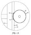
図1は、本開示による1つの例示の方法100を示す。ここで図1を参照すると、第1のモータ190によって駆動される研磨ホイール130(図2及び以下の説明も参照)が、保持アセンブリ127内に装着された基材120の表面122と摩擦接触し、第2のモータ192によって駆動されて回転する(and driven by second motor 192 is rotated)際、ディンプル110(例示のくぼみ)が基材120内に形成される。示された実施形態では、研磨ホイール130は、第1の回転軸162の周りを回転する。研磨ホイール130が回転すると、研磨ホイール130の構造化研磨層136は、基材120の表面122において第1の方向160に沿って、縦方向に前進する(図1Aを参照)。同時に、基材120は、第1の回転軸162に実質的に直交する第2の回転軸164の周りを回転する。プロセスが続くと、ディンプル110が徐々に形成され、ディンプルの大きさは、研磨物品が基材を貫通する深さによって決まる。 FIG. 1 illustrates one
研磨が発生する速さは、摩擦接触圧、研磨粒度、研磨ホイール(又は研磨ベルト)の回転速度、研磨粒子の径及び硬度、並びに成形研磨複合体の形状及び密度などの要素に左右されることになる。典型的には、より大きく硬い研磨粒子は、最も速く研磨される(abraded fastest)が、小さい、かつ/又はより柔らかい研磨粒子よりも仕上がりが粗くなる結果になる。したがって、比較的大きい、かつ/又はより硬い研磨粒子を使用して(例えば、3M TRIZACT DIAMOND TILE 677XA 20マイクロメートルダイヤモンドノミナル級(nominal grade)構造化研磨剤を使用して)プロセスを実行し、くぼみ内で荒加工し、次いで、より小さい、かつ/又はより柔らかい研磨粒子を使用して(例えば、3M TRIZACT LAPPING FILM CERIUM OXIDE M−568XA(0.5マイクロメートル)構造化研磨剤を使用して)プロセスを繰り返し、最適にポリッシュされた仕上げを準備するのが望ましい場合がある。 The speed at which polishing occurs depends on factors such as frictional contact pressure, polishing particle size, polishing wheel (or polishing belt) rotation speed, abrasive particle diameter and hardness, and the shape and density of the molded abrasive composite. become. Typically, larger and harder abrasive particles are abraded fastest, but result in a rougher finish than smaller and / or softer abrasive particles. Thus, the process is carried out using a relatively large and / or harder abrasive particle (eg, using 3M TRIZACT DIAMOND TILE 677XA 20 micrometer diamond nominal grade structured abrasive) and indented. Roughing in, then using smaller and / or softer abrasive particles (eg, using 3M TRIZACT LAPPING FILM CERIUM OXIDE M-568XA (0.5 micrometer) structured abrasive) It may be desirable to repeat the process and prepare an optimally polished finish.
より大きいくぼみ(例えば、約0.125インチより大きいディンプル)については、上記のような二工程の手順が、典型的には、好ましい。より小さいくぼみについて、一工程で十分に速く良好な表面仕上げを達成する場合があり、この仕上げは、(例えば、セリア研磨剤を使用して)方法の単一の適用において達成され得る(a single step may be sufficiently fast to achieve a fine surfacefinish can be achieved in a single application of the method(e.g., using ceria abrasive))。 For larger indentations (eg, dimples larger than about 0.125 inches), a two-step procedure as described above is typically preferred. For smaller indentations, a good surface finish may be achieved fast enough in one step, and this finish can be achieved in a single application of the method (eg using a ceria abrasive). step may be sufficiently fast to achieve a fine surface finish can be achieved in a single application of the method (eg, using ceria abrasive)).
ここで図2及び図2Aを参照すると、例示の研磨ホイール130は、支持ホイール131の周面134に沿って配された構造化研磨部材132を含む。構造化研磨部材132は、裏材139に固着した構造化研磨層136を含む。構造化研磨層136は、有機結合剤材料152中に保持された研磨粒子150を含む成形研磨複合体138を含む。構造化研磨層136は、実質的に均一な幅142を有する。高品質のディンプルを形成するのに有用であるために、支持ホイール131は、直径144を有する。幅142対直径144の比は、0.125以下である。 With reference now to FIGS. 2 and 2A, an
好都合に、本開示による方法は、遊離研磨粒子及び/又は液体ビヒクル中に研磨粒子を含む研磨スラリーを添加することなく実行され得るが、これは、必須条件ではない。これにより、概ね、汚れ及び浪費を低減する結果となり、くぼみが基材の周囲面と接触する所について、より鋭い辺縁の画定(sharper edge definition)を提供する。 Conveniently, the method according to the present disclosure may be carried out without the addition of abrasive slurry comprising abrasive particles in free abrasive particles and / or liquid vehicle, but this is not a requirement. This generally results in reduced dirt and waste, and provides a sharper edge definition where the indentation contacts the peripheral surface of the substrate.
研磨物品は、例えば、研磨ホイール(例えば、図1及び図2に示すような)又は研磨ベルトを含んでもよい。好ましくは、支持部材の幅は、その外周面に装着されている構造化研磨層の幅とほぼ同じであるべきであるが、これは、必須条件ではない。研磨物品は、概ね、モータによって駆動されるが、手動で行ってもよい。 The abrasive article may include, for example, an abrasive wheel (eg, as shown in FIGS. 1 and 2) or an abrasive belt. Preferably, the width of the support member should be approximately the same as the width of the structured abrasive layer attached to its outer peripheral surface, but this is not a requirement. The abrasive article is generally driven by a motor, but may be done manually.
好ましくは、構造化研磨層は、基材の表面と摩擦接触している回転軸の周りで縦方向に前進する。これは、研磨物品が研磨ホイールであり、また、ホイール(例えば、駆動ホイール又はガイドホイール)の周りの研磨ベルトの走行に対応する場合に、本来達成される。このような実施形態では、研磨物品の回転軸と基材の表面とは、平行であってはならない。いくつかの実施形態では、研磨物品の回転軸と基材の表面は、実質的に直交するが、これは、必須条件ではない。 Preferably, the structured abrasive layer advances longitudinally about an axis of rotation that is in frictional contact with the surface of the substrate. This is inherently achieved when the abrasive article is an abrasive wheel and corresponds to the travel of an abrasive belt around a wheel (eg, drive wheel or guide wheel). In such an embodiment, the axis of rotation of the abrasive article and the surface of the substrate should not be parallel. In some embodiments, the axis of rotation of the abrasive article and the surface of the substrate are substantially orthogonal, but this is not a requirement.
基材にディンプルを形成するために、研磨物品と基材との間の摩擦接触の区域は、概ね、基材の回転軸上に、ディンプルの最深点と対応する点を含む。 In order to form dimples on the substrate, the area of frictional contact between the abrasive article and the substrate generally includes a point on the axis of rotation of the substrate that corresponds to the deepest point of the dimple.
他の実施形態では、研磨物品と基材との間の摩擦接触の区域を、基材の回転軸に対して動かすことができる。例えば、基材の表面が第1の回転軸の周りを回転し、研磨ホイールが第2の回転軸(即ち、第1の回転軸に平行ではない)の周りを回転する場合、研磨ホイール及び/又は基材は、基材の表面に平行な平面における第3の異なる方向に沿って、並進する。このような動きは、概ね、球状に丸くされた端部を有する円筒の一部として成形された表面を有する溝をもたらす結果となる。 In other embodiments, the area of frictional contact between the abrasive article and the substrate can be moved relative to the axis of rotation of the substrate. For example, if the surface of the substrate rotates about a first axis of rotation and the polishing wheel rotates about a second axis of rotation (ie, not parallel to the first axis of rotation), the polishing wheel and / or Or the substrate translates along a third different direction in a plane parallel to the surface of the substrate. Such movement generally results in a groove having a surface that is shaped as part of a cylinder having a spherically rounded end.
更に他の実施形態では、研磨物品と基材との間の摩擦接触の区域を、基材の回転軸からオフセットしてもよい。例えば、基材の表面が、摩擦接触の区域から横方向にオフセットされている第1の回転軸の周りを回転し、研磨ホイールは第2の回転軸(即ち、第1の回転軸に平行ではない)の周りを回転する場合、方法は、概ね、円環の一部に対応する表面を有するリング状のくぼみをもたらす結果となるであろう。 In still other embodiments, the area of frictional contact between the abrasive article and the substrate may be offset from the axis of rotation of the substrate. For example, the surface of the substrate rotates about a first axis of rotation that is laterally offset from the area of frictional contact, and the grinding wheel is not parallel to the second axis of rotation (ie, parallel to the first axis of rotation). When rotating around (not), the method will generally result in a ring-shaped depression having a surface corresponding to a portion of the annulus.
本開示による方法を実施する際、摩擦接触は、研磨物品と基材の表面との間で確立され、時間とともに基材を貫通する研磨物品をもたらす結果となる。よって、基材の研磨及びくぼみの形成は、研磨物品及び/又は基材に対して、研磨物品及び基材の他の動きと組み合わせて、それらが互いに向かうように促す、あるレベルの力を付与することによって達成される。付与される力の適切な量の選択は、当業者の能力の範囲内である。力は、研磨の良好な速度を達成するのに十分であるが、静摩擦が発生するほど高くないのが好ましい。 In practicing the method according to the present disclosure, frictional contact is established between the abrasive article and the surface of the substrate, resulting in an abrasive article that penetrates the substrate over time. Thus, the polishing of the substrate and the formation of the depressions imparts a level of force to the abrasive article and / or substrate that, in combination with other movements of the abrasive article and substrate, urges them to move toward each other. Is achieved by doing Selection of an appropriate amount of force to be applied is within the ability of one skilled in the art. The force is sufficient to achieve a good rate of polishing, but is preferably not so high that static friction occurs.
いくつかの実施形態では、研磨物品は、基材を研削する間に、基材の表面に対して垂直に整列する。いくつかの実施形態では、研磨物品は、基材の表面に対して、90度、80度、70度、60度、50度、40度、30度未満、又は更に20度未満の角度で、傾斜してもよい。 In some embodiments, the abrasive article is aligned perpendicular to the surface of the substrate while grinding the substrate. In some embodiments, the abrasive article is at an angle of 90 degrees, 80 degrees, 70 degrees, 60 degrees, 50 degrees, 40 degrees, less than 30 degrees, or even less than 20 degrees to the surface of the substrate, It may be inclined.
基材の研削の間、発熱を低減し、かつ/又は残屑を洗い流すために研削液を使用してもよい。研削液としては、例えば、水、(例えば、米国特許第7,278,904(B2)号(Woo et al.)に記載の)1又は2以上の界面活性剤を含有する、水、油、グリコール、又は他の潤滑剤が挙げられる。 During grinding of the substrate, grinding fluid may be used to reduce heat generation and / or to wash away debris. Grinding fluids include, for example, water, water, oils containing one or more surfactants (for example, as described in US Pat. No. 7,278,904 (B2) (Woo et al.)), Glycols or other lubricants may be mentioned.
基材は、任意の形状を有し得る。いくつかの実施形態では、基材は、実質的に平面状の表面を有するが、他の実施形態では、表面は、凸状、凹状、平面状、又はこれらの組み合わせであってもよい。好適な基材の形状の例としては、板、ブロック、ウエハ、及びスラブが挙げられる。基材は、いかなる材料を含んでもよいが、基材(及び特に研削されることになる基材表面)は、ガラス、セラミック、又はガラスセラミック材料の少なくとも1つを含むことが好ましい。好適なガラスの例としては、ソーダ石灰シリカガラス、ホウケイ酸ガラス、フッ化物ガラス、アルミノケイ酸ガラス(例えば、リン酸ガラス、ホウ酸ガラス、及びカルコゲン化物ガラス)、及び化学強化ガラス(例えば、ソーダ石灰ケイ酸、アルカリホウアルミノケイ酸、及びアルカリアルミノケイ酸(例えば、商品名「GORILLA GLASS」で、Corning(Corning,New York)によって販売されているものを含む)などのイオン交換アルカリ含有ガラスに対応する)が挙げられる。好適なセラミックの例としては、アルミナ、サファイア、ルビー、ジルコニア、ガラスセラミックスを含有する、イットリア及び/又は希土類酸化物、及びこれらの組み合わせが挙げられる。好ましい実施形態では、基材は、透明であるが、これは、必須条件ではない。これら実施形態のいくつかでは、基材は、実質的に無色であることが好ましい。いくつかの実施形態において、基材は、金属又は金属合金を含む。 The substrate can have any shape. In some embodiments, the substrate has a substantially planar surface, but in other embodiments the surface may be convex, concave, planar, or a combination thereof. Examples of suitable substrate shapes include plates, blocks, wafers, and slabs. The substrate may comprise any material, but it is preferred that the substrate (and particularly the substrate surface to be ground) comprises at least one of glass, ceramic, or glass ceramic material. Examples of suitable glasses include soda lime silica glass, borosilicate glass, fluoride glass, aluminosilicate glass (eg, phosphate glass, borate glass, and chalcogenide glass), and chemically tempered glass (eg, soda lime). Silicas, alkali boroaluminosilicates, and alkalialuminosilicates (including, for example, those sold by Corning (Corning, New York) under the trade name “GORILLA GLASS”). Is mentioned. Examples of suitable ceramics include alumina, sapphire, ruby, zirconia, yttria and / or rare earth oxides containing glass ceramics, and combinations thereof. In a preferred embodiment, the substrate is transparent, but this is not a requirement. In some of these embodiments, it is preferred that the substrate is substantially colorless. In some embodiments, the substrate comprises a metal or metal alloy.
好都合に、本開示による方法は、例えば、ディンプル、楕円体のくぼみ(即ち、楕円体の一部として成形された表面を有する)、トラフ、及びリング(例えば、円環の一セクションとして成形された表面を有する陥凹リング又は溝)を含む多様なくぼみを作ることができる。典型的な実施形態では、くぼみは、滑らかで連続的に凹状の表面を有するが、これは、必須条件ではない。また、典型的な実施形態では、くぼみは、基材の表面に当接する明確に画定された境界(a well-defined boundary where is abuts the surface of the substrate)で突然終わるが、これは、必須条件ではない。くぼみのこれらの特性により、この方法は、カバー(例えば、指又はスタイラスを使用した触覚インタラクションのために適合されているディスプレイカバー)を作製するのにふさわしいものになっている。 Conveniently, the method according to the present disclosure may be formed, for example, as a dimple, an ellipsoidal depression (ie having a surface shaped as part of an ellipsoid), a trough, and a ring (eg, a section of an annulus). Various indentations can be made, including recessed rings or grooves with surfaces. In an exemplary embodiment, the indentation has a smooth, continuously concave surface, but this is not a requirement. In an exemplary embodiment, the indentation also ends abruptly at a well-defined boundary where is a buts the surface of the substrate, which is a prerequisite. is not. These properties of the indent make this method suitable for making a cover (eg, a display cover adapted for tactile interaction using a finger or stylus).
本開示による方法は、例えば、ディスプレイカバー、医療機器カバー、及び/又はセンサー装置カバーなどのカバーにおいて複雑な形状を有するくぼみを形成するために使用されてもよい。例えば、基材を通って延在する円筒孔(即ち、ビア)の上で中心になるディンプルが形成されてもよい。このような例において、典型的には、本開示による1つ又は2つ以上の方法を実施する前に、(例えば、穿孔によって)円筒孔を形成することが好ましい。そうすることによって、穿孔により形成され得るチップは、研削プロセスの間に除去される。 The method according to the present disclosure may be used to form indentations with complex shapes in covers such as, for example, display covers, medical device covers, and / or sensor device covers. For example, a dimple centered on a cylindrical hole (ie, via) extending through the substrate may be formed. In such examples, it is typically preferred to form a cylindrical hole (eg, by drilling) before performing one or more methods according to the present disclosure. By doing so, the chips that can be formed by drilling are removed during the grinding process.
ここで図3を参照すると、カバー300は、第1の対向する平行主表面320及び第2の対向する平行主表面322を有する化学的強化ガラス板310を備える。球状に凹んだくぼみ330は、第1の主表面320に当接し、かつ第1の主表面320から内向きに延在する。その最深点350において、球状に凹んだくぼみ330は、球状に凹んだくぼみ330と第2の主表面322との間に延在し、かつ球状に凹んだくぼみ330と第2の主表面322に当接する、円筒形通路340に当接する。円筒形通路340は、第1の対向する平行主表面320及び第2の対向する平行主表面322に垂直である。 Referring now to FIG. 3, the
ここで図4を参照すると、ディスプレイカバー400は、第1の対向する平行主表面420及び第2の対向する平行主表面422を有するサファイア板410を含む。第1の球状に凹んだくぼみ430は、第1の主表面420に当接し、かつ第1の主表面420から内向きに延在する。第2の球状に凹んだくぼみ432は、第2の主表面440に当接し、かつ第2の主表面440から内向きに延在する。第1の球状に凹んだくぼみ430と第2の球状に凹んだくぼみ432との間に延在し、かつ、第1の球状に凹んだくぼみ430と第2の球状に凹んだくぼみ432の最深点450、452で、第1の球状に凹んだくぼみ430と第2の球状に凹んだくぼみ432に当接する、円筒形通路440は、第1の対向する平行主表面420及び第2の対向する平行主表面422に垂直である。 Referring now to FIG. 4, the
図3及び図4に示すもののようなくぼみは、ディスプレイカバーに近接する相互作用要素の加工における構成要素として、加工に有用であり得る。 Indentations such as those shown in FIGS. 3 and 4 can be useful in processing as a component in processing interactive elements proximate to the display cover.
本開示の方法の開発の過程で、本発明者は、研磨物品、及び本開示の方法で使用するように適合された研磨物品を作製する方法を開発した。研磨物品及び方法について、以下で詳細に述べる。 In the course of developing the method of the present disclosure, the inventor has developed a method for making an abrasive article and an abrasive article adapted for use in the method of the present disclosure. The abrasive article and method are described in detail below.
本開示を実施するのに有用な研磨ホイール及び研磨ベルトは、例えば、図2Aの構造化研磨部材132のような構造化研磨剤を使用して形成されてもよい。一方法では、構造化研磨剤の細片が支持ホイール(典型的には、駆動源に接続するための好適な機械的締結システムに取り付けられる)の周面(即ち、辺縁)に接着される。好適な接着剤の例としては、グルー、感圧接着剤、及びエポキシ樹脂が挙げられるが、確実な結合剤を作製することができる任意の材料を使用してもよい。 Abrasive wheels and abrasive belts useful in practicing the present disclosure may be formed using a structured abrasive such as, for example, structured abrasive member 132 of FIG. 2A. In one method, a strip of structured abrasive is adhered to the peripheral surface (ie, edge) of a support wheel (typically attached to a suitable mechanical fastening system for connection to a drive source). . Examples of suitable adhesives include glues, pressure sensitive adhesives, and epoxy resins, but any material that can produce a reliable binder may be used.
図2Aでは、構造化研磨部材132は、支持ホイールを省略することにより、支持ホイールに固着しているが、例えば、周知の技術により、構造化研磨ベルトを作製することができる。 In FIG. 2A, the structured polishing member 132 is fixed to the support wheel by omitting the support wheel. However, for example, a structured polishing belt can be manufactured by a known technique.
好適な構造化研磨剤は、裏材の主表面に固着した構造化研磨層を有する。好適な裏材は、典型的には、前面及び背面を有する。裏材を作製するのに有用な材料の代表例としては、ポリマーフィルム(下塗りポリマーフィルム(primed polymeric films)を含む)、圧縮可能な弾力性フォーム(例えば、エラストマーフォーム)、織布、ニット生地、不織布、及びこれらの組み合わせが挙げられる。研磨ホイール内で使用するために、裏材は、ポリマーフィルムを含むのが好ましい。研磨ベルト内で使用するために、裏材は、十分な寸法安定性及び耐久性を有する必要があり、好ましくは織物材料又はニット材料を含む。フィルム裏材が使用され得、接着促進剤又は防滑コーティングを含んでもよい。いくつかの好ましい実施形態では、裏材は、厚さが約2〜8ミル(50〜200マイクロメートル)のポリエチレンテレフタレートフィルムであってもよい。 A preferred structured abrasive has a structured abrasive layer secured to the major surface of the backing. Suitable backings typically have a front surface and a back surface. Representative examples of materials useful for making the backing include polymer films (including primed polymeric films), compressible elastic foams (eg, elastomeric foams), woven fabrics, knitted fabrics, Nonwoven fabrics, and combinations thereof can be mentioned. For use in an abrasive wheel, the backing preferably comprises a polymer film. For use within an abrasive belt, the backing must have sufficient dimensional stability and durability, and preferably comprises a woven or knitted material. Film backings can be used and may include adhesion promoters or anti-slip coatings. In some preferred embodiments, the backing may be a polyethylene terephthalate film having a thickness of about 2-8 mils (50-200 micrometers).
裏材は、紫外線若しくは可視光線に対して透過性若しくは不透過性であってもよく、又は紫外線及び可視光線の両方に対して透過性若しくは不透過性であってもよいが、これは、必須条件ではない。裏材は、また、裏材をシールするか、又は、裏材のいくつかの物理的特性を修正するための処理剤にさらされてもよい。これらの処理剤は、当技術分野において周知である。例えば、布の裏材は、飽和剤被覆、バックサイズ(backsize)被覆、プレサイズ(presize)被覆、又はこれらの任意の組み合わせを含有してもよい。飽和剤被覆は、裏材に染みこませ、裏材中の小さな開口を満たす。バックサイズ被覆は、裏材の裏側に塗布され、使用中の繊維又は糸を保護し得る。プレサイズ被覆は、裏材の表側に塗布される。布の表側のプレサイズ被覆は、布をシールするよう機能する。布を処理するのに有用な樹脂の例としては、フェノール、ラテックス、エポキシ、アクリレート、アクリレート化エポキシ、アクリレート化ウレタン、ポリエステル、デンプン、及びこれらの組み合わせが挙げられる。布を処理するための樹脂は、例えば、充填剤、繊維、カップリング剤、湿潤剤、染料、及び顔料などの添加剤を更に含んでもよい。 The backing may be transparent or opaque to ultraviolet or visible light, or transparent or opaque to both ultraviolet and visible light, but this is essential It is not a condition. The backing may also be exposed to a treating agent to seal the backing or to modify some physical properties of the backing. These treating agents are well known in the art. For example, the fabric backing may contain a saturant coating, a backsize coating, a presize coating, or any combination thereof. The saturant coating soaks into the backing and fills the small openings in the backing. A backsize coating can be applied to the backside of the backing to protect the fibers or yarns in use. The presize coating is applied to the front side of the backing. The presize coating on the front side of the fabric functions to seal the fabric. Examples of resins useful for treating fabric include phenol, latex, epoxy, acrylate, acrylated epoxy, acrylated urethane, polyester, starch, and combinations thereof. The resin for treating the fabric may further contain additives such as fillers, fibers, coupling agents, wetting agents, dyes, and pigments.
構造化研磨層は、製造用ツール内の空洞を研磨粒子と硬化性結合剤前駆体との混合物で満たすことと、裏材を製造用ツール及び結合剤前駆体と接触させることと、次いで結合剤前駆体を十分に硬化させて、製造用ツールからの裏材の分離により、製造用ツール内で形成された、成形研磨複合体を裏材に固着したままとして、これにより構造化研磨層を形成することと、によって、裏材上で形成されてもよい。 The structured abrasive layer fills the cavities in the manufacturing tool with a mixture of abrasive particles and a curable binder precursor, contacts the backing with the manufacturing tool and the binder precursor, and then the binder. The precursor is fully cured and separation of the backing from the manufacturing tool leaves the molded abrasive composite formed in the manufacturing tool fixed to the backing, thereby forming a structured polishing layer And may be formed on the backing.
構造化研磨層は、意図される使用期間中に、それが裏材から分離しないように、裏材に固着している。成形研磨複合体は、任意の形状を有してもよいが、典型的には、角錐(例えば、三角錐又は四角錐)、切頭角錐(例えば、切頭三角錐又は切頭四角錐)、角柱(例えば、三角柱、四角柱、又は六角柱)、棒、円錐、円錐台、及びこれらの組み合わせを含む。異なる成形をされた研磨複合体及び/又は異なる高さの成形研磨複合体の組み合わせを使用してもよい。例えば、角錐に成形された研磨複合体に、それよりも低い高さの切頭角錐に成形された研磨複合体が散在させてあってもよい。成形研磨複合体は、規則的(全ての側部が同一である)又は不規則であってもよい。 The structured abrasive layer is affixed to the backing so that it does not separate from the backing during the intended period of use. The shaped abrasive composite may have any shape, but typically a pyramid (eg, a triangular pyramid or a quadrangular pyramid), a truncated pyramid (eg, a truncated triangular pyramid or a truncated quadrangular pyramid), Includes prisms (eg, triangular, quadrangular, or hexagonal), rods, cones, truncated cones, and combinations thereof. A combination of differently shaped abrasive composites and / or different heights of molded abrasive composites may be used. For example, an abrasive composite formed into a truncated pyramid having a height lower than that of the abrasive composite formed into a pyramid may be scattered. The shaped abrasive composite may be regular (all sides are the same) or irregular.
いくつかの実施形態において、成形研磨複合体は、精密に成形された研磨複合体であってもよい。これは、成形研磨複合体の形状が、明確に画定された辺縁によって境界とされ、結合された比較的滑らかな表面を有する側面によって画定されることを意味する。辺縁は、異なる側面の交点によって画定される明確な端点を有する明確な辺長を有する。「境界とする」及び「境界」という用語は、各研磨複合体の実際の三次元形状を区切って画定する各複合体の露出面及び辺縁を指す。これらの境界は、研磨物品の断面を走査型電子顕微鏡において観察する際、容易に視認可能かつ識別可能である。これらの境界は、研磨複合体同士がその基部において共通の境界に沿って互いに当接するような場合であっても、1つの精密に成形された研磨複合体を別の精密に成形された研磨複合体から分離し、区別するものである。比較すると、精密形状を有さない成形研磨複合体においては、境界及び辺縁は、明確に画定されていない(例えば、成形研磨複合体が、硬化完了前に撓む場合)。 In some embodiments, the shaped abrasive composite may be a precisely shaped abrasive composite. This means that the shape of the shaped abrasive composite is defined by the sides having a relatively smooth surface bounded by a well-defined edge. The edge has a distinct edge length with a distinct end point defined by the intersection of the different sides. The terms “boundary” and “boundary” refer to the exposed surfaces and edges of each composite that delimit and delimit the actual three-dimensional shape of each polishing composite. These boundaries are easily visible and distinguishable when the cross section of the abrasive article is observed with a scanning electron microscope. These boundaries are such that even if the abrasive composites abut each other along a common boundary at their bases, one precisely molded abrasive composite is another precisely molded abrasive composite. It separates and distinguishes from the body. By comparison, in shaped abrasive composites that do not have a precise shape, the boundaries and edges are not clearly defined (eg, when the shaped abrasive composite is deflected before curing is complete).
成形研磨複合体は、構造化研磨層を画定し、典型的には、密集した配置(例えば、配列)で並べられており、隣り合う成形研磨複合体は、それぞれの基部で互いに接触しているが、少なくとも一部の隣り合う成形研磨複合体間の分離は容認される。トポグラフィカル構造化研磨層に間隙(例えば、縞)が存在してもよい。 The shaped abrasive composites define a structured abrasive layer and are typically arranged in a dense arrangement (eg, an array), with adjacent shaped abrasive composites in contact with each other at their respective bases. However, separation between at least some adjacent shaped abrasive composites is acceptable. There may be gaps (eg, stripes) in the topographical structured polishing layer.
成形研磨複合体の裏材に対する高さは、典型的には10〜900マイクロメートルの範囲であるが、より高い、又はより低い高さを使用してもよい。より典型的には、成形研磨複合体の裏材に対する高さは、50〜850マイクロメートルの範囲、又は更に75マイクロメートル〜800マイクロメートルの範囲であってよい。 The height of the shaped abrasive composite relative to the backing is typically in the range of 10 to 900 micrometers, although higher or lower heights may be used. More typically, the height of the shaped abrasive composite relative to the backing may be in the range of 50 to 850 micrometers, or even in the range of 75 micrometers to 800 micrometers.
いくつかの実施形態では、トポグラフィカル構造化研磨層中の成形研磨複合体の面密度は、典型的には、1平方インチあたり少なくとも1,000、10,000、又は更に少なくとも20,000の研磨複合体(例えば、1平方センチメートルあたり少なくとも150、1,500、又は更に7,800の研磨複合体)から、1平方インチあたり50,000、70,000、又は更に100,000もの研磨複合体(1平方センチメートルあたり7,800、11,000、又は更に15,000までもの研磨複合体を含む)までの範囲であるが、より大きい又は小さい密度の研磨複合体を使用してもよい。 In some embodiments, the areal density of the shaped abrasive composites in the topographical structured abrasive layer is typically at least 1,000, 10,000, or even at least 20,000 polish per square inch. From composites (eg, at least 150, 1,500, or even 7,800 abrasive composites per square centimeter) to 50,000, 70,000, or even 100,000 abrasive composites per square inch (1 Up to 7,800, 11,000, or even up to 15,000 abrasive composites per square centimeter, but larger or smaller density abrasive composites may be used.
成形研磨複合体(角錐状又は切頭角錐状に関わらず)は、また、典型的には研磨粒子と同程度の大きさの希釈剤粒子を含んでいてもよい。そのような希釈剤粒子の例としては、石膏、大理石、石灰岩、フリント、シリカ、ガラス球、ガラスビーズ、及びケイ酸アルミニウムが挙げられる。 The shaped abrasive composite (whether pyramidal or truncated pyramidal) may also include diluent particles that are typically as large as the abrasive particles. Examples of such diluent particles include gypsum, marble, limestone, flint, silica, glass spheres, glass beads, and aluminum silicate.
研磨複合体の形成に使用される混合物は、結合剤前駆体中に分散されている複数の研磨粒子を含む。本明細書で使用される場合、用語「混合物」は、結合剤前駆体中に分散されている複数の研磨粒子を含む、任意の組成物を意味する。混合物は、流動性であることが好ましい。しかしながら、混合物が流動性でない場合には、混合物は、製造用ツールの接触表面又は裏材の前面上に押し出されるか、又は他の手段(例えば熱、圧力、又はその両方)により押され得る。この混合物は、形状順応性と特徴付けられ、即ち、これを製造用ツールの接触表面及び裏材の前面と同一の形状、外形、又は輪郭をとるようにすることができる。 The mixture used to form the abrasive composite includes a plurality of abrasive particles dispersed in a binder precursor. As used herein, the term “mixture” means any composition comprising a plurality of abrasive particles dispersed in a binder precursor. The mixture is preferably fluid. However, if the mixture is not flowable, the mixture can be extruded onto the contact surface of the manufacturing tool or the front surface of the backing, or by other means (eg, heat, pressure, or both). This mixture is characterized as conformable, i.e. it can take the same shape, contour or contour as the contact surface of the manufacturing tool and the front surface of the backing.
研磨粒子は、典型的には、約0.1〜100マイクロメートル、好ましくは約0.2〜50マイクロメートル、より好ましくは0.5〜45マイクロメートルの範囲の大きさを有するが、他の大きさもまた使用されてもよい。本開示による構造化研磨剤中で使用するのに好適な研磨粒子の例としては、溶融酸化アルミニウム、セラミック酸化アルミニウム、熱処理酸化アルミニウム、白色酸化アルミニウム、グリーンシリコンカーバイド、シリコンカーバイド、アルミナ、ジルコニア、ダイヤモンド、セリア、立方窒化ホウ素、ガーネット、シリカ、及びこれらの組み合わせが挙げられる。「研磨粒子」という語句は、個別の研磨粗粒子及び結合して粒塊を形成する複数の個別の研磨粗粒子の両方を含む。研磨粒子は、その上に表面処理剤を有してよい。いくつかの例では、表面処理剤は、結合剤との接着性を高める、研磨粒子の研磨特性を変化させる等の場合がある。表面処理剤の例としては、カップリング剤(例えばシランカップリング剤)、ハロゲン塩、シリカを含む金属酸化物、耐熱金属窒化物、及び耐熱金属炭化物が挙げられる。 The abrasive particles typically have a size in the range of about 0.1-100 micrometers, preferably about 0.2-50 micrometers, more preferably 0.5-45 micrometers, but other Size may also be used. Examples of abrasive particles suitable for use in structured abrasives according to the present disclosure include molten aluminum oxide, ceramic aluminum oxide, heat treated aluminum oxide, white aluminum oxide, green silicon carbide, silicon carbide, alumina, zirconia, diamond , Ceria, cubic boron nitride, garnet, silica, and combinations thereof. The phrase “abrasive particles” includes both individual abrasive coarse particles and a plurality of individual abrasive coarse particles that combine to form agglomerates. The abrasive particles may have a surface treatment agent thereon. In some examples, the surface treatment agent may increase adhesion with the binder, alter the abrasive properties of the abrasive particles, and the like. Examples of the surface treatment agent include a coupling agent (for example, a silane coupling agent), a halogen salt, a metal oxide containing silica, a refractory metal nitride, and a refractory metal carbide.
結合剤前駆体は、エネルギー、好ましくは放射エネルギー、より好ましくは、紫外光、可視光、又は電子ビーム源からの放射エネルギーによって硬化することができる。他のエネルギー源は、赤外、熱、及びマイクロ波を含む。そのエネルギーは、本発明の方法において使用される製造用ツールに悪影響を与えず、これによって、ツールを再使用できることが好ましい。結合剤前駆体は、フリーラジカル機構又はカチオン機構により重合することができる。放射エネルギーに曝露することにより重合可能な結合剤前駆体の例としては、アクリレート化ウレタン、アクリレート化エポキシ、エチレン系不飽和化合物、ペンダント不飽和カルボニル基を有するアミノプラスト誘導体、少なくとも1つのペンダントアクリレート基を有するイソシアヌレート誘導体、少なくとも1つのペンダント(メタ)アクリレート基を有するイソシアネート誘導体、ビニルエーテル、エポキシ樹脂、及びこれらの組み合わせが挙げられる。本明細書で使用される場合、「(メタ)アクリレート」という用語は、アクリレート及び/又はメタクリレートを指す。 The binder precursor can be cured by energy, preferably radiant energy, more preferably by ultraviolet light, visible light, or radiant energy from an electron beam source. Other energy sources include infrared, heat, and microwave. The energy preferably does not adversely affect the manufacturing tool used in the method of the present invention so that the tool can be reused. The binder precursor can be polymerized by a free radical mechanism or a cationic mechanism. Examples of binder precursors that can be polymerized by exposure to radiant energy include acrylated urethanes, acrylated epoxies, ethylenically unsaturated compounds, aminoplast derivatives having pendant unsaturated carbonyl groups, at least one pendant acrylate group. Isocyanurate derivatives having an isocyanate, isocyanate derivatives having at least one pendant (meth) acrylate group, vinyl ethers, epoxy resins, and combinations thereof. As used herein, the term “(meth) acrylate” refers to acrylate and / or methacrylate.
紫外線又は可視光線のいずれかが使用されることになる場合、結合剤前駆体は、結合剤前駆体の硬化を促進する、フリーラジカル光開始剤及び/又はカチオン性光触媒を更に含むことが好ましい。フリーラジカル光開始剤の例としては、有機ペルオキシド、アゾ化合物、キノン、ベンゾフェノン、ニトロソ化合物、アシルハライド、ヒドラゾン、メルカプト化合物、ピリリウム化合物、ビスイミダゾール、ホスフィンオキシド、クロロアルキルトリアジン、ベンゾインエーテル、ベンジルケタール、チオキサントン、アセトフェノン誘導体、感作ヨードニウム塩、及びそれらの組み合わせが挙げられる。 Where either ultraviolet or visible light is to be used, the binder precursor preferably further comprises a free radical photoinitiator and / or a cationic photocatalyst that promotes curing of the binder precursor. Examples of free radical photoinitiators include organic peroxides, azo compounds, quinones, benzophenones, nitroso compounds, acyl halides, hydrazones, mercapto compounds, pyrylium compounds, bisimidazoles, phosphine oxides, chloroalkyltriazines, benzoin ethers, benzyl ketals, Examples include thioxanthone, acetophenone derivatives, sensitized iodonium salts, and combinations thereof.
カチオン性光触媒は、例えば、エポキシ樹脂の重合を開始するための酸源を生成する。カチオン性光触媒としては、オニウムカチオンと、金属又は半金属の錯体アニオンを含有するハロゲンと、を有する塩を挙げることができる。他のカチオン性光触媒としては、有機金属錯体カチオンと、金属又は半金属のハロゲン含有錯体アニオンと、を有する塩が挙げられる。カチオン性光触媒は、米国特許第4,751,138号(Tumey et al.)及び同第4,985,340号(Palazzotto et al.)において更に記載されている。 The cationic photocatalyst generates, for example, an acid source for initiating polymerization of the epoxy resin. Examples of the cationic photocatalyst include a salt having an onium cation and a halogen containing a metal or metalloid complex anion. Other cationic photocatalysts include salts having an organometallic complex cation and a metal or metalloid halogen-containing complex anion. Cationic photocatalysts are further described in US Pat. Nos. 4,751,138 (Tumey et al.) And 4,985,340 (Palazzoto et al.).
放射線硬化性樹脂に加えて、結合剤前駆体は、放射エネルギー以外のエネルギー源により硬化可能である、縮合硬化性樹脂などの樹脂を更に含んでもよい。このような縮合硬化性樹脂の例としては、フェノール系樹脂、メラミン−ホルムアルデヒド樹脂、及び尿素−ホルムアルデヒド樹脂が挙げられる。 In addition to the radiation curable resin, the binder precursor may further include a resin such as a condensation curable resin that is curable by an energy source other than radiant energy. Examples of such condensation curable resins include phenolic resins, melamine-formaldehyde resins, and urea-formaldehyde resins.
結合剤前駆体は、例えば、充填剤(研磨助剤を含む)、繊維、潤滑剤、湿潤剤、界面活性剤、顔料、染料、カップリング剤、可塑剤、及び懸濁剤などの任意選択の添加剤を更に含むことができる。これら材料の量は、所望の性質を付与するように調整され得る。充填剤の例としては、炭酸カルシウム、シリカ、石英、硫酸アルミニウム、粘土、ドロマイト、メタケイ酸カルシウム、及びこれらの組み合わせが挙げられる。研磨助剤の例としては、テトラフルオロホウ酸カリウム、氷晶石、硫黄、黄鉄鉱、黒鉛、塩化ナトリウム、及びこれらの組み合わせが挙げられる。混合物は、70重量パーセント(重量%)以下、典型的には、40重量%以下、好ましくは1〜10重量%、より好ましくは1〜5重量%の充填剤又は研磨助剤を含有してもよい。 Binder precursors are optional, such as, for example, fillers (including polishing aids), fibers, lubricants, wetting agents, surfactants, pigments, dyes, coupling agents, plasticizers, and suspending agents. Additives can be further included. The amount of these materials can be adjusted to give the desired properties. Examples of fillers include calcium carbonate, silica, quartz, aluminum sulfate, clay, dolomite, calcium metasilicate, and combinations thereof. Examples of polishing aids include potassium tetrafluoroborate, cryolite, sulfur, pyrite, graphite, sodium chloride, and combinations thereof. The mixture may also contain 70 weight percent (wt%) or less, typically 40 wt% or less, preferably 1 to 10 wt%, more preferably 1 to 5 wt% filler or polishing aid. Good.
混合物は、好ましくは低剪断ミキサーにより成分を混合することによって調製され得る。高剪断ミキサーもまた使用され得る。典型的には、研磨粒子が結合剤前駆体の中に少しずつ添加される。加えて、混合物中の気泡の量を最少とすることが可能である。これは、混合工程時に真空を引くことにより達成され得る。 The mixture can be prepared by mixing the components, preferably with a low shear mixer. A high shear mixer may also be used. Typically, abrasive particles are added in portions into the binder precursor. In addition, it is possible to minimize the amount of bubbles in the mixture. This can be achieved by pulling a vacuum during the mixing process.
製造時に、放射エネルギーは、典型的には、製造用ツールを通って混合物の中に透過され、結合剤前駆体を少なくとも部分的に硬化させる。語句「部分硬化」は、結果的に得られる混合物が製造用ツールから剥離するような状態まで結合剤前駆体を重合させることを意味する。結合剤前駆体は、一旦、製造用ツールから取り出されると、例えば熱エネルギー又は放射エネルギーなどの任意のエネルギー源により充分に硬化され得る。結合剤前駆体は、また、成形研磨複合体を製造用ツールから取り出す前に、充分に硬化され得る。 During manufacturing, radiant energy is typically transmitted through the manufacturing tool and into the mixture to at least partially cure the binder precursor. The phrase “partially cured” means that the binder precursor is polymerized to such a state that the resulting mixture peels from the manufacturing tool. Once removed from the manufacturing tool, the binder precursor can be fully cured by any energy source, such as thermal energy or radiant energy. The binder precursor can also be fully cured before removing the shaped abrasive composite from the manufacturing tool.
本開示による、構造化研磨剤に好ましい放射エネルギー源としては、電子ビーム、紫外光、及び可視光が挙げられる。他の放射エネルギー源としては、赤外及びマイクロ波が挙げられる。熱エネルギーも使用され得る。電離放射線としても知られる電子ビーム放射線は、約2〜25メガラド(Mrad)の線量で、好ましくは約10〜20Mradの線量で使用され得る。紫外線は、約200〜約400ナノメートルの範囲内の、好ましくは約250〜400ナノメートルの範囲内の波長を有する非粒子状放射線を指す。紫外線は、紫外光によって供給されることが好ましい。可視光線とは、約400〜約800ナノメートルの範囲内、好ましくは約400〜約550ナノメートルの範囲内)の波長を有する非粒子状放射線を指す。 Preferred radiant energy sources for structured abrasives according to the present disclosure include electron beam, ultraviolet light, and visible light. Other radiant energy sources include infrared and microwave. Thermal energy can also be used. Electron beam radiation, also known as ionizing radiation, may be used at a dose of about 2-25 megarads (Mrad), preferably at a dose of about 10-20 Mrad. Ultraviolet radiation refers to non-particulate radiation having a wavelength in the range of about 200 to about 400 nanometers, preferably in the range of about 250 to 400 nanometers. The ultraviolet light is preferably supplied by ultraviolet light. Visible light refers to non-particulate radiation having a wavelength in the range of about 400 to about 800 nanometers, preferably in the range of about 400 to about 550 nanometers.
放射エネルギーが製造用ツールを透過して、混合物に直接入る場合、製造用ツールを作製する材料は、かなりの量の放射エネルギーを吸収することも、その放射エネルギーによって劣化することもないのが好ましい。例えば、電子ビームエネルギーを使用する場合には、電子がセルロースを劣化させるので、製造用ツールは、セルロース系材料から製造されないことが好ましい。紫外線又は可視光線を使用する場合には、製造用ツール材料は、それぞれ、充分な紫外線又は可視光線を透過して、所望のレベルの硬化を引き起こすものでなければならない。 When radiant energy passes through the manufacturing tool and enters the mixture directly, the material from which the manufacturing tool is made preferably does not absorb or degrade due to the radiant energy. . For example, when using electron beam energy, it is preferred that the manufacturing tool is not manufactured from cellulosic materials because electrons degrade cellulose. If ultraviolet or visible light is used, the manufacturing tool material must transmit sufficient ultraviolet or visible light, respectively, to cause the desired level of curing.
製造用ツールは、線源による劣化を回避するのに充分な速度で運転されなければならない。線源による劣化に対して比較的高い耐性を有する製造用ツールは、比較的低速度で運転され得、線源による劣化に対して比較的低い耐性を有する製造用ツールは、比較的高速度で運転され得る。端的に言うと、製造用ツールの適切な速度は、製造用ツールを作製する材料に左右される。 The manufacturing tool must be operated at a speed sufficient to avoid degradation due to the source. Manufacturing tools that have a relatively high resistance to degradation by the source can be operated at a relatively low speed, and manufacturing tools that have a relatively low resistance to degradation by the source can be operated at a relatively high speed. Can be driven. In short, the appropriate speed of the manufacturing tool depends on the material from which the manufacturing tool is made.
製造用ツールは、ベルト、例えばエンドレスベルト、シート、連続シート若しくはウェブ、コーティングロール、コーティングロール上に装着したスリーブ、又はダイの形であり得る。この混合物と接触するようになる製造用ツールの表面は、平滑であり得るか、又はトポグラフィー若しくはパターンを有することができる。この表面は、本明細書では「接触表面」と呼ばれる。製造用ツールがベルト、シート、ウェブ又はスリーブの形のものである場合には、製造用ツールは、接触表面と非接触表面を有することになる。製造用ツールがロールの形のものである場合には、製造用ツールは、接触表面のみを有することになる。本開示による構造化研磨剤の方法により形成される研磨物品のトポグラフィーは、製造用ツールの接触表面のパターンの逆を有することになる。製造用ツールの接触表面のパターンは、概ね、複数の空洞又はくぼみを特徴とすることになる。これらの空洞の開口は、例えば、規則的であれ又は不規則であれ、矩形、半円、円、三角形、四角形、六角形、又は八角形などの任意の形状を有する。空洞の壁は、垂直又はテーパー形状であり得る。空洞により形成されるパターンを、特定の平面図に従って配列してもよく、又はランダムとしてもよい。空洞を互いに隣接させることができる。 The manufacturing tool can be in the form of a belt, such as an endless belt, a sheet, a continuous sheet or web, a coating roll, a sleeve mounted on the coating roll, or a die. The surface of the manufacturing tool that comes into contact with the mixture can be smooth or can have a topography or pattern. This surface is referred to herein as the “contact surface”. If the manufacturing tool is in the form of a belt, sheet, web or sleeve, the manufacturing tool will have a contact surface and a non-contact surface. If the manufacturing tool is in the form of a roll, the manufacturing tool will have only a contact surface. The topography of the abrasive article formed by the structured abrasive method according to the present disclosure will have the inverse of the pattern of the contact surface of the manufacturing tool. The pattern of the contact surface of the manufacturing tool will generally be characterized by a plurality of cavities or indentations. The openings in these cavities have any shape, for example, regular or irregular, such as a rectangle, semicircle, circle, triangle, square, hexagon, or octagon. The walls of the cavity can be vertical or tapered. The pattern formed by the cavities may be arranged according to a specific plan view or may be random. The cavities can be adjacent to each other.
製造用ツールの構築に使用可能な熱可塑性材料としては、ポリエステル、ポリカーボネート、ポリ(エーテルスルホン)、ポリ(メチルメタクリレート)、ポリウレタン、ポリ塩化ビニル、ポリオレフィン、ポリスチレン、又はこれらの組み合わせが挙げられる。熱可塑性材料は、可塑剤、フリーラジカル掃去剤又は安定化剤、熱安定化剤、酸化防止剤、及び紫外線吸収剤などの添加剤を含むことができる。 Thermoplastic materials that can be used to build manufacturing tools include polyester, polycarbonate, poly (ether sulfone), poly (methyl methacrylate), polyurethane, polyvinyl chloride, polyolefin, polystyrene, or combinations thereof. The thermoplastic material can include additives such as plasticizers, free radical scavengers or stabilizers, thermal stabilizers, antioxidants, and UV absorbers.
熱可塑性製造用ツールを、例えば、次の手順に従って作製することができる。最初にマスターツールを準備する。マスターツールは、金属、例えばニッケルからできているのが好ましい。マスターツールは、彫り込み、ホブ切り、ローレット切り、電鋳、ダイヤモンド旋盤、レーザーマシニングなどのいかなる慣用の方法によっても加工可能である。このマスターツールは、製造用ツールの表面に所望の逆パターンを有するべきである。熱可塑性材料をマスターツールによりエンボスして、パターンを形成することができる。熱可塑性材料が流動可能な状態にある間に、エンボスを行うことができる。エンボス後、熱可塑性材料を冷却して、固化させることができる。 A thermoplastic manufacturing tool can be produced, for example, according to the following procedure. First, prepare a master tool. The master tool is preferably made of metal, such as nickel. The master tool can be processed by any conventional method such as engraving, hobbing, knurling, electroforming, diamond lathe, laser machining and the like. The master tool should have the desired reverse pattern on the surface of the manufacturing tool. The thermoplastic material can be embossed with a master tool to form a pattern. Embossing can be performed while the thermoplastic material is in a flowable state. After embossing, the thermoplastic material can be cooled and solidified.
製造用ツールは、硬化した熱硬化性樹脂で作製することもできる。次の手順に従って熱硬化性材料でできた製造用ツールを作製することができる。未硬化熱硬化性樹脂を前述の種類のマスターツールに塗布する。未硬化樹脂がマスターツールの表面上にある間に、未硬化樹脂がマスターツールの表面のパターンの逆形状を有するよう固化するように、未硬化樹脂を加熱により硬化又は重合させることができる。次に、硬化された熱硬化性樹脂をマスターツールの表面から除去する。製造用ツールを例えばアクリレート化ウレタンオリゴマーなどの硬化された放射線硬化性樹脂から作製することができる。放射線(例えば紫外線)に曝露することにより硬化を行うことを除いて、熱硬化性樹脂でできた製造用ツールと同一の方法で放射線硬化された製造用ツールを作製する。 The manufacturing tool can also be made of a cured thermosetting resin. A manufacturing tool made of a thermosetting material can be made according to the following procedure. Uncured thermosetting resin is applied to a master tool of the type described above. While the uncured resin is on the surface of the master tool, the uncured resin can be cured or polymerized by heating so that the uncured resin solidifies to have the reverse shape of the pattern on the surface of the master tool. Next, the cured thermosetting resin is removed from the surface of the master tool. Manufacturing tools can be made from a cured radiation curable resin such as an acrylated urethane oligomer. A radiation-cured manufacturing tool is produced in the same manner as a manufacturing tool made of a thermosetting resin, except that it is cured by exposure to radiation (eg, ultraviolet light).
製造用ツールの接触表面は、また、製造用ツールからの研磨物品の剥離をより容易にするため、剥離コーティングを包含してもよい。このような剥離コーティングの例としては、シリコーン及びフルオロケミカルが挙げられる。 The contact surface of the manufacturing tool may also include a release coating to make it easier to release the abrasive article from the manufacturing tool. Examples of such release coatings include silicones and fluorochemicals.
裏材に固着した構造化研磨層を作製する材料及び方法に関する更なる詳細は、例えば、米国特許第5,435,816号(Spurgeon et al.)、同第5,672,097号(Hoopman)、同第5,681,217号(Hoopman et al.)、同第5,454,844号(Hibbard et al.)、同第5,851,247号(Stoetzel et al.)、同第6,139,594号(Kincaid et al.)、及び同第8,251,774(B2)号(Joseph et al.)において認められる。 Further details regarding materials and methods for making structured abrasive layers affixed to a backing can be found, for example, in US Pat. Nos. 5,435,816 (Spurgeon et al.) And 5,672,097 (Hoopman). No. 5,681,217 (Hoopman et al.), No. 5,454,844 (Hibbard et al.), No. 5,851,247 (Stoetzel et al.), No. 6, 139,594 (Kincaid et al.) And 8,251,774 (B2) (Joseph et al.).
様々な好適な構造化研磨剤が、例えば、「TRIZACT」の商品名で3M Company(Saint Paul,Minnesota)から市販されている。例としては、3M TRIZACT LAPPING FILM 162XA(46マイクロメートルノミナル級、モース硬度<3)、3M TRIZACT LAPPING FILM ALUMINUM OXIDE 268XA(5、10、20、及び35マイクロメートルノミナル級で入手可能)、3M TRIZACT LAPPING FILM CERIUM OXIDE M−568XA(0.5マイクロメートルノミナル級)、3M TRIZACT DIAMOND LAPPING FILM(0.5、2、及び9マイクロメートルダイヤモンドノミナル級で入手可能)、3M TRIZACT DIAMOND TILE 677XA構造化研磨シート(3、6、9、及び20マイクロメートルダイヤモンドノミナル級で入手可能)が挙げられる。このように調製された構造化研磨剤は、次いで、既知の方法によって、研磨ベルトに変えられる。また、支持ホイールの周面に固着して研磨ホイールを形成してもよい。 A variety of suitable structured abrasives are commercially available from, for example, 3M Company (Saint Paul, Minnesota) under the trade designation “TRIZACT”. Examples include 3M TRIZACT LAPPING FILM 162XA (46 micron nominal grade, Mohs hardness <3), 3M TRIZACT LAPPING FILM ALUMINUM OXIDE 268XA (available in 5, 10, 20, and 35 micron nominal grades), 3M TRIPPT FILM CERIUM OXIDE M-568XA (0.5 micrometer nominal grade), 3M TRIZACT DIAMOND LAPPING FILM (available in 0.5, 2, and 9 micrometer diamond nominal grade), 3M TRIZACT DIAMOND TILE 677XA structured polishing sheet (Available in 3, 6, 9, and 20 micron diamond nominal grade) And the like. The structured abrasive thus prepared is then converted into an abrasive belt by known methods. Moreover, you may adhere to the surrounding surface of a support wheel and may form a grinding | polishing wheel.
好ましくは、構造化研磨層の幅は、研磨物品の直径(例えば、ホイールの場合)及び/又は所望のくぼみの大きさ及び形状(例えば、ディンプルの直径又はリングの幅(即ち、直径ではなく幅))の、約1/8(12.5パーセント)以下、1/10(10パーセント)未満、又は更に1/20(5パーセント)未満である。典型的には、構造化研磨層の幅及びホイールの直径の選択は、特定の用途によって決定づけられることになり、ディンプルの大きさ、及び研削プロセスの正確さ及び速さによって決定されることになる。 Preferably, the width of the structured abrasive layer is the diameter of the abrasive article (eg in the case of a wheel) and / or the desired indentation size and shape (eg dimple diameter or ring width (ie width, not diameter). )) Less than about 1/8 (12.5 percent), less than 1/10 (10 percent), or even less than 1/20 (5 percent). Typically, the choice of structured abrasive layer width and wheel diameter will be dictated by the particular application, and will depend on the size of the dimple and the accuracy and speed of the grinding process. .
本開示の選択された実施形態
第1の実施形態では、本開示は、基材の表面にくぼみを形成する方法であって、
支持部材の周面に沿って配された構造化研磨部材を含む研磨物品を準備するステップであって、構造化研磨部材は、裏材に固着した成形研磨複合体を含む構造化研磨層を含み、裏材は、支持部材に近接し、成形研磨複合体は、結合剤材料中に保持された研磨粒子を含む、ステップと、
構造化研磨層を基材の表面と摩擦接触させるステップであって、基材の表面は、実質的に平面である、ステップと、
構造化研磨層を基材の表面に対して縦方向に前進させるステップと、
構造化研磨層が基材の表面との接触を維持し、基材の表面を研磨するように、基材の表面に垂直な回転軸の周りで基材を回転させることにより、基材にくぼみを形成するステップと、を含む、方法を提供する。Selected Embodiments of the Present Disclosure In a first embodiment, the present disclosure is a method for forming a recess in a surface of a substrate comprising:
Providing an abrasive article comprising a structured abrasive member disposed along a circumferential surface of a support member, the structured abrasive member comprising a structured abrasive layer comprising a molded abrasive composite secured to a backing; The backing is proximate to the support member and the shaped abrasive composite comprises abrasive particles retained in a binder material; and
Bringing the structured abrasive layer into frictional contact with the surface of the substrate, wherein the surface of the substrate is substantially planar;
Advancing the structured polishing layer longitudinally relative to the surface of the substrate;
Recess in the substrate by rotating the substrate about an axis of rotation perpendicular to the surface of the substrate so that the structured polishing layer maintains contact with the surface of the substrate and polishes the surface of the substrate. Forming a method.
第2の実施形態では、本開示は、第1の実施形態による方法であって、方法は、遊離研磨粒子又は研磨スラリーを添加することなく実行される、方法を提供する。 In a second embodiment, the present disclosure provides a method according to the first embodiment, wherein the method is performed without adding free abrasive particles or abrasive slurry.
第3の実施形態では、本開示は、第1又は第2の実施形態による方法であって、研磨物品は、研磨ホイール又は研磨ベルトを含む、方法を提供する。 In a third embodiment, the present disclosure provides a method according to the first or second embodiment, wherein the abrasive article comprises an abrasive wheel or an abrasive belt.
第4の実施形態では、本開示は、第1〜第3の実施形態のいずれか1つによる方法であって、研磨粒子は、酸化セリウム又はダイヤモンドの少なくとも一方を含む、方法を提供する。 In a fourth embodiment, the present disclosure provides a method according to any one of the first to third embodiments, wherein the abrasive particles comprise at least one of cerium oxide or diamond.
第5の実施形態では、本開示は、第1〜第4の実施形態のいずれか1つによる方法であって、くぼみは、ディンプルを含む、方法を提供する。 In a fifth embodiment, the present disclosure provides a method according to any one of the first to fourth embodiments, wherein the indentation includes dimples.
第6の実施形態では、本開示は、第1〜第5の実施形態のいずれか1つによる方法であって、くぼみは、リングを含む、方法を提供する。 In a sixth embodiment, the present disclosure provides a method according to any one of the first to fifth embodiments, wherein the indentation includes a ring.
第7の実施形態では、本開示は、第1〜第6の実施形態のいずれか1つによる方法であって、基材は、基材の表面に垂直な、基材の中を通って延在する円筒形通路を有し、回転軸は、円筒形通路と同一線上にある、方法を提供する。 In a seventh embodiment, the present disclosure is a method according to any one of the first to sixth embodiments, wherein the substrate extends through the substrate perpendicular to the surface of the substrate. A method is provided having an existing cylindrical passage and the axis of rotation is collinear with the cylindrical passage.
第8の実施形態では、本開示は、第1〜第7の実施形態のいずれか1つによる方法であって、くぼみは、連続的凹面を有する、方法を提供する。 In an eighth embodiment, the present disclosure provides a method according to any one of the first to seventh embodiments, wherein the indentation has a continuous concave surface.
第9の実施形態では、本開示は、第1〜第8の実施形態のいずれか1つによる方法であって、前記研磨物品及び基材の少なくとも一方を他方に対して動かすことは、基材を回転させることを含む、方法を提供する。 In a ninth embodiment, the present disclosure is a method according to any one of the first to eighth embodiments, wherein moving at least one of the abrasive article and the substrate relative to the other is a substrate A method is provided that includes rotating.
第10の実施形態では、本開示は、第1〜第9の実施形態のいずれか1つによる方法であって、基材は、ガラス板及びサファイア板からなる群から選択される、方法を提供する。 In a tenth embodiment, the present disclosure provides the method according to any one of the first to ninth embodiments, wherein the substrate is selected from the group consisting of a glass plate and a sapphire plate. To do.
第11の実施形態では、本開示は、円形支持ホイールの周面上に配された構造化研磨部材を含む研磨ホイールであって、構造化研磨部材は、裏材に固着した成形研磨複合体を含む構造化研磨層を含み、裏材は、支持ホイールに近接し、成形研磨複合体は、結合剤材料中に保持された研磨粒子を含み、支持ホイールは、外径を有し、構造化研磨部材は、実質的に均一な幅を有し、構造化研磨部材の幅の、支持ホイールの外径に対する比は、0.125以下である、研磨ホイールを準備する。 In an eleventh embodiment, the present disclosure is a polishing wheel that includes a structured abrasive member disposed on a circumferential surface of a circular support wheel, the structured abrasive member comprising a molded abrasive composite secured to a backing. A structured abrasive layer comprising, a backing adjacent to the support wheel, a molded abrasive composite comprising abrasive particles retained in a binder material, the support wheel having an outer diameter, and structured abrasive The member has a substantially uniform width, and a polishing wheel is provided wherein the ratio of the width of the structured polishing member to the outer diameter of the support wheel is 0.125 or less.
第12の実施形態では、本開示は、支持ホイールの周面は、構造化研磨層によって実質的に覆われている、第11の実施形態に記載の研磨ホイールを準備する。 In a twelfth embodiment, the present disclosure provides the polishing wheel according to the eleventh embodiment, wherein the peripheral surface of the support wheel is substantially covered by the structured polishing layer.
第13の実施形態では、本開示は、第1及び第2の対向する主表面を有する板であって、ガラス、セラミック、又はこれらの組み合わせを含む、板と、
第1の主表面に当接し、かつ第1の主表面から内向きに延在する球状に凹んだくぼみであって、最内部を有する、球状に凹んだくぼみと、
第2の主表面と球状に凹んだくぼみの最内部との間に延在し、かつ第2の主表面と球状に凹んだくぼみの最内部に当接する円筒形通路であって、第1の主表面に垂直である、円筒形通路と、を含む、カバーを準備する。In a thirteenth embodiment, the present disclosure provides a plate having first and second opposing major surfaces, the plate comprising glass, ceramic, or a combination thereof;
A spherically recessed recess that abuts the first major surface and extends inwardly from the first major surface, the innermost recess having a spherically recessed shape;
A cylindrical passage extending between the second main surface and the innermost portion of the spherically recessed recess and in contact with the second main surface and the innermost portion of the spherically recessed recess, A cover is provided that includes a cylindrical passage that is perpendicular to the major surface.
第14の実施形態では、本開示は、
第1及び第2の対向する主表面を有する板であって、ガラス、セラミック、又はこれらの組み合わせを含む、板と、
第1の主表面に当接し、かつ第1の主表面から内向きに延在する第1の球状に凹んだくぼみであって、第1の最内部を有する、第1の球状に凹んだくぼみと、
第2の主表面に当接し、かつ第2の主表面から内向きに延在する第2の球状に凹んだくぼみであって、第2の最内部を有する、第2の球状に凹んだくぼみと、
第1の球状に凹んだくぼみの第1の最内部と第2の球状に凹んだくぼみの第2の最内部との間に延在し、かつ第1の最内部と第2の最内部にそれぞれ当接する円筒形通路であって、第1の主表面に垂直である、円筒形通路と、を含む、カバーを準備する。In a fourteenth embodiment, the present disclosure
A plate having first and second opposing major surfaces, the plate comprising glass, ceramic, or a combination thereof;
A first spherically recessed dent in contact with the first major surface and extending inwardly from the first major surface, the first spherically recessed dent having a first innermost portion When,
A second spherically recessed dent in contact with the second major surface and extending inwardly from the second major surface, the second spherically recessed dent having a second innermost portion When,
Extending between the first innermost portion of the first spherically recessed recess and the second innermost portion of the second spherically recessed recess, and between the first innermost portion and the second innermost portion A cover is provided that includes cylindrical passages that abut each other and that are perpendicular to the first major surface.
第15の実施形態では、本開示は、
第1及び第2の対向する主表面を有する板であって、ガラス、セラミック、又はこれらの組み合わせを含む、板と、
第1の主表面に当接し、かつ第1の主表面から内向きに延在する球状に凹んだくぼみであって、最内部を有する、球状に凹んだくぼみと、を含む、カバーを準備する。In a fifteenth embodiment, the present disclosure
A plate having first and second opposing major surfaces, the plate comprising glass, ceramic, or a combination thereof;
A cover is provided that includes a spherically recessed recess abutting the first major surface and extending inwardly from the first major surface, the innermost recess having a spherical interior. .
本開示の目的及び利点は、以下の非限定的な実施例によって更に示されるが、これらの実施例に記載される具体的な材料及びその量、並びに他の条件及び詳細は、本開示を不当に限定するものとして解釈されるべきではない。 Objects and advantages of the present disclosure are further illustrated by the following non-limiting examples, although the specific materials and amounts described in these examples, as well as other conditions and details, are not Should not be construed as limiting.
特に記載のない限り、実施例及び本明細書の残りの部分における全ての部分、割合、比率等は、重量による。 Unless otherwise stated, all parts, proportions, ratios, etc. in the examples and the rest of the specification are by weight.
試験方法
表面粗さ測定法
KLA−Tencor Corporation(Milpitas California)から入手可能なP16+スタイラスプロファイラを使用して、接触表面粗さ測定法を行った。走査長は、8.0mmであり、走査速度は、100μm/sであった。スタイラスへの負荷は、0.5mgであり、スタイラス先端半径は、0.15μmであった。Test Method Surface Roughness Measurement Method Contact surface roughness measurement was performed using a P16 + stylus profiler available from KLA-Tencor Corporation (Milpitas California). The scanning length was 8.0 mm and the scanning speed was 100 μm / s. The load on the stylus was 0.5 mg and the stylus tip radius was 0.15 μm.
(実施例1)
本実施例は、本開示による研磨ホイールの作製を説明する。3M Company(St.Paul,Minnesota)から入手可能な、3M TRIZACT 568XAセリア研磨剤のシートは、幅0.045インチ(0.11cm)、長さ12インチ(30.5cm)の細片に切断された。3M Companyから入手可能な、3M SCOTCH−WELD瞬間接着剤は、研磨細片の端部の裏側に塗布され、約0.5インチ(1.3cm)の長さの細片を覆った。接着剤を含む研磨細片の裏側を、一体型中心軸を有する直径88mm×厚さ0.1in(0.25cm)の金属支持部材の外周面と接触させた。この接着剤を硬化させた。追加の接着剤を、約0.5インチ(1.3cm)の長さで、研磨細片の裏側に塗布した。研磨剤を含む接着剤を、支持部材の外周面と接触させた。支持部材の全周面が研磨剤で覆われるまで、このプロセスを継続する。研磨表面の最後のセクションを周面に固着する前に、研磨細片の最後のセクションが、支持部材に取り付けられた研磨細片の第1のセクションと重ならないように、研磨細片を適切な長さに切断した。接着剤を硬化させ、研磨ホイールを作製した。Example 1
This example illustrates the production of an abrasive wheel according to the present disclosure. A sheet of 3M TRIZACT 568XA ceria abrasive available from 3M Company (St. Paul, Minnesota) is cut into strips 0.045 inches (0.11 cm) wide and 12 inches (30.5 cm) long. It was. 3M SCOTCH-WELD Instant Adhesive, available from 3M Company, was applied to the back side of the end of the abrasive strip and covered a strip about 0.5 inches (1.3 cm) long. The back side of the polishing strip containing the adhesive was brought into contact with the outer peripheral surface of a metal support member having a diameter of 88 mm and a thickness of 0.1 in (0.25 cm) having an integrated central axis. The adhesive was cured. Additional adhesive was applied to the back of the abrasive strip, approximately 0.5 inches (1.3 cm) long. An adhesive containing an abrasive was brought into contact with the outer peripheral surface of the support member. This process is continued until the entire circumference of the support member is covered with the abrasive. Prior to securing the last section of the polishing surface to the peripheral surface, the polishing strip must be properly secured so that the last section of the polishing strip does not overlap the first section of the polishing strip attached to the support member. Cut to length. The adhesive was cured to produce a polishing wheel.
(実施例2)
本実施例は、本開示によるディンプルを加工する一工程のラッピング方法を説明する。実施例1で作製した研磨ホイールを、ホイールの主表面が地面と平行になるように、回転可能ドライブのチャック内に装着した。2in(5.1cm)×3in(7.6cm)×0.12cmのソーダ石灰ガラスプレートを、Buehler(Lake Bluff,Illinois)から入手可能な、FIBERMET光ファイバポリッシャ、モデル#69−3000−160の回転可能フィクスチャに装着した。ガラスプレートをフィクスチャに装着する前に、両面接着テープを使用して、約2in(5.1cm)×3in(7.6cm)×1mmのゴムシートをフィクスチャの面の上に装着した。両面接着テープを使用して、ガラスプレートをゴムシートに装着した。フィクスチャの主表面(即ち、ガラスプレートを装着した表面)は、地面に対して垂直であった。ポリッシャを、横移動できるように、プログラム可能なx−yステージ上に装着した。研磨ホイールの周面がポリッシャの回転可能フィクスチャの中心軸と接触できるように、ポリッシャを有するステージを研磨ホイールに隣接して位置付けた。研磨ホイールは、1,000rpmで回転し、ガラスプレートは、150rpmで回転した。装着されたガラスプレートの回転軸が回転する研磨ホイールの先端と接触するように、ポリッシャは、x−yステージを介して横移動した。接触前に、冷却液である水を、ガラスプレートにすぐ隣接する回転ホイールの辺縁の上に8mL/分で流した。ポリッシャは、12μm/分の速度で、研磨ホイールの辺縁の中に、継続的に横移動した。ポリッシャの横移動を、4分間継続したそのとき、ポリッシャは、静止位置に残され、ラッピングを更に30秒間継続した。このとき、ガラスプレート及び研磨ホイールの両方の回転が停止した。ガラスは、ポリッシャから取り外された。ガラスプレートのラッピングされた領域にわたって、上記の試験方法による表面計の走査を行い、ガラスプレートは、深さ約48μm、直径約4.5mmの、半球型のくぼみを有することが観察された。(Example 2)
This example illustrates a one-step lapping method for processing dimples according to the present disclosure. The grinding wheel produced in Example 1 was mounted in a chuck of a rotatable drive so that the main surface of the wheel was parallel to the ground. Spinning FIBERMET fiber optic polisher, model # 69-3000-160, 2in (5.1cm) x 3in (7.6cm) x 0.12cm soda lime glass plate available from Buehler (Lake Bluff, Illinois) Attached to a possible fixture. Before mounting the glass plate on the fixture, a rubber sheet of about 2 in (5.1 cm) × 3 in (7.6 cm) × 1 mm was mounted on the surface of the fixture using double-sided adhesive tape. A glass plate was attached to the rubber sheet using a double-sided adhesive tape. The main surface of the fixture (i.e., the surface with the glass plate) was perpendicular to the ground. The polisher was mounted on a programmable xy stage for lateral movement. The stage with the polisher was positioned adjacent to the polishing wheel so that the peripheral surface of the polishing wheel could contact the central axis of the polisher's rotatable fixture. The grinding wheel was rotated at 1,000 rpm and the glass plate was rotated at 150 rpm. The polisher moved laterally through the xy stage so that the rotating shaft of the mounted glass plate was in contact with the tip of the rotating polishing wheel. Prior to contact, the coolant, water, was run at 8 mL / min over the edge of the rotating wheel immediately adjacent to the glass plate. The polisher continuously moved laterally into the edge of the grinding wheel at a speed of 12 μm / min. The lateral movement of the polisher was continued for 4 minutes, at which time the polisher was left in a rest position and lapping was continued for another 30 seconds. At this time, the rotation of both the glass plate and the polishing wheel stopped. The glass was removed from the polisher. A surface gauge scan according to the test method described above was performed over the wrapped area of the glass plate, and the glass plate was observed to have a hemispherical depression with a depth of about 48 μm and a diameter of about 4.5 mm.
(実施例3)
本実施例は、本開示による研磨ホイールの作製を説明する。3M TRIZACT 568XAセリア研磨シートを、3M Companyから入手可能な3M TRIZACT DIAMOND TILE 677XAの20μm研磨剤のシートと交換し、研磨シートを幅0.100in(0.25cm)、長さ12インチ(30.5cm)の細片に切断し、研磨ホイールを作製したことを除いて、実施例1と同じ手順で、研磨ホイールを作製した。(Example 3)
This example illustrates the production of an abrasive wheel according to the present disclosure. The 3M TRIZACT 568XA ceria abrasive sheet was replaced with a 3M TRIZACT DIAMOND TILE 677XA 20 μm abrasive sheet available from 3M Company, and the abrasive sheet was 0.100 inches wide (0.25 cm) and 12 inches long (30.5 cm) The grinding wheel was produced in the same procedure as in Example 1 except that the grinding wheel was produced.
(実施例4)
本実施例は、本開示による研磨ホイールの作製を説明する。3M TRIZACT 568XAセリア研磨剤を、幅0.075in(0.19cm)、長さ12インチ(30.5cm)の細片に切断し、研磨ホイールを作製したことを除いて、実施例1と同じ手順で、研磨ホイールを作製した。Example 4
This example illustrates the production of an abrasive wheel according to the present disclosure. Same procedure as Example 1 except that 3M TRIZACT 568XA ceria abrasive was cut into strips of 0.075 in (0.19 cm) wide and 12 inches (30.5 cm) long to produce a grinding wheel. Thus, a polishing wheel was produced.
(実施例5)
本実施例は、本開示によるディンプルを加工する二工程のラッピング方法を説明する。実施例2で説明されている、機器、機器の構成、及び全体のラッピング手順は、二工程のラッピングプロセスに使用された。実施例3で作製した研磨ホイールを、回転可能ドライブのチャックに装着した。2in(5.1cm)×3in(7.6cm)×0.12cmのソーダ石灰ガラスプレートを、ポリッシャの回転可能フィクスチャ上に装着した。研磨ホイールは、2,000rpmで回転し、ガラスプレートは、150rpmで回転した。20mL/分で流れる水を、ここでも冷却液として使用した。ポリッシャを有するステージは、1.25mm/分の速度で15分間、研磨ホイールの辺縁の中に継続的に横移動し、そのとき、ポリッシャは、静止位置に残され、ラッピングは、更に5秒間継続された。ガラスプレートは、ステージを介して研磨ホイールと接触するところから取り外され、ガラスプレート及び研磨ホイールの両方の回転は、停止した。研磨ホイールは、チャックから取り外され、実施例4で作製された研磨ホイールは、チャック内に装着された。研磨ホイールは、1,000rpmで回転し、ガラスプレートは、150rpmで回転した。8mL/分で流れる水を、ここでも冷却液として使用した。ポリッシャを有するステージは、25μm/分の速度で2分間、研磨ホイールの辺縁の中に継続的に横移動し、そのとき、ポリッシャは、静止位置に残され、ラッピングは、更に30秒間継続された。ガラスは、ポリッシャから取り外された。ガラスプレートのラッピングされた領域にわたって、上記の試験方法による表面計の走査(図5に示す)を行い、ガラスプレートは、深さ約340μm、直径約11mmの、半球型のくぼみを有することが観察された。(Example 5)
This example illustrates a two-step lapping method for processing dimples according to the present disclosure. The instrument, instrument configuration, and overall wrapping procedure described in Example 2 were used in a two-step wrapping process. The grinding wheel produced in Example 3 was mounted on a chuck of a rotatable drive. A 2 in (5.1 cm) × 3 in (7.6 cm) × 0.12 cm soda lime glass plate was mounted on the rotatable fixture of the polisher. The grinding wheel was rotated at 2,000 rpm and the glass plate was rotated at 150 rpm. Water flowing at 20 mL / min was again used as the coolant. The stage with the polisher continuously traverses into the edge of the grinding wheel for 15 minutes at a speed of 1.25 mm / min, when the polisher is left in a rest position and lapping is continued for an additional 5 seconds. Continued. The glass plate was removed from contact with the grinding wheel through the stage, and the rotation of both the glass plate and the grinding wheel was stopped. The grinding wheel was removed from the chuck, and the grinding wheel produced in Example 4 was mounted in the chuck. The grinding wheel was rotated at 1,000 rpm and the glass plate was rotated at 150 rpm. Water flowing at 8 mL / min was again used as the coolant. The stage with the polisher continuously traverses into the edge of the grinding wheel for 2 minutes at a speed of 25 μm / min, at which time the polisher is left in a rest position and lapping is continued for another 30 seconds. It was. The glass was removed from the polisher. A surface gauge scan (shown in FIG. 5) according to the above test method was performed over the wrapped area of the glass plate, and it was observed that the glass plate had a hemispherical depression with a depth of about 340 μm and a diameter of about 11 mm. It was done.
比較例A
本実施例は、本開示による非研磨ホイールの作製を説明する。3M Companyから入手可能な、3M TRIZACT 568XAセリア研磨シートを、3M POLISHING FILM 968M(非研磨材料)のシートと交換し、非研磨ホイール(即ち、研磨なしのポリッシングパッドに覆われた)を作製したことを除いて、実施例1と同じ手順で、非研磨ホイールを作製した。Comparative Example A
This example illustrates the production of a non-abrasive wheel according to the present disclosure. The 3M TRIZACT 568XA ceria abrasive sheet available from 3M Company was replaced with a 3M POLISHING FILM 968M (non-abrasive material) sheet to create a non-abrasive wheel (ie, covered with a polishing pad without polishing). A non-polished wheel was produced in the same procedure as in Example 1 except for.
比較例B
本実施例は、研磨スラリーと共に非研磨ホイールを使用して、ディンプルを加工する方法を説明する。実施例1で説明された、機器、機器構成、及び全体のラッピング手順を、スラリープロセスに使用した。比較例Aの非研磨ホイールを、回転可能ドライブのチャックに装着した。2in(5.1cm)×3in(7.6cm)×0.12cmのソーダ石灰ガラスプレートを、ポリッシャの回転可能フィクスチャ上に装着した。非研磨ホイールは、1,000rpmで回転し、ガラスプレートは、120rpmで回転した。プロセスの間、スラリーを非研磨ホイール/ガラスの界面に流した。スラリーは、脱イオン水中の0.5μmの酸化セリウムの10重量%混合物であった。ポリッシャを有するステージは、25μm/分の速度で3分間、研磨ホイールの辺縁の中に継続的に横移動し、そのとき、ポリッシャは、静止位置に残され、ラッピングは、更に30秒間継続された。ガラスは、ポリッシャから取り外された。ガラスプレートのラッピングされた領域にわたって、上記の試験方法による表面計の走査を行い、ガラスプレートは、深さ約45μm、直径約5.5mmの、半球型のくぼみを有することが観察された。Comparative Example B
This example illustrates a method for processing dimples using a non-abrasive wheel with an abrasive slurry. The equipment, equipment configuration, and overall lapping procedure described in Example 1 was used for the slurry process. The non-abrasive wheel of Comparative Example A was mounted on a rotatable drive chuck. A 2 in (5.1 cm) × 3 in (7.6 cm) × 0.12 cm soda lime glass plate was mounted on the rotatable fixture of the polisher. The non-abrasive wheel rotated at 1,000 rpm and the glass plate rotated at 120 rpm. During the process, the slurry was flowed to the non-abrasive wheel / glass interface. The slurry was a 10 wt% mixture of 0.5 μm cerium oxide in deionized water. The stage with the polisher continuously traverses into the edge of the grinding wheel for 3 minutes at a speed of 25 μm / min, at which time the polisher is left in a rest position and lapping is continued for another 30 seconds. It was. The glass was removed from the polisher. A surface gauge scan according to the test method described above was performed over the wrapped area of the glass plate and the glass plate was observed to have a hemispherical depression with a depth of about 45 μm and a diameter of about 5.5 mm.
実施例2の結果(図5を参照)を比較例Bの結果(図6を参照)と比較すると、研磨パッドホイールを使用するラッピングプロセスは、酸化セリウムのスラリーと共に非研磨パッドを利用したプロセスで作製されたものよりも、より鋭い辺縁のトポグラフィーと、より小さい直径を有するくぼみを作製した。 Comparing the results of Example 2 (see FIG. 5) with those of Comparative Example B (see FIG. 6), the lapping process using the polishing pad wheel is a process utilizing a non-polishing pad with a cerium oxide slurry. A sharper edge topography and a smaller diameter indentation were made than those produced.
背景技術の項を除いて、特許証のための上記の出願において引用された、参照文献、特許、又は特許出願は、いずれも一貫性を有するようにそれらの全容を参照により本明細書に援用する。援用された参照文献の部分と本願の部分との間に不一致又は矛盾がある場合、前述の情報が優先されるものとする。前述の説明は、請求する開示内容を当業者が実施することを可能にするためのものであり、本開示の範囲を限定するものとして解釈されるべきではなく、本開示の範囲は、特許請求の範囲及びそのすべての等価物によって定義される。 All references, patents, or patent applications cited in the above applications for patents, except for the Background section, are incorporated herein by reference in their entirety for consistency. To do. If there is a discrepancy or contradiction between the part of the incorporated reference and the part of the present application, the above information shall prevail. The foregoing description is intended to enable any person skilled in the art to practice the claimed disclosure and should not be construed as limiting the scope of the present disclosure, which is Defined by its scope and all its equivalents.
Claims (14)
Translated fromJapanese支持部材の周面に沿って配された構造化研磨部材を含む研磨物品を準備するステップであって、該構造化研磨部材は、裏材に固着した成形研磨複合体を含む構造化研磨層を含み、該裏材は、該支持部材に近接し、該成形研磨複合体は、結合剤材料中に保持された研磨粒子を含む、ステップと、
該構造化研磨層を該基材の該表面と摩擦接触させるステップと、
該構造化研磨層を該基材の該表面に対して縦方向に前進させるステップと、
該構造化研磨層が該基材の該表面との接触を維持し、該基材の該表面を研磨するように、該基材の該表面に垂直な回転軸の周りで該基材を回転させることにより、該基材に該くぼみを形成するステップと、を含む、方法。A method of forming a depression on a surface of a substrate, the method comprising:
Providing an abrasive article comprising a structured abrasive member disposed along a peripheral surface of a support member, the structured abrasive member comprising a structured abrasive layer comprising a molded abrasive composite secured to a backing. The backing is proximate to the support member and the shaped abrasive composite includes abrasive particles retained in a binder material;
Frictionally contacting the structured abrasive layer with the surface of the substrate;
Advancing the structured abrasive layer longitudinally relative to the surface of the substrate;
Rotating the substrate about an axis of rotation perpendicular to the surface of the substrate such that the structured polishing layer maintains contact with the surface of the substrate and polishes the surface of the substrate Forming the indentation in the substrate.
該第1の主表面に当接し、かつ該第1の主表面から内向きに延在する球状に凹んだくぼみであって、最内部を有する、球状に凹んだくぼみと、
該第2の主表面と該球状に凹んだくぼみの該最内部との間に延在し、かつ該第2の主表面と該球状に凹んだくぼみの該最内部に当接する円筒形通路であって、該第1の主表面に垂直である、円筒形通路と、を含む、カバー。A plate having first and second opposing major surfaces, the plate comprising glass, ceramic, or a combination thereof;
A spherically recessed recess abutting the first major surface and extending inwardly from the first major surface, the innermost recess having a spherical interior;
A cylindrical passage extending between the second main surface and the innermost portion of the spherically recessed recess and abutting the innermost surface of the second main surface and the spherically recessed recess And a cylindrical passage that is perpendicular to the first major surface.
該第1の主表面に当接し、かつ該第1の主表面から内向きに延在する第1の球状に凹んだくぼみであって、第1の最内部を有する、第1の球状に凹んだくぼみと、
該第2の主表面に当接し、かつ該第2の主表面から内向きに延在する第2の球状に凹んだくぼみであって、第2の最内部を有する、第2の球状に凹んだくぼみと、
該第1の球状に凹んだくぼみの該第1の最内部と該第2の球状に凹んだくぼみの該第2の最内部との間に延在し、かつ該第1の最内部と該第2の最内部にそれぞれ当接する円筒形通路であって、該第1の主表面に垂直である、円筒形通路と、を含む、カバー。A plate having first and second opposing major surfaces, the plate comprising glass, ceramic, or a combination thereof;
A first spherically recessed recess that abuts the first major surface and extends inwardly from the first major surface, the first spherically concave having a first innermost portion; With dimples,
A second spherically recessed recess abutting the second major surface and extending inwardly from the second major surface, the second spherically concave having a second innermost portion With dimples,
And extending between the first innermost portion of the first spherically recessed recess and the second innermost portion of the second spherically recessed recess, and the first innermost portion and the A cylindrical passage that abuts each of the second innermost portions and is perpendicular to the first major surface.
Applications Claiming Priority (3)
| Application Number | Priority Date | Filing Date | Title |
|---|---|---|---|
| US201361832327P | 2013-06-07 | 2013-06-07 | |
| US61/832,327 | 2013-06-07 | ||
| PCT/US2014/040830WO2014197551A2 (en) | 2013-06-07 | 2014-06-04 | Method of forming a recess in a substrate, abrasive wheel, and cover |
Publications (2)
| Publication Number | Publication Date |
|---|---|
| JP2016530109Atrue JP2016530109A (en) | 2016-09-29 |
| JP2016530109A5 JP2016530109A5 (en) | 2017-07-13 |
Family
ID=51059631
Family Applications (1)
| Application Number | Title | Priority Date | Filing Date |
|---|---|---|---|
| JP2016518426APendingJP2016530109A (en) | 2013-06-07 | 2014-06-04 | Method of forming substrate indentation, polishing wheel, and cover |
Country Status (7)
| Country | Link |
|---|---|
| US (1) | US10265826B2 (en) |
| JP (1) | JP2016530109A (en) |
| KR (1) | KR20160015356A (en) |
| CN (1) | CN105339135B (en) |
| SG (1) | SG11201510027RA (en) |
| TW (1) | TW201509593A (en) |
| WO (1) | WO2014197551A2 (en) |
Families Citing this family (6)
| Publication number | Priority date | Publication date | Assignee | Title |
|---|---|---|---|---|
| WO2018097261A1 (en)* | 2016-11-23 | 2018-05-31 | Hoya株式会社 | Method for polishing glass substrate, method for producing glass substrate, method for producing glass substrate for magnetic disks, method for producing magnetic disk, polishing liquid and method for reducing cerium oxide |
| JP7155582B2 (en)* | 2017-04-04 | 2022-10-19 | Agc株式会社 | Method for manufacturing opening member, method for manufacturing processed member, and plate-like member |
| US20190060967A1 (en)* | 2017-08-24 | 2019-02-28 | William Cody Fairbanks | Versatile cleaning implements |
| CN108445569A (en)* | 2018-02-08 | 2018-08-24 | 苏州市联超光电科技有限公司 | A kind of optics smalt and its preparation process |
| CN109093534B (en)* | 2018-09-11 | 2023-12-08 | 桂林创源金刚石有限公司 | Pneumatic feeding cup-shaped grinding wheel, parallel grinding wheel and grinding disc |
| CN112239649B (en)* | 2019-07-19 | 2022-04-22 | 东莞市中微纳米科技有限公司 | Novel fixed abrasive and preparation method thereof |
Citations (9)
| Publication number | Priority date | Publication date | Assignee | Title |
|---|---|---|---|---|
| JPS58143958A (en)* | 1982-02-15 | 1983-08-26 | Niro Inoue | Grindstone |
| JPS6119571A (en)* | 1984-07-03 | 1986-01-28 | Hiroki Yamazaki | Producing method for abrasive grindstone |
| JPH04360773A (en)* | 1991-06-03 | 1992-12-14 | Sanwa Daiyamondo Kogyo Kk | Diamond grinding wheel |
| JPH07266235A (en)* | 1994-03-30 | 1995-10-17 | Toyoda Mach Works Ltd | Segment grinding wheel |
| JPH081497A (en)* | 1994-06-23 | 1996-01-09 | Mitsubishi Electric Corp | Dimple grinder |
| JP2004034246A (en)* | 2002-07-05 | 2004-02-05 | Okamoto Machine Tool Works Ltd | Vitrified bond cbn grinding wheel for grooving |
| US6866560B1 (en)* | 2003-01-09 | 2005-03-15 | Sandia Corporation | Method for thinning specimen |
| JPWO2006054674A1 (en)* | 2004-11-19 | 2008-06-05 | 豊田バンモップス株式会社 | Grinding wheel |
| JP2012529997A (en)* | 2009-09-22 | 2012-11-29 | ワイジェーシー カンパニーリミテッド | Cylindrical polishing brush |
Family Cites Families (65)
| Publication number | Priority date | Publication date | Assignee | Title |
|---|---|---|---|---|
| US2067089A (en)* | 1934-05-22 | 1937-01-05 | Carborundum Co | Yieldably mounted abrasive elements |
| GB833309A (en)* | 1957-12-24 | 1960-04-21 | Philips Electrical Ind Ltd | Improvements in or relating to abrasive cutting discs |
| US3073690A (en)* | 1960-04-07 | 1963-01-15 | Republic Steel Corp | Method of grinding diamond-shaped recesses in metal-embossing roll |
| US3902277A (en)* | 1974-04-01 | 1975-09-02 | Itek Corp | Method and apparatus for generating toric surfaces by the use of a peripheral surfacing tool |
| US4276678A (en)* | 1977-12-14 | 1981-07-07 | Gunter & Cooke, Inc. | Ring doffer |
| US4751138A (en) | 1986-08-11 | 1988-06-14 | Minnesota Mining And Manufacturing Company | Coated abrasive having radiation curable binder |
| US4985340A (en) | 1988-06-01 | 1991-01-15 | Minnesota Mining And Manufacturing Company | Energy curable compositions: two component curing agents |
| US4885051A (en) | 1989-03-16 | 1989-12-05 | Bell Communications Research, Inc. | Optically controlled dimpler for preparation of ultrathin samples |
| US5435816A (en) | 1993-01-14 | 1995-07-25 | Minnesota Mining And Manufacturing Company | Method of making an abrasive article |
| CN1067315C (en) | 1993-09-13 | 2001-06-20 | 美国3M公司 | Abrasive article, method of manufacture of same, method of using same for finishing, and a production tool |
| US5454844A (en)* | 1993-10-29 | 1995-10-03 | Minnesota Mining And Manufacturing Company | Abrasive article, a process of making same, and a method of using same to finish a workpiece surface |
| CA2133259A1 (en)* | 1993-10-29 | 1995-04-30 | Gene O. Lindholm | Method for the polishing and finishing of optical lenses |
| CA2182580A1 (en) | 1994-02-22 | 1995-08-24 | Timothy L. Hoopman | Abrasive article, a method of making same, and a method of using same for finishing |
| CA2150320A1 (en) | 1995-05-26 | 1996-11-27 | Bimsara Disanayaka | Uv activated air purifying apparatus |
| DE19529786C1 (en)* | 1995-08-12 | 1997-03-06 | Loh Optikmaschinen Ag | Method and tool for producing a concave surface on a lens blank |
| US6475253B2 (en)* | 1996-09-11 | 2002-11-05 | 3M Innovative Properties Company | Abrasive article and method of making |
| US5851247A (en) | 1997-02-24 | 1998-12-22 | Minnesota Mining & Manufacturing Company | Structured abrasive article adapted to abrade a mild steel workpiece |
| JP3244454B2 (en)* | 1997-06-05 | 2002-01-07 | 理化学研究所 | Cutting and grinding dual use tool |
| US6139594A (en) | 1998-04-13 | 2000-10-31 | 3M Innovative Properties Company | Abrasive article with tie coat and method |
| KR100285413B1 (en)* | 1998-09-03 | 2001-04-02 | 김세광 | Rim type diamond blade |
| US6155778A (en)* | 1998-12-30 | 2000-12-05 | General Electric Company | Recessed turbine shroud |
| US6458018B1 (en) | 1999-04-23 | 2002-10-01 | 3M Innovative Properties Company | Abrasive article suitable for abrading glass and glass ceramic workpieces |
| JP3426544B2 (en)* | 1999-08-30 | 2003-07-14 | 理化学研究所 | Neutron lens member processing apparatus and method |
| US20040020244A1 (en) | 2000-06-15 | 2004-02-05 | Carl Kramer | Method and device for forming recesses in a plane sheet of glass as well as a plane sheet of glass comprising recesses |
| JP2002254321A (en)* | 2001-02-28 | 2002-09-10 | Noritake Co Ltd | Segmented grinding wheel |
| JP3739304B2 (en)* | 2001-07-26 | 2006-01-25 | 株式会社ノリタケスーパーアブレーシブ | Rotating disc grinding wheel |
| KR100428947B1 (en)* | 2001-09-28 | 2004-04-29 | 이화다이아몬드공업 주식회사 | Diamond Tool |
| JP2003119207A (en) | 2001-10-11 | 2003-04-23 | Jsr Corp | Photocurable composition, cured product thereof, and laminate |
| US6845767B2 (en)* | 2002-05-14 | 2005-01-25 | Diamant Boart, Inc. | Segmented diamond blade with undercut protection |
| KR100420933B1 (en)* | 2003-03-06 | 2004-03-02 | 이화다이아몬드공업 주식회사 | Gear type machining tip and tool attaching the same thereon |
| DE10321629A1 (en)* | 2003-05-13 | 2004-12-02 | Robert Bosch Gmbh | Cutting disc for hand machine tools |
| JP2007514553A (en) | 2003-11-26 | 2007-06-07 | スリーエム イノベイティブ プロパティズ カンパニー | Workpiece polishing method |
| KR100572669B1 (en)* | 2004-02-09 | 2006-04-24 | 신한다이아몬드공업 주식회사 | Cutting tool with a plurality of abrasive grain layers and a manufacturing method thereof |
| JP2006203563A (en) | 2005-01-20 | 2006-08-03 | Nippon Soken Inc | Ultrasonic sensor |
| JP2006250677A (en) | 2005-03-10 | 2006-09-21 | Seiko Epson Corp | Sample preparation method |
| US7390242B2 (en)* | 2005-08-29 | 2008-06-24 | Edge Technologies, Inc. | Diamond tool blade with circular cutting edge |
| JP4938018B2 (en) | 2006-09-06 | 2012-05-23 | 株式会社トクヤマ | Method for manufacturing ceramic substrate and ceramic substrate |
| JP5100225B2 (en)* | 2006-11-06 | 2012-12-19 | 株式会社ジェイテクト | Inclined grooved whetstone and manufacturing method thereof |
| KR100778280B1 (en)* | 2007-02-02 | 2007-11-22 | 조성행 | Cutting tip |
| ITPD20070097A1 (en)* | 2007-03-16 | 2008-09-17 | Adi S P A | CUTTING TOOL, PARTICULARLY FOR STONE MATERIALS AND RELATED |
| US7748856B2 (en) | 2007-05-23 | 2010-07-06 | Donnelly Corporation | Exterior mirror element with integral wide angle portion |
| US7900384B2 (en) | 2008-05-02 | 2011-03-08 | Disney Enterprises, Inc. | Magical image cups and containers with 3D displays |
| WO2010025003A2 (en) | 2008-08-28 | 2010-03-04 | 3M Innovative Properties Company | Structured abrasive article, method of making the same, and use in wafer planarization |
| KR101013467B1 (en) | 2008-11-18 | 2011-02-14 | 삼성전기주식회사 | Touch screen for touch and display device having same |
| US8460060B2 (en)* | 2009-01-30 | 2013-06-11 | Smr Patents S.A.R.L. | Method for creating a complex surface on a substrate of glass |
| US8077021B2 (en) | 2009-03-03 | 2011-12-13 | Empire Technology Development Llc | Dynamic tactile interface |
| KR101070137B1 (en) | 2009-08-21 | 2011-10-05 | 삼성전기주식회사 | Touch feedback panel, touch screen device and electronic device including the same |
| KR101622632B1 (en) | 2009-08-26 | 2016-05-20 | 엘지전자 주식회사 | Mobile terminal |
| KR20110023031A (en) | 2009-08-28 | 2011-03-08 | 삼성전기주식회사 | Touch screen device |
| JP2011051082A (en) | 2009-09-04 | 2011-03-17 | Hoya Corp | Method for manufacturing glass mold for multifocal lens, and method for manufacturing multifocal lens |
| JP2011242386A (en) | 2010-04-23 | 2011-12-01 | Immersion Corp | Transparent compound piezoelectric material aggregate of contact sensor and tactile sense actuator |
| JP5664471B2 (en) | 2010-06-28 | 2015-02-04 | 信越化学工業株式会社 | Method for producing synthetic quartz glass substrate for semiconductor |
| US9143668B2 (en) | 2010-10-29 | 2015-09-22 | Apple Inc. | Camera lens structures and display structures for electronic devices |
| KR20130132494A (en) | 2010-11-29 | 2013-12-04 | 신에쓰 가가꾸 고교 가부시끼가이샤 | Super hard alloy baseplate outer circumference cutting blade and manufacturing method thereof |
| PL2651601T3 (en)* | 2010-12-16 | 2020-07-27 | Saint-Gobain Abrasives, Inc. | A slot wear indicator for a grinding tool |
| US20120235969A1 (en) | 2011-03-15 | 2012-09-20 | Qualcomm Mems Technologies, Inc. | Thin film through-glass via and methods for forming same |
| JP5597583B2 (en) | 2011-03-28 | 2014-10-01 | 太陽誘電株式会社 | Touch panel device and electronic device |
| US9370883B2 (en) | 2011-04-15 | 2016-06-21 | Polaroid Eyewear, Ltd. | Curved lenses and related methods |
| JP5881414B2 (en) | 2011-04-20 | 2016-03-09 | Hoya株式会社 | Cover glass for mobile devices |
| US20120287057A1 (en) | 2011-05-10 | 2012-11-15 | Weis Limited | Glass with sculpted area, touch sensor device using the same, mold and method for making the same |
| KR101642314B1 (en) | 2011-06-24 | 2016-07-25 | 삼성전자주식회사 | Glass manufacture method and mold for glass manufacture |
| EP2537633B1 (en) | 2011-06-24 | 2014-05-07 | Comadur S.A. | Bevel machining system |
| EP2792003A4 (en) | 2011-12-16 | 2015-08-12 | 3M Innovative Properties Co | Methods for making electrodes |
| CN103368755A (en) | 2012-03-30 | 2013-10-23 | 富泰华工业(深圳)有限公司 | A far-end server operation management system and management method |
| KR20160015354A (en)* | 2013-06-07 | 2016-02-12 | 쓰리엠 이노베이티브 프로퍼티즈 컴파니 | Techniques for forming recess in substrate and articles including recesses |
- 2014
- 2014-06-04SGSG11201510027RApatent/SG11201510027RA/enunknown
- 2014-06-04JPJP2016518426Apatent/JP2016530109A/enactivePending
- 2014-06-04KRKR1020167000025Apatent/KR20160015356A/ennot_activeCeased
- 2014-06-04USUS14/896,011patent/US10265826B2/ennot_activeExpired - Fee Related
- 2014-06-04CNCN201480037246.4Apatent/CN105339135B/enactiveActive
- 2014-06-04WOPCT/US2014/040830patent/WO2014197551A2/enactiveApplication Filing
- 2014-06-06TWTW103119794Apatent/TW201509593A/enunknown
Patent Citations (9)
| Publication number | Priority date | Publication date | Assignee | Title |
|---|---|---|---|---|
| JPS58143958A (en)* | 1982-02-15 | 1983-08-26 | Niro Inoue | Grindstone |
| JPS6119571A (en)* | 1984-07-03 | 1986-01-28 | Hiroki Yamazaki | Producing method for abrasive grindstone |
| JPH04360773A (en)* | 1991-06-03 | 1992-12-14 | Sanwa Daiyamondo Kogyo Kk | Diamond grinding wheel |
| JPH07266235A (en)* | 1994-03-30 | 1995-10-17 | Toyoda Mach Works Ltd | Segment grinding wheel |
| JPH081497A (en)* | 1994-06-23 | 1996-01-09 | Mitsubishi Electric Corp | Dimple grinder |
| JP2004034246A (en)* | 2002-07-05 | 2004-02-05 | Okamoto Machine Tool Works Ltd | Vitrified bond cbn grinding wheel for grooving |
| US6866560B1 (en)* | 2003-01-09 | 2005-03-15 | Sandia Corporation | Method for thinning specimen |
| JPWO2006054674A1 (en)* | 2004-11-19 | 2008-06-05 | 豊田バンモップス株式会社 | Grinding wheel |
| JP2012529997A (en)* | 2009-09-22 | 2012-11-29 | ワイジェーシー カンパニーリミテッド | Cylindrical polishing brush |
Also Published As
| Publication number | Publication date |
|---|---|
| SG11201510027RA (en) | 2016-01-28 |
| CN105339135B (en) | 2018-02-02 |
| TW201509593A (en) | 2015-03-16 |
| WO2014197551A2 (en) | 2014-12-11 |
| CN105339135A (en) | 2016-02-17 |
| WO2014197551A3 (en) | 2015-04-02 |
| US20160129544A1 (en) | 2016-05-12 |
| KR20160015356A (en) | 2016-02-12 |
| US10265826B2 (en) | 2019-04-23 |
Similar Documents
| Publication | Publication Date | Title |
|---|---|---|
| JP3874790B2 (en) | Abrasive article, process for its production and its use for finishing | |
| JP6899219B2 (en) | Abrasives with different sets of polishing elements | |
| TW411306B (en) | Abrasive article for providing a clear surface finish on glass | |
| CN105263701B (en) | Technique for forming grooves in substrate and article having grooves | |
| AU727191B2 (en) | Abrasive article for providing a clear surface finish on glass | |
| CA2173853C (en) | Abrasive article, a process of making same, and a method of using same to finish a workpiece surface | |
| KR100810205B1 (en) | Glass grinding method | |
| AU672925B2 (en) | Method for the polishing and finishing of optical lenses | |
| KR100562446B1 (en) | Abrasive Supplies and Glass Polishing Methods | |
| EP0949986B1 (en) | Method for the production of optical quality surfaces on glass | |
| JP5379481B2 (en) | Abrasive article and method of correcting surface of workpiece | |
| JP2016530109A (en) | Method of forming substrate indentation, polishing wheel, and cover | |
| US5632668A (en) | Method for the polishing and finishing of optical lenses | |
| KR20060101791A (en) | How to Grind Glass |
Legal Events
| Date | Code | Title | Description |
|---|---|---|---|
| RD03 | Notification of appointment of power of attorney | Free format text:JAPANESE INTERMEDIATE CODE: A7423 Effective date:20170214 | |
| RD04 | Notification of resignation of power of attorney | Free format text:JAPANESE INTERMEDIATE CODE: A7424 Effective date:20170216 | |
| A521 | Request for written amendment filed | Free format text:JAPANESE INTERMEDIATE CODE: A523 Effective date:20170531 | |
| A621 | Written request for application examination | Free format text:JAPANESE INTERMEDIATE CODE: A621 Effective date:20170531 | |
| A131 | Notification of reasons for refusal | Free format text:JAPANESE INTERMEDIATE CODE: A131 Effective date:20180130 | |
| A977 | Report on retrieval | Free format text:JAPANESE INTERMEDIATE CODE: A971007 Effective date:20180130 | |
| A02 | Decision of refusal | Free format text:JAPANESE INTERMEDIATE CODE: A02 Effective date:20180904 |