JP2016530045A - Injection device for selective quantitative or variable dose administration - Google Patents
Injection device for selective quantitative or variable dose administrationDownload PDFInfo
- Publication number
- JP2016530045A JP2016530045AJP2016542339AJP2016542339AJP2016530045AJP 2016530045 AJP2016530045 AJP 2016530045AJP 2016542339 AJP2016542339 AJP 2016542339AJP 2016542339 AJP2016542339 AJP 2016542339AJP 2016530045 AJP2016530045 AJP 2016530045A
- Authority
- JP
- Japan
- Prior art keywords
- dose
- housing
- drug delivery
- indicating
- delivery device
- Prior art date
- Legal status (The legal status is an assumption and is not a legal conclusion. Google has not performed a legal analysis and makes no representation as to the accuracy of the status listed.)
- Withdrawn
Links
Images


Classifications
- A—HUMAN NECESSITIES
- A61—MEDICAL OR VETERINARY SCIENCE; HYGIENE
- A61M—DEVICES FOR INTRODUCING MEDIA INTO, OR ONTO, THE BODY; DEVICES FOR TRANSDUCING BODY MEDIA OR FOR TAKING MEDIA FROM THE BODY; DEVICES FOR PRODUCING OR ENDING SLEEP OR STUPOR
- A61M5/00—Devices for bringing media into the body in a subcutaneous, intra-vascular or intramuscular way; Accessories therefor, e.g. filling or cleaning devices, arm-rests
- A61M5/178—Syringes
- A61M5/31—Details
- A61M5/315—Pistons; Piston-rods; Guiding, blocking or restricting the movement of the rod or piston; Appliances on the rod for facilitating dosing ; Dosing mechanisms
- A61M5/31533—Dosing mechanisms, i.e. setting a dose
- A61M5/31535—Means improving security or handling thereof, e.g. blocking means, means preventing insufficient dosing, means allowing correction of overset dose
- A61M5/31541—Means preventing setting of a dose beyond the amount remaining in the cartridge
- A—HUMAN NECESSITIES
- A61—MEDICAL OR VETERINARY SCIENCE; HYGIENE
- A61M—DEVICES FOR INTRODUCING MEDIA INTO, OR ONTO, THE BODY; DEVICES FOR TRANSDUCING BODY MEDIA OR FOR TAKING MEDIA FROM THE BODY; DEVICES FOR PRODUCING OR ENDING SLEEP OR STUPOR
- A61M5/00—Devices for bringing media into the body in a subcutaneous, intra-vascular or intramuscular way; Accessories therefor, e.g. filling or cleaning devices, arm-rests
- A61M5/178—Syringes
- A61M5/24—Ampoule syringes, i.e. syringes with needle for use in combination with replaceable ampoules or carpules, e.g. automatic
- A—HUMAN NECESSITIES
- A61—MEDICAL OR VETERINARY SCIENCE; HYGIENE
- A61M—DEVICES FOR INTRODUCING MEDIA INTO, OR ONTO, THE BODY; DEVICES FOR TRANSDUCING BODY MEDIA OR FOR TAKING MEDIA FROM THE BODY; DEVICES FOR PRODUCING OR ENDING SLEEP OR STUPOR
- A61M5/00—Devices for bringing media into the body in a subcutaneous, intra-vascular or intramuscular way; Accessories therefor, e.g. filling or cleaning devices, arm-rests
- A61M5/178—Syringes
- A61M5/31—Details
- A61M5/315—Pistons; Piston-rods; Guiding, blocking or restricting the movement of the rod or piston; Appliances on the rod for facilitating dosing ; Dosing mechanisms
- A61M5/31533—Dosing mechanisms, i.e. setting a dose
- A61M5/31535—Means improving security or handling thereof, e.g. blocking means, means preventing insufficient dosing, means allowing correction of overset dose
- A61M5/31536—Blocking means to immobilize a selected dose, e.g. to administer equal doses
- A—HUMAN NECESSITIES
- A61—MEDICAL OR VETERINARY SCIENCE; HYGIENE
- A61M—DEVICES FOR INTRODUCING MEDIA INTO, OR ONTO, THE BODY; DEVICES FOR TRANSDUCING BODY MEDIA OR FOR TAKING MEDIA FROM THE BODY; DEVICES FOR PRODUCING OR ENDING SLEEP OR STUPOR
- A61M5/00—Devices for bringing media into the body in a subcutaneous, intra-vascular or intramuscular way; Accessories therefor, e.g. filling or cleaning devices, arm-rests
- A61M5/178—Syringes
- A61M5/31—Details
- A61M5/315—Pistons; Piston-rods; Guiding, blocking or restricting the movement of the rod or piston; Appliances on the rod for facilitating dosing ; Dosing mechanisms
- A61M5/31533—Dosing mechanisms, i.e. setting a dose
- A61M5/31545—Setting modes for dosing
- A61M5/31548—Mechanically operated dose setting member
- A61M5/3155—Mechanically operated dose setting member by rotational movement of dose setting member, e.g. during setting or filling of a syringe
- A61M5/31551—Mechanically operated dose setting member by rotational movement of dose setting member, e.g. during setting or filling of a syringe including axial movement of dose setting member
- A—HUMAN NECESSITIES
- A61—MEDICAL OR VETERINARY SCIENCE; HYGIENE
- A61M—DEVICES FOR INTRODUCING MEDIA INTO, OR ONTO, THE BODY; DEVICES FOR TRANSDUCING BODY MEDIA OR FOR TAKING MEDIA FROM THE BODY; DEVICES FOR PRODUCING OR ENDING SLEEP OR STUPOR
- A61M5/00—Devices for bringing media into the body in a subcutaneous, intra-vascular or intramuscular way; Accessories therefor, e.g. filling or cleaning devices, arm-rests
- A61M5/178—Syringes
- A61M5/31—Details
- A61M5/315—Pistons; Piston-rods; Guiding, blocking or restricting the movement of the rod or piston; Appliances on the rod for facilitating dosing ; Dosing mechanisms
- A61M5/31565—Administration mechanisms, i.e. constructional features, modes of administering a dose
- A61M5/31576—Constructional features or modes of drive mechanisms for piston rods
- A61M5/31578—Constructional features or modes of drive mechanisms for piston rods based on axial translation, i.e. components directly operatively associated and axially moved with plunger rod
- A61M5/3158—Constructional features or modes of drive mechanisms for piston rods based on axial translation, i.e. components directly operatively associated and axially moved with plunger rod performed by axially moving actuator operated by user, e.g. an injection button
- A—HUMAN NECESSITIES
- A61—MEDICAL OR VETERINARY SCIENCE; HYGIENE
- A61M—DEVICES FOR INTRODUCING MEDIA INTO, OR ONTO, THE BODY; DEVICES FOR TRANSDUCING BODY MEDIA OR FOR TAKING MEDIA FROM THE BODY; DEVICES FOR PRODUCING OR ENDING SLEEP OR STUPOR
- A61M5/00—Devices for bringing media into the body in a subcutaneous, intra-vascular or intramuscular way; Accessories therefor, e.g. filling or cleaning devices, arm-rests
- A61M5/178—Syringes
- A61M5/31—Details
- A61M5/32—Needles; Details of needles pertaining to their connection with syringe or hub; Accessories for bringing the needle into, or holding the needle on, the body; Devices for protection of needles
- A61M5/3202—Devices for protection of the needle before use, e.g. caps
- A—HUMAN NECESSITIES
- A61—MEDICAL OR VETERINARY SCIENCE; HYGIENE
- A61M—DEVICES FOR INTRODUCING MEDIA INTO, OR ONTO, THE BODY; DEVICES FOR TRANSDUCING BODY MEDIA OR FOR TAKING MEDIA FROM THE BODY; DEVICES FOR PRODUCING OR ENDING SLEEP OR STUPOR
- A61M5/00—Devices for bringing media into the body in a subcutaneous, intra-vascular or intramuscular way; Accessories therefor, e.g. filling or cleaning devices, arm-rests
- A61M5/178—Syringes
- A61M5/20—Automatic syringes, e.g. with automatically actuated piston rod, with automatic needle injection, filling automatically
- A61M2005/2006—Having specific accessories
- A61M2005/202—Having specific accessories cocking means, e.g. to bias the main drive spring of an injector
- A—HUMAN NECESSITIES
- A61—MEDICAL OR VETERINARY SCIENCE; HYGIENE
- A61M—DEVICES FOR INTRODUCING MEDIA INTO, OR ONTO, THE BODY; DEVICES FOR TRANSDUCING BODY MEDIA OR FOR TAKING MEDIA FROM THE BODY; DEVICES FOR PRODUCING OR ENDING SLEEP OR STUPOR
- A61M5/00—Devices for bringing media into the body in a subcutaneous, intra-vascular or intramuscular way; Accessories therefor, e.g. filling or cleaning devices, arm-rests
- A61M5/178—Syringes
- A61M5/31—Details
- A61M2005/3125—Details specific display means, e.g. to indicate dose setting
- A61M2005/3126—Specific display means related to dosing
Landscapes
- Health & Medical Sciences (AREA)
- Vascular Medicine (AREA)
- Engineering & Computer Science (AREA)
- Anesthesiology (AREA)
- Biomedical Technology (AREA)
- Heart & Thoracic Surgery (AREA)
- Hematology (AREA)
- Life Sciences & Earth Sciences (AREA)
- Animal Behavior & Ethology (AREA)
- General Health & Medical Sciences (AREA)
- Public Health (AREA)
- Veterinary Medicine (AREA)
- Infusion, Injection, And Reservoir Apparatuses (AREA)
Abstract
Translated fromJapaneseDescription
Translated fromJapanese本発明は、例えば、自動注射装置などの動力補助薬物送達装置といった、薬物送達装置に関する。詳細には、本発明は、このような送達装置のための投与量設定機構に関する。 The present invention relates to drug delivery devices such as, for example, power assisted drug delivery devices such as automatic injection devices. In particular, the present invention relates to a dose setting mechanism for such a delivery device.
一部の治療分野においては、指示された治療を忠実に守ろうとする患者の傾向は、具体的な処置計画の簡潔さに依存している。例えば、2型糖尿病の多くの人々は、比較的高齢で病気と診断され、それらの人々の通常の生活様式にあまりに干渉する処置を受け入れようとしない。これらの人々のほとんどは、自身の病気を常に思い出させられることを好まず、結果として、複雑な処置パターン、または、面倒な送達システムを操作するのを学ぶことへの時間の無駄に、巻き込まれたくないと思っている。 In some therapeutic areas, the patient's tendency to adhere to the indicated therapy depends on the simplicity of the specific treatment plan. For example, many people with
基本的に、糖尿病の人々は、自身のグルコースエクスカーションを最小限に抑える必要がある。インスリンは、身体に効果的であるために非経口で投与されなければならない、よく知られているグルコース低下薬剤である。インスリンを投与する現在の最も一般的な方法は、皮下注射によるものである。このような注射は、従来、バイアルおよび注射器を用いて実施されてきたが、近年では、いわゆる注射装置、または注射ペンが、市場で益々注目を集めている。多くの人々が、これらの装置を、バイアルおよび注射器の解決策よりも取り扱うのが容易で概ね使い勝手が良いと見出している。例えば、注射ペンは、あらかじめ充填された薬物容器を持っているため、または、あらかじめ充填された薬物容器を受け入れるように適合されているため、使用者は、各々の注射の前に、別の充填手順を実行する必要がない。 Basically, people with diabetes need to minimize their glucose excursions. Insulin is a well-known glucose-lowering drug that must be administered parenterally in order to be effective for the body. The current most common method of administering insulin is by subcutaneous injection. Such injections have traditionally been performed using vials and syringes, but in recent years so-called injection devices, or injection pens, have gained more and more attention on the market. Many people find these devices easier to handle and generally easier to use than vial and syringe solutions. For example, the injection pen has a pre-filled drug container, or is adapted to accept a pre-filled drug container, so the user will have a separate fill before each injection. There is no need to perform any steps.
自己注射に適した一部の先行技術の注射装置は、複数で設定可能な投与量の薬物を送達するように適合されている。使用者は、投与量設定機構を操作することで所望の投与量を設定でき、続いて、注射機構を操作することでその設定された投与量を注射できる。この場合、投与量は可変であり、すなわち、使用者は、投与量が注射される度に、特定の状況に適した投与量を設定しなければならない。このような注射装置の例は、米国特許第5,226,896号(Eli Lilly and Company)に見出される。 Some prior art injection devices suitable for self-injection are adapted to deliver multiple configurable doses of drug. The user can set a desired dose by operating the dose setting mechanism, and can then inject the set dose by operating the injection mechanism. In this case, the dosage is variable, that is, the user must set the dosage appropriate for the particular situation each time the dosage is injected. Examples of such injection devices are found in US Pat. No. 5,226,896 (Eli Lilly and Company).
他の先行技術の注射装置は、固定投与量の薬物を繰り返し送達するように適合されている。これらの装置は、典型的には、同じ量の薬物を断続的に注射することを含む治療処置計画に人々が従うように、投与手順を簡潔化するように設計されており、したがって、固定投与量の素早くて簡単な調製を提供する。このような固定投与量の注射装置の例は、WO2005/039676(Eli Lilly and Company)に見出される。 Other prior art injection devices are adapted to deliver fixed doses of drug repeatedly. These devices are typically designed to simplify the dosing procedure so that people follow a therapeutic treatment plan that involves intermittent injection of the same amount of drug, and thus fixed dosing Provides a quick and easy preparation of the quantity. An example of such a fixed dose injection device is found in WO 2005/039676 (Eli Lilly and Company).
前述の種類の注射装置は、様々な処置計画に応じた様々な種類の薬物の送達に非常に適しているが、明らかな欠点を有している。例えば、可変投与量の注射装置に関して、各々のあらゆる投与量送達手順は、注射が開始される前、正しい投与量が設定されることを確保するために、使用者が投与量設定の間に投与量表示に特別な注意を払うことを求めている。具体的には、すべての機械的装置ができるだけ小さくて便利であるように努めている場合、設定投与量を表示するために使用可能な面はむしろ制限されてしまい、目に不自由がある使用者は、数字を指し示す物理的に小さな投与量を読み取るのにしばしば苦労してしまう。固定投与量の注射装置に関しては、最も一定した処置計画であっても、例えば投与量滴定期間の間といった、いくつかの点で投与量の調節を必要とする可能性があり、その場合、固定投与量の注射装置は使い物にならず、異なる大きさの投与量を送達するように適合された別の注射装置が必要とされる。 The aforementioned types of injection devices are very suitable for the delivery of different types of drugs according to different treatment plans, but have obvious drawbacks. For example, for a variable dose injection device, each and every dose delivery procedure allows the user to administer during dose setting to ensure that the correct dose is set before the injection is initiated. Require special attention to quantity display. Specifically, if all the mechanical devices strive to be as small and convenient as possible, the useable surface for displaying the set dose is rather limited and the use is inconvenient One often finds it difficult to read physically small doses that point to numbers. For fixed dose injection devices, even the most consistent treatment plan may require dose adjustment at several points, for example during the dose titration period, in which case Dosage injection devices are unusable and separate injection devices adapted to deliver different sized doses are required.
WO2009/098299(Novo Nordisk A/S)は、調節リングの回転によって、所定の固定投与量を新たな固定投与量レベルへと変更するための機会を提供する、固定投与量の注射装置を開示している。これによって、使用者は、例えば投与量滴定の間に有用な簡単な方法で、ある所定の固定投与量を別の所定の固定投与量へと変更することができる。しかしながら、使用者は、製造者によって選択される数少ない所定の固定投与量の間で選択できるだけであり、そのため、この特徴は限られた集団の人々にとって適切なだけである。 WO 2009/098299 (Novo Nordisk A / S) discloses a fixed dose injection device that provides an opportunity to change a predetermined fixed dose to a new fixed dose level by rotating the adjustment ring. ing. This allows the user to change from one predetermined fixed dose to another predetermined fixed dose, for example, in a simple manner useful during dose titration. However, the user can only choose between the few predetermined fixed doses selected by the manufacturer, so this feature is only appropriate for a limited population of people.
前述のことを考慮して、特定の投与量計画が固定、可変、またはそれらの組み合わせであろうと、特定の投与量計画に従うためにより大きな可能性を提供しつつ、なおも使用するのが簡単で、日中に持ち運ぶのが容易である、さらにより融通性のある薬物送達装置に対する要望がある。 In view of the foregoing, whether a particular dosage plan is fixed, variable, or a combination thereof, it is easy to use while still providing greater possibilities to follow a particular dosage plan. There is a need for an even more flexible drug delivery device that is easy to carry around during the day.
先行技術の少なくとも1つの欠点を排除または低減すること、または、先行技術の有用な代替を提供することが、本発明の目的である。 It is an object of the present invention to eliminate or reduce at least one disadvantage of the prior art, or to provide a useful alternative to the prior art.
具体的には、使用者の必要性または要望に応じて、固定投与量の装置として、または、可変な投与量の装置として、選択的に機能できる薬物送達装置を提供することが、本発明の目的である。 Specifically, it is an object of the present invention to provide a drug delivery device that can selectively function as a fixed dose device or as a variable dose device, depending on the needs or desires of the user. Is the purpose.
使用するのが安全で取り扱うのが簡単であるこのような薬物送達装置を提供することが、本発明のさらなる目的である。 It is a further object of the present invention to provide such a drug delivery device that is safe to use and easy to handle.
比較的少数の構造部品を必要とし、それによって製造コストを最小限にする前述の種類の薬物送達装置を提供することが、本発明のなおさらなる目的である。 It is a still further object of the present invention to provide a drug delivery device of the aforementioned type that requires a relatively small number of structural parts, thereby minimizing manufacturing costs.
本発明の開示では、上記の目的のうちの1つまたは複数に対処することになる、および/または、以下の文から明らかな目的に対処することになる態様および実施形態が、説明されることになる。 The present disclosure describes aspects and embodiments that will address one or more of the above objects and / or will address objects that are apparent from the following text. become.
本発明の原理を具現化する薬物送達装置は、筐体と、物質リザーバが筐体と結合されるとき、物質リザーバから送達される投与量を設定するための投与量設定機構と、投与量送達機構とを備え、投与量設定機構は、初期投与量を設定するために操作可能な投与量設定構造と、投与量指示構造とを備え、投与量設定構造および投与量指示構造は、初期投与量の設定の間と投与量送達の間とのそれぞれで、筐体に対する相関変位を受けるために結合され、初期投与量の設定の間の相関変位は、投与量送達の間の相関変位と反対であり、投与量設定構造は、初期投与量を設定するために、筐体に対して固定される投与量調製位置へと移動され、投与量指示構造は、投与量送達の間、筐体に対して固定される投与量停止位置に移動され、投与量指示構造は、投与量設定構造が投与量調製位置にあることで初期投与量の調整と最終投与量の設定とを可能にするとき、筐体に対して選択的に変位可能である。 A drug delivery device embodying the principles of the present invention includes a housing, a dose setting mechanism for setting a dose delivered from the substance reservoir when the substance reservoir is coupled to the housing, and a dose delivery The dose setting mechanism includes a dose setting structure operable to set an initial dose, and a dose indicating structure, and the dose setting structure and the dose indicating structure are the initial dose. Are coupled to receive a correlated displacement relative to the housing during each of the setting of the dose and during the dose delivery, the correlated displacement during the initial dose setting is opposite to the correlated displacement during the dose delivery Yes, the dose setting structure is moved to a dose preparation position that is fixed relative to the housing to set the initial dose, and the dose indicating structure is relative to the housing during dose delivery. Moved to a fixed dose stop position and When the dose setting structure allows the setting of the adjustment and final dose of the initial dose by in dose preparation position, is selectively displaceable relative to the housing.
したがって、本発明の一態様では、
・筐体と、
・物質リザーバが筐体と結合されるとき、物質リザーバから送達される投与量を設定するために操作可能な投与量設定機構と、
・設定投与量の放出を引き起こすために、投与量放出手順の間に作動可能な投与量送達構造と
を備え、
投与量設定機構が、
・投与量放出手順の間に投与量送達構造と結合され、筐体に対してゼロ投与量指示位置へと移動される、設定投与量の大きさを指し示すための投与量指示構造と、
・第1の大きさの投与量を設定するために、筐体に対する投与量調製方向において、投与量調製位置へと移動されるように適合される投与量設定構造と
を備え、
ゼロ投与量指示位置が筐体に対して固定され、
投与量調製位置が、筐体に対して固定される投与量調製方向に沿う位置であり、
投与量設定構造および投与量指示構造が、ゼロ投与量指示位置への投与量指示構造の移動の間、筐体に対して第1の相関変位を受けるように結合および構成され、投与量調製位置への投与量設定構造の移動の間、筐体に対する第2の相関変位を受けるようにさらに結合および構成され、第1の相関変位と第2の相関変位とが相互に反対であり、
投与量設定構造が投与量調製位置にあるとき、投与量指示構造が、筐体に対して選択的に変位可能であり、一方、投与量設定構造は、第1の大きさの投与量の調節を可能にすることで第2の大きさの投与量の設定を可能にするために、投与量調製方向に静止したままである、薬物送達装置が提供される。Therefore, in one embodiment of the present invention,
A housing,
A dose setting mechanism operable to set a dose delivered from the substance reservoir when the substance reservoir is coupled with the housing;
A dose delivery structure operable during a dose release procedure to cause release of a set dose; and
The dose setting mechanism
A dose indicating structure for indicating a set dose size, which is coupled with a dose delivery structure during a dose release procedure and moved to a zero dose indicating position relative to the housing;
A dose setting structure adapted to be moved to a dose preparation position in a dose preparation direction relative to the housing to set a first magnitude dose;
The zero dose indication position is fixed with respect to the housing,
The dose preparation position is a position along the dose preparation direction fixed to the housing,
The dose setting structure and the dose indicating structure are coupled and configured to receive a first correlated displacement relative to the housing during movement of the dose indicating structure to the zero dose indicating position, the dose adjusting position Further coupled and configured to receive a second correlated displacement relative to the housing during movement of the dose setting structure to the first and second correlated displacements are opposite to each other;
When the dose setting structure is in the dose preparation position, the dose indicating structure is selectively displaceable with respect to the housing, while the dose setting structure is capable of adjusting the dose of the first magnitude. A drug delivery device is provided that remains stationary in the dose preparation direction to allow setting of a second magnitude dose.
本発明の別の態様では、
・筐体と、
・投与量設定構造と、
・投与量送達構造に、物質リザーバから、対応する計量された投与量を送達させるために、投与量作動手段の操作に応答して、第1の投与量設定位置からゼロ投与量指示位置へと移動するように構成される投与量指示構造であって、ゼロ投与量指示位置が、筐体に対して固定され、投与量設定構造が、第1の投与量設定位置からゼロ投与量指示位置への投与量指示構造の移動に応答して、投与量調製位置から投与量終了位置へと移動するように構成される、投与量指示構造と
を備え、
投与量設定構造が、投与量調製方向において、投与量終了位置から投与量調製位置へとさらに移動可能であり、投与量指示構造が、投与量終了位置から投与量調製位置への投与量設定構造の移動に応答して、ゼロ投与量指示位置から第1の投与量設定位置へと移動するようにさらに構成され、投与量設定構造が投与量調製位置にあるとき、投与量指示構造が、第2の投与量設定位置へと選択的に再位置決め可能であり、一方、投与量設定構造が、投与量調製方向に静止したままであり、
投与量調製位置が、筐体に対して固定される投与量調製方向に沿う位置である、薬物送達装置が提供される。In another aspect of the invention,
A housing,
・ Dose setting structure;
In response to operation of the dose actuation means, from the first dose setting position to the zero dose indication position, in order to cause the dose delivery structure to deliver the corresponding metered dose from the substance reservoir A dose indicating structure configured to move, wherein the zero dose indicating position is fixed relative to the housing, and the dose setting structure is moved from the first dose setting position to the zero dose indicating position. A dose indicating structure configured to move from a dose preparation position to a dose end position in response to movement of the dose indicating structure of
The dose setting structure is further movable from the dose end position to the dose preparation position in the dose preparation direction, and the dose instruction structure is a dose setting structure from the dose end position to the dose preparation position. Is further configured to move from the zero dose indicating position to the first dose setting position, and when the dose setting structure is in the dose adjusting position, the dose indicating structure is 2 can be selectively repositioned to a dose setting position of 2, while the dose setting structure remains stationary in the dose preparation direction;
A drug delivery device is provided in which the dose adjustment position is a position along a dose adjustment direction fixed to the housing.
本発明のさらなる態様では、
・筐体と、
・物質リザーバから送達される調製投与量を定めるために、筐体に対する投与量調製方向において、筐体に対して固定される投与量調製方向に沿う位置である投与量調製位置へと移動可能な投与量設定構造と、
・投与量設定構造が、調製投与量を調節し、物質リザーバから送達される調節投与量を定めるために、投与量調製位置にあるとき、選択的に操作可能な投与量指示構造であって、それに続いて、調製投与量または調節投与量のいずれかの送達に従って、筐体に対するゼロ投与量指示位置への第1の距離または第2の距離を移動可能であり、ゼロ投与量指示位置が筐体に対して固定される、投与量指示構造と、
・投与量指示構造と結合される投与量作動手段の運転に応答し、ゼロ投与量指示位置への投与量指示構造の移動を引き起こすことで、投与量送達をもたらし、そのときに投与量指示構造から切り離される投与量送達構造と
を備え、
投与量指示構造が、投与量送達の間、ゼロ投与量指示位置へと移動されるとき、投与量設定構造および投与量指示構造が、筐体に対する第1の相関変位を受け、それに続いて、投与量設定構造が投与量調製位置へと移動されるとき、投与量設定構造および投与量指示構造が、筐体に対する第2の相関変位を受け、第1の相関変位と第2の相関変位とが相互に反対であり、
投与量設定構造が投与量調製位置にあるとき、筐体に対する投与量指示構造の変位が許容され、一方、投与量設定構造が、筐体に対して、投与量調製方向に静止したままである、薬物送達装置が提供される。In a further aspect of the invention,
A housing,
In order to determine the prepared dose delivered from the substance reservoir, in the dose preparation direction relative to the housing, it can be moved to a dose preparation position that is a position along the dose preparation direction that is fixed relative to the housing A dose setting structure;
A dose indicating structure that is selectively operable when in a dose preparation position, wherein the dose setting structure is in a dose preparation position to adjust the prepared dose and define an adjusted dose delivered from the substance reservoir; Subsequently, the first or second distance to the zero dose indicating position relative to the housing can be moved according to the delivery of either the prepared dose or the adjusted dose, where the zero dose indicating position is A dose indicating structure fixed to the body;
Responsive to the operation of the dose actuating means coupled with the dose indicating structure, causing the dose indicating structure to move to the zero dose indicating position, resulting in dose delivery, at which time the dose indicating structure A dose delivery structure separated from the
When the dose indicating structure is moved to a zero dose indicating position during dose delivery, the dose setting structure and the dose indicating structure undergo a first relative displacement relative to the housing, followed by When the dose setting structure is moved to the dose adjustment position, the dose setting structure and the dose indicating structure receive the second correlation displacement with respect to the housing, and the first correlation displacement and the second correlation displacement are Are opposite of each other
When the dose setting structure is in the dose preparation position, displacement of the dose indicating structure relative to the housing is allowed, while the dose setting structure remains stationary in the dose preparation direction relative to the housing. A drug delivery device is provided.
例えば、選択的に開閉可能な薬物出口と移動可能な壁とを備えるといった、可変容積リザーバであり得る物質リザーバ(自己封止隔膜とスライド可能ピストンとを備える従来のカートリッジ式のリザーバなど)は、筐体と解放不可能に結合されてもよく、または、薬物送達装置の使用の前、例えば、物質リザーバの少なくとも一部を保持するように構成されたリザーバ支持構造を介して、筐体と結合されるように適合されてもよい。いずれに拘わらず、物質リザーバが筐体と結合されるとき、薬物出口は、薬物送達装置の出口端を定める。 For example, a substance reservoir (such as a conventional cartridge-type reservoir with a self-sealing diaphragm and a slidable piston) that can be a variable volume reservoir, such as with a selectively openable and closable drug outlet and a movable wall, May be releasably coupled to the housing or coupled to the housing prior to use of the drug delivery device, eg, via a reservoir support structure configured to hold at least a portion of the substance reservoir May be adapted. Regardless, when the substance reservoir is coupled with the housing, the drug outlet defines an outlet end of the drug delivery device.
ゼロ投与量指示位置は、例えば、投与量の完全な送達の後、および、投与量調製位置への投与量設定構造の移動から生じる自動的な投与量設定の前といった、設定投与量が設定されないとき、投与量指示構造が占める位置である。ゼロ投与量指示位置では、投与量指示構造は、例えば、筐体に対する特定の視覚的に検査可能な位置にあるおかげで、投与量が設定されていないことを周囲に合図する。この特定の位置では、投与量指示構造は、例えば、「0」または同様の明確な記号を伝えることができる。 The zero dose indicating position is not set at a set dose, for example, after complete delivery of the dose and before automatic dose setting resulting from movement of the dose setting structure to the dose preparation position When this is the position occupied by the dose indicating structure. At the zero dose indicating position, the dose indicating structure signals to the surroundings that no dose has been set, for example thanks to a specific visually inspectable position relative to the housing. In this particular position, the dose indicating structure can convey, for example, “0” or a similar clear symbol.
本発明の上記の態様によれば、本発明の薬物送達装置のための投与量設定手順は、投与量調製と、選択的な投与量調節(薬物送達装置が、投与量設定構造がすでに投与量調製位置にある一方で投与量指示構造がゼロ投与量指示位置にある使用前の状態で、製造者によって提供され得るとき、少なくとも正に最初の投与量送達の後に)とを含む。最初の投与量送達に続いて、投与量調製が、投与量調製位置への投与量設定構造の移動によって実行され、投与量調製位置は、必然的に、設定投与量が送達の準備が整っていることを指し示す投与量準備位置である。第1の投与量終了位置から投与量調製位置への投与量設定構造の移動は、第1の投与量送達と関連する投与量調製位置から第1の投与量終了位置への投与量設定構造の以前の移動の間に投与量指示構造が受けた移動の正確に反対である、投与量指示構造の移動を引き起こす。それによって、最後に送達された投与量に対応する投与量が調製される。これによって、使用者は、選択的な数の投与量送達についての固定投与量送達装置として装置を使用でき、それによって、小さい投与量を指示する数字の凝視を必要とする投与量設定手順を繰り返し実行する必要性を回避できる。投与量が、特定の時点で変更される必要がある場合、使用者は、調製投与量を容易に調節でき、投与量調製の後の投与量指示構造の簡単な操作によって、必要とされる投与量へと正確に対応する新たな投与量を設定できる。さらに、最後に送達された投与量と等しい投与量の自動設定は、直近の投与された投与量の大きさを使用者に容易に照合させることができる、薬物送達装置における安価な機械的記憶装置に対応する。このような照合は、特に定期的な形で医薬品を自己投与する人々にとって、魅力的であるが、それは、投与の動作自体が、繰り返しのものとなる傾向があり、すなわち、手順が十分に注意されずに実施される危険性があり、例えば、他の最近あった投与と混同された投与量といったことの可能性を増大させてしまうからである。 According to the above aspect of the present invention, the dose setting procedure for the drug delivery device of the present invention comprises the steps of dose preparation and selective dose adjustment (the drug delivery device is already dosed by the dose setting structure). In a pre-use state where the dose indicating structure is in the zero dose indicating position while in the preparation position, and at least just after the initial dose delivery when provided by the manufacturer. Subsequent to the initial dose delivery, the dose preparation is performed by moving the dose setting structure to the dose preparation position, which is inevitably the set dose is ready for delivery. This is a dose preparation position indicating that the patient is present. The movement of the dose setting structure from the first dose end position to the dose preparation position is related to the dose setting structure from the dose preparation position to the first dose end position associated with the first dose delivery. Causes a movement of the dose indicating structure that is exactly the opposite of the movement experienced by the dose indicating structure during the previous movement. Thereby, a dose corresponding to the last delivered dose is prepared. This allows the user to use the device as a fixed dose delivery device for a selective number of dose delivery, thereby repeating the dose setting procedure requiring a numerical gaze indicating a small dose. Avoid the need to do it. If the dosage needs to be changed at a particular point in time, the user can easily adjust the prepared dosage and the required administration by simple manipulation of the dosage indicating structure after dosage preparation. A new dose can be set that accurately corresponds to the dose. In addition, the automatic setting of the dose equal to the last delivered dose allows the user to easily check the size of the last dose delivered, and an inexpensive mechanical storage device in the drug delivery device. Corresponding to Such collation is particularly attractive for people who self-administer pharmaceuticals in a regular manner, but it does tend to make the dosing operation itself repetitive, i.e. the procedure is sufficiently careful Because it increases the likelihood of a dose being confused with other recent doses, for example.
投与量調製方向は、例えば、筐体の長手方向軸と平行である長手方向などの軸方向、回転方向、または、軸方向と回転方向との組み合わせであり得る。別の言い方をすれば、投与量設定構造は、筐体に対する並進、回転、または螺旋運動によって、投与量調製位置へと移動可能であり得る。 The dose preparation direction can be, for example, an axial direction such as a longitudinal direction parallel to the longitudinal axis of the housing, a rotational direction, or a combination of an axial direction and a rotational direction. In other words, the dose setting structure may be movable to a dose preparation position by translation, rotation, or helical movement relative to the housing.
「投与量設定構造が、筐体に対して、投与量調製方向に静止したままである」という文言は、投与量設定構造が、投与量調製方向にも、投与量調製方向と反対の方向(筐体に対して)にも移動しないことを指定していることは、留意されたい。 The phrase “the dose setting structure remains stationary in the dose preparation direction with respect to the housing” means that the dose setting structure is also in the dose preparation direction opposite to the dose preparation direction ( Note that it also specifies not to move (with respect to the enclosure).
本発明の上記の態様によって定められるような薬物送達装置は、比較的少数の構造部品の使用によって実現でき、そのため、製作するのが比較的安価である。さらに、ゼロ投与量指示位置および投与量調製位置が、筐体に対して具合良く定義されて変更不可能であるため、調製投与量(すなわち、第1の大きさの投与量)が、投与量の投与の開始における投与量設定構造と投与量指示構造との相対位置に依存するだけであるので、投与量調製の解決策は正確性と再現可能性の両方がある。また、機械的な記憶機能を危険に曝すことになる、ゼロ投与量指示位置および投与量調製位置の一方または両方の何らかの偶発的または意図的な使用者が招く変更が、防止される。 A drug delivery device as defined by the above aspects of the present invention can be realized by the use of a relatively small number of structural components and is therefore relatively inexpensive to manufacture. Further, since the zero dose indication position and the dose preparation position are well defined with respect to the housing and cannot be changed, the prepared dose (ie, the first magnitude dose) is the dose. The dose preparation solution is both accurate and reproducible because it only depends on the relative position of the dose setting structure and the dose indicating structure at the start of administration. Also, changes caused by some accidental or intentional user of one or both of the zero dose indicating position and the dose adjusting position that would jeopardize the mechanical memory function are prevented.
投与量設定構造および投与量指示構造は、長手方向軸に沿って同軸に配置されてもよく、投与量指示構造は、投与量設定構造の少なくとも一部を包囲してもよい。これによって、薬物送達装置の全体の大きさを縮小するように作用し得る細長い投与量設定機構の提供を可能にする。 The dose setting structure and the dose indicating structure may be arranged coaxially along the longitudinal axis, and the dose indicating structure may surround at least a portion of the dose setting structure. This allows the provision of an elongated dose setting mechanism that can act to reduce the overall size of the drug delivery device.
さらに、投与量送達構造および投与量設定構造は、同軸に配置されてもよく、投与量設定構造は、投与量送達構造の少なくとも一部を包囲してもよい。それによって、薬物送達装置は、概して円形な円筒形の構成を有するペン形の装置として実現されてもよい。このような装置は、特に細長い設計のものであるため、一部の人に好まれ得る。 Further, the dose delivery structure and the dose setting structure may be arranged coaxially, and the dose setting structure may surround at least a portion of the dose delivery structure. Thereby, the drug delivery device may be realized as a pen-shaped device having a generally circular cylindrical configuration. Such devices may be preferred by some people because of their particularly elongated design.
投与量調製(すなわち、初期投与量の設定)は、所定の使用者の行為に応答して、自動的に生じされ得る。使用者の行為は、投与量設定構造に直接的に接触することと、投与量設定構造を停止へと移動すること、または、投与量設定構造に、もしくは、投与量設定構造と操作可能に結合される中間要素に当接し、投与量設定構造もしくは中間要素を停止へと移動するために、投与量装填構造を操作することとを含み得る。停止は、例えば、投与量設定構造もしくは中間要素の壁との当接によって定められる位置、または、筐体に対する投与量装填構造の一部の可能な移動の範囲によって定められる位置であり得る。 Dosage preparation (ie, initial dose setting) can occur automatically in response to a predetermined user action. User actions include direct contact with the dose setting structure, moving the dose setting structure to stop, or operably coupled to or with the dose setting structure. Manipulating the dose loading structure to abut and move the dose setting structure or the intermediate element to a stop. The stop may be, for example, a position determined by abutment with the dose setting structure or the wall of the intermediate element, or a position determined by the extent of possible movement of a part of the dose loading structure relative to the housing.
本発明の具体的な実施形態では、薬物送達装置は、蓋が、例えば物質リザーバの少なくとも端部といった、薬物送達装置の遠位の大部分を覆う位置で、蓋を受け入れて解放可能に保持するように適合される蓋受入部をさらに備え、所定の使用者の行為は、蓋を蓋受入部へと取り付けることを含む。これらの実施形態の一部では、蓋は投与量装填構造を備え、一方、他では、投与量装填構造は薬物送達装置の一部を形成し、蓋は、蓋受入部への取り付けの間、投与量装填構造と相互作用するように構成される。いずれの方法でも、非常に簡単な薬物送達装置が提供されるが、それは、蓋が薬物送達装置の遠位部分のための保護カバーとして使用できる一方で、薬物の投与量の送達のために、薬物送達装置を自動的に調製させるのにも使用可能なためである。したがって、2回の投与量送達の間に、蓋受入部への蓋の取り付け、および、蓋受入部からの蓋の取り外しをすでに含んでいる薬物送達装置の通常の使用パターンに、投与量調製のステップが組み込まれているため、投与量調製のステップは、使用者に気付かれずに実際には実行される。 In a specific embodiment of the invention, the drug delivery device receives and holds the lid releasably in a position where the lid covers a large portion distal of the drug delivery device, eg, at least the end of the substance reservoir. The lid receiving portion is further adapted, and the predetermined user action includes attaching the lid to the lid receiving portion. In some of these embodiments, the lid comprises a dose loading structure, while in others, the dosage loading structure forms part of the drug delivery device and the lid is during attachment to the lid receiving portion, Configured to interact with the dose loading structure. Either way, a very simple drug delivery device is provided, but it can be used as a protective cover for the distal portion of the drug delivery device, while the lid can be used as a protective cover for the drug delivery device, This is because it can also be used to automatically prepare a drug delivery device. Thus, during the two dose delivery, the dose adjustment preparation would be in the normal use pattern of a drug delivery device that already included the attachment of the lid to the lid receiver and the removal of the lid from the lid receiver. Because the steps are incorporated, the dose preparation step is actually performed without the user's knowledge.
投与量設定構造が投与量調製位置にあるとき、使用者は、調製投与量を調節するために、投与量指示構造を選択的に操作でき、すなわち、使用者は、望む場合には、送達された最後の投与量と異なる最終的な投与量を設定するという選択肢を有する。このような操作は、投与量設定構造が投与量調製位置に到達することに応答して自動的に可能とされ得る、または、投与量設定構造が投与量調製位置に到達することに続いて、例えば固定の解放によって、手動で可能とされ得る。 When the dose setting structure is in the dose preparation position, the user can selectively manipulate the dose indicating structure to adjust the prepared dose, i.e., the user is delivered if desired. You have the option of setting a final dose that is different from the last dose. Such manipulation may be enabled automatically in response to the dose setting structure reaching the dose preparation position, or following the dose setting structure reaching the dose preparation position, It can be made possible manually, for example by releasing the fixation.
投与量指示構造は、設定投与量の表示において使用可能な投与量に関する目印を備えてもよく、筐体は、投与量に関する目印が、例えば一度に1つの目印といった、それを通して連続して視認可能である窓を備えてもよい。それによって、筐体に対する投与量指示構造の位置が、実際の設定投与量の大きさと相関され、実際の設定投与量の大きさを示すことになる。具体的には、投与量指示構造は、目盛ドラム、オドメータなどであり得る、または、目盛ドラム、オドメータなどを備え得る。 The dose indicating structure may be provided with indicia relating to the doses that can be used in the display of the set dose, and the housing is continuously visible through the indicia relating to the dose, for example one at a time. A window may be provided. As a result, the position of the dose indicating structure with respect to the housing is correlated with the actual set dose, and indicates the actual set dose. Specifically, the dose indicating structure may be a scale drum, odometer, etc., or may comprise a scale drum, odometer, etc.
薬物送達装置は、筐体に対して投与量指示構造を変位させるために、例えば投与量ダイヤルの形態で、使用者が操作可能な投与量調節構造をさらに備えてもよい。この場合、投与量調節構造は、投与量設定構造が投与量調製位置にあるときだけ、投与量指示構造を変位させるために操作可能である。これにより、追加的な安全対策が講じられ、そのため、例えば投与量放出の一時的な休止の間といった、投与量送達手順(すなわち、装置からの設定投与量の放出をもたらす投与量作動手段の作動)の間に、筐体に対して投与量指示構造を手動で再位置決めし、それによって実際に送達される投与量に関して不確実性をもたらすことは、可能ではない。 The drug delivery device may further comprise a dose adjustment structure operable by a user, for example in the form of a dose dial, to displace the dose indicating structure relative to the housing. In this case, the dose adjustment structure is operable to displace the dose indicating structure only when the dose setting structure is in the dose preparation position. This provides additional safety measures, so that the dose delivery procedure (ie activation of the dose actuating means resulting in the release of the set dose from the device, eg during a temporary pause of dose release) ), It is not possible to manually reposition the dose indicating structure relative to the housing, thereby causing uncertainty regarding the dose actually delivered.
投与量調節構造は、投与量設定構造が投与量調製位置から離すように移動されることに応答して、投与量指示構造から切り離されるように構成されてもよく、さらに、投与量設定構造が投与量調製位置へと運ばれることに応答して、投与量指示構造と結合されるように構成されてもよい。 The dose adjustment structure may be configured to be disconnected from the dose indicating structure in response to the dose setting structure being moved away from the dose preparation position, and the dose setting structure further comprises Responsive to being delivered to the dose preparation position, it may be configured to be coupled to the dose indicating structure.
代替または追加で、投与量調節構造は、投与量設定構造が投与量調製位置から離すように移動されることに応答して、操作不可能とされるように構成されてもよく、さらに、投与量設定構造が投与量調製位置へと運ばれることに応答して、操作可能とされるように構成されてもよい。 Alternatively or additionally, the dose adjustment structure may be configured to be inoperable in response to the dose setting structure being moved away from the dose preparation position, and The dose setting structure may be configured to be operable in response to being brought to the dose preparation position.
本発明の一部の実施形態では、投与量調節構造は投与量ダイヤルを備え、投与量指示構造は目盛ドラムを備え、投与量ダイヤルは、投与量設定構造が投与量調製位置にあるとき、目盛ドラムと回転方向において結合され、投与量設定構造が投与量調製位置から離すように移動されるとき、目盛ドラムから回転方向において切り離される。 In some embodiments of the invention, the dose adjustment structure comprises a dose dial, the dose indication structure comprises a scale drum, and the dose dial is calibrated when the dose setting structure is in the dose preparation position. When coupled with the drum in the rotational direction and the dose setting structure is moved away from the dose preparation position, it is disconnected from the scale drum in the rotational direction.
本発明の具体的な実施形態では、投与量設定構造は、第1の外面部に非自己固定のネジ山と、第1の外面部に境を接する第2の外面部に長手方向の溝とを備え、薬物送達装置は、投与量設定構造および投与量指示構造のための中間連結片として作用する回転体をさらに備える。回転体は外部の長手方向の軌道を備え、その長手方向の軌道は、投与量指示構造の内面にある突起と係合し、回転体と投与量指示構造との間の回転方向における連動した連結を提供するように適合される。回転体は、投与量設定構造が投与量調製位置にあるとき、非自己固定のネジ山と係合するように、および、投与量設定構造が投与量調製位置から離れているとき、長手方向の溝と回転方向において連動して連結するように適合される内部突部をさらに備え、それによって、投与量送達の間と共に投与量調製の間に、投与量設定構造の並進変位に応答して、投与量指示構造の螺旋変位を可能とし、また、投与量設定構造が投与量調製位置にあるとき、投与量設定構造の回転変位に応答して、投与量指示構造の螺旋変位を可能とする。 In a specific embodiment of the present invention, the dose setting structure comprises a non-self-fixing thread on the first outer surface and a longitudinal groove on the second outer surface bordering the first outer surface. And the drug delivery device further comprises a rotating body acting as an intermediate connecting piece for the dose setting structure and the dose indicating structure. The rotating body has an external longitudinal trajectory that engages a protrusion on the inner surface of the dose indicating structure and interlocked connection in the rotational direction between the rotating body and the dose indicating structure Adapted to provide. The rotating body is longitudinally engaged when engaged with a non-self-fixing thread when the dose setting structure is in the dose adjustment position and when the dose setting structure is remote from the dose adjustment position. Further comprising an internal projection adapted to interlock with the groove in a rotational direction, thereby responding to translational displacement of the dose setting structure during dose delivery as well as during dose delivery; The helical displacement of the dose indicating structure is enabled, and when the dose setting structure is at the dose adjusting position, the helical displacement of the dose indicating structure is enabled in response to the rotational displacement of the dose setting structure.
投与量送達構造は、物質リザーバへと力を加えることができるピストンロッド、圧力板、または同様の構造を備えてもよい。本発明の具体的な実施形態では、投与量送達構造は、カートリッジにおいてピストンの変位を引き起こすように構成されるピストンロッドを備える。投与量送達構造は、投与量作動手段の操作に応答して、ピストンロッド(または、同様の構造)を作動するための駆動部材をさらに備えてもよい。 The dose delivery structure may comprise a piston rod, pressure plate, or similar structure that can apply force to the substance reservoir. In a specific embodiment of the present invention, the dose delivery structure comprises a piston rod configured to cause displacement of the piston in the cartridge. The dose delivery structure may further comprise a drive member for actuating the piston rod (or similar structure) in response to operation of the dose actuation means.
投与量作動手段は、受動位置と作動位置との間で推移可能で使用者が操作可能な投与量作動ボタンを備えてもよい。作動位置への投与量作動ボタンの推移は、ゼロ投与量指示位置に向かう投与量指示構造の移動を引き起こし得る。さらに、投与量送達構造は、投与量作動ボタンが作動位置へと推移されることに応答して、投与量指示構造と結合されるように構成されてもよく、また、投与量作動ボタンが受動位置へと推移されることに応答して、投与量指示構造から切り離されるように構成されてもよい。 The dose activation means may comprise a dose activation button that is transitionable between a passive position and an activation position and that is operable by the user. Transition of the dose activation button to the activation position can cause movement of the dose indication structure toward the zero dose indication position. Further, the dose delivery structure may be configured to be coupled to the dose indicating structure in response to the dose activation button being moved to the activated position, and the dose activation button is passive. In response to transitioning to position, it may be configured to be disconnected from the dose indicating structure.
薬物送達装置は、例えばバネの補助といった、動力補助がされてもよく、バネの補助の場合、投与量送達構造の作動のためにエネルギーを保存および解放ができるバネ手段をさらに備える。バネ手段は、再び張力を掛けることなく物質リザーバを空にさせるために、あらかじめ張力が掛けられ、寸法が決定されてもよい、または、例えば、投与量設定動作との関連で、張力が掛けられるように適合されてもよい。バネ手段は、具体的には、例えば螺旋バネなどのトルク誘発バネ、または、例えば圧縮バネなどの力誘発バネを備えてもよい。 The drug delivery device may be power assisted, e.g. spring assisted, further comprising spring means that can store and release energy for actuation of the dose delivery structure. The spring means may be pre-tensioned and dimensioned to empty the substance reservoir without re-tensioning, or is tensioned, eg, in the context of a dose setting operation. May be adapted as such. Specifically, the spring means may comprise a torque inducing spring such as a helical spring or a force inducing spring such as a compression spring.
バネ手段は、投与量作動ボタンが受動位置にあるときに保持され、投与量作動ボタンが作動位置にあるときに解放され得る。具体的には、バネ手段は、投与量作動ボタンが受動位置から作動位置へと推移されることに応答して解放され、設定投与量の放出の間に投与量作動ボタンが作動位置から受動位置へと推移されることに応答して拘束されるように構成され得る。これは、投与量作動ボタンの受動位置への推移によって、進行中の投与量の投与の休止を可能にする。 The spring means can be held when the dose activation button is in the passive position and can be released when the dose activation button is in the activation position. Specifically, the spring means is released in response to the dose activation button being moved from the passive position to the activation position, and the dose activation button is moved from the activation position to the passive position during release of the set dose. May be configured to be restrained in response to transitioning to This allows for a pause in administration of an ongoing dose by transitioning the dose activation button to the passive position.
投与量作動ボタンは、例えば戻しバネによって、受動位置に向かって付勢されてもよく、それによって、進行中の投与量の投与の休止が、使用者が投与量作動ボタンに加えられる力を遮断することだけによって得ることができる。 The dose activation button may be biased towards a passive position, for example by a return spring, so that a pause in dose administration in progress blocks the force the user can apply to the dose activation button You can get it only by doing.
投与量作動ボタンおよび/または投与量ダイヤルは、蓋が蓋受入部に取り付けられるときに蓋によって覆われることになるように、筐体に対して(例えば、筐体の遠位半体に)配置されてもよい。これは、薬物送達装置が使用されていない状態にあるとき、すなわち、使用者による意識的な行為を必要とすることなく、投与量作動ボタンおよび/または投与量ダイヤルのあらゆる望まれていない操作を自動的に防止することになる。 The dose activation button and / or dose dial is positioned relative to the housing (eg, in the distal half of the housing) such that the lid will be covered by the lid when the lid is attached to the lid receptacle. May be. This allows any undesired operation of the dose activation button and / or dose dial when the drug delivery device is not being used, i.e., without requiring conscious action by the user. It will prevent automatically.
ここでの文脈において、投与量設定構造および投与量指示構造の相関変位との関連で用いられるとき、用語「相互に反対」は、投与量指示構造が投与量送達の間にゼロ投与量指示位置へと移動されるときと、投与量設定構造が続いて投与量調製位置へと移動されるときとのそれぞれで、筐体に対する投与量設定構造および投与量指示構造の個々の変位が、大きさにおいて同一であるが方向において反対であることを指定している。 In the context herein, the term “opposite to each other” when used in connection with the correlated displacement of the dose setting structure and the dose indicating structure is the zero dose indicating position during dose delivery of the dose indicating structure. The individual displacements of the dose setting structure and the dose indicating structure relative to the housing each time the dose setting structure and the dose setting structure are subsequently moved to the dose preparation position. Specifies that they are identical but opposite in direction.
さらに、ここでの文脈において、用語「近位」は、薬物送達装置の出口端の反対または出口端から離れる部分、位置、または方向を言っており、「遠位」は、反対に、薬物送達装置の出口端に近いまたは出口端に向かう部分、位置、または方向を言っている。 Further, in the context herein, the term “proximal” refers to the portion, position, or direction opposite or away from the outlet end of the drug delivery device, and “distal”, on the contrary, refers to drug delivery. A portion, position, or direction that is near or toward the outlet end of the device.
本明細書では、特定の態様または特定の実施形態(例えば、「態様」、「第1の態様」、「一実施形態」、「例示の実施形態」など)への言及は、それぞれの態様または実施形態との関連で記載される特定の特徴、構造、または特性が、少なくとも本発明のその一態様または一実施形態に含まれる、または、固有であるが、本発明のすべての態様または実施形態に必ずしもあるとは限らないことを表している。しかしながら、本発明との関連で記載される様々な特徴、構造、および/または特性の任意の組み合わせが、本明細書において明白に述べられていない場合、または、文脈によって明らかに否定されない場合、本発明によって包含されていることは、強調される。 As used herein, reference to a particular aspect or embodiment (eg, “aspect”, “first aspect”, “one embodiment”, “exemplary embodiment”, etc.) refers to each aspect or Any particular feature, structure, or characteristic described in connection with an embodiment is included or unique in at least one aspect or embodiment of the invention, but all aspects or embodiments of the invention This means that it is not always present. However, if any combination of the various features, structures and / or characteristics described in connection with the invention is not expressly stated herein or otherwise clearly denied by context, It is emphasized that it is covered by the invention.
本文における任意およびすべての例または例示の言語(例えば、「〜など」)の使用は、本発明の理解を容易にすることだけを意図されており、そのように請求されていない場合、本発明の範囲に限定をもたらすことはない。さらに、明細書における言語または言葉は、あらゆる請求されていない要素を、本発明の実施に対して必須であるとして指示するように解釈されるべきではない。 The use of any and all examples or exemplary languages (e.g., “to etc.”) herein is intended only to facilitate understanding of the invention and, unless so claimed, There is no limitation on the scope of this. Furthermore, no language or language in the specification should be construed as indicating any unclaimed element as essential to the practice of the invention.
以下において、本発明が、図面を参照しつつさらに説明されることになる。 In the following, the present invention will be further described with reference to the drawings.
図では、同様の構造は、同様の参照番号によって大部分は特定される。 In the figures, similar structures are largely identified by similar reference numbers.
以下において、「上向き」および「下向き」などの相対的な表現が用いられるとき、これらは、添付の図に言及しており、必ずしも実際の使用の状況に言及していない。示した図は概略的な描写となっており、したがって異なる構造の構成、および、それら構造の相対的な寸法は、図示の目的のみに供するように意図されている。 In the following, when relative expressions such as “upward” and “downward” are used, these refer to the attached figures and do not necessarily refer to the actual situation of use. The figures shown are schematic depictions, so the construction of the different structures and the relative dimensions of those structures are intended to serve the purposes of illustration only.
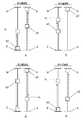
図1は、本発明の根底にある原理の単純化された概略的な描写である。図1aから図1hは、投与量設定と投与量送達とのそれぞれの間の、ある往復動する薬物送達装置要素の移動パターンを示している。それぞれの移動は、例えば薬物送達装置筐体など、薬物送達装置の基礎構造(図1には示されていない)に対する変位として理解されるものである。明確にするために、移動は、直線に沿った純粋な軸方向の移動として示されているが、角度的にずれた基準位置同士の間での純粋な回転方向の移動、または、軸方向の移動と回転方向の移動との任意の組み合わせでもよいことは、留意されたい。 FIG. 1 is a simplified schematic depiction of the principles underlying the present invention. FIGS. 1a to 1h show the movement pattern of certain reciprocating drug delivery device elements between dose setting and dose delivery, respectively. Each movement is to be understood as a displacement relative to the drug delivery device infrastructure (not shown in FIG. 1), eg, the drug delivery device housing. For clarity, the movement is shown as pure axial movement along a straight line, but pure rotational movement between angularly offset reference positions, or axial movement. Note that any combination of movement and rotational movement may be used.
先に記載したように、本発明による薬物送達装置の使用者によって実行される投与量設定手順は、投与量調製ステップと、選択的な投与量調節ステップとを含む。投与量調製ステップは、最後に排出された投与量に対応する投与量を自動的に設定することになり、これは、以下のことから明らかとなり、一方、選択的な投与量調節ステップは、使用者に自動的な設定投与量を新たな投与量へと変更させることができ、したがって、新たな投与量は最終的な設定投与量になる。使用者が投与量調節ステップを実行したかどうかに依存して、投与量送達手順の実行に応じて薬物送達装置から排出される最終的な設定投与量は、自動的な設定投与量または新たな投与量のいずれかとなる。使用者が自動的な設定投与量を変更する機会を用い、それによって排出される投与量が以前の排出された投与量と異なる場合、次の投与量調製ステップは、新たな投与量に対応する投与量を自動的に設定することになる。それによって、処置計画が毎回同じ投与量が投与されることを指示する場合、使用者は、投与量調節ステップを実施することを控えるだけであり、楽な自動的な投与量設定から利益を得られるが、処置がそのように要求する場合は、いつでも投与量を変更する選択肢を持っている。 As described above, the dose setting procedure performed by the user of the drug delivery device according to the present invention includes a dose preparation step and a selective dose adjustment step. The dose preparation step will automatically set the dose corresponding to the last discharged dose, which will become apparent from the following, while the selective dose adjustment step is used The person can change the automatically set dose to a new dose, so that the new dose becomes the final set dose. Depending on whether the user has performed a dose adjustment step, the final set dose drained from the drug delivery device in response to performing the dose delivery procedure may be an automatic set dose or a new set dose. One of the doses. If the user has an opportunity to automatically change the set dose and the dose that is discharged is different from the previous dose, the next dose preparation step will correspond to the new dose The dose will be set automatically. Thereby, if the treatment plan indicates that the same dose is to be administered each time, the user simply refrains from performing the dose adjustment step and benefits from easy automatic dose setting. However, if the treatment so requires, you have the option of changing the dose whenever you want.
図1aでは、投与量調製要素20’が、投与量調製要素20’のための投与量調製位置を定める線Pにおいて実線で示されている。投与量調製要素20’が線Pにあるとき、薬物送達装置は、投与量を薬物リザーバ(図示せず)から送達する準備が整っている「投与量調製」状態にある。投与量調製要素20’の投与量調製位置は、薬物送達装置の前述の基礎構造に対して固定されている軸方向の位置である。 In FIG. 1 a, the
さらに、投与量定義要素40’が、投与量定義要素40’のための最大投与量設定位置を定める停止面Mに当接する第1の極限位置において実線で示されている。投与量定義要素40’が停止面Mに当接するとき、薬物送達装置に関する最大設定可能投与量が設定される。したがって、投与量調製要素20’および投与量定義要素40’が示した位置にあるとき、薬物送達装置は、最大設定可能投与量を送達する準備が整っている。 Further, the dose defining element 40 'is shown in solid lines at a first extreme position that abuts a stop surface M that defines a maximum dose setting position for the dose defining element 40'. When the dose defining element 40 'abuts against the stop surface M, the maximum settable dose for the drug delivery device is set. Thus, when the dose preparation element 20 'and the dose definition element 40' are in the position shown, the drug delivery device is ready to deliver the maximum settable dose.
図1aは、投与量送達の間の投与量調製要素20’および投与量定義要素40’の移動パターンを示している。点線の矢印は、投与量送達の間、投与量送達の間の投与量調製要素20’および投与量定義要素40’が結合され、相関された移動を受け、それによって、投与量定義要素40’が、最大投与量設定位置から、投与量定義要素40’についてのゼロ投与量指示位置を定める停止面Zに当接する第2の極限位置へと移動し、投与量調製要素20’が、投与量調製位置から、投与量調製要素20’についての最大投与量送達位置を定める線Xによって指し示された位置へと移動することを指し示している。 FIG. 1a shows the movement pattern of the dose preparation element 20 'and the dose definition element 40' during dose delivery. Dotted arrows indicate that during dose delivery, the dose preparation element 20 'and the dose definition element 40' during dose delivery are combined and undergo a correlated movement, whereby the dose definition element 40 ' Moves from the maximum dose setting position to a second extreme position that abuts a stop surface Z that defines a zero dose indication position for the dose definition element 40 ', and the dose adjustment element 20' Moving from the preparation position to the position indicated by line X defining the maximum dose delivery position for the dose preparation element 20 '.
投与量送達機構(図示せず)は、最大設定可能投与量を薬物リザーバから排出させるために、最大投与量設定位置からゼロ投与量指示位置への投与量定義要素40’の移動の間、投与量定義要素40’と結合される。 A dose delivery mechanism (not shown) is administered during the movement of the dose definition element 40 'from the maximum dose setting position to the zero dose indication position in order to drain the maximum settable dose from the drug reservoir. Combined with the quantity definition element 40 '.
投与量定義要素40’が停止面Zと当接するとき、薬物送達装置は、設定投与量が送達され、投与量設定手順が実行されるまでさらなる投与量送達が起こり得ない「投与量送達」状態にある。停止面Zは、薬物送達装置の基礎構造に対して固定される。しかしながら、以下のことから明らかとなるように、ゼロ投与量指示位置への投与量定義要素40’の移動は、最大設定可能投与量が送達されるときの最大投与量送達位置への投与量調製要素20’の移動によって伴われるだけである。 When the
図1bは、続く投与量調製の間の投与量調製要素20’および投与量定義要素40’の移動パターンを示している。点線の矢印は、投与量調製要素20’および投与量定義要素40’が結合され、相関された移動を受けることを同じく指し示している。したがって、投与量調製要素20’は、例えば、使用者が単純な所定の行為を実施する結果として、投与量調製位置へと戻るように移動し、投与量定義要素40’は、したがって最大投与量設定位置へと戻るように移動する。それによって、最大設定可能投与量は、送達のために自動的に調製されている。投与量調製の間、投与量送達機構は、投与量定義要素40’から切り離されている。投与量調製要素20’が投与量調製位置に向かって移動する方向は、投与量調製方向と称されることに留意されたい。 FIG. 1b shows the movement pattern of the dose preparation element 20 'and the dose definition element 40' during subsequent dose preparation. The dotted arrows also indicate that the dose preparation element 20 'and the dose definition element 40' are combined and undergo a correlated movement. Thus, the
図1cは、使用者が調製投与量を変更し、異なる最終投与量が送達されるように設定するために、使用するのを選択することができる選択的な投与量調節を示している。実線で示されているように、投与量調製要素20’が投与量調製位置に到達するとき、または、その到達の後、投与量調製要素20’と投与量定義要素40’とは、投与量調製方向の移動に関して切り離されることになり、使用者は、投与量定義要素40’を投与量調製要素20’および薬物送達装置の基礎構造に対して再位置決めすることができ、一方、投与量調製要素20’は、少なくとも投与量調製方向に静止したままである。この再位置決めは、点線の矢印によって指し示されている。図1cでは、投与量定義要素40’は、最大設定可能投与量より小さい具体的な投与量「投与量1」に対応する投与量設定位置である位置d1に移動される。したがって、「投与量1」は、投与量送達手順の次の実行に応答して送達されることになる最終的な設定投与量である。使用者が投与量調製要素20’に対して投与量定義要素40’を再位置決めしないと選択する場合では、調製された最大設定可能投与量が、投与量送達手順の次の実行に応答して送達されることになる。FIG. 1c shows the selective dose adjustment that the user can choose to use to change the prepared dose and set the different final doses to be delivered. As shown by the solid line, when the
図1dは、「投与量1」の送達の間の投与量調製要素20’および投与量定義要素40’の移動パターンを示している。投与量調製要素20’および投与量定義要素40’は、再び結合され、相関された移動を受け、それによって、投与量定義要素40’は、位置d1からゼロ投与量指示位置へと運ばれ、投与量調製要素20’は、投与量調製位置から、投与量調製位置と最大投与量送達位置との間の位置e1へと運ばれる。したがって、位置e1は、「投与量1」の送達に対応する投与量調製要素20’のための投与量終了位置である。FIG. 1d shows the movement pattern of the
図1eは、続く投与量調製の間の投与量調製要素20’および投与量定義要素40’の移動パターンを示している。ここで、投与量調製要素20’と投与量定義要素40’との間の結合動作のため、例えば、以前に実施されたものと同様または同一の所定の使用者の行為から生じる、位置e1から投与量調製位置への投与量調製要素20’の反対の移動が、位置d1へと戻す投与量定義要素40’の移動を引き起こす。したがって、薬物送達装置は、「投与量1」をもう一度送達する準備が自動的に整う「投与量調製」状態へと運ばれる。FIG. 1e shows the movement pattern of the
図1fは、「投与量1」の調製に続く別の投与量調節を示している。投与量調製要素20’が投与量調製位置に到達しているため、投与量調製要素20’に対する投与量定義要素40’の再位置決めが可能であり、投与量定義要素40’は、最大設定可能投与量より小さいが「投与量1」より大きい別の具体的な投与量である「投与量2」に対応する位置d2へと移動される。ここで、「投与量2」は、投与量送達手順の次の実行に応答して送達されることになる最終的な設定投与量である。FIG. 1 f shows another dose adjustment following the preparation of “
図1gは、「投与量2」の送達の間の投与量調製要素20’および投与量定義要素40’の移動パターンを示している。2つの要素は、再び結合され、相関された移動を受け、投与量定義要素40’を位置d2からゼロ投与量指示位置へと運び、投与量調製要素20’を、投与量調製位置から、位置e1と最大投与量送達位置との間の位置e2へと運ぶ。したがって、位置e2は、「投与量2」の送達に対応する投与量調製要素20’のための投与量終了位置である。FIG. 1g shows the movement pattern of the
続く投与量調製を示す図1hでは、投与量調製要素20’が、例えば所定の使用者の行為に応答して、投与量調製位置へと移動され、投与量調製要素20’との結合動作のため、投与量定義要素40’を位置d2へと戻すように移動させる。したがって、今回は、所定の使用者の行為によって、「投与量2」が送達に向けて自動的に調整させられている。そのため、中間の投与量調節のない投与量送達手順のあらゆる後に続く実行が、「投与量2」を薬物送達装置から送達させることになる(その具体的な大きさの投与量が、薬物リザーバからの送達のために利用可能である限り)。In FIG. 1 h showing subsequent dose preparation, the
前述のことから、投与量が調製される度に、どの位置から出発するかに拘わらず、投与量調製要素20’が投与量調製位置へと運ばれることと、投与量が送達される度に、どの位置から出発するかに拘わらず、投与量定義要素40’がゼロ投与量指示位置へと送達されることとは、明確である。さらに、投与量調製要素20’と投与量定義要素40’とは、結合され、投与量調製および投与量送達の間に、相互に反対の相関された移動を受け、薬物送達装置が「投与量調製」状態にあるとき、少なくとも投与量調製方向における移動に対して切り離される。そのため、「投与量調製」状態にある薬物送達装置の基礎構造(例えば、筐体)に対する投与量定義要素40’の位置こそが、送達される投与量の大きさを決定する。各々の設定投与量は、薬物送達装置の基礎構造に対する投与量定義要素40’の固有の位置と一致し、各々の送達投与量は、薬物送達装置の基礎構造に対する投与量調製要素20’の固有の位置と一致する。これは、投与量が送達される度に、投与量調製要素20’が、送達される投与量の大きさに依存する薬物送達装置の基礎構造に対する特定の位置を保持することを意味し、また、投与量調製要素20’および投与量定義要素40’が結合され、投与量調製および投与量送達の間に、相互に反対の相関された移動を受けるため、投与量が調製される度に、投与量定義要素40’が、最後に出発した位置へと戻るように運ばれることを意味する。別の言い方をすれば、投与量調製位置への投与量調製要素20’の移動は、送達された最後の投与量と等しい投与量の自動的な調製を常にもたらすことになる。この自動的な調整投与量は、次に、投与量送達手順が実行される前に、新たな最終投与量を設定するために、使用者によって選択的に調節され得る。 From the foregoing, every time a dose is prepared, regardless of where it starts, the dose preparation element 20 'is brought to the dose preparation position and every time a dose is delivered. It is clear that the dose definition element 40 'is delivered to the zero dose indication position regardless of where it starts. In addition, the
前述の解決策は、装置が取り扱うのが簡単で、簡単な所定の使用者の行為に応答して最後に送達された投与量に対応する投与量の自動的な調製を提供する一方で、調製投与量の選択的な手動の調節も提供するため、使用者の観点から魅力的である。比較的少数の構成部品しか、高度な使用者の利便性を提供する非常に正確な装置を提供するのに必要とされないため、製造の観点からも魅力的である。 The foregoing solution is easy to handle by the device and provides an automatic preparation of a dose corresponding to the last delivered dose in response to a simple predetermined user action. It is also attractive from the user's point of view because it also provides selective manual adjustment of dosage. It is also attractive from a manufacturing standpoint because relatively few components are required to provide a very accurate device that provides a high degree of user convenience.
図1のそれぞれの停止面M、Zは、投与量定義要素40’の軸方向の移動のための軸方向の停止を作り出す。しかしながら、本発明の範囲内で、これらの停止は、軸方向である必要はなく、代替で、回転方向もしくは横方向であってもよく、または、軸方向、回転方向、および横方向の組み合わせであってもよいことは、留意されたい。 Each stop surface M, Z in FIG. 1 creates an axial stop for the axial movement of the dose defining element 40 '. However, within the scope of the present invention, these stops need not be axial, but may alternatively be rotational or lateral, or a combination of axial, rotational and lateral directions. Note that there may be.
また、図1の投与量調製要素20’および投与量定義要素40’の様々な指し示された相関された移動は、投与量が調整および送達されるときにそれぞれ、2つの要素が正確に同じ方向で同じ距離だけ移動するという印象を与え得る。しかしながら、これは、必ずしも事実ではない。本発明の概念の異なる実施では、投与量調製要素20’および投与量定義要素40’は、実際、以下において明らかとなるように、投与量調製および/または投与量送達の間、異なる距離および/または異なる方向で移動できる。したがって、それぞれの要素の変位の大きさおよび方向は、移動が相関されている限り、すなわち、一方の要素のある特定の移動(投与量調製/投与量送達の局面において)が、他方の要素のある特定の移動によって常に伴われる限り、および、その逆である限り、本発明の実施にとって不可欠ではない。 Also, the various indicated correlated movements of the
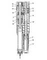
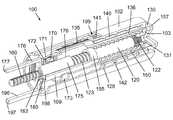
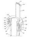
図2は、本発明の例示の実施形態による注射装置1の長手方向の断面図である。注射装置1は、使用前の状態で描写されており、薬物カートリッジ10が備え付けられる筐体2の形態の基礎構造を有している。カートリッジ10は、カートリッジ保持器14によって筐体2に対して軸方向に固定されている。カートリッジ10の遠位端部は、貫通可能な自己封止ゴム隔膜11によって閉じられており、近位端部は、スライド可能ゴムピストン12によって封止されており、隔膜11とピストン12とは共に、細長いカートリッジ壁のフレーム内に可変容積室13を定めている。 FIG. 2 is a longitudinal sectional view of an
針ハブ16に固定的に保持されている注射針17を備える針組立体が、注射針17の後端が隔膜11を貫き、室13に位置するように、針装着部18のネジ付き針境界面15に取り付けられている。 The threaded needle boundary of the
ネジ付きピストンロッド60が、ピストンロッド足部61を介してピストン12に当接し、ピストン12をカートリッジ10において下向きに移動させ、室13にある多量の物質を、注射針17を通じて押し出させるように適合されている。ピストンロッド60の移動は、螺旋状であり、筐体2と一体的に形成されているナット62によって案内される。ピストンロッド60は、投与量送達の間にピストンロッド60に回転運動を与えるように適合されているピストンロッド案内部63と、スプライン係合している。ピストンロッド案内部63は、ピストンロッド60の一部を包囲し、筐体2に固定的に備え付けられたバネ筐体3の内部スリーブ85の周りに嵌め込まれた近位延在部64を有する細長い円筒構造である。近位延在部64は、筐体2に対するピストンロッド案内部63の一方向の回転を確保するラチェット機構を提供するために、バネ筐体3において内部に配置されている鋸状歯87の環体と相互作用する一対の可撓性アーム(見ることができない)を持っている。 A threaded
ピストンロッド案内部63は、その中心領域に歯付き外部ベルト部(見ることができない)をさらに有しており、その歯付き外部ベルト部は、以下に説明するように、投与量送達の間、軸方向に変位可能な歯車80における内部歯(見ることができない)と係合するように適合されている。歯車80は、投与量送達の間を除いて、バネ筐体3における内部周囲歯86と係合するように適合された近位歯付き縁部81と、中心歯付き縁部82とを有している。歯車80は、図3aにおいて最もよく見えるように、注射装置1の遠位部分から軸方向に延び、歯車80の遠位部分と係合するための捕捉部73のある結合ロッド72を備える伝達バー70によって、軸方向に変位可能である。伝達バー70は、戻しバネ65によって注射装置1の近位端に向かって付勢され、これは、近位歯付き縁部81が周囲歯86との係合に向かって付勢されることを意味する。 The
あらかじめ張力を掛けた螺旋バネ50が、バネ筐体3に配置されている。バネ50は、バネ筐体3に固定されている外側バネ端部と、回転可能なバネシャフト51に固定されている内側バネ端部とを備えている。バネシャフト51は、バネ50から軸方向下向きに延びており、コグホイール52に回転方向において固定されており、コグホイール52は、さらに歯車80の中心歯付き縁部82と回転方向において結合されている。 A
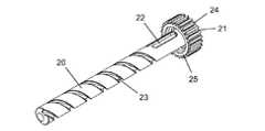
近位歯付きヘッド32を有する回転体30が、コグホイール52のすぐ遠位において筐体2に軸方向で固定されている。歯付きヘッド32は、後に説明されているように、歯車80が戻しバネの付勢に対して遠位へと変位されるとき、中心歯付き縁部82を受け入れて係合するように適合されている。回転体30は、細長い投与量調製ロッド20を受け入れる中空の円筒スリーブ31をさらに備えている。投与量調製ロッド20は、長手方向溝22における遠位において途切れる外部螺旋溝23を有している。スリーブ31における内部突起33は、図2では長手方向溝22内に位置決めされており、投与量設定および投与量送達の間、螺旋溝23の少なくとも一部を進むように適合されている。投与量調製ロッド20は、注射装置1の図示されている状態において内部壁58に当接している結合ヘッド21を、さらに備えている。投与量調製ロッド20は、図示されている近位位置と、結合ヘッド21が径方向壁59に当接する遠位位置との間で、軸方向に移動することができる。 A rotating
回転体30は、さらに、外面に投与量に関する目印41を持ち(図4参照)、回転体30によって回転されるとき、筐体2における内部ネジ山28に沿う螺旋変位を受けるような構造とされている目盛ドラム40に、回転方向において固定されている。注射装置1の図示した使用前の状態において、目盛ドラム40は、筐体2に対して、投与量が設定されていないことを指示するゼロ投与量指示位置にある。筐体2に対する目盛ドラム40の任意の具体的な位置は特定の設定投与量に対応しており、その特定の設定投与量は、窓99を通じて表示される。図2の位置から、目盛ドラム40は、目盛ドラム40の遠位端面にあるスタッド46が筐体2における遠位スタッド92と接するまで螺旋状に下向きに変位可能であり、遠位スタッド92は、遠位方向における目盛ドラム40の変位のための回転方向の停止を構成している。これは、筐体2に対する目盛ドラム40の底位置を定めており、設定されている最大設定可能投与量に対応している。 The rotating
結合ヘッド21には、その周囲に沿って歯24が設けられており(図5参照)、それらの歯24は、投与量調製ロッド20の図示した位置において、投与量ダイヤル55の内側歯付き部と回転方向において係合している。投与量ダイヤル55は、投与量送達の間に投与されることになる最終投与量を定めるために、使用者によって操作されるように適合されている。投与量送達の間、結合ヘッド21は遠位へと変位され、それによって、歯24は投与量ダイヤル55から係合解除され、代わりに内部スプライン29と係合され、筐体2に対する投与量調製ロッド20の回転を防止する。 The
注射ボタン57が、投与量ダイヤル55の遠位に配置されており、近位の受動位置と、投与量送達が開始される遠位の作動位置との間で、筐体2に対して軸方向にスライド可能である。注射ボタン57は、注射ボタン57が作動位置へとスライドされることに応答して投与量調製ロッド20を投与量開始位置へと運ぶように構成されている搬送器56に、軸方向で固定されている。 An
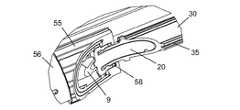
図2に示した使用前の状態で、蓋4が注射装置1に取り付けられており、カートリッジ10の遠位部分と、針組立体と、投与量ダイヤル55と、注射ボタン57とを覆っている。蓋4は、円筒形の側壁5と、端壁6とを備えている。内部スリーブ7が、端壁6の内面に形成されており、作動ロッド9の受け入れのための空所8を提供している。作動ロッド9は、内部スリーブ7に軸方向で固定されており、径方向壁59を貫いて結合ヘッド21の遠位端面まで近位へと延びている。蓋4は、筐体2の蓋受入部によって受け入れられ、解放可能に保持されている。 2, the
図3aは、伝達バー70がその遠位端部において注射ボタン57に軸方向で結合されていることを露わにするために筐体2および蓋4が取り去られた注射装置1の斜視図である。伝達バー70が軸方向に延びる脚71を備えていることも、さらに見て取れる。脚71は結合ロッド72に軸方向で結合されており、そのため、筐体2における歯車80の軸方向の位置は、注射ボタン57が受動位置から作動位置へと移動されるとき、伝達バー70および歯車80が戻しバネ65の付勢に抗して遠位へと駆り立てられ、また、注射ボタン57が解放されるとき、注射ボタン57が受動位置へと戻るまで、戻しバネ65が注射ボタン57を移動し、それによって伝達バー70および歯車80を近位へと後方に移動する意味において、注射ボタン57の軸方向の位置によって決定される。 FIG. 3a is a perspective view of the
図3bは、図3aにおける領域Qによって範囲を定められた注射装置1の一部の拡大である。この拡大は、投与量ダイヤル55と、搬送器56と、投与量調製ロッド20と、回転体30との間の様々な連結をさらに詳細に示している。具体的には、図は、投与量ダイヤル55と投与量調製ロッド20との間の回転方向における係合と、搬送器56と投与量調製ロッド20との間の内部壁58を介した軸方向の係合とを示している。同じく図示されているのは、回転体30を目盛ドラム40に回転方向において固定するために使用されている、回転体30の外部にある軸方向スプライン35である。 FIG. 3b is an enlargement of a part of the
図4は目盛ドラム40の斜視図であり、周囲面に印刷、エンボス加工、または他の加工がされた投与量に関する目印41の一部を示している。明確にするために、数字0、24、48、および72だけがこの図では示されているが、目盛ドラム40は、好ましくは、例えば一単位ごとの増分でといった、これらの数字の間の設定投与量も示すように構成される。螺旋軌道区域42が、内部ネジ山28との係合のために表面に配置されている。最後に、図は、スプライン35のうちの1つで受け入れるように適合された長手方向の内部突部44を示している。目盛ドラム40は、目盛ドラム40と回転体30との間の安定した回転方向の連結を確実にするために、回転体30における対応するスプラインでの受け入れのために、内周に沿って等距離に分配された3つのこのような突部を有している。 FIG. 4 is a perspective view of the
図5は、螺旋溝23と長手方向溝22とが連結されていることを詳細に示し、さらに、結合ヘッド21の歯付き構造を示す投与量調製ロッド20の斜視図である。24個の歯24が結合ヘッド21の周囲に沿って等距離に分配されており、筐体2に対する投与量調製ロッド20の一回転あたりの可能な回転位置の数に対応している。24個の歯24は、投与量調製ロッド20を、筐体2に対する実際の回転位置に拘わらず、投与量送達の間、内部スプライン29との相互作用によって、筐体2に対して回転方向において固定させることができる。結合ヘッド21は、内部壁58との係合のための手段として作用する環状当接面25を有している。 FIG. 5 is a perspective view of the
図6aおよび図6bは、それぞれ、回転体30をさらに詳細に示す斜視図および長手方向の断面図である。見て取れるように、歯付きヘッド32は、単純な歯車連結で、中心歯付き縁部82との相互作用のために設けられている多くの歯34を保持している。 6a and 6b are a perspective view and a longitudinal sectional view showing the rotating
図7〜図12は、使用中の異なる状態における注射装置1の長手方向の断面図である。以下において、注射装置1の使用の一連を、これらの図を参照しつつ説明する。 7 to 12 are longitudinal sectional views of the
図7は、正に最初の投与量の送達の直前の状態における注射装置1を示している。蓋4は筐体2から取り外されており、投与量は、投与量調製ロッド20によって定められている長手方向軸の周りの投与量ダイヤル55の回転によって設定されている。投与量ダイヤル55が回転されるとき、歯24と投与量ダイヤル55の内側歯付き部との間の回転方向の係合は、投与量調製ロッド20の接合回転を引き起こし、この接合回転が、長手方向溝22に位置する内部突起33のため、回転体30の接合回転を引き起こす。軸方向スプライン35と長手方向の内部突部44との間の係合のため、目盛ドラム40も強制的に回転し、そのため目盛ドラム40は、内部ネジ山28に沿って筐体2において下向きに螺旋状に変位されられる。目盛ドラム40が筐体2に対するこの螺旋状の移動を実施するため、投与量目印41は、窓99を順次通過して、どの投与量が設定されるかを指示する。使用者が偶発的に大き過ぎる投与量に回した場合、投与量ダイヤル55の回転の方向が単に反対にされることで、投与量調製ロッド20、回転体30、および目盛ドラム40の回転の方向は同様に反対にされ、目盛ドラム40は筐体2において上向きに螺旋状に移動する。したがって、筐体2に対する投与量ダイヤル55の全体の角度変位は、窓99に対する目盛ドラム40の螺旋変位と相関し、それによって実際の投与量設定と相関する。図7における目盛ドラム40の位置は、最大設定可能投与量のおおよそ3分の1に対応する投与量が設定されていることを指し示している。 FIG. 7 shows the
図8では、注射ボタン57はその遠位の作動位置へと前方にスライドされ、図は、バネ50がエネルギーを解放する直前の投与量開始状態における注射装置1を示している。注射ボタン57の遠位への移動によって、内部壁58と当接面25との間の係合のため、搬送器56は投与量調製ロッド20を遠位へと引っ張る。投与量調製ロッド20の軸方向の移動によって、歯24は投与量ダイヤル55から係合解除し、代わりに内部スプライン29と係合し、それによって結合ヘッド21を筐体2に回転方向において固定する。さらに、投与量調製ロッド20と回転体30との間の相対的な軸方向の運動によって、内部突起33は、長手方向溝22と螺旋溝23との間の接合位置に位置決めされることになる。注射ボタン57の遠位への移動によって、同時に、伝達バー70は、結合ロッド72および捕捉部73を介して、戻しバネ65からの付勢力に抗して、歯車80を遠位へと引っ張り、それによって、先ず中心歯付き縁部82が歯付きヘッド32との追加的な係合へと移動し、続いて近位歯付き縁部81が周囲歯86から係合解除し、あらかじめ張力を掛けたバネ50を解放する。 In FIG. 8, the
図9は、その結果として、バネ50が緩まり、内側バネ端部がバネシャフト51を回転させるところを示している。この回転は、中心歯付き縁部82を介して歯付きヘッド32へと伝えられ、回転体30が回転するとき、目盛ドラム40はそのゼロ投与量指示位置に向かって内部ネジ山28に沿って上向きに駆動され、一方、内部突起33は、螺旋溝23において上向きに進み、投与量調製ロッド20は、結果的に、筐体2との回転方向における固定係合のため、下向きに駆り立てられる。 FIG. 9 shows that as a result, the
目盛ドラム40の近位部分が筐体2における近位スタッド(見ることができない)と当接するように回転するとき、目盛ドラム40はゼロ投与量指示位置へと戻っており、そのため、筐体2に対してその方向においてさらに回転することはできない。結果として、回転体30は回転を停止し、投与量調製ロッド20は、送達される特定の投与量に対応する投与量終了位置を構成する軸方向の位置で、筐体2に対する下向きの変位を停止する。バネ50は、この位置において、さらなるエネルギーを解放することが妨げられ、注射装置1は「投与量送達」状態にある。原則として、目盛ドラム40および投与量調製ロッド20の前述のそれぞれの移動は、図1dで概略を説明した投与量定義要素40’および投与量調製要素20’のそれぞれの移動に対応している。 When the proximal portion of the
バネ50がエネルギーを解放する限り、歯車80は、バネシャフト51と中心歯付き縁部82との間の相互作用により回転し、歯車80が伝達バー70に依って遠位へと移動されており、それによって歯車80における内部歯(見ることができない)がピストンロッド案内部63における歯付き外部(見ることができない)との係合へと軸方向に移動しているため、歯車80の回転はピストンロッド案内部63へと伝達され、ピストンロッド案内部63からピストンロッド60へと伝達され、ナット62との係合のため、遠位方向において螺旋状に進行される。それによって、ピストン12はカートリッジ10へと押し込まれて、薬物収容室13の容積を縮小し、注射針17を通じてある量の薬物を放出する。ひとたび目盛ドラム40がゼロ投与量指示位置に到達し、バネ50がさらに緩まるのが妨げられると、歯車80は回転を停止し、薬物放出が結果として停止する。目盛ドラム40のこの位置において、投与量目印41は、投与量が送達のために調製されていないことを、窓99を通じて指し示す。 As long as the
注射ボタン57の解放によって、図10に示すように、伝達バー70と、結果的に歯車80とは、戻しバネ65によって近位へと移動される。これによって、中心歯付き縁部82は、歯付きヘッド32および近位歯付き縁部81と係合解除し、周囲歯86と再係合することで、バネ50を締め付ける。また伝達バー70の近位への移動によって、注射ボタン57はその近位の受動位置へと戻り、搬送器56を一緒に押し、それによって内部壁58は、投与量ダイヤル55との当接へと押し進められる。 The release of the
しかしながら、注目すべきことに、投与量調製ロッド20はこの行為によって移動されていない。投与量調製ロッド20は、投与量終了位置に残っており、したがって、筐体2に対してなおも回転方向において固定されている。これは、注射装置1の投与量送達状態において、新たな投与量が送達のためにまだ自動的に調製されていない場合、投与量ダイヤル55と目盛ドラム40とが切り離されているため、投与量ダイヤル55の回転は目盛ドラム40の位置に影響がないことを意味している。 However, it should be noted that the
室13からの薬物の放出の間における任意のときに、使用者が何らかの理由のために投与量送達を一時停止したい場合、使用者は、注射ボタン57を解放するだけであり、それによって、戻しバネ65は、伝達バー70および歯車80を筐体2において近位へと押し進めることになり、近位歯付き縁部81を周囲歯86と係合させ、先に記載したことと同様に、バネ50がさらに緩むのを止めることは、さらに留意されたい。重要なことに、注射ボタン57が作動されるとき、バネ50が解放される前に結合ヘッド21が投与量ダイヤル55から係合解除されることになり、注射ボタン57が解放されるときに結合ヘッド21が戻らないため、注射が一時停止されるとき、送達される投与量を変更するために投与量ダイヤル55を操作することが可能となっていない。それによって、使用者は、送達手順の途中で最終的な設定投与量を調節し、そのため実際の投与量設定を潜在的に不確実にしてしまうことはない。 If at any time during the release of the drug from the
図11は、蓋4の再取り付けの後の「投与量調製」状態における注射装置1を示している。筐体2に対する蓋4の再取り付けの動きにより、作動ロッド9は、近位へと向かわされる押す力を結合ヘッド21に発揮し、そのため、これによって、投与量調製ロッド20は、内部スプライン29に沿う投与量調製位置へと戻す反対の軸方向の変位を受ける。投与量調製位置へと戻すこの変位は、当接面25が内部壁58に当接し、内部突起33を、螺旋溝23において下向きに進ませ、さらに長手方向溝22へと進ませ、注射ボタン57が作動位置へとスライドされる前に長手方向溝22において元々保持されていた位置に戻すまで進ませる。内部突起33が螺旋溝23において下に戻るように進む間、回転体30は回転し、目盛ドラム40を従属させる。内部突起33は、螺旋溝23と長手方向溝22との間の接合位置に到達するとき、回転体30の回転は停止し、この位置において、目盛ドラム40は、そのゼロ投与量指示位置への移動の間に受けたのと反対の方向であるが大きさは同一である、内部ネジ山28に沿う螺旋状の変位を受けており、したがって、投与量送達が開始される前にあったのと同じ筐体2に対する位置へと戻すように運ばれており、すなわち、窓99を通じて読み取られ得る数字は、正に送達された投与量と等しい。 FIG. 11 shows the
注射装置1への蓋4の取り付けの間、投与量調製ロッド20と回転体30との間の相対運動の最後の部分は、内部突起33が長手方向溝22に位置決めされているため、純粋に軸方向である。別の言い方をすれば、投与量調製ロッド20の戻り変位の最後の部分の間、結合ヘッド21は内部スプライン29から係合解除し、投与量ダイヤル55の内側歯付き部と再係合し、目盛ドラム40は筐体2に対して静止したままである。 During the attachment of the
したがって、筐体2の蓋受入部への蓋4の取り付けによって、a)投与量調製ロッド20は、投与量送達手順の途中で受けた変位と正確に反対である筐体2に対する変位を受け、b)目盛ドラム40は、投与量送達手順の途中で受けた変位と正確に反対である筐体2に対する変位を受ける。 Therefore, by attaching the
正に最初の投与量送達の後に蓋4が蓋受入部に取り付けられるとき、注射装置1は、投与量が送達のために実際に調製されたにも拘らず、側壁5が注射ボタン57を覆っており、したがって操作のためにアクセスできないままであるため、「投与量調製」状態にあるだけでなく、保護状態または非作動状態にもある。同様に、蓋4が投与量ダイヤル55にあるとき、操作のためにアクセスできず、そのため調製投与量は調節できない。結果として、注射装置1は、使用者が調製投与量の不注意な調節、または、蓋4への調製投与量の投与をする危険を冒すことなく、例えばバッグまたはポケットにおいて、安全に持ち運びできる。 When the
投与量調製ロッド20は、投与量調製位置にあるとき、回転体30にスナップで嵌め込まれ、それによって、筐体2に対して軸方向に解放可能に固定される。そのため、投与量調製ロッド20は、図12に示したように、使用者が次の注射を打つ前に蓋4を除去するとき、その位置に留まっている。蓋4を除去した後、使用者は2つの選択肢を有する。すなわち、次の注射との関連で必要とされる投与量が以前に送達された投与量と同じである場合、投与量設定行為は必要とされず、注射針17が皮膚へと挿入され得るだけであり、注射ボタン57が作動位置へとスライドされ得る。使用者が投与量を上げるまたは下げるよう調節する場合には、投与量ダイヤル55は、好ましくは注射針17が皮膚へと挿入される前に、調節を実行するために操作可能である。 When the
先に述べたように、最初に注射装置1を使用するとき、使用者は、送達される投与量を初めに設定でき、初期投与量が後に続く注射で変更される必要がある場合にのみ、投与量ダイヤル55を再び操作できる。代替で、注射装置1は、健康管理専門者によって、または、製造者によって、あらかじめ設定されてもよく、その場合、使用者は、初めに、または、完全に、投与量を設定することがない。 As mentioned above, when using the
さらに、先に記載したように、正に最初の投与量送達に続いて、投与量は、蓋受入部への蓋4の取り付けに応答して自動的に送達のために調製される。しかしながら、蓋4ではなく、投与量調製ロッド20を投与量調製位置へと戻す他の手段が採用されてもよいことは、明らかである。例えば、作動ロッド9は、別体の品物として提供されてもよく、蓋4とは無関係に、結合ヘッド21を内部壁58との当接へと戻すように押すために、使用者によって用いられてもよい。 Further, as described above, following the very first dose delivery, the dose is automatically prepared for delivery in response to attachment of the
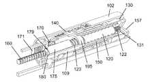
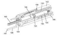
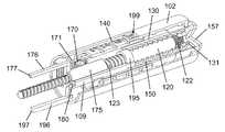
図13は、本発明の別の例示の実施形態による注射装置100の一部の斜視図であり、具体的には、投与量機関を持つ注射装置100の近位部分の斜視図である。注射装置100は使用前の状態にあり、注射装置100の一部の要素の一部が、構造の詳細な外観を提供するために、図から除去されている。 FIG. 13 is a perspective view of a portion of an
注射装置100は、いわゆるペン注射器式のものであり、長手方向の大まかな軸に沿って延びていくつかの機能部品を収容する管状筐体102を有している。筐体102は、技術的に従来から知られている手法で、薬物収容カートリッジ(図示せず)と結合されており、特に、注射装置100の使用中におけるカートリッジが、筐体102に対して少なくとも軸方向に固定されることを意味する。注射装置100の機能の中心は、筐体102に軸方向および回転方向の両方において固定されているナット162と係合している軸方向に延びるピストンロッド160である。ピストンロッド160の遠位端部は、ピストンロッド160のあらゆる進行する軸方向の運動が、技術的に従来からも知られているように、必然的にカートリッジの加圧に向けて、ピストンへと伝達されるように、カートリッジにおいてピストン(図示せず)に結合されている。 The
時計回りまたは反時計回りとして参照される、本発明のこの実施形態に関連して記載されるすべての回転方向の移動は、ピストンロッド160の遠位端から(すなわち、図13における左から右へと)見たものとして記載されていることに留意されたい。 All rotational movements described in connection with this embodiment of the invention, referred to as clockwise or counterclockwise, are from the distal end of the piston rod 160 (ie, from left to right in FIG. 13). Note that it is listed as seen.
筐体102には、目盛ドラム140における外部螺旋軌道区域142と協働し、目盛ドラム140に筐体102において明確に定義された螺旋運動を受けさせることができる内部ネジ山128が、設けられている。目盛ドラム140は、使用者に設定投与量の具体的な大きさを指示するための複数の投与量目印141を持っている。投与量目印141は、目盛ドラム140が、例えば近位の「ゼロ投与量」位置から遠位の「最大投与量設定」位置まで、内部ネジ山128に沿って進むとき、筐体102における窓199を通じて連続して視認可能である。近位の「ゼロ投与量」位置は、内部ネジ山128の近位端において目盛ドラム140の近位への運動のための回転方向の停止を提供する近位停止面(見ることができない)によって定められており、一方、「最大投与量設定」位置は、内部ネジ山128の遠位端において目盛ドラム140の遠位への運動のための回転方向の停止を提供する遠位停止面(見ることができない)によって定められている。 The
目盛ドラム140は、長手方向の内部突部144(図16を参照)と、回転体130の外面において軸方向に延びるスプライン135とを介して、回転体130に回転方向において固定されている。目盛ドラム140および回転体130を回転方向において連動させつつ、このスプラインによる連結によって、目盛ドラム140と回転体130との間の相対的な軸方向の運動を可能にしている。回転体130は、その遠位端部において、径方向内側を向く歯付き面172と軸方向に並べられた脚部171を備えている結合片173に軸方向に固定されている。回転体130の近位端部には、押しボタン157が配置されており、押しボタン157は、回転体130に軸方向において固定されているが、回転方向において切り離されており、押しボタン157および回転体130は一緒になって注射ボタンとして作用する。さらに、スリーブ131が、回転体130の内側端面103から軸方向に延びている。スリーブ131は、歯付き内側面を有し、筐体102内で軸方向に延びる投与量調製管120の歯付き端部122と回転方向において連動する係合とさせる、および、係合解除とさせるように構成されている。 The
投与量調製管120は、歯付き端部122の反対にネジ付き端部123を有している。ネジ付き端部123は、非自己固定の係合で駆動ナット195と接続している。駆動ナット195は作動ロッド109の一部を形成しており、作動ロッド109の機能は、後で詳細に説明されることになる。作動ロッド109は、筐体102に対して軸方向において変位可能であるが回転方向において固定されており、当接面197で途切れる長手方向延在部196を有している。長手方向延在部196は、作動ロッド109の主要部から横方向にずらされており、投与量送達と投与量調製との両方の間でカートリッジ保持器(図13で示されていない)に沿ってスライドするように適合されている。カートリッジ保持器は、筐体102の遠位部分に備え付けられ、技術的に従来から知られている手法で、カートリッジを保持して保護するように作用する。 The
あらかじめ張力を掛けた圧縮バネ150が、内側端面103と作動ロッド109との間で作用するように配置されており、筐体102から回転体130および押しボタン157を近位へと常に付勢しており、作動ロッド109を遠位へと常に付勢している。注射装置100の示した使用前の状態では、作動ロッド109の遠位への運動は、作動ロッド109の横面198に当接する固定部材180によって防止される。固定部材180は、ナット162に枢動可能に配置されるが、図13では、筐体102に対して軸方向に変位可能であるが回転方向に固定されているボタン結合ロッド175の縁部によって枢動が防止されている。ボタン結合ロッド175は歯付き直線縁178を有し、歯付き直線縁178は、伝達ホイール170および長手方向延在部176と係合しており、長手方向延在部176は、歯付き直線縁178から横方向にずらされており、当接面177で途切れている。伝達ホイール170は、結合片173、ボタン結合ロッド175、および伝達ホイール170が共に二重のラックアンドピニオン駆動部を提供するように、歯付き面172とさらに係合している。 A
現在の状況では、固定部材180のため、作動ロッド109が筐体102における遠位への運動を受けるのが防止されている場合、回転体130におけるバネ150の付勢は、回転体130に結合片173への引っ張り力を発揮させ、ひいては、反対に作用する力が当接面177に加えられない場合、二重のラックアンドピニオン構成を介して、ボタン結合ロッド175の遠位への移動へと変換される。図13には示されていないが、注射装置100の描写した使用前の状態では、除去可能な保護蓋は、蓋の一部が当接面177に当接し、長手方向延在部176へと伝えられる付勢に抗することで、ボタン結合ロッド175を所定位置に維持するように、筐体102の遠位端部において蓋受入部にしっかりと取り付けられている。したがって、注射装置100は、実際、張力を掛けた状態で安定して固定されている。後でより詳細に説明されるが、当接面177への保持力がひとたび除去されると、バネ150の弛緩が、回転体130および押しボタン157を近位へと並進させることになる。回転体130における停止面136は、筐体102に対する回転体130および押しボタン157の近位への運動を制限する。 In the current situation, if the
図14は、注射装置100において用いられているピストンロッド進行機構の詳細図である。回転可能なピストンロッド案内部163は、ナット162との軸方向での連動した連結のための内側溝167と、ネジ付き端部123との軸方向での連動した連結のための内側溝168とを介して、ナット162と投与量調製管120とを結合させている。ピストンロッド案内部163は、遠位爪164を有しており、遠位爪164は、ナット162において周方向に離間されている複数の刻み目187との組み合わせで、遠位ラチェット機構を提供しており、また、ピストンロッド案内部163は、近位爪166を有しており、近位爪166は、投与量調製管120において周方向に離間されている複数の刻み目126との組み合わせで、近位ラチェット機構を提供している。遠位ラチェット機構は、ナット162に対するピストンロッド案内部163の時計回りの回転を許容するが、ピストンロッド案内部163の反時計回りの回転を防止する。近位ラチェット機構は、投与量調製管120が反時計回りに回転されるとき、投与量調製管120とピストンロッド案内部163との間の相対回転を許容するが、投与量調製管120が時計回りに回転されるとき、投与量調製管120とピストンロッド案内部163との間の相対回転を防止する。したがって、遠位ラチェット機構および近位ラチェット機構から成る二重のラチェットによって、投与量調製管120は、時計回り方向においてピストンロッド案内部163を伴って引き摺り、反時計回り方向において、ピストンロッド案内部163が静止している一方で自由に回転することが可能となる。 FIG. 14 is a detailed view of a piston rod advancing mechanism used in the
ピストンロッド案内部163は、ピストンロッド160に軸方向の溝169と係合するための径方向内向きに方向付けられた突起(見ることができない)をさらに有している。したがって、ピストンロッド160およびピストンロッド案内部163は、回転方向において連動されているが、軸方向の相対運動ができる。 The
投与量設定機構および投与量送達機構の機能性が、図15〜図19を参照してここで説明される。注射装置100を使用するとき、保護キャップが最初に除去される。これは、当接面177への保持力を除去し、バネ150を伸長させることができる。したがって、バネ150は、停止面136が筐体102の内部端壁に当接するまで、回転体130を押しボタン157と共に近位へと駆り立て、そのため二重のラックアンドピニオン駆動部が、ボタン結合ロッド175を遠位へとある距離で押し進める。この結末が図15に示されている。 The functionality of the dose setting mechanism and the dose delivery mechanism will now be described with reference to FIGS. When using the
回転体130の近位への運動は、スリーブ131を歯付き端部122から係合解除させることにもなる。したがって、回転体130は、ここで、投与量調製管120に影響を与えることなく回転させることができる。投与量は、筐体102に対する回転体130の回転によって設定される。回転体130と目盛ドラム140との間のスプライン連結、および、目盛ドラム140と筐体102との間のネジ付き境界面のため、回転体130が反時計回りにダイヤルされるとき、目盛ドラム140はそれに応じて筐体102において螺旋状に下向きに変位し、回転体130が時計回りにダイヤルされるとき、目盛ドラム140は筐体102において螺旋状に上向きに変位する。図16では、回転体130が、「72」単位の投与量を設定するためにダイヤルされている。 Proximal movement of the
投与量送達は、図17に示しているように、押しボタン157の押し下げによって実行される。押しボタン157は、二重のラックアンドピニオン駆動部の反対の運動を超えることなく、バネ150を圧縮せずに、ある距離で実際に押し下げられ得る。この例では、押し下げ力の中止は、バネ150に押しボタン157をその最も近位の位置へと戻させるだけである。しかしながら、ボタン結合ロッド175が、その近位への変位の間、筐体102における特定の軸方向位置に到達すると、端面179は固定部材180の支点を通過し、固定部材180は自由に枢動することになり、それによって、あらかじめ張力を掛けた圧縮バネ150は解放され、結果として作動ロッド109を遠位へと押し進めることになる。固定部材180が作動ロッド109の通過を許容するために枢動するため、ボタン結合ロッド175は、固定部材180が作動ロッド109によって元々の位置へと戻るのが防止されるため、筐体102における遠位への運動が防止される。この位置において、使用者が押しボタン157への圧力を解放する場合、回転体130は、結果的に近位への運動が防止され、したがって筐体102の内部に留まることになる。 Dose delivery is performed by depressing
押しボタン157の押し下げは、スリーブ131と歯付き端部122との回転における再係合ももたらす。これは、バネ150が解放されて作動ロッド109が突然遠位へと押し出されるとき、回転体130および投与量調製管120が回転方向において連動されるように、固定部材180をひっくり返す前に起こる。駆動ナット195とネジ付き端部123との間の係合のため、作動ロッド109の遠位への移動によって、投与量調製管120が時計回りに回る。 Depressing the
投与量調製管120の時計回りの回転は、前述の二重のラチェット機構のため、ピストンロッド案内部163の時計回りの回転を引き起こし、それによるピストンロッド160の時計回りの回転も引き起こす。したがって、ピストンロッド160とナット162との間の係合は、ピストンロッド160の螺旋の進行をもたらし、それによって、ピストン(図示せず)は、備え付けられた注射針(図示せず)を通じてある容量の薬物を放出するために、カートリッジ(図示せず)において軸方向に進行される。放出される容量は、投与量調製管120の時計回りの回転が回転体130の時計回りの回転も引き起こし、それによって目盛ドラム140の時計回りの回転も引き起こすため、バネ150の解放のときの筐体102における目盛ドラム140の位置によって決定され、3つの回転は、「ゼロ投与量」位置を定める近位停止面に目盛ドラム140が接するまで続く。注射装置100のこの投与量終了状態は、図18に示されている。 The clockwise rotation of the
注射が進むにつれて、作動ロッド109はさらに遠位へと移動され、目盛ドラム140の「ゼロ投与量」位置に対応する当接面197の軸方向の端位置は、バネ150の解放における目盛ドラム140の位置から近位停止面へと目盛ドラム140によって進められる距離と一義的に相関されていることは、留意されたい。 As the injection proceeds, the
注射装置100の投与量終了状態では、押しボタン157は近位への運動が防止されており、そのため、筐体102において押し下げられたまま留まる必要がある。したがって、この時点で投与量を設定することはできない。注射に続いて保護蓋を再び取り付けることは、注射装置を取り扱うときの一般的な慣行である。注射装置100の蓋受入部に保護蓋を再び取り付ける途中で、例えば蓋の縁の一部または突起といった、蓋の一部が当接面197に当接し、作動ロッド109を筐体102に対して近位へと押す。 In the end dose state of the
結果的に生じる駆動ナット195の近位への移動によって、投与量調製管120は筐体102に対して反時計回りに回るが、二重のラチェット機構のため、ピストンロッド案内部163に対しても反時計回りに回り、そのためピストンロッド160は影響されないままである。投与量調製管120の反時計回りの回転は、回転体130の対応する反時計回りの回転を引き起こし、これは、目盛ドラム140の下向きの螺旋状の変位をもたらす。 The resulting proximal movement of the
駆動ナット195の近位への移動は、横面198が固定部材180の支点を通過する軸方向の位置に作動ロッド109が到達するまで進むバネ150の圧縮も引き起こす。作動ロッド109のこの位置において、固定部材180は自由に枢動し、したがって、ボタン結合ロッド175の遠位への運動のための障害物としてもはや機能しない。そのため、バネ150が緩もうとし、内側端面103を近位方向に常に付勢するため、回転体130は近位へと駆り立てられ、結合片173を引っ張り、その結果、二重のラックアンドピニオン駆動部がボタン結合ロッド175を遠位へと駆り立てることで、固定部材180がひっくり返って横面198に当接する。バネ150は、当接面177が保護蓋に当接するまで近位へと小さい距離で回転体130を変位させ、それによってボタン結合ロッド175のさらなる遠位への移動が防止される。これは、図19に示された注射装置100の状態に対応している。この状態では、固定部材180は、ボタン結合ロッド175によって枢動が防止されているため、作動ロッド109の遠位への運動を安定的に防止する。保護蓋が蓋受入部に取り付けられたままである限り、押しボタン157の押し下げは、固定された注射機構に何の影響も持たないバネ150の追加的な圧縮をもたらすだけである。押す力の終結において、バネ150は、図19に示した若干弱められた圧縮状態へと戻ることになる。 Proximal movement of the
注目すべきことに、保護蓋が蓋受入部に再び取り付けられるとき、作動ロッド109は、投与量排出が開始される前に初めに取った筐体102内での正確な同じ軸方向の位置に戻される。駆動ナット195とネジ付き端部123との間のネジ付き境界面のため、これは、投与量調製管120が、結果的に、投与量排出が開始される前に初めに取った筐体102に対する正確な同じ角度位置へと回転において戻されることを意味している。したがって、投与量調製管120は、保護蓋の再取り付けの間、投与量送達の間に受けた回転と正確な反対の回転を受けており、また、投与量調製管120と回転体130とが回転方向において連動されているため、回転体130も同様である。その結果、回転体130と目盛ドラム140との間のスプライン連結、および、目盛ドラム140と筐体102との間のネジ連結のため、目盛ドラム140は、押しボタン157が押し下げられてバネ150が解放されたときの直前に取った位置へと戻っている。別の言い方をすれば、蓋受入部への保護蓋の再取り付けによって、最終排出投与量の設定が自動的に実施されている。 It should be noted that when the protective lid is reattached to the lid receptacle, the
実際、保護蓋が蓋受入部に取り付けられる度に、投与量調製管120は、前述の手法で、筐体102内における投与量調製位置として定義され得る初めの角度位置へと戻されることになり、それによって注射装置100を「投与量調製」状態にする。 In fact, each time the protective lid is attached to the lid receptacle, the
使用者が次の注射の前に保護蓋を取り外すとき、図15との関連で先に記載したように、回転体130および押しボタン157は筐体102から再び突出し、スリーブ131は歯付き端部122から係合解除することになる。使用者は、ここで、所望の皮膚の部位に注射装置100を単に位置決めし、押しボタン157を押して最後に送達されたのと同じ投与量を送達するか、注射手順を実施する前に、適切な方向に回転体130をダイヤルすることで投与量の大きさを調節するかのいずれかを選択できる。 When the user removes the protective lid before the next injection, the
使用者が投与量を調節することを選択し、それによって新たな投与量を設定する場合、目盛ドラム140は、筐体102内の位置を変え、窓199を通じて見られる新たな投与量に対応する新たな位置を取る。回転体130が歯付き端部122から切り離されるため、目盛ドラム140の再位置決めは、投与量調製管120に影響を与えることはない。押しボタン157が続いて押し下げられ、スリーブ131が歯付き端部122と再び係合するときだけ、目盛ドラム140および投与量調製管120は、前述のように、バネ150によって引き起こされる筐体102に対する相関された移動を受けるために、結合されることになる。これらの相関された移動の間、目盛ドラム140は、「ゼロ投与量」位置に同じく到達し、バネ150のさらなる伸長と、作動ロッド109の遠位への運動とを突然止めることになる。これが起こると、筐体102に対する当接面197の軸方向の投与量終了位置が、以前の投与量終了位置と異なることになり、結果として、投与量調製管120は、以前の投与量送達の間に受けた角度変位と異なる角度変位を受けていることになる。それにも拘わらず、蓋が蓋受入部に再び取り付けられると、作動ロッド109は、以前と同じ軸方向の位置へと再び戻されることになるが、これは、その軸方向の位置が、蓋がしっかりと取り付けられているとき、当接面197に当接している蓋部の筐体102に対する位置によって定められるためである。駆動ナット195とネジ付き端部123との間の係合のため、作動ロッド109の反対の運動は投与量調製管120の反対の運動をもたらし、これは、目盛ドラム140の反対の運動を同じくもたらすことになる。それによって、投与量調製管120は、投与量排出の前に取った筐体102に対する正確な同じ角度位置(投与量調製位置)に戻され、目盛ドラム140は、新たな投与量が窓199を通じて見られる位置へと戻される。 If the user chooses to adjust the dose and thereby sets a new dose, the
図20は、本発明の別の例示の実施形態による薬物送達装置の分解図である。薬物送達装置は、カートリッジ210から薬物の設定投与量を送達するように適合されている自動注射装置200の形態となっている。注射装置200は、概して管状の構成の単一の外部キャビネットを形成するために連結されている近位筐体部201および遠位筐体部202を備えている。遠位筐体部202は、カートリッジ210を保持および保護するために構成されると共に、針組立体(図示せず)を受け入れるための針取付部218が備え付けられた遠位へと延びるカートリッジ保持器214と、横仕切り206と、ナット組立体220のための案内構造として作用する近位へと延びた中空のスピンドル205とを有している。 FIG. 20 is an exploded view of a drug delivery device according to another exemplary embodiment of the present invention. The drug delivery device is in the form of an
スピンドル205は、遷移位置288において長手方向の軌道289へと導く外部の螺旋軌道287を備えている。螺旋軌道287は、そのピッチが、純粋な軸方向の外部力の影響の下で、嵌り合うナット構造の螺旋状の変位を可能にすることを意味する非自己固定であるように構成されている。横仕切り206は一対の狭い長穴207を有し、各々の長穴207は、それぞれの荷重ロッド209を受け入れ、それぞれの荷重ロッド209の長手方向の変位を許容するように構成されている。各々の荷重ロッド209は、保護蓋204が遠位筐体部202の蓋受入部208へと挿入されるときの蓋204の縁298との相互作用のための遠位当接縁290と、後でより詳細に説明する手法でナット組立体220と相互作用するための近位捕捉部291とを有する。リセットバネ295が、遠位当接縁290と横仕切り206の遠位を向く部分との間で作用するために配置されている。 The
ナット組立体220は、注射装置200の投与量設定機構における中間結合要素であるナット連結器275に連結されている。ナット連結器275は、2つの連結アーム276が近位へと延び出す環状の基部を有している。各々の連結アーム276は、その自由端において歯277を有している。ナット連結器275の基部は、内部表面部に周囲方向の歯278のセットと、外部表面部に沿って分配された複数の突起279とを有している。 The
各々のアーム276における歯277は、投与量ダイヤル255の嵌り合う歯付き縁253との回転方向において連動する係合のために適合されている。投与量ダイヤル255は、いくつかのスナップ固定具254を介して近位筐体部201と連結されており、注射ボタン257を、ボタンバネ265の影響の下で軸方向に上下に移動させることができるような方法で収容するように構成されている。注射ボタン257は、後でより詳細にさらに説明する手法でナット連結器275と相互作用するために、遠位へと向けられた突起259を有している。 The
突起279は、目盛ドラム連結器230の内面において、それぞれの長手方向の軌道234(図23参照)に受け入れられ、ナット連結器275と目盛ドラム連結器230との間で、軸方向において自由であるが長手方向において連動された関係を定める。開口236が、アーム276の通過を許容するために目盛ドラム連結器230の横部分に設けられており、歯付き縁232が近位端に設けられている。目盛ドラム連結器230の外部面には、目盛ドラム240におけるそれぞれのスプライン244と係合している複数のスプライン235が分配されている。
目盛ドラム240は、近位筐体部201の内壁部と係合するための螺旋状に延びる溝242と共に、外面に螺旋経路で印刷された複数の投与量に関する数字(図示せず)とを有する管状の構造である。したがって、目盛ドラム240は、目盛ドラム連結器230に回転方向において固定されており、目盛ドラム連結器230の回転に応答して、近位筐体部201に対して螺旋状に移動するようにされている。近位筐体部201に対する目盛ドラム240のすべての可能な角度位置において、少なくとも1つの数字に関連する投与量は、窓299を通じて見ることができ、使用者は設定投与量の大きさを容易に特定することができる。 The
投与量送達を行うためのドライバ280が、スピンドル205の中空内にスライドするように配置されている。ドライバ280は、近位端にドライバヘッド283のある細長い管状体と、遠位位置に配置された歯付き横面281とを有している。ドライバヘッド283は、投与量送達の間に歯付き縁232と回転方向において連動して係合するための、遠位へと配向された歯付き縁282を有しており、歯付き横面281は、仕切り206の遠位を向く部分において合わさる歯(見ることができない)と解放可能に係合するように適合されており、ドライバ280と遠位筐体部202との間の解放可能な回転方向において連動する連結を定める。 A
ドライバ280の最も遠位の部分は、螺旋バネ250の内側の自由端に連結されている。螺旋バネ250の外側の自由端はバネ筐体203の内面に連結されており、このバネ筐体203は、遠位筐体部202において回転方向において固定されている。 The most distal portion of the
螺旋バネ250は、あらかじめ負荷が掛けられており、カートリッジ210を完全に空にさせるだけの容量を有している。 The
ドライバ280は、遠位筐体部202に固定的に配置されている案内ナット262との相互作用のためのネジ山268を有するピストンロッド260を収容している。ネジ山268は、ピストンロッド260の全長に沿って延びる長手方向の軌道269によって割って入られている。これは、ドライバ280の内面部における突起(見ることができない)と長手方向の軌道269との間のスプライン連結を定め、ドライバ280のあらゆる角度変位がピストンロッド260へと伝えられることを確保している。 The
ピストンロッド260の遠位端はピストンワッシャ261に当接し、ピストンワッシャ261は、カートリッジ壁219と封止連結で配置されている軸方向に変位可能なピストン212の近位面部に同じく当接する。したがって、投与量送達のために開始されたドライバ280の反時計回りの回転は、ピストンロッド260の反時計回りの回転を引き起こし、これは、案内ナット262との係合のため、螺旋状に下向きに進行され、取り付けられた針組立体の注射針(図示せず)を通じたある容量の薬物の放出のために、ピストンワッシャ261およびピストン212をカートリッジ210へと押し込む。 The distal end of the
図21は、ナット組立体220を詳細に示す分解図である。ナット組立体220は、主ナット221と、ロックナット321と、ナットバネ296とを備えている。主ナット221は、その周囲で丸くなっている歯226のセットが設けられている横バネ基部222と、螺旋軌道287と嵌り合って係合するための内向きに突出する螺旋区域224、および、複数の周方向に分配された外部隆起225を有する円筒部223とを備えている。歯226のセットは、主ナット221およびナット連結器275の第1の相対的な軸方向の位置において、それらの間の回転方向における連動した連結と、主ナット221およびナット連結器275の第2の相対的な軸方向の位置において回転方向における切り離しとを定めるために、歯278のセットとの解放可能な係合を可能にするように構成されている。 FIG. 21 is an exploded view showing the
ロックナット321は、いくつかのフック部材326が突出する環状基部322と、内面に沿って分配された複数の刻み目325を有する円筒部323とを備えている。各々の刻み目325は、主ナット221とロックナット321との間の回転方向における連動した連結を確保するために、1つの隆起225をスライドで受け入れるように構成されている。ロックナット321において内向きに方向付けられた突起324は、ナット組立体220のある状態において螺旋軌道287と嵌り合って係合するように、および、ナット組立体220の別の状態において長手方向の軌道289と係合するように、構成されている。フック部材326は、ナット連結器275の内部縁を軸方向に保持し、それによって、ナット連結器275とロックナット321との間の相対的な軸方向の移動を防止する一方、相対的な回転を許容するように構成されている。ナットバネ296は、バネ基部222と環状基部322との間で作用し、主ナット221およびロックナット321を互いから軸方向に離すように付勢するように配置されている。 The
図22は、針組立体が針取付部218に取り付けられる前の投与量設定状態における注射装置200の長手方向の断面図である。蓋204は、カートリッジ210を覆って保護するために、注射装置200に取り外し可能に取り付けられている。カートリッジ210は、カートリッジ壁219、スライド可能ピストン212、および貫通可能な自己封止隔膜211によって画定されている可変容積室213に、薬物物質(見ることができない)を保持している。 FIG. 22 is a longitudinal sectional view of the
図23は、図22の領域Qによって範囲を定められた注射装置200の近位部分の拡大図である。図は、注射装置200の投与量設定状態における様々な構成部品と、それら構成部品の他の構成部品とのそれぞれの連結とを詳細に示している。具体的には、図は、軸方向に伸長された状態にあるナット組立体220がスピンドル205で動けなくされているところを示しており、すなわち、突起324は長手方向の軌道289と係合しており、主ナット221およびロックナット321はナットバネ296によって軸方向に離間されている。これは、ナット組立体220の最上位置または投与量調製位置と称され得る。注目すべきことに、蓋204の除去の後、ナット組立体220は、バネ基部222と下方縁227との間で軸方向に固定されている荷重ロッド209を介して主ナット221に作用するリセットバネ295からの付勢する軸方向の力に抗して、最上位置に残ることになるが、これは、ロックナット321が、長手方向の軌道289との係合により、スピンドル205に対して回転するのが防止されているためである。 FIG. 23 is an enlarged view of the proximal portion of the
注射ボタン257は、近位筐体部201に対して非作動位置にあり、これは、突起259がアーム276のうちの一方の近位端において縁274に大きな力を加えることなく圧し掛かっており、歯277が歯付き縁253と係合していることを意味する。したがって、投与量ダイヤル255の回転はナット連結器275の回転を引き起こすことになり、この回転は、突起279と長手方向の軌道234との間の回転方向における相互作用のため、目盛ドラム連結器230の回転を引き起こすことになる。そして、目盛ドラム連結器230の回転は、目盛ドラム連結器230と目盛ドラム240との間のスプラインによる関係のため、目盛ドラム240へと伝達される。したがって、ナット組立体220が最上位置にあるとき、投与量ダイヤル255のあらゆる角度変位は、目盛ドラム240の同様の角度変位をもたらすことになる。螺旋状に延びる溝242と近位筐体部201との間のネジ連結のため、投与量ダイヤル255の角度変位は、実際には、目盛ドラム240の組み合わされた角度および軸方向の変位をもたらすことになる。ゼロ投与量指示位置からの近位筐体部201に対する目盛ドラム240のこの変位は、窓299を通じて読み取ることができる設定投与量の大きさと直接的に相関している。 The
注射ボタン257は、ボタンバネ265によって非作動位置に向かって付勢され、それによってドライバ280は、ドライバヘッド283が保持部材258によって軸方向において保持されているため、近位位置に向かって付勢される。したがって、注射ボタン257の非作動位置では、歯付き横面281は仕切り206と回転方向において連動した連結でしっかりと保持されており、それによってバネ250は安全に撓められている。 The
図24は、最上位置におけるナット組立体220を示すスピンドル205の近位部分の斜視における断面図である。ここでは、螺旋区域224が螺旋軌道287と係合している一方、突起324が長手方向の軌道289と係合しており、ロックナット321のあらゆる回転と主ナット221のすべてのあらゆる移動とを、主ナット221とロックナット321との間の回転方向における連動した連結を提供するそれぞれの隆起225と刻み目325との間の係合によって効果的に防止することが、よりはっきりと見て取れる。さらに、主ナット221およびナット連結器275の相対的な軸方向位置は、バネ基部222における歯226のセットが、ナット連結器275の基部の内面における歯278のセットから係合解除され、それによってナット連結器275は、ナット組立体220に対して回転が可能となっているものであることが見られる。 FIG. 24 is a cross-sectional view in perspective of the proximal portion of the
図25は、注射装置200の近位部分を示しており、注射ボタン257が押し下げられるときに起こることを示している。ボタンバネ265の圧縮とは別に、注射ボタン257の押し下げは、特定の構成部品同士の間の相互関係への4つの大きな変化を伴う。第1に、縁274は、突起259によって下向きに押し進められ、歯277を歯付き縁253から係合解除させる。それによって、投与量設定機構は、その結果生じる投与量ダイヤル205からの目盛ドラム240の切り離しのため、機能されなくなる。第2に、ロックナット321は、環状基部322に押す力を発揮するナット連結器275によって、下向きに押し進められる。これはナットバネ296を圧縮し、ロックナット321を遷移位置288へと運ぶ。第3に、ドライバヘッド283が下向きに押し進められ、それによって歯付き縁282が目盛ドラム連結器230における歯付き縁232と係合させられ、ドライバ280と目盛ドラム240とを回転方向において結合する。第4に、ドライバ280の下向きの移動は、歯付き横面281を、仕切り206との回転方向において固定する係合から解除させ、したがってバネ250が解放される。 FIG. 25 shows the proximal portion of the
図26は、バネ250の解放の効果を示している。歯付き横面281が、仕切り206に対する角度変位からもはや防止されていないとき、バネ250は、ドライバ280の回転のための保存されたエネルギーを自由に解放する。これは、ピストンロッド260の対応する回転を引き起こし、ピストンロッド260は、案内ナット262との係合のため、カートリッジ壁219に沿ってピストン212を押し進めながら、遠位筐体部202を通じて螺旋状に進行される。ドライバヘッド283が回転するとき、目盛ドラム連結器230および目盛ドラム240が回転し、近位筐体部201における目盛ドラム240の螺旋状の上向きの移動を引き起こす。 FIG. 26 shows the effect of releasing the
バネ250は、エネルギーを解放し、注射装置200の投与量終了状態を意味する近位筐体部201における物理的な停止面に目盛ドラム240が到達するまで、投与量送達部品を回転することになる。バネ250からのエネルギーの解放の間における近位筐体部201に対する目盛ドラム240の全体の角度変位は、室213からの薬物物質の送達される量と相関し、投与量終了状態において、目盛ドラム240は、ゼロ投与量指示位置にある。続いて注射ボタン257から押し下げ力を除去すると、ボタンバネ265は、ドライバヘッド283を伴って、注射ボタン257を非作動位置へと戻すことになり、それによって、歯付き縁282を歯付き縁232から切り離し、歯付き横面281を、仕切り206との回転方向において連動した係合へと戻すように移動する。 The
バネ250の解放の効果に戻ると、ロックナット321が遷移位置288に位置決めされるとき、ナット連結器275の内面における歯278のセットは、バネ基部222の周囲における歯226のセットと係合するように移動されており、それによってナット連結器275は、主ナット221に回転方向において固定される。したがって目盛ドラム連結器230へと伝達されるドライバ280のバネに誘発された回転は、それぞれの突起279と長手方向の軌道234との間の係合のため、および、ナット組立体220のため、ナット連結器275へも伝達される。したがって、突起324は螺旋軌道287へと入り、一式としてのナット組立体220は、ここで主ナット221とロックナット321との両方が螺旋軌道287と係合しているため、スピンドル205を下へと螺旋状に変位させられる。ナット組立体220のこの螺旋変位は、ドライバ280が回転する限り続く。それによって、主ナット221が、荷重ロッド209を伴って、仕切り206に向かって下へと移動されるとき、リセットバネ295は伸長することが許容される。 Returning to the effect of releasing the
図27は、図26によって描写された位置と同じ位置でのナット組立体220の斜視における断面図である。図は、軸方向において圧縮された状態におけるナット組立体220を示しており、螺旋区域224と突起324との両方が長手方向の軌道287と係合していることが明確に見て取れる。 27 is a cross-sectional view in perspective of the
完全な投与量送達に続いて、使用者が蓋204を注射装置200に再び取り付けるとき、蓋204の縁298は、それぞれの荷重ロッド209における当接縁290に当接し、リセットバネ295からの付勢力に抗して、荷重ロッド209を近位筐体部201の近位端に向かって押し進める。それによって、それぞれの捕捉部291は、バネ基部222に作用し、同じ方向において主ナット221を押し、一方、リセットバネ295は圧縮される。螺旋区域224が螺旋軌道287と係合していることと、それぞれの隆起225と刻み目325との間の回転方向における連動した連結とによって、ナット組立体220全体は、圧縮状態において、遷移位置288に向かってスピンドル205を螺旋状に上方へと進む。 Following full dose delivery, when the user reattaches the
その結果生じる主ナット221の角度変位は、ナット連結器275へと伝達され、さらに目盛ドラム連結器230および目盛ドラム240へと伝達され、たった今送達された投与量に対応する投与量の自動的な設定に向けて、近位筐体部201において目盛ドラム240をゼロ投与量指示位置から離すように螺旋状に移動させる。ナット組立体220がスピンドル205を上方へと進む間、使用者が蓋204を除去することを突然選択する場合、リセットバネ295は伸長し、ナット組立体220をスピンドル205の下へと戻すように駆動し、主ナット221、ナット連結器275、目盛ドラム連結器230、および目盛ドラム240の反対の角度変位を引き起こし、これは目盛ドラム240をゼロ投与量指示位置へと戻すことになる。したがって、リセットバネ295は、無作為の投与量が設定される中間位置に目盛ドラム240が留められないことを確保するように作用する。 The resulting angular displacement of the
ロックナット321が遷移位置288を通過するとき、ナットバネ296は伸長し、突起324を長手方向の軌道289に沿ってさらに近位へと押し進め、一方、蓋204が注射装置200に完全に取り付けられているため、主ナット221は所定位置に留まっている。それによって、ナット組立体220はスピンドル205において動けなくされており、リセットバネ295はしっかりと撓められている。さらに、ロックナット321の軸方向の変位は、ナット連結器275を投与量ダイヤル255と再び係合させ、歯226のセットを歯278のセットから係合解除させ、それによって、ナット組立体220に影響することなく目盛ドラム240にアクセスして変位を行わせることができ、そのため、自動的な設定投与量の手動の調節を可能にしている(図26と図23とを比較されたい)。 As the
蓋204および荷重ロッド209は、蓋204が注射装置200に完全に取り付けられるとき、ナット組立体220が投与量調製位置へと移動され、それにより注射装置200が「投与量調製」状態になるように設計されている。ナット組立体220のこの投与量調製位置は、目盛ドラム240の位置が手動で調節されるかどうかに拘わらず、次の投与量放出手順が開始されるまで維持される。投与量放出手順の実行は、ナット組立体220をスピンドル205において投与量調製位置から投与量終了位置へと運び、これは、目盛ドラム240のその投与量設定位置からゼロ投与量指示位置への移動に一義的に対応しており、それによって、放出される具体的な投与量に一義的に対応している。目盛ドラム240がゼロ投与量指示位置に到達するとき、注射装置200は「投与量送達」状態にある。 The
したがって、続いての蓋204の再取り付けは、ナット組立体220がどの投与量終了位置から出発するかに拘わらず、ナット組立体220を投与量調製位置へと戻し、ナット組立体220の戻る移動の間のナット組立体220と目盛ドラム240との間の結合のため、目盛ドラム240は、以前の投与量排出手順の間に受けた移動と反対である移動を受けさせられ、それによって、ナット組立体220が投与量調製位置から最後に出発したときに占めていた近位筐体部201に対する正確な同じ投与量設定位置へと戻される。そのため、投与量調製位置およびゼロ投与量指示位置は、両方とも近位筐体部201に対して固定されている位置であり、投与量終了位置および投与量設定位置は、両方とも可変であり、特定の使用者の入力に依存する。 Thus, subsequent reattachment of the
Claims (15)
Translated fromJapanese可変容積リザーバから放出される投与量を設定するために操作可能な投与量設定機構と、
設定投与量の放出を引き起こすために、投与量放出手順の間に作動可能な投与量送達構造(60;160;260)と
を備え、
前記投与量設定機構が、
前記投与量放出手順の間に前記投与量送達構造(60;160;260)と結合され、前記筐体(2;102;201、202)に対してゼロ投与量指示位置へと移動される、前記設定投与量の大きさを指し示すための投与量指示構造(40;140;240)であって、前記ゼロ投与量指示位置が前記筐体(2;102;201、202)に対して固定される位置である、投与量指示構造(40;140;240)と、
第1の大きさの投与量を設定するために、前記筐体(2;102;201、202)に対する投与量調製方向において、前記筐体(2;102;201、202)に対して固定される前記投与量調製方向に沿う位置である投与量調製位置へと移動可能な投与量設定構造(20;120;220)と
を備え、
前記投与量設定構造(20;120;220)および前記投与量指示構造(40;140;240)が、前記投与量放出手順の間、前記筐体(2;102;201、202)に対して第1の相関変位を受けるように構成され、前記投与量調製位置への前記投与量設定構造(20;120;220)の移動の間、前記筐体(2;102;201、202)に対する第2の相関変位を受けるように構成され、前記第1の相関変位と前記第2の相関変位とが相互に反対であり、
前記投与量設定構造(20;120;220)が前記投与量調製位置にあるとき、前記投与量指示構造(40;140;240)が、前記筐体(2;102;201、202)に対して選択的に変位可能であり、一方、前記投与量設定構造(20;120;220)が、前記第1の大きさの前記投与量の調節を可能にすることで第2の大きさの投与量の設定を可能にするために、前記投与量調製方向に静止したままである、薬物送達装置(1;100;200)。A housing (2; 102; 201, 202);
A dose setting mechanism operable to set a dose released from the variable volume reservoir;
A dose delivery structure (60; 160; 260) operable during a dose release procedure to cause release of a set dose;
The dose setting mechanism is
Coupled to the dose delivery structure (60; 160; 260) during the dose release procedure and moved to a zero dose indicating position relative to the housing (2; 102; 201, 202); A dose indicating structure (40; 140; 240) for indicating the size of the set dose, wherein the zero dose indicating position is fixed with respect to the housing (2; 102; 201, 202). A dose indicating structure (40; 140; 240),
Fixed to the housing (2; 102; 201, 202) in a dose preparation direction relative to the housing (2; 102; 201, 202) to set a first magnitude dose. A dose setting structure (20; 120; 220) that is movable to a dose preparation position that is a position along the dose preparation direction.
The dose setting structure (20; 120; 220) and the dose indicating structure (40; 140; 240) are relative to the housing (2; 102; 201, 202) during the dose release procedure. A first relative to the housing (2; 102; 201, 202) during movement of the dose setting structure (20; 120; 220) to the dose preparation position. Wherein the first correlation displacement and the second correlation displacement are opposite to each other;
When the dose setting structure (20; 120; 220) is in the dose preparation position, the dose indicating structure (40; 140; 240) is relative to the housing (2; 102; 201, 202). While the dose setting structure (20; 120; 220) allows adjustment of the dose of the first size so that the dose of the second size can be adjusted. Drug delivery device (1; 100; 200), which remains stationary in the dose preparation direction to allow setting of the dose.
前記投与量指示構造(40;140;240)が、前記窓(99;199;299)を通して連続的に表示可能である複数の投与量目印(41、141)を持つ、請求項1に記載の薬物送達装置。The housing (2; 102; 201, 202) comprises a window (99; 199; 299);
2. The dose indicator structure (40; 140; 240) according to claim 1, wherein the dose indicator structure (40; 140; 240) has a plurality of dose indicators (41, 141) that can be displayed continuously through the window (99; 199; 299). Drug delivery device.
前記蓋受入部が、前記蓋(4;204)と前記投与量設定構造(20;120;220)との間の結合動作を許容し、
前記所定の使用者の行為が、前記蓋(4;204)を前記蓋受入部へと取り付けることを含む、請求項5に記載の薬物送達装置。A lid receiving adapted to receive and releasably retain the lid (4; 204) at a position where the lid (4; 204) covers the distal end of the drug delivery device (1; 100; 200) Further comprising
The lid receiving part allows a coupling operation between the lid (4; 204) and the dose setting structure (20; 120; 220);
The drug delivery device according to claim 5, wherein the predetermined user action comprises attaching the lid (4; 204) to the lid receiving part.
前記回転体(30)が、長手方向に延びる外部軌道(35)を備え、前記投与量指示構造(40)が、前記外部軌道(35)と係合するための内部突起(44)を備え、
前記回転体(30)が内部突部(33)をさらに備え、前記投与量設定構造(20)が、外部螺旋溝(23)と、前記外部螺旋溝(23)と連結される外部長手方向溝(22)とを備え、
前記内部突部(33)が、前記投与量設定構造(20)が前記投与量調製位置にあるとき、前記外部長手方向溝(22)と係合するように構成され、前記投与量設定構造(20)が前記投与量調製位置から離れるとき、前記外部螺旋溝(23)と非自己固定で係合するように構成される、請求項4に記載の薬物送達装置。A rotating body (30) connecting the dose setting structure (20; 120; 220) and the dose indicating structure (40; 140; 240);
The rotating body (30) includes an external track (35) extending longitudinally, and the dose indicating structure (40) includes an internal projection (44) for engaging the external track (35);
The rotating body (30) further includes an internal protrusion (33), and the dose setting structure (20) is connected to the external spiral groove (23) and the external spiral groove (23) in the longitudinal direction of the outside. A groove (22),
The internal protrusion (33) is configured to engage with the external longitudinal groove (22) when the dose setting structure (20) is in the dose adjustment position, and the dose setting structure 5. The drug delivery device according to claim 4, wherein the drug delivery device is configured to engage non-self-fixing with the external spiral groove (23) when (20) leaves the dosage preparation position.
前記投与量設定構造(20)が前記投与量調製位置にあるとき、前記投与量設定構造(20)と前記投与量指示構造(40)とが回転方向において連動され、前記投与量設定構造(20)と前記投与量ダイヤル(55)とが回転方向において連動される、請求項4または10に記載の薬物送達装置。When the dose setting structure (20) is in the dose preparation position, a dose that can be manipulated by the user to influence the position of the dose indicating structure (40) relative to the housing (2) A dial (55),
When the dose setting structure (20) is in the dose adjustment position, the dose setting structure (20) and the dose indicating structure (40) are interlocked in the rotation direction, and the dose setting structure (20 The drug delivery device according to claim 4 or 10, wherein said dose dial (55) is interlocked in the rotational direction.
前記投与量作動ボタン(57)が、前記投与量送達構造(60)が静止している受動位置と、前記投与量送達構造(60)が作動され、前記投与量指示構造(40)が前記ゼロ投与量指示位置に向かって移動する作動位置との間で推移可能であり、
前記投与量設定構造(20)が、前記投与量作動ボタン(57)が前記作動位置へと推移されることに応答して、前記投与量ダイヤル(55)から回転して係合解除するように構成され、前記投与量調製位置へと戻されるまで、前記投与量ダイヤル(55)から回転して係合解除されたままであるように構成される、請求項11に記載の薬物送達装置。A dose activation button (57) for actuating the dose delivery structure (60);
The dose activation button (57) is activated in a passive position where the dose delivery structure (60) is stationary, the dose delivery structure (60) is activated, and the dose indicating structure (40) is the zero. It is possible to change between the operating position that moves toward the dose indication position,
The dose setting structure (20) is rotated and disengaged from the dose dial (55) in response to the dose actuation button (57) being moved to the actuation position. 12. A drug delivery device according to claim 11, configured and configured to rotate and remain disengaged from the dose dial (55) until returned to the dose preparation position.
前記投与量作動ボタン(57;157;257)の操作に応答して前記投与量送達構造(60;160;260)を作動するためにエネルギーを送るためのあらかじめ張力を掛けたバネ(50;150;250)と
をさらに備える、請求項1から14のいずれか一項に記載の薬物送達装置。A dose activation button (57; 157; 257);
A pre-tensioned spring (50; 150) for delivering energy to actuate the dose delivery structure (60; 160; 260) in response to operation of the dose actuation button (57; 157; 257) 250) and the drug delivery device according to any one of the preceding claims.
Applications Claiming Priority (9)
| Application Number | Priority Date | Filing Date | Title |
|---|---|---|---|
| EP13184598.4 | 2013-09-16 | ||
| EP13184598 | 2013-09-16 | ||
| US201361878803P | 2013-09-17 | 2013-09-17 | |
| US61/878,803 | 2013-09-17 | ||
| EP13199032 | 2013-12-20 | ||
| EP13199032.7 | 2013-12-20 | ||
| EP14178575.8 | 2014-07-25 | ||
| EP14178575 | 2014-07-25 | ||
| PCT/EP2014/069695WO2015036616A1 (en) | 2013-09-16 | 2014-09-16 | Injection device for selective fixed or variable dosing |
Publications (1)
| Publication Number | Publication Date |
|---|---|
| JP2016530045Atrue JP2016530045A (en) | 2016-09-29 |
Family
ID=52665114
Family Applications (1)
| Application Number | Title | Priority Date | Filing Date |
|---|---|---|---|
| JP2016542339AWithdrawnJP2016530045A (en) | 2013-09-16 | 2014-09-16 | Injection device for selective quantitative or variable dose administration |
Country Status (5)
| Country | Link |
|---|---|
| US (1) | US20160220759A1 (en) |
| EP (1) | EP3046606A1 (en) |
| JP (1) | JP2016530045A (en) |
| CN (1) | CN105517605A (en) |
| WO (1) | WO2015036616A1 (en) |
Families Citing this family (16)
| Publication number | Priority date | Publication date | Assignee | Title |
|---|---|---|---|---|
| US10441725B2 (en)* | 2014-05-28 | 2019-10-15 | Sanofi-Aventis Deutschland Gmbh | Dose setting mechanism for a drug delivery device and drug delivery device |
| EP3229869B1 (en)* | 2014-12-10 | 2019-10-09 | Sanofi | Space saving drug injection device |
| GB2550924A (en) | 2016-05-31 | 2017-12-06 | Ndm Technologies Ltd | Improvements in or relating to transdermal delivery |
| FR3053894B1 (en) | 2016-07-15 | 2018-07-20 | Nemera La Verpilliere | AUTOMATIC INJECTION DEVICE WITH REDUCED RESIDUAL VOLUME. |
| GB2552337A (en)* | 2016-07-19 | 2018-01-24 | Ndm Technologies Ltd | Improvements in or relating to transdermal delivery |
| CA3063418A1 (en) | 2017-05-17 | 2018-11-22 | Massachusetts Institute Of Technology | Self-actuating articles |
| US11541015B2 (en) | 2017-05-17 | 2023-01-03 | Massachusetts Institute Of Technology | Self-righting systems, methods, and related components |
| US10688247B2 (en)* | 2017-07-13 | 2020-06-23 | Haselmeier Ag | Injection device with flexible dose selection |
| US12115358B2 (en)* | 2018-03-23 | 2024-10-15 | Novo Nordisk A/S | Drug delivery device with dose counting mechanism |
| CA3100710A1 (en) | 2018-05-17 | 2019-11-21 | Massachusetts Institute Of Technology | Systems for electrical stimulation |
| CN108721733B (en)* | 2018-06-19 | 2020-10-27 | 青岛大学附属医院 | Painless trace anesthetic injection device |
| US11969583B2 (en) | 2018-07-17 | 2024-04-30 | Medmix Switzerland Ag | Injection device with dose interruption fail safe |
| JP2022523121A (en) | 2019-02-01 | 2022-04-21 | マサチューセッツ インスティテュート オブ テクノロジー | Systems and methods for liquid injection |
| CN110237366B (en)* | 2019-07-08 | 2024-02-23 | 深圳惠迈智能科技有限公司 | Simple medical injection device with replaceable medicine bottle |
| US11541216B2 (en) | 2019-11-21 | 2023-01-03 | Massachusetts Institute Of Technology | Methods for manufacturing tissue interfacing components |
| IT202100012020A1 (en)* | 2021-05-11 | 2022-11-11 | Stevanato Group Spa | Drug injection device |
Citations (7)
| Publication number | Priority date | Publication date | Assignee | Title |
|---|---|---|---|---|
| US5599314A (en)* | 1992-09-19 | 1997-02-04 | Hypoguard (Uk) Limited | Syringe with incrementally actuated plunger |
| JP2008515578A (en)* | 2004-10-11 | 2008-05-15 | ノボ・ノルデイスク・エー/エス | Injection device |
| JP2010540046A (en)* | 2007-09-25 | 2010-12-24 | モラー,クラウス,シュミット | Dose delivery device having transmission structure |
| JP2011510775A (en)* | 2008-02-07 | 2011-04-07 | ノボ・ノルデイスク・エー/エス | Injection device with mode defining element |
| WO2012089616A1 (en)* | 2010-12-29 | 2012-07-05 | Novo Nordisk A/S | Device for injecting adjustable doses of liquid drug |
| JP2013507214A (en)* | 2009-10-16 | 2013-03-04 | サノフィ−アベンティス・ドイチュラント・ゲゼルシャフト・ミット・ベシュレンクテル・ハフツング | Drug delivery device |
| JP2013511300A (en)* | 2009-11-20 | 2013-04-04 | モラー,クラウス,シュミット | Injection device without a transmission structure (GEARING) |
Family Cites Families (2)
| Publication number | Priority date | Publication date | Assignee | Title |
|---|---|---|---|---|
| US5961495A (en)* | 1998-02-20 | 1999-10-05 | Becton, Dickinson And Company | Medication delivery pen having a priming mechanism |
| DE102005023824A1 (en)* | 2005-05-24 | 2006-12-07 | Tecpharma Licensing Ag | Dosing device for an injection device |
- 2014
- 2014-09-16EPEP14766479.1Apatent/EP3046606A1/ennot_activeWithdrawn
- 2014-09-16WOPCT/EP2014/069695patent/WO2015036616A1/enactiveApplication Filing
- 2014-09-16USUS15/021,174patent/US20160220759A1/ennot_activeAbandoned
- 2014-09-16CNCN201480050954.1Apatent/CN105517605A/ennot_activeWithdrawn
- 2014-09-16JPJP2016542339Apatent/JP2016530045A/ennot_activeWithdrawn
Patent Citations (7)
| Publication number | Priority date | Publication date | Assignee | Title |
|---|---|---|---|---|
| US5599314A (en)* | 1992-09-19 | 1997-02-04 | Hypoguard (Uk) Limited | Syringe with incrementally actuated plunger |
| JP2008515578A (en)* | 2004-10-11 | 2008-05-15 | ノボ・ノルデイスク・エー/エス | Injection device |
| JP2010540046A (en)* | 2007-09-25 | 2010-12-24 | モラー,クラウス,シュミット | Dose delivery device having transmission structure |
| JP2011510775A (en)* | 2008-02-07 | 2011-04-07 | ノボ・ノルデイスク・エー/エス | Injection device with mode defining element |
| JP2013507214A (en)* | 2009-10-16 | 2013-03-04 | サノフィ−アベンティス・ドイチュラント・ゲゼルシャフト・ミット・ベシュレンクテル・ハフツング | Drug delivery device |
| JP2013511300A (en)* | 2009-11-20 | 2013-04-04 | モラー,クラウス,シュミット | Injection device without a transmission structure (GEARING) |
| WO2012089616A1 (en)* | 2010-12-29 | 2012-07-05 | Novo Nordisk A/S | Device for injecting adjustable doses of liquid drug |
Also Published As
| Publication number | Publication date |
|---|---|
| CN105517605A (en) | 2016-04-20 |
| WO2015036616A1 (en) | 2015-03-19 |
| US20160220759A1 (en) | 2016-08-04 |
| EP3046606A1 (en) | 2016-07-27 |
Similar Documents
| Publication | Publication Date | Title |
|---|---|---|
| JP2016530045A (en) | Injection device for selective quantitative or variable dose administration | |
| JP7395646B2 (en) | Data collection device for attachment to injection devices | |
| JP5080976B2 (en) | Method for assembling drug delivery device | |
| JP6901975B2 (en) | Data acquisition device attached to the injection device | |
| TWI389715B (en) | Improvements in and relating to drive mechanisms suitable for use in drug delivery devices,drug delivery device incorporating the drive mechanism,method of delivering a drug | |
| JP4350525B2 (en) | Drug dispensing device with gear set giving mechanical advantages | |
| JP7688640B2 (en) | fixed dose injection device | |
| JP6886070B2 (en) | Dose detection module for drug delivery device | |
| TWI621458B (en) | Drug infusion device with safety interlock | |
| ES2654139T3 (en) | Drive mechanism for medication delivery device | |
| JP6359774B2 (en) | Dose setting mechanism and drug delivery device including dose setting mechanism | |
| JP7656611B2 (en) | Drug delivery device for delivering a predetermined fixed dose - Patents.com | |
| JP2008526455A (en) | Pen-type drug injection device | |
| CN105813669A (en) | Mechanical dose expelled indicator | |
| JP2016515434A (en) | Drug delivery device | |
| WO2003020347A2 (en) | Medication dispensing apparatus configured for pull to set dose and push to inject set dose functionality | |
| JP2014503296A (en) | Device for injecting liquids of adjustable dosage | |
| JP7336455B2 (en) | Drug delivery device with dose counting mechanism | |
| JP2018519949A (en) | Drug delivery device with end-of-dose trigger arrangement | |
| JP2021533885A (en) | Data acquisition device for attachment to injection devices | |
| JP2017537723A (en) | Drug delivery device with integrated setting and release member | |
| JP5982387B2 (en) | Drive mechanism for drug delivery device and drug delivery device | |
| JP2023506854A (en) | fixed dose injection device | |
| JP7656610B2 (en) | Fixed Dose Injection Device | |
| RU2729432C1 (en) | Device for drug delivery |
Legal Events
| Date | Code | Title | Description |
|---|---|---|---|
| A621 | Written request for application examination | Free format text:JAPANESE INTERMEDIATE CODE: A621 Effective date:20170823 | |
| A131 | Notification of reasons for refusal | Free format text:JAPANESE INTERMEDIATE CODE: A131 Effective date:20180703 | |
| A977 | Report on retrieval | Free format text:JAPANESE INTERMEDIATE CODE: A971007 Effective date:20180629 | |
| A761 | Written withdrawal of application | Free format text:JAPANESE INTERMEDIATE CODE: A761 Effective date:20180911 |