JP2016529682A - High-speed connector with hermetically sealed housing - Google Patents
High-speed connector with hermetically sealed housingDownload PDFInfo
- Publication number
- JP2016529682A JP2016529682AJP2016540460AJP2016540460AJP2016529682AJP 2016529682 AJP2016529682 AJP 2016529682AJP 2016540460 AJP2016540460 AJP 2016540460AJP 2016540460 AJP2016540460 AJP 2016540460AJP 2016529682 AJP2016529682 AJP 2016529682A
- Authority
- JP
- Japan
- Prior art keywords
- connector
- assembly
- housing
- halves
- connector assembly
- Prior art date
- Legal status (The legal status is an assumption and is not a legal conclusion. Google has not performed a legal analysis and makes no representation as to the accuracy of the status listed.)
- Pending
Links
Images


Classifications
- H—ELECTRICITY
- H01—ELECTRIC ELEMENTS
- H01R—ELECTRICALLY-CONDUCTIVE CONNECTIONS; STRUCTURAL ASSOCIATIONS OF A PLURALITY OF MUTUALLY-INSULATED ELECTRICAL CONNECTING ELEMENTS; COUPLING DEVICES; CURRENT COLLECTORS
- H01R13/00—Details of coupling devices of the kinds covered by groups H01R12/70 or H01R24/00 - H01R33/00
- H01R13/62—Means for facilitating engagement or disengagement of coupling parts or for holding them in engagement
- H01R13/623—Casing or ring with helicoidal groove
- H—ELECTRICITY
- H01—ELECTRIC ELEMENTS
- H01R—ELECTRICALLY-CONDUCTIVE CONNECTIONS; STRUCTURAL ASSOCIATIONS OF A PLURALITY OF MUTUALLY-INSULATED ELECTRICAL CONNECTING ELEMENTS; COUPLING DEVICES; CURRENT COLLECTORS
- H01R13/00—Details of coupling devices of the kinds covered by groups H01R12/70 or H01R24/00 - H01R33/00
- H01R13/46—Bases; Cases
- H01R13/502—Bases; Cases composed of different pieces
- H—ELECTRICITY
- H01—ELECTRIC ELEMENTS
- H01R—ELECTRICALLY-CONDUCTIVE CONNECTIONS; STRUCTURAL ASSOCIATIONS OF A PLURALITY OF MUTUALLY-INSULATED ELECTRICAL CONNECTING ELEMENTS; COUPLING DEVICES; CURRENT COLLECTORS
- H01R13/00—Details of coupling devices of the kinds covered by groups H01R12/70 or H01R24/00 - H01R33/00
- H01R13/46—Bases; Cases
- H01R13/52—Dustproof, splashproof, drip-proof, waterproof, or flameproof cases
- H01R13/5213—Covers
- H—ELECTRICITY
- H01—ELECTRIC ELEMENTS
- H01R—ELECTRICALLY-CONDUCTIVE CONNECTIONS; STRUCTURAL ASSOCIATIONS OF A PLURALITY OF MUTUALLY-INSULATED ELECTRICAL CONNECTING ELEMENTS; COUPLING DEVICES; CURRENT COLLECTORS
- H01R13/00—Details of coupling devices of the kinds covered by groups H01R12/70 or H01R24/00 - H01R33/00
- H01R13/62—Means for facilitating engagement or disengagement of coupling parts or for holding them in engagement
- H01R13/629—Additional means for facilitating engagement or disengagement of coupling parts, e.g. aligning or guiding means, levers, gas pressure electrical locking indicators, manufacturing tolerances
- H—ELECTRICITY
- H01—ELECTRIC ELEMENTS
- H01R—ELECTRICALLY-CONDUCTIVE CONNECTIONS; STRUCTURAL ASSOCIATIONS OF A PLURALITY OF MUTUALLY-INSULATED ELECTRICAL CONNECTING ELEMENTS; COUPLING DEVICES; CURRENT COLLECTORS
- H01R13/00—Details of coupling devices of the kinds covered by groups H01R12/70 or H01R24/00 - H01R33/00
- H01R13/62—Means for facilitating engagement or disengagement of coupling parts or for holding them in engagement
- H01R13/639—Additional means for holding or locking coupling parts together, after engagement, e.g. separate keylock, retainer strap
- H—ELECTRICITY
- H01—ELECTRIC ELEMENTS
- H01R—ELECTRICALLY-CONDUCTIVE CONNECTIONS; STRUCTURAL ASSOCIATIONS OF A PLURALITY OF MUTUALLY-INSULATED ELECTRICAL CONNECTING ELEMENTS; COUPLING DEVICES; CURRENT COLLECTORS
- H01R13/00—Details of coupling devices of the kinds covered by groups H01R12/70 or H01R24/00 - H01R33/00
- H01R13/648—Protective earth or shield arrangements on coupling devices, e.g. anti-static shielding
- H01R13/658—High frequency shielding arrangements, e.g. against EMI [Electro-Magnetic Interference] or EMP [Electro-Magnetic Pulse]
- H01R13/6581—Shield structure
- H01R13/6582—Shield structure with resilient means for engaging mating connector
- H—ELECTRICITY
- H01—ELECTRIC ELEMENTS
- H01R—ELECTRICALLY-CONDUCTIVE CONNECTIONS; STRUCTURAL ASSOCIATIONS OF A PLURALITY OF MUTUALLY-INSULATED ELECTRICAL CONNECTING ELEMENTS; COUPLING DEVICES; CURRENT COLLECTORS
- H01R24/00—Two-part coupling devices, or either of their cooperating parts, characterised by their overall structure
- H01R24/60—Contacts spaced along planar side wall transverse to longitudinal axis of engagement
- H01R24/62—Sliding engagements with one side only, e.g. modular jack coupling devices
- H01R24/64—Sliding engagements with one side only, e.g. modular jack coupling devices for high frequency, e.g. RJ 45
- H—ELECTRICITY
- H01—ELECTRIC ELEMENTS
- H01R—ELECTRICALLY-CONDUCTIVE CONNECTIONS; STRUCTURAL ASSOCIATIONS OF A PLURALITY OF MUTUALLY-INSULATED ELECTRICAL CONNECTING ELEMENTS; COUPLING DEVICES; CURRENT COLLECTORS
- H01R13/00—Details of coupling devices of the kinds covered by groups H01R12/70 or H01R24/00 - H01R33/00
- H01R13/62—Means for facilitating engagement or disengagement of coupling parts or for holding them in engagement
- H01R13/622—Screw-ring or screw-casing
Landscapes
- Details Of Connecting Devices For Male And Female Coupling (AREA)
Abstract
Translated fromJapaneseDescription
Translated fromJapanese 関連出願
本開示は、米国特許商標庁に2013年9月6日に出願され、「密閉筐体ケーブルアセンブリを有する高速コネクタ(High Speed Connector With Sealed Housing Cable Assembly)」と題された先願の米国仮出願第61/874,400号に対する優先権を主張するものである。上記出願の内容は、本明細書にその全体が完全に組み込まれる。RELATED APPLICATIONS This disclosure is filed with the United States Patent and Trademark Office on September 6, 2013, and is filed in the United States of the prior application entitled "High Speed Connector With Sealed Housing Cable Assembly". It claims priority to provisional application 61 / 874,400. The contents of the above applications are fully incorporated herein in their entirety.
本開示は、一般に、高速コネクタ、より具体的には、密閉筐体内に包囲された高速コネクタに関する。 The present disclosure relates generally to high-speed connectors, and more specifically to high-speed connectors enclosed within a hermetically sealed housing.
USBおよびEsataコネクタなどの高速コネクタは、コネクタを取り付けるための回路基板を利用するデバイスにおいて一般的に用いられ、これらのデバイスは、それらの動作中に静的なデバイスであり、すなわち、それらは、内部の安定した環境においてそれらに外力を加えずに使用される。これらの種類のコネクタを、車両や航空機などの動的な環境に組み込むことが望ましく、その場合、コネクタが、嵌合されるときに環境から密閉されると共に、コネクタの嵌合を外してバラバラにさせ得る振動および他の外力から保護されることを確実にする必要がある。特に軍事用途における使用のための、1つのコネクタ規格は、コネクタが環境要因から保護されることおよび迅速な接続/切断型のものであることを要求するD38999規格である。典型的なD38999コネクタは、コネクタ筐体半部(half)の一方においてピンフィールドに配列した複数の伝導性ピンと、もう一方のコネクタ筐体半部においてピンレセプタクルを利用する。ピンは曲がり得、ピンフィールドは、コネクタのために選択された電気特性を引き出すように慎重に設計される必要があり、それは全体的なコネクタ費用を増加させる。更に、ピンフィールドに利用可能な小さいサイズは、適切な高速動作のためのピン配列を設計する際に問題を引き起こす可能性がある。USBおよびEsata規格に準拠する高速コネクタは、所望の電気特性を有するものの、軍用規格の要求を満たす外部構造が備えられていない。更に、これらの平坦な様式のコネクタは、所望の結合のためにそれらの接触子に利用可能な包囲接地構造を必要とする。したがって、軍用規格の標準に適切に合致する高速コネクタの必要性が存在する。 High speed connectors such as USB and Edata connectors are commonly used in devices that utilize a circuit board to attach the connectors, and these devices are static devices during their operation, i.e. they are Used in the stable environment inside without applying external force to them. It is desirable to incorporate these types of connectors in a dynamic environment such as a vehicle or aircraft, in which case the connector is sealed from the environment when mated, and the connector is unmated and broken apart. There is a need to ensure that it is protected from possible vibrations and other external forces. One connector standard, especially for use in military applications, is the D38999 standard which requires that the connector be protected from environmental factors and be of a quick connect / disconnect type. A typical D38999 connector utilizes a plurality of conductive pins arranged in a pin field in one of the connector housing halves and a pin receptacle in the other connector housing half. The pins can be bent and the pin field needs to be carefully designed to bring out the electrical characteristics selected for the connector, which increases the overall connector cost. Furthermore, the small size available for the pin field can cause problems in designing pinouts for proper high speed operation. High speed connectors conforming to the USB and Esta standards have the desired electrical characteristics but do not have an external structure that meets the requirements of military standards. In addition, these flat style connectors require an enclosed ground structure available on their contacts for the desired connection. Thus, there is a need for a high speed connector that properly meets military standards.
したがって、本開示は、特にそのような用途に好適であり、耐振動性であるものの迅速な接続機能を有する、コネクタアセンブリに関するものである。 The present disclosure thus relates to a connector assembly that is particularly suitable for such applications and is vibration resistant but has a quick connection function.
したがって、動的環境に好適であり、嵌合のために高速コネクタ部分を適所に保持する、コネクタアセンブリが提供される。 Accordingly, a connector assembly is provided that is suitable for a dynamic environment and that holds the high speed connector portion in place for mating.
以下の本開示に記載されるような実施形態によれば、コネクタアセンブリは、2つの相互係合する雄および雌コネクタ構成要素を含む。各構成要素は、少なくとも1つの列に直線方式で配列された複数の伝導性接触子を有するコネクタ半部を含む。コネクタ半部は、対向の、相互係合する雄嵌合ブレードおよび雌レセプタクル部分をそれぞれ含む。コネクタ構成要素の2つのコネクタ半部間の嵌合は、雄嵌合ブレードを雌レセプタクルの中に押し込むように軸方向の直線運動によって達成される。その高速性能を向上させる遮蔽を提供するために、各コネクタ半部が、関連したコネクタ構成要素内に保持されたそれと関連付けられた一体型接地遮蔽体を有する。コネクタ接触子およびそれらの取り囲み接地遮蔽体が、直線接続運動の間に共に嵌合される。 According to embodiments as described in the present disclosure below, the connector assembly includes two interengaging male and female connector components. Each component includes a connector half having a plurality of conductive contacts arranged in a linear fashion in at least one row. The connector halves each include opposing, interengaging male mating blade and female receptacle portions. The mating between the two connector halves of the connector component is accomplished by an axial linear motion to push the male mating blade into the female receptacle. In order to provide a shield that improves its high speed performance, each connector half has an integral ground shield associated with it held in an associated connector component. Connector contacts and their surrounding ground shields are mated together during a linear connection movement.
コネクタ半部およびそれらの接地遮蔽体は、コネクタ構成要素内に保持された内側の絶縁性コネクタ筐体内に支持される。これらのコネクタ筐体半部は、例えばねじなどによって、支持基板に取り付けられ、それによって、コネクタ構成要素内のインサートとして一体化される方式でそれらの間でコネクタ半部を包囲する。コネクタ構成要素は、コネクタ半部を部分的に包囲するコネクタ本体部分と、圧縮力をコネクタ本体部分に加える構造を有する接地遮蔽体とを更に含む。このようにして、コネクタ半部が、直線の軸方向運動でそれらが嵌合されることを可能にする態様で、基板と筐体半部との間の内側に堅固に保持される。それらはまた、コネクタ半部がコネクタ筐体内で分離され、極端な振動にさらされないように保持される。それによって、基板、コネクタ筐体、およびコネクタ半部が、第1および第2のコネクタシェル内に支持される2つの一体型コネクタインサートを形成する。各コネクタシェルは、コネクタインサートがその中に保持される中空内部を有する。 The connector halves and their ground shields are supported in an inner insulative connector housing that is held in the connector component. These connector housing halves are attached to the support substrate, for example by screws, thereby enclosing the connector halves between them in an integrated manner as an insert in the connector component. The connector component further includes a connector body portion that partially surrounds the connector half and a ground shield having a structure that applies a compressive force to the connector body portion. In this way, the connector halves are firmly held inside the substrate and the housing halves in a manner that allows them to be fitted in a linear axial movement. They are also held so that the connector halves are separated within the connector housing and are not exposed to extreme vibrations. Thereby, the substrate, the connector housing, and the connector half form two integral connector inserts that are supported in the first and second connector shells. Each connector shell has a hollow interior in which a connector insert is held.
コネクタシェルは、好ましくは、1つの係合手段として外部ねじ部が備えられ、一方のシェルがもう一方のシェルよりも大きく、その結果、2つのシェルは、一方のシェルがもう一方のシェル上に延出する入れ子式で容易に係合され得る。このようにして、シェルは、Oリングまたは他の種類の環境密閉を提供され得る。高速コネクタ半部に向上された接地を提供するために、2つのコネクタシェルのうちの一方と関連付けられた接地遮蔽体のうちの少なくとも1つが、コネクタ筐体インサートを完全に通って延出する長さを有し、この長さは、2つのコネクタシェル上の外部ねじ部の最長の長さを超える。これは、コネクタ長の約半分を横断する内部接地遮蔽体を提供する。 The connector shell is preferably provided with an external thread as one engagement means, one shell being larger than the other, so that the two shells are one on top of the other. Can be easily engaged with a telescopic telescopic extension. In this way, the shell may be provided with an O-ring or other type of environmental seal. In order to provide improved grounding for the high-speed connector half, at least one of the grounding shields associated with one of the two connector shells has a length that extends completely through the connector housing insert. This length exceeds the longest length of the external thread on the two connector shells. This provides an internal ground shield that traverses about half of the connector length.
本開示のこれらのおよび他の目的、特徴、および利点は、以下の発明を実施するための形態を考慮することにより明確に理解される。 These and other objects, features and advantages of the present disclosure will be clearly understood in view of the following detailed description.
本開示の構造および動作の機構および様式は、それらの更なる目的および利点と共に、添付の図面と関連して行われる、以下の発明を実施するための形態への参照によって最も良く理解され得、図面中、同じ参照番号は、同じ要素を特定する。 The structure and mode of operation and manner of this disclosure, together with their further objects and advantages, may best be understood by reference to the following detailed description, taken in conjunction with the accompanying drawings, In the drawings, the same reference number identifies the same element.
本開示は、様々な形態の実施形態が可能であり得るが、本開示が、本開示の原理の例示であると考えられ、かつ本開示を例示されたようなものに限定することを意図しないという理解の下で、特定の実施形態が図面に示され、本明細書に詳細に記載される。 While this disclosure may be capable of various forms of embodiment, this disclosure is considered to be illustrative of the principles of this disclosure and is not intended to limit the disclosure to those illustrated. With the understanding that, specific embodiments are shown in the drawings and are described in detail herein.
そのように、特徴または態様への参照は、本開示のあらゆる実施形態が記載した特徴または態様を有する必要があることを暗示するのではなく、本開示の一例の特徴または態様を記載することを意図している。更に、記載が幾つかの特徴を例示することに留意されたい。一定の特徴が、可能性のあるシステム設計を例示するために共に組み合わされているが、それらの特徴はまた、明示的に開示されない他の組み合わせで使用されてもよい。それゆえ、描写した組み合わせは、別段断りのない限り、限定することを意図されない。 As such, references to features or aspects do not imply that any embodiment of the disclosure needs to have the features or aspects described, but rather describe exemplary features or aspects of the disclosure. Intended. It should further be noted that the description illustrates several features. Although certain features have been combined together to exemplify possible system designs, those features may also be used in other combinations not explicitly disclosed. Therefore, the depicted combinations are not intended to be limiting unless otherwise specified.
図面に例示された実施形態では、本開示の様々な要素の構造や動きを説明するために使用される方向の表現、例えば、上、下、左、右、前、および後などは、絶対的なものではなくて相対的なものである。これらの表現は、要素が図面に示される位置にあるときに適切である。しかしながら、要素の位置の記載が変わる場合、これらの表現は、それに応じて変更される。 In the embodiments illustrated in the drawings, representations of directions used to describe the structure and movement of various elements of the present disclosure, such as up, down, left, right, front, and back, are absolute. It ’s not relative but relative. These representations are appropriate when the element is in the position shown in the drawing. However, if the description of the position of an element changes, these representations are changed accordingly.
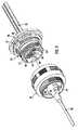
図1は、本開示の原理に従って構築されたコネクタアセンブリ20を例示する。アセンブリ20は、第1および第2の電気ケーブル24、25にそれぞれ取り付けられた嵌合可能な第1および第2のコネクタ要素22、23を備える。そのような各ケーブル24、25は、複数の電気配線(図示されない)を含む。図2は、第1または左のコネクタ要素22の分解図であり、このコネクタ要素22は、絶縁性の第1のコネクタ筐体30を協働的に含む第1のコネクタインサートと、第1のコネクタ接触子35および取り囲み接地遮蔽体38を含む第1のコネクタ半部28と、オーバーモールドされた第1のコネクタ本体部分26と、基板43と、保持リング52と、コネクタインサートとしてこれらのものを共に保持するねじ48と、を含む。 FIG. 1 illustrates a
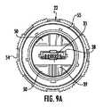
第1のコネクタ半部28は、第1のコネクタ半部28の一部分と、第1のケーブル24の配線が第1のコネクタ接触子35の尾部分35aへと終端されるその後方配線終端領域とを覆う第1のコネクタ本体部分26内に保持される。図5に示されるように、コネクタ半部28の第1の接触子35は、接触子35を実質的に取り囲む伝導性接地遮蔽体38内に支持され、接地遮蔽体38の基部分がまた、第1のコネクタ本体部分26内に保持される。第1のコネクタ要素22の第1のコネクタ半部28が雌コネクタとして示され、そのようなものとして、その雌コネクタは、レセプタクル37を用いてブロック34の支持表面上で少なくとも1つの直線列で複数の伝導性の第1の接触子35を支持するブロック34を含む。接触子35は、ブロック34に沿って横方向に間隔を置かれ、レセプタクル37内を軸方向に延出し、第1のコネクタ接地遮蔽体38によって覆われる(図9A)。 The
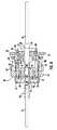
第1のコネクタ本体部分26は、好ましくは、オーバーモールドされるかまたはその構造内にインサート成形される。第1のコネクタ本体部分26および関連した第1のコネクタ半部28は、環状の構成である第1の垂直基板43内に受容される。第1の基板43はスロット44を含み、そのスロットを通ってコネクタ本体および接地遮蔽体36、38の部分が延出する。これらの2つの構成要素26、38は、前方へ更に延出し、第1のコネクタ筐体30に形成された対応する開口部40の中に突出する。コネクタ本体部分26が、基板43の前方表面に対向するリブの形態を取る一対の第1の(後方)停止面41を含むように示される。第2の(前方)停止面42は、コネクタ本体部分26の先端または前方上に形成され、これらは、第1のコネクタ筐体30の対向する内部肩部31にもたれる。第1の基板43は、第1のコネクタ筐体30内で対応する開口部47と整合される1つ以上の穴45を含む。ねじ48または他の締結具が、穴45および開口部47内に受け入れられ、その結果、第1の基板43が、圧縮する様態で第1のコネクタ筐体30に対して第1のコネクタ本体部分26を押圧する。この圧縮係合は、第1のコネクタ半部28を、それが外力、そのような力および衝撃力、ならびに振動力に反応して動かないように、適所に保持するのに役立つ。 The first
第1のコネクタ筐体30は、対応する第2のコネクタ要素23のみと、軸方向係合運動で嵌合するよう第1のコネクタ要素22を方向付けるのに役立つ1つ以上の凸部50を更に含み得る。これらの凸部50は、コネクタアセンブリ20Aのための嵌合鍵として機能し、1つの配列のみで2つのコネクタ要素22、23の正確な整合および嵌合を、それらが最初に結び付けられるときに確実にするように可変サイズのものである。保持リング52は、第1の基板43と第1のコネクタ筐体30との間に挿入され、それは、第1の基板43へのその接続によって第1のコネクタインサートを第1のコネクタシェル54内に適所に保持するのに役立つ。第1の基板43への第1のコネクタ筐体30の取り付けは、それらの間で第1のコネクタ半部28および本体部分26を包囲する。このようにして、第1のコネクタ半部28とその関連した接触子35および接地遮蔽体38が、著しい軸方向および横方向運動から抑制される。それゆえ、外部衝撃および振動負荷が、コネクタ要素22、23の嵌合に共に悪影響を与えないはずである。 The
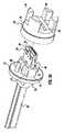
左のコネクタシェル54は、第1のコネクタインサートを収容し、中空内部57を有する円筒形本体56を含む。中空内部57は、左のコネクタ筐体30のへり53がもたれる、内部縁59を画定する座ぐり58を有する。保持リング52は、第1のコネクタ筐体30を適所に維持するために使用され、第1の基板43は、保持リング52に適応する溝部46を有する。第2(右)のコネクタ要素23はまた、第1のコネクタ半部28と嵌合可能な雄レセプタクルコネクタである第2のコネクタ半部60を含む。第2のコネクタ半部60は、eSata様式の雄レセプタクルコネクタとして例示され、また、軸方向に突出した嵌合ブレード62の上に少なくとも1つの直線列で配列された、複数の伝導性の第2の接触子63を含む。第2のコネクタ半部60およびその嵌合ブレード62はまた、伝導性の中空接地遮蔽体64によって取り囲まれ、その遮蔽体は、第2のコネクタ半部60の少なくとも一部分を包囲する第2のコネクタ本体部分66内に少なくとも部分的に保持される。第1の接地遮蔽体38は、2つのコネクタ半部が共に嵌合されるときに、第2の接地遮蔽体64の内部に接触する片持ち接触部分39を含む。 The
第2のコネクタ本体66部分は、インサートまたはオーバーモールドによってそれに最も良く適用され得る。第2のコネクタ本体部分66、接地遮蔽体64、およびコネクタ半部60は、第2のコネクタシェル72内に受容された第2の環状基板68に固定された配向で保持される。第2の基板68はまた、第2のコネクタシェル72の中空内部内に保持された第2のコネクタインサートを形成するために、ねじ70のようなものによって、第2の絶縁性コネクタ筐体69に取り付けられる。第2のコネクタ筐体69は、第2のコネクタ半部60とその関連した第2の接地遮蔽体64の一部分に適応する横方向スロット74を含む。第2のコネクタ本体部分66は、第2のコネクタ半部60および接地遮蔽体64の上に形成され、このコネクタ本体部分66は、第2のコネクタ半部60の配線終端領域の上に置かれ、第2のコネクタ半部60を第2のケーブル24に接合するのに役立つ。第2のコネクタ本体部分66は、第2のコネクタ筐体スロット74よりも寸法が大きい先端67を有し、それによって、第2のコネクタ筐体69の開口部83に形成された内部肩部77に係合するその前方停止面75を画定する。基板は、コネクタシェルが共にねじ込まれるときにケーブルがねじられないように、それらが外部コネクタシェルに対して回転することを可能にする態様で、好ましくは、それらの各コネクタシェル内に保持される。 The
第2のコネクタ筐体69は、図4に示されるように、2つの部分69a、69bから形成され得、その2つの部分が、2つの部分69a、69bを共に接合するための相補的に形作られた係合口部86および凹部87をそれぞれ含む。第2のコネクタ本体部分66はまた、図4〜5に示されるように、横方向に延出し、第2の基板68の前方面に隣接するか、または他の場合には接触する後方停止面76を含み得る。前方および後方停止面75、76は、第2のコネクタ筐体69および基板68にそれぞれ接触し、その結果、第2の基板68がねじ70によって第2のコネクタ筐体69に取り付けられるときに、第2のコネクタ本体66が圧縮下に置かれる。このようにして、第1および第2のコネクタ本体部分26、66の両方が、それらのそれぞれのコネクタ要素22、23内に圧縮下で保持され、それは、外部衝撃または振動に起因して起こり得る、全面的でないにせよかなりの軸方向および横方向運動を防止する。第2のコネクタシェル72の外部は、ねじ込まれ、これらのねじ部73は、第1のコネクタシェル54の内部表面上の対応するねじ部55に係合する。第2のコネクタシェル72の別の外部表面78は、ねじ込まれ、それは、第2のコネクタ要素23がパネルに取り付けられ得るように停止リング80を支持する。第2のコネクタ筐体69の前方面は、第1のコネクタ筐体30上に形成された突出した凸部50を受け入れる凹部92を含み得る図9B)。これらの凹部92はまた、それらの鍵機能に適切に作用するように第1のコネクタ筐体凸部50と同じ可変サイズのものである。第1および第2のコネクタインサートの両方は、それらの関連した外部シェル54、72内に、それらがその外部シェル内で自由に回転するような態様で適所に保持される。外部ねじ部の代わりに、2つのコネクタシェルが、2つのコネクタ要素22、23の迅速な接続および切断を可能にするバヨネット(bayonet)型取り付け構造を含んでもよい。 The
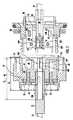
図7は、コネクタアセンブリ20の断面図であり、コネクタ半部100、102がUSB様式のものである。左または第1のコネクタ半部100は、雄コネクタ102の右または第2のコネクタ半部の嵌合ブレード105をその中に受け入れる中空内部104を有する雌レセプタクルコネクタである。この嵌合は、上記した図1〜6に示されるeSata様式のコネクタ半部と同様に、直線の軸方向運動で行われ、その結果、コネクタ半部100、102の接触子108、109は、直線および軸方向方式で嵌合し、互いに摺動して、雌コネクタ半部100の接触子によって加えられる標準圧力により接触を維持し、一方、外部コネクタシェル54、72の結合は共に円弧、回転運動で行われる。この実施形態では、図8に最も良く示されるように、第1の接地遮蔽体106が、第1のコネクタシェル54の長さLSよりも大きな長さLCを有する。これに関して、第1の接地遮蔽体106は、第1のコネクタシェルの後方縁を超えて延出し、第1のコネクタシェル54の前方縁のわずかに手前で停止する(図7)。2つの接地遮蔽体106、107が共に嵌合されるときに、それらが、2つのコネクタシェル54、72のうちの少なくとも1つの長さを超える結合された長さ、かつ、いかなる場合でも、コネクタシェル54、72上の外部ねじ部55、73のいかなる長さよりも長い長さを有する。この長さは、接触子の周りに実質的に均一に間隔を置かれたコネクタ接触子108、109のための接地基準を提供する。第2の接地遮蔽体107が、嵌合ブレード105とその接触子109を包囲し、その関連したコネクタシェル72よりも短い長さを有する。 FIG. 7 is a cross-sectional view of the
このようにして、伝導性ピンが接触子に使用される場合のように1つ1つの接触子に個々の接地を提供するのではなくて、ただ1つの接地が、各雄および雌コネクタ半部のために各複数の接触子に提供されるので、これらのコネクタの高速動作が、最低限の費用で実現され得る。コネクタインサートは、それらの絶縁性筐体および基板によって、非伝導性であり、それゆえ、コネクタシェルは、コネクタアセンブリ20にケーブル24、25のそれに合致する外側の外部接地を提供する伝導性材料から形成され得るか、その伝導性材料でめっきされ得る。 In this way, instead of providing individual grounds for each contact as in the case where conductive pins are used for the contacts, only one ground is provided for each male and female connector half. For this reason, high speed operation of these connectors can be realized at a minimum cost. The connector inserts are non-conductive due to their insulating housing and substrate, and therefore the connector shell is from a conductive material that provides the
本開示の好適な実施形態が示され記載されたが、当業者は、前述の記載および添付の特許請求の範囲の趣旨ならびに範囲から逸脱することなく、様々な修正を考案し得ることが想定される。 While preferred embodiments of the present disclosure have been shown and described, it is envisioned that those skilled in the art may devise various modifications without departing from the spirit and scope of the foregoing description and the appended claims. The
Claims (20)
Translated fromJapanese前記第1および第2のコネクタシェルによってそれぞれ支持される第1および第2の絶縁性のコネクタ筐体と、
前記第1および第2のコネクタ筐体によってそれぞれ支持される第1および第2のコネクタ半部と、を備え、各コネクタ半部が、少なくとも1つの直線列でそれらのそれぞれのコネクタ筐体内に配列されたそれぞれの第1および第2の複数の伝導性の接触子を含み、前記第1および第2の接触子が、前記第1および第2のコネクタシェルの軸に対して横方向に延出し、前記第1のコネクタ半部が、前記第1のコネクタ筐体内で軸方向に延出する雌レセプタクル部分を含み、該雌レセプタクル部分が、前記第1の接触子をその上に支持し、前記第1のコネクタ筐体が、前記第1の接触子を少なくとも部分的に包囲する第1の伝導性の接地遮蔽体を更に含み、前記第2のコネクタ半部が、前記第2のコネクタ筐体内で延出する雄嵌合部分を含み、該雄嵌合部分が、前記第2の接触子をその上に支持し、前記第2のコネクタ筐体が、前記第2の接触子を少なくとも部分的に包囲する第2の伝導性の接地遮蔽体を含み、前記第1および第2の接触子が、それらのそれぞれのコネクタ半部内に配置され、その結果、前記第1および第2のコネクタ筐体が直線の軸方向運動で共に係合されるときに、前記第1および第2の接触子が共に嵌合されるように、かつ、前記第1および第2の接地遮蔽体が互いに係合するようになり、前記第1および第2の接地遮蔽体が、係合されるときに、前記第1および第2のコネクタシェルのうちの一方の長さよりも長い長さを有し、
前記第1および第2のコネクタ筐体が、嵌合前および嵌合中に前記第1および第2のコネクタ半部を共に整合させる相補的な相互係合部材を含み、
前記第1および第2のコネクタシェルが、円弧回転嵌合運動のみによって互いに係合する、コネクタアセンブリ。First and second interengaging connector shells;
First and second insulating connector housings respectively supported by the first and second connector shells;
First and second connector halves supported by the first and second connector housings, respectively, each connector half arranged in their respective connector housings in at least one linear row Each of the first and second plurality of conductive contacts, wherein the first and second contacts extend transversely with respect to the axes of the first and second connector shells. The first connector half includes a female receptacle portion extending axially within the first connector housing, the female receptacle portion supporting the first contact thereon, and The first connector housing further includes a first conductive ground shield that at least partially surrounds the first contact, wherein the second connector half is within the second connector housing. Including a male mating part extending at A second conductive ground shield that has a male mating portion supporting the second contact thereon and wherein the second connector housing at least partially surrounds the second contact. And the first and second contacts are disposed in their respective connector halves so that the first and second connector housings are engaged together in a linear axial motion Sometimes the first and second contacts are fitted together and the first and second ground shields are engaged with each other, the first and second grounds. The shield has a length that is greater than the length of one of the first and second connector shells when engaged;
The first and second connector housings include complementary interengaging members that align the first and second connector halves together before and during mating;
The connector assembly, wherein the first and second connector shells engage each other only by arcuate rotational mating motion.
前記第1のコネクタ要素が、レセプタクルを有して複数の伝導性の第1の接触子がそれによって支持される、雌コネクタを支持する第1のコネクタ筐体を含み、前記第1の接触子が、接触部分と、第1のケーブルの導体へと終端するための反対側の尾部分とを含み、前記雌コネクタが、伝導性の第1の接地遮蔽体によって少なくとも部分的に取り囲まれ、
前記第2のコネクタ要素が、嵌合ブレードを有してそれによって支持される複数の伝導性の第2の接触子を支持する、雄コネクタを支持する第2のコネクタ筐体を含み、前記第2の接触子が、接触部分と、第2のケーブルの導体へと終端するための反対側の尾部分とを含み、前記第2のコネクタが、伝導性の第2の接地遮蔽体によって少なくとも部分的に取り囲まれる、第1および第2のコネクタ要素と、
前記雌コネクタおよび前記第1の接地遮蔽体の少なくとも一部分の周りに延出する第1のコネクタ本体と、
前記雄コネクタおよび前記第2の接地遮蔽体の少なくとも一部分の周りに延出する第2のコネクタ本体と、
前記第1および第2のコネクタ要素内にそれぞれ配置された第1および第2の基板と、を備え、前記第1のコネクタ本体が、前記第1の基板と前記第1のコネクタ筐体との間に挿入され、前記第2のコネクタ本体が、前記第2の基板と前記第2のコネクタ筐体との間に挿入され、前記第1および第2のコネクタ本体が、前記基板と前記コネクタ筐体との間で圧縮される、コネクタアセンブリ。First and second connector elements that can be mated together,
The first connector element includes a first connector housing supporting a female connector having a receptacle by which a plurality of conductive first contacts are supported; Includes a contact portion and an opposite tail portion for terminating into a conductor of the first cable, wherein the female connector is at least partially surrounded by a conductive first ground shield,
The second connector element includes a second connector housing supporting a male connector supporting a plurality of conductive second contacts supported by and having a mating blade; Two contacts including a contact portion and an opposite tail portion for terminating to a conductor of a second cable, wherein the second connector is at least partially by a conductive second ground shield. First and second connector elements surrounded by
A first connector body extending around at least a portion of the female connector and the first ground shield;
A second connector body extending around at least a portion of the male connector and the second ground shield;
First and second substrates disposed in the first and second connector elements, respectively, wherein the first connector body is formed between the first substrate and the first connector housing. The second connector body is inserted between the second substrate and the second connector housing, and the first and second connector bodies are inserted between the substrate and the connector housing. A connector assembly that is compressed between the body.
Applications Claiming Priority (3)
| Application Number | Priority Date | Filing Date | Title |
|---|---|---|---|
| US201361874400P | 2013-09-06 | 2013-09-06 | |
| US61/874,400 | 2013-09-06 | ||
| PCT/US2014/054528WO2015035294A1 (en) | 2013-09-06 | 2014-09-08 | High speed connector with sealed housing |
Publications (1)
| Publication Number | Publication Date |
|---|---|
| JP2016529682Atrue JP2016529682A (en) | 2016-09-23 |
Family
ID=52629001
Family Applications (1)
| Application Number | Title | Priority Date | Filing Date |
|---|---|---|---|
| JP2016540460APendingJP2016529682A (en) | 2013-09-06 | 2014-09-08 | High-speed connector with hermetically sealed housing |
Country Status (5)
| Country | Link |
|---|---|
| US (1) | US20160197437A1 (en) |
| EP (1) | EP3042422A4 (en) |
| JP (1) | JP2016529682A (en) |
| CN (1) | CN105684227A (en) |
| WO (1) | WO2015035294A1 (en) |
Families Citing this family (6)
| Publication number | Priority date | Publication date | Assignee | Title |
|---|---|---|---|---|
| US9450338B2 (en)* | 2014-08-06 | 2016-09-20 | Molex, Llc | High speed connector with ruggedized exterior structure and shielding |
| CN106998005A (en)* | 2016-01-22 | 2017-08-01 | 马要武 | Locking electrical outlets plug |
| US9548558B1 (en)* | 2016-08-12 | 2017-01-17 | Cheng Uei Precision Industry Co., Ltd. | Electrical connector assembly |
| EP3396330A1 (en)* | 2017-04-28 | 2018-10-31 | Traxens | Device designed for tracking and monitoring of a travelling asset |
| CN107834301A (en)* | 2017-10-24 | 2018-03-23 | 番禺得意精密电子工业有限公司 | Electric connector |
| CN109817874B (en)* | 2019-03-21 | 2021-09-17 | 贵州航天电器股份有限公司 | Button cell electric connector |
Citations (5)
| Publication number | Priority date | Publication date | Assignee | Title |
|---|---|---|---|---|
| JP2003197314A (en)* | 2001-12-24 | 2003-07-11 | Hyundai Motor Co Ltd | Connector for door of vehicle |
| JP2003243093A (en)* | 2002-02-21 | 2003-08-29 | Yazaki Corp | USB connector |
| US20100261367A1 (en)* | 2009-04-09 | 2010-10-14 | Souriau Usa, Inc. | Plug assembly |
| JP2011049165A (en)* | 2009-08-20 | 2011-03-10 | Tyco Electronics Corp | Electrical connector with locking collar |
| JP2011524605A (en)* | 2008-05-23 | 2011-09-01 | タイコ・エレクトロニクス・コーポレイション | High density circular interconnect with plug-in action |
Family Cites Families (16)
| Publication number | Priority date | Publication date | Assignee | Title |
|---|---|---|---|---|
| US4808127A (en)* | 1985-10-18 | 1989-02-28 | Arbus, Inc. | Connector assembly |
| JPH0455766U (en)* | 1990-09-20 | 1992-05-13 | ||
| US5906513A (en)* | 1997-03-20 | 1999-05-25 | Woodhead Industries Inc. | Shielded, molded electrical connector |
| US6135800A (en)* | 1998-12-22 | 2000-10-24 | Conxall Corporation | Anti-rotational electrical connector |
| US6957971B2 (en)* | 2003-10-07 | 2005-10-25 | Jeng-Shyong Wu | Multiplex wire connector unit |
| US7033195B2 (en)* | 2004-05-14 | 2006-04-25 | Woodhead Industries, Inc. | Coaxial electrical connector for hazardous locations |
| US6991494B1 (en)* | 2004-07-28 | 2006-01-31 | Hon Hai Precision Ind. Co., Ltd. | Panel mount cable connector assembly |
| US7063549B1 (en)* | 2004-12-17 | 2006-06-20 | Topower Computer Industrial Co., Ltd. | Electric connection assembly for power supply with interlocking components |
| JP2008140744A (en)* | 2006-12-05 | 2008-06-19 | Carecom:Kk | Nurse call slave unit, wall-embedded nurse slave unit, and structure of connection between wall outlet and plug |
| US7922517B2 (en)* | 2006-12-05 | 2011-04-12 | Tyco Electronics Corporation | Retaining system and method for preventing the release of wires from a poke-in connector |
| US8070504B2 (en)* | 2009-06-17 | 2011-12-06 | John Mezzalingua Associates, Inc. | Coaxial cable port locking terminator and method of use thereof |
| US7942699B1 (en)* | 2010-07-23 | 2011-05-17 | Tyco Electronics Corporation | Electrical connector with a flange secured to an antenna and electrically connected to a ground shield of an electrical power cable |
| US8573853B2 (en)* | 2010-08-23 | 2013-11-05 | Tyco Electronics Corporation | Plug assembly |
| KR101215638B1 (en)* | 2011-10-06 | 2012-12-26 | 주식회사 위너스 | Connector |
| CN202534864U (en)* | 2012-05-04 | 2012-11-14 | 赵士立 | Sealed-type USB connection interface assembly |
| US9397441B2 (en)* | 2013-03-15 | 2016-07-19 | Cinch Connections, Inc. | Connector with anti-decoupling mechanism |
- 2014
- 2014-09-08JPJP2016540460Apatent/JP2016529682A/enactivePending
- 2014-09-08USUS14/916,623patent/US20160197437A1/ennot_activeAbandoned
- 2014-09-08CNCN201480060132.1Apatent/CN105684227A/enactivePending
- 2014-09-08WOPCT/US2014/054528patent/WO2015035294A1/enactiveApplication Filing
- 2014-09-08EPEP14843059.8Apatent/EP3042422A4/ennot_activeWithdrawn
Patent Citations (5)
| Publication number | Priority date | Publication date | Assignee | Title |
|---|---|---|---|---|
| JP2003197314A (en)* | 2001-12-24 | 2003-07-11 | Hyundai Motor Co Ltd | Connector for door of vehicle |
| JP2003243093A (en)* | 2002-02-21 | 2003-08-29 | Yazaki Corp | USB connector |
| JP2011524605A (en)* | 2008-05-23 | 2011-09-01 | タイコ・エレクトロニクス・コーポレイション | High density circular interconnect with plug-in action |
| US20100261367A1 (en)* | 2009-04-09 | 2010-10-14 | Souriau Usa, Inc. | Plug assembly |
| JP2011049165A (en)* | 2009-08-20 | 2011-03-10 | Tyco Electronics Corp | Electrical connector with locking collar |
Also Published As
| Publication number | Publication date |
|---|---|
| WO2015035294A1 (en) | 2015-03-12 |
| EP3042422A1 (en) | 2016-07-13 |
| CN105684227A (en) | 2016-06-15 |
| EP3042422A4 (en) | 2017-08-02 |
| US20160197437A1 (en) | 2016-07-07 |
Similar Documents
| Publication | Publication Date | Title |
|---|---|---|
| JP6314284B2 (en) | High speed connector with hermetic housing | |
| US7632126B1 (en) | High density circular interconnect with bayonet action | |
| JP2016529682A (en) | High-speed connector with hermetically sealed housing | |
| TWI644484B (en) | Plug connector | |
| CA2756189C (en) | Rf connector assembly | |
| CA2755681C (en) | Rf module | |
| CN202076598U (en) | Electric connector assembly and plug connector | |
| JP5748111B2 (en) | Coaxial connector device | |
| US9419377B2 (en) | Dual orientation electrical connector assembly | |
| EP2946444B1 (en) | Electrical connector system with backplane connector and daughtercard connector | |
| CN112531372B (en) | Connector with a locking member | |
| EP2304853B1 (en) | High density rectangular interconnect | |
| US9997879B2 (en) | Cable connector assembly with dual ports | |
| CN105071172A (en) | Rectangular high and low frequency mixed connector assembly | |
| EP4104259B1 (en) | Multiple connector assembly | |
| US7927150B2 (en) | Connectors including spring tabs for holding a contact module | |
| TWI794387B (en) | Adapter | |
| CN102544807A (en) | Electric connector | |
| HK1168695B (en) | Usb connector | |
| HK1168695A1 (en) | Usb connector | |
| TWM509464U (en) | Electric connector |
Legal Events
| Date | Code | Title | Description |
|---|---|---|---|
| A621 | Written request for application examination | Free format text:JAPANESE INTERMEDIATE CODE: A621 Effective date:20160421 | |
| A977 | Report on retrieval | Free format text:JAPANESE INTERMEDIATE CODE: A971007 Effective date:20170317 | |
| A131 | Notification of reasons for refusal | Free format text:JAPANESE INTERMEDIATE CODE: A131 Effective date:20170328 | |
| A02 | Decision of refusal | Free format text:JAPANESE INTERMEDIATE CODE: A02 Effective date:20171024 |