JP2016520470A - Vehicle seat having simultaneous connection of seat pan and seat back - Google Patents
Vehicle seat having simultaneous connection of seat pan and seat backDownload PDFInfo
- Publication number
- JP2016520470A JP2016520470AJP2016507606AJP2016507606AJP2016520470AJP 2016520470 AJP2016520470 AJP 2016520470AJP 2016507606 AJP2016507606 AJP 2016507606AJP 2016507606 AJP2016507606 AJP 2016507606AJP 2016520470 AJP2016520470 AJP 2016520470A
- Authority
- JP
- Japan
- Prior art keywords
- seat
- assembly
- pan
- seat pan
- attached
- Prior art date
- Legal status (The legal status is an assumption and is not a legal conclusion. Google has not performed a legal analysis and makes no representation as to the accuracy of the status listed.)
- Pending
Links
Images


Classifications
- B—PERFORMING OPERATIONS; TRANSPORTING
- B64—AIRCRAFT; AVIATION; COSMONAUTICS
- B64D—EQUIPMENT FOR FITTING IN OR TO AIRCRAFT; FLIGHT SUITS; PARACHUTES; ARRANGEMENT OR MOUNTING OF POWER PLANTS OR PROPULSION TRANSMISSIONS IN AIRCRAFT
- B64D11/00—Passenger or crew accommodation; Flight-deck installations not otherwise provided for
- B64D11/06—Arrangements of seats, or adaptations or details specially adapted for aircraft seats
- B64D11/0639—Arrangements of seats, or adaptations or details specially adapted for aircraft seats with features for adjustment or converting of seats
- B64D11/0643—Adjustable foot or leg rests
- B—PERFORMING OPERATIONS; TRANSPORTING
- B60—VEHICLES IN GENERAL
- B60N—SEATS SPECIALLY ADAPTED FOR VEHICLES; VEHICLE PASSENGER ACCOMMODATION NOT OTHERWISE PROVIDED FOR
- B60N2/00—Seats specially adapted for vehicles; Arrangement or mounting of seats in vehicles
- B60N2/02—Seats specially adapted for vehicles; Arrangement or mounting of seats in vehicles the seat or part thereof being movable, e.g. adjustable
- B60N2/04—Seats specially adapted for vehicles; Arrangement or mounting of seats in vehicles the seat or part thereof being movable, e.g. adjustable the whole seat being movable
- B60N2/06—Seats specially adapted for vehicles; Arrangement or mounting of seats in vehicles the seat or part thereof being movable, e.g. adjustable the whole seat being movable slidable
- B—PERFORMING OPERATIONS; TRANSPORTING
- B60—VEHICLES IN GENERAL
- B60N—SEATS SPECIALLY ADAPTED FOR VEHICLES; VEHICLE PASSENGER ACCOMMODATION NOT OTHERWISE PROVIDED FOR
- B60N2/00—Seats specially adapted for vehicles; Arrangement or mounting of seats in vehicles
- B60N2/02—Seats specially adapted for vehicles; Arrangement or mounting of seats in vehicles the seat or part thereof being movable, e.g. adjustable
- B60N2/22—Seats specially adapted for vehicles; Arrangement or mounting of seats in vehicles the seat or part thereof being movable, e.g. adjustable the back-rest being adjustable
- B60N2/2209—Seats specially adapted for vehicles; Arrangement or mounting of seats in vehicles the seat or part thereof being movable, e.g. adjustable the back-rest being adjustable by longitudinal displacement of the cushion, e.g. back-rest hinged on the bottom to the cushion and linked on the top to the vehicle frame
- B—PERFORMING OPERATIONS; TRANSPORTING
- B60—VEHICLES IN GENERAL
- B60N—SEATS SPECIALLY ADAPTED FOR VEHICLES; VEHICLE PASSENGER ACCOMMODATION NOT OTHERWISE PROVIDED FOR
- B60N2/00—Seats specially adapted for vehicles; Arrangement or mounting of seats in vehicles
- B60N2/02—Seats specially adapted for vehicles; Arrangement or mounting of seats in vehicles the seat or part thereof being movable, e.g. adjustable
- B60N2/22—Seats specially adapted for vehicles; Arrangement or mounting of seats in vehicles the seat or part thereof being movable, e.g. adjustable the back-rest being adjustable
- B60N2/23—Seats specially adapted for vehicles; Arrangement or mounting of seats in vehicles the seat or part thereof being movable, e.g. adjustable the back-rest being adjustable by linear actuators, e.g. linear screw mechanisms
- B60N2/231—Seats specially adapted for vehicles; Arrangement or mounting of seats in vehicles the seat or part thereof being movable, e.g. adjustable the back-rest being adjustable by linear actuators, e.g. linear screw mechanisms by hydraulic actuators
- B—PERFORMING OPERATIONS; TRANSPORTING
- B60—VEHICLES IN GENERAL
- B60N—SEATS SPECIALLY ADAPTED FOR VEHICLES; VEHICLE PASSENGER ACCOMMODATION NOT OTHERWISE PROVIDED FOR
- B60N2/00—Seats specially adapted for vehicles; Arrangement or mounting of seats in vehicles
- B60N2/24—Seats specially adapted for vehicles; Arrangement or mounting of seats in vehicles for particular purposes or particular vehicles
- B60N2/32—Seats specially adapted for vehicles; Arrangement or mounting of seats in vehicles for particular purposes or particular vehicles convertible for other use
- B60N2/34—Seats specially adapted for vehicles; Arrangement or mounting of seats in vehicles for particular purposes or particular vehicles convertible for other use into a bed
- B—PERFORMING OPERATIONS; TRANSPORTING
- B60—VEHICLES IN GENERAL
- B60N—SEATS SPECIALLY ADAPTED FOR VEHICLES; VEHICLE PASSENGER ACCOMMODATION NOT OTHERWISE PROVIDED FOR
- B60N2/00—Seats specially adapted for vehicles; Arrangement or mounting of seats in vehicles
- B60N2/90—Details or parts not otherwise provided for
- B60N2/995—Lower-leg-rests, e.g. calf-rests
- B—PERFORMING OPERATIONS; TRANSPORTING
- B64—AIRCRAFT; AVIATION; COSMONAUTICS
- B64D—EQUIPMENT FOR FITTING IN OR TO AIRCRAFT; FLIGHT SUITS; PARACHUTES; ARRANGEMENT OR MOUNTING OF POWER PLANTS OR PROPULSION TRANSMISSIONS IN AIRCRAFT
- B64D11/00—Passenger or crew accommodation; Flight-deck installations not otherwise provided for
- B64D11/06—Arrangements of seats, or adaptations or details specially adapted for aircraft seats
- B64D11/0639—Arrangements of seats, or adaptations or details specially adapted for aircraft seats with features for adjustment or converting of seats
- B64D11/0641—Seats convertible into beds
- B—PERFORMING OPERATIONS; TRANSPORTING
- B64—AIRCRAFT; AVIATION; COSMONAUTICS
- B64D—EQUIPMENT FOR FITTING IN OR TO AIRCRAFT; FLIGHT SUITS; PARACHUTES; ARRANGEMENT OR MOUNTING OF POWER PLANTS OR PROPULSION TRANSMISSIONS IN AIRCRAFT
- B64D11/00—Passenger or crew accommodation; Flight-deck installations not otherwise provided for
- B64D11/06—Arrangements of seats, or adaptations or details specially adapted for aircraft seats
- B64D11/0647—Seats characterised by special upholstery or cushioning features
- B—PERFORMING OPERATIONS; TRANSPORTING
- B64—AIRCRAFT; AVIATION; COSMONAUTICS
- B64D—EQUIPMENT FOR FITTING IN OR TO AIRCRAFT; FLIGHT SUITS; PARACHUTES; ARRANGEMENT OR MOUNTING OF POWER PLANTS OR PROPULSION TRANSMISSIONS IN AIRCRAFT
- B64D11/00—Passenger or crew accommodation; Flight-deck installations not otherwise provided for
- B64D2011/0069—Rest berths, beds or the like
Landscapes
- Engineering & Computer Science (AREA)
- Aviation & Aerospace Engineering (AREA)
- Transportation (AREA)
- Mechanical Engineering (AREA)
- Seats For Vehicles (AREA)
- Passenger Equipment (AREA)
- Chairs For Special Purposes, Such As Reclining Chairs (AREA)
Abstract
Translated fromJapaneseDescription
Translated fromJapanese 関連出願の相互参照
本出願は、2013年4月8日に出願された米国仮出願第61/809,491号に対する優先権を主張する。This application claims priority to US Provisional Application No. 61 / 809,491, filed Apr. 8, 2013.
本発明は、乗客により良い快適さを与えることを意図する改良された動作を有する、航空機の乗客用シートのような乗物用シートに関する。プレミアムクラス席のエリアにおいて、シートは、十分に直立した、地上走行、離陸及び着陸時(「TTOL」)の位置から、休憩に適した腹臥位置まで、これら二つの両極端な状態の間の中間位置と共に、乗客が動かすことを可能とする、「フルフラットになる」又は「ほぼフルフラットになる」という特徴を有していることが多い。先行技術のシートが十分に直立した位置から動く場合、シートパンの後端は下方に傾き、シートパンの前部は上昇し、それとともに固定されたレッグレストが航空機の床から乗客の足を持ち上げる。 The present invention relates to a vehicle seat, such as an aircraft passenger seat, having an improved operation intended to give passengers better comfort. In the premium class seating area, the seat is intermediate between these two extremes, from a fully upright, ground-run, take-off and landing (“TTOL”) position to a prone position suitable for rest. Along with the position, it often has the feature of being “full flat” or “substantially full flat” that allows the passenger to move. When the prior art seat moves from a fully upright position, the rear end of the seat pan tilts downward, the front of the seat pan rises, and a fixed legrest lifts the passenger's foot off the aircraft floor .
乗客はシートバックもリクライニングもなしにシートの座部をより角度のある位置に動かすことをめったに望まないことが知られており、先行技術のシートは、シートバックがリクライニングする場合に相対的に同じ体の角度を維持するように足を持ち上げる。 It is known that passengers rarely want to move the seat of the seat to a more angled position without a seatback or reclining, and the prior art seats are relatively the same when the seatback reclines Lift your feet to maintain your body angle.
それゆえ、より快適で空間的に効率の良いシートを提供する乗客用シートが必要である。客室のプレミアム席のエリアにおけるより新しい航空機用シートは、より多くの快適な設備や特徴を有するべきであり、より調節可能であるべきであり、シートパンの角度と実質的に平坦にリクライニングする機能性とを含み、それによって、機内の更なる快適さを乗客に提供する。航空会社は、調節可能なシートのような快適な設備を乗客に提供することを望む一方で、従来の移動可能なシートバックやシートパンよりも快適な、シートパンとシートバックを同時に曲げられ、及びより快適な動作にリクライニング機能を結合できるシートを提供したいと考えている。 Therefore, there is a need for a passenger seat that provides a more comfortable and spatially efficient seat. Newer aircraft seats in the premium seating area of the cabin should have more comfortable facilities and features, should be more adjustable, and the ability to recline substantially flat with the seat pan angle And thereby provide passengers with additional comfort in the cabin. While the airline wants to provide passengers with comfortable facilities like adjustable seats, the seat pan and seat back can be bent simultaneously, which is more comfortable than traditional movable seat backs and seat pans, We want to provide a seat that can combine the reclining function with more comfortable operation.
それゆえ、航空機の床のような支持面上に足を留めることを可能とする位置にレッグレストを実質的に維持しているときに、最初のリクライニングの動作の間、シートバックとシートボトムの間の快適な角度を維持する乗物用シートを提供することが本発明の目的である。 Therefore, during the initial reclining operation, the seat back and bottom of the seat bottom when the leg rest is substantially maintained in a position that allows the foot to rest on a support surface such as an aircraft floor. It is an object of the present invention to provide a vehicle seat that maintains a comfortable angle therebetween.
シートバックやシートパンが実質的に前方の回転軸周りで回転するようなシートパンの連結を提供する航空機の乗客用シートを提供することがさらなる本発明の目的である。この動作は、乗客の足を床から持ち上げずに、シート調整や乗客の快適さを向上させる。 It is a further object of the present invention to provide an aircraft passenger seat that provides a seat pan connection such that the seat back or seat pan rotates substantially about the forward axis of rotation. This action improves seat adjustment and passenger comfort without lifting the passenger's foot off the floor.
足や脚が持ち上げられるように、乗客がさらにリクライニングすることを可能とする、続くリクライニングの動作の間、シートバックやシートパンが実質的に前方の回転軸周りで回転するようなシートパンの連結を提供する航空機の乗客用シートを提供することがさらなる発明の目的である。 A seat pan connection that allows the passenger to recline further so that the feet and legs can be lifted, so that the seat back or seat pan rotates about the forward axis of rotation during subsequent reclining movements. It is a further object of the invention to provide an aircraft passenger seat that provides
これらや他の本発明の目的及び効果は、床の上での前後の動作のために支持している床に取り付けられるためのシート台車アセンブリと、シート台車アセンブリに対する前後の動作のためにシート台車アセンブリに取り付けられるシートパンアセンブリと、シートパンアセンブリ後部でシート台車アセンブリに取り付けられ、シートパンアセンブリと同時の動作に適合されるシートバックアセンブリとを含む乗物用シートを提供することにより達成される。レッグレストアセンブリは、シートパン前部でシート台車アセンブリに取り付けられ、シート台車アセンブリは、シートパンアセンブリ、シートバックアセンブリ及びレッグレストアセンブリを相互に連結させている連結アセンブリを含む。シート台車アセンブリが、シートが取り付けられる床に対して後方に動くとき、シートパンアセンブリとシートバックアセンブリとは、最初のリクライニングの動作の間、レッグレストアセンブリをシートパンアセンブリの下方に収納された位置に留まらせると共に、所定のシート位置を維持するように同時に調整する。続くリクライニングの動作の間、バックレストアセンブリとシートパンアセンブリとがフルフラット形状に向かって徐々に後ろに倒れるに従い、レッグレストアセンブリが脚を支持する位置に向かって徐々に持ち上がる。 These and other objects and advantages of the present invention include a seat carriage assembly for mounting on a supporting floor for back and forth movement on the floor and a seat carriage for back and forth movement relative to the seat carriage assembly. This is accomplished by providing a vehicle seat including a seat pan assembly attached to the assembly and a seat back assembly attached to the seat carriage assembly at the rear of the seat pan assembly and adapted for simultaneous operation with the seat pan assembly. The leg rest assembly is attached to the seat trolley assembly at the front of the seat pan, and the seat trolley assembly includes a coupling assembly that interconnects the seat pan assembly, the seat back assembly, and the leg rest assembly. When the seat carriage assembly moves backward relative to the floor to which the seat is mounted, the seat pan assembly and the seat back assembly are in a position where the leg rest assembly is stored below the seat pan assembly during the initial reclining operation. And simultaneously adjust so as to maintain a predetermined sheet position. During the subsequent reclining motion, the legrest assembly gradually lifts toward the position supporting the legs as the backrest assembly and seat pan assembly gradually fall back toward the full flat shape.
本発明の他の実施形態によれば、航空機の乗客用シートの最初の位置は、シートバックアセンブリの前面が、シートパンアセンブリの上面に対して略直角に配置される、TTOL形状である。 According to another embodiment of the present invention, the initial position of the passenger seat of the aircraft is a TTOL shape where the front surface of the seat back assembly is positioned substantially perpendicular to the top surface of the seat pan assembly.
本発明の他の実施形態によれば、ヘッドレストアセンブリは、シートバックアセンブリの上端に配置され、ヘッドレストアセンブリの前面はシートバックアセンブリの前面と解剖学的に整列され、レッグレストアセンブリの前面はシートパンアセンブリの上面及び床に対して略直角である。 According to another embodiment of the present invention, the headrest assembly is disposed at the upper end of the seatback assembly, the front surface of the headrest assembly is anatomically aligned with the front surface of the seatback assembly, and the front surface of the legrest assembly is the seat pan assembly. Approximately perpendicular to the top and floor of the assembly.
本発明の他の実施形態によれば、前記最初のリクライニングの動作の間、シートバックアセンブリは後方に傾けられ、シートパンアセンブリの上面は上方に傾き、シートバックアセンブリの前面とシートパンアセンブリの上面との間の略直角位置が維持される。 According to another embodiment of the present invention, during the initial reclining operation, the seat back assembly is tilted rearward, the upper surface of the seat pan assembly is tilted upward, the front surface of the seat back assembly and the upper surface of the seat pan assembly. A substantially right angle position between is maintained.
本発明の他の実施形態によれば、シートパンアセンブリは、シートパンと、シートパンフレームと、上方シート支持フレーム及び前後に平行移動可能なスライドレールアセンブリを相互に連結させている前方シートパンピボットアーム及び後方シートパンピボットアームと、を含んでいる。 According to another embodiment of the present invention, a seat pan assembly includes a seat pan, a seat pan frame, an upper seat support frame, and a front seat pan pivot that interconnects a slide rail assembly that is movable back and forth. An arm and a rear seat pan pivot arm.
本発明の他の実施形態によれば、シートは、シートパンフレームと、シートパンアセンブリ、シートバックアセンブリ及びレッグレストアセンブリの所望の動作を可能とするために相互に作用する四棒リンク機構を形成するための、上方シート支持フレーム及び前後に平行移動可能なスライドレールアセンブリを相互に連結させている前方のシートパンピボットアーム及び後方ピボットアームと、に支持されるシートパンを含んでいる。 In accordance with another embodiment of the present invention, the seat forms a seat pan frame and a four bar linkage that interacts to allow the desired operation of the seat pan assembly, seat back assembly, and leg rest assembly. And a front seat pan pivot arm and a rear pivot arm interconnecting an upper seat support frame and a slide rail assembly that is translatable back and forth.
本発明の他の実施形態によれば、シートの動作は、クランクリンクによりシートバックアセンブリに接続され、上部シート支持フレームの連結部を介して上部シート支持フレームに取り付けることによりシートパンアセンブリに接続されるリニア流水圧固定装置によって駆動される。 According to another embodiment of the invention, the movement of the seat is connected to the seat back assembly by a crank link and connected to the seat pan assembly by attaching to the upper seat support frame via a coupling of the upper seat support frame. It is driven by a linear fluid pressure fixing device.
本発明の他の実施形態によれば、流体圧固定装置はピストン及びシリンダーアセンブリを含んでいる。 According to another embodiment of the present invention, the fluid pressure fixation device includes a piston and cylinder assembly.
本発明の他の実施形態によれば、シート台車アセンブリは、スライドレールピストン及びシリンダーアセンブリによって駆動される平行移動可能なスライドレールアセンブリ上の動作のために取り付けられる。 According to another embodiment of the invention, the seat carriage assembly is mounted for operation on a translatable slide rail assembly driven by a slide rail piston and cylinder assembly.
本発明の他の実施形態によれば、航空機の乗客用シートは、床の上での前後の動作のために支持している床に取り付けられるためのシート台車アセンブリと、シート台車アセンブリに対する前後の動作のためにシート台車アセンブリに取り付けられるシートパンアセンブリと、シートパンアセンブリ後部でシート台車アセンブリに取り付けられ、シートパンアセンブリと同時の動作に適合されるシートバックアセンブリであって、航空機の乗客用シートの最初の位置は、シートバックアセンブリの前面がシートパンアセンブリの上面に対して略直角に配置される、TTOL形状である、シートバックアセンブリと、を提供され、含んでいる。レッグレストアセンブリは、シートパンの前部でシート台車アセンブリに取り付けられる。シート台車アセンブリは、シートパンアセンブリ、シートバックアセンブリ及びレッグレストアセンブリを相互に連結させている連結アセンブリを含み、シート台車アセンブリが、シートが取り付けられる床に対して後方に動くとき、シートパンアセンブリとシートバックアセンブリとは、最初のリクライニングの動作の間、レッグレストアセンブリをシートパンアセンブリの下方に収納された位置に留まらせると共に、所定のシート位置を維持するように同時に調整し、最初のリクライニングの動作の間、シートバックアセンブリは後方に傾けられ、シートパンアセンブリの上面は上方に傾き、シートバックアセンブリの前面とシートパンアセンブリの上面との間の略直角位置が維持される。続くリクライニングの動作の間、バックレストアセンブリとシートパンアセンブリとがフルフラット形状に向かって徐々に後ろに倒れるに従い、レッグレストアセンブリは脚を支持する位置に向かって徐々に持ち上がる。 In accordance with another embodiment of the present invention, an aircraft passenger seat includes a seat carriage assembly for attachment to a supporting floor for back and forth movement on the floor, and a front and rear seat with respect to the seat carriage assembly. A seat pan assembly that is attached to a seat trolley assembly for operation and a seat back assembly that is attached to the seat trolley assembly at the rear of the seat pan assembly and adapted for simultaneous operation with the seat pan assembly, comprising: The first position is provided and includes a seat back assembly that is TTOL-shaped, wherein the front surface of the seat back assembly is disposed substantially perpendicular to the upper surface of the seat pan assembly. The legrest assembly is attached to the seat carriage assembly at the front of the seat pan. The seat trolley assembly includes a coupling assembly interconnecting the seat pan assembly, the seat back assembly, and the leg rest assembly, and when the seat trolley assembly moves backward relative to the floor to which the seat is attached, The seat back assembly means that the leg rest assembly stays in a position stored below the seat pan assembly during the initial reclining operation and is adjusted simultaneously to maintain a predetermined seat position. During operation, the seat back assembly is tilted rearward and the top surface of the seat pan assembly is tilted upward, maintaining a substantially perpendicular position between the front surface of the seat back assembly and the top surface of the seat pan assembly. During the subsequent reclining operation, the legrest assembly gradually lifts toward the position supporting the legs as the backrest assembly and seat pan assembly gradually fall back toward the full flat shape.
本発明の他の実施形態によれば、航空機の乗客用シートは、床の上での前後の動作のために支持している床に取り付けられるためのシート台車アセンブリと、シート台車アセンブリに対する前後の動作のためにシート台車アセンブリに取り付けられるシートパンアセンブリと、を提供され、含んでいる。シートパンアセンブリは、シートパンと、シートパンフレームと、上方シート支持フレーム及び前後に平行移動可能なスライドレールアセンブリを相互に連結させている前方のシートパンピボットアーム及び後方のシートパンピボットアームと、を含んでいる。シートバックアセンブリは、シートパンアセンブリ後部でシート台車アセンブリに取り付けられ、シートパンアセンブリと同時の動作に適合される。航空機の乗客用シートの最初の位置は、シートバックアセンブリの前面がシートパンアセンブリの上面に対して略直角に配置される、TTOL形状である。レッグレストアセンブリは、シートパン前部でシート台車アセンブリに取り付けられ、シート台車アセンブリは、シートパンアセンブリ、シートバックアセンブリ及びレッグレストアセンブリを相互に連結させている連結アセンブリを含んでいる。シート台車アセンブリが、シートが取り付けられる床に対して後方に動くとき、シートパンアセンブリとシートバックアセンブリとは、最初のリクライニングの動作の間、レッグレストアセンブリをシートパンアセンブリの下方に収納された位置に留まらせると共に、所定のシート位置を維持するように同時に調整し、最初のリクライニングの動作の間、シートバックアセンブリは後方に傾けられ、シートパンアセンブリの上面は上方に傾き、シートバックアセンブリの前面とシートパンアセンブリの上面との間の略直角位置が維持される。続くリクライニングの動作の間、バックレストアセンブリとシートパンアセンブリとがフルフラット形状に向かって徐々に後ろに倒れるに従い、レッグレストアセンブリは脚を支持する位置に向かって徐々に持ち上がる。 In accordance with another embodiment of the present invention, an aircraft passenger seat includes a seat carriage assembly for attachment to a supporting floor for back and forth movement on the floor, and a front and rear seat with respect to the seat carriage assembly. And a seat pan assembly attached to the seat carriage assembly for operation. A seat pan assembly includes a seat pan, a seat pan frame, a front seat pan pivot arm and a rear seat pan pivot arm interconnecting an upper seat support frame and a slide rail assembly that is movable back and forth. Is included. The seat back assembly is attached to the seat carriage assembly at the rear of the seat pan assembly and is adapted for simultaneous operation with the seat pan assembly. The initial position of the aircraft passenger seat is a TTOL shape where the front surface of the seat back assembly is positioned substantially perpendicular to the top surface of the seat pan assembly. The leg rest assembly is attached to the seat trolley assembly at the front of the seat pan, and the seat trolley assembly includes a coupling assembly that interconnects the seat pan assembly, the seat back assembly, and the leg rest assembly. When the seat carriage assembly moves backward relative to the floor to which the seat is mounted, the seat pan assembly and the seat back assembly are in a position where the leg rest assembly is stored below the seat pan assembly during the initial reclining operation. And simultaneously adjust to maintain a predetermined seat position, during the initial reclining operation, the seat back assembly is tilted backwards, the upper surface of the seat pan assembly is tilted upward, and the front of the seat back assembly And a substantially right angle position between the upper surface of the seat pan assembly is maintained. During the subsequent reclining operation, the legrest assembly gradually lifts toward the position supporting the legs as the backrest assembly and seat pan assembly gradually fall back toward the full flat shape.
本発明は以下の本発明の詳細な説明を添付の図面を参照しつつ読むと最も良く理解される。 The invention is best understood from the following detailed description of the invention when read with reference to the accompanying drawings.
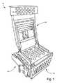
図面を具体的に参照すると、乗物用シート10の組み立てられた構造的要素が示されている。図1〜4に示されるように、主要な構造的要素は、シートパンアセンブリ12、シートバックアセンブリ14、ヘッドレストアセンブリ16、レッグレストアセンブリ18及び他の主要な構造的要素が上に取り付けられる台車アセンブリ20である。台車アセンブリ20は、横方向に延在するフレームチューブ19のように、前後の動作のために航空機の床のような支持面に固定されるように構成される。アームレスト等のような非本質的な要素もまた示される。例示される実施形態は航空機の乗客用シートであるが、本発明は他の種類の乗物用シートに対して適用される。 Referring specifically to the drawings, the assembled structural elements of the
図1〜4は、ある例示されたシート10に適用されるような新規の動作の連続を広く示す。図1に示されるように、航空機の乗客用シート10の最初の位置は、シートパンアセンブリ12の上面に対して略90度でシートバックアセンブリ14の前方の面を備える、TTOL形状である。ヘッドレストアセンブリ16の前面は、シートバックアセンブリ14の前面と解剖学的に整列され、レッグレストアセンブリ18の前面は、シートパンアセンブリ12の上面に対して略直角であり、レッグレストアセンブリ18が配置される水平な床と直角である。この位置によって規定されるシート位置は、TTOL時での安全性の要求を満たすとともに、直立に着席する位置を乗客が望む場合に快適さを供給するように設計される。 1-4 broadly illustrate a series of new operations as applied to an
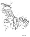
図2に示されるように、シート10は、ややリクライニングされた位置に動かすことができ、その位置では、シートバック14が後ろに傾けられ、シートパン12の前面がわずかに上方に傾いて、快適なシート位置を維持することができる。しかしながら、レッグレストアセンブリ18が床に対して垂直に直立した位置に留まることに注意すること。この特徴は、従来のこの種類の座席にはなく、乗客は座席をわずかにだけ後ろに倒したときには、足を床の上にまだ置いておきたいものであるという報告結果に基づく。したがって、シートパンアセンブリ12とレッグレストアセンブリ18との間の角度は、このとき鋭角となる。 As shown in FIG. 2, the
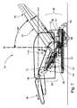
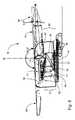
ここで図3を参照すると、シート10がその後ろに倒れる動作を続けるとき、シートバックアセンブリ14はさらに後ろに傾き、同時にシートパンアセンブリ12の前端縁は次第にさらに上方に傾き、レッグレストアセンブリ18は、シートパン12の前端のちょうど前方の回転軸周りで上方に回転し始める。シートバックアセンブリ14とシートパンアセンブリ12との間の角度は鈍角に開き、シートパンアセンブリ12とレッグレストアセンブリの間の角度はまっすぐになり始める。図4に示されるように、この進行して同時に起こるリクライニングの過程が続く。シートパンアセンブリ12とレッグレストアセンブリ18との間の関係に注意すること。図8に示されるように、その最終的なフルフラット位置において、レグレストアセンブリ18、シートパンアセンブリ12及びシートバックアセンブリ14は互いに対して平面的な位置に移動している。 Referring now to FIG. 3, as the
ここで図5〜8を参照すると、シート10の概略構造の側面が順に示され、図5から図8まで、また、図8から図5まで連続してシートアセンブリの位置を観察することにより、リクライニングやTTOL位置への復帰の精密な様子を観察することができる。図1〜4に示されるのと同様のアセンブリは、図5〜8において、同様の範囲の参照数字で示される。 Referring now to FIGS. 5-8, the schematic structural sides of the
図5に示されるように、シートパンアセンブリ12はシートパン12Aとシートパンフレーム30を含んでいる。前方のシートパンピボットアーム32と後方のピボットアーム34は上部シート支持フレーム36と、前後に平行移動可能なスライドレールアセンブリ38とを相互に連結させる。これらの構成要素はシートパンアセンブリ12、シートバックアセンブリ14及びレッグレストアセンブリ16の所望の動作を可能にするために相互に作用する四棒リンク機構(four−bar linkage)を形成する。 As shown in FIG. 5, the
台車40は、上部シート支持フレーム36に取り付けられ、図6に示されるように、本発明に従ってバックレストアセンブリ14とシートパンアセンブリ12の角度を同時に変化させる。レッグレストアセンブリ18は、リクライニングの動作の最初の段階の間、動かないままであり、この動作に続く段階の間、上方に回転する。図5及び図6と図7及び図8とを比較すること。 The
シート10は、クランクリンク42によりシートバックアセンブリ14に接続され、連結部44を介して上部シート支持フレーム36に取り付けることによりシートパンアセンブリに接続される、Hydrolok(登録商標)ピストンとシリンダーアセンブリ41のようなリニア流体圧固定装置によって駆動される。 The
乗り物用シート10全体は、前後の動作のために、スライドレールアセンブリ38を横切るボールベアリングローラ46によって、台車40に取り付けられている。この動きは、スライドレールアセンブリ38と平行に取り付けられるピストンとシリンダーアセンブリ50によって制御される。 The
本発明によるシートパンの前端部及び後端部の同時連結を備える乗物用シートを特定の実施形態及び例を参照して記載してきた。本発明の範囲から逸脱することなく本発明の種々の詳細を変更してもよい。更に、前述の本発明の好ましい実施形態及び本発明を実施するための最良の形態の記載は単に説明目的で提供されるものであり、限定目的ではなく、本発明は請求項によって規定される。
A vehicle seat with simultaneous connection of the front and rear ends of a seat pan according to the present invention has been described with reference to specific embodiments and examples. Various details of the invention may be changed without departing from the scope of the invention. Furthermore, the foregoing description of preferred embodiments of the invention and the best mode for carrying out the invention are provided for the purpose of illustration only and are not intended to be limiting, the invention being defined by the claims.
本発明によるシートパンの前端部及び後端部の同時連結を備える乗物用シートを特定の実施形態及び例を参照して記載してきた。本発明の範囲から逸脱することなく本発明の種々の詳細を変更してもよい。更に、前述の本発明の好ましい実施形態及び本発明を実施するための最良の形態の記載は単に説明目的で提供されるものであり、限定目的ではなく、本発明は請求項によって規定される。
以下の項目は、国際出願時の請求の範囲に記載の要素である。
(項目1)
乗物用シートであって、
(a)床の上での前後の動作のために支持している床に取り付けられるためのシート台車アセンブリと、
(b)前記シート台車アセンブリに対する前後の動作のために前記シート台車アセンブリに取り付けられるシートパンアセンブリと、
(c)前記シートパンアセンブリ後部で前記シート台車アセンブリに取り付けられ、前記シートパンアセンブリと同時の動作に適合されるシートバックアセンブリと、
(d)シートパン前部で前記シート台車アセンブリに取り付けられるレッグレストアセンブリと、
(e)前記シートパンアセンブリ、前記シートバックアセンブリ及び前記レッグレストアセンブリを相互に連結させている連結アセンブリを含む前記シート台車アセンブリであって、前記シート台車アセンブリが、前記シートが取り付けられる前記床に対して後方に動くとき、
(i)前記シートパンアセンブリと前記シートバックアセンブリとは、最初のリクライニングの動作の間、前記レッグレストアセンブリを前記シートパンアセンブリの下方に収納された位置に留まらせると共に、所定のシート位置を維持するように同時に調整し、
(ii)続くリクライニングの動作の間、バックレストアセンブリと前記シートパンアセンブリとがフルフラット形状に向かって徐々に後ろに倒れるに従い、前記レッグレストアセンブリは脚を支持する位置に向かって徐々に脚を持ち上げがる、シート台車アセンブリと、を含む、乗物用シート。
(項目2)
前記航空機の乗客用シートの最初の位置は、前記シートバックアセンブリの前面が、前記シートパンアセンブリの上面に対して略直角に配置される、TTOL形状である、項目1に記載の乗物用シート。
(項目3)
前記シートバックアセンブリの上端に配置されるヘッドレストアセンブリを含み、前記ヘッドレストアセンブリの前面は前記シートバックアセンブリの前面と解剖学的に整列され、最初の位置では、前記レッグレストアセンブリの前面は前記シートパンアセンブリの上面及び前記床に対して略直角である、項目1に記載の乗物用シート。
(項目3)
前記最初のリクライニングの動作の間、前記シートバックアセンブリは後方に傾けられ、前記シートパンアセンブリの上面は上方に傾き、前記シートバックアセンブリの前面と前記シートパンアセンブリの上面との間の略直角位置が維持される、項目1に記載の乗物用シート。
(項目4)
前記シートパンアセンブリは、シートパンと、シートパンフレームと、上方シート支持フレーム及び前後に平行移動可能なスライドレールアセンブリを相互に連結させている前方シートパンピボットアーム及び後方シートパンピボットアームと、を含む、項目1に記載の乗物用シート。
(項目5)
前記シートは、シートパンフレームと、前記シートパンアセンブリ、前記シートバックアセンブリ及び前記レッグレストアセンブリの所望の動作を可能とするために相互に作用する四棒リンク機構を形成するための、上方シート支持フレーム及び前後に平行移動可能なスライドレールアセンブリを相互に連結させている前方シートパンピボットアーム及び後方ピボットアームと、に支持されるシートパンを含む、項目4に記載の乗物用シート。
(項目6)
前記シートの動作は、クランクリンクにより前記シートバックアセンブリに接続され、上部シート支持フレームの連結部を介して前記上部シート支持フレームに取り付けることにより前記シートパンアセンブリに接続されるリニア流体圧固定装置によって駆動される、項目4に記載の乗物用シート。
(項目7)
前記流体圧固定装置はピストン及びシリンダーアセンブリを含む、項目6に記載の乗物用シート。
(項目8)
前記シート台車アセンブリは、スライドレールピストン及びシリンダーアセンブリにより駆動される平行移動可能なスライドレールアセンブリ上の動作のために取り付けられる、項目1に記載の乗物用シート。
(項目9)
航空機の乗客用シートであって、
(a)床の上での前後の動作のために支持している床に取り付けられるためのシート台車アセンブリと、
(b)前記シート台車アセンブリに対する前後の動作のために前記シート台車アセンブリに取り付けられるシートパンアセンブリと、
(c)前記シートパンアセンブリ後部で前記シート台車アセンブリに取り付けられ、前記シートパンアセンブリと同時の動作に適合されるシートバックアセンブリであって、前記航空機の乗客用シートの最初の位置は、前記シートバックアセンブリの前面が、前記シートパンアセンブリの上面に対して略直角に配置される、TTOL形状である、前記シートバックアセンブリと、
(d)シートパン前部で前記シート台車アセンブリに取り付けられるレッグレストアセンブリと、
(e)前記シートパンアセンブリ、前記シートバックアセンブリ及び前記レッグレストアセンブリを相互に連結させている連結アセンブリを含む前記シート台車アセンブリであって、前記シート台車アセンブリが、前記シートが取り付けられる前記床に対して後方に動くとき、
(i)前記シートパンアセンブリと前記シートバックアセンブリとは、最初のリクライニングの動作の間、前記レッグレストアセンブリを前記シートパンアセンブリの下方に収納された位置に留まらせると共に、所定のシート位置を維持するように同時に調整し、前記最初のリクライニングの動作の間、前記シートバックアセンブリは後方に傾けられ、前記シートパンアセンブリの上面は上方に傾き、前記シートバックアセンブリの前面と前記シートパンアセンブリの上面との間の略直角位置が維持され、
(ii)続くリクライニングの動作の間、バックレストアセンブリと前記シートパンアセンブリとがフルフラット形状に向かって徐々に後ろに倒れるに従い、前記レッグレストアセンブリは脚を支持する位置に向かって徐々に脚を持ち上げがる、シート台車アセンブリと、を含む、航空機の乗客用シート。
(項目10)
前記シートパンアセンブリは、シートパンと、シートパンフレームと、上方シート支持フレーム及び前後に平行移動可能なスライドレールアセンブリを相互に連結させている前方シートパンピボットアーム及び後方シートパンピボットアームと、を含む、項目9に記載の航空機の乗客用シート。
(項目11)
前記シートは、シートパンフレームと、前記シートパンアセンブリ、前記シートバックアセンブリ及び前記レッグレストアセンブリの所望の動作を可能とするために相互に作用する四棒リンク機構を形成するための、上方シート支持フレーム及び前後に平行移動可能なスライドレールアセンブリを相互に連結させている前方シートパンピボットアーム及び後方ピボットアームと、に支持されるシートパンを含む、項目9に記載の航空機の乗客用シート。
(項目12)
前記シートの動作は、クランクリンクにより前記シートバックアセンブリに接続され、上部シート支持フレームの連結部を介して前記上部シート支持フレームに取り付けることにより前記シートパンアセンブリに接続されるリニア流体圧固定装置によって駆動される、項目9に記載の航空機の乗客用シート。
(項目13)
前記流体圧固定装置はピストン及びシリンダーアセンブリを含む、項目12に記載の航空機の乗客用シート。
(項目14)
前記シート台車アセンブリは、スライドレールピストン及びシリンダーアセンブリにより駆動される平行移動可能なスライドレールアセンブリ上の動作のために取り付けられる、項目9に記載の航空機の乗客用シート。
(項目15)
航空機の乗客用シートであって、
(a)床の上での前後の動作のために支持している床に取り付けられるためのシート台車アセンブリと、
(b)前記シート台車アセンブリに対する前後の動作のために前記シート台車アセンブリに取り付けられるシートパンアセンブリであって、シートパンと、シートパンフレームと、上方シート支持フレーム及び前後に平行移動可能なスライドレールアセンブリを相互に連結させている前方シートパンピボットアーム及び後方シートパンピボットアームと、を含む、前記シートパンアセンブリと、
(c)前記シートパンアセンブリ後部で前記シート台車アセンブリに取り付けられ、前記シートパンアセンブリと同時の動作に適合されるシートバックアセンブリであって、前記航空機の乗客用シートの最初の位置は、前記シートパンアセンブリの前面が、前記シートバックアセンブリの上面に対して略直角に配置される、TTOL形状である、前記シートバックアセンブリと、
(d)シートパン前部で前記シート台車アセンブリに取り付けられるレッグレストアセンブリと、
(e)前記シートパンアセンブリ、前記シートバックアセンブリ及び前記レッグレストアセンブリを相互に連結させている連結アセンブリを含む前記シート台車アセンブリであって、前記シート台車アセンブリが、前記シートが取り付けられる前記床に対して後方に動くとき、
(i)前記シートパンアセンブリと前記シートバックアセンブリとは、最初のリクライニングの動作の間、前記レッグレストアセンブリを前記シートパンアセンブリの下方に収納された位置に留まらせると共に、所定のシート位置を維持するように同時に調整し、前記最初のリクライニングの動作の間、前記シートバックアセンブリは後方に傾けられ、前記シートパンアセンブリの上面は上方に傾き、前記シートバックアセンブリの前面と前記シートパンアセンブリの上面との間の略直角位置が維持され、
(ii)続くリクライニングの動作の間、バックレストアセンブリと前記シートパンアセンブリとがフルフラット形状に向かって徐々に後ろに倒れるに従い、前記レッグレストアセンブリは脚を支持する位置に向かって徐々に脚を持ち上げがる、シート台車アセンブリと、を含む、航空機の乗客用シート。
(項目16)
前記シートの動作は、クランクリンクにより前記シートバックアセンブリに接続され、上部シート支持フレームの連結部を介して前記上部シート支持フレームに取り付けることにより前記シートパンアセンブリに接続されるリニア流体圧固定装置によって駆動される、項目15に記載の航空機の乗客用シート。
(項目17)
前記流体圧固定装置はピストン及びシリンダーアセンブリを含む、項目16に記載の航空機の乗客用シート。
(項目18)
前記シート台車アセンブリは、スライドレールピストン及びシリンダーアセンブリにより駆動される平行移動可能なスライドレールアセンブリ上の動作のために取り付けられる、項目15に記載の航空機の乗客用シート。A vehicle seat with simultaneous connection of the front and rear ends of a seat pan according to the present invention has been described with reference to specific embodiments and examples. Various details of the invention may be changed without departing from the scope of the invention. Furthermore, the foregoing description of preferred embodiments of the invention and the best mode for carrying out the invention are provided for the purpose of illustration only and are not intended to be limiting, the invention being defined by the claims.
The following items are the elements described in the claims at the time of international application.
(Item 1)
A vehicle seat,
(A) a seat trolley assembly for mounting on a supporting floor for back and forth movement on the floor;
(B) a seat pan assembly attached to the seat cart assembly for back and forth movement relative to the seat cart assembly;
(C) a seat back assembly attached to the seat carriage assembly at the rear of the seat pan assembly and adapted for simultaneous operation with the seat pan assembly;
(D) a legrest assembly attached to the seat carriage assembly at the front of the seat pan;
(E) the seat trolley assembly including a coupling assembly interconnecting the seat pan assembly, the seat back assembly and the leg rest assembly, wherein the seat trolley assembly is mounted on the floor to which the seat is attached; When moving backward,
(I) The seat pan assembly and the seat back assembly allow the leg rest assembly to remain in a position stored below the seat pan assembly and maintain a predetermined seat position during an initial reclining operation. Adjust at the same time,
(Ii) During the subsequent reclining operation, as the backrest assembly and the seat pan assembly gradually fall back toward the full flat shape, the legrest assembly gradually moves the leg toward the position supporting the leg. A vehicle seat including a seat carriage assembly for lifting.
(Item 2)
The vehicle seat of claim 1, wherein an initial position of the aircraft passenger seat is a TTOL shape wherein a front surface of the seat back assembly is disposed substantially perpendicular to an upper surface of the seat pan assembly.
(Item 3)
A headrest assembly disposed at an upper end of the seatback assembly, wherein a front surface of the headrest assembly is anatomically aligned with a front surface of the seatback assembly, and in an initial position, the front surface of the legrest assembly is the seat pan assembly. Item 2. The vehicle seat of item 1, wherein the vehicle seat is substantially perpendicular to the top surface of the assembly and the floor.
(Item 3)
During the initial reclining operation, the seat back assembly is tilted rearward, the upper surface of the seat pan assembly is tilted upward, and a substantially perpendicular position between the front surface of the seat back assembly and the upper surface of the seat pan assembly. The vehicle seat according to item 1, wherein:
(Item 4)
The seat pan assembly includes a seat pan, a seat pan frame, a front seat pan pivot arm and a rear seat pan pivot arm interconnecting an upper seat support frame and a slide rail assembly which can be moved back and forth. The vehicle seat according to item 1, including the vehicle seat.
(Item 5)
The seat supports an upper seat to form a seat pan frame and a four-bar linkage that interacts to allow the desired operation of the seat pan assembly, the seat back assembly, and the leg rest assembly. 5. A vehicle seat according to item 4, comprising a seat pan supported by a front seat pan pivot arm and a rear pivot arm interconnecting the frame and a slide rail assembly movable in parallel back and forth.
(Item 6)
The movement of the seat is connected to the seat back assembly by a crank link, and by a linear fluid pressure fixing device connected to the seat pan assembly by being attached to the upper seat support frame via a connecting portion of the upper seat support frame. Item 5. The vehicle seat according to item 4, which is driven.
(Item 7)
7. A vehicle seat according to item 6, wherein the fluid pressure fixing device includes a piston and cylinder assembly.
(Item 8)
The vehicle seat of claim 1, wherein the seat carriage assembly is mounted for operation on a translatable slide rail assembly driven by a slide rail piston and cylinder assembly.
(Item 9)
An aircraft passenger seat,
(A) a seat trolley assembly for mounting on a supporting floor for back and forth movement on the floor;
(B) a seat pan assembly attached to the seat cart assembly for back and forth movement relative to the seat cart assembly;
(C) a seat back assembly attached to the seat carriage assembly at the rear of the seat pan assembly and adapted for simultaneous operation with the seat pan assembly, wherein the initial position of the passenger seat of the aircraft is the seat The seat back assembly having a TTOL shape, wherein a front surface of a back assembly is disposed substantially perpendicular to an upper surface of the seat pan assembly;
(D) a legrest assembly attached to the seat carriage assembly at the front of the seat pan;
(E) the seat trolley assembly including a coupling assembly interconnecting the seat pan assembly, the seat back assembly and the leg rest assembly, wherein the seat trolley assembly is mounted on the floor to which the seat is attached; When moving backward,
(I) The seat pan assembly and the seat back assembly allow the leg rest assembly to remain in a position stored below the seat pan assembly and maintain a predetermined seat position during an initial reclining operation. During the initial reclining operation, the seat back assembly is tilted rearward, the upper surface of the seat pan assembly is tilted upward, the front surface of the seat back assembly and the upper surface of the seat pan assembly. A substantially perpendicular position between
(Ii) During the subsequent reclining operation, as the backrest assembly and the seat pan assembly gradually fall back toward the full flat shape, the legrest assembly gradually moves the leg toward the position supporting the leg. A seat for an aircraft passenger comprising a seat carriage assembly for lifting.
(Item 10)
The seat pan assembly includes a seat pan, a seat pan frame, a front seat pan pivot arm and a rear seat pan pivot arm interconnecting an upper seat support frame and a slide rail assembly which can be moved back and forth. The aircraft passenger seat according to item 9, including the aircraft passenger seat.
(Item 11)
The seat supports an upper seat to form a seat pan frame and a four-bar linkage that interacts to allow the desired operation of the seat pan assembly, the seat back assembly, and the leg rest assembly. 10. An aircraft passenger seat according to item 9, comprising a seat pan supported by a front seat pan pivot arm and a rear pivot arm interconnecting the frame and a slide rail assembly movable in parallel back and forth.
(Item 12)
The movement of the seat is connected to the seat back assembly by a crank link, and by a linear fluid pressure fixing device connected to the seat pan assembly by being attached to the upper seat support frame via a connecting portion of the upper seat support frame. 10. The aircraft passenger seat of item 9, which is driven.
(Item 13)
13. An aircraft passenger seat according to
(Item 14)
The aircraft passenger seat of claim 9, wherein the seat carriage assembly is mounted for operation on a translatable slide rail assembly driven by a slide rail piston and cylinder assembly.
(Item 15)
An aircraft passenger seat,
(A) a seat trolley assembly for mounting on a supporting floor for back and forth movement on the floor;
(B) A seat pan assembly attached to the seat cart assembly for back and forth movement with respect to the seat cart assembly, the seat pan, a seat pan frame, an upper seat support frame, and a slide rail movable in parallel in the front and rear directions. A front seat pan pivot arm and a rear seat pan pivot arm interconnecting the assemblies;
(C) a seat back assembly attached to the seat carriage assembly at the rear of the seat pan assembly and adapted for simultaneous operation with the seat pan assembly, wherein the initial position of the passenger seat of the aircraft is the seat The seat back assembly having a TTOL shape, wherein a front surface of a pan assembly is disposed substantially perpendicular to an upper surface of the seat back assembly;
(D) a legrest assembly attached to the seat carriage assembly at the front of the seat pan;
(E) the seat trolley assembly including a coupling assembly interconnecting the seat pan assembly, the seat back assembly and the leg rest assembly, wherein the seat trolley assembly is mounted on the floor to which the seat is attached; When moving backward,
(I) The seat pan assembly and the seat back assembly allow the leg rest assembly to remain in a position stored below the seat pan assembly and maintain a predetermined seat position during an initial reclining operation. During the initial reclining operation, the seat back assembly is tilted rearward, the upper surface of the seat pan assembly is tilted upward, the front surface of the seat back assembly and the upper surface of the seat pan assembly. A substantially perpendicular position between
(Ii) During the subsequent reclining operation, as the backrest assembly and the seat pan assembly gradually fall back toward the full flat shape, the legrest assembly gradually moves the leg toward the position supporting the leg. A seat for an aircraft passenger comprising a seat carriage assembly for lifting.
(Item 16)
The movement of the seat is connected to the seat back assembly by a crank link, and by a linear fluid pressure fixing device connected to the seat pan assembly by being attached to the upper seat support frame via a connecting portion of the upper seat support frame. 16. The aircraft passenger seat according to item 15, which is driven.
(Item 17)
The aircraft passenger seat of
(Item 18)
16. An aircraft passenger seat according to item 15, wherein the seat carriage assembly is mounted for operation on a translatable slide rail assembly driven by a slide rail piston and cylinder assembly.
Claims (19)
Translated fromJapanese(a)床の上での前後の動作のために支持している床に取り付けられるためのシート台車アセンブリと、
(b)前記シート台車アセンブリに対する前後の動作のために前記シート台車アセンブリに取り付けられるシートパンアセンブリと、
(c)前記シートパンアセンブリ後部で前記シート台車アセンブリに取り付けられ、前記シートパンアセンブリと同時の動作に適合されるシートバックアセンブリと、
(d)シートパン前部で前記シート台車アセンブリに取り付けられるレッグレストアセンブリと、
(e)前記シートパンアセンブリ、前記シートバックアセンブリ及び前記レッグレストアセンブリを相互に連結させている連結アセンブリを含む前記シート台車アセンブリであって、前記シート台車アセンブリが、前記シートが取り付けられる前記床に対して後方に動くとき、
(i)前記シートパンアセンブリと前記シートバックアセンブリとは、最初のリクライニングの動作の間、前記レッグレストアセンブリを前記シートパンアセンブリの下方に収納された位置に留まらせると共に、所定のシート位置を維持するように同時に調整し、
(ii)続くリクライニングの動作の間、バックレストアセンブリと前記シートパンアセンブリとがフルフラット形状に向かって徐々に後ろに倒れるに従い、前記レッグレストアセンブリは脚を支持する位置に向かって徐々に持ち上がる、シート台車アセンブリと、を含む、乗物用シート。A vehicle seat,
(A) a seat trolley assembly for mounting on a supporting floor for back and forth movement on the floor;
(B) a seat pan assembly attached to the seat cart assembly for back and forth movement relative to the seat cart assembly;
(C) a seat back assembly attached to the seat carriage assembly at the rear of the seat pan assembly and adapted for simultaneous operation with the seat pan assembly;
(D) a legrest assembly attached to the seat carriage assembly at the front of the seat pan;
(E) the seat trolley assembly including a coupling assembly interconnecting the seat pan assembly, the seat back assembly and the leg rest assembly, wherein the seat trolley assembly is mounted on the floor to which the seat is attached; When moving backward,
(I) The seat pan assembly and the seat back assembly allow the leg rest assembly to remain in a position stored below the seat pan assembly and maintain a predetermined seat position during an initial reclining operation. Adjust at the same time,
(Ii) During the subsequent reclining operation, as the backrest assembly and the seat pan assembly gradually fall back toward the full flat shape, the legrest assembly is gradually lifted toward the position supporting the legs; A vehicle seat including a seat carriage assembly.
(a)床の上での前後の動作のために支持している床に取り付けられるためのシート台車アセンブリと、
(b)前記シート台車アセンブリに対する前後の動作のために前記シート台車アセンブリに取り付けられるシートパンアセンブリと、
(c)前記シートパンアセンブリ後部で前記シート台車アセンブリに取り付けられ、前記シートパンアセンブリと同時の動作に適合されるシートバックアセンブリであって、前記航空機の乗客用シートの最初の位置は、前記シートバックアセンブリの前面が、前記シートパンアセンブリの上面に対して略直角に配置される、TTOL形状である、前記シートバックアセンブリと、
(d)シートパン前部で前記シート台車アセンブリに取り付けられるレッグレストアセンブリと、
(e)前記シートパンアセンブリ、前記シートバックアセンブリ及び前記レッグレストアセンブリを相互に連結させている連結アセンブリを含む前記シート台車アセンブリであって、前記シート台車アセンブリが、前記シートが取り付けられる前記床に対して後方に動くとき、
(i)前記シートパンアセンブリと前記シートバックアセンブリとは、最初のリクライニングの動作の間、前記レッグレストアセンブリを前記シートパンアセンブリの下方に収納された位置に留まらせると共に、所定のシート位置を維持するように同時に調整し、前記最初のリクライニングの動作の間、前記シートバックアセンブリは後方に傾けられ、前記シートパンアセンブリの上面は上方に傾き、前記シートバックアセンブリの前面と前記シートパンアセンブリの上面との間の略直角位置が維持され、
(ii)続くリクライニングの動作の間、バックレストアセンブリと前記シートパンアセンブリとがフルフラット形状に向かって徐々に後ろに倒れるに従い、前記レッグレストアセンブリは脚を支持する位置に向かって徐々に持ち上がる、シート台車アセンブリと、を含む、航空機の乗客用シート。An aircraft passenger seat,
(A) a seat trolley assembly for mounting on a supporting floor for back and forth movement on the floor;
(B) a seat pan assembly attached to the seat cart assembly for back and forth movement relative to the seat cart assembly;
(C) a seat back assembly attached to the seat carriage assembly at the rear of the seat pan assembly and adapted for simultaneous operation with the seat pan assembly, wherein the initial position of the passenger seat of the aircraft is the seat The seat back assembly having a TTOL shape, wherein a front surface of a back assembly is disposed substantially perpendicular to an upper surface of the seat pan assembly;
(D) a legrest assembly attached to the seat carriage assembly at the front of the seat pan;
(E) the seat trolley assembly including a coupling assembly interconnecting the seat pan assembly, the seat back assembly and the leg rest assembly, wherein the seat trolley assembly is mounted on the floor to which the seat is attached; When moving backward,
(I) The seat pan assembly and the seat back assembly allow the leg rest assembly to remain in a position stored below the seat pan assembly and maintain a predetermined seat position during an initial reclining operation. During the initial reclining operation, the seat back assembly is tilted rearward, the upper surface of the seat pan assembly is tilted upward, the front surface of the seat back assembly and the upper surface of the seat pan assembly. A substantially perpendicular position between
(Ii) During the subsequent reclining operation, as the backrest assembly and the seat pan assembly gradually fall back toward the full flat shape, the legrest assembly is gradually lifted toward the position supporting the legs; A seat for an aircraft passenger, comprising: a seat carriage assembly;
(a)床の上での前後の動作のために支持している床に取り付けられるためのシート台車アセンブリと、
(b)前記シート台車アセンブリに対する前後の動作のために前記シート台車アセンブリに取り付けられるシートパンアセンブリであって、シートパンと、シートパンフレームと、上方シート支持フレーム及び前後に平行移動可能なスライドレールアセンブリを相互に連結させている前方シートパンピボットアーム及び後方シートパンピボットアームと、を含む、前記シートパンアセンブリと、
(c)前記シートパンアセンブリ後部で前記シート台車アセンブリに取り付けられ、前記シートパンアセンブリと同時の動作に適合されるシートバックアセンブリであって、前記航空機の乗客用シートの最初の位置は、前記シートパンアセンブリの前面が、前記シートバックアセンブリの上面に対して略直角に配置される、TTOL形状である、前記シートバックアセンブリと、
(d)シートパン前部で前記シート台車アセンブリに取り付けられるレッグレストアセンブリと、
(e)前記シートパンアセンブリ、前記シートバックアセンブリ及び前記レッグレストアセンブリを相互に連結させている連結アセンブリを含む前記シート台車アセンブリであって、前記シート台車アセンブリが、前記シートが取り付けられる前記床に対して後方に動くとき、
(i)前記シートパンアセンブリと前記シートバックアセンブリとは、最初のリクライニングの動作の間、前記レッグレストアセンブリを前記シートパンアセンブリの下方に収納された位置に留まらせると共に、所定のシート位置を維持するように同時に調整し、前記最初のリクライニングの動作の間、前記シートバックアセンブリは後方に傾けられ、前記シートパンアセンブリの上面は上方に傾き、前記シートバックアセンブリの前面と前記シートパンアセンブリの上面との間の略直角位置が維持され、
(ii)続くリクライニングの動作の間、バックレストアセンブリと前記シートパンアセンブリとがフルフラット形状に向かって徐々に後ろに倒れるに従い、前記レッグレストアセンブリは脚を支持する位置に向かって徐々に持ち上がる、シート台車アセンブリと、を含む、航空機の乗客用シート。An aircraft passenger seat,
(A) a seat trolley assembly for mounting on a supporting floor for back and forth movement on the floor;
(B) A seat pan assembly attached to the seat cart assembly for back and forth movement with respect to the seat cart assembly, the seat pan, a seat pan frame, an upper seat support frame, and a slide rail movable in parallel in the front and rear directions. A front seat pan pivot arm and a rear seat pan pivot arm interconnecting the assemblies;
(C) a seat back assembly attached to the seat carriage assembly at the rear of the seat pan assembly and adapted for simultaneous operation with the seat pan assembly, wherein the initial position of the passenger seat of the aircraft is the seat The seat back assembly having a TTOL shape, wherein a front surface of a pan assembly is disposed substantially perpendicular to an upper surface of the seat back assembly;
(D) a legrest assembly attached to the seat carriage assembly at the front of the seat pan;
(E) the seat trolley assembly including a coupling assembly interconnecting the seat pan assembly, the seat back assembly and the leg rest assembly, wherein the seat trolley assembly is mounted on the floor to which the seat is attached; When moving backward,
(I) The seat pan assembly and the seat back assembly allow the leg rest assembly to remain in a position stored below the seat pan assembly and maintain a predetermined seat position during an initial reclining operation. During the initial reclining operation, the seat back assembly is tilted rearward, the upper surface of the seat pan assembly is tilted upward, the front surface of the seat back assembly and the upper surface of the seat pan assembly. A substantially perpendicular position between
(Ii) During the subsequent reclining operation, as the backrest assembly and the seat pan assembly gradually fall back toward the full flat shape, the legrest assembly is gradually lifted toward the position supporting the legs; A seat for an aircraft passenger, comprising: a seat carriage assembly;
The aircraft passenger seat of claim 15, wherein the seat carriage assembly is mounted for operation on a translatable slide rail assembly driven by a slide rail piston and cylinder assembly.
Applications Claiming Priority (3)
| Application Number | Priority Date | Filing Date | Title |
|---|---|---|---|
| US201361809491P | 2013-04-08 | 2013-04-08 | |
| US61/809,491 | 2013-04-08 | ||
| PCT/US2014/033326WO2014168945A1 (en) | 2013-04-08 | 2014-04-08 | Vehicle seat with simultaneous articulation of seat pan and seat back |
Publications (1)
| Publication Number | Publication Date |
|---|---|
| JP2016520470Atrue JP2016520470A (en) | 2016-07-14 |
Family
ID=51653931
Family Applications (1)
| Application Number | Title | Priority Date | Filing Date |
|---|---|---|---|
| JP2016507606APendingJP2016520470A (en) | 2013-04-08 | 2014-04-08 | Vehicle seat having simultaneous connection of seat pan and seat back |
Country Status (6)
| Country | Link |
|---|---|
| US (1) | US9284055B2 (en) |
| EP (1) | EP2983563B1 (en) |
| JP (1) | JP2016520470A (en) |
| CN (1) | CN105163628B (en) |
| CA (1) | CA2904113C (en) |
| WO (1) | WO2014168945A1 (en) |
Cited By (2)
| Publication number | Priority date | Publication date | Assignee | Title |
|---|---|---|---|---|
| JP2019202121A (en)* | 2018-05-16 | 2019-11-28 | ファミリーイナダ株式会社 | Massage machine |
| KR102815396B1 (en)* | 2024-10-29 | 2025-05-29 | 이향미 | Full flat seat for vehicle |
Families Citing this family (62)
| Publication number | Priority date | Publication date | Assignee | Title |
|---|---|---|---|---|
| DE102012214541A1 (en)* | 2012-08-15 | 2014-05-22 | Kintec-Solution Gmbh | Fitting for a piece of seating furniture |
| DE102012224358A1 (en)* | 2012-12-24 | 2014-06-26 | Lufthansa Technik Ag | vehicle seat |
| US9399418B2 (en) | 2013-01-24 | 2016-07-26 | Ford Global Technologies, Llc | Independent cushion extension and thigh support |
| US9409504B2 (en) | 2013-01-24 | 2016-08-09 | Ford Global Technologies, Llc | Flexible seatback system |
| US9415713B2 (en) | 2013-01-24 | 2016-08-16 | Ford Global Technologies, Llc | Flexible seatback system |
| US9315131B2 (en) | 2014-01-23 | 2016-04-19 | Ford Global Technologies, Llc | Suspension seat back and cushion system having an inner suspension panel |
| EP2923946B1 (en)* | 2014-03-28 | 2018-05-30 | Airbus Operations GmbH | Passenger seat arrangement for a vehicle |
| US9421894B2 (en) | 2014-04-02 | 2016-08-23 | Ford Global Technologies, Llc | Vehicle seating assembly with manual independent thigh supports |
| US9789790B2 (en) | 2014-10-03 | 2017-10-17 | Ford Global Technologies, Llc | Tuned flexible support member and flexible suspension features for comfort carriers |
| EP3271249A1 (en)* | 2015-03-17 | 2018-01-24 | B/E Aerospace, Inc. | Spring loaded seat bottom which locks during taxi, take-off and landing |
| CN105146941A (en)* | 2015-07-16 | 2015-12-16 | 泰州市奥德家具配件有限公司 | Leisure chair self-controlled leg supporter rack |
| US10046682B2 (en) | 2015-08-03 | 2018-08-14 | Ford Global Technologies, Llc | Back cushion module for a vehicle seating assembly |
| US9718387B2 (en) | 2015-08-03 | 2017-08-01 | Ford Global Technologies, Llc | Seat cushion module for a vehicle seating assembly |
| US10266270B2 (en) | 2015-08-21 | 2019-04-23 | Textron Innovations, Inc. | Locking system for articulating aircraft seat |
| CA3040977A1 (en)* | 2015-10-20 | 2017-04-27 | James Shing Hin Lee | Convertible seating unit and seating arrangement |
| US10940948B2 (en) | 2015-11-10 | 2021-03-09 | Safran Seats | Aircraft seat for cabin crew |
| CN105416106A (en)* | 2015-12-29 | 2016-03-23 | 苏州汉实汽车机械有限公司 | Comfortable seat of automobile |
| US10286818B2 (en) | 2016-03-16 | 2019-05-14 | Ford Global Technologies, Llc | Dual suspension seating assembly |
| US9849817B2 (en) | 2016-03-16 | 2017-12-26 | Ford Global Technologies, Llc | Composite seat structure |
| US9994135B2 (en) | 2016-03-30 | 2018-06-12 | Ford Global Technologies, Llc | Independent cushion thigh support |
| US10220737B2 (en) | 2016-04-01 | 2019-03-05 | Ford Global Technologies, Llc | Kinematic back panel |
| US9889773B2 (en) | 2016-04-04 | 2018-02-13 | Ford Global Technologies, Llc | Anthropomorphic upper seatback |
| US9802512B1 (en) | 2016-04-12 | 2017-10-31 | Ford Global Technologies, Llc | Torsion spring bushing |
| JP6728979B2 (en)* | 2016-05-26 | 2020-07-22 | トヨタ紡織株式会社 | Vehicle seat |
| US9845029B1 (en) | 2016-06-06 | 2017-12-19 | Ford Global Technologies, Llc | Passive conformal seat with hybrid air/liquid cells |
| US9849856B1 (en) | 2016-06-07 | 2017-12-26 | Ford Global Technologies, Llc | Side airbag energy management system |
| US9834166B1 (en) | 2016-06-07 | 2017-12-05 | Ford Global Technologies, Llc | Side airbag energy management system |
| US10166895B2 (en) | 2016-06-09 | 2019-01-01 | Ford Global Technologies, Llc | Seatback comfort carrier |
| US10377279B2 (en) | 2016-06-09 | 2019-08-13 | Ford Global Technologies, Llc | Integrated decking arm support feature |
| US10933787B2 (en) | 2016-08-19 | 2021-03-02 | Adient Luxembourg Holding S.Á R.L. | Head restraint follower |
| US10286824B2 (en) | 2016-08-24 | 2019-05-14 | Ford Global Technologies, Llc | Spreader plate load distribution |
| US10279714B2 (en) | 2016-08-26 | 2019-05-07 | Ford Global Technologies, Llc | Seating assembly with climate control features |
| US10391910B2 (en) | 2016-09-02 | 2019-08-27 | Ford Global Technologies, Llc | Modular assembly cross-tube attachment tab designs and functions |
| US10239431B2 (en) | 2016-09-02 | 2019-03-26 | Ford Global Technologies, Llc | Cross-tube attachment hook features for modular assembly and support |
| CA3013671C (en)* | 2016-10-19 | 2023-01-24 | B/E Aerospace, Inc. | Passenger seat having side sleep support assembly |
| US9914378B1 (en) | 2016-12-16 | 2018-03-13 | Ford Global Technologies, Llc | Decorative and functional upper seatback closeout assembly |
| DE102017204886A1 (en)* | 2017-03-23 | 2018-09-27 | Airbus Operations Gmbh | Passenger seat with a manually expandable seat element and passenger cabin area |
| GB2560996B (en)* | 2017-03-31 | 2021-04-14 | Ipeco Holdings Ltd | Seating apparatus |
| FR3064555B1 (en)* | 2017-04-04 | 2019-06-14 | Stelia Aerospace | CONVERTIBLE ARMCHAIR WITH LEG REST OR WITHOUT REST LEG AND CONVERSION METHOD |
| DE102018108374A1 (en)* | 2017-04-13 | 2018-10-18 | Ford Global Technologies, Llc | COLLABORABLE LIFTING MECHANISM FOR H-POINT LIFTING |
| US10596936B2 (en) | 2017-05-04 | 2020-03-24 | Ford Global Technologies, Llc | Self-retaining elastic strap for vent blower attachment to a back carrier |
| CN108749657A (en)* | 2017-08-18 | 2018-11-06 | 张金才 | Car room chair bed |
| JP6851949B2 (en)* | 2017-10-12 | 2021-03-31 | 本田技研工業株式会社 | Vehicle seat |
| US10829222B2 (en) | 2017-11-20 | 2020-11-10 | B/E Aerospace, Inc. | Aircraft passenger seat with zero-g taxi, take-off and landing recline position |
| CN108715227B (en)* | 2018-05-25 | 2021-07-06 | 湖北航宇嘉泰飞机设备有限公司 | Framework structure of full-flat-lying aviation seat |
| US11111023B2 (en)* | 2018-06-25 | 2021-09-07 | Rami Kayyali | Reclining chair with rear impingement prevention |
| CN109124142A (en)* | 2018-10-22 | 2019-01-04 | 东阳市金不换红木家具厂 | A kind of redwood multifunction sofa |
| GB2580292B (en)* | 2018-10-30 | 2022-11-30 | Safran Seats Gb Ltd | Aircraft seat and cabin arrangement |
| JP2020111252A (en)* | 2019-01-15 | 2020-07-27 | 日本発條株式会社 | Vehicle seat |
| US10850648B2 (en) | 2019-03-26 | 2020-12-01 | B/E Aerospace, Inc. | Seat pan articulation mechanism |
| DE102019204488B4 (en)* | 2019-03-29 | 2023-05-04 | Adient Aerospace, Llc | Seat, in particular aircraft seat |
| CN110606097B (en)* | 2019-09-13 | 2020-09-15 | 李志斌 | Full-automatic business cabin capable of converting sitting posture, lying posture and sleeping posture into sleeping posture |
| CN114466794B (en)* | 2019-09-30 | 2025-05-16 | 赛峰座椅美国有限责任公司 | Zero-intrusive motion and tilt mechanisms for commercial aircraft seats |
| FR3102721B1 (en)* | 2019-10-31 | 2021-10-08 | Safran Seats | SEAT ESPECIALLY FOR A SINGLE ACTUATOR AIRPLANE |
| US11267383B2 (en) | 2020-06-24 | 2022-03-08 | Faurecia Automotive Seating, Llc | Leg support for a vehicle seat |
| FR3121913B1 (en)* | 2021-04-16 | 2024-04-19 | Stelia Aerospace | Aircraft passenger seating unit and associated cabin arrangement |
| CN113303616B (en)* | 2021-05-28 | 2025-08-19 | 福建荣耀品牌营销有限公司 | Chair adjusting linkage mechanism |
| CN114312499B (en)* | 2021-12-13 | 2022-10-11 | 麦格纳座椅研发(重庆)有限公司 | Vehicle seat cushion lifting mechanism |
| US12116135B2 (en)* | 2022-07-12 | 2024-10-15 | B/E Aerospace, Inc. | Self supporting berthing platform system for aircraft seats |
| US11772536B1 (en) | 2022-07-27 | 2023-10-03 | Ford Global Technologies, Llc | Vehicle seating assembly with lower leg support |
| US12090905B2 (en) | 2022-07-29 | 2024-09-17 | Ford Global Technologies, Llc | Vehicle seating assembly with lower leg support |
| KR102550551B1 (en)* | 2022-12-02 | 2023-07-04 | 주식회사 비비 | Full-flat seat for vehicle |
Citations (1)
| Publication number | Priority date | Publication date | Assignee | Title |
|---|---|---|---|---|
| JPH08258796A (en)* | 1994-12-13 | 1996-10-08 | British Airways Plc | Seat unit |
Family Cites Families (21)
| Publication number | Priority date | Publication date | Assignee | Title |
|---|---|---|---|---|
| US5318341A (en)* | 1992-01-28 | 1994-06-07 | Hoover Universal, Inc. | Vehicle seat assembly with structural seat back to accommodate seat belt loads applied to seat back |
| US5435625A (en) | 1993-08-20 | 1995-07-25 | Hoover Universal, Inc. | Hydraulically controlled seat adjuster and recliner mechanisms for vehicle seats |
| US5636898A (en)* | 1994-04-15 | 1997-06-10 | Burns Aerospace Corporation | Seat with recline linkage |
| SG54502A1 (en)* | 1997-02-20 | 1998-11-16 | Singapore Airlines Ltd | Improvements in transport accommodation |
| US6227489B1 (en)* | 1998-05-15 | 2001-05-08 | Koito Industries, Ltd. | Aircraft seat apparatus |
| GB9918263D0 (en)* | 1999-08-04 | 1999-10-06 | Britax Rumbold Ltd | Seating unit of a passenger vehicle |
| DE10019484A1 (en)* | 2000-04-19 | 2001-10-31 | Recaro Aircraft Seating Gmbh | Vehicle seat, in particular passenger seat |
| FR2820400B1 (en)* | 2001-02-05 | 2003-04-11 | Sicma Aero Seat | MULTI-POSITION SEAT FOR AIRPLANE |
| US6692069B2 (en) | 2001-07-20 | 2004-02-17 | B E Aerospace, Inc. | Aircraft sleeper seat |
| ATE529293T1 (en)* | 2001-08-09 | 2011-11-15 | Virgin Atlantic Airways Ltd | A SEATING ARRANGEMENT AND A PASSENGER SEAT UNIT FOR AN AIRCRAFT |
| US6669295B2 (en)* | 2001-11-21 | 2003-12-30 | B E Aerospace, Inc. | Passenger seat with low profile seat back recline locking assembly |
| US6698836B1 (en) | 2002-08-26 | 2004-03-02 | Aviointeriors S.P.A. | Mechanism to obtain the complete reclining of a seat, particularly for an aircraft seat |
| US7182402B1 (en) | 2004-06-22 | 2007-02-27 | Timco Aviation Services, Inc. | Seat recline control override |
| US7475944B2 (en)* | 2005-02-18 | 2009-01-13 | Krueger International, Inc. | Reclining and convertible seating furniture with trendelenburg feature |
| GB2454751B (en)* | 2007-11-19 | 2012-12-12 | British Airways Plc | Aircraft passenger seat |
| CN105539853B (en)* | 2009-01-30 | 2018-08-28 | 新西兰航空公司 | Seat arrangement, seat unit, tray table and seat system |
| EP2414233B1 (en) | 2009-04-03 | 2013-07-31 | BE Aerospace, Inc. | Passenger seat with single actuator seat mechanism |
| JP5350961B2 (en)* | 2009-09-30 | 2013-11-27 | ファミリーイナダ株式会社 | Chair type massage machine |
| US8403415B2 (en)* | 2010-08-16 | 2013-03-26 | Be Aerospace, Inc. | Aircraft passenger seat recline mechanism |
| EP2646319A1 (en)* | 2010-12-01 | 2013-10-09 | Société Industrielle et Commerciale de Matériel Aéronautique | Aircraft seat |
| EP2729365B1 (en)* | 2011-07-06 | 2016-11-30 | Zodiac Seats US LLC | Seat pan assembly |
- 2014
- 2014-04-08EPEP14782339.7Apatent/EP2983563B1/enactiveActive
- 2014-04-08JPJP2016507606Apatent/JP2016520470A/enactivePending
- 2014-04-08CACA2904113Apatent/CA2904113C/enactiveActive
- 2014-04-08WOPCT/US2014/033326patent/WO2014168945A1/enactiveApplication Filing
- 2014-04-08CNCN201480019944.1Apatent/CN105163628B/enactiveActive
- 2014-04-08USUS14/247,850patent/US9284055B2/enactiveActive
Patent Citations (1)
| Publication number | Priority date | Publication date | Assignee | Title |
|---|---|---|---|---|
| JPH08258796A (en)* | 1994-12-13 | 1996-10-08 | British Airways Plc | Seat unit |
Cited By (3)
| Publication number | Priority date | Publication date | Assignee | Title |
|---|---|---|---|---|
| JP2019202121A (en)* | 2018-05-16 | 2019-11-28 | ファミリーイナダ株式会社 | Massage machine |
| JP7266851B2 (en) | 2018-05-16 | 2023-05-01 | ファミリーイナダ株式会社 | Massage machine |
| KR102815396B1 (en)* | 2024-10-29 | 2025-05-29 | 이향미 | Full flat seat for vehicle |
Also Published As
| Publication number | Publication date |
|---|---|
| CA2904113A1 (en) | 2014-10-16 |
| WO2014168945A1 (en) | 2014-10-16 |
| CN105163628A (en) | 2015-12-16 |
| CN105163628B (en) | 2018-05-25 |
| CA2904113C (en) | 2019-01-08 |
| EP2983563A1 (en) | 2016-02-17 |
| EP2983563A4 (en) | 2016-11-23 |
| EP2983563B1 (en) | 2019-09-25 |
| US20140300145A1 (en) | 2014-10-09 |
| US9284055B2 (en) | 2016-03-15 |
Similar Documents
| Publication | Publication Date | Title |
|---|---|---|
| JP2016520470A (en) | Vehicle seat having simultaneous connection of seat pan and seat back | |
| US10450071B2 (en) | Aircraft passenger seat mechanism | |
| JP6214767B2 (en) | Independently articulating seat pan for aircraft seats | |
| US9809133B2 (en) | Reclining seat assembly | |
| US8042867B2 (en) | Seat pan drop down link | |
| US8376458B2 (en) | Seat pan cam follower with drop down mechanism | |
| US20160325837A1 (en) | Aircraft seat | |
| CN101969817B (en) | Convertible aircraft passenger seat and method | |
| CN103781659B (en) | adjustable seat | |
| CA2904875A1 (en) | Aircraft seat with translating seatback linkage pivot | |
| US20090295209A1 (en) | Seat With Pivoting Backrest | |
| EP1991265A2 (en) | Aircraft passenger seat | |
| JP2018197101A (en) | Vehicle passenger chair having rest configuration | |
| CA3086225A1 (en) | Reclinable passenger seat | |
| US6808234B2 (en) | Seat | |
| JP6041618B2 (en) | Seat device | |
| US9402480B2 (en) | Adjustable seat assembly | |
| CA3178812A1 (en) | Reclinable seat with multiple configurations | |
| CN218141203U (en) | Pedal turnover mechanism for seat | |
| EP3543126A1 (en) | Seat for a vehicle |
Legal Events
| Date | Code | Title | Description |
|---|---|---|---|
| A521 | Request for written amendment filed | Free format text:JAPANESE INTERMEDIATE CODE: A523 Effective date:20160121 | |
| A621 | Written request for application examination | Free format text:JAPANESE INTERMEDIATE CODE: A621 Effective date:20160121 | |
| A521 | Request for written amendment filed | Free format text:JAPANESE INTERMEDIATE CODE: A523 Effective date:20160310 | |
| A977 | Report on retrieval | Free format text:JAPANESE INTERMEDIATE CODE: A971007 Effective date:20161108 | |
| A131 | Notification of reasons for refusal | Free format text:JAPANESE INTERMEDIATE CODE: A131 Effective date:20161115 | |
| A601 | Written request for extension of time | Free format text:JAPANESE INTERMEDIATE CODE: A601 Effective date:20170124 | |
| A601 | Written request for extension of time | Free format text:JAPANESE INTERMEDIATE CODE: A601 Effective date:20170314 | |
| A02 | Decision of refusal | Free format text:JAPANESE INTERMEDIATE CODE: A02 Effective date:20170711 |