JP2016519984A - Segment electrode lead formed from a pre-electrode having a recess or a hole, and a method for manufacturing the same - Google Patents
Segment electrode lead formed from a pre-electrode having a recess or a hole, and a method for manufacturing the sameDownload PDFInfo
- Publication number
- JP2016519984A JP2016519984AJP2016516705AJP2016516705AJP2016519984AJP 2016519984 AJP2016519984 AJP 2016519984AJP 2016516705 AJP2016516705 AJP 2016516705AJP 2016516705 AJP2016516705 AJP 2016516705AJP 2016519984 AJP2016519984 AJP 2016519984A
- Authority
- JP
- Japan
- Prior art keywords
- electrode
- segment
- lead
- electrodes
- segment electrodes
- Prior art date
- Legal status (The legal status is an assumption and is not a legal conclusion. Google has not performed a legal analysis and makes no representation as to the accuracy of the status listed.)
- Pending
Links
Images


Classifications
- A—HUMAN NECESSITIES
- A61—MEDICAL OR VETERINARY SCIENCE; HYGIENE
- A61N—ELECTROTHERAPY; MAGNETOTHERAPY; RADIATION THERAPY; ULTRASOUND THERAPY
- A61N1/00—Electrotherapy; Circuits therefor
- A61N1/02—Details
- A61N1/04—Electrodes
- A61N1/05—Electrodes for implantation or insertion into the body, e.g. heart electrode
- A61N1/0526—Head electrodes
- A61N1/0529—Electrodes for brain stimulation
- A61N1/0534—Electrodes for deep brain stimulation
- A—HUMAN NECESSITIES
- A61—MEDICAL OR VETERINARY SCIENCE; HYGIENE
- A61N—ELECTROTHERAPY; MAGNETOTHERAPY; RADIATION THERAPY; ULTRASOUND THERAPY
- A61N1/00—Electrotherapy; Circuits therefor
- A61N1/18—Applying electric currents by contact electrodes
- A61N1/32—Applying electric currents by contact electrodes alternating or intermittent currents
- A61N1/36—Applying electric currents by contact electrodes alternating or intermittent currents for stimulation
- A61N1/3605—Implantable neurostimulators for stimulating central or peripheral nerve system
- Y—GENERAL TAGGING OF NEW TECHNOLOGICAL DEVELOPMENTS; GENERAL TAGGING OF CROSS-SECTIONAL TECHNOLOGIES SPANNING OVER SEVERAL SECTIONS OF THE IPC; TECHNICAL SUBJECTS COVERED BY FORMER USPC CROSS-REFERENCE ART COLLECTIONS [XRACs] AND DIGESTS
- Y10—TECHNICAL SUBJECTS COVERED BY FORMER USPC
- Y10T—TECHNICAL SUBJECTS COVERED BY FORMER US CLASSIFICATION
- Y10T29/00—Metal working
- Y10T29/49—Method of mechanical manufacture
- Y10T29/49002—Electrical device making
- Y10T29/49117—Conductor or circuit manufacturing
- Y10T29/49204—Contact or terminal manufacturing
- Y10T29/49208—Contact or terminal manufacturing by assembling plural parts
- Y10T29/4922—Contact or terminal manufacturing by assembling plural parts with molding of insulation
Landscapes
- Health & Medical Sciences (AREA)
- Neurology (AREA)
- Neurosurgery (AREA)
- Psychology (AREA)
- Cardiology (AREA)
- Heart & Thoracic Surgery (AREA)
- Engineering & Computer Science (AREA)
- Biomedical Technology (AREA)
- Nuclear Medicine, Radiotherapy & Molecular Imaging (AREA)
- Radiology & Medical Imaging (AREA)
- Life Sciences & Earth Sciences (AREA)
- Animal Behavior & Ethology (AREA)
- General Health & Medical Sciences (AREA)
- Public Health (AREA)
- Veterinary Medicine (AREA)
- Electrotherapy Devices (AREA)
Abstract
Translated fromJapaneseDescription
Translated fromJapanese〔関連出願への相互参照〕
本出願は、2014年4月18日出願の米国特許仮出願第61/829,918号及び米国特許仮出願第61/981,606号の「35 U.S.C.§119(e)」の下での利益を主張し、これらの米国特許仮出願を本明細書に援用する。[Cross-reference to related applications]
This application is filed in US Provisional Application No. 61 / 829,918, filed April 18, 2014, and US Provisional Application No. 61 / 981,606, “35 USC §119 (e)”. These US provisional applications are hereby incorporated by reference.
本発明は、電気刺激システム及びリード、並びにこのシステム及びリードを製造かつ使用する方法の分野に関する。本発明はまた、外部凹部又は孔を有するプレ電極から形成されたセグメント電極を備えた電気刺激リード、並びにセグメント電極、リード、及び電気刺激システムを製造かつ使用する方法に関する。 The present invention relates to the field of electrical stimulation systems and leads and methods of making and using the systems and leads. The present invention also relates to an electrical stimulation lead comprising a segment electrode formed from a pre-electrode having an external recess or hole, and a method of making and using the segment electrode, lead and electrical stimulation system.
電気刺激は、様々な病状を治療するのに有用である。脳深部刺激は、例えば、パーキンソン病、ジストニア、本態性振戦、慢性疼痛、ハンチングトン舞踏病、レボドパ誘起のジスキネジア及び硬直、運動緩慢、癲癇及び発作、摂食障害、並びに気分障害を治療するのに有用である。一般的に、リードの先端又はその近くにある刺激電極を有するリードが、脳内のターゲット神経細胞に刺激を与える。核磁気共鳴撮像(「MRI」)走査又はコンピュータ断層撮影(「CT」)走査は、ターゲット神経細胞に望ましい刺激を与えるために刺激電極を何処に配置するかを決定するための端緒を与えることができる。 Electrical stimulation is useful for treating a variety of medical conditions. Deep brain stimulation treats, for example, Parkinson's disease, dystonia, essential tremor, chronic pain, Huntington's chorea, levodopa-induced dyskinesia and stiffness, slowness of movement, epilepsy and seizures, eating disorders, and mood disorders Useful for. Generally, a lead having a stimulation electrode at or near the tip of the lead provides stimulation to target neurons in the brain. Nuclear magnetic resonance imaging (“MRI”) scanning or computed tomography (“CT”) scanning can provide the starting point for determining where to place the stimulation electrodes to provide the desired stimulation to the target neurons. it can.
リードを患者の脳の中に埋込んだ後、電気刺激電流を、リード上の選択された電極を通して送出し、脳のターゲット神経を刺激する。典型的には、電極は、リードの遠位部分上に配置されたリングの形態に形成される。刺激電流は、リング電極から全ての方向に等しく放出される。それらの電極のリング形状のために、刺激電流は、リング電極の周囲の1つ又は2つ以上の特定の位置に(例えば、1つ又は2つ以上の側部又は点の上、リードの周囲に)差し向けることはできない。その結果、方向性のない刺激により、隣接した神経組織の不要な刺激を行う場合があり、望ましくない副作用を生じさせる可能性がある。 After the lead is implanted in the patient's brain, an electrical stimulation current is delivered through selected electrodes on the lead to stimulate the target nerves in the brain. Typically, the electrode is formed in the form of a ring disposed on the distal portion of the lead. Stimulation current is emitted equally from the ring electrode in all directions. Due to the ring shape of these electrodes, the stimulation current is applied to one or more specific locations around the ring electrode (eg, around one or more sides or points, around the lead Can't be sent to. As a result, non-directional stimulation can cause unwanted stimulation of adjacent neural tissue, which can cause undesirable side effects.
1つの実施形態は、外面と、外面の反対側の内面と、近位端部と、遠位端部とを有するほぼ円筒形の本体を含む刺激リードのためのプレ電極である。本体は、それに沿って離間した形態で配置されたセグメント電極を含む。セグメント電極の各々は、本体の近位端部と遠位端部の間に延びる両側の側壁を有する。本体はまた、セグメント電極の各々を互いに結合して本体の外面を形成する連結材料と、隣接するセグメント電極の間に定められた切欠きと、各セグメント電極に対してプレ電極の直接に隣接する部分よりも凹部においてプレ電極が肉薄であるようなセグメント電極の上のプレ電極の外面内の凹部とを含む。 One embodiment is a pre-electrode for a stimulation lead that includes a generally cylindrical body having an outer surface, an inner surface opposite the outer surface, a proximal end, and a distal end. The body includes segment electrodes disposed in spaced relation along the body. Each of the segment electrodes has opposite side walls that extend between the proximal and distal ends of the body. The body also couples each of the segment electrodes to each other to form the outer surface of the body, a notch defined between adjacent segment electrodes, and the adjacent pre-electrodes for each segment electrode. And a recess in the outer surface of the pre-electrode above the segment electrode such that the pre-electrode is thinner in the recess than in the portion.
別の実施形態は、外面と、外面の反対側の内面と、近位端部と、遠位端部とを有するほぼ円筒形の本体を含む刺激リードのためのプレ電極である。本体は、それに沿って離間した形態で配置されたセグメント電極を含む。セグメント電極の各々は、本体の近位端部と遠位端部の間に延びる両側の側壁を有する。本体はまた、複数のセグメント電極の各々を互いに結合する連結材料と、隣接するセグメント電極の間に定められた切欠きと、外面から本体内にセグメント電極のうちの2つの間で延びる少なくとも1つの孔とを更に含む。連結材料の各部分は、孔とプレ電極の近位端部及び遠位端部それぞれとの間に第1の孔境界部及び第2の孔境界部を形成する。 Another embodiment is a pre-electrode for a stimulation lead that includes a generally cylindrical body having an outer surface, an inner surface opposite the outer surface, a proximal end, and a distal end. The body includes segment electrodes disposed in spaced relation along the body. Each of the segment electrodes has opposite side walls that extend between the proximal and distal ends of the body. The body also includes a connecting material that couples each of the plurality of segment electrodes to each other, a notch defined between adjacent segment electrodes, and at least one extending from the outer surface between two of the segment electrodes into the body. And a hole. Each portion of the connecting material forms a first hole boundary and a second hole boundary between the hole and the proximal and distal ends of the pre-electrode, respectively.
更に別の実施形態は、刺激リードを作る方法である。本方法は、上述のプレ電極のうちのいずれかをリード本体の遠位端部分に沿って配置する段階と、プレ電極の周りにリード本体を形成する段階と、プレ電極から連結材料を除去してセグメント電極を解放する段階とを含む。 Yet another embodiment is a method of making a stimulation lead. The method includes placing any of the pre-electrodes described above along the distal end portion of the lead body, forming a lead body around the pre-electrode, and removing the connecting material from the pre-electrode. And releasing the segment electrode.
別の実施形態は、リードの製造中にセグメント電極を生成するのに上述のプレ電極のうちの1つ又は2つ以上のいずれかを用いて形成されたリードである。 Another embodiment is a lead formed using any one or more of the pre-electrodes described above to create a segment electrode during lead manufacture.
本発明の非限定的かつ非網羅的な実施形態を以下の図面を参照して説明する。これらの図面では、様々な図を通して別途指定しない限り類似の参照番号が類似の部分を示している。 Non-limiting and non-exhaustive embodiments of the present invention are described with reference to the following drawings. In these drawings, like reference numerals designate like parts unless otherwise specified throughout the various figures.
本発明のより明快な理解に向けて添付図面に関連付けて読解される以下に続く詳細説明を参照されたい。 For a clearer understanding of the present invention, reference should be made to the following detailed description read in conjunction with the accompanying drawings.
本発明は、電気刺激システム及びリード、及びシステム及びリードを製造かつ使用する方法の分野に関する。本発明は、更に、外部凹部又は孔を有するプレ電極から形成されたセグメント電極を有する電気刺激リード、並びにセグメント電極、リード、及び電気刺激システムを製造かつ使用する方法に関する。 The present invention relates to the field of electrical stimulation systems and leads and methods of making and using the systems and leads. The present invention further relates to electrical stimulation leads having segment electrodes formed from pre-electrodes having external recesses or holes, and methods of making and using the segment electrodes, leads, and electrical stimulation systems.
脳深部刺激のためのリードは、刺激電極、記録電極、又はその両方の組合せを含む。少なくともいくつかの刺激電極、記録電極、又はその両方は、リードの円周の周りを部分的にだけ延びるセグメント電極の形態で設けられる。これらのセグメント電極は、電極のセットの形態で設けられ、各セットは、特定の長手方向位置のところのリードの周りに半径方向に分配された電極を有する。例示の目的で、リードは、本明細書では脳深部刺激における使用に関して説明されるが、リードの何れも脊髄刺激、末梢神経刺激、又はその他の神経及び組織の刺激を含む脳深部刺激以外の用途に用いることができることを理解すべきである。 Leads for deep brain stimulation include stimulation electrodes, recording electrodes, or a combination of both. At least some of the stimulation electrodes, recording electrodes, or both are provided in the form of segment electrodes that extend only partially around the circumference of the lead. These segment electrodes are provided in the form of a set of electrodes, each set having electrodes distributed radially around the leads at a particular longitudinal position. For illustrative purposes, leads are described herein for use in deep brain stimulation, but any of the leads may be used for applications other than deep brain stimulation, including spinal cord stimulation, peripheral nerve stimulation, or other nerve and tissue stimulation. It should be understood that
適当な埋込み可能な電気刺激システムは、限定するわけではないが、リードの遠位端部の上に配置された1つ又は2つ以上の電極と、リードの1つ又は2つ以上の近位端部の上に配置された1つ又は2つ以上の端子とを有する少なくとも1つのリードを含む。リードは、例えば経皮リードを含む。リードを有する電気刺激システムの例は、例えば、特許文献3〜46に見出され、これらの特許文献の全てを本明細書に援用する。 Suitable implantable electrical stimulation systems include, but are not limited to, one or more electrodes disposed on the distal end of the lead and one or more proximal of the lead. At least one lead having one or more terminals disposed on the end. The lead includes, for example, a transdermal lead. Examples of electrical stimulation systems having leads are found, for example, in US Pat.
少なくともいくつかの実施形態では、施術者は、記録電極を使用してターゲット神経の位置を決定し、次に、その状態で刺激電極を位置決めする。いくつかの実施形態では、記録及び刺激の両方に同じ電極が使用される。いくつかの実施形態では、別々のリードが使用され、第1のリードはターゲット神経を識別する記録電極を有し、第2のリードは刺激電極を有し、ターゲット神経の識別後、第2のリードを第1のリードと交換する。いくつかの実施形態では、同じリードが記録電極と刺激電極の両方を含み、又は電極が、記録及び刺激の両方のために使用される。 In at least some embodiments, the practitioner uses the recording electrode to determine the location of the target nerve and then positions the stimulation electrode in that state. In some embodiments, the same electrode is used for both recording and stimulation. In some embodiments, separate leads are used, the first lead has a recording electrode that identifies the target nerve, the second lead has a stimulation electrode, and after identification of the target nerve, the second lead Replace the lead with the first lead. In some embodiments, the same lead includes both recording and stimulation electrodes, or electrodes are used for both recording and stimulation.
図1は、脳刺激のためのデバイス100の1つの実施形態を示す。デバイスは、リード110と、リード110の外周に少なくとも部分的に配置された複数の電極125と、電極を制御ユニットに接続するためのコネクタ132と、患者の脳内へのリードの挿入及び位置決めを助けるためのスタイレット140とを含む。スタイレット140は、剛性材料で作られるのがよい。スタイレットに適する材料の例は、タングステン、ステンレス鋼、及びプラスチックを含むが、これらに限定されない。スタイレット140は、リード110内への挿入、並びにスタイレット140及びリード110の回転を助けるためのハンドル150を有するのがよい。コネクタ132は、好ましくは、スタイレット140を取外した後、リード110の近位端部の上に装着される。 FIG. 1 shows one embodiment of a
制御ユニット(図示せず)は、一般的に、患者の身体内、例えば、患者の鎖骨区域の下に埋込むことができる埋込可能パルス発生器である。パルス発生器は、各々からの電流刺激の大きさを制御するように独立してプログラム可能にすることができる8つの刺激チャネルを有することができる。一部の場合に、パルス発生器は、8つよりも多いか又は少ない刺激チャネル(例えば、4個、6個、16個、32個、又はそれよりも多い刺激チャネル)を有することができる。制御ユニットは、リード110の近位端部において複数の端子135を受け入れるための1つ、2つ、3つ、4つ、又はそれよりも多いコネクタポートを有することができる。 The control unit (not shown) is typically an implantable pulse generator that can be implanted within the patient's body, for example, under the patient's clavicle area. The pulse generator can have eight stimulation channels that can be independently programmed to control the magnitude of the current stimulus from each. In some cases, the pulse generator may have more or fewer than eight stimulation channels (eg, 4, 6, 16, 32, or more stimulation channels). The control unit can have one, two, three, four, or more connector ports for receiving a plurality of terminals 135 at the proximal end of the
手術の一例では、脳内の望ましい位置へのアクセスは、頭蓋ドリル(一般的にバリと呼ばれる)を用いて患者の頭骨又は頭蓋骨内に孔をあけ、硬膜又は脳の覆いを凝固させて切開することによって達成することができる。リード110は、スタイレット140の補助により、頭蓋骨及び脳組織内に挿入することができる。リード110は、例えば、定位固定フレーム及びマイクロドライブモータシステムを用いて脳内のターゲット場所まで案内することができる。いくつかの実施形態では、マイクロドライブモータシステムは、完全又は部分的に自動とすることができる。マイクロドライブモータシステムは、リード110を挿入すること、リード110を後退させること、又はリード110を回転させることという操作のうちの1つ又は2つ以上を実施するように(単独で又は組合せで)構成することができる。 In one example of surgery, access to the desired location in the brain is performed by drilling a hole in the patient's skull or skull using a skull drill (commonly referred to as a burr) to coagulate the dura or brain covering. Can be achieved. The
いくつかの実施形態では、ターゲット神経細胞による刺激を受ける筋肉又はその他の組織に結合された測定デバイス、又は患者又は臨床医に応答するユニットを制御ユニット又はマイクロドライブモータシステムに結合することができる。ターゲット神経細胞をより詳しく識別し、刺激電極の位置決めを容易にするために、測定デバイス、ユーザ、又は臨床医は、ターゲット筋肉又はその他の組織による刺激電極又は記録電極への応答を示すことができる。例えば、ターゲット神経細胞が、振戦に罹患した筋肉に向けられる場合に、筋肉を観察し、神経細胞の刺激に応答する振戦の周波数及び振幅の変化を示すための測定デバイスを使用することができる。これに代えて、患者又は臨床医が筋肉を観察してフィードバックを与えることができる。 In some embodiments, a measurement device coupled to muscle or other tissue that is stimulated by a target neuron, or a unit that responds to a patient or clinician can be coupled to a control unit or microdrive motor system. In order to better identify the target nerve cell and facilitate the positioning of the stimulation electrode, the measurement device, user, or clinician can show the response to the stimulation or recording electrode by the target muscle or other tissue . For example, when a target nerve cell is directed to a muscle affected by tremor, using the measurement device to observe the muscle and to show changes in tremor frequency and amplitude in response to nerve cell stimulation it can. Alternatively, the patient or clinician can observe the muscle and provide feedback.
脳深部刺激のためのリード110は、刺激電極、記録電極、又はこれらの両方を含むことができる。少なくともいくつかの実施形態では、記録電極を用いてターゲット神経細胞が位置付けられた後に、刺激電極をこれらの神経細胞に整列させることができるようにリード110は回転可能である。 Lead 110 for deep brain stimulation can include stimulation electrodes, recording electrodes, or both. In at least some embodiments, after the target neurons are positioned using the recording electrodes, the
刺激電極は、ターゲット神経細胞を刺激するようにリード110の外周上に配置することができる。刺激電極は、電流が各電極からリード110の長さに沿う電極の位置から全ての方向に均等に射出するようにリング形とすることができる。一般的にリング電極は、刺激電流をリードの周りの限られた角度範囲だけから向けることを可能にしない。しかし、刺激電流をリードの周りの選択される角度範囲に向けるためにセグメント電極を使用することができる。セグメント電極が、定電流刺激を送出する埋込可能パルス発生器と併用される場合に、リードの軸の周りの位置に刺激をより正確に送出するように電流ステアリングを達成することができる(すなわち、リードの軸の周りの半径方向位置決め)。 The stimulation electrode can be disposed on the outer periphery of the
電流ステアリングを達成するために、リング電極に加えて又はその代わりにセグメント電極を利用することができる。以下に続く説明では刺激電極を解説するが、解説する刺激電極の全ての構成を記録電極を配置するのにも利用することができることを理解すべきである。 In order to achieve current steering, segment electrodes can be utilized in addition to or instead of the ring electrodes. In the description that follows, stimulation electrodes will be described, but it should be understood that all of the described stimulation electrode configurations can also be used to place recording electrodes.
リード100は、リード本体110と、1つ又は2つ以上の任意的なリング電極120と、複数のセグメント電極130のセットとを含む。リード本体110は、例えば、ポリマー材料のような生体適合性非導電材料で形成することができる。適切なポリマー材料は、シリコーン、ポリウレタン、ポリ尿素、ポリウレタン尿素、ポリエチレンなどを含むが、これらに限定されない。身体内に埋込まれると、リード100は、長期間にわたって体組織と接触状態にすることができる。少なくともいくつかの実施形態では、リード100は、1.5mmよりも大きくない断面直径を有し、0.5から1.5mmの範囲にあるとすることができる。少なくともいくつかの実施形態では、リード100は、少なくとも10cmの長さを有し、リード100の長さは、10cmから70cmの範囲にあるとすることができる。 The
電極は、金属、合金、導電性酸化物、又は任意その他の適切な導電性生体適合材料を用いて作ることができる。適切な材料の例は、プラチナ、プラチナイリジウム合金、イリジウム、チタン、タングステン、パラジウム、パラジウムロジウムなどを含むが、これらに限定されない。好ましくは、電極は、生体適合性のものである材料で製造され、作動環境における予想作動条件下で予想使用継続時間にわたって実質的に腐食しない。 The electrodes can be made using metals, alloys, conductive oxides, or any other suitable conductive biocompatible material. Examples of suitable materials include, but are not limited to, platinum, platinum iridium alloys, iridium, titanium, tungsten, palladium, palladium rhodium, and the like. Preferably, the electrode is made of a material that is biocompatible and does not substantially corrode for the expected duration of use under expected operating conditions in the operating environment.
電極の各々は、使用状態又は未使用状態(オフ)のいずれかとすることができる。電極が使用状態にある場合に、これらの電極は、アノード又はカソードとして使用することができ、アノード電流又はカソード電流を伝達することができる。一部の事例では、電極は、ある期間にわたってアノードとし、ある期間にわたってカソードとすることができる。 Each of the electrodes can be either in use or unused (off). When the electrodes are in use, they can be used as anodes or cathodes and can carry anode currents or cathode currents. In some cases, the electrode can be an anode for a period of time and a cathode for a period of time.
リング電極120の形態にある刺激電極は、リード本体110のいずれかの部分、通常はリード100の遠位端部の近くに配置することができる。図1では、リード100は、2つのリング電極120を含む。リード本体110の長さに沿って、例えば、1個、2個、3個、4個、5個、6個、7個、8個、9個、10個、11個、12個、13個、14個、15個、16個、又はそれよりも多いリング電極120を含むあらゆる個数のリング電極120を配置することができる。リード本体110の長さに沿ってあらゆる個数のリング電極を配置することができることを理解すべきである。いくつかの実施形態では、リング電極120は実質的に円筒形であり、リード本体110の外周全体の周りに巻き付けられる。いくつかの実施形態では、リング電極120の外径は、リード本体110の外径に実質的に等しい。リング電極120の長さは、望ましい治療とターゲット神経細胞の場所とに従って変更することができる。いくつかの実施形態では、リング電極120の長さは、リング電極120の直径よりも小さいか又はそれに等しい。他の実施形態では、リング電極120の長さは、リング電極120の直径よりも大きい。最も遠位のリング電極120は、リードの遠位先端の殆ど又は全てを覆う先端電極(例えば、図3Eの先端電極320aを参照されたい)とすることができる。 A stimulation electrode in the form of a
脳深部刺激リードは、1つ又は2つ以上のセグメント電極セットを含むことができる。一般的に脳深部刺激におけるターゲット構造は遠位電極アレイの軸に関して対称ではないので、セグメント電極は、リング電極よりも優れた電流ステアリングを可能にすることができる。その代わりにターゲットは、リードの軸を通って延びる平面の片側に位置する可能性がある。半径方向セグメント電極アレイ(「RSEA」)の使用により、リードの長さに沿ってだけでなく、リードの外周の周りにも電流ステアリングを実施することができる。それによって他の組織の刺激を回避する可能性を有しながら、神経ターゲット組織への電流刺激の正確な3次元ターゲット化及び送出が可能になる。セグメント電極を有するリードの例は、特許文献28〜29、47〜48、31〜34、36〜43を含み、これらの特許文献の全てを本明細書に援用する。 The deep brain stimulation lead can include one or more segment electrode sets. Since the target structure in deep brain stimulation is generally not symmetric with respect to the axis of the distal electrode array, segment electrodes can allow better current steering than ring electrodes. Instead, the target may be located on one side of a plane that extends through the axis of the lead. The use of a radial segment electrode array ("RSEA") allows current steering to be performed not only along the length of the lead, but also around the outer periphery of the lead. This allows accurate three-dimensional targeting and delivery of current stimuli to neural target tissue while having the potential to avoid stimulation of other tissues. Examples of leads having segment electrodes include Patent Documents 28 to 29, 47 to 48, 31 to 34, and 36 to 43, all of which are incorporated herein by reference.
複数のセグメント電極130を有するリード100が示されている。リード本体110上には、例えば、1個、2個、3個、4個、5個、6個、7個、8個、9個、10個、11個、12個、13個、14個、15個、16個、又はそれよりも多いセグメント電極130を含むあらゆる個数のセグメント電極130を配置することができる。リード本体110の長さに沿ってあらゆる個数のセグメント電極130を配置することができることを理解すべきである。一般的にセグメント電極130は、リードの外周の周りを75%、67%、60%、50%、40%、33%、25%、20%、17%、15%、又はそれ未満しか延びない。 A lead 100 having a plurality of
セグメント電極130は、各々がリード100の特定の長手部分においてリード10の外周の周りに配置されたセグメント電極セットにグループ分けすることができる。リードは、与えられたセグメント電極セット内にあらゆる個数のセグメント電極130を有することができる。リード100は、与えられたセット内に1個、2個、3個、4個、5個、6個、7個、8個、又はそれよりも多いセグメント電極130を有することができる。少なくともいくつかの実施形態では、リード100のセグメント電極130の各セットは、同じ個数のセグメント電極130を含む。リード100上に配置されたセグメント電極130は、リード100上に配置されたセグメント電極130の少なくとも1つの他のセットとは異なる個数の電極を含むことができる。 The
セグメント電極130は、サイズ及び形状を変えることができる。いくつかの実施形態では、セグメント電極130は、全てが同じサイズ、形状、直径、幅、又は面積、又はその組合せのものである。いくつかの実施形態では、各外周セグメント電極セット130(又は、更にリード100上に配置された全てのセグメント電極)は、サイズ及び形状が等しいとすることができる。 The
セグメント電極130の各セットは、リード本体110の周りに実質的に円筒形状を形成するようにリード本体110の外周の周りに配置することができる。与えられたセグメント電極セットの個々の電極の間の間隔は、リード100上の別のセグメント電極セットの個々の電極の間の間隔と同じものとするか又は異なるとすることができる。少なくともいくつかの実施形態では、リード本体110の外周の周りの各セグメント電極130の間に等しい間隔、隙間、又は切欠きが配置される。他の実施形態では、セグメント電極130の間の間隔、隙間、又は切欠きは、サイズ又は形状が異なることができる。他の実施形態では、セグメント電極130の間の間隔、隙間、又は切欠きは、セグメント電極130の特定のセット又はセグメント電極130の全てのセットにおいて均一とすることができる。セグメント電極130のセットは、リード本体110の長さに沿って不規則又は規則的な間隔で配置することができる。 Each set of
リング電極120又はセグメント電極130に取付けられる導線は、リード本体110に沿って延びる。これらの導線は、リード100の材料を貫通して、又はリード100によって定められる1つ又は2つ以上の内腔に沿って、又はこれらの両方で延びることができる。導線は、電極120、130を端子135に結合する。 A conducting wire attached to the
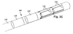
リード100がリング電極120とセグメント電極130の両方を含む場合に、リング電極120及びセグメント電極130は、任意適当な形態で配置することができる。例えば、リード100が2つのリング電極120とセグメント電極130の2つのセットとを含む場合に、リング電極120は、セグメント電極130の2つのセットの両側を挟むことができる(例えば、図1、並びに図3A及び図3E〜図3Hのリング電極320及びセグメント電極330を参照されたい)。これに代えて、リング電極120の2つのセットは、セグメント電極130の2つのセットに対して近位に配置するか(例えば、図3Cのリング電極320及びセグメント電極330を参照されたい)、又はリング電極120の2つのセットをセグメント電極130の2つのセットに対して遠位に配置することができる(図3Dのリング電極320及びセグメント電極330を参照されたい)。リング電極の一方は、先端電極とすることができる(図3E及び図3Gの先端電極320aを参照されたい)。他の形態(例えば、交替するリング電極とセグメント電極など)も可能であることを理解すべきである。 When the
セグメント電極130の位置を変更することにより、ターゲット神経細胞の異なるカバレージを選択することができる。例えば、図3Cの電極配置は、神経ターゲットがリード本体110の遠位先端の近くになることを医師が予想した場合に有用とすることができ、一方、図3Dの電極配置は、神経ターゲットがリード本体110の近位端部の近くになることを医師が予想した場合に有用である。 By changing the position of the
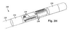
リード100上には、リング電極120とセグメント電極130の任意の組合せを配置することができる。例えば、リードは、最初のリング電極120と、各々が4つのセグメント電極130で形成された2つのセグメント電極セットと、リードの端部にある最終リング電極120とを含むことができる。この構成を単純に1−4−4−1形態と記す場合がある(図3A及び図3Eのリング電極320及びセグメント電極330)。電極をこの簡略表記で記すことが有用な場合がある。従って、図3Cの実施形態を1−1−4−4形態と記す場合があり、一方、図3Dの実施形態を4−4−1−1形態と記す場合がある。図3F、図3G、及び図3Hの実施形態は、1−3−3−1形態と記すことができる。他の電極形態は、例えば、4つのセグメント電極セットがリード上に配置された2−2−2−2形態、及び4つのセグメント電極130を各々が有する2つのセグメント電極セットがリード上に配置された4−4形態を含む。図3F、図3G、及び図3Hの1−3−3−1電極形態は、各々がリードの外周の周りに配置された3つの電極を含み、2つのリング電極によって両側が挟まれた((図3F及び図3H)、又はリング電極と先端電極とによって両側が挟まれた(図3G)2つのセグメント電極セットを有する。いくつかの実施形態では、リードは16個の電極を含む。16個の電極リードに対して可能な形態は、4−4−4−4、8−8、3−3−3−3−3−1(及びこの形態の全ての再配置)、及び2−2−2−2−2−2−2−2を含むことができるが、これらに限定されない。 An arbitrary combination of the
図2は、リード200の長さに沿う様々な電極レベルに沿った半径方向電流ステアリングを示す概略図である。リング電極を有する従来のリード形態は、リードの長さ(z軸)に沿って電流をステアリングすることしかできないが、セグメント電極形態は、電流をx軸、y軸、並びにz軸においてステアリングすることができる。従って、刺激の重心をリード200を取り囲む3次元空間内のあらゆる方向にステアリングすることができる。いくつかの実施形態では、半径距離r及びリード200の外周の周りの角度θは、各電極に導入されるアノード電流の百分率によって決定付けることができる(刺激は、主としてカソードの近くで発生するが、強いアノードも同じく刺激を引起こす場合があることを認識した上で)。少なくともいくつかの実施形態では、セグメント電極に沿ったアノード及びカソードの形態により、刺激重心をリード200に沿う様々な異なる場所にシフトさせることが可能になる。 FIG. 2 is a schematic diagram illustrating radial current steering along various electrode levels along the length of the
図2から分るように、刺激重心をリード200の長さに沿う各レベルにシフトさせることができる。リードの長さに沿う異なるレベルでの複数のセグメント電極セットの使用は、3次元電流ステアリングを可能にする。いくつかの実施形態では、セグメント電極セットは、互いにシフトされる(すなわち、刺激重心は、リードの長さに沿う各レベルで同様である)。少なくともいくつかの他の実施形態では、各セグメント電極セットは、独立して制御される。各セグメント電極セットは、2つ、3つ、4つ、5つ、6つ、7つ、8つ、又はそれよりも多いセグメント電極を含むことができる。各レベルにおけるセグメント電極の個数を変更することにより、異なる刺激分布を生成することができることを理解すべきである。例えば、各セグメント電極セットが2つのセグメント電極のみを含む場合に、刺激分布内に均一に分散された隙間(選択的に刺激することが不能)を形成することができる。いくつかの実施形態では、真の360°選択性を可能にするために、セット内の少なくとも3個のセグメント電極230が利用される。 As can be seen from FIG. 2, the stimulation centroid can be shifted to each level along the length of the
上述したように、上述の形態は、記録電極を利用しながら使用することができる。いくつかの実施形態では、ターゲット神経細胞による刺激を受ける筋肉又はその他の組織に結合された測定デバイス、又は患者又は臨床医に応答するユニットを制御ユニット又はマイクロドライブモータシステムに結合することができる。ターゲット神経細胞をより詳しく識別し、刺激電極の位置決めを容易にするために、測定デバイス、ユーザ、又は臨床医は、ターゲット筋肉又はその他の組織による刺激電極又は記録電極への応答を示すことができる。例えば、ターゲット神経細胞が、振戦に罹患した筋肉に向けられる場合に、筋肉を観察し、神経細胞の刺激に応答する振戦の周波数及び振幅の変化を示すための測定デバイスを使用することができる。これに代えて、患者又は臨床医が筋肉を観察してフィードバックを与えることができる。 As described above, the above-described embodiment can be used while using the recording electrode. In some embodiments, a measurement device coupled to muscle or other tissue that is stimulated by a target neuron, or a unit that responds to a patient or clinician can be coupled to a control unit or microdrive motor system. In order to better identify the target nerve cell and facilitate the positioning of the stimulation electrode, the measurement device, user, or clinician can show the response to the stimulation or recording electrode by the target muscle or other tissue . For example, when a target nerve cell is directed to a muscle affected by tremor, using the measurement device to observe the muscle and to show changes in tremor frequency and amplitude in response to nerve cell stimulation it can. Alternatively, the patient or clinician can observe the muscle and provide feedback.
リードの信頼性及び耐久性は、設計及び製造方法に重度に依存することになる。以下に解説する製作技術は、製造可能性及び信頼性の高いリードを生産することができる方法を提供する。 Lead reliability and durability will depend heavily on the design and manufacturing method. The fabrication techniques described below provide a method that can produce leads that are highly manufacturable and reliable.
図1を参照すると、リード100がセグメント電極130の複数のセットを含む場合に、セグメント電極130の異なるセットの対応する電極が、リード100の長さに沿って互いに半径方向に整列するようにリード100を形成することが望ましい場合がある(例えば、図1に示すセグメント電極130を参照されたい)。リード100の長さに沿ったセグメント電極130の異なるセットの対応する電極の間の半径方向の整列は、異なるセグメント電極セットの対応するセグメント電極の間の場所又は向きに関する不定性を低減することができる。従って、リード100の長さに沿う異なるセグメント電極セットの対応する電極が、互いに半径方向に整列し、リード100の製造中に互いに対して半径方向からシフトしないように電極アレイを形成することが有益である。 Referring to FIG. 1, when the
他の実施形態では、セグメント電極130の2つのセット内の個々の電極は、リード本体110の長さに沿って互いに対して交互配置される(図3Bを参照されたい)。一部の場合に、リード100の長さに沿う異なるセグメント電極セットの対応する電極の交互配置による位置決めを特定の用途に向けて設計することができる。 In other embodiments, the individual electrodes in the two sets of
セグメント電極は、リング電極を使用する場合に達成されることになるリードの外周の周りの組織を刺激することに代わって、刺激領域を明示的にターゲット化することができるように刺激領域を調整するために使用することができる。一部の事例では、図2に示すように、リード200の電極を含む平行六面体(又はスラブ)領域250をターゲットにすることが望ましい。平行六面体領域内に刺激場を向けるための1つの配置は、リードの両側に配置されたセグメント電極を使用する。 Segment electrodes adjust the stimulation area so that the stimulation area can be explicitly targeted instead of stimulating the tissue around the perimeter of the lead that would be achieved when using a ring electrode Can be used to In some cases, it may be desirable to target a parallelepiped (or slab)
図3A〜図3Hは、セグメント電極330と、選択的なリング電極320又は先端電極320aと、リード本体310とを示している。セグメント電極330のセットの各々は、2つ(図3B)、3つ(図3E〜図3H)、又は4つ(図3A、図3C、及び3D)のいずれか、又は例えば3つ、5つ、6つ、又はそれよりも多くを含む任意その他の個数のセグメント電極を含む。セグメント電極330のセットは、互いに整列させるか(図3A〜図3G)又は交互配置することができる(図3H)。 3A-3H show a
セグメント電極のいずれかの他の適切な配置を使用することができる。一例として、セグメント電極が互いに対して螺旋状に配置された配置がある。1つの実施形態は、二重螺旋を含む。 Any other suitable arrangement of segment electrodes can be used. As an example, there is an arrangement in which the segment electrodes are arranged spirally with respect to each other. One embodiment includes a double helix.
セグメント電極を有するリードを作る際の1つの難問は、製造工程中及び製造後の電極の正しい配置、及び望ましい電極配置の維持である。セグメント電極及び製造方法は、これら及び他の問題に対処するように設計することができる。例えば、全てが引用によって本明細書に組み込まれている特許文献1、50〜53、並びに上記に挙げた他の特許出願は、セグメント電極及び製造方法のいくつかの例を提供している。 One challenge in making leads with segmented electrodes is the correct placement of the electrodes during and after the manufacturing process and maintaining the desired electrode placement. Segment electrodes and manufacturing methods can be designed to address these and other issues. For example, U.S. Patent Nos. 5,058,036, all incorporated herein by reference, and the other patent applications listed above provide some examples of segment electrodes and manufacturing methods.
少なくともいくつかの実施形態では、セグメント電極セットは、リードに取付けられてセグメント電極と一体的な連結材料の外側リングによって互いに結合されたセグメント電極の各々を収容するプレ電極を与えることによって生成される。リード本体がプレ電極の周りに形成されると、この外側リングは除去され、個々のセグメント電極が解放されて分離される。 In at least some embodiments, the segment electrode set is generated by providing a pre-electrode that accommodates each of the segment electrodes attached to the leads and joined together by an outer ring of connecting material integral with the segment electrode. . When the lead body is formed around the pre-electrode, this outer ring is removed and the individual segment electrodes are released and separated.
半径方向に配置されたセグメント電極セットをプレ電極から形成することができる。図4A〜図7は、プレ電極及びプレ電極から形成された(例えば、プレ電極を研削して電気絶縁セグメント電極を形成することにより)セグメント電極セットの実施形態を示している。プレ電極及びそれから形成されたセグメント電極は、金属、合金、導電性酸化物、又は任意その他の適切な導電材料等の導体で形成することができる。いくつかの実施形態では、プレ電極は、プラチナ、プラチナ−イリジウム、イリジウム、616Lステンレス鋼(又は任意その他の適切なステンレス鋼)、タンタル、ニチノール、イリジウム−ロジウム、又は導電性ポリマーで形成される。 A radially arranged segment electrode set can be formed from pre-electrodes. 4A-7 illustrate an embodiment of a segment electrode set formed from a pre-electrode and a pre-electrode (eg, by grinding the pre-electrode to form an electrically insulating segment electrode). The pre-electrode and the segment electrode formed therefrom can be formed of a conductor such as a metal, alloy, conductive oxide, or any other suitable conductive material. In some embodiments, the pre-electrode is formed of platinum, platinum-iridium, iridium, 616L stainless steel (or any other suitable stainless steel), tantalum, nitinol, iridium-rhodium, or a conductive polymer.
いくつかの実施形態では、プレ電極は実質的に円筒形であり、リードの望ましい最終直径よりも大きい直径を有する。円筒形断面輪郭を有するリードは、プレ電極の外面を研削(例えば、心なし研削)、機械加工、エッチング、又は切除することによって達成することができる。研削は、個々のセグメント電極を解放することができる。図4A〜図7には、各プレ電極から形成される3つのセグメント電極を示している。プレ電極の他の実施形態は、2つ、4つ、5つ、6つ、7つ、8つ、又はそれよりも多いセグメント電極を有することを認識すべきである。 In some embodiments, the pre-electrode is substantially cylindrical and has a diameter that is larger than the desired final diameter of the lead. A lead having a cylindrical cross-sectional profile can be achieved by grinding (eg, centerless grinding), machining, etching, or ablating the outer surface of the pre-electrode. Grinding can release the individual segment electrodes. 4A to 7 show three segment electrodes formed from the respective pre-electrodes. It should be appreciated that other embodiments of the pre-electrode have two, four, five, six, seven, eight, or more segment electrodes.
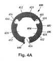
図4A〜図4Cは、内面404と外面406とを有する本体402を有するプレ電極400の1つの実施形態を示している。図4Aは、プレ電極の横断面図であり、図4Bは、プレ電極の斜視図を示しており、図4Cは、プレ電極の側面図である。プレ電極400の本体402は実質的に円筒形であり、プレ電極400は、その上に配置されるリードの望ましい最終直径よりも大きい直径を有する。 FIGS. 4A-4C illustrate one embodiment of a pre-electrode 400 having a body 402 having an inner surface 404 and an
本体402は、プレ電極400を視覚的に整列させるために、又はプレ電極の周りにリード本体を形成するために内部にプレ電極が配置されるモールド内の対応するレール、突出部などの上にプレ電極を整列させるために使用することができるスリット440を外面406内に定める。スリット440は、プレ電極400の長手全長を延びるか、又はプレ電極400の少なくとも一端から延びる。図4A〜図4Cの実施形態では、スリット400は、更に本体402の外面406から本体の内面404まで延びる。しかし、他の実施形態では、スリットは、必ずしも本体の内面まで延び切るとは限らず、プレ電極の本体の外面内に溝を形成することができることを理解すべきである。 The body 402 is over a corresponding rail, protrusion, etc. in the mold in which the pre-electrode is placed to visually align the pre-electrode 400 or to form a lead body around the pre-electrode. A
プレ電極は、リード上に配置された時のプレ電極の向きによって定められる近位端部と遠位端部を有する。例えば、プレ電極がリード上に配置された時に、プレ電極の近位端部は、リードの近位端部分に最も近い。プレ電極のこの向き、並びにリード上に配置された時のプレ電極の向きは、本明細書に解説するプレ電極の各々に適用されることを理解すべきである。 The pre-electrode has a proximal end and a distal end defined by the orientation of the pre-electrode when placed on the lead. For example, when the pre-electrode is placed on the lead, the proximal end of the pre-electrode is closest to the proximal end portion of the lead. It should be understood that this orientation of the pre-electrode, as well as the orientation of the pre-electrode when placed on the lead, applies to each of the pre-electrodes described herein.
プレ電極400は、連結材料414によって接合された個々のセグメント電極412を含む。連結材料414は、プレ電極がリード上に配置された状態にある時に、分離されたセグメント電極412が残るように除去することができる(例えば、連結材料414を研削、機械加工、エッチング、アブレーション、又はその他の仕方で除去することにより)。 The pre-electrode 400 includes
プレ電極400は、一般的に特定のセグメント電極セットのセグメント電極の間の間隔を定める切欠き416を個々のセグメント電極の間に有する。連結材料414は、セグメント電極412と、プレ電極400のうちでセグメント電極の上に配置された部分との間の材料に対応する。少なくともいくつかの実施形態では、連結材料414は、セグメント電極下部を解放するように研削除去される材料の外側リングを形成する。切欠きは、リード本体(例えば、セグメント電極セットの間、又はセグメント電極セットとリング電極の間に配置されたスペーサを含む)からの材料のような材料を切欠きに配置するか又は流し入れることを可能にすることによってリード保持特徴部として機能することができる。切欠き内の材料は、セグメント電極の位置及び間隔の持続を容易にすることができる。 The pre-electrode 400 generally has
切欠き416は、プレ電極400の内面404の隣接した部分の間に延びる周面を有する。周面は、連続又は不連続とすることができる。各切欠きは、2つのセグメント電極に当接し、周面の一部分は、2つのセグメント電極の側壁を形成する。少なくともいくつかの実施形態では、切欠きのうちの少なくとも1つの周面は、切欠きに当接するセグメント電極のうちの少なくとも一方の側壁の少なくとも一部分に沿って1つ又は2つ以上の開放キャビティ(例えば、凹陥、ノッチ、間隔、陥没、空所など、又はその組合せ)が形成されるように成形される。切欠き416は、様々な異なる形状及び配置を有することができる。切欠き416に対する他の形状及び配置の例は、特許文献1、50〜53に見出すことができ、これらの特許文献を本明細書に援用する。 The
プレ電極400は、セグメント電極412内に形成された1つ又は2つ以上のチャネル428を更に含む。セグメント電極の各々内に形成された1つ、2つ、3つ、4つ、又はそれよりも多いチャネルを存在させることができる。各セグメント電極内のチャネルの個数は、他のセグメント電極内のチャネルの個数と同じか又は異なるとすることができる。チャネル428は、セグメント電極412への導体の取付けに対して特に有用である。少なくともいくつかの実施形態では、1つ又は2つ以上のチャネルは、本体402の内面404に沿って定められる。図4Aでは、1つ又は2つ以上のチャネル428は、弧状の横断面形状を有する。チャネル428は、様々な異なる形状及び配置を有することができる。チャネル428に対する他の形状及び配置の例は、特許文献1、50〜53に見出すことができ、これらの特許文献を本明細書に援用する。 The pre-electrode 400 further includes one or
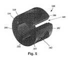
図5は、内面504と外面506とを有する本体502を有するプレ電極の別の実施形態500を示している。プレ電極500は、連結材料514によって接合されたセグメント電極512、並びに切欠き516、チャネル528、及びスリット540を更に含む。これらの要素の全て、及びこれらの要素に対する設計要件は、図4A〜図4Cに図示の実施形態の対応する(同様に命名した)要素と同じである。 FIG. 5 shows another embodiment of a pre-electrode 500 having a body 502 having an
更に、プレ電極500は、その外面506内に1つ又は2つ以上の凹部542(「ポケット」とも呼ぶ)を含む。少なくともいくつかの実施形態では、各凹部542は、セグメント電極512のうちの1つ又は2つ以上の上に配置される。いくつかの実施形態では、プレ電極のセグメント電極512の各々の上に配置された異なる凹部542が存在する。凹部542は、プレ電極500の外面542内の凹み、窪み、凹所、陥没、又は切欠きとすることができ、モールド成形、フライス、アブレーションなどを含むがこれらに限定されないあらゆる適切な方法によって形成することができる。凹部542は、任意の形状を取ることができる。図5の例示実施形態では、凹部542は円形の横断面を有するが、正方形、矩形、三角形、又はその他の規則的又は不規則な形状を含む他の横断面形状を使用することができる。図示の実施形態では、凹部542は、一端において丸み付き縁部を有する円筒形であるが、立方体、平行六面体、ピラミッド形、又はその他の規則的又は不規則な形状を含むがこれらに限定されない他の3次元形状を使用することができ、丸み付き縁部を有する1つ又は2つ以上の端部を有しても持たなくてもよい。 Further, the pre-electrode 500 includes one or more recesses 542 (also referred to as “pockets”) in its
凹部542は、プレ電極500又はそれに結合されたセグメント電極512の内面504への導体(図示せず)の溶接を容易にすることができる。凹部542におけるプレ電極500の厚みは、プレ電極の隣接した部分よりも小さく、導体を取付けるのに溶接器具による加熱をそれ程必要とせず、それによって製造の速度を促進し、製造の欠陥又は不良を低減することができる。 The recess 542 can facilitate welding of a conductor (not shown) to the pre-electrode 500 or the
少なくともいくつかの実施形態では、凹部542は、セグメント電極512の上に配置されるが、その中に延びることはない。これらの実施形態では、凹部542は、製造中に個々のセグメント電極を解放するために除去されることになるセグメント電極512の上に配置された連結材料512内に全体が配置される。他の実施形態では、凹部542は、セグメント電極512内に途中まで延びることができる。 In at least some embodiments, the recess 542 is disposed over the segment electrode 512 but does not extend into it. In these embodiments, the recesses 542 are disposed entirely within the connecting material 512 disposed over the segment electrodes 512 that will be removed to release the individual segment electrodes during manufacture. In other embodiments, the recess 542 can extend partway into the segment electrode 512.
いくつかの実施形態では、外面506上の1つ又は2つ以上の凹部542は、プレ電極500を視覚的に整列させるために、又はプレ電極の周りにリード本体を形成するために内部にプレ電極が配置されるモールド内の対応する突出部などの上にプレ電極を整列させるために使用することができる。 In some embodiments, one or more recesses 542 on the
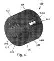
図6は、内面604と外面606とを有する本体602を有するプレ電極の別の実施形態600を示している。更に、プレ電極600は、連結材料614によって接合されたセグメント電極612、並びに切欠き616及びチャネル628を含む。これらの要素の全て及びこれらの要素に対する設計要件は、図4A〜図4Cに図示の実施形態の対応する(同様に命名した)要素と同じである。 FIG. 6 illustrates another
プレ電極600は、本体602の外面606内にセグメント電極612の間の連結材料614を貫通して延びる少なくとも1つの孔644を含む。孔644は、図6に示すように、切欠き616のうちの1つに整列させることができる。 The pre-electrode 600 includes at least one
孔644は、プレ電極400のスリット440とは対照的に、プレ電極600の遠位端部又は近位端部のいずれにも延びない。孔644のそれぞれの長手端部には、第1の孔境界部646aと第2の孔境界部646bが配置される。第1の孔境界部646a及び第2の孔境界部646bは、プレ電極600の本体602の一部であり、連結材料614で形成される。少なくともいくつかの実施形態では、孔644は、連結材料だけを貫通して延びる。少なくともいくつかの実施形態では、図6に示すように、孔644は、本体602の外面606において、その全ての辺の境界部が連結材料614によって定められる。 The
少なくともいくつかの実施形態では、プレ電極600は、少なくとも部分的に第1の孔境界部646a及び第2の孔境界部646bに起因して製造中に少なくとも連結材料614が除去されるまでは円筒形形状を維持することになるので、スリット440(図4A)の代わりに孔644を使用することを有用である。それとは対照的に、スリット440の境界を定めるプレ電極400の対抗する面は、製造中に更に分離してスリット440を拡幅する可能性があり、それによって最終リード製品に欠陥がもたらされる場合がある。プレ電極600では、第1の孔境界部646a及び第2の孔境界部646bは、製造中に孔644が拡幅することを防止する。 In at least some embodiments, the pre-electrode 600 is cylindrical until at least partially the connecting
外面606内の孔644は、プレ電極600を視覚的に整列させるために、又はプレ電極の周りにリード本体を形成するために内部にプレ電極が配置されるモールド内の対応する突出部などの上にプレ電極を整列させるために使用することができる。図6の実施形態では、孔644は、更に本体602の外面606から本体の内面604まで延びる。他の実施形態では、孔は必ずしも本体の内面まで延び切るとは限らないことを理解すべきである。 The
図7は、内面704と外面706とを有する本体702を有するプレ電極の別の実施形態700を示している。プレ電極700は、連結材料714によって接合されたセグメント電極712、並びに切欠き716、チャネル728、1つ又は2つ以上の凹部742、孔744、並びに第1の孔境界部及び第2の孔境界部746a、746bを更に含む。これらの要素の全て及びこれらの要素に対する設計要件は、図4A〜図4C、図5、又は図6に図示の実施形態の対応する(同様に命名した)要素と同じである。 FIG. 7 illustrates another
図4A〜図7に図示の実施形態は、プレ電極の例である。しかし、凹部と、スリットと、孔とのいずれかの組合せを用いて他のプレ電極を形成することができることを理解すべきである。例えば、図4A〜図4Cの実施形態は、図5の凹部542と類似の1つ又は2つ以上の凹部を追加するように修正することができる。いかなるスリット又は孔も用いずに1つ又は2つ以上の凹部を用いて他のプレ電極を形成することができることも理解すべきである。更に、全てが引用によって組み込まれている特許文献1、50〜53に記載されているように、1つ又は2つ以上の凹部(例えば、図5の凹部542)、1つ又は2つ以上の孔(例えば、図6の孔644)、又はこれらの両方をプレ電極の外側に配置された1つ又は2つ以上のノッチ又は溝などのような他のプレ電極特徴部と併用することができる。 The embodiment illustrated in FIGS. 4A-7 is an example of a pre-electrode. However, it should be understood that any combination of recesses, slits, and holes can be used to form other pre-electrodes. For example, the embodiment of FIGS. 4A-4C can be modified to add one or more recesses similar to the recess 542 of FIG. It should also be understood that other pre-electrodes can be formed using one or more recesses without any slits or holes. Further, one or more recesses (eg, recess 542 in FIG. 5), one or more than one, as described in US Pat. A hole (eg,
上述の仕様、例、及びデータは、本発明の構成物の製造及び使用の説明を提供するものである。本発明の多くの実施形態を本発明の精神及び範囲から逸脱することなく生成することができるので、本発明はまた、以下に添付する特許請求の範囲内に存する。 The above specifications, examples and data provide an explanation of the manufacture and use of the composition of the invention. Since many embodiments of the invention can be made without departing from the spirit and scope of the invention, the invention also resides in the claims hereinafter appended.
Claims (15)
Translated fromJapaneseほぼ円筒形の本体を有し、
前記本体は、外面と、前記外面の反対側の内面と、近位端部と、遠位端部と、複数のセグメント電極と、連結材料と、複数の切欠きと、を含み、
前記複数のセグメント電極は、前記本体に沿って離間した形態で配置され、前記複数のセグメント電極の各々は、前記本体の近位端部と遠位端部の間に延びる両側の側壁を有し、
前記連結材料は、前記複数のセグメント電極の各々を互いに結合して、前記本体の外面を形成し、
前記複数の切欠きは、前記複数のセグメント電極のうちの隣接したセグメント電極の間に配置され、
前記複数のセグメント電極のセグメント電極ごとに、前記本体は更に、凹部を前記プレ電極の外面に且つ前記セグメント電極の上に有し、前記プレ電極の前記凹部のところは、それにすぐ隣接した前記プレ電極の部分よりも薄い、プレ電極。A pre-electrode for the stimulation lead,
Has a substantially cylindrical body,
The body includes an outer surface, an inner surface opposite the outer surface, a proximal end, a distal end, a plurality of segment electrodes, a connecting material, and a plurality of notches;
The plurality of segment electrodes are spaced apart along the body, each of the plurality of segment electrodes having side walls on both sides extending between a proximal end and a distal end of the body. ,
The connecting material combines each of the plurality of segment electrodes to form an outer surface of the main body,
The plurality of notches are disposed between adjacent segment electrodes of the plurality of segment electrodes,
For each segment electrode of the plurality of segment electrodes, the body further has a recess on an outer surface of the pre-electrode and on the segment electrode, and the recess of the pre-electrode is located immediately adjacent to the pre-electrode. Pre-electrode thinner than the electrode part.
請求項1〜5のいずれか1項に記載のプレ電極をリード本体の遠位端部分に沿って配置する段階と、
リード本体を前記プレ電極の周りに形成する段階と、
連結材料を前記プレ電極から除去して、セグメント電極を解放する段階と、を含む方法。A method of making a stimulation lead,
Disposing the pre-electrode according to any one of claims 1 to 5 along the distal end portion of the lead body;
Forming a lead body around the pre-electrode;
Removing the connecting material from the pre-electrode to release the segment electrode.
各導体は、前記セグメント電極のうちの1つとその反対側に位置する前記凹部うちの1つとに対応する前記プレ電極の内面の一部分に取付けられる、請求項6に記載の方法。Prior to the step of removing the connecting material, further comprising attaching a conductor to the segment electrode;
7. A method according to claim 6, wherein each conductor is attached to a portion of the inner surface of the pre-electrode corresponding to one of the segment electrodes and one of the recesses located on the opposite side.
ほぼ円筒形の本体を有し、
前記本体は、外面と、前記外面の反対側の内面と、近位端部と、遠位端部と、複数のセグメント電極と、連結材料と、複数の切欠きと、を有し、
前記複数のセグメント電極は、前記本体に沿って離間した形態で配置され、前記複数のセグメント電極の各々は、前記本体の近位端部と遠位端部の間に延びる両側の側壁を有し、
前記連結材料は、前記複数のセグメント電極の各々を互いに結合し、前記本体の外面を形成し、
前記複数の切欠きは、前記複数のセグメント電極のうちの隣接したセグメント電極の間に配置され、
前記本体は、少なくとも1つの孔を有し、前記孔は、前記外面から前記本体内に前記セグメント電極のうちの2つの間に延び、前記連結材料の複数の部分は、前記孔と前記プレ電極の近位端部及び遠位端部との間にそれぞれ、第1の孔境界部及び第2の孔境界部を形成する、プレ電極。A pre-electrode for the stimulation lead,
Has a substantially cylindrical body,
The body includes an outer surface, an inner surface opposite to the outer surface, a proximal end, a distal end, a plurality of segment electrodes, a connecting material, and a plurality of notches;
The plurality of segment electrodes are spaced apart along the body, each of the plurality of segment electrodes having side walls on both sides extending between a proximal end and a distal end of the body. ,
The connecting material couples each of the plurality of segment electrodes to form an outer surface of the main body,
The plurality of notches are disposed between adjacent segment electrodes of the plurality of segment electrodes,
The body has at least one hole, the hole extending from the outer surface into the body between two of the segment electrodes, and a plurality of portions of the connecting material comprising the hole and the pre-electrode A pre-electrode forming a first hole boundary and a second hole boundary between the proximal end and the distal end of the first electrode, respectively.
請求項9〜13のいずれか1項に記載のプレ電極をリード本体の遠位端部分に沿って配置する段階と、
リード本体を前記プレ電極の周りに形成する段階と、
前記連結材料を前記プレ電極から除去して、前記セグメント電極を解放する段階と、を含む方法。A method of making a stimulation lead,
Disposing the pre-electrode according to any one of claims 9 to 13 along the distal end portion of the lead body;
Forming a lead body around the pre-electrode;
Removing the connecting material from the pre-electrode to release the segment electrode.
Applications Claiming Priority (5)
| Application Number | Priority Date | Filing Date | Title |
|---|---|---|---|
| US201361829918P | 2013-05-31 | 2013-05-31 | |
| US61/829,918 | 2013-05-31 | ||
| US201461981606P | 2014-04-18 | 2014-04-18 | |
| US61/981,606 | 2014-04-18 | ||
| PCT/US2014/039423WO2014193758A1 (en) | 2013-05-31 | 2014-05-23 | Segmented electrode leads formed from pre-electrodes with depressions or apertures and methods of making |
Publications (1)
| Publication Number | Publication Date |
|---|---|
| JP2016519984Atrue JP2016519984A (en) | 2016-07-11 |
Family
ID=50972807
Family Applications (1)
| Application Number | Title | Priority Date | Filing Date |
|---|---|---|---|
| JP2016516705APendingJP2016519984A (en) | 2013-05-31 | 2014-05-23 | Segment electrode lead formed from a pre-electrode having a recess or a hole, and a method for manufacturing the same |
Country Status (7)
| Country | Link |
|---|---|
| US (1) | US9248272B2 (en) |
| EP (1) | EP3003465A1 (en) |
| JP (1) | JP2016519984A (en) |
| CN (1) | CN105246542A (en) |
| AU (1) | AU2014274412A1 (en) |
| CA (1) | CA2911389A1 (en) |
| WO (1) | WO2014193758A1 (en) |
Families Citing this family (122)
| Publication number | Priority date | Publication date | Assignee | Title |
|---|---|---|---|---|
| US7860570B2 (en) | 2002-06-20 | 2010-12-28 | Boston Scientific Neuromodulation Corporation | Implantable microstimulators and methods for unidirectional propagation of action potentials |
| US8321025B2 (en) | 2006-07-31 | 2012-11-27 | Cranial Medical Systems, Inc. | Lead and methods for brain monitoring and modulation |
| CA2732309C (en) | 2008-07-30 | 2018-04-10 | Ecole Polytechnique Federale De Lausanne (Epfl) | Apparatus and method for optimized stimulation of a neurological target |
| JP5667987B2 (en) | 2008-11-12 | 2015-02-12 | エコーレ ポリテクニーク フェデラーレ デ ローザンヌ (イーピーエフエル) | Micromachined nerve stimulation device |
| CA2795159C (en) | 2010-04-01 | 2020-11-03 | Ecole Polytechnique Federale De Lausanne | Device for interacting with neurological tissue and methods of making and using the same |
| US9919148B2 (en) | 2012-05-25 | 2018-03-20 | Boston Scientific Neuromodulation Corporation | Distally curved electrical stimulation lead and methods of making and using |
| US20140277267A1 (en) | 2013-03-15 | 2014-09-18 | Boston Scientific Neuromodulation Corporation | Neuromodulation system and method for transitioning between programming modes |
| WO2014186122A2 (en) | 2013-05-15 | 2014-11-20 | Boston Scientific Neuromodulation Corporation | Systems and methods for making and using tip electrodes for leads of electrical stimulation systems |
| WO2015084745A1 (en) | 2013-12-02 | 2015-06-11 | Boston Scientific Neuromodulation Corporation | Electrical stimulation leads with helically arranged electrodes and methods for their manufacture |
| WO2015173787A1 (en) | 2014-05-16 | 2015-11-19 | Aleva Neurotherapeutics Sa | Device for interacting with neurological tissue and methods of making and using the same |
| US11311718B2 (en) | 2014-05-16 | 2022-04-26 | Aleva Neurotherapeutics Sa | Device for interacting with neurological tissue and methods of making and using the same |
| WO2015192058A1 (en) | 2014-06-13 | 2015-12-17 | Boston Scientific Neuromodulation Corporation | Leads with electrode carriers for segmented electrodes and methods of making and using |
| US9474894B2 (en) | 2014-08-27 | 2016-10-25 | Aleva Neurotherapeutics | Deep brain stimulation lead |
| US9925376B2 (en) | 2014-08-27 | 2018-03-27 | Aleva Neurotherapeutics | Treatment of autoimmune diseases with deep brain stimulation |
| US9770598B2 (en) | 2014-08-29 | 2017-09-26 | Boston Scientific Neuromodulation Corporation | Systems and methods for making and using improved connector contacts for electrical stimulation systems |
| US9974959B2 (en) | 2014-10-07 | 2018-05-22 | Boston Scientific Neuromodulation Corporation | Systems, devices, and methods for electrical stimulation using feedback to adjust stimulation parameters |
| US9561362B2 (en) | 2014-11-10 | 2017-02-07 | Boston Scientific Neuromodulation Corporation | Systems and methods for making and using improved contact arrays for electrical stimulation systems |
| US9604068B2 (en) | 2014-11-10 | 2017-03-28 | Boston Scientific Neuromodulation Corporation | Systems and methods for making and using improved connector contacts for electrical stimulation systems |
| EP3229891B1 (en) | 2015-02-06 | 2019-08-14 | Boston Scientific Neuromodulation Corporation | Systems with improved contact arrays for electrical stimulation systems |
| WO2016164361A1 (en) | 2015-04-10 | 2016-10-13 | Boston Scientific Neuromodulation Corporation | Systems and methods for making and using improved contact arrays for electrical stimulation systems |
| ES2940303T3 (en) | 2015-06-29 | 2023-05-05 | Boston Scient Neuromodulation Corp | Stimulation parameter selection systems by use of targets and direction |
| EP3280490B1 (en) | 2015-06-29 | 2021-09-01 | Boston Scientific Neuromodulation Corporation | Systems for selecting stimulation parameters based on stimulation target region, effects, or side effects |
| US9656093B2 (en) | 2015-07-16 | 2017-05-23 | Boston Scientific Neuromodulation Corporation | Systems and methods for making and using connector contact arrays for electrical stimulation systems |
| WO2017035158A1 (en) | 2015-08-24 | 2017-03-02 | Boston Scientific Neuromodulation Corporation | Systems and methods for determining orientation of an electrical stimulation lead |
| WO2017040573A1 (en) | 2015-09-01 | 2017-03-09 | Boston Scientific Neuromodulation Corporation | Detection of lead orientation |
| US9956394B2 (en) | 2015-09-10 | 2018-05-01 | Boston Scientific Neuromodulation Corporation | Connectors for electrical stimulation systems and methods of making and using |
| US10413737B2 (en) | 2015-09-25 | 2019-09-17 | Boston Scientific Neuromodulation Corporation | Systems and methods for providing therapy using electrical stimulation to disrupt neuronal activity |
| WO2017062378A1 (en) | 2015-10-09 | 2017-04-13 | Boston Scientific Neuromodulation Corporation | System and methods for clinical effects mapping for directional stimulations leads |
| US10342983B2 (en) | 2016-01-14 | 2019-07-09 | Boston Scientific Neuromodulation Corporation | Systems and methods for making and using connector contact arrays for electrical stimulation systems |
| US10335607B2 (en) | 2016-02-05 | 2019-07-02 | Boston Scientific Neuromodulation Corporation | Implantable optical stimulation lead and methods of making and using |
| US10814127B2 (en) | 2016-02-05 | 2020-10-27 | Boston Scientific Neuromodulation Corporation | Slotted sleeve neurostimulation device |
| EP3389763B1 (en) | 2016-02-19 | 2023-06-28 | Boston Scientific Neuromodulation Corporation | Electrical stimulation cuff devices and systems |
| US10716942B2 (en) | 2016-04-25 | 2020-07-21 | Boston Scientific Neuromodulation Corporation | System and methods for directional steering of electrical stimulation |
| WO2017201058A1 (en) | 2016-05-17 | 2017-11-23 | Boston Scientific Neuromodulation Corporation | Systems and methods for anchoring a lead for neurostimulation of a target anatomy |
| US10493269B2 (en) | 2016-06-02 | 2019-12-03 | Boston Scientific Neuromodulation Corporation | Leads for electrostimulation of peripheral nerves and other targets |
| US10201713B2 (en) | 2016-06-20 | 2019-02-12 | Boston Scientific Neuromodulation Corporation | Threaded connector assembly and methods of making and using the same |
| EP3458152B1 (en) | 2016-06-24 | 2021-04-21 | Boston Scientific Neuromodulation Corporation | Systems and methods for visual analytics of clinical effects |
| US10307602B2 (en) | 2016-07-08 | 2019-06-04 | Boston Scientific Neuromodulation Corporation | Threaded connector assembly and methods of making and using the same |
| WO2018022460A1 (en) | 2016-07-29 | 2018-02-01 | Boston Scientific Neuromodulation Corporation | Systems and methods for making and using an electrical stimulation system for peripheral nerve stimulation |
| US10780274B2 (en) | 2016-08-22 | 2020-09-22 | Boston Scientific Neuromodulation Corporation | Systems and methods for delivering spinal cord stimulation therapy |
| US10912475B2 (en)* | 2016-08-24 | 2021-02-09 | Biosense Webster (Israel) Ltd | Catheter with split electrode sleeve and related methods |
| WO2018044881A1 (en) | 2016-09-02 | 2018-03-08 | Boston Scientific Neuromodulation Corporation | Systems and methods for visualizing and directing stimulation of neural elements |
| US10780282B2 (en) | 2016-09-20 | 2020-09-22 | Boston Scientific Neuromodulation Corporation | Systems and methods for steering electrical stimulation of patient tissue and determining stimulation parameters |
| US10543374B2 (en) | 2016-09-30 | 2020-01-28 | Boston Scientific Neuromodulation Corporation | Connector assemblies with bending limiters for electrical stimulation systems and methods of making and using same |
| US10525257B2 (en) | 2016-10-14 | 2020-01-07 | Boston Scientific Neuromodulation Corporation | Orientation marker for implantable leads and leads, systems, and methods utilizing the orientation marker |
| ES2869184T3 (en) | 2016-10-14 | 2021-10-25 | Boston Scient Neuromodulation Corp | Systems to determine in closed loop the configuration of the stimulation parameters of an electrical stimulation system |
| US10625072B2 (en) | 2016-10-21 | 2020-04-21 | Boston Scientific Neuromodulation Corporation | Electrical stimulation methods with optical observation and devices therefor |
| US10716935B2 (en) | 2016-11-04 | 2020-07-21 | Boston Scientific Neuromodulation Corporation | Electrical stimulation leads, systems and methods for stimulation of dorsal root ganglia |
| US10603485B2 (en) | 2016-11-28 | 2020-03-31 | Boston Scientific Neuromodulation Corporation | Features in increased surface area on neuromodulation leads |
| WO2018102773A1 (en) | 2016-12-02 | 2018-06-07 | Boston Scientific Neuromodulation Corporation | Methods and systems for selecting stimulation parameters for electrical stimulation devices |
| JP6834005B2 (en) | 2017-01-03 | 2021-02-24 | ボストン サイエンティフィック ニューロモデュレイション コーポレイション | Systems and methods for selecting MRI-matched stimulus parameters |
| US10576269B2 (en) | 2017-01-03 | 2020-03-03 | Boston Scientific Neuromodulation Corporation | Force-decoupled and strain relieving lead and methods of making and using |
| US20180193653A1 (en) | 2017-01-10 | 2018-07-12 | Boston Scientific Neuromodulation Corporation | Patterned stimulation for deep brain stimulation |
| EP3519043B1 (en) | 2017-01-10 | 2020-08-12 | Boston Scientific Neuromodulation Corporation | Systems and methods for creating stimulation programs based on user-defined areas or volumes |
| US10905871B2 (en) | 2017-01-27 | 2021-02-02 | Boston Scientific Neuromodulation Corporation | Lead assemblies with arrangements to confirm alignment between terminals and contacts |
| US10709886B2 (en) | 2017-02-28 | 2020-07-14 | Boston Scientific Neuromodulation Corporation | Electrical stimulation leads and systems with elongate anchoring elements and methods of making and using |
| US10814136B2 (en) | 2017-02-28 | 2020-10-27 | Boston Scientific Neuromodulation Corporation | Toolless connector for latching stimulation leads and methods of making and using |
| US10625082B2 (en) | 2017-03-15 | 2020-04-21 | Boston Scientific Neuromodulation Corporation | Visualization of deep brain stimulation efficacy |
| US10835739B2 (en) | 2017-03-24 | 2020-11-17 | Boston Scientific Neuromodulation Corporation | Electrical stimulation leads and systems with elongate anchoring elements and methods of making and using |
| US11357986B2 (en) | 2017-04-03 | 2022-06-14 | Boston Scientific Neuromodulation Corporation | Systems and methods for estimating a volume of activation using a compressed database of threshold values |
| US10603499B2 (en) | 2017-04-07 | 2020-03-31 | Boston Scientific Neuromodulation Corporation | Tapered implantable lead and connector interface and methods of making and using |
| US10631937B2 (en) | 2017-04-14 | 2020-04-28 | Boston Scientific Neuromodulation Corporation | Systems and methods for determining orientation of an implanted electrical stimulation lead |
| WO2019005689A1 (en) | 2017-06-26 | 2019-01-03 | Boston Scientific Neuromodulation Corporation | SYSTEMS AND METHODS FOR VISUALIZING AND CONTROLLING OPTOGENETIC STIMULATION USING OPTICAL STIMULATION SYSTEMS |
| JP6932835B2 (en) | 2017-07-14 | 2021-09-08 | ボストン サイエンティフィック ニューロモデュレイション コーポレイション | Systems and methods for estimating the clinical effects of electrical stimulation |
| US20190015660A1 (en) | 2017-07-14 | 2019-01-17 | Boston Scientific Neuromodulation Corporation | Systems and methods for planning and programming electrical stimulation |
| WO2019023067A1 (en) | 2017-07-25 | 2019-01-31 | Boston Scientific Neuromodulation Corporation | Systems and methods for making and using an enhanced connector of an electrical stimulation system |
| EP3634569A1 (en) | 2017-08-15 | 2020-04-15 | Boston Scientific Neuromodulation Corporation | Systems and methods for controlling electrical stimulation using multiple stimulation fields |
| US10953221B2 (en) | 2017-08-30 | 2021-03-23 | Medtronic, Inc. | Medical lead with segmented electrodes |
| US10639485B2 (en) | 2017-09-15 | 2020-05-05 | Boston Scientific Neuromodulation Corporation | Actuatable lead connector for an operating room cable assembly and methods of making and using |
| US11045656B2 (en) | 2017-09-15 | 2021-06-29 | Boston Scientific Neuromodulation Corporation | Biased lead connector for operating room cable assembly and methods of making and using |
| US11139603B2 (en) | 2017-10-03 | 2021-10-05 | Boston Scientific Neuromodulation Corporation | Connectors with spring contacts for electrical stimulation systems and methods of making and using same |
| JP2021502215A (en) | 2017-11-13 | 2021-01-28 | ボストン サイエンティフィック ニューロモデュレイション コーポレイション | Systems and methods for manufacturing and using flat control modules for electrical stimulation systems |
| WO2019099887A1 (en) | 2017-11-17 | 2019-05-23 | Boston Scientific Neuromodulation Corporation | Systems and methods for generating intermittent stimulation using electrical stimulation systems |
| EP3737464A1 (en) | 2018-01-11 | 2020-11-18 | Boston Scientific Neuromodulation Corporation | Methods and systems for stimulation for glial modulation |
| US11497914B2 (en) | 2018-01-16 | 2022-11-15 | Boston Scientific Neuromodulation Corporation | Systems and methods for making and using an electrical stimulation system with a case-neutral battery |
| US11103712B2 (en) | 2018-01-16 | 2021-08-31 | Boston Scientific Neuromodulation Corporation | Connector assemblies with novel spacers for electrical stimulation systems and methods of making and using same |
| US10702692B2 (en) | 2018-03-02 | 2020-07-07 | Aleva Neurotherapeutics | Neurostimulation device |
| US11058870B2 (en) | 2018-03-09 | 2021-07-13 | Boston Scientific Neuromodulation Corporation | Burr hole plugs for electrical stimulation systems and methods of making and using |
| EP3765142B1 (en) | 2018-03-16 | 2022-05-04 | Boston Scientific Neuromodulation Corporation | Kit for securing burr hole plugs for stimulation systems |
| WO2019183054A1 (en) | 2018-03-23 | 2019-09-26 | Boston Scientific Neuromodulation Corporation | Optical stimulation systems with calibration and methods of making and using |
| EP3768372A1 (en) | 2018-03-23 | 2021-01-27 | Boston Scientific Neuromodulation Corporation | An optical stimulation system with on-demand monitoring and methods of making and using |
| US11298553B2 (en) | 2018-04-27 | 2022-04-12 | Boston Scientific Neuromodulation Corporation | Multi-mode electrical stimulation systems and methods of making and using |
| EP3784332B1 (en) | 2018-04-27 | 2023-04-26 | Boston Scientific Neuromodulation Corporation | Systems for visualizing and programming electrical stimulation |
| US11172959B2 (en) | 2018-05-02 | 2021-11-16 | Boston Scientific Neuromodulation Corporation | Long, flexible sheath and lead blank and systems and methods of making and using |
| US11052259B2 (en) | 2018-05-11 | 2021-07-06 | Boston Scientific Neuromodulation Corporation | Connector assembly for an electrical stimulation system and methods of making and using |
| AU2019302442B2 (en) | 2018-07-09 | 2022-06-30 | Boston Scientific Neuromodulation Corporation | Directional electrical stimulation leads and systems for spinal cord stimulation |
| US11224743B2 (en) | 2018-09-21 | 2022-01-18 | Boston Scientific Neuromodulation Corporation | Systems and methods for making and using modular leads for electrical stimulation systems |
| WO2020102039A1 (en) | 2018-11-16 | 2020-05-22 | Boston Scientific Neuromodulation Corporation | An optical stimulation system with on-demand monitoring and methods of making |
| US11167128B2 (en) | 2018-11-16 | 2021-11-09 | Boston Scientific Neuromodulation Corporation | Directional electrical stimulation leads, systems and methods for spinal cord stimulation |
| WO2020172071A2 (en) | 2019-02-19 | 2020-08-27 | Boston Scientific Neuromodulation Corporation | Lead introducers and systems and methods including the lead introducers |
| US11357992B2 (en) | 2019-05-03 | 2022-06-14 | Boston Scientific Neuromodulation Corporation | Connector assembly for an electrical stimulation system and methods of making and using |
| US20220362560A1 (en) | 2019-10-28 | 2022-11-17 | Boston Scientific Neuromodulation Corporation | Systems and methods for measuring temperature on or near an implantable medical device |
| CA3172072A1 (en) | 2020-02-19 | 2021-08-26 | Boston Scientific Neuromodulation Corporation | Methods and systems for treatment of insomnia using deep brain stimulation |
| US11806547B2 (en) | 2020-09-04 | 2023-11-07 | Boston Scientific Neuromodulation Corporation | Stimulation systems with a lens arrangement for light coupling and methods of making and using |
| CN112274775B (en)* | 2020-09-16 | 2025-07-29 | 北京品驰医疗设备股份有限公司 | Contact structure, directional electrode assembly method and directional electrode |
| US12402004B2 (en) | 2020-11-04 | 2025-08-26 | Boston Scient ation Corporation | Methods and systems for managing access to implantable medical devices |
| EP4196208A1 (en) | 2020-11-11 | 2023-06-21 | Boston Scientific Neuromodulation Corporation | Voice command handler for programming stimulation systems and methods of using |
| JP7688170B2 (en) | 2021-02-25 | 2025-06-03 | ボストン サイエンティフィック ニューロモデュレイション コーポレイション | Method and system for deep brain stimulation of the nucleus basalis of meynert |
| WO2022216844A1 (en) | 2021-04-08 | 2022-10-13 | Boston Scientific Neuromodulation Corporation | Photobiomodulation system and delivery device |
| US12403315B2 (en) | 2021-04-27 | 2025-09-02 | Boston Scientific Neuromodulation Corporation | Systems and methods for automated programming of electrical stimulation |
| AU2022277556B2 (en) | 2021-05-21 | 2025-03-06 | Boston Scientific Neuromodulation Corporation | Electrical stimulation cuff devices and systems with helical arrangement of electrodes |
| US12403313B2 (en) | 2021-06-15 | 2025-09-02 | Boston Scientific Neuromodulation Corporation | Methods and systems for estimating neural activation by stimulation using a stimulation system |
| US12343547B2 (en) | 2021-08-19 | 2025-07-01 | Boston Scientific Neuromodulation Corporation | Connectors for an electrical stimulation system and methods of making and using |
| WO2023107457A2 (en) | 2021-12-09 | 2023-06-15 | Boston Scientific Neuromodulation Corparation | Methods and systems for monitoring or assessing movement disorders or other physiological parameters using a stimulation system |
| EP4415809A2 (en) | 2021-12-10 | 2024-08-21 | Boston Scientific Neuromodulation Corporation | Systems and methods for generating and using response maps for electrical stimulation |
| EP4475936A1 (en) | 2022-02-10 | 2024-12-18 | Boston Scientific Neuromodulation Corporation | Automatic therapy adjustment based on sensors |
| EP4440687A1 (en) | 2022-02-24 | 2024-10-09 | Boston Scientific Neuromodulation Corporation | Systems and methods for using cost parameters for programming electrical stimulation |
| WO2023167872A1 (en) | 2022-03-02 | 2023-09-07 | Boston Scientific Neuromodulation Corporation | Systems and methods for monitoring stimulation drift in an electrical stimulation system |
| EP4368242A1 (en) | 2022-11-14 | 2024-05-15 | Boston Scientific Neuromodulation Corporation | Systems and methods for generating and using stimulation programs with temporal variation |
| EP4590390A1 (en) | 2022-12-14 | 2025-07-30 | Boston Scientific Neuromodulation Corporation | Systems and methods for monitoring and revising electrical stimulation |
| EP4398258A3 (en) | 2023-01-04 | 2024-08-28 | Boston Scientific Neuromodulation Corporation | Systems and methods incorporating a light therapy user interface for optical modulation |
| WO2024226642A2 (en) | 2023-04-28 | 2024-10-31 | Boston Scientific Neuromodulation Corporation | Systems and methods for modifying stimulation in response to a change in a symptom, therapeutic effect, or side effect |
| US20250010079A1 (en) | 2023-07-06 | 2025-01-09 | Boston Scientific Neuromodulation Corporation | Systems and methods for selecting electrodes and providing stimulation |
| WO2025034507A1 (en) | 2023-08-10 | 2025-02-13 | Boston Scientific Neuromodulation Corporation | Enhancing neuromodulation for sleep |
| US20250050107A1 (en) | 2023-08-11 | 2025-02-13 | Boston Scientific Neuromodulation Corporation | Methods and systems for control and modification of stimulation |
| US20250058116A1 (en) | 2023-08-16 | 2025-02-20 | Boston Scientific Neuromodulation Corporation | Photobiomodulation of basal forebrain to improve cognition |
| WO2025038710A1 (en) | 2023-08-16 | 2025-02-20 | Boston Scientific Neuromodulation Corporation | Integration of fiber tracts into deep brain stimulation targeting |
| US20250058107A1 (en) | 2023-08-16 | 2025-02-20 | Boston Scientific Neuromodulation Corporation | Integration of related probability shells into deep brain stimulation targeting |
| US20250082938A1 (en) | 2023-09-07 | 2025-03-13 | Boston Scientific Neuromodulation Corporation | System and method for modulating neural synchrony |
| WO2025075826A1 (en) | 2023-10-02 | 2025-04-10 | Boston Scientific Neuromodulation Corporation | Lead introducers and systems including the lead introducers |
| WO2025096870A1 (en) | 2023-11-02 | 2025-05-08 | Boston Scientific Neuromodulation Corporation | Optimization of dbs program using a prespecified selection of contacts |
| US20250242159A1 (en) | 2024-01-30 | 2025-07-31 | Boston Scientific Neuromodulation Corporation | System and method for combined photobiomodulation and electrical stimulation for epilepsy |
Citations (2)
| Publication number | Priority date | Publication date | Assignee | Title |
|---|---|---|---|---|
| US20110078900A1 (en)* | 2009-07-07 | 2011-04-07 | Boston Scientific Neuromodulation Corporation | Methods for making leads with radially-aligned segmented electrodes for electrical stimulation systems |
| US20120203320A1 (en)* | 2011-02-08 | 2012-08-09 | Boston Scientific Neuromodulation Corporation | Leads with spirally arranged segmented electrodes and methods of making and using the leads |
Family Cites Families (102)
| Publication number | Priority date | Publication date | Assignee | Title |
|---|---|---|---|---|
| US4630611A (en) | 1981-02-02 | 1986-12-23 | Medtronic, Inc. | Orthogonally-sensing lead |
| US4602624A (en) | 1984-10-11 | 1986-07-29 | Case Western Reserve University | Implantable cuff, method of manufacture, and method of installation |
| US4744370A (en) | 1987-04-27 | 1988-05-17 | Cordis Leads, Inc. | Lead assembly with selectable electrode connection |
| US5000194A (en) | 1988-08-25 | 1991-03-19 | Cochlear Corporation | Array of bipolar electrodes |
| US5135001A (en) | 1990-12-05 | 1992-08-04 | C. R. Bard, Inc. | Ultrasound sheath for medical diagnostic instruments |
| EP0580928A1 (en) | 1992-07-31 | 1994-02-02 | ARIES S.r.l. | A spinal electrode catheter |
| ZA948393B (en) | 1993-11-01 | 1995-06-26 | Polartechnics Ltd | Method and apparatus for tissue type recognition |
| US5458629A (en) | 1994-02-18 | 1995-10-17 | Medtronic, Inc. | Implantable lead ring electrode and method of making |
| US5522874A (en) | 1994-07-28 | 1996-06-04 | Gates; James T. | Medical lead having segmented electrode |
| EP0929341B1 (en) | 1996-03-07 | 2005-08-24 | Axon Engineering, Inc. | Polymer-metal foil structure for neural stimulating electrodes |
| US5713922A (en) | 1996-04-25 | 1998-02-03 | Medtronic, Inc. | Techniques for adjusting the locus of excitation of neural tissue in the spinal cord or brain |
| US5711316A (en) | 1996-04-30 | 1998-01-27 | Medtronic, Inc. | Method of treating movement disorders by brain infusion |
| US5843148A (en) | 1996-09-27 | 1998-12-01 | Medtronic, Inc. | High resolution brain stimulation lead and method of use |
| US5938688A (en) | 1997-10-22 | 1999-08-17 | Cornell Research Foundation, Inc. | Deep brain stimulation method |
| US6161047A (en) | 1998-04-30 | 2000-12-12 | Medtronic Inc. | Apparatus and method for expanding a stimulation lead body in situ |
| US6134478A (en) | 1998-06-05 | 2000-10-17 | Intermedics Inc. | Method for making cardiac leads with zone insulated electrodes |
| US6322559B1 (en) | 1998-07-06 | 2001-11-27 | Vnus Medical Technologies, Inc. | Electrode catheter having coil structure |
| US6018684A (en) | 1998-07-30 | 2000-01-25 | Cardiac Pacemakers, Inc. | Slotted pacing/shocking electrode |
| US6564078B1 (en) | 1998-12-23 | 2003-05-13 | Nuvasive, Inc. | Nerve surveillance cannula systems |
| EP1146816B1 (en) | 1998-12-23 | 2005-10-12 | Nuvasive Inc. | Nerve surveillance cannulae systems |
| US6216045B1 (en) | 1999-04-26 | 2001-04-10 | Advanced Neuromodulation Systems, Inc. | Implantable lead and method of manufacture |
| US6167311A (en) | 1999-06-14 | 2000-12-26 | Electro Core Techniques, Llc | Method of treating psychological disorders by brain stimulation within the thalamus |
| US6556873B1 (en) | 1999-11-29 | 2003-04-29 | Medtronic, Inc. | Medical electrical lead having variable bending stiffness |
| IL151099A0 (en) | 2000-02-09 | 2003-04-10 | Transneuronix Inc | Medical implant device for electrostimulation using discrete micro-electrodes |
| US6510347B2 (en) | 2000-08-17 | 2003-01-21 | William N. Borkan | Spinal cord stimulation leads |
| US6757970B1 (en) | 2000-11-07 | 2004-07-06 | Advanced Bionics Corporation | Method of making multi-contact electrode array |
| EP1341579B1 (en) | 2000-12-07 | 2006-11-29 | Medtronic, Inc. | Directional brain stimulation and recording leads |
| GB0104982D0 (en) | 2001-02-28 | 2001-04-18 | Gill Steven | Electrode |
| US6678564B2 (en) | 2001-12-06 | 2004-01-13 | Advanced Cochlear Systems, Inc. | Bio-implant and method of making the same |
| US8000802B2 (en) | 2002-04-22 | 2011-08-16 | Medtronic, Inc. | Implantable lead with coplanar contact coupling |
| US7027852B2 (en) | 2002-05-21 | 2006-04-11 | Pacesetter, Inc. | Lead with distal tip surface electrodes connected in parallel |
| US7203548B2 (en) | 2002-06-20 | 2007-04-10 | Advanced Bionics Corporation | Cavernous nerve stimulation via unidirectional propagation of action potentials |
| US7860570B2 (en) | 2002-06-20 | 2010-12-28 | Boston Scientific Neuromodulation Corporation | Implantable microstimulators and methods for unidirectional propagation of action potentials |
| US7292890B2 (en) | 2002-06-20 | 2007-11-06 | Advanced Bionics Corporation | Vagus nerve stimulation via unidirectional propagation of action potentials |
| US7047084B2 (en) | 2002-11-20 | 2006-05-16 | Advanced Neuromodulation Systems, Inc. | Apparatus for directionally stimulating nerve tissue |
| US20050038489A1 (en) | 2003-08-14 | 2005-02-17 | Grill Warren M. | Electrode array for use in medical stimulation and methods thereof |
| US8147486B2 (en) | 2003-09-22 | 2012-04-03 | St. Jude Medical, Atrial Fibrillation Division, Inc. | Medical device with flexible printed circuit |
| WO2005053789A2 (en) | 2003-11-25 | 2005-06-16 | Advanced Neuromodulation Systems, Inc. | Directional stimulation lead and orientation system, and improved percutaneous-insertion needle and method of implanting a lead |
| US7489971B1 (en) | 2004-06-05 | 2009-02-10 | Advanced Neuromodulation Systems, Inc. | Notched electrode for electrostimulation lead |
| US20060025841A1 (en) | 2004-07-27 | 2006-02-02 | Mcintyre Cameron | Thalamic stimulation device |
| JP5112879B2 (en) | 2004-12-22 | 2013-01-09 | プロテウス デジタル ヘルス, インコーポレイテッド | Segmented electrodes that are implantable and addressable |
| US20080077186A1 (en) | 2006-04-18 | 2008-03-27 | Proteus Biomedical, Inc. | High phrenic, low capture threshold pacing devices and methods |
| US8019439B2 (en) | 2005-01-11 | 2011-09-13 | Boston Scientific Neuromodulation Corporation | Lead assembly and method of making same |
| US8066702B2 (en) | 2005-01-11 | 2011-11-29 | Rittman Iii William J | Combination electrical stimulating and infusion medical device and method |
| WO2006083881A1 (en) | 2005-01-31 | 2006-08-10 | Medtronic, Inc. | Method of manufacturing a medical lead |
| US8565898B2 (en) | 2005-04-28 | 2013-10-22 | Medtronic, Inc. | Rate control during AF using cellular intervention to modulate AV node |
| US7822482B2 (en) | 2005-07-29 | 2010-10-26 | Medtronic, Inc. | Electrical stimulation lead with rounded array of electrodes |
| US7848802B2 (en) | 2006-02-24 | 2010-12-07 | Medtronic, Inc. | Programming interface with a concentric axial view of a stimulation lead with complex electrode array geometry |
| US7822483B2 (en) | 2006-02-24 | 2010-10-26 | Medtronic, Inc. | Electrical and activation field models for configuring stimulation therapy |
| WO2007100277A1 (en) | 2006-03-02 | 2007-09-07 | St.Jude Medical Ab | A medical implantable lead and a method for manufacturing of the same |
| US8321025B2 (en) | 2006-07-31 | 2012-11-27 | Cranial Medical Systems, Inc. | Lead and methods for brain monitoring and modulation |
| ES2699474T3 (en) | 2006-08-07 | 2019-02-11 | Alpha Omega Neuro Tech Ltd | Brain electrodes |
| JP5475453B2 (en) | 2006-09-26 | 2014-04-16 | サピエンス ステアリング ブレイン スティムレーション ベー ヴィ | Tissue stimulator |
| US7684873B2 (en) | 2006-10-31 | 2010-03-23 | Medtronic, Inc. | Implantable medical lead including a directional electrode and fixation elements along an interior surface |
| WO2008053789A1 (en) | 2006-10-31 | 2008-05-08 | Semiconductor Energy Laboratory Co., Ltd. | Semiconductor device |
| US20080103580A1 (en) | 2006-10-31 | 2008-05-01 | Medtronic, Inc. | Implantable medical elongated member with dual purpose conduit |
| US20080114230A1 (en) | 2006-11-14 | 2008-05-15 | Bruce Addis | Electrode support |
| US7979140B2 (en) | 2006-12-12 | 2011-07-12 | Alfred E. Mann Foundation For Scientific Research | Segmented electrode |
| WO2008072125A1 (en) | 2006-12-13 | 2008-06-19 | Koninklijke Philips Electronics, N.V. | First time right placement of a dbs lead |
| WO2008107815A1 (en) | 2007-03-02 | 2008-09-12 | Koninklijke Philips Electronics N.V. | Electrode system for deep brain stimulation |
| US7668601B2 (en) | 2007-04-26 | 2010-02-23 | Medtronic, Inc. | Implantable medical lead with multiple electrode configurations |
| US20090054947A1 (en) | 2007-08-20 | 2009-02-26 | Medtronic, Inc. | Electrode configurations for directional leads |
| US9220889B2 (en) | 2008-02-11 | 2015-12-29 | Intelect Medical, Inc. | Directional electrode devices with locating features |
| US8019440B2 (en) | 2008-02-12 | 2011-09-13 | Intelect Medical, Inc. | Directional lead assembly |
| US20100076535A1 (en) | 2008-09-25 | 2010-03-25 | Boston Scientific Neuromodulation Corporation | Leads with non-circular-shaped distal ends for brain stimulation systems and methods of making and using |
| US8335551B2 (en) | 2008-09-29 | 2012-12-18 | Chong Il Lee | Method and means for connecting a large number of electrodes to a measuring device |
| US8359107B2 (en) | 2008-10-09 | 2013-01-22 | Boston Scientific Neuromodulation Corporation | Electrode design for leads of implantable electric stimulation systems and methods of making and using |
| JP5667987B2 (en) | 2008-11-12 | 2015-02-12 | エコーレ ポリテクニーク フェデラーレ デ ローザンヌ (イーピーエフエル) | Micromachined nerve stimulation device |
| US7974705B2 (en) | 2008-11-13 | 2011-07-05 | Proteus Biomedical, Inc. | Multiplexed multi-electrode neurostimulation devices |
| AU2010236196B2 (en) | 2009-04-16 | 2015-11-12 | Boston Scientific Neuromodulation Corporation | Deep brain stimulation current steering with split electrodes |
| US8046909B2 (en) | 2009-04-24 | 2011-11-01 | Advanced Neuromodulation Systems, Inc. | Method of fabricating stimulation lead |
| US8225504B2 (en) | 2009-04-24 | 2012-07-24 | Advanced Neuromodulation Systems, Inc. | Medical leads with segmented electrodes and methods of fabrication thereof |
| US8250755B2 (en) | 2009-04-24 | 2012-08-28 | Advanced Neuromodulation Systems, Inc. | Process for fabricating a medical lead |
| US20100287770A1 (en) | 2009-05-14 | 2010-11-18 | Cochlear Limited | Manufacturing an electrode carrier for an implantable medical device |
| US8887387B2 (en) | 2009-07-07 | 2014-11-18 | Boston Scientific Neuromodulation Corporation | Methods of manufacture of leads with a radially segmented electrode array |
| US20110047795A1 (en) | 2009-09-01 | 2011-03-03 | Kevin Turner | Medical leads with segmented electrodes and methods of fabrication thereof |
| US20110077699A1 (en) | 2009-09-30 | 2011-03-31 | John Swanson | Medical leads with segmented electrodes and methods of fabrication thereof |
| US8391985B2 (en) | 2009-11-30 | 2013-03-05 | Boston Scientific Neuromodulation Corporation | Electrode array having concentric windowed cylinder electrodes and methods of making the same |
| US8295944B2 (en) | 2009-11-30 | 2012-10-23 | Boston Scientific Neuromodulation Corporation | Electrode array with electrodes having cutout portions and methods of making the same |
| US8874232B2 (en) | 2009-11-30 | 2014-10-28 | Boston Scientific Neuromodulation Corporation | Electrode array having concentric split ring electrodes and methods of making the same |
| US8788063B2 (en) | 2009-11-30 | 2014-07-22 | Boston Scientific Neuromodulation Corporation | Electrode array having a rail system and methods of manufacturing the same |
| US8571665B2 (en) | 2010-03-23 | 2013-10-29 | Boston Scientific Neuromodulation Corporation | Helical radial spacing of contacts on a cylindrical lead |
| CA2794093A1 (en) | 2010-04-02 | 2011-10-06 | Boston Scientific Neuromodulation Corporation | Directional lead assembly |
| EP2582425B1 (en) | 2010-06-18 | 2018-04-04 | Boston Scientific Neuromodulation Corporation | Method of making electrode array having embedded electrodes |
| US9675795B2 (en) | 2010-07-16 | 2017-06-13 | Boston Scientific Neuromodulation Corporation | Systems and methods for radial steering of electrode arrays |
| US20120046710A1 (en) | 2010-08-18 | 2012-02-23 | Boston Scientific Neuromodulation Corporation | Methods, systems, and devices for deep brain stimulation using helical movement of the centroid of stimulation |
| US8583237B2 (en)* | 2010-09-13 | 2013-11-12 | Cranial Medical Systems, Inc. | Devices and methods for tissue modulation and monitoring |
| AU2011305914B2 (en) | 2010-09-21 | 2016-05-12 | Boston Scientific Neuromodulation Corporation | Systems and methods for making and using radially-aligned segmented electrodes for leads of electrical stimulation systems |
| CA2822343A1 (en) | 2010-12-23 | 2012-06-28 | Boston Scientific Neuromodulation Corporation | Methods for making leads with segmented electrodes for electrical stimulation systems |
| US8700179B2 (en) | 2011-02-02 | 2014-04-15 | Boston Scientific Neuromodulation Corporation | Leads with spiral of helical segmented electrode arrays and methods of making and using the leads |
| US20120203316A1 (en) | 2011-02-08 | 2012-08-09 | Boston Scientific Neuromodulation Corporation | Leads with segmented electrodes for electrical stimulation of planar regions and methods of making and using |
| JP2014511227A (en) | 2011-02-08 | 2014-05-15 | ボストン サイエンティフィック ニューロモデュレイション コーポレイション | Method of manufacturing a lead having segmented electrodes for an electrical stimulation system |
| US9138576B2 (en)* | 2011-10-28 | 2015-09-22 | Medtronic, Inc. | Lead end having inner support |
| WO2013112905A1 (en) | 2012-01-26 | 2013-08-01 | Boston Scientific Neuromodulation Corporation | Systems and methods for identifying the circumferential positioning of electrodes of leads for electrical stimulation systems |
| WO2013148092A1 (en) | 2012-03-30 | 2013-10-03 | Boston Scientific Neuromodulation Corporation | Leads with x-ray fluorescent capsules for electrode identification and methods of manufacture and use |
| WO2013162775A2 (en) | 2012-04-27 | 2013-10-31 | Medtronic, Inc. | Structures and techniques for medical lead fabrication |
| WO2013177145A1 (en) | 2012-05-25 | 2013-11-28 | Boston Scientific Neuromodulation Corporation | Methods for stimulating the dorsal root ganglion with a lead having segmented electrodes |
| EP3111989B1 (en) | 2012-06-01 | 2021-09-01 | Boston Scientific Neuromodulation Corporation | Leads with tip electrode for electrical stimulation systems |
| US9555234B2 (en) | 2012-07-26 | 2017-01-31 | Medtronic, Inc. | Implantable medical leads |
| US8897891B2 (en) | 2012-08-03 | 2014-11-25 | Boston Scientific Neuromodulation Corporation | Leads with electrode carrier for segmented electrodes and methods of making and using |
| AU2014274414A1 (en)* | 2013-05-31 | 2015-11-19 | Boston Scientific Neuromodulation Corporation | Leads with segmented electrodes and methods of making the leads |
| CN105263567A (en)* | 2013-05-31 | 2016-01-20 | 波士顿科学神经调制公司 | Segmented electrode leads formed from pre-electrodes with alignment features and mehods of making and using the leads |
- 2014
- 2014-05-23JPJP2016516705Apatent/JP2016519984A/enactivePending
- 2014-05-23USUS14/286,797patent/US9248272B2/enactiveActive
- 2014-05-23CACA2911389Apatent/CA2911389A1/ennot_activeAbandoned
- 2014-05-23EPEP14731124.5Apatent/EP3003465A1/ennot_activeWithdrawn
- 2014-05-23AUAU2014274412Apatent/AU2014274412A1/ennot_activeAbandoned
- 2014-05-23CNCN201480030147.3Apatent/CN105246542A/enactivePending
- 2014-05-23WOPCT/US2014/039423patent/WO2014193758A1/enactiveApplication Filing
Patent Citations (3)
| Publication number | Priority date | Publication date | Assignee | Title |
|---|---|---|---|---|
| US20110078900A1 (en)* | 2009-07-07 | 2011-04-07 | Boston Scientific Neuromodulation Corporation | Methods for making leads with radially-aligned segmented electrodes for electrical stimulation systems |
| WO2012082240A1 (en)* | 2010-12-13 | 2012-06-21 | Boston Scientific Neuromodulation Corporation | Methods for making leads with radially-aligned segmented electrodes for electrical stimulation systems |
| US20120203320A1 (en)* | 2011-02-08 | 2012-08-09 | Boston Scientific Neuromodulation Corporation | Leads with spirally arranged segmented electrodes and methods of making and using the leads |
Also Published As
| Publication number | Publication date |
|---|---|
| EP3003465A1 (en) | 2016-04-13 |
| CN105246542A (en) | 2016-01-13 |
| US20140358207A1 (en) | 2014-12-04 |
| AU2014274412A1 (en) | 2015-11-19 |
| CA2911389A1 (en) | 2014-12-04 |
| US9248272B2 (en) | 2016-02-02 |
| WO2014193758A1 (en) | 2014-12-04 |
Similar Documents
| Publication | Publication Date | Title |
|---|---|---|
| JP6158440B2 (en) | Method for manufacturing molded segment electrode leads | |
| JP2016519984A (en) | Segment electrode lead formed from a pre-electrode having a recess or a hole, and a method for manufacturing the same | |
| EP3003468B1 (en) | Methods for manufacturing segmented electrode leads using a removable ring and the leads formed thereby | |
| US9498620B2 (en) | Leads containing segmented electrodes with non-perpendicular legs and methods of making and using | |
| US9381347B2 (en) | Segmented electrode leads formed from pre-electrodes with alignment features and methods of making and using the leads | |
| JP5793190B2 (en) | Method for manufacturing a brain stimulator | |
| US8788063B2 (en) | Electrode array having a rail system and methods of manufacturing the same | |
| JP5889917B2 (en) | Method of manufacturing a lead having segmented electrodes for an electrical stimulation system | |
| CA2792153C (en) | Helical radial spacing of contacts on a cylindrical lead | |
| US9283375B2 (en) | Leads with segmented electrodes for electrical stimulation of planar regions and methods of making and using | |
| US9775988B2 (en) | Electrical stimulation leads with helically arranged electrodes and methods of making and using | |
| JP5830107B2 (en) | Method for manufacturing a lead having radially aligned segment electrodes for an electrical stimulation system | |
| JP2016527054A (en) | System and method for manufacturing and using segmented tip electrodes for electrical stimulation system leads |
Legal Events
| Date | Code | Title | Description |
|---|---|---|---|
| A621 | Written request for application examination | Free format text:JAPANESE INTERMEDIATE CODE: A621 Effective date:20151130 | |
| A977 | Report on retrieval | Free format text:JAPANESE INTERMEDIATE CODE: A971007 Effective date:20161026 | |
| A131 | Notification of reasons for refusal | Free format text:JAPANESE INTERMEDIATE CODE: A131 Effective date:20161031 | |
| RD04 | Notification of resignation of power of attorney | Free format text:JAPANESE INTERMEDIATE CODE: A7424 Effective date:20170420 | |
| A02 | Decision of refusal | Free format text:JAPANESE INTERMEDIATE CODE: A02 Effective date:20170529 |