JP2016519982A - Access needle and stylet assembly - Google Patents
Access needle and stylet assemblyDownload PDFInfo
- Publication number
- JP2016519982A JP2016519982AJP2016516683AJP2016516683AJP2016519982AJP 2016519982 AJP2016519982 AJP 2016519982AJP 2016516683 AJP2016516683 AJP 2016516683AJP 2016516683 AJP2016516683 AJP 2016516683AJP 2016519982 AJP2016519982 AJP 2016519982A
- Authority
- JP
- Japan
- Prior art keywords
- stylet
- cannula
- lumen
- distal end
- access needle
- Prior art date
- Legal status (The legal status is an assumption and is not a legal conclusion. Google has not performed a legal analysis and makes no representation as to the accuracy of the status listed.)
- Granted
Links
Images


Classifications
- A—HUMAN NECESSITIES
- A61—MEDICAL OR VETERINARY SCIENCE; HYGIENE
- A61B—DIAGNOSIS; SURGERY; IDENTIFICATION
- A61B17/00—Surgical instruments, devices or methods
- A61B17/34—Trocars; Puncturing needles
- A61B17/3478—Endoscopic needles, e.g. for infusion
- A—HUMAN NECESSITIES
- A61—MEDICAL OR VETERINARY SCIENCE; HYGIENE
- A61B—DIAGNOSIS; SURGERY; IDENTIFICATION
- A61B1/00—Instruments for performing medical examinations of the interior of cavities or tubes of the body by visual or photographical inspection, e.g. endoscopes; Illuminating arrangements therefor
- A61B1/012—Instruments for performing medical examinations of the interior of cavities or tubes of the body by visual or photographical inspection, e.g. endoscopes; Illuminating arrangements therefor characterised by internal passages or accessories therefor
- A61B1/018—Instruments for performing medical examinations of the interior of cavities or tubes of the body by visual or photographical inspection, e.g. endoscopes; Illuminating arrangements therefor characterised by internal passages or accessories therefor for receiving instruments
- A—HUMAN NECESSITIES
- A61—MEDICAL OR VETERINARY SCIENCE; HYGIENE
- A61B—DIAGNOSIS; SURGERY; IDENTIFICATION
- A61B17/00—Surgical instruments, devices or methods
- A61B17/00234—Surgical instruments, devices or methods for minimally invasive surgery
- A—HUMAN NECESSITIES
- A61—MEDICAL OR VETERINARY SCIENCE; HYGIENE
- A61B—DIAGNOSIS; SURGERY; IDENTIFICATION
- A61B17/00—Surgical instruments, devices or methods
- A61B17/34—Trocars; Puncturing needles
- A61B17/3417—Details of tips or shafts, e.g. grooves, expandable, bendable; Multiple coaxial sliding cannulas, e.g. for dilating
- A—HUMAN NECESSITIES
- A61—MEDICAL OR VETERINARY SCIENCE; HYGIENE
- A61B—DIAGNOSIS; SURGERY; IDENTIFICATION
- A61B6/00—Apparatus or devices for radiation diagnosis; Apparatus or devices for radiation diagnosis combined with radiation therapy equipment
- A61B6/12—Arrangements for detecting or locating foreign bodies
- A—HUMAN NECESSITIES
- A61—MEDICAL OR VETERINARY SCIENCE; HYGIENE
- A61B—DIAGNOSIS; SURGERY; IDENTIFICATION
- A61B8/00—Diagnosis using ultrasonic, sonic or infrasonic waves
- A61B8/08—Clinical applications
- A61B8/0833—Clinical applications involving detecting or locating foreign bodies or organic structures
- A61B8/0841—Clinical applications involving detecting or locating foreign bodies or organic structures for locating instruments
- A—HUMAN NECESSITIES
- A61—MEDICAL OR VETERINARY SCIENCE; HYGIENE
- A61B—DIAGNOSIS; SURGERY; IDENTIFICATION
- A61B8/00—Diagnosis using ultrasonic, sonic or infrasonic waves
- A61B8/48—Diagnostic techniques
- A61B8/481—Diagnostic techniques involving the use of contrast agents, e.g. microbubbles introduced into the bloodstream
- A—HUMAN NECESSITIES
- A61—MEDICAL OR VETERINARY SCIENCE; HYGIENE
- A61B—DIAGNOSIS; SURGERY; IDENTIFICATION
- A61B10/00—Instruments for taking body samples for diagnostic purposes; Other methods or instruments for diagnosis, e.g. for vaccination diagnosis, sex determination or ovulation-period determination; Throat striking implements
- A61B10/02—Instruments for taking cell samples or for biopsy
- A61B10/0233—Pointed or sharp biopsy instruments
- A—HUMAN NECESSITIES
- A61—MEDICAL OR VETERINARY SCIENCE; HYGIENE
- A61B—DIAGNOSIS; SURGERY; IDENTIFICATION
- A61B17/00—Surgical instruments, devices or methods
- A61B17/34—Trocars; Puncturing needles
- A61B17/3403—Needle locating or guiding means
- A—HUMAN NECESSITIES
- A61—MEDICAL OR VETERINARY SCIENCE; HYGIENE
- A61B—DIAGNOSIS; SURGERY; IDENTIFICATION
- A61B10/00—Instruments for taking body samples for diagnostic purposes; Other methods or instruments for diagnosis, e.g. for vaccination diagnosis, sex determination or ovulation-period determination; Throat striking implements
- A61B10/02—Instruments for taking cell samples or for biopsy
- A61B10/04—Endoscopic instruments, e.g. catheter-type instruments
- A61B2010/045—Needles
- A—HUMAN NECESSITIES
- A61—MEDICAL OR VETERINARY SCIENCE; HYGIENE
- A61B—DIAGNOSIS; SURGERY; IDENTIFICATION
- A61B17/00—Surgical instruments, devices or methods
- A61B17/00234—Surgical instruments, devices or methods for minimally invasive surgery
- A61B2017/00292—Surgical instruments, devices or methods for minimally invasive surgery mounted on or guided by flexible, e.g. catheter-like, means
- A61B2017/00336—Surgical instruments, devices or methods for minimally invasive surgery mounted on or guided by flexible, e.g. catheter-like, means with a protective sleeve, e.g. retractable or slidable
- A—HUMAN NECESSITIES
- A61—MEDICAL OR VETERINARY SCIENCE; HYGIENE
- A61B—DIAGNOSIS; SURGERY; IDENTIFICATION
- A61B17/00—Surgical instruments, devices or methods
- A61B17/00234—Surgical instruments, devices or methods for minimally invasive surgery
- A61B2017/00292—Surgical instruments, devices or methods for minimally invasive surgery mounted on or guided by flexible, e.g. catheter-like, means
- A61B2017/0034—Surgical instruments, devices or methods for minimally invasive surgery mounted on or guided by flexible, e.g. catheter-like, means adapted to be inserted through a working channel of an endoscope
- A—HUMAN NECESSITIES
- A61—MEDICAL OR VETERINARY SCIENCE; HYGIENE
- A61B—DIAGNOSIS; SURGERY; IDENTIFICATION
- A61B17/00—Surgical instruments, devices or methods
- A61B17/34—Trocars; Puncturing needles
- A61B17/3403—Needle locating or guiding means
- A61B2017/3413—Needle locating or guiding means guided by ultrasound
- A—HUMAN NECESSITIES
- A61—MEDICAL OR VETERINARY SCIENCE; HYGIENE
- A61B—DIAGNOSIS; SURGERY; IDENTIFICATION
- A61B90/00—Instruments, implements or accessories specially adapted for surgery or diagnosis and not covered by any of the groups A61B1/00 - A61B50/00, e.g. for luxation treatment or for protecting wound edges
- A61B90/39—Markers, e.g. radio-opaque or breast lesions markers
- A61B2090/3925—Markers, e.g. radio-opaque or breast lesions markers ultrasonic
Landscapes
- Health & Medical Sciences (AREA)
- Life Sciences & Earth Sciences (AREA)
- Surgery (AREA)
- Engineering & Computer Science (AREA)
- Medical Informatics (AREA)
- Animal Behavior & Ethology (AREA)
- Biomedical Technology (AREA)
- Heart & Thoracic Surgery (AREA)
- Nuclear Medicine, Radiotherapy & Molecular Imaging (AREA)
- Molecular Biology (AREA)
- General Health & Medical Sciences (AREA)
- Public Health (AREA)
- Veterinary Medicine (AREA)
- Pathology (AREA)
- Physics & Mathematics (AREA)
- Biophysics (AREA)
- Radiology & Medical Imaging (AREA)
- Optics & Photonics (AREA)
- High Energy & Nuclear Physics (AREA)
- Hematology (AREA)
- Media Introduction/Drainage Providing Device (AREA)
- Ultra Sonic Daignosis Equipment (AREA)
- Infusion, Injection, And Reservoir Apparatuses (AREA)
Abstract
Translated fromJapaneseDescription
Translated fromJapanese関連出願の相互参照
本出願は、2013年5月31日出願の米国仮特許出願第61/829,421号明細書の優先権を主張し、その開示全体を本願明細書に援用する。This application claims priority to US Provisional Patent Application No. 61 / 829,421, filed May 31, 2013, the entire disclosure of which is incorporated herein by reference.
本開示は、概して医療機器に関する。より詳細には、本開示は、造影液の通過を可能にする、スタイレットが明確に構成されたアクセス針に関する。 The present disclosure relates generally to medical devices. More particularly, the present disclosure relates to an access needle with a clearly configured stylet that allows passage of contrast fluid.
ここ数年の最小侵襲の方法および装置の発展は、医療活動に革命をもたらした。これらの方法および装置は、患者の外傷を最小限にしながら、医療専門家が広範囲の処置を行うことを可能にしている。アクセス針は、いくつかの最小侵襲医療処置に関連して使用されている。これらの針は、チューブ状のカニューレ本体を含み、これは、患者の体内の標的部位と患者の体外にある場所との間に導管を形成し得る。続いて、この導管は、標的部位に関連したいくつかの処置を行うために、またはそこにガイドワイヤーを通すために、医療専門家によって使用され得る。 The development of minimally invasive methods and devices in recent years has revolutionized medical activities. These methods and devices allow medical professionals to perform a wide range of procedures while minimizing patient trauma. Access needles are used in connection with several minimally invasive medical procedures. These needles include a tubular cannula body that may form a conduit between a target site within the patient's body and a location outside the patient's body. Subsequently, this conduit can be used by medical professionals to perform some procedure associated with the target site or to pass a guide wire therethrough.
アクセス針は、そのカニューレのルーメン内にスタイレットを含み、カニューレの遠位端部での不用意な試料採集を回避し、穿刺を行うことができる鋭い先端すなわちチップを提供し、かつ体内の標的部位へ移動するときにカニューレをある程度補強するようにし得る。針の遠位端部が体内のその標的位置に到達した後に、スタイレットは引き抜かれ、その引き抜きにより、例えば、ガイドワイヤーが配置され得る、カニューレのルーメンを通る空間を空けることができる。そのような処置を行う医療専門家は、カニューレの遠位端部が患者の体内の正確な標的部位に到達したことを確実にするために、その遠位端部の正確な位置を判断できる必要がある。 The access needle includes a stylet within the lumen of its cannula, provides a sharp tip or tip that can be punctured, avoiding inadvertent sample collection at the distal end of the cannula, and a target within the body The cannula may be somewhat reinforced as it moves to the site. After the distal end of the needle has reached its target location in the body, the stylet is withdrawn, which can open a space through the lumen of the cannula where, for example, a guide wire can be placed. A medical professional performing such a procedure must be able to determine the exact location of the distal end of the cannula to ensure that the distal end of the cannula has reached the correct target site within the patient's body There is.
患者の体内でのカニューレの遠位端部の位置を判断するのに有用な1つの方法は、超音波内視鏡検査(EUS:endoscopic ultrasound)を使用して行われる。EUSは、医療専門家に、開放切開、大口径針の使用、または経皮性トロカール(percutaneous trocars)を必要とせずに、患者の体内での針の遠位端部の位置を可視化できるようにする。位置捜索のためにこの方法を使用する場合には、アクセス針は、その遠位端部にエコー源性(echogenic)先端を含み得る。理想的には、その後、EUSを使用して、エコー源性先端の位置を判断し得る。しかしながら、EUS技術は、医療専門家にいつでも正確な位置データを提供できるわけではない。それゆえ、EUSが失敗に終わった場合に、EUSデータを補足するかまたは位置データを提供するかのいずれかのために、EUSを、異なる形態の位置捜索技術に結合することが好都合とし得る。 One method useful for determining the position of the distal end of the cannula within the patient's body is performed using endoscopic ultrasonography (EUS). The EUS allows medical professionals to visualize the location of the distal end of the needle within the patient's body without the need for open incisions, the use of large caliber needles, or percutaneous trocars To do. When using this method for locating, the access needle may include an echogenic tip at its distal end. Ideally, the EUS can then be used to determine the location of the echogenic tip. However, EUS technology cannot always provide accurate location data to medical professionals. Therefore, it may be advantageous to couple the EUS to a different form of location search technique to either supplement the EUS data or provide location data if the EUS fails.
これに関して、患者の体内の針の遠位端部の位置を判断するための追加的な方法としてx線透視検査を使用し得る。一態様では、x線透視検査を使用して、患者の体内にある色素または造影液を検出し得る。具体的には、患者の体を通してx線を放出して、造影液の正確な位置を判断する。その結果得られる画像がモニターに送信されてから、処置を行う医療専門家は、針の遠位端部が標的部位にあるかどうかを判断し得る。 In this regard, fluoroscopy can be used as an additional method for determining the position of the distal end of the needle within the patient's body. In one aspect, fluoroscopy may be used to detect dyes or contrast fluid in the patient's body. Specifically, x-rays are emitted through the patient's body to determine the exact position of the contrast solution. After the resulting image is transmitted to the monitor, the medical professional performing the procedure can determine whether the distal end of the needle is at the target site.
この形態の位置捜索技術を使用するとき、x線不透過性の色素(例えば造影液)を、カニューレのルーメンを通してその遠位端部から出すように、供給できる必要がある。このことは、特に、スタイレットがカニューレのルーメン内に配置されているときには、問題となり得る。従来技術のスタイレットのほとんどは、中実ワイヤーで形成されており、ルーメンの内径全体を実質的に占有する。そのようなものとして、スタイレットは、カニューレのルーメンを通る造影液の流れを事実上遮断するかまたは著しく妨げてしまう。それゆえ、より大きなカニューレおよび/または1つまたは複数の追加的なルーメンの提供の必要なくして、カニューレのルーメンに造影液を通過させるようにするスタイレット構成を提供することが望ましい。 When using this form of location technique, it is necessary to be able to deliver radiopaque dye (eg, contrast fluid) out of its distal end through the lumen of the cannula. This can be a problem, especially when the stylet is placed within the lumen of the cannula. Most of the prior art stylets are formed of solid wire and occupy substantially the entire inner diameter of the lumen. As such, the stylet effectively blocks or significantly impedes the flow of contrast fluid through the lumen of the cannula. Therefore, it is desirable to provide a stylet configuration that allows contrast fluid to pass through the lumen of the cannula without the need to provide a larger cannula and / or one or more additional lumens.
本明細書ではアクセス針が開示されている。一態様では、アクセス針は、近位端部、遠位端部、およびそれらの間に延在するルーメンを有する細長い中空カニューレと;カニューレのルーメン内に除去可能に配置されたスタイレットとを含み、スタイレットは、スタイレットの遠位端部における穿孔先端;および穿孔先端から近位端部の方へ向かって近位に延在する可撓性本体の長さ部分であって、それにより、スタイレットの可撓性本体は、カニューレのルーメン全体を通る流体連通路を提供して、造影液がカニューレのルーメンを効果的に通過できるようにする、可撓性本体の長さ部分を含む。 An access needle is disclosed herein. In one aspect, an access needle includes an elongated hollow cannula having a proximal end, a distal end, and a lumen extending therebetween; and a stylet removably disposed within the lumen of the cannula. A stylet is a piercing tip at the distal end of the stylet; and a length of flexible body extending proximally from the piercing tip toward the proximal end, thereby The flexible body of the stylet includes a length of the flexible body that provides a fluid communication path through the entire lumen of the cannula to allow contrast fluid to effectively pass through the lumen of the cannula.
別の態様では、アクセス針は、近位端部、遠位端部、およびそれらの間に延在するルーメンを有する細長い中空カニューレと;カニューレのルーメン内に除去可能に配置されたスタイレットとを含み、スタイレットは、スタイレットの遠位端部における穿孔先端;および穿孔先端から近位端部の方へ向かって近位に延在する可撓性本体の長さ部分であって、それにより、スタイレットの可撓性本体は、カニューレのルーメン全体を通る流体連通路を提供して、造影液がカニューレのルーメンを効果的に通過できるようにし、スタイレットはコイル状ワイヤーを含み、およびコイル状ワイヤーの遠位端部が、穿孔先端の近位端部に接続される、可撓性本体の長さ部分を含む。 In another aspect, the access needle comprises an elongated hollow cannula having a proximal end, a distal end, and a lumen extending therebetween; and a stylet removably disposed within the lumen of the cannula. The stylet is a piercing tip at the distal end of the stylet; and a length of flexible body extending proximally from the piercing tip toward the proximal end, thereby The flexible body of the stylet provides a fluid communication path through the entire lumen of the cannula to allow contrast fluid to effectively pass through the lumen of the cannula, the stylet includes a coiled wire, and the coil The distal end of the wire includes a length portion of the flexible body connected to the proximal end of the piercing tip.
さらなる態様では、アクセス針は、近位端部、遠位端部、およびそれらの間に延在するルーメンを有する細長い中空カニューレと;カニューレのルーメン内に除去可能に配置されたスタイレットとを含み、スタイレットは、スタイレットの遠位端部における穿孔先端;および穿孔先端から近位端部の方へ向かって近位に延在する可撓性本体の長さ部分であって、それにより、スタイレットの可撓性本体は、カニューレのルーメン全体を通る流体連通路を提供して、造影液がカニューレのルーメンを効果的に通過できるようにし、スタイレットは複数のワイヤーストランドを含み、および複数のワイヤーストランドを含む各ワイヤーストランドの遠位端部は、穿孔先端の近位端部に接続される、可撓性本体の長さ部分を含む。 In a further aspect, the access needle includes an elongated hollow cannula having a proximal end, a distal end, and a lumen extending therebetween; and a stylet removably disposed within the lumen of the cannula. A stylet is a piercing tip at the distal end of the stylet; and a length of flexible body extending proximally from the piercing tip toward the proximal end, thereby The flexible body of the stylet provides a fluid communication path through the entire lumen of the cannula to allow contrast fluid to effectively pass through the lumen of the cannula, the stylet includes a plurality of wire strands, and a plurality of The distal end of each wire strand, including a plurality of wire strands, includes a length portion of a flexible body connected to the proximal end of the piercing tip.
内視鏡を通してカニューレを患者の体内の標的位置に導入する方法も開示される。一態様では、方法は、上述のアクセス針のいずれかを提供するステップと;カニューレの遠位端部およびスタイレットを内視鏡のルーメンに装填するステップと;標的位置を穿孔先端、カニューレの遠位端部、およびスタイレットの遠位端部によって穿刺するステップと;造影液を、カニューレのルーメンを通って流してカニューレの遠位端部から流出させるように、方向付けるステップと;患者の体をx線透視によって可視化して、造影液の位置を判断するステップと;造影液の位置によって、カニューレの遠位端部が標的位置にあることを確認するステップと;スタイレットを引き抜くステップと;カニューレの遠位端部が標的位置にある状態で、カニューレを適所に残すステップとを含む。 Also disclosed is a method of introducing a cannula through a endoscope to a target location within a patient's body. In one aspect, the method comprises providing any of the access needles described above; loading the cannula distal end and stylet into the lumen of the endoscope; Puncturing through the distal end and the distal end of the stylet; directing contrast fluid to flow through the lumen of the cannula and out of the distal end of the cannula; Visualizing by fluoroscopy to determine the position of the contrast solution; confirming that the distal end of the cannula is at the target position according to the position of the contrast liquid; extracting the stylet; Leaving the cannula in place with the distal end of the cannula in the target position.
上記では、以下の詳細な説明をより理解し得るように、幾分広範に本開示の特徴および技術的利点の要点を述べた。本開示の追加的な特徴および利点を以下説明し、これら特徴および利点は、本出願の特許請求の範囲の主題を形成する。当業者には、開示する概念および具体的な実施形態は、本開示の同じ目的を実施するための他の実施形態の修正または設計の根拠として、容易に用いられ得ることを認識されたい。当業者には、そのような等価の実施形態は、添付の特許請求の範囲に記載されるような本開示の趣旨および範囲から逸脱しないことにも気付かれたい。 The foregoing has outlined rather broadly the features and technical advantages of the present disclosure in order that the detailed description that follows may be better understood. Additional features and advantages of the disclosure will be described hereinafter which form the subject of the claims of the present application. Those skilled in the art will recognize that the disclosed concepts and specific embodiments can be readily used as a basis for modification or design of other embodiments for carrying out the same purposes of the present disclosure. Those skilled in the art will also recognize that such equivalent embodiments do not depart from the spirit and scope of the present disclosure as set forth in the appended claims.
本発明の詳細な説明を、以下、図面を具体的に参照して説明する。 A detailed description of the present invention will now be given with reference to the drawings.
下記でより詳細に説明するように、本開示は、アクセス針、および明確に(distinctly)構成されたスタイレットに関する。アクセス針に関連してスタイレットを説明するが、本開示は、他の医療機器、例えば標準的なEUS針および経皮的針に関連してここで開示されているスタイレットの使用を網羅するものである。別段の規定がない限り、本明細書で使用される技術用語および科学用語は全て、本開示が関連する当業者に一般に理解されているものと同じ意味を有する。矛盾する場合には、定義を含む本文書が統制する。好ましいシステム、構成要素、方法、および材料を以下説明するが、本明細書で説明するものと同様または等価のシステム、方法、構成要素、および材料を本開示の実施または検査において使用できる。本明細書で開示するシステム、構成要素、材料、方法、および例は、例示にすぎず、および限定を意図するものではない。 As will be described in more detail below, the present disclosure relates to access needles and distinctly configured stylets. Although the stylet will be described in the context of an access needle, the present disclosure covers the use of the stylet disclosed herein in connection with other medical devices such as standard EUS needles and percutaneous needles. Is. Unless defined otherwise, all technical and scientific terms used herein have the same meaning as commonly understood by one of ordinary skill in the art to which this disclosure relates. In case of conflict, the present document, including definitions, will control. Preferred systems, components, methods, and materials are described below, but systems, methods, components, and materials similar or equivalent to those described herein can be used in the practice or testing of the present disclosure. The systems, components, materials, methods, and examples disclosed herein are illustrative only and not intended to be limiting.
本開示では、用語「近位」および「遠位」は、本明細書で説明されるアクセス針の様々な構成要素を含む、本明細書で開示される医療機器の特定の構成要素の対向する軸端を説明するために使用される。用語「近位」をその従来の意味で使用し、器具(またはその構成要素)のの部分のうち、器具の使用中に操作者または医療専門家の最も近くにある端部の部分を指す。用語「遠位」をその従来の意味で使用し、器具(またはその構成要素)のの部分のうち、患者の体に最初に挿入される、または装置を使用する操作者または医療専門家から最も離れている端部の部分を指す。 In the present disclosure, the terms “proximal” and “distal” oppose certain components of the medical device disclosed herein, including the various components of the access needle described herein. Used to describe the shaft end. The term “proximal” is used in its conventional sense to refer to the portion of the instrument (or component thereof) that is closest to the operator or medical professional during use of the instrument. The term “distal” is used in its conventional sense and is the most part of the instrument (or its components) that is first inserted into the patient's body or from an operator or medical professional using the device. Refers to the part of the end that is separated.
本明細書では、用語「エコー源性(echogenic)」は、エコー輝度が高められた構成要素と定義される。具体的には、カニューレに使用される標準的な材料、カニューレ、および/またはスタイレットよりも超音波の反射性を高められるように構成されたまたはそのように処理された材料または材料の部分を指すために使用される。当技術分野では、カニューレに使用される材料のほとんど、カニューレ、および/またはスタイレットは、ある程度超音波を反射することが知られているが、本明細書では、用語「エコー輝度」は、患者の体内での装置の正確な位置およびナビゲーションをもたらす解像度で、超音波によるはっきりとした可視化をもたらすように構成された、ディンプル、ディボットなどによって表面を処理することを含む(および/または、具体的に述べると、エコー源性プロファイルを高めることが知られている材料を使用して)。 As used herein, the term “echogenic” is defined as a component with enhanced echo intensity. In particular, a standard material, cannula, and / or stylet used for cannulas is constructed or treated with a material or portion of material that is configured to be more reflective of ultrasound. Used to point. Although it is known in the art that most of the materials used for cannulas, cannulas, and / or stylets reflect ultrasound to some extent, the term “echo intensity” is used herein to refer to patients. Treatment of the surface with dimples, divots, etc. configured to provide clear visualization with ultrasound at a resolution that provides accurate positioning and navigation of the device within the body (and / or specific (Using materials known to enhance the echogenic profile).
本明細書で述べる用語「カニューレ」は、剛性でも可撓性でもよいチューブ状の本体を含むと定義される。本体は、ルーメンを規定する全体的にチューブ状または実質的にチューブ状の壁を有する。用語「カニューレ」はまた、針(例えば、組織を貫通または他の方法で通過するように構成された先端すなわちチップを有する医療機器)、ならびにルーメンを有し、構造体および/または材料がルーメンを通るように方向付けられ得るカテーテルを網羅するものとする。そのような針およびカテーテルは、ポリマー、金属、および/またはプラスチック材料を含み得る。本明細書で開示される態様の多くでは、アクセス針は、スタイレットと組み合わせられた可撓性カニューレを含む。 The term “cannula” described herein is defined to include a tubular body that may be rigid or flexible. The body has a generally tubular or substantially tubular wall that defines the lumen. The term “cannula” also includes a needle (eg, a medical device having a tip or tip configured to penetrate or otherwise pass through tissue), and a lumen, where the structure and / or material has a lumen. Cover catheters that can be directed through. Such needles and catheters can include polymers, metals, and / or plastic materials. In many of the aspects disclosed herein, the access needle includes a flexible cannula in combination with a stylet.
本明細書で述べる用語「カテーテル」は、医療機器の分野で知られているいずれのカテーテルも網羅するものとする。非限定的な説明に役立つ例として、カテーテルは、本出願の出願日に入手可能であるCook Inc.製の製品番号CXI−4.0−35−150−P−NS−0に関連付けられたカテーテルなどのブレードすなわち編組構成を有し得る。 The term “catheter” described herein is intended to cover any catheter known in the medical device field. As a non-limiting illustrative example, a catheter is available from Cook Inc., available on the filing date of this application. It may have a blade or braid configuration such as a catheter associated with the product number CXI-4.0-35-150-P-NS-0 manufactured by
アクセス針の様々な態様が本開示において説明されている。アクセス針は、当技術分野で知られている任意の好適な1つまたは複数の材料から作製され得る。いくつかの態様では、アクセス針は、プラスチックおよび/またはポリマー材料を含み得る。他の態様では、アクセス針は、金属、例えばステンレス鋼を含み得る。追加的な態様では、アクセス針は、金属、プラスチック、およびポリマー材料の任意の組み合わせを含む。 Various aspects of the access needle are described in this disclosure. The access needle may be made from any suitable material or materials known in the art. In some aspects, the access needle may include a plastic and / or polymer material. In other aspects, the access needle may comprise a metal, such as stainless steel. In additional aspects, the access needle comprises any combination of metal, plastic, and polymeric material.
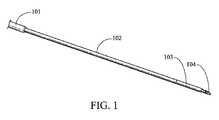
図1を参照して説明すると、アクセス針は、細長い可撓性カニューレ(102)の近位端部に動作可能に接続されたハンドル(図示せず)を含み得る。いくつかの実施形態では、ハンドルは、Hardinらへの米国特許第6,976,955号明細書(これを本願明細書に援用する)に開示されているような方法で構成され得る一方、他の実施形態では、ハンドルは、生検針に適切な任意の方法で構成され得る(特定のハンドル構造がここで特許請求されているわけではなく、医療用生検針の設計および使用の当業者によって様々なハンドル設計が容易に実施され得ることに留意されたい)。カニューレ(102)は、その近位端部からその遠位端部まで延在するルーメンを含む。いくつかの態様では、カニューレの遠位端部は、エコー源性先端(103)を含むように構成され得る。いくつかの実施形態では、保護シース(101)がカニューレの外面を取り囲み、および除去可能なスタイレットがカニューレ(102)のルーメン内に配置され得る。スタイレットは、閉塞部に貫通するように構成された穿孔先端(104)を含み得る。穿孔先端は、組織を穿孔および/または貫通するのに効果的であるように、当技術分野で知られている任意の斜めになった、先のとがったまたは他の方法で構成された先端を含む。穿孔先端(104)は中実でも中空でもよい。 Referring to FIG. 1, the access needle may include a handle (not shown) operably connected to the proximal end of the elongated flexible cannula (102). In some embodiments, the handle may be configured in a manner as disclosed in US Pat. No. 6,976,955 to Hardin et al., Which is hereby incorporated by reference. In this embodiment, the handle may be configured in any manner suitable for a biopsy needle (the specific handle structure is not claimed here and will vary depending on the person skilled in the art of medical biopsy needle design and use. Note that a simple handle design can be easily implemented). Cannula (102) includes a lumen that extends from its proximal end to its distal end. In some aspects, the distal end of the cannula may be configured to include an echogenic tip (103). In some embodiments, a protective sheath (101) may surround the outer surface of the cannula and a removable stylet may be placed within the lumen of the cannula (102). The stylet can include a piercing tip (104) configured to penetrate the occlusion. The piercing tip may be any beveled, pointed or otherwise configured tip known in the art so as to be effective in piercing and / or penetrating tissue. Including. The piercing tip (104) may be solid or hollow.
カニューレの少なくとも一部分が可撓性であることによって、体管腔に波形をつけたりまたはそうでなければ体管腔を閉塞したりするという有意なリスクを生じることなく、体管腔または他の通路を通してナビゲーションできるすなわち操縦して進めることができるようにするのに十分な押しやすさ(pushability)および追従性(trackability)をもたらす。一態様では、カニューレは、例えば、ポリイミド、ポリエーテルブロックアミド(PEBA)、PEBAX、ポリ−エーテル−エーテル−ケトン(PEEK)、ePTFE、PTFE、熱可塑性ポリウレタン(TPU)、またはPETを含むプラスチック材料とし得る。編組構成および/またはステンレス鋼などの金属部品を備える、ポリマーを含む他のポリマー材料も、本開示の範囲内で使用され得ることが認識される。 The flexibility of at least a portion of the cannula allows it to pass through the body lumen or other passageway without creating a significant risk of corrugating the body lumen or otherwise occluding the body lumen. Provides sufficient pushability and trackability to be navigable, i.e., to be able to steer and advance. In one aspect, the cannula is a plastic material including, for example, polyimide, polyether block amide (PEBA), PEBAX, poly-ether-ether-ketone (PEEK), ePTFE, PTFE, thermoplastic polyurethane (TPU), or PET. obtain. It will be appreciated that other polymeric materials, including polymers, comprising braided configurations and / or metal parts such as stainless steel may also be used within the scope of this disclosure.
いくつかの態様では、カニューレの遠位端部は、エコー源性先端を含み得る。いくつかの態様では、カニューレの遠位端部は、エコー源性ポリマー(echogenic polymer)から構成され得るかまたはそれによって被覆され得る。他の態様では、カニューレの遠位端部は、その外面にディンプル、ディボットなどを設けることによって、エコー源性として作製され得る。ディンプルは、例えば、超音波内視鏡検査からの画像をもたらすのに十分な超音波を反射し得る。カニューレの遠位端部にディンプルが付けられるか、カニューレの遠位端部がエコー源性ポリマーで被覆されるかまたはそれから構成されるかに関わらず、位置およびナビゲーションデータを提供し得る超音波可視化部材を提供する。 In some aspects, the distal end of the cannula may include an echogenic tip. In some aspects, the distal end of the cannula can be composed of or coated with an echogenic polymer. In other aspects, the distal end of the cannula can be made echogenic by providing dimples, divots, etc. on its outer surface. The dimples can reflect enough ultrasound to provide an image from, for example, an ultrasound endoscopy. Ultrasound visualization that can provide location and navigation data regardless of whether the distal end of the cannula is dimpled or whether the distal end of the cannula is coated or constructed of an echogenic polymer Providing a member.
カニューレの押しやすさおよび追従性は、さらに、そのルーメン内へのスタイレットの配置によって高められ得る。ひとたびカニューレの遠位端部およびスタイレットが患者の体内の標的部位に到達し、穿刺が行われたら、スタイレットは除去され、それにより、カニューレのルーメンを通って病巣に至るアクセスチャンネルを生じ得る。軟らかいカニューレ先端は、被覆されたガイドワイヤーを、ワイヤーからコーティングを剥離させることなく、カニューレのルーメンを通して挿入できるようにする。 Cannula pushability and followability can be further enhanced by the placement of a stylet within its lumen. Once the cannula distal end and stylet reach the target site in the patient's body and a puncture is made, the stylet can be removed, thereby creating an access channel through the lumen of the cannula to the lesion . The soft cannula tip allows the coated guidewire to be inserted through the lumen of the cannula without stripping the coating from the wire.
スタイレットは、形状記憶合金を含むニッケル−チタニウム合金、ステンレス鋼、鋼NiTiなどの合金で構成され得るか、またはPEEKなどのポリマーで構成され得る。スタイレットの遠位端部は、斜めになった先端を含んでもよく、これは、組織を効果的に穿孔するように構成されたランセット構成でまたは任意の数の他の斜めになった構成で斜めにされ得る。スタイレットの先端は、中空または中実にし得る。 The stylet can be composed of an alloy such as a nickel-titanium alloy including shape memory alloy, stainless steel, steel NiTi, or can be composed of a polymer such as PEEK. The distal end of the stylet may include a beveled tip, which may be a lancet configuration configured to effectively puncture tissue or any number of other beveled configurations. Can be slanted. The tip of the stylet can be hollow or solid.
図2および図3に関して、本開示のいくつかの態様では、スタイレット(105)は、コイル状ワイヤーの形態で提供される。そのようなコイル状ワイヤースタイレット(105)は、典型的なスタイレット構成とは異なる。単一のワイヤーまたはマルチワイヤーのブレード/コイルを使用し得る。強度を高めるために、コイル状ワイヤースタイレット(105)のルーメン内には支持マンドレルまたは駆動ワイヤー(106)も設けられ得る。このタイプのスタイレットは、一般的にカニューレのルーメン全体を占有する中実ワイヤーからなる従来技術のスタイレットに勝る多数の利点を有する。 With reference to FIGS. 2 and 3, in some aspects of the present disclosure, the stylet (105) is provided in the form of a coiled wire. Such a coiled wire stylet (105) differs from a typical stylet configuration. A single wire or multi-wire blade / coil may be used. A support mandrel or drive wire (106) may also be provided in the lumen of the coiled wire stylet (105) to increase strength. This type of stylet has a number of advantages over prior art stylets consisting of solid wire which generally occupies the entire lumen of the cannula.
例えば、ここで開示されるコイル状ワイヤースタイレットは、可撓性を増し得る。アクセス針は、著しく制御されたかつ複雑な方法で使用されることが多い。それゆえ、ここで開示した可撓性のコイル状ワイヤースタイレットを使用することにより、例えば、曲がりくねった体管腔(例えば血管)などのこれらのねじれたかつ複雑な環境においてかなり使いやすくしたり、十二指腸内視鏡(duodenoscope)を通って患者の胆管(biliary tree)内まで通過させたり、または標的部位に到達するまで高度の可撓性を必要とする他の使用に用いたりすることが可能となる。本明細書では、用語「可撓性」および「可撓性本体の長さ部分」は、非剛性であるが、一般的に予測可能な案内方法で、針のカニューレルーメン、胃内視鏡作業チャンネル、曲がりくねった体管腔、または任意の他の体管腔またはトラック(track)を通して、押しやすくかつ追従可能であるように、十分な線形状態(linear integrity)を維持することを意味すると定義され、かつ当業者によってそのように理解される。そのようなものとして、ここで開示する実施形態は、従来のスタイレット(例えば円柱状および縦の針支持体)に勝る利点を提供する一方で、本明細書で説明されるさらなる利点を含む。 For example, the coiled wire stylet disclosed herein can increase flexibility. Access needles are often used in a highly controlled and complex manner. Therefore, the use of the flexible coiled wire stylet disclosed herein can be much easier to use in these twisted and complex environments, such as, for example, tortuous body lumens (eg, blood vessels), Can be passed through the duodenoscope into the patient's biliary tree or used for other uses that require a high degree of flexibility until reaching the target site Become. As used herein, the terms “flexible” and “length portion of the flexible body” are non-rigid but generally predictable guide methods such as needle cannula lumen, gastroendoscopy Defined to mean maintaining sufficient linear integrity to be easy to push and follow through a channel, tortuous body lumen, or any other body lumen or track And will be understood as such by those skilled in the art. As such, the embodiments disclosed herein include the advantages described herein, while providing advantages over conventional stylets (eg, cylindrical and vertical needle supports).
医療専門家は、カニューレの遠位端部が標的部位まで体を通ってナビゲートされて進んでいるときにこの端部の位置を突き止めようとする必要がある(例えば、先端の位置および向きを可視化することによって)。ナビゲーション中すなわち進んでいる最中、スタイレットを適所に保つことが望ましいため、スタイレットは、造影液がカニューレのルーメンを通過できるように構成される必要がある。駆動ワイヤー(106)が使用される場合には、駆動ワイヤーがコイル状ワイヤースタイレット(105)のルーメンを十分に埋めていない限り、ここで開示するコイル状ワイヤースタイレット(105)は、造影液が、カニューレのルーメンを通過し、およびコイル状ワイヤースタイレットのルーメンさえも通過することを可能にする。従来技術の中実ワイヤーのスタイレットが使用され、かつスタイレットの外径がカニューレのルーメンの内径に本質的に等しかった場合、カニューレのルーメンを通して造影液を注入することは不可能であるか、または、よくても、造影液がカニューレのルーメンを流れ、かつそれが検出され得る遠位端部から流出するまでにはかなりの期間がかかる。この特徴は、x線透視による可視化を最小暴露時間で行うことができるようにするため、望ましい(x線透視検査中に使用される放射線に対する患者および処置を行う人員の暴露を最小にするのに適合したベストな実施に合わせて)。 The medical professional needs to attempt to locate the end of the cannula as it is being navigated and advanced through the body to the target site (e.g., position and orientation of the tip). By visualizing). Since it is desirable to keep the stylet in place during navigation or progression, the stylet needs to be configured to allow contrast fluid to pass through the lumen of the cannula. If a drive wire (106) is used, the coiled wire stylet (105) disclosed herein will be a contrast medium unless the drive wire sufficiently fills the lumen of the coiled wire stylet (105). Allows passage through the lumen of the cannula and even the lumen of the coiled wire stylet. If a prior art solid wire stylet is used and the outer diameter of the stylet is essentially equal to the inner diameter of the cannula lumen, is it impossible to inject contrast fluid through the lumen of the cannula? Or, at best, it will take a significant amount of time for the contrast fluid to flow through the lumen of the cannula and out of the distal end where it can be detected. This feature is desirable because it allows fluoroscopy visualization to be performed with minimal exposure time (to minimize patient and procedure personnel exposure to radiation used during fluoroscopy). According to the best practice fit).
しかしながら、ここで開示するコイル状ワイヤースタイレットを使用することによって、造影液は、ハンドルのポートに簡単に注入でき、かつカニューレの近位端部へ自由に流れ、カニューレのルーメンおよび/またはコイル状ワイヤースタイレットのルーメンを通り、かつカニューレの遠位端部から流出することができる。スタイレットの先端が中空である場合(図3の参照符号304を参照)、造影液は、そこを通って自由に流れることができる。スタイレットの遠位端部が中実である場合(図2の参照符号204を参照)、造影液は、中実のスタイレット先端に到達するまで、カニューレまたはスタイレットのルーメンを自由に流れる。しかしながら、中実のスタイレット先端は、最短の長さとし得、潜在的には長さ約5mm程度の短さにでき、およびカニューレの遠位端部と液密シールを形成しない。それゆえ、造影液は、カニューレルーメンの遠位端部から浸出し得る。スタイレット先端に好適な長さは、約5mm〜約50mmの間のいずれかの長さとし得る。また、スタイレットの先端が中実である場合、コイル状ワイヤーの遠位端部におけるコイルのピッチを密にして(図2に示すスタイレット(105)の遠位端部を参照)、造影液を、スタイレットのルーメンから出て、カニューレの遠位端部における中実先端を通り越して通過させることを可能にし得る。 However, by using the coiled wire stylet disclosed herein, contrast fluid can be easily injected into the port of the handle and flows freely to the proximal end of the cannula, the cannula lumen and / or coiled. It can flow through the lumen of the wire stylet and out of the distal end of the cannula. If the stylet tip is hollow (see
スタイレットの先端が中空である場合、先端は、コイル状ワイヤーに溶接され得る。スタイレットの先端が中実である場合、同様にコイル状ワイヤーに溶接され得る。さらには、スタイレットの先端が中実である場合、駆動ワイヤー(106)は、コイル状ワイヤーのルーメンを通過でき、かつ駆動ワイヤーの遠位端部は、スタイレットの先端の近位端部に溶接され得る。 If the stylet tip is hollow, the tip can be welded to the coiled wire. If the stylet tip is solid, it can be welded to the coiled wire as well. Further, if the stylet tip is solid, the drive wire (106) can pass through the lumen of the coiled wire, and the distal end of the drive wire is at the proximal end of the stylet tip. Can be welded.
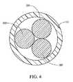
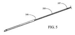
図4、図5、図5A、および図6を参照して説明すると、開示のアクセス針に従ってマルチワイヤースタイレット(205)を使用し得る。この態様では、スタイレットは、複数のワイヤーストランド(205)を含み得る。例えば、スタイレットは、2個のワイヤーストランド、3個のワイヤーストランド、4個のワイヤーストランド、5個のワイヤーストランド、6個のワイヤーストランド、7個のワイヤーストランドなどを含み得る。本開示は、任意の数のワイヤーストランドを含むスタイレットを網羅するものとする。 Referring to FIGS. 4, 5, 5A, and 6, a multi-wire stylet (205) may be used in accordance with the disclosed access needle. In this aspect, the stylet can include a plurality of wire strands (205). For example, a stylet can include 2 wire strands, 3 wire strands, 4 wire strands, 5 wire strands, 6 wire strands, 7 wire strands, and the like. The present disclosure is intended to cover stylets that include any number of wire strands.
図4および図6に最も明瞭に示すように、特定の一態様では、スタイレットは、3個のワイヤーストランドを含み得る。各ワイヤーストランドは、既述のコイル状ワイヤースタイレットに関連して述べたものと同じ材料から作製され得る。各ワイヤーストランドは、溶接、はんだ付けなどによって、鋭い先端(図5の参照符号108または図5Aの208を参照)を備えるカニューレに接合され得る。カニューレの先端は中空にも、または中実にもできる。スタイレットは、カニューレの近位端部からその遠位端部までの空間を占有し得る。そのような構成では、スタイレットは、カニューレのルーメン全体を実質的に占有しておらず、それにより、カニューレのルーメンに造影液を通過させることができる。例えば、図4に示すように、マルチワイヤーストランドのスタイレットは、カニューレのルーメンに何もない空間を残し、そこを造影液が自由に流れることができる。 As shown most clearly in FIGS. 4 and 6, in one particular embodiment, the stylet may include three wire strands. Each wire strand may be made from the same materials as described in connection with the previously described coiled wire stylet. Each wire strand may be joined to a cannula with a sharp tip (see
マルチワイヤースタイレットの1個以上のワイヤーストランドの遠位端部は、溶接、はんだ付けなどによって中空先端または中実先端に接合され得る。接着剤を使用してもよい。図5Aに示すような一実施形態では、スタイレットの遠位端部において、複数のワイヤーストランド(205)の各々は、スタイレットの先端(404)の内径に入る。その後、スタイレットの先端の近位端部に溶接またははんだ接合(208)が形成され、それにより、スタイレットを先端に取り付け得る。いくつかの実施形態では、カニューレへのワイヤーストランドの取り付けにより、依然として、造影液がスタイレットの先端を通過する空間を可能にし、および他の実施形態では、先端へワイヤーストランドを接合することにより、先端の近位端部を密封し得る、つまり、造影液はスタイレットの先端の周囲に浸出して、カテーテルから出てくる。 The distal end of one or more wire strands of the multi-wire stylet can be joined to the hollow tip or solid tip by welding, soldering, or the like. An adhesive may be used. In one embodiment, as shown in FIG. 5A, at the distal end of the stylet, each of the plurality of wire strands (205) falls within the inner diameter of the stylet tip (404). A weld or solder joint (208) is then formed at the proximal end of the stylet tip so that the stylet can be attached to the tip. In some embodiments, attachment of the wire strand to the cannula still allows space for contrast fluid to pass through the tip of the stylet, and in other embodiments, by joining the wire strand to the tip, The proximal end of the tip can be sealed, i.e., contrast fluid leaches around the stylet tip and exits the catheter.
さらに、図5を参照して説明すると、マルチワイヤーは、さらに補強するために、スタイレット本体のいくつかの部分においてはんだ付けまたは溶接によって一緒に接合され得る(107)。アクセス針が内視鏡を通って進まされているすなわちナビゲートされるとき、標的部位に向かいながら、曲がりくねった場所を移動し得る。スタイレットはカニューレのルーメン全体を占有していないため、標的を穿刺するのとは対照的に、カニューレのルーメンに押し返される傾向を有し得る。しかしながら、ワイヤーストランドがスタイレット本体に沿ったいくつかの箇所において接合された場合、これにより、さらに補強しかつ強度を高め、およびスタイレットストランドがカニューレのルーメンに押し返されないようにする。同様に、ワイヤーストランドは、好ましくは、カニューレのルーメンの直径のサイズにされるが、単一の中実ワイヤーとは対照的にマルチワイヤーストランドを使用することによって、造影液が通過できる十分な空間がある(図4および図6を参照)。 Further, referring to FIG. 5, the multi-wires can be joined together by soldering or welding at several portions of the stylet body (107) for further reinforcement. As the access needle is advanced through the endoscope, ie, navigated, it can move through a tortuous location while moving toward the target site. Since the stylet does not occupy the entire lumen of the cannula, it may have a tendency to be pushed back into the lumen of the cannula as opposed to piercing the target. However, if the wire strands are joined at several points along the stylet body, this further strengthens and increases strength and prevents the stylet strands from being pushed back into the cannula lumen. Similarly, the wire strands are preferably sized to the diameter of the cannula lumen, but by using multi-wire strands as opposed to a single solid wire, there is sufficient space for the contrast fluid to pass through. (See FIGS. 4 and 6).
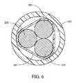
スタイレットの本体に沿ってマルチワイヤーストランドを一緒に接合するとき、熱収縮チューブ(図6の参照符号109を参照)ならびにはんだ付け、溶接などが使用され得る。マルチワイヤーストランドスタイレットの全長を接合し得るか、または、その代わりに、上述の通り、スタイレットの本体に沿って周期的にマルチワイヤーストランドを接合し得る。いくつかの実施形態では、マルチワイヤーストランドは、ワイヤーストランドの長さに沿って、繰り返しの間隔で、周期的に接合され得る。間隔は、任意の長さ、例えば、約1インチの間隔〜約20インチの間隔とし得る。例えば、マルチワイヤーストランドの長さに沿って、ストランドは、約12インチ毎の間隔でまたは約8インチ毎〜約16インチ毎の範囲の間隔で一緒に接合され得る。 When joining multi-wire strands along the stylet body, heat shrink tubing (see
ここで開示するアクセス針の近位端部において、カニューレは、ハンドル/デュアルポートルアーアダプターに接続され得る。造影液は、ルアーアダプターのサイドポートに注入され、かつコイル状ワイヤースタイレットであるかまたはマルチワイヤースタイレットであるかに関わらず、カニューレのルーメンを通って、およびいくつかの態様では、スタイレットのルーメンを通って、スタイレットを自由に流れ過ぎて、スタイレットの先端を越えてカニューレの遠位端部から流出することができる。その後、x線透視を使用して、造影液の位置、それゆえカニューレの遠位端部の位置を判断できる。スタイレットの先端が中空でない限り、スタイレットの先端が長いほど、造影液の流れをより妨げ、それにより、浸出を発生させるために必要な期間を長くする。そのようなものとして、スタイレットの先端の長さは、約5mm〜約50mm、約5mm〜約25mm、約5mm〜約15mm、または約5mm〜約10mmなど、かなり短くする必要がある。 At the proximal end of the access needle disclosed herein, the cannula can be connected to a handle / dual port luer adapter. Contrast fluid is injected into the side port of the luer adapter and, regardless of whether it is a coiled or multi-wire stylet, through the lumen of the cannula and in some embodiments, the stylet Through the lumen of the stylet, it can flow freely over the stylet and out of the distal end of the cannula over the tip of the stylet. X-ray fluoroscopy can then be used to determine the position of the contrast solution and hence the distal end of the cannula. Unless the stylet tip is hollow, the longer the stylet tip, the more obstructed the flow of contrast liquid, thereby increasing the time required to cause leaching. As such, the length of the stylet tip needs to be fairly short, such as about 5 mm to about 50 mm, about 5 mm to about 25 mm, about 5 mm to about 15 mm, or about 5 mm to about 10 mm.
それゆえ、ここで開示するスタイレットの全ての態様は、カニューレのルーメンに造影液を効果的に通過させることができ、およびいくつかの態様は、スタイレットのルーメンに造影液を効果的に通過させることができることが認識され得る。造影液は、高粘性とし得るため、カニューレのルーメンには十分な空間が必要であり、この十分な空間は、スタイレットがそこに配置されていることに起因して、達成することが困難であるとし得る。しかしながら、ここで開示するスタイレットの全ての態様は、造影液が通過するのに十分な空間を生じる。すなわち、ここで開示するスタイレットの全ては、可撓性本体の長さ部分を、穿孔先端からハンドルまで近位に延在した状態にし、それにより、スタイレットの可撓性本体は、カニューレのルーメン全体を十分には占有しないで、造影液がカニューレのルーメンを効果的に通過できるようにし得る。スタイレットがカニューレのルーメンを十分には占有しないようにするために、カニューレのルーメンには、少なくとも造影液がスタイレットの先端に到達するまで造影液が妨げられずに通過するための十分な非占有空間がある必要がある。 Thus, all aspects of the stylet disclosed herein can effectively pass contrast fluid through the lumen of the cannula, and some aspects effectively pass contrast fluid through the lumen of the stylet. It can be recognized that Since contrast fluids can be highly viscous, the lumen of the cannula requires sufficient space, which is difficult to achieve due to the stylet being placed there. It can be. However, all aspects of the stylet disclosed herein create sufficient space for the contrast fluid to pass through. That is, all of the stylets disclosed herein leave the length of the flexible body extending proximally from the piercing tip to the handle, so that the flexible body of the stylet Contrast fluid can effectively pass through the lumen of the cannula without fully occupying the entire lumen. To prevent the stylet from fully occupying the cannula lumen, the lumen of the cannula has sufficient non-obstructed passage for the contrast fluid to pass unimpeded until at least the contrast fluid reaches the tip of the stylet. There must be occupied space.
図2および図3を参照すると、造影液が、これらのスタイレットのいずれかを含んでいるカニューレルーメンに注入された場合、そこは、造影液が流れ得るカニューレのルーメン内に大量の非占有空間があることが示されている。例えば、造影液は、スタイレット内のルーメンの中心を自由に流れ得る。図4を参照して説明すると、スタイレットのこの実施形態は、カニューレのルーメン全体を十分には占有しておらず、それにより、造影液がカニューレのルーメンを効果的に通過できることが容易に分かる。この図は、3個のワイヤーストランドを含むスタイレットを示している。図に示すように、造影液が自由に通過できるカニューレルーメン内には、十分な非占有空間がある。 2 and 3, when contrast fluid is injected into a cannula lumen containing any of these stylets, there is a large amount of unoccupied space in the lumen of the cannula through which the contrast fluid can flow. It has been shown that there is. For example, contrast fluid can flow freely through the center of the lumen within the stylet. Referring to FIG. 4, it can be readily seen that this embodiment of the stylet does not fully occupy the entire lumen of the cannula so that contrast fluid can effectively pass through the lumen of the cannula. . This figure shows a stylet comprising three wire strands. As shown in the figure, there is sufficient unoccupied space in the cannula lumen through which contrast fluid can pass freely.
造影液を通過させるためのカニューレのルーメン内の自由空間の量を定量化しようとして、少なくとも図2、図3、図4、および図6を参照して説明すると、ここで開示するスタイレットのうちの1つを含むときには、カニューレのルーメンの横断面の約70%〜約10%がスタイレットによって占有されないと判断し得る。いくつかの態様では、カニューレルーメンの約20%〜約50%が占有されないとし得る。それゆえ、本明細書で開示される全ての態様において、スタイレットの可撓性本体が、カニューレのルーメン全体を通る流体連通路を提供して、造影液がカニューレのルーメンを効果的に通過できるようにすることが認識され得る。あるいは、スタイレットの可撓性本体は、カニューレのルーメン全体を十分には占有しないため、スタイレットの可撓性本体は、カニューレのルーメン全体を通る流体連通路を提供し、造影液がカニューレのルーメンを効果的に通過できるようにすると言われ得る。 In an attempt to quantify the amount of free space in the lumen of the cannula for passing contrast fluid, it will be described with reference to at least FIGS. 2, 3, 4, and 6 and of the stylets disclosed herein. It can be determined that about 70% to about 10% of the cross-section of the cannula lumen is not occupied by the stylet. In some aspects, about 20% to about 50% of the cannula lumen may not be occupied. Thus, in all aspects disclosed herein, the stylet's flexible body provides a fluid communication path through the entire cannula lumen so that contrast fluid can effectively pass through the cannula lumen. It can be appreciated that. Alternatively, the stylet's flexible body does not fully occupy the entire lumen of the cannula, so the stylet's flexible body provides a fluid communication path through the entire lumen of the cannula so that contrast fluid can flow through the cannula. It can be said that it can effectively pass through the lumen.
ここで開示するスタイレットとは対照的に、中実ワイヤーの従来技術のスタイレットは、カニューレのルーメン全体を十分に占有して、造影液がカニューレのルーメンを事実上通過できないようにすることを認識されたい。それゆえ、従来技術のスタイレットは、スタイレットのルーメンを通る流体連通路を提供しない。カニューレのルーメンの直径と実質的に同じ直径を有する中実ワイヤーのスタイレットでは、カニューレルーメンのわずか約1%から多くても約5%まで、およびおそらくはそれを下回る領域が、スタイレットによって占有されていない。これは、このルーメンを通る造影液の流れを大きく妨げる。造影液を、従来技術の中実ワイヤーのスタイレットを有するカニューレ内に注入することは可能な場合があるが、造影液がカニューレの長さの距離を移動するのを待つために必要な時間は、処置を実行不可能なものにする。ここで開示するスタイレットのいくつかの態様は、従来技術の中実ワイヤースタイレットと同様に、カニューレのルーメンの直径にほぼ等しい直径を有し得る中実先端を有するが、これらの先端は非常に短く、潜在的には長さ約5mmであるため、造影液が通過するのを待つために必要な時間は、そのような短い距離によって、最少になる。 In contrast to the stylets disclosed herein, solid wire prior art stylets are designed to fully occupy the entire cannula lumen so that contrast fluid cannot effectively pass through the cannula lumen. I want to be recognized. Therefore, prior art stylets do not provide a fluid communication path through the stylet lumen. For a solid wire stylet having a diameter that is substantially the same as the diameter of the cannula lumen, only about 1% to at most about 5% of the cannula lumen, and possibly less, is occupied by the stylet. Not. This greatly hinders the flow of contrast fluid through this lumen. While it may be possible to inject contrast fluid into a cannula having a solid wire stylet in the prior art, the time required to wait for contrast fluid to travel the cannula length distance is , Make the action infeasible. Some embodiments of the stylet disclosed herein, like the prior art solid wire stylets, have solid tips that can have a diameter approximately equal to the diameter of the lumen of the cannula, but these tips are very Because it is short and potentially about 5 mm long, the time required to wait for the contrast liquid to pass is minimized by such a short distance.
好適な造影液は当技術分野で知られており、およびここで開示する装置は、任意のタイプの造影液に特に限定されない。Telebrix(登録商標)は、ここで開示するアクセス針に関連して使用され得る造影液のタイプの例示的な一例である。 Suitable contrast media are known in the art, and the devices disclosed herein are not particularly limited to any type of contrast media. Telebrix® is an illustrative example of a type of contrast fluid that can be used in connection with the access needle disclosed herein.
患者の体内の標的位置にカニューレを配置する方法も、本明細書で開示される。一態様では、患者の体内の標的部位は、超音波内視鏡によって可視化される。ここで開示するアクセス針は、超音波内視鏡に挿入され、かつスコープに取り付けられ得る。アクセス針のハンドルは、カニューレ/スタイレットアセンブリの遠位端部が患者の体内の標的部位を穿刺するように、前進され得る。スタイレットが依然としてカニューレのルーメン内の適所にある状態で、造影液を、ハンドルにあるポートに注入し得る。造影液は、カニューレのルーメンを通って、かつ、いくつかの実施形態に関連して既に説明したように、スタイレットルーメンを通って、移動できる。造影液はカニューレの遠位端部から流出して、および装置を操作する医療専門家は、スタイレットを除去する前に、カニューレの遠位端部の解剖学的位置をx線透視によって確認し得る。ひとたびカニューレの遠位端部が正しい位置にあるとの確認を得たら、スタイレットを除去し得る。本明細書で開示される方法によれば、コイル状ワイヤースタイレットまたはマルチワイヤーストランドのスタイレットのいずれかを使用し得る。 A method of placing a cannula at a target location within a patient's body is also disclosed herein. In one aspect, a target site within a patient's body is visualized by an ultrasound endoscope. The access needle disclosed herein can be inserted into an ultrasound endoscope and attached to a scope. The access needle handle may be advanced so that the distal end of the cannula / stylet assembly pierces the target site within the patient. With the stylet still in place within the lumen of the cannula, contrast fluid can be injected into a port in the handle. Contrast fluid can travel through the lumen of the cannula and through the stylet lumen as previously described in connection with some embodiments. Contrast fluid flows out of the distal end of the cannula, and the medical professional operating the device confirms the anatomical location of the distal end of the cannula by fluoroscopy before removing the stylet. obtain. Once the confirmation that the distal end of the cannula is in place, the stylet can be removed. According to the methods disclosed herein, either a coiled wire stylet or a multi-wire strand stylet may be used.
スタイレットを除去すると、カニューレは、その遠位端部が標的部位にある状態で、適所に残される。方法の次のステップは、医療専門家および患者のニーズに依存する。例えば、アクセス針のハンドルにシリンジを接続して、標的位置から流体を吸引し得る。さらなる説明に役立つ例として、ガイドワイヤーを、カニューレのルーメンに通過させて患者の体内の標的部位に至らせ得る。その後、アクセス針のハンドルを引っ込めて、針を、カニューレを取り囲むシース内に戻し得る。次に、装置を内視鏡から除去して、標的部位に対するさらなるアクセスのためにガイドワイヤーを適所に残し得る。 When the stylet is removed, the cannula is left in place with its distal end at the target site. The next step of the method depends on the needs of medical professionals and patients. For example, a syringe may be connected to the access needle handle to aspirate fluid from the target location. As a further illustrative example, a guide wire may be passed through the lumen of the cannula to a target site within the patient's body. The access needle handle can then be withdrawn and the needle can be returned into the sheath surrounding the cannula. The device can then be removed from the endoscope, leaving the guide wire in place for further access to the target site.
本明細書で開示されかつ特許請求される装置および方法は全て、本開示を踏まえて、必要以上の実験を行うことなく、行われ、かつ実行され得る。本開示は、多くの異なる態様または実施形態に関連し得るが、本明細書では、本発明の好ましい具体的な実施形態が詳細に説明される。本開示は、本発明の原理の例示であり、および本発明を、図示の特定の実施形態または態様に限定するものではない。さらに、それとは反対であると明白に述べられない限り、用語「a」の使用は、「少なくとも1つ」または「1つまたは複数」を含むものとする。例えば、「装置」は、「少なくとも1つの装置」または「1つまたは複数の装置」を含むものとする。 All of the devices and methods disclosed and claimed herein can be made and executed without undue experimentation in light of the present disclosure. While the present disclosure may be related to many different aspects or embodiments, preferred specific embodiments of the invention are described in detail herein. This disclosure is an exemplification of the principles of the invention and is not intended to limit the invention to the particular embodiments or aspects illustrated. Further, unless expressly stated to the contrary, the use of the term “a” is intended to include “at least one” or “one or more”. For example, “device” includes “at least one device” or “one or more devices”.
絶対的または近似的のいずれかで与えられたいずれかの範囲は、双方を含むものとし、および本明細書で使用されるいずれの定義も、明確にするものであり、かつ限定するものではない。本発明の広範な範囲で述べる数値の範囲およびパラメータは近似であるにもかかわらず、具体例で述べられる数値は、可能な限り正確に報告される。しかしながら、いずれの数値も、本質的に、それらそれぞれの検査測定値に見られる標準偏差から必然的に生じるいくつかの誤差を含み得る。さらに、本明細書で開示される全ての範囲は、そこに組み込まれる任意のおよび全ての部分範囲を含むものと理解されたい(全ての小数値および全体値(whole value)を含む)。 Any ranges given as either absolute or approximate are intended to include both, and any definitions used herein are for the purpose of clarity and not limitation. Although the numerical ranges and parameters set forth in the broad scope of the invention are approximate, the numerical values set forth in the examples are reported as accurately as possible. Any numerical value, however, can inherently contain certain errors necessarily resulting from the standard deviation found in their respective testing measurements. Further, all ranges disclosed herein are to be understood to include any and all subranges incorporated therein (including all decimal values and whole values).
さらに、本発明は、本明細書で説明される様々な実施形態のいくつかまたは全ての任意のおよび全ての考えられる組み合わせを含む。本明細書で説明されるここでの好ましい実施形態に対する様々な変更形態および修正形態は、当業者に明白であることも理解されたい。そのような変更形態および修正形態は、本発明の趣旨および範囲から逸脱することなく、およびその意図した利点を減じることなく、行われ得る。それゆえ、そのような変更形態および修正形態は、添付の特許請求の範囲によって網羅されるものとする。 Furthermore, the present invention includes any and all possible combinations of some or all of the various embodiments described herein. It should also be understood that various changes and modifications to the presently preferred embodiments described herein will be apparent to those skilled in the art. Such changes and modifications can be made without departing from the spirit and scope of the present invention and without diminishing its intended advantages. Accordingly, such changes and modifications are intended to be covered by the appended claims.
Claims (20)
Translated fromJapanese前記カニューレの前記ルーメン内に除去可能に配置されるスタイレットと
を含み、前記スタイレットは、
前記スタイレットの遠位端部における穿孔先端;および
前記穿孔先端から前記近位端部の方へ向かって近位に延在する可撓性本体の長さ部分であって、それにより、前記スタイレットの前記可撓性本体は、前記カニューレの前記ルーメン全体を通る流体連通路を提供して、造影液が前記カニューレの前記ルーメンを効果的に通過できるようにする、可撓性本体の長さ部分
を含む、アクセス針。An elongated hollow cannula having a proximal end, a distal end, and a lumen extending therebetween;
A stylet removably disposed within the lumen of the cannula, the stylet comprising:
A piercing tip at the distal end of the stylet; and a length of a flexible body extending proximally from the piercing tip toward the proximal end, whereby the stylet The flexible body length of a let provides a fluid communication path through the entire lumen of the cannula to allow contrast fluid to effectively pass through the lumen of the cannula. Access needle including part.
請求項1に記載のアクセス針を提供するステップと;
前記アクセス針の前記遠位端部を前記内視鏡のルーメンに装填するステップと;
前記アクセス針の前記遠位端部を前記標的位置に穿刺させるステップと;
造影液を、前記カニューレのルーメンを通って流して前記カニューレの前記遠位端部から流出させるように、方向付けるステップと;
前記患者の前記体をx線透視で可視化して、前記造影液の位置を判断するステップと;
前記造影液の前記位置によって、前記カニューレの前記遠位端部が前記標的位置にあることを確認するステップと;
前記スタイレットを引き抜くステップと;
前記カニューレの前記遠位端部が前記標的位置にある状態で、前記カニューレを適所に残すステップと
を含む方法。A method of introducing a cannula through a endoscope to a target location in a patient's body, comprising:
Providing an access needle according to claim 1;
Loading the distal end of the access needle into the lumen of the endoscope;
Piercing the distal end of the access needle into the target location;
Directing contrast fluid to flow through the lumen of the cannula and out of the distal end of the cannula;
Visualizing the body of the patient with fluoroscopy to determine the position of the contrast solution;
Confirming that the distal end of the cannula is at the target location by the location of the contrast medium;
Withdrawing the stylet;
Leaving the cannula in place with the distal end of the cannula in the target location.
前記カニューレの前記ルーメン内に除去可能に配置されたスタイレットと
を含み、前記スタイレットは、
前記スタイレットの遠位端部における穿孔先端;および
前記穿孔先端から前記近位端部の方へ向かって近位に延在する可撓性本体の長さ部分であって、それにより、前記スタイレットの前記可撓性本体は、前記カニューレの前記ルーメン全体を通る流体連通路を提供して、造影液が、前記カニューレの前記ルーメンを効果的に通過できるようにし、前記スタイレットは複数のワイヤーストランドを含み、および前記複数のワイヤーストランドを含む各ワイヤーストランドの遠位端部は、前記穿孔先端の近位端部に接続される、可撓性本体の長さ部分
を含む、アクセス針。An elongated hollow cannula having a proximal end, a distal end, and a lumen extending therebetween;
A stylet removably disposed within the lumen of the cannula, the stylet comprising:
A piercing tip at the distal end of the stylet; and a length of a flexible body extending proximally from the piercing tip toward the proximal end, whereby the stylet The flexible body of the let provides a fluid communication path through the entire lumen of the cannula to allow contrast fluid to effectively pass through the lumen of the cannula, the stylet comprising a plurality of wires An access needle comprising a length of a flexible body including a strand and a distal end of each wire strand including the plurality of wire strands connected to a proximal end of the piercing tip.
Applications Claiming Priority (3)
| Application Number | Priority Date | Filing Date | Title |
|---|---|---|---|
| US201361829421P | 2013-05-31 | 2013-05-31 | |
| US61/829,421 | 2013-05-31 | ||
| PCT/US2014/037992WO2014204593A1 (en) | 2013-05-31 | 2014-05-14 | Access needles and stylet assemblies |
Publications (2)
| Publication Number | Publication Date |
|---|---|
| JP2016519982Atrue JP2016519982A (en) | 2016-07-11 |
| JP6340415B2 JP6340415B2 (en) | 2018-06-06 |
Family
ID=50942888
Family Applications (1)
| Application Number | Title | Priority Date | Filing Date |
|---|---|---|---|
| JP2016516683AActiveJP6340415B2 (en) | 2013-05-31 | 2014-05-14 | Access needle and stylet assembly |
Country Status (7)
| Country | Link |
|---|---|
| US (1) | US9750532B2 (en) |
| EP (1) | EP3003423A1 (en) |
| JP (1) | JP6340415B2 (en) |
| CN (1) | CN105377324B (en) |
| AU (1) | AU2014281178B2 (en) |
| BR (1) | BR112015029752A2 (en) |
| WO (1) | WO2014204593A1 (en) |
Cited By (1)
| Publication number | Priority date | Publication date | Assignee | Title |
|---|---|---|---|---|
| JP2019118819A (en)* | 2017-12-28 | 2019-07-22 | スパイレーション インコーポレイテッド ディー ビー エイ オリンパス レスピラトリー アメリカ | System and method for controlling stiffness of needle or catheter |
Families Citing this family (30)
| Publication number | Priority date | Publication date | Assignee | Title |
|---|---|---|---|---|
| EP1907042B1 (en) | 2005-07-06 | 2009-03-11 | Vascular Pathways Inc. | Intravenous catheter insertion device and method of use |
| EP2150304B1 (en) | 2007-05-07 | 2010-12-01 | Vascular Pathways Inc. | Intravenous catheter insertion and blood sample devices and method of use |
| US8932258B2 (en) | 2010-05-14 | 2015-01-13 | C. R. Bard, Inc. | Catheter placement device and method |
| US9872971B2 (en) | 2010-05-14 | 2018-01-23 | C. R. Bard, Inc. | Guidewire extension system for a catheter placement device |
| US10384039B2 (en) | 2010-05-14 | 2019-08-20 | C. R. Bard, Inc. | Catheter insertion device including top-mounted advancement components |
| US11925779B2 (en) | 2010-05-14 | 2024-03-12 | C. R. Bard, Inc. | Catheter insertion device including top-mounted advancement components |
| US9950139B2 (en) | 2010-05-14 | 2018-04-24 | C. R. Bard, Inc. | Catheter placement device including guidewire and catheter control elements |
| US8690833B2 (en) | 2011-01-31 | 2014-04-08 | Vascular Pathways, Inc. | Intravenous catheter and insertion device with reduced blood spatter |
| ES2835652T3 (en) | 2011-02-25 | 2021-06-22 | Bard Inc C R | Medical component insertion device including a retractable needle |
| USD903101S1 (en) | 2011-05-13 | 2020-11-24 | C. R. Bard, Inc. | Catheter |
| WO2014120741A1 (en) | 2013-01-30 | 2014-08-07 | Vascular Pathways, Inc. | Systems and methods for venipuncture and catheter placement |
| WO2016037127A1 (en) | 2014-09-05 | 2016-03-10 | C.R. Bard, Inc. | Catheter insertion device including retractable needle |
| US11660115B2 (en) | 2014-12-23 | 2023-05-30 | The Regents Of The University Of California | Methods, compositions, and systems for device implantation |
| USD903100S1 (en) | 2015-05-01 | 2020-11-24 | C. R. Bard, Inc. | Catheter placement device |
| CN113350614A (en) | 2015-05-15 | 2021-09-07 | C·R·巴德股份有限公司 | Catheter placement device including extendable needle safety feature |
| US10493262B2 (en) | 2016-09-12 | 2019-12-03 | C. R. Bard, Inc. | Blood control for a catheter insertion device |
| JP6901582B2 (en) | 2017-02-22 | 2021-07-14 | ジャイラス エーシーエムアイ インク | Improved covered flexible needle assembly |
| EP3585471B1 (en) | 2017-03-01 | 2025-01-01 | C. R. Bard, Inc. | Catheter insertion device |
| CN107569258A (en)* | 2017-09-29 | 2018-01-12 | 上海长海医院 | A kind of puncture needle |
| ES2980192T3 (en) | 2018-03-07 | 2024-09-30 | Bard Access Systems Inc | Guidewire advancement and blood reflux systems for a medical device insertion system |
| US10960147B2 (en)* | 2018-04-20 | 2021-03-30 | Flextronics Ap, Llc | Flex needle |
| USD921884S1 (en) | 2018-07-27 | 2021-06-08 | Bard Access Systems, Inc. | Catheter insertion device |
| US11317789B2 (en)* | 2018-08-17 | 2022-05-03 | Cook Medical Technologies Llc | Endoscope with control for tip deflection |
| US12017012B2 (en) | 2019-02-05 | 2024-06-25 | Bard Access Systems, Inc. | Apparatus and methods to modulate stylet stiffness profile |
| CA3151126A1 (en) | 2019-08-19 | 2021-02-25 | Becton, Dickinson And Company | Midline catheter placement device |
| US11986229B2 (en)* | 2019-09-18 | 2024-05-21 | Merit Medical Systems, Inc. | Osteotome with inflatable portion and multiwire articulation |
| US11717324B2 (en) | 2020-09-02 | 2023-08-08 | Angiomed Gmbh & Co. Medizintechnik Kg | Puncture device for creating a TIPS shunt and corresponding methods |
| US11774327B2 (en)* | 2020-12-29 | 2023-10-03 | Dionex Corporation | Bioinert sampling needle |
| CN116916994A (en)* | 2021-02-22 | 2023-10-20 | 株式会社钟化 | Puncture device |
| CN114305615A (en)* | 2022-01-05 | 2022-04-12 | 中国医学科学院北京协和医院 | A single-channel electronic neuroendoscopy system for intraspinal subdural lesions |
Citations (6)
| Publication number | Priority date | Publication date | Assignee | Title |
|---|---|---|---|---|
| JPH02241446A (en)* | 1989-03-01 | 1990-09-26 | Natl Standard Co | Positioning needle assembly for focus |
| WO1996013295A1 (en)* | 1994-10-20 | 1996-05-09 | Micro Therapeutics, Inc. | Infusion device with preformed shape |
| EP0904797A2 (en)* | 1997-09-24 | 1999-03-31 | Eclipse Surgical Technologies, Inc. | Steerable catheter with tip alignment and surface contact detector |
| WO2006011970A1 (en)* | 2004-06-24 | 2006-02-02 | Boston Scientific Limited | Apparatus for treating occluded vasculature |
| US20100160731A1 (en)* | 2008-12-22 | 2010-06-24 | Marc Giovannini | Ultrasound-visualizable endoscopic access system |
| JP2012000143A (en)* | 2010-06-14 | 2012-01-05 | Olympus Corp | Drug administration needle |
Family Cites Families (46)
| Publication number | Priority date | Publication date | Assignee | Title |
|---|---|---|---|---|
| US4582061A (en) | 1981-11-18 | 1986-04-15 | Indianapolis Center For Advanced Research, Inc. | Needle with ultrasonically reflective displacement scale |
| US5370675A (en) | 1992-08-12 | 1994-12-06 | Vidamed, Inc. | Medical probe device and method |
| US4869259A (en) | 1988-05-17 | 1989-09-26 | Vance Products Incorporated | Echogenically enhanced surgical instrument and method for production thereof |
| US4977897A (en) | 1988-08-17 | 1990-12-18 | Robert Hurwitz | Amniocentesis needle with improved sonographic visibility |
| US20040002647A1 (en) | 1991-10-18 | 2004-01-01 | Ashvin Desai | Gel injection treatment of body parts |
| US7549424B2 (en) | 1991-10-18 | 2009-06-23 | Pro Surg, Inc. | Method and apparatus for tissue treatment with laser and electromagnetic radiation |
| US5357961A (en) | 1993-05-12 | 1994-10-25 | Hdc Corporation | Catheter guidewire and flushing apparatus and method of insertion |
| US5490521A (en) | 1993-08-31 | 1996-02-13 | Medtronic, Inc. | Ultrasound biopsy needle |
| WO1996027329A1 (en) | 1995-03-08 | 1996-09-12 | Terwilliger Richard A | Echogenic needle |
| US20050182297A1 (en)* | 1996-10-04 | 2005-08-18 | Dietrich Gravenstein | Imaging scope |
| GB9622711D0 (en) | 1996-10-31 | 1997-01-08 | British Tech Group | Instrument having enhanced ultrasound visibility |
| US6106473A (en) | 1996-11-06 | 2000-08-22 | Sts Biopolymers, Inc. | Echogenic coatings |
| CA2275249C (en) | 1997-01-30 | 2004-03-23 | Boston Scientific Corporation | Pneumatically actuated tissue sampling device |
| US6053870A (en) | 1997-11-08 | 2000-04-25 | Angiodynamics, Inc. | Ultrasonic visible surgical needle |
| US6371963B1 (en)* | 1998-11-17 | 2002-04-16 | Scimed Life Systems, Inc. | Device for controlled endoscopic penetration of injection needle |
| CA2358387C (en) | 1998-12-31 | 2007-11-13 | Jeffrey E. Yeung | Tissue fastening devices and delivery means |
| US6689142B1 (en) | 1999-04-26 | 2004-02-10 | Scimed Life Systems, Inc. | Apparatus and methods for guiding a needle |
| GB0011568D0 (en) | 2000-05-15 | 2000-06-28 | Nycomed Amersham Plc | Grooved medical devices |
| US6607496B1 (en) | 2000-09-12 | 2003-08-19 | Medtronic, Inc. | Steerable stylet with enhanced torsional transfer strength |
| US6871086B2 (en) | 2001-02-15 | 2005-03-22 | Robin Medical Inc. | Endoscopic examining apparatus particularly useful in MRI, a probe useful in such apparatus, and a method of making such probe |
| WO2002078611A2 (en) | 2001-03-30 | 2002-10-10 | Drexel University | Echogenic polymer microcapsules and nanocapsules and methods for production and use thereof |
| US6524247B2 (en) | 2001-05-15 | 2003-02-25 | U-Systems, Inc. | Method and system for ultrasound imaging of a biopsy needle |
| US7087212B2 (en) | 2001-08-17 | 2006-08-08 | Mallinckrodt, Inc | Multicomponent assemblies having enhanced binding properties for diagnosis and therapy |
| EP1420702B1 (en) | 2001-08-31 | 2005-04-20 | Boston Scientific Limited | Percutaneous pringle occlusion device |
| EP1434530A2 (en) | 2001-10-12 | 2004-07-07 | AMS Research Corporation | Surgical instrument and method |
| US6860856B2 (en) | 2002-01-11 | 2005-03-01 | Scimed Life Systems, Inc. | Echogenic surface for enhanced ultasonic visibility |
| US6895282B2 (en) | 2002-10-04 | 2005-05-17 | Boston Scientific Scimed, Inc. | Induction heating for the delivery of thermal therapy |
| US6936048B2 (en) | 2003-01-16 | 2005-08-30 | Charlotte-Mecklenburg Hospital Authority | Echogenic needle for transvaginal ultrasound directed reduction of uterine fibroids and an associated method |
| US6875219B2 (en)* | 2003-02-14 | 2005-04-05 | Yves P. Arramon | Bone access system |
| JP4744294B2 (en) | 2003-06-19 | 2011-08-10 | ウィルソン−クック・メディカル・インコーポレーテッド | Handle for medical instrument and medical instrument assembly including the handle |
| US20050148512A1 (en) | 2003-11-10 | 2005-07-07 | Angiotech International Ag | Medical implants and fibrosis-inducing agents |
| AU2004289362A1 (en) | 2003-11-10 | 2005-05-26 | Angiotech International Ag | Intravascular devices and fibrosis-inducing agents |
| US20050256426A1 (en) | 2004-05-12 | 2005-11-17 | William Brugge | Apparatus and method for collecting tissue samples |
| US20050261571A1 (en) | 2004-05-21 | 2005-11-24 | Willis Nathaniel P | 3-D ultrasound navigation during radio-frequency ablation |
| US7335155B2 (en) | 2004-09-14 | 2008-02-26 | Boston Scientific Scimed, Inc. | Unitary formulation delivery device |
| WO2006044374A1 (en) | 2004-10-14 | 2006-04-27 | Cook Incorporated | Echogenic medical device and method of forming echogenic surface |
| WO2006094044A1 (en) | 2005-02-28 | 2006-09-08 | Wilson-Cook Medical Inc. | Echogenic markers on gi medical devices |
| US20060235446A1 (en) | 2005-04-14 | 2006-10-19 | Norman Godin | Article, system, and method for securing medical device to tissue or organ |
| US20070021767A1 (en) | 2005-07-25 | 2007-01-25 | Breznock Eugene M | Steerable endoluminal punch |
| US7867169B2 (en) | 2005-12-02 | 2011-01-11 | Abbott Cardiovascular Systems Inc. | Echogenic needle catheter configured to produce an improved ultrasound image |
| JP2009519104A (en) | 2005-12-12 | 2009-05-14 | クック クリティカル ケア インコーポレーテッド | High intensity echo stimulation block needle |
| WO2007069248A2 (en) | 2005-12-16 | 2007-06-21 | Galil Medical Ltd. | Apparatus and method for thermal ablation of uterine fibroids |
| WO2008062451A2 (en) | 2006-09-07 | 2008-05-29 | Gautam Allahbadia | Echogenic surface for surgical instrument |
| WO2008048575A2 (en)* | 2006-10-16 | 2008-04-24 | Medtronic, Inc. | Vessel support device and method of vessel harvesting |
| US7713215B2 (en)* | 2008-01-31 | 2010-05-11 | Shriver Edgar L | Steering, piercing, anchoring, distending extravascular guidewire |
| WO2010144362A1 (en) | 2009-06-12 | 2010-12-16 | Wilson-Cook Medical Inc. | Endoscopic ultrasound-guided stent placement device and method |
- 2014
- 2014-05-14WOPCT/US2014/037992patent/WO2014204593A1/enactiveApplication Filing
- 2014-05-14BRBR112015029752Apatent/BR112015029752A2/ennot_activeIP Right Cessation
- 2014-05-14JPJP2016516683Apatent/JP6340415B2/enactiveActive
- 2014-05-14AUAU2014281178Apatent/AU2014281178B2/enactiveActive
- 2014-05-14USUS14/277,496patent/US9750532B2/enactiveActive
- 2014-05-14CNCN201480037991.9Apatent/CN105377324B/enactiveActive
- 2014-05-14EPEP14730351.5Apatent/EP3003423A1/ennot_activeWithdrawn
Patent Citations (10)
| Publication number | Priority date | Publication date | Assignee | Title |
|---|---|---|---|---|
| JPH02241446A (en)* | 1989-03-01 | 1990-09-26 | Natl Standard Co | Positioning needle assembly for focus |
| WO1996013295A1 (en)* | 1994-10-20 | 1996-05-09 | Micro Therapeutics, Inc. | Infusion device with preformed shape |
| JPH10509350A (en)* | 1994-10-20 | 1998-09-14 | マイクロ・セラピューティクス・インコーポレーテッド | Injection device with pre-formed shape |
| EP0904797A2 (en)* | 1997-09-24 | 1999-03-31 | Eclipse Surgical Technologies, Inc. | Steerable catheter with tip alignment and surface contact detector |
| JPH11221229A (en)* | 1997-09-24 | 1999-08-17 | Eclipse Surgical Technol Inc | Catheter |
| WO2006011970A1 (en)* | 2004-06-24 | 2006-02-02 | Boston Scientific Limited | Apparatus for treating occluded vasculature |
| JP2008504062A (en)* | 2004-06-24 | 2008-02-14 | ボストン サイエンティフィック リミテッド | Device for treating occluded blood vessels |
| US20100160731A1 (en)* | 2008-12-22 | 2010-06-24 | Marc Giovannini | Ultrasound-visualizable endoscopic access system |
| JP2012513286A (en)* | 2008-12-22 | 2012-06-14 | ウィルソン−クック・メディカル・インコーポレーテッド | Ultrasound visualization endoscope access device |
| JP2012000143A (en)* | 2010-06-14 | 2012-01-05 | Olympus Corp | Drug administration needle |
Cited By (2)
| Publication number | Priority date | Publication date | Assignee | Title |
|---|---|---|---|---|
| JP2019118819A (en)* | 2017-12-28 | 2019-07-22 | スパイレーション インコーポレイテッド ディー ビー エイ オリンパス レスピラトリー アメリカ | System and method for controlling stiffness of needle or catheter |
| JP7220559B2 (en) | 2017-12-28 | 2023-02-10 | ジャイラス エーシーエムアイ インク ディー/ビー/エー オリンパス サージカル テクノロジーズ アメリカ | Systems and methods for controlling needle or catheter stiffness |
Also Published As
| Publication number | Publication date |
|---|---|
| AU2014281178B2 (en) | 2017-05-18 |
| US9750532B2 (en) | 2017-09-05 |
| EP3003423A1 (en) | 2016-04-13 |
| CN105377324B (en) | 2018-12-21 |
| AU2014281178A1 (en) | 2015-12-24 |
| US20140357983A1 (en) | 2014-12-04 |
| CN105377324A (en) | 2016-03-02 |
| JP6340415B2 (en) | 2018-06-06 |
| WO2014204593A1 (en) | 2014-12-24 |
| BR112015029752A2 (en) | 2020-04-28 |
Similar Documents
| Publication | Publication Date | Title |
|---|---|---|
| JP6340415B2 (en) | Access needle and stylet assembly | |
| CN103096964B (en) | Bending conduit | |
| JP6419773B2 (en) | Boosting catheter and related systems and methods | |
| JP7671679B2 (en) | System for harvesting eccentric nodal tissue | |
| US20140276051A1 (en) | Device for Minimally Invasive Delivery of Treatment Substance | |
| JP2012513286A (en) | Ultrasound visualization endoscope access device | |
| US20220347394A1 (en) | Sheaths for needle delivery | |
| US11167095B2 (en) | Variable pitch flexible needle | |
| CN113456190B (en) | Puncture instruments | |
| CN113520549B (en) | Puncture instruments | |
| CN113456990B (en) | Interventional catheter devices | |
| EP3052034B1 (en) | Wire-embedded polymer-body needle | |
| US11426235B2 (en) | Electrode loop assembly including shaped support tube and method of assembling same | |
| CN110269645B (en) | Catheter assembly with deflection device for tissue sampling | |
| EP3370803B1 (en) | Injection devices | |
| US20110270090A1 (en) | Needle having ultrasound opaque elements | |
| JP2024100601A (en) | catheter |
Legal Events
| Date | Code | Title | Description |
|---|---|---|---|
| A977 | Report on retrieval | Free format text:JAPANESE INTERMEDIATE CODE: A971007 Effective date:20161118 | |
| A131 | Notification of reasons for refusal | Free format text:JAPANESE INTERMEDIATE CODE: A131 Effective date:20161206 | |
| A521 | Request for written amendment filed | Free format text:JAPANESE INTERMEDIATE CODE: A523 Effective date:20170306 | |
| A131 | Notification of reasons for refusal | Free format text:JAPANESE INTERMEDIATE CODE: A131 Effective date:20170905 | |
| A521 | Request for written amendment filed | Free format text:JAPANESE INTERMEDIATE CODE: A523 Effective date:20171128 | |
| TRDD | Decision of grant or rejection written | ||
| A01 | Written decision to grant a patent or to grant a registration (utility model) | Free format text:JAPANESE INTERMEDIATE CODE: A01 Effective date:20180502 | |
| A61 | First payment of annual fees (during grant procedure) | Free format text:JAPANESE INTERMEDIATE CODE: A61 Effective date:20180514 | |
| R150 | Certificate of patent or registration of utility model | Ref document number:6340415 Country of ref document:JP Free format text:JAPANESE INTERMEDIATE CODE: R150 | |
| R250 | Receipt of annual fees | Free format text:JAPANESE INTERMEDIATE CODE: R250 | |
| R250 | Receipt of annual fees | Free format text:JAPANESE INTERMEDIATE CODE: R250 | |
| R250 | Receipt of annual fees | Free format text:JAPANESE INTERMEDIATE CODE: R250 | |
| R250 | Receipt of annual fees | Free format text:JAPANESE INTERMEDIATE CODE: R250 | |
| R250 | Receipt of annual fees | Free format text:JAPANESE INTERMEDIATE CODE: R250 |