JP2016517318A - System and method for administering decompression therapy - Google Patents
System and method for administering decompression therapyDownload PDFInfo
- Publication number
- JP2016517318A JP2016517318AJP2016502217AJP2016502217AJP2016517318AJP 2016517318 AJP2016517318 AJP 2016517318AJP 2016502217 AJP2016502217 AJP 2016502217AJP 2016502217 AJP2016502217 AJP 2016502217AJP 2016517318 AJP2016517318 AJP 2016517318A
- Authority
- JP
- Japan
- Prior art keywords
- negative pressure
- therapy
- screw
- wound
- gui
- Prior art date
- Legal status (The legal status is an assumption and is not a legal conclusion. Google has not performed a legal analysis and makes no representation as to the accuracy of the status listed.)
- Pending
Links
Images


Classifications
- A—HUMAN NECESSITIES
- A61—MEDICAL OR VETERINARY SCIENCE; HYGIENE
- A61M—DEVICES FOR INTRODUCING MEDIA INTO, OR ONTO, THE BODY; DEVICES FOR TRANSDUCING BODY MEDIA OR FOR TAKING MEDIA FROM THE BODY; DEVICES FOR PRODUCING OR ENDING SLEEP OR STUPOR
- A61M1/00—Suction or pumping devices for medical purposes; Devices for carrying-off, for treatment of, or for carrying-over, body-liquids; Drainage systems
- G—PHYSICS
- G16—INFORMATION AND COMMUNICATION TECHNOLOGY [ICT] SPECIALLY ADAPTED FOR SPECIFIC APPLICATION FIELDS
- G16H—HEALTHCARE INFORMATICS, i.e. INFORMATION AND COMMUNICATION TECHNOLOGY [ICT] SPECIALLY ADAPTED FOR THE HANDLING OR PROCESSING OF MEDICAL OR HEALTHCARE DATA
- G16H20/00—ICT specially adapted for therapies or health-improving plans, e.g. for handling prescriptions, for steering therapy or for monitoring patient compliance
- G16H20/40—ICT specially adapted for therapies or health-improving plans, e.g. for handling prescriptions, for steering therapy or for monitoring patient compliance relating to mechanical, radiation or invasive therapies, e.g. surgery, laser therapy, dialysis or acupuncture
- A—HUMAN NECESSITIES
- A61—MEDICAL OR VETERINARY SCIENCE; HYGIENE
- A61M—DEVICES FOR INTRODUCING MEDIA INTO, OR ONTO, THE BODY; DEVICES FOR TRANSDUCING BODY MEDIA OR FOR TAKING MEDIA FROM THE BODY; DEVICES FOR PRODUCING OR ENDING SLEEP OR STUPOR
- A61M1/00—Suction or pumping devices for medical purposes; Devices for carrying-off, for treatment of, or for carrying-over, body-liquids; Drainage systems
- A61M1/71—Suction drainage systems
- A61M1/73—Suction drainage systems comprising sensors or indicators for physical values
- A61M1/732—Visual indicating means for vacuum pressure
- A—HUMAN NECESSITIES
- A61—MEDICAL OR VETERINARY SCIENCE; HYGIENE
- A61M—DEVICES FOR INTRODUCING MEDIA INTO, OR ONTO, THE BODY; DEVICES FOR TRANSDUCING BODY MEDIA OR FOR TAKING MEDIA FROM THE BODY; DEVICES FOR PRODUCING OR ENDING SLEEP OR STUPOR
- A61M1/00—Suction or pumping devices for medical purposes; Devices for carrying-off, for treatment of, or for carrying-over, body-liquids; Drainage systems
- A61M1/71—Suction drainage systems
- A61M1/74—Suction control
- A—HUMAN NECESSITIES
- A61—MEDICAL OR VETERINARY SCIENCE; HYGIENE
- A61M—DEVICES FOR INTRODUCING MEDIA INTO, OR ONTO, THE BODY; DEVICES FOR TRANSDUCING BODY MEDIA OR FOR TAKING MEDIA FROM THE BODY; DEVICES FOR PRODUCING OR ENDING SLEEP OR STUPOR
- A61M1/00—Suction or pumping devices for medical purposes; Devices for carrying-off, for treatment of, or for carrying-over, body-liquids; Drainage systems
- A61M1/90—Negative pressure wound therapy devices, i.e. devices for applying suction to a wound to promote healing, e.g. including a vacuum dressing
- A61M1/96—Suction control thereof
- A—HUMAN NECESSITIES
- A61—MEDICAL OR VETERINARY SCIENCE; HYGIENE
- A61M—DEVICES FOR INTRODUCING MEDIA INTO, OR ONTO, THE BODY; DEVICES FOR TRANSDUCING BODY MEDIA OR FOR TAKING MEDIA FROM THE BODY; DEVICES FOR PRODUCING OR ENDING SLEEP OR STUPOR
- A61M1/00—Suction or pumping devices for medical purposes; Devices for carrying-off, for treatment of, or for carrying-over, body-liquids; Drainage systems
- A61M1/90—Negative pressure wound therapy devices, i.e. devices for applying suction to a wound to promote healing, e.g. including a vacuum dressing
- A61M1/98—Containers specifically adapted for negative pressure wound therapy
- F—MECHANICAL ENGINEERING; LIGHTING; HEATING; WEAPONS; BLASTING
- F16—ENGINEERING ELEMENTS AND UNITS; GENERAL MEASURES FOR PRODUCING AND MAINTAINING EFFECTIVE FUNCTIONING OF MACHINES OR INSTALLATIONS; THERMAL INSULATION IN GENERAL
- F16M—FRAMES, CASINGS OR BEDS OF ENGINES, MACHINES OR APPARATUS, NOT SPECIFIC TO ENGINES, MACHINES OR APPARATUS PROVIDED FOR ELSEWHERE; STANDS; SUPPORTS
- F16M11/00—Stands or trestles as supports for apparatus or articles placed thereon ; Stands for scientific apparatus such as gravitational force meters
- F16M11/02—Heads
- F16M11/04—Means for attachment of apparatus; Means allowing adjustment of the apparatus relatively to the stand
- F—MECHANICAL ENGINEERING; LIGHTING; HEATING; WEAPONS; BLASTING
- F16—ENGINEERING ELEMENTS AND UNITS; GENERAL MEASURES FOR PRODUCING AND MAINTAINING EFFECTIVE FUNCTIONING OF MACHINES OR INSTALLATIONS; THERMAL INSULATION IN GENERAL
- F16M—FRAMES, CASINGS OR BEDS OF ENGINES, MACHINES OR APPARATUS, NOT SPECIFIC TO ENGINES, MACHINES OR APPARATUS PROVIDED FOR ELSEWHERE; STANDS; SUPPORTS
- F16M13/00—Other supports for positioning apparatus or articles; Means for steadying hand-held apparatus or articles
- F16M13/02—Other supports for positioning apparatus or articles; Means for steadying hand-held apparatus or articles for supporting on, or attaching to, an object, e.g. tree, gate, window-frame, cycle
- F16M13/022—Other supports for positioning apparatus or articles; Means for steadying hand-held apparatus or articles for supporting on, or attaching to, an object, e.g. tree, gate, window-frame, cycle repositionable
- G—PHYSICS
- G16—INFORMATION AND COMMUNICATION TECHNOLOGY [ICT] SPECIALLY ADAPTED FOR SPECIFIC APPLICATION FIELDS
- G16H—HEALTHCARE INFORMATICS, i.e. INFORMATION AND COMMUNICATION TECHNOLOGY [ICT] SPECIALLY ADAPTED FOR THE HANDLING OR PROCESSING OF MEDICAL OR HEALTHCARE DATA
- G16H40/00—ICT specially adapted for the management or administration of healthcare resources or facilities; ICT specially adapted for the management or operation of medical equipment or devices
- G16H40/60—ICT specially adapted for the management or administration of healthcare resources or facilities; ICT specially adapted for the management or operation of medical equipment or devices for the operation of medical equipment or devices
- G16H40/63—ICT specially adapted for the management or administration of healthcare resources or facilities; ICT specially adapted for the management or operation of medical equipment or devices for the operation of medical equipment or devices for local operation
- A—HUMAN NECESSITIES
- A61—MEDICAL OR VETERINARY SCIENCE; HYGIENE
- A61M—DEVICES FOR INTRODUCING MEDIA INTO, OR ONTO, THE BODY; DEVICES FOR TRANSDUCING BODY MEDIA OR FOR TAKING MEDIA FROM THE BODY; DEVICES FOR PRODUCING OR ENDING SLEEP OR STUPOR
- A61M1/00—Suction or pumping devices for medical purposes; Devices for carrying-off, for treatment of, or for carrying-over, body-liquids; Drainage systems
- A61M1/90—Negative pressure wound therapy devices, i.e. devices for applying suction to a wound to promote healing, e.g. including a vacuum dressing
- A61M1/98—Containers specifically adapted for negative pressure wound therapy
- A61M1/982—Containers specifically adapted for negative pressure wound therapy with means for detecting level of collected exudate
- A—HUMAN NECESSITIES
- A61—MEDICAL OR VETERINARY SCIENCE; HYGIENE
- A61M—DEVICES FOR INTRODUCING MEDIA INTO, OR ONTO, THE BODY; DEVICES FOR TRANSDUCING BODY MEDIA OR FOR TAKING MEDIA FROM THE BODY; DEVICES FOR PRODUCING OR ENDING SLEEP OR STUPOR
- A61M2205/00—General characteristics of the apparatus
- A61M2205/35—Communication
- A61M2205/3546—Range
- A61M2205/3553—Range remote, e.g. between patient's home and doctor's office
- A—HUMAN NECESSITIES
- A61—MEDICAL OR VETERINARY SCIENCE; HYGIENE
- A61M—DEVICES FOR INTRODUCING MEDIA INTO, OR ONTO, THE BODY; DEVICES FOR TRANSDUCING BODY MEDIA OR FOR TAKING MEDIA FROM THE BODY; DEVICES FOR PRODUCING OR ENDING SLEEP OR STUPOR
- A61M2205/00—General characteristics of the apparatus
- A61M2205/42—Reducing noise
- A—HUMAN NECESSITIES
- A61—MEDICAL OR VETERINARY SCIENCE; HYGIENE
- A61M—DEVICES FOR INTRODUCING MEDIA INTO, OR ONTO, THE BODY; DEVICES FOR TRANSDUCING BODY MEDIA OR FOR TAKING MEDIA FROM THE BODY; DEVICES FOR PRODUCING OR ENDING SLEEP OR STUPOR
- A61M2209/00—Ancillary equipment
- A61M2209/08—Supports for equipment
- A61M2209/082—Mounting brackets, arm supports for equipment
Landscapes
- Health & Medical Sciences (AREA)
- Engineering & Computer Science (AREA)
- Heart & Thoracic Surgery (AREA)
- Biomedical Technology (AREA)
- General Health & Medical Sciences (AREA)
- Public Health (AREA)
- Vascular Medicine (AREA)
- Veterinary Medicine (AREA)
- Animal Behavior & Ethology (AREA)
- Life Sciences & Earth Sciences (AREA)
- Hematology (AREA)
- Anesthesiology (AREA)
- General Engineering & Computer Science (AREA)
- Epidemiology (AREA)
- Primary Health Care (AREA)
- Medical Informatics (AREA)
- Mechanical Engineering (AREA)
- Business, Economics & Management (AREA)
- General Business, Economics & Management (AREA)
- Nuclear Medicine, Radiotherapy & Molecular Imaging (AREA)
- Surgery (AREA)
- Urology & Nephrology (AREA)
- Media Introduction/Drainage Providing Device (AREA)
- External Artificial Organs (AREA)
- User Interface Of Digital Computer (AREA)
- Control Of Fluid Pressure (AREA)
Abstract
Translated fromJapaneseDescription
Translated fromJapanese関連出願の相互参照
本出願は、その開示全体が参照により本明細書に組み込まれている、2013年3月14日に出願した米国仮出願第61/785,384号および2013年7月31日に出願した米国仮出願第61/860,809号の利益を主張するものである。CROSS REFERENCE TO RELATED APPLICATIONS This application is filed on US Provisional Application No. 61 / 785,384 filed March 14, 2013 and filed July 31, 2013, the entire disclosure of which is incorporated herein by reference. Claims the benefit of US Provisional Application No. 61 / 860,809.
本開示の実施形態は、創傷に被覆材をあてがい、減圧療法または局所陰圧(TNP)療法で創傷を治療するための方法および装置に関する。特に、ただし限定はしないが、本明細書で開示されている実施形態は、陰圧療法デバイス、TNPシステムの動作を制御するための方法、およびTNPシステムを使用する方法に関する。それに加えて、本明細書で開示されている実施形態は、陰圧療法デバイス用のアタッチメント機構またはシステムに関する。 Embodiments of the present disclosure relate to a method and apparatus for applying a dressing to a wound and treating the wound with reduced pressure therapy or local negative pressure (TNP) therapy. In particular, but not limited to, embodiments disclosed herein relate to negative pressure therapy devices, methods for controlling the operation of a TNP system, and methods of using a TNP system. In addition, embodiments disclosed herein relate to attachment mechanisms or systems for negative pressure therapy devices.
いくつかの実施形態では、陰圧療法を創傷に施すための装置は、被覆材に結合されるように構成された陰圧源と、タスクの第1のセットを実行するように構成された第1のコントローラと、第1のコントローラと通信する第2のコントローラであって、タスクの第2のセットを実行するように構成された第2のコントローラとを備える。タスクの第1のセットは、第1のリスクレベルに関連付けられ、タスクの第2のセットは、第1のリスクレベルと異なる第2のリスクレベルに関連付けられ得る。第1のコントローラによって実行されるタスクの第1のセットは、ユーザから受け取った入力を処理することと、ユーザに出力されるべきデータを提供することとを含むことができ、ユーザから受け取った入力は、陰圧療法パラメータを含むことができる。第2のコントローラによって実行されるタスクの第2のセットは、陰圧療法パラメータに従って陰圧源を操作することを含むことができる。ユーザから受け取った入力を処理することは、反応性の第1のレベルに関連付けられ、陰圧源を操作することは、反応性の第2のレベルに関連付けられるものとしてよく、反応性の第2のレベルは反応性の第1のレベルを超える。 In some embodiments, an apparatus for applying negative pressure therapy to a wound includes a negative pressure source configured to be coupled to a dressing and a first set configured to perform a first set of tasks. A controller and a second controller in communication with the first controller, the second controller configured to perform a second set of tasks. The first set of tasks may be associated with a first risk level and the second set of tasks may be associated with a second risk level that is different from the first risk level. The first set of tasks performed by the first controller may include processing input received from the user and providing data to be output to the user, input received from the user Can include negative pressure therapy parameters. The second set of tasks performed by the second controller can include manipulating the negative pressure source according to the negative pressure therapy parameters. Processing the input received from the user may be associated with the first level of reactivity, and manipulating the negative pressure source may be associated with the second level of reactivity, and the second level of reactivity. The level of exceeds the first level of reactivity.
前の段落の装置は、本明細書で説明されている中でもとりわけ、この段落で説明されている以下の特徴の組合せも含み得る。装置は、第1のコントローラと通信する第3のコントローラを備えることができ、第3のコントローラは第1および第2のリスクレベルと異なる第3のリスクレベルに関連付けられているタスクの第3のセットを実行するように構成される。第3のコントローラによって実行されるタスクの第3のセットは、データをリモートコンピューティングデバイスに伝達することを含むことができ、データをリモートコンピューティングデバイスに伝達することは、反応性の第3のレベルに関連付けられるものとしてよく、反応性の第3のレベルは反応性の第1および第2のレベルと異なる。装置は、創傷の上に留置され、実質的に流体不浸透性を有するシールを創傷の上に形成するように構成された被覆材を含み得る。 The apparatus of the previous paragraph may also include a combination of the following features described in this paragraph, among other things described herein. The apparatus can comprise a third controller in communication with the first controller, wherein the third controller is a third task associated with a third risk level that is different from the first and second risk levels. Configured to execute the set. The third set of tasks performed by the third controller can include communicating data to the remote computing device, and communicating data to the remote computing device is a reactive third The third level of reactivity may differ from the first and second levels of reactivity. The device can include a dressing that is placed over the wound and configured to form a substantially fluid impermeable seal over the wound.
いくつかの実施形態において、陰圧療法を創傷に施すための装置は、被覆材に結合されるように構成された陰圧源であって、創傷から流体を吸引するように構成された陰圧源と、創傷から吸引された流体を回収するように構成されたキャニスターと、被覆材、キャニスター、および陰圧源を流体的に接続するように構成された流体流路と、流体流路内に留置されるように構成された流動制限器(flow restrictor)とを備える。装置は、また、流動制限器の下流の圧力を測定するように構成された第1および第2の圧力センサーであって、第2の圧力センサーは第1の圧力センサーへのバックアップ圧力センサーとして動作するように構成されている、第1および第2の圧力センサーと、流動制限器の上流の圧力を測定するように構成された第3の圧力センサーと、第1、第2、および第3の圧力センサーから受信された圧力測定結果に少なくとも一部は基づき、流体流路内の漏出、閉塞、および過圧のうちの少なくとも1つを指示するように構成されたコントローラとを備えることができる。 In some embodiments, an apparatus for applying negative pressure therapy to a wound is a negative pressure source configured to be coupled to a dressing, the negative pressure configured to aspirate fluid from the wound A fluid source configured to fluidly connect a source, a canister configured to collect fluid aspirated from the wound, a dressing, a canister, and a negative pressure source; A flow restrictor configured to be detained. The device is also a first and second pressure sensor configured to measure the pressure downstream of the flow restrictor, the second pressure sensor acting as a backup pressure sensor to the first pressure sensor A first and second pressure sensor configured to measure, a third pressure sensor configured to measure a pressure upstream of the flow restrictor, and a first, second, and third And a controller configured to indicate at least one of leakage, occlusion, and overpressure in the fluid flow path based at least in part on the pressure measurement result received from the pressure sensor.
さまざまな実施形態において、陰圧療法を創傷に施すための装置は、創傷の上に留置されるように構成された被覆材に流体的に接続されるように構成された陰圧源であって、複数の陰圧療法パラメータに従って創傷に陰圧創傷療法を遂行するように構成された陰圧源を備える。装置は、また、複数の陰圧療法パラメータのうちの少なくともいくつかの調整を可能にするように構成されたグラフィカルユーザインターフェース(GUI)を提供することと、GUIを介して、第1の陰圧療法パラメータの第1の調整を受信することと、第1の陰圧療法パラメータの第1の調整に少なくとも一部は基づき陰圧源の動作を調整するか、または調整を行わせることと、複数の陰圧療法パラメータに関連付けられている複数の履歴データパラメータを記録することであって、少なくとも1つの履歴データパラメータは、陰圧療法圧力療法パラメータの第1および第2の設定に関連付けられ、第1および第2の設定は異なる時間に陰圧療法パラメータに割り当てられる、記録することと、通信インターフェース上で、複数の履歴データパラメータのうちの少なくともいくつかをリモートコンピュータに伝送するか、または伝送を行わせることとを行うように構成されたコントローラも備えることができ、 In various embodiments, an apparatus for applying negative pressure therapy to a wound is a negative pressure source configured to be fluidly connected to a dressing configured to be placed over the wound. A negative pressure source configured to perform negative pressure wound therapy on the wound according to a plurality of negative pressure therapy parameters. The device also provides a graphical user interface (GUI) configured to allow adjustment of at least some of the plurality of negative pressure therapy parameters, and the first negative pressure via the GUI. Receiving a first adjustment of a therapy parameter; adjusting or causing an adjustment of the negative pressure source based at least in part on the first adjustment of the first negative pressure therapy parameter; and Recording a plurality of historical data parameters associated with the negative pressure therapy parameter, wherein at least one historical data parameter is associated with the first and second settings of the negative pressure therapy pressure therapy parameter; The first and second settings are assigned to negative pressure therapy parameters at different times, and on the communication interface, a plurality of historical data parameters are recorded. Some also can include controller configured to perform a possible or transmitted to a remote computer, or to perform transmission even without,
前の段落のうちのどの装置も、本明細書で説明されている中でもとりわけ、この段落で説明されている以下の特徴の組合せを含み得る。リモートコンピュータに伝送される複数の履歴データパラメータのうちの少なくともいくつかは、装置識別データ、装置配置データ、療法履歴データ、およびアラームデータのうちの1つまたは複数を含み得る。コントローラは、装置の地理的配置に対応する装置配置データを記録するか、または記録を行わせるようにも構成され得る。コントローラは、全世界測位データ(GPS)およびセルラーネットワークデータのうちの少なくとも一方に基づき装置配置データを記録するか、または記録を行わせるようにも構成され得る。コントローラは、通信インターフェース上で、複数の履歴データパラメータのうちの少なくともいくつかをリモートコンピュータに定期的に伝送するか、または定期的伝送を行わせるようにも構成され得る。コントローラは、GUIを介して、複数の履歴データパラメータのうちの少なくともいくつかをリモートコンピュータに伝送する要求を受信し、複数の履歴データパラメータのうちの少なくともいくつかをリモートコンピュータに伝送するか、または伝送を行わせるようにも構成され得る。コントローラは、陰圧源および被覆材を含む流体流路内の流量を決定するか、または決定を行わせ、GUIを介して、決定された流量の指示を提示するようにも構成され得る。流量の指示は、ゲージを含み得る。 Any of the devices in the previous paragraph may include a combination of the following features described in this paragraph, among other things described herein. At least some of the plurality of historical data parameters transmitted to the remote computer may include one or more of device identification data, device placement data, therapy history data, and alarm data. The controller can also be configured to record or cause recording of device placement data corresponding to the geographical location of the device. The controller may also be configured to record or cause device location data to be recorded based on at least one of global positioning data (GPS) and cellular network data. The controller may also be configured to periodically transmit or cause periodic transmission of at least some of the plurality of historical data parameters to the remote computer over the communication interface. The controller receives a request to transmit at least some of the plurality of historical data parameters to the remote computer via the GUI and transmits at least some of the plurality of historical data parameters to the remote computer, or It can also be configured to cause transmission. The controller may also be configured to determine or cause a determination to be made and to provide an indication of the determined flow rate via the GUI, including the negative pressure source and the dressing. The flow indication may include a gauge.
前の段落のうちのどの装置も、本明細書で説明されている中でもとりわけ、この段落で説明されている以下の特徴の組合せを含み得る。装置は、流体流路の少なくとも一部の中の圧力を測定するように構成された圧力センサーを備えることができ、コントローラは、圧力センサーによって測定された圧力に少なくとも一部は基づき流体流路内の流量を決定するか、または決定を行わせるようにも構成され得る。陰圧源は、真空ポンプであってもよく、コントローラは、真空ポンプの測定された速度に少なくとも一部は基づき流体流路内の流量を決定するか、または決定を行わせるようにも構成され得る。コントローラは、流量が高流量閾値を満たし、GUIを介して、決定することに応答して陰圧源を非アクティブ化するか、または非アクティブ化を行わせ、高流量指示を提示するようにも構成され得る。提供される高流量指示は、高流量状態を解決するための情報も含み得る。 Any of the devices in the previous paragraph may include a combination of the following features described in this paragraph, among other things described herein. The apparatus can comprise a pressure sensor configured to measure the pressure in at least a portion of the fluid flow path, and the controller can be within the fluid flow path based at least in part on the pressure measured by the pressure sensor. May be configured to determine or cause a determination to be made. The negative pressure source may be a vacuum pump and the controller is also configured to determine or make a determination in the fluid flow path based at least in part on the measured speed of the vacuum pump. obtain. The controller may also cause the negative pressure source to be deactivated or deactivated in response to the determination that the flow rate meets the high flow threshold and is presented via the GUI to provide a high flow indication. Can be configured. The provided high flow indication may also include information for resolving the high flow condition.
前の段落のうちのどの装置も、本明細書で説明されている中でもとりわけ、この段落で説明されている以下の特徴の組合せを含み得る。コントローラは、GUIを介して、複数の陰圧療法パラメータに関連付けられている履歴データパラメータのうちの少なくともいくつかを時間順に表示するようにも構成され得る。履歴データパラメータの少なくともいくつかは、陰圧創傷療法の遂行に関連付けられている1つまたは複数のエラーを含み得る。コントローラは、GUIを介して、複数の期間にわたって遂行される陰圧創傷療法の全時間を含むログを提供するようにも構成され、1つまたは複数のエラーは、このログに含まれ得る。コントローラは、複数の履歴データパラメータのうちの少なくともいくつかを伝送するか、または伝送を行わせることに応答して、リモートコンピュータから第2の陰圧療法パラメータの第2の調整を受信するか、または受信することを行わせ、第2の陰圧療法パラメータの受信された第2の調整に少なくとも一部は基づき陰圧源の動作を調整するか、または調整を行わせるようにも構成され得る。コントローラは、GUIを介して、第2の陰圧療法パラメータの調整を可能にするようにも構成され得る。 Any of the devices in the previous paragraph may include a combination of the following features described in this paragraph, among other things described herein. The controller may also be configured to display at least some of the historical data parameters associated with the plurality of negative pressure therapy parameters in chronological order via the GUI. At least some of the historical data parameters may include one or more errors associated with performing negative pressure wound therapy. The controller is also configured to provide a log that includes the total time of negative pressure wound therapy performed over multiple time periods via the GUI, and one or more errors may be included in this log. The controller transmits at least some of the plurality of historical data parameters or receives a second adjustment of the second negative pressure therapy parameter from the remote computer in response to causing the transmission to occur, Or can be configured to adjust the operation of the negative pressure source or to make an adjustment based at least in part on the received second adjustment of the second negative pressure therapy parameter. . The controller may also be configured to allow adjustment of the second negative pressure therapy parameter via the GUI.
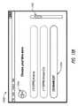
前の段落のうちのどの装置も、本明細書で説明されている中でもとりわけ、この段落で説明されている以下の特徴の組合せを含み得る。装置は、GUIを表示し、複数の陰圧療法パラメータのうちの少なくともいくつかの調整を可能にするように構成されたタッチスクリーンディスプレイを備えることができる。装置は、陰圧創傷療法で2つの創傷を治療するように構成され、プロセッサは、GUIを介して、2つの創傷の治療のアクティブ化を可能にするようにも構成され得る。GUIは、複数の画面、およびメニューにまとめられている複数のアイコンを備えるように構成され、メニューは、各画面の同じ部分に表示されるように構成され得る。 Any of the devices in the previous paragraph may include a combination of the following features described in this paragraph, among other things described herein. The device can comprise a touch screen display configured to display a GUI and allow adjustment of at least some of the plurality of negative pressure therapy parameters. The device may be configured to treat two wounds with negative pressure wound therapy, and the processor may also be configured to allow activation of treatment of the two wounds via the GUI. The GUI may be configured to include multiple screens and multiple icons organized into menus, and the menus may be configured to be displayed on the same portion of each screen.
いくつかの実施形態では、陰圧創傷療法装置は、創傷の上に留置されるように構成された被覆材に流体的に接続されるように構成された陰圧源とコントローラとを備える。コントローラは、流体流路内の少なくとも1つの一時的閉塞の存在を検出するか、または検出を行わせるように構成されるものとしてよく、この流体流路は陰圧源と創傷から吸引された流体を貯蔵するように構成されたキャニスターと、および被覆材とを備え、創傷から吸引された流体がキャニスター内に吸引されることによって少なくとも1つの一時的閉塞が引き起こされる。コントローラは、陰圧源によってもたらされる陰圧のレベルを増加させることによって少なくとも1つの一時的閉塞を除去するか、または除去を行わせるようにも構成され得る。 In some embodiments, a negative pressure wound therapy device comprises a negative pressure source and a controller configured to be fluidly connected to a dressing configured to be placed over the wound. The controller may be configured to detect or cause the presence of at least one temporary occlusion in the fluid flow path, wherein the fluid flow path is a fluid aspirated from the negative pressure source and the wound At least one temporary occlusion is caused by aspiration of fluid aspirated from the wound into the canister. The controller may also be configured to remove or cause at least one temporary occlusion by increasing the level of negative pressure provided by the negative pressure source.
前の段落のうちのどの装置も、本明細書で説明されている中でもとりわけ、この段落で説明されている以下の特徴の組合せを含み得る。コントローラは、流体流路内の少なくとも1つの一時的閉塞の存在を、陰圧源を非アクティブ化するか、または非アクティブ化を行わせることと、陰圧源が非アクティブ化されている間に流体流路内の陰圧の実質的に不連続な減少を検出するか、または検出を行わせることとによって検出するか、または検出を行わせるようにも構成され得る。装置は、キャニスター入口における圧力を測定するように構成された圧力センサーも備えることができ、コントローラは、少なくとも1つの一時的閉塞の存在を、圧力センサーによって測定された圧力の増加を検出することによって検出するか、または検出することを行わせるようにも構成されるものとしてよく、ただし圧力の増加は少なくとも1つの一時的閉塞によって引き起こされる。 Any of the devices in the previous paragraph may include a combination of the following features described in this paragraph, among other things described herein. The controller determines the presence of at least one temporary blockage in the fluid flow path while deactivating or deactivating the negative pressure source and while the negative pressure source is deactivated. It can also be configured to detect or cause a detection by detecting or causing a substantially discontinuous decrease in negative pressure in the fluid flow path. The apparatus can also include a pressure sensor configured to measure the pressure at the canister inlet, and the controller can detect the presence of at least one temporary occlusion by detecting an increase in pressure measured by the pressure sensor. It may also be configured to detect or cause detection to occur, provided that the increase in pressure is caused by at least one temporary occlusion.
いくつかの実施形態において、コンピュータシステムは、通信インターフェース上で、複数の陰圧創傷療法デバイスから複数の動作パラメータを受信することであって、各陰圧創傷療法デバイスは陰圧創傷療法を行うように構成される、受信することと、複数の陰圧創傷療法デバイスのうちの少なくともいくつかを1つのフリートにグループ化することと、共通所有または共通リースステータスに基づきフリート内のデバイスのうちの少なくともいくつかに対する複数の受信された動作パラメータのうちの少なくともいくつかを提供することとを行うように構成された少なくとも1つのプロセッサを備える。 In some embodiments, the computer system is configured to receive a plurality of operating parameters from a plurality of negative pressure wound therapy devices over a communication interface such that each negative pressure wound therapy device performs negative pressure wound therapy. Configured to receive, group at least some of the plurality of negative pressure wound therapy devices into one fleet, and at least one of the devices in the fleet based on common ownership or common lease status At least one processor configured to provide at least some of the plurality of received operating parameters for some.
前の段落のコンピュータシステムは、本明細書で説明されている中でもとりわけ、この段落で説明されている以下の特徴の組合せも含み得る。プロセッサは、フリート内のデバイスの少なくともいくつかに対する地理的配置データ、電池充電データ、および電池寿命データのうちの少なくとも1つを提供するようにも構成され得る。プロセッサは、フリート内の少なくとも1つのデバイスに関連付けられている少なくとも1つの動作パラメータの調整を受信し、受信された調整を伝送し、それによって、少なくとも1つのデバイスに調整に従って陰圧創傷療法の遂行を修正させるようにも構成され得る。 The computer system of the previous paragraph may also include a combination of the following features described in this paragraph, among other things described herein. The processor may also be configured to provide at least one of geographical location data, battery charge data, and battery life data for at least some of the devices in the fleet. The processor receives an adjustment of at least one operating parameter associated with at least one device in the fleet and transmits the received adjustment, thereby performing negative pressure wound therapy according to the adjustment to the at least one device. Can also be configured to modify.
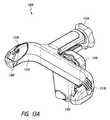
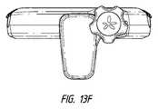
さまざまな実施形態において、装置を装着するためのアタッチメントシステムは、装置に取り外し可能に取り付けられるように構成されたクレードルと、クレードルに取り付けられた第1のアームと、第2のアームとを備え、第2のアームは締付位置と締付解除位置との間で移動されるように構成され、第1および第2のアームは、締付位置で構造体に実質的に固定されて取り付けられるように構成され、第1および第2のアームは、締付解除位置で構造体に実質的に固定されて取り付けられないように構成される。アタッチメントシステムは、また、第1のネジと、第2のアームに取り付けられる第2のネジであって、第1のネジが第2のネジと係合している、第2のネジと、第2のネジに取り付けられ、締付位置と締付解除位置との間で第2のアームを移動するように構成されたつまみとを備える。 In various embodiments, an attachment system for mounting a device comprises a cradle configured to be removably attached to the device, a first arm attached to the cradle, and a second arm, The second arm is configured to be moved between a tightening position and a tightening release position, and the first and second arms are substantially fixed and attached to the structure at the tightening position. The first and second arms are configured to be substantially fixed and not attached to the structure at the tightening release position. The attachment system also includes a first screw and a second screw attached to the second arm, wherein the first screw is engaged with the second screw, And a knob attached to the second screw and configured to move the second arm between a tightening position and a tightening release position.
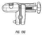
前の段落のアタッチメントシステムは、本明細書で説明されている中でもとりわけ、この段落で説明されている以下の特徴の組合せも含み得る。第1および第2のネジは、パワースクリューであってよい。第1のネジは第1のネジ山を備え、第2ネジは第2のネジ山を備えることができ、第1および第2のネジ山はアクメネジであってよい。第1のネジは、実質的に中空の部分を備え、第2のネジの少なくとも一部は、締付位置で第1のネジの内側部分内に位置決めされるように構成される。第1のネジの内側部分は、第2のネジの第2のネジ山と係合するように構成された雌ネジを備えることができる。第1のネジは、第1の方向に配向された第1のネジ山を備え、第2のネジは、第1の方向とは反対の第2の方向に配向された第2のネジ山を備え得る。ハンドルを回転して、第2のアームを第1のネジの第1のリードと第2のネジの第2のリードとの総和に比例する距離だけ移動させることができる。第2のアームは、完全開放位置と完全閉鎖位置との間で移動されるようにも構成されるものとしてよく、第1および第2のアームは完全閉鎖位置で接触し、第1および第2のアームは完全開放位置である距離だけ隔てられ、それによって、つまみを約4回転すると、第2のアームは完全閉鎖位置と完全開放位置との間で移動する。 The attachment system of the previous paragraph may also include, among other things described herein, a combination of the following features described in this paragraph. The first and second screws may be power screws. The first screw may comprise a first thread, the second screw may comprise a second thread, and the first and second threads may be acme screws. The first screw includes a substantially hollow portion, and at least a portion of the second screw is configured to be positioned within the inner portion of the first screw in a tightened position. The inner portion of the first screw can comprise a female screw configured to engage the second thread of the second screw. The first screw has a first thread oriented in a first direction, and the second screw has a second thread oriented in a second direction opposite to the first direction. Can be prepared. The handle can be rotated to move the second arm by a distance proportional to the sum of the first lead of the first screw and the second lead of the second screw. The second arm may also be configured to be moved between a fully open position and a fully closed position, wherein the first and second arms contact in the fully closed position and the first and second The arms are separated by a distance that is the fully open position, so that after about 4 turns of the knob, the second arm moves between the fully closed and fully open positions.
前の段落のうちのどのアタッチメントシステムも、本明細書で説明されている中でもとりわけ、この段落で説明されている以下の特徴の組合せを含み得る。この構造体は、支柱およびベッドレールの少なくとも一方であってよい。陰圧源は、創傷の上に留置され、実質的に流体不浸透性を有するシールを創傷の上に形成するように構成された被覆材に流体的に接続されるように構成され得る。装置は、ポンプを備えることができる。ポンプは、陰圧創傷療法(NPWT)装置であるものとしてよい。いくつかの実施形態において、前の段落のうちのどのアタッチメントシステムも、陰圧創傷療法(NPWT)装置を構造体に取り付ける方法において使用され得る。 Any attachment system in the previous paragraph may include, among other things described herein, a combination of the following features described in this paragraph. This structure may be at least one of a column and a bed rail. The negative pressure source may be configured to be placed over the wound and fluidly connected to a dressing configured to form a substantially fluid impermeable seal over the wound. The device can comprise a pump. The pump may be a negative pressure wound therapy (NPWT) device. In some embodiments, any attachment system of the previous paragraph can be used in a method of attaching a negative pressure wound therapy (NPWT) device to a structure.
いくつかの実施形態では、装置を装着するためのアタッチメントシステムは、装置に取り外し可能に取り付けられるように構成されたクレードルと、クレードルに取り付けられた第1のクランプアームと、第2のクランプアームとを備え、第2のクランプアームは締付位置と締付解除位置との間で移動されるように構成され、第1および第2のクランプアームは、締付位置で構造体に実質的に固定されて取り付けられるように構成され、第1のネジは第2のネジと係合し、第1のネジは第2のネジの第2のネジ山から反対の方向に配向された第1のネジ山を備え、第2のネジは締付位置と締付解除位置との間で第2のアームを移動するように構成される。 In some embodiments, an attachment system for mounting a device includes a cradle configured to be removably attached to the device, a first clamp arm attached to the cradle, and a second clamp arm. The second clamp arm is configured to be moved between a tightening position and a tightening release position, and the first and second clamp arms are substantially fixed to the structure in the tightening position. The first screw engages the second screw and the first screw is oriented in the opposite direction from the second thread of the second screw A crest is provided and the second screw is configured to move the second arm between a tightening position and a tightening release position.
前の段落のうちのどのアタッチメントシステムも、本明細書で説明されている中でもとりわけ、この段落で説明されている以下の特徴の組合せを含み得る。装置は、ポンプであってよい。ポンプは、陰圧創傷療法(NPWT)装置であるものとしてよい。いくつかの実施形態において、前の段落のうちのどのアタッチメントシステムも、陰圧創傷療法(NPWT)装置を構造体に取り付ける方法において使用され得る。 Any attachment system in the previous paragraph may include, among other things described herein, a combination of the following features described in this paragraph. The device may be a pump. The pump may be a negative pressure wound therapy (NPWT) device. In some embodiments, any attachment system of the previous paragraph can be used in a method of attaching a negative pressure wound therapy (NPWT) device to a structure.
いくつかの実施形態において、装置を装着するためのアタッチメントシステムは、第1のアームを有するクレードルと、ハウジングと、装置に取り外し可能に取り付けられるように構成された複数のラッチとを備える。アタッチメントシステムは、締付位置と締付解除位置との間で移動されるように構成された第2のアームも備え、第1および第2のアームは、締付位置で構造体に実質的に固定されて取り付けられるように構成され、第1および第2のアームは、締付解除位置で構造体に実質的に固定されて取り付けられないように構成される。アタッチメントシステムは、また、クレードルのハウジング内に少なくとも部分的に位置決めされた第1のネジであって、第1の方向に配向された第1のネジ山を備える、第1のネジと、第2の方向に配向された第2のネジ山を備える第2のネジであって、クレードルのハウジング内に少なくとも部分的に位置決めされ、第2のアームの開口部を介して第2のアームに取り付けられ、開口部は第2のネジの第2のネジ山と係合するように構成された第1の雌ネジを備える、第2のネジとを具備する。第2のネジは、第1のネジの少なくとも一部が締付位置で第2のネジの内側に位置決めされるように構成されるように第1のネジの第1のネジ山と係合するように構成された第2の雌ネジを有する実質的に中空の内側部分を備える。アタッチメントシステムは、また、第2のネジに取り付けられたつまみを備え、つまみは締付位置と締付解除位置との間で第2のアームを移動するように構成される。 In some embodiments, an attachment system for mounting a device includes a cradle having a first arm, a housing, and a plurality of latches configured to be removably attached to the device. The attachment system also includes a second arm configured to be moved between a clamping position and a clamping release position, wherein the first and second arms are substantially on the structure in the clamping position. The first and second arms are configured to be fixedly attached and configured to be substantially fixed and not attached to the structure in the clamp release position. The attachment system also includes a first screw at least partially positioned within the housing of the cradle, the first screw comprising a first thread oriented in a first direction, and a second screw A second screw with a second thread oriented in the direction of and positioned at least partially within the housing of the cradle and attached to the second arm through an opening in the second arm The opening comprises a second screw comprising a first female screw configured to engage a second thread of the second screw. The second screw engages the first thread of the first screw such that at least a portion of the first screw is configured to be positioned inside the second screw in the tightened position. A substantially hollow inner portion having a second internal thread configured as described above. The attachment system also includes a knob attached to the second screw, the knob configured to move the second arm between a tightened position and a tightened release position.
前の段落のうちのどのアタッチメントシステムも、本明細書で説明されている中でもとりわけ、この段落で説明されている以下の特徴の組合せを含み得る。装置は、ポンプであってよい。ポンプは、陰圧創傷療法(NPWT)装置であるものとしてよい。いくつかの実施形態において、前の段落のうちのどのアタッチメントシステムも、陰圧創傷療法(NPWT)装置を構造体に取り付ける方法において使用され得る。 Any attachment system in the previous paragraph may include, among other things described herein, a combination of the following features described in this paragraph. The device may be a pump. The pump may be a negative pressure wound therapy (NPWT) device. In some embodiments, any attachment system of the previous paragraph can be used in a method of attaching a negative pressure wound therapy (NPWT) device to a structure.
さまざまな実施形態において、陰圧創傷療法装置を操作する方法は、創傷の上に留置されるように構成された被覆材に流体的に接続されるように構成された陰圧源を操作するステップを含み、陰圧源は複数の陰圧療法パラメータに従って創傷に陰圧創傷療法を遂行するように構成される。この方法は、また、複数の陰圧療法パラメータのうちの少なくともいくつかの調整を可能にするように構成されたグラフィカルユーザインターフェース(GUI)を操作するステップと、GUIを介して、第1の陰圧療法パラメータの第1の調整を行い、それによって、第1の陰圧療法パラメータの第1の調整に少なくとも一部は基づき陰圧源の動作の調整を行わせるステップとを含む。装置は、複数の陰圧療法パラメータに関連付けられている複数の履歴データパラメータを記録するように構成され、通信インターフェース上で、複数の履歴データパラメータのうちの少なくともいくつかをリモートコンピュータに伝送するようにさらに構成される。少なくとも1つの履歴データパラメータは、陰圧療法圧力療法パラメータの第1および第2の設定に関連付けられ、第1および第2の設定は異なる時間に陰圧療法パラメータに割り当てられる。 In various embodiments, a method of operating a negative pressure wound therapy device includes operating a negative pressure source configured to be fluidly connected to a dressing configured to be placed over a wound. And the negative pressure source is configured to perform negative pressure wound therapy on the wound according to a plurality of negative pressure therapy parameters. The method also includes manipulating a graphical user interface (GUI) configured to allow adjustment of at least some of the plurality of negative pressure therapy parameters, and the first negative via the GUI. Making a first adjustment of the pressure therapy parameter, thereby causing an adjustment of the operation of the negative pressure source based at least in part on the first adjustment of the first negative pressure therapy parameter. The apparatus is configured to record a plurality of historical data parameters associated with the plurality of negative pressure therapy parameters to transmit at least some of the plurality of historical data parameters to the remote computer over the communication interface. Further configured. At least one historical data parameter is associated with the first and second settings of the negative pressure therapy pressure therapy parameter, and the first and second settings are assigned to the negative pressure therapy parameter at different times.
前の段落の方法は、本明細書で説明されている中でもとりわけ、この段落で説明されている以下の特徴の組合せも含み得る。リモートコンピュータに伝送される複数の履歴データパラメータのうちの少なくともいくつかは、装置識別データ、装置配置データ、療法履歴データ、およびアラームデータのうちの1つまたは複数を含み得る。装置は、装置の地理的配置に対応する装置配置データを記録するようにも構成され得る。装置は、全世界測位データ(GPS)およびセルラーネットワークデータのうちの少なくとも一方に基づき装置配置データを記録するようにも構成され得る。装置は、通信インターフェース上で、複数の履歴データパラメータのうちの少なくともいくつかをリモートコンピュータに定期的に伝送するようにも構成され得る。この方法は、また、GUIを介して、複数の履歴データパラメータのうちの少なくともいくつかをリモートコンピュータに伝送する要求を提供し、それによって、複数の履歴データパラメータのうちの少なくともいくつかのリモートコンピュータへの伝送を行わせるステップも含み得る。装置は、流体流路内の流量を決定し、流体流路は陰圧源および被覆材を備え、GUIを介して、決定された流量の指示を提示するようにも構成され得る。流量の指示は、ゲージを含み得る。装置は、流体流路の少なくとも一部の中の圧力を測定するように構成された圧力センサーを備えることもでき、装置は、圧力センサーによって測定された圧力に少なくとも一部は基づき流体流路内の流量を決定するようにも構成され得る。 The method of the previous paragraph may also include combinations of the following features described in this paragraph, among other things described herein. At least some of the plurality of historical data parameters transmitted to the remote computer may include one or more of device identification data, device placement data, therapy history data, and alarm data. The device may also be configured to record device placement data corresponding to the geographical location of the device. The device may also be configured to record device location data based on at least one of global positioning data (GPS) and cellular network data. The apparatus may also be configured to periodically transmit at least some of the plurality of historical data parameters to the remote computer over the communication interface. The method also provides a request to transmit at least some of the plurality of historical data parameters to the remote computer via the GUI, thereby providing at least some remote computers of the plurality of historical data parameters. It may also include the step of causing the transmission to be performed. The apparatus determines a flow rate in the fluid flow path, the fluid flow path includes a negative pressure source and a dressing, and may also be configured to present an indication of the determined flow rate via the GUI. The flow indication may include a gauge. The apparatus can also comprise a pressure sensor configured to measure a pressure in at least a portion of the fluid flow path, the apparatus being in the fluid flow path based at least in part on the pressure measured by the pressure sensor. It may also be configured to determine the flow rate.
前の段落のうちのどの段落の方法も、本明細書で説明されている中でもとりわけ、この段落で説明されている以下の特徴の組合せを含み得る。陰圧源は、真空ポンプを備えることができ、装置は、真空ポンプの測定された速度に少なくとも一部は基づき流体流路内の流量を決定するようにも構成され得る。装置は、流量が高流量閾値を満たすことを決定することに応答して陰圧源を非アクティブ化し、GUIを介して、高流量指示を提示するようにも構成され得る。提供される高流量指示は、高流量状態を解決するための情報を含み得る。GUIは、複数の陰圧療法パラメータに関連付けられている履歴データパラメータのうちの少なくともいくつかを時間順に表示するように構成され得る。履歴データパラメータの少なくともいくつかは、陰圧創傷療法の遂行に関連付けられている1つまたは複数のエラーを含み得る。GUIは、複数の期間にわたって遂行される陰圧創傷療法の全時間を含むログを表示するように構成され、1つまたは複数のエラーは、このログに含まれ得る。 The method of any of the previous paragraphs may include the following combination of features described in this paragraph, among other things described herein. The negative pressure source can comprise a vacuum pump and the apparatus can also be configured to determine the flow rate in the fluid flow path based at least in part on the measured speed of the vacuum pump. The device may also be configured to deactivate the negative pressure source in response to determining that the flow rate meets the high flow threshold and present a high flow indication via the GUI. The provided high flow indication may include information for resolving the high flow condition. The GUI may be configured to display at least some of the historical data parameters associated with the plurality of negative pressure therapy parameters in chronological order. At least some of the historical data parameters may include one or more errors associated with performing negative pressure wound therapy. The GUI is configured to display a log that includes the total time of negative pressure wound therapy performed over multiple time periods, and one or more errors may be included in this log.
前の段落のうちのどの段落の方法も、本明細書で説明されている中でもとりわけ、この段落で説明されている以下の特徴の組合せを含み得る。装置は、複数の履歴データパラメータのうちの少なくともいくつかを伝送することに応答して、リモートコンピュータから第2の陰圧療法パラメータの第2の調整を受信し、第2の陰圧療法パラメータの受信された第2の調整に少なくとも一部は基づき陰圧源の動作を調整するようにも構成され得る。GUIは、第2の陰圧療法パラメータの調整を可能にするように構成され得る。装置は、GUIを表示するように構成されたタッチスクリーンディスプレイを備えることができる。装置は、陰圧創傷療法で2つの創傷を治療するように構成され、GUIは、2つの創傷の治療のアクティブ化を可能にするように構成され得る。GUIは、複数の画面、およびメニューにまとめられている複数のアイコンを備えるように構成され、メニューは、各画面の同じ部分に表示されるように構成され得る。 The method of any of the previous paragraphs may include the following combination of features described in this paragraph, among other things described herein. The device receives a second adjustment of the second negative pressure therapy parameter from the remote computer in response to transmitting at least some of the plurality of historical data parameters, and the second negative pressure therapy parameter It may also be configured to adjust the operation of the negative pressure source based at least in part on the received second adjustment. The GUI may be configured to allow adjustment of the second negative pressure therapy parameter. The device can comprise a touch screen display configured to display a GUI. The device may be configured to treat two wounds with negative pressure wound therapy and the GUI may be configured to allow activation of treatment of the two wounds. The GUI may be configured to include multiple screens and multiple icons organized into menus, and the menus may be configured to be displayed on the same portion of each screen.
いくつかの実施形態において、陰圧創傷療法装置を操作する方法は、創傷の上に留置されるように構成された被覆材に流体的に接続されるように構成された陰圧源を操作するステップを含み、陰圧源は創傷に陰圧創傷療法を遂行するように構成される。装置は、陰圧源、創傷から吸引された流体を貯蔵するように構成されたキャニスター、および被覆材を備える流体流路内の少なくとも1つの一時的閉塞の存在を検出することであって、少なくとも1つの一時的閉塞は創傷から吸引された流体がキャニスター内に吸引されることによって引き起こされる、検出することと、陰圧源によってもたらされる陰圧のレベルを増加させることによって少なくとも1つの一時的閉塞を除去することとを行うように構成される。 In some embodiments, a method of operating a negative pressure wound therapy device operates a negative pressure source configured to be fluidly connected to a dressing configured to be placed over a wound. The negative pressure source is configured to perform negative pressure wound therapy on the wound. The device detects the presence of at least one temporary occlusion in a fluid flow path comprising a negative pressure source, a canister configured to store fluid aspirated from a wound, and a dressing, and at least One temporary occlusion is caused by fluid aspirated from the wound being aspirated into the canister, and at least one temporary occlusion by increasing the level of negative pressure provided by the negative pressure source Is configured to perform.
前の段落のうちのどの段落の方法も、本明細書で説明されている中でもとりわけ、この段落で説明されている以下の特徴の組合せを含み得る。装置は、流体流路内の少なくとも1つの一時的閉塞の存在を、陰圧源を非アクティブ化するステップと、陰圧源が非アクティブ化されている間に流体流路内の陰圧の実質的に不連続な減少を検出するステップとによって、検出するようにも構成され得る。装置は、キャニスター入口における圧力を測定するように構成された圧力センサーも備えることができ、装置は、少なくとも1つの一時的閉塞の存在を、圧力センサーによって測定された圧力の増加を検出することによって、検出するようにも構成されるものとしてよく、ただし圧力の増加は少なくとも1つの一時的閉塞によって引き起こされる。 The method of any of the previous paragraphs may include the following combination of features described in this paragraph, among other things described herein. The apparatus detects the presence of at least one temporary occlusion in the fluid flow path by deactivating the negative pressure source and a substantial amount of negative pressure in the fluid flow path while the negative pressure source is deactivated. And detecting a non-continuous decrease. The apparatus can also comprise a pressure sensor configured to measure the pressure at the canister inlet, the apparatus detecting the presence of at least one temporary blockage by detecting an increase in pressure measured by the pressure sensor. May also be configured to detect, but the increase in pressure is caused by at least one temporary occlusion.
いくつかの実施形態では、複数の陰圧創傷療法デバイスを管理する方法は、通信インターフェース上で、複数の陰圧創傷療法デバイスから複数の動作パラメータを受信するステップであって、各陰圧創傷療法デバイスは陰圧創傷療法を行うように構成される、ステップと、複数の陰圧創傷療法デバイスのうちの少なくともいくつかを1つのフリートにグループ化するステップと、共通所有または共通リースステータスに基づきフリート内のデバイスのうちの少なくともいくつかに対する複数の受信された動作パラメータのうちの少なくともいくつかを提供するステップとを含む。この方法は、プロセッサによって実行され得る。 In some embodiments, a method of managing a plurality of negative pressure wound therapy devices includes receiving a plurality of operating parameters from a plurality of negative pressure wound therapy devices over a communication interface, each negative pressure wound therapy The device is configured to perform negative pressure wound therapy, grouping at least some of the multiple negative pressure wound therapy devices into a fleet, and fleet based on common ownership or common lease status Providing at least some of a plurality of received operating parameters for at least some of the devices within. This method may be performed by a processor.
前の段落のうちのどの段落の方法も、本明細書で説明されている中でもとりわけ、この段落で説明されている以下の特徴の組合せを含み得る。方法は、フリート内のデバイスの少なくともいくつかに対する地理的配置データ、電池充電データ、および電池寿命データのうちの少なくとも1つを提供するステップも含み得る。この方法は、また、フリート内の少なくとも1つのデバイスに関連付けられている少なくとも1つの動作パラメータの調整を受信するステップと、受信された調整を伝送し、それによって、少なくとも1つのデバイスに調整に従って陰圧創傷療法の遂行を修正させるステップとを含み得る。 The method of any of the previous paragraphs may include the following combination of features described in this paragraph, among other things described herein. The method may also include providing at least one of geographical location data, battery charge data, and battery life data for at least some of the devices in the fleet. The method also includes receiving an adjustment of at least one operating parameter associated with at least one device in the fleet, and transmitting the received adjustment, thereby impairing the at least one device according to the adjustment. Modifying the performance of pressure wound therapy.
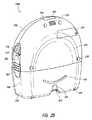
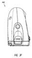
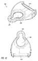
さまざまな実施形態において、陰圧創傷療法デバイスは、突起部がハウジングの外側に形成されているハウジングと、第1の部分および第2の部分を備える、突起部に取り付けられるように構成された装着具とを備える。第1の部分は、突起部の直径より大きい直径を有する、第1の円形開口部と、第1の開口部から延在する第2の細長い開口部とを備え、第2の開口部は突起部の直径と実質的に同じである幅を有する。第2の部分は、キャリーストラップの取り付けを可能にするように構成されたロッドを備える。装着具は、第2の細長い開口部の領域内の突起部に装着具を結合することによってデバイスに取り付けられるように構成される。 In various embodiments, a negative pressure wound therapy device is an attachment configured to be attached to a protrusion comprising a housing having a protrusion formed outside the housing, and a first portion and a second portion. Equipment. The first portion includes a first circular opening having a diameter greater than the diameter of the protrusion, and a second elongated opening extending from the first opening, the second opening being a protrusion Having a width that is substantially the same as the diameter of the part. The second part comprises a rod configured to allow attachment of a carry strap. The mounting device is configured to be attached to the device by coupling the mounting device to a protrusion in the region of the second elongated opening.
本発明の実施形態は、付属の図面を参照しつつ、例としてのみ、以下で説明される。 Embodiments of the present invention are described below by way of example only with reference to the accompanying drawings.
概要
本明細書で開示されている実施形態は、減圧で創傷を治療するシステムおよび方法に関係する。本明細書で使用されているように、-XmmHgなどの減圧または陰圧レベルは、760mmHg(または1atm、29.93inHg、101.325kPa、14.696psiなど)に対応し得る、通常の環境大気圧に相対的な圧力レベルを表す。したがって、-XmmHgの陰圧値は、760mmHgよりXmmHg低い絶対圧力、言い換えると、(760-X)mmHgの絶対圧力を反映する。それに加えて、XmmHgより「少ない」または「小さい」陰圧は、大気圧に近い圧力に対応する(たとえば、-40mmHgは-60mmHgより少ない)。それに加えて、-XmmHgより「多い」または「大きい」陰圧は、大気圧から遠い圧力に対応する(たとえば、-80mmHgは-60mmHgより多い)。いくつかの実施形態では、局所環境大気圧は、基準点として使用され、そのような局所大気圧は、必ずしも、たとえば、760mmHgでなくてもよい。SUMMARY Embodiments disclosed herein relate to systems and methods for treating wounds with reduced pressure. As used herein, vacuum or negative pressure levels such as -XmmHg are relative to normal ambient atmospheric pressure, which may correspond to 760 mmHg (or 1 atm, 29.93 inHg, 101.325 kPa, 14.696 psi, etc.) Represents the correct pressure level. Therefore, the negative pressure value of -XmmHg reflects an absolute pressure lower than 760 mmHg by XmmHg, in other words, an absolute pressure of (760-X) mmHg. In addition, a “less” or “smaller” negative pressure than XmmHg corresponds to a pressure close to atmospheric pressure (eg, −40 mmHg is less than −60 mmHg). In addition, a “more” or “greater” negative pressure than -XmmHg corresponds to a pressure far from atmospheric (eg, -80 mmHg is more than -60 mmHg). In some embodiments, local ambient atmospheric pressure is used as a reference point, and such local atmospheric pressure may not necessarily be, for example, 760 mmHg.
本発明の実施形態は、局所陰圧(「TNP」)または減圧または陰圧療法システムにおける使用に一般的に適用可能である。簡単に言うと、陰圧創傷療法は、組織浮腫を低減し、血流および肉芽組織の形成を促し、および/または過剰な浸出液を取り除くことによって「治癒しにくい」創傷の多くの形態の閉鎖および治癒を補助し、細菌量(したがって感染症のリスク)を減らすことができる。それに加えて、この療法は、創傷の障害を少なくしてより速やかな治癒をもたらすことを可能にする。TNP療法システムは、流体を取り除くことによって手術で縫合された創傷の治癒をも助けることができる。いくつかの実施形態では、TNP療法は、閉鎖部の併置位置にある組織を安定化するのを助ける。TNP療法のさらに有益な使用はグラフトおよびフラップに見ることができ、そこでは、過剰な流体を取り除くことが重要であり、組織の生存を確実にするためにグラフトから組織への近接近が必要である。 Embodiments of the present invention are generally applicable for use in local negative pressure (“TNP”) or reduced pressure or negative pressure therapy systems. Simply put, negative pressure wound therapy reduces the tissue edema, promotes blood flow and granulation tissue formation, and / or removes excess forms of wounds that are “hard to heal” by removing excess exudate and Helps with healing and reduces the amount of bacteria (and thus the risk of infection). In addition, this therapy makes it possible to reduce wound damage and provide faster healing. The TNP therapy system can also help heal surgically sutured wounds by removing fluid. In some embodiments, TNP therapy helps stabilize tissue in the apposition position of the closure. A further beneficial use of TNP therapy can be found in grafts and flaps, where it is important to remove excess fluid and close proximity from the graft to the tissue is required to ensure tissue survival. is there.
いくつかの実施形態では、ポンプアセンブリは、ユーザ(たとえば、患者、医師、看護婦など)とインターフェースすること、陰圧ポンプを制御すること、ネットワーク接続を提供することなど、反応性のさまざまなレベルに関連付けられているさまざまなシステム機能に関与する1つまたは複数のプロセッサまたはコントローラを備えることができる。いくつかの実施形態では、反応性のレベルは、リスクのレベルに対応するか、または関連付けられ得る。たとえば、陰圧源を制御するステップは、高リスク活動として分類されるものとしてよいが、それは、療法の遂行が、患者の安全、治癒などに重要だからである。したがって、陰圧源を制御するステップは、反応性の高いレベルに関連付けられ得る。ポンプアセンブリは、また、データを受信し、提供するための1つまたは複数の入力/出力デバイスも備えることができる。これらのデバイスは、画面、タッチスクリーン、ボタン、つまみ、ポート、および同様のものを含み得る。ポンプアセンブリは、TNPシステムの動作を制御し、監視するためのグラフィカルユーザインターフェース(GUI)画面を提示するように構成され得る。 In some embodiments, the pump assembly can interface with users (e.g., patients, doctors, nurses, etc.), control negative pressure pumps, provide network connectivity, etc. One or more processors or controllers may be provided that are responsible for various system functions associated with the. In some embodiments, the level of reactivity may correspond to or be associated with a level of risk. For example, the step of controlling the negative pressure source may be classified as a high-risk activity because the performance of therapy is important for patient safety, healing, etc. Thus, controlling the negative pressure source can be associated with a high level of reactivity. The pump assembly can also include one or more input / output devices for receiving and providing data. These devices may include screens, touch screens, buttons, knobs, ports, and the like. The pump assembly may be configured to present a graphical user interface (GUI) screen for controlling and monitoring the operation of the TNP system.
いくつかの実施形態では、TNPシステムは、システム内の流体の流れを決定し、監視するように構成され得る。これは、流体流路内の圧力を測定し、フィードバックをコントローラに送る1つまたは複数の圧力トランスデューサまたはセンサーを使用することによって実行され得る。さまざまな実施形態において、流体流の決定は、ポンプモーターの速度を監視する技術、較正された流体流制限器を留置することによって流体流路の一部の中の流体の流れを監視する技術、検出された圧力パルスの振幅、周波数、または勾配などの1つまたは複数の特性を監視する技術のうちの1つまたは複数を利用することによって実行され得る。算出された流量は、所望の療法が患者に対して遂行されるかどうか、システム内に1つまたは複数の漏出が存在するかどうか、および同様のことを決定するために使用され得る。 In some embodiments, the TNP system may be configured to determine and monitor fluid flow within the system. This can be done by using one or more pressure transducers or sensors that measure the pressure in the fluid flow path and send feedback to the controller. In various embodiments, the determination of fluid flow is accomplished by a technique that monitors the speed of the pump motor, a technique that monitors the flow of fluid in a portion of the fluid flow path by deploying a calibrated fluid flow restrictor, It can be performed by utilizing one or more of techniques that monitor one or more characteristics such as the amplitude, frequency, or slope of the detected pressure pulse. The calculated flow rate can be used to determine whether the desired therapy is performed on the patient, whether one or more leaks are present in the system, and the like.
いくつかの実施形態では、システムは、動作状態をユーザに対して反映する、指示、アラームなどを提供するように構成され得る。システムは、さまざまな動作状態を信号としてユーザに送るように構成された視覚的、聴覚的、およびタイプのインジケータおよびまたはアラームを含み得る。そのような状態は、システムのオンオフ、スタンバイ、一時停止、通常動作、被覆材問題、漏出、エラー、および同様のものを含む。インジケータおよび/またはアラームは、スピーカー、ディスプレイ、光源など、および/またはこれらの組合せを含み得る。さまざまな実施形態において、指示、アラームなどは、1つまたは複数の適用可能な標準によって誘導される。 In some embodiments, the system may be configured to provide instructions, alarms, etc. that reflect operating conditions to the user. The system may include visual, audible, and type indicators and / or alarms configured to send various operating conditions as signals to the user. Such conditions include system on / off, standby, pause, normal operation, dressing problems, leaks, errors, and the like. Indicators and / or alarms may include speakers, displays, light sources, etc., and / or combinations thereof. In various embodiments, instructions, alarms, etc. are guided by one or more applicable standards.
いくつかの実施形態において、ポンプアセンブリは、外部接続を提供するために1つまたは複数の通信プロセッサを備えることができる。そのような接続は、ポンプアセンブリの配置追跡、順守監視、動作パラメータの追跡、療法設定のリモート選択および調整、および同様のものなどのさまざまな活動に使用され得る。接続は、全世界測位システム(GPS)技術、セルラー接続(たとえば、2G、3G、LTE、4G)、WiFi接続、インターネット接続、および同様のものを含み得る。いくつかの実施形態では、有線接続が利用され得る。さまざまな実施形態において、ポンプアセンブリは、データをクラウドに送り、クラウドからデータを受信することができる。データは、配置データ、順守監視データ、動作パラメータ、療法設定のリモート選択および調整のためのデータ、および同様のものを含み得る。 In some embodiments, the pump assembly can include one or more communication processors to provide external connections. Such connections may be used for various activities such as pump assembly placement tracking, compliance monitoring, operating parameter tracking, remote selection and adjustment of therapy settings, and the like. Connections may include global positioning system (GPS) technology, cellular connections (eg, 2G, 3G, LTE, 4G), WiFi connections, Internet connections, and the like. In some embodiments, a wired connection may be utilized. In various embodiments, the pump assembly can send data to the cloud and receive data from the cloud. The data may include placement data, compliance monitoring data, operating parameters, data for remote selection and adjustment of therapy settings, and the like.
本発明の実施形態は、限定はしないが、陰圧創傷療法(「NPWT」)装置を含む、装置またはデバイスを監視するためのアタッチメントシステムに関する。いくつかの実施形態では、アタッチメントシステムは、装置に取り外し可能に取り付けられるように構成されたクレードルを備える。アタッチメントシステムは、クレードルに取り付けられた第1のクランプアームと、第2のクランプアームとを備える。第2のクランプアームは、締付解除位置と締付位置との間で移動されるように構成されるものとしてよく、第1および第2のクランプアームは、構造体に実質的に確実に取り付けられるように構成される。締付解除位置では、第1および第2のアームは、構造体に取り付けられないように構成され得る。構造体は、IVポール、ベッドレール、および同様なものなどの、装置(たとえば、医療装置)を装着するのに適した構造体を含み得る。アタッチメントシステムは、締付位置と締付解除位置との間で第2のアームを移動するように構成され得る第2のネジと係合された第1のネジも備える。第2のネジは、ハンドルに取り付けられ得る。第1および第2のネジのネジ山は、単一のハンドル回転が1つのネジを使用するのと比較して2倍または実質的に2倍の直線運動をもたらすように対向するピッチとすることができる。たとえば、一実施形態では、第2のクランプを第1および第2のクランプアームが分離されないか、または実質的に分離されない(たとえば、接触している)完全閉鎖位置と第1および第2のクランプアームが互いに最大距離だけ分離されている完全開放位置との間で移動するためにハンドルを約4回転させる必要がある。その結果、アタッチメントシステムは、装置をさまざまな厚さの構造体に効率的に、固定して取り付けるために使用され得る。 Embodiments of the present invention relate to an attachment system for monitoring an apparatus or device, including but not limited to a negative pressure wound therapy (“NPWT”) apparatus. In some embodiments, the attachment system comprises a cradle configured to be removably attached to the device. The attachment system includes a first clamp arm attached to the cradle and a second clamp arm. The second clamp arm may be configured to be moved between a clamp release position and a clamp position, and the first and second clamp arms are substantially securely attached to the structure. Configured to be. In the clamp release position, the first and second arms may be configured not to be attached to the structure. The structure may include structures suitable for mounting devices (eg, medical devices), such as IV poles, bed rails, and the like. The attachment system also includes a first screw engaged with a second screw that may be configured to move the second arm between a clamped position and a clamped release position. The second screw can be attached to the handle. The threads of the first and second screws should be opposed pitches so that a single handle rotation results in a linear motion that is twice or substantially twice that of using a single screw Can do. For example, in one embodiment, the second clamp has a fully closed position and the first and second clamps where the first and second clamp arms are not separated or substantially separated (eg, in contact). In order to move between the fully open positions where the arms are separated by a maximum distance from each other, the handle needs to be rotated about 4 turns. As a result, the attachment system can be used to efficiently and securely attach the device to various thickness structures.
陰圧システム
図1は、創傷被覆120によって封止される創腔110内に留置された創傷充填材130を備える陰圧または減圧創傷治療(またはTNPもしくはNPWT)システム100の一実施形態を示している。創傷充填材130は、創傷被覆120と組み合わせて、創傷被覆材と称され得る。単一または多重内腔管または導管140は、減圧を供給するように構成されたポンプアセンブリまたはNPWT装置150で創傷被覆120に接続される。創傷被覆120は、創腔110と流体的に連通することができる。本明細書で開示されているシステム実施形態のいずれにおいて、図1に示されている実施形態と同様に、ポンプアセンブリは、キャニスターレスポンプアセンブリであってよい(つまり、浸出液が創傷被覆材内に回収されるか、または別の場所に回収のため管140を介して移送される)。しかし、本明細書で開示されているポンプアセンブリ実施形態はどれも、キャニスターを備えるか、または支持するように構成され得る。それに加えて、本明細書で開示されているシステム実施形態のいずれにおいても、ポンプアセンブリ実施形態はどれも、被覆材によって、または被覆材に隣接して装着されるか、または支持され得る。創傷充填材130は、親水性または疎水性発泡体、ガーゼ、膨張袋、などの好適なタイプのものであってよい。創傷充填材130は、実質的に空洞を充填するように創腔110に形状適合可能であるものとしてよい。創傷被覆120は、創腔110の上に実質的に流体不浸透性のシールを設けることができる。いくつかの実施形態では、創傷被覆120は、頂部側と底部側とを有し、底部側は創腔110と接着剤で(または他の好適な手段で)シールを形成する。導管140または本明細書で開示されている他の導管は、ポリウレタン、PVC、ナイロン、ポリエチレン、シリコーン、または他の好適な材料から形成され得る。Negative Pressure System FIG. 1 illustrates one embodiment of a negative or reduced pressure wound treatment (or TNP or NPWT)
創傷被覆120のいくつかの実施形態は、導管140の端部を受け入れるように構成されたポート(図示せず)を有することができる。いくつかの実施形態では、導管140は、他の何らかの方法で、創傷被覆120を通過し、および/または下を通り、減圧を創腔110に供給して、創腔内の減圧の所望のレベルを維持することができる。導管140は、ポンプアセンブリ150と創傷被覆120との間に少なくとも実質的に封止された流体流路を形成するように構成された好適な物品であってよく、これによりポンプアセンブリ150によってもたらされる減圧を創腔110に供給することができる。 Some embodiments of the wound dressing 120 may have a port (not shown) configured to receive the end of the
創傷被覆120および創傷充填材130は、単一の物品または一体化された単一ユニットとして提供され得る。いくつかの実施形態では、創傷充填材は提供されず、創傷被覆だけが、創傷被覆材としてみなされ得る。次いで、創傷被覆材は、導管140を介して、ポンプアセンブリ150などの、陰圧源に接続され得る。いくつかの実施形態では、必要ではないが、ポンプアセンブリ150は、小型化された携帯型のものであってよいが、より大きい従来型のポンプもそのように使用され得る。 Wound covering 120 and wound
創傷被覆120は、治療されるべき創傷部位の上に配置され得る。創傷被覆120は、創傷部位の上に実質的に封止された空洞またはエンクロージャを形成することができる。いくつかの実施形態では、創傷被覆120は、高い透湿度を有するフィルムを有し余剰流体の蒸発を可能にするように構成されるものとしてよく、その中に超吸収材料が含まれており、それにより創傷浸出液を完全に吸収することができる。本明細書全体を通して創傷が言及されていることは理解されるであろう。この意味で、創傷という用語は、広い意味で解釈されるべきであり、皮膚が破れているか、切れているか、もしくは穴が空いているか、または外傷が患者の皮膚に打撲傷、または他の表面もしくは他の状態もしくは欠陥を引き起こすか、そうでなければ減圧治療から恩恵を受ける、開放創および閉鎖創を包含することが理解されるべきである。したがって、創傷は、流体が産生される場合も産生されない場合もある組織の損傷領域として広い意味で定義される。このような創傷の例として、限定はしないが、急性創傷、慢性創傷、外科的切開および他の切開、亜急性および裂開創傷、外傷、皮弁および植皮、裂傷、表皮剥離、打撲傷、火傷、糖尿病性潰瘍、褥瘡、瘻孔、外科創傷、外傷性および静脈性潰瘍、または同様のものが挙げられる。いくつかの実施形態では、本明細書で説明されているTNPシステムのコンポーネントは、少量の創傷浸出液を滲み出す切開創傷に特に適しているものとしてよい。 The wound covering 120 can be placed over the wound site to be treated. The wound covering 120 can form a substantially sealed cavity or enclosure over the wound site. In some embodiments, the wound covering 120 may be configured to have a film with high moisture permeability and to allow excess fluid to evaporate, including a superabsorbent material therein, Thereby, the wound exudate can be completely absorbed. It will be understood that wounds are referred to throughout the specification. In this sense, the term wound should be construed in a broad sense: the skin is torn, cut or punctured, or the trauma is a bruise on the patient's skin, or other surface or It should be understood to encompass open and closed wounds that cause other conditions or defects or otherwise benefit from reduced pressure treatment. Thus, a wound is broadly defined as a damaged area of tissue that may or may not produce fluid. Examples of such wounds include, but are not limited to, acute wounds, chronic wounds, surgical incisions and other incisions, subacute and dehiscence wounds, trauma, flaps and skin grafts, lacerations, epidermis peeling, bruises, burns, Diabetic ulcers, pressure ulcers, fistulas, surgical wounds, traumatic and venous ulcers, or the like. In some embodiments, the components of the TNP system described herein may be particularly suitable for an incision wound that oozes a small amount of wound exudate.
システムのいくつかの実施形態は、浸出液キャニスターを使用せずに動作するように設計される。いくつかの実施形態は、浸出液キャニスターを支持するように構成され得る。いくつかの実施形態では、配管140がポンプアセンブリ150から素早く容易に取り外せるようにポンプアセンブリ150および配管140を構成することで、必要ならば、被覆材およびポンプの交換のプロセスを円滑にするか、または改善することができる。本明細書で開示されているポンプ実施形態は、配管とポンプとの間に好適な接続を有するように構成され得る。 Some embodiments of the system are designed to operate without using a leachate canister. Some embodiments may be configured to support a leachate canister. In some embodiments, configuring the
いくつかの実施形態では、ポンプアセンブリ150は、約-80mmHg、または約-20mmHgと-200mmHgとの間の陰圧を送達するように構成され得る。これらの圧力は、通常の環境大気圧に相対的なものであり、したがって、-200mmHgは、実際面では、約560mmHgとなる。いくつかの実施形態において、圧力範囲は、約-40mmHgから-150mmHgまでの範囲とすることができる。代替的に、最大-75mmHgまで、最大-80mmHgまで、または-80mmHgを超える圧力範囲が使用され得る。また、他の実施形態では、-75mmHgより低い圧力範囲が使用され得る。代替的に、約-100mmHgを超える、さらには-150mmHgを超える圧力範囲が、ポンプアセンブリ150によって供給され得る。 In some embodiments, the
いくつかの実施形態では、ポンプアセンブリ150は、連続的または間欠的陰圧療法を行うように構成される。連続的療法は、-25mmHgより高い、-25mmHg、-40mmHg、-50mmHg、-60mmHg、-70mmHg、-80mmHg、-90mmHg、-100mmHg、-120mmHg、-140mmHg、-160mmHg、-180mmHg、-200mmHg、または-200mmHgより低い圧力で遂行され得る。間欠的療法は、低陰圧設定点と高陰圧設定点との間で遂行され得る。低設定点は、0mmHgより高い、0mmHg、-25mmHg、-40mmHg、-50mmHg、-60mmHg、-70mmHg、-80mmHg、-90mmHg、-100mmHg、-120mmHg、-140mmHg、-160mmHg、-180mmHg、または-180mmHgより低い圧力に設定され得る。高設定点は、-25mmHgより高い、-40mmHg、-50mmHg、-60mmHg、-70mmHg、-80mmHg、-90mmHg、-100mmHg、-120mmHg、-140mmHg、-160mmHg、-180mmHg、-200mmHg、または-200mmHgより低い圧力に設定され得る。間欠的療法では、低設定点の陰圧は、第1の持続時間の間に送達され、第1の持続時間の終了後に、高設定点の陰圧は、第2の持続時間の間に送達され得る。第2の持続時間の終了後、低設定点の陰圧が送達され得る。第1および第2の持続時間は、同じ値であるか、または異なる値であってもよい。第1および第2の持続時間は、2分未満、2分、3分、4分、6分、8分、10分、または10分超の範囲から選択され得る。いくつかの実施形態では、低設定点から高設定点へ、またその逆の切り替えは、ステップ波の波形、方形波の波形、正弦波の波形、および同様の波形に従って実行され得る。 In some embodiments, the
動作時に、創傷充填材130は、創腔110内に挿入され、創傷被覆120は、創腔110を封止するように留置される。ポンプアセンブリ150は、創傷充填材130を介して創腔110に伝達される、創傷被覆120への陰圧の供給源となる。流体(たとえば、創傷浸出液)は、導管140を通して引き出され、キャニスター内に貯蔵され得る。いくつかの実施形態では、流体は、創傷充填材130または1つまたは複数の吸収層(図示せず)によって吸収される。 In operation, the
本出願のポンプアセンブリおよび他の実施形態とともに利用され得る創傷被覆材は、Smith & Nephewから入手可能なRenasys-F、Renasys-G、Renasys AB、およびPico Dressingsを含む。本出願のポンプアセンブリおよび他の実施形態とともに使用され得る陰圧創傷療法システムのそのような創傷被覆材および他のコンポーネントのさらなる説明については、参照により本明細書に組み込まれている米国特許出願第2012/0116334号、米国特許出願第2011/0213287号、米国特許出願第2011/0282309号、米国特許出願第2012/0136325号、および米国特許出願第2013/0110058号を参照されたい。他の実施態様では、他の好適な創傷被覆材が利用され得る。 Wound dressings that can be utilized with the pump assembly and other embodiments of the present application include Renasys-F, Renasys-G, Renasys AB, and Pico Dressings available from Smith & Nephew. For a further description of such wound dressings and other components of a negative pressure wound therapy system that can be used with the pump assembly and other embodiments of the present application, see US patent application Ser. See 2012/0116334, US patent application 2011/0213287, US patent application 2011/0282309, US patent application 2012/0136325, and
ポンプアセンブリおよびキャニスター
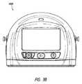
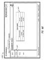
図2Aは、いくつかの実施形態によるポンプアセンブリ230およびキャニスター220の正面図200Aを示す。図示されているように、ポンプアセンブリ230とキャニスターとは接続されて、それにより、デバイス(またはNPWT装置)を形成する。ポンプアセンブリ230は、アラームを指示するように構成された視覚的インジケータ202およびTNPシステムのステータスを指示するように構成された視覚的インジケータ204などの、1つまたは複数のインジケータを備える。インジケータ202および204は、システムのさまざまな動作および/または故障状態をユーザに警告するように構成されるものとしてよく、これは通常または適切な動作状態、ポンプ故障、ポンプに供給される電力、または停電をユーザに警告すること、創傷被覆または流路内の漏出、吸引閉塞、または他の類似のもしくは適当な状態もしくはこれらの組合せを含む。いくつかの実施形態では、ポンプアセンブリ230は、追加のインジケータを備えることができる。いくつかの実施形態では、単一のインジケータが使用される。他の実施形態では、複数のインジケータが使用される。視覚的、聴覚的、触覚的なインジケータなどの好適なインジケータが使用され得る。インジケータ202は、キャニスター満杯、電力低下、導管140の切断、創傷シール120内でシールが破れていることなどのアラーム状態を信号で伝達するように構成され得る。インジケータ202は、赤色の点滅光を表示してユーザの注意を引くように構成され得る。インジケータ204は、療法遂行がokである、漏出が検出されたなどのTNPシステムのステータスを信号で伝達するように構成され得る。インジケータ204は、緑色、黄色などの1つまたは複数の異なる色の光を表示するように構成され得る。たとえば、緑色の光は、TNPシステムが適切に動作しているときに発光し、黄色の光は、警告を指示するために発光するものとしてよい。Pump Assembly and Canister FIG. 2A shows a front view 200A of a
ポンプアセンブリ230は、ポンプアセンブリのケース内に形成される陥凹部208に装着されるディスプレイまたは画面206を備える。いくつかの実施形態では、ディスプレイ206は、タッチスクリーンディスプレイであってよい。いくつかの実施形態では、ディスプレイ206は、教育ビデオなどの、オーディオビジュアル(AV)コンテンツの再生をサポートすることができる。以下で説明されているように、ディスプレイ206は、TNPシステムの動作を構成し、制御し、監視するための多数の画面またはグラフィカルユーザインターフェース(GUI)を描画するように構成され得る。ポンプアセンブリ230は、ポンプアセンブリのケース内に形成された把持部分210を備える。把持部分210は、キャニスター220の取り外し時などにおいて、ポンプアセンブリ230をユーザが保持するのを補助するように構成され得る。いくつかの実施形態では、キャニスター220は、キャニスター220が流体を充填されたときなどにおいて、別のキャニスターと交換され得る。 The
ポンプアセンブリ230は、TNPシステムの動作をユーザが操作し監視することを可能にするように構成された1つまたは複数のキーもしくはボタン212を備える。図示されているように、いくつかの実施形態では、3つのボタン212a、212b、および212cが備えられている。ボタン212aは、ポンプアセンブリ230のオン/オフを行う電源ボタンとして構成され得る。ボタン212bは、陰圧療法の遂行のための実行/一時停止ボタンとして構成され得る。たとえば、ボタン212bを押すと、療法が開始し、その後ボタン212bを押すと、療法は一時停止するか、または終了し得る。ボタン212cは、ディスプレイ206および/またはボタン212をロックするように構成され得る。たとえば、ボタン212cは、ユーザがうっかり療法の遂行を変えてしまわないようにするため、押され得る。ボタン212cを押下することで、これらのコントロールのロックを解除することができる。他の実施形態では、追加のボタンが使用され得るか、または図示されているボタン212a、212b、または212cの1つまたは複数が省かれ得る。いくつかの実施形態では、ポンプアセンブリ230を操作するために、複数回のキー押下および/またはキー押下のシーケンスが使用され得る。 The
ポンプアセンブリ230は、被覆内に形成された1つまたは複数のラッチ陥凹部222を備える。図示されている実施形態では、2つのラッチ陥凹部222は、ポンプアセンブリ230の側部に形成され得る。ラッチ陥凹部222は、1つまたは複数のキャニスターラッチ221を使用してキャニスター220の着脱を可能にするように構成され得る。ポンプアセンブリ230は、創腔110から取り出された空気を逃がすための空気出口224を備える。ポンプアセンブリ内に入った空気は、抗菌フィルターなどの、1つまたは複数の好適なフィルター(図10などのように、以下で説明されている)を通過するものとしてよい。これは、ポンプアセンブリの再利用性を維持することができる。ポンプアセンブリ230は、キャリーストラップをポンプアセンブリ230に接続するため、またはクレードルを取り付けるための1つまたは複数の装着具226を備える。図示されている実施形態では、2つの装着具226は、ポンプアセンブリ230の側部に形成され得る。いくつかの実施形態では、これらの特徴のうちのさまざまなものが省かれ、および/またはさまざまな追加の特徴がポンプアセンブリ230に加えられる。 The
キャニスター220は、創腔110から取り出された流体(たとえば、浸出液)を保持するように構成される。キャニスター220は、キャニスターをポンプアセンブリ230に取り付けるための1つまたは複数のラッチ221を備える。図示されている実施形態では、キャニスター220は、キャニスターの側部に2つのラッチ221を備える。キャニスター220の外装は、キャニスターが実質的に不透明であるように曇りプラスチックから形成することができ、キャニスターの内容物が平面図から実質的に隠されている。キャニスター220は、キャニスターのケース内に形成された把持部分214を備える。把持部分214は、キャニスター220を装置230から取り外すときなどにおいて、ポンプアセンブリ220をユーザが保持するのを可能にするように構成され得る。キャニスター220は、実質的に透明な窓216を備え、これは体積の目盛りも備えることができる。たとえば、図示されている300mLキャニスター220は50mL、100mL、150mL、200mL、250mL、および300mLの目盛りを備える。キャニスターの他の実施形態は、異なる体積の流体を保持することができ、また異なる目盛りスケールを備えることができる。キャニスター220は、導管140に接続するための配管流路218を備える。いくつかの実施形態では、把持部分214などの、これらの特徴のうちのさまざまなものが省かれ、および/またはさまざまな追加の特徴がキャニスター220に加えられる。 The
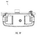
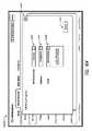
図2Bは、いくつかの実施形態によるポンプアセンブリ230およびキャニスター220の後面図200Bを示す。ポンプアセンブリ230は、音を発生し、および/または放射するためのスピーカーポート232を備える。ポンプアセンブリ230は、臭気フィルター、抗菌フィルターなどの、1つまたは複数のフィルターにアクセスして、交換するためのフィルターアクセスドア234を備える。一実施形態において、アクセスドア234は、騒音抑制または吸音材料が留置されているチャンバー(プレナムチャンバーなど)にアクセスするために使用され得る。チャンバーおよび吸音材料は、陰圧源によって発生する騒音を抑制するか、または吸収するために使用される消音システムの一部とすることができる。吸音材料は、チャンバーを通過する(反響する)ときに音波を減衰させる働きをし得る。吸音材料は、臭気抑制剤としてさらに機能し得る。一実施形態において、たとえば、吸音材料は、臭気抑制のために活性炭を含浸させることができる。アクセスドア234は、チャンバーがぴったり閉じるようにシール(封止ガスケットなど)をさらに備え得る。消音システムの追加の詳細は、参照により本明細書に組み込まれている米国特許公開第2010/0185165号で説明されている。 FIG. 2B illustrates a rear view 200B of the
ポンプアセンブリ230は、ポンプアセンブリのケース内に形成された把持部分236を備える。図示されているように、把持部分236は、ポンプアセンブリ230の外側ケーシング内に形成された陥凹部である。いくつかの実施形態では、把持部分236は、ゴム、シリコーンなどのコーティングを含み得る。把持部分236は、キャニスター220の取り外し時などにおいて、ポンプアセンブリ230をユーザがしっかりと保持できるように構成され(たとえば、位置決めされ、寸法を決められ)得る。ポンプアセンブリ230は、ポンプアセンブリ230を表面上に留置するようにネジ被覆および/または足部またはプロテクタとして構成された1つまたは複数の被覆238を備える。被覆230は、ゴム、シリコーン、または他の好適な材料から形成され得る。ポンプアセンブリ230は、ポンプアセンブリの内蔵電池を充電および再充電するための電源ジャック239を備える。いくつかの実施形態では、電源ジャック239は、直流(DC)ジャックである。いくつかの実施形態では、ポンプアセンブリは、電源ジャックが必要ないように、電池などの使い捨て型電源を備えることができる。
キャニスター220は、キャニスターを表面上に留置するための1つまたは複数の足部244を備える。足部244は、ゴム、シリコーン、または他の好適な材料から形成されるものとしてよく、また表面上に留置されたときにキャニスター220が安定を維持するように好適な角度を付けることができる。キャニスター220は、1つまたは複数の管がデバイスの前部から出ることができるように構成されたチューブマウントリリーフ(tube mount relief)246を備える。キャニスター220は、表面上に留置されたときにキャニスターを支持するためのスタンドまたはキックスタンド248を備える。以下で説明されているように、キックスタンド248は、開放位置と閉鎖位置との間で枢動し得る。閉鎖位置では、キックスタンド248は、キャニスター220にラッチされ得る。いくつかの実施形態では、キックスタンド248は、プラスチックなどの不透明材料から作られ得る。他の実施形態では、キックスタンド248は、透明材料から作られ得る。キックスタンド248は、キックスタンド内に形成された把持部分242を備える。把持部分242は、ユーザがキックスタンド248を閉鎖位置に留置することを可能にするように構成され得る。キックスタンド248は、ユーザがキックスタンドを開放位置に留置することを可能にするための穴249を備える。穴249は、ユーザが指を使ってキックスタンドを拡張することを可能にするサイズであるものとしてよい。 The
図2Cは、いくつかの実施形態によるキャニスター220から分離されたポンプアセンブリ230の図200Cを示す。ポンプアセンブリ230は、真空ポンプが陰圧をキャニスター220に伝える際に介する真空アタッチメントまたはコネクタ252を備える。ポンプアセンブリ230は、1つまたは複数のUSBポートへのアクセスを可能にするように構成されたUSBアクセスドア256を備える。いくつかの実施形態では、USBアクセスドアは、省かれ、USBポートが、ドア234を通じてアクセスされる。ポンプアセンブリ230は、SD、コンパクトディスク(CD)、DVD、FireWire、Thunderbolt、PCI Express、および同様のものなどの、追加のシリアル、パラレル、および/またはハイブリッドデータ転送インターフェースへのアクセスを可能にするように構成された追加のアクセスドアを備えることができる。他の実施形態では、これらの追加のポートのうちの1つまたは複数は、ドア234を通じてアクセスされる。 FIG. 2C shows a diagram 200C of the
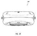
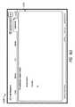
図2Dは、いくつかの実施形態によるポンプアセンブリ200Dの概略正面図200Dおよび後面図230D'を示す。 FIG. 2D shows a schematic front view 200D and a rear view 230D ′ of a pump assembly 200D according to some embodiments.
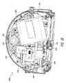
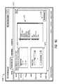
図2Eは、いくつかの実施形態によるポンプアセンブリ230の内部コンポーネントの図200Eを示す。ポンプアセンブリ230は、封止リング253を備えるキャニスターコネクタ252、制御プリント基板(PCB)260、周辺機器PCB262(たとえば、USB接続用)、電源PCB264、真空ポンプ266、電源268(たとえば、充電式電池)、スピーカー270、および光導波路もしくはパイプ272(たとえば、1つまたは複数のLEDによって放射される誘導光を使用するステータス指示用)などの、さまざまなコンポーネントを備えることができる。ステータス指示のさらなる詳細については、本出願の譲受人に譲渡された、参照により本明細書に組み込まれている米国特許第8,294,586号に記載されている。他のコンポーネント、たとえば、電気ケーブル、コネクタ、配管、弁、フィルター、留め具、ネジ、ホルダーなども備えられ得る。いくつかの実施形態では、ポンプアセンブリ230は、代替的な、または追加のコンポーネントを備えることができる。 FIG. 2E shows a diagram 200E of the internal components of the
図2Fは、いくつかの実施形態によるポンプアセンブリ230の内部コンポーネントの別の図200Fを示す。以下で説明されているように、ポンプアセンブリ230は、アンテナ276を備える。真空ポンプ266とキャニスター220との間のコネクタ252は、流動制限器278を備える。以下で説明されているように、流動制限器278は、流体流路内の流れを測定し、漏出、閉塞、高圧(超過真空)、または同様のものなどの、さまざまな動作状態を決定するために使用される較正済み流動制限器であるものとしてよい。いくつかの実施形態では、制限器278を横切る流れは、流動制限器にかかる差圧(または圧力低下)を測定することによって決定され得る。さまざまな実施形態において、制限器278を横切る流れは、高流(たとえば、漏出による)、低流(たとえば、閉塞またはキャニスター満杯であることによる)、通常流などとして特徴付けられ得る。図示されているように、圧力センサー284は、流動制限器278の上流の(またはキャニスター側の)圧力を測定する。圧力センサー284は、制御PCB264上に装着された電子圧力センサーであってよい。導管または内腔286は、流動制限器278の上流側を圧力センサー284と接続することができる。圧力センサー280および282は、流動制限器278の下流の(または真空ポンプ側の)圧力を測定する。圧力センサー280および282は、制御PCB264上に装着された電子圧力センサーであってよい。導管または内腔288は、Y字形コネクタ289を介して流動制限器278の下流側を圧力センサー280および284と接続することができる。 FIG. 2F illustrates another view 200F of the internal components of the
いくつかの実施形態では、圧力センサー280および282のうちの一方は、一次圧力センサーとして指定され、他方は、一次圧力センサーが故障するか、または動作不能に陥ったときのバックアップ圧力センサーとして指定され得る。たとえば、圧力センサー280は、一次圧力センサーであり、圧力センサー282は、バックアップ圧力センサーであるものとしてよい。流動制限器278上の圧力低下は、センサー280およびセンサー284によって測定された圧力を差し引くことによって決定され得る。圧力センサー280が故障した場合、流動制限器上の圧力低下は、センサー282およびセンサー284によって測定された圧力を差し引くことによって決定され得る。いくつかの実施形態において、バックアップ圧力センサーは、高圧状態、すなわち、流路内の圧力が最大圧力閾値をいつ超えるかを監視し、指示するために使用され得る。いくつかの実施形態では、1つまたは複数の差圧センサーが使用され得る。たとえば、流動制限器278の上流側および下流側に接続されている差圧センサーは、流動制限器にかかる圧力低下を測定することができる。いくつかの実施形態では、流動制限器278などの、これらのコンポーネントのうちの1つまたは複数は、省かれ、および/または、1つまたは複数の流量計などの、追加のコンポーネントが使用される。 In some embodiments, one of the
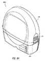
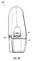
図3A〜図3Gは、いくつかの実施形態によるポンプアセンブリを示す図である。図3A-1は、ポンプアセンブリの斜視図301Aを示している。図3A-2は、ポンプアセンブリの別の斜視図302Aを示している。図3Bは、ポンプアセンブリの正面図300Bを示している。図3Cは、ポンプアセンブリの右側面図300Cを示している。図3Dは、ポンプアセンブリの後面図300Dを示している。図示されているように、ポンプアセンブリは、1つまたは複数のフィルター(図10に示され、以下で説明されているような)にアクセスするための取り外し可能な被覆を備えることができる、フィルターエンクロージャ302を備える。図3Eは、ポンプアセンブリの上面図300Eを示している。図3Fは、ポンプアセンブリの左側面図300Fを示している。図3Gは、ポンプアセンブリの底面図300Gを示している。 3A-3G illustrate a pump assembly according to some embodiments. FIG. 3A-1 shows a
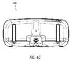
図4A〜図4Gは、いくつかの実施形態による、300mLキャニスターなどの、キャニスターを示す。図4A-1は、キャニスターの斜視図400Aを示している。図4A-2は、キャニスターの別の斜視図401Aを示している。図4Bは、キャニスターの正面図400Bを示している。図4Cは、キャニスターの右側面図400Cを示している。図4Dは、キャニスターの後面図400Dを示している。図4Eは、キャニスターの上面図400Eを示している。図4Fは、キャニスターの左側面図400Fを示している。図4Gは、キャニスターの底面図400Gを示している。 4A-4G illustrate a canister, such as a 300 mL canister, according to some embodiments. FIG. 4A-1 shows a
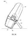
図5A〜図5Cは、いくつかの実施形態による動作中のキックスタンドを示す。図5Aは、キックスタンド248が、拡張(または開放)位置にあることを示している。図示されているように、ポンプアセンブリ230とキャニスター220とは、ラッチ221を使用することなどによって、接続されるか、または一緒に組み立てられる。デバイス500Aは、キックスタンド248および足部244によって表面上で支持される。図示されている実施形態では、キックスタンド248は、1つまたは複数の枢軸502を操作することによって拡張される。図5Bは、デバイスを表面上に位置決めすることを示している。500Bに図示されているように、キックスタンド248は拡張され、デバイスは表面上に実質的に垂直に留置され、および/または画面206の視認性を改善する(たとえば、グレアを低減することによって)。501Bにおいて、デバイスは、表面上に安定した形で静止するように傾けられる。501Aに関する501Bにおけるデバイスの傾きは、インジケータ512によって示される。いくつかの実施形態では、傾きは、30度未満、約30度、または30度超であるものとしてよい。図5Cは、穴249および2つのほぞ穴504を備えるキックスタンド248を示している。いくつかの実施形態では、デバイスの傾きは、ユーザに要求条件に適合するように調整可能である。たとえば、キックスタンド248は、ラチェット機構を利用することができる。 5A-5C illustrate a kickstand in operation according to some embodiments. FIG. 5A shows that the
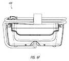
図6A〜図6Fは、いくつかの実施形態による、300mLキャニスターなどの、キャニスターを示す。図6Aは、キャニスターの斜視図600Aを示している。キャニスターは、キャニスターを創傷被覆120に接続するように構成された管140を備える。図6Bは、キャニスターの正面図600Bを示している。図6Cは、キャニスターの側面図600Cを示している。図6Dは、キャニスターの別の側面図600Dを示している。図示されているように、キックスタンド248は、傾けられたキャニスターを表面上に支持する開放位置にある。図6Eは、キャニスターの上面図600Eを示している。図6Fは、キャニスターの後面図600Fを示している。 6A-6F illustrate a canister, such as a 300 mL canister, according to some embodiments. FIG. 6A shows a
図7A〜図7Eは、さまざまな実施形態による、800mLキャニスターなどの、キャニスターを示す。図7Aは、キャニスターの斜視図700Aを示している。キャニスターは、キャニスターを創傷被覆120に接続するように構成された管140を備える。キャニスターは、キャニスターがポンプアセンブリ230によって伝達される真空を受ける際に介する真空アタッチメントまたはコネクタ702を備える。いくつかの実施形態では、コネクタ702は、ポンプアセンブリ230のコネクタ252と接続されるか、または嵌合するように構成される。図7Bは、キャニスターの正面図700Bを示している。図7Cは、キャニスターの側面図700Cを示している。図7Dは、キャニスターの上面図700Dを示している。図7Eは、キャニスターの後面図700Eを示している。キャニスターは、管140を保持するためのクリップ712を備える。 7A-7E show a canister, such as an 800 mL canister, according to various embodiments. FIG. 7A shows a
図8A〜図8Gは、いくつかの実施形態によるデバイスを示している。図8Aは、ポンプアセンブリ230およびキャニスター220を備える、デバイスの斜視図800Aを示している。キャニスター220は、キャニスター220の側面上の2つのラッチ221などの、1つまたは複数のラッチ221を使用してポンプアセンブリ230に接続され得る。図8Bは、デバイスの正面図800Bを示している。図8Cは、デバイスの右側面図800Cを示している。デバイスは、1つまたは複数の枢軸502を介して開閉されるように構成されているキックスタンド248を備える。図8Dは、デバイスの後面図800Dを示している。図8Eは、デバイスの上面図800Eを示している。図8Fは、デバイスの左側面図800Fを示している。ラッチ221は、キャニスター220をポンプアセンブリ230に接続するためにポンプアセンブリ230上に形成された陥凹部702に接続するように構成され得る。図8Gは、デバイスの底面図800Gを示している。キャニスター220は、足部244を備える。 8A-8G illustrate a device according to some embodiments. FIG. 8A shows a
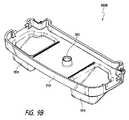
図9A〜図9Cは、いくつかの実施形態によるキャニスター隔壁910を示す。図9Aは、キャニスター隔壁910の上面図900Aを示している。図9Bは、キャニスター隔壁910の斜視図900Bを示している。図9Cは、キャニスター隔壁910の底面図900Cを示している。キャニスター隔壁は、ポンプアセンブリ隔壁などを介して、キャニスター220をポンプアセンブリ230の陰圧源に接続するように構成され得る。この機能を円滑にするために、キャニスター隔壁910は、ポンプアセンブリ230の真空コネクタ252に取り付けるコネクタまたはポート902を備える。キャニスター隔壁910は、キャニスター220をポンプアセンブリ230に接続することを円滑にするためのゲートマークまたはゲート906も備える。キャニスター隔壁910は、デバイス(およびキャニスター)が垂直、水平に配向され、および/または垂直に傾けられる(たとえば、キックスタンド248が拡張されたと)ように満タンになるにつれ、または満杯になったときにキャニスター220の容量を制限するように構成された1つまたは複数の領域もしくは突起部904を備える。図9Bおよび9Cに示されているように、キャニスター220によって保持される流体の量は、1つまたは複数の突起部904によって低減されるか、または制限される。いくつかの実施形態では、デバイス隔壁は平坦である。他の実施形態では、デバイス隔壁は、キャニスター隔壁910の特徴部と嵌合することができる。 9A-9C illustrate a
図10は、いくつかの実施形態によるフィルタースタック1000を示す。キャニスターフィルタースタック1000は、フィルターキャリア1002、遮断部1004、臭気フィルター1006、および抗菌フィルター1008を備える。遮断部1004は、キャニスターの過剰充填が防止されるようにキャニスター220が満杯になったときに吸引を停止するように動作する。遮断部は、親水性材料から形成され得る。臭気フィルター1006は、臭気を吸収するか、低減するか、または排除する材料を含むものとしてよい。たとえば、そのような材料は、活性炭素、活性炭、または同様のものとすることができる。材料は、疎水性であってもよい。抗菌フィルター1008は、微生物の増殖を抑制するか、または排除することができる。いくつかの実施形態では、フィルタースタック1000のコンポーネントは、好適な順序で配置構成され得る。たとえば、臭気フィルター1006は、遮断部1004の材料への添加剤として、または遮断部1004の材料上に形成された層として、遮断部1004内に組み込まれ得る。いくつかの実施形態では、フィルタースタック1000は、キャニスター内に留置される。いくつかの実施形態では、フィルタースタック1000は、ポンプアセンブリ内のキャニスターの間のコネクタ内に留置される。いくつかの実施形態では、フィルタースタック1000は、ポンプアセンブリ内に留置される。 FIG. 10 illustrates a
図11は、いくつかの実施形態によるキャニスター220とポンプアセンブリ230との間の接続部1104を示す。図示されているように、接続部1104は、ポンプアセンブリ230の真空アタッチメント1106とキャニスター220のアタッチメントまたはポート1102との間に留置される。接続部1104は、キャニスター220とポンプアセンブリ230との間の実質的に漏出のない封止を確実にするワッシャ、リング、または同様のものとすることができる。 FIG. 11 illustrates a
ストラップ
いくつかの実施形態では、ストラップは、肩、腰などでデバイスを携帯するためポンプアセンブリ230にストラップが取り付けられ得る。ストラップは、長さ調整可能であるものとしてよい。図12は、いくつかの実施形態によるストラップ装着アタッチメント1200を示す。アタッチメント1200は、ポンプアセンブリ230の装着具226(図2B)上に取り外し可能にクリップ留めされ得る。動作時に、アタッチメント1200の穴1202は、装着具226と位置合わせされ、一部分1204が、装着具226に取り付けられ得る。一部分1204の内径は、装着具226との実質的にぴったり嵌るように選択され得る。ストラップ(図示せず)は、ロッド1210に取り付けられ得る。いくつかの実施形態では、2つのアタッチメント1200は、ポンプアセンブリ230の対向する側部上に配置されている2つの装着具226上にクリップ留めされる。Strap In some embodiments, the strap can be attached to the
いくつかの実施形態では、デバイスは、キャリングケースまたはキャリングバッグ内に留置され得る。キャリングケースは、キャニスター220に接続されているポンプアセンブリ230を収容するように構成され得る。キャリングケースは、デバイスを取り囲むように構成されたポーチを備えることができ、ポーチは上側部分および下側部分を備える。ポーチの下側部分内の下側開口部は、デバイスの挿入を可能にするように構成され得る。下側開口部は、下側開口部を閉鎖し、装置がポーチからずれるのを防ぐように構成された閉鎖部を備えることができる。下側開口部は、閉鎖部が下側開口部を閉鎖した後にポーチの内側と外側との間で開いたままになる開口(たとえば、管140に対する)も備え得る。下側開口部は、キャニスター220を見ることを可能にするように持ち上げられ得るフラップを備えることができる。上側部分は、ディスプレイ206および/またはボタン212へのアクセスを可能にするように持ち上げられ得るフラップも備えることができる。キャリングバッグの追加の詳細については、本出願の譲受人に譲渡された、参照により本明細書に組み込まれている米国特許第8,240,470号に記載されている。いくつかの実施形態では、ポンプアセンブリ230および/またはキャニスター220は、ポンプアセンブリを患者のベルト、ポケットなどに取り付けるためのクリップを備える。 In some embodiments, the device may be placed in a carrying case or carrying bag. The carrying case may be configured to accommodate a
アタッチメントシステム
図13A〜図13Bは、いくつかの実施形態によるアタッチメントシステム1300を示す。動作時に、アタッチメントシステム1300は、IVポール(たとえば、直径が0.75インチから2.0インチであるIVポール)、ベッドレール(たとえば、幅が0.75インチから3インチのベッドレール)、および同様のものなどの、好適な構造体にデバイスまたは装置を装着するために使用される。アタッチメントシステム1300は、構造体に、限定はしないが、NPWT装置またはデバイスを含む、医療用デバイスなどの、好適なデバイスを装着するために使用され得る。アタッチメントシステム1300は、確実な接続が効率よく行われ得るように調節可能なように構成され得る。図13Aに示されているように、アタッチメントシステム1300は、デバイスに取り付けるクレードル1310と、クランプ1330とを備える。クランプ1330は、さまざまな構造体に確実に取り付けられるように調整可能である。図示されている実施形態では、クランプ1330の幅は、つまみ1334を回すことによって調整される。いくつかの実施形態では、クレードル1310は、装置具226(図2A〜図2Bを参照)を陥凹部1302内に留置し、閉鎖部1318をアクティブ化することによってデバイスに取り付けられる。閉鎖部1318は、ラッチ、ロック、またはデバイスをクレードル1310に取り付けるのに適している他の機構とすることができる。クレードル1310は、クレードルの各側部上の2つ閉鎖部などの、1つまたは複数の閉鎖部1318を備えることができる。Attachment System FIGS. 13A-13B illustrate an
アタッチメントシステム1300は、ポール、レール、または同様のものに、構造体の一部が以下で説明されているように第1のクランプアームと第2のクランプアームとの間の空間内に固定されるようにつまみ1334を回すことによって取り付ける。デバイスは、1つまたは複数の閉鎖部1318を非アクティブ化することによってクレードル1310から取り外され得る。たとえば、1つまたは複数の閉鎖部1318は、クレードル1310からデバイスを取り外せるように解放されるか、またはロック解除され得る(たとえば、押下することによって)。アタッチメントシステム1300は、さまざまな厚さの構造体に取り付けられるように構成される。たとえば、アタッチメントシステム1300は、細いポールまたは管だけでなく、太いベッドレールにも取り付けられ得る。
図13Bは、いくつかの実施形態によるアタッチメントシステム1300の分解図を示している。図13Bに示されているように、クレードル1310は、クレードルハウジング1312および第1の送りネジ1314を備える。ネジ1314は、クレードルハウジング1312の内側に位置決めされ、ハウジング1312の内側で自由に回転させることができる。クレードル1310は、クレードルをデバイス(たとえば、NPWT装置230)に取り付けるための左閉鎖部1316および右閉鎖部1318も備える。クレードル1310は、ゴムから作られ得る、バンパー1320をデバイスに面する側にさらに備える。クレードル1310は、また、コイルバネであってもよい、ピン1322と、ネジ1324と、ワッシャ1326とを備え、これにより閉鎖部1316および1318をクレードルに取り付ける。クランプ1330は、第1のクランプアーム1331と、第2のクランプアーム1332と、ハンドル1334が取り付けられる第2のネジ1335と、ハンドル1334に取り付けられるように構成されたキャップ1336とを備える。ゴムパッドなどの、パッド1338は、第1のクランプアーム1331および第2のクランプアーム1332に取り付けられるように構成される。第2のクランプアーム1332は、第2のネジ1335を留置するための開口部1333を備える。開口部1333は、第2のネジ1335のネジ山と係合するように構成された雌ネジを備えることができる。第2のネジ1335は、第1のネジ1314と係合するための中空の内側トンネル部分を備えることができる。第2のネジ1335の内側部分は、第1のネジ1314のネジ山と係合するように構成されたネジ山を備え得る。他の実施形態では、第2のネジ1335は、他の好適なアタッチメントを使用して第2のクランプアーム1332に取り付けられる。 FIG. 13B shows an exploded view of an
いくつかの実施形態では、動作時に、クレードル1310は、デバイス(たとえば、装置230)に取り付けられる。デバイス230の後部は、クレードル1310が取り付けられるときにバンパー1320に当接し得る。いくつかの実施形態では、陥凹部1302および/または閉鎖部1318は、デバイスの後部がバンパー1320に当接する構成でのみクレードル1310がデバイスに取り付けられるように構成され得る。デバイスの前部がバンパー1320に当接するように逆方向など、不正にデバイスを取り付けることは、許されない。アタッチメントシステム1300は、ポール、レール、または同様のものに、構造体の一部が第1のクランプアーム1331と第2のクランプアーム1332との間の空間内に留置されるようにつまみ1334を回すことによって取り付ける。これは、第1のネジ1314および第2のネジ1335が第2のクランプアーム1332を第1のクランプアーム1331(静止している)から所望の距離のところへ移動するアクションによって達成される。次いで、つまみ1334を回して、デバイスを構造体上に固定して装着する。取り外しは、つまみ1334を回してデバイスを構造体から取り外すことによって実行される。クレードルは、閉鎖部1318のラッチまたはロックを解除することによってデバイスから切断され得る。 In some embodiments, in operation,
図13Cは、いくつかの実施形態によるアタッチメントシステム2100を示す。アタッチメントシステム2100は、構造体に、限定はしないが、NPWT装置またはデバイス230を含む、医療用デバイスなどの、好適なデバイスを装着するために使用され得る。アタッチメントシステム2100は、クレードル2110と、第1のクランプアーム2140と、第2のクランプアーム2150とを備える。第1のクランプアーム2140は、クレードル2110に固定されるか、または接続され、それによって、アタッチメントが動作しているときに静止状態を保つ。第2のクランプアーム2150は、第1のクランプアーム2140に関して移動し、これは第1のクレードルアームと第2のクレードルアームとの間の間隙を変化させる。構造体は、第1のクレードルアーム2140と第2のクレードルアーム2150との間に固定される。構造体は、ポール2190'などの細いもの、またはポールもしくはレール2190などの太いものであってよい。 FIG. 13C illustrates an
アタッチメントシステム2100は、第1のネジ2160と第2のネジ2170とを備える。第2のネジ2170は、つまみ2134に接続される。動作時に、つまみ2170を回すことで、第1のネジ2160および第2のネジ2170は、第2のクランプアーム2150が第1のクランプアーム2140に関して直線的に滑らかで均一な様式で移動することを行わせる。第2のクランプアーム2150は、デバイスが構造体に装着されている締付位置およびデバイスが構造体に装着されていない締付解除位置から移動する。第2のクランプアーム2150は、第1のクランプアーム2140および第2のクランプアーム2150が分離されていないか、または実質的に分離されていない(たとえば、互いに接触している)完全閉鎖位置と第1のクランプアーム2140および第2のクランプアーム2150が互いから最大距離だけ分離されている完全開放位置との間でも移動する。この最大距離は、デバイスがアタッチメントシステム2100を使用して取り付けられ得る構造体の最大厚さに対する上限を課す。第2のクランプアーム2150の移動は、図2100A、図2100B、および図2100Cに示されている。図2100Aでは、第1のクランプアーム2140および第2のクランプアーム2150は、互いの近くに配置されている。図2100Bおよび図2100Cでは、第1のクランプアーム2140と第2のクランプアーム2150との間の間隙は広がっている。すなわち、第2のクランプアーム2150は、つまみ2134を回すことなどによって、第1のクランプアーム2140から遠ざかる方向に移動される。 The
第1のネジ2160は、クレードルのハウジング内に、または実質的にクレードルのハウジング内に配置され、第1のネジ2160は、ハウジングの内側で自由に回転させることができる。第1のネジ2160は、リード(ネジの完全な1回転によって覆われるネジの軸に沿った距離)およびピッチ(あるネジ山から次のネジ山への頂点からの距離)を持つネジ山を有する。一実施形態において、第1のネジのリードおよびピッチは同じである。第2のネジ2170は、一実施形態において同じであってよい、リードおよびピッチを持つネジ山を有する。第1のネジ2160および第2のネジ2170のネジ山は、正方形、アクメ、バットレス、および同様のものであってよい。いくつかの実施形態では、第1のネジ2160および第2のネジ2170は、アクメネジなどの同じタイプのネジ山を有する。いくつかの実施形態では、第1のネジ2160および第2のネジ2170は、異なるタイプのネジ山を有する。第2のネジ2170は、図13Bに示されている開口部1333などを介して、第2のクランプアーム2150に接続されるか、または取り付けられ得る。 The
いくつかの実施形態では、第1のネジ2160のネジ山および第2のネジ2170のネジ山は、反対方向に(または反対のピッチで)配向され得る。たとえば、第1のネジ2160のネジ山は右回りであり、第2のネジ2170のネジ山は左回りとすることができ、またその逆であり得る。反対方向に配向されたネジ山を持つ第1のネジ2160および第2のネジ2170が、互いに係合したときに、ハンドル2134の1回転は、単一のネジを使用するのとは反対に2倍の、または実質的に2倍の直線的移動をもたらす。第1のネジ2160および第2のネジ2170は、第1のネジ2160の少なくとも一部を受け入れるように構成された中空開口部を有する第2のネジ2170によって係合され得る。図13Bに示されているように、中空開口部は、第1のネジ2160のネジ山と係合するように構成された雌ネジを有するものとしてよい。いくつかの実施形態では、第1のネジ2160は、第2のネジ2170の少なくとも一部を受け入れるように構成された中空開口部を備えることができる。他の実施形態では、第1のネジ2160および第2のネジ2170は、ナットを使用することなどの、好適な方法で係合される。 In some embodiments, the threads of the
いくつかの実施形態では、そのような二重ネジ配置構成は、さまざまな厚さの構造体に素早く装着することを可能にし、その一方で、構造体にぴったり(または固定する形で)取り付けることに対して適切な制御を維持する。たとえば、第1のクランプアーム2140および第2のクランプアーム2150の構成を完全閉鎖位置から完全開放位置に、またはその逆に変更するために、ハンドルを約4回転から10回転させることが必要になる。いくつかの実施形態では、構造体に取り付ける公称締付力は、約20〜30ポンドフォース(lbf)であり、これが達成される。部品の故障に至る前の最大締付力は、約100lbfであるものとしてよい。公称締付を達成するために必要なトルクは、約20インチポンドフォース(inlb)未満であるものとしてよい。他の実施形態では、他の好適な締付力、最大締付力、および公称締付トルクが使用され得る。二重ネジ配置構成は、急角度のピッチのネジ山を持つ単一のネジを使用すること、単一の多条ネジを使用すること、および同様の方法などで、代替的配置個構成よりも耐久性があり、安価であり得る。 In some embodiments, such a double screw arrangement allows for quick attachment to structures of varying thickness, while attaching snugly (or fixedly) to the structure. Maintain proper control against. For example, to change the configuration of the
いくつかの実施形態では、第1のネジ2160および第2のネジ2170は、回転運動を直線運動に変換するように構成されたパワースクリューである。パワースクリューは、http://www.roymech.co.uk/Useful_Tables/Cams_Springs/Power_Screws.htmlにて入手可能な文献「Power Screws」において説明されている。パワースクリューの効率については、http://www.roymech.co.uk/Useful_Tables/Cams_Springs/Power_Screws_1.htmlにて入手可能な文献「Power Screw Equations」において説明されている。パワースクリュー強度解析は、http://www.roymech.co.uk/Useful_Tables/Cams_Springs/Power_Screws_2.htmlにて入手可能な文献「Strength Considerations for Power Screws」において説明されている。これらの文書の各々は、参照により本明細書に含まれる。 In some embodiments, the
いくつかの実施形態では、クレードル2110、第1のクランプアーム2140、第2のクランプアーム2150、およびつまみ2134は、プラスチック材料から作られ、それによって、アタッチメントシステム2100を軽量化している。いくつかの実施形態では、本明細書で説明されている他のアタッチメント部品の1つまたは複数も、プラスチック材料から作られる。いくつかの実施形態では、第1のクランプアームは、静止するように構成されず、第2のクランプアームは、静止するように構成される。いくつかの実施形態では、第1および第2のクランプアームは、静止しない。いくつかの実施形態では、ハンドルは使用されない。 In some embodiments, the
図13Dから図13Jは、いくつかの実施形態によるアタッチメントシステムを示す。アタッチメントシステム2200は、構造体に、限定はしないが、NPWT装置またはデバイスを含む、医療用デバイスなどの、好適なデバイスを装着するために使用され得る。図13Dは、閉鎖位置またはほとんど閉鎖された位置にあるアタッチメントシステムの斜視図を示している。図13Eは、図13Dに示されているアタッチメントシステムの正面図を示している。図13Fは、図13Dに示されているアタッチメントシステムの後面図を示している。図13Gは、図13Dに示されているアタッチメントシステムの右側面図を示している。図13Hは、図13Dに示されているアタッチメントシステムの左側面図を示している。図13Iは、図13Dに示されているアタッチメントシステムの上面図を示している。図13Jは、図13Dに示されているアタッチメントシステムの底面図を示している。図示されているように、アタッチメントシステム2200は、キャリーストラップ、キャリングケース、またはキャリングバッグなどの、1つまたは複数の品物を固定するために使用され得る1つまたは複数の突起部もしくは突出部2210を備える。 FIGS. 13D-13J illustrate an attachment system according to some embodiments. The
図13Kは、いくつかの実施形態による動作中のアタッチメントシステムを示す。2300Aに示されているように、装置(たとえば、NPWT装置230)は、いくつかの実施形態によるアタッチメントシステムを使用してIVポールに装着される。2300Bに示されているように、装置は、いくつかの実施形態によるアタッチメントシステムを使用してベッドレールに装着される。図13Kに示されているアタッチメントシステムは、アタッチメントシステム1300、2100、または2200のうちのいずれか1つから選択され得る。 FIG. 13K illustrates an attachment system in operation according to some embodiments. As shown in 2300A, a device (eg, NPWT device 230) is attached to an IV pole using an attachment system according to some embodiments. As shown in 2300B, the device is attached to the bed rail using an attachment system according to some embodiments. The attachment system shown in FIG. 13K may be selected from any one of
電子機器およびソフトウェア
図14は、いくつかの実施形態によるポンプアセンブリの電気部品概略図1400である。電気部品は、ユーザ入力を受け入れ、出力をユーザに送り、ポンプアセンブリおよびTNPシステムを操作し、ネットワーク接続を提供するなどを行うように動作し得る。電気部品は、制御PCB260、周辺機器PCB262、および/または電源PCB264などの、1つまたは複数のPCB上に装着され得る。図示されているように、ポンプアセンブリ230は、複数のプロセッサを備え得る。複数のプロセッサを利用してさまざまなタスクを異なるプロセッサに割り振るか、または割り当てると都合がよい場合がある。いくつかの実施形態では、第1のプロセッサは、ユーザ活動に関与し、第2のプロセッサは、ポンプを制御することに関与し得る。このようにして、より高いレベルの反応性(より高いリスクレベルに対応する)を必要とし得る、ポンプを制御する活動は、専用プロセッサにオフロードされ、それによって、ユーザとのインタラクティブなやり取りがあることで完了に時間がかかる可能性のある、ユーザインターフェースタスクによって中断されなくなる。Electronics and Software FIG. 14 is a schematic electrical diagram 1400 of a pump assembly according to some embodiments. The electrical components may operate to accept user input, send output to the user, operate the pump assembly and TNP system, provide network connections, and so on. The electrical components may be mounted on one or more PCBs, such as
ポンプアセンブリ230は、ユーザ入力を受け入れ、出力をユーザに提供するための、ディスプレイ206、ボタン212などの、1つまたは複数のコンポーネントを操作するように構成されたユーザインターフェースプロセッサまたはコントローラ1410を備えることができる。ポンプアセンブリ230への入力およびポンプアセンブリからの出力は、入出力(I/O)モジュール1420によって制御され得る。たとえば、I/Oモジュールは、シリアルポート、パラレルポート、ハイブリッドポート、および同様のポートなどの、1つまたは複数のポートからデータを受信することができる。プロセッサ1410は、1つまたは複数のUSBポート、SDポート、コンパクトディスク(CD)ドライブ、DVDドライブ、FireWireポート、Thunderboltポート、PCI Expressポート、および同様のものなどの、1つまたは複数の拡張モジュール1460との間で、データの受信およびデータの送信も行う。プロセッサ1410は、他のコントローラまたはプロセッサとともに、プロセッサ1410の内部および/または外部にあるものとしてよい、1つまたは複数のメモリモジュール1450にデータを記憶することができる。RAM、ROM、磁気メモリ、ソリッドステートメモリ、磁気抵抗ランダムアクセスメモリ(MRAM)、および同様のものなどの、揮発性および/または不揮発性メモリを含む、好適などのようなタイプのメモリをも使用することができる。
いくつかの実施形態では、プロセッサ1410は、低電力プロセッサなどの、汎用コントローラとすることができる。他の実施形態では、プロセッサ1410は、特定用途向けプロセッサであってもよい。いくつかの実施形態では、プロセッサ1410は、ポンプアセンブリ230の電子アーキテクチャにおける「中央」プロセッサとして構成され、プロセッサ1410は、ポンプ制御プロセッサ1470、通信プロセッサ1430、および1つまたは複数の追加のプロセッサ1480などの、他のプロセッサの活動を協調させることができる。プロセッサ1410は、Linux(登録商標)、Windows(登録商標) CE、VxWorksなどの、好適なオペレーティングシステムを実行することができる。 In some embodiments, the
ポンプ制御プロセッサ1470は、陰圧ポンプ1490の動作を制御するように構成され得る。ポンプ1490は、隔膜ポンプ、蠕動ポンプ、回転ポンプ、回転ベーンポンプ、スクロールポンプ、ネジポンプ、液封式ポンプ、圧電変換器によって作動される隔膜ポンプ、ボイスコイルポンプ、および同様のものなどの、好適なポンプであってよい。いくつかの実施形態では、ポンプ制御プロセッサ1470は、1つまたは複数の圧力センサーから受信されたデータを使用して流体流路内の圧力を測定し、流体流の速度を算出し、ポンプを制御することができる。いくつかの実施形態では、ポンプ制御プロセッサ1470は、所望のレベルの陰圧が創腔110内で得られるようにポンプモーターを制御する。所望のレベルの陰圧は、ユーザによって設定されるか、または選択された圧力であってよい。さまざまな実施形態において、ポンプ制御プロセッサ1470は、パルス幅変調(PWM)を使用してポンプ(たとえば、ポンプモーター)を制御する。ポンプを駆動するための制御信号は、0〜100%デューティサイクルのPWM信号とすることができる。ポンプ制御プロセッサ1470は、流量算出を実行し、アラームを検出することができる。ポンプ制御プロセッサ1470は、情報をプロセッサ1410に伝達することができる。ポンプ制御プロセッサ1470は、内部メモリを備え、および/またはメモリ1450を利用することができる。ポンプ制御プロセッサ1470は、低電力プロセッサであってよい。 Pump control processor 1470 may be configured to control the operation of
通信プロセッサ1430は、有線および/またはワイヤレス接続を行うように構成され得る。通信プロセッサ1430は、データの送受信に1つまたは複数のアンテナ1440(アンテナ276など)を利用することができる。いくつかの実施形態では、通信プロセッサ1430は、全世界測位システム(GPS)技術、セルラー接続(たとえば、2G、3G、LTE、4G)、WiFi接続、インターネット接続、および同様の接続タイプのうちの1つまたは複数を提供することができる。接続は、ポンプアセンブリの配置追跡、資産追跡、順守監視、リモート選択、ログ、アラーム、および他の動作データのアップロード、ならびに療法設定の調整、ソフトウェアおよび/またはファームウェアのアップグレード、および同様のものなどのさまざまな活動に使用され得る。いくつかの実施形態では、通信プロセッサ1430は、GPS/セルラーのデュアル機能を提供することができる。セルラー機能は、たとえば、3G機能であってよい。そのような場合、GPSモジュールが、大気状態、ビルもしくは地形の干渉、衛星ジオメトリなどを含む、さまざまな要因により衛星接続を確立できない場合、デバイス配置は、セル識別、三角測量、フォワードリンクタイミング、および同様のものを使用することなどによって、3Gネットワーク接続を使用して決定され得る。いくつかの実施形態では、ポンプアセンブリ230は、SIMカードを備えることができ、SIMベースの位置情報が取得され得る。
通信プロセッサ1430は、情報をプロセッサ1410に伝達することができる。通信プロセッサ1430は、内部メモリを備え、および/またはメモリ1450を利用することができる。通信プロセッサ1430は、低電力プロセッサであってよい。
いくつかの実施形態では、ポンプアセンブリ230は、Table 1(表1)に示されているデータを記憶することができる。このデータは、たとえば、メモリ1450に記憶され得る。さまざまな実施形態において、異なる、または追加のデータが、ポンプアセンブリ230によって記憶され得る。いくつかの実施形態では、配置情報は、GPS、またはセルラー三角測量、セル識別フォワードリンクタイミング、および同様のものなどの、他の好適な方法によって取得され得る。 In some embodiments, the

いくつかの実施形態において、ポンプアセンブリ230は、療法および他の動作データを追跡し、ログに記録することができる。そのようなデータは、たとえば、メモリ1450に記憶され得る。いくつかの実施形態では、ポンプアセンブリ230は、Table 2(表2A, B)に示されているログデータを記憶することができる。Table 3(表3)は、いくつかの実施形態による例示的なイベントログを示している。1つまたは複数のそのようなイベントログが、ポンプアセンブリ230によって記憶され得る。示されているように、イベントログは、発生した時間を示すタイムスタンプを含み得る。いくつかの実施形態では、追加の、および/または代替的なデータがログに記録され得る。 In some embodiments, the
いくつかの実施形態では、デバイスは、通信プロセッサ1430によって提供される接続を使用することで、ポンプアセンブリ230によって記憶され、維持され、および/または追跡されるデータをアップロードすることができる。いくつかの実施形態では、リモートコンピュータまたはサーバにアップロードできる情報は、療法持続時間など、療法遂行情報を含む、活動ログ、アラームタイプおよび発生時刻を含む、アラームログ、内部エラー情報、伝送エラー、および同様のものを含む、エラーログ、毎時間、毎日、および同様の間隔で計算され得る、療法持続時間情報、最初に特定の1つまたは複数の療法プログラムを適用することからの療法持続時間を含む、総療法時間、生涯療法時間、シリアル番号、ソフトウェアバージョン、電池レベルなどの、デバイス情報、デバイス配置情報、患者情報などである。デバイスは、療法選択およびパラメータ、ファームウェアおよびソフトウェアパッチおよびアップグレード、ならびに同様のものなどの、さまざまな動作データをダウンロードすることもできる。いくつかの実施形態において、デバイスは、1つまたは複数のブラウザプログラム、メールプログラム、アプリケーションソフトウェア(たとえば、アプリ)などを使用してインターネット閲覧機能を提供することができる。さまざまな実施形態において、ディスプレイ206を制御するためのプロセッサなどの、追加のプロセッサ1480が利用され得る。 In some embodiments, the device can upload data that is stored, maintained, and / or tracked by the
図15は、いくつかの実施形態によるファームウェアおよび/またはソフトウェアの線図1500である。ポンプアセンブリ1520は、ユーザインターフェースプロセッサ1410によって実行され得る、ユーザインターフェースプロセッサファームウェアおよび/またはソフトウェア1522と、ポンプ制御プロセッサ1470によって実行され得る、ポンプ制御プロセッサファームウェアおよび/またはソフトウェアと、通信プロセッサ1430によって実行され得る、通信プロセッサファームウェアおよび/またはソフトウェア1526と、1つまたは複数の追加のプロセッサ1480によって実行され得る、追加のプロセッサファームウェアおよび/またはソフトウェアとを備える。ポンプアセンブリ1520は、ラップトップ、デスクトップ、タブレット、スマートフォン、および同様のものであってよい、コンピュータ1510に接続され得る。コンピュータ1510をポンプアセンブリ1520に接続するために有線またはワイヤレス接続が利用され得る。いくつかの実施態様では、USB接続が使用される。コンピュータ1510とポンプアセンブリ1520との間の接続は、ポンプアセンブリの配置追跡、資産追跡、順守監視、選択、ログ、アラーム、および他の動作データのアップロード、ならびに療法設定の調整、ソフトウェアおよび/またはファームウェアのアップグレード、および同様のものなどのさまざまな活動に使用され得る。ポンプアセンブリ1520およびコンピュータ1510は、クラウド1530を介してリモートコンピュータまたはサーバ1540と通信することができる。リモートコンピュータ1540は、データ記憶装置モジュール1542とリモートコンピュータにアクセスするためのウェブインターフェース1544とを備えることができる。 FIG. 15 is a diagram 1500 of firmware and / or software according to some embodiments.
コンピュータ1510とポンプアセンブリ1520との間の接続は、ポンプアセンブリ1520の初期化およびプログラミング、ファームウェアおよび/またはソフトウェアアップグレード、メンテナンスおよびトラブルシューティング、療法パラメータの選択および調整、ならびに同様のものうちの1つまたは複数を実行するために利用され得る。いくつかの実施形態では、コンピュータ1510は、ポンプアセンブリ1520と通信するためのアプリケーションプログラムを実行することができる。 The connection between the
ポンプアセンブリ1520は、クラウド1530を介してさまざまなデータをリモートコンピュータ1540にアップロードすることができる。いくつかの実施形態では、コンパアセンブリ1520は、データを1つまたは複数のリモートコンピュータ1540にアップロードすることができる。上で説明されているように、アップロードデータは、活動ログ、アラームログ、療法持続時間情報、総療法時間、生涯療法情報、デバイス情報、デバイス配置情報、患者情報などを含み得る。それに加えて、ポンプアセンブリ1520は、クラウド1530からコマンドを受信し、クラウド1530から受信されたコマンドを処理することができる。
リモートインターフェース
図16A〜図16Sは、いくつかの実施形態によるリモートインターフェース画面またはページを示す。これらの画面は、リモートコンピュータ1540のウェブインターフェース1544において生成され得る。リモートコンピュータ1540は、クラウドプラットフォームと称され得る。図16Aは、1つまたは複数のデバイスによってアップロードされたデータにアクセスするためのログイン画面1600Aを示している。ログイン画面1600Aは、メニュー1610を備え、メニュー1610はホームページにアクセスするためのメニュー項目1612、デバイス記録にアクセスするためのメニュー項目1614、フリートステータスにアクセスするためのメニュー項目1616、および連絡先ページにアクセスするためのメニュー項目1618を備える。ログイン画面1600Aは、デバイス情報を探すための検索ボックス1632、ログアウトボタン1634、およびアクセシビリティ情報、使用規約、特許、商標および著作権表示、ならびに免責条項を表示するための追加の情報メニュー1636も備える。メニュー項目1612から1618および検索ボックス1632は、クラウドプラットフォーム1540がユーザの資格証明書を検証することに成功するまで非アクティブ化され得る。Remote Interface FIGS. 16A-16S illustrate remote interface screens or pages according to some embodiments. These screens may be generated in the
ログイン画面1600Aは、ユーザが検証のため資格証明書を入力するログインウィンドウ1602を備える。ユーザが自分のパスワードを忘れてしまった場合、ユーザがパスワードをリセットできるようにユーザの電子メールアカウントにリンクが送信され得る。クラウドプラットフォーム1540がサブミットされたログイン資格証明書を検証した後、アプリケーションは、図16Bに示されているホームページ1600Bを表示する。ホームページ1600Bは、デバイスの画像、ウェルカムメッセージ、メニュー項目がアクティブ化されているメニュー1610、アクティブ化されている検索ボックス1632、およびログアウトボタン1634を表示する。ホーム画面1600Bから、ユーザは、ユーザが1つのデバイスを表示するか、複数のデバイスを表示することを望んでいるかに応じて、デバイス記録のメニュー項目1614またはフリートステータスのメニュー項目1616を選択することができる。いくつかの実施形態では、さまざまな特権を有するユーザのさまざまなグループがサポートされ得る。たとえば、複数のデバイスを所有するか、またはレンタルしている施設に対する治療設備ユーザグループは、一人または複数のユーザがデバイスを追加し、および/または取り除くことを許す管理者特権を有することができる。これを実行するために、メニュー1610は、管理者項目などの、追加の、および/または代替的なメニュー項目を有することができる。 The
ユーザは、図16Cに示されているデバイス記録画面1600Cを立ち上げることができるデバイス記録のメニュー項目1614を選択することができる。デバイス記録画面1600Cは、デバイス1621を検索するためのメニュー項目、デバイスサマリー情報1622、デバイス療法情報1623、デバイスアラーム情報1624、デバイスソフトウェアおよび/またはファームウェア更新1625、デバイスエラーログ情報1626、ならびにデバイス配置追跡1627を備えるメニューを具備する。デバイス記録画面1600Cは、ユーザに利用可能なすべてのデバイスのリストまたはテーブル1604を提示する。結果は、ページアップロード時間を短縮するために独立したページに分割され得る。テーブル1604は、検索メニューによってフィルタリングされ、昇順または降順で並べ替えられ得る。ユーザは、1ページごとにエントリがいくつ表示されるかを選択することもできる。 The user can select a device
テーブル1604内のデバイスを選択した後のデバイスサマリー画面1600Dは図15Dに示されている図である。いくつかの実施形態では、ユーザのログイン特権は、ページにどのデータ項目が示されるか、および現在のデバイス配置が報告されるかどうかを決定する。Table 4(表4)は、いくつかの実施形態により、ユーザのユーザグループに従って、デバイスサマリー画面1600D上に表示できる。テーブルに示されているように、ユーザグループとして、管理者、医者、課金、販売者/購入者ロジスティック、販売店/購入者カスタマーサービス/技術サポート、メンテナンス、カスタマーサービス、ポットライン、ロジスティックがサポートされ得る。Table 4(表4)において、図2-5は図16Dに対応し、図2-6は、図16Eに対応し、図2-7は、図16Fに対応し、図2-8は、図16Gに対応し、図2-9は、図16Hに対応し、図2-10は、図16Iに対応し、図2-11は、図16Jに対応する。 The device summary screen 1600D after selecting a device in the table 1604 is the view shown in FIG. 15D. In some embodiments, the user's login privilege determines what data items are shown on the page and whether the current device configuration is reported. Table 4 can be displayed on the device summary screen 1600D according to the user group of the user according to some embodiments. As shown in the table, user groups are supported as administrator, doctor, billing, seller / buyer logistic, dealer / buyer customer service / technical support, maintenance, customer service, potline, logistic obtain. In Table 4, Figure 2-5 corresponds to Figure 16D, Figure 2-6 corresponds to Figure 16E, Figure 2-7 corresponds to Figure 16F, and Figure 2-8 corresponds to Figure 2G corresponds to FIG. 16H, FIG. 2-10 corresponds to FIG. 16I, and FIG. 2-11 corresponds to FIG. 16J.
デバイス特性は、テーブル1605に示されるものとしてよく、マップ1606aを含む、配置情報は、テーブル1606に示され得る。テーブル1605および1606に示されているすべての値は、デバイスからアップロードされた最新のデータセットを反映し得る。いくつかの実施形態では、適切な場合に、ツールチップ機能をテーブル1605および1606に追加し、ユーザが特定のテーブル項目上でポインティングデバイスをホバリングしたときにさらなる詳細(たとえば、「デバイス留置」の定義)を提示することができる。テーブル1606に示されているように、マップ1606aは、最新の報告されたアドレスを表示するために使用される。配置座標、この配置がGPSによって(またはセルラーネットワークデータを介して)取得された時間、および最も近い住所が、マップに平行して表示される。最も近い住所は、逆ジオコーディングを介して決定され得る。 Device characteristics may be shown in table 1605, and placement information, including
いくつかの実施形態によれば、デバイスサマリー画面1600Dは、管理者(「Admin」)特権を有するユーザによって閲覧されるようなサマリー画面に対応する。Table 4(表4)に示されているように、「Admin」ユーザグループのメンバーは、すべてのデータ項目およびナビゲーション選択に対するアクセス権を有する。他のすべてのユーザグループは、Table 4(表4)で説明されているように、この画面のさまざまなサブセットへのアクセス権を有する。たとえば、図16Eは、「Clinician」ユーザグループに割り当てられたユーザによって閲覧されるようなサマリー画面1600Eを表示する。そのようなユーザは、テーブル1607にリストされている情報を閲覧することができる。 According to some embodiments, device summary screen 1600D corresponds to a summary screen as viewed by a user with administrator (“Admin”) privileges. As shown in Table 4, members of the “Admin” user group have access to all data items and navigation choices. All other user groups have access to various subsets of this screen, as described in Table 4. For example, FIG. 16E displays a summary screen 1600E as viewed by users assigned to the “Clinician” user group. Such a user can view the information listed in table 1607.
図16Fは、デバイス療法情報画面1600Fを示している。画面1600Fは、メニュー項目1623を介して選択され得る。いくつかの実施形態では、療法ログ1652にリストされているイベントは、すべての療法オンおよびオフイベント、さらには療法モードおよび圧力に対する調整を含む。過去のアップロードされたすべてのデータが、タイムスタンプで、またはユーザによって選択された順序で並べ替えられた各イベントとともに表示され得る。デバイス特性エディタ1642およびレポートジェネレータ1644は、以下で説明されている機能実行するためにユーザによって選択され得る。 FIG. 16F shows a device
図16Gは、デバイスアラーム情報画面1600Gを示している。画面1600Gは、メニュー項目1624を介して選択され得る。いくつかの実施形態では、テーブル1654にリストされているアラームログは、各アラームイベントの順次リスティングを提示する。各イベントは、アラームタイプおよび関連するデータ(たとえば、超過真空高圧)によって記述される。異なる順序付けオプションが、ユーザによって選択され得る。図16Hは、デバイスソフトウェア情報画面1600Hを示している。画面1600Hは、メニュー項目1625を介して選択され得る。いくつかの実施形態では、テーブル1656は、過去の成功したすべての(および、適宜、不成功の)ソフトウェア更新を、タイムスタンプで、またはユーザによって選択された他の順序でリストする。 FIG. 16G shows a device
図16Iは、デバイスエラー情報画面1600Iを示している。画面1600Iは、メニュー項目1626を介して選択され得る。いくつかの実施形態では、テーブル1658は、ログに記録された各エラーイベントを、ユーザによって選択された順序で順次リストする。エラー障害または警告コードが、各エラーイベントについて提示される。図16Jは、デバイス配置情報画面1600Jを示している。画面1600Jは、メニュー項目1627を介して選択され得る。いくつかの実施形態では、テーブル1660は、デバイスの過去の報告されたすべての配置をリストする。マップ1600aは、一番最近報告された最大N個までの配置のマーカーを示している。Nは、適当な任意の整数であってよい。テーブル1600の行1660bが選択された場合、マップ1600a上の対応するマーカーがハイライト表示される。 FIG. 16I shows a device error information screen 1600I. Screen 1600I may be selected via
図16Kは、デバイス特性エディタ画面1600Kを示している。画面1600Kは、ボタン1642を介して選択され得る。いくつかの実施形態では、デバイス特性エディタ1662は、ユーザが、たとえば、製造日1664、販売店情報1666、および設備情報1668などの、デバイスによってアップロードされていないデバイスデータを更新することを可能にする。販売店フィールド1666および設備フィールド1668は、クラウドシステム1540上に記憶されているすべての販売店デバイスグループおよび選択された販売店の下に記憶されているすべての設備デバイスグループを示すドロップダウンメニューであってよい。更新された情報は、更新ボタン1669を押すことによって、データ記憶装置モジュール1542など、クラウドシステム1540内に保存され得る。 FIG. 16K shows a device
図16Lは、レポートジェネレータ画面1600Lを示している。画面1600Lは、ボタン1644を介して選択され得る。いくつかの実施形態では、レポートジェネレータ1670は、過去および現在のデバイス記録のレポートをCVS、PDF、または他の好適なフォーマットでダウンロードするために使用され得る。レポートのフォーマットは、1672で選択され、レポート日付は、1676で選択され、レポートに入れるための特性は、1676で選択され、レポートは、ボタン1678を押すことによって生成され、ダウンロードされ得る。 FIG. 16L shows the
いくつかの実施形態では、設備ユーザなどのユーザは、所有されている、および/またはリースされている複数のデバイスを閲覧することができる。これらのデバイスは、フリートと称され得る。フリート管理は、メニュー項目1616を介して選択されるものとしてよく、これはユーザの現在のフリート内の複数のデバイスから最新データを表示するメニューのセットを立ち上げる。 In some embodiments, a user, such as a facility user, can view multiple devices that are owned and / or leased. These devices may be referred to as fleets. Fleet management may be selected via
いくつかの実施形態において、フリート記録にアクセスするために、ユーザは、最初に、図16Mに示されているフリート検索画面1600Mから1つまたは複数のデバイスの選択すべきである。画面1600Mは、メニュー項目1616および1621を介して選択され得る。画面1600Mは、検索メニュー1682および結果テーブル1684を含む。フリートからの1つまたは複数のデバイスに関連付けられているデータは、ボタン1686を押すことによって表示され得る。図16Nに示されているフリートデバイス特性画面1600Nは、フリート検索画面1600Mで選択されたデバイスのセットに対するサマリーデータのリストを示す。デバイス特性は、テーブル1690にリストされる。特性画面1600Nは、メニュー項目1622を介してアクセスされ得る。選択されたデバイスに対する療法データは、選択項目1623を選択して図16Oに示されているフリートデバイス療法情報画面1600Oを立ち上げることによって閲覧され得る。いくつかの実施形態では、選択されたすべてのデバイスに対する最新の療法情報は、テーブル1692で閲覧することができる。 In some embodiments, to access the fleet record, the user should first select one or more devices from the
さまざまな実施形態において、図16Pに示されているフリートデバイス電池情報画面1600Pは、選択されたすべてのデバイスに対する最新の報告された電池寿命および電池充電状態を示す電池情報は、テーブル1694に表示され得る。フリート電池情報画面1600Pは、メニュー項目1628を介して選択され得る。図16Qに示されているフリートデバイスソフトウェア情報画面1600Qは、選択されたすべてのデバイスに対する、テーブル1685内の、現在のソフトウェアバージョンを示すフリートデバイスソフトウェア情報画面1600Qは、メニュー項目1629を介して選択され得る。図16Rに示されているフリートデバイス配置情報画面1600Rは、選択されたすべてのデバイスに対する最新の報告されたアドレスを示すフリート配置情報画面1600Rは、メニュー項目1629を介して選択され得る。デバイス配置情報は、マップ1696aを含むテーブル1696に示され得る。いくつかの実施形態では、マップ1696aは、Nを好適な整数として、各選択されたデバイスのN個の過去の配置に対するマーカーを含む。 In various embodiments, the fleet device
図16Sに示されている連絡先ページ1600Sは、メニュー項目16518を介して選択され得る。管理および技術連絡先情報などの連絡先情報は、ウィンドウ1698内に提示され得る。 The
グラフィカルユーザインターフェース
図17A〜図17Vは、いくつかの実施形態によるグラフィカルユーザインターフェース(GUI)画面を示す。GUI画面は、タッチスクリーンインターフェースとして構成され得る、画面206上に表示され得る。画面に表示される情報は、プロセッサ1410によって生成され、ユーザから受け取った入力は、プロセッサ1410によって処理され得る。GUI画面は、デバイスを初期化するステップ、療法設定を選択し、調整するステップ、デバイス動作を監視するステップ、データをクラウドにアップロードするステップ、および同様のステップのために利用され得る。画面1700A〜1700Dのうちのいくつかは、Adobe Flash Player 10の外部ウィンドウを含むが、画面1700A〜1700Dは、Flash Playerなしで実行され得る。いくつかの実施形態では、画面1700A〜1700Dは、プロセッサ1410上で実行しているオペレーティングシステムによって直接的に、および/またはオペレーティングシステムの上で実行しているグラフィカルユーザインターフェース層によって生成され得る。たとえば、画面は、Digiaから入手可能なQtフレームワークを使用して開発され得る。Graphical User Interface FIGS. 17A-17V illustrate graphical user interface (GUI) screens according to some embodiments. The GUI screen may be displayed on
図17A〜図17Dは、さまざまな実施形態実によるデバイスを初期化するためのGUI画面1700A〜1700Dを示している。いくつかの実施形態では、画面1700A〜1700Dは、デバイスが、最初に、デバイスリセット後に、などのタイミングで、電源投入されたときに表示され得る。図17Aの画面1700Aは、ユーザが、デバイスがユーザに対して情報を表示し、および/またはアナウンスする際の言語を選択することを可能にする。スクロールバー1702は、ユーザが利用可能な言語をスクロールして表示することを可能にする。ユーザは、メニュー項目1701を押すか、またはタップすることによって所望の言語を選択することができる。言語を選択した後、図17Bの画面1700Bが表示され、これにより、ユーザは時間帯を選択することができる。ユーザは、メニュー項目1704を押すことによって所望の時間帯を選択することができる。ユーザは、矢印1703を押すことによって前の画面に戻ることができる。図17Cの画面1700Cにおいて、ユーザは、ボタン1705を介して受け入れるか、またはボタン1706を介して拒絶することによって時間帯選択を確認することができる。図17Dの画面1700Dにおいて、ユーザは、ボタン1707を押すことによって初期化を完了することができる。 17A-17D illustrate
図17Eは、いくつかの実施形態によるホーム画面1700Eを示している。ホーム画面1700Eは、ユーザがデバイスを初期化した後に表示され得る。ホーム画面1700Eは、デバイスの動作パラメータを指示するアイコンを含むステータスバー1712を備えている。アニメーション表示されるアイコン1713は、療法遂行インジケータである。いくつかの実施形態では、療法が遂行されていないときに、アイコン1713は静止し、灰色である。療法が遂行されているときに、アイコン1713はオレンジ色になり回転している(たとえば、時計回りに)。他のステータスバーアイコンは、ボリュームインジケータ、ならびにGPSおよび3G接続インジケータを含む。ホーム画面は、電池充電レベルおよび日時情報1718を指示するための電池インジケータ1716を備える。ホーム画面1700Eは、デバイス設定にアクセスするためのメニュー項目1722、ログにアクセスするためのメニュー項目1724、ヘルプにアクセスするためのメニュー項目1726、および他の画面からホーム画面に戻るためのメニュー項目1728(図17Gを参照)を備えるメニュー1720を具備する。いくつかの実施形態では、デバイスは、ユーザから入力を受信しないなどの非活動期間の後、ホーム画面1700Eが表示されるように構成され得る。 FIG. 17E illustrates a
ホーム画面1700Eは、陰圧アップコントロール1732、陰圧ダウンコントロール1734、および陰圧のレベルを調整するためのスクロールバー1736を備える療法設定1730を具備する。いくつかの実施形態では、アップコントロール1732およびダウンコントロール1734は、±5mmHgなどの、好適なステップサイズで減圧を調整する。ラベル1738で示されているように、現在の療法選択は、-80mmHgである。ホーム画面1700Eは、連続的/間欠的療法選択1740を含む。連続的療法選択画面は、コントロール1742を介してアクセスされ、間欠的療法選択画面は、コントロール1744を介してアクセスされ得る。いくつかの実施形態において、ホーム画面1700Eは、連続的療法選択画面を示している。ホーム画面1700Eは、複数の創傷を治療するためのYコネクタ選択1745を備える。コントロール1746は、単一の創傷の治療を選択し、コントロール1748は、デバイスによる複数の創傷の治療を選択する。 The
図17Fは、いくつかの実施形態による間欠的療法を選択するためのホーム画面1700Fを示している。画面1700Fは、コントロール1744を介してアクセスされ得る。ホーム画面1700Fは、間欠的療法設定1750および1755を備える。コントロール1752、1754、1756、および1758によって示されているように、現在の療法選択は、5分間、-80mmHgを印加し、その後、2分間、大気圧を印加している(または、真空ポンプをオフにしている)。陰圧レベルおよび持続時間は、コントロール1752、1754、1756、または1758のうちの1つを選択し、アップコントロール1732およびダウンコントロール1736またはスクロールバー1736を操作することによって調整され得る。 FIG. 17F illustrates a
図17Gは、いくつかの実施形態による設定画面1700Gを示している。画面1700Gは、メニュー項目1722を介して選択され得る。図示されているように、創傷ボリューム1760が調整され(小さい創傷に対応する現在低い創傷ボリュームが選択される)、療法強度1764が調整され(現在低い強度が選択される)、創傷ウィザード1768がアクティブ化され得る(現在の選択は低/小である)。図17Hは、創傷ボリューム選択画面1700Hを示しており、そこでは低ボリューム(小さい創傷)1761、中ボリューム(中程度の創傷)1762、または高ボリューム(大きい創傷)1763が選択され得る。図17Iは、療法強度選択画面1700Iを示しており、そこでは低強度1765、中強度1766、または高強度1767が選択され得る。いくつかの実施形態では、療法強度は、創傷浸出液の体積に対応するものとしてよく、既定の陰圧レベルは、療法強度のさまざまなレベルに関連付けられ得る。図17Jは、創傷ウィザード画面1700Jを示しており、そこでは、小さい、低浸出創傷1769が選択され得るか、中程度の、中浸出創傷1770が選択され得るか、または大きい、高浸出創傷1771が選択され得る。療法設定は、創傷タイプのユーザの選択に従って調整され得る。 FIG. 17G illustrates a
図17Kは、いくつかの実施形態による流量計ゲージ画面1700Kを示している。画面1700Kは、システム内の現在の漏出速度をグラフィックで示している。画面1700Kは、マーキング1777、1778、および1779、ならびにゲージ1776を有するダイアル1775を備えている。低漏出レベルは、ゲージ1776の位置によって示される。漏出速度が高くなるとアラームをトリガーし得る。 FIG. 17K illustrates a flow
図17Lは、療法ログデータ、アラームログデータ、および同様のものにアクセスするためのログ画面1700Lを示している。ログ画面1700Lは、メニュー項目1724を介して選択され得る。ログ画面1700Lは、療法カウンター1783(たとえば、最後のデバイスリセットに関する)、ログビュー選択コントロール1781および1782、ならびにログデータビューア1784を備える。コントロール1781は、詳細ビューを選択し、コントロール1782は、ログデータの概要表示を選択する。いくつかの実施形態では、画面1700Lは、ログデータの詳細ビューを示している。ログデータビューア1784は、暦日1785および1787によって隔てられたイベントを示している。暦日1785は、2012年1月1日に、午前12時30分から開始する-120mmHgの陰圧療法が遂行されていることを示している。暦日1787は、2012年12月31日、午後7時33分に閉塞/キャニスター完全アラームがデバイスに発生し(1788)、午後7時45分に-80mmHgから大気圧(0mmHg)までの間欠的療法が遂行され(1789)、療法のその遂行が、午後11時45分に停止した(1790)を示している。 FIG. 17L shows a
図17Kは、いくつかの実施形態によるログデータ概要画面1700Mを示している。画面1700Mは、コントロール1782を介して選択され得る。概要画面1700Mは、暦日に対応するログデータを表示するグラフ1792を含む。所望の月は、コントロール1793を使用して選択され得る。1798などの、バーは、暦日1794に対応する療法遂行時間をグラフで示す。たとえば、12月21日に(1794)、15時間の療法(1798)が遂行された。それに加えて、アラームイベントは、線1795および1796などの、バー上の線によって指示される。いくつかの実施形態では、バー1798などの、特定のバーを押すか、またはタップすることで、対応する日に対するログに記録されたイベントの詳細ビュー(図示せず)を立ち上げることができる。 FIG. 17K illustrates a log
図17Nは、いくつかの実施形態によるヘルプ画面1700Nを示している。メインヘルプ画面1700Nは、コントロール1726を介してアクセスされ得る。ヘルプ画面1726は、アラーム/トラブルシューティング用のヘルプ項目1802、レファレンスガイド1804、ビデオガイド1806、ユーザガイド1808、および顧客補助1810のメニューを備える。これらの項目の各々は、対応するコントロールを押すことによって選択され得る。図17Oは、コントロール1806を介してアクセスされ得る、ビデオガイド画面1700Oを示している。画面1700Oは、デバイスおよび/またはシステムを操作するための教育ビデオなどの、ビデオのリストを含む。ビデオ、レファレンスガイド、ユーザガイド、および同様のものは、デバイスメモリ(たとえば、メモリ1450)に記憶され、有線もしくはワイヤレス接続を使用してネットワークからダウンロードされ、および/またはストリーミングされ得る。いくつかの実施形態では、利用可能なビデオ、レファレンスガイド、ユーザガイドなどのリストは、リモートサーバからダウンロードされ、ユーザが閲覧する特定のビデオまたはガイドを選択したことに応答して、選択された資料が、ネットワークからダウンロードされ、ネットワーク上でストリーミングされる。所望のビデオは、図17Pの画面1700Pに示されているように、選択され、閲覧され得る。選択されたビデオは、コントロール1814を操作することによって閲覧、一時停止、停止などを行うことができる。図17Qは、コントロール1808を介してアクセスされ得る、ユーザガイド画面1700Qを示している。ユーザは、画面1700Qに表示されている情報をスクロールさせることができる。 FIG. 17N illustrates a
図17Rは、いくつかの実施形態によるアラーム画面1700Rを示している。たとえば、療法遂行時に、デバイスは、高真空状態を検出することができる(たとえば、高レベルの真空が創腔110に印加されている)。デバイスは、図17Rの左画面に示されているような、療法を遂行している間に高真空が検出されたことを示す高真空アラームを表示することができる(情報バー1822)。いくつかの実施形態では、そのようなアラームは消音できないので、療法は一時停止され、これは図17Rの右画面に示されている情報バー1822によって指示されているとおりである。この画面は、図17Rの左側の画面によるプロンプトでユーザが療法一時停止ボタン212bを押した後に表示される。ユーザは、コントロール1820を選択することによってシステムのトラブルシューティングを行うことができる。トラブルシューティングが正常に実行された場合(たとえば、漏出が軽減されるか、排除される)、デバイスは、図17Tの画面1700Tを表示することができ、ユーザは、療法の遂行を再開することができる。 FIG. 17R illustrates an
図17Sは、いくつかの実施形態によるアラーム画面1700Sを示している。電池電力低下アラームが示されている。いくつかの実施形態では、このアラームは、療法の遂行が継続している期間中、消音することができる。ユーザは、コントロール1823を選択することによってアラームを消音するができる。次いで、ユーザに電池充電を行うことを警告するメッセージ1824が表示され得る。 FIG. 17S illustrates an
図17U〜図17Vは、いくつかの実施形態によるデータアップロード画面を示す。画面1700Uに示されているように、ユーザは、データアップロードウィンドウ1830にアクセスすることができ、このウィンドウはデータアップロードコントロール1832(アップロードを起動する)および1834(取り消す)を備える。ユーザがコントロール1832を選択した場合、データがリモートコンピュータに送信されていることを指示するメッセージ1835がユーザに対して表示される。アップロードが成功した場合、確認画面(図示せず)が表示され得る。そのような確認画面は、一定期間経過した後、自動的に次第に消えて行くことができる。しかし、アップロードが成功しなかった場合、図17Vの画面1700Vが表示され得る。ユーザは、コントロール1838を選択することによってアップロードを再試行するか、またはコントロール1836を選択することによってアップロードトラブルシューティング情報にアクセスすることができる。 17U-17V illustrate data upload screens according to some embodiments. As shown in
図18は、いくつかの実施形態によるデバイスを操作するプロセス1850を示す。プロセス1850は、プロセッサ1410によって実行され得る。ブロック1852において、プロセス1850はユーザに対してGUI画面を提示する。ブロック1854において、プロセス1850はユーザから入力を受け取る。ブロック1856において、プロセス1856はユーザから入力を受け取った入力に従って1つまたは複数のオペレーションを実行する。 FIG. 18 illustrates a
流量監視
システムのいくつかの実施形態は、システム内の流体の流量を監視し、および/または決定する。いくつかの実施形態において、流量監視は、ポンプ制御プロセッサ1470単独で、またはプロセッサ1410と組み合わせて実行され得る。流量を監視することは、とりわけ、創傷に対して療法が適切に遂行されることを確実にし、閉塞、キャニスター満杯状態、および/または流体流路内の漏出、高圧を検出し、流量が、安全でない量(たとえば、危険なほど高い)ではないことを確実にするなどのために使用され得る。Some embodiments of the flow monitoring system monitor and / or determine the flow rate of fluid in the system. In some embodiments, the flow monitoring may be performed alone or in combination with the
いくつかの実施形態では、システムは、回転速度計を使用することなどによって、真空ポンプモーターの速度を測定し、および/または監視することによって流量監視を実行する。ポンプ制御プロセッサ1470は、ポンプからの回転速度計のフィードバックを使用してポンプを駆動している電圧および/または電流を連続的に監視することができる。回転速度計のフィードバックは、ポンプ速度を決定するために使用され得る。ポンプ速度が、2分間などの特定の期間にわたって閾値を下回った場合、流路内に閉塞が存在していると判定され得る。閉塞は、管または内腔内の閉塞、キャニスターが満杯であることなどによる可能性がある。アラームがトリガーされ、システムは、ユーザが閉塞を解決するため1つまたは複数の処置を行うまで待つことができる。 In some embodiments, the system performs flow monitoring by measuring and / or monitoring the speed of the vacuum pump motor, such as by using a tachometer. The pump control processor 1470 can continuously monitor the voltage and / or current driving the pump using tachometer feedback from the pump. Tachometer feedback can be used to determine pump speed. If the pump speed falls below a threshold for a specific period, such as 2 minutes, it can be determined that an obstruction exists in the flow path. The blockage may be due to a blockage in the tube or lumen, a full canister, or the like. An alarm is triggered and the system can wait until the user takes one or more actions to resolve the blockage.
さまざまな実施形態において、回転速度計は、100ミリ秒などの、定期的間隔で読み取ることができ、32秒などの、持続時間にわたって行われる定期的読み取りは、組み合わされ(たとえば、平均化され)得る。組み合わされた回転速度計読み取りは、漏出検出、閉塞検出、最大流量の制限などに使用され得る。組み合わされた回転速度計読み取り(たとえば、カウント数)は、1つまたは複数の変換式および/またはテーブルを使用して現在の流量を決定することで流量(たとえば、mL/分)に変換され得る。いくつかの実施形態では、流量は、以下の式に従って決定される。 In various embodiments, the tachometer can be read at regular intervals, such as 100 milliseconds, and periodic readings taken over a duration, such as 32 seconds, are combined (e.g., averaged). obtain. The combined tachometer reading can be used for leak detection, occlusion detection, maximum flow rate limitation, and the like. A combined tachometer reading (e.g., count number) can be converted to a flow rate (e.g., mL / min) by determining the current flow rate using one or more conversion equations and / or tables. . In some embodiments, the flow rate is determined according to the following equation:
FR = C1 *F*P + C2FR = C1 * F * P + C2
ただし、FRは流量であり、Fはポンプ回転速度計信号の周波数であり、Pはポンプが発生する圧力であり、C1およびC2は、好適な定数である。決定された流量は、閉塞閾値、漏出閾値、および最大流量閾値などのさまざまな流量閾値と比較され、それにより、閉塞、漏出、超過真空などの、特定の状態の存在を判定することができる。Where FR is the flow rate, F is the frequency of the pump tachometer signal, P is the pressure generated by the pump, and C1 and C2 are suitable constants. The determined flow rate is compared to various flow thresholds, such as an occlusion threshold, a leakage threshold, and a maximum flow threshold, thereby determining the presence of a particular condition, such as an occlusion, leakage, excess vacuum.
いくつかの実施形態では、閉塞状態は、決定された流量が、閉塞閾値を下回るときに検出される。閉塞アラームは、閉塞状態が30秒間などの一定期間存在している場合に有効化され得る。閉塞アラームは、決定された流量が閉塞閾値を超えるときに無効化され得る。いくつかの実施形態では、システムは、管または内腔内の閉塞とキャニスター満杯状態とを区別することができる。いくつかの実施形態では、漏出状態は、決定された流量が、漏出閾値を超えるときに検出される。漏出アラームは、漏出状態が30秒間などの一定期間存在している場合に有効化され得る。漏出アラームは、検出された流量が漏出閾値を超えるときに無効化され得る。いくつかの実施形態では、超過真空状態を防ぐために、1.6リットル/分などの、最大流量が課される。電圧または電流信号などのポンプ駆動信号は、この流量閾値を超えないように制限され得る。 In some embodiments, an occlusion condition is detected when the determined flow rate is below an occlusion threshold. The occlusion alarm can be activated when the occlusion state exists for a certain period of time, such as 30 seconds. An occlusion alarm can be disabled when the determined flow rate exceeds an occlusion threshold. In some embodiments, the system can distinguish between blockage in a tube or lumen and canister fullness. In some embodiments, a leak condition is detected when the determined flow rate exceeds a leak threshold. A leak alarm can be activated if a leak condition exists for a certain period of time, such as 30 seconds. A leak alarm may be disabled when the detected flow rate exceeds a leak threshold. In some embodiments, a maximum flow rate is imposed, such as 1.6 liters / minute, to prevent over vacuum conditions. Pump drive signals, such as voltage or current signals, can be limited so as not to exceed this flow threshold.
いくつかの実施形態において、1つまたは複数の圧力センサーが、流体流路内に好適な配置で留置され得る。1つまたは複数のセンサーによって測定された圧力は、所望の陰圧レベルを達成するようにポンプ駆動信号を決定し調整できるようにシステム(たとえば、ポンプ制御プロセッサ1470)に送られる。ポンプ駆動信号は、PWMを使用して生成され得る。流量検出およびポンプ制御の詳細については、本出願の譲受人に譲渡された、参照により本明細書に組み込まれている米国特許出願第13/589,021号に記載されている。 In some embodiments, one or more pressure sensors can be placed in a suitable arrangement within the fluid flow path. The pressure measured by the one or more sensors is sent to a system (eg, pump control processor 1470) so that the pump drive signal can be determined and adjusted to achieve the desired negative pressure level. The pump drive signal can be generated using PWM. Details of flow detection and pump control are described in US patent application Ser. No. 13 / 589,021, assigned to the assignee of the present application and incorporated herein by reference.
いくつかの実施形態では、流量監視は、流体流路の一部に留置された流動制限器を通る流れを測定することによって実行される。いくつかの実施形態において、図2Fに示されている流動制限器278が使用され得る。流動制限器は、異なるタイプの創傷、被覆材、および動作状態に対する流量を確実に監視するために使用できるように較正され得る。たとえば、高精度シリコン流動制限器が使用され得る。流動制限器は、陰圧源とキャニスターとの間など、陰圧源の上流、キャニスターの下流など、流路内の好適な任意の位置に配置され得る。差圧センサーまたは2つの圧力センサーを使用して、流動制限器にかかる圧力低下を測定することができる。たとえば、図2Fに関連して上で説明されているように、流動制限器278にかかる圧力低下は、センサー282および284を使用して測定され得る。いくつかの実施形態において、圧力低下が差圧閾値を下回った場合、これは低流量を示しており、測定された流量は流量閾値と比較される。測定された流量が流量閾値を下回った場合、閉塞状態が検出される。閉塞検出の追加の詳細については、本出願の譲受人に譲渡された、参照により本明細書に組み込まれている米国特許公開第2011/0071483号に記載されている。いくつかの実施形態では、測定された流量は、漏出閾値と比較される。測定された流量が漏出閾値を超える場合、漏出が検出される。漏出検出の追加の詳細については、本出願の譲受人に譲渡された、参照により本明細書に組み込まれている米国特許第8,308,714号に記載されている。 In some embodiments, flow monitoring is performed by measuring flow through a flow restrictor placed in a portion of the fluid flow path. In some embodiments, the
いくつかの実施形態では、1つまたは複数の管または内腔内の流体の閉塞および存在は、センサー280、282、および284などの、1つまたは複数圧力センサーからのデータを処理することによって検出される。この検出は、ポンプによって送達される真空レベルを増加させるステップ、真空レベルを減少させるステップ、ポンプを停止するステップ、ポンプ速度を変更するステップ、ポンプのリズムを変更するステップ、および同様のステップなどの、真空ポンプの1つまたは複数の設定を変更するステップによって高められ得る。いくつかの実施形態では、ポンプが動作すると、これは、流体流路を通して伝搬される圧力パルスを発生する。圧力パルスは、いくつかの実施形態よる図19Aの圧力曲線1902に示されている。領域1904は、システムの通常動作の間に検出される圧力パルスを示し、領域1906は、キャニスターが満杯になったときに検出される圧力パルスを示す。図示されているように、キャニスターの閉塞があると、キャニスターの上流に量の低減が見られ、圧力パルスの振幅が増加する。いくつかの実施形態において、圧力パルス信号のこの変化または「跳ね返り」は、ポンプ速度を変化させるステップ、ポンプのリズムを変化させるステップ、PWMパラメータを調整するステップ、および同様のステップなどによって拡大されるか、または増強され得る。ポンプ動作のそのような調整は、短時間のうちに実行され、変化は、システムの動作が比較的影響を受けないままとなるような小ささとすることができる。 In some embodiments, occlusion and presence of fluid in one or more tubes or lumens is detected by processing data from one or more pressure sensors, such as
いくつかの実施形態では、圧力パルスの振幅の増加(領域1906)が検出され、閉塞状態が存在するかどうかを判定するために閉塞閾値と比較され得る。いくつかの実施形態において、圧力パルス信号の周波数、振幅の変化率(または勾配)、周波数の変化率などは、振幅を監視する代わりに、またはそれに加えて、監視され得る。たとえば、図19Bの曲線1910は、キャニスターフィルターの下流にある圧力センサーによって感知される圧力を示している。図示されているように、キャニスターフィルターが閉塞したときには、小さい圧力パルスが検出されるか、または全く検出されない。検出された圧力信号の大きな負の変化は、勾配1912によって示されているように、観察される。いくつかの実施形態では、たとえば、高速フーリエ変換(FFT)を使用することによる、検出された圧力パルス信号を周波数領域に変換するステップ、および周波数領域内の圧力パルス信号を分析するステップなど、信号処理技術が利用され得る。流量検出の追加の詳細については、本出願の譲受人に譲渡された、参照により本明細書に組み込まれている米国特許公開第2012/0078539号に記載されている。 In some embodiments, an increase in pressure pulse amplitude (region 1906) may be detected and compared to an occlusion threshold to determine if an occlusion condition exists. In some embodiments, the frequency, rate of change (or slope) of the pressure pulse signal, rate of change of frequency, etc. may be monitored instead of or in addition to monitoring the amplitude. For example,
いくつかの実施形態では、管または内腔内の流体のスラグによって引き起こされる一時的閉塞は、ポンプをオフにし、流体流路内の圧力変化を監視することによって検出される。ポンプは、システムの動作に影響を与えないように短時間でオフにすることができる。流体のスラグによるシステム内の一時的閉塞の存在は、図20の曲線2002によって示されているような、不連続の「階段の段と階段の蹴上げ」パターンで真空レベルが減衰することを引き起こし得る。この不連続の減衰パターンは、流体流路を通って移動し、キャニスター入口に到達する流体のスラグによるものであり、これは圧力センサー(およびポンプ)において見られる体積を急に変化させ得る。流体のスラグが存在していないときに、曲線2004に示されているような、より連続的な減衰パターンが観察される。いくつかの実施形態において、曲線2002に示されているパターンが検出されたときに、システムは、ポンプによって生じる真空のレベルを増加させて、スラグを除去することができる。 In some embodiments, a temporary occlusion caused by a slug of fluid in a tube or lumen is detected by turning off the pump and monitoring pressure changes in the fluid flow path. The pump can be turned off in a short time so as not to affect the operation of the system. The presence of a temporary blockage in the system due to fluid slugs can cause the vacuum level to decay in a discontinuous “stair step and stair lift” pattern, as shown by curve 2002 in FIG. . This discontinuous decay pattern is due to the slug of fluid moving through the fluid flow path and reaching the canister inlet, which can suddenly change the volume seen in the pressure sensor (and pump). When no fluid slug is present, a more continuous decay pattern is observed, as shown in curve 2004. In some embodiments, when the pattern shown in curve 2002 is detected, the system can increase the level of vacuum generated by the pump to remove slag.
いくつかの実施形態では、流体流を直接測定するために、1つまたは複数の流量センサーおよび/または流量計が使用され得る。いくつかの実施形態では、システムは、上記の流量監視技術のうちの1つまたは複数を利用することができる。システムは、1つまたは複数のそのような技術が並列実行される場合に複数の流量監視技術を使用して決定される流量のアービトレーションを適切に行うように構成され得る。いくつかの実施形態において、システムは、ポンプ速度に基づき流量決定などの技術のうちの1つを実行し、必要に応じて1つまたは複数の他の技術を利用する。さまざまな実施形態において、システムは、決定された流量が不正確または信頼できないと認められた場合に1つまたは複数の他の技術を利用することができる。 In some embodiments, one or more flow sensors and / or flow meters can be used to directly measure fluid flow. In some embodiments, the system can utilize one or more of the flow monitoring techniques described above. The system may be configured to properly arbitrate the flow determined using multiple flow monitoring techniques when one or more such techniques are run in parallel. In some embodiments, the system performs one of techniques such as flow determination based on pump speed and utilizes one or more other techniques as needed. In various embodiments, the system can utilize one or more other techniques if the determined flow rate is found to be inaccurate or unreliable.
他の変更形態
本明細書で提示されている閾値、制限、持続時間などの値は、絶対的であることを意図されておらず、したがって、近似的であってよい。それに加えて、本明細書で提示されている閾値、制限、持続時間などは、自動的に、またはユーザによって、のいずれかで、固定されるか、または可変であるものとしてよい。さらに、本明細書で使用されているように、基準値に関して、超える、より大きい、より小さいなどの相対的な用語は、基準値に等しいことも包含することを意図されている。たとえば、正である基準値を超えることは、基準値以上であることを包含し得る。それに加えて、本明細書で使用されているように、基準値に関して、超える、より大きい、より小さいなどの相対的な用語は、基準値に関して、より下、より小さい、より大きいなどの、開示されている関係の逆も包含することを意図されている。Other Variations Values such as thresholds, limits, durations, etc. presented herein are not intended to be absolute and may therefore be approximate. In addition, the thresholds, limits, durations, etc. presented herein may be fixed or variable, either automatically or by the user. Further, as used herein, relative terms such as above, greater than, less than, etc., with respect to a reference value are intended to encompass being equal to the reference value. For example, exceeding a reference value that is positive can include exceeding a reference value. In addition, as used herein, relative terms such as above, greater than, less than, etc. with respect to a reference value are disclosed, such as below, less than, greater than, etc. with respect to the reference value. It is intended to encompass the inverse of the relationship being used.
特定の態様、実施形態、または例に関して説明されている特徴部、材料、特性、グループは、不適合でない限り、本明細書で説明されている他の態様、実施形態、または例に適用可能であるものと理解されるべきである。本明細書(付属の請求項、要約、および図面を含む)で開示されている特徴部のすべて、および/またはこうして開示されている方法もしくはプロセスのステップのすべては、そのような特徴部および/またはステップの少なくともいくつかが相互排他的である組合せを除く、任意の組合せに組み合わせることができる。保護は、前記の実施形態の詳細に制限されない。保護は、本明細書(付属の請求項、要約、および図面)で開示されている特徴のうちの新規性のある特徴、もしくは新規性のある組合せに、またはこうして開示されている方法もしくはプロセスのステップのうちの新規性のあるもの、または新規性のある組合せに拡大適用される。 Features, materials, properties, or groups described with respect to a particular aspect, embodiment, or example are applicable to other aspects, embodiments, or examples described herein, unless otherwise specified. Should be understood. All of the features disclosed in this specification (including the appended claims, abstracts, and drawings), and / or all of the steps of the method or process thus disclosed, are included in such features and / or Or it can be combined in any combination, except combinations where at least some of the steps are mutually exclusive. Protection is not limited to the details of the previous embodiment. Protection applies to a novel feature or combination of novel features disclosed herein (attached claims, abstract, and drawings) or to a method or process thus disclosed. It extends to novelty or novel combinations of steps.
いくつかの実施形態が説明されているが、これらの実施形態は、ほんの一例であり、保護の範囲を制限することは意図されていない。実際、本明細書で説明されている新規性のある方法およびシステムは、さまざまな他の形態で具現化することができる。さらに、本明細書で説明されている方法およびシステムの形態のさまざまな省略、置換、および変更も行うことができる。当業者であれば、いくつかの実施形態において、例示され、および/または開示されているプロセスで実行される実際のステップは、図に示されているものと異なり得ることを理解するであろう。実施形態に応じて、上で説明されているステップのいくつかを取り除くことができ、また他のステップを追加することもできる。たとえば、開示されているプロセスにおいて実行される実際のステップおよび/またはステップの順序は、図に示されているのと異なることがある。実施形態に応じて、上で説明されているステップのいくつかを取り除くことができ、また他のステップを追加することもできる。たとえば、図に示されているさまざまなコンポーネントは、プロセッサ、コントローラ、ASIC、FPGA、および/または専用ハードウェア上のソフトウェアおよび/またはファームウェアとして実装され得る。開示されているハードウェアコンポーネントまたはモジュールは、論理回路を含み得る。さらに、上で開示されている特定の実施形態の特徴部および属性を異なる仕方で組み合わせて追加の実施形態を形成することができるが、すべて本開示の範囲内に収まる。 Although several embodiments have been described, these embodiments are merely examples and are not intended to limit the scope of protection. Indeed, the novel methods and systems described herein can be embodied in a variety of other forms. In addition, various omissions, substitutions, and changes may be made in the form of the methods and systems described herein. One skilled in the art will appreciate that in some embodiments, the actual steps performed in the illustrated and / or disclosed process may differ from those shown in the figures. . Depending on the embodiment, some of the steps described above can be removed, and other steps can be added. For example, the actual steps and / or order of steps performed in the disclosed process may differ from those shown in the figures. Depending on the embodiment, some of the steps described above can be removed, and other steps can be added. For example, the various components shown in the figures may be implemented as software and / or firmware on a processor, controller, ASIC, FPGA, and / or dedicated hardware. The disclosed hardware components or modules can include logic circuits. Further, the features and attributes of the specific embodiments disclosed above can be combined in different ways to form additional embodiments, all within the scope of this disclosure.
図示され、本明細書で説明されているユーザインターフェース画面は、追加の、および/または代替的なコンポーネントを備えることができる。これらのコンポーネントは、メニュー、リスト、ボタン、テキストボックス、ラベル、ラジオボタン、スクロールバー、スライダー、チェックボックス、コンボボックス、ステータスバー、ダイアログボックス、ウィンドウ、および同様のものを含み得る。ユーザインターフェース画面は、追加の、および/または代替的な情報を含み得る。コンポーネントは、好適な順序で配置構成され、グループ化され、表示され得る。 The user interface screens shown and described herein may comprise additional and / or alternative components. These components can include menus, lists, buttons, text boxes, labels, radio buttons, scroll bars, sliders, check boxes, combo boxes, status bars, dialog boxes, windows, and the like. The user interface screen may include additional and / or alternative information. The components can be arranged, grouped and displayed in any suitable order.
本開示は特定の実施形態、例、および応用を含んでいるけれども、当業者であれば、本発明は、具体的に開示された実施形態を超えて、他の代替的実施形態および/または用途、ならびにその明らかな修正形態および等価物にも、本明細書で述べられていない特徴および利点のすべてをもたらさない実施形態を含めて、拡大適用されることを理解するであろう。したがって、本開示の範囲は、本明細書の好ましい実施形態の特定の開示によって制限されることを意図されておらず、また本明細書に提示されていような、または将来提示されるような請求項によって定義され得る。 While this disclosure includes specific embodiments, examples, and applications, those skilled in the art will recognize that the invention extends beyond the specifically disclosed embodiments to other alternative embodiments and / or applications. And its obvious modifications and equivalents, including those embodiments that do not provide all of the features and advantages not described herein, will be understood to be extended. Accordingly, the scope of the present disclosure is not intended to be limited by the specific disclosures of the preferred embodiments herein, and claims as presented herein or as presented in the future. Can be defined by terms.
100 陰圧または減圧創傷治療(またはTNPもしくはNPWT)システム
110 創腔
120 創傷被覆
130 創傷充填材
140 単一または多重内腔管または導管
150 ポンプアセンブリまたはNPWT装置
202 視覚的インジケータ
204 視覚的インジケータ
206 ディスプレイまたは画面
208 陥凹部
210 把持部分
212 キーもしくはボタン
212a、212b、212c ボタン
214 把持部分
218 配管流路
220 キャニスター
221 ラッチ
222 ラッチ陥凹部
224 空気出口
226 装着具
230 ポンプアセンブリ
232 スピーカーポート
234 フィルターアクセスドア
236 把持部分
238 被覆
239 電源ジャック
242 把持部分
244 足部
246 チューブマウントリリーフ
248 スタンドまたはキックスタンド
249 穴
252 真空アタッチメントまたはコネクタ
252 キャニスターコネクタ
253 封止リング
256 USBアクセスドア
260 制御プリント基板(PCB)
262 周辺機器PCB
264 電源PCB
266 真空ポンプ
268 電源
270 スピーカー
272 光導波路もしくはパイプ
276 アンテナ
278 流動制限器
280、282 圧力センサー
284 圧力センサー
286 導管または内腔
288 導管または内腔
289 Y字形コネクタ
302 フィルターエンクロージャ
502 枢軸
504 ほぞ穴
512 インジケータ
702 真空アタッチメントまたはコネクタ
712 クリップ
902 コネクタまたはポート
904 領域もしくは突起部
906 ゲートマークまたはゲート
910 キャニスター隔壁
1000 フィルタースタック
1002 フィルターキャリア
1004 遮断部
1006 臭気フィルター
1008 抗菌フィルター
1102 アタッチメントまたはポート
1104 接続部
1106 真空アタッチメント
1200 ストラップ装着アタッチメント
1202 穴
1204 一部分
1210 ロッド
1300 アタッチメントシステム
1302 陥凹部
1310 クレードル
1312 クレードルハウジング
1314 第1の送りネジ
1316 左閉鎖部
1318 右閉鎖部
1318 閉鎖部
1320 バンパー
1322 ピン
1324 ネジ
1326 ワッシャ
1330 クランプ
1331 第1のクランプアーム
1332 第2のクランプアーム
1333 開口部
1334 つまみ
1335 第2のネジ
1336 キャップ
1338 パッド
1410 ユーザインターフェースプロセッサまたはコントローラ
1420 入出力(I/O)モジュール
1430 通信プロセッサ
1450 メモリ
1470 ポンプ制御プロセッサ
1480 追加のプロセッサ
1490 ポンプ
1510 コンピュータ
1520 ポンプアセンブリ
1522 ユーザインターフェースプロセッサファームウェアおよび/またはソフトウェア
1526 通信プロセッサファームウェアおよび/またはソフトウェア
1530 クラウド
1540 リモートコンピュータまたはサーバ
1542 データ記憶装置モジュール
1544 リモートコンピュータにアクセスするためのウェブインターフェース
1600 テーブル
1600a マップ
1660b 行
1600A ログイン画面
1600B ホームページ
1600C デバイス記録画面
1600D デバイスサマリー画面
1600E サマリー画面
1600F デバイス療法情報画面
1600G デバイスアラーム情報画面
1600H デバイスソフトウェア情報画面
1600I デバイスエラー情報画面
1600J デバイス配置情報画面
1600K デバイス特性エディタ画面
1600L レポートジェネレータ画面
1600M フリート検索画面
1600N フリートデバイス特性画面
1600O フリートデバイス療法情報画面
1600P フリートデバイス電池情報画面
1600Q フリートデバイスソフトウェア情報画面
1600R フリートデバイス配置情報画面
1600S 連絡先ページ
1602 ログインウィンドウ
1604 リストまたはテーブル
1605、1606 テーブル
1606a マップ
1607 テーブル
1610 メニュー
1612 メニュー項目
1614 メニュー項目
1616 メニュー項目
1618 メニュー項目
1621 デバイス
1622 デバイスサマリー情報
1623 デバイス療法情報
1624 デバイスアラーム情報
1625 デバイスソフトウェアおよび/またはファームウェア更新
1626 デバイスエラーログ情報
1627 デバイス配置追跡
1628 メニュー項目
1629 メニュー項目
1632 検索ボックス
1634 ログアウトボタン
1636 情報メニュー
1642 デバイス特性エディタ
1642 ボタン
1644 レポートジェネレータ
1644 ボタン
1654 テーブル
1656 テーブル
1658 テーブル
1660 テーブル
1662 デバイス特性エディタ
1664 製造日
1666 販売店情報
1668 設備情報
1669 更新ボタン
1670 レポートジェネレータ
1678 ボタン
1682 検索メニュー
1684 結果テーブル
1685 テーブル
1686 ボタン
1690 テーブル
1692 テーブル
1694 テーブル
1696 テーブル
1696a マップ
1698 ウィンドウ
1700A〜1700D 画面
1700E ホーム画面
1700F ホーム画面
1700G 設定画面
1700H 創傷ボリューム選択画面
1700I 療法強度選択画面
1700J 創傷ウィザード画面
1700K 流量計ゲージ画面
1700L ログ画面
1700M ログデータ概要画面
1700N ヘルプ画面
1700O ビデオガイド画面
1700P 画面
1700Q ユーザガイド画面
1700R アラーム画面
1700T 画面
1700S アラーム画面
1700U 画面
1700V 画面
1701 メニュー項目
1702 スクロールバー
1703 矢印
1704 メニュー項目
1705、1706 ボタン
1707 ボタン
1712 ステータスバー
1713 アニメーション表示されるアイコン
1716 電池インジケータ
1718 電池充電レベルおよび日時情報
1720 メニュー
1722 メニュー項目
1724 メニュー項目
1726 メニュー項目
1726 コントロール
1728 メニュー項目
1730 療法設定
1732 陰圧アップコントロール
1734 陰圧ダウンコントロール
1736 スクロールバー
1740 連続的/間欠的療法選択
1742、1744 コントロール
1745 Yコネクタ選択
1746、1748 コントロール
1750、1755 間欠的療法設定
1752、1754、1756、1758 コントロール
1760 創傷ボリューム
1761 低ボリューム(小さい創傷)
1762 中ボリューム(中程度の創傷)
1763 高ボリューム(大きい創傷)
1764 療法強度
1765 低強度
1766 中強度
1767 高強度
1768 創傷ウィザード
1769 低浸出創傷
1770 中浸出創傷
1771 高浸出創傷
1775 ダイアル
1776 ゲージ
1777、1778、1779 マーキング
1781、1782 ログビュー選択コントロール
1783 療法カウンター
1784 ログデータビューア
1785、1787 暦日
1792 グラフ
1793 コントロール
1795、1796 線
1802 アラーム/トラブルシューティング用のヘルプ項目
1804 レファレンスガイド
1806 ビデオガイド
1808 ユーザガイド
1810 顧客補助
1814 コントロール
1820 コントロール
1822 情報バー
1823 コントロール
1824 メッセージ
1830 データアップロードウィンドウ
1832、1834 データアップロードコントロール
1835 メッセージ
1836、1838 コントロール
1850 プロセス
1856 プロセス
1902 圧力曲線
1904 領域
1906 領域
1910 曲線
1912 勾配
2002 曲線
2004 曲線
2100 アタッチメントシステム
2110 クレードル
2140 第1のクランプアーム
2140 第1のクレードルアーム
2150 第2のクランプアーム
2150 第2のクレードルアーム
2160 第1のネジ
2170 第2のネジ
2190 ポールもしくはレール
2190' ポール
2200 アタッチメントシステム
2210 突起部もしくは突出部
16518 メニュー項目100 Negative or reduced pressure wound treatment (or TNP or NPWT) system
110 wound cavity
120 Wound covering
130 Wound filler
140 single or multiple lumen tubes or conduits
150 Pump assembly or NPWT equipment
202 Visual indicator
204 Visual indicator
206 Display or screen
208 Recess
210 Gripping part
212 keys or buttons
212a, 212b, 212c buttons
214 Gripping part
218 Piping flow path
220 canister
221 Latch
222 Latch recess
224 Air outlet
226 Wearing equipment
230 Pump assembly
232 speaker port
234 Filter access door
236 Gripping part
238 coating
239 power jack
242 Gripping part
244 feet
246 Tube Mount Relief
248 stand or kickstand
249 holes
252 Vacuum attachment or connector
252 Canister connector
253 Seal ring
256 USB access door
260 Control PCB (PCB)
262 Peripheral PCB
264 power PCB
266 vacuum pump
268 power supply
270 speakers
272 Optical waveguide or pipe
276 antenna
278 flow restrictor
280, 282 Pressure sensor
284 Pressure sensor
286 conduit or lumen
288 conduit or lumen
289 Y-shaped connector
302 filter enclosure
502 Axis
504 Mortise
512 indicator
702 vacuum attachment or connector
712 clips
902 connector or port
904 Area or protrusion
906 Gate mark or gate
910 canister bulkhead
1000 filter stack
1002 Filter carrier
1004 Blocking part
1006 Odor filter
1008 Antibacterial filter
1102 Attachment or port
1104 Connection
1106 Vacuum attachment
1200 strap attachment
1202 holes
1204 partial
1210 Rod
1300 attachment system
1302 Recess
1310 Cradle
1312 Cradle housing
1314 1st lead screw
1316 Left closure
1318 Right closure
1318 Closure
1320 bumper
1322 pin
1324 screw
1326 Washer
1330 Clamp
1331 1st clamp arm
1332 Second clamp arm
1333 opening
1334 Knob
1335 Second screw
1336 cap
1338 pad
1410 User interface processor or controller
1420 Input / output (I / O) module
1430 communications processor
1450 memory
1470 Pump control processor
1480 additional processors
1490 pump
1510 computer
1520 pump assembly
1522 User interface processor firmware and / or software
1526 Communication processor firmware and / or software
1530 cloud
1540 remote computer or server
1542 Data storage module
1544 Web interface for accessing remote computers
1600 tables
1600a map
1660b line
1600A login screen
1600B Homepage
1600C device recording screen
1600D device summary screen
1600E summary screen
1600F device therapy information screen
1600G device alarm information screen
1600H Device software information screen
1600I Device error information screen
1600J Device location information screen
1600K device characteristics editor screen
1600L report generator screen
1600M Fleet Search screen
1600N Fleet device characteristics screen
1600O Fleet Device Therapy Information screen
1600P Fleet Device Battery Information Screen
1600Q Fleet device software information screen
1600R Fleet device placement information screen
1600S contact page
1602 Login window
1604 List or table
1605, 1606 table
1606a Map
1607 table
1610 Menu
1612 Menu item
1614 Menu item
1616 Menu item
1618 Menu item
1621 devices
1622 Device summary information
1623 Device Therapy Information
1624 Device alarm information
1625 Device software and / or firmware update
1626 Device error log information
1627 Device placement tracking
1628 Menu item
1629 Menu item
1632 Search box
1634 Logout button
1636 Information menu
1642 Device characteristics editor
1642 button
1644 Report generator
1644 button
1654 table
1656 table
1658 table
1660 table
1662 Device Characteristics Editor
1664 Date of manufacture
1666 Dealer Information
1668 Facility information
1669 Update button
1670 Report generator
1678 button
1682 Search menu
1684 results table
1685 table
1686 button
1690 table
1692 table
1694 table
1696 tables
1696a Map
1698 window
1700A ~ 1700D screen
1700E home screen
1700F home screen
1700G setting screen
1700H Wound volume selection screen
1700I therapy intensity selection screen
1700J wound wizard screen
1700K flow meter gauge screen
1700L log screen
1700M Log data overview screen
1700N Help screen
1700O video guide screen
1700P screen
1700Q user guide screen
1700R alarm screen
1700T screen
1700S alarm screen
1700U screen
1700V screen
1701 Menu item
1702 Scroll bar
1703 arrow
1704 Menu item
1705, 1706 button
1707 button
1712 Status bar
1713 Animated icons
1716 battery indicator
1718 Battery charge level and date / time information
1720 menu
1722 Menu item
1724 Menu item
1726 Menu item
1726 control
1728 Menu item
1730 therapy settings
1732 Negative pressure up control
1734 Negative pressure down control
1736 scroll bar
1740 Continuous / intermittent therapy selection
1742, 1744 control
1745 Y connector selection
1746, 1748 controls
1750, 1755 intermittent therapy setting
1752, 1754, 1756, 1758 controls
1760 wound volume
1761 Low volume (small wound)
1762 Medium volume (medium wound)
1763 High volume (large wound)
1764 Intensity of therapy
1765 Low strength
1766 Medium strength
1767 high strength
1768 Wound Wizard
1769 Low leaching wound
1770 Medium leaching wound
1771 Highly exuded wound
1775 dial
1776 gauge
1777, 1778, 1779 markings
1781, 1782 Log view selection control
1783 therapy counter
1784 Log data viewer
1785, 1787 calendar days
1792 chart
1793 control
1795, 1796 lines
1802 Help items for alarm / troubleshooting
1804 Reference Guide
1806 video guide
1808 User Guide
1810 Customer assistance
1814 control
1820 control
1822 Information Bar
1823 control
1824 messages
1830 Data upload window
1832, 1834 Data upload control
1835 messages
1836, 1838 control
1850 process
1856 process
1902 Pressure curve
1904 area
1906 area
1910 Curve
1912 slope
2002 Curve
2004 Curve
2100 attachment system
2110 Cradle
2140 1st clamp arm
2140 First cradle arm
2150 Second clamp arm
2150 Second cradle arm
2160 1st screw
2170 Second screw
2190 Pole or rail
2190 'Paul
2200 attachment system
2210 Protrusion or protrusion
16518 Menu item
Claims (73)
Translated fromJapanese創傷の上に留置されるように構成された被覆材に流体的に接続されるように構成された陰圧源であって、複数の陰圧療法パラメータに従って前記創傷に陰圧創傷療法を遂行するように構成された、陰圧源と、
コントローラとを備え、前記コントローラは、
前記複数の陰圧療法パラメータのうちの少なくともいくつかの調整を可能にするように構成されたグラフィカルユーザインターフェース(GUI)を提供することと、
前記GUIを介して、第1の陰圧療法パラメータの第1の調整を受信することと、
前記第1の陰圧療法パラメータの前記第1の調整に少なくとも一部は基づき前記陰圧源の動作を調整するか、または調整を行わせることと、
前記複数の陰圧療法パラメータに関連付けられている複数の履歴データパラメータを記録することであって、少なくとも1つの履歴データパラメータは、陰圧療法圧力療法パラメータの第1および第2の設定に関連付けられ、前記第1および第2の設定は異なる時間に前記陰圧療法パラメータに割り当てられる、記録することと、
通信インターフェース上で、前記複数の履歴データパラメータのうちの少なくともいくつかをリモートコンピュータに伝送するか、または伝送を行わせることとを行うように構成される、装置。A device for applying negative pressure therapy to a wound,
A negative pressure source configured to be fluidly connected to a dressing configured to be placed over a wound and performing negative pressure wound therapy on the wound according to a plurality of negative pressure therapy parameters A negative pressure source configured as
A controller, the controller comprising:
Providing a graphical user interface (GUI) configured to allow adjustment of at least some of the plurality of negative pressure therapy parameters;
Receiving a first adjustment of a first negative pressure therapy parameter via the GUI;
Adjusting or causing the adjustment of the negative pressure source based at least in part on the first adjustment of the first negative pressure therapy parameter; and
Recording a plurality of historical data parameters associated with the plurality of negative pressure therapy parameters, wherein at least one historical data parameter is associated with the first and second settings of the negative pressure therapy pressure therapy parameters. Recording the first and second settings are assigned to the negative pressure therapy parameters at different times; and
An apparatus configured to transmit or cause at least some of the plurality of historical data parameters to be transmitted to a remote computer over a communication interface.
前記GUIを介して、前記複数の履歴データパラメータのうちの前記少なくともいくつかを前記リモートコンピュータに伝送する要求を受信し、
複数の履歴データパラメータのうちの前記少なくともいくつかを前記リモートコンピュータに伝送するか、または伝送を行わせるようにさらに構成される請求項1から5のいずれか一項に記載の装置。The controller is
Receiving a request to transmit the at least some of the plurality of historical data parameters to the remote computer via the GUI;
6. The apparatus of any one of claims 1-5, further configured to transmit or cause the at least some of a plurality of historical data parameters to be transmitted to the remote computer.
前記陰圧源および前記被覆材を含む流体流路内の流量を決定するか、または決定を行わせ、
前記GUIを介して、前記決定された流量の指示を提示するようにさらに構成される請求項1から6のいずれか一項に記載の装置。The controller is
Determining or making a flow rate in a fluid flow path comprising the negative pressure source and the dressing;
The apparatus according to any one of claims 1 to 6, further configured to present an indication of the determined flow rate via the GUI.
前記流量が高流量閾値を満たすと決定したことに応答して前記陰圧源を非アクティブ化するか、または非アクティブ化を行わせ、
前記GUIを介して、高流量指示を提示する請求項7から10のいずれか一項に記載の装置。The controller is
Deactivating or deactivating the negative pressure source in response to determining that the flow rate meets a high flow threshold;
11. The apparatus according to any one of claims 7 to 10, wherein a high flow rate instruction is presented via the GUI.
前記複数の履歴データパラメータのうちの前記少なくともいくつかを伝送するか、または伝送を行わせることに応答して、前記リモートコンピュータから第2の陰圧療法パラメータの第2の調整を受信するか、または受信することを行わせ、
前記第2の陰圧療法パラメータの前記受信された第2の調整に少なくとも一部は基づき陰前記圧源の動作を調整するか、または調整を行わせるようにさらに構成される請求項1から15のいずれか一項に記載の装置。The controller is
Transmitting a second adjustment of a second negative pressure therapy parameter from the remote computer in response to transmitting or causing the transmission of the at least some of the plurality of historical data parameters; Or let them do the receiving and
16. The device is further configured to adjust or cause an adjustment of the negative pressure source based at least in part on the received second adjustment of the second negative pressure therapy parameter. The apparatus as described in any one of.
コントローラとを備え、前記コントローラは、
前記陰圧源、前記創傷から吸引された流体を貯蔵するように構成されたキャニスター、および前記被覆材を備える流体流路内の少なくとも1つの一時的閉塞の存在を検出するか、または検出を行わせることであって、前記少なくとも1つの一時的閉塞は前記創傷から吸引された流体が前記キャニスター内に吸引されることによって引き起こされる、検出するか、または検出を行わせることと、
前記陰圧源によってもたらされる陰圧のレベルを増加させることによって前記少なくとも1つの一時的閉塞を除去する、または除去を行わせることとを行うように構成される、陰圧創傷療法装置。A negative pressure source configured to be fluidly connected to a dressing configured to be placed over the wound;
A controller, the controller comprising:
Detect or perform the presence of at least one temporary occlusion in a fluid flow path comprising the negative pressure source, a canister configured to store fluid aspirated from the wound, and the dressing Detecting or causing the at least one temporary occlusion to be caused by fluid aspirated from the wound being aspirated into the canister; and
A negative pressure wound therapy apparatus configured to remove or cause the at least one temporary occlusion by increasing the level of negative pressure provided by the negative pressure source.
通信インターフェース上で、複数の陰圧創傷療法デバイスから複数の動作パラメータを受信することであって、各陰圧創傷療法デバイスは陰圧創傷療法を行うように構成される、受信することと、
前記複数の陰圧創傷療法デバイスのうちの少なくともいくつかを1つのフリートにグループ化することと、
共通所有または共通リースステータスに基づき前記フリート内の前記デバイスのうちの少なくともいくつかに対する前記複数の受信された動作パラメータのうちの少なくともいくつかを提供することとを行うように構成される、コンピュータシステム。A computer system comprising at least one processor, the processor receiving a plurality of operating parameters from a plurality of negative pressure wound therapy devices over a communication interface, wherein each negative pressure wound therapy device is a negative pressure wound Receiving, configured to perform therapy;
Grouping at least some of the plurality of negative pressure wound therapy devices into a fleet;
A computer system configured to provide at least some of the plurality of received operating parameters for at least some of the devices in the fleet based on common ownership or common lease status. .
前記フリート内の少なくとも1つのデバイスに関連付けられている少なくとも1つの動作パラメータの調整を受信し、
前記受信された調整を伝送し、それによって、前記少なくとも1つのデバイスに前記調整に従って陰圧創傷療法の遂行を修正させるようにさらに構成される請求項24または25に記載のコンピュータシステム。The processor is
Receiving an adjustment of at least one operating parameter associated with at least one device in the fleet;
26. The computer system of claim 24 or 25, further configured to transmit the received adjustment, thereby causing the at least one device to modify the performance of negative pressure wound therapy according to the adjustment.
前記装置に取り外し可能に取り付けられるように構成されたクレードルと、
前記クレードルに取り付けられた第1のアーム、および第2のアームであって、前記第2のアームは締付位置と締付解除位置との間で移動されるように構成され、前記第1および第2のアームは、前記締付位置で構造体に実質的に固定されて取り付けられるように構成され、前記第1および第2のアームは、前記締付解除位置で前記構造体に実質的に固定されて取り付けられないように構成される、第1のアームおよび第2のアームと、
第1のネジと、
前記第2のアームに取り付けられる第2のネジであって、前記第1のネジは前記第2のネジと係合する、第2のネジと、
前記第2のネジに取り付けられ、前記締付位置と締付解除位置との間で前記第2のアームを移動するように構成される、つまみとを備えるアタッチメントシステム。An attachment system for mounting the device,
A cradle configured to be removably attached to the device;
A first arm and a second arm attached to the cradle, wherein the second arm is configured to be moved between a tightening position and a tightening release position; The second arm is configured to be substantially fixed and attached to the structure at the tightening position, and the first and second arms are substantially attached to the structure at the tightening release position. A first arm and a second arm configured to be fixed and not attached;
The first screw,
A second screw attached to the second arm, wherein the first screw engages the second screw;
An attachment system comprising: a knob attached to the second screw and configured to move the second arm between the tightening position and the tightening release position.
前記装置に取り外し可能に取り付けられるように構成されたクレードルと、
前記クレードルに取り付けられた第1のクランプアーム、および第2のクランプアームであって、前記第2のクランプアームは締付位置と締付解除位置との間で移動されるように構成され、前記第1および第2のクランプアームは、前記締付位置で構造体に実質的に固定されて取り付けられるように構成されている、第1のクランプアームおよび第2のクランプアームと、
第2のネジと係合する第1のネジであって、前記第1のネジは前記第2のネジの第2のネジ山から反対の方向に配向された第1のネジ山を備える、第1のネジと、
前記締付位置と前記締付解除位置との間で前記第2のアームを移動するように構成された前記第2のネジとを備えるアタッチメントシステム。An attachment system for mounting the device,
A cradle configured to be removably attached to the device;
A first clamp arm and a second clamp arm attached to the cradle, wherein the second clamp arm is configured to be moved between a tightening position and a tightening release position; A first clamp arm and a second clamp arm configured to be substantially fixed and attached to the structure in the tightening position; and
A first screw engaging a second screw, the first screw comprising a first thread oriented in an opposite direction from a second thread of the second screw; With 1 screw,
An attachment system comprising: the second screw configured to move the second arm between the tightening position and the tightening release position.
第1のアーム、ハウジング、および前記装置に取り外し可能に取り付けられるように構成された複数のラッチとを備えるクレードルと、
締付位置と締付解除位置との間で移動されるように構成された第2のアームであって、前記第1および第2のアームは、前記締付位置で構造体に実質的に固定されて取り付けられるように構成され、前記第1および第2のアームは、前記締付解除位置で前記構造体に実質的に固定されて取り付けられないように構成される、第2のアームと、
前記クレードルの前記ハウジング内に少なくとも部分的に位置決めされた第1のネジであって、第1の方向に配向された第1のネジ山を備える、第1のネジと、
第2の方向に配向された第2のネジ山を備える第2のネジであって、前記クレードルの前記ハウジング内に少なくとも部分的に位置決めされ、前記第2のアームの開口部を介して前記第2のアームに取り付けられ、前記開口部は前記第2のネジの前記第2のネジ山と係合するように構成された第1の雌ネジを備え、前記第1のネジの少なくとも一部が前記締付位置で前記第2のネジの内側に位置決めされるように構成されるように前記第1のネジの前記第1のネジ山と係合するように構成された第2の雌ネジを備える実質的に中空の内側部分を備える第2のネジと、
前記第2のネジに取り付けられ、前記締付位置と締付解除位置との間で前記第2のアームを移動するように構成される、つまみとを備えるアタッチメントシステム。An attachment system for mounting the device,
A cradle comprising a first arm, a housing, and a plurality of latches configured to be removably attached to the device;
A second arm configured to be moved between a tightening position and a tightening release position, wherein the first and second arms are substantially fixed to the structure at the tightening position. A second arm configured to be attached and wherein the first and second arms are configured to be substantially fixed and not attached to the structure in the clamp release position;
A first screw at least partially positioned within the housing of the cradle, the first screw comprising a first thread oriented in a first direction;
A second screw comprising a second thread oriented in a second direction, at least partially positioned within the housing of the cradle, and through the opening of the second arm. Attached to the second arm, the opening comprises a first female screw configured to engage the second thread of the second screw, at least a portion of the first screw being A second female screw configured to engage with the first thread of the first screw so as to be positioned inside the second screw at the tightened position; A second screw comprising a substantially hollow inner portion comprising:
An attachment system comprising: a knob attached to the second screw and configured to move the second arm between the tightening position and the tightening release position.
創傷の上に留置されるように構成された被覆材に流体的に接続されるように構成された陰圧源を操作するステップであって、前記陰圧源は複数の陰圧療法パラメータに従って前記創傷に陰圧創傷療法を遂行するように構成される、ステップと、
前記複数の陰圧療法パラメータのうちの少なくともいくつかの調整を可能にするように構成されたグラフィカルユーザインターフェース(GUI)を操作するステップと、
前記GUIを介して、第1の陰圧療法パラメータの第1の調整を行い、それによって、前記第1の陰圧療法パラメータの前記第1の調整に少なくとも一部は基づき前記陰圧源の動作の調整を行わせるステップとを含み、
前記装置は、前記複数の陰圧療法パラメータに関連付けられている複数の履歴データパラメータを記録するように構成され、
前記装置は、通信インターフェース上で、前記複数の履歴データパラメータのうちの少なくともいくつかをリモートコンピュータに伝送するようにさらに構成され、
少なくとも1つの履歴データパラメータは、陰圧療法圧力療法パラメータの第1および第2の設定に関連付けられ、前記第1および第2の設定は異なる時間に前記陰圧療法パラメータに割り当てられる、方法。A method for operating a negative pressure wound therapy device comprising:
Manipulating a negative pressure source configured to be fluidly connected to a dressing configured to be placed over a wound, the negative pressure source according to a plurality of negative pressure therapy parameters A step configured to perform negative pressure wound therapy on the wound; and
Manipulating a graphical user interface (GUI) configured to allow adjustment of at least some of the plurality of negative pressure therapy parameters;
Via the GUI, make a first adjustment of a first negative pressure therapy parameter, thereby operating the negative pressure source based at least in part on the first adjustment of the first negative pressure therapy parameter The step of making adjustments of
The apparatus is configured to record a plurality of historical data parameters associated with the plurality of negative pressure therapy parameters;
The apparatus is further configured to transmit at least some of the plurality of historical data parameters to a remote computer over a communication interface;
The method, wherein at least one historical data parameter is associated with first and second settings of negative pressure therapy pressure therapy parameters, wherein the first and second settings are assigned to the negative pressure therapy parameters at different times.
前記流量が高流量閾値を満たすと決定したことに応答して前記陰圧源を非アクティブ化し、
前記GUIを介して、高流量指示を提示するようにさらに構成される請求項54から57のいずれか一項に記載の方法。The device is
Deactivating the negative pressure source in response to determining that the flow rate meets a high flow threshold;
58. A method according to any one of claims 54 to 57, further configured to present a high flow indication via the GUI.
前記複数の履歴データパラメータのうちの前記少なくともいくつかを伝送することに応答して、前記リモートコンピュータから第2の陰圧療法パラメータの第2の調整を受信し、
前記第2の陰圧療法パラメータの前記受信された第2の調整に少なくとも一部は基づき前記陰圧源の動作を調整するようにさらに構成される請求項48から62のいずれか一項に記載の方法。The device is
Responsive to transmitting the at least some of the plurality of historical data parameters, receiving a second adjustment of a second negative pressure therapy parameter from the remote computer;
64. The method of any one of claims 48 to 62, further configured to adjust operation of the negative pressure source based at least in part on the received second adjustment of the second negative pressure therapy parameter. the method of.
創傷の上に留置されるように構成された被覆材に流体的に接続されるように構成された陰圧源を操作するステップであって、前記陰圧源は前記創傷に陰圧創傷療法を遂行するように構成される、ステップを含み、
前記装置は、
前記陰圧源、前記創傷から吸引された流体を貯蔵するように構成されたキャニスター、および前記被覆材を備える流体流路内の少なくとも1つの一時的閉塞の存在を検出することであって、前記少なくとも1つの一時的閉塞は前記創傷から吸引された流体が前記キャニスター内に吸引されることによって引き起こされる、検出することと、
前記陰圧源によってもたらされる陰圧のレベルを増加させることによって前記少なくとも1つの一時的閉塞を除去することとを行うように構成される方法。A method for operating a negative pressure wound therapy device comprising:
Manipulating a negative pressure source configured to be fluidly connected to a dressing configured to be placed over a wound, the negative pressure source applying negative pressure wound therapy to the wound; Comprising steps configured to perform,
The device is
Detecting the presence of at least one temporary blockage in a fluid flow path comprising the negative pressure source, a canister configured to store fluid aspirated from the wound, and the dressing; Detecting at least one temporary occlusion caused by fluid aspirated from the wound being aspirated into the canister;
Removing the at least one temporary occlusion by increasing the level of negative pressure provided by the negative pressure source.
通信インターフェース上で、前記複数の陰圧創傷療法デバイスから複数の動作パラメータを受信するステップであって、各陰圧創傷療法デバイスは陰圧創傷療法を行うように構成される、ステップと、
前記複数の陰圧創傷療法デバイスのうちの少なくともいくつかを1つのフリートにグループ化するステップと、
共通所有または共通リースステータスに基づき前記フリート内の前記デバイスのうちの少なくともいくつかに対する前記複数の受信された動作パラメータのうちの少なくともいくつかを提供するステップとを含み、
プロセッサによって実行される方法。A method for managing a plurality of negative pressure wound therapy devices comprising:
Receiving a plurality of operating parameters from the plurality of negative pressure wound therapy devices over a communication interface, wherein each negative pressure wound therapy device is configured to perform negative pressure wound therapy;
Grouping at least some of the plurality of negative pressure wound therapy devices into a fleet;
Providing at least some of the plurality of received operating parameters for at least some of the devices in the fleet based on a common ownership or common lease status;
The method performed by the processor.
前記受信された調整を伝送し、それによって、前記少なくとも1つのデバイスに調整に従って陰圧創傷療法の遂行を修正させるステップとをさらに含む請求項71または72に記載の方法。Receiving an adjustment of at least one operating parameter associated with at least one device in the fleet;
73. The method of claim 71 or 72, further comprising: transmitting the received adjustment, thereby causing the at least one device to modify the performance of negative pressure wound therapy according to the adjustment.
Applications Claiming Priority (5)
| Application Number | Priority Date | Filing Date | Title |
|---|---|---|---|
| US201361785384P | 2013-03-14 | 2013-03-14 | |
| US61/785,384 | 2013-03-14 | ||
| US201361860809P | 2013-07-31 | 2013-07-31 | |
| US61/860,809 | 2013-07-31 | ||
| PCT/US2014/026692WO2014151930A2 (en) | 2013-03-14 | 2014-03-13 | Systems and methods for applying reduced pressure therapy |
Related Child Applications (1)
| Application Number | Title | Priority Date | Filing Date |
|---|---|---|---|
| JP2018146637ADivisionJP7130489B2 (en) | 2013-03-14 | 2018-08-03 | Systems and methods for administering reduced pressure therapy |
Publications (2)
| Publication Number | Publication Date |
|---|---|
| JP2016517318Atrue JP2016517318A (en) | 2016-06-16 |
| JP2016517318A5 JP2016517318A5 (en) | 2017-04-13 |
Family
ID=50928239
Family Applications (3)
| Application Number | Title | Priority Date | Filing Date |
|---|---|---|---|
| JP2016502217APendingJP2016517318A (en) | 2013-03-14 | 2014-03-13 | System and method for administering decompression therapy |
| JPD2014-16859FActiveJP1527764S (en) | 2013-03-14 | 2014-08-01 | |
| JP2018146637AActiveJP7130489B2 (en) | 2013-03-14 | 2018-08-03 | Systems and methods for administering reduced pressure therapy |
Family Applications After (2)
| Application Number | Title | Priority Date | Filing Date |
|---|---|---|---|
| JPD2014-16859FActiveJP1527764S (en) | 2013-03-14 | 2014-08-01 | |
| JP2018146637AActiveJP7130489B2 (en) | 2013-03-14 | 2018-08-03 | Systems and methods for administering reduced pressure therapy |
Country Status (11)
| Country | Link |
|---|---|
| US (5) | US10328188B2 (en) |
| EP (2) | EP4159253B1 (en) |
| JP (3) | JP2016517318A (en) |
| CN (2) | CN105492035B (en) |
| AU (4) | AU2014236701B2 (en) |
| BR (1) | BR112015021924A2 (en) |
| CA (1) | CA2902634C (en) |
| MX (1) | MX2015011812A (en) |
| RU (1) | RU2015143724A (en) |
| WO (1) | WO2014151930A2 (en) |
| ZA (1) | ZA201506161B (en) |
Cited By (6)
| Publication number | Priority date | Publication date | Assignee | Title |
|---|---|---|---|---|
| JP2019537458A (en)* | 2016-09-29 | 2019-12-26 | スミス アンド ネフュー インコーポレイテッド | Construction and protection of components in negative pressure wound treatment systems |
| JP2020509822A (en)* | 2017-03-08 | 2020-04-02 | スミス アンド ネフュー ピーエルシーSmith & Nephew Public Limited Company | Control of a negative pressure wound therapy device in the presence of a fault condition |
| JP2020510481A (en)* | 2017-03-07 | 2020-04-09 | スミス アンド ネフュー インコーポレイテッド | Decompression therapy system and method including antenna |
| JP2020534896A (en)* | 2017-09-27 | 2020-12-03 | ティージェイ スミス アンド ネフュー リミテッド | Device movement monitoring and control in wound therapy systems |
| WO2021070792A1 (en)* | 2019-10-07 | 2021-04-15 | 泉工医科工業株式会社 | Medical device fixing system |
| JP7623554B1 (en)* | 2024-05-23 | 2025-01-29 | 株式会社グレイトチレン | Devices for regenerative medicine |
Families Citing this family (145)
| Publication number | Priority date | Publication date | Assignee | Title |
|---|---|---|---|---|
| USD660868S1 (en)* | 2010-04-07 | 2012-05-29 | Apple Inc. | Icon for a display screen or portion thereof |
| US9526920B2 (en) | 2010-10-12 | 2016-12-27 | Smith & Nephew, Inc. | Medical device |
| US20120131507A1 (en)* | 2010-11-24 | 2012-05-24 | General Electric Company | Patient information timeline viewer |
| US9067003B2 (en) | 2011-05-26 | 2015-06-30 | Kalypto Medical, Inc. | Method for providing negative pressure to a negative pressure wound therapy bandage |
| EP2852333B1 (en) | 2012-05-22 | 2021-12-15 | Smith & Nephew plc | Apparatuses for wound therapy |
| JP6400570B2 (en) | 2012-05-23 | 2018-10-10 | スミス アンド ネフュー ピーエルシーSmith & Nephew Public Limited Company | Apparatus and method for local negative pressure closure therapy |
| US9737649B2 (en) | 2013-03-14 | 2017-08-22 | Smith & Nephew, Inc. | Systems and methods for applying reduced pressure therapy |
| JP2016517318A (en) | 2013-03-14 | 2016-06-16 | スミス アンド ネフュー インコーポレーテッド | System and method for administering decompression therapy |
| USD764654S1 (en) | 2014-03-13 | 2016-08-23 | Smith & Nephew, Inc. | Canister for collecting wound exudate |
| US20160120706A1 (en) | 2013-03-15 | 2016-05-05 | Smith & Nephew Plc | Wound dressing sealant and use thereof |
| EP2968647B1 (en) | 2013-03-15 | 2022-06-29 | Smith & Nephew plc | Wound dressing sealant and use thereof |
| CN105407932A (en) | 2013-03-15 | 2016-03-16 | 史密夫及内修公开有限公司 | Wound dressing and method of treatment |
| US10695226B2 (en) | 2013-03-15 | 2020-06-30 | Smith & Nephew Plc | Wound dressing and method of treatment |
| WO2015023515A1 (en) | 2013-08-13 | 2015-02-19 | Smith & Nephew, Inc. | Systems and methods for applying reduced pressure therapy |
| USD764653S1 (en) | 2014-05-28 | 2016-08-23 | Smith & Nephew, Inc. | Canister for collecting wound exudate |
| USD764047S1 (en) | 2014-05-28 | 2016-08-16 | Smith & Nephew, Inc. | Therapy unit assembly |
| USD765830S1 (en) | 2014-06-02 | 2016-09-06 | Smith & Nephew, Inc. | Therapy unit assembly |
| USD864984S1 (en) | 2018-01-30 | 2019-10-29 | Cognitive Scale, Inc. | Display screen with a cognitive design graphical user interface |
| USD911353S1 (en)* | 2018-02-23 | 2021-02-23 | Cognitive Scale, Inc. | Display screen with a cognitive design graphical user interface |
| USD864987S1 (en) | 2018-02-23 | 2019-10-29 | Cognitive Scale, Inc. | Display screen with a cognitive design graphical user interface |
| US20150363714A1 (en)* | 2014-06-17 | 2015-12-17 | Entic, Llc | Business intelligence and analytics of energy consuming systems |
| US10610414B2 (en) | 2014-06-18 | 2020-04-07 | Smith & Nephew Plc | Wound dressing and method of treatment |
| CA3179001A1 (en) | 2014-07-31 | 2016-02-04 | Smith & Nephew, Inc. | Systems and methods for applying reduced pressure therapy |
| US12133789B2 (en) | 2014-07-31 | 2024-11-05 | Smith & Nephew, Inc. | Reduced pressure therapy apparatus construction and control |
| US20170220755A1 (en)* | 2014-07-31 | 2017-08-03 | Smith & Nephew, Inc. | Inventory management and location tracking of medical devices |
| USD752624S1 (en)* | 2014-09-01 | 2016-03-29 | Apple Inc. | Display screen or portion thereof with graphical user interface |
| US11309080B2 (en) | 2014-10-14 | 2022-04-19 | Kci Licensing, Inc. | System for monitoring compliant usage of negative pressure wound therapy |
| EP3237032B1 (en)* | 2014-12-22 | 2024-08-07 | Smith & Nephew plc | Negative pressure wound therapy apparatus |
| EP3240587B1 (en) | 2014-12-30 | 2020-05-27 | Smith & Nephew, Inc | Systems for applying reduced pressure therapy |
| CA2972701A1 (en)* | 2014-12-30 | 2016-07-07 | Smith & Nephew, Inc. | Systems and methods for applying reduced pressure therapy |
| JP7042084B2 (en)* | 2015-02-17 | 2022-03-25 | 帝人ファーマ株式会社 | Medical pump filtration device, its manufacturing method and usage method |
| USD786270S1 (en)* | 2015-03-13 | 2017-05-09 | Adp, Llc | Display screen or portion thereof with graphical user interface |
| US10033831B2 (en) | 2015-03-20 | 2018-07-24 | Adp, Llc | Dynamic workflow generation |
| USD808974S1 (en)* | 2015-06-04 | 2018-01-30 | Sentiment 360 Ltd. | Display screen or portion thereof with a transitional graphical user interface |
| USD764498S1 (en) | 2015-06-07 | 2016-08-23 | Apple Inc. | Display screen or portion thereof with graphical user interface |
| USD797771S1 (en)* | 2015-06-11 | 2017-09-19 | Airwatch Llc | Display screen, or portion thereof, with a navigational graphical user interface component |
| USD794669S1 (en) | 2015-08-05 | 2017-08-15 | Lutron Electronics Co., Inc. | Display screen or portion thereof with graphical user interface |
| CN108289979A (en)* | 2015-09-11 | 2018-07-17 | 史密夫和内修有限公司 | System and method for the negative pressure treatment that application reduces |
| USD785010S1 (en)* | 2015-09-30 | 2017-04-25 | Apple Inc. | Display screen or portion thereof with graphical user interface |
| US11315681B2 (en)* | 2015-10-07 | 2022-04-26 | Smith & Nephew, Inc. | Reduced pressure therapy device operation and authorization monitoring |
| DE102015014527A1 (en)* | 2015-11-11 | 2017-05-11 | Fresenius Medical Care Deutschland Gmbh | Medical device with operator assistance and procedures |
| US11090196B2 (en) | 2015-12-30 | 2021-08-17 | Smith & Nephew Plc | Absorbent negative pressure wound therapy dressing |
| US11364150B2 (en) | 2015-12-30 | 2022-06-21 | Smith & Nephew Plc | Negative pressure wound therapy apparatus |
| EP4393526A3 (en) | 2016-02-12 | 2024-08-14 | Smith & Nephew, Inc | Systems and methods for detecting operational conditions of reduced pressure therapy |
| US11399995B2 (en) | 2016-02-23 | 2022-08-02 | Deka Products Limited Partnership | Mobility device |
| WO2017147347A1 (en) | 2016-02-23 | 2017-08-31 | Deka Products Limited Partnership | Mobility device control system |
| US10926756B2 (en) | 2016-02-23 | 2021-02-23 | Deka Products Limited Partnership | Mobility device |
| US10908045B2 (en) | 2016-02-23 | 2021-02-02 | Deka Products Limited Partnership | Mobility device |
| JP1586116S (en) | 2016-02-29 | 2017-09-19 | ||
| WO2017148824A1 (en) | 2016-03-04 | 2017-09-08 | Smith & Nephew Plc | Negative pressure wound therapy apparatus for post breast surgery wounds |
| USD851672S1 (en)* | 2016-03-29 | 2019-06-18 | British Gas Trading Limited | Display screen with user interface and icons |
| CA3024145A1 (en) | 2016-04-14 | 2017-10-19 | Deka Products Limited Partnership | User control device for a transporter |
| WO2017192810A1 (en)* | 2016-05-04 | 2017-11-09 | Parasol Medical LLC | Portable pump for negative pressure wound therapy |
| CN109069713A (en) | 2016-05-13 | 2018-12-21 | 史密夫和内修有限公司 | Automatic wound in negative pressure wound treating system couples detection |
| SG11201810584UA (en)* | 2016-05-24 | 2018-12-28 | Somavac Medical Solutions Inc | Portable device with disposable reservoir for collection of internal fluid after surgery |
| CN106039543A (en)* | 2016-06-30 | 2016-10-26 | 昆山韦睿医疗科技有限公司 | Negative pressure therapy equipment and pressure regulating method thereof |
| USD862199S1 (en)* | 2016-08-31 | 2019-10-08 | Avent, Inc. | Mounting bracket |
| JP7032384B2 (en) | 2016-08-31 | 2022-03-08 | スミス アンド ネフュー ピーエルシー | Systems and methods for controlling the operation of decompression therapy systems to detect leaks |
| USD808417S1 (en)* | 2016-09-15 | 2018-01-23 | General Electric Company | Display screen or portion thereof with transitional graphical user interface |
| AU2017335762B2 (en) | 2016-09-27 | 2022-03-17 | Bigfoot Biomedical, Inc. | Medicine injection and disease management systems, devices, and methods |
| US12263294B2 (en) | 2016-09-28 | 2025-04-01 | T.J.Smith And Nephew, Limited | Systems and methods for operating negative pressure wound therapy devices |
| US11511021B2 (en) | 2016-09-29 | 2022-11-29 | Smith & Nephew Plc | Protection of electronics in negative pressure wound therapy systems |
| USD830385S1 (en) | 2016-09-30 | 2018-10-09 | Deka Products Limited Partnership | Computer display with selection screen |
| USD829740S1 (en)* | 2016-09-30 | 2018-10-02 | Deka Products Limited Partnership | Computer display with menu screen |
| USD830384S1 (en) | 2016-09-30 | 2018-10-09 | Deka Products Limited Partnership | Computer display with home screen |
| USD830386S1 (en) | 2016-09-30 | 2018-10-09 | Deka Products Limited Partnership | Computer display with transition screen |
| USD835648S1 (en)* | 2016-10-27 | 2018-12-11 | Smith & Nephew, Inc. | Display screen or portion thereof with a graphical user interface for a therapy device |
| EP3544646A1 (en)* | 2016-11-23 | 2019-10-02 | Mölnlycke Health Care AB | Methods and systems for managing patient compliance |
| EP3500161A4 (en) | 2016-12-12 | 2020-01-08 | Bigfoot Biomedical, Inc. | ALARMS AND WARNINGS FOR MEDICINE DELIVERY DEVICES AND RELATED SYSTEMS AND METHODS |
| EP3551147B1 (en) | 2016-12-12 | 2023-08-09 | Smith & Nephew PLC | Wound dressing |
| USD836769S1 (en) | 2016-12-12 | 2018-12-25 | Bigfoot Biomedical, Inc. | Insulin delivery controller |
| DE102017000893A1 (en)* | 2017-01-27 | 2018-08-02 | Seca Ag | Device for holding a medical component |
| US11395870B2 (en)* | 2017-02-15 | 2022-07-26 | Smith & Nephew Asia Pacific Pte. Limited | Negative pressure wound therapy apparatuses and methods for using the same |
| JP2020508794A (en)* | 2017-03-06 | 2020-03-26 | ケーシーアイ ライセンシング インコーポレイテッド | System and method for improving battery life in portable negative pressure therapy through hysteresis control |
| WO2018195101A1 (en) | 2017-04-19 | 2018-10-25 | Smith & Nephew, Inc. | Negative pressure wound therapy canisters |
| USD886119S1 (en) | 2017-04-28 | 2020-06-02 | Stryker Corporation | Display screen or portion thereof with a graphical user interface for an ultrasonic surgical console |
| USD854549S1 (en)* | 2017-04-28 | 2019-07-23 | Stryker Corporation | Display screen with graphic user interface for a surgical console |
| USD856345S1 (en) | 2017-04-28 | 2019-08-13 | Stryker Corporation | Display screen with graphical user interface for a multimode surgical console |
| USD881202S1 (en)* | 2017-05-08 | 2020-04-14 | Kci Licensing, Inc. | Display screen with graphical user interface for negative pressure unit |
| USD846452S1 (en) | 2017-05-20 | 2019-04-23 | Deka Products Limited Partnership | Display housing |
| USD829612S1 (en) | 2017-05-20 | 2018-10-02 | Deka Products Limited Partnership | Set of toggles |
| USD1047785S1 (en) | 2017-05-20 | 2024-10-22 | Deka Products Limited Partnership | Toggle control device |
| US11123476B2 (en) | 2017-06-14 | 2021-09-21 | Smith & Nephew, Inc. | Fluid removal management and control of wound closure in wound therapy |
| WO2018231874A1 (en)* | 2017-06-14 | 2018-12-20 | Smith & Nephew, Inc. | Control of wound closure and fluid removal management in wound therapy |
| JP7155162B2 (en) | 2017-06-14 | 2022-10-18 | ティージェイ スミス アンド ネフュー リミテッド | Negative pressure wound therapy unit |
| USD839294S1 (en)* | 2017-06-16 | 2019-01-29 | Bigfoot Biomedical, Inc. | Display screen with graphical user interface for closed-loop medication delivery |
| GB2564115A (en)* | 2017-07-03 | 2019-01-09 | Spectrum Medical Ltd | Indicator device and system |
| WO2019014141A1 (en) | 2017-07-10 | 2019-01-17 | Smith & Nephew, Inc. | Systems and methods for directly interacting with communications module of wound therapy apparatus |
| EP3651647A1 (en) | 2017-07-13 | 2020-05-20 | Bigfoot Biomedical, Inc. | Multi-scale display of blood glucose information |
| USD830564S1 (en)* | 2017-07-19 | 2018-10-09 | Gtg Wellness Co., Ltd. | Holder cover for fat removal apparatus |
| USD830563S1 (en)* | 2017-07-19 | 2018-10-09 | Gtg Wellness Co., Ltd. | Holder cover for a fat removal apparatus |
| SG11202000913XA (en)* | 2017-08-10 | 2020-02-27 | Smith & Nephew | Positioning of sensors for sensor enabled wound monitoring or therapy |
| USD861704S1 (en)* | 2017-09-11 | 2019-10-01 | Apple Inc. | Electronic device with graphical user interface |
| USD863343S1 (en)* | 2017-09-27 | 2019-10-15 | Bigfoot Biomedical, Inc. | Display screen or portion thereof with graphical user interface associated with insulin delivery |
| EP3687592B1 (en) | 2017-09-29 | 2025-09-03 | T.J. Smith & Nephew, Limited | Negative pressure wound therapy apparatus with removable panels |
| USD887437S1 (en)* | 2017-11-09 | 2020-06-16 | Siemens Schweiz Ag | Display screen or portion thereof with graphical user interface |
| USD867600S1 (en)* | 2017-11-14 | 2019-11-19 | Hollister Incorporated | Controller with a user interface |
| USD867601S1 (en)* | 2017-11-20 | 2019-11-19 | Hollister Incorporated | Controller with a user interface |
| CN109985283B (en)* | 2017-12-29 | 2021-08-13 | 厦门圣慈医疗器材有限公司 | Negative pressure wound therapy devices, systems, and methods |
| USD861878S1 (en)* | 2018-02-01 | 2019-10-01 | General Electric Company | Handle for a display |
| CN108187158A (en)* | 2018-02-07 | 2018-06-22 | 苏州元禾医疗器械有限公司 | A kind of treat uses flusher |
| GB201804347D0 (en) | 2018-03-19 | 2018-05-02 | Smith & Nephew Inc | Securing control of settings of negative pressure wound therapy apparatuses and methods for using the same |
| USD928199S1 (en) | 2018-04-02 | 2021-08-17 | Bigfoot Biomedical, Inc. | Medication delivery device with icons |
| GB201808438D0 (en)* | 2018-05-23 | 2018-07-11 | Smith & Nephew | Systems and methods for determining blockages in a negative pressure wound therapy system |
| JP2021527204A (en) | 2018-06-07 | 2021-10-11 | デカ・プロダクツ・リミテッド・パートナーシップ | Systems and methods for delivery multipurpose service execution |
| USD897362S1 (en)* | 2018-07-11 | 2020-09-29 | Timeshifter, Inc. | Display screen or portion thereof with graphical user interface |
| USD903591S1 (en) | 2018-07-13 | 2020-12-01 | Deka Products Limited Partnership | Powerbase housing |
| USD884884S1 (en)* | 2018-08-20 | 2020-05-19 | Eye Drop Imaging Technology, Llc | Holder for a container of liquid |
| USD885419S1 (en) | 2018-10-04 | 2020-05-26 | Intuitive Surgical Operations, Inc. | Combined display screens or portions thereof with graphical user interface |
| USD899077S1 (en)* | 2018-10-26 | 2020-10-20 | Butterfly Network, Inc. | Holster |
| USD909048S1 (en)* | 2018-10-26 | 2021-02-02 | Butterfly Network, Inc. | Holster |
| USD909408S1 (en)* | 2018-11-01 | 2021-02-02 | Samsung Electronics Co., Ltd. | Display screen or portion thereof with graphical user interface |
| GB201820388D0 (en) | 2018-12-14 | 2019-01-30 | Smith & Nephew | Changing therapy devices or wound dressings in reduced pressure wound therapy |
| GB201820668D0 (en) | 2018-12-19 | 2019-01-30 | Smith & Nephew Inc | Systems and methods for delivering prescribed wound therapy |
| US12409633B2 (en) | 2019-01-07 | 2025-09-09 | Sony Group Corporation | Structure and exterior housing |
| GB201903778D0 (en)* | 2019-03-20 | 2019-05-01 | Smith & Nephew | Exhaust blockage detection for negative pressure wound treatment apparatuses |
| GB201904686D0 (en) | 2019-04-03 | 2019-05-15 | Smith & Nephew | Data recorder in wound therapy systems |
| USD914031S1 (en)* | 2019-04-29 | 2021-03-23 | Facebook, Inc. | Display screen with graphical user interface |
| USD900855S1 (en)* | 2019-06-13 | 2020-11-03 | Cnh Industrial America Llc | Display screen or portion thereof with graphical user interface for driveline calibration |
| USD918395S1 (en) | 2019-07-03 | 2021-05-04 | Stryker Corporation | Throttle for a patient support |
| GB201911693D0 (en) | 2019-08-15 | 2019-10-02 | Smith & Nephew | Systems and methods for monitoring essential performance of wound therapy |
| GB201914283D0 (en) | 2019-10-03 | 2019-11-20 | Smith & Nephew | Apparatuses and methods for negative pressure wound therapy |
| GB202001212D0 (en) | 2020-01-29 | 2020-03-11 | Smith & Nephew | Systems and methods for measuring and tracking wound volume |
| USD938468S1 (en)* | 2020-03-03 | 2021-12-14 | Google Llc | Display screen or portion thereof with transitional graphical user interface |
| CN111609264B (en)* | 2020-05-30 | 2022-03-15 | 江苏双楼建设集团有限公司 | Electromechanical device mounting, positioning and adjusting device |
| BR112022027046A2 (en) | 2020-07-02 | 2023-01-24 | Johnson & Johnson Consumer Inc | SYSTEMS, METHODS AND APPARATUS FOR FIXING AN OTOSCOPE |
| USD1078042S1 (en)* | 2020-07-02 | 2025-06-03 | Kenvue Brands Llc | Optical device with an alignment tab |
| USD1069116S1 (en)* | 2021-07-01 | 2025-04-01 | Kenvue Brands Llc | Clip-on device |
| USD957432S1 (en)* | 2020-10-23 | 2022-07-12 | Smith & Nephew, Inc. | Display screen with surgical controller graphical user interface |
| CN112316224A (en)* | 2020-11-23 | 2021-02-05 | 南京宁星医疗科技有限公司 | Negative pressure wound drainage device for big fish |
| USD1039556S1 (en)* | 2020-11-26 | 2024-08-20 | Brad Management Consulting Sp. Z O.O. | Display screen of a mobile device with a graphical user interface for real-time evaluation |
| USD997107S1 (en)* | 2020-12-04 | 2023-08-29 | Zoox, Inc. | Door interface system having an animated visual indicator |
| US12279999B2 (en) | 2021-01-22 | 2025-04-22 | Hill-Rom Services, Inc. | Wireless configuration and authorization of a wall unit that pairs with a medical device |
| US12186241B2 (en) | 2021-01-22 | 2025-01-07 | Hill-Rom Services, Inc. | Time-based wireless pairing between a medical device and a wall unit |
| USD1054430S1 (en) | 2021-03-02 | 2024-12-17 | Walmart Apollo, Llc | Display screen with graphical user interface |
| CN113081593B (en)* | 2021-03-10 | 2022-07-01 | 何君品 | Noise-cancelling airtight cabin and breathing assistance system |
| EP4062954B1 (en)* | 2021-03-22 | 2024-12-11 | Mölnlycke Health Care AB | A removable enclosure for a negative pressure wound therapy device |
| USD1006051S1 (en) | 2021-06-08 | 2023-11-28 | Stryker Corporation | Display screen with animated graphical user interface |
| USD1015362S1 (en)* | 2021-07-08 | 2024-02-20 | Medicaltek Co., Ltd. | Display screen with graphical user interface |
| CN113946247A (en)* | 2021-10-15 | 2022-01-18 | 珠海市美瑞华医用科技有限公司 | Graphical user interface generation method, terminal device and storage medium for infusion system |
| USD1040823S1 (en)* | 2022-01-10 | 2024-09-03 | Beijing Bytedance Network Technology Co., Ltd. | Display screen or portion thereof with a graphical user interface |
| CN115388306B (en)* | 2022-08-01 | 2023-07-25 | 深圳市淘晶驰电子有限公司 | Wireless man-machine interaction display device for smart home |
| USD1056930S1 (en)* | 2022-08-05 | 2025-01-07 | Samsung Electronics Co., Ltd. | Display screen or portion thereof with graphical user interface |
| USD1069809S1 (en) | 2022-08-25 | 2025-04-08 | Kandu Health, Inc. | Display screen or portion thereof with graphical user interface |
| CN119423991B (en)* | 2024-10-23 | 2025-09-30 | 江西中船航海仪器有限公司 | A storage cabinet for wound detection instruments used in shelters |
Citations (4)
| Publication number | Priority date | Publication date | Assignee | Title |
|---|---|---|---|---|
| JP2005531340A (en)* | 2002-05-31 | 2005-10-20 | ヒル−ロム サービシズ,インコーポレイテッド | Wound treatment device |
| US20100036333A1 (en)* | 2008-08-06 | 2010-02-11 | Schenk Iii Albert A | Fluid level sensor for a container of a negative pressure wound treatment system |
| JP2010504113A (en)* | 2006-09-19 | 2010-02-12 | ケーシーアイ ライセンシング インコーポレイテッド | Vacuum treatment system with blockage removal and dual zone pressure protection capability |
| JP2010504816A (en)* | 2006-09-26 | 2010-02-18 | ボリンジャー・テクノロジーズ・エル・ピー | Pump system for negative pressure wound therapy |
Family Cites Families (1169)
| Publication number | Priority date | Publication date | Assignee | Title |
|---|---|---|---|---|
| US6241704B1 (en) | 1901-11-22 | 2001-06-05 | Sims Deltec, Inc. | Drug pump systems and methods |
| US695270A (en) | 1901-12-05 | 1902-03-11 | George M Beringer | Vaccine-shield. |
| US3194239A (en) | 1963-01-16 | 1965-07-13 | Cornelius J P Sullivan | Suture provided with radiopaque free metal |
| NL301211A (en)* | 1963-04-01 | |||
| USD262237S (en)* | 1979-10-29 | 1981-12-08 | Baxter Travenol Laboratories, Inc. | Intravenous pole adapter for support of a solution container |
| USD304496S (en)* | 1987-06-26 | 1989-11-07 | H. G. Wallace Limited | Female urinal |
| US4832299A (en)* | 1987-12-04 | 1989-05-23 | Pacesetter Infusion, Ltd. | Clamp fixture |
| US4969880A (en) | 1989-04-03 | 1990-11-13 | Zamierowski David S | Wound dressing and treatment method |
| US5100396A (en) | 1989-04-03 | 1992-03-31 | Zamierowski David S | Fluidic connection system and method |
| US5527293A (en) | 1989-04-03 | 1996-06-18 | Kinetic Concepts, Inc. | Fastening system and method |
| US5261893A (en) | 1989-04-03 | 1993-11-16 | Zamierowski David S | Fastening system and method |
| GB2235877A (en) | 1989-09-18 | 1991-03-20 | Antonio Talluri | Closed wound suction apparatus |
| US5158528A (en) | 1990-06-15 | 1992-10-27 | Sherwood Medical Company | Peristaltic infusion device and charger unit |
| US5057081A (en) | 1990-06-15 | 1991-10-15 | Sherwood Medical Company | Peristaltic infusion device |
| US5419768A (en) | 1991-03-07 | 1995-05-30 | Aeros Instruments, Inc. | Electrical medical vacuum regulator |
| US5174533A (en) | 1991-05-13 | 1992-12-29 | Pryor Products | Adjustable instrument mounting assembly |
| US5215523A (en) | 1991-05-30 | 1993-06-01 | Eli Williams | Balloon catheter inflation syringe with remote display |
| US7198046B1 (en) | 1991-11-14 | 2007-04-03 | Wake Forest University Health Sciences | Wound treatment employing reduced pressure |
| US5636643A (en) | 1991-11-14 | 1997-06-10 | Wake Forest University | Wound treatment employing reduced pressure |
| US5645081A (en) | 1991-11-14 | 1997-07-08 | Wake Forest University | Method of treating tissue damage and apparatus for same |
| US6400996B1 (en) | 1999-02-01 | 2002-06-04 | Steven M. Hoffberg | Adaptive pattern recognition based control system and method |
| US6151019A (en) | 1992-04-15 | 2000-11-21 | Canon Kabushiki Kaisha | Method and apparatus for controlling access of stored data in a system having a plurality of information processing apparatuses connected to a network |
| US5219428A (en)* | 1992-04-29 | 1993-06-15 | Becton, Dickinson And Company | Pole camp |
| US5219146A (en)* | 1992-05-11 | 1993-06-15 | Footage Tools | Gear operated squeeze off tool |
| US7624028B1 (en) | 1992-11-17 | 2009-11-24 | Health Hero Network, Inc. | Remote health monitoring and maintenance system |
| US20010011224A1 (en) | 1995-06-07 | 2001-08-02 | Stephen James Brown | Modular microprocessor-based health monitoring system |
| US5960403A (en) | 1992-11-17 | 1999-09-28 | Health Hero Network | Health management process control system |
| DE4301524A1 (en) | 1993-01-21 | 1994-07-28 | Jostra Medizintechnik | Medical unit or device for operating theaters, in particular heart-lung machine |
| US5533079A (en) | 1993-01-25 | 1996-07-02 | Medselect Systems, Inc. | Inventory monitoring apparatus |
| GB9312849D0 (en) | 1993-06-22 | 1993-08-04 | Richards John | Data acquisition and processing system |
| US5466229A (en) | 1993-08-06 | 1995-11-14 | Davstar, Inc. | Fluid collection system |
| ES2204936T3 (en) | 1993-12-27 | 2004-05-01 | Abbott Laboratories | PROTECTION DEVICE TO PREVENT THE OVERFLOW OF A DRAINAGE BY DRAINAGE SYSTEM. |
| US5473536A (en) | 1994-04-04 | 1995-12-05 | Spacelabs Medical, Inc. | Method and system for customizing the display of patient physiological parameters on a medical monitor |
| US5584824A (en) | 1994-06-08 | 1996-12-17 | Syntec, Inc. | Controlled vacuum cassette in ophthalmic retinal surgery |
| US5449347A (en) | 1994-07-05 | 1995-09-12 | The United States Of America As Represented By The Secretary Of The Air Force | Patient transport, plural power source suction apparatus |
| USD364679S (en) | 1994-08-22 | 1995-11-28 | Kinetic Concepts, Inc. | Wound drainage disposable canister |
| DE69505545T2 (en) | 1994-08-22 | 1999-03-11 | Kinetic Concepts Inc | WOUND DRAINAGE DEVICE |
| US5582601A (en) | 1994-09-12 | 1996-12-10 | Surgin Surgical Instrumentation, Inc. | Cassette for receiving aspirated fluids |
| US5581687A (en) | 1994-11-10 | 1996-12-03 | Baxter International Inc. | Interactive control systems for medical processing devices |
| US8280682B2 (en) | 2000-12-15 | 2012-10-02 | Tvipr, Llc | Device for monitoring movement of shipped goods |
| DE69429118T2 (en) | 1994-12-20 | 2002-03-21 | The Boeing Co., Seattle | DEVICE AND METHOD FOR PRODUCING A THREE-DIMENSIONAL, LAMINATED BODY |
| US5682525A (en) | 1995-01-11 | 1997-10-28 | Civix Corporation | System and methods for remotely accessing a selected group of items of interest from a database |
| DE19502305C2 (en) | 1995-01-26 | 2002-01-17 | Geuder Hans Gmbh | Apparatus for aspirating lens debris in cataract surgery |
| AU6507196A (en) | 1995-02-28 | 1996-09-18 | Clinicomp International, Inc. | Clinical critical care path system and method of using same |
| US5713856A (en) | 1995-03-13 | 1998-02-03 | Alaris Medical Systems, Inc. | Modular patient care system |
| US6652495B1 (en) | 1995-04-10 | 2003-11-25 | Kenneth Gordon Walker | System for disposal of fluids |
| DE19517699C2 (en) | 1995-05-13 | 1999-11-04 | Wilhelm Fleischmann | Device for vacuum sealing a wound |
| US6671563B1 (en) | 1995-05-15 | 2003-12-30 | Alaris Medical Systems, Inc. | System and method for collecting data and managing patient care |
| US5656027A (en) | 1995-06-06 | 1997-08-12 | Cobe Laboratories, Inc. | Surgical fluid suction accumulator and volume measurement device |
| US5829723A (en)* | 1995-06-28 | 1998-11-03 | Medex, Inc. | Medical device mounting structure |
| US5599308A (en) | 1995-09-19 | 1997-02-04 | Krupa; Michael A. | Intermittent vacuum regulator with timing module |
| US5704905A (en) | 1995-10-10 | 1998-01-06 | Jensen; Ole R. | Wound dressing having film-backed hydrocolloid-containing adhesive layer with linear depressions |
| GB9523253D0 (en) | 1995-11-14 | 1996-01-17 | Mediscus Prod Ltd | Portable wound treatment apparatus |
| GB2312234B (en) | 1996-04-17 | 2000-07-19 | Baxter Int | Medical device clamp |
| EP0898753B1 (en) | 1996-05-22 | 2002-01-09 | Universitaire Ziekenhuizen Leuven | Relational database compiled/stored on a memory structure |
| US6050940A (en) | 1996-06-17 | 2000-04-18 | Cybernet Systems Corporation | General-purpose medical instrumentation |
| US5687717A (en) | 1996-08-06 | 1997-11-18 | Tremont Medical, Inc. | Patient monitoring system with chassis mounted or remotely operable modules and portable computer |
| SE9603315D0 (en) | 1996-09-12 | 1996-09-12 | Siemens Elema Ab | Medical equipment |
| EP1011420B1 (en) | 1996-09-19 | 2004-12-08 | Ortivus Aktiebolag | Portable telemedicine device |
| USD408625S (en) | 1996-09-27 | 1999-04-27 | Wallace Cameron & Company Limited | Container for medical apparatus |
| US5813972A (en) | 1996-09-30 | 1998-09-29 | Minnesota Mining And Manufacturing Company | Medical perfusion system with data communications network |
| US5989234A (en) | 1997-01-14 | 1999-11-23 | Deknatel Technology Corporation | Device and system for draining a body cavity and methods related thereto |
| US5960085A (en) | 1997-04-14 | 1999-09-28 | De La Huerga; Carlos | Security badge for automated access control and secure data gathering |
| US6055506A (en) | 1997-04-25 | 2000-04-25 | Unitron Medical Communications, Inc. | Outpatient care data system |
| US7214202B1 (en) | 1997-07-28 | 2007-05-08 | Kci Licensing, Inc. | Therapeutic apparatus for treating ulcers |
| US5956203A (en) | 1997-08-26 | 1999-09-21 | International Business Machines Corporation | Disk drive having an insert with a channel for directing air flow to a rotary actuator voicecoil |
| DE19742637C5 (en) | 1997-09-26 | 2005-06-02 | Fresenius Medical Care Deutschland Gmbh | Device and method for operating medical devices |
| US6183412B1 (en) | 1997-10-02 | 2001-02-06 | Micromed Technology, Inc. | Implantable pump system |
| US5995937A (en) | 1997-11-07 | 1999-11-30 | Deroyal Industries, Inc. | Modular health-care information management system utilizing reusable software objects |
| JP3534419B2 (en) | 1997-12-27 | 2004-06-07 | 株式会社ジェイ・エム・エス | Blood flow circulating assist device using continuous flow blood pump and diagnostic device for blood flow circulating state of living body |
| US6071267A (en) | 1998-02-06 | 2000-06-06 | Kinetic Concepts, Inc. | Medical patient fluid management interface system and method |
| US7222054B2 (en) | 1998-03-03 | 2007-05-22 | Card Guard Scientific Survival Ltd. | Personal ambulatory wireless health monitor |
| US6579231B1 (en) | 1998-03-27 | 2003-06-17 | Mci Communications Corporation | Personal medical monitoring unit and system |
| US6801916B2 (en) | 1998-04-01 | 2004-10-05 | Cyberpulse, L.L.C. | Method and system for generation of medical reports from data in a hierarchically-organized database |
| US7647237B2 (en) | 1998-04-29 | 2010-01-12 | Minimed, Inc. | Communication station and software for interfacing with an infusion pump, analyte monitor, analyte meter, or the like |
| US6278999B1 (en) | 1998-06-12 | 2001-08-21 | Terry R. Knapp | Information management system for personal health digitizers |
| US6458109B1 (en) | 1998-08-07 | 2002-10-01 | Hill-Rom Services, Inc. | Wound treatment apparatus |
| US6558320B1 (en) | 2000-01-20 | 2003-05-06 | Medtronic Minimed, Inc. | Handheld personal data assistant (PDA) with a medical device and method of using the same |
| GB9822341D0 (en) | 1998-10-13 | 1998-12-09 | Kci Medical Ltd | Negative pressure therapy using wall suction |
| US6434572B2 (en) | 1998-11-25 | 2002-08-13 | Ge Medical Technology Services, Inc. | Medical diagnostic system management method and apparatus |
| US6353445B1 (en) | 1998-11-25 | 2002-03-05 | Ge Medical Systems Global Technology Company, Llc | Medical imaging system with integrated service interface |
| US6540672B1 (en) | 1998-12-09 | 2003-04-01 | Novo Nordisk A/S | Medical system and a method of controlling the system for use by a patient for medical self treatment |
| US6250482B1 (en) | 1998-12-15 | 2001-06-26 | Atrium Medical Corporation | Holder for a fluid recovery system |
| USD434778S (en)* | 1999-02-04 | 2000-12-05 | KiraCom Corporation | Computer screen with an icon image |
| US20040158193A1 (en) | 1999-02-10 | 2004-08-12 | Baxter International Inc. | Medical apparatus using selective graphical interface |
| JP2002541563A (en) | 1999-04-01 | 2002-12-03 | アシスト メディカル システムズ, インコーポレイテッド | System and method for integrated medical information management and medical device control |
| US20070021697A1 (en)* | 2004-07-26 | 2007-01-25 | Kci Licensing, Inc. | System and method for use of agent in combination with subatmospheric tissue treatment |
| US7534240B1 (en) | 1999-04-02 | 2009-05-19 | Kci Licensing, Inc. | Negative pressure wound therapy system with provision for introduction of an agent |
| US20060064323A1 (en) | 1999-04-12 | 2006-03-23 | Alleckson Todd D | Data management center for patient monitoring |
| US6336900B1 (en) | 1999-04-12 | 2002-01-08 | Agilent Technologies, Inc. | Home hub for reporting patient health parameters |
| GB9909301D0 (en) | 1999-04-22 | 1999-06-16 | Kci Medical Ltd | Wound treatment apparatus employing reduced pressure |
| US6228056B1 (en) | 1999-06-16 | 2001-05-08 | Boehringer Laboratories, Inc. | Intermittent regulator |
| DE60028874T2 (en) | 1999-07-06 | 2006-11-09 | Canon K.K. | System for searching a device in the network |
| SE9902971L (en) | 1999-08-23 | 2001-02-24 | Two Inventors Hb | Method and apparatus for treating and adding an additive in the collection of a liquid |
| US6640246B1 (en) | 1999-09-17 | 2003-10-28 | Ge Medical Systems Global Technology Company, Llc | Integrated computerized materials management system |
| US6681003B2 (en) | 1999-10-05 | 2004-01-20 | Lifecor, Inc. | Data collection and system management for patient-worn medical devices |
| WO2001033457A1 (en) | 1999-10-29 | 2001-05-10 | Strategic Visualization, Inc. | Apparatus and method for providing medical services over a communication network |
| US7225809B1 (en) | 1999-11-01 | 2007-06-05 | Ric Investments, Llc | Method and apparatus for monitoring and controlling a medical device |
| US6406426B1 (en) | 1999-11-03 | 2002-06-18 | Criticare Systems | Medical monitoring and alert system for use with therapeutic devices |
| US6241739B1 (en) | 1999-11-12 | 2001-06-05 | Altair Instruments, Inc. | Microdermabrasion device and method of treating the skin surface |
| ES2257096T3 (en) | 1999-11-19 | 2006-07-16 | Cardinal Health 303, Inc. | INTERFACE SYSTEM OF MEDICAL DEVICES. |
| JP4681185B2 (en) | 1999-11-29 | 2011-05-11 | ケーシーアイ メディカル リソーシーズ | Trauma treatment device |
| US6574518B1 (en) | 1999-11-29 | 2003-06-03 | General Electric Company | Method and apparatus for communicating operational data for a system unit in a medical diagnostic system |
| US6602191B2 (en) | 1999-12-17 | 2003-08-05 | Q-Tec Systems Llp | Method and apparatus for health and disease management combining patient data monitoring with wireless internet connectivity |
| ATE552869T1 (en) | 2000-01-21 | 2012-04-15 | Medtronic Minimed Inc | MICROPROCESSOR-CONTROLLED, AMBULATORY MEDICAL DEVICE WITH HAND-HOLD COMMUNICATION DEVICE |
| US6577899B2 (en) | 2000-01-21 | 2003-06-10 | Medtronic Minimed, Inc. | Microprocessor controlled ambulatory medical apparatus with hand held communication device |
| DK1248661T3 (en) | 2000-01-21 | 2012-11-26 | Medtronic Minimed Inc | Medical device for outpatient use and method of control software that can be modified by telemetry |
| IL134269A (en) | 2000-01-27 | 2006-06-11 | L R Res & Dev Ltd | Anti-inflammatory pad |
| US7212829B1 (en) | 2000-02-28 | 2007-05-01 | Chung Lau | Method and system for providing shipment tracking and notifications |
| US20010049609A1 (en) | 2000-03-09 | 2001-12-06 | Michael Girouard | System for assisting wound treatment management |
| US6871211B2 (en) | 2000-03-28 | 2005-03-22 | Ge Medical Systems Information Technologies, Inc. | Intranet-based medical data distribution system |
| FR2807542B1 (en) | 2000-04-06 | 2006-09-29 | Capsule Technologie | METHOD AND SYSTEM FOR COLLECTING AND DISSEMINATING DATA FROM DEVICES, IN PARTICULAR MEDICAL DEVICES |
| US6460041B2 (en) | 2000-04-26 | 2002-10-01 | Inshift Technologies, Inc. | Browser-based database-access engine apparatus and method |
| US6643661B2 (en) | 2000-04-27 | 2003-11-04 | Brio Software, Inc. | Method and apparatus for implementing search and channel features in an enterprise-wide computer system |
| USD451536S1 (en)* | 2000-04-28 | 2001-12-04 | Honeywell International Inc. | Symbol set for fireplace control unit |
| US6730024B2 (en) | 2000-05-17 | 2004-05-04 | Brava, Llc | Method and apparatus for collecting patient compliance data including processing and display thereof over a computer network |
| US7035864B1 (en) | 2000-05-18 | 2006-04-25 | Endeca Technologies, Inc. | Hierarchical data-driven navigation system and method for information retrieval |
| US7860583B2 (en) | 2004-08-25 | 2010-12-28 | Carefusion 303, Inc. | System and method for dynamically adjusting patient therapy |
| US10062457B2 (en) | 2012-07-26 | 2018-08-28 | Carefusion 303, Inc. | Predictive notifications for adverse patient events |
| US6616606B1 (en) | 2000-05-19 | 2003-09-09 | Welch Allyn Protocol, Inc. | Patient monitoring system |
| JP4627353B2 (en) | 2000-06-19 | 2011-02-09 | 株式会社群馬コイケ | Multiple liquid waste treatment equipment |
| PT1292218E (en) | 2000-06-23 | 2006-09-29 | Bodymedia Inc | SYSTEM FOR HEALTH, WELL-BEING AND APPROPRIATE SURVEILLANCE |
| US6559620B2 (en) | 2001-03-21 | 2003-05-06 | Digital Angel Corporation | System and method for remote monitoring utilizing a rechargeable battery |
| JP4359381B2 (en) | 2000-06-30 | 2009-11-04 | 株式会社ニデック | Ophthalmic equipment |
| HK1053002A1 (en) | 2000-06-30 | 2003-10-03 | Digital Angel Corporation | System and method for remotely monitoring |
| US6847892B2 (en) | 2001-10-29 | 2005-01-25 | Digital Angel Corporation | System for localizing and sensing objects and providing alerts |
| US7384267B1 (en) | 2000-07-20 | 2008-06-10 | Ge Medical Technology Services, Inc. | Automatic identification of medical staff training needs |
| SE0002806D0 (en) | 2000-08-01 | 2000-08-01 | Siemens Elema Ab | User interface |
| GB2371178B (en) | 2000-08-22 | 2003-08-06 | Symbian Ltd | A method of enabling a wireless information device to access data services |
| DE10047547B4 (en) | 2000-09-22 | 2007-03-29 | Siemens Ag | A method for troubleshooting a medical device and a medical device suitable for performing such a method |
| DE10047552B4 (en) | 2000-09-22 | 2007-01-04 | Siemens Ag | Medical device |
| US20030105649A1 (en) | 2000-09-27 | 2003-06-05 | Seth Sheiner | Automated data reporting system and method |
| WO2002041190A2 (en) | 2000-11-15 | 2002-05-23 | Holbrook David M | Apparatus and method for organizing and/or presenting data |
| EP2384782A1 (en) | 2000-11-30 | 2011-11-09 | Canon Kabushiki Kaisha | Portable terminal and health management method and system using portable terminal |
| US6976977B2 (en) | 2000-12-06 | 2005-12-20 | Sherwood Services Ag | Vacuum setting and indication system for a drainage device |
| EP1216651A1 (en) | 2000-12-21 | 2002-06-26 | BrainLAB AG | Wireless medical acquisition and treatment system |
| US20020087360A1 (en) | 2001-01-02 | 2002-07-04 | Pettit Stephen W. | Immunization tracking method |
| US6723046B2 (en) | 2001-01-29 | 2004-04-20 | Cybernet Systems Corporation | At-home health data management method and apparatus |
| DE10106305A1 (en) | 2001-02-12 | 2002-08-29 | Siemens Ag | Method and medical system for improved utilization of a medical device and medical device |
| US7133869B2 (en) | 2001-03-06 | 2006-11-07 | Knowledge Vector, Inc. | Methods and systems for and defining and distributing information alerts |
| US7890887B1 (en) | 2001-03-07 | 2011-02-15 | Fonar Corporation | System and method for the operation of diagnostic medical equipment |
| EP1397068A2 (en) | 2001-04-02 | 2004-03-17 | Therasense, Inc. | Blood glucose tracking apparatus and methods |
| GB0108215D0 (en) | 2001-04-02 | 2001-05-23 | Glaxo Group Ltd | Medicament dispenser |
| US7645269B2 (en)* | 2001-04-30 | 2010-01-12 | Kci Licensing, Inc. | Gradient wound treatment system and method |
| US7108683B2 (en) | 2001-04-30 | 2006-09-19 | Kci Licensing, Inc | Wound therapy and tissue management system and method with fluid differentiation |
| EP1256897A3 (en) | 2001-05-10 | 2009-12-09 | Siemens Aktiengesellschaft | Method for monitoring the course of a therapy for a patient in therapy |
| US20020177757A1 (en) | 2001-05-22 | 2002-11-28 | Siemens Medical Systems, Inc. | Systems and methods to facilitate an exchange of information associated with medical care provided to a patient |
| EP1260926A3 (en) | 2001-05-23 | 2009-12-09 | Siemens Aktiengesellschaft | System for capturing and informing of regionally grouped , daily-updated medical data |
| US7103578B2 (en) | 2001-05-25 | 2006-09-05 | Roche Diagnostics Operations, Inc. | Remote medical device access |
| US20020184055A1 (en) | 2001-05-29 | 2002-12-05 | Morteza Naghavi | System and method for healthcare specific operating system |
| US6902550B2 (en) | 2001-06-05 | 2005-06-07 | Atrium Medical Corporation | System for draining fluids |
| US7143100B2 (en) | 2001-06-13 | 2006-11-28 | Mci, Llc | Method, system and program product for viewing and manipulating graphical objects representing hierarchically arranged elements of a modeled environment |
| US6868528B2 (en) | 2001-06-15 | 2005-03-15 | Microsoft Corporation | Systems and methods for creating and displaying a user interface for displaying hierarchical data |
| EP1406540B1 (en) | 2001-07-09 | 2011-06-15 | Novo Nordisk A/S | Method and system for controlling data information between two portable medical apparatuses |
| JP2004534595A (en) | 2001-07-12 | 2004-11-18 | ヒル−ロム サービシズ,インコーポレイテッド | Control of vacuum rate of change |
| AU2002354975A1 (en) | 2001-07-16 | 2003-03-03 | Wavemarket Inc. | System for providing alert-based services to mobile stations in a wireless communications network |
| US6955664B2 (en) | 2001-07-17 | 2005-10-18 | D'antonio Consultants International, Inc. | Suction regulator and fluid drainage system |
| US6775577B2 (en) | 2001-07-18 | 2004-08-10 | Fresenius Usa, Inc. | Method and system for controlling a medical device |
| US6747556B2 (en) | 2001-07-31 | 2004-06-08 | Medtronic Physio-Control Corp. | Method and system for locating a portable medical device |
| US20050216456A1 (en) | 2001-08-10 | 2005-09-29 | T-Systemev, Ltd. | Method for entering, recording, distributing and reporting data |
| DE10142738C1 (en) | 2001-08-24 | 2003-04-17 | Storz Endoskop Prod Gmbh | Device for operating a medical device, in particular a movable operating table |
| US7004915B2 (en) | 2001-08-24 | 2006-02-28 | Kci Licensing, Inc. | Negative pressure assisted tissue treatment system |
| US6832200B2 (en) | 2001-09-07 | 2004-12-14 | Hewlett-Packard Development Company, L.P. | Apparatus for closed-loop pharmaceutical delivery |
| WO2003030966A1 (en) | 2001-10-11 | 2003-04-17 | Hill-Rom Services, Inc. | Waste container for negative pressure therapy |
| US7051012B2 (en) | 2001-10-22 | 2006-05-23 | Siemens Medical Solutions Health Services Corporation | User interface system for maintaining organization related information for use in supporting organization operation |
| US7430608B2 (en) | 2001-12-04 | 2008-09-30 | Siemens Medical Solutions Usa, Inc. | System for processing data acquired from multiple medical devices |
| US20030120512A1 (en) | 2001-12-20 | 2003-06-26 | Dengler William C. | Internet-based integrated healthcare delivery process and model |
| EP1461113A4 (en) | 2001-12-26 | 2009-05-06 | Hill Rom Services Inc | Wound vacuum therapy dressing kit |
| NL1019669C2 (en) | 2001-12-27 | 2003-07-01 | Libbe Jitze Jonkman | Hook, object holder and suspension system with such a hook and use of such an object holder. |
| US20030128125A1 (en) | 2002-01-04 | 2003-07-10 | Burbank Jeffrey H. | Method and apparatus for machine error detection by combining multiple sensor inputs |
| US10173008B2 (en) | 2002-01-29 | 2019-01-08 | Baxter International Inc. | System and method for communicating with a dialysis machine through a network |
| US7698156B2 (en) | 2002-01-29 | 2010-04-13 | Baxter International Inc. | System and method for identifying data streams associated with medical equipment |
| JP2003224674A (en) | 2002-01-30 | 2003-08-08 | Nec Infrontia Corp | Health management service system by portable telephone terminal |
| JP4488666B2 (en) | 2002-02-15 | 2010-06-23 | 株式会社東芝 | Medical system reproduction test service equipment |
| US20080172026A1 (en) | 2006-10-17 | 2008-07-17 | Blomquist Michael L | Insulin pump having a suspension bolus |
| US6893425B2 (en) | 2002-03-04 | 2005-05-17 | Dornoch Medical Systems, Inc. | High volume liquid waste collection and disposal system |
| US20030182158A1 (en) | 2002-03-21 | 2003-09-25 | Son William Y. | Health care monitoring system and method |
| US7761309B2 (en) | 2002-03-22 | 2010-07-20 | Thinksharp, Inc. | Method and system of mass and multiple casualty triage |
| EP1349099A3 (en) | 2002-03-25 | 2007-01-10 | Siemens Aktiengesellschaft | Method for automatic gathering of patient actions |
| US20040172301A1 (en) | 2002-04-30 | 2004-09-02 | Mihai Dan M. | Remote multi-purpose user interface for a healthcare system |
| WO2003094090A2 (en) | 2002-04-30 | 2003-11-13 | Baxter International Inc. | System and method for identifying data streams associated with medical equipment |
| US20050065817A1 (en) | 2002-04-30 | 2005-03-24 | Mihai Dan M. | Separation of validated information and functions in a healthcare system |
| US20050055242A1 (en) | 2002-04-30 | 2005-03-10 | Bryan Bello | System and method for medical data tracking, analysis and reporting for healthcare system |
| US20040167804A1 (en) | 2002-04-30 | 2004-08-26 | Simpson Thomas L.C. | Medical data communication notification and messaging system and method |
| US7120488B2 (en) | 2002-05-07 | 2006-10-10 | Medtronic Physio-Control Manufacturing Corp. | Therapy-delivering portable medical device capable of triggering and communicating with an alarm system |
| US20030221687A1 (en) | 2002-05-09 | 2003-12-04 | William Kaigler | Medication and compliance management system and method |
| US7457804B2 (en) | 2002-05-10 | 2008-11-25 | Medrad, Inc. | System and method for automated benchmarking for the recognition of best medical practices and products and for establishing standards for medical procedures |
| US6731216B2 (en) | 2002-05-20 | 2004-05-04 | B. Braun Medical, Inc. | Proper tubing installation testing method and apparatus for a peristaltic pump |
| USD469107S1 (en)* | 2002-05-28 | 2003-01-21 | Bayer Corporation | Set of icons for display on a glucose meter |
| US7491367B2 (en) | 2002-06-04 | 2009-02-17 | Applera Corporation | System and method for providing a standardized state interface for instrumentation |
| WO2003105942A1 (en) | 2002-06-14 | 2003-12-24 | Margaret Pamela Richardson | Improvements in and relating to control of liquid flow into or out of a human or animal body |
| US6997905B2 (en) | 2002-06-14 | 2006-02-14 | Baxter International Inc. | Dual orientation display for a medical device |
| US20040054775A1 (en) | 2002-06-26 | 2004-03-18 | Poliac Research Corporation | Medical data collection and deliver system |
| USD498532S1 (en)* | 2002-07-08 | 2004-11-16 | Keymed (Medical & Industrial Equipment) Limited | Endoscope hanger |
| EP1389476A1 (en) | 2002-08-14 | 2004-02-18 | Precimedix S.A. | Programming device for a pump for injecting medicaments |
| US7890342B1 (en) | 2002-08-27 | 2011-02-15 | Ric Investments, Llc | Method and system for tracking and monitoring patient compliance with medical device usage prescription |
| US7846141B2 (en) | 2002-09-03 | 2010-12-07 | Bluesky Medical Group Incorporated | Reduced pressure treatment system |
| US6979324B2 (en) | 2002-09-13 | 2005-12-27 | Neogen Technologies, Inc. | Closed wound drainage system |
| US7625362B2 (en) | 2003-09-16 | 2009-12-01 | Boehringer Technologies, L.P. | Apparatus and method for suction-assisted wound healing |
| US7815616B2 (en) | 2002-09-16 | 2010-10-19 | Boehringer Technologies, L.P. | Device for treating a wound |
| GB2393356B (en) | 2002-09-18 | 2006-02-01 | E San Ltd | Telemedicine system |
| US7998107B2 (en) | 2002-09-24 | 2011-08-16 | Kensey Nash Corporation | Interventional procedure drive and control system |
| AU2003275297A1 (en) | 2002-09-27 | 2004-04-23 | Hill-Rom Services, Inc. | Universal communications, monitoring, tracking, and control system for a healthcare facility |
| FR2845888B1 (en) | 2002-10-16 | 2005-07-15 | Promepla Sam | DEVICE FOR SINGLE USE OF INFORMATION TRANSMISSIONS, USED IN MEDICAL AND SURGICAL FIELDS |
| US7104763B2 (en) | 2002-10-16 | 2006-09-12 | Abbott Laboratories | Method for discriminating between operating conditions in medical pump |
| GB0224986D0 (en) | 2002-10-28 | 2002-12-04 | Smith & Nephew | Apparatus |
| WO2004042563A2 (en) | 2002-11-04 | 2004-05-21 | Instrumentarium Corporation | Method and system for integrated processing of automatically collected interaction data |
| US8332233B2 (en) | 2002-11-13 | 2012-12-11 | Biomedical Systems Corporation | Method and system for collecting and analyzing holter data employing a web site |
| US7353179B2 (en) | 2002-11-13 | 2008-04-01 | Biomedical Systems | System and method for handling the acquisition and analysis of medical data over a network |
| US7890341B2 (en) | 2002-12-09 | 2011-02-15 | Baxter International Inc. | System and a method for providing integrated access management for peritoneal dialysis and hemodialysis |
| JP2006510982A (en) | 2002-12-19 | 2006-03-30 | コーニンクレッカ フィリップス エレクトロニクス エヌ ヴィ | Method for managing metrics for use on diagnostic medical modalities, and apparatus and methods for performing medical investigations |
| US6951553B2 (en) | 2002-12-31 | 2005-10-04 | Kci Licensing, Inc | Tissue closure treatment system and method with externally-applied patient interface |
| US7976519B2 (en) | 2002-12-31 | 2011-07-12 | Kci Licensing, Inc. | Externally-applied patient interface system and method |
| CA2516510C (en) | 2003-02-20 | 2012-07-10 | Macropore Biosurgery, Inc. | Method of using adipose tissue-derived cells in the treatment of cardiovascular conditions |
| JP2004254952A (en) | 2003-02-26 | 2004-09-16 | Toshiba Corp | Information collection and provision system and information collection and provision method |
| WO2004079554A2 (en) | 2003-03-05 | 2004-09-16 | University Of Florida | Managing critical care physiologic data using data synthesis technology (dst) |
| US7300418B2 (en) | 2003-03-10 | 2007-11-27 | Siemens Medical Solutions Health Services Corporation | Healthcare system supporting multiple network connected fluid administration pumps |
| US20040181433A1 (en) | 2003-03-11 | 2004-09-16 | Blair David J. | Patient compliance and follow-up techniques |
| US6912481B2 (en) | 2003-03-14 | 2005-06-28 | Ge Medical Systems, Inc. | Medical equipment predictive maintenance method and apparatus |
| US20040204962A1 (en) | 2003-04-14 | 2004-10-14 | Howser Steven Joseph | Automated patient compliancy monitoring system and method |
| WO2004093648A2 (en) | 2003-04-18 | 2004-11-04 | Insulet Corporation | User interface for infusion pump remote controller and method of using the same |
| WO2004095179A2 (en) | 2003-04-18 | 2004-11-04 | Medical Interactive Corporation | Integrated point-of-care systems and methods |
| US7311665B2 (en) | 2003-05-19 | 2007-12-25 | Alcohol Monitoring Systems, Inc. | Bio-information sensor monitoring system and method |
| DE10325106A1 (en) | 2003-06-03 | 2004-12-30 | Disetronic Licensing Ag | Device and method for recognizing a user of a medical device |
| US7298280B2 (en) | 2003-06-06 | 2007-11-20 | Ameriflo Inc. | Lighted fluid flow indication apparatus |
| WO2005001739A2 (en) | 2003-06-11 | 2005-01-06 | Draeger Medical Systems, Inc. | A portable patient monitoring system including location identification capability |
| EP1495713A1 (en) | 2003-07-10 | 2005-01-12 | Faisal Almoammar Fahad | Portable medical device |
| US8100956B2 (en) | 2006-05-09 | 2012-01-24 | Thermotek, Inc. | Method of and system for thermally augmented wound care oxygenation |
| US20050055244A1 (en) | 2003-07-18 | 2005-03-10 | Janet Mullan | Wireless medical communication system and method |
| US7627334B2 (en) | 2003-07-21 | 2009-12-01 | Contextual Information, Inc. | Systems and methods for context relevant information management and display |
| DE10334516B4 (en) | 2003-07-29 | 2006-06-14 | Sorin Group Deutschland Gmbh | Display and operating device for medical devices and display / control unit therefor |
| US7238156B1 (en) | 2003-07-31 | 2007-07-03 | At&T Intellectual Property, Inc. | Systems, methods, and devices for health monitoring |
| US7167858B2 (en) | 2003-08-15 | 2007-01-23 | Intelligent Medical Objects, Inc. | Identification mapping and translation method |
| US8137305B2 (en) | 2007-01-22 | 2012-03-20 | Kelly Patricia A | Programmable electric breast pump |
| US20050060192A1 (en) | 2003-08-28 | 2005-03-17 | Brown Alan H. | Healthcare information apparatus and method |
| US7865375B2 (en) | 2003-08-28 | 2011-01-04 | Cerner Innovation, Inc. | System and method for multidimensional extension of database information using inferred groupings |
| WO2005033832A2 (en) | 2003-08-28 | 2005-04-14 | University Of Maryland, Baltimore | Techniques for delivering coordination data for a shared facility |
| US20050055225A1 (en) | 2003-09-05 | 2005-03-10 | Reinhard Mehl | Medical apparatus and method for generating a checklist |
| US7361184B2 (en) | 2003-09-08 | 2008-04-22 | Joshi Ashok V | Device and method for wound therapy |
| US20050065471A1 (en) | 2003-09-23 | 2005-03-24 | Charles Kuntz | Continuous safe suction device |
| US20050108057A1 (en) | 2003-09-24 | 2005-05-19 | Michal Cohen | Medical device management system including a clinical system interface |
| WO2005031632A2 (en) | 2003-09-24 | 2005-04-07 | Medtronic, Inc. | Apparatus and method for serving medical device application content to a remote computing device |
| ITMO20030259A1 (en) | 2003-09-25 | 2005-03-26 | Gambro Lundia Ab | USER INTERFACE FOR A TREATMENT MACHINE |
| EP2273401A1 (en) | 2003-10-07 | 2011-01-12 | Hospira, Inc. | Evaluation of caregivers' performance from data collected by medical devices |
| US20050079871A1 (en) | 2003-10-14 | 2005-04-14 | Rf Monolithics, Inc. | System and method for wireless data communications |
| US20050097200A1 (en) | 2003-10-14 | 2005-05-05 | Denning Donald R.Jr. | System and method for aggregating sensor devices using a network |
| WO2005045461A1 (en) | 2003-10-16 | 2005-05-19 | Hill-Rom Services, Inc. | Universal communications, monitoring, tracking, and control system for a healthcare facility |
| EP1686890A4 (en) | 2003-10-20 | 2012-07-18 | Zoll Medical Corp | Time coordination and synchronization of event times in electronic medical records |
| US7896572B2 (en)* | 2003-10-30 | 2011-03-01 | Hospira, Inc. | Medical device system |
| US20050102167A1 (en) | 2003-11-12 | 2005-05-12 | Kapoor Ashok K. | Provisioning and controlling medical instruments using wireless data communication |
| US20050108046A1 (en) | 2003-11-18 | 2005-05-19 | Boehringer Ingelheim Pharmaceuticals, Inc. | Clinical management system and methods |
| US7430598B2 (en) | 2003-11-25 | 2008-09-30 | Microsoft Corporation | Systems and methods for health monitor alert management for networked systems |
| US7304573B2 (en) | 2003-11-26 | 2007-12-04 | Ge Medical Systems, Inc | Method and system for determining hardware configuration of medical equipment using RF tags |
| US20050114176A1 (en) | 2003-11-26 | 2005-05-26 | Dominick Mark B. | Method and system for automated debriefing of service activity |
| US20050113885A1 (en) | 2003-11-26 | 2005-05-26 | Haubrich Gregory J. | Patient notification of medical device telemetry session |
| US8020564B2 (en) | 2003-12-01 | 2011-09-20 | Carefusion 303, Inc. | System and method for analyzing medical treatment data |
| US6969031B2 (en) | 2003-12-02 | 2005-11-29 | Cari Lynn Ugent | Adjustable movable IV stand |
| US8554374B2 (en)* | 2003-12-02 | 2013-10-08 | Honeywell International Inc. | Thermostat with electronic image display |
| AU2004298025B9 (en) | 2003-12-05 | 2010-12-09 | Carefusion 303, Inc. | System and method for network monitoring of multiple medical devices |
| US7887510B2 (en) | 2003-12-08 | 2011-02-15 | Boehringer Laboratories, Inc. | Suction control apparatus and methods for maintaining fluid flow without compromising sterile lines |
| US20060155584A1 (en) | 2003-12-12 | 2006-07-13 | Abhinav Aggarwal | System and Method for Patient Identification, Monitoring, Tracking, and Rescue |
| US20090224889A1 (en) | 2003-12-12 | 2009-09-10 | Abhinav Aggarwal | System and method for universal identity verification of biological humans |
| CN1859935B (en) | 2003-12-22 | 2011-07-20 | 美德乐控股公司 | Drainage devices and methods |
| US7128735B2 (en) | 2004-01-02 | 2006-10-31 | Richard Scott Weston | Reduced pressure wound treatment appliance |
| GB2409951A (en) | 2004-01-08 | 2005-07-13 | Remote Diagnostic Technologies | Wireless local area network of medical sensors |
| USD525550S1 (en)* | 2004-02-11 | 2006-07-25 | Progetica S.R.L. | Interface screen |
| US8954336B2 (en) | 2004-02-23 | 2015-02-10 | Smiths Medical Asd, Inc. | Server for medical device |
| US20050187528A1 (en) | 2004-02-25 | 2005-08-25 | Ent By The Sea, Llc | Self-cleaning apparatus for material transfer, collection and disposal |
| EP1782303A1 (en) | 2004-03-15 | 2007-05-09 | Siemens Medical Solutions Health Services Corporation | A mobile patient care system |
| DE102004013415B4 (en) | 2004-03-18 | 2011-12-08 | Disetronic Licensing Ag | Rotatable display of a medical, pharmaceutical or cosmetic device |
| US7811255B2 (en) | 2004-03-22 | 2010-10-12 | Alcon, Inc. | Method of controlling a surgical system based on a rate of change of an operating parameter |
| WO2005096206A1 (en) | 2004-03-31 | 2005-10-13 | Neptec Design Group Ltd. | Medical patient monitoring and data input systems, methods and user interfaces |
| US7776028B2 (en) | 2004-04-05 | 2010-08-17 | Bluesky Medical Group Incorporated | Adjustable overlay reduced pressure wound treatment system |
| US20050228693A1 (en) | 2004-04-09 | 2005-10-13 | Webb James D | Data exchange web services for medical device systems |
| EP1587017A3 (en) | 2004-04-15 | 2006-11-02 | BIOTRONIK CRM Patent AG | Data management system |
| US7556619B2 (en) | 2004-04-16 | 2009-07-07 | Medrad, Inc. | Fluid delivery system having a fluid level sensor and a fluid control device for isolating a patient from a pump device |
| US7850676B2 (en) | 2004-04-19 | 2010-12-14 | The Invention Science Fund I, Llc | System with a reservoir for perfusion management |
| US8337482B2 (en) | 2004-04-19 | 2012-12-25 | The Invention Science Fund I, Llc | System for perfusion management |
| KR20050102321A (en) | 2004-04-21 | 2005-10-26 | 정창진 | Method of managing health and system for performing the same |
| GB0508528D0 (en) | 2005-04-27 | 2005-06-01 | Smith & Nephew | SAI with macrostress |
| GB0409446D0 (en) | 2004-04-28 | 2004-06-02 | Smith & Nephew | Apparatus |
| US7753894B2 (en) | 2004-04-27 | 2010-07-13 | Smith & Nephew Plc | Wound cleansing apparatus with stress |
| US8529548B2 (en) | 2004-04-27 | 2013-09-10 | Smith & Nephew Plc | Wound treatment apparatus and method |
| WO2005109297A2 (en) | 2004-05-11 | 2005-11-17 | Philips Intellectual Property & Standards Gmbh | Mobile electronic device for medical diagnosis |
| US20050282566A1 (en) | 2004-06-02 | 2005-12-22 | Bixler Craig S | Apparatus and method for constructing and routing a message |
| US20050283382A1 (en) | 2004-06-21 | 2005-12-22 | Epic Systems Corporation | System and method for managing and tracking the location of patients and health care facility resources in a health care facility |
| US20060004604A1 (en) | 2004-07-02 | 2006-01-05 | White Martin A | Method and system for providing a service to a person |
| US7460872B2 (en) | 2004-07-06 | 2008-12-02 | International Business Machines Corporation | Method and application for automatic tracking of mobile devices for computer network processor systems |
| MX2007001018A (en) | 2004-07-26 | 2007-08-07 | Kci Licensing Inc | Method for coating substrate with antimicrobial agent and product formed thereby. |
| CA2578753A1 (en) | 2004-07-28 | 2006-02-02 | National University Of Ireland, Galway | Portable medical monitoring and diagnostic system |
| CN1586643A (en) | 2004-08-27 | 2005-03-02 | 古群 | Central control transfusion method and transfusion monitoring and managing system |
| DE102004045743A1 (en) | 2004-09-21 | 2006-03-30 | Siemens Ag | Device and method for remote maintenance |
| US8131472B2 (en) | 2004-09-28 | 2012-03-06 | International Business Machines Corporation | Methods for hierarchical organization of data associated with medical events in databases |
| US20060085393A1 (en) | 2004-09-30 | 2006-04-20 | Perillon Software, Inc. | Method and system for environmental, health, and safety compliance |
| US20080009681A1 (en) | 2004-10-06 | 2008-01-10 | Karim Al Hussiny | Real time arrhythmia detector for mobile applications |
| US20060089539A1 (en) | 2004-10-25 | 2006-04-27 | Saul Miodownik | Integrated messages from multiple patient care devices |
| CA2584521C (en) | 2004-10-27 | 2014-07-29 | E-Z-Em, Inc. | Data collection device, system, method, and computer program product for collecting data related to the dispensing of contrast media |
| CA2486482A1 (en) | 2004-11-01 | 2006-05-01 | Canadian Medical Protective Association | Event analysis system and method |
| USD540466S1 (en)* | 2004-11-11 | 2007-04-10 | Mar-Lin Medical, Llc | Three-way clamp body |
| CN101056663B (en) | 2004-11-16 | 2010-10-27 | 心血管微创医疗公司 | Remote data monitor for cardiac pump system |
| US20060106789A1 (en) | 2004-11-16 | 2006-05-18 | Unival, Inc. | System and method for collecting data from data sources using data collection tools |
| US20060161460A1 (en) | 2004-12-15 | 2006-07-20 | Critical Connection Inc. | System and method for a graphical user interface for healthcare data |
| US8422377B2 (en) | 2004-12-17 | 2013-04-16 | General Electric Company | Remote monitoring and diagnostics system with automated problem notification |
| US7734764B2 (en) | 2004-12-17 | 2010-06-08 | General Electric Company | Automated remote monitoring and diagnostics service method and system |
| US20060136267A1 (en) | 2004-12-22 | 2006-06-22 | Cemer Innovation, Inc. | System and method for automatic scheduling based on remote monitoring |
| US20060137699A1 (en) | 2004-12-23 | 2006-06-29 | Moore Mark P | Providing data destination information to a medical device |
| WO2006066585A2 (en) | 2004-12-23 | 2006-06-29 | Novo Nordisk A/S | Method and device for enhanced determination of patterns in data related to at least one physiological condition of a user |
| WO2006066583A1 (en) | 2004-12-23 | 2006-06-29 | Novo Nordisk A/S | Method and device for enhanced determination of patterns in data related to at least one physiological condition of a user |
| US7357142B2 (en) | 2004-12-31 | 2008-04-15 | Md Technologies Inc. | Apparatus for continuously aspirating a fluid from a fluid source |
| US8255238B2 (en) | 2005-01-03 | 2012-08-28 | Airstrip Ip Holdings, Llc | System and method for real time viewing of critical patient data on mobile devices |
| DE102005001868A1 (en) | 2005-01-14 | 2006-07-20 | Inmeditec Medizintechnik Gmbh | Medical pump system operating method, e.g. for bedsore prevention system, uses controller to record data , and transfers data to data centre for storage and statistical analysis via two-way interface |
| US7827148B2 (en) | 2005-01-17 | 2010-11-02 | Kabushiki Kaisha Toshiba | Medical equipment having audit log managing function |
| WO2006077798A1 (en) | 2005-01-19 | 2006-07-27 | Olympus Corporation | Medical device data analysis apparatus |
| US7598855B2 (en) | 2005-02-01 | 2009-10-06 | Location Based Technologies, Inc. | Apparatus and method for locating individuals and objects using tracking devices |
| US20060184376A1 (en) | 2005-02-11 | 2006-08-17 | Nortel Networks Limited | Use of location awareness to detect potentially supsicious motion or presence of equipment in a healthcare environment |
| US20060195843A1 (en) | 2005-02-25 | 2006-08-31 | Hall Richard G | Method and apparatus for scheduling maintenance and repair |
| US7616110B2 (en) | 2005-03-11 | 2009-11-10 | Aframe Digital, Inc. | Mobile wireless customizable health and condition monitor |
| DE102005032431B4 (en) | 2005-03-15 | 2025-04-30 | Weinmann Emergency Medical Technology Gmbh + Co. Kg | Modular medical device |
| US20110145018A1 (en) | 2005-03-21 | 2011-06-16 | Fotsch Edward J | Drug and medical device safety and support information reporting system, processing device and method |
| US7889069B2 (en) | 2005-04-01 | 2011-02-15 | Codman & Shurtleff, Inc. | Wireless patient monitoring system |
| US20090055216A1 (en) | 2005-04-04 | 2009-02-26 | Mitsunori Inaba | Home Care Equipment Monitoring System |
| CA2633617A1 (en) | 2005-04-11 | 2006-10-19 | F. Hoffmann-La Roche Ag | Web-enabled portable medical device |
| US7945452B2 (en) | 2005-04-11 | 2011-05-17 | Hospira, Inc. | User interface improvements for medical devices |
| EP1722310A1 (en) | 2005-04-12 | 2006-11-15 | Roche Diagnostics GmbH | Medical software download to mobile phone |
| DE112005003619A5 (en) | 2005-04-21 | 2008-04-03 | Aleksander Winiarski | Method and device for health orientation |
| US7499713B2 (en) | 2005-04-28 | 2009-03-03 | Northrop Grumann Corporation | Systems and methods for condition and location monitoring of mobile entities |
| US8781847B2 (en) | 2005-05-03 | 2014-07-15 | Cardiac Pacemakers, Inc. | System and method for managing alert notifications in an automated patient management system |
| CN101170943A (en) | 2005-05-06 | 2008-04-30 | 皇家飞利浦电子股份有限公司 | Wireless Medical Monitoring Equipment |
| US7333002B2 (en) | 2005-05-27 | 2008-02-19 | Ge Security, Inc. | Automatically tracking mobilized equipment and nurse call priority assignment system and method |
| DE102005025516A1 (en) | 2005-06-03 | 2006-12-07 | Fresenius Medical Care Deutschland Gmbh | Medical treatment system with a device for providing patient-related data |
| WO2006131775A1 (en) | 2005-06-09 | 2006-12-14 | Gambro Lundia Ab | Medical apparatus and method for setting up a medical apparatus |
| US8054950B1 (en) | 2005-06-17 | 2011-11-08 | Sprint Spectrum L.P. | Network initiation and pull of media from mobile devices |
| US20060287885A1 (en) | 2005-06-21 | 2006-12-21 | Frick W V | Treatment management system |
| US7604615B2 (en) | 2006-03-20 | 2009-10-20 | Alcon, Inc. | Surgical cassette with bubble separating structure |
| US20070005030A1 (en) | 2005-06-21 | 2007-01-04 | Hopkins Mark A | Aspiration control via flow or impedance |
| US7438705B2 (en) | 2005-07-14 | 2008-10-21 | Boehringer Technologies, L.P. | System for treating a wound with suction and method detecting loss of suction |
| US7857806B2 (en) | 2005-07-14 | 2010-12-28 | Boehringer Technologies, L.P. | Pump system for negative pressure wound therapy |
| US20110077605A1 (en)* | 2005-07-14 | 2011-03-31 | Boehringer Technologies, L.P. | Pump system for negative pressure wound therapy |
| US7503910B2 (en) | 2006-02-01 | 2009-03-17 | Carmeli Adahan | Suctioning system, method and kit |
| US20080221396A1 (en) | 2005-07-25 | 2008-09-11 | Becton Dickinson And Company | Method and System for Monitoring Medical Treatment |
| US7867173B2 (en) | 2005-08-05 | 2011-01-11 | Devicor Medical Products, Inc. | Biopsy device with replaceable probe and incorporating vibration insertion assist and static vacuum source sample stacking retrieval |
| US7608066B2 (en) | 2005-08-08 | 2009-10-27 | Innovative Therapies, Inc. | Wound irrigation device pressure monitoring and control system |
| US7837673B2 (en) | 2005-08-08 | 2010-11-23 | Innovative Therapies, Inc. | Wound irrigation device |
| USD566129S1 (en)* | 2005-08-09 | 2008-04-08 | Microsoft Corporation | Icon for a portion of a display screen |
| US7812212B2 (en) | 2005-08-23 | 2010-10-12 | Centurion Medical Products Corporation | Window dressing |
| US8075509B2 (en) | 2005-08-25 | 2011-12-13 | Gambro Lundia Ab | Medical apparatus |
| WO2007023329A1 (en) | 2005-08-25 | 2007-03-01 | Gambro Lundia Ab | Medical apparatus and user interface for a medical apparatus |
| US20070094128A1 (en) | 2005-08-29 | 2007-04-26 | Peter Rung | System and method for communications and interface with assets and data sets |
| CA2949821C (en) | 2005-09-06 | 2021-05-18 | Smith & Nephew, Inc. | Self contained wound dressing with micropump |
| CA3045572C (en) | 2005-09-07 | 2023-01-31 | Smith & Nephew, Inc. | Self contained wound dressing apparatus |
| CA2619925A1 (en) | 2005-09-07 | 2007-03-15 | Tyco Healthcare Group Lp | Wound dressing with vacuum reservoir |
| US20090229610A1 (en) | 2005-09-12 | 2009-09-17 | Resmed Ltd. | Network Enabled Flow Generator |
| WO2007035646A2 (en) | 2005-09-16 | 2007-03-29 | Children's Hospital Medical Center | Medical diagnosis feedback tool |
| USD589529S1 (en)* | 2005-10-14 | 2009-03-31 | Microsoft Corporation | Icon for a portion of a display screen |
| US7779153B2 (en) | 2005-10-27 | 2010-08-17 | Cochlear Limited | Automated collection of operational data from distributed medical devices |
| EP1788503A3 (en) | 2005-11-16 | 2010-03-10 | Arcomed Ag | Device and method for transmitting data from mobile medical devices |
| EP2468351B1 (en) | 2005-11-21 | 2019-01-09 | ACIST Medical Systems, Inc. | Medical fluid injection system |
| EP2010245B1 (en) | 2005-11-21 | 2015-10-14 | Joshua David Smith | Wound care system |
| US20070227537A1 (en) | 2005-12-02 | 2007-10-04 | Nellcor Puritan Bennett Incorporated | Systems and Methods for Facilitating Management of Respiratory Care |
| UA91241C2 (en) | 2005-12-06 | 2010-07-12 | Кейсиай ЛАЙСЕНСИНГ, ИНК. | Wound treatment apparatus (variants), wound stasis and isolation apparatus, method of providing stasis and isolation to a wound |
| US20070136099A1 (en) | 2005-12-13 | 2007-06-14 | Gordon Neligh | Distributed medicine system |
| EP1968691A4 (en) | 2005-12-14 | 2012-01-25 | Welch Allyn Inc | WIRELESS ADAPTER FOR MEDICAL DEVICE |
| EP1964013A2 (en) | 2005-12-15 | 2008-09-03 | Koninklijke Philips Electronics N.V. | External user interface based measurement association |
| EP2130559B1 (en) | 2005-12-16 | 2018-06-20 | Swi Barak | Syringe pump and docking station mountable on an IV pole |
| EP1969507B1 (en) | 2005-12-19 | 2012-05-16 | Gambro Lundia AB | Medical apparatus with improved user interface |
| US20070250009A1 (en) | 2005-12-22 | 2007-10-25 | Casearea Medical Electronics, Ltd., | Syringe pump |
| US8015972B2 (en) | 2006-01-03 | 2011-09-13 | Shahzad Pirzada | System, device and process for remotely controlling a medical device |
| US20070156456A1 (en) | 2006-01-04 | 2007-07-05 | Siemens Medical Solutions Health Services Corporation | System for Monitoring Healthcare Related Activity In A Healthcare Enterprise |
| US7451002B2 (en) | 2006-01-06 | 2008-11-11 | Ge Medical Systems Global Technology Company, Llc | Automated generation of transfer functions based upon machine data |
| US20090005746A1 (en) | 2006-02-02 | 2009-01-01 | Brian Nielsen | Suction System |
| US20070180904A1 (en) | 2006-02-06 | 2007-08-09 | Alcon, Inc. | Fluid level sensor |
| US20070185545A1 (en) | 2006-02-06 | 2007-08-09 | Medtronic Emergency Response Systems, Inc. | Post-download patient data protection in a medical device |
| EP3165247B1 (en) | 2006-02-09 | 2020-10-28 | DEKA Products Limited Partnership | Pumping fluid delivery systems and methods using force application assembley |
| KR101339539B1 (en) | 2006-02-11 | 2013-12-10 | 키웍 인크. | Method for remotely monitoring biological data |
| US20070197881A1 (en) | 2006-02-22 | 2007-08-23 | Wolf James L | Wireless Health Monitor Device and System with Cognition |
| US20080004818A1 (en) | 2006-02-27 | 2008-01-03 | Siemens Medical Solutions Health Services Corporation | System for Monitoring and Managing Patient Fluid Input and Output |
| US20070214006A1 (en) | 2006-03-08 | 2007-09-13 | Duckert David W | Method and system for producing performance reports for payors |
| US20070219585A1 (en) | 2006-03-14 | 2007-09-20 | Cornet Douglas A | System for administering reduced pressure treatment having a manifold with a primary flow passage and a blockage prevention member |
| US20070219823A1 (en) | 2006-03-17 | 2007-09-20 | Warner Adrian F | Patient monitoring device for remote patient monitoring |
| US7671733B2 (en) | 2006-03-17 | 2010-03-02 | Koninklijke Philips Electronics N.V. | Method and system for medical alarm monitoring, reporting and normalization |
| WO2007108855A2 (en) | 2006-03-17 | 2007-09-27 | Haemonetics Corporation | Method and system for patient information processing and management |
| US9047648B1 (en) | 2006-03-30 | 2015-06-02 | At&T Mobility Ii Llc | Measurement, collection, reporting and processing of health condition data |
| US8753435B2 (en) | 2006-04-03 | 2014-06-17 | Ric Investments, Llc | Portable oxygen concentrator |
| US8852149B2 (en) | 2006-04-06 | 2014-10-07 | Bluesky Medical Group, Inc. | Instructional medical treatment system |
| US9215581B2 (en) | 2006-04-14 | 2015-12-15 | Qualcomm Incorported | Distance-based presence management |
| US10410308B2 (en) | 2006-04-14 | 2019-09-10 | Fuzzmed, Inc. | System, method, and device for personal medical care, intelligent analysis, and diagnosis |
| USD563422S1 (en)* | 2006-04-20 | 2008-03-04 | Matsushita Electric Industrial Co., Ltd. | Video screen with user interface using hand image |
| US8770482B2 (en) | 2006-04-26 | 2014-07-08 | Roche Diagnostics Operations, Inc. | Apparatus and method to administer and manage an intelligent base unit for a handheld medical device |
| US7942844B2 (en) | 2006-04-28 | 2011-05-17 | Medtronic Minimed, Inc. | Remote monitoring for networked fluid infusion systems |
| US20070255126A1 (en) | 2006-04-28 | 2007-11-01 | Moberg Sheldon B | Data communication in networked fluid infusion systems |
| US20070260491A1 (en) | 2006-05-08 | 2007-11-08 | Pamela Palmer | System for delivery and monitoring of administration of controlled substances |
| US7615036B2 (en) | 2006-05-11 | 2009-11-10 | Kalypto Medical, Inc. | Device and method for wound therapy |
| US20070276309A1 (en) | 2006-05-12 | 2007-11-29 | Kci Licensing, Inc. | Systems and methods for wound area management |
| US7952475B2 (en) | 2006-05-16 | 2011-05-31 | Koninklijke Philips Electronics N.V. | Communication system for monitoring the health status of a patient, communication device, sensor device and method |
| CN101075274A (en) | 2006-05-18 | 2007-11-21 | 台湾胸腔疾病协会 | Method for analysis and management of health status, network platform and mobile phone |
| TW200744359A (en) | 2006-05-18 | 2007-12-01 | Nat Applied Res Lab Nat Ct For High Performance Computing | Method of analyzing and managing for telehealth, internet grid platform, and mobile phone thereof |
| US8755894B2 (en)* | 2006-05-22 | 2014-06-17 | Empire Bio-Medical Devices Inc. | Method and device for enhanced blood flow |
| US20080015526A1 (en) | 2006-05-23 | 2008-01-17 | Solomon Reiner | Suction canister |
| US20070282629A1 (en) | 2006-06-01 | 2007-12-06 | Norbert Plambeck | Patient information and communication system |
| US7649449B2 (en) | 2006-06-05 | 2010-01-19 | Cardiac Pacemakers, Inc. | System and method for providing synergistic alert condition processing in an automated patient management system |
| US20070299317A1 (en) | 2006-06-13 | 2007-12-27 | Hoyme Kenneth P | System and method for programming customized data collection for an autonomous medical device |
| US7933817B2 (en) | 2006-06-14 | 2011-04-26 | Boehringer Technologies, L.P. | Billing method for pump usage |
| US7925603B1 (en) | 2006-06-16 | 2011-04-12 | Apogee Informatics Corp. | System for measuring and improving patient flow in health care systems |
| US7749164B2 (en) | 2006-06-28 | 2010-07-06 | The General Electric Company | System and method for the processing of alarm and communication information in centralized patient monitoring |
| US20080014550A1 (en) | 2006-07-13 | 2008-01-17 | Henry Schein, Inc. | Dental handpiece performance sensor |
| US20090248744A1 (en) | 2006-07-17 | 2009-10-01 | Kika Medical | Transactional storage system for healthcare information |
| USD552121S1 (en)* | 2006-07-20 | 2007-10-02 | Xerion Avionix, Llc | Computer-generated icon for a portion of an engine instrument display |
| USD563977S1 (en)* | 2006-07-20 | 2008-03-11 | Xerion Avionix, Llc | Computer-generated icon and portion of an engine instrument display |
| US20090326488A1 (en) | 2006-07-24 | 2009-12-31 | Klaus Budig | Canister, Suction Device and System For Vacuum Treatment Securing a Fixed Treatment Pressure |
| US8149131B2 (en) | 2006-08-03 | 2012-04-03 | Smiths Medical Asd, Inc. | Interface for medical infusion pump |
| US20080041401A1 (en) | 2006-08-15 | 2008-02-21 | Casola Robert P | Computer adjusted pressure wound care devices, systems & methods |
| EP1891998B1 (en) | 2006-08-24 | 2019-03-13 | Alka Kumar | Surgical aspiration system |
| US9539373B2 (en) | 2006-08-30 | 2017-01-10 | Southeastern Medical Technologies, Llc | Methods, compositions and apparatuses to treat wounds with pressures altered from atmospheric |
| US7789828B2 (en) | 2006-08-31 | 2010-09-07 | Health Hero Network, Inc. | Health related location awareness |
| EP1897568B1 (en) | 2006-09-08 | 2010-06-23 | Carl Zeiss Surgical GmbH | Surgical system |
| US8652086B2 (en) | 2006-09-08 | 2014-02-18 | Abbott Medical Optics Inc. | Systems and methods for power and flow rate control |
| US8465467B2 (en) | 2006-09-14 | 2013-06-18 | Novartis Ag | Method of controlling an irrigation/aspiration system |
| WO2008033970A2 (en) | 2006-09-14 | 2008-03-20 | Sloan Kettering Institute For Cancer Research | Automated association of patient care devices |
| US8025634B1 (en) | 2006-09-18 | 2011-09-27 | Baxter International Inc. | Method and system for controlled infusion of therapeutic substances |
| US8366690B2 (en) | 2006-09-19 | 2013-02-05 | Kci Licensing, Inc. | System and method for determining a fill status of a canister of fluid in a reduced pressure treatment system |
| US7876546B2 (en)* | 2006-09-19 | 2011-01-25 | Kci Licensing Inc. | Component module for a reduced pressure treatment system |
| BRPI0715035A2 (en) | 2006-09-19 | 2013-05-28 | Kci Licensing Inc | medical device suspension apparatus and apparatus for the treatment of reduced pressure |
| US8725528B2 (en) | 2006-09-19 | 2014-05-13 | Kci Licensing, Inc. | System and method for managing history of patient and wound therapy treatment |
| US8061360B2 (en) | 2006-09-19 | 2011-11-22 | Kci Licensing, Inc. | System and method for locating fluid leaks at a drape of a reduced pressure delivery system |
| US7862339B2 (en) | 2006-09-21 | 2011-01-04 | Tyco Healthcare Group Lp | Negative wound pressure therapy test system |
| US20080086357A1 (en) | 2006-09-22 | 2008-04-10 | General Electric Company | System and method of managing assets |
| US20100030132A1 (en) | 2006-09-28 | 2010-02-04 | Jeffrey Niezgoda | Apparatus and method for wound, cavity, and bone treatment |
| US20080082077A1 (en) | 2006-09-29 | 2008-04-03 | David Lloyd Williams | System and method for flow rate control |
| US20080243096A1 (en) | 2006-10-05 | 2008-10-02 | Paul Svedman | Device For Active Treatment and Regeneration of Tissues Such as Wounds |
| ES2564519T3 (en) | 2006-10-13 | 2016-03-23 | Bluesky Medical Group Inc. | Pressure control of a medical vacuum pump |
| US20080091659A1 (en) | 2006-10-13 | 2008-04-17 | Mcfaul William J | System and method for consumption and utilization analysis in an organization |
| US20120123796A1 (en) | 2006-10-13 | 2012-05-17 | Mcfaul William J | System and method for consumption and utilization analysis in an organization |
| AU2007317669A1 (en) | 2006-10-16 | 2008-05-15 | Hospira, Inc. | System and method for comparing and utilizing activity information and configuration information from mulitple device management systems |
| US8126735B2 (en) | 2006-10-24 | 2012-02-28 | Medapps, Inc. | Systems and methods for remote patient monitoring and user interface |
| WO2008063936A2 (en) | 2006-11-13 | 2008-05-29 | Infologix, Inc. | Method and apparatus for managing and locating hospital assets, patients and personnel |
| USD549721S1 (en)* | 2006-11-17 | 2007-08-28 | Hitachi Construction Machinery Co., Ltd. | Graphic user interface for display for construction machine |
| US20080119705A1 (en) | 2006-11-17 | 2008-05-22 | Medtronic Minimed, Inc. | Systems and Methods for Diabetes Management Using Consumer Electronic Devices |
| USD549722S1 (en)* | 2006-11-17 | 2007-08-28 | Hitachi Construction Machinery Co., Ltd. | Graphic user interface for display for construction machine |
| WO2008061318A1 (en) | 2006-11-23 | 2008-05-29 | Precedence Health Care Pty Ltd | Process for facilitating the management of care |
| US20100070299A1 (en) | 2006-11-24 | 2010-03-18 | Koninklijke Philips Electronics N. V. | Time management in a healthcare facility |
| WO2008069829A1 (en) | 2006-12-06 | 2008-06-12 | Medtronic, Inc. | Intelligent discovery of medical devices by a programming system |
| US20080167534A1 (en) | 2007-01-04 | 2008-07-10 | National Yang-Ming University | Information collecting apparatus for collecting physiological parameters and method thereof |
| US8377016B2 (en) | 2007-01-10 | 2013-02-19 | Wake Forest University Health Sciences | Apparatus and method for wound treatment employing periodic sub-atmospheric pressure |
| US10635260B2 (en) | 2007-01-22 | 2020-04-28 | Cerner Innovation, Inc. | System and user interface for clinical reporting and ordering provision of an item |
| RU2428208C2 (en) | 2007-02-09 | 2011-09-10 | КейСиАй Лайсензинг Инк. | System and method of low pressure control in tissue area |
| WO2008100446A2 (en) | 2007-02-09 | 2008-08-21 | Kci Licensing Inc. | Apparatus and method for administering reduced pressure treatment to a tissue site |
| KR20090117721A (en) | 2007-02-09 | 2009-11-12 | 케이씨아이 라이센싱 인코포레이티드 | Systems and Methods for Applying Reduced Pressure to Tissue Sites |
| US8870812B2 (en) | 2007-02-15 | 2014-10-28 | Baxter International Inc. | Dialysis system having video display with ambient light adjustment |
| US7945461B2 (en) | 2007-02-15 | 2011-05-17 | Vivonex, L.L.C. | Prescription compliance monitoring system |
| US8558964B2 (en) | 2007-02-15 | 2013-10-15 | Baxter International Inc. | Dialysis system having display with electromagnetic compliance (“EMC”) seal |
| AU2008219034B2 (en) | 2007-02-20 | 2012-01-19 | Solventum Intellectual Properties Company | System and method for distinguishing leaks from a disengaged canister condition in a reduced pressure treatment system |
| GB2446923B (en) | 2007-02-21 | 2013-05-08 | Bilcare Ltd | A personalized healthcare management system |
| WO2008104609A1 (en) | 2007-03-01 | 2008-09-04 | Coloplast A/S | Pressure-distributing elements for use with negative pressure therapy |
| US8545483B2 (en) | 2007-03-12 | 2013-10-01 | Honeywell International Inc. | Physiological sensors with telemonitor and notification systems |
| US8180750B2 (en) | 2007-03-14 | 2012-05-15 | The Boeing Company | Support model integration system and method |
| WO2008116295A1 (en) | 2007-03-23 | 2008-10-02 | Abdul Karim Qayumi | Remote integrated healthcare management system and methods |
| US20090327102A1 (en) | 2007-03-23 | 2009-12-31 | Jatin Maniar | System and method for providing real time asset visibility |
| US20080242945A1 (en) | 2007-03-30 | 2008-10-02 | Stanley Security Solutions, Inc. | Facility management system |
| EP1975828A2 (en) | 2007-03-30 | 2008-10-01 | Searete LLC. | Configuring software for effective health monitoring or the like |
| US8255241B2 (en) | 2007-04-01 | 2012-08-28 | Jason Edward Cafer | Iconic graphical method for displaying complex information |
| USD565177S1 (en) | 2007-04-01 | 2008-03-25 | Kci Licensing, Inc. | Reduced pressure treatment apparatus |
| US8010380B2 (en) | 2007-04-02 | 2011-08-30 | Verizon Patent And Licensing Inc. | System and method for healthcare advisory system |
| US8798284B2 (en) | 2007-04-02 | 2014-08-05 | Baxter International Inc. | User selectable masking sounds for medical instruments |
| GB0706382D0 (en) | 2007-04-02 | 2007-05-09 | Huntleigh Technology Plc | Fluid level sensor |
| USD667949S1 (en)* | 2007-04-02 | 2012-09-25 | Carl Zeiss Meditec Ag | Ceiling mount having an arm holding a monitor and an arm assembly for holding a surgical microscope |
| USD592304S1 (en)* | 2007-04-12 | 2009-05-12 | Karl Storz Gmbh & Co. Kg | Medical instrument |
| FR2915105A1 (en) | 2007-04-19 | 2008-10-24 | Gambro Lundia Ab | MEDICAL FLUID TREATMENT APPARATUS AND METHOD FOR PREPARING MEDICAL FLUID TREATMENT APPARATUS. |
| DE102007018741A1 (en) | 2007-04-20 | 2008-10-23 | Fresenius Medical Care Deutschland Gmbh | Arrangement of medical treatment units and peripheral devices as well as peripheral device and treatment unit for use in such an arrangement |
| WO2008132215A1 (en) | 2007-04-30 | 2008-11-06 | Meditec Clinical Limited | Wound treatment apparatus |
| US7980521B2 (en) | 2007-05-04 | 2011-07-19 | Tyco Healthcare Group Lp | Medical device safety support with infinite positioning |
| EP2152333B1 (en) | 2007-05-07 | 2012-10-17 | Carmeli Adahan | Suction system |
| USD581522S1 (en) | 2007-05-11 | 2008-11-25 | Kci Licensing, Inc. | Reduced pressure treatment system |
| USD581042S1 (en) | 2007-05-11 | 2008-11-18 | Kci Licensing, Inc. | Reduced pressure treatment system |
| USD590934S1 (en) | 2007-05-11 | 2009-04-21 | Kci Licensing, Inc. | Reduced pressure treatment system |
| US7518502B2 (en) | 2007-05-24 | 2009-04-14 | Smith & Nephew, Inc. | System and method for tracking surgical assets |
| ES2693097T3 (en) | 2007-05-30 | 2018-12-07 | Ascensia Diabetes Care Holdings Ag | System and method for managing health data |
| US20080300572A1 (en) | 2007-06-01 | 2008-12-04 | Medtronic Minimed, Inc. | Wireless monitor for a personal medical device system |
| US9286443B2 (en) | 2007-06-04 | 2016-03-15 | Rapid Systems, Llc | Systems and methods for data aggregation and prioritization |
| US20080312953A1 (en) | 2007-06-14 | 2008-12-18 | Advanced Medical Optics, Inc. | Database design for collection of medical instrument parameters |
| USD575296S1 (en)* | 2007-06-25 | 2008-08-19 | Accenture Global Services Gmbh | User interface for a display |
| USD602582S1 (en) | 2007-07-02 | 2009-10-20 | Smith & Nephew LLC | Therapy unit assembly |
| GB0712757D0 (en) | 2007-07-02 | 2007-08-08 | Smith & Nephew | Pressure control |
| GB0712737D0 (en) | 2007-07-02 | 2007-08-08 | Smith & Nephew | Apparatus |
| USD602583S1 (en) | 2007-07-02 | 2009-10-20 | Smith & Nephew Plc | Device for applying negative pressure to a wound |
| GB0712759D0 (en) | 2007-07-02 | 2007-08-08 | Smith & Nephew | Measuring pressure |
| GB0715263D0 (en) | 2007-08-06 | 2007-09-12 | Smith & Nephew | Determining pressure |
| GB0715211D0 (en) | 2007-08-06 | 2007-09-12 | Smith & Nephew | Apparatus |
| GB0715276D0 (en) | 2007-08-06 | 2007-09-12 | Smith & Nephew | Pump control |
| GB0712739D0 (en) | 2007-07-02 | 2007-08-08 | Smith & Nephew | Apparatus |
| GB0712764D0 (en) | 2007-07-02 | 2007-08-08 | Smith & Nephew | Carrying Bag |
| US9408954B2 (en) | 2007-07-02 | 2016-08-09 | Smith & Nephew Plc | Systems and methods for controlling operation of negative pressure wound therapy apparatus |
| GB0715210D0 (en) | 2007-08-06 | 2007-09-12 | Smith & Nephew | Apparatus |
| GB0712760D0 (en) | 2007-07-02 | 2007-08-08 | Smith & Nephew | Status indication |
| GB0715264D0 (en) | 2007-08-06 | 2007-09-12 | Smith & Nephew | Determining flow rate |
| GB0712736D0 (en) | 2007-07-02 | 2007-08-08 | Smith & Nephew | Apparatus |
| GB0715259D0 (en) | 2007-08-06 | 2007-09-12 | Smith & Nephew | Canister status determination |
| GB2450926A (en) | 2007-07-12 | 2009-01-14 | Talley Group Ltd | Medical apparatus for collecting fluid |
| GB0715212D0 (en) | 2007-08-06 | 2007-09-12 | Smith & Nephew | Apparatus |
| CA2695728A1 (en) | 2007-08-06 | 2009-02-12 | Ohio Medical Corporation | Wound treatment system and suction regulator for use therewith |
| WO2009023634A2 (en) | 2007-08-10 | 2009-02-19 | Smiths Medical Md, Inc. | System for controlling medical devices |
| WO2009021523A1 (en) | 2007-08-14 | 2009-02-19 | Coloplast A/S | Pressure-distributing element of closed cell foam |
| US20090048492A1 (en) | 2007-08-15 | 2009-02-19 | General Electric Company | Method for managing multiple patient monitoring sensors |
| US20090048865A1 (en) | 2007-08-16 | 2009-02-19 | Breazeale Jr Earl Edward | Patient Tracking Systems and Methods |
| US9740823B2 (en) | 2007-08-16 | 2017-08-22 | Earl Edward Breazeale, JR. | Healthcare tracking |
| DE102007042964A1 (en) | 2007-09-10 | 2009-03-19 | Fresenius Medical Care Deutschland Gmbh | Apparatus and method for treating a medical fluid and medical cassette |
| WO2009063325A2 (en) | 2007-09-13 | 2009-05-22 | H. Lundbeck A/S | Methods and systems for treating illnesses |
| US20110173028A1 (en) | 2007-09-17 | 2011-07-14 | Eclipsys Practice Solutions, Llc | Method and apparatus for supply chain management |
| CN201120006Y (en) | 2007-09-21 | 2008-09-24 | 捷锐企业(上海)有限公司 | Multipurpose medical negative pressure regulator |
| US8659420B2 (en) | 2007-09-26 | 2014-02-25 | S.I.P. Holdings, Llc | Tracking system and device |
| US7933783B2 (en) | 2007-10-01 | 2011-04-26 | American Well Corporation | Medical listener |
| GB2491066B (en) | 2007-10-04 | 2013-01-09 | Dornoch Medical Systems Inc | Medical waste fluid collection and disposal system |
| US20090097623A1 (en) | 2007-10-10 | 2009-04-16 | Gowrishankar Bharadwaj | Remote Patient Handset and System for Remote Collection of Bio-Metric Data and Device Control |
| WO2009047524A2 (en) | 2007-10-10 | 2009-04-16 | Talley Group Limited | Medical apparatus for use in negative pressure wound therapy |
| US8082160B2 (en) | 2007-10-26 | 2011-12-20 | Hill-Rom Services, Inc. | System and method for collection and communication of data from multiple patient care devices |
| DE102007051756A1 (en) | 2007-10-30 | 2009-05-07 | Biotronik Crm Patent Ag | Device for determining a follow-up appointment for the supply of an implantable medical device |
| US7893876B2 (en) | 2007-11-01 | 2011-02-22 | Carefusion 303, Inc. | System and method for determining locations of medical devices |
| US20090118591A1 (en) | 2007-11-02 | 2009-05-07 | H3 System Co., Ltd. | Method and apparatus for collecting data from household medical devices |
| US8246028B2 (en) | 2007-11-08 | 2012-08-21 | Tyco Healthcare Group Lp | Telescopingly adjustable clamp |
| US20090124864A1 (en) | 2007-11-09 | 2009-05-14 | Steven Bruce Alexander | Information and pneumatic architecture for a patient care and treatment device |
| EP2217141B1 (en) | 2007-11-13 | 2021-03-31 | Oridion Medical 1987 Ltd. | Medical apparatus |
| EP2214612B1 (en) | 2007-11-21 | 2019-05-01 | Smith & Nephew PLC | Wound dressing |
| JP2009129338A (en) | 2007-11-27 | 2009-06-11 | Sony Corp | Interpersonal relationship evaluation device, interpersonal relationship evaluation method, interpersonal relationship evaluation system, and terminal device |
| US8190448B2 (en) | 2007-11-30 | 2012-05-29 | Becton, Dickinson And Company | Methods and apparatus for healthcare supply planning for healthcare continuity and/or patient surge |
| EP2232430A4 (en) | 2007-12-03 | 2011-11-23 | Abbott Medical Optics Inc | Medical product management methods |
| GB0723855D0 (en) | 2007-12-06 | 2008-01-16 | Smith & Nephew | Apparatus and method for wound volume measurement |
| GB0723876D0 (en) | 2007-12-06 | 2008-01-16 | Smith & Nephew | Apparatus and method for topical negative pressure therapy |
| KR100869242B1 (en) | 2007-12-13 | 2008-11-18 | 한국전자통신연구원 | Health care system and method using mobile communication terminal |
| US8317752B2 (en) | 2007-12-18 | 2012-11-27 | Hospira, Inc. | Touch screen system and navigation and programming methods for an infusion pump |
| US9026370B2 (en) | 2007-12-18 | 2015-05-05 | Hospira, Inc. | User interface improvements for medical devices |
| GB0724564D0 (en) | 2007-12-18 | 2008-01-30 | Smith & Nephew | Portable wound therapy apparatus and method |
| US20090163774A1 (en) | 2007-12-20 | 2009-06-25 | Sudeesh Thatha | Managment and Diagnostic System for Patient Monitoring and Symptom Analysis |
| GB0724836D0 (en) | 2007-12-20 | 2008-01-30 | Smith & Nephew | Waste control apparatus |
| US20090171166A1 (en) | 2007-12-31 | 2009-07-02 | Nellcor Puritan Bennett Llc | Oximeter with location awareness |
| US8292847B2 (en) | 2008-01-02 | 2012-10-23 | Raptor Ridge, Llc | Systems and methods for vacuum-assisted regeneration of damaged tissue |
| US8366692B2 (en) | 2008-01-08 | 2013-02-05 | Richard Scott Weston | Sustained variable negative pressure wound treatment and method of controlling same |
| US9314553B2 (en) | 2008-01-10 | 2016-04-19 | Alcon Research, Ltd. | Surgical system |
| USD587277S1 (en)* | 2008-01-11 | 2009-02-24 | Samsung Electronics Co., Ltd. | Transitional video image display for portable phone |
| USD637279S1 (en)* | 2008-01-11 | 2011-05-03 | Resmed Limited | Strap and yoke for mask |
| US8036925B2 (en) | 2008-01-14 | 2011-10-11 | General Electric Company | System and method to manage assets of healthcare facility |
| US20090187424A1 (en) | 2008-01-22 | 2009-07-23 | Grabowski Matthew L | System and method for monitoring and recording locations of medical products and applications thereto |
| WO2009093116A1 (en) | 2008-01-25 | 2009-07-30 | The University Of Cape Town | Wound dressing system and method |
| US20090204435A1 (en) | 2008-01-31 | 2009-08-13 | Brian Gale | System for automating medical imaging diagnostic service delivery |
| US9550031B2 (en) | 2008-02-01 | 2017-01-24 | Reciprocal Labs Corporation | Device and method to monitor, track, map, and analyze usage of metered-dose inhalers in real-time |
| WO2009098648A2 (en) | 2008-02-04 | 2009-08-13 | Nilimedix Ltd. | Drug delivery system with wireless monitor |
| AU2009214439B2 (en) | 2008-02-14 | 2014-09-25 | Solventum Intellectual Properties Company | Devices and methods for treatment of damaged tissue |
| US7892423B2 (en) | 2008-02-14 | 2011-02-22 | Baxter International Inc. | Dialysis system including multi-heater power coordination |
| US8360975B1 (en) | 2008-02-25 | 2013-01-29 | Midmark Corporation | Networked interface appliance for improved medical device integration and physician workflow |
| EP2471562B1 (en) | 2008-02-29 | 2013-11-27 | KCI Licensing, Inc. | A system for collecting exudates |
| US8449508B2 (en) | 2008-03-05 | 2013-05-28 | Kci Licensing, Inc. | Dressing and method for applying reduced pressure to and collecting and storing fluid from a tissue site |
| AU2009221772B2 (en) | 2008-03-05 | 2015-01-22 | Solventum Intellectual Properties Company | Dressing and method for applying reduced pressure to and collecting and storing fluid from a tissue site |
| GB2458139A (en) | 2008-03-06 | 2009-09-09 | Toumaz Technology Ltd | Monitoring and tracking of wireless sensor devices in a healthcare monitoring system |
| US8298200B2 (en) | 2009-06-01 | 2012-10-30 | Tyco Healthcare Group Lp | System for providing continual drainage in negative pressure wound therapy |
| EP2271384B1 (en) | 2008-03-10 | 2018-04-18 | Roche Diabetes Care GmbH | Portable infusion and sensing device with battery charging and data transferring mechanisms |
| AU2009223037A1 (en) | 2008-03-12 | 2009-09-17 | Smith & Nephew Plc | Negative pressure dressing and method of using same |
| US7546993B1 (en)* | 2008-03-25 | 2009-06-16 | Tyco Healthcare Group Lp | Flexible clamping apparatus for medical devices |
| CA2723364A1 (en) | 2008-04-01 | 2009-11-12 | Ohio Medical Corporation | Wound treatment system |
| WO2009124134A2 (en) | 2008-04-01 | 2009-10-08 | Smiths Medical Md, Inc. | Software features for medical infusion pump |
| ITMI20080584A1 (en) | 2008-04-04 | 2009-10-05 | Gambro Lundia Ab | MEDICAL EQUIPMENT |
| ITMI20080585A1 (en) | 2008-04-04 | 2009-10-05 | Gambro Lundia Ab | MEDICAL EQUIPMENT |
| BRPI0906527A2 (en) | 2008-04-04 | 2016-09-06 | 3Mm Innovative Properties Company | apparatus for applying bandages to wounds and medical bandages |
| US8069057B2 (en) | 2008-04-07 | 2011-11-29 | General Electric Company | Systems and methods for providing healthcare asset intelligence using service-oriented architecture and service-oriented computing |
| US8436871B2 (en) | 2008-04-18 | 2013-05-07 | General Electric Company | Space efficent sortable table |
| US20090281867A1 (en) | 2008-05-06 | 2009-11-12 | General Electric Company | System and Method to Service Medical Equipment |
| US8630866B2 (en) | 2008-05-06 | 2014-01-14 | General Electric Company | System and method to automate service delivery to medical equipment |
| US20090281830A1 (en) | 2008-05-07 | 2009-11-12 | Apdm, Inc | Collaboration marketplace platform system for research and management of chronic conditions |
| WO2009151877A2 (en) | 2008-05-16 | 2009-12-17 | Terahop Networks, Inc. | Systems and apparatus for securing a container |
| US9503526B2 (en) | 2008-05-19 | 2016-11-22 | Tandem Diabetes Care, Inc. | Therapy management system |
| BRPI0912824B8 (en) | 2008-05-21 | 2021-06-22 | Topaz Morris | wound healing device |
| US8007481B2 (en) | 2008-07-17 | 2011-08-30 | Tyco Healthcare Group Lp | Subatmospheric pressure mechanism for wound therapy system |
| US8048046B2 (en) | 2008-05-21 | 2011-11-01 | Tyco Healthcare Group Lp | Wound therapy system with housing and canister support |
| US20090299306A1 (en) | 2008-05-27 | 2009-12-03 | John Buan | Control unit with pump module for a negative pressure wound therapy device |
| CN102036699B (en) | 2008-05-30 | 2013-08-21 | 凯希特许有限公司 | Decompression Linear Wound Therapy System |
| CA2765419C (en) | 2008-06-13 | 2017-10-24 | Premco Medical Systems, Inc. | Wound treatment apparatus and method |
| ITMI20081144A1 (en) | 2008-06-25 | 2009-12-26 | Gambro Lundia Ab | USER INTERFACE FOR MONITORING THE STATUS OF MEDICAL MACHINES |
| US20090326339A1 (en) | 2008-06-26 | 2009-12-31 | Microsoft Corporation | Connected healthcare devices with real-time and proactive capture and relay of contextual information |
| WO2010005709A1 (en) | 2008-07-08 | 2010-01-14 | Tyco Healthcare Group Lp | Portable negative pressure wound therapy device |
| US8062513B2 (en) | 2008-07-09 | 2011-11-22 | Baxter International Inc. | Dialysis system and machine having therapy prescription recall |
| US10089443B2 (en) | 2012-05-15 | 2018-10-02 | Baxter International Inc. | Home medical device systems and methods for therapy prescription and tracking, servicing and inventory |
| US8165849B2 (en) | 2008-07-14 | 2012-04-24 | General Electric Company | Medical equipment monitoring method and system |
| US9968732B2 (en) | 2008-07-14 | 2018-05-15 | Medtronic, Inc. | Interface for implantable medical device programming |
| US20100017471A1 (en) | 2008-07-15 | 2010-01-21 | William Douglas Brown | System and method for transmitting electrocardiogram data |
| IT1391555B1 (en) | 2008-07-16 | 2012-01-11 | Gambro Lundia Ab | EXTRACORPOREO BLOOD TREATMENT SYSTEM |
| US20100020021A1 (en) | 2008-07-22 | 2010-01-28 | General Electric Company | Touch screen control system and method |
| TW201005685A (en) | 2008-07-25 | 2010-02-01 | Imriss Technology Corp | Physiological status monitoring and positioning system |
| US20100022990A1 (en) | 2008-07-25 | 2010-01-28 | Boehringer Technologies, L.P. | Pump system for negative pressure wound therapy and improvements thereon |
| US8290791B2 (en) | 2008-07-29 | 2012-10-16 | Medtronic, Inc. | Patient management system |
| US20100030302A1 (en) | 2008-07-30 | 2010-02-04 | Medtronic, Inc. | Method for displaying trended data retrieved from a medical device |
| US8689008B2 (en) | 2008-08-05 | 2014-04-01 | Net.Orange, Inc. | Operating system |
| US8554195B2 (en) | 2008-08-06 | 2013-10-08 | Bindu Rama Rao | Health management system for group interactions between patients and healthcare practitioners |
| USD613747S1 (en)* | 2008-08-07 | 2010-04-13 | Yahoo! Inc. | Graphical user interface for a display screen |
| US8366691B2 (en) | 2008-08-08 | 2013-02-05 | Kci Licensing, Inc | Reduced-pressure treatment systems with reservoir control |
| US8827983B2 (en) | 2008-08-21 | 2014-09-09 | Smith & Nephew, Inc. | Sensor with electrical contact protection for use in fluid collection canister and negative pressure wound therapy systems including same |
| US8216198B2 (en) | 2009-01-09 | 2012-07-10 | Tyco Healthcare Group Lp | Canister for receiving wound exudate in a negative pressure therapy system |
| US8284046B2 (en) | 2008-08-27 | 2012-10-09 | The Invention Science Fund I, Llc | Health-related signaling via wearable items |
| US8094009B2 (en) | 2008-08-27 | 2012-01-10 | The Invention Science Fund I, Llc | Health-related signaling via wearable items |
| US8130095B2 (en) | 2008-08-27 | 2012-03-06 | The Invention Science Fund I, Llc | Health-related signaling via wearable items |
| US8600777B2 (en) | 2008-08-28 | 2013-12-03 | I.M.D. Soft Ltd. | Monitoring patient conditions |
| US20100056878A1 (en) | 2008-08-28 | 2010-03-04 | Partin Dale L | Indirectly coupled personal monitor for obtaining at least one physiological parameter of a subject |
| US8187182B2 (en) | 2008-08-29 | 2012-05-29 | Dp Technologies, Inc. | Sensor fusion for activity identification |
| US8887100B1 (en) | 2008-09-10 | 2014-11-11 | Intuit Inc. | Multi-dimensional hierarchical browsing |
| DE102008047576A1 (en) | 2008-09-17 | 2010-04-08 | Siemens Aktiengesellschaft | System for detecting, managing and / or evaluating configuration data describing the hardware and / or software configuration of various, in particular, medical-technical devices |
| MX2011002861A (en) | 2008-09-18 | 2011-04-26 | Kci Licensing Inc | Therapy delivery systems and methods. |
| EP2172859A1 (en) | 2008-10-02 | 2010-04-07 | EMedLink ApS | Home health system |
| BRPI0913748A2 (en)* | 2008-10-03 | 2019-09-24 | Kci Licensing Inc | "reduced pressure release system for treating a patient's tissue site, method for treating a patient's tissue site, and reduced pressure therapy system for removing exudate fluid from a patient's tissue and treating tissue" |
| US9007908B2 (en) | 2008-10-03 | 2015-04-14 | Telecommunications Research Laboratories | System and method for remote and mobile patient monitoring service using heterogeneous wireless access networks |
| US8626526B2 (en) | 2008-10-06 | 2014-01-07 | Sap Ag | System and method for a healthcare communication framework |
| US20100090004A1 (en) | 2008-10-09 | 2010-04-15 | Sands Daniel L | System and method for inventory management of medical assets |
| US20100099956A1 (en) | 2008-10-13 | 2010-04-22 | Confidant Hawaii, Llc | Wireless Device and Method for Secure Auto Transfer of Medical Device Information to a Network of Wireless and Non-Wireless Devices |
| US20100113908A1 (en) | 2008-10-31 | 2010-05-06 | Nellcor Puritan Bennett Llc | System And Method For Facilitating Observation Of Monitored Physiologic Data |
| US8613719B2 (en) | 2008-11-03 | 2013-12-24 | Calibra Medical, Inc. | Dosage sensing unit with tactile feedback |
| KR101644206B1 (en)* | 2008-11-07 | 2016-08-10 | 케이씨아이 라이센싱 인코포레이티드 | Reduced-pressure, wound-treatment dressings and systems |
| AU2009313402C1 (en) | 2008-11-07 | 2015-10-15 | Johnson & Johnson Surgical Vision, Inc. | Automatically switching different aspiration levels and/or pumps to an ocular probe |
| US8469050B2 (en) | 2008-11-07 | 2013-06-25 | Abbott Medical Optics Inc. | Capacitive fluid level sensing |
| CA2744548C (en) | 2008-11-25 | 2017-06-13 | Spiracur Inc. | Device for delivery of reduced pressure to body surfaces |
| US8996393B2 (en) | 2008-12-03 | 2015-03-31 | Carefusion 303, Inc. | Method and apparatus for inventory control in medical treatment areas |
| US20100150991A1 (en) | 2008-12-15 | 2010-06-17 | Bernstein Brent H | Combination Wound Therapy |
| US8495074B2 (en) | 2008-12-30 | 2013-07-23 | Apple Inc. | Effects application based on object clustering |
| TWI418374B (en) | 2008-12-31 | 2013-12-11 | Ind Tech Res Inst | Wound treatment apparatus and guiding unit thereof |
| US8361043B2 (en) | 2009-01-07 | 2013-01-29 | Spiracur Inc. | Reduced pressure therapy of the sacral region |
| WO2010080894A2 (en) | 2009-01-07 | 2010-07-15 | Enlighten Technologies, Inc. | Tissue removal devices, systems and methods |
| KR101025578B1 (en) | 2009-01-23 | 2011-03-28 | 주식회사 비트컴퓨터 | Healthcare service system and method using ubiquitous network |
| US8560082B2 (en) | 2009-01-30 | 2013-10-15 | Abbott Diabetes Care Inc. | Computerized determination of insulin pump therapy parameters using real time and retrospective data processing |
| US8649510B2 (en) | 2009-01-30 | 2014-02-11 | Devilbiss Healthcare, Llc | Device having coded output of operational data |
| EP2223711A1 (en) | 2009-02-06 | 2010-09-01 | Jap:Ventures Ltd. | Mechanical vacuum source for negative pressure wound therapy and general exudate management |
| US8167869B2 (en) | 2009-02-10 | 2012-05-01 | Tyco Healthcare Group Lp | Wound therapy system with proportional valve mechanism |
| GB0902368D0 (en) | 2009-02-13 | 2009-04-01 | Smith & Nephew | Wound packing |
| EP2218478A1 (en) | 2009-02-17 | 2010-08-18 | Herzsicher AG | Method and system for alarming rescue workers in the case of heart attack patients |
| US8947237B2 (en) | 2009-02-25 | 2015-02-03 | Xanthia Global Limited | Physiological data acquisition utilizing vibrational identification |
| US20100222645A1 (en) | 2009-02-27 | 2010-09-02 | Verizon Patent And Licensing Inc. | Health and wellness monitoring system |
| US8728045B2 (en) | 2009-03-04 | 2014-05-20 | Spiracur Inc. | Devices and methods to apply alternating level of reduced pressure to tissue |
| EP2226002B1 (en) | 2009-03-04 | 2012-01-18 | Fujitsu Limited | Improvements to body area networks |
| US8882678B2 (en) | 2009-03-13 | 2014-11-11 | Atrium Medical Corporation | Pleural drainage system and method of use |
| US20100234708A1 (en) | 2009-03-16 | 2010-09-16 | Harvey Buck | Wirelessly configurable medical device for a broadcast network system |
| US20100251114A1 (en) | 2009-03-31 | 2010-09-30 | Hospira, Inc. | Digital interface for a medical device |
| HRP20211849T1 (en)* | 2009-03-31 | 2022-03-04 | Dilon Technologies, Inc. | Laryngoscope and system |
| NZ575943A (en) | 2009-04-01 | 2009-07-31 | Nexus6 Ltd | Improvements in or Relating to Medicament Delivery Devices |
| US8983535B2 (en) | 2009-04-03 | 2015-03-17 | Ubiquity Broadcasting Corporation | Medical scan clip on |
| US7866617B2 (en) | 2009-04-08 | 2011-01-11 | Baxter International Inc. | Slide and lock clamps |
| US8591485B2 (en) | 2009-04-23 | 2013-11-26 | Prospera Technologies, LLC | System, method, and pump to prevent pump contamination during negative pressure wound therapy |
| BRPI1014240A2 (en) | 2009-04-24 | 2016-04-12 | Regenesis Biomedical Inc | pulsed electromagnetic field and negative pressure therapy wound treatment method and system |
| US20160110507A1 (en) | 2009-04-29 | 2016-04-21 | Fred E. Abbo | Personal Medical Data Device and Associated Methods |
| SE533726C2 (en) | 2009-04-30 | 2010-12-14 | Moelnlycke Health Care Ab | Apparatus with negative pressure for treatment of wounds |
| US9792660B2 (en) | 2009-05-07 | 2017-10-17 | Cerner Innovation, Inc. | Clinician to device association |
| US9656092B2 (en) | 2009-05-12 | 2017-05-23 | Chronicmobile, Inc. | Methods and systems for managing, controlling and monitoring medical devices via one or more software applications functioning in a secure environment |
| US20100305523A1 (en) | 2009-05-27 | 2010-12-02 | Tyco Healthcare Group Lp | Active Exudate Control System |
| WO2010138874A1 (en) | 2009-05-29 | 2010-12-02 | Abbott Diabetes Care Inc. | Integrated report generation of medical data with varying levels of information |
| US9105006B2 (en) | 2009-05-29 | 2015-08-11 | Red Hat, Inc. | Generating floating desktop representation of extracted model object |
| US20100318071A1 (en) | 2009-06-10 | 2010-12-16 | Tyco Healthcare Group Lp | Fluid Collection Canister Including Canister Top with Filter Membrane and Negative Pressure Wound Therapy Systems Including Same |
| US20100318043A1 (en) | 2009-06-10 | 2010-12-16 | Tyco Healthcare Group Lp | Negative Pressure Wound Therapy Systems Capable of Vacuum Measurement Independent of Orientation |
| US20110196321A1 (en) | 2009-06-10 | 2011-08-11 | Tyco Healthcare Group Lp | Fluid Collection Canister Including Canister Top with Filter Membrane and Negative Pressure Wound Therapy Systems Including Same |
| US8457908B2 (en) | 2009-06-11 | 2013-06-04 | University Of Washington | Sensing events affecting liquid flow in a liquid distribution system |
| WO2010142045A1 (en) | 2009-06-11 | 2010-12-16 | Ao Technology Ag | Device for processing and transmitting measured signals for monitoring and/or controlling medical implants, diagnostic devices or biological processes |
| US20100314517A1 (en) | 2009-06-12 | 2010-12-16 | Smiths Medical Asd, Inc. | Pole Clamp |
| DE102009025003A1 (en) | 2009-06-16 | 2010-12-23 | Vcs Medical Technology Gmbh | A method of operating a therapeutic device to promote wound healing |
| USD604325S1 (en)* | 2009-06-26 | 2009-11-17 | Microsoft Corporation | Animated image for a portion of a display screen |
| US8874035B2 (en) | 2009-07-07 | 2014-10-28 | Impact Instrumentation, Inc. | Apparatus, system and method for monitoring and maintaining critical medical equipment |
| US8303547B2 (en) | 2009-07-07 | 2012-11-06 | Relox Medical, Llc | Method and apparatus for syringe injection of fluids |
| US8344847B2 (en) | 2009-07-09 | 2013-01-01 | Medtronic Minimed, Inc. | Coordination of control commands in a medical device system having at least one therapy delivery device and at least one wireless controller device |
| US20110015590A1 (en) | 2009-07-14 | 2011-01-20 | Pal Svedman | Disposable therapeutic device |
| US20110015587A1 (en) | 2009-07-14 | 2011-01-20 | Tumey David M | Irrigation Device and Method Using Same |
| US20110015585A1 (en) | 2009-07-14 | 2011-01-20 | Pal Svedman | Method and device for providing intermittent negative pressure wound healing |
| US8758291B2 (en) | 2009-08-07 | 2014-06-24 | Acute Ideas, Inc. | Wound ventilation system |
| WO2011018748A2 (en) | 2009-08-09 | 2011-02-17 | Yissum Research Development Company Of Hebrew University Of Jerusalem | A System and Method for Tracking Recording and Analyzing Spatial Activity of a Subject for Medical and Other Applications |
| DE102009038130A1 (en) | 2009-08-12 | 2011-02-17 | ATMOS Medizin Technik GmbH & Co. KG | A user portable device for providing negative pressure for medical applications |
| DE102009038131A1 (en) | 2009-08-12 | 2011-02-17 | ATMOS Medizin Technik GmbH & Co. KG | A user portable device for providing negative pressure for medical applications |
| GB2474007A (en) | 2009-08-27 | 2011-04-06 | Simon R Daniel | Communication in and monitoring of a disaster area, optionally including a disaster medical pack |
| DE102009039336B4 (en) | 2009-08-29 | 2023-07-13 | Paul Hartmann Ag | Vacuum therapy device with pressure sensor |
| DE102009039515A1 (en) | 2009-08-31 | 2011-03-03 | Vcs Medical Technology Gmbh | Vacuum therapy device |
| US9098114B2 (en) | 2009-09-03 | 2015-08-04 | Human Touch, Llc | Comprehensive user control system for therapeutic wellness devices |
| USD623194S1 (en)* | 2009-09-08 | 2010-09-07 | Rain Bird Corporation | Graphical user interface for a wireless rain sensor |
| US20110066096A1 (en) | 2009-09-11 | 2011-03-17 | Pal Svedman | Device for traction wound closure |
| US20110066123A1 (en) | 2009-09-15 | 2011-03-17 | Aidan Marcus Tout | Medical dressings, systems, and methods employing sealants |
| US20110071844A1 (en) | 2009-09-22 | 2011-03-24 | Cerner Innovation, Inc. | Pharmacy infusion management |
| AU2010298770B2 (en) | 2009-09-22 | 2015-05-28 | Molnlycke Health Care Ab | An apparatus and method for controlling the negative pressure in a wound |
| US9818164B2 (en) | 2009-09-25 | 2017-11-14 | Cerner Innovation, Inc. | Facilitating and tracking clinician-assignment status |
| WO2011038407A2 (en) | 2009-09-28 | 2011-03-31 | Sequal Technologies Inc. | Controlling and communicating with respiratory care devices |
| WO2011039676A2 (en) | 2009-09-29 | 2011-04-07 | Koninklijke Philips Electronics N.V. | Assessing patient compliance |
| US8886792B2 (en) | 2009-10-13 | 2014-11-11 | Cardiopulmonary Corp. | Method and apparatus for displaying and storing data from medical devices and alarming in response to triggers by a plurality of alarm types |
| CA2777838A1 (en) | 2009-10-15 | 2011-04-21 | Brian Gale | System and method for clinical practice and health risk reduction monitoring |
| US9020827B2 (en) | 2009-10-16 | 2015-04-28 | Baxter International Inc. | Peritoneal dialysis optimized using a patient hand-held scanning device |
| USD624928S1 (en)* | 2009-10-16 | 2010-10-05 | Microsoft Corporation | Graphic user interface for a display screen |
| US8529526B2 (en) | 2009-10-20 | 2013-09-10 | Kci Licensing, Inc. | Dressing reduced-pressure indicators, systems, and methods |
| US8700423B2 (en) | 2009-11-04 | 2014-04-15 | Cerner Innovation, Inc. | Location-based management of healthcare environments |
| US10799117B2 (en) | 2009-11-05 | 2020-10-13 | Fresenius Medical Care Holdings, Inc. | Patient treatment and monitoring systems and methods with cause inferencing |
| CH702195A1 (en) | 2009-11-05 | 2011-05-13 | Medela Holding Ag | Drainage pump unit |
| US8632485B2 (en) | 2009-11-05 | 2014-01-21 | Fresenius Medical Care Holdings, Inc. | Patient treatment and monitoring systems and methods |
| GB2475091A (en) | 2009-11-06 | 2011-05-11 | Rahul Kardam | Portable multifunctional biometric monitoring system |
| KR101063342B1 (en) | 2009-12-04 | 2011-09-07 | 주식회사 바이오알파 | Portable vacuum generator and medical suction device using same |
| US8552880B2 (en) | 2009-12-04 | 2013-10-08 | Smiths Medical Asd, Inc. | Guided user help system for an ambulatory infusion system |
| US9245305B2 (en) | 2009-12-07 | 2016-01-26 | Aethon, Inc. | System and method for providing information regarding a status of an item |
| US8334768B2 (en) | 2009-12-22 | 2012-12-18 | Mindray Ds Usa, Inc. | Systems and methods for determining a location of a medical device |
| AU2010341491B2 (en) | 2009-12-22 | 2015-05-14 | Smith & Nephew, Inc. | Apparatuses and methods for negative pressure wound therapy |
| US8377018B2 (en) | 2009-12-23 | 2013-02-19 | Kci Licensing, Inc. | Reduced-pressure, multi-orientation, liquid-collection canister |
| US8676597B2 (en) | 2009-12-28 | 2014-03-18 | General Electric Company | Methods and systems for mapping healthcare services analytics for volume and trends |
| US8066243B2 (en) | 2010-01-08 | 2011-11-29 | Richard C. Vogel | Adapter for portable negative pressure wound therapy device |
| US11210611B2 (en) | 2011-12-21 | 2021-12-28 | Deka Products Limited Partnership | System, method, and apparatus for electronic patient care |
| US20110313789A1 (en) | 2010-01-22 | 2011-12-22 | Deka Products Limited Partnership | Electronic patient monitoring system |
| US10911515B2 (en) | 2012-05-24 | 2021-02-02 | Deka Products Limited Partnership | System, method, and apparatus for electronic patient care |
| KR101739912B1 (en) | 2010-01-28 | 2017-05-25 | 삼성전자주식회사 | Remote health care method and remote health care system employing the same |
| US8394081B2 (en) | 2010-01-29 | 2013-03-12 | Kci Licensing, Inc. | Wound treatment apparatuses and methods for controlled delivery of fluids to a wound |
| US8449502B2 (en) | 2010-01-29 | 2013-05-28 | Kci Licensing, Inc. | Systems and methods for positioning fluid supply system |
| USD626132S1 (en)* | 2010-02-04 | 2010-10-26 | Microsoft Corporation | User interface for a display screen |
| JP6150523B2 (en) | 2010-02-05 | 2017-06-21 | デカ・プロダクツ・リミテッド・パートナーシップ | Infusion pump apparatus, method and system |
| US8662458B2 (en) | 2010-02-05 | 2014-03-04 | Firefly Medical, Inc. | Infusion management system and holder |
| US9662438B2 (en) | 2010-02-05 | 2017-05-30 | Deka Products Limited Partnership | Devices, methods and systems for wireless control of medical devices |
| US8791315B2 (en) | 2010-02-26 | 2014-07-29 | Smith & Nephew, Inc. | Systems and methods for using negative pressure wound therapy to manage open abdominal wounds |
| US9883332B2 (en) | 2010-03-01 | 2018-01-30 | Innovative Timing Systems, Llc | System and method of an event timing system having integrated geodetic timing points |
| IT1398683B1 (en) | 2010-03-05 | 2013-03-08 | Ergon Sutramed S P A | PULMONARY DRAINAGE SYSTEM. |
| US20110225008A1 (en) | 2010-03-09 | 2011-09-15 | Respira Dv, Llc | Self-Similar Medical Communications System |
| US8814842B2 (en) | 2010-03-16 | 2014-08-26 | Kci Licensing, Inc. | Delivery-and-fluid-storage bridges for use with reduced-pressure systems |
| DE102010012521A1 (en) | 2010-03-17 | 2011-09-22 | Aesculap Ag | Medical kit for use in vacuum sealing therapy |
| US20110246219A1 (en) | 2010-03-17 | 2011-10-06 | Gregory Smith | System and Method of Integrated Logistics Management for Inventory |
| US9427506B2 (en) | 2010-03-31 | 2016-08-30 | Kci Licensing, Inc. | System and method for locating fluid leaks at a drape using sensing techniques |
| WO2011123933A1 (en) | 2010-04-05 | 2011-10-13 | Pcas Patient Care Automation Services Inc. | Medication delivery and compliance system, method and apparatus |
| USD643923S1 (en)* | 2010-04-07 | 2011-08-23 | Fujifilm Corporation | Biopsy needle support device |
| EP2556650B1 (en) | 2010-04-08 | 2017-05-17 | Koninklijke Philips N.V. | Patient monitoring over heterogeneous networks |
| WO2011124388A1 (en) | 2010-04-09 | 2011-10-13 | Gesundheitsmanager Gmbh | Extraction system for extracting a body fluid |
| IES20100214A2 (en)* | 2010-04-14 | 2011-11-09 | Smartwatch Ltd | Programmable controllers and schedule timers |
| US8604265B2 (en) | 2010-04-16 | 2013-12-10 | Kci Licensing, Inc. | Dressings and methods for treating a tissue site on a patient |
| US9061095B2 (en) | 2010-04-27 | 2015-06-23 | Smith & Nephew Plc | Wound dressing and method of use |
| US8453643B2 (en) | 2010-04-27 | 2013-06-04 | Covidien Lp | Ventilation system with system status display for configuration and program information |
| US20110275353A1 (en) | 2010-04-30 | 2011-11-10 | Jun Liu | Methods and Apparatus of a Remote Monitoring System |
| US8623047B2 (en) | 2010-04-30 | 2014-01-07 | Kci Licensing, Inc. | System and method for sealing an incisional wound |
| US20110275907A1 (en) | 2010-05-07 | 2011-11-10 | Salvatore Richard Inciardi | Electronic Health Journal |
| USD641375S1 (en)* | 2010-05-11 | 2011-07-12 | Microsoft Corporation | Display screen with a user interface |
| US8403902B2 (en) | 2010-05-18 | 2013-03-26 | Kci Licensing, Inc. | Reduced-pressure medical systems and methods employing a moisture processing device |
| US8641693B2 (en) | 2010-05-18 | 2014-02-04 | Kci Licensing, Inc. | Reduced-pressure canisters and methods for recycling |
| US20110288878A1 (en) | 2010-05-19 | 2011-11-24 | Blair David J | Patient compliance and follow-up techniques |
| DE102010022201A1 (en) | 2010-05-20 | 2011-11-24 | Fresenius Medical Care Deutschland Gmbh | Medical treatment arrangement |
| DE202010013431U1 (en) | 2010-05-31 | 2010-11-25 | ORTHOS Orthopädietechnik GmbH | Medical device for improving the wound healing process |
| US8595553B2 (en) | 2010-06-03 | 2013-11-26 | Siemens Aktiengesellschaft | Error pattern identification in an installed base of systems |
| USD666209S1 (en)* | 2010-06-05 | 2012-08-28 | Apple Inc. | Display screen or portion thereof with graphical user interface |
| USD644250S1 (en) | 2010-06-17 | 2011-08-30 | Huntleigh Technology Limited | Pump |
| USD635588S1 (en) | 2010-06-17 | 2011-04-05 | Huntleigh Technology Limited | Pump |
| USD661701S1 (en)* | 2010-06-18 | 2012-06-12 | Pathogen Detection Systems, Inc. | Display screen with graphical user interface |
| US20130218053A1 (en) | 2010-07-09 | 2013-08-22 | The Regents Of The University Of California | System comprised of sensors, communications, processing and inference on servers and other devices |
| CN201921164U (en) | 2010-07-09 | 2011-08-10 | 惠州市华阳多媒体电子有限公司 | Wound therapeutic apparatus with communication function |
| DE102010036405A1 (en) | 2010-07-14 | 2012-01-19 | Philippe Vogt | tripod head |
| US8795257B2 (en)* | 2010-07-19 | 2014-08-05 | Kci Licensing, Inc. | Systems and methods for electrically detecting the presence of exudate in dressings |
| CN101884575A (en) | 2010-07-23 | 2010-11-17 | 惠州市华阳多媒体电子有限公司 | Negative pressure wound treating system capable of detecting liquid volume in liquid collecting bottle |
| US20120029313A1 (en) | 2010-07-27 | 2012-02-02 | Alison Burdett | System and method for tracking vital-signs monitor patches |
| US20120029312A1 (en) | 2010-07-27 | 2012-02-02 | Carefusion 303, Inc. | System and method for location tracking of patients in a vital-signs monitor system |
| US9104788B2 (en) | 2010-08-03 | 2015-08-11 | General Electric Company | System and method of using location technology to aid patient recovery |
| KR101827885B1 (en) | 2010-08-06 | 2018-02-12 | 삼성전자주식회사 | Apparatus and Method for measuring user`s action using mobile terminal |
| US8795246B2 (en) | 2010-08-10 | 2014-08-05 | Spiracur Inc. | Alarm system |
| AU2011292096B2 (en) | 2010-08-18 | 2016-04-28 | Solventum Intellectual Properties Company | Reduced-pressure, multi-orientation, liquid-collection canister |
| WO2012027342A1 (en) | 2010-08-23 | 2012-03-01 | Rashmi Sharma | Timing arrangement for medical devices |
| US8890656B2 (en) | 2010-08-31 | 2014-11-18 | pomdevices, LLC | Mobile panic button for health monitoring system |
| EP2612255A4 (en) | 2010-08-31 | 2015-05-27 | Lantronix Inc | Medical device connectivity to hospital information systems using device server |
| US10061894B2 (en) | 2010-09-01 | 2018-08-28 | Apixio, Inc. | Systems and methods for medical referral analytics |
| CN101947348B (en) | 2010-09-03 | 2012-03-07 | 惠州市华阳医疗电子有限公司 | Negative pressure wound therapy system capable of detecting colors of exudates |
| CN101966364A (en) | 2010-09-03 | 2011-02-09 | 惠州市华阳多媒体电子有限公司 | Negative pressure wound treatment system capable of detecting air leakage rate |
| CN101940804B (en) | 2010-09-03 | 2012-08-29 | 惠州市华阳医疗电子有限公司 | Negative pressure wound therapeutic system capable of detecting and displaying transudate volume |
| CN101947349B (en) | 2010-09-03 | 2013-03-06 | 惠州市华阳医疗电子有限公司 | Negative pressure wound treatment system based on wound exudate management |
| CN101940805B (en) | 2010-09-03 | 2012-05-30 | 惠州市华阳医疗电子有限公司 | Negative pressure wound therapy system that can detect the transparency of wound exudate |
| EP2614455A4 (en) | 2010-09-08 | 2015-04-15 | Lantronix Inc | Graphical tools for obtaining data from a medical device |
| USD701869S1 (en)* | 2011-10-14 | 2014-04-01 | Nest Labs, Inc. | Display screen or portion thereof with a graphical user interface |
| US8918219B2 (en)* | 2010-11-19 | 2014-12-23 | Google Inc. | User friendly interface for control unit |
| USD687057S1 (en)* | 2011-08-16 | 2013-07-30 | Nest Labs, Inc. | Display screen with an animated graphical user interface |
| USD687046S1 (en)* | 2011-08-16 | 2013-07-30 | Nest Labs, Inc. | Display screen with a graphical user interface |
| USD687056S1 (en)* | 2011-08-16 | 2013-07-30 | Nest Labs, Inc. | Display screen with an animated graphical user interface |
| USD687043S1 (en)* | 2011-08-16 | 2013-07-30 | Nest Labs, Inc. | Display screen with a graphical user interface |
| GB201015656D0 (en) | 2010-09-20 | 2010-10-27 | Smith & Nephew | Pressure control apparatus |
| US8400295B1 (en) | 2010-09-23 | 2013-03-19 | Ravinder Khaira | Human tracking device for hospitals, nursing homes, and private use |
| US8786402B2 (en) | 2010-09-24 | 2014-07-22 | Carefusion 303, Inc. | Automatic association of medical elements |
| JP5625676B2 (en) | 2010-09-24 | 2014-11-19 | アイシン精機株式会社 | Torque fluctuation absorber |
| WO2012050898A1 (en) | 2010-09-29 | 2012-04-19 | The Board Of Regents Of The University Of Nebraska | Lifespace data collection from discrete areas |
| US8694282B2 (en) | 2010-09-30 | 2014-04-08 | Fitbit, Inc. | Methods and systems for geo-location optimized tracking and updating for events having combined activity and location information |
| US20120089369A1 (en) | 2010-10-07 | 2012-04-12 | Patrick Abuzeni | Medical sensor data manager |
| US9526920B2 (en) | 2010-10-12 | 2016-12-27 | Smith & Nephew, Inc. | Medical device |
| US20120157889A1 (en) | 2010-10-22 | 2012-06-21 | Smith & Nephew, Inc. | Medical device |
| EP2633479A4 (en) | 2010-10-26 | 2016-04-27 | Lantronix Inc | Decoding, model and presentation system |
| US20120109034A1 (en) | 2010-10-27 | 2012-05-03 | Kci Licensing, Inc. | Interactive, wireless reduced-pressure dressings, methods, and systems |
| US20120110510A1 (en)* | 2010-11-03 | 2012-05-03 | Liew Hui Min Cindy | Electronic device and method for adjusting settings thereof |
| CN103200862B (en) | 2010-11-08 | 2016-08-03 | 皇家飞利浦电子股份有限公司 | Location-based wireless medical devices |
| CA2814873C (en) | 2010-11-17 | 2018-04-24 | Kci Licensing, Inc. | Systems and methods for managing reduced pressure at a plurality of wound sites |
| AU2011329278B2 (en) | 2010-11-17 | 2016-06-09 | Kci Licensing, Inc. | Systems and methods for subcutaneous administration of reduced pressure employing reconfigurable lumens |
| DE102010052336A1 (en) | 2010-11-25 | 2012-05-31 | Paul Hartmann Ag | Wound dressing for the negative pressure therapy |
| CA2819032C (en) | 2010-11-25 | 2020-06-23 | Smith & Nephew Plc | Composition i-ii and products and uses thereof |
| US10207031B2 (en) | 2010-12-08 | 2019-02-19 | Convatec Technologies Inc. | Integrated system for assessing wound exudates |
| US20120157941A1 (en) | 2010-12-15 | 2012-06-21 | James Luckemeyer | Occluder to Prevent Fluid Flow Through Pump with Vacuum at Output |
| US8572489B2 (en)* | 2010-12-16 | 2013-10-29 | Harman International Industries, Incorporated | Handlebar audio controls |
| JP5923519B2 (en) | 2010-12-22 | 2016-05-24 | コーニンクレッカ フィリップス エヌ ヴェKoninklijke Philips N.V. | System and method for providing medical care provider and device management for patient care |
| WO2012092197A2 (en) | 2010-12-27 | 2012-07-05 | Medtronic, Inc. | Application limitations for a medical communication module and host device |
| US9741084B2 (en) | 2011-01-04 | 2017-08-22 | Calgary Scientific Inc. | Method and system for providing remote access to data for display on a mobile device |
| US20120191475A1 (en) | 2011-01-07 | 2012-07-26 | Abhishek Pandey | Method and system for user centric, centralized access and management of healthcare related information, day today functions and administrative functions across multiple providers and entities in the healthcare eco-system |
| US9190010B2 (en) | 2011-01-10 | 2015-11-17 | CareFushion 303, Inc. | Displaying visual elements on a medical device |
| US20120181405A1 (en)* | 2011-01-14 | 2012-07-19 | Doug Zlatic | Bottle mounting system including separable bottle and clamp |
| US8694600B2 (en) | 2011-03-01 | 2014-04-08 | Covidien Lp | Remote monitoring systems for monitoring medical devices via wireless communication networks |
| US9020419B2 (en) | 2011-01-14 | 2015-04-28 | Covidien, LP | Wireless relay module for remote monitoring systems having power and medical device proximity monitoring functionality |
| US8818260B2 (en) | 2011-01-14 | 2014-08-26 | Covidien, LP | Wireless relay module for remote monitoring systems |
| US8897198B2 (en) | 2011-01-14 | 2014-11-25 | Covidien Lp | Medical device wireless network architectures |
| CH704423A1 (en) | 2011-01-17 | 2012-07-31 | Medela Holding Ag | Drainage pump unit. |
| CN103299604B (en) | 2011-01-19 | 2016-10-05 | 日本电气株式会社 | Mobile communications device and communication means |
| AU338378S (en)* | 2011-01-25 | 2011-09-02 | Sony Computer Entertainment Inc | Portable information terminal |
| CN102068750B (en) | 2011-01-26 | 2013-05-15 | 惠州市华阳医疗电子有限公司 | System equipment management-based negative pressure wound therapy system |
| US8361031B2 (en) | 2011-01-27 | 2013-01-29 | Carefusion 303, Inc. | Exchanging information between devices in a medical environment |
| US8788236B2 (en) | 2011-01-31 | 2014-07-22 | Covidien Lp | Systems and methods for medical device testing |
| DE102011011831A1 (en) | 2011-02-10 | 2012-08-16 | Paul Hartmann Ag | Apparatus for providing negative pressure for medical applications |
| US9251685B2 (en) | 2011-02-17 | 2016-02-02 | International Business Machines Corporation | System and method for medical diagnosis using geospatial location data integrated with biomedical sensor information |
| DE102011011769A1 (en) | 2011-02-18 | 2012-08-23 | Fresenius Medical Care Deutschland Gmbh | Medical device with touch screen and procedure |
| DE102011011767A1 (en) | 2011-02-18 | 2012-08-23 | Fresenius Medical Care Deutschland Gmbh | Medical device with multi-function display |
| USD693834S1 (en)* | 2011-02-28 | 2013-11-19 | Hitachi Construction Machinery Co., Ltd. | Construction machine display with a graphic user interface |
| US9610389B2 (en) | 2011-02-28 | 2017-04-04 | The United States Of America As Represented By The Secretary Of The Navy | Self-contained cryothetrapy and suction system |
| US9547428B2 (en)* | 2011-03-01 | 2017-01-17 | Apple Inc. | System and method for touchscreen knob control |
| EP2495009A1 (en) | 2011-03-02 | 2012-09-05 | Lohmann & Rauscher GmbH | Wound treatment assembly and suction attachment for same |
| AU2012201402A1 (en) | 2011-03-11 | 2012-09-27 | The Carer's Phone Pty Ltd | A System and Method of Monitoring Care of Patients |
| USD669497S1 (en)* | 2011-03-21 | 2012-10-23 | Microsoft Corporation | Display screen with animated graphical user interface |
| WO2012127281A1 (en) | 2011-03-21 | 2012-09-27 | Talaat Mohamed | Use of gsm networks for enhanced national level mhealth solution |
| EP2503478A3 (en) | 2011-03-22 | 2012-11-14 | Erbe Elektromedizin GmbH | Device and method for secure signal inputting |
| US9135398B2 (en) | 2011-03-25 | 2015-09-15 | Zoll Medical Corporation | System and method for adapting alarms in a wearable medical device |
| GR20110100184A (en) | 2011-03-28 | 2012-09-15 | Αχιλλεας Τσουκαλης | Liquid-exchanging system for medical use |
| US8708959B2 (en) | 2011-04-07 | 2014-04-29 | Medtronic, Inc. | Detecting fill status for medical pump reservoir |
| US20120259651A1 (en) | 2011-04-07 | 2012-10-11 | Full Recovery, Inc. | Systems and methods for remote monitoring, management and optimization of physical therapy treatment |
| WO2012142001A1 (en) | 2011-04-12 | 2012-10-18 | Kci Licensing, Inc. | Reduced-pressure interfaces, systems, and methods employing a coanda device |
| US9474838B2 (en) | 2011-04-20 | 2016-10-25 | Kci Licensing, Inc. | System and method for managing reduced pressure delivered to a tissue site |
| USD657054S1 (en)* | 2011-05-05 | 2012-04-03 | Bacon Glenn S | Medical bracket and clamp |
| USD693837S1 (en)* | 2011-05-11 | 2013-11-19 | Anthony Bouchier | Portion of a display screen with user interface |
| USD693836S1 (en)* | 2011-05-11 | 2013-11-19 | Anthony Bouchier | Portion of a display screen with user interface |
| GB2490745B (en) | 2011-05-13 | 2013-12-11 | Bioquell Uk Ltd | Improvements in apparatus for disinfecting a surface |
| DE102011075844A1 (en) | 2011-05-13 | 2012-11-15 | Paul Hartmann Ag | Device for providing negative pressure for the negative pressure treatment of wounds |
| DE102011075842A1 (en) | 2011-05-13 | 2012-11-15 | Paul Hartmann Ag | Device for providing negative pressure for medical negative pressure treatment of wounds |
| ES2397472R1 (en) | 2011-05-16 | 2013-03-26 | Borrallo Juan Jose Gomez | CLINICAL SIMULATION PLATFORM |
| GB201108229D0 (en) | 2011-05-17 | 2011-06-29 | Smith & Nephew | Tissue healing |
| US8630660B2 (en) | 2011-05-18 | 2014-01-14 | At&T Mobility Ii Llc | Mobile device supported medical information services |
| US8521125B2 (en) | 2011-05-20 | 2013-08-27 | Motorola Solutions, Inc. | Electronic communication systems and methods for real-time location and information coordination |
| US9058634B2 (en) | 2011-05-24 | 2015-06-16 | Kalypto Medical, Inc. | Method for providing a negative pressure wound therapy pump device |
| AU2011368701A1 (en) | 2011-05-24 | 2013-12-12 | Smith & Nephew, Inc. | Device with controller and pump modules for providing negative pressure for wound therapy |
| US20140228768A1 (en) | 2011-05-25 | 2014-08-14 | Sanofi-Aventis Deutschland Gmbh | Handheld medicament injection device with illuminated dose button |
| US9067003B2 (en) | 2011-05-26 | 2015-06-30 | Kalypto Medical, Inc. | Method for providing negative pressure to a negative pressure wound therapy bandage |
| CN106730060B (en) | 2011-05-27 | 2020-12-04 | 凯希特许有限公司 | Systems and methods for delivering fluid to a wound therapy dressing |
| USD656950S1 (en)* | 2011-05-27 | 2012-04-03 | Microsoft Corporation | Display screen with animated graphical user interface |
| DE102011076833A1 (en) | 2011-05-31 | 2012-12-06 | Atmos Medizintechnik Gmbh & Co. Kg | Wound drainage procedures |
| DE102011076868A1 (en) | 2011-06-01 | 2012-12-06 | Paul Hartmann Ag | Device for providing negative pressure for the negative pressure treatment of wounds with a holding or carrying device |
| CN102805894A (en) | 2011-06-03 | 2012-12-05 | 惠州市华阳医疗电子有限公司 | Negative pressure wound therapy system based on external terminal monitoring |
| CN102813977B (en) | 2011-06-06 | 2016-04-06 | 西诺医药有限责任公司 | The medical pump of customizable programming license is provided |
| WO2012170744A2 (en) | 2011-06-07 | 2012-12-13 | Spiracur, Inc. | Solutions for bridging and pressure concentration reduction at wound sites |
| USD660425S1 (en)* | 2011-06-14 | 2012-05-22 | Bigelow Warren V | Bracket for securing laryngoscope components |
| GB2492056A (en) | 2011-06-14 | 2012-12-26 | Alistair Bruce Kelman | A secure home telemetry system |
| WO2012172818A1 (en) | 2011-06-16 | 2012-12-20 | テルモ株式会社 | Color display circuit for liquid crystal display |
| US20130087609A1 (en) | 2011-06-17 | 2013-04-11 | The University of Washington through its Center for Commercialization, a public Institution of Hig | Medical Device Tracking System and Method |
| US9323893B2 (en) | 2011-06-23 | 2016-04-26 | Orca Health, Inc. | Using mobile consumer devices to communicate with consumer medical devices |
| US10076592B2 (en) | 2011-06-23 | 2018-09-18 | Medela Holding Ag | System for aspirating fluids from a body using negative pressure |
| CA142193S (en)* | 2011-07-11 | 2012-04-16 | Sony Computer Entertainment Inc | Portable electronic multi-media device |
| DE102011107795A1 (en) | 2011-07-15 | 2013-01-17 | Fresenius Medical Care Deutschland Gmbh | Method and device for remote monitoring and control of medical fluid management devices |
| CN102886078A (en) | 2011-07-19 | 2013-01-23 | 捷锐企业(上海)有限公司 | Timing unit for intermittent vacuum regulator |
| US20130204106A1 (en) | 2011-07-24 | 2013-08-08 | John A. Bennett | Cloud-Based Monitoring of Medical Devices |
| US9114054B2 (en) | 2011-07-24 | 2015-08-25 | Oakwell Distribution, Inc. | System for monitoring the use of medical devices |
| CN103764186B (en) | 2011-07-26 | 2016-05-04 | 凯希特许有限公司 | Systems and methods for treating a tissue site with reduced pressure, involving a reduced-pressure interface having a multi-lumen catheter for contacting a manifold |
| DE102011052196B4 (en) | 2011-07-27 | 2017-06-08 | MAQUET GmbH | Device for aspirating liquids and / or particles from body orifices |
| EP2551784A1 (en) | 2011-07-28 | 2013-01-30 | Roche Diagnostics GmbH | Method of controlling the display of a dataset |
| DE102011108784A1 (en) | 2011-07-29 | 2013-01-31 | Fresenius Medical Care Deutschland Gmbh | Method and devices for checking at least one function of a medical functional device |
| US20130035615A1 (en) | 2011-08-02 | 2013-02-07 | Hsieh Lisa Li-Chen | Instant-suction pressure-adjustable cupping device and cupping therapy method using the same |
| DE112012003387T5 (en) | 2011-08-15 | 2014-04-30 | Nxstage Medical, Inc. | Devices, methods and systems for detecting leaks in medical devices |
| US20130045764A1 (en) | 2011-08-17 | 2013-02-21 | Daniel Vik | Associating a medical device with an identifier |
| WO2013026999A1 (en) | 2011-08-19 | 2013-02-28 | Pulse Innovate Ltd | A wound management system |
| AU2012299169B2 (en) | 2011-08-19 | 2017-08-24 | Icu Medical, Inc. | Systems and methods for a graphical interface including a graphical representation of medical data |
| CN202236824U (en) | 2011-08-29 | 2012-05-30 | 惠州市华阳医疗电子有限公司 | Negative pressure wound therapy system with exudate flow rate alarm function |
| US9990466B2 (en) | 2011-09-01 | 2018-06-05 | Deroyal Industries, Inc. | Automated system for medical item dispensing, billing, and inventory management |
| WO2013036853A2 (en) | 2011-09-09 | 2013-03-14 | Discus Investments, Llc | Medical information systems and medical data processing methods |
| JP6225110B2 (en) | 2011-09-13 | 2017-11-01 | コーニンクレッカ フィリップス エヌ ヴェKoninklijke Philips N.V. | Leak inspection module based on gas pressure |
| US9770554B2 (en) | 2011-09-13 | 2017-09-26 | Quest Medical, Inc. | Cardioplegia apparatus and method |
| CN103796692B (en) | 2011-09-13 | 2016-06-22 | 凯希特许有限公司 | Pressure Relief Tanks with Hydrophobic Pores |
| JP6050819B2 (en) | 2011-09-14 | 2016-12-21 | ケーシーアイ ライセンシング インコーポレイテッド | Pressure reduction system and method using leak detection member |
| US20130073303A1 (en) | 2011-09-20 | 2013-03-21 | Tseng Jan Hsu | Care system |
| US20130076528A1 (en) | 2011-09-27 | 2013-03-28 | General Electric Company | Health monitoring system utilizing service consumption data |
| DE102011083957B4 (en) | 2011-10-04 | 2018-12-27 | Siemens Healthcare Gmbh | Device control with switchable touch user interfaces |
| US9222693B2 (en)* | 2013-04-26 | 2015-12-29 | Google Inc. | Touchscreen device user interface for remote control of a thermostat |
| USD688678S1 (en)* | 2011-10-07 | 2013-08-27 | Honda Patents & Technologies North America, Llc | Display screen portion with icon |
| US20130090949A1 (en) | 2011-10-11 | 2013-04-11 | Solome Tibebu | Therapy management, communication and interaction system |
| WO2013056160A2 (en) | 2011-10-13 | 2013-04-18 | Masimo Corporation | Medical monitoring hub |
| US8917173B2 (en) | 2011-10-19 | 2014-12-23 | Carefusion 303, Inc. | Method and system for detecting location of fixed wireless asset in a hospital environment |
| US8512222B2 (en) | 2011-10-24 | 2013-08-20 | Bruce Ian Millman | System and method for reorienting and decreasing patient anxiety in a medical facility |
| JP5823814B2 (en) | 2011-10-25 | 2015-11-25 | 株式会社モリタ製作所 | Medical system |
| US9610388B2 (en) | 2011-10-31 | 2017-04-04 | Smith & Nephew, Inc. | Apparatuses and methods for detecting leaks in a negative pressure wound therapy system |
| CN102357276B (en) | 2011-10-31 | 2014-02-26 | 惠州市华阳医疗电子有限公司 | Negative pressure wound therapy system for detecting transudate level by photoelectric total reflection |
| US9393354B2 (en) | 2011-11-01 | 2016-07-19 | J&M Shuler Medical, Inc. | Mechanical wound therapy for sub-atmospheric wound care system |
| US9084845B2 (en) | 2011-11-02 | 2015-07-21 | Smith & Nephew Plc | Reduced pressure therapy apparatuses and methods of using same |
| US9159148B2 (en) | 2011-11-02 | 2015-10-13 | Covidien Lp | System, method, and software for displaying parameter values with historical ranges |
| US9687618B2 (en) | 2011-11-02 | 2017-06-27 | Carefusion 207, Inc. | Ventilation harm index |
| US20130151274A1 (en) | 2011-11-04 | 2013-06-13 | Michael D. Bage | Method and apparatus for enhancing home healthcare |
| US20130124227A1 (en) | 2011-11-15 | 2013-05-16 | Precision Dynamics Corporation | Tracking system for healthcare facilities |
| US8769625B2 (en) | 2011-11-17 | 2014-07-01 | Fresenius Medical Care Holdings, Inc. | Remote control of dialysis machines |
| WO2013077887A1 (en) | 2011-11-21 | 2013-05-30 | Medtronic, Inc. | Medical device communications system with communication controller using interface device |
| ITMI20120100A1 (en) | 2012-01-27 | 2013-07-28 | Gambro Lundia Ab | APPARATUS, PROCESS AND MONITORING INFRASTRUCTURE OF A PURITY OF PATIENTS WITH RENAL INSUFFICIENCY. |
| AU2012340789B2 (en) | 2011-11-23 | 2017-05-04 | Solventum Intellectual Properties Company | Reduced-pressure systems, methods, and devices for simultaneously treating a plurality of tissue sites |
| US20150159066A1 (en) | 2011-11-25 | 2015-06-11 | Smith & Nephew Plc | Composition, apparatus, kit and method and uses thereof |
| GB2497079A (en) | 2011-11-25 | 2013-06-05 | Netscientific Ltd | Medical monitoring and control systems for healthcare |
| US20130150686A1 (en) | 2011-12-07 | 2013-06-13 | PnP INNOVATIONS, INC | Human Care Sentry System |
| US20130150698A1 (en) | 2011-12-08 | 2013-06-13 | OP Global Holdings Limited | Event-based bio-signal capturing system |
| US8762175B1 (en) | 2011-12-09 | 2014-06-24 | Express Scripts, Inc. | Methods and systems for promoting mobile awareness |
| US20140351738A1 (en) | 2011-12-14 | 2014-11-27 | Draeger Medical Systems, Inc. | Patient Monitoring System User Interface |
| US20130157571A1 (en) | 2011-12-19 | 2013-06-20 | Dene Robert Iliff | System for wireless remote monitoring of alarm events of a medical device and corresponding patient |
| US20130165877A1 (en) | 2011-12-21 | 2013-06-27 | University Of Pittsburgh-Of The Commonwealth System Of Higher Education | Augmented chest tube drainage system and method with volume sensing, automated alerts and messaging capability |
| EP3958272A1 (en) | 2011-12-21 | 2022-02-23 | DEKA Products Limited Partnership | System, method, and apparatus for electronic patient care |
| US8920368B2 (en) | 2011-12-22 | 2014-12-30 | St. Jude Medical, Atrial Fibrillation Division, Inc. | Multi-user touch-based control of a remote catheter guidance system (RCGS) |
| US8976021B2 (en) | 2011-12-28 | 2015-03-10 | Turkcell Teknoloji Arastirma Ve Gelistirme Anonim Sirketi | Remote patient management device and method |
| US9332363B2 (en) | 2011-12-30 | 2016-05-03 | The Nielsen Company (Us), Llc | System and method for determining meter presence utilizing ambient fingerprints |
| USD681649S1 (en)* | 2012-01-05 | 2013-05-07 | Flextronics Ap, Llc | Display panel with graphical user interface for analyzing and presenting supply, fabrication, and logistics data |
| USD681662S1 (en)* | 2012-01-05 | 2013-05-07 | Flextronics Ap, Llc | Display panel with graphical user interface for analyzing and presenting supply, fabrication, and logistics data |
| US9168006B2 (en) | 2012-01-05 | 2015-10-27 | General Electric Company | Systems and methods for wirelessly controlling medical devices |
| EP2801079A1 (en) | 2012-01-06 | 2014-11-12 | Koninklijke Philips N.V. | Emergency response and tracking using lighting networks |
| USD682304S1 (en)* | 2012-01-06 | 2013-05-14 | Path, Inc. | Display screen with graphical user interface |
| USD682289S1 (en)* | 2012-01-08 | 2013-05-14 | Noah DiJulio | Display screen with graphical user interface |
| USD682297S1 (en)* | 2012-01-08 | 2013-05-14 | Noah DiJulio | Display screen with graphical user interface |
| US20150094830A1 (en) | 2012-01-18 | 2015-04-02 | Rest Devices, Inc. | Network-based Care System |
| SG11201404133RA (en) | 2012-01-18 | 2014-08-28 | Covidien Lp | Remote monitoring systems and methods for medical devices |
| USD696265S1 (en)* | 2012-01-19 | 2013-12-24 | Pepsico, Inc. | Display screen with graphical user interface |
| US9352207B2 (en) | 2012-01-19 | 2016-05-31 | Nike, Inc. | Action detection and activity classification |
| US20130186405A1 (en) | 2012-01-25 | 2013-07-25 | Openpeak Inc. | System and method for monitoring medical equipment |
| US20130196703A1 (en) | 2012-02-01 | 2013-08-01 | Medtronic, Inc. | System and communication hub for a plurality of medical devices and method therefore |
| CA2857971C (en) | 2012-02-02 | 2022-08-02 | Kci Licensing, Inc. | Systems and methods for delivering fluid to a wound therapy dressing |
| US10638999B2 (en) | 2012-02-02 | 2020-05-05 | Netspective Communications Llc | System for controlling medical devices |
| WO2013119978A1 (en) | 2012-02-10 | 2013-08-15 | Draeger Medical Systems, Inc. | Selectively displaying temporal medication administration and patient physiological data |
| EP2814532B2 (en) | 2012-02-13 | 2020-04-15 | Integrated Healing Technologies | Multi-modal wound treatment apparatus |
| US8830054B2 (en) | 2012-02-17 | 2014-09-09 | Wavemarket, Inc. | System and method for detecting and responding to an emergency |
| US8758315B2 (en) | 2012-02-21 | 2014-06-24 | Kci Licensing, Inc. | Multi-orientation canister for use with a reduced pressure treatment system |
| EP3081240B1 (en) | 2012-02-21 | 2019-04-03 | KCI Licensing, Inc. | A multi-orientation canister for use with a reduced pressure treatment system |
| USD704204S1 (en)* | 2012-02-22 | 2014-05-06 | Blackberry Limited | Display screen with a graphical user interface |
| USD686244S1 (en)* | 2012-02-23 | 2013-07-16 | JVC Kenwood Corporation | Display screen with an animated dial for a wireless communication device |
| US20150234995A1 (en) | 2012-02-24 | 2015-08-20 | Peter Casady | Real-time recall inventory matching system |
| US20130226607A1 (en) | 2012-02-28 | 2013-08-29 | Assura Technology Group, Llc | Automated health care delivery verification |
| WO2013130255A1 (en) | 2012-02-29 | 2013-09-06 | Kci Licensing, Inc. | Systems and methods for supplying reduced pressure and measuring flow using a disc pump system |
| GB2499986A (en) | 2012-02-29 | 2013-09-11 | Fujitsu Ltd | Emergency data transmission and base station with emergency data handling module |
| US20130231596A1 (en) | 2012-03-02 | 2013-09-05 | David W. Hornbach | Sequential compression therapy compliance monitoring systems & methods |
| JP6250571B2 (en) | 2012-03-12 | 2017-12-20 | スミス アンド ネフュー ピーエルシーSmith & Nephew Public Limited Company | Pressure reducing apparatus and method |
| WO2013138182A1 (en) | 2012-03-14 | 2013-09-19 | Elwha Llc | Systems, devices, and method for determining treatment compliance according to a treatment staging plan |
| AU2013237095B2 (en) | 2012-03-20 | 2017-10-05 | Smith & Nephew Plc | Controlling operation of a reduced pressure therapy system based on dynamic duty cycle threshold determination |
| WO2013141870A1 (en) | 2012-03-22 | 2013-09-26 | Draeger Medical Systems, Inc. | Monitoring activities of ambulatory patients |
| US9195385B2 (en) | 2012-03-25 | 2015-11-24 | Masimo Corporation | Physiological monitor touchscreen interface |
| US10755368B2 (en) | 2012-03-26 | 2020-08-25 | Tc1 Llc | Medical equipment customer web portal |
| US20130255681A1 (en) | 2012-03-30 | 2013-10-03 | Nellcor Puritan Bennett Llc | Data collection system and method using parametric-based sampling rates |
| US9092762B2 (en) | 2012-04-05 | 2015-07-28 | Welch Allyn, Inc. | Medical device maintenance system |
| EP2833941B1 (en) | 2012-04-05 | 2019-06-26 | Tecpharma Licensing AG | Infusion pump device with venting feature |
| US20130267919A1 (en) | 2012-04-05 | 2013-10-10 | Richard Brand Caso | Solenoid activated vacuum control device |
| US20130268283A1 (en) | 2012-04-05 | 2013-10-10 | Welch Allyn, Inc. | Process to Streamline Workflow for Continuous Monitoring of a Patient |
| US20130267918A1 (en) | 2012-04-05 | 2013-10-10 | Li Pan | Negative Pressure Wound Therapy Pump with Tilt and Fill Sensors |
| US8858517B2 (en) | 2012-04-05 | 2014-10-14 | Oakwell Distribution, Inc. | Power saving control system for negative pressure wound therapy pumps |
| US9251313B2 (en) | 2012-04-11 | 2016-02-02 | Intouch Technologies, Inc. | Systems and methods for visualizing and managing telepresence devices in healthcare networks |
| US8902278B2 (en) | 2012-04-11 | 2014-12-02 | Intouch Technologies, Inc. | Systems and methods for visualizing and managing telepresence devices in healthcare networks |
| EP2836269B1 (en) | 2012-04-12 | 2019-08-14 | Elwha LLC | Method and system for monitoring a wound dressings |
| JP6216771B2 (en) | 2012-04-16 | 2017-10-18 | エアストリップ アイピー ホールディングス リミテッド ライアビリティ カンパニー | System and method for collecting and viewing patient data |
| DE102012008301A1 (en) | 2012-04-26 | 2013-10-31 | Paul Hartmann Ag | Fastening device for a negative pressure therapy device |
| US8974115B2 (en) | 2012-04-27 | 2015-03-10 | Kinsa, Inc. | Temperature measurement system and method |
| EP2659918B1 (en) | 2012-05-03 | 2016-11-23 | B. Braun Avitum AG | Method for batch parameter setting in a medical apparatus and medical apparatus |
| US10328184B2 (en) | 2012-05-08 | 2019-06-25 | John M Gvodas, Jr. | Wound treatment device |
| US20130304489A1 (en) | 2012-05-08 | 2013-11-14 | Lantronix, Inc. | Remote Monitoring And Diagnostics Of Medical Devices |
| USD705242S1 (en)* | 2012-05-11 | 2014-05-20 | Unitedhealth Group Incorporated | Display screen or portions thereof with graphical user interface |
| DE102012009517A1 (en) | 2012-05-14 | 2013-11-14 | Fresenius Medical Care Deutschland Gmbh | Apparatus and method for entering user information into medical devices |
| US20160321422A1 (en) | 2012-05-14 | 2016-11-03 | K-Laser, Llc | System and method of managing portable laser therapy apparatus |
| USD714816S1 (en)* | 2012-05-16 | 2014-10-07 | Microsoft Corporation | Display screen with user interface |
| US8827890B2 (en) | 2012-05-17 | 2014-09-09 | Thoratec Corporation | Touch screen interface and infrared communication system integrated into a battery |
| US20150186611A1 (en) | 2012-05-18 | 2015-07-02 | Stryker Corporation | Patient support with data communication |
| US9996681B2 (en) | 2012-05-18 | 2018-06-12 | Carefusion 303, Inc. | Mobile device access for medical devices |
| US20130317463A1 (en) | 2012-05-22 | 2013-11-28 | Apex Medical Corp. | Negative pressure wound therapy system with a buffering unit |
| FI123450B (en) | 2012-05-25 | 2013-05-15 | Innolion Oy | Electrical alarm system and procedure for this |
| JP2015524956A (en) | 2012-05-30 | 2015-08-27 | コヴィディエン リミテッド パートナーシップ | Systems and methods for providing transparent medical care |
| JP6232055B2 (en) | 2012-05-31 | 2017-11-15 | コーニンクレッカ フィリップス エヌ ヴェKoninklijke Philips N.V. | Measuring apparatus and communication method |
| JP6527821B2 (en) | 2012-06-03 | 2019-06-05 | マケ クリティカル ケア エービー | Breathing apparatus and method of user interaction with the apparatus |
| USD709907S1 (en)* | 2012-06-04 | 2014-07-29 | Microsoft Corporation | Display screen with graphical user interface |
| US9703931B2 (en) | 2012-06-06 | 2017-07-11 | Jennifer M. Hinkel | Method and system for authenticating and monitoring home health interactions |
| US9889063B2 (en) | 2012-06-11 | 2018-02-13 | Wright Therapy Products, Inc. | Methods and systems for determining use compliance of a compression therapy device |
| US20130335233A1 (en) | 2012-06-11 | 2013-12-19 | Anthony Kamar | Systems and methods for portable device communications and interaction |
| US9125770B2 (en) | 2012-06-12 | 2015-09-08 | George Brennan | Portable, adjustable disposable medical suction system and method of use |
| EP2674845A1 (en) | 2012-06-14 | 2013-12-18 | ICT Automatisering N.V. | User interaction via a touch screen |
| US9171131B2 (en) | 2012-06-22 | 2015-10-27 | Integrated Deficit Examinations, LLC | Device and methods for mobile monitoring and assessment of clinical function through sensors and interactive patient responses |
| US10086117B2 (en) | 2012-06-28 | 2018-10-02 | Kci Licensing, Inc. | Wound connection pad with RFID and integrated strain gauge pressure sensor |
| USD737278S1 (en)* | 2012-06-28 | 2015-08-25 | Samsung Electronics Co., Ltd. | Portable electronic device with animated GUI |
| US10930400B2 (en) | 2012-06-28 | 2021-02-23 | LiveData, Inc. | Operating room checklist system |
| US20140002241A1 (en) | 2012-06-29 | 2014-01-02 | Zoll Medical Corporation | Response system with emergency response equipment locator |
| US8922377B2 (en) | 2012-06-29 | 2014-12-30 | Covidien Lp | System, method, and software for automating complex alerts |
| US10650917B2 (en) | 2012-07-02 | 2020-05-12 | Carefusion 303, Inc. | Patient-device association system |
| CN104641375B (en) | 2012-07-09 | 2018-01-02 | 生物技术公司 | Secure communication between medical devices and their remote devices |
| CN104520855B (en) | 2012-07-16 | 2019-03-15 | 北京怡和嘉业医疗科技股份有限公司 | Medical equipment remote information transmission method, medical equipment |
| WO2014015293A1 (en) | 2012-07-19 | 2014-01-23 | Remind Technologies L.L.C. | Medication compliance |
| US20140025809A1 (en) | 2012-07-19 | 2014-01-23 | Cepheid | Remote monitoring of medical devices |
| EP2874682B1 (en) | 2012-07-20 | 2017-07-05 | Fresenius Vial SAS | Syringe pump with pivotable display |
| WO2014018786A2 (en) | 2012-07-25 | 2014-01-30 | Robert Bosch Gmbh | Quality compliance system for refurbishment of medical device |
| US9220912B2 (en) | 2012-07-26 | 2015-12-29 | Zoll Medical Corporation | Medical equipment servicing |
| AU2013200972A1 (en) | 2012-07-27 | 2014-02-13 | Resmed Limited | System and Method for Tracking Medical Device Usage |
| US9662427B2 (en) | 2012-08-13 | 2017-05-30 | Kci Licensing, Inc. | Intelligent therapy system with evaporation management |
| USD701879S1 (en)* | 2012-08-17 | 2014-04-01 | Touchstone Media Group Llc | Display screen of a sales system toolkit with a graphical user interface |
| US20140052202A1 (en) | 2012-08-20 | 2014-02-20 | Physio-Control, Inc. | Medical device with screen, and door covering the screen |
| USD717335S1 (en)* | 2012-08-21 | 2014-11-11 | Fujifilm Corporation | Display screen of digital camera |
| US9081885B2 (en) | 2012-08-24 | 2015-07-14 | Elwha Llc | Computational systems and methods for monitoring medication events including a camera and identified time intervals |
| US20140058714A1 (en) | 2012-08-27 | 2014-02-27 | Nellcor Puritan Bennett Llc | Dynamic configurable clinical analysis |
| US8838136B2 (en) | 2012-08-28 | 2014-09-16 | Covidien Lp | System, method, and software for configuring communication with medical devices |
| EP2890456B1 (en) | 2012-08-29 | 2019-02-06 | Koninklijke Philips N.V. | Environment and use monitoring system for advanced life support devices |
| USD740315S1 (en)* | 2012-08-29 | 2015-10-06 | Samsung Electronics Co., Ltd. | Digital camera with a graphical user interface |
| TWI488050B (en) | 2012-08-29 | 2015-06-11 | 國立中央大學 | Analysis module, cloud analysis system and method thereof |
| US8757485B2 (en) | 2012-09-05 | 2014-06-24 | Greatbatch Ltd. | System and method for using clinician programmer and clinician programming data for inventory and manufacturing prediction and control |
| CN102961815A (en) | 2012-09-11 | 2013-03-13 | 苏州瑞华医院有限公司 | Disposable high negative pressure drainage device |
| US9585565B2 (en) | 2012-09-21 | 2017-03-07 | Covidien Lp | System, method, and software for automating physiologic displays and alerts with trending heuristics |
| US8912897B2 (en) | 2012-09-21 | 2014-12-16 | Covidien Lp | System, method, and software for controlling alert notifications |
| USD745566S1 (en)* | 2012-09-22 | 2015-12-15 | uMotif, Ltd. | Display screen or a portion thereof with animated graphical user interface |
| US9026147B2 (en) | 2012-09-24 | 2015-05-05 | Physio-Control, Inc. | Defibrillator location tracking device |
| TW201414126A (en)* | 2012-09-28 | 2014-04-01 | Powertech Ind Co Ltd | System and method for controlling device switching on/off, and mobile communication device therefor |
| US20140107932A1 (en) | 2012-10-11 | 2014-04-17 | Aliphcom | Platform for providing wellness assessments and recommendations using sensor data |
| US20140108033A1 (en) | 2012-10-11 | 2014-04-17 | Kunter Seref Akbay | Healthcare enterprise simulation model initialized with snapshot data |
| US20140108035A1 (en) | 2012-10-11 | 2014-04-17 | Kunter Seref Akbay | System and method to automatically assign resources in a network of healthcare enterprises |
| US20140108034A1 (en) | 2012-10-11 | 2014-04-17 | Kunter Seref Akbay | Continuous automated healthcare enterprise resource assignment system and method |
| US10535423B2 (en) | 2012-10-12 | 2020-01-14 | Baxter International Inc. | Module and system for medical information management |
| US9602952B2 (en) | 2012-10-19 | 2017-03-21 | Kyungpook National University Industry-Academic Cooperation Foundation | Self-direct M2M (machine-to-machine) communication based user's daily activity logging and analyzing system with wearable and personal mobile devices |
| US9119699B2 (en) | 2012-10-22 | 2015-09-01 | Alcon Research, Ltd. | Pressure control in phacoemulsification system |
| US9119701B2 (en) | 2012-10-22 | 2015-09-01 | Alcon Research, Ltd. | Pressure control in phacoemulsification system |
| USD743992S1 (en)* | 2012-10-31 | 2015-11-24 | Lg Electronics Inc. | Television with graphical user interface |
| DE102012021805A1 (en) | 2012-11-08 | 2014-05-08 | Fresenius Medical Care Deutschland Gmbh | Apparatus and method for monitoring the treatment of a patient |
| USD732049S1 (en)* | 2012-11-08 | 2015-06-16 | Uber Technologies, Inc. | Computing device display screen with electronic summary or receipt graphical user interface |
| US9633325B2 (en) | 2012-11-12 | 2017-04-25 | Global Healthcare Exchange, Llc | Systems and methods for supply chain management |
| CN103801003A (en) | 2012-11-13 | 2014-05-21 | 深圳迈瑞生物医疗电子股份有限公司 | First aid device, monitoring server and monitoring system |
| US8706537B1 (en) | 2012-11-16 | 2014-04-22 | Medidata Solutions, Inc. | Remote clinical study site monitoring and data quality scoring |
| US9253247B2 (en) | 2012-11-21 | 2016-02-02 | Signove Tecnologia S/A | Transcoding of communication with personal health devices |
| TW201421417A (en) | 2012-11-29 | 2014-06-01 | 周源祥 | Method to transmit physiological detection signals via Bluetooth/Wi-Fi and mobile phone device |
| US9141270B1 (en) | 2012-12-01 | 2015-09-22 | Allscipts Software, Llc | Smart scroller user interface element |
| US20140155827A1 (en) | 2012-12-03 | 2014-06-05 | Mylan, Inc. | Medicament information system and method |
| USD741873S1 (en)* | 2012-12-05 | 2015-10-27 | Samsung Electronics Co., Ltd. | Display screen or portion thereof with graphical user interface |
| US20140171753A1 (en) | 2012-12-14 | 2014-06-19 | Leo MONTEJO | Portable medical monitoring system with cloud connection and global access |
| US20150242578A1 (en) | 2012-12-14 | 2015-08-27 | Institute For Cancer Research D/B/A The Research Institute Of Fox Chase Cancer Center | Methods and systems for mitigating or avoiding delays in infusion room seating |
| KR102037416B1 (en) | 2012-12-17 | 2019-10-28 | 삼성전자주식회사 | Method for managing of external devices, method for operating of an external device, host device, management server, and the external device |
| WO2014100036A1 (en) | 2012-12-18 | 2014-06-26 | Coney Lillie Bruce | Secure healthcare management and communication system |
| MX355476B (en) | 2012-12-21 | 2018-04-18 | Deka Products Lp | SYSTEM, METHOD AND APPARATUS FOR ELECTRONIC CARE OF PATIENTS. |
| US20140187888A1 (en) | 2012-12-27 | 2014-07-03 | Type2Companion.Com, Llc | Monitoring and communication system for patients with diabetes |
| GB2526948A (en) | 2012-12-27 | 2015-12-09 | Kaleo Inc | Systems for locating and interacting with medicament delivery devices |
| USD762678S1 (en)* | 2012-12-28 | 2016-08-02 | Samsung Electronics Co., Ltd. | Display screen or portion thereof with graphical user interface |
| AU349915S (en)* | 2013-01-09 | 2013-07-29 | Samsung Electronics Co Ltd | Display screen for an electronic device |
| AU349996S (en)* | 2013-01-09 | 2013-07-31 | Samsung Electronics Co Ltd | Display screen for an electronic device |
| USD733179S1 (en)* | 2013-01-09 | 2015-06-30 | Samsung Electronics Co., Ltd. | Display screen or portion thereof with graphical user interface |
| AU349918S (en)* | 2013-01-09 | 2013-07-29 | Samsung Electronics Co Ltd | Display screen for an electronic device |
| US9693691B2 (en) | 2013-01-18 | 2017-07-04 | ZOLL Medical Corpoaration | Systems and methods for determining spatial locations of patient data gathering devices |
| KR101468917B1 (en) | 2013-01-24 | 2014-12-04 | 서울대학교병원 (분사무소) | Apparatus and method for displaying data in electronic medical record |
| US20140350949A1 (en) | 2013-05-22 | 2014-11-27 | Carefusion 303, Inc. | Medication retrieval optimization |
| US20150370984A1 (en) | 2013-01-30 | 2015-12-24 | Quality Assured Services, Inc. | System for outpatient monitoring of ventricular assistance device patients |
| CN110491471A (en) | 2013-02-05 | 2019-11-22 | 艾韦尼克斯股份有限公司 | Utilize the system and method for associated medical device management |
| USD753685S1 (en)* | 2013-02-06 | 2016-04-12 | Life Technologies Corporation | Thermal cycler display screen with graphical user interface |
| US20140222446A1 (en) | 2013-02-07 | 2014-08-07 | Cerner Innovation, Inc. | Remote patient monitoring system |
| DE102013002231A1 (en) | 2013-02-11 | 2014-08-14 | Fresenius Medical Care Deutschland Gmbh | Apparatus and method for generating and displaying graphics encodings specific to medical devices and medical treatments |
| US20140235975A1 (en) | 2013-02-15 | 2014-08-21 | Covidien Lp | System and method for adjusting configuration parameter collection rates received from a plurality of medical devices |
| USD727336S1 (en)* | 2013-02-15 | 2015-04-21 | dotloop, Inc. | Display screen with animated user interface |
| WO2014130442A1 (en) | 2013-02-19 | 2014-08-28 | Medical Solutions, Inc. | Method and system for tracking equipment |
| CL2013001371E1 (en)* | 2013-02-22 | 2013-12-06 | Samsung Electronics Co Ltd | Industrial drawing applicable to the screen of a mobile communication device, consisting of a horizontal rectangle that inside it presents, from left to right, a square, three circles, the center with double edge and two rectangles in its center, the sides with two triangles and an inverted "v" shaped figure. |
| EP2770452A1 (en) | 2013-02-22 | 2014-08-27 | Samsung Electronics Co., Ltd. | Method and system for transmitting result of examination of specimen from medical device to destination through mobile device |
| US10404784B2 (en) | 2013-02-22 | 2019-09-03 | Samsung Electronics Co., Ltd. | Method and system for transmitting result of examination of specimen from medical device to destination |
| EP2770453A1 (en) | 2013-02-22 | 2014-08-27 | Samsung Electronics Co., Ltd. | Method and system for implementing alarms for medical device through mobile device |
| USD748101S1 (en)* | 2013-02-22 | 2016-01-26 | Samsung Electronics Co., Ltd. | Graphic user interface for a display screen or a portion thereof |
| TWD165411S (en)* | 2013-02-23 | 2015-01-11 | 三星電子股份有限公司 | Graphical user interface for display screen |
| USD760768S1 (en)* | 2013-02-23 | 2016-07-05 | Samsung Electronics Co., Ltd. | Display screen or portion thereof with graphical user interface |
| USD757109S1 (en)* | 2013-02-23 | 2016-05-24 | Samsung Electronics Co., Ltd. | Display screen or portion thereof with animated graphical user interface |
| US10402924B2 (en) | 2013-02-27 | 2019-09-03 | Interactive Intelligence, Inc. | System and method for remote management and detection of client complications |
| USD690717S1 (en)* | 2013-02-28 | 2013-10-01 | Nike, Inc. | Display screen with graphical user interface |
| USD690718S1 (en)* | 2013-02-28 | 2013-10-01 | Nike, Inc. | Display screen with color graphical user interface |
| USD697519S1 (en)* | 2013-02-28 | 2014-01-14 | Nike, Inc. | Display screen with graphical user interface |
| USD690719S1 (en)* | 2013-02-28 | 2013-10-01 | Nike, Inc. | Display screen with animated graphical user interface |
| USD697518S1 (en)* | 2013-02-28 | 2014-01-14 | Nike, Inc. | Display screen with color graphical user interface |
| US20140249848A1 (en) | 2013-03-01 | 2014-09-04 | 3M Innovative Properties Company | Defining patient episodes based on healthcare events |
| US20140249829A1 (en) | 2013-03-01 | 2014-09-04 | 3M Innovative Properties Company | Configurable resource utilization determinator and estimator |
| US9460431B2 (en) | 2013-03-04 | 2016-10-04 | Pjc Investments, Llc | Condition status-based device system and operation |
| USD723055S1 (en)* | 2013-03-14 | 2015-02-24 | Microsoft Corporation | Display screen with graphical user interface |
| JP2016517318A (en) | 2013-03-14 | 2016-06-16 | スミス アンド ネフュー インコーポレーテッド | System and method for administering decompression therapy |
| US9737649B2 (en) | 2013-03-14 | 2017-08-22 | Smith & Nephew, Inc. | Systems and methods for applying reduced pressure therapy |
| US20140266713A1 (en) | 2013-03-14 | 2014-09-18 | Carefusion 303, Inc. | Predictive Maintenance For Medical Devices |
| USD717823S1 (en)* | 2013-03-14 | 2014-11-18 | iJET International, Inc | Display screen or portion thereof with graphical user interface |
| WO2014152963A1 (en) | 2013-03-14 | 2014-09-25 | Hodges Camille | Dynamic medical ecosystems modeling |
| US9898584B2 (en) | 2013-03-15 | 2018-02-20 | Abbott Medical Optics Inc. | System and method for providing a common medical device architecture |
| US20140279882A1 (en) | 2013-03-15 | 2014-09-18 | Carefusion 303, Inc. | Synchronization of centralized systems and medical devices |
| AU2014228778B2 (en) | 2013-03-15 | 2019-06-06 | Atrium Medical Corporation | Fluid analyzer and associated methods |
| US20140278532A1 (en) | 2013-03-15 | 2014-09-18 | Ravi K. Kalathil | Payment Request-Triggered, Pull-Based Collection of Electronic Health Records |
| US20140275876A1 (en) | 2013-03-15 | 2014-09-18 | Covidien Lp | Systems and methods for locating and/or identifying a wireless sensor associated with a patient monitor |
| US20140280882A1 (en) | 2013-03-15 | 2014-09-18 | Carefusion 303, Inc. | Synchronization and routing of components and data |
| US20140278502A1 (en) | 2013-03-15 | 2014-09-18 | Bryan Laskin | Clinic management system |
| CN115337517A (en) | 2013-03-15 | 2022-11-15 | 瑞思迈私人有限公司 | Humidifier reservoir |
| US20140278552A1 (en) | 2013-03-15 | 2014-09-18 | Global Telehealth Solutions, Inc. | Modular centralized patient monitoring system |
| EP2973253A4 (en) | 2013-03-15 | 2017-02-08 | Goldberg, Eli S. | Integrated modular health platforms and methods of use |
| US9558331B2 (en) | 2013-03-15 | 2017-01-31 | Carefusion 303, Inc. | Application licensing for a centralized system of medical devices |
| US9215516B2 (en) | 2013-03-15 | 2015-12-15 | Covidien Lp | System and method for identifying newly captured configuration parameters of a plurality of medical devices |
| US20160034982A1 (en) | 2013-03-15 | 2016-02-04 | Moshe Rogosnitzky | Business Methods for Providing an Off-Label Medical Use Portal |
| US20140297299A1 (en) | 2013-03-29 | 2014-10-02 | Mckesson Financial Holdings | Mobile healthcare management |
| US8976062B2 (en) | 2013-04-01 | 2015-03-10 | Fitbit, Inc. | Portable biometric monitoring devices having location sensors |
| WO2014168985A1 (en) | 2013-04-08 | 2014-10-16 | Iogyn, Inc | Medical systems and methods |
| EP2989620A1 (en) | 2013-04-22 | 2016-03-02 | Domosafety SA | System and method for automated triggering and management of alarms |
| USD728603S1 (en)* | 2013-04-24 | 2015-05-05 | Lookout, Inc. | Mobile communication device display screen with graphical user interface comprising notification icon with contextual information and selection bar |
| USD739864S1 (en)* | 2013-04-24 | 2015-09-29 | Samsung Electronics Co., Ltd. | Display screen or portion thereof with graphical user interface |
| USD746829S1 (en)* | 2013-04-24 | 2016-01-05 | Samsung Electronics Co., Ltd. | Graphic user interface for a display screen or a portion thereof |
| US20160055310A1 (en) | 2013-05-01 | 2016-02-25 | 3M Innovative Properties Company | Determination of potentially preventable healthcare events |
| CA2909965A1 (en) | 2013-05-02 | 2014-11-06 | Bryan James Traughber | A method and system for healthcare provider tracking |
| JP2016517993A (en) | 2013-05-09 | 2016-06-20 | オオツカアメリカファーマシューティカル、インコーポレイテッド | System and method for operating a healthcare system |
| USD753666S1 (en)* | 2013-05-15 | 2016-04-12 | Tencent Technology (Shenzhen) Company Limited | Display screen portion with graphical user interface |
| WO2014189070A1 (en) | 2013-05-21 | 2014-11-27 | 株式会社 東芝 | Medical information distribution system |
| WO2014190310A2 (en) | 2013-05-24 | 2014-11-27 | Boston Scientific Neuromodulation Corporation | Systems and methods for managing medical services |
| USD741898S1 (en)* | 2013-05-29 | 2015-10-27 | Microsoft Corporation | Display screen with animated graphical user interface |
| US9338819B2 (en) | 2013-05-29 | 2016-05-10 | Medtronic Minimed, Inc. | Variable data usage personal medical system and method |
| FR3006575B1 (en) | 2013-06-05 | 2018-02-02 | L.3 Medical | DEVICE FOR REMOTELY TRACKING AT LEAST ONE MEDICAL DEVICE |
| US10476921B2 (en) | 2013-06-12 | 2019-11-12 | Carefusion 303, Inc. | System event notification |
| WO2014201164A2 (en) | 2013-06-13 | 2014-12-18 | NaviNet, Inc. | Systems, methods, and environment for identification and processing of medical events |
| US9820699B2 (en) | 2013-06-18 | 2017-11-21 | Koninklijke Philips N.V. | Processing status information of a medical device |
| US20130282395A1 (en) | 2013-06-18 | 2013-10-24 | Naryan L. Rustgi | Medical registry |
| US20140375470A1 (en) | 2013-06-20 | 2014-12-25 | Chester Charles Malveaux | Wearable networked and standalone biometric sensor system to record and transmit biometric data for multiple applications |
| US20140378895A1 (en) | 2013-06-20 | 2014-12-25 | Clinicare Ltd. | Enhanced electric breast pump |
| US9838645B2 (en) | 2013-10-31 | 2017-12-05 | Elwha Llc | Remote monitoring of telemedicine device |
| US20150119652A1 (en) | 2013-10-31 | 2015-04-30 | Elwha LLC, a limited liability company of the State of Delaware | Telemedicine visual monitoring device with structured illumination |
| US9463951B1 (en)* | 2013-07-05 | 2016-10-11 | Thomas Oliver Davis, JR. | Gas supply system |
| US20150019237A1 (en) | 2013-07-15 | 2015-01-15 | Covidien Lp | Holistic patient advisory system, method, and software |
| US20150019257A1 (en) | 2013-07-15 | 2015-01-15 | Covidien Lp | System and method for predictive care management |
| TW201504987A (en) | 2013-07-29 | 2015-02-01 | Kuo-Yuan Chang | Medical cloud system with a recording self-status function |
| WO2015017770A1 (en) | 2013-08-02 | 2015-02-05 | Circulite, Inc. | Implantable system with secure remote control |
| DE102013215406B4 (en) | 2013-08-06 | 2023-03-16 | Siemens Healthcare Gmbh | Method and device for visualizing a functional sequence of a medical apparatus |
| US9842191B2 (en) | 2013-08-07 | 2017-12-12 | Koninklijke Philips N.V. | Imaging system operational property monitoring |
| WO2015023515A1 (en) | 2013-08-13 | 2015-02-19 | Smith & Nephew, Inc. | Systems and methods for applying reduced pressure therapy |
| WO2015023682A1 (en) | 2013-08-14 | 2015-02-19 | Bonhomme Chad E | Systems and methods for interpretive medical data management |
| WO2015026387A1 (en) | 2013-08-21 | 2015-02-26 | Kit Check, Inc. | Management of pharmacy items based on contextual attributes |
| WO2015025482A1 (en) | 2013-08-23 | 2015-02-26 | パナソニックヘルスケア株式会社 | Medical treatment assistance system, medical treatment assistance method, and medical treatment assistance program |
| EP3039596A4 (en) | 2013-08-30 | 2017-04-12 | Hospira, Inc. | System and method of monitoring and managing a remote infusion regimen |
| US9186518B2 (en) | 2013-09-06 | 2015-11-17 | Boston Scientific Neuromodulation Corporation | Medical device application for configuring a mobile device into an external controller for an implantable medical device |
| US9565718B2 (en) | 2013-09-10 | 2017-02-07 | Tandem Diabetes Care, Inc. | System and method for detecting and transmitting medical device alarm with a smartphone application |
| US20150094545A1 (en) | 2013-10-01 | 2015-04-02 | Covidien Lp | Automated at-rest status sensing |
| US20150095067A1 (en) | 2013-10-01 | 2015-04-02 | Cerner Innovation, Inc. | Providing cross venue antiobiograms, comprehensive medication advisors, and medication stewardship claims |
| US20170017765A1 (en) | 2013-10-02 | 2017-01-19 | 1Comm Medical, Inc. | Provider driven model remote healthcare monitoring billing system |
| BR112016007156B1 (en) | 2013-10-02 | 2022-12-13 | 3M Innovative Properties Company | REDUCED PRESSURE SYSTEM |
| US10016543B2 (en) | 2013-10-02 | 2018-07-10 | Kci Licensing, Inc. | Disposable reduced-pressure therapy system with electronic feedback |
| US20150095059A1 (en) | 2013-10-02 | 2015-04-02 | 1Comm Medical, Inc. | Provider driven model remote healthcare monitoring and billing system |
| US20150100340A1 (en) | 2013-10-04 | 2015-04-09 | Allen Technologies, Inc. | Systems and methods for hospital energy management |
| AU355256S (en)* | 2013-10-09 | 2014-05-02 | Milenco Ltd | Towing mirror clamp |
| US9498163B2 (en) | 2013-10-10 | 2016-11-22 | Pushd, Inc. | Automated location and activity aware medical monitoring |
| JP5942956B2 (en) | 2013-10-11 | 2016-06-29 | セイコーエプソン株式会社 | MEASUREMENT INFORMATION MANAGEMENT SYSTEM, INFORMATION DEVICE, MEASUREMENT INFORMATION MANAGEMENT METHOD, AND MEASUREMENT INFORMATION MANAGEMENT PROGRAM |
| US9652867B2 (en)* | 2013-10-18 | 2017-05-16 | Apple Inc. | Grain generation and blending |
| US9619767B2 (en) | 2013-10-18 | 2017-04-11 | Emergency University, Inc. | Method and apparatus for tracking and maintaining emergency equipment |
| US10019555B2 (en) | 2013-10-19 | 2018-07-10 | Cohero Health, Inc. | Interactive respiratory device usage tracking system |
| USD748118S1 (en)* | 2013-10-25 | 2016-01-26 | Microsoft Corporation | Display screen with graphical user interface |
| WO2015059306A1 (en) | 2013-10-25 | 2015-04-30 | Ares Trading S.A. | Patient care system reporting adherence to treatment regimen |
| US20150118662A1 (en) | 2013-10-28 | 2015-04-30 | Brian Ellison | Process to promote healthy behaviors through motivation using mobile messaging and geofencing technologies |
| JP5911837B2 (en) | 2013-10-30 | 2016-04-27 | 富士フイルム株式会社 | Medical device repair information management apparatus, operation method and control program thereof, and repair information management system |
| DE102013112096B4 (en) | 2013-11-04 | 2022-03-17 | Phoenix Contact Gmbh & Co. Kg | Functional component housing with a seal, functional component housing assembly with a seal and seal |
| CA3085574C (en) | 2013-11-14 | 2021-03-16 | Deroyal Industries, Inc. | System for monitoring and controlling negative pressure wound therapy |
| USD738907S1 (en)* | 2013-11-14 | 2015-09-15 | Microsoft Corporation | Display screen with icon group |
| US20150143300A1 (en) | 2013-11-15 | 2015-05-21 | Case Western Reserve University | Conjunctive menu organization |
| JP6305736B2 (en) | 2013-11-20 | 2018-04-04 | 測位衛星技術株式会社 | Information management system, data bank apparatus, data management method, database management method, and program |
| USD741891S1 (en)* | 2013-11-21 | 2015-10-27 | Microsoft Corporation | Display screen with graphical user interface |
| CN103610445B (en) | 2013-11-26 | 2015-12-30 | 深圳市倍轻松科技股份有限公司 | The check processing method and system of physiological signal |
| EP2881875B1 (en) | 2013-12-03 | 2019-05-22 | Micrel Medical Devices S.A. | Device or system for locating and operating a medical device |
| EP2894581A1 (en) | 2014-01-13 | 2015-07-15 | Ares Trading S.A. | Medical device connection station |
| MX2016006549A (en) | 2013-12-06 | 2016-09-06 | Carefusion 303 Inc | Analytics regarding patient care. |
| USD752618S1 (en)* | 2013-12-09 | 2016-03-29 | Lg Electronics Inc. | Display screen of a television receiver with a graphical user interface |
| US20150161344A1 (en) | 2013-12-11 | 2015-06-11 | H2 Inc. | Cloud systems for providing health-related services in a communication network and methods thereof |
| US20150164323A1 (en) | 2013-12-16 | 2015-06-18 | Medtronic Minimed, Inc. | Secure communications between elements in a wireless network |
| TWI615798B (en) | 2013-12-17 | 2018-02-21 | 動聯國際股份有限公司 | Health care system based on internet of things |
| DE102013226708A1 (en) | 2013-12-19 | 2015-06-25 | Paul Hartmann Ag | System for combined vacuum and instillation treatment of wounds |
| USD750125S1 (en)* | 2013-12-30 | 2016-02-23 | Beijing Qihoo Technology Co., Ltd. | Display screen or portion thereof with animated icon for optimizing computer device resources |
| US9740825B2 (en) | 2013-12-31 | 2017-08-22 | Cerner Innovation, Inc. | Dynamic presentation of actionable content items |
| US9483614B2 (en) | 2013-12-31 | 2016-11-01 | Cerner Innovation, Inc. | Dynamic presentation of actionable content items |
| USD752640S1 (en)* | 2014-01-03 | 2016-03-29 | Samsung Electronics Co., Ltd. | Display screen with graphical user interface |
| USD757810S1 (en)* | 2014-01-03 | 2016-05-31 | Samsung Electronics Co., Ltd. | Display screen or portion thereof with icon |
| US9424020B2 (en) | 2014-01-13 | 2016-08-23 | Carefusion 303, Inc. | Remote flashing during infusion |
| US10228837B2 (en)* | 2014-01-24 | 2019-03-12 | Honeywell International Inc. | Dashboard framework for gadgets |
| GB2523544A (en) | 2014-01-30 | 2015-09-02 | Cellnovo Ltd | Handset device |
| JP6526036B2 (en) | 2014-02-20 | 2019-06-05 | フレゼニウス ヴィアル エスアーエスFresenius Vial SAS | Medical communication system and communication method |
| EP2911054A1 (en) | 2014-02-20 | 2015-08-26 | Siemens Aktiengesellschaft | System for management and processing of data of a medical device |
| US20170068781A1 (en) | 2014-02-21 | 2017-03-09 | 3M Innovative Properties Company | Computer-assisted medical information analysis |
| US20150242583A1 (en) | 2014-02-26 | 2015-08-27 | Stat Health Services, Inc. | Online Health Service Program, Systems, and Methods |
| FR3018356B1 (en) | 2014-03-04 | 2021-02-12 | Podvin Jean Marie | PROCESS FOR TRANSMISSION OF DATA FROM A DELOCALIZED ANALYSIS |
| EP2916249A1 (en) | 2014-03-06 | 2015-09-09 | Medela Holding AG | Service system |
| US20150254403A1 (en) | 2014-03-09 | 2015-09-10 | Lucy LaPerna | Electronic Medical Record Interface |
| US20150261920A1 (en) | 2014-03-12 | 2015-09-17 | Kenneth BLICK | Apparatus, method, and system for cumulative reporting of medical information |
| USD753131S1 (en)* | 2014-04-03 | 2016-04-05 | Google Inc. | Portion of a display panel with an animated computer icon |
| DE202014101752U1 (en) | 2014-04-14 | 2014-06-03 | B. Braun Melsungen Ag | Pressure monitoring and alarm device of a medical vacuum wound care system |
| USD715813S1 (en)* | 2014-05-02 | 2014-10-21 | Nike, Inc. | Display screen with graphical user interface |
| USD760739S1 (en)* | 2014-08-11 | 2016-07-05 | Samsung Electronics Co., Ltd. | Display screen or portion thereof with graphical user interface |
| USD760738S1 (en)* | 2015-01-15 | 2016-07-05 | SkyBell Technologies, Inc. | Display screen or a portion thereof with a graphical user interface |
| USD761303S1 (en)* | 2015-01-20 | 2016-07-12 | Microsoft Corporation | Display screen with animated graphical user interface |
| CN104721892A (en) | 2015-02-09 | 2015-06-24 | 隗刚 | Medical vacuum negative-pressure therapeutic system |
| USD762670S1 (en)* | 2015-02-13 | 2016-08-02 | Nike, Inc. | Display screen with graphical user interface |
- 2014
- 2014-03-13JPJP2016502217Apatent/JP2016517318A/enactivePending
- 2014-03-13WOPCT/US2014/026692patent/WO2014151930A2/enactiveApplication Filing
- 2014-03-13BRBR112015021924Apatent/BR112015021924A2/ennot_activeIP Right Cessation
- 2014-03-13CNCN201480027510.6Apatent/CN105492035B/enactiveActive
- 2014-03-13USUS14/775,339patent/US10328188B2/enactiveActive
- 2014-03-13MXMX2015011812Apatent/MX2015011812A/enunknown
- 2014-03-13AUAU2014236701Apatent/AU2014236701B2/enactiveActive
- 2014-03-13EPEP22209260.3Apatent/EP4159253B1/enactiveActive
- 2014-03-13CACA2902634Apatent/CA2902634C/enactiveActive
- 2014-03-13EPEP14729499.5Apatent/EP2968706B1/enactiveActive
- 2014-03-13CNCN201910405214.XApatent/CN110141689A/enactivePending
- 2014-03-13RURU2015143724Apatent/RU2015143724A/ennot_activeApplication Discontinuation
- 2014-05-28USUS29/492,115patent/USD788911S1/enactiveActive
- 2014-05-29USUS29/492,263patent/USD772924S1/enactiveActive
- 2014-06-11AUAU201412852Fpatent/AU356351S/ennot_activeExpired - Lifetime
- 2014-06-16AUAU201412938Fpatent/AU356487S/ennot_activeExpired - Lifetime
- 2014-08-01JPJPD2014-16859Fpatent/JP1527764S/jaactiveActive
- 2015
- 2015-08-24ZAZA2015/06161Apatent/ZA201506161B/enunknown
- 2017
- 2017-04-26USUS29/601,817patent/USD818581S1/enactiveActive
- 2018
- 2018-08-03JPJP2018146637Apatent/JP7130489B2/enactiveActive
- 2018-10-19AUAU2018250482Apatent/AU2018250482B2/enactiveActive
- 2019
- 2019-06-20USUS16/447,509patent/US12002566B2/enactiveActive
Patent Citations (4)
| Publication number | Priority date | Publication date | Assignee | Title |
|---|---|---|---|---|
| JP2005531340A (en)* | 2002-05-31 | 2005-10-20 | ヒル−ロム サービシズ,インコーポレイテッド | Wound treatment device |
| JP2010504113A (en)* | 2006-09-19 | 2010-02-12 | ケーシーアイ ライセンシング インコーポレイテッド | Vacuum treatment system with blockage removal and dual zone pressure protection capability |
| JP2010504816A (en)* | 2006-09-26 | 2010-02-18 | ボリンジャー・テクノロジーズ・エル・ピー | Pump system for negative pressure wound therapy |
| US20100036333A1 (en)* | 2008-08-06 | 2010-02-11 | Schenk Iii Albert A | Fluid level sensor for a container of a negative pressure wound treatment system |
Cited By (9)
| Publication number | Priority date | Publication date | Assignee | Title |
|---|---|---|---|---|
| JP2019537458A (en)* | 2016-09-29 | 2019-12-26 | スミス アンド ネフュー インコーポレイテッド | Construction and protection of components in negative pressure wound treatment systems |
| JP7063887B2 (en) | 2016-09-29 | 2022-05-09 | スミス アンド ネフュー インコーポレイテッド | Construction and protection of components in negative pressure wound healing systems |
| JP2020510481A (en)* | 2017-03-07 | 2020-04-09 | スミス アンド ネフュー インコーポレイテッド | Decompression therapy system and method including antenna |
| JP7063912B2 (en) | 2017-03-07 | 2022-05-09 | スミス アンド ネフュー インコーポレイテッド | Decompression therapy system and method including antenna |
| JP2020509822A (en)* | 2017-03-08 | 2020-04-02 | スミス アンド ネフュー ピーエルシーSmith & Nephew Public Limited Company | Control of a negative pressure wound therapy device in the presence of a fault condition |
| JP7361606B2 (en) | 2017-03-08 | 2023-10-16 | スミス アンド ネフュー ピーエルシー | Control of negative pressure wound therapy devices in the presence of fault conditions |
| JP2020534896A (en)* | 2017-09-27 | 2020-12-03 | ティージェイ スミス アンド ネフュー リミテッド | Device movement monitoring and control in wound therapy systems |
| WO2021070792A1 (en)* | 2019-10-07 | 2021-04-15 | 泉工医科工業株式会社 | Medical device fixing system |
| JP7623554B1 (en)* | 2024-05-23 | 2025-01-29 | 株式会社グレイトチレン | Devices for regenerative medicine |
Also Published As
| Publication number | Publication date |
|---|---|
| AU2014236701B2 (en) | 2018-07-19 |
| JP1527764S (en) | 2015-06-29 |
| CN105492035B (en) | 2019-06-14 |
| US10328188B2 (en) | 2019-06-25 |
| US20190328943A1 (en) | 2019-10-31 |
| USD788911S1 (en) | 2017-06-06 |
| US20160136339A1 (en) | 2016-05-19 |
| AU2018250482A1 (en) | 2018-11-15 |
| CA2902634A1 (en) | 2014-09-25 |
| EP4159253A1 (en) | 2023-04-05 |
| EP4159253B1 (en) | 2025-07-23 |
| WO2014151930A3 (en) | 2015-04-23 |
| AU2018250482B2 (en) | 2020-10-22 |
| ZA201506161B (en) | 2017-04-26 |
| EP2968706A2 (en) | 2016-01-20 |
| MX2015011812A (en) | 2016-07-05 |
| CN110141689A (en) | 2019-08-20 |
| BR112015021924A2 (en) | 2017-07-18 |
| AU356351S (en) | 2014-07-10 |
| CN105492035A (en) | 2016-04-13 |
| US12002566B2 (en) | 2024-06-04 |
| JP2019000663A (en) | 2019-01-10 |
| RU2015143724A (en) | 2017-04-17 |
| CA2902634C (en) | 2023-01-10 |
| AU2014236701A1 (en) | 2015-09-03 |
| USD772924S1 (en) | 2016-11-29 |
| WO2014151930A2 (en) | 2014-09-25 |
| AU356487S (en) | 2014-07-15 |
| RU2015143724A3 (en) | 2018-05-07 |
| USD818581S1 (en) | 2018-05-22 |
| EP2968706B1 (en) | 2022-12-07 |
| JP7130489B2 (en) | 2022-09-05 |
Similar Documents
| Publication | Publication Date | Title |
|---|---|---|
| JP7130489B2 (en) | Systems and methods for administering reduced pressure therapy | |
| US11633533B2 (en) | Control architecture for reduced pressure wound therapy apparatus | |
| JP6968857B2 (en) | A device for giving negative pressure therapy | |
| JP6942698B2 (en) | Systems and methods for performing decompression therapy | |
| US20200289723A1 (en) | Reduced pressure therapy apparatus construction and control | |
| JP6773773B2 (en) | Systems and Methods for Negative Pressure Wound Therapy |
Legal Events
| Date | Code | Title | Description |
|---|---|---|---|
| A521 | Request for written amendment filed | Free format text:JAPANESE INTERMEDIATE CODE: A523 Effective date:20170309 | |
| A621 | Written request for application examination | Free format text:JAPANESE INTERMEDIATE CODE: A621 Effective date:20170309 | |
| A977 | Report on retrieval | Free format text:JAPANESE INTERMEDIATE CODE: A971007 Effective date:20171228 | |
| A131 | Notification of reasons for refusal | Free format text:JAPANESE INTERMEDIATE CODE: A131 Effective date:20180205 | |
| A601 | Written request for extension of time | Free format text:JAPANESE INTERMEDIATE CODE: A601 Effective date:20180502 | |
| A02 | Decision of refusal | Free format text:JAPANESE INTERMEDIATE CODE: A02 Effective date:20181022 |