JP2016515428A - Detection of skin electrode peeling using electrode-skin impedance - Google Patents
Detection of skin electrode peeling using electrode-skin impedanceDownload PDFInfo
- Publication number
- JP2016515428A JP2016515428AJP2016505616AJP2016505616AJP2016515428AJP 2016515428 AJP2016515428 AJP 2016515428AJP 2016505616 AJP2016505616 AJP 2016505616AJP 2016505616 AJP2016505616 AJP 2016505616AJP 2016515428 AJP2016515428 AJP 2016515428A
- Authority
- JP
- Japan
- Prior art keywords
- electrode
- impedance
- skin
- stimulation
- user
- Prior art date
- Legal status (The legal status is an assumption and is not a legal conclusion. Google has not performed a legal analysis and makes no representation as to the accuracy of the status listed.)
- Pending
Links
- 238000001514detection methodMethods0.000titledescription5
- 230000000638stimulationEffects0.000claimsabstractdescription90
- 238000012544monitoring processMethods0.000claimsabstractdescription30
- 210000005036nerveAnatomy0.000claimsabstractdescription25
- 230000008859changeEffects0.000claimsabstractdescription14
- 238000004458analytical methodMethods0.000claimsabstractdescription13
- 230000004936stimulating effectEffects0.000claimsabstractdescription10
- 230000007383nerve stimulationEffects0.000claimsabstractdescription8
- 238000002646transcutaneous electrical nerve stimulationMethods0.000claimsdescription74
- 238000000034methodMethods0.000claimsdescription32
- 230000007423decreaseEffects0.000claimsdescription16
- 230000006870functionEffects0.000claimsdescription5
- 230000035807sensationEffects0.000claims1
- 210000003491skinAnatomy0.000description50
- 208000002193PainDiseases0.000description12
- 238000010586diagramMethods0.000description10
- 239000000017hydrogelSubstances0.000description9
- 244000309466calfSpecies0.000description8
- 230000000694effectsEffects0.000description8
- 238000012360testing methodMethods0.000description7
- 230000001965increasing effectEffects0.000description5
- 230000001953sensory effectEffects0.000description5
- 239000003814drugSubstances0.000description4
- 229940079593drugDrugs0.000description4
- 238000004299exfoliationMethods0.000description4
- 238000002474experimental methodMethods0.000description4
- 230000009467reductionEffects0.000description4
- 210000001519tissueAnatomy0.000description4
- 210000003484anatomyAnatomy0.000description3
- 230000002051biphasic effectEffects0.000description3
- 238000009826distributionMethods0.000description3
- 230000007794irritationEffects0.000description3
- 239000000463materialSubstances0.000description3
- 239000000523sampleSubstances0.000description3
- 208000000094Chronic PainDiseases0.000description2
- 238000000692Student's t-testMethods0.000description2
- 238000013459approachMethods0.000description2
- 230000006399behaviorEffects0.000description2
- 210000000988bone and boneAnatomy0.000description2
- 230000032798delaminationEffects0.000description2
- 238000011835investigationMethods0.000description2
- 238000007726management methodMethods0.000description2
- 230000007246mechanismEffects0.000description2
- 210000003205muscleAnatomy0.000description2
- 230000008569processEffects0.000description2
- 230000008430psychophysiologyEffects0.000description2
- 238000000926separation methodMethods0.000description2
- 210000000434stratum corneumAnatomy0.000description2
- 238000012353t testMethods0.000description2
- 230000001225therapeutic effectEffects0.000description2
- 238000002560therapeutic procedureMethods0.000description2
- 208000032131Diabetic NeuropathiesDiseases0.000description1
- 206010052804Drug toleranceDiseases0.000description1
- BQCADISMDOOEFD-UHFFFAOYSA-NSilverChemical compound[Ag]BQCADISMDOOEFD-UHFFFAOYSA-N0.000description1
- 206010040880Skin irritationDiseases0.000description1
- 238000011497Univariate linear regressionMethods0.000description1
- 210000000577adipose tissueAnatomy0.000description1
- 230000009286beneficial effectEffects0.000description1
- 230000008901benefitEffects0.000description1
- 239000003990capacitorSubstances0.000description1
- 238000006243chemical reactionMethods0.000description1
- 230000000295complement effectEffects0.000description1
- 239000004020conductorSubstances0.000description1
- 230000003247decreasing effectEffects0.000description1
- 238000000605extractionMethods0.000description1
- 239000000499gelSubstances0.000description1
- 230000026781habituationEffects0.000description1
- 230000012447hatchingEffects0.000description1
- 230000001939inductive effectEffects0.000description1
- 230000001788irregularEffects0.000description1
- 210000003127kneeAnatomy0.000description1
- 238000004519manufacturing processMethods0.000description1
- 238000005259measurementMethods0.000description1
- 230000001537neural effectEffects0.000description1
- 230000037361pathwayEffects0.000description1
- 230000002093peripheral effectEffects0.000description1
- 238000003825pressingMethods0.000description1
- 238000011160researchMethods0.000description1
- 229910052709silverInorganic materials0.000description1
- 239000004332silverSubstances0.000description1
- 230000036556skin irritationEffects0.000description1
- 231100000475skin irritationToxicity0.000description1
- 230000036555skin typeEffects0.000description1
- 230000003860sleep qualityEffects0.000description1
- 239000000758substrateSubstances0.000description1
- 208000024891symptomDiseases0.000description1
- 210000001364upper extremityAnatomy0.000description1
Images


Classifications
- A—HUMAN NECESSITIES
- A61—MEDICAL OR VETERINARY SCIENCE; HYGIENE
- A61B—DIAGNOSIS; SURGERY; IDENTIFICATION
- A61B5/00—Measuring for diagnostic purposes; Identification of persons
- A61B5/05—Detecting, measuring or recording for diagnosis by means of electric currents or magnetic fields; Measuring using microwaves or radio waves
- A61B5/053—Measuring electrical impedance or conductance of a portion of the body
- A61B5/0531—Measuring skin impedance
- A—HUMAN NECESSITIES
- A61—MEDICAL OR VETERINARY SCIENCE; HYGIENE
- A61B—DIAGNOSIS; SURGERY; IDENTIFICATION
- A61B5/00—Measuring for diagnostic purposes; Identification of persons
- A61B5/48—Other medical applications
- A61B5/486—Biofeedback
- A—HUMAN NECESSITIES
- A61—MEDICAL OR VETERINARY SCIENCE; HYGIENE
- A61B—DIAGNOSIS; SURGERY; IDENTIFICATION
- A61B5/00—Measuring for diagnostic purposes; Identification of persons
- A61B5/68—Arrangements of detecting, measuring or recording means, e.g. sensors, in relation to patient
- A61B5/6801—Arrangements of detecting, measuring or recording means, e.g. sensors, in relation to patient specially adapted to be attached to or worn on the body surface
- A61B5/6813—Specially adapted to be attached to a specific body part
- A61B5/6828—Leg
- A—HUMAN NECESSITIES
- A61—MEDICAL OR VETERINARY SCIENCE; HYGIENE
- A61N—ELECTROTHERAPY; MAGNETOTHERAPY; RADIATION THERAPY; ULTRASOUND THERAPY
- A61N1/00—Electrotherapy; Circuits therefor
- A61N1/02—Details
- A61N1/04—Electrodes
- A61N1/0404—Electrodes for external use
- A61N1/0408—Use-related aspects
- A61N1/0456—Specially adapted for transcutaneous electrical nerve stimulation [TENS]
- A—HUMAN NECESSITIES
- A61—MEDICAL OR VETERINARY SCIENCE; HYGIENE
- A61N—ELECTROTHERAPY; MAGNETOTHERAPY; RADIATION THERAPY; ULTRASOUND THERAPY
- A61N1/00—Electrotherapy; Circuits therefor
- A61N1/02—Details
- A61N1/04—Electrodes
- A61N1/0404—Electrodes for external use
- A61N1/0472—Structure-related aspects
- A61N1/0492—Patch electrodes
- A—HUMAN NECESSITIES
- A61—MEDICAL OR VETERINARY SCIENCE; HYGIENE
- A61N—ELECTROTHERAPY; MAGNETOTHERAPY; RADIATION THERAPY; ULTRASOUND THERAPY
- A61N1/00—Electrotherapy; Circuits therefor
- A61N1/18—Applying electric currents by contact electrodes
- A61N1/32—Applying electric currents by contact electrodes alternating or intermittent currents
- A61N1/36—Applying electric currents by contact electrodes alternating or intermittent currents for stimulation
- A61N1/36014—External stimulators, e.g. with patch electrodes
- A61N1/36021—External stimulators, e.g. with patch electrodes for treatment of pain
- A—HUMAN NECESSITIES
- A61—MEDICAL OR VETERINARY SCIENCE; HYGIENE
- A61N—ELECTROTHERAPY; MAGNETOTHERAPY; RADIATION THERAPY; ULTRASOUND THERAPY
- A61N1/00—Electrotherapy; Circuits therefor
- A61N1/18—Applying electric currents by contact electrodes
- A61N1/32—Applying electric currents by contact electrodes alternating or intermittent currents
- A61N1/36—Applying electric currents by contact electrodes alternating or intermittent currents for stimulation
- A61N1/36014—External stimulators, e.g. with patch electrodes
- A61N1/3603—Control systems
- A—HUMAN NECESSITIES
- A61—MEDICAL OR VETERINARY SCIENCE; HYGIENE
- A61B—DIAGNOSIS; SURGERY; IDENTIFICATION
- A61B2560/00—Constructional details of operational features of apparatus; Accessories for medical measuring apparatus
- A61B2560/02—Operational features
- A61B2560/0266—Operational features for monitoring or limiting apparatus function
- A61B2560/0276—Determining malfunction
Landscapes
- Health & Medical Sciences (AREA)
- Life Sciences & Earth Sciences (AREA)
- Public Health (AREA)
- Engineering & Computer Science (AREA)
- Biomedical Technology (AREA)
- Animal Behavior & Ethology (AREA)
- General Health & Medical Sciences (AREA)
- Veterinary Medicine (AREA)
- Heart & Thoracic Surgery (AREA)
- Nuclear Medicine, Radiotherapy & Molecular Imaging (AREA)
- Radiology & Medical Imaging (AREA)
- Biophysics (AREA)
- Physics & Mathematics (AREA)
- Pathology (AREA)
- Medical Informatics (AREA)
- Molecular Biology (AREA)
- Surgery (AREA)
- Pain & Pain Management (AREA)
- Dermatology (AREA)
- Biodiversity & Conservation Biology (AREA)
- Electrotherapy Devices (AREA)
- Neurology (AREA)
- Measurement And Recording Of Electrical Phenomena And Electrical Characteristics Of The Living Body (AREA)
Abstract
Translated fromJapaneseDescription
Translated fromJapanese係属中の先行特許出願への言及
本特許出願は、Shai Gozaniによる、係属中の先行の米国特許仮出願番号第61/806,481号(2013年3月29日出願)の「DETECTING ELECTRODE PEELING BY RELATIVE CHANGES IN SKIN−ELECTRODE IMPEDANCE」(代理人整理番号NEURO−64PROV)の利益を主張し、参考として本明細書に組み込まれている。REFERENCE TO PENDING PRIOR PATENT APPLICATION This patent application is filed by Shai Gozani, “DETECTING ELECTRODE PEELING BY” in pending US Provisional Patent Application No. 61 / 806,481 (filed March 29, 2013). Claims the benefit of “RELATIVE CHANGES IN SKIN-ELECTRODE IMPEDANCE” (Attorney Docket Number NEURO-64PROV), which is incorporated herein by reference.
本発明は一般に、痛みの症状軽減を提供するために電極を介してユーザの無傷の皮膚に電流を送達する経皮的電気神経刺激(TENS)デバイスに関し、より詳細には、TENSデバイスの電極を、使用中にユーザの皮膚から意図せずに分離する「電極剥離」を検出することに関する。 The present invention relates generally to a transcutaneous electrical nerve stimulation (TENS) device that delivers electrical current through an electrode to the user's intact skin to provide pain relief, and more particularly, to an electrode of a TENS device. It relates to detecting “electrode separation” that unintentionally separates from the user's skin during use.
経皮的電気神経刺激(TENS)デバイスは、疼痛を抑制するために人体の特定の領域に電流を印加する。TENSの最も一般的な形態は、従来型TENSと呼ばれる。従来型TENSでは、痛みの領域内で、痛みの領域に隣接して、または、痛みの領域に近接して、皮膚上に電極が配置される。その後、電極を介して電気刺激がユーザに送達される。この場合、電気刺激は、一般的に周波数約10〜200Hzの低強度(一般的に100mA未満)、短い持続時間(一般的に50〜400マイクロ秒)のパルスの形態を成す。 Percutaneous electrical nerve stimulation (TENS) devices apply current to specific areas of the human body to control pain. The most common form of TENS is called conventional TENS. In conventional TENS, electrodes are placed on the skin within, adjacent to, or in close proximity to the pain area. Thereafter, electrical stimulation is delivered to the user via the electrodes. In this case, the electrical stimulus is typically in the form of a low intensity (typically less than 100 mA), short duration (typically 50 to 400 microsecond) pulse with a frequency of about 10-200 Hz.
TENS電極は、安定した低インピーダンス電極−皮膚インタフェースを作るために、通常はヒドロゲルを利用することで、ユーザへの電流の送達を促進し、周辺の知覚神経を刺激する。刺激電流および出力密度(接触面積単位の出力強度)が、皮膚の炎症、および極端な場合には、熱傷を避けるために、安全な閾値より低いままであることを確保するために、最小の電極−皮膚接触面積が維持されねばならない。 TENS electrodes typically utilize hydrogels to facilitate the delivery of current to the user and stimulate surrounding sensory nerves to create a stable low impedance electrode-skin interface. Minimal electrode to ensure that the stimulation current and power density (power intensity in contact area units) remain below a safe threshold to avoid skin irritation and, in extreme cases, burns -The skin contact area must be maintained.
従来のTENSの使用への大きな安全の懸念は、「電極剥離」の可能性であり(即ち、TENSデバイスの電極が意図せずにユーザの皮膚から分離する場合)、電極−皮膚接触面積が減少することにより、電流および出力密度が増加する結果となる。電流および出力密度が増加することで、痛みを伴う刺激につながり、極端な場合には、熱傷になり得る。アメリカ食品医薬局(FDA)は、意図しない電極剥離の危険性のため、睡眠中のかかるデバイスの使用に対する警告が必要であるとする、TENSデバイスについての指針案を発行した(Food and Drug Administration,Draft Guidance for Industry and Staff:ClassII Special Controls Guidance Document:Transcutaneous Electrical Nerve Stimulator for Pain Relief 2010年4月5日)。 A major safety concern with the use of conventional TENS is the possibility of “electrode stripping” (ie, when the electrodes of the TENS device unintentionally separate from the user's skin), reducing the electrode-skin contact area Doing so results in increased current and power density. Increases in current and power density can lead to painful irritation, and in extreme cases can result in burns. The US Food and Drug Administration (FDA) has issued a draft guidance for TENS devices that warns against the use of such devices during sleep because of the risk of unintentional electrode stripping (Food and Drug Administration, Draft Guidance for Industry and Staff: Class II Special Controls Guidance Document: Transcutaneous Electrical New Stimulator for Pain 5
睡眠の質が悪いことは、慢性疼痛に悩む患者の中で大きな罹患原因の1つである(Fishbain DA, Hall J,Meyers AL,Gonzales J,Mallinckrodt C.Does pain mediate the pain interference with sleep problem in chronic pain?Findings from studies for management of diabetic peripheral neuropathic pain with duloxetine.J Pain Symptom Manage.Dec 2008;36(6):639−647)。したがって、患者が睡眠中にTENS治療を受ける選択肢を有することが望ましい。実際、いくつかの研究では、TENS治療は睡眠の質を改善することができることが示されている(例えば、Barbarisi M,Pace MC,Passavanti MB,et al.Pregabalin and transcutaneous electrical nerve stimulation for postherpetic neuralgia treatment.Clin J Pain.Sep 2010;26(7):567−572を参照のこと)。このような理由から、TENSデバイスが、意図しない電極剥離からユーザを保護しつつ、睡眠中に疼痛緩和の目的で使用可能なように、電極−皮膚接触面積をリアルタイムで測定する、自動化された手段を提供することは有益であろう。特に、電極−皮膚面積において、かなりの減少が検出された場合には、残りの電極−皮膚接触面積上の過剰な電流または出力密度を防止するために、TENSの刺激は停止され、または低減されるべきであり、それによって痛みを伴う刺激や極端な場合には熱傷を防ぐ。 Poor quality of sleep is one of the major causes of morbidity in patients suffering from chronic pain (Fishbain DA, Hall J, Meyers AL, Gonzales J, Mallinckrodt C. Does pain medium the pain in the rain. Chronic pain? Findings from studies for management of diabetic peripheral neuropathic pain with duxetine.J Pain Symptom Management.Dec 2008; Therefore, it is desirable for patients to have the option of receiving TENS treatment during sleep. In fact, some studies have shown that TENS treatment can improve sleep quality (eg, Barbarisi M, Pace MC, Passavanti MB, et al. Pregbalin and transcutaneous electrical reversal stimulation stimulation possess. Clin J Pain.Sep 2010; 26 (7): 567-572). For this reason, automated means to measure the electrode-skin contact area in real time so that the TENS device can be used for pain relief during sleep while protecting the user from unintentional electrode detachment. It would be beneficial to provide In particular, if a significant decrease in electrode-skin area is detected, TENS stimulation is stopped or reduced to prevent excessive current or power density on the remaining electrode-skin contact area. Should prevent painful irritation and, in extreme cases, burns.
本願発明の一実施例は、例えば、電極−皮膚インピーダンスを使用する皮膚電極剥離の検出に関する。 One embodiment of the present invention relates to detection of skin electrode peeling using, for example, electrode-skin impedance.
本発明は、ユーザの上部ふくらはぎに配置されるように設計された刺激器と、上部ふくらはぎの領域に外周刺激を提供するように設計される事前構成された電極配列で構成される、新規なTENSデバイスの提供および使用を含む。本発明の鍵となる特徴は、連続的に電極−皮膚接触面積を監視するために、TENSデバイスが電極−皮膚インピーダンスを測定するように適合されていることである。事前構成された電極配列の既知の形状は、初期の電極−皮膚接触面積を確立し、次の電極−皮膚インピーダンスの変化の分析により、電極−皮膚接触面積の予測を可能にする(即ち、電極剥離を検出するため)。電極−皮膚インピーダンスが、接触面積の減少(即ち、意図しない電極剥離の結果として)に対応して、過剰な刺激電流または出力密度という結果をもたらす限界値に達した場合、痛みを伴う刺激の危険、および極端な場合には、熱傷の危険を避けるために、TENSデバイスは自動的に、TENSの刺激を停止するか低減する。 The present invention is a novel TENS comprised of a stimulator designed to be placed on the user's upper calf and a pre-configured electrode arrangement designed to provide peripheral stimulation to the region of the upper calf. Includes provision and use of devices. A key feature of the present invention is that the TENS device is adapted to measure electrode-skin impedance in order to continuously monitor the electrode-skin contact area. The known shape of the pre-configured electrode arrangement establishes the initial electrode-skin contact area and allows the prediction of the electrode-skin contact area by analysis of subsequent electrode-skin impedance changes (ie, electrode To detect delamination). Risk of painful irritation when electrode-skin impedance reaches a limit that results in excessive stimulation current or power density, corresponding to a decrease in contact area (ie, as a result of unintentional electrode detachment) In extreme cases, and to avoid the risk of burns, the TENS device automatically stops or reduces the stimulation of the TENS.
本発明の1つの好ましい形態では、ユーザにおける経皮的電気神経刺激のための装置であって、少なくとも1つの神経を電気的に刺激するための刺激手段と、前記刺激手段に接続可能な電極配列であって、少なくとも1つの神経の電気刺激のための複数の電極を備え、前記電極は、前記ユーザの皮膚に完全に接触するときに、予め形成された形状、および既知の電極−皮膚接触面積サイズを有する、電極配列と、前記電極配列を通して、電気刺激のインピーダンスを監視するための、前記刺激手段に電気的に接続された監視手段と、前記電極−皮膚接触面積内の変化を推定するために前記インピーダンスを分析するための分析手段と、を備える装置が提供される。 In one preferred form of the invention, a device for percutaneous electrical nerve stimulation in a user, the stimulation means for electrically stimulating at least one nerve, and an electrode arrangement connectable to said stimulation means A plurality of electrodes for electrical stimulation of at least one nerve, said electrodes being in a pre-formed shape when fully in contact with the user's skin, and known electrode-skin contact areas An electrode arrangement having a size, a monitoring means electrically connected to the stimulation means for monitoring the impedance of the electrical stimulation through the electrode arrangement, and for estimating a change in the electrode-skin contact area And an analyzing means for analyzing the impedance.
本発明の別の好適な形態においては、経皮的電気神経刺激を、複数の電極を備える電極配列を通してユーザの少なくとも1つの神経へと送達する間に電極−皮膚接触面積を監視するための方法が提供され、それぞれの電極は既知の形状およびサイズを有し、前記方法は、複数の電極と皮膚との間で完全に接触することを可能にするために電極配列をユーザの皮膚の表面に適用するステップと、前記少なくとも1つのユーザの神経を、電極配列に接続された電気刺激器で電気的に刺激するステップと、電極−皮膚インタフェースのインピーダンスを監視するステップと、電極−皮膚接触面積サイズを推定するために、監視されたインピーダンスを分析するステップと、を含む。 In another preferred form of the invention, a method for monitoring electrode-skin contact area during delivery of percutaneous electrical nerve stimulation to at least one nerve of a user through an electrode array comprising a plurality of electrodes. Each electrode has a known shape and size, and the method places an electrode array on the surface of the user's skin to allow complete contact between the plurality of electrodes and the skin. Applying, electrically stimulating the at least one user nerve with an electrical stimulator connected to an electrode array, monitoring impedance of an electrode-skin interface, and electrode-skin contact area size Analyzing the monitored impedance to estimate.
本発明の別の好ましい形態では、ユーザの経皮的電気神経刺激のための装置であって、複数の電極を備える電極配列であって、前記複数の電極は、前記複数の電極がユーザの皮膚に完全に接触するときに、予め形成された形状と既知の電極−皮膚接触面積を有する、電極配列と、ユーザの少なくとも1つの神経を刺激するように、ユーザの皮膚に電気刺激を提供するための前記電極配列に接続可能な刺激手段と、電極−皮膚インピーダンス値を監視するための、前記電極配列に電気的に接続可能な監視手段と、監視手段が電極−皮膚インピーダンス値が所定の値だけ変更されたと決定するときに、ユーザの皮膚に提供された電気刺激を制御するための制御手段と、を備える装置が提供される。 In another preferred form of the present invention, a device for percutaneous electrical nerve stimulation of a user, an electrode arrangement comprising a plurality of electrodes, wherein the plurality of electrodes are the user's skin. To provide electrical stimulation to the user's skin so as to stimulate at least one nerve of the user with an electrode array having a pre-formed shape and a known electrode-skin contact area when fully contacting A stimulating means connectable to the electrode array, a monitoring means electrically connected to the electrode array for monitoring an electrode-skin impedance value, and the monitoring means has an electrode-skin impedance value of a predetermined value. And a control means for controlling electrical stimulation provided to the user's skin when determined to have been changed.
本発明の別の好ましい形態では、ユーザに経皮的電気神経刺激を印加するための方法が提供され、前記方法は、刺激電流をユーザに、電極−皮膚インタフェースを有するアノードおよび電極−皮膚インタフェースを有するカソードを通して適用するステップと、電極−皮膚インピーダンスを決定するために、(i)アノードとカソードを通る刺激電流、および(ii)アノードとカソードとの間の電圧差を測定するステップと、電極−皮膚インピーダンスが所定の方法で変化するときに、刺激電流を調整するステップと、を含む。 In another preferred form of the invention, a method is provided for applying percutaneous electrical nerve stimulation to a user, the method comprising providing a stimulation current to the user, an anode having an electrode-skin interface and an electrode-skin interface. Applying through a cathode having, to determine electrode-skin impedance, (i) measuring a stimulation current through the anode and the cathode, and (ii) a voltage difference between the anode and the cathode; Adjusting the stimulation current when the skin impedance changes in a predetermined manner.
本発明のこれらおよび他の目的と特徴は、添付図面と共に考慮されるべき本発明の好ましい実施形態の以下の詳細な説明によってさらに十分に開示されあるいは明らかにされる。図中、同様の数字は同様の部分を示す。 These and other objects and features of the invention will be more fully disclosed or made clear by the following detailed description of preferred embodiments of the invention to be considered in conjunction with the accompanying drawings. In the figure, like numerals indicate like parts.
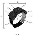
図1は、本発明によって形成された新規のTENSデバイス100を示し、ユーザの上部ふくらはぎ140に装着されている。ユーザは、TENSデバイス100を片方または両方の足に装着し得る。TENSデバイス100は、図2にさらに詳細に示され、好ましくは3つの構成要素、即ち、刺激器105、ストラップ110、および、電極配列120を備える。刺激器105は、好ましくは、機械的および電気的に相互接続された3つの区画室101、102、103を備える。区画室101、102、103はヒンジ機構104によって相互接続され(そのうちの1つのみが図2に示されている)、それにより、TENSデバイス100はユーザの足の湾曲した生体構造に適合できる。好ましい実施形態において、区画室102は、TENS刺激ハードウェア(バッテリを除く)とユーザインタフェース要素106および108を収容する。好ましい実施形態において、区画室101および103は、TENSデバイス100がワイヤレスでその他の要素(例えば、遠隔サーバ)と通信することを可能にするワイヤレスインタフェースユニットなどの、TENS刺激ハードウェアおよび他の付属要素に給電するためのバッテリを収容するさらに小さな補助区画室である。本発明の別の実施形態では、1つの区画室102のみがすべてのTENS刺激ハードウェア、バッテリおよびその他の付属要素を、側面の区画室101と103を必要とせず、収納するために使用され得る。 FIG. 1 shows a novel TENS
さらに図2を見ると、インタフェース要素106は、電気刺激のユーザ制御のためのプッシュボタンを備え、インタフェース要素108は、刺激状態を表示し、ユーザにその他のフィードバックを提供するLEDを備える。さらなるユーザインタフェース要素(例えば、LCDディスプレイ、ポケベルまたは音声出力を介した音声フィードバック、振動モータなどの触覚デバイス等)も考えられ、それらの要素は、本発明の範囲内にあるとみなされる。 Still referring to FIG. 2, the
本発明の好ましい実施形態は、図1に示されるようにユーザの上部ふくらはぎ140に装着されるように設計される。TENSデバイス100は、刺激器105と、電極配列120と、ストラップ110とを備え、装置を所定位置に配置し、次にストラップ110を締めることによって、上部ふくらはぎ140に固定される。特に、電極配列120は、ユーザの足におけるTENSデバイス100の特定の回転位置にかかわらず電極配列が適切な電気刺激をユーザの適切な生体構造に対して印加するように、意図的にサイズ調整され、構成される。好ましい実施形態は、TENSデバイスをユーザの上部ふくらはぎに配置することを含むが、追加の位置(膝の上部、背中の下部および上肢など)も考えられ、それらも本発明の範囲内であるとみなされる。 The preferred embodiment of the present invention is designed to be worn on the user's
図3は、電極配列120の1つの好ましい実施形態の概略図を示す。電極配列120は、好ましくは、4つの別個の電極202、204、206、208を備え、それぞれが均一または同様のサイズ(例えば、表面積)である。電極202、204、206、208は、好ましくは、電極204および206(カソードに相当する)が互いに対して(例えばコネクタ205を介して)電気的に接続されるように且つ電極202および208(アノードに相当する)が互いに対して(例えばコネクタ207を介して)電気的に接続されるように、対を成して接続される。電極202、204、206および208は、ユーザの足の上の電極配列120の回転位置にかかわらず適正な皮膚被覆率を確保するように適切にサイズ調整され、対を成して接続されることを理解すべきである。さらに、電極202、204、206および208は、交互的態様で接続されず、むしろ、2つの内側電極204および206が互いに接続されるように且つ2つの外側電極202および208が互いに接続されるように接続されると理解されるべきである。この電極の接続パターンは、もし2つの外側電極202および208が意図せず、互いに接触するようになった場合、カソードからアノードへの直接流れる刺激電流の電気的短絡が起きないことを確実にする。電流(即ち、組織に対する電気刺激のための電流)は、刺激器105上の相補的なコネクタ130、132と結合するコネクタ210、212(図3および図4を参照)によって電極対204、206、および202、208に対して提供される。コネクタ210は電極204および206と電気的に接続され、また、コネクタ212は電極202および208と電気的に接続される。刺激器105は、コネクタ210、212をそれぞれ介して電極204、206および電極202、208に通される電流を発生させる。 FIG. 3 shows a schematic diagram of one preferred embodiment of the
好ましい実施形態では、皮膚に接触する導電性材料は、電極202、204、206、208に作られたヒドロゲル物質である。電極上のヒドロゲルは、刺激器と、刺激される知覚神経があるユーザの体の部分との間のインタフェースとして機能する。乾電極および非接触刺激などの、他の種類の電極も考えられ、本発明の範囲内であるとみなされる。 In a preferred embodiment, the conductive material in contact with the skin is a hydrogel material made on the
TENSデバイス100の前述の態様の製造および使用に関するさらなる詳細は、Shai N. Gozaniらによる、係属中の2012年11月15日出願の米国特許出願通し番号13/678,221号「APPARATUS AND METHOD FOR RELIEVING PAIN USING TRANSCUTANEOUS ELECTRICAL NERVE STIMULATION」(代理人整理番号NEURO−5960)に開示され、その特許出願は本明細書により参考として本明細書に組み込まれている。 Further details regarding the manufacture and use of the foregoing aspects of the
好ましい実施形態では、電極配列120はカソードおよびアノードのそれぞれに、少なくとも28cm2の電極−皮膚接触面積を作る。In a preferred embodiment,
治療期間中の意図しない電極剥離は、ユーザへの潜在的危険性を意味する。電流および出力密度が増加し、ユーザに不快感を起こし、極端な場合には、熱傷の危険を呈し得るからである。電極剥離が起こると、同じ刺激電流が電極とユーザの皮膚との間のより小さな接触面積を介して流れることによって、より大きな電流および出力密度が生じる。 Unintentional electrode stripping during the treatment period represents a potential risk to the user. This is because current and power density increase, causing discomfort to the user, and in extreme cases can present a risk of burns. When electrode stripping occurs, the same stimulation current flows through a smaller contact area between the electrode and the user's skin, resulting in greater current and power density.
理想的には、電極−皮膚接触面積は、TENSの刺激の間、直接監視され、次に電流および出力密度が決定され、電流または出力密度のどちらか一方の閾値が超過した場合には、刺激が停止されるか低減され得る。しかしながら、実用的な観点から、電極−皮膚接触面積はリアルタイムで容易に測定されることはできない。 Ideally, the electrode-skin contact area is monitored directly during the stimulation of TENS, then the current and power density are determined and if either current or power density threshold is exceeded, the stimulation Can be stopped or reduced. However, from a practical point of view, the electrode-skin contact area cannot be easily measured in real time.
前述したことを考慮すると、本発明は、電極−皮膚インピーダンスの変化を監視することにより、電極−皮膚接触面積を推定する方法を開示する。本方法は、接触面積は、経皮的電気刺激の間の電極−皮膚インピーダンスにおける変化に影響する、主要な要因であるという生体電気の原理に基づいている(Lykken DT.Properties of electrodes used in electrodermal measurement.J Comp Physiol Psychol.Oct 1959;52:629−634)(Lykken DT.Square−wave analysis of skin impedance.Psychophysiology.Sep 1970;7(2):262−275)。
電極−皮膚インタフェース
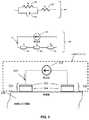
ヒドロゲル電極の機能は、経皮的電気神経刺激器(即ち、TENSデバイス)と、刺激される表在感覚神経が存在するユーザの体との間のインタフェースとしての役割を果たす。図5は、TENSデバイスとユーザとの間の電流の流れの略図である。図5は、また、TENSデバイスと生体構造との間のインタフェースの等価回路図350を示す。図5で明らかなように、定電流源310からの刺激電流315は、カソード電極320を介してユーザの皮膚330に流れる。カソード電極320は、導電性下地(例えば、シルバーハッチング)342およびヒドロゲル344で構成される。電極−皮膚インタフェース構成要素320および330(即ち、カソード320および皮膚330)は、インピーダンスを、等価回路350の入力インピーダンスZI352内に含まれる電流の流れに提供する。体に一旦入ると、電流は、等価回路350の生体インピーダンスZB354によって代表される、脂肪組織、筋肉、神経および骨(図示せず)などの、様々な組織要素からさらにインピーダンスを受ける。最後に、電流は、皮膚330とアノード電極332で構成される(アノード電極332も導電性下地342とヒドロゲル344を含む)、別の電極−皮膚インタフェースを通って電流源310に戻る。皮膚330とアノード電極332との間のインタフェースは、等価回路モデル350内の出力インピーダンスZo356によって代表される。アノードとカソード電極(および同様に入力と出力インピーダンス)の名称は単に表記のためであることを理解すべきである。二相刺激パルスがTENS刺激の第2相内で極性を反転すると、電流はインタフェース332を介してユーザの体内に流れ、インタフェース320を介して体外に流れる。In view of the foregoing, the present invention discloses a method for estimating electrode-skin contact area by monitoring changes in electrode-skin impedance. The method is based on the principle of bioelectricity that the contact area is a major factor affecting changes in electrode-skin impedance during percutaneous electrical stimulation (Lykken DT. Properties of electrodes used in electrodermal. measurement.J Comp Physiol Psychol.Oct 1959; 52: 629-634) (Lykken DT. square-wave analysis of skin impedance.Psychology.
Electrode-Skin Interface The function of the hydrogel electrode serves as an interface between the transcutaneous electrical nerve stimulator (ie, the TENS device) and the user's body where the superficial sensory nerve to be stimulated is present. FIG. 5 is a schematic diagram of current flow between a TENS device and a user. FIG. 5 also shows an equivalent circuit diagram 350 of the interface between the TENS device and the anatomy. As is apparent from FIG. 5, the stimulation current 315 from the constant
等価回路350の電極−皮膚インタフェースZI352と電極−皮膚インタフェースZo356の挙動は、パッシブ型電気回路360によってさらにモデル化され得る(van Boxtel A. Skin resistance during square−wave electrical pulses of 1 to 10mA.Med Biol Eng Comput.Nov 1977;15(6):679−687)。パッシブ型電気回路360の平行板静電容量Cp362および抵抗RP364は、角質層と関係する。パッシブ型電気回路360の構成要素Rs366は、アグリゲート直列抵抗を表し、角質層を含め、いくつかの皮膚構造に関係する構成要素を有する。The behavior of the electrode-
等価回路350の生体インピーダンスZB354は、刺激電流が中を流れる組織の種類に依存する(例えば、脂肪、筋肉、神経、骨等)。しかしながら、特定の組織経路に関係なく、等価回路350のZB354は通常、電極−皮膚インピーダンスZI352と等価回路350のZO356よりもはるかに小さい。等価回路350の3つのインピーダンスは直列であるので、全インピーダンスZは個別のインピーダンスの合計である(式1)。The
Z = Z0+ ZB+ ZI 式1
式1は、ZB<<(Zo+ZI)であるため、生体インピーダンスZBを下げることにより簡略化され得る。さらに、Z0とZIは類似した特徴を有するため(例えば、ヒドロゲルの種類、表面積、類似した皮膚の種類に適用等)、次にインピーダンス全体のZは式2に簡略化することが可能であり、ZEは一般的な電極−皮膚インタフェースインピーダンスである。Z = Z0 + ZB + ZI Formula 1
Since
Z = ZO+ ZI= ZE+ ZE= 2ZE 式2
好ましい実施形態では、モデルを簡略化し、インピーダンスを実質的に測定可能な量に調整するために、電極−皮膚インピーダンスは擬似抵抗を使用して定められる。具体的には、擬似抵抗は、刺激パルスの最後に電圧と電流の比によって与えられる。2相刺激パルスの場合には、第2相に同じ結果が予想されるが、第1相の最後の電圧および電流が使用される。この矩形波分析の手法は、一般的に、電極−皮膚インピーダンスの挙動を説明し研究するために使用される。相の持続時間が電極−皮膚の充電時定数に対して十分に長い場合には、次に擬似抵抗がRp+Rs(図5のパッシブ型電気回路360)に近似する。Z = Z O + Z I = Z E + Z E = 2Z E Formula 2
In a preferred embodiment, the electrode-skin impedance is defined using a pseudo-resistance to simplify the model and adjust the impedance to a substantially measurable amount. Specifically, the pseudoresistance is given by the voltage to current ratio at the end of the stimulation pulse. In the case of a biphasic stimulation pulse, the same result is expected for the second phase, but the last voltage and current of the first phase is used. This square wave analysis technique is commonly used to describe and study the behavior of electrode-skin impedance. If the duration of the phase is long enough for the electrode-skin charging time constant, then the pseudoresistance approximates Rp + Rs (passive
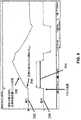
図6は、インピーダンスZの両端のインピーダンスZおよび電圧392を通る電流390のオシロスコープトレースの見本を示す。パルス持続時間394は、本実施例では、電極−皮膚充電時定数と比較して短く、これはまた、たいていのTENS刺激の場合にあてはまる。その結果、(図5のパッシブ型電気回路360の)直列抵抗Rs366の両端の小規模の電圧降下396と共に、擬似抵抗は主に、(図5のパッシブ型電気回路360の)キャパシタCp362の充電(トレース398)を示す。したがって、擬似抵抗は主に、電極−皮膚インピーダンスZの容量部を示す。
「電極剥離」モデル
電極と皮膚の間の接触面積、ヒドロゲルの物理的および生体電気的な特徴、電流密度、および皮膚の状態を含む、いくつかの要因が電極−皮膚インピーダンス(ZE)に影響を与える(Lykken DT.Square−wave analysis of skin impedance. Psychophysiology. Sep 1970;7(2):262−275)(van Boxtel A. Skin resistance during square−wave electrical pulses of 1 to 10 mA. Med Biol Eng Comput. Nov 1977;15(6):679−687)(Keller T, Kuhn A. Electrodes for transcutaneous (surface) electrical stimulation. J Automatic Control, University of Belgrade. 2008;18(2):35−45)。ここで開発された「電極剥離」モデルにおいては、電極−皮膚インピーダンスに影響を与えるすべての要因は、接触面積と電流密度を除いて、TENS治療期間の間は安定している(典型的なTENS治療期間は30から60分の間継続する)として仮定を単純化される。この仮定は厳密ではないが、検出閾値を設定するときに、この理想的なケースからの逸脱は限定され、安全要因を組み込むことにより説明され得る(即ち、「電極剥離」の受入不可能な程度を示す電極−皮膚インピーダンスにおける変化を識別するとき)。FIG. 6 shows a sample oscilloscope trace of current 390 through impedance Z and
"Electrode peeling" model Several factors affect electrode-skin impedance (ZE ), including contact area between electrode and skin, physical and bioelectric characteristics of hydrogel, current density, and skin condition (Lykken DT. Square-wave analysis of skin impedance. Psychophysiology. Sep 1970. 7 (2): 262-275) (van Boxel A swing ce s ri s ed s ed s ed s ed s ed s ed s e r e n e s e r e n e s e n e s e n e s e r e n e s e n e n e s e n e n e s e n e n e s e n e s e n e s e n e s e n e s e n e s e n e n e e n e n e s e n e n e e n e n e e n e n e e e e n e n e. Nov. 1977; 15 (6): 679-687) (Keller T, Kuhn A. Electrodes for transcutane. . Us (surface) electrical stimulation J Automatic Control, University of Belgrade 2008; 18 (2):. 35-45). In the “electrode stripping” model developed here, all factors affecting electrode-skin impedance are stable during the TENS treatment period, except for contact area and current density (typical TENS). The assumption is simplified as the treatment period lasts for 30 to 60 minutes). This assumption is not exact, but when setting the detection threshold, the deviation from this ideal case is limited and can be explained by incorporating a safety factor (ie, the unacceptable extent of “electrode stripping”) Electrode—when identifying changes in skin impedance).
電極剥離モデルは、第1に接触面積のみを考慮して開発され、次に電流密度の影響に対処されるであろう。 The electrode stripping model will be developed first considering only the contact area, and then the effect of current density will be addressed.
本発明の目的は、電極−皮膚インピーダンスにおける変化によって決定された電極−皮膚接触面積の相対的な変化を決定することであることは、注目に値する。本発明の目的は、任意の所与のモーメントで正確な接触面積を推定することではない。 It is noteworthy that the object of the present invention is to determine the relative change in electrode-skin contact area determined by the change in electrode-skin impedance. The object of the present invention is not to estimate the exact contact area at any given moment.
接触面積と電極−皮膚インピーダンスとの間の関係は、逆線状のものとしてモデル化され得る(Lykken DT.Square−wave analysis of skin impedance.Psychophysiology.Sep 1970;7(2):262−275)。インピーダンスZEと接触面積Aとの間の関係は、式3によって表される。The relationship between contact area and electrode-skin impedance can be modeled as an inverse line (Lyken DT. Square-wave analysis of skin impedance. Psychophysology. Sep 1970; 7 (2): 262-275). . Relationship between the contact area A and the impedance ZE is represented by equation 3.

式中、ρは、接触面積から、治療期間の間、安定していると仮定された各種要因の影響を組み込むインピーダンスへの変換定数である。新規な接触面積がαAであるように、接触面積が減少する場合、式中、0<α≦1,であり、式4に示されたように、インピーダンスが増加する。Where ρ is a conversion constant from the contact area to an impedance that incorporates the effects of various factors assumed to be stable during the treatment period. If the contact area decreases so that the new contact area is αA, then 0 <α ≦ 1, and the impedance increases as shown in Equation 4.
両方の電極が剥離し(即ち、意図せずにユーザの皮膚から外れる)、そのためそれぞれの接触面積が減少する可能性があるが、1つの電極のみが剥離する可能性のほうが高い(より控えめな推定)。この条件下では、全インピーダンス(元は式2)は式5によって与えられる。 Both electrodes may peel (ie, unintentionally disengage from the user's skin), thus reducing the contact area of each, but only one electrode is more likely to peel (more conservative) Estimated). Under this condition, the total impedance (originally equation 2) is given by equation 5.
1つの電極の剥離による、全インピーダンスにおける変化は、接触面積が電極の全表面積Aであると知られている場合の治療期間の開始時におけるインピーダンス(Zt=0)と、接触面積がαAに減少したときのその後の時刻Tでのインピーダンス(Zt=T)との間の比で表現され得る。この比は式6に示されている。The change in total impedance due to the separation of one electrode is the impedance at the start of the treatment period (Zt =0 ) when the contact area is known to be the total surface area A of the electrode, and the contact area is αA. It can be expressed as a ratio between the impedance (Zt =T ) at the subsequent time T when it decreases. This ratio is shown in Equation 6.
このように、インピーダンスにおける接触面積の影響のみが原因となる。 Thus, only the influence of the contact area on the impedance is the cause.
一定の電極−皮膚接触面積を仮定すると、前述のリサーチではインピーダンスは増加された電流密度とともに減少するであろうことが示唆される(Lykken DT.Square−wave analysis of skin impedance.Psychophysiology.Sep 1970;7(2):262−275)(van Boxtel A. Skin resistance during square−wave electrical pulses of 1 to 10 mA.Med Biol Eng Comput.Nov 1977;15(6):679−687)(Keller T, Kuhn A.Electrodes for transcutaneous (surface) electrical stimulation.J Automatic Control, University of Belgrade.2008;18(2):35−45)。電流密度は接触面積単位当たりの電流強度として定義される。固定された全体の電流強度とともに、電極−皮膚接触面積の減少により、残りの接触面積を流れる有効な電流密度が増加し、このため、単位面積当たりのインピーダンスが減少する。本質的には、接触面積の減少の結果、インピーダンスの電流密度を増加する影響は、一部にはインピーダンスの接触面積を減少する影響を相殺し得る。電流密度の影響は、本明細書ではδ>0である倍数因子αδとしてモデル化されている。δは電流強度と逆相関の関係にあるということに注意すべきである(即ち、δは低刺激電流に対して最も大きい)。この電極に使用される導電性ゲル材料の電気化学特性は、また、δ値に影響を与える可能性があり、実験的にまたは分析的に決定され得る。完全な「電極剥離」モデルは式7に示されている(倍数因子は剥離電極のみに適用されることに注意)。Assuming a constant electrode-skin contact area, the previous research suggests that impedance will decrease with increased current density (Lykken DT. Square-wave analysis of skin impedance. Psychology. Sep. 1970; 7 (2): 262-275) (van Boxtel A. Skin resistance during square-wave electrical pulses of 1 to 10 mA. Med Biol Eng Compute. Nov 1977; A. Electrodes for transcutaneous (surface) electrical stimulus J. Automatic Control, University of Belgrade. 2008; 18 (2): 35-45). Current density is defined as the current intensity per unit of contact area. Along with the fixed overall current intensity, the reduction of the electrode-skin contact area increases the effective current density through the remaining contact area, thus reducing the impedance per unit area. In essence, the effect of increasing the current density of the impedance as a result of the reduction of the contact area may partially offset the effect of reducing the contact area of the impedance. The effect of current density is modeled herein as a multiple factor αδ where δ> 0. Note that δ is inversely related to current intensity (ie, δ is greatest for low stimulation currents). The electrochemical properties of the conductive gel material used for this electrode can also affect the δ value and can be determined experimentally or analytically. The complete “electrode stripping” model is shown in Equation 7 (note that the multiple factor only applies to stripping electrodes).
皮膚インピーダンスの矩形波分析では、インピーダンスにおける電流密度の前述の影響は、(図5のパッシブ型電気回路360との関係において)主に並列抵抗、RPを通って伝達され、一方、CpおよびRsはたいてい電流密度に依存しないと示されている。(Lykken DT.Square−wave analysis of skin impedance.Psychophysiology.Sep 1970;7(2):262−275)(van Boxtel A. Skin resistance during square−wave electrical pulses of 1 to 10 mA.Med Biol Eng Comput.Nov 1977;15(6):679−687)(Kaczmarek KA, Webster JG, Bach−y−Rita P, Tompkins WJ.Electrotactile and vibrotactile displays for sensory substitution systems.IEEE Trans Biomed Eng.Jan 1991;38(1):1−16)。したがって、通常のTENSデバイスと電極との電極−皮膚インピーダンスにおける電流密度の影響は低いと考えられる。新規なTENSデバイス100の好ましい実施形態では、刺激パルス相の持続時間は100μ秒であり、電極−皮膚インピーダンス時定数と比較すると小さい(通常、>1ミリ秒)。その結果、TENS刺激のインピーダンスは、主に抵抗性よりはむしろ、容量性であり、CpおよびRsと比較すると、そのため全体のインピーダンスへのRpの貢献は小さい(図6を参照)。In the rectangular wave analysis of skin impedance, the aforementioned effect of current density in the impedance (relative to the passive
δ<1の場合、電流密度は、インピーダンスにおける接触面積を減少する影響を、部分的にまたは完全に相殺する(図6を参照)。低電流強度(例えば、10mA未満)であり、Rpが関係する長い刺激パルス(例えば、>1ミリ秒)の場合には、δは0.6から0.8の高さであり得る(van Boxtel A.Skin resistance during square−wave electrical pulses of 1 to 10mA.Med Biol Eng Comput.Nov 1977;15(6):679−687)(Keller T,Kuhn A.Electrodes for transcutaneous(surface)electrical stimulation.J Automatic Control,University of Belgrade.2008;18(2):35−45)。しかしながら、通常従来のTENSデバイスに使用されるより高い電流強度と、TENS刺激のインピーダンスはたいてい容量性(即ち、電流は、たいてい、図5のパッシブ型電気回路360との関係において考慮すると、RpよりむしろCpを通って流れる)である事実を仮定すると、δに予測される値は小さい。支援として、少なくとも1つのTENSデバイスによって得られる実験データは、インピーダンスにおける電流密度の影響は小さいことを示唆しており、したがって、このモデルの目的のために、以下の分析ではδが0.1に設定される。If δ <1, the current density partially or completely cancels the effect of reducing the contact area on the impedance (see FIG. 6). For low stimulation currents (eg, less than 10 mA) and long stimulation pulses involving Rp (eg,> 1 ms), δ can be as high as 0.6 to 0.8 (van Boxtel A. Skin resistance during square-wave electrical pulses of 1 to 10 mA. Med Biol Eng Compute.Nov 1977; 15 (6): 679 687. (Keller T, ken-t). Automatic Control, University of Belgrade. 2008; 18 (2): 35-45). However, a higher current strength than used in conventional TENS devices typically impedance of TENS stimulation mostly capacitive (i.e., current is usually when considered in relation to the passive
図7における、3つの曲線は、パラメータ値δの影響を示す。曲線410はδ=0.0、曲線412はδ=0.1、曲線414はδ=0.7に相当する。X軸405は、絶対単位(cm2)と、初期面積の28cm2に対する相対的割合の、電極−皮膚接触面積を表す。Y軸407は、現インピーダンス(即ち、Zt=T)とベースラインインピーダンス(即ち、Zt=0)との間のインピーダンス比である。ここに示すように、インピーダンス比は、接触面積のサイズが7から10cm2未満に減少する場合、急速に変化する。電極−皮膚接触面積の大きな減少に対して電極剥離検出器を高感度にすることにより、面積−インピーダンスの関係における、この非線形性は、安全機構を提供する。The three curves in FIG. 7 show the influence of the parameter value δ. Curve 410 corresponds to δ = 0.0, curve 412 corresponds to δ = 0.1, and curve 414 corresponds to δ = 0.7. The X-axis 405 represents the electrode-skin contact area in absolute units (cm2 ) and the relative ratio of the initial area to 28 cm2 . Y-
電極−皮膚インピーダンスは、通常、電極が皮膚にある持続時間に伴い減少するため、(van Boxtel A. Skin resistance during square−wave electrical pulses of 1 to 10 mA.Med Biol Eng Comput.Nov 1977;15(6):679−687)、式7中に具体的にモデル化されず、Zt=0をZt<Tに置き換え、すべての時刻t<Tに対して、Zt<Tが最小のインピーダンスである。したがって、最終的な電極剥離検出器は式8にて与えられる。Since the electrode-skin impedance usually decreases with the duration that the electrode is in the skin (van Boxel A. Skin resistance curing square-wave electrical pulses of 1 to 10 mA. Med Biol Env. 15; 6): 679-687), which is not specifically modeled in Equation 7, replacing Zt = 0 with Zt <T , and for all times t <T, Zt <T is the smallest impedance It is. Thus, the final electrode strip detector is given by Equation 8.
の場合、刺激を停止 式8
好ましい実施形態では、TENSデバイス100は、定電流刺激器310によって送達される刺激電流315を測定することによって、および、定電流刺激器310のカソード320とアノード332の間の電圧差を測定することによって、TENS刺激の間、継続的に電極−皮膚インピーダンスを監視するための回路および/またはソフトウェアを備える「電極剥離」検出器を備える。刺激器310によって「見られる」全体の等価インピーダンスは、電流で電圧差を割ることにより計算され得る。全インピーダンスは、電極−皮膚インタフェース320および332と関連する(等価回路350の)インピーダンスZIおよびZOによって左右され、接触面積サイズの逆数によって概ね決定される。初期の全インピーダンスはメモリに保存され、「ベースライン」インピーダンスと称される。それぞれ、次のサンプル時刻Tにて測定された全インピーダンスは、ベースラインインピーダンスZt<T=min(Zt<T−1,ZT)をアップデートする。換言すれば、電極−皮膚インピーダンスは通常、電極が皮膚の上にある時間の長さの関数として減少するため、ベースラインインピーダンスは、その治療期間の持続時間の間、測定される最小のインピーダンスに設定されるよう、継続してアップデートされることが好ましい。全インピーダンスZTは、次に、ベースラインインピーダンス値Zt<Tと比較される。もし電極が皮膚から剥離された場合(即ち、電極が意図せずに皮膚から外れた場合)には、電極−皮膚接触面積は減少し、そのため電極−皮膚インピーダンスは増加する。全インピーダンスもまた増加する。したがって、全インピーダンス値がベースラインインピーダンス値の一定の倍数を超過するとき、電極−皮膚接触面積は全接触面積の限界のパーセントより低くなったと推定することができる。経皮的電気刺激は、次に、高い電流および出力密度のために、ユーザに過剰な不快感および/または熱傷を与えないように直ちに停止される(または低減される)。In case of, stop stimulation
In a preferred embodiment, the
例えば、図9を参照すると、TENSデバイス100は、「電極剥離」検出器500を備え、電極剥離検出器500は、刺激電流を決定するための手段505(例えば、当該技術分野において周知である電流センサのようなもの)と、アノード320とカソード332との間の電圧差を決定するための手段510(例えば、当該技術分野において周知である電圧センサのようなもの)と、経皮的電気刺激の間の電極−皮膚インピーダンスを計算するための手段515(例えば、当該技術分野において周知である、本明細書で開示された機能を提供するための適切なプログラミングを有する、マイクロプロセッサのようなもの)と、電極−皮膚インピーダンスが所定の閾値を超えた場合刺激電流を中止するための手段520(例えば、当該技術分野において周知である、本明細書にて開示された機能を提供するよう、前述のマイクロプロセッサによって制御されるスイッチのようなもの)とを含む。 For example, referring to FIG. 9, the
本発明の好ましい実施形態の使用は簡単である。ユーザは、電極配列120を図4に示すように、刺激器105にスナップ留めし、それにより、2つの構成要素間に強固な機械的および電気的な接触を確立する。ストラップ110を使用して、本アセンブリは次に、ユーザの上部ふくらはぎに電極と皮膚を完全に接触させて配置される(図1)。TENS治療を送達するための電流刺激は、押ボタン106を押すことにより開始される。新規なTENSデバイス100の「電極剥離」検出器は、治療期間の間にわたって電圧および刺激器105のアノード端子210とカソード端子212間の電流を測定することによって、電極−皮膚インピーダンスを監視する。ベースラインインピーダンスは、より小さなインピーダンス値が治療期間の間に測定されたときにアップデートされる。現在の電極−皮膚インピーダンス値とベースラインインピーダンス値との間の比が所定の閾値を超えた場合、TENSデバイスの「電極剥離」検出器は次にTENSデバイスに刺激を停止させる。LED108は、この状態、即ち、電極−皮膚接触面積が限界値より下になったため、TENSデバイスが刺激を停止する状態、になったことを知らせるために赤を点滅する。
TENS治療への電極剥離モデルの適用
本発明の有用性は、後述の「電極剥離」検出器を装備したTENSデバイスを使用する実験において証明された。TENSデバイスは100mAまでの強度を有する刺激電流を送達するよう設計されている。二相刺激パルスは230μ秒の持続時間(各相は100μ秒の持続時間で、2つの相の間には30μ秒の間隙がある)および60Hzと100Hzとの間の不規則な周波数を有する。アノードとカソードの電極は、電極配列120が皮膚に正しく配置された場合、少なくとも28cm2の電極−皮膚接触面積を作る。したがって、最大の平均電流密度および出力密度は、それぞれ、0.5mA/cm2および3.6mW/cm2である。最大平均電流密度は、最大強度が100mAかつ最大パルス周波数が100Hzである、二相電流パルスの二乗平均平方根値である。出力密度は、FDA指針案に従って抵抗負荷が500Ωの同じ条件で計算されている(Food and Drug Administration, Draft Guidance for Industry and Staff:Class II Special Controls Guidance Document:Transcutaneous Electrical Nerve Stimulator for Pain Relief April 5, 2010)。TENSデバイスの「電極剥離」検出器は、87.5%を超える電極−皮膚接触面積の減少となる電極剥離の事象を検出するように設計されている(即ち、残存する電極−皮膚接触面積は当初の電極−皮膚接触面積の8分の1未満になったとき)。電極−皮膚接触面積が、当初の電極−皮膚接触面積サイズである28cm2の8分の1になったとき、結果として最大の平均出力密度は28.5mW/cm2であり、実質的に、FDA指針案に記述された熱傷のリスクを増加させると認識される250mW/cm2の閾値未満となる。(Food and Drug Administration, Draft Guidance for Industry and Staff:Class II Special Controls Guidance Document:Transcutaneous Electrical Nerve Stimulator for Pain Relief April 5,2010)。The use of the preferred embodiment of the present invention is simple. The user snaps the
Application of electrode stripping model to TENS therapy The utility of the present invention has been demonstrated in experiments using a TENS device equipped with an “electrode stripping” detector as described below. TENS devices are designed to deliver stimulation currents having an intensity up to 100 mA. A biphasic stimulation pulse has a duration of 230 μs (each phase is 100 μs long with a 30 μs gap between the two phases) and an irregular frequency between 60 Hz and 100 Hz. The anode and cathode electrodes create an electrode-skin contact area of at least 28 cm2 when the
現時点でのインピーダンスとベースラインインピーダンスとの間のインピーダンス比は、式8によって与えられる。TENSデバイスによって得られる実験データは、パラメータδに0.1の値を生じる。安全域を増加し、示されていない要因と変動の原因を説明するために、50%の安全性の調整係数がインピーダンス比閾値を決定することに取り入れられる。電極−皮膚接触面積の当初のサイズ(α=0.125)の8分の7が減少したことを検出すると、0.5*[1.0+0.125(0.1−1.0)]/2=1.87のインピーダンス比閾値になる。TENSデバイスの「電極剥離」検出器にプログラミングされた最終的な検出閾値は、端数切り捨てで1.80になった。このように、TENSデバイスの「電極剥離」検出器は、一旦、現在のインピーダンスがベースラインインピーダンスの180%以上であると決定すると、刺激を停止する。The impedance ratio between the current impedance and the baseline impedance is given by Equation 8. Experimental data obtained with a TENS device yields a value of 0.1 for the parameter δ. A 50% safety adjustment factor is incorporated in determining the impedance ratio threshold to increase the safety margin and account for the factors not shown and the sources of variation. When it is detected that 7/8 of the initial size of the electrode-skin contact area (α = 0.125) has decreased, 0.5 * [1.0 + 0.125(0.1-1.0) ] / The impedance ratio threshold is 2 = 1.87. The final detection threshold programmed into the “electrode stripping” detector of the TENS device was 1.80 rounded down. Thus, the “electrode stripping” detector of the TENS device stops stimulation once it determines that the current impedance is greater than or equal to 180% of the baseline impedance.
電極−皮膚接触面積における減少は、TENS刺激におけるインピーダンスの増加の主な原因である。この実験においては、電極−皮膚接触面積の減少は、制御された剥離過程を通して行われる。制御された剥離過程は、事前剥離時間および剥離速度を特徴とする。事前剥離時間は、電極−皮膚接触面積が制御された剥離で減少される前に、電極が被験者の皮膚上にある持続時間を意味する。剥離速度は、1分当たりの電極−皮膚接触面積の減少である。剥離は、徐々に被験者の皮膚から電極を持ち上げることにより行われる。それぞれの調査の被験者に、任意の片方の足を10分の事前剥離時間に、もう片方の足を40分の事前剥離時間に割り当てられた。各試験ごとに、剥離速度は1.5から60cm2/分の間で任意に選択される。これは外側の電極202および208が、約30秒から20分で完全に剥離することを意味する。The decrease in electrode-skin contact area is a major cause of increased impedance in TENS stimulation. In this experiment, the electrode-skin contact area reduction is accomplished through a controlled exfoliation process. The controlled stripping process is characterized by pre-stripping time and stripping rate. Pre-exfoliation time means the duration that an electrode is on the subject's skin before the electrode-skin contact area is reduced with controlled exfoliation. The peel rate is the decrease in electrode-skin contact area per minute. Peeling is performed by gradually lifting the electrode from the subject's skin. Each study subject was assigned an arbitrary one foot for a pre-exfoliation time of 10 minutes and the other foot for a pre-extraction time of 40 minutes. For each test, the peel rate is arbitrarily selected between 1.5 and 60 cm2 / min. This means that the
66人の被験者(女性37人)がこの実験に参加した。平均の被験者の年齢は、51.3歳であり、標準偏差は15.0歳、19から85歳の範囲(最小から最大)であった。異なる電極がそれぞれの足に使用された。合計で132の電極剥離試験が行われた。 66 subjects (37 women) participated in this experiment. The average subject age was 51.3 years, with a standard deviation of 15.0 years, ranging from 19 to 85 years (minimum to maximum). Different electrodes were used for each foot. A total of 132 electrode peel tests were performed.
各試験の初めに、電極120が被験者の選択された足に配置され、TENS治療期間が5mAの強度で開始された。事前剥離時間が経過した後、外側の電極パッド202または208のうち1つが指定された剥離速度で皮膚から剥離された。最初のパッドが皮膚から完全に取れた場合、必要に応じて、もう片方の外側のパッドが同じ剥離速度で皮膚から剥離された。刺激が自動的に停止された時点で、皮膚上に残っている全体の外側の電極面積が記録された。 At the beginning of each test,
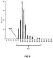
電極剥離の条件を誘発する、残りの電極接触面積422(cm2)の分布は図8に示されている。言い換えると、図8は、実施された132の電極剥離試験について、「電極剥離」の条件が発生した時点、即ち、インピーダンス比(適切な場合にはアップデートされた、ベースラインインピーダンスによって割られた現インピーダンス)が閾値1.80を超える時点、で残っている電極接触面積(cm2)の分布を示す。最小の残りの電極−皮膚接触面積424は、6.9cm2であり、ターゲットの最小接触面積3.5cm2の約2倍の大きさであった。132すべての実験で、電極−皮膚接触面積が最小接触面積3.5cm2より小さくなる前に、刺激はTENSデバイスによって停止された。電極剥離が検出されたときの平均の電極−皮膚接触面積は、それぞれ、10分および40分の事前剥離時間のグループで、10.2±2.1cm2および10.1±1.7cm2であった。2つのグループの平均の電極−皮膚接触面積の違いは、統計的に顕著ではなかった(p>0.05、対t−検定)。すべての132の試験を統合すると、平均の接触面積は10.1±1.9cm2であった。連続型変数(剥離速度、年齢、身長、体重、肥満度指数)およびカテゴリー変数(性別)の2つのグループのt−検定の場合において、残りの接触面積と人口統計要因との間の関係は、残りの接触面積と電極剥離速度との間の関係と同様に、一変量の直線回帰によって評価された。剥離速度およびいかなる人口統計変数も残りの接触面積を予測しなかった(すべてp>0.05)。The distribution of the remaining electrode contact area 422 (cm2 ) that induces electrode stripping conditions is shown in FIG. In other words, FIG. 8 shows, for the 132 electrode peel test performed, the time when the “electrode peel” condition occurred, ie the impedance ratio (updated where appropriate, the baseline impedance divided by the baseline impedance). The distribution of the remaining electrode contact area (cm2 ) when the impedance) exceeds the threshold value 1.80 is shown. The minimum remaining electrode - skin contact area 424 is 6.9 cm2, was about twice the size of the smallest contact area 3.5 cm2 of the target. In all 132 experiments, stimulation was stopped by the TENS device before the electrode-skin contact area was less than the minimum contact area of 3.5 cm2 . The average electrode-skin contact area when electrode stripping is detected is 10.2 ± 2.1 cm2 and 10.1 ± 1.7 cm2 in the 10 min and 40 min pre-peel time groups, respectively. there were. The difference in the average electrode-skin contact area between the two groups was not statistically significant (p> 0.05 vs t-test). When all 132 tests were combined, the average contact area was 10.1 ± 1.9 cm2 . In the case of two groups of t-tests, continuous variables (peeling rate, age, height, weight, body mass index) and categorical variables (gender), the relationship between the remaining contact area and demographic factors is Similar to the relationship between the remaining contact area and electrode strip rate, it was evaluated by univariate linear regression. Peel rate and any demographic variables did not predict the remaining contact area (all p> 0.05).
実験結果は、電極剥離は電極−皮膚インピーダンスをリアルタイムで監視することによって確実に検出可能であることを示した。接触面積が試験被験者の人口統計および事前剥離時間と統計的に顕著な相関関係を有さないという事実は、インピーダンスの監視に基づく電極剥離の検出がロバストであることを示唆する。そのため、「電極剥離」検出器は、絶えずユーザおよび電極の特徴の変化に面して操作するべきである。
好ましい実施形態の変形例
本発明の別の実施形態では、その時間インスタンスまで取得されたすべてのインピーダンス値の実行最小インピーダンス値の代わりに、ベースラインインピーダンスは、初期のインピーダンス値である。The experimental results showed that electrode peeling can be reliably detected by monitoring electrode-skin impedance in real time. The fact that the contact area has no statistically significant correlation with the test subject's demographic and pre-peel time suggests that the detection of electrode delamination based on impedance monitoring is robust. As such, the “electrode stripping” detector should be operated constantly in the face of changes in user and electrode characteristics.
Variations of the Preferred Embodiment In another embodiment of the invention, instead of the running minimum impedance value of all impedance values acquired up to that time instance, the baseline impedance is the initial impedance value.
本発明の別の実施形態においては、インピーダンス比が所定の閾値を超える場合、刺激を停止する代わりに、TENS刺激電流の強さが、推定された電極−皮膚接触面積の減少に比例して減少され得る。この手法は、電流および出力密度を安全な閾値より下のレベルに維持しつつ、治療を継続可能にするであろう。 In another embodiment of the invention, if the impedance ratio exceeds a predetermined threshold, instead of stopping the stimulation, the strength of the TENS stimulation current decreases in proportion to the estimated decrease in electrode-skin contact area. Can be done. This approach would allow treatment to continue while maintaining current and power density at levels below safe thresholds.
各治療期間は通常、約1時間継続する。1つの好適な実施形態においては、各治療期間はユーザがプッシュボタン106を作動させるときに開始される。別の好適な実施形態では、ユーザがさらに介入することなく、タイマが次の治療期間を開始するために使用される。この手法は、夜間の睡眠中に2つ以上の治療期間が望まれるときに、特に有用である。ユーザによって手動で開始された最初の治療期間が完了したとき、タイマが自動的に予め設定した時刻で開始し、ベースラインインピーダンスがその次の治療期間のために保存される。一実施形態では、タイマの期間はその前の治療期間の持続時間と同じである。タイマの満了は新しい治療期間を開始し、前回の期間からの最終のベースラインインピーダンスは、現在の治療期間のためのベースラインインピーダンスの初期値として使用される。 Each treatment period typically lasts about 1 hour. In one preferred embodiment, each treatment period begins when the user activates
本発明の好ましい実施形態においては、刺激電流の強度は、治療期間が進むにつれて増加または減少する場合がある。例えば、増加は、神経の慣れに対応するため必要とされ得る。したがって、全インピーダンスを推定するために使用される刺激電流強度は、治療期間の中で、または複数の期間にわたって異なり得る。 In preferred embodiments of the invention, the intensity of the stimulation current may increase or decrease as the treatment period progresses. For example, an increase may be required to accommodate neural habituation. Thus, the stimulation current intensity used to estimate the total impedance may vary during the treatment period or over multiple periods.
別の実施形態では、全インピーダンスは、固定された特徴(例えば、刺激電流強度およびパルス持続時間)を有する専用の調査電流により評価される。強度は、調査電流が治療的電気刺激を妨げないように、電気触覚閾値の強度を下回るレベルに設定され得る。調査電流のパルスは、治療用の電流パルスよりもはるかに長い持続時間を有することができ、そのためインピーダンスの抵抗性および容量性構成要素が評価され得る。 In another embodiment, the total impedance is evaluated by a dedicated survey current with fixed characteristics (eg, stimulation current intensity and pulse duration). The intensity can be set to a level below the intensity of the electrotactile threshold so that the investigation current does not interfere with the therapeutic electrical stimulation. The probe current pulse can have a much longer duration than the therapeutic current pulse so that the resistive and capacitive components of the impedance can be evaluated.
本発明の別の実施形態では、電極−皮膚接触面積はTENS治療期間、および治療期間と治療期間の間の期間の両方とも監視される。感覚閾値の強度より低い刺激強度を有する、同様の調査電流は、電極−皮膚インピーダンスを監視するために休止期間で使用される。 In another embodiment of the invention, the electrode-skin contact area is monitored both during the TENS treatment period and during the period between treatment and treatment periods. A similar investigation current having a stimulus intensity lower than the sensory threshold intensity is used in the rest period to monitor the electrode-skin impedance.
最後に、本発明の本質を説明するために本明細書中に記載して例示してきた細部、材料、ステップ、および、部品の配置のさらなる変更は、本発明の原理および範囲内に依然としてとどまりつつ当業者によりなされてもよいということは理解すべきである。 Finally, further changes in the details, materials, steps, and arrangement of parts described and illustrated herein to illustrate the nature of the invention remain within the principles and scope of the invention. It should be understood that this may be done by one skilled in the art.
Claims (36)
Translated fromJapanese少なくとも1つの神経を電気的に刺激するための刺激手段と、
前記刺激手段に接続可能な電極配列であって、前記少なくとも1つの神経の電気刺激のための複数の電極を備え、前記電極は、前記ユーザの皮膚に完全に接触するときに、予め形成された形状、および既知の電極−皮膚接触面積サイズを有する、電極配列と、
前記電極配列を通して、前記電気刺激のインピーダンスを監視するための、前記刺激手段に電気的に接続された監視手段と、
前記電極−皮膚接触面積内の変化を推定するために前記インピーダンスを分析するための分析手段と、を備える装置。A device for transcutaneous electrical nerve stimulation in a user comprising:
A stimulation means for electrically stimulating at least one nerve;
An electrode arrangement connectable to the stimulation means, comprising a plurality of electrodes for electrical stimulation of the at least one nerve, the electrodes being pre-formed when in full contact with the user's skin An electrode array having a shape and a known electrode-skin contact area size;
Monitoring means electrically connected to the stimulation means for monitoring the impedance of the electrical stimulation through the electrode arrangement;
An analysis means for analyzing the impedance to estimate a change in the electrode-skin contact area.
前記複数の電極と皮膚との間で完全に(complete)接触することを可能にするために前記ユーザの前記皮膚の表面に前記電極配列を適用するステップと、
前記少なくとも1つの前記ユーザの神経を、前記電極配列に接続された電気刺激器で電気的に刺激するステップと、
前記電極−皮膚インタフェースのインピーダンスを監視するステップと、
電極−皮膚接触面積のサイズ(contact area size)を推定するために、前記監視されたインピーダンスを分析するステップと、を含む方法。A method for monitoring an electrode-skin contact area during delivery of transcutaneous electrical nerve stimulation through an electrode array comprising a plurality of electrodes to at least one nerve of a user, each electrode having a known shape And the method comprises:
Applying the electrode arrangement to a surface of the user's skin to allow complete contact between the plurality of electrodes and the skin;
Electrically stimulating the at least one user nerve with an electrical stimulator connected to the electrode array;
Monitoring the impedance of the electrode-skin interface;
Analyzing the monitored impedance to estimate an electrode-skin contact area size.
複数の電極を備える電極配列であって、前記複数の電極は、前記複数の電極がユーザの皮膚に完全に接触するときに、予め形成された形状と既知の電極−皮膚接触面積を有する、電極配列と、
前記ユーザの少なくとも1つの神経を刺激するように、前記ユーザの前記皮膚に電気刺激を提供するための前記電極配列に接続可能な刺激手段と、
前記電極−皮膚インピーダンス値を監視するための、前記電極配列に電気的に接続可能な監視手段と、
前記監視手段が、前記電極−皮膚インピーダンス値が所定の値だけ変更されたと決定するときに、前記ユーザの前記皮膚に提供された前記電気刺激を制御するための制御手段と、を備える装置。A device for transcutaneous electrical nerve stimulation in a user comprising:
An electrode arrangement comprising a plurality of electrodes, the electrodes having a pre-formed shape and a known electrode-skin contact area when the plurality of electrodes are in full contact with the user's skin An array,
Stimulating means connectable to the electrode arrangement for providing electrical stimulation to the user's skin to stimulate at least one nerve of the user;
Monitoring means electrically connectable to the electrode array for monitoring the electrode-skin impedance value;
Control means for controlling the electrical stimulation provided to the skin of the user when the monitoring means determines that the electrode-skin impedance value has been changed by a predetermined value.
刺激電流をユーザに、電極−皮膚インタフェースを有するアノードと電極−皮膚インタフェースを有するカソードを通して印加するステップと、
電極−皮膚インピーダンスを決定するために、(i)アノードおよびカソードを通る刺激電流、および(ii)アノードとカソードとの間の電圧差を測定するステップと、
前記電極−皮膚インピーダンスが所定の方法で変化するときに、前記刺激電流を調整するステップと、を含む方法。A method for applying percutaneous electrical nerve stimulation to a user comprising:
Applying a stimulation current to a user through an anode having an electrode-skin interface and a cathode having an electrode-skin interface;
Measuring (i) a stimulation current through the anode and cathode, and (ii) a voltage difference between the anode and cathode to determine electrode-skin impedance;
Adjusting the stimulation current when the electrode-skin impedance changes in a predetermined manner.
Applications Claiming Priority (3)
| Application Number | Priority Date | Filing Date | Title |
|---|---|---|---|
| US201361806481P | 2013-03-29 | 2013-03-29 | |
| US61/806,481 | 2013-03-29 | ||
| PCT/US2014/032390WO2014161000A1 (en) | 2013-03-29 | 2014-03-31 | Detecting cutaneous electrode peeling using electrode-skin impedance |
Related Child Applications (1)
| Application Number | Title | Priority Date | Filing Date |
|---|---|---|---|
| JP2019044566ADivisionJP7017676B2 (en) | 2013-03-29 | 2019-03-12 | Electrode-Detection of skin electrode exfoliation using skin impedance |
Publications (2)
| Publication Number | Publication Date |
|---|---|
| JP2016515428Atrue JP2016515428A (en) | 2016-05-30 |
| JP2016515428A5 JP2016515428A5 (en) | 2017-05-18 |
Family
ID=51621578
Family Applications (2)
| Application Number | Title | Priority Date | Filing Date |
|---|---|---|---|
| JP2016505616APendingJP2016515428A (en) | 2013-03-29 | 2014-03-31 | Detection of skin electrode peeling using electrode-skin impedance |
| JP2019044566AActiveJP7017676B2 (en) | 2013-03-29 | 2019-03-12 | Electrode-Detection of skin electrode exfoliation using skin impedance |
Family Applications After (1)
| Application Number | Title | Priority Date | Filing Date |
|---|---|---|---|
| JP2019044566AActiveJP7017676B2 (en) | 2013-03-29 | 2019-03-12 | Electrode-Detection of skin electrode exfoliation using skin impedance |
Country Status (6)
| Country | Link |
|---|---|
| US (3) | US9474898B2 (en) |
| EP (1) | EP2978488B1 (en) |
| JP (2) | JP2016515428A (en) |
| CN (1) | CN105377359B (en) |
| ES (1) | ES2879286T3 (en) |
| WO (1) | WO2014161000A1 (en) |
Cited By (5)
| Publication number | Priority date | Publication date | Assignee | Title |
|---|---|---|---|---|
| JP2019076716A (en)* | 2017-10-20 | 2019-05-23 | パナソニック株式会社 | Stimulation system and rehabilitation support system |
| JP2020524577A (en)* | 2017-06-23 | 2020-08-20 | ジーエスケイ コンシューマー ヘルスケア エス.エイ. | Buttonless control device and method for a wearable percutaneous electrical nerve stimulator using interactive gestures and other means |
| WO2020183931A1 (en)* | 2019-03-14 | 2020-09-17 | テルモ株式会社 | Electrical stimulus application device and determination method |
| JP2021514208A (en)* | 2018-01-03 | 2021-06-10 | エヌエスイー プロダクツ インコーポレイテッド | Fingertip mounting micro current device for skin |
| JP2023538569A (en)* | 2020-08-20 | 2023-09-08 | アクテジー リミテッド | Device for detecting conductivity |
Families Citing this family (99)
| Publication number | Priority date | Publication date | Assignee | Title |
|---|---|---|---|---|
| US9675801B2 (en) | 2011-11-15 | 2017-06-13 | Neurometrix, Inc. | Measuring the “on-skin” time of a transcutaneous electrical nerve stimulator (TENS) device in order to minimize skin irritation due to excessive uninterrupted wearing of the same |
| PT2780073T (en) | 2011-11-15 | 2017-12-18 | Neurometrix Inc | Apparatus for relieving pain using transcutaneous electrical nerve stimulation |
| US10335595B2 (en) | 2011-11-15 | 2019-07-02 | Neurometrix, Inc. | Dynamic control of transcutaneous electrical nerve stimulation therapy using continuous sleep detection |
| US11259744B2 (en) | 2011-11-15 | 2022-03-01 | Neurometrix, Inc. | Transcutaneous electrical nerve stimulator with automatic detection of leg orientation and leg motion for enhanced sleep analysis, including enhanced transcutaneous electrical nerve stimulation (TENS) using the same |
| US11247040B2 (en) | 2011-11-15 | 2022-02-15 | Neurometrix, Inc. | Dynamic control of transcutaneous electrical nerve stimulation therapy using continuous sleep detection |
| US10279179B2 (en) | 2013-04-15 | 2019-05-07 | Neurometrix, Inc. | Transcutaneous electrical nerve stimulator with automatic detection of user sleep-wake state |
| US10112040B2 (en) | 2011-11-15 | 2018-10-30 | Neurometrix, Inc. | Transcutaneous electrical nerve stimulation using novel unbalanced biphasic waveform and novel electrode arrangement |
| US9827420B2 (en) | 2013-03-29 | 2017-11-28 | Neurometrix, Inc. | Transcutaneous electrical nerve stimulator with user gesture detector and electrode-skin contact detector, with transient motion detector for increasing the accuracy of the same |
| US9731126B2 (en) | 2011-11-15 | 2017-08-15 | Neurometrix, Inc. | Transcutaneous electrical nerve stimulator with automatic detection of leg orientation and leg motion for enhanced sleep analysis, including enhanced transcutaneous electrical nerve stimulation (TENS) using the same |
| DE102012013534B3 (en) | 2012-07-05 | 2013-09-19 | Tobias Sokolowski | Apparatus for repetitive nerve stimulation for the degradation of adipose tissue by means of inductive magnetic fields |
| BR112015017042B1 (en) | 2013-01-21 | 2022-03-03 | Cala Health, Inc | Device to treat tremor |
| JP2016515428A (en) | 2013-03-29 | 2016-05-30 | ニューロメトリックス・インコーポレーテッド | Detection of skin electrode peeling using electrode-skin impedance |
| CN105431196B (en) | 2013-04-15 | 2019-02-01 | Gsk消费者健康有限公司 | Transcutaneous electrical nerve stimulator with automatic detection of user sleep-wake state |
| USD735873S1 (en)* | 2014-01-27 | 2015-08-04 | Neurometrix, Inc. | Transcutaneous electrical nerve stimulation (tens) device |
| CA2949843A1 (en) | 2014-06-02 | 2015-12-10 | Cala Health, Inc. | Systems and methods for peripheral nerve stimulation to treat tremor |
| ES2782556T3 (en) | 2014-08-15 | 2020-09-15 | Axonics Modulation Tech Inc | System for neurostimulation electrode configurations based on neuronal location |
| CA2958210C (en) | 2014-08-15 | 2023-09-26 | Axonics Modulation Technologies, Inc. | Integrated electromyographic clinician programmer for use with an implantable neurostimulator |
| AU2015301401B2 (en) | 2014-08-15 | 2020-01-16 | Axonics Modulation Technologies, Inc. | Electromyographic lead positioning and stimulation titration in a nerve stimulation system for treatment of overactive bladder |
| PL3244965T3 (en) | 2015-01-13 | 2023-07-24 | Theranica Bio-Electronics Ltd. | Treatment of headaches by electrical stimulation |
| US11364380B2 (en) | 2015-03-27 | 2022-06-21 | Elwha Llc | Nerve stimulation system, subsystem, headset, and earpiece |
| US11491342B2 (en) | 2015-07-01 | 2022-11-08 | Btl Medical Solutions A.S. | Magnetic stimulation methods and devices for therapeutic treatments |
| EP4342516A3 (en) | 2015-06-10 | 2024-07-10 | Cala Health, Inc. | Systems and methods for peripheral nerve stimulation to treat tremor with detachable therapy and monitoring units |
| US20180001107A1 (en) | 2016-07-01 | 2018-01-04 | Btl Holdings Limited | Aesthetic method of biological structure treatment by magnetic field |
| US10695575B1 (en) | 2016-05-10 | 2020-06-30 | Btl Medical Technologies S.R.O. | Aesthetic method of biological structure treatment by magnetic field |
| US10786204B2 (en)* | 2015-08-03 | 2020-09-29 | Kabushiki Kaisha Toshiba | Electronic device |
| WO2017053847A1 (en) | 2015-09-23 | 2017-03-30 | Cala Health, Inc. | Systems and methods for peripheral nerve stimulation in the finger or hand to treat hand tremors |
| US9895533B2 (en)* | 2016-01-11 | 2018-02-20 | Theranica Bio-Electronics Ltd. | Impedance monitoring during electrostimulation |
| WO2017125921A2 (en)* | 2016-01-18 | 2017-07-27 | L.E.V. Lakeev Ltd. | Device system and method for noninvasive application of stimuli |
| CA3011993C (en) | 2016-01-21 | 2024-05-14 | Cala Health, Inc. | Systems, methods and devices for peripheral neuromodulation for treating diseases related to overactive bladder |
| US10252053B2 (en) | 2016-03-31 | 2019-04-09 | University Of Utah Research Foundation | Electronic nerve stimulation |
| US20180303704A1 (en) | 2016-04-08 | 2018-10-25 | Vibrating Therapeutic Apparel, Llc | Vibrating therapeutic apparel |
| EP3448191A4 (en) | 2016-04-25 | 2020-01-08 | PreActive Technologies Inc. | REDUCING BRAIN INJURIES BY LIMITING BRAIN MOVEMENT WHEN SUDDENLY BRAKING DOWN OR ACCELERATING THE HEAD |
| US12041997B2 (en) | 2016-04-25 | 2024-07-23 | Preactive Technologies Inc. | Reducing brain injury by limiting brain motion during sudden deceleration or acceleration of the head |
| US11464993B2 (en) | 2016-05-03 | 2022-10-11 | Btl Healthcare Technologies A.S. | Device including RF source of energy and vacuum system |
| US11247039B2 (en) | 2016-05-03 | 2022-02-15 | Btl Healthcare Technologies A.S. | Device including RF source of energy and vacuum system |
| US11534619B2 (en) | 2016-05-10 | 2022-12-27 | Btl Medical Solutions A.S. | Aesthetic method of biological structure treatment by magnetic field |
| USD841178S1 (en)* | 2016-07-28 | 2019-02-19 | Satina Medical Ug (Haftungsbeschränkt) | Belt with vibrating modules to stimulate diaphragm |
| US10583287B2 (en) | 2016-05-23 | 2020-03-10 | Btl Medical Technologies S.R.O. | Systems and methods for tissue treatment |
| DE102017112080A1 (en)* | 2016-06-15 | 2017-12-21 | Rieter Ingolstadt Gmbh | Method for optimizing the production of a rotor spinning machine |
| US10556122B1 (en) | 2016-07-01 | 2020-02-11 | Btl Medical Technologies S.R.O. | Aesthetic method of biological structure treatment by magnetic field |
| WO2018009680A1 (en)* | 2016-07-08 | 2018-01-11 | Cala Health, Inc. | Systems and methods for stimulating n nerves with exactly n electrodes and improved dry electrodes |
| WO2018013708A1 (en) | 2016-07-13 | 2018-01-18 | Neurometrix, Inc. | Apparatus and method for automated compensation of transcutaneous electrical nerve stimulation for temporal fluctuations such as circadian rhythms |
| USD851260S1 (en)* | 2016-07-15 | 2019-06-11 | Neurometrix, Inc. | Bioelectrode |
| US11426580B2 (en) | 2016-08-12 | 2022-08-30 | Health Discovery Labs Llc | Systems and methods for low intensity high efficiency electrical stimulation |
| US11141219B1 (en) | 2016-08-16 | 2021-10-12 | BTL Healthcare Technologies, a.s. | Self-operating belt |
| CA3033662A1 (en) | 2016-08-25 | 2018-03-01 | Cala Health, Inc. | Systems and methods for treating cardiac dysfunction through peripheral nerve stimulation |
| US11357980B2 (en) | 2016-09-29 | 2022-06-14 | Theranica Bio-Electronics Ltd. | Apparatus for applying an electrical signal to a subject |
| EP3535846B1 (en)* | 2016-11-03 | 2021-04-07 | Vicwood Prosperity Technology Limited | Living body detection method and apparatus |
| RU2019112898A (en)* | 2016-11-11 | 2020-12-11 | ДжиЭсКей Консьюмер Хелткер С.А. | TESN device for activity monitoring, gait analysis and balance assessment |
| CN106581854A (en)* | 2016-11-16 | 2017-04-26 | 西安交通大学 | Transcranial direct current stimulation device and working method |
| JP1587573S (en) | 2016-11-28 | 2018-01-09 | ||
| CN110418659B (en) | 2016-12-23 | 2023-12-19 | 纽诺麦斯股份有限公司 | 'Smart' electrode assembly for transcutaneous electrical nerve stimulation (TENS) |
| JP7159169B2 (en) | 2017-01-05 | 2022-10-24 | ノクトリックス ヘルス インコーポレイテッド | Restless legs syndrome or overactive nerve treatment |
| WO2021067751A1 (en) | 2019-10-03 | 2021-04-08 | Noctrix Health, Inc. | Peripheral nerve stimulation for restless legs syndrome |
| US20180242858A1 (en)* | 2017-02-25 | 2018-08-30 | Tetiana BOTSVA | Method of registering the intervals between adjacent R-peaks of the ECG signal with the one hand in order to diagnose and assess the state of the human body and Heart Rate Variability wearable monitoring device |
| EP3606604A4 (en) | 2017-04-03 | 2020-12-16 | Cala Health, Inc. | SYSTEMS, METHODS AND DEVICES FOR PERIPHERAL NEUROMODULATION FOR THE TREATMENT OF DISEASES RELATED TO OVERACTIVE BLADDER |
| CN110573210A (en) | 2017-04-28 | 2019-12-13 | 提维克健康系统股份有限公司 | Adaptive triggers for microcurrent stimulation devices |
| EP3630271B1 (en) | 2017-05-21 | 2023-11-01 | Theranica Bio-Electronics Ltd. | Apparatus for providing pain relief therapy |
| US11058877B2 (en) | 2017-05-30 | 2021-07-13 | Neurometrix, Inc. | Apparatus and method for the automated control of transcutaneous electrical nerve stimulation based on current and forecasted weather conditions |
| US10702184B2 (en)* | 2017-06-07 | 2020-07-07 | Analog Devices International Unlimited Company | Low power measurement of skin electrical properties |
| TWI643646B (en)* | 2017-07-10 | 2018-12-11 | 陳慎銚 | Skin nerve stimulating device group |
| USD837394S1 (en) | 2017-07-11 | 2019-01-01 | Neurometrix, Inc. | Transcutaneous electrical nerve stimulation (TENS) device |
| US10603504B2 (en) | 2017-09-08 | 2020-03-31 | Alacrity, Inc. | Methods and apparatus for electrically inducing net macro-current across neuronal cell membranes |
| USD865986S1 (en) | 2017-09-21 | 2019-11-05 | Neurometrix, Inc. | Transcutaneous electrical nerve stimulation device strap |
| USD857910S1 (en) | 2017-09-21 | 2019-08-27 | Neurometrix, Inc. | Transcutaneous electrical nerve stimulation device |
| CN107678543B (en)* | 2017-09-25 | 2020-06-16 | 南昌大学 | Method for estimating parameters of human hand skin-electrode bio-impedance model based on electric touch equipment |
| JP1612991S (en) | 2017-10-03 | 2018-09-10 | ||
| EP3737456A1 (en)* | 2018-01-11 | 2020-11-18 | Theranica Bio-Electronics Ltd. | Electrode patch |
| EP3740274A4 (en) | 2018-01-17 | 2021-10-27 | Cala Health, Inc. | Systems and methods for treating inflammatory bowel disease through peripheral nerve stimulation |
| CN110151150B (en)* | 2018-02-12 | 2022-03-29 | 财团法人工业技术研究院 | Physiological sensor device and system, correction method and wearable device |
| TWI664951B (en)* | 2018-02-12 | 2019-07-11 | 財團法人工業技術研究院 | Physiological signal correction device, correction method, and wearable device with correction function |
| GB2572439A (en) | 2018-03-29 | 2019-10-02 | Bio Medical Res Limited | Electrode contact monitoring |
| JP1625637S (en) | 2018-04-26 | 2019-03-04 | ||
| USD861903S1 (en) | 2018-05-15 | 2019-10-01 | Neurometrix, Inc. | Apparatus for transcutaneous electrical nerve stimulation |
| IT201800007252A1 (en)* | 2018-07-17 | 2020-01-17 | Device and method for the treatment of joint instability. | |
| EP4137198A1 (en) | 2018-08-31 | 2023-02-22 | Avation Medical, Inc. | System, method, and apparatus for applying transcutaneous electrical stimulation |
| US11883661B2 (en) | 2018-12-07 | 2024-01-30 | Neurometrix, Inc. | Intelligent determination of therapeutic stimulation intensity for transcutaneous electrical nerve stimulation |
| US12156689B2 (en) | 2019-04-11 | 2024-12-03 | Btl Medical Solutions A.S. | Methods and devices for aesthetic treatment of biological structures by radiofrequency and magnetic energy |
| ES2926904T3 (en) | 2019-04-11 | 2022-10-31 | Btl Medical Solutions A S | Device for the aesthetic treatment of biological structures using radiofrequency and magnetic energy |
| WO2020242900A1 (en) | 2019-05-24 | 2020-12-03 | Axonics Modulation Technologies, Inc. | Trainer device for a neurostimulator programmer and associated methods of use with a neurostimulation system |
| US11439829B2 (en) | 2019-05-24 | 2022-09-13 | Axonics, Inc. | Clinician programmer methods and systems for maintaining target operating temperatures |
| US20220233125A1 (en)* | 2019-06-07 | 2022-07-28 | The Johns Hopkins University | Intraoperative 'non-lifting' peripheral nerve action potential recording |
| US12251560B1 (en) | 2019-08-13 | 2025-03-18 | Cala Health, Inc. | Connection quality determination for wearable neurostimulation systems |
| US11890468B1 (en) | 2019-10-03 | 2024-02-06 | Cala Health, Inc. | Neurostimulation systems with event pattern detection and classification |
| AU2020358093A1 (en) | 2019-10-03 | 2022-04-28 | Noctrix Health, Inc. | Peripheral nerve stimulation for restless legs syndrome |
| US20210121682A1 (en)* | 2019-10-27 | 2021-04-29 | Texas Woman's University | Sock that wirelessly delivers electrical signals directly to the foot and ankle muscles for the treatment of pain |
| EP3842094B1 (en)* | 2019-12-23 | 2024-05-22 | STIMVIA s.r.o. | Neuromodulation apparatus |
| EP4126193B1 (en) | 2020-04-03 | 2024-12-04 | NSE Products, Inc. | Modulated waveform treatment device and method |
| USD933840S1 (en) | 2020-04-21 | 2021-10-19 | Nse Products, Inc. | Microcurrent skin treatment device |
| US11878167B2 (en) | 2020-05-04 | 2024-01-23 | Btl Healthcare Technologies A.S. | Device and method for unattended treatment of a patient |
| WO2021224678A1 (en) | 2020-05-04 | 2021-11-11 | Btl Medical Technologies S.R.O. | Device and method for unattended treatment of a patient |
| USD949415S1 (en) | 2020-09-14 | 2022-04-19 | Health Bloom, LLC | Electrical stimulation device |
| US11395919B1 (en)* | 2021-02-05 | 2022-07-26 | Theragen, Inc. | Therapeutic stimulator system |
| CN113576656B (en)* | 2021-07-27 | 2022-12-09 | 北京索吉瑞科技有限公司 | Method and device for detecting contact quality of polar plate and skin |
| CN113892934A (en)* | 2021-08-27 | 2022-01-07 | 北京机械设备研究所 | Myoelectric and electroencephalogram electrode contact impedance detection method and device and storage medium |
| EP4415812A1 (en) | 2021-10-13 | 2024-08-21 | BTL Medical Solutions a.s. | Devices for aesthetic treatment of biological structures by radiofrequency and magnetic energy |
| US11896816B2 (en) | 2021-11-03 | 2024-02-13 | Btl Healthcare Technologies A.S. | Device and method for unattended treatment of a patient |
| CN118286593B (en)* | 2024-03-07 | 2025-05-23 | 复远数科医疗(杭州)有限公司 | Wearable medical equipment for treating peripheral pain |
| CN118649333B (en)* | 2024-08-19 | 2025-02-18 | 浙江普可医疗科技有限公司 | Microcurrent sleeping instrument and control method |
Citations (4)
| Publication number | Priority date | Publication date | Assignee | Title |
|---|---|---|---|---|
| JPS61171943U (en)* | 1985-04-15 | 1986-10-25 | ||
| JP2000167067A (en)* | 1998-12-11 | 2000-06-20 | Minato Ikagaku Kk | Electric stimulation device |
| JP2000510726A (en)* | 1996-05-10 | 2000-08-22 | ミネソタ マイニング アンド マニュファクチャリング カンパニー | Biological electrodes for early detection of accidental detachment |
| US20110066209A1 (en)* | 2008-05-16 | 2011-03-17 | Koninklijke Philips Electronics N.V. | Method and system for dynamic recalibration of tens stimulation points to compensate for changing electrode conditions with fail-safe and auto-recovery functionality |
Family Cites Families (229)
| Publication number | Priority date | Publication date | Assignee | Title |
|---|---|---|---|---|
| US1741962A (en) | 1928-03-26 | 1929-12-31 | Aristede A Theodoropulos | Cleaning and massaging device |
| USD263869S (en) | 1978-05-10 | 1982-04-13 | IDR Electronics Co., Ltd. | Medical magnetic band |
| US4290431A (en) | 1979-06-21 | 1981-09-22 | Novametrix Medical Systems, Inc. | Transcutaneous oxygen and local perfusion measurement |
| US4503863A (en) | 1979-06-29 | 1985-03-12 | Katims Jefferson J | Method and apparatus for transcutaneous electrical stimulation |
| US4605010A (en) | 1984-05-17 | 1986-08-12 | Western Clinical Engineering Ltd. | Pressurizing cuff |
| JPS61171943A (en) | 1985-01-26 | 1986-08-02 | Honda Motor Co Ltd | Automatic tensioning device for wrapped transmission members in internal combustion engines |
| US4738250A (en) | 1985-10-01 | 1988-04-19 | Mems Technology, Incorporated | Apparatus and method for micro-electric medical stimulation of cells of living animal tissue |
| GB2186191B (en) | 1985-11-06 | 1990-01-10 | Univ Strathclyde | Hybrid orthosis |
| US4989605A (en) | 1989-03-31 | 1991-02-05 | Joel Rossen | Transcutaneous electrical nerve stimulation (TENS) device |
| JPH02265571A (en) | 1989-04-07 | 1990-10-30 | Omron Tateisi Electron Co | Low frequency remedial equipment |
| US5063929A (en) | 1989-08-25 | 1991-11-12 | Staodyn, Inc. | Electronic stimulating device having timed treatment of varying intensity and method therefor |
| EP0778003A3 (en) | 1990-03-09 | 1998-09-30 | Matsushita Electric Industrial Co., Ltd. | Presence detecting apparatus |
| JPH068550B2 (en) | 1990-11-19 | 1994-02-02 | 敏一 大松 | Expansion joints |
| JP2979713B2 (en) | 1991-05-24 | 1999-11-15 | 松下電器産業株式会社 | Sleep state determination device |
| US5169384A (en) | 1991-08-16 | 1992-12-08 | Bosniak Stephen L | Apparatus for facilitating post-traumatic, post-surgical, and/or post-inflammatory healing of tissue |
| USD342571S (en) | 1991-10-15 | 1993-12-21 | Givens Sr Ernest | Wrist-worn body function monitor |
| US5350414A (en) | 1991-12-10 | 1994-09-27 | Electro Science Technologies, Inc. | Local application microprocessor based nerve and muscle stimulator |
| USD346029S (en) | 1991-12-27 | 1994-04-12 | Solar Wide Industrial Ltd. | Wrist band for relief of stress |
| US5429589A (en) | 1992-04-02 | 1995-07-04 | New Dimensions In Medicine, Inc. | Hydrogel gauze wound dressing |
| US5487759A (en) | 1993-06-14 | 1996-01-30 | Bastyr; Charles A. | Nerve stimulating device and associated support device |
| US5562718A (en) | 1994-06-03 | 1996-10-08 | Palermo; Francis X. | Electronic neuromuscular stimulation device |
| US5645077A (en) | 1994-06-16 | 1997-07-08 | Massachusetts Institute Of Technology | Inertial orientation tracker apparatus having automatic drift compensation for tracking human head and other similarly sized body |
| US5806522A (en) | 1995-08-15 | 1998-09-15 | Katims; Jefferson Jacob | Digital automated current perception threshold (CPT) determination device and method |
| US5948000A (en) | 1996-10-03 | 1999-09-07 | United States Surgical Corporation | System for suture anchor placement |
| US6064912A (en) | 1997-03-28 | 2000-05-16 | Kenney; John P. | Orthotic/electrotherapy for treating contractures due to immobility |
| US6099488A (en) | 1997-05-05 | 2000-08-08 | Hung; Chuang-Ti | Massage apparatus for colonic transit |
| US6611789B1 (en) | 1997-10-02 | 2003-08-26 | Personal Electric Devices, Inc. | Monitoring activity of a user in locomotion on foot |
| US6430450B1 (en) | 1998-02-06 | 2002-08-06 | Wisconsin Alumni Research Foundation | Tongue placed tactile output device |
| US6002965A (en) | 1998-06-10 | 1999-12-14 | Katz; Amiram | Self applied device and method for prevention of deep vein thrombosis |
| US6161044A (en) | 1998-11-23 | 2000-12-12 | Synaptic Corporation | Method and apparatus for treating chronic pain syndromes, tremor, dementia and related disorders and for inducing electroanesthesia using high frequency, high intensity transcutaneous electrical nerve stimulation |
| US6266558B1 (en) | 1998-12-01 | 2001-07-24 | Neurometrix, Inc. | Apparatus and method for nerve conduction measurements with automatic setting of stimulus intensity |
| USD411887S (en) | 1999-01-19 | 1999-07-06 | Empi, Inc. | Combined pelvic floor stimulation and electromyography device |
| US9521999B2 (en) | 2005-09-13 | 2016-12-20 | Arthrex, Inc. | Fully-threaded bioabsorbable suture anchor |
| US9101765B2 (en) | 1999-03-05 | 2015-08-11 | Metacure Limited | Non-immediate effects of therapy |
| USD450313S1 (en) | 1999-12-06 | 2001-11-13 | Asahi Kogaku Kogyo Kabushiki Kaisha | Remote controller |
| WO2001060282A2 (en) | 2000-02-16 | 2001-08-23 | Massachusetts Eye & Ear Infirmary | Balance prosthesis |
| US6662051B1 (en) | 2000-03-31 | 2003-12-09 | Stephen A. Eraker | Programmable pain reduction device |
| US7221980B2 (en) | 2000-08-15 | 2007-05-22 | Stimel Ltd. | Electrostimulation system with electromyographic and visual biofeedback |
| US7218226B2 (en) | 2004-03-01 | 2007-05-15 | Apple Inc. | Acceleration-based theft detection system for portable electronic devices |
| USD462772S1 (en) | 2001-01-25 | 2002-09-10 | Beiersdorf Inc. | Knee strap |
| US7254444B2 (en) | 2001-10-17 | 2007-08-07 | Encore Medical Asset Corporation | Electrical nerve stimulation device |
| US6829510B2 (en) | 2001-12-18 | 2004-12-07 | Ness Neuromuscular Electrical Stimulation Systems Ltd. | Surface neuroprosthetic device having an internal cushion interface system |
| WO2009021080A2 (en) | 2007-08-06 | 2009-02-12 | Great Lakes Biosciences, Llc | Methods and apparatus for electrical stimulation of tissues using signals that minimize the effects of tissue impedance |
| CA2484916A1 (en) | 2002-05-03 | 2003-11-13 | Afferent Corporation | A method and apparatus for enhancing neurophysiologic performance |
| US20080077192A1 (en) | 2002-05-03 | 2008-03-27 | Afferent Corporation | System and method for neuro-stimulation |
| US20040098065A1 (en) | 2002-11-19 | 2004-05-20 | Alliance Health Products, Llc | Transcutaneous nerve and muscle stimulator and method of using the same |
| US20060052788A1 (en) | 2003-02-04 | 2006-03-09 | Thelen Sarah L | Expandable fixation devices for minimally invasive surgery |
| US8512221B2 (en) | 2003-02-28 | 2013-08-20 | Consolidated Research Of Richmond, Inc. | Automated treatment system for sleep |
| US7654948B2 (en) | 2003-02-28 | 2010-02-02 | Consolidate Research of Richmond, Inc. | Automated insomnia treatment system |
| US20060251334A1 (en) | 2003-05-22 | 2006-11-09 | Toshihiko Oba | Balance function diagnostic system and method |
| JP2005034402A (en) | 2003-07-15 | 2005-02-10 | Matsushita Electric Ind Co Ltd | Biological rhythm evaluation apparatus and biological rhythm evaluation method |
| US7616988B2 (en) | 2003-09-18 | 2009-11-10 | Cardiac Pacemakers, Inc. | System and method for detecting an involuntary muscle movement disorder |
| US7887493B2 (en) | 2003-09-18 | 2011-02-15 | Cardiac Pacemakers, Inc. | Implantable device employing movement sensing for detecting sleep-related disorders |
| EP1670547B1 (en) | 2003-08-18 | 2008-11-12 | Cardiac Pacemakers, Inc. | Patient monitoring system |
| JP2005081068A (en) | 2003-09-11 | 2005-03-31 | Tanita Corp | Impedance type thickness measuring device |
| JP4185846B2 (en) | 2003-10-24 | 2008-11-26 | 株式会社山武 | Activity state determination device, watching support system, and activity state determination method |
| US20080009772A1 (en) | 2003-11-26 | 2008-01-10 | Wicab, Inc. | Systems and methods for altering brain and body functions and for treating conditions and diseases of the same |
| CA2648286A1 (en) | 2003-11-26 | 2005-06-09 | Wicab, Inc. | Systems and methods for altering vestibular biology |
| US7499746B2 (en) | 2004-01-30 | 2009-03-03 | Encore Medical Asset Corporation | Automated adaptive muscle stimulation method and apparatus |
| US7981064B2 (en) | 2005-02-18 | 2011-07-19 | So Sound Solutions, Llc | System and method for integrating transducers into body support structures |
| US8010189B2 (en) | 2004-02-20 | 2011-08-30 | Brainsgate Ltd. | SPG stimulation for treating complications of subarachnoid hemorrhage |
| WO2005094679A1 (en) | 2004-03-26 | 2005-10-13 | Boston Medical Center Corporation | A system and method for gait synchronized vibratory stimulation of the feet |
| US20050234525A1 (en) | 2004-04-14 | 2005-10-20 | Phillips David B | Electric stimulation for treating neuropathy using asymmetric biphasic signals |
| US8079969B2 (en) | 2004-06-09 | 2011-12-20 | Benny Rousso | Portable self-contained device for enhancing circulation |
| USD516576S1 (en) | 2004-06-24 | 2006-03-07 | Apple Computer, Inc. | Media device |
| JP4592360B2 (en) | 2004-09-02 | 2010-12-01 | 公立大学法人会津大学 | Physical condition monitoring device |
| US20060085047A1 (en) | 2004-10-18 | 2006-04-20 | Unsworth John D | Neuromuscular electrical stimulation of the foot muscles for prevention of deep vein thrombosis and pulmonary embolism with motion detection control |
| US7865236B2 (en) | 2004-10-20 | 2011-01-04 | Nervonix, Inc. | Active electrode, bio-impedance based, tissue discrimination system and methods of use |
| US8239029B2 (en) | 2004-10-21 | 2012-08-07 | Advanced Neuromodulation Systems, Inc. | Stimulation of the amygdalohippocampal complex to treat neurological conditions |
| US20060190057A1 (en)* | 2005-02-24 | 2006-08-24 | Reese Edward W | Synthetic traveling wave transcutaneous electrical stimulation device |
| US7555345B2 (en) | 2005-03-11 | 2009-06-30 | Medtronic, Inc. | Implantable neurostimulator device |
| WO2006113801A2 (en) | 2005-04-19 | 2006-10-26 | Compex Technologies, Inc. | Electrical stimulation device and method for therapeutic treatment and pain management |
| WO2006119015A1 (en) | 2005-04-30 | 2006-11-09 | Medtronic, Inc. | Impedance-based stimulation adjustment |
| WO2006124068A1 (en) | 2005-05-13 | 2006-11-23 | Ndi Medical, Llc | Systems for electrical stimulation of nerves in adipose tissue regions |
| US20070276449A1 (en) | 2005-06-15 | 2007-11-29 | Med-Lectric Corporation | Interactive transcutaneous electrical nerve stimulation device |
| US7756576B2 (en)* | 2005-08-26 | 2010-07-13 | Biosense Webster, Inc. | Position sensing and detection of skin impedance |
| USD541042S1 (en) | 2005-09-02 | 2007-04-24 | Apple Computer, Inc. | Electronic device holder |
| US7725193B1 (en) | 2005-09-09 | 2010-05-25 | Jus-Jas Llc | Intramuscular stimulation therapy using surface-applied localized electrical stimulation |
| US8676324B2 (en) | 2005-11-10 | 2014-03-18 | ElectroCore, LLC | Electrical and magnetic stimulators used to treat migraine/sinus headache, rhinitis, sinusitis, rhinosinusitis, and comorbid disorders |
| US8366641B2 (en) | 2005-11-18 | 2013-02-05 | Cardiac Pacemakers, Inc. | Posture detector calibration and use |
| US20070203547A1 (en) | 2005-12-15 | 2007-08-30 | Costello Benedict J | Medical device identification |
| US7668598B2 (en) | 2006-05-18 | 2010-02-23 | Uroplasty, Inc. | Method and apparatus for stimulating a nerve of a patient |
| CN101489478B (en) | 2006-06-01 | 2012-07-04 | 必安康医疗有限公司 | Devices, systems and methods for monitoring physiological symptoms |
| US8078283B2 (en) | 2006-06-20 | 2011-12-13 | Ebr Systems, Inc. | Systems and methods for implantable leadless bone stimulation |
| CN101557788A (en) | 2006-08-03 | 2009-10-14 | 皇家飞利浦电子股份有限公司 | CPR coaching device providing tactile feedback |
| US8421642B1 (en) | 2006-08-24 | 2013-04-16 | Navisense | System and method for sensorized user interface |
| US8255026B1 (en) | 2006-10-12 | 2012-08-28 | Masimo Corporation, Inc. | Patient monitor capable of monitoring the quality of attached probes and accessories |
| DE102006058346A1 (en) | 2006-12-11 | 2008-06-19 | Lohmann & Rauscher GmbH, Schönau | Device for transcutaneous electrical stimulation of motor and / or sensory nerves |
| WO2008075250A1 (en)* | 2006-12-18 | 2008-06-26 | Koninklijke Philips Electronics N.V. | Electrotherapeutic device |
| US8175718B2 (en) | 2006-12-19 | 2012-05-08 | Ethicon, Inc. | Electrode patch and method for neurostimulation |
| US8638228B2 (en) | 2007-02-02 | 2014-01-28 | Hartford Fire Insurance Company | Systems and methods for sensor-enhanced recovery evaluation |
| US8284070B2 (en) | 2007-05-14 | 2012-10-09 | The Ohio State University | Assessment device |
| USD611611S1 (en) | 2007-05-18 | 2010-03-09 | Toru Sachi | Analgesic supporter |
| US7974689B2 (en) | 2007-06-13 | 2011-07-05 | Zoll Medical Corporation | Wearable medical treatment device with motion/position detection |
| USD607198S1 (en) | 2007-09-05 | 2010-01-05 | Apple Inc. | Electronic device holder |
| US8116841B2 (en) | 2007-09-14 | 2012-02-14 | Corventis, Inc. | Adherent device with multiple physiological sensors |
| WO2009036327A1 (en) | 2007-09-14 | 2009-03-19 | Corventis, Inc. | Adherent device for respiratory monitoring and sleep disordered breathing |
| US20090264789A1 (en) | 2007-09-26 | 2009-10-22 | Medtronic, Inc. | Therapy program selection |
| US8380314B2 (en) | 2007-09-26 | 2013-02-19 | Medtronic, Inc. | Patient directed therapy control |
| USD566383S1 (en) | 2007-09-28 | 2008-04-15 | Microsoft Corporation | Holder for an electronic device |
| WO2009051638A1 (en) | 2007-10-16 | 2009-04-23 | Medtronic, Inc. | Therapy control based on a patient movement state |
| US8858563B2 (en) | 2007-10-30 | 2014-10-14 | Hipco, Inc. | Device and method for hip distention and access |
| USD592200S1 (en) | 2007-12-03 | 2009-05-12 | Nokia Corporation | Handset rear cover |
| US8447413B2 (en) | 2008-04-29 | 2013-05-21 | Medtronic, Inc. | Configuring stimulation therapy using stimulation intensity |
| CA3075063A1 (en) | 2008-07-02 | 2010-01-07 | Sage Products, Llc | Systems and methods for automated muscle stimulation |
| US8401666B2 (en) | 2008-07-11 | 2013-03-19 | Medtronic, Inc. | Modification profiles for posture-responsive therapy |
| US8700177B2 (en) | 2008-08-01 | 2014-04-15 | Ndi Medical, Llc | Systems and methods for providing percutaneous electrical stimulation |
| USD609353S1 (en) | 2008-08-13 | 2010-02-02 | Neurometrix, Inc. | Bioelectrode |
| USD600352S1 (en) | 2008-08-14 | 2009-09-15 | Neurometrix, Inc. | Bioelectrode |
| US8265763B2 (en) | 2008-08-26 | 2012-09-11 | Niveus Medical, Inc. | Device, system, and method to improve powered muscle stimulation performance in the presence of tissue edema |
| WO2010031055A1 (en)* | 2008-09-15 | 2010-03-18 | Newlife Sciences Llc | Spherical vibrating probe apparatus and method for conducting efficacy analysis of pain treatment using probe apparatus |
| US8219196B2 (en) | 2008-10-31 | 2012-07-10 | Medtronic, Inc. | Determination of stimulation output capabilities throughout power source voltage range |
| USD598556S1 (en) | 2008-11-21 | 2009-08-18 | Chien-Chou Chen | Heated back brace |
| TWI355260B (en) | 2008-11-21 | 2012-01-01 | Univ Yuan Ze | Remote sleeping quality detecting system and metho |
| US9462978B2 (en) | 2009-01-24 | 2016-10-11 | Ming Young Biomedical Corp. | Sensing device |
| US20100198124A1 (en) | 2009-01-30 | 2010-08-05 | Kern Bhugra | System and method for controlling the joint motion of a user based on a measured physiological property |
| US8444564B2 (en) | 2009-02-02 | 2013-05-21 | Jointvue, Llc | Noninvasive diagnostic system |
| USD636881S1 (en) | 2009-02-10 | 2011-04-26 | Sessions Pharmaceuticals Inc. | Wound dressing |
| CA2751527C (en) | 2009-02-20 | 2020-05-05 | Niveus Medical, Inc. | Systems and methods of powered muscle stimulation using an energy guidance field |
| US9333347B2 (en) | 2010-08-19 | 2016-05-10 | ElectroCore, LLC | Devices and methods for non-invasive electrical stimulation and their use for vagal nerve stimulation on the neck of a patient |
| US9254383B2 (en) | 2009-03-20 | 2016-02-09 | ElectroCore, LLC | Devices and methods for monitoring non-invasive vagus nerve stimulation |
| US9561366B2 (en) | 2009-03-27 | 2017-02-07 | Medtronic, Inc. | Conditional electrical stimulation |
| EP3228350B1 (en) | 2009-04-22 | 2025-09-24 | Nevro Corporation | Device for selective high frequency spinal cord modulation for inhibiting pain with reduced side effects, and associated systems and methods |
| CA131130S (en) | 2009-06-16 | 2010-04-28 | Ray Arbesman | Adhesive ankle support brace |
| GB0910811D0 (en) | 2009-06-23 | 2009-08-05 | Medical Res Council | Cochlear implant apparatus and methods |
| USD629115S1 (en) | 2009-08-28 | 2010-12-14 | Ossur Hf | Back brace |
| US8348840B2 (en) | 2010-02-04 | 2013-01-08 | Robert Bosch Gmbh | Device and method to monitor, assess and improve quality of sleep |
| ITMI20100216A1 (en) | 2010-02-12 | 2011-08-13 | Ths Therapeutic Solutions S R L | NEUROLOGICAL MEDICAL INSTRUMENT |
| EP2544759B1 (en) | 2010-03-11 | 2017-05-31 | Mainstay Medical Limited | Modular stimulator for treatment of back pain, implantable rf ablation system |
| CN102202131B (en) | 2010-03-26 | 2014-06-04 | 索尼爱立信移动通讯有限公司 | Vibration-based application activation of portable electronic equipment |
| US8965498B2 (en)* | 2010-04-05 | 2015-02-24 | Corventis, Inc. | Method and apparatus for personalized physiologic parameters |
| JP2013525029A (en) | 2010-04-27 | 2013-06-20 | ロード アイランド ホスピタル | Pain management system |
| US9020589B2 (en) | 2010-04-27 | 2015-04-28 | Medtronic, Inc. | Electrical stimulator with voltage mode emulation using regulated current |
| US9339195B2 (en) | 2010-05-28 | 2016-05-17 | Research Triangle Institute | Apparatus, system, and method for seizure symptom detection |
| USD637988S1 (en) | 2010-07-29 | 2011-05-17 | Motorola Mobility, Inc. | Communication device |
| GB201016812D0 (en) | 2010-10-06 | 2010-11-17 | Isis Innovation | Method and apparatus for treating respiratory diesease |
| US10201296B2 (en) | 2010-11-11 | 2019-02-12 | Ascensia Diabetes Care Holdings Ag | Apparatus, systems, and methods adapted to transmit analyte data having common electronic architecture |
| DE102010052710B4 (en)* | 2010-11-26 | 2021-12-02 | Horst Dittmann E.K. | TENS or EMS device for transcutaneous electrical nerve stimulation or electrical muscle stimulation |
| CA2819346C (en) | 2010-11-30 | 2020-01-21 | Ian A. Cook | Pulse generator for cranial nerve stimulation |
| SG191090A1 (en) | 2010-12-10 | 2013-07-31 | Synagile Corp | Subcutaneously infusible levodopa prodrug compositions and methods of infusion |
| RU2609459C2 (en) | 2011-03-02 | 2017-02-01 | Мердок Чилдренз Рисерч Инститьют | Transcutaneous stimulation method and system |
| US20140057232A1 (en) | 2011-04-04 | 2014-02-27 | Daniel Z. Wetmore | Apparatus, system, and method for modulating consolidation of memory during sleep |
| US9561397B2 (en) | 2011-05-16 | 2017-02-07 | Amir Zaki | Grab-and-use exercise strap |
| USD658302S1 (en) | 2011-08-02 | 2012-04-24 | Nixon Amy H | Hand brace |
| US10279179B2 (en) | 2013-04-15 | 2019-05-07 | Neurometrix, Inc. | Transcutaneous electrical nerve stimulator with automatic detection of user sleep-wake state |
| US10335595B2 (en) | 2011-11-15 | 2019-07-02 | Neurometrix, Inc. | Dynamic control of transcutaneous electrical nerve stimulation therapy using continuous sleep detection |
| US9827420B2 (en) | 2013-03-29 | 2017-11-28 | Neurometrix, Inc. | Transcutaneous electrical nerve stimulator with user gesture detector and electrode-skin contact detector, with transient motion detector for increasing the accuracy of the same |
| US9675801B2 (en) | 2011-11-15 | 2017-06-13 | Neurometrix, Inc. | Measuring the “on-skin” time of a transcutaneous electrical nerve stimulator (TENS) device in order to minimize skin irritation due to excessive uninterrupted wearing of the same |
| US9731126B2 (en) | 2011-11-15 | 2017-08-15 | Neurometrix, Inc. | Transcutaneous electrical nerve stimulator with automatic detection of leg orientation and leg motion for enhanced sleep analysis, including enhanced transcutaneous electrical nerve stimulation (TENS) using the same |
| US11259744B2 (en) | 2011-11-15 | 2022-03-01 | Neurometrix, Inc. | Transcutaneous electrical nerve stimulator with automatic detection of leg orientation and leg motion for enhanced sleep analysis, including enhanced transcutaneous electrical nerve stimulation (TENS) using the same |
| PT2780073T (en) | 2011-11-15 | 2017-12-18 | Neurometrix Inc | Apparatus for relieving pain using transcutaneous electrical nerve stimulation |
| US9764133B2 (en) | 2012-01-13 | 2017-09-19 | Modular Therapeutx, Llc | Portable TENS apparatus and method of use thereof |
| US9282897B2 (en) | 2012-02-13 | 2016-03-15 | MedHab, LLC | Belt-mounted movement sensor system |
| GB2500642B (en) | 2012-03-28 | 2017-02-01 | Actegy Ltd | Apparatus for electrically stimulating muscles of a subject |
| USD688707S1 (en) | 2012-05-16 | 2013-08-27 | Ge Intelligent Platforms, Inc. | Electronics enclosure |
| AU2013296823A1 (en) | 2012-07-28 | 2015-03-19 | Thimble Bioelectronics, Inc. | System and method for managing pain |
| USD680735S1 (en) | 2012-08-21 | 2013-04-30 | Christina Itabashi | Leg or arm strap having knife holster |
| USD705428S1 (en) | 2012-08-29 | 2014-05-20 | Merit Medical Systems, Inc. | Medical compression bandage |
| USD712045S1 (en) | 2012-11-21 | 2014-08-26 | Betty R. Thornton | Wrinkle guard |
| WO2014089331A1 (en) | 2012-12-06 | 2014-06-12 | Ossur Hf | Electrical stimulation for orthopedic devices |
| BR112015017042B1 (en) | 2013-01-21 | 2022-03-03 | Cala Health, Inc | Device to treat tremor |
| EP2961477A4 (en) | 2013-02-26 | 2016-12-07 | Univ California | FUNCTIONAL STIMULATION ELECTRIC LOAD BALANCING METHOD USING PRECISION PULSE WIDTH COMPENSATION |
| US9445651B2 (en) | 2013-03-04 | 2016-09-20 | Hello Inc. | Wearable device with overlapping ends coupled by magnets |
| US9579457B2 (en) | 2013-03-15 | 2017-02-28 | Flint Hills Scientific, L.L.C. | Method, apparatus and system for automatic treatment of pain |
| JP2016515428A (en) | 2013-03-29 | 2016-05-30 | ニューロメトリックス・インコーポレーテッド | Detection of skin electrode peeling using electrode-skin impedance |
| RU2522400C1 (en) | 2013-04-05 | 2014-07-10 | Общество С Ограниченной Ответственностью "Хилби" | Method for determining human sleep phase favourable to awakening |
| CA2914240C (en) | 2013-06-06 | 2023-04-04 | Koninklijke Philips N.V. | Fall detection system and method |
| US20150335288A1 (en) | 2013-06-06 | 2015-11-26 | Tricord Holdings, Llc | Modular physiologic monitoring systems, kits, and methods |
| US10524661B2 (en) | 2013-06-12 | 2020-01-07 | Proactive Live, Inc. | Sleep monitoring and stimulation |
| USD750263S1 (en) | 2013-06-14 | 2016-02-23 | Omron Healthcare Co., Ltd. | Low-frequency massage device |
| US20140371814A1 (en) | 2013-06-14 | 2014-12-18 | Disruptive Innovations Unlimited, Llc | Stimulation device and method of use thereof |
| USD754973S1 (en) | 2013-12-02 | 2016-05-03 | Alex Danze | Self-tightening holding strap |
| CN105992550A (en) | 2013-12-05 | 2016-10-05 | 塞伯奥尼克斯公司 | Motion-based seizure detection systems and methods |
| KR102306064B1 (en) | 2014-02-14 | 2021-09-30 | 쓰리엠 이노베이티브 프로퍼티즈 캄파니 | Activity recognition using accelerometer data |
| USD762628S1 (en) | 2014-03-06 | 2016-08-02 | Lg Electronics Inc. | Cellular phone |
| US10299736B2 (en) | 2014-03-27 | 2019-05-28 | The Arizona Board Of Regents On Behalf Of The University Of Arizona | Method, device, and system for diagnosing and monitoring frailty |
| HK1250673A1 (en) | 2014-05-17 | 2019-01-11 | 赛威医疗公司 | Methods and apparatuses for the application of ensemble waveforms using transdermal neurostimulation |
| USD744661S1 (en) | 2014-05-21 | 2015-12-01 | Rapid Aid Corp. | Thermal pack |
| US20150335877A1 (en) | 2014-05-25 | 2015-11-26 | Douglas Jeffery | Cantilever electrodes for transdermal and transcranial stimulation |
| USD716963S1 (en) | 2014-06-11 | 2014-11-04 | IQ Technologies Inc. | Controller for an electric massager |
| KR101669181B1 (en) | 2014-06-25 | 2016-10-25 | 주식회사 엠아이텍 | Transcutaneous Electrical Nerve Stimulation(TENS) apparatus |
| USD754355S1 (en) | 2014-07-30 | 2016-04-19 | Neurometrix, Inc. | Transcutaneous electrical nerve stimulation (TENS) device |
| USD788056S1 (en) | 2014-08-29 | 2017-05-30 | Samsung Electronics Co., Ltd. | Portable electronic device |
| US9282287B1 (en) | 2014-09-09 | 2016-03-08 | Google Inc. | Real-time video transformations in video conferences |
| USD784946S1 (en) | 2014-10-29 | 2017-04-25 | Samsung Electronics Co., Ltd. | Electronic device |
| USD792363S1 (en) | 2014-11-06 | 2017-07-18 | Samsung Electronics Co., Ltd. | Electronic device |
| USD732682S1 (en) | 2014-11-10 | 2015-06-23 | Amir Porat | Massager |
| USD767775S1 (en) | 2014-12-12 | 2016-09-27 | Invictus Medical, Inc. | Cranial wrap |
| USD759958S1 (en) | 2014-12-19 | 2016-06-28 | James Requa | Modular armband |
| US9715622B2 (en) | 2014-12-30 | 2017-07-25 | Cognizant Technology Solutions India Pvt. Ltd. | System and method for predicting neurological disorders |
| USD832230S1 (en) | 2014-12-31 | 2018-10-30 | Samsung Electronics Co., Ltd. | Electronic device |
| USD784544S1 (en) | 2015-02-06 | 2017-04-18 | Miracle Back Brace, Llc | Lower back pain treatment and spinal protection device |
| USD750798S1 (en) | 2015-02-24 | 2016-03-01 | IQ Technologies Inc. | Controller for an electric massager |
| USD778453S1 (en) | 2015-04-07 | 2017-02-07 | Meditech International Inc. | Controller |
| USD758605S1 (en) | 2015-06-26 | 2016-06-07 | Healthmate International, LLC | Electronic massager |
| USD759262S1 (en) | 2015-06-26 | 2016-06-14 | Healthmate International, LLC | Electronic massager |
| USD762872S1 (en) | 2015-06-26 | 2016-08-02 | Healthmate International, LLC | Electronic massager |
| USD758606S1 (en) | 2015-06-26 | 2016-06-07 | Healthmate International, LLC | Electronic massager |
| USD757292S1 (en) | 2015-06-26 | 2016-05-24 | Healthmate International, LLC | Electronic massager |
| USD779677S1 (en) | 2015-06-26 | 2017-02-21 | Healthmate International, LLC | Electronic massager |
| USD759263S1 (en) | 2015-06-26 | 2016-06-14 | Healthmate International, LLC | Electronic massager |
| WO2017007518A1 (en) | 2015-07-07 | 2017-01-12 | Obma Padraic R | Noninvasive medical monitoring device, system and method |
| USD774654S1 (en) | 2015-07-29 | 2016-12-20 | Sarah A. Anderson | Sock with integrated strap |
| US11154228B2 (en) | 2015-08-31 | 2021-10-26 | Zoll Medical Corporation | Electrode use indication |
| USD784546S1 (en) | 2015-09-11 | 2017-04-18 | Glenn Dale Gordon | Support belt |
| USD806669S1 (en) | 2015-09-14 | 2018-01-02 | Microsoft Corporation | Handset |
| USD791333S1 (en) | 2015-10-15 | 2017-07-04 | Bulletproof Sport Protection Limited | Belt |
| US10076662B2 (en) | 2015-10-26 | 2018-09-18 | Hivox Biotek Inc. | Portable one-piece therapeutical apparatus with dual heating and low-frequency treatment functions |
| USD813407S1 (en) | 2015-10-27 | 2018-03-20 | Healthmate International, LLC | Electronic massager |
| USD813408S1 (en) | 2015-10-28 | 2018-03-20 | Healthmate International, LLC | Electronic massager |
| USD789547S1 (en) | 2015-11-02 | 2017-06-13 | Idea Village Products Corp. | Athletic belt |
| USD789546S1 (en) | 2015-11-02 | 2017-06-13 | Original Ideas Inc | Athletic belt with insert |
| USD810843S1 (en) | 2016-02-11 | 2018-02-20 | Kusha Karvandi | Exercise strap |
| USD794331S1 (en) | 2016-02-25 | 2017-08-15 | Griffin Technology, Llc | Electronic device case |
| WO2018009680A1 (en) | 2016-07-08 | 2018-01-11 | Cala Health, Inc. | Systems and methods for stimulating n nerves with exactly n electrodes and improved dry electrodes |
| USD831017S1 (en) | 2016-08-23 | 2018-10-16 | Lg Electronics Inc. | Mobile phone |
| USD828569S1 (en) | 2016-09-24 | 2018-09-11 | John Mercuro | Facial thermal-pack holder |
| RU2019112898A (en) | 2016-11-11 | 2020-12-11 | ДжиЭсКей Консьюмер Хелткер С.А. | TESN device for activity monitoring, gait analysis and balance assessment |
| USD802780S1 (en) | 2016-11-25 | 2017-11-14 | Raymond Hsu | Transcutaneous electrical nerve stimulation or tens device |
| USD836788S1 (en) | 2016-12-07 | 2018-12-25 | Shenzhen As-Tec Technology Co., Ltd | Tens machine |
| USD811729S1 (en) | 2016-12-16 | 2018-03-06 | Simon Bysshe | Device holding strap |
| CN110418659B (en) | 2016-12-23 | 2023-12-19 | 纽诺麦斯股份有限公司 | 'Smart' electrode assembly for transcutaneous electrical nerve stimulation (TENS) |
| USD813405S1 (en) | 2017-03-22 | 2018-03-20 | Hoi Ming Michael HO | Transcutaneous electrical nerve stimulation device |
| USD831221S1 (en) | 2017-04-20 | 2018-10-16 | My Tooth Fairy, LLC | Back brace |
| USD837394S1 (en) | 2017-07-11 | 2019-01-01 | Neurometrix, Inc. | Transcutaneous electrical nerve stimulation (TENS) device |
| USD831335S1 (en) | 2017-08-03 | 2018-10-23 | Steven Campbell Crease | Belt |
| USD834719S1 (en) | 2017-11-29 | 2018-11-27 | Trevor James Theriot | Muscle stimulator |
| USD830565S1 (en) | 2017-12-04 | 2018-10-09 | Jianhua Xu | Transcutaneous electrical nerve stimulation or TENS device |
| USD829182S1 (en) | 2018-05-31 | 2018-09-25 | Shenzhen Astec Technology Co Ltd | Massager controller |
- 2014
- 2014-03-31JPJP2016505616Apatent/JP2016515428A/enactivePending
- 2014-03-31EPEP14773602.9Apatent/EP2978488B1/enactiveActive
- 2014-03-31WOPCT/US2014/032390patent/WO2014161000A1/enactiveApplication Filing
- 2014-03-31ESES14773602Tpatent/ES2879286T3/enactiveActive
- 2014-03-31USUS14/230,648patent/US9474898B2/enactiveActive
- 2014-03-31CNCN201480030596.8Apatent/CN105377359B/enactiveActive
- 2016
- 2016-10-24USUS15/332,367patent/US10159835B2/enactiveActive
- 2018
- 2018-12-24USUS16/231,673patent/US11191443B2/enactiveActive
- 2019
- 2019-03-12JPJP2019044566Apatent/JP7017676B2/enactiveActive
Patent Citations (4)
| Publication number | Priority date | Publication date | Assignee | Title |
|---|---|---|---|---|
| JPS61171943U (en)* | 1985-04-15 | 1986-10-25 | ||
| JP2000510726A (en)* | 1996-05-10 | 2000-08-22 | ミネソタ マイニング アンド マニュファクチャリング カンパニー | Biological electrodes for early detection of accidental detachment |
| JP2000167067A (en)* | 1998-12-11 | 2000-06-20 | Minato Ikagaku Kk | Electric stimulation device |
| US20110066209A1 (en)* | 2008-05-16 | 2011-03-17 | Koninklijke Philips Electronics N.V. | Method and system for dynamic recalibration of tens stimulation points to compensate for changing electrode conditions with fail-safe and auto-recovery functionality |
Cited By (11)
| Publication number | Priority date | Publication date | Assignee | Title |
|---|---|---|---|---|
| JP2020524577A (en)* | 2017-06-23 | 2020-08-20 | ジーエスケイ コンシューマー ヘルスケア エス.エイ. | Buttonless control device and method for a wearable percutaneous electrical nerve stimulator using interactive gestures and other means |
| JP7145176B2 (en) | 2017-06-23 | 2022-09-30 | ニューロメトリックス・インコーポレーテッド | Apparatus and method for buttonless control of wearable transcutaneous electrical nerve stimulators using interactive gestures and other means |
| JP2022184968A (en)* | 2017-06-23 | 2022-12-13 | ニューロメトリックス・インコーポレーテッド | Apparatus and method for buttonless control of wearable transcutaneous electrical nerve stimulators using interactive gestures and other means |
| JP7395685B2 (en) | 2017-06-23 | 2023-12-11 | ニューロメトリックス・インコーポレーテッド | Buttonless control device and method for wearable transcutaneous electrical nerve stimulator using interactive gestures and other means |
| JP2019076716A (en)* | 2017-10-20 | 2019-05-23 | パナソニック株式会社 | Stimulation system and rehabilitation support system |
| JP2021514208A (en)* | 2018-01-03 | 2021-06-10 | エヌエスイー プロダクツ インコーポレイテッド | Fingertip mounting micro current device for skin |
| JP7231616B2 (en) | 2018-01-03 | 2023-03-01 | エヌエスイー プロダクツ インコーポレイテッド | Fingertip microcurrent device for skin |
| WO2020183931A1 (en)* | 2019-03-14 | 2020-09-17 | テルモ株式会社 | Electrical stimulus application device and determination method |
| JPWO2020183931A1 (en)* | 2019-03-14 | 2020-09-17 | ||
| JP7342105B2 (en) | 2019-03-14 | 2023-09-11 | テルモ株式会社 | Electrical stimulation application device and determination method |
| JP2023538569A (en)* | 2020-08-20 | 2023-09-08 | アクテジー リミテッド | Device for detecting conductivity |
Also Published As
| Publication number | Publication date |
|---|---|
| US20140296934A1 (en) | 2014-10-02 |
| WO2014161000A1 (en) | 2014-10-02 |
| US9474898B2 (en) | 2016-10-25 |
| JP7017676B2 (en) | 2022-02-09 |
| US10159835B2 (en) | 2018-12-25 |
| EP2978488A1 (en) | 2016-02-03 |
| ES2879286T3 (en) | 2021-11-22 |
| US20170036015A1 (en) | 2017-02-09 |
| US20190269909A1 (en) | 2019-09-05 |
| US11191443B2 (en) | 2021-12-07 |
| EP2978488A4 (en) | 2017-06-21 |
| EP2978488B1 (en) | 2021-04-14 |
| CN105377359A (en) | 2016-03-02 |
| JP2019103869A (en) | 2019-06-27 |
| CN105377359B (en) | 2019-02-01 |
Similar Documents
| Publication | Publication Date | Title |
|---|---|---|
| JP7017676B2 (en) | Electrode-Detection of skin electrode exfoliation using skin impedance | |
| JP6454370B2 (en) | Device for transcutaneous electrical nerve stimulation | |
| US10293159B2 (en) | Measuring the “on-skin” time of a transcutaneous electrical nerve stimulator (TENS) device in order to minimize skin irritation due to excessive uninterrupted wearing of the same | |
| CN108778411B (en) | Systems, methods, and devices for peripheral neuromodulation for the treatment of overactive bladder-related disorders | |
| US9002458B2 (en) | Transdermal electrical stimulation devices for modifying or inducing cognitive state | |
| CN110603073A (en) | Restless leg syndrome or hyperactive nerve treatment | |
| CN110809486A (en) | Peripheral neuromodulation systems, methods, and devices for treating diseases associated with overactive bladder | |
| JP2014533525A5 (en) | Device for relieving pain using transcutaneous electrical nerve stimulation and electrode arrangement | |
| US10384063B2 (en) | Apparatus and method for automated compensation of transcutaneous electrical nerve stimulation for temporal fluctuations such as circadian rhythms | |
| WO2015024945A1 (en) | Systems and methods for electrotherapy combined with feedback from sensors |
Legal Events
| Date | Code | Title | Description |
|---|---|---|---|
| A521 | Request for written amendment filed | Free format text:JAPANESE INTERMEDIATE CODE: A523 Effective date:20170330 | |
| A621 | Written request for application examination | Free format text:JAPANESE INTERMEDIATE CODE: A621 Effective date:20170330 | |
| A131 | Notification of reasons for refusal | Free format text:JAPANESE INTERMEDIATE CODE: A131 Effective date:20180109 | |
| A601 | Written request for extension of time | Free format text:JAPANESE INTERMEDIATE CODE: A601 Effective date:20180330 | |
| A521 | Request for written amendment filed | Free format text:JAPANESE INTERMEDIATE CODE: A523 Effective date:20180706 | |
| A711 | Notification of change in applicant | Free format text:JAPANESE INTERMEDIATE CODE: A711 Effective date:20180926 | |
| A02 | Decision of refusal | Free format text:JAPANESE INTERMEDIATE CODE: A02 Effective date:20181113 |