JP2016514258A - Imaging apparatus and imaging method - Google Patents
Imaging apparatus and imaging methodDownload PDFInfo
- Publication number
- JP2016514258A JP2016514258AJP2015559462AJP2015559462AJP2016514258AJP 2016514258 AJP2016514258 AJP 2016514258AJP 2015559462 AJP2015559462 AJP 2015559462AJP 2015559462 AJP2015559462 AJP 2015559462AJP 2016514258 AJP2016514258 AJP 2016514258A
- Authority
- JP
- Japan
- Prior art keywords
- sample
- imaging
- module
- boundary
- acoustic
- Prior art date
- Legal status (The legal status is an assumption and is not a legal conclusion. Google has not performed a legal analysis and makes no representation as to the accuracy of the status listed.)
- Granted
Links
Images


Classifications
- G—PHYSICS
- G01—MEASURING; TESTING
- G01N—INVESTIGATING OR ANALYSING MATERIALS BY DETERMINING THEIR CHEMICAL OR PHYSICAL PROPERTIES
- G01N29/00—Investigating or analysing materials by the use of ultrasonic, sonic or infrasonic waves; Visualisation of the interior of objects by transmitting ultrasonic or sonic waves through the object
- G01N29/04—Analysing solids
- G01N29/06—Visualisation of the interior, e.g. acoustic microscopy
- G01N29/0654—Imaging
- G—PHYSICS
- G01—MEASURING; TESTING
- G01N—INVESTIGATING OR ANALYSING MATERIALS BY DETERMINING THEIR CHEMICAL OR PHYSICAL PROPERTIES
- G01N29/00—Investigating or analysing materials by the use of ultrasonic, sonic or infrasonic waves; Visualisation of the interior of objects by transmitting ultrasonic or sonic waves through the object
- G01N29/22—Details, e.g. general constructional or apparatus details
- G01N29/24—Probes
- G01N29/2418—Probes using optoacoustic interaction with the material, e.g. laser radiation, photoacoustics
- G—PHYSICS
- G01—MEASURING; TESTING
- G01N—INVESTIGATING OR ANALYSING MATERIALS BY DETERMINING THEIR CHEMICAL OR PHYSICAL PROPERTIES
- G01N29/00—Investigating or analysing materials by the use of ultrasonic, sonic or infrasonic waves; Visualisation of the interior of objects by transmitting ultrasonic or sonic waves through the object
- G01N29/44—Processing the detected response signal, e.g. electronic circuits specially adapted therefor
Landscapes
- Physics & Mathematics (AREA)
- General Physics & Mathematics (AREA)
- Pathology (AREA)
- Life Sciences & Earth Sciences (AREA)
- Chemical & Material Sciences (AREA)
- Analytical Chemistry (AREA)
- Biochemistry (AREA)
- General Health & Medical Sciences (AREA)
- Immunology (AREA)
- Health & Medical Sciences (AREA)
- Acoustics & Sound (AREA)
- Engineering & Computer Science (AREA)
- Optics & Photonics (AREA)
- Signal Processing (AREA)
- Microscoopes, Condenser (AREA)
- Investigating, Analyzing Materials By Fluorescence Or Luminescence (AREA)
- Investigating Or Analysing Materials By Optical Means (AREA)
- Investigating Or Analyzing Materials By The Use Of Ultrasonic Waves (AREA)
Abstract
Translated fromJapaneseDescription
Translated fromJapanese本発明は、圧力波を結像するために試料を励起する励起モジュールと、生成された圧力波を検出するための音響モジュールと、音響モジュールのデータに基づいて音響画像を確定する制御モジュールとを備えた撮影装置に関する。 The present invention includes an excitation module that excites a sample to image a pressure wave, an acoustic module for detecting the generated pressure wave, and a control module that determines an acoustic image based on data of the acoustic module. The present invention relates to a provided photographing apparatus.
励起モジュールは、例えば試料(またはその一部)をレーザ・パルス(例えばナノ秒パルス)で照明することができる。導入される光エネルギーの少なくとも一部は試料内の組織によって吸収され、その結果、局部加熱およびそれに続く熱弾性膨張が生じることによって、音波が生じる。この音波は音響モジュールを用いて検出されるので、局所分解画像を生成するために使用することができる。 The excitation module can, for example, illuminate the sample (or a portion thereof) with a laser pulse (eg, a nanosecond pulse). At least a portion of the introduced light energy is absorbed by the tissue in the sample, resulting in local heating and subsequent thermoelastic expansion, resulting in sound waves. Since this sound wave is detected using an acoustic module, it can be used to generate a locally resolved image.
このように生成された音響画像には、例えば試料と試料を包囲する媒体との間の境界における検出対象の音波の屈折に起因するアーチファクトが含まれていることがある。また、例えば組織種類の相違による試料内部の不均質性を原因として、生成された音響画像においてアーチファクトが生じ得る。 The acoustic image generated in this way may include artifacts due to, for example, refraction of the sound wave to be detected at the boundary between the sample and the medium surrounding the sample. Also, artifacts may occur in the generated acoustic image due to, for example, inhomogeneities inside the sample due to differences in tissue type.
これを踏まえて、本発明は、確定された音響画像が有するアーチファクトを極力低減した、冒頭で言及した種類の撮影装置を提供することを課題とする。また、これに対応する撮影方法も提供される。 In view of this, an object of the present invention is to provide an imaging apparatus of the type mentioned at the beginning, in which artifacts of a confirmed acoustic image are reduced as much as possible. An imaging method corresponding to this is also provided.
本発明によれば、圧力波を放出させるために試料を励起する励起モジュールと、生成された圧力波を検出するための音響モジュールと、音響モジュールのデータに基づいて音響画像を確定する制御モジュールとを備えた撮影装置によって上記の課題が解決される。この撮影装置は、試料を光学的に結像するための結像モジュールをさらに備えており、制御モジュールが、試料の光学的結像に基づいて、試料境界および試料内部の1つのセグメント境界(もしくは複数のセグメント境界)のうちの少なくとも一方を特定し、特定された試料境界および1つもしくは複数のセグメント境界のうちの少なくとも一方を音響画像の確定の際に考慮する。「試料境界および1つのセグメント境界もしくは複数のセグメント境界のうちの少なくとも一方」は、ここでは特に、試料境界もしくはセグメント境界の全体、または試料境界およびセグメント境界のうちの少なくとも一方の一部のみを意味する。 According to the present invention, an excitation module for exciting a sample to emit a pressure wave, an acoustic module for detecting the generated pressure wave, and a control module for determining an acoustic image based on data of the acoustic module, The above-mentioned problem is solved by a photographing apparatus equipped with the above. The imaging apparatus further includes an imaging module for optically imaging the sample, and the control module is configured to control the sample boundary and one segment boundary (or inside the sample) based on the optical imaging of the sample. At least one of the plurality of segment boundaries), and at least one of the identified sample boundary and one or more segment boundaries is taken into account when determining the acoustic image. “Sample boundary and one segment boundary or at least one of a plurality of segment boundaries” here means in particular the entire sample boundary or segment boundary or only a part of at least one of the sample boundary and segment boundary To do.
この試料境界および1つもしくは複数のセグメント境界のうちの少なくとも一方の光学的確定によって、音響画像の確定の際にこの境界を(例えば、適切な計算アルゴリズムにおいて)考慮することができるので、生成される局所分解音響画像においてアーチファクトを低減することができる。 Optical determination of at least one of the sample boundary and one or more segment boundaries is generated so that this boundary can be taken into account (eg, in a suitable computational algorithm) when determining the acoustic image. Artifacts can be reduced in locally resolved acoustic images.
特に、制御モジュールは、2次元の光学的撮影または3次元の光学的撮影に基づいて、試料境界および1つもしくは複数のセグメント境界のうちの少なくとも一方を特定してもよい。 In particular, the control module may identify at least one of the sample boundary and the one or more segment boundaries based on two-dimensional optical imaging or three-dimensional optical imaging.
また、制御モジュールは、特定された試料境界および1つもしくは複数のセグメント境界のうちの少なくとも一方を、音響画像を確定するために使用される試料の音響伝搬モデルにおいて考慮してもよい。 The control module may also consider at least one of the identified sample boundary and one or more segment boundaries in the acoustic propagation model of the sample used to determine the acoustic image.
それにより、音響画像におけるアーチファクトを低減することが可能になる。
光学的結像のための結像モジュールは、従来の顕微鏡の場合と同様に構成されていてもよい。特に、撮影装置は試料を照明するための照明モジュールをも備えていてもよい。照明モジュールもまた従来の光学顕微鏡の場合と同様に構成されていてもよい。Thereby, artifacts in the acoustic image can be reduced.
The imaging module for optical imaging may be configured in the same way as in a conventional microscope. In particular, the imaging device may also include an illumination module for illuminating the sample. The illumination module may also be configured as in the case of a conventional optical microscope.
特に、光学的撮影のために、例えば、透過光顕微鏡法、入射光顕微鏡法、光学投影断層撮影法、および光学的断面撮影のための光シート照明を用いた顕微鏡法のうちの少なくとも一つ等の、あらゆる既知の光学画像作成技術を適用することができる。その際、例えば位相コントラスト、蛍光コントラスト、および吸収コントラストのうちの少なくとも一つを利用することができる。 In particular, for optical imaging, for example, at least one of transmission light microscopy, incident light microscopy, optical projection tomography, and microscopy using light sheet illumination for optical cross-section imaging, etc. Any known optical imaging technique can be applied. In this case, for example, at least one of phase contrast, fluorescence contrast, and absorption contrast can be used.
結像モジュールは、例えばレーザ走査顕微鏡として構成されていてもよい。
また、結像モジュールは対物レンズを備えていてもよい。対物レンズは特に液浸対物レンズであってもよい。The imaging module may be configured as a laser scanning microscope, for example.
Further, the imaging module may include an objective lens. The objective lens may in particular be an immersion objective lens.
励起モジュールは、圧力波を生成するために試料に電磁放射線を当てるように構成されていてもよい。特に、光学的結像のための結像モジュールを介して励起を実施してもよい。 The excitation module may be configured to irradiate the sample with electromagnetic radiation to generate a pressure wave. In particular, excitation may be performed via an imaging module for optical imaging.
音響モジュールの圧力センサが励起モジュールの一部であり、試料に向けられた音波を生成するために使用されることも考えられる。
本発明による撮影装置では、結像モジュールが対物レンズを備えていてもよい。この対物レンズは、光学的に利用される中央領域を画定する試料側の前部レンズを含んでおり、音響モジュールは、対物レンズの光軸の方向に見て、この光学的に利用される中央領域を覆わないように対物レンズの試料側端部の領域に配置されるとともにその内径が選定されているリング状の圧力センサを備えている。It is also conceivable that the pressure sensor of the acoustic module is part of the excitation module and is used to generate a sound wave directed at the sample.
In the photographing apparatus according to the present invention, the imaging module may include an objective lens. The objective lens includes a front lens on the sample side that defines an optically utilized central region, and the acoustic module is viewed in the direction of the optical axis of the objective lens in the optically utilized central area. A ring-shaped pressure sensor is provided which is arranged in the region of the sample side end portion of the objective lens so as not to cover the region and whose inner diameter is selected.
光学的に利用される中央領域が圧力センサによって覆われないので、このような撮影装置では光学的検出が影響を受けないことが達成されるという利点がある。他方では、対物レンズの試料側端部の領域における圧力センサの配置によって、圧力センサと試料との間の必要な音響結合を確実にもたらすことができる。 Since the optically utilized central region is not covered by the pressure sensor, such an imaging device has the advantage that optical detection is not affected. On the other hand, the placement of the pressure sensor in the region of the sample side end of the objective lens can ensure the necessary acoustic coupling between the pressure sensor and the sample.
圧力センサは減衰体に固定されており、この減衰体がさらに鏡筒に固定されていてもよい。それにより、鏡筒における望ましくない音波反射が低減され得る。
また、圧力センサを対物レンズから離間して配置することも可能である。これは特に、圧力センサと対物レンズとの間に直接的な接続が存在しない配置を意味する。例えば、圧力センサをカバー・ガラスまたはスライド・ガラスに配置してもよい。圧力センサを試料室の壁部に配置することも可能である。The pressure sensor is fixed to the attenuation body, and this attenuation body may be further fixed to the lens barrel. Thereby, undesirable sound wave reflection in the lens barrel can be reduced.
It is also possible to dispose the pressure sensor away from the objective lens. This in particular means an arrangement in which there is no direct connection between the pressure sensor and the objective lens. For example, the pressure sensor may be placed on a cover glass or a slide glass. It is also possible to arrange the pressure sensor on the wall of the sample chamber.
本発明による撮影装置では、対物レンズは鏡筒を備えていてもよく、圧力センサが鏡筒に固定されていてもよい。それにより、非常にコンパクトな構造が実現される。
圧力センサは圧電セラミック・トランスデューサを備えていてもよい。このようなトランスデューサを用いれば、正確な音波検出が可能である。In the photographing apparatus according to the present invention, the objective lens may include a lens barrel, and the pressure sensor may be fixed to the lens barrel. Thereby, a very compact structure is realized.
The pressure sensor may comprise a piezoceramic transducer. If such a transducer is used, accurate sound wave detection is possible.
また、圧力センサは光学的に検出可能な特性を備えていてもよい。
対物レンズは液浸対物レンズとして構成されていてもよい。それにより、液浸媒体を圧力センサとも接触させることができるので、良好な光結合が可能になる。Further, the pressure sensor may have a characteristic that can be detected optically.
The objective lens may be configured as an immersion objective lens. Thereby, since the immersion medium can be brought into contact with the pressure sensor, good optical coupling is possible.
励起モジュールは、圧力波を生成するために試料に電磁放射線を当てるように構成されていてもよい。電磁放射線は特に、300nmから3μm、好ましくは300nmから1300nm、300nmから1000nm、300nmから700nm、700nmから3μm、700nmから1300nm、または700nmから1000nmの範囲からの放射線であってもよい。特に、電磁放射線はパルス状のレーザ放射線である。パルス長はナノ秒の範囲であってもよい。 The excitation module may be configured to irradiate the sample with electromagnetic radiation to generate a pressure wave. The electromagnetic radiation may in particular be radiation from a range of 300 nm to 3 μm, preferably 300 nm to 1300 nm, 300 nm to 1000 nm, 300 nm to 700 nm, 700 nm to 3 μm, 700 nm to 1300 nm, or 700 nm to 1000 nm. In particular, the electromagnetic radiation is pulsed laser radiation. The pulse length may be in the nanosecond range.
圧力センサは励起モジュールの一部であり、試料に向けられた音波を生成するために使用されてもよい。この場合、圧力センサは、圧力波または音波を生成するため、および試料から戻ってくる音波応答を検出するために使用される。 The pressure sensor is part of the excitation module and may be used to generate a sound wave directed at the sample. In this case, the pressure sensor is used to generate a pressure wave or sound wave and to detect a sound wave response returning from the sample.
本発明による撮影装置は、顕微鏡として構成されていてもよく、顕微鏡を運用するための当業者に知られているさらなるユニットおよびモジュールを含んでいてもよい。
上記の課題はさらに、圧力波を放出させるために試料を励起し、生成された圧力波を検出し、検出された圧力波に基づいて音響画像を確定する撮影方法によって解決される。この方法では、試料の光学的結像をさらに実施し、試料の光学的結像に基づいて試料境界および試料内部の1つのセグメント境界(もしくは複数のセグメント境界)のうちの少なくとも一方を特定し、特定された試料境界および1つもしくは複数のセグメント境界のうちの少なくとも一方を音響画像の確定の際に考慮する。The imaging device according to the invention may be configured as a microscope and may comprise further units and modules known to those skilled in the art for operating the microscope.
The above problem is further solved by an imaging method in which a sample is excited to emit a pressure wave, the generated pressure wave is detected, and an acoustic image is determined based on the detected pressure wave. In this method, optical imaging of the sample is further performed, and at least one of the sample boundary and one segment boundary (or a plurality of segment boundaries) inside the sample is identified based on the optical imaging of the sample, At least one of the identified sample boundary and one or more segment boundaries is considered when determining the acoustic image.
本発明による撮影装置(既述の発展構成を含む)に関して説明される工程が実施されるように、本発明による撮影方法を発展させることができる。また、本発明による撮影方法(発展構成を含む)に関して説明される工程が実施可能となるように、本発明による撮影装置を発展させることができる。 The imaging method according to the present invention can be developed so that the steps described with respect to the imaging device according to the present invention (including the above-described advanced configuration) are carried out. In addition, the photographing apparatus according to the present invention can be developed so that the steps described regarding the photographing method (including the development configuration) according to the present invention can be performed.
なお、上述の特徴および以下でこれから説明される特徴は、提示された組み合わせに限らず、本発明の枠内で他の組み合わせにおいても、または単独でも適用可能である。
以下では本発明を例示的に、これらもまた本発明の基本的な特徴を開示するものである添付図面を用いてより詳細に説明する。Note that the above-described features and the features to be described below are not limited to the presented combinations, and can be applied to other combinations or alone within the scope of the present invention.
The invention will now be described in more detail by way of example with reference to the accompanying drawings, which also disclose the basic features of the invention.
図1に示された実施形態では、本発明による撮影装置1が顕微鏡として構成されており、試料3を照明するための照明モジュール2と、試料3を結像するための、対物レンズ4を備えた結像モジュール5とを含んでいる。 In the embodiment shown in FIG. 1, the photographing
対物レンズ4は液浸対物レンズとして構成されている。したがって、図1の概略図では、カバー・ガラス6とスライド・ガラス7との間に位置する試料3の他に、液浸媒体8がカバー・ガラス6と対物レンズ4のカバー・ガラス6に対向する端部との間に示されている。 The
また、顕微鏡1は、カバー・ガラス6または試料3に対向する対物レンズ4の端部に配置されたリング状の圧力センサ9と、制御モジュール10と、出力ユニット11とを含んでいる。 Further, the
制御モジュール10を用いて照明モジュール2を制御することにより、照明モジュール2に含まれる偏向ユニット12と対物レンズ4とを介して試料3内に(例えば焦点として)集束されてこの試料内で動かされる、例えば300nm〜3μmの範囲のパルス状の電磁放射線(以下、励起放射線とも呼ぶ)を生成することができる。その際に導入されるエネルギーの一部は、試料3内の組織によって吸収され、その結果、局部加熱およびそれに続く熱弾性膨張が生じることによって、圧力波または音波が生じる。 By controlling the
例えば試料3が生体試料である場合、この音波が試料を通って伝播する際にごく僅かにしか散乱しないので、この音波を局所分解画像の生成に使用することができる。その際、画像作成時の、例えば1mmを超えるような大きい侵入深さが可能である。音波の検出には、リング状の圧力センサ9が使用される。 For example, if the
図2において対物レンズ4の試料側端部の拡大断面図から明らかであるように、対物レンズ4は鏡筒13を含んでおり、この鏡筒内に複数のレンズ14と試料側の前部レンズ15とが配置されている。前部レンズ15は、試料にパルス状の励起放射線を当てるために、および対物レンズを介した試料3の従来の光学的結像のために使用される、光学的に利用される中央領域16を画定する。対物レンズ4の正面側端部にはリング状の圧力センサ9が配置されており、圧力センサ9の内径および位置は、対物レンズ4の光軸17の方向に見て、圧力センサ9が光学的に利用される中央領域16を覆わないように選定されている。超音波センサとも呼ぶことができる圧力センサ9は圧電セラミックから構成されていてもよく、それによって音波の正確な検出が可能となる。対物レンズ4の正面側端部における圧力センサ9の配置によって、顕微鏡1の運用中に圧力センサ9が液浸媒体8と接触した状態になるので、圧力センサ9に対する試料3の良好な音響結合がもたらされる。 As is apparent from the enlarged cross-sectional view of the sample side end of the
図1に概略的に示されているように、圧力センサ9は制御モジュール10と接続されている。制御モジュール10は圧力センサ9の測定データに基づいて画像データを生成することができ、それによって光音響画像作成が実現される。画像データは、例えば出力ユニット11を介して表示することができる。 As schematically shown in FIG. 1, the
対物レンズ4の機能は圧力センサ9の本発明による配置によって制限されないので、対物レンズ4を用いて従来の光学顕微鏡法を実施することが引き続き可能である。この対物レンズ4を、プレビュー・コントラスト画像、蛍光コントラスト画像等の撮影に使用することができる。 Since the function of the
また、液浸対物レンズ4の高開口数を利用して、圧力波を励起するために試料3内に励起放射線の微小な焦点を生成することができる。したがって、パルス状の励起放射線(例えば、ナノ秒パルスのレーザ放射線)による試料3の局所励起が可能となり、それによって、光音響画像作成モードにおいて高い空間分解能が達成される。圧力波を生成する励起放射線(特にレーザ放射線)は、光軸17に対して垂直な平面内で試料3を走査することができる。これは例えば、レーザ走査顕微鏡の場合に通常そうであるように、対物レンズ4の瞳に配置された偏向ユニット12の走査ミラー(不図示)によって実現することができる。追加的に、励起放射線の焦点面を適宜設定することによって、パルス状の励起放射線が光軸17の方向に試料3を走査するようにしてもよい。もちろん、代替的または追加的に、試料3を適宜移動させてもよい。 In addition, by using the high numerical aperture of the
鏡筒13の正面側端部におけるリング状の圧力センサ9の本発明による配置によって、既存の顕微鏡システムとの互換性がもたらされる。本発明による対物レンズを既存の顕微鏡システムに適用するだけでよい。 The arrangement according to the invention of the ring-shaped
既に説明したように、制御モジュール10は圧力センサ9の測定データに基づいて音響画像データを生成することができる。
生成された音響画像データには、例えば試料3と試料3を包囲する媒体8との間の境界における検出対象の圧力波または音波の屈折に起因するアーチファクトが含まれていることがある。また、例えば組織種類の相違による試料3内部の不均質性を原因として、音響画像においてアーチファクトが生じ得る。このように、例えば、骨組織、肺組織、および脳組織における音速は著しく異なっており、これが一般的に組織境界における音波の屈折および反射の原因となる。As already described, the
The generated acoustic image data may include, for example, artifacts caused by refraction of the pressure wave or sound wave to be detected at the boundary between the
そこで、本発明による撮影装置1では、追加的に試料の光学的結像が実施される。試料の光学的結像に基づいて、制御モジュール10は試料境界および試料内部の1つのセグメント境界(もしくは複数のセグメント境界)のうちの少なくとも一方を確定する。「セグメント境界」は、ここでは特に、試料内部の基本的に一定である音響特性が変化する境界を意味する。この光学的に特定された試料境界およびセグメント境界のうちの少なくとも一方が、圧力センサ9のデータに基づく音響画像の確定の際に制御モジュールによって考慮される。このように、例えば制御モジュール10は、試料境界およびセグメント境界のうちの少なくとも一方に関する情報を、音響画像決定または画像再構成の際にパラメータおよび境界条件のうちの少なくとも一方として利用することができる。例えば、使用する音響伝搬モデルにおいて音響画像を再構成するためにこれらの境界を考慮することができる。 Therefore, in the
したがって、本発明によれば、少なくともほぼ一定な音響インピーダンスを有する1つの領域または複数の領域が光学画像から導出されると言える。特定の領域における音響インピーダンスの具体的な値を音響画像から直接的に導出できない場合は、経験値またはその他の妥当な値を使用してもよい。これらの値は、制御モジュール10に含まれるか、または制御モジュール10がアクセス可能なデータバンク内に保存することができる。これらの保存された値は、例えば、各試料セグメントまたは試料領域の形状および面積のうちの少なくとも一方に基づいて、制御モジュール10によって自動的に選択されてもよい。それからこれを音響画像再構成の際に考慮することによって、音響画像におけるアーチファクトが低減される。 Therefore, according to the present invention, it can be said that one region or a plurality of regions having at least a substantially constant acoustic impedance is derived from the optical image. Empirical values or other reasonable values may be used if specific values of acoustic impedance in a particular region cannot be derived directly from the acoustic image. These values can be included in the
試料の光学的結像は、実に様々な方法で実施することができる。前述のように、光学的結像を音響検出用の装置内で実施してもよい。しかしまた、これを個別の装置内で実施してもよい。 Optical imaging of the sample can be performed in a variety of ways. As described above, optical imaging may be performed in an apparatus for acoustic detection. However, this may also be performed in a separate device.
光学的画像作成技術として、例えば、透過光顕微鏡法、入射光顕微鏡法、光学投影断層撮影法、および光学的断面撮影のための光シート照明を用いた顕微鏡法のうちの少なくとも一つを適用することができる。また、例えば、位相コントラスト、蛍光コントラスト、および吸収コントラストのうちの少なくとも一つを利用することができる。試料の光学的撮影は、2次元の撮影または3次元の撮影であってもよい。3次元の撮影を行うには、複数回の光学的撮影を実施してもよい。このために、例えば、試料および撮影装置1のうちの少なくとも一方自体を、各回の撮影の間に回転させることができる。 As an optical image creation technique, for example, at least one of transmission light microscopy, incident light microscopy, optical projection tomography, and microscopy using light sheet illumination for optical cross-sectional imaging is applied. be able to. Further, for example, at least one of phase contrast, fluorescence contrast, and absorption contrast can be used. Optical imaging of the sample may be two-dimensional imaging or three-dimensional imaging. In order to perform three-dimensional imaging, a plurality of optical imaging may be performed. For this purpose, for example, at least one of the sample and the
試料の光学的結像は、単一の波長、複数の波長を用いた照明、または波長帯の照明のもとで実施してもよい。
ここで説明されている音響検出の方法の他に、当業者に知られているさらなる音響検出も可能である。Optical imaging of the sample may be performed under a single wavelength, illumination using multiple wavelengths, or illumination in a wavelength band.
In addition to the method of acoustic detection described herein, further acoustic detection known to those skilled in the art is possible.
図3には対物レンズ4の正面側端部の底面図が示されている。この図から再び明らかであるように、圧力センサ9は前部レンズ15を覆わずに包囲しており、したがって、前部レンズ15の光学的に利用される中央領域16も覆っていない。 FIG. 3 shows a bottom view of the front end portion of the
圧力センサ9には、清浄度を高めるための、または保護のための保護被覆が設けられていてもよい。その際、保護被覆はプラスチック被覆であってもよい。
また、圧力センサ9を鏡筒13に直接的には固定せずに、圧力センサ9と鏡筒13との間に減衰体(不図示)を配置してもよい。それにより、音波反射を防止するために、鏡筒13から圧力センサ9を背面側で切り離すことを実現できる。The
Further, an attenuation body (not shown) may be arranged between the
図1には、制御モジュール10から圧力センサ9への別個の接続が概略的に示されている。もちろん、例えば電気的接触の際には、電気接点が対物レンズ・フランジに配置されるように、対物レンズ4が構成されていてもよい。 In FIG. 1, a separate connection from the
図1に示された本発明による顕微鏡の構造は、例示に過ぎないものと解釈すべきである。図1に示された入射光構造以外に、もちろんその他の変型も可能である。したがって、この顕微鏡は、対物レンズ4が試料3の下方に配置される倒立顕微鏡として構成されていてもよい。 The structure of the microscope according to the invention shown in FIG. 1 should be construed as illustrative only. Of course, other variations are possible in addition to the incident light structure shown in FIG. Therefore, this microscope may be configured as an inverted microscope in which the
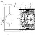
また、図4に概略的に示されているように、水が張られた試料室20を対物レンズ4が側方から見ることも可能である。この実施形態では、鏡筒13と試料室20との間が、例えば概略的に示されたOリング21によって封止を実現される。さらに、対物レンズ4を介した既述の照明の他、任意的な照明モジュール22(破線で示す)を用いた透過光照明、および別の任意的な照明モジュール23(破線で示す)を用いた側方からの光シート照明のうちの少なくとも一方を実施することができる。これらの可能な照明が、矢印P1およびP2で示唆されている。 Further, as schematically shown in FIG. 4, the
図5には図4の実施形態の変形例が示されている。この変形例では、リング状の圧力センサ9が鏡筒13にもはや直接的に固定されておらず、対物レンズ4に対向する試料室壁部22に固定されている。その際、圧力センサ9はここでも、光軸17の方向に見て、前部レンズ15の光学的に利用される中央領域16を覆わないように配置されている。また、望ましい良好な音響結合を実現するために、圧力センサ9が試料室20内の水または試料室20内のその他の媒体と接触するように、圧力センサ9が試料室壁部22に配置されている。 FIG. 5 shows a modification of the embodiment of FIG. In this modification, the ring-shaped
図6には本発明による撮影装置1の別の実施形態が示されており、本実施形態では、両矢印P3で示唆されているように、本発明による撮影装置1が試料3を光学的に結像するための光学モジュール24を備えている。光学モジュール24は、例えば照明モジュールと結像モジュールとを含んでいてもよい。 FIG. 6 shows another embodiment of the photographing
また、撮影装置1は、制御モジュール10によって制御される保持装置25を含んでいる。制御モジュール10は、光学モジュール24と圧力センサ9とも接続されている。矢印P4によって示唆されているように、圧力波は圧力センサ9を用いて検出される。 The photographing
所望の光学的撮影および音響的撮影のうちの少なくとも一方を実施するために、保持装置25を用いて試料3を回転させることができる。
また、概略的に図示されたコンピュータ・マウスによって示唆されているように、さらに任意的な入力ユニット26が設けられていてもよい。この入力ユニットを介して、制御モジュール10への入力を行うことができる。The
An
これまでに説明した実施形態では、音波の励起が常に光学的に実施されていた。しかし、圧力センサ9を音波生成に使用することも可能である。この種の検出の際には、圧力センサ9が所定の時間にわたって試料3内に音波を送信し、試料3から戻ってくる音波応答を検出するように、制御モジュール10が圧力センサ9を制御する。超音波の周波数は、例えば20MHz以上である。 In the embodiments described so far, excitation of sound waves has always been performed optically. However, the
既に説明したように、圧力センサ9は圧電セラミックから構成されていてもよい。したがって、圧電効果を利用して、圧力検出のために音響エネルギーを電気信号に変換することができる。圧力センサ9を音源として使用する場合は、圧電効果を利用して電気信号を圧力信号に変換することもできる。 As already described, the
この種の圧力検出以外にも、その他の考えられるあらゆる圧力検出の方法が可能である。したがって、例えば超音波を光学的に検出するためのファイバー・ブラッグ・センサまたは導波構造を使用することができる。この場合、センサは光学的に検出可能な圧力依存の特性を有しており、これが光学的に検出される。圧力センサは、共振圧力センサおよび広帯域圧力センサのうちの少なくとも一方として設計されていてもよい。 In addition to this type of pressure detection, all other possible pressure detection methods are possible. Thus, for example, a fiber Bragg sensor or waveguide structure for optically detecting ultrasound can be used. In this case, the sensor has an optically detectable pressure-dependent characteristic, which is optically detected. The pressure sensor may be designed as at least one of a resonant pressure sensor and a broadband pressure sensor.
本発明による顕微鏡1は、検出対象の圧力波の励起が光学的に、および音波のうちの少なくとも一方によって可能となるように構成されていてもよい。 The
Claims (10)
Translated fromJapanese生成された該圧力波を検出するための音響モジュール(9、10)と、
該音響モジュール(9、10)のデータに基づいて音響画像を確定する制御モジュール(10)とを備えた撮影装置であって、
該撮影装置が、該試料(3)を光学的に結像するための結像モジュール(5)をさらに備えており、該制御モジュール(10)が、該試料(3)の光学的結像に基づいて、試料境界および該試料(3)内部のセグメント境界のうちの少なくとも一方を特定し、特定された該試料境界およびセグメント境界のうちの少なくとも一方を該音響画像の確定の際に考慮する、撮影装置。An excitation module (2, 10; 9, 10) for exciting the sample (3) to emit a pressure wave;
An acoustic module (9, 10) for detecting the generated pressure wave;
An imaging device comprising a control module (10) for determining an acoustic image based on data of the acoustic module (9, 10),
The imaging apparatus further includes an imaging module (5) for optically imaging the sample (3), and the control module (10) performs optical imaging of the sample (3). Based on at least one of a sample boundary and a segment boundary within the sample (3), and taking into account at least one of the identified sample boundary and segment boundary in determining the acoustic image; Shooting device.
生成された該圧力波を検出し、
検出された該圧力波に基づいて音響画像を確定する撮影方法であって、
該試料の光学的結像をさらに実施し、該試料の該光学的結像に基づいて試料境界および該試料内部のセグメント境界のうちの少なくとも一方を特定し、特定された該試料境界およびセグメント境界のうちの少なくとも一方を該音響画像の確定の際に考慮する、撮影方法。Excite the sample to emit pressure waves,
Detecting the generated pressure wave;
An imaging method for determining an acoustic image based on the detected pressure wave,
Further performing optical imaging of the sample, identifying at least one of a sample boundary and a segment boundary within the sample based on the optical imaging of the sample, the identified sample boundary and segment boundary An imaging method in which at least one of the above is taken into account when determining the acoustic image.
Applications Claiming Priority (3)
| Application Number | Priority Date | Filing Date | Title |
|---|---|---|---|
| DE201310203454DE102013203454A1 (en) | 2013-02-28 | 2013-02-28 | Recording device and recording method |
| DE102013203454.7 | 2013-02-28 | ||
| PCT/EP2014/052915WO2014131632A1 (en) | 2013-02-28 | 2014-02-14 | Recording device and recording method |
Publications (3)
| Publication Number | Publication Date |
|---|---|
| JP2016514258Atrue JP2016514258A (en) | 2016-05-19 |
| JP2016514258A5 JP2016514258A5 (en) | 2017-03-09 |
| JP6473699B2 JP6473699B2 (en) | 2019-02-20 |
Family
ID=50114350
Family Applications (1)
| Application Number | Title | Priority Date | Filing Date |
|---|---|---|---|
| JP2015559462AExpired - Fee RelatedJP6473699B2 (en) | 2013-02-28 | 2014-02-14 | Imaging apparatus and imaging method |
Country Status (5)
| Country | Link |
|---|---|
| US (1) | US20160003777A1 (en) |
| EP (1) | EP2962095A1 (en) |
| JP (1) | JP6473699B2 (en) |
| DE (1) | DE102013203454A1 (en) |
| WO (1) | WO2014131632A1 (en) |
Families Citing this family (4)
| Publication number | Priority date | Publication date | Assignee | Title |
|---|---|---|---|---|
| US11596313B2 (en) | 2017-10-13 | 2023-03-07 | Arizona Board Of Regents On Behalf Of Arizona State University | Photoacoustic targeting with micropipette electrodes |
| US12161295B2 (en) | 2018-03-16 | 2024-12-10 | Arizona Board Of Regents On Behalf Of Arizona State University | Deep brain stimulation electrode with photoacoustic and ultrasound imaging capabilities |
| US11768182B2 (en)* | 2019-04-26 | 2023-09-26 | Arizona Board Of Regents On Behalf Of Arizona State University | Photoacoustic and optical microscopy combiner and method of generating a photoacoustic image of a sample |
| US11975327B2 (en) | 2019-06-19 | 2024-05-07 | Arizona Board Of Regents On Behalf Of Arizona State University | Integrated container adapter for photoacoustic microscopy |
Citations (9)
| Publication number | Priority date | Publication date | Assignee | Title |
|---|---|---|---|---|
| US4011748A (en)* | 1975-09-18 | 1977-03-15 | The Board Of Trustees Of Leland Stanford Junior University | Method and apparatus for acoustic and optical scanning of an object |
| JPH11326580A (en)* | 1998-05-15 | 1999-11-26 | Toshiba Corp | Shroud automatic inspection device |
| US20060017937A1 (en)* | 2004-07-22 | 2006-01-26 | The Boeing Company | Non-destructive inspection using laser profiling and associated method |
| JP2006308337A (en)* | 2005-04-26 | 2006-11-09 | Honda Electronic Co Ltd | Ultrasonic probe for optical microscope, ultrasonic microscope system, and optical/ultrasonic microscope system |
| JP2010088627A (en)* | 2008-10-07 | 2010-04-22 | Canon Inc | Apparatus and method for processing biological information |
| JP2011519281A (en)* | 2007-10-25 | 2011-07-07 | ワシントン・ユニバーシティ | Confocal photoacoustic microscopy with optical orientation resolution |
| JP2011523048A (en)* | 2008-05-16 | 2011-08-04 | ロッキード・マーチン・コーポレーション | Vision system and method for mapping ultrasound data to CAD space |
| JP2011160936A (en)* | 2010-02-08 | 2011-08-25 | Canon Inc | Photoacoustic image forming apparatus and photoacoustic image forming method |
| WO2013185784A1 (en)* | 2012-06-11 | 2013-12-19 | Helmholtz Zentrum München Deutsches Forschungszentrum Für Gesundheit Und Umwelt (Gmbh) | Imaging system and method for imaging an object |
Family Cites Families (9)
| Publication number | Priority date | Publication date | Assignee | Title |
|---|---|---|---|---|
| US3790281A (en)* | 1973-02-26 | 1974-02-05 | Zenith Radio Corp | Combined system for acoustical-optical microscopy |
| US20040154402A1 (en)* | 1998-06-30 | 2004-08-12 | Lockheed Martin Corporation | Remote laser beam delivery system and method for use with a robotic positioning system for ultrasonic testing purposes |
| US7227127B2 (en)* | 2004-10-06 | 2007-06-05 | Peter Saggau | High speed microscope with three-dimensional laser beam scanning including acousto-optic deflector for controlling the lateral position and collimation of the light beam |
| US20060184042A1 (en)* | 2005-01-22 | 2006-08-17 | The Texas A&M University System | Method, system and apparatus for dark-field reflection-mode photoacoustic tomography |
| US9271654B2 (en)* | 2009-06-29 | 2016-03-01 | Helmholtz Zentrum Munchen Deutsches Forschungszentrum Fur Gesundheit Und Umwelt (Gmbh) | Thermoacoustic imaging with quantitative extraction of absorption map |
| WO2012174413A1 (en)* | 2011-06-15 | 2012-12-20 | University Of Southern California | Optical coherence photoacoustic microscopy |
| JP5832182B2 (en)* | 2011-07-19 | 2015-12-16 | キヤノン株式会社 | Acoustic signal receiving apparatus and imaging apparatus |
| JP5885600B2 (en)* | 2012-06-20 | 2016-03-15 | オリンパス株式会社 | Photoacoustic microscope |
| EP2946721B1 (en)* | 2014-05-20 | 2017-12-20 | Helmholtz Zentrum München Deutsches Forschungszentrum für Gesundheit und Umwelt GmbH | Device and method for optoacoustic imaging of an object |
- 2013
- 2013-02-28DEDE201310203454patent/DE102013203454A1/ennot_activeCeased
- 2014
- 2014-02-14JPJP2015559462Apatent/JP6473699B2/ennot_activeExpired - Fee Related
- 2014-02-14EPEP14704785.6Apatent/EP2962095A1/ennot_activeWithdrawn
- 2014-02-14WOPCT/EP2014/052915patent/WO2014131632A1/enactiveApplication Filing
- 2014-02-14USUS14/771,463patent/US20160003777A1/ennot_activeAbandoned
Patent Citations (9)
| Publication number | Priority date | Publication date | Assignee | Title |
|---|---|---|---|---|
| US4011748A (en)* | 1975-09-18 | 1977-03-15 | The Board Of Trustees Of Leland Stanford Junior University | Method and apparatus for acoustic and optical scanning of an object |
| JPH11326580A (en)* | 1998-05-15 | 1999-11-26 | Toshiba Corp | Shroud automatic inspection device |
| US20060017937A1 (en)* | 2004-07-22 | 2006-01-26 | The Boeing Company | Non-destructive inspection using laser profiling and associated method |
| JP2006308337A (en)* | 2005-04-26 | 2006-11-09 | Honda Electronic Co Ltd | Ultrasonic probe for optical microscope, ultrasonic microscope system, and optical/ultrasonic microscope system |
| JP2011519281A (en)* | 2007-10-25 | 2011-07-07 | ワシントン・ユニバーシティ | Confocal photoacoustic microscopy with optical orientation resolution |
| JP2011523048A (en)* | 2008-05-16 | 2011-08-04 | ロッキード・マーチン・コーポレーション | Vision system and method for mapping ultrasound data to CAD space |
| JP2010088627A (en)* | 2008-10-07 | 2010-04-22 | Canon Inc | Apparatus and method for processing biological information |
| JP2011160936A (en)* | 2010-02-08 | 2011-08-25 | Canon Inc | Photoacoustic image forming apparatus and photoacoustic image forming method |
| WO2013185784A1 (en)* | 2012-06-11 | 2013-12-19 | Helmholtz Zentrum München Deutsches Forschungszentrum Für Gesundheit Und Umwelt (Gmbh) | Imaging system and method for imaging an object |
Also Published As
| Publication number | Publication date |
|---|---|
| EP2962095A1 (en) | 2016-01-06 |
| WO2014131632A1 (en) | 2014-09-04 |
| US20160003777A1 (en) | 2016-01-07 |
| JP6473699B2 (en) | 2019-02-20 |
| DE102013203454A1 (en) | 2014-09-11 |
Similar Documents
| Publication | Publication Date | Title |
|---|---|---|
| JP6174658B2 (en) | Hand-held device and method for tomographic photoacoustic imaging of an object | |
| JP6780665B2 (en) | Objective optical system and photoacoustic imaging equipment | |
| CN104188625B (en) | A kind of multi-modal micro imaging system | |
| US10209226B2 (en) | Photoacoustic microscope apparatus | |
| US20150126858A1 (en) | Fiber scanning optical probe and medical imaging apparatus including the same | |
| JP2011519281A5 (en) | ||
| JP6473699B2 (en) | Imaging apparatus and imaging method | |
| CN105877711A (en) | Multimode imaging detection system for skin disease | |
| US20160143542A1 (en) | Minimally Invasive Optical Photoacoustic Endoscopy with a Single Waveguide for Light and Sound | |
| CN106419839B (en) | Photoacoustic/ultrasonic fan-scan imaging device and method with fast large field of view and high resolution | |
| CN114403785B (en) | A photoacoustic-white light common field endoscope device and imaging method with optical path multiplexing | |
| CN106821320A (en) | A kind of opto-acoustic microscopic imaging system | |
| JP2020036898A (en) | Probe, system and method for optoacoustic imaging of object | |
| JP5896702B2 (en) | Photoacoustic microscope | |
| JP2012024426A (en) | Measuring device | |
| JP6431928B2 (en) | Photoacoustic microscope and photoacoustic signal detection method | |
| US20220155213A1 (en) | Erythrocyte differentiation monitoring apparatus and erythrocyte differentiation monitoring method | |
| Bost et al. | High frequency optoacoustic microscopy | |
| CN207768360U (en) | A kind of opto-acoustic microscopic imaging system | |
| JP4518549B2 (en) | Fluorescence tomographic image measuring device | |
| WO2014174800A1 (en) | Acousto-optical imaging device | |
| JP6656204B2 (en) | Acoustic wave detection probe and photoacoustic measurement device | |
| US20130345557A1 (en) | Light scanning probe and medical imaging apparatus employing the same | |
| CN105246396B (en) | Subject information acquisition device and control method of subject information acquisition device | |
| JP6086719B2 (en) | Photoacoustic microscope |
Legal Events
| Date | Code | Title | Description |
|---|---|---|---|
| A521 | Request for written amendment filed | Free format text:JAPANESE INTERMEDIATE CODE: A523 Effective date:20170130 | |
| A621 | Written request for application examination | Free format text:JAPANESE INTERMEDIATE CODE: A621 Effective date:20170130 | |
| A977 | Report on retrieval | Free format text:JAPANESE INTERMEDIATE CODE: A971007 Effective date:20171228 | |
| A131 | Notification of reasons for refusal | Free format text:JAPANESE INTERMEDIATE CODE: A131 Effective date:20180116 | |
| A601 | Written request for extension of time | Free format text:JAPANESE INTERMEDIATE CODE: A601 Effective date:20180416 | |
| A601 | Written request for extension of time | Free format text:JAPANESE INTERMEDIATE CODE: A601 Effective date:20180618 | |
| A521 | Request for written amendment filed | Free format text:JAPANESE INTERMEDIATE CODE: A523 Effective date:20180711 | |
| TRDD | Decision of grant or rejection written | ||
| A01 | Written decision to grant a patent or to grant a registration (utility model) | Free format text:JAPANESE INTERMEDIATE CODE: A01 Effective date:20181204 | |
| A601 | Written request for extension of time | Free format text:JAPANESE INTERMEDIATE CODE: A601 Effective date:20181217 | |
| A61 | First payment of annual fees (during grant procedure) | Free format text:JAPANESE INTERMEDIATE CODE: A61 Effective date:20190128 | |
| R150 | Certificate of patent or registration of utility model | Ref document number:6473699 Country of ref document:JP Free format text:JAPANESE INTERMEDIATE CODE: R150 | |
| S111 | Request for change of ownership or part of ownership | Free format text:JAPANESE INTERMEDIATE CODE: R313117 | |
| R350 | Written notification of registration of transfer | Free format text:JAPANESE INTERMEDIATE CODE: R350 | |
| LAPS | Cancellation because of no payment of annual fees |