JP2016514002A - Surgical implant - Google Patents
Surgical implantDownload PDFInfo
- Publication number
- JP2016514002A JP2016514002AJP2015561972AJP2015561972AJP2016514002AJP 2016514002 AJP2016514002 AJP 2016514002AJP 2015561972 AJP2015561972 AJP 2015561972AJP 2015561972 AJP2015561972 AJP 2015561972AJP 2016514002 AJP2016514002 AJP 2016514002A
- Authority
- JP
- Japan
- Prior art keywords
- film
- protrusions
- surgical implant
- mesh
- surgical
- Prior art date
- Legal status (The legal status is an assumption and is not a legal conclusion. Google has not performed a legal analysis and makes no representation as to the accuracy of the status listed.)
- Granted
Links
Images


Classifications
- A—HUMAN NECESSITIES
- A61—MEDICAL OR VETERINARY SCIENCE; HYGIENE
- A61F—FILTERS IMPLANTABLE INTO BLOOD VESSELS; PROSTHESES; DEVICES PROVIDING PATENCY TO, OR PREVENTING COLLAPSING OF, TUBULAR STRUCTURES OF THE BODY, e.g. STENTS; ORTHOPAEDIC, NURSING OR CONTRACEPTIVE DEVICES; FOMENTATION; TREATMENT OR PROTECTION OF EYES OR EARS; BANDAGES, DRESSINGS OR ABSORBENT PADS; FIRST-AID KITS
- A61F2/00—Filters implantable into blood vessels; Prostheses, i.e. artificial substitutes or replacements for parts of the body; Appliances for connecting them with the body; Devices providing patency to, or preventing collapsing of, tubular structures of the body, e.g. stents
- A61F2/0063—Implantable repair or support meshes, e.g. hernia meshes
- A—HUMAN NECESSITIES
- A61—MEDICAL OR VETERINARY SCIENCE; HYGIENE
- A61F—FILTERS IMPLANTABLE INTO BLOOD VESSELS; PROSTHESES; DEVICES PROVIDING PATENCY TO, OR PREVENTING COLLAPSING OF, TUBULAR STRUCTURES OF THE BODY, e.g. STENTS; ORTHOPAEDIC, NURSING OR CONTRACEPTIVE DEVICES; FOMENTATION; TREATMENT OR PROTECTION OF EYES OR EARS; BANDAGES, DRESSINGS OR ABSORBENT PADS; FIRST-AID KITS
- A61F2/00—Filters implantable into blood vessels; Prostheses, i.e. artificial substitutes or replacements for parts of the body; Appliances for connecting them with the body; Devices providing patency to, or preventing collapsing of, tubular structures of the body, e.g. stents
- A61F2/0077—Special surfaces of prostheses, e.g. for improving ingrowth
- B—PERFORMING OPERATIONS; TRANSPORTING
- B29—WORKING OF PLASTICS; WORKING OF SUBSTANCES IN A PLASTIC STATE IN GENERAL
- B29C—SHAPING OR JOINING OF PLASTICS; SHAPING OF MATERIAL IN A PLASTIC STATE, NOT OTHERWISE PROVIDED FOR; AFTER-TREATMENT OF THE SHAPED PRODUCTS, e.g. REPAIRING
- B29C70/00—Shaping composites, i.e. plastics material comprising reinforcements, fillers or preformed parts, e.g. inserts
- B29C70/68—Shaping composites, i.e. plastics material comprising reinforcements, fillers or preformed parts, e.g. inserts by incorporating or moulding on preformed parts, e.g. inserts or layers, e.g. foam blocks
Landscapes
- Health & Medical Sciences (AREA)
- Engineering & Computer Science (AREA)
- Life Sciences & Earth Sciences (AREA)
- Animal Behavior & Ethology (AREA)
- Oral & Maxillofacial Surgery (AREA)
- Biomedical Technology (AREA)
- Heart & Thoracic Surgery (AREA)
- Vascular Medicine (AREA)
- Cardiology (AREA)
- Transplantation (AREA)
- General Health & Medical Sciences (AREA)
- Public Health (AREA)
- Veterinary Medicine (AREA)
- Chemical & Material Sciences (AREA)
- Composite Materials (AREA)
- Mechanical Engineering (AREA)
- Prostheses (AREA)
- Materials For Medical Uses (AREA)
Abstract
Translated fromJapaneseDescription
Translated fromJapanese本発明は外科用インプラントに関し、特に、鼠径ヘルニ及び/又は、腹壁/瘢痕ヘルニアを修復するための組織強化インプラントに関する。 The present invention relates to surgical implants, and in particular to tissue-enhancing implants for repairing inguinal and / or abdominal wall / scar hernias.
ヘルニア修復は、最も一般的な外科手技の1つであり、毎年世界中で約640万回実施されている。年間約310万のヘルニア(48%)は、平坦なメッシュで修復されている。 Hernia repair is one of the most common surgical procedures and is performed approximately 6.4 million times worldwide every year. Approximately 3.1 million hernias (48%) per year are repaired with a flat mesh.
外科用インプラントとして機能するメッシュは、ヘルニアの領域を強化する。安全に定着させるために、メッシュはヘルニアと近接する体組織に縫合され得る。しかしながら、縫合工程は、外科手技を遅延させ、例えば神経損傷などによる外科手術後の痛みを患者に引き起こすことがある。 A mesh that functions as a surgical implant reinforces the area of the hernia. The mesh can be sutured to body tissue adjacent to the hernia for secure anchoring. However, the suturing process may delay surgical procedures and cause post-surgical pain in the patient, such as due to nerve damage.
国際特許第2003/099160(A)号は、外科用メッシュに連結され得るこぶ付きフィルムを含む外科用インプラントを開示している。こぶは、中空であり、フィルムの柔軟性を増加させる。こぶ付きフィルムは、熱変形プロセスを使用して、再吸収性ポリマーフィルムから生成され得る。設計に応じて、こぶは、インプラントと体組織との間の摩擦を増加させるか、又は減少させ、それによってそれぞれ定着化効果を得るか、又は可動性を増加させ得る。 International Patent Publication No. 2003/099160 (A) discloses a surgical implant comprising a knurled film that can be coupled to a surgical mesh. The hump is hollow and increases the flexibility of the film. The knurled film can be produced from a resorbable polymer film using a thermal deformation process. Depending on the design, the hump may increase or decrease the friction between the implant and the body tissue, thereby providing a fixation effect or increasing mobility, respectively.
国際特許第2011/026987(A)号は、織物の一方の面から外側に突出した糸及び棘の配列を含む、補綴用織物(メッシュ)を記載している。糸から形成され得る定着補助具又は生体適合性材料から作成されるフックとして機能する棘は、織物に取り付けられる。織物のもう一方の面は、生体再吸収性材料から作製される微多孔質層を含む。棘は、一般的に、切削プロセスが原因となって鋭利である。トロカールスリーブによって送達するために折り畳まれる場合などに、この製造物が自身に接着する傾向を減少させるために、棘は、外科手術中に溶解する水溶性材料から作製されるコーティングで覆われる。しかしながら、この製造物の取り扱いは難しいことがある。 International Patent Publication No. 2011/026987 (A) describes a prosthetic fabric (mesh) comprising an array of threads and barbs protruding outwardly from one side of the fabric. Barbs that function as anchoring aids that can be formed from yarns or hooks made from biocompatible materials are attached to the fabric. The other side of the fabric includes a microporous layer made from a bioresorbable material. The barbs are generally sharp due to the cutting process. To reduce the tendency of the product to adhere to itself, such as when folded for delivery by a trocar sleeve, the barbs are covered with a coating made from a water soluble material that dissolves during surgery. However, handling of this product can be difficult.
米国特許第7,331,199号は、編構造のループから作製されるスパイク付きの毛羽を含む、医療用又は外科手術に使用する補綴用編地を開示している。編地によって画定されるシートから垂直に突出するスパイク付きの毛羽は、実質的に直線状の本体、及びその直線状の本体よりも若干広い頭部を含む自由端を有する。スパイク付きの毛羽は把持特性を提供し、編地構造の2つの部分を互いに取り付けるのに使用され得る。 U.S. Patent No. 7,331,199 discloses a prosthetic knitted fabric for use in medical or surgical procedures, including a spiked fuzz made from a loop of knitted structure. A spiked fluff that projects perpendicularly from a sheet defined by the knitted fabric has a substantially straight body and a free end that includes a head that is slightly wider than the straight body. The spiked fluff provides gripping properties and can be used to attach the two parts of the knitted fabric structure together.
本発明の課題は、特に、ヘルニアの修復において、縫合の必要性を削減し、外科手技中に容易に、迅速かつ安全な方法で操作され得る外科用インプラントを提供することである。 It is an object of the present invention to provide a surgical implant that reduces the need for suturing, particularly in hernia repair, and can be manipulated easily, quickly and in a safe manner during a surgical procedure.
この課題は、請求項1に記載の外科用インプラントによって解決される。本発明の有利な実施形態は、以下の付属の請求項で示される。請求項19は、かかる外科用インプラントの製造方法に関する。 This problem is solved by the surgical implant according to
本発明による外科用インプラントは、第1面を有する基本構造を含み、この基本構造は、第1面及び第1面の反対側の第2面を有するメッシュ様構造を含むのが好ましい。再吸収性(生体吸収性)フィルムは、基本構造の第1面に取り付けられる。複数の固体突起部が、基本構造から離れた方向にフィルムから出る。突起部は、各本体及び各頭部で画定される形状を含み、本体はフィルムから出て、頭部で終端し、頭部は本体に対して横方向に突出している。 The surgical implant according to the present invention includes a basic structure having a first surface, which preferably includes a mesh-like structure having a first surface and a second surface opposite the first surface. A resorbable (bioabsorbable) film is attached to the first surface of the basic structure. A plurality of solid protrusions exit the film in a direction away from the basic structure. The protrusion includes a shape defined by each main body and each head. The main body exits from the film and terminates at the head, and the head protrudes laterally with respect to the main body.
突起部は、固体材料から作製され、中空ではない。こうすることで、フィルムに対して平行な平面における剪断抵抗が増加する。突起部の本体は、足部(フィルムに隣接している)及び茎様部を含み得るが、十分に画定された足部を有さない設計も同様に考えられる。突起部の頭部は、本体、すなわち、頭部がはじまる本体の端部に対して、横方向(すなわち、一般的には突起部が出るフィルムの局所領域に対して平行方向)に突出する。これは、頭部より横方向に広い延伸を有する本体の足部分を除外しない。更には、頭部は、頭部の全周に沿って、本体に対して横方向に突出している必要はない。本発明の有利な実施形態において、突起部のうちの少なくとも一部はキノコ様の形状を含む。先に記載された突起部に加えて、外科用インプラントは、異なる様式で設計された突起部を含み得る。 The protrusion is made of a solid material and is not hollow. This increases the shear resistance in a plane parallel to the film. The body of the protrusion can include a foot (adjacent to the film) and a stem-like portion, but designs that do not have a well-defined foot are conceivable as well. The head of the protrusion protrudes in the lateral direction (that is, generally parallel to the local region of the film from which the protrusion protrudes) with respect to the main body, that is, the end of the main body where the head starts. This does not exclude the foot portion of the body having a wider extension in the lateral direction than the head. Furthermore, the head does not need to protrude laterally with respect to the main body along the entire circumference of the head. In an advantageous embodiment of the invention, at least some of the protrusions comprise a mushroom-like shape. In addition to the protrusions described above, the surgical implant may include protrusions designed in different ways.
本発明による外科用インプラントは、一般的な面形状を有し、更なる利点である自己定着性を示すヘルニアインプラントとして使用され得る。インプラントを軽く押すと、フィルムから出る固体突出物は、軟組織(例えば、筋膜(facial)組織、筋肉組織、脂肪組織)を機械的に把持することができ、それらの形状によって、フィルムの剪断力並びに剥離力に対する抵抗が上昇する。したがって、フィルムが取り付けられる基本構造は、移動が阻止され、初期の重篤創傷治癒期間中(組織統合期間)の配置が確実に保持される。フィルムは再吸収性であるため、突起部による任意の機械的な刺激が治癒プロセス中に消滅するであろう。一般的には、インプラントを固定するための縫合を必要としない。これは、患者により快適さをもたらし、縫合による従来の定着に伴う慢性的な痛みのリスクを軽減する。 The surgical implant according to the invention can be used as a hernia implant having a general surface shape and exhibiting a further advantage of self-fixation. When the implant is lightly pressed, the solid protrusions coming out of the film can mechanically grip soft tissue (eg, fascial tissue, muscle tissue, adipose tissue), and depending on their shape, the shear force of the film In addition, the resistance to peeling force increases. Thus, the basic structure to which the film is attached is prevented from moving and reliably maintained in position during the initial severe wound healing period (tissue integration period). Since the film is resorbable, any mechanical irritation by the protrusions will disappear during the healing process. Generally, no suture is required to secure the implant. This provides more comfort to the patient and reduces the risk of chronic pain associated with traditional colonization by suturing.
外科手技中、本発明による外科用インプラントは、従来の様式で取扱うことができる。一般的には、突起部の設計のため、巻かれているか、又は折り畳まれた状態にある際に、インプラントは自身に接着しない傾向がある。したがって、インプラントは、腹腔鏡下における配置に非常に好適である。インプラントは、トロカールスリーブによって外科手術の部位に送られ、その後、自身に固着することなく、容易に解かれるか、又は広げられ得る。更には、インプラントは自己定着性であるが、一般的には、体組織からインプラントを剥がし、再びそれを異なる場所又は移動した場所に配置できるような再配置が可能である。インプラントは、縫合によってインプラントを定着する必要がないため、外科手技が短縮される傾向がある。必要であれば、インプラントは、例えば縫合によって更に定着され得る。 During a surgical procedure, a surgical implant according to the present invention can be handled in a conventional manner. In general, due to the design of the protrusions, the implant tends to not adhere to itself when it is rolled or folded. The implant is therefore very suitable for laparoscopic placement. The implant can be delivered to the surgical site by a trocar sleeve and then easily unwound or unfolded without sticking to itself. Furthermore, although the implant is self-fixing, it is generally possible to reposition the implant so that it can be removed from the body tissue and placed again at a different or moved location. Implants tend to shorten surgical procedures because they do not need to be anchored by suturing. If necessary, the implant can be further anchored, for example by suturing.
外科用インプラントは、例えば、ヘルニアのような軟組織インプラントとして設計され、インプラントを筋肉又は脂肪などの軟組織に少なくとも部分的に定着するように適合される場合、外科用インプラントと軟組織との間の摩擦は、対応する突起部を含まないインプラントと比較して、少なくとも1つの方向において2倍以上増加され得る(本質的に、インプラントの平面において測定される)。 If a surgical implant is designed as a soft tissue implant such as a hernia and is adapted to at least partially anchor the implant to soft tissue such as muscle or fat, the friction between the surgical implant and the soft tissue is Can be increased by more than a factor of two in at least one direction compared to an implant without the corresponding protrusion (essentially measured in the plane of the implant).
既に述べられているように、本発明の有利な実施形態において、基本構造はメッシュ様構造を含み、この用語は、一般的にある程度認識されており、例えば、メッシュ(外科用メッシュ)、テープ、穿孔フィルム、不織布、織布、編シート、編テープ、編組シート、編組テープ、膠原線維シート、メッシュポーチ及びメッシュプラグなどが挙げられる。メッシュポーチ又はメッシュプラグにおいて、メッシュは、いくつかの地点又は領域で自身が折り畳まれるか又は巻かれ、任意で定着され、あるいは、いくつかのメッシュ片から対応する構造が提供される。本発明による外科用インプラントを、例えば、骨盤メッシュ又は乳房インプラントとして使用することも考えられる。かかる場合では、インプラントの基本構造は、所望の目的に適合される。一般的には、再吸収性フィルムは、メッシュ様構造、又はより一般的には基本構造の第1(又は第2)面全体に取り付けられる。 As already mentioned, in an advantageous embodiment of the invention, the basic structure comprises a mesh-like structure, which term is generally recognized to some extent, for example, a mesh (surgical mesh), a tape, Examples thereof include a perforated film, a nonwoven fabric, a woven fabric, a knitted sheet, a knitted tape, a braided sheet, a braided tape, a collagen fiber sheet, a mesh pouch, and a mesh plug. In a mesh pouch or mesh plug, the mesh is folded or rolled up at several points or regions, optionally anchored, or a corresponding structure is provided from several mesh pieces. It is also conceivable to use the surgical implant according to the invention as, for example, a pelvic mesh or a breast implant. In such a case, the basic structure of the implant is adapted to the desired purpose. In general, the resorbable film is attached to the entire first (or second) surface of the mesh-like structure, or more generally the basic structure.
本発明の有利な実施形態において、突起部は、フィルムと同じ材料からなる。フィルム及び突起部は、一体的に作製され得る。かかるインプラントの製造方法は、更に以下で記載される。 In an advantageous embodiment of the invention, the projection is made of the same material as the film. The film and the protrusion can be made integrally. The method of manufacturing such an implant is further described below.
既に述べられているように、突起部の頭部は、その本体に対して横向きに突出している。有利な実施形態において、本体の横軸に対して垂直な平面で測定される本体の最少断面積は、頭部の縦軸に対して垂直な平面で測定される頭部の最大断面積よりも小さく、本体の縦軸に沿って測定される本体の高さは、頭部の縦軸に沿って測定される頭部の厚さよりも大きくてもよく、少なくとも2倍、好ましくは少なくとも3倍である。それは、突起部の頭部は、基本的に「平坦」であることを意味する。 As already described, the head of the protrusion protrudes laterally with respect to the main body. In an advantageous embodiment, the minimum cross-sectional area of the body measured in a plane perpendicular to the transverse axis of the body is greater than the maximum cross-sectional area of the head measured in a plane perpendicular to the longitudinal axis of the head. The height of the main body, measured along the longitudinal axis of the main body, may be smaller than the thickness of the head measured along the longitudinal axis of the head, at least twice, preferably at least three times is there. That means that the head of the protrusion is basically “flat”.
本発明による外科用インプラントの目的に応じて、突起部の寸法並びに面密度は、広い範囲にわたって変化し得る。好ましくは、突起部の高さ(本体+頭部)は、20μm〜5000μmの範囲内である。これらの制限間の全中間値も同様に開示されており、例えば、100μm〜500μm又は200μm〜400μm又は20μm〜250μmの範囲である。突起部は、例えば0.5個の突起部/mm2〜5個の突起部/mm2又は2個の突起部/mm2〜4個の突起部/mm2の範囲の密度を有し得る。突起部の頭部の許容可能なサイズ又は直径もまた、面密度に応じて変化する。典型的な頭部の直径は、例えば、200μmである。突起部は、高密度で配列され得る。更には、所定のインプラントにおいて、突起部の配列におけるパターンを選択することが可能である。Depending on the purpose of the surgical implant according to the invention, the dimensions and the surface density of the protrusions can vary over a wide range. Preferably, the height of the protrusion (main body + head) is in the range of 20 μm to 5000 μm. All intermediate values between these limits are disclosed as well, for example in the range of 100 μm to 500 μm or 200 μm to 400 μm or 20 μm to 250 μm. The protrusions can have a density in the range of, for example, 0.5 protrusions / mm2 to 5 protrusions / mm2 or 2 protrusions / mm2 to 4 protrusions / mm2. . The allowable size or diameter of the protrusion head also varies depending on the surface density. A typical head diameter is, for example, 200 μm. The protrusions can be arranged with high density. Furthermore, it is possible to select a pattern in the arrangement of protrusions in a given implant.
各々が縦軸を有する突起部は、フィルムの表面に対して、フィルムから例えば、50°〜90°又は70°〜90°の角度で出ており、これは垂直(90°)に直立する突起部を含む。 The protrusions each having a longitudinal axis protrude from the film at an angle of, for example, 50 ° to 90 ° or 70 ° to 90 ° with respect to the surface of the film, and this is a protrusion that stands upright (90 °) Part.
外科用インプラントのフィルムは、突起部間に孔を含んでいてもよく、好ましくは、孔は0.5mm〜50mm又は2mm〜20mmの範囲のサイズ(例えば円形の孔の直径のような典型的な寸法)を有するのが好ましい。かかる孔は、フィルムが再吸収される前に、組織内殖を促進する。更には、孔の形状及びパターンに応じて、例えば、外科用インプラントに使用される基本構造の弾性を一般的には高弾性に適合させるなど、フィルムの弾性を向上させ得る。 Surgical implant films may include holes between the protrusions, preferably the holes are sized in the range of 0.5 mm to 50 mm or 2 mm to 20 mm (eg, typical diameters of circular holes, for example). Preferably). Such holes promote tissue ingrowth before the film is resorbed. Furthermore, depending on the shape and pattern of the holes, the elasticity of the film can be improved, for example by adapting the elasticity of the basic structure used in the surgical implant to generally high elasticity.
少なくとも1つの孔は、孔の縁部から孔の領域中に出て、フィルムの材料からなる少なくとも1つの突起部を含み得る。かかる突起部は、ドイツ国特許第10 2012 005 978(A)号に記載されており、インプラントの自己定着効果を向上するのに供され得る。 The at least one hole may include at least one protrusion made of a film material that protrudes from the edge of the hole into the region of the hole. Such protrusions are described in
フィルムの厚さは、例えば、10μm〜250μmの範囲又は20μm〜200μmの範囲であり得るが、他の数値も同様に考えられる。フィルムの厚さは、インプラントによって変化し得る。更には、完成したインプラントのフィルムの厚さは、インプラントが製造される際に、更に以下の実施例で記載されるように、例えば、かかるフィルム層の材料が突起部を形成するのに使用される際などに使用される初期フィルム層の厚さとは異なっていてもよい。 The thickness of the film can be, for example, in the range of 10 μm to 250 μm or in the range of 20 μm to 200 μm, but other values are conceivable as well. The thickness of the film can vary from implant to implant. Further, the film thickness of the finished implant can be used when the implant is manufactured, for example, such film layer material is used to form protrusions, as described in the examples below. It may be different from the thickness of the initial film layer used in the process.
基本構造がメッシュ様構造を含む場合、本発明による外科用インプラントは、突起部を担持し、基本構造の第1面に取り付けられる再吸収性フィルムに加えて、第2フィルムを含み得る。第2フィルムは、メッシュ様構造の第2面に取り付けられ、再吸収性であってよく、及び/又は抗接着特性を有し得る。所望であれば、第2フィルムは突起部を備えていてもよく、その突起部は、好ましくは、第1フィルムから出る突起部と同様の方法で、メッシュ様構造から離れた方向に第2フィルムから出る。 When the basic structure includes a mesh-like structure, a surgical implant according to the present invention may include a second film in addition to the resorbable film that carries the protrusions and is attached to the first surface of the basic structure. The second film is attached to the second side of the mesh-like structure and may be resorbable and / or have anti-adhesive properties. If desired, the second film may comprise a protrusion, which is preferably in a direction away from the mesh-like structure in the same manner as the protrusion exiting the first film. Get out of.
本発明の別の有利な実施形態において、突起部を備える2つのフィルムの効果は1つのフィルムによって達成される。この場合、基本構造はメッシュ様であり、フィルムは基本構造中に存在するメッシュ孔内部に延伸し、ここで突起部はフィルムから、基本構造の第1面から離れた方向及び基本構造の第2面から離れた方向の両方向に出る。かかるインプラントの製造方法の一例は、更に以下で示される。 In another advantageous embodiment of the invention, the effect of two films with protrusions is achieved by one film. In this case, the basic structure is mesh-like, and the film extends into the mesh holes present in the basic structure, where the protrusions are away from the film from the first surface of the basic structure and the second of the basic structure. Exit in both directions away from the surface. An example of a method for manufacturing such an implant is further described below.
再吸収性フィルムに好適な材料は、当該技術分野で周知である。フィルム材料の選択は、例えば再吸収期間などに依存する。本発明によるインプラントの製造方法を考慮すると、基本構造の材料の融点に対するフィルム材料の融点にも依存する(以下参照)。例えば、フィルムは、ポリ−p−ジオキサノン(「PDS」)、グリコリドとε−カプロラクトンとのコポリマー(例えば、Johnson & Jounson Medical GmbH製の「Monocryl」)及び/又はグリコリドとラクチドとのコポリマー(特に、90:10の比率である、Johnson & Jounson Medical GmbH製の「Vicryl」)を含み得る。一般的には、様々な合成生体吸収性ポリマー材料を使用することができ、例えば、ポリヒドロキシ酸(例えば、ポリラクチド、ポリグリコリド、ポリヒドロキシブチレート、ポリヒドロキシ酪酸)、ラクチドとトリメチレンカーボネートとのコポリマー、グリコリドとラクチドとトリメチレンカーボネートとのコポリマー、ポリカプロラクトン、ポリジオキサノン、合成(天然も可)オリゴ−及びポリアミノ酸、ポリ無水物、ポリオルトエステル、ポリリン酸エステル、ポリホスホン酸エステル、ポリアルコール、多糖類、ポリエーテルである。しかしながら、コラーゲン及びゼラチンなどの天然起源材料、又はオメガ3脂肪酸で架橋された生体吸収性ゲルフィルム又は酸化再生セルロース(ORC)などの天然由来材料も同様に考えられる。 Suitable materials for the resorbable film are well known in the art. The selection of the film material depends on, for example, the reabsorption period. Considering the method for producing an implant according to the invention, it also depends on the melting point of the film material relative to the melting point of the material of the basic structure (see below). For example, the film may be poly-p-dioxanone (“PDS”), a copolymer of glycolide and ε-caprolactone (eg, “Monocryl” from Johnson & Johnson Medical GmbH) and / or a copolymer of glycolide and lactide (in particular, 90:10 ratio, “Vicryl” from Johnson & Johnson Medical GmbH). In general, a variety of synthetic bioabsorbable polymer materials can be used, such as polyhydroxy acids (eg, polylactide, polyglycolide, polyhydroxybutyrate, polyhydroxybutyric acid), lactide and trimethylene carbonate. Copolymers, copolymers of glycolide, lactide and trimethylene carbonate, polycaprolactone, polydioxanone, synthetic (or natural) oligo- and polyamino acids, polyanhydrides, polyorthoesters, polyphosphates, polyphosphonates, polyalcohols, polyalcohols Saccharides and polyethers. However, naturally occurring materials such as collagen and gelatin, or naturally derived materials such as bioabsorbable gel films or oxidized regenerated cellulose (ORC) crosslinked with omega-3 fatty acids are also conceivable.
例えば、外科用メッシュのような外科用インプラントの基本構造は、再吸収性、非再吸収性又は部分的に再吸収性であり得る。一般的には、メッシュのように可撓性であり、面基本形状を有する。例えば、経編などによって作製された市販のヘルニア修復メッシュに基づいたものであり得る。 For example, the basic structure of a surgical implant, such as a surgical mesh, can be resorbable, non-resorbable or partially resorbable. Generally, it is flexible like a mesh and has a surface basic shape. For example, it may be based on a commercially available hernia repair mesh produced by warp knitting or the like.
基本構造に好適な材料は、当該技術分野で周知である。非再吸収性又は非常に遅い再吸収性物質としては、例えば、ポリアルケン(例えば、ポリプロピレン又はポリエチレン)、フッ素化ポリオレフィン(例えば、ポリテトラフルオロエチレン(PTFE)又はポリフッ化ビニリデン)、ポリアミド、ポリウレタン、ポリイソプレン、ポリスチレン、ポリシリコーン、ポリカーボネート、ポリアリールエーテルケトン(PEEK)、ポリメタクリル酸エステル、ポリアクリル酸エステル、芳香族ポリエステル、ポリイミド、並びにこれらの物質の混合物及び/又はコポリマーが挙げられる。他の有利な材料としては、それらの多くは再吸収性であり、ポリヒドロキシ酸、ポリラクチド、ポリグリコリド、ポリヒドロキシ酪酸、ポリヒドロキシ吉草酸、ポリカプロラクトン、ポリジオキサノン、ポリ−p−ジオキサノン、合成並びに天然オリゴアミノ酸及びポリアミノ酸、ポリホスファゼン、ポリ無水物、ポリオルトエステル、ポリリン酸エステル、ポリホスホン酸エステル、ポリアルコール、多糖類、ポリエーテル、セルロース、バクテリアセルロース、ポリアミド、脂肪族ポリエステル、芳香族ポリエステル、これらの重合性物質のコポリマー、再吸収性ガラスが挙げられる。特に有利な材料としては、ポリプロピレン(非再吸収性)、フッ化ポリビニリデンと、フッ化ビニリデンとヘキサフルオロプロペンとのコポリマーとのブレンド(非再吸収性、例えば、Johnson & Jounson Medical GmbH製の「Pronova」)、PTFE(非再吸収性、ePTFE及びcPTFEを含む)、ポリシリコーン(非再吸収性)、ポリーp−ジオキサノン(「PDS」、再吸収性)、グリコリドとラクチドとのコポリマー(吸収性)(特に、グリコリドとラクチドとのコポリマー比率が90:10である(「Vicryl」、再吸収性))、ラクチドとトリメチレンカーボネートとのコポリマー(再吸収性)、グリコリドとラクチドとトリメチレンカーボネートとのコポリマー(再吸収性)、グリコリドとε−カプロラクトンとのコポリマー(「Monocryl」、再吸収性)が挙げられる。-同種移植及び異種移植などの生物由来材料も同様に考えられる。 Suitable materials for the basic structure are well known in the art. Non-resorbable or very slow resorbable materials include, for example, polyalkenes (eg, polypropylene or polyethylene), fluorinated polyolefins (eg, polytetrafluoroethylene (PTFE) or polyvinylidene fluoride), polyamides, polyurethanes, poly Examples include isoprene, polystyrene, polysilicone, polycarbonate, polyaryletherketone (PEEK), polymethacrylic acid ester, polyacrylic acid ester, aromatic polyester, polyimide, and mixtures and / or copolymers of these materials. Other advantageous materials are many of which are resorbable, such as polyhydroxy acid, polylactide, polyglycolide, polyhydroxybutyric acid, polyhydroxyvaleric acid, polycaprolactone, polydioxanone, poly-p-dioxanone, synthetic and natural Oligoamino acid and polyamino acid, polyphosphazene, polyanhydride, polyorthoester, polyphosphate ester, polyphosphonate ester, polyalcohol, polysaccharide, polyether, cellulose, bacterial cellulose, polyamide, aliphatic polyester, aromatic polyester, these And a copolymer of the polymerizable material and reabsorbable glass. Particularly advantageous materials include polypropylene (non-resorbable), a blend of polyvinylidene fluoride and a copolymer of vinylidene fluoride and hexafluoropropene (non-resorbable, for example, “Johnson & Johnson Medical GmbH” Pronova "), PTFE (non-resorbable, including ePTFE and cPTFE), Polysilicone (non-resorbable), Poly-p-dioxanone (" PDS ", resorbable), Copolymer of glycolide and lactide (absorbent) ) (Particularly the copolymer ratio of glycolide and lactide is 90:10 (“Vicryl”, resorbable)), copolymer of lactide and trimethylene carbonate (resorbable), glycolide, lactide and trimethylene carbonate Copolymer (resorbable), grease Copolymers of Lido and ε- caprolactone ( "Monocryl", resorbable) and the like. -Biological materials such as allogeneic and xenotransplantation are considered as well.
第2フィルムにおいて(上述を参照)、所望の目的に応じて、(第1)フィルムと同じ材料とすることが考えられ得る。第2フィルムにおいて、例えば、特定の抗接着特性を得るために、異なる材料を使用することも考えられる。 In the second film (see above), the same material as the (first) film can be considered depending on the desired purpose. It is also conceivable to use different materials in the second film, for example to obtain specific anti-adhesive properties.
本発明による外科用インプラントは、各々が1つの突起部の形状を有する空隙の配列を含む可撓性型を提供する工程と、型を突起部及びフィルムを形成する流体材料で充填する工程と、流体材料を硬化する工程と、フィルムを基本構造(例えば、メッシュ)に、突起部が基本構造から離れた方向を向いた状態で、取り付ける工程と、型を取り除く工程と、を使用して製造され得る。 A surgical implant according to the present invention includes providing a flexible mold that includes an array of voids each having the shape of a protrusion, and filling the mold with a fluid material that forms the protrusion and film; It is manufactured using a step of curing a fluid material, a step of attaching a film to a basic structure (for example, a mesh) with a protrusion facing away from the basic structure, and a step of removing a mold. obtain.
上に列挙したこれらの工程は、本発明による製造方法が実施される際に、この工程が実行される順序を示している必要はなく、以下で説明される実施例によって明らかにされるであろう。 These steps listed above need not indicate the order in which the steps are performed when the production method according to the invention is carried out, but will be made clear by the examples described below. Let's go.
型は、好ましくはシリコーン、ポリウレタン、天然ゴム及び/又は合成ゴムを含む。例えば、シリコーンは、非常に可撓性及び熱安定性が高い。型は、基本的には平面であり、フィルムを形成するための表面を提供する。この表面から延伸し、各々1つずつが1つの突起部の形状を有する空隙がある。例えば、シリコーン型は、シリコーン前駆体が充填され、反応応するマスター型として機械的に作成された金属製又はポリマー製のマスター(突起部の配列のポジ型)を使用して製造され得る。シリコーンの弾性が高いため、マスター型は、反応の完了後に取り外され得る。 The mold preferably comprises silicone, polyurethane, natural rubber and / or synthetic rubber. For example, silicone is very flexible and heat stable. The mold is essentially flat and provides a surface for forming a film. There are voids extending from this surface, each one having the shape of one protrusion. For example, the silicone mold can be manufactured using a metal or polymer master (positive array of protrusions) that is filled with a silicone precursor and mechanically made as a reactive master mold. Due to the high elasticity of silicone, the master mold can be removed after the reaction is complete.
型を突起部及びフィルムを形成する流体材料で充填する工程、流体材料を硬化する工程、及びフィルムをメッシュ(基本構造として機能する)に取り付ける工程は、例えば、以下の方法で、実質的に同時に実行され得る。フィルム材料(例えば、ポリ−p−ジオキサノン)を、型に載置し、フィルム材料より高い融点を有するメッシュ(例えば、ポリプロピレン)をフィルム材料の上に載置する。メッシュ上で対片(例えば、型のショア硬度よりも低いショア硬度を有する弾性プレスパッド)を載置することで型を閉じた後、アセンブリを、フィルム材料が融解するか、又は少なくとも非常に柔らかくなり、空隙を充填し、所望のフィルムを形成する流体材料となるまで圧力下で加熱し、メッシュの片面(形状を維持する)をフィルム中に埋め込む。本実施例において、アセンブリをフィルムの融点又は軟化点よりかなり低くまで冷却することで硬化を達成する。終了時、突起部の頭部が存在するにも関わらず、シリコーンの弾性が高いために型を取り除くことが可能である。 The steps of filling the mold with the fluid material forming the protrusions and the film, curing the fluid material, and attaching the film to the mesh (functioning as a basic structure) can be performed substantially simultaneously, for example, in the following manner. Can be executed. A film material (eg, poly-p-dioxanone) is placed on the mold and a mesh (eg, polypropylene) having a higher melting point than the film material is placed on the film material. After closing the mold by placing a pair of pieces (eg, an elastic press pad having a shore hardness lower than the shore hardness of the mold) on the mesh, the assembly is melted or at least very soft. And heating under pressure until it becomes a fluid material that fills the void and forms the desired film, and embeds one side of the mesh (maintains its shape) into the film. In this example, curing is achieved by cooling the assembly to a temperature well below the melting or softening point of the film. At the end, it is possible to remove the mold due to the high elasticity of silicone, despite the presence of the head of the protrusion.
使用される材料及び方法の詳細に応じて、硬化工程は、溶媒を蒸発させるか、冷却するか(上述の実施例の通り)又はフィルム及び突起部を形成する反応物を反応させることで実行され得る。 Depending on the details of the materials and methods used, the curing step is carried out by evaporating the solvent, cooling (as in the examples above) or reacting the reactants that form the film and protrusions. obtain.
第1工程において突起部を含むフィルムを形成し(例えば、上述の通りではあるが、型内部のメッシュを使用せずに)、型を取り除いた後、第2工程においてそのフィルムをメッシュ(別の種類の基本構造)に、例えば、メルト接着剤の一種として、別のフィルム(低融点)を載置し融解することなどによって、フィルムとメッシュ(基本構造)との間に取り付けることも可能である。 In the first step, a film including protrusions is formed (for example, as described above, without using a mesh inside the mold), and after removing the mold, the film is meshed (another It is also possible to attach between the film and the mesh (basic structure) by placing another film (low melting point) as a kind of melt adhesive and melting it, for example. .
外科用インプラントが第2フィルムを含む場合、突起部を含む両方のフィルムが作製され、上述するようなアセンブリを使用してメッシュに取り付けられることが可能であり、ここで対片は、第2フィルムの型を含む。あるいは、第2フィルム(又は両方のフィルム)は、別々に作製され、その後メッシュに取り付けられ得る。 If the surgical implant includes a second film, both films including protrusions can be made and attached to the mesh using an assembly as described above, where the counterpiece is the second film Including types. Alternatively, the second film (or both films) can be made separately and then attached to the mesh.
フィルムがメッシュ孔内に延伸し、突起部がフィルムから両方向に出るメッシュ様基本構造を含む外科用インプラントは、例えば、以下の方法で製造され得る。フィルム材料の層及びメッシュ様基本構造は、互いに対向して配置され、各々が形成される突起部に対応する空隙の配列を備える2つの型の間に載置されている。温度が上昇し、両方の型が互いに押し付けられる際、フィルム層は融解するか、又は非常に柔らかくなり、フィルム材料は基本構造の孔及び両方の型の空隙に吸い込まれる。元のフィルム層には必要な材料が含有されている場合、材料が空隙を充填し、材料は部分的にメッシュ孔に残るであろう。アセンブリが冷却され、型が取り除かれる際、生じた外科用インプラントは、両方向に、すなわち、基礎構造の第1面から離れ、及び基礎構造の第2面から離れて、フィルムから出る突起部を含む。 A surgical implant including a mesh-like basic structure in which the film extends into the mesh holes and the protrusions protrude from the film in both directions can be manufactured, for example, by the following method. The layer of film material and the mesh-like basic structure are placed between two molds that are arranged opposite each other and that each have an array of voids corresponding to the protrusions to be formed. As the temperature rises and both molds are pressed together, the film layer melts or becomes very soft and the film material is sucked into the pores of the base structure and the voids of both molds. If the original film layer contains the necessary material, the material will fill the voids and the material will partially remain in the mesh pores. When the assembly is cooled and the mold is removed, the resulting surgical implant includes protrusions that exit the film in both directions, i.e., away from the first side of the foundation structure and away from the second side of the foundation structure. .
以下で、本発明について実施形態を用いて更に詳細に説明する。図面において、各図は次の通りである。 Hereinafter, the present invention will be described in more detail using embodiments. In the drawings, each figure is as follows.
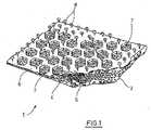
図1は、参照番号1で表記される外科用インプラントの1つの実施形態を図示しており、インプラントの一部分を3次元図で示している。 FIG. 1 illustrates one embodiment of a surgical implant, denoted by
外科用インプラント1は、第1面4及び第2面5を有する外科用メッシュとして表記される基本構造2を含む。実施形態において、Johnson & Johnson Medical GmbHから販売されている「Ultrapro」メッシュが、メッシュ2として使用され、「Monocryl」(上記参照)のフィラメント及びポリプロピレンのフィラメントを含んでいる。 The
基本構造2の第1面4に対して、六角形の形状を有し、規則的なパターンで配列される孔7を含む再吸収性フィルム6が取り付けられている。実施形態において、フィルム6は、染色された(バイオレット)ポリ−p−ジオキサノンから作製され、150μmの厚さを有する。 A
複数の固体突起部8は、基本構造2から離れた方向にフィルム6から出る。実施形態において、突起部は、各本体及び各頭部で画定されるキノコ様形状を含み、本体はフィルムから出て、頭部で終端し、頭部は本体に対して横方向に突出している。 The plurality of solid protrusions 8 exits the
更に以下のように、突起部のいくつかの実施形態において、更に詳しく説明される(図5〜図10参照)。図1に示されるものと同様の外科用インプラントの製造が、実施例によって図示されるであろう。 Further details will be described in some embodiments of the protrusions as follows (see FIGS. 5-10). The manufacture of a surgical implant similar to that shown in FIG. 1 will be illustrated by example.
図2は、参照番号10で表記される外科用インプラントの別の実施形態を分解図で示したものである。この場合、基本構造12は、第1面14及び第2面15を有する外科用メッシュとして表記される基本構造12を含む。例えば、ポリ−p−ジオキサノンのような再吸収性材料から作製されるフィルム16は、比較的大きな矩形の孔17を含む。 FIG. 2 is an exploded view of another embodiment of a surgical implant denoted by
孔17の間の領域中、突起部18は、フィルム16の表面から基本構造12から離れて出る。挿入されているのは、突起部18を図示したフィルム16の一部分の拡大図である。 In the region between the
図3は、組み立てられた状態における図2の外科用インプラント10を示しており、ここで、フィルム16は、基本構造12の第1面に取り付けられている。突起部18は、非常に小さいためこの倍率では目視できない。 FIG. 3 shows the
図4は、参照番号10’で表記される外科用インプラントの別の実施形態を図示しており、図2及び図3の外科用インプラント10と非常に類似している。しかしながら、外科用インプラント10と対照的に、外科用インプラント10’は、基本構造12の第2面15に取り付けられた第2フィルム19を含む。実施形態において、第2フィルム19は、第2面15を介して基本構造12に体組織が侵入するのを防ぐために、非孔質であって、抗接着特性を有する。 FIG. 4 illustrates another embodiment of the surgical implant denoted by
ブタの腹部で試験した際、突起部8、18によって、筋膜及び筋肉上の摩擦力が実質的に増加する。それとは対照的に、ポリ−p−ジオキサノンの滑らかなフィルム並びに未加工織物メッシュとして設計された外科用メッシュは、剪断力に対してより強い摩擦抵抗を示さなかった。 When tested on the pig abdomen, the
図5(部分図(a)〜(d))は、突起部20のいくつかの拡大図を示している。突起物20は、拡大した断面積と茎部25を有する足部24を含む本体22を含む。本体22は、凸状の上面28及び凹状下面29を有する頭部26で終端する(特に、図5(d)を参照)。突起部20はキノコ様形状を有しており、ここで、頭部26は、本体22に対して頭部26の全周に沿って、横方向に突出している。実施形態において、突起部20は、突起部20がそこから出るフィルムと一体的に作製される。 FIG. 5 (partial views (a) to (d)) shows several enlarged views of the
図6は(部分図(a)〜(c))は、別の実施形態としての突起部30を図示している。突起物30は、足部34及び茎部35並びに頭部36を含む本体32を含む。この場合、上面38及び下面39は、図6(b)で最もよく見えるように、平坦である。 FIG. 6 (partial views (a) to (c)) illustrates a
図7(部分(a)〜(d))は、図7(d)で最もよく見えるように、突起部40を示しており、これは本体42(足部44及び茎部45を含む)並びに凹状の上面48及び凸状の下面49を有する頭部46を含む。 FIG. 7 (parts (a)-(d)) shows a
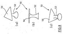
図8(部分図(a)〜(c))は、本体52及び三角形の基本形状を有する頭部56を含む突起部50を示している。 FIG. 8 (partial views (a) to (c)) shows a
図9(部分図(a)〜(c))に示される実施形態において、突起部60は、茎部64を有する本体62を含む。茎部64は、ほぼ全長にわたって円筒形状を有し、続く移行領域65において四角形の基本形状の頭部66の縁に到達するまで外向きに湾曲している。 In the embodiment shown in FIG. 9 (partial views (a)-(c)), the
図10(部分図(a)〜(c))は、円筒状本体72(足部を含まず)及び六角形の基本形状を有する平坦な頭部76を有する突起部70を示している。 FIG. 10 (partial views (a) to (c)) shows a
突起部の他の多くの実施形態が同様に考えられる。一般的には、突起部の頭部は、本件の外科用インプラントが外科手技中に載置される際に体組織を把持し、これによって実質的に摩擦力が増加し、インプラントの配置が安定化する。そのためには、各突起部において、頭部は、頭部の全周に沿って、本体に対して横方向に突出している必要はない。このような非対称な形状の場合、突起部の頭部は、同じ方向又は違う方向に配列され得る。突起部の典型的な寸法及び突起部の面密度の範囲は、既に上記で指定されている。例えば、突起部は、100μm〜500μmの高さ、及び約0.5個の突起部/m2〜5個の突起部/mm2の密度を有し得る。Many other embodiments of the protrusion are conceivable as well. In general, the protuberance head grips the body tissue when the surgical implant is placed during a surgical procedure, which substantially increases the frictional force and stabilizes the placement of the implant. Turn into. For this purpose, in each protrusion, the head does not need to protrude laterally with respect to the main body along the entire circumference of the head. In the case of such an asymmetric shape, the heads of the protrusions can be arranged in the same direction or in different directions. The typical dimensions of the protrusions and the range of surface density of the protrusions have already been specified above. For example, the protrusions can have a height of 100 μm to 500 μm and a density of about 0.5 protrusions / m2 to 5 protrusions / mm2 .
図11は、外科用インプラント1又は外科用インプラント10のような外科用インプラントの製造方法の一例を概念的に図示したものである。 FIG. 11 conceptually illustrates an example of a method for manufacturing a surgical implant such as the
はじめに、手技とは別に、各々が1つの突起部の形状を有する空隙82の配列を含む可撓性型80が調製される。かかる型は、例えば、シリコーン又はポリウレタンから作製され得る。以下の実施例は、溶媒非含有方法における可撓性シリコーン型の調製を示している。 First, apart from the procedure, a
実施例において、シリコーン(ポリ−p−ジメチルシロキサン、PDMS)とスタータを当該技術分野で既知の適切な比率で混合し、真空下で脱気し、ポジ型にコーティングする。このポジ型は、突起物の配列を示し、例えば、ポリマー又は金属ブロックを微粉砕することなどで作製され得る。第2工程の真空脱気は、混入した泡を取り除くために推奨されている。混合物は、所定の時間加熱によってより硬化される。硬化後、ポジ型はシリコーン型80から取り除かれ得る。これは、型80のシリコーン材料の柔軟性によって問題なく達成され得る。 In the examples, silicone (poly-p-dimethylsiloxane, PDMS) and starter are mixed in appropriate proportions known in the art, degassed under vacuum, and coated positively. This positive mold shows the arrangement of protrusions and can be made, for example, by pulverizing a polymer or metal block. The second step of vacuum degassing is recommended to remove entrained bubbles. The mixture is more cured by heating for a predetermined time. After curing, the positive mold can be removed from the
外科用インプラントを製造するために、図11に示されるように、まず、再吸収性フィルム84は空隙82の配列と対向するように型80上に載置される。この実施形態において、ポリ−p−ジオキサノン(PDS)から作製されているフィルム84は、150μmの厚さを有し、長方形又は菱形の孔の規則的なパターンを備えている。その後、「Ultrapro」メッシュ(上記参照)のような外科用メッシュ86は、フィルム84の表面上に載置される。以下で記載される熱処理中、メッシュ86の収縮を防ぐために、メッシュ86は、熱硬化性(事前に熱収縮している)であり得るか、又は保持枠中で維持され得る。 In order to manufacture a surgical implant, a resorbable film 84 is first placed on a
ソフトパッド88は、メッシュ86の表面上に載置される。この実施形態において、パッド88は、型80のショア硬さよりもショア硬さが低い弾性プレスパッドである。追加のソフトパッド(図11では示されていない)は、型80の下に配置され得る。 The
次に、図11で示される配列は、所定の時間押し付けられて加熱される。この実施例において、PDSのフィルム84が使用され、圧力は、1バール〜50バール(好ましくは1バール〜50バール)の範囲であり、温度は、105℃〜140℃(好ましくは約120℃)の範囲であり、時間周期は、1分〜30分(好ましくは約5分)の範囲であり得る。これらの条件下、フィルムのPDS材料は融解するか、又は非常に柔らかくなる(すなわち、定義によれば流体になる)が、メッシュ86は実質的にその形状を維持する。PDS材料は、型80中の空隙に入り、それによって突起部が形成され、それと同時にメッシュ86に安全に取り付けられる。 Next, the array shown in FIG. 11 is pressed and heated for a predetermined time. In this example, a PDS film 84 is used, the pressure ranges from 1 bar to 50 bar (preferably 1 bar to 50 bar), and the temperature ranges from 105 ° C to 140 ° C (preferably about 120 ° C). And the time period can range from 1 minute to 30 minutes (preferably about 5 minutes). Under these conditions, the PDS material of the film melts or becomes very soft (ie, becomes fluid by definition), while the
その後、アセンブリは室温まで冷却されるか(圧力下)、又は2つの冷金属板の間に数分間載置される。PDSポリマーが十分に固化した後、基本構造としてのメッシュ86、孔及びメッシュ86と離れた方向に向かう突起部を有するフィルム84を含む完成したインプラントは、可撓性型80から容易に取り外され得る。型80のシリコーン材料の柔軟性のため、横に突出する突起部の頭部を損傷することなく、取り外しが達成され得る。 The assembly is then cooled to room temperature (under pressure) or placed between two cold metal plates for several minutes. After the PDS polymer is fully solidified, the completed implant comprising the mesh 84 as the basic structure, the film 84 with the pores and the protrusions away from the
シリコーン型80は、数回使用可能である。 The
外科用メッシュの第2面に追加フィルムを含むインプラント10’のような外科用インプラントが製造される際、かかる追加フィルムは、図11による配列でメッシュ86とパッド88との間に載置され得る。更に、突起部の形状化及びインプラント層の互いへの取り付けは、実質的に1つの工程で達成され得る。 When a surgical implant, such as an implant 10 'that includes an additional film on the second side of the surgical mesh, is manufactured, such additional film may be placed between the
一般的に、図11によって記載される方法は多くの変形が可能である。例えば、型の空隙を充填し、表面上で非孔質フィルム層を形成する流体材料は、溶媒中でポリマーを溶解することで調製され得る。この場合流体材料の硬化工程は、溶媒の蒸発を含む。更には、突起部を有するフィルムは、メルト接着剤として機能する中間層を介して基本構造に取り付けられ得る。又は、インプラントの製造工程は、ほぼ同時ではなく、順番に実行され得る。方法のいくつかの態様は、一般的には、上述で既に議論されている。 In general, the method described by FIG. 11 can have many variations. For example, a fluid material that fills the mold voids and forms a non-porous film layer on the surface can be prepared by dissolving the polymer in a solvent. In this case, the curing process of the fluid material includes evaporation of the solvent. Furthermore, the film having the protrusions can be attached to the basic structure via an intermediate layer that functions as a melt adhesive. Alternatively, the manufacturing process of the implants can be performed in sequence rather than substantially simultaneously. Some aspects of the method are generally already discussed above.
より詳しいいくつかの実施例を以下で示す。 Some more detailed examples are given below.
実施例1:キノコ状のネガ型を有するシリコーン型の製作
マイクロテクスチュア化シリコーン型を2成分シリコーン前駆体キット(エラストマーキット)から作製した。そのために、全長約250μm、頭部直径約375μm、茎部直径約200μm及び足部直径約340μmを有する288個のキノコ状突起部/cm2(図5〜図7のものと同様)を1つの表面に有するポリプロピレンのポジ型(マスター)を使用した。液体シリコーンエラストマーを水平配置を維持したままポリプロピレンマスター上に流延し、数時間、炉中で高温(50℃〜80℃)で硬化した。室温まで冷却した後、突起部のキノコ状ネガ型を含むシリコーン型は、ポリプロピレンマスターから取り除くことができる。Example 1: Fabrication of a silicone mold having a mushroom-like negative mold A microtextured silicone mold was fabricated from a two-component silicone precursor kit (elastomer kit). For this purpose, 288 mushroom-like projections / cm2 (similar to those in FIGS. 5 to 7) having a total length of about 250 μm, a head diameter of about 375 μm, a stem diameter of about 200 μm and a foot diameter of about 340 μm A positive type (master) of polypropylene on the surface was used. The liquid silicone elastomer was cast on a polypropylene master while maintaining a horizontal arrangement, and cured at a high temperature (50 ° C. to 80 ° C.) in an oven for several hours. After cooling to room temperature, the silicone mold, including the mushroom negative mold on the protrusions, can be removed from the polypropylene master.
実施例2:片面上にキノコ状突起部を有するポリ−p−ジオキサノンフィルム/ポリプロピレンメッシュ積層体の製作。
第1工程において、菱形状の孔(長さ11.5mm、幅9mm)を、レーザーカッターを使用して、厚さ150μmのポリ−p−ジオキサン(PDS)フィルム中で規則的なパターンとなるように切断した。孔の間のフィルムの領域は、約2mmの幅を有する。Example 2: Production of a poly-p-dioxanone film / polypropylene mesh laminate having mushroom-like protrusions on one side.
In the first step, the rhomboid holes (length 11.5 mm, width 9 mm) are formed into a regular pattern in a 150 μm thick poly-p-dioxane (PDS) film using a laser cutter. Disconnected. The area of the film between the holes has a width of about 2 mm.
温度(110℃)及び圧力(75MPa(7.5kN/cm2))の制御下、熱プレスを使用して、フィルムをポリプロピレンメッシュ上に3.5分間積層した。そのために、ポリプロピレンメッシュを、12±5のショアA硬さを有する第1弾性シリコーンプレスパッドの上に配置した。PDSフィルムをポリプロピレンメッシュの上に、かつ型として機能し、約42±5のショアA硬さを有し、突起部を形成するためのキノコ状の空隙を含む第2弾性シリコーンプレスパッドの下にPDSフィルムを配置し、これによってPDSフィルムの融解中に空隙が充填される。減圧前にフィルム/メッシュ積層体を45℃まで冷却した。その後、弾性シリコーン型から積層体を剥離することで積層体を取り外した。The film was laminated on a polypropylene mesh for 3.5 minutes using a hot press under control of temperature (110 ° C.) and pressure (75 MPa (7.5 kN / cm2 )). To that end, a polypropylene mesh was placed on a first elastic silicone press pad having a Shore A hardness of 12 ± 5. A PDS film on a polypropylene mesh and under a second elastic silicone press pad that functions as a mold, has a Shore A hardness of about 42 ± 5, and includes mushroom-like voids to form protrusions A PDS film is placed, which fills the voids during melting of the PDS film. The film / mesh laminate was cooled to 45 ° C. before decompression. Thereafter, the laminate was removed by peeling the laminate from the elastic silicone mold.
実施例3:片面上にキノコ状突起部を有するポリ−p−ジオキサノンフィルム/ポリプロピレンメッシュ/Monocryl(商標)フィルム積層体の製作
第1工程において、菱形状の孔(長さ11.5mm、幅9mm)を、レーザーカッターを使用して、ポリ−p−ジオキサン(PDS)フィルム(フィルム厚:150μm)中で規則的なパターンとなるように切断した。孔の間のフィルムの領域は、約2mmの幅を有する。Example 3 Production of Poly-p-Dioxanone Film / Polypropylene Mesh / Monocryl ™ Film Laminate Having Mushroom-like Projections on One Side In the first step, rhomboid holes (length 11.5 mm, The width 9 mm) was cut into a regular pattern in a poly-p-dioxane (PDS) film (film thickness: 150 μm) using a laser cutter. The area of the film between the holes has a width of about 2 mm.
厚さが20μmの「Monocryl」フィルム(ポリグレカプロン25、グリコリドとε−カプロラクトンとのコポリマー、Johnson & Johnson Medical GmbH)を有するポリプロピレンメッシュの底面にフィルム表面を積層し、ここで、ポリプロピレンメッシュ及び「Monocryl」フィルムは、積層方法中にPDSフィルムをメルトグルーすることで連結した。詳細:温度(110℃)及び圧力(75MPa(7.5kN/cm2))の制御下、熱プレスを使用して、3.5分間積層を実行した。積層中、「Monocryl」フィルムを、12±5のショアA硬さを有する第1弾性シリコーンプレスパッドの上に配置した。ポリプロピレンメッシュを、「Monocryl」フィルムの上に配置した。PDSフィルムをポリプロピレンメッシュの上に、かつ型として機能し、約42±5のショアA硬さを有し、キノコ状の空隙を含む第2弾性シリコーンプレスパッドの下にPDSフィルムを配置し、これによってPDSフィルムの融解中に空隙が充填される。減圧前にフィルム/メッシュ積層体を45℃まで冷却した。その後、弾性シリコーン型から積層体を剥離することで積層体を取り外した。The film surface was laminated to the bottom of a polypropylene mesh having a “Monocryl” film (
実施例4:両面上にキノコ状突起部を有するポリ−p−ジオキサノンフィルム/ポリプロピレンメッシュ積層体の製作。
第1工程において、菱形状の孔(長さ11.5mm、幅9mm)を、レーザーカッターを使用して、厚さ150μmのポリ−p−ジオキサン(PDS)フィルム中で規則的なパターンとなるように切断した。孔の間のフィルムの領域は、約2mmの幅を有する。Example 4: Production of a poly-p-dioxanone film / polypropylene mesh laminate having mushroom-like protrusions on both sides.
In the first step, the rhomboid holes (length 11.5 mm, width 9 mm) are formed into a regular pattern in a 150 μm thick poly-p-dioxane (PDS) film using a laser cutter. Disconnected. The area of the film between the holes has a width of about 2 mm.
温度(110℃)及び圧力(75MPa(7.5kN/cm2))の制御下、熱プレスを使用して、フィルムをポリプロピレンメッシュ上に3.5分間積層した。そのために、ポリプロピレンメッシュを、12±5のショアA硬さを有する第1弾性シリコーンプレスパッドの上に配置した。PDSフィルムをポリプロピレンメッシュの上に、かつ型として機能し、約42±5のショアA硬さを有し、突起部を形成するためのキノコ状の空隙を含む第2弾性シリコーンプレスパッドの下にPDSフィルムを配置し、これによってPDSフィルムの融解中に空隙が充填される。減圧前にフィルム/メッシュ積層体を45℃まで冷却した。The film was laminated on a polypropylene mesh for 3.5 minutes using a hot press under control of temperature (110 ° C.) and pressure (75 MPa (7.5 kN / cm2 )). To that end, a polypropylene mesh was placed on a first elastic silicone press pad having a Shore A hardness of 12 ± 5. A PDS film on a polypropylene mesh and under a second elastic silicone press pad that functions as a mold, has a Shore A hardness of about 42 ± 5, and includes mushroom-like voids to form protrusions A PDS film is placed, which fills the voids during melting of the PDS film. The film / mesh laminate was cooled to 45 ° C. before decompression.
第2プロセス工程において、第2PDSフィルム(150μmの厚さ及び上記するような孔を有する)をポイプロピレンメッシュの下に配置し、ポリプロピレンメッシュの下に配置される12±5のショアA硬さを有する第1弾性シリコーンプレスパッドを、型として機能し、42±5のショアA硬さを有し、突起部を形成するためのキノコ状の空隙を含む第2弾性シリコーンプレスパッドに置き換え、これによって第2PDSフィルムの融解中に空隙が充填される。減圧前にフィルム/メッシュ積層体を45℃まで再び冷却した。 In the second process step, a second PDS film (with a thickness of 150 μm and pores as described above) is placed under the polypropylene mesh and a Shore A hardness of 12 ± 5 is placed under the polypropylene mesh. The first elastic silicone press pad has a second elastic silicone press pad that functions as a mold, has a Shore A hardness of 42 ± 5, and includes mushroom-like voids to form protrusions, thereby Gaps are filled during melting of the second PDS film. The film / mesh laminate was cooled again to 45 ° C. before decompression.
その後、頂面及び底面上の弾性シリコーン型から積層体を剥離することで積層体を取り外した。 Thereafter, the laminate was removed by peeling the laminate from the elastic silicone mold on the top and bottom surfaces.
実施例5:ラット皮膚における実施例2のインプラントによる試験
実施例2のインプラントを国際公開第2006/092236(A1)号によりラット皮膚摩擦モデルで試験した。比較のため、突起部を有するフィルムを含まないUtrapro(商標)メッシュを供した。測定した摩擦力(N)を、変位経路(mm)においてプロット化した。Example 5: Test with the implant of Example 2 on rat skin The implant of Example 2 was tested in a rat skin friction model according to WO 2006/092236 (A1). For comparison, a Utrapro ™ mesh without a film with protrusions was provided. The measured friction force (N) was plotted in the displacement path (mm).
ラット皮膚をキノコ状突起部を有する表面上を垂直に移動させる際、実施例2のインプラントは、約16Nの最大値まで力の急激な増加を示した。この増加は、所与の試験条件下で、変位が増大するにつれて、ますます多くの突起部がラット皮膚組織に噛合するようになり、このことが全ての突起部に適用するまで続いたという事実により説明される。 When moving rat skin vertically over a surface with mushroom-like protrusions, the implant of Example 2 showed a rapid increase in force to a maximum of about 16N. This increase is the fact that, under given test conditions, as displacement increases, more and more protrusions become engaged with rat skin tissue and this lasted until applied to all protrusions. Explained by
力の最大値の比較において、同じ条件下でのメッシュ(Ultrapro(商標))は、約3Nに過ぎなかった。 In the comparison of force maxima, the mesh under the same conditions (Ultrapro ™) was only about 3N.
実施例6:ブタ腹部における実施例2のインプラントによる試験
実施例2のインプラントをブタ腹部の異なる層(脂肪接触、筋膜接触及び筋肉接触)に載置した。引きのない若干の圧力によって、既にキノコ状突起部の固定が生じていた。突起部の向きに対して垂直の方向への引きで、インプラントを固定した。異なる組織(筋肉、筋膜、脂肪)で優れた付着性があった。Example 6: Test with the implant of Example 2 on the porcine abdomen The implant of Example 2 was placed on different layers (fat contact, fascia contact and muscle contact) of the porcine abdomen. The mushroom-like protrusion was already fixed by a slight pressure without pulling. The implant was fixed by pulling in a direction perpendicular to the direction of the protrusion. Excellent adhesion in different tissues (muscle, fascia, fat).
〔実施の態様〕
(1) 外科用インプラントであって、
第1面(4;14)を有する基本構造(2;12)と、
前記基本構造(2;12)の前記第1面(4;14)に取り付けられる再吸収性フィルム(6;16)と、
前記基本構造(2;12)から離れた方向に前記フィルム(6;16)から出る複数の固体突起部(8;18;20;30;40;50;60;70)と、を含み、
前記突起部(8;18;20;30;40;50;60;70)は、それぞれの本体(22;32;42;52;62;72)及びそれぞれの頭部(26;36;46;56;66;76)によって画定される形状を含み、前記本体(22;32;42;52;62;72)は、前記フィルム(6;16)から出て、前記頭部(26;36;46;56;66;76)で終端し、前記頭部(26;36;46;56;66;76)は、前記本体(22;32;42;52;62;72)に対して横方向に突出する、外科用インプラント。
(2) 前記突起部(8;18;20;30;40;50;60;70)のうちの少なくとも一部分は、キノコ様形状を含むことを特徴とする、実施態様1に記載の外科用インプラント。
(3) 前記突起部(8;18;20;30;40;50;60;70)は、前記フィルム(6;16)と同じ材料からなることを特徴とする、実施態様1又は2に記載の外科用インプラント。
(4) 前記フィルム(6;16)及び前記突起部(8;18;20;30;40;50;60;70)は、一体的に作製されることを特徴とする、実施態様3に記載の外科用インプラント。
(5) 前記本体(22;32;42;52;62;72)の縦軸に対して垂直な平面で測定される前記本体(22;32;42;52;62;72)の最少断面積は、前記頭部(26;36;46;56;66;76)の縦軸に対して垂直な平面で測定される前記頭部(26;36;46;56;66;76)の最大断面積よりも小さく、前記本体(22;32;42;52;62;72)の縦軸に沿って測定される前記本体(22;32;42;52;62;72)の高さは、前記頭部(26;36;46;56;66;76)の縦軸に沿って測定される前記頭部(26;36;46;56;66;76)の厚さよりも、少なくとも2倍、好ましくは少なくとも3倍、大きいことを特徴とする、実施態様1〜4のいずれかに記載の外科用インプラント。Embodiment
(1) a surgical implant,
A basic structure (2; 12) having a first surface (4; 14);
A resorbable film (6; 16) attached to the first surface (4; 14) of the basic structure (2; 12);
A plurality of solid protrusions (8; 18; 20; 30; 40; 50; 60; 70) exiting the film (6; 16) in a direction away from the basic structure (2; 12);
The protrusions (8; 18; 20; 30; 40; 50; 60; 70) are connected to the respective bodies (22; 32; 42; 52; 62; 72) and the respective heads (26; 36; 46; 56; 66; 76), wherein the body (22; 32; 42; 52; 62; 72) exits the film (6; 16) and the head (26; 36; 46; 56; 66; 76) and the head (26; 36; 46; 56; 66; 76) is transverse to the body (22; 32; 42; 52; 62; 72) Surgical implant that protrudes into
(2) The surgical implant of
(3) The embodiment (1) or (2), wherein the protrusion (8; 18; 20; 30; 40; 50; 60; 70) is made of the same material as the film (6; 16). Surgical implants.
(4) The embodiment (3), wherein the film (6; 16) and the protrusion (8; 18; 20; 30; 40; 50; 60; 70) are integrally formed. Surgical implants.
(5) Minimum cross-sectional area of the body (22; 32; 42; 52; 62; 72) measured in a plane perpendicular to the longitudinal axis of the body (22; 32; 42; 52; 62; 72) Is the maximum break of the head (26; 36; 46; 56; 66; 76) measured in a plane perpendicular to the longitudinal axis of the head (26; 36; 46; 56; 66; 76). The height of the body (22; 32; 42; 52; 62; 72), which is smaller than the area and measured along the longitudinal axis of the body (22; 32; 42; 52; 62; 72), is At least twice the thickness of the head (26; 36; 46; 56; 66; 76) measured along the longitudinal axis of the head (26; 36; 46; 56; 66; 76), preferably The surgical implant according to any of embodiments 1-4, characterized in that is at least three times larger. Plant.
(6) 前記突起部(8;18;20;30;40;50;60;70)は、以下の範囲:20μm〜5000μm、100μm〜500μm、200μm〜400μm、のうちの1つの高さを有することを特徴とする、実施態様1〜5のいずれかに記載の外科用インプラント。
(7) 前記突起部(8;18;20;30;40;50;60;70)は、以下の範囲:0.5個の突起部/mm2〜5個の突起部/mm2、2個の突起部/mm2〜4個の突起部/mm2、のうちの1つの密度を有することを特徴とする、実施態様1〜6のいずれかに記載の外科用インプラント。
(8) 前記突起部(8;18;20;30;40;50;60;70)は、前記フィルムの表面に対して50°〜90°、70°〜90°の範囲のうちの1つの角度で前記フィルムから出るそれぞれの縦軸を有することを特徴とする、実施態様1〜7のいずれかに記載の外科用インプラント。
(9) 前記フィルム(6;16)は、前記突起部(8;18;20;30;40;50;60;70)の間に孔(7;17)を含み、好ましくは前記孔(7;17)は、以下の範囲:0.5mm〜50mm、2mm〜20mmm、のうちの1つのサイズを有することを特徴とする、実施態様1〜8のいずれかに記載の外科用インプラント。
(10) 少なくとも1つの孔は、前記孔の縁部から前記孔の領域に出て、前記フィルム(6;16)の材料からなる少なくとも1つの突起部を含むことを特徴とする、実施態様9に記載の外科用インプラント。(6) The protrusion (8; 18; 20; 30; 40; 50; 60; 70) has a height of one of the following ranges: 20 μm to 5000 μm, 100 μm to 500 μm, 200 μm to 400 μm. The surgical implant according to any of
(7) The protrusions (8; 18; 20; 30; 40; 50; 60; 70) have the following ranges: 0.5 protrusions / mm2 to 5 protrusions / mm2 , 2 The surgical implant according to any of
(8) The protrusion (8; 18; 20; 30; 40; 50; 60; 70) is one of a range of 50 ° to 90 ° and 70 ° to 90 ° with respect to the surface of the film. Surgical implant according to any of
(9) The film (6; 16) includes holes (7; 17) between the protrusions (8; 18; 20; 30; 40; 50; 60; 70), and preferably the holes (7 17) Surgical implant according to any of
(10) Embodiment 9 characterized in that the at least one hole comprises at least one protrusion made of the material of the film (6; 16), coming out from the edge of the hole into the region of the hole. A surgical implant as described in 1.
(11) 前記基本構造は、前記第1面(4;14)及び前記第1面(4;14)の反対側の第2面(5;15)を有するメッシュ様構造(2;12)を含むことを特徴とする、実施態様1〜10のいずれかに記載の外科用インプラント。
(12) 前記メッシュ様構造(12)の前記第2面(15)に取り付けられる第2フィルム(19)を特徴とし、任意に、前記第2フィルム(19)は、以下の特性:再吸収性である、抗接着性である、のうちの少なくとも1つを有する、実施態様11に記載の外科用インプラント。
(13) 複数の突起部は、前記メッシュ様構造(12)から離れた方向に、前記第2フィルム(19)から出ることを特徴とする、実施態様12に記載の外科用インプラント。
(14) 前記メッシュ様基本構造はメッシュ孔を含み、前記フィルムは前記メッシュ孔内部に延伸し、実施態様1に記載の突起部は、前記フィルムから、前記基本構造の前記第1面から離れた方向及び前記基本構造の前記第2面から離れた方向の両方向に出ることを特徴とする、実施態様11に記載の外科用インプラント。
(15) 前記フィルム(6;16)は、以下のリスト:合成生体吸収性ポリマー材料、ポリヒドロキシ酸、ポリラクチド、ポリグリコリド、グリコリドとラクチドとのコポリマー、90:10の比率のグリコリドとラクチドとのコポリマー、ラクチドとトリメチレンカーボネートとのコポリマー、グリコリドとラクチドとトリメチレンカーボネートとのコポリマー、ポリヒドロキシ酪酸、ポリヒドロキシ吉草酸(polyhydroxyvaleriates)、ポリカプロラクトン、グリコリドとε−カプロラクトンとのコポリマー、ポリジオキサノン、ポリ−p−ジオキサノン、合成並びに天然オリゴアミノ酸及びポリアミノ酸、ポリホスファゼン、ポリ無水物、ポリオルトエステル、ポリリン酸エステル、ポリホスホン酸エステル、ポリアルコール、多糖類、ポリエーテル、コラーゲン、ゼラチン、オメガ3脂肪酸で架橋された生体吸収性ゲルフィルム、酸化再生セルロース、から選択される材料を含むことを特徴とする、実施態様1〜14のいずれかに記載の外科用インプラント。(11) The basic structure comprises a mesh-like structure (2; 12) having a first surface (4; 14) and a second surface (5; 15) opposite to the first surface (4; 14). The surgical implant according to any of embodiments 1-10, characterized by comprising.
(12) characterized by a second film (19) attached to the second surface (15) of the mesh-like structure (12), optionally, the second film (19) has the following properties:
(13) The surgical implant according to
(14) The mesh-like basic structure includes a mesh hole, the film extends into the mesh hole, and the protrusion according to
(15) The film (6; 16) comprises the following list: synthetic bioabsorbable polymer material, polyhydroxy acid, polylactide, polyglycolide, copolymer of glycolide and lactide, 90:10 ratio of glycolide and lactide Copolymer, copolymer of lactide and trimethylene carbonate, copolymer of glycolide and lactide and trimethylene carbonate, polyhydroxybutyric acid, polyhydroxyvaleriates, polycaprolactone, copolymer of glycolide and ε-caprolactone, polydioxanone, poly- p-dioxanone, synthetic and natural oligoamino acids and polyamino acids, polyphosphazenes, polyanhydrides, polyorthoesters, polyphosphate esters, polyphosphonate esters, polyalcohols, polysaccharides, polyesters Surgical implant according to any of
(16) 前記基本構造(2;12)は、以下のリスト:ポリアルケン、ポリプロピレン、ポリエチレン、フッ素化ポリオレフィン、ポリテトラフルオロエチレン、PTFE、ePTFE、cPTFE、ポリフッ化ビニリデン、ポリフッ化ビニリデンとフッ化ビニリデン及びヘキサフルオロプロペンのコポリマーとのブレンド、ポリアミド、ポリウレタン、ポリイソプレン、ポリスチレン、ポリシリコーン、ポリカーボネート、ポリアリールエーテルケトン、ポリメタクリル酸エステル、ポリアクリル酸エステル、芳香族ポリエステル、ポリイミド、ポリヒドロキシ酸、ポリラクチド、ポリグリコリド、グリコリドとラクチドとのコポリマー、90:10の比率のグリコリドとラクチドとのコポリマー、ラクチドとトリメチレンカーボネートとのコポリマー、グリコリドとラクチドとトリメチレンカーボネートとのコポリマー、ポリヒドロキシ酪酸、ポリヒドロキシ吉草酸、ポリカプロラクトン、グリコリドとε−カプロラクトンとのコポリマー、ポリジオキサノン、ポリ−p−ジオキサノン、合成並びに天然オリゴアミノ酸及びポリアミノ酸、ポリホスファゼン、ポリ無水物、ポリオルトエステル、ポリリン酸エステル、ポリホスホン酸エステル、ポリアルコール、多糖類、ポリエーテル、ポリアミド、脂肪族ポリエステル、芳香族ポリエステル、これらの重合性物質のコポリマー、再吸収性ガラス、セルロース、バクテリアセルロース、同種移植片、異種移植片、から選択される材料のうちの少なくとも1つを含むことを特徴とする、実施態様1〜15のいずれかに記載の外科用インプラント。
(17) 前記外科用インプラント(1;10;10’)は、腹腔鏡下で配置するために巻かれるか、又は折り畳まれるように適合され、トロカールスリーブを通して外科手術の部位に送られ、自身に固着することなく、解かれるか、又は広げられることを特徴とする、実施態様1〜16のいずれかに記載の外科用インプラント。
(18) 前記外科用インプラント(1;10;10’)が、軟組織インプラント、好ましくはヘルニアインプラントとして設計され、前記インプラントを、筋肉又は脂肪などの軟組織に少なくとも部分的に固定するよう適合され、前記外科用インプラント(1;10;10’)と前記軟組織との間の摩擦が、突起部を含まない対応するインプラントと比較して2倍以上、少なくとも1つの方向に増加する、実施態様1〜17のいずれかに記載の外科用インプラント。
(19) 実施態様1に記載の外科用インプラントの製造方法であって、
各々が1つの突起部の形状を有する空隙(82)の配列を含む可撓性型(80)を提供する工程と、
前記型(80)を前記突起部及び前記フィルムを形成する流体材料(84)で充填する工程と、
前記流体材料(84)を硬化する工程と、
前記フィルム(84)を基本構造(86)に、前記突起部が前記基本構造(86)から離れた方向を向いた状態で、取り付ける工程と、
前記型(80)を取り除く工程と、を特徴とする、方法。
(20) 前記可撓性型(80)は、以下の材料:シリコーン、ポリウレタン、天然ゴム、合成ゴム、のうちの少なくとも1つを含むことを特徴とする、実施態様19に記載の方法。(16) The basic structure (2; 12) has the following list: polyalkene, polypropylene, polyethylene, fluorinated polyolefin, polytetrafluoroethylene, PTFE, ePTFE, cPTFE, polyvinylidene fluoride, polyvinylidene fluoride and vinylidene fluoride, and Blends with copolymers of hexafluoropropene, polyamide, polyurethane, polyisoprene, polystyrene, polysilicone, polycarbonate, polyaryl ether ketone, polymethacrylic acid ester, polyacrylic acid ester, aromatic polyester, polyimide, polyhydroxy acid, polylactide, Polyglycolide, copolymer of glycolide and lactide, copolymer of glycolide and lactide in a ratio of 90:10, lactide and trimethylene carbonate Copolymers of glycolide, lactide and trimethylene carbonate, polyhydroxybutyric acid, polyhydroxyvaleric acid, polycaprolactone, copolymers of glycolide and ε-caprolactone, polydioxanone, poly-p-dioxanone, synthetic and natural oligoamino acids and poly Amino acids, polyphosphazenes, polyanhydrides, polyorthoesters, polyphosphate esters, polyphosphonate esters, polyalcohols, polysaccharides, polyethers, polyamides, aliphatic polyesters, aromatic polyesters, copolymers of these polymerizable substances, reabsorption Surgical according to any of
(17) The surgical implant (1; 10; 10 ') is adapted to be rolled or folded for placement under a laparoscope and sent through a trocar sleeve to a surgical site and to itself Surgical implant according to any of embodiments 1-16, characterized in that it is unwound or unfolded without sticking.
(18) the surgical implant (1; 10; 10 ') is designed as a soft tissue implant, preferably a hernia implant, adapted to at least partially fix the implant to soft tissue such as muscle or fat, Embodiments 1-17, wherein the friction between a surgical implant (1; 10; 10 ′) and said soft tissue is increased in at least one direction more than twice as compared to a corresponding implant without protrusions. The surgical implant according to any one of the above.
(19) A method for manufacturing the surgical implant according to
Providing a flexible mold (80) comprising an array of voids (82) each having the shape of one protrusion;
Filling the mold (80) with a fluid material (84) forming the protrusions and the film;
Curing the fluid material (84);
Attaching the film (84) to the basic structure (86) with the protrusion facing away from the basic structure (86);
Removing the mold (80).
(20) The method of
Claims (20)
Translated fromJapanese第1面(4;14)を有する基本構造(2;12)と、
前記基本構造(2;12)の前記第1面(4;14)に取り付けられる再吸収性フィルム(6;16)と、
前記基本構造(2;12)から離れた方向に前記フィルム(6;16)から出る複数の固体突起部(8;18;20;30;40;50;60;70)と、を含み、
前記突起部(8;18;20;30;40;50;60;70)は、それぞれの本体(22;32;42;52;62;72)及びそれぞれの頭部(26;36;46;56;66;76)によって画定される形状を含み、前記本体(22;32;42;52;62;72)は、前記フィルム(6;16)から出て、前記頭部(26;36;46;56;66;76)で終端し、前記頭部(26;36;46;56;66;76)は、前記本体(22;32;42;52;62;72)に対して横方向に突出する、外科用インプラント。A surgical implant,
A basic structure (2; 12) having a first surface (4; 14);
A resorbable film (6; 16) attached to the first surface (4; 14) of the basic structure (2; 12);
A plurality of solid protrusions (8; 18; 20; 30; 40; 50; 60; 70) exiting the film (6; 16) in a direction away from the basic structure (2; 12);
The protrusions (8; 18; 20; 30; 40; 50; 60; 70) are connected to the respective bodies (22; 32; 42; 52; 62; 72) and the respective heads (26; 36; 46; 56; 66; 76), wherein the body (22; 32; 42; 52; 62; 72) exits the film (6; 16) and the head (26; 36; 46; 56; 66; 76) and the head (26; 36; 46; 56; 66; 76) is transverse to the body (22; 32; 42; 52; 62; 72) Surgical implant that protrudes into
各々が1つの突起部の形状を有する空隙(82)の配列を含む可撓性型(80)を提供する工程と、
前記型(80)を前記突起部及び前記フィルムを形成する流体材料(84)で充填する工程と、
前記流体材料(84)を硬化する工程と、
前記フィルム(84)を基本構造(86)に、前記突起部が前記基本構造(86)から離れた方向を向いた状態で、取り付ける工程と、
前記型(80)を取り除く工程と、を特徴とする、方法。A method of manufacturing a surgical implant according to claim 1,
Providing a flexible mold (80) comprising an array of voids (82) each having the shape of one protrusion;
Filling the mold (80) with a fluid material (84) forming the protrusions and the film;
Curing the fluid material (84);
Attaching the film (84) to the basic structure (86) with the protrusion facing away from the basic structure (86);
Removing the mold (80).
Applications Claiming Priority (3)
| Application Number | Priority Date | Filing Date | Title |
|---|---|---|---|
| DE102013004573.8 | 2013-03-11 | ||
| DE102013004573.8ADE102013004573A1 (en) | 2013-03-11 | 2013-03-11 | Surgical implant |
| PCT/EP2014/000466WO2014139633A1 (en) | 2013-03-11 | 2014-02-21 | Surgical implant |
Publications (2)
| Publication Number | Publication Date |
|---|---|
| JP2016514002Atrue JP2016514002A (en) | 2016-05-19 |
| JP6348129B2 JP6348129B2 (en) | 2018-06-27 |
Family
ID=50159191
Family Applications (1)
| Application Number | Title | Priority Date | Filing Date |
|---|---|---|---|
| JP2015561972AExpired - Fee RelatedJP6348129B2 (en) | 2013-03-11 | 2014-02-21 | Surgical implant |
Country Status (14)
| Country | Link |
|---|---|
| US (2) | US10052184B2 (en) |
| EP (1) | EP2967787B1 (en) |
| JP (1) | JP6348129B2 (en) |
| KR (1) | KR102237650B1 (en) |
| CN (1) | CN105120797A (en) |
| AU (1) | AU2014231265B2 (en) |
| BR (1) | BR112015021955B1 (en) |
| CA (1) | CA2904412A1 (en) |
| DE (1) | DE102013004573A1 (en) |
| ES (1) | ES2728507T3 (en) |
| IL (1) | IL240349B (en) |
| MX (1) | MX360990B (en) |
| RU (1) | RU2689763C2 (en) |
| WO (1) | WO2014139633A1 (en) |
Cited By (3)
| Publication number | Priority date | Publication date | Assignee | Title |
|---|---|---|---|---|
| JP2016510612A (en)* | 2013-03-11 | 2016-04-11 | ジョンソン・アンド・ジョンソン・メディカル・ゲーエムベーハー | Surgical implant |
| JP2017533803A (en)* | 2014-10-31 | 2017-11-16 | プリヴェント パッチ リミテッド ライアビリティ カンパニー | Apparatus and method for preventing scar hernia |
| JP2023536919A (en)* | 2020-08-04 | 2023-08-30 | ビーブイダブリュ ホールディング エージー | microstructured soft tissue graft |
Families Citing this family (47)
| Publication number | Priority date | Publication date | Assignee | Title |
|---|---|---|---|---|
| US20050182443A1 (en) | 2004-02-18 | 2005-08-18 | Closure Medical Corporation | Adhesive-containing wound closure device and method |
| US20060009099A1 (en) | 2004-07-12 | 2006-01-12 | Closure Medical Corporation | Adhesive-containing wound closure device and method |
| CN101869516B (en)* | 2010-06-07 | 2011-10-26 | 钟春燕 | Bacterial cellulose ice pack and production method thereof |
| RU2012157129A (en)* | 2010-06-08 | 2014-07-20 | Смит Энд Нефью, Инк. | IMPLANT AND METHODS OF ITS MANUFACTURE |
| US9475709B2 (en) | 2010-08-25 | 2016-10-25 | Lockheed Martin Corporation | Perforated graphene deionization or desalination |
| US9610546B2 (en) | 2014-03-12 | 2017-04-04 | Lockheed Martin Corporation | Separation membranes formed from perforated graphene and methods for use thereof |
| US9744617B2 (en) | 2014-01-31 | 2017-08-29 | Lockheed Martin Corporation | Methods for perforating multi-layer graphene through ion bombardment |
| US9834809B2 (en) | 2014-02-28 | 2017-12-05 | Lockheed Martin Corporation | Syringe for obtaining nano-sized materials for selective assays and related methods of use |
| US10653824B2 (en) | 2012-05-25 | 2020-05-19 | Lockheed Martin Corporation | Two-dimensional materials and uses thereof |
| WO2014164621A1 (en) | 2013-03-12 | 2014-10-09 | Lockheed Martin Corporation | Method for forming filter with uniform aperture size |
| US9572918B2 (en) | 2013-06-21 | 2017-02-21 | Lockheed Martin Corporation | Graphene-based filter for isolating a substance from blood |
| DE102013014295A1 (en) | 2013-08-22 | 2015-02-26 | Johnson & Johnson Medical Gmbh | Surgical implant |
| SG11201606287VA (en) | 2014-01-31 | 2016-08-30 | Lockheed Corp | Processes for forming composite structures with a two-dimensional material using a porous, non-sacrificial supporting layer |
| JP2017510461A (en) | 2014-01-31 | 2017-04-13 | ロッキード マーティン コーポレイションLockheed Martin Corporation | Perforation of two-dimensional materials using a broad ion field |
| AU2015229331A1 (en) | 2014-03-12 | 2016-10-27 | Lockheed Martin Corporation | Separation membranes formed from perforated graphene |
| AU2015311978A1 (en) | 2014-09-02 | 2017-05-11 | Lockheed Martin Corporation | Hemodialysis and hemofiltration membranes based upon a two-dimensional membrane material and methods employing same |
| EP3000489B1 (en)* | 2014-09-24 | 2017-04-05 | Sofradim Production | Method for preparing an anti-adhesion barrier film |
| US9622844B2 (en)* | 2014-10-31 | 2017-04-18 | Prevent Patch, LLC | Devices and methods for preventing incisional hernias |
| ES2903129T3 (en) | 2015-03-26 | 2022-03-31 | Bard Inc C R | Force activated grasping device for an implantable prosthesis |
| WO2017023376A1 (en) | 2015-08-05 | 2017-02-09 | Lockheed Martin Corporation | Perforatable sheets of graphene-based material |
| JP2018530499A (en) | 2015-08-06 | 2018-10-18 | ロッキード・マーチン・コーポレーション | Nanoparticle modification and perforation of graphene |
| US11058530B2 (en)* | 2015-10-16 | 2021-07-13 | Lifenet Health | Soft tissue grafts, and methods of making and using same |
| DE102015013989A1 (en)* | 2015-10-30 | 2017-05-04 | Johnson & Johnson Medical Gmbh | Surgical implant |
| GB201521474D0 (en) | 2015-12-04 | 2016-01-20 | Univ Manchester | Textured surfaces for implants |
| CN105596112B (en)* | 2016-01-25 | 2018-06-15 | 北京天助畅运医疗技术股份有限公司 | The dedicated ventral hernia repair mesh sheet of open surgery |
| CN105727371B (en)* | 2016-01-25 | 2019-04-09 | 北京天助畅运医疗技术股份有限公司 | Ventral hernia repair material |
| CN105596114B (en)* | 2016-01-25 | 2018-06-15 | 北京天助畅运医疗技术股份有限公司 | The sticking patch that prevents adhesion with interior drainage function |
| CN105596113B (en)* | 2016-01-25 | 2018-03-06 | 北京天助畅运医疗技术股份有限公司 | Composite patch with the mantle skirt that prevents adhesion |
| WO2017180134A1 (en) | 2016-04-14 | 2017-10-19 | Lockheed Martin Corporation | Methods for in vivo and in vitro use of graphene and other two-dimensional materials |
| SG11201809016QA (en) | 2016-04-14 | 2018-11-29 | Lockheed Corp | Selective interfacial mitigation of graphene defects |
| EP3442739A4 (en) | 2016-04-14 | 2020-03-04 | Lockheed Martin Corporation | Method for treating graphene sheets for large-scale transfer using free-float method |
| JP2019519756A (en) | 2016-04-14 | 2019-07-11 | ロッキード・マーチン・コーポレーション | In-situ monitoring and control of defect formation or defect repair |
| WO2017180135A1 (en) | 2016-04-14 | 2017-10-19 | Lockheed Martin Corporation | Membranes with tunable selectivity |
| JP2019517909A (en) | 2016-04-14 | 2019-06-27 | ロッキード・マーチン・コーポレーション | Two-dimensional membrane structure having a flow path |
| CN105944151A (en)* | 2016-05-05 | 2016-09-21 | 山东省药学科学院 | Stitching-free isolating membrane for repairing bone defects and preparation method of stitching-free isolating membrane |
| US10792024B2 (en) | 2016-09-28 | 2020-10-06 | Ethicon, Inc. | Scaffolds with channels for joining layers of tissue at discrete points |
| USD848624S1 (en) | 2016-09-29 | 2019-05-14 | Ethicon, Inc. | Release paper for wound treatment devices |
| US10687986B2 (en) | 2016-09-29 | 2020-06-23 | Ethicon, Inc. | Methods and devices for skin closure |
| US10470935B2 (en) | 2017-03-23 | 2019-11-12 | Ethicon, Inc. | Skin closure systems and devices of improved flexibility and stretchability for bendable joints |
| US20180271505A1 (en)* | 2017-03-23 | 2018-09-27 | Ethicon, Inc. | Scaffolds for Joining Layers of Tissue at Discrete Points |
| US11504446B2 (en) | 2017-04-25 | 2022-11-22 | Ethicon, Inc. | Skin closure devices with self-forming exudate drainage channels |
| CN111432749B (en) | 2017-10-19 | 2023-04-04 | C.R.巴德公司 | Self-gripping hernia prosthesis |
| ES2980412T3 (en) | 2018-03-13 | 2024-10-01 | Institut Quim De Sarria Cets Fundacio Privada | Vascular repair patch |
| US10993708B2 (en) | 2018-07-31 | 2021-05-04 | Ethicon, Inc. | Skin closure devices with interrupted closure |
| AU2020241892B2 (en)* | 2019-03-20 | 2025-01-30 | Lifenet Health | Soft tissue supports, and methods of making and using same |
| IT201900025231A1 (en)* | 2019-12-23 | 2021-06-23 | Pasquale Giordano | SELF-FIXING MESH PROSTHETIC IMPLANT |
| KR102611674B1 (en)* | 2023-08-31 | 2023-12-11 | 주식회사 베누스메드 | Method For Manufacturing Implants Having Micro-Texture Structure |
Citations (4)
| Publication number | Priority date | Publication date | Assignee | Title |
|---|---|---|---|---|
| US5397355A (en)* | 1994-07-19 | 1995-03-14 | Stentco, Inc. | Intraluminal stent |
| US20020077661A1 (en)* | 2000-12-20 | 2002-06-20 | Vahid Saadat | Multi-barbed device for retaining tissue in apposition and methods of use |
| WO2003099160A1 (en)* | 2002-05-23 | 2003-12-04 | Ethicon Gmbh | Medical implant |
| JP2013503673A (en)* | 2009-09-04 | 2013-02-04 | ソフラディム・プロデュクスィヨン | Retaining fabric coated with a bioresorbable impermeable layer |
Family Cites Families (9)
| Publication number | Priority date | Publication date | Assignee | Title |
|---|---|---|---|---|
| FR2807937B1 (en) | 2000-04-20 | 2002-08-02 | Sofradim Production | GRIPPED PROSTHETIC KNIT, MANUFACTURING METHOD THEREOF AND REINFORCEMENT IMPLANT FOR THE TREATMENT OF WALL DEFICITS |
| EP1572259A2 (en)* | 2002-12-05 | 2005-09-14 | Cardio Incorporated | Layered bioresorbable implant |
| RU2235525C1 (en)* | 2003-02-03 | 2004-09-10 | Меньщиков Александр Владимирович | Implant for making plastic repair of inguinal hernia |
| DE102005009356A1 (en) | 2005-03-01 | 2006-09-07 | Ethicon Gmbh | Surgical implant |
| US8123817B2 (en)* | 2007-12-28 | 2012-02-28 | Boston Scientific Scimed, Inc. | Meshes of variable construction |
| AU2009305116B2 (en)* | 2008-10-17 | 2014-11-06 | Sofradim Production | Surgical patch |
| FR2962646B1 (en)* | 2010-07-16 | 2012-06-22 | Sofradim Production | PROSTHETIC WITH RADIO OPAQUE ELEMENT |
| AU2012212070A1 (en) | 2011-02-04 | 2013-09-19 | University Of Massachusetts | Negative pressure wound closure device |
| DE102012005978A1 (en) | 2012-03-23 | 2013-09-26 | Johnson & Johnson Medical Gmbh | Surgical implant |
- 2013
- 2013-03-11DEDE102013004573.8Apatent/DE102013004573A1/ennot_activeWithdrawn
- 2014
- 2014-02-21EPEP14706288.9Apatent/EP2967787B1/enactiveActive
- 2014-02-21RURU2015143200Apatent/RU2689763C2/ennot_activeIP Right Cessation
- 2014-02-21AUAU2014231265Apatent/AU2014231265B2/ennot_activeCeased
- 2014-02-21MXMX2015012195Apatent/MX360990B/enactiveIP Right Grant
- 2014-02-21WOPCT/EP2014/000466patent/WO2014139633A1/enactiveApplication Filing
- 2014-02-21JPJP2015561972Apatent/JP6348129B2/ennot_activeExpired - Fee Related
- 2014-02-21BRBR112015021955-1Apatent/BR112015021955B1/ennot_activeIP Right Cessation
- 2014-02-21CNCN201480013091.0Apatent/CN105120797A/enactivePending
- 2014-02-21ESES14706288Tpatent/ES2728507T3/enactiveActive
- 2014-02-21CACA2904412Apatent/CA2904412A1/ennot_activeAbandoned
- 2014-02-21KRKR1020157027933Apatent/KR102237650B1/ennot_activeExpired - Fee Related
- 2014-02-26USUS14/190,512patent/US10052184B2/enactiveActive
- 2015
- 2015-08-04ILIL240349Apatent/IL240349B/ennot_activeIP Right Cessation
- 2018
- 2018-03-29USUS15/939,935patent/US20180235740A1/ennot_activeAbandoned
Patent Citations (4)
| Publication number | Priority date | Publication date | Assignee | Title |
|---|---|---|---|---|
| US5397355A (en)* | 1994-07-19 | 1995-03-14 | Stentco, Inc. | Intraluminal stent |
| US20020077661A1 (en)* | 2000-12-20 | 2002-06-20 | Vahid Saadat | Multi-barbed device for retaining tissue in apposition and methods of use |
| WO2003099160A1 (en)* | 2002-05-23 | 2003-12-04 | Ethicon Gmbh | Medical implant |
| JP2013503673A (en)* | 2009-09-04 | 2013-02-04 | ソフラディム・プロデュクスィヨン | Retaining fabric coated with a bioresorbable impermeable layer |
Cited By (4)
| Publication number | Priority date | Publication date | Assignee | Title |
|---|---|---|---|---|
| JP2016510612A (en)* | 2013-03-11 | 2016-04-11 | ジョンソン・アンド・ジョンソン・メディカル・ゲーエムベーハー | Surgical implant |
| US11013587B2 (en) | 2013-03-11 | 2021-05-25 | Johnson & Johnson Medical Gmbh | Surgical implant |
| JP2017533803A (en)* | 2014-10-31 | 2017-11-16 | プリヴェント パッチ リミテッド ライアビリティ カンパニー | Apparatus and method for preventing scar hernia |
| JP2023536919A (en)* | 2020-08-04 | 2023-08-30 | ビーブイダブリュ ホールディング エージー | microstructured soft tissue graft |
Also Published As
| Publication number | Publication date |
|---|---|
| CN105120797A (en) | 2015-12-02 |
| BR112015021955A2 (en) | 2017-07-18 |
| WO2014139633A1 (en) | 2014-09-18 |
| IL240349A0 (en) | 2015-09-24 |
| DE102013004573A1 (en) | 2014-09-11 |
| RU2689763C2 (en) | 2019-05-28 |
| MX360990B (en) | 2018-11-23 |
| US20140257517A1 (en) | 2014-09-11 |
| BR112015021955B1 (en) | 2021-12-28 |
| US20180235740A1 (en) | 2018-08-23 |
| ES2728507T3 (en) | 2019-10-25 |
| IL240349B (en) | 2020-04-30 |
| JP6348129B2 (en) | 2018-06-27 |
| KR20150130394A (en) | 2015-11-23 |
| CA2904412A1 (en) | 2014-09-18 |
| RU2015143200A (en) | 2017-04-13 |
| EP2967787B1 (en) | 2019-04-03 |
| EP2967787A1 (en) | 2016-01-20 |
| MX2015012195A (en) | 2016-05-26 |
| AU2014231265A1 (en) | 2015-10-29 |
| KR102237650B1 (en) | 2021-04-09 |
| US10052184B2 (en) | 2018-08-21 |
| AU2014231265B2 (en) | 2018-02-22 |
Similar Documents
| Publication | Publication Date | Title |
|---|---|---|
| JP6348129B2 (en) | Surgical implant | |
| CN105473102B (en) | Surgical implant | |
| US11013587B2 (en) | Surgical implant | |
| US9788930B2 (en) | Soft tissue implants and methods for making same | |
| US10278701B2 (en) | Adhesive structure with tissue piercing protrusions on its surface |
Legal Events
| Date | Code | Title | Description |
|---|---|---|---|
| A621 | Written request for application examination | Free format text:JAPANESE INTERMEDIATE CODE: A621 Effective date:20170221 | |
| A977 | Report on retrieval | Free format text:JAPANESE INTERMEDIATE CODE: A971007 Effective date:20180130 | |
| A131 | Notification of reasons for refusal | Free format text:JAPANESE INTERMEDIATE CODE: A131 Effective date:20180213 | |
| A521 | Request for written amendment filed | Free format text:JAPANESE INTERMEDIATE CODE: A523 Effective date:20180508 | |
| TRDD | Decision of grant or rejection written | ||
| A01 | Written decision to grant a patent or to grant a registration (utility model) | Free format text:JAPANESE INTERMEDIATE CODE: A01 Effective date:20180522 | |
| A61 | First payment of annual fees (during grant procedure) | Free format text:JAPANESE INTERMEDIATE CODE: A61 Effective date:20180530 | |
| R150 | Certificate of patent or registration of utility model | Ref document number:6348129 Country of ref document:JP Free format text:JAPANESE INTERMEDIATE CODE: R150 | |
| R250 | Receipt of annual fees | Free format text:JAPANESE INTERMEDIATE CODE: R250 | |
| R250 | Receipt of annual fees | Free format text:JAPANESE INTERMEDIATE CODE: R250 | |
| LAPS | Cancellation because of no payment of annual fees |