JP2016513551A - Unicondylar tibial knee implant - Google Patents
Unicondylar tibial knee implantDownload PDFInfo
- Publication number
- JP2016513551A JP2016513551AJP2016502635AJP2016502635AJP2016513551AJP 2016513551 AJP2016513551 AJP 2016513551AJP 2016502635 AJP2016502635 AJP 2016502635AJP 2016502635 AJP2016502635 AJP 2016502635AJP 2016513551 AJP2016513551 AJP 2016513551A
- Authority
- JP
- Japan
- Prior art keywords
- bone
- protrusion
- tibial
- implant
- orthopedic implant
- Prior art date
- Legal status (The legal status is an assumption and is not a legal conclusion. Google has not performed a legal analysis and makes no representation as to the accuracy of the status listed.)
- Pending
Links
- 239000007943implantSubstances0.000titleclaimsabstractdescription237
- 210000003127kneeAnatomy0.000titledescription12
- 210000000988bone and boneAnatomy0.000claimsabstractdescription150
- 239000011148porous materialSubstances0.000claimsabstractdescription17
- 230000000399orthopedic effectEffects0.000claimsdescription29
- 239000007787solidSubstances0.000claimsdescription17
- 230000001737promoting effectEffects0.000claimsdescription3
- 238000000034methodMethods0.000abstractdescription16
- 230000007774longtermEffects0.000abstractdescription7
- 239000002184metalSubstances0.000description35
- 229910052751metalInorganic materials0.000description35
- 239000000463materialSubstances0.000description18
- 239000002639bone cementSubstances0.000description12
- 230000014509gene expressionEffects0.000description11
- 210000002303tibiaAnatomy0.000description9
- 229920000642polymerPolymers0.000description6
- 239000012620biological materialSubstances0.000description4
- 239000011343solid materialSubstances0.000description4
- 239000012634fragmentSubstances0.000description3
- 238000002513implantationMethods0.000description3
- 210000000629knee jointAnatomy0.000description3
- 238000004519manufacturing processMethods0.000description3
- 239000000758substrateSubstances0.000description3
- 238000004381surface treatmentMethods0.000description3
- 239000004698PolyethyleneSubstances0.000description2
- 239000000654additiveSubstances0.000description2
- 230000000996additive effectEffects0.000description2
- 238000000149argon plasma sinteringMethods0.000description2
- 238000011882arthroplastyMethods0.000description2
- 239000004568cementSubstances0.000description2
- 201000010099diseaseDiseases0.000description2
- 208000037265diseases, disorders, signs and symptomsDiseases0.000description2
- 208000014674injuryDiseases0.000description2
- -1polyethylenePolymers0.000description2
- 229920000573polyethylenePolymers0.000description2
- 238000007493shaping processMethods0.000description2
- 230000006641stabilisationEffects0.000description2
- 238000011105stabilizationMethods0.000description2
- 230000003746surface roughnessEffects0.000description2
- 238000001356surgical procedureMethods0.000description2
- 238000002054transplantationMethods0.000description2
- 230000008733traumaEffects0.000description2
- 238000011282treatmentMethods0.000description2
- 229910001200FerrotitaniumInorganic materials0.000description1
- VVQNEPGJFQJSBK-UHFFFAOYSA-NMethyl methacrylateChemical compoundCOC(=O)C(C)=CVVQNEPGJFQJSBK-UHFFFAOYSA-N0.000description1
- 239000004696Poly ether ether ketoneSubstances0.000description1
- 208000004550Postoperative PainDiseases0.000description1
- RTAQQCXQSZGOHL-UHFFFAOYSA-NTitaniumChemical compound[Ti]RTAQQCXQSZGOHL-UHFFFAOYSA-N0.000description1
- JUPQTSLXMOCDHR-UHFFFAOYSA-Nbenzene-1,4-diol;bis(4-fluorophenyl)methanoneChemical compoundOC1=CC=C(O)C=C1.C1=CC(F)=CC=C1C(=O)C1=CC=C(F)C=C1JUPQTSLXMOCDHR-UHFFFAOYSA-N0.000description1
- 230000007227biological adhesionEffects0.000description1
- 230000015572biosynthetic processEffects0.000description1
- 230000007423decreaseEffects0.000description1
- 230000006866deteriorationEffects0.000description1
- 238000009826distributionMethods0.000description1
- 230000000694effectsEffects0.000description1
- 238000005516engineering processMethods0.000description1
- 210000003780hair follicleAnatomy0.000description1
- 238000009434installationMethods0.000description1
- 238000013150knee replacementMethods0.000description1
- 230000014759maintenance of locationEffects0.000description1
- 238000002844meltingMethods0.000description1
- 230000008018meltingEffects0.000description1
- 239000007769metal materialSubstances0.000description1
- 150000002739metalsChemical class0.000description1
- 238000012986modificationMethods0.000description1
- 230000004048modificationEffects0.000description1
- 201000001119neuropathyDiseases0.000description1
- 230000007823neuropathyEffects0.000description1
- 201000008482osteoarthritisDiseases0.000description1
- 239000002245particleSubstances0.000description1
- 208000033808peripheral neuropathyDiseases0.000description1
- 229920002530polyetherether ketonePolymers0.000description1
- 239000002861polymer materialSubstances0.000description1
- 238000002271resectionMethods0.000description1
- 206010039073rheumatoid arthritisDiseases0.000description1
- 238000007788rougheningMethods0.000description1
- 238000005245sinteringMethods0.000description1
- 230000000087stabilizing effectEffects0.000description1
- 229910001220stainless steelInorganic materials0.000description1
- 239000010935stainless steelSubstances0.000description1
- 239000010936titaniumSubstances0.000description1
Images


Classifications
- A—HUMAN NECESSITIES
- A61—MEDICAL OR VETERINARY SCIENCE; HYGIENE
- A61F—FILTERS IMPLANTABLE INTO BLOOD VESSELS; PROSTHESES; DEVICES PROVIDING PATENCY TO, OR PREVENTING COLLAPSING OF, TUBULAR STRUCTURES OF THE BODY, e.g. STENTS; ORTHOPAEDIC, NURSING OR CONTRACEPTIVE DEVICES; FOMENTATION; TREATMENT OR PROTECTION OF EYES OR EARS; BANDAGES, DRESSINGS OR ABSORBENT PADS; FIRST-AID KITS
- A61F2/00—Filters implantable into blood vessels; Prostheses, i.e. artificial substitutes or replacements for parts of the body; Appliances for connecting them with the body; Devices providing patency to, or preventing collapsing of, tubular structures of the body, e.g. stents
- A61F2/02—Prostheses implantable into the body
- A61F2/30—Joints
- A61F2/30767—Special external or bone-contacting surface, e.g. coating for improving bone ingrowth
- A61F2/30771—Special external or bone-contacting surface, e.g. coating for improving bone ingrowth applied in original prostheses, e.g. holes or grooves
- A—HUMAN NECESSITIES
- A61—MEDICAL OR VETERINARY SCIENCE; HYGIENE
- A61F—FILTERS IMPLANTABLE INTO BLOOD VESSELS; PROSTHESES; DEVICES PROVIDING PATENCY TO, OR PREVENTING COLLAPSING OF, TUBULAR STRUCTURES OF THE BODY, e.g. STENTS; ORTHOPAEDIC, NURSING OR CONTRACEPTIVE DEVICES; FOMENTATION; TREATMENT OR PROTECTION OF EYES OR EARS; BANDAGES, DRESSINGS OR ABSORBENT PADS; FIRST-AID KITS
- A61F2/00—Filters implantable into blood vessels; Prostheses, i.e. artificial substitutes or replacements for parts of the body; Appliances for connecting them with the body; Devices providing patency to, or preventing collapsing of, tubular structures of the body, e.g. stents
- A61F2/02—Prostheses implantable into the body
- A61F2/30—Joints
- A61F2/38—Joints for elbows or knees
- A—HUMAN NECESSITIES
- A61—MEDICAL OR VETERINARY SCIENCE; HYGIENE
- A61B—DIAGNOSIS; SURGERY; IDENTIFICATION
- A61B17/00—Surgical instruments, devices or methods
- A61B17/16—Instruments for performing osteoclasis; Drills or chisels for bones; Trepans
- A61B17/1662—Instruments for performing osteoclasis; Drills or chisels for bones; Trepans for particular parts of the body
- A61B17/1675—Instruments for performing osteoclasis; Drills or chisels for bones; Trepans for particular parts of the body for the knee
- A—HUMAN NECESSITIES
- A61—MEDICAL OR VETERINARY SCIENCE; HYGIENE
- A61F—FILTERS IMPLANTABLE INTO BLOOD VESSELS; PROSTHESES; DEVICES PROVIDING PATENCY TO, OR PREVENTING COLLAPSING OF, TUBULAR STRUCTURES OF THE BODY, e.g. STENTS; ORTHOPAEDIC, NURSING OR CONTRACEPTIVE DEVICES; FOMENTATION; TREATMENT OR PROTECTION OF EYES OR EARS; BANDAGES, DRESSINGS OR ABSORBENT PADS; FIRST-AID KITS
- A61F2/00—Filters implantable into blood vessels; Prostheses, i.e. artificial substitutes or replacements for parts of the body; Appliances for connecting them with the body; Devices providing patency to, or preventing collapsing of, tubular structures of the body, e.g. stents
- A61F2/02—Prostheses implantable into the body
- A61F2/30—Joints
- A61F2/38—Joints for elbows or knees
- A61F2/3859—Femoral components
- A—HUMAN NECESSITIES
- A61—MEDICAL OR VETERINARY SCIENCE; HYGIENE
- A61F—FILTERS IMPLANTABLE INTO BLOOD VESSELS; PROSTHESES; DEVICES PROVIDING PATENCY TO, OR PREVENTING COLLAPSING OF, TUBULAR STRUCTURES OF THE BODY, e.g. STENTS; ORTHOPAEDIC, NURSING OR CONTRACEPTIVE DEVICES; FOMENTATION; TREATMENT OR PROTECTION OF EYES OR EARS; BANDAGES, DRESSINGS OR ABSORBENT PADS; FIRST-AID KITS
- A61F2/00—Filters implantable into blood vessels; Prostheses, i.e. artificial substitutes or replacements for parts of the body; Appliances for connecting them with the body; Devices providing patency to, or preventing collapsing of, tubular structures of the body, e.g. stents
- A61F2/02—Prostheses implantable into the body
- A61F2/30—Joints
- A61F2/38—Joints for elbows or knees
- A61F2/389—Tibial components
- A—HUMAN NECESSITIES
- A61—MEDICAL OR VETERINARY SCIENCE; HYGIENE
- A61F—FILTERS IMPLANTABLE INTO BLOOD VESSELS; PROSTHESES; DEVICES PROVIDING PATENCY TO, OR PREVENTING COLLAPSING OF, TUBULAR STRUCTURES OF THE BODY, e.g. STENTS; ORTHOPAEDIC, NURSING OR CONTRACEPTIVE DEVICES; FOMENTATION; TREATMENT OR PROTECTION OF EYES OR EARS; BANDAGES, DRESSINGS OR ABSORBENT PADS; FIRST-AID KITS
- A61F2/00—Filters implantable into blood vessels; Prostheses, i.e. artificial substitutes or replacements for parts of the body; Appliances for connecting them with the body; Devices providing patency to, or preventing collapsing of, tubular structures of the body, e.g. stents
- A61F2/02—Prostheses implantable into the body
- A61F2/30—Joints
- A61F2/30721—Accessories
- A61F2/30744—End caps, e.g. for closing an endoprosthetic cavity
- A—HUMAN NECESSITIES
- A61—MEDICAL OR VETERINARY SCIENCE; HYGIENE
- A61F—FILTERS IMPLANTABLE INTO BLOOD VESSELS; PROSTHESES; DEVICES PROVIDING PATENCY TO, OR PREVENTING COLLAPSING OF, TUBULAR STRUCTURES OF THE BODY, e.g. STENTS; ORTHOPAEDIC, NURSING OR CONTRACEPTIVE DEVICES; FOMENTATION; TREATMENT OR PROTECTION OF EYES OR EARS; BANDAGES, DRESSINGS OR ABSORBENT PADS; FIRST-AID KITS
- A61F2/00—Filters implantable into blood vessels; Prostheses, i.e. artificial substitutes or replacements for parts of the body; Appliances for connecting them with the body; Devices providing patency to, or preventing collapsing of, tubular structures of the body, e.g. stents
- A61F2/02—Prostheses implantable into the body
- A61F2/30—Joints
- A61F2002/30001—Additional features of subject-matter classified in A61F2/28, A61F2/30 and subgroups thereof
- A61F2002/30003—Material related properties of the prosthesis or of a coating on the prosthesis
- A61F2002/3006—Properties of materials and coating materials
- A61F2002/30062—(bio)absorbable, biodegradable, bioerodable, (bio)resorbable, resorptive
- A—HUMAN NECESSITIES
- A61—MEDICAL OR VETERINARY SCIENCE; HYGIENE
- A61F—FILTERS IMPLANTABLE INTO BLOOD VESSELS; PROSTHESES; DEVICES PROVIDING PATENCY TO, OR PREVENTING COLLAPSING OF, TUBULAR STRUCTURES OF THE BODY, e.g. STENTS; ORTHOPAEDIC, NURSING OR CONTRACEPTIVE DEVICES; FOMENTATION; TREATMENT OR PROTECTION OF EYES OR EARS; BANDAGES, DRESSINGS OR ABSORBENT PADS; FIRST-AID KITS
- A61F2/00—Filters implantable into blood vessels; Prostheses, i.e. artificial substitutes or replacements for parts of the body; Appliances for connecting them with the body; Devices providing patency to, or preventing collapsing of, tubular structures of the body, e.g. stents
- A61F2/02—Prostheses implantable into the body
- A61F2/30—Joints
- A61F2/30767—Special external or bone-contacting surface, e.g. coating for improving bone ingrowth
- A61F2/30771—Special external or bone-contacting surface, e.g. coating for improving bone ingrowth applied in original prostheses, e.g. holes or grooves
- A61F2002/30878—Special external or bone-contacting surface, e.g. coating for improving bone ingrowth applied in original prostheses, e.g. holes or grooves with non-sharp protrusions, for instance contacting the bone for anchoring, e.g. keels, pegs, pins, posts, shanks, stems, struts
- A61F2002/30884—Fins or wings, e.g. longitudinal wings for preventing rotation within the bone cavity
- A—HUMAN NECESSITIES
- A61—MEDICAL OR VETERINARY SCIENCE; HYGIENE
- A61F—FILTERS IMPLANTABLE INTO BLOOD VESSELS; PROSTHESES; DEVICES PROVIDING PATENCY TO, OR PREVENTING COLLAPSING OF, TUBULAR STRUCTURES OF THE BODY, e.g. STENTS; ORTHOPAEDIC, NURSING OR CONTRACEPTIVE DEVICES; FOMENTATION; TREATMENT OR PROTECTION OF EYES OR EARS; BANDAGES, DRESSINGS OR ABSORBENT PADS; FIRST-AID KITS
- A61F2/00—Filters implantable into blood vessels; Prostheses, i.e. artificial substitutes or replacements for parts of the body; Appliances for connecting them with the body; Devices providing patency to, or preventing collapsing of, tubular structures of the body, e.g. stents
- A61F2/02—Prostheses implantable into the body
- A61F2/30—Joints
- A61F2/3094—Designing or manufacturing processes
- A61F2002/30967—Diffusion bonding
- A—HUMAN NECESSITIES
- A61—MEDICAL OR VETERINARY SCIENCE; HYGIENE
- A61F—FILTERS IMPLANTABLE INTO BLOOD VESSELS; PROSTHESES; DEVICES PROVIDING PATENCY TO, OR PREVENTING COLLAPSING OF, TUBULAR STRUCTURES OF THE BODY, e.g. STENTS; ORTHOPAEDIC, NURSING OR CONTRACEPTIVE DEVICES; FOMENTATION; TREATMENT OR PROTECTION OF EYES OR EARS; BANDAGES, DRESSINGS OR ABSORBENT PADS; FIRST-AID KITS
- A61F2/00—Filters implantable into blood vessels; Prostheses, i.e. artificial substitutes or replacements for parts of the body; Appliances for connecting them with the body; Devices providing patency to, or preventing collapsing of, tubular structures of the body, e.g. stents
- A61F2/02—Prostheses implantable into the body
- A61F2/30—Joints
- A61F2/38—Joints for elbows or knees
- A61F2002/3895—Joints for elbows or knees unicompartimental
Landscapes
- Health & Medical Sciences (AREA)
- Orthopedic Medicine & Surgery (AREA)
- Life Sciences & Earth Sciences (AREA)
- Animal Behavior & Ethology (AREA)
- Veterinary Medicine (AREA)
- Public Health (AREA)
- Oral & Maxillofacial Surgery (AREA)
- Engineering & Computer Science (AREA)
- Biomedical Technology (AREA)
- Heart & Thoracic Surgery (AREA)
- General Health & Medical Sciences (AREA)
- Transplantation (AREA)
- Vascular Medicine (AREA)
- Cardiology (AREA)
- Physical Education & Sports Medicine (AREA)
- Surgery (AREA)
- Dentistry (AREA)
- Nuclear Medicine, Radiotherapy & Molecular Imaging (AREA)
- Medical Informatics (AREA)
- Molecular Biology (AREA)
- Prostheses (AREA)
Abstract
Translated fromJapaneseDescription
Translated fromJapanese[関連出願の相互参照]
本願は、2013年3月15日付で出願された米国特許仮出願第61/794,339号の出願日の利益を主張する。この出願の開示は参照により本明細書に組み込まれる。[Cross-reference of related applications]
This application claims the benefit of the filing date of US Provisional Application No. 61 / 794,339, filed March 15, 2013. The disclosure of this application is incorporated herein by reference.
本発明は概して、整形外科インプラントに関する。特に、本発明は、単顆(unicondylar)膝インプラントシステムの脛骨コンポーネントに関して説明するが、本発明はこの種のコンポーネントだけに限定されない。 The present invention relates generally to orthopedic implants. In particular, although the present invention will be described with respect to the tibial component of a unicondylar knee implant system, the present invention is not limited to this type of component.
整形外科膝インプラントシステムは、骨関節炎や関節リウマチ、無血管神経症といった疾患又は外傷によって損傷した膝関節を有する患者の治療のために長年に用いられている。概して、膝関節形成処置では、膝の傷害断片を切除、切断、又は表面処置(resurface)し、その断片を内部人工関節又はインプラントに置換する。 Orthopedic knee implant systems have been used for many years for the treatment of patients with knee joints damaged by diseases or trauma, such as osteoarthritis, rheumatoid arthritis, avascular neuropathy. In general, in knee arthroplasty procedures, an injured fragment of the knee is excised, cut, or surfaced, and the fragment is replaced with an endoprosthesis or implant.
膝インプラントシステムのほとんどが、3区画、又は、全インプラントであり、このようなインプラントを用いる外科的手技は、全人工膝関節置換術と一般に知られている。これらのインプラントは、3つの関節区画(即ち、大腿脛骨の内側及び外側表面並びに膝蓋大腿表面)の表面処置又は切除によりインプラントを収容するように膝関節を処置する場合に使用されるため、3区画インプラントとして知られている。使用されるインプラントの種類に関係なく、関節形成では、概して、対応するインプラントを収容するために正確に骨を処置することが要求され、この調整において、インプラントを収納するように骨を切除、切断、表面処置、或いは、変形する。 Most knee implant systems are three-compartment or total implants, and surgical procedures using such implants are commonly known as total knee replacements. Since these implants are used when treating the knee joint to accommodate the implant by surface treatment or resection of the three joint compartments (ie, the medial and lateral surfaces of the femoral tibia and the patellofemoral surface), the three compartments Known as an implant. Regardless of the type of implant used, arthroplasty generally requires accurate bone treatment to accommodate the corresponding implant, and in this adjustment, the bone is excised and cut to accommodate the implant. Surface treatment or deformation.
単顆又は単区画(unicompartmental)膝インプラントは、その低侵襲性及び他の健常な膝区画を維持できることから、整形外科産業において大きな関心を呼んでいる。単顆膝では、通常、内側又は外側の大腿脛骨関節面が表面処置/切除されるが、これにより他の外傷又は疾患によって損傷していない区画を維持することが可能となる。 Unicondylar or unicompartmental knee implants are of great interest in the orthopedic industry because of their low invasiveness and ability to maintain other healthy knee segments. In a unicompartmental knee, the medial or lateral femoral tibial articular surface is usually surface treated / removed, which allows to maintain a section that has not been damaged by other trauma or disease.
歴史的に、矯正装置は、概して骨セメントと称されるメタクリル酸メチルの使用により、所定の位置でホスト骨とセメント接合し、結合されてきた。処置を施した骨の内部又は表面に人工関節を取り付ける際に骨セメントを使用することによって、短時間で良好に固定されるが、骨セメントの使用は時間の経過とともに起こる様々な欠点もある。インプラントにその寿命期間中に物理的な負荷が繰り返しかかる。単区画膝人工関節を固定するために骨セメントを用いた場合、繰り返し負荷がかかるため骨セメントが疲労し破壊されてしまう恐れがある。時には、骨セメントの完全性が低下して、装置が緩み、交換の必要がでてくる。インプラント置換処置の一部として、古い骨セメントをホスト骨から除去しなければならない。この処置は、複雑で、時間がかかることがあり、インプラントを囲む健常な骨構造を破壊する可能性がある。更に、従来の骨セメントは、患者の関節に施された後に硬化する。緩んでしまったものの未検出のセメント断片が、関節の隙間に残存することがあり、経時的な患者の運動に伴い関節インプラント表面の劣化率を引き上げてしまうことがある。 Historically, orthodontic devices have been cemented and bonded with host bone in place by the use of methyl methacrylate, commonly referred to as bone cement. The use of bone cement when attaching an artificial joint to the interior or surface of the treated bone is fixed well in a short time, but the use of bone cement also has various drawbacks that occur over time. The implant is subjected to repeated physical loads during its lifetime. When bone cement is used to fix a single-compartment knee prosthesis, the bone cement may be fatigued and destroyed due to repeated loads. Sometimes the integrity of the bone cement is reduced, the device becomes loose and needs to be replaced. As part of the implant replacement procedure, the old bone cement must be removed from the host bone. This procedure can be complex and time consuming and can destroy the healthy bone structure surrounding the implant. Furthermore, conventional bone cements harden after being applied to a patient's joint. Although the loosened but undetected cement fragment may remain in the joint gap, the deterioration rate of the joint implant surface may increase with the patient's movement over time.
近年、整形外科インプラントの設計開発は、高い需要を持つ患者の要求を満たすことに向けられている。現在の患者は、インプラントにより多くを要求している。患者の寿命が延びていることから、より長く使用できるインプラントが必要とされている。それ故、インプラントの寿命を改善するために、整形外科インプラントの製造に使用される材料(生物学的な骨固定化を改善する非常に多孔質な金属等)が開発されている。このようなインプラントは、概して、プレスフィットやセメントレスと称されている。 In recent years, the design and development of orthopedic implants has been directed to meeting the demands of patients with high demand. Current patients are demanding more from implants. There is a need for longer-lasting implants due to the extended life of the patient. Therefore, materials used to manufacture orthopedic implants (such as highly porous metals that improve biological bone fixation) have been developed to improve implant life. Such implants are generally referred to as press fit or cementless.
セメント固定技術の欠点を考慮して、即効で且つ安定的にインプラントを骨に連結する他の機械的取り付け手段を利用する先行技術に係る装置も開発されている。長期間安定取り付けのために骨との生物学的接着を図る様々なインプラント表面処理の成功が証明されているが、骨が成長する前に、初期において固定安定化が必要である。インプラントを機械的に固定する簡単な技術は、ネジ又は他の機械式締め具を用いて骨内にインプラントを固定することである。しかし、手術部位を囲む骨の性質、及び、動脈位置等の他の限定要因のため、ネジを使用できるのは特定の限られた領域だけである。インプラントを固定するためのネジの使用は、外科医がインプラント位置と骨質に応じて選択する選択肢の一つとしてのみ考えなければならない。 In view of the shortcomings of cement fixation technology, prior art devices have also been developed that utilize other mechanical attachment means to quickly and stably connect the implant to the bone. Although various implant surface treatments that provide biological adhesion to bone for long-term stable attachment have proven successful, fixation stabilization is required early before the bone grows. A simple technique for mechanically fixing the implant is to fix the implant in the bone using screws or other mechanical fasteners. However, due to the nature of the bone surrounding the surgical site and other limiting factors such as the arterial location, the screw can only be used in certain limited areas. The use of screws to secure the implant should only be considered as one option that the surgeon chooses depending on the implant location and bone quality.
従って、短期及び長期の固定安定化を実現する改善されたインプラント設計が必要とされている。 Accordingly, there is a need for improved implant designs that provide short and long term fixation stabilization.
本発明を、好適な態様である単顆脛骨インプラントに関して以下に説明する。尤も、本発明は、単顆大腿インプラントや全インプラントさえも含む他の整形外科インプラントにも適用可能である。例えば、本発明の下記説明は、内側顆上で使用される脛骨インプラントのためのものであるが、好適な態様を外側顆に適用してもよく、利用する際、ある特徴を逆向きにしてもよい。単に説明を簡略化するため、脛骨インプラントの内側コンポーネントの特徴を説明する。 The present invention is described below with respect to a preferred embodiment of a single condylar tibial implant. However, the present invention is also applicable to other orthopedic implants, including unicondylar femoral implants and even whole implants. For example, the following description of the present invention is for a tibial implant used on the medial condyle, but a preferred embodiment may be applied to the lateral condyle, with certain features reversed in use. Also good. For ease of explanation only, the features of the inner component of the tibial implant will be described.
好適な態様によれば、本発明は、単顆脛骨インプラントを提供する。この脛骨インプラントは、その表面に位置決めされた脛骨キールを備える。脛骨インプラントは、その長さ方向に沿って延出する第1突起部及び第1突起部に垂直な方向に沿って延出する第2突起部を利用して、処置済の骨に埋め込まれる。第1突起部は、他のインプラント又は器具用の隙間となる空隙によって分断されてもよい。第2突起部は第1突起部と交差する。この脛骨インプラントは、金属、ポリマー、生物分解可能な材料、多孔質金属材料、又はこれらの組合せから作製できる。上記装置は、直接金属レーザ焼結法等の付加製造技術によって製造できる。 According to a preferred aspect, the present invention provides a unicompartmental tibial implant. The tibial implant includes a tibial keel positioned on its surface. The tibial implant is embedded in a treated bone using a first protrusion extending along the length direction and a second protrusion extending along a direction perpendicular to the first protrusion. The first protrusion may be divided by a gap serving as a gap for another implant or instrument. The second protrusion intersects with the first protrusion. The tibial implant can be made from metal, polymer, biodegradable material, porous metal material, or combinations thereof. The apparatus can be manufactured by an additive manufacturing technique such as a direct metal laser sintering method.
この脛骨キールは前後突起部として構成され、キールの交差部はほぼ内外方向に延出する。脛骨キールにおいて、脛骨キールの骨に面した先縁部は中実材料から成る(即ち、中実端部を備える)。脛骨キールは、脛骨トレイと脛骨キールの中実端部との間に多孔質材料を有している。脛骨インプラントは、必要に応じて、脛骨インプラントを骨に固定するために、骨接合用ネジを備えてもよい。 The tibial keel is configured as an anterior-posterior protrusion, and the intersection of the keels extends substantially inward and outward. In the tibial keel, the leading edge of the tibial keel facing the bone is made of solid material (ie, comprises a solid end). The tibial keel has a porous material between the tibial tray and the solid end of the tibial keel. The tibial implant may optionally include osteosynthesis screws to secure the tibial implant to the bone.
他の好適な態様によれば、本発明は、前後突起部として構成された脛骨キールを有する単顆脛骨インプラントを提供し、脛骨キールの最前部は内外方向で交差しているキールである。この脛骨キールにおいて、キールの先縁部は中実材料から成り、脛骨トレイとキールの中実端部との間、並びに脛骨キールと脛骨トレイが交差する脛骨キールの内側対向部上の小型突出部は、多孔質材料から成る。この脛骨インプラントは、金属、ポリマー、及び/又は生物分解可能な材料から製作される。脛骨インプラントは、必要に応じて、脛骨インプラントを骨に固定するために、骨接合用ネジを備えてもよい。 According to another preferred aspect, the present invention provides a unicompartmental tibial implant having a tibial keel configured as an anterior-posterior protrusion, the foremost part of the tibial keel being a keel that intersects in the medial and external directions. In this tibial keel, the leading edge of the keel is made of solid material, and a small protrusion between the tibial tray and the solid end of the keel and on the medial facing of the tibial keel where the tibial keel and the tibial tray intersect Consists of a porous material. The tibial implant is fabricated from metal, polymer, and / or biodegradable material. The tibial implant may optionally include osteosynthesis screws to secure the tibial implant to the bone.
更に他の好適な態様によれば、本発明は、前後突起部として構成された脛骨キールを有する単顆脛骨インプラントを提供し、脛骨キールの最前部は内外方向で交差しているキールである。この脛骨キールにおいて、キールの先縁部は中実材料から成り、骨内に減寸で調製することによって作成される締り嵌め部(interference−fit)に移植されるキールの中実端部と脛骨トレイとの間は多孔質材料から成る。この脛骨インプラントは、金属、ポリマー、及び/又は生物分解可能な材料から製作される。脛骨インプラントは、必要に応じて、脛骨インプラントを骨に固定するために、骨接合用ネジを備えてもよい。 According to yet another preferred aspect, the present invention provides a unicompartmental tibial implant having a tibial keel configured as an anterior-posterior projection, the foremost portion of the tibial keel being a keel that intersects inward and outward. In this tibial keel, the leading edge of the keel is made of a solid material, and the solid end of the keel and the tibia to be implanted into an interference-fit created by reducing the size in the bone The space between the trays is made of a porous material. The tibial implant is fabricated from metal, polymer, and / or biodegradable material. The tibial implant may optionally include osteosynthesis screws to secure the tibial implant to the bone.
他の好適な態様によれば、本発明は、前後突起部として構成された脛骨キールを有する単顆脛骨インプラントを提供し、脛骨キールの最前部は内外方向で交差しているキールである。この脛骨キールにおいて、キールの先縁部は中実材料から成り、脛骨トレイとキールの中実端部との間、並びに脛骨キールと脛骨トレイが交差するキールの内側対向部上の小型突出部は、多孔質材料から成る。この突出部により、切除された脛骨中央隆起部近くを処置された骨に脛骨インプラントが優先的に押し込まれる。脛骨インプラントは、骨内に減寸で調製することによって作成される締り嵌め部に移植される。この脛骨インプラントは、金属、ポリマー、及び/又は生物分解可能な材料から製作される。脛骨インプラントは、必要に応じて、脛骨インプラントを骨に固定するために、骨接合用ネジを備えてもよい。 According to another preferred aspect, the present invention provides a unicompartmental tibial implant having a tibial keel configured as an anterior-posterior protrusion, the foremost part of the tibial keel being a keel that intersects in the medial and external directions. In this tibial keel, the leading edge of the keel is made of solid material and the small protrusions between the tibial tray and the solid end of the keel as well as on the medial facing of the keel where the tibial keel and the tibial tray intersect are Made of porous material. This protrusion preferentially pushes the tibial implant into the treated bone near the resected central tibia ridge. The tibial implant is implanted in an interference fit created by preparing a reduced size in the bone. The tibial implant is fabricated from metal, polymer, and / or biodegradable material. The tibial implant may optionally include osteosynthesis screws to secure the tibial implant to the bone.
更に他の好適な態様によれば、本発明は、単顆脛骨インプラント用のキールを提供する。このキールは、脛骨インプラントの脛骨トレイに接続され、キールと脛骨トレイが交差するキールの内側対向部上に小型突出部を備える。この突出部により、切除された脛骨隆起部近くを処置された骨に脛骨インプラントが押される。キールは、金属、ポリマー、及び/又は生物分解可能な材料から製作される。脛骨インプラントは、必要に応じて、脛骨インプラントを骨に固定するために、骨接合用ネジを備えてもよい。 According to yet another preferred aspect, the present invention provides a keel for a unicompartmental tibial implant. The keel is connected to the tibial tray of the tibial implant and includes a miniature protrusion on the medial opposing portion of the keel where the keel and tibial tray intersect. This protrusion pushes the tibial implant into the treated bone near the resected tibia protuberance. The keel is made from metal, polymer, and / or biodegradable material. The tibial implant may optionally include osteosynthesis screws to secure the tibial implant to the bone.
他の好適な態様によれば、本発明は、多孔質キールと、キールから延出する突出部を備える脛骨トレイとを有する単顆脛骨インプラントを提供する。この脛骨トレイは、大腿コンポーネントを関節でつなげるために関節表面を有するポリエチレン製脛骨軸受を受ける。この脛骨軸受は、モジュール化されたポリエチレン製脛骨軸受であってもよい。脛骨インプラント及び脛骨軸受を、一体となった構成要素として形成してもよい。或いは、多孔質キールを備えた脛骨トレイを、脛骨軸受形成にも用いられる一つの生体材料から形成してもよい。脛骨インプラントは、必要に応じて、脛骨インプラントを骨に固定するために、骨接合用ネジを備えてもよい。 According to another preferred aspect, the present invention provides a unicompartmental tibial implant having a porous keel and a tibial tray with a protrusion extending from the keel. The tibial tray receives a polyethylene tibial bearing having an articulating surface for articulating the femoral components. The tibial bearing may be a modularized tibial bearing made of polyethylene. The tibial implant and the tibial bearing may be formed as an integral component. Alternatively, a tibial tray with a porous keel may be formed from a single biomaterial that is also used for tibial bearing formation. The tibial implant may optionally include osteosynthesis screws to secure the tibial implant to the bone.
更に他の好適な態様によれば、本発明は、少なくとも一部がある材料からなる単顆脛骨インプラントを提供する。この材料とは、正常状態で、剪断部の存在によって画定される予測可能な形状で、脛骨インプラントの大半から分離可能で、インプラントに少なくとも一つの連続する表面を形成するものである。材料の剪断部は、取り外されると、少なくとも一つの追加インプラントや骨接合用ネジ等のための通路が露出する。剪断部の取り外しにより、外科器具、骨生物学的材料の使用、又は骨セメントの使用のための通路も露出する。 According to yet another preferred aspect, the present invention provides a unicompartmental tibial implant made of a material at least in part. This material is in a normal state, in a predictable shape defined by the presence of shears, separable from most of the tibial implant, and forms at least one continuous surface on the implant. When the shear of material is removed, the passage for at least one additional implant, osteosynthesis screw or the like is exposed. The removal of the shear also exposes passages for surgical instruments, use of bone biological material, or use of bone cement.
他の好適な態様によれば、本発明は、下記の図面で図示し説明する単顆脛骨インプラントの装飾設計を提供する。 According to another preferred aspect, the present invention provides a decorative design for a unicompartmental tibial implant as illustrated and described in the following drawings.
本発明の他の態様は、骨接触表面と骨接触表面から延出するキールとを備える、骨の一部を置換するための整形外科インプラントである。このキールは、第1長手方向軸線を有する第1突起部及び第2長手方向軸線を有する第2突起部を有する第2突起部を備える。第1及び第2長手方向軸線は、互いに直交するように指向している。穴を複数の異なる角度で骨接合用ネジを収納するように構成してもよく、第1及び第2突起部をこの穴によって互いに分離させてもよい。この穴に、力を加えることにより取り外し可能なプラグを備えてもよい。少なくとも一つのフィンを第1突起部と結合させ、第1長手方向軸線に対して斜めに延出させてもよい。このフィンを、骨と係合する形状にし、且つ/又は骨の未処置部分に侵入するように構成してもよい。少なくとも一つの延出部を、第2突起部と結合させ、第2長手方向軸線に対して斜めに延出させてもよい。この延出部を、骨と係合する形状にし、且つ/又は骨と摩擦して係合させてもよい。インプラントに、骨を内部に成長可能とするように適応される多孔質部分を更に備えてもよい。この多孔質部分は、骨接触表面の少なくとも一部及びキールの少なくとも一部を覆ってもよい。キールは、キールの遠位端部に中実部分を備えてもよい。多孔質部分は、第1多孔質表面、及びこの表面から第1方向に延出する少なくとも一つの境界ストラットを画定してもよい。この境界ストラットは、第1多孔質表面の垂線から任意の角度(0度〜10度を含む)傾いて延出させてもよい。インプラントは、第3突起部と、インプラントに取り付け可能な軸受構成要素とを更に備えてもよい。特定の態様において、このインプラントは単顆脛骨台プレートであり、このインプラントを備えるキットは、少なくとも一つの他のインプラントを備えてもよい。 Another aspect of the invention is an orthopedic implant for replacing a portion of bone comprising a bone contacting surface and a keel extending from the bone contacting surface. The keel includes a second protrusion having a first protrusion having a first longitudinal axis and a second protrusion having a second longitudinal axis. The first and second longitudinal axes are oriented perpendicular to each other. The hole may be configured to house osteosynthesis screws at a plurality of different angles, and the first and second protrusions may be separated from each other by the hole. The hole may be provided with a plug that can be removed by applying force. At least one fin may be coupled to the first protrusion and extend obliquely with respect to the first longitudinal axis. The fin may be configured to engage the bone and / or be configured to penetrate an untreated portion of the bone. At least one extension may be coupled to the second protrusion and may be extended obliquely with respect to the second longitudinal axis. The extension may be shaped to engage the bone and / or frictionally engage the bone. The implant may further comprise a porous portion adapted to allow bone to grow therein. The porous portion may cover at least a portion of the bone contacting surface and at least a portion of the keel. The keel may comprise a solid portion at the distal end of the keel. The porous portion may define a first porous surface and at least one boundary strut extending from the surface in a first direction. This boundary strut may be extended at an arbitrary angle (including 0 to 10 degrees) from the normal of the first porous surface. The implant may further comprise a third protrusion and a bearing component attachable to the implant. In certain embodiments, the implant is a unicompartmental tibial plate and the kit comprising the implant may comprise at least one other implant.
本発明の更に他の態様は、前方側、後方側、内側及び外側を有する骨接触表面と、骨接触表面から延出する第1突起部であって、その前方側端部と後方側端部との間で第1方向に延出する第1長さを有する第1突起部と、骨接触表面から延出する第2突起部であって、その内側と外側との間で第2方向に延出する第2長さを有する第2突起部と、骨接合用ネジを収容するための開口と、骨内部成長を促進するための多孔質材料であって、骨接触表面、第1突起部、及び第2突起部を少なくとも部分的に覆う多孔質材料とを備える脛骨台プレートである。この台プレートは第3突起部を更に備えてもよい。多孔質材料は、骨接触表面の垂線から0度〜10度の間の角度に傾いて骨接触表面から第1方向に延出する複数の境界ストラットを画定してもよい。第1及び第2突起部を、この開口によって互いに分離させてもよい。この開口は、複数の異なる角度で骨接合用ネジを収納するように構成してもよく、力を加えることにより取り外し可能なプラグを備えてもよい。少なくとも一つのフィン又は延出部を、第1及び第2突起部のうちの少なくとも一つと結合させてもよい。ここで、フィンは骨の未処置部分に侵入するように構成され、延出部は骨と摩擦して係合する。中実部分を、第1及び第2突起部の遠位端部に備えてもよい。 Still another aspect of the present invention is a bone contact surface having an anterior side, a posterior side, an inner side and an outer side, and a first protrusion extending from the bone contact surface, the front end portion and the posterior side end portion. A first protrusion having a first length extending in a first direction and a second protrusion extending from a bone contact surface in a second direction between the inside and the outside A second protrusion having a second length extending; an opening for receiving an osteosynthesis screw; and a porous material for promoting bone ingrowth, wherein the bone contact surface, the first protrusion And a porous material that at least partially covers the second protrusion. The base plate may further include a third protrusion. The porous material may define a plurality of boundary struts extending from the bone contact surface in a first direction inclined at an angle between 0 degrees and 10 degrees from the normal of the bone contact surface. The first and second protrusions may be separated from each other by this opening. The opening may be configured to house osteosynthesis screws at a plurality of different angles, and may include a plug that can be removed by applying force. At least one fin or extension may be coupled to at least one of the first and second protrusions. Here, the fin is configured to enter the untreated portion of the bone, and the extension portion frictionally engages the bone. A solid portion may be provided at the distal ends of the first and second protrusions.
また更なる態様は、前方側、後方側、内側及び外側を有する骨接触表面と、骨接触表面から延出する第1突起部であって、その前方側端部と後方側端部との間で第1方向に延出する第1長さを有する第1突起部と、骨接触表面から延出する第2突起部であって、その内側と外側との間で第2方向に延出する第2長さを有する第2突起部と、骨接合用ネジを収容するための開口と、開口を少なくとも部分的に覆うプラグであって、力を加えることにより取り外し可能なプラグと、骨内部成長を促進するための多孔質材料であって、骨接触表面、第1突起部、及び第2突起部を少なくとも部分的に覆う多孔質材料とを備え、多孔質材料が、骨接触表面の垂線から0度〜10度傾いて骨接触表面から延出する複数の境界ストラットを画定する脛骨台プレートである。 A still further aspect is a bone contact surface having an anterior side, a posterior side, an inner side and an outer side, and a first protrusion extending from the bone contact surface between the front side end and the rear side end. A first protrusion having a first length extending in the first direction and a second protrusion extending from the bone contact surface and extending in the second direction between the inside and the outside A second protrusion having a second length; an opening for receiving an osteosynthesis screw; a plug at least partially covering the opening, removable by application of force; and bone ingrowth And a porous material that at least partially covers the bone contact surface, the first protrusion, and the second protrusion, wherein the porous material is perpendicular to the bone contact surface. A tibial platform that defines a plurality of boundary struts extending from the bone contacting surface with an inclination of 0-10 degrees Is the rate.
前述の概要、並びに以下の本発明の好適な実施形態の詳細な説明は、添付の図面と共に読めば、よりよく理解されよう。本発明の説明するために現時点で好適な実施形態を図示する。但し、本発明は図示される配置や手段に厳密に限定されないと理解すべきである。 The foregoing summary, as well as the following detailed description of preferred embodiments of the invention, will be better understood when read in conjunction with the appended drawings. For the purpose of illustrating the invention, there are shown in the drawings embodiments which are presently preferred. However, it should be understood that the invention is not limited to the precise arrangements and instrumentalities shown.
図面を参照する際、複数の図面に亘って同様の符号は同様な部品を示す。 Referring to the drawings, like numerals indicate like parts throughout the several views.
特定の移植可能な装置に関する以下の説明の中で特定の方向に言及するとき、その方向は、人体への例示的に適用した際の移植可能な装置の向きと位置に関して述べていると理解すべきである。従って、本明細書中で使用される、「近位」という表現は心臓に近いことを意味し、「遠位」という表現は心臓からより遠いことを意味する。「下位」という表現は足の方向を意味し、「上位」という表現は頭の方向を意味する。「前方」という表現は体又は顔の正面を意味し、「後方」という表現は体の背面を意味する。「内側」という表現は、体の正中線に向かう方向を意味し、「外側」という表現は体の正中線から離れる方向を意味する。また、本明細書中で使用される「約」、「概して」、及び「実質的に」という表現は、絶対値からわずかに外れる値もそのように改変された用語の範囲内に含むと意味することを意図している。同様に、便宜上且つ明瞭化する目的のみから、上面、底面、上、下、及び対角線といった方向を示す表現も、添付の図面に関して使用され得る。以下の図面の説明に関連して使用されるこのような方向を示す表現は、明示されずとも本発明の範囲を限定するものと解釈されるべきではない。また、本明細書中で使用された「a」という表現は、「少なくとも一つ」を意味する。用語には、特に上で言及した語、その派生語、及び類似の意味の語も含まれる。 When referring to a particular direction in the following description of a particular implantable device, it is understood that the direction refers to the orientation and position of the implantable device when applied illustratively to the human body. Should. Thus, as used herein, the expression “proximal” means closer to the heart and the expression “distal” means further away from the heart. The expression “lower” means the direction of the foot, and the expression “upper” means the direction of the head. The expression “front” means the front of the body or face, and the expression “back” means the back of the body. The expression “inside” means the direction toward the midline of the body, and the expression “outside” means the direction away from the midline of the body. Also, as used herein, the expressions “about”, “generally”, and “substantially” mean that values that deviate slightly from the absolute value also fall within the scope of such modified terms. Is intended to be. Similarly, representations of directions such as top, bottom, top, bottom, and diagonal may be used with reference to the accompanying drawings for convenience and clarity only. Such orientation expressions used in connection with the following description of the drawings should not be construed as limiting the scope of the present invention, even if not explicitly stated. Further, the expression “a” used in the present specification means “at least one”. Terms also include the words mentioned above, derivatives thereof, and words of similar meaning.
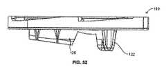
以下、添付図面に示される本発明の好適な実施形態を詳細に説明する。概して、同一又は同様の特徴を示すために図面全体に亘って同一又は同様の符号を用いるが、参照番号は異なる三桁内の数字を用いる。例えば、図9は単顆脛骨インプラント10を示すが、図30では他の実施形態の単顆脛骨インプラント110を示す。なお、図面は簡略化した形状のものであり、正確な寸法で描かれていない。 Preferred embodiments of the present invention shown in the accompanying drawings will be described in detail below. Generally, the same or similar symbols are used throughout the drawings to denote the same or similar features, but the reference numbers are numbers within three different digits. For example, FIG. 9 shows a
上記したように、部分的な膝インプラント(別名、単顆又は一区画膝インプラント)は、膝関節の内側又は外側の区画を置換するように設計されている。単顆置換組立体は、(後述する)脛骨インプラントを単独で、又は大腿顆を置換するように設計されたインプラントと共に備えてもよい。このようなインプラントを収納するため、器具(例えば骨やすり、座金、鋸、パンチ、コンピュータ及び/又はロボット支援器具/ナビゲーションシステム)を用いて容易に骨を処置できる。骨が処置されれば、様々な手段でインプラントを骨に固定できる。この手段としては、インプラントに接着させて、骨に染み込ませることによってインプラントを骨界面に固定する骨セメントが挙げられる。 As noted above, partial knee implants (also known as unicondylar or single compartment knee implants) are designed to replace the medial or lateral compartment of the knee joint. A single condyle replacement assembly may comprise a tibial implant (described below) alone or with an implant designed to replace the femoral condyle. To house such an implant, the bone can be easily treated using an instrument (eg, a bone file, washer, saw, punch, computer and / or robot-assisted instrument / navigation system). Once the bone has been treated, the implant can be secured to the bone by various means. This means includes bone cement that fixes the implant to the bone interface by adhering to the implant and allowing it to penetrate the bone.
本発明は、容易に骨へ直接固定できるように(即ち、骨セメントを用いずに)設計されている。このような骨セメントを用いずに行う固定化は、セメントレス固定化又はプレスフィット固定化と知られている。本発明は、インプラント構成要素のセメントレス固定化の課題に対処するものであり、移植後の初期安定性が許容可能で、術後直ちに又は短期間で患者による運動を可能にし、長期に亘るインプラントの骨への適度な生物学的固定化を促進する。初期安定性と長期固定化は、インプラントのたるみ発生率を低下させ、経時的な患者の術後痛を和らげるためのインプラントの要件である。 The present invention is designed to be easily fixed directly to the bone (ie, without using bone cement). Such immobilization without using bone cement is known as cementless immobilization or press fit immobilization. The present invention addresses the problem of cementless fixation of implant components, allows for initial stability after implantation, allows patient movement immediately or shortly after surgery, and provides long-term implants. Promotes moderate biological immobilization of bone. Initial stability and long-term immobilization are implant requirements to reduce the incidence of implant sag and relieve patient post-operative pain over time.
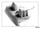
図1〜32の本発明は、単顆脛骨インプラント(脛骨トレイ又は台プレート)10と、単顆脛骨インプラント軸受12とを有する単顆脛骨インプラント組立体5のいくつかの異なる実施形態を含む。勿論、上記したように、本発明を単顆脛骨インプラントに関連させて述べたが、他の種類のインプラントにも適用可能である。例えば、本発明は、単顆大腿インプラント又は全区画インプラントにも適用できる。単顆脛骨インプラント10は、主にセメントレス用に開発され、独特の骨に面する脛骨キール14と、多孔質構造生体材料界面、即ち、多孔質部分16(図21〜29に最も良く示す)とを備える。脛骨インプラント10は、中実金属、多孔質金属、ポリマー及び/又は他の再吸収可能な材料よりなる任意の組合せにから構築できる。例えば、PEEKといったポリマー材からなる軸受12及びチタン又はステンレス鋼といった金属からなるインプラント10を形成するように想定されている。同様に、様々な材料からインプラント10を形成するようにも想定されている。例えば、多孔質部分16を、インプラントの残部と異なる材料から形成してもよい。 The present invention of FIGS. 1-32 includes several different embodiments of a unicompartmental
前述の単顆脛骨インプラント組立体5の好適な実施形態の説明として、単に便宜上、内側脛骨顆用の単顆脛骨インプラント組立体5を説明し図示するが、これに限らない。単顆脛骨インプラント組立体5の前述の説明と特徴は、外側顆用の単顆脛骨インプラント組立体に等しく適用できる。このような外側単顆脛骨インプラント組立体の類似の特徴は、内側単顆脛骨インプラント組立体の特徴と実質的に鏡像関係にある。勿論、組立体の内側及び外側の変形例が、脛骨の内側及び外側部分の様々な骨解剖構造に適応するように異なる構築とされ得ることも想定される。 As a description of the preferred embodiment of the unicondylar
脛骨キール14は、好ましくは、中実及び多孔質部分の組合せから構築され、脛骨インプラント10の下面又は底部に設置される。そして、切除された脛骨(図示せず)に接触するように設計されている。脛骨インプラント10が骨に移植されるとき、脛骨キール14は概して骨に埋め込まれる。脛骨キール14は、切除された脛骨に挿入されるときに自身の空洞が骨に侵入するように調製されてもよい。或いは、器具又は他のインプラントによって事前に処置された骨内の空洞を占めるようにもできる。事前に処置する場合、脛骨キール14を収容する事前に設けられた空洞はいかなるものでも、脛骨キール14よりも概して小さい。これは、骨界面と脛骨キール14との間に圧縮力を発生させ、骨と脛骨キール14との間の摩擦力を増加させるためである。即ち、脛骨キール14は、骨に圧入(press−fit)される。 The
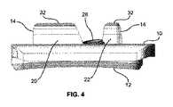
脛骨キール14を図2、4〜10及び14〜20に示す。脛骨キール14は、第1突起部又は突出部20(概して平坦であり、脛骨キール14が突出する処置済の骨内の深さに対応した高さを有する)と、第2突起部又は突出部22(これも概して平坦であり、脛骨キール14が突出する処置済の骨内の深さに対応した高さを有し、第1突起部20に対して実質的に垂直である(即ち、突起部20、22の長手方向軸線は、直交するように配列される))とを備える。明瞭化目的で、突起部20、22に、図2では参照番号14を付し、インプラント10に関連する残りの図では参照番号20又は22を付している。 The
脛骨インプラント10の骨への固定化を最大化しながらも、脛骨キール14の第1及び第2突起部20、22の高さは、アクセス制限に適応するために変動させてもよい。好ましくは、脛骨キール14は、脛骨トレイ10の下側又は下位表面24に位置決めされ、第1突起部20は前後方向に沿って延び、第2突起部22は内外方向に沿って延びる。これにより、突起部20、22の長手方向軸線が交差する。脛骨キールの第1及び第2突起部20、22は両方とも脛骨トレイ10の下側に対して実質的に垂直であるが、他の実施形態では異なってもよい。更に、高さは一定のように示されているが(例えば、図4参照)、突起部20、22をその長さに沿って変化する高さを有するようにも構成できる。事実、後の実施形態(図32)において、突起部20と類似の突起部は、傾斜した構成で示されている。 While maximizing the fixation of the
脛骨インプラント10の第1及び第2突起部20、22の各々を、一つ以上の延出部(即ち、第2突起部22から延出する、図2及び5に示す複数の延出部26)を有するように構成できる。突起部から放射している延出部26は、突起部のある平面から外れるように指向している。即ち、延出部26は突起部の外側面から外向きに延出する。延出部26は、脛骨キール14と周囲の骨との間の圧縮摩擦力を発生且つ/又は最大化させるために、骨内に空洞を形成且つ/又は充填するように設計されている。延出部26は、脛骨インプラント10を切除された脛骨へ挿入する結果生じる力が脛骨インプラント10の位置を所定の又は所望の方向にバイアスをかけるように設置されることが好ましい。延出部26は、キールの実質的に全高に沿って延出する実質的に楔型延出部として構成され、遠位方向にテーパー状に形成されることが好ましい。第2突起部22の延出部26は、互いに離れて配置され、実質的に第2突起部22を囲んでいる。好ましくは、第2突起部は5つの延出部26を含むが、5つより多くても少なくてもよい。 Each of the first and
第1及び第2突起部20、22の両方の周辺に延出部26を設置し、より多くの延出部26又は延出部26が高密度で第2突起部22から放射されることが好ましい。第2突起部22は、脛骨インプラント10の前方領域付近に配置されており、このような設置により、脛骨インプラント10を骨内に移植する際に脛骨インプラント10の前方が持ち上がってしまう(lift−off)安定性の問題に対してより大きな貢献を、より強い摩擦力によりもたらすことが可能となる。延出部26の数は、脛骨インプラント10の中心領域から離れた突起部22の側で多く、これにより、骨の反応力が脛骨インプラント10を脛骨の中心領域に押す/導くようになる。 The extending
脛骨キール14はまた、脛骨キール14(特に突起部20)の呼び容積を越えて延出する複数のフィン34を備える。フィン34は、フィン34を収容するように処置されていない骨に侵入する。或いは、フィン34は、骨へ挿入される際に骨内で自身が収容される容積を調整する。即ち、フィン34は、骨に配置される際に骨に取って代わる。換言すれば、フィン34を骨へ挿入するために、このようなフィン34を収容するために骨を処置する必要ない。フィン34は、その表面積を最大化し且つその容積を最小化する大きさであり、骨へ埋め込みし易い形状である。例えば、フィン34は、好ましくは、図2及び7に示されるように構成され、実質的に楔形状、又は二つの斜面平坦構造を有する形状である。更に、フィン34は、脛骨キール14の近位端から遠位方向に延出するにつれてテーパー状になるように形成される。フィン34はまた、好ましくは、脛骨キール14の全高の約半分まで全長が延出するように構成される。 The
突起部20、22は、特定の構造に示されている。例えば、突起部20は、長く細い矩形構造であり、中実縁部32で平らになる(より完全には後述する)。同様に、突起部22は、中実縁部32を備えるが、突起部20より若干短く細い。突起部20、22の他の形状として、限定されないが、曲状体等を含み得ることが想定されている。また、これらの突起部は複数の構成要素を備えることが想定されている。例えば、突起部20は、互いに隣接して又はある距離だけ離れて配置される、より正方形に近い形状の複数の構成要素を備えることもできる。中実縁部32も、描かれている実質的に平坦な表面よりも鋭角で細い表面に置換できる。更にまた、特定の設計が示されているが、延出部26及びフィン34として多くの様々な種類の設計を含み得ることを理解されたい。一例として、両方の突起部も、延出部26、フィン34、又はこれらの組合せを備えることができる。加えて、延出部26及びフィン34を、異なる形状・大きさのものでもよい。例として、突起部20、22の一方又は両方に、描かれた延出部26及びフィン34の代わりに複数の歯又はスパイクを備えさせることも想定されている。 The
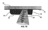
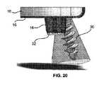
脛骨インプラント10は、必要に応じて、貫通孔又は開口28(図2、5及び21に最も良く示す)を備えるように構成でき。貫通孔又は開口28を通して、他の装置、器具又は材料、例えば(図19及び20に示すような)骨接合用ネジ30を挿入できる。貫通孔28は、キール14を突起部20、22に分割するように示されており、突起部20、22のうち少なくとも一つを通過させることによってこれらの全般的な形状を分断してもよい。例えば、図5から分かるように、貫通孔28周辺の又はそれに隣接する突起部20、22から材料を除去することによって、装置(骨接合用ネジ30等)、器具又は材料を挿入する隙間が設けられる。 The
好ましくは、貫通孔28は、骨接合用ネジ30(図19及び20に最も良く示す)が脛骨インプラント10の上位側面を通って脛骨トレイ10の下側又は下位表面の下の骨へ通過される形状・大きさである。骨接合用ネジ30は、好ましくは、貫通孔28がユーザにとって望ましい方向に角張るように設計される。更に、隣接する突起部20から材料が除去されていることから、貫通孔28を通る骨接合用ネジ30の通過を突起部20が妨害することはない。このような骨接合用ネジ30は当該技術分野において既に知られており、その構造や作用の詳細な説明は本発明の完全な理解のために必要ではない。 Preferably, the through-
脛骨インプラント10では、貫通孔28内に、脛骨インプラント10の大半と冶金学的に連続する材料から形成されるノックアウトプラグ36を使用してもよい。ノックアウトプラグ36は、適切な力を加えることによりにプラグ36周辺の境界剪断部又は脆い領域38を介して脛骨インプラント10の残部から取り外されるように構成される(図5参照)。プラグ36は、付加製造プロセス、例えば、直接金属レーザ焼結法によって、脛骨トレイ10内に加工したり、最終形状に設けたりできる(より完全には後述する)。貫通孔28をノックアウトプラグ36により塞ぐことが好ましく、これにより、軸受構成要素12に対向する脛骨トレイ10の上位表面40とは完全につながっているが、細片又は材料が脛骨トレイ10を通過して、脛骨インプラント10の下側と係合する骨に至る経路は存在しない。従って、軸受構成要素12の背側が摩耗しても、既に設けられた貫通孔があるべき場所にある場合よりも、摩耗した粒子が脛骨トレイ10から出づらい。ノックアウトプラグ36は、必要に応じて、ノックアウトプラグ36の取り外しを容易にする器具と結合するネジ状スタッド42(図12に最も良く示す)を備えてもよい。 The
まとめると、脛骨トレイ10では、移植の際に処置済の骨に対して脛骨インプラント10を更に安定化させるネジ30が配置される貫通孔28が初期の状態で覆われている。これは、インプラントの初期安定性にとって、並びに、適度な短期安定性を確保するために骨自体が十分安定しているかユーザ/外科医が確信のないほど密度が疑わしい骨に脛骨インプラントを移植する場合に、特に有利である。 In summary, in the
脛骨キール14の全般形状は、骨を処置する際に骨が除去される量を最小化させながら、脛骨キール14の表面積−容積比を最大化し、キール内への骨内部成長を向上させる(以下により詳細に説明する)ように設計されている。骨内部成長に利用できる表面積の広さは、骨へのインプラントの短期及び長期固定化にとって重要である。短期固定化は、より大きなキール本体をより小さな処置済の骨に「プレスフィット」することによっても達成される。配置されたら、脛骨キール14周辺の圧縮した骨からの残留応力によって、脛骨キール14に対する摩擦力が増加し、脛骨インプラント10の処置済の骨への安定性が増加する。圧入締め(press−fit interference)が効果的となる表面積を増加させることは、脛骨インプラント10の有効領域により広く摩擦力を分布させ、インプラントの安定性に貢献できる全摩擦力を増加させることに役立つ。 The general shape of the
多孔質構造及び表面(以下「多孔質金属」と称する(概して、参照番号16で示される))を有する脛骨インプラント10の領域が脛骨インプラント10の長期固定化を向上する要因である。骨が再構築して多孔質金属16内に成長すると、骨内部成長が摩擦保持力を置換且つ/又は強化する。骨内部成長による固定化の度合は、一つには、骨内部成長に利用できる多孔質金属の表面積の広さと分布に依存する。脛骨キールに分布する表面積が広いと、骨内部成長がより広い領域で起こり、安定性を増加する構造となる。 The area of the
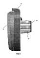
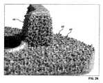
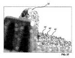
多孔質金属16は多孔質構造生体材料から形成され、様々な長さと断面を有する複数のストラット44(図21〜29に最も良く示す)を備える。多孔質金属16の少なくとも一つのストラットが、ノード点46(図29参照)において一つ以上の他のストラットに接続している端部を有し、これにより多孔質金属16の多孔質幾何学的配列が形成される。多孔質金属16は、多孔質金属16の名目境界線を越えて延出するように構成される境界ストラット48(図26、27及び28参照)も備える。即ち、多孔質金属16は、指状又は毛包状に多孔質金属16の表面から離れて延出する境界ストラット48を有する。この延出境界ストラット48により表面が粗くなる。粗さの度合は、存在する境界ストラット48の数と長さに依存する。境界ストラット48の標準的又は主要方向も表面を粗くする。この粗さは装置が移植のためにどの方向に動かされるかに依存して変わる。 The
脛骨キール14を、金属基板とこの基板に隣接する多孔質金属16の層から形成することが好ましい。脛骨キール14上の多孔質金属16は、脛骨トレイ10の底部又は下位表面に向かって指向又は延出する未接続の端部を有する延出境界ストラット48を備える。類似の負荷条件下で、脛骨トレイ10の底面に向かって傾斜したストラットに亘りスライドさせる場合の方が、脛骨トレイ10の底面から離れて骨をスライドさせる場合よりも、摩擦力は小さくて済む。好ましくは、境界ストラット48は、多孔質金属16を塗布する基板表面の垂線に対して約+/−10度傾斜している。 The
本発明の他の要素として、境界ストラット48が骨界面を押す又は向くように、境界ストラット48を所定の方向に指向させる。多孔質金属16の表面が表面を粗くする特徴を発揮し得ると共に、骨界面に移植された多孔質金属16の境界ストラット48自身は骨に埋まって、周囲の骨と機械的に噛合う。これは、初期の固定化を目的として移植初期において特に有利である。集合体として、複数の境界ストラット48は、移植初期において脛骨インプラント10全体の安定性を有意に改善する。好ましくは、脛骨トレイ10は底面に、脛骨トレイ10の底面に対して実質的に垂直方向に延出する境界ストラット48’を有する(図26及び27に最も良く示す)。脛骨インプラント10が骨界面に対して明らかに着座することから、境界ストラット48’は処置済の骨表面に突き刺さり、脛骨インプラント10の骨への安定性を増加させる。 As another element of the present invention, the
開示した実施形態において、脛骨インプラント10は、骨と接触する全ての表面に多孔質金属16を有する。多孔質金属16の表面は、特定の表面粗さを有するように、脛骨インプラント10の特定の領域ごとに調整され、これにより、骨と係合するときに特定の摩擦量が発生する。即ち、脛骨インプラント10は、脛骨インプラント10上の多孔質金属16の位置に依存して所定の角度の境界ストラット48と共に多孔質金属16を有するように構成される。 In the disclosed embodiment, the
まとめると、多孔質金属16の表面には、脛骨インプラント10の表面粗さを修正する役割を果たす延出境界ストラット48を有する。延出境界ストラット48の大きさと標準的な方向により、その境界ストラット48の延出方向に依存して、様々な摩擦係数が得られる。境界ストラット48を、それらが延出する表面にほぼ垂直な方向に向かせることもできる。これにより、脛骨インプラント10の骨への安定性を向上する付加的アンカー効果が発揮できる。 In summary, the surface of the
脛骨キール14の突起部20、22の一方又は両方の遠位端の中実縁部32は(図2、7及び21に最も良く示す)、骨が下から上へと脛骨キール14内に成長するのを防止する。従って、脛骨インプラント10の大部分の表面積は(骨内部成長により)固定するために設計されているが、このような固定化は突起部の遠位端では起こらない。むしろ、脛骨インプラント10の骨への固定化は、脛骨キール14の外周(即ち、脛骨キール14の外側側面)だけで行われる。即ち、脛骨インプラント10は、中実縁部32により脛骨キール14の遠位面近くではどのような骨内部成長又は固定化を防止するように構成されている。脛骨キール14の遠心面近くでの骨内部成長を防止することによって、必要とされる際、(例えば、整形処置の際)骨からインプラントを容易に取り外しできる。これは、このような脛骨キール14の遠位面上での骨内部成長が、整形処置の際にインプラントを骨から分離するのに最も困難な領域をもたらすからである。換言すれば、インプラントを骨から引き抜くときに、脛骨キールの底部へ内部成長した骨は、(インプラントの下の深部にある骨部分というより)まさにインプラントとの界面にある骨の大部分から分離しないかもしれない。もしインプラントを取り外す際に分離されないと、偶発的に取り出されてしまう余計な骨によって整形処置が複雑となり、より大掛かりな整形部品を使用する結果となってしまう。いずれにしても、脛骨キール14の底部と係合し接触する骨は、脛骨インプラント10の全表面積に対してわずかな割合でしかない。 A solid edge 32 (best shown in FIGS. 2, 7 and 21) of the distal end of one or both of the
インプラント10の多孔質金属16は、任意の適切なプロセスを利用して形成できる。例えば、選択的レーザ溶融法又は焼結法を採用することによって、多孔質金属16やインプラント10全体も作成できる。後者に関連して、インプラント10は、実質的に無孔又は中実部分と、同じプロセスにより形成される多孔質金属16部分とを含み得ることが想定されている。このようなプロセスの例が、各々米国特許第7,537,664号明細書及び米国特許公開第2006/0147332号及び第2007/0142914号明細書に開示されており、これらの開示は参照により本明細書に組み込まれる。勿論、インプラント10を形成するために適切で既知の全ての方法を利用することも想定されている。 The
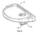
図30〜33を参照して、他の好適な実施形態によれば、本発明は、脛骨インプラント110を提供する。脛骨インプラント110は、以下に述べるものを除いて、脛骨インプラント10と同様に構成される。例えば、脛骨インプラント10は、突起部20、22と同様に構成される第1及び第2突起部120、122を備えるが、突起部120は傾斜しており(図32参照)、穴128(図33参照)により作られる空隙によって2つの異なる部分に分割されている。また、第2突起部122は、第2突起部22ほど広い表面積を有さない。図32に最も良く示すように、第1突起部120の高さに関して、脛骨インプラント110の後方端部に向かって傾いており、これにより第1突起部は前方端部から後方端部へ延出するにつれて高さが減少している。勿論、突起部120はいずれの方向に傾斜させてよい。 With reference to FIGS. 30-33, according to another preferred embodiment, the present invention provides a
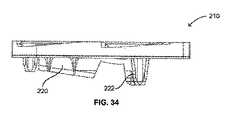
図34及び35を参照して、更に他の好適な実施形態によれば、本発明は、脛骨インプラント210を提供する。脛骨インプラント210は、以下に述べるものを除いて、脛骨インプラント110と同様に構成される。特に、インプラント210は第3突出部223を備えている。第3突出部223は、第2突出部222のように、第1突出部220から若干離れて配置されており、延出部を備えてもよい。好ましくは、第3突出部223は、第1突出部の背部又は後方近くに位置決めされ、第3突出部223が隣接する第1突出部220の後方端部の高さに同等の高さを有する。しかし、第3突出部223の高さは、第2突出部222のものよりも低い。第3突出部223の長手方向軸線は、第1突出部220の長手方向軸線と交差しないようにも構成される。 With reference to FIGS. 34 and 35, according to yet another preferred embodiment, the present invention provides a
図36〜38は更に他の実施形態であるインプラント310を示す。インプラント310は、第1突出部320の中間部分近くに又はその周りに第3突出部323が配置されていることを除いて、インプラント210と類似する。第1突出部320の中間部分の周りに位置決めされる第3突出部323は、隣接する第1突出部320の領域と実質的に同じ高さを有する。 36-38 show an
図39及び40は、更に他の実施形態である脛骨インプラント410を示す。上述したインプラントと異なり、インプラント410は、一単位として設計されたキール414を備える。穴又は開口428がキール414から逸れて位置することにより、キール414が単一構造を有することができる(即ち、上記設計のように穴428によって分割されない)。前述の実施形態のように、キール414は2つの突起部420、422を備え、突起部420はフィン434を備え、突起部422は延出部426を備える。勿論、上記実施形態のように、いずれの突起部も延出部426又はフィン434の一方又は両方を備えることができる。これらの構造体は、突起部に関しいかなる形状及び/又は大きさでもよい。また、キール414は、丸みを帯びた切欠部421を備え、これにより、ネジ430をインプラント410に対して角張らせることができる。換言すれば、切欠部421により、ネジ430がプレート上でキール414方向に移動できる隙間が設けられている。 39 and 40 show a further embodiment, a
当業者であれば、本発明の広い概念から逸脱することなく上記実施形態を変更し得ることが理解されよう。例えば、別の構成要素は、脛骨インプラント組立体に加えることができる。従って、本発明は開示した特定の実施形態に限定されず、上述したような本発明の趣旨及び範囲内にある変形例も含むことが意図されていると理解されたい。 Those skilled in the art will appreciate that the above embodiments can be modified without departing from the broad concept of the invention. For example, another component can be added to the tibial implant assembly. Accordingly, it is to be understood that the invention is not intended to be limited to the particular embodiments disclosed, but is intended to include modifications within the spirit and scope of the invention as described above.
本明細書に記載される開示には、説明した特定の特徴の全ての可能な組合せが含まれることも理解されたい。例えば、特定の特徴が、特定の態様、配置、構成、又は実施形態、或いは特定の請求の文脈で開示される場合、その特徴は、概して、本発明の他の特定の態様、配置、構成、及び実施形態と組み合わせて、且つ/又はそれらの文脈、並びに本発明においても、可能な限り利用できる。 It is also to be understood that the disclosure described herein includes all possible combinations of the particular features described. For example, if a particular feature is disclosed in a particular aspect, arrangement, configuration, or embodiment, or in a particular claim context, that feature generally refers to the other particular aspect, arrangement, configuration, And / or in combination with the embodiments and / or their context, as well as in the present invention.
更に、本明細書中の発明を特定の実施形態を参照して説明したが、これらの実施形態は単に本発明の原則及び用途の例示に過ぎないことを理解されたい。従って、これらの例示実施形態を多様に変形できること、添付の特許請求の範囲により規定される本発明の趣旨と範囲から逸脱することなく他の配置も考案し得ることを理解されたい。 Furthermore, although the invention herein has been described with reference to particular embodiments, it is to be understood that these embodiments are merely illustrative of the principles and applications of the present invention. Accordingly, it should be understood that these exemplary embodiments can be varied in many ways and that other arrangements can be devised without departing from the spirit and scope of the invention as defined by the appended claims.
Claims (30)
Translated fromJapanese骨接触表面と、
前記骨接触表面から延出するキールであって、第1長手方向軸線を有する第1突起部と、第2長手方向軸線を有する第2突起部とを備えているキールと、
を備え、
前記第1及び第2長手方向軸線は、互いに直交していることを特徴とする整形外科インプラント。In orthopedic implants for replacing parts of bone,
A bone contacting surface;
A keel extending from the bone contacting surface, the keel comprising a first protrusion having a first longitudinal axis and a second protrusion having a second longitudinal axis;
With
The orthopedic implant, wherein the first and second longitudinal axes are orthogonal to each other.
少なくとも一つの他のインプラントと
を備えていることを特徴とするキット。An implant according to claim 1;
A kit comprising at least one other implant.
前記骨接触表面から延出する第1突起部であって、前記前方側端部と前記後方側端部との間で第1方向に延出する第1長さを有する第1突起部と、
前記骨接触表面から延出する第2突起部であって、前記内側と前記外側との間で第2方向に延出する第2長さを有する第2突起部と、
骨接合用ネジを収容するための開口と、
骨内部成長を促進するための多孔質材料であって、前記骨接触表面、前記第1突起部、及び前記第2突起部を少なくとも部分的に覆う多孔質材料と
を備えていることを特徴とする脛骨台プレート。A bone contacting surface having an anterior side, a posterior side, an inner side and an outer side;
A first protrusion extending from the bone contact surface, the first protrusion having a first length extending in a first direction between the front end and the rear end;
A second protrusion extending from the bone contact surface, the second protrusion having a second length extending in a second direction between the inner side and the outer side;
An opening for receiving an osteosynthesis screw;
A porous material for promoting bone ingrowth, comprising: a porous material that at least partially covers the bone contact surface, the first protrusion, and the second protrusion. Tibial table plate to do.
前記延出部が骨と摩擦して係合していることを特徴とする請求項27に記載の脛骨台プレート。The fin is configured to penetrate an untreated portion of the bone;
28. The tibial plate according to claim 27, wherein the extending portion is frictionally engaged with the bone.
前記骨接触表面から延出する第1突起部であって、前記前方側端部と前記後方側端部との間で第1方向に延出する第1長さを有する第1突起部と、
前記骨接触表面から延出する第2突起部であって、前記内側と前記外側との間で第2方向に延出する第2長さを有する第2突起部と、
骨接合用ネジを収容するための開口と、
前記開口を少なくとも部分的に覆うプラグであって、力を加えることにより取り外し可能なプラグと、
骨内部成長を促進するための多孔質材料であって、前記骨接触表面、前記第1突起部、及び前記第2突起部を少なくとも部分的に覆う多孔質材料と
を備え、
前記多孔質材料が、前記骨接触表面の垂線に対して0度〜10度傾いて前記骨接触表面から延出する複数の境界ストラットを画定していることを特徴とする脛骨台プレート。A bone contacting surface having an anterior side, a posterior side, an inner side and an outer side;
A first protrusion extending from the bone contact surface, the first protrusion having a first length extending in a first direction between the front end and the rear end;
A second protrusion extending from the bone contact surface, the second protrusion having a second length extending in a second direction between the inner side and the outer side;
An opening for receiving an osteosynthesis screw;
A plug that at least partially covers the opening, wherein the plug is removable by applying force;
A porous material for promoting bone ingrowth, comprising: a porous material that at least partially covers the bone contact surface, the first protrusion, and the second protrusion;
The tibial plate, wherein the porous material defines a plurality of boundary struts extending from the bone contact surface at an angle of 0 to 10 degrees with respect to the normal of the bone contact surface.
Applications Claiming Priority (3)
| Application Number | Priority Date | Filing Date | Title |
|---|---|---|---|
| US201361794339P | 2013-03-15 | 2013-03-15 | |
| US61/794,339 | 2013-03-15 | ||
| PCT/US2014/027827WO2014143740A1 (en) | 2013-03-15 | 2014-03-14 | Unicondylar tibial knee implant |
Publications (1)
| Publication Number | Publication Date |
|---|---|
| JP2016513551Atrue JP2016513551A (en) | 2016-05-16 |
Family
ID=50792536
Family Applications (1)
| Application Number | Title | Priority Date | Filing Date |
|---|---|---|---|
| JP2016502635APendingJP2016513551A (en) | 2013-03-15 | 2014-03-14 | Unicondylar tibial knee implant |
Country Status (7)
| Country | Link |
|---|---|
| US (3) | US9445909B2 (en) |
| EP (1) | EP2967885B1 (en) |
| JP (1) | JP2016513551A (en) |
| CN (1) | CN105392450B (en) |
| AU (1) | AU2014228237B2 (en) |
| CA (1) | CA2906631C (en) |
| WO (1) | WO2014143740A1 (en) |
Cited By (1)
| Publication number | Priority date | Publication date | Assignee | Title |
|---|---|---|---|---|
| JP2019044959A (en)* | 2017-08-29 | 2019-03-22 | レンク・アクティエンゲゼルシャフト | Slide bearing and manufacturing method thereof |
Families Citing this family (45)
| Publication number | Priority date | Publication date | Assignee | Title |
|---|---|---|---|---|
| US20060147332A1 (en) | 2004-12-30 | 2006-07-06 | Howmedica Osteonics Corp. | Laser-produced porous structure |
| AU2003261497B2 (en) | 2002-11-08 | 2009-02-26 | Howmedica Osteonics Corp. | Laser-produced porous surface |
| US8728387B2 (en) | 2005-12-06 | 2014-05-20 | Howmedica Osteonics Corp. | Laser-produced porous surface |
| US9408705B2 (en)* | 2011-09-29 | 2016-08-09 | Christiaan Rudolf Oosthuizen | Tibial component |
| US9180010B2 (en) | 2012-04-06 | 2015-11-10 | Howmedica Osteonics Corp. | Surface modified unit cell lattice structures for optimized secure freeform fabrication |
| CN105392450B (en) | 2013-03-15 | 2017-09-29 | 马科外科公司 | Tibial knee list condyle implant |
| WO2015024122A1 (en)* | 2013-08-21 | 2015-02-26 | Laboratoires Bodycad Inc. | Anatomically adapted orthopedic implant and method of manufacturing same |
| US10098746B1 (en) | 2015-02-13 | 2018-10-16 | Nextstep Arthropedix, LLC | Medical implants having desired surface features and methods of manufacturing |
| CN104887355B (en)* | 2015-05-08 | 2017-05-03 | 江苏奥康尼医疗科技发展有限公司 | Artificial knee joint tibial tray |
| US10117713B2 (en) | 2015-07-01 | 2018-11-06 | Mako Surgical Corp. | Robotic systems and methods for controlling a tool removing material from a workpiece |
| US10070928B2 (en) | 2015-07-01 | 2018-09-11 | Mako Surgical Corp. | Implant placement planning |
| WO2017011576A2 (en)* | 2015-07-13 | 2017-01-19 | Mako Surgical Corp. | Lower extremities leg length calculation method |
| US10856992B2 (en)* | 2016-04-27 | 2020-12-08 | AOD Holdings, LLC | Implant device(s) including tapered protrusions and method(s) for inserting the same into bone |
| US10136998B2 (en)* | 2016-08-30 | 2018-11-27 | Wright Medical Technology, Inc. | Revision total ankle implants |
| HK1224885A (en)* | 2016-09-08 | 2017-08-25 | 科能三维技术(医疗)有限公司 | Device and method for producing artificial solid bone |
| CA2988052A1 (en)* | 2016-12-06 | 2018-06-06 | Smed-Ta/Td, Llc | Orthopaedic implant with fixation feature and a method of implanting thereof |
| US11039938B2 (en) | 2017-07-26 | 2021-06-22 | Optimotion Implants LLC | Modular knee prothesis |
| US12083027B2 (en) | 2017-03-02 | 2024-09-10 | Optimotion Implants LLC | Universal femoral trial system and methods |
| US10905436B2 (en) | 2017-03-02 | 2021-02-02 | Optimotion Implants, Llc | Knee arthroplasty systems and methods |
| US11406502B2 (en) | 2017-03-02 | 2022-08-09 | Optimotion Implants LLC | Orthopedic implants and methods |
| US20210290410A1 (en)* | 2017-03-03 | 2021-09-23 | Engage Uni Llc | Unicompartmental knee arthroplasty |
| US11298747B2 (en) | 2017-05-18 | 2022-04-12 | Howmedica Osteonics Corp. | High fatigue strength porous structure |
| EP3412252B1 (en) | 2017-06-09 | 2020-02-12 | Howmedica Osteonics Corp. | Polymer interlock support structure |
| USD850616S1 (en) | 2017-10-31 | 2019-06-04 | Sicage Llc | Parallel surgical guide spacer |
| USD847336S1 (en) | 2017-10-31 | 2019-04-30 | Sicage Llc | Parallel surgical guide spacer |
| US10603054B2 (en) | 2017-10-31 | 2020-03-31 | Sicage Llc | Parallel guide for surgical implants |
| ZAF201801915S (en)* | 2018-12-13 | 2019-11-27 | Oosthuizen Christian Rudolf | Fixed bearing insert |
| ZAF201801914S (en)* | 2018-12-13 | 2019-11-27 | Oosthuizen Christian Rudolf | Tibial component |
| JP7519369B2 (en)* | 2019-02-28 | 2024-07-19 | リマコルポラーテ エッセ.ピ.ア. | Tibial base plate for a tibial component of an artificial knee joint, a tibial component including a tibial base plate, and a method for manufacturing the tibial base plate |
| CN109771104A (en)* | 2019-03-11 | 2019-05-21 | 北京力达康科技有限公司 | A kind of MTS medial tibial plateau sticking patch, assembly type MTS medial tibial plateau sticking patch and its minimally invasive method of replacing |
| WO2020223564A1 (en) | 2019-05-02 | 2020-11-05 | World Class Technology Corporation | Orthodontic bracket with a biased ligating member |
| US11160568B1 (en) | 2019-09-10 | 2021-11-02 | Lento Medical, Inc | Optimal selection of contact curves |
| GB201918534D0 (en)* | 2019-12-16 | 2020-01-29 | Depuy Ireland Ultd Co | Tibial preparation |
| US11357634B1 (en) | 2020-01-15 | 2022-06-14 | Lento Medical, Inc. | Posterior-stabilized symmetric knee prosthesis |
| US11382757B1 (en) | 2020-01-15 | 2022-07-12 | Lento Medical, Inc. | Condylar asymmetry knee prosthesis |
| CN113633436A (en)* | 2020-04-27 | 2021-11-12 | 萨摩(重庆)医疗器材有限公司 | A 3D printed metal trabecular tibial revision pad |
| US11478260B2 (en) | 2020-07-17 | 2022-10-25 | Asfora Ip, Llc | Parallel guide for access needle |
| US11844697B2 (en) | 2020-09-03 | 2023-12-19 | Globus Medical, Inc. | Systems and methods for knee arthroplasty |
| US11730603B2 (en) | 2020-09-03 | 2023-08-22 | Globus Medical, Inc. | Systems and methods for knee arthroplasty |
| AU2021269401A1 (en)* | 2020-11-25 | 2022-06-09 | Howmedica Osteonics Corp. | Fixation device for unicondylar prothesis |
| AU2021277758A1 (en)* | 2020-12-30 | 2022-07-14 | Howmedica Osteonics Corp. | Cementless screw-in-peg fixation |
| JP2024506178A (en)* | 2021-02-05 | 2024-02-09 | オーバーチュア・リサーフェシング・インコーポレイテッド | Articular surface replacement implant system and method for osteochondral defects |
| CN113367854B (en)* | 2021-05-24 | 2023-08-01 | 北京纳通医疗科技控股有限公司 | Tibial tray prosthesis and knee joint prosthesis |
| US20230210670A1 (en)* | 2021-12-31 | 2023-07-06 | Depuy Ireland Unlimited Company | Knee prosthesis having non-uniform stiffness |
| WO2025171292A1 (en)* | 2024-02-09 | 2025-08-14 | Ignite Orthomotion, Llc | Implants, systems and methods of using the same |
Family Cites Families (255)
| Publication number | Priority date | Publication date | Assignee | Title |
|---|---|---|---|---|
| US3715763A (en) | 1971-04-21 | 1973-02-13 | W Link | Artificial limb for the knee joint |
| US3774244A (en) | 1972-02-08 | 1973-11-27 | Relief Ruptured And Crippled S | Knee-joint prosthesis |
| US3824630A (en) | 1972-06-23 | 1974-07-23 | Zimmer Mfg Co | Prosthetic joint for total knee replacement |
| US3852830A (en) | 1973-02-15 | 1974-12-10 | Richards Mfg Co | Knee prosthesis |
| GB1509194A (en) | 1974-04-22 | 1978-05-04 | Nat Res Dev | Endoprosthetic devices |
| US4085466A (en) | 1974-11-18 | 1978-04-25 | National Research Development Corporation | Prosthetic joint device |
| CA1045752A (en) | 1975-05-26 | 1979-01-09 | Robert W. Jackson | Prosthetic implant |
| US4001896A (en) | 1975-06-09 | 1977-01-11 | Zimmer, U.S.A. Inc. | Prosthetic joint for total knee replacement |
| US4224696A (en) | 1978-09-08 | 1980-09-30 | Hexcel Corporation | Prosthetic knee |
| US4309778A (en) | 1979-07-02 | 1982-01-12 | Biomedical Engineering Corp. | New Jersey meniscal bearing knee replacement |
| DE3433264C2 (en) | 1984-09-11 | 1986-10-02 | S + G Implants GmbH, 2400 Lübeck | Tibial part for a knee joint endoprosthesis |
| FR2593390B1 (en) | 1986-01-27 | 1991-09-06 | Epinette Jean Alain | TIBIAL COMPONENT OF UNICOMPARTMENTAL KNEE PROSTHESIS TO BE IMPLANTED WITHOUT CEMENT |
| US4719908A (en) | 1986-08-15 | 1988-01-19 | Osteonics Corp. | Method and apparatus for implanting a prosthetic device |
| US4978357A (en) | 1987-06-12 | 1990-12-18 | Mecron Medizinische Produkte Gmbh | Endoprosthesis |
| US4795468A (en)* | 1987-12-23 | 1989-01-03 | Zimmer, Inc. | Mechanism and method for locking a bearing insert to the base of a prosthetic implant |
| US5080673A (en)* | 1988-02-03 | 1992-01-14 | Intermedics Orthopedics, Inc. | Glenoid prosthesis and method of use |
| SE468199B (en) | 1988-04-11 | 1992-11-23 | Astra Ab | KNAELEDSPROTES |
| US4944757A (en)* | 1988-11-07 | 1990-07-31 | Martinez David M | Modulator knee prosthesis system |
| US4935023A (en) | 1989-01-09 | 1990-06-19 | Dow Corning Wright | Femoral surface shaping guide for knee implants |
| US5171244A (en) | 1990-01-08 | 1992-12-15 | Caspari Richard B | Methods and apparatus for arthroscopic prosthetic knee replacement |
| US5171276A (en)* | 1990-01-08 | 1992-12-15 | Caspari Richard B | Knee joint prosthesis |
| GB9005496D0 (en) | 1990-03-12 | 1990-05-09 | Howmedica | Tibial component for a replacement knee prosthesis and total knee prosthesis incorporating such a component |
| GB9102348D0 (en) | 1991-02-04 | 1991-03-20 | Inst Of Orthopaedics The | Prosthesis for knee replacement |
| US5314487A (en)* | 1991-02-14 | 1994-05-24 | Smith & Nephew Richards Inc. | Acetabular prosthesis with anchoring pegs |
| US5203807A (en) | 1991-07-10 | 1993-04-20 | Smith & Nephew Richards Inc. | Knee joint prosthesis articular surface |
| US5201881A (en) | 1991-08-13 | 1993-04-13 | Smith & Nephew Richards Inc. | Joint prosthesis with improved shock absorption |
| US5152797A (en)* | 1991-10-25 | 1992-10-06 | Johnson & Johnson Orthopaedics, Inc. | Modular prosthesis |
| US5282866A (en) | 1992-02-12 | 1994-02-01 | Osteonics Corp. | Prosthetic knee tibial component with axially ribbed keel and apparatus for effecting implant |
| US5520695A (en) | 1992-02-14 | 1996-05-28 | Johnson & Johnson Professional, Inc. | Instruments for use in knee replacement surgery |
| US5246459A (en) | 1992-02-24 | 1993-09-21 | Elias Sarmed G | Modular tibial support pegs for the tibial component of a prosthetic knee replacement system |
| US5258032A (en) | 1992-04-03 | 1993-11-02 | Bertin Kim C | Knee prosthesis provisional apparatus and resection guide and method of use in knee replacement surgery |
| US5226915A (en) | 1992-04-03 | 1993-07-13 | Bertin Kim C | Femoral prosthesis component system for knee replacement surgery |
| US6102954A (en) | 1992-05-18 | 2000-08-15 | Astra Aktiebolag | Joint prosthesis and apparatus for preparing the bone prior to fitting of the prosthesis |
| US5271737A (en)* | 1992-09-04 | 1993-12-21 | U.S. Medical Products, Inc. | Tibial prosthetic implant with offset stem |
| US5312411A (en) | 1992-10-27 | 1994-05-17 | Smith & Nephew Richards, Inc. | Uni-compartmental femoral knee instruments and prosthesis |
| AU691162B2 (en) | 1992-12-14 | 1998-05-14 | Biomedical Engineering Trust I | Fixed bearing joint endoprosthesis |
| US5413604A (en) | 1992-12-24 | 1995-05-09 | Osteonics Corp. | Prosthetic knee implant for an anterior cruciate ligament deficient total knee replacement |
| EP0611559A1 (en) | 1993-02-18 | 1994-08-24 | Societe Civile Essor | Unicondylar knee prostheses |
| FR2702368B1 (en) | 1993-03-10 | 1995-06-09 | Medinov Sa | Tibial implant for knee prosthesis. |
| US5534027A (en) | 1993-06-21 | 1996-07-09 | Zimmer, Inc. | Method for providing a barrier to the advancement of wear debris in an orthopaedic implant assembly |
| GB9314832D0 (en) | 1993-07-16 | 1993-09-01 | Walker Peter S | Prostheses for knee replacement |
| US5480444A (en) | 1994-06-02 | 1996-01-02 | Incavo; Stephen J. | Hybrid tibial tray knee prosthesis |
| GB9413607D0 (en) | 1994-07-06 | 1994-08-24 | Goodfellow John W | Endoprosthetic knee joint device |
| GB9415180D0 (en) | 1994-07-28 | 1994-09-21 | Walker Peter S | Stabilised mobile bearing knee |
| CA2160198C (en)* | 1994-10-27 | 2003-12-30 | Michael J. Pappas | Prosthesis fixturing device |
| WO1996013233A1 (en) | 1994-10-28 | 1996-05-09 | Intermedics Orthopedics, Inc. | Knee prosthesis with shims |
| US5514183A (en) | 1994-12-20 | 1996-05-07 | Epstein; Norman | Reduced friction prosthetic knee joint utilizing replaceable roller bearings |
| JP3501542B2 (en) | 1995-04-07 | 2004-03-02 | 富久 腰野 | Medical hard tissue replacements and artificial joints |
| EP0749733B1 (en) | 1995-06-21 | 2002-05-29 | Sulzer Orthopädie AG | Tibialplatform for a knee-joint prosthesis and knee-joint prosthesis with such a tibialplatform |
| US5716361A (en) | 1995-11-02 | 1998-02-10 | Masini; Michael A. | Bone cutting guides for use in the implantation of prosthetic joint components |
| HU219444B (en) | 1996-02-26 | 2001-04-28 | Gábor Krakovits | Sliding surface for knee-joint prothesis |
| US20070100462A1 (en) | 2001-05-25 | 2007-05-03 | Conformis, Inc | Joint Arthroplasty Devices |
| US20030055502A1 (en)* | 2001-05-25 | 2003-03-20 | Philipp Lang | Methods and compositions for articular resurfacing |
| US20070233269A1 (en)* | 2001-05-25 | 2007-10-04 | Conformis, Inc. | Interpositional Joint Implant |
| GB9705172D0 (en) | 1997-03-13 | 1997-04-30 | Zimmer Limited | Evaluating the fit of an orthopaedic implant |
| GB2323034B (en) | 1997-03-13 | 2001-07-25 | Zimmer Ltd | Prosthesis for knee replacement |
| GB9707717D0 (en) | 1997-04-16 | 1997-06-04 | Walker Peter S | Knee prosthesis having guide surfaces for control of anterior-posterior translation |
| US5824103A (en) | 1997-05-12 | 1998-10-20 | Howmedica Inc. | Tibial prosthesis |
| DE59708326D1 (en)* | 1997-06-12 | 2002-10-31 | Sulzer Orthopaedie Ag Baar | Fastening system for metallic support shells |
| US5782925A (en) | 1997-11-06 | 1998-07-21 | Howmedica Inc. | Knee implant rotational alignment apparatus |
| EP0956836B1 (en)* | 1998-05-13 | 2004-07-28 | DePuy Products, Inc. | Tibial tray with adjustable keel |
| US6616696B1 (en) | 1998-09-04 | 2003-09-09 | Alan C. Merchant | Modular knee replacement system |
| US6132468A (en) | 1998-09-10 | 2000-10-17 | Mansmann; Kevin A. | Arthroscopic replacement of cartilage using flexible inflatable envelopes |
| US6179876B1 (en)* | 1998-11-04 | 2001-01-30 | Blake A. Stamper | Orthopedic prosthesis with cement compression ring and method |
| US6152962A (en)* | 1998-12-30 | 2000-11-28 | Depuy Orthopaedics, Inc. | Acetabular cup with plug for screw holes |
| US20020198529A1 (en) | 1999-02-16 | 2002-12-26 | Michael A. Masini | Optimizing patellar femoral mechanics through alternative depth referencing |
| US6059831A (en) | 1999-03-31 | 2000-05-09 | Biomet, Inc. | Method of implanting a uni-condylar knee prosthesis |
| US6966928B2 (en)* | 1999-05-10 | 2005-11-22 | Fell Barry M | Surgically implantable knee prosthesis having keels |
| US20050033424A1 (en)* | 1999-05-10 | 2005-02-10 | Fell Barry M. | Surgically implantable knee prosthesis |
| US7297161B2 (en)* | 1999-05-10 | 2007-11-20 | Fell Barry M | Surgically implantable knee prosthesis |
| US6620198B2 (en) | 1999-10-07 | 2003-09-16 | Exactech, Inc. | Composite bearing inserts for total knee joints |
| US6875235B2 (en) | 1999-10-08 | 2005-04-05 | Bret A. Ferree | Prosthetic joints with contained compressible resilient members |
| US6554866B1 (en) | 1999-10-29 | 2003-04-29 | Sulzer Orthopedics Ltd. | Mono-condylar knee joint prosthesis |
| US6379388B1 (en)* | 1999-12-08 | 2002-04-30 | Ortho Development Corporation | Tibial prosthesis locking system and method of repairing knee joint |
| ES2330829T3 (en) | 1999-12-13 | 2009-12-16 | Zimmer Gmbh | KIT FOR A PROTECTION OF KNEE ARTICULATION. |
| FR2802799B1 (en)* | 1999-12-23 | 2002-08-16 | Depuy France | SHOULDER PROSTHESIS KIT |
| US7635390B1 (en)* | 2000-01-14 | 2009-12-22 | Marctec, Llc | Joint replacement component having a modular articulating surface |
| US6342075B1 (en) | 2000-02-18 | 2002-01-29 | Macarthur A. Creig | Prosthesis and methods for total knee arthroplasty |
| US6491726B2 (en) | 2000-03-08 | 2002-12-10 | Biomedical Engineering Trust I | Posterior stabilized prosthetic knee replacement with bearing translation and dislocation prevention features |
| ES2553715T3 (en) | 2000-03-10 | 2015-12-11 | Smith & Nephew, Inc. | Apparatus for use in arthroplasty in a knee joint |
| US6475241B2 (en) | 2000-03-13 | 2002-11-05 | Biomedical Engineering Trust I | Posterior stabilized knee replacement with bearing translation for knees with retained collateral ligaments |
| US6558426B1 (en) | 2000-11-28 | 2003-05-06 | Medidea, Llc | Multiple-cam, posterior-stabilized knee prosthesis |
| US6494914B2 (en) | 2000-12-05 | 2002-12-17 | Biomet, Inc. | Unicondylar femoral prosthesis and instruments |
| US6589281B2 (en)* | 2001-01-16 | 2003-07-08 | Edward R. Hyde, Jr. | Transosseous core approach and instrumentation for joint replacement and repair |
| US9050192B2 (en) | 2001-02-05 | 2015-06-09 | Formae, Inc. | Cartilage repair implant with soft bearing surface and flexible anchoring device |
| US6569202B2 (en)* | 2001-04-02 | 2003-05-27 | Whiteside Biomechanics, Inc. | Tray and liner for joint replacement system |
| US6554838B2 (en) | 2001-05-31 | 2003-04-29 | Howmedica Osteonics Corp. | Method and apparatus for implanting a prosthetic device |
| US7708741B1 (en) | 2001-08-28 | 2010-05-04 | Marctec, Llc | Method of preparing bones for knee replacement surgery |
| FR2831796B1 (en)* | 2001-11-06 | 2003-12-26 | Ldr Medical | BONE ANCHORING DEVICE FOR PROSTHESIS |
| AU2002365379A1 (en)* | 2001-11-28 | 2003-06-10 | Wright Medical Technology, Inc. | Knee joint prostheses |
| US6890358B2 (en)* | 2002-03-29 | 2005-05-10 | Depuy Products, Inc. | Distal component for wrist prosthesis |
| US6946001B2 (en) | 2003-02-03 | 2005-09-20 | Zimmer Technology, Inc. | Mobile bearing unicompartmental knee |
| DE10220591B4 (en)* | 2002-05-08 | 2004-03-18 | Mathys Medizinaltechnik Ag | Joint prosthesis with an intermediate element with different radii of curvature |
| US7048741B2 (en) | 2002-05-10 | 2006-05-23 | Swanson Todd V | Method and apparatus for minimally invasive knee arthroplasty |
| US7150761B2 (en) | 2002-05-24 | 2006-12-19 | Medicinelodge, Inc. | Modular femoral components for knee arthroplasty |
| US6797006B2 (en) | 2002-06-18 | 2004-09-28 | Zimmer Technology, Inc. | Porous unicondylar knee |
| US20040006393A1 (en) | 2002-07-03 | 2004-01-08 | Brian Burkinshaw | Implantable prosthetic knee for lateral compartment |
| WO2004024037A1 (en) | 2002-09-10 | 2004-03-25 | Ferree Bret A | Shock-absorbing joint and spine replacements |
| US6840960B2 (en) | 2002-09-27 | 2005-01-11 | Stephen K. Bubb | Porous implant system and treatment method |
| AU2003261497B2 (en) | 2002-11-08 | 2009-02-26 | Howmedica Osteonics Corp. | Laser-produced porous surface |
| US20060147332A1 (en) | 2004-12-30 | 2006-07-06 | Howmedica Osteonics Corp. | Laser-produced porous structure |
| US6749638B1 (en) | 2002-11-22 | 2004-06-15 | Zimmer Technology, Inc. | Modular knee prosthesis |
| US7094241B2 (en) | 2002-11-27 | 2006-08-22 | Zimmer Technology, Inc. | Method and apparatus for achieving correct limb alignment in unicondylar knee arthroplasty |
| US7033397B2 (en)* | 2003-02-03 | 2006-04-25 | Zimmer Technology, Inc. | Mobile bearing unicondylar tibial knee prosthesis |
| US20040153087A1 (en) | 2003-02-04 | 2004-08-05 | Sanford Adam H. | Provisional orthopedic implant with removable guide |
| US6916324B2 (en) | 2003-02-04 | 2005-07-12 | Zimmer Technology, Inc. | Provisional orthopedic prosthesis for partially resected bone |
| US6916341B2 (en)* | 2003-02-20 | 2005-07-12 | Lindsey R. Rolston | Device and method for bicompartmental arthroplasty |
| US7442211B2 (en)* | 2003-05-27 | 2008-10-28 | Spinalmotion, Inc. | Intervertebral prosthetic disc |
| US8187336B2 (en) | 2003-06-16 | 2012-05-29 | Jamali Amir A | Device and method for reconstruction of osseous skeletal defects |
| US20070067032A1 (en)* | 2003-06-27 | 2007-03-22 | Felt Jeffrey C | Meniscus preserving implant method and apparatus |
| US7625408B2 (en)* | 2003-07-22 | 2009-12-01 | Avanta Orthopaedics, Llc | Prosthetic wrist implant |
| EP1648348B1 (en)* | 2003-07-24 | 2015-06-17 | Tecomet Inc. | Assembled non-random foams |
| US9844442B2 (en)* | 2003-07-31 | 2017-12-19 | Globus Medical, Inc. | Prosthetic spinal disc replacement and methods thereof |
| US7294149B2 (en) | 2003-12-05 | 2007-11-13 | Howmedica Osteonics Corp. | Orthopedic implant with angled pegs |
| JP4510030B2 (en) | 2004-01-12 | 2010-07-21 | デピュイ・プロダクツ・インコーポレイテッド | System and method for splitting and replacing a knee |
| US20050171604A1 (en) | 2004-01-20 | 2005-08-04 | Alexander Michalow | Unicondylar knee implant |
| AU2005209244A1 (en) | 2004-01-23 | 2005-08-11 | Massachusetts General Hospital | Anterior cruciate ligament substituting knee replacement prosthesis |
| US20050165491A1 (en) | 2004-01-23 | 2005-07-28 | Diaz Robert L. | Method and apparatus for bi-compartmental partial knee replacement |
| US7189263B2 (en)* | 2004-02-03 | 2007-03-13 | Vita Special Purpose Corporation | Biocompatible bone graft material |
| US7753960B2 (en) | 2004-02-26 | 2010-07-13 | Omni Life Science, Inc. | Modular knee prosthesis |
| AR043908A1 (en) | 2004-02-27 | 2005-08-17 | Morhac Martin Jorge Dr | MEDIAL OR SIDE FEMORAL COMPONENT AND MEDIAL-SIDE UNICOMPARTIMENTAL PROTECTION OF KNEE |
| US7608079B1 (en) | 2004-03-05 | 2009-10-27 | Biomet Manufacturing Corp. | Unicondylar knee apparatus and system |
| US20050203632A1 (en) | 2004-03-09 | 2005-09-15 | Daniels Michael E. | Tibial implant with a through post |
| EP1574185B1 (en) | 2004-03-09 | 2012-05-23 | Zimmer Technology, Inc. | Tibial knee component with a mobile bearing |
| US7465320B1 (en) | 2004-05-06 | 2008-12-16 | Biomet Manufacturing Corp. | Knee joint prosthesis |
| ATE503442T1 (en)* | 2004-05-19 | 2011-04-15 | Zimmer Gmbh | GLENOID ANCHORAGE |
| US20060085078A1 (en) | 2004-10-20 | 2006-04-20 | Steffensmeier Scott J | Mobile bearing unicondylar knee prosthesis |
| US20060157543A1 (en)* | 2004-11-10 | 2006-07-20 | Stanley Abkowitz | Fine grain titanium-alloy article and articles with clad porous titanium surfaces |
| US7524334B2 (en)* | 2004-11-29 | 2009-04-28 | Haidukewych George J | Tibial tray for total knee arthroplasty |
| WO2006060555A1 (en) | 2004-11-30 | 2006-06-08 | Mansmann Kevin A | Anchoring systems and interfaces for flexible surgical implants for replacing cartilage |
| US7883653B2 (en)* | 2004-12-30 | 2011-02-08 | Depuy Products, Inc. | Method of making an implantable orthopaedic bearing |
| US7896921B2 (en)* | 2004-12-30 | 2011-03-01 | Depuy Products, Inc. | Orthopaedic bearing and method for making the same |
| US20060178749A1 (en) | 2005-02-10 | 2006-08-10 | Zimmer Technology, Inc. | Modular porous implant |
| US20060184176A1 (en) | 2005-02-17 | 2006-08-17 | Zimmer Technology, Inc. | Tibial trialing assembly and method of trialing a tibial implant |
| US20060190086A1 (en) | 2005-02-22 | 2006-08-24 | Mako Surgical Corporation | Knee implant |
| US20060195196A1 (en) | 2005-02-26 | 2006-08-31 | Zimmer Technology, Inc. | Modular tibial implant with a mortise coupling |
| US20060200248A1 (en) | 2005-03-03 | 2006-09-07 | Laurent Beguin | Prosthesis for the glenoid cavity of the scapula |
| US20060217734A1 (en) | 2005-03-09 | 2006-09-28 | Zimmer Technology, Inc. | Femoral resection guide apparatus and method |
| WO2006110896A2 (en) | 2005-04-12 | 2006-10-19 | The University Of Vermont And State Agriculture College | Knee prosthesis |
| US20060235541A1 (en) | 2005-04-15 | 2006-10-19 | Zimmer Technology, Inc. | Bearing implant |
| US7578850B2 (en)* | 2005-04-18 | 2009-08-25 | Uni-Knee, Llc | Unicondylar knee implant |
| US7357817B2 (en) | 2005-05-19 | 2008-04-15 | Howmedica Osteonics Corp. | Modular keel tibial component |
| US8002777B2 (en)* | 2005-06-09 | 2011-08-23 | Biomet Manufacturing Corp. | Instrumentation and method for implanting a curved stem tibial tray |
| US9301845B2 (en) | 2005-06-15 | 2016-04-05 | P Tech, Llc | Implant for knee replacement |
| US7572293B2 (en) | 2005-06-30 | 2009-08-11 | Depuy Products, Inc. | Tibial insert and associated surgical method |
| US7862619B2 (en) | 2005-08-05 | 2011-01-04 | Vot, Llc | Knee joint prosthesis |
| US20070055269A1 (en) | 2005-08-16 | 2007-03-08 | Iannarone Ronald C | Implants, instruments and procedure for a unicompartmental knee replacement |
| GB0519832D0 (en) | 2005-09-30 | 2005-11-09 | Depuy Int Ltd | Instrument assembly for use in knee joint replacement surgery |
| US20070100460A1 (en) | 2005-10-27 | 2007-05-03 | Rhodes James M | Orthopaedic implant systems with anti-abrasion studs |
| EP1945151A4 (en) | 2005-10-31 | 2009-09-09 | Depuy Products Inc | Modular fixed and mobile bearing prosthesis system |
| WO2007062079A2 (en)* | 2005-11-21 | 2007-05-31 | Philipp Lang | Devices and methods for treating facet joints, uncovertebral joints, costovertebral joints and other joints |
| US8728387B2 (en) | 2005-12-06 | 2014-05-20 | Howmedica Osteonics Corp. | Laser-produced porous surface |
| WO2007090784A1 (en) | 2006-02-03 | 2007-08-16 | Zimmer Gmbh | Tibia platform implant |
| AU2007227678A1 (en) | 2006-03-13 | 2007-09-27 | Mako Surgical Corp. | Prosthetic device and system and method for implanting prosthetic device |
| JP2009529954A (en) | 2006-03-14 | 2009-08-27 | マコ サージカル コーポレーション | Prosthetic device and system and method for implanting a prosthetic device |
| FR2899790B1 (en)* | 2006-04-13 | 2008-06-13 | Tornier Sas | GLENOIDAL COMPONENT FOR TOTAL SHOULDER PROSTHESIS, SET OF SUCH COMPONENTS, AND TOTAL SHOULDER PROSTHESIS COMPRISING SUCH A COMPONENT |
| WO2007123861A2 (en)* | 2006-04-18 | 2007-11-01 | University Of Florida | Prosthetic device |
| GB0609058D0 (en) | 2006-05-09 | 2006-06-14 | Finsbury Dev Ltd | Knee prosthesis |
| US8273131B2 (en) | 2006-05-31 | 2012-09-25 | Biomet Manufacturing Corp. | Method and apparatus for positioning a multiple piece prosthesis |
| US7678115B2 (en) | 2006-06-21 | 2010-03-16 | Howmedia Osteonics Corp. | Unicondylar knee implants and insertion methods therefor |
| US8764839B2 (en)* | 2006-06-22 | 2014-07-01 | DePuy Synthes Products, LLC | Tibial insert having a keel including a bore formed therein |
| US8163027B2 (en) | 2006-06-22 | 2012-04-24 | Depuy Products, Inc. | Tibial insert having a reinforced keel |
| US8114165B2 (en) | 2006-06-22 | 2012-02-14 | Depuy Products, Inc. | Tibial insert and method for implanting the same |
| US8540778B2 (en) | 2006-06-22 | 2013-09-24 | DePuy Synthes Products, LLC | Tibial insert having multiple keels |
| US20080027556A1 (en) | 2006-07-10 | 2008-01-31 | Biomet Manufacturing Corp. | Compliant tibial component |
| US20100016981A1 (en) | 2006-07-24 | 2010-01-21 | Advanced Surgical Design & Manufacture Limited | Bone reinforcement device |
| EP3628244A1 (en)* | 2006-07-24 | 2020-04-01 | Centinel Spine Schweiz GmbH | Intervertebral implant with keel |
| ITMI20061568A1 (en)* | 2006-08-03 | 2008-02-04 | Plustek S R L | SHOULDER PROSTHESIS |
| JP5851080B2 (en) | 2006-09-06 | 2016-02-03 | スミス アンド ネフュー インコーポレーテッド | Implants with transition surfaces and related processes |
| US7828752B2 (en) | 2006-10-05 | 2010-11-09 | Arthroplasty Innovations, Llc | Device and method for locating the anteroposterior femoral axis to determine proper femoral component rotation in knee replacement |
| US20080091273A1 (en)* | 2006-10-13 | 2008-04-17 | Hazebrouck Stephen A | Mobile/fixed prosthetic knee systems |
| US20080119938A1 (en) | 2006-11-17 | 2008-05-22 | Sang Soo Oh | Knee joint prosthesis for bi-compartmental knee replacement and surgical devices thereof |
| US7896923B2 (en)* | 2006-11-30 | 2011-03-01 | Biomet Manufacturing Corp. | Arthroscopic unicompartmental knee implantation system and related method |
| US20080183291A1 (en) | 2007-01-29 | 2008-07-31 | Howmedica Osteonics Corp. | Resurfacing the tibial plateau |
| US8147557B2 (en)* | 2007-03-30 | 2012-04-03 | Depuy Products, Inc. | Mobile bearing insert having offset dwell point |
| US8147558B2 (en)* | 2007-03-30 | 2012-04-03 | Depuy Products, Inc. | Mobile bearing assembly having multiple articulation interfaces |
| US8328874B2 (en) | 2007-03-30 | 2012-12-11 | Depuy Products, Inc. | Mobile bearing assembly |
| US8142510B2 (en) | 2007-03-30 | 2012-03-27 | Depuy Products, Inc. | Mobile bearing assembly having a non-planar interface |
| US8083803B2 (en) | 2007-05-03 | 2011-12-27 | Arthrex, Inc. | Arthroscopic unicompartmental knee technique and instrumentation |
| AU2008255048B2 (en)* | 2007-05-15 | 2014-05-01 | Barry M. Fell | Surgically implantable knee prosthesis with captured keel |
| DE102007032150B4 (en) | 2007-07-04 | 2013-10-31 | Aesculap Ag | Artificial meniscus part and knee joint prosthesis |
| US8366783B2 (en) | 2007-08-27 | 2013-02-05 | Samuelson Kent M | Systems and methods for providing deeper knee flexion capabilities for knee prosthesis patients |
| US20110035018A1 (en)* | 2007-09-25 | 2011-02-10 | Depuy Products, Inc. | Prosthesis with composite component |
| US8632600B2 (en)* | 2007-09-25 | 2014-01-21 | Depuy (Ireland) | Prosthesis with modular extensions |
| US8470047B2 (en) | 2007-09-25 | 2013-06-25 | Depuy (Ireland) | Fixed-bearing knee prosthesis |
| ES2422584T3 (en) | 2007-11-02 | 2013-09-12 | Biomet Uk Ltd | Prosthesis to stimulate natural kinematics |
| US7896924B1 (en) | 2008-01-09 | 2011-03-01 | Howmedica Osteonics Corp. | Unicondylar femoral prosthetic implant component |
| GB2469253A (en) | 2008-01-18 | 2010-10-06 | Atlax Pty Ltd | An augment for use in a knee replacement system and method of performing a knee replacement operation |
| CN102006839B (en) | 2008-02-18 | 2014-07-23 | 麦克斯外科整形公司 | Total knee replacement prosthesis |
| US7988736B2 (en)* | 2008-02-27 | 2011-08-02 | Biomet Manufacturing Corp. | Method and apparatus for providing resorbable fixation of press-fit implants |
| WO2009108789A1 (en)* | 2008-02-29 | 2009-09-03 | Vot, Llc | Tibial prosthesis |
| WO2009111626A2 (en)* | 2008-03-05 | 2009-09-11 | Conformis, Inc. | Implants for altering wear patterns of articular surfaces |
| US8361147B2 (en)* | 2008-04-09 | 2013-01-29 | Active Implants Corporation | Meniscus prosthetic devices with anti-migration features |
| US8192498B2 (en) | 2008-06-30 | 2012-06-05 | Depuy Products, Inc. | Posterior cructiate-retaining orthopaedic knee prosthesis having controlled condylar curvature |
| US8828086B2 (en) | 2008-06-30 | 2014-09-09 | Depuy (Ireland) | Orthopaedic femoral component having controlled condylar curvature |
| US8236061B2 (en) | 2008-06-30 | 2012-08-07 | Depuy Products, Inc. | Orthopaedic knee prosthesis having controlled condylar curvature |
| GB0812631D0 (en) | 2008-07-10 | 2008-08-20 | Imp Innovations Ltd | Modular knee implants |
| US8202323B2 (en) | 2008-07-16 | 2012-06-19 | Depuy Products, Inc. | Knee prostheses with enhanced kinematics |
| US7981159B2 (en) | 2008-07-16 | 2011-07-19 | Depuy Products, Inc. | Antero-posterior placement of axis of rotation for a rotating platform |
| US20110178607A1 (en) | 2008-07-24 | 2011-07-21 | Christiaan Rudolf Oosthuizen | Orthopedic Prosthesis |
| EP2346446B1 (en) | 2008-08-20 | 2017-06-07 | Synvasive Technology, Inc. | Sensing force during partial and total knee replacement surgery |
| EP2349111B1 (en) | 2008-10-02 | 2019-05-22 | Mako Surgical Corp. | Prosthetic device for knee joint |
| US8157868B2 (en) | 2008-10-10 | 2012-04-17 | New York University | Implants for the treatment of osteoarthritis of the knee |
| US8771364B2 (en) | 2008-10-17 | 2014-07-08 | Biomet Manufacturing, Llc | Tibial tray having a reinforcing member |
| US20100100191A1 (en)* | 2008-10-17 | 2010-04-22 | Biomet Manufacturing Corp. | Tibial Tray Having a Reinforcing Member |
| US20100191341A1 (en) | 2009-01-28 | 2010-07-29 | Zimmer, Inc. | Lateral condyle posterior inflection for total knee implant |
| FR2947444B1 (en) | 2009-07-02 | 2012-08-03 | Tornier Sa | BONE AND CARTILAGINOUS RECONSTRUCTION IMPLANT |
| WO2010099231A2 (en)* | 2009-02-24 | 2010-09-02 | Conformis, Inc. | Automated systems for manufacturing patient-specific orthopedic implants and instrumentation |
| US20100298947A1 (en) | 2009-04-22 | 2010-11-25 | Unger Anthony S | Precision Total Knee Arthroplasty |
| US9101476B2 (en) | 2009-05-21 | 2015-08-11 | Depuy (Ireland) | Prosthesis with surfaces having different textures and method of making the prosthesis |
| KR101973101B1 (en) | 2009-05-29 | 2019-04-26 | 스미스 앤드 네퓨, 인크. | Methods and apparatus for performing knee arthroplasty |
| US9173743B2 (en) | 2009-07-01 | 2015-11-03 | Biomet Uk Limited | Method of implanting a unicondylar knee prosthesis |
| EP2272466A1 (en) | 2009-07-10 | 2011-01-12 | Medizinische Hochschule Hannover | Knee joint prosthesis and method for producing said prosthesis |
| CN102497837B (en) | 2009-07-27 | 2015-12-02 | 托马斯·P·安瑞尔基 | Knee joint replacement system |
| US8568485B2 (en)* | 2009-08-11 | 2013-10-29 | Imds Corporation | Articulating trials for prosthetic implants |
| US8382848B2 (en) | 2009-08-11 | 2013-02-26 | Imds Corporation | Position adjustable trial systems for prosthetic implants |
| WO2011049637A1 (en) | 2009-10-23 | 2011-04-28 | Synvasive Technology, Inc. | Knee balancing for revision procedures |
| US20110112650A1 (en) | 2009-11-09 | 2011-05-12 | Masini Michael A | Modified modular joint prosthesis component |
| FR2955247B1 (en) | 2010-01-21 | 2013-04-26 | Tornier Sa | GLENOIDAL COMPONENT OF SHOULDER PROSTHESIS |
| AU2010337239B2 (en)* | 2009-12-14 | 2015-08-27 | Ascension Orthopedics, Inc. | Humeral head resurfacing implant |
| US9011547B2 (en) | 2010-01-21 | 2015-04-21 | Depuy (Ireland) | Knee prosthesis system |
| US20110178606A1 (en) | 2010-01-21 | 2011-07-21 | Depuy Products, Inc. | Tibial components for a knee prosthesis system |
| US20110184528A1 (en)* | 2010-01-22 | 2011-07-28 | Osteomed L.P. | Resurfacing Implant |
| US8900316B2 (en)* | 2010-01-29 | 2014-12-02 | Smith & Nephew, Inc. | Cruciate-retaining knee prosthesis |
| WO2011112710A1 (en) | 2010-03-09 | 2011-09-15 | Rolston Lindsey R | Device for unicompartmental knee arthroplasty |
| US9271840B2 (en) | 2010-03-10 | 2016-03-01 | John Keggi | Low stress all poly tibial component |
| GB201004068D0 (en)* | 2010-03-11 | 2010-04-28 | Goodfellow John | Tibial prosthetic component for a partial or unicondylar meniscal bearing knee replacement,method of selecting such a tibial prosthetic component |
| GB201006590D0 (en) | 2010-04-20 | 2010-06-02 | Goodfellow John | Unicondylar knee replacement |
| US10441428B2 (en)* | 2010-05-03 | 2019-10-15 | New York University | Early intervention knee implant device and methods |
| US8932364B2 (en)* | 2010-07-14 | 2015-01-13 | Howmedica Osteonics Corp. | Prosthetic knee void filers with splined fixation |
| ES2632995T3 (en) | 2010-07-24 | 2017-09-18 | Zimmer, Inc. | Asymmetric tibia components for a knee prosthesis |
| WO2012021764A2 (en)* | 2010-08-13 | 2012-02-16 | Smith & Nephew, Inc. | Orthopaedic implants and methods |
| US8668739B2 (en) | 2010-08-20 | 2014-03-11 | Zimmer, Inc. | Unitary orthopedic implant |
| US20130020733A1 (en)* | 2010-11-23 | 2013-01-24 | Richard Berger | Apparatus and Method for Creating Spacer Lattice |
| EP2651341B1 (en) | 2010-12-16 | 2017-01-04 | Engage Medical Holdings, LLC | Arthroplasty systems and methods |
| WO2012125704A2 (en) | 2011-03-14 | 2012-09-20 | Topsfield Medical Gmbh | Implantable glenoid prostheses |
| CA2830197C (en)* | 2011-03-25 | 2016-08-09 | Zimmer Gmbh | Shoulder prosthesis |
| US8900317B2 (en) | 2011-05-20 | 2014-12-02 | Zimmer, Inc. | Stabilizing prosthesis support structure |
| US9381085B2 (en) | 2011-06-23 | 2016-07-05 | Stryker Corporation | Prosthetic implant and method of implantation |
| EP3308726A3 (en) | 2011-07-13 | 2018-10-24 | The General Hospital Corporation d/b/a Massachusetts General Hospital | Devices for knee joint replacement with anterior cruciate ligament substitution |
| US9186252B2 (en) | 2011-07-26 | 2015-11-17 | Rita Leibinger GmbH & Co. KG | Tibia implant for tightening the patella tendons |
| US9408705B2 (en)* | 2011-09-29 | 2016-08-09 | Christiaan Rudolf Oosthuizen | Tibial component |
| EP2775966B1 (en) | 2011-10-24 | 2015-09-16 | Synvasive Technology, Inc. | Knee balancing systems |
| US8409293B1 (en) | 2011-10-26 | 2013-04-02 | Sevika Holding AG | Knee prosthesis |
| WO2013096399A1 (en)* | 2011-12-19 | 2013-06-27 | Smith & Nephew, Inc. | Orthopedic insert systems and methods |
| US9237950B2 (en)* | 2012-02-02 | 2016-01-19 | Biomet Manufacturing, Llc | Implant with patient-specific porous structure |
| US20130218284A1 (en)* | 2012-02-16 | 2013-08-22 | Mobius Medical LLC | Tibial baseplate assembly for knee joint prosthesis |
| US8945229B2 (en)* | 2012-03-27 | 2015-02-03 | DePuy Synthes Products, LLC | Reverse shoulder orthopaedic implant having a metaglene component with a screw locking cap |
| US9345578B2 (en)* | 2013-02-22 | 2016-05-24 | Stryker Corporation | Bicruciate retaining tibial implant system |
| US9044330B2 (en)* | 2013-03-12 | 2015-06-02 | DePuy Synthes Products, Inc. | System and method for implanting a secondary glenoid prosthesis |
| US8968413B2 (en)* | 2013-03-14 | 2015-03-03 | Depuy (Ireland) | Orthopaedic tibial prosthesis having tibial augments |
| CN105392450B (en)* | 2013-03-15 | 2017-09-29 | 马科外科公司 | Tibial knee list condyle implant |
| US10596009B2 (en)* | 2013-03-15 | 2020-03-24 | Smith & Nephew, Inc. | Knee augment |
| JP6419181B2 (en) | 2013-07-24 | 2018-11-07 | レノビス サージカル テクノロジーズ,インコーポレイテッド | Surgical implant device incorporating a porous surface |
| WO2015051080A1 (en) | 2013-10-02 | 2015-04-09 | Renovis Surgical Technologies, Inc. | Surgical implant devices incorporating porous surfaces and a locking plate |
- 2014
- 2014-03-14CNCN201480027567.6Apatent/CN105392450B/enactiveActive
- 2014-03-14WOPCT/US2014/027827patent/WO2014143740A1/enactiveApplication Filing
- 2014-03-14CACA2906631Apatent/CA2906631C/ennot_activeExpired - Fee Related
- 2014-03-14USUS14/210,921patent/US9445909B2/enactiveActive
- 2014-03-14USUS14/212,051patent/US9744044B2/enactiveActive
- 2014-03-14JPJP2016502635Apatent/JP2016513551A/enactivePending
- 2014-03-14AUAU2014228237Apatent/AU2014228237B2/enactiveActive
- 2014-03-14EPEP14726238.0Apatent/EP2967885B1/enactiveActive
- 2016
- 2016-08-29USUS15/250,236patent/US9907658B2/enactiveActive
Cited By (2)
| Publication number | Priority date | Publication date | Assignee | Title |
|---|---|---|---|---|
| JP2019044959A (en)* | 2017-08-29 | 2019-03-22 | レンク・アクティエンゲゼルシャフト | Slide bearing and manufacturing method thereof |
| JP7468987B2 (en) | 2017-08-29 | 2024-04-16 | レンク・ゲーエムベーハー | Plain bearing and manufacturing method thereof |
Also Published As
| Publication number | Publication date |
|---|---|
| US9907658B2 (en) | 2018-03-06 |
| US9744044B2 (en) | 2017-08-29 |
| US20140277548A1 (en) | 2014-09-18 |
| EP2967885A1 (en) | 2016-01-20 |
| CA2906631C (en) | 2018-05-01 |
| WO2014143740A1 (en) | 2014-09-18 |
| US20140343681A1 (en) | 2014-11-20 |
| EP2967885B1 (en) | 2016-12-14 |
| US9445909B2 (en) | 2016-09-20 |
| AU2014228237B2 (en) | 2016-09-08 |
| CA2906631A1 (en) | 2014-09-18 |
| AU2014228237A1 (en) | 2015-11-05 |
| CN105392450A (en) | 2016-03-09 |
| US20170027700A1 (en) | 2017-02-02 |
| CN105392450B (en) | 2017-09-29 |
Similar Documents
| Publication | Publication Date | Title |
|---|---|---|
| JP2016513551A (en) | Unicondylar tibial knee implant | |
| US8128704B2 (en) | Femoral trochlea prostheses | |
| US12220321B2 (en) | Augmented glenoid with groove | |
| JP4494898B2 (en) | Set of femoral augment, implant system and femoral augment for use with an artificial knee joint | |
| JP7126855B2 (en) | Tibial tray with fixation mechanism | |
| US7608111B2 (en) | Methods and devices for resurfacing the wrist joint | |
| ES2419661T3 (en) | Orthopedic prosthesis | |
| US20160302933A9 (en) | Methods and apparatus for conformable prosthetic implants | |
| JP2004113803A (en) | Joint part, rammer, method for providing shoulder arthroplasty, and kit for the same | |
| EP3459501B1 (en) | Talar ankle implant | |
| CN118119362A (en) | Tibial component for endoprosthesis knee implants, kits and instruments for tibial component, and methods of use | |
| US9474620B2 (en) | Talonavicular joint prosthesis and its method of implantation |