JP2016511111A - Disinfection end cap - Google Patents
Disinfection end capDownload PDFInfo
- Publication number
- JP2016511111A JP2016511111AJP2016501159AJP2016501159AJP2016511111AJP 2016511111 AJP2016511111 AJP 2016511111AJP 2016501159 AJP2016501159 AJP 2016501159AJP 2016501159 AJP2016501159 AJP 2016501159AJP 2016511111 AJP2016511111 AJP 2016511111A
- Authority
- JP
- Japan
- Prior art keywords
- cap
- annular wall
- disinfection
- disinfecting
- base
- Prior art date
- Legal status (The legal status is an assumption and is not a legal conclusion. Google has not performed a legal analysis and makes no representation as to the accuracy of the status listed.)
- Pending
Links
- 238000004659sterilization and disinfectionMethods0.000titleclaimsabstractdescription159
- 239000000463materialSubstances0.000claimsabstractdescription70
- 239000000645desinfectantSubstances0.000claimsabstractdescription18
- 230000000249desinfective effectEffects0.000claimsdescription90
- 230000001954sterilising effectEffects0.000claimsdescription89
- KFZMGEQAYNKOFK-UHFFFAOYSA-NIsopropanolChemical compoundCC(C)OKFZMGEQAYNKOFK-UHFFFAOYSA-N0.000claimsdescription27
- LFQSCWFLJHTTHZ-UHFFFAOYSA-NEthanolChemical compoundCCOLFQSCWFLJHTTHZ-UHFFFAOYSA-N0.000claimsdescription16
- 229910052751metalInorganic materials0.000claimsdescription8
- 239000002184metalSubstances0.000claimsdescription8
- 238000011012sanitizationMethods0.000claimsdescription6
- 239000004332silverSubstances0.000claimsdescription6
- 229910052709silverInorganic materials0.000claimsdescription5
- GHXZTYHSJHQHIJ-UHFFFAOYSA-NChlorhexidineChemical compoundC=1C=C(Cl)C=CC=1NC(N)=NC(N)=NCCCCCCN=C(N)N=C(N)NC1=CC=C(Cl)C=C1GHXZTYHSJHQHIJ-UHFFFAOYSA-N0.000claimsdescription4
- 229960003260chlorhexidineDrugs0.000claimsdescription4
- 239000007788liquidSubstances0.000claimsdescription4
- 239000002861polymer materialSubstances0.000claimsdescription4
- 238000005507sprayingMethods0.000claims3
- 238000007598dipping methodMethods0.000claims1
- 239000012530fluidSubstances0.000description63
- 230000007246mechanismEffects0.000description19
- 230000002209hydrophobic effectEffects0.000description10
- 238000001802infusionMethods0.000description10
- 239000004033plasticSubstances0.000description10
- 229920003023plasticPolymers0.000description10
- 230000000844anti-bacterial effectEffects0.000description7
- 239000003146anticoagulant agentSubstances0.000description6
- 229940127219anticoagulant drugDrugs0.000description6
- 238000000034methodMethods0.000description6
- 238000007789sealingMethods0.000description6
- NDVLTYZPCACLMA-UHFFFAOYSA-Nsilver oxideChemical compound[O-2].[Ag+].[Ag+]NDVLTYZPCACLMA-UHFFFAOYSA-N0.000description6
- 239000004094surface-active agentSubstances0.000description6
- 230000002745absorbentEffects0.000description5
- 239000002250absorbentSubstances0.000description5
- 239000000853adhesiveSubstances0.000description5
- 230000001070adhesive effectEffects0.000description5
- 150000002736metal compoundsChemical class0.000description5
- MHAJPDPJQMAIIY-UHFFFAOYSA-NHydrogen peroxideChemical compoundOOMHAJPDPJQMAIIY-UHFFFAOYSA-N0.000description4
- LRHPLDYGYMQRHN-UHFFFAOYSA-NN-ButanolChemical compoundCCCCOLRHPLDYGYMQRHN-UHFFFAOYSA-N0.000description4
- 230000002093peripheral effectEffects0.000description4
- 229910001923silver oxideInorganic materials0.000description4
- RYGMFSIKBFXOCR-UHFFFAOYSA-NCopperChemical compound[Cu]RYGMFSIKBFXOCR-UHFFFAOYSA-N0.000description3
- 230000000845anti-microbial effectEffects0.000description3
- 239000004599antimicrobialSubstances0.000description3
- 229960002152chlorhexidine acetateDrugs0.000description3
- 229960003333chlorhexidine gluconateDrugs0.000description3
- YZIYKJHYYHPJIB-UUPCJSQJSA-Nchlorhexidine gluconateChemical compoundOC[C@@H](O)[C@@H](O)[C@H](O)[C@@H](O)C(O)=O.OC[C@@H](O)[C@@H](O)[C@H](O)[C@@H](O)C(O)=O.C1=CC(Cl)=CC=C1NC(=N)NC(=N)NCCCCCCNC(=N)NC(=N)NC1=CC=C(Cl)C=C1YZIYKJHYYHPJIB-UUPCJSQJSA-N0.000description3
- 229910052802copperInorganic materials0.000description3
- 239000010949copperSubstances0.000description3
- 229920001971elastomerPolymers0.000description3
- FDWREHZXQUYJFJ-UHFFFAOYSA-Mgold monochlorideChemical compound[Cl-].[Au+]FDWREHZXQUYJFJ-UHFFFAOYSA-M0.000description3
- MCSINKKTEDDPNK-UHFFFAOYSA-Npropyl propionateChemical compoundCCCOC(=O)CCMCSINKKTEDDPNK-UHFFFAOYSA-N0.000description3
- 150000003839saltsChemical class0.000description3
- 229920003031santoprenePolymers0.000description3
- 229920002725thermoplastic elastomerPolymers0.000description3
- BQCADISMDOOEFD-UHFFFAOYSA-NSilverChemical compound[Ag]BQCADISMDOOEFD-UHFFFAOYSA-N0.000description2
- XEFQLINVKFYRCS-UHFFFAOYSA-NTriclosanChemical compoundOC1=CC(Cl)=CC=C1OC1=CC=C(Cl)C=C1ClXEFQLINVKFYRCS-UHFFFAOYSA-N0.000description2
- KZNMRPQBBZBTSW-UHFFFAOYSA-N[Au]=OChemical compound[Au]=OKZNMRPQBBZBTSW-UHFFFAOYSA-N0.000description2
- 150000001298alcoholsChemical class0.000description2
- 230000002421anti-septic effectEffects0.000description2
- 239000011248coating agentSubstances0.000description2
- 238000000576coating methodMethods0.000description2
- 238000004891communicationMethods0.000description2
- 238000011109contaminationMethods0.000description2
- 229910001922gold oxideInorganic materials0.000description2
- 229960002163hydrogen peroxideDrugs0.000description2
- 239000003978infusion fluidSubstances0.000description2
- PNDPGZBMCMUPRI-UHFFFAOYSA-NiodineChemical compoundIIPNDPGZBMCMUPRI-UHFFFAOYSA-N0.000description2
- 230000014759maintenance of locationEffects0.000description2
- 238000012986modificationMethods0.000description2
- 230000004048modificationEffects0.000description2
- 238000000465mouldingMethods0.000description2
- BASFCYQUMIYNBI-UHFFFAOYSA-NplatinumChemical compound[Pt]BASFCYQUMIYNBI-UHFFFAOYSA-N0.000description2
- -1polyethylenePolymers0.000description2
- 239000011148porous materialSubstances0.000description2
- BDERNNFJNOPAEC-UHFFFAOYSA-Npropan-1-olChemical compoundCCCOBDERNNFJNOPAEC-UHFFFAOYSA-N0.000description2
- CQLFBEKRDQMJLZ-UHFFFAOYSA-Msilver acetateChemical compound[Ag+].CC([O-])=OCQLFBEKRDQMJLZ-UHFFFAOYSA-M0.000description2
- 229940071536silver acetateDrugs0.000description2
- 229940100890silver compoundDrugs0.000description2
- 150000003379silver compoundsChemical class0.000description2
- YPNVIBVEFVRZPJ-UHFFFAOYSA-Lsilver sulfateChemical compound[Ag+].[Ag+].[O-]S([O-])(=O)=OYPNVIBVEFVRZPJ-UHFFFAOYSA-L0.000description2
- 229910000367silver sulfateInorganic materials0.000description2
- SQGYOTSLMSWVJD-UHFFFAOYSA-Nsilver(1+) nitrateChemical compound[Ag+].[O-]N(=O)=OSQGYOTSLMSWVJD-UHFFFAOYSA-N0.000description2
- 239000007787solidSubstances0.000description2
- 238000011282treatmentMethods0.000description2
- 229960003500triclosanDrugs0.000description2
- 210000003462veinAnatomy0.000description2
- ZXSQEZNORDWBGZ-UHFFFAOYSA-N1,3-dihydropyrrolo[2,3-b]pyridin-2-oneChemical compoundC1=CN=C2NC(=O)CC2=C1ZXSQEZNORDWBGZ-UHFFFAOYSA-N0.000description1
- JKFYKCYQEWQPTM-UHFFFAOYSA-N2-azaniumyl-2-(4-fluorophenyl)acetateChemical compoundOC(=O)C(N)C1=CC=C(F)C=C1JKFYKCYQEWQPTM-UHFFFAOYSA-N0.000description1
- 208000030090Acute DiseaseDiseases0.000description1
- 241000894006BacteriaSpecies0.000description1
- OYPRJOBELJOOCE-UHFFFAOYSA-NCalciumChemical compound[Ca]OYPRJOBELJOOCE-UHFFFAOYSA-N0.000description1
- 229920000742CottonPolymers0.000description1
- JOYRKODLDBILNP-UHFFFAOYSA-NEthyl urethaneChemical compoundCCOC(N)=OJOYRKODLDBILNP-UHFFFAOYSA-N0.000description1
- DGAQECJNVWCQMB-PUAWFVPOSA-MIlexoside XXIXChemical compoundC[C@@H]1CC[C@@]2(CC[C@@]3(C(=CC[C@H]4[C@]3(CC[C@@H]5[C@@]4(CC[C@@H](C5(C)C)OS(=O)(=O)[O-])C)C)[C@@H]2[C@]1(C)O)C)C(=O)O[C@H]6[C@@H]([C@H]([C@@H]([C@H](O6)CO)O)O)O.[Na+]DGAQECJNVWCQMB-PUAWFVPOSA-M0.000description1
- 239000004677NylonSubstances0.000description1
- 239000004698PolyethyleneSubstances0.000description1
- 239000004743PolypropyleneSubstances0.000description1
- 229910021607Silver chlorideInorganic materials0.000description1
- 229910021612Silver iodideInorganic materials0.000description1
- HCHKCACWOHOZIP-UHFFFAOYSA-NZincChemical compound[Zn]HCHKCACWOHOZIP-UHFFFAOYSA-N0.000description1
- 239000002253acidSubstances0.000description1
- 239000003242anti bacterial agentSubstances0.000description1
- 229940088710antibiotic agentDrugs0.000description1
- 229940045985antineoplastic platinum compoundDrugs0.000description1
- 230000000712assemblyEffects0.000description1
- 238000000429assemblyMethods0.000description1
- 230000004888barrier functionEffects0.000description1
- 229910052791calciumInorganic materials0.000description1
- 239000011575calciumSubstances0.000description1
- 229920002678cellulosePolymers0.000description1
- 239000001913celluloseSubstances0.000description1
- 230000001684chronic effectEffects0.000description1
- 238000004140cleaningMethods0.000description1
- 230000006835compressionEffects0.000description1
- 238000007906compressionMethods0.000description1
- 239000000356contaminantSubstances0.000description1
- 238000013461designMethods0.000description1
- 239000000428dustSubstances0.000description1
- 238000001704evaporationMethods0.000description1
- 230000008020evaporationEffects0.000description1
- 239000000835fiberSubstances0.000description1
- 239000006260foamSubstances0.000description1
- 239000011888foilSubstances0.000description1
- PCHJSUWPFVWCPO-UHFFFAOYSA-NgoldChemical compound[Au]PCHJSUWPFVWCPO-UHFFFAOYSA-N0.000description1
- 229910052737goldInorganic materials0.000description1
- 239000010931goldSubstances0.000description1
- 229920001903high density polyethylenePolymers0.000description1
- 239000004700high-density polyethyleneSubstances0.000description1
- 230000001939inductive effectEffects0.000description1
- 230000005764inhibitory processEffects0.000description1
- 238000003780insertionMethods0.000description1
- 230000037431insertionEffects0.000description1
- 238000011866long-term treatmentMethods0.000description1
- 238000004519manufacturing processMethods0.000description1
- 239000012528membraneSubstances0.000description1
- 150000002739metalsChemical class0.000description1
- 239000000203mixtureSubstances0.000description1
- 229920001778nylonPolymers0.000description1
- 239000002245particleSubstances0.000description1
- 244000052769pathogenSpecies0.000description1
- 229910052697platinumInorganic materials0.000description1
- 150000003058platinum compoundsChemical class0.000description1
- 229920000728polyesterPolymers0.000description1
- 229920000573polyethylenePolymers0.000description1
- 229920000642polymerPolymers0.000description1
- 229920001155polypropylenePolymers0.000description1
- 229920001296polysiloxanePolymers0.000description1
- 239000010970precious metalSubstances0.000description1
- 230000001681protective effectEffects0.000description1
- 239000011347resinSubstances0.000description1
- 229920005989resinPolymers0.000description1
- 230000000717retained effectEffects0.000description1
- 238000000926separation methodMethods0.000description1
- 229910001958silver carbonateInorganic materials0.000description1
- LKZMBDSASOBTPN-UHFFFAOYSA-Lsilver carbonateSubstances[Ag].[O-]C([O-])=OLKZMBDSASOBTPN-UHFFFAOYSA-L0.000description1
- 229940071575silver citrateDrugs0.000description1
- 229940045105silver iodideDrugs0.000description1
- HKZLPVFGJNLROG-UHFFFAOYSA-Msilver monochlorideChemical compound[Cl-].[Ag+]HKZLPVFGJNLROG-UHFFFAOYSA-M0.000description1
- 229910001961silver nitrateInorganic materials0.000description1
- 229960003600silver sulfadiazineDrugs0.000description1
- UEJSSZHHYBHCEL-UHFFFAOYSA-Nsilver(1+) sulfadiazinateChemical compound[Ag+].C1=CC(N)=CC=C1S(=O)(=O)[N-]C1=NC=CC=N1UEJSSZHHYBHCEL-UHFFFAOYSA-N0.000description1
- CLDWGXZGFUNWKB-UHFFFAOYSA-Msilver;benzoateChemical compound[Ag+].[O-]C(=O)C1=CC=CC=C1CLDWGXZGFUNWKB-UHFFFAOYSA-M0.000description1
- 229910052708sodiumInorganic materials0.000description1
- 239000011734sodiumSubstances0.000description1
- 239000007921spraySubstances0.000description1
- QUTYHQJYVDNJJA-UHFFFAOYSA-Ktrisilver;2-hydroxypropane-1,2,3-tricarboxylateChemical compound[Ag+].[Ag+].[Ag+].[O-]C(=O)CC(O)(CC([O-])=O)C([O-])=OQUTYHQJYVDNJJA-UHFFFAOYSA-K0.000description1
- 210000005166vasculatureAnatomy0.000description1
- 229910052725zincInorganic materials0.000description1
- 239000011701zincSubstances0.000description1
- 150000003752zinc compoundsChemical class0.000description1
- 235000014692zinc oxideNutrition0.000description1
- RNWHGQJWIACOKP-UHFFFAOYSA-Nzinc;oxygen(2-)Chemical class[O-2].[Zn+2]RNWHGQJWIACOKP-UHFFFAOYSA-N0.000description1
Images


Classifications
- A—HUMAN NECESSITIES
- A61—MEDICAL OR VETERINARY SCIENCE; HYGIENE
- A61M—DEVICES FOR INTRODUCING MEDIA INTO, OR ONTO, THE BODY; DEVICES FOR TRANSDUCING BODY MEDIA OR FOR TAKING MEDIA FROM THE BODY; DEVICES FOR PRODUCING OR ENDING SLEEP OR STUPOR
- A61M39/00—Tubes, tube connectors, tube couplings, valves, access sites or the like, specially adapted for medical use
- A61M39/10—Tube connectors; Tube couplings
- A61M39/16—Tube connectors; Tube couplings having provision for disinfection or sterilisation
- A61M39/162—Tube connectors; Tube couplings having provision for disinfection or sterilisation with antiseptic agent incorporated within the connector
- A—HUMAN NECESSITIES
- A61—MEDICAL OR VETERINARY SCIENCE; HYGIENE
- A61M—DEVICES FOR INTRODUCING MEDIA INTO, OR ONTO, THE BODY; DEVICES FOR TRANSDUCING BODY MEDIA OR FOR TAKING MEDIA FROM THE BODY; DEVICES FOR PRODUCING OR ENDING SLEEP OR STUPOR
- A61M39/00—Tubes, tube connectors, tube couplings, valves, access sites or the like, specially adapted for medical use
- A61M39/20—Closure caps or plugs for connectors or open ends of tubes
Landscapes
- Health & Medical Sciences (AREA)
- Heart & Thoracic Surgery (AREA)
- Pulmonology (AREA)
- Engineering & Computer Science (AREA)
- Anesthesiology (AREA)
- Biomedical Technology (AREA)
- Hematology (AREA)
- Life Sciences & Earth Sciences (AREA)
- Animal Behavior & Ethology (AREA)
- General Health & Medical Sciences (AREA)
- Public Health (AREA)
- Veterinary Medicine (AREA)
- Epidemiology (AREA)
- Apparatus For Disinfection Or Sterilisation (AREA)
- Infusion, Injection, And Reservoir Apparatuses (AREA)
Abstract
Translated fromJapaneseDescription
Translated fromJapanese 発明の分野
本発明は、消毒キャップ、特に医療用コネクタのための消毒終端キャップに関する。The present invention relates to a disinfecting cap, particularly a disinfecting end cap for a medical connector.
発明の背景
様々な医学的処置を必要とする患者を治療するためにカテーテルが広く用いられている。カテーテルは、短期使用のための急性期病治療用、すなわち一時的なものか、または長期治療のための慢性病用であり得る。カテーテルは一般に、患者の血管系にアクセスできるように、末梢静脈部位から中心静脈(大静脈など)に導入される。Background of the Invention Catheters are widely used to treat patients in need of various medical procedures. The catheter may be for acute disease treatment for short-term use, i.e. temporary or chronic for long-term treatment. The catheter is generally introduced from a peripheral vein site into a central vein (such as the vena cava) to gain access to the patient's vasculature.
点滴投与システムにおいて、ルアーコネクタ、たとえばオスルアーコネクタは、第1の端部および第2の端部を有することができる。オスルアーコネクタの第1の端部は、流体で充填された点滴用バッグなどの流体源に接続される流体ラインに接続することができる。オスルアーコネクタの第2の端部は、メス無針ルアーコネクタの第1の端部に取外し可能に取付けることができる。メス無針ルアーコネクタの第2の端部は、患者に導入されたカテーテルに取付けることができる。 In an infusion system, a luer connector, such as a male luer connector, can have a first end and a second end. The first end of the male luer connector can be connected to a fluid line that is connected to a fluid source, such as a drip bag filled with fluid. The second end of the male luer connector can be removably attached to the first end of the female needleless luer connector. The second end of the female needleless luer connector can be attached to a catheter introduced to the patient.
オスルアーコネクタおよびメス無針ルアーコネクタが互いに取付けられると、点滴用バッグからの流体が患者に流入することができる。これらのコネクタは、様々な時、たとえば患者が洗面所を用いる必要がある時に、互いから分離されることが多い。コネクタが互いから離されると、コネクタが露出し、汚染されやすくなる。コネクタの汚染を減少させる現在の処置は、消毒によってコネクタを拭取ることを含む。これらの処置は人為的ミスをもたらしやすく、実施されないことが多い。さらに、オスルアーコネクタがメス無針コネクタから離されると、メスコネクタに再び取付けられるまでオスルアーコネクタを格納し保護するための標準的な方法がない。 When the male luer connector and the female needleless luer connector are attached to each other, fluid from the infusion bag can flow into the patient. These connectors are often separated from each other at various times, such as when a patient needs to use a toilet. When the connectors are separated from each other, the connectors are exposed and susceptible to contamination. Current treatments that reduce connector contamination include wiping the connector by disinfection. These procedures are prone to human error and are often not performed. Furthermore, once the male luer connector is separated from the female needleless connector, there is no standard way to store and protect the male luer connector until it is reattached to the female connector.
発明の概要
本発明は、第1の側および第2の側を有する基部と、基部の第1の側から延在する第1の環状壁と、基部の第1の側から延在する円筒中心プラグと、基部の第2の側から延在する第2の環状壁とを含む、コネクタとともに使用するための消毒終端キャップに関する。第1の環状壁は、外面および内面を有する。円筒中心プラグは、外面および内面を有し、第1の環状壁内に位置決めされて環状チャンバを形成する。第2の環状壁は、外面および内面を有し、開放端を有する第2のチャンバを規定する。第1の環状壁の内面、第2の環状壁の内面、第2の環状壁の外面、および円筒中心プラグの外面のうち少なくとも1つの上に消毒材料がある。SUMMARY OF THE INVENTION The present invention comprises a base having a first side and a second side, a first annular wall extending from the first side of the base, and a cylindrical center extending from the first side of the base. A disinfecting termination cap for use with a connector that includes a plug and a second annular wall extending from a second side of the base. The first annular wall has an outer surface and an inner surface. The cylindrical center plug has an outer surface and an inner surface and is positioned within the first annular wall to form an annular chamber. The second annular wall has an outer surface and an inner surface and defines a second chamber having an open end. Disinfecting material is on at least one of the inner surface of the first annular wall, the inner surface of the second annular wall, the outer surface of the second annular wall, and the outer surface of the cylindrical center plug.
本発明は、さらに、第1の側および第2の側を有する基部と、基部の第1の側から延在し、メスルアーに接続可能であるように構成されたオスコネクタ部分と、基部の第2の側から延在し、オスルアーに接続可能であるように構成されたメスコネクタ部分とを含む、コネクタとともに使用するための消毒終端キャップに関する。オスコネクタ部分またはメスコネクタ部分の一部分上に消毒材料がある。 The present invention further includes a base having a first side and a second side, a male connector portion extending from the first side of the base and configured to be connectable to a female luer, And a female connector portion configured to be connectable to a male luer and to a sanitizing end cap for use with a connector. There is disinfectant material on a portion of the male connector portion or the female connector portion.
いくつかの局面では、オスコネクタ部分は、基部の第1の側から延在し、外面および内面を有する第1の環状壁と、基部の第1の側から延在する円筒中心プラグとを含む。円筒中心プラグは、外面および内面を有し、第1の環状壁内に位置決めされて環状チャンバを形成する。このような局面において、メスコネクタ部分は、基部の第2の側から延在する第2の環状壁を含み、外面および内面を有し、開放端を有する第2のチャンバを規定する。 In some aspects, the male connector portion includes a first annular wall extending from the first side of the base and having an outer surface and an inner surface and a cylindrical center plug extending from the first side of the base. . The cylindrical center plug has an outer surface and an inner surface and is positioned within the first annular wall to form an annular chamber. In such an aspect, the female connector portion includes a second annular wall extending from the second side of the base, has an outer surface and an inner surface, and defines a second chamber having an open end.
いくつかの局面では、消毒材料は金属であり、他の局面では、消毒材料はアルコールであり得る。 In some aspects, the disinfecting material is a metal, and in other aspects, the disinfecting material can be an alcohol.
他の局面では、第1の環状壁は1つ以上のねじ山を含む。さらに別の局面では、第2の環状壁は1つ以上のねじ山を含む。 In other aspects, the first annular wall includes one or more threads. In yet another aspect, the second annular wall includes one or more threads.
さらに別の局面では、消毒材料は、第1の環状壁の内面、第2の環状壁の内面、第2の環状壁の外面、および円筒中心プラグの外面のうち少なくとも1つに形成される。 In yet another aspect, the disinfecting material is formed on at least one of the inner surface of the first annular wall, the inner surface of the second annular wall, the outer surface of the second annular wall, and the outer surface of the cylindrical center plug.
図面の簡単な説明
本発明のより完全な理解のために、添付図面と共に考慮される以下の発明の詳細な説明に言及する。BRIEF DESCRIPTION OF THE DRAWINGS For a more complete understanding of the present invention, reference is made to the following detailed description of the invention considered in conjunction with the accompanying drawings.
発明の詳細な説明
本発明は、ルアーコネクタのオス型端部と係合する消毒キャップアセンブリに関する。しかしながら、本明細書における教示は他の種類の医療用コネクタとともに用いることができると理解されるべきである。The present invention relates to a disinfecting cap assembly that engages a male end of a luer connector. However, it should be understood that the teachings herein can be used with other types of medical connectors.
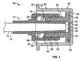
図1は、ルアーコネクタ12に係合した消毒キャップアセンブリ10の断面図である。ルアーコネクタ12の近位端14は、流体で充填された点滴用バッグなどの流体源(図示せず)に接続される流体ライン16に取付けられている。ルアーコネクタ12は、雌ねじ20を有する環状ねじ部分18と、メスルアーコネクタ(図示せず)内への挿入のために位置決めされた切頭円錐形のオスルアー22とを含む。オスルアー22は、流体ライン16と流体連通する開口部24を有する先端部26を含む。オスルアー22は、ねじ部分18内に実質的に同心円状に配置される。それらの概ね共軸配置の結果として、オスルアー22およびねじ部分18は協動して、環状の空間をそれらの間に形成する。 FIG. 1 is a cross-sectional view of a
消毒キャップアセンブリ10は、キャップホルダ28と、キャップホルダ28内に位置決めされるように寸法決めされたキャップ30とを含む。キャップ30は、基部32と、基部32から延在する環状ねじ部分34とを含む。基部32は、実質的に平坦な表面36と、外側フランジ38とを含み得る。 The
キャップ30のねじ部分34は、開放端42を規定するリム40を含む(図3参照)。基部32は、ねじ部分34の対向端を閉じる。ねじ部分34は、ルアーコネクタ12のオスルアー22を補完する先細りの内面46を有して形成され得る。特に、先細りの内面46は、リム40から基部32に向かって細くなる。ねじ部分34は、オスルアー22を受取るように寸法決めされたチャンバ48(図3参照)を規定する。ねじ部分34は、ルアーコネクタ12のねじ山20と係合するための雄ねじ50を含む。雄ねじ50およびルアーコネクタ12のねじ山20は、キャップ30がルアーコネクタ12と確実に螺合接続されることを可能にし、かつキャップ30がルアーコネクタ12に対して回転されるにつれてキャップ30とルアーコネクタ12との間の相対的移動を可能にするように、互いに協動する。雄ねじ50は、基部32とリム40との間を延在する。 The threaded
キャップ30の構成が図3の斜視図に示される。なお、この構成は例示的なものである。たとえば、以下に記載されるように、キャップ30は、ねじ山なしに構成され、押込摩擦嵌合によってルアーコネクタ12と係合するように寸法決めされ得る。 The configuration of the
キャップ30は、吸収性材料から作成され得る。キャップ30は、多孔質プラスチック、たとえばジョージア州フェアバーンに本拠地を置くPorex社から入手可能な医療用グレードの焼結多孔質プラスチック材料から形成され得る。多孔質プラスチック材料の他の好適な製造業者は、Filtrona、GenporeおよびThermoporeを含む。材料が消毒流体などの流体を吸収し保持することができることが望ましい。材料がその構造を維持するために十分に硬質であることも望ましい。材料が圧縮可能であり、吸収された流体が圧縮後に放出されることも望ましい。多孔質プラスチック材料は、ポリエチレン、ポリプロピレン、ナイロンなどといったいずれかの好適なポリマーからなり得る。 The
多孔質プラスチック材料の使用は例示的なものに過ぎない。キャップ30は、接合されたファイバ、綿、シリコーン、ウレタン、ポリエステル、セルロースなどといったいずれかの他の好適な材料からなり得ることが理解されるであろう。材料は、天然かまたは合成であり得る。 The use of porous plastic material is only exemplary. It will be appreciated that the
キャップ30のねじ部分34は、消毒流体、抗凝固性流体、および/または抗菌性流体によってコーティングされ得るか、または消毒流体、抗凝固性流体、および/または抗菌性流体を含浸させ得る。好適な消毒流体の一例はイソプロピルアルコールである。イソプロピルアルコールの濃度は変動することができ、好ましくは70%v/vである。アルコールの濃度は、20%から100%の範囲にあり得る。エタノール、プロパノール、および/またはブタノールを含む他のアルコール、またはヨウ素、過酸化水素、グルコン酸クロルヘキシジン、クロルヘキシジンアセテートなどといった他の材料が使用され得ることが理解されるであろう。消毒剤、抗凝固剤、および/または抗菌剤は、液体または固体の形態であり得る。 The threaded
キャップホルダ28は、キャップ30を受取り、かつオスルアー22を収容するように寸法決めされたチャンバ54を規定する円筒形状の側壁52を含む。キャップホルダ28は、側壁52の遠位端58から径方向外方に突出する外側フランジ56を含み得る。外側フランジ56は開放端60を規定する。キャップホルダ28は、対向する閉鎖端を規定する実質的に平坦な表面62を含み得る。キャップホルダ28は、商標SANTOPRENE(登録商標)でExxonMobil社によって販売されている熱可塑性エラストマーなどの熱可塑性エラストマー、またはいずれかの他の好適な材料から作成され得る。キャップホルダ28は、高密度ポリエチレンなどの、より硬質の材料から作成され得る。キャップホルダ28およびキャップ30は、接着剤によるまたは成形によるなどのいずれかの好適な方法によって、互いに接合され得るかまたは互いに取付けられ得る。
キャップ30がキャップホルダ28に取付けられた時に、キャップ30のフランジ38とキャップホルダ28との間、およびキャップ30のねじ部分34とキャップホルダ28との間に間隙64が存在してもよい。またキャップ30は、キャップ30がキャップホルダ28と共同して回転するように、キャップホルダ28に取付けられる。 A
図2に示されるように、キャップホルダ28は、接着剤による、または伝導性もしくは誘導性熱封止技術によるなどのいずれかの好適な方法によってフランジ56に取付けることができる膜66、箔材料または蓋ストック材料などの材料で封止され得る。膜66の取外しを容易にして消毒キャップ10にアクセスできるようにプルタブ68が設けられ得る。 As shown in FIG. 2, the
一般に、キャップ30は疎水性であってもよい。しかしながら、疎水性材料はイソプロピルアルコールなどの消毒流体がキャップ30を通過することを阻止するかまたは最小化するように作用し得ることから、キャップ30の少なくとも一部分を親水性にすることが望ましい場合がある。たとえば、キャップ30の少なくとも一部分を親水性界面活性剤で処理することが望ましい場合がある。このように、親水性部分はアルコールがそれを通過することを可能にし得るが、疎水性部分は、イソプロピルアルコールなどの消毒流体がそれを通過することを阻止するかまたは最小化するように作用し得る。一実施形態では、ねじ部分34は親水性界面活性剤によって処理され得るが、アルコールなどの消毒流体に対して耐性を有するように、基部32は疎水性のままであり得る。疎水性セクションは、管類を通って点滴用流体が漏れ、キャップ30を通り過ぎるのを防ぐためのプラグとしての役割も果たし得る。 In general, the
図1を参照して、キャップ30のねじ部分34がルアーコネクタ12のねじ山20と噛合い、基部32がオスルアー22の開口部24に隣接して位置決めされるようにルアーコネクタ12に取付けられた消毒キャップアセンブリ10が示される。また、この位置において、ねじ部分34の内面46がオスルアー22に隣接し、オスルアー22は、キャップ30を圧縮し、消毒流体の少なくとも一部分を放出して、ルアーコネクタ12を消毒する。消毒キャップアセンブリ10は、いずれかの好適な期間ルアーコネクタ12に取付けたままにしておくことができる。図4の斜視図に示されるように、消毒キャップアセンブリ10がルアーコネクタ12に取付けられると、ルアーコネクタ12は消毒流体に晒される。 Referring to FIG. 1, the threaded
キャップホルダ28は、消毒キャップアセンブリ10がルアーコネクタ12と係合した後にキャップ30上に残るように構成され得る。代替的に、キャップホルダ28は、キャップ30に取外し可能に取付けられるように構成され得る。たとえば、キャップホルダ28は、消毒キャップアセンブリ10がルアーコネクタ12と係合した後でキャップ30から取外され得る。 The
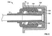
図5は、オスルアー22と係合し、消毒するように寸法決めされた、全体として110として示される消毒キャップアセンブリを示す。消毒キャップアセンブリ110は、特に明記しない限り、図1〜図4に示した消毒キャップアセンブリ10と一致するやり方で動作し、構成される。消毒キャップアセンブリ10のように、消毒キャップアセンブリ110は、キャップホルダ128と、キャップホルダ128内に位置決めされるように寸法決めされたキャップ130とを含む。 FIG. 5 shows a disinfection cap assembly, generally indicated as 110, that is sized to engage and disinfect the
キャップ130は、外側フランジ138から、かつねじ部分134と実質的に同心に延在する環状の側壁111を含む。キャップホルダ128が使用される時、環状の側壁111は、キャップホルダ12の外面に近接して位置決めされる。消毒キャップアセンブリ110がルアーコネクタ12に取付けられると、環状の側壁111は、ルアーコネクタ12のねじ部分18の外面に当接する。環状の側壁111は、キャップ130の残りの部分のような多孔質プラスチック、またはいずれかの他の好適な材料から作成することができる。環状の側壁111は、ルアーコネクタ12のねじ部分18の外面を覆い、保護する。環状の側壁111は、消毒流体を含有し、消毒流体の少なくとも一部分を放出してもよい。 The
図6は、オスルアー22と係合し、消毒するように寸法決めされた、全体として210として示される消毒キャップアセンブリを示す。消毒キャップアセンブリ210は、特に明記しない限り、図1〜図4に示した消毒キャップアセンブリ10と一致するやり方で動作し、構成される。消毒キャップアセンブリ10のように、消毒キャップアセンブリ210は、キャップホルダ228と、キャップホルダ228内に位置決めされるように寸法決めされたキャップ230とを含む。 FIG. 6 shows a disinfection cap assembly, generally designated 210, that is dimensioned to engage and disinfect the
キャップ230は、一体的にそれに接続される中心挿入物211を含む。代替的に、キャップ230および中心挿入物211は、別個の構成要素であり得る。中心挿入物211は、キャップ230の残りの部分のような多孔質プラスチック、またはいずれかの他の好適な材料から作成されてもよく、消毒流体を含有し、消毒流体の少なくとも一部分を放出してもよい。中心挿入物211は、親水性界面活性剤によって処理され得るか、または他の方法で親水性にされ得る。 The
中心挿入物211は、キャップ230の基部232から突出し、キャップ230のねじ部分234内に位置決めされる。中心挿入物211は、角のあるエッジ215を有し得る遠位端213を有し、それによって中心挿入物211に概ね台形形状を与える。中心挿入物211は、円錐形、正方形、長方形などといった他の形状を規定し得る。 The
キャップ230がルアーコネクタ12に取付けられると、中心挿入物211は、オスルアー22に形成された開口部24内に位置決めされ、消毒流体をオスルアー22に入らせ、オスルアー22の内側先端部26に消毒流体を塗布することを可能にする。 When the
図7は、オスルアー22と係合し、消毒するように寸法決めされた、全体として310として示される消毒キャップアセンブリを示す。消毒キャップアセンブリ310は、特に明記しない限り、図1〜図3に示した消毒キャップアセンブリ10と一致するやり方で動作し、構成される。消毒キャップアセンブリ10のように、消毒キャップアセンブリ310は、キャップホルダ328と、キャップホルダ328内に位置決めされるように寸法決めされたキャップ330とを含む。 FIG. 7 shows a disinfection cap assembly, generally designated 310, that is dimensioned to engage and disinfect the
中心プラグ311などの封止機構は、キャップ330の基部332から延在するように寸法決めされ、キャップ330のねじ部分334内に位置決めされるように寸法決めされる。キャップ330および中心プラグ311は、図示されるような別個の構成要素であり得るか、または代替的に、キャップ330および中心プラグ311は一体的に形成され得る。代替的に、中心プラグ311は、中に成形されたキャップホルダ328の延長部分であり得る。 A sealing mechanism, such as the
中心プラグ311は、角のあるエッジ315を有し得る遠位端313を有し、それによって中心プラグ311に概ね台形形状を与える。中心プラグ311は、円錐形、正方形、長方形などといった他の形状を規定し得る。 The
中心プラグ311は、オスルアー22に形成された開口部24に当接して、消毒流体がオスルアー22に入るのを防ぐ。中心プラグ311は、キャップ330のねじ部分334がオスルアー22によって圧縮される前にオスルアー22内の開口部24と係合するのに十分な距離だけ基部332から延在して、オスルアー22内の開口部24を封止する。 The
中心プラグ311は、ゴムなどの非多孔質材料、またはいずれかの他の好適な材料からなり得る。中心プラグ311は、多孔質プラスチックからなり、疎水性状態のままであり得る、つまりキャップ330のねじ部分334のように界面活性剤によって処理されず、それによって、消毒流体がそれを通ってオスルアー22に形成された開口部24へと通過することを阻止するかまたは最小化し得る。このように、中心プラグ311は、アルコールがルアーコネクタ312の流体ライン316に入るのを制限するかまたは防ぐように作用する。また、中心プラグ311は、点滴用流体がラインから滴るのを防ぐためのプラグとして機能し得る。 The
封止機構の構成は、例示的なものに過ぎない。本発明は他の封止機構を採用し得ることが理解されるであろう。たとえば、封止機構は、中心プラグ311よりも、オスルアー22に形成された開口部24内にさらに延在するように寸法決めされた中心ピン(図示せず)であり得る。中心プラグ311は、ねじ部分324上のねじ山を越えて延在し、ねじ係合に先立って挿入され得る。 The configuration of the sealing mechanism is merely exemplary. It will be appreciated that the present invention may employ other sealing mechanisms. For example, the sealing mechanism can be a center pin (not shown) that is dimensioned to extend further into the
図8は、オスルアー22と係合し、消毒するように寸法決めされた、全体として410として示される消毒キャップアセンブリを示す。消毒キャップアセンブリ410は、特に明記しない限り、図1〜図4に示した消毒キャップアセンブリ10と一致するやり方で動作し、構成される。消毒キャップアセンブリ10のように、消毒キャップアセンブリ410は、キャップホルダ428と、キャップホルダ428内に位置決めされるように寸法決めされたキャップ430とを含む。 FIG. 8 shows a disinfection cap assembly, generally designated 410, that is sized to engage and disinfect the
キャップホルダ428は、消毒キャップアセンブリ410がルアーコネクタ12に係合されるとキャップホルダ428の内部を閉鎖する保護シールを形成し得る内向きフランジ411を含む。内側フランジ411は、キャップホルダ428の側壁452の遠位端458から径方向内方に延在する。消毒キャップアセンブリ410がルアーコネクタ12に係合されると、キャップホルダ428の内向きフランジ411がルアーコネクタ12のねじ部分18と接触して、キャップホルダ428の内部を封止し得る。 The
キャップホルダ428の内向きフランジ411は、キャップホルダ428内への病原体、塵埃または他の汚染物質の侵入に対して物理的な障壁を提供し得る。内向きフランジ411は、消毒キャップアセンブリ410からの消毒流体の少なくとも一部分が漏出しないよう保持するように作用し得る。内向きフランジ411は、保持される消毒流体の少なくとも一部分の蒸発を防ぎ得る。 The
キャップホルダ428の構成は異なり得る。たとえば、キャップホルダ428は、側壁452の遠位端458から径方向外方に突出する外側フランジ56(図1)などの外側フランジ(図示せず)と、側壁452の遠位端458から径方向内方に突出する内向きフランジ411とを含み得る。 The configuration of the
図9は、オスルアー22と係合し、消毒するように寸法決めされた、全体として510として示される消毒キャップアセンブリを示す。消毒キャップアセンブリ510は、特に明記しない限り、図1〜図4に示した消毒キャップアセンブリ10と一致するやり方で動作し、構成される。消毒キャップアセンブリ10のように、消毒キャップアセンブリ510は、キャップホルダ528と、キャップホルダ528内に位置決めされるように寸法決めされたキャップ530とを含む。 FIG. 9 shows a disinfection cap assembly, shown generally as 510, that is dimensioned to engage and disinfect the
消毒キャップアセンブリ510は、図7に示した中心プラグ311などの中心プラグ511を含む。その上、キャップホルダは、図8に示したフランジ411などの内向きフランジ513を含む。 The
本明細書に開示される様々な実施形態の様々な特徴は、本発明の精神または範囲から逸脱することなく、共に使用され得ることが理解されるべきである。 It should be understood that various features of the various embodiments disclosed herein can be used together without departing from the spirit or scope of the present invention.
図10は、オスルアー22と係合し、消毒するように寸法決めされた、全体として610として示される消毒キャップアセンブリを示す。消毒キャップアセンブリ610は、特に明記しない限り、図1〜図4に示した消毒キャップアセンブリ10と一致するやり方で動作し、構成される。消毒キャップアセンブリ10のように、消毒キャップアセンブリ610は、キャップホルダ628と、キャップホルダ628内に位置決めされるように寸法決めされたキャップ630とを含む。 FIG. 10 shows a disinfection cap assembly, generally designated as 610, that is dimensioned to engage and disinfect
キャップ630は、基部632から延在する環状部分611を含む。環状部分611は、ねじ山なしに構成されるが、押込摩擦嵌合によってルアーコネクタ12と係合するように寸法決めされる。消毒キャップアセンブリ610は、ルアーコネクタ12から引張り出すことによって取外され得る。
キャップ630の環状部分611は、キャップ630がオスルアー22に押付けられると、内面がオスルアー22と接触し、オスルアー22によって圧縮されて、消毒流体を放出するように構成され得る。環状部分611の外面は、オスルアー22のねじ部分18の雌ねじ18に対して接触することもでき、この側で消毒流体を放出することもできる。代替的に、環状部分611は、ルアーコネクタ12のねじ山20との接触を回避するように構成され得る。環状部分611は、図示されるように先細りである必要はない。 The
図11および図12は、オスルアー22と係合し、消毒するように寸法決めされた、全体として710として示される消毒キャップアセンブリを示す。消毒キャップアセンブリ710は、特に明記しない限り、図1〜図3に示した消毒キャップアセンブリ10と一致するやり方で動作し、構成される。消毒キャップアセンブリ710は、消毒チャンバ715とキャップ730とを含む。 FIGS. 11 and 12 show a disinfection cap assembly, generally designated as 710, that is sized to engage and disinfect the
キャップ730は、基部732から延在する環状部分711を含む。環状部分711は、押込摩擦嵌合によってルアーコネクタ12と係合するように構成され、寸法決めされる。
消毒チャンバ715は、キャップ730の基部732に取付けられ、連続的な側壁713および端壁723によって形成される。側壁713は、側壁713から径方向内方に延在する内側フランジ717を含む。フランジ717は、開放端721を規定する。 The
キャップ730の基部732は、消毒チャンバ715に合わせられる。キャップ730の基部732は、基部732上を延在する消毒チャンバ715の内側フランジ717によって基部732の外側フランジ738が消毒チャンバ715に取込まれるように、消毒チャンバ715内に位置決めされる。基部732は、消毒剤チャンバ715を閉鎖し、キャップ730の環状部分711は、消毒チャンバ715の内側フランジ717に接している。キャップ730は、キャップ730が消毒チャンバ715と共同して回転するように消毒チャンバ715に取付けられ得る。一実施形態では、キャップ730の基部732を、押込設計において消毒チャンバ715に合わせる必要はない。 The
消毒チャンバ715は、消毒流体を保持するように構成されたパッド、スポンジ、または弾性発泡体などの吸収性材料725を含むことができる。吸収性材料725は、消毒流体で湿らせられ得るか、または消毒流体に浸漬され得る。吸収性材料725は変形可能であり得る。キャップ730は、消毒流体を消毒剤チャンバ715から移動させるための担体として作用する多孔質プラスチック材料から作成され得る。キャップホルダ728が圧縮されると、吸収性材料725は、消毒流体の少なくとも一部分を放出する。流体は次いで、基部732を通り、環状部分711に沿って流れ、オスルアー22に送達されることができる。図12は、消毒キャップアセンブリ710の斜視図を示す。 The
本発明は、消毒流体を活性化するかまたは放出するために消毒キャップアセンブリの構成要素上を押すことを伴う他の機構を採用し得ることが理解されるであろう。 It will be appreciated that the present invention may employ other mechanisms that involve pushing on the components of the sterilization cap assembly to activate or release the sterilization fluid.
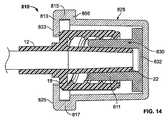
図13〜図15は、オスルアー22と係合し、消毒するように寸法決めされた、全体として810として示される消毒キャップアセンブリを示す。消毒キャップアセンブリ810は、特に明記しない限り、図1〜図3に示した消毒キャップアセンブリ10と一致するやり方で動作し、構成される。消毒キャップアセンブリ10のように、消毒キャップアセンブリ810は、キャップホルダ828と、キャップホルダ828内に位置決めされるように寸法決めされたキャップ830とを含む。 FIGS. 13-15 show a disinfection cap assembly, generally designated as 810, that is dimensioned to engage and disinfect
キャップ830は、基部832から延在する環状部分811を含む。環状部分811は、ねじ山なしに構成され、押込摩擦嵌合によってルアーコネクタ12と係合するように寸法決めされる。消毒キャップアセンブリ810は、ルアーコネクタ12から引張り出すことによって取外され得る。
キャップホルダ828は、キャップ830をルアーコネクタ12上に保持するかまたは固定するように作用する保持器813を含む。保持器813は、キャップホルダ828の外側フランジ856の対向する側から垂直に延在する1対の肩部815,817と、肩部815,817から径方向内方に延在する1対のアーム823,825とを含む。 The
消毒キャップアセンブリ810がルアーコネクタ12に係合されると、保持器813のアーム823,825は、オスルアー22上を延在してキャップ830を保持する。保持器813は、SANTOPRENE(登録商標)などの熱可塑性エラストマー、またはいずれかの他の好適な材料から作成され得る。保持器813は、可撓性材料から作成され得る。 When the
キャップホルダ828は、外側側壁852の対向する側上の凹み部分827(図13および図15)と凹み部分829(図13および図15)とによって規定される把持領域を含んでもよい。凹み部分827,829は、キャップ830を把持してキャップ830をオスルアー22に取付けるように構成される。 The
図16〜図18は、オスルアー22と係合し、消毒するように寸法決めされた、全体として910として示される消毒キャップアセンブリを示す。消毒キャップアセンブリ910は、特に明記しない限り、図1〜図4に示した消毒キャップアセンブリ10と一致するやり方で動作し、構成される。消毒キャップアセンブリ10のように、消毒キャップアセンブリ910は、キャップホルダ928と、キャップホルダ928内に挿入されたキャップ930とを含む。本実施形態は、オスルアー22を破損し得る、オスルアー22上へのキャップ930の過度の締付けを防ぐための機構を含む。これは、ラチェットアセンブリによって対処される。 FIGS. 16-18 illustrate a disinfection cap assembly, generally designated 910, that is dimensioned to engage and disinfect
キャップ930は、基部932と、基部932から延在する環状ねじ部934とを含む。基部932は、外周に沿って複数の歯911(図17および図18参照)を有する外側フランジ938を含み、一方向のみへの回転が可能となる。代替的に、歯の両面に角度を付けることによって両方向への回転を可能にするように構成され得る。歯911は、角のある面912と概ね垂直な面914とを有する。
キャップホルダ928は、キャップホルダ928にキャップ930を保持するための保持機構を含む。保持機構は、キャップホルダ928の側壁952の一セクションから延在する第1の突起913と、キャップホルダ928の側壁952の対向セクションから延在する第2の突起915とを含み得る。第1および第2の突起913,915は、キャップ930の基部932上を延在するように構成される。代替的に、保持機構は、キャップホルダ928の内部の周りに単一のリングを含み得る。 The
キャップホルダ928は、歯911と噛合ってラチェット機構を形成する複数の歯917を含む。歯917は、キャップ930がキャップホルダ928内で一方向のみに回転することを可能にするように歯911と相互作用し、基部932の歯911のように、角のある面916と概ね垂直な面918とを有する。代替的に、両方向への回転を可能にするように構成され得る。 The
ラチェット機構は、消毒キャップアセンブリ910が適切に固定されることを示す可聴または触覚フィードバックを提供する。また、ラチェット機構は、ルアーコネクタ12またはキャップ930に対する損傷を防ぐためにトルクを制限する。キャップ930は、キャップ930の他の実施形態に従って、オスルアー22上に装着される。キャップ930がねじ山の限界を越えて回されると、オスルアー22を破損する代わりに、キャップ930がキャップホルダ928に関して摺動することになり、キャップ930の基部932の角のある歯911,917およびキャップホルダ930はそれぞれ互いに通り過ぎて摺動し、キャップ930のオスルアー22上でのさらなる締結を防ぐ。オスルアー22からキャップ930を取外すと、概ね垂直の面914,918が係合し、摺動を可能にしない。 The ratchet mechanism provides audible or tactile feedback indicating that the
図19は、オスルアー22と係合し、消毒するように寸法決めされた、全体として1010として示される消毒キャップアセンブリを示す。消毒キャップアセンブリ1010は、特に明記しない限り、図1〜図4に示した消毒キャップアセンブリ10と一致するやり方で動作し、構成される。 FIG. 19 shows a sterilization cap assembly, generally designated 1010, that is dimensioned to engage and disinfect
キャップ1030は、キャップホルダなしに使用される。キャップ1030は、基部1032と、基部1032から延在する環状ねじ部分1034とを含む。消毒流体は、環状ねじ部分1034の内面と対応付けることができる。 The
キャップ1030の構成は、例示的なものに過ぎない。たとえば、キャップ1030は、ねじ山なしに構成され、押込摩擦嵌合によってルアーコネクタ12と係合するように寸法決めされ得る。同様に、キャップ1030は、図5に示したように側壁も含み得る。 The configuration of the
図20は、オスルアーと係合し、消毒するように寸法決めされた、全体として1110として示される消毒キャップアセンブリを示す。消毒キャップアセンブリ1110は、特に明記しない限り図18に示した消毒キャップアセンブリ1010と一致するやり方で動作し、構成される。 FIG. 20 shows a sterilization cap assembly, generally designated 1110, that is sized to engage and disinfect a male luer. The
キャップ1130の少なくとも一部分は、親水性界面活性剤によって処理し得るか、または他の方法で親水性にされ得る。ねじ部分1134は親水性界面活性剤によって処理され得るが、基部1132は、消毒流体に対して耐性および非吸収性を有するように疎水性のままであり得る。 At least a portion of
中心プラグ1111は、オスルアー22に形成された開口部24に当接して、消毒流体がオスルアー22に入るのを防ぎ得る。中心プラグ1111は、多孔質プラスチックからなり、疎水性状態のままであり得、それによって、消毒流体がそれを通ってオスルアー22に形成された開口部24へと通過することを阻止するかまたは最小化し得る。疎水性セクションは、点滴用ライン内でプラグとしても作用して、消毒流体の侵入を防ぐかまたは点滴用流体の漏れを止め得る。 The
図21は、オスルアー22と係合し、消毒するように寸法決めされた、全体として1210として示される消毒キャップアセンブリを示す。消毒キャップアセンブリ1210は、特に明記しない限り、図1〜図4に示した消毒キャップアセンブリ10と一致するやり方で動作し、構成される。 FIG. 21 shows a sterilization cap assembly, generally designated 1210, that is sized to engage and disinfect the
キャップホルダ1228は、流体ライン1213などの支持面に取付けられるように構成された外側フランジ1256にノッチ1211を有する。図示されるように、キャップホルダ1228は、キャップホルダ1228の一端1217からキャップホルダ1228の対向端1219まで側壁1252に沿って延在する複数のリブ1215を有する。リブ1215は、キャップホルダ1228の把持を容易にする。 The
図22は、オスルアーと係合し、消毒するように寸法決めされた、全体として1310として示される消毒キャップアセンブリを示す。消毒キャップアセンブリ1310は、特に明記しない限り、図1〜図3に示した消毒キャップアセンブリ10と一致するやり方で動作し、構成される。消毒キャップアセンブリ10のように、消毒キャップアセンブリ1310は、キャップホルダ1328と、キャップホルダ1328内に位置決めされるように寸法決めされたキャップ1330とを含む。 FIG. 22 shows a sterilization cap assembly, generally designated 1310, dimensioned to engage and disinfect a male luer. The
中心プラグ1311などの封止機構は、キャップホルダ1328から基部1332を通って延在するように寸法決めされ、キャップ1330のねじ部分1334内に位置決めされるように寸法決めされる。そのため、中心プラグ1311は、SANTOPRENE(登録商標)などの非多孔質材料、またはいずれかの他の好適な材料からなる。特に、中心プラグ1311は、一端1315が基部1332から延在しているアーム1313と、アーム1313の対向端1319に取付けられた球体1317とを含む。球体1317は、消毒流体がオスルアー22内に進むことができる距離を制限するために、オスルアー22に形成された開口部24に当接するように構成される。代替的に、中心プラグ1311は、基部1332から延在し、ゴムなどの別の材料からなり得る。球体1317は、非球状の装置で置換され得る。 A sealing mechanism, such as
本明細書に開示した消毒キャップアセンブリ10,110,210,310,410,510,610,710,810,910,1010,1110,1210,および1310のうちいずれかは、点滴用バッグ、点滴用ポンプ、または点滴用ポールなどといった好適な表面(図示せず)に取外し可能に取付けられて使用されるように構成され得る。たとえば、図23では、キャップホルダ28の実質的に平坦な表面62は、消毒キャップアセンブリ10を点滴用バッグなどの支持面(図示せず)に取外し可能に固定するように寸法決めされたクリップ80を含む。図24では、キャップホルダ28の実質的に平坦な表面62から延在し、消毒キャップアセンブリ10を支持面(図示せず)に取外し可能に固定するように寸法決めされたフック82が設けられ得る。 Any of the disinfecting
図25では、キャップホルダ28の実質的に平坦な表面62から延在し、消毒キャップアセンブリ10を支持面(図示せず)に解放可能に締結するように寸法決めされた蹄鉄形状のクリップ84が設けられ得る。締結部材の場所は異なり得る。たとえば、図26では、キャップホルダ28の側壁52がクリップ86を含む。 In FIG. 25, there is a horseshoe-shaped
図27では、キャップホルダ28の端面62は、剥離シート89によって覆われ得る接着剤88を含む。接着剤88は、点滴用ポールなどの支持面に消毒キャップアセンブリ10を取付けるために使用され得る。剥離シート89を取外して接着剤88を露出させるためにプルタブ90が設けられ得る。 In FIG. 27, the
代替的な締結機構が設けられ得る。たとえば、消毒キャップアセンブリは、リング(図示せず)を含み得る。 Alternative fastening mechanisms can be provided. For example, the sterilization cap assembly may include a ring (not shown).
消毒キャップアセンブリは、洗浄用注射器、カテーテルまたは無針コネクタを扱うためのキャップ、およびラインアクセス装置等を有するキットに組込まれ得る。使用される消毒流体は、抗凝固性材料および/または抗菌性材料を含み得る。使用され得る消毒流体の例は、2007年6月22日付けで提出された米国仮特許出願番号第11/821,190号および2008年6月19日付けで提出された米国仮特許出願番号第12/214,526号に開示されている。米国仮特許出願番号第11/821,190号および第12/214,526号の開示全体は、それらの全体を引用することによって本明細書において援用される。 The disinfecting cap assembly can be incorporated into a kit having a cleaning syringe, a cap for handling a catheter or needleless connector, a line access device, and the like. The disinfecting fluid used may include anticoagulant materials and / or antimicrobial materials. Examples of disinfecting fluids that may be used are US Provisional Patent Application No. 11 / 821,190 filed June 22, 2007 and US Provisional Patent Application No. 11 / 821,190 filed June 19, 2008. 12 / 214,526. The entire disclosures of US Provisional Patent Application Nos. 11 / 821,190 and 12 / 214,526 are hereby incorporated by reference in their entirety.
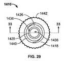
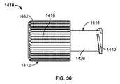
図28は、多機能の消毒終端キャップ1410の斜視図である。消毒終端キャップ1410は、メスルアー(図示せず)に接続する第1の部分1412、たとえばオスコネクタ部分と、オスルアー(図示せず)に接続する第2の部分1414、たとえばメスコネクタ部分とを含む。オスルアーまたはメスルアーは、流体で充填された点滴用バッグなどの流体源(図示せず)にそれぞれ取付けられ得る。たとえば、オスルアーは、図1および図3〜図27に例示され、それに関連して記載されたオスルアー22であり得る。 FIG. 28 is a perspective view of a multifunctional
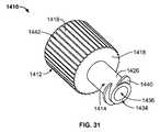
図28〜図33に示されるように、第1の部分1412は、基部1418から延在する第1の環状壁1416を含む。第1の環状壁1416は、第1の環状壁1416の内壁上に位置決めされた1つ以上のねじ山1420を含む。第1の部分1412のねじ山1420は、メスルアーのねじ山と係合し、協動して、終端キャップ1410がメスルアーに確実に螺合接続されることを可能にするように構成される。 As shown in FIGS. 28-33, the
第1の環状壁1416は、開放端1422を規定する。基部1418は、第1の環状壁1416の対向端を閉じる。円筒中心プラグ1430が第1の環状壁1416の方向に基部1418から延在し、端壁1432によって閉じられる。第1の環状壁1416および円筒中心プラグ1430は互いに共軸であり、円筒中心プラグ1430は、第1の環状壁1416よりも直径が小さい。第1の環状壁1416、基部1418および円筒中心プラグ1430は、環状であり、かつ開放端1422によってアクセス可能であり、かつメスルアーを受取るように寸法決めされた第1のチャンバ1424を規定する。メスルアーが第1の部分1412の開放端1422を通って挿入されると、円筒中心プラグ1430および端壁1432がメスルアーの一部分に挿入される。 The first
第2の部分1414は、第1の環状壁1416の方向に対向して基部1418から延在する第2の環状壁1426を含み、基部1418とともに内側肩部1428を形成する。第2の環状壁1426は、開放端1434を有し、第2のチャンバ1436を形成する一方、円筒中心プラグ1430および端壁1432は第3のチャンバ1438を形成する。第2のチャンバ1436および第3のチャンバ1438は流体連通しており、第2のチャンバ1436は、開放端1434によってアクセス可能である。第2のチャンバ1436は、オスルアーを受取るように寸法決めされる。 The
1つ以上のねじ山1440が第2の環状壁1426の外壁上に位置決めされる。ねじ山1440は、図1に示したルアーコネクタ12などのオスルアーコネクタのねじ山と係合し、協動するように構成される。終端キャップ1410がオスルアーコネクタに確実に螺合接続されることを可能にするように、ねじ山1440とオスルアーコネクタのねじ山とは互いに協動する。終端キャップ1410は、操作中およびコネクタとの接続中の終端キャップ1410の把持を容易にするために第1の部分1412上に設けられた複数の外側隆起1442を含んでもよい。 One or
図1に示したオスルアーコネクタ12を例として用いて、オスルアーコネクタ12が第2の部分1414と係合すると、オスルアーコネクタ12のオスルアー22は、開放端1434および第2のチャンバ1436に挿入される。オスルアーコネクタ12のねじ山20が第2の部分1414のねじ山1440と係合するにつれて、オスルアー22は、第2のチャンバ1436内をさらに横断し、第3のチャンバ1428内を横断し得る。第2の環状壁1426は、ルアーコネクタ12のオスルアー22を補完する先細りの形状で形成され得る。そのような構成では、第2の環状壁1426は、開放端1434から基部1418に細くなり得る。 Using the
上述したように、消毒終端キャップ1410は2重の操作性を有し、オスルアーコネクタだけでなく、メスルアーコネクタにも取付けられるように構成される。一般に、メスルアーコネクタは、チャンバを規定し、雄ねじを有する周囲壁を含むことができる。終端キャップ1410をメスルアーコネクタに取付けると、円筒中心プラグ1420がメスルアーコネクタの周囲壁に挿入されるように、メスルアーコネクタの周囲壁が開放端1422を通って第1のチャンバ1424に挿入される。終端キャップ1410は、1つ以上のねじ山1420がメスルアーコネクタと係合するようにねじることができ、終端キャップ1410をメスルアーコネクタで固定する。 As described above, the
図33は、線33−33に沿って得られた図28の多機能の消毒終端キャップ1410の断面である。図33は、終端キャップ1410の構成をより詳細に示す。なお、この構成は例示的なものである。たとえば、終端キャップ1410は、第1の部分ねじ山1420および/または第2の部分ねじ山1440なしに構成され得る。そのような構成では、第1の環状壁1416および円筒中心プラグ1430は、押込摩擦嵌合によってメスルアーコネクタと係合するように寸法決めされてもよい。同様に、第2の環状壁1426は、押込摩擦嵌合によってオスルアーコネクタと係合するように寸法決めされてもよい。 FIG. 33 is a cross section of the multifunctional sanitizing
終端キャップ1410は、流体が流体源から漏れないように、オスルアーコネクタおよび/またはメスルアーコネクタの上を覆うように機能する。終端キャップ1410は、廃棄を保証しないように、オスルアーおよびメスルアーの一時的な分離に用いられてもよい。 The
本明細書に開示した消毒キャップはオスコネクタ部分およびメスコネクタ部分を含むが、オス部分のみ、またはメス部分のみを有して設けることもできる。消毒終端キャップ1420がオスコネクタ部分のみを含む配置では、終端キャップ1420は、基部1418と、基部1418から延在する第1の環状壁1416と、第1の環状壁1416の方向に基部1418から延在し、端壁1432によって閉じられる円筒中心プラグ1430と、複数のねじ山1420とを含み得る。第2の環状壁1426およびキャップのメス側を除去することができる。消毒終端キャップ1420がメスコネクタ部分のみを含む配置では、終端キャップ1420は、基部1418と、第2の環状壁1426と、ねじ山1440とを含み得る。基部1418および第2の環状壁1426は、第2のチャンバ1436を規定する。第1の環状壁1416および円筒中心プラグ1430は除去され得る。 The disinfecting cap disclosed herein includes a male connector portion and a female connector portion, but may be provided with only a male portion or only a female portion. In an arrangement where the
第1の環状壁1416の内面、複数のねじ山1420、第2の環状壁1426の外面、第2の環状壁1426の内面、および第2の部分ねじ山1440などの消毒終端キャップ1410の部分は、消毒流体、抗凝固性流体および/または抗菌性流体でコーティングすることができるかもしくは消毒流体、抗凝固性流体および/または抗菌性流体を含浸させ得る。好適な消毒流体の一例は、イソプロピルアルコールである。イソプロピルアルコールの濃度は変動することができ、好ましくは70%である。アルコールの濃度は20%から100%の範囲にあり得る。エタノール、プロパノール、および/またはブタノールを含む他のアルコール、またはヨウ素、過酸化水素、グルコン酸クロルヘキシジン、クロルヘキシジンアセテートなどといった他の材料が使用され得ることが理解されるであろう。消毒剤、抗凝血剤および/または抗生物質は、液体または固体の形態であり得る。 Parts of the
消毒終端キャップ1410は、ショアAスケールで40〜60のジュロメータ硬度値を有する材料で構成されてもよい。材料は、ルアーとの係合の目的で重ねることができ、可鍛性のある中軟性から中硬性のゴムであり得る。 The
消毒剤コーティング
本明細書に記載した装置は、当該部の消毒液への浸漬、当該部の消毒液によるスプレーコーティング、装置を製造するのに使用されるポリマー材料に消毒液または材料を混合するなどのいずれかの好適な技術によって、消毒剤コーティングでコーティングすることができることが企図される。Disinfectant coating The device described herein can be used to immerse the part in the disinfectant, spray coat the part with disinfectant, mix the disinfectant or material with the polymer material used to manufacture the device, etc. It is contemplated that it can be coated with a disinfectant coating by any suitable technique.
物品の直接成形のために、ある量の生理抗菌性金属化合物が樹脂に添加される。生理抗菌性金属は、銀、金およびプラチナなどの貴金属、ならびに銅および亜鉛を含むことが意図される。本明細書において使用される生理抗菌性金属化合物は、好ましくは銀および酸化金ならびに塩類、たとえば、酢酸銀、安息香酸銀、炭酸銀、クエン酸銀、塩化銀、ヨウ化銀、硝酸銀、酸化銀、スルファジアジン銀、硫酸銀、塩化金、および酸化金を含む。塩化白金酸またはその塩類(たとえば塩化白金酸ナトリウムおよび塩化白金酸カルシウム)などの白金化合物も使用されてもよい。また、銅および亜鉛の化合物、たとえば、銀について上記したものなどの銅および亜鉛の酸化物および塩類が使用されてもよい。単一の生理抗菌性金属化合物または生理抗菌性金属化合物の組合せが使用されてもよい。 An amount of physiological antibacterial metal compound is added to the resin for direct molding of the article. Physiological and antibacterial metals are intended to include precious metals such as silver, gold and platinum, and copper and zinc. Physiological and antibacterial metal compounds used herein are preferably silver and gold oxide and salts such as silver acetate, silver benzoate, silver carbonate, silver citrate, silver chloride, silver iodide, silver nitrate, silver oxide , Silver sulfadiazine, silver sulfate, gold chloride, and gold oxide. Platinum compounds such as chloroplatinic acid or salts thereof (eg, sodium chloroplatinate and calcium chloroplatinate) may also be used. Also, copper and zinc compounds such as copper and zinc oxides and salts such as those described above for silver may be used. A single physiological antibacterial metal compound or a combination of physiological antibacterial metal compounds may be used.
本発明で使用される好ましい生理抗菌性金属化合物は、酢酸銀、酸化銀、硫酸銀、塩化金、ならびに酸化銀および塩化金の組合せである。銀の化合物の粒子は、バクテリアの成長を妨げ、かつ消滅させるための阻止帯を形成するために十分に抽出されることができる。 Preferred physiological antibacterial metal compounds used in the present invention are silver acetate, silver oxide, silver sulfate, gold chloride, and a combination of silver oxide and gold chloride. The silver compound particles can be sufficiently extracted to form a zone of inhibition to prevent and extinguish bacteria.
発明の別の好ましい形態では、本明細書における装置に、トリクロサンおよび銀の化合物もしくはトリクロサンおよびクロルヘキシジン、またはグルコン酸クロルヘキシジン、またはクロルヘキシジンアセテートを含浸させる。 In another preferred form of the invention, the device herein is impregnated with triclosan and silver compounds or triclosan and chlorhexidine, or chlorhexidine gluconate, or chlorhexidine acetate.
本明細書に記載した実施形態は例示的なものに過ぎず、当業者が発明の精神および範囲から逸脱することなく多くの変形および修正を行なってもよいことが理解されるであろう。そのような変形および修正はすべて、添付の請求項によって規定される発明の範囲内に含まれることが意図される。 It will be appreciated that the embodiments described herein are exemplary only, and that many variations and modifications may be made by those skilled in the art without departing from the spirit and scope of the invention. All such variations and modifications are intended to be included within the scope of the invention as defined by the appended claims.
Claims (41)
Translated fromJapanese第1の側および第2の側を有する基部と、
前記基部の前記第1の側から延在し、外面および内面を有する第1の環状壁と、
前記基部の前記第1の側から延在し、外面および内面を有し、前記第1の環状壁内に位置決めされて環状チャンバを形成する円筒中心プラグと、
前記基部の前記第2の側から延在し、外面および内面を有し、開放端を有する第2のチャンバを規定する第2の環状壁とを備え、前記第2のチャンバは、前記円筒中心プラグの前記内面によってさらに規定され、さらに、
前記第1の環状壁の前記内面、前記第2の環状壁の前記内面、前記第2の環状壁の前記外面、および前記円筒中心プラグの前記外面のうち少なくとも1つの上に消毒材料を備える、消毒終端キャップ。A sanitizing end cap for use with a connector,
A base having a first side and a second side;
A first annular wall extending from the first side of the base and having an outer surface and an inner surface;
A cylindrical central plug extending from the first side of the base and having an outer surface and an inner surface and positioned within the first annular wall to form an annular chamber;
A second annular wall extending from the second side of the base and having an outer surface and an inner surface and defining a second chamber having an open end, the second chamber having a cylindrical center Further defined by the inner surface of the plug;
Disinfecting material on at least one of the inner surface of the first annular wall, the inner surface of the second annular wall, the outer surface of the second annular wall, and the outer surface of the cylindrical center plug; Disinfection end cap.
第1の側および第2の側を有する基部と、
前記基部の前記第1の側から延在し、外面および内面を有する第1の環状壁と、
前記基部の前記第1の側から延在し、外面を有し、前記第1の環状壁内に位置決めされて環状チャンバを形成する円筒中心プラグとを備え、
前記第1の環状壁の前記内面および前記円筒中心プラグの前記外面のうち少なくとも一方の上に消毒材料がある、消毒終端キャップ。A sanitizing end cap for use with a connector,
A base having a first side and a second side;
A first annular wall extending from the first side of the base and having an outer surface and an inner surface;
A cylindrical center plug extending from the first side of the base and having an outer surface and positioned within the first annular wall to form an annular chamber;
A disinfection termination cap having a disinfectant material on at least one of the inner surface of the first annular wall and the outer surface of the cylindrical center plug.
第1の側および第2の側を有する基部と、
前記基部の前記第2の側から延在し、外面および内面を有し、開放端を有するチャンバを規定する環状壁とを備え、
前記環状壁の前記外面および前記環状壁の前記内面のうち少なくとも一方の上に消毒材料がある、消毒終端キャップ。A sanitizing end cap for use with a connector,
A base having a first side and a second side;
An annular wall extending from the second side of the base and having an outer surface and an inner surface and defining a chamber having an open end;
A disinfection termination cap, wherein a disinfecting material is on at least one of the outer surface of the annular wall and the inner surface of the annular wall.
Applications Claiming Priority (3)
| Application Number | Priority Date | Filing Date | Title |
|---|---|---|---|
| US13/803,289US10166381B2 (en) | 2011-05-23 | 2013-03-14 | Antiseptic cap |
| US13/803,289 | 2013-03-14 | ||
| PCT/US2014/023140WO2014159346A1 (en) | 2013-03-14 | 2014-03-11 | Antiseptic dead-end cap |
Publications (1)
| Publication Number | Publication Date |
|---|---|
| JP2016511111Atrue JP2016511111A (en) | 2016-04-14 |
Family
ID=51625149
Family Applications (1)
| Application Number | Title | Priority Date | Filing Date |
|---|---|---|---|
| JP2016501159APendingJP2016511111A (en) | 2013-03-14 | 2014-03-11 | Disinfection end cap |
Country Status (6)
| Country | Link |
|---|---|
| EP (1) | EP2968868A4 (en) |
| JP (1) | JP2016511111A (en) |
| CN (1) | CN105102055A (en) |
| AU (1) | AU2014240994A1 (en) |
| CA (1) | CA2905829A1 (en) |
| WO (1) | WO2014159346A1 (en) |
Cited By (20)
| Publication number | Priority date | Publication date | Assignee | Title |
|---|---|---|---|---|
| JP2019005440A (en)* | 2017-06-28 | 2019-01-17 | テルモ株式会社 | Holding tool |
| JP2019531814A (en)* | 2016-10-14 | 2019-11-07 | アイシーユー・メディカル・インコーポレーテッド | Purification cap for medical connector |
| JP2020503161A (en)* | 2016-12-24 | 2020-01-30 | ペリパル アクチェンゲゼルシャフト | Units for medical purposes, especially mechanical connection devices for peritoneal dialysis |
| JP2020517342A (en)* | 2017-04-21 | 2020-06-18 | ベクトン・ディキンソン・アンド・カンパニーBecton, Dickinson And Company | Connector cap |
| JP2021511880A (en)* | 2018-01-30 | 2021-05-13 | ベクトン・ディキンソン・アンド・カンパニーBecton, Dickinson And Company | Universal connectors or caps for male and female threaded fittings |
| JP2021520886A (en)* | 2018-04-10 | 2021-08-26 | ベクトン・ディキンソン・アンド・カンパニーBecton, Dickinson And Company | General purpose single use cap for male and female connectors |
| JP2021166628A (en)* | 2020-04-10 | 2021-10-21 | ニプロ株式会社 | Anti-fouling sheet for medical connector |
| WO2021211674A3 (en)* | 2020-04-17 | 2021-11-18 | Becton, Dickinson And Company | Disinfection cap |
| JP2022500152A (en)* | 2018-09-14 | 2022-01-04 | ベクトン・ディキンソン・アンド・カンパニーBecton, Dickinson And Company | Universal disinfection cap |
| JP2022510289A (en)* | 2018-11-30 | 2022-01-26 | ベクトン・ディキンソン・アンド・カンパニー | Dual-ended disinfection cap for stopcock valve |
| JP2022513673A (en)* | 2018-11-30 | 2022-02-09 | ベクトン・ディキンソン・アンド・カンパニー | Rotationally actuated universal connector cap |
| JP2022519235A (en)* | 2019-01-30 | 2022-03-22 | ベクトン・ディキンソン・アンド・カンパニー | Universal cap for male and female connectors |
| US11344715B2 (en) | 2018-01-26 | 2022-05-31 | Becton, Dickinson And Company | Flush syringe with disinfecting feature |
| JP2022543848A (en)* | 2019-08-08 | 2022-10-14 | ベクトン・ディキンソン・アンド・カンパニー | Universal cap with pressure seal |
| JP2023508042A (en)* | 2019-12-23 | 2023-02-28 | ベクトン・ディキンソン・アンド・カンパニー | universal disinfection cap |
| JP2023063322A (en)* | 2017-06-30 | 2023-05-09 | リジェネロン・ファーマシューティカルズ・インコーポレイテッド | Therapeutic agent delivery device |
| JP2024036648A (en)* | 2018-03-16 | 2024-03-15 | アイシーユー・メディカル・インコーポレーテッド | Disinfection cap for medical connectors |
| JP2024037783A (en)* | 2019-02-19 | 2024-03-19 | クリーンサイト メディカル インコーポレイテッド | Sealing and cleaning device for needleless vascular access connectors |
| JP2024096474A (en)* | 2018-04-10 | 2024-07-12 | ベクトン・ディキンソン・アンド・カンパニー | Universal single-use caps for male and female connectors |
| US12440659B2 (en) | 2019-11-26 | 2025-10-14 | Becton, Dickinson And Company | Dual ended disinfecting cap for stopcock valves |
Families Citing this family (40)
| Publication number | Priority date | Publication date | Assignee | Title |
|---|---|---|---|---|
| US11229746B2 (en) | 2006-06-22 | 2022-01-25 | Excelsior Medical Corporation | Antiseptic cap |
| US9259535B2 (en) | 2006-06-22 | 2016-02-16 | Excelsior Medical Corporation | Antiseptic cap equipped syringe |
| US9078992B2 (en) | 2008-10-27 | 2015-07-14 | Pursuit Vascular, Inc. | Medical device for applying antimicrobial to proximal end of catheter |
| US10166381B2 (en) | 2011-05-23 | 2019-01-01 | Excelsior Medical Corporation | Antiseptic cap |
| WO2013009998A2 (en) | 2011-07-12 | 2013-01-17 | Pursuit Vascular, Inc. | Device for delivery of antimicrobial agent into trans-dermal catheter |
| US9750928B2 (en) | 2013-02-13 | 2017-09-05 | Becton, Dickinson And Company | Blood control IV catheter with stationary septum activator |
| US10376686B2 (en) | 2014-04-23 | 2019-08-13 | Becton, Dickinson And Company | Antimicrobial caps for medical connectors |
| EP3137122B1 (en) | 2014-05-02 | 2019-09-04 | Excelsior Medical Corporation | Strip package for antiseptic cap |
| US10232088B2 (en) | 2014-07-08 | 2019-03-19 | Becton, Dickinson And Company | Antimicrobial coating forming kink resistant feature on a vascular access device |
| DK3294404T3 (en) | 2015-05-08 | 2025-09-08 | Icu Medical Inc | MEDICAL CONNECTORS CONFIGURED TO RECEIVE EMISSIONS OF THERAPEUTIC AGENTS |
| WO2016198092A1 (en) | 2015-06-08 | 2016-12-15 | Stephan Fox | Apparatus for connecting a tube connector to a fitting and to fasten or unfasten closure caps |
| US10493244B2 (en) | 2015-10-28 | 2019-12-03 | Becton, Dickinson And Company | Extension tubing strain relief |
| EP3383478B1 (en) | 2015-11-30 | 2024-12-11 | Avent, Inc. | Flexible cap for conical connectors |
| JP6743379B2 (en)* | 2015-12-03 | 2020-08-19 | 株式会社ジェイ・エム・エス | Wiping tip |
| MX2018008749A (en) | 2016-01-18 | 2018-11-09 | Becton Dickinson Co | Disinfection cap for iv needleless connectors. |
| EP3396246B1 (en)* | 2017-04-24 | 2021-11-24 | Centrotherm Systemtechnik GmbH | Exhaust gas system with measurement site system |
| WO2018204206A2 (en) | 2017-05-01 | 2018-11-08 | Icu Medical, Inc. | Medical fluid connectors and methods for providing additives in medical fluid lines |
| US20200269033A1 (en)* | 2017-11-09 | 2020-08-27 | 3M Innovative Properties Company | Disinfecting cap for luer devices |
| WO2019111613A1 (en)* | 2017-12-06 | 2019-06-13 | 住友ゴム工業株式会社 | Tip cap |
| US11083847B2 (en) | 2018-01-26 | 2021-08-10 | Becton, Dickinson And Company | Flush syringe with flip cap |
| WO2019199750A1 (en)* | 2018-04-10 | 2019-10-17 | Becton, Dickinson And Company | Universal single-use cap for male and female connectors |
| CA3098579C (en)* | 2018-05-01 | 2021-03-02 | Fresenius Medical Care Holdings, Inc. | Multi-purpose cap for fluid ports on a medical device |
| WO2019243011A1 (en)* | 2018-06-20 | 2019-12-26 | Fresenius Kabi Deutschland Gmbh | Connector assembly for connecting medical lines comprising a cap element |
| MX2020014294A (en)* | 2018-06-25 | 2021-06-15 | Peripal Ag | Unit for a mechanical connecting device for medical purposes, particularly for peritoneal dialysis. |
| EP3593840A1 (en)* | 2018-07-12 | 2020-01-15 | Becton Dickinson France | Glass made luer tip with marking means and method for manufacturing the same |
| US11517732B2 (en) | 2018-11-07 | 2022-12-06 | Icu Medical, Inc. | Syringe with antimicrobial properties |
| US11400195B2 (en) | 2018-11-07 | 2022-08-02 | Icu Medical, Inc. | Peritoneal dialysis transfer set with antimicrobial properties |
| US11541221B2 (en) | 2018-11-07 | 2023-01-03 | Icu Medical, Inc. | Tubing set with antimicrobial properties |
| US11534595B2 (en) | 2018-11-07 | 2022-12-27 | Icu Medical, Inc. | Device for delivering an antimicrobial composition into an infusion device |
| US11541220B2 (en) | 2018-11-07 | 2023-01-03 | Icu Medical, Inc. | Needleless connector with antimicrobial properties |
| EP3883638A1 (en) | 2018-11-21 | 2021-09-29 | ICU Medical, Inc. | Antimicrobial device comprising a cap with ring and insert |
| US11975168B2 (en) | 2019-11-18 | 2024-05-07 | Becton, Dickinson And Company | Disinfectant cap |
| US11857753B2 (en) | 2019-12-23 | 2024-01-02 | Becton, Dickinson And Company | Disinfecting syringe tip |
| US12029828B2 (en) | 2020-03-05 | 2024-07-09 | Becton, Dickinson And Company | Disinfection cap |
| US12383719B2 (en) | 2020-04-17 | 2025-08-12 | Becton, Dickinson And Company | Disinfecting cap with re-use prevention |
| US11969572B2 (en) | 2020-04-17 | 2024-04-30 | Becton, Dickinson And Company | Disinfection cap |
| JP7070601B2 (en)* | 2020-04-17 | 2022-05-18 | 株式会社ジェイ・エム・エス | Wiping tip |
| US11890446B2 (en) | 2020-04-17 | 2024-02-06 | Becton, Dickinson And Company | Cap for male and female threaded fittings |
| CA3204371A1 (en) | 2020-12-07 | 2022-06-16 | Icu Medical, Inc. | Peritoneal dialysis caps, systems and methods |
| WO2025048845A1 (en)* | 2023-08-30 | 2025-03-06 | Becton, Dickinson And Company | Flush syringe with integrated male and female luer scrubbing devices |
Family Cites Families (12)
| Publication number | Priority date | Publication date | Assignee | Title |
|---|---|---|---|---|
| US3987930A (en)* | 1974-09-26 | 1976-10-26 | Ethicon, Inc. | Dual-ended tubing cap |
| US4440207A (en)* | 1982-05-14 | 1984-04-03 | Baxter Travenol Laboratories, Inc. | Antibacterial protective cap for connectors |
| US8167847B2 (en)* | 2006-06-22 | 2012-05-01 | Excelsior Medical Corporation | Antiseptic cap and antiseptic cap equipped plunger and syringe barrel assembly |
| US8197749B2 (en)* | 2007-01-16 | 2012-06-12 | The University Of Utah Research Foundation | Methods for cleaning luer connectors |
| US8177761B2 (en)* | 2007-01-16 | 2012-05-15 | The University Of Utah Research Foundation | Assembly for cleaning luer connectors |
| US8336152B2 (en)* | 2007-04-02 | 2012-12-25 | C. R. Bard, Inc. | Insert for a microbial scrubbing device |
| US8065773B2 (en)* | 2007-04-02 | 2011-11-29 | Bard Access Systems, Inc. | Microbial scrub brush |
| US8252247B2 (en)* | 2008-05-06 | 2012-08-28 | Ferlic Michael J | Universal sterilizing tool |
| CN102834140B (en)* | 2010-03-23 | 2015-11-25 | N.V.努特里西阿公司 | For the three-dimensional cut-out tap of enteral tube feed application |
| JP2013523222A (en)* | 2010-03-26 | 2013-06-17 | イベラ・メディカル・コーポレイション | Medical device cleaning device with friction fit and energy director |
| EP2444117A1 (en)* | 2010-10-20 | 2012-04-25 | Fresenius Kabi Deutschland GmbH | Protective cap for a connector |
| US9867975B2 (en)* | 2011-05-23 | 2018-01-16 | Excelsior Medical Corporation | Antiseptic line cap |
- 2014
- 2014-03-11CACA2905829Apatent/CA2905829A1/ennot_activeAbandoned
- 2014-03-11WOPCT/US2014/023140patent/WO2014159346A1/enactiveApplication Filing
- 2014-03-11CNCN201480020638.XApatent/CN105102055A/enactivePending
- 2014-03-11AUAU2014240994Apatent/AU2014240994A1/ennot_activeAbandoned
- 2014-03-11EPEP14776447.6Apatent/EP2968868A4/ennot_activeWithdrawn
- 2014-03-11JPJP2016501159Apatent/JP2016511111A/enactivePending
Cited By (45)
| Publication number | Priority date | Publication date | Assignee | Title |
|---|---|---|---|---|
| JP2019531814A (en)* | 2016-10-14 | 2019-11-07 | アイシーユー・メディカル・インコーポレーテッド | Purification cap for medical connector |
| JP7005609B2 (en) | 2016-10-14 | 2022-02-10 | アイシーユー・メディカル・インコーポレーテッド | Purification cap for medical connectors |
| JP2020503161A (en)* | 2016-12-24 | 2020-01-30 | ペリパル アクチェンゲゼルシャフト | Units for medical purposes, especially mechanical connection devices for peritoneal dialysis |
| JP7117321B2 (en) | 2016-12-24 | 2022-08-12 | ペリパル アクチェンゲゼルシャフト | Units for mechanical connection devices for medical purposes, especially peritoneal dialysis |
| JP2020517342A (en)* | 2017-04-21 | 2020-06-18 | ベクトン・ディキンソン・アンド・カンパニーBecton, Dickinson And Company | Connector cap |
| US12151077B2 (en) | 2017-04-21 | 2024-11-26 | Becton, Dickinson And Company | Connector cap |
| JP7586861B2 (en) | 2017-04-21 | 2024-11-19 | ベクトン・ディキンソン・アンド・カンパニー | Connector cap |
| JP2022125291A (en)* | 2017-04-21 | 2022-08-26 | ベクトン・ディキンソン・アンド・カンパニー | connector cap |
| JP7104064B2 (en) | 2017-04-21 | 2022-07-20 | ベクトン・ディキンソン・アンド・カンパニー | Connector cap |
| JP2019005440A (en)* | 2017-06-28 | 2019-01-17 | テルモ株式会社 | Holding tool |
| JP2023063322A (en)* | 2017-06-30 | 2023-05-09 | リジェネロン・ファーマシューティカルズ・インコーポレイテッド | Therapeutic agent delivery device |
| US11344715B2 (en) | 2018-01-26 | 2022-05-31 | Becton, Dickinson And Company | Flush syringe with disinfecting feature |
| JP2021511880A (en)* | 2018-01-30 | 2021-05-13 | ベクトン・ディキンソン・アンド・カンパニーBecton, Dickinson And Company | Universal connectors or caps for male and female threaded fittings |
| JP7419237B2 (en) | 2018-01-30 | 2024-01-22 | ベクトン・ディキンソン・アンド・カンパニー | Universal connectors or caps for male and female threaded fittings |
| JP2024026700A (en)* | 2018-01-30 | 2024-02-28 | ベクトン・ディキンソン・アンド・カンパニー | Universal connectors or caps for male and female threaded fittings |
| US12098785B2 (en) | 2018-01-30 | 2024-09-24 | Becton, Dickinson And Company | Universal connector or cap for male and female threaded fittings |
| JP2024036648A (en)* | 2018-03-16 | 2024-03-15 | アイシーユー・メディカル・インコーポレーテッド | Disinfection cap for medical connectors |
| JP2023126437A (en)* | 2018-04-10 | 2023-09-07 | ベクトン・ディキンソン・アンド・カンパニー | Universal single-use cap for male and female connectors |
| JP7630561B2 (en) | 2018-04-10 | 2025-02-17 | ベクトン・ディキンソン・アンド・カンパニー | Universal single-use caps for male and female connectors |
| JP7315579B2 (en) | 2018-04-10 | 2023-07-26 | ベクトン・ディキンソン・アンド・カンパニー | Universal single-use caps for male and female connectors |
| JP7612926B2 (en) | 2018-04-10 | 2025-01-14 | ベクトン・ディキンソン・アンド・カンパニー | Universal single-use caps for male and female connectors |
| JP2021520886A (en)* | 2018-04-10 | 2021-08-26 | ベクトン・ディキンソン・アンド・カンパニーBecton, Dickinson And Company | General purpose single use cap for male and female connectors |
| JP2024096474A (en)* | 2018-04-10 | 2024-07-12 | ベクトン・ディキンソン・アンド・カンパニー | Universal single-use caps for male and female connectors |
| JP2024022667A (en)* | 2018-09-14 | 2024-02-16 | ベクトン・ディキンソン・アンド・カンパニー | universal disinfection cap |
| JP7649840B2 (en) | 2018-09-14 | 2025-03-21 | ベクトン・ディキンソン・アンド・カンパニー | Universal Disinfection Cap |
| JP7404353B2 (en) | 2018-09-14 | 2023-12-25 | ベクトン・ディキンソン・アンド・カンパニー | universal disinfection cap |
| JP2022500152A (en)* | 2018-09-14 | 2022-01-04 | ベクトン・ディキンソン・アンド・カンパニーBecton, Dickinson And Company | Universal disinfection cap |
| JP7387735B2 (en) | 2018-11-30 | 2023-11-28 | ベクトン・ディキンソン・アンド・カンパニー | Rotary actuated universal connector cap |
| US12097350B2 (en) | 2018-11-30 | 2024-09-24 | Becton, Dickinson And Company | Rotary activated universal connector cap |
| JP2022513673A (en)* | 2018-11-30 | 2022-02-09 | ベクトン・ディキンソン・アンド・カンパニー | Rotationally actuated universal connector cap |
| JP2022510289A (en)* | 2018-11-30 | 2022-01-26 | ベクトン・ディキンソン・アンド・カンパニー | Dual-ended disinfection cap for stopcock valve |
| US12257414B2 (en) | 2019-01-30 | 2025-03-25 | Becton, Dickinson And Company | Universal cap for male and female connectors |
| JP2022519235A (en)* | 2019-01-30 | 2022-03-22 | ベクトン・ディキンソン・アンド・カンパニー | Universal cap for male and female connectors |
| US11511100B2 (en) | 2019-01-30 | 2022-11-29 | Becton, Dickinson And Company | Universal cap for male and female connectors |
| JP7534309B2 (en) | 2019-01-30 | 2024-08-14 | ベクトン・ディキンソン・アンド・カンパニー | Universal cap for male and female connectors |
| JP2024037783A (en)* | 2019-02-19 | 2024-03-19 | クリーンサイト メディカル インコーポレイテッド | Sealing and cleaning device for needleless vascular access connectors |
| JP7682156B2 (en) | 2019-08-08 | 2025-05-23 | ベクトン・ディキンソン・アンド・カンパニー | Universal Cap with Pressure Seal |
| JP2022543848A (en)* | 2019-08-08 | 2022-10-14 | ベクトン・ディキンソン・アンド・カンパニー | Universal cap with pressure seal |
| US12329925B2 (en) | 2019-08-08 | 2025-06-17 | Becton, Dickinson And Company | Universal cap with pressure seal |
| US12440659B2 (en) | 2019-11-26 | 2025-10-14 | Becton, Dickinson And Company | Dual ended disinfecting cap for stopcock valves |
| JP2023508042A (en)* | 2019-12-23 | 2023-02-28 | ベクトン・ディキンソン・アンド・カンパニー | universal disinfection cap |
| JP7753212B2 (en) | 2019-12-23 | 2025-10-14 | ベクトン・ディキンソン・アンド・カンパニー | Universal Disinfection Cap |
| JP7359071B2 (en) | 2020-04-10 | 2023-10-11 | ニプロ株式会社 | Antifouling sheet for medical connectors |
| JP2021166628A (en)* | 2020-04-10 | 2021-10-21 | ニプロ株式会社 | Anti-fouling sheet for medical connector |
| WO2021211674A3 (en)* | 2020-04-17 | 2021-11-18 | Becton, Dickinson And Company | Disinfection cap |
Also Published As
| Publication number | Publication date |
|---|---|
| CA2905829A1 (en) | 2014-10-02 |
| CN105102055A (en) | 2015-11-25 |
| WO2014159346A1 (en) | 2014-10-02 |
| EP2968868A1 (en) | 2016-01-20 |
| AU2014240994A1 (en) | 2015-10-08 |
| EP2968868A4 (en) | 2016-08-03 |
Similar Documents
| Publication | Publication Date | Title |
|---|---|---|
| US12076521B2 (en) | Antiseptic cap | |
| JP2016511111A (en) | Disinfection end cap | |
| US9867975B2 (en) | Antiseptic line cap | |
| US10695550B2 (en) | Caps for needleless connectors | |
| US12296137B2 (en) | Needleless connector and access port disinfection cleaner and antimicrobial protection cap | |
| ES2936469T3 (en) | Antimicrobial caps for medical connectors | |
| US9352140B2 (en) | Medical component scrubbing device with detachable cap | |
| US10029087B2 (en) | Disinfection device for connectors | |
| JP5108591B2 (en) | Microbe washing brush | |
| JP2019531814A (en) | Purification cap for medical connector | |
| JP2015120005A (en) | Microbial scraping equipment | |
| JP2021511132A (en) | Flush syringe with disinfection function |