JP2016510650A - Fastener handling inside surgical instruments - Google Patents
Fastener handling inside surgical instrumentsDownload PDFInfo
- Publication number
- JP2016510650A JP2016510650AJP2016500332AJP2016500332AJP2016510650AJP 2016510650 AJP2016510650 AJP 2016510650AJP 2016500332 AJP2016500332 AJP 2016500332AJP 2016500332 AJP2016500332 AJP 2016500332AJP 2016510650 AJP2016510650 AJP 2016510650A
- Authority
- JP
- Japan
- Prior art keywords
- fastener
- follower
- shaft assembly
- surgical instrument
- elongate shaft
- Prior art date
- Legal status (The legal status is an assumption and is not a legal conclusion. Google has not performed a legal analysis and makes no representation as to the accuracy of the status listed.)
- Granted
Links
Images


Classifications
- A—HUMAN NECESSITIES
- A61—MEDICAL OR VETERINARY SCIENCE; HYGIENE
- A61B—DIAGNOSIS; SURGERY; IDENTIFICATION
- A61B17/00—Surgical instruments, devices or methods
- A61B17/064—Surgical staples, i.e. penetrating the tissue
- A—HUMAN NECESSITIES
- A61—MEDICAL OR VETERINARY SCIENCE; HYGIENE
- A61B—DIAGNOSIS; SURGERY; IDENTIFICATION
- A61B17/00—Surgical instruments, devices or methods
- A61B17/068—Surgical staplers, e.g. containing multiple staples or clamps
- A—HUMAN NECESSITIES
- A61—MEDICAL OR VETERINARY SCIENCE; HYGIENE
- A61B—DIAGNOSIS; SURGERY; IDENTIFICATION
- A61B17/00—Surgical instruments, devices or methods
- A61B17/00234—Surgical instruments, devices or methods for minimally invasive surgery
- A61B2017/00292—Surgical instruments, devices or methods for minimally invasive surgery mounted on or guided by flexible, e.g. catheter-like, means
- A61B2017/003—Steerable
- A61B2017/00305—Constructional details of the flexible means
- A61B2017/00309—Cut-outs or slits
- A—HUMAN NECESSITIES
- A61—MEDICAL OR VETERINARY SCIENCE; HYGIENE
- A61B—DIAGNOSIS; SURGERY; IDENTIFICATION
- A61B17/00—Surgical instruments, devices or methods
- A61B17/064—Surgical staples, i.e. penetrating the tissue
- A61B2017/0647—Surgical staples, i.e. penetrating the tissue having one single leg, e.g. tacks
- A—HUMAN NECESSITIES
- A61—MEDICAL OR VETERINARY SCIENCE; HYGIENE
- A61B—DIAGNOSIS; SURGERY; IDENTIFICATION
- A61B17/00—Surgical instruments, devices or methods
- A61B17/28—Surgical forceps
- A61B17/29—Forceps for use in minimally invasive surgery
- A61B2017/2901—Details of shaft
- A61B2017/2905—Details of shaft flexible
- A—HUMAN NECESSITIES
- A61—MEDICAL OR VETERINARY SCIENCE; HYGIENE
- A61B—DIAGNOSIS; SURGERY; IDENTIFICATION
- A61B17/00—Surgical instruments, devices or methods
- A61B17/28—Surgical forceps
- A61B17/29—Forceps for use in minimally invasive surgery
- A61B2017/2926—Details of heads or jaws
- A61B2017/2927—Details of heads or jaws the angular position of the head being adjustable with respect to the shaft
- A—HUMAN NECESSITIES
- A61—MEDICAL OR VETERINARY SCIENCE; HYGIENE
- A61B—DIAGNOSIS; SURGERY; IDENTIFICATION
- A61B17/00—Surgical instruments, devices or methods
- A61B17/28—Surgical forceps
- A61B17/29—Forceps for use in minimally invasive surgery
- A61B2017/2926—Details of heads or jaws
- A61B2017/2932—Transmission of forces to jaw members
- A61B2017/2939—Details of linkages or pivot points
- A61B2017/2941—Toggle linkages
Landscapes
- Health & Medical Sciences (AREA)
- Life Sciences & Earth Sciences (AREA)
- Surgery (AREA)
- Heart & Thoracic Surgery (AREA)
- Engineering & Computer Science (AREA)
- Biomedical Technology (AREA)
- Nuclear Medicine, Radiotherapy & Molecular Imaging (AREA)
- Medical Informatics (AREA)
- Molecular Biology (AREA)
- Animal Behavior & Ethology (AREA)
- General Health & Medical Sciences (AREA)
- Public Health (AREA)
- Veterinary Medicine (AREA)
- Surgical Instruments (AREA)
Abstract
Translated fromJapaneseDescription
Translated fromJapanese分野
[0001]開示される実施形態は、手術器具内部におけるファスナのハンドリングに関する。Field
[0001] The disclosed embodiments relate to the handling of fasteners within a surgical instrument.
背景
[0002]ヘルニアを外科的に修復するために手術用メッシュファブリック又は他の補綴修復ファブリックが使用されうる。補綴修復ファブリックは、一般に、開胸腹術において又は腹腔鏡的に配置される。修復ファブリックを所定の位置に固定するため、補綴修復ファブリックを介して下の組織内に1つ又は複数のファスナが留置されうる。ヘルニアの外科的修復又は他の適切な処置中に使用される手術器具には、手術器具からの留置のため複数のファスナを保持することが可能なマガジン又は他の構造を含むことが多い。手術器具内に複数のファスナを含むと、処置の速度を増加することができ、且つまた、追加ファスナの提供のために手術器具を取り出し、術野に手術器具を再導入する必要を低減することができる。background
[0002] A surgical mesh fabric or other prosthetic repair fabric may be used to surgically repair the hernia. Prosthetic repair fabrics are typically placed in thoracoabdominal surgery or laparoscopically. One or more fasteners may be placed in the underlying tissue through the prosthetic repair fabric to secure the repair fabric in place. Surgical instruments used during hernia surgical repairs or other suitable procedures often include a magazine or other structure capable of holding a plurality of fasteners for placement from the surgical instrument. Inclusion of multiple fasteners within the surgical instrument can increase the speed of the procedure and also reduce the need to remove the surgical instrument and provide reintroduction of the surgical instrument into the surgical field to provide additional fasteners. Can do.
概要
[0003]一実施形態において、手術器具は、ハンドルと、ハンドルから先端側に延出する長尺状シャフトアセンブリと、を含む。手術器具は、また、長尺状シャフトアセンブリ内に配置されたドライブシャフトを含むファスナ留置システムを含む。ドライブシャフトは、ドライブシャフトの内部チャネルを少なくとも部分的に画定する少なくとも1つの案内面を含む。少なくとも1つの案内面はドライブシャフトのチャネル内における少なくとも1つのファスナの向きを維持するような形状にされ且つそのように配置されている。Overview
[0003] In one embodiment, a surgical instrument includes a handle and an elongate shaft assembly extending distally from the handle. The surgical instrument also includes a fastener placement system that includes a drive shaft disposed within the elongate shaft assembly. The drive shaft includes at least one guide surface that at least partially defines an internal channel of the drive shaft. The at least one guide surface is shaped and arranged so as to maintain the orientation of the at least one fastener within the channel of the drive shaft.
[0004]別の実施形態においては、手術器具を操作する方法は、ハンドルと、ハンドルから先端側に延出する長尺状シャフトアセンブリと、長尺状シャフトアセンブリ内に配置されたドライブシャフトを含む長尺状シャフトアセンブリからファスナを留置するためのファスナ留置システムであって、ドライブシャフトが内部チャネルを含む、ファスナ留置システムと、ドライブシャフトの内部チャネル内に配置された少なくとも1つのファスナと、を含む、手術器具を用意するステップと、ドライブシャフトを移動し、第2のファスナを長尺状シャフトアセンブリから留置するためにファスナ留置システムを作動するステップと、第2のファスナを留置するために、ファスナ留置システムの作動中、ドライブシャフトに対し少なくとも1つのファスナの向きを維持するステップと、を含む。 [0004] In another embodiment, a method of operating a surgical instrument includes a handle, an elongate shaft assembly extending distally from the handle, and a drive shaft disposed within the elongate shaft assembly. A fastener placement system for placing a fastener from an elongate shaft assembly, wherein the drive shaft includes an internal channel and includes at least one fastener disposed within the internal channel of the drive shaft. Providing a surgical instrument; activating a fastener placement system to move the drive shaft to place the second fastener from the elongate shaft assembly; and to place the second fastener. During operation of the indwelling system, at least one Comprising a step of maintaining the Na orientation, a.
[0005]更に別の実施形態においては、手術器具は、ハンドルと、ハンドルから先端側に延出する長尺状シャフトアセンブリと、を含む。手術器具は、また、長尺状シャフトアセンブリ内に配置されたドライブシャフトを含む長尺状シャフトアセンブリからファスナを留置するためのファスナ留置システムを含む。ドライブシャフトは、少なくとも1つのファスナを含むように適合され且つ配置された内部チャネルを含む。また、ドライブシャフトの先端側に位置する部分内のチャネルの断面は平坦部及び丸み部を含む。 [0005] In yet another embodiment, a surgical instrument includes a handle and an elongate shaft assembly extending distally from the handle. The surgical instrument also includes a fastener placement system for placing the fastener from the elongated shaft assembly that includes a drive shaft disposed within the elongated shaft assembly. The drive shaft includes an internal channel adapted and arranged to include at least one fastener. Moreover, the cross section of the channel in the part located in the front end side of a drive shaft contains a flat part and a round part.
[0006]別の実施形態においては、手術器具は、ハンドルと、ハンドルから先端側に延出する長尺状シャフトアセンブリと、を含む。手術器具は、また、長尺状シャフトアセンブリからファスナを留置するためのファスナ留置システムと、長尺状シャフトアセンブリ内に配置され且つ長尺状シャフトアセンブリ内に配置された1つ又は複数のファスナと対応付けられたフォロアと、を含む。ファスナ留置システムの作動によりフォロアが第1の長さから第2の長さへと圧縮し、1つ又は複数のファスナに対し先端側誘導力を印加し、ファスナを先端側方向に移動させる。1つ又は複数のファスナの移動中、フォロアは第2の長さから第1の長さへと伸張する。 [0006] In another embodiment, a surgical instrument includes a handle and an elongate shaft assembly extending distally from the handle. The surgical instrument also includes a fastener placement system for placing a fastener from the elongate shaft assembly, one or more fasteners disposed within the elongate shaft assembly and disposed within the elongate shaft assembly. And associated followers. Activation of the fastener placement system causes the follower to compress from the first length to the second length, applying a tip-side guidance force to the one or more fasteners and moving the fastener in the tip-side direction. During movement of the one or more fasteners, the follower extends from the second length to the first length.
[0007]更に別の実施形態においては、手術器具は、ハンドル、ハンドルから先端側に延出する長尺状シャフトアセンブリを含む。手術器具は、また、長尺状シャフトアセンブリからファスナを留置するためのファスナ留置システムを含む。ファスナ留置システムは、長尺状シャフトアセンブリ内に配置されたドライブシャフトと、長尺状シャフトアセンブリ内に配置され、且つドライブシャフトに対応付けられたフォロアと、を含む。ドライブシャフトの先端側への移動により、長尺状シャフトアセンブリからファスナが留置し、フォロアが先端側方向に移動し、長尺状シャフトアセンブリ内に配置された1つ又は複数のファスナが先端側方向へと移動する。留置されたファスナにドライブシャフトによって印加される力は1つ又は複数のファスナにフォロアによって印加される力よりも大きい。 [0007] In yet another embodiment, a surgical instrument includes a handle and an elongate shaft assembly extending distally from the handle. The surgical instrument also includes a fastener placement system for placing the fastener from the elongate shaft assembly. The fastener placement system includes a drive shaft disposed within the elongate shaft assembly and a follower disposed within the elongate shaft assembly and associated with the drive shaft. Due to the movement of the drive shaft toward the distal end, the fastener is detained from the long shaft assembly, the follower moves in the distal direction, and one or more fasteners arranged in the elongated shaft assembly are moved in the distal direction. Move to. The force applied by the drive shaft to the deployed fastener is greater than the force applied by the follower to one or more fasteners.
[0008]別の実施形態においては、手術器具は、ハンドルと、ハンドルから先端側に延出する長尺状シャフトアセンブリと、を含む。手術器具は、また、長尺状シャフトアセンブリからファスナを留置するためのファスナ留置システムと、長尺状シャフトアセンブリ内に配置された、長尺状シャフトアセンブリ内の1つ又は複数のファスナを先端側方向へと移動させるためのフォロアと、を含む。フォロアは、ファスナ留置システムの作動前に1つ又は複数のファスナに第1の力を印加し、ファスナ留置システムの作動により1つ又は複数のファスナが先端側方向へと移動を開始した後に1つ又は複数のファスナに第2の力を印加する。長尺状シャフトアセンブリは、1つ又は複数のファスナに第1の拘束力及び第2の拘束力を印加するように構成されている。第1の力は第1の拘束力よりも小さい。更に、第2の力は第1の拘束力よりも大きく、第2の拘束力よりも小さい。 [0008] In another embodiment, a surgical instrument includes a handle and an elongate shaft assembly extending distally from the handle. The surgical instrument also includes a fastener placement system for placing the fastener from the elongate shaft assembly and one or more fasteners in the elongate shaft assembly disposed within the elongate shaft assembly. And a follower for moving in the direction. The follower applies a first force to one or more fasteners prior to operation of the fastener placement system, and one after the fastener placement system has been activated to move the one or more fasteners in the distal direction. Alternatively, the second force is applied to the plurality of fasteners. The elongate shaft assembly is configured to apply a first restraining force and a second restraining force to the one or more fasteners. The first force is smaller than the first restraining force. Furthermore, the second force is larger than the first restraining force and smaller than the second restraining force.
[0009]更に別の実施形態においては、手術器具は、ハンドルと、ハンドルから先端側に延出する長尺状シャフトアセンブリと、を含む。第1の拘束要素及び第2の拘束要素は長尺状シャフトアセンブリと対応付けられている。第2の拘束要素は第1の拘束要素から先端側に配置されている。第1の拘束要素及び第2の拘束要素はファスナ留置位置を画定する。手術器具は、また、長尺状シャフトアセンブリからファスナを留置するためのファスナ留置システムを含む。ファスナ留置システムは、ファスナ留置位置に配置されたファスナに留置力を印加するように適合され且つ配置されたドライブシャフトを含む。 [0009] In yet another embodiment, a surgical instrument includes a handle and an elongate shaft assembly extending distally from the handle. The first restraining element and the second restraining element are associated with the elongate shaft assembly. The second restraining element is disposed on the distal end side from the first restraining element. The first restraining element and the second restraining element define a fastener placement position. The surgical instrument also includes a fastener placement system for placing the fastener from the elongate shaft assembly. The fastener placement system includes a drive shaft adapted and arranged to apply a placement force to a fastener located at a fastener placement location.
[0010]別の実施形態においては、手術器具を操作する方法は、ハンドルと、ハンドルから先端側に延出する長尺状シャフトアセンブリと、長尺状シャフトアセンブリからファスナを留置するためのファスナ留置システムと、長尺状シャフトアセンブリ内に配置され、長尺状シャフトアセンブリ内に配置された1つ又は複数のファスナと対応付けられたフォロアと、を用意するステップと、長尺状シャフトアセンブリからファスナを留置するためにファスナ留置システムを作動するステップと、フォロアを先端側に移動してフォロアを第1の長さから第2の長さへと圧縮し、1つ又は複数のファスナに対し先端側誘導力を印加し、1つ又は複数のファスナを先端側方向に移動させるステップと、を含み、1つ又は複数のファスナの移動中、フォロアは第2の長さから第1の長さへと伸張する。 [0010] In another embodiment, a method for operating a surgical instrument includes a handle, an elongate shaft assembly extending distally from the handle, and a fastener placement for placing a fastener from the elongate shaft assembly. Providing a system and a follower disposed within the elongate shaft assembly and associated with one or more fasteners disposed within the elongate shaft assembly; from the elongate shaft assembly; Actuating a fastener indwelling system for indwelling, moving the follower to the distal side, compressing the follower from a first length to a second length, and distal to one or more fasteners Applying an inductive force and moving the one or more fasteners in a distal direction, during movement of the one or more fasteners, It is extending into the first length from the second length.
[0011]更に別の実施形態においては、手術器具は、ハンドルと、ハンドルから先端側に延出する長尺状シャフトアセンブリと、を含む。手術器具は、また、長尺状シャフトアセンブリからファスナを留置するためのファスナ留置システムを含む。ファスナ留置システムはドライブシャフトを含む。フォロアは、ファスナのスタックを移動するように構成されており、ドライブシャフト内に配置されている。フォロア及びドライブシャフトは、ファスナ留置システムの各作動サイクル中にフォロアを先端側方向へと順次移動させるためのウォーキングビームアセンブリを形成する。 [0011] In yet another embodiment, a surgical instrument includes a handle and an elongate shaft assembly extending distally from the handle. The surgical instrument also includes a fastener placement system for placing the fastener from the elongate shaft assembly. The fastener placement system includes a drive shaft. The follower is configured to move through the stack of fasteners and is disposed within the drive shaft. The follower and drive shaft form a walking beam assembly for sequentially moving the follower in the distal direction during each operating cycle of the fastener placement system.
[0012]別の実施形態においては、手術器具は、ハンドルと、ハンドルから先端側に延出する長尺状シャフトアセンブリと、を含む。手術器具は、また、長尺状シャフトアセンブリからファスナを留置するためのファスナ留置システムを含む。ファスナ留置システムはドライブシャフトを含む。後退防止要素は、ファスナ留置システムの作動によりドライブシャフトが先端側に移動し、各作動サイクル中、ドライブシャフトの先端側への動きにより後退防止要素が予め選択した長さまで伸長するように、ドライブシャフトに対応付けられている。 [0012] In another embodiment, a surgical instrument includes a handle and an elongate shaft assembly extending distally from the handle. The surgical instrument also includes a fastener placement system for placing the fastener from the elongate shaft assembly. The fastener placement system includes a drive shaft. The anti-retraction element moves the drive shaft toward the distal end upon actuation of the fastener placement system, and the movement of the drive shaft toward the distal end during each operating cycle causes the anti-retraction element to extend to a preselected length. Is associated with.
[0013]本開示はこの点において限定されないため、前述の概念及び以下に記載する更なる概念は任意の適切な組み合わせにおいて調整してもよいことを認識すべきである。本教示の前述及びその他の態様、実施形態及び特徴については添付の図面とともに以下の説明からより詳細に理解されうる。 [0013] It should be recognized that the foregoing concepts and the further concepts described below may be adjusted in any suitable combination, as the present disclosure is not limited in this respect. The foregoing and other aspects, embodiments and features of the present teachings can be understood in more detail from the following description in conjunction with the accompanying drawings.
図面の簡単な説明
[0014]添付の図面は一定の縮尺で描かれることを意図していない。図面では、種々の図に示される各同一の又はほぼ同一の構成要素は同様の符号によって示される場合がある。明確化のため、各図面における全ての構成要素に符号が付されるわけではない。Brief Description of Drawings
[0014] The accompanying drawings are not intended to be drawn to scale. In the drawings, each identical or nearly identical component that is illustrated in various figures may be represented by a like numeral. For clarity, not all components in each drawing are numbered.
詳細な説明
[0039]本発明者らは、作動中におけるファスナのスタックへの過度の力の印加及び隣接するファスナ間の回転などの相対運動がファスナ留置の妨げになりうることを認識した。Detailed description
[0039] The inventors have recognized that relative movement, such as applying excessive force to the stack of fasteners and rotation between adjacent fasteners during operation, can interfere with fastener placement.
[0040]上記に鑑み、本発明者らは、ファスナのスタックに対し制御された力を付与し、ファスナ留置を容易にすることに関する利点を認めた。更に、いくつかの実施形態では、この力は先端側ファスナ留置位置に配置されたファスナに印加されるおおよその作動力よりも小さくてもよい。本発明者らは、また、ファスナのスタック内における個々のファスナの向きを維持すること、及び最先端側ファスナをファスナ留置位置に保持することに関するいくつかの利点を認めた。上記利点は、また、ファスナ留置の一貫性及び手術器具操作の向上につながる場合がある。 [0040] In view of the above, the inventors have recognized the advantages associated with applying a controlled force to the fastener stack to facilitate fastener placement. Further, in some embodiments, this force may be less than the approximate actuation force applied to the fastener located at the distal fastener placement position. The inventors have also recognized several advantages relating to maintaining the orientation of individual fasteners within the stack of fasteners and maintaining the most advanced fasteners in the fastener placement position. The above advantages may also lead to improved fastener placement consistency and surgical instrument operation.
[0041]一実施形態において、手術器具は、ハンドルと、ハンドルから先端側に延出する長尺状シャフトアセンブリと、を含んでもよい。長尺状シャフトアセンブリは、先端側に位置するファスナ留置位置を含んでもよく、ファスナはそこから留置されてもよい。手術器具は、また、ファスナを長尺状シャフトアセンブリの先端部のファスナ留置位置から出して留置するためのファスナ留置システムを含んでもよい。ファスナ留置システムは任意の数の方法で具現化されてもよい。更に、いくつかの実施形態では、ファスナ留置システムは、マガジン又は複数のファスナを収容するための他の適切な構造体を含んでもよい。特定の実施形態によっては、複数のファスナは入れ子状のファスナのスタックとして配置されてもよいが、他の配置構成もまた想定される。ファスナ留置システムは、また、ファスナ留置システムの作動サイクル中、1つ又は複数のファスナをファスナ留置位置に向かって移動するようにファスナのスタックに対応付けられたフォロア又は他の適切な構成要素を含んでもよい。 [0041] In one embodiment, the surgical instrument may include a handle and an elongate shaft assembly extending distally from the handle. The elongate shaft assembly may include a fastener placement position located on the distal side, from which the fastener may be placed. The surgical instrument may also include a fastener placement system for placing the fastener out of the fastener placement location at the distal end of the elongate shaft assembly. The fastener placement system may be implemented in any number of ways. Further, in some embodiments, the fastener placement system may include a magazine or other suitable structure for housing a plurality of fasteners. In some embodiments, the plurality of fasteners may be arranged as a stack of nested fasteners, although other arrangements are also envisioned. The fastener placement system also includes a follower or other suitable component associated with the fastener stack to move one or more fasteners toward the fastener placement position during the fastener placement system operating cycle. But you can.
[0042]ファスナの留置に加え、ファスナ留置システムの作動により、フォロアの先端側への移動も生じ、ファスナのスタックがファスナ留置位置に向かって先端側に移動し、次の最先端側ファスナがファスナ留置位置に配置してもよい。ファスナ留置システムはフォロアを任意の適切な方法で移動してもよい。例えば、一実施形態においては、ドライブシャフトの先端側への移動によりフォロアが先端側に移動するようにフォロアはファスナ留置システムのドライブシャフトと対応付けられてもよい。フォロアの後方への動きもまた、フォロアに対応付けられた適切な後退防止要素の使用により防止されてもよい。フォロアが移動する特定の方法にかかわらず、フォロアは、移動中、制御された力をファスナのスタックに付与するように配置及び構成されてもよい。ファスナのスタックに印加される力は任意の適切な力であってもよく、一実施形態においては、ファスナをファスナ留置位置から留置するために印加される作動力よりも小さくてもよい。 [0042] In addition to fastener placement, actuation of the fastener placement system also causes movement of the follower to the distal side, causing the fastener stack to move toward the fastener placement position, leading to the next most advanced fastener. You may arrange | position in an indwelling position. The fastener placement system may move the follower in any suitable manner. For example, in one embodiment, the follower may be associated with the drive shaft of the fastener placement system such that movement of the drive shaft toward the distal end causes the follower to move toward the distal end. Backward movement of the follower may also be prevented by the use of a suitable anti-retraction element associated with the follower. Regardless of the particular way in which the follower moves, the follower may be arranged and configured to impart a controlled force to the fastener stack during movement. The force applied to the fastener stack may be any suitable force, and in one embodiment may be less than the actuation force applied to place the fastener from the fastener placement position.
[0043]特定の実施形態においては、フォロアは、ファスナ留置システムの後の作動サイクル中にファスナのスタックに同様の力を印加するような任意の適切な方法で作製してもよい。例えば、フォロアは従動要素を含んでもよく、従動要素はファスナ留置システムの作動により従動要素が先端側に移動するようにファスナ留置システムに対応付けられている。従動要素は、また、押込要素に対応付けられた圧縮可能な弾性要素に対応付けられてもよい。弾性要素は、従動要素の移動時に押込要素に対し制御された力を付与するように適合され且つ配置されてもよい。弾性要素は、コイルばね、円すいコイルばね、空気ばね、圧縮可能な材料(例えばゴム)から作製された適切な形状の構成要素、又は圧縮された際にファスナのスタックに力を印加することが可能な任意の他の適切な形状及びサイズの圧縮可能な構成要素を含んでもよい。いくつかの実施形態では、ファスナのスタックに対し制御可能な力を付与することに加え、弾性要素は、フォロアがファスナのスタックに力をなお印加しつつも長尺状シャフトアセンブリの関節動作可能部分を通過することを可能にするほど十分に可撓性を付与してもよい。そのような一実施形態においては、従動要素、弾性要素及び押込要素は、また、直線構成及び関節構成の両方において長尺状シャフトアセンブリを通過するようなサイズ及び形状にしてもよい。 [0043] In certain embodiments, the follower may be made in any suitable manner such that a similar force is applied to the stack of fasteners during a subsequent actuation cycle of the fastener placement system. For example, the follower may include a follower element that is associated with the fastener placement system such that the follower element moves distally upon actuation of the fastener placement system. The driven element may also be associated with a compressible elastic element associated with the pushing element. The elastic element may be adapted and arranged to apply a controlled force to the pushing element during movement of the driven element. Elastic elements can apply forces to coil springs, conical coil springs, air springs, suitably shaped components made from compressible materials (eg rubber), or a stack of fasteners when compressed Any other suitable shape and size of compressible components may be included. In some embodiments, in addition to providing a controllable force on the stack of fasteners, the resilient element may be an articulatable portion of the elongate shaft assembly while the follower still applies a force to the fastener stack. It may be sufficiently flexible to allow it to pass through. In one such embodiment, the follower element, elastic element, and pusher element may also be sized and shaped to pass through the elongate shaft assembly in both linear and articulated configurations.
[0044]本明細書中に記載される実施形態は互いに物理的に対応付けられた別個の構成要素としての従動要素、弾性要素及び押込要素を意味し且つ示すが、本開示は別個の構成要素の使用に限定されない。例えば、いくつかの実施形態では、従動要素、弾性要素及び押込要素は一体構成要素の一部として提供してもよい。 [0044] Although the embodiments described herein refer to and illustrate follower elements, elastic elements and pusher elements as separate components physically associated with each other, the present disclosure provides for separate components It is not limited to the use of. For example, in some embodiments, the follower element, elastic element, and pusher element may be provided as part of a unitary component.
[0045]いくつかの実施形態では、フォロアは、後の作動サイクル中にファスナのスタックに対し同様の力を付与するように構成してもよい。これは任意の数の方法で実現してもよいが、一実施形態においては、フォロアは以下の方法で操作してもよい。ファスナ留置システムの作動時、従動要素は先端側に移動してもよい。従動要素の先端側への移動により、弾性要素を第1の長さから圧縮された第2の長さへと圧縮してもよい。弾性要素の圧縮後、弾性要素は圧縮された第2の長さから元の第1の長さへと伸張してもよい。弾性要素が第2の長さへと伸張するにつれて、ファスナは長尺状シャフトアセンブリに沿ってファスナ留置位置に向かい先端側に移動してもよい。いくつかの実施形態では、第1の長さと第2の長さとの間の差は1つのファスナの長さに相当してもよい。弾性要素が第1の長さに相当する伸張状態にある場合、弾性要素は押込要素及びファスナのスタックに対し第1の力を印加してもよい。その後、弾性要素が第2の長さに相当する圧縮状態にある場合、弾性要素は押込要素及びファスナのスタックに対し第2の力を印加してもよい。圧縮された弾性要素において予想されるように、第2の力は第1の力よりも大きい。いくつかの実施形態では、第1の力はほぼゼロであってもよい。しかしながら、他の実施形態においては、作動サイクル全体にわたりファスナのスタックに先端側への付勢を付与し、ファスナのスタックの後方への動きを防止することが望ましい場合がある。そのような一実施形態においては、第1の力はゼロよりも大きくてもよく、この力は、ファスナ留置システムの作動前における弾性要素の初期圧縮に相当する。 [0045] In some embodiments, the follower may be configured to apply a similar force to the stack of fasteners during a subsequent actuation cycle. This may be accomplished in any number of ways, but in one embodiment the follower may be operated in the following manner. When the fastener placement system is in operation, the follower element may move distally. The elastic element may be compressed from the first length to the compressed second length by movement of the driven element toward the tip side. After compression of the elastic element, the elastic element may stretch from the compressed second length to the original first length. As the elastic element extends to the second length, the fastener may move distally along the elongate shaft assembly toward the fastener placement position. In some embodiments, the difference between the first length and the second length may correspond to the length of one fastener. When the elastic element is in an extended state corresponding to the first length, the elastic element may apply a first force against the stack of pushing elements and fasteners. Thereafter, when the elastic element is in a compressed state corresponding to the second length, the elastic element may apply a second force against the stack of pusher elements and fasteners. As expected in the compressed elastic element, the second force is greater than the first force. In some embodiments, the first force may be approximately zero. However, in other embodiments, it may be desirable to impart a forward bias to the fastener stack throughout the operating cycle to prevent movement of the fastener stack backwards. In one such embodiment, the first force may be greater than zero, and this force corresponds to the initial compression of the elastic element prior to operation of the fastener placement system.
[0046]フォロアによって印加される力が予め選択した閾値力を超えるまでファスナの先端側への動きを防止するため、フォロアによりファスナのスタックに印加される力に加え、スタックファスナに対し拘束力も印加してよい。例えば、第1の拘束力はファスナ留置システムの作動前及び作動中にファスナのスタックに印加してもよい。第1の拘束力はフォロアによりファスナのスタックに印加された第1の力に抗するためにファスナのスタックに印加してもよい。したがって、ファスナ留置システムの作動前、ファスナのスタックは長尺状シャフトアセンブリ内において静止したままであってもよい。しかしながら、作動中、弾性要素は、上に示したようにファスナのスタックに対しより大きな力を印加するために第2の圧縮長さまで圧縮されてもよい。印加される力(例えば第2の力)が第1の拘束力よりも大きくなると、ファスナのスタックはフォロアによって先端側に移動し、次のファスナをファスナ留置位置に配置してもよい。その後、その作動サイクル中におけるファスナのスタックの更なる先端側への動きを拘束するため、第2の拘束力を印加してもよい。 [0046] In addition to the force applied to the fastener stack by the follower, a restraining force is also applied to the stack fastener to prevent movement of the fastener to the tip side until the force applied by the follower exceeds a preselected threshold force. You can do it. For example, the first restraining force may be applied to the fastener stack before and during operation of the fastener placement system. The first restraining force may be applied to the fastener stack to resist a first force applied to the fastener stack by the follower. Thus, prior to operation of the fastener placement system, the stack of fasteners may remain stationary within the elongate shaft assembly. However, in operation, the elastic element may be compressed to a second compression length to apply a greater force against the stack of fasteners as indicated above. When the applied force (for example, the second force) becomes larger than the first restraining force, the fastener stack may be moved to the front end side by the follower, and the next fastener may be disposed at the fastener detention position. Thereafter, a second restraining force may be applied to restrain further movement of the stack of fasteners toward the distal end during the operating cycle.
[0047]記載した拘束力はいずれも、1つ又は複数の拘束要素によって付与してもよい。更に、拘束要素は任意の数の方法で具現化してもよい。例えば、拘束要素は、長尺状シャフトアセンブリに対し内方向及び先端側に延出する1つ又は複数のタブと、移動止め機構と、他の適切な特徴と、を含んでもよい。更に、拘束要素は長尺状シャフトアセンブリと一体形成してもよく、あるいは、拘束要素は別個に形成し、その後、溶接、はんだ付け、接着剤、機械的なカップリング、ファスナ及びしまり嵌めを含むがこれらに限定されない任意の適切な方法を用いて長尺状シャフトアセンブリに組み付けてもよい。 [0047] Any of the described restraining forces may be applied by one or more restraining elements. Further, the restraining elements may be implemented in any number of ways. For example, the restraining element may include one or more tabs that extend inward and distal to the elongate shaft assembly, a detent mechanism, and other suitable features. Further, the constraining element may be integrally formed with the elongate shaft assembly, or the constraining element may be formed separately and then include welding, soldering, adhesive, mechanical coupling, fasteners and interference fit. May be assembled to the elongate shaft assembly using any suitable method, including but not limited to these.
[0048]いくつかの実施形態では、ファスナのスタックに対し拘束力を付与することに加え、拘束要素は、また、ファスナ留置位置を画定するために用いてもよい。例えば、ファスナ留置位置を画定するためにファスナの頭部又は他の適切な特徴を第1の拘束要素と第2の拘束要素との間に保持してもよい。 [0048] In some embodiments, in addition to providing a restraining force to the stack of fasteners, the restraining element may also be used to define a fastener placement position. For example, a fastener head or other suitable feature may be retained between the first and second restraining elements to define the fastener placement position.
[0049]上に示したようにファスナのスタックに印加される力を制御するためにフォロアを設けることに加え、ファスナのスタックがフォロアによりファスナ留置位置に向かって移動する際の長尺状シャフトアセンブリ内におけるファスナの向きを維持するための機構を提供することが望ましい場合がある。一実施形態においては、案内面は、ファスナの少なくとも一部の対応する表面と相互作用し、長尺状シャフトアセンブリ内を移動する際のファスナの向きを維持するようなサイズ及び形状にしてもよい。場合によっては、ファスナの対応する表面は、形状及びサイズの両方において案内面に相補的となるような形状であってもよい。案内面は、長尺状シャフトアセンブリの任意の適切な構成要素、又は長尺状シャフトアセンブリ内に配置され、長尺状シャフトアセンブリ内を移動する際にファスナと相互作用する構成要素に配置してもよい。更に、本開示は案内面の位置及び範囲に関して限定されないため、案内面はこの構成要素の先端側部分、ファスナのスタックに対応するこの構成要素の一部分、又はこの構成要素の全長に沿って延在してもよい。 [0049] In addition to providing a follower to control the force applied to the stack of fasteners as indicated above, the elongate shaft assembly as the fastener stack is moved toward the fastener placement position by the follower. It may be desirable to provide a mechanism for maintaining the orientation of the fastener within. In one embodiment, the guide surface may be sized and shaped to interact with a corresponding surface of at least a portion of the fastener and maintain the orientation of the fastener as it moves through the elongate shaft assembly. . In some cases, the corresponding surface of the fastener may be shaped to be complementary to the guide surface in both shape and size. The guide surface may be located on any suitable component of the elongate shaft assembly, or on a component that is disposed within the elongate shaft assembly and that interacts with the fastener as it moves through the elongate shaft assembly. Also good. Further, since the present disclosure is not limited with respect to the position and extent of the guide surface, the guide surface extends along the distal portion of the component, a portion of the component corresponding to the fastener stack, or the entire length of the component. May be.
[0050]案内面及びファスナ上の対応する表面はファスナの向きを維持することが可能な適切な形状及び/又は特徴の任意の組み合わせを含んでもよいことは理解すべきである。例えば、当業者には明らかなように、案内面及びファスナの対応する表面は、対応する平坦面、突起物及び対応する溝、並びに他の相補的な配置構成を含んでもよい。 [0050] It should be understood that the guide surfaces and corresponding surfaces on the fasteners may include any combination of suitable shapes and / or features capable of maintaining the fastener orientation. For example, as will be apparent to those skilled in the art, the guide surfaces and corresponding surfaces of the fasteners may include corresponding flat surfaces, protrusions and corresponding grooves, and other complementary arrangements.
[0051]1つの特定の実施形態においては、ファスナは、基端側方向及び先端側方向に往復運動する往復動ドライブシャフトの内部チャネル内に配置してもよい。更に、案内面はチャネルの内部表面に組み込んでもよい。そのような一実施形態においては、案内面は往復動ドライブシャフト内におけるファスナの向きを維持するためにファスナの対応する表面と相互作用してもよい。ファスナ留置システムの作動中、ドライブシャフトは、基端側方向に移動して次の作動サイクルに備える前に先端側方向に移動し、ファスナを留置してもよい。このドライブシャフトの往復運動中、ドライブシャフトはファスナのスタックに対し移動してもよい。更に、ファスナの留置中又は留置後、ファスナのスタックは任意の適切な付勢要素を用いてドライブシャフトの先端部に向かって移動し、次の最先端側ファスナをファスナ留置位置に配置してもよい。例えば、ファスナのスタックは本明細書中に記載されるフォロアを用いて移動してもよい。スタックファスナがファスナ留置位置に向かって移動する際、及びドライブシャフトがその中に配置されたファスナのスタックに対し移動する際、案内面は、互いに及びドライブシャフトに対し予め選択した向きにファスナを維持してもよい。前述のように、互いに及びドライブシャフトに対し予め選択した向きにファスナを維持することにより、ファスナの適切なアライメントが確実となり、長尺状シャフトアセンブリの関節動作可能部分内においてファスナを移動するのに必要な力を低減してもよい。 [0051] In one particular embodiment, the fasteners may be disposed within an internal channel of a reciprocating drive shaft that reciprocates proximally and distally. Further, the guide surface may be incorporated into the inner surface of the channel. In one such embodiment, the guide surface may interact with a corresponding surface of the fastener to maintain the fastener's orientation within the reciprocating drive shaft. During operation of the fastener placement system, the drive shaft may move in the distal direction before moving in the proximal direction to prepare for the next cycle of operation to place the fastener. During this reciprocation of the drive shaft, the drive shaft may move relative to the fastener stack. In addition, during or after fastener placement, the fastener stack may be moved toward the tip of the drive shaft using any suitable biasing element and the next most advanced fastener may be placed in the fastener placement position. Good. For example, a stack of fasteners may be moved using a follower as described herein. The guide surfaces maintain the fasteners in a preselected orientation relative to each other and the drive shaft as the stack fastener moves toward the fastener placement position and the drive shaft moves relative to the stack of fasteners disposed therein. May be. As previously described, maintaining the fasteners in a preselected orientation relative to each other and the drive shaft ensures proper alignment of the fasteners to move the fasteners within the articulatable portion of the elongated shaft assembly. The necessary force may be reduced.
[0052]明確にするため、ここで開示される実施形態は腹腔鏡下デバイスに関する。しかしながら、本開示は腹腔鏡下デバイスに限定されない。その代わりに、ここで開示されるフォロア、拘束要素及び案内面は組織内へのファスナの留置用の任意の適切なデバイスにおいて使用されうる。例えば、ここで開示される構成要素又は開示される構成要素の組み合わせのいずれも、内視鏡デバイス、ボアスコープデバイス、カテーテル、「開胸腹」術で使用するための手術器具、又は任意の他の適切な手術器具に組み込まれうる。更に、手術器具には、最終使用者に提供される前に1つ又は複数のファスナを装填してもよく、あるいは、手術器具は、使用者が器具に1つ又は複数のファスナを装填することを可能にするように構成してもよい。更に、本明細書中に示される種々の実施形態は特定のファスナとともに使用されるものとして記載されているが、ここで開示される実施形態においては、鋲、クリップ、止め金、ピン、組織アンカー、骨アンカー又は任意の他の適切なタイプのファスナを含む任意の適切なファスナが使用されうる。 [0052] For clarity, the embodiments disclosed herein relate to laparoscopic devices. However, the present disclosure is not limited to laparoscopic devices. Instead, the followers, restraining elements and guide surfaces disclosed herein can be used in any suitable device for placement of fasteners in tissue. For example, any of the disclosed components or combinations of disclosed components may be an endoscopic device, a borescope device, a catheter, a surgical instrument for use in an “thoracoabdominal” procedure, or any other Can be incorporated into any suitable surgical instrument. Further, the surgical instrument may be loaded with one or more fasteners before being provided to the end user, or the surgical instrument may be loaded by the user with one or more fasteners. It may be configured to enable. Further, although the various embodiments shown herein are described as being used with particular fasteners, in the embodiments disclosed herein, scissors, clips, clasps, pins, tissue anchors Any suitable fastener may be used, including bone anchors or any other suitable type of fastener.
[0053]ここで図を参照すると、手術器具の特定の実施形態が記載されている。 [0053] Referring now to the drawings, particular embodiments of surgical instruments are described.
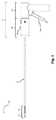
[0054]図1は、手術器具2の一実施形態を示す。手術器具は、ハンドル4と、ハンドル4から先端側に延出する長尺状シャフトアセンブリ6と、を含む。長尺状シャフトアセンブリの先端部から留置されるファスナに加え、長尺状シャフトアセンブリ6は関節動作可能部分8を含んでもよい。手術器具2は、また、対応するファスナ留置システム15(図2を参照)を作動し、且つファスナを組織内に留置するためのトリガ14を含んでもよい。 FIG. 1 illustrates one embodiment of a
[0055]関節動作可能部分8は、関節動作制御部10を用いて、非関節(すなわち直線)動作位置などの第1の位置と、完全関節動作位置などの第2の位置との間において関節式に動作してもよい。いくつかの実施形態では、関節動作可能部分8は第1の位置と第2の位置との間においてのみ関節式に動作してもよい。本開示はこの方法において限定されないため、他の実施形態においては、関節動作可能部分8は、1つ又は複数の予め選択した関節動作位置又は任意の(すなわち予め選択されていない)関節動作位置に関節式に動作してもよい。更に、実施形態によっては、関節動作可能部分8は1つの方向のみに関節式に動作しても、2つの方向に関節式に動作してもよい。例えば、関節動作可能部分8は約0°〜90°、0°〜45°、−90°〜90°、−180°〜180°又は任意の他の適切な角度範囲において関節式に動作してもよい。加えて、いくつかの実施形態では、関節動作可能部分8は2つの異なる軸線の周りにおいて関節式に動作してもよい(例えば、水平方向及び垂直方向における関節動作)。 [0055] The joint
[0056]いくつかの実施形態では、先端側先端の位置決めを容易にするために長尺状シャフトアセンブリ6を回転させることが望ましい場合がある。そのような実施形態の1つは図1及び図12に示される。長尺状シャフトアセンブリ6の回転は任意の適切な方法で提供してもよい。例えば、長尺状シャフトアセンブリ6は単にハンドル4の少なくとも一部に対し回転可能となるように構成してもよい。あるいは、長尺状シャフトアセンブリ6を含むハンドル4の一部はグリップを含む部分などのハンドル4の別の部分に対して回転可能であってもよい。そのような実施形態の1つを図1に示す。示される実施形態においては、手術器具2は、第1のハンドル部16と、長尺状シャフトアセンブリ6を含む第2のハンドル部18と、を含む。第1のハンドル部16及び第2のハンドル部18は互いに対して回転可能となるように任意の適切な方法で構成及び配置してもよい。図には回転可能な長尺状シャフトアセンブリ6又はハンドル4を含む手術器具を示すが、本開示はこの方法に限定されないため、一体型ハンドル及び/又はハンドルに対し固定された長尺状シャフトアセンブリ6を含む手術器具もまた可能であることは理解すべきである。 [0056] In some embodiments, it may be desirable to rotate the
[0057]特定の用途においては、関節動作可能部分8から先端側に配置された剛性直線部12を含むと有利な場合がある。例えば、理論に拘束されることを望むものではないが、ファスナがカーブを進む際にドライブシャフトがファスナに力を印加する場合、ドライブシャフトによってファスナの基端側部分に印加される力はファスナの留置方向と整列していない場合がある。これにより、印加される力の一部が長尺状シャフトアセンブリ6の側面に対し誘導されることとなる場合がある。これに対し、ドライブシャフトがファスナに対し直線部分に沿って力を印加する場合、印加される力はファスナの留置方向と整列する。したがって、関節動作可能部分8から特定の長さだけ先端側に延出する剛性直線部12を含むことにより、印加される作動力は留置方向と整列することができるため、ファスナを留置するためにドライブシャフトが印加する作動力が低下することを可能としてもよい。更に、留置方向と整列した作動力の印加により、手術器具が様々な関節角度間において変化するため、ファスナ留置の一貫性もまた向上してよい。上記の利点に加え、剛性直線部12は、また、手術器具からのファスナの位置決め及び留置を補助するために他の構成要素又は特徴を組み込んでもよい。先端側剛性直線部12を含む手術器具2が本明細書中に記載され且つ図に示されるが、手術器具が先端側剛性直線部を含まないように関節動作可能部分8が長尺状シャフトアセンブリ6の先端部まで延在する実施形態も想定されることは理解すべきである。 [0057] In certain applications, it may be advantageous to include a rigid
[0058]前述のように、手術器具2は、また、図2に示されるようなファスナ留置システム15を含んでもよい。ファスナ留置システム15は任意の数の異なる方法で具現化してもよい。しかしながら、図2に示される特定の実施形態においては、ファスナ留置システムは、トリガ14と、剛性リンク20と、シャトル22と、パワーアシストデバイス24と、往復動ドライブシャフト26と、図示しない他の構成要素と、を含んでもよい。トリガ14の作動により、剛性リンク20が先端側に移動し、シャトル20が先端側に移動して、パワーアシストデバイス24にエネルギーを蓄積してもよい。予め選択した量の動作後,パワーアシストデバイス24は蓄積されたエネルギーを放出し、ドライブシャフト26を先端側へと加速させ、長尺状シャフトアセンブリ6の先端部からファスナを留置してもよい。 [0058] As mentioned above, the
[0059]特定のパワーアシストデバイス24が示されるが、パワーアシストデバイス24は手術器具の長尺状シャフトアセンブリ6からのファスナの留置を補助することが可能な任意の適切な構造に対応してもよい。特定の実施形態によっては、パワーアシストデバイス24は、トリガ14の作動に応答してファスナを留置するのに必要な動力の全てを供給しても、ファスナを留置するのに必要な動力の一部のみを供給してもよい。1つの特定の実施形態においては、パワーアシストデバイス24は、本出願と同日に出願された手術器具用のパワーアシストデバイス(POWER ASSIST DEVICE FOR A SURGICAL INSTRUMENT)という名称の米国特許出願第13/804,043号に開示されているパワーアシストデバイスに一致してもよい。パワーアシストデバイスを含む手術器具が示されているが、いくつかの実施形態では,手術器具2はパワーアシストデバイスを含まなくてもよく、この場合、トリガ12の作動により、適切な変速機の使用により直接的又は間接的のいずれかにおいてドライブシャフト26を移動し、長尺状シャフトアセンブリ6の先端部からファスナを留置してもよい。 [0059] Although a particular power assist device 24 is shown, the power assist device 24 may correspond to any suitable structure capable of assisting fastener placement from the
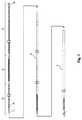
[0060]図3は、長尺状シャフトアセンブリ6及び長尺状シャフトアセンブリ内に配置された種々の構成要素の一実施形態の分解図を示す。示される実施形態においては、ドライブシャフト26は長尺状シャフトアセンブリ6内に配置されている。図2及び図3によって示されるように、長尺状シャフトアセンブリ6内に配置されている場合、ドライブシャフト26は長尺状シャフトアセンブリ6から基端側へとハンドル4内に延在する。手術器具は、また、ファスナのスタック28と、フォロア34と、ドライブシャフト26の内部チャネル内に配置された後退防止要素と、を含む。ファスナのスタック28は1つ又は複数のファスナ30を含んでもよく、場合によっては、複数のファスナ30であってもよい。 [0060] FIG. 3 shows an exploded view of one embodiment of the
[0061]上記構成要素に加え、手術器具は、また、ファスナのスタック28、フォロア34及びドライブシャフト26の内部チャネル内の後退防止要素36のアライメントの維持を補助するためのファスナガイド32を含んでもよい。任意の適切な構造を用いてもよいが、示される実施形態においては、ファスナガイド32は、ドライブシャフトのチャネルのほぼ中心に配置された、先端側に延在するワイヤである。ファスナガイド32は任意の適切な方法でチャネル内に保持されてもよい。例えば、ファスナガイド32は後退防止要素36の一部、ハンドル4の一部又は任意の他の適切な構造に取り付けてもよい。更に、より速いガイド32は、接着剤、機械的な干渉、クランプ、はんだ付け及び溶接を含むがこれらに限定されない任意の適切な方法を用いて取り付けてもよい。 [0061] In addition to the above components, the surgical instrument may also include a
[0062]トリガを作動すると、ファスナ留置システムが作動され、ドライブシャフト26の先端側への移動が生じてもよい。以下に更に詳細に記載するように、ドライブシャフト26の先端側への移動により、ファスナ留置位置に配置された最先端側ファスナが留置される。ドライブシャフト26は、また、フォロア34を先端側に移動し、ファスナのスタック28を移動して、次の最先端側ファスナをファスナ留置位置に配置する。フォロイング34の先端側への移動により、先端側方向に延在する後退防止要素がフォロア34の基端側への動きを妨げるようにフォロア34と後退防止要素36とは対応付けられてもよい。ファスナの留置及び次のファスナのファスナ留置位置への配置後、ドライブシャフト26は、ファスナのスタック28、フォロア34及び後退防止要素36の基端側への動きを妨げつつ、基端側方向に移動し、手術器具を次の作動に備えてもよい。 [0062] Actuating the trigger activates the fastener placement system and may cause the
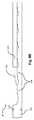
[0063]フォロア34とドライブシャフト26との間の相互作用を図4〜6に示す。 [0063] The interaction between the
[0064]示される実施形態においては、フォロア34は、従動要素100と、弾性要素102と、押込要素104と、を含む。従動要素100はドライブシャフト26と相互作用してフォロア34を先端側方向に移動するように構成されている。従動要素100はドライブシャフト26上の開口部124と相互作用するタブ106を含む。タブ106は可撓性であってもよく、従動要素100から外側及び先端側に延出してもよい。加えて、タブ106は、従動要素100がドライブシャフト26内を先端側に移動する際にタブ106が開口部124内に配置されうるようなサイズにしても、形状にしても、配置にしてもよい。従動要素100は、また、先端側部分108a及び肩部110を含んでもよい。先端側部分108a及び肩部110は弾性要素102の先端部を先端側部分108a上において保持するようなサイズ及び形状にしてもよい。先端側部分108aは、また、1つ又は複数の保持特徴部116を含んでもよい。示される保持特徴部116は、先端側部分108aに配置され、弾性要素102を妨げて先端側部分108a上に弾性要素を保持する突起物である。あるいは、弾性要素102は、機械的な干渉、インターロック機能、接着剤、溶接、はんだ付け及びろう付けを含むがこれらに限定されない任意の適切な方法を用いて従動要素100上に保持してもよい。従動要素100は、また、基端側部分108bに配置されたカップリング118を含んでもよい。カップリング118はフォロア34を後退防止要素36に取り付けるように適合され且つ配置されてもよい。 [0064] In the illustrated embodiment, the
[0065]示される弾性要素102は従動要素100と押込要素104との間に延在するコイルばねである。上に示したように、コイルばねが示されるが、コイルばねの代わりに他のばね及び適切な構成要素を用いることもできる。弾性要素102として使用される特定の構成要素にかかわらず、弾性要素102は、従動要素100及び押込要素104の両方に対応付けられるようなサイズにしても、形状にしても、配置にしてもよい。更に、ばね又は他の適切な圧縮可能な構成要素の使用により、従動要素が先端側方向に移動すると、弾性要素102が圧縮されて押込要素104に力を印加する。押込要素104の動作前における従動要素100の移動が大きいほど弾性要素102の圧縮が大きくなってもよく、同様に、力が大きくなってもよい。本開示はこの方法において限定されないため、特定の実施形態によっては、弾性要素102は移動関係に対し直線力又は移動関係に対し非直線力を示してもよい。 [0065] The
[0066]従動要素100と同様に、押込要素104は、弾性要素102の先端部を保持するようなサイズ及び形状の基端側部分112b及び肩部114を含んでもよい。押込要素104は、また、従動要素100に関して上述したものに類似する、弾性要素102を保持するための1つ又は複数の保持特徴部116を含んでもよい。押込要素104は、また、ファスナスタックの最も基端側に配置されたファスナに力を印加するように適合され且つ配置された先端側部分112aを含んでもよい。いくつかの実施形態では、先端側部分112aはファスナのスタック内の少なくとも最基端側ファスナに直接接触してもよいが、先端側部分112aがファスナのスタックに間接的に力を印加する実施形態もまた想定される。 [0066] Like the driven
[0067]図5に示されるように、ドライブシャフト26はドライブシャフト26の先端部に配置された1つ又は複数のファスナ駆動要素120を含んでもよい。いくつかの実施形態では、ファスナ駆動要素120はドライブシャフト26の先端部から内方向及び先端側に延出する1つ又は複数の可撓性タブであってもよい。ファスナ駆動要素120は、ファスナ留置位置に配置されたファスナに力を印加し、長尺状シャフトアセンブリの先端部からファスナを留置するように構成してもよい。ドライブシャフトは、また、長尺状シャフトアセンブリの関節動作可能部分内における往復動ドライブシャフトの動きに適応するために可撓性部分122を含んでもよい。示される実施形態においては、可撓性部分122はあるパターンのスロット又は切り込みをドライブシャフト26に設けることによって形成される。上に示したように、ドライブシャフト26は、また、伸張位置において従動要素100のタブ106を収容するようなサイズ及び形状の開口部124を含んでもよい。1つ又は複数組の開口部124がドライブシャフト124の1つ又は複数の表面に沿って軸方向に間隔を空けて配置されてもよい。いくつかの実施形態では、開口部124間の軸方向の間隔は1つのファスナの長さに相当してもよい。本実施形態においては、2組の開口部124がドライブシャフト26の両側に沿って延在し、従動要素100のタブ106の両方を収容する。開口部124はドライブシャフト24の全体に沿って延在してもよく、あるいは、図に示されるように、開口部124は、フォロア34の初期基端側位置及び全てのファスナが手術器具から留置された後のフォロア34の最終先端側位置に相当するドライブシャフト24の一部に沿って延在してもよい。 [0067] As shown in FIG. 5, the
[0068]ドライブシャフト26及びフォロア34の対応する特徴を記載したが、1つの可能な実施形態における、作動中のこれら2つの構成要素の相互作用についてここで記載する(図6を参照)。作動前、従動要素100のタブ106は伸張状態においてドライブシャフト26の対応する開口部124の任意の1つ内に配置されてもよい。タブ106が対応する開口部124内において伸張状態にある間、開口部の基端側縁端などのドライブシャフト124aの基端側部分はタブ106の基端側側面106aと軸方向に整列してもよい。したがって、作動中、ドライブシャフト26が先端側方向に移動すると、基端側ドライブシャフト部124aはタブ106の基端側側面106aに先端側誘導力を印加し、従動要素100の先端側への移動が生じる。ファスナが留置された後、ドライブシャフト26は続いて基端側方向に移動する。ドライブシャフト26の基端側への動きの最中、開口部124の先端側縁端などのシャフト124bの先端側部分はタブの外部表面などの外部側面106b上に引き出されてもよい。以下に更に詳細に記載するように、従動要素100はドライブシャフト26と従動要素100との相対運動中に後方に移動することを妨げられてもよい。更に、上に示したように、タブ106は可撓性である。したがって、先端側ドライブシャフト部124bがタブの外部側面106b上に引き出されている際、タブ106は内方向に移動し、開口部124から出て従動要素100とドライブシャフト26との相対運動を可能にしてもよい。ドライブシャフト26の基端側への移動は、タブ106が次の先端側に配置された開口部124の組と整列し、且つタブ106が開口部124内において伸張状態になるまで継続してもよい。後の作動サイクルでは、従動要素100がドライブシャフトの次の対応する開口部124の組と係合するため、従動要素100が先端側方向に継続的に移動してもよい。上記に鑑み、フォロア34の従動要素100及びドライブシャフト26は、ファスナ留置システムの各作動サイクル中フォロア34を先端側方向に順次移動するように構成されたウォーキングビームアセンブリの2つの別個の構成要素を形成するものとして記載されうる。 [0068] Although the corresponding features of
[0069]図7A〜7Bは、ファスナ留置システムの作動サイクル中におけるファスナのスタック28、フォロア34及び後退防止要素36の相互作用を示す。図に示されるように、押込要素104はファスナスタック28の基端側に配置されたファスナと接触してもよい。弾性要素102は、また、押込要素104の基端側部分及び従動要素100の先端側部分と対応付けられてもよい。従動要素100はカップリング130によって後退防止要素36のラックアーム126に結合されてもよい。従動要素100とラックアーム126とは、従動要素100の先端側への動きによりラックアーム126が後退防止要素36の爪付きアーム128に対して先端側に伸展しうるような状態で結合されてもよい。したがって、フォロア34が長尺状シャフトアセンブリ内において先端側に移動すると、後退防止要素36は同様に伸長する。したがって、フォロア34の基端側への動きは作動サイクル全体にわたり後退防止要素36によって妨げられてもよい。図に示されるように、カップリング130はピン連結に相当する。しかしながら、インターロック式の機械的な特徴、止めねじ、ファスナ、接着剤、溶接、ろう付け及びしまり嵌めを含むがこれらに限定されない任意の適切な連結を使用してもよい。 [0069] FIGS. 7A-7B illustrate the interaction of
[0070]作動前、図7Aに示されるように、フォロア34の弾性要素102は第1の長さに相当する伸張状態にあり、先端側に配置された押込要素104及びファスナのスタック28に第1の先端側誘導力を印加してもよい。フォロア34及びファスナのスタック28は後退防止要素36によって先端側方向への移動が妨げられる。示される実施形態においては、後退防止要素36は、先端側方向に移動してもよいラックアーム126と、手術器具の作動中静止したままの爪付きアーム128と、を含む。 [0070] Prior to operation, as shown in FIG. 7A, the
[0071]図7Bを参照すると、ファスナ留置システムが作動されると、不図示のドライブシャフトは従動要素100のタブ106に力FDを印加してもよく、これにより、上述のように従動要素100を先端側方向に駆動する。基端側に誘導される第1の拘束力FR1がファスナのスタック28に印加されてもよい。当初、第1の拘束力FR1は力FDに等しくてもよい。したがって、動作の初期部分の間、ファスナのスタック28は静止したままであってもよく、その結果、押込要素104と従動要素100との間の弾性要素102の圧縮が生じる。作動が継続する際、弾性要素102が更に圧縮されるにつれて従動要素100に印加される力は増加し続けてもよい。この継続的な弾性要素102の圧縮により、ファスナのスタック28に対し増加する先端側誘導力を印加する。作動中のある時点において、ばねは弾性要素102に相当する第2の長さまで圧縮され、押込要素104及び対応するファスナのスタック28に対し第2の先端側誘導力を印加してもよい。この第2の先端側誘導力は第1の拘束力FR1よりも大きく、弾性要素102の伸張並びに押込要素104及び対応するファスナのスタック28の先端側への移動を生じてもよい(図7B〜7Cを参照)。[0071] Referring to FIG. 7B, when the fastener placement system is activated, a drive shaft (not shown) may be applied a force FD in the
[0072]図によって示されるように、ファスナのスタック28が先端側方向に移動するにつれて弾性要素102は第2の長さから第1の長さへと伸張し続ける。弾性要素102が伸張した第1の長さに近づくと、ファスナのスタック28に対し基端側に誘導される第2の拘束力FR2が印加され、ファスナのスタックの先端側への更なる動きを妨げてもよい。弾性要素102によってファスナのスタック28に印加される力と、ファスナのスタック28及びフォロア34が先端側に移動する際それらに蓄積される、予想される運動エネルギーとの両方に抗するため、第2の拘束力FR2は第1の拘束力よりも大きくてもよい。第2の拘束力は、また、長尺状シャフトアセンブリからファスナを留置するために作動力よりも小さくてもよい。いくつかの実施形態では、スタックファスナ20のうちの先端側に配置されたファスナがファスナ指定位置に配置されると、第2の拘束力FR2が印加されてもよい。ファスナのスタック28が先端側に移動し、ファスナ留置システムがリセットされた後、手術器具が再度作動され、その結果、フォロア34及び対応するファスナのスタック28の更なる先端側への移動が生じてもよい。[0072] As shown by the figure, the
[0073]フォロア34及び対応するファスナのスタック28の移動に加え、ファスナ留置システムの作動により、また、上に示したように後退防止要素36の伸長が生じてもよい。より具体的には、従動要素100及びラックアーム126が結合されているため、従動要素100の先端側への移動により爪付きアーム128に対する、ラックアーム126の対応する先端側への移動が生じてもよい。ファスナのスタック28が先端側に移動した後、ラックアーム126の先端側への動きにより後退防止要素36が先端側方向に伸長し、従動要素100の後方への動きを妨げてもよい。ラックアーム126と爪付きアーム128との相互作用を図8A及び図8Bにより詳細に示す。歯134はラックアーム126の軸方向長さに沿って間隔を空けて配置してもよい。対応する爪132を爪付きアーム128の先端側部分に配置してもよい。爪132及び対応する歯134は従動要素の先端側への動きに応じてラックアーム126の先端側への動きを可能にするように適合され且つ配置されてもよい。爪132及び対応する歯134は、また、ラックアーム126の基端側への動きを妨げるように適合され且つ配置されてもよい。一実施形態においては、歯134間の距離は1つのファスナ長さにほぼ等しくてもよい。しかしながら、歯134間の距離がファスナ長さの数分の1である又はファスナ長さよりも長い実施形態もまた想定される。上記に加え、後退防止要素36としてラック及び爪システムを示したが、フォロア及びスタックファスナの後方への動きを妨げることが可能な任意の適切な機構が使用されうる。 [0073] In addition to movement of the
[0074]図9〜12は、長尺状シャフトアセンブリ6の構成要素である内部管状部材200を示す。内部管状部材200は、長尺状シャフトアセンブリ6の先端部を形成する剛性直線部12を含む。内部管状部材は、また、剛性直線部12内に配置された1つ又は複数の第1の拘束要素202及び1つ又は複数の第2の拘束要素204を含んでもよい。図9に示されるように、2つの第2の拘束要素204は第1の拘束要素202に対し先端側に配置されている。第1の拘束要素は、作動中、ファスナのスタックに対し第1の拘束力を付与するように適合され且つ配置されてもよい。同様に、第2の拘束要素204は、作動中、スタックファスナに対し第2の拘束力を付与するように適合され且つ配置されてもよい。前述のように、第1の拘束力は第2の拘束力よりも小さくてもよい。本開示はファスナのスタックに対し拘束力が印加される方法に限定されないため、種々の拘束力を任意の数の方法で付与してもよい。いくつかの実施形態では、拘束要素は長尺状シャフトアセンブリ又は長尺状シャフトアセンブリの構成要素と一体形成してもよい。あるいは、拘束要素は別個に形成し、長尺状シャフトアセンブリに対し、溶接、はんだ付け、接着剤、しまり嵌め及びファスナを含むがこれらに限定されない任意の適切な方法で組み付けてもよい。 FIGS. 9-12 show an inner
[0075]種々の第1及び第2の拘束力を任意の適切な方法で付与してもよい。例えば、一実施形態においては、異なる第1及び第2の拘束力を付与するために第1及び第2の拘束要素の異なるコンプライアンスを用いてもよい。より具体的には、第2の拘束要素は第1の拘束要素よりもコンプライアンスが低くてもよい。別の実施形態においては、異なる第1及び第2の拘束力を様々な数の第1及び第2の拘束要素を用いて付与してもよい。このような一実施形態においては、第1の拘束要素の数と比較してより多数の第2の拘束要素を用いてもよい。異なる拘束力を提供する特定の方法を上記したが、拘束力を提供する他の方法もまた企図される。 [0075] The various first and second restraining forces may be applied in any suitable manner. For example, in one embodiment, different compliances of the first and second restraining elements may be used to apply different first and second restraining forces. More specifically, the second constraint element may be less compliant than the first constraint element. In other embodiments, different first and second restraining forces may be applied using various numbers of first and second restraining elements. In such an embodiment, a greater number of second constraint elements may be used compared to the number of first constraint elements. While specific methods for providing different restraining forces have been described above, other methods for providing restraining forces are also contemplated.
[0076]1つの可能な実施形態においては、及び図9〜12に示されるように、第1の拘束要素202及び第2の拘束要素204は長尺状シャフトアセンブリの内部管状部材200に対し内方向及び先端側に延出するタブに相当してもよい。所望の第1及び第2の拘束力を付与するために、1つのよりコンプライアンスのある第1の拘束要素202及び2つのよりコンプライアンスのない第2の拘束要素204は長尺状シャフトアセンブリの内部管状部材200の剛性直線部12に組み込まれる。第2の拘束要素204に相当するタブは第1の拘束要素202に相当するタブと比べて短い長さ及び/又は広い幅を有してもよい。理論によって拘束されることを望むものではないが、これにより、第2の拘束要素204は第1の拘束要素202よりもコンプライアンスのないものとなる。したがって、1つのよりコンプライアンスのあるタブを第1の拘束要素202として使用することに比べて2つのよりコンプライアンスのないタブを第2の拘束要素204として使用することにより、示される実施形態は第1の拘束力よりも大きい第2の拘束力を付与するように構成されている。第1及び第2の拘束要素の特定の配置構成を図に示し且つ上記したが、第1及び第2の拘束力を付与するための他の実施形態もまた可能であることは理解すべきである。 [0076] In one possible embodiment, and as shown in FIGS. 9-12, the
[0077]第1の拘束要素202と、第2の拘束要素204と、ファスナ30と、ファスナ留置システムのドライブシャフト26との間の相互作用を、ファスナ留置システムの作動中における長尺状シャフトアセンブリ6の先端側部分の一連の断面を示す図13A〜13Cによって示す。作動前、先端側に配置されたファスナ30がファスナ留置位置206に配置される。ファスナ留置位置206は第1の拘束要素202と第2の拘束要素204との相対位置によって画定されてもよい。第1の拘束要素202及び第2の拘束要素204は作動前にそれらの間にファスナ30の頭部30aを保持することによってファスナ留置位置を画定してもよい。拘束要素202及び204を用いてファスナ30をファスナ留置位置206に保持すると、ファスナが長尺状シャフトアセンブリ6から意図せずに移動して出ることを有利に防止しうるとともに、次の留置のためのファスナの一貫した位置を提供する。ファスナ留置システムの作動時、ドライブシャフト26は先端側に移動し、その結果、ファスナ駆動要素120がファスナ留置位置206に配置されたファスナ30に力を印加する。印加される作動力は第2の拘束要素204によって付与される第2の拘束力よりも大きく、その結果、図13Bに示されるようなファスナの先端側への移動及び留置が生じる。上に示したように、ファスナのスタックは、ファスナのスタックを先端側に移動するために印加される、及び次の作動サイクルのため次のファスナをファスナ留置位置206に配置するために印加される別個の力を有してもよい。ファスナ留置システムを次の作動サイクルのためにリセットするためドライブシャフト26が基端側方向に引き抜かれると、ファスナ駆動要素120はファスナ留置位置206に配置されたファスナ30の頭部30aの周り及びファスナ30の頭部30aを越えて変形する(図13Cを参照)。図に示されるように、第1の拘束要素202及び第2の拘束要素204に相当するタブは、拘束要素202及び204から先端側に配置されているファスナ30の基端側への動きに耐えるように配置及び構成されてもよい。したがって、ドライブシャフトが基端側方向に移動する際、ファスナ留置位置206に配置されたファスナ30の基端側への動きが第1の拘束要素202によって妨げられてもよい。ドライブシャフト26が基端側方向に完全に移動すると、手術器具は次のファスナを留置する準備ができる。 [0077] The interaction between the
[0078]上記の実施形態は基端側方向及び先端側方向におけるドライブシャフトの往復動動作によって駆動されるフォロアに関するものであるが、他の実施形態も可能である。例えば、一実施形態においては、フォロアは、ドライブシャフトの回転により、フォロア及びドライブシャフト内に配置された対応するファスナの先端側への移動が生じてもよいように回転ドライブシャフトと対応付けられてもよい。別の例示的実施形態においては、フォロアはファスナ留置システムの作動によりフォロアの先端側への動きが生じるようにファスナ留置システムの別の構成要素と対応付けられてもよい。例えば、フォロアはトリガ14、剛性リンク20又はシャトル22と対応付けられてもよい。更に、フォロアは上記構成要素のいずれかと直接的又は間接的に対応付けられてもよい。 [0078] Although the above embodiment relates to a follower driven by a reciprocating motion of the drive shaft in the proximal and distal directions, other embodiments are possible. For example, in one embodiment, the follower is associated with the rotating drive shaft such that rotation of the drive shaft may cause movement of the follower and the corresponding fastener disposed within the drive shaft to the distal side. Also good. In another exemplary embodiment, the follower may be associated with another component of the fastener placement system such that actuation of the fastener placement system causes movement of the follower to the distal side. For example, the follower may be associated with the
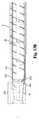
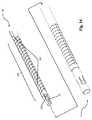
[0079]前述のように、次のファスナをファスナ留置位置に配置するためにファスナのスタックを移動することに加え、いくつかの実施形態では、長尺状シャフトアセンブリ内においてファスナの特定の向きを維持することが望ましい場合がある。図14は、長尺状シャフトアセンブリ6及び長尺状シャフトアセンブリ6の内部内に配置されてもよいドライブシャフト26の概略分解図を示す。示される長尺状シャフトアセンブリ6の外側に形成されたスロットのパターンは、関節動作可能部分8に相当する長尺状シャフトアセンブリ6の部分に可撓性を付与する。示される実施形態においては、ドライブシャフトはその中に配置される1つ又は複数のファスナ30を収容するための内部チャネルを含む。ドライブシャフト26は、また、案内面136を含んでもよい。案内面136は任意の適切な形状であってもよく、図に示されるように、ドライブシャフト26の軸方向に延在する平坦面に相当してもよい。ファスナ30がドライブシャフト26内に配置されている間、及び作動中、ドライブシャフトが先端側位置と基端側位置との間において往復運動する際、案内面136はファスナの向きを維持するためにファスナ30の対応する表面と相互作用してもよい。案内面136に加え、ドライブシャフト26は、また、ファスナ30がファスナ留置位置に配置される際にファスナ30の向きを維持するためにファスナ30の対応する表面と相互作用するファスナ駆動要素120aを含んでもよい。 [0079] As described above, in addition to moving the stack of fasteners to place the next fastener in the fastener detained position, in some embodiments, a particular orientation of the fastener within the elongate shaft assembly is determined. It may be desirable to maintain. FIG. 14 shows a schematic exploded view of the
[0080]示される実施形態においては、案内面136に相当する平坦面はドライブシャフト26の内部チャネルの内側表面にある。更に、案内面136は任意選択的にドライブシャフト26の外部表面にも存在してよい。案内面136の特定の形状を示したが、ドライブシャフト26内に配置されるファスナ30の向きを維持するための任意の適切な形状又は特徴の組み合わせがドライブシャフト26上に存在しうる。例えば、案内面136は、突起物、溝又は任意の他の適切な形状に相当してもよい。更に、案内面136はドライブシャフト26の任意の適切な部分に沿って延在してもよい。例えば、本開示はこの方法において限定されないため、案内面136はドライブシャフトの先端側部分、ドライブシャフトの可撓性部分122、ドライブシャフト内に配置されたファスナのスタックに対応するドライブシャフトの部分、又はドライブシャフトの長さ全体に沿って延在してもよい。 [0080] In the illustrated embodiment, the flat surface corresponding to the
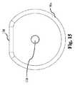
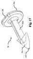
[0081]図15〜17は、ドライブシャフト26とともに使用するためのファスナ30の1つの可能な実施形態を示す。示されるファスナ30の実施形態は、頭部30aと、頭部30aから延出するシャフト30bと、シャフト30bの先端部にある返しの付いた端部30cと、を含む。ドライブシャフトの案内面136に対応する表面138が頭部30aに配置されてもよい。ファスナ30がドライブシャフト26の内側表面と滑らかに接合するように表面138は案内面136ドライブシャフトを補完するようなサイズ及び形状にしてもよい。示される実施形態においては、表面138は、頭部30aの断面がドライブシャフトの内部チャネルの断面の対応する平坦部及び丸み部を補完するようなサイズ及び形状の平坦部及び丸み部を含むような平坦面に相当する。案内面136に対応する表面138はファスナの頭部30aに位置するものとして示したが、表面138はファスナ30の任意の適切な部分に位置してもよい。例えば、シャフト30bの一部又は返しの付いた端部30cはファスナ30の向きを維持するためにドライブシャフトの案内面136と相互作用するような形状、サイズ及び配置にされた対応する表面又は特徴を含みうる。 [0081] FIGS. 15-17 illustrate one possible embodiment of a
[0082]ファスナ30上に存在する、案内面136に対応する表面138に加え、ファスナ30は、また、頭部30aの基端側表面からシャフト30b及び返しの付いた端部30cを通過して先端側に延出する貫通穴140を含んでもよい。上述のように、長尺状シャフトアセンブリ内におけるファスナ30のアライメントを維持するために貫通穴140はファスナガイドを収容するようなサイズ及び形状にしてもよい。本開示は貫通穴140がどこに配置されるかについては限定されないため、貫通穴140は中心に配置しても、半径方向にオフセットしても、又は任意の他の適切な位置に配置してもよい。長尺状シャフトアセンブリ内におけるファスナ30のアライメントの維持を補助するために貫通穴140を含むことが望ましい場合があるが、また、特定の実施形態においては、図に示されるようにファスナに尖頭の先端142を設けることが望ましい場合がある。しかしながら、尖頭でない先端及び対応する針を用いた実施形態もまた想定される。貫通穴140を収容するため、尖頭の先端142は貫通穴140に対し半径方向にオフセットしてもよい。 [0082] In addition to the
[0083]図18は、ドライブシャフト26の内部チャネル140内に配置された、先端側に配置されたファスナ30を示す。図によって示されるように、ドライブシャフト26の案内面136及びファスナ駆動要素120aはファスナ30の対応する表面138と整列している。内部チャネル断面の平坦部とファスナ頭部の平坦部(すなわち案内面136と対応する表面138)及び内部チャネル断面の丸み部とファスナ頭部の丸み部との相互作用により、ファスナ30はドライブシャフト26の長さ全体にわたり予め選択した向きに維持されてもよい。 [0083] FIG. 18 shows the distally disposed
[0084]図19は、長尺状シャフトアセンブリ6内に配置された図18のファスナ30及びドライブシャフト26を示す。図13Bによって最も良く示されるように、いくつかの実施形態では、ファスナを留置するためにドライブシャフト26が先端側に移動される際、ファスナ駆動要素120は第1の拘束要素202及び第2の拘束要素204に対し先端側に延在してもよい。したがって、ファスナ駆動要素120並びに第1の拘束要素202及び第2の拘束要素204を、ドライブシャフトの先端側への移動中、それらが互いに妨げることのないように配置することが望ましい場合がある。示される実施形態においては、ドライブシャフトの先端側への移動中、ファスナ駆動要素122が第1の拘束要素202及び第2の拘束要素204を妨げることのないようにファスナ駆動要素120はドライブシャフト26の先端部に三角形のパターンで配置されており、第1の拘束要素202及び第2の拘束要素204は長尺状シャフトアセンブリ6の内側表面周囲に別の対応する三角形のパターンで配置されている。特定の数及び配置のファスナ駆動要素及び拘束要素を図に示し且つ本明細書中に記載してきたが、本開示はこのように限定されないことは理解すべきである。代わりに、任意の適切な数及び配置のファスナ駆動要素及び拘束要素を使用してもよい。更に、他の適切な種類のファスナ駆動要素及び拘束要素もまた使用してよい。 FIG. 19 shows the
[0085]本教示を種々の実施形態及び例とともに記載してきたが、本教示はそのような実施形態又は例に限定されることを意図しない。逆に、当業者には理解されるように、本教示は種々の代替物、変更形態及び均等物を含む。したがって、前述の記載及び図面は単に例である。 [0085] Although the present teachings have been described in conjunction with various embodiments and examples, the present teachings are not intended to be limited to such embodiments or examples. On the contrary, the present teachings include various alternatives, modifications and equivalents, as will be appreciated by those skilled in the art. Accordingly, the foregoing description and drawings are merely examples.
Claims (38)
Translated fromJapanese前記ハンドルから先端側に延出する長尺状シャフトアセンブリと、
前記長尺状シャフトアセンブリからファスナを留置するためのファスナ留置システムと、
前記長尺状シャフトアセンブリ内に配置され、且つ前記長尺状シャフトアセンブリ内に配置された1つ又は複数のファスナと対応付けられたフォロアと、
を含み、前記ファスナ留置システムの作動により前記フォロアが第1の長さから第2の長さへと圧縮して前記1つ又は複数のファスナに対し先端側誘導力を印加し、前記ファスナを先端側方向に移動させ、前記1つ又は複数のファスナの移動中、前記フォロアが前記第2の長さから前記第1の長さへと伸張する、手術器具。A handle,
An elongate shaft assembly extending from the handle toward the distal end;
A fastener placement system for placing a fastener from the elongate shaft assembly;
A follower disposed within the elongate shaft assembly and associated with one or more fasteners disposed within the elongate shaft assembly;
The follower is compressed from a first length to a second length by the operation of the fastener indwelling system to apply a leading-side induction force to the one or more fasteners, A surgical instrument that is moved laterally and the follower extends from the second length to the first length during movement of the one or more fasteners.
前記ハンドルから先端側に延出する長尺状シャフトアセンブリと、
前記長尺状シャフトアセンブリからファスナを留置するためのファスナ留置システムであって、前記ファスナ留置システムが前記長尺状シャフトアセンブリ内に配置されたドライブシャフトを含む、ファスナ留置システムと、
前記長尺状シャフトアセンブリ内に配置され、且つ前記ドライブシャフトに対応付けられたフォロアと、
を含み、前記ドライブシャフトの先端側への移動により前記長尺状シャフトアセンブリからファスナが留置され、前記ドライブシャフトの前記先端側への移動により前記フォロアが先端側方向に移動し、前記長尺状シャフトアセンブリ内に配置された1つ又は複数のファスナが先端側方向へと移動し、前記留置されたファスナに前記ドライブシャフトによって印加される力が前記1つ又は複数のファスナに前記フォロアによって印加される力よりも大きい、手術器具。A handle,
An elongate shaft assembly extending from the handle toward the distal end;
A fastener placement system for placing a fastener from the elongate shaft assembly, the fastener placement system comprising a drive shaft disposed within the elongate shaft assembly;
A follower disposed within the elongate shaft assembly and associated with the drive shaft;
A fastener is detained from the elongated shaft assembly by movement of the drive shaft toward the distal end side, and the follower moves in the distal end direction by movement of the drive shaft toward the distal end side, and the elongated shape One or more fasteners disposed within the shaft assembly move in a distal direction, and a force applied by the drive shaft to the deployed fastener is applied to the one or more fasteners by the follower. Surgical instruments that are greater than the force that
前記ハンドルから先端側に延出する長尺状シャフトアセンブリと、
前記長尺状シャフトアセンブリからファスナを留置するためのファスナ留置システムと、
前記長尺状シャフトアセンブリ内に配置された、前記長尺状シャフトアセンブリ内の1つ又は複数のファスナを先端側方向へと移動させるためのフォロアと、
を含み、前記フォロアが、前記ファスナ留置システムの作動前に前記1つ又は複数のファスナに第1の力を印加し、前記ファスナ留置システムの作動により前記1つ又は複数のファスナが前記先端側方向へと移動を開始した後に前記1つ又は複数のファスナに第2の力を印加し、前記長尺状シャフトアセンブリが前記1つ又は複数のファスナに第1の拘束力及び第2の拘束力を印加するように構成されており、前記第1の力が前記第1の拘束力よりも小さく、前記第2の力が前記第1の拘束力よりも大きく且つ前記第2の拘束力よりも小さい、手術器具。A handle,
An elongate shaft assembly extending from the handle toward the distal end;
A fastener placement system for placing a fastener from the elongate shaft assembly;
A follower disposed in the elongate shaft assembly for moving one or more fasteners in the elongate shaft assembly in a distal direction;
The follower applies a first force to the one or more fasteners prior to operation of the fastener placement system, and the fastener placement system is activated to cause the one or more fasteners to move in the distal direction. A second force is applied to the one or more fasteners after starting to move, and the elongate shaft assembly exerts a first and a second restraining force on the one or more fasteners. The first force is smaller than the first restraining force, the second force is larger than the first restraining force and smaller than the second restraining force. , Surgical instruments.
前記ハンドルから先端側に延出する長尺状シャフトアセンブリと、
前記長尺状シャフトアセンブリと対応付けられている第1の拘束要素と、
前記長尺状シャフトアセンブリと対応付けられており、且つ前記第1の拘束要素から先端側に配置されている第2の拘束要素であって、前記第1の拘束要素及び前記第2の拘束要素がファスナ留置位置を画定する、第2の拘束要素と、
前記長尺状シャフトアセンブリからファスナを留置するためのファスナ留置システムであって、前記ファスナ留置位置に配置されたファスナに留置力を印加するように適合され且つ配置されたドライブシャフトを含む、ファスナ留置システムと、
を含む、手術器具。A handle,
An elongate shaft assembly extending from the handle toward the distal end;
A first restraining element associated with the elongate shaft assembly;
A second restraining element associated with the elongate shaft assembly and disposed distally from the first restraining element, wherein the first restraining element and the second restraining element A second restraining element defining a fastener detention position;
A fastener placement system for placing a fastener from the elongate shaft assembly, the fastener placement system including a drive shaft adapted and arranged to apply a placement force to a fastener disposed at the fastener placement position. System,
Including surgical instruments.
ハンドルと、
前記ハンドルから先端側に延出する長尺状シャフトアセンブリと、
前記長尺状シャフトアセンブリからファスナを留置するためのファスナ留置システムと、
前記長尺状シャフトアセンブリ内に配置され、且つ前記長尺状シャフトアセンブリ内に配置された1つ又は複数のファスナと対応付けられたフォロアと、
を用意するステップと、
前記長尺状シャフトアセンブリからファスナを留置するために前記ファスナ留置システムを作動するステップと、
前記フォロアを第1の長さから第2の長さへと圧縮し、1つ又は複数のファスナに対し先端側誘導力を印加し、前記1つ又は複数のファスナを先端側方向に移動させるために前記フォロアを先端側に移動するステップと、
を含み、前記1つ又は複数のファスナの移動中、前記フォロアが前記第2の長さから前記第1の長さへと伸張する、方法。A method of operating a surgical instrument,
A handle,
An elongate shaft assembly extending from the handle toward the distal end;
A fastener placement system for placing a fastener from the elongate shaft assembly;
A follower disposed within the elongate shaft assembly and associated with one or more fasteners disposed within the elongate shaft assembly;
Steps to prepare,
Activating the fastener placement system to place a fastener from the elongate shaft assembly;
Compressing the follower from a first length to a second length, applying a tip-side guidance force to one or more fasteners, and moving the one or more fasteners in a tip-side direction Moving the follower to the tip side,
And the follower extends from the second length to the first length during movement of the one or more fasteners.
前記ハンドルから先端側に延出する長尺状シャフトアセンブリと、
前記長尺状シャフトアセンブリからファスナを留置するためのファスナ留置システムであって、ドライブシャフトを含む、ファスナ留置システムと、
ファスナのスタックを移動するように構成されたフォロアであって、前記ドライブシャフト内に配置された、フォロアと、
を含み、前記フォロア及び前記ドライブシャフトが前記ファスナ留置システムの各作動サイクル中に前記フォロアを先端側方向へと順次移動させるためのウォーキングビームアセンブリを形成する、手術器具。A handle,
An elongate shaft assembly extending from the handle toward the distal end;
A fastener placement system for placing a fastener from the elongate shaft assembly, comprising a drive shaft;
A follower configured to move a stack of fasteners, the follower disposed within the drive shaft;
A surgical instrument wherein the follower and the drive shaft form a walking beam assembly for sequentially moving the follower in a distal direction during each operating cycle of the fastener placement system.
前記ハンドルから先端側に延出する長尺状シャフトアセンブリと、
前記長尺状シャフトアセンブリからファスナを留置するためのファスナ留置システムであって、ドライブシャフトを含む、ファスナ留置システムと、
前記ドライブシャフトに対応付けられた後退防止要素と、
を含み、前記ファスナ留置システムの作動により前記ドライブシャフトが先端側に移動し、各作動サイクル中、前記ドライブシャフトの先端側への動きにより前記後退防止要素が予め選択した長さだけ伸長する、手術器具。A handle,
An elongate shaft assembly extending from the handle toward the distal end;
A fastener placement system for placing a fastener from the elongate shaft assembly, comprising a drive shaft;
An anti-retraction element associated with the drive shaft;
And the operation of the fastener placement system causes the drive shaft to move distally, and during each actuation cycle, the movement of the drive shaft toward the distal end causes the anti-retraction element to extend a preselected length. Instruments.
Applications Claiming Priority (3)
| Application Number | Priority Date | Filing Date | Title |
|---|---|---|---|
| US13/826,979US9427230B2 (en) | 2013-03-14 | 2013-03-14 | Handling of fasteners within a surgical instrument |
| US13/826,979 | 2013-03-14 | ||
| PCT/US2014/017657WO2014143525A1 (en) | 2013-03-14 | 2014-02-21 | Handling of fasteners within a surgical instrument |
Related Child Applications (1)
| Application Number | Title | Priority Date | Filing Date |
|---|---|---|---|
| JP2017122763ADivisionJP6486993B2 (en) | 2013-03-14 | 2017-06-23 | Fastener handling inside surgical instruments |
Publications (2)
| Publication Number | Publication Date |
|---|---|
| JP2016510650Atrue JP2016510650A (en) | 2016-04-11 |
| JP6166835B2 JP6166835B2 (en) | 2017-07-19 |
Family
ID=50290254
Family Applications (3)
| Application Number | Title | Priority Date | Filing Date |
|---|---|---|---|
| JP2016500332AActiveJP6166835B2 (en) | 2013-03-14 | 2014-02-21 | Fastener handling inside surgical instruments |
| JP2017122763AActiveJP6486993B2 (en) | 2013-03-14 | 2017-06-23 | Fastener handling inside surgical instruments |
| JP2019028244AActiveJP6698189B6 (en) | 2013-03-14 | 2019-02-20 | Fastener handling inside surgical instruments |
Family Applications After (2)
| Application Number | Title | Priority Date | Filing Date |
|---|---|---|---|
| JP2017122763AActiveJP6486993B2 (en) | 2013-03-14 | 2017-06-23 | Fastener handling inside surgical instruments |
| JP2019028244AActiveJP6698189B6 (en) | 2013-03-14 | 2019-02-20 | Fastener handling inside surgical instruments |
Country Status (6)
| Country | Link |
|---|---|
| US (3) | US9427230B2 (en) |
| EP (3) | EP2967558B1 (en) |
| JP (3) | JP6166835B2 (en) |
| CA (2) | CA2903198C (en) |
| ES (2) | ES2693342T3 (en) |
| WO (1) | WO2014143525A1 (en) |
Cited By (3)
| Publication number | Priority date | Publication date | Assignee | Title |
|---|---|---|---|---|
| JP2021510553A (en)* | 2018-01-10 | 2021-04-30 | シー・アール・バード・インコーポレーテッドC R Bard Incorporated | Surgical instruments that work with joints |
| JP2021530261A (en)* | 2018-07-12 | 2021-11-11 | デボル,インコーポレイテッド | Surgical instrument with fastener preload lockout |
| US12029416B2 (en) | 2019-04-17 | 2024-07-09 | Davol Inc. | Surgical instrument with fastener preload lock-out |
Families Citing this family (8)
| Publication number | Priority date | Publication date | Assignee | Title |
|---|---|---|---|---|
| US9427230B2 (en) | 2013-03-14 | 2016-08-30 | C.R. Bard, Inc. | Handling of fasteners within a surgical instrument |
| US9474530B2 (en) | 2013-03-14 | 2016-10-25 | C.R. Bard, Inc. | Handling of fasteners within a surgical instrument |
| US20160262754A1 (en)* | 2015-03-12 | 2016-09-15 | Nir Altman | Flexible tack guide |
| WO2017026141A1 (en)* | 2015-08-07 | 2017-02-16 | オリンパス株式会社 | Treatment device |
| US10918381B2 (en) | 2016-12-07 | 2021-02-16 | Ethicon, Inc. | Applicator instruments having drive systems with flexible members for dispensing surgical fasteners |
| US10932776B2 (en) | 2018-01-10 | 2021-03-02 | C.R. Bard, Inc. | Surgical fasteners for articulating surgical instruments |
| US10779813B2 (en) | 2018-01-10 | 2020-09-22 | C.R. Bard, Inc. | Articulating surgical instruments |
| US11116500B2 (en)* | 2018-06-28 | 2021-09-14 | Covidien Lp | Surgical fastener applying device, kits and methods for endoscopic procedures |
Citations (3)
| Publication number | Priority date | Publication date | Assignee | Title |
|---|---|---|---|---|
| JP2006289099A (en)* | 2005-04-14 | 2006-10-26 | Ethicon Endo Surgery Inc | Surgical clip mounting method |
| WO2007098512A1 (en)* | 2006-02-28 | 2007-09-07 | Ami Agency For Medical Innovations Gmbh | Device for inserting securing anchors into human or animal tissue |
| JP2008279260A (en)* | 2007-05-10 | 2008-11-20 | Tyco Healthcare Group Lp | Powered tacker instrument |
Family Cites Families (66)
| Publication number | Priority date | Publication date | Assignee | Title |
|---|---|---|---|---|
| US5114065A (en) | 1988-05-23 | 1992-05-19 | Technalytics, Inc. | Surgical stapler |
| US4991763A (en) | 1988-05-23 | 1991-02-12 | Technalytics Inc. | Surgical stapler |
| US5258010A (en) | 1991-05-30 | 1993-11-02 | United States Surgical Corporation | Anvilless surgical apparatus for applying surgical fasteners |
| US6030162A (en)* | 1998-12-18 | 2000-02-29 | Acumed, Inc. | Axial tension screw |
| US5582616A (en)* | 1994-08-05 | 1996-12-10 | Origin Medsystems, Inc. | Surgical helical fastener with applicator |
| US5827298A (en) | 1995-11-17 | 1998-10-27 | Innovasive Devices, Inc. | Surgical fastening system and method for using the same |
| US5830221A (en)* | 1996-09-20 | 1998-11-03 | United States Surgical Corporation | Coil fastener applier |
| US6228098B1 (en) | 1998-07-10 | 2001-05-08 | General Surgical Innovations, Inc. | Apparatus and method for surgical fastening |
| AU4067800A (en)* | 1999-04-02 | 2000-10-23 | Osteotech, Inc. | Surgical bone screw |
| US6096060A (en)* | 1999-05-20 | 2000-08-01 | Linvatec Corporation | Bioabsorbable threaded soft tissue anchor system |
| US6551333B2 (en)* | 2000-10-19 | 2003-04-22 | Ethicon Endo-Surgery, Inc. | Method for attaching hernia mesh |
| US7485124B2 (en) | 2000-10-19 | 2009-02-03 | Ethicon Endo-Surgery, Inc. | Surgical instrument having a fastener delivery mechanism |
| US6824547B2 (en)* | 2001-07-13 | 2004-11-30 | Pilling Weck Incorporated | Endoscopic clip applier and method |
| US20050267495A1 (en)* | 2004-05-17 | 2005-12-01 | Gateway Medical, Inc. | Systems and methods for closing internal tissue defects |
| AU2002348033B2 (en)* | 2001-10-23 | 2008-05-29 | Covidien Lp | Surgical fasteners |
| US8231639B2 (en)* | 2001-11-28 | 2012-07-31 | Aptus Endosystems, Inc. | Systems and methods for attaching a prosthesis within a body lumen or hollow organ |
| WO2003105670A2 (en)* | 2002-01-10 | 2003-12-24 | Guided Delivery Systems, Inc. | Devices and methods for heart valve repair |
| FR2836816B1 (en) | 2002-03-08 | 2005-01-28 | Sofradim Production | APPARATUS FOR STORING, DISPENSING AND LAYING SURGICAL I-LAYER FASTENERS |
| ES2279156T3 (en)* | 2002-06-11 | 2007-08-16 | Tyco Healthcare Group Lp | MALE TIGHTS FOR HERNIAS. |
| DE10300787B4 (en) | 2003-01-13 | 2016-06-09 | A.M.I (Agency for Medical Innovations GmbH) | Device for attaching a mesh to human or animal tissue |
| US8926637B2 (en) | 2003-06-13 | 2015-01-06 | Covidien Lp | Multiple member interconnect for surgical instrument and absorbable screw fastener |
| US7670362B2 (en) | 2003-06-13 | 2010-03-02 | Tyco Healthcare Group Lp | Multiple member interconnect for surgical instrument and absorbable screw fastener |
| JP2007518446A (en) | 2003-07-11 | 2007-07-12 | エンドグン・メディカル・システムズ・リミテッド | Surgical fasteners and surgical fixation devices |
| US20050273138A1 (en)* | 2003-12-19 | 2005-12-08 | Guided Delivery Systems, Inc. | Devices and methods for anchoring tissue |
| US7621926B2 (en)* | 2004-04-16 | 2009-11-24 | Applied Medical Resources Corporation | Multi-fire surgical clip applier |
| US7758612B2 (en) | 2004-04-27 | 2010-07-20 | Tyco Healthcare Group Lp | Surgery delivery device and mesh anchor |
| US10478179B2 (en)* | 2004-04-27 | 2019-11-19 | Covidien Lp | Absorbable fastener for hernia mesh fixation |
| US8114099B2 (en) | 2004-04-27 | 2012-02-14 | Tyco Healthcare Group Lp | Absorbable anchor for hernia mesh fixation |
| DE102004022590A1 (en)* | 2004-05-07 | 2005-12-01 | Feussner, Hubertus, Prof.Dr.med. | Blind rivet for adaptation of biological tissue and device for setting the same, in particular through the instrument channel of an endoscope |
| AU2005310320B2 (en)* | 2004-06-02 | 2012-02-09 | Kfx Medical Corporation | System and method for attaching soft tissue to bone |
| US20060088398A1 (en)* | 2004-10-07 | 2006-04-27 | Lund Casey B | Alignment washer |
| EP2641548B1 (en)* | 2004-10-08 | 2015-08-19 | Covidien LP | Endoscopic surgical clip applier |
| CA2809110A1 (en)* | 2004-10-08 | 2006-04-20 | Tyco Healthcare Group Lp | Apparatus for applying surgical clips |
| WO2007076018A2 (en)* | 2005-12-22 | 2007-07-05 | Kfx Medical Corporation | System and method for attaching soft tissue to bone |
| CA2908132C (en) | 2006-02-16 | 2018-12-11 | Ams Research Corporation | Surgical articles and methods for treating pelvic conditions |
| US7828820B2 (en)* | 2006-03-21 | 2010-11-09 | Biomet Sports Medicine, Llc | Method and apparatuses for securing suture |
| US7862573B2 (en)* | 2006-04-21 | 2011-01-04 | Darois Roger E | Method and apparatus for surgical fastening |
| WO2007137228A2 (en)* | 2006-05-19 | 2007-11-29 | Norman Godin | Medical staple, system and methods of use |
| CN101500507B (en) | 2006-06-16 | 2013-09-25 | Ams研究公司 | Surgical implants, tools for the treatment of pelvic diseases |
| WO2008010948A2 (en)* | 2006-07-18 | 2008-01-24 | Davol Inc. | Method and apparatus for surgical fastening |
| US9017345B2 (en) | 2006-10-06 | 2015-04-28 | Covidien Lp | Coil fastener applier with flexible shaft |
| US8414628B2 (en)* | 2006-10-26 | 2013-04-09 | Warsaw Orthopedic, Inc. | Bone screw |
| EP2157920B1 (en)* | 2007-03-26 | 2017-09-27 | Covidien LP | Endoscopic surgical clip applier |
| US7959640B2 (en) | 2008-02-13 | 2011-06-14 | Apollo Endosurgery, Inc. | Method of performing transgastric ventral hernia repair and tissue anchors and deployment devices therefor |
| JP2009261772A (en) | 2008-04-28 | 2009-11-12 | Fujifilm Corp | Coupling ring, coupling clip package, and clip loading method |
| JP2012512715A (en) | 2008-12-19 | 2012-06-07 | クック メディカル テクノロジーズ エルエルシー | A tacking device of varying thickness and method of delivery and deployment thereof |
| US20100204717A1 (en) | 2009-02-12 | 2010-08-12 | Cardica, Inc. | Surgical Device for Multiple Clip Application |
| US8523881B2 (en) | 2010-07-26 | 2013-09-03 | Valtech Cardio, Ltd. | Multiple anchor delivery tool |
| US8579920B2 (en) | 2009-05-12 | 2013-11-12 | Ethicon, Inc. | Surgical fasteners, applicator instruments, and methods for deploying surgical fasteners |
| US8920439B2 (en) | 2009-05-12 | 2014-12-30 | Ethicon, Inc. | Applicator instruments having curved and articulating shafts for deploying surgical fasteners and methods therefor |
| US8821514B2 (en) | 2009-06-08 | 2014-09-02 | Covidien Lp | Powered tack applier |
| US8474679B2 (en)* | 2009-07-13 | 2013-07-02 | C.R. Bard, Inc. | Instrument for applying a surgical fastener |
| DE102009054005A1 (en)* | 2009-11-19 | 2011-05-26 | A. Raymond Et Cie | Fixing anchor, fixing anchor band and setting tool |
| US20110178537A1 (en) | 2010-01-20 | 2011-07-21 | Whitman Michael P | Tissue repair implant and delivery device and method |
| JP4941853B2 (en)* | 2010-06-23 | 2012-05-30 | 山一電機株式会社 | Contact head, probe pin provided with the same, and electrical connection device using the probe pin |
| US20120029538A1 (en) | 2010-07-27 | 2012-02-02 | Reeser Steven M | Surgical Tack and Tack Drive Apparatus |
| US8403946B2 (en)* | 2010-07-28 | 2013-03-26 | Covidien Lp | Articulating clip applier cartridge |
| US9168076B2 (en)* | 2011-01-25 | 2015-10-27 | Bridging Medical, Llc | Bone compression screw |
| WO2012137927A1 (en)* | 2011-04-06 | 2012-10-11 | 京セラ株式会社 | Radio communication system, network apparatus, radio terminal, and communication control method |
| CA2849887A1 (en)* | 2011-09-26 | 2013-04-04 | Artack Medical (2013) Ltd. | Surgical fastening device and method |
| US8974482B2 (en)* | 2012-12-21 | 2015-03-10 | Edgar Louis Shriver | Device to steer into subintimal false lumen and parallel park in true lumen |
| US9427230B2 (en) | 2013-03-14 | 2016-08-30 | C.R. Bard, Inc. | Handling of fasteners within a surgical instrument |
| US9364235B2 (en) | 2013-03-14 | 2016-06-14 | C.R. Bard, Inc. | Power assist device for a surgical instrument |
| US9474530B2 (en)* | 2013-03-14 | 2016-10-25 | C.R. Bard, Inc. | Handling of fasteners within a surgical instrument |
| US9351728B2 (en)* | 2013-06-28 | 2016-05-31 | Covidien Lp | Articulating apparatus for endoscopic procedures |
| US9615830B2 (en)* | 2013-11-08 | 2017-04-11 | C.R. Bard, Inc. | Surgical fastener |
- 2013
- 2013-03-14USUS13/826,979patent/US9427230B2/enactiveActive
- 2014
- 2014-02-21CACA2903198Apatent/CA2903198C/enactiveActive
- 2014-02-21WOPCT/US2014/017657patent/WO2014143525A1/enactiveApplication Filing
- 2014-02-21JPJP2016500332Apatent/JP6166835B2/enactiveActive
- 2014-02-21ESES14711039.9Tpatent/ES2693342T3/enactiveActive
- 2014-02-21EPEP14711039.9Apatent/EP2967558B1/enactiveActive
- 2014-02-21CACA3157166Apatent/CA3157166A1/enactivePending
- 2014-02-21EPEP23209396.3Apatent/EP4316393A3/enactivePending
- 2014-02-21EPEP18188451.1Apatent/EP3420928B1/enactiveActive
- 2014-02-21ESES18188451Tpatent/ES2970330T3/enactiveActive
- 2016
- 2016-08-19USUS15/241,904patent/US10251642B2/enactiveActive
- 2017
- 2017-06-23JPJP2017122763Apatent/JP6486993B2/enactiveActive
- 2019
- 2019-02-06USUS16/268,596patent/US11234693B2/enactiveActive
- 2019-02-20JPJP2019028244Apatent/JP6698189B6/enactiveActive
Patent Citations (3)
| Publication number | Priority date | Publication date | Assignee | Title |
|---|---|---|---|---|
| JP2006289099A (en)* | 2005-04-14 | 2006-10-26 | Ethicon Endo Surgery Inc | Surgical clip mounting method |
| WO2007098512A1 (en)* | 2006-02-28 | 2007-09-07 | Ami Agency For Medical Innovations Gmbh | Device for inserting securing anchors into human or animal tissue |
| JP2008279260A (en)* | 2007-05-10 | 2008-11-20 | Tyco Healthcare Group Lp | Powered tacker instrument |
Cited By (5)
| Publication number | Priority date | Publication date | Assignee | Title |
|---|---|---|---|---|
| JP2021510553A (en)* | 2018-01-10 | 2021-04-30 | シー・アール・バード・インコーポレーテッドC R Bard Incorporated | Surgical instruments that work with joints |
| JP7482025B2 (en) | 2018-01-10 | 2024-05-13 | シー・アール・バード・インコーポレーテッド | Articulating surgical instruments |
| JP2021530261A (en)* | 2018-07-12 | 2021-11-11 | デボル,インコーポレイテッド | Surgical instrument with fastener preload lockout |
| JP7418360B2 (en) | 2018-07-12 | 2024-01-19 | デボル,インコーポレイテッド | Surgical instruments with fastener preload lockout |
| US12029416B2 (en) | 2019-04-17 | 2024-07-09 | Davol Inc. | Surgical instrument with fastener preload lock-out |
Also Published As
| Publication number | Publication date |
|---|---|
| EP3420928C0 (en) | 2023-11-15 |
| EP4316393A3 (en) | 2024-04-03 |
| JP6698189B6 (en) | 2020-07-01 |
| CA3157166A1 (en) | 2014-09-18 |
| EP3420928A1 (en) | 2019-01-02 |
| US11234693B2 (en) | 2022-02-01 |
| US9427230B2 (en) | 2016-08-30 |
| EP2967558B1 (en) | 2018-08-15 |
| US10251642B2 (en) | 2019-04-09 |
| JP6698189B2 (en) | 2020-05-27 |
| US20140276965A1 (en) | 2014-09-18 |
| EP3420928B1 (en) | 2023-11-15 |
| EP2967558A1 (en) | 2016-01-20 |
| WO2014143525A1 (en) | 2014-09-18 |
| JP2019093199A (en) | 2019-06-20 |
| ES2693342T3 (en) | 2018-12-11 |
| JP6486993B2 (en) | 2019-03-20 |
| ES2970330T3 (en) | 2024-05-28 |
| US20190167261A1 (en) | 2019-06-06 |
| JP6166835B2 (en) | 2017-07-19 |
| CA2903198C (en) | 2022-08-09 |
| CA2903198A1 (en) | 2014-09-18 |
| EP4316393A2 (en) | 2024-02-07 |
| US20160354081A1 (en) | 2016-12-08 |
| JP2017192771A (en) | 2017-10-26 |
Similar Documents
| Publication | Publication Date | Title |
|---|---|---|
| JP6486993B2 (en) | Fastener handling inside surgical instruments | |
| JP7137551B2 (en) | Device for minimally invasive suturing | |
| US11896227B2 (en) | Handling of fasteners within a surgical instrument | |
| CN112384155B (en) | Surgical instrument with fastener preload lockout | |
| AU2005277848A1 (en) | Suturing instrument | |
| US12029416B2 (en) | Surgical instrument with fastener preload lock-out |
Legal Events
| Date | Code | Title | Description |
|---|---|---|---|
| A621 | Written request for application examination | Free format text:JAPANESE INTERMEDIATE CODE: A621 Effective date:20160224 | |
| A131 | Notification of reasons for refusal | Free format text:JAPANESE INTERMEDIATE CODE: A131 Effective date:20170105 | |
| A977 | Report on retrieval | Free format text:JAPANESE INTERMEDIATE CODE: A971007 Effective date:20161228 | |
| A521 | Request for written amendment filed | Free format text:JAPANESE INTERMEDIATE CODE: A523 Effective date:20170330 | |
| TRDD | Decision of grant or rejection written | ||
| A01 | Written decision to grant a patent or to grant a registration (utility model) | Free format text:JAPANESE INTERMEDIATE CODE: A01 Effective date:20170531 | |
| A61 | First payment of annual fees (during grant procedure) | Free format text:JAPANESE INTERMEDIATE CODE: A61 Effective date:20170623 | |
| R150 | Certificate of patent or registration of utility model | Ref document number:6166835 Country of ref document:JP Free format text:JAPANESE INTERMEDIATE CODE: R150 | |
| R250 | Receipt of annual fees | Free format text:JAPANESE INTERMEDIATE CODE: R250 | |
| R250 | Receipt of annual fees | Free format text:JAPANESE INTERMEDIATE CODE: R250 | |
| R250 | Receipt of annual fees | Free format text:JAPANESE INTERMEDIATE CODE: R250 | |
| R250 | Receipt of annual fees | Free format text:JAPANESE INTERMEDIATE CODE: R250 | |
| R250 | Receipt of annual fees | Free format text:JAPANESE INTERMEDIATE CODE: R250 |