JP2016510635A - Electrosurgical instrument - Google Patents
Electrosurgical instrumentDownload PDFInfo
- Publication number
- JP2016510635A JP2016510635AJP2016500240AJP2016500240AJP2016510635AJP 2016510635 AJP2016510635 AJP 2016510635AJP 2016500240 AJP2016500240 AJP 2016500240AJP 2016500240 AJP2016500240 AJP 2016500240AJP 2016510635 AJP2016510635 AJP 2016510635A
- Authority
- JP
- Japan
- Prior art keywords
- electrode
- arm
- electrodes
- electrosurgical instrument
- energy
- Prior art date
- Legal status (The legal status is an assumption and is not a legal conclusion. Google has not performed a legal analysis and makes no representation as to the accuracy of the status listed.)
- Granted
Links
Images


Classifications
- A—HUMAN NECESSITIES
- A61—MEDICAL OR VETERINARY SCIENCE; HYGIENE
- A61B—DIAGNOSIS; SURGERY; IDENTIFICATION
- A61B18/00—Surgical instruments, devices or methods for transferring non-mechanical forms of energy to or from the body
- A61B18/04—Surgical instruments, devices or methods for transferring non-mechanical forms of energy to or from the body by heating
- A61B18/12—Surgical instruments, devices or methods for transferring non-mechanical forms of energy to or from the body by heating by passing a current through the tissue to be heated, e.g. high-frequency current
- A61B18/14—Probes or electrodes therefor
- A61B18/1442—Probes having pivoting end effectors, e.g. forceps
- A61B18/1445—Probes having pivoting end effectors, e.g. forceps at the distal end of a shaft, e.g. forceps or scissors at the end of a rigid rod
- A—HUMAN NECESSITIES
- A61—MEDICAL OR VETERINARY SCIENCE; HYGIENE
- A61B—DIAGNOSIS; SURGERY; IDENTIFICATION
- A61B18/00—Surgical instruments, devices or methods for transferring non-mechanical forms of energy to or from the body
- A61B2018/00053—Mechanical features of the instrument of device
- A61B2018/00059—Material properties
- A61B2018/00089—Thermal conductivity
- A—HUMAN NECESSITIES
- A61—MEDICAL OR VETERINARY SCIENCE; HYGIENE
- A61B—DIAGNOSIS; SURGERY; IDENTIFICATION
- A61B18/00—Surgical instruments, devices or methods for transferring non-mechanical forms of energy to or from the body
- A61B2018/00571—Surgical instruments, devices or methods for transferring non-mechanical forms of energy to or from the body for achieving a particular surgical effect
- A61B2018/00607—Coagulation and cutting with the same instrument
- A—HUMAN NECESSITIES
- A61—MEDICAL OR VETERINARY SCIENCE; HYGIENE
- A61B—DIAGNOSIS; SURGERY; IDENTIFICATION
- A61B18/00—Surgical instruments, devices or methods for transferring non-mechanical forms of energy to or from the body
- A61B18/04—Surgical instruments, devices or methods for transferring non-mechanical forms of energy to or from the body by heating
- A61B18/12—Surgical instruments, devices or methods for transferring non-mechanical forms of energy to or from the body by heating by passing a current through the tissue to be heated, e.g. high-frequency current
- A61B18/1206—Generators therefor
- A61B2018/1246—Generators therefor characterised by the output polarity
- A61B2018/1253—Generators therefor characterised by the output polarity monopolar
- A—HUMAN NECESSITIES
- A61—MEDICAL OR VETERINARY SCIENCE; HYGIENE
- A61B—DIAGNOSIS; SURGERY; IDENTIFICATION
- A61B18/00—Surgical instruments, devices or methods for transferring non-mechanical forms of energy to or from the body
- A61B18/04—Surgical instruments, devices or methods for transferring non-mechanical forms of energy to or from the body by heating
- A61B18/12—Surgical instruments, devices or methods for transferring non-mechanical forms of energy to or from the body by heating by passing a current through the tissue to be heated, e.g. high-frequency current
- A61B18/1206—Generators therefor
- A61B2018/1246—Generators therefor characterised by the output polarity
- A61B2018/126—Generators therefor characterised by the output polarity bipolar
- A—HUMAN NECESSITIES
- A61—MEDICAL OR VETERINARY SCIENCE; HYGIENE
- A61B—DIAGNOSIS; SURGERY; IDENTIFICATION
- A61B18/00—Surgical instruments, devices or methods for transferring non-mechanical forms of energy to or from the body
- A61B18/04—Surgical instruments, devices or methods for transferring non-mechanical forms of energy to or from the body by heating
- A61B18/12—Surgical instruments, devices or methods for transferring non-mechanical forms of energy to or from the body by heating by passing a current through the tissue to be heated, e.g. high-frequency current
- A61B18/14—Probes or electrodes therefor
- A61B2018/1467—Probes or electrodes therefor using more than two electrodes on a single probe
Landscapes
- Health & Medical Sciences (AREA)
- Surgery (AREA)
- Engineering & Computer Science (AREA)
- Life Sciences & Earth Sciences (AREA)
- Biomedical Technology (AREA)
- Otolaryngology (AREA)
- Nuclear Medicine, Radiotherapy & Molecular Imaging (AREA)
- Plasma & Fusion (AREA)
- Physics & Mathematics (AREA)
- Heart & Thoracic Surgery (AREA)
- Medical Informatics (AREA)
- Molecular Biology (AREA)
- Animal Behavior & Ethology (AREA)
- General Health & Medical Sciences (AREA)
- Public Health (AREA)
- Veterinary Medicine (AREA)
- Surgical Instruments (AREA)
Abstract
Translated fromJapaneseDescription
Translated fromJapanese本発明は、全般的には、双極デバイスと単極/双極組合せデバイスの両方で使用するための電気手術器具先端配置構成に関する。より具体的には、本教示は、多電極電気手術先端構造の配置構成を対象とする。 The present invention relates generally to electrosurgical instrument tip placement configurations for use with both bipolar devices and combined monopolar / bipolar devices. More specifically, the present teachings are directed to an arrangement of a multi-electrode electrosurgical tip structure.
一般に、電気手術器具は独立型の単極機能または双極機能を有する。単極モードと双極モードの両方で使用可能な組合せデバイスも開発されている。それぞれの種類のデバイスの動作上の必要に基づいて、独立型単極デバイス、独立型双極デバイス、または単極/双極組合せデバイスのそれぞれのために異なる電気手術デバイス先端構造が一般的に使用されている。 In general, electrosurgical instruments have a stand-alone monopolar or bipolar function. Combination devices have also been developed that can be used in both monopolar and bipolar modes. Based on the operational needs of each type of device, different electrosurgical device tip structures are commonly used for each of the stand-alone monopolar device, stand-alone bipolar device, or combined monopolar / bipolar device. Yes.
そのような電気手術器具先端配置構成のいくつかの例が、特許文献1、特許文献2、特許文献3、特許文献4、特許文献5、および特許文献6に認めることができ、これらの特許のすべてをあらゆる目的のために本願に引用して援用する。独立型の双極デバイスに改良された機能をもたせる電気手術デバイス先端構造であって、単極/双極組合せデバイスにも使用可能な電気手術デバイス先端構造があれば望ましいであろう。また、切開外科手術において鉗子として使用可能であり、電気切開および/または止血のために使用可能な電気手術デバイスがあればさらに有益であろう。 Some examples of such electrosurgical instrument tip placement configurations can be found in
本教示は、第1および第2の電極と、任意による第3の電極とを担持する第1のアームを含む電気手術器具であって、第1および第2の電極は、任意により2つの一体的に形成された別個の導体である電気手術器具を提供することによって、本明細書で特定されている必要のうちの1つ以上を満たす。この器具は、第1のアームに対向する第2のアームをさらに含んでよく、第2のアームは、不導体要素または1つ以上の導電要素のうちの1つの要素を担持する。単極モードでは、第1の電極、第2の電極、第3の電極または1つ以上の導電要素のうちの1つのみがエネルギーを通すことができ、双極モードでは、第1の電極、第2の電極または1つ以上の導電要素のうちの少なくとも2つがエネルギーを通し得る。 The present teachings are an electrosurgical instrument that includes a first arm carrying first and second electrodes and optionally a third electrode, wherein the first and second electrodes are optionally two integrals. By providing an electrosurgical instrument that is a separately formed discrete conductor, one or more of the needs identified herein are met. The instrument may further include a second arm opposite the first arm, the second arm carrying one element of a non-conductive element or one or more conductive elements. In monopolar mode, only one of the first electrode, second electrode, third electrode or one or more conductive elements can pass energy, and in bipolar mode, the first electrode, second electrode At least two of the two electrodes or one or more conductive elements can pass energy.
本教示の別の実施形態では、上記器具は、第1および第2の電極と任意による第3の電極とを担持する第1のアームと、第1のアームに対向し、1つ以上の電極を担持する第2のアームとを含み得る。第1のアーム、第2のアームまたはその両方は、単極モードにおいてエネルギーを通すために、互いに直接接触はしていないが互いに電気的に接続された複数の電極を含んでよく、第1の電極、第2の電極、または第2のアームの1つ以上の電極のうちの少なくとも2つの電極は双極モードにおいてエネルギーを通す。 In another embodiment of the present teachings, the instrument includes a first arm carrying first and second electrodes and an optional third electrode, and one or more electrodes opposite the first arm. And a second arm carrying the. The first arm, the second arm, or both may include a plurality of electrodes that are not in direct contact with each other but are electrically connected to each other for passing energy in monopolar mode, At least two of the electrode, second electrode, or one or more electrodes of the second arm pass energy in bipolar mode.
本教示の別の可能な実施形態は、第1および第2の電極を担持する第1のアームと、第1のアームに対向し、導電要素を担持する第2のアームとを含む電気手術器具を含む。導電要素は、双極モードにおいて第1および第2の電極のうちの1つ以上から浮遊電極を介したエネルギーの流れのために優先経路が形成されるように浮遊電極であってもよい。 Another possible embodiment of the present teachings includes an electrosurgical instrument that includes a first arm that carries first and second electrodes, and a second arm that faces the first arm and carries a conductive element. including. The conductive element may be a floating electrode so that a preferential path is formed for the flow of energy through the floating electrode from one or more of the first and second electrodes in bipolar mode.
本教示が対象とするさらに別の実施形態は、第1の電極を担持する第1のアームと、第1のアームに対向し、第2の電極を担持する第2のアームとを含む電気手術器具を含む。単極モードでは第1の電極または第2の電極のうちの1つのみがエネルギーを通し、双極モードでは第1の電極と第2の電極の両方がエネルギーを通し得る。 Yet another embodiment to which the present teachings are directed is an electrosurgery that includes a first arm carrying a first electrode and a second arm facing the first arm and carrying a second electrode. Including instruments. In monopolar mode, only one of the first electrode or the second electrode can pass energy, and in bipolar mode, both the first electrode and the second electrode can pass energy.
本明細書に記載の本教示が対象とする別の実施形態は、第1の電極を担持する第1のアームと、第1のアームに対向し、第2の電極を担持する第2のアームとを含む電気手術器具を含む。第1の電極および前記第2の電極のうちの1つ以上の電極の少なくとも一部は単極モードにおいてエネルギーを通し、第1の電極および第2の電極のうちの1つ以上の電極の少なくとも一部は双極モードでエネルギーを通し得る。第1の電極と第2の電極のうちの1つ以上の電極の少なくとも一部は、単極モードにおいてエネルギーを通し、第1または第2のアームのうちの少なくとも1つのアームの背または側縁から延びている。 Another embodiment directed to the present teachings described herein includes a first arm carrying a first electrode and a second arm facing the first arm and carrying a second electrode. Including electrosurgical instruments. At least a portion of one or more of the first electrode and the second electrode passes energy in a unipolar mode, and at least one of the one or more electrodes of the first electrode and the second electrode Some can pass energy in bipolar mode. At least a portion of one or more of the first electrode and the second electrode is energized in monopolar mode and the back or side edge of at least one of the first or second arms. Extends from.
本明細書に記載の教示はさらに、第1の電極を担持する第1のアームと、第1のアームに対向し、第2の電極を担持する第2のアームと、第3の電極と、任意により1つ以上の追加の電極とを含む電気手術器具を提供する。第1の電極および第2の電極は単極モードにおいてエネルギーを通し、第1の電極、第3の電極、または1つ以上の追加の電極のうちの少なくとも2つの電極は双極モードにおいてエネルギーを通し得る。 The teachings described herein further include a first arm carrying a first electrode, a second arm facing the first arm and carrying a second electrode, and a third electrode; An electrosurgical instrument is provided that optionally includes one or more additional electrodes. The first electrode and the second electrode pass energy in monopolar mode, and at least two of the first electrode, third electrode, or one or more additional electrodes pass energy in bipolar mode. obtain.
本明細書に記載の教示は、双極デバイスと単極/双極組合せデバイスの両方で使用可能な電気手術器具先端配置構成を提供する。本明細書に記載の教示は、切開手術において鉗子として使用可能であり、電気切開および/または止血のために使用可能な電気手術器具先端配置構成をさらに提供する。本明細書に記載の教示は、切開または止血の必要、および先端を通して促進されるエネルギーの単極性または双極性に応じて、改善されたエネルギーの流れを容易にするための複数の電極と絶縁部とを含む先端配置構成も提供する。 The teachings described herein provide an electrosurgical instrument tip arrangement that can be used with both bipolar devices and combined monopolar / bipolar devices. The teachings described herein further provide an electrosurgical instrument tip arrangement that can be used as forceps in open surgery and that can be used for electrical incision and / or hemostasis. The teachings described herein provide a plurality of electrodes and insulators to facilitate improved energy flow in response to the need for incision or hemostasis and the unipolar or bipolar energy promoted through the tip. And a tip arrangement comprising:
本出願は、2013年3月15日に出願された米国特許仮出願第61/787,731号および2013年11月12日に出願された米国特許仮出願第61/902,933号の出願日の利益を主張し、これらの出願の内容をあらゆる目的のために本願に引用して援用する。 This application is filed on the filing date of US Provisional Application No. 61 / 787,731 filed Mar. 15, 2013 and US Provisional Application No. 61 / 902,933 filed Nov. 12, 2013. The contents of these applications are incorporated herein by reference for all purposes.
本明細書に提示されている説明および例示は、当業者に、本教示、その原理、およびその実際の適用を知らせることを意図している。当業者は、特定の用途の要件に最適であり得るように本教示をその多くの形態で改変および適用してもよい。したがって、記載されている本教示の特定の実施形態は、網羅的であることまたは本教示を制限するものであることを意図していない。したがって、本教示の範囲は、上記記載に基づいて決定されるべきではなく、添付の特許請求の範囲の権利が与えられる同等物の全範囲とともに、その特許請求の範囲に基づいて決定されるべきである。特許出願および特許公報を含むすべての記載記事および参考文献の開示は、あらゆる目的のために引用して援用する。以下の特許請求の範囲から得られる他の組合せも可能であり、それらの組合せも本願に引用して援用する。 The explanations and illustrations presented herein are intended to acquaint others skilled in the art with the teachings, their principles, and their practical application. Those skilled in the art may modify and apply the present teachings in its many forms so that it may be optimal for the requirements of a particular application. Accordingly, the specific embodiments of the present teachings described are not intended to be exhaustive or limiting of the present teachings. Accordingly, the scope of the present teachings should not be determined based on the above description, but should be determined with reference to the appended claims, along with the full scope of equivalents to which the appended claims are entitled. It is. The disclosures of all written articles and references, including patent applications and patent publications, are incorporated by reference for all purposes. Other combinations derived from the following claims are possible and are incorporated herein by reference.
本教示は、電気手術器具の先端配置構成に関する。先端は、一般に、電気手術鉗子に付随するものである。先端が配置される電気手術器具は、外科医が外科手術を行うために使用可能などのようなデバイスであってもよい。電気手術デバイスは、切開、止血、凝固、乾燥、高周波治療、電気焼灼の実施、またはこれらの任意の組合せのために可能である。電気手術器具先端は、双極機能または双極機能と単極機能の両方を備える任意のデバイスと一体化することができる。電気手術器具先端は、単に腹腔鏡処置だけでなく、開腹手術または腹腔鏡手術で使用されることが好ましい。 The present teachings relate to a distal arrangement of electrosurgical instruments. The tip is generally associated with electrosurgical forceps. The electrosurgical instrument on which the tip is placed may be any device that can be used by a surgeon to perform a surgical operation. The electrosurgical device is possible for incision, hemostasis, coagulation, drying, radiofrequency therapy, electrocautery performance, or any combination thereof. The electrosurgical instrument tip can be integrated with bipolar devices or any device that has both bipolar and monopolar functions. The electrosurgical instrument tip is preferably used not only in laparoscopic procedures, but also in open or laparoscopic procedures.
器具先端は、単極/双極組合せデバイスにおいて使用可能である。単極構成で使用する場合(たとえば、単極/双極組合せデバイスに組み込まれる場合)、複数の電極のうちの1つ以上が、デバイスを介して電力を受け取り、リターン電極が電気手術器具の手持ち部の外側の別の位置に配置され得る。あるいは、単極電極として機能するように2つ以上の電極を一体に形成または互いに電気的に接続された状態としてもよい。単極構成は、組織の切開、広い領域への電力の印加、またはこれらの組合せを行うのに望ましい場合がある。双極電気外科手術と比較して、単極モードでの本明細書に記載の器具先端の任意の使用は、解剖、より精緻でない処置、より局所的でない電気外科手術、またはその両方を目的とし得る。 The instrument tip can be used in a monopolar / bipolar combination device. When used in a monopolar configuration (eg, when incorporated into a monopolar / bipolar combination device), one or more of the plurality of electrodes receive power through the device and the return electrode is a handpiece of an electrosurgical instrument May be placed at a different location outside. Alternatively, two or more electrodes may be integrally formed or electrically connected to each other so as to function as a single electrode. A monopolar configuration may be desirable for performing tissue incisions, applying power over large areas, or a combination thereof. As compared to bipolar electrosurgery, any use of the instrument tip described herein in monopolar mode may be aimed at dissection, less sophisticated procedures, less localized electrosurgery, or both .
双極構成(たとえば独立型双極装置の一部として、または単極/双極組合せデバイスの一部として)の場合、器具先端は、複数の電極のうちの1つが電力を受け取り、その電力が、単極構成における経路と比較して相対的に短い電力経路を形成する第2の隣接および/または対向電極に伝わるように構成され得る。好ましい双極構成では、器具先端は、第1の面上に2つの電極を備え、対向する第2の面上に1つの電極(たとえば1つの導電部)を備える。別の好ましい双極構成では、器具先端は、第1の面上に第1の双極電極を備え、第2の対向面上に第2の双極電極を備える。これらの面は、第1のアームが第1の面を担持し、第2のアームが第2の面を担持するように第1および第2のアームを備える鉗子として構成され得る。1つ以上の電極またはその他の任意の導電部は、1つ以上の追加の電極または導電部と対向する位置関係に配置され得る。1つ以上の電極は、器具先端のアームの非対向(たとえば外側縁端)面上に配置されてもよい。導電部は、電極であってよく、または単に性質が導電性であるだけで電極として動作しなくてもよいものと理解される。 In a bipolar configuration (eg, as part of a stand-alone bipolar device or as part of a monopolar / bipolar combination device), the instrument tip receives power from one of the electrodes, and the power is monopolar It may be configured to travel to a second adjacent and / or counter electrode that forms a relatively short power path compared to the path in the configuration. In a preferred bipolar configuration, the instrument tip comprises two electrodes on the first surface and one electrode (eg, one conductive portion) on the opposing second surface. In another preferred bipolar configuration, the instrument tip comprises a first bipolar electrode on a first surface and a second bipolar electrode on a second opposing surface. These surfaces can be configured as forceps with first and second arms such that the first arm carries the first surface and the second arm carries the second surface. One or more electrodes or any other conductive portion may be disposed in a positional relationship opposite one or more additional electrodes or conductive portions. One or more electrodes may be disposed on the non-opposing (eg, outer edge) surface of the arm at the instrument tip. It is understood that the conductive portion may be an electrode, or may simply be conductive in nature and not operate as an electrode.
器具先端は、鉗子器具先端であってもよい。鉗子は、1つ以上の物体の把持、保持、圧搾、またはこれらの組合せを行うために使用可能である。鉗子は、1つ以上の物体を把持するために使用できるように鉗子を動かすために使用可能な、1つ以上のフィンガーグリップを備えてよい(すなわち鋏のように構成されてよい)。鉗子は、フィンガーグリップがなくてもよく、鉗子が閉じて物体を把持するように鉗子の向かい合った側部に直接圧力が加わることによって作動されてもよい。鉗子は、第1および第2のアームを備える。 The instrument tip may be a forceps instrument tip. The forceps can be used to grip, hold, squeeze, or a combination of one or more objects. The forceps may comprise one or more finger grips that can be used to move the forceps so that they can be used to grip one or more objects (ie, can be configured as a scissors). The forceps may be free of finger grips and may be actuated by applying pressure directly to the opposite sides of the forceps so that the forceps close and grip an object. The forceps includes first and second arms.
各アームは、本明細書に記載の器具先端配置構成を形成する1つ以上の面を含み得る。上述のように、器具先端は、1つ以上の電気手術用構成(たとえば単極構成、双極構成、または両方の組合せ)で構成可能である。本明細書に記載の先端面の構成に加えて、先端は、歯、鋸歯、ねずみ歯、歯なし(すなわち平滑)、またはこれらの任意の組合せを含んでもよい。器具先端は、1つ以上の電極を含み得る導電部、および1つ以上の絶縁部を含んでもよい。好ましくは、先端領域は、偶然接触によって電気手術エネルギーが伝達されないように、アームの非接触部分上に絶縁を備える。アームは、アクティブ部(たとえば導電部)と非アクティブ部(たとえば絶縁部)とを含んでもよい。 Each arm may include one or more surfaces that form the instrument tip arrangement described herein. As described above, the instrument tip can be configured in one or more electrosurgical configurations (eg, a monopolar configuration, a bipolar configuration, or a combination of both). In addition to the tip face configurations described herein, the tip may include teeth, saw teeth, rodent teeth, no teeth (ie, smooth), or any combination thereof. The instrument tip may include a conductive portion that may include one or more electrodes, and one or more insulating portions. Preferably, the tip region comprises insulation on the non-contact portion of the arm so that electrosurgical energy is not transmitted by accidental contact. The arm may include an active part (for example, a conductive part) and an inactive part (for example, an insulating part).
アクティブ部は、電力を印加するため、またはエネルギーの流れを促進するために使用可能な、デバイスの任意の部分とすることができる。アクティブ部は、アームの面上の電極と同じ部分であってもよい。したがって、たとえば、アームの第1の面と第2の面(たとえば接触部)の間で組織を把持するとき、この接触部を介して組織に電力を供給することができる。したがって、エネルギーは第1の面および第2の面のうちの1つ以上を通り、組織内および/または組織上に流れ得る。アクティブ部は、非アクティブ部または絶縁された部分によって実質的に囲まれていてもよい。非アクティブ部は、電力を供給しない部分、絶縁された部分、またはその両方である部分であってもよい。非アクティブ部は、偶然接触によって電力を伝達しない任意の部分であってよい。たとえば、アームが偶然、対象組織に近接した組織と接触した場合に近接組織が電力の伝達を受けないように、アームの外側部分を絶縁材料で被覆してもよい。非アクティブ部およびアクティブ部は、異なる材料で作製されているか、異なる材料で被覆されているか、またはその両方であってもよい。 The active part can be any part of the device that can be used to apply power or to facilitate the flow of energy. The active part may be the same part as the electrode on the surface of the arm. Therefore, for example, when the tissue is grasped between the first surface and the second surface (for example, the contact portion) of the arm, electric power can be supplied to the tissue through the contact portion. Accordingly, energy can flow through one or more of the first and second surfaces into and / or over the tissue. The active part may be substantially surrounded by an inactive part or an insulated part. The inactive portion may be a portion that does not supply power, an insulated portion, or both. The inactive part may be any part that does not transmit power by accidental contact. For example, the outer portion of the arm may be coated with an insulating material so that if the arm accidentally contacts a tissue proximate to the target tissue, the adjacent tissue does not receive power transmission. The inactive portion and the active portion may be made of different materials, coated with different materials, or both.
アームは、把持、保持、圧搾またはこれらの組合せのために使用可能であって、単極電力、双極電力または両方の組合せを所望の位置に供給する任意の材料で作製されていてもよい。アームは、1つの材料で作製されていてよく、各アームの先端領域の少なくとも一部が、絶縁材料であってよい1つ以上の材料を含むかまたはそのような材料で被覆されてもよい。アームの一方または両方の先端領域の少なくとも一部が導電材料を含んでいてもよい。導電材料は、基材よりも高い導電率を有する被覆として形成されていてもよい。アームの所与の部分の導電率は、アームの隣接部分よりも高いかまたは低い導電率を有してよい。1つ以上のアームは、アームの全長に沿って1つ以上の材料を含んでもよい。たとえば、アームは全部がステンレススチールで作製されていてもよい。好ましくは、各アームは2つ以上の材料を含む。たとえば、アームはステンレススチールの基材を有してよく、アームの少なくとも一部が、シリコーンまたはポリテトラフルオロエチレン(PTFE)などの絶縁材料で被覆されていてもよい。アームは、外科的処置、好ましくは電気手術処置で使用するのに安全な任意の材料を含んでもよい。アームは、金属、プラスチック、ポリマー、エラストマー、金、銀、銅、チタン、アルミニウム、鉄ベースの金属、ステンレススチール、シリコーン、ポリテトラフルオロエチレン(PTFE)、絶縁性ポリマー、ゴム、またはこれらの組合せを含んでもよい。各アームは、アームが第2のアームと直接接触する接触領域を除いて実質的に絶縁材料で被覆されていることが好ましい。アームは、ユーザがアームに接触する領域が被覆されていてもよい。アームは、アクティブ部とパッシブ部とを有してもよい。たとえば、アクティブ部はアームを通して延びる金属であってよく、単極エネルギー、双極エネルギー、把持機能、保持機能、圧搾機能、またはこれらの組合せを提供するために使用される。パッシブ部は、アクティブ部を収容する部分であってよい。パッシブ部はハウジングであってもよい。 The arm can be used for gripping, holding, squeezing, or a combination thereof, and may be made of any material that supplies monopolar power, bipolar power, or a combination of both to the desired location. The arms may be made of one material, and at least a portion of the tip region of each arm may include or be coated with one or more materials that may be insulating materials. At least a portion of the tip region of one or both of the arms may include a conductive material. The conductive material may be formed as a coating having a higher conductivity than the base material. The conductivity of a given part of the arm may have a conductivity that is higher or lower than the adjacent part of the arm. One or more arms may include one or more materials along the entire length of the arms. For example, the arm may be made entirely of stainless steel. Preferably, each arm includes more than one material. For example, the arm may have a stainless steel substrate and at least a portion of the arm may be coated with an insulating material such as silicone or polytetrafluoroethylene (PTFE). The arm may comprise any material that is safe for use in a surgical procedure, preferably an electrosurgical procedure. Arm can be metal, plastic, polymer, elastomer, gold, silver, copper, titanium, aluminum, iron-based metal, stainless steel, silicone, polytetrafluoroethylene (PTFE), insulating polymer, rubber, or combinations thereof May be included. Each arm is preferably coated with an insulating material substantially except for the contact area where the arm is in direct contact with the second arm. The arm may be covered with a region where the user contacts the arm. The arm may have an active part and a passive part. For example, the active portion may be a metal that extends through the arm and is used to provide monopolar energy, bipolar energy, gripping function, holding function, squeezing function, or a combination thereof. The passive part may be a part that accommodates the active part. The passive part may be a housing.
アームは、ハウジング内に配置されていてもよい。ハウジングは、1つ以上のアームを含むことができ、使用時にユーザによって把持される得る任意のデバイスであってよい。ハウジングは、2つ以上のアームの間に電気的接続、機械的接続、またはこれらの組合せをもたらし得る。ハウジングは、ハウジングが圧迫されると2つのアームが動かされ得るように、旋回中心とすることができる。ハウジングは、先端部分を含む先端領域のみがハウジングの外に延び、露出されるようにアームを実施的に囲んでいてよい。ハウジングは、アームの外面を囲んでよく、アームの内面は露出していてよい。ハウジングは、電源に電気的に接続されてよく、アームのそれぞれに電力を供給してよい。ハウジングは電気的に絶縁性であってよい。ハウジングは、1つ以上の起動ボタン、1つ以上のプリント回路基板および付随する制御部、1つ以上の単極電極、1つ以上の双極電極、1つ以上の遮蔽部、1つ以上のチャネル、またはこれらの組合せを含み得る。 The arm may be disposed in the housing. The housing can include one or more arms and can be any device that can be grasped by the user in use. The housing can provide an electrical connection, a mechanical connection, or a combination thereof between two or more arms. The housing can be pivoted so that the two arms can be moved when the housing is compressed. The housing may effectively surround the arm so that only the tip region, including the tip portion, extends out of the housing and is exposed. The housing may surround the outer surface of the arm and the inner surface of the arm may be exposed. The housing may be electrically connected to a power source and may supply power to each of the arms. The housing may be electrically insulating. The housing includes one or more activation buttons, one or more printed circuit boards and associated controls, one or more monopolar electrodes, one or more bipolar electrodes, one or more shields, one or more channels Or a combination thereof.
単極電極は、処置時に単極電力を印加するために使用可能な任意のデバイスであってよい。単極電極は、起動されると単極電力を供給するために使用可能な別個の要素であってもよい。単極電極は1つのアーム上のみに形成されてもよい。単極電極は、両方のアーム上に形成されてもよい。単極電極は、デバイスのアームの内端面上またはそれに隣接して配置されてよい。単極電極は、デバイスのアームの外端面上またはそれに隣接して配置されてよい。単極電極は、単極エネルギーを受け取ると単極モードで動作することができる。単極電極の一部は、双極電極系の一部としても動作してもよい。単極電極は、第2の電極とともに1つのアームの1つの面上に配置されてもよい。単極電極は、電気切開のために使用することができる。 A monopolar electrode may be any device that can be used to apply monopolar power during a procedure. A monopolar electrode may be a separate element that can be used to provide monopolar power when activated. The monopolar electrode may be formed on only one arm. A monopolar electrode may be formed on both arms. The monopolar electrode may be disposed on or adjacent to the inner end face of the device arm. The monopolar electrode may be disposed on or adjacent to the outer end surface of the device arm. A monopolar electrode can operate in a monopolar mode upon receiving monopolar energy. Part of the monopolar electrode may also operate as part of the bipolar electrode system. The monopolar electrode may be disposed on one surface of one arm together with the second electrode. Monopolar electrodes can be used for electrotomy.
電極のうちの1つ以上の電極(たとえば第1、第2、第3または任意の追加の電極)は、アームの一方または両方と同じ材料で作製されていてよい。好ましくは、アームおよび1つ以上の電極は、異なる材料で作製されている。1つ以上の電極は、1つの材料で作製されてもよい。好ましくは、1つ以上の電極は、2つ以上の材料を含む。1つ以上の電極は、間に形成された接合部を有する2つ以上の一体に形成された電極(たとえば別個の導体)で形成されてもよい。一実施形態では、2つの一体形成された電極の一方はより良好な熱散逸を可能にし、他方は低減された熱散逸を可能にする。1つ以上の電極は、ステンレススチール、銅、銀、チタン、金属、サージカルスチール、良好な熱散逸特性を有する金属、低減された熱散逸特性を有する金属、またはこれらの組合せで作製されてよい。1つ以上の電極(またはその一部)は、被覆を備えてもよい。被覆は、絶縁性をもたせ、熱散逸を生じさせ、腐食を防ぎ、またはこれらの組合せをもたらすものであればどのような被覆でもよい。被覆は、ポリマー、エラストマー、シリコーン、ポリテトラフルオロエチレン(PTFE)など、またはこれらの組合せであってもよい。被覆は、1つ以上の電極のアクティブ領域を除く、1つ以上の電極の実質的に全体にわたって延在してよい。1つ以上の電極は、1つ以上の電極絶縁体を含み得る。 One or more of the electrodes (eg, the first, second, third or any additional electrode) may be made of the same material as one or both of the arms. Preferably, the arm and the one or more electrodes are made of different materials. One or more electrodes may be made of one material. Preferably, the one or more electrodes comprise two or more materials. The one or more electrodes may be formed of two or more integrally formed electrodes (eg, separate conductors) with a joint formed therebetween. In one embodiment, one of the two integrally formed electrodes allows for better heat dissipation and the other allows for reduced heat dissipation. The one or more electrodes may be made of stainless steel, copper, silver, titanium, metal, surgical steel, metal with good heat dissipation properties, metal with reduced heat dissipation properties, or combinations thereof. One or more electrodes (or portions thereof) may comprise a coating. The coating can be any coating that provides insulative properties, causes heat dissipation, prevents corrosion, or provides a combination thereof. The coating may be a polymer, elastomer, silicone, polytetrafluoroethylene (PTFE), etc., or a combination thereof. The coating may extend substantially throughout the one or more electrodes, excluding the active area of the one or more electrodes. The one or more electrodes can include one or more electrode insulators.
任意の電極絶縁体が、アームのアクティブ部の全部または一部を絶縁し得る材料で形成されてよい。電極絶縁体は、電気手術デバイスの使用中、組織と電極との望ましくない接触を防ぐことができる。電極絶縁体は、一方または両方のアームから1つ以上の電極に電力が伝達されるのを防止することができる。 Any electrode insulator may be formed of a material that can insulate all or part of the active portion of the arm. The electrode insulator can prevent unwanted contact between the tissue and the electrode during use of the electrosurgical device. An electrode insulator can prevent power from being transmitted from one or both arms to one or more electrodes.
第1のアーム上に形成された第1の面上に第1の電極を配置してもよい。第1の電極は、第1のアームの内面に沿って配置してよい。第1の電極は、第1のアームの1つ以上の外面から延びていてもよい。第1の電極(または電極のうちのいずれか)は、第1のアームの内面に沿って配置されてよく、第1のアームの外面から延びていてもよい。第1のアームおよび第1の面は、第1および第2の電極を含み得る。第2の電極は、第1のアームの外面から延びていてよい。第2の電極(または電極のうちのいずれか)は、第1のアームの内面に沿って配置されてよく、第1のアームの外面から延びていてもよい。第2の電極は、第1の電極との直接接触(たとえば、対向電気接触としての直接物理接触)が実質的にないものとすることができる。第1および第2の電極(または電極の任意の組合せ)は、一体形成された別個の導体であってよく、その間に形成された接合部を有してもよい。第1および第2の電極(または電極の任意の組合せ)は、電極としてともに動作するために互いに電気的に連通していてよい。第1および第2の電極のうちの1つ以上は、双極電極であってもよい。第1および第2の電極のうちの1つ以上は、単極電極であってもよい。第1および第2の電極のうちの1つ以上は、単極電極と双極電極の両方として機能してもよい。第1および第2の電極は、第1の面を形成するように互いに隣接して配置されてよい。第1のアームは、第3の電極も含んでよく、第3の電極も第1のアームの第1の面上に配置されているか、または第1のアームの外縁から延びていてもよい。第3の電極は、単極モードのみ、双極モードのみで動作するように調整されてよく、または単極と双極の両方の使用のために調整されていてもよい。第1、第2または第3の電極のいずれかが、電極の1つ以上の終端縁に隣接して配置された絶縁部を含んでもよく、そのような絶縁部は1つ以上の電極の間に配置されてよい。1つ以上の電極の間の絶縁部の大きさ(たとえば1つ以上の電極の間の距離)は、1つ以上の電極の間の直接接触を防止するのに十分な大きさである必要がある。1つ以上の電極の間の絶縁部の大きさは、一般には組織の一部を介して、1つの電極から別の電極に電力が流れることができるように十分に小さくてよい。 You may arrange | position a 1st electrode on the 1st surface formed on the 1st arm. The first electrode may be disposed along the inner surface of the first arm. The first electrode may extend from one or more outer surfaces of the first arm. The first electrode (or any of the electrodes) may be disposed along the inner surface of the first arm and may extend from the outer surface of the first arm. The first arm and the first surface can include first and second electrodes. The second electrode may extend from the outer surface of the first arm. The second electrode (or any of the electrodes) may be disposed along the inner surface of the first arm and may extend from the outer surface of the first arm. The second electrode can be substantially free of direct contact with the first electrode (eg, direct physical contact as counter electrical contact). The first and second electrodes (or any combination of electrodes) may be separate conductors that are integrally formed and may have a junction formed therebetween. The first and second electrodes (or any combination of electrodes) may be in electrical communication with each other to operate together as electrodes. One or more of the first and second electrodes may be bipolar electrodes. One or more of the first and second electrodes may be a monopolar electrode. One or more of the first and second electrodes may function as both a monopolar electrode and a bipolar electrode. The first and second electrodes may be disposed adjacent to each other so as to form a first surface. The first arm may also include a third electrode, and the third electrode may be disposed on the first surface of the first arm or may extend from the outer edge of the first arm. The third electrode may be tuned to operate in unipolar mode only, bipolar mode only, or may be tuned for both monopolar and bipolar use. Any of the first, second, or third electrodes may include an insulating portion disposed adjacent to one or more terminal edges of the electrode, such insulating portion being between one or more electrodes. May be arranged. The size of the insulation between one or more electrodes (eg, the distance between the one or more electrodes) must be large enough to prevent direct contact between the one or more electrodes. is there. The size of the insulation between one or more electrodes may be small enough so that power can flow from one electrode to another, typically through a portion of tissue.
第2の面が第1の面に対向してよく、第2のアーム上に配置されてよい。第2の面は、電極であってもよい1つ以上の導電要素を含むことができる。第2の面は、絶縁部も含んでよい。絶縁部は、導電要素の少なくとも1つの縁に沿って配置されてよい。絶縁部は、導電要素の少なくとも2つの縁に沿って配置されてよい。絶縁部は、導電要素の少なくとも3つの縁に沿って配置されてもよい。あるいは、第2の面には導電要素が実質的になくてもよい。第2の面は基本的に絶縁部からなっていてよい。第2の面上の導電要素は、第2のアームの内面に沿って配置された電極であってもよく、第1の内面上の1つ以上の電極に対向してもよい。2つ以上の導電要素が第2のアームの内面に沿って配置されてよく、第2のアームの外面から延びていてもよい。導電要素は、単極モード、双極モード、または単極モードと双極モードの両方のモードで動作するように調整された電極であってもよい。 The second surface may oppose the first surface and may be disposed on the second arm. The second surface can include one or more conductive elements that can be electrodes. The second surface may also include an insulating part. The insulation may be disposed along at least one edge of the conductive element. The insulation may be disposed along at least two edges of the conductive element. The insulation may be disposed along at least three edges of the conductive element. Alternatively, the second surface may be substantially free of conductive elements. The second surface may basically consist of an insulating part. The conductive element on the second surface may be an electrode disposed along the inner surface of the second arm and may face one or more electrodes on the first inner surface. Two or more conductive elements may be disposed along the inner surface of the second arm and may extend from the outer surface of the second arm. The conductive element may be an electrode tuned to operate in a monopolar mode, a bipolar mode, or both a monopolar mode and a bipolar mode.
第1のアームは、単極モード、双極モード、または単極と双極の両方のモードで動作可能な第1の電極を含み得る。第1の電極は、第1のアームの内面に沿って配置されてよいが、第1の電極の一部は、アームの1つ以上の側縁から、またはアームの後縁(たとえば背部)から延びていてもよい。第1の電極は、第1のアームの複数の側縁から延びていてもよい。第2のアームは第2の電極を含んでよく、双極モードで使用されるときに第1のアーム上の第1の電極から第2のアーム上の第2の電極にエネルギーが通過することができる。同じ構成において、単極モード時に第1の電極のみがエネルギーを通す(または別法として単極モードで第2の電極のみがエネルギーを通す)ように、スイッチを作動させてもよい。第1と第2の電極の両方が第1および第2のアームのそれぞれの内面部分に沿って配置され、第1と第2の電極の両方が、第1および第2のアームのそれぞれの側縁または後縁から延びる延長部を含むように、第1のアームは第1の電極を含んでよく、第2のアームは対向する第2の電極を含んでよい。双極モードでは第1の電極から第2の電極にエネルギーが通過し得る。単極モードでは延長部のそれぞれがエネルギーを通過させ得る。 The first arm may include a first electrode operable in monopolar mode, bipolar mode, or both monopolar and bipolar modes. The first electrode may be disposed along the inner surface of the first arm, but a portion of the first electrode may be from one or more side edges of the arm or from the rear edge (eg, the back) of the arm. It may extend. The first electrode may extend from a plurality of side edges of the first arm. The second arm may include a second electrode, and energy may pass from the first electrode on the first arm to the second electrode on the second arm when used in bipolar mode. it can. In the same configuration, the switch may be actuated so that only the first electrode passes energy when in monopolar mode (or alternatively only the second electrode passes energy when in monopolar mode). Both the first and second electrodes are disposed along respective inner surface portions of the first and second arms, and both the first and second electrodes are on each side of the first and second arms. The first arm may include a first electrode and the second arm may include an opposing second electrode to include an extension extending from the edge or trailing edge. In bipolar mode, energy can pass from the first electrode to the second electrode. In monopolar mode, each of the extensions can pass energy.
第1のアームは、第1および第2の電極を含んでもよい。第1および第2の電極のうちの1つ以上が双極モードで動作してもよい。第1および第2の電極のうちの1つ以上が単極モードで動作してもよい。第1および第2の電極の1つ以上が双極と単極の両方のモードで動作してもよい。第2のアームは、絶縁材料のみを含んでもよく、導電部(たとえば電極)が実質的になくてもよい。第2のアームは、1つ以上の電極を含んでもよい。第2のアームは、第1および第2の電極を含んでもよい。第2のアームは、第3の電極を含んでもよい。第1または第2のアーム上に配置された任意の電極が、アームの内面上に配置されてよく、またはアームの外面上に配置されてよく(たとえば外面から延びていてよく)、この外面は、アームの側縁またはアームの後縁(たとえば背部)であってもよい。 The first arm may include first and second electrodes. One or more of the first and second electrodes may operate in bipolar mode. One or more of the first and second electrodes may operate in a monopolar mode. One or more of the first and second electrodes may operate in both bipolar and monopolar modes. The second arm may include only an insulating material and may be substantially free of conductive portions (eg, electrodes). The second arm may include one or more electrodes. The second arm may include first and second electrodes. The second arm may include a third electrode. Any electrode disposed on the first or second arm may be disposed on the inner surface of the arm, or may be disposed on the outer surface of the arm (eg, may extend from the outer surface), the outer surface being It may be the side edge of the arm or the rear edge (eg back) of the arm.
任意の電極が、1つの材料または2つ以上の材料で作製されてよい。同じ材料または異なる材料の2つ以上の電極が、単一の電極の役割を果たす2つの別個の導体として一体的に形成されてもよい。2つ以上の材料は、異なる位置にある電極の所望の熱散逸に基づいて選択してよい。一例として、デバイスを単極モードで使用しているときにエネルギーが流れる電極には低熱散逸材料を使用してもよい。そのような材料は、電極のその部分が熱くなることができるようにし、それによって全体的な電圧が少なくて済む。第2の電極には高熱散逸材料を使用してもよい。2つの別個の導体(低散逸および高散逸)は、その間に配置された接合部を含んでもよい。この接合部は、低熱散逸材料の加熱によって高熱散逸材料の加熱を生じさせないように、断熱機能を与えることができる。非限定的な一例では、低熱散逸材料は鋼を含んでもよく、高熱散逸材料は銅および/または銀を含んでよい。 Any electrode may be made of one material or more than one material. Two or more electrodes of the same material or different materials may be integrally formed as two separate conductors that act as a single electrode. Two or more materials may be selected based on the desired heat dissipation of the electrodes at different locations. As an example, low heat dissipation materials may be used for electrodes through which energy flows when the device is used in monopolar mode. Such a material allows that part of the electrode to become hot, thereby reducing the overall voltage. A high heat dissipation material may be used for the second electrode. Two separate conductors (low dissipation and high dissipation) may include a junction disposed therebetween. This joint can provide an insulating function so that heating of the low heat dissipation material does not cause heating of the high heat dissipation material. In one non-limiting example, the low heat dissipation material may include steel and the high heat dissipation material may include copper and / or silver.
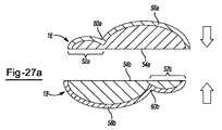
熱伝達および電気伝達を制御することを目的とする2つ以上の電極の間の接合部という発想は、1つの一体材料のみで形成された電極でも採用することができる。そのような接合部は、導電性材料の成形によって形成してよい。より具体的には、1つ以上の電極を、電極を形成するための材料が凹部とされ、2つ以上の丸い突出部(たとえば図27aおよび図27bを参照)に隣接する、「ボトルネック」形状を有するように形成してもよい。この凹部は、丸い突出部間のエネルギー伝達を可能にするが熱伝達を最小限にすることによって、熱分離を可能にする。接合部は、先端に沿って配置されたスロット内に押し込むことができる波形リボンの形であってもよい。接合部は、ノブのあるスロットに押し込まれる平坦なリボンとして形成されてもよい。リボンを所定の位置に保持するために、先端に沿ったスロットにはエポキシ、パテ、または充填剤を充填してよい。 The idea of a joint between two or more electrodes intended to control heat transfer and electrical transfer can also be employed with electrodes formed from only one integral material. Such a joint may be formed by molding a conductive material. More specifically, one or more electrodes are “bottleneck” where the material for forming the electrodes is recessed and adjacent to two or more round protrusions (see, eg, FIGS. 27a and 27b). You may form so that it may have a shape. This recess allows for heat separation by allowing energy transfer between round protrusions but minimizing heat transfer. The joint may be in the form of a corrugated ribbon that can be pushed into a slot disposed along the tip. The joint may be formed as a flat ribbon that is pushed into a slot with a knob. In order to hold the ribbon in place, the slots along the tip may be filled with epoxy, putty, or filler.
一実施形態では、導電要素が浮遊電極である場合には、第1のアームの内面に沿って配置された第1および第2の双極電極と浮遊電極との間の相互作用は、エネルギーが第1の双極電極を通り、浮遊電極に向かって流れ、第2の双極電極に戻るようなものとすることができる。使用時には、第1の内面と第2の内面との間(たとえば第1のアームと第2のアームの間)に組織の部分を配置してもよい。したがって、エネルギーが第1の双極電極を流れ、その後、組織上、組織内部、または組織を通過の任意の組合せの方向に流れることができる。双極モードでの使用時に器具が第1のアームと第2のアームとの間で組織を受ける場合、双極エネルギーが第1の電極と浮遊電極と第2の電極との間のエネルギー経路に沿って移動するときに、双極エネルギーは組織の少なくとも一部を通過する。双極エネルギーが絶縁部のない場合の第2のアームの部分と比較して組織のより大きな部分を通過するように、第2のアームは(たとえば図4bに示すように)絶縁部を含んでもよい。 In one embodiment, when the conductive element is a floating electrode, the interaction between the first and second bipolar electrodes disposed along the inner surface of the first arm and the floating electrode is such that the energy is It can be such that it passes through one bipolar electrode, flows towards the floating electrode and returns to the second bipolar electrode. In use, a portion of tissue may be placed between the first inner surface and the second inner surface (eg, between the first arm and the second arm). Thus, energy can flow through the first bipolar electrode and then in the direction of any combination of on tissue, within tissue, or through tissue. When the instrument receives tissue between the first arm and the second arm when used in bipolar mode, the bipolar energy is along the energy path between the first electrode, the floating electrode, and the second electrode. As it travels, bipolar energy passes through at least a portion of the tissue. The second arm may include an insulating portion (eg, as shown in FIG. 4b) so that the bipolar energy passes through a larger portion of tissue compared to the portion of the second arm without the insulating portion. .
2つの対向するアームのうちの第1のアーム上に第1および第2の電極が配置されてよく、2つの対向するアームのうちの第2のアーム上に第3の電極が配置されてもよい。あるいは、第1のアーム上に第1、第2、および第3の電極が配置されてもよい。第1のアーム上に第1の電極が配置され、第2のアーム上に第2の電極が配置されてもよい。したがって、2つの対向するアーム間に配置された組織が、これらのアームを電気的に接続するか、2つのアーム間に電気的ブリッジを形成するか、またはその両方を実現することができる。デバイスを単極モードで使用する場合は、第1のアームは単一の単極電極(これは第1、第2または第3の電極であってよい)を有してよく、この電極が接触する組織は、この単極電極をリターン電極に電気的に接続するか、単極電極とリターン電極との間の電気的ブリッジの役割を果たすか、またはその両方の役割を果たすことができる。単極モードにおいて、これらの電極のうちの1つ以上を組み合わせて単一の電位を形成してもよい。デバイスが単極/双極組合せデバイスの場合、回路は、単極構成と双極構成とを切り替えるスイッチを含んでよい。このスイッチは、双極電極のうちの1つを起動し、リターン電極の動作を停止させるか、もしくはその逆を行うか、1つの双極電極を起動し単極電極の動作を停止するか、もしくはその逆を行うか、1つの双極電極の動作を停止して電極を開状態にしておく(すなわち電力供給しない)か、単極電極の動作を停止して電極を開状態にしておくか、両方の双極電極の動作を停止し、単極電極とリターン電極とを起動するか、もしくはその逆を行うか、またはこれらの組合せを行ってもよい。単極電極(たとえば第1および第2の電極のうちの1つ)、双極電極(たとえば第1および第2の電極)のうちの1つ以上、またはこれらの組合せを、交流電源、直流電源、またはその両方に接続してよい。好ましくは、単極電極、双極電極、またはその両方が交流電源に接続される。単極電極、双極電極、またはその両方は、組織との接触時に回路を完成させ得る。 The first and second electrodes may be disposed on the first arm of the two opposing arms, and the third electrode may be disposed on the second arm of the two opposing arms. Good. Alternatively, the first, second, and third electrodes may be disposed on the first arm. The first electrode may be disposed on the first arm, and the second electrode may be disposed on the second arm. Thus, tissue placed between two opposing arms can electrically connect the arms, form an electrical bridge between the two arms, or both. When the device is used in monopolar mode, the first arm may have a single monopolar electrode (which may be the first, second or third electrode) that is in contact The tissue that does this can electrically connect this monopolar electrode to the return electrode, act as an electrical bridge between the monopolar electrode and the return electrode, or both. In monopolar mode, one or more of these electrodes may be combined to form a single potential. If the device is a monopolar / bipolar combination device, the circuit may include a switch that switches between a monopolar configuration and a bipolar configuration. This switch activates one of the bipolar electrodes and stops the operation of the return electrode, or vice versa, activates one bipolar electrode and stops the operation of the monopolar electrode, or Do the reverse, stop the operation of one bipolar electrode and leave the electrode open (ie do not supply power), stop the operation of the single electrode and leave the electrode open, The operation of the bipolar electrode may be stopped and the monopolar electrode and the return electrode may be activated, or vice versa, or a combination thereof. One or more of a monopolar electrode (eg, one of the first and second electrodes), a bipolar electrode (eg, the first and second electrodes), or a combination thereof, an AC power source, a DC power source, Or you may connect to both. Preferably, the monopolar electrode, the bipolar electrode, or both are connected to an AC power source. Monopolar electrodes, bipolar electrodes, or both can complete the circuit upon contact with tissue.
本明細書に記載のデバイス先端配置構成は、様々なデバイス構成における機能および互換性の向上のために設計されている。デバイスの機能を向上させるために、記載されている各面は、選択された位置において所望の機能を有する特定の材料を含むことができる。そのような材料は、デバイスの所望の機能に応じて選択され、配置される。たとえば、第1のアームのみが導電要素を含むように、第2のアームは不導体要素を担持してよく、実質的に導電性の面がなくてよい。したがって、第2のアームは電気接続性がなくてよく、単に外科処置時に圧迫力を与えるに過ぎない。あるいは、第2のアームは導電要素を担持する。第2のアーム上の導電要素は、双極モードにおいて電極間のエネルギー経路を改善する役割を果たすことができる。導電要素は、第1および第2の電極のうちの1つ以上からのエネルギーの流れのために優先経路が形成され、浮遊電極の位置によってこの経路の位置が容易に変更されるように、浮遊電極であってよい。したがって、双極モードにおいて、エネルギーは、浮遊電極を介して第1の電極と第2の電極との間を流れてもよい。単極モードにおいて、エネルギーは、第1の電極または第2の電極のうちの一方のみから、第1のアームから遠隔にあるが第1のアームに電気的に連通したリターン電極に流れてもよい。 The device tip arrangement described herein is designed for improved functionality and compatibility in various device configurations. In order to improve the functionality of the device, each described surface can include a specific material having a desired function at a selected location. Such materials are selected and arranged according to the desired function of the device. For example, the second arm may carry a non-conductive element so that only the first arm includes a conductive element and may be substantially free of conductive surfaces. Thus, the second arm may not have electrical connectivity and merely provides a compression force during the surgical procedure. Alternatively, the second arm carries a conductive element. The conductive element on the second arm can serve to improve the energy path between the electrodes in bipolar mode. The conductive element is floating so that a preferential path is formed for the flow of energy from one or more of the first and second electrodes, and the position of this path is easily changed by the position of the floating electrode. It may be an electrode. Thus, in bipolar mode, energy may flow between the first electrode and the second electrode via the floating electrode. In monopolar mode, energy may flow from only one of the first electrode or the second electrode to a return electrode that is remote from the first arm but in electrical communication with the first arm. .
第1および第2のアームのうちの1つ以上は、絶縁された部分を含んでもよい。第2のアームは、絶縁部を担持しておよい。この絶縁部は、第1の電極と第2の電極との間のエネルギー経路の長さを延長するように配置されてよい(図2および図3の長さ(l)を参照)。第1のアームは、第1の電極と第2の電極との間に絶縁部を含んでよい。第2のアームは、第1のアーム上の第1の電極と第2の電極の間の絶縁部に対向する絶縁部を含んでよい。 One or more of the first and second arms may include an insulated portion. The second arm may carry an insulating part. This insulating portion may be arranged to extend the length of the energy path between the first electrode and the second electrode (see length (l) in FIGS. 2 and 3). The first arm may include an insulating portion between the first electrode and the second electrode. The second arm may include an insulating portion facing the insulating portion between the first electrode and the second electrode on the first arm.
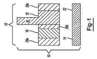
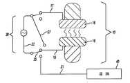
図1に電気手術器具先端10の例示の配置構成を示す。先端10は、第1のアーム12と第2のアーム14とを含む。第1のアーム12は、第1の電極16を含む。第1のアームは、第2の電極18も含む。第2のアーム14は、電極がなくてもよく、不導体構成要素22のみを有して導体構成要素を含まなくてもよい。第1のアーム12は、第1の絶縁部28aが第1の電極の終端縁に隣接して配置されるように、絶縁(不導体)部28a、28bおよび28cも含んでよい。第2の絶縁部28bは、第1の電極と第2の電極の間に配置されてもよい。第3の絶縁部は、第2の電極の終端縁に隣接して配置されてもよい。 An exemplary arrangement of an
あるいは、図2に示すように、器具先端10は、第1のアーム12と第2のアーム14とを含む。第1のアーム12は、第1の電極16を含む。第1のアームは第2の電極18も含む。第2のアーム14も、電極20(たとえば第3の電極)を含んでよく、電極20は浮遊電極であってよく(たとえばいずれの電極または接地とも電気接続がなくてよい)、または1つの電位に固定(たとえば接地に電気的に接続)されてよい。第2のアームは、1つ以上の絶縁(不導体)部28を含んでよい。第2のアームは、少なくとも1つ、2つまたは3つの側において第2のアーム上の電極20(たとえば導体部)を実質的に囲む第1の絶縁部28dを含む。またはその代わりに、電極20は第1の絶縁部28dと同一平面上にあってもよく、または第1の絶縁部の面を越えて延びていてもよい。図1に示すように、第1のアーム12は、第1の絶縁部28aが第1の電極の終端縁に隣接して配置されるようにして、絶縁(不導体)部28a、28bおよび28cを含む。第2の絶縁部28bが、第1の電極と第2の電極の間に配置されてもよい。第3の絶縁部28cが第2の電極の終端縁に隣接して配置されてもよい。 Alternatively, as shown in FIG. 2, the
図3に、第2のアーム上に配置された第2の絶縁部26を含む別の実施形態を示す。第2の絶縁部26の追加は、エネルギーの流れが第2のアームの第2の絶縁部26と第1の絶縁部28dとの間を通過するように、エネルギーを第1の電極16から第3の電極20を介して第2の電極18に向けさせるのに役立つ。 FIG. 3 shows another embodiment that includes a second insulating portion 26 disposed on the second arm. The addition of the second insulating portion 26 adds energy from the
図4aに、図2の器具先端10と組織サンプル30との界面の断面図を示す。図のように、エネルギーの経路32が第2の電極18内に流れ、組織30の一部を通過し、第3の電極20に向かい、第1の電極16に戻る。 4a shows a cross-sectional view of the interface between the
図4bに、図3の器具先端10と組織サンプル30との界面の別の断面図を示す。この実施形態では、第2の絶縁部がエネルギーをさらに第3の電極20に向かうように誘導する役割を果たすため、第2の絶縁部26を含めることによりエネルギーの経路32が組織30のさらに内部に延びる。第2の絶縁部26の長さが、対向する絶縁部28bの長さよりも長く、したがってエネルギーの経路32をさらに延長させることも図示されている。 FIG. 4b shows another cross-sectional view of the interface between the
図5aに、双極モードでの使用時における器具先端10とそれに付随する電気接続部とを示す。第1のアーム12は、第1の電極16を含み、第2のアーム14は第2の電極18を含む。第1の電極16の第1の延長部34が第1のアームの側縁36から延びている。双極モードでの使用時、エネルギーの経路32は第1の電極と第2の電極の間を移動する。第1の電極および第2の電極はさらに回路38を介して接続されている。 FIG. 5a shows the
図5bに、単極モードでの使用時における図5aの器具先端を示す。第1および第2の電極(16、18)があるが、第1の電極と第2の電極の間にはエネルギーの流れがない。その代わりに、エネルギーの経路32は、第1の電極の延長部34を通り、組織(図示せず)を通って遠隔の接地パッド40に流れる。 FIG. 5b shows the instrument tip of FIG. 5a when used in monopolar mode. There are first and second electrodes (16, 18), but there is no flow of energy between the first and second electrodes. Instead, the
図6aに、第1のアーム12上の第1の電極16と第2のアーム14上の第2の電極18とを含む器具先端10を示す。第1の電極と第2の電極の両方が、それぞれ第1のアームおよび第2のアームの終端側縁36a、36bから延びる延長部34a、34bを含む。このような配置構成では、第1の電極と第2の電極の両方が、単極モードで動作する機能を有する。 FIG. 6 a shows the
図6bに示すように、図6aの器具先端は回路38を介して接続されてもよい。双極モードで使用するときは、エネルギー経路32が第1の電極16と第2の電極18の間を流れ、第1および第2の電極はエネルギー源(および互いと)回路38を介して接続される。第1の電極16は第1のコネクタ17を介して電源に接続され、第2の電極18は第2のコネクタ(たとえば、コネクタ部19および23を含む第2のコネクタ)を介して電源に接続される。第3のコネクタ21が利用可能であるが、デバイスが双極モードで使用されるときは、接続を提供しない。 The instrument tip of FIG. 6 a may be connected via a
図6cに、回路38がもはや第1の電極16と第2の電極18とを接続していない単極モードでの使用時における図6aおよび図6bの器具先端を示す。図のように、第1および第2の電極の第1の延長部34a、34bは両方とも単極エネルギー源に接続され、エネルギー経路32は各延長部を通り、組織(図示せず)を通って遠隔の接地パッド40に流れる。図のように、単極モードでの使用時には、両方の延長部を使用するために単一の単極エネルギー供給を行うことができるように、第1および第2の電極が互いに電気的に接続されている。図6bに示す双極構成と同様に、第1の電極は第1のコネクタ17を介して電源に接続される。しかし、第2の電極には第2のコネクタ19を介した電源への接続がない。ただし、双極モードで第2のコネクタの一部であったコネクタ部23が電源に接続され、コネクタ部25を介して第3のコネクタ21にも接続される。 FIG. 6 c shows the instrument tip of FIGS. 6 a and 6 b when used in monopolar mode where the
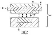
たとえば図7に示すように、器具先端10は、第1の延長部34と第2の延長部35とを含み得る第1の電極16を含んでもよい。単極モードのとき、第1の延長部と第2の延長部の一方または両方が、エネルギーを通すことができる。第1の電極16は、双極モードでは、双極エネルギー経路32が第1の電極16と第2の電極18の間を流れるように、エネルギーを通してもよい。 For example, as shown in FIG. 7, the
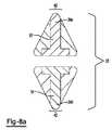
図8a〜図8cに示すように、器具先端10の背部42から第1の延長部34a、34bが延びてよい。図8aに、それぞれが器具先端の背部42から延びる第1の延長部34a、34bを含む、第1の電極16と第2の電極18とを含む例示の器具先端10を示す。図8bに、双極モードで使用するときの図8aの器具先端を示す。図のように、回路38からのエネルギー経路32が第1の電極16と第2の電極18の間を流れる。あるいは、図8cに示すように、単極モードではエネルギー経路32は、背部42上に配置された第1の延長部34a、34bのうちの1つ以上から組織(図示せず)を通って接地パッド40に流れる。図のように、単極モードでの使用時には、両方の延長部を使用するために単一の単極エネルギー供給を行うことができるように、第1の電極および第2の電極は互いに電気的に接続されている。 As shown in FIGS. 8 a-8 c,
あるいは、第1または第2の電極のうちの一方のみが、器具先端の背部から延びる延長部を含んでもよい。たとえば図9に示すように、第1の電極16が、器具先端10の第1のアーム12の背部42から延びる延長部34を含む。図のように、第2のアーム14は、第2の電極18を含むが、第2の電極には延長部がなく、したがって、単極モードでの器具先端の使用時には、エネルギーの流れを受け取っていなくてよい。 Alternatively, only one of the first or second electrodes may include an extension that extends from the back of the instrument tip. For example, as shown in FIG. 9, the
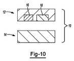
図10に、第1の電極16および第2の電極18が両方とも器具先端10の第1のアーム12上に配置された、代替の器具先端配置構成を示す。図10に示す実施形態は、電極のない器具先端の第2のアーム14をさらに含む。第1のアーム12と第2のアーム14の両方とも、単極モードでエネルギーを通す電極がない。 FIG. 10 illustrates an alternative instrument tip arrangement in which both the
単極と双極の両方のモードで動作するための従来技術の先端配置構成の具体例を、図11a〜図11bおよび図12a〜図12bに示す。たとえば図11aに示すように、器具先端10は第1の電極16と第2の電極とを含み、双極モードでは回路38が第1と第2の電極16、18を接続し、接地パッド40には接続されないままである。第1の電極16は、第1のコネクタ17を介して電源に接続される。第2の電極18は、複数のコネクタ部19、23、25から形成された第2のコネクタを介して電源に接続される。双極モードのときは、回路において追加のコネクタ21、27は使用されない。しかし、図11bに示すように、単極モードでは、回路38は、第1の電極16と第2の電極18とにエネルギーを供給するとともに、エネルギー経路32を介して接地パッド40にも接続するように構成されている。接地40を含む回路を形成するために、追加のコネクタ21が第2のコネクタ25に接続される。第2のコネクタ部19に接続することにより、回路には追加のコネクタ27も含まれる。単極機能のみ、または双極機能のみを提供するように構成された従来技術の先端配置構成を図12aおよび図12bに示す。たとえば図12aに示すように、双極モードで使用されるときは第1の電極16と第2の電極18との間にエネルギー経路32が形成され、回路38には接地パッド40への接続がない。しかし、(図12bに示すように)単極モードでは、第1のアーム12および第2のアーム14が互いに向かって閉じられて単極モードでの第1の電極16および第2の電極のうちの1つ以上の電極の一部の使用を可能にし、それによって回路38は第1の電極と第2の電極を接続しなくなるが、接地パッド40を含むエネルギー経路32を形成する。これらの従来の構成は、背部(たとえばアームの後縁)から延びる部分がない第1および第2の電極を含む。したがって、第1の電極および第2の電極が接合されて、尖っておらず延長部分(たとえば刃)がない共通単極電極を形成する。 Specific examples of prior art tip arrangements for operating in both monopolar and bipolar modes are shown in FIGS. 11a-11b and 12a-12b. For example, as shown in FIG. 11 a,
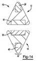
器具先端は、1つのアーム上に複数の別個の電極を含み、1つの電極が双極モードでのみエネルギーを通し、1つの電極が単極モードでのみエネルギーを通すように構成してもよい。より具体的には、図13に示すように、第1のアーム12は第1の電極16を含み、第2のアーム14は第2の電極18を含む。第1のアームは、第3の電極20をさらに含み、第3の電極には第1の電極16との直接接続がない。第3の電極20は、器具先端10の背部42に沿って配置され、第1の電極および第2の電極は、第1のアームおよび第2のアームのそれぞれの内面部46a、46bに沿って配置されている。図14に、第1のアーム12と第2のアーム14の両方が複数の電極を含む同様の器具先端配置構成を示す。具体的には、第2のアーム14は、第1のアーム12上の第3の電極20と位置が同様である、器具先端10の背部42に沿って配置された第4の電極48を含む。同様の構成では、電極20および48は、1本または複数本の線(図示せず)を介して電気的に接続されている。したがって、電極20および48は、図8cに示すものと類似した外科用両刃メスを形成する共通単極電極の役割を果たすことになる。図15に、3つ以上の電極を含む別の器具先端実施形態を示す。第1のアーム12は、器具先端の内面部46に沿って配置され、絶縁部28によって分離された第1および第2の電極16、18を含む。第1のアームは、器具先端の背部42に沿って配置された第3の電極20も含む。したがって、第1および第2の電極は双極モードにおいてエネルギーを通し、第3の電極20は単極モードにおいてエネルギーを通す。第2のアーム14には導電要素はない。 The instrument tip may include a plurality of separate electrodes on one arm, with one electrode passing energy only in bipolar mode and one electrode passing energy only in monopolar mode. More specifically, as shown in FIG. 13, the
図16に、図13のものと類似した器具先端配置構成を示す。第1のアーム12は第1の電極16を含み、第2のアーム14は第2の電極18を含む。第1のアームは、第3の電極をさらに含み、第3の電極には第1の電極16との直接接続がない。第3の電極20は、器具先端10の第1のアーム12の両方の対向する終端側縁36a、36bから延びて外科用両面メスを形成するように配置され、第1の電極および第2の電極は、第1および第2のアームのそれぞれの内面部46a、46bに沿って配置されている。図17に、図16のものと類似しているが、第3の電極20のみが第1のアームの1つの終端側縁36bのみから延びて外科用片面メスを形成する器具先端を示す。 FIG. 16 shows an instrument tip arrangement similar to that of FIG. The
図18に、第1の電極16と第2の電極18が第1のアームの内面部46aに沿って配置された図15に類似した別の実施形態を示す。ただし、第2のアームは、器具先端の背部42に沿って配置された第3の電極20を含む。 FIG. 18 shows another embodiment similar to FIG. 15 in which the
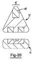
図19に、第1のアーム12上に第1の電極16と第2の電極18とを含む器具先端配置構成を示す。この器具先端10は、第1および第2の電極に対向する、第2のアーム14上の第3の電極20(たとえば導電要素)をさらに含む。第4の電極48も含まれ、背部42に沿って配置され、単極モードでの使用時に使用される。双極モードでの器具の使用時にエネルギー経路32を方向付けるのを助けるために、1つ以上の絶縁部28も含み得る。図20に、図19の器具先端に類似しているが、第4の電極48が第1のアーム12の背部42上に配置された配置構成を示す。図21aは、図19と図20の両方を組み合わせたもので、第1のアーム12と第2のアーム14の両方が、器具先端10の各背部42上に電極(たとえば第4の電極48および第5の電極50)を含む。同様の構成では、電極20および48は、1つ以上の線(図示せず)を介して電気的に接続されている。したがって、電極20および48は、共通単極電極の役割を果たすことになる。図21bに、21aの先端配置構成の回路接続を示す。2つの単極電極48、50のそれぞれから1本ずつ出ている2本の単極コネクタリード線32aが示されている。2本の双極コネクタリード線32bが、第1の電極16および第2の電極18のそれぞれに電源を接続する。 FIG. 19 shows an instrument tip arrangement configuration including the
1つ以上の電極を複数の金属で形成してもよい。そのような一実施形態では、電極のうちの1つ以上が、間に熱接合部を含む2つの別個の隣接する導体から形成されてもよい。たとえば図22aに示すように、第1の電極16が第1のアーム12上に配置され、第1の導体52と第2の隣接する導体54から形成され、それによって、接合された2つの導体間に熱接合部56を形成している。第2の導体は器具先端の背部42から延びている。第2のアーム14は、第2のアームの内面46に沿って配置された第2の電極18を含む。したがって、第1の導体は双極モードにおいてエネルギーの通過を容易にし、第2の導体は単極モードにおいてエネルギーの通過を容易にする。図22bに、22aの先端配置構成の回路接続を示す。単極電極54から出ている1本の単極コネクタリード線32aが示されている。2本の双極コネクタリード線32bが、第1の電極16および第2の電極18のそれぞれに電源を接続する。 One or more electrodes may be formed of a plurality of metals. In one such embodiment, one or more of the electrodes may be formed from two separate adjacent conductors that include a thermal junction therebetween. For example, as shown in FIG. 22a, a
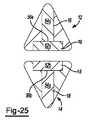
図23に、第1のアーム12が第1の電極16を含み、第2のアームが第2の電極18と第3の電極20とを含む3電極システムを示す。デバイスが単極モードで使用されるときは第1の電極の一部16aが使用され、デバイスが双極モードで使用されるときは第1の電極の第2の部分16bが使用される。単極モードにおけるエネルギー経路32aは、単極動作に使用される各電極または電極部分16a、20から接地パッド40に延びる。双極リード線32bは、電源からデバイスが双極モードで使用されるときに使用される電極または電極部分16b、18まで延びている。 FIG. 23 shows a three-electrode system in which the
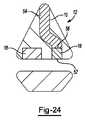
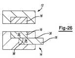
図24に、図22aおよび図22bの実施形態に類似しているが、第1のアーム12が複数の別個の導体52、54で形成された第1の電極16を含むことに加えて、第1のアームは第2の標準電極18も含む。図25に、間に熱接合部56a、56bを有する第1および第2の導体52a、52b、54a、54bで形成された電極を含む(たとえば、第1の電極16および第2の電極18がそれぞれ、複数の隣接する別個の導体で形成されている)第1のアームと12と第2のアーム14の両方を含むさらに別の実施形態を示す。図26に、1つの電極(この場合は第2の電極18)が複数の別個の導体で形成されている、図22a〜図22bの実施形態と類似した実施形態を示す。図のように、第1のアーム12は第1の電極16を含み、第2のアーム14は第2の電極18を含み、第2の電極は、熱接合部56によって接続された第2の導体54に接合された第1の導体52で形成されている。しかし、図22a〜22bとは異なり、図26の実施形態は、第2の導体54が第2のアーム14の外側縁36から延びている器具先端配置構成を備える。 FIG. 24 is similar to the embodiment of FIGS. 22a and 22b, except that the
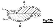
図27aおよび図27bに、導体材料の形状が熱接合部構成を形成する別の実施形態を示す。第1および第2の電極16、18のそれぞれが、ボトルネック導体58a、58bで形成されている。各ボトルネック導体は、第1の導体部(たとえば丸い突起部)52a、52bと、第2の導体部(たとえば丸い突起部)54a、54bと、第1と第2の導体部との間の凹部60a、60bとを含む。図27aに、第1のアームと第2のアームとが開位置にあるときの対向する導体を示す。図27bに閉位置にある導体を示す。 Figures 27a and 27b show another embodiment in which the shape of the conductor material forms a thermal joint configuration. Each of the first and
本明細書に記載されている任意の数値が、任意の低値と任意の高値との間に少なくとも2単位の間隔がある場合、1単位ずつの低値から高値までのすべての値を含む。一例として、たとえば温度、圧力、時間などの成分の量またはプロセス変数の値が、たとえば1から90まで、好ましくは20から80まで、より好ましくは30から70までであると記載されている場合、15から85まで、22から68まで、43から51まで、30から32までなどの値が本明細書で明示的に列挙されることが意図されている。1未満の値の場合、必要に応じて1単位が0.0001、0.001、0.01または0.1であるとみなされる。これらは、具体的に意図されていることの例に過ぎず、列挙されている最低値と最高値との間の数値のすべての可能な組合せが、同様にして本願で明記されているものとみなされる。 Any numerical value described herein includes all values from a low value to a high value in units of one unit if there is an interval of at least 2 units between any low value and any high value. As an example, if the amount of a component such as temperature, pressure, time or the value of a process variable is described as being, for example, 1 to 90, preferably 20 to 80, more preferably 30 to 70, It is intended that values such as 15 to 85, 22 to 68, 43 to 51, 30 to 32, etc. are explicitly listed herein. For values less than 1, one unit is considered to be 0.0001, 0.001, 0.01 or 0.1 as appropriate. These are merely examples of what is specifically intended, and all possible combinations of numerical values between the lowest and highest values listed are similarly specified herein. It is regarded.
特に明記されていない限り、すべての範囲は両端点および両端点間のすべての数字を含む。範囲に関連する「約」または「略」の使用は、その範囲の両端に適用される。したがって、「約20から30まで」は、少なくとも明記されている両端点を含めて「約20から約30まで」を包含することが意図されている。 Unless otherwise stated, all ranges include the endpoints and all numbers between the endpoints. The use of “about” or “approximately” in relation to a range applies to both ends of the range. Thus, “about 20 to 30” is intended to encompass “about 20 to about 30” including at least the specified endpoints.
特許出願および特許公報を含むすべての記事および参考文献の開示は、あらゆる目的のために本願に引用して援用する。組合せを説明するための「本質的に〜からなる」という用語は、特定されている要素、成分、構成要素またはステップ、および組合せの基本的特性および新規な特性に実質的に影響を及ぼさないそのような他の要素、成分、構成要素、またはステップを含むものとする。本明細書に記載の要素、成分、構成要素またはステップの組合せを記載するための「comprising(含む)」または「including(含む)」という用語の使用は、本質的にそれらの要素、成分、構成要素、またはステップからなる実施形態も企図する。本明細書における「may(〜てもよい、し得る)」という用語の使用によって、含まれ「てもよい(得る)」任意の記載されている属性が随意的であることが意図されている。 The disclosures of all articles and references, including patent applications and patent publications, are incorporated herein by reference for all purposes. The term “consisting essentially of” to describe a combination refers to the elements, components, components or steps that are identified and those that do not substantially affect the basic and novel characteristics of the combination. Such other elements, components, components, or steps are intended to be included. The use of the term “comprising” or “including” to describe a combination of elements, components, components or steps described herein is essentially what those elements, components, components Embodiments comprising elements or steps are also contemplated. Any use of the term “may” herein is intended to be inclusive of any described attribute that may be “may” be included. .
複数の要素、成分、構成要素またはステップが、単一の統合された要素、成分、構成要素またはステップにより設けられ得る。あるいは、単一の統合された要素、成分、構成要素、またはステップが、別個の複数の要素、成分、構成要素、またはステップに分割され得る。要素、成分、構成要素、またはステップを記載するための「a」または「one(1つの)」という開示は、追加の要素、成分、構成要素、またはステップを除外するものではない。 Multiple elements, components, components or steps may be provided by a single integrated element, component, component or step. Alternatively, a single integrated element, component, component or step may be divided into separate multiple elements, components, components or steps. The disclosure of “a” or “one” to describe an element, component, component, or step does not exclude an additional element, component, component, or step.
当然のことながら、上記記載は例示的であり、制限的でないことが意図されている。上記記載を読めば、記載されている例に加えて多くの実施形態および多くの応用が当業者には明らかであろう。したがって、本教示の範囲は、上記記載に基づいて決定されるべきではなく、添付の特許請求の範囲の権利が与えられる同等物の全範囲とともに、その特許請求の範囲に基づいて決定されるべきである。特許出願および特許公報を含むすべての記事および参考文献の開示は、あらゆる目的のために引用して援用する。本明細書に開示されている主題の任意の態様に関する以下の特許請求の範囲における省略は、そのような主題の権利放棄ではなく、発明者らがそのような主題を開示されている発明の主題の一部であると考えないとみなされるべきではない。
Of course, the above description is intended to be illustrative and not restrictive. After reading the above description, many embodiments and many applications will be apparent to persons skilled in the art in addition to the examples described. Accordingly, the scope of the present teachings should not be determined based on the above description, but should be determined with reference to the appended claims, along with the full scope of equivalents to which the appended claims are entitled. It is. The disclosures of all articles and references, including patent applications and patent publications, are incorporated by reference for all purposes. Omissions in the following claims relating to any aspect of the subject matter disclosed herein are not a waiver of such subject matter, but subject matter of the invention in which the inventors have disclosed such subject matter. Should not be considered as not considered part of.
Claims (11)
Translated fromJapaneseb.前記第1のアームに対向し、1つ以上の電極を担持する第2のアームとを含む電気手術器具であって、
前記第1のアーム、前記第2のアームまたはその両方は、単極モードにおいてエネルギーを通すために、互いに直接接触はしていないが互いに電気的に接続された複数の電極を含み、前記第1の電極、前記第2の電極、または前記第2のアームの1つ以上の電極のうちの少なくとも2つの電極は双極モードにおいてエネルギーを通すことを特徴とする電気手術器具。a. A first arm carrying first and second electrodes and an optional third electrode;
b. An electrosurgical instrument that includes a second arm facing the first arm and carrying one or more electrodes,
The first arm, the second arm, or both include a plurality of electrodes that are not in direct contact with each other but are electrically connected to each other for passing energy in monopolar mode, An electrosurgical instrument characterized in that at least two of the first electrode, the second electrode, or one or more electrodes of the second arm pass energy in a bipolar mode.
b.前記第1のアームに対向し、導電要素を担持する第2のアームとを含む電気手術器具であって、
前記導電要素は、双極モードにおいて前記第1および前記第2の電極のうちの1つ以上から浮遊電極を介したエネルギーの流れのために優先経路が形成されるように浮遊電極であることを特徴とする電気手術器具。a. A first arm carrying first and second electrodes;
b. An electrosurgical instrument comprising a second arm facing the first arm and carrying a conductive element,
The conductive element is a floating electrode so that a priority path is formed for the flow of energy from one or more of the first and second electrodes through the floating electrode in bipolar mode. An electrosurgical instrument.
b.前記第1のアームに対向し、第2の電極を担持する第2のアームとを含む電気手術器具であって、
前記第1の電極および前記第2の電極のうちの1つ以上の電極の少なくとも一部は単極モードにおいてエネルギーを通し、前記第1の電極と前記第2の電極のうちの1つ以上の電極の少なくとも一部は双極モードにおいてエネルギーを通し、
前記第1の電極および前記第2の電極のうちの1つ以上の電極のうちの単極モードにおいてエネルギーを通す前記少なくとも一部は、前記第1のアームまたは前記第2のアームのうちの少なくとも1つの背または側縁から延びていることを特徴とする電気手術器具。a. A first arm carrying a first electrode;
b. An electrosurgical instrument comprising a second arm facing the first arm and carrying a second electrode,
At least a portion of one or more of the first electrode and the second electrode passes energy in a unipolar mode, and one or more of the first electrode and the second electrode At least some of the electrodes pass energy in bipolar mode;
The at least part of passing energy in a unipolar mode of one or more of the first electrode and the second electrode is at least one of the first arm or the second arm An electrosurgical instrument that extends from one back or side edge.
b.前記第1のアームに対向し、第2の電極を担持する第2のアームと、
c.第3の電極と、任意により1つ以上の追加の電極とを含む電気手術器具であって、
前記第1の電極と前記第2の電極とは単極モードにおいてエネルギーを通し、前記第1の電極、前記第3の電極、または1つ以上の追加の電極のうちの少なくとも2つの電極は双極モードにおいてエネルギーを通すことを特徴とする電気手術器具。
a. A first arm carrying a first electrode;
b. A second arm facing the first arm and carrying a second electrode;
c. An electrosurgical instrument comprising a third electrode and optionally one or more additional electrodes,
The first electrode and the second electrode pass energy in a monopolar mode, and at least two of the first electrode, the third electrode, or one or more additional electrodes are bipolar An electrosurgical instrument characterized by passing energy in mode.
Applications Claiming Priority (5)
| Application Number | Priority Date | Filing Date | Title |
|---|---|---|---|
| US201361787731P | 2013-03-15 | 2013-03-15 | |
| US61/787,731 | 2013-03-15 | ||
| US201361902933P | 2013-11-12 | 2013-11-12 | |
| US61/902,933 | 2013-11-12 | ||
| PCT/US2014/015923WO2014143476A1 (en) | 2013-03-15 | 2014-02-12 | Electrosurgical instrument |
Publications (2)
| Publication Number | Publication Date |
|---|---|
| JP2016510635Atrue JP2016510635A (en) | 2016-04-11 |
| JP6275813B2 JP6275813B2 (en) | 2018-02-07 |
Family
ID=50179959
Family Applications (3)
| Application Number | Title | Priority Date | Filing Date |
|---|---|---|---|
| JP2016500236APendingJP2016510633A (en) | 2013-03-15 | 2014-02-11 | Electrosurgical instrument |
| JP2016500240AActiveJP6275813B2 (en) | 2013-03-15 | 2014-02-12 | Electrosurgical instrument |
| JP2018094142APendingJP2018140222A (en) | 2013-03-15 | 2018-05-15 | Electrosurgical instrument |
Family Applications Before (1)
| Application Number | Title | Priority Date | Filing Date |
|---|---|---|---|
| JP2016500236APendingJP2016510633A (en) | 2013-03-15 | 2014-02-11 | Electrosurgical instrument |
Family Applications After (1)
| Application Number | Title | Priority Date | Filing Date |
|---|---|---|---|
| JP2018094142APendingJP2018140222A (en) | 2013-03-15 | 2018-05-15 | Electrosurgical instrument |
Country Status (5)
| Country | Link |
|---|---|
| US (4) | US9763730B2 (en) |
| EP (3) | EP2967719B1 (en) |
| JP (3) | JP2016510633A (en) |
| CN (2) | CN105163683B (en) |
| WO (2) | WO2014143472A1 (en) |
Cited By (9)
| Publication number | Priority date | Publication date | Assignee | Title |
|---|---|---|---|---|
| WO2018061124A1 (en)* | 2016-09-28 | 2018-04-05 | オリンパス株式会社 | Treatment tool |
| CN109475380A (en)* | 2016-07-19 | 2019-03-15 | 奥林巴斯株式会社 | Treatment apparatus |
| US10828087B2 (en) | 2013-03-15 | 2020-11-10 | Gyrus Acmi, Inc. | Hand switched combined electrosurgical monopolar and bipolar device |
| US10893900B2 (en) | 2013-03-15 | 2021-01-19 | Gyrus Acmi, Inc. | Combination electrosurgical device |
| JP2022527346A (en)* | 2019-04-04 | 2022-06-01 | シラグ・ゲーエムベーハー・インターナショナル | Electrosurgical equipment with unipolar and bipolar functions |
| JP2023508558A (en)* | 2019-12-30 | 2023-03-02 | シラグ・ゲーエムベーハー・インターナショナル | Electrosurgical instrument with support for energizing electrodes |
| US11744634B2 (en) | 2013-03-15 | 2023-09-05 | Gyrus Acmi, Inc. | Offset forceps |
| US11779384B2 (en) | 2013-03-15 | 2023-10-10 | Gyrus Acmi, Inc. | Combination electrosurgical device |
| US11957401B2 (en) | 2013-03-15 | 2024-04-16 | Gyrus Acmi, Inc. | Electrosurgical instrument |
Families Citing this family (55)
| Publication number | Priority date | Publication date | Assignee | Title |
|---|---|---|---|---|
| US8663220B2 (en) | 2009-07-15 | 2014-03-04 | Ethicon Endo-Surgery, Inc. | Ultrasonic surgical instruments |
| US11090104B2 (en) | 2009-10-09 | 2021-08-17 | Cilag Gmbh International | Surgical generator for ultrasonic and electrosurgical devices |
| US9439668B2 (en) | 2012-04-09 | 2016-09-13 | Ethicon Endo-Surgery, Llc | Switch arrangements for ultrasonic surgical instruments |
| US9408622B2 (en) | 2012-06-29 | 2016-08-09 | Ethicon Endo-Surgery, Llc | Surgical instruments with articulating shafts |
| WO2016028835A1 (en) | 2014-08-20 | 2016-02-25 | GYRUS ACMI, INC. (d/b/a OLYMPUS SURGICAL TECHNOLOGIES AMERICA) | Surgical forceps and latching system |
| EP3581133A1 (en) | 2015-03-23 | 2019-12-18 | Gyrus ACMI, Inc. (D.B.A. Olympus Surgical Technologies America) | Medical forceps with vessel transection capability |
| EP3323367A4 (en)* | 2015-07-16 | 2019-04-03 | Olympus Corporation | Therapeutic instrument |
| US10194973B2 (en) | 2015-09-30 | 2019-02-05 | Ethicon Llc | Generator for digitally generating electrical signal waveforms for electrosurgical and ultrasonic surgical instruments |
| US10595930B2 (en) | 2015-10-16 | 2020-03-24 | Ethicon Llc | Electrode wiping surgical device |
| EP3364902B1 (en) | 2015-11-25 | 2021-01-06 | Gyrus ACMI, Inc. (D.B.A. Olympus Surgical Technologies America) | Thermal control devices for electrosurgical instruments |
| US10660692B2 (en)* | 2015-12-10 | 2020-05-26 | Ethicon Llc | End effector for instrument with ultrasonic blade and bipolar clamp arm |
| EP3386408B1 (en) | 2016-01-11 | 2024-10-16 | Gyrus ACMI, Inc. (D.B.A. Olympus Surgical Technologies America) | Advanced energy device with bipolar dissection capability |
| US11523860B2 (en) | 2016-01-11 | 2022-12-13 | Gyrus Acmi, Inc. | Electrosurgical device for vessel sealing and cutting |
| US12193698B2 (en) | 2016-01-15 | 2025-01-14 | Cilag Gmbh International | Method for self-diagnosing operation of a control switch in a surgical instrument system |
| US11229471B2 (en) | 2016-01-15 | 2022-01-25 | Cilag Gmbh International | Modular battery powered handheld surgical instrument with selective application of energy based on tissue characterization |
| US11051840B2 (en) | 2016-01-15 | 2021-07-06 | Ethicon Llc | Modular battery powered handheld surgical instrument with reusable asymmetric handle housing |
| US11129670B2 (en) | 2016-01-15 | 2021-09-28 | Cilag Gmbh International | Modular battery powered handheld surgical instrument with selective application of energy based on button displacement, intensity, or local tissue characterization |
| US10456193B2 (en) | 2016-05-03 | 2019-10-29 | Ethicon Llc | Medical device with a bilateral jaw configuration for nerve stimulation |
| US10376305B2 (en) | 2016-08-05 | 2019-08-13 | Ethicon Llc | Methods and systems for advanced harmonic energy |
| US11266430B2 (en) | 2016-11-29 | 2022-03-08 | Cilag Gmbh International | End effector control and calibration |
| US10636175B2 (en)* | 2016-12-22 | 2020-04-28 | Facebook, Inc. | Dynamic mask application |
| EP3624715B1 (en)* | 2017-05-16 | 2023-08-02 | Smith & Nephew, Inc. | Electrosurgical systems |
| GB2565135B (en)* | 2017-08-04 | 2022-11-09 | Gyrus Medical Ltd | Bipolar surgical instruments |
| US11298801B2 (en) | 2017-11-02 | 2022-04-12 | Gyrus Acmi, Inc. | Bias device for biasing a gripping device including a central body and shuttles on the working arms |
| US11383373B2 (en) | 2017-11-02 | 2022-07-12 | Gyms Acmi, Inc. | Bias device for biasing a gripping device by biasing working arms apart |
| US10667834B2 (en) | 2017-11-02 | 2020-06-02 | Gyrus Acmi, Inc. | Bias device for biasing a gripping device with a shuttle on a central body |
| JP2019126377A (en)* | 2018-01-19 | 2019-08-01 | オリンパス株式会社 | High-frequency electrode and high-frequency incision instrument |
| CN109009414B (en)* | 2018-08-23 | 2021-06-25 | 上海微创医疗机器人(集团)股份有限公司 | Surgical instrument and end effector thereof |
| US11737680B2 (en)* | 2018-10-02 | 2023-08-29 | Biosense Webster (Israel) Ltd. | Extending the tracking volume in a probe tracking system |
| DE102019108141A1 (en)* | 2019-03-28 | 2020-10-01 | Karl Storz Se & Co. Kg | Bipolar electrosurgical tool |
| US11944366B2 (en) | 2019-12-30 | 2024-04-02 | Cilag Gmbh International | Asymmetric segmented ultrasonic support pad for cooperative engagement with a movable RF electrode |
| US12064109B2 (en) | 2019-12-30 | 2024-08-20 | Cilag Gmbh International | Surgical instrument comprising a feedback control circuit |
| US12023086B2 (en) | 2019-12-30 | 2024-07-02 | Cilag Gmbh International | Electrosurgical instrument for delivering blended energy modalities to tissue |
| US11786294B2 (en) | 2019-12-30 | 2023-10-17 | Cilag Gmbh International | Control program for modular combination energy device |
| US12082808B2 (en) | 2019-12-30 | 2024-09-10 | Cilag Gmbh International | Surgical instrument comprising a control system responsive to software configurations |
| US11812957B2 (en) | 2019-12-30 | 2023-11-14 | Cilag Gmbh International | Surgical instrument comprising a signal interference resolution system |
| US20210196357A1 (en) | 2019-12-30 | 2021-07-01 | Ethicon Llc | Electrosurgical instrument with asynchronous energizing electrodes |
| US11779387B2 (en) | 2019-12-30 | 2023-10-10 | Cilag Gmbh International | Clamp arm jaw to minimize tissue sticking and improve tissue control |
| US12076006B2 (en) | 2019-12-30 | 2024-09-03 | Cilag Gmbh International | Surgical instrument comprising an orientation detection system |
| US11660089B2 (en) | 2019-12-30 | 2023-05-30 | Cilag Gmbh International | Surgical instrument comprising a sensing system |
| US11950797B2 (en) | 2019-12-30 | 2024-04-09 | Cilag Gmbh International | Deflectable electrode with higher distal bias relative to proximal bias |
| US11684412B2 (en) | 2019-12-30 | 2023-06-27 | Cilag Gmbh International | Surgical instrument with rotatable and articulatable surgical end effector |
| US11786291B2 (en) | 2019-12-30 | 2023-10-17 | Cilag Gmbh International | Deflectable support of RF energy electrode with respect to opposing ultrasonic blade |
| US12114912B2 (en) | 2019-12-30 | 2024-10-15 | Cilag Gmbh International | Non-biased deflectable electrode to minimize contact between ultrasonic blade and electrode |
| US12053224B2 (en) | 2019-12-30 | 2024-08-06 | Cilag Gmbh International | Variation in electrode parameters and deflectable electrode to modify energy density and tissue interaction |
| US12343063B2 (en) | 2019-12-30 | 2025-07-01 | Cilag Gmbh International | Multi-layer clamp arm pad for enhanced versatility and performance of a surgical device |
| US11696776B2 (en) | 2019-12-30 | 2023-07-11 | Cilag Gmbh International | Articulatable surgical instrument |
| US11779329B2 (en) | 2019-12-30 | 2023-10-10 | Cilag Gmbh International | Surgical instrument comprising a flex circuit including a sensor system |
| US12262937B2 (en) | 2019-12-30 | 2025-04-01 | Cilag Gmbh International | User interface for surgical instrument with combination energy modality end-effector |
| US12336747B2 (en) | 2019-12-30 | 2025-06-24 | Cilag Gmbh International | Method of operating a combination ultrasonic / bipolar RF surgical device with a combination energy modality end-effector |
| US11937866B2 (en) | 2019-12-30 | 2024-03-26 | Cilag Gmbh International | Method for an electrosurgical procedure |
| US11937863B2 (en) | 2019-12-30 | 2024-03-26 | Cilag Gmbh International | Deflectable electrode with variable compression bias along the length of the deflectable electrode |
| US20210196362A1 (en) | 2019-12-30 | 2021-07-01 | Ethicon Llc | Electrosurgical end effectors with thermally insulative and thermally conductive portions |
| US11986201B2 (en) | 2019-12-30 | 2024-05-21 | Cilag Gmbh International | Method for operating a surgical instrument |
| CN119214782A (en)* | 2023-06-29 | 2024-12-31 | 武汉联影智融医疗科技有限公司 | End effectors, surgical instruments and surgical equipment |
Citations (6)
| Publication number | Priority date | Publication date | Assignee | Title |
|---|---|---|---|---|
| JPH10504485A (en)* | 1994-08-24 | 1998-05-06 | ベスタ・メデイカル・インコーポレーテツド | Coagulation forceps |
| JP2000070280A (en)* | 1998-09-02 | 2000-03-07 | Olympus Optical Co Ltd | High-frequency treatment implement |
| US20020107517A1 (en)* | 2001-01-26 | 2002-08-08 | Witt David A. | Electrosurgical instrument for coagulation and cutting |
| JP2008018226A (en)* | 2006-07-11 | 2008-01-31 | Olympus Medical Systems Corp | Treatment device |
| JP2011212449A (en)* | 2003-11-17 | 2011-10-27 | Covidien Ag | Bipolar forceps having monopolar extension |
| US20120150165A1 (en)* | 2010-12-10 | 2012-06-14 | Salient Surgical Technologies, Inc. | Bipolar Electrosurgical Device |
Family Cites Families (326)
| Publication number | Priority date | Publication date | Assignee | Title |
|---|---|---|---|---|
| US391358A (en) | 1888-10-16 | de waele | ||
| US1198958A (en) | 1915-07-12 | 1916-09-19 | Cleveland Dental Mfg Company | Tweezers. |
| US1530952A (en) | 1922-05-24 | 1925-03-24 | Charles L Lawton | Golf club |
| US2042985A (en) | 1934-08-22 | 1936-06-02 | Albert B Gardella | Tweezers |
| US2214984A (en) | 1938-04-07 | 1940-09-17 | Bachmann Henry | Tweezers |
| US2381084A (en) | 1943-07-15 | 1945-08-07 | Lillian Catherine Slad | Tweezers |
| US2575652A (en) | 1947-08-19 | 1951-11-20 | Ransom Y Bovee | Pocket tweezer article |
| US2894424A (en) | 1958-04-24 | 1959-07-14 | Jr Charles Swoope Vaughan | Tweezer type wire stripping tool having an adjustable stop and stop latching means |
| US3417752A (en) | 1965-11-12 | 1968-12-24 | Byron C. Butler | Magnetic clamp closing device for use with surgical instruments |
| US3399583A (en) | 1966-12-09 | 1968-09-03 | Hall Gordon Lance | Locking tweezers |
| US3465621A (en) | 1967-11-29 | 1969-09-09 | Ladd Res Ind | Locking tweezers |
| US3643663A (en) | 1968-10-16 | 1972-02-22 | F L Fischer | Coagulating instrument |
| US3576072A (en) | 1969-09-29 | 1971-04-27 | James Bernard Turner Foster | Surgical instrument |
| US3685518A (en)* | 1970-07-29 | 1972-08-22 | Aesculap Werke Ag | Surgical instrument for high-frequency surgery |
| US3699632A (en) | 1971-07-30 | 1972-10-24 | Itt | Overriding latch mechanism |
| BE793463A (en) | 1971-12-29 | 1973-06-28 | Ici Ltd | STAPLE REMOVAL INSTRUMENT |
| US3818784A (en) | 1973-01-03 | 1974-06-25 | Scient Components Inc | Changeable tip tweezers and the like |
| US3913586A (en) | 1974-01-28 | 1975-10-21 | Gomco Surgical Mfg Co | Hemostat |
| US4041952A (en) | 1976-03-04 | 1977-08-16 | Valleylab, Inc. | Electrosurgical forceps |
| US4171700A (en) | 1976-10-13 | 1979-10-23 | Erbe Elektromedizin Gmbh & Co. Kg | High-frequency surgical apparatus |
| DE2717607C3 (en) | 1977-04-20 | 1981-06-25 | Coloplast A/S, Espergaerde | Magnetic stopper for an anus |
| US4202337A (en) | 1977-06-14 | 1980-05-13 | Concept, Inc. | Bipolar electrosurgical knife |
| US4418692A (en) | 1978-11-17 | 1983-12-06 | Guay Jean Louis | Device for treating living tissue with an electric current |
| US4318313A (en) | 1980-03-10 | 1982-03-09 | Tartaglia John A | Tweezer forceps |
| CA1192465A (en) | 1981-03-11 | 1985-08-27 | Edward A. Lottick | Removable switch electrocautery instruments |
| US4375218A (en) | 1981-05-26 | 1983-03-01 | Digeronimo Ernest M | Forceps, scalpel and blood coagulating surgical instrument |
| US4407069A (en) | 1981-12-08 | 1983-10-04 | The Scott & Fetzer Company | Scissors with cushioned stop |
| US4463759A (en) | 1982-01-13 | 1984-08-07 | Garito Jon C | Universal finger/foot switch adaptor for tube-type electrosurgical instrument |
| US4443935A (en) | 1982-03-01 | 1984-04-24 | Trident Surgical Corporation | Process for making electrosurgical scalpel pencil |
| US4494543A (en) | 1982-03-05 | 1985-01-22 | Hart Ernest D | Instrument for extracting splinters |
| US4504707A (en) | 1982-03-15 | 1985-03-12 | Kyushu Hitachi Maxell, Ltd. | Push-button switch locking device for use in electric appliance |
| JPS58193907U (en) | 1982-06-18 | 1983-12-23 | 持田製薬株式会社 | Ultrasonic scalpel with electric scalpel attached |
| US4492231A (en) | 1982-09-17 | 1985-01-08 | Auth David C | Non-sticking electrocautery system and forceps |
| US4492832A (en) | 1982-12-23 | 1985-01-08 | Neomed, Incorporated | Hand-controllable switching device for electrosurgical instruments |
| US4524648A (en) | 1984-08-17 | 1985-06-25 | Chung Charng J | Fixation tweezers |
| US4655215A (en) | 1985-03-15 | 1987-04-07 | Harold Pike | Hand control for electrosurgical electrodes |
| US4757612A (en) | 1985-03-21 | 1988-07-19 | Preposreve S.A.R.L. | Fixed-blade knife with retractable blade cover |
| US4669470A (en) | 1985-11-20 | 1987-06-02 | Brandfield Robert T | Surgical forceps/scissors |
| US4686980A (en) | 1986-04-17 | 1987-08-18 | Alcon Laboratories, Inc. | Disposable bipolar instrument |
| US4688569A (en) | 1986-06-09 | 1987-08-25 | Medi-Tech, Inc. | Finger actuated surgical electrode holder |
| DE3689889D1 (en) | 1986-07-17 | 1994-07-07 | Erbe Elektromedizin | High-frequency surgical device for the thermal coagulation of biological tissues. |
| US4713885A (en) | 1986-12-08 | 1987-12-22 | Ronald Keklak | Safe utility knife |
| US4784136A (en) | 1987-01-12 | 1988-11-15 | Peter Klein | Electrical epilation |
| DE3722142A1 (en) | 1987-06-17 | 1989-01-05 | S & T Spingler Tritt Chirurgis | SPRING PLIERS OR TWEEZERS, IN PARTICULAR COAGULATION TWEEZERS |
| US5035695A (en) | 1987-11-30 | 1991-07-30 | Jaroy Weber, Jr. | Extendable electrocautery surgery apparatus and method |
| US4896661A (en) | 1988-02-05 | 1990-01-30 | Pfizer, Inc. | Multi purpose orthopedic ratcheting forceps |
| US5071426A (en) | 1989-04-06 | 1991-12-10 | Stuart Dolgin | Surgical scalpel with retractable blade guard |
| US5104397A (en) | 1989-04-14 | 1992-04-14 | Codman & Shurtleff, Inc. | Multi-position latching mechanism for forceps |
| CA2014302A1 (en) | 1989-04-14 | 1990-10-14 | John A. Santangelo | Multi-position latching mechanism for forceps |
| US4935027A (en) | 1989-08-21 | 1990-06-19 | Inbae Yoon | Surgical suture instrument with remotely controllable suture material advancement |
| US5021616A (en) | 1989-11-03 | 1991-06-04 | Compaq Computer Corporation | Switch cover |
| US6099550A (en) | 1989-12-05 | 2000-08-08 | Yoon; Inbae | Surgical instrument having jaws and an operating channel and method for use thereof |
| US5922001A (en) | 1989-12-05 | 1999-07-13 | Yoon; Inbae | Surgical instrument with jaws and a movable internal blade member and method for use thereof |
| US5293878A (en) | 1991-04-04 | 1994-03-15 | Symbiosis Corporation | Endoscopic surgical instruments having stepped rotatable end effectors |
| US5190541A (en) | 1990-10-17 | 1993-03-02 | Boston Scientific Corporation | Surgical instrument and method |
| US5226904A (en) | 1991-02-08 | 1993-07-13 | Conmed Corporation | Electrosurgical instrument |
| US5147378A (en) | 1991-03-05 | 1992-09-15 | Harold Markham | Grapsing forceps |
| US5176702A (en) | 1991-04-04 | 1993-01-05 | Symbiosis Corporation | Ratchet locking mechanism for surgical instruments |
| US5208983A (en) | 1991-08-19 | 1993-05-11 | Masse Joseph H | Retracting cutter |
| US5196009A (en) | 1991-09-11 | 1993-03-23 | Kirwan Jr Lawrence T | Non-sticking electrosurgical device having nickel tips |
| CA2075319C (en) | 1991-09-26 | 1998-06-30 | Ernie Aranyi | Handle for surgical instruments |
| US5207691A (en) | 1991-11-01 | 1993-05-04 | Medical Scientific, Inc. | Electrosurgical clip applicator |
| US5531744A (en) | 1991-11-01 | 1996-07-02 | Medical Scientific, Inc. | Alternative current pathways for bipolar surgical cutting tool |
| US5197964A (en) | 1991-11-12 | 1993-03-30 | Everest Medical Corporation | Bipolar instrument utilizing one stationary electrode and one movable electrode |
| US6974453B2 (en)* | 1993-05-10 | 2005-12-13 | Arthrocare Corporation | Dual mode electrosurgical clamping probe and related methods |
| US6355032B1 (en)* | 1995-06-07 | 2002-03-12 | Arthrocare Corporation | Systems and methods for selective electrosurgical treatment of body structures |
| US5484435A (en) | 1992-01-15 | 1996-01-16 | Conmed Corporation | Bipolar electrosurgical instrument for use in minimally invasive internal surgical procedures |
| US5281216A (en) | 1992-03-31 | 1994-01-25 | Valleylab, Inc. | Electrosurgical bipolar treating apparatus |
| US5314424A (en) | 1992-04-06 | 1994-05-24 | United States Surgical Corporation | Surgical instrument locking mechanism |
| US5370659A (en) | 1992-04-09 | 1994-12-06 | Olympus Optical Co., Ltd. | Grasping forceps for medical treatment |
| US5318589A (en) | 1992-04-15 | 1994-06-07 | Microsurge, Inc. | Surgical instrument for endoscopic surgery |
| US5207696A (en) | 1992-04-30 | 1993-05-04 | Medical Sterile Products, Inc. | Surgical scalpel |
| US5443463A (en) | 1992-05-01 | 1995-08-22 | Vesta Medical, Inc. | Coagulating forceps |
| US5293863A (en) | 1992-05-08 | 1994-03-15 | Loma Linda University Medical Center | Bladed endoscopic retractor |
| US5401272A (en)* | 1992-09-25 | 1995-03-28 | Envision Surgical Systems, Inc. | Multimodality probe with extendable bipolar electrodes |
| US5807393A (en) | 1992-12-22 | 1998-09-15 | Ethicon Endo-Surgery, Inc. | Surgical tissue treating device with locking mechanism |
| US5403312A (en) | 1993-07-22 | 1995-04-04 | Ethicon, Inc. | Electrosurgical hemostatic device |
| US5342359A (en) | 1993-02-05 | 1994-08-30 | Everest Medical Corporation | Bipolar coagulation device |
| US5440813A (en) | 1993-06-04 | 1995-08-15 | Roskam; Scott H. | Rideless scissors with an adjustable load transverse to the pivot axis on a pivot joint |
| US5709680A (en) | 1993-07-22 | 1998-01-20 | Ethicon Endo-Surgery, Inc. | Electrosurgical hemostatic device |
| WO1995007662A1 (en) | 1993-09-14 | 1995-03-23 | Microsurge, Inc. | Endoscopic surgical instrument with guided jaws and ratchet control |
| US5456695A (en) | 1993-10-25 | 1995-10-10 | United States Surgical Corporation | Multi-tool surgical apparatus |
| US5458598A (en) | 1993-12-02 | 1995-10-17 | Cabot Technology Corporation | Cutting and coagulating forceps |
| US5441498A (en) | 1994-02-16 | 1995-08-15 | Envision Surgical Systems, Inc. | Method of using a multimodality probe with extendable bipolar electrodes |
| US5626577A (en) | 1994-02-28 | 1997-05-06 | Harris; George A. | Manually extendable electrocautery surgical apparatus |
| US5472442A (en) | 1994-03-23 | 1995-12-05 | Valleylab Inc. | Moveable switchable electrosurgical handpiece |
| US5413575A (en) | 1994-04-19 | 1995-05-09 | Innovative Medical Technologies, Ltd. | Multifunction electrocautery tool |
| US5562503A (en) | 1994-12-05 | 1996-10-08 | Ellman; Alan G. | Bipolar adaptor for electrosurgical instrument |
| US6447511B1 (en) | 1994-12-13 | 2002-09-10 | Symbiosis Corporation | Bipolar endoscopic surgical scissor blades and instrument incorporating the same |
| US5540685A (en) | 1995-01-06 | 1996-07-30 | Everest Medical Corporation | Bipolar electrical scissors with metal cutting edges and shearing surfaces |
| US5573424A (en) | 1995-02-09 | 1996-11-12 | Everest Medical Corporation | Apparatus for interfacing a bipolar electrosurgical instrument to a monopolar generator |
| US5779701A (en) | 1995-04-27 | 1998-07-14 | Symbiosis Corporation | Bipolar endoscopic surgical scissor blades and instrument incorporating the same |
| JPH08322847A (en) | 1995-05-31 | 1996-12-10 | Kyocera Corp | Blood coagulation hemostatic device |
| US6837887B2 (en) | 1995-06-07 | 2005-01-04 | Arthrocare Corporation | Articulated electrosurgical probe and methods |
| GB9526627D0 (en) | 1995-12-29 | 1996-02-28 | Gyrus Medical Ltd | An electrosurgical instrument and an electrosurgical electrode assembly |
| US5693052A (en) | 1995-09-01 | 1997-12-02 | Megadyne Medical Products, Inc. | Coated bipolar electrocautery |
| US5674220A (en)* | 1995-09-29 | 1997-10-07 | Ethicon Endo-Surgery, Inc. | Bipolar electrosurgical clamping device |
| US6428538B1 (en) | 1995-10-20 | 2002-08-06 | United States Surgical Corporation | Apparatus and method for thermal treatment of body tissue |
| GB9521772D0 (en) | 1995-10-24 | 1996-01-03 | Gyrus Medical Ltd | An electrosurgical instrument |
| JPH09122140A (en) | 1995-10-31 | 1997-05-13 | Olympus Optical Co Ltd | Operation device |
| US5658281A (en) | 1995-12-04 | 1997-08-19 | Valleylab Inc | Bipolar electrosurgical scissors and method of manufacture |
| US5827281A (en) | 1996-01-05 | 1998-10-27 | Levin; John M. | Insulated surgical scissors |
| US5810805A (en) | 1996-02-09 | 1998-09-22 | Conmed Corporation | Bipolar surgical devices and surgical methods |
| US6325795B1 (en) | 1996-03-12 | 2001-12-04 | Sherwood Services Ag | Replaceable accessory cord and handswitch |
| US5702390A (en)* | 1996-03-12 | 1997-12-30 | Ethicon Endo-Surgery, Inc. | Bioplar cutting and coagulation instrument |
| DE19628482A1 (en) | 1996-07-15 | 1998-01-22 | Berchtold Gmbh & Co Geb | Method for operating a high-frequency surgical device and high-frequency surgical device |
| DE19730724A1 (en) | 1996-07-18 | 1998-01-29 | Valleylab Inc | Electrosurgical instrument for tissue removal and coagulation |
| US7112199B2 (en) | 1996-09-20 | 2006-09-26 | Ioan Cosmescu | Multifunctional telescopic monopolar/bipolar surgical device and method therefore |
| US5735849A (en) | 1996-11-07 | 1998-04-07 | Everest Medical Corporation | Endoscopic forceps with thumb-slide lock release mechanism |
| JPH10137259A (en) | 1996-11-08 | 1998-05-26 | Olympus Optical Co Ltd | Electric operation device |
| US5891142A (en) | 1996-12-06 | 1999-04-06 | Eggers & Associates, Inc. | Electrosurgical forceps |
| US5891140A (en) | 1996-12-23 | 1999-04-06 | Cardiothoracic Systems, Inc. | Electrosurgical device for harvesting a vessel especially the internal mammary artery for coronary artery bypass grafting |
| US6113596A (en) | 1996-12-30 | 2000-09-05 | Enable Medical Corporation | Combination monopolar-bipolar electrosurgical instrument system, instrument and cable |
| US5902300A (en)* | 1997-02-05 | 1999-05-11 | Symbiosis Corporation | Electrodes having upper and lower operating surfaces for electrocautery probes for use with a resectoscope |
| US7083613B2 (en) | 1997-03-05 | 2006-08-01 | The Trustees Of Columbia University In The City Of New York | Ringed forceps |
| US5884954A (en) | 1997-06-04 | 1999-03-23 | Trozera; Thomas | Locking tweezers for tying fly-fishing hooks |
| US6402747B1 (en) | 1997-07-21 | 2002-06-11 | Sherwood Services Ag | Handswitch cord and circuit |
| US6102909A (en) | 1997-08-26 | 2000-08-15 | Ethicon, Inc. | Scissorlike electrosurgical cutting instrument |
| US6050996A (en) | 1997-11-12 | 2000-04-18 | Sherwood Services Ag | Bipolar electrosurgical instrument with replaceable electrodes |
| US6726686B2 (en) | 1997-11-12 | 2004-04-27 | Sherwood Services Ag | Bipolar electrosurgical instrument for sealing vessels |
| US6486419B2 (en) | 1998-01-09 | 2002-11-26 | Ricoh Company, Ltd. | Multifunctional image forming apparatus having a covered main power switch |
| JP3610306B2 (en)* | 2000-07-05 | 2005-01-12 | オリンパス株式会社 | High frequency treatment tool |
| US6273887B1 (en) | 1998-01-23 | 2001-08-14 | Olympus Optical Co., Ltd. | High-frequency treatment tool |
| US5902301A (en) | 1998-02-23 | 1999-05-11 | Everest Medical Corporation | Cutting/coagulating forceps with interleaved electrodes |
| US6540695B1 (en) | 1998-04-08 | 2003-04-01 | Senorx, Inc. | Biopsy anchor device with cutter |
| US6030384A (en) | 1998-05-01 | 2000-02-29 | Nezhat; Camran | Bipolar surgical instruments having focused electrical fields |
| US6514252B2 (en) | 1998-05-01 | 2003-02-04 | Perfect Surgical Techniques, Inc. | Bipolar surgical instruments having focused electrical fields |
| DK1089664T3 (en) | 1998-06-22 | 2006-02-13 | Lina Medical Aps | Electrosurgical device for coagulation and for incision |
| US6679882B1 (en) | 1998-06-22 | 2004-01-20 | Lina Medical Aps | Electrosurgical device for coagulating and for making incisions, a method of severing blood vessels and a method of coagulating and for making incisions in or severing tissue |
| US6117169A (en) | 1998-06-24 | 2000-09-12 | Sulzer Carbomedics Inc. | Living hinge attachment of leaflet to a valve body |
| JP4225624B2 (en) | 1998-08-27 | 2009-02-18 | オリンパス株式会社 | High frequency treatment device |
| AU756626B2 (en) | 1998-10-23 | 2003-01-16 | Covidien Ag | Open vessel sealing forceps with disposable electrodes |
| US6585735B1 (en) | 1998-10-23 | 2003-07-01 | Sherwood Services Ag | Endoscopic bipolar electrosurgical forceps |
| US6053908A (en) | 1999-01-07 | 2000-04-25 | Design Standards Corporation | Ratchet assembly for surgical instrument |
| US6174309B1 (en) | 1999-02-11 | 2001-01-16 | Medical Scientific, Inc. | Seal & cut electrosurgical instrument |
| US6110171A (en) | 1999-03-09 | 2000-08-29 | Everest Medical Corporation | Electrosurgical cutting and coagulating instrument for open surgery |
| US6190386B1 (en) | 1999-03-09 | 2001-02-20 | Everest Medical Corporation | Electrosurgical forceps with needle electrodes |
| US6152923A (en) | 1999-04-28 | 2000-11-28 | Sherwood Services Ag | Multi-contact forceps and method of sealing, coagulating, cauterizing and/or cutting vessels and tissue |
| US6117158A (en) | 1999-07-07 | 2000-09-12 | Ethicon Endo-Surgery, Inc. | Ratchet release mechanism for hand held instruments |
| GB9919722D0 (en) | 1999-08-20 | 1999-10-20 | Surgical Innovations Ltd | Laparoscopic forceps handle |
| US6464698B1 (en) | 1999-12-02 | 2002-10-15 | C.R. Bard, Inc. | Medical device having an incrementally displaceable electrode |
| JP2001170070A (en) | 1999-12-20 | 2001-06-26 | Olympus Optical Co Ltd | Medical treatment instrument |
| US6358268B1 (en) | 2000-03-06 | 2002-03-19 | Robert B. Hunt | Surgical instrument |
| US6953461B2 (en) | 2002-05-16 | 2005-10-11 | Tissuelink Medical, Inc. | Fluid-assisted medical devices, systems and methods |
| US8048070B2 (en) | 2000-03-06 | 2011-11-01 | Salient Surgical Technologies, Inc. | Fluid-assisted medical devices, systems and methods |
| US6558385B1 (en) | 2000-09-22 | 2003-05-06 | Tissuelink Medical, Inc. | Fluid-assisted medical device |
| US6905498B2 (en) | 2000-04-27 | 2005-06-14 | Atricure Inc. | Transmural ablation device with EKG sensor and pacing electrode |
| US6494886B1 (en) | 2000-06-22 | 2002-12-17 | Granit Medical Innovation, Inc. | Off-set clamp mechanism and associated method for minimally invasive surgery |
| JP2002022007A (en) | 2000-07-04 | 2002-01-23 | Kanzaki Kokyukoki Mfg Co Ltd | Axle driving apparatus |
| WO2002017807A1 (en) | 2000-08-26 | 2002-03-07 | Olympus Winter & Ibe Gmbh | Monopolar and bipolar electrode for a urological resectoscope |
| US7387628B1 (en) | 2000-09-15 | 2008-06-17 | Boston Scientific Scimed, Inc. | Methods and systems for focused bipolar tissue ablation |
| US6656177B2 (en) | 2000-10-23 | 2003-12-02 | Csaba Truckai | Electrosurgical systems and techniques for sealing tissue |
| US8133218B2 (en) | 2000-12-28 | 2012-03-13 | Senorx, Inc. | Electrosurgical medical system and method |
| US6840938B1 (en) | 2000-12-29 | 2005-01-11 | Intuitive Surgical, Inc. | Bipolar cauterizing instrument |
| US6458128B1 (en) | 2001-01-24 | 2002-10-01 | Ethicon, Inc. | Electrosurgical instrument with a longitudinal element for conducting RF energy and moving a cutting element |
| US20020106609A1 (en) | 2001-02-06 | 2002-08-08 | Palermo Rosanne M. | Dental forceps |
| ES2262639T3 (en)* | 2001-04-06 | 2006-12-01 | Sherwood Services Ag | SHUTTER AND DIVIDER OF GLASSES WITH BUMPER MEMBERS N OCONDUCTIVES. |
| US6551313B1 (en) | 2001-05-02 | 2003-04-22 | John M. Levin | Electrosurgical instrument with separate cutting and coagulating members |
| JP3722729B2 (en) | 2001-06-04 | 2005-11-30 | オリンパス株式会社 | Endoscope treatment device |
| US6513206B1 (en) | 2001-07-20 | 2003-02-04 | International Business Machines Corporation | Retaining clip for panel mounted input/output connector |
| US6808525B2 (en) | 2001-08-27 | 2004-10-26 | Gyrus Medical, Inc. | Bipolar electrosurgical hook probe for cutting and coagulating tissue |
| US6652514B2 (en) | 2001-09-13 | 2003-11-25 | Alan G. Ellman | Intelligent selection system for electrosurgical instrument |
| US6773434B2 (en) | 2001-09-18 | 2004-08-10 | Ethicon, Inc. | Combination bipolar forceps and scissors instrument |
| US6926716B2 (en) | 2001-11-09 | 2005-08-09 | Surgrx Inc. | Electrosurgical instrument |
| US6752183B2 (en) | 2001-12-07 | 2004-06-22 | Nalge Nunc International Corporation | Waste funnel system |
| US7052496B2 (en)* | 2001-12-11 | 2006-05-30 | Olympus Optical Co., Ltd. | Instrument for high-frequency treatment and method of high-frequency treatment |
| US6942662B2 (en) | 2001-12-27 | 2005-09-13 | Gyrus Group Plc | Surgical Instrument |
| US6726690B2 (en) | 2002-01-17 | 2004-04-27 | Concept Matrix, Llc | Diskectomy instrument and method |
| US7699849B2 (en) | 2002-01-17 | 2010-04-20 | Concept Matrix, Llc | Diskectomy instrument with disposable blade head |
| JP2003210483A (en)* | 2002-01-21 | 2003-07-29 | Koichi Hosokawa | High frequency tissue incision instrument |
| US20030181904A1 (en) | 2002-01-23 | 2003-09-25 | Levine Andy H. | Electrosurgical cutting, coagulating and suction instrument |
| US6749609B1 (en) | 2002-02-05 | 2004-06-15 | Origin Medsystems, Inc. | Electrocautery scissors |
| US6623499B1 (en) | 2002-02-21 | 2003-09-23 | Michael Andreini | Retractable safety scalpel |
| US6648839B2 (en) | 2002-02-28 | 2003-11-18 | Misonix, Incorporated | Ultrasonic medical treatment device for RF cauterization and related method |
| US6752767B2 (en) | 2002-04-16 | 2004-06-22 | Vivant Medical, Inc. | Localization element with energized tip |
| US20040030330A1 (en) | 2002-04-18 | 2004-02-12 | Brassell James L. | Electrosurgery systems |
| US6749610B2 (en) | 2002-08-15 | 2004-06-15 | Kirwan Surgical Products, Inc. | Electro-surgical forceps having fully plated tines and process for manufacturing same |
| US7276068B2 (en) | 2002-10-04 | 2007-10-02 | Sherwood Services Ag | Vessel sealing instrument with electrical cutting mechanism |
| US7931649B2 (en) | 2002-10-04 | 2011-04-26 | Tyco Healthcare Group Lp | Vessel sealing instrument with electrical cutting mechanism |
| US7041096B2 (en) | 2002-10-24 | 2006-05-09 | Synergetics Usa, Inc. | Electrosurgical generator apparatus |
| JP2004147724A (en) | 2002-10-29 | 2004-05-27 | Aisin Kiko Co Ltd | Disposable surgical instrument and its reuse prevention method |
| EP1415600A1 (en) | 2002-11-04 | 2004-05-06 | Stryker Trauma - Selzach AG | Orthopaedic ratcheting forceps |
| US7244257B2 (en) | 2002-11-05 | 2007-07-17 | Sherwood Services Ag | Electrosurgical pencil having a single button variable control |
| US7108694B2 (en) | 2002-11-08 | 2006-09-19 | Olympus Corporation | Heat-emitting treatment device |
| US6835082B2 (en) | 2002-11-18 | 2004-12-28 | Conmed Corporation | Monopolar electrosurgical multi-plug connector device and method which accepts multiple different connector plugs |
| US20040097912A1 (en) | 2002-11-18 | 2004-05-20 | Gonnering Wayne J. | Electrosurgical generator and method with removable front panel having replaceable electrical connection sockets and illuminated receptacles |
| US6905499B1 (en) | 2002-11-26 | 2005-06-14 | Thermal Corp. | Heat pipe for cautery surgical Instrument |
| US6860882B2 (en) | 2003-02-06 | 2005-03-01 | Codman & Shurtleff, Inc. | Electro-surgical bipolar forceps |
| WO2004080278A2 (en) | 2003-03-06 | 2004-09-23 | Tissuelink Medical, Inc. | Fluid -assisted medical devices, systems and methods |
| CA2523675C (en) | 2003-05-01 | 2016-04-26 | Sherwood Services Ag | Electrosurgical instrument which reduces thermal damage to adjacent tissue |
| US7156846B2 (en) | 2003-06-13 | 2007-01-02 | Sherwood Services Ag | Vessel sealer and divider for use with small trocars and cannulas |
| US7150749B2 (en) | 2003-06-13 | 2006-12-19 | Sherwood Services Ag | Vessel sealer and divider having elongated knife stroke and safety cutting mechanism |
| US7563261B2 (en) | 2003-08-11 | 2009-07-21 | Electromedical Associates Llc | Electrosurgical device with floating-potential electrodes |
| US7232440B2 (en) | 2003-11-17 | 2007-06-19 | Sherwood Services Ag | Bipolar forceps having monopolar extension |
| US7252667B2 (en) | 2003-11-19 | 2007-08-07 | Sherwood Services Ag | Open vessel sealing instrument with cutting mechanism and distal lockout |
| US7131970B2 (en) | 2003-11-19 | 2006-11-07 | Sherwood Services Ag | Open vessel sealing instrument with cutting mechanism |
| US7156842B2 (en) | 2003-11-20 | 2007-01-02 | Sherwood Services Ag | Electrosurgical pencil with improved controls |
| US7503917B2 (en) | 2003-11-20 | 2009-03-17 | Covidien Ag | Electrosurgical pencil with improved controls |
| GB2408936B (en) | 2003-12-09 | 2007-07-18 | Gyrus Group Plc | A surgical instrument |
| US7632269B2 (en) | 2004-01-16 | 2009-12-15 | Ethicon Endo-Surgery, Inc. | Electrosurgical instrument with replaceable cartridge |
| US7094231B1 (en) | 2004-01-22 | 2006-08-22 | Ellman Alan G | Dual-mode electrosurgical instrument |
| US7223267B2 (en) | 2004-02-06 | 2007-05-29 | Misonix, Incorporated | Ultrasonic probe with detachable slidable cauterization forceps |
| US7955331B2 (en) | 2004-03-12 | 2011-06-07 | Ethicon Endo-Surgery, Inc. | Electrosurgical instrument and method of use |
| JP4643328B2 (en) | 2004-04-07 | 2011-03-02 | オリンパス株式会社 | Medical ligature suturing device |
| US7604636B1 (en) | 2004-04-20 | 2009-10-20 | Biomet Sports Medicine, Llc | Method and apparatus for arthroscopic tunneling |
| US20050283149A1 (en) | 2004-06-08 | 2005-12-22 | Thorne Jonathan O | Electrosurgical cutting instrument |
| DE202004010780U1 (en) | 2004-07-02 | 2004-09-09 | Karl Storz Gmbh & Co. Kg | Medical instrument for electrosurgery |
| US8357154B2 (en) | 2004-07-20 | 2013-01-22 | Microline Surgical, Inc. | Multielectrode electrosurgical instrument |
| US20060190035A1 (en) | 2004-10-08 | 2006-08-24 | Sherwood Services Ag | Latching mechanism for forceps |
| US20060084973A1 (en) | 2004-10-14 | 2006-04-20 | Dylan Hushka | Momentary rocker switch for use with vessel sealing instruments |
| US7686827B2 (en) | 2004-10-21 | 2010-03-30 | Covidien Ag | Magnetic closure mechanism for hemostat |
| US7686804B2 (en) | 2005-01-14 | 2010-03-30 | Covidien Ag | Vessel sealer and divider with rotating sealer and cutter |
| US7670336B2 (en) | 2005-03-25 | 2010-03-02 | Boston Scientific Scimed, Inc. | Ablation probe with heat sink |
| US7674261B2 (en) | 2005-03-28 | 2010-03-09 | Elliquence, Llc | Electrosurgical instrument with enhanced capability |
| US8287535B2 (en) | 2005-05-11 | 2012-10-16 | Mayo Foundation For Medical Education And Research | Apparatus and methods for internal surgical procedures |
| US7727177B2 (en) | 2005-06-21 | 2010-06-01 | Inasurgica, Llc | Four function surgical instrument |
| US7618413B2 (en) | 2005-06-22 | 2009-11-17 | Boston Scientific Scimed, Inc. | Medical device control system |
| US20070016105A1 (en) | 2005-06-27 | 2007-01-18 | Mamourian Alexander C | Wire torque apparatus, wire insertion devices, improved aneurysm clips and improved aneurysm clip applicators |
| US7749221B2 (en) | 2005-08-23 | 2010-07-06 | Rontal Daniel A | Retractable electrosurgical electrode |
| ES2381560T3 (en) | 2005-09-30 | 2012-05-29 | Covidien Ag | Insulating sleeve for electrosurgical forceps |
| US7879035B2 (en) | 2005-09-30 | 2011-02-01 | Covidien Ag | Insulating boot for electrosurgical forceps |
| US7722607B2 (en) | 2005-09-30 | 2010-05-25 | Covidien Ag | In-line vessel sealer and divider |
| US7789878B2 (en) | 2005-09-30 | 2010-09-07 | Covidien Ag | In-line vessel sealer and divider |
| US8702691B2 (en) | 2005-10-19 | 2014-04-22 | Thermage, Inc. | Treatment apparatus and methods for delivering energy at multiple selectable depths in tissue |
| JP2009513255A (en) | 2005-10-26 | 2009-04-02 | ザ・ブリガム・アンド・ウイメンズ・ホスピタル・インコーポレイテッド | Apparatus and method for treating mitral regurgitation |
| US7513896B2 (en)* | 2006-01-24 | 2009-04-07 | Covidien Ag | Dual synchro-resonant electrosurgical apparatus with bi-directional magnetic coupling |
| US20070179491A1 (en) | 2006-01-31 | 2007-08-02 | Medtronic, Inc. | Sensing needle for ablation therapy |
| CA2636054A1 (en) | 2006-02-15 | 2007-08-23 | Jinding Group Co. Ltd. | Rotary power tool |
| US7942872B2 (en) | 2006-02-27 | 2011-05-17 | Moshe Ein-Gal | Blended monopolar and bipolar application of RF energy |
| DE102006027150A1 (en) | 2006-06-08 | 2007-12-13 | Celon Ag Medical Instruments | Device for cutting and coagulating tissue |
| US8251989B1 (en)* | 2006-06-13 | 2012-08-28 | Encision, Inc. | Combined bipolar and monopolar electrosurgical instrument and method |
| US7419490B2 (en) | 2006-07-27 | 2008-09-02 | Applied Medical Resources Corporation | Bipolar electrosurgical scissors |
| US20080033428A1 (en) | 2006-08-04 | 2008-02-07 | Sherwood Services Ag | System and method for disabling handswitching on an electrosurgical instrument |
| US8177784B2 (en) | 2006-09-27 | 2012-05-15 | Electromedical Associates, Llc | Electrosurgical device having floating potential electrode and adapted for use with a resectoscope |
| US20080147092A1 (en) | 2006-10-23 | 2008-06-19 | Michael Rogge | Hybrid energy instrument combined with clip application capability |
| US7758577B2 (en) | 2006-12-05 | 2010-07-20 | Ethicon Endo-Surgery, Inc. | Monopolar resection device and method of use |
| US20080154300A1 (en) | 2006-12-15 | 2008-06-26 | Noel Jabbour | Surgical forceps |
| US20080236860A1 (en) | 2007-04-02 | 2008-10-02 | Prevention Products, Inc. | Electrical switch cover |
| US20080249523A1 (en)* | 2007-04-03 | 2008-10-09 | Tyco Healthcare Group Lp | Controller for flexible tissue ablation procedures |
| US8267935B2 (en) | 2007-04-04 | 2012-09-18 | Tyco Healthcare Group Lp | Electrosurgical instrument reducing current densities at an insulator conductor junction |
| US7931668B2 (en) | 2007-04-26 | 2011-04-26 | Sloat Glenn B | Medical tool with retractible heads |
| GB0708783D0 (en) | 2007-05-04 | 2007-06-13 | Gyrus Medical Ltd | Electrosurgical system |
| US8931682B2 (en) | 2007-06-04 | 2015-01-13 | Ethicon Endo-Surgery, Inc. | Robotically-controlled shaft based rotary drive systems for surgical instruments |
| US9155526B2 (en) | 2007-08-29 | 2015-10-13 | Olympus Corporation | Puncture apparatus with automatic puncture function |
| US8998891B2 (en) | 2007-08-30 | 2015-04-07 | Ellman International, Inc. | Tri-frequency electrosurgical instrument |
| US8262655B2 (en) | 2007-11-21 | 2012-09-11 | Ethicon Endo-Surgery, Inc. | Bipolar forceps |
| US8568410B2 (en) | 2007-08-31 | 2013-10-29 | Ethicon Endo-Surgery, Inc. | Electrical ablation surgical instruments |
| DE102007047243A1 (en) | 2007-09-25 | 2009-04-02 | Karl Storz Gmbh & Co. Kg | Bipolar medical instrument |
| GB0719733D0 (en) | 2007-10-09 | 2007-11-21 | Gyrus Medical Ltd | Electrosurgical system |
| US9050098B2 (en) | 2007-11-28 | 2015-06-09 | Covidien Ag | Cordless medical cauterization and cutting device |
| US8334468B2 (en) | 2008-11-06 | 2012-12-18 | Covidien Ag | Method of switching a cordless hand-held ultrasonic cautery cutting device |
| DE102007061483A1 (en) | 2007-12-20 | 2009-07-02 | Erbe Elektromedizin Gmbh | Surgery Equipment connector system |
| US8882756B2 (en) | 2007-12-28 | 2014-11-11 | Medtronic Advanced Energy Llc | Fluid-assisted electrosurgical devices, methods and systems |
| US20090171147A1 (en) | 2007-12-31 | 2009-07-02 | Woojin Lee | Surgical instrument |
| GB2456353A (en) | 2008-01-14 | 2009-07-15 | Gyrus Medical Ltd | Electrosurgical system including a switch adapter cable |
| JP2009182479A (en) | 2008-01-29 | 2009-08-13 | Duaxes Corp | Filtering device |
| US8870867B2 (en) | 2008-02-06 | 2014-10-28 | Aesculap Ag | Articulable electrosurgical instrument with a stabilizable articulation actuator |
| ES2442241T3 (en) | 2008-03-31 | 2014-02-10 | Applied Medical Resources Corporation | Electrosurgical system with a switching mechanism |
| US9642669B2 (en) | 2008-04-01 | 2017-05-09 | Olympus Corporation | Treatment system, and treatment method for living tissue using energy |
| JP5380705B2 (en) | 2008-05-15 | 2014-01-08 | 株式会社リバーセイコー | Endoscopic high frequency hemostatic forceps |
| GB0809461D0 (en) | 2008-05-23 | 2008-07-02 | Gyrus Medical Ltd | An electrosurgical generator and system |
| US8298226B2 (en) | 2008-05-23 | 2012-10-30 | Gyrus Medical Limited | Electrosurgical generator and system |
| US8361065B2 (en) | 2008-07-10 | 2013-01-29 | HS West Investements, LLC | Electrosurgical instrument with an ablation mode and a coagulation mode |
| US9028491B2 (en) | 2008-08-18 | 2015-05-12 | Alan G. Ellman | MIS electrosurgical handpiece |
| WO2010030850A2 (en) | 2008-09-12 | 2010-03-18 | Ethicon Endo-Surgery, Inc. | Ultrasonic device for fingertip control |
| FR2937430B1 (en) | 2008-10-16 | 2010-12-31 | Commissariat Energie Atomique | TWEEZERS WITH GRIPPING ELEMENTS MOUNTED TO PIVOTE ON BRANCHES. |
| US8226654B2 (en) | 2008-12-04 | 2012-07-24 | Aeton Medical Llc | Trocar-tipped drill bit |
| US8287534B2 (en) | 2008-12-09 | 2012-10-16 | Carl Balog | Light emitting electrosurgical scalpel |
| US8632539B2 (en) | 2009-01-14 | 2014-01-21 | Covidien Lp | Vessel sealer and divider |
| US8485413B2 (en) | 2009-02-05 | 2013-07-16 | Ethicon Endo-Surgery, Inc. | Surgical stapling instrument comprising an articulation joint |
| FR2942128B1 (en) | 2009-02-19 | 2011-02-11 | Moria Sa | SURGICAL FORCEPS |
| EP2398416B1 (en) | 2009-02-23 | 2015-10-28 | Medtronic Advanced Energy LLC | Fluid-assisted electrosurgical device |
| US8647342B2 (en) | 2009-03-02 | 2014-02-11 | Bovie Medical Corporation | Surgical apparatus for tissue sealing and cutting |
| US8418073B2 (en) | 2009-03-09 | 2013-04-09 | Intuitive Surgical Operations, Inc. | User interfaces for electrosurgical tools in robotic surgical systems |
| DE102009011912A1 (en) | 2009-03-10 | 2010-09-16 | Celon Ag Medical Instruments | High-frequency surgical device |
| US9131985B2 (en) | 2009-03-27 | 2015-09-15 | Micron Shiga, Inc. | Medical treatment device |
| US8657851B2 (en) | 2009-05-21 | 2014-02-25 | Moria Sa | Surgical tweezers |
| US8328170B2 (en) | 2009-06-19 | 2012-12-11 | Toyota Motor Engineering & Manufacturing North America , Inc. | Clamping apparatus |
| US8319134B2 (en) | 2009-06-19 | 2012-11-27 | E Surgical, Llc | Electrosurgical pencil switch, circuitry, and method of assembly |
| GB2472216A (en)* | 2009-07-28 | 2011-02-02 | Gyrus Medical Ltd | Bipolar electrosurgical instrument with four electrodes |
| DE102009049401B4 (en) | 2009-08-20 | 2023-09-28 | Erbe Elektromedizin Gmbh | Electrosurgical forceps |
| US8287536B2 (en) | 2009-08-26 | 2012-10-16 | Tyco Healthcare Group Lp | Cutting assembly for surgical instruments |
| US20110054462A1 (en) | 2009-08-28 | 2011-03-03 | Ellman Alan G | Electrosurgical instrument with multi-function handpiece |
| US9820806B2 (en) | 2009-09-29 | 2017-11-21 | Covidien Lp | Switch assembly for electrosurgical instrument |
| US20110098733A1 (en) | 2009-10-26 | 2011-04-28 | Ky Huynh | Medical device assembly having freedom of rotation |
| US20110112530A1 (en) | 2009-11-06 | 2011-05-12 | Keller Craig A | Battery Powered Electrosurgery |
| JP2013524862A (en) | 2010-01-15 | 2013-06-20 | メドトロニック・アドヴァンスド・エナジー・エルエルシー | Electrosurgical apparatus, electrosurgical unit, and method of use thereof |
| EP2544616B1 (en) | 2010-03-11 | 2017-09-06 | Medtronic Advanced Energy LLC | Bipolar electrosurgical cutter with position insensitive return electrode contact |
| WO2011111271A1 (en) | 2010-03-11 | 2011-09-15 | オリンパスメディカルシステムズ株式会社 | Forceps suitable for intraperitoneal manipulations and technique of using forceps suitable for intraperitoneal manipulations |
| US8496682B2 (en) | 2010-04-12 | 2013-07-30 | Ethicon Endo-Surgery, Inc. | Electrosurgical cutting and sealing instruments with cam-actuated jaws |
| US8491626B2 (en) | 2010-06-02 | 2013-07-23 | Covidien Lp | Apparatus for performing an electrosurgical procedure |
| US9011437B2 (en) | 2010-07-23 | 2015-04-21 | Ethicon Endo-Surgery, Inc. | Electrosurgical cutting and sealing instrument |
| AU2011308509B8 (en) | 2010-10-01 | 2015-04-02 | Applied Medical Resources Corporation | Electrosurgical instrument |
| US9655672B2 (en) | 2010-10-04 | 2017-05-23 | Covidien Lp | Vessel sealing instrument |
| US8906018B2 (en) | 2010-10-18 | 2014-12-09 | Covidien Lp | Surgical forceps |
| CN103200892B (en) | 2010-10-20 | 2015-08-26 | 泰尔茂心血管系统公司 | Surgical instrument |
| US8628529B2 (en) | 2010-10-26 | 2014-01-14 | Ethicon Endo-Surgery, Inc. | Surgical instrument with magnetic clamping force |
| JP2012093563A (en) | 2010-10-27 | 2012-05-17 | Nitto Denko Corp | Method of manufacturing optical waveguide for touch panel |
| EP2635226B1 (en) | 2010-11-02 | 2018-06-13 | U.S. Patent Innovations, LLC | System for electrosurgical conductive gas cutting for improving eschar, sealing vessels and tissues |
| US8998899B2 (en) | 2010-11-08 | 2015-04-07 | Bovie Medical Corporation | Multi-button electrosurgical apparatus |
| US9144453B2 (en) | 2010-11-08 | 2015-09-29 | Bovie Medical Corporation | Multi-mode electrosurgical apparatus |
| US8945122B2 (en) | 2010-11-16 | 2015-02-03 | Covidien Lp | Power glove |
| CN102476360B (en) | 2010-11-24 | 2013-10-16 | 佛山普立华科技有限公司 | Clamp |
| EP2486885B1 (en) | 2011-02-09 | 2013-05-01 | Erbe Elektromedizin GmbH | Universal slide-on |
| US9427281B2 (en) | 2011-03-11 | 2016-08-30 | Medtronic Advanced Energy Llc | Bronchoscope-compatible catheter provided with electrosurgical device |
| US8900161B2 (en) | 2011-04-01 | 2014-12-02 | Cook Medical Technologies Llc | Tissue sampling device and method |
| US8939972B2 (en) | 2011-05-06 | 2015-01-27 | Covidien Lp | Surgical forceps |
| US9636167B2 (en) | 2011-05-31 | 2017-05-02 | Covidien Lp | Surgical device with DC power connection |
| US9358065B2 (en) | 2011-06-23 | 2016-06-07 | Covidien Lp | Shaped electrode bipolar resection apparatus, system and methods of use |
| US9788882B2 (en) | 2011-09-08 | 2017-10-17 | Arthrocare Corporation | Plasma bipolar forceps |
| US8961515B2 (en) | 2011-09-28 | 2015-02-24 | Covidien Lp | Electrosurgical instrument |
| GB2496624A (en) | 2011-11-16 | 2013-05-22 | Gyrus Medical Ltd | Surgical instrument with a plurality of handswitches |
| US9023035B2 (en) | 2012-01-06 | 2015-05-05 | Covidien Lp | Monopolar pencil with integrated bipolar/ligasure tweezers |
| US20140005718A1 (en) | 2012-06-28 | 2014-01-02 | Ethicon Endo-Surgery, Inc. | Multi-functional powered surgical device with external dissection features |
| US9439665B2 (en) | 2012-12-20 | 2016-09-13 | Covidien Lp | Pediatric combination surgical device |
| GB2509110B (en) | 2012-12-20 | 2018-07-18 | Gerard Michael Brooke | Electrosurgical Forceps with Adjustable Spring |
| JP6141506B2 (en) | 2013-03-15 | 2017-06-07 | ジャイラス エーシーエムアイ インク | Combined electrosurgical device |
| BR122015018777A2 (en) | 2013-03-15 | 2019-08-27 | Gyrus Acmi Inc Tambem Comercializando Como Olympus Surgical Tech America | electrosurgical apparatus |
| CN105380711B (en) | 2013-03-15 | 2018-01-02 | 捷锐士阿希迈公司(以奥林巴斯美国外科技术名义) | Combine electrosurgery device |
| JP6153654B2 (en) | 2013-03-15 | 2017-06-28 | ジャイラス エーシーエムアイ インク | Combined electrosurgical device |
| WO2014143472A1 (en) | 2013-03-15 | 2014-09-18 | GYRUS ACMI, INC. (d/b/a OLYMPUS SURGICAL TECHNOLOGIES AMERICA) | Electrosurgical instrument |
| CN105142556B (en) | 2013-03-15 | 2019-01-08 | 捷锐士阿希迈公司(以奥林巴斯美国外科技术名义) | Bias surgical clamp |
| US9717548B2 (en) | 2013-09-24 | 2017-08-01 | Covidien Lp | Electrode for use in a bipolar electrosurgical instrument |
| CN106456236B (en) | 2014-05-12 | 2019-10-29 | 捷锐士阿希迈公司(以奥林巴斯美国外科技术名义) | Resistance Heated Electrosurgical Instruments |
| WO2016028835A1 (en) | 2014-08-20 | 2016-02-25 | GYRUS ACMI, INC. (d/b/a OLYMPUS SURGICAL TECHNOLOGIES AMERICA) | Surgical forceps and latching system |
| EP3386408B1 (en) | 2016-01-11 | 2024-10-16 | Gyrus ACMI, Inc. (D.B.A. Olympus Surgical Technologies America) | Advanced energy device with bipolar dissection capability |
- 2014
- 2014-02-11WOPCT/US2014/015812patent/WO2014143472A1/enactiveApplication Filing
- 2014-02-11JPJP2016500236Apatent/JP2016510633A/enactivePending
- 2014-02-11EPEP14706759.9Apatent/EP2967719B1/enactiveActive
- 2014-02-11USUS14/177,780patent/US9763730B2/enactiveActive
- 2014-02-11CNCN201480021729.5Apatent/CN105163683B/enactiveActive
- 2014-02-12CNCN201480023592.7Apatent/CN105451678B/enactiveActive
- 2014-02-12JPJP2016500240Apatent/JP6275813B2/enactiveActive
- 2014-02-12WOPCT/US2014/015923patent/WO2014143476A1/enactiveApplication Filing
- 2014-02-12USUS14/178,411patent/US10292757B2/enactiveActive
- 2014-02-12EPEP17199065.8Apatent/EP3308731B1/enactiveActive
- 2014-02-12EPEP14709449.4Apatent/EP2967724B1/enactiveActive
- 2018
- 2018-05-15JPJP2018094142Apatent/JP2018140222A/enactivePending
- 2019
- 2019-04-16USUS16/385,013patent/US11957401B2/enactiveActive
- 2024
- 2024-03-19USUS18/609,204patent/US20240299078A1/enactivePending
Patent Citations (6)
| Publication number | Priority date | Publication date | Assignee | Title |
|---|---|---|---|---|
| JPH10504485A (en)* | 1994-08-24 | 1998-05-06 | ベスタ・メデイカル・インコーポレーテツド | Coagulation forceps |
| JP2000070280A (en)* | 1998-09-02 | 2000-03-07 | Olympus Optical Co Ltd | High-frequency treatment implement |
| US20020107517A1 (en)* | 2001-01-26 | 2002-08-08 | Witt David A. | Electrosurgical instrument for coagulation and cutting |
| JP2011212449A (en)* | 2003-11-17 | 2011-10-27 | Covidien Ag | Bipolar forceps having monopolar extension |
| JP2008018226A (en)* | 2006-07-11 | 2008-01-31 | Olympus Medical Systems Corp | Treatment device |
| US20120150165A1 (en)* | 2010-12-10 | 2012-06-14 | Salient Surgical Technologies, Inc. | Bipolar Electrosurgical Device |
Cited By (12)
| Publication number | Priority date | Publication date | Assignee | Title |
|---|---|---|---|---|
| US10828087B2 (en) | 2013-03-15 | 2020-11-10 | Gyrus Acmi, Inc. | Hand switched combined electrosurgical monopolar and bipolar device |
| US10893900B2 (en) | 2013-03-15 | 2021-01-19 | Gyrus Acmi, Inc. | Combination electrosurgical device |
| US11224477B2 (en) | 2013-03-15 | 2022-01-18 | Gyrus Acmi, Inc. | Combination electrosurgical device |
| US11744634B2 (en) | 2013-03-15 | 2023-09-05 | Gyrus Acmi, Inc. | Offset forceps |
| US11779384B2 (en) | 2013-03-15 | 2023-10-10 | Gyrus Acmi, Inc. | Combination electrosurgical device |
| US11957401B2 (en) | 2013-03-15 | 2024-04-16 | Gyrus Acmi, Inc. | Electrosurgical instrument |
| CN109475380A (en)* | 2016-07-19 | 2019-03-15 | 奥林巴斯株式会社 | Treatment apparatus |
| WO2018061124A1 (en)* | 2016-09-28 | 2018-04-05 | オリンパス株式会社 | Treatment tool |
| JPWO2018061124A1 (en)* | 2016-09-28 | 2019-08-15 | オリンパス株式会社 | Treatment tool |
| JP2022527346A (en)* | 2019-04-04 | 2022-06-01 | シラグ・ゲーエムベーハー・インターナショナル | Electrosurgical equipment with unipolar and bipolar functions |
| JP2023508558A (en)* | 2019-12-30 | 2023-03-02 | シラグ・ゲーエムベーハー・インターナショナル | Electrosurgical instrument with support for energizing electrodes |
| JP7676710B2 (en) | 2019-12-30 | 2025-05-15 | シラグ・ゲーエムベーハー・インターナショナル | Electrosurgical instrument with support for energizing electrodes - Patents.com |
Also Published As
| Publication number | Publication date |
|---|---|
| CN105451678A (en) | 2016-03-30 |
| JP2016510633A (en) | 2016-04-11 |
| CN105451678B (en) | 2019-07-02 |
| EP2967719B1 (en) | 2017-07-12 |
| EP2967724A1 (en) | 2016-01-20 |
| US20140276794A1 (en) | 2014-09-18 |
| WO2014143472A1 (en) | 2014-09-18 |
| WO2014143476A1 (en) | 2014-09-18 |
| US10292757B2 (en) | 2019-05-21 |
| US20140276785A1 (en) | 2014-09-18 |
| EP2967719A1 (en) | 2016-01-20 |
| JP6275813B2 (en) | 2018-02-07 |
| US11957401B2 (en) | 2024-04-16 |
| EP3308731B1 (en) | 2019-10-23 |
| US20190239942A1 (en) | 2019-08-08 |
| EP2967724B1 (en) | 2017-12-06 |
| US20240299078A1 (en) | 2024-09-12 |
| JP2018140222A (en) | 2018-09-13 |
| US9763730B2 (en) | 2017-09-19 |
| CN105163683A (en) | 2015-12-16 |
| CN105163683B (en) | 2018-06-15 |
| EP3308731A1 (en) | 2018-04-18 |
Similar Documents
| Publication | Publication Date | Title |
|---|---|---|
| JP6275813B2 (en) | Electrosurgical instrument | |
| JP6386010B2 (en) | Combined electrosurgical device | |
| JP6109908B2 (en) | Combined electrosurgical device | |
| EP3364902B1 (en) | Thermal control devices for electrosurgical instruments | |
| EP4179990A1 (en) | Vessel sealer with plasma blade dissection electrode | |
| US20220122748A1 (en) | Electrosurgical device power cable |
Legal Events
| Date | Code | Title | Description |
|---|---|---|---|
| A521 | Request for written amendment filed | Free format text:JAPANESE INTERMEDIATE CODE: A523 Effective date:20151109 | |
| A621 | Written request for application examination | Free format text:JAPANESE INTERMEDIATE CODE: A621 Effective date:20151109 | |
| A977 | Report on retrieval | Free format text:JAPANESE INTERMEDIATE CODE: A971007 Effective date:20161013 | |
| A131 | Notification of reasons for refusal | Free format text:JAPANESE INTERMEDIATE CODE: A131 Effective date:20161025 | |
| A601 | Written request for extension of time | Free format text:JAPANESE INTERMEDIATE CODE: A601 Effective date:20170123 | |
| A521 | Request for written amendment filed | Free format text:JAPANESE INTERMEDIATE CODE: A523 Effective date:20170215 | |
| A131 | Notification of reasons for refusal | Free format text:JAPANESE INTERMEDIATE CODE: A131 Effective date:20170509 | |
| A521 | Request for written amendment filed | Free format text:JAPANESE INTERMEDIATE CODE: A523 Effective date:20170712 | |
| TRDD | Decision of grant or rejection written | ||
| A01 | Written decision to grant a patent or to grant a registration (utility model) | Free format text:JAPANESE INTERMEDIATE CODE: A01 Effective date:20171212 | |
| A61 | First payment of annual fees (during grant procedure) | Free format text:JAPANESE INTERMEDIATE CODE: A61 Effective date:20180110 | |
| R150 | Certificate of patent or registration of utility model | Ref document number:6275813 Country of ref document:JP Free format text:JAPANESE INTERMEDIATE CODE: R150 | |
| R250 | Receipt of annual fees | Free format text:JAPANESE INTERMEDIATE CODE: R250 | |
| R250 | Receipt of annual fees | Free format text:JAPANESE INTERMEDIATE CODE: R250 | |
| R250 | Receipt of annual fees | Free format text:JAPANESE INTERMEDIATE CODE: R250 | |
| R250 | Receipt of annual fees | Free format text:JAPANESE INTERMEDIATE CODE: R250 | |
| R250 | Receipt of annual fees | Free format text:JAPANESE INTERMEDIATE CODE: R250 |