JP2016509465A - Wireless power transmitter and control method thereof - Google Patents
Wireless power transmitter and control method thereofDownload PDFInfo
- Publication number
- JP2016509465A JP2016509465AJP2015561276AJP2015561276AJP2016509465AJP 2016509465 AJP2016509465 AJP 2016509465AJP 2015561276 AJP2015561276 AJP 2015561276AJP 2015561276 AJP2015561276 AJP 2015561276AJP 2016509465 AJP2016509465 AJP 2016509465A
- Authority
- JP
- Japan
- Prior art keywords
- wireless power
- power
- transmitter
- power transmitter
- wireless
- Prior art date
- Legal status (The legal status is an assumption and is not a legal conclusion. Google has not performed a legal analysis and makes no representation as to the accuracy of the status listed.)
- Pending
Links
Images


Classifications
- H—ELECTRICITY
- H02—GENERATION; CONVERSION OR DISTRIBUTION OF ELECTRIC POWER
- H02J—CIRCUIT ARRANGEMENTS OR SYSTEMS FOR SUPPLYING OR DISTRIBUTING ELECTRIC POWER; SYSTEMS FOR STORING ELECTRIC ENERGY
- H02J50/00—Circuit arrangements or systems for wireless supply or distribution of electric power
- H02J50/60—Circuit arrangements or systems for wireless supply or distribution of electric power responsive to the presence of foreign objects, e.g. detection of living beings
- H—ELECTRICITY
- H02—GENERATION; CONVERSION OR DISTRIBUTION OF ELECTRIC POWER
- H02J—CIRCUIT ARRANGEMENTS OR SYSTEMS FOR SUPPLYING OR DISTRIBUTING ELECTRIC POWER; SYSTEMS FOR STORING ELECTRIC ENERGY
- H02J50/00—Circuit arrangements or systems for wireless supply or distribution of electric power
- H02J50/10—Circuit arrangements or systems for wireless supply or distribution of electric power using inductive coupling
- H02J50/12—Circuit arrangements or systems for wireless supply or distribution of electric power using inductive coupling of the resonant type
- H—ELECTRICITY
- H02—GENERATION; CONVERSION OR DISTRIBUTION OF ELECTRIC POWER
- H02J—CIRCUIT ARRANGEMENTS OR SYSTEMS FOR SUPPLYING OR DISTRIBUTING ELECTRIC POWER; SYSTEMS FOR STORING ELECTRIC ENERGY
- H02J50/00—Circuit arrangements or systems for wireless supply or distribution of electric power
- H02J50/40—Circuit arrangements or systems for wireless supply or distribution of electric power using two or more transmitting or receiving devices
- H—ELECTRICITY
- H02—GENERATION; CONVERSION OR DISTRIBUTION OF ELECTRIC POWER
- H02J—CIRCUIT ARRANGEMENTS OR SYSTEMS FOR SUPPLYING OR DISTRIBUTING ELECTRIC POWER; SYSTEMS FOR STORING ELECTRIC ENERGY
- H02J50/00—Circuit arrangements or systems for wireless supply or distribution of electric power
- H02J50/70—Circuit arrangements or systems for wireless supply or distribution of electric power involving the reduction of electric, magnetic or electromagnetic leakage fields
- H—ELECTRICITY
- H02—GENERATION; CONVERSION OR DISTRIBUTION OF ELECTRIC POWER
- H02J—CIRCUIT ARRANGEMENTS OR SYSTEMS FOR SUPPLYING OR DISTRIBUTING ELECTRIC POWER; SYSTEMS FOR STORING ELECTRIC ENERGY
- H02J50/00—Circuit arrangements or systems for wireless supply or distribution of electric power
- H02J50/80—Circuit arrangements or systems for wireless supply or distribution of electric power involving the exchange of data, concerning supply or distribution of electric power, between transmitting devices and receiving devices
- H—ELECTRICITY
- H02—GENERATION; CONVERSION OR DISTRIBUTION OF ELECTRIC POWER
- H02J—CIRCUIT ARRANGEMENTS OR SYSTEMS FOR SUPPLYING OR DISTRIBUTING ELECTRIC POWER; SYSTEMS FOR STORING ELECTRIC ENERGY
- H02J7/00—Circuit arrangements for charging or depolarising batteries or for supplying loads from batteries
- H02J7/00032—Circuit arrangements for charging or depolarising batteries or for supplying loads from batteries characterised by data exchange
- H02J7/00034—Charger exchanging data with an electronic device, i.e. telephone, whose internal battery is under charge
Landscapes
- Engineering & Computer Science (AREA)
- Power Engineering (AREA)
- Computer Networks & Wireless Communication (AREA)
- Physics & Mathematics (AREA)
- Electromagnetism (AREA)
- Charge And Discharge Circuits For Batteries Or The Like (AREA)
- Transmitters (AREA)
Abstract
Translated fromJapaneseDescription
Translated fromJapanese本発明は、無線電力送信器及びその制御方法に関し、詳細には、無線電力受信器に充電電力を送信できる無線電力送信器及びその制御方法に関する。 The present invention relates to a wireless power transmitter and a control method thereof, and more particularly to a wireless power transmitter capable of transmitting charging power to a wireless power receiver and a control method thereof.
携帯電話またはPDA(Personal Digital Assistants)などのような移動端末機は、移動性の便宜のために再充電が可能なバッテリで駆動され、このようなバッテリを充電するためには、別途の充電装置を利用して移動端末機のバッテリに電気エネルギーを供給する。一般的に、充電装置とバッテリには外部に各々別途の接触端子が構成され、これを相互接触させることで充電装置とバッテリを電気的に接続する。 A mobile terminal such as a cellular phone or a PDA (Personal Digital Assistants) is driven by a rechargeable battery for convenience of mobility, and a separate charging device is used to charge such a battery. To supply electric energy to the battery of the mobile terminal. Generally, separate contact terminals are formed outside the charging device and the battery, and the charging device and the battery are electrically connected to each other by bringing them into mutual contact.
しかし、このような接触式充電方式は、接触端子が外部に突出されているので、異質物により汚染されやすいため、バッテリ充電が正しく遂行されない問題点が発生する。また接触端子が湿気に露出される場合にも充電が正しく遂行されない。
このような問題点を解決するために、近来は、無線充電または無接点充電技術が開発され、最近、多くの電子機器に活用されている。However, in such a contact charging method, since the contact terminal protrudes to the outside, it is easily contaminated by foreign substances, and thus there is a problem that battery charging is not performed correctly. Also, charging is not performed correctly when the contact terminals are exposed to moisture.
Recently, in order to solve such problems, wireless charging or contactless charging technology has been developed and recently used in many electronic devices.
このような無線充電技術は、無線電力送受信を利用したものであって、例えば、携帯端末を別途の充電コネクターを接続せずに、単に充電パッドにかざすことだけで、自動でバッテリが充電され得るシステムである。一般的に無線充電技術は一般人に知られており、有線充電器を必要としないため、電子機器の携帯性を高めることができる長所がある。従って、将来の電気自動車時代にも関連技術が大きく発展されると期待される。 Such wireless charging technology uses wireless power transmission / reception. For example, a battery can be automatically charged by simply holding the mobile terminal over a charging pad without connecting a separate charging connector. System. In general, wireless charging technology is known to the general public and does not require a wired charger, and thus has the advantage of improving the portability of electronic devices. Therefore, it is expected that related technologies will be greatly developed even in the future electric vehicle era.
このような無線充電技術には、コイルを利用した電磁誘導方式と、共振を利用する共振方式と、電気的エネルギーをマイクロ波に変換させて伝達する電波放射方式に大きく分かれる。 Such wireless charging technology can be broadly divided into an electromagnetic induction method using a coil, a resonance method using resonance, and a radio wave radiation method that converts electric energy into microwaves and transmits it.
今日までは、電磁誘導を利用した方式が主流になっているが、最近、国内外でマイクロ波を利用して数十メートル距離から無線で電力を伝送する実験に成功して、近い未来にはいつどこでもあらゆる電子製品を電線無しで、無線で充電できると予想される。 Until now, the method using electromagnetic induction has become the mainstream, but recently, in the near future, we succeeded in conducting experiments to transmit power wirelessly from several tens of meters using microwaves at home and abroad. It is expected that any electronic products can be charged wirelessly anytime and anywhere without wires.
電磁誘導による電力伝送方法は、1次コイルと2次コイル間の電力を伝送する方式である。コイルに磁石を動かすと誘導電流が発生するが、これを利用して送信端で磁場を発生させ、受信端で磁場の変化によって電流が誘導されてエネルギーを作り出す。このような現象を磁気誘導現象と称し、これを利用した電力伝送方法はエネルギー伝送効率が非常に良い。 The power transmission method by electromagnetic induction is a method for transmitting power between the primary coil and the secondary coil. When a magnet is moved to the coil, an induced current is generated. Using this, a magnetic field is generated at the transmitting end, and a current is induced by a change in the magnetic field at the receiving end to generate energy. Such a phenomenon is called a magnetic induction phenomenon, and a power transmission method using this phenomenon has very good energy transmission efficiency.
共振方式は、共振方式電力伝送原理を使用して充電装置と数メートル(m)離れていても電気が無線で伝えられるシステムを提供する。無線充電システムは、共鳴と呼ばれる、電磁気波が共振を誘導する電気的エネルギーを含むという物理学概念を利用したものである。研究チームは、音を共鳴させる代わりに、電気エネルギーを込めた電磁波を共鳴させた。共鳴された電気エネルギーは共振周波数を有する機器が存在する場合にのみ直接伝えられ、使用されない部分は空気中に広まる代わり電磁場に再吸収されるために、他の電磁波とは違って、周辺の機械や身体には影響を与えないと見ている。 The resonant method provides a system in which electricity can be transmitted wirelessly even when several meters (m) away from the charging device using the resonant power transfer principle. The wireless charging system utilizes a physics concept called electromagnetic resonance, in which electromagnetic waves contain electrical energy that induces resonance. Instead of resonating sound, the research team resonated electromagnetic waves with electrical energy. Unlike other electromagnetic waves, the resonant electrical energy is directly transmitted only when there is a device having a resonant frequency, and the unused portion is spread in the air and reabsorbed by the electromagnetic field. And does not affect the body.
一方、無線充電方式に対する研究は、最近活発に進行されており、その無線充電順位、無線電力送/受信器の検索、無線電力送/受信器間の通信周波数選択、無線電力調整、マッチング回路の選択、一つの充電サイクルにおけるそれぞれの無線電力受信器に対する通信時間分配などに対する標準は提言されていない。特に、無線電力受信器が、無線電力を受信する無線電力送信器を選択する構成及び手順に対する標準の提言が要求される。 On the other hand, research on wireless charging methods has been actively carried out recently. The wireless charging order, search for wireless power transmitter / receiver, communication frequency selection between wireless power transmitter / receiver, wireless power adjustment, matching circuit No standards for selection, communication time sharing for each wireless power receiver in one charge cycle, etc. are proposed. In particular, a standard recommendation for a configuration and procedure for a wireless power receiver to select a wireless power transmitter for receiving wireless power is required.
特に、無線電力送信器上に、無線電力受信器または異質物が配置されるか、または、エラーが発生した場合において、該当物質が除去されたか否かを効率的に判定できる技術の開発が要求される。 In particular, when a wireless power receiver or foreign material is placed on the wireless power transmitter, or when an error occurs, it is necessary to develop a technology that can efficiently determine whether or not the substance has been removed. Is done.
本発明は、上述したことを達成するために案出されたものであり、本発明は無線電力送信器上に無線電力受信器または異質物が配置された場合またはエラーが発生した場合において、該当物質が除去されたか否かを効率的に判定できる無線電力送信器及びその制御方法を提供する。 The present invention has been devised to achieve the above, and the present invention is applicable when a wireless power receiver or a foreign object is arranged on a wireless power transmitter or when an error occurs. A wireless power transmitter capable of efficiently determining whether a substance has been removed and a control method thereof are provided.
上述したことを達成するための本発明の一実施形態による無線電力受信器に充電電力を送信する無線電力送信器の制御方法は、
上記無線電力送信器を駆動するステップと、A method for controlling a wireless power transmitter for transmitting charging power to a wireless power receiver according to an embodiment of the present invention to achieve the above-described object is as follows.
Driving the wireless power transmitter;
第1の電力量を有する第1の電力を第1の周期で周期的に印加するラッチ失敗モードに進入するようにするラッチ失敗モード進入条件が満たされるか否かを判定するステップと、
上記ラッチ失敗モード進入条件が満たされると、上記第1の電力を上記第1の周期で周期的に印加するステップとを含む。
一方、本発明の他の側面による無線電力受信器に充電電力を送信する無線電力送信器は、
上記無線電力送信器を駆動する駆動部と、
上記無線電力受信器に上記充電電力を送信する電力送信部と、Determining whether a latch failure mode entry condition for entering a latch failure mode in which first power having a first power amount is periodically applied in a first period is satisfied; and
Applying the first power periodically in the first period when the latch failure mode entry condition is satisfied.
Meanwhile, a wireless power transmitter for transmitting charging power to a wireless power receiver according to another aspect of the present invention,
A drive unit for driving the wireless power transmitter;
A power transmitter for transmitting the charging power to the wireless power receiver;
第1の電力量を有する第1の電力を第1の周期で周期的に印加するラッチ失敗モードに進入するようにするラッチ失敗モード進入条件が満たされるか否かを判定し、上記ラッチ失敗モード進入条件が満たされると、上記第1の電力を上記第1の周期で周期的に上記無線電力送信部に印加するように制御する制御部とを含むことを特徴とする無線電力送信器を含む。 Determining whether or not a latch failure mode entry condition for entering a latch failure mode in which first power having a first power amount is periodically applied in a first period is satisfied, and said latch failure mode A wireless power transmitter comprising: a control unit that controls to apply the first power periodically to the wireless power transmission unit in the first period when an entry condition is satisfied .
上述した通り、無線電力送信器は複数個の無線電力受信器に充電電力を印加する場合にも、エラー発生時に容易に無線電力受信器または異質物が除去されたか否かを判定できる。 As described above, even when charging power is applied to a plurality of wireless power receivers, the wireless power transmitter can easily determine whether or not the wireless power receiver or the foreign object has been removed when an error occurs.
本発明の多様な実施形態によって、無線電力送信器上に無線電力受信器または異質物が配置された場合またはエラーが発生した場合において、該当物質が除去されたか否かを効率的に判定できる無線電力送信器及びその制御方法が提供される。 According to various embodiments of the present invention, when a wireless power receiver or a foreign object is disposed on a wireless power transmitter or when an error occurs, it is possible to efficiently determine whether or not the corresponding material has been removed. A power transmitter and a control method thereof are provided.
以下では、本発明の望ましい実施形態を添付図面を参照してより詳細に説明する。図面における同一の構成要素はできるだけ同一の符号で示すこと留意すべきである。下記説明及び添付図面で本発明の要旨を不必要にする公知機能及び構成に対する詳細な説明は省略する。 Hereinafter, exemplary embodiments of the present invention will be described in more detail with reference to the accompanying drawings. It should be noted that identical components in the drawings are denoted by the same reference numerals as much as possible. In the following description and the accompanying drawings, detailed descriptions of well-known functions and configurations that make the gist of the present invention unnecessary are omitted.
図1は、無線充電システム動作の全般を説明するための概念図である。図1に図示されるように、無線充電システムは、無線電力送信器100及び少なくとも一つの無線電力受信器(110−1,110−2,110−n)を含む。 FIG. 1 is a conceptual diagram for explaining the overall operation of the wireless charging system. As illustrated in FIG. 1, the wireless charging system includes a
無線電力送信器100は、少なくとも一つの無線電力受信器(110−1,110−2,110−n)に無線で各々電力(1−1,1−2,1−n)を送信できる。詳細には、無線電力送信器100は、所定の認証手順を遂行した、認証された無線電力受信器のみに対して、無線で電力(1−1,1−2,1−n)を送信できる。 The
無線電力送信器100は、無線電力受信器(110−1,110−2,110−n)と電気的接続を形成できる。例えば、無線電力送信器100は、無線電力受信器(110−1,110−2,110−n)に電磁波形態の無線電力を送信できる。 The
一方、無線電力送信器100は、無線電力受信器(110−1,110−2,110−n)と双方向通信を遂行することができる。ここで、無線電力送信器100及び無線電力受信器(110−1,110−2,110−n)は、所定のフレームで構成されたパケット(2−1,2−2,2−n)を処理するかまたは送受信できる。上述したフレームに対して、より詳細に後述する。無線電力受信器は、特に、移動通信端末機、PDA(Personal Digital Assistants)、PMP(Portable Multi media Player)、スマートフォンなどで具現されることができる。 On the other hand, the
無線電力送信器100は、複数個の無線電力受信器(110−1,110−2,110−n)に無線で電力を提供できる。例えば、無線電力送信器100は、共振方式を通して複数個の無線電力受信器(110−1,110−2,110−n)に電力を伝送できる。無線電力送信器100が共振方式を採択した場合、無線電力送信器100と複数個の無線電力受信器(110−1,110−2,1110−n)との間の距離は、望ましくは30m以下であり得る。また、無線電力送信器100が電磁誘導方式を採択した場合、電力提供装置100と複数個の無線電力受信器(110−1,110−2,110−n)との間の距離は、望ましくは10cm以下であり得る。 The
無線電力受信器(110−1,110−2,110−n)は、無線電力送信器100から無線電力を受信して、内部に含まれるバッテリの充電を遂行することができる。また、無線電力受信器(110−1,110−2,110−n)は、無線電力伝送を要請する信号や、無線電力受信に必要な情報、無線電力受信器状態情報または無線電力送信器100制御情報などを無線電力送信器100に送信できる。上記の送信信号の情報に関して詳細に後述する。
また、無線電力受信器(110−1,110−2,110−n)は、それぞれの充電状態を示すメッセージを無線電力送信器100に送信できる。The wireless power receivers (110-1, 110-2, 110-n) can receive wireless power from the
Further, the wireless power receivers (110-1, 110-2, 110-n) can transmit messages indicating their respective charging states to the
無線電力送信器100は、ディスプレイのような表示手段を含むことができ、無線電力受信器(110−1,110−2,110−n)の各々から受信したメッセージに基づいて、無線電力受信器(110−1,110−2,110−n)のそれぞれの状態を表示できる。併せて、無線電力送信器100は、それぞれの無線電力受信器(110−1,110−2,110−n)の充電が完了するまでの予想される時間を共に表示することができる。 The
無線電力送信器100は、無線電力受信器(110−1,110−2,110−n)各々に無線充電機能をディセーブルする制御信号を送信することができる。無線電力送信器100から無線充電機能のディセーブル制御信号を受信した無線電力受信器は、無線充電機能をディセーブルすることができる。 The
図2aは、本発明の実施形態による無線電力送信器及び無線電力受信器のブロック図である。
図2aに図示されるように、無線電力送信器200は、電力送信部211、制御部212及び通信部213を含むことができる。また、無線電力受信器250は、電力受信部251、制御部252及び通信部253を含むことができる。FIG. 2a is a block diagram of a wireless power transmitter and a wireless power receiver according to an embodiment of the present invention.
As illustrated in FIG. 2 a, the
電力送信部211は、無線電力送信器200が要求する電力を提供でき、無線で無線電力受信器250に電力を提供できる。ここで、電力送信部211は交流波形の形態で電力を供給でき、直流波形の形態で電力を供給しながら、これを、インバータを利用して交流波形に変換することで交流波形の形態で供給することができる。電力送信部211は、内蔵されたバッテリの形態で具現されることもでき、または電力受信インターフェースの形態で具現されて外部から電力を受信して他の構成要素に供給する形態でも具現され得る。電力送信部211は、一定の交流波形の電力を提供できる手段であれば制限されないことは当業者にとって容易に理解される。 The
併せて、電力送信部211は、交流波形を電磁波形態で無線電力受信器250に提供できる。電力送信部211は、追加的にループコイルをさらに含むことができ、したがって、所定の電磁波を送信または受信することができる。電力送信部211がループコイルで具現される場合、ループコイルのインダクタンス(L)は変更可能である。一方、電力送信部211は、電磁波を送受信できる手段であれば制限されないことは当業者にとって容易に理解される。 In addition, the
制御部212は、無線電力送信器200の動作全般を制御できる。制御部212は、保存部(図示せず)から読み出した制御に要求されるアルゴリズム、プログラムまたはアプリケーションを利用して無線電力送信器200の動作の全般を制御できる。制御部212は、CPU、マイクロプロセッサー、ミニコンピュータのような形態で具現されることができる。制御部212の細部動作に関しては、より詳細に後述する。 The
通信部213は、無線電力受信器250と所定の方式で通信を遂行することができる。通信部213は、無線電力受信器250の通信部253とNear Field Communication(NFC)、ジグビー通信、赤外線通信、可視光線通信、ブルートゥース(登録商標)通信、Bluetooth(登録商標) Low Energy(BLE)方式などを利用して通信を遂行することができる。本発明の一実施形態による通信部213は、IEEE802.15.4方式のジグビー通信方式またはBLE方式を利用して通信を遂行することができる。併せて、通信部213は、Carrier Sense Multiple Access with Collision Avoidance(CSMA/CA)アルゴリズムを利用できる。通信部213が利用する周波数及びチャネル選択に関する構成はより詳細に後述する。一方、上述した通信方式は、単純に例示のためであり、本願発明は、通信部213で遂行する特定通信方式によってその権利範囲が限定されるものではない。 The
一方、通信部213は、無線電力送信器200の情報に対する信号を送信できる。ここで、通信部213は、上記信号をユニキャスト、マルチキャストまたはブロードキャストすることができる。<表1>は、本発明の一実施形態による無線電力送信器200から送信される信号のデータ構造である。無線電力送信器200は、下記のフレームを有する信号を既設定された周期ごとに送信し、上記信号は以下でNotice信号に命名されることもできる。 On the other hand, the

<表1>におけるフレームタイプは信号のタイプを示すフィールドであって、<表1>では該当信号がNotice信号であることを示す。プロトコルバージョンフィールドは、通信方式のプロトコルの種類を示すフィールドであって、例えば4ビットが割り当てられることができる。シーケンス番号フィールドは、該当信号の順次的な順序を示すフィールドであって、例えば1バイトが割り当てられることができる。シーケンス番号は、例えば、信号の送受信段階に対応して1ずつ増加できる。ネットワークIDフィールドは、無線電力送信器200のネットワーク識別子‘ネットワークID’を示すフィールドであって、例えば1バイトが割り当てられることができる。‘Rx to Report(schedule mask)’フィールドは、無線電力送信器200に報告を遂行する無線電力受信器を示すフィールドであって、例えば1バイトが割り当てられることができる。<表2>は、本発明の一実施形態による‘Rx to Report(schedule mask)’フィールドである。 The frame type in <Table 1> is a field indicating a signal type, and <Table 1> indicates that the corresponding signal is a Notice signal. The protocol version field is a field indicating the protocol type of the communication method, and for example, 4 bits can be allocated. The sequence number field is a field indicating the sequential order of the corresponding signals, and can be assigned, for example, 1 byte. For example, the sequence number can be increased by one corresponding to the signal transmission / reception stage. The network ID field is a field indicating a network identifier 'network ID' of the
ここで、Rx1乃至Rx8は無線電力受信器1乃至8に対応できる。‘Rx to Report(schedule mask)’フィールドは、スケジュールマスクの番号が1で表示された無線電力受信器が報告を遂行するように具現されることができる。 Here, Rx1 to Rx8 can correspond to the
Reservedフィールドは、将来の利用のために予約されたフィールドであって、例えば5バイトが割り当てられることができる。Number of Rxフィールドは、無線電力送信器200の周囲の無線電力受信器の個数を示すフィールドであって、例えば3ビットが割り当てられることができる。 The Reserved field is a field reserved for future use, and for example, 5 bytes can be allocated. The Number of Rx field is a field indicating the number of wireless power receivers around the
一方、<表1>のフレーム形式の信号はIEEE802.15.4形式のデータ構造のうちWireless Power Transfer(WPT)に割り当てられる形式で具現されることができる。<表3>はIEEE802.15.4のデータ構造である。 On the other hand, the frame format signal of Table 1 can be implemented in a format assigned to Wireless Power Transfer (WPT) in the IEEE 802.15.4 format data structure. Table 3 shows the data structure of IEEE 802.15.4.
<表3>のように、IEEE802.15.4のデータ構造は、Preamble、Start of Frame Delimiter(SFD)、Frame Length、WPT、Cyclic Redundancy Check16(CRC16)フィールドを含むことができ、<表1>のようなデータ構造はWPTフィールドに含まれることができる。 As shown in <Table 3>, the data structure of IEEE 802.15.4 can include Preamble, Start of Frame Delimiter (SFD), Frame Length, WPT, and Cyclic Redundancy Check 16 (CRC16) fields. Such a data structure can be included in the WPT field.
通信部213は、無線電力受信器250から電力情報を受信することができる。ここで、電力情報は無線電力受信器250の容量、バッテリ残量、充電回数、使用量、バッテリ容量、バッテリ比率のうち少なくとも一つを含むことができる。また、通信部213は、無線電力受信器250の充電機能を制御する充電機能制御信号を送信できる。充電機能制御信号は、特定無線電力受信器250の無線電力受信部251を制御して、充電機能をイネーブルまたはディセーブルするようにする制御信号であり得る。 The
通信部213は、無線電力受信器250だけではなく、他の無線電力送信器(図示せず)からの信号を受信することができる。例えば、通信部213は、他の無線電力送信器から上述した<表1>のフレームのNotice信号を受信することができる。 The
一方、図2aでは電力送信部211及び通信部213が相異なるハードウェアで構成されて、無線電力送信器200がアウトバンド形式で通信を遂行することが図示されるが、これは例示的なものである。本発明は、電力送信部211及び通信部213が一つのハードウェアで具現されて無線電力送信器200がインバンド形式で通信を遂行することもできる。 Meanwhile, FIG. 2A illustrates that the
無線電力送信器200及び無線電力受信器250は、各種信号を送受信でき、したがって、無線電力送信器200が管理する無線電力ネットワークへの無線電力受信器250の加入と無線電力送受信を通じる充電過程が遂行でき、上述した過程はより詳細に後述する。 The
図2bは、本発明の一実施形態による無線電力送信器及び無線電力受信器の詳細ブロック図である。
図2bに図示されるように、無線電力送信器200は、電力送信部211、制御部及び通信部212,213、駆動部214、増幅部215及びマッチング部216を含むことができる。無線電力受信器250は、電力受信部251、制御部及び通信部252,253、整流部254、Direct Current to Direct Current(DC/DC)変換器255、スイッチ部256及びロード部257を含むことができる。FIG. 2b is a detailed block diagram of a wireless power transmitter and a wireless power receiver according to an embodiment of the present invention.
As illustrated in FIG. 2 b, the
駆動部214は、既設定された電圧値を有する直流電力を出力できる。駆動部214で出力される直流電力の電圧値は、制御部及び通信部212,213によって制御できる。 The
駆動部214から出力される直流電流は、増幅部215に出力されることができる。増幅部215は、既設定された利得で直流電流を増幅できる。併せて、制御部及び通信部212,213から入力される信号に基づいて、直流電力を交流に変換できる。したがって、増幅部215は交流電力を出力できる。 The direct current output from the driving
マッチング部216は、インピーダンスマッチングを遂行することができる。例えば、マッチング部216から見られるインピーダンスを調整して、出力電力が高効率または高出力になるように制御できる。マッチング部216は、制御部及び通信部212,213の制御に基づいて、インピーダンスを調整することができる。マッチング部216は、コイル及びコンデンサのうち少なくとも一つを含むことができる。制御部及び通信部212,213は、コイル及びコンデンサのうち少なくとも一つとの接続状態を制御でき、したがってインピーダンスマッチングを遂行することができる。 The
電力送信部211は、入力された交流電力を電力受信部251に送信できる。電力送信部211及び電力受信部251は、同一の共振周波数を有する共振回路で具現されることができる。例えば、共振周波数は6.78MHzに決定されることができる。 The
一方、制御部及び通信部212,213は、無線電力受信器250側の制御部及び通信部252,253と通信を遂行することができ、例えば双方向2.4GHz周波数で通信を遂行することができる。
一方、電力受信部251は充電電力を受信することができる。On the other hand, the control unit and
On the other hand, the
整流部254は、電力受信部251に受信される無線電力を直流形態で整流でき、例えば、ブリッジダイオードの形態で具現されることができる。DC/DC変換器255は、整流された電力を既設定された利得で変換することができる。例えば、DC/DC変換器255は、出力端子259の電圧が5Vになるように整流された電力を変換することができる。一方、DC/DC変換器255の入力端子258には、印加されることができる電圧の最小値及び最大値が既設定できる。 The rectifying
スイッチ部256は、DC/DC変換器255及びロード部257を接続することができる。スイッチ部256は、制御部252の制御によってオン/オフ状態を維持できる。ロード部257は、スイッチ部256がオン状態である場合にDC/DC変換器255から入力される変換された電力を保存することができる。 The
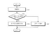
図3は、無線電力送信器の制御方法を説明するフローチャートである。
図3に図示されるように、無線電力送信器は駆動を開始できる(S301)。一方、無線電力送信器は、ラッチ失敗(latch fault)モードに進入するようにするラッチ失敗モード進入条件を充足するか否かを判定できる(S303)。ここで、ラッチ失敗モードは、無線電力送信器が図2aまたは2bの電力送信部211に第1の電力を、第1の周期で第1の期間の間に印加するモードを意味する。ラッチ失敗モードに対しては図5を参照してより詳細に説明する。併せて、ラッチ失敗モード進入条件は、例えば無線電力受信器ではない異質物が無線電力送信器上に配置されることであり得る。併せて、ラッチ失敗モード進入条件は、上述した異質物配置の他にも多様な形態があり、これに対しては、より詳細に後述する。
したがって、ラッチ失敗モード進入条件が満たされると(S303−Y)、無線電力送信器は第1の電力を周期的に印加できる(S305)。
一方、ラッチ失敗モード進入条件が満たされないと(S303−N)、無線電力送信器は正常モードで動作できる(S307)。FIG. 3 is a flowchart illustrating a method for controlling the wireless power transmitter.
As shown in FIG. 3, the wireless power transmitter can start driving (S301). On the other hand, the wireless power transmitter may determine whether or not a latch failure mode entry condition for entering a latch fault mode is satisfied (S303). Here, the latch failure mode means a mode in which the wireless power transmitter applies the first power to the
Accordingly, when the latch failure mode entry condition is satisfied (S303-Y), the wireless power transmitter can periodically apply the first power (S305).
On the other hand, if the latch failure mode entry condition is not satisfied (S303-N), the wireless power transmitter can operate in the normal mode (S307).
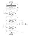
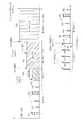
図4は、本発明の他の実施形態による無線電力送信器の制御方法を説明するフローチャートである。図4の制御方法は、図5を参照してより詳細に説明する。図5は、図4の実施形態による無線電力送信器が印加する電力量の時間軸に対するグラフィックである。 FIG. 4 is a flowchart illustrating a method for controlling a wireless power transmitter according to another embodiment of the present invention. The control method of FIG. 4 will be described in more detail with reference to FIG. FIG. 5 is a graphic of the amount of power applied by the wireless power transmitter according to the embodiment of FIG. 4 with respect to the time axis.
図4に図示されるように、無線電力送信器は駆動を開始できる(S401)。併せて、無線電力送信器は、初期設定をリセットできる(S403)。無線電力送信器は電力節約モードに進入できる(S405)。ここで、電力節約モードは、無線電力送信器が電力送信部に電力量が相異なる異種の電力を印加する区間であり得る。例えば、無線電力送信器は、図5における第2の検出電力501,502及び第3の検出電力(511,512,513,514,515)を電力送信部に印加する区間であり得る。ここで、無線電力送信器は、第2の検出電力501,502を第2の周期で周期的に印加でき、第2の検出電力501,502を印加する場合には、第2の期間の間に印加できる。無線電力送信器は、第3の検出電力(511,512,513,514,515)を第3の周期で周期的に印加でき、第3の検出電力(511,512,513,514,515)を印加する場合には、第3の期間の間に印加できる。一方、第3の検出電力(511,512,513,514,515)のそれぞれの電力値は相異なるように図示されるが、第3の検出電力(511,512,513,514,515)のそれぞれの電力値は相異するかまたは同一であり得る。 As shown in FIG. 4, the wireless power transmitter can start driving (S401). In addition, the wireless power transmitter can reset the initial setting (S403). The wireless power transmitter may enter a power saving mode (S405). Here, the power saving mode may be a section in which the wireless power transmitter applies different types of power with different amounts of power to the power transmission unit. For example, the wireless power transmitter may be a section in which the
無線電力送信器は、第3の検出電力511を出力した以後に、同一のサイズの電力量を有する第3の検出電力512を出力できる。上記の通りに無線電力送信器が同一のサイズの第3の検出電力を出力する場合、第3の検出電力の電力量は最も小型の無線電力受信器、例えばカテゴリ1の無線電力受信器を検出できる電力量を有することができる。 After outputting the third detected
無線電力送信器は、第3の検出電力511を出力した以後に、相異なるサイズの電力量を有する第3の検出電力512を出力できる。上記の通りに無線電力送信器が相異なるサイズの第3の検出電力を出力する場合、第3の検出電力の電力量の各々はカテゴリ1乃至5の無線電力受信器を検出できる電力量であり得る。例えば、第3の検出電力511は、カテゴリ5の無線電力受信器を検出できる電力量を有することができ、第3の検出電力512は、カテゴリ3の無線電力受信器を検出できる電力量を有することができ、第3の検出電力513は、カテゴリ1の無線電力受信器を検出できる電力量を有することができる。 After outputting the
一方、第2の検出電力501,502は、無線電力受信器を駆動させることができる電力であり得る。詳細には、第2の検出電力501,502は無線電力受信器の制御部及び通信部を駆動させる電力量を有することができる。 On the other hand, the second detected
無線電力送信器は第2の検出電力501,502及び第3の検出電力(511,512,513,514,515)を電力受信部に各々第2の周期及び第3の周期で印加できる。無線電力送信器上に無線電力受信器が配置される場合、無線電力送信器の一地点で見られるインピーダンスが変更されることができる。無線電力送信器は、第2の検出電力501,502及び第3の検出電力(511,512,513,514,515)が印加される間にインピーダンス変更を検出できる。例えば、無線電力送信器は、第3の検出電力515を印加する間、インピーダンスが変更されることを検出できる。したがって、無線電力送信器はオブジェクトを検出できる(S407)。オブジェクトが検出されない場合には(S407−N)、無線電力送信器は異種の電力を周期的に印加する電力節約モードを維持できる(S405)。 The wireless power transmitter can apply the
一方、インピーダンスが変更されてオブジェクトが検出される場合には(S407−Y)、無線電力送信器は、低電力モードに進入できる。ここで、低電力モードは、無線電力送信器が無線電力受信器の制御部及び通信部を駆動させる電力量を有する駆動電力を印加するモードである。例えば、図5では、無線電力送信器は駆動電力520を電力送信部に印加できる。無線電力受信器は、駆動電力520を受信して制御部及び通信部を駆動できる。無線電力受信器は、駆動電力520に基づき、無線電力送信器と所定の方式に基づいて通信を遂行することができる。例えば、無線電力受信器は認証に要求されるデータを送受信でき、これに基づいて無線電力送信器が管理する無線電力ネットワークに加入できる。ただし、無線電力受信器ではない異質物が配置される場合には、データ送受信が遂行されることができない。したがって、無線電力送信器は配置されたオブジェクトが異質物であるか否かを決定できる(S411)。例えば、無線電力送信器は既設定された時間の間にオブジェクトから応答を受信できない場合、オブジェクトが異質物であると決定できる。 On the other hand, when the impedance is changed and an object is detected (S407-Y), the wireless power transmitter can enter the low power mode. Here, the low power mode is a mode in which the wireless power transmitter applies driving power having an amount of power for driving the control unit and the communication unit of the wireless power receiver. For example, in FIG. 5, the wireless power transmitter can apply drive
異質物に決定された場合には(S411−Y)、無線電力送信器はラッチ失敗モードに進入できる。例えば、無線電力送信器は、図5における第1の電力(531乃至534)を第1の周期で周期的に印加できる。無線電力送信器は、第1の電力を印加する間にインピーダンス変更を検出できる。例えば、異質物が除去された場合にはインピーダンス変更を検出でき、無線電力送信器は異質物が除去されたと判定できる。または、異質物が除去されなかった場合には、無線電力送信器はインピーダンス変更を検出できず、無線電力送信器は異質物が除去されなかったと判定できる。異質物が除去されてない場合には、無線電力送信器はランプ及び警告音のうち少なくとも一つを出力して現在の無線電力送信器の状態がエラー状態であることをユーザに通知することができる。したがって、無線電力送信器は、ランプ及び警告音のうち少なくとも一つを出力する出力部を含むことができる。 If the foreign power is determined (S411-Y), the wireless power transmitter can enter the latch failure mode. For example, the wireless power transmitter can periodically apply the first power (531 to 534) in FIG. 5 in the first period. The wireless power transmitter can detect an impedance change while applying the first power. For example, when a foreign object is removed, the impedance change can be detected, and the wireless power transmitter can determine that the foreign object has been removed. Alternatively, if the foreign material is not removed, the wireless power transmitter cannot detect the impedance change, and the wireless power transmitter can determine that the foreign material has not been removed. If the foreign object has not been removed, the wireless power transmitter may output at least one of a lamp and a warning sound to notify the user that the current wireless power transmitter is in an error state. it can. Accordingly, the wireless power transmitter may include an output unit that outputs at least one of a lamp and a warning sound.
異質物が除去されなかったと判定される場合(S415−N)、無線電力送信器はラッチ失敗モードを維持できる(S413)。一方、異質物が除去されたと判定される場合(S415−Y)、無線電力送信器は電力節約モードに再進入できる(S417)。例えば、無線電力送信器は、図5の第2電力(551,552)及び第3の電力(561乃至565)を印加できる。 When it is determined that the extraneous matter has not been removed (S415-N), the wireless power transmitter can maintain the latch failure mode (S413). On the other hand, if it is determined that the extraneous matter has been removed (S415-Y), the wireless power transmitter can re-enter the power saving mode (S417). For example, the wireless power transmitter can apply the second power (551, 552) and the third power (561 to 565) of FIG.
上述した通り、無線電力送信器は、無線電力受信器ではなく異質物が配置された場合にラッチ失敗モードに進入できる。併せて、無線電力送信器は、ラッチ失敗モードで印加する電力に基づくインピーダンス変更に基づいて異質物が除去されたか否かを判定できる。すなわち、図4及び5の実施形態におけるラッチ失敗モード進入条件は、異質物の配置であり得る。一方、無線電力送信器は異質物の配置の他にも多様なラッチ失敗モード進入条件を有することができる。例えば、無線電力送信器は、配置された無線電力受信器と交差接続されることができ、これに対しては図6を参照してより詳細に説明する。 As described above, the wireless power transmitter can enter the latch failure mode when a foreign object is placed instead of the wireless power receiver. In addition, the wireless power transmitter can determine whether or not the foreign material has been removed based on the impedance change based on the power applied in the latch failure mode. That is, the latch failure mode entry condition in the embodiment of FIGS. 4 and 5 may be an arrangement of a foreign object. Meanwhile, the wireless power transmitter may have various latch failure mode entry conditions in addition to the disposition of foreign objects. For example, the wireless power transmitter can be cross-connected with a deployed wireless power receiver, which will be described in more detail with reference to FIG.
図6は交差接続を説明するための概念図である。図6で、第1の無線電力送信器TX1及び第2の無線電力送信器TX2が配置される。併せて、第1の無線電力送信器TX1上には、第1の無線電力受信器RX1が配置され、第2の無線電力送信器TX2上には第2の無線電力受信器RX2が配置される。ここで、第1の無線電力送信器TX1は、近隣に配置された第1の無線電力受信器RX1に電力を送信すべきである。併せて、第2の無線電力送信器TX2は、近隣に配置された第2の無線電力受信器RX2に電力を送信すべきである。したがって、望ましくは、第1の無線電力送信器TX1は、第1の無線電力受信器RX1と通信を遂行し、第2の無線電力送信器TX2は、第2の無線電力受信器RX2と通信を遂行する。ただし、通信道の増加にしたがって、第1の無線電力受信器RX1が第2の無線電力送信器TX2が管理する無線電力ネットワークに加入し、第2の無線電力受信器RX2が第1の無線電力送信器TX1が管理する無線電力ネットワークに加入できる。これを交差接続と称する。したがって、第1の無線電力送信器TX1が第1の無線電力受信器RX1が要求する電力ではなく、第2の無線電力受信器RX2が要求する電力を送信する問題が発生できる。第2の無線電力受信器RX2の容量が第1の無線電力受信器RX1より大きい場合には、第1の無線電力受信器RX1に過用量が印加されて問題になる。また第2の無線電力受信器RX2の容量が第1の無線電力受信器RX1より小さな場合には、第1の無線電力受信器RX1が充電容量以下の電力を受信する問題が発生する。 FIG. 6 is a conceptual diagram for explaining cross connection. In FIG. 6, a first wireless power transmitter TX1 and a second wireless power transmitter TX2 are arranged. In addition, the first wireless power receiver RX1 is disposed on the first wireless power transmitter TX1, and the second wireless power receiver RX2 is disposed on the second wireless power transmitter TX2. . Here, the first wireless power transmitter TX1 should transmit power to the first wireless power receiver RX1 arranged in the vicinity. In addition, the second wireless power transmitter TX2 should transmit power to the second wireless power receiver RX2 located in the vicinity. Therefore, preferably, the first wireless power transmitter TX1 communicates with the first wireless power receiver RX1, and the second wireless power transmitter TX2 communicates with the second wireless power receiver RX2. Carry out. However, as the number of communication paths increases, the first wireless power receiver RX1 joins the wireless power network managed by the second wireless power transmitter TX2, and the second wireless power receiver RX2 A wireless power network managed by the transmitter TX1 can be joined. This is called cross connection. Therefore, there is a problem that the first wireless power transmitter TX1 transmits not the power required by the first wireless power receiver RX1, but the power required by the second wireless power receiver RX2. When the capacity of the second wireless power receiver RX2 is larger than that of the first wireless power receiver RX1, an overdose is applied to the first wireless power receiver RX1, which causes a problem. Further, when the capacity of the second wireless power receiver RX2 is smaller than that of the first wireless power receiver RX1, there arises a problem that the first wireless power receiver RX1 receives power less than the charging capacity.
したがって、無線電力送信器は交差接続の発生時、初期状態への復帰が要求され、無線電力受信器の除去が要求される。無線電力送信器は、他の無線電力送信器上に配置される無線電力受信器が無線電力ネットワークに加入する交差接続をラッチ失敗モード進入条件に設定できる。交差接続を含むエラー発生時の無線電力送信器の動作を、図7を参照して説明する。 Therefore, the wireless power transmitter is required to return to the initial state when cross connection occurs, and the wireless power receiver is required to be removed. The wireless power transmitter can set a cross-connection in which a wireless power receiver disposed on another wireless power transmitter joins the wireless power network as a latch failure mode entry condition. The operation of the wireless power transmitter when an error including cross connection occurs will be described with reference to FIG.
図7は、本発明の一実施形態による無線電力送信器の制御方法を説明するフローチャートである。図7の制御方法は図8を参照してより詳細に説明する。図8は、図7の実施形態による無線電力送信器が印加する電力量の時間軸に対するグラフィックである。 FIG. 7 is a flowchart illustrating a method for controlling a wireless power transmitter according to an embodiment of the present invention. The control method of FIG. 7 will be described in more detail with reference to FIG. FIG. 8 is a graphic of the amount of power applied by the wireless power transmitter according to the embodiment of FIG. 7 with respect to the time axis.
無線電力送信器は駆動を開始できる(S701)。併せて、無線電力送信器は初期設定をリセットできる(S703)。無線電力送信器は電力節約モードに進入できる(S705)。ここで、電力節約モードは、無線電力送信器が電力送信部に電力量が相異なる異種の電力を印加する区間であり得る。例えば、無線電力送信器は図8における第2の検出電力801,802及び第3の検出電力(811,812,813,814,815)を電力送信部に印加する区間であり得る。ここで、無線電力送信器は、第2の検出電力801,802を第2の周期で周期的に印加でき、第2の検出電力801,802を印加する場合には第2の期間の間に印加できる。無線電力送信器は、第3の検出電力(811,812,813,814,815)を第3の周期で周期的に印加でき、第3の検出電力(811,812,813,814,815)を印加する場合には第3の期間の間に印加できる。 The wireless power transmitter can start driving (S701). In addition, the wireless power transmitter can reset the initial setting (S703). The wireless power transmitter may enter a power saving mode (S705). Here, the power saving mode may be a section in which the wireless power transmitter applies different types of power with different amounts of power to the power transmission unit. For example, the wireless power transmitter may be a section in which the
一方、第3の検出電力(811,812,813,814,815)のそれぞれの電力値は相異なるように図示されるが、第3の検出電力(811,812,813,814,815)のそれぞれの電力値は相異するかまたは同一であり得る。 On the other hand, although the power values of the third detection powers (811, 812, 813, 814, 815) are illustrated as different from each other, the third detection powers (811, 812, 813, 814, 815) Each power value may be different or the same.
一方、第2の検出電力801,802は、無線電力受信器を駆動させることができる電力であり得る。詳細には、第2の検出電力801,802は無線電力受信器の制御部及び通信部を駆動させることができる電力量を有することができる。 On the other hand, the second detected
無線電力送信器は、第2の検出電力801,802及び第3の検出電力(811,812,813,814,815)を電力受信部に各々第2の周期及び第3の周期で印加できる。無線電力送信器上に無線電力受信器が配置される場合、無線電力送信器の一地点で見られるインピーダンスが変更されることができる。無線電力送信器は、第2の検出電力801,802及び第3の検出電力(811,812,813,814,815)が印加される間にインピーダンス変更を検出できる。例えば、無線電力送信器は、第3の検出電力815を印加する間、インピーダンスが変更されることを検出できる。したがって、無線電力送信器は、オブジェクトを検出できる(S707)。オブジェクトが検出されない場合には(S707−N)、無線電力送信器は異種の電力を周期的に印加する電力節約モードを維持できる(S705)。 The wireless power transmitter can apply the
一方、インピーダンスが変更されてオブジェクトが検出される場合には(S807−Y)、無線電力送信器は、低電力モードに進入できる(S809)。ここで、低電力モードは、無線電力送信器が無線電力受信器の制御部及び通信部を駆動させることができる電力量を有する駆動電力を印加するモードである。例えば、図8では、無線電力送信器は、駆動電力820を電力送信部に印加できる。無線電力受信器は、駆動電力820を受信して制御部及び通信部を駆動できる。無線電力受信器は、駆動電力820に基づいて無線電力送信器と所定の方式に基づいて通信を遂行することができる。例えば、無線電力受信器は、認証に要求されるデータを送受信でき、これに基づいて無線電力送信器が管理する無線電力ネットワークに加入できる。 On the other hand, when the impedance is changed and the object is detected (S807-Y), the wireless power transmitter can enter the low power mode (S809). Here, the low power mode is a mode in which the wireless power transmitter applies drive power having an amount of power that can drive the control unit and the communication unit of the wireless power receiver. For example, in FIG. 8, the wireless power transmitter can apply drive
以後、無線電力送信器は、充電電力を送信する電力送信モードに進入できる(S711)。例えば、無線電力送信器は図8のように充電電力821を印加でき、充電電力は無線電力受信器に送信できる。 Thereafter, the wireless power transmitter can enter a power transmission mode for transmitting charging power (S711). For example, the wireless power transmitter can apply charging
無線電力送信器は電力送信モードで、エラーが発生するか否かを判定できる。ここで、エラーは無線電力送信器上に異質物が配置されること、交差接続、過電圧、過電流、過温度などであり得る。無線電力送信器は過電圧、過電流、過温度などを測定できるセンシング部を含むことができる。例えば、無線電力送信器は基準地点の電圧または電流を測定でき、測定された電圧または電流が閾値を超過することを過電圧または過電流の条件が満たされることと判定できる。または無線電力送信器は、温度センシング手段を含むことができ、温度センシング手段は無線電力送信器の基準地点の温度を測定できる。基準地点の温度が閾値を超過する場合には、無線電力送信器は過温度条件が満たされていると判定できる。 The wireless power transmitter can determine whether an error occurs in the power transmission mode. Here, the error may be a foreign object placed on the wireless power transmitter, a cross connection, an overvoltage, an overcurrent, an overtemperature, or the like. The wireless power transmitter may include a sensing unit that can measure overvoltage, overcurrent, overtemperature, and the like. For example, the wireless power transmitter can measure a voltage or current at a reference point, and can determine that an overvoltage or overcurrent condition is met if the measured voltage or current exceeds a threshold. Alternatively, the wireless power transmitter can include temperature sensing means, and the temperature sensing means can measure the temperature of the reference point of the wireless power transmitter. If the temperature at the reference point exceeds the threshold, the wireless power transmitter can determine that the overtemperature condition is satisfied.
図8の実施形態では、無線電力送信器上に異質物が追加的に配置されるエラーが図示されるが、エラーはこれに限定されず、異質物が配置されること、交差接続、過電圧、過電流、過温度に対しでも無線電力送信器が類似の過程で動作することが当業者にとって容易に理解される。 In the embodiment of FIG. 8, an error in which extraneous matter is additionally placed on the wireless power transmitter is illustrated, but the error is not limited to this, the extraneous matter is placed, cross-connection, overvoltage, It will be readily appreciated by those skilled in the art that the wireless power transmitter operates in a similar process for overcurrent and overtemperature.
エラーが発生しなければ(S713−N)、無線電力送信器は、電力送信モードを維持できる(S711)。一方、エラーが発生すれば(S713−Y)、無線電力送信器は、ラッチ失敗モードに進入できる(S715)。例えば、無線電力送信器は、図8のように第1の電力(831乃至835)を印加できる。併せて、無線電力送信器は、ラッチ失敗モード間ランプ及び警告音のうち少なくとも一つを含むエラー発生表示を出力できる。異質物または無線電力受信器が除去されないことに判定される場合(S717−N)、無線電力送信器はラッチ失敗モードを維持できる(S715)。一方、異質物または無線電力受信器が除去されたと判定される場合(S717−)、無線電力送信器は電力節約モードに再進入できる(S719)。例えば、無線電力送信器は、図8の第2電力(851,852)及び第3の電力(861乃至865)を印加できる。 If no error occurs (S713-N), the wireless power transmitter can maintain the power transmission mode (S711). On the other hand, if an error occurs (S713-Y), the wireless power transmitter can enter the latch failure mode (S715). For example, the wireless power transmitter can apply the first power (831 to 835) as shown in FIG. In addition, the wireless power transmitter can output an error occurrence indication including at least one of a lamp during latch failure mode and a warning sound. If it is determined that the foreign object or the wireless power receiver is not removed (S717-N), the wireless power transmitter can maintain the latch failure mode (S715). On the other hand, if it is determined that the foreign object or the wireless power receiver has been removed (S717-), the wireless power transmitter can re-enter the power saving mode (S719). For example, the wireless power transmitter can apply the second power (851, 852) and the third power (861 to 865) of FIG.
以上、無線電力送信器が充電電力を送信する間にエラーが発生した場合の動作に対して説明した。以下では、無線電力送信器上に複数の無線電力受信器が充電電力を受信する場合の動作に対して説明する。 The operation when an error occurs while the wireless power transmitter transmits charging power has been described above. Hereinafter, an operation when a plurality of wireless power receivers receive charging power on the wireless power transmitter will be described.
図9は、本発明の一実施形態による無線電力送信器の制御方法を説明するためのフローチャートである。図9の制御方法は図10を参照してより詳細に説明する。図10は図9の実施形態による無線電力送信器が印加する電力量の時間軸に対するグラフィックである。 FIG. 9 is a flowchart illustrating a method for controlling a wireless power transmitter according to an embodiment of the present invention. The control method of FIG. 9 will be described in more detail with reference to FIG. FIG. 10 is a graphic of the amount of power applied by the wireless power transmitter according to the embodiment of FIG. 9 with respect to the time axis.
図9に図示されるように、無線電力送信器は、第1の無線電力受信器に充電電力を送信できる(S901)。併せて、無線電力送信器は、追加的に第2の無線電力受信器を無線電力ネットワークに加入させることができる(S903)。また、無線電力送信器は、第2の無線電力受信器にも充電電力を送信できる(S905)。詳細には、無線電力送信器は、第1の無線電力受信器及び第2の無線電力受信器が要求する充電電力の合計を電力送信部に印加できる。 As shown in FIG. 9, the wireless power transmitter can transmit charging power to the first wireless power receiver (S901). In addition, the wireless power transmitter can additionally join the second wireless power receiver to the wireless power network (S903). The wireless power transmitter can also transmit the charging power to the second wireless power receiver (S905). Specifically, the wireless power transmitter can apply the total charging power required by the first wireless power receiver and the second wireless power receiver to the power transmitter.
図10では、上記のステップS901乃至ステップS905に対する一実施形態が図示される。例えば、無線電力送信器は、第2の検出電力(1001,1002)及び第3の検出電力(1011乃至1015)を印加する電力節約モードを維持できる。以後、無線電力送信器は、第1の無線電力受信器を検出し、検出電力1020を維持する低電力モードに進入できる。以後、無線電力送信器は、第1の充電電力1030を印加する電力送信モードに進入できる。無線電力送信器は第2の無線電力受信器を検出でき、第2の無線電力受信器を無線電力ネットワークに加入させることができる。併せて、無線電力送信器は、第1の無線電力受信器及び第2の無線電力受信器が要求する電力量の合計の電力量を有する第2の充電電力1040を印加できる。 In FIG. 10, an embodiment for the above steps S901 to S905 is shown. For example, the wireless power transmitter can maintain a power saving mode in which the second detected power (1001, 1002) and the third detected power (1011 to 1015) are applied. Thereafter, the wireless power transmitter can enter the low power mode in which the first wireless power receiver is detected and the detected
また、図9を参照すれば、無線電力送信器は第1の及び第2の無線電力受信器両方に充電電力を送信する間(S905)、エラー発生を検出できる(S907)。ここで、エラーは上述した通り、異質物配置、交差接続、過電圧、過電流、過温度などであり得る。エラーが発生しなければ(S907−N)、無線電力送信器は第2の充電電力1040の印加を維持できる。 Referring to FIG. 9, the wireless power transmitter can detect the occurrence of an error (S907) while transmitting charging power to both the first and second wireless power receivers (S905). Here, as described above, the error may be a foreign matter arrangement, cross connection, overvoltage, overcurrent, overtemperature, or the like. If no error occurs (S907-N), the wireless power transmitter can maintain the application of the
一方、エラーが発生すれば(S907−Y)、無線電力送信器はラッチ失敗モードに進入できる(S909)。例えば、無線電力送信器は図10の第1の電力(1051乃至1055)を第1の周期で印加できる。無線電力送信器は、第1の無線電力受信器及び第2の無線電力受信器の全てが除去されたか否かを判定できる(S911)。例えば、無線電力送信器は、第1の電力(1051乃至1055)を印加する間にインピーダンス変更を検出できる。無線電力送信器は、インピーダンスが初期値に戻るか否かに基づいて、第1の無線電力受信器及び第2の無線電力受信器の全てが除去されたか否かを判定できる。 On the other hand, if an error occurs (S907-Y), the wireless power transmitter can enter the latch failure mode (S909). For example, the wireless power transmitter can apply the first power (1051 to 1055) of FIG. 10 in the first period. The wireless power transmitter can determine whether all of the first wireless power receiver and the second wireless power receiver have been removed (S911). For example, the wireless power transmitter can detect an impedance change while applying the first power (1051 to 1055). The wireless power transmitter can determine whether all of the first wireless power receiver and the second wireless power receiver have been removed based on whether the impedance returns to the initial value.
第1の無線電力受信器及び第2の無線電力受信器の全てが除去されたと判定されれば(S911−Y)、無線電力送信器は電力節約モードに進入できる(S913)。例えば、無線電力送信器は、図10のように第2の検出電力(1061,1062)及び第3の検出電力(1071乃至1075)を各々第2の周期及び第3の周期で印加できる。 If it is determined that all of the first wireless power receiver and the second wireless power receiver have been removed (S911-Y), the wireless power transmitter can enter the power saving mode (S913). For example, the wireless power transmitter can apply the second detection power (1061, 1062) and the third detection power (1071 to 1075) in the second period and the third period, respectively, as shown in FIG.
以上では、本発明の望ましい実施形態に対して図示と共に説明したが、当業者であれば、誰でも本発明の技術的思想及び範囲を逸脱しない範囲内で、本発明の望ましい実施形態を多様に変更可能である。したがって、本発明は特許請求の範囲で請求する本発明の要旨を逸脱せずに多様な変形実施が可能であり、このような変形実施は本発明の技術的思想や見込みから個別的に理解されてはならない。 In the above, the preferred embodiments of the present invention have been described with reference to the drawings. However, any person skilled in the art can make various preferred embodiments of the present invention without departing from the technical idea and scope of the present invention. It can be changed. Therefore, the present invention can be variously modified without departing from the scope of the present invention as claimed in the claims, and such modified embodiments are individually understood from the technical idea and prospect of the present invention. must not.
100 無線電力送信器
200 無線電力送信器
211 電力送信部
212 制御部
213 通信部
214 駆動部
215 増幅部
216 マッチング部
250 無線電力受信器
251 電力受信部
252 制御部
253 通信部
254 整流部
255 DC変換器
256 スイッチ部
257 ロード部
258 入力端子
259 出力端100
Claims (15)
Translated fromJapanese前記無線電力送信器を駆動するステップと、
第1の電力量を有する第1の電力を第1の周期で周期的に印加するラッチ失敗モードに進入するようにするラッチ失敗モード進入条件が満たされるか否かを判定するステップと、
前記ラッチ失敗モード進入条件が満たされると、前記第1の電力を前記第1の周期で周期的に印加するステップと、を含むことを特徴とする方法。A method for controlling a wireless power transmitter for transmitting charging power to a wireless power receiver, comprising:
Driving the wireless power transmitter;
Determining whether a latch failure mode entry condition for entering a latch failure mode in which first power having a first power amount is periodically applied in a first period is satisfied; and
Applying the first power periodically in the first period when the latch failure mode entry condition is satisfied.
第2の電力量を有する第2の検出電力を第2の周期で周期的に印加し、第3の電力量を有する第3の検出電力を第3の周期で周期的に印加する電力節約モードを維持するステップをさらに含むことを特徴とする請求項1に記載の方法。After the step of driving the wireless power transmitter and before the step of determining whether the latch failure mode entry condition is satisfied,
A power saving mode in which the second detection power having the second power amount is periodically applied in the second period and the third detection power having the third power amount is periodically applied in the third period. The method of claim 1, further comprising the step of maintaining:
前記インピーダンス変更が検出されると、前記無線電力受信器を駆動させる駆動電力を印加するステップと、
前記駆動電力を印加した以後に、前記無線電力送信器が管理する無線電力ネットワークへの加入のための信号が受信されるか否かを判定するステップと、をさらに含むことを特徴とする請求項2に記載の方法。Detecting an impedance change of the wireless power transmitter while applying at least one of the second detected power and the third detected power;
When the impedance change is detected, applying drive power to drive the wireless power receiver;
The method further comprises: determining whether a signal for joining a wireless power network managed by the wireless power transmitter is received after applying the driving power. 2. The method according to 2.
前記既設定された時間の間に前記無線電力ネットワークへの加入のための信号を受信できないと、前記無線電力送信器に配置されたオブジェクトを異質物と判定するステップと、
前記第1の電力の印加によって測定されるインピーダンスが初期値に戻るか否かによって、前記異質物が除去されたか否かを判定するステップと、
前記異質物が除去されるまで前記ラッチ失敗モードを維持するステップと、
前記異質物が除去されると、第2の電力量を有する第2の検出電力を第2の周期で周期的に印加し、第3の電力量を有する第3の検出電力を第3の周期で周期的に印加する電力節約モードに進入するステップと、を含み、
前記ラッチ失敗モード進入条件は、既設定された期間の間に前記無線電力ネットワークへの加入のための信号を受信できないことを特徴とする請求項3に記載の方法。The step of periodically applying the first power in the first period includes:
Determining that the object located in the wireless power transmitter is foreign if it cannot receive a signal for joining the wireless power network during the preset time;
Determining whether the extraneous matter has been removed according to whether the impedance measured by applying the first power returns to an initial value;
Maintaining the latch failure mode until the extraneous material is removed;
When the foreign matter is removed, the second detection power having the second power amount is periodically applied in the second period, and the third detection power having the third power amount is applied to the third period. Entering a power saving mode that is applied periodically at
4. The method of claim 3, wherein the latch failure mode entry condition is incapable of receiving a signal for joining the wireless power network during a preset period.
前記無線電力受信器に充電電力を送信するステップをさらに含み、前記ラッチ失敗モード進入条件は、前記無線電力受信器に前記充電電力を送信する過程でエラーが発生することを特徴とする請求項1に記載の方法。After the step of driving the wireless power transmitter, before the step of determining whether the latch failure mode entry condition is satisfied,
The method of claim 1, further comprising: transmitting charging power to the wireless power receiver, wherein the latch failure mode entry condition causes an error in the process of transmitting the charging power to the wireless power receiver. The method described in 1.
前記第1の電力を第1の周期で周期的に印加するステップは、前記他の無線電力送信器上に配置される無線電力受信器が除去されるまで前記第1の電力を印加することを特徴とする請求項5に記載の方法。The error is that a wireless power receiver located in another wireless power transmitter is cross-connected to the wireless power transmitter;
The step of periodically applying the first power at a first period includes applying the first power until a wireless power receiver disposed on the other wireless power transmitter is removed. 6. A method according to claim 5, characterized in that
前記第1の電力を前記第1の周期で周期的に印加するステップは、前記過電圧、過電流及び過温度のうち少なくとも一つの条件が解除されるまで、前記第1の電力を印加することを特徴とする請求項5に記載の方法。The error is satisfying at least one condition of overvoltage, overcurrent and overtemperature of the wireless power transmitter,
The step of periodically applying the first power in the first period includes applying the first power until at least one of the overvoltage, overcurrent, and overtemperature conditions is canceled. 6. A method according to claim 5, characterized in that
前記無線電力送信器を駆動する駆動部と、
前記無線電力受信器に前記充電電力を送信する電力送信部と、
第1の電力量を有する第1の電力を第1の周期で周期的に印加するラッチ失敗モードに進入するようにするラッチ失敗モード進入条件が満たされるか否かを判定し、前記ラッチ失敗モード進入条件が満たされると、前記第1の電力を前記第1の周期で周期的に前記電力送信部に印加するように制御する制御部と、を含むことを特徴とする無線電力送信器。A wireless power transmitter for transmitting charging power to a wireless power receiver,
A drive unit for driving the wireless power transmitter;
A power transmitter for transmitting the charging power to the wireless power receiver;
Determining whether a latch failure mode entry condition for entering a latch failure mode in which first power having a first power amount is periodically applied in a first period is satisfied, and the latch failure mode A wireless power transmitter comprising: a control unit configured to control the first power to be periodically applied to the power transmission unit in the first period when an entry condition is satisfied.
前記インピーダンス変更が検出されると、前記無線電力受信器を駆動させる駆動電力を前記電力送信部に印加し、
前記無線電力送信器が管理する無線電力ネットワークへの加入のための信号が通信部を通じて受信されたか否かを判定することを特徴とする請求項10に記載の無線電力送信器。The controller detects an impedance change of the wireless power transmitter while applying at least one of the second detection power and the third detection power,
When the impedance change is detected, driving power for driving the wireless power receiver is applied to the power transmission unit,
The wireless power transmitter according to claim 10, wherein a signal for joining a wireless power network managed by the wireless power transmitter is received through a communication unit.
前記ラッチ失敗モード進入条件は、前記通信部に既設定された期間の間に前記無線電力ネットワークへの加入のための信号を受信できないことを特徴とする請求項12に記載の無線電力送信器。The controller determines that the object arranged in the wireless power transmitter is a foreign object if a signal for joining the wireless power network is not received by the communication unit during a preset time. The latch failure mode is maintained until the extraneous matter is removed, and it is determined whether the extraneous matter is removed depending on whether the impedance measured by applying the first power returns to an initial value. When the extraneous matter is removed, the second detection power having the second power amount is periodically applied in the second period, and the third detection power having the third power amount is applied to the third power. Enter the power saving mode to apply periodically with a period of
The wireless power transmitter according to claim 12, wherein the latch failure mode entry condition cannot receive a signal for joining the wireless power network during a period set in the communication unit.
前記ラッチ失敗モード進入条件は、前記充電電力を送信する過程でエラーが発生することであり、
前記エラーは、前記充電電力を送信する過程でオブジェクトが配置される場合、既設定された期間の間に前記無線電力送信器が管理する無線電力ネットワークへの加入のための信号を受信できなこと、他の無線電力送信器に配置された無線電力送信器が交差接続されること、前記無線電力送信器の過電圧、過電流及び過温度のうち少なくとも一つの条件を満たすことのうち一つであることを特徴とする請求項10に記載の無線電力送信器。The power transmission unit transmits charging power to the wireless power receiver after driving the wireless power transmitter and before the latch failure mode entry condition is satisfied,
The latch failure mode entry condition is that an error occurs in the process of transmitting the charging power,
When the object is arranged in the process of transmitting the charging power, the error is not able to receive a signal for joining the wireless power network managed by the wireless power transmitter during a preset period. A wireless power transmitter disposed in another wireless power transmitter is cross-connected, and at least one of the overvoltage, overcurrent and overtemperature conditions of the wireless power transmitter is satisfied. The wireless power transmitter according to claim 10.
前記制御部は、前記ラッチ失敗モード進入条件が満たされると、前記ランプ及び警告音のうち少なくとも一つを出力するように前記出力部を制御することを特徴とする請求項10に記載の無線電力送信器。An output unit that outputs at least one of a lamp and a warning sound;
The wireless power of claim 10, wherein the control unit controls the output unit to output at least one of the lamp and a warning sound when the latch failure mode entry condition is satisfied. Transmitter.
Applications Claiming Priority (3)
| Application Number | Priority Date | Filing Date | Title |
|---|---|---|---|
| KR10-2013-0024937 | 2013-03-08 | ||
| KR1020130024937AKR102039375B1 (en) | 2013-03-08 | 2013-03-08 | Wireless power transmitter, wireless power receiver and method for controlling each thereof |
| PCT/KR2014/001916WO2014137199A1 (en) | 2013-03-08 | 2014-03-07 | Wireless power transmitter and method for controlling same |
Related Child Applications (1)
| Application Number | Title | Priority Date | Filing Date |
|---|---|---|---|
| JP2018211680ADivisionJP6820053B2 (en) | 2013-03-08 | 2018-11-09 | Wireless power transmitter and its control method |
Publications (1)
| Publication Number | Publication Date |
|---|---|
| JP2016509465Atrue JP2016509465A (en) | 2016-03-24 |
Family
ID=50231051
Family Applications (2)
| Application Number | Title | Priority Date | Filing Date |
|---|---|---|---|
| JP2015561276APendingJP2016509465A (en) | 2013-03-08 | 2014-03-07 | Wireless power transmitter and control method thereof |
| JP2018211680AExpired - Fee RelatedJP6820053B2 (en) | 2013-03-08 | 2018-11-09 | Wireless power transmitter and its control method |
Family Applications After (1)
| Application Number | Title | Priority Date | Filing Date |
|---|---|---|---|
| JP2018211680AExpired - Fee RelatedJP6820053B2 (en) | 2013-03-08 | 2018-11-09 | Wireless power transmitter and its control method |
Country Status (6)
| Country | Link |
|---|---|
| US (1) | US9472983B2 (en) |
| EP (1) | EP2779363B1 (en) |
| JP (2) | JP2016509465A (en) |
| KR (1) | KR102039375B1 (en) |
| CN (1) | CN105009412B (en) |
| WO (1) | WO2014137199A1 (en) |
Cited By (1)
| Publication number | Priority date | Publication date | Assignee | Title |
|---|---|---|---|---|
| JP2019520024A (en)* | 2016-06-29 | 2019-07-11 | クアルコム,インコーポレイテッド | Device and method for wireless power charging of a subsequent receiver |
Families Citing this family (31)
| Publication number | Priority date | Publication date | Assignee | Title |
|---|---|---|---|---|
| WO2013089485A1 (en)* | 2011-12-15 | 2013-06-20 | Samsung Electronics Co., Ltd. | Apparatus and method for transmitting wireless power |
| KR102039375B1 (en)* | 2013-03-08 | 2019-11-04 | 삼성전자주식회사 | Wireless power transmitter, wireless power receiver and method for controlling each thereof |
| KR101787796B1 (en) | 2013-05-03 | 2017-10-18 | 삼성전자주식회사 | Wireless power transmitter, wireless power receiver and method for controlling each thereof |
| CN105264744B (en) | 2013-06-05 | 2018-03-06 | 三星电子株式会社 | Wireless power receiving unit and method of generating load change for detecting same in wireless charging |
| CA2956795C (en) | 2014-08-03 | 2020-06-30 | PogoTec, Inc. | Wearable camera systems and apparatus and method for attaching camera systems or other electronic devices to wearable articles |
| US9635222B2 (en) | 2014-08-03 | 2017-04-25 | PogoTec, Inc. | Wearable camera systems and apparatus for aligning an eyewear camera |
| KR102026984B1 (en)* | 2014-12-15 | 2019-10-07 | 주식회사 위츠 | Wireless charging control method, and wireless power transmission apparatus and wireless power receive apparatus using the same |
| CA2972064A1 (en) | 2014-12-23 | 2016-06-30 | PogoTec, Inc. | Wireless camera system and methods |
| WO2016164790A1 (en)* | 2015-04-10 | 2016-10-13 | Ossia Inc. | Wireless power transceivers for supplementing wireless power delivery and extending range |
| EP3308216B1 (en) | 2015-06-10 | 2021-04-21 | Pogotec, Inc. | Eyewear with magnetic track for electronic wearable device |
| US10481417B2 (en) | 2015-06-10 | 2019-11-19 | PogoTec, Inc. | Magnetic attachment mechanism for electronic wearable device |
| KR102443355B1 (en)* | 2015-08-31 | 2022-09-14 | 지이 하이브리드 테크놀로지스, 엘엘씨 | Wireless power transmission and charging system |
| TW201729610A (en) | 2015-10-29 | 2017-08-16 | 帕戈技術股份有限公司 | Hearing aid adapted for wireless power reception |
| US10270260B2 (en)* | 2015-12-18 | 2019-04-23 | Intel Corporation | Cross-connection resolution in wireless power transfer systems |
| US11558538B2 (en) | 2016-03-18 | 2023-01-17 | Opkix, Inc. | Portable camera system |
| US10488543B2 (en)* | 2016-03-31 | 2019-11-26 | Intel Corporation | Rogue object detection algorithm for wireless charging notification |
| KR102572577B1 (en)* | 2016-04-15 | 2023-08-30 | 삼성전자주식회사 | Charging apparatus and method for controlling wireless charging |
| KR102628358B1 (en)* | 2016-07-18 | 2024-01-23 | 엘지이노텍 주식회사 | Foreign Object Detection Method and Apparatus and System therefor |
| US11070095B2 (en) | 2016-07-01 | 2021-07-20 | Lg Innotek Co., Ltd. | Method for detecting foreign material, and device and system therefor |
| WO2018004304A1 (en)* | 2016-07-01 | 2018-01-04 | 엘지이노텍(주) | Method for detecting foreign material, and device and system therefor |
| KR20180007117A (en) | 2016-07-12 | 2018-01-22 | 삼성전자주식회사 | Wireless power transmitter and wireless power receiver and method for operating thereof |
| EP3539285A4 (en) | 2016-11-08 | 2020-09-02 | Pogotec, Inc. | A smart case for electronic wearable device |
| US10164476B2 (en) | 2016-12-06 | 2018-12-25 | X Development Llc | Device handover |
| KR102615017B1 (en)* | 2017-11-13 | 2023-12-19 | 한국전자통신연구원 | Apparatus and method for dynamic excution of programs |
| KR20190054416A (en)* | 2017-11-13 | 2019-05-22 | 삼성전기주식회사 | Wireless power transmission apparatus |
| KR102509314B1 (en) | 2018-05-16 | 2023-03-14 | 엘지이노텍 주식회사 | Method and Apparatus for Controlling Wireless Power Transmission |
| US11300857B2 (en) | 2018-11-13 | 2022-04-12 | Opkix, Inc. | Wearable mounts for portable camera |
| KR102148082B1 (en)* | 2018-11-29 | 2020-08-26 | 한국과학기술원 | Determination method of the magnetic resonant condition for the milti-device wireless power transfer systems |
| US11095153B2 (en)* | 2019-03-15 | 2021-08-17 | Ossia Inc. | Wireless power system technology implemented in lighting infrastructure |
| CN110169090B (en)* | 2019-04-09 | 2021-12-14 | 北京小米移动软件有限公司 | Information transmission method, device and storage medium |
| US20220278553A1 (en)* | 2019-07-09 | 2022-09-01 | Lg Electronics Inc. | Wireless power reception device and wireless power transmission device |
Citations (6)
| Publication number | Priority date | Publication date | Assignee | Title |
|---|---|---|---|---|
| WO2008056415A1 (en)* | 2006-11-08 | 2008-05-15 | Panasonic Corporation | Non-contact charger, electronic device, battery pack, and non-contact charge system |
| JP2009124878A (en)* | 2007-11-15 | 2009-06-04 | Meleagros Corp | Power transmission device, power transmission device and power reception device of power transmission device |
| JP2012504931A (en)* | 2008-10-03 | 2012-02-23 | アクセス ビジネス グループ インターナショナル リミテッド ライアビリティ カンパニー | Power system |
| WO2012037279A1 (en)* | 2010-09-14 | 2012-03-22 | Witricity Corporation | Wireless energy distribution system |
| JP2012175824A (en)* | 2011-02-22 | 2012-09-10 | Canon Inc | Power supply device |
| WO2012141239A1 (en)* | 2011-04-15 | 2012-10-18 | Necカシオモバイルコミュニケーションズ株式会社 | Transmitter, receiver, non-contact power transmission control method, and computer-readable recording medium |
Family Cites Families (16)
| Publication number | Priority date | Publication date | Assignee | Title |
|---|---|---|---|---|
| US7334158B2 (en)* | 2004-06-29 | 2008-02-19 | Intel Corporation | Power fault handling method, apparatus, and system |
| JP4600462B2 (en)* | 2007-11-16 | 2010-12-15 | セイコーエプソン株式会社 | Power transmission control device, power transmission device, electronic device, and non-contact power transmission system |
| KR101061661B1 (en)* | 2008-01-09 | 2011-09-01 | 세이코 엡슨 가부시키가이샤 | Power transmission control device, power transmission device, contactless power transmission system, electronic equipment and power transmission control method |
| US8712324B2 (en)* | 2008-09-26 | 2014-04-29 | Qualcomm Incorporated | Inductive signal transfer system for computing devices |
| JP2011229265A (en)* | 2010-04-19 | 2011-11-10 | Panasonic Electric Works Co Ltd | Non-contacting power transmitter |
| TWI389416B (en)* | 2010-05-31 | 2013-03-11 | Fu Da Tong Technology Co Ltd | Power transmission method of high power wireless inductive power supply |
| JP2012016125A (en)* | 2010-06-30 | 2012-01-19 | Panasonic Electric Works Co Ltd | Non-contact power supply system and metal foreign matter detection device for non-contact power supply system |
| US9178369B2 (en)* | 2011-01-18 | 2015-11-03 | Mojo Mobility, Inc. | Systems and methods for providing positioning freedom, and support of different voltages, protocols, and power levels in a wireless power system |
| US9735623B2 (en)* | 2011-05-17 | 2017-08-15 | Samsung Electronics Co., Ltd. | Power transmitting method and power transmitter for communication with power receiver |
| US9306401B2 (en)* | 2011-06-29 | 2016-04-05 | Lg Electronics Inc. | Wireless power transmitter and wireless power transfer method thereof in many-to-one communication |
| JP2014187725A (en)* | 2011-07-22 | 2014-10-02 | Sanyo Electric Co Ltd | Battery built-in apparatus |
| JP5840886B2 (en)* | 2011-07-25 | 2016-01-06 | ソニー株式会社 | Detection device, power reception device, power transmission device, non-contact power transmission system, and detection method |
| KR20130084619A (en) | 2012-01-17 | 2013-07-25 | 삼성전자주식회사 | Wireless power transmitter and wireless power receiver and method for controlling each thereof |
| JP5147999B1 (en) | 2012-02-13 | 2013-02-20 | パナソニック株式会社 | Power feeding device, power receiving device, charging system, and obstacle detection method |
| US9518852B2 (en)* | 2012-09-27 | 2016-12-13 | Rosemount Inc. | Hybrid power module with fault detection |
| KR102039375B1 (en)* | 2013-03-08 | 2019-11-04 | 삼성전자주식회사 | Wireless power transmitter, wireless power receiver and method for controlling each thereof |
- 2013
- 2013-03-08KRKR1020130024937Apatent/KR102039375B1/enactiveActive
- 2014
- 2014-03-07WOPCT/KR2014/001916patent/WO2014137199A1/ennot_activeCeased
- 2014-03-07EPEP14158289.0Apatent/EP2779363B1/enactiveActive
- 2014-03-07JPJP2015561276Apatent/JP2016509465A/enactivePending
- 2014-03-07CNCN201480012628.1Apatent/CN105009412B/ennot_activeExpired - Fee Related
- 2014-03-10USUS14/202,641patent/US9472983B2/enactiveActive
- 2018
- 2018-11-09JPJP2018211680Apatent/JP6820053B2/ennot_activeExpired - Fee Related
Patent Citations (6)
| Publication number | Priority date | Publication date | Assignee | Title |
|---|---|---|---|---|
| WO2008056415A1 (en)* | 2006-11-08 | 2008-05-15 | Panasonic Corporation | Non-contact charger, electronic device, battery pack, and non-contact charge system |
| JP2009124878A (en)* | 2007-11-15 | 2009-06-04 | Meleagros Corp | Power transmission device, power transmission device and power reception device of power transmission device |
| JP2012504931A (en)* | 2008-10-03 | 2012-02-23 | アクセス ビジネス グループ インターナショナル リミテッド ライアビリティ カンパニー | Power system |
| WO2012037279A1 (en)* | 2010-09-14 | 2012-03-22 | Witricity Corporation | Wireless energy distribution system |
| JP2012175824A (en)* | 2011-02-22 | 2012-09-10 | Canon Inc | Power supply device |
| WO2012141239A1 (en)* | 2011-04-15 | 2012-10-18 | Necカシオモバイルコミュニケーションズ株式会社 | Transmitter, receiver, non-contact power transmission control method, and computer-readable recording medium |
Cited By (1)
| Publication number | Priority date | Publication date | Assignee | Title |
|---|---|---|---|---|
| JP2019520024A (en)* | 2016-06-29 | 2019-07-11 | クアルコム,インコーポレイテッド | Device and method for wireless power charging of a subsequent receiver |
Also Published As
| Publication number | Publication date |
|---|---|
| JP6820053B2 (en) | 2021-01-27 |
| KR102039375B1 (en) | 2019-11-04 |
| WO2014137199A1 (en) | 2014-09-12 |
| CN105009412A (en) | 2015-10-28 |
| EP2779363A2 (en) | 2014-09-17 |
| EP2779363B1 (en) | 2020-06-17 |
| CN105009412B (en) | 2018-07-31 |
| US9472983B2 (en) | 2016-10-18 |
| JP2019022450A (en) | 2019-02-07 |
| US20140253028A1 (en) | 2014-09-11 |
| KR20140110500A (en) | 2014-09-17 |
| EP2779363A3 (en) | 2014-12-31 |
Similar Documents
| Publication | Publication Date | Title |
|---|---|---|
| JP6820053B2 (en) | Wireless power transmitter and its control method | |
| KR102055866B1 (en) | Wireless power transmitter, wireless power receiver and method for controlling each thereof | |
| KR102187962B1 (en) | Differential load detection method for detecting a wireless power receiver in wireless power network and wireless power transmitter | |
| KR102853454B1 (en) | Wireless power transmitter and wireless power receiver and method for operating thereof | |
| KR102042094B1 (en) | Wireless power transmitter for excluding cross connected wireless power receiver and method for controlling thereof | |
| US9859745B2 (en) | Wireless power transmitter, wireless power receiver, and method for controlling same | |
| KR102039350B1 (en) | Method for controlling abnormal condition in wireless power receiver | |
| KR102363633B1 (en) | Method for controlling wireless power transmitter and wireless power transmitter | |
| JP6254587B2 (en) | Apparatus and method for providing wireless charging power to a wireless power receiver | |
| KR102407895B1 (en) | Method for transmitting a signal of wireless power transmitting unit in wireless charge system, the wireless power transmitting unit, the wireless power receiving unit | |
| KR101787796B1 (en) | Wireless power transmitter, wireless power receiver and method for controlling each thereof | |
| KR102481953B1 (en) | Wireless power transmitter and method for controlling thereof | |
| KR101807899B1 (en) | Wireless power transmitter, wireless power receiver and method for permitting wireless power receiver of wireless power transmitter in wireless power network | |
| KR101962667B1 (en) | Wireless power transmitter, wireless power receiver and method for controlling each thereof | |
| KR102028455B1 (en) | Wireless power transmitter, wireless power receiver and method for controlling each thereof | |
| KR20130084619A (en) | Wireless power transmitter and wireless power receiver and method for controlling each thereof | |
| KR102039495B1 (en) | Wireless power transmitter and method for controlling thereof | |
| KR102426688B1 (en) | Method for transmitting a wireless power in wireless charge system, the wireless power transmitting unit, the wireless power receiving unit | |
| KR102079035B1 (en) | Wireless power transmitter, wireless power receiver and method for controlling each thereof |
Legal Events
| Date | Code | Title | Description |
|---|---|---|---|
| A621 | Written request for application examination | Free format text:JAPANESE INTERMEDIATE CODE: A621 Effective date:20170223 | |
| A977 | Report on retrieval | Free format text:JAPANESE INTERMEDIATE CODE: A971007 Effective date:20180227 | |
| A131 | Notification of reasons for refusal | Free format text:JAPANESE INTERMEDIATE CODE: A131 Effective date:20180312 | |
| A521 | Request for written amendment filed | Free format text:JAPANESE INTERMEDIATE CODE: A523 Effective date:20180612 | |
| A02 | Decision of refusal | Free format text:JAPANESE INTERMEDIATE CODE: A02 Effective date:20180709 | |
| A521 | Request for written amendment filed | Free format text:JAPANESE INTERMEDIATE CODE: A523 Effective date:20181109 | |
| A911 | Transfer to examiner for re-examination before appeal (zenchi) | Free format text:JAPANESE INTERMEDIATE CODE: A911 Effective date:20181121 | |
| A912 | Re-examination (zenchi) completed and case transferred to appeal board | Free format text:JAPANESE INTERMEDIATE CODE: A912 Effective date:20181221 |