JP2016509179A - Lock washer assembly - Google Patents
Lock washer assemblyDownload PDFInfo
- Publication number
- JP2016509179A JP2016509179AJP2015560140AJP2015560140AJP2016509179AJP 2016509179 AJP2016509179 AJP 2016509179AJP 2015560140 AJP2015560140 AJP 2015560140AJP 2015560140 AJP2015560140 AJP 2015560140AJP 2016509179 AJP2016509179 AJP 2016509179A
- Authority
- JP
- Japan
- Prior art keywords
- lock washer
- screw
- lock
- assembly
- washer
- Prior art date
- Legal status (The legal status is an assumption and is not a legal conclusion. Google has not performed a legal analysis and makes no representation as to the accuracy of the status listed.)
- Granted
Links
Images


Classifications
- F—MECHANICAL ENGINEERING; LIGHTING; HEATING; WEAPONS; BLASTING
- F16—ENGINEERING ELEMENTS AND UNITS; GENERAL MEASURES FOR PRODUCING AND MAINTAINING EFFECTIVE FUNCTIONING OF MACHINES OR INSTALLATIONS; THERMAL INSULATION IN GENERAL
- F16B—DEVICES FOR FASTENING OR SECURING CONSTRUCTIONAL ELEMENTS OR MACHINE PARTS TOGETHER, e.g. NAILS, BOLTS, CIRCLIPS, CLAMPS, CLIPS OR WEDGES; JOINTS OR JOINTING
- F16B39/00—Locking of screws, bolts or nuts
- F16B39/22—Locking of screws, bolts or nuts in which the locking takes place during screwing down or tightening
- F16B39/24—Locking of screws, bolts or nuts in which the locking takes place during screwing down or tightening by means of washers, spring washers, or resilient plates that lock against the object
- F—MECHANICAL ENGINEERING; LIGHTING; HEATING; WEAPONS; BLASTING
- F16—ENGINEERING ELEMENTS AND UNITS; GENERAL MEASURES FOR PRODUCING AND MAINTAINING EFFECTIVE FUNCTIONING OF MACHINES OR INSTALLATIONS; THERMAL INSULATION IN GENERAL
- F16B—DEVICES FOR FASTENING OR SECURING CONSTRUCTIONAL ELEMENTS OR MACHINE PARTS TOGETHER, e.g. NAILS, BOLTS, CIRCLIPS, CLAMPS, CLIPS OR WEDGES; JOINTS OR JOINTING
- F16B39/00—Locking of screws, bolts or nuts
- F16B39/22—Locking of screws, bolts or nuts in which the locking takes place during screwing down or tightening
- F16B39/28—Locking of screws, bolts or nuts in which the locking takes place during screwing down or tightening by special members on, or shape of, the nut or bolt
- F16B39/282—Locking by means of special shape of work-engaging surfaces, e.g. notched or toothed nuts
- F—MECHANICAL ENGINEERING; LIGHTING; HEATING; WEAPONS; BLASTING
- F16—ENGINEERING ELEMENTS AND UNITS; GENERAL MEASURES FOR PRODUCING AND MAINTAINING EFFECTIVE FUNCTIONING OF MACHINES OR INSTALLATIONS; THERMAL INSULATION IN GENERAL
- F16B—DEVICES FOR FASTENING OR SECURING CONSTRUCTIONAL ELEMENTS OR MACHINE PARTS TOGETHER, e.g. NAILS, BOLTS, CIRCLIPS, CLAMPS, CLIPS OR WEDGES; JOINTS OR JOINTING
- F16B43/00—Washers or equivalent devices; Other devices for supporting bolt-heads or nuts
- F16B43/02—Washers or equivalent devices; Other devices for supporting bolt-heads or nuts with special provisions for engaging surfaces which are not perpendicular to a bolt axis or do not surround the bolt
- F—MECHANICAL ENGINEERING; LIGHTING; HEATING; WEAPONS; BLASTING
- F16—ENGINEERING ELEMENTS AND UNITS; GENERAL MEASURES FOR PRODUCING AND MAINTAINING EFFECTIVE FUNCTIONING OF MACHINES OR INSTALLATIONS; THERMAL INSULATION IN GENERAL
- F16B—DEVICES FOR FASTENING OR SECURING CONSTRUCTIONAL ELEMENTS OR MACHINE PARTS TOGETHER, e.g. NAILS, BOLTS, CIRCLIPS, CLAMPS, CLIPS OR WEDGES; JOINTS OR JOINTING
- F16B43/00—Washers or equivalent devices; Other devices for supporting bolt-heads or nuts
- F16B43/003—Washers or equivalent devices; Other devices for supporting bolt-heads or nuts with a special hole shape in order to allow a quick mounting or dismounting of the washer, e.g. with a keyhole slot
Landscapes
- Engineering & Computer Science (AREA)
- General Engineering & Computer Science (AREA)
- Mechanical Engineering (AREA)
- Bolts, Nuts, And Washers (AREA)
Abstract
Translated fromJapaneseDescription
Translated fromJapanese 本発明は、請求項1のおいて書き部による技術範囲に関する。本発明は、請求項13のおいて書き部による取付組立体にも関する。 The present invention relates to the technical scope of the writing section in
ロックするためのワッシャが、すでに公知であり、且つ通常、ネジシャンクのための中心孔を備えている。一般的に、この装置の多くのさまざまな変形例がある。1つの特別な装置は、一側に歯を備え且つ他側にカムを備えるロックワッシャである。歯は、一般的に、それら歯がネジヘッド、ナット又は取り付けられる要素の表面と係合することを可能にする形状のものと説明することができる。1つの考えられる形状は、傾斜ピラミッド形状である。歯は、ロックワッシャ表面上で径方向に延在している。公知のロックワッシャの他側は、カムパターンを有している。カムパターンは、一般的に、傾いた楔面として説明することができ、楔面では、カムの傾斜角度は、ネジのネジ山のピッチよりも大きいべきである。カムパターンは、径方向に延在している。これらロックワッシャは、組が2つの同じワッシャから構成される組で使用されるが、カムが互いに隣接し且つワッシャの他側の対応する歯が互いから離れるように面するように利用される。適当な方法では、取り付けられる要素と、ネジ結合部をロックするためのワッシャと、に適切な硬度が付与され、この形態は、極めて安全且つ信頼性を有する取り付けを提供する。このタイプのワッシャは、例えば、特許文献1に開示されている。 Locking washers are already known and usually have a central hole for the screw shank. In general, there are many different variations of this device. One special device is a lock washer with teeth on one side and a cam on the other side. The teeth can generally be described as having a shape that allows the teeth to engage the surface of a screw head, nut or attached element. One possible shape is an inclined pyramid shape. The teeth extend radially on the lock washer surface. The other side of the known lock washer has a cam pattern. The cam pattern can generally be described as a tilted wedge surface, where the cam tilt angle should be greater than the thread pitch of the screw. The cam pattern extends in the radial direction. These lock washers are used in sets where the set consists of two identical washers, but are utilized so that the cams face each other and the corresponding teeth on the other side of the washer face away from each other. In a suitable manner, the elements to be attached and the washers for locking the screw joints are given adequate hardness, and this configuration provides a very safe and reliable attachment. This type of washer is disclosed in
別の特許文献2でも、組で使用されるよう意図されたワッシャが開示されている。 Another
本発明は、請求項1の特徴部分に従うロックワッシャ組立体に関する。本発明は、請求項13に従う取付組立体にも関する。一般に、組で使用されるロックワッシャの内径は、ネジヘッドの幾何学的形状に適合される。特に、クリアランスが、ボルトヘッドの下の半径に対して与えられる。大径を有するねじのためのワッシャは、内径への面取り縁部と組み合わせられる。ワッシャ内径と、ネジヘッドの下の半径又は面取り面と、は、結合部でのトルク及び要求荷重とネジ結合部での負荷分配との間の比率と、締結後の結合部の安定と、ワッシャのテンションと、に影響を与えることに留意されたい。径方向に向けられた大きな力は、ワッシャのクラックにつながる可能性がある。また、さらに、ロックワッシャの内径をボルトヘッドの下の半径に適合させると、ワッシャが、ネジヘッドに対して取り付けられないときに、不利な条件の下でネジの雄型ネジ山付きシャンクセクションに対して正しく整列されない。この不整列は、トルクテンション比率に影響を与え、楔ロック機能を損なわせるワッシャの組の間で不整列を引き起こすかもしれない。また、さらに、ロックワッシャの組の貫通孔が極めて小さい場合、ネジヘッドの前記半径に切り込みが入る問題が発生する可能性がある。そして、トルクとクランプ荷重との間の比率は影響を与えられる。これは、ネジ結合部の予荷重のロスにつながり、すなわち同じ締結トルクで予荷重のロスが発生する。トルクは、基本的に、ネジ結合部に予荷重を作り出すことの代わりにネジを機械加工することによって消耗される。従って、結合部の疲労のリスクが増大される。 The invention relates to a lock washer assembly according to the features of
上述した問題の少なくとも1つを解決するために、解決法が提案される。ロックワッシャ組立体は、第1ロックワッシャ及び第2ロックワッシャを備え、第1ロックワッシャ及び第2ロックワッシャが、ネジ結合部により取り付けられる要素と係合するための手段を備え、前記第1ロックワッシャ及び第2ロックワッシャが、互いに係合するための手段をさらに備え、第1ロックワッシャが、第2ロックワッシャの貫通孔よりも大きな中心貫通孔を備えている。 In order to solve at least one of the problems mentioned above, a solution is proposed. The lock washer assembly comprises a first lock washer and a second lock washer, the first lock washer and the second lock washer comprising means for engaging with an element attached by a screw coupling, the first lock washer The washer and the second lock washer further include means for engaging each other, and the first lock washer has a central through hole larger than the through hole of the second lock washer.
この効果は、ロックワッシャ組立体が、横方向において位置を変える危険性なく、ロックワッシャ組立体が適用されるネジと堅く係合することができることである。また、クラックするリスクは、第1ワッシャがネジヘッドの下面に隣接して位置決めすることができるので、減少される。また、ネジの機械加工に起因するネジ結合部の疲労が防止されると同時に、ネジシャンクへの第2ロックワッシャによるロックワッシャ組立体のガイドが達成される。 The effect is that the lock washer assembly can tightly engage the screw to which the lock washer assembly is applied without the risk of changing position in the lateral direction. Also, the risk of cracking is reduced because the first washer can be positioned adjacent to the lower surface of the screw head. In addition, fatigue of the screw joint due to screw machining is prevented, and at the same time, the guide of the lock washer assembly by the second lock washer to the screw shank is achieved.
さらなる発展では、第1ロックワッシャの中心貫通孔は、第1ロックワッシャが、第1ロックワッシャが適用されるよう意図されるネジシャンク上で係合されるときに横方向に移動可能となることを可能とする直径を有して配置され、このため、第1ロックワッシャが、明らかに中心から横方向にずれるように移動できる、上述したものに従うロックワッシャ組立体が提案される。 In a further development, the central through hole of the first lock washer can be moved laterally when the first lock washer is engaged on a screw shank intended to be applied with the first lock washer. A lock washer assembly according to what has been described above is proposed in which the first lock washer can be moved so as to be clearly laterally offset from the center.
このずれる効果は、ロックワッシャ組立体がネジのシャンクに容易に嵌合できることである。また、さらに、これは、ネジヘッドとネジシャンクとの間の移行部において、第1ロックワッシャがネジの半径又は面取り面にわたって嵌合することを可能にする。また、これは、第1ロックワッシャを切断すること、所定半径を有するネジヘッドに機械加工すること、の問題の可能性を防ぐ。従って、疲労及びネジ結合部の予荷重のロスのリスクを回避する。 The effect of this shift is that the lock washer assembly can be easily fitted into the screw shank. Still further, this allows the first lock washer to fit over the radius or chamfer of the screw at the transition between the screw head and screw shank. This also prevents the possibility of problems of cutting the first lock washer and machining into a screw head having a predetermined radius. Therefore, the risk of fatigue and loss of preload at the screw joint is avoided.
さらなる発展では、第2ロックワッシャの中心孔が、第2ロックワッシャが適用されるよう意図されるネジシャンクの直径に本質的に対応するサイズを有する、上述したものに従うロックワッシャ組立体が提案される。 In a further development, a lock washer assembly according to what has been described above is proposed in which the central hole of the second lock washer has a size essentially corresponding to the diameter of the screw shank to which the second lock washer is intended to be applied. The
この効果は、ロックワッシャ組立体が、効率的な方法で横方向の移動を防止されることである。また、これは、第2ロックワッシャとネジシャンクとの間の相互作用により、ロックワッシャ組立体の正確な案内を提供する。 The effect is that the lock washer assembly is prevented from moving laterally in an efficient manner. This also provides accurate guidance of the lock washer assembly due to the interaction between the second lock washer and the screw shank.
さらなる発展では、第1ロックワッシャが、第1ロックワッシャの歯が、ネジのヘッドとネジのシャンクとの間の移行部に面取り面又は半径が設けられたネジヘッドの表面と係合することを可能にする中心貫通孔の直径を有し、この係合が、第1ロックワッシャが、ネジのヘッドとネジのシャンクとの間の移行部に面取り面又は半径を備える上記ネジのヘッドに対して押し上げられるときに可能となる、上述したものに従うロックワッシャ組立体が提案される。 In a further development, the first lock washer allows the teeth of the first lock washer to engage the surface of the screw head provided with a chamfer or radius at the transition between the screw head and the screw shank. The engagement of the first lock washer against the screw head with a chamfer or radius at the transition between the screw head and the screw shank. A lock washer assembly is proposed according to what has been described above, which is possible when done.
これは、ロックワッシャのロック機能が改善されるという効果を有する。これは、第1ロックワッシャの歯が係合することができる表面が、表面ができる限り大きくなるので、最適化されることを意味する。 This has the effect that the lock function of the lock washer is improved. This means that the surface with which the teeth of the first lock washer can engage is optimized because the surface is as large as possible.
さらなる発展では、前記第2ロックワッシャが、第2ロックワッシャの歯がネジヘッドと係合することを防止する中心貫通孔の直径を有し、ネジヘッドが、ネジヘッドと、第2ロックワッシャがともに使用されるよう意図されるネジのシャンクと、の間の移行部に面取り面又は半径を有する、上述したものに従うロックワッシャ組立体が提案される。 In a further development, the second lock washer has a diameter of a central through hole that prevents the teeth of the second lock washer from engaging the screw head, and the screw head is used together with the screw head and the second lock washer. A lock washer assembly according to what has been described above is proposed which has a chamfer or radius at the transition between the screw shank intended to be.
これは、第2ロックワッシャが第1ロックワッシャとの混同が容易でなく、従って使用者によるロックワッシャ組立体の利用の安全性を向上し、このため、誤ったロックワッシャがネジシャンク上で誤った方向に適用されないという効果を有する。 This is because the second lock washer is not easily confused with the first lock washer, thus improving the safety of the user's use of the lock washer assembly, so that the wrong lock washer can be mistaken on the screw shank. This has the effect of not being applied in the other direction.
さらなる発展では、第1ロックワッシャ及び第2ロックワッシャが、ロックワッシャユニットに予め組み立てられている、上述したものに従うロックワッシャ組立体が提案される。 In a further development, a lock washer assembly according to what has been described above is proposed, in which the first lock washer and the second lock washer are preassembled in the lock washer unit.
これは、プロセス中にロックワッシャを全く緩ませるリスクなく、使用者がロックワッシャ組立体を容易に取り扱うことができるという効果を有する。また、ワッシャが異なる直径を有するので、このプロセスが標準的なロックワッシャの組よりもより困難になされることがネジシャンクに利用するための利点である。 This has the effect that the user can easily handle the lock washer assembly without the risk of loosening the lock washer at all during the process. It is also an advantage to utilize for screw shanks that this process is made more difficult than a standard lock washer set because the washers have different diameters.
さらなる発展では、第1ロックワッシャ及び第2ロックワッシャが、接着剤によって予め組み立てられている、上述したものに従うロックワッシャ組立体が提案される。 In a further development, a lock washer assembly according to what has been described above is proposed, in which the first lock washer and the second lock washer are preassembled with an adhesive.
これは、特に、第1ロックワッシャ及び第2ロックワッシャが互いから取り外され且つその後に再び取り付けられることができるので、第1ロックワッシャ及び第2ロックワッシャを有利に組み立てる方法である。 This is a method of advantageously assembling the first lock washer and the second lock washer, in particular, since the first lock washer and the second lock washer can be removed from each other and then reattached.
さらなる発展では、取り付けられる要素と係合するための前記手段が、径方向に延在する歯の形態である、上述したものに従うロックワッシャ組立体が提案される。 In a further development, a lock washer assembly according to what has been described above is proposed in which the means for engaging the attached element is in the form of a radially extending tooth.
これは、係合手段を示すのに便利且つ有利な方法である。 This is a convenient and advantageous way to show the engagement means.
さらなる発展では、第1ロックワッシャ及び第2ロックワッシャを互いに係合させるための前記手段が、径方向に延在するカムの形態である、上述したものに従うロックワッシャ組立体が提案される。 In a further development, a lock washer assembly according to what has been described above is proposed, in which said means for engaging the first lock washer and the second lock washer are in the form of a radially extending cam.
これは、係合手段を示すのに便利且つ有利な方法である。 This is a convenient and advantageous way to show the engagement means.
さらなる発展では、第1ロックワッシャ及び第2ロックワッシャが、カムロックタイプからなる、上述したものに従うロックワッシャ組立体が提案される。 In a further development, a lock washer assembly according to what has been described above is proposed, in which the first lock washer and the second lock washer are of the cam lock type.
さらなる発展では、前記カムが、ロックワッシャ組立体がともに使用されるよう意図されたネジのネジ山のための対応するピッチ角βよりも大きくなるように構成された傾斜角αを有している、上述したものに従うロックワッシャ組立体が提案される。 In a further development, the cam has a tilt angle α configured to be greater than the corresponding pitch angle β for the thread of the screw intended to be used with the lock washer assembly. A lock washer assembly according to what has been described above is proposed.
これは、ロックワッシャ組立体のロック機能を達成する好ましい方法である。 This is the preferred method of achieving the locking function of the lock washer assembly.
さらなる発展では、第1ロックワッシャが、中心貫通孔の縁部に面取り面を有している、上述したものに従うロックワッシャ組立体が提案される。 In a further development, a lock washer assembly according to what has been described above is proposed in which the first lock washer has a chamfered surface at the edge of the central through hole.
これは、ネジのヘッドとの第1ロックワッシャのさらにより緊密な係合を提供する。 This provides an even tighter engagement of the first lock washer with the screw head.
さらなる発展では、第1ロックワッシャが、第2ロックワッシャの貫通孔と本質的に同じであるロックワッシャのカム側での縁部の所定直径を有する面取り面を有し、このため、第1ロックワッシャが、第1ロックワッシャがともに使用されるネジシャンクに適用されるときに、明らかに中心から横方向に移動することができない、上述したものに従うロックワッシャ組立体が提案される。 In a further development, the first lock washer has a chamfered surface having a predetermined diameter at the cam-side edge of the lock washer that is essentially the same as the through hole of the second lock washer, so that the first lock washer A lock washer assembly according to what has been described above is proposed which, when applied to a screw shank with which the first lock washer is used, obviously cannot move laterally from the center.
これは、特に、意図されたネジシャンクに適用されるときに横方向でのロックワッシャ組立体の安定性をさらに向上させる。 This further improves the stability of the lock washer assembly in the lateral direction, especially when applied to the intended screw shank.
上記のいずれかによるロックワッシャ組立体とともに使用されるよう意図されたネジを備える取付組立体も提案される。 A mounting assembly with screws intended for use with a lock washer assembly according to any of the above is also proposed.
この利点は、使用者が、意図されたネジとともに正しいロックワッシャ組立体を常に使用し、このため、例えば、ロックワッシャ組立体が、極めて細いシャンクを有するネジとともに利用されず、特に横方向での安定性が損なわれないことである。 This advantage is that the user always uses the correct lock washer assembly with the intended screw, so that, for example, the lock washer assembly is not utilized with a screw having a very thin shank, especially in the lateral direction. The stability is not impaired.
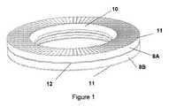
図1から図3は、組で使用されるロックワッシャ8A,8Bの従来技術を開示している。ロックワッシャは、通常、一側において歯11の形態の係合手段と、他側においてカム12の形態の係合手段と、を備えている。ロックワッシャ8A,8Bは、組で使用されるよう意図され、且つ常に互いに精密なコピーである。ワッシャ8A及び8Bの間の唯一の差異は、それらが互いに反対に回転させられることである。 1 to 3 disclose the prior art of
図1は、面取り面10を有するロックワッシャ8A,8Bの従来技術を開示している。この面取り面10は、どのようにネジ15が構成されるかを説明するために、ロックワッシャを、半径5を有するネジ、又は2つの半径5’,5a,5b(図7及び図8参照)を有する面取り面を有するネジに適合させるために導入される。図1のワッシャは、面取り面10を有するこの構成を有し、このため、ワッシャ8A,8Bは、半径5を有するネジ、又は2つの半径5a,5bを有する面取り面5’を有するネジ上に嵌合することができ、従って、ワッシャ8Aの歯は、図1aから分かるようにネジのヘッドと係合することができる。 FIG. 1 discloses the prior art of
図1aは、歯11及びカム12の機能を開示している。歯11は、ネジヘッドと、取り付けられるワークピース16と、と係合する。ネジ15は、ネジ山付き要素17と係合するネジ山を有している。ネジ山のピッチ角βは、ロックワッシャのカムの楔角αよりも常に小さい。この形態により、ネジ結合部は、堅くロックされる。 FIG. 1 a discloses the function of the
歯11は、係合することを可能とするために任意の全体的形態を有することができる。示される形態は、傾斜歯11がそれらのより急勾配の側でネジ15のヘッド又はワークピース16と係合する傾斜ピラミッド形状である。歯11の他の形態が考えられる。例えば、歯11は、一様なピラミッド形状の形態を有することができる。また、歯11は、台形形状を有することができる。歯11は、ネジヘッド及びワークピース16よりも高い硬度を有することが重要である。この理由は、歯11が、ロック機能を達成するために、隣接して位置決めされた材料と係合することができなければならないからである。そうでなければ、歯は、ネジ結合部を締結したときに運動量によって平坦にされるか、又はより硬い隣接面上でスライドする可能性がある。従って、ロックワッシャ8Aは、ネジ結合部を締結するときにネジ15とともに動かされ、ロックワッシャ8Bは、ワークピース16上にあるままとなる。 The
カム12は、この例として図2を参照して楔として説明される。カム12は、互いの急勾配面に対してロックする能力を有する。従って、それぞれのロックワッシャ8A,8Bは、互いに締結されるときに、それらのそれぞれのカム12が互いに対して位置決めされる。ロックは、カム12の楔形状によって達成される。締結されたネジが、例えば振動又は使用者によって螺合解除されるときに、ロックワッシャの歯11は、ネジのヘッドと、取り付けられた要素16と、と係合する。従って、ロックワッシャ8Aは、ネジ15の回転方向で動きをたどろうとし、他方のワッシャ8Bは、ワークピース16と係合するそのそれぞれの歯11によって所定位置に維持されようとする。カム12は、互い上でスライドし、従って、締結解除方向にスライドするときにカム面の傾き及び楔角αにより、ネジ15の長手方向にネジ結合部を延長させようとする。この延長は、ネジ結合部をロックし、ネジが締結解除することを防止する。従って、カム12は、ロックワッシャ8A,8Bが、ネジの締結解除方向に動かされることを防止する。 The
歯11とカム12との間の差異は、通例、歯が別の鋸歯状面と相互作用する一方で、カム12がそれぞれのロックワッシャ上で互いに意図的に協働するように意図される点として説明される。また、カム12は、上述し且つ図1aで分かるように楔状に角度を有する特別な形態を有するべきである。 The difference between the
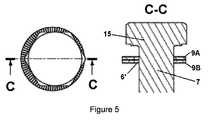
ネジ15のヘッドからネジのシャンク7へ急激でない移行部を有するネジにロックワッシャを適合させるために、ワッシャの中心貫通孔は、図4に開示されるワッシャに適合させられている。図3では、ロックワッシャ8A,8Bの標準形態を見ることができる。また、ロックワッシャ8Aの上部鋸歯状側とネジヘッドとの間には小さい間隙4が設けられていることが分かる。これは、ネジ15上に存在する半径5に起因している。図4では、中心貫通孔は、上部ワッシャ9Aの歯がネジ15のヘッドと係合することを可能とするために、拡大されている。図5は、図4のこの形態の問題点を開示している。ロックワッシャ9A及び9Bは、一側に位置を変えられ、従って、ロックワッシャ9A,9Bは、ネジ上で中心を合わせられていない。このように、図3、図4及び図5は、従来技術の問題点を明確に説明している。このように、図3のロックワッシャ8A及び8Bは、間隙4に起因してクラックするか又は正常に機能しない可能性がある。また、図5では、ロックワッシャ9A,9Bのロック機能が互いに中心合わせされないリスクを有することが明らかである。これは、ロックワッシャ9A,9Bの協働ロックが損なわれることを意味する。また、歯11が係合する表面に対する力の分配は、歯11が不安定になり且つロックワッシャ9A,9Bの一方の側面において他方の側面よりも大きな表面が設けられるので、ネガティブに影響を与えられる。 In order to fit the lock washer to a screw having a transition that is not abrupt from the head of the
図6は、述べた従来技術の欠点の少なくともいくつかを取り除くために、提案される解決法に従うロックワッシャ組立体1を開示している。ロックワッシャ組立体は、第1ロックワッシャ2及び第2ロックワッシャ3を備えている。第1ロックワッシャ2は、ネジ15のネジヘッドと隣接して位置決めされるよう意図されている。図6に開示されたネジ15は、ネジのヘッドとシャンク7との間に半径を有している。 FIG. 6 discloses a
第1ロックワッシャ2は、第2ロックワッシャ3の貫通孔よりも大きな貫通孔を有している。貫通孔の直径は、ネジ15の半径が、半径5が終端したときに始まるネジ15の下側の平面に結合する場所と説明することができる円の直径と本質的に同じである。第1ロックワッシャ2の貫通孔のこの直径は、貫通孔の最小直径を設定する。ロックワッシャ2のより大きな貫通孔が考えられるが、貫通孔は、この双方が、ネジ15の表面と係合することができる歯11の表面を減少するので、最小直径よりも大幅に大きいべきではない。ネジヘッドに対するロックワッシャ2の所定の接触面が必要である。非常に大きな貫通孔は接触面を減少させ、また、ネジのヘッドが変形するリスク及びネジのヘッドの圧縮永久ひずみのリスクがある。ロックワッシャ2’の代わりの実施形態では、貫通孔は、図9に従って面取りされた縁部を有している。面取り面2’aは、貫通孔の直径が、第2ロックワッシャ3の貫通孔の直径よりも大きな最小直径を有するように構成されている。面取り面2’aは、貫通孔の縁部を、頂部が切断されたコーンの構成にさせる。 The
第2ロックワッシャ3は、ロックワッシャ8Bと一致する標準形態からなり、第2ロックワッシャ3は、ネジシャンク7の外径よりも若干大きい貫通孔の直径を有する。この文章では、若干は、ロックワッシャ3の貫通孔がネジ15のシャンク7よりも大きいが、ネジシャンク7に対するロックワッシャ3の案内が達成されないほど大きくはないことを意味している。言い換えると、第2ロックワッシャ3は、本質的に、ネジシャンク7上の中心に置くことができるべきではない。第2ロックワッシャ3のガイドは、第2ロックワッシャ3の直径の貫通孔がネジシャンク7のシャンクよりも若干大きいのみであり、このため、ワッシャがシャンク上に導入されるときにシャンクからの案内を得ることを意味すると理解されるべきである。これは、貫通孔が、ワッシャをネジシャンク7上に導入することが困難である範囲であって、ワッシャがシャンク上で滑らかに走行するが、それでも相当な程度には中心から全く離れることができない、範囲内にあるべきであることを意味する。ワッシャ3の貫通孔は、好ましくは、ワッシャが誤って、すなわち半径5、又は2つの半径5a,5bを有する面5’を有するネジ15のヘッドに最も近く導入される場合に、第2ロックワッシャ3がネジヘッドの下側と平行であるときに図3から分かるような間隙を形成することを意味する直径を有するべきである。 The
上述したロックワッシャ組立体1は、第1ロックワッシャ2の歯11のネジ15との極めて良好な係合を提供する。また、同様に第1ロックワッシャ2と第2ロックワッシャ3との間のカム12の係合によって、第1ロックワッシャ2は、ネジ15の横方向に位置を変えられることを防止する。従って、第2ロックワッシャ3は、ネジ15のシャンク7に対する貫通孔3のより小さい内径により、第1ロックワッシャ2を保持する。 The
ロックワッシャ組立体1は、ネジ15のいくつかの異なる形態とともに使用することが可能である。ネジ15のヘッドの間の移行部は、図7に示されるような半径5を有することができる。また、ネジ15のヘッドの間の移行部は、図8で分かるような2つの半径5a,5bを有する面取り面5’の形態であってもよい。 The
また、図示されないが、上部半径5aがネジヘッド内のノッチで終端するネジヘッドとともにロックワッシャ組立体1を使用することが可能である。この特別な形態は、第1ロックワッシャ2を適切な位置に堅く保持する。 Although not shown, it is possible to use the
特別な一実施形態では、図9のロックワッシャ組立体1は、図8に従うネジ15’とともに使用される。第1ロックワッシャ2’の上部直径及び第1ロックワッシャ2’の面取り面の角度のネジ15’’の面取り面部分への良好な適合により、特に十分な機能的ロック機能が達成され、この場合、ロックワッシャ2’の楔状カム面が貫通孔の直線内縁部を有する第1ロックワッシャ2よりも若干大きく形成される。 In a special embodiment, the
上記では、ロックワッシャ組立体1は、ロックワッシャ組立体1’によって常に置換することができることが理解されるべきである。 In the above, it should be understood that the
好ましい一形態では、第1ロックワッシャ2,2’及び第2ロックワッシャ3は、ロックワッシャ組立体1,1’が容易に取り扱われるように、互いに結合される。ロックワッシャ組立体1,1’は、ロックワッシャユニットと称される。ロックワッシャ2,2’,3は、好ましくは、接着剤により互いに結合される。接着剤は、第1ロックワッシャ2,2’と第2ロックワッシャ3との間の相対運動を可能にするべきである。この能力を有する接着剤は、例えばさまざまな熱溶融性接着剤である。ロックワッシャ2,2’,3は、接着剤によりロックワッシャ組立体1,1’として取り扱われることができるべきである。 In a preferred form, the
好ましい一形態では、ロックワッシャ組立体1,1’は、取付組立体にネジ15,15’及び15”上で予め据え付けられている。好ましくは、ロックワッシャ組立体は、ネジ山のないネジ15,15’,15”上に配置され、その後、ネジ山がネジ15,15’,15”の一部上に巻かれ、これは、直径を増大させ、且つロックワッシャ組立体1,1’がネジから取り外されることを防止する。 In a preferred form, the
1,1’ ロックワッシャ組立体、2,2’ 第1ロックワッシャ、2’a 面取り面、3 第2ロックワッシャ、5 半径、5’ 面取り面、7 ネジシャンク、11 歯、12 カム、16,17 要素1, 1 'lock washer assembly, 2, 2' first lock washer, 2'a chamfered surface, 3 second lock washer, 5 radius, 5 'chamfered surface, 7 screw shank, 11 teeth, 12 cam, 16, 17 elements
Claims (13)
Translated fromJapanese前記第1ロックワッシャ(2,2’)及び前記第2ロックワッシャ(3)が、ネジ結合部により取り付けられる要素(16,17)と係合するための手段(11)を備え、前記第1ロックワッシャ及び前記第2ロックワッシャ(1,1’)が、互いに係合するための手段(12)をさらに備える、ロックワッシャ組立体(1,1’)において、
前記第1ロックワッシャ(2,2’)が、前記第2ロックワッシャ(3)の貫通孔よりも大きな中心貫通孔を備えていることを特徴とするロックワッシャ組立体(1,1’)。A lock washer assembly (1, 1 ') comprising a first lock washer (2, 2') and a second lock washer (3),
The first lock washer (2, 2 ') and the second lock washer (3) comprise means (11) for engaging elements (16, 17) attached by screw couplings, In a lock washer assembly (1, 1 '), the lock washer and said second lock washer (1, 1') further comprising means (12) for engaging with each other
The lock washer assembly (1, 1 '), wherein the first lock washer (2, 2') has a central through hole larger than the through hole of the second lock washer (3).
Applications Claiming Priority (3)
| Application Number | Priority Date | Filing Date | Title |
|---|---|---|---|
| SE1350242-2 | 2013-02-28 | ||
| SE1350242ASE537673C2 (en) | 2013-02-28 | 2013-02-28 | Låsbrickanordning |
| PCT/SE2014/050246WO2014133446A1 (en) | 2013-02-28 | 2014-02-28 | Locking washer assembly |
Publications (2)
| Publication Number | Publication Date |
|---|---|
| JP2016509179Atrue JP2016509179A (en) | 2016-03-24 |
| JP6530320B2 JP6530320B2 (en) | 2019-06-12 |
Family
ID=51428587
Family Applications (1)
| Application Number | Title | Priority Date | Filing Date |
|---|---|---|---|
| JP2015560140AActiveJP6530320B2 (en) | 2013-02-28 | 2014-02-28 | Lock washer assembly and mounting assembly |
Country Status (9)
| Country | Link |
|---|---|
| US (1) | US9732782B2 (en) |
| EP (1) | EP2962001B1 (en) |
| JP (1) | JP6530320B2 (en) |
| KR (1) | KR102232065B1 (en) |
| CN (1) | CN105074235B (en) |
| PL (1) | PL2962001T3 (en) |
| RU (1) | RU2640465C2 (en) |
| SE (1) | SE537673C2 (en) |
| WO (1) | WO2014133446A1 (en) |
Cited By (4)
| Publication number | Priority date | Publication date | Assignee | Title |
|---|---|---|---|---|
| WO2020174790A1 (en)* | 2019-02-28 | 2020-09-03 | ボルトエンジニア株式会社 | Lock washer, fastening structure, and method for unfastening said fastening structure |
| WO2020174652A1 (en)* | 2019-02-28 | 2020-09-03 | ボルトエンジニア株式会社 | Lock washer, fastening structure, and method for unfastening said fastening structure |
| CN113550966A (en)* | 2020-04-24 | 2021-10-26 | 中国气动工业股份有限公司 | Bolt clamping force induction washer |
| JP2021169998A (en)* | 2020-04-13 | 2021-10-28 | 中國氣動工業股▲ふん▼有限公司China Pneumatic Corporation | Bolt tightening force sensing washer |
Families Citing this family (19)
| Publication number | Priority date | Publication date | Assignee | Title |
|---|---|---|---|---|
| JP6377559B2 (en)* | 2015-02-20 | 2018-08-22 | 株式会社マルナカ | Screws with washers |
| GB201510008D0 (en)* | 2015-06-09 | 2015-07-22 | Completion Products Ltd | Clamp and method of applying a clamp |
| JP6934161B2 (en)* | 2017-02-24 | 2021-09-15 | ボルトエンジニア株式会社 | Fastening structure |
| CN110494658B (en) | 2017-03-24 | 2022-04-05 | Ejot建筑紧固件有限责任公司 | Fixing plate and method for initially fixing fastening elements and removing protective film |
| DE102017131005A1 (en)* | 2017-12-21 | 2019-06-27 | Hartmut Flaig | Threaded element and thus produced connection |
| TWM562351U (en)* | 2018-01-30 | 2018-06-21 | Unitech Products Corp | Two-piece type anti-loose screw assembly |
| TWM562350U (en)* | 2018-01-30 | 2018-06-21 | Unitech Products Corp | Two-piece type anti-loose nut assembly |
| WO2019241097A1 (en)* | 2018-06-11 | 2019-12-19 | Chapman John Eric | Hybrid washer |
| US11396902B2 (en)* | 2019-06-20 | 2022-07-26 | The Reaction Washer Company, Llc | Engaging washers |
| US11242884B2 (en) | 2019-09-18 | 2022-02-08 | Laitram, L.L.C. | Sealing wedge-lock washer and fastening system |
| US11525384B2 (en)* | 2020-02-03 | 2022-12-13 | Fca Us Llc | High temperature resistant low friction washer and assembly |
| WO2021224979A1 (en)* | 2020-05-08 | 2021-11-11 | ボルトエンジニア株式会社 | Washer |
| US11444002B2 (en)* | 2020-07-29 | 2022-09-13 | Taiwan Semiconductor Manufacturing Company, Ltd. | Package structure |
| US11534894B2 (en) | 2020-11-17 | 2022-12-27 | The Reaction Washer Company Llc | Socket devices and methods of use |
| KR102507463B1 (en)* | 2021-03-23 | 2023-03-09 | 주식회사 엔케이 | Anti rotation pressure vessel |
| US20230087369A1 (en) | 2021-09-21 | 2023-03-23 | Caterpillar Inc. | Track shoe or track bolt with increased surface roughness |
| CN114909385B (en)* | 2022-05-13 | 2023-03-17 | 中国人民解放军总医院第四医学中心 | A Screw Pretensioning System to Avoid Loosening |
| DE102023107759A1 (en)* | 2023-03-28 | 2024-10-02 | Nord-Lock International Ab | arrangement for connecting components |
| US12385514B1 (en)* | 2024-02-09 | 2025-08-12 | Heico Befestigungstechnik Gmbh | Wedge lock washer pair and tensioning arrangement with such wedge lock washer pair |
Citations (5)
| Publication number | Priority date | Publication date | Assignee | Title |
|---|---|---|---|---|
| JPS5259868U (en)* | 1975-10-29 | 1977-04-30 | ||
| JPS5820724U (en)* | 1981-08-03 | 1983-02-08 | セントラル通商株式会社 | Watsusha |
| US20040131443A1 (en)* | 2002-10-09 | 2004-07-08 | Terry Sydney L. | Wedge cam lock washer for threaded fasteners |
| US20080014046A1 (en)* | 2003-09-05 | 2008-01-17 | Robert Bauer | Retaining Element for Blocking Screw Elements |
| US20100239389A1 (en)* | 2006-06-08 | 2010-09-23 | Nord-Lock Ab | Method for coating washers for locking and coated washer for locking |
Family Cites Families (10)
| Publication number | Priority date | Publication date | Assignee | Title |
|---|---|---|---|---|
| GB792215A (en) | 1956-07-09 | 1958-03-19 | John Ryan Mckee Jr | Improvements relating to composite washers |
| GB1109240A (en) | 1965-06-26 | 1968-04-10 | Girling Ltd | Improvements in and relating to tab washers |
| RU2008534C1 (en)* | 1991-05-07 | 1994-02-28 | Войсковая Часть 25840 | Device for fixing screw stem |
| CN2101133U (en) | 1991-09-06 | 1992-04-08 | 刘永熙 | Axial fastening theft proof block nut |
| US5203656A (en)* | 1991-09-19 | 1993-04-20 | Hong Kong Disc Lock Company, Limited | Self-centering, self-tightening fastener |
| US5688091A (en)* | 1995-09-15 | 1997-11-18 | Hong-Kong Disc Lock Company, Ltd. | Self-locking fastener with captive washer |
| AU5426600A (en)* | 1999-06-14 | 2001-01-02 | Masaki Yamazaki | Screw mechanism |
| DE102005054471A1 (en)* | 2005-11-15 | 2007-05-24 | Thyssenkrupp Bilstein Suspension Gmbh | threadlocking |
| SE532106C2 (en) | 2006-09-01 | 2009-10-27 | Nord Lock Ab | Locking system comprising a fastener and a lock washer |
| US8079795B2 (en)* | 2009-03-23 | 2011-12-20 | Junkers John K | Washer for tightening and loosening threaded connectors |
- 2013
- 2013-02-28SESE1350242Apatent/SE537673C2/enunknown
- 2014
- 2014-02-28KRKR1020157026943Apatent/KR102232065B1/enactiveActive
- 2014-02-28EPEP14756437.1Apatent/EP2962001B1/enactiveActive
- 2014-02-28WOPCT/SE2014/050246patent/WO2014133446A1/enactiveApplication Filing
- 2014-02-28JPJP2015560140Apatent/JP6530320B2/enactiveActive
- 2014-02-28CNCN201480010691.1Apatent/CN105074235B/enactiveActive
- 2014-02-28USUS14/771,470patent/US9732782B2/enactiveActive
- 2014-02-28PLPL14756437Tpatent/PL2962001T3/enunknown
- 2014-02-28RURU2015141067Apatent/RU2640465C2/enactive
Patent Citations (5)
| Publication number | Priority date | Publication date | Assignee | Title |
|---|---|---|---|---|
| JPS5259868U (en)* | 1975-10-29 | 1977-04-30 | ||
| JPS5820724U (en)* | 1981-08-03 | 1983-02-08 | セントラル通商株式会社 | Watsusha |
| US20040131443A1 (en)* | 2002-10-09 | 2004-07-08 | Terry Sydney L. | Wedge cam lock washer for threaded fasteners |
| US20080014046A1 (en)* | 2003-09-05 | 2008-01-17 | Robert Bauer | Retaining Element for Blocking Screw Elements |
| US20100239389A1 (en)* | 2006-06-08 | 2010-09-23 | Nord-Lock Ab | Method for coating washers for locking and coated washer for locking |
Cited By (4)
| Publication number | Priority date | Publication date | Assignee | Title |
|---|---|---|---|---|
| WO2020174790A1 (en)* | 2019-02-28 | 2020-09-03 | ボルトエンジニア株式会社 | Lock washer, fastening structure, and method for unfastening said fastening structure |
| WO2020174652A1 (en)* | 2019-02-28 | 2020-09-03 | ボルトエンジニア株式会社 | Lock washer, fastening structure, and method for unfastening said fastening structure |
| JP2021169998A (en)* | 2020-04-13 | 2021-10-28 | 中國氣動工業股▲ふん▼有限公司China Pneumatic Corporation | Bolt tightening force sensing washer |
| CN113550966A (en)* | 2020-04-24 | 2021-10-26 | 中国气动工业股份有限公司 | Bolt clamping force induction washer |
Also Published As
| Publication number | Publication date |
|---|---|
| JP6530320B2 (en) | 2019-06-12 |
| KR20150119475A (en) | 2015-10-23 |
| SE537673C2 (en) | 2015-09-29 |
| EP2962001A1 (en) | 2016-01-06 |
| CN105074235B (en) | 2017-06-09 |
| US9732782B2 (en) | 2017-08-15 |
| PL2962001T3 (en) | 2021-11-02 |
| KR102232065B1 (en) | 2021-03-24 |
| EP2962001A4 (en) | 2016-10-12 |
| EP2962001B1 (en) | 2021-04-14 |
| RU2640465C2 (en) | 2018-01-09 |
| US20160003287A1 (en) | 2016-01-07 |
| CN105074235A (en) | 2015-11-18 |
| RU2015141067A (en) | 2017-04-03 |
| WO2014133446A1 (en) | 2014-09-04 |
| SE1350242A1 (en) | 2014-08-29 |
Similar Documents
| Publication | Publication Date | Title |
|---|---|---|
| JP2016509179A (en) | Lock washer assembly | |
| US9011060B2 (en) | No flange damage wedge lock washers | |
| US9845821B2 (en) | Fastening element and fastening assembly | |
| JP4225546B2 (en) | Tapping screw | |
| TW201418590A (en) | Self-clinching fastener | |
| WO2015118702A1 (en) | Bolt provided with locking function | |
| JP2010043678A (en) | Locking bolt | |
| EP2016298B1 (en) | Pierce nut and use thereof | |
| CN102781613A (en) | Clamp assistant member and cutting tool including clamp assistant member | |
| US20140212206A1 (en) | Shackle assembly with locking pin | |
| MXPA01000649A (en) | Threaded fastener and assembly. | |
| CA2769951C (en) | Fastening arrangement | |
| KR950001121A (en) | Fasteners for hole alignment of workpiece | |
| US20120177459A1 (en) | System and method for fixedly connecting sheets | |
| US7828500B2 (en) | Threaded engagement element with self-locking threads | |
| JP5083511B2 (en) | Fastening / fixing structure | |
| US6361019B1 (en) | Fastening system for connecting actuators, or other attachable devices, to rotary valves | |
| KR20170002262A (en) | Fixture set with connecting surface for increasing fixation stability | |
| US20100034577A1 (en) | Mounting arrangement | |
| JP4644752B1 (en) | Bolt / nut drop-off prevention structure | |
| EP3604834B1 (en) | Bolt |
Legal Events
| Date | Code | Title | Description |
|---|---|---|---|
| A529 | Written submission of copy of amendment under article 34 pct | Free format text:JAPANESE INTERMEDIATE CODE: A529 Effective date:20150827 | |
| A621 | Written request for application examination | Free format text:JAPANESE INTERMEDIATE CODE: A621 Effective date:20170215 | |
| A977 | Report on retrieval | Free format text:JAPANESE INTERMEDIATE CODE: A971007 Effective date:20180123 | |
| A131 | Notification of reasons for refusal | Free format text:JAPANESE INTERMEDIATE CODE: A131 Effective date:20180226 | |
| A521 | Request for written amendment filed | Free format text:JAPANESE INTERMEDIATE CODE: A523 Effective date:20180525 | |
| A131 | Notification of reasons for refusal | Free format text:JAPANESE INTERMEDIATE CODE: A131 Effective date:20180806 | |
| A601 | Written request for extension of time | Free format text:JAPANESE INTERMEDIATE CODE: A601 Effective date:20181106 | |
| A521 | Request for written amendment filed | Free format text:JAPANESE INTERMEDIATE CODE: A523 Effective date:20181218 | |
| A131 | Notification of reasons for refusal | Free format text:JAPANESE INTERMEDIATE CODE: A131 Effective date:20190111 | |
| A521 | Request for written amendment filed | Free format text:JAPANESE INTERMEDIATE CODE: A523 Effective date:20190411 | |
| TRDD | Decision of grant or rejection written | ||
| A01 | Written decision to grant a patent or to grant a registration (utility model) | Free format text:JAPANESE INTERMEDIATE CODE: A01 Effective date:20190422 | |
| A61 | First payment of annual fees (during grant procedure) | Free format text:JAPANESE INTERMEDIATE CODE: A61 Effective date:20190516 | |
| R150 | Certificate of patent or registration of utility model | Ref document number:6530320 Country of ref document:JP Free format text:JAPANESE INTERMEDIATE CODE: R150 | |
| R250 | Receipt of annual fees | Free format text:JAPANESE INTERMEDIATE CODE: R250 | |
| R250 | Receipt of annual fees | Free format text:JAPANESE INTERMEDIATE CODE: R250 | |
| R250 | Receipt of annual fees | Free format text:JAPANESE INTERMEDIATE CODE: R250 | |
| R250 | Receipt of annual fees | Free format text:JAPANESE INTERMEDIATE CODE: R250 |