JP2016503717A - Acupuncture devices and methods - Google Patents
Acupuncture devices and methodsDownload PDFInfo
- Publication number
- JP2016503717A JP2016503717AJP2015553799AJP2015553799AJP2016503717AJP 2016503717 AJP2016503717 AJP 2016503717AJP 2015553799 AJP2015553799 AJP 2015553799AJP 2015553799 AJP2015553799 AJP 2015553799AJP 2016503717 AJP2016503717 AJP 2016503717A
- Authority
- JP
- Japan
- Prior art keywords
- distal
- foldable
- suture
- distal anchor
- proximal
- Prior art date
- Legal status (The legal status is an assumption and is not a legal conclusion. Google has not performed a legal analysis and makes no representation as to the accuracy of the status listed.)
- Pending
Links
- 238000001467acupunctureMethods0.000titleclaimsabstractdescription28
- 238000000034methodMethods0.000titleabstractdescription12
- 230000007246mechanismEffects0.000claimsdescription29
- 239000000853adhesiveSubstances0.000claimsdescription7
- 230000001070adhesive effectEffects0.000claimsdescription7
- 210000001519tissueAnatomy0.000description47
- 206010016717FistulaDiseases0.000description18
- 230000003890fistulaEffects0.000description18
- 210000000936intestineAnatomy0.000description15
- 206010036790Productive coughDiseases0.000description10
- 210000003802sputumAnatomy0.000description10
- 208000024794sputumDiseases0.000description10
- 238000007789sealingMethods0.000description7
- 238000012084abdominal surgeryMethods0.000description6
- 210000000056organAnatomy0.000description6
- 238000001356surgical procedureMethods0.000description6
- 208000006784Cutaneous FistulaDiseases0.000description5
- 238000003780insertionMethods0.000description5
- 230000037431insertionEffects0.000description5
- 239000000463materialSubstances0.000description5
- 238000002560therapeutic procedureMethods0.000description5
- 210000001035gastrointestinal tractAnatomy0.000description4
- 239000012530fluidSubstances0.000description3
- HLXZNVUGXRDIFK-UHFFFAOYSA-Nnickel titaniumChemical compound[Ti].[Ti].[Ti].[Ti].[Ti].[Ti].[Ti].[Ti].[Ti].[Ti].[Ti].[Ni].[Ni].[Ni].[Ni].[Ni].[Ni].[Ni].[Ni].[Ni].[Ni].[Ni].[Ni].[Ni].[Ni]HLXZNVUGXRDIFK-UHFFFAOYSA-N0.000description3
- 229910001000nickel titaniumInorganic materials0.000description3
- 230000037303wrinklesEffects0.000description3
- 241000239290AraneaeSpecies0.000description2
- 208000004680Rectal FistulaDiseases0.000description2
- 230000002159abnormal effectEffects0.000description2
- 206010002156anal fistulaDiseases0.000description2
- 230000008901benefitEffects0.000description2
- 230000008602contractionEffects0.000description2
- 230000035876healingEffects0.000description2
- 230000006872improvementEffects0.000description2
- 208000014674injuryDiseases0.000description2
- 239000002184metalSubstances0.000description2
- 230000004048modificationEffects0.000description2
- 238000012986modificationMethods0.000description2
- 208000015380nutritional deficiency diseaseDiseases0.000description2
- 206010033675panniculitisDiseases0.000description2
- 235000016236parenteral nutritionNutrition0.000description2
- 230000001575pathological effectEffects0.000description2
- 230000003014reinforcing effectEffects0.000description2
- 239000004071sootSubstances0.000description2
- 210000004304subcutaneous tissueAnatomy0.000description2
- 230000008733traumaEffects0.000description2
- 210000001215vaginaAnatomy0.000description2
- 210000001835visceraAnatomy0.000description2
- 206010003226Arteriovenous fistulaDiseases0.000description1
- 241001609030Brosme brosmeSpecies0.000description1
- 208000011231Crohn diseaseDiseases0.000description1
- 208000002720MalnutritionDiseases0.000description1
- 206010027406MesotheliomaDiseases0.000description1
- 206010065813Vaginal fistulaDiseases0.000description1
- 206010052428WoundDiseases0.000description1
- 208000027418Wounds and injuryDiseases0.000description1
- 230000003187abdominal effectEffects0.000description1
- 210000003815abdominal wallAnatomy0.000description1
- 206010000269abscessDiseases0.000description1
- 230000009286beneficial effectEffects0.000description1
- 230000015572biosynthetic processEffects0.000description1
- 239000008280bloodSubstances0.000description1
- 210000004369bloodAnatomy0.000description1
- 210000004204blood vesselAnatomy0.000description1
- 210000001124body fluidAnatomy0.000description1
- 230000008859changeEffects0.000description1
- 230000001684chronic effectEffects0.000description1
- 208000037976chronic inflammationDiseases0.000description1
- 230000006020chronic inflammationEffects0.000description1
- 238000001804debridementMethods0.000description1
- 238000000502dialysisMethods0.000description1
- 235000012489doughnutsNutrition0.000description1
- 239000003792electrolyteSubstances0.000description1
- 206010015037epilepsyDiseases0.000description1
- 210000003238esophagusAnatomy0.000description1
- 235000013305foodNutrition0.000description1
- 230000006870functionEffects0.000description1
- 230000008105immune reactionEffects0.000description1
- 230000028993immune responseEffects0.000description1
- 208000015181infectious diseaseDiseases0.000description1
- 230000000968intestinal effectEffects0.000description1
- 208000003243intestinal obstructionDiseases0.000description1
- 230000007774longtermEffects0.000description1
- 230000001071malnutritionEffects0.000description1
- 235000000824malnutritionNutrition0.000description1
- 238000004519manufacturing processMethods0.000description1
- 230000005012migrationEffects0.000description1
- 238000013508migrationMethods0.000description1
- 230000002969morbidEffects0.000description1
- 230000002980postoperative effectEffects0.000description1
- 230000008569processEffects0.000description1
- 210000000664rectumAnatomy0.000description1
- 230000000284resting effectEffects0.000description1
- 230000002441reversible effectEffects0.000description1
- 239000012781shape memory materialSubstances0.000description1
- 210000004872soft tissueAnatomy0.000description1
- 230000002269spontaneous effectEffects0.000description1
- 210000002784stomachAnatomy0.000description1
- 238000006467substitution reactionMethods0.000description1
- 238000002636symptomatic treatmentMethods0.000description1
- 230000001225therapeutic effectEffects0.000description1
- 210000003437tracheaAnatomy0.000description1
Images


Classifications
- A—HUMAN NECESSITIES
- A61—MEDICAL OR VETERINARY SCIENCE; HYGIENE
- A61B—DIAGNOSIS; SURGERY; IDENTIFICATION
- A61B17/00—Surgical instruments, devices or methods
- A61B17/0057—Implements for plugging an opening in the wall of a hollow or tubular organ, e.g. for sealing a vessel puncture or closing a cardiac septal defect
- A—HUMAN NECESSITIES
- A61—MEDICAL OR VETERINARY SCIENCE; HYGIENE
- A61B—DIAGNOSIS; SURGERY; IDENTIFICATION
- A61B17/00—Surgical instruments, devices or methods
- A61B17/04—Surgical instruments, devices or methods for suturing wounds; Holders or packages for needles or suture materials
- A61B17/0401—Suture anchors, buttons or pledgets, i.e. means for attaching sutures to bone, cartilage or soft tissue; Instruments for applying or removing suture anchors
- A—HUMAN NECESSITIES
- A61—MEDICAL OR VETERINARY SCIENCE; HYGIENE
- A61B—DIAGNOSIS; SURGERY; IDENTIFICATION
- A61B17/00—Surgical instruments, devices or methods
- A61B17/064—Surgical staples, i.e. penetrating the tissue
- A—HUMAN NECESSITIES
- A61—MEDICAL OR VETERINARY SCIENCE; HYGIENE
- A61B—DIAGNOSIS; SURGERY; IDENTIFICATION
- A61B17/00—Surgical instruments, devices or methods
- A61B17/064—Surgical staples, i.e. penetrating the tissue
- A61B17/0644—Surgical staples, i.e. penetrating the tissue penetrating the tissue, deformable to closed position
- A—HUMAN NECESSITIES
- A61—MEDICAL OR VETERINARY SCIENCE; HYGIENE
- A61B—DIAGNOSIS; SURGERY; IDENTIFICATION
- A61B17/00—Surgical instruments, devices or methods
- A61B17/12—Surgical instruments, devices or methods for ligaturing or otherwise compressing tubular parts of the body, e.g. blood vessels or umbilical cord
- A61B17/12022—Occluding by internal devices, e.g. balloons or releasable wires
- A61B17/12027—Type of occlusion
- A61B17/12031—Type of occlusion complete occlusion
- A—HUMAN NECESSITIES
- A61—MEDICAL OR VETERINARY SCIENCE; HYGIENE
- A61F—FILTERS IMPLANTABLE INTO BLOOD VESSELS; PROSTHESES; DEVICES PROVIDING PATENCY TO, OR PREVENTING COLLAPSING OF, TUBULAR STRUCTURES OF THE BODY, e.g. STENTS; ORTHOPAEDIC, NURSING OR CONTRACEPTIVE DEVICES; FOMENTATION; TREATMENT OR PROTECTION OF EYES OR EARS; BANDAGES, DRESSINGS OR ABSORBENT PADS; FIRST-AID KITS
- A61F2/00—Filters implantable into blood vessels; Prostheses, i.e. artificial substitutes or replacements for parts of the body; Appliances for connecting them with the body; Devices providing patency to, or preventing collapsing of, tubular structures of the body, e.g. stents
- A61F2/82—Devices providing patency to, or preventing collapsing of, tubular structures of the body, e.g. stents
- A61F2/848—Devices providing patency to, or preventing collapsing of, tubular structures of the body, e.g. stents having means for fixation to the vessel wall, e.g. barbs
- A—HUMAN NECESSITIES
- A61—MEDICAL OR VETERINARY SCIENCE; HYGIENE
- A61F—FILTERS IMPLANTABLE INTO BLOOD VESSELS; PROSTHESES; DEVICES PROVIDING PATENCY TO, OR PREVENTING COLLAPSING OF, TUBULAR STRUCTURES OF THE BODY, e.g. STENTS; ORTHOPAEDIC, NURSING OR CONTRACEPTIVE DEVICES; FOMENTATION; TREATMENT OR PROTECTION OF EYES OR EARS; BANDAGES, DRESSINGS OR ABSORBENT PADS; FIRST-AID KITS
- A61F2/00—Filters implantable into blood vessels; Prostheses, i.e. artificial substitutes or replacements for parts of the body; Appliances for connecting them with the body; Devices providing patency to, or preventing collapsing of, tubular structures of the body, e.g. stents
- A61F2/82—Devices providing patency to, or preventing collapsing of, tubular structures of the body, e.g. stents
- A61F2/86—Stents in a form characterised by the wire-like elements; Stents in the form characterised by a net-like or mesh-like structure
- A—HUMAN NECESSITIES
- A61—MEDICAL OR VETERINARY SCIENCE; HYGIENE
- A61B—DIAGNOSIS; SURGERY; IDENTIFICATION
- A61B17/00—Surgical instruments, devices or methods
- A61B17/0057—Implements for plugging an opening in the wall of a hollow or tubular organ, e.g. for sealing a vessel puncture or closing a cardiac septal defect
- A61B2017/00575—Implements for plugging an opening in the wall of a hollow or tubular organ, e.g. for sealing a vessel puncture or closing a cardiac septal defect for closure at remote site, e.g. closing atrial septum defects
- A61B2017/00579—Barbed implements
- A—HUMAN NECESSITIES
- A61—MEDICAL OR VETERINARY SCIENCE; HYGIENE
- A61B—DIAGNOSIS; SURGERY; IDENTIFICATION
- A61B17/00—Surgical instruments, devices or methods
- A61B17/0057—Implements for plugging an opening in the wall of a hollow or tubular organ, e.g. for sealing a vessel puncture or closing a cardiac septal defect
- A61B2017/00575—Implements for plugging an opening in the wall of a hollow or tubular organ, e.g. for sealing a vessel puncture or closing a cardiac septal defect for closure at remote site, e.g. closing atrial septum defects
- A61B2017/0061—Implements located only on one side of the opening
- A—HUMAN NECESSITIES
- A61—MEDICAL OR VETERINARY SCIENCE; HYGIENE
- A61B—DIAGNOSIS; SURGERY; IDENTIFICATION
- A61B17/00—Surgical instruments, devices or methods
- A61B17/0057—Implements for plugging an opening in the wall of a hollow or tubular organ, e.g. for sealing a vessel puncture or closing a cardiac septal defect
- A61B2017/00641—Implements for plugging an opening in the wall of a hollow or tubular organ, e.g. for sealing a vessel puncture or closing a cardiac septal defect for closing fistulae, e.g. anorectal fistulae
- A—HUMAN NECESSITIES
- A61—MEDICAL OR VETERINARY SCIENCE; HYGIENE
- A61B—DIAGNOSIS; SURGERY; IDENTIFICATION
- A61B17/00—Surgical instruments, devices or methods
- A61B17/0057—Implements for plugging an opening in the wall of a hollow or tubular organ, e.g. for sealing a vessel puncture or closing a cardiac septal defect
- A61B2017/00646—Type of implements
- A61B2017/00659—Type of implements located only on one side of the opening
- A—HUMAN NECESSITIES
- A61—MEDICAL OR VETERINARY SCIENCE; HYGIENE
- A61F—FILTERS IMPLANTABLE INTO BLOOD VESSELS; PROSTHESES; DEVICES PROVIDING PATENCY TO, OR PREVENTING COLLAPSING OF, TUBULAR STRUCTURES OF THE BODY, e.g. STENTS; ORTHOPAEDIC, NURSING OR CONTRACEPTIVE DEVICES; FOMENTATION; TREATMENT OR PROTECTION OF EYES OR EARS; BANDAGES, DRESSINGS OR ABSORBENT PADS; FIRST-AID KITS
- A61F2/00—Filters implantable into blood vessels; Prostheses, i.e. artificial substitutes or replacements for parts of the body; Appliances for connecting them with the body; Devices providing patency to, or preventing collapsing of, tubular structures of the body, e.g. stents
- A61F2/02—Prostheses implantable into the body
- A61F2/04—Hollow or tubular parts of organs, e.g. bladders, tracheae, bronchi or bile ducts
- A61F2002/045—Stomach, intestines
Landscapes
- Health & Medical Sciences (AREA)
- Life Sciences & Earth Sciences (AREA)
- Engineering & Computer Science (AREA)
- Biomedical Technology (AREA)
- Surgery (AREA)
- General Health & Medical Sciences (AREA)
- Veterinary Medicine (AREA)
- Heart & Thoracic Surgery (AREA)
- Public Health (AREA)
- Animal Behavior & Ethology (AREA)
- Medical Informatics (AREA)
- Nuclear Medicine, Radiotherapy & Molecular Imaging (AREA)
- Molecular Biology (AREA)
- Cardiology (AREA)
- Vascular Medicine (AREA)
- Transplantation (AREA)
- Oral & Maxillofacial Surgery (AREA)
- Reproductive Health (AREA)
- Rheumatology (AREA)
- Surgical Instruments (AREA)
- Prostheses (AREA)
Abstract
Translated fromJapaneseDescription
Translated fromJapanese本発明は、医療装置および方法に関する。より具体的には、本発明は、瘻を閉鎖するための移植可能なデバイスおよびかかるデバイスを使用する方法に関する。 The present invention relates to medical devices and methods. More specifically, the present invention relates to an implantable device for closing a heel and a method of using such a device.
瘻は、疾病および死亡の大きな要因である。毎年10万件を超える病的な瘻の症例があり、そのうち死亡の症例は1万件を超える。治療のための医療システムには毎年何十億ドルものコストがかかっている。 Acupuncture is a major cause of illness and death. There are over 100,000 cases of pathological epilepsy annually, of which more than 10,000 die. The medical system for treatment costs billions of dollars each year.
瘻とは、体腔と中空器官との間、または体腔または器官と体表面との間をつげるような組織で裏打ちされた部分のことである。瘻による管としては、1つの瘻開口部から始まり、時には臓器の組織平面に沿ってまたは器官と器官の間で延伸し、先端が閉じて終わるもの、あるいは1つまたは複数の二次的な瘻開口部につながるような軟組織における孔または孔になる可能性のあるものが挙げられる。瘻は、しばしば感染症によって発症し、膿瘍形成を伴うこともある。一部の瘻は、気管切開管、胃栄養チューブ用の管、または透析にアクセスするための動静脈瘻といった治療目的のために意図的に作成されたものだが、病的な瘻は、通常、先天的に発生するか、あるいは手術、手術関連の合併症、または外傷により形成される異常な管である。瘻は、多くの場合、上皮化、内皮化、または粘膜化した開口管である。 A heel is a portion lined with tissue that connects between a body cavity and a hollow organ, or between a body cavity or organ and a body surface. A tube by scissors starts with one sputum opening and sometimes extends along the tissue plane of the organ or between organs and ends with a closed tip or one or more secondary scissors Examples include soft tissue holes or holes that can lead to openings. Spiders are often caused by infections and may be accompanied by abscess formation. Some sputums are intentionally created for therapeutic purposes, such as tracheostomy tubes, gastrofeeding tubes, or arteriovenous sputum to access dialysis, but pathological sputum usually An abnormal tube that occurs congenitally or is formed by surgery, surgical complications, or trauma. A sputum is often an open tube that is epithelialized, endothelialized, or mucous.
瘻は、任意の2つまたは複数の器官にまたがって形成されることもあるし、同じ器官の異なる箇所間に形成されることもある。例えば、瘻は、内部器官と皮膚との間に発生することもあるし(腸皮瘻、胃皮瘻、肛門瘻、直腸膣瘻、直腸と皮膚間の瘻、小疱性皮膚瘻、腸管と皮膚間の瘻、気管と皮膚間の瘻、気管支と皮膚間の瘻等)、内部器官同士の間で発生することもある(気管と食道間の瘻、胃腸間の瘻、直腸内に小胞として発生する瘻、口蓋瘻、等)。また、瘻は、動静脈瘻のように血管間で形成することもある。 A fold may be formed across any two or more organs, or may be formed between different locations on the same organ. For example, wrinkles can occur between internal organs and the skin (enteric skin fistula, stomach cutaneous fistula, anal fistula, rectal vaginal fistula, rectal and cutaneous fistula, vesicular cutaneous fistula, intestinal tract and It may occur between internal organs (eg, between the trachea and the esophagus, between the gastrointestinal tract, and the vesicle in the rectum) Sputum, palatal fistula, etc.) In addition, wrinkles may be formed between blood vessels like arteriovenous fistulas.
瘻は、体内の多くの場所で形成され、ほぼあまねく患者に対し病的であり、医師が治療するのが困難である。例えば、腸皮瘻は、腹部手術で最も恐れられて合併症の一つである。腸皮瘻は腸と皮膚との間に形成される異常なつながりであり、腹部手術後、外傷後、またはクローン病の合併症として発生し得る。いくつかの報告では、腹部大手術を受けた患者の1%もで腸皮瘻が形成する可能性があると推定されている。患者は、対症療法および/または腹部大手術に数ヶ月も必要とする場合が多い。腸皮瘻が進行した患者の死亡率は全体として約20%と依然として高い。 Spiders are formed in many places in the body and are almost always morbid to the patient and difficult for doctors to treat. For example, bowel folds are one of the most feared complications of abdominal surgery. Mesothelioma is an abnormal connection formed between the intestine and the skin and can occur after abdominal surgery, trauma, or as a complication of Crohn's disease. In some reports, it is estimated that as many as 1% of patients undergoing major abdominal surgery can have enteric fistulas. Patients often require months of symptomatic therapy and / or major abdominal surgery. The overall mortality rate for patients with advanced enteric fistula remains high at about 20%.
腸皮瘻を治療するための現在の選択肢としては、長期保存療法や大手術がある。保存療法を選択すると、患者は腸からの摂取が制限され、非経口的な栄養補助により管理される。瘻漏れは、ストーマバッグを用いて制御される。瘻から出る量が多い場合、ドレーンを設け瘻から出る量を制御しようとすることもある。保存療法下において瘻が自然に閉鎖する可能性は、約25%と非常に低い。保存療法下におき、腸管を休ませてから5週間経っても瘻が自然に閉鎖しない場合、多くの外科医は外科的治療を提唱するが、対症療法を無期限で続けなくてはならないこともある。瘻管が開口している患者は、多くの場合、関連性の栄養失調が続き、電解質のバランスも悪く、そして慢性かつ非治癒性の腹部傷を有する。 Current options for treating enteric fistulas include long-term conservative therapy and major surgery. When conservative therapy is selected, the patient is restricted from intestinal intake and is managed with parenteral nutrition. The soot leakage is controlled using a stoma bag. If there is a large amount coming out of the kite, a drain may be provided to control the amount coming out of the kite. The probability of spontaneous closure of wrinkles under conservative therapy is very low, about 25%. Many surgeons advocate surgical treatment if they remain under conservative therapy and the sputum does not close spontaneously 5 weeks after resting the intestinal tract, but symptomatic treatment may have to continue indefinitely is there. Patients with open fistula often have associated malnutrition, poor electrolyte balance, and chronic and non-healing abdominal wounds.
大手術という選択肢だと、死亡率が30%近くになる。大手術は罹患した腸断片の切除、瘻の摘出、および腹壁および皮下組織を貫通する瘻管の創面切除を伴う。この腹部大手術は、多くの場合、輸血および術後のICU入院を必要とする。慢性的な炎症と以前の腹部手術の結果、これらの患者は、密な癒着が形成されており、組織が非常にもろいのが典型的である。また、これらの患者は、重度の栄養失調にもなり得る。かかる状態で、腸皮瘻を手術するのは非常に困難で危険である。手術後、患者は、数日間完全非経口栄養(「TPN」)状態に置かれ、その後TPNから徐々に通常の食品に戻すことになる。 The option of major surgery results in a mortality rate of nearly 30%. Major surgery involves excision of the affected bowel segment, removal of the fistula, and debridement of the fistula that penetrates the abdominal wall and subcutaneous tissue. This major abdominal surgery often requires blood transfusion and post-operative ICU hospitalization. As a result of chronic inflammation and previous abdominal surgery, these patients typically have tight adhesions and the tissue is very fragile. These patients can also be severely malnourished. In such a state, it is very difficult and dangerous to operate the enteric skin fistula. Following surgery, patients will be placed in a complete parenteral nutrition (“TPN”) state for several days, after which they will be gradually returned to normal food from the TPN.
他の治療の選択肢として、瘻の閉鎖を補助するために設計された移植可能なデバイスが挙げられる。しかし、これらのデバイスは、患者に有害な免疫反応を引き起こすことがあり、デバイス周辺の流体が漏れ出ることもあり、あるいは患者が運動等の活動をしているときにデバイスが移動したり外れることもある。従って、有害な免疫反応、瘻管からの流体漏出、そして使用中に移動または外れてしまう可能性を低減する、瘻を閉鎖するための移植可能なデバイスが必要である。 Other treatment options include implantable devices designed to assist in the closure of vagina. However, these devices can cause an immune response that is harmful to the patient, the fluid around the device can leak, or the device can move or disengage when the patient is exercising There is also. Accordingly, there is a need for an implantable device for closing a sputum that reduces harmful immune reactions, fluid leakage from the fistula tract, and the possibility of migration or disengagement during use.
いくつかの瘻治療デバイスおよび方法が、本出願の受託者らにより以前に記述されている。例えば、米国特許番号第8,177,809号、第8,206,416号および第8,221,451号、米国特許出願番号第2013/0006283号および第2012/0016412号、およびPCT出願番号WO/2012/174468号に、かかる瘻治療デバイスおよび方法が記載されている。上記の参考文献の全ては本明細書にその全体が本明細書に組み込まれており、本明細書では「組み込まれた参考文献」と総称することがある。本開示は、組み込まれた参考文献に記載されている瘻治療デバイス等に対する様々の新たな特徴、改良、および実施形態に関する。しかし、本明細書に記載された特徴、改良、および実施形態は全て、組み込まれた参考文献に記載のいかなる特定の実施形態にも限定されることはない。 Several acupuncture devices and methods have been previously described by the applicants of the present application. For example, U.S. Patent Nos. 8,177,809, 8,206,416 and 8,221,451, U.S. Patent Application Nos. 2013/0006283 and 2012/0016412, and PCT Application No. WO. Such acupuncture devices and methods are described in US / 2012/174468. All of the above references are incorporated herein in their entirety and may be collectively referred to herein as “incorporated references”. The present disclosure relates to various new features, improvements, and embodiments for acupuncture devices and the like described in the incorporated references. However, all features, improvements, and embodiments described herein are not limited to any particular embodiment described in the incorporated references.
これらのそしてその他の態様および実施形態を、添付の図面を参照しながら、以下さらに詳細に説明する。 These and other aspects and embodiments are described in further detail below with reference to the accompanying drawings.
好ましい実施形態及びそれらの改変のいくつかが、当業者にとって以下の図面および詳細な説明から明らかであろう。 Some of the preferred embodiments and their modifications will be apparent to those skilled in the art from the following drawings and detailed description.
上記で参照した組み込まれた参考文献、具体的には、例えば米国特許出願番号第2013/0006283号に記載されるように、多くの実施形態において、瘻治療デバイスは、一方の端部に1つまたは複数のアンカー部材を備える。アンカー部材により、デバイスが体腔内で瘻の一端に固定される。デバイスのいくつかの実施形態では、デバイスの一部が瘻を貫通してアンカーから延伸する。先に記載の一実施形態並びに図1Aおよび図1Bに示すように、瘻管の遠位開口部を閉塞するための遠位アンカー100は、縫合糸110が通された複数の折り畳み式部材102、104、106、および108を備え得る。図1Aおよび図1Bは、遠位アンカー100の拡張構成および収縮構成をそれぞれ示す。図1Aに示す拡張構成は、体腔へデバイスが挿入された後に開放されたときの遠位アンカー100の構成を示し得る。図1Bに示す収縮構成は、遠位アンカー100を瘻管の遠位開口部を覆うように位置させながら、縫合糸110に張力をかけることにより収縮力を遠位アンカー100にかけた場合の遠位アンカーの構成を示し得る。 In many embodiments, the acupuncture device has one at one end, as described in the incorporated references referenced above, specifically, for example, in US Patent Application No. 2013/0006283. Alternatively, a plurality of anchor members are provided. The anchor member secures the device to one end of the heel within the body cavity. In some embodiments of the device, a portion of the device extends from the anchor through the heel. As shown in one embodiment described above and in FIGS. 1A and 1B, a
本出願において、用語「近位」および「遠位」は、デバイスのユーザを基準とする。換言すれば、デバイスの最遠位部分は、デバイスが装着されたときに、デバイスのユーザから最も遠い部分であり、最近位部分は、デバイスが装着されたときに、ユーザに最も近い部分である。本明細書に記載の瘻治療デバイスの場合、デバイスの遠位端は、一般に、患者内の最も深くに位置する端部であり、近位端は、患者の外側(皮膚)の表面に最も近い端部である。図1Aおよび図1Bの複数のディスクを有する実施形態では、例えば、最初の折り畳み式部材102が最遠位ディスクであり、最後の折り畳み式部材108が最近位ディスクである。 In this application, the terms “proximal” and “distal” refer to the user of the device. In other words, the most distal portion of the device is the portion furthest from the user of the device when the device is worn, and the most proximal portion is the portion closest to the user when the device is worn. . For the acupuncture devices described herein, the distal end of the device is generally the deepest located end within the patient and the proximal end is closest to the outer (skin) surface of the patient It is an end. In the embodiment having multiple disks of FIGS. 1A and 1B, for example, the first
図1Aおよび図1Bを比較することによって理解できるように、可撓性部材104、106、および108は、縫合糸110に沿ってスライドするように構成される。更に、最近位折り畳み式部材(proximal-most foldable member)108を、瘻管の遠位開口部を閉塞するように構成してもよい。最遠位折り畳み式部材102は、遠位アンカー100を位置決めしつつ縫合糸110を引っ張る際に折り畳み式部材108の中央が裂けるのを低減または防止するように構成してもよい。最遠位折り畳み式部材102は、縫合糸によって加えられる力を、折り畳み式部材102と次の折り畳み式部材である第1内側折り畳み式部材104とが接触するより広い面積にわたって分配するような大きさと形状に構成してもよい。このように、縫合糸110に張力をかけることにより折り畳み式部材108にかかる圧力を減少させることができる。また、内側折り畳み式部材104および106も、最近位折り畳み式部材108にかかる力を更に分散させて折り畳み式部材108が裂けるのを低減または防止するような構成にしてもよい。また、最遠位折り畳み式部材102は、縫合糸110を取り付けるための縫合糸取付構造112を備えてもよい。 As can be appreciated by comparing FIGS. 1A and 1B, the
図1Aおよび図1Bに示す実施形態そして可撓性アンカー部材を備える他の多くのデバイスの実施形態が、前述の本明細書に組み込まれた米国特許出願番号第2013/0006283号により詳細に記載されているので、ここでは説明を省略する。 The embodiment shown in FIGS. 1A and 1B and many other device embodiments comprising a flexible anchor member are described in more detail in the aforementioned US Patent Application No. 2013/0006283, incorporated herein above. Therefore, the description is omitted here.
図1Aおよび図1Bに示したものに関連する様々の代替的な実施形態において、患者の内側または外側に配置された1つまたは複数のディスクを、瘻内に圧力差が生じるように構成してもよい。この圧力差により、瘻を閉鎖しやすくなることがある。例えば、一実施形態では、患者の身体の外側の皮膚に接するディスクをカップ状(凹状の)形にして、カップの開口部を患者の皮膚に対面させてもよい。カップ状のディスクを平面状態で皮膚に接触させ、その後カップ状の形状に戻すように解放させた場合、このディスクにより、瘻内の圧力が腸内の圧力に比べ低くなるので、瘻が部分的にまたは完全に閉鎖されるようになる。別の代替的な実施形態では、底面の密封部材(または「ディスク」)全体をカップ形状とし、該部材が張力により内側の小孔壁(ostium wall)に対し平らになるよう位置決めした後に、デバイスがカップ状に戻るようにしてもよい。デバイスのこのような「へこむ」動きにより、以下の2つの利点を提供できる:(1)瘻管のたわみを許容し、デバイスが瘻管の曲がりに沿って密封させ瘻管長の差を吸収するようにする;(2)瘻管内の圧力をわずかに減少させる。 In various alternative embodiments related to those shown in FIGS. 1A and 1B, one or more disks positioned inside or outside the patient are configured to create a pressure differential within the vagina. Also good. This pressure difference may make it easier to close the heel. For example, in one embodiment, the disc that contacts the skin outside the patient's body may be cup-shaped (concave), with the cup opening facing the patient's skin. When the cup-shaped disc is brought into contact with the skin in a flat state and then released to return to the cup-shaped shape, this disc reduces the pressure in the sputum compared to the pressure in the intestine, so that the sputum is partially Or become completely closed. In another alternative embodiment, the entire bottom sealing member (or “disc”) is cup-shaped and positioned after the member is flattened against the inner ostium wall by tension. May return to a cup shape. This “dent” movement of the device can provide the following two advantages: (1) allow deflection of the canal and allow the device to seal along the bend of the canal to absorb differences in the length of the canal (2) Slightly reduce the pressure in the soot tube.
別の代替的な実施形態では、ディスク同士が接合しやすいようにテクスチャ加工された表面を備えてもよい。このような表面は、例えば、サンドペーパーのようなものであってもよい。別の実施形態では、ディスクは、ディスクの縁部および主表面(すなわち、上面および底面)にインターロック機能を有していてもよい。 In another alternative embodiment, the disks may be provided with a textured surface to facilitate joining. Such a surface may be, for example, sandpaper. In another embodiment, the disc may have an interlock function at the edge and main surface (ie, top and bottom) of the disc.
また、米国特許出願番号第2013/0006283号で説明したように、互いに連動することで相対的な動きを防止するロック機能を含め、可撓性アンカー部材の適切な代替的な実施形態が多く存在する。上記で参照した特許出願において多くの例が提供されている。別の代替的な実施形態では、図2に示すように、瘻治療デバイスのアンカー部200に、最遠位層210、第2層212、第3層214、および最近位層216を含む複数の層を備えてもよい。一実施形態では、最遠位の層210の突出部218は、他の層212、214、及び216の開口内にフィットするものであってもよい。様々な代替的な実施形態では、突出部218は、最近位層216の全部または一部を貫通して延伸してもよく、あるいは、突出部218は単に最近位層216の上部に当接するのみであってもよい。 There are also many suitable alternative embodiments of flexible anchor members, including a locking feature that interlocks with each other to prevent relative movement, as described in US Patent Application No. 2013/0006283. To do. Many examples are provided in the above-referenced patent applications. In another alternative embodiment, the
図2に示す実施形態のような、ただしこれに限定されない複数の可撓性層を含む任意の実施形態において、これらの可撓性層のうち少なくとも1層が、少なくとも他の1層と異なる厚みおよび/または異なる剛性を有してもよい。一実施形態では、例えば、隣接する瘻に最も近く存在する第1の層(または近位層)が最も可撓性があり、第2の層がより剛性を有し、第3の層が第2の層よりも剛性を有し、第4の層が第3の層よりもさらに剛性を有するなどであってもよい。代替的な実施形態では、第1の近位層が最も剛性を有し、それに続く層の番号が大きくなるにつれ可撓性が増すという逆の構成を採用してもよい。さらに別の代替的な実施形態では、1つの層が第1の剛性を有し、他のすべての層が第2の剛性を有してもよい。他の代替的な実施形態では、ある1つの層で縁から中央部に向かってより剛性が高くなり、中央部から縁に向かってより可撓性が高くなるといった層自体の中で異なる剛性を有してもよい。もちろん、複数の層について、同様にこのような剛性の変化があってもよい。アンカー部材の層における剛性/可撓性の任意の組み合わせが様々な実施形態に応じて可能である。 In any embodiment that includes a plurality of flexible layers, such as, but not limited to, the embodiment shown in FIG. 2, at least one of these flexible layers has a different thickness than at least one other layer. And / or may have different stiffnesses. In one embodiment, for example, the first layer (or proximal layer) that is closest to the adjacent fold is the most flexible, the second layer is more rigid, and the third layer is the first layer. The fourth layer may be more rigid than the second layer, and the fourth layer may be more rigid than the third layer. In an alternative embodiment, the reverse configuration may be employed in which the first proximal layer is most rigid and increases in flexibility as the number of subsequent layers increases. In yet another alternative embodiment, one layer may have a first stiffness and all other layers may have a second stiffness. In another alternative embodiment, one layer has different stiffnesses within the layer itself, such that it is more rigid from edge to center and more flexible from center to edge. You may have. Of course, there may be such a change in rigidity for a plurality of layers as well. Any combination of stiffness / flexibility in the anchor member layer is possible, depending on the various embodiments.
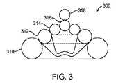
別の実施形態では、図3に示すように、瘻治療デバイスのアンカー部300に複数の積み重ね層310、312、314、316、318を備えてもよい。最下層310から始まる層の少なくともいくつかを環状(すなわち、ドーナツ状)に形成してもよい。図3の実施形態では、例えば、層310、312および314は、環状である。1つまたは複数の球状の層316および318を、環状層310、312、314の上に配置してもよい。これらの層が、例えば縫合糸又は他の引張構造により、最上層から下方へ引っ張られると、該層は、互いの層および瘻の開口部の周りの組織と密封する。1つの代替的な実施形態では、子供の積み重ね玩具のように、中央の柱を環状の層の円形の開口部内に配置して、環状の層が柱にフィットして密封するようにしてもよい。 In another embodiment, as shown in FIG. 3, the
いくつかの変形例において、図4に示しように、いくつかの実施形態では、アンカー部材400は、非円形である1つまたは複数の折り畳み式可撓性部材410、412、414、416を備えてもよい。一実施形態では、可撓性部材410、412、414、416は全て、組み立て後のアンカー部材400の全周402より小さくてもよく、アンカー部材400は、組み立て後に、円形402に近似するようになってもよい。一実施形態では、可撓性部材410、412、414、416は、ピンまたは縫合糸のような取付部材418によって一緒に保持されてもよい。小さい外周の層を複数使用して大きな外周402を形成することの一つの利点は、それぞれが小さい層410、412、414、416を使用するほうが折りたたむことや、瘻を貫通して小径の送達カテーテルを前進させることに容易なことである。一実施形態では、複数の層の組み立てまたは取り付けを容易にするために、外周402に近似する外周を有し非常に可撓性があるより薄い層(図示せず)を、小さい外周の複数の層410、412、414、416の上または下に配置してもよい。 In some variations, as shown in FIG. 4, in some embodiments, the
非円形形状とは、外周が中心点からの半径が一定でない任意の形状のことであることが理解できる。非円形形状は、1つまたは複数の位置において第一微分の不連続性を有する形状を含む。非円形形状は、体腔の所定の表面を収容するように外周に凸部又は凹部を有する略円形の形状であってもよい。非円形形状は、楕円、長円、長方形、レンズ、三角形、およびベル形状を含み得るが、これらに限定されるものではない。非円形状の折り畳み式部材の直径は、部材の一次元上の長さを意味すると理解できる。例えば、中心点または部材の最も広い幅を通るように引いた線の長さが挙げられる。そのような変形例では、最遠位の内側折り畳み式部材の直径は、最近位の折り畳み式部材の直径の1%〜100%として特徴付けてもよいし、時には、約5%、10%、20%、25%、30%、35%、40%、45%、50%、55%、60%、65%、70%、75%、80%、85%、90%、または95%であってもよいし、あるいは、上記パーセントの任意の2つの間の範囲内の任意のパーセントであってもよい。いくつかの変形例において、折り畳み式部材のいくつかは、他の折り畳み式部材の1つまたは複数の形状と異なる。例えば、遠位部材が円形で、最近位折り畳み式部材が非円形の瘻開口部を閉塞するような形であってもよい。いくつかの他の変形例では、遠位の折り畳み式部材は、例えば、所望のように力を分散させるために非円形である。 It can be understood that the non-circular shape is an arbitrary shape whose outer periphery has a constant radius from the center point. Non-circular shapes include shapes having a first derivative discontinuity at one or more locations. The non-circular shape may be a substantially circular shape having a convex portion or a concave portion on the outer periphery so as to accommodate a predetermined surface of the body cavity. Non-circular shapes can include, but are not limited to, ellipses, ellipses, rectangles, lenses, triangles, and bell shapes. The diameter of a non-circular foldable member can be understood to mean the one-dimensional length of the member. For example, the length of the line drawn through the center point or the widest width of the member may be mentioned. In such variations, the diameter of the distal-most inner foldable member may be characterized as 1% to 100% of the diameter of the most recent foldable member, and sometimes about 5%, 10%, 20%, 25%, 30%, 35%, 40%, 45%, 50%, 55%, 60%, 65%, 70%, 75%, 80%, 85%, 90%, or 95% Or any percentage within the range between any two of the above percentages. In some variations, some of the collapsible members are different from one or more shapes of other collapsible members. For example, the distal member may be circular and the proximal foldable member may be configured to occlude a non-circular heel opening. In some other variations, the distal collapsible member is non-circular, for example, to distribute the force as desired.
いくつかの変形例において、最近位折り畳み式部材の近位表面を、遠位アンカーを体腔面にしっかりと永久的に連結しやすくするように構成してもよい。いくつかの変形例において、かかる構成は、本明細書に記載のような組織牽引機構であってもよい。いくつかの変形例において、接着剤を、最近位部材の近位表面に塗布してもよい。接着剤は、体腔内へ最近位折り畳み式部材を挿入する前に、医師によって塗布してもよいし、または挿入後に塗布してもよい。他の変形例では、接着剤を製造工程中に塗布し、ライナーで覆ってもよい。いくつかの変形例では、挿入する前に医師によってライナーを除去する。他の変形例では、ライナーは、体液と接触したとき、または遠位アンカーに力がかかったら、溶解するように構成される。接着剤は、最初は最近位折り畳み式部材と組織を強く接着させるが、その後、瘻管の治癒中または瘻管の治癒後に接着が徐々に弱くなるようなものであってもよい。変形例に応じ、接着剤は、少なくとも7、14、21、28、35、60または任意の他の日数の間、流体が透過できないような密閉を形成してもよい。 In some variations, the proximal surface of the proximal collapsible member may be configured to facilitate secure and permanent connection of the distal anchor to the body cavity surface. In some variations, such a configuration may be a tissue traction mechanism as described herein. In some variations, an adhesive may be applied to the proximal surface of the proximal member. The adhesive may be applied by the physician prior to inserting the proximal foldable member into the body cavity or may be applied after insertion. In other variations, the adhesive may be applied during the manufacturing process and covered with a liner. In some variations, the liner is removed by the physician prior to insertion. In other variations, the liner is configured to dissolve when in contact with bodily fluids or when a force is applied to the distal anchor. The adhesive initially provides a strong bond between the proximal collapsible member and the tissue, but may then be such that the adhesion gradually weakens during or after healing of the fistula. Depending on the variant, the adhesive may form a seal that is impermeable to fluid for at least 7, 14, 21, 28, 35, 60 or any other number of days.
本明細書に記載の任意の実施形態において、瘻治療デバイスのアンカーデバイスまたはアンカー部材の全部または一部を、生体吸収性材料から形成してもよい。一実施形態では、可撓性部材の全部を、生体吸収性材料から形成してもよい。これは、腸内で瘻治療デバイスを固定するためにアンカー部材を使用する場合、例えば、長期間にわたり異物に腸内を残す場合に、腸閉塞を引き起こす可能性があるので特に有利である。アンカー部材が吸収されると、閉塞のリスクが低減される。いくつかの実施形態では、1つまたは複数の可撓性部材は、ニチノールまたは他の適切な金属製のワイヤメッシュまたは金属膜といった、より恒久的な補強構造を含んでいてもよいし、これらと結合していてもよい。いくつかの場合、薄い補強構造と生体吸収性のアンカー部材を組み合わせるのが有益なこともある。 In any of the embodiments described herein, all or part of the anchor device or anchor member of the acupuncture device may be formed from a bioabsorbable material. In one embodiment, the entire flexible member may be formed from a bioabsorbable material. This is particularly advantageous when using an anchor member to secure the acupuncture device in the intestine, for example, when leaving the intestine in a foreign body for an extended period of time, which can cause intestinal obstruction. When the anchor member is absorbed, the risk of blockage is reduced. In some embodiments, the one or more flexible members may include a more permanent reinforcing structure, such as Nitinol or other suitable metal wire mesh or metal film, and It may be bonded. In some cases it may be beneficial to combine a thin reinforcing structure with a bioabsorbable anchor member.
図5は、最遠位折り畳み式部材502と、第1の内側折り畳み式部材504と、第2の内側折り畳み式部材506と、最近位折り畳み式部材508とを備える遠位アンカー500の断面図を示す。いくつかの変形例では、図5に示すように、最遠位折り畳み式部材502、第1の内側折り畳み式部材504、および第2の内側折り畳み式部材506は湾曲していてもよい。最近位折り畳み式部材の近位表面は、実質的に平面であってもよい。最近位折り畳み式部材508の遠位表面は、突出部512を有する外側領域を備えてもよい。また、最近位折り畳み式部材508は、最近位折り畳み式部材の縁と突出部512とをつなぐ平坦な表面510を備えてもよい。また、最近位部材508の近位表面は、体腔表面と係合し、遠位アンカー500を体腔に拘留するように構成された組織牽引機構514および518を備えてもよい。図示のように、典型的には、組織牽引機構514および518を最近位折り畳み式部材508の外周に配置し、部材508の内側部分を平滑/平坦なままにする。いくつかの変形例において、1つまたは複数の組織牽引機構514および518を省略してもよい。他の変形例では、追加の組織牽引機構を加える。様々な実施形態では、組織牽引機構514および518は、任意の適切な大きさおよび形状を有してよい。図5に示すように、一実施形態では、組織牽引機構514および518は、二分円錐の形状を有する。別の実施形態では、組織牽引機構は、円錐形状、角錐形状、尖った長方形の形状、尖った半ドーム形状等を有してもよい。 FIG. 5 illustrates a cross-sectional view of a
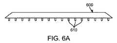
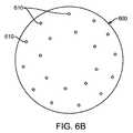
図6Aおよび図6Bに示すように、別の実施形態では、アンカー部材の近位層600に、例えば、ピン、フックおよび/または棘のような複数のマイクロニードル610を備えてもよい。マイクロニードル610は、最近位部材の近位表面全体に分布してもよいが所定の位置に分布してもよい。いくつかの変形例において、マイクロニードルは、近位表面の外周に沿って分布するが、他の実施例では、マイクロニードルは、本明細書に記載するような内側密封領域等の接触が予想される位置に分布してもよい。マイクロニードルは、ニチノールまたは生体吸収性材料等の任意の適切な材料で作成してよいが、これらに限定されるものではない。 As shown in FIGS. 6A and 6B, in another embodiment, the
図7に示すように、一実施形態では、アンカー部材700は、組織を部分的にまたは完全に貫通し、組織内の開口部を閉鎖するように構成された1つまたは複数の湾曲組織牽引機構714(または「突起」)を備えてもよい。図7は、内側折り畳み式部材702および最近位折り畳み式部材704を含む遠位アンカー700の一部を示す。内側折り畳み式部材702は、本明細書に記載の任意の内側折り畳み式部材と同様な形状を有してもよい。最近位折り畳み式部材704は、遠位突出部706および外側領域708を備えてもよい。遠位突出部706は、本明細書に記載の任意の突出部と同様な形状を有してもよい。外側領域708は、本明細書に記載の任意の最近位折り畳み式部材の外側領域と同様な形状を有してもよい。また、最近位折り畳み式部材704は、遠位表面に可動突出部710、近位表面に凹部712、そして近位表面に組織牽引機構714を備える。可動突出部710および凹部712は、最近位折り畳み式部材704内で厚みが薄い領域ができるように設置してもよい。凹部712および組織牽引機構714を互いにつなげて、内側折り畳み式部材702が最近位折り畳み式部材704と接合したときに、組織牽引機構714が体腔の組織に入り体腔組織を把持するようにしてもよい。より具体的には、内側折り畳み式部材702の近位表面が可動突出部710と係合すると、突出部が近位に移動することにより、遠位凹部712も近位に移動する。遠位凹部712および組織牽引機構714は、一体的に連結させ、遠位凹部712が近位に移動すると、組織牽引機構714が近位そして内側に移動ようにし得る。このように、内側折り畳み式部材702が近位へ動き、組織牽引機構714が近位かつ内側へ動くことにより組織への侵入及び把持が容易になる。 As shown in FIG. 7, in one embodiment, the
突出部710は円形として図示されているが、いくつかの変形例では突出部710は非円形である。円形の場合、突起部710は、最近位折り畳み式部材704の内側領域の遠位表面と交差する半径を有する円弧として特徴付けしてもよい。いくつかの変形例において、円弧の半径は、最近位折り畳み式部材の直径に対する割合として記載してもよく、時には、1%、2%、3%、4%、5%、10%、15%、20%、25%、30%であってもよく、あるいは、上記パーセントの任意の2つの間の範囲内の任意のパーセントであってもよい。いくつかの変形例において、円弧の半径は一定ではない。いくつかの変形例において、突出部710は、最近位折り畳み式部材704を囲む領域よりも、動きやすくてもよい。このように、突出部710は、最近位折り畳み式部材を囲む領域に対して動くように構成してもよい。いくつかの変形例において、変形に対する動きやすさは、最近位折り畳み式部材704の突出部710の領域内における厚みを薄くすることによってより強まる。他の領域では、材料の密度を突出部710の領域内において減少させる。図7Aは、最近位折り畳み式部材704を周囲領域に対して動くように構成された単一の突起部として示すが、他の変形例では、かかる突出部の数は、任意、例えば、2個、3個、4個、5個、6個、7個、8個、または10個でもよい。更に、図7Aは、最近位折り畳み式部材702の遠位表面上の突出部を示すが、いくつかの変形例では、突出部が内側折り畳み式部材702の近位表面上にあり、平坦な表面または突出部が最近位折り畳み式部材704の遠位表面上にあってもよい。 Although the
組織牽引機構714を「牙」形状として図示するが、組織牽引機構714は、他の実施形態では、体腔表面を穿刺可能な、例えば、フック形状といった代替形状をとる。組織牽引機構714は、挿入方向から離れる方向に向けた棘を備えて、挿入後に牙の離脱を防ぐようにしてもよい。いくつかの変形例において、組織牽引機構714の長さは、最近位折り畳み式部材704の最遠位点から最近位点間の厚みに対する割合として記載され、その割合は、時には、5%、10%、20%、30%、40%、45%、50%、60%、70%、80%、90%、または95%であってもよいし、あるいは、上記パーセントの任意の2つの間の範囲内の任意のパーセントであってもよい。他の変形例において、最近位折り畳み式部材704の最遠位点から最近位点間の厚みは、組織牽引機構714の長さに対する割合として記載され、その割合は、時には、5%、10%、20%、30%、40%、45%、50%、60%、70%、80%、90%、または95%であってもよいし、あるいは、上記パーセントの任意の2つの間の範囲内の任意のパーセントであってもよい。 Although the
図7は、突起部710、凹部712、及び組織牽引機構714を折り畳み式部材704の縁部付近に配置して示しているが、他の変形例では、組織牽引機構が最近位折り畳み式部材704の任意の位置に配置してもよい。いくつかの変形例において、突出部710、凹部712、および組織牽引機構714の位置は、最近位部材の直径に対する割合として特徴付けてもよく、時には、5%、10%、20%、30%、40%、45%、50%、60%、70%、80%、90%、または95%であってもよいし、あるいは、上記パーセントの任意の2つの間の範囲内の任意のパーセントであってもよい。更に、部分700は、内側折り畳み式部材を備えるものとして説明するが、さらに、本開示の範囲から逸脱することなく、内側折り畳み式部材702を最遠位の折り畳み式部材に置き換えてもよい。 FIG. 7 shows the
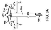
図8A〜8Cは、瘻が開口している組織等の組織Tの開口部を閉鎖するように、遠位アンカー750を組織Tに取り付けるための方法の一実施形態を示す。図8Aに示すように、第1段階として、カテーテル送達デバイス760を、アンカー750に当接させて配置してもよい。縫合糸756を、取付点758でアンカー750に取り付けて、カテーテル760内部に通して延伸させてもよい。図8Aおよび図8Bの矢印で示すように、縫合糸756を、カテーテル760の反対側の端部から引っ張って、アンカー750に張力を付与し、これにより図8Bに示すようにアンカー750端部を上向きに変形させるようにしてもよい。最後に、図8Cに示すように、アンカー750は、組織Tへと引っ張られ、これにより組織牽引機構754を湾曲させて組織内に挿入させ、組織Tの対向する縁部同士を一緒に引っ張って開口部を閉鎖する。つまり、組織牽引機構754は、組織Tにアンカー750を取り付けるのみでなく、組織の縁部同士も一緒に集めて引き寄せる。このような実施形態は、組織内の開口部の径が大きく、瘻孔の長さが短い、腸外(enteroatmospheric)瘻の治療に特に有用であり得る。 FIGS. 8A-8C illustrate one embodiment of a method for attaching a
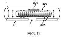
組み込まれた参考文献で詳細に説明されるが、図9に示すように、腸外瘻は、典型的に、直径が瘻自体の長さに対し比較的大きい。いくつかの場合、例えば、瘻の長さは、皮膚と皮下組織の層の厚みに過ぎない。図9に示す例では、概略的に、腸Iの一部を、隣接する皮膚Sと腸外瘻Fと共に図示する。組み込まれた参考文献に記載するように、このような瘻Fを治療する方法の一つは、腸I(あるいは、代替的な実施形態では、他の体腔または空洞)内部に、被覆ステント800を配置し、(図9の矢印のように)ステント800を拡張させて、ステント800と腸との間を密封することである。このような実施形態では、ステント800と腸Iとの間を良好に密封するのが非常に重要である。この目的のため、いくつかの実施形態では、ステント800は、ステント800の両端またはその近傍に密封部材802を備えてもよい。加えて、いくつかの実施形態では、追加的に別個の密封デバイス804をステント800に取り付けて、(接着剤または他の手段により)ステント800と腸Iとの間の密封を増強/強化してもよい。このような密封デバイス804は、円周形状または円周形状の一部であってもよく、そして様々な実施形態では、任意の数の別個の封止デバイス804を使用してもよい。 As described in detail in the incorporated references, as shown in FIG. 9, extra-enteric fistulas are typically relatively large in diameter with respect to the length of the fistula itself. In some cases, for example, the length of the fold is only the thickness of the skin and subcutaneous tissue layers. In the example illustrated in FIG. 9, a part of the intestine I is schematically illustrated together with the adjacent skin S and the external gut F. As described in the incorporated references, one method of treating such a fistula F is to place a
ステント800は、任意の適切な方法を用いて腸I(あるいは、代替的な実施形態では、他の体腔または空洞)に送達できる。いくつかの実施形態では、例えば、ステント800は、直接瘻Fを通る経路によりまたは管状の送達デバイスを瘻Fの内部で前進させることにより、瘻Fを介して体腔内へ送達する。瘻Fを介してステント800を送達する場合、腸I内に入ったらステント800を戻す方向に引っ張って、腸における瘻Fの開口部を閉鎖する必要がある。腸Iと密閉するようにステント800を拡張する必要もある。いくつかの実施形態では、腸Iあるいは他の体腔/空洞にステント800を送達する方法は、以下の(1)〜(4)のいずれかにより実施し得る:(1)ステント800を挿入し、ステント800を戻す方向に引っ張り、そしてステント800を拡張する;(2)ステント800を挿入し、ステント800を引っ張り、そしてステント800を完全に拡張する;(3)マルチセグメンステント(図示せず)を小分けして挿入し、ステントを組み立て、そしてステントを拡張する;または、(4)マルチセグメンステントを小分けして挿入し、ステント部分的に拡張し、ステントを組み立て、そしてステントを完全に拡張する。このような工程の任意の組合せまたは順序が、様々な実施形態に従い、本発明の範囲内で企図される。
1つの代替的な実施形態では、ステントは、中央部または中央付近で屈曲可能で、屈曲した状態の瘻Fを通って前進できるようにしてもよい。腸Iあるいは他の体腔または空洞内へ送達してから、この屈曲可能なステントを真っ直ぐにする。このような屈曲可ばステントをニチノールまたはその他の形状記憶材料から作製して、送達したら元の直線的な形状に戻るようにしてもよい。 In one alternative embodiment, the stent may be bendable at or near the middle and may be advanced through the fold F in a bent state. Once delivered into the intestine I or other body cavity or cavity, the bendable stent is straightened. Such a bendable stent may be made from nitinol or other shape memory material and return to its original linear shape upon delivery.
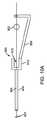
図10Aに、腸皮瘻治療デバイス用の搭載装置900の一実施形態を示す。搭載装置900は、ハブ910の近位に取り付けられたカテーテル906(または「管状部材」)を備えてもよい。ハブ910は、ハンドル908と連結されている。ハブ910は、スロット912を備えてもよい。搭載装置900は、複数の可撓性アンカー部材901および902(または「ディスク」)に、ハンドル908により所定の位置に保持された縫合糸904を通して前進させるのに使用してもよい。いくつかの実施形態では、ディスク901と902を1個ずつ、ハブ910内部へ前進させ、カテーテル906の方へ進めることにより、縫合糸904を通して前進させてもよい。本方法の一実施形態では、ユーザは、二本の指の間にディスク902を保持してもよい。その後、ディスク902と指をスロット付きハブ910内に前進させて、ディスク902がほぼ対称的にスロット外に出るようにしてもよい。その後、ハブ910内で指を回転させ、ディスク902が指の周りに巻きつくようにしてもよい。次に、指をより完全にハブ910の孔の奥へと前進させカテーテル906内に挿入し得る。 FIG. 10A shows an embodiment of a mounting
いくつかの実施形態では、挿入は、ロッド(図示せず)を使用することを含んでもよく、内部にディスク902用のスロットを有してもよい。一実施態様では、直径は約0.080インチ等、比較的小さい。一実施態様では、約0.025インチの幅および約0.75インチの長さのスロットを有してもよい。ロッドがディスク902を二分するようにディスク902をスロット内に配置してしてもよい。ロッドを、その後、ディスクの底部がハブ910内のスロットから出るまで、ハブ910内に挿入し得る。その後、ロッドを回転させて、ディスク902をロッドの周りに巻き付ける。ディスク902を完全にロッドの周りに巻き付けたら、ロッドを更にハブ910およびカテーテル906内に完全に挿入し得る。ディスクスロット912に近接して位置するロッド表面のチューブを使用して、ディスク902がカテーテル906内に配置されたらディスク902を押し出しロッドから離す。 In some embodiments, the insertion may include using a rod (not shown) and may have a slot for the
患者内に最初に配置されるディスク901(最遠位ディスク)は、縫合糸904を有する。縫合糸904はディスク901と共に移動する。第2ディスク902は、縫合糸904がハブ910内へそしてカテーテル906の奥へと前進するに従い、縫合糸904上をスライドする。これには、縫合糸904がカテーテル906に対する位置関係を固定しつつ保持されていることが必要である。ハンドル908によりディスク902を縫合糸904の奥へ前進させながら、縫合糸904を所定の位置に保持できる。この機能により、ユーザが搭載プロセスの一部を補助する必要なく、ディスク901および902を縫合糸904と奥へ前進させることができる。 The disc 901 (the most distal disc) that is initially placed in the patient has a
図10Bに示すように、代替的な実施形態では、搭載装置900は、更に湾曲したハンドル908を備えてもよい。また、本実施形態では、搭載装置900は、追加の縫合糸911および913用の取り付け点を備えてもよい。というのは、搭載ディスク901、902、および903に複数の縫合糸を使用することが有利な場合もあるからである。他のすべての点で、図10Bの実施形態は図10Aのものと同じである。 As shown in FIG. 10B, in an alternative embodiment, the mounting
多数の変更、変形、および置換が、本発明から逸脱することなく当業者によって行われるであろう。本発明を実施する際に、本明細書に記載の本発明の実施形態に対する様々な代替例を採用し得る。 Numerous changes, modifications, and substitutions will be made by those skilled in the art without departing from the invention. In practicing the present invention, various alternatives to the embodiments of the invention described herein may be employed.
Claims (27)
Translated fromJapanese該遠位アンカーは、
縫合糸と;
近位対向突出部(proximal-facing protrusion)を有する最遠位折り畳み式部材(distal-most foldable member)と;
縫合糸を最遠位折り畳み式部材に取り付ける縫合糸取付構造と;
最近位折り畳み式部材と、該最遠位折り畳み式部材と該最近位折り畳み式部材との間に位置する少なくとも1つの追加折り畳み式部材と、を含む複数の追加折り畳み式部材と;
を備え、
該複数の追加折り畳み式部材は、縫合糸に沿って最遠位折り畳み式部材の方へスライドするように構成され、該追加折り畳み式部材の少なくとも一部は、最遠位折り畳み式部材の近位対向突出部が入るような大きさの間隙を備え、該折り畳み式部材を最遠位折り畳み式部材に対する所定の位置でロックするようになっており、
該最近位折り畳み式部材は、瘻の遠位開口部において体腔の表面と連結し、該遠位開口部において瘻を閉鎖するように構成されている、遠位アンカー。A distal anchor for an implantable acupuncture device comprising:
The distal anchor is
With sutures;
A distal-most foldable member having a proximal-facing protrusion;
A suture attachment structure for attaching the suture to the distal-most foldable member;
A plurality of additional collapsible members including a proximal foldable member and at least one additional foldable member positioned between the distal-most foldable member and the proximal foldable member;
With
The plurality of additional collapsible members are configured to slide along the suture toward the distal-most collapsible member, wherein at least a portion of the additional collapsible member is proximal to the distal-most collapsible member. Having a gap sized to accommodate the opposing protrusion, and locking the foldable member in place relative to the distal-most foldable member;
A distal anchor, wherein the proximal collapsible member is configured to connect to a surface of a body cavity at a distal opening of the heel and to close the heel at the distal opening.
該遠位アンカーは、
縫合糸と;
最遠位部材と;
縫合糸を最遠位部材に取り付ける縫合糸取付構造と;
最近位環状折り畳み式部材と、該最遠位部材と該最近位折り畳み式部材との間に位置する少なくとも1つの追加環状折り畳み式部材と、を含む複数の環状折り畳み式部材と;
を備え、
該複数の折り畳み式部材は、縫合糸に沿って最遠位部材の方へスライドするように構成され、該複数の折り畳み式部材の少なくとも1つは、最遠位部材または最遠位部材に隣接する他の折り畳み式部材と密封を形成し、
該最近位折り畳み式部材は、瘻の遠位開口部において体腔の表面と連結し、該遠位開口部において瘻を閉鎖するように構成されている、遠位アンカー。A distal anchor for an implantable acupuncture device comprising:
The distal anchor is
With sutures;
The most distal member;
A suture attachment structure for attaching the suture to the distal-most member;
A plurality of annular foldable members comprising a proximal annular foldable member and at least one additional annular foldable member positioned between the distal most member and the proximal foldable member;
With
The plurality of collapsible members are configured to slide along the suture toward the most distal member, wherein at least one of the plurality of collapsible members is adjacent to the most distal member or the most distal member. To form a seal with other foldable members to
A distal anchor, wherein the proximal collapsible member is configured to connect to a surface of a body cavity at a distal opening of the heel and to close the heel at the distal opening.
該遠位アンカーは、
縫合糸と;
最遠位折り畳み式部材と;
縫合糸を最遠位折り畳み式部材に取り付ける縫合糸取付構造と;
最近位折り畳み式部材と、該最遠位折り畳み式部材と該最近位折り畳み式部材との間に位置する少なくとも1つの追加折り畳み式部材と、を含む複数の追加折り畳み式部材と;
を備え、
該複数の追加折り畳み式部材は、縫合糸に沿って最遠位折り畳み式部材の方へスライドするように構成され、
該最遠位折り畳み式部材および該複数の追加折り畳み式部材の各々は非円形で、組み立て後の遠位アンカーの全外周より小さい外周を有し、
組み立て後の遠位アンカーは、略円形であり、
該最近位折り畳み式部材および該折り畳み式部材の少なくとも他の1つは、一緒に接合したときに、瘻の遠位開口部において体腔の表面と連結し、該遠位開口部において瘻を閉鎖するように構成されている、遠位アンカー。A distal anchor for an implantable acupuncture device comprising:
The distal anchor is
With sutures;
A distal-most foldable member;
A suture attachment structure for attaching the suture to the distal-most foldable member;
A plurality of additional collapsible members including a proximal foldable member and at least one additional foldable member positioned between the distal-most foldable member and the proximal foldable member;
With
The plurality of additional collapsible members are configured to slide along the suture toward the distal-most collapsible member;
Each of the distal-most collapsible member and the plurality of additional collapsible members is non-circular and has an outer periphery that is less than the entire outer periphery of the assembled distal anchor;
The assembled distal anchor is generally circular,
The proximal foldable member and at least one other of the foldable members, when joined together, connect to the surface of the body cavity at the distal opening of the heel and close the heel at the distal opening A distal anchor configured.
該遠位アンカーシステムは、
複数の縫合糸と、近位側に対向する組織に対し複数の組織牽引突起を備える組織接触折り畳み式部材と、縫合糸を該折り畳み式部材に取り付ける縫合糸取付構造と、を備える遠位アンカー;及び、
瘻を貫通して遠位アンカーを送達する送達カテーテル;
を備え、
該折り畳み式部材を該送達カテーテルの遠位端から送達した後、カテーテルを所定の位置に残しつつ縫合糸を引っ張ることで縫合糸を張って、該縫合糸により、該折り畳み式部材の外周を該縫合糸取付構造を介し該部材の取り付け点において上向きに引っ張り、
該縫合糸の張りを開放すると、該折り畳み式部材の外周が瘻を取り囲む組織の方へ移動し、これにより、該組織接触折り畳み式部材の突起が組織を係合し、瘻の直径を小さくする、遠位アンカーシステム。A distal anchor system for an implantable acupuncture device comprising:
The distal anchor system is
A distal anchor comprising a plurality of sutures, a tissue contact foldable member comprising a plurality of tissue traction protrusions for proximally opposed tissue, and a suture attachment structure for attaching a suture to the foldable member; as well as,
A delivery catheter that delivers the distal anchor through the heel;
With
After delivering the foldable member from the distal end of the delivery catheter, the suture is pulled by pulling the suture while leaving the catheter in place, and the suture allows the outer periphery of the foldable member to be Pull upward at the attachment point of the member through the suture attachment structure,
When the suture tension is released, the outer periphery of the foldable member moves toward the tissue surrounding the fold, so that the protrusions of the tissue contacting foldable member engage the tissue and reduce the diameter of the fold. Distal anchor system.
Applications Claiming Priority (5)
| Application Number | Priority Date | Filing Date | Title |
|---|---|---|---|
| US201361752910P | 2013-01-15 | 2013-01-15 | |
| US61/752,910 | 2013-01-15 | ||
| US14/155,593 | 2014-01-15 | ||
| PCT/US2014/011663WO2014113461A2 (en) | 2013-01-15 | 2014-01-15 | Fistula treatment devices and methods |
| US14/155,593US20140200604A1 (en) | 2013-01-15 | 2014-01-15 | Fistula treatment devices and methods |
Publications (2)
| Publication Number | Publication Date |
|---|---|
| JP2016503717Atrue JP2016503717A (en) | 2016-02-08 |
| JP2016503717A5 JP2016503717A5 (en) | 2017-02-16 |
Family
ID=51165719
Family Applications (1)
| Application Number | Title | Priority Date | Filing Date |
|---|---|---|---|
| JP2015553799APendingJP2016503717A (en) | 2013-01-15 | 2014-01-15 | Acupuncture devices and methods |
Country Status (6)
| Country | Link |
|---|---|
| US (2) | US20140200604A1 (en) |
| EP (1) | EP2945547A2 (en) |
| JP (1) | JP2016503717A (en) |
| CN (1) | CN105208940A (en) |
| AU (1) | AU2014207673A1 (en) |
| WO (1) | WO2014113461A2 (en) |
Families Citing this family (7)
| Publication number | Priority date | Publication date | Assignee | Title |
|---|---|---|---|---|
| EP2330985A4 (en) | 2008-09-04 | 2015-11-18 | Curaseal Inc | Inflatable devices for enteric fistula treatment |
| US11701096B2 (en) | 2015-05-28 | 2023-07-18 | National University Of Ireland, Galway | Fistula treatment device |
| US10028733B2 (en) | 2015-05-28 | 2018-07-24 | National University Of Ireland, Galway | Fistula treatment device |
| WO2018087587A1 (en)* | 2016-11-11 | 2018-05-17 | Husein R M Salah | A surgical equipment and a method for treatment of enterocutaneous fistula |
| WO2018109494A1 (en) | 2016-12-16 | 2018-06-21 | Xiros Limited | Medical probe, assembly and method |
| WO2018224687A1 (en) | 2017-06-09 | 2018-12-13 | Signum Surgical Limited | An implant for closing an opening in tissue |
| WO2021198353A1 (en)* | 2020-03-31 | 2021-10-07 | Danmarks Tekniske Universitet | A flexible foil for the delivery of therapeutic cargos |
Citations (1)
| Publication number | Priority date | Publication date | Assignee | Title |
|---|---|---|---|---|
| WO2012174469A2 (en)* | 2011-06-16 | 2012-12-20 | Curaseal Inc. | Fistula treatment devices and related methods |
Family Cites Families (8)
| Publication number | Priority date | Publication date | Assignee | Title |
|---|---|---|---|---|
| CA2833585C (en)* | 2005-04-29 | 2017-06-20 | Cook Biotech Incorporated | Volumetric grafts for treatment of fistulae and related methods and systems |
| EP2330985A4 (en) | 2008-09-04 | 2015-11-18 | Curaseal Inc | Inflatable devices for enteric fistula treatment |
| US8840643B2 (en)* | 2009-07-02 | 2014-09-23 | Arthrex, Inc. | Segmented suture anchor |
| US8932325B2 (en)* | 2010-05-19 | 2015-01-13 | Cook Medical Technologies Llc | Devices and methods useful for sealing bodily openings |
| AU2011314156A1 (en)* | 2010-09-28 | 2013-05-02 | Cook Biotech Incorporated | Devices and methods for treating fistulae and other bodily openings and passageways |
| WO2012174234A2 (en)* | 2011-06-14 | 2012-12-20 | Cook Medical Technologies Llc | Fistula closure devices and methods |
| CN107137114A (en) | 2011-06-17 | 2017-09-08 | 库拉希尔公司 | The device and method treated for fistula |
| US8808363B2 (en)* | 2012-08-31 | 2014-08-19 | Cormatrix Cardiovascular, Inc. | Vascular prosthesis |
- 2014
- 2014-01-15JPJP2015553799Apatent/JP2016503717A/enactivePending
- 2014-01-15CNCN201480014902.9Apatent/CN105208940A/enactivePending
- 2014-01-15AUAU2014207673Apatent/AU2014207673A1/ennot_activeAbandoned
- 2014-01-15WOPCT/US2014/011663patent/WO2014113461A2/enactiveApplication Filing
- 2014-01-15USUS14/155,593patent/US20140200604A1/ennot_activeAbandoned
- 2014-01-15EPEP14703977.0Apatent/EP2945547A2/ennot_activeWithdrawn
- 2016
- 2016-10-07USUS15/288,491patent/US20170020499A1/ennot_activeAbandoned
Patent Citations (1)
| Publication number | Priority date | Publication date | Assignee | Title |
|---|---|---|---|---|
| WO2012174469A2 (en)* | 2011-06-16 | 2012-12-20 | Curaseal Inc. | Fistula treatment devices and related methods |
Also Published As
| Publication number | Publication date |
|---|---|
| US20170020499A1 (en) | 2017-01-26 |
| CN105208940A (en) | 2015-12-30 |
| EP2945547A2 (en) | 2015-11-25 |
| WO2014113461A2 (en) | 2014-07-24 |
| US20140200604A1 (en) | 2014-07-17 |
| WO2014113461A3 (en) | 2014-09-12 |
| AU2014207673A1 (en) | 2015-07-30 |
Similar Documents
| Publication | Publication Date | Title |
|---|---|---|
| JP6122424B2 (en) | Device for fistula treatment and related method | |
| JP2016503717A (en) | Acupuncture devices and methods | |
| CN103841903B (en) | Devices and methods for fistula treatment | |
| US10575851B2 (en) | Atrial appendage ligation | |
| JP5787405B2 (en) | Multiple intestinal fistula expandable devices | |
| JP6741653B2 (en) | Occluder and anastomosis device | |
| JP5547712B2 (en) | Implantable fistula closure device | |
| JP2014524780A5 (en) | ||
| CN103841929B (en) | Negative pressure intestinal anastomosis protective device | |
| US20090084386A1 (en) | Tubal ligation | |
| WO2021219074A1 (en) | Covered stent | |
| US20220323731A1 (en) | Systems and methods for percutaneous body lumen drainage | |
| JP2017528199A (en) | Fistula treatment device and related method | |
| JP2016524946A (en) | Intestinal open acupuncture treatment device | |
| CN114144122A (en) | Apparatus for closing a wound | |
| CN221844845U (en) | A locking system for an implantable tension device | |
| CN110507373A (en) | A medical sealing system |
Legal Events
| Date | Code | Title | Description |
|---|---|---|---|
| A521 | Request for written amendment filed | Free format text:JAPANESE INTERMEDIATE CODE: A523 Effective date:20170112 | |
| A621 | Written request for application examination | Free format text:JAPANESE INTERMEDIATE CODE: A621 Effective date:20170112 | |
| A977 | Report on retrieval | Free format text:JAPANESE INTERMEDIATE CODE: A971007 Effective date:20171005 | |
| A131 | Notification of reasons for refusal | Free format text:JAPANESE INTERMEDIATE CODE: A131 Effective date:20171017 | |
| A601 | Written request for extension of time | Free format text:JAPANESE INTERMEDIATE CODE: A601 Effective date:20180116 | |
| A02 | Decision of refusal | Free format text:JAPANESE INTERMEDIATE CODE: A02 Effective date:20180626 |