JP2016503710A - Anchor element for intracardiac device - Google Patents
Anchor element for intracardiac deviceDownload PDFInfo
- Publication number
- JP2016503710A JP2016503710AJP2015553224AJP2015553224AJP2016503710AJP 2016503710 AJP2016503710 AJP 2016503710AJP 2015553224 AJP2015553224 AJP 2015553224AJP 2015553224 AJP2015553224 AJP 2015553224AJP 2016503710 AJP2016503710 AJP 2016503710A
- Authority
- JP
- Japan
- Prior art keywords
- ring
- anchor
- arm
- valve
- intracardiac
- Prior art date
- Legal status (The legal status is an assumption and is not a legal conclusion. Google has not performed a legal analysis and makes no representation as to the accuracy of the status listed.)
- Pending
Links
Images


Classifications
- A—HUMAN NECESSITIES
- A61—MEDICAL OR VETERINARY SCIENCE; HYGIENE
- A61F—FILTERS IMPLANTABLE INTO BLOOD VESSELS; PROSTHESES; DEVICES PROVIDING PATENCY TO, OR PREVENTING COLLAPSING OF, TUBULAR STRUCTURES OF THE BODY, e.g. STENTS; ORTHOPAEDIC, NURSING OR CONTRACEPTIVE DEVICES; FOMENTATION; TREATMENT OR PROTECTION OF EYES OR EARS; BANDAGES, DRESSINGS OR ABSORBENT PADS; FIRST-AID KITS
- A61F2/00—Filters implantable into blood vessels; Prostheses, i.e. artificial substitutes or replacements for parts of the body; Appliances for connecting them with the body; Devices providing patency to, or preventing collapsing of, tubular structures of the body, e.g. stents
- A61F2/02—Prostheses implantable into the body
- A61F2/24—Heart valves ; Vascular valves, e.g. venous valves; Heart implants, e.g. passive devices for improving the function of the native valve or the heart muscle; Transmyocardial revascularisation [TMR] devices; Valves implantable in the body
- A61F2/2412—Heart valves ; Vascular valves, e.g. venous valves; Heart implants, e.g. passive devices for improving the function of the native valve or the heart muscle; Transmyocardial revascularisation [TMR] devices; Valves implantable in the body with soft flexible valve members, e.g. tissue valves shaped like natural valves
- A61F2/2418—Scaffolds therefor, e.g. support stents
- A—HUMAN NECESSITIES
- A61—MEDICAL OR VETERINARY SCIENCE; HYGIENE
- A61F—FILTERS IMPLANTABLE INTO BLOOD VESSELS; PROSTHESES; DEVICES PROVIDING PATENCY TO, OR PREVENTING COLLAPSING OF, TUBULAR STRUCTURES OF THE BODY, e.g. STENTS; ORTHOPAEDIC, NURSING OR CONTRACEPTIVE DEVICES; FOMENTATION; TREATMENT OR PROTECTION OF EYES OR EARS; BANDAGES, DRESSINGS OR ABSORBENT PADS; FIRST-AID KITS
- A61F2/00—Filters implantable into blood vessels; Prostheses, i.e. artificial substitutes or replacements for parts of the body; Appliances for connecting them with the body; Devices providing patency to, or preventing collapsing of, tubular structures of the body, e.g. stents
- A61F2/02—Prostheses implantable into the body
- A61F2/24—Heart valves ; Vascular valves, e.g. venous valves; Heart implants, e.g. passive devices for improving the function of the native valve or the heart muscle; Transmyocardial revascularisation [TMR] devices; Valves implantable in the body
- A61F2/2409—Support rings therefor, e.g. for connecting valves to tissue
- A—HUMAN NECESSITIES
- A61—MEDICAL OR VETERINARY SCIENCE; HYGIENE
- A61F—FILTERS IMPLANTABLE INTO BLOOD VESSELS; PROSTHESES; DEVICES PROVIDING PATENCY TO, OR PREVENTING COLLAPSING OF, TUBULAR STRUCTURES OF THE BODY, e.g. STENTS; ORTHOPAEDIC, NURSING OR CONTRACEPTIVE DEVICES; FOMENTATION; TREATMENT OR PROTECTION OF EYES OR EARS; BANDAGES, DRESSINGS OR ABSORBENT PADS; FIRST-AID KITS
- A61F2/00—Filters implantable into blood vessels; Prostheses, i.e. artificial substitutes or replacements for parts of the body; Appliances for connecting them with the body; Devices providing patency to, or preventing collapsing of, tubular structures of the body, e.g. stents
- A61F2/02—Prostheses implantable into the body
- A61F2/24—Heart valves ; Vascular valves, e.g. venous valves; Heart implants, e.g. passive devices for improving the function of the native valve or the heart muscle; Transmyocardial revascularisation [TMR] devices; Valves implantable in the body
- A61F2/2442—Annuloplasty rings or inserts for correcting the valve shape; Implants for improving the function of a native heart valve
- A61F2/2445—Annuloplasty rings in direct contact with the valve annulus
- A—HUMAN NECESSITIES
- A61—MEDICAL OR VETERINARY SCIENCE; HYGIENE
- A61F—FILTERS IMPLANTABLE INTO BLOOD VESSELS; PROSTHESES; DEVICES PROVIDING PATENCY TO, OR PREVENTING COLLAPSING OF, TUBULAR STRUCTURES OF THE BODY, e.g. STENTS; ORTHOPAEDIC, NURSING OR CONTRACEPTIVE DEVICES; FOMENTATION; TREATMENT OR PROTECTION OF EYES OR EARS; BANDAGES, DRESSINGS OR ABSORBENT PADS; FIRST-AID KITS
- A61F2220/00—Fixations or connections for prostheses classified in groups A61F2/00 - A61F2/26 or A61F2/82 or A61F9/00 or A61F11/00 or subgroups thereof
- A61F2220/0025—Connections or couplings between prosthetic parts, e.g. between modular parts; Connecting elements
- A61F2220/0058—Connections or couplings between prosthetic parts, e.g. between modular parts; Connecting elements soldered or brazed or welded
- A—HUMAN NECESSITIES
- A61—MEDICAL OR VETERINARY SCIENCE; HYGIENE
- A61F—FILTERS IMPLANTABLE INTO BLOOD VESSELS; PROSTHESES; DEVICES PROVIDING PATENCY TO, OR PREVENTING COLLAPSING OF, TUBULAR STRUCTURES OF THE BODY, e.g. STENTS; ORTHOPAEDIC, NURSING OR CONTRACEPTIVE DEVICES; FOMENTATION; TREATMENT OR PROTECTION OF EYES OR EARS; BANDAGES, DRESSINGS OR ABSORBENT PADS; FIRST-AID KITS
- A61F2220/00—Fixations or connections for prostheses classified in groups A61F2/00 - A61F2/26 or A61F2/82 or A61F9/00 or A61F11/00 or subgroups thereof
- A61F2220/0025—Connections or couplings between prosthetic parts, e.g. between modular parts; Connecting elements
- A61F2220/0066—Connections or couplings between prosthetic parts, e.g. between modular parts; Connecting elements stapled
- A—HUMAN NECESSITIES
- A61—MEDICAL OR VETERINARY SCIENCE; HYGIENE
- A61F—FILTERS IMPLANTABLE INTO BLOOD VESSELS; PROSTHESES; DEVICES PROVIDING PATENCY TO, OR PREVENTING COLLAPSING OF, TUBULAR STRUCTURES OF THE BODY, e.g. STENTS; ORTHOPAEDIC, NURSING OR CONTRACEPTIVE DEVICES; FOMENTATION; TREATMENT OR PROTECTION OF EYES OR EARS; BANDAGES, DRESSINGS OR ABSORBENT PADS; FIRST-AID KITS
- A61F2230/00—Geometry of prostheses classified in groups A61F2/00 - A61F2/26 or A61F2/82 or A61F9/00 or A61F11/00 or subgroups thereof
- A61F2230/0002—Two-dimensional shapes, e.g. cross-sections
- A61F2230/0004—Rounded shapes, e.g. with rounded corners
- A61F2230/0006—Rounded shapes, e.g. with rounded corners circular
- A—HUMAN NECESSITIES
- A61—MEDICAL OR VETERINARY SCIENCE; HYGIENE
- A61F—FILTERS IMPLANTABLE INTO BLOOD VESSELS; PROSTHESES; DEVICES PROVIDING PATENCY TO, OR PREVENTING COLLAPSING OF, TUBULAR STRUCTURES OF THE BODY, e.g. STENTS; ORTHOPAEDIC, NURSING OR CONTRACEPTIVE DEVICES; FOMENTATION; TREATMENT OR PROTECTION OF EYES OR EARS; BANDAGES, DRESSINGS OR ABSORBENT PADS; FIRST-AID KITS
- A61F2230/00—Geometry of prostheses classified in groups A61F2/00 - A61F2/26 or A61F2/82 or A61F9/00 or A61F11/00 or subgroups thereof
- A61F2230/0002—Two-dimensional shapes, e.g. cross-sections
- A61F2230/0004—Rounded shapes, e.g. with rounded corners
- A61F2230/001—Figure-8-shaped, e.g. hourglass-shaped
- A—HUMAN NECESSITIES
- A61—MEDICAL OR VETERINARY SCIENCE; HYGIENE
- A61F—FILTERS IMPLANTABLE INTO BLOOD VESSELS; PROSTHESES; DEVICES PROVIDING PATENCY TO, OR PREVENTING COLLAPSING OF, TUBULAR STRUCTURES OF THE BODY, e.g. STENTS; ORTHOPAEDIC, NURSING OR CONTRACEPTIVE DEVICES; FOMENTATION; TREATMENT OR PROTECTION OF EYES OR EARS; BANDAGES, DRESSINGS OR ABSORBENT PADS; FIRST-AID KITS
- A61F2230/00—Geometry of prostheses classified in groups A61F2/00 - A61F2/26 or A61F2/82 or A61F9/00 or A61F11/00 or subgroups thereof
- A61F2230/0063—Three-dimensional shapes
- A61F2230/0069—Three-dimensional shapes cylindrical
- A—HUMAN NECESSITIES
- A61—MEDICAL OR VETERINARY SCIENCE; HYGIENE
- A61F—FILTERS IMPLANTABLE INTO BLOOD VESSELS; PROSTHESES; DEVICES PROVIDING PATENCY TO, OR PREVENTING COLLAPSING OF, TUBULAR STRUCTURES OF THE BODY, e.g. STENTS; ORTHOPAEDIC, NURSING OR CONTRACEPTIVE DEVICES; FOMENTATION; TREATMENT OR PROTECTION OF EYES OR EARS; BANDAGES, DRESSINGS OR ABSORBENT PADS; FIRST-AID KITS
- A61F2250/00—Special features of prostheses classified in groups A61F2/00 - A61F2/26 or A61F2/82 or A61F9/00 or A61F11/00 or subgroups thereof
- A61F2250/0014—Special features of prostheses classified in groups A61F2/00 - A61F2/26 or A61F2/82 or A61F9/00 or A61F11/00 or subgroups thereof having different values of a given property or geometrical feature, e.g. mechanical property or material property, at different locations within the same prosthesis
- A61F2250/0036—Special features of prostheses classified in groups A61F2/00 - A61F2/26 or A61F2/82 or A61F9/00 or A61F11/00 or subgroups thereof having different values of a given property or geometrical feature, e.g. mechanical property or material property, at different locations within the same prosthesis differing in thickness
- A—HUMAN NECESSITIES
- A61—MEDICAL OR VETERINARY SCIENCE; HYGIENE
- A61F—FILTERS IMPLANTABLE INTO BLOOD VESSELS; PROSTHESES; DEVICES PROVIDING PATENCY TO, OR PREVENTING COLLAPSING OF, TUBULAR STRUCTURES OF THE BODY, e.g. STENTS; ORTHOPAEDIC, NURSING OR CONTRACEPTIVE DEVICES; FOMENTATION; TREATMENT OR PROTECTION OF EYES OR EARS; BANDAGES, DRESSINGS OR ABSORBENT PADS; FIRST-AID KITS
- A61F2250/00—Special features of prostheses classified in groups A61F2/00 - A61F2/26 or A61F2/82 or A61F9/00 or A61F11/00 or subgroups thereof
- A61F2250/0014—Special features of prostheses classified in groups A61F2/00 - A61F2/26 or A61F2/82 or A61F9/00 or A61F11/00 or subgroups thereof having different values of a given property or geometrical feature, e.g. mechanical property or material property, at different locations within the same prosthesis
- A61F2250/0039—Special features of prostheses classified in groups A61F2/00 - A61F2/26 or A61F2/82 or A61F9/00 or A61F11/00 or subgroups thereof having different values of a given property or geometrical feature, e.g. mechanical property or material property, at different locations within the same prosthesis differing in diameter
- A—HUMAN NECESSITIES
- A61—MEDICAL OR VETERINARY SCIENCE; HYGIENE
- A61F—FILTERS IMPLANTABLE INTO BLOOD VESSELS; PROSTHESES; DEVICES PROVIDING PATENCY TO, OR PREVENTING COLLAPSING OF, TUBULAR STRUCTURES OF THE BODY, e.g. STENTS; ORTHOPAEDIC, NURSING OR CONTRACEPTIVE DEVICES; FOMENTATION; TREATMENT OR PROTECTION OF EYES OR EARS; BANDAGES, DRESSINGS OR ABSORBENT PADS; FIRST-AID KITS
- A61F2250/00—Special features of prostheses classified in groups A61F2/00 - A61F2/26 or A61F2/82 or A61F9/00 or A61F11/00 or subgroups thereof
- A61F2250/0058—Additional features; Implant or prostheses properties not otherwise provided for
- A61F2250/006—Additional features; Implant or prostheses properties not otherwise provided for modular
- A—HUMAN NECESSITIES
- A61—MEDICAL OR VETERINARY SCIENCE; HYGIENE
- A61F—FILTERS IMPLANTABLE INTO BLOOD VESSELS; PROSTHESES; DEVICES PROVIDING PATENCY TO, OR PREVENTING COLLAPSING OF, TUBULAR STRUCTURES OF THE BODY, e.g. STENTS; ORTHOPAEDIC, NURSING OR CONTRACEPTIVE DEVICES; FOMENTATION; TREATMENT OR PROTECTION OF EYES OR EARS; BANDAGES, DRESSINGS OR ABSORBENT PADS; FIRST-AID KITS
- A61F2250/00—Special features of prostheses classified in groups A61F2/00 - A61F2/26 or A61F2/82 or A61F9/00 or A61F11/00 or subgroups thereof
- A61F2250/0058—Additional features; Implant or prostheses properties not otherwise provided for
- A61F2250/0069—Sealing means
Landscapes
- Health & Medical Sciences (AREA)
- Cardiology (AREA)
- Engineering & Computer Science (AREA)
- Biomedical Technology (AREA)
- Heart & Thoracic Surgery (AREA)
- Transplantation (AREA)
- Oral & Maxillofacial Surgery (AREA)
- Vascular Medicine (AREA)
- Life Sciences & Earth Sciences (AREA)
- Animal Behavior & Ethology (AREA)
- General Health & Medical Sciences (AREA)
- Public Health (AREA)
- Veterinary Medicine (AREA)
- Prostheses (AREA)
Abstract
Translated fromJapaneseDescription
Translated fromJapanese本発明は、心臓内装置の安定性を向上させる安定化およびアンカー要素を対象とする。具体的には、本発明は、僧帽弁輪内での心臓内装置の安定化およびアンカーに関する。 The present invention is directed to stabilization and anchor elements that improve the stability of intracardiac devices. Specifically, the present invention relates to stabilization and anchoring of intracardiac devices within a mitral annulus.
心臓弁の閉鎖不全は、心臓の収縮時に心臓の弁葉が完全に閉鎖せずに、血液を、不適切にしか閉鎖されていない弁葉を通って逆流させてしまうときに起こる。例えば、僧帽弁の閉鎖不全は、心室の収縮時に血液が僧帽弁を通って逆流し、左心房の中に至るとき起こる。 Heart valve insufficiency occurs when the heart's leaflets do not completely close when the heart contracts, causing blood to flow back through the leaflets that are improperly closed. For example, mitral insufficiency occurs when blood flows back through the mitral valve and into the left atrium during ventricular contraction.
現在では、器質性閉鎖不全は、心臓の収縮時に生来弁葉が完全に閉鎖することを可能にするためにそれらを例えばクリップ、縫合糸、フック等で再構築するよう試みることによって矯正される。疾患が進行し過ぎているときには、弁全体が機械的または生物学的な人工器官と置換される必要がある。この例には、縫合弁輪形成リング、ならびに実際の弁の弁葉との置換が含まれる。弁は僧帽弁輪に縫合される。縫合弁輪形成リングも弁輪に縫合されるが、これも、弁輪を再構築して、生来弁葉をより近付けてそれらが適切に閉鎖するのを可能にするよう試みるために使用されてきた。 At present, organic atresia is corrected by attempting to reconstruct them with, for example, clips, sutures, hooks, etc., to allow the native leaflets to completely close when the heart contracts. When the disease is too advanced, the entire valve needs to be replaced with a mechanical or biological prosthesis. Examples include suture annuloplasty rings, as well as replacement of actual valve leaflets. The valve is sutured to the mitral annulus. A suture annuloplasty ring is also sutured to the annulus, which has also been used to attempt to reconstruct the annulus and bring the native leaflets closer and allow them to close properly. It was.
カテーテルに基づく大動脈弁置換の成功に基づいて、類似のタイプの置換弁を使用して僧房弁を非侵襲的に置換する類似の技術を評価することに関心が広がっている。 Based on the success of catheter-based aortic valve replacement, there is growing interest in evaluating similar techniques for noninvasive replacement of mitral valves using similar types of replacement valves.
しかし大動脈弁とは異なって、僧帽弁輪は置換用僧帽弁を位置決めするための良い目印を提供しない。置換用大動脈弁を必要とする患者では、大動脈弁輪の高さおよび幅が一般的にカルシウム形成に関係付けられる変質性疾患の存在で縮小される。これらの組織内の変化は、大動脈弁輪の縮小された断面積によって、置換用大動脈弁を所定位置内に適切に固定することをし易くする。しかし、典型的に大動脈弁に見受けられる変質性変化は、閉鎖不全を受けている僧帽弁には存在せず、したがって僧帽弁輪は一般的に、疾患のある大動脈弁の弁輪よりも細く、広く、かつ柔軟である。僧帽弁輪の形状および形態は、生来僧帽弁輪内に置換用僧帽弁を適切に着座させることを相対的より困難にする。僧帽弁輪の一般的な解剖学的構造も、置換用僧帽弁を所定位置内に適切にアンカーすることをより困難にする。僧帽弁輪は、大動脈弁輪が提供する大動脈から左心室への移行よりもスムーズな移行を左心房から左心室へ提供する。大動脈弁輪は解剖学的により顕著であって、置換用大動脈弁がより簡単に所定位置内に固定されることが可能な、より大きな「隆起部」を提供する。 However, unlike the aortic valve, the mitral annulus does not provide a good landmark for positioning the replacement mitral valve. In patients who require a replacement aortic valve, the height and width of the aortic annulus is reduced due to the presence of degenerative diseases generally associated with calcium formation. These changes in tissue make it easier to properly secure the replacement aortic valve in place due to the reduced cross-sectional area of the aortic annulus. However, the degenerative changes typically found in aortic valves are not present in mitral valves undergoing incompetence, so mitral annulus is generally more than that of diseased aortic valves. It is thin, wide and flexible. The shape and form of the mitral annulus makes it relatively more difficult to properly seat the replacement mitral valve within the native mitral annulus. The general anatomy of the mitral annulus also makes it more difficult to properly anchor the replacement mitral valve in place. The mitral annulus provides a smoother transition from the left atrium to the left ventricle than the transition from the aorta to the left ventricle provided by the aortic annulus. The aortic annulus is anatomically more prominent and provides a larger “ridge” that allows the replacement aortic valve to be more easily secured in place.
一般的に、大動脈弁輪は僧房弁輪よりも小さい。僧房弁輪は直径が約2.4cmから約5cmであると推定されているが、大動脈弁輪は直径が約1.6cmから約2.5cmであると推定されている。 In general, the aortic annulus is smaller than the mitral annulus. The mitral annulus is estimated to be about 2.4 cm to about 5 cm in diameter, while the aortic annulus is estimated to be about 1.6 cm to about 2.5 cm in diameter.
より大きな僧房弁輪は、現在の経皮的に送達される弁を生来僧房弁位置内にしっかりと埋め込むことを困難にする。現在の置換用大動脈弁は、展開中および埋め込み中にそれらが受けることが可能な半径方向の拡張の量が制限されている。僧房弁輪内にしっかりと固着されることが可能になるような拡張構成を有する置換用大動脈弁を提供するとなると、置換用大動脈弁の折り畳まれた送達プロフィルが拡大されることが必要になる。しかし、折り畳まれた送達プロフィルを拡大すると、より大きな直径の送達システムを用いて、血管内送達を患者にとってより危険に、血管系のナビゲートをより困難にすることになる。 The larger mitral annulus makes it difficult to securely implant current percutaneously delivered valves within the natural mitral valve position. Current replacement aortic valves have a limited amount of radial expansion they can undergo during deployment and implantation. When providing a replacement aortic valve having an expanded configuration that allows it to be firmly secured within the mitral annulus, the folded delivery profile of the replacement aortic valve needs to be expanded. However, enlarging the folded delivery profile will use a larger diameter delivery system, making intravascular delivery more dangerous for the patient and making navigation of the vasculature more difficult.
単一片型置換用僧帽弁を送達および埋め込みする様々な試みがなされている。しかし、このアプローチには問題がある。これはとりわけ、充分に小さな送達プロフィルを有するように小さく折り畳まれることが可能であり、尚且つ血管アクセス位置を介して僧帽弁内で拡張され、所定位置内に固定されることが可能な装置を開発することが困難であることが判明したことによる。 Various attempts have been made to deliver and implant single piece replacement mitral valves. However, there are problems with this approach. This is especially a device that can be folded small to have a sufficiently small delivery profile, yet can be expanded in the mitral valve via the vascular access position and fixed in place Because it proved difficult to develop.
この問題を克服するために、2部片型置換用弁も開発されている。ステント付弁への支持を提供するために2リング型構造体が使用されるこのタイプのシステムの例が、国際公開第2012/031141号パンフレットとして公開された共同出願、同時係属中の特許出願に見出されることができる。単リング型支持構造体を使用する他のタイプの2部片型弁システムが、国際公開第2013/128436号パンフレットという公開番号を有する共同出願、同時係属中のPCT特許出願に開示されている。 In order to overcome this problem, a two-part replacement valve has also been developed. An example of this type of system in which a two-ring structure is used to provide support for a stented valve is shown in co-pending and co-pending patent applications published as WO 2012/031141. Can be found. Another type of two-piece valve system that uses a single ring type support structure is disclosed in a co-pending and co-pending PCT patent application having a publication number of WO 2013/128436.
上述の先行技術のアプローチのいずれでも、弁支持装置は、それらが送達カテーテルの中に挿入するための折り畳まれた送達構成に「クリンプ」され、その後前記カテーテルから解放されることができるように構築される。次いでこの装置−一般的にニチノールなどの形状記憶材料から構築される−は、その作業位置での埋め込みの前に、先の拡張された作動構成を取り戻すことを可能にされる。 In any of the prior art approaches described above, the valve support devices are constructed such that they can be “crimped” into a folded delivery configuration for insertion into a delivery catheter and then released from the catheter. Is done. This device, typically constructed from a shape memory material such as Nitinol, is then allowed to regain the previous expanded working configuration prior to implantation at its working position.
僧帽弁の閉鎖不全(および関連する僧帽弁の病態)を治療するために使用される上述の装置全てに関して、対処されなければならない1つの問題は、左心室によって収縮期の狭窄中に前記装置上に生成される極めて強い力の結果として生じる上向きの変位(即ち左心房の中への)を防止するために、僧帽弁輪付近のそれらの作動位置で充分にアンカーおよび/または安定化する必要性である。 With respect to all of the above-described devices used to treat mitral regurgitation (and related mitral valve pathology), one problem that must be addressed is that the left ventricle during systolic stenosis Fully anchored and / or stabilized in their working position near the mitral annulus to prevent upward displacement (ie into the left atrium) resulting from the extremely strong forces generated on the device There is a need to do.
本発明の目的は、置換用弁支持装置(上述の特許出願で開示されたものなど)の中に、あるいは縫合弁輪形成リングおよび1部片型人工僧帽弁などの僧帽弁輪の領域内に埋め込むことを目的とした他の装置の中に組み込まれることができる改良型の安定化およびアンカー要素を提供することである。 It is an object of the present invention to provide a replacement valve support device (such as that disclosed in the above-mentioned patent application) or regions of a mitral annulus such as a suture annuloplasty ring and a one-piece prosthetic mitral valve. It is to provide an improved stabilization and anchor element that can be incorporated into other devices intended to be embedded therein.
本発明の特定の実施形態のさらなる目的は、安定化された心臓内装置のまわりの密閉を改良し、それによって弁傍の漏出を低減または防止することである。 A further object of certain embodiments of the present invention is to improve the seal around the stabilized intracardiac device, thereby reducing or preventing paravalvular leakage.
この説明が進むにつれて本発明の他の目的および利点が明らかになろう。 As the description proceeds, other objects and advantages of the invention will become apparent.
本発明者らは、心臓内装置の即時(即ち埋め込み後)かつ長期の安定性を達成するという課題への技術的解決法を実現した。これらの解決法のそれぞれは、1つまたは複数の安定化またはアンカー要素の形態で実現され、それぞれが、一般的に外側周囲と内側周囲と前記内側周囲によって外部を囲まれた中央空間とによって画定されるリング様または輪状構造体から構成される心臓内装置の本体に取り付けられる(またはその一部を形成する)。装置の厚み(即ち、使用中に心臓の長手軸と平行になる装置の寸法)は一般的に、外部周囲によって外部を、内部周囲によって内方を囲まれた装置の表面積に対して極めて小さい。「リング様」という用語は、円形または非円形(楕円形、長円形、他の規則的または不規則的形状など)のいずれかである外部輪郭を有する環状構造体を含むものと理解されるべきであることに留意されたい。 The inventors have realized a technical solution to the problem of achieving immediate (ie post-implantation) and long-term stability of the intracardiac device. Each of these solutions is realized in the form of one or more stabilizing or anchoring elements, each generally defined by an outer perimeter, an inner perimeter, and a central space surrounded by the inner perimeter Is attached to (or forms part of) the body of an intracardiac device comprised of a ring-like or ring-shaped structure. The thickness of the device (i.e., the size of the device that is parallel to the longitudinal axis of the heart in use) is generally very small relative to the surface area of the device surrounded externally by the external perimeter and inwardly by the internal perimeter. The term “ring-like” should be understood to include annular structures having an outer contour that is either circular or non-circular (eg, oval, oval, other regular or irregular shapes). Please note that.
本発明の特に好ましい実施形態では、心臓内装置は、2ステップ式の僧帽弁置換処置で使用することを目的とした弁支持装置であり、以下に続く説明の大部分はこのタイプの装置に関する。しかし、言うまでもなく、様々な実施形態の全てが、1部片型人工弁および縫合弁輪形成リングを含む(それらに限定されるわけではない)他のタイプの心臓内装置に同等に適用されることができる。 In a particularly preferred embodiment of the invention, the intracardiac device is a valve support device intended for use in a two-step mitral valve replacement procedure, and most of the description that follows is directed to this type of device. . However, it will be appreciated that all of the various embodiments apply equally to other types of intracardiac devices including, but not limited to, one-piece prosthetic valves and suture annuloplasty rings. be able to.
以下に続く開示では、本発明の一部の構造要素は、「アーム」または「翼」と呼ばれる。この点で、これらの用語は互換的に使用されることに留意されたい。同様に、用語「安定化」および「アンカー」(前記用語の派生語も)も、アームまたは翼に適用されるとき互換的に使用される。 In the disclosure that follows, some structural elements of the present invention are referred to as “arms” or “wings”. Note that in this respect, these terms are used interchangeably. Similarly, the terms “stabilization” and “anchor” (and derivatives thereof) are also used interchangeably when applied to an arm or wing.
このように、第1態様では、本発明は、リング形状の本体と1つまたは複数のアンカーアームと1つまたは複数の支点とを備える心臓内装置であって、前記アンカーアームは前記支点を中心に枢動されることができ、前記装置は2つの配座、即ち送達カテーテルの中に挿入するのに適した折り畳まれた配座と心臓弁輪での埋め込みに適した開放された配座との間で姿勢を変えることが可能である、心臓内装置を対象とする。 Thus, in a first aspect, the present invention is an intracardiac device comprising a ring-shaped body, one or more anchor arms and one or more fulcrums, wherein the anchor arms are centered on the fulcrum The device can be pivoted into two conformations: a folded conformation suitable for insertion into a delivery catheter and an open conformation suitable for implantation in a heart valve annulus. Intended for intracardiac devices that can change posture between.
上述のアンカーアームと支点は、前記アンカーアームに半径方向外向きの力が掛けられた際に各アンカーアームがその支点を中心に上方側方に枢動する能力があるように互いに配設される。 The anchor arm and the fulcrum described above are arranged so that each anchor arm is capable of pivoting upward and downward about the fulcrum when a radial outward force is applied to the anchor arm. .
上述の枢動可能な構造体はレバーとして作用し、このように、アンカーアームが基本的に静止的構造体として構築されていた場合に可能であろうよりも著しく大きな力を心室壁上に掛けることが可能である。このようにして、本発明の装置は充分な大きさの力を心室に掛ける能力があり、それによって心室収縮期中に生成される強い変位力に抵抗することが可能になる。しかし、本発明のレバー構造体がその意図する方式で機能するためには、さらなる2つの技術的問題を解決する必要がある。第一には、アンカーアームが側方に枢動し、今度は同様に大きな力を内側心室壁上に掛けるように充分に大きな力をアンカーアームに掛ける必要であり、第二には、前記力が必要な場合にのみ、即ち2段階の置換用弁埋め込み処置の第2段階でのみ掛けられるように、この側方に向けられる拡張力の生成の時間調整をする必要である。この第二の点を説明するために、僧房弁が正常に機能する方式を簡単に考察する必要がある。このように、初期の心臓収縮期中、心室内圧力は、僧房弁葉上にそのようにして及ぼされた力が弁葉を閉鎖させて左心室から左心房内への血液の逆流を防止する点まで上昇する。2段階の処置のうちの第1段階(支持構造体の埋め込み)中、生来弁葉の閉鎖によって、支持装置は心室収縮期中に強い変位力に晒されず、その結果左心室と左心房との間の完全な(または完全に近い)分離をもたらす。さらに、生来弁葉が開いているとき(心弛緩期中)も、弁支持装置は極めて低い圧力にしか晒されない。これは第一に、リング形状支持装置の表面積が小さいこと、第二に前記表面積の大部分が心房と心室との間の流体流れの経路内に位置付けられないことによる。しかし、2段階の方法のうちの第2段階(置換用弁の埋め込みおよび拡張)中は、生来僧房弁葉は側方に変位された状態になる。このようにして、前記弁葉は、初期の収縮期中は閉鎖するのを防止される。その結果、心室収縮期中には、極めて強い上方に向けられた力が置換用弁葉上に及ぼされ、それによって弁葉を閉鎖させる。ここで置換用弁葉が弁支持装置と一緒に単一構造体を形成することから、前記置換用弁葉上に作用する力は、取り付けられた弁支持装置の変位を、それが心室壁に強力に固着されていないと、引き起こすことになる。このように、埋め込み処置のこの第2段階中にこそ、支持装置に掛けられる変位力の急激な増大に対抗するために、前記支持装置のアンカーアームが強力に心室壁に係合できることが必須である。 The pivotable structure described above acts as a lever, thus applying a significantly greater force on the ventricular wall than would be possible if the anchor arm was basically constructed as a stationary structure. It is possible. In this way, the device of the present invention is capable of applying a sufficiently large force to the ventricle, thereby allowing it to resist the strong displacement forces generated during ventricular systole. However, in order for the lever structure of the present invention to function in its intended manner, two additional technical problems need to be solved. First, the anchor arm pivots to the side and this time it is necessary to apply a sufficiently large force to the anchor arm so that a large force is applied on the inner ventricular wall as well, and second, the force It is necessary to time the generation of the expansion force directed to this side so that it is only applied when necessary, ie only in the second stage of the two-stage replacement valve implantation procedure. To explain this second point, it is necessary to briefly consider how the mitral valve functions normally. Thus, during the initial systolic period, intraventricular pressure is the point at which the force so exerted on the mitral leaflets closes the leaflets and prevents backflow of blood from the left ventricle into the left atrium. To rise. During the first of the two stages (implantation of the support structure), due to the closure of the native leaflets, the support device is not exposed to strong displacement forces during ventricular systole, so that the left ventricle and the left atrium Resulting in complete (or near perfect) separation between. Furthermore, the valve support is only exposed to very low pressures when the native leaflets are open (during the systole). This is primarily due to the small surface area of the ring-shaped support device, and secondly, the majority of the surface area is not located in the fluid flow path between the atrium and the ventricle. However, during the second stage of the two-stage method (implantation and expansion of the replacement valve), the native mitral leaflets are displaced laterally. In this way, the leaflets are prevented from closing during the initial systole. As a result, during ventricular systole, a very strong upward force is exerted on the replacement leaflets, thereby closing the leaflets. Here, since the replacement leaflet forms a single structure with the valve support device, the force acting on the replacement leaflet causes the displacement of the attached valve support device to the ventricular wall. If it is not firmly fixed, it will cause. Thus, during this second phase of the implantation procedure, it is essential that the anchor arm of the support device be able to strongly engage the ventricular wall in order to counter the sudden increase in displacement force applied to the support device. is there.
上述の2つの技術的問題は、本発明者によって独創的な方式で、膨張式バルーンによって、または自己拡張式ステントの使用のいずれかによって、置換用弁の半径方向の拡張を利用することによって解決された(2段階式埋め込み法のうちの第2段階中に;例えば、参照により本明細書に両方とも組み込まれる共同出願の国際公開第2012/031141号パンフレットと国際公開第2013/128436号パンフレットとに述べられた方法を参照されたい)。このようにして、バルーン(または自己拡張式ステント)によって及ぼされた外向き半径方向の力は、支持装置内のアンカーアームのそれぞれの内側部位に伝達される。次いで前記アームはそれらの支点を中心に枢動される(これに関する詳細は以下に掲げられる)。次いでこの枢動運動は、各アンカーアームの側方部位が心室壁と接触するまで継続する(あるいは一部の実施形態では、内側部位と一緒に生来弁葉のピンチングを引き起こし、あるいは他の実施形態では、装置の側方取付け翼と接触する(図10に図示の通り―このように翼を左心室に取り付ける軸方向の力を増大し、翼の固着力を増大する))。要約すると、拡張する置換用弁によって掛けられる力はアンカーアームの半径方向の拡張を引き起こす。前記アームのレバー配置の結果、拡張する弁によって生成される半径方向に向けられた力の大きさは増幅される。枢動可能なアームの配置から得られる追加の利点は、拡張されたアンカーアームそれぞれの側方端と心室壁の組織との間に形成される角度が、前記アームが前記半径方向に向けられた力を前記組織に軸方向に(即ち、アンカーアームの自由側方端の長手軸に沿って)伝達させるように変更された状態になることである。この方向性の効果は極めて有利である。これは、アンカーアームの幾何学的形状が、力が長手軸に対して90度で掛けられた場合よりもより大きな前記力をアンカーアームが心臓壁上にそれらの前記軸線の方向に掛けることが可能となるようなものであることによる。この点で、注目されるべきは、上述の方向性効果は、組織と接触するのがアンカーアームの自由端部であることを必要としないということである。実際、特定の状況では、このような配置は心室組織に対して外傷をもたらす場合のあることから、望ましくないことが判明する場合がある。むしろ、アンカーアームの長さの短い終端部位(即ち最も側方)に角度付けされ、それによって非外傷性の基部を形成するだけで充分である。このような配置では、心室壁によってアンカーアームに及ぼされた力の大部分は依然として軸方向に方向付けられ、そのように前記アームの座屈が防止される。最終的に、力生成ステップが置換用弁の拡張であるということによって、結果的に、正に適切なタイミングで、即ち生来弁葉が不動化された状態になった瞬間から極めて大きな力がアンカーアームによって掛けられることになる。 The above two technical problems are solved by utilizing the radial expansion of the replacement valve, either in an ingenious manner by the inventor, either by an inflatable balloon, or by using a self-expanding stent. (During the second stage of the two-stage embedding method; for example, co-applications WO 2012/031141 and WO 2013/128436, both of which are incorporated herein by reference) See the method described in). In this way, the outward radial force exerted by the balloon (or self-expanding stent) is transmitted to each inner site of the anchor arm in the support device. The arms are then pivoted about their fulcrum (details on this are given below). This pivoting movement then continues until the side part of each anchor arm contacts the ventricular wall (or in some embodiments, causes pinching of the native leaflets together with the inner part, or other embodiments). In contact with the side mounting wings of the device (as shown in FIG. 10—thus increasing the axial force to attach the wings to the left ventricle and increasing the wing sticking force)). In summary, the force applied by the expanding replacement valve causes radial expansion of the anchor arm. As a result of the lever arrangement of the arm, the magnitude of the radially directed force generated by the expanding valve is amplified. An additional advantage gained from the arrangement of the pivotable arms is that the angle formed between the lateral ends of each of the expanded anchor arms and the tissue of the ventricular wall is such that the arms are oriented in the radial direction. It is modified to transmit force to the tissue in the axial direction (ie, along the longitudinal axis of the free lateral end of the anchor arm). This directional effect is extremely advantageous. This is because the anchor arm geometry causes the anchor arms to apply greater forces in the direction of their axis on the heart wall than if the force was applied at 90 degrees to the longitudinal axis. Because it is possible. In this regard, it should be noted that the directional effect described above does not require that the free end of the anchor arm be in contact with the tissue. Indeed, in certain situations, such an arrangement may prove undesirable because it may cause trauma to the ventricular tissue. Rather, it is sufficient to angle the anchor arm's short end site (ie, the most lateral), thereby forming an atraumatic base. In such an arrangement, most of the force exerted on the anchor arm by the ventricular wall is still directed axially, thus preventing the arm from buckling. Eventually, the force generation step is the expansion of the replacement valve, resulting in a very large force anchoring at the right time, i.e. from the moment the native leaflet is in a stationary state. It will be hung by the arm.
好ましくは、アンカーアームは、前記アームが内側部位と側方部位を備えるように考慮されることができるように、その長さに沿った点で屈曲されるように構築され、前記部位はそれらの間に0度よりも大きな角度を形成する。注目されるべきは、この角度はアンカーアームの枢動運動中により大きくまたはより小さくなる場合があることである。しかし、好ましい一実施形態では、側方の拡張がその終点に向かって続いてゆくにつれて、角度は徐々にほぼ0度まで縮小される(即ち側方部位の内側部位へのほぼ完全な閉鎖。 Preferably, the anchor arm is constructed to be bent at points along its length so that the arm can be considered to comprise an inner part and a side part, said part being their An angle greater than 0 degrees is formed between them. It should be noted that this angle may be larger or smaller during the pivoting movement of the anchor arm. However, in a preferred embodiment, as the lateral expansion continues toward its end point, the angle is gradually reduced to approximately 0 degrees (ie, almost complete closure of the lateral portion to the inner portion).
好ましい一実施形態では、上に開示された心臓内装置は、2つ以上の架橋要素によってリング形状の本体に接続された下側支点支持リングをさらに備え、支点は各前記架橋要素内に形成された開孔部の縁辺部によってもたらされ、各アンカーアームは前記開孔部を通過する。 In a preferred embodiment, the intracardiac device disclosed above further comprises a lower fulcrum support ring connected to the ring-shaped body by two or more bridging elements, wherein the fulcrum is formed in each said bridging element. Each anchor arm passes through the aperture, provided by the edge of the aperture.
一部の好ましい実施形態では、下側支点支持リングはワイヤである。他の好ましい実施形態では下側支点支持リングは環状構造体である。 In some preferred embodiments, the lower fulcrum support ring is a wire. In another preferred embodiment, the lower fulcrum support ring is an annular structure.
本発明のこの態様のほとんどの実施形態では、アンカーアームは上述の支点支持リングに枢動可能に接続される。 In most embodiments of this aspect of the invention, the anchor arm is pivotally connected to the fulcrum support ring described above.
第2態様では、本発明は、細長いアンカーアームまたは翼を有する心臓内装置を対象とする。好ましくは、心臓内装置(例えば単リング型心臓弁支持装置)は、心臓内装置そのものを形成するのに使用される同じニチノールのディスクから切り出された2つ以上の細長いアンカー翼を備える。前記翼は、内側心室壁に圧力を掛けることによって、支持装置をその作動位置にアンカーおよび安定化するように使用される。本明細書で述べられる好ましい実施形態のほとんどで、弁支持装置はこのようなアンカー翼を2つしか備えない。しかしある特定バージョンの装置(以下で述べるような)は2つよりも多くの翼を有することができる。 In a second aspect, the present invention is directed to an intracardiac device having an elongated anchor arm or wing. Preferably, an intracardiac device (eg, a single ring heart valve support device) comprises two or more elongated anchor wings cut from the same Nitinol disk used to form the intracardiac device itself. The wing is used to anchor and stabilize the support device in its operating position by applying pressure to the inner ventricular wall. In most of the preferred embodiments described herein, the valve support device comprises only two such anchor wings. However, certain versions of the device (as described below) can have more than two wings.
本発明のこの態様は主に、リング形状の本体と細長いアンカーアームとを備える心臓内装置であって、各前記アームは、前記装置の内側円周と連続した基部セクションと自由遠位先端部とを備え、前記装置は2つの配座、即ち送達カテーテルの中への挿入に適した折り畳まれた配座と開放された配座との間で姿勢を変えることが可能であり、前記アンカーアームは、各前記アームの近位部位が一般的に内方および/または下方に、次いで側方および/または上方に方向付けられるように前記リングから離して湾曲される、心臓内装置を対象とする。 This aspect of the invention is primarily an intracardiac device comprising a ring-shaped body and an elongated anchor arm, each arm comprising a base section contiguous with the inner circumference of the device and a free distal tip. The device is capable of changing posture between two conformations, a folded conformation suitable for insertion into a delivery catheter and an open conformation, wherein the anchor arm comprises: , Directed to an intracardiac device wherein the proximal portion of each arm is curved away from the ring so that it is generally directed inward and / or downward and then laterally and / or upward.
本発明のこの態様の特に好ましい一実施形態では、アームの湾曲は、前記アーム上に半径方向外向きの力(例えば、弁支持装置の中央空洞内に位置付けられた半径方向に拡張する置換用弁によって及ぼされる力)が掛けられた際にその自由遠位端部が上向きに動かされることができるようなものである。この実施形態の一実施例が図8に表され、それについて以下により詳しく説明される。 In one particularly preferred embodiment of this aspect of the invention, the curvature of the arm is a radially outward force on the arm (eg, a radially expanding replacement valve positioned within the central cavity of the valve support device). Such that the free distal end thereof can be moved upwards when applied. An example of this embodiment is depicted in FIG. 8, which is described in more detail below.
本発明のアンカー翼は、上述の共同出願の特許出願に開示された安定化構造体よりも長い。アンカー翼の長さのこの増大は有利である。これは、それらが心室壁表面のより大きな面積と接触することが可能であり、それによって結果として支持装置の安定化の向上をもたらすことによる。 The anchor wing of the present invention is longer than the stabilizing structure disclosed in the above-mentioned joint application. This increase in anchor wing length is advantageous. This is because they are able to contact a larger area of the ventricular wall surface, thereby resulting in improved stabilization of the support device.
本発明の一部の好ましい実施形態では、単リング型支持構造体は2つの翼しか含まず、それらは180度+/−数度で離隔される。この理由は一般的に、翼は、置換用弁の埋め込み中に生来弁の機能への妨害を防止するために、僧帽弁の交連部に沿って位置合わせされなければならないということである。 In some preferred embodiments of the invention, the single ring support structure includes only two wings, which are separated by 180 degrees +/- several degrees. The reason for this is generally that the wings must be aligned along the commissure of the mitral valve to prevent interference with the function of the native valve during replacement valve implantation.
しかし、翼が互いに向かい合うように配設される必要があるにもかかわらず、ほとんどの翼のデザインは非対称である。即ち、2つの翼は互いに完全に向かい合うように(即ち正確に180度の離隔)は形成されない。これは送達カテーテルの中に装置を装填する前、そのクリンプ中に問題が起こるのを回避するためである。むしろ、ディスクが平坦な配座にあるときに(翼が下向きに屈曲される前)それらは並んで配置される。 However, most wing designs are asymmetric, even though the wings need to be arranged to face each other. That is, the two wings are not formed to be completely opposite each other (ie, exactly 180 degrees apart). This is to avoid problems during crimping before loading the device into the delivery catheter. Rather, they are placed side by side when the disks are in a flat conformation (before the wings are bent downward).
他の好ましい実施形態では、細長い翼は互いに向かい合うように(即ち180度ではなく、むしろ180度未満、好ましくは130〜179度の範囲の角度で相互に離隔される)ように配設される。 In other preferred embodiments, the elongated wings are arranged to face each other (i.e., not 180 degrees, but rather less than 180 degrees, preferably spaced from one another by an angle in the range of 130-179 degrees).
第3の態様では、本発明は、心臓内装置の安定化を増大すると同時に傍弁の漏出の問題を解決する、前記装置の同軸の位置決めを向上させる手段を提供し、前記手段は、装置の円周のまわりで好ましくは約180度離隔された2つ以上の側方延長部を備える。この態様の好ましい実施形態では、側方延長部は置換用弁支持リング(単一リングまたは二重リング型装置の上側リングのいずれか)に取り付けられ、それらは向かい合って位置付けられる。延長部は、本質的にリングの表面積を側方にリングの外側面に延ばす(即ち半径方向外向きに延びる)表面を有する。リングの平面(側方面)の延長部の長さおよび幅は延長部の厚み、即ち長手方向断面に沿って測定された寸法(それは典型的には、延長部が作られたワイヤまたはシートの幅に過ぎない)よりも著しく大きい。本発明の延長部は、前記延長部が比較的弾性かつ形状化可能となって、延長部が左心房の解剖学的構造にうまく合致するような方式でリングの両側に接続される。この結果を達成するために、延長要素はそれらの長さ全体に沿ってリングの外部面に連続的に接続されず、むしろ個別の単一接続点でのみリングに接続され(例えば前記要素の前縁部の1点とその後縁部の1点との2点でのみ接続され)、要素の中央部での接続はない。重要なこととして、延長部が互いに接続し合うことはなく、それらは完全なリングを形成しない。このことは、より簡単なクリンプと送達寸法の縮小とを可能にして、本発明の装置の経カテーテル的な埋め込みを可能にする。 In a third aspect, the present invention provides means for improving the coaxial positioning of the device, which increases the stabilization of the intracardiac device and at the same time solves the problem of paravalvular leakage, said means comprising: It comprises two or more lateral extensions, preferably about 180 degrees apart around the circumference. In a preferred embodiment of this aspect, the side extensions are attached to a replacement valve support ring (either a single ring or the upper ring of a double ring type device) that are positioned face to face. The extension has a surface that essentially extends the surface area of the ring laterally to the outer surface of the ring (ie, extends radially outward). The length and width of the extension in the plane (side) of the ring is the thickness of the extension, ie the dimension measured along the longitudinal section (it is typically the width of the wire or sheet from which the extension was made) Is significantly larger than The extension of the present invention is connected to both sides of the ring in such a way that the extension is relatively elastic and shapeable so that the extension fits well with the anatomy of the left atrium. To achieve this result, the extension elements are not continuously connected along their entire length to the outer surface of the ring, but rather are connected to the ring only at individual single connection points (e.g. in front of said elements). Only connected at two points, one point at the edge and one point at the trailing edge), there is no connection at the center of the element. Importantly, the extensions do not connect to each other and they do not form a complete ring. This allows for easier crimping and reduced delivery dimensions, allowing transcatheter implantation of the device of the present invention.
本発明のこの態様は主に、リング形状の本体と前記装置の本体から側方に延びる1つまたは複数の側方延長要素とを備える心臓内装置であって、各前記延長要素は、前記リング形状の本体の外側円周に2つ以上の個別の接続点で取り付けられ、前記装置は、2つの配座、即ち送達カテーテルの中への挿入に適した折り畳まれた配座と心臓弁輪での埋め込みに適した開放された配座との間で姿勢を変えることが可能である心臓内装置を対象とする。 This aspect of the invention is primarily an intracardiac device comprising a ring-shaped body and one or more lateral extension elements extending laterally from the body of the device, each extension element comprising the ring Attached to the outer circumference of the shaped body at two or more separate connection points, the device is in two conformations: a folded conformation suitable for insertion into a delivery catheter and a heart valve annulus It is intended for an intracardiac device that is capable of changing posture between an open conformation suitable for implantation.
本発明のこの態様の好ましい一実施形態では、装置は側方延長部を2つしか備えず、前記翼はリング形状の本体の円周のまわりに互いに向かい合って位置決めされる。 In a preferred embodiment of this aspect of the invention, the device comprises only two lateral extensions and the wings are positioned facing each other around the circumference of the ring-shaped body.
他の好ましい実施形態では、装置は、リング形状の本体の円周のまわりに配置された4つの側方延長部を備え、前記延長部は2対の向かい合った延長部の形態で配置される。この実施形態の特に好ましい一構成配置では、一方対の側方延長部は第2対の側方延長部よりも大きい。 In another preferred embodiment, the device comprises four lateral extensions arranged around the circumference of the ring-shaped body, said extensions being arranged in the form of two pairs of opposing extensions. In one particularly preferred arrangement of this embodiment, one pair of lateral extensions is larger than a second pair of lateral extensions.
言うまでもなく、他の数の側方延長部(例えば3つの延長部または4つより多い延長部)を有する装置も本発明の範囲に含まれる。 Of course, devices having other numbers of lateral extensions (eg, three extensions or more than four extensions) are also within the scope of the present invention.
本発明のこの態様の特定の好ましい実施形態では、隣り合った側方延長部同士は接続要素によって相互に接続され、前記接続要素はリング形状の装置の本体の側方側部に位置付けられる。 In certain preferred embodiments of this aspect of the invention, adjacent side extensions are connected to each other by a connecting element, which is positioned on the side of the body of the ring-shaped device.
最も好ましい実施形態では、各側方延長部はリング形状の本体に2つ以上の個別の接続点で(連続した形で取り付けられるよりもむしろ)取り付けられる。 In the most preferred embodiment, each lateral extension is attached to the ring-shaped body at two or more separate connection points (rather than attached in a continuous manner).
僧帽弁支持装置の一部として使用されるとき、本発明の側方延長部は僧帽弁輪の心房側で展開され(支持リングと一緒に)、交連部によって形成された空間をそれらがカバーするように僧帽弁の交連部の上に位置付けられる。 When used as part of a mitral valve support device, the lateral extensions of the present invention are deployed on the atrial side of the mitral annulus (together with the support ring), allowing them to occupy the space formed by the commissures. Positioned over the commissure of the mitral valve to cover.
装置のリング支持体が僧帽弁の心房側で僧帽弁輪をカバーするように配置されると、本発明の側方延長部は弁葉同士の間で交連部によって形成された、リング下の空間を効果的にカバーして、心臓収縮中にこの空間を通って左心室から左心房の中へ至る血液の漏出を防止する。 When the ring support of the device is arranged to cover the mitral annulus on the atrial side of the mitral valve, the lateral extension of the present invention is formed by a commissure between the leaflets, below the ring Effectively preventing the leakage of blood through the space from the left ventricle into the left atrium during cardiac contraction.
上に開示されたように、本発明のこの態様の好ましい一実施形態では、心臓内装置は4つの側方延長要素を備えることができる。好ましくはこれらの延長要素は心房の方へ上向きに角度付けされる。これらの要素は、装置が僧帽弁輪を通って心室に向かって落下することを防止することによって、その安定性に寄与する。延長部は生体適合性繊維でカバーされることから、それらは血液の漏出を防止する(弁傍の漏出を防止する)。 As disclosed above, in a preferred embodiment of this aspect of the invention, the intracardiac device can comprise four lateral extension elements. Preferably, these extension elements are angled upward toward the atria. These elements contribute to its stability by preventing the device from falling through the mitral annulus toward the ventricle. Since the extensions are covered with biocompatible fibers, they prevent blood leakage (prevents paravalvular leakage).
強調されるべきは、以上に開示された安定化要素の3つの主要なタイプ(即ちレバー作動式アンカー、細長いアンカー翼、および側方延長部)はそれぞれ、前記装置の心臓弁輪内での安定性を向上させるために、単一の心臓装置内で単独にまたは組み合わせて使用されることができることである。例えば、好ましい一実施形態では、心臓内装置は、以上に開示され、以下でより詳しく述べられるように、レバー作動式アンカー翼と側方延長要素とを両方、組み合わせて備えることができる。 It should be emphasized that each of the three main types of stabilizing elements disclosed above (ie lever-actuated anchor, elongated anchor wing, and lateral extension) is stable within the heart valve annulus of the device. It can be used alone or in combination within a single heart device to improve performance. For example, in a preferred embodiment, the intracardiac device can comprise a combination of both lever-actuated anchor wings and lateral extension elements, as disclosed above and described in more detail below.
本発明の多くの好ましい実施形態では、様々なタイプの安定化およびアンカー要素(レバー作動式翼、細長い翼、および側方延長部)は、同じタイプの各要素がその相手に向かい合って配設されるように、対で配置される(例えば2つのレバー作動式翼が180度の離隔角度で配設される)。しかし、他の好ましい実施形態では、前記安定化およびアンカー要素は、それらの間の角度が180未満、好ましくは130から179度の範囲内になるように配設されることができる。 In many preferred embodiments of the present invention, various types of stabilizing and anchoring elements (lever actuated wings, elongated wings, and lateral extensions) are arranged with each element of the same type facing its counterpart. So that they are arranged in pairs (eg, two lever-actuated wings are arranged at a 180 degree separation angle). However, in other preferred embodiments, the stabilization and anchor elements can be arranged such that the angle between them is less than 180, preferably in the range of 130 to 179 degrees.
強調されるべきは、本明細書で開示されるアンカーおよび安定化の手段および要素は任意の適切な心臓内装置の中に組み込まれることができるということである。しかし、好ましくは、装置は、置換用弁支持装置、1部片型置換用弁、および縫合弁輪形成リングから成る群から選択される。より好ましくは、装置の寸法および形態は僧帽弁輪で使用するのに適している。 It should be emphasized that the anchors and stabilization means and elements disclosed herein can be incorporated into any suitable intracardiac device. Preferably, however, the device is selected from the group consisting of a replacement valve support device, a one-piece replacement valve, and a suture annuloplasty ring. More preferably, the size and configuration of the device is suitable for use with a mitral annulus.
このように、要約すると、本発明は、リング形状の本体と前記本体に取り付けられた1つまたは複数の安定化要素とを備える心臓内装置であって、2つの配座、即ち送達カテーテルの中への挿入に適した折り畳まれた配座と開放された配座との間で姿勢を変えることが可能であり、心臓弁輪での埋め込みに適しており、前記安定化要素は、a)アンカーアームと1つまたは複数の支点とにして、前記アンカーアームは前記支点を中心に枢動されることができるアンカーアームと1つまたは複数の支点、b)細長いアンカーアームにして、各前記アームは前記装置の内側円周と連続した基部セクションと自由遠位先端部とを備え、前記アンカーアームは、各前記アームの近位部位が一般的に内方および/または下方に、次いで側方および/または上方に方向付けられるように前記リングから離して湾曲される、アンカーアーム、c)前記装置の本体から側方に延びる側方延長要素にして、各前記延長要素は前記リング形状の本体の外側円周に2つ以上の個別の接続点で取り付けられた側方延長要素、から成る群から選択される、心臓内装置を対象とする。 Thus, in summary, the present invention is an intracardiac device comprising a ring-shaped body and one or more stabilizing elements attached to the body, wherein the two conformations, i. It is possible to change the posture between a folded conformation suitable for insertion into an open conformation and an open conformation, suitable for implantation in a heart valve annulus, the stabilizing element comprising: a) an anchor An anchor arm and one or more fulcrums, wherein the anchor arm can be pivoted about the fulcrum and one or more fulcrums; b) an elongate anchor arm, each said arm A base section contiguous with the inner circumference of the device and a free distal tip, the anchor arm comprising a proximal portion of each arm generally inward and / or downward, then laterally and / or Also An anchor arm that is curved away from the ring to be directed upwards, c) lateral extension elements that extend laterally from the body of the device, each extension element being an outer circle of the ring-shaped body Intended for an intracardiac device selected from the group consisting of lateral extension elements attached at two or more individual connection points around the circumference.
以上に説明されたように、本発明は主に、心臓内装置の安定性を向上させる手段および要素を対象とする。一連の好ましい実施形態では、前記装置は、好ましくは僧帽弁の位置の2ステップ式の弁置換用手順で使用される心臓弁支持装置である。他の好ましい実施形態では、心臓内装置は、心臓内の他の位置での埋め込みを目的とした弁支持装置であることができる。さらに、本発明の安定化およびアンカー要素は縫合弁輪形成リングおよび1部片型人工弁などの他のタイプの心臓内装置の安定性を向上させるためにも使用されることができる。このように、以下に続く詳しい説明は主に(以下に限られない)僧帽弁の位置で使用される弁支持装置に関するが、本発明はその範囲内に他の上述のタイプの心臓内装置のいずれかに組み込まれたとき、ここに開示および特許請求される安定化およびアンカー要素も含む。 As explained above, the present invention is primarily directed to means and elements that improve the stability of intracardiac devices. In a series of preferred embodiments, the device is a heart valve support device used in a two-step valve replacement procedure, preferably at the position of the mitral valve. In other preferred embodiments, the intracardiac device can be a valve support device intended for implantation at other locations within the heart. Furthermore, the stabilization and anchor elements of the present invention can also be used to improve the stability of other types of intracardiac devices such as suture annuloplasty rings and one-piece prosthetic valves. Thus, although the detailed description that follows is primarily directed to a valve support device for use in (but not limited to) the position of a mitral valve, the present invention is within its scope to other intracardiac devices of the other types described above. When incorporated into any of the above, the stabilizing and anchoring elements disclosed and claimed herein are also included.
次に、本発明の範囲内に含まれる主な3つのタイプのアンカー/安定化要素、即ちレバー作動式アンカーアーム、細長いアーム、および側方延長要素のそれぞれの詳細を明記するために説明が進む。 The description will now proceed to clarify the details of each of the three main types of anchor / stabilizing elements included within the scope of the present invention: lever-actuated anchor arm, elongated arm, and lateral extension element. .
レバー作動式アンカー要素
本発明のこの態様の第1実装では、弁支持装置は、2つ以上の架橋要素によって下側の支点支持リングに接続された上側の弁支持リングを備える。この実装の弁支持装置は、2つ以上のアンカーアーム(即ち架橋要素の数と同じ数のアンカーアーム)をさらに備え、それぞれがその長さに沿った点で屈曲され(以上に説明されたように)、それによって内方アンカーアーム部位と側方アンカーアーム部位とを画定する。各アンカーアームの一方端部は、架橋要素の1つが取り付けられた点付近の上側の(即ち弁支持体の)リングに取り付けられる。各アンカーアームの反対側の末端部は装置内の他のどの構造体とも接続されない。アンカーアームは、その内方部位または側方部位のいずれかが、隣接する架橋要素内の開孔部を側方に通過するように配設される。前記開孔部は任意の好都合な形状で形成されることができるが、本発明のこの態様の好ましい実施形態では、開孔部は長方形である。前記開孔部の下方側または上方側のいずれかが、アンカーアームが枢動することが可能な支点として作用する。Lever Actuated Anchor Element In a first implementation of this aspect of the invention, the valve support device comprises an upper valve support ring connected to the lower fulcrum support ring by two or more bridging elements. The valve support device of this implementation further comprises two or more anchor arms (ie, the same number of anchor arms as the number of bridging elements), each bent at a point along its length (as explained above) And) thereby defining an inner anchor arm portion and a side anchor arm portion. One end of each anchor arm is attached to the upper (ie, valve support) ring near the point where one of the bridging elements is attached. The opposite end of each anchor arm is not connected to any other structure in the device. The anchor arm is arranged such that either its inner part or its side part passes laterally through the opening in the adjacent bridging element. While the aperture can be formed in any convenient shape, in a preferred embodiment of this aspect of the invention, the aperture is rectangular. Either the lower side or the upper side of the aperture serves as a fulcrum on which the anchor arm can pivot.
装置のこの実装の1つの好ましい実施形態では、支点支持リングは細いワイヤ(例えば0.4mmの直径を有するニチノール)の形態で設けられる。この実施形態では、ワイヤ「リング」は収縮した状態にあり、アンカーアームの側方拡張の前には、(開放リングよりもむしろ)あぶみの形態を取る。この収縮した形態の1つの利点は、2ステップ式埋め込み処置の第1ステップ中に生来弁葉の機能を妨害しないことである。また、この収縮された形態によって提示される最小表面積は、前記処置の第2ステップでのステント付弁の拡張をし易くする。ステント付弁の拡張が進行するにつれて、収縮されたあぶみ形状の支点支持要素にそれによって掛けられた力は、前記要素にその開放リングの配座を採らせる。 In one preferred embodiment of this implementation of the device, the fulcrum support ring is provided in the form of a thin wire (eg Nitinol having a diameter of 0.4 mm). In this embodiment, the wire “ring” is in a contracted state and takes the form of a stirrup (rather than an open ring) prior to lateral expansion of the anchor arm. One advantage of this contracted configuration is that it does not interfere with the function of the native leaflets during the first step of the two-step implantation procedure. Also, the minimum surface area presented by this contracted configuration facilitates the expansion of the stented valve in the second step of the procedure. As the stented valve expands, the force applied thereto by the contracted stirrup-shaped fulcrum support element causes the element to adopt its open ring conformation.
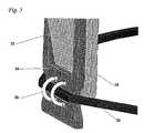
本発明のこの実施形態の実施例のその完全に拡張された配座で示された斜視図が図1に表され、全体が10として示される。これは上側支持リング12を備える。上側支持リング12は2つの架橋要素14によって、細いニチノールのワイヤの形態で構築される下側の支点支持リング16に接続される。装置は2つのアンカーアーム17を備え、それぞれの内方部位18は、上側支持リングに取り付けられた(溶接された等)上側端部18aと、鋭角部位で終端する下側端部18bとを有する。次いで各アンカーアームの側方部位19は角度付き部位から上向きおよび外向きに移動して、架橋要素14内の長方形開口部を通過する。この図に示される実施形態では、側方アンカーアーム部位19の遠位端部の終端部位は、前記側方部位の残りの部分に対して約90度に角度付けされる。しかし、この終端部位は様々な異なった形態にも構築されることができる。 A perspective view, shown in its fully expanded conformation of an example of this embodiment of the invention, is represented in FIG. This comprises an
図2は図1に提示された装置に極めて類似しているが、予備拡張配座での装置の側面図を示す。この図から、2つのアンカーアームそれぞれの角度付部位22が最初は、弁支持装置の中央空間内で互いに接近して位置付けられることが分かる。次いで、置換用弁の埋め込みおよび拡張の後に(置換処置の第2段階中に)、アンカーアームの側方部位24のそれぞれがその支点を中心に枢動する間、拡張する弁は角度付部位に圧力を掛けてそれらを側方に動かす。支点は架橋要素26内の長方形開口部の下方縁部によって提供される。 FIG. 2 is very similar to the device presented in FIG. 1, but shows a side view of the device in a pre-expanded configuration. From this figure, it can be seen that the
上述のように、この実施形態では、前記長方形開口部の下方縁部はレバー付固着アームにとっての支点として作用する。支点の拡大図が図3に示される。ここでは装置の片側上のアンカーアームの側方部位32が、架橋要素36内の長方形開口部の下方縁辺部34と接触し、そこを中心に枢動する能力があることが分かる。この図は、架橋要素36が支点支持リング38に接続される、即ち小さなワイヤの留め金またはループ39によって接続されることができる一方法も示す。 As described above, in this embodiment, the lower edge of the rectangular opening serves as a fulcrum for the lever-equipped fixing arm. An enlarged view of the fulcrum is shown in FIG. Here it can be seen that the
代替方法として、他の実施形態では、下側リングは、生体適合性金属(ニチノールなど)のシートから切り出され、2リング型支持装置の下側支持リングとして機能することができる(共同出願、同時係属中の国際公開第2012/031141号パンフレットで述べられるように)。このタイプの下側支持リングを有するこの実装の装置の一実施例が図4に示される。図4は、架橋要素42によって下側支持リング43に接続された上側支持リング40を備える装置の原位置斜視図を提供する。装置は、心臓の中に僧帽弁付近で埋め込まれた後のその拡張された配座で示される。アンカーアームの側方部位44は、拡張された置換用弁(明確にするために示されない)によって外向きに(側方に)押しやられており、それらの遠位先端部45が内側心室壁46と接触し、そこに安定化力を掛けるようにしている。2つの架橋要素42と関連するアンカーアームとは僧帽弁交連部の両端部に位置付けられるが、短い下側支点48を中心に枢動される追加のアンカーアーム47も示される。以下により詳しく説明されるように、この追加のアンカーアームは生来弁葉49を把持し、本発明の第2実装の一実施形態の一部を形成する。 As an alternative, in other embodiments, the lower ring can be cut from a sheet of biocompatible metal (such as Nitinol) and function as the lower support ring of a two-ring support device (joint application, simultaneous As described in the pending International Publication No. 2012/031141 pamphlet). An example of an apparatus for this implementation with this type of lower support ring is shown in FIG. FIG. 4 provides an in-situ perspective view of the apparatus comprising an
本発明のレバー作動式アンカー翼の第2実装では、弁支持装置は上側支持リング(第1実装に類似)を備え、2つ以上のアンカーアームをさらに備え、それらの上方端部は前記上側支持リングに取り付けられる。加えて、弁支持装置は、以上の第1実装の好ましい実施形態の1つに関連して述べられたあぶみ形状要素に類似の下側リング要素をさらに備える。しかし、第1の実装とは反対に、ここで述べられる実装は、前記あぶみ形状要素を上側支持リングに接続する架橋要素を備えない。むしろ、各あぶみ形状要素は直接アンカーアームのそれぞれに接続される。 In a second implementation of the lever actuated anchor wing of the present invention, the valve support device comprises an upper support ring (similar to the first implementation), further comprising two or more anchor arms, whose upper ends are said upper support Attached to the ring. In addition, the valve support device further comprises a lower ring element similar to the stirrup-shaped element described in connection with one of the preferred embodiments of the first implementation above. However, as opposed to the first implementation, the implementation described here does not comprise a bridging element that connects the stirrup-shaped element to the upper support ring. Rather, each stirrup-shaped element is connected directly to each of the anchor arms.
機能的には、この実装は上述の第1の実装とは著しく異なる。これは、支持装置がその静止位置にあるとき(即ち半径方向の拡張の前)、レバー式アンカーアームが回転することが可能な支点はない。むしろ、支点はあぶみ形状のワイヤが拡張された後に初めて作り出される(拡張するステント付き置換用弁によって掛けられる圧力によって)。ある時点で、下方ワイヤ要素はリング形状になる。この時点で、下方ワイヤ要素はさらに拡張することが不可能であり、各アンカーアームの下方ワイヤ要素への取付け点がここで支点として機能する。そこを中心に前記アンカーアームは、拡張する置換用弁によって生成された半径方向外向きの力に応えて回転する。このように言うまでもなく、第1の実装(前述)では、支点は全段階(予備拡張から全拡張まで)で存在するが、第2の実装では、下方ワイヤ要素がそのリング配座に完全に拡張されるまで支点はない。 Functionally, this implementation is significantly different from the first implementation described above. This is because there is no fulcrum for the lever anchor arm to rotate when the support device is in its rest position (ie before radial expansion). Rather, the fulcrum is created only after the stirrup-shaped wire is expanded (by the pressure exerted by the expanding stented replacement valve). At some point, the lower wire element becomes ring-shaped. At this point, the lower wire element cannot be further expanded and the attachment point of each anchor arm to the lower wire element now serves as a fulcrum. Centered there, the anchor arm rotates in response to a radially outward force generated by the expanding replacement valve. Needless to say, in the first implementation (described above), the fulcrum exists at all stages (from pre-expansion to full expansion), but in the second implementation, the lower wire element is fully extended to its ring conformation. There is no fulcrum until it is done.
この実装の好ましい一実施形態では、装置は2つのアンカーアームを備える。それらは上側支持リングに(下側ワイヤ要素にも)、互いに約180度離隔された(上側支持リングの円周に沿って測定して)点で取り付けられる。この実施形態では、弁支持装置は、アンカーアームが、2段階式埋め込み処置の第1段階中に生来弁葉の機能を妨害しないように弁交連部に沿って配設されるように、僧帽弁輪の中へ埋め込まれることを目的とする。さらに、前記アンカーアームの側方部位は、それらが軸方向に向けられた力を心室壁上に掛けるよう使用されることができるように形状化される(装置の第1の実装に関して上述されたように)。 In a preferred embodiment of this implementation, the device comprises two anchor arms. They are attached to the upper support ring (also to the lower wire element) at points that are approximately 180 degrees apart from each other (measured along the circumference of the upper support ring). In this embodiment, the valve support device is such that the anchor arm is disposed along the valve commissure so that it does not interfere with the function of the native leaflets during the first stage of the two-stage implantation procedure. It is intended to be embedded in the annulus. Further, the lateral portions of the anchor arms are shaped so that they can be used to apply axially directed forces on the ventricular wall (as described above with respect to the first implementation of the device). like).
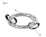
このタイプの装置の実施例が図5に示される。図5は装置のその完全に拡張された位置での斜視図を示す。上に説明されたように、装置は上側支持リング50と下側の支点支持リング52とを備える。支点支持リング52はその予備拡張配座であぶみ様の形状を有する(図6参照)。アンカーアーム54は前記上側支持リングに移動不可能に取り付けられ(溶接等によって)、例えば小さなリングまたは留め金(明確にするため示されない)によって下側リング/あぶみ52に枢動可能に取り付けられる。 An example of this type of device is shown in FIG. FIG. 5 shows a perspective view of the device in its fully expanded position. As explained above, the apparatus comprises an
図5に示される装置と類似のこの実装の装置の、予備拡張配座での側面図が図6に示される。この図面から、下側の支点支持リング60がこの配座ではあぶみ形状であり、極めてコンパクトであり、それによって生来弁機能に抵抗または妨害を示さないことが分かる。 A side view of the device of this implementation similar to that shown in FIG. 5 in a pre-expanded configuration is shown in FIG. From this figure, it can be seen that the lower
この実装の他の好ましい実施形態では、装置は2つ以上のアンカーアームを備える。それらは、それらの側方に拡張された位置にあるとき、前記アームの内側部位と側方部位との間の角度が極めて小さくなるように、前記部位がほぼ相互接触した状態となるように構築される。次いでこれらの部位の間の小さな空間が、生来弁葉を「ピンチ」し、それによってそれらを完全に変位された、完全に開放した配列に維持するために利用されることができる。言うまでもなく、この実施形態では、支持装置の固着および安定化は、アンカーアームがしっかりと弁葉を把持し、今度は弁葉が腱索と下層の乳頭筋とによって心室壁の組織に固着されるということによって達成される。この実施形態の特定の1つのバージョンでは、アンカーアームによって及ぼされる弁葉ピンチングの効果は、アンカーアームの部位の一方(内側または側方)の内側表面に装着された複数の突起物の使用によって高められることができる。突起物は、前記アームの側方拡張時に、閉じ込められた弁葉の組織に突き刺さり、その他方部位の内側表面上に一致するように位置付けおよび寸法決めされた開孔部の中にロックされた状態となる能力がある。 In another preferred embodiment of this implementation, the device comprises two or more anchor arms. They are constructed so that the parts are in close contact with each other so that the angle between the inner part and the side part of the arm is very small when in the extended position on their sides Is done. The small space between these sites can then be utilized to “pinch” the native leaflets, thereby maintaining them in a fully open, fully displaced arrangement. Needless to say, in this embodiment, the anchoring and stabilization of the support device is such that the anchor arm firmly grasps the leaflet, which in turn is anchored to the ventricular wall tissue by the chordae and the underlying papillary muscle. It is achieved by that. In one particular version of this embodiment, the effect of leaflet pinching exerted by the anchor arm is enhanced by the use of multiple protrusions attached to the inner surface of one (inner side or side) of the anchor arm site. Can be done. Protrusions stab into the confined leaflet tissue upon lateral expansion of the arm and locked into apertures positioned and dimensioned to coincide on the inner surface of the other site There is the ability to become.
本発明の第2の実装のこの実施形態の実施例の斜視図が図7に示される。以上に説明されたように、それぞれのアンカーアームの部位の1つの内側表面、この事例では側方部位72には複数の鋭い突起部74が装着される。この特定の実施形態の各アンカーアームの内側部位75は、位置および寸法で前記突起部74と一致する一式の小さな開孔部76を備える。使用中、置換用弁の拡張(2ステップ式置換処置の第2ステップ)に続いて、アンカーアームのそれぞれの側方部位72は、生来弁葉の1つがそれと同じアンカーアームの内側部位75との間に捕えられ、または「ピンチ」され、最終的に突起部74によって所定位置内にしっかりと保持されるように操作される。突起部74は弁葉組織に突き刺さり、開孔部76内に固着された状態になる。 A perspective view of an example of this embodiment of the second implementation of the present invention is shown in FIG. As explained above, a plurality of
本発明の装置のこの実装はこのように、とりわけ以下の利点を有する:
− 上側支持翼と下側支持翼との間に架橋要素がないことは、少ない材料しか含まない、したがってより低コストで構築でき、生来弁の機能をあまり妨害せず、送達カテーテル内への装置の挿入中にそのクリンプをより簡単にする弁支持構造をもたらす。
− 架橋要素がないことは、アンカーアーム(第1の実装では前記架橋要素に取り付けられた)をそれらが弁の交連部に沿って位置付けられるように位置合わせする必要がもはやないことから、さらに有利である。むしろ、アンカーアームは(一実施形態で)、生来弁葉のそれぞれがアンカーアームのうちの1つの内側部位と側方部位によって「ピンチ」された状態になるように位置合わせされることができる。
− 支点は、まさにレバー作用が最も必要とされるとき、即ち、拡張する置換用弁が生来僧房弁葉の最大の側方変位を引き起こした時点に作り出される。This implementation of the device of the invention thus has the following advantages, among others:
-The absence of a bridging element between the upper and lower support wings contains less material and can therefore be built at a lower cost, less disturbing the function of the native valve and the device into the delivery catheter Resulting in a valve support structure that makes the crimp easier during insertion.
The absence of a bridging element is further advantageous since the anchor arms (attached to said bridging element in the first implementation) no longer need to be aligned so that they are positioned along the commissures of the valve It is. Rather, the anchor arms (in one embodiment) can be aligned such that each of the native leaflets is “pinched” by the inner and side portions of one of the anchor arms.
-The fulcrum is created when the lever action is most needed, i.e. when the expanding replacement valve causes the greatest lateral displacement of the native mitral leaflet.
以上に開示および記述された装置の最初の2つの実装では、支持装置は、ステント付置換用弁の拡張中および拡張後にのみ心室壁にアンカーされた状態となる。しかし本発明の第3の実装では、弁支持装置は、2ステップ式埋め込み処置の第1段階中に心室壁に弱い力と、次いで前記処置の第2段階中に強い力との両方を掛ける能力のあるアンカーアームを備える。この技術的効果を達成するために、装置は、この実装では、一部の実施形態で本質的に真っ直ぐな部位のない、2つ以上の湾曲したアンカーアームが取り付けられた上側支持リングを備える。この実装の好ましい一実施形態では、前記湾曲したアンカーアームは最初に下内方向に(即ち支持リングの内部空間の中心に向かって)湾曲する。次いで前記アームの湾曲の方向は、それらが下側方、側方、上側方、次いで上方向に湾曲し、最終的に下方に湾曲して戻る短い部位で終わるように変化する。この特定の実施形態では、湾曲したアンカーアームは大文字の「D」の字と類似の輪郭を有する。「D」の平らな部位は前記アームの上側部位によって表される。埋め込み処置の第1段階中、湾曲したアームは比較的弱い安定化力を心室空胴の側方壁、ならびに前記空胴の屋根部を形成する組織の両方に掛ける能力がある。次いで、支持リングの中央空洞内でのステント付置換用弁の拡張中および拡張後に、前記リングの湾曲したアームは外向きおよび(それらの湾曲の結果として)上向きに押されて、前記アームは左心室の側方壁および上方壁上に極めて強い力を及ぼす能力があるようになる。さらに、アームの外向きおよび上向きの動きは、その終端の自由部位が心室屋根部と作る角度を変更して、心室組織上に及ぼされる力が前記終端部位の軸方向に沿ったものとなる(それによってアンカーアームの座屈を防止する。そうでなければ、アンカーアームが心室屋根部に前記軸方向に対して90度で出会う場合、座屈が起こる場合がある)。 In the first two implementations of the device disclosed and described above, the support device remains anchored to the ventricular wall only during and after expansion of the stented replacement valve. However, in a third implementation of the present invention, the valve support device is capable of applying both a weak force to the ventricular wall during the first stage of the two-step implantation procedure and then a strong force during the second stage of the procedure. It has an anchor arm. In order to achieve this technical effect, the device comprises in this implementation an upper support ring fitted with two or more curved anchor arms, which in some embodiments is essentially free of straight sections. In a preferred embodiment of this implementation, the curved anchor arm is first bent inwardly (ie towards the center of the inner space of the support ring). The direction of curvature of the arms then changes so that they curve downwards, laterally, upwards, then upwards, and finally end in a short section that curves downward and returns. In this particular embodiment, the curved anchor arm has a contour similar to the capital letter “D”. The flat part of “D” is represented by the upper part of the arm. During the first stage of the implantation procedure, the curved arm is capable of exerting a relatively weak stabilizing force on both the side walls of the ventricular cavity as well as the tissue forming the roof of the cavity. Then, during and after expansion of the stented replacement valve within the central cavity of the support ring, the curved arm of the ring is pushed outward and (as a result of their curvature) upwards, and the arm is left It becomes capable of exerting very strong forces on the lateral and upper walls of the ventricle. Further, the outward and upward movement of the arm changes the angle that the free region at the end makes with the ventricular roof, so that the force exerted on the ventricular tissue is along the axial direction of the end region ( This prevents buckling of the anchor arm, otherwise buckling may occur if the anchor arm meets the ventricular roof at 90 degrees to the axial direction).
本発明のこの実装の一実施例が図8内に表される。湾曲したアンカーアーム82の内側端部は支持リング80に取り付けられ、前記アームの側方端部は外向きおよび上向きに湾曲するのが分かる。この図に表された装置はその拡張した状態(即ち、支持装置の中央空洞内に配置されることになる置換用弁の拡張後)にあり、アンカーアーム82の側方端部は、それらが支持リング80の平面よりも上の平面内にあるかのように示される。しかし、現実には、前記側方端部は実際には支持リングとおおよそ同じ平面内に静止することになり、強い安定化力を心室屋根部の組織に掛けることになる。 One embodiment of this implementation of the invention is represented in FIG. It can be seen that the inner end of the
注目されるべきは、本発明の装置の第3の実装は、力の増幅作用を得るためのレバーを利用しないことである。 It should be noted that the third implementation of the device of the present invention does not utilize a lever to obtain a force amplification effect.
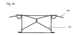
本発明の第3の実装に対する代替として、より短い静止型アンカーアームを備えた第1の実装または第2の実装の組み合わせを備える装置を構築することも可能である。このような装置では、2段階式実装処置の第1段階中に心室壁に比較的弱い力を掛けるのに固定アームが使用され、処置の第2段階中に必要とされるより強い安定化力を掛けるのにより長いレバー付アンカーアームが使用される。短い静止型アームを備える第1または第2の実装の組み合わせを備える他の実施形態では、様々なアンカー要素が、レバー付アンカーアーム(第1または第2の実装)が、置換用弁の拡張ステップ中に(心室組織よりもむしろ)静止型アームに接触し、それによってそれらのより強い安定化力を間接的に、即ち短い静止型アームを介して心室壁に掛けるように配置されることができる。この実施形態の例が図10および図11に見られることが可能である。ここで図10は置換用弁の拡張前の本発明の装置を示し、図11は置換用弁の拡張後の装置を示す。両方の図で、静止型アームは100として示され、レバー付アームは101として示される。 As an alternative to the third implementation of the present invention, it is also possible to construct an apparatus comprising a first implementation or a combination of the second implementation with a shorter stationary anchor arm. In such a device, a fixed arm is used to apply a relatively weak force to the ventricular wall during the first phase of the two-stage mounting procedure, and the stronger stabilization force required during the second phase of the procedure. Longer anchored arms with levers are used. In other embodiments comprising a combination of a first or second implementation comprising a short stationary arm, the various anchor elements are levered anchor arms (first or second implementation) and the replacement valve expansion step. Can be placed in contact with the stationary arms (rather than ventricular tissue), thereby applying their stronger stabilizing force indirectly, i.e. through the short stationary arm, to the ventricular wall . An example of this embodiment can be seen in FIGS. Here, FIG. 10 shows the device of the present invention before expansion of the replacement valve, and FIG. 11 shows the device after expansion of the replacement valve. In both figures, the stationary arm is shown as 100 and the arm with lever is shown as 101.
特定の他の実施形態では、装置は上述の実装のうちのいくつかの異なったアンカー機構の組み合わせ、例えば、第3の実装の湾曲アンカーアームと共に第2の実装の「弁葉ピンチング」の実施形態とを備えることもできる。拡張された配座でのこのような実施形態の斜視図が図9に示される。使用中、一対の湾曲アンカーアーム92は生来僧房弁の交連線に沿って配置され、レバー付アンカーアームの内側部位94および側方部位96は、それらの間に生来僧房弁葉を閉じ込めるように使用されることが可能となるように所定位置内に配置される。 In certain other embodiments, the apparatus is a combination of several different anchor mechanisms of the above implementations, eg, a “leaflet pinching” embodiment of the second implementation along with a curved anchor arm of the third implementation. Can also be provided. A perspective view of such an embodiment in an expanded conformation is shown in FIG. In use, a pair of
本発明の第1および第2の実装の他の特定の実施形態では、アンカーアームおよび/または架橋要素(第1の実装)は、アンカーアームを、それらが置換用弁上に内側に向けられた力を掛けないように、それらの側方に拡張された位置内にロックする機構を追加的に備えることができる。このような実施形態では、ロック機構は架橋要素に接続されたピンによって提供されることができ、前記ピンはレバー付アンカーアーム内に形成された適正寸法の開孔部と相互作用する能力がある。 In other specific embodiments of the first and second implementations of the present invention, the anchor arms and / or bridging elements (first implementation) are oriented with the anchor arms inward on the replacement valve. Additional mechanisms can be provided to lock in their laterally expanded positions so that no force is applied. In such embodiments, the locking mechanism can be provided by a pin connected to the bridging element, said pin being capable of interacting with a properly sized aperture formed in the levered anchor arm. .
細長いアンカーアーム
このタイプの2つのアンカー翼を備える単リング型支持構造物の実施例が図12に示される(言うまでもなく、この図、ならびに類似の装置の上面図を例証する全ての類似の図は、予備クリンプ配座の前記装置を示すことを目的とする)。この実施例の支持構成体110は、要素114が装着された円形支持リング112を備えるのが分かる。要素114は前記リングの内側円周が半径方向に弾性変形するのを可能にする(それによって任意の寸法の置換用弁へのリングの精確な適合をし易くする)。装置は2つのアンカー翼116も備え、その基部セクション118はリングそのものと連続する。実際、ほとんどの好ましい実施形態では、翼はリングそのものと同じディスクから切り出されている。最後に、前記翼のそれぞれは、その遠位先端部付近に形成された小さな開孔部119も有する。前記開孔部の目的は、以下により詳しく述べられるように、手術者が埋め込み中に支持装置を把持する助けとなることである。Elongated Anchor Arm An example of a single ring support structure with two anchor wings of this type is shown in FIG. 12 (not to mention this figure, as well as all similar views illustrating a top view of a similar device, , Aiming to show said device in a pre-crimp conformation). It can be seen that the
図13は、送達カテーテルから解放された直後と、アンカー翼120がそれらの開放した作動配座へと拡張した後との同じ弁支持装置を示す。 FIG. 13 shows the same valve support device immediately after being released from the delivery catheter and after the
図14は、心臓弁輪130の領域内の心臓内への埋め込みの直後の図12および図13の弁支持装置を示す。このように、アンカー翼132は、支持装置の存在がこの段階で前記生来弁の機能を妨害しないように、生来僧帽弁134の交連部に沿って位置合わせされることが分かる。注目されるべきは、アンカー翼132はそれが接触する心室組織を圧迫し、それによって前記組織の僅かな半径方向外向きの変位を引き起こすことである。(この変位は図面の制限によって図14内では見えない)。 FIG. 14 shows the valve support device of FIGS. 12 and 13 immediately after implantation into the heart in the region of the
本発明のこの態様の異なった実施形態が図15に示される。ここでは、各アンカー翼が拡大された基部セクション140を有することが分かる。さらに、拡張配座でのこの装置の拡大側面図(図16に示される)で、拡張された基部セクション(ここでは150として示される)が、アンカー翼の機械的強度に、前記翼がリング支持構造体から離れて湾曲する正にその点で寄与するのが分かる。 A different embodiment of this aspect of the invention is shown in FIG. Here, it can be seen that each anchor wing has an
さらに他の実施形態では、図17で示されるように、アンカー翼160は先の図面で表された翼よりも幅広であり、この幅の増大は前記各翼の全体長さにわたって基部セクション162から遠位先端部164まで維持される。それらの大きな幅の結果として、この図に表された実施形態のアンカー翼は、より大きな安定化力を心室組織上に伝えることができる。このより大きな翼はまた、アンカー力を心臓のより大きな表面積上に分散する。これは、力の分散が心筋組織上の局部のストレスを低減することから有益である。これは、組織を損傷する場合のある大きなストレスをそれが防止することから、臨床的に有益であることができる。 In yet another embodiment, as shown in FIG. 17, the
僅かに異なるアプローチが図18に示される。このアプローチでは支持装置は4つのアンカー翼、即ち2つの短い翼170と2つの長い翼172とを備える。それらは、1つの短い翼と1つの長い翼とが装置の両側に並んで位置付けられるように配設される。支持装置のこの実施形態の1つの利点は、両側に短い翼と長い翼との両方が存在することが、両側上の前記翼(長い翼など)の一方が心室壁と満足な接触をしない場合、他方(短い翼)がそのようにできるように、補償機構を形成することである。 A slightly different approach is shown in FIG. In this approach, the support device comprises four anchor wings: two
これまでに述べられ、図12から図18に表された様々な実施形態の全てで、アンカー翼は、支持リングそのものと同じディスクから切り出された中実の構造体として形成される。代替的なアプローチでは、図19に提示される写真図で示されるように、翼180は開放構造として構築される。このタイプの翼は、例えば最初に支持リングのディスクから幅広の翼を切り出し、次いでさらに、1つまたは複数の金属ストランドが翼内に残るように材料を取り除くことによって作り出されることができる。2つのこのようなストランド182が図19に表されたデザインに示される。このアプローチの1つの利点は、前記翼の嵩または重量に追加をせずに、より幅広のアンカー翼が構築されることができる(それによって安定化力を心室壁のより大きな面積に掛けることが可能である)ことである。先に説明されたように、このより大きな翼はアンカー力を心臓のより大きな表面積上に分散する。これは、力の分散が心筋組織上の局部ストレスを低減することから有益であり、これは、組織を損傷する場合のある大きなストレスをそれが防止することから臨床的に有益であることができる。 In all of the various embodiments described thus far and represented in FIGS. 12-18, the anchor wing is formed as a solid structure cut from the same disk as the support ring itself. In an alternative approach, the
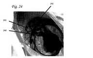
さらなる実施形態が図20に提示された写真に示される。この図に示される装置は、2つの異なった配座に存在する能力のある、開放構造を有する翼を備える。翼は、2つの異なった配座、即ち(a)送達カテーテル内への装置の挿入中のクリンプ中に作り出される、細長い小径の配座、(b)図20に示される短くされた幅広の形態、で存在する能力がある。図に示される通り、この特定の実施形態のアンカー翼190は、それらの作動配座では、幅広のダイアモンド様形状を有し、そのようにして比較的大きな安定化力を支持装置付近の心室壁の領域上に及ぼす能力がある。注目されるべきは、この拡大された幅を有する翼が中実構造として形成されるべきものであったら、装置をその折り畳まれた送達の配座にクリンプすることは極めて困難となるはずであるということである。このように、この図に示されるタイプのスケルトン構造の使用は、それがカテーテル送達用の長い幅狭の翼の利点と、支持装置が展開された後の短い幅広の翼の機械的な利点とを組み合わせることから、極めて有利である。 A further embodiment is shown in the photograph presented in FIG. The device shown in this figure comprises a wing with an open structure capable of existing in two different conformations. The wings are in two different conformations: (a) an elongated small diameter conformation created during crimping of the device into the delivery catheter; (b) the shortened wide configuration shown in FIG. , Have the ability to exist. As shown in the figure, the
翼は、織物または他のカバー材料で完全に、または代替としてそれらの遠位先端部だけカバーされることができる。1つの極めて好ましい実施形態では、心臓組織の内方成長を可能にする生体適合性のダクロンなどのカバー材料が使用される。このようにして、心臓組織への翼の追加のアンカーリングが達成されることができる。 The wings can be covered completely with fabric or other cover material, or alternatively only their distal tips. In one highly preferred embodiment, a cover material such as biocompatible Dacron that allows ingrowth of heart tissue is used. In this way, additional anchoring of the wing to the heart tissue can be achieved.
このセクションで述べられた細長い翼を組み込んだ装置は、ニチノールのディスクをレーザ切断することによって生産されることができる。次いでそのようにして形成されたリング様の構造体は熱処理を受ける(例えば摂氏500〜600度の温度で)。送達装置からの解放に続いて翼がこの新しい形状記憶位置を採るように、翼は所望の作動位置内で湾曲される。 Devices incorporating the elongated wings described in this section can be produced by laser cutting a Nitinol disc. The ring-like structure thus formed is then subjected to a heat treatment (eg, at a temperature of 500 to 600 degrees Celsius). The wing is curved in the desired operating position so that the wing takes this new shape memory position following release from the delivery device.
一部の好ましい実施形態では、翼はそれらの最遠位部位を通して開けられた小さな穴を有する。これは、手術者が、送達カテーテルからの解放中に支持装置を狭端化ツールまたはワイヤで簡単に把持するのを可能にし、それによって前記装置をその作動位置内へと操作してゆくのをし易くするためである。 In some preferred embodiments, the wings have small holes drilled through their most distal sites. This allows the operator to easily grasp the support device with a narrowing tool or wire during release from the delivery catheter, thereby maneuvering the device into its operating position. This is to make it easier.
側方延長要素
側方延長要素を備える本発明の支持要素の実施例(単一の弁支持リングを示し、あるいは二重リング型弁支持装置の上側リングだけを示す)が、図21に示される。この実施例の支持構造体は、円形の支持リング210と2つの例示的なアンカー翼211とを備えるのが分かり、その基部セクションはリングそのものと連続している(アンカーは例示的なものに過ぎず、任意の他のアンカーおよび/または安定化手段も、先行出願で詳述されたように使用されることができる)。リングの両側から側方延長要素212が延び、それぞれが一般的にその側のアンカー要素の上をカバーする区域にある。アンカー要素は、僧帽弁輪での展開で、各アンカー要素が僧帽弁の交連部の区域(弁の2つの弁葉の間)にあるように位置付けられ、本発明の側方延長部は、それらが前記交連部の区域の上の心房内に位置付けられるように位置決めされる。この位置決めは、側方延長部が交連部をカバーするのを可能にし、側方延長部が、血液不浸透性の材料(例えばダクロンまたはPTFEなどの生体適合性繊維)によってカバーされるとき、延長部は密閉部として機能し、血液の漏出を低減する。Side Extension Element An embodiment of a support element of the present invention comprising a side extension element (showing a single valve support ring or only the upper ring of a dual ring valve support device) is shown in FIG. . It can be seen that the support structure of this example comprises a
本発明の他の実施形態では、支持装置は三尖弁の位置に位置決めすることを目的とする。三尖弁は3つの弁葉を有し、そのようなことから3つの側方延長部があることができ、それらも同様に弁の3つの交連部全てをカバーすることができる。 In another embodiment of the invention, the support device is intended to be positioned at the position of the tricuspid valve. A tricuspid valve has three leaflets, and as such, there can be three lateral extensions, which can also cover all three commissures of the valve as well.
本発明の好ましい実施形態では、図21に示されるように、側方延長要素212は、網構造体またはステント様構造体として設計され、この実施例では三角筋形状のセルを有する。しかし、これは実施例に過ぎず、セルの形状および寸法と前記側方延長部の構造とは、それが向上した密閉および位置決めの機能を与えると同時に心房の解剖学的構造に適合可能である限り、様々であることができる。 In a preferred embodiment of the present invention, as shown in FIG. 21, the
本発明の好ましい実施形態では、図21に示されるように、側方要素212の中央区域213は支持リングに接続されない。むしろ、側方延長要素212は側方延長要素の2つの縁部でのみ支持リングに接続され、要素の中央部では接続されない。このことは特異的に側方延長要素に弾性能力、柔軟性を与える。それは心房の解剖学的構造(ならびに異なった心臓の様々な解剖学的構造)に従って湾曲し、よりうまく心房内に嵌るのを可能にする。柔軟性のある設計のさらなる利点は、クリンプ能力を向上させること、経カテーテル送達のために支持要素のクリンプ外形を縮小することである。この弾性の設計は例示目的で示しており、当業者に知られている他の設計も本発明の範囲に含まれる。 In a preferred embodiment of the present invention, as shown in FIG. 21, the
図22は、図21に示された本発明の同じ支持要素の側面図である。例示的なアンカー翼220が示されるが、それらは支持リングの内部面から延びる。支持リングの外部面、側方面は221として示される。支持リング221の側方面の向こうに、本発明の例示的な側方延長要素が示されており、側方延長要素の外部の、側方面は222として示される。 FIG. 22 is a side view of the same support element of the present invention shown in FIG.
本発明のこの態様の特定の好ましい実施形態では、側方延長要素は支持リングから上向きの角度を付けて設計される。この角度設計は支持装置の解剖学的位置決めの助けとなることができる。しかし他の角度、下向きの(心室に向かった)角度、平角度(0度、リングと全く同じ平面で外部に延びる)、または他の上向きの角度も本発明の範囲に含まれる。 In certain preferred embodiments of this aspect of the invention, the lateral extension elements are designed with an upward angle from the support ring. This angular design can aid in the anatomical positioning of the support device. However, other angles, downward (towards the ventricle) angle, flat angle (0 degrees, extending outwards in exactly the same plane as the ring), or other upward angles are within the scope of the present invention.
本発明の好ましい実施形態では、側方延長要素と支持リングとの間の角度は上向きに(心室から離れて)0(ゼロ)から30(三十)度の間である。 In a preferred embodiment of the invention, the angle between the lateral extension element and the support ring is between 0 (zero) and 30 (30) degrees upward (away from the ventricle).
図26は、本発明のこの態様の他の好ましい実施形態を示し、そこでは弁支持装置260(その予備クリンプされた平坦な形態の)は4つの個別の側方延長部262を備える(図21〜図25に表された実施形態の交連側方延長要素の対とは対照的に)。装置は細長いアンカーアーム264の対も備える。支持リングの円周のまわりに存在する側方延長要素は、装置が僧帽弁輪を通って下向きに心室に向かって変位されるのを防止する働きをする。延長部が生体適合性繊維でカバーされることから、それらは弁傍の血液漏出も防止する。延長部の骨格的透かし細工の設計はそれらに適切な弾性をもたらして、装置が容易に小径のカテーテル(例えば18Fr〜36Frの外形直径を備えた)へとクリンプされることができるようにする。 FIG. 26 shows another preferred embodiment of this aspect of the invention, where the valve support device 260 (in its pre-crimped flat form) comprises four individual lateral extensions 262 (FIG. 21). To (as opposed to the pair of commissural lateral extension elements of the embodiment depicted in FIG. 25). The device also includes a pair of
4つの側方延長要素を備えた異なった設計が図27に示される。この実施形態では、弁交連部の上に配置されるべく予定された延長要素266は、前後方延長部268よりも著しく大きい。さらに、交連延長要素と前後方延長要素とは任意選択の接続要素270によって相互接続される。この設計はクリンプの向上を可能にする。それは、前後方延長要素が小さく、それによって小さなクリンプ直径をもたらすと同時に交連区域で充分な密閉を維持することによる。 A different design with four lateral extension elements is shown in FIG. In this embodiment, the
図28は先の図と同じであるが、その拡張された作動配座での実施形態を示す。4つの側方延長要素が接続要素と一緒に弁支持リング270に対して上向きに角度付けされ、それによって前記リングを取り囲む冠様の構造体272を形成することが分かる。 FIG. 28 is the same as the previous figure but shows an embodiment in its expanded working conformation. It can be seen that the four lateral extension elements, together with the connecting elements, are angled upward with respect to the
本発明の側方延長要素の代表的な寸法は、半径方向長さ(リングの外部面から延長要素の外部面までの長さ)4mm〜20mm、円周長さ(延長要素の両縁部同士の間の)5mm〜20mm、延長要素の厚み(長手方向断面の)0.2〜1mmである。 Typical dimensions of the lateral extension elements of the present invention are: radial length (length from the outer surface of the ring to the outer surface of the extension element) 4 mm to 20 mm, circumferential length (between both edges of the extension element) Between 5 mm and 20 mm and the thickness of the extension element (in the longitudinal section) between 0.2 and 1 mm.
図23は、2つの例示的な側方延長要素230を例証する本発明の弁支持構造体の写真である。 FIG. 23 is a photograph of a valve support structure of the present invention illustrating two exemplary
図24は、体外で死体心臓内へ埋め込まれた本発明の弁支持構造体の写真である。支持構造体は、僧帽弁輪の直ぐ上の左心室の下側面に位置付けられる。例示的なアンカー要素240が支持リングの内部面から延び、僧帽弁の2つの弁葉の間で内方かつ下向きに方向付けられ、左心室内に延び、次いで弁交連部の区域内で再度側方に延び、そのようにしてリングを交連部の区域で僧帽弁にアンカーする。左心室の壁上に位置付けられた側方延長要素241が示される。この写真では延長要素は密閉材料でカバーされていない(したがって要素のセル間で血液を流れさせてしまう)。これはあくまで代表的な例示目的のものに過ぎない。この写真で点242上の矢印によって、側方要素が前記要素の中央部でリングに接続されないことが強調される。したがって接続は連続的ではなく部分的であって、要素の柔軟性の増大と送達のためのクリンプの向上とを可能にする。 FIG. 24 is a photograph of the valve support structure of the present invention implanted outside the body into a cadaver heart. The support structure is positioned on the lower side of the left ventricle just above the mitral annulus. An
図25は、体外で死体心臓内へ埋め込まれた本発明の弁支持構造体の他の写真である。支持構造体は、僧帽弁輪の直ぐ上の左心室の下側面に位置付けられる。この写真では、側方延長要素250の両方が示される。 FIG. 25 is another photograph of the valve support structure of the present invention implanted outside the body into a cadaver heart. The support structure is positioned on the lower side of the left ventricle just above the mitral annulus. In this photo, both
弁の心房面への支持リングの展開中、弁が傾転(または回転)せず、弁の弁葉同士の間に落下しなければ有利である。図25は、本発明の側方延長要素の独自の設計が、どのようにして支持構造体が心房の床部(下側面)上に最適に位置付けられるようにし、同時に傾転の可能性を防止し、装置が弁の中に落下するのを防止し、装置が僧帽弁の平面と同軸であることを確認するのを可能にするのかを示す。これは、装置の展開において大きな予想外の利点を実現し、それは本発明の特別に設計された側方延長要素がなければ可能とならない。 During deployment of the support ring to the atrial surface of the valve, it is advantageous if the valve does not tilt (or rotate) and does not fall between the valve leaflets. FIG. 25 shows how the unique design of the lateral extension element of the present invention allows the support structure to be optimally positioned on the atrial floor (lower side) while simultaneously preventing the possibility of tilting. And prevent the device from falling into the valve and allow it to be verified that it is coaxial with the plane of the mitral valve. This realizes a great unexpected advantage in the deployment of the device, which is possible without the specially designed lateral extension elements of the present invention.
装置は、ニチノールなどの形状記憶材料をレーザ切断し、続いて、送達装置からの解放に続いて側方延長要素がこの新しい形状記憶位置を採るようにこの要素が所望の作動位置内で湾曲された状態で熱処理(例えば摂氏500〜600度の温度で)することによって生産されることができる。 The device laser cuts a shape memory material, such as Nitinol, which is then bent in the desired working position so that the lateral extension element assumes this new shape memory position following release from the delivery device. Can be produced by heat treatment (for example, at a temperature of 500 to 600 degrees Celsius).
本発明の好ましい実施形態では、本発明の側方延長要素は前記要素の密閉を可能にする材料によってカバーされる。代表的な材料は、生体適合性繊維(例えばダクロン、EPTFE)、生体適合性プラスチック、およびナイロン等を含む群からとられることができる。要素は完全あるいは部分的にこれらの材料の1つまたは複数によってカバーされることができる。 In a preferred embodiment of the invention, the lateral extension element of the invention is covered by a material that allows the element to be sealed. Exemplary materials can be taken from the group comprising biocompatible fibers (eg Dacron, EPTFE), biocompatible plastics, nylon and the like. The element can be completely or partially covered by one or more of these materials.
本発明の弁支持装置の他の特徴
本発明の弁支持装置の重要な特徴は、それが2つの異なった安定した構成、即ち、患者の血管系に通されたカテーテルを介して装置の送達を可能にする折り畳まれた構成と、心臓弁輪内の埋め込み中に送達カテーテルの領域から装置が出るようにされる際にそれがとる第2の拡張された構成とをとることができるように構築されるということである。Other features of the valve support device of the present invention An important feature of the valve support device of the present invention is that it provides for delivery of the device via two different stable configurations, namely a catheter threaded through the patient's vasculature. Constructed to allow a folded configuration that allows for and a second expanded configuration that it takes when the device is allowed to exit the area of the delivery catheter during implantation within the heart valve annulus It is to be done.
本発明の支持要素は、それらの拡張された構成で一般的に閉鎖リングの形態を有し、その輪郭形状は好ましくは円形または円形に近いものである。しかし、これらのリング要素は任意の他の所望の適切な形状、楕円形、長円形などで構築されることもできる。 The support elements according to the invention generally have the form of a closed ring in their expanded configuration, the contour shape of which is preferably circular or nearly circular. However, these ring elements can also be constructed of any other desired suitable shape, oval, oval, etc.
本発明の特に好ましい実施形態では、弁支持装置は、僧帽弁輪内に埋め込まれることを可能にする寸法および形状にある。 In a particularly preferred embodiment of the invention, the valve support device is sized and shaped to allow it to be implanted within the mitral annulus.
本発明の好ましい実施形態では、支持要素は、送達構成へと変形されることが可能である、しかも拡張構成に自己拡張するように適合され、任意選択のバルーン膨張による追加の拡張も備える弾性材料から製作される。例えば、支持体は、超弾性の特徴を頼ってニチノールから製作されることが可能である。一部の実施形態では、弁支持体は、ニチノールなどの形状記憶特性を備えた材料から製作され、その転移温度よりも高温に加熱された後、拡張記憶構成に戻るように適合される。弁支持体がニチノールなどの材料から製作される一部の実施形態では、形状記憶特性および超弾性特性が利用される。 In a preferred embodiment of the invention, the support element is elastic material that can be transformed into a delivery configuration and that is adapted to self-expand into an expanded configuration, with additional expansion by optional balloon inflation. It is made from. For example, the support can be made from nitinol relying on superelastic characteristics. In some embodiments, the valve support is fabricated from a material with shape memory properties, such as nitinol, and is adapted to return to an expanded memory configuration after being heated above its transition temperature. In some embodiments where the valve support is fabricated from a material such as nitinol, shape memory and superelastic properties are utilized.
他の好ましい実施形態では、本発明の弁支持装置は、上側支持要素と下側支持要素とを備える2リング型装置として構築されることができ、前記支持要素は2つ以上の架橋要素によって相互に接続される。このような実施形態の例が同時係属中の共同出願の国際特許出願第PCT/US2011/050232号明細書(WO2012/031141号パンフレットとして公開されており、その内容全体が参照により本明細書に組み込まれる)に見出される。単リング型支持装置に関して以上に述べられたアンカー翼の構造的および機能的特徴の全てが等しくこの2リング型の実施形態にも当てはまる。 In another preferred embodiment, the valve support device of the present invention can be constructed as a two-ring type device comprising an upper support element and a lower support element, said support elements being mutually connected by two or more bridging elements Connected to. An example of such an embodiment has been published as a co-pending International Patent Application No. PCT / US2011 / 050232 (WO2012 / 031141), the entire contents of which are incorporated herein by reference. Found). All of the structural and functional characteristics of the anchor wing described above with respect to the single ring support device apply equally to this two ring embodiment.
2リング型支持要素の実施形態の場合には、第1支持体の基部から第2支持体の頂部までを測定した弁支持体の高さは、ステント付心臓弁などの置換用心臓弁の高さを収容することが可能となるように一般的に約2mmから約5cmの範囲にある。一部の実施形態では、高さは5cmよりも大きい。一部の実施形態では、弁支持体の高さは約1cmから約2.5cmの間である。例えば、拡張構成のステント付き心臓弁は約17.5mmの高さを有することが可能である。当然ながら、これらの数字は単に例示的なものであり、いかなる意味でも限定するものではないことに留意されたい。 In the case of a two-ring support element embodiment, the height of the valve support measured from the base of the first support to the top of the second support is the height of a replacement heart valve such as a heart valve with a stent. It is generally in the range of about 2 mm to about 5 cm so that it can be accommodated. In some embodiments, the height is greater than 5 cm. In some embodiments, the height of the valve support is between about 1 cm and about 2.5 cm. For example, an expanded stented heart valve can have a height of about 17.5 mm. Of course, it should be noted that these numbers are merely illustrative and are not limiting in any way.
他の態様では、本発明は置換用心臓弁を埋め込む2段階式の方法であって、第1段階は本発明の安定化翼が装着された弁支持装置を対象者の心臓弁付近の位置に送達することと、支持要素を折り畳まれた構成から、拡張された支持要素の存在が生来弁葉の機能を妨害しないように、弁輪の領域内の心臓組織に対して固定された、拡張され、展開された構成へと拡張することとを備え、前記安定化翼の位置を少なくともその遠位端部が内側心臓壁と接触させられるように、移動、湾曲、または他の方式で適合させることをさらに備え、第2段階は、置換用弁を弁支持体に固定することを備える、2段階式の方法も提供する。置換用心臓弁を弁支持体に固定することは、置換用心臓弁を折り畳まれた送達構成から拡張された構成に拡張することを備えることが可能である。置換用心臓弁を拡張することは、バルーンによって置換用心臓弁を拡張すること、および/または置換用心臓弁が自己拡張できるようにすることを含むことが可能である。置換用心臓弁を弁支持体に固定することは、置換用心臓弁を弁支持体内に半径方向に固定することを備えることが可能である。 In another aspect, the present invention is a two-stage method of implanting a replacement heart valve, wherein the first stage is to place a valve support device fitted with the stabilizing wing of the present invention in a position near the subject's heart valve. From the delivered and folded configuration of the support element, an expanded, fixed relative to the heart tissue in the region of the annulus, so that the presence of the expanded support element does not interfere with the function of the native leaflet Expanding to a deployed configuration and adapting the position of the stabilizing wing in a moving, curved, or other manner so that at least its distal end is in contact with the inner heart wall And the second stage also provides a two-stage method comprising securing the replacement valve to the valve support. Securing the replacement heart valve to the valve support can comprise expanding the replacement heart valve from a folded delivery configuration to an expanded configuration. Dilating the replacement heart valve can include dilating the replacement heart valve with a balloon and / or allowing the replacement heart valve to self-expand. Securing the replacement heart valve to the valve support can comprise securing the replacement heart valve radially within the valve support.
置換用心臓弁の展開中、前記弁の拡張は生来弁葉の側方変位を引き起こし、それによってそれらを動作不能にする。ここで心臓弁の機能はもっぱら展開された置換用心臓弁の弁葉によってのみ遂行される。 During deployment of replacement heart valves, expansion of the valves causes lateral displacement of the native leaflets, thereby rendering them inoperable. Here, the function of the heart valve is performed exclusively by the valve leaflet of the replacement heart valve deployed.
本発明の方法の極めて好ましい実施形態では、置換されるべき心臓弁は僧帽弁である。 In a highly preferred embodiment of the method of the invention, the heart valve to be replaced is a mitral valve.
本方法の好ましい一実施形態では、弁支持装置は以上に述べられたタイプの単リング型装置である。本方法のさらなる好ましい実施形態では、弁支持装置は、2つ以上の架橋要素によって相互に接続された上側支持要素と下側支持要素とを備える2リング型装置である。この実施形態では、上に開示された支持要素を拡張するステップは、支持要素の1つ、架橋要素、および第2支持要素を順に拡張することを備える。 In a preferred embodiment of the method, the valve support device is a single ring type device of the type described above. In a further preferred embodiment of the method, the valve support device is a two-ring type device comprising an upper support element and a lower support element interconnected by two or more bridging elements. In this embodiment, expanding the support element disclosed above comprises sequentially expanding one of the support elements, the bridging element, and the second support element.
一実施形態では、上に規定された方法は、弁支持体を血管内の経路によって送達するように用いられることができる。他の実施形態では、本方法は弁支持体を経皮的経路によって送達するように用いられることができる。 In one embodiment, the method defined above can be used to deliver a valve support by an intravascular route. In other embodiments, the method can be used to deliver the valve support by a transdermal route.
以上に開示および記述された装置の様々な実施形態の全ての構成要素は、形状記憶および/または超弾性の特性を有する任意の適切な生体適合性材料を使用して構築されることができる。これらの特性は、本発明の弁支持装置が折り畳まれた配座(前記装置が送達カテーテル内に装填されることができるように)と拡張された作動配座との間で変形されるのを可能にするために必要とされる。装置を構築するのに使用する好ましい材料はニチノールであるが、他の適切な金属材料および非金属材料も使用されることができ、本発明の範囲内に含まれる。本明細書で述べられる様々な実施形態は、レーザ切断、スポット溶接などを含むこの分野の当業者に知られている標準的な製造技術のいずれを使用しても構築されることができる。 All components of the various embodiments of the devices disclosed and described above can be constructed using any suitable biocompatible material having shape memory and / or superelastic properties. These characteristics prevent the valve support device of the present invention from being deformed between a folded configuration (so that the device can be loaded into a delivery catheter) and an expanded working configuration. Needed to make possible. The preferred material used to construct the device is Nitinol, but other suitable metallic and non-metallic materials can also be used and are within the scope of the present invention. The various embodiments described herein can be constructed using any of the standard manufacturing techniques known to those skilled in the art, including laser cutting, spot welding, and the like.
主に2段階式の僧帽弁置換処置(共同出願、同時係属中の国際特許出願第2012/031141号パンフレットおよび米国特許出願第61/604,083号明細書(両方とも参照により本明細書に組み込まれる)で詳述されたものなど)で使用することを目的とするが、以上に開示および記述された本発明のアンカーおよび安定化要素は、特に(以下に限定されないが)心臓病学の分野の様々な他の医療外科処置にも使用されることができる。以上に述べられたように、本発明のアンカー要素を組み込むことができる他の例示的な心臓内装置には(以下に限定されないが)、僧帽弁輪以外の場所で使用することを目的とした弁支持装置と縫合弁輪形成リングと1部片型人工弁とが含まれる。本発明の安定化およびアンカー要素を組み込んだこれらのタイプの心臓内装置の一部の実施例が図29〜図32に示される。 Mainly a two-stage mitral valve replacement procedure (joint application, co-pending international patent application 2012/031141 and US patent application 61 / 604,083 (both are hereby incorporated by reference) The anchors and stabilizing elements of the present invention disclosed and described above are particularly (but not limited to) cardiology It can also be used for various other medical surgical procedures in the field. As noted above, other exemplary intracardiac devices that can incorporate the anchor elements of the present invention (but not limited to) are intended for use in locations other than the mitral annulus. And a one-piece prosthetic valve. Examples of some of these types of intracardiac devices incorporating the stabilization and anchor elements of the present invention are shown in FIGS.
したがって、図29は本発明による1対のレバー作動式アンカー翼を備える1部片型経カテーテル人工弁280を示す。 Thus, FIG. 29 shows a one-piece transcatheter prosthetic valve 280 with a pair of lever-actuated anchor wings according to the present invention.
図30は、図29に表されたものと類似の1部片型人工弁を示すが、これは、弁を取り囲む冠様構造体を一緒に形成する交連部の位置284と前後方位置286との両方に側方延長要素をさらに備える。 FIG. 30 shows a one-piece prosthetic valve similar to that represented in FIG. 29, which includes a commissure position 284 and an anterior-
図31は、本発明のレバー作動式アンカーアーム292を、2つの交連側方延長要素294と2つの前後方側方延長要素296とから成る側方延長「冠」と共に備える経カテーテル縫合弁輪形成リング290を示す。 FIG. 31 shows a transcatheter suture annuloplasty comprising a lever-actuated
図32は、図31に示されたものと類似の縫合弁輪形成リングを表す。しかしこの実施形態では、レバー作動式アンカーアーム298同士は互いに向かい合うように配置されず、むしろそれらの間に180度よりかなり小さい離隔角度がある。 FIG. 32 represents a suture annuloplasty ring similar to that shown in FIG. However, in this embodiment, the lever-actuated
Claims (18)
Translated fromJapaneseApplications Claiming Priority (7)
| Application Number | Priority Date | Filing Date | Title |
|---|---|---|---|
| US201361752994P | 2013-01-16 | 2013-01-16 | |
| US201361752996P | 2013-01-16 | 2013-01-16 | |
| US61/752,996 | 2013-01-16 | ||
| US61/752,994 | 2013-01-16 | ||
| US201361835588P | 2013-06-16 | 2013-06-16 | |
| US61/835,588 | 2013-06-16 | ||
| PCT/IL2014/000004WO2014111918A1 (en) | 2013-01-16 | 2014-01-16 | Anchoring elements for intracardiac devices |
Publications (1)
| Publication Number | Publication Date |
|---|---|
| JP2016503710Atrue JP2016503710A (en) | 2016-02-08 |
Family
ID=50190514
Family Applications (1)
| Application Number | Title | Priority Date | Filing Date |
|---|---|---|---|
| JP2015553224APendingJP2016503710A (en) | 2013-01-16 | 2014-01-16 | Anchor element for intracardiac device |
Country Status (5)
| Country | Link |
|---|---|
| US (1) | US20140200662A1 (en) |
| EP (1) | EP2945572A1 (en) |
| JP (1) | JP2016503710A (en) |
| CN (2) | CN105263441A (en) |
| WO (1) | WO2014111918A1 (en) |
Cited By (21)
| Publication number | Priority date | Publication date | Assignee | Title |
|---|---|---|---|---|
| US10595994B1 (en) | 2018-09-20 | 2020-03-24 | Vdyne, Llc | Side-delivered transcatheter heart valve replacement |
| US11071627B2 (en) | 2018-10-18 | 2021-07-27 | Vdyne, Inc. | Orthogonally delivered transcatheter heart valve frame for valve in valve prosthesis |
| US11076956B2 (en) | 2019-03-14 | 2021-08-03 | Vdyne, Inc. | Proximal, distal, and anterior anchoring tabs for side-delivered transcatheter mitral valve prosthesis |
| US11109969B2 (en) | 2018-10-22 | 2021-09-07 | Vdyne, Inc. | Guidewire delivery of transcatheter heart valve |
| US11166814B2 (en) | 2019-08-20 | 2021-11-09 | Vdyne, Inc. | Delivery and retrieval devices and methods for side-deliverable transcatheter prosthetic valves |
| US11173027B2 (en) | 2019-03-14 | 2021-11-16 | Vdyne, Inc. | Side-deliverable transcatheter prosthetic valves and methods for delivering and anchoring the same |
| US11185409B2 (en) | 2019-01-26 | 2021-11-30 | Vdyne, Inc. | Collapsible inner flow control component for side-delivered transcatheter heart valve prosthesis |
| US11202706B2 (en) | 2019-05-04 | 2021-12-21 | Vdyne, Inc. | Cinch device and method for deployment of a side-delivered prosthetic heart valve in a native annulus |
| US11234813B2 (en) | 2020-01-17 | 2022-02-01 | Vdyne, Inc. | Ventricular stability elements for side-deliverable prosthetic heart valves and methods of delivery |
| US11253359B2 (en) | 2018-12-20 | 2022-02-22 | Vdyne, Inc. | Proximal tab for side-delivered transcatheter heart valves and methods of delivery |
| US11273033B2 (en) | 2018-09-20 | 2022-03-15 | Vdyne, Inc. | Side-delivered transcatheter heart valve replacement |
| US11273032B2 (en) | 2019-01-26 | 2022-03-15 | Vdyne, Inc. | Collapsible inner flow control component for side-deliverable transcatheter heart valve prosthesis |
| US11278437B2 (en) | 2018-12-08 | 2022-03-22 | Vdyne, Inc. | Compression capable annular frames for side delivery of transcatheter heart valve replacement |
| US11298227B2 (en) | 2019-03-05 | 2022-04-12 | Vdyne, Inc. | Tricuspid regurgitation control devices for orthogonal transcatheter heart valve prosthesis |
| US11331186B2 (en) | 2019-08-26 | 2022-05-17 | Vdyne, Inc. | Side-deliverable transcatheter prosthetic valves and methods for delivering and anchoring the same |
| US11344413B2 (en) | 2018-09-20 | 2022-05-31 | Vdyne, Inc. | Transcatheter deliverable prosthetic heart valves and methods of delivery |
| US11786366B2 (en) | 2018-04-04 | 2023-10-17 | Vdyne, Inc. | Devices and methods for anchoring transcatheter heart valve |
| JP2024531794A (en)* | 2021-09-30 | 2024-08-29 | 寧波健世科技股▲ふん▼有限公司 | Heart valve prosthesis that can be anchored to native valve leaflets |
| JP2024533593A (en)* | 2021-09-30 | 2024-09-12 | 寧波健世科技股▲ふん▼有限公司 | Valve replacement system |
| US12186187B2 (en) | 2018-09-20 | 2025-01-07 | Vdyne, Inc. | Transcatheter deliverable prosthetic heart valves and methods of delivery |
| US12343256B2 (en) | 2019-01-10 | 2025-07-01 | Vdyne, Inc. | Anchor hook for side-delivery transcatheter heart valve prosthesis |
Families Citing this family (93)
| Publication number | Priority date | Publication date | Assignee | Title |
|---|---|---|---|---|
| US8652202B2 (en) | 2008-08-22 | 2014-02-18 | Edwards Lifesciences Corporation | Prosthetic heart valve and delivery apparatus |
| US10517719B2 (en) | 2008-12-22 | 2019-12-31 | Valtech Cardio, Ltd. | Implantation of repair devices in the heart |
| US9968452B2 (en) | 2009-05-04 | 2018-05-15 | Valtech Cardio, Ltd. | Annuloplasty ring delivery cathethers |
| US8449599B2 (en) | 2009-12-04 | 2013-05-28 | Edwards Lifesciences Corporation | Prosthetic valve for replacing mitral valve |
| CA2822381C (en) | 2010-12-23 | 2019-04-02 | Foundry Newco Xii, Inc. | System for mitral valve repair and replacement |
| JP5872692B2 (en) | 2011-06-21 | 2016-03-01 | トゥエルヴ, インコーポレイテッド | Artificial therapy device |
| EP3345573B1 (en) | 2011-06-23 | 2020-01-29 | Valtech Cardio, Ltd. | Closure element for use with annuloplasty structure |
| US9763780B2 (en) | 2011-10-19 | 2017-09-19 | Twelve, Inc. | Devices, systems and methods for heart valve replacement |
| US9655722B2 (en) | 2011-10-19 | 2017-05-23 | Twelve, Inc. | Prosthetic heart valve devices, prosthetic mitral valves and associated systems and methods |
| JP6133309B2 (en) | 2011-10-19 | 2017-05-24 | トゥエルヴ, インコーポレイテッド | Prosthetic heart valve device |
| US11202704B2 (en) | 2011-10-19 | 2021-12-21 | Twelve, Inc. | Prosthetic heart valve devices, prosthetic mitral valves and associated systems and methods |
| US9039757B2 (en) | 2011-10-19 | 2015-05-26 | Twelve, Inc. | Prosthetic heart valve devices, prosthetic mitral valves and associated systems and methods |
| EA201400478A1 (en) | 2011-10-19 | 2014-10-30 | Твелв, Инк. | DEVICES, SYSTEMS AND METHODS OF PROTESIZING THE HEART VALVE |
| US9579198B2 (en) | 2012-03-01 | 2017-02-28 | Twelve, Inc. | Hydraulic delivery systems for prosthetic heart valve devices and associated methods |
| US9011515B2 (en) | 2012-04-19 | 2015-04-21 | Caisson Interventional, LLC | Heart valve assembly systems and methods |
| US9427315B2 (en) | 2012-04-19 | 2016-08-30 | Caisson Interventional, LLC | Valve replacement systems and methods |
| US9439763B2 (en) | 2013-02-04 | 2016-09-13 | Edwards Lifesciences Corporation | Prosthetic valve for replacing mitral valve |
| AU2014268631B2 (en) | 2013-05-20 | 2019-08-01 | Twelve, Inc. | Implantable heart valve devices, mitral valve repair devices and associated systems and methods |
| WO2015057735A1 (en) | 2013-10-15 | 2015-04-23 | Cedars-Sinai Medical Center | Anatomically-orientated and self-positioning transcatheter mitral valve |
| US10543078B2 (en) | 2013-10-16 | 2020-01-28 | Cedars-Sinai Medical Center | Modular dis-assembly of transcatheter valve replacement devices and uses thereof |
| WO2015058001A1 (en) | 2013-10-17 | 2015-04-23 | Cedars-Sinai Medical Center | Device to percutaneously treat heart valve embolization |
| US9050188B2 (en)* | 2013-10-23 | 2015-06-09 | Caisson Interventional, LLC | Methods and systems for heart valve therapy |
| US9622863B2 (en) | 2013-11-22 | 2017-04-18 | Edwards Lifesciences Corporation | Aortic insufficiency repair device and method |
| JP2016538076A (en)* | 2013-11-28 | 2016-12-08 | ムバルブ・テクノロジーズ・リミテッド | Intracardiac device comprising a stabilizing element with improved fatigue resistance |
| CN111991117B (en) | 2013-12-11 | 2023-10-24 | 雪松-西奈医学中心 | Device for transcatheter mitral valve replacement in a double-orifice mitral valve |
| US10507301B2 (en) | 2014-01-31 | 2019-12-17 | Cedars-Sinai Medical Center | Pigtail for optimal aortic valvular complex imaging and alignment |
| ES2755938T3 (en) | 2014-02-04 | 2020-04-24 | Innovheart S R L | Prosthetic device for a heart valve |
| US9974647B2 (en)* | 2014-06-12 | 2018-05-22 | Caisson Interventional, LLC | Two stage anchor and mitral valve assembly |
| US9750605B2 (en) | 2014-10-23 | 2017-09-05 | Caisson Interventional, LLC | Systems and methods for heart valve therapy |
| US9750607B2 (en) | 2014-10-23 | 2017-09-05 | Caisson Interventional, LLC | Systems and methods for heart valve therapy |
| WO2016090308A1 (en) | 2014-12-04 | 2016-06-09 | Edwards Lifesciences Corporation | Percutaneous clip for repairing a heart valve |
| EP4193965A1 (en) | 2015-03-12 | 2023-06-14 | Cedars-Sinai Medical Center | Devices, systems, and methods to optimize annular orientation of transcatheter valves |
| EP3270827B1 (en) | 2015-03-19 | 2023-12-20 | Caisson Interventional, LLC | Systems for heart valve therapy |
| US10064718B2 (en) | 2015-04-16 | 2018-09-04 | Edwards Lifesciences Corporation | Low-profile prosthetic heart valve for replacing a mitral valve |
| EP3294219B1 (en) | 2015-05-14 | 2020-05-13 | Edwards Lifesciences Corporation | Heart valve sealing devices and delivery devices therefor |
| US10238490B2 (en) | 2015-08-21 | 2019-03-26 | Twelve, Inc. | Implant heart valve devices, mitral valve repair devices and associated systems and methods |
| CN109091272B (en) | 2015-11-06 | 2021-10-22 | 麦克尔有限公司 | mitral valve prosthesis |
| WO2017117388A1 (en) | 2015-12-30 | 2017-07-06 | Caisson Interventional, LLC | Systems and methods for heart valve therapy |
| US10835714B2 (en) | 2016-03-21 | 2020-11-17 | Edwards Lifesciences Corporation | Multi-direction steerable handles for steering catheters |
| US10799675B2 (en) | 2016-03-21 | 2020-10-13 | Edwards Lifesciences Corporation | Cam controlled multi-direction steerable handles |
| US11219746B2 (en) | 2016-03-21 | 2022-01-11 | Edwards Lifesciences Corporation | Multi-direction steerable handles for steering catheters |
| US20190099267A1 (en) | 2016-03-22 | 2019-04-04 | Mvalve Technologies Ltd. | Replacement cardiac valve |
| WO2017189276A1 (en) | 2016-04-29 | 2017-11-02 | Medtronic Vascular Inc. | Prosthetic heart valve devices with tethered anchors and associated systems and methods |
| US10973638B2 (en) | 2016-07-07 | 2021-04-13 | Edwards Lifesciences Corporation | Device and method for treating vascular insufficiency |
| US10828150B2 (en) | 2016-07-08 | 2020-11-10 | Edwards Lifesciences Corporation | Docking station for heart valve prosthesis |
| US10058426B2 (en)* | 2016-07-20 | 2018-08-28 | Abbott Cardiovascular Systems Inc. | System for tricuspid valve repair |
| WO2018025260A1 (en) | 2016-07-31 | 2018-02-08 | Mvalve Technologies Ltd. | Intracardiac devices comprising wire-supported valve leaflets |
| US10653862B2 (en) | 2016-11-07 | 2020-05-19 | Edwards Lifesciences Corporation | Apparatus for the introduction and manipulation of multiple telescoping catheters |
| US10420565B2 (en) | 2016-11-29 | 2019-09-24 | Abbott Cardiovascular Systems Inc. | Cinch and post for tricuspid valve repair |
| US10548614B2 (en) | 2016-11-29 | 2020-02-04 | Evalve, Inc. | Tricuspid valve repair system |
| US10905554B2 (en) | 2017-01-05 | 2021-02-02 | Edwards Lifesciences Corporation | Heart valve coaptation device |
| US10952852B2 (en) | 2017-02-24 | 2021-03-23 | Abbott Cardiovascular Systems Inc. | Double basket assembly for valve repair |
| EP4613214A2 (en) | 2017-04-18 | 2025-09-10 | Edwards Lifesciences Corporation | Heart valve sealing devices and delivery devices therefor |
| US10433961B2 (en) | 2017-04-18 | 2019-10-08 | Twelve, Inc. | Delivery systems with tethers for prosthetic heart valve devices and associated methods |
| US10702378B2 (en) | 2017-04-18 | 2020-07-07 | Twelve, Inc. | Prosthetic heart valve device and associated systems and methods |
| US10575950B2 (en) | 2017-04-18 | 2020-03-03 | Twelve, Inc. | Hydraulic systems for delivering prosthetic heart valve devices and associated methods |
| US11224511B2 (en)* | 2017-04-18 | 2022-01-18 | Edwards Lifesciences Corporation | Heart valve sealing devices and delivery devices therefor |
| US10799312B2 (en) | 2017-04-28 | 2020-10-13 | Edwards Lifesciences Corporation | Medical device stabilizing apparatus and method of use |
| US10959846B2 (en) | 2017-05-10 | 2021-03-30 | Edwards Lifesciences Corporation | Mitral valve spacer device |
| US10792151B2 (en) | 2017-05-11 | 2020-10-06 | Twelve, Inc. | Delivery systems for delivering prosthetic heart valve devices and associated methods |
| US10646338B2 (en) | 2017-06-02 | 2020-05-12 | Twelve, Inc. | Delivery systems with telescoping capsules for deploying prosthetic heart valve devices and associated methods |
| US10709591B2 (en) | 2017-06-06 | 2020-07-14 | Twelve, Inc. | Crimping device and method for loading stents and prosthetic heart valves |
| US10828154B2 (en) | 2017-06-08 | 2020-11-10 | Boston Scientific Scimed, Inc. | Heart valve implant commissure support structure |
| US10786352B2 (en) | 2017-07-06 | 2020-09-29 | Twelve, Inc. | Prosthetic heart valve devices and associated systems and methods |
| US10729541B2 (en) | 2017-07-06 | 2020-08-04 | Twelve, Inc. | Prosthetic heart valve devices and associated systems and methods |
| CN107212950B (en)* | 2017-07-12 | 2019-10-18 | 宁波健世生物科技有限公司 | A kind of heart valve prosthesis with clamping device |
| US11051940B2 (en) | 2017-09-07 | 2021-07-06 | Edwards Lifesciences Corporation | Prosthetic spacer device for heart valve |
| US11065117B2 (en) | 2017-09-08 | 2021-07-20 | Edwards Lifesciences Corporation | Axisymmetric adjustable device for treating mitral regurgitation |
| US11040174B2 (en) | 2017-09-19 | 2021-06-22 | Edwards Lifesciences Corporation | Multi-direction steerable handles for steering catheters |
| US10722349B2 (en)* | 2017-12-07 | 2020-07-28 | Medtronic Vascular, Inc. | Adjustable prosthetic heart valve |
| US10973639B2 (en) | 2018-01-09 | 2021-04-13 | Edwards Lifesciences Corporation | Native valve repair devices and procedures |
| US10238493B1 (en) | 2018-01-09 | 2019-03-26 | Edwards Lifesciences Corporation | Native valve repair devices and procedures |
| US10231837B1 (en) | 2018-01-09 | 2019-03-19 | Edwards Lifesciences Corporation | Native valve repair devices and procedures |
| US10245144B1 (en) | 2018-01-09 | 2019-04-02 | Edwards Lifesciences Corporation | Native valve repair devices and procedures |
| FI3964175T3 (en) | 2018-01-09 | 2024-12-03 | Edwards Lifesciences Corp | Native valve repair devices |
| US10076415B1 (en) | 2018-01-09 | 2018-09-18 | Edwards Lifesciences Corporation | Native valve repair devices and procedures |
| US10123873B1 (en) | 2018-01-09 | 2018-11-13 | Edwards Lifesciences Corporation | Native valve repair devices and procedures |
| US10136993B1 (en) | 2018-01-09 | 2018-11-27 | Edwards Lifesciences Corporation | Native valve repair devices and procedures |
| US10111751B1 (en) | 2018-01-09 | 2018-10-30 | Edwards Lifesciences Corporation | Native valve repair devices and procedures |
| US10105222B1 (en) | 2018-01-09 | 2018-10-23 | Edwards Lifesciences Corporation | Native valve repair devices and procedures |
| US10159570B1 (en) | 2018-01-09 | 2018-12-25 | Edwards Lifesciences Corporation | Native valve repair devices and procedures |
| US11389297B2 (en) | 2018-04-12 | 2022-07-19 | Edwards Lifesciences Corporation | Mitral valve spacer device |
| US11207181B2 (en) | 2018-04-18 | 2021-12-28 | Edwards Lifesciences Corporation | Heart valve sealing devices and delivery devices therefor |
| US10945844B2 (en) | 2018-10-10 | 2021-03-16 | Edwards Lifesciences Corporation | Heart valve sealing devices and delivery devices therefor |
| CN113226223A (en) | 2018-11-20 | 2021-08-06 | 爱德华兹生命科学公司 | Deployment tools and methods for delivering devices to native heart valves |
| CA3118988A1 (en) | 2018-11-21 | 2020-05-28 | Edwards Lifesciences Corporation | Heart valve sealing devices, delivery devices therefor, and retrieval devices |
| CR20210312A (en) | 2018-11-29 | 2021-09-14 | Edwards Lifesciences Corp | Catheterization method and apparatus |
| EP3897370B1 (en)* | 2018-12-21 | 2025-06-11 | W. L. Gore & Associates, Inc. | Medical treatment system using measurement data from multiple sensors |
| CA3127232A1 (en)* | 2019-02-04 | 2020-08-13 | Edwards Lifesciences Corporation | Reinforced regenerative heart valves |
| ES2969252T3 (en) | 2019-02-14 | 2024-05-17 | Edwards Lifesciences Corp | Heart valve sealing devices and delivery devices therefor |
| US11534303B2 (en) | 2020-04-09 | 2022-12-27 | Evalve, Inc. | Devices and systems for accessing and repairing a heart valve |
| WO2022116140A1 (en)* | 2020-12-04 | 2022-06-09 | Hangzhou Sequoia Medical Device Co., Ltd | Prosthetic heart valve device, system, and methods |
| USD1071198S1 (en) | 2023-06-28 | 2025-04-15 | Edwards Lifesciences Corporation | Cradle |
Citations (2)
| Publication number | Priority date | Publication date | Assignee | Title |
|---|---|---|---|---|
| WO2006089236A1 (en)* | 2005-02-18 | 2006-08-24 | The Cleveland Clinic Foundation | Apparatus and methods for replacing a cardiac valve |
| US20110137397A1 (en)* | 2009-12-04 | 2011-06-09 | Edwards Lifesciences Corporation | Prosthetic valve for replacing mitral valve |
Family Cites Families (7)
| Publication number | Priority date | Publication date | Assignee | Title |
|---|---|---|---|---|
| US7381220B2 (en)* | 2000-09-20 | 2008-06-03 | Ample Medical, Inc. | Devices, systems, and methods for supplementing, repairing, or replacing a native heart valve leaflet |
| US20050075719A1 (en)* | 2003-10-06 | 2005-04-07 | Bjarne Bergheim | Minimally invasive valve replacement system |
| US7722666B2 (en)* | 2005-04-15 | 2010-05-25 | Boston Scientific Scimed, Inc. | Valve apparatus, system and method |
| US8308798B2 (en)* | 2008-12-19 | 2012-11-13 | Edwards Lifesciences Corporation | Quick-connect prosthetic heart valve and methods |
| WO2012031141A2 (en) | 2010-09-01 | 2012-03-08 | Maurice Buchbinder | Cardiac valve support structure |
| WO2013021374A2 (en)* | 2011-08-05 | 2013-02-14 | Mitraltech Ltd. | Techniques for percutaneous mitral valve replacement and sealing |
| WO2013128436A1 (en) | 2012-02-28 | 2013-09-06 | Mvalve Technologies Ltd. | Single-ring cardiac valve support |
- 2014
- 2014-01-15USUS14/156,055patent/US20140200662A1/ennot_activeAbandoned
- 2014-01-16CNCN201480016079.5Apatent/CN105263441A/enactivePending
- 2014-01-16EPEP14707463.7Apatent/EP2945572A1/ennot_activeWithdrawn
- 2014-01-16WOPCT/IL2014/000004patent/WO2014111918A1/enactiveApplication Filing
- 2014-01-16CNCN201611111470.0Apatent/CN107411848A/enactivePending
- 2014-01-16JPJP2015553224Apatent/JP2016503710A/enactivePending
Patent Citations (2)
| Publication number | Priority date | Publication date | Assignee | Title |
|---|---|---|---|---|
| WO2006089236A1 (en)* | 2005-02-18 | 2006-08-24 | The Cleveland Clinic Foundation | Apparatus and methods for replacing a cardiac valve |
| US20110137397A1 (en)* | 2009-12-04 | 2011-06-09 | Edwards Lifesciences Corporation | Prosthetic valve for replacing mitral valve |
Cited By (24)
| Publication number | Priority date | Publication date | Assignee | Title |
|---|---|---|---|---|
| US11786366B2 (en) | 2018-04-04 | 2023-10-17 | Vdyne, Inc. | Devices and methods for anchoring transcatheter heart valve |
| US10595994B1 (en) | 2018-09-20 | 2020-03-24 | Vdyne, Llc | Side-delivered transcatheter heart valve replacement |
| US11344413B2 (en) | 2018-09-20 | 2022-05-31 | Vdyne, Inc. | Transcatheter deliverable prosthetic heart valves and methods of delivery |
| US11273033B2 (en) | 2018-09-20 | 2022-03-15 | Vdyne, Inc. | Side-delivered transcatheter heart valve replacement |
| US12186187B2 (en) | 2018-09-20 | 2025-01-07 | Vdyne, Inc. | Transcatheter deliverable prosthetic heart valves and methods of delivery |
| US11071627B2 (en) | 2018-10-18 | 2021-07-27 | Vdyne, Inc. | Orthogonally delivered transcatheter heart valve frame for valve in valve prosthesis |
| US11109969B2 (en) | 2018-10-22 | 2021-09-07 | Vdyne, Inc. | Guidewire delivery of transcatheter heart valve |
| US11278437B2 (en) | 2018-12-08 | 2022-03-22 | Vdyne, Inc. | Compression capable annular frames for side delivery of transcatheter heart valve replacement |
| US11253359B2 (en) | 2018-12-20 | 2022-02-22 | Vdyne, Inc. | Proximal tab for side-delivered transcatheter heart valves and methods of delivery |
| US12343256B2 (en) | 2019-01-10 | 2025-07-01 | Vdyne, Inc. | Anchor hook for side-delivery transcatheter heart valve prosthesis |
| US11273032B2 (en) | 2019-01-26 | 2022-03-15 | Vdyne, Inc. | Collapsible inner flow control component for side-deliverable transcatheter heart valve prosthesis |
| US11185409B2 (en) | 2019-01-26 | 2021-11-30 | Vdyne, Inc. | Collapsible inner flow control component for side-delivered transcatheter heart valve prosthesis |
| US11298227B2 (en) | 2019-03-05 | 2022-04-12 | Vdyne, Inc. | Tricuspid regurgitation control devices for orthogonal transcatheter heart valve prosthesis |
| US11173027B2 (en) | 2019-03-14 | 2021-11-16 | Vdyne, Inc. | Side-deliverable transcatheter prosthetic valves and methods for delivering and anchoring the same |
| US11076956B2 (en) | 2019-03-14 | 2021-08-03 | Vdyne, Inc. | Proximal, distal, and anterior anchoring tabs for side-delivered transcatheter mitral valve prosthesis |
| US11202706B2 (en) | 2019-05-04 | 2021-12-21 | Vdyne, Inc. | Cinch device and method for deployment of a side-delivered prosthetic heart valve in a native annulus |
| US11179239B2 (en) | 2019-08-20 | 2021-11-23 | Vdyne, Inc. | Delivery and retrieval devices and methods for side-deliverable transcatheter prosthetic valves |
| US11166814B2 (en) | 2019-08-20 | 2021-11-09 | Vdyne, Inc. | Delivery and retrieval devices and methods for side-deliverable transcatheter prosthetic valves |
| US11331186B2 (en) | 2019-08-26 | 2022-05-17 | Vdyne, Inc. | Side-deliverable transcatheter prosthetic valves and methods for delivering and anchoring the same |
| US11234813B2 (en) | 2020-01-17 | 2022-02-01 | Vdyne, Inc. | Ventricular stability elements for side-deliverable prosthetic heart valves and methods of delivery |
| JP2024531794A (en)* | 2021-09-30 | 2024-08-29 | 寧波健世科技股▲ふん▼有限公司 | Heart valve prosthesis that can be anchored to native valve leaflets |
| JP2024533593A (en)* | 2021-09-30 | 2024-09-12 | 寧波健世科技股▲ふん▼有限公司 | Valve replacement system |
| JP7717410B2 (en) | 2021-09-30 | 2025-08-04 | 寧波健世科技股▲ふん▼有限公司 | Artificial Valve Replacement System |
| JP7727345B2 (en) | 2021-09-30 | 2025-08-21 | 寧波健世科技股▲ふん▼有限公司 | Heart valve prosthesis that can be anchored to the patient's own valve leaflets |
Also Published As
| Publication number | Publication date |
|---|---|
| CN105263441A (en) | 2016-01-20 |
| WO2014111918A1 (en) | 2014-07-24 |
| WO2014111918A9 (en) | 2015-09-17 |
| CN107411848A (en) | 2017-12-01 |
| EP2945572A1 (en) | 2015-11-25 |
| US20140200662A1 (en) | 2014-07-17 |
Similar Documents
| Publication | Publication Date | Title |
|---|---|---|
| JP2016503710A (en) | Anchor element for intracardiac device | |
| US10856974B2 (en) | Heart valve repair and replacement | |
| US11246706B2 (en) | Transcatheter mitral valve stent frames | |
| US10426605B2 (en) | Device and method for mitral valve regurgitation treatment | |
| US20230390052A1 (en) | Prosthetic valve systems, components, and methods | |
| CN108156805B (en) | Mitral valve assembly | |
| JP6576944B2 (en) | Toggle cell fixation in mitral valve replacement | |
| AU2013227235B2 (en) | Single-ring cardiac valve support | |
| US9833313B2 (en) | Transcatheter valve replacement | |
| US9393111B2 (en) | Device and method for mitral valve regurgitation treatment | |
| JP2023184533A (en) | Artificial valve leaflet device | |
| CN107690323B (en) | Small-profile artificial heart valve for mitral valve replacement | |
| EP3052053B1 (en) | Device for mitral valve regurgitation method | |
| CA2922123C (en) | Device and use for mitral valve regurgitation treatment | |
| US20150094802A1 (en) | Single-ring cardiac valve support | |
| JP2016523606A (en) | Heart valve support device with leaflets attached | |
| US20160095701A1 (en) | Bi-Leaflet Mitral Valve Design |
Legal Events
| Date | Code | Title | Description |
|---|---|---|---|
| A621 | Written request for application examination | Free format text:JAPANESE INTERMEDIATE CODE: A621 Effective date:20161214 | |
| A977 | Report on retrieval | Free format text:JAPANESE INTERMEDIATE CODE: A971007 Effective date:20171011 | |
| A131 | Notification of reasons for refusal | Free format text:JAPANESE INTERMEDIATE CODE: A131 Effective date:20171017 | |
| A02 | Decision of refusal | Free format text:JAPANESE INTERMEDIATE CODE: A02 Effective date:20181113 |