JP2016501700A - Reciprocating ultrasonic device - Google Patents
Reciprocating ultrasonic deviceDownload PDFInfo
- Publication number
- JP2016501700A JP2016501700AJP2015551740AJP2015551740AJP2016501700AJP 2016501700 AJP2016501700 AJP 2016501700AJP 2015551740 AJP2015551740 AJP 2015551740AJP 2015551740 AJP2015551740 AJP 2015551740AJP 2016501700 AJP2016501700 AJP 2016501700A
- Authority
- JP
- Japan
- Prior art keywords
- drive shaft
- gear
- transducer
- motor
- rotation
- Prior art date
- Legal status (The legal status is an assumption and is not a legal conclusion. Google has not performed a legal analysis and makes no representation as to the accuracy of the status listed.)
- Granted
Links
- 230000033001locomotionEffects0.000claimsabstractdescription45
- 238000002604ultrasonographyMethods0.000claimsdescription48
- 230000004044responseEffects0.000claimsdescription21
- 230000002457bidirectional effectEffects0.000claimsdescription4
- 239000004020conductorSubstances0.000abstractdescription47
- 238000000034methodMethods0.000abstractdescription25
- 238000006073displacement reactionMethods0.000description23
- 238000005452bendingMethods0.000description19
- 239000000463materialSubstances0.000description18
- 238000013461designMethods0.000description15
- 239000012530fluidSubstances0.000description13
- 230000036961partial effectEffects0.000description12
- 230000002829reductive effectEffects0.000description10
- 238000003384imaging methodMethods0.000description7
- 230000008859changeEffects0.000description5
- 210000004204blood vesselAnatomy0.000description4
- 230000007935neutral effectEffects0.000description4
- 238000012285ultrasound imagingMethods0.000description4
- 239000008280bloodSubstances0.000description3
- 210000004369bloodAnatomy0.000description3
- 210000001124body fluidAnatomy0.000description3
- 239000010839body fluidSubstances0.000description3
- 230000008878couplingEffects0.000description3
- 238000010168coupling processMethods0.000description3
- 238000005859coupling reactionMethods0.000description3
- LFQSCWFLJHTTHZ-UHFFFAOYSA-NEthanolChemical compoundCCOLFQSCWFLJHTTHZ-UHFFFAOYSA-N0.000description2
- FAPWRFPIFSIZLT-UHFFFAOYSA-MSodium chlorideChemical compound[Na+].[Cl-]FAPWRFPIFSIZLT-UHFFFAOYSA-M0.000description2
- 230000004888barrier functionEffects0.000description2
- 230000008901benefitEffects0.000description2
- 230000005540biological transmissionEffects0.000description2
- 238000001574biopsyMethods0.000description2
- 239000004359castor oilSubstances0.000description2
- 235000019438castor oilNutrition0.000description2
- 238000004891communicationMethods0.000description2
- 230000003247decreasing effectEffects0.000description2
- 230000008713feedback mechanismEffects0.000description2
- 230000006870functionEffects0.000description2
- ZEMPKEQAKRGZGQ-XOQCFJPHSA-Nglycerol triricinoleateNatural productsCCCCCC[C@@H](O)CC=CCCCCCCCC(=O)OC[C@@H](COC(=O)CCCCCCCC=CC[C@@H](O)CCCCCC)OC(=O)CCCCCCCC=CC[C@H](O)CCCCCCZEMPKEQAKRGZGQ-XOQCFJPHSA-N0.000description2
- 230000000670limiting effectEffects0.000description2
- 238000004519manufacturing processMethods0.000description2
- 239000002480mineral oilSubstances0.000description2
- 235000010446mineral oilNutrition0.000description2
- 238000012986modificationMethods0.000description2
- 230000004048modificationEffects0.000description2
- 239000003921oilSubstances0.000description2
- 230000008569processEffects0.000description2
- 239000011780sodium chlorideSubstances0.000description2
- 208000002223abdominal aortic aneurysmDiseases0.000description1
- 239000004676acrylonitrile butadiene styreneSubstances0.000description1
- 239000000853adhesiveSubstances0.000description1
- 230000001070adhesive effectEffects0.000description1
- 208000007474aortic aneurysmDiseases0.000description1
- 230000001174ascending effectEffects0.000description1
- 230000000712assemblyEffects0.000description1
- 238000000429assemblyMethods0.000description1
- 210000000746body regionAnatomy0.000description1
- 239000000919ceramicSubstances0.000description1
- 238000003745diagnosisMethods0.000description1
- 238000010586diagramMethods0.000description1
- 210000005069earsAnatomy0.000description1
- 230000000694effectsEffects0.000description1
- 230000003073embolic effectEffects0.000description1
- 238000005516engineering processMethods0.000description1
- 230000002349favourable effectEffects0.000description1
- 210000001105femoral arteryAnatomy0.000description1
- 229920001903high density polyethylenePolymers0.000description1
- 239000004700high-density polyethyleneSubstances0.000description1
- 230000003116impacting effectEffects0.000description1
- 239000007943implantSubstances0.000description1
- 238000002347injectionMethods0.000description1
- 239000007924injectionSubstances0.000description1
- 229910052500inorganic mineralInorganic materials0.000description1
- 238000003780insertionMethods0.000description1
- 230000037431insertionEffects0.000description1
- 238000002608intravascular ultrasoundMethods0.000description1
- 238000007562laser obscuration time methodMethods0.000description1
- 230000007774longtermEffects0.000description1
- 238000005461lubricationMethods0.000description1
- 230000007246mechanismEffects0.000description1
- 229910052751metalInorganic materials0.000description1
- 239000002184metalSubstances0.000description1
- 150000002739metalsChemical class0.000description1
- 210000005036nerveAnatomy0.000description1
- 230000009972noncorrosive effectEffects0.000description1
- 230000000474nursing effectEffects0.000description1
- 230000003287optical effectEffects0.000description1
- 238000005457optimizationMethods0.000description1
- 210000003800pharynxAnatomy0.000description1
- 239000004033plasticSubstances0.000description1
- 229920003023plasticPolymers0.000description1
- 229920000642polymerPolymers0.000description1
- 239000011116polymethylpenteneSubstances0.000description1
- 210000003240portal veinAnatomy0.000description1
- 230000001737promoting effectEffects0.000description1
- 210000000664rectumAnatomy0.000description1
- 230000009467reductionEffects0.000description1
- 230000002441reversible effectEffects0.000description1
- 239000000523sampleSubstances0.000description1
- 230000001568sexual effectEffects0.000description1
- 238000007920subcutaneous administrationMethods0.000description1
- 239000000126substanceSubstances0.000description1
- 230000001225therapeutic effectEffects0.000description1
- 238000002560therapeutic procedureMethods0.000description1
- 238000009210therapy by ultrasoundMethods0.000description1
- 238000012546transferMethods0.000description1
- 230000007704transitionEffects0.000description1
- 210000000626ureterAnatomy0.000description1
- 210000003708urethraAnatomy0.000description1
- 210000001215vaginaAnatomy0.000description1
- XLYOFNOQVPJJNP-UHFFFAOYSA-NwaterSubstancesOXLYOFNOQVPJJNP-UHFFFAOYSA-N0.000description1
Images


Classifications
- A—HUMAN NECESSITIES
- A61—MEDICAL OR VETERINARY SCIENCE; HYGIENE
- A61B—DIAGNOSIS; SURGERY; IDENTIFICATION
- A61B8/00—Diagnosis using ultrasonic, sonic or infrasonic waves
- A61B8/44—Constructional features of the ultrasonic, sonic or infrasonic diagnostic device
- A61B8/4444—Constructional features of the ultrasonic, sonic or infrasonic diagnostic device related to the probe
- A61B8/445—Details of catheter construction
- A—HUMAN NECESSITIES
- A61—MEDICAL OR VETERINARY SCIENCE; HYGIENE
- A61B—DIAGNOSIS; SURGERY; IDENTIFICATION
- A61B8/00—Diagnosis using ultrasonic, sonic or infrasonic waves
- A61B8/08—Clinical applications
- A61B8/0891—Clinical applications for diagnosis of blood vessels
- A—HUMAN NECESSITIES
- A61—MEDICAL OR VETERINARY SCIENCE; HYGIENE
- A61B—DIAGNOSIS; SURGERY; IDENTIFICATION
- A61B8/00—Diagnosis using ultrasonic, sonic or infrasonic waves
- A61B8/12—Diagnosis using ultrasonic, sonic or infrasonic waves in body cavities or body tracts, e.g. by using catheters
- A—HUMAN NECESSITIES
- A61—MEDICAL OR VETERINARY SCIENCE; HYGIENE
- A61B—DIAGNOSIS; SURGERY; IDENTIFICATION
- A61B8/00—Diagnosis using ultrasonic, sonic or infrasonic waves
- A61B8/44—Constructional features of the ultrasonic, sonic or infrasonic diagnostic device
- A61B8/4444—Constructional features of the ultrasonic, sonic or infrasonic diagnostic device related to the probe
- A61B8/4461—Features of the scanning mechanism, e.g. for moving the transducer within the housing of the probe
- A61B8/4466—Features of the scanning mechanism, e.g. for moving the transducer within the housing of the probe involving deflection of the probe
Landscapes
- Health & Medical Sciences (AREA)
- Life Sciences & Earth Sciences (AREA)
- Engineering & Computer Science (AREA)
- Medical Informatics (AREA)
- Biophysics (AREA)
- Nuclear Medicine, Radiotherapy & Molecular Imaging (AREA)
- Pathology (AREA)
- Radiology & Medical Imaging (AREA)
- Veterinary Medicine (AREA)
- Biomedical Technology (AREA)
- Heart & Thoracic Surgery (AREA)
- Physics & Mathematics (AREA)
- Molecular Biology (AREA)
- Surgery (AREA)
- Animal Behavior & Ethology (AREA)
- General Health & Medical Sciences (AREA)
- Public Health (AREA)
- Vascular Medicine (AREA)
- Ultra Sonic Daignosis Equipment (AREA)
Abstract
Translated fromJapaneseDescription
Translated fromJapanese 関連出願への参照
この出願は、2013年1月4日に提出された、米国仮特許出願番号第61/748,773号の恩恵を主張し、それをここに引用により援用する。This application claims the benefit of US Provisional Patent Application No. 61 / 748,773, filed Jan. 4, 2013, which is hereby incorporated by reference.
開示の分野
この開示は、患者の体内において超音波を用いるための装置および方法に関する。それは、特に、血管内のような小さい身体領域において超音波ビームの効率的な往復運動を可能にする特徴に関する。FIELD OF DISCLOSURE This disclosure relates to an apparatus and method for using ultrasound in a patient's body. It relates in particular to features that allow efficient reciprocation of the ultrasound beam in small body regions such as within blood vessels.
背景
超音波技術は治療および診断の医学的手法に対して用いられており、それは、身体の内部部分の画像化を与えることを含むことができる。超音波手法では、典型的には変換器アセンブリを用いて信号を送信および/または受信する。いくつかの場合では、定置型変換器アセンブリは、アレイ状の複数の超音波素子の特定の位置決めまたは電子的操作のため、完全な画像域を見ることができる。他の設計では、三次元の超音波画像が、機械式アクチュエータと接続されて体内で移動される一次元のアレイによって得られ得る。そのような設計は費用がかかり、結果として、一部の脈管または他の使用に対しては大きすぎる装置となり得る。十分な画像の質を達成するために、アレイ変換器は、多くの別個のチャネル上でシーケンシャルに送受信しなければならない。その条件は、多くの、高価でかさ高い同軸ケーブルを必要とする。より少数の同軸ケーブルを用いることができるが、そうすることは、画像の質および画像フレーム率を低減する。Background Ultrasound technology has been used for medical procedures in therapy and diagnosis, which can include providing imaging of internal parts of the body. In ultrasonic techniques, a transducer assembly is typically used to transmit and / or receive signals. In some cases, the stationary transducer assembly can view the complete image area for specific positioning or electronic manipulation of the array of ultrasound elements. In other designs, a three-dimensional ultrasound image may be obtained with a one-dimensional array that is moved in the body in connection with a mechanical actuator. Such a design is expensive and can result in a device that is too large for some vessels or other uses. In order to achieve sufficient image quality, array transducers must transmit and receive sequentially on many separate channels. The condition requires many expensive and bulky coaxial cables. Fewer coaxial cables can be used, but doing so reduces image quality and image frame rate.
回転する変換器アセンブリを含む設計が提案されている。データの取得は、変化する回転位置でシーケンシャルな超音波パルスを発する変換器アセンブリによって行なわれる。アレイ設計と比較して、単一素子の回転設計の利点は、カテーテル直径がより小さく、画像の質がより良く、考えられ得る中心周波数がより高く、超音波画像化コンソールに対するコストがより低く、および多重反射(ring down artifact)(デッドゾーン)がより少ないことを含む。しかしながら、これらの設計は、カテーテル軸と平行な面において超音波手法を実行することとともに、または三次元の走査を実行するときに、問題を呈し、というのも、変換器をカテーテル軸に垂直な軸のまわりで回転させることが必要であるからである。高さにおける完全な360°の回転は典型的には望ましくないので、往復運動するよう働く運動が必要とされる。 Designs involving rotating transducer assemblies have been proposed. Data acquisition is performed by a transducer assembly that emits sequential ultrasonic pulses at varying rotational positions. Compared to the array design, the advantages of the single element rotation design are smaller catheter diameter, better image quality, higher possible center frequency, lower cost for the ultrasound imaging console, And fewer ring down artifacts (dead zones). However, these designs present problems when performing ultrasound techniques in a plane parallel to the catheter axis, or when performing a three-dimensional scan, because the transducer is perpendicular to the catheter axis. This is because it is necessary to rotate around the axis. Since a full 360 ° rotation in height is typically undesirable, a movement that works to reciprocate is required.
単一素子設計は、非一様な回転歪み(NURD)などのような、ある欠点も含み得る。単一素子設計を含む画像化手順中では、超音波素子は、典型的にはトルクケーブルで回転される。超音波パルスは、超音波素子の一様な回転速度を期待して、均一に離間された時間シーケンシャルな態様において発せられる。各反射された超音波エコー信号は、画像の一部または走査線を表す。画像プロセッサは、データ点が均一に離間されたパルスから画像を表すという仮定に基づいてデータをアセンブルする。しかしながら、トルクケーブルを駆動手段として用いるとき、超音波素子のために一様な回転速度を達成することは困難となり得る。超音波素子は、トルクケーブルの駆動端部から1メートルのあたりにある。理想的には、トルクケーブルは、両端で一様な回転を与えながら同時に操縦し易さを可能にするために、十分な剛さを有する。しかしながら、実際問題として、十分に操作しやすいトルクケーブルは、弾性エネルギを保存し解放するので、ケーブルの一方端から他方端へのトルクの移動において遅延の可能性を生じさせ、それは、回転源が一様な速度で回転するときでさえ、変換器アセンブリを非一様な速度で回転させ得る。非一様な回転速度は、結果として生じる画像を歪める。 Single element designs can also include certain drawbacks, such as non-uniform rotational strain (NURD). During an imaging procedure that includes a single element design, the ultrasonic element is typically rotated with a torque cable. The ultrasonic pulses are emitted in a uniformly spaced time sequential manner in anticipation of a uniform rotational speed of the ultrasonic element. Each reflected ultrasound echo signal represents a portion of an image or a scan line. The image processor assembles the data based on the assumption that the data points represent the image from uniformly spaced pulses. However, when using a torque cable as the drive means, it can be difficult to achieve a uniform rotational speed for the ultrasonic element. The ultrasonic element is about 1 meter from the driving end of the torque cable. Ideally, the torque cable has sufficient stiffness to allow for easy maneuvering at the same time while providing uniform rotation at both ends. However, as a practical matter, torque cables that are sufficiently easy to operate store and release elastic energy, thus creating a potential delay in the transfer of torque from one end of the cable to the other, which is why the source of rotation is Even when rotating at a uniform speed, the transducer assembly can be rotated at a non-uniform speed. Non-uniform rotation speed distorts the resulting image.
このように、カテーテルと統合され得、費用効果的であり、サイズが小さく、NURDアーティファクトおよび遮断された視野領域がない画像を形成する超音波システム設計を有することに対するニーズがある。 Thus, there is a need to have an ultrasound system design that can be integrated with a catheter, is cost effective, is small in size, has no NURD artifacts, and has no occluded field of view.
概要
1つの方策は、変換器アセンブリの往復運動をカテーテル軸上およびカテーテル軸に垂直な軸上において与えるモータを用いて、回転する機械的/電気的な結合に対する必要性をなくすことが考えられる。しかしながら、モータで往復運動を与えることは、強力なモータおよび複雑なフィードバック制御システムを必要とする。Overview One strategy could be to eliminate the need for rotating mechanical / electrical coupling using motors that provide reciprocating motion of the transducer assembly on the catheter axis and on an axis perpendicular to the catheter axis. However, providing reciprocating motion with a motor requires a powerful motor and a complex feedback control system.
とりわけ、内部の超音波手法で用いられる装置の実施の形態およびそれらを形成し用いる方法が開示される。たとえば、医療装置は、一方向回転モータと、双方向超音波変換器と、モータと変換器との間に作動的に配置される、一方向から双方向への歯車装置アセンブリとを含む。加えて、内部超音波処置のための装置は、駆動軸と作動的に結合される回転モータを含むことができ、駆動軸は、モータの径方向に内側に位置決めされ、実質的に回転軸に沿って延在し、したがって、モータの動作は、駆動軸を回転軸のまわりで回転させる。超音波信号を送信および/または受信することに対して構成される変換器アセンブリが含まれる。歯車装置アセンブリは、一方向の回転と同時の往復運動する回転との間において変換を行なうように構成され、歯車装置アセンブリは、内歯車と第1および第2の外歯車とを含む。第1および第2の外歯車は互いと相互係合される。内歯車は回転軸のまわりで回転するよう位置決めされる。歯車装置アセンブリは、第1の駆動軸および変換器と作動的に結合される。内歯車は、第1の歯状部分および第1の非歯状部分を有し、内歯車の回転中に、第1の歯状部分が第1および第2の外歯車を交互に係合するように、配置される。 In particular, embodiments of devices used in internal ultrasound techniques and methods of forming and using them are disclosed. For example, the medical device includes a one-way rotary motor, a bidirectional ultrasonic transducer, and a one-way to bidirectional gear assembly that is operatively disposed between the motor and the transducer. In addition, the apparatus for internal ultrasonic treatment can include a rotary motor operatively coupled to the drive shaft, the drive shaft being positioned radially inward of the motor and substantially on the rotary shaft. Extending along, and therefore the operation of the motor causes the drive shaft to rotate about the rotational axis. A transducer assembly configured for transmitting and / or receiving ultrasound signals is included. The gear assembly is configured to convert between a unidirectional rotation and a simultaneous reciprocating rotation, the gear assembly including an internal gear and first and second external gears. The first and second external gears are interengaged with each other. The internal gear is positioned to rotate about the axis of rotation. The gear assembly is operatively coupled to the first drive shaft and the transducer. The internal gear has a first toothed portion and a first non-toothed portion, and the first toothed portion alternately engages the first and second external gears during rotation of the internal gear. Arranged.
装置は、さらに、直径上の第1の外歯車および直径上の第2の外歯車を含むこともできる。直径上の第1の外歯車は、径方向に第1の外歯車と対向して位置決めされ、直径上の第2の外歯車は、径方向に第2の外歯車と対向して位置決めされる。直径上の第1の外歯車は第2の外歯車および直径上の第2の外歯車の両方を係合する。直径上の第2の外歯車は第1の外歯車および直径上の第1の外歯車の両方を係合する。外歯車の構成は、歯車装置アセンブリを通って回転軸を辿る、径方向に中央の開口を形成する。装置は、変換器から開口を通って延在する導通経路を含むことができる。 The apparatus may further include a first external gear on the diameter and a second external gear on the diameter. The first external gear on the diameter is positioned to face the first external gear in the radial direction, and the second external gear on the diameter is positioned to face the second external gear in the radial direction. . The first external gear on the diameter engages both the second external gear and the second external gear on the diameter. The second external gear on the diameter engages both the first external gear and the first external gear on the diameter. The configuration of the external gear forms a radially central opening that follows the axis of rotation through the gear assembly. The device can include a conduction path extending from the transducer through the opening.
装置は、変換器と歯車装置アセンブリとの間において作動的に配置される第2の駆動軸を含むことができる。第1の駆動軸は、そこを通って走る第1の内腔を含むことができ、第2の駆動軸は、そこを通って走る第2の内腔を含むことができる。第1の駆動軸は、内歯車と作動的に接続され、導通経路は変換器から第1および第2の内腔を通って延在することができる。 The apparatus can include a second drive shaft operatively disposed between the transducer and the gear assembly. The first drive shaft can include a first lumen that runs therethrough, and the second drive shaft can include a second lumen that runs therethrough. The first drive shaft is operatively connected to the internal gear and the conduction path can extend from the transducer through the first and second lumens.
装置は第3の外歯車および駆動歯車を含むことができ、第3の外歯車は、同軸で、および第2の外歯車の回転に応答して回転するよう配置される。駆動歯車は、第3の外歯車と相互係合され、回転軸のまわりで回転するよう配置されることができる。駆動歯車は径方向に中央の穴を含み、導通経路はその穴を通って延在することができる。第2の駆動軸は、駆動歯車と作動的に接続することができる。 The apparatus can include a third external gear and a drive gear, wherein the third external gear is coaxial and arranged to rotate in response to rotation of the second external gear. The drive gear is interengaged with the third external gear and can be arranged to rotate about the axis of rotation. The drive gear includes a central hole in the radial direction, and the conduction path can extend through the hole. The second drive shaft can be operatively connected to the drive gear.
内歯車は、第1の歯状部分の径方向に対向して位置決めされる第2の歯状部分を含むことができる。第1および第2の歯状部分は弧長(L)が式L=θrによって規定されることができ、rは回転軸から歯状部分まで測定された半径であり、θ≦90°である。装置はカテーテルに取付けることができる。装置は、変換器が各方向に少なくとも360°の範囲を通して往復運動するように回転するように、構成することができる。 The internal gear can include a second tooth-like portion positioned opposite to the radial direction of the first tooth-like portion. The first and second tooth portions can have an arc length (L) defined by the equation L = θr, where r is the radius measured from the axis of rotation to the tooth portion and θ ≦ 90 °. . The device can be attached to a catheter. The device can be configured to rotate so that the transducer reciprocates through a range of at least 360 ° in each direction.
内部の超音波のための装置の代替的実施の形態は、第1の駆動軸が実質的に回転軸に沿って延在するように、第1の駆動軸と作動的に結合される第1のモータを含むことができ、第1のモータの動作は、第1の駆動軸を回転軸のまわりで回転させる。変換器は、超音波信号を送信および/または受信することに対して構成され、回転軸に実質的に垂直な回動軸のまわりで回転するよう配置される。第1の駆動軸は、第1の駆動軸が回転すると変換器に回動運動を与えるよう配置されるカム表面を含む。装置は、カム表面を受けるよう位置決めされる細長いスロットを含むことができ、カム表面は、回転軸に関して角度的なオフセットで屈曲された、第1の駆動軸の一部上に位置決めされる。装置は、カムプレートを含むことができ、細長いスロットは、カムプレートに位置され、カムプレートは変換器の表面から延在する。 An alternative embodiment of the apparatus for internal ultrasound is a first operatively coupled to the first drive shaft such that the first drive shaft extends substantially along the rotational axis. The operation of the first motor causes the first drive shaft to rotate about the rotational axis. The transducer is configured for transmitting and / or receiving ultrasound signals and is arranged to rotate about a pivot axis substantially perpendicular to the axis of rotation. The first drive shaft includes a cam surface that is arranged to impart rotational movement to the transducer as the first drive shaft rotates. The apparatus can include an elongated slot positioned to receive the cam surface, the cam surface being positioned on a portion of the first drive shaft that is bent at an angular offset with respect to the rotational axis. The device can include a cam plate, the elongated slot being located in the cam plate, the cam plate extending from the surface of the transducer.
装置は、内腔が中を通って延在する第2の駆動軸と作動的に結合される第2のモータを含むことができ、第2の駆動軸は実質的に回転軸に沿って延在し、第2のモータの動作は、第2の駆動軸を回転軸のまわりで回転させる。変換器は、第2の駆動軸と作動的に接続されることができ、第1のモータの回転速度と第2のモータの回転速度との間の差は、回動軸のまわりの変換器の回転速度を決定する。第1および第2の駆動軸は同心状に位置決めされることができる。第1のモータは回転軸に沿って可動であることができ、回転軸に沿った第1のモータの移動は、回動軸のまわりの変換器の運動の回転範囲を変更する。 The apparatus can include a second motor operatively coupled to a second drive shaft having a lumen extending therethrough, the second drive shaft extending substantially along the rotational axis. The operation of the second motor causes the second drive shaft to rotate about the rotation axis. The transducer can be operatively connected to the second drive shaft, and the difference between the rotational speed of the first motor and the rotational speed of the second motor is the transducer around the rotational shaft. Determine the rotation speed. The first and second drive shafts can be positioned concentrically. The first motor can be movable along the rotation axis, and movement of the first motor along the rotation axis changes the rotational range of motion of the transducer about the rotation axis.
内部の超音波のための装置の他の実施の形態は、超音波信号を送信および/または受信することに対して構成される変換器を含むことができる。第1のモータは、回転軸に実質的に垂直な回動軸のまわりで変換器に回転運動を与えるよう作動的に配置される。第2のモータは、回転軸のまわりで変換器に回転運動を与えるよう作動的に配置される。回動軸のまわりの変換器の回転速度は、第1のモータの回転速度と第2のモータの回転速度との間の差によって決定される。第1のモータは第1の駆動軸と作動的に結合されることができ、第1の駆動軸は実質的に回転軸に沿って延在し、第1のモータの動作は、第1の駆動軸を回転軸のまわりで回転させる。第2のモータは第2の駆動軸と作動的に結合されることができ、第2の駆動軸は実質的に回転軸に沿って延在し、第2のモータの動作は、第2の駆動軸を回転軸のまわりで回転させる。変換器は、第2の駆動軸に、回動するように接続されることができる。第2の駆動軸は中空の駆動軸であることができ、第1および第2の駆動軸は同心状に位置決めされる。 Other embodiments of an apparatus for internal ultrasound can include a transducer configured for transmitting and / or receiving ultrasound signals. The first motor is operatively disposed to impart rotational motion to the transducer about a pivot axis that is substantially perpendicular to the pivot axis. The second motor is operatively disposed to impart rotational motion to the transducer about the rotational axis. The rotational speed of the transducer around the pivot axis is determined by the difference between the rotational speed of the first motor and the rotational speed of the second motor. The first motor can be operatively coupled to the first drive shaft, the first drive shaft extends substantially along the rotational axis, and the operation of the first motor is the first drive shaft. Rotate the drive shaft around the rotation shaft. The second motor can be operatively coupled to the second drive shaft, the second drive shaft extends substantially along the rotational axis, and the operation of the second motor is the second drive shaft. Rotate the drive shaft around the rotation shaft. The transducer can be pivotally connected to the second drive shaft. The second drive shaft can be a hollow drive shaft, and the first and second drive shafts are positioned concentrically.
第1のモータは、第1の駆動軸と作動的に結合されることができ、第1の駆動軸は実質的に回転軸に沿って延在し、第1のモータの動作は、第1の駆動軸を回転軸のまわりで回転させる。第1の駆動軸は、第1の駆動軸が回転すると変換器に回動運動を与えるよう配置されるカム表面を含むことができる。第2のモータは、第2の駆動軸と作動的に結合されることができ、第2の駆動軸は実質的に回転軸に沿って延在し、第2のモータの動作は、第2の駆動軸を回転軸のまわりで回転させる。変換器は、第2の駆動軸に、回動するように接続されることができる。装置は、カム表面を受けるよう位置決めされる細長いスロットを含むことができ、カム表面は、回転軸に関して角度的なオフセットで屈曲された、駆動軸の部分に位置決めされる。装置はカムプレートを含むことができ、細長いスロットはカムプレートに位置し、カムプレートは変換器の表面から延在する。 The first motor can be operatively coupled to the first drive shaft, the first drive shaft extending substantially along the rotational axis, and the operation of the first motor is the first Rotate the drive shaft around the rotation axis. The first drive shaft can include a cam surface that is arranged to impart a rotational motion to the transducer as the first drive shaft rotates. The second motor can be operatively coupled to the second drive shaft, the second drive shaft extends substantially along the rotational axis, and the operation of the second motor is the second Rotate the drive shaft around the rotation axis. The transducer can be pivotally connected to the second drive shaft. The apparatus can include an elongate slot positioned to receive the cam surface, the cam surface being positioned at a portion of the drive shaft that is bent at an angular offset with respect to the rotational axis. The device can include a cam plate, the elongated slot is located in the cam plate, and the cam plate extends from the surface of the transducer.
示される実施の形態の説明
本開示の原理の理解を促進する目的で、ここで、図面に示される実施の形態を参照し、具体的な文言を用いてそれらを記載する。しかしながら、特許請求の範囲の限定は、それによっては意図されないことが理解される。記載される実施の形態における任意の変更およびさらなる修正、ならびにここに記載される開示の原理の任意のさらなる適用が、開示が関係する当業者には通常想起されるであろうように、企図される。Description of the Illustrated Embodiments For the purposes of promoting an understanding of the principles of the disclosure, reference will now be made to the embodiments illustrated in the drawings and specific language will be used to describe the same. However, it is understood that no limitation on the scope of the claims is intended thereby. Any changes and further modifications in the described embodiments, and any further applications of the disclosed principles described herein are contemplated as would normally occur to one of ordinary skill in the art to which the disclosure pertains. The
図面を全般的に参照して、腔内医療手法に対して好適な装置20の実施の形態が示される。装置20は、超音波変換器から受取られるデータまたは信号を処理するためにコンソール(図示せず)を含むシステムとともに用いることができる。超音波コンソールは、一般に医療用超音波画像化に対して用いられるタイプであり得、たとえば、一般的には、医師によって使用可能な制御装置と、超音波手法中に得られるグラフィカル画像を表示するグラフィックディスプレイとを含む。装置20は、たとえば、血管、尿道、尿管、膣、直腸、喉、耳のような身体のさまざまな位置で、または経皮的な穿刺によって人工管(または内腔)を通って画像を得るために用いることができる。コンソール部分は、適合するピン配置を有する市販の超音波探触子もしくはカテーテル、または腔内手法のために構成される他の医療装置に接続することができる。装置20は、超音波信号を送受信し、次いで、超音波信号から得られるデータをコンソールに通信することができる。 Referring generally to the drawings, an embodiment of a device 20 suitable for intraluminal medical procedures is shown. The device 20 can be used with a system that includes a console (not shown) to process data or signals received from an ultrasound transducer. The ultrasound console may be of the type commonly used for medical ultrasound imaging, for example, typically displays a controller that can be used by a physician and graphical images obtained during an ultrasound procedure. Graphic display. The device 20 obtains images through artificial tubes (or lumens) at various locations on the body such as blood vessels, urethra, ureters, vagina, rectum, throat, ears, or by percutaneous puncture. Can be used for The console portion can be connected to a commercially available ultrasound probe or catheter having a suitable pin arrangement, or other medical device configured for endoluminal procedures. The device 20 can send and receive ultrasound signals and then communicate data obtained from the ultrasound signals to the console.
図1において概略的に示される実施の形態では、装置20は、内部のチャンバ26を規定する壁部24を有するカテーテル22または他の可撓性のある細長い部材を含む。カテーテル22は、身体の開口部または体腔内への挿入および/またはそれらに沿った動程のために、サイズ決めおよび構成される。チャンバ26内に位置決めされるのは、変換器28、歯車装置アセンブリ30、および歯車装置アセンブリ30を介して変換器28と作動的に結合される回転モータ32である。一般に、カテーテル22は、回転モータ32が変換器28に回転運動を与える身体の位置に、変換器28を搬送する。装置20は、任意で、回転モータ32、歯車装置アセンブリ30および変換器28に対する構造的な支持を与えるためのモータハウジング(図示せず)を含み得る。変換器28は、回転モータ32によって与えられる回転運動と関連して、変換器28と超音波コンソールとの間のデータ信号通信線に沿って渡される超音波信号をさまざまな方向において送受信することができる。 In the embodiment schematically illustrated in FIG. 1, the apparatus 20 includes a
カテーテル22は、示される実施の形態においては、プラスチックまたは他の頑強な可撓性材料からなる細長い装置である。カテーテル22は、使用中においてユーザに最も近い制御端部と、使用中においてユーザの対象の点に最も近い適用端部とを含む。「制御」および「適用」という用語はこれらの位置的な向きを記載するためにこの記載の全体にわたって用いられる。壁部24はチャンバ26を取り囲み、チャンバ26は示される実施の形態では装置20の適用端部にある。壁部24および/またはカテーテル22の制御端部は使用中に患者の外部に延在してもよく(または患者の外部に延在する別のピースに取付けられてもよく)、カテーテル22を操作するための把手または他の操作部分で終ってもよい。カテーテル22または少なくともチャンバ26の特定の実施の形態は円筒形であり、身体の開口部および体腔内への挿入ならびに通過のために、たとえば大腿動脈に挿入しそれを心臓に向かって通過するなどのために、サイズ決めされる。壁部24は、さらに以下に論じられるように、チャンバ26内への流体の注入を可能にするためにポートまたは他の構造物を有してもよい。
カテーテル22は、少なくとも一部が、超音波信号の通過に対する最小の障壁を呈し、それは、超音波画像が障壁を介して妥当に得られ得る程度に十分に小さい。カテーテル22は、周囲の作業環境に配置されたときに、実質的にエコールーセントである材料から構築される(つまり超音波減衰が小さいか、または音響インピーダンスにおいて周辺環境との差が小さい)少なくとも一部が、装置20を取り囲み、それは音響窓として作用して、超音波信号の通過を最小の反射で可能にする。たとえば、体組織と血液とを含む血管内において用いられる場合、カテーテル22は、構造上剛性で、血液のような体液の音響インピーダンスと同様の音響インピーダンスを有する材料から構築されることが好ましい。考えられ得る材料は、たとえば、高密度ポリエチレン、ポリメチルペンテン(PMP)またはアクリロニトリルブタジエンスチレン(ABS)などの高分子材料を含み得る。いくつかの場合では、少なくとも視界窓として働くカテーテル22の部分の厚みは、超音波信号の中心周波数に対応する波長のおおよそN/2(Nは正の整数)であることができる、と判断されている。 The
変換器28は、図面において概略的に示される。用語「変換器」は、2つ以上の部品のアセンブリおよび単一ピースを含むよう理解されるべきである。例示的な変換器28は、少なくとも1つの超音波素子42が一方側に取付けられた本体または背部支持体40と、1つ以上のクランプリング44とを含む。変換器28は、素子42の一方側に取付けられる整合層(図示せず)を含むことができる。素子42は、電気エネルギを音波に、および音波を電気エネルギに変換する能力を有する圧電素子であることができる。示されるような、背部支持体40の、ある側における素子42の位置決めは、結果として、方向付けられる超音波ビーム方向をもたらす。背部支持体40は、超音波信号に対して実質的に不透明であってもよく、したがって、そのような信号は素子42から外方向にのみ、たとえば背部支持体40から、一方側に、または(回転軸に関して)径方向に限定された角度範囲において、有効に投射される。整合層は、変換器28と変換器28を取り囲む媒体との間の整合されない音響インピーダンスを最小限にするために、音響インピーダンスを、概ね素子42のそれと変換器28を取り囲む媒体との間に有する。変換器28は、論じられるように、たとえば20kHzから100MHzの範囲のような、医療超音波手法において典型的に用いられる周波数範囲において超音波を送受することができる単一素子変換器であることができる。いくつかの例では、変換器28は、回転軸に沿って延在する素子の線形アレイを含むことができる。クランプリング44は、効率を改善し、変換器28に機械的安定性を付加するよう決定されている。 The
回転モータ32は、カテーテル22のチャンバ26内における封じ込めに対して好適な小さいサイズの超小型モータである。小さい圧電モータ、電磁気モータまたは形状記憶モータなどのような超小型モータが用いられてもよい。一実施の形態では、モータは、三相のコアレス、ブラシレスDC電磁気モータであり、それは構成要素が少なく、小型であり、複雑さが最小である。他の実施の形態は圧電モータを含む。モータ32は、好ましくは0.3mmから4mmの範囲に直径を有するような、小型である。カテーテル22の適用端部におけるそのような超小型モータの使用は、トルクケーブルに関する問題をなくすことができる。 The
装置20は、歯車装置アセンブリ30を介して変換器28およびモータ32を接続する回転可能な軸70、71を含む。軸70はモータ32と結合され、モータの回転に応答して回転する。軸70は特定の実施の形態ではモータ32の全体を通って延在し、歯車装置アセンブリ30と作動的に結合される。軸71は変換器28と作動的に結合され、変換器28は軸71の回転に応答して回転する。軸71は変換器28から延在し、歯車装置アセンブリ30と作動的に結合される。軸70、71は示された実施の形態では中空の円筒軸であることができ、中を通って延在する内腔72、73を有している。内腔72、73は、導電体(たとえばワイヤ、ケーブル、ガイドワイヤ)、機械的な動作部材(たとえばガイドワイヤ)、および/または他の構造物を通過させて、軸70、71を通過することを可能にし、電気的および/もしくは機械的な力またはエネルギが軸70、71の回転に影響することなく内腔72、73を通って伝達されることを可能にする。 Device 20 includes
図1の実施の形態では、歯車装置アセンブリ30はハウジング76を含む(図2および図3)。ハウジング76は、カテーテル22に対して定置状態であるかまたは固定されるように配置される。歯車装置アセンブリ30は、図3および図4において概略的に示される歯車の構成を含む。輪歯車80は軸70と結合され、第1の平歯車84、85および第2の平歯車86、87と相互に作用するように構成される。駆動歯車82は、軸71と結合され、第3の平歯車88、89と相互に作用するように構成される。歯車装置アセンブリ30は、一方向の回転運動を、往復運動する(または双方向の)回転運動に変換するように構成される。一実施の形態では、歯車装置アセンブリ30はモータ32から実質的に一方向の回転入力を受け、往復運動する回転運動を変換器28に出力する。したがって、歯車装置アセンブリ30は軸70から実質的に一定の回転入力を受け、往復運動するよう働く回転を軸71を介して出力する。歯車装置アセンブリ30の例の部分的な断面の概略図が、図2に示される。軸70は歯車装置アセンブリ30の制御側で歯車装置アセンブリ30と結合し、軸71は歯車装置アセンブリ30の適用側で歯車装置アセンブリ30と結合する。 In the embodiment of FIG. 1, the
輪歯車80は内歯車であり、つまり、その回転軸に向かう歯を有する。輪歯車80はセクタ歯車または一部の歯が除去された歯車とも呼ばれ、歯状部分90、91(またはセクタ)および非歯状部分92、93を含むタイプの歯車である。歯状部分90、91は、回転軸に関して径方向に互いと対向して位置決めされる。各歯状部分90、91は、輪歯車80の円周の1/4以下の部分を占める。言いかえれば、各歯状部分90、91は、弧長(L)が式L=θrによって規定される輪歯車80の部分を占め、rは、回転軸から歯状部分90、91まで測定された半径であり、θ≦90°(またはπ/2ラジアン)である。同様に、各非歯状部分92、93は、輪歯車80の円周の1/4以上の部分を占める。歯状部分90、91は、各歯状部分90、91の一方端または両端に位置決めされる食付き部分(図示せず)を含んでもよい。食付き部分は、歯状部分90、91の中間に位置決めされる歯に対して、徐々に低減された高さ(または径方向で測定した長さ)を有する歯を含む。輪歯車80は、軸70に取付けられるか、または軸70の適用側端部で軸70の一体的な部分として構築されてもよい。輪歯車80は図2においてフランジの一部として示される。しかしながら、輪歯車80は、さまざまな構成で軸70とともに組入れられてもよい(たとえば、軸70は、輪歯車80の直径より大きくてもよい)。軸70はハウジング76によって支持されてもよく、または、代替的に、軸70はもっぱらモータ32によって支持されてもよい。 The
平歯車は外歯車であり、つまり、それらの回転の軸から遠ざかる方向を指す歯を有する。第1の平歯車84、85は、軸94、95と結合され、軸94、95の回転に応答して回転する。第2の平歯車86、87は、軸96、97と結合され、軸96、97の回転に応答して回転する。軸94、95、96、97は、ハウジング76によって回転可能に支持され、それは軸受、ハブまたは他の好適な回転式支持体を含み得る。第1の平歯車85は、回転軸に関して直径上において第1の平歯車84と対向して位置決めされる。第2の平歯車87は、回転軸に関して直径上において第2の平歯車86と対向して位置決めされる。第1の平歯車84は両方の第2の平歯車86、87を係合する。第1の平歯車85も両方の第2の平歯車86、87を係合する。第1の平歯車84、85および第2の平歯車86、87の位置決めは、平歯車間において径方向に中央の開口を形成し、いくつかの実施の形態(たとえば図4)では、そこを通る軸71の通過を可能にすることができる。軸71の位置決めは、その制御側の部分が軸70の適用側端部の或る部分と同心である、および/またはそれと近接するように、行なうことができる。代替的に、軸71は開口を通過する必要はない。 Spur gears are external gears, that is, have teeth that point in a direction away from their axis of rotation. The first spur gears 84 and 85 are coupled to the
第1の平歯車84、85の位置決めは、輪歯車80の、ある回転位置で、歯状部分90が第1の平歯車84を係合するとき、歯状部分91が同時に第1の平歯車85を係合するように、行なわれる。歯状部分90が第1の平歯車85を係合するときは、歯状部分91が同時に第1の平歯車84を係合する。歯状部分90が第1の平歯車84、85のどちらも係合しないときは、歯状部分91も第1の平歯車84、85のどちらも係合しない。第2の平歯車86、87の位置決めは、輪歯車80の、ある回転位置で、歯状部分90が第2の平歯車86を係合するとき、歯状部分91が同時に第2の平歯車87を係合するように、行なわれる。歯状部分90が第2の平歯車87を係合するときは、歯状部分91が同時に第2の平歯車86を係合する。歯状部分90が第2の平歯車86、87のどちらも係合しないときは、歯状部分91も第2の平歯車86、87のどちらも係合しない。このようにして、輪歯車80の所与の回転位置で、歯状部分90、91は、第1の平歯車84、85または第2の平歯車86、87のいずれかを排他的に係合する。 The positioning of the first spur gears 84 and 85 is such that when the tooth-shaped
第3の平歯車88は軸94上に位置決めされ、それは、第1の平歯車84に関して軸94の適用側で、第1の平歯車84の回転に応答して回転する。第3の平歯車89は軸95上に位置決めされ、それは、第1の平歯車85に関して軸95の適用側で、第1の平歯車85の回転に応答して回転する。第3の平歯車88、89は、この実施の形態では、回転軸に関して直径上において互いと反対に位置決めされ、駆動歯車82と係合するよう位置決めされる。駆動歯車82は、径方向に中央の穴を有する外平歯車であり、径方向に中央の穴は、軸71がそこを通って位置決めされることを可能にする。駆動歯車82は軸71に固定的に接続され、軸71は駆動歯車82の回転に応答して回転する。他の実施の形態では、駆動歯車は回転軸からずれて位置決めすることができる。 The
歯車装置機構の動作をここで記載する。輪歯車80は軸70から一方向の回転駆動力を受けるように構成される。軸70がたとえば図3で見て時計回りの方向において回転すると、輪歯車80も時計回りに回転する。輪歯車80が時計回りに回転すると、歯状部分90、91は、第1の平歯車84、85を係合し、第1の平歯車84、85を同時に時計回りに回転させる。第1の平歯車84、85は、第2の平歯車86、87を係合し、第2の平歯車86、87を反時計回りに回転させる。第1の平歯車84、85の時計回り回転は、第3の平歯車88、89を軸94、95を介して同時に時計回りに回転させる。第3の平歯車88、89の時計回り回転は駆動歯車82および軸71を反時計回りに回転させる。輪歯車80が時計回りに回転し続けると、歯状部分90、91は第1の平歯車84、85の係合を解除し、その後(または実質的に同時に)第2の平歯車86、87を係合し、第2の平歯車86、87を時計回りに回転させる。第1の平歯車84、85は応答して反時計回りに回転する。第1の平歯車84、85の反時計回り回転は、第3の平歯車88、89を軸94、95を介して同時に反時計回りに回転させる。第3の平歯車88、89の反時計回り回転は駆動歯車82および軸71を時計回りに回転させる。輪歯車80が時計回りに回転し続けると、歯状部分90、91は第2の平歯車86、87の係合を解除し、第1の平歯車84、85を再係合し、それは、軸71を再び反時計回りに回転させる。歯状部分90、91の食付き部分は、歯状部分90、91が第1の平歯車84、85と第2の平歯車86、87との間で係合するように遷移する際の歯車の詰まりを伴う潜在的な問題を最小限にするかまたは取除く。このように、軸70が一様な方向(それは時計回りまたは反時計回りのいずれかであり得る)で回転すると、軸71は往復運動するよう働く回転運動を経る。 The operation of the gear mechanism will now be described. The
歯車装置アセンブリ30のさまざまな局面は、変更することができる。たとえば、歯部分90、91の弧長は、輪歯車80の回転中に歯状部分90、91が第1の平歯車84、85または第2の平歯車86、87をどちらも係合しない瞬間を可能にするよう、変更することができる。そのような期間は、歯車を再係合し、歯車の方向を逆転する前に、エネルギが歯車装置アセンブリ30内で放散することを可能にするか、または超音波画像化の最適化のための特徴として用いられ得る。 Various aspects of the
加えて、駆動歯車82のサイズは、各方向において軸71の回転の範囲を制御するために変更することができる。駆動歯車82のサイズにおける変動は第3の平歯車88、89のサイズにおける逆変動を必要とする。たとえば、駆動歯車82が低減された直径を有し得る一方で、第3の平歯車88、89は増大された直径を有して、駆動歯車82が第3の平歯車88、89との係合を維持するようにする。駆動歯車82は、増大された軸71の回転(または領域)範囲(たとえば360°以上)を斟酌するために第3の平歯車88、89の直径より実質的に小さい直径を有することができる。同様に、駆動歯車82は、低減された軸71の回転の範囲を斟酌するために第3の平歯車88、89の直径より実質的に大きい直径を有することができる。小さい回転範囲は画像化される量を制限し得るが、フレーム率を改善することができ、およびその逆も可能である。このように、回転の範囲は小さくなり得る(たとえば20°)。完全なスライス、円錐形または環状面の画像を得るために、変換器28は各方向において少なくとも約360°回転することが好ましい。 In addition, the size of the
歯車装置アセンブリ30が両方の第3の平歯車88、89を有さず、たった1つの第3の平歯車(88または89)を有するアセンブリを含むことがあることが注目されるべきである。しかしながら、両方の第3の平歯車88、89の追加は、歯車装置アセンブリ30に機械的安定性を与える。 It should be noted that the
変換器28は、その長手方向軸が軸71の回転軸と平行なように、またはいくつかの場合では軸71の回転軸と一致するように、この実施の形態では軸71と作動的に結合される。変換器28から発せられた超音波ビームまたは信号は、この実施の形態では回転軸から概ね外方向に進む。同様に、変換器28は、超音波ビームまたは信号を回転軸の外側の方向から受ける。変換器28は、軸71に直接結合することができる。代替的に、変換器28は、一例では、中間支持体(図示せず)の使用を通して軸71と結合され得る。中間支持体は中空であり得、軸71と同様の態様で内側内腔を規定することができる。その全体がここに引用により援用される米国出願連続番号第61/713172号で説明されるように、中間支持体は、変換器に回動する(または上昇する)回転運動を与えるジンバルマウントまたは他のタイプの支持体の形式であってもよい。 The
カテーテル22の適用端部に向かって延在する、変換器28を直接取り囲むチャンバ26の部分は、生理食塩水、油剤(たとえば鉱物油もしくはヒマシ油)または混合アルコールのような、血液または組織の音響インピーダンスと同様の音響インピーダンスを有する流体または他の物質で完全に満たすことができる。封止74、軸受または他の構造を、歯車装置アセンブリ30および軸71と近接して位置決めすることにより、歯車装置アセンブリ30と変換器28を取り囲むチャンバとの間に流体封止を与える。物質は、回転中に変換器28に対して作用する摩擦を最小限にするべきである。このようにして、音響的整合を、体液と、カテーテル22と、変換器28を直接取り囲む媒体との間において達成することができる。音響的整合は、変換器28と体組織との間で超音波信号を送受するときに信号損失が最小であることを保証し、結果として生じる画像の明瞭さを高める。流体は装置20に製造中に加えることができるか、または代替的に使用に先立って加えることがある。変換器が封止されて、結合流体が製造中にチャンバに入れられると、部品との長期的な接触は、製品の保管寿命を維持するために、鉱物油またはヒマシ油などのような非腐食性流体を必要とする。好ましくは、油剤は、生体適合性があり、音響学的に透明であり、低い粘性を有する。代替的に、流体を加えるための到達を可能にするよう、流体流通ポート(図示せず)が、カテーテル内において、またはカテーテル壁部を通って、位置決めされるかまたは形成可能であってもよい。その場合、腐食性流体が装置20の展開時に追加されてもよい。水、生理食塩水およびアルコールなどのような腐食性流体は、典型的には、生体適合性と音響学的透明度と粘性との、より好ましい組合せを有する。 The portion of the
装置20は変換器28から内腔72、73を通して電気信号を送るよう設計される。図1の実施の形態では、導体50、52は、変換器28から内腔72、73を通って延在し、導通するように作動的にコンソールと結合される導通経路の一部である。たとえば、導体50は信号チャネルとしてであり、導体52は接地チャネルとしてである。導体50、52は、適用側端部が導通経路の回転する部分に取付けられ、制御側端部(図示せず)が導通経路の回転しない部分に取付けられ、たとえばカテーテル22の壁部において固定された導体に、または超音波コンソールに延在する。導体50、52は、軸71および変換器28からの回転運動に応答して、破滅的な損傷を経ることなく、軸70を通過し、ねじり運動を経ながら、電気信号を伝達することができる。 Device 20 is designed to send electrical signals from
一例として、導体50、52は、特定の構成の要件に依って、変換器素子42にさまざまな位置で取付けることができる。導体50、52は背部支持体40および/またはクランプリング44を通って内腔73内に延在する細いワイヤであり得る。代替的に、導体50、52は、変換器28の両側から延在し、封止されたポート(図示せず)を通って内腔73に封止するように入り得る。代替的に、背部支持体40全体が導通経路の一部であるように、背部支持体40は導電性であり得る。同様に、整合層は導通経路の一部である導電層であり得る。導体50、52は変換器28から超音波コンソールまでカテーテル22の内腔の全長を通して走ってもよい。代替的に、導体50、52は、カテーテル22内にある中間連結器(図示せず)または制御側取付点まで延在することがある。制御側取付点または連結器は、導体50、52と超音波コンソールとの間の電気的通信を容易にする。制御側取付点は、一般的に、駆動軸70の制御側端部の制御側にある非回転位置に固定される。しかしながら、いくつかの例では、制御側取付点は中空の駆動軸内に位置決めされることがある。他の例では、導体50、52は、たとえば同軸であり得る単一のケーブル内に固定され得る。他の例では、導体50、52は、変換器28と導体50、52との間に位置決めされる、1つ以上の中間導体(たとえば剛性軸または単一のケーブル)と結合され得る。このように、導通経路は、内腔72、73を通って延在し、導体50、52を含む、さまざまな態様で達成される。 As an example, the
装置20の動作中、医師は、患者の体内に装置20を挿入し、それを所望の位置に、たとえば特定の血管において操作する。一旦、装置20が画像化されるべき体組織の領域に、またはその領域の近くに適切に位置決めされると、軸70が回転するように回転モータ32に電力が供給される。対応して、軸71および変換器28は回転軸のまわりを回転する。変換器28は、コンソールから電力を受ける導通経路(たとえば導体50)を通って通電される。変換器28は、この実施の形態では軸71に関して実質的に外側の方向に、つまり回転軸に実質的に垂直に、超音波信号を送信する。 During operation of the device 20, the physician inserts the device 20 into the patient's body and manipulates it to the desired location, eg, in a particular blood vessel. Once the device 20 is properly positioned at or near the region of body tissue to be imaged, power is supplied to the
超音波信号が送信されると、超音波信号は、音響インピーダンス境界(たとえば体液または他の周囲の物質とは十分に異なる音響インピーダンスを有する体組織、プラーク、医療用移植物または他の物質)に遭遇するまで、カテーテル22の壁部24を横切って通過し、超音波信号は、その境界で少なくとも部分的に反射される。超音波信号の少なくとも一部は、変換器28に向かって反射し返される。変換器28で受取られた、反射された超音波を表す1つ以上の電気信号は、画像化および医師に対する表示のために、変換器28から導通経路(たとえば導体50)を介して超音波コンソールに送られる。同時に、または続いて、変換器28はさらなる超音波信号を発し続け、そのプロセスは、ある実施の形態においては継続的に、所望の期間にわたって繰り返される。 When an ultrasound signal is transmitted, the ultrasound signal is transmitted to an acoustic impedance boundary (eg, body tissue, plaque, medical implant or other material having an acoustic impedance that is sufficiently different from the body fluid or other surrounding material). Until it is encountered, it passes across the
変換器28は、回転モータ32の動力下で歯車装置アセンブリ30を介して往復運動する態様で回転し、ある固定された距離を1つの方向に回転し、次いで、ある固定された距離を反対方向に回転する。図1の例では、導体50、52は変換器28と同期して回転し、特定の実施の形態では、1つの方向において互いに少なくとも部分的に巻付けられ、解かれ、そして反対の方向において互いに少なくとも部分的に巻付けられる(たとえば、360°時計回りに巻付けられ、360°反時計回りに解かれ、360°反時計回りに巻付けられ、360°時計回りに解かれる)。導体50、52の制御側接続点(図示せず)は、静止したままであり、それは、制御された導体のねじれ、およびコンソールとの回転しない結合を可能にすることを、容易にする。導体50、52は、内腔72、73内に十分なたるみとともに位置決めされて、導体50、52が、導体50、52またはそれらの変換器28もしくは制御側接続点との接続点のいずれも損傷せずに、巻付けられることを可能にする。他の例では、導体50、52を、弾性(または他の)特性を伴って構築される単一のケーブル(たとえば同軸の)内に固定して、導体に対する破滅的な損傷を経ることなく、ケーブルのなんらかのねじれを可能にし得る。さらに別の例では、導体50、52は、素子42と導体50、52との間に導通するように作動的に位置決めされる中間導体に取付けられたときに、ねじれる応答を経るように、構成される。 The
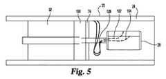
装置20の代替的実施の形態が図5に示される。装置20は、変換器28、歯車装置アセンブリ100およびモータ32を含む。装置20は図1の実施の形態と同様であり、歯車装置アセンブリ100および導通経路(導体102、104を含む)を注目すべき例外として、同じ態様で機能する。装置20は、モータ32と歯車装置アセンブリ100と変換器28との間における動作可能な接続のために、回転軸70、71を含む。この実施の形態では、軸70は内腔を含んでも、含まなくてもよい。 An alternative embodiment of the device 20 is shown in FIG. Device 20 includes a
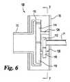
歯車装置アセンブリ100はモータ32から一定の回転入力を受けて、往復運動する回転を変換器28に出力するように構成される。歯車装置アセンブリ100の一部の断面の概略図が図6に示される。軸70は歯車装置アセンブリ100の制御側で歯車装置アセンブリ100と結合し、軸71は歯車装置アセンブリ100の適用側で歯車装置アセンブリ100と結合する。歯車装置アセンブリ100はハウジング76を含む。ハウジング76は、カテーテル22に対して定置状態であるかまたは固定されるように配置される。歯車装置アセンブリ100は、図7において概略的に示される歯車の構成を含む。輪歯車110は軸70と結合され、第1の平歯車114および第2の平歯車116と相互に作用するように構成される。駆動歯車112は、軸71と結合され、第3の平歯車118と相互に作用するように構成される。 The
輪歯車110は内歯車であり、つまり、その回転軸に向かう歯を有する。輪歯車110はセクタ歯車または一部の歯が除去された歯車とも呼ばれ、歯状部分120(またはセクタ)および非歯状部分122を含むタイプの歯車である。歯状部分120は、輪歯車110の円周の半分以下の部分を占める。言いかえれば、歯状部分120は、弧長が式L=θrによって規定される輪歯車110の部分を占め、rは、回転軸から歯状部分120まで測定された半径であり、θ≦180°である。同様に、非歯状部分122は、輪歯車110の円周の半分以上の部分を占める。歯状部分120は、歯状部分120の一方端または両端に位置決めされる食付き部分(図示せず)を含んでもよい。食付き部分は、歯状部分120の中間に位置決めされる歯に対して、徐々に低減された高さ(または径方向で測定した長さ)を有する歯を含む。輪歯車110は、軸70に取付けられるか、または軸70の適用側端部で軸70の一体的な部分として構築されてもよい。輪歯車110は図6においてフランジの一部として示される。しかしながら、輪歯車110はさまざまな構成で軸70とともに組入れられてもよい。 The
平歯車114、116、118は外歯車であり、つまり、それらのそれぞれの回転軸から遠ざかる方向を指す歯を有する。第1の平歯車114は、それが軸124の回転に応答して回転するように、軸124と結合される。第2の平歯車116は、それが軸126の回転に応答して回転するように、軸126と結合される。軸124、126は、ハウジング76によって回転可能に支持され、それは軸受、ハブまたは他の好適な回転式支持体を含み得る。歯車114、116は、直径上において互いと対向して位置決めされ、第1の平歯車114が第2の平歯車116を係合するように配置される。第1の平歯車114、第2の平歯車116および歯状部分120の配置および構成は、歯状部分120は平歯車114または平歯車116のいずれかを排他的に係合することはできるが、両方を同時には係合できないように、なされる。第3の平歯車118は、それが第2の平歯車116の回転に応答して回転するように、軸126上に位置決めされる。第3の平歯車118は、第2の平歯車116に関して軸126の適用側に位置決めされる。駆動歯車112は外歯車であり、軸71が駆動歯車112の回転に応答して回転するように、軸71に固定的に取付けられる。 The spur gears 114, 116, 118 are external gears, that is, have teeth that point in a direction away from their respective rotational axes. The
輪歯車110は軸70から一方向の回転駆動力を受けるように構成される。輪歯車110が図7で見て時計回りの方向に回転すると、歯状部分120は第1の平歯車114を係合し、第1の平歯車114を軸124の軸のまわりで同時に時計回りに回転させる。第1の平歯車114は第2の平歯車116を係合し、第2の平歯車116を軸126の軸のまわりで反時計回りに回転させる。第2の平歯車116の反時計回り回転は、第3の平歯車118を軸126のまわりで同時に反時計回りに回転させる。第3の平歯車118の反時計回り回転は、駆動歯車112および軸71を時計回りに回転させる。輪歯車110が時計回りに回転し続けると、歯状部分120は第1の平歯車114の係合を解除し、その後第2の平歯車116を係合し、第2の平歯車116を時計回りに回転させる。第1の平歯車114は、応答して反時計回りに回転する。第2の平歯車116の時計回り回転は、第3の平歯車118を軸126を介して同時に時計回りに回転させる。第3の平歯車118の時計回り回転は駆動歯車112および軸71を反時計回りに回転させる。輪歯車110が時計回りに回転し続けると、歯状部分120は第2の平歯車116の係合を解除し、その後第1の平歯車114を再係合し、それは、軸71を再び時計回りに回転させる。歯状部分120の食付き部分は、歯状部分120が第1の平歯車114と第2の平歯車116との間で係合するように遷移する際の歯車の詰まりとのいかなる潜在的な問題も最小限にするかまたは取除く。このように、軸70が一方向の方向(それは時計回りまたは反時計回りのいずれかであり得る)で回転すると、軸71は往復運動するよう働く回転運動を経る。 The
歯車装置アセンブリ100のさまざまな局面は、先に図1の実施の形態に対して記載されたように、歯状部分120の弧長および駆動歯車112のサイズにおける変形のように、およびここに記載されるのと同じ効果になるように、変更することができる。 Various aspects of the
図5の実施の形態では、導体102、104は、変換器28から壁部24まで通過し、壁部24に沿って走って、導通を与えるようにコンソールと結合する。導体102、104はまず中空軸71に入って通過し、開口部128を通って出ることができる。代替的に、導体102、104は中空軸71の外部の位置で変換器28と結合することができる。軸71が回転するときに、導体102、104が交互に軸71のまわりでねじれ、そしてねじりを解くように、導体102、104は、変換器28と壁部24での取付点との間に十分な空間がある状態で位置決めされる。たとえば、変換器28にとって、各方向にシーケンシャルに720°回転することが望ましい場合、導体102、104は、中立の開始点からの各回転方向における少なくとも完全な360°の回転のために軸71のまわりに巻付くために、十分な余分を有することになる。 In the embodiment of FIG. 5,
図1の実施の形態は図5の導体構成と組み合わせることができる。その場合、軸71の内腔73は、たとえばガイドワイヤのような他の構成要素を収容することがある。一例では、ガイドワイヤはモータ軸70の内腔72を通り、軸71の内腔73を通り、変換器28を通過し(または通り)、およびカテーテル先端を通って、延在し得る。いくつかの実施の形態では、内腔72、73はガイドワイヤおよび導体の両方を収容することがある。 The embodiment of FIG. 1 can be combined with the conductor configuration of FIG. In that case, the
代替的に、またはここに記載されるさまざまな実施の形態の歯状部分食付き部分と関連して、摩擦インターフェイスを平歯車と輪歯車との間に追加することができる。一実施の形態では、ローブ200が、歯状部分の端部に近接して位置決めされる(図14)。ローブ200は輪歯車に取付けられる隆起したこぶであり、特定の場合では、たとえばゴムのような、弾性的に圧縮可能な材料から構築される。動作中、輪歯車が第1または第2の平歯車を係合解除し、第2または第1の平歯車を(それぞれ)係合すると、ローブ200は、平歯車が方向を変更する際に、平歯車のエネルギ(または運動量)のいくらか吸収する。平歯車が適切な速度で回転して輪歯車を係合するように、ローブ200は摩擦によって平歯車を係合し、それに方向を逆転させる(または回転を開始させる)。 Alternatively, or in connection with the toothed portion of the various embodiments described herein, a friction interface can be added between the spur gear and the ring gear. In one embodiment, the
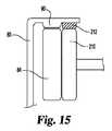
代替的実施の形態は、平歯車の回転に応答して回転するように、平歯車と近接して位置決めされ、平歯車に接続される、1つ以上の非歯状ディスク210を含む(図15)。この実施の形態では、ローブ212は、輪歯車の歯状部分における歯に関して軸方向のオフセットで位置決めされる。ディスク210も弾性的に圧縮可能な材料から構築することができ、または代替的に、それは相対的に剛性の材料から構築することができる。動作中、輪歯車が平歯車の係合を解除し、平歯車を再係合するとき、ディスク210は摩擦によってローブ212を係合し、それは、輪歯車と平歯車との間の歯状歯車係合に先立って、ディスク210および平歯車に回転速度を低減させ、方向を変更させる。図14および図15の実施の形態は、歯車歯に衝撃を与えて損傷することなく、平歯車の速度を滑らかに逆転するという目的を果たす。言いかえれば、歯車は、他の態様では反対方向に回転する間に歯車の係合から引起されるかもしれない損傷から保護される。このように、ローブ200、ローブ212およびディスク210は手動変速機歯車箱における同期装置のそれと同様の機能を供する。 An alternative embodiment includes one or more
さらに代替的な歯車装置アセンブリの実施の形態が図11に示される。歯車装置アセンブリ170は、先に記載された歯車装置アセンブリ30に、多くの局面において類似している。歯車装置アセンブリ170は、3つの第1の平歯車172、3つの第2の平歯車174、および輪歯車176を含む。輪歯車176は3つの歯状部分177と3つの非歯状部分178とを含む。輪歯車176が回転軸のまわりで一方向に回転すると、歯状部分177は第1の平歯車172および第2の平歯車174を交互に係合する。交互する係合は、第1および第2の平歯車の往復運動するよう働く運動を引起し、それから、第3の平歯車がその往復運動するよう働く運動を駆動歯車(図示せず)に変換することができる。6つの平歯車の使用は、直径を低減した平歯車の使用を可能にし、対応して、平歯車は、輪歯車の中心の近くにおいて、より少ない領域を占める。したがって、軸71はより大きな直径およびより大きな内腔73で形成することができ、それは、より大きな直径の導体、(たとえば線形アレイを有する変換器のための)より多くの導体、および/またはより大きなガイドワイヤを収容することができる。歯車装置アセンブリ170は、さらに、4つの第1の平歯車と4つの第2の平歯車と4つの歯状部分とを有する、8つの平歯車の構成を含むことがある。同様に、歯車装置アセンブリ170は、10個以上の偶数個の平歯車を有する構成を含むことがある。 A further alternative gear assembly assembly embodiment is shown in FIG. The
さらに代替的な歯車装置アセンブリの実施の形態が図12および図13に示される。その実施の形態では、歯車装置アセンブリ180はモータ32から一定の回転入力を受けて、往復運動する回転を変換器28に出力するように構成される。歯車装置アセンブリ180の一部の断面の概略図が図12に示される。軸70は歯車装置アセンブリ180の制御側で歯車装置アセンブリ180と結合し、軸71は歯車装置アセンブリ180の適用側で歯車装置アセンブリ180と結合する。歯車装置アセンブリ180はハウジング76を含み、それは、カテーテル22に対して固定されるように配置される。 A further alternative gear assembly assembly embodiment is shown in FIGS. In that embodiment,
歯車装置アセンブリ180は、図13において概略的に示される歯車の構成を含む。その例では、輪歯車181は軸70と結合され、第1の平歯車182、183および第2の平歯車184、185と相互に作用するように構成される。駆動歯車186は、軸71と結合され、第3の平歯車187、188と相互に作用するように構成される。輪歯車181は、図2の実施の形態に対して記載されるような2つの歯状部分を有する内歯車である。第1の平歯車182、183は図2の実施の形態に対して記載されるような外歯車である。第1の平歯車182、183は、ハウジング76に(またはそれに関して)固定される歯車支持体197、198に回転可能に取付けることができる。第2の平歯車184、185は、第1の平歯車182、183の幅(または歯車の中心軸に沿って測定された長さ)より大きい幅を有する外歯車である。第4の平歯車194、195は、第3の平歯車187、188に固定的に取付けられ、第3の平歯車187、188と一致して回転する。第3および第4の平歯車は、第1の平歯車182、183の回転軸と平行ではない回転軸上で、ハウジング76に、回転可能に取付けられる(図13)。第4の平歯車194は第2の平歯車184を係合するよう位置決めされる。第4の平歯車195は第2の平歯車185を係合するよう位置決めされる。駆動歯車186は第3の平歯車187、188を係合するよう位置決めされる。 The
歯車装置アセンブリ180は、360°の、往復運動するよう働く回転を、軸71に与える一方で、軸71を通る内腔も与えて、複数個の導体および/またはガイドワイヤを収容する。第4の平歯車194、195は、第2の平歯車184、185と第4の平歯車194、195との間の歯車比を増大するために、(第3の平歯車187、188と比較して)低減された直径および低減された歯数を含むことができる。増大された歯車比は、第2の平歯車184、185の各完全な回転ごとに、第4の平歯車194、195に複数の完全な回転(または1つを超える完全な回転)を経させる。第4の平歯車194、195は第3の平歯車187、188に取付けられるので、第3の平歯車187、188も、第2の平歯車184、185の各完全な回転ごとに、複数の完全な回転を経る。第3の平歯車187、188と駆動歯車186との間の歯車比も、第3の平歯車187、188の直径を拡大または低減すること、および駆動歯車186の直径を拡大または低減することによって、修正することができる。このように、軸71が、(非歯状部分192、193によって分離されるおよび)歯状部分190、191と第1の平歯車182、183または第2の平歯車184、185のいずれかとの間における1つの係合(または輪歯車181の約90°の回転)に応答して一方向に完全に360°回転する、歯車比を達成することができる。 The
第4の平歯車194、195と第2の平歯車184、185との間の係合を維持しながら、軸71を通る、より大きな内腔73に対応するために、第4の平歯車194、195(および第3の平歯車187、188)の回転の軸は、回転軸からさらに移動させることができる。内腔は、輪歯車との係合のために、図12の例を、4つを超える平歯車を有する歯車装置アセンブリ(たとえば図11)と組み合わせることによって、さらに拡大することができる。 To accommodate the
装置20のさらなる代替的実施の形態が図8から図10に示される。装置20は、回転モータ32、33と、カテーテル22(図示せず)と、軸140と、変換器28と、付勢力部材142とを含む。変換器28の特定の位置の前方および/または後方を見るために、装置20が、装置20の回転軸のまわりを回転するだけでなく回動可能でもある超音波信号掃引または場を与えるように、変換器28は、軸140に回動するように取付けられる。回動アセンブリ160は、回動マウント150、変換器マウント152、カムプレート154、および屈曲軸144を含む。回動アセンブリ160は回動軸のまわりで中立位置と最大変位位置との間において変換器28の往復運動するよう働く移動を与える。 A further alternative embodiment of the device 20 is shown in FIGS. Device 20 includes
回転モータ32、33は先に記載されるような超小型のモータである。回転モータ32は軸140と結合され、軸140を回転軸のまわりで回転させる。軸140は中空の円筒軸であり、中を通って延在する内腔141を有している。回転モータ33は屈曲軸144と結合され、屈曲軸144を回転軸のまわりで回転させる。屈曲軸144はモータ33から内腔141を通って延在する。屈曲軸144は軸受143によって軸140の適用側端部の近くで支持することができる。付勢力部材142はモータ32とモータ33との間に位置決めされ、モータ32に向かってモータ33を引く傾向がある付勢力を引起すように、モータ32、33に接続される。付勢力部材142は、コイルばね、弾性のゴム部材または他の好適な付勢部材であることができる。 The
回動マウント150は、軸140の回転に応答して回転するように、軸140と結合される。回動マウント150はピン156を受入れるように構成される。変換器マウント152は、変換器28と固定的に結合され、ピン156を受けるように構成される。変換器マウント152は、回動マウント150および軸140に対して回転可能であるように、ピン156を介して、回動マウント150と、回転するように結合される。ピン156は、変換器28が回動可能な回動軸を規定する。回動マウント150は、2つの延在する部材が変換器マウント152の2つの対向する側部(図示せず)に結合するように変換器マウント152を受けるよう構成されたスロットを含むことができる。代替的に、回動マウント150は、変換器マウント152の1つの側に接続する部材であることができる(図8)。 The
カムプレート154は、実質的に回動軸と平行に(しかし必ずしもそれに一致せずに)位置決めされるように、変換器28(たとえば背部支持体40)の底部に取付けられる。カムプレート154はカム従動子として動作する。カムプレート154は、回動軸と概ね平行な、細長いスロット158を含む。細長いスロット158は頂部表面162および底部表面163を含む。屈曲軸144は屈曲端部164を含む。屈曲端部164は、回転軸から角度をなしてずれた方向に延在する屈曲軸144の部分(つまり屈曲166の適用側にある軸144の部分)を含む。屈曲端部164は細長いスロット158を通過するように構成される。屈曲端部164は、カム表面として作用し、屈曲軸144の回転位置に依って頂部表面162および/または底部表面163を係合するように構成される表面を有する。 The
回動アセンブリ160は、変換器28に対して、往復運動する回動運動を可能にする。モータ33は屈曲軸144を回転軸のまわりで回転させることができる。屈曲軸144が軸140(および同様にカムプレート154)に関して回転軸のまわりで回転すると、屈曲端部164はカムプレート154を係合し、変換器28を回動軸のまわりで往復運動するよう働くように回動させる。屈曲軸144の回転は、屈曲端部164を回転軸のまわりで0の変位位置(図8)と最大変位位置(図10)との間において回転させる。0の変位位置では、屈曲端部164は、最大変位位置にあるときよりも概して回動軸に近い。しかしながら、回動軸から細長いスロット158までの距離は最大変位位置と0の変位位置との間において変動しない。このように、屈曲端部164は、回転軸に関して概ね軸方向において、スロット158内で、0の変位位置と最大変位位置との間において、異なるように位置する。 The pivot assembly 160 allows a reciprocating pivot movement relative to the
図8の構成では、屈曲軸144は中立位置にあり、屈曲端部164は0の変位位置にあり、つまり、変換器28は、回転軸に実質的に垂直な送信角度で位置決めされる。その構成では、屈曲端部164の或る部分が、頂部表面162および/または底部表面163に抗して当接する。屈曲軸144が(図9に関して)0の変位位置と最大変位位置との間において90°時計回りに回転すると、屈曲端部164は、スロット158内で(回転軸に関して)概ね径方向に、中心の位置からスロット158の端部に向かって移動する。表面162、163に対する屈曲端部164の当接、および回動軸からより遠い屈曲端部164の位置決めは、カムプレート154および変換器28を、回動軸のまわりで、回転軸に向かう方向に(つまり図8に関して時計回りに)回動させる。 In the configuration of FIG. 8, the bending
屈曲軸144がさらに90°時計回りに回転すると、屈曲端部164は最大変位位置に移動する。同時に、屈曲端部164はスロット158内で(回転軸に関して)概ね径方向に移動して、スロット158内における中央の位置に向かって戻る。表面162、163は、屈曲端部164に沿って、概ね屈曲軸144の制御側方向に摺動して、回動軸からスロット158および屈曲端部164までの距離における相対的な差に対応する。表面162、163に対する屈曲端部164の当接、および屈曲端部164の最大変位点に向かう移動は、変換器28を、回動軸のまわりで、回転軸に向かってさらに回動させる。回転中に屈曲軸144がさらに90°時計回りに回転すると、屈曲端部164は、再びスロット158内において(回転軸に関して)概ね径方向に移動し、屈曲端部164は、0の変位位置と最大変位位置との間の中間位置に戻る。同時に、変換器28は最大変位位置から中間変位位置に移動する。さらなる90°の回転は、屈曲軸144を0の変位位置に戻させ、変換器28は中立位置を再開する。このように、回動アセンブリ160は、モータ33の一様な回転に基づいて、変換器28に、往復運動するよう働く回動運動を与える。 When the bending
軸140の回転運動と組み合わせられるとき、変換器28は回動軸および回転軸の両方のまわりで可動である。回動運動の速度は、モータ32とモータ33との間の速度差(または位相差)によって制御される。たとえば、モータ32およびモータ33が同じ速度で回転するとき、変換器28は回転軸のまわりのみでの回転を経、なぜならば、屈曲軸144は回動軸に関して位置を変更しないからである。モータ32が静止している一方でモータ33が回転するとき、変換器28は回動軸のまわりのみでの移動を経る。モータ33が静止している(または異なる角速度で回転している)一方でモータ32が回転するとき、変換器28は回転軸および回動軸の両方のまわりでの移動を経る。この構成では、(モータ33およびモータ32を反対方向に回転させることを除き)回転軸のまわりでの回転に対する回動移動の相対速度は最大限にされる。回転軸のまわりでの回転に対する回動移動の相対速度は、モータ33を係合し、それをモータ32と同時に回転させることによって、低減することができる。回動速度は、モータ32とモータ33との間の回転速度における差が低減されるにつれ、低減される。同様に、回動速度は、モータ32とモータ33との間の回転率における差が増大するにつれ、増大する。言いかえれば、モータ32およびモータ33が異なる角速度で回転すると、位相差が、回動軸のまわりにおける屈曲軸144の回転速度と変換器28の回転速度との間において蓄積する。 When combined with the rotational movement of the
モータ32および/または33に対する制御は、一方または両方を特定の回転速度またはパターンで維持するよう与えられてもよい。たとえば、回転軸のまわりの30〜100Hz間のスピンなどのようなモダリティを、回動軸のまわりの約1〜2Hzの、より遅い回動と組み合わせて、明瞭な画像を、前方および後方に、規定されたパターンで与えてもよい。さらに、回転軸のまわりの相対的に遅いスピン(たとえば約1〜2Hz)を、回動軸のまわりでのより速い、たとえば装置20の共振周波数付近での回動と組み合わせると、好結果を与えることができる、ということも判断されている。さらに、変換器28が回転軸により接近して向けられるときに回転軸のまわりでより高速の回転を与え、変換器28が回転軸からより遠いときに回転軸のまわりでより低速の回転を与えるモダリティも、画像フレーム率および明瞭性を改善するのに有用である。 Control over the
モータ33の回転速度に対する回動軸のまわりの運動の回動範囲および速度は、屈曲端部164の構成および/またはサイズ(つまり、屈曲部の、軸144の適用側端部からの距離)の変更、ならびにカムプレート154の変換器28への取付けの配置の位置および角度の変更によって制御することができる。加えて、スロット158の構成および位置を変更することができる(および/またはカムプレート154のサイズを変更することができる)。たとえば、回動範囲は、カムプレート154を変換器28の制御側に向かってより近く移動させること、および/または屈曲端部164を回転軸に沿って装置20の制御側により近く移動させることによって、増大させることができる。その場合、カムプレート154と回動軸との間の、より短い距離は、0の変位位置と最大変位位置との間において回動軸から屈曲端部164まで測定される距離における、より大きな比例する差のため、変換器28の、より大きい変位を結果として生じる。他の例として、屈曲端部164を拡大することによって回動範囲を増大させることができる。 The rotation range and speed of the movement around the rotation shaft with respect to the rotation speed of the motor 33 is determined by the configuration and / or size of the bent end 164 (that is, the distance of the bent portion from the application side end of the shaft 144). It can be controlled by changing and changing the position and angle of the placement of the mounting of the
図8の実施の形態は、対象でない領域が画像化された量から省略されてフレーム率を増大させるようにユーザによって調整可能である回動範囲および振幅を有することができる。モータ33は、それが軸方向において回転軸に沿って可動であるように、カテーテル22内に配置することができる。その場合、張力ワイヤがモータ33の制御側に取付けられ、カテーテル22を通って、ユーザにより作動される回転式ノブまたは他の張力をかける装置まで延在する。ユーザはノブを回転させて、張力ワイヤをノブの或る部分のまわりに巻き付けさせて、張力ワイヤを短くし、モータ33の制御側に力をかけて、モータ33を回転軸に関して軸方向に、制御側方向に移動させることができる。この移動は、付勢力部材142からモータに作用する力の方向に抗して作用し、モータ33に作用する張力を増大する。同様に、ユーザはノブを反対方向に回転させて、張力ワイヤを長くして、モータ33が付勢力部材142の張力の元で軸方向に適用側方向に移動することを可能にすることができる。モータ33を軸方向に装置20の制御側に向かって移動させることにより、屈曲軸144が回転するとき、スロット158(および同様に変換器28)が増大された変位を経るように、概して回転軸からより遠い点で屈曲端部164に表面162、163を係合させることによって、振幅および範囲を増大させることができる。 The embodiment of FIG. 8 can have a pivot range and amplitude that can be adjusted by the user to increase the frame rate by omitting non-target areas from the imaged amount. The motor 33 can be placed in the
図8の実施の形態では、変換器28を取り囲む流体は、さらに、屈曲軸144と軸140との間において、および付勢力部材142に対して、潤滑を与えることもできる。流体は、上に記載されるように使用の前にあらかじめ組入れられるかまたは加えることができる。 In the embodiment of FIG. 8, the fluid surrounding the
ここに記載される実施の形態は、装置20が直接回転する変換器素子を含むことを可能にし、回転鏡設計の使用に対する必要性、およびそのような設計と関連付けられる欠点を回避する。たとえば、装置20は、より短く、回転鏡設計より少ない空間を占める。ここに記載される、直接回転する変換器の実施の形態は、回転鏡設計よりも深い音響学的焦点深度を有する。開示される実施の形態では、超音波は、超音波が、対象の方向に進み始める前に反射器に向かって数ミリメートル進まなければならない反射器設計とは対照的に、対象の方向に直接送られる。 The embodiments described herein allow apparatus 20 to include a directly rotating transducer element, avoiding the need for the use of a rotating mirror design and the disadvantages associated with such a design. For example, the device 20 is shorter and occupies less space than a rotating mirror design. The embodiment of the direct rotating transducer described herein has an acoustic depth of focus that is deeper than the rotating mirror design. In the disclosed embodiment, ultrasound is transmitted directly in the direction of the object, as opposed to a reflector design where the ultrasound must travel several millimeters toward the reflector before it begins to travel in the direction of the object. It is done.
装置20は視界窓を通して画像の捕捉を容易にし、画像内における、アーティファクト、障害物またはエラーなどのような不必要な音響学的減衰を免れる。たとえば、回転モータ32、導体50、52、および他の構成要素の適用側における位置での変換器28の位置決めは、変換器28が、回転軸のまわりを完全な360°の回転で回転し、回動軸のまわりを回動するのであっても、ワイヤまたは他のエコー源性材料が、変換器28の視界窓内において、またはそれを横切って位置決めされないことを保証する。このように、方向を変更された超音波の画像またはブロック部分内においてアーティファクトを引起すかもしれないようなワイヤや他の反射材料がない。これは、医師に、視界窓全体の明瞭な視野を与える。ワイヤまたは他の導体50、52を軸70、71の内腔72、73を通して配置することは、装置20の全体幅における低減も可能にし、なぜならば、装置の周囲上においてそのような導体に対して余分な空間を与える必要はないからである。ここに用いられるように、用語「窓」は、装置20の構造の全体にわたって、使用中に変換器28と装置20の外部に位置決めされ得る有機流体または組織との間において、実質的に妨害物のない経路を含む。 The device 20 facilitates image capture through the viewing window and avoids unnecessary acoustic attenuation, such as artifacts, obstructions or errors, in the image. For example, positioning the
装置20は、経皮的手順、腔内的手順、または間質的手順のために設計される既存の医療装置とともに用いられるよう構成される。たとえば、装置20は、異なる目的のために、さまざまなカテーテルとして、またはそれらとともに、特定の構成に依って、たとえば、カテーテルの適用側、またはその内に位置決めされて、用いることができる。先に記載されるような装置20の部品はカテーテル内において既存の内腔内に位置決めすることができる。ある代替的実施の形態では、装置20は、壁部24を有するカテーテル22と同様であるが、装置20をコンパクトに含むように短くされている外部筐体を含むことがある。装置20は、カテーテルの外部において、さまざまな取付装置、接着剤または他のタイプの構成を用いて、取付けられ得る。既存の医療装置に対する装置20のための特定のタイプの取付手順は、さまざまな異なるタイプの取付方法を含むことができることが、当業者には理解される。したがって、ここに記載される特定の方法は、装置20の使用の仕方の能力のいかなる限定的な局面も示さない。 Device 20 is configured for use with existing medical devices designed for percutaneous, intraluminal, or interstitial procedures. For example, the device 20 can be used for different purposes as or with various catheters, depending on the particular configuration, for example, positioned on or within the application side of the catheter. Components of the device 20 as described above can be positioned within an existing lumen within the catheter. In an alternative embodiment, the device 20 may be similar to the
ここに記載されるいくつかの実施の形態では、ホールセンサ(図示せず)、光学式エンコーダ(図示せず)、超音波、バックEMF、モータ突極性またはこれらの1つ以上の組合せを用いて、モータの角度位置を制御および/または監視してもよい。ホールセンサは、それらの小型で成熟した設計のため、フィードバック機構として有利である、と判断されている。いくつかの実施の形態では、変換器28によって発せられた、および/または受取られた、超音波ビームまたは信号を、フィードバック機構として用いて、装置20の残りの部分に対する回転モータ32(およびそれによって回転される超音波ビーム)の回転位置を精密に評価または監視して、変換器28を通して得られる画像の適切な位置合わせを保証する。索引システムおよび三次元超音波装置のような他の特徴が、ここで注目された実施の形態とともに含まれてもよい。 In some embodiments described herein, Hall sensors (not shown), optical encoders (not shown), ultrasound, back EMF, motor saliency or a combination of one or more of these are used. The angular position of the motor may be controlled and / or monitored. Hall sensors have been determined to be advantageous as a feedback mechanism because of their small and mature design. In some embodiments, the ultrasonic beam or signal emitted and / or received by the
上記の議論の一部は、超音波システム適用例の文脈における特定の使用に関したが、装置20の実施の形態は、さまざまな他の医学的手法のためにも、およびさまざまな他の医療装置とともにも用いられ得ることが理解される。ここに記載される実施の形態の多用性は、たとえば塞栓コイル、ステント、フィルタ、グラフ、バルーン、生検および看護療法などのような経皮的な治療の介入を案内するために装置20が用いられることを可能にする。装置20を用いて、治療を正確に配置または案内するべく用いられるさまざまな解剖学的目標を見つけ出すことができる。典型的な目標は、変換器を含む脈管または他の開口部と近接する、合流点、分岐、側枝、付近の脈管、付近の神経、心臓、および他の組織を含む。装置20は、処置または回避される病変組織を見つけ出すために用いることもできる。装置20を生検中に用いて、組織内に展開されつつある針の画像を提供することができる。TIPS(経頸静脈性肝内門脈大静脈短絡術)手順中に、画像を形成して、医師が、針が門脈に入れられるのを見ることを可能にできる。AAA(大動脈腹部大動脈瘤)移植片送給のために、装置20は、医師が反対側の脚部内にガイドワイヤを配置することを可能にすることができる。装置20を用いて、展開される移植可能な装置の展開中および展開後の両方の位置を画像化することもできる。 Although some of the above discussion has been directed to specific uses in the context of ultrasound system applications, embodiments of the device 20 are also useful for various other medical procedures and various other medical devices. It is understood that it can also be used with. The versatility of the embodiments described herein is used by the device 20 to guide percutaneous therapeutic interventions such as embolic coils, stents, filters, graphs, balloons, biopsies and nursing care, for example. To be able to. The device 20 can be used to find various anatomical targets that are used to accurately position or guide the treatment. Typical goals include confluences, branches, side branches, nearby vessels, nearby nerves, heart, and other tissues in close proximity to the vessel or other opening that contains the transducer. The device 20 can also be used to find diseased tissue to be treated or avoided. The device 20 can be used during a biopsy to provide an image of a needle being deployed in tissue. During a TIPS (transjugular intrahepatic portal vena cava shunt) procedure, an image can be formed to allow the physician to see the needle entering the portal vein. For AAA (aortic abdominal aortic aneurysm) graft delivery, the device 20 may allow a physician to place a guidewire in the opposite leg. Device 20 can also be used to image both during and after deployment of the implantable device being deployed.
特定の材料が装置20のいくつかの構成要素についてここに強調されたが、それらの材料は、装置20において用いられることが好適な材料のタイプの限定であるようには意図されない。加えて、材料が強調されなかった場合では、皮下使用およびIVUS画像化手順のための装置における使用のために好適な、あるタイプの金属、ポリマー、セラミック、または他のタイプの材料のような、さまざまな材料が用いられ得る。 Although specific materials have been highlighted here for some components of the device 20, they are not intended to be a limitation of the type of material that is suitable for use in the device 20. In addition, if the material was not highlighted, such as certain types of metals, polymers, ceramics, or other types of materials suitable for use in devices for subcutaneous use and IVUS imaging procedures, Various materials can be used.
装置20は、さらに、さまざまな他の医学的手法のためにも、およびさまざまな他の医療装置とともにも、用いられ得る。特定の取付手順のタイプは、さまざまな異なるタイプの取付法を含むことができることが、当業者によって理解される。したがって、ここに記載される特定の方法は、装置20の使用の仕方の能力のいかなる限定的な局面も示さない。 The device 20 can also be used for a variety of other medical procedures and with a variety of other medical devices. It will be appreciated by those skilled in the art that the particular type of attachment procedure can include a variety of different types of attachment methods. Thus, the particular methods described herein do not represent any limiting aspect of the ability to use the device 20.
たとえば回転軸に関する「回転」または「回転の」という用語の使用においては、回転は、360°よりはるかに大きい角度変化を意味することがしばしばであるが、ここに開示される装置は、ある実施の形態においては、回転角が360°未満の角度を通して回転するように、構成されてもよいことが理解されるべきである。いくつかの例では、用語「回動」は、一部では、「回転」より自然であると考えられるかもしれず、またはその逆であるかもしれないが、本願の目的のため、用語「回転」および「回動」は、角度変化の性質または大きさではなく、角度における変化が生じる軸を示すべく明瞭にするために用いられる。 For example, in the use of the terms “rotation” or “rotation” with respect to the axis of rotation, rotation often means an angular change much greater than 360 °, although the apparatus disclosed herein is It should be understood that in this form, the rotation angle may be configured to rotate through an angle of less than 360 °. In some examples, the term “rotation” may be considered more natural than “rotation” in part, or vice versa, but for purposes of this application, the term “rotation”. And “rotation” is used to clarify the axis on which the change in angle occurs, rather than the nature or magnitude of the change in angle.
この開示は、図面および前述の記載において詳細に示され記載されたが、この開示は、例示的なものとして考慮され、本質においては限定的ではなく、好ましい実施の形態のみが示され記載されたこと、ならびに特許請求の範囲によって規定される主題の精神内に入るすべての変更、均等物および修正が保護されることが望まれることが理解される。1つの特定の実施の形態または項目に関して記載される構造または他の特徴が、ここに含まれる他の特徴、項目または実施の形態と関連して、またはそれらとともに用いられてもよいことが理解される。この明細書において引用されるすべての刊行物、特許、および特許出願は、各個々の刊行物、特許または特許出願が、引用により援用され、その全体がここに述べられるよう、具体的および個々に示されるかの如く、ここに引用により援用される。 While this disclosure has been shown and described in detail in the drawings and foregoing description, this disclosure is considered illustrative and not restrictive in nature and only the preferred embodiments have been shown and described. It is understood that all changes, equivalents and modifications that fall within the spirit of the subject matter defined by the claims are desired to be protected. It is understood that structures or other features described with respect to one particular embodiment or item may be used in connection with or in conjunction with other features, items or embodiments included herein. The All publications, patents, and patent applications cited in this specification are specifically and individually listed, as each individual publication, patent or patent application is incorporated herein by reference in its entirety. As indicated, incorporated herein by reference.
Claims (28)
Translated fromJapanese一方向回転モータと;
双方向超音波変換器と;
前記モータと前記変換器との間に作動的に配置される、一方向から双方向への歯車装置アセンブリとを含む、医療装置。A medical device,
A unidirectional rotating motor;
A bidirectional ultrasonic transducer;
A medical device comprising a one-way to two-way gear assembly that is operatively disposed between the motor and the transducer.
前記回転モータは、第1の駆動軸と作動的に結合され、前記第1の駆動軸は、実質的に回転軸に沿って延在し、前記モータの動作は前記駆動軸を前記回転軸のまわりで回転させ;
前記歯車装置アセンブリは内歯車と第1および第2の外歯車とを含み、前記第1の外歯車は前記第2の外歯車と相互係合され、前記内歯車は前記回転軸のまわりで回転するよう位置決めされ、前記歯車装置アセンブリは、前記第1の駆動軸および前記変換器と作動的に結合され;
前記内歯車は、第1の歯状部分および第1の非歯状部分を有し、前記内歯車は、前記内歯車の回転中に前記第1の歯状部分が前記第1および第2の外歯車を交互に係合するように、配置される、請求項1に記載の装置。The transducer is configured for transmitting and / or receiving ultrasound signals;
The rotary motor is operatively coupled to a first drive shaft, the first drive shaft extends substantially along the rotary shaft, and the operation of the motor causes the drive shaft to move relative to the rotary shaft. Rotate around;
The gear assembly includes an internal gear and first and second external gears, the first external gear is interengaged with the second external gear, and the internal gear rotates about the rotation axis. The gear assembly is operatively coupled to the first drive shaft and the transducer;
The internal gear has a first toothed portion and a first non-toothed portion, and the internal gear has the first toothed portion being the first and second teeth during rotation of the internal gear. The apparatus of claim 1, arranged to alternately engage external gears.
第1の駆動軸と作動的に結合される第1のモータを含み、前記第1の駆動軸は、実質的に回転軸に沿って延在し、前記第1のモータの動作は、前記第1の駆動軸を前記回転軸のまわりで回転させ;前記医療装置はさらに、
超音波信号を送信および/または受信することに対して構成される変換器を含み、前記変換器は前記回転軸に実質的に垂直な回動軸のまわりで移動するよう配置され;
前記第1の駆動軸は、前記第1の駆動軸が回転すると前記変換器に回動運動を与えるよう配置されるカム表面を含む、医療装置。Medical device:
A first motor operatively coupled to the first drive shaft, wherein the first drive shaft extends substantially along the rotational axis, and the operation of the first motor is Rotating one drive shaft about the rotational axis; the medical device further comprising:
Including a transducer configured to transmit and / or receive ultrasonic signals, the transducer being arranged to move about a pivot axis substantially perpendicular to the rotation axis;
The medical device, wherein the first drive shaft includes a cam surface that is arranged to impart a rotational motion to the transducer as the first drive shaft rotates.
回転軸に実質的に垂直な回動軸のまわりで前記変換器に移動を与えるよう作動的に配置される第1のモータと;
前記回転軸のまわりで前記変換器に回転運動を与えるよう作動的に配置される第2のモータとを含み;
前記回動軸のまわりの前記変換器の移動の速度は、前記第1のモータの回転速度と前記第2のモータの回転速度との間の差によって決定される、医療装置。A transducer configured for transmitting and / or receiving ultrasound signals;
A first motor operatively disposed to impart movement to the transducer about a pivot axis substantially perpendicular to the pivot axis;
A second motor operatively disposed to provide rotational motion to the transducer about the rotational axis;
The medical device, wherein the speed of movement of the transducer about the pivot axis is determined by the difference between the rotational speed of the first motor and the rotational speed of the second motor.
Applications Claiming Priority (3)
| Application Number | Priority Date | Filing Date | Title |
|---|---|---|---|
| US201361748773P | 2013-01-04 | 2013-01-04 | |
| US61/748,773 | 2013-01-04 | ||
| PCT/US2013/078245WO2014107427A1 (en) | 2013-01-04 | 2013-12-30 | Reciprocating ultrasound device |
Publications (2)
| Publication Number | Publication Date |
|---|---|
| JP2016501700Atrue JP2016501700A (en) | 2016-01-21 |
| JP6169724B2 JP6169724B2 (en) | 2017-07-26 |
Family
ID=51061497
Family Applications (1)
| Application Number | Title | Priority Date | Filing Date |
|---|---|---|---|
| JP2015551740AExpired - Fee RelatedJP6169724B2 (en) | 2013-01-04 | 2013-12-30 | Reciprocating ultrasonic device |
Country Status (6)
| Country | Link |
|---|---|
| US (1) | US9474507B2 (en) |
| EP (1) | EP2941194B1 (en) |
| JP (1) | JP6169724B2 (en) |
| CN (1) | CN105007827B (en) |
| AU (1) | AU2013371338B2 (en) |
| WO (1) | WO2014107427A1 (en) |
Families Citing this family (10)
| Publication number | Priority date | Publication date | Assignee | Title |
|---|---|---|---|---|
| JP6526640B2 (en) | 2013-10-01 | 2019-06-05 | マフィン・インコーポレイテッドMuffin Incorporated | Wire extrapolation ultrasound system |
| WO2017027781A1 (en)* | 2015-08-12 | 2017-02-16 | Muffin Incorporated | Device for three-dimensional, internal ultrasound with rotating transducer and rotating reflector |
| US11317892B2 (en) | 2015-08-12 | 2022-05-03 | Muffin Incorporated | Over-the-wire ultrasound system with torque-cable driven rotary transducer |
| CN105433984A (en)* | 2015-12-16 | 2016-03-30 | 徐州市凯信电子设备有限公司 | Mechanical linear scanning high-frequency ultrasonic diagnosis device |
| EP3492391B1 (en) | 2016-10-10 | 2021-04-28 | SZ DJI Osmo Technology Co., Ltd. | Three-axis pan-tilt base, and three-axis pan-tilt camera device |
| CN106725747B (en)* | 2016-12-30 | 2023-08-04 | 重庆西山科技股份有限公司 | medical cutting device |
| US10433852B2 (en) | 2017-05-08 | 2019-10-08 | William Z. H'Doubler | Aortic occlusion balloon apparatus, system and method of making |
| JP7043622B2 (en) | 2018-03-13 | 2022-03-29 | ベラソン インコーポレイテッド | Generalized interlaced scanning with ultrasonic probes |
| CN111053576B (en)* | 2019-12-31 | 2020-08-21 | 绵阳美科电子设备有限责任公司 | Transmission device for enabling ultrasonic three-dimensional probe transducer to rotate in reciprocating mode and application method thereof |
| CN113426033B (en)* | 2021-07-20 | 2025-05-02 | 河南翔宇医疗设备股份有限公司 | Ultrasonic treatment device and ultrasonic treatment head |
Citations (8)
| Publication number | Priority date | Publication date | Assignee | Title |
|---|---|---|---|---|
| JPS57200138A (en)* | 1981-06-04 | 1982-12-08 | Tokyo Shibaura Electric Co | Ultrasonic diagnostic apparatus |
| US4811617A (en)* | 1988-02-01 | 1989-03-14 | Whiteman Marvin E Jr | Unidirectional to bidirectional angular displacement conversion apparatus |
| JPH02264642A (en)* | 1989-04-04 | 1990-10-29 | Fuji Electric Co Ltd | Ultrasonic wave probe |
| JPH0856948A (en)* | 1994-08-25 | 1996-03-05 | Toshiba Corp | Ultrasonic diagnostic equipment |
| JPH09276271A (en)* | 1996-04-16 | 1997-10-28 | Olympus Optical Co Ltd | Ultrasonic probe |
| JPH11332867A (en)* | 1998-05-25 | 1999-12-07 | Olympus Optical Co Ltd | Ultrasonic endoscope apparatus |
| JP2000333958A (en)* | 1999-05-26 | 2000-12-05 | Matsushita Electric Ind Co Ltd | Ultrasonic probe |
| US20110166455A1 (en)* | 2010-01-07 | 2011-07-07 | Cully Edward H | Catheter |
Family Cites Families (19)
| Publication number | Priority date | Publication date | Assignee | Title |
|---|---|---|---|---|
| NL84461C (en) | 1952-03-06 | 1957-03-15 | Philips Nv | DEVICE FOR CONVERTING ONE-WAY ROTATING MOTION INTO A BACKGROUND MOTION OR REVERSE |
| US4637256A (en)* | 1983-06-23 | 1987-01-20 | Matsushita Electric Industrial Co., Ltd. | Ultrasonic probe having dual-motion transducer |
| US5237884A (en) | 1991-04-22 | 1993-08-24 | Osada Research Institute, Ltd. | Power transmission device |
| US5611246A (en) | 1993-08-20 | 1997-03-18 | Eastman Kodak Company | Variable angular velocity coupling for reciprocating devices |
| US5535715A (en) | 1994-11-23 | 1996-07-16 | Mouton; William J. | Geared reciprocating piston engine with spherical rotary valve |
| US5770913A (en)* | 1995-10-23 | 1998-06-23 | Omnific International, Ltd. | Actuators, motors and wheelless autonomous robots using vibratory transducer drivers |
| DE19726702A1 (en) | 1997-06-24 | 1999-01-07 | Ralf Dr Ing Kaufmann | Device, especially pump |
| US7798971B2 (en)* | 2005-07-07 | 2010-09-21 | Vermon | Motorized ultrasonic scanhead |
| US20070062290A1 (en) | 2005-08-30 | 2007-03-22 | Ultrasonic Technologies Ltd. | Motor driven mechanism for mechanically scanned ultrasound transducers |
| US8006578B2 (en) | 2005-10-12 | 2011-08-30 | Kiester Douglas P | Apparatus and method for a high speed rotation-to-rotation oscillation converter for surgical use |
| US20070167821A1 (en) | 2005-11-30 | 2007-07-19 | Warren Lee | Rotatable transducer array for volumetric ultrasound |
| JP2008075783A (en)* | 2006-09-22 | 2008-04-03 | National Institute Of Advanced Industrial & Technology | Ultrasonic motor transmission using differential gears |
| CN107126182B (en)* | 2007-01-19 | 2020-06-16 | 桑尼布鲁克健康科学中心 | Scanning mechanism for imaging probe |
| CN101677810B (en)* | 2007-06-04 | 2012-04-04 | 松下电器产业株式会社 | Ultrasonic diagnostic device |
| US8285362B2 (en)* | 2007-06-28 | 2012-10-09 | W. L. Gore & Associates, Inc. | Catheter with deflectable imaging device |
| JP2011520528A (en)* | 2008-05-16 | 2011-07-21 | フルイド メディカル,インコーポレイテッド | Small forward-viewing ultrasonic imaging mechanism operable by local shape memory alloy actuator |
| EP2280652A4 (en)* | 2008-05-30 | 2012-12-19 | Gore Enterprise Holdings Inc | Real time ultrasound catheter probe |
| US8317713B2 (en) | 2009-01-09 | 2012-11-27 | Volcano Corporation | Ultrasound catheter with rotatable transducer |
| AU2011316783A1 (en)* | 2010-10-22 | 2013-05-23 | W. L. Gore & Associates, Inc. | Catheter with shape memory alloy actuator |
- 2013
- 2013-12-30EPEP13870090.1Apatent/EP2941194B1/enactiveActive
- 2013-12-30AUAU2013371338Apatent/AU2013371338B2/ennot_activeCeased
- 2013-12-30CNCN201380074116.3Apatent/CN105007827B/ennot_activeExpired - Fee Related
- 2013-12-30WOPCT/US2013/078245patent/WO2014107427A1/enactiveApplication Filing
- 2013-12-30JPJP2015551740Apatent/JP6169724B2/ennot_activeExpired - Fee Related
- 2013-12-30USUS14/143,375patent/US9474507B2/enactiveActive
Patent Citations (8)
| Publication number | Priority date | Publication date | Assignee | Title |
|---|---|---|---|---|
| JPS57200138A (en)* | 1981-06-04 | 1982-12-08 | Tokyo Shibaura Electric Co | Ultrasonic diagnostic apparatus |
| US4811617A (en)* | 1988-02-01 | 1989-03-14 | Whiteman Marvin E Jr | Unidirectional to bidirectional angular displacement conversion apparatus |
| JPH02264642A (en)* | 1989-04-04 | 1990-10-29 | Fuji Electric Co Ltd | Ultrasonic wave probe |
| JPH0856948A (en)* | 1994-08-25 | 1996-03-05 | Toshiba Corp | Ultrasonic diagnostic equipment |
| JPH09276271A (en)* | 1996-04-16 | 1997-10-28 | Olympus Optical Co Ltd | Ultrasonic probe |
| JPH11332867A (en)* | 1998-05-25 | 1999-12-07 | Olympus Optical Co Ltd | Ultrasonic endoscope apparatus |
| JP2000333958A (en)* | 1999-05-26 | 2000-12-05 | Matsushita Electric Ind Co Ltd | Ultrasonic probe |
| US20110166455A1 (en)* | 2010-01-07 | 2011-07-07 | Cully Edward H | Catheter |
Also Published As
| Publication number | Publication date |
|---|---|
| CN105007827A (en) | 2015-10-28 |
| JP6169724B2 (en) | 2017-07-26 |
| AU2013371338A1 (en) | 2015-08-06 |
| EP2941194B1 (en) | 2020-04-29 |
| AU2013371338B2 (en) | 2016-12-08 |
| CN105007827B (en) | 2017-11-03 |
| US9474507B2 (en) | 2016-10-25 |
| EP2941194A1 (en) | 2015-11-11 |
| US20140194743A1 (en) | 2014-07-10 |
| EP2941194A4 (en) | 2016-08-24 |
| WO2014107427A1 (en) | 2014-07-10 |
Similar Documents
| Publication | Publication Date | Title |
|---|---|---|
| JP6169724B2 (en) | Reciprocating ultrasonic device | |
| US10154830B2 (en) | 3D catheter-based ultrasound assembly with gimbal-mount transducer and single coil drive | |
| JP6661372B2 (en) | Reciprocating internal ultrasonic transducer assembly | |
| JP6154027B2 (en) | Ultrasonic transducer direction control | |
| US9649092B2 (en) | Devices and methods for three-dimensional internal ultrasound usage | |
| US9456802B2 (en) | Mechanical scanning ultrasound transducer with micromotor | |
| US10314560B2 (en) | Over-the-wire ultrasound system | |
| CN119405353A (en) | A water-driven interventional micro-ultrasonic catheter |
Legal Events
| Date | Code | Title | Description |
|---|---|---|---|
| A621 | Written request for application examination | Free format text:JAPANESE INTERMEDIATE CODE: A621 Effective date:20150930 | |
| A977 | Report on retrieval | Free format text:JAPANESE INTERMEDIATE CODE: A971007 Effective date:20160812 | |
| A131 | Notification of reasons for refusal | Free format text:JAPANESE INTERMEDIATE CODE: A131 Effective date:20160913 | |
| A521 | Request for written amendment filed | Free format text:JAPANESE INTERMEDIATE CODE: A523 Effective date:20161213 | |
| TRDD | Decision of grant or rejection written | ||
| A01 | Written decision to grant a patent or to grant a registration (utility model) | Free format text:JAPANESE INTERMEDIATE CODE: A01 Effective date:20170606 | |
| A61 | First payment of annual fees (during grant procedure) | Free format text:JAPANESE INTERMEDIATE CODE: A61 Effective date:20170628 | |
| R150 | Certificate of patent or registration of utility model | Ref document number:6169724 Country of ref document:JP Free format text:JAPANESE INTERMEDIATE CODE: R150 | |
| R250 | Receipt of annual fees | Free format text:JAPANESE INTERMEDIATE CODE: R250 | |
| LAPS | Cancellation because of no payment of annual fees |