JP2016216024A - Driving support method, driving support device, driving control device, vehicle, and driving support program using the same - Google Patents
Driving support method, driving support device, driving control device, vehicle, and driving support program using the sameDownload PDFInfo
- Publication number
- JP2016216024A JP2016216024AJP2015252670AJP2015252670AJP2016216024AJP 2016216024 AJP2016216024 AJP 2016216024AJP 2015252670 AJP2015252670 AJP 2015252670AJP 2015252670 AJP2015252670 AJP 2015252670AJP 2016216024 AJP2016216024 AJP 2016216024A
- Authority
- JP
- Japan
- Prior art keywords
- vehicle
- image
- behavior
- action
- unit
- Prior art date
- Legal status (The legal status is an assumption and is not a legal conclusion. Google has not performed a legal analysis and makes no representation as to the accuracy of the status listed.)
- Granted
Links
Images


Classifications
- B—PERFORMING OPERATIONS; TRANSPORTING
- B60—VEHICLES IN GENERAL
- B60W—CONJOINT CONTROL OF VEHICLE SUB-UNITS OF DIFFERENT TYPE OR DIFFERENT FUNCTION; CONTROL SYSTEMS SPECIALLY ADAPTED FOR HYBRID VEHICLES; ROAD VEHICLE DRIVE CONTROL SYSTEMS FOR PURPOSES NOT RELATED TO THE CONTROL OF A PARTICULAR SUB-UNIT
- B60W50/00—Details of control systems for road vehicle drive control not related to the control of a particular sub-unit, e.g. process diagnostic or vehicle driver interfaces
- B60W50/08—Interaction between the driver and the control system
- B60W50/10—Interpretation of driver requests or demands
- B—PERFORMING OPERATIONS; TRANSPORTING
- B60—VEHICLES IN GENERAL
- B60K—ARRANGEMENT OR MOUNTING OF PROPULSION UNITS OR OF TRANSMISSIONS IN VEHICLES; ARRANGEMENT OR MOUNTING OF PLURAL DIVERSE PRIME-MOVERS IN VEHICLES; AUXILIARY DRIVES FOR VEHICLES; INSTRUMENTATION OR DASHBOARDS FOR VEHICLES; ARRANGEMENTS IN CONNECTION WITH COOLING, AIR INTAKE, GAS EXHAUST OR FUEL SUPPLY OF PROPULSION UNITS IN VEHICLES
- B60K35/00—Instruments specially adapted for vehicles; Arrangement of instruments in or on vehicles
- B60K35/10—Input arrangements, i.e. from user to vehicle, associated with vehicle functions or specially adapted therefor
- B—PERFORMING OPERATIONS; TRANSPORTING
- B60—VEHICLES IN GENERAL
- B60K—ARRANGEMENT OR MOUNTING OF PROPULSION UNITS OR OF TRANSMISSIONS IN VEHICLES; ARRANGEMENT OR MOUNTING OF PLURAL DIVERSE PRIME-MOVERS IN VEHICLES; AUXILIARY DRIVES FOR VEHICLES; INSTRUMENTATION OR DASHBOARDS FOR VEHICLES; ARRANGEMENTS IN CONNECTION WITH COOLING, AIR INTAKE, GAS EXHAUST OR FUEL SUPPLY OF PROPULSION UNITS IN VEHICLES
- B60K35/00—Instruments specially adapted for vehicles; Arrangement of instruments in or on vehicles
- B60K35/20—Output arrangements, i.e. from vehicle to user, associated with vehicle functions or specially adapted therefor
- B60K35/21—Output arrangements, i.e. from vehicle to user, associated with vehicle functions or specially adapted therefor using visual output, e.g. blinking lights or matrix displays
- B60K35/22—Display screens
- B—PERFORMING OPERATIONS; TRANSPORTING
- B60—VEHICLES IN GENERAL
- B60K—ARRANGEMENT OR MOUNTING OF PROPULSION UNITS OR OF TRANSMISSIONS IN VEHICLES; ARRANGEMENT OR MOUNTING OF PLURAL DIVERSE PRIME-MOVERS IN VEHICLES; AUXILIARY DRIVES FOR VEHICLES; INSTRUMENTATION OR DASHBOARDS FOR VEHICLES; ARRANGEMENTS IN CONNECTION WITH COOLING, AIR INTAKE, GAS EXHAUST OR FUEL SUPPLY OF PROPULSION UNITS IN VEHICLES
- B60K35/00—Instruments specially adapted for vehicles; Arrangement of instruments in or on vehicles
- B60K35/20—Output arrangements, i.e. from vehicle to user, associated with vehicle functions or specially adapted therefor
- B60K35/21—Output arrangements, i.e. from vehicle to user, associated with vehicle functions or specially adapted therefor using visual output, e.g. blinking lights or matrix displays
- B60K35/23—Head-up displays [HUD]
- B—PERFORMING OPERATIONS; TRANSPORTING
- B60—VEHICLES IN GENERAL
- B60K—ARRANGEMENT OR MOUNTING OF PROPULSION UNITS OR OF TRANSMISSIONS IN VEHICLES; ARRANGEMENT OR MOUNTING OF PLURAL DIVERSE PRIME-MOVERS IN VEHICLES; AUXILIARY DRIVES FOR VEHICLES; INSTRUMENTATION OR DASHBOARDS FOR VEHICLES; ARRANGEMENTS IN CONNECTION WITH COOLING, AIR INTAKE, GAS EXHAUST OR FUEL SUPPLY OF PROPULSION UNITS IN VEHICLES
- B60K35/00—Instruments specially adapted for vehicles; Arrangement of instruments in or on vehicles
- B60K35/20—Output arrangements, i.e. from vehicle to user, associated with vehicle functions or specially adapted therefor
- B60K35/26—Output arrangements, i.e. from vehicle to user, associated with vehicle functions or specially adapted therefor using acoustic output
- B60K35/265—Voice
- B—PERFORMING OPERATIONS; TRANSPORTING
- B60—VEHICLES IN GENERAL
- B60K—ARRANGEMENT OR MOUNTING OF PROPULSION UNITS OR OF TRANSMISSIONS IN VEHICLES; ARRANGEMENT OR MOUNTING OF PLURAL DIVERSE PRIME-MOVERS IN VEHICLES; AUXILIARY DRIVES FOR VEHICLES; INSTRUMENTATION OR DASHBOARDS FOR VEHICLES; ARRANGEMENTS IN CONNECTION WITH COOLING, AIR INTAKE, GAS EXHAUST OR FUEL SUPPLY OF PROPULSION UNITS IN VEHICLES
- B60K35/00—Instruments specially adapted for vehicles; Arrangement of instruments in or on vehicles
- B60K35/20—Output arrangements, i.e. from vehicle to user, associated with vehicle functions or specially adapted therefor
- B60K35/28—Output arrangements, i.e. from vehicle to user, associated with vehicle functions or specially adapted therefor characterised by the type of the output information, e.g. video entertainment or vehicle dynamics information; characterised by the purpose of the output information, e.g. for attracting the attention of the driver
- B—PERFORMING OPERATIONS; TRANSPORTING
- B60—VEHICLES IN GENERAL
- B60K—ARRANGEMENT OR MOUNTING OF PROPULSION UNITS OR OF TRANSMISSIONS IN VEHICLES; ARRANGEMENT OR MOUNTING OF PLURAL DIVERSE PRIME-MOVERS IN VEHICLES; AUXILIARY DRIVES FOR VEHICLES; INSTRUMENTATION OR DASHBOARDS FOR VEHICLES; ARRANGEMENTS IN CONNECTION WITH COOLING, AIR INTAKE, GAS EXHAUST OR FUEL SUPPLY OF PROPULSION UNITS IN VEHICLES
- B60K35/00—Instruments specially adapted for vehicles; Arrangement of instruments in or on vehicles
- B60K35/50—Instruments characterised by their means of attachment to or integration in the vehicle
- B—PERFORMING OPERATIONS; TRANSPORTING
- B60—VEHICLES IN GENERAL
- B60K—ARRANGEMENT OR MOUNTING OF PROPULSION UNITS OR OF TRANSMISSIONS IN VEHICLES; ARRANGEMENT OR MOUNTING OF PLURAL DIVERSE PRIME-MOVERS IN VEHICLES; AUXILIARY DRIVES FOR VEHICLES; INSTRUMENTATION OR DASHBOARDS FOR VEHICLES; ARRANGEMENTS IN CONNECTION WITH COOLING, AIR INTAKE, GAS EXHAUST OR FUEL SUPPLY OF PROPULSION UNITS IN VEHICLES
- B60K35/00—Instruments specially adapted for vehicles; Arrangement of instruments in or on vehicles
- B60K35/60—Instruments characterised by their location or relative disposition in or on vehicles
- B—PERFORMING OPERATIONS; TRANSPORTING
- B60—VEHICLES IN GENERAL
- B60K—ARRANGEMENT OR MOUNTING OF PROPULSION UNITS OR OF TRANSMISSIONS IN VEHICLES; ARRANGEMENT OR MOUNTING OF PLURAL DIVERSE PRIME-MOVERS IN VEHICLES; AUXILIARY DRIVES FOR VEHICLES; INSTRUMENTATION OR DASHBOARDS FOR VEHICLES; ARRANGEMENTS IN CONNECTION WITH COOLING, AIR INTAKE, GAS EXHAUST OR FUEL SUPPLY OF PROPULSION UNITS IN VEHICLES
- B60K35/00—Instruments specially adapted for vehicles; Arrangement of instruments in or on vehicles
- B60K35/80—Arrangements for controlling instruments
- B—PERFORMING OPERATIONS; TRANSPORTING
- B60—VEHICLES IN GENERAL
- B60K—ARRANGEMENT OR MOUNTING OF PROPULSION UNITS OR OF TRANSMISSIONS IN VEHICLES; ARRANGEMENT OR MOUNTING OF PLURAL DIVERSE PRIME-MOVERS IN VEHICLES; AUXILIARY DRIVES FOR VEHICLES; INSTRUMENTATION OR DASHBOARDS FOR VEHICLES; ARRANGEMENTS IN CONNECTION WITH COOLING, AIR INTAKE, GAS EXHAUST OR FUEL SUPPLY OF PROPULSION UNITS IN VEHICLES
- B60K35/00—Instruments specially adapted for vehicles; Arrangement of instruments in or on vehicles
- B60K35/90—Calibration of instruments, e.g. setting initial or reference parameters; Testing of instruments, e.g. detecting malfunction
- B—PERFORMING OPERATIONS; TRANSPORTING
- B60—VEHICLES IN GENERAL
- B60R—VEHICLES, VEHICLE FITTINGS, OR VEHICLE PARTS, NOT OTHERWISE PROVIDED FOR
- B60R16/00—Electric or fluid circuits specially adapted for vehicles and not otherwise provided for; Arrangement of elements of electric or fluid circuits specially adapted for vehicles and not otherwise provided for
- B60R16/02—Electric or fluid circuits specially adapted for vehicles and not otherwise provided for; Arrangement of elements of electric or fluid circuits specially adapted for vehicles and not otherwise provided for electric constitutive elements
- B—PERFORMING OPERATIONS; TRANSPORTING
- B60—VEHICLES IN GENERAL
- B60W—CONJOINT CONTROL OF VEHICLE SUB-UNITS OF DIFFERENT TYPE OR DIFFERENT FUNCTION; CONTROL SYSTEMS SPECIALLY ADAPTED FOR HYBRID VEHICLES; ROAD VEHICLE DRIVE CONTROL SYSTEMS FOR PURPOSES NOT RELATED TO THE CONTROL OF A PARTICULAR SUB-UNIT
- B60W30/00—Purposes of road vehicle drive control systems not related to the control of a particular sub-unit, e.g. of systems using conjoint control of vehicle sub-units
- B60W30/08—Active safety systems predicting or avoiding probable or impending collision or attempting to minimise its consequences
- B60W30/09—Taking automatic action to avoid collision, e.g. braking and steering
- B—PERFORMING OPERATIONS; TRANSPORTING
- B60—VEHICLES IN GENERAL
- B60W—CONJOINT CONTROL OF VEHICLE SUB-UNITS OF DIFFERENT TYPE OR DIFFERENT FUNCTION; CONTROL SYSTEMS SPECIALLY ADAPTED FOR HYBRID VEHICLES; ROAD VEHICLE DRIVE CONTROL SYSTEMS FOR PURPOSES NOT RELATED TO THE CONTROL OF A PARTICULAR SUB-UNIT
- B60W30/00—Purposes of road vehicle drive control systems not related to the control of a particular sub-unit, e.g. of systems using conjoint control of vehicle sub-units
- B60W30/18—Propelling the vehicle
- B60W30/18009—Propelling the vehicle related to particular drive situations
- B60W30/18163—Lane change; Overtaking manoeuvres
- B—PERFORMING OPERATIONS; TRANSPORTING
- B60—VEHICLES IN GENERAL
- B60W—CONJOINT CONTROL OF VEHICLE SUB-UNITS OF DIFFERENT TYPE OR DIFFERENT FUNCTION; CONTROL SYSTEMS SPECIALLY ADAPTED FOR HYBRID VEHICLES; ROAD VEHICLE DRIVE CONTROL SYSTEMS FOR PURPOSES NOT RELATED TO THE CONTROL OF A PARTICULAR SUB-UNIT
- B60W40/00—Estimation or calculation of non-directly measurable driving parameters for road vehicle drive control systems not related to the control of a particular sub unit, e.g. by using mathematical models
- B60W40/08—Estimation or calculation of non-directly measurable driving parameters for road vehicle drive control systems not related to the control of a particular sub unit, e.g. by using mathematical models related to drivers or passengers
- B60W40/09—Driving style or behaviour
- B—PERFORMING OPERATIONS; TRANSPORTING
- B60—VEHICLES IN GENERAL
- B60W—CONJOINT CONTROL OF VEHICLE SUB-UNITS OF DIFFERENT TYPE OR DIFFERENT FUNCTION; CONTROL SYSTEMS SPECIALLY ADAPTED FOR HYBRID VEHICLES; ROAD VEHICLE DRIVE CONTROL SYSTEMS FOR PURPOSES NOT RELATED TO THE CONTROL OF A PARTICULAR SUB-UNIT
- B60W50/00—Details of control systems for road vehicle drive control not related to the control of a particular sub-unit, e.g. process diagnostic or vehicle driver interfaces
- B60W50/08—Interaction between the driver and the control system
- B60W50/082—Selecting or switching between different modes of propelling
- B—PERFORMING OPERATIONS; TRANSPORTING
- B60—VEHICLES IN GENERAL
- B60W—CONJOINT CONTROL OF VEHICLE SUB-UNITS OF DIFFERENT TYPE OR DIFFERENT FUNCTION; CONTROL SYSTEMS SPECIALLY ADAPTED FOR HYBRID VEHICLES; ROAD VEHICLE DRIVE CONTROL SYSTEMS FOR PURPOSES NOT RELATED TO THE CONTROL OF A PARTICULAR SUB-UNIT
- B60W50/00—Details of control systems for road vehicle drive control not related to the control of a particular sub-unit, e.g. process diagnostic or vehicle driver interfaces
- B60W50/08—Interaction between the driver and the control system
- B60W50/085—Changing the parameters of the control units, e.g. changing limit values, working points by control input
- B—PERFORMING OPERATIONS; TRANSPORTING
- B60—VEHICLES IN GENERAL
- B60W—CONJOINT CONTROL OF VEHICLE SUB-UNITS OF DIFFERENT TYPE OR DIFFERENT FUNCTION; CONTROL SYSTEMS SPECIALLY ADAPTED FOR HYBRID VEHICLES; ROAD VEHICLE DRIVE CONTROL SYSTEMS FOR PURPOSES NOT RELATED TO THE CONTROL OF A PARTICULAR SUB-UNIT
- B60W50/00—Details of control systems for road vehicle drive control not related to the control of a particular sub-unit, e.g. process diagnostic or vehicle driver interfaces
- B60W50/08—Interaction between the driver and the control system
- B60W50/14—Means for informing the driver, warning the driver or prompting a driver intervention
- B—PERFORMING OPERATIONS; TRANSPORTING
- B60—VEHICLES IN GENERAL
- B60W—CONJOINT CONTROL OF VEHICLE SUB-UNITS OF DIFFERENT TYPE OR DIFFERENT FUNCTION; CONTROL SYSTEMS SPECIALLY ADAPTED FOR HYBRID VEHICLES; ROAD VEHICLE DRIVE CONTROL SYSTEMS FOR PURPOSES NOT RELATED TO THE CONTROL OF A PARTICULAR SUB-UNIT
- B60W60/00—Drive control systems specially adapted for autonomous road vehicles
- B60W60/001—Planning or execution of driving tasks
- B60W60/0027—Planning or execution of driving tasks using trajectory prediction for other traffic participants
- B—PERFORMING OPERATIONS; TRANSPORTING
- B60—VEHICLES IN GENERAL
- B60W—CONJOINT CONTROL OF VEHICLE SUB-UNITS OF DIFFERENT TYPE OR DIFFERENT FUNCTION; CONTROL SYSTEMS SPECIALLY ADAPTED FOR HYBRID VEHICLES; ROAD VEHICLE DRIVE CONTROL SYSTEMS FOR PURPOSES NOT RELATED TO THE CONTROL OF A PARTICULAR SUB-UNIT
- B60W60/00—Drive control systems specially adapted for autonomous road vehicles
- B60W60/005—Handover processes
- B60W60/0053—Handover processes from vehicle to occupant
- G—PHYSICS
- G01—MEASURING; TESTING
- G01C—MEASURING DISTANCES, LEVELS OR BEARINGS; SURVEYING; NAVIGATION; GYROSCOPIC INSTRUMENTS; PHOTOGRAMMETRY OR VIDEOGRAMMETRY
- G01C21/00—Navigation; Navigational instruments not provided for in groups G01C1/00 - G01C19/00
- G01C21/26—Navigation; Navigational instruments not provided for in groups G01C1/00 - G01C19/00 specially adapted for navigation in a road network
- G01C21/34—Route searching; Route guidance
- G01C21/3453—Special cost functions, i.e. other than distance or default speed limit of road segments
- G01C21/3484—Personalized, e.g. from learned user behaviour or user-defined profiles
- G—PHYSICS
- G01—MEASURING; TESTING
- G01C—MEASURING DISTANCES, LEVELS OR BEARINGS; SURVEYING; NAVIGATION; GYROSCOPIC INSTRUMENTS; PHOTOGRAMMETRY OR VIDEOGRAMMETRY
- G01C21/00—Navigation; Navigational instruments not provided for in groups G01C1/00 - G01C19/00
- G01C21/26—Navigation; Navigational instruments not provided for in groups G01C1/00 - G01C19/00 specially adapted for navigation in a road network
- G01C21/34—Route searching; Route guidance
- G01C21/36—Input/output arrangements for on-board computers
- G01C21/3605—Destination input or retrieval
- G01C21/3617—Destination input or retrieval using user history, behaviour, conditions or preferences, e.g. predicted or inferred from previous use or current movement
- G—PHYSICS
- G05—CONTROLLING; REGULATING
- G05D—SYSTEMS FOR CONTROLLING OR REGULATING NON-ELECTRIC VARIABLES
- G05D1/00—Control of position, course, altitude or attitude of land, water, air or space vehicles, e.g. using automatic pilots
- G05D1/02—Control of position or course in two dimensions
- G05D1/021—Control of position or course in two dimensions specially adapted to land vehicles
- G05D1/0257—Control of position or course in two dimensions specially adapted to land vehicles using a radar
- G—PHYSICS
- G06—COMPUTING OR CALCULATING; COUNTING
- G06F—ELECTRIC DIGITAL DATA PROCESSING
- G06F3/00—Input arrangements for transferring data to be processed into a form capable of being handled by the computer; Output arrangements for transferring data from processing unit to output unit, e.g. interface arrangements
- G06F3/01—Input arrangements or combined input and output arrangements for interaction between user and computer
- G06F3/048—Interaction techniques based on graphical user interfaces [GUI]
- G—PHYSICS
- G06—COMPUTING OR CALCULATING; COUNTING
- G06V—IMAGE OR VIDEO RECOGNITION OR UNDERSTANDING
- G06V20/00—Scenes; Scene-specific elements
- G06V20/20—Scenes; Scene-specific elements in augmented reality scenes
- G—PHYSICS
- G06—COMPUTING OR CALCULATING; COUNTING
- G06V—IMAGE OR VIDEO RECOGNITION OR UNDERSTANDING
- G06V20/00—Scenes; Scene-specific elements
- G06V20/50—Context or environment of the image
- G06V20/56—Context or environment of the image exterior to a vehicle by using sensors mounted on the vehicle
- G—PHYSICS
- G06—COMPUTING OR CALCULATING; COUNTING
- G06V—IMAGE OR VIDEO RECOGNITION OR UNDERSTANDING
- G06V20/00—Scenes; Scene-specific elements
- G06V20/50—Context or environment of the image
- G06V20/59—Context or environment of the image inside of a vehicle, e.g. relating to seat occupancy, driver state or inner lighting conditions
- G—PHYSICS
- G06—COMPUTING OR CALCULATING; COUNTING
- G06V—IMAGE OR VIDEO RECOGNITION OR UNDERSTANDING
- G06V40/00—Recognition of biometric, human-related or animal-related patterns in image or video data
- G06V40/10—Human or animal bodies, e.g. vehicle occupants or pedestrians; Body parts, e.g. hands
- G06V40/16—Human faces, e.g. facial parts, sketches or expressions
- G06V40/172—Classification, e.g. identification
- G—PHYSICS
- G08—SIGNALLING
- G08G—TRAFFIC CONTROL SYSTEMS
- G08G1/00—Traffic control systems for road vehicles
- G08G1/09—Arrangements for giving variable traffic instructions
- G08G1/0962—Arrangements for giving variable traffic instructions having an indicator mounted inside the vehicle, e.g. giving voice messages
- G08G1/0968—Systems involving transmission of navigation instructions to the vehicle
- G08G1/096877—Systems involving transmission of navigation instructions to the vehicle where the input to the navigation device is provided by a suitable I/O arrangement
- G08G1/096888—Systems involving transmission of navigation instructions to the vehicle where the input to the navigation device is provided by a suitable I/O arrangement where input information is obtained using learning systems, e.g. history databases
- B—PERFORMING OPERATIONS; TRANSPORTING
- B60—VEHICLES IN GENERAL
- B60K—ARRANGEMENT OR MOUNTING OF PROPULSION UNITS OR OF TRANSMISSIONS IN VEHICLES; ARRANGEMENT OR MOUNTING OF PLURAL DIVERSE PRIME-MOVERS IN VEHICLES; AUXILIARY DRIVES FOR VEHICLES; INSTRUMENTATION OR DASHBOARDS FOR VEHICLES; ARRANGEMENTS IN CONNECTION WITH COOLING, AIR INTAKE, GAS EXHAUST OR FUEL SUPPLY OF PROPULSION UNITS IN VEHICLES
- B60K2360/00—Indexing scheme associated with groups B60K35/00 or B60K37/00 relating to details of instruments or dashboards
- B60K2360/16—Type of output information
- B60K2360/166—Navigation
- B—PERFORMING OPERATIONS; TRANSPORTING
- B60—VEHICLES IN GENERAL
- B60K—ARRANGEMENT OR MOUNTING OF PROPULSION UNITS OR OF TRANSMISSIONS IN VEHICLES; ARRANGEMENT OR MOUNTING OF PLURAL DIVERSE PRIME-MOVERS IN VEHICLES; AUXILIARY DRIVES FOR VEHICLES; INSTRUMENTATION OR DASHBOARDS FOR VEHICLES; ARRANGEMENTS IN CONNECTION WITH COOLING, AIR INTAKE, GAS EXHAUST OR FUEL SUPPLY OF PROPULSION UNITS IN VEHICLES
- B60K2360/00—Indexing scheme associated with groups B60K35/00 or B60K37/00 relating to details of instruments or dashboards
- B60K2360/16—Type of output information
- B60K2360/167—Vehicle dynamics information
- B—PERFORMING OPERATIONS; TRANSPORTING
- B60—VEHICLES IN GENERAL
- B60K—ARRANGEMENT OR MOUNTING OF PROPULSION UNITS OR OF TRANSMISSIONS IN VEHICLES; ARRANGEMENT OR MOUNTING OF PLURAL DIVERSE PRIME-MOVERS IN VEHICLES; AUXILIARY DRIVES FOR VEHICLES; INSTRUMENTATION OR DASHBOARDS FOR VEHICLES; ARRANGEMENTS IN CONNECTION WITH COOLING, AIR INTAKE, GAS EXHAUST OR FUEL SUPPLY OF PROPULSION UNITS IN VEHICLES
- B60K2360/00—Indexing scheme associated with groups B60K35/00 or B60K37/00 relating to details of instruments or dashboards
- B60K2360/16—Type of output information
- B60K2360/175—Autonomous driving
- B—PERFORMING OPERATIONS; TRANSPORTING
- B60—VEHICLES IN GENERAL
- B60K—ARRANGEMENT OR MOUNTING OF PROPULSION UNITS OR OF TRANSMISSIONS IN VEHICLES; ARRANGEMENT OR MOUNTING OF PLURAL DIVERSE PRIME-MOVERS IN VEHICLES; AUXILIARY DRIVES FOR VEHICLES; INSTRUMENTATION OR DASHBOARDS FOR VEHICLES; ARRANGEMENTS IN CONNECTION WITH COOLING, AIR INTAKE, GAS EXHAUST OR FUEL SUPPLY OF PROPULSION UNITS IN VEHICLES
- B60K2360/00—Indexing scheme associated with groups B60K35/00 or B60K37/00 relating to details of instruments or dashboards
- B60K2360/16—Type of output information
- B60K2360/179—Distances to obstacles or vehicles
- B—PERFORMING OPERATIONS; TRANSPORTING
- B60—VEHICLES IN GENERAL
- B60W—CONJOINT CONTROL OF VEHICLE SUB-UNITS OF DIFFERENT TYPE OR DIFFERENT FUNCTION; CONTROL SYSTEMS SPECIALLY ADAPTED FOR HYBRID VEHICLES; ROAD VEHICLE DRIVE CONTROL SYSTEMS FOR PURPOSES NOT RELATED TO THE CONTROL OF A PARTICULAR SUB-UNIT
- B60W50/00—Details of control systems for road vehicle drive control not related to the control of a particular sub-unit, e.g. process diagnostic or vehicle driver interfaces
- B60W2050/0062—Adapting control system settings
- B60W2050/0063—Manual parameter input, manual setting means, manual initialising or calibrating means
- B60W2050/0066—Manual parameter input, manual setting means, manual initialising or calibrating means using buttons or a keyboard connected to the on-board processor
- B60W2050/0067—Confirmation by the driver
- B—PERFORMING OPERATIONS; TRANSPORTING
- B60—VEHICLES IN GENERAL
- B60W—CONJOINT CONTROL OF VEHICLE SUB-UNITS OF DIFFERENT TYPE OR DIFFERENT FUNCTION; CONTROL SYSTEMS SPECIALLY ADAPTED FOR HYBRID VEHICLES; ROAD VEHICLE DRIVE CONTROL SYSTEMS FOR PURPOSES NOT RELATED TO THE CONTROL OF A PARTICULAR SUB-UNIT
- B60W50/00—Details of control systems for road vehicle drive control not related to the control of a particular sub-unit, e.g. process diagnostic or vehicle driver interfaces
- B60W2050/0062—Adapting control system settings
- B60W2050/0075—Automatic parameter input, automatic initialising or calibrating means
- B—PERFORMING OPERATIONS; TRANSPORTING
- B60—VEHICLES IN GENERAL
- B60W—CONJOINT CONTROL OF VEHICLE SUB-UNITS OF DIFFERENT TYPE OR DIFFERENT FUNCTION; CONTROL SYSTEMS SPECIALLY ADAPTED FOR HYBRID VEHICLES; ROAD VEHICLE DRIVE CONTROL SYSTEMS FOR PURPOSES NOT RELATED TO THE CONTROL OF A PARTICULAR SUB-UNIT
- B60W50/00—Details of control systems for road vehicle drive control not related to the control of a particular sub-unit, e.g. process diagnostic or vehicle driver interfaces
- B60W50/08—Interaction between the driver and the control system
- B60W50/14—Means for informing the driver, warning the driver or prompting a driver intervention
- B60W2050/146—Display means
- B—PERFORMING OPERATIONS; TRANSPORTING
- B60—VEHICLES IN GENERAL
- B60W—CONJOINT CONTROL OF VEHICLE SUB-UNITS OF DIFFERENT TYPE OR DIFFERENT FUNCTION; CONTROL SYSTEMS SPECIALLY ADAPTED FOR HYBRID VEHICLES; ROAD VEHICLE DRIVE CONTROL SYSTEMS FOR PURPOSES NOT RELATED TO THE CONTROL OF A PARTICULAR SUB-UNIT
- B60W2520/00—Input parameters relating to overall vehicle dynamics
- B60W2520/10—Longitudinal speed
- B—PERFORMING OPERATIONS; TRANSPORTING
- B60—VEHICLES IN GENERAL
- B60W—CONJOINT CONTROL OF VEHICLE SUB-UNITS OF DIFFERENT TYPE OR DIFFERENT FUNCTION; CONTROL SYSTEMS SPECIALLY ADAPTED FOR HYBRID VEHICLES; ROAD VEHICLE DRIVE CONTROL SYSTEMS FOR PURPOSES NOT RELATED TO THE CONTROL OF A PARTICULAR SUB-UNIT
- B60W2540/00—Input parameters relating to occupants
- B60W2540/10—Accelerator pedal position
- B—PERFORMING OPERATIONS; TRANSPORTING
- B60—VEHICLES IN GENERAL
- B60W—CONJOINT CONTROL OF VEHICLE SUB-UNITS OF DIFFERENT TYPE OR DIFFERENT FUNCTION; CONTROL SYSTEMS SPECIALLY ADAPTED FOR HYBRID VEHICLES; ROAD VEHICLE DRIVE CONTROL SYSTEMS FOR PURPOSES NOT RELATED TO THE CONTROL OF A PARTICULAR SUB-UNIT
- B60W2540/00—Input parameters relating to occupants
- B60W2540/12—Brake pedal position
- B—PERFORMING OPERATIONS; TRANSPORTING
- B60—VEHICLES IN GENERAL
- B60W—CONJOINT CONTROL OF VEHICLE SUB-UNITS OF DIFFERENT TYPE OR DIFFERENT FUNCTION; CONTROL SYSTEMS SPECIALLY ADAPTED FOR HYBRID VEHICLES; ROAD VEHICLE DRIVE CONTROL SYSTEMS FOR PURPOSES NOT RELATED TO THE CONTROL OF A PARTICULAR SUB-UNIT
- B60W2540/00—Input parameters relating to occupants
- B60W2540/18—Steering angle
- B—PERFORMING OPERATIONS; TRANSPORTING
- B60—VEHICLES IN GENERAL
- B60W—CONJOINT CONTROL OF VEHICLE SUB-UNITS OF DIFFERENT TYPE OR DIFFERENT FUNCTION; CONTROL SYSTEMS SPECIALLY ADAPTED FOR HYBRID VEHICLES; ROAD VEHICLE DRIVE CONTROL SYSTEMS FOR PURPOSES NOT RELATED TO THE CONTROL OF A PARTICULAR SUB-UNIT
- B60W2540/00—Input parameters relating to occupants
- B60W2540/20—Direction indicator values
- B—PERFORMING OPERATIONS; TRANSPORTING
- B60—VEHICLES IN GENERAL
- B60W—CONJOINT CONTROL OF VEHICLE SUB-UNITS OF DIFFERENT TYPE OR DIFFERENT FUNCTION; CONTROL SYSTEMS SPECIALLY ADAPTED FOR HYBRID VEHICLES; ROAD VEHICLE DRIVE CONTROL SYSTEMS FOR PURPOSES NOT RELATED TO THE CONTROL OF A PARTICULAR SUB-UNIT
- B60W2540/00—Input parameters relating to occupants
- B60W2540/215—Selection or confirmation of options
- B—PERFORMING OPERATIONS; TRANSPORTING
- B60—VEHICLES IN GENERAL
- B60W—CONJOINT CONTROL OF VEHICLE SUB-UNITS OF DIFFERENT TYPE OR DIFFERENT FUNCTION; CONTROL SYSTEMS SPECIALLY ADAPTED FOR HYBRID VEHICLES; ROAD VEHICLE DRIVE CONTROL SYSTEMS FOR PURPOSES NOT RELATED TO THE CONTROL OF A PARTICULAR SUB-UNIT
- B60W2540/00—Input parameters relating to occupants
- B60W2540/30—Driving style
- B—PERFORMING OPERATIONS; TRANSPORTING
- B60—VEHICLES IN GENERAL
- B60W—CONJOINT CONTROL OF VEHICLE SUB-UNITS OF DIFFERENT TYPE OR DIFFERENT FUNCTION; CONTROL SYSTEMS SPECIALLY ADAPTED FOR HYBRID VEHICLES; ROAD VEHICLE DRIVE CONTROL SYSTEMS FOR PURPOSES NOT RELATED TO THE CONTROL OF A PARTICULAR SUB-UNIT
- B60W2554/00—Input parameters relating to objects
- B60W2554/80—Spatial relation or speed relative to objects
- B60W2554/802—Longitudinal distance
- B—PERFORMING OPERATIONS; TRANSPORTING
- B60—VEHICLES IN GENERAL
- B60W—CONJOINT CONTROL OF VEHICLE SUB-UNITS OF DIFFERENT TYPE OR DIFFERENT FUNCTION; CONTROL SYSTEMS SPECIALLY ADAPTED FOR HYBRID VEHICLES; ROAD VEHICLE DRIVE CONTROL SYSTEMS FOR PURPOSES NOT RELATED TO THE CONTROL OF A PARTICULAR SUB-UNIT
- B60W2554/00—Input parameters relating to objects
- B60W2554/80—Spatial relation or speed relative to objects
- B60W2554/804—Relative longitudinal speed
- B—PERFORMING OPERATIONS; TRANSPORTING
- B60—VEHICLES IN GENERAL
- B60W—CONJOINT CONTROL OF VEHICLE SUB-UNITS OF DIFFERENT TYPE OR DIFFERENT FUNCTION; CONTROL SYSTEMS SPECIALLY ADAPTED FOR HYBRID VEHICLES; ROAD VEHICLE DRIVE CONTROL SYSTEMS FOR PURPOSES NOT RELATED TO THE CONTROL OF A PARTICULAR SUB-UNIT
- B60W2556/00—Input parameters relating to data
- B60W2556/10—Historical data
- B—PERFORMING OPERATIONS; TRANSPORTING
- B60—VEHICLES IN GENERAL
- B60W—CONJOINT CONTROL OF VEHICLE SUB-UNITS OF DIFFERENT TYPE OR DIFFERENT FUNCTION; CONTROL SYSTEMS SPECIALLY ADAPTED FOR HYBRID VEHICLES; ROAD VEHICLE DRIVE CONTROL SYSTEMS FOR PURPOSES NOT RELATED TO THE CONTROL OF A PARTICULAR SUB-UNIT
- B60W2556/00—Input parameters relating to data
- B60W2556/45—External transmission of data to or from the vehicle
- B60W2556/55—External transmission of data to or from the vehicle using telemetry
- B—PERFORMING OPERATIONS; TRANSPORTING
- B60—VEHICLES IN GENERAL
- B60W—CONJOINT CONTROL OF VEHICLE SUB-UNITS OF DIFFERENT TYPE OR DIFFERENT FUNCTION; CONTROL SYSTEMS SPECIALLY ADAPTED FOR HYBRID VEHICLES; ROAD VEHICLE DRIVE CONTROL SYSTEMS FOR PURPOSES NOT RELATED TO THE CONTROL OF A PARTICULAR SUB-UNIT
- B60W2720/00—Output or target parameters relating to overall vehicle dynamics
- B60W2720/10—Longitudinal speed
Landscapes
- Engineering & Computer Science (AREA)
- Mechanical Engineering (AREA)
- Transportation (AREA)
- Automation & Control Theory (AREA)
- Remote Sensing (AREA)
- Radar, Positioning & Navigation (AREA)
- Physics & Mathematics (AREA)
- General Physics & Mathematics (AREA)
- Combustion & Propulsion (AREA)
- Chemical & Material Sciences (AREA)
- Human Computer Interaction (AREA)
- Theoretical Computer Science (AREA)
- Multimedia (AREA)
- Health & Medical Sciences (AREA)
- General Health & Medical Sciences (AREA)
- General Engineering & Computer Science (AREA)
- Social Psychology (AREA)
- Mathematical Physics (AREA)
- Oral & Maxillofacial Surgery (AREA)
- Aviation & Aerospace Engineering (AREA)
- Databases & Information Systems (AREA)
- Traffic Control Systems (AREA)
- Control Of Driving Devices And Active Controlling Of Vehicle (AREA)
- Steering Control In Accordance With Driving Conditions (AREA)
- Business, Economics & Management (AREA)
- Artificial Intelligence (AREA)
- Evolutionary Computation (AREA)
- Game Theory and Decision Science (AREA)
- Medical Informatics (AREA)
- Instrument Panels (AREA)
Abstract
Translated fromJapaneseDescription
Translated fromJapanese本発明は、車両、車両に設けられる運転支援方法およびそれを利用した運転支援装置、運転制御装置、運転支援プログラムに関する。 The present invention relates to a vehicle, a driving support method provided in the vehicle, a driving support device using the same, a driving control device, and a driving support program.
近年、車両の周囲の状況や前記車両の走行状態(例えば、自車両の速度や操舵・アクセル・ブレーキ・方向指示器・アクチュエータの制御情報など)に基づいて、運転者が自ら運転操作を行う手動運転と一部若しくはすべての運転操作を自動で行う自動運転とによる走行が可能な車両や完全自動運転可能な車両に関する様々な技術が提案され、実用化されている。 In recent years, the driver manually performs the driving operation based on the situation around the vehicle and the running state of the vehicle (for example, the control information of the speed of the own vehicle, steering, accelerator, brake, direction indicator, and actuator). Various technologies relating to a vehicle capable of traveling by driving and automatic driving in which part or all of driving operations are automatically performed and a vehicle capable of fully automatic driving have been proposed and put into practical use.
例えば、特許文献1には、自車両が自動操舵制御や自動加減速制御となる場合に、自動操舵制御や自動加減速制御の作動状態を視覚的にドライバに認識させる走行制御装置が開示されている。 For example,
しかしながら、自動運転(完全自動運転及び一部自動運転の両方を含む)中、車に運転を任せるということで、車と運転者の間の信頼関係が極めて大事であり、車両と運転者(乗員)との間に適切な情報を伝達することが必要となる。特許文献1には、運転者に対して現在の作動状態のみを報知している。 However, during automatic driving (including both fully automatic driving and partial automatic driving), leaving the driving to the car means that the trust relationship between the car and the driver is extremely important, and the vehicle and the driver (occupant) ) To communicate appropriate information. In
自動運転中、車両の現在の挙動(作動状態)を報知されるだけで、これから実施する挙動(例えば、特に合流前、交差点進入の前や緊急車両が近くにいた場合や周囲の他車が何らかの作動をした/しそうなときに、車両が実施しようとする車線変更、加速、減速といった挙動)について何も知らされていない状態だと、運転者が非常に不安感を抱えてしまうという第1の課題があった。 During automatic driving, only the current behavior (operation state) of the vehicle is notified, and the behavior to be carried out (for example, before joining, before entering an intersection, when an emergency vehicle is nearby, The first is that the driver will be very worried if he / she knows nothing about the lane change, acceleration, deceleration, etc. that the vehicle is trying to carry out. There was a problem.
また、完全自動運転中だと、運転者が運転監視以外の他の行動を取っている可能性が高く、いきなり現在の作動状態のみ表示されても、現在の車両の周囲状況や車両の走行状態も把握できないし、運転者の意思で運転を指示しようとしてもすぐに対応できなく、運転者がスムーズに車へ指示を与えることができないという第2の課題があった。 Also, during fully automatic driving, it is highly likely that the driver is taking actions other than driving monitoring, and even if only the current operating state is suddenly displayed, However, there is a second problem that the driver cannot give an instruction to the car smoothly because the driver cannot give an instruction for driving with the intention of the driver.
また、運転者に現在の作動状態のみを報知しているだけで、運転者が車に対して直接手動運転を行おうとしても、すぐに切り替えられないという第3の課題があった。 Further, there has been a third problem that even if the driver is only informed of the current operating state, the driver cannot immediately switch even if he / she tries to perform manual driving directly on the vehicle.
また、運転者若しくは乗員によって、車が同じ動作を取るとしても、動作のタイミングや操作量は人によって異なり、実際運転者が手動運転する場合の感覚と乖離する可能性が高く、最悪な場合、自動運転中に運転者による不要な操作介入を誘発してしまうことがあるという第4の課題があった。 In addition, even if the car takes the same movement depending on the driver or the occupant, the timing and operation amount of the movement differ depending on the person, and there is a high possibility that the actual driver will deviate from the sense of manual driving. There was a fourth problem that unnecessary operation intervention by the driver may be induced during automatic driving.
本発明は、完全自動運転または一部自動運転中において、上記課題のうち少なくとも1つの課題を解決することが可能な運転支援方法およびそれを利用した運転支援装置、自動運転制御装置、車両、プログラムに関する。 The present invention provides a driving support method capable of solving at least one of the above problems during fully automatic driving or partial automatic driving, and a driving support apparatus, automatic driving control apparatus, vehicle, and program using the same About.
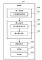
上記課題を解決するために、本発明のある態様の運転支援装置は、車両の自動運転における車両の行動を決定する自動運転制御部から、車両に実行させる第1行動を示す行動情報を取得する行動情報入力部と、車両の周囲状況および走行状態を検出する検出部から、検出結果を示す検出情報を取得する検出情報入力部と、行動情報が示す第1行動の後に車両に実行させることが可能な第2行動を検出情報に基づいて決定する候補決定部と、行動情報が示す第1行動を表す第1画像を生成し、第2行動を表す第2画像を生成する画像生成部と、車両の運転者の一定視野内に第1画像と第2画像を表示させるように第1画像と第2画像を車両内の表示部に出力する画像出力部と、を備える。 In order to solve the above problems, a driving support device according to an aspect of the present invention acquires behavior information indicating a first behavior to be executed by a vehicle from an automatic driving control unit that determines the behavior of the vehicle in automatic driving of the vehicle. A detection information input unit that acquires detection information indicating a detection result from a behavior information input unit, and a detection unit that detects a surrounding situation and a running state of the vehicle, and a vehicle that is executed after the first action indicated by the behavior information. A candidate determination unit that determines possible second behavior based on the detection information, an image generation unit that generates a first image representing the first behavior indicated by the behavior information, and generates a second image representing the second behavior; An image output unit that outputs the first image and the second image to a display unit in the vehicle so that the first image and the second image are displayed within a fixed visual field of the driver of the vehicle.
本発明の別の態様は、運転制御装置である。この装置は、車両の自動運転における車両の行動を決定する自動運転制御部と、車両の周囲状況および走行状態を検出する検出部から、検出結果を示す検出情報を取得する検出情報入力部と、自動運転制御部が車両に実行させる第1行動の後に車両に実行させることが可能な第2行動を検出情報に基づいて決定する候補決定部と、第1行動を表す第1画像を生成し、第2行動を表す第2画像を生成する画像生成部と、車両の運転者の一定視野内に第1画像と第2画像を表示させるように第1画像と第2画像を車両内の表示部に出力する画像出力部と、を備える。 Another aspect of the present invention is an operation control device. The apparatus includes an automatic driving control unit that determines a behavior of the vehicle in automatic driving of the vehicle, a detection information input unit that acquires detection information indicating a detection result from a detection unit that detects a surrounding state and a running state of the vehicle, A candidate determination unit that determines, based on the detection information, a second action that can be executed by the vehicle after the first action that the automatic operation control unit causes the vehicle to execute, and a first image that represents the first action, An image generation unit that generates a second image representing the second action, and a display unit in the vehicle that displays the first image and the second image in a fixed field of view of the driver of the vehicle. An image output unit for outputting to
本発明のさらに別の態様は、車両である。この車両は、本車両の自動運転における本車両の行動を決定する自動運転制御部と、本車両の周囲状況および走行状態を検出する検出部から、検出結果を示す検出情報を取得する検出情報入力部と、自動運転制御部が本車両に実行させる第1行動の後に本車両に実行させることが可能な第2行動を検出情報に基づいて決定する候補決定部と、第1行動を表す第1画像を生成し、第2行動を表す第2画像を生成する画像生成部と、本車両の運転者の一定視野内に第1画像と第2画像を表示させるように第1画像と第2画像を本車両内の表示部に出力する画像出力部と、を備える。 Yet another embodiment of the present invention is a vehicle. This vehicle has a detection information input for obtaining detection information indicating a detection result from an automatic driving control unit that determines the behavior of the vehicle in automatic driving of the vehicle and a detection unit that detects a surrounding state and a running state of the vehicle. A candidate determination unit that determines, based on the detection information, a second action that can be executed by the vehicle after the first action that the automatic driving control unit causes the vehicle to execute, and a first that represents the first action An image generation unit that generates an image and generates a second image representing the second action, and the first image and the second image so that the first image and the second image are displayed within a fixed visual field of the driver of the vehicle. And an image output unit that outputs to a display unit in the vehicle.
本発明のさらに別の態様は、運転支援方法である。この方法は、車両の自動運転における車両の行動を決定する自動運転制御部から、車両に実行させる第1行動を示す行動情報を取得するステップと、車両の周囲状況および走行状態を検出する検出部から、検出結果を示す検出情報を取得するステップと、行動情報が示す第1行動の後に車両に実行させることが可能な第2行動を検出情報に基づいて決定するステップと、行動情報が示す第1行動を表す第1画像を生成し、第2行動を表す第2画像を生成するステップと、車両の運転者の一定視野内に第1画像と第2画像を表示させるように第1画像と第2画像を車両内の表示部に出力するステップと、をコンピュータが実行する。 Yet another embodiment of the present invention is a driving support method. In this method, a step of acquiring behavior information indicating a first behavior to be executed by the vehicle from an automatic driving control unit that determines the behavior of the vehicle in the automatic driving of the vehicle, and a detection unit that detects a surrounding state and a running state of the vehicle. The step of acquiring detection information indicating the detection result, the step of determining the second action that can be executed by the vehicle after the first action indicated by the action information based on the detection information, and the first indicated by the action information Generating a first image representing one action, generating a second image representing the second action, and displaying the first image and the second image within a fixed field of view of the driver of the vehicle; The computer executes the step of outputting the second image to the display unit in the vehicle.
なお、以上の構成要素の任意の組合せ、本発明の表現を装置、システム、方法、プログラム、プログラムを記録した記録媒体、本装置を搭載した車両などの間で変換したものもまた、本発明の態様として有効である。 An arbitrary combination of the above components, the expression of the present invention converted between an apparatus, a system, a method, a program, a recording medium recording the program, a vehicle equipped with the apparatus, and the like are also included in the present invention. It is effective as an embodiment.
本発明によれば、完全自動運転または一部自動運転において、車両と運転者の操作が対立しにくい、快適な自動運転ができるように、適切に情報を伝達することができる。 According to the present invention, in fully automatic driving or partial automatic driving, information can be appropriately transmitted so that comfortable automatic driving can be performed in which the operations of the vehicle and the driver are unlikely to conflict with each other.
以下、本発明の実施の形態について、図面を参照して詳細に説明する。なお、以下に説明する各実施の形態は一例であり、本発明はこれらの実施の形態により限定されるものではない。 Hereinafter, embodiments of the present invention will be described in detail with reference to the drawings. Each embodiment described below is an example, and the present invention is not limited to these embodiments.
(実施の形態1)
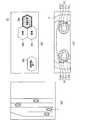
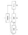
図1は、本発明の実施の形態1に係る情報報知装置を含む車両1の要部構成を示すブロック図である。車両1は、運転者の操作を必要とせずに、運転制御の全てまたは一部を自動で行うことができる車両である。(Embodiment 1)
FIG. 1 is a block diagram showing a main configuration of a
車両1は、ブレーキペダル2と、アクセルペダル3と、ウィンカレバー4と、ステアリングホイール5と、検出部6と、車両制御部7と、記憶部8と、情報報知装置9とを有する。 The
ブレーキペダル2は、運転者によるブレーキ操作を受けつけ、車両1を減速させる。またブレーキペダル2は、車両制御部7による制御結果を受けつけ、車両1の減速の度合いに対応した量変化してもよい。アクセルペダル3は、運転者によるアクセル操作を受けつけ、車両1を加速させる。またアクセルペダル3は、車両制御部7による制御結果を受けつけ、車両1の加速の度合いに対応した量変化してもよい。ウィンカレバー4は、運転者によるレバー操作を受けつけ、車両1の図示しない方向指示器を点灯させる。またウィンカレバー4は、車両制御部7による制御結果を受けつけ、車両1の方向指示方向に対応する状態にウィンカレバー4を変化させ、車両1の図示しない方向指示器を点灯させてもよい。 The
ステアリングホイール5は、運転者によるステアリング操作を受けつけ、車両1の走行する方向を変更する。またステアリングホイール5は、車両制御部7による制御結果を受けつけ、車両1の走行する方向の変更に対応した量変化してもよい。ステアリングホイール5は、操作部51を有する。 The
操作部51は、ステアリングホイール5の前面(運転者と対向する面)に設けられ、運転者からの入力操作を受け付ける。操作部51は、例えば、ボタン、タッチパネル、グリップセンサ等の装置である。操作部51は、運転者から受けつけた入力操作の情報を車両制御部7へ出力する。 The
検出部6は、車両1の走行状態、及び、車両1の周囲の状況を検出する。そして、検出部6は、検出した走行状態、及び、周囲の状況の情報を車両制御部7へ出力する。 The
この検出部6は、位置情報取得部61と、センサ62と、速度情報取得部63と、地図情報取得部64とを有する。 The
位置情報取得部61は、GPS(Global Positioning System)測位等により車両1の位置情報を走行状態の情報として取得する。 The position
センサ62は、車両1の周囲に存在する他車両の位置および車線位置情報から、他車両の位置および先行車両かどうかという種別、他車両の速度と自車両の速度から衝突予測時間(TTC:Time To Collision)、車両1の周囲に存在する障害物など、車両1の周囲の状況を検出する。 The
速度情報取得部63は、走行状態の情報として、図示しない速度センサ等から車両1の速度或いは走行方向などの情報を取得する。 The speed
地図情報取得部64は、車両1が走行する道路、道路における他車両との合流ポイント、現在走行中の車線、交差点の位置などの車両1の周辺の地図情報を、車両1の周囲の状況の情報として取得する。 The map
なお、センサ62は、ミリ波レーダ、レーザレーダ或いはカメラなど、またそれらの組合せから構成される。 The
記憶部8は、ROM(Read Only Memory)、RAM(Random Access Memory)、ハードディスク装置或いはSSD(Solid State Drive)などの記憶装置であり、現時点の走行環境と、次に(第1の所定時間経過後に)とり得る挙動の候補との間の対応関係を記憶する。 The
現時点の走行環境とは、車両1の位置、車両1が走行している道路、車両1の周囲に存在する他車両の位置および速度等によって判定される環境である。なお、瞬間的なデータのみならず、その時点の前後のデータまでを基に、例えば、他車両の位置或いは速度により加速中、減速中、他車両が割込んできて1秒後には衝突する可能性まで判定してもよい。これにより、他車両の行動を予測することができ、走行環境をより詳細かつ正確に把握することが可能である。挙動の候補とは、現時点の走行環境に対して、車両1が次に(第1の所定時間経過後に)とり得る挙動の候補である。 The current traveling environment is an environment determined by the position of the
例えば、記憶部8は、車両1が走行する車線の前方に合流路があり、車線の左方から合流する車両が存在し、かつ、車両1が走行する車線の右方への車線変更が可能な走行環境に対応付けて、車両1の加速、車両1の減速、及び、車両1の右方への車線変更の3通りの挙動の候補を予め記憶する。 For example, the
また、記憶部8は、車両1と同一車線の前方を走行する車両(以下、「先行車両」と記載)が車両1よりも遅い速度で走行し、かつ、隣の車線への車線変更が可能な走行環境に対応付けて、先行車両を追い越す走行、隣の車線へ車線変更を行う走行、車両1を減速させて先行車両に追従する走行の3通りの挙動の候補を予め記憶する。 In addition, the
さらに、記憶部8は、それぞれの挙動の候補に対する優先順位を記憶してもよい。例えば、記憶部8は、過去の同一の走行環境において実際に採用された挙動の回数を記憶し、採用された回数の多い挙動ほど高く設定された優先順位を記憶してもよい。 Further, the
車両制御部7は、例えば、LSI回路、または、車両を制御する電子制御ユニット(Electronic Control Unit:ECU)の一部として実現可能である。車両制御部7は、検出部6から取得する走行状態および周囲の状況の情報に基づいて、車両を制御し、車両制御結果に対応してブレーキペダル2、アクセルペダル3、ウィンカレバー4、情報報知装置9を制御する。なお、車両制御部7が制御する対象は、これらに限定されない。 The
まず、車両制御部7は、走行状態および周囲の状況の情報に基づいて、現時点の走行環境を判定する。この判定には、従来提案されている様々な方法が利用され得る。 First, the
例えば、車両制御部7は、走行状態および周囲の状況の情報に基づいて、現時点の走行環境が、「車両1が走行する車線の前方に合流路があり、車線の左方から合流する車両が存在し、かつ、車両1が走行する車線の右方への車線変更が可能な走行環境」であると判定する。 For example, the
また、例えば、車両制御部7は、走行状態および周囲の状況の情報に基づいて、走行環境の時系列が、「車両1と同一車線の前方を走行する車両が車両1よりも遅い速度で走行し、かつ、隣の車線への車線変更が可能な走行環境」であると判定する。 In addition, for example, the
車両制御部7は、走行状態および周囲の状況を示す走行環境に関する情報を情報報知装置9の報知部92に報知させる。また、車両制御部7は、判定した走行環境に対して、車両1が次に(第1の所定時間経過後に)とり得る挙動の候補を記憶部8から読み出す。 The
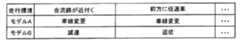
車両制御部7は、読み出した挙動の候補から、現在の走行環境に最も適した挙動がどれかを判定し、現在の走行環境に最も適した挙動を第1の挙動に設定する。なお、第1の挙動は車両現在実施している挙動と同じ挙動、即ち現在実施している挙動を継続することであってもよい。そして、車両制御部7は、現在の走行環境において第1の挙動を除く他に運転者が実施可能性な挙動の候補を第2の挙動(いわゆる実施する挙動とは異なる挙動)に設定する。 The
例えば、車両制御部7は、走行状態および周囲の状況の情報に基づいて最も適した挙動を判定する従来技術を用いて、最も適した挙動を第1の挙動に設定することとしてもよい。 For example, the
または、車両制御部7は、複数の挙動の候補のうち、予め設定された挙動を最も適した挙動として設定してもよいし、前回選択された挙動の情報を記憶部8に記憶しておき、その挙動を最も適した挙動と判定してもよいし、過去に各挙動が選択された回数を記憶部8に記憶しておき、回数が最も多い挙動を最も適した挙動と判定してもよい。 Alternatively, the
そして、車両制御部7は、第1の挙動と第2の挙動の情報を情報報知装置9の報知部92に報知させる。なお、車両制御部7は第2の挙動が無いと判定した場合、第1の挙動のみを報知部92に報知させる。 And the
なお、車両制御部7は、第1の挙動と第2の挙動の情報と、走行状態および周囲の状況の情報とを、同時に、報知部92に報知させてもよい。 Note that the
さらに、車両制御部7は、操作部51が運転者から受けつけた操作の情報を取得する。車両制御部7は、第1の挙動と第2の挙動を報知してから、第2の所定時間内に操作部51が操作を受けつけたか否かを判定する。この操作は、例えば、第2の挙動に含まれる挙動の中から1つの挙動を選択する操作である。 Further, the
車両制御部7は、第2の所定時間内に操作部51が操作を受けつけなかった場合、第1の挙動を実行するように車両を制御し、車両制御結果に対応してブレーキペダル2、アクセルペダル3、ウィンカレバー4を制御する。 The
車両制御部7は、第2の所定時間内に操作部51が操作を受けつけた場合、受けつけた操作に対応する制御を行う。 When the
情報報知装置9は、車両制御部7から車両1の走行に関する種々の情報を取得し、取得した情報を報知する。情報報知装置9は、情報取得部91と報知部92とを有する。 The
情報取得部91は、車両制御部7から車両1の走行に関する種々の情報を取得する。例えば、情報取得部91は、車両制御部7が車両1の挙動を更新する可能性があると判定した場合に、車両制御部7から第1の挙動の情報と第2の挙動の情報を取得する。 The
そして、情報取得部91は、取得した情報を図示しない記憶部に一時的に記憶し、必要に応じて記憶した情報を記憶部から読み出して報知部92へ出力する。 And the
報知部92は、車両1の走行に関する情報を運転者に報知する。報知部92は、例えば、車内に設置されているカーナビゲーションシステム、ヘッドアップディスプレイ、センターディスプレイ、ステアリングホイール5或いはピラーに設置されているLEDなどの発光体などのような情報を表示する表示部であってもよいし、情報を音声に変換して運転者に報知するスピーカであってもよいし、あるいは、運転者が感知できる位置(例えば、運転者の座席、ステアリングホイール5など)に設けられる振動体であってもよい。また、報知部92は、これらの組み合わせであってもよい。 The
以下の説明では、報知部92が報知装置であるものとする。 In the following description, it is assumed that the
この場合、報知部92とは、例えば、ヘッドアップディスプレイ(Head Up Display:HUD)、LCD(Liquid Crystal Display)、HMD(Head-Mounted DisplayまたはHelmet-Mounted Display)、眼鏡型ディスプレイ(Smart Glasses)、その他の専用のディスプレイなどである。HUDは、例えば、車両1のウインドシールドであってもよいし、別途設けられるガラス面、プラスチック面(例えば、コンバイナ)などであってもよい。また、ウインドシールドは、例えば、フロントガラスであってもよいし、車両1のサイドガラスまたはリアガラスであってもよい。 In this case, the
さらに、HUDは、ウインドシールドの表面または内側に備えられた透過型ディスプレイであってもよい。ここで、透過型ディスプレイとは、例えば、透過型の有機ELディスプレイ、または、特定の波長の光を照射した際に発光するガラスを用いた透明なディスプレイである。運転者は、背景を視認すると同時に、透過型ディスプレイ上の表示を視認することができる。このように報知部92は、光を透過する表示媒体であってもよい。いずれの場合も、画像が報知部92に表示される。 Further, the HUD may be a transmissive display provided on or inside the windshield. Here, the transmissive display is, for example, a transmissive organic EL display or a transparent display using glass that emits light when irradiated with light of a specific wavelength. The driver can view the display on the transmissive display at the same time as viewing the background. Thus, the
報知部92は、車両制御部7から情報取得部91を介して取得した走行に関する情報を運転者に報知する。例えば、報知部92は、車両制御部7から取得した第1の挙動、及び、第2の挙動の情報を運転者に報知する。 The
ここで、具体的な表示内容、及び、操作部51に対してなされる操作について説明する。 Here, specific display contents and operations performed on the
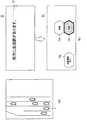
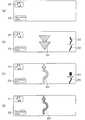
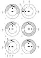
図2は、走行環境の第1の例と、それに対する報知部92の表示、及び、操作部51の操作について説明する図である。 FIG. 2 is a diagram for explaining a first example of the traveling environment, the display of the
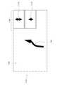
図2(a)は、車両1の走行環境を示す俯瞰図である。具体的には、図2(a)は、車両1が走行する車線の前方に合流路があり、車線の左方から合流する車両が存在し、かつ、車両1が走行する車線の右方への車線変更が可能な走行環境であることを示している。 FIG. 2A is an overhead view showing the traveling environment of the
車両制御部7は、走行状態および周囲の状況の情報に基づき、走行環境が、図2(a)に示すような走行環境であると判定する。なお、車両制御部7は、図2(a)に示す俯瞰図を生成し、第1の挙動、及び、第2の挙動の情報に加えて、生成した俯瞰図を報知部92に報知させてもよい。 The
図2(b)は、図2(a)に示した走行環境に対する報知部92の表示の一例を示している。報知部92の表示範囲のうち、右側には、車両1の挙動に関わる選択肢が表示され、左側には、手動運転に切り替えるための情報が表示される。 FIG. 2B shows an example of the display of the
第1の挙動は、表示領域29a〜29c、29gのうち、強調されている表示領域29bに示されている「車線変更」である。第2の挙動は、表示領域29a、29cにそれぞれ示されている「加速」、「減速」である。また、表示領域29gには、手動運転に切替えることを示す「自動運転終了」が表示されている。 The first behavior is “lane change” shown in the highlighted
図2(c)は、ステアリングホイール5に設けられる操作部51の一例を示している。操作部51は、ステアリングホイール5の右側に設けられる操作ボタン51a〜51dと、ステアリングホイール5の左側に設けられる操作ボタン51e〜51hとを有する。なお、ステアリングホイール5に設けられる操作部51の数や形状等はこれらに限定されない。 FIG. 2C shows an example of the
本実施の形態では、図2(b)に示す表示領域29a〜29cと操作ボタン51a〜51cがそれぞれ対応し、表示領域29gと操作ボタン51gとが対応する。 In the present embodiment, the
この構成において、運転者は、各表示領域に表示される内容のいずれかを選択する際に、各表示領域に対応する操作ボタンを押下する。例えば、運転者が表示領域29aに表示される「加速」という挙動を選択する場合、運転者は、操作ボタン51aを押下する。 In this configuration, the driver presses an operation button corresponding to each display area when selecting any of the contents displayed in each display area. For example, when the driver selects the behavior “acceleration” displayed in the
なお、図2(b)には、各表示領域に文字の情報のみが表示されているが、次に説明するように、車両の駆動に関する記号或いはアイコンを表示してもよい。これにより、運転者に表示内容を一目瞭然に把握できる。 In FIG. 2B, only character information is displayed in each display area. However, as described below, a symbol or icon relating to driving of the vehicle may be displayed. As a result, the driver can grasp the display contents at a glance.
図3は、報知部92における表示の別の例を示す図である。図3に示すように、表示領域39a〜39c、39gに文字の情報とその情報を示す記号の両方が表示される。なお、記号のみが表示されてもよい。 FIG. 3 is a diagram illustrating another example of display in the
次に、具体的な走行環境を例に挙げて、表示制御の流れについて説明する。 Next, the flow of display control will be described using a specific traveling environment as an example.
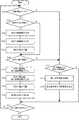
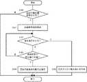
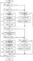
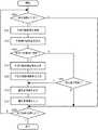
図4は、本実施の形態における情報報知処理の処理手順を示すフローチャートである。図5は、走行環境の第1の例と、それに対する表示制御を示す図である。 FIG. 4 is a flowchart showing a processing procedure of information notification processing in the present embodiment. FIG. 5 is a diagram illustrating a first example of a traveling environment and display control for the first example.
図4に示すように、検出部6は、車両の走行状態を検出する(ステップS11)。次に、検出部6は、車両の周囲の状況を検出する(ステップS12)。検出された車両の走行状態、及び、車両の周囲の状況の情報は、検出部6により車両制御部7へ出力される。 As shown in FIG. 4, the
つぎに、車両制御部7は、走行状態および周囲の状況の情報に基づいて、現時点の走行環境を判定する(ステップS13)。図5(a)の例の場合、車両制御部7は、現時点の走行環境が、「車両1が走行する車線の前方に合流路があり、車線の左方から合流する車両が存在し、かつ、車両1が走行する車線の右方への車線変更が可能な走行環境」であると判定する。 Next, the
その後、車両制御部7は、判定した走行環境の情報を情報報知装置9の報知部92に報知させる(ステップS14)。図5(b)の例の場合、車両制御部7は、判定した走行環境の情報を情報取得部91へ出力する。報知部92は、情報取得部91から走行環境の情報を取得し、文字情報59として表示させる。なお、車両制御部7は、走行環境の情報を報知部92に表示させる代わりに、スピーカ等で音声として走行環境の情報を運転者に報知してもよい。これにより、運転者がディスプレイ或いはモニターを見ていない、もしくは見落としている場合でも、運転者に確実に情報を伝達できる。 Thereafter, the
次に、車両制御部7は、判定した走行環境が挙動の更新の可能性があるとするか否かを判定し、更新する可能性があるとすると判定された場合、さらに第1の挙動、及び、第2の挙動の判定を行う(ステップS15)。走行環境が挙動の更新の可能性があるとするか否かの判定は、走行環境が変更したか否かによって判定される。更新後実施する挙動とは、例えば、他の車両等と衝突が発生する可能性がある場合に減速する、ACC(Adaptive Cruise Control)において先行車両が消えた場合に速度変更する、隣の車線が空いた場合に車線変更するなどが考えられる。更新するか否かを判定するときは従来技術を用いてなされる。 Next, the
この場合、車両制御部7は、判定した走行環境に対して、車両1が次に(第1の所定時間経過後に)とり得る挙動の候補を記憶部8から読み出す。そして、車両制御部7は、挙動の候補から、現在の走行環境に最も適した挙動がどれかを判定し、現在の走行環境に最も適した挙動を第1の挙動に設定する。そして、車両制御部7は、第1の挙動を除く挙動の候補を第2の挙動に設定する。 In this case, the
図5(b)の例の場合、車両制御部7は、記憶部8から、車両1の加速、車両1の減速、及び車両1の右方への車線変更の3通りの挙動の候補を読み出す。そして、車両制御部7は、左方から合流する車両の速度、及び、車両1の右方の車線の状況に基づき、車両1の右方への車線変更が最も適した挙動であると判定し、その挙動を第1の挙動に設定する。そして、車両制御部7は、第1の挙動を除く挙動の候補を第2の挙動に設定する。 In the case of the example of FIG. 5B, the
次に、車両制御部7は、第1の挙動、及び、第2の挙動を情報報知装置9の報知部92に報知させる(ステップS16)。図5(b)の例の場合、報知部92は、第1の挙動の情報である「車線変更」という文字情報を表示領域59bに強調して表示し、第2の挙動の情報である「加速」、「減速」をそれぞれ表示領域59a、59cに表示させる。 Next, the
次に、車両制御部7は、第2の所定時間内に操作部51が運転者からの操作を受けつけたか否かを判定する(ステップS17)。 Next, the
例えば、車両制御部7は、現時点での走行環境が図5(a)に示す走行環境であると判定してから、合流ポイントに到達するまでの時間を第1の所定時間と設定する。そして、車両制御部7は、第1の所定時間よりも短い第2の所定時間を、合流ポイントまでに実行される次の挙動に対する操作の受付が可能な時間として設定する。 For example, the
車両制御部7は、第2の所定時間内に操作部51が運転者からの操作を受けつけた場合(ステップS17においてYES)、受けつけた操作が自動運転終了の操作か、挙動の選択操作(いわゆる更新)かを判定する(ステップS18)。 When the
図2にて説明したように、報知部92の各表示領域と操作部51の各操作ボタンとは対応している。運転者は、図5(b)における自動運転終了を選択する場合、図2(c)に示した操作ボタン51gを押下する。また、運転者は、挙動の選択を行う場合、図2(c)に示した操作ボタン51a〜51cのいずれかを押下する。 As described with reference to FIG. 2, the display areas of the
車両制御部7は、操作部51が受けつけた操作が自動運転終了の操作である場合(つまり、操作ボタン51gが押下されたことを検知した場合)、自動運転を終了させる(ステップS19)。車両制御部7は、操作部51が受けつけた操作が挙動の選択操作である場合(つまり、操作ボタン51a〜51cのいずれかが押下された場合)、押下された操作ボタンに対応する挙動を実行するように、車両1の制御を行う(ステップS20)。 When the operation received by the
車両制御部7は、第2の所定時間内に操作部51が運転者からの操作を受けつけなかった場合(ステップS17においてNO)、第1の挙動を実行するように、車両1の制御を行う(ステップS21)。 The
図6は、走行環境の第1の例と、それに対する別の表示制御を示す図である。図6(a)は、図5(a)と同様であるが、図6(b)の表示制御が図5(b)の表示制御とは異なっている。 FIG. 6 is a diagram illustrating a first example of a traveling environment and another display control for the first example. FIG. 6A is the same as FIG. 5A, but the display control of FIG. 6B is different from the display control of FIG. 5B.
図5(b)を用いて説明した場合と同様に、車両制御部7は、図6(a)に示した走行環境に対して、記憶部8から、車両1の加速、車両1の減速、及び車両1の右方への車線変更の3通りの挙動の候補を読み出す。その際、記憶部8には、車両1の右方への車線変更が最も優先される挙動として記憶されているものとする。 Similarly to the case described with reference to FIG. 5B, the
この場合、車両制御部7は、走行環境の情報と、第1の挙動の情報とを報知部92に報知させる。図6(b)の場合、車両制御部7は、走行環境の情報と、第1の挙動の情報を示す文字情報69を生成し、報知部92に文字情報69を表示させる。 In this case, the
そして、車両制御部7は、運転者に第1の挙動の採否を促す表示を表示領域69a、69cに表示させる。また、車両制御部7は、手動運転に切り替え可能であることを示す「自動運転終了」という表示を表示領域69gに表示させる。 Then, the
ここで、車両制御部7は、第1の挙動を採用することに対応する「YES」を強調して表示する。「YES」、「NO」のどちらを強調して表示するかは、予め定められていてもよいし、前回選択された選択肢を強調して表示することとしてもよいし、過去に選択された回数を記憶部8に記憶しておき、回数が多い方を報知部92が強調して表示することとしてもよい。 Here, the
このように過去に選択された挙動を学習することにより、車両制御部7は、運転者に適切に情報を報知できる。また、図5(b)の場合よりも報知部92に報知させる表示を減らすことができ、運転者の煩わしさを低減できる。 Thus, by learning the behavior selected in the past, the
図7は、走行環境の第2の例と、それに対する表示制御を示す図である。図7(a)は、走行環境を示す俯瞰図である。図7(a)に示す走行環境は、前方に合流路がある点で図5(a)、図6(a)と同様であるが、車両1の右側に走行車両が存在する点で図5(a)、図6(a)と異なる。このような場合、車両制御部7は、車線変更が行えないと判断する。 FIG. 7 is a diagram illustrating a second example of a traveling environment and display control for the second example. FIG. 7A is an overhead view showing the traveling environment. The driving environment shown in FIG. 7A is the same as that shown in FIGS. 5A and 6A in that there is a joint path ahead, but the driving environment shown in FIG. (A) is different from FIG. 6 (a). In such a case, the
そして、車両制御部7は、車両1の走行環境が図7(a)のようなものと判定した場合、図7(b)に示すように、判定した走行環境の情報を報知部92に文字情報79として表示させる。 When the
さらに、車両制御部7は、記憶部8から読み出した車両1の加速、車両1の減速、及び、車両1の右方への車線変更の3通りの挙動の候補のうち、車両1の右方への車線変更はできないため、車両1の加速、及び、車両1の減速のみを選択する。 Further, the
また、車両制御部7は、このままの速度で進むと合流車両と接近しすぎることを予測し、車両1の減速が最も適した挙動である、つまり、第1の挙動であると判定する。 Further, the
ここで、3通りの挙動の候補のうち、最も適した挙動がどれかは、走行状態および周囲の状況の情報に基づいて最も適した挙動を判定する従来技術を用いて判定される。また、最も適した挙動がどれかは、予め定められていてもよいし、前回選択された挙動の情報を記憶部8に記憶しておき、その挙動を最も適した挙動と判定してもよいし、過去に各挙動が選択された回数を記憶部8に記憶しておき、回数が最も多い挙動を最も適した挙動と判定してもよい。 Here, of the three behavior candidates, which is the most suitable behavior is determined using a conventional technique for determining the most suitable behavior based on information on the running state and the surrounding situation. Further, which behavior is most suitable may be determined in advance, or information on the behavior selected last time may be stored in the
その後、車両制御部7は、「減速」を第1の挙動として表示領域79cに表示させ、「加速」を第2の挙動として表示領域79aに表示させる。また、車両制御部7は、手動運転に切替えることを示す「自動運転終了」という表示を表示領域79gに表示させる。 Thereafter, the
このような表示制御により、車両制御部7は、走行環境に応じて、その走行環境に最も適した挙動を第1の挙動として運転者に報知できる。 By such display control, the
第1の挙動の情報を上方に、第2の挙動の情報を下方に配置し、それぞれ操作ボタン51a、51cに選択機能を割り当ててもよいし、加速挙動の情報を上方に、減速挙動の情報を下方に、右車線変更の挙動の情報を右方に、左車線変更の挙動の情報を左方へ配置し、それぞれ操作ボタン51a、51c、51b、51dに選択機能を割り当ててもよいし、それらを切り替えられるようにし、別途行動優先配置か、操作優先配置かを表示してもよい。さらに、第1の挙動の情報の表示サイズを大きく、第2の挙動の情報の表示サイズを小さくしてもよい。なお、車の前後・左右の挙動と対応して挙動情報の表示を配置することにより、運転者に直感的な認識と操作が可能である。 The information on the first behavior may be arranged on the upper side, the information on the second behavior may be arranged on the lower side, and a selection function may be assigned to each of the
次に、前方に合流路があるという走行環境以外の走行環境の例について説明する。 Next, an example of a traveling environment other than the traveling environment in which there is a joint path ahead will be described.
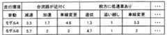
図8は、走行環境の第3の例と、それに対する表示制御を示す図である。図8(a)は、車両1の走行環境を示す俯瞰図である。具体的には、図8(a)には、先行車両が車両1よりも遅い速度で走行し、かつ、隣の車線への車線変更が可能な走行環境が示されている。 FIG. 8 is a diagram illustrating a third example of the traveling environment and display control for the third example. FIG. 8A is an overhead view showing the traveling environment of the
車両制御部7は、走行状態および周囲の状況の情報に基づき、走行環境が、図8(a)に示すような走行環境であると判定する。この場合、車両制御部7は、判定した走行環境の情報を報知部92に文字情報89として表示させる。 The
また、車両制御部7は、判定した走行環境に対応する挙動の候補として、先行車両を追い越す走行、隣の車線へ車線変更を行う走行、車両1を減速させて先行車両を追従する走行の3通りの挙動の候補を記憶部8から読み出す。 In addition, the
そして、車両制御部7は、例えば、先行車両の減速後の速度が所定値より高く許容できることから、車両1を減速させて先行車両を追従する走行が最も適した挙動、つまり、第1の挙動であると判定する。 For example, the
ここで、3通りの挙動の候補のうち、最も適した挙動がどれかは、走行状態および周囲の状況の情報に基づいて最も適した挙動を判定する従来技術を用いて判定される。また、最も適した挙動がどれかは、予め定められていてもよいし、前回選択された挙動の情報を記憶部8に記憶しておき、その挙動を最も適した挙動と判定してもよいし、過去に各挙動が選択された回数を記憶部8に記憶しておき、回数が最も多い挙動を最も適した挙動と判定してもよい。 Here, of the three behavior candidates, which is the most suitable behavior is determined using a conventional technique for determining the most suitable behavior based on information on the running state and the surrounding situation. Further, which behavior is most suitable may be determined in advance, or information on the behavior selected last time may be stored in the
さらに、車両制御部7は、図8(b)に示すように、第1の挙動を示す「追従」という文字情報を表示領域89cに強調して表示し、第2の挙動を示す「追い越し」、「車線変更」という文字情報をそれぞれ表示領域89a、89bに表示させる。また、車両制御部7は、手動運転に切替えることを示す「自動運転終了」という表示を表示領域89gに表示させる。 Further, as shown in FIG. 8B, the
第1の挙動の情報を上方に、第2の挙動の情報を下方に配置し、それぞれ操作ボタン51a、51cに選択機能を割り当ててもよいし、追い越し挙動の情報を上方に、追従挙動の情報を下方に、右車線変更の挙動の情報を右方に、左車線変更の挙動の情報を左方へ配置し、それぞれ操作ボタン51a、51c、51b、51dに選択機能を割り当ててもよいし、それらを切り替えられるようにし、別途行動優先配置か、操作優先配置かを表示してもよい。さらに、第1の挙動の情報の表示サイズを大きく、第2の挙動の情報の表示サイズを小さくしてもよい。 The information on the first behavior may be arranged on the upper side, the information on the second behavior may be arranged on the lower side, and a selection function may be assigned to the
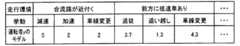
図9は、走行環境の第4の例と、それに対する表示制御を示す図である。図9(a)は、車両1の走行環境を示す俯瞰図である。具体的には、図9(a)は、走行環境が、車両1と同一車線の前方において、車線が減少する走行環境であることを示している。 FIG. 9 is a diagram illustrating a fourth example of the traveling environment and display control for the fourth example. FIG. 9A is an overhead view showing the traveling environment of the
車両制御部7は、走行状態および周囲の状況の情報に基づき、走行環境が、図9(a)に示すような走行環境であると判定する。この場合、車両制御部7は、判定した走行環境の情報を報知部92に文字情報99として表示させる。 The
また、車両制御部7は、判定した走行環境に対応する挙動の候補として、隣の車線へ車線変更を行う走行、そのまま現車線を維持する走行の2通りの挙動の候補を記憶部8から読み出す。 In addition, the
そして、車両制御部7は、例えば、車線減少箇所までのTTCが所定値より短いため、隣の車線へ車線変更を行う走行が最も適した挙動である、つまり、第1の挙動であると判定する。 For example, the
ここで、2通りの挙動の候補のうち、最も適した挙動がどれかは、走行状態および周囲の状況の情報に基づいて最も適した挙動を判定する従来技術を用いて判定される。また、最も適した挙動がどれかは、予め定められていてもよいし、前回選択された挙動の情報を記憶部8に記憶しておき、その挙動を最も適した挙動と判定してもよいし、過去に各挙動が選択された回数を記憶部8に記憶しておき、回数が最も多い挙動を最も適した挙動と判定してもよい。 Here, of the two behavior candidates, which is the most suitable behavior is determined using a conventional technique for determining the most suitable behavior based on information on the running state and the surrounding situation. Further, which behavior is most suitable may be determined in advance, or information on the behavior selected last time may be stored in the
さらに、車両制御部7は、図9(b)に示すように、第1の挙動を示す「車線変更」という文字情報を表示領域99bに強調して表示し、第2の挙動を示す「そのまま」という文字情報を表示領域99cに表示させる。また、車両制御部7は、手動運転に切替えることを示す「自動運転終了」という表示を表示領域99gに表示させる。 Further, as shown in FIG. 9B, the
第1の挙動の情報を上方に、第2の挙動の情報を下方に配置し、それぞれ操作ボタン51a、51cに選択機能を割り当ててもよいし、何もしない挙動の情報を下方に、右車線変更の挙動の情報を右方に、左車線変更の挙動の情報を左方へ配置し、それぞれ操作ボタン51c、51b、51dに選択機能を割り当ててもよいし、それらを切り替えられるようにし、別途行動優先配置か、操作優先配置かを表示してもよい。さらに、第1の挙動の情報の表示サイズを大きく、第2の挙動の情報の表示サイズを小さくしてもよい。なお、図7、8、9に示されているように、異なる走行環境によって、表示領域にはそれぞれ異なる機能が割り当てられることで、少ない領域で情報報知或いは操作することができる。 The first behavior information may be arranged above, the second behavior information may be arranged below, and a selection function may be assigned to each of the
上記の説明では、車両制御部7が、走行環境および周囲の状況の情報に応じて、報知部92に挙動を報知させる場合について説明したが、本発明はこれに限定されない。例えば、運転者による所定の操作があったときに、報知部92に挙動を報知させることとしてもよい。 In the above description, the case where the
図10は、走行環境の第5の例と、それに対する表示制御を示す図である。図10(a)は、車両1の走行環境を示す俯瞰図である。具体的には、図10(a)には、車両1が左方と右方にそれぞれ車線変更可能な走行環境であることを示す走行環境が示されている。 FIG. 10 is a diagram illustrating a fifth example of a traveling environment and display control for the fifth example. FIG. 10A is an overhead view showing the traveling environment of the
図10(a)に示す走行環境は、図5(a)〜図9(a)の場合と異なり、車線の変更或いは車両の加速、減速が不要な通常走行が可能な走行環境である。この場合、車両制御部7は、図10(b)の表示109に示すように、走行環境の情報を報知部92に文字情報として表示させなくともよい。 The travel environment shown in FIG. 10 (a) is a travel environment in which normal travel is possible without changing lanes or acceleration / deceleration of the vehicle, unlike the cases of FIGS. 5 (a) to 9 (a). In this case, as shown in the
このように報知部92に文字情報が表示されていない状況において、運転者が操作部51のいずれかの操作ボタンを押下した場合、車両制御部7は、通常走行における挙動の候補を記憶部8から読み出す。 When the driver presses one of the operation buttons of the
具体的には、記憶部8には、図10(a)に示すような通常走行の走行環境に対応付けて、車両1の加速、車両1の減速、車両1の右方への車線変更、車両1の左方への車線変更の4通りの挙動の候補が記憶されている。車両制御部7は、これらを読み出し、報知部92の表示領域109a〜109dにそれぞれ表示させる。 Specifically, in the
また、車両制御部7は、手動運転に切り替えることを示す「自動運転終了」という表示を表示領域99gに表示させるとともに、挙動の更新をキャンセルすることを示す「キャンセル」という表示を表示領域109eに強調して表示させる。 In addition, the
以上説明した本実施の形態によれば、運転者に次に実施される挙動の候補を効果的に報知し、運転者により好ましい挙動を選択させることができる。 According to the present embodiment described above, it is possible to effectively notify the driver of behavior candidates to be performed next, and to select a preferable behavior for the driver.
なお、運転者が実施したい挙動を選択する代わりに、直接ステアリングホイールなどの手動操作をしてもよい。これにより、運転者が自分の意思により素早く手動運転操作に切り替えられる。 Instead of selecting the behavior that the driver wants to implement, manual operation of the steering wheel or the like may be performed directly. As a result, the driver can quickly switch to the manual driving operation according to his / her own intention.
[変形例]
以上説明した本実施の形態では、報知部92における表示は、文字情報であるとして説明したが、本発明はこれに限定されない。例えば、挙動を示す記号を用いて運転者に視覚的に表示させてもより。以下では、運転者に視覚的に表示させる記号を用いた表示を図5および図7に対する表示を例にとって説明する。[Modification]
In the present embodiment described above, the display in the
図11は、図5に示した走行環境の第1の例に対する別の表示制御を示す図である。この例では、上述した第1の挙動が車両1の右方への車線変更であり、第2の挙動が車両1の加速、及び、車両1の減速である。 FIG. 11 is a diagram showing another display control for the first example of the traveling environment shown in FIG. In this example, the first behavior described above is a lane change to the right of the
この場合、第1の挙動である「車線変更」を示す記号111が中央に大きく表示され、第2の挙動である「車両1の加速」を示す記号112、及び、「車両1の減速」を示す記号113が右方に小さく表示される。また、自動運転終了を示す記号114が左方に小さく表示される。 In this case, a
そして、このまま運転手により車両1の挙動の変更指示を受けつけなければ、車線変更が行われる。 If the driver does not accept an instruction to change the behavior of the
図12は、図7に示した走行環境の第2の例に対する別の表示制御を示す図である。この例では、上記第1の例と異なり、車両1の右方に別の車両が走行しているため、車線変更ができない。そのため、例えば、「車両1の減速」が第1の挙動に設定され、「車両1の加速」が第2の挙動に設定される。 FIG. 12 is a diagram illustrating another display control for the second example of the traveling environment illustrated in FIG. 7. In this example, unlike the first example, since another vehicle is traveling to the right of the
そして、この場合、図12(a)に示すように、第1の挙動である「車両1の減速」を示す記号121が中央に大きく表示され、第2の挙動である「車両1の加速」を示す記号122が右方に小さく表示される。また、自動運転終了を示す記号123が左方に小さく表示される。 In this case, as shown in FIG. 12A, the
ここで、操作部51が運転手から「車両1の加速」を選択する操作を受けつけたものとする。この場合、図12(b)に示すように、第1の挙動である「車両1の加速」を示す記号122’が中央に大きく表示され、第2の挙動である「車両1の減速」を示す記号121’が右方に小さく表示されることになる。 Here, it is assumed that the
以上説明した本実施の形態によれば、運転者に次に実施される挙動の候補を効果的に報知し、運転者により好ましい挙動を選択させることができる。一方、運転者は、車両が実施する挙動や他に選択可能な挙動を把握でき、安心感を持って自動運転を継続することできる。または、運転者がスムーズに車へ指示を与えることができる。 According to the present embodiment described above, it is possible to effectively notify the driver of behavior candidates to be performed next, and to select a preferable behavior for the driver. On the other hand, the driver can grasp the behavior performed by the vehicle and other behaviors that can be selected, and can continue the automatic driving with a sense of security. Alternatively, the driver can give instructions to the car smoothly.
また、本実施の形態によれば、走行環境に応じて、報知部に報知させる選択肢、つまり、第2の挙動を可変にすることができる。 Moreover, according to this Embodiment, according to driving | running | working environment, the choice made to alert | report an information part, ie, a 2nd behavior, can be made variable.
(実施の形態2)
実施の形態1では、ステアリングホイール5に設けられた操作部51によって、報知部92の表示に応じた操作を行う構成について説明した。本実施の形態では、ステアリングホイール5に設けられる操作部51の代わりに、タッチパネルが設けられる構成について説明する。(Embodiment 2)
In the first embodiment, the configuration in which the
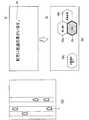
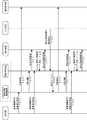
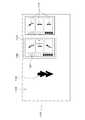
図13は、本発明の実施の形態2に係る情報報知装置を含む車両1の要部構成を示すブロック図である。なお、図13において、図1と共通する構成には図1と同一の符号を付し、その詳しい説明を省略する。図13に示す車両1には、ステアリングホイール5の操作部51の代わりにタッチパネル10が設けられている。 FIG. 13 is a block diagram showing a main configuration of the
タッチパネル10は、情報の表示と入力の受付が可能な液晶パネル等からなる装置であり、車両制御部7と接続される。タッチパネル10は、車両制御部7による制御に基づいて情報を表示する表示部101と、運転者等からの操作を受けつけ、受けつけた操作を車両制御部7へ出力する入力部102とを有する。 The
次に、タッチパネル10の表示制御について説明する。ここでは、車両1が3車線の中央を走行中であり、右方の車線と左方の車線のいずれかに車線変更が可能である場合の表示制御について説明する。 Next, display control of the
図14は、実施の形態2におけるタッチパネル10の表示を説明する図である。図14(a)は、タッチパネル10の表示部101の初期表示である。車両制御部7は、車両1が右方の車線と左方の車線のいずれかに車線変更が可能であると判定した場合、タッチパネル10の表示部101に図14(a)のような表示を実行させる。ここで、表示領域121における「Touch」という表示は、タッチパネル10が運転者によるタッチ操作を受けつけ可能なモードであることを示している。 FIG. 14 is a diagram illustrating display on
運転者は、図14(a)に示す表示において、表示領域121をタッチするタッチ操作を行う場合、入力部102は、この操作を受けつけて、この操作が行われたことを示す情報を車両制御部7へ出力する。車両制御部7は、この情報を受けつけると、図14(b)に示す表示を表示部101に表示させ、また、図14(c)に示す表示を報知部92に表示させる。 When the driver performs a touch operation of touching the
図14(b)には、車両1へ移動を指示する操作であることを示す「Move」と表示された表示領域121aが示されている。また、図14(b)には、車両1が3車線のそれぞれを走行可能であることを示す表示領域121b〜121dが示されている。なお、表示領域121b〜121dは、それぞれ、図14(c)に矢印X、Y、Zで示される車線での走行と対応する。 FIG. 14B shows a
また、図14(b)の各表示領域と、図14(c)の各矢印とは、それぞれ、態様(例えば、色或いは配置など)を一致させる。これにより、運転者により理解しやすい表示となる。 In addition, each display area in FIG. 14B and each arrow in FIG. 14C have the same mode (for example, color or arrangement). As a result, the display is easier to understand for the driver.
さらに、矢印X、Y、Zで示される車線の太さなどを変えて、車両制御が判定した車両が実施する挙動と他に運転者が選択可能な挙動が区別できるように表示してもよい。 Further, by changing the thickness of the lane indicated by the arrows X, Y, and Z, the behavior performed by the vehicle determined by the vehicle control may be displayed so that the behavior selectable by the driver can be distinguished. .
運転者は、表示領域121b〜121dのうち、走行したい車線に対応する表示領域に触れることによって、車両1の挙動の選択を行う。この場合、入力部102は、運転者の挙動の選択操作を受けつけて、選択された挙動の情報を車両制御部7へ出力する。そして、車両制御部7は、選択された挙動を実行するよう車両1を制御する。これにより、運転者が走行したい車線を車両1が走行することになる。 A driver | operator selects the behavior of the
なお、運転者は、タッチパネル10に対して、タッチ操作の代わりに、スワイプ操作を行ってもよい。例えば、図14に示す例において、運転者が図14(c)の矢印Xで示される車線への変更を行いたい場合、運転者は、タッチパネル10において右方へのスワイプ操作を行う。 The driver may perform a swipe operation on the
この場合、入力部102は、スワイプ操作を受けつけ、スワイプ操作の内容を示す情報を車両制御部7へ出力する。そして、車両制御部7は、選択された挙動である矢印Xで示される車線への車線変更を実行するよう車両1を制御する。 In this case, the
さらに、車両1へ移動を指示する操作であることを示す「Move」と表示された表示領域121aが示されるときに、音声で「挙動選択」などと発話してもよい。これにより、手元のタッチパネルを見ることなく、HUDの表示のみで操作が可能となる。 Further, when the
また、タッチ操作或いはスワイプ操作の際に、選択したタッチパネルの表示領域に対応する車線の表示態様を変更し、どの車線を選択しようとしているのか選択前に確認できるようにしてもよい。例えば、表示領域bをタッチした瞬間に、車線Xの太さが拡大し、すぐに手を離せば車線Xは選択されず車線Xの太さが元の大きさに戻り、表示領域121cにタッチを移動した瞬間に、車線Yの太さが拡大し、しばらくその状態を保持すると、車線Yが選択され、車線Yが点滅することで決定されたことを伝えても良い。これにより、手元を目視せずに選択或いは決定の操作ができる。 Further, at the time of touch operation or swipe operation, the display mode of the lane corresponding to the display area of the selected touch panel may be changed so that it can be confirmed before selecting which lane is being selected. For example, at the moment when the display area b is touched, the thickness of the lane X increases, and if the hand is released immediately, the lane X is not selected and the thickness of the lane X returns to the original size, and the
なお、実施の形態1と同様に、加速、減速、追越し、そのままなどの車両制御機能を、走行環境に応じて、表示領域に割り当てても良い。 As in the first embodiment, vehicle control functions such as acceleration, deceleration, overtaking, and the like may be assigned to the display area according to the driving environment.
以上説明した本実施の形態によれば、操作部の代わりにタッチパネルを設けることにより、運転者に直感的な操作を行わせることができる。また、タッチパネルは、操作を受けつける表示領域の数、形状、色などを自由に変更させることができるため、ユーザインタフェースの自由度が向上する。 According to the present embodiment described above, by providing a touch panel instead of the operation unit, the driver can perform an intuitive operation. In addition, since the touch panel can freely change the number, shape, color, and the like of display areas for receiving operations, the degree of freedom of the user interface is improved.
(実施の形態3)
実施の形態1では、第1の挙動と第2の挙動が同時に表示される場合について説明した。本実施の形態では、まず、報知部92に第1の挙動が表示され、運転者の操作を受けつけた場合に、第2の挙動が表示される構成について説明する。(Embodiment 3)
In the first embodiment, the case where the first behavior and the second behavior are displayed simultaneously has been described. In the present embodiment, first, a configuration in which the first behavior is displayed on the
本実施の形態に係る構成は、実施の形態1で説明した図1の構成において、操作部51に運転者がステアリングホイール5を握ったか否かを検出するグリップセンサがさらに含まれた構成となる。 The configuration according to the present embodiment is a configuration in which, in the configuration of FIG. 1 described in the first embodiment, the
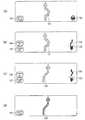
図15は、本発明の実施の形態3における報知部92の表示を説明する図である。図15には、図8(a)に示した場合と同様に、車両1と同一車線の前方を走行する車両が車両1よりも遅い速度で走行し、かつ、隣の車線への車線変更が可能な走行環境における表示の例が示されている。 FIG. 15 is a diagram illustrating the display of the
車両制御部7は、走行環境が、図8(a)に示した走行環境であると判定すると、まず、報知部92に図15(a)に示す表示を実行させる。 When the
図15(a)には、第1の所定時間が経過した後に実施される挙動の候補うち、第1の挙動である「追い越し」を示す記号131が第1の態様(例えば、第1の色)で示されている。 In FIG. 15A, among the behavior candidates to be implemented after the first predetermined time has elapsed, the
車両制御部7は、図15(a)に示す表示を報知部92に実行させた後、第2の所定時間が経過した場合、記号131を第1の態様から、第1の態様とは異なる第2の態様(例えば、第1の色とは異なる第2の色)で報知部92に表示させる。ここで、第2の所定時間は、実施の形態1で説明した第2の所定時間と同様のものである。 The
つまり、記号131が第1の態様で示されている間、運転者は、第2の挙動の選択が可能であるが、記号131が第2の態様に変更された場合、運転者は、第2の挙動の選択が不可能になる。 That is, while the
また、図15(a)には、第2の挙動が選択可能であることを示すステアリングホイール形状の記号132が示されている。記号132が表示されている場合に運転者がステアリングホイール5を握ることによって、第2の挙動が表示される。記号132は、第2の挙動が選択可能であることを示す表示であるが、記号131が第1の態様にて表示されることによって、運転者に第2の挙動が選択可能であることを示すこととしてもよい。この場合、記号132は、表示されなくてもよい。 Further, FIG. 15A shows a steering
また、図15(a)には、現在、自動運転中であることを示す記号133が示されている。記号133は、自動運転で走行中であることを運転者に示す補助的な表示であるが、記号133は表示されなくてもよい。 FIG. 15A shows a
図15(a)の表示に対して運転者がステアリングホイール5を握った場合、グリップセンサがそれを検出し、その検出結果の情報を車両制御部7へ出力する。この場合、車両制御部7は、図15(b)に示す表示を報知部92に実行させる。 When the driver grips the
図15(b)には、図15(a)と同様に、第1の挙動である「追い越し」を示す記号131が第1の態様(例えば、第1の色)で示されている。また、第2の挙動である「車線変更」を示す記号134と、第2の挙動である「減速」を示す記号135が示されている。 In FIG. 15B, similarly to FIG. 15A, a
運転者は、ステアリングホイール5の操作部51を操作することによって、第1の挙動から第2の挙動への変更を行う。例えば、運転者は、操作部51の操作ボタン51a、または、操作ボタン51c(図2(c)参照)を押下することによって、「車線変更」(記号134)、または、「減速」(記号135)への挙動の更新を行う。 The driver changes the first behavior to the second behavior by operating the
また、図15(b)には、車両制御部7が、車両1の挙動を学習中であることを示す記号136が示されている。記号136が表示されている場合、車両制御部7は、運転者が選択した挙動を学習する。記号136は表示されなくても構わない。また、学習は常に行っていても構わない。 Further, FIG. 15B shows a
つまり、車両制御部7は、運転者が選択した挙動を記憶部8に記憶し、次に同様の走行環境になった場合、記憶した挙動を第1の挙動として、報知部92に表示させる。または、車両制御部7は、過去に各挙動が選択された回数を記憶部8に記憶しておき、回数が最も多い挙動を第1の挙動として、報知部92に表示させてもよい。 In other words, the
また、図15(b)には、自動運転中ではないことを示す記号137が示されている。記号137が表示されている場合、車両制御部7は、第1の所定時間経過後に行う挙動が運転者によって選択されるまで待機する。 FIG. 15B shows a
図15(b)に示す表示に対して、運転者が操作部51の操作ボタン51aを押下して「車線変更」を選択した場合、車両制御部7は、この選択操作の情報を受けつけ、図15(c)に示す表示を報知部92に実行させる。 When the driver presses the
図15(c)には、「車線変更」を示す記号134’が、第1の態様で示されている。車両制御部7は、「車線変更」を選択する選択操作の情報を受けつけた場合、この選択された挙動が次に行う挙動であると判定し、「車線変更」を示す記号134’を第1の態様で報知部92に表示させる。 In FIG. 15C, a symbol 134 'indicating "lane change" is shown in the first mode. When the
また、図15(c)の記号131’は、図15(b)において第1の挙動として表示されていた記号131が記号134と入れ替わって表示されたものである。 Also, the
また、図15(c)に示す表示に対して、運転者が操作ボタンのいずれかを2度連続して押下した場合、運転者が前に行った選択操作をキャンセルできるようにしてもよい。この場合、車両制御部7は、操作ボタンのいずれかを2度連続して押下する操作の情報を受けつけ、図15(c)に示す表示から図15(b)に示す表示への変更を報知部92に実行させる。 In addition, when the driver presses one of the operation buttons twice in succession with respect to the display shown in FIG. 15C, the selection operation previously performed by the driver may be canceled. In this case, the
車両制御部7は、図15(a)に示す表示を報知部92に実行させてから、第2の所定時間が経過するまでの間に、運転者の操作に基づいて、図15(b)、図15(c)へと報知部92の表示を変化させる。その後、車両制御部7は、図15(a)に示す表示を報知部92に実行させてから第2の所定時間が経過した後に、図15(d)に示す表示を報知部92に表示させる。 The
なお、車両制御部7は、運転者がステアリングホイール5から手を離したこと示す情報をグリップセンサから取得した場合に、第2の所定時間が経過する前に図15(d)に示す表示を報知部92に表示させてもよい。 Note that the
ここで、図15(d)には、次の挙動として、運転者が選択した「車線変更」を示す記号134’が第2の態様で表示され、また、自動運転で走行中であることを示す記号133が、再び、表示された状態が示されている。 Here, in FIG. 15 (d), as the next behavior, the
以上説明した本実施の形態によれば、車両制御部7は、運転者が次にとる挙動の更新したい場合にのみ、他の挙動の候補を確認できるように、報知部92での表示を変更する。この構成により、運転者が視認する表示を減らすことができ、運転者の煩わしさを低減できる。 According to the present embodiment described above, the
(実施の形態4)
上述した実施の形態において、車両1が実行しうる複数の挙動の候補のうち最も適した挙動がどれかを判定する方法についていくつか説明した。本実施の形態では、最も適した挙動を判定する方法として、予め学習により構築されたドライバモデルを用いる場合について説明する。(Embodiment 4)
In the embodiment described above, several methods have been described for determining which of the plurality of behavior candidates that the
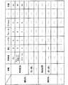
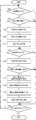
ここで、ドライバモデルの構築方法について説明する。ドライバモデルは、走行環境毎の運転者による操作の傾向を各操作の頻度の情報などに基づいてモデル化したものである。ドライバモデルは、複数の運転者の走行履歴を集約し、集約した走行履歴から構築される。 Here, a driver model construction method will be described. The driver model is obtained by modeling the tendency of the operation by the driver for each driving environment based on information on the frequency of each operation. The driver model aggregates the traveling histories of a plurality of drivers and is constructed from the aggregated traveling histories.
運転者の走行履歴は、例えば、各走行環境に対応する挙動の候補のうち、運転者が実際に選択した挙動の頻度が、挙動の候補毎に集約された履歴である。 The driving history of the driver is, for example, a history in which the behavior frequency actually selected by the driver among the behavior candidates corresponding to each driving environment is aggregated for each behavior candidate.
図16は、走行履歴の一例を示す図である。図16には、運転者xが「合流路が近づく」という走行環境において、「減速」、「加速」、「車線変更」という挙動の候補を、それぞれ、3回、1回、5回選択したことが示されている。また、図16には、運転者Xが「前方に低速車あり」という走行環境において、「追従」、「追い越し」、「車線変更」という挙動の候補を、それぞれ、2回、2回、1回選択したことが示されている。運転者yについても同様である。 FIG. 16 is a diagram illustrating an example of a travel history. In FIG. 16, in the driving environment where the driver x “closes the joint path”, the behavior candidates “decelerate”, “accelerate”, and “lane change” are selected three times, once, and five times, respectively. It has been shown. Further, in FIG. 16, in a driving environment where the driver X “has a low speed vehicle ahead”, candidate behaviors “follow”, “passing”, and “lane change” are shown twice, twice, 1 It is shown that you have selected once. The same applies to the driver y.
運転者の走行履歴は、自動運転中に選択した挙動を集約してもよいし、運転者が手動運転中に実際に行った挙動を集約してもよい。これにより、自動運転或いは手動運転といった運転状態に応じた走行履歴の収集ができる。 The driving history of the driver may aggregate behaviors selected during automatic driving, or may aggregate behaviors actually performed by the driver during manual driving. This makes it possible to collect travel histories according to operating conditions such as automatic driving or manual driving.
ドライバモデルには、複数の運転者の走行履歴をクラスタリングして構築するクラスタリング型と、特定の運転者(例えば、運転者x)の走行履歴と類似する複数の走行履歴から運転者xのドライバモデルを構築する個別適応型とがある。 The driver model includes a clustering type constructed by clustering the driving histories of a plurality of drivers, and a driver model of the driver x from a plurality of driving histories similar to a driving history of a specific driver (for example, driver x). There is an individual adaptive type that builds.
まず、クラスタリング型について説明する。クラスタリング型のドライバモデルの構築方法は、図16に示したような複数の運転者の走行履歴を予め集約する。そして、互いの走行履歴の類似度が高い複数の運転者、つまり、類似した運転操作傾向を有する複数の運転者をグループ化してドライバモデルを構築する。 First, the clustering type will be described. The clustering type driver model construction method aggregates the driving histories of a plurality of drivers as shown in FIG. Then, a driver model is constructed by grouping a plurality of drivers having a high degree of similarity between the traveling histories, that is, a plurality of drivers having similar driving operation tendencies.
図17は、クラスタリング型のドライバモデルの構築方法を示す図である。図17には、運転者a〜fの走行履歴が表形式で示されている。そして、運転者a〜fの走行履歴から、モデルAが運転者a〜cの走行履歴から構築され、モデルBが運転者d〜fの走行履歴から構築されることが示されている。 FIG. 17 is a diagram illustrating a clustering type driver model construction method. FIG. 17 shows the driving histories of the drivers a to f in a table format. From the driving histories of the drivers a to f, it is shown that the model A is constructed from the traveling histories of the drivers a to c and the model B is constructed from the traveling histories of the drivers d to f.
走行履歴の類似度は、例えば、運転者aと運転者bの走行履歴における各頻度(各数値)を頻度分布として扱い、互いの頻度分布の相関値を算出し、算出した相関値を類似度としてもよい。この場合、例えば、運転者aと運転者bの走行履歴から算出した相関値が所定値よりも高い場合に、運転者aと運転者bの走行履歴を1つのグループとする。 The similarity of the travel histories is, for example, treating each frequency (each numerical value) in the travel histories of the driver a and the driver b as a frequency distribution, calculating a correlation value between the frequency distributions, and using the calculated correlation value as the similarity It is good. In this case, for example, when the correlation value calculated from the driving history of the driver a and the driver b is higher than a predetermined value, the driving history of the driver a and the driver b is set as one group.
なお、類似度の算出については、これに限定されない。例えば、運転者aと運転者bの各走行履歴において、最も頻度の高い挙動が一致する数に基づいて、類似度を算出してもよい。 The calculation of the similarity is not limited to this. For example, the degree of similarity may be calculated based on the number of the most frequently matched behaviors in the driving histories of the driver a and the driver b.
そして、クラスタリング型のドライバモデルは、例えば、各グループ内の運転者の走行履歴において、それぞれの頻度の平均を算出することによって構築される。 The clustering type driver model is constructed, for example, by calculating the average of the respective frequencies in the driving history of the drivers in each group.
図18は、構築されたクラスタリング型のドライバモデルの一例を示す図である。図17で示した各グループ内の運転者の走行履歴において、それぞれの頻度の平均を算出することによって、各グループの走行履歴の平均頻度を導出する。このように、クラスタリング型のドライバモデルは、走行環境毎に定められた挙動に対する平均頻度で構築される。 FIG. 18 is a diagram illustrating an example of a built clustering driver model. In the travel history of the drivers in each group shown in FIG. 17, the average frequency of each group is derived by calculating the average of the respective frequencies. Thus, the clustering type driver model is constructed with an average frequency for the behavior determined for each driving environment.
なお、ドライバモデルは、算出した平均頻度から最も頻度の高いもののみで構築してもよい。図19は、構築されたクラスタリング型のドライバモデルの別の一例を示す図である。図19に示すように、走行環境毎に最頻の挙動が選択され、選択された挙動からドライバモデルが構築される。 It should be noted that the driver model may be constructed with only the highest frequency from the calculated average frequency. FIG. 19 is a diagram illustrating another example of the constructed clustering type driver model. As shown in FIG. 19, the most frequent behavior is selected for each traveling environment, and a driver model is constructed from the selected behavior.
ここで、構築したクラスタリング型のドライバモデルの使用方法について、例を挙げて説明する。 Here, an example of how to use the constructed clustering type driver model will be described.
図18に示したようなドライバモデルは、予め車両1の記憶部8に記憶される。また、車両制御部7は、運転者yが過去に運転した際の走行履歴を記憶部8に記憶しておく。なお、運転者yの検知は、車内に設置されるカメラ等(図示しない)で実行される。 The driver model as shown in FIG. 18 is stored in advance in the
そして、車両制御部7は、運転者yの走行履歴とドライバモデルの各モデルの走行履歴との類似度を算出し、どのモデルが運転者yに最も適しているかを判定する。例えば、図16に示した運転者yの走行履歴と図18に示したドライバモデルの場合、車両制御部7は、モデルBが運転者yに最も適していると判定する。 Then, the
車両制御部7は、実際の自動走行の際に、モデルBの各走行環境において、最も頻度が高い挙動が運転者yに最も適した挙動、つまり、第1の挙動であると判定する。 The
このように、予め複数の運転者の走行履歴からドライバモデルを構築することにより、運転者により適した挙動を報知できる。 In this way, by constructing a driver model in advance from the driving histories of a plurality of drivers, a behavior that is more suitable for the driver can be notified.
例えば、図16の示すように、運転者yの走行履歴に「前方に低速車あり」という走行環境に対する挙動の頻度が0、つまり、運転者が「前方に低速車あり」という走行環境において「追従」、「追い越し」、「車線変更」という挙動を選択したことが無い場合においても、車両制御部7は、図18に示すモデルBに基づき、「前方に低速車あり」という走行環境において、「追従」を第1の挙動として判定できる。 For example, as shown in FIG. 16, in a driving environment where the driving history of the driver y is “there is a low speed vehicle ahead” in the driving history of the driver y, that is, the driving environment is “a low speed vehicle ahead”. Even when the behavior of “follow”, “passing”, and “lane change” has never been selected, the
次に、個別適応型について説明する。個別適応型のドライバモデルの構築方法は、クラスタリング型の場合と同様に、図16に示したような複数の運転者の走行履歴を予め集約する。ここで、クラスタリング型の場合と異なる点は、運転者毎にドライバモデルを構築する点である。以下では、運転者yに対してドライバモデルを構築する例について説明する。 Next, the individual adaptive type will be described. As in the case of the clustering type, the individual adaptive type driver model construction method aggregates the driving histories of a plurality of drivers as shown in FIG. Here, the difference from the clustering type is that a driver model is constructed for each driver. Below, the example which builds a driver model with respect to the driver | operator y is demonstrated.
まず、集約した複数の運転者の走行履歴の中から、運転者yの走行履歴と類似度が高い複数の運転者の走行履歴を抽出する。そして、抽出した複数の運転者の走行履歴から運転者yのドライバモデルを構築する。 First, the driving histories of a plurality of drivers having high similarity to the driving history of the driver y are extracted from the collected driving histories of the plurality of drivers. Then, a driver model of the driver y is constructed from the extracted driving histories of the plurality of drivers.
図20は、個別適応型のドライバモデルの構築方法を示す図である。図20には、図17と同様に、運転者a〜fの走行履歴が表形式で示されている。また、図20には、図16に示した運転者yの走行履歴と類似度が高い運転者c〜eの走行履歴とから運転者yのドライバモデルが構築されることが示されている。 FIG. 20 is a diagram illustrating a method for constructing an individual adaptive driver model. In FIG. 20, as in FIG. 17, the driving histories of the drivers a to f are shown in a table format. FIG. 20 shows that the driver model of the driver y is constructed from the driving history of the driver y shown in FIG. 16 and the driving histories of the drivers c to e having a high degree of similarity.
個別適応型のドライバモデルは、抽出した各運転者の走行履歴において、それぞれの頻度の平均を算出することによって構築される。 The individual adaptive driver model is constructed by calculating the average of the respective frequencies in the extracted driving history of each driver.
図21は、構築された個別適応型のドライバモデルの一例を示す図である。図16に示した運転者yの走行履歴、及び、図20に示した運転者c〜eの走行履歴において、走行環境毎に、各挙動の平均頻度を導出する。このように、運転者yに対する個別適応型のドライバモデルは、各走行環境に対応する挙動の平均頻度で構築される。 FIG. 21 is a diagram illustrating an example of a constructed individual adaptive driver model. In the driving history of the driver y shown in FIG. 16 and the driving history of the drivers c to e shown in FIG. 20, the average frequency of each behavior is derived for each driving environment. As described above, the individually adaptive driver model for the driver y is constructed with an average frequency of behavior corresponding to each traveling environment.
ここで、構築した個別適応型のドライバモデルの使用方法について、例を挙げて説明する。 Here, an example of how to use the constructed individual adaptive driver model will be described.
図21に示したような運転者yのドライバモデルは、予め車両1の記憶部8に記憶される。また、車両制御部7は、運転者yが過去に運転した際の走行履歴を記憶部8に記憶しておく。なお、運転者yの検知は、車内に設置されるカメラ等(図示しない)で実行される。 The driver model of the driver y as shown in FIG. 21 is stored in the
そして、車両制御部7は、実際の自動走行の際に、運転者yのドライバモデルの各走行環境において、最も頻度が高い挙動が運転者yに最も適した挙動、つまり、第1の挙動であると判定する。 Then, the
このように、予め複数の運転者の走行履歴から運転者個人のドライバモデルを構築することにより、運転者により適した挙動を報知できる。 In this way, by constructing a driver model of a driver individually from a plurality of driver's driving histories in advance, a behavior more suitable for the driver can be notified.
例えば、図16の示すように、運転者yの走行履歴に「前方に低速車あり」という走行環境に対する挙動の頻度が0、つまり、運転者が「前方に低速車あり」という走行環境において「追従」、「追い越し」、「車線変更」という挙動を選択したことが無い場合においても、車両制御部7は、図21に示すドライバモデルに基づき、「前方に低速車あり」という走行環境において、「車線変更」を第1の挙動として判定できる。 For example, as shown in FIG. 16, in a driving environment where the driving history of the driver y is “there is a low speed vehicle ahead” in the driving history of the driver y, that is, the driving environment is “a low speed vehicle ahead”. Even when the behaviors of “follow”, “passing”, and “lane change” have never been selected, the
次に、運転者の運転特性(運転の癖)を取得し、運転者の嗜好に応じた自動運転を行う場合について説明する。一般に、1つの挙動(例えば、車線変更)に対する実際の動作(例えば、加速、減速の大きさ、あるいは、ステアリングホイールの操作量)は、運転者毎に異なる。そのため、運転者の嗜好に応じた自動運転を行うことにより、運転者にとってより快適な走行が可能となる。 Next, a case where the driving characteristics (driving habits) of the driver are acquired and automatic driving according to the driver's preference is performed will be described. In general, the actual operation (for example, the magnitude of acceleration, deceleration, or the amount of operation of the steering wheel) for one behavior (for example, lane change) differs for each driver. Therefore, it is possible to travel more comfortably for the driver by performing the automatic driving according to the preference of the driver.
なお、以下の説明では、手動運転中に運転者の運転特性を取得し、取得した運転特性を自動運転の際に反映させる場合について説明するが、本発明はこれに限定されない。 In addition, although the following description demonstrates the case where a driver | operator's driving characteristic is acquired during manual driving | operation and the acquired driving | running characteristic is reflected in the case of automatic driving | running, this invention is not limited to this.
車両制御部7は、運転者の車両1の各部の操作内容から、運転者の運転特性を示す特徴量を抽出し、記憶部8に記憶する。ここで、特徴量とは、例えば、速度に関する特徴量、ステアリングに関する特徴量、操作タイミングに関する特徴量、車外センシングに関する特徴量、車内センシングに関する特徴量等がある。 The
速度に関する特徴量は、例えば、車両の速度、加速度、減速度などがあり、これらの特徴量は、車両が有する速度センサ等から取得される。 The feature quantity related to speed includes, for example, the speed, acceleration, and deceleration of the vehicle, and these feature quantities are acquired from a speed sensor or the like that the vehicle has.
ステアリングに関する特徴量は、例えば、ステアリングの舵角、角速度、各加速度などがあり、これらの特徴量は、ステアリングホイール5から取得される。 The feature amount related to steering includes, for example, the steering angle, the angular velocity, and each acceleration of the steering. These feature amounts are acquired from the
操作タイミングに関する特徴量は、例えば、ブレーキ、アクセル、ウィンカレバー、ステアリングホイールの操作タイミングなどがあり、これらの特徴量は、それぞれ、ブレーキペダル2、アクセルペダル3、ウィンカレバー4、ステアリングホイール5から取得される。 The feature quantities related to the operation timing include, for example, the operation timing of the brake, accelerator, blinker lever, and steering wheel. These feature quantities are obtained from the
車外センシングに関する特徴量は、例えば、前方、側方、後方に存在する車両との車間距離などがあり、これらの特徴量は、センサ62から取得される。 For example, the feature amount related to the outside sensing includes an inter-vehicle distance with a vehicle existing in the front, side, and rear, and these feature amounts are acquired from the
車内センシングに関する特徴量は、例えば、運転者が誰であるか、及び、同乗者が誰であるかを示す個人認識情報であり、これらの特徴量は、車内に設置されるカメラ等から取得される。 The feature amount related to in-vehicle sensing is, for example, personal recognition information indicating who the driver is and who is the passenger, and these feature amounts are acquired from a camera or the like installed in the vehicle. The
例えば、運転者が手動で車線変更を行う場合、車両制御部7は、運転者が手動で車線変更を行ったことを検知する。検知方法は、予め車線変更の操作時系列パターンをルール化しておくことにより、CAN情報などから取得した操作時系列データを解析することで検知する。その際、車両制御部7は、上述した特徴量を取得する。車両制御部7は、運転者毎に、特徴量を記憶部8に記憶し、運転特性モデルを構築する。 For example, when the driver manually changes the lane, the
なお、車両制御部7は、運転者毎の特徴量に基づき、上述したドライバモデルを構築してもよい。つまり、車両制御部7は、速度に関する特徴量、ステアリングに関する特徴量、操作タイミングに関する特徴量、車外センシングに関する特徴量、車内センシングに関する特徴量を抽出し、記憶部8に記憶する。そして、記憶部8に記憶した特徴量に基づいて、走行環境毎の運転者による操作の傾向と各操作の頻度の情報を対応づけたドライバモデルを構築してもよい。 The
図22は、運転特性モデルの一例を示す図である。図22は、運転者毎に、特徴量が表形式で示されている。また、図22には、運転者毎に、各挙動を過去に選択した回数が示されている。特徴量についても一部のみが記載されているが、上記に挙げたいずれか、またはその全てを記載してもよい。 FIG. 22 is a diagram illustrating an example of the driving characteristic model. FIG. 22 shows the feature values in a tabular format for each driver. FIG. 22 also shows the number of times each behavior has been selected in the past for each driver. Although only a part of the feature amount is described, any or all of the above may be described.
図22に記載の特徴量について詳細を説明する。速度の数値は、実際の速度を段階的に示している数値である。ステアリングホイール、ブレーキ、アクセルの数値は、操作量を段階的に示している数値である。これらの数値は、例えば、過去の所定の期間内の速度、ステアリングホイール、ブレーキ、アクセルの操作量の平均値を算出し、その平均値を段階的に表すことによって得られる。 Details of the feature amount described in FIG. 22 will be described. The numerical value of speed is a numerical value indicating the actual speed in stages. The numerical values for the steering wheel, brake, and accelerator are numerical values that indicate the operation amount in stages. These numerical values are obtained, for example, by calculating an average value of speed, steering wheel, brake, and accelerator operation amounts within a predetermined period in the past and expressing the average value stepwise.
例えば、図22において、運転者xが同乗者がいない状態で車線変更を行う場合、速さのレベルは8であり、ステアリングホイール、ブレーキ、アクセルの操作量のレベルはそれぞれ4、6、8である。 For example, in FIG. 22, when the driver x changes lanes without a passenger, the speed level is 8, and the steering wheel, brake, and accelerator operation amounts are 4, 6, and 8, respectively. is there.
自動運転の際は、車両制御部7は、運転者が誰か、どのような挙動が実行されるか、及び、同乗者が誰かに応じて、運転者、挙動、及び、同乗者に対応する運転特性モデルが図22に示す運転特性モデルの中から選択する。 In the case of automatic driving, the
そして、車両制御部7は、選択した運転特性モデルに対応する速度で車両1を走行させ、また、ステアリングホイール、ブレーキ、アクセルの操作量およびそのタイミングの組み合わせで車両1を制御する。これにより、運転者の嗜好に応じた自動運転を行うことができる。なお、図22に示すような運転特性モデルの情報は、報知部92に報知させることができる。 Then, the
図23は、本発明の実施の形態4における報知部92の表示を説明する図である。図23は、図5に示した走行環境の第1の例に対する表示である。 FIG. 23 is a diagram for explaining the display of the
図23(a)は、車線の変更或いは車両の加速、減速が不要な通常走行を行っている状態の報知部92の表示である。図23(a)には、運転者の運転特性が「減速が多い」運転特性であることを示す記号231と、現在、自動運転中であることを示す記号232が示されている。 FIG. 23A is a display of the
車両制御部7は、例えば、図22に示した運転特性モデルに含まれる各挙動を過去に選択した回数に基づいて、運転者の運転特性を判定する。この場合、車両制御部7は、例えば、運転特性から「減速」が多い(いわゆる「減速」という挙動を選択した回数が多い)運転者に対して、図23のような記号231を含む表示を報知部92に表示させる。 For example, the
そして、車両制御部7が、走行環境が図5に示した第1の例の走行環境であると判定した場合、車両制御部7は、運転者の運転特性が「減速が多い」運転特性であることに基づいて、第1の挙動を「減速」と判定し、図23(b)の表示を報知部92に実行させる。 When the
図23(b)には、第1の挙動である「減速」を示す記号233が第1の態様(例えば、第1の色)で示されている。また、第2の挙動である「加速」を示す記号234と、第2の挙動である「車線変更」を示す記号235が示されている。 In FIG. 23B, a
運転者は、実施の形態1で説明したような操作により、「加速」への挙動の変更を行った場合、車両制御部7は、図23(c)の表示を報知部92に実行させる。 When the driver changes the behavior to “acceleration” by the operation described in the first embodiment, the
図23(c)には、選択された挙動である「加速」を示す記号234’が、第1の態様で示されている。また、記号233’は、図23(b)において第1の挙動として表示されていた記号233が記号234と入れ替わって表示されたものである。 In FIG. 23C, a symbol 234 'indicating "acceleration" which is the selected behavior is shown in the first mode. Further, the
その後、車両制御部7は、図23(a)に示す表示を報知部92に実行させてから第2の所定時間が経過した後に、図23(d)に示す表示を報知部92に表示させる。ここで、図15(d)には、次の挙動として、運転者が選択した「加速」を示す記号234’が第2の態様で表示される。 Thereafter, the
車両制御部7は、次にとる挙動が「加速」と決定した場合、運転特性モデルに含まれる「加速」の挙動に対応する特徴量を読み出し、それらの特徴量を反映させた「加速」を行うように、車両1を制御する。 When it is determined that the next behavior to be taken is “acceleration”, the
図24は、本発明の実施の形態4における報知部92の表示を説明する図である。図24は、図7に示した走行環境の第2の例に対する表示である。なお、図24において、図23と共通する構成には図23と同一の符号を付し、その詳しい説明を省略する。図24は、図23から、「車線変更」を示す記号235が削除された図である。 FIG. 24 is a diagram for explaining the display of the
前述の通り、第2の例(図7)では、第1の例(図5)と異なり、車両1の右方に別の車両が走行しているため、車線変更ができない。そのため、図24(b)、(c)では、「車線変更」が表示されていない。また、図24(c)の例では、図23(c)の場合と同様に、「加速」が選択されたため、車両制御部7は、図23と同様に、運転特性モデルに含まれる「加速」の挙動に対応する特徴量を読み出し、それらの特徴量を反映させた「加速」を行うように、車両1を制御する。 As described above, in the second example (FIG. 7), unlike the first example (FIG. 5), another vehicle is running on the right side of the
図25は、本発明の実施の形態4における報知部92の表示を説明する図である。図25は、図8に示した走行環境の第3の例に対する表示である。 FIG. 25 is a diagram illustrating the display of the
図25(a)は、図23(a)と同様である。車両制御部7が図8に示した第3の例の走行環境であることを判定した場合、車両制御部7は、運転者の運転特性が「減速が多い」運転特性であることに基づいて、第1の挙動を「減速」と判定し、図25(b)の表示を報知部92に実行させる。 FIG. 25A is the same as FIG. When the
図25(b)には、第1の挙動である「減速」を示す記号251が第1の態様(例えば、第1の色)で示されている。また、第2の挙動である「追い越し」を示す記号252と、第2の挙動である「車線変更」を示す記号253が示されている。 In FIG. 25B, a
運転者は、実施の形態1で説明したような操作により、「追い越し」への挙動の変更を行った場合、車両制御部7は、図25(c)の表示を報知部92に実行させる。 When the driver changes the behavior to “overtaking” by the operation described in the first embodiment, the
図25(c)には、選択された挙動である「追い越し」を示す記号252’が、第1の態様で示されている。また、記号251’は、図25(b)において第1の挙動として表示されていた記号251が記号252と入れ替わって表示されたものである。 In FIG. 25C, a symbol 252 'indicating "passing" which is the selected behavior is shown in the first mode. The
その後、車両制御部7は、図25(a)に示す表示を報知部92に実行させてから第2の所定時間が経過した後に、図25(d)に示す表示を報知部92に表示させる。ここで、図15(d)には、次の挙動として、運転者が選択した「追い越し」を示す記号252’が第2の態様で表示される。 Thereafter, the
車両制御部7は、次にとる挙動が「追い越し」と決定した場合、運転特性モデルに含まれる「追い越し」の挙動に対応する特徴量を読み出し、それらの特徴量を反映させた「加速」を行うように、車両1を制御する。 When the behavior to be taken next is determined to be “passing”, the
次に、運転者の運転特性が「減速が多い」運転特性ではない場合の表示の例を説明する。 Next, an example of display in the case where the driving characteristics of the driver are not “high deceleration” driving characteristics will be described.
図26は、本発明の実施の形態4における報知部92の表示を説明する図である。図26は、図5に示した走行環境の第1の例に対する表示である。なお、図26(a)は、運転者の運転特性が「加速が多い」運転特性である場合の例を示し、図26(b)は、運転者の運転特性が「車線変更が多い」運転特性である場合の例を示している。 FIG. 26 is a diagram illustrating the display of the
図26(a)には、運転者の運転特性が「加速が多い」運転特性であることを示す記号261が示されている。また、第1の挙動である「加速」を示す記号262が第1の態様(例えば、第1の色)で示されている。また、第2の挙動である「車線変更」を示す記号263と、第2の挙動である「減速」を示す記号264が示されている。 FIG. 26A shows a
車両制御部7は、例えば、運転特性から過去に「加速」が多い(いわゆる過去に「加速」という挙動を選択した回数が多い)運転者に対して、図26(a)のような記号261を含む表示を報知部92に実行させる。また、車両制御部7は、運転者の運転特性が「加速が多い」運転特性であることに基づいて、第1の挙動を「加速」と判定し、図26(a)の表示を報知部92に実行させる。 For example, the
図26(b)には、運転者の運転特性が「車線変更が多い」運転特性であることを示す記号265が示されている。また、第1の挙動である「車線変更」を示す記号266が第1の態様(例えば、第1の色)で示されている。また、第2の挙動である「車線変更」を示す記号267と、第2の挙動である「減速」を示す記号268が示されている。 FIG. 26B shows a
車両制御部7は、例えば、運転特性から過去に「車線変更」が多い(いわゆる過去に「車線変更」という挙動を選択した回数が多い)運転者に対して、図26(b)のような記号265を含む表示を報知部92に実行させる。車両制御部7は、運転者の運転特性が「車線変更が多い」運転特性であることに基づいて、第1の挙動を「車線変更」と判定し、図26(b)の表示を報知部92に実行させる。 For example, FIG. 26B shows the
上記は、運転特性モデルのみを使用して説明したが、ドライバモデルを加味してもよく、図23、図25、図26において、記号231は運転者の操作履歴から選択されたドライバモデルの種類を示してもよい。例えば、図5に示した走行環境の第1の例について、「減速」をよく選ぶ運転者に適用するドライバモデルには図23のような記号231を含む表示を報知部92に実行させ、第1の挙動を「減速」と判定する。「加速」をよく選ぶ運転者に適用するドライバモデルには図26(a)のような記号261を含む表示を報知部92に実行させ、第1の挙動を「加速」と判定する。「車線変更」をよく選ぶ運転者に適用するドライバモデルには図26(a)のような記号261を含む表示を報知部92に実行させ、第1の挙動を「車線変更」と判定する。 Although the above has been described using only the driving characteristic model, a driver model may be considered. In FIGS. 23, 25, and 26, the
以上説明した本実施の形態によれば、車の将来の挙動を決定する際に、運転者の過去の走行履歴を学習し、その結果を将来の挙動の決定に反映させることができる。また、車両制御部が車を制御する際に、運転者の運転特性(運転嗜好)を学習し、車の制御に反映させることができる。 According to the present embodiment described above, when the future behavior of the vehicle is determined, the past driving history of the driver can be learned, and the result can be reflected in the determination of the future behavior. Further, when the vehicle control unit controls the vehicle, the driving characteristics (driving preference) of the driver can be learned and reflected in the control of the vehicle.
これにより、車両が運転者若しくは乗員が嗜好するタイミング或いは操作量で自動運転を制御でき、実際運転者が手動運転する場合の感覚と乖離することなく、自動運転中に運転者による不要な操作介入を抑制することができる。 As a result, automatic driving can be controlled at the timing or amount of operation that the driver or occupant prefers the vehicle, and unnecessary operation intervention by the driver during automatic driving without departing from the sense of actual driving by the actual driver. Can be suppressed.
なお、本発明では、車両制御部7が実行する機能と同様の機能をクラウドサーバなどのサーバ装置に実行させてもよい。また、記憶部8は、車両1ではなく、クラウドサーバなどのサーバ装置にあってもよい。あるいは、記憶部8は、既に構築されたドライバモデルを記憶し、車両制御部7は、記憶部8に記憶されたドライバモデルを参照して、挙動を判定することとしてもよい。 In the present invention, a function similar to the function executed by the
このように、実施の形態4では、車両制御部7が、運転者の運転特性を示す特徴量の情報を取得し、記憶部8がその特徴量の情報を記憶し、車両制御部7が記憶部8に記憶された特徴量の情報に基づいて、運転者が選択した車両の挙動の傾向を、選択された各挙動の頻度で示すドライバモデルを車両の走行環境毎に構築することとした。 As described above, in the fourth embodiment, the
また、車両制御部7は、複数の運転者のうち、類似した挙動の選択を行う運転者のグループを決定し、グループ毎、車両の走行環境毎にドライバモデルを構築することとした。 In addition, the
また、車両制御部7は、類似した操作を行う運転者のグループ毎に各運転者が選択した挙動の頻度の平均値を算出し、運転者が選択した車両の挙動の傾向を、算出した平均値で示すドライバモデルを車両の走行環境毎に構築することとした。 Further, the
また、車両制御部7は、特定の運転者が選択した車両の挙動の傾向と類似する傾向がある他の運転者が選択した車両の挙動に基づいて、上記特定の運転者が選択した車両の挙動の傾向を、選択された各挙動の頻度で示すドライバモデルを車両の走行環境毎に構築することとした。 In addition, the
以上により、車両制御部7は、運転者の運転傾向により適したドライバモデルを構築でき、構築したドライバモデルに基づいて、運転者に対してより適切な自動運転を行うことができる。 As described above, the
(ドライバモデルの変形例)
なお、上記で説明したドライバモデルは、走行環境毎の運転者による操作(挙動)の傾向を各操作の頻度の情報などに基づいてモデル化したものであったが、本発明はこれに限定されない。(Modified example of driver model)
In addition, although the driver model demonstrated above modeled the tendency of operation (behavior) by the driver for every driving environment based on the information of the frequency of each operation, etc., the present invention is not limited to this. .
例えば、ドライバモデルは、過去に走行した走行環境(つまり、シチュエーション)を示す環境パラメータと、その走行環境において運転者が実際に選択した操作(挙動)とを対応させた走行履歴に基づいて構築されてもよい。環境パラメータをドライバモデルに組み込むことにより、走行環境の検出・分類を別途行い、その分類結果をドライバモデルに入力(記憶)するという手続きを踏むことなく、選択肢を決めることが出来る。具体的には、図23、24のような走行環境の違いを、環境パラメータとして取得し、ドライバモデルに直接入力(記憶)することにより、図23では「加速」、「減速」、「車線変更」が選択肢となり、図24では、「加速」、「減速」が選択肢となる。以下では、このようなドライバモデルを構築する場合について説明する。なお、以下に説明するドライバモデルは、シチュエーションデータベースと言い換えても良い。 For example, the driver model is constructed based on a travel history in which environmental parameters indicating travel environments (that is, situations) that have traveled in the past and operations (behaviors) actually selected by the driver in the travel environment are associated with each other. May be. By incorporating environmental parameters into the driver model, options can be determined without going through the procedure of separately detecting and classifying the driving environment and inputting (storing) the classification result into the driver model. Specifically, the driving environment differences as shown in FIGS. 23 and 24 are acquired as environment parameters and directly input (stored) in the driver model, so that “acceleration”, “deceleration”, “lane change” in FIG. "Is an option, and in FIG. 24," acceleration "and" deceleration "are options. Hereinafter, a case where such a driver model is constructed will be described. The driver model described below may be referred to as a situation database.
ここで、本変形例におけるドライバモデルを構築するための走行履歴について説明する。図27は、走行履歴の一例を示す図である。図27には、運転者xが運転する車両が、過去に走行した走行環境を示す環境パラメータと、その走行環境において運転者が実際に選択した操作(挙動)とを対応させた走行履歴が示されている。 Here, the travel history for constructing the driver model in this modification will be described. FIG. 27 is a diagram illustrating an example of a travel history. FIG. 27 shows a travel history in which an environment parameter indicating a travel environment in which the vehicle driven by the driver x has traveled in the past and an operation (behavior) actually selected by the driver in the travel environment are associated with each other. Has been.
図27に示す走行履歴の(a)〜(c)の環境パラメータは、それぞれ、例えば、図8(b)、図5(b)、図7(b)に示したようにして運転者に車両の挙動を提示した際の走行環境を示すものである。この走行履歴の環境パラメータは、センシング情報およびインフラ情報から得られる。 The environmental parameters of (a) to (c) of the travel history shown in FIG. 27 are, for example, as shown in FIGS. 8 (b), 5 (b), and 7 (b). It shows the driving environment when presenting the behavior of the vehicle. The environmental parameter of the travel history is obtained from sensing information and infrastructure information.
センシング情報は、車両が有するセンサ或いはレーダ等が検知した情報である。インフラ情報は、GPSの情報、地図情報、路車間通信で取得される情報などである。 Sensing information is information detected by a sensor or radar included in the vehicle. The infrastructure information includes GPS information, map information, information acquired through road-to-vehicle communication, and the like.
例えば、図27に示す走行履歴の環境パラメータは、「自車両の情報」、自車両aが走行する車線の前方を走行する車両の情報を示す「先行車両の情報」、自車両が走行する車線の側方車線の情報を示す「側方車線の情報」、自車両が走行する位置に合流車線がある場合に、その合流車線の情報を示す「合流車線の情報」、自車両の位置とその周囲の情報を示す「位置情報」などを含む。また、後方車両の情報を含めてもよい。その場合、後方車両と自車両との相対速度、車頭間距離、車頭間距離の変化率などを用いても良い。また、車両の存在の情報を含めてもよい。 For example, the environmental parameters of the travel history shown in FIG. 27 are “own vehicle information”, “preceding vehicle information” indicating information of a vehicle traveling ahead of the lane on which the own vehicle a travels, and the lane on which the own vehicle travels. "Side lane information" indicating the side lane information of the vehicle, and if there is a merging lane at the position where the host vehicle is traveling, the "Merge lane information" indicating the information of the merging lane, It includes “location information” indicating surrounding information. Moreover, you may include the information of a back vehicle. In that case, you may use the relative speed of a back vehicle and the own vehicle, the distance between heads, the change rate of the distance between heads, etc. Moreover, you may include the information of presence of a vehicle.
例えば、「自車両の情報」は、自車両の速度Vaの情報を含む。「先行車両の情報」は、自車両に対する先行車両の相対速度Vba、先行車両と自車両との車間距離DRba、先行車両のサイズの変化率RSbの情報を含む。 For example, “information on own vehicle” includes information on the speed Va of the own vehicle. The “preceding vehicle information” includes information on the relative speed Vba of the preceding vehicle with respect to the own vehicle, the inter-vehicle distance DRba between the preceding vehicle and the own vehicle, and the rate of change RSb of the size of the preceding vehicle.
ここで、自車両の速度Vaは、自車両が有する速度センサによって検知される。相対速度Vba、車間距離DRbaは、センサ或いはレーダ等によって検知される。サイズの変化率RSbは、RSb=−Vba/DRbaという関係式によって算出される。 Here, the speed Va of the host vehicle is detected by a speed sensor of the host vehicle. The relative speed Vba and the inter-vehicle distance DRba are detected by a sensor or a radar. The size change rate RSb is calculated by the relational expression RSb = −Vba / DRba.
「側方車線の情報」は、側方車線において自車両より後方を走行する側後方車両cの情報と、側方車線において自車両より前方を走行する側前方車両dの情報と、自車両の残存側方車線長DRdaの情報とを含む。 “Information on the side lane” includes information on the side rear vehicle c traveling behind the host vehicle in the side lane, information on the side front vehicle d traveling ahead of the host vehicle in the side lane, Information of the remaining side lane length DRda.
側後方車両の情報は、自車両に対する側後方車両の相対速度Vca、側後方車両と自車両との車頭間距離Dca、車頭間距離の変化率Rcaの情報を含む。側後方車両と自車両との車頭間距離Dcaとは、自車両(および側後方車両)の進行方向に沿った方向において測定される自車両の先端部(車頭)と側後方車両の先端部(車頭)との間の距離である。なお、車頭間距離は、車間距離及び車長から算出してもよい。また、車頭間距離は、車間距離に代替させてもよい。 The information on the side rear vehicle includes information on the relative speed Vca of the side rear vehicle with respect to the own vehicle, the inter-head distance Dca between the side rear vehicle and the own vehicle, and the change rate Rca of the inter-head distance. The inter-head distance Dca between the side rear vehicle and the host vehicle is determined by measuring the front end portion (vehicle head) of the host vehicle and the front end portion of the side rear vehicle (in the direction along the traveling direction of the host vehicle (and the side rear vehicle)). This is the distance between The inter-vehicle distance may be calculated from the inter-vehicle distance and the vehicle length. The inter-vehicle distance may be substituted for the inter-vehicle distance.
ここで、相対速度Vca、車頭間距離Dcaは、センサ或いはレーダ等によって検知される。車頭間距離の変化率Rcaは、Rca=Vca/Dcaという関係式によって算出される。 Here, the relative speed Vca and the inter-head distance Dca are detected by a sensor or a radar. The change rate Rca of the inter-vehicle head distance is calculated by the relational expression Rca = Vca / Dca.
また、側前方車両の情報は、自車両に対する側前方車両の相対速度Vda、側前方車両と自車両との車頭間距離Dda、車頭間距離の変化率Rdaの情報を含む。側前方車両と自車両との車頭間距離Ddaは、自車両(および側前方車両)の進行方向に沿って測定される自車両の先端部(車頭)と側前方車両の先端部(車頭)との間の距離である。 The information on the side front vehicle includes information on the relative speed Vda of the side front vehicle with respect to the host vehicle, the inter-head distance Dda between the side front vehicle and the host vehicle, and the change rate Rda of the inter-head distance. The head-to-head distance Dda between the side front vehicle and the host vehicle is measured along the traveling direction of the host vehicle (and the side front vehicle) and the tip end portion (vehicle head) of the host vehicle and the tip portion (vehicle head) of the side front vehicle. Is the distance between.
相対速度Vda、車頭間距離Ddaは、センサ或いはレーダ等によって検知される。また、車頭間距離の変化率Rdaは、Rda=Vda/Ddaという関係式によって算出される。 The relative speed Vda and the inter-head distance Dda are detected by a sensor or a radar. Further, the change rate Rda of the inter-vehicle head distance is calculated by the relational expression Rda = Vda / Dda.
自車両の残存側方車線長DRdaは、側方車線への車線変更の可能性の高さを示すパラメータである。具体的には、自車両の残存側方車線長DRdaは、自車両(および側前方車両)進行方向に沿った方向において測定される自車両の先端部(車頭)と側前方車両の後端部との間の距離が、先行車両と自車両との車間距離DRbaより長い場合、自車両の先端部(車頭)と側前方車両の後端部との間の距離となり、自車両の先端部(車頭)と側前方車両の後端部との間の距離が、DRbaより短い場合、DRbaとなる。自車両の残存側方車線長DRdaは、センサ或いはレーダ等によって検知される。 The remaining side lane length DRda of the host vehicle is a parameter indicating a high possibility of changing the lane to the side lane. Specifically, the remaining side lane length DRda of the host vehicle is measured in the direction along the traveling direction of the host vehicle (and the side front vehicle) and the rear end portion of the side front vehicle. Is longer than the inter-vehicle distance DRba between the preceding vehicle and the host vehicle, the distance between the front end portion (vehicle head) of the host vehicle and the rear end portion of the side forward vehicle, and the front end portion of the host vehicle ( When the distance between the vehicle head) and the rear end portion of the side front vehicle is shorter than DRba, DRba is set. The remaining side lane length DRda of the host vehicle is detected by a sensor or a radar.
「合流車線の情報」は、自車両に対する合流車両の相対速度Vma、合流車両と自車両との車頭間距離Dma、車頭間距離の変化率Rmaの情報を含む。ここで、合流車両と自車両との車頭間距離Dmaは、自車両(および合流車両)の進行方向に沿った方向において測定される自車両の先端部(車頭)と合流車両の先端部(車頭)との間の距離である。 The “merging lane information” includes information on the relative speed Vma of the merging vehicle with respect to the own vehicle, the head distance Dma between the merging vehicle and the own vehicle, and the change rate Rma of the head distance. Here, the inter-head distance Dma between the joining vehicle and the host vehicle is measured in the direction along the traveling direction of the host vehicle (and the joining vehicle) and the leading end portion (head of the host vehicle) and the leading end portion (head of the joining vehicle) ).
相対速度Vma、車頭間距離Dmaは、センサ或いはレーダ等によって検知される。車頭間距離の変化率Rmaは、Rma=Vma/Dmaという関係式によって算出される。 The relative speed Vma and the inter-head distance Dma are detected by a sensor or a radar. The change rate Rma of the inter-vehicle head distance is calculated by the relational expression Rma = Vma / Dma.
図27に示す走行履歴の例では、上記で説明した速度、距離、及び変化率の数値が複数のレベルに分類され、分類されたレベルを示す数値が記憶されている。なお、速度、距離、及び変化率の数値は、レベルに分類されることなくそのまま記憶されてもよい。 In the example of the travel history shown in FIG. 27, the numerical values of the speed, distance, and change rate described above are classified into a plurality of levels, and numerical values indicating the classified levels are stored. Note that the numerical values of the speed, the distance, and the change rate may be stored as they are without being classified into levels.
位置情報は、「自車両の位置情報」、「走行車線数」、「自車両の走行車線」、「合流区間の開始・終了地点までの距離」「分岐区間の開始・終了地点までの距離」「工事区間開始・終了地点までの距離」「車線減少区間開始・終了地点までの距離」「交通事故発生地点までの距離」などの情報を含む。図27には、位置情報の例として「自車両の走行車線」(図27の走行車線)、及び「合流区間の開始・終了地点までの距離」の情報が示されている。 The location information is "location information of own vehicle", "number of lanes", "travel lane of own vehicle", "distance to start / end points of merge section" "distance to start / end points of branch section" It includes information such as “distance to construction section start / end points”, “distance to lane decrease section start / end points”, and “distance to traffic accident occurrence point”. FIG. 27 shows information on “travel lane of own vehicle” (travel lane of FIG. 27) and “distance to start / end points of merge section” as examples of position information.
例えば、「自車両の位置情報」の欄には、GPSより得られた緯度・経度を示す数値情報が記憶される。「走行車線数」の欄には、走行している道の車線の数が記憶される。「自車両の走行車線」の欄には、走行している車線の位置を示す数値情報が記憶される。「合流区間の開始・終了地点までの距離」の欄には、所定の距離内に合流区間の開始・終了地点が存在する場合に、合流区間の開始・終了地点までの距離が予め決められた複数のレベルに分類され、分類されたレベルの数値が記憶される。なお、所定の距離内に合流区間の開始・終了地点が存在しない場合、「合流区間の開始・終了地点までの距離」の欄には「0」が記憶される。 For example, numerical information indicating latitude / longitude obtained from GPS is stored in the “position information of own vehicle” column. The number of lanes on the road on which the vehicle is traveling is stored in the “number of lanes” column. Numeric information indicating the position of the lane in which the vehicle is traveling is stored in the “travel lane of own vehicle” column. In the “Distance to start / end point of merge section” column, the distance to the start / end point of the merge section is determined in advance when the start / end point of the merge section exists within a predetermined distance. It is classified into a plurality of levels, and the numerical values of the classified levels are stored. If there is no start / end point of the merging section within the predetermined distance, “0” is stored in the “distance to the start / end point of the merging section” column.
「分岐区間の開始・終了地点までの距離」の欄には、所定の距離内に分岐区間の開始・終了地点が存在する場合に、分岐区間の開始・終了地点までの距離が予め決められた複数のレベルに分類され、分類されたレベルの数値が記憶される。なお、所定の距離内に分岐区間の開始・終了地点が存在しない場合、「分岐区間の開始・終了地点までの距離」の欄には「0」が記憶される。「工事区間開始・終了地点までの距離」の欄には、所定の距離内に工事区間開始・終了地点が存在する場合に、工事区間開始・終了地点までの距離が予め決められた複数のレベルに分類され、分類されたレベルの数値が記憶される。なお、所定の距離内に工事区間開始・終了地点が存在しない場合、「工事区間開始・終了地点までの距離」の欄には「0」が記憶される。 In the “distance to start / end point of branch section” field, when the start / end point of the branch section exists within a predetermined distance, the distance to the start / end point of the branch section is determined in advance. It is classified into a plurality of levels, and the numerical values of the classified levels are stored. If there is no start / end point of the branch section within the predetermined distance, “0” is stored in the “distance to the start / end point of the branch section”. In the "Distance to construction section start / end point" column, if there is a construction section start / end point within a predetermined distance, the distance to the construction section start / end point is determined in multiple levels. And the numerical value of the classified level is stored. When there is no construction section start / end point within a predetermined distance, “0” is stored in the column “Distance to construction section start / end point”.
「車線減少区間開始・終了地点までの距離」の欄には、所定の距離内に車線減少区間開始・終了地点が存在する場合に、車線減少区間開始・終了地点までの距離が予め決められた複数のレベルに分類され、分類されたレベルの数値が記憶される。なお、所定の距離内に車線減少区間開始・終了地点が存在しない場合、「車線減少区間開始・終了地点までの距離」の欄には「0」が記憶される。 In the “Distance to start / end point of lane reduction section” column, the distance to the start / end point of lane decrease section is determined in advance when there is a start / end point of lane reduction section within the predetermined distance. It is classified into a plurality of levels, and the numerical values of the classified levels are stored. When there is no lane decrease section start / end point within a predetermined distance, “0” is stored in the “distance to lane decrease section start / end point” column.
「交通事故発生地点までの距離」の欄には、所定の距離内に交通事故発生地点が存在する場合に、交通事故発生地点までの距離が予め決められた複数のレベルに分類され、分類されたレベルの数値が記憶される。なお、所定の距離内に交通事故発生地点が存在しない場合、「交通事故発生地点までの距離」の欄には「0」が記憶される。 In the “distance to traffic accident occurrence point” column, when the traffic accident occurrence point exists within a predetermined distance, the distance to the traffic accident occurrence point is classified into a plurality of predetermined levels. The numerical value of the selected level is stored. If there is no traffic accident occurrence point within a predetermined distance, “0” is stored in the “distance to the traffic accident occurrence point” column.
さらに、位置情報は、自車両が走行している道の全車線のうちどの車線が合流車線、分岐車線、工事車線、減少車線、事故発生車線かの情報を含んでも良い。 Further, the position information may include information on which lanes of all the lanes on the road on which the host vehicle is traveling are merge lanes, branch lanes, construction lanes, reduced lanes, and accident lanes.
なお、図27に示した走行履歴はあくまで一例であり、本発明はこれに限定されない。例えば、上記側方車線の情報が右側方車線の情報である場合、走行履歴に、その反対側である「左側方車線の情報」がさらに含まれても良い。 The travel history shown in FIG. 27 is merely an example, and the present invention is not limited to this. For example, when the information on the side lane is information on the right side lane, the travel history may further include “information on the left side lane” on the opposite side.
「左側方車線の情報」は、左側方車線において自車両より後方を走行する左側後方車両の情報と、左側方車線において自車両より前方を走行する左側前方車両の情報と、自車両の残存左側方車線長DRdaの情報とを含む。 “Left lane information” includes information on the left rear vehicle traveling behind the host vehicle in the left lane, information on the left front vehicle traveling ahead of the host vehicle in the left lane, and the remaining left side of the host vehicle. Information on the direction lane length DRda.
左側後方車両の情報は、自車両に対する左側後方車両の相対速度Vfa、左側後方車両と自車両との車頭間距離Dfa、車頭間距離の変化率Rfaの情報を含む。左側後方車両と自車両との車頭間距離Dfaとは、自車両(および左側後方車両)の進行方向に沿った方向において測定される自車両の先端部(車頭)と左側後方車両の先端部(車頭)との間の距離である。 The information on the left rear vehicle includes information on the relative speed Vfa of the left rear vehicle with respect to the host vehicle, the head distance Dfa between the left rear vehicle and the host vehicle, and the change rate Rfa of the head head distance. The head-to-head distance Dfa between the left rear vehicle and the host vehicle is a front end portion (vehicle head) of the host vehicle measured in a direction along the traveling direction of the host vehicle (and the left rear vehicle) and a front end portion of the left rear vehicle ( This is the distance between
ここで、相対速度Vfa、車頭間距離Dfaは、センサ或いはレーダ等によって検知される。また、車頭間距離の変化率Rfaは、Rfa=Vfa/Dfaという関係式によって算出される。 Here, the relative speed Vfa and the inter-head distance Dfa are detected by a sensor or a radar. Further, the change rate Rfa of the inter-vehicle head distance is calculated by the relational expression Rfa = Vfa / Dfa.
また、左側前方車両の情報は、自車両に対する左側前方車両の相対速度Vga、左側前方車両と自車両との車頭間距離Dga、車頭間距離の変化率Rgaの情報を含む。左側前方車両と自車両との車頭間距離Dgaは、自車両(および左側前方車両)の進行方向に沿って測定される自車両の先端部(車頭)と左側前方車両の先端部(車頭)との間の距離である。 The information on the left front vehicle includes information on the relative speed Vga of the left front vehicle with respect to the own vehicle, the inter-head distance Dga between the left front vehicle and the own vehicle, and the change rate Rga of the inter-head distance. The head-to-head distance Dga between the left front vehicle and the host vehicle is measured along the traveling direction of the host vehicle (and the left front vehicle) and the tip portion (vehicle head) of the host vehicle and the tip portion (vehicle head) of the left front vehicle. Is the distance between.
ここで、相対速度Vga、車頭間距離Dgaは、センサ或いはレーダ等によって検知される。また、車頭間距離の変化率Rgaは、Rga=Vga/Dgaという関係式によって算出される。 Here, the relative speed Vga and the inter-head distance Dga are detected by a sensor or a radar. Further, the change rate Rga of the inter-vehicle head distance is calculated by the relational expression Rga = Vga / Dga.
なお、ここでは、車両の通行が左側通行である場合について説明したが、左右を逆転させることにより右側通行の場合にも同様の処理が可能である。 In addition, although the case where the traffic of the vehicle is the left-hand traffic has been described here, the same processing can be performed in the case of the right-hand traffic by reversing the left and right.
また、図27に示す走行履歴は、走行車線において自車両より後方を走行する後方車両の情報を示す「後方車両の情報」を含んでもよい。 Further, the travel history shown in FIG. 27 may include “rear vehicle information” indicating information on a rear vehicle traveling behind the host vehicle in the travel lane.
後方車両の情報は、自車両に対する後方車両の相対速度Vea、後方車両と自車両との車頭間距離Dea、車頭間距離の変化率Reaの情報を含む。後方車両と自車両との車頭間距離Deaとは、自車両(および後方車両)の進行方向に沿った方向において測定される自車両の先端部(車頭)と後方車両の先端部(車頭)との間の距離である。 The information on the rear vehicle includes information on a relative speed Vea of the rear vehicle with respect to the host vehicle, a head-to-head distance Dea between the rear vehicle and the host vehicle, and a rate of change Rea of the head-to-head distance. The head-to-head distance Dea between the rear vehicle and the host vehicle is determined by the front end portion (vehicle head) of the host vehicle and the front end portion (vehicle head) of the rear vehicle measured in the direction along the traveling direction of the host vehicle (and the rear vehicle). Is the distance between.
ここで、相対速度Vea、車頭間距離Deaは、センサ或いはレーダ等によって検知される。車頭間距離の変化率Reaは、Rea=Vea/Deaという関係式によって算出される。 Here, the relative speed Vea and the inter-head distance Dea are detected by a sensor or a radar. The change rate Rea of the inter-vehicle distance is calculated by a relational expression Rea = Vea / Dea.
なお、移動体に隠れて車頭間距離が計測できない場合などは、車頭間距離の代替として、計測できる車間距離或いは車間距離に所定の車長を加えた近似値を使用しても良いし、車間距離に認識した車種ごとの車長を加えて算出してもよい。また、車頭間距離が計測できるかできないかに拘わらず、車頭間距離の代替として、計測できる車間距離或いは車間距離に所定の車長を加えた近似値を使用しても良いし、車間距離に認識した車種ごとの車長を加えて算出してもよい。 If the distance between the vehicle heads cannot be measured because it is hidden behind a moving body, the measurable distance between vehicles or an approximate value obtained by adding a predetermined vehicle length to the distance between vehicles may be used instead of the distance between vehicle heads. The distance may be calculated by adding the length of each recognized vehicle type to the distance. Regardless of whether the head-to-head distance can be measured or not, as an alternative to the head-to-head distance, a measurable head-to-head distance or an approximate value obtained by adding a predetermined vehicle length to the head-to-head distance may be used. You may calculate by adding the vehicle length for every recognized vehicle type.
走行履歴には、車両の走行環境に関する他の様々な情報が含まれていてもよい。例えば、走行履歴には、先行車両、側方車両、合流車両の大きさ或いは種別、または自車両との相対位置の情報が含まれていてもよい。例えば、後方から接近する車両の種別をカメラセンサで認識し、車両が緊急車両である場合に車両が救急車両であることを示す情報を含めても良い。これにより、緊急車両への対応のための情報報知であることを情報報知できる。あるいは、図22で説明したような、ステアリングホイール、ブレーキ、アクセル操作量を段階的に示した数値或いは同乗者の情報などが走行履歴に含まれていてもよい。 The travel history may include various other information related to the travel environment of the vehicle. For example, the travel history may include information on the size or type of the preceding vehicle, the side vehicle, the joining vehicle, or the relative position with respect to the host vehicle. For example, the type of a vehicle approaching from behind may be recognized by a camera sensor, and information indicating that the vehicle is an emergency vehicle may be included when the vehicle is an emergency vehicle. Thereby, it can inform that it is information reporting for correspondence to an emergency vehicle. Or the numerical value which showed the steering wheel, the brake, the amount of accelerator operation in steps, or the passenger's information etc. as demonstrated in FIG.
また、運転者の走行履歴として、自動運転中に選択した挙動が集約されてもよいし、運転者が手動運転中に実際に行った挙動が集約されてもよい。これにより、自動運転或いは手動運転といった運転状態に応じた走行履歴の収集ができる。 Further, as the driving history of the driver, behaviors selected during automatic driving may be aggregated, or behaviors actually performed by the driver during manual driving may be aggregated. This makes it possible to collect travel histories according to operating conditions such as automatic driving or manual driving.
また、図27の例では、走行履歴に含まれる環境パラメータが、運転者に車両の挙動を提示した際の走行環境を示すものとしたが、運転者が挙動の選択を行った際の走行環境を示すものであってもよい。あるいは、運転者に車両の挙動を提示した際の走行環境を示す環境パラメータと、運転者が挙動の選択を行った際の走行環境を示す環境パラメータとが両方とも走行履歴に含まれてもよい。 In the example of FIG. 27, the environmental parameter included in the travel history indicates the travel environment when the behavior of the vehicle is presented to the driver. However, the travel environment when the driver selects the behavior. May be shown. Alternatively, both the environmental parameter indicating the driving environment when the behavior of the vehicle is presented to the driver and the environmental parameter indicating the driving environment when the driver selects the behavior may be included in the driving history. .
さらに、車両制御部7が、図2(a)、図5(a)、図6(a)、図7(a)、図8(a)、図9(a)、図10(a)に示す俯瞰図、または図14(c)に示す表示を生成するに伴い、第1の挙動、及び、第2の挙動が選択される要因となった、寄与度の高い環境パラメータの情報、および、その環境パラメータに関連する情報(例えば、アイコンなど)の少なくとも一つを報知情報として生成し、生成した報知情報を俯瞰図上に示すなどして報知情報を報知部92に報知させてもよい。 Further, the
この場合、例えば、車両制御部7は、先行車両と自車両との車間距離DRba或いは先行車両のサイズの変化率RSbの寄与度が高ければ、俯瞰図における先行車両と自車両との間に輝度を上げたり色を変えたりした領域を表示させ、報知情報を報知部92に報知させてもよい。 In this case, for example, if the contribution of the inter-vehicle distance DRba between the preceding vehicle and the host vehicle or the rate of change RSb of the size of the preceding vehicle is high, the
また、車両制御部7が、先行車両と自車両との間の領域に車間距離DRba或いは変化率RSbの寄与度が高いことを示すアイコンを報知情報として表示させてもよい。さらに、車両制御部7が、報知部92に、俯瞰図上で先行車両と自車両とを結ぶ線分を報知情報として描画させるか、全ての周辺車両と自車両とを結ぶ線分を報知情報として描画させ、俯瞰図上で先行車両と自車両とを結ぶ線分を強調させてもよい。 Further, the
また、車両制御部7は、俯瞰図ではなく、運転者から見える視点画像の中で、報知部92に先行車両と自車両との間に周囲の領域よりも輝度を上げたり、周囲の領域と異なる色にした領域を報知情報として表示させたりしてAR(Augmented Reality)表示を実現させてもよい。また、車両制御部7が視点画像の中で、先行車両と自車との間の領域に高い寄与度の環境パラメータを示すアイコンを報知情報として報知部92にAR表示させてもよい。 In addition, the
さらに、車両制御部7が視点画像の中で、先行車両と自車とを結ぶ線分を報知情報としてAR表示させるか、視点画像の中で、全ての周辺車両と自車両とを結ぶ線分を報知情報としてAR表示させ、先行車両と自車両とを結ぶ線分を強調させてもよい。 Further, the
なお、寄与度の高い環境パラメータあるいはその環境パラメータに関連する情報を報知する方法は、上記に限定されない。例えば、車両制御部7は、寄与度の高い環境パラメータの対象となる先行車両を強調表示した画像を報知情報として生成し、報知部92に表示させてもよい。 In addition, the method of alerting | reporting the environmental parameter with a high contribution degree, or the information relevant to the environmental parameter is not limited above. For example, the
また、車両制御部7が、俯瞰図またはAR表示において、寄与度の高い環境パラメータの対象となる先行車両等の方向を示す情報を報知情報として生成し、その情報を自車両または自車両の周辺に表示させてもよい。 In addition, the
また、例えば、車両制御部7は、寄与度が高い環境パラメータの情報あるいはその環境パラメータに関連する情報を報知する代わりに、寄与度が低い環境パラメータの対象となる先行車両等の表示輝度を低くするなどして目立たなくし、相対的に目立つようにした寄与度が高い環境パラメータの情報あるいはその環境パラメータに関連する情報を報知情報として生成し、報知部92に表示させてもよい。 In addition, for example, the
次に、運転者の走行履歴に基づくドライバモデルの構築について説明する。ドライバモデルには、複数の運転者の走行履歴をクラスタリングして構築するクラスタリング型と、特定の運転者(例えば、運転者x)の走行履歴と類似する複数の走行履歴から運転者xのドライバモデルを構築する個別適応型とがある。 Next, the construction of a driver model based on the driving history of the driver will be described. The driver model includes a clustering type constructed by clustering the driving histories of a plurality of drivers, and a driver model of the driver x from a plurality of driving histories similar to a driving history of a specific driver (for example, driver x). There is an individual adaptive type that builds.
まず、クラスタリング型について説明する。クラスタリング型のドライバモデルの構築方法は、図27に示したような運転者の走行履歴を運転者毎に予め集約する。そして、互いの走行履歴の類似度が高い複数の運転者、つまり、類似した運転操作傾向を有する複数の運転者をグループ化してドライバモデルを構築する。 First, the clustering type will be described. In the clustering type driver model construction method, the driving history of the driver as shown in FIG. 27 is aggregated in advance for each driver. Then, a driver model is constructed by grouping a plurality of drivers having a high degree of similarity between the traveling histories, that is, a plurality of drivers having similar driving operation tendencies.
走行履歴の類似度は、例えば、運転者aと運転者bの走行履歴における挙動を所定のルールに基づいて数値化した場合に、環境パラメータの数値と挙動の数値とを要素とするベクトルの相関値から決定できる。この場合、例えば、運転者aと運転者bの走行履歴から算出した相関値が所定値よりも高い場合に、運転者aと運転者bの走行履歴を1つのグループとする。なお、類似度の算出については、これに限定されない。 For example, when the behaviors of the driving histories of the driver a and the driver b are quantified based on a predetermined rule, the similarity between the driving histories is a correlation between vectors having environmental parameter values and behavior values as elements. Can be determined from the value. In this case, for example, when the correlation value calculated from the driving history of the driver a and the driver b is higher than a predetermined value, the driving history of the driver a and the driver b is set as one group. The calculation of the similarity is not limited to this.
次に、個別適応型について説明する。個別適応型のドライバモデルの構築方法は、クラスタリング型の場合と同様に、図27に示したような複数の運転者の走行履歴を予め集約する。ここで、クラスタリング型の場合と異なる点は、運転者毎にドライバモデルを構築する点である。例えば、運転者yに対してドライバモデルを構築する場合、運転者yの走行履歴と他の複数の運転者の走行履歴とを比較し、類似度が高い複数の運転者の走行履歴を抽出する。そして、抽出した複数の運転者の走行履歴から運転者yの個別適応型のドライバモデルを構築する。 Next, the individual adaptive type will be described. As in the case of the clustering type, the individual adaptive type driver model construction method aggregates the driving histories of a plurality of drivers as shown in FIG. Here, the difference from the clustering type is that a driver model is constructed for each driver. For example, when a driver model is constructed for the driver y, the driving history of the driver y is compared with the driving histories of other drivers, and the driving histories of a plurality of drivers with high similarity are extracted. . Then, an individually adaptive driver model for the driver y is constructed from the extracted driving histories of the plurality of drivers.
なお、図27に示す走行履歴に基づくドライバモデル(シチュエーションデータベース)は、クラスタリング型、または、個別適応型に限定されず、例えば、全ての運転者の走行履歴を含むように構成されてもよい。 The driver model (situation database) based on the travel history shown in FIG. 27 is not limited to the clustering type or the individual adaptive type, and may be configured to include the travel histories of all drivers, for example.
ここで、構築したドライバモデルの使用方法について、例を挙げて説明する。以下の例では、運転者xに対し、4人の運転者a〜dの走行履歴を集約したドライバモデルが用いられる場合について説明する。なお、ドライバモデルは、車両制御部7によって構築される。 Here, an example of how to use the constructed driver model will be described. The following example demonstrates the case where the driver model which aggregated the driving | running | working history of four drivers ad is used with respect to the driver x. The driver model is constructed by the
図28は、本変形例におけるドライバモデルの使用方法を示す図である。図28(a)は、運転者xが運転する車両の現時点における走行環境を示す環境パラメータである。図28(b)は、運転者xに対するドライバモデルの一例である。 FIG. 28 is a diagram illustrating a method of using the driver model in this modification. FIG. 28A shows environment parameters indicating the current traveling environment of the vehicle driven by the driver x. FIG. 28B is an example of a driver model for the driver x.
図28(a)に示すように、現時点における走行環境を示す環境パラメータに対する挙動(操作)はブランクになる。車両制御部7は、環境パラメータを所定の間隔で取得し、環境パラメータのいずれかをトリガとして、図28(b)に示すドライバモデルから次の挙動を判定する。 As shown in FIG. 28A, the behavior (operation) with respect to the environmental parameter indicating the traveling environment at the present time is blank. The
トリガとしては、例えば、合流区間の開始地点までの距離が所定の距離以下になった場合、あるいは、先行車両との相対速度が所定値以下になった場合など、車両の操作の変更が必要となる場合を示す環境パラメータをトリガとしてもよい。 As a trigger, for example, when the distance to the start point of the merging section is a predetermined distance or less, or when the relative speed with the preceding vehicle is a predetermined value or less, it is necessary to change the operation of the vehicle. An environmental parameter indicating the case may be used as a trigger.
車両制御部7は、図28(a)に示す環境パラメータと、図28(b)に示すドライバモデルのそれぞれの走行履歴の環境パラメータとを比較し、最も類似する環境パラメータに対応づけられた挙動を第1の挙動であると判定する。また、それ以外の類似する環境パラメータに対応づけられたいくつかの挙動については、第2の挙動と判定する。 The
環境パラメータが類似するか否かは、環境パラメータの数値を要素とするベクトルの相関値から決定できる。例えば、図28(a)に示す環境パラメータの数値を要素とするベクトルと、図28(b)に示す環境パラメータの数値を要素とするベクトルとから算出した相関値が所定値よりも高い場合に、これらの環境パラメータが類似すると判定される。なお、環境パラメータが類似するか否かの判定方法については、これに限定されない。 Whether or not the environmental parameters are similar can be determined from the correlation value of the vectors whose elements are the numerical values of the environmental parameters. For example, when the correlation value calculated from the vector whose element is the numerical value of the environmental parameter shown in FIG. 28A and the vector whose element is the numerical value of the environmental parameter shown in FIG. 28B is higher than a predetermined value. These environmental parameters are determined to be similar. Note that the method for determining whether the environmental parameters are similar is not limited to this.
例えば、ここでは環境パラメータの類似度に基づいて挙動を決定することとしたが、まず環境パラメータの類似度の高いグループを作成し、そのグループにおける環境パラメータの統計をとり、その統計データから挙動を決定してもよい。 For example, here we decided to determine the behavior based on the similarity of the environmental parameters, but first create a group with a high degree of similarity of the environmental parameters, take statistics of the environmental parameters in that group, and then determine the behavior from the statistical data. You may decide.
このように、予め複数の運転者の走行履歴から運転者個人のドライバモデルを構築することにより、運転者により適した挙動を報知できる。なお、より安全な走行履歴をデータベースに登録するため、安全な走行の基準を示す情報を記憶部8が記憶しておき、走行履歴がこの基準を満たすか否かを車両制御部7が判定し、さらに車両制御部7が、この基準を満たす走行履歴をデータベースに登録し、この基準を満たさない走行履歴をデータベースに登録しないこととしてもよい。 In this way, by constructing a driver model of a driver individually from a plurality of driver's driving histories in advance, a behavior more suitable for the driver can be notified. In order to register a safer driving history in the database, the
さらに、走行環境を示すパラメータと挙動とが対応づけられることにより、車両制御部7が、具体的な走行環境を判定することなく、つまり、走行環境のラベリングを行う事無く、精度よく次の挙動を判定できる。 Further, by associating the parameter indicating the driving environment with the behavior, the
なお、ドライバモデル(シチュエーションデータベース)は、自動運転中に運転者が選択した挙動とその挙動を提示した際の走行環境を示す環境パラメータとを対応づけた走行履歴から構築されてもよい。あるいは、ドライバモデル(シチュエーションデータベース)は、自動運転中に運転者が選択した挙動とその挙動を車両が行った際の走行環境を示す環境パラメータとを対応付けた走行履歴から構築されてもよい。 The driver model (situation database) may be constructed from a travel history in which a behavior selected by the driver during automatic driving and an environmental parameter indicating a travel environment when the behavior is presented are associated with each other. Alternatively, the driver model (situation database) may be constructed from a travel history in which a behavior selected by the driver during automatic driving and an environmental parameter indicating a travel environment when the behavior is performed by the vehicle are associated with each other.
環境パラメータが、運転者により選択された挙動を車両が行った際の走行環境を示すものである場合、現時点における走行環境を示す環境パラメータから将来の走行環境を示す環境パラメータを予測し、運転者により選択された挙動を車両が行った際の走行環境を示す環境パラメータのうち、予測された環境パラメータに最も類似する環境パラメータに対応付けられた挙動を第1の挙動、それ以外の類似する環境パラメータに対応付けられたいくつかの挙動を第2の挙動であると判定してもよい。 If the environmental parameter indicates the driving environment when the vehicle performs the behavior selected by the driver, the environmental parameter indicating the future driving environment is predicted from the environmental parameter indicating the current driving environment, and the driver Of the environmental parameters indicating the driving environment when the vehicle performs the behavior selected by the above, the behavior associated with the environmental parameter most similar to the predicted environmental parameter is the first behavior, and other similar environments Some behaviors associated with the parameters may be determined to be the second behavior.
上記予測は、例えば、現時点と現時点よりも前の時点の走行環境を示す環境パラメータから将来の時点の環境パラメータを外挿することにより行う。 The prediction is performed, for example, by extrapolating an environmental parameter at a future time from an environmental parameter indicating a traveling environment at the current time and a time before the current time.
あるいは、ドライバモデル(シチュエーションデータベース)は、自動運転中に運転者が選択した挙動とその挙動を提示した際の走行環境を示す環境パラメータとを対応づけた走行履歴、および、自動運転中に運転者が選択した挙動とその挙動を車両が行った際の走行環境を示す環境パラメータとを対応付けた走行履歴の両方から構築されてもよい。 Alternatively, the driver model (situation database) includes a driving history that associates a behavior selected by the driver during automatic driving with an environmental parameter indicating a driving environment when the behavior is presented, and a driver during automatic driving. May be constructed from both the travel history in which the behavior selected by and the environmental parameters indicating the travel environment when the vehicle performs the behavior are associated with each other.
この場合、例えば、両者の走行履歴が図28(b)に示したような形式で記憶され、車両制御部7は、それらから次の挙動を判定する。ここで、車両制御部7は、両者の間で優先度を設け、例えば、自動運転中に運転者が選択した挙動とその挙動を車両が行った際の走行環境を示す環境パラメータとを対応付けた走行履歴から優先的に次の挙動を判定してもよい。 In this case, for example, both travel histories are stored in a format as shown in FIG. 28B, and the
なお、本発明では、車両制御部7が実行する機能と同様の機能をクラウドサーバなどのサーバ装置に実行させてもよい。特に、記憶部8は走行履歴の蓄積に伴い膨大なデータ数となるため、車両1ではなくクラウドサーバなどのサーバ装置にあってもよい。あるいは、記憶部8は、既に構築されたドライバモデルを記憶し、車両制御部7は、記憶部8に記憶されたドライバモデルを参照して、挙動を判定することとしてもよい。 In the present invention, a function similar to the function executed by the
なお、記憶部8がクラウドサーバに設けられる構成では、通信速度の低下・通信断などの原因により記憶部8にアクセスできない場合に備えキャッシュが設けられることが望ましい。 In the configuration in which the
図29は、キャッシュの配置の一例を示すブロック図である。車両制御部7は、通信部291を通じて記憶部8に走行履歴を保存させ、通信部291を通じてキャッシュ292に記憶部8に記憶されたドライバモデル(シチュエーションデータベース)の一部を保持させる。 FIG. 29 is a block diagram illustrating an example of a cache arrangement. The
車両制御部7は、キャッシュ292のドライバモデルにアクセスする。このときのキャッシュの作成方法については、環境パラメータの有無で限定する方法、位置情報を用いる方法、データを加工する方法などが考えられる。以下、それぞれについて説明する。 The
まず、環境パラメータの有無で限定する方法について説明する。周囲の状況の比較により似た状況を抽出するには、同じ環境パラメータのみが存在する走行環境(シチュエーション)が十分にあれば可能である。従って、車両制御部7は、記憶部8に記憶された走行環境の中から同じ環境パラメータのみを持つ走行環境を抽出して、これらをソートし、キャッシュ292に保持する。 First, a method for limiting the presence / absence of environmental parameters will be described. In order to extract a similar situation by comparing surrounding situations, it is possible to have a sufficient driving environment (situation) in which only the same environmental parameters exist. Therefore, the
ここで、車両制御部7は、検出された状況から得られる環境パラメータが変更されたタイミングで、一次キャッシュの更新を行う。こうすることで、車両制御部7は、通信速度の低下が発生しても似た周囲の状況を抽出することが可能になる。なお、変更の有無を判断する環境パラメータは、先に挙げた全ての環境パラメータでもよいし、一部の環境パラメータでもよい。 Here, the
さらに、この環境パラメータは刻一刻と変化するため、キャッシュ292内に一次キャッシュおよび二次キャッシュを用意しても良い。例えば、車両制御部7は、同じ環境パラメータを持つ走行環境を一次キャッシュに保持する。さらに、車両制御部7は、環境パラメータが一時キャッシュに保持された走行環境に一つ追加された状態にある走行環境、および、環境パラメータが一時キャッシュに保持された走行環境から一つ削減された状態にある走行環境の少なくとも一方を二次キャッシュに保持する。 Further, since this environmental parameter changes every moment, a primary cache and a secondary cache may be prepared in the
このようにすることで、車両制御部7は、一時的な通信断が発生しても、キャッシュ292のデータのみで、似た状況を抽出することが可能になる。 In this way, the
図30を使って、この場合についてさらに具体的に説明する。センサ62により、自車両301の周囲に側前方車両302のみが存在している周囲状況303が検出されたとき、車両制御部7は、側前方車両302のみが存在している走行環境(同一の環境パラメータのみ存在する走行環境)を、全ての走行環境(シチュエーション)が記憶された記憶部8から抽出し、一次キャッシュ304に格納させる。 This case will be described more specifically with reference to FIG. When the
さらに、車両制御部7は、側前方車両302以外の車が1台だけ追加された走行環境(同一の環境パラメータに1つの環境パラメータが追加された状態にある走行環境)もしくは、側前方車両302のいない走行環境(同一の環境パラメータから1つの環境パラメータが削減された状態にある走行環境)を記憶部8から抽出し、二次キャッシュ305に格納させる。 Further, the
そして、センサ62により検出された周囲状況303が変わったとき、車両制御部7は、変わった周囲状況303に対応する走行環境を二次キャッシュ305から一次キャッシュ304にコピーし、変わった周囲状況303に対応する走行環境に対し、環境パラメータが一つ追加された走行環境、及び、環境パラメータが一つ削減された走行環境を記憶部8から抽出し、二次キャッシュ305に格納することで、二次キャッシュ305を更新する。これにより、車両制御部7は、周囲状況のスムーズに比較により似た周囲状況をスムーズに抽出することが可能になる。 When the
次に、位置情報を用いる方法について説明する。環境パラメータに位置情報が含まれている場合、車両制御部7は、その位置情報により示される位置が自車位置を中心とする一定の範囲内に含まれる走行環境(シチュエーション)を記憶部8から抽出し、キャッシュ292に格納させることが可能となる。 Next, a method using position information will be described. When position information is included in the environmental parameters, the
この場合、車両制御部7は、走行環境に対応する位置情報により示される位置が上記一定の範囲から外れたときに、キャッシュ292の更新を行う。このようにすることで、車両制御部7は、長期間の通信断が発生しても位置が一定の範囲内であれば似た周囲状況を抽出することが可能になる。 In this case, the
さらに、データを加工する方法について説明する。記憶部8には環境パラメータを含む操作履歴が蓄積されている。車両制御部7は、各々の環境パラメータを一定の範囲毎に分割し、多次元空間上でメッシュを作成する。そして、車両制御部7は、各々のメッシュに含まれる挙動をその種別ごとにカウントしたテーブルを作成する。 Further, a method for processing data will be described. The
例えば、使用する環境パラメータを二つに限定して説明する。車両制御部7は、操作履歴に含まれる環境パラメータを図31(a)のように平面状にマッピングし、これらの各々の軸を一定の範囲で分割することで、平面を複数のブロックに分ける。これをメッシュと呼ぶ。 For example, a description will be given by limiting the number of environment parameters to be used to two. The
車両制御部7は、各々のメッシュの中に含まれる挙動の個数をその種別(例えば、加速、減速、車線変更、追い越しなどの種別)ごとにカウントする。図31(b)に各メッシュの中に含まれる挙動の個数をその種別ごとにカウントしたテーブルを示す。 The
車両制御部7は、この内容をキャッシュ292に保持する。そして、車両制御部7は、周囲状況の比較により似た周囲状況の抽出を行う際に、検出された環境パラメータがどのメッシュに位置するかを判別し、判別したメッシュの中に含まれる挙動のうち個数が最大である挙動を選択し、選択された挙動を報知する挙動に決定する。 The
例えば、車両制御部7は、検出された環境パラメータがメッシュの3番に位置すると判別したとき、3番のメッシュの中に含まれる挙動のうち最大個数を示す挙動(ここでは「加速」)の操作を報知する挙動に決定する。この方法であれば、キャッシュ292の更新タイミングはいつでもよく、キャッシュ292の容量も一定とすることができる。 For example, when the
これらの方法を一つもしくは複数を組み合わせることでキャッシュを作成する。ただし、上に挙げた方法は一例であり、キャッシュの作成方法はこの限りではない。 A cache is created by combining one or more of these methods. However, the above method is only an example, and the cache creation method is not limited to this.
このように、実施の形態4のドライバモデル拡張の例では、車両制御部7が、過去の走行環境の情報を含む運転者の運転特性を示す特徴量の情報を取得し、記憶部8がその特徴量の情報を記憶し、車両の挙動を変更する必要があると判定された場合、車両制御部7が記憶部8に記憶された特徴量の情報の中から、新たに取得した走行環境の情報を含む運転者の運転特性を示す特徴量に類似する情報を決定し、決定された情報に対応する挙動を報知することとした。 As described above, in the example of the driver model extension of the fourth embodiment, the
また、実施の形態4のドライバモデル拡張の例では、過去の走行環境の情報を含む運転者の運転特性を示す特徴量の情報は、運転者に車両の挙動を提示した際の特徴量の情報、および、運転者が挙動の選択を行った際の特徴量の情報の少なくとも1つであることとした。 Further, in the example of the driver model extension of the fourth embodiment, the feature amount information indicating the driving characteristics of the driver including the past driving environment information is the feature amount information when the vehicle behavior is presented to the driver. And at least one piece of feature amount information when the driver selects the behavior.
また、実施の形態4のドライバモデル拡張の例では、過去の走行環境の情報を含む運転者の運転特性を示す特徴量の情報が、運転者に車両の挙動を提示した際の特徴量の情報、および、運転者が挙動の選択を行った際の特徴量の情報の両方である場合、それら両方の特徴量の情報の中から、新たに取得した走行環境の情報を含む運転者の運転特性を示す特徴量に類似する情報を決定し、決定された情報に対応する挙動を報知することとした。 Further, in the example of the driver model extension of the fourth embodiment, the feature amount information indicating the driving characteristics of the driver including the past driving environment information is the feature amount information when the behavior of the vehicle is presented to the driver. And the feature information when the driver has selected the behavior, the driver's driving characteristics including information on the driving environment newly acquired from both feature information. The information similar to the feature amount indicating is determined, and the behavior corresponding to the determined information is notified.
また、実施の形態4のドライバモデル拡張の例では、過去の走行環境の情報を含む運転者の運転特性を示す特徴量の情報が、運転者に車両の挙動を提示した際の特徴量の情報、および、運転者が挙動の選択を行った際の特徴量の情報の両方である場合、運転者が挙動の選択を行った際の特徴量の情報の中から優先的に、新たに取得した走行環境の情報を含む運転者の運転特性を示す特徴量に類似する情報を決定し、決定された情報に対応する挙動を報知することとした。 Further, in the example of the driver model extension of the fourth embodiment, the feature amount information indicating the driving characteristics of the driver including the past driving environment information is the feature amount information when the behavior of the vehicle is presented to the driver. And when it is both the information of the feature value when the driver has selected the behavior, it has been newly acquired preferentially from the information of the feature value when the driver has selected the behavior Information similar to the feature amount indicating the driving characteristics of the driver including information on the driving environment is determined, and the behavior corresponding to the determined information is notified.
また、実施の形態4のドライバモデル拡張の例では、過去の走行環境の情報を含む運転者の運転特性を示す特徴量の情報が、車両の自動運転時、および/または、手動運転時の運転者の運転特性を示す特徴量の情報であることとした。 Further, in the example of the driver model extension of the fourth embodiment, the feature amount information indicating the driving characteristics of the driver including the past driving environment information is the driving information during the automatic driving and / or the manual driving. Information on the characteristic amount indicating the driving characteristics of the user.
以上により、車両制御部7は、運転者の運転傾向により適したドライバモデルを構築でき、構築したドライバモデルに基づいて、運転者に対してより適切な自動運転を行うことができる。走行環境を示すパラメータと挙動とが対応づけられることにより、具体的な走行環境を判定する処理を要することなく、つまり、走行環境のラベリングを行うことなく、精度よく次の挙動を判定できる。 As described above, the
(実施の形態5〜11に関する共通説明)
近年、自動車の自動運転に関する開発が進められている。自動運転について、NHTSA(National Highway Traffic Safety Administration)が2013年に定義した自動化レベルは、自動化なし(レベル0)、特定機能の自動化(レベル1)、複合機能の自動化(レベル2)、半自動運転(レベル3)、完全自動運転(レベル4)に分類される。レベル1は加速・減速・操舵の内、1つを自動的に行う運転支援システムであり、レベル2は加速・減速・操舵の内、2つ以上を調和して自動的に行う運転支援システムである。いずれの場合も運転者による運転操作の関与が残る。自動化レベル4は加速・減速・操舵の全てを自動的に行う完全自動走行システムであり、運転者が運転操作に関与しない。自動化レベル3は加速・減速・操舵の全てを自動的に行うが、必要に応じて運転者が運転操作を行う準完全自動走行システムである。(Common
In recent years, development related to automatic driving of automobiles has been promoted. As for automatic operation, the automation levels defined in 2013 by NHTSA (National Highway Traffic Safety Administration) are no automation (level 0), automation of specific functions (level 1), automation of complex functions (level 2), semi-automatic operation ( Level 3) and fully automatic operation (level 4).
以下の実施の形態では主に、自動運転のレベル3または4において、車両の自動運転に関する情報を車両の乗員(例えば運転者)との間でやり取りするためのHMI(Human Machine Interface)を制御する装置(以下「運転支援装置」とも呼ぶ。)を提案する。実施の形態5〜11に記載の技術は、車両の自動運転中に、運転者に対して有用な情報を提示することにより、安心で快適な自動運転の実現を支援することを1つの目的とする。また、実施の形態5〜11に記載の技術は、運転者に対して違和感の少ない情報を提示することで、運転者が自動運転中の車両側の決められた行動に対する変更をより簡単且つ簡便にできる。 In the following embodiments, an HMI (Human Machine Interface) for exchanging information related to automatic driving of a vehicle with a vehicle occupant (for example, a driver) is mainly controlled at
なお、以下の説明における車両の「行動」は、実施の形態1〜4の説明における車両の「挙動」に対応し、自動運転または手動運転において、車両の走行中または停止時の操舵や制動などの作動状態、もしくは自動運転制御に係る制御内容を含む。例えば、定速走行、加速、減速、一時停止、停止、車線変更、進路変更、右左折、駐車など。なお、車両の行動は、現在実行している行動(「現在行動」とも呼ぶ。)、現在実行中の行動の後に実行する行動(「予定行動」とも呼ぶ。)などに分けられる。更に予定行動では、直後に実行する行動、現在実行中の行動の終了後にタイミングを問わず実行予定の行動を含む。なお、予定行動は、現在実行中の行動が終了後に実行する行動を含んでもよい。 Note that the “behavior” of the vehicle in the following description corresponds to the “behavior” of the vehicle in the description of the first to fourth embodiments, and in automatic driving or manual driving, steering or braking when the vehicle is running or stopped. The control contents related to the operation state of the automatic operation control. For example, constant speed running, acceleration, deceleration, temporary stop, stop, lane change, course change, right / left turn, parking, etc. Note that the behavior of the vehicle is classified into an action that is currently being executed (also referred to as “current action”), an action that is executed after the action that is currently being executed (also referred to as “scheduled action”), and the like. Further, the scheduled action includes an action to be executed immediately and an action scheduled to be executed regardless of the timing after the end of the currently executing action. The scheduled action may include an action that is executed after the currently executed action ends.
図32は、車両1000の構成を示すブロック図であり、自動運転に関する構成を示している。車両1000は、自動運転モードで走行可能であり、報知装置1002、入力装置1004、無線装置1008、運転操作部1010、検出部1020、自動運転制御装置1030、運転支援装置1040を備える。図32に示す各装置の間は、専用線或いはCAN(Controller Area Network)等の有線通信で接続されてもよい。また、USB、Ethernet(登録商標)、Wi−Fi(登録商標)、Bluetooth(登録商標)等の有線通信または無線通信で接続されてもよい。 FIG. 32 is a block diagram showing a configuration of the
報知装置1002は、車両1000の走行に関する情報を運転者に報知する。報知装置1002は、例えば、車内に設置されているカーナビゲーションシステム、ヘッドアップディスプレイ、センターディスプレイ、ステアリングホイール、ピラー、ダッシュボード、メータパネル周りなどに設置されているLEDなどの発光体などのような情報を表示する表示部であってもよいし、情報を音声に変換して運転者に報知するスピーカであってもよいし、あるいは、運転者が感知できる位置(例えば、運転者の座席、ステアリングホイールなど)に設けられる振動体であってもよい。また、報知装置1002は、これらの組み合わせであってもよい。 The
車両1000は実施の形態1〜4の車両1に対応する。報知装置1002は図1、図13の情報報知装置9に対応し、入力装置1004は図1の操作部51、図13の入力部102に対応し、検出部1020は図1、図13の検出部6に対応する。また自動運転制御装置1030と運転支援装置1040は、図1、図13の車両制御部7に対応する。以下、実施の形態1〜4で説明済の構成の説明は適宜省略する。
報知装置1002は、車両の自動運転に関する情報を乗員へ提示するユーザインタフェース装置である。報知装置1002は、カーナビゲーションシステム、ディスプレイオーディオ等のヘッドユニットであってもよいし、スマートフォン、タブレット等の携帯端末機器であってもよいし、専用のコンソール端末装置であってもよい。また報知装置1002は、液晶ディスプレイ或いは有機ELディスプレイ或いはヘッドアップディスプレイ(HUD)であってもよい。入力装置1004は、乗員による操作入力を受け付けるユーザインタフェース装置である。例えば入力装置1004は、運転者が入力した自車の自動運転に関する情報を受け付ける。入力装置1004は、受け付けた情報を操作信号として運転支援装置1040に出力する。 The
図33は、図32の車両1000の室内を模式的に示す。報知装置1002は、ヘッドアップディスプレイ(HUD)1002aであってもよく、センターディスプレイ1002bであってもよい。入力装置1004は、ステアリング1011に設けられた第1操作部1004aであってもよく、運転席と助手席との間に設けられた第2操作部1004bであってもよい。なお、報知装置1002と入力装置1004は一体化されてもよく、例えばタッチパネルディスプレイとして実装されてもよい。 FIG. 33 schematically shows the interior of the
以下では言及しないが、図33に示すように、車両1000には自動運転に関する情報を音声にて乗員へ提示するスピーカ1006が設けられてもよい。この場合、運転支援装置1040は、自動運転に関する情報を示す画像を報知装置1002に表示させ、それとともに、またはそれに代えて、自動運転に関する情報を示す音声をスピーカ1006から出力させてもよい。 Although not mentioned below, as shown in FIG. 33, the
図32に戻り、無線装置1008は、携帯電話通信システム、WMAN(Wireless Metropolitan Area Network)等に対応しており、車両1000外部の装置(図示せず)との無線通信を実行する。運転操作部1010は、ステアリング1011、ブレーキペダル1012、アクセルペダル1013、ウィンカスイッチ1014を備える。ステアリング1011は図1、図13のステアリングホイール5、ブレーキペダル1012は図1、図13のブレーキペダル2、アクセルペダル1013は図1、図13のアクセルペダル3、ウィンカスイッチ1014は図1、図13のウィンカレバー4に対応する。 Returning to FIG. 32,
ステアリング1011、ブレーキペダル1012、アクセルペダル1013、ウィンカスイッチ1014は、ステアリングECU、ブレーキECU、エンジンECUとモータECUとの少なくとも一方、ウィンカコントローラにより電子制御が可能である。自動運転モードにおいて、ステアリングECU、ブレーキECU、エンジンECU、モータECUは、自動運転制御装置1030から供給される制御信号に応じて、アクチュエータを駆動する。またウィンカコントローラは、自動運転制御装置1030から供給される制御信号に応じてウィンカランプを点灯あるいは消灯する。 The
検出部1020は、車両1000の周囲状況および走行状態を検出する。実施の形態1〜4で一部既述したが、例えば検出部1020は、車両1000の速度、車両1000に対する先行車両の相対速度、車両1000と先行車両との距離、車両1000に対する側方車線の車両の相対速度、車両1000と側方車線の車両との距離、車両1000の位置情報を検出する。検出部1020は、検出した各種情報(以下、「検出情報」という)を自動運転制御装置1030、運転支援装置1040に出力する。なお、検出部1020の詳細は後述する。
自動運転制御装置1030は、自動運転制御機能を実装した自動運転コントローラであり、自動運転における車両1000の行動を決定する。自動運転制御装置1030は、制御部1031、記憶部1032、I/O部1033を備える。制御部1031の構成はハードウェア資源とソフトウェア資源の協働、又はハードウェア資源のみにより実現できる。ハードウェア資源としてプロセッサ、ROM、RAM、その他のLSIを利用でき、ソフトウェア資源としてオペレーティングシステム、アプリケーション、ファームウェア等のプログラムを利用できる。記憶部1032は、フラッシュメモリ等の不揮発性記録媒体を備える。I/O部1033は、各種の通信フォーマットに応じた通信制御を実行する。例えば、I/O部1033は、自動運転に関する情報を運転支援装置1040に出力するとともに、制御コマンドを運転支援装置1040から入力する。また、I/O部1033は、検出情報を検出部1020から入力する。 The automatic
制御部1031は、運転支援装置1040から入力した制御コマンド、検出部1020或いは各種ECUから収集した各種情報を自動運転アルゴリズムに適用して、車両1000の進行方向等の自動制御対象を制御するための制御値を算出する。制御部1031は算出した制御値を、各制御対象のECU又はコントローラに伝達する。本実施の形態ではステアリングECU、ブレーキECU、エンジンECU、ウィンカコントローラに伝達する。なお電気自動車或いはハイブリッドカーの場合、エンジンECUに代えて又は加えてモータECUに制御値を伝達する。 The
運転支援装置1040は、車両1000と運転者との間のインタフェース機能を実行するHMIコントローラであり、制御部1041、記憶部1042、I/O部1043を備える。制御部1041は、HMI制御等の各種データ処理を実行する。制御部1041は、ハードウェア資源とソフトウェア資源の協働、またはハードウェア資源のみにより実現できる。ハードウェア資源としてプロセッサ、ROM、RAM、その他のLSIを利用でき、ソフトウェア資源としてオペレーティングシステム、アプリケーション、ファームウェア等のプログラムを利用できる。 The driving
記憶部1042は、制御部1041により参照され、または更新されるデータを記憶する記憶領域である。例えばフラッシュメモリ等の不揮発の記録媒体により実現される。I/O部1043は、各種の通信フォーマットに応じた各種の通信制御を実行する。I/O部1043は、操作入力部1050、画像出力部1051、検出情報入力部1052、コマンドIF1053、通信IF1056を備える。 The
操作入力部1050は、入力装置1004に対してなされた運転者或いは乗員もしくは車外にいるユーザの操作による操作信号を入力装置1004から受信し、制御部1041へ出力する。画像出力部1051は、制御部1041が生成した画像データを報知装置1002へ出力して表示させる。検出情報入力部1052は、検出部1020による検出処理の結果であり、車両1000の現在の周囲状況および走行状態を示す情報(以下「検出情報」と呼ぶ。)を検出部1020から受信し、制御部1041へ出力する。 The
コマンドIF1053は、自動運転制御装置1030とのインタフェース処理を実行し、行動情報入力部1054とコマンド出力部1055を含む。行動情報入力部1054は、自動運転制御装置1030から送信された車両1000の自動運転に関する情報を受信し、制御部1041へ出力する。コマンド出力部1055は、自動運転制御装置1030に対して自動運転の態様を指示する制御コマンドを、制御部1041から受け付けて自動運転制御装置1030へ送信する。 The command IF 1053 executes interface processing with the automatic
通信IF1056は、無線装置1008とのインタフェース処理を実行する。通信IF1056は、制御部1041から出力されたデータを無線装置1008へ送信し、無線装置1008から車外の装置へ送信させる。また、通信IF1056は、無線装置1008により転送された、車外の装置からのデータを受信し、制御部1041へ出力する。 The communication IF 1056 executes interface processing with the
なお、ここでは、自動運転制御装置1030と運転支援装置1040は別個の装置として構成される。変形例として、図32の破線で示すように、自動運転制御装置1030と運転支援装置1040を1つのコントローラに統合してもよい。言い換えれば、1つの自動運転制御装置が、図32の自動運転制御装置1030と運転支援装置1040の両方の機能を備える構成としてもよい。この場合に、統合したコントローラ内に複数のECUを設け、一方のECUが自動運転制御装置1030の機能を実現し、他方のECUが運転支援装置1040の機能を実現してもよい。また、統合したコントローラ内の1つのECUが複数のOS(Operating System)を実行し、一方のOSが自動運転制御装置1030の機能を実現し、他方のOSが運転支援装置1040の機能を実現してもよい。 Here, the automatic
図34は、図32の検出部1020の詳細な構成を示すブロック図である。検出部1020は、位置情報取得部1021、センサ1022、速度情報取得部1023、地図情報取得部1024を備える。位置情報取得部1021は、GPS受信機から車両1000の現在位置を取得する。 FIG. 34 is a block diagram showing a detailed configuration of the
センサ1022は、車外の状況および車両1000の状態を検出するための各種センサの総称である。車外の状況を検出するためのセンサとして例えばカメラ、ミリ波レーダ、LIDAR(Light Detection and Ranging、Laser Imaging Detection and Ranging)、気温センサ、気圧センサ、湿度センサ、照度センサ等が搭載される。車外の状況は、車線情報を含む自車の走行する道路状況、天候を含む環境、自車周辺状況、近傍位置にある他車(隣接車線を走行する他車等)を含む。なお、センサが検出できる車外の情報であれば何でもよい。また車両1000の状態を検出するためのセンサとして例えば、加速度センサ、ジャイロセンサ、地磁気センサ、傾斜センサ等が搭載される。 The
速度情報取得部1023は、車速センサから車両1000の現在速度を取得する。地図情報取得部1024は、地図データベースから車両1000の現在位置周辺の地図情報を取得する。地図データベースは、車両1000内の記録媒体に記録されていてもよいし、使用時にネットワークを介して地図サーバからダウンロードしてもよい。以下、各実施の形態を説明する。 The speed
(実施の形態5)
まず概要を説明する。車両の自動運転中に、車両の現在の行動を報知するだけで将来の行動について何も報知しない場合、車両の乗員に不安感を抱かせてしまうことがあった。
そこで実施の形態5では、自動運転において車両1000に現在実行させる行動(以下「現在行動」と呼ぶ。)と、その行動の次に実行させる予定の行動(以下「予定行動」と呼ぶ。)の両方を運転者へ提示する。具体的には、自動運転制御装置1030が現在行動と予定行動を決定する。そして運転支援装置1040が、現在行動と予定行動の両方を車両1000内の報知装置1002に表示させる。(Embodiment 5)
First, an outline will be described. During the automatic driving of the vehicle, if only the current behavior of the vehicle is notified and nothing about the future behavior is notified, the vehicle occupant may feel uneasy.
Therefore, in the fifth embodiment, an action that the
以下では、これまでの実施の形態で説明済の内容は適宜省略する。本実施の形態で説明する構成或いは動作は、趣旨を逸脱しない範囲で、他の実施の形態或いは変形例で説明する構成或いは動作と組み合わせることができ、また置き換えることができる。 In the following, the contents already described in the above embodiments are omitted as appropriate. The structure or operation described in this embodiment can be combined with or replaced with the structure or operation described in another embodiment or modification without departing from the spirit of the present invention.
実施の形態5の自動運転制御装置1030は、検出部1020が出力した検出情報に基づいて、現在行動と予定行動の両方を決定する。運転支援装置1040の行動情報入力部1054は、自動運転制御装置1030が車両1000に実行させる現在行動を示す現在行動情報と、その現在行動の次に自動運転制御装置1030が車両1000に実行させる予定行動を示す予定行動情報を自動運転制御装置1030から取得する。実施の形態5では、現在行動情報と予定行動情報の両方を含むデータを行動情報として取得する。現在行動とは、車両が現在実行している行動と言える。また予定行動とは、現在実行している行動が終了した後に、実行する行動と言え、例えば現在行動の次に実行する行動であってもよく、現在行動の次の次に実行する行動であってもよい。 The automatic
図35は、自動運転制御装置1030から入力される行動情報を示す。この行動情報には、現在行動の識別情報である現在行動情報と、予定行動の識別情報である予定行動情報が含まれる。現在行動および予定行動の識別情報は、行動の種類をユニークに識別可能なコード等であってもよい。また行動情報には、現在時刻から予定行動が実行されるまでの時間であり、言い換えれば、現在行動から予定行動に切り替わるまでの現在時刻からの時間を示す残り時間情報が含まれる。例えば、図35の行動情報は、現在行動が右への車線変更であり、予定行動が加速であり、現在行動を終了して予定行動を開始するまでの残り時間が10秒であることを示している。「現在時刻」は、自動運転制御装置1030が認識する現在時点の時刻であり、例えば自動運転制御装置1030内部のシステム時刻でもよい。また、車両1000内部で現在時刻を計時する不図示の時計装置から取得した時刻でもよい。さらにまた、現在行動の内容を決定した時点の時刻でもよく、将来実行する予定行動の内容を決定した時点の時刻でもよく、行動情報を運転支援装置1040へ通知する時点の時刻でもよい。 FIG. 35 shows action information input from the automatic
図36は、運転支援装置1040の制御部1041の詳細な構成を示すブロック図である。制御部1041は画像生成部1060を含む。画像生成部1060は、自動運転制御装置1030から入力された現在行動情報に基づいて現在行動を表す現在行動画像を生成し、予定行動情報に基づいて予定行動を表す予定行動画像を生成する。実施の形態5では、予定行動画像のサイズよりも大きいサイズの現在行動画像を生成する。 FIG. 36 is a block diagram illustrating a detailed configuration of the
運転支援装置1040の画像出力部1051は、車両1000の運転者の一定視野内に現在行動画像と予定行動画像を表示させるように、現在行動画像と予定行動画像を報知装置1002へ出力する。運転者の一定視野内に表示させるとは、運転者の同一視野内に表示させるとも言える。例えば、現在行動画像と予定行動画像の両方を運転者が同時に視認可能なように、それらの画像を近傍位置或いは予め定められた距離内に同時に表示させてもよい。また、それらの画像を同一画面内の予め定められた位置に時間的な重なりを設けて表示させてもよい。また、現在行動画像と予定行動画像の両方を視線の移動が不要な近傍範囲に表示させてもよい。さらにまた、このような近傍範囲に現在行動画像と予定行動画像を並べた画面の画像データを画像生成部1060が生成してもよい。 The
また画像生成部1060は、自動運転制御装置1030から入力された残り時間情報によって更新される予定行動が実行されるまでの時間を表す残り時間画像をさらに生成する。画像出力部1051は、残り時間画像を報知装置1002へさらに出力し、車両1000の運転者の一定視野内に、現在行動画像と、残り時間画像を加えた予定行動画像とを表示させる。 The
報知装置1002に表示される自動運転に関する各種情報を含む画面を「自動運転情報画面」とも呼ぶ。図37は、自動運転情報画面の一例を示す。図37(a)は第1時点での自動運転情報画面1103の例を示し、図37(b)は第1時点より後の第2時点での自動運転情報画面1103の例を示している。 A screen including various types of information regarding automatic driving displayed on the
自動運転情報画面1103における現在行動画像1104の表示態様は、予定行動画像1106の表示態様とは異なるよう設定される。これにより、車両の現在行動と、その現在行動に続く予定行動とを運転者が混同してしまうことを防止する。例えば、現在行動画像1104は、予定行動画像1106より大きいサイズで表示される。また、現在行動画像1104は、車両1000の運転者の一定視野内の中心位置で表示され、例えば自動運転情報画面1103の中心の近傍位置に表示される。その一方、予定行動画像1106は、運転者の一定視野内の周辺位置で表示され、例えば自動運転情報画面1103の端付近に表示される。図37(a)(b)の例では、現在行動画像1104は、自動運転情報画面1103上の画面上のメイン領域1100に表示される一方、予定行動画像1106はメイン領域1100よりも小さいサブ領域1102に表示される。 The display mode of the
また自動運転情報画面1103では、残り時間画像1108が予定行動画像1106に対応付けて表示される、具体的には、予定行動画像1106と残り時間画像1108は、同じサブ領域1102内の近傍位置に並べて表示される。実施の形態5では、残り時間画像1108は複数の時間インジケータ1109を含む。各時間インジケータ1109は、点灯状態または消灯状態で表示され、予定行動が実行されるまでの残り時間が長いほど多くの時間インジケータ1109が点灯状態で表示される。 Further, on the automatic
また残り時間画像1108では、時間経過に伴って、点灯状態の時間インジケータ1109が徐々に消灯状態へ変化していくことにより、予定行動実行までの残り時間の状況を運転者に報知する。例えば、1つの時間インジケータ1109あたり5秒が割当てられ、5つの時間インジケータ1109で最大25秒の残り時間を示す構成であってもよい。1つの時間インジケータ1109が消灯するまでの時間は、開発者の知見或いは実験等により適切な値が定められてよく、運転者等のユーザが任意の時間を設定可能であってもよい。 In the remaining
典型的には、図37(a)の自動運転情報画面1103が表示された第1時点から、1つの時間インジケータ1109分の時間が経過すると、車両1000の現在行動が図37(a)の予定行動画像1106で示された「加速」に切り替わる。それとともに、報知装置1002でも図37(b)の自動運転情報画面1103が表示される。図37(b)の自動運転情報画面1103においては、図37(a)の予定行動画像1106で示された「加速」が現在行動画像1104で示される。 Typically, when one
自動運転制御装置1030は、予定行動として、複数の行動(単一行動)を連続して組み合わせた情報である行動計画を決定してもよい。行動計画は「追い越し」を含む。例えば、行動計画「追い越し」は、3つの単一行動の組み合わせで構成され、具体的には(1)右への車線変更、(2)加速、(3)左への車線変更、の組み合わせで構成される。自動運転制御装置1030が予定行動として行動計画を決定した場合、運転支援装置1040の行動情報入力部1054は、その行動計画を示す予定行動情報を取得する。具体的には、図35で示した行動情報の予定行動欄(予定行動情報)に、複数の単一行動と、それぞれの単一行動の実行順序を示す情報が設定される。 The automatic
予定行動が行動計画である場合、画像生成部1060は、行動計画に含まれる複数の単一行動を行動単位で表現した複数の画像を、複数の単一行動が実行される順序にしたがって配列した予定行動画像1106を生成する。図38は、自動運転情報画面の一例を示す。同図の自動運転情報画面1103には、追い越しを示す行動計画を表す予定行動画像1106が表示されている。また同図の予定行動画像1106は、3つの単一行動を示す3つの画像を含み、実行順序が早い単一行動の画像ほど下位置に配置されている。 When the scheduled action is an action plan, the
また自動運転制御装置1030は、予定行動として、自動運転において現在行動の次に実行することが可能な複数の行動候補を予定行動として決定してもよい。この場合の予定行動は、例えば第1候補「加速」と第2候補「減速」の2つを含んでもよく、さらに第3候補「左への車線変更」を加えた3つを含んでもよい。自動運転制御装置1030は、複数の行動候補のそれぞれを実行する場合の残り時間を決定し、さらに複数の行動候補間の優先順位を決定する。 Further, the automatic
運転支援装置1040の行動情報入力部1054は、複数の行動候補を含む予定行動情報(ここでは「候補情報」と呼ぶ。)を取得する。具体的には、図35で示した行動情報の予定行動欄に、複数の行動候補と、各行動候補についての残り時間および優先順位を示す候補情報が設定される。 The behavior
画像生成部1060は、行動情報が示す現在行動を表す現在行動画像1104と、行動情報が示す複数の行動候補に対応する複数の候補画像を生成する。実施の形態5では、複数の候補画像として、複数の行動候補を表す複数の予定行動画像1106と、各行動候補の残り時間を表す複数の残り時間画像1108を生成する。画像出力部1051は、報知装置1002に対して現在行動画像1104を出力するとともに、複数の候補画像を所定の順位付けをして出力する。これにより、運転者の一定視野内に現在行動画像1104とともに、所定の順位付けにより表示配置された複数の候補画像を表示させる。 The
候補行動間の順位付けは、行動情報に示された各行動候補の優先度にしたがって実行し、具体的には、優先度が高い行動候補ほど順位を高くする。変形例として、実行までの残り時間が短い行動候補ほど順位を高くしてもよい。また、後述の実施の形態で説明するように、現在の車両1000の周囲状況および走行状態の下、運転者の嗜好或いは操作パターンとの合致の度合いが高い行動候補ほど順位を高くしてもよい。 Ranking among the candidate actions is executed according to the priority of each action candidate indicated in the action information, and specifically, the action candidate having a higher priority is given a higher rank. As a modified example, an action candidate with a shorter remaining time until execution may have a higher rank. Further, as will be described later in the embodiment, the action candidate having a higher degree of matching with the driver's preference or operation pattern under the current surrounding conditions and running state of the
順位付けによる表示配置は、複数の行動候補に対応する複数の候補画像を、各行動候補の順位に応じた自動運転情報画面1103内の所定位置に、上下左右などに順位の並びに可視化したノンパラメトリック表示の形態で、配置することでもよい。この順位(他の実施の形態でも同様)は、画面上の表示或いは運転者への提案の優先順位、優先度合と言え、推奨順位、推奨度合とも言える。例えば、高順位の行動候補の候補画像ほど自動運転情報画面1103のサブ領域1102における右側(左側でもよく、事前に取決められてよい)に配置してもよい。 The display arrangement by ranking is a non-parametric method in which a plurality of candidate images corresponding to a plurality of behavior candidates are visualized in a predetermined position in the automatic
また、順位付けによる表示配置は、ヒストグラムなどで順位を可視化したパラメトリック表示であってもよい。例えば、各候補画像を、画像生成部1060により生成された順位を示すオブジェクトを付加した態様で表示させてもよい。このオブジェクトは、順位に応じた形状のヒストグラム画像或いは順位そのものを示す数字画像等でもよく、画像生成部1060により生成されてもよい。パラメトリック表示の例は後述の図63(a)(b)にも示す。さらにまた、高順位の行動候補の候補画像ほど目立つ外観(意匠)で表示してもよく、例えば表示サイズを大きくしてもよく、より視認性が高いと想定される色彩で表示してもよい。 Further, the display arrangement by ranking may be a parametric display in which the ranking is visualized by a histogram or the like. For example, each candidate image may be displayed in a form to which an object indicating the order generated by the
図39は、自動運転情報画面の一例を示す。同図の自動運転情報画面1103では、第1行動候補「加速」を表す第1予定行動画像1106aと、第2行動候補「減速」を表す第2予定行動画像1106bが表示されている。また、第1行動候補が実行されるまでの残り時間を示す第1残り時間画像1108aと、第2行動候補が実行されるまでの残り時間を示す第2残り時間画像1108bが表示されている。ここでは、「加速」の方の優先度が高いこととし、「加速」を表す第1予定行動画像1106aが、より順位が高いことを示す右側に表示されている。図39では、ノンパラメトリック表示の形態で、第1予定行動画像1106aと残り時間画像1108の順位を提示している。既述したように、第1予定行動画像1106aと第2予定行動画像1106bのそれぞれに対して順位に応じた形状のヒストグラム等を付加するパラメトリック形式で順位を提示してもよい。 FIG. 39 shows an example of the automatic driving information screen. In the automatic
この態様によると、車両の自動運転で将来実行されうる複数の行動候補を運転者に事前に把握させ、運転者に一層の安心感を提供できる。また、後の実施の形態で説明するように、運転者が予定行動を選択可能である場合、運転者は、自動運転における車両の将来行動を複数の候補の中から選択可能になる。また、候補間の順位を運転者に示すことで、運転者による候補の選択を支援できる。 According to this aspect, the driver can know in advance a plurality of action candidates that can be executed in the future by automatic driving of the vehicle, and the driver can be provided with a greater sense of security. Further, as will be described in a later embodiment, when the driver can select the scheduled action, the driver can select the future action of the vehicle in automatic driving from a plurality of candidates. Moreover, the selection of candidates by the driver can be supported by showing the rank among candidates to the driver.
図40は、車両1000のHMI制御に係る処理の例を示すシーケンス図である。検出部1020は、車両1000の周囲状況および走行状態を検出し、その検出結果を示す検出情報を自動運転制御装置1030へ出力する(P1)。自動運転制御装置1030は、検出部1020から取得した検出情報にしたがって、車両の現在行動、予定行動、予定行動実行までの残り時間を決定する。そして、現在行動の実行を指示する行動指示を運転操作部1010へ出力することにより、その現在行動を車両1000に実行させる(P2)。さらに自動運転制御装置1030は、現在行動情報、予定行動情報、残り時間情報を運転支援装置1040へ送信する(P3)。 FIG. 40 is a sequence diagram illustrating an example of processing related to HMI control of the
運転支援装置1040は、自動運転制御装置1030から取得した現在行動情報、予定行動情報、残り時間情報をもとに現在行動画像、予定行動画像、残り時間画像を生成し、報知装置1002に表示させる(P4)。具体的には、運転支援装置1040の画像生成部1060は、現在行動画像、予定行動画像、残り時間画像の画面上での表示位置をさらに決定する。運転支援装置1040の画像出力部1051は、現在行動画像、予定行動画像、残り時間画像とともに、各画像の表示位置を示す表示位置情報を報知装置1002へ出力し、各画像を図37等で示した位置に配置した自動運転情報画面を表示させる。 The driving
変形例として、運転支援装置1040の画像生成部1060は、現在行動画像を中心位置に配置し、予定行動画像および残り時間画像を周辺位置に配置した自動運転情報画面全体の画像データを生成してもよい。運転支援装置1040の画像出力部1051は、生成された自動運転情報画面の画像データを報知装置1002へ出力して表示させてもよい。 As a modification, the
運転支援装置1040は、P4からの時間を計測し(P5)、時間経過を反映した更新後の残り時間画像を報知装置1002へ出力することにより、自動運転情報画面における残り時間画像の態様を更新する(P6)。更新後の残り時間画像は、例えばそれまで点灯状態であった時間インジケータを消灯状態に変更した画像である。運転支援装置1040は、新たな現在行動情報、予定行動情報、残り時間情報を自動運転制御装置1030から取得するまで、残り時間画像の更新処理を繰り返す(S7〜S8)。 The driving
検出部1020は定期的に、車両1000の周囲状況および走行状態を検出し、その検出結果を示す検出情報を自動運転制御装置1030へ出力する(P9)。自動運転制御装置1030は、検出情報にしたがって現在行動、予定行動、予定行動までの残り時間を新たに決定する。そして、新たに決定した現在行動の実行を指示する行動指示を運転操作部1010へ出力することにより、新たに決定した現在行動を車両1000に実行させる(P10)。自動運転制御装置1030は、新たに決定した現在行動、予定行動、残り時間を示す新たな現在行動情報、予定行動情報、残り時間情報を運転支援装置1040へ送信する(P11)。運転支援装置1040は、自動運転制御装置1030から取得した新たな現在行動情報、新たな予定行動情報、新たな残り時間情報に基づいて、新たな現在行動画像、新たな予定行動画像、新たな残り時間画像を生成し、報知装置1002に表示させる(P12)。 The
なお図40の破線で示すように、自動運転制御装置1030と運転支援装置1040は1つの自動運転制御装置に統合されてよい。その場合、1つの自動運転制御装置が自動運転制御装置1030と運転支援装置1040の両方の処理を実行してもよい。以降の実施形態についても同様である。 Note that, as indicated by a broken line in FIG. 40, the automatic
図41は、運転支援装置1040の処理の例を示すフローチャートである。自動運転制御装置1030から出力された行動情報を行動情報入力部1054が取得すると(S100のY)、画像生成部1060は、行動情報が示す現在行動と、予め記憶部1042に記憶させた現在行動とが一致するか否かを判定する。さらに、行動情報が示す予定行動と、予め記憶部1042に記憶させた予定行動とが一致するか否かを判定する。 FIG. 41 is a flowchart illustrating an example of processing of the driving
行動情報が示す現在行動と記憶部1042に予め記憶された現在行動が不一致の場合、すなわち現在行動が更新された場合(S102のY)、画像生成部1060は、行動情報が示す現在行動を表す現在行動画像を生成する(S103)。画像出力部1051は、現在行動画像を報知装置1002へ出力して表示させ(S104)、画像生成部1060は、行動情報が示す現在行動を記憶部1042に記憶させる(S105)。行動情報が示す現在行動と記憶部1042に予め記憶された現在行動が一致する場合、すなわち現在行動の更新がなければ(S102のN)、S103〜S105をスキップする。 When the current action indicated by the action information does not match the current action stored in advance in the
行動情報が示す予定行動と記憶部1042に予め記憶された予定行動が不一致の場合、すなわち予定行動が更新された場合(S106のY)、画像生成部1060は、行動情報が示す予定行動を表す予定行動画像を生成する。さらに画像生成部1060は、行動情報が示す残り時間を表す残り時間画像を生成する(S107)。画像出力部1051は、予定行動画像と残り時間画像を報知装置1002へ出力して表示させ(S108)、画像生成部1060は、行動情報が示す予定行動を記憶部1042に記憶させる(S109)。画像生成部1060は、予定行動画像と残り時間画像の表示開始からの経過時間の計測を開始する(S110)。 When the scheduled action indicated by the action information does not match the scheduled action stored in advance in the
所定の終了条件が満たされた場合(S111のY)、本図のフローを終了し、終了条件が満たされなければ(S111のN)、S100に戻る。終了条件は、以降の実施の形態で共通であり、例えば運転者が自動運転モードを終了させた場合或いは、車両のイグニッションキーまたは電源がオフに切り替わった場合に満たされる。 If the predetermined end condition is satisfied (Y in S111), the flow of this figure is terminated. If the end condition is not satisfied (N in S111), the process returns to S100. The termination condition is common to the following embodiments, and is satisfied, for example, when the driver terminates the automatic driving mode or when the vehicle ignition key or the power source is switched off.
自動運転制御装置1030から行動情報が未入力の場合(S100のN)、画像生成部1060は、経過時間の計測開始から所定時間が経過したか否かを判定する。同様に、行動情報が示す予定行動と記憶部1042に予め記憶された予定行動が一致する場合、すなわち予定行動の更新がない場合(S106のN)、画像生成部1060は、経過時間の計測開始から所定時間が経過したか否かを判定する。経過時間の計測開始から所定時間が経過したことを検出すると(S112のY)、画像生成部1060は、残り時間画像を更新する(S113)。例えば、1つの時間インジケータ1109に割当てられた時間が経過したことを検出すると、1つの時間インジケータ1109を点灯状態から消灯状態に変更した残り時間画像を生成する。画像出力部1051は、更新された残り時間画像を報知装置1002へ出力して表示させる(S114)。変形例として、残り時間画像を更新する場合も、自動運転情報画面の画像全体を更新してもよい。経過時間の計測開始から所定時間が未経過であれば(S112のN)、S113とS114をスキップする。 When action information is not input from the automatic driving control apparatus 1030 (N in S100), the
図41のS106〜S109に関連し、自動運転制御装置1030は、ある現在行動を実行中に、予定行動を第1予定行動(例えば右への車線変更)から第2予定行動(例えば加速)に変更することがある。この場合、運転支援装置1040の行動情報入力部1054は、現在行動情報が未更新の一方、予定行動情報および残り時間情報が更新された行動情報を自動運転制御装置1030から取得する。具体的には、予定行動情報が第2予定行動を示すように更新され、残り時間情報が第2予定行動を実行するまでの時間を示すように更新された行動情報を取得する。 In relation to S106 to S109 in FIG. 41, the automatic
画像生成部1060は、第2予定行動を表す新たな予定行動画像と、第2予定行動を実行するまでの時間を表す新たな残り時間画像を生成する。画像出力部1051は、新たな予定行動画像と新たな残り時間画像を報知装置1002へ出力する。これにより、運転者の一定視野内に、第1予定行動を表すそれまでの予定行動画像と残り時間画像に代えて、第2予定行動を表す新たな予定行動画像と新たな残り時間画像を、未更新の現在行動画像とともに表示させる。 The
なお、図41のフローチャートでは各処理を順次実行することとしたが、各処理を適宜並行実行してもよい。例えば、S102〜S105の処理と、S106〜S110の処理を並行実行してもよい。また、自動運転制御装置1030から行動情報が入力された場合にS102およびS106の判定をスキップしてもよい。すなわち、現在行動と予定行動の更新有無にかかわらず、常に現在行動画像、予定行動画像、残り時間画像の新たな生成と出力を実行してもよい。 In the flowchart of FIG. 41, each process is sequentially executed, but each process may be appropriately executed in parallel. For example, the processing of S102 to S105 and the processing of S106 to S110 may be executed in parallel. Further, when behavior information is input from the automatic
以上説明したように、実施の形態5の運転支援装置1040は、車両の乗員(運転者等)に対して、自動運転における現在行動を報知するとともに、将来時点の行動であり、具体的には現在行動に続く予定行動も事前に報知する。また、現在行動が予定行動に切り替わるまでの残り時間もさらに報知する。これにより、車両の運転者が自動運転における予定行動を予見し、また、その予定行動がいつ実行されるかを予見できるよう支援できる。言い換えれば、車両の自動運転において乗員の予期せぬ行動を実行することを抑制し、乗員に不安感を抱かせてしまうことを抑制できる。また、自動運転を中止して運転権限を取り戻すかどうかの判断を運転者が適切に下せるように支援できる。 As described above, the driving
変形例を説明する。自動運転制御装置1030は、車両の自動運転中に、現在行動である第1行動(例えば右への車線変更)の次に実行させる予定の第2行動(例えば加速)と、その第2行動を実行するまでの残り時間を決定する。この場合に、自動運転制御装置1030は、第2行動の次に実行させる予定の第3行動(例えば減速)と、その第3行動を実行するまでの残り時間をさらに決定してもよい。 A modification will be described. The automatic
運転支援装置1040の行動情報入力部1054は、第1行動を示す現在行動情報と、第2行動と第3行動を示す予定行動情報と、第2行動までの残り時間と第3行動までの残り時間を示す残り時間情報を自動運転制御装置1030から取得してもよい。画像生成部1060は、第1行動を表す現在行動画像、第2行動と第2行動までの残り時間を示す予定行動画像と残り時間画像、第3行動と第3行動までの残り時間を示す予定行動画像と残り時間画像を生成してもよい。 The action
画像出力部1051は、これらの画像データを報知装置1002へ出力し、これらの画像を図39に示した態様で運転者の一定視野内に並べて表示させてもよい。例えば、第2行動と第2行動までの残り時間を示す予定行動画像と残り時間画像を、図39の第1予定行動画像1106a、第2予定行動画像1106bのように配置してもよい。また、第3行動と第3行動までの残り時間を示す予定行動画像と残り時間画像を、図39の第2予定行動画像1106b、第2残り時間画像1108bのように配置してもよい。 The
なお、車両の現在行動が第1行動の間は、第3行動と第3行動までの残り時間を示す予定行動画像と残り時間画像を非表示としてもよい。例えば、これらの画像の生成、出力または表示に係る処理をスキップしてもよい。第3行動を非表示とする場合、図37(a)の態様で表示させてもよい。 Note that while the current action of the vehicle is the first action, the scheduled action image indicating the remaining time until the third action and the third action and the remaining time image may be hidden. For example, processing related to generation, output, or display of these images may be skipped. When the third action is not displayed, the third action may be displayed in the form of FIG.
ここで、車両の現在行動が第1行動から第2行動に切り替わった場合、画像出力部1051は、第1行動を表す画像を非表示とするとともに、運転者の同一視野内に第2行動を表す画像と第3行動を表す画像を表示させてもよい。これは例えば、車両の現在行動を第1行動から第2行動に切り替えた旨の通知(新たな行動情報等)を自動運転制御装置1030から受け付けた場合である。画像生成部1060は、第2行動を現在行動として表す現在行動画像と、第3行動を予定行動として示す予定行動画像を生成し、画像出力部1051は、それらの画像を報知装置1002に出力して自動運転情報画面1103の内容を切り替えてもよい。 Here, when the current behavior of the vehicle is switched from the first behavior to the second behavior, the
この変形例の自動運転情報画面1103は、第1行動の実行中に第3行動を非表示とする場合、例えば図37(a)から図37(b)への画面遷移になる。その一方、第1行動の実行中に第3行動を表示させる場合、例えば図39から図37(b)への画面遷移になる。第1行動の実行中に第3行動を表示するか否かに関わらず、車両の現在行動が第1行動から第2行動に切り替わると、第2行動を表す画像の位置は、運転者の一定視野内の周辺位置から中心位置に変わる。また、第2行動を表す相対的に小さい予定行動画像の表示から、第2行動を表す相対的に大きい現在行動画像の表示へ切り替わる。その一方、第3行動を表す画像である予定行動画像は、第2行動を表す現在行動画像よりも小さいサイズで運転者の一定視野内の周辺位置に表示される。 The automatic
(実施の形態6)
まず概要を説明する。車両の自動運転中に、車両に即時実行させる行動として指示可能な行動が何かを運転者が把握できないことがあり、またそのために、運転者に不安感を抱かせてしまうことがあった。(Embodiment 6)
First, an outline will be described. During automatic driving of the vehicle, the driver may not be able to grasp what action can be instructed as an action to be immediately executed by the vehicle, and this may cause the driver to feel uneasy.
そこで実施の形態6では、自動運転における車両の現在行動に代えて車両に即時実行させる行動の候補(以下「現在行動候補」と呼ぶ。)を運転者へ提示する。現在行動候補は、現在行動に代わる代替行動の候補とも言え、また、現在行動に代わって車両1000に実行させることが可能な行動の候補とも言える。具体的には、自動運転制御装置1030が現在行動を決定し、運転支援装置1040が現在行動候補を決定する。そして運転支援装置1040が、現在行動と現在行動候補の両方を車両1000内の報知装置1002に表示させる。なお、運転者が即時実行すべき行動を指示した場合も、実際には各装置内の処理或いは装置間での通信等が発生するため、現在時点からある程度の遅延が許容されることはもちろんである。 Therefore, in the sixth embodiment, a candidate for action (hereinafter referred to as “current action candidate”) to be immediately executed by the vehicle is presented to the driver instead of the current action of the vehicle in automatic driving. The current action candidate can be said to be a candidate for an alternative action that replaces the current action, and can also be a candidate for an action that can be executed by the
以下では、これまでの実施の形態で説明済の内容は適宜省略する。本実施の形態で説明する構成或いは動作は、趣旨を逸脱しない範囲で、他の実施の形態或いは変形例で説明する構成或いは動作と組み合わせることができ、また置き換えることができる。 In the following, the contents already described in the above embodiments are omitted as appropriate. The structure or operation described in this embodiment can be combined with or replaced with the structure or operation described in another embodiment or modification without departing from the spirit of the present invention.
図42は、運転支援装置1040の記憶部1042の詳細な構成を示すブロック図である。記憶部1042は、統計情報蓄積部1070と判定基準保持部1071を含む。 FIG. 42 is a block diagram illustrating a detailed configuration of the
統計情報蓄積部1070は、車両の周囲状況および走行状態と車両の行動との関連性を示す統計情報を蓄積する。図43は、統計情報蓄積部1070に蓄積される統計情報を模式的に示す。実施の形態6の統計情報は、図27の走行履歴および図28のドライバモデルに対応する。統計情報は、車両の周囲状況および走行状態を示す複数種類の環境パラメータの値と、車両に即時実行させる行動(もしくは車両に即時実行させた行動実績)を対応付けたレコードを複数含む情報である。言い換えれば、様々な環境状態において実行された現在行動を、その環境状態を示すパラメータ値と対応付けて蓄積された情報である。既知の統計処理によりモデル化・パターン化された情報であってもよい。 The statistical
実施の形態6の統計情報で規定される行動は、車両の現在行動であり、言い換えれば、車両に即時実行させる行動である。統計情報で規定される行動には、履歴(d)(e)で示すように単一行動が含まれ、履歴(f)で示すように複数の単一行動を組み合わせた行動計画も含まれる。また、統計情報で規定される各環境パラメータの意味は、実施の形態4で説明済のためここでの説明は省略する。なお、環境パラメータには、車両1000の速度、車両1000に対する先行車両の相対速度、車両1000と先行車両との距離、車両1000に対する側方車線の他車両の相対速度、車両1000と側方車線の他車両との距離、車両1000の位置情報が含まれる。統計情報で規定される環境パラメータの項目は、検出部1020から入力される検出情報に含まれ、もしくは検出情報に基づく計算により項目値を特定可能である。 The action defined by the statistical information of the sixth embodiment is the current action of the vehicle, in other words, the action that is immediately executed by the vehicle. The behavior defined by the statistical information includes a single behavior as shown by histories (d) and (e), and also includes an action plan combining a plurality of single behaviors as shown by history (f). Further, since the meaning of each environmental parameter defined by the statistical information has been described in the fourth embodiment, the description thereof is omitted here. The environmental parameters include the speed of the
図42に戻り、判定基準保持部1071は、後述の判定部1062による判定処理の基準となるデータ(以下「判定基準」と呼ぶ。)を保持する。判定基準は、検出部1020から入力される検出情報の複数のパターンについて、パターン毎に車両1000に現在(即時)実行させることが可能な行動を定めたデータである。例えば、検出情報のあるパターンが前方と右車線に他の車両が存在することを示す場合、そのパターンには可能な行動候補として減速と左への車線変更が定められてもよい。言い換えれば、可能な行動候補から加速と右への車線変更が除外されてもよい。 Returning to FIG. 42, the determination
運転支援装置1040の行動情報入力部1054は、自動運転制御装置1030が車両1000に実行させる現在行動を示す行動情報を自動運転制御装置1030から取得する。運転支援装置1040の検出情報入力部1052は、車両1000の周囲状況および走行状態の検出結果を示す検出情報を検出部1020から取得する。 The behavior
図44は、運転支援装置1040の制御部1041の詳細な構成を示すブロック図である。制御部1041は、画像生成部1060、候補決定部1061、判定部1062、指示部1063を含む。候補決定部1061および判定部1062は、自動運転制御装置1030から取得した行動情報が示す現在行動とは別に実行可能な行動候補を、検出部1020から取得した検出情報に基づいて決定する。 FIG. 44 is a block diagram illustrating a detailed configuration of the
具体的には、候補決定部1061は、統計情報蓄積部1070に蓄積された統計情報における環境パラメータの個数(n)に対応するn次元のベクトル空間を構築し、統計情報に定められた行動をそのベクトル空間に配置する。次に、ベクトル空間内の特定の位置であり、検出情報が示す環境パラメータ値に対応する位置(以下「現在環境位置」とも呼ぶ。)を特定する。そして、ベクトル空間において現在環境位置から所定範囲内(言い換えれば所定の距離内)に存在する1つ以上の行動を仮の現在行動候補として決定する。すなわち、候補決定部1061は、統計情報に規定された複数種類の行動のうち、検出情報に近似する環境パラメータ値に対応付けられた行動を仮の現在行動候補として決定する。所定範囲の閾値は、開発者の知見或いは実験により決定されてよい。 Specifically, the
判定部1062は、検出部1020から出力された検出情報と、判定基準保持部1071に保持された判定基準を参照して、候補決定部1061により決定された仮の現在行動候補のそれぞれが、車両に現在(即時)実行させることが可能か否かを判定する。判定部1062は、候補決定部1061により決定された1つ以上の仮の現在行動候補のうち、車両に現在実行させることが可能な候補を、運転者に提示する最終的な現在行動候補として決定する。例えば、仮の現在行動候補が右への車線変更である場合に、右車線に他の車両が存在しなければ、その仮の現在行動候補を最終的な現在行動候補として決定してもよい。逆に、仮の現在行動候補が右への車線変更である場合に、右車線に他の車両が存在すれば、その仮の現在行動候補を最終的な現在行動候補から除外してもよい。なお、判定部1062による、特定の行動を車両に現在実行させることが可能か否かの判定処理は既知の方法により実現されてもよい。 The
このように、実施の形態6では、候補決定部1061と判定部1062の連携により運転者へ提示する現在行動候補を決定するが、いずれか一方の処理のみ実行して現在行動候補を決定してもよい。なお、候補決定部1061または判定部1062は、1つ以上の現在行動候補を一旦決定すると、行動情報が示す現在行動と各候補とが一致するか否かを判定する。そして、現在行動と一致する現在行動候補は候補から除外し、現在行動と不一致の現在行動候補のみ運転者へ提示対象として画像生成部1060に渡す。これにより、現在行動と一致する行動を、現在行動に代わる行動として提示することを抑制する。 As described above, in the sixth embodiment, the current action candidate to be presented to the driver is determined by the cooperation of the
画像生成部1060は、行動情報が示す現在行動を表す現在行動画像を生成し、候補決定部1061および判定部1062により決定された最終的な現在行動候補を表す現在行動候補画像を生成する。画像出力部1051は、車両の運転者の一定視野内に現在行動画像と現在行動候補画像を表示させるように、現在行動画像と現在行動候補画像を報知装置1002に出力する。実施の形態6では言及しないが、実施の形態5と同様に、運転支援装置1040は、現在行動情報に加えて予定行動情報および残り時間情報を自動運転制御装置1030から取得し、予定行動画像および残り時間画像を報知装置1002にさらに表示させてもよい。 The
報知装置1002は、運転支援装置1040から出力された現在行動画像と現在行動候補画像を含む自動運転情報画面を表示する。図45は、自動運転情報画面の一例を示す。同図では、メイン領域1100に現在行動画像1104を配置し、サブ領域1102に2つの現在行動候補画像1110を配置した自動運転情報画面1103を示している。同図において上の現在行動候補画像1110は第1の現在行動候補である「減速」を示し、下の現在行動候補画像1110は第2の現在行動候補である「前進(速度維持)」を示している。 The
また自動運転情報画面1103における現在行動画像1104の表示態様は、現在行動候補画像1110の表示態様とは異なるよう設定される。これにより、自動運転コントローラで決定済の現在行動と、その現在行動に代わる行動として提案された現在行動候補とを運転者が混同することを防止する。例えば、現在行動画像1104は、現在行動候補画像1110より大きいサイズで表示される。また、現在行動画像1104は、車両1000の運転者の一定視野内の中心位置で表示され、例えば自動運転情報画面1103の中心の近傍位置に表示される。その一方、現在行動候補画像1110は、運転者の一定視野内の周辺位置で表示され、例えば自動運転情報画面1103の端付近に表示される。 Further, the display mode of the
図44に戻り、指示部1063は、現在行動候補画像1110を出力後(表示後)、所定時間が経過した場合に、現在行動候補を車両に実行させるための制御コマンドをコマンド出力部1055から自動運転制御装置1030へ出力させる。 Returning to FIG. 44, the
具体的には、操作入力部1050は、自動運転中に実行すべき車両の行動を指定する信号(以下「操作指示」と呼ぶ。)を入力装置1004から受信する。指示部1063は、現在行動画像1104および現在行動候補画像1110が報知装置1002に表示されている所定時間内に操作指示を未受信の場合、現在行動候補画像1110が表す現在行動候補を実行させるための制御コマンドをコマンド出力部1055から自動運転制御装置1030へ出力させる。この状況は、現在行動候補画像1110を出力後の所定時間内に操作指示を受け付けない場合とも言える。操作指示の受信を待機する所定時間は、開発者の知見或いは実験により適切な値が定められてよく、例えば5秒〜10秒に設定されてもよい。 Specifically, the
また指示部1063は、現在行動画像1104および現在行動候補画像1110が報知装置1002に表示されている所定時間内に操作指示が受信された場合、その操作指示により指定された行動を車両に実行させる制御コマンドをコマンド出力部1055から自動運転制御装置1030へ出力させる。操作指示により指定される行動は、自動運転制御装置1030が決定した現在行動または運転支援装置1040が決定した現在行動候補である。 Further, when an operation instruction is received within a predetermined time when the
例えば、現在行動候補画像1110を選択する操作指示が入力装置1004から入力された場合、現在行動候補画像1110が表す現在行動候補を車両に実行させる制御コマンドをコマンド出力部1055から自動運転制御装置1030へ出力させる。逆に、現在行動画像1104を選択する操作指示が入力装置1004から入力された場合、現在行動画像1104が表す現在行動を車両に実行させる制御コマンドをコマンド出力部1055から自動運転制御装置1030へ出力させる。 For example, when an operation instruction for selecting the current
図46は、車両1000のHMI制御に係る処理の例を示すシーケンス図である。検出部1020は、車両1000の周囲状況および走行状態を定期的に検出し、その検出結果を示す検出情報を自動運転制御装置1030へ定期的に出力する(P21)。自動運転制御装置1030は、検出部1020から取得した検出情報にしたがって車両の現在行動を決定する。そして、現在行動の実行を指示する行動指示を運転操作部1010へ出力することにより、その現在行動を車両1000に実行させる(P22)。さらに自動運転制御装置1030は、現在行動を示す行動情報を運転支援装置1040へ送信する(P23)。運転支援装置1040は、自動運転制御装置1030から取得した現在行動情報をもとに現在行動画像を生成し、報知装置1002に表示させる(P24)。 FIG. 46 is a sequence diagram illustrating an example of processing related to HMI control of the
運転支援装置1040は、検出部1020が定期的に出力する検出情報を取得する(P25)。例えば、P21において検出部1020が出力した検出情報を、自動運転制御装置1030と並行して(独立して)取得してもよい。または、自動運転制御装置1030により転送された検出情報を取得してもよい。運転支援装置1040は、定期的に出力される検出情報を取得する都度、その検出情報に基づいて現在行動候補を決定する(P26)。運転支援装置1040は、現在行動候補を表す現在行動候補画像を生成して報知装置1002に表示させる(P27)。 The driving
報知装置1002の自動運転情報画面を確認した運転者が、現在行動候補の実行を指示するための選択操作を入力装置1004へ入力すると、入力装置1004は、現在行動候補の実行を指示する旨の操作指示を運転支援装置1040へ送信する(P28)。運転支援装置1040は、現在行動候補の実行を指示する内容の制御コマンドを自動運転制御装置1030へ送信する(P29)。自動運転制御装置1030は、制御コマンドで指定された現在行動候補を新たな現在行動として識別し、新たな現在行動の実行を指示する新たな行動指示を運転操作部1010へ出力することにより、新たな現在行動を車両1000に実行させる(P30)。 When a driver who has confirmed the automatic driving information screen of the
自動運転制御装置1030は、新たな現在行動を示す新たな行動情報を運転支援装置1040へ送信する(P31)。運転支援装置1040は、自動運転制御装置1030から取得した新たな現在行動情報をもとに新たな現在行動画像を生成し、報知装置1002に表示させる(P32)。運転支援装置1040は、検出部1020が出力した最新の検出情報を取得し(P33)、新たな現在行動候補を決定する(P34)。運転支援装置1040は、新たな現在候補画像を報知装置1002に表示させる(P35)。 The automatic
図46のP29〜P35に関連し、運転支援装置1040の検出情報入力部1052は、制御コマンドが自動運転制御装置1030へ送信された後、その制御コマンドに応じて更新された現在行動を示す行動情報を自動運転制御装置1030から取得する。更新された現在行動は、制御コマンドで指定した行動であり、すなわち運転者により指定された現在行動候補である。そして運転支援装置1040は、報知装置1002の自動運転情報画面1103の内容を、最新の状態を反映するように更新する。 In relation to P29 to P35 in FIG. 46, the detection
図47は、運転支援装置1040の処理の例を示すフローチャートである。自動運転制御装置1030から出力された行動情報を行動情報入力部1054が取得すると(S120のY)、画像生成部1060は、行動情報が示す現在行動と、予め記憶部1042に記憶させた現在行動とが一致するか否かを判定する。以降のS121〜S124の処理は、図41のS102〜S105の処理と同じであるため説明を省略する。行動情報を未取得の場合(S120のN)、S121〜S124をスキップする。 FIG. 47 is a flowchart illustrating an example of processing of the driving
検出部1020から出力された検出情報を検出情報入力部1052が取得すると(S125のY)、候補決定部1061は、その検出情報、統計情報蓄積部1070に蓄積された統計情報、判定基準保持部1071に保持された判定基準に基づいて、1つ以上の現在行動候補を決定する(S126)。候補決定部1061は、S126で決定した現在行動候補が、予め記憶部1042に記憶させた現在行動候補と一致する否かを判定する。S126で決定した現在行動候補が、予め記憶部1042に記憶させた現在行動候補と不一致であり、すなわち現在行動候補が更新された場合(S127のY)、候補決定部1061は、S126で決定した現在行動候補と、行動情報が示す現在行動とが一致するか否かを判定する。そして、現在行動と一致する現在行動候補を以降の処理対象から除外する(S128)。 When the detection
画像生成部1060は、S127とS128のフィルタリングを通過した現在行動候補を表す現在行動候補画像を生成し(S129)、画像出力部1051は、現在候補画像を報知装置1002へ出力して表示させる(S130)。候補決定部1061は、現在行動候補画像が生成された現在行動候補の情報を記憶部1042に記憶させる(S131)。検出情報を未取得であれば(S125のN)、S126〜S131をスキップし、現在行動候補の更新がなければ(S127のN)、S128〜S131をスキップする。所定の終了条件が満たされた場合(S132のY)、本図のフローを終了し、終了条件が満たされなければ(S132のN)、S120に戻る。 The
後述の変形例で説明するが、複数の現在行動候補を運転者に提示する場合、候補決定部1061は、現在の車両1000の周囲状況および走行状態の下、運転者の嗜好或いは操作パターンとの合致の度合いが高い行動候補ほど順位を高くしてもよい。そして、実施の形態5において複数の予定行動が入力された場合と同様に、画像生成部1060は、複数の現在行動候補に対応する複数の現在行動候補画像を、各候補の順位に応じた態様で生成してもよい。また、画像出力部1051は、複数の現在行動候補画像を、各候補の順位に応じた態様で報知装置1002に表示させてもよい。 As will be described in a later-described modification, when presenting a plurality of current action candidates to the driver, the
また、実施の形態5で既述したように、画像生成部1060は、現在行動画像と現在行動候補画像の両方を含む自動運転情報画面のデータを生成し、画像出力部1051は、自動運転情報画面のデータを報知装置1002へ出力して表示させてもよい。すなわち、現在行動画像と現在行動候補画像の両方を一括して報知装置1002へ出力してもよい。 Further, as already described in the fifth embodiment, the
図48も、運転支援装置1040の処理の例を示すフローチャートである。現在行動候補画像が画像出力部1051から報知装置1002へ出力されると(S140のY)、指示部1063は、その出力からの経過時間の測定を開始する(S141)。入力装置1004から操作指示が入力されず(S142のN)、経過時間が所定の閾値に達すると(S143のY)、指示部1063は、現在行動候補の実行を指示する制御コマンドをコマンド出力部1055から自動運転制御装置1030へ出力させる(S144)。この閾値は、開発者の知見或いは実験により予め定められた時間値であり、例えば5秒〜10秒であってもよい。なお、複数の現在行動候補を運転者に提示した場合、指示部1063は、予め決定された各候補の順位にしたがって、最も高順位の現在行動候補の実行を指示する制御コマンドを出力させてもよい。 FIG. 48 is also a flowchart illustrating an example of processing of the driving
経過時間が所定の閾値に未達であれば(S143のN)、S142に戻る。現在行動または現在行動候補を指定する操作指示が入力されると(S142のY)、指示部1063は、操作指示で指定された現在行動または現在行動候補の実行を指示する制御コマンドをコマンド出力部1055から自動運転制御装置1030へ出力させる(S145)。この操作指示は、自動運転情報画面上の現在行動画像と現在行動候補画像の一方を選択する操作が入力されたことを示す信号であってもよい。現在行動候補画像を未出力であれば(S140のN)、S141以降の処理をスキップして本図のフローを終了する。 If the elapsed time does not reach the predetermined threshold (N in S143), the process returns to S142. When an operation instruction for designating the current action or the current action candidate is input (Y in S142), the
以上説明したように、実施の形態6の運転支援装置1040は、車両の乗員(運転者等)に対して、自動運転における現在行動を報知するとともに、その現在行動に代えて即時実行可能な現在行動候補を提案する。このように、車両の直近の行動の選択肢を運転者へ提示することで、運転者の意思を一層反映した自動運転であり、運転者の嗜好等に即した自動運転を実現できる。また、運転者が選択可能な現在行動候補は現在の車両の周囲状況或いは走行状態において実行可能なものであるため、運転者は安心して自動運転に対する変更の指示を出すことができる。 As described above, the driving
変形例を説明する。実施の形態6では、現在行動画像1104および現在行動候補画像1110が報知装置1002に表示されている所定時間内に操作指示を未受信の場合、現在行動候補を実行させるための制御コマンドを自動運転制御装置1030へ出力した。すなわち、実施の形態6では、自動運転制御装置1030が決定した行動よりも運転支援装置1040が決定した行動を優先的に車両に実行させた。変形例として、所定時間内に操作指示を未受信であれば、指示部1063は、現在行動画像1104が表す現在行動を車両に実行させるための制御コマンドをコマンド出力部1055から自動運転制御装置1030へ出力させてもよい。すなわち、運転支援装置1040が決定した行動よりも自動運転制御装置1030が決定した行動を優先的に車両に実行させてもよい。 A modification will be described. In the sixth embodiment, when the
別の変形例を説明する。実施の形態6では、運転支援装置1040が、車両の周囲状況および走行状態と車両の行動との関連性を示す統計情報をローカルの記憶部に蓄積した。変形例として、この統計情報は、車両外部の情報処理装置、例えば通信網を介して接続されるデータベースサーバ等に蓄積されてもよい。すなわち統計情報蓄積部1070は、車両外部の遠隔地(例えばクラウド上)に設けられてもよい。運転支援装置1040の候補決定部1061は、通信IF1056および無線装置1008を介して、車両外部の統計情報蓄積部に蓄積された統計情報へアクセスし、その統計情報と、検出部1020の検出情報にしたがって現在行動候補を決定してもよい。統計情報を使用する以降の実施の形態においても同様である。 Another modification will be described. In the sixth embodiment, the driving
さらに別の変形例を説明する。一部既述したが、統計情報蓄積部1070に蓄積される統計情報は、車両の乗員(典型的には運転者)の嗜好或いは運転パターンを反映した情報(ドライバモデル)であってもよい。本変形例の統計情報は、過去の環境パラメータ値と、その環境下での現在行動の実績の組み合わせを蓄積したものと言える。例えば、運転支援装置1040は、車両の走行における過去の環境パラメータ値と、その環境パラメータ値の場合の運転者による直近の操作(結果としての車両の直近行動)を統計情報蓄積部1070の統計情報へ逐次記録する統計情報記録部をさらに備えてもよい。 Still another modification will be described. As described above, the statistical information stored in the statistical
本変形例の候補決定部1061は、統計情報蓄積部1070を参照して、現在検出された環境パラメータ値との差異が所定範囲内の環境パラメータ値に対応付けられた複数の現在行動候補を決定する。また、それとともに複数の現在行動候補それぞれの優先順位(優先度合とも言える)を決定する。例えば候補決定部1061は、複数の現在行動候補を決定した場合に、現在検出された環境パラメータ値に近い環境パラメータ値に対応付けられた現在行動候補ほど順位を高くしてもよい。すなわち、複数の現在行動候補の中で、運転者の嗜好或いは運転パターンに即した現在行動候補ほど高い優先順位を付与してもよい。 The
画像生成部1060は、候補決定部1061により決定された複数の現在行動候補に対応する複数の現在行動候補画像であり、すなわち各候補の内容を表す画像を生成する。画像出力部1051は、車両1000の運転者の一定視野内に現在行動画像と複数の現在行動候補画像を表示させるように現在行動画像と複数の現在行動候補画像を報知装置1002へ出力する。また画像出力部1051は、複数の現在行動候補画像を各候補の優先順位に応じた態様で報知装置1002に表示させる。 The
例えば、画像生成部1060および画像出力部1051は、実施の形態5で既述したように、ヒストグラムなどで優先度を可視化したパラメトリック表示、または上下左右などに順位の並びに可視化したノンパラメトリック表示の形態にて、複数の現在行動候補画像を表示させてもよい。具体的には、順位そのものを示す画像を現在行動候補画像のそれぞれに付加してもよく、高順位の現在行動候補画像ほど視認性が高い態様で表示させてもよく、自動運転情報画面1103の所定位置から順位の降順に現在行動候補画像を並べてもよい。また、所定の順位以上の現在行動候補のみ画像を生成し、また表示対象としてもよい。 For example, as described in the fifth embodiment, the
この変形例によると、複数の現在行動候補の中から乗員にとって好適な候補を選択できるよう支援できる。また、ドライバモデルに即した優先順位を決定することで、ドライバモデルの対象者(例えば運転者自身、同乗者自身、標準的または模範的な運転者のモデル等)の運転パターンに即した優先順位を提示できる。他の実施の形態における現在候補画像または予定行動候補画像の生成、表示にも本変形例を適用できる。 According to this modification, it is possible to assist so that a suitable candidate for the occupant can be selected from a plurality of current action candidates. In addition, by determining the priority according to the driver model, the priority according to the driving pattern of the target person of the driver model (for example, the driver himself, the passenger himself, a standard or exemplary driver model, etc.) Can be presented. This modification can also be applied to generation and display of current candidate images or scheduled action candidate images in other embodiments.
なお、図45では、現在行動画像1104が現在行動「車線変更」を示しながら、上の現在行動候補画像1110は第1の現在行動候補である「減速」を示し、下の現在行動候補画像1110は第2の現在行動候補である「前進(速度維持)」を示している。図示しないが別例として、先行車が減速し車間距離が短くなったことから、自動運転制御装置1030(自動走行制御ECUとも言える)は、現在行動「追い越し車線側へ車線変更」の実行を決定し、運転支援装置1040(HMI制御ECUとも言える)は、その現在行動が実行されていることを提示していることとする。このときに運転支援装置1040は、先行車の右ウィンカーが点灯していることが検知されたことに基づいて、『先行車も追い越し車線側へ車線変更することにより、自車が車線変更するメリットが減少すること』を判定してもよい。そして運転支援装置1040は、現在行動「追い越し車線側へ車線変更」に代わる現在行動候補として「車線維持の後に可能であれば加速」を、今すぐ指示が出せる(言い換えれば選択可能な)選択肢として推薦提示してもよい。 In FIG. 45, while the
(実施の形態7)
まず概要を説明する。車両の自動運転中に、自動運転の制御を変えるために指示可能な車両の将来行動が何かを運転者が把握できないことがあり、またそのために、運転者に不安感を抱かせてしまうことがあった。(Embodiment 7)
First, an outline will be described. During automatic driving of a vehicle, the driver may not be able to grasp what the future behavior of the vehicle that can be instructed to change the control of the automatic driving is, and this causes the driver to feel uneasy was there.
そこで実施の形態7では、自動運転において車両に将来実行させる行動の候補(以下「予定行動候補」と呼ぶ。)を運転者へ提示する。具体的には、自動運転制御装置1030が現在行動を決定し、運転支援装置1040が予定行動候補を決定する。そして運転支援装置1040が、現在行動と予定行動候補の両方を車両1000内の報知装置1002に表示させる。予定行動候補は、現在実行している行動の後に実行可能な行動であって、次に選択できる行動計画とも言える。また予定行動候補は、実施の形態5の予定行動に対応するものであり、実施の形態7では運転支援装置1040が決定して、選択可能な候補として運転者へ提示する予定行動とも言える。 Therefore, in the seventh embodiment, candidates for actions to be executed in the future by the vehicle in automatic driving (hereinafter referred to as “scheduled action candidates”) are presented to the driver. Specifically, the automatic
以下では、これまでの実施の形態で説明済の内容は適宜省略する。本実施の形態で説明する構成や動作は、趣旨を逸脱しない範囲で、他の実施の形態や変形例で説明する構成や動作と組み合わせることができ、また置き換えることができる。 In the following, the contents already described in the above embodiments are omitted as appropriate. The structures and operations described in this embodiment can be combined with or replaced with the structures and operations described in the other embodiments and modifications without departing from the spirit of the present invention.
運転支援装置1040の機能ブロックは実施の形態6と同様である。すなわち、制御部1041は、図44に示すように、画像生成部1060、候補決定部1061、判定部1062、指示部1063を含む。また、記憶部1042は、図42に示すように、統計情報蓄積部1070、判定基準保持部1071を含む。 The functional blocks of the driving
判定基準保持部1071に保持される判定基準は実施の形態6と同様である。すなわち判定基準は、検出部1020から入力される検出情報の複数のパターンについて、パターン毎に車両1000に現在(即時)実行させることが可能な行動を定めたデータである。 The determination criterion held in the determination
実施の形態7の統計情報蓄積部1070に蓄積される統計情報も、図27の走行履歴および図28のドライバモデルに対応し、車両の周囲状況および走行状態と車両の行動との関連性を示す統計情報(図43)である。ただし、実施の形態7の統計情報は、車両の周囲状況および走行状態を示す複数種類の環境パラメータの値と、将来時点で車両に実行させる行動(もしくは行動実績)を対応付けたレコードを複数含む情報である。言い換えれば、現在の環境状態に対して将来時点で(所定時間後に)実行された行動を、現在の環境状態を示すパラメータ値と対応付けて蓄積された情報である。将来時点は10秒後〜数分後であってもよい。また、統計情報が規定する各行動には、その行動が将来実行されるまでの残り時間情報(例えば10秒〜数分)が対応付けられている。既述したように、統計情報は車両1000の外部の装置に蓄積されてもよく、運転支援装置1040は、通信IF1056および無線装置1008を介してリモートの統計情報にアクセスしてもよい。 The statistical information stored in the statistical
運転支援装置1040の行動情報入力部1054は、自動運転制御装置1030が車両1000に実行させる現在行動を示す行動情報を自動運転制御装置1030から取得する。運転支援装置1040の検出情報入力部1052は、車両1000の周囲状況および走行状態の検出結果を示す検出情報を検出部1020から取得する。 The behavior
候補決定部1061は、行動情報が示す現在行動の後に車両1000に実行させることが可能な行動である1つ以上の予定行動候補を、検出部1020から出力された検出情報に基づいて決定する。具体的には、候補決定部1061は、実施の形態6と同様に、統計情報に規定された行動のうち、検出情報に近似する環境パラメータ値に対応付けられた1つ以上の行動を候補として抽出する。ただし、実施の形態7の統計情報から抽出される候補は、実施の形態6とは異なり将来時点で車両に実行させる行動を示す予定行動候補となる。予定行動候補は、車両1000の現在行動に続いて実行が予定される行動であってもよく、車両1000の現在行動終了後、他の行動を挟みつつ、現在から数十秒後或いは数分後に実行が予定される行動であってもよい。両者の行動は、統計情報において異なる残り時間が規定される。
画像生成部1060は、行動情報が示す現在行動を表す現在行動画像を生成し、1つ以上の予定行動候補を表す1つ以上の予定行動候補画像を生成する。画像出力部1051は、車両の運転者の一定視野内に現在行動画像と予定行動候補画像を表示させるように、現在行動画像と予定行動候補画像を報知装置1002に出力する。報知装置1002は、運転支援装置1040から出力された現在行動画像と予定行動候補画像を含む自動運転情報画面を表示する。 The
また候補決定部1061は、予定行動候補を決定すると、統計情報においてその予定行動候補に対応付けられた残り時間情報をさらに画像生成部1060に渡す。画像生成部1060は、予定行動候補を表す予定行動候補画像を生成する際に、残り時間情報が示す残り時間を表す残り時間画像をさらに生成する。画像出力部1051は、現在行動画像と予定行動候補画像に加えて残り時間画像を報知装置1002へ出力することにより、残り時間画像を加えた予定行動候補画像を自動運転情報画面に表示させる。 In addition, when the
図49は、自動運転情報画面の一例を示す。同図では、メイン領域1100に現在行動画像1104を配置し、サブ領域1102に1つの予定行動候補を表す予定行動候補画像1112と残り時間画像1108を配置した自動運転情報画面1103を示している。同図の予定行動候補画像1112は、1つの予定行動候補として、3つの単一行動を組み合わせた行動計画(この例では追い越し)を示している。 FIG. 49 shows an example of the automatic driving information screen. The figure shows an automatic
また同図の残り時間画像1108は、予定行動候補が実行されるまでの残り時間の長さを、サブ領域1102に占める網掛け領域の割合で示している。例えば、残り時間が減少するほど、網掛け領域の割合を増加させてもよい。具体的には、当初の残り時間が60秒である場合に、予定行動候補画像1112の表示開始から20秒が経過すると、サブ領域1102の下から3分の1の領域を網掛け領域とするように残り時間画像1108の表示態様を更新してもよい。また、予定行動候補画像1112の表示開始から40秒が経過すると、サブ領域1102の下から3分の2の領域を網掛け領域とするように残り時間画像1108の表示態様を更新してもよい。このように模様或いは色彩の変化により残り時間を報知してもよく、残り時間をカウントするタイマオブジェクトを表示させる等、他の方法で残り時間を報知してもよい。 Further, the remaining
なお、予定行動候補画像1112の表示開始後、予定行動候補実行までの残り時間がゼロになった場合、画像出力部1051は、予定行動候補画像1112の表示を終了するよう指示するコマンドを報知装置1002へ送信して、予定行動候補画像1112の表示を終了させてもよい。また、画像生成部1060は、候補決定部1061が新たに決定した予定行動候補を示す新たな予定行動候補画像を生成し、画像出力部1051は新たな予定行動候補画像を報知装置1002へ送信して表示させてもよい。 In addition, when the remaining time until the scheduled action candidate execution is zero after the display of the scheduled
図50も、自動運転情報画面の一例を示す。図50(a)〜(f)の自動運転情報画面1103では、二重円の中心位置に予定行動候補画像1112を配置し、外側の円に現在行動画像1104を配置している。また、外側の円には残り時間表示領域1114を設けており、予定行動候補が実行されるまでの残り時間が短くなるほど、残り時間画像1108で示す網掛け領域が拡大していく(図50(a)〜(e))。例えば、当初の残り時間が60秒である場合に、予定行動候補画像1112の表示開始から20秒が経過すると、残り時間表示領域1114の3分の1の領域を網掛け領域とするように残り時間画像1108の表示態様を更新してもよい。 FIG. 50 also shows an example of the automatic driving information screen. In the automatic
図50(f)は、予定行動候補実行までの残り時間がゼロになった場合、言い換えれば、予定行動候補画像1112の表示開始からの経過時間が、統計情報で予定行動候補に対応付けられた残り時間に達した場合の自動運転情報画面1103を示している。この例では、それまで予定行動候補画像1112に示されていた予定行動候補(加速)が現在行動に切り替わり、それに伴って、右への車線変更を示す現在行動画像1104から、加速を示す現在行動画像1104に切り替わっている。 FIG. 50F shows that when the remaining time until execution of the scheduled action candidate becomes zero, in other words, the elapsed time from the start of displaying the scheduled
図51も、自動運転情報画面の一例を示す。図51の自動運転情報画面1103は、図50に示した自動運転情報画面1103と以下の3点で異なる。(1)実施の形態5と同様に予定行動を自動運転制御装置1030から取得し、その予定行動を表す予定行動画像1106を二重円の中心位置に配置している点。(2)予定行動候補画像1112を内側の円の周辺部に配置している点。なお上向きの三角は加速、下向きの三角は減速、左向きの三角は左への車線変更、右向きの三角は右への車線変更を示している。(3)残り時間画像1108は、予定行動画像1106により表される予定行動が実行されるまでの残り時間を示す点。 FIG. 51 also shows an example of the automatic driving information screen. 51 differs from the automatic
図51(a)〜(e)で示すように、予定行動画像1106が示す予定行動「加速」が実行されるまでの残り時間が減っていく間、運転者に提示される予定行動候補(予定行動候補画像1112)は随時更新される。図51(f)は、予定行動実行までの残り時間がゼロになった場合、言い換えれば、予定行動画像1106の表示開始からの経過時間が、自動運転制御装置1030から通知された残り時間に達した場合の自動運転情報画面1103を示している。この例では、それまで予定行動画像1106に示されていた予定行動(加速)が現在行動に切り替わり、それに伴って、右への車線変更を示す現在行動画像1104から、加速を示す現在行動画像1104に切り替わっている。 As shown in FIGS. 51A to 51E, while the remaining time until the scheduled action “acceleration” indicated by the scheduled
運転者は、入力装置1004に設けられた十字ボタンを押下して予定行動候補画像1112が表す予定行動候補の実行を指示してもよい。例えば、上向きの三角を示す予定行動候補画像1112が表示中に、運転者が十字ボタンにおける上ボタンを選択することで、予定行動候補画像1112が示す加速の実行を指示してもよい。 The driver may instruct execution of the scheduled action candidate represented by the scheduled
図52も、自動運転情報画面の一例を示す。自動運転情報画面1103では、2つの予定行動候補(2つの行動計画)を表す2つの予定行動候補画像1112が表示されている。また自動運転情報画面1103では、それぞれの予定行動候補が実行されるまでの残り時間を表す残り時間画像1108を、実施の形態5と同様に複数の時間インジケータ1109で示している。また自動運転情報画面1103では、複数の予定行動候補画像1112が表す複数の予定行動候補の中から特定の予定行動候補を運転者に選択させるための選択枠1116が表示されている。運転者は、選択枠1116により所望の予定行動候補を指定する操作を入力装置1004に入力する。 FIG. 52 also shows an example of the automatic driving information screen. On the automatic
運転支援装置1040の画像生成部1060は、操作入力部1050を介して、予定行動候補を指定する操作が入力された場合、指定された予定行動候補の「実行」または「予約」を運転者に問い合わせる内容の問い合わせ画像を生成する。「実行」は、予定行動候補を車両に即時実行させることを意味する。「予約」は、予約を指定する操作指示から所定時間後のタイミングであり、予定行動候補を車両が実行可能になったタイミングで実行させることを意味する。画像出力部1051は、問い合わせ画像を報知装置1002へ出力して表示させる。 When an operation for designating a scheduled action candidate is input via the
指示部1063は、操作入力部1050を介して、問い合わせ画像の表示中に「実行」を指定する操作が入力された場合、予定行動候補を車両1000に実行させるための制御コマンドを第1のタイミングにおいて自動運転制御装置1030へ出力する。その一方、問い合わせ画像の表示中に「予約」を指定する操作が入力された場合、予定行動候補を車両1000に実行させるための制御コマンドを、第1のタイミングより後の第2のタイミングにおいて自動運転制御装置1030へ出力する。 The
実施の形態7における車両1000の処理シーケンスは、実施の形態6で説明した図46の処理シーケンスと同様である。ただし、現在行動候補の決定と現在行動候補画像の表示は、予定行動候補の決定と予定行動候補画像の表示に置き換わる(P26、P27)。また入力装置1004は、予定行動候補の選択操作を運転支援装置1040へ通知する(P28)。運転支援装置1040は、予定行動候補の実行を指示する制御コマンドを自動運転制御装置1030へ出力する(P29)。 The processing sequence of the
図46のP29〜P35に関連し、運転支援装置1040の検出情報入力部1052は、制御コマンドが自動運転制御装置1030へ送信された後、その制御コマンドに応じて更新された現在行動を示す行動情報を自動運転制御装置1030から取得する。更新された現在行動は、制御コマンドで指定した行動であり、すなわち運転者により指定された予定行動候補である。運転支援装置1040は、報知装置1002の自動運転情報画面1103の内容を、車両の最新行動を反映するように更新する。 In relation to P29 to P35 in FIG. 46, the detection
図53は、運転支援装置1040の処理の例を示すフローチャートである。自動運転制御装置1030から出力された行動情報を行動情報入力部1054が取得すると(S150のY)、画像生成部1060は、行動情報が示す現在行動と、予め記憶部1042に記憶させた現在行動とが一致するか否かを判定する。以降のS151〜S154の処理は、図41のS102〜S105の処理と同じであるため説明を省略する。行動情報を未取得の場合(S150のN)、S151〜S154をスキップする。 FIG. 53 is a flowchart illustrating an example of processing of the driving
検出部1020から出力された検出情報を検出情報入力部1052が取得すると(S155のY)、候補決定部1061は、その検出情報と、統計情報蓄積部1070に蓄積された統計情報に基づいて、1つ以上の予定行動候補を決定する(S156)。画像生成部1060は、S156で決定された予定行動候補が、予め記憶部1042に記憶させた予定行動候補と一致する否かを判定する。S156で決定された予定行動候補が、予め記憶部1042に記憶させた予定行動候補と不一致であり、すなわち予定行動候補が更新された場合(S157のY)、画像生成部1060は、予定行動候補を表す予定行動候補画像を生成する(S158)。 When the detection
画像生成部1060は、統計情報において予定行動候補に予め対応付けられた実行までの残り時間をさらに識別し、S158において、その残り時間を表す残り時間画像をさらに生成する。画像出力部1051は、予定行動候補画像と残り時間画像を報知装置1002へ出力して自動運転情報画面を表示させる(S159)。画像生成部1060は、画像を生成した予定行動候補を示す情報を記憶部1042に格納し(S160)、予定行動候補画像を出力(表示開始)してからの経過時間の計測を開始する(S161)。所定の終了条件が満たされた場合(S162のY)、本図のフローを終了し、終了条件が満たされなければ(S162のN)、S150に戻る。 The
検出情報の入力がなく(S155のN)、または、予定行動候補が更新されない場合(S157のN)、画像生成部1060は、経過時間の計測開始から所定時間が経過したか否かを判定する。この所定時間は、残り時間画像を更新すべき単位時間であり、例えば1つの時間インジケータ1109に割当てられた時間であってもよい。経過時間の計測開始から所定時間が経過したことを検出すると(S163のY)、画像生成部1060は、残り時間画像を更新する(S164)。画像出力部1051は、更新された残り時間画像を報知装置1002へ出力して表示させる(S165)。これにより、例えば図49、図50の残り時間表示領域1114における網掛け領域を拡大させ、また、図52の1つの時間インジケータ1109を点灯状態から消灯状態へ切り替える。経過時間の計測開始から所定時間が未経過であれば(S163のN)、S164とS165をスキップする。 When no detection information is input (N in S155) or the scheduled action candidate is not updated (N in S157), the
図54も、運転支援装置1040の処理の例を示すフローチャートである。画像出力部1051が予定行動候補画像を報知装置1002へ出力後、予定行動候補画像が報知装置1002の自動運転情報画面で表示中に(S170のY)、予定行動候補(予定行動候補画像)が未選択であれば(S171のN)、S170に戻る。自動運転情報画面で予定行動候補が選択されると(S171のY)、候補決定部1061は、新たな予定行動候補決定処理を一時的に停止する(S172)。 FIG. 54 is also a flowchart illustrating an example of processing of the driving
判定部1062は、選択された予定行動候補(以下「選択行動」とも呼ぶ。)を車両1000が即時実行可能か否かを判定する(S173)。具体的には、判定部1062は、検出部1020から出力された最新の検出情報と、判定基準保持部1071に保持された判定基準を参照して、選択行動を車両に現在実行させることが可能か否かを判定する。ここで、車両に即時実行させることができない選択行動であっても、車両の周囲環境或いは走行状態が変化すれば実行可能になることがある。そこで実施の形態7では、選択行動の予約を可能にする。予約は、ある程度の時間範囲内の可能なタイミングで選択行動を実行するように指示する行為と言える。 The
画像生成部1060は、選択行動の即時実行または予約を運転者に問い合わせるための問い合わせ画像を生成し、画像出力部1051は、問い合わせ画像を報知装置1002へ出力して表示させる(S174)。図55は、自動運転情報画面の一例を示す。図55(a)の自動運転情報画面1103には、図52の自動運転情報画面1103で選択された予定行動候補画像1112が表示されている。また同図の自動運転情報画面1103には、実行ボタン1118と予約ボタン1120を含む問い合わせ画像が表示されている。画像生成部1060は、判定部1062により選択行動の即時実行が可能と判定された場合、実行ボタン1118と予約ボタン1120の両方を含む問い合わせ画像を生成する。その一方、判定部1062により選択行動の即時実行が不可と判定された場合、予約ボタン1120を含むが実行ボタン1118を含まない問い合わせ画像を生成する。これにより即時実行できない選択行動は予約のみ可能になる。 The
図54に戻り、自動運転情報画面において選択行動の「実行」が選択された場合(S175のN)、操作入力部1050は、選択行動の即時実行を指示する操作指示を入力装置1004から受け付ける。この操作指示は、予定行動候補画像が表す予定行動候補を即時に実行させることが問い合わせ画像において選択されたことを示す信号であってもよい。指示部1063は、選択行動の即時実行を指示する制御コマンドをコマンド出力部1055から自動運転制御装置1030へ送信する(S176)。この制御コマンドは、自動運転情報画面の現在行動画像が表す現在行動に代えて、予定行動候補画像が表す予定行動候補を車両に即時に実行することを指示する制御コマンドと言える。 Returning to FIG. 54, when “execution” of the selected action is selected on the automatic driving information screen (N of S175), the
以降、図53のS150〜S153の処理により、自動運転情報画面の現在行動画像が選択行動を示すものに変化する。候補決定部1061は、新たな予定行動候補決定処理を再開する(S177)。予定行動候補画像が表示中でなければ(S170のN)、以降の処理をスキップして本図のフローを終了する。 Thereafter, the current action image on the automatic driving information screen is changed to one showing the selected action by the processes of S150 to S153 in FIG. The
自動運転情報画面において選択行動の「予約」が選択された場合(S175のY)、操作入力部1050は、選択行動の予約を指示する操作指示を入力装置1004から受け付ける。画像生成部1060は、予約が指示された選択行動(以下、「予約行動」とも呼ぶ。)の実行をキャンセルするまでの時間を運転者に設定させるためのキャンセル時間設定画像を生成する。画像出力部1051は、キャンセル時間設定画像を報知装置1002へ出力して表示させる(S178)。図55(b)は、キャンセル時間設定画像1122を含む自動運転情報画面1103を示す。同図のキャンセル時間設定画像1122では、30秒から10分の間でキャンセル時間の設定が可能である。予約中は新たな予定行動候補の決定処理が停止するが、運転者が予約のキャンセル時間を設定することで、予約のキャンセル以降、新たな予定行動候補が運転者へ提示される。 When “reservation” of the selected action is selected on the automatic driving information screen (Y in S175), the
図54に戻り、運転者が予約のキャンセル時間を設定する操作を入力装置1004へ入力すると、操作入力部1050は、設定されたキャンセル時間を示す信号を入力装置1004から受け付ける(S179)。指示部1063は、予約開始からの経過時間の測定を開始する(S180)。画像生成部1060は、予約行動を表す画像である予約行動画像と、予約のキャンセル時間までの長さを表す画像である制限時間画像を生成する。画像出力部1051は、予約行動画像と制限時間画像を報知装置1002へ出力して表示させる(S181)。予約行動画像は、予定行動候補画像とは異なる表示態様の画像であり、運転者により選択された特定の行動が予約中であることを示す画像である。例えば、予約中を示す所定のシンボルが付加された画像であってもよい。 Returning to FIG. 54, when the driver inputs an operation for setting a reservation cancellation time to the
図56は、自動運転情報画面の一例を示す。図56(a)の自動運転情報画面1103では、そのサブ領域1102に、予約行動画像1124と制限時間画像1126が表示されている。この例では、制限時間画像1126は、複数の時間インジケータ1109により予約キャンセルまでの時間の長さを表している。画像生成部1060は、予定行動候補画像1112の態様とは異なる態様で予約行動画像1124を生成する。または、画像出力部1051は、予定行動候補画像1112の態様とは異なる態様で予約行動画像1124を表示させる。これにより、自動運転情報画面1103において、予約行動候補が提案中であるのか、既に予約済であるのかを運転者が容易に判別できるようにする。 FIG. 56 shows an example of the automatic driving information screen. In the automatic
具体的には、図52の自動運転情報画面1103のように、予定行動候補を運転者へ提示する場合は、予定行動候補画像1112の左側に残り時間画像1108を配置する。その一方、図56(a)の自動運転情報画面1103のように、予約行動を運転者へ提示する場合は、予約行動画像1124の右側に制限時間画像1126を配置する。変形例として、予定行動候補画像1112と予約行動画像1124の背景色を異ならせてもよいし、表示サイズを異ならせてもよい。また、予約行動画像1124に対して予約中であることを示す所定のシンボルの画像を付加してもよい。 Specifically, as shown in the automatic
図54に戻り、判定部1062は、検出部1020から出力された最新の検出情報と、判定基準保持部1071に保持された判定基準にしたがって、予約行動を車両に即時実行させることが可能か否かを判定する(S182)。予約行動を即時実行させることが可能であれば(S183のY)、指示部1063は、予約行動の即時実行を指示する制御コマンドを、コマンド出力部1055から自動運転制御装置1030へ送信させる(S176)。以降、図53のS150〜S153の処理により、自動運転情報画面の現在行動画像が予約行動を示すものに変化する。 Returning to FIG. 54, whether or not the
予約行動の即時実行が不可と判定され(S183のN)、キャンセル時間が経過すると(S184のY)、予約行動の実行を指示することなく、候補決定部1061は新たな予定行動候補の決定処理を再開し(S177)、本図のフローを終了する。キャンセル時間が未経過であり(S184のN)、制限時間画像を更新すべき所定時間も未経過であれば(S185のN)、S182に戻り、予約行動の即時実行可否を再度判定する。制限時間画像を更新すべき所定時間が経過した場合(S185のY)、画像生成部1060は、制限時間画像を更新する。画像出力部1051は、更新された制限時間画像を報知装置1002へ出力して表示させる(S186)。そしてS182に戻り、予約行動の即時実行可否を再度判定する。 If it is determined that the reservation action cannot be immediately executed (N in S183) and the cancellation time has elapsed (Y in S184), the
図56(b)は、図56(a)より後の時点の自動運転情報画面1103を示している。図56(a)と(b)との間では、現在行動画像1104が表す車両の現在行動が減速から前進(速度維持)へ切り替わっているが、予約行動がまだ実行できないため、サブ領域1102では制限時間画像1126のみ変化している。具体的には、時間インジケータ1109の一部を点灯状態から消灯状態へ変化させることで、予約キャンセルまでの残り時間が減少したことを運転者へ報知する。予約開始からの経過時間がキャンセル時間(例えば5分)に至ると、予約行動画像1124の表示は終了し、新たに候補決定部1061が決定した予定行動候補を提示する自動運転情報画面1103(図52等)に戻る。 FIG. 56 (b) shows an automatic
以上説明したように、実施の形態7の運転支援装置1040は、車両の乗員(運転者等)に対して、自動運転における現在行動を報知するとともに、自動運転の制御を変えるために指示可能な車両の将来行動を運転者に提示する。このように、自動運転における車両の将来行動の選択肢を運転者へ提示することで、運転者の意思を一層反映した自動運転であり、運転者の嗜好等に即した自動運転を実現できる。また、自動運転に対する運転者の不安感を抑制できる。また、実施の形態7の運転支援装置1040によると、現在は実行できない行動であっても、将来に亘る行動の予約が可能であるため、運転者の嗜好等に即した自動運転を一層実現しやすくなる。 As described above, the driving
変形例を説明する。実施の形態7では、運転者による選択行動の即時実行可否を運転支援装置1040が判定した。変形例として、自動運転制御装置1030が運転者による選択行動の即時実行可否を判定してもよい。この場合、運転支援装置1040はこの判定処理を実行しなくてもよい。運転支援装置1040は、運転者による選択行動が即時実行可能か否かにかかわらず、即時実行と予約の両方を選択可能な問い合わせ画像を生成し、運転者へ提示してもよい。 A modification will be described. In the seventh embodiment, the driving
また運転支援装置1040の指示部1063は、問い合わせ画像に対する運転者の操作として、選択操作の即時実行を示す操作指示を受け付けた場合、選択操作を即時に車両に実行させる第1の制御コマンドをコマンド出力部1055から自動運転制御装置1030へ送信させてもよい。また、問い合わせ画像に対する運転者の操作として、選択行動の予約を示す操作指示を受け付けた場合、選択行動を所定時間後に車両に実行させる第2の制御コマンドをコマンド出力部1055から自動運転制御装置1030へ送信させてもよい。第2の制御コマンドは、例えば、キャンセル時間設定画像1122に対して運転者が設定したキャンセル時間内に選択行動を実行することを指示する制御コマンドであってもよい。言い換えれば、キャンセル時間が経過した場合、選択行動の実行をキャンセルすることを指示する制御コマンドであってもよい。 In addition, the
別の変形例を説明する。実施の形態7では言及していないが、予定行動候補を車両に実行させる構成は、実施の形態6で説明した構成と同様であってもよい。すなわち、運転支援装置1040の指示部1063は、現在行動画像1104と予定行動候補画像1112が自動運転情報画面1103に所定時間表示された後、予定行動候補を車両に実行させる制御コマンドをコマンド出力部1055から自動運転制御装置1030へ送信させてもよい。 Another modification will be described. Although not mentioned in the seventh embodiment, the configuration for causing the vehicle to execute the scheduled action candidate may be the same as the configuration described in the sixth embodiment. That is, the
また指示部1063は、現在行動画像1104と予定行動候補画像1112が自動運転情報画面1103に表示されている所定時間内に車両の行動を指定する操作指示が未入力である場合、予定行動候補を車両に実行させる制御コマンドをコマンド出力部1055から自動運転制御装置1030へ送信させてもよい。さらにまた指示部1063は、現在行動画像1104と予定行動候補画像1112が自動運転情報画面1103に表示されている所定時間内に予定行動候補(予定行動候補画像1112)を選択する操作指示を受け付けた場合、予定行動候補を車両に実行させる制御コマンドをコマンド出力部1055から自動運転制御装置1030へ送信させてもよい。 In addition, the
さらに別の変形例を説明する。統計情報蓄積部1070に蓄積される統計情報は、車両の乗員(典型的には運転者)の嗜好或いは運転パターンを反映した情報(ドライバモデル)であってもよい。本変形例の統計情報は、過去の環境パラメータ値と、その環境下での予定行動の実績の組み合わせを蓄積したものと言える。例えば、運転支援装置1040は、車両の走行における過去の環境パラメータ値と、その環境パラメータ値の場合の運転者による所定の未来時点の操作(結果としての車両の将来行動)を統計情報蓄積部1070の統計情報へ逐次記録する統計情報記録部をさらに備えてもよい。 Still another modification will be described. The statistical information stored in the statistical
本変形例の候補決定部1061は、統計情報蓄積部1070を参照して、現在検出された環境パラメータ値との差異が所定範囲内の環境パラメータ値に対応付けられた複数の予定行動候補を決定する。また、それとともに複数の予定行動候補それぞれの優先順位(優先度合とも言える)を決定する。例えば候補決定部1061は、複数の予定行動候補を決定した場合に、現在検出された環境パラメータ値に近い環境パラメータ値に対応付けられた予定行動候補ほど順位を高くしてもよい。すなわち、複数の予定行動候補の中で、運転者の嗜好或いは運転パターンに即した予定行動候補ほど高い優先順位を付与してもよい。 The
画像生成部1060は、候補決定部1061により決定された複数の予定在行動候補に対応する複数の予定行動候補画像であり、すなわち各候補の内容を表す画像を生成する。画像出力部1051は、車両1000の運転者の一定視野内に現在行動画像と複数の予定行動候補画像を表示させるように現在行動画像と複数の予定行動候補画像を報知装置1002へ出力する。また画像出力部1051は、複数の予定行動候補画像を各候補の優先順位に応じた態様で報知装置1002に表示させる。 The
例えば、画像生成部1060および画像出力部1051は、実施の形態5で既述したように、ヒストグラムなどで優先度を可視化したパラメトリック表示、または上下左右などに順位の並びに可視化したノンパラメトリック表示の形態にて、複数の予定行動候補画像を表示させてもよい。具体的には、順位そのものを示す画像を予定行動候補画像のそれぞれに付加してもよく、高順位の予定行動候補画像ほど視認性が高い態様で表示させてもよく、自動運転情報画面1103の所定位置から順位の降順に予定行動候補画像を並べてもよい。また、所定の順位以上の予定行動候補のみ画像を生成し、また表示対象としてもよい。この変形例によると、複数の予定行動候補の中から乗員にとって好適な候補を選択できるよう支援できる。また、ドライバモデルに即した優先順位を決定することで、ドライバモデルの対象者(例えば運転者自身、同乗者自身、標準的または模範的な運転者のモデル等)の運転パターンに即した優先順位を提示できる。 For example, as described in the fifth embodiment, the
なお、図示しないが別例として、先行車が減速し車間距離が短くなったが、追い越し車線後方から自車より速度の速い車両が連続して接近していることから、自動運転制御装置1030は、現在行動「減速」の実行を決定し、運転支援装置1040は、その現在行動が実行されていることを提示していることとする。このときに運転支援装置1040は、検出部1020の検出情報に基づいて、『追い越し車線後方から接近する車両がいなければメリットが大きくなること』を判定してもよい。そして運転支援装置1040は、現在行動「減速」のあとに、タイミングを見計らって走行制御指示できる予定行動候補として「追い越し車線側へ車線変更」を、指示が予約できる選択肢として運転者へ推薦提示してもよい。 As another example, although not shown, the preceding vehicle has decelerated and the inter-vehicle distance has been shortened. However, since vehicles with higher speed than the own vehicle are continuously approaching from behind the overtaking lane, the automatic
(実施の形態8)
まず概要を説明する。車両の自動運転中に、計画されている将来時点での車両の行動(以下「予定行動」と呼ぶ。)が運転者へ提示される場合であっても、その予定行動より前に車両に実行させる行動として指示可能な行動が何かを運転者が把握できないことがあった。またその結果、運転者に不安感を抱かせることがあった。(Embodiment 8)
First, an outline will be described. Even when the planned vehicle behavior (hereinafter referred to as “scheduled behavior”) is presented to the driver during automatic driving of the vehicle, it is executed on the vehicle before the scheduled behavior. In some cases, the driver cannot grasp what action can be instructed as the action to be performed. As a result, the driver may feel uneasy.
そこで実施の形態8では、自動運転コントローラで計画されている予定行動に加えて、予定行動より前に車両に実行させる行動の候補を運転者へ提示する。実施の形態8で運転者に提示する候補は、車両に即時実行させる行動の候補(以下「現在行動候補」と呼ぶ。)とする。具体的には、自動運転制御装置1030が予定行動を決定し、運転支援装置1040が現在行動候補を決定する。そして運転支援装置1040が、予定行動と現在行動候補の両方を車両1000内の報知装置1002に表示させる。 Therefore, in the eighth embodiment, in addition to the scheduled behavior planned by the automatic driving controller, a candidate for behavior to be executed by the vehicle before the scheduled behavior is presented to the driver. The candidates presented to the driver in the eighth embodiment are action candidates that are immediately executed by the vehicle (hereinafter referred to as “current action candidates”). Specifically, the automatic
以下では、これまでの実施の形態で説明済の内容は適宜省略する。本実施の形態で説明する構成或いは動作は、趣旨を逸脱しない範囲で、他の実施の形態或いは変形例で説明する構成或いは動作と組み合わせることができ、また置き換えることができる。 In the following, the contents already described in the above embodiments are omitted as appropriate. The structure or operation described in this embodiment can be combined with or replaced with the structure or operation described in another embodiment or modification without departing from the spirit of the present invention.
実施の形態8は、実施の形態6における現在行動の表示が予定行動の表示に置き換わったものと言え、実施の形態8の運転支援装置1040の機能ブロックは、実施の形態6と同様である。すなわち、制御部1041は、画像生成部1060、候補決定部1061、判定部1062、指示部1063を含む。また、記憶部1042は、統計情報蓄積部1070、判定基準保持部1071を含む。 In the eighth embodiment, it can be said that the display of the current action in the sixth embodiment is replaced with the display of the scheduled action, and the functional blocks of the driving
統計情報蓄積部1070に蓄積される統計情報と、判定基準保持部1071に保持される判定基準も実施の形態6と同様である。すなわち、統計情報蓄積部1070には現在行動候補を決定するための統計情報が蓄積され、判定基準保持部1071には環境パラメータに応じた即時実行可能な行動の判定基準が保持される。既述したように、統計情報は車両1000の外部の装置に蓄積されてもよく、運転支援装置1040は、通信IF1056および無線装置1008を介してリモートの統計情報にアクセスしてもよい。 The statistical information stored in the statistical
行動情報入力部1054は、自動運転制御装置1030が車両1000に将来時点で実行させる予定の行動である予定行動を示す行動情報(実施の形態5の「予定行動情報」)を自動運転制御装置1030から取得する。行動情報入力部1054はさらに、現在の時刻から予定行動を実行させるまでの時間を示す残り時間情報を自動運転制御装置1030から取得する。図35で示したように、残り時間情報は、自動運転制御装置1030から取得される行動情報のデータセットに含まれることとする。 The behavior
検出情報入力部1052は、車両1000の周囲状況および走行状態の検出結果を示す検出情報を検出部1020から取得する。運転支援装置1040の候補決定部1061および判定部1062は、行動情報が示す予定行動の前に車両1000に実行させることが可能な行動を検出情報に基づいて決定する。実施の形態7では、その行動として、現在、車両1000に即時実行させることが可能な行動を現在行動候補として決定する。変形例として、行動情報が示す予定行動の実行時点より前であるが、現在時点からは遅れて実行される行動であり、例えば車両1000が実行中の現在行動が終了後に実行される行動を現在行動候補として決定してもよい。 The detection
具体的には、候補決定部1061は、実施の形態6と同様に、統計情報蓄積部1070の統計情報に規定された複数種類の行動のうち、検出情報に近似する環境パラメータ値に対応付けられた1つ以上の行動を仮の現在行動候補として決定する。判定部1062も、実施の形態6と同様に、検出部1020から出力された検出情報と、判定基準保持部1071の判定基準を参照して、候補決定部1061により決定された仮の現在行動候補のそれぞれが、車両に現在(即時)実行させることが可能か否かを判定する。そして、車両に現在実行させることが可能な候補を、運転者に提示する最終的な現在行動候補として決定する。 Specifically, the
画像生成部1060は、行動情報が示す予定行動を表す予定行動画像を生成し、候補決定部1061および判定部1062により決定された最終的な現在行動候補を表す現在行動候補画像を生成する。画像出力部1051は、車両1000の運転者の一定視野内に予定行動画像と現在行動候補画像を表示させるように、予定行動画像と現在行動候補画像を報知装置1002に出力する。 The
また画像生成部1060は、自動運転制御装置1030から入力された残り時間情報によって更新される予定行動が実行されるまでの時間を表す残り時間画像をさらに生成する。画像出力部1051は、残り時間画像を報知装置1002へさらに出力して、車両1000の運転者の一定視野内に、残り時間画像を加えた予定行動画像、および、現在行動候補画像を表示させる。報知装置1002は、これらの画像を含む自動運転情報画面を表示する。 The
図57は、自動運転情報画面の一例を示す。図57(a)〜(e)の自動運転情報画面1103では、内側の円に予定行動画像1106と残り時間画像1108を配置し、外側の円に現在行動候補画像1110を配置している。内側の円はその全体が残り時間表示領域であり、予定行動実行までの残り時間が減るほど、網掛けで示す残り時間画像1108の範囲が拡大していくように残り時間画像1108を更新する。現在行動候補画像1110について、例えば上向きの三角は加速、下向きの三角は減速、左向きの三角は左への車線変更、右向きの三角は右への車線変更を示す。例えば図57(b)の自動運転情報画面1103では、2つの現在行動候補「左への車線変更」「減速」を提示している。 FIG. 57 shows an example of the automatic driving information screen. In the automatic
図57(a)〜(d)に示すように、予定行動実行までの残り時間が減少する間も、車両の周囲状況或いは走行状態の変化に応じて現在行動候補画像1110は随時更新される。運転者は、入力装置1004に設けられた十字ボタンを押下して現在行動候補画像1110が表す現在行動候補の実行を指示してもよい。例えば、下向きの三角を示す現在行動候補画像1110が表示中に、運転者が十字ボタンにおける下ボタンを選択することで、現在行動候補画像1110が示す減速の実行を指示してもよい。 As shown in FIGS. 57A to 57D, the current
図57(e)は、図57(d)の予定行動画像1106が示す加速が実行される前に、運転者がいずれかの現在行動候補(現在行動候補画像1110)を選択した結果を示している。例えば、図57(d)の自動運転情報画面1103において運転者が現在行動候補「減速」を選択した場合、車両の現在行動は減速に切り替わる。それとともに図57(e)の自動運転情報画面1103では、自動運転制御装置1030が決定した車両の予定行動(予定行動画像1106)と、運転支援装置1040が決定した車両の現在行動候補(現在行動候補画像1110)が変化している。 FIG. 57E shows the result of the driver selecting one of the current action candidates (current action candidate image 1110) before the acceleration indicated by the scheduled
実施の形態8における車両1000の処理シーケンスは、実施の形態6で説明した図46の処理シーケンスと同様であるため説明を省略する。ただし、現在行動を示す行動情報の取得(P23、P31)、現在行動画像の生成および出力(P24、P32)はそれぞれ、予定行動および残り時間を示す行動情報の取得と、予定行動画像の生成および出力に置き換わる。 Since the processing sequence of the
図58は、運転支援装置1040の処理の例を示すフローチャートである。予定行動画像の生成と表示に係る同図のS190〜S199の処理は、実施の形態5で説明した図41のS100、S106〜S110、S112〜S114の処理と同じであるため、説明を省略する。検出部1020から出力された検出情報を検出情報入力部1052が取得すると(S200のY)、候補決定部1061は、その検出情報、統計情報蓄積部1070に蓄積された統計情報、判定基準保持部1071に保持された判定基準に基づいて、1つ以上の現在行動候補を決定する(S201)。画像生成部1060は、S201で決定された現在行動候補が、予め記憶部1042に記憶させた現在行動候補と一致する否かを判定する。 FIG. 58 is a flowchart illustrating an example of processing of the driving
S201で決定された現在行動候補が、予め記憶部1042に記憶させた現在行動候補と不一致であり、すなわち現在行動候補が更新された場合(S202のY)、画像生成部1060は、現在行動候補を表す現在行動候補画像を生成する(S203)。画像出力部1051は、現在行動候補画像を報知装置1002へ出力して表示させる(S204)。画像生成部1060は、現在行動候補画像を生成した現在行動候補の情報を記憶部1042に記憶させる(S205)。検出情報を未取得であれば(S200のN)、S201〜S205をスキップし、現在行動候補の更新がなければ(S202のN)、S203〜S205をスキップする。所定の終了条件が満たされた場合(S206のY)、本図のフローを終了し、終了条件が満たされなければ(S206のN)、S190に戻る。 When the current action candidate determined in S201 is inconsistent with the current action candidate previously stored in the
運転者による現在行動候補の選択に係る運転支援装置1040の処理は、実施の形態6と同様であり、処理フローは図48の処理フローと同様である。現在行動候補の選択を受け付ける時間の長さは、予め定められた固定値でもよく、自動運転制御装置1030で決定された予定行動実行までの残り時間未満の値(例えば残り時間−5秒等)であってもよい。 The processing of the driving
以上説明したように、実施の形態8の運転支援装置1040は、車両の乗員(運転者等)に対して、自動運転において計画されている予定行動を報知するとともに、現在において即時実行可能な現在行動候補を提案する。このように、車両の直近の行動の選択肢を運転者へ提示することで、運転者の意思を一層反映した自動運転であり、運転者の嗜好等に即した自動運転を実現できる。また、運転者が選択可能な現在行動候補は現在の車両の周囲状況或いは走行状態において実行可能なものであるため、運転者は安心して自動運転に対する変更の指示を出すことができる。 As described above, the driving
実施の形態6に既述した変形例は実施の形態8にも適用でき、同様の効果を奏する。例えば、統計情報蓄積部1070に蓄積される統計情報は、車両の乗員(典型的には運転者)の嗜好或いは運転パターンを反映した情報(ドライバモデル)であってもよい。候補決定部1061は、統計情報蓄積部1070を参照して、現在検出された環境パラメータ値との差異が所定範囲内の環境パラメータ値に対応付けられた複数の現在行動候補を決定してもよい。また、それとともに複数の現在行動候補それぞれの優先順位を決定してもよい。画像生成部1060は、候補決定部1061により決定された複数の現在行動候補に対応する複数の現在行動候補画像であり、すなわち各候補の内容を表す画像を生成してもよい。画像出力部1051は、車両1000の運転者の一定視野内に予定行動画像と複数の現在行動候補画像を表示させるように予定行動画像と複数の現在行動候補画像を報知装置1002へ出力してもよい。また画像出力部1051は、複数の現在行動候補画像を各候補の優先順位に応じた態様で報知装置1002に表示させてもよい。 The modification described in the sixth embodiment can also be applied to the eighth embodiment, and has the same effect. For example, the statistical information stored in the statistical
なお、図示しないが、予定行動(将来についての走行制御計画とも言える)と現在行動候補(現在についての状況適応型推薦とも言える)を提示する別例を説明する。ここでは、合流路に接近する最左側車線を走行中に合流車両がいないことに基づいて、自動運転制御装置1030は、現在の運転行動の次に、予定行動「車線維持」を実行することを決定し、運転支援装置1040は、「車線維持」を実行予定であることを提示していることとする。このときに運転支援装置1040は、『合流路に接近するまでに合流車両が現れると急な操作が必要となりデメリットが大きくなること』を判定してもよい。そして運転支援装置1040は、車両1000がこの後に実行する予定の「車線維持」の前に、走行制御指示できる現在行動候補として「最左側車線から右車線へ車線変更」を、今すぐ指示が出せる選択肢として推薦提示してもよい。 In addition, although not shown in figure, another example which presents a schedule action (it can also be said to be a driving control plan about the future) and a present action candidate (it can also be said to be a situation adaptive type recommendation about the present) is demonstrated. Here, based on the fact that there is no merging vehicle while traveling in the leftmost lane approaching the merging path, the automatic
(実施の形態9)
まず概要を説明する。車両の自動運転中に、計画されている将来時点での車両の行動(以下「予定行動」と呼ぶ。)が運転者へ提示される場合であっても、その予定行動に代わる行動として指示可能な行動が何かを運転者が把握できないことがあった。またその結果、運転者に不安感を抱かせてしまうことがあった。(Embodiment 9)
First, an outline will be described. Even if the vehicle's behavior at the planned future time point (hereinafter referred to as “scheduled behavior”) is presented to the driver during automatic driving of the vehicle, it can be instructed as an alternative to the scheduled behavior. The driver may not be able to figure out what the wrong behavior is. As a result, the driver may feel uneasy.
そこで実施の形態9では、自動運転コントローラで計画されている予定行動に加えて、予定行動に代えて将来時点で車両に実行させる行動の候補である予定行動候補を運転者へ提示する。具体的には、自動運転制御装置1030が予定行動を決定し、運転支援装置1040が予定行動候補を決定する。そして運転支援装置1040が予定行動と予定行動候補の両方を車両1000内の報知装置1002に表示させる。予定行動候補は、自動運転コントローラが決定した予定行動とは異なる行動であり、車両に実行させる予定の行動になり得るものと言える。 Therefore, in
以下では、これまでの実施の形態で説明済の内容は適宜省略する。本実施の形態で説明する構成或いは動作は、趣旨を逸脱しない範囲で、他の実施の形態或いは変形例で説明する構成或いは動作と組み合わせることができ、また置き換えることができる。 In the following, the contents already described in the above embodiments are omitted as appropriate. The structure or operation described in this embodiment can be combined with or replaced with the structure or operation described in another embodiment or modification without departing from the spirit of the present invention.
実施の形態9は、実施の形態7における現在行動の表示が予定行動の表示に置き換わったものと言え、実施の形態9の運転支援装置1040の機能ブロックは、実施の形態7と同様である。すなわち、制御部1041は、画像生成部1060、候補決定部1061、判定部1062、指示部1063を含む。また、記憶部1042は、統計情報蓄積部1070、判定基準保持部1071を含む。 In the ninth embodiment, it can be said that the display of the current action in the seventh embodiment is replaced with the display of the scheduled action, and the functional blocks of the driving
統計情報蓄積部1070に蓄積される統計情報と、判定基準保持部1071に保持される判定基準も実施の形態7と同様である。すなわち、統計情報蓄積部1070には予定行動候補を決定するための統計情報が蓄積され、判定基準保持部1071には環境パラメータに応じた即時実行可能な行動の判定基準が保持される。既述したように、統計情報は車両1000の外部の装置に蓄積されてもよく、運転支援装置1040は、通信IF1056および無線装置1008を介してリモートの統計情報にアクセスしてもよい。 The statistical information stored in the statistical
行動情報入力部1054は、自動運転制御装置1030が車両1000に将来時点で実行させる予定の行動である予定行動を示す行動情報(実施の形態5の「予定行動情報」)を自動運転制御装置1030から取得する。行動情報入力部1054はさらに、現在の時刻から予定行動を実行させるまでの時間を示す残り時間情報を自動運転制御装置1030から取得する。図35で示したように、残り時間情報は、自動運転制御装置1030から取得される行動情報のデータセットに含まれることとする。 The behavior
検出情報入力部1052は、車両1000の周囲状況および走行状態の検出結果を示す検出情報を検出部1020から取得する。候補決定部1061は、行動情報が示す予定行動とは異なる行動であって、車両1000に実行させる予定の行動になり得る1つ以上の予定行動候補を検出部1020から出力された検出情報に基づいて決定する。予定行動候補は、行動情報が示す予定行動に代えて車両1000に実行させることが可能な行動とも言える。具体的には、候補決定部1061は、実施の形態7と同様に、統計情報に規定された行動のうち、検出情報に近似する環境パラメータ値に対応付けられた1つ以上の行動を予定行動候補として抽出する。 The detection
候補決定部1061は、統計情報から抽出した1つ以上の予定行動候補の中に、行動情報が示す予定行動と同じ候補があれば、その候補を運転者への提示対象から除外する。言い換えれば、候補決定部1061は、統計情報から抽出した予定行動候補のうち、行動情報が示す予定行動とは異なる候補を運転者への提示対象として決定する。これにより、予定行動と同じ予定行動候補を運転者へ提示することを防止する。 If one or more scheduled action candidates extracted from the statistical information include the same candidate as the scheduled action indicated by the action information, the
画像生成部1060は、行動情報が示す予定行動を表す予定行動画像を生成し、候補決定部1061により運転者への提示対象として決定された1つ以上の予定行動候補を表す1つ以上の予定行動候補画像を生成する。画像出力部1051は、車両の運転者の一定視野内に予定行動画像と予定行動候補画像を表示させるように、予定行動画像と予定行動候補画像を報知装置1002に出力する。報知装置1002は、運転支援装置1040から出力された予定行動画像と予定行動候補画像を含む自動運転情報画面を表示する。 The
また画像生成部1060は、自動運転制御装置1030から入力された残り時間情報によって更新される予定行動が実行されるまでの時間を表す第1残り時間画像をさらに生成する。画像出力部1051は、予定行動画像に対応付けて第1残り時間画像を報知装置1002へさらに出力することにより、第1残り時間画像を加えた予定行動画像を自動運転情報画面に表示させる。 In addition, the
また候補決定部1061は、予定行動候補を決定すると、統計情報においてその予定行動候補に対応付けられた残り時間情報をさらに画像生成部1060に渡す。画像生成部1060は、予定行動候補を表す予定行動候補画像を生成する際に、残り時間情報が示す残り時間を表す第2残り時間画像をさらに生成する。画像出力部1051は、予定行動候補画像に対応付けて第2残り時間画像を報知装置1002へさらに出力することにより、第2残り時間画像を加えた予定行動候補画像を自動運転情報画面に表示させる。 In addition, when the
図59は、自動運転情報画面の一例を示す。同図の自動運転情報画面1103では、1つの予定行動を表す1つの予定行動画像1106と、1つの予定行動候補を表す1つの予定行動候補画像1112が表示されている。複数の予定行動が決定された場合は複数の予定行動画像1106が表示されてよく、複数の予定行動候補が決定された場合は複数の予定行動候補画像1112が表示されてよい。また、第1残り時間画像1108aは予定行動画像1106の近傍位置に配置され、第2残り時間画像1108bは予定行動候補画像1112の近傍位置に配置され、いずれも複数の時間インジケータ1109の表示態様により残り時間の長さを報知する。なお、図59で示す予定行動と予定行動候補はいずれも、複数の単一行動を組み合わせた行動計画であるが、単一行動であってもよい。 FIG. 59 shows an example of the automatic driving information screen. In the automatic
自動運転情報画面1103において、予定行動画像1106の表示態様は、予定行動候補画像1112の表示態様と異なるように設定される。例えば、予定行動画像1106と予定行動候補画像1112の間で、模様或いは色彩、サイズ等を異ならせてもよい。これにより、自動運転コントローラにおいて計画済の予定行動と、その予定行動に代わる行動として提案された予定行動候補とを運転者が混同することを防止する。図59では、予定行動画像1106にはラベル「予定行動」が付加され、予定行動候補画像1112にはラベル「オススメ行動」が付加されている。予定行動候補画像1112にはさらに、網掛け領域が付加されている。 In the automatic
予定行動画像1106と予定行動候補画像1112間で表示態様を異ならせるために、画像生成部1060は、予定行動画像1106とは異なるシンボル或いは装飾を予定行動候補画像1112に設定してもよい。また画像出力部1051は、予定行動画像1106の表示態様と、予定行動候補画像1112の表示態様とが異なるように指定する表示制御データを報知装置1002へさらに出力してもよい。 In order to change the display mode between the scheduled
また自動運転情報画面1103には、1つ以上の予定行動(予定行動画像1106)と、1つ以上の予定行動候補(予定行動候補画像1112)の中から特定の行動を運転者に選択さえるための選択枠1116が表示されている。運転者は、選択枠1116により所望の予定行動または予定行動候補を選択する操作を入力装置1004へ入力する。 The automatic
予定行動または予定行動候補が選択された場合の処理は実施の形態7と同様である。すなわち、判定部1062は、選択行動の即時実行可否を判定する。画像生成部1060は、判定部1062の判定結果に応じて、選択行動の「実行」または「予約」を運転者に指定させるための問い合わせ画像(例えば図55)を生成する。指示部1063は、問い合わせ画像表示中に「実行」または「予約」が指定された場合に、指定された「実行」または「予約」に応じたタイミングで、運転者による選択行動を実行させるための制御コマンドを自動運転制御装置1030へ送信する。 Processing when a scheduled action or a scheduled action candidate is selected is the same as that in the seventh embodiment. That is, the
実施の形態9における車両1000の処理シーケンスは、実施の形態6で説明した図46の処理シーケンスと同様であるため説明を省略する。ただし、現在行動を示す行動情報の取得(P23、P31)、現在行動画像の生成および出力(P24、P32)はそれぞれ、予定行動および残り時間を示す行動情報の取得と、予定行動画像の生成および出力に置き換わる。また、現在行動候補画像の生成と出力(P26、P27、P34、P35)は、予定行動候補画像の生成と出力に置き換わる。 Since the processing sequence of the
図60は、運転支援装置1040の処理の例を示すフローチャートである。予定行動画像の生成と表示に係る同図のS210〜S218の処理は、実施の形態5で説明した図41のS100、S106〜S110、S112〜S114の処理と同じであるため、説明を省略する。検出部1020から出力された検出情報を検出情報入力部1052が取得すると(S219のY)、候補決定部1061は、その検出情報と、統計情報蓄積部1070に蓄積された統計情報に基づいて、1つ以上の予定行動候補を決定する。その際、候補決定部1061は、行動情報が示す予定行動と同じ行動を統計情報から抽出した場合、その行動については予定行動候補から除外する。すなわち候補決定部1061は、予定行動とは異なる予定行動候補を決定する(S220)。 FIG. 60 is a flowchart illustrating an example of processing of the driving
画像生成部1060は、S220で決定された予定行動候補が、予め記憶部1042に記憶させた予定行動候補と一致する否かを判定する。S220で決定された現在行動候補が、予め記憶部1042に記憶させた予定行動候補と不一致であり、すなわち予定行動候補が更新された場合(S221のY)、画像生成部1060は、予定行動候補を表す予定行動候補画像を生成する(S222)。画像生成部1060は、統計情報において予定行動候補に予め対応付けられた実行までの残り時間をさらに識別し、S222において、その残り時間を表す残り時間画像をさらに生成する。 The
画像出力部1051は、予定行動候補画像と残り時間画像を報知装置1002へ出力して自動運転情報画面を表示させる(S223)。画像生成部1060は、画像を生成した予定行動候補を示す情報を記憶部1042に格納し(S224)、予定行動候補画像を出力(表示開始)してからの経過時間の計測を開始する(S225)。所定の終了条件が満たされた場合(S229のY)、本図のフローを終了し、終了条件が満たされなければ(S229のN)、S210に戻る。 The
検出情報の入力がなく(S219のN)、または、予定行動候補が更新されない場合(S221のN)、画像生成部1060は、経過時間の計測開始から所定時間が経過したか否かを判定する。この所定時間は、残り時間画像を更新すべき単位時間であり、例えば1つの時間インジケータ1109に割当てられた時間であってもよい。経過時間の計測開始から所定時間が経過したことを検出すると(S226のY)、画像生成部1060は、残り時間画像を更新する(S227)。画像出力部1051は、更新された残り時間画像を報知装置1002へ出力して表示させる(S228)。これにより、例えば図59の1つの時間インジケータ1109を点灯状態から消灯状態へ切り替える。経過時間の計測開始から所定時間が未経過であれば(S226のN)、S227とS228をスキップする。 When no detection information is input (N in S219) or the scheduled action candidate is not updated (N in S221), the
運転者による予定行動または予定行動候補の選択に係る運転支援装置1040(画像生成部1060、判定部1062、指示部1063等)の処理は、実施の形態7と同様である。例えば、図54のフローチャートに示す処理と、図55および図56の自動運転情報画面1103に示すユーザインタフェースは、実施の形態9にそのまま適用される。ただし、運転者による選択対象は、運転支援装置1040が決定した予定行動候補に加えて、自動運転制御装置1030が決定した予定行動を含む。 The processing of the driving support device 1040 (the
以上説明したように、実施の形態9の運転支援装置1040は、車両の乗員(運転者等)に対して、自動運転における予定行動を報知するとともに、その予定行動に代えて実行可能な予定行動候補を提案する。このように、車両の将来時点の行動の選択肢を運転者へ提示することで、運転者の意思を一層反映した自動運転であり、運転者の嗜好等に即した自動運転を実現できる。また、自動運転に対する運転者の不安感を抑制できる。また、実施の形態7と同様に、現在は実行できない行動であっても、将来に亘る行動の予約が可能であるため、運転者の嗜好等に即した自動運転を一層実現しやすくなる。 As described above, the driving
実施の形態7に既述した変形例は実施の形態9にも適用でき、同様の効果を奏する。例えば、統計情報蓄積部1070に蓄積される統計情報は、車両の乗員(典型的には運転者)の嗜好或いは運転パターンを反映した情報(ドライバモデル)であってもよい。候補決定部1061は、統計情報蓄積部1070を参照して、現在検出された環境パラメータ値との差異が所定範囲内の環境パラメータ値に対応付けられた複数の予定行動候補を決定してもよい。また、それとともに複数の予定行動候補それぞれの優先順位を決定してもよい。画像生成部1060は、候補決定部1061により決定された複数の予定行動候補に対応する複数の予定行動候補画像であり、すなわち各候補の内容を表す画像を生成してもよい。画像出力部1051は、車両1000の運転者の一定視野内に予定行動画像と複数の予定行動候補画像を表示させるように予定行動画像と複数の予定行動候補画像を報知装置1002へ出力してもよい。また画像出力部1051は、複数の予定行動候補画像を各候補の優先順位に応じた態様で報知装置1002に表示させてもよい。 The modification already described in the seventh embodiment can be applied to the ninth embodiment and has the same effect. For example, the statistical information stored in the statistical
なお、図示しないが、予定行動(将来についての走行制御計画とも言える)と予定行動候補(将来についての状況適応型推薦とも言える)を提示する別例を説明する。ここでは、合流路に接近する最左側車線を走行中に、右車線後方から自車より速度の速い車両が連続して接近していることに基づいて、自動運転制御装置1030は、現在の運転行動の次に、予定行動「車線維持」を実行することを決定し、運転支援装置1040は、「車線維持」を実行予定であることを提示していることとする。このときに運転支援装置1040は、『合流路に接近するまでに合流車両が現れると急な操作が必要となりデメリットが大きくなること』を判定してもよい。そして運転支援装置1040は、車両1000がこの後に実行する予定の「車線維持」の前に、タイミングを見計らって走行制御指示できる予定行動候補として「最左側車線から右車線へ車線変更」を、指示が予約できる選択肢として推薦提示してもよい。 In addition, although not shown in figure, the another example which shows a schedule action (it can also be said to be a driving control plan about the future) and a schedule action candidate (it can also be said to be a situation adaptive type recommendation about the future) is demonstrated. Here, based on the fact that a vehicle having a speed higher than that of the host vehicle is approaching continuously from the rear of the right lane while traveling in the leftmost lane approaching the combined channel, the automatic
(実施の形態10)
まず概要を説明する。車両の自動運転中、車両に即時実行させる行動(以下「現在行動」と呼ぶ。)を運転者に選択させる場合に、その行動選択を支援する情報が運転者に対して十分に提供されておらず、運転者によるスムーズな行動選択が困難なことがあった。また、運転者に不安感を抱かせることがあった。(Embodiment 10)
First, an outline will be described. When the driver selects an action to be immediately executed by the vehicle (hereinafter referred to as “current action”) during automatic driving of the vehicle, sufficient information is provided to the driver to support the action selection. In some cases, it was difficult for the driver to select a smooth action. In addition, the driver may feel uneasy.
そこで実施の形態10では、車両の現在行動の選択を支援する情報として、運転者個人に適応した情報を提供する。具体的には、運転支援装置1040が、車両1000の周囲状況或いは走行状態に基づく観点と、運転者個人に基づく観点の両方から現在行動候補を決定し、車両1000内の報知装置1002に表示させる。これにより、運転者の意に即したスムーズな行動選択を支援し、また、運転者が安心して行動選択或いは行動変更の指示を出せるよう支援する。 Therefore, in the tenth embodiment, information adapted to the individual driver is provided as information for supporting selection of the current behavior of the vehicle. Specifically, the driving
以下では、これまでの実施の形態で説明済の内容は適宜省略する。本実施の形態で説明する構成或いは動作は、趣旨を逸脱しない範囲で、他の実施の形態或いは変形例で説明する構成或いは動作と組み合わせることができ、また置き換えることができる。 In the following, the contents already described in the above embodiments are omitted as appropriate. The structure or operation described in this embodiment can be combined with or replaced with the structure or operation described in another embodiment or modification without departing from the spirit of the present invention.
図61は、運転支援装置1040の記憶部1042の詳細な構成を示すブロック図である。判定基準保持部1071は、他の実施の形態と同様の判定基準を保持する。統計情報蓄積部1070は、第1統計情報を蓄積する第1統計情報蓄積部1072と、第2統計情報を蓄積する第2統計情報蓄積部1073を含む。 FIG. 61 is a block diagram illustrating a detailed configuration of the
第1統計情報と第2統計情報はいずれも、これまでの実施の形態と同様に、車両の周囲状況および走行状態と車両の行動との関連性を示す統計情報である。具体的には、実施の形態6の統計情報(図43)と同様に、車両の周囲状況および走行状態を示す複数種類の環境パラメータの値と、車両に即時実行させる行動(もしくは車両に即時実行させた行動実績)を対応付けたレコードを複数含む情報である。 Both the first statistical information and the second statistical information are statistical information indicating the relevance between the surrounding situation and the running state of the vehicle and the behavior of the vehicle, as in the previous embodiments. Specifically, similar to the statistical information of the sixth embodiment (FIG. 43), the values of a plurality of types of environmental parameters indicating the surrounding conditions and the running state of the vehicle, and actions to be immediately executed by the vehicle (or immediate execution by the vehicle) Information including a plurality of records associated with each other.
ただし、第1統計情報と第2統計情報は統計の範囲が異なり、具体的には第1統計情報の方が第2統計情報よりも統計の範囲が広い。第1統計情報は、複数人の集団・多数の車両を対象として、様々な環境状態における操作実績、行動実績を記録したものである。もちろん、様々な環境状態における操作実績、行動実績の履歴を既知の統計手法により操作パターン、行動パターンとしてモデル化したものでもよい。第2統計情報は、運転者個人・車両1000単体を対象として、これまでの環境状態における操作実績或いは行動実績を記録したものである。運転者個人の操作実績、車両1000単体の行動実績の履歴を、既知の統計手法により操作パターン、行動パターンとしてモデル化したものでもよい。 However, the first statistical information and the second statistical information have different statistical ranges. Specifically, the first statistical information has a wider statistical range than the second statistical information. The first statistical information is a record of operation results and action results in various environmental states for a group of a plurality of people and a large number of vehicles. Of course, the history of operation results and behavior results in various environmental states may be modeled as operation patterns and behavior patterns by a known statistical method. The second statistical information is a record of an operation result or an action result in an environmental state so far for an individual driver and a
例えば、第1統計情報は、大人数の集団における操作履歴、言い換えれば、複数の車両の行動履歴が、環境パラメータ値とともに逐次記録されたものであってもよい。また、大人数の集団における環境パラメータ値と行動との平均的な組み合わせが記録されたものであってもよい。第1統計情報は、様々な周囲環境或いは走行状態に応じた、典型的な操作パターン、言い換えれば、車両の典型的な行動パターンを示す情報と言える。また第1統計情報は、大人数の集団における操作履歴、多数の車両の行動履歴に基づくため、環境パラメータ値および行動の網羅性が高い。 For example, the first statistical information may be information in which operation histories in a large group, in other words, action histories of a plurality of vehicles are sequentially recorded together with environmental parameter values. Alternatively, an average combination of environmental parameter values and behavior in a large group of people may be recorded. The first statistical information can be said to be information indicating a typical operation pattern according to various surrounding environments or running conditions, in other words, a typical behavior pattern of the vehicle. In addition, since the first statistical information is based on the operation history of a large group and the behavior histories of a large number of vehicles, the environmental parameter value and the behavior are comprehensive.
その一方、第2統計情報は、運転者個人の操作履歴、言い換えれば、車両1000単独の行動履歴を蓄積したものであってもよい。また、運転者個人の操作に基づく環境パラメータ値と行動との組み合わせが逐次記録されたものであってもよい。第2統計情報は、運転者個人の嗜好或いは操作パターンを第1統計情報より強く反映した統計情報であると言える。また第2統計情報は、運転者個人の操作履歴、車両1000単独の行動履歴を蓄積したものであるため、環境パラメータ値および行動の網羅性が低い。 On the other hand, the second statistical information may be an accumulation of an individual driver's operation history, in other words, an action history of the
実施の形態10では、第1統計情報と第2統計情報の両方が車両1000のローカルに記憶されるが、第1統計情報と第2統計情報の少なくとも一方が車両外部の装置、例えばクラウド上のデータベース等に蓄積されてもよい。例えば、第2統計情報は、統計の範囲が運転者個人または車両1000単独であるため、車両1000のローカルに逐次蓄積されてもよい。その一方、第1統計情報は、統計の範囲が大人数の集団または多数の車両に亘るため、クラウド上のサーバで集計・統計・蓄積等の処理が実行されてもよい。運転支援装置1040は、通信IF1056および無線装置1008を介してリモートの統計情報にアクセスしてもよい。 In the tenth embodiment, both the first statistical information and the second statistical information are stored locally in the
運転支援装置1040の行動情報入力部1054は、自動運転制御装置1030が車両1000に実行させる現在行動を示す行動情報を自動運転制御装置1030から取得する。運転支援装置1040の検出情報入力部1052は、車両1000の周囲状況および走行状態の検出結果を示す検出情報を検出部1020から取得する。 The behavior
図62は、運転支援装置1040の制御部1041の詳細な構成を示すブロック図である。制御部1041は、第1決定部1080、第2決定部1082、画像生成部1060、判定部1062、指示部1063を含む。 FIG. 62 is a block diagram illustrating a detailed configuration of the
第1決定部1080は、検出部1020から出力された検出情報と、第1統計情報蓄積部1072に蓄積された第1統計情報に基づいて、車両1000に実行させることが可能な1つ以上の第1行動を決定する。第1決定部1080は状況適応型決定部1081を含む。 The
状況適応型決定部1081は、実施の形態6の候補決定部1061に対応する。状況適応型決定部1081は、行動情報が示す現在行動に代えて車両1000に実行させることが可能な1つ以上の行動の候補(以下「状況適応現在行動候補」と呼ぶ。)を第1行動として決定する。具体的には、実施の形態6と同様に、第1統計情報に規定された行動のうち、検出情報に近似する環境パラメータ値に対応付けられた行動を状況適応現在行動候補(実施の形態6の現在行動候補に対応)として決定する。状況適応現在行動候補は、現在の周囲状況或いは走行状態において即時実行される典型的な操作パターン・行動パターンと言える。 The situation
なお、状況適応型決定部1081は、第1統計情報から抽出した状況適応現在行動候補の中に、行動情報が示す現在行動と同じ候補があれば、その候補を運転者への提示対象から除外する。言い換えれば、状況適応型決定部1081は、第1統計情報から抽出した状況適応現在行動候補のうち、行動情報が示す現在行動とは異なる候補を運転者への提示対象として決定する。これにより、現在行動と同じ候補を運転者へ提示することを防止する。 The situation
判定部1062は、実施の形態6と同様に、検出部1020から出力された検出情報と、判定基準保持部1071の判定基準を参照して、状況適応型決定部1081により決定された状況適応現在行動候補のそれぞれが、車両に即時実行させることが可能か否かを判定する。状況適応型決定部1081は、第1統計情報から抽出した1つ以上の状況適応現在行動候補のうち、判定部1062により即時実行可能と判定された候補を運転者への提示対象として決定する。 As in the sixth embodiment, the
第2決定部1082は、検出部1020から出力された検出情報と、第2統計情報蓄積部1073に蓄積された第2統計情報に基づいて、車両1000に実行させることが可能な1つ以上の第2行動を決定する。実施の形態10では、第2決定部1082は、1つ以上の状況適応現在行動候補それぞれに対する優先度であり、第2統計情報と検出情報との相関性に応じた優先度を示す情報を第2行動として決定する。言い換えれば、第2決定部1082が決定する1つ以上の第2行動は、1つ以上の第1行動それぞれの優先度を示すものである。 Based on the detection information output from the
第2決定部1082は、個人適応型決定部1083と優先度決定部1084を含む。個人適応型決定部1083は、実施の形態6の候補決定部1061に対応する。個人適応型決定部1083は、行動情報が示す現在行動に代えて車両1000に実行させることが可能な1つ以上の行動(以下「個人適応現在行動候補」と呼ぶ。)を決定する。具体的には、実施の形態6と同様に、第2統計情報に規定された行動のうち、検出情報に近似する環境パラメータ値に対応付けられた行動を個人適応現在行動候補(実施の形態6の現在行動候補に対応)として決定する。個人適応現在行動候補は、現在の周囲状況或いは走行状態における運転者個人の操作パターンと言え、また車両1000単体の行動パターンと言える。 The
なお、個人適応型決定部1083は、第2統計情報から抽出した個人適応現在行動候補の中に、行動情報が示す現在行動と同じ候補があれば、その候補を後述の順位付けの対象から除外する。言い換えれば、個人適応型決定部1083は、第2統計情報から抽出した個人適応現在行動候補のうち、行動情報が示す現在行動とは異なる候補を順位付けの対象として決定する。 The personal
判定部1062は、状況適応現在行動候補と同様に、検出情報と判定基準を参照して、個人適応型決定部1083により決定された個人適応現在行動候補のそれぞれが即時実行可能か否かを判定してもよい。個人適応型決定部1083は、第2統計情報から抽出した1つ以上の個人適応現在行動候補のうち、即時実行可能と判定された候補を順位付けの対象とするよう絞り込んでもよく、即時実行できない候補を個人適応現在行動候補から除外してもよい。 The
個人適応型決定部1083は、1つ以上の個人適応現在行動候補を順位付けする。個人適応型決定部1083は、最新の検出情報が示す環境パラメータ値に近い環境パラメータ値に対応付けられた個人適応現在行動候補ほど順位を高くしてもよい。例えば、n個の環境パラメータに対応するn次元のベクトル空間において、最新の検出情報が示す環境パラメータ値の位置(現在環境位置)から所定範囲内の環境パラメータ値に対応付けられた行動を個人適応現在行動候補として抽出してもよい。そして、抽出した各候補について、ベクトル空間内の位置が現在環境位置に近い候補ほど順位を高くしてもよい。 The personal adaptation
優先度決定部1084は、個人適応型決定部1083により決定された1つ以上の個人適応現在行動候補の順位に基づいて、状況適応型決定部1081により運転者提示対象として決定された1つ以上の状況適応現在行動候補の優先度を決定する。例えば、個人適応現在行動候補と同じ行動を示す状況適応現在行動候補に対して、その個人適応現在行動候補の順位を仮順位として付与する。そして、1つ以上の状況適応現在行動候補のそれぞれに付与した仮順位にしたがって、仮順位が高いものほど画面表示上の優先度、言い換えれば、運転者への提案・お勧めの優先順位を高く設定する。なお、同じ行動を示す個人適応現在行動候補が存在しない状況適応現在行動候補、すなわち仮順位を付与できない状況適応現在行動候補の優先順位は最下位とする。 The
画像生成部1060は、1つ以上の第1行動を表す第1画像を生成し、1つ以上の第2行動を表す第2画像を生成する。具体的には、画像生成部1060は、1つ以上の状況適応現在行動候補のそれぞれを表わす現在行動候補画像を第1画像として生成する。また画像生成部1060は、1つ以上の状況適応現在行動候補のそれぞれに対して優先度決定部1084が設定した優先順位を表わす優先度画像を第2画像として生成する。画像生成部1060は、1つ以上の状況適応現在行動候補のそれぞれに付与された優先順位をヒストグラムまたは数字で表わす優先度画像を生成してもよい。ヒストグラムは、優先度合に対応する表示サイズが設定された図形オブジェクトの画像であってもよい。 The
画像出力部1051は、車両の運転者の一定視野内に現在行動候補画像と優先度画像を表示させるように、現在行動候補画像と優先度画像を報知装置1002に出力する。報知装置1002は、現在行動候補画像と優先度画像を含む自動運転情報画面を表示する。 The
図63は、自動運転情報画面の一例を示す。図63(a)の自動運転情報画面1103では、各状況適応現在行動候補の優先順位を数字で示している。図63(a)では、外側の円が行動候補表示領域1128になり、4つの状況適応現在行動候補を表わす4つの現在行動候補画像1110が表示されている。また図63(a)では、内側の円が優先度表示領域1130になり、4つの状況適応現在行動候補の優先順位を表わす4つの優先度画像1132が表示されている。図63(a)では、右への車線変更を示す現在行動候補画像1110に対して最も高い優先度「1」を示す優先度画像1132が付与されており、右への車線変更が運転者個人に対する最もお勧めの現在行動であることを示している。 FIG. 63 shows an example of the automatic driving information screen. In the automatic
図63(b)の自動運転情報画面1103では、各状況適応現在行動候補の優先度合をヒストグラムで示している。図63(b)では、円の周辺部に4つの状況適応現在行動候補を表わす4つの現在行動候補画像1110が表示されている。また図63(b)では、4つの状況適応現在行動候補の優先順位を表わす4つの優先度画像1132が表示されており、優先度が高い状況適応現在行動候補ほど大きいサイズの優先度画像1132が付加されている。図63(b)では、右への車線変更を示す現在行動候補画像1110に対して最も高い優先度を示す最大サイズの優先度画像1132が付与されており、右への車線変更が運転者個人に対する最もお勧めの現在行動であることを示している。 In the automatic
図63(a)(b)の自動運転情報画面1103が表示中に、運転者は、入力装置1004に設けられた十字ボタンを押下して現在行動候補画像1110が表す現在行動候補の実行を指示してもよい。例えば、下向きの三角を示す現在行動候補画像1110が表示中に、運転者が十字ボタンにおける下ボタンを選択することで、現在行動候補画像1110が示す減速の実行を指示してもよい。運転支援装置1040の指示部1063の処理は、実施の形態6と同様である。 While the automatic
図64は、車両1000のHMI制御に係る処理の例を示すシーケンス図である。同図のP41〜P44は、実施の形態6で説明した図46のシーケンス図のP21〜P23、P25と同じである。図64では不図示だが、図46のP24で示されるように、運転支援装置1040は、自動運転制御装置1030から取得した行動情報に基づいて現在行動画像を報知装置1002にさらに表示させてもよい。 FIG. 64 is a sequence diagram illustrating an example of processing related to HMI control of the
運転支援装置1040は、検出情報と第1統計情報の相関性に応じて1つ以上の状況適応現在行動候補を決定し、検出情報と第2統計情報の相関性に応じて各状況適応現在行動候補の優先度を決定する(S45)。運転支援装置1040は、1つ以上の状況適応現在行動候補を表わす現在行動候補画像と、各候補の優先度を表わす優先度画像を生成し、報知装置1002へ出力して表示させる(S46)。以降のP47〜P49の処理は、実施の形態6で説明した図46のシーケンス図のP28〜P30と同じである。 The driving
図65は、運転支援装置1040の処理の例を示すフローチャートである。自動運転制御装置1030から出力された行動情報を行動情報入力部1054が取得すると(S240のY)、制御部1041は、行動情報が示す現在行動と、予め記憶部1042に記憶させた現在行動とが一致するか否かを判定する。不一致であり、すなわち現在行動が更新された場合(S241のY)、制御部1041は、行動情報が示す現在行動を記憶部1042に記憶させる(S242)。行動情報を未取得であれば(S240のN)、S241とS242をスキップし、現在行動が未更新であれば(S241のN)、S242をスキップする。 FIG. 65 is a flowchart illustrating an example of processing of the driving
検出部1020から出力された検出情報を検出情報入力部1052が取得すると(S243のY)、状況適応型決定部1081は、検出情報と第1統計情報に基づいて1つ以上の状況適応現在行動候補を決定する(S244)。状況適応型決定部1081は、一旦決定した1つ以上の状況適応現在行動候補のうち記憶部1042に格納された現在行動と一致するものは候補から除外する(S245)。個人適応型決定部1083は、検出情報と第2統計情報に基づいて1つ以上の個人適応現在行動候補を決定し、それぞれの候補の順位を決定する。なお、状況適応型決定部1081も、一旦決定した1つ以上の個人適応現在行動候補のうち記憶部1042に格納された現在行動と一致するものは候補から除外してもよい。優先度決定部1084は、1つ以上の個人適応現在行動候補の順位に基づいて、1つ以上の状況適応現在行動候補の画面表示上の優先度を決定する(S246)。優先度決定部1084は、状況適応現在行動候補と優先度を示す情報を記憶部1042へ格納する。 When the detection
状況適応現在行動候補が更新された場合(S247のY)、画像生成部1060は、更新された状況適応現在行動候補を表わす現在行動候補画像を生成する(S248)。画像出力部1051は、現在行動候補画像を報知装置1002へ出力して表示させる(S249)。画像生成部1060は、1つ以上の状況適応現在行動候補それぞれの優先度を表わす優先度画像を生成し(S250)、画像出力部1051は、優先度画像を報知装置1002へ出力して表示させる(S251)。状況適応現在行動候補が未更新であるが(S247のN)、優先度が更新された場合(S252のY)、S250へ進み、優先度も未更新であれば(S252のN)、S253へ進む。 When the situation adaptation current action candidate is updated (Y in S247), the
所定の終了条件が満たされた場合(S253のY)、本図のフローを終了し、終了条件が満たされなければ(S253のN)、S240に戻る。検出情報が未入力であれば(S243のN)、S244〜S251をスキップする。このように、実施の形態10の運転支援装置1040は、検出情報が入力される都度、状況適応現在行動候補を決定し、運転者の嗜好に応じた提案の優先度を決定する。そして、状況適応現在行動候補と優先度の少なくとも一方が更新されると、自動運転情報画面1103の表示内容も更新される。 If the predetermined end condition is satisfied (Y in S253), the flow of this figure is terminated. If the end condition is not satisfied (N in S253), the process returns to S240. If the detection information is not input (N in S243), S244 to S251 are skipped. As described above, the driving
運転者による現在行動候補の選択に係る運転支援装置1040の処理は、実施の形態6と同様であり、処理フローは図48の処理フローと同様である。現在行動候補の選択を受け付ける待機時間の長さは、予め定められた固定値でもよい。現在行動候補画像1110を表示させてから待機時間が経過するまでに行動の選択が未入力の場合、運転支援装置1040の指示部1063は、優先度が最も高い現在行動候補(状況適応現在行動候補)の即時実行を指示する制御コマンドをコマンド出力部1055から自動運転制御装置1030へ送信させてもよい。 The processing of the driving
以上説明したように、実施の形態10の運転支援装置1040は、1つ以上の状況適応現在行動候補に対して、運転者個人または車両1000単体に適応した優先度を付与した自動運転情報画面1103を運転者へ提示する。これにより、車両の現在行動の選択を支援するために有用な情報を運転者へ提示できる。実施の形態10では、自動運転情報画面1103に表示させる現在行動の候補を、様々な環境パラメータ値と様々な行動が網羅的に記録された第1統計情報から抽出することで、刻々と変化する車両の環境パラメータ値により適合した現在行動候補を提示しやすくなる。また、各候補の優先順位を、運転者の嗜好を強く反映する第2統計情報をもとに決定することで、運転手個人の嗜好或いは操作パターンに応じた優先度を提示することができる。 As described above, the driving
変形例を説明する。実施の形態10では、状況適応型決定部1081が決定した状況適応現在行動候補と、優先度決定部1084が決定した優先度を自動運転情報画面1103に表示させた。変形例として、状況適応型決定部1081が決定した状況適応現在行動候補と、個人適応型決定部1083が決定した個人適応現在行動候補の両方を並列して自動運転情報画面1103に表示させてもよい。 A modification will be described. In the tenth embodiment, the situation adaptive current action candidate determined by the situation
本変形例の状況適応型決定部1081は、自動運転制御装置1030から取得された行動情報が示す現在行動とは異なる状況適応現在行動候補を決定することが望ましい。同様に個人適応型決定部1083も、行動情報が示す現在行動とは異なる個人適応現在行動候補を決定することが望ましい。これにより、車両の現在行動と同じ候補を運転者へ提示することを防止できる。 It is desirable that the situation
本変形例の自動運転情報画面1103では、状況適応現在行動候補の表示態様と、個人適応現在行動候補の表示態様とが異なることが望ましい。例えば、運転者が状況適応現在行動候補と個人適応現在行動候補を容易に区別できるように、表示位置、模様、色彩、サイズ等を異ならせてもよい。画像生成部1060は、状況適応現在行動候補の画像の態様とは異なる態様で個人適応現在行動候補の画像を生成してもよい。画像出力部1051は、状況適応現在行動候補の画像と個人適応現在行動候補の画像を報知装置1002へ送信する際に、両者の画像を異なる態様で表示させるように指示する表示制御データをさらに送信してもよい。 In the automatic
また、本変形例の状況適応型決定部1081は、1つ以上の状況適応現在行動候補の優先順位を、検出情報と第1統計情報との相関性に基づき決定してもよい。個人適応型決定部1083も、1つ以上の個人適応現在行動候補の優先順位を、実施の形態と同様に検出情報と第2統計情報との相関性に基づき決定してもよい。画像生成部1060および画像出力部1051は、1つ以上の状況適応現在行動候補を表わす画像と各候補の優先順位を表わす画像、および、1つ以上の個人適応現在行動候補を表わす画像と各候補の優先順位を表わす画像を自動運転情報画面1103に表示させてもよい。また、優先順位毎に、1つ以上の状況適応現在行動候補と1つ以上の個人適応現在行動候補を比較容易な態様で並べて表示させてもよい。 In addition, the situation
なお、図示しないが、状況適応現在行動候補(現在についての状況適応型推薦とも言える)と個人適応現在行動候補(現在についての個人適応型推薦とも言える)を提示する別例を説明する。ここでは、合流路に接近する最左側車線を走行中に、右車線後方から自車より速度の速い車両が連続して接近していることに基づいて、自動運転制御装置1030は、現在行動「車線維持(任意)」を実行することを決定し、運転支援装置1040は、「車線維持(任意)」を実行していることを提示していることとする(例えば実施の形態5、6等を参照)。 In addition, although not shown in figure, the another example which presents a situation adaptation current action candidate (it can also be said to be the situation adaptation type recommendation about the present) and a personal adaptation current action candidate (it can also be called the individual adaptation type recommendation about the present) is demonstrated. Here, based on the fact that a vehicle having a speed higher than that of the host vehicle is continuously approaching from the rear of the right lane while traveling in the leftmost lane approaching the merge path, the automatic
このときに運転支援装置1040は、『合流路に接近するまでに合流車両が現れると急な操作が必要となりデメリットが大きくなること』を判定してもよい。そして運転支援装置1040は、車両1000が実行している「車線維持」に代わり走行制御指示できる状況適応現在行動候補として「減速」を、今すぐ指示が出せる選択肢として推薦提示してもよい。 At this time, the driving
さらに運転支援装置1040は、『合流路の手前において、左側車線の後方からある速度で接近する車両がある場合にドライバが採る運転行動の傾向に基づいて』、車両1000が実行している「車線維持」に代わり走行制御指示できる個人適応現在行動候補として「加速」を決定してもよい。そして運転支援装置1040は、個人適応現在行動候補「加速」を、今すぐ指示が出せる選択肢としてさらに推薦提示してもよい。このように、運転支援装置1040は、近似のタイミングで決定した状況適応現在行動候補と個人適応現在行動候補のそれぞれを同時並行して運転者へ提示してもよい。 Further, the driving
(実施の形態11)
まず概要を説明する。車両の自動運転中、車両に将来時点で実行させる行動、言い換えれば、所定時間後に車両に実行させる予定の行動(以下「予定行動」と呼ぶ。)を運転者に選択させる場合に、その行動選択を支援する情報が運転者に対して十分に提供されておらず、運転者によるスムーズな行動選択が困難なことがあった。また、運転者に不安感を抱かせることがあった。(Embodiment 11)
First, an outline will be described. When the driver selects an action to be executed by the vehicle at a future time during automatic driving of the vehicle, in other words, an action to be executed by the vehicle after a predetermined time (hereinafter referred to as “scheduled action”), the action is selected. Information for assisting the driver is not sufficiently provided to the driver, and it is sometimes difficult for the driver to select a smooth action. In addition, the driver may feel uneasy.
そこで実施の形態11では、車両の予定行動の選択を支援する情報として、運転者個人に適応した情報を提供する。具体的には、運転支援装置1040が、車両1000の周囲状況或いは走行状態に基づく観点と、運転者個人に基づく観点の両方から予定行動候補を決定し、車両1000内の報知装置1002に表示させる。これにより、運転者の意に即したスムーズな行動選択を支援し、また、運転者が安心して行動選択或いは行動変更の指示を出せるよう支援する。 Therefore, in the eleventh embodiment, information adapted to the individual driver is provided as information for supporting selection of the scheduled behavior of the vehicle. Specifically, the driving
上記の実施の形態10では、車両の現在行動の候補を運転者へ提示したが、本実施の形態11では、車両の予定行動の候補を運転者へ提示する点で異なる。以下では、これまでの実施の形態で説明済の内容は適宜省略する。本実施の形態で説明する構成或いは動作は、趣旨を逸脱しない範囲で、他の実施の形態或いは変形例で説明する構成或いは動作と組み合わせることができ、また置き換えることができる。 In the tenth embodiment described above, the candidate for the current behavior of the vehicle is presented to the driver, but in the present eleventh embodiment, the candidate for the scheduled behavior of the vehicle is presented to the driver. In the following, the contents already described in the above embodiments are omitted as appropriate. The structure or operation described in this embodiment can be combined with or replaced with the structure or operation described in another embodiment or modification without departing from the spirit of the present invention.
運転支援装置1040の記憶部1042は、実施の形態10で説明した図61に示す構成であり、運転支援装置1040の制御部1041は、実施の形態10で説明した図62に示す構成である。 The
第1統計情報蓄積部1072に蓄積される第1統計情報と、第2統計情報蓄積部1073に蓄積される第2統計情報はいずれも、車両の周囲状況および走行状態と車両の行動との関連性を示す統計情報(図43)である。具体的には、実施の形態7と同様に、車両の周囲状況および走行状態を示す複数種類の環境パラメータの値と、将来時点で車両に実行させる行動(もしくは行動実績)を対応付けたレコードを複数含む情報である。言い換えれば、現在の環境状態に対して将来時点で(所定時間後に)実行された行動を、現在の環境状態を示すパラメータ値と対応付けて蓄積された情報である。このように、第1統計情報と第2統計情報で規定される行動が予定行動である点で実施の形態10と異なる。 The first statistical information stored in the first statistical
その一方、実施の形態10と同様に、第1統計情報と第2統計情報は統計の範囲が異なり、具体的には第1統計情報の方が第2統計情報よりも統計の範囲が広い。第1統計情報は、複数人の集団・多数の車両を対象として、様々な環境状態における操作実績、行動実績を記録したものである。もちろん、様々な環境状態における操作実績、行動実績の履歴を既知の統計手法により操作パターン、行動パターンとしてモデル化したものでもよい。第2統計情報は、運転者個人・車両1000単体を対象として、これまでの環境状態における操作実績或いは行動実績を記録したものである。運転者個人の操作実績、車両1000単体の行動実績の履歴を、既知の統計手法により操作パターン、行動パターンとしてモデル化したものでもよい。 On the other hand, as in the tenth embodiment, the first statistical information and the second statistical information have different statistical ranges. Specifically, the first statistical information has a wider statistical range than the second statistical information. The first statistical information is a record of operation results and action results in various environmental states for a group of a plurality of people and a large number of vehicles. Of course, the history of operation results and behavior results in various environmental states may be modeled as operation patterns and behavior patterns by a known statistical method. The second statistical information is a record of an operation result or an action result in an environmental state so far for an individual driver and a
実施の形態11では、第1統計情報と第2統計情報の両方が車両1000のローカルに記憶されるが、第1統計情報と第2統計情報の少なくとも一方が車両外部の装置、例えばクラウド上のデータベース等に蓄積されてもよい。例えば、第2統計情報は、統計の範囲が運転者個人または車両1000単独であるため、車両1000のローカルに逐次蓄積されてもよい。その一方、第1統計情報は、統計の範囲が大人数の集団または多数の車両に亘るため、クラウド上のサーバで集計・統計・蓄積等の処理が実行されてもよい。運転支援装置1040は、通信IF1056および無線装置1008を介してリモートの統計情報にアクセスしてもよい。 In the eleventh embodiment, both the first statistical information and the second statistical information are stored locally in the
運転支援装置1040の検出情報入力部1052は、車両1000の周囲状況および走行状態の検出結果を示す検出情報を検出部1020から取得する。第1決定部1080は、検出部1020から出力された検出情報と、第1統計情報蓄積部1072に蓄積された第1統計情報に基づいて、車両1000に実行させる予定の行動になり得る1つ以上の第1行動を決定する。 The detection
第1決定部1080の状況適応型決定部1081は、車両1000に実行させる予定の行動になり得る1つ以上の行動の候補(以下「状況適応予定行動候補」と呼ぶ。)を第1行動として決定する。具体的には、実施の形態7と同様に、第1統計情報に規定された行動のうち、検出情報に近似する環境パラメータ値に対応付けられた行動を状況適応予定行動候補(実施の形態7の予定行動候補に対応)として決定する。状況適応予定行動候補は、現在の周囲状況或いは走行状態に対して将来時点で実行される典型的な操作パターン・行動パターンと言える。 The situation adaptation
第2決定部1082は、検出部1020から出力された検出情報と、第2統計情報蓄積部1073に蓄積された第2統計情報に基づいて、車両1000に実行させる予定の行動になり得る1つ以上の第2行動を決定する。実施の形態11では、第2決定部1082は、1つ以上の状況適応予定行動候補それぞれに対する優先度であり、第2統計情報と検出情報との相関性に応じた優先度を示す情報を第2行動として決定する。言い換えれば、第2決定部1082が決定する1つ以上の第2行動は、1つ以上の第1行動それぞれの優先度を示すものである。 Based on the detection information output from the
第2決定部1082の個人適応型決定部1083は、車両1000に実行させる予定の行動になり得る1つ以上の行動の候補(以下「個人適応予定行動候補」と呼ぶ。)を決定する。具体的には、実施の形態7と同様に、第2統計情報に規定された行動のうち、検出情報に近似する環境パラメータ値に対応付けられた行動を個人適応予定行動候補(実施の形態7の予定行動候補に対応)として決定する。個人適応予定行動候補は、現在の周囲状況或いは走行状態に対する運転者個人の将来の操作パターンと言え、また車両1000単体の将来の行動パターンと言える。 The personal
個人適応型決定部1083は、実施の形態10と同様に、第2統計情報から抽出した1つ以上の個人適応予定行動候補を順位付けする。優先度決定部1084は、実施の形態10と同様に、個人適応型決定部1083により決定された1つ以上の個人適応予定行動候補の順位に基づいて、状況適応型決定部1081により決定された1つ以上の状況適応予定行動候補の優先順位を決定する。 The personal adaptation
画像生成部1060は、1つ以上の第1行動を表す第1画像を生成し、1つ以上の第2行動を表す第2画像を生成する。具体的には、画像生成部1060は、1つ以上の状況適応予定行動候補のそれぞれを表わす予定行動候補画像を第1画像として生成する。また画像生成部1060は、1つ以上の状況適応予定行動候補のそれぞれに対して優先度決定部1084が設定した優先順位を表わす優先度画像を第2画像として生成する。画像生成部1060は、1つ以上の状況適応予定行動候補のそれぞれに付与された優先度合をヒストグラムまたは数字で表わす優先度画像を生成してもよい。ヒストグラムは、優先度合に対応する表示サイズが設定された図形オブジェクトの画像であってもよい。 The
画像出力部1051は、車両の運転者の一定視野内に予定行動候補画像と優先度画像を表示させるように、予定行動候補画像と優先度画像を報知装置1002に出力する。報知装置1002は、予定行動候補画像と優先度画像を含む自動運転情報画面を表示する。 The
図66は、自動運転情報画面の一例を示す。同図の自動運転情報画面1103では、予定行動候補画像として第1予定行動候補画像1112aと第2予定行動候補画像1112bが表示されている。同図の予定行動候補(状況適応予定行動候補)はいずれも、複数の単一行動を組み合わせた行動計画であるが、状況適応現在行動候補として単一行動が決定された場合、その単一行動を表わす予定行動候補画像が表示される。 FIG. 66 shows an example of the automatic driving information screen. In the automatic
また同図では、各予定行動候補の優先度をヒストグラムで示している。具体的には、第1予定行動候補画像1112aが示す予定行動候補の優先度を第1優先度画像1132a(網掛け)で示し、第2予定行動候補画像1112bが示す予定行動候補の優先度を第2優先度画像1132b(網掛け)で示している。同図では、第1予定行動候補画像1112aに対して相対的に大きい優先度画像1132が付加されている。これにより、第1予定行動候補画像1112aが示す行動の方が、運転者個人に対するお勧め度が高いことを示している。なお、図63(a)で示したように、各予定行動候補の優先度を数字を表わす優先度画像を表示してもよい。 In the same figure, the priority of each scheduled action candidate is shown in a histogram. Specifically, the priority of the scheduled action candidate indicated by the first scheduled
実施の形態11における車両1000の処理シーケンスは、実施の形態10で説明した図64の処理シーケンスと同様であるため説明を省略する。ただし、図64のP43で示した自動運転制御装置1030から運転支援装置1040への行動情報の入力は、実施の形態11ではないものとし、後述の変形例において説明する。また、図64に記載の現在行動候補と現在行動候補画像はそれぞれ、予定行動候補(具体的には状況適応予定行動候補、個人適応予定行動候補)と予定行動候補画像に置き換わる。 Since the processing sequence of the
図67は、運転支援装置1040の処理の例を示すフローチャートである。検出部1020から出力された検出情報を検出情報入力部1052が取得すると(S260のY)、状況適応型決定部1081は、検出情報と第1統計情報に基づいて1つ以上の状況適応予定行動候補を決定する(S261)。個人適応型決定部1083は、検出情報と第2統計情報に基づいて1つ以上の個人適応予定行動候補を決定し、各候補の順位を決定する。優先度決定部1084は、1つ以上の個人適応予定行動候補の順位に基づいて、1つ以上の状況適応予定行動候補の優先度を決定する(S262)。優先度決定部1084は、状況適応予定行動候補と優先度を示す情報を記憶部1042へ格納する。 FIG. 67 is a flowchart illustrating an example of processing of the driving
状況適応予定行動候補が更新された場合(S263のY)、画像生成部1060は、更新された状況適応予定行動候補を表わす予定行動候補画像を生成する(S264)。画像出力部1051は、予定行動候補画像を報知装置1002へ出力して表示させる(S265)。画像生成部1060は、1つ以上の状況適応予定行動候補それぞれの優先度を表わす優先度画像を生成し(S266)、画像出力部1051は、優先度画像を報知装置1002へ出力して表示させる(S267)。状況適応予定行動候補が未更新であるが(S263のN)、優先度が更新された場合(S268のY)、S266へ進み、優先度も未更新であれば(S268のN)、S269へ進む。 When the situation adaptation scheduled action candidate is updated (Y of S263), the
所定の終了条件が満たされた場合(S269のY)、本図のフローを終了し、終了条件が満たされなければ(S269のN)、S240に戻る。検出情報が未入力であれば(S260のN)、S261〜S268をスキップする。このように、実施の形態10の運転支援装置1040は、検出情報が入力される都度、状況適応予定行動候補を決定し、運転者の嗜好に応じた提案の優先度を決定する。そして、状況適応予定行動候補と優先度の少なくとも一方が更新されると、自動運転情報画面1103の表示内容も更新される。 If the predetermined end condition is satisfied (Y in S269), the flow of this figure is terminated. If the end condition is not satisfied (N in S269), the process returns to S240. If the detection information is not input (N in S260), S261 to S268 are skipped. As described above, the driving
運転者による予定行動候補の選択に係る運転支援装置1040(画像生成部1060、判定部1062、指示部1063等)の処理は、実施の形態7と同様である。例えば、図54のフローチャートに示す処理と、図55および図56の自動運転情報画面1103に示すユーザインタフェースは、実施の形態11にそのまま適用される。 The processing of the driving support device 1040 (
以上説明したように、実施の形態11の運転支援装置1040は、1つ以上の状況適応予定行動候補に対して、運転者個人または車両1000単体に適応した優先度を付与した自動運転情報画面1103を運転者へ提示する。これにより、車両の予定行動の選択を支援するために有用な情報を運転者へ提示できる。実施の形態11では、自動運転情報画面1103に表示させる予定行動の候補を、様々な環境パラメータ値と様々な行動が網羅的に記録された第1統計情報から抽出することで、刻々と変化する車両の環境パラメータ値により適合した予定行動候補を提示しやすくなる。また、各候補の優先順位を、運転者の嗜好を強く反映する第2統計情報をもとに決定することで、運転手個人の嗜好或いは操作パターンに応じた優先度を提示することができる。 As described above, the driving
なお、図示しないが、状況適応予定行動候補(将来についての状況適応型推薦とも言える)と個人適応予定行動候補(将来についての個人適応型推薦とも言える)を提示する別例を説明する。ここでは、片側二車線道路の交差点を右折する際に、対向車線を接近する車両がいることに基づいて、自動運転制御装置1030は、現在行動「一時停止」を実行することを決定し、運転支援装置1040は、「一時停止」を実行していることを提示していることとする(例えば実施の形態5、6等を参照)。 In addition, although not shown in figure, the another example which presents a situation adaptation scheduled action candidate (it can also be said to be a situation adaptation type recommendation about the future) and a personal adaptation scheduled action candidate (it can also be called a personal adaptation type recommendation about the future) is demonstrated. Here, when turning right at the intersection of the one-sided two-lane road, based on the fact that there is a vehicle approaching the opposite lane, the automatic
このとき運転支援装置1040は、『自車が右折するために要する時間が充分確保できる対向車線前方から接近する車両との距離』を判定してもよい。そして運転支援装置1040は、現在行動「一時停止」のあとに、タイミングを見計らって走行制御指示できる状況適応予定行動候補として「右折」を、指示が予約できる選択肢として推薦提示してもよい。 At this time, the driving
さらに運転支援装置1040は、『対抗車線の前方から接近する車両がある場合において運転者が採る運転行動の傾向』に基づいて、現在行動「一時停止」のあとに、タイミングを見計らって走行制御指示できる個人適応予定行動候補として「タイミングを見て一車線分右折→一時停止→タイミングを見て一車線分右折」(ここでは複数の単一行動を組み合わせた行動計画)を決定してもよい。そして運転支援装置1040は、その個人適応現在行動候補を、指示が予約できる選択肢としてさらに推薦提示してもよい。なお運転者が採る運転行動の傾向は、例えば、対向車線手前側後方が信号で詰まっており前方から接近する車両が減速しており、かつ対向車線奥側前方から接近する車両が左折ウィンカーを点灯する場合には、対向車線手前側前方から接近する車両の前に右折で割込み、一時停止したあと再度対向車線奥側前方から接近する車両の減速或いは左折ウィンカーの継続など左折意思が確認できる場合に右折を再開する傾向があること、などであってもよい。このように、運転支援装置1040は、近似するタイミングで決定した状況適応予定行動候補と個人適応予定行動候補のそれぞれを同時並行して運転者へ提示してもよい。 Further, the driving
変形例を説明する。行動情報入力部1054は、自動運転制御装置1030により決定された予定行動を示す行動情報を自動運転制御装置1030から取得してもよい。画像生成部1060は、予定行動を示す予定行動画像をさらに生成してもよい。画像出力部1051は、予定行動画像を報知装置1002へさらに出力して、予定行動画像、予定行動候補画像、優先度画像を運転者の一定視野内に同時に表示させてもよい。この場合、運転支援装置1040が決定した予定行動候補に加えて、自動運転制御装置1030が決定した予定行動が、運転者による選択対象となってよく、運転支援装置1040から自動運転制御装置1030へ指示する行動の候補となってよい。 A modification will be described. The behavior
また、この変形例において、状況適応型決定部1081は、第1統計情報から抽出した状況適応予定行動候補の中に、行動情報が示す予定行動と同じ候補があれば、その候補を状況適応予定行動候補(例えば運転者への提示対象)から除外してもよい。また、個人適応型決定部1083は、第2統計情報から抽出した個人適応予定行動候補の中に、行動情報が示す予定行動と同じ候補があれば、その候補を個人適応予定行動候補(例えば順位付けの対象)から除外してもよい。これにより、自動運転制御装置1030で計画済の予定行動と同じ候補を運転者へ提示することを防止できる。 Further, in this modification, the situation adaptation
別の変形例として、実施の形態11では言及していないが、実施の形態7或いは実施の形態9と同様に、統計情報(例えば第1統計情報)で規定された予定行動が実行されるまでの残り時間を自動運転情報画面1103にさらに表示させてもよい。例えば、予定行動候補画像に対して、その画像が示す予定行動候補(例えば状況適応現在行動候補)が実行されるまでの残り時間を示す残り時間画像を付加してもよい。 As another modification, although not mentioned in the eleventh embodiment, the scheduled action defined by the statistical information (for example, the first statistical information) is executed as in the seventh or ninth embodiment. May be further displayed on the automatic
次に各実施の形態に共通の変形例を説明する。
車両1000内のシートが、手動運転中の前向き状態と、自動運転中に前列と後列が向い合せる対面状態とに変形できる場合、運転支援装置1040は、シート状態を検知する不図示のシートセンサの検出情報に基づいて、シートが対面状態の場合、報知方法を全て音声にしてもよい。また、報知方法を表示から音声に切り替えてもよい。また、運転支援装置1040は、現在行動を音声で報知し、予定行動を表示で報知してもよい。言い換えれば、現在行動、現在行動候補、予定行動、予定行動候補について、その一部種類の情報を報知する手段(媒体)を、他の種類の情報を報知する手段(媒体)と異ならせてもよい。さらにまた、自動運転制御装置1030により決定された行動情報を音声で報知し、運転支援装置1040により決定された行動候補を画面表示で報知してもよく、この逆の組み合わせでもよい。運転者、乗員などを含む車両1000内の状態に合わせて報知方法を適切に変更することで、受け取り側が煩わしく感じにくくなり、且つ情報伝達の確実性を高めることができる。Next, a modification common to the embodiments will be described.
When the seat in the
また、運転支援装置1040は、報知装置1002(ここではヘッドアップディスプレイ等の表示装置)を見るべきことを振動により運転者へ知らせた後(自動運転では運転者は報知装置1002を常に見ている必要がないため)、運転者が報知装置1002の表示を見るタイミング付近で音声による説明音声をスピーカから出力させてもよい。人間は、触覚(振動)と、聴覚(音)≒触覚(鼓膜への振動)への反応は早いが、視覚(表示)への反応は遅い。一方で、触覚や単音の聴覚は、その意味するところがわかりにくい。音声による聴覚は、意味は伝わるがその意味が伝わりきるまでに時間がかかる。視覚は、意味を表現する情報を伝達可能である。本変形例の構成は、このような各感覚の特徴を好適に組み合わせて利用するものである。 The driving
また、報知すべき状況は単発の連続でなく、重なることがあってもよい。例えば、踏切の矢印表示のように、「←」が表示されていて、しばらく待つうちに「→」が追加され、「←」は消えるが「→」は残り、両方が消えることで、出発可能になることを、触覚、聴覚、視覚の組み合わせにより、運転者や同乗者に伝達してもよい。例えば、報知装置1002(ここではヘッドアップディスプレイ等の表示装置)を見るべきことを振動により知らせた後、運転者が報知装置1002の表示を見るタイミング付近で音声による説明音声を出力してもよい。さらに、その説明が終わらないうちに、状況が変化したことを所定の報知音で知らせて、報知装置1002の表示内容を変化させ、或いは追加してもよい。 Moreover, the situation which should be alert | reported may not overlap in one shot but may overlap. For example, as indicated by the arrow at the railroad crossing, “←” is displayed and “→” is added while waiting for a while, “←” disappears, but “→” remains, and both can disappear, allowing departure May be transmitted to the driver and passengers by a combination of touch, hearing, and vision. For example, after notifying by vibration that the notification device 1002 (here, a display device such as a head-up display) should be viewed, an explanatory voice description may be output in the vicinity of the timing when the driver views the display of the
以上、本発明に係る実施形態について図面を参照して詳述してきたが、上述した装置或いは各処理部の機能は、コンピュータプログラムにより実現され得る。 As described above, the embodiments according to the present invention have been described in detail with reference to the drawings. However, the functions of the above-described apparatus or each processing unit can be realized by a computer program.
上述した機能をプログラムにより実現するコンピュータは、キーボード或いはマウス、タッチパッドなどの入力装置、ディスプレイ或いはスピーカなどの出力装置、CPU(Central Processing Unit)、ROM(Read Only Memory)、RAM(Random Access Memory)、ハードディスク装置或いはSSD(Solid State Drive)などの記憶装置、DVD−ROM(Digital Versatile Disk Read Only Memory)或いはUSB(Universal Serial Bus)メモリなどの記録媒体から情報を読み取る読取装置、ネットワークを介して通信を行うネットワークカードなどを備え、各部はバスにより接続される。 A computer that realizes the above-described functions by a program includes an input device such as a keyboard or a mouse and a touch pad, an output device such as a display or a speaker, a CPU (Central Processing Unit), a ROM (Read Only Memory), and a RAM (Random Access Memory). , A storage device such as a hard disk device or SSD (Solid State Drive), a reading device that reads information from a recording medium such as a DVD-ROM (Digital Versatile Disk Read Only Memory) or a USB (Universal Serial Bus) memory, and communication via a network A network card or the like is provided, and each unit is connected by a bus.
そして、読取装置は、上記プログラムを記録した記録媒体からそのプログラムを読み取り、記憶装置に記憶させる。あるいは、ネットワークカードが、ネットワークに接続されたサーバ装置と通信を行い、サーバ装置からダウンロードした上記各装置の機能を実現するためのプログラムを記憶装置に記憶させる。 Then, the reading device reads the program from the recording medium on which the program is recorded, and stores the program in the storage device. Or a network card communicates with the server apparatus connected to the network, and memorize | stores the program for implement | achieving the function of said each apparatus downloaded from the server apparatus in a memory | storage device.
そして、CPUが、記憶装置に記憶されたプログラムをRAMにコピーし、そのプログラムに含まれる命令をRAMから順次読み出して実行することにより、上記各装置の機能が実現される。 Then, the CPU copies the program stored in the storage device to the RAM, and sequentially reads out the instructions included in the program from the RAM and executes them, thereby realizing the functions of the respective devices.
なお、実施の形態は、以下の項目によって特定されてもよい。
[項目1]
車両の自動運転における前記車両の行動を決定する自動運転制御部から、前記車両に実行させる第1行動を示す行動情報を取得する行動情報入力部と、
前記車両の周囲状況および走行状態を検出する検出部から、検出結果を示す検出情報を取得する検出情報入力部と、
前記行動情報が示す第1行動の後に前記車両に実行させることが可能な第2行動を前記検出情報に基づいて決定する候補決定部と、
前記行動情報が示す第1行動を表す第1画像を生成し、前記第2行動を表す第2画像を生成する画像生成部と、
前記車両の運転者の一定視野内に前記第1画像と前記第2画像を表示させるように前記第1画像と前記第2画像を前記車両内の表示部に出力する画像出力部と、
を備える運転支援装置。
これにより、自動運転制御部が決定した車両の現在行動の後に実行させる予定行動の候補を運転者へ提示でき、車両の将来行動を指示するか否かの運転者の判断を支援できる。また、自動運転に対して運転者が抱く不安感を低減できる。
[項目2]
車両の周囲状況および走行状態と車両の行動との関連性を示す統計情報を蓄積する蓄積部をさらに備え、
前記候補決定部は、前記統計情報と前記検出情報に基づいて前記第2行動を決定する項目1に記載の運転支援装置。
これにより、予定行動の適切な候補を決定しやすくなる。
[項目3]
通信網を介して、車両の周囲状況および走行状態と車両の行動との関連性を示す統計情報を蓄積する本車両外部の蓄積部と通信可能な通信インタフェースをさらに備え、
前記候補決定部は、前記通信インタフェースを介して前記蓄積部の統計情報にアクセスし、前記統計情報と前記検出情報に基づいて前記第2行動を決定する項目1に記載の運転支援装置。
これにより、予定行動の適切な候補を決定しやすくなる。
[項目4]
前記画像生成部は、前記第2行動が実行されるまでの時間を表す付加画像を生成し、
前記画像出力部は、前記車両内の表示部に前記付加画像を出力し、前記付加画像を加えた前記第2画像を表示させる項目1に記載の運転支援装置。
これにより、予定行動が実行されるタイミングを運転者へ報知することができる。
[項目5]
前記第1画像および前記第2画像が前記車両の表示部に所定時間表示された後、前記第2行動を前記車両に実行させるためのコマンドを前記自動運転制御部に出力するコマンド出力部をさらに備える項目1から4のいずれか一項に記載の運転支援装置。
これにより、運転支援装置が決定した予定行動を車両に実行させることができる。
[項目6]
前記車両の行動を指定する操作指示を受け付ける操作信号入力部と、
前記第1画像および前記第2画像が前記車両の表示部に表示されている所定時間内に、前記操作指示を受け付けなかった場合、前記第2行動を前記車両に実行させるためのコマンドを前記自動運転制御部に出力するコマンド出力部と、
をさらに備える項目1から4のいずれか一項に記載の運転支援装置。
これにより、運転支援装置が決定した予定行動を車両に実行させることができる。
[項目7]
前記車両の行動を指定する操作指示を受け付ける操作信号入力部と、
前記第1画像および前記第2画像が前記車両の表示部に表示されている所定時間内に、前記第2画像を選択する操作指示を受け付けた場合、前記第2行動を前記車両に実行させるためのコマンドを前記自動運転制御部に出力するコマンド出力部と、
をさらに備える項目1から4のいずれか一項に記載の運転支援装置。
これにより、運転支援装置が決定した予定行動を、運転者の意思を反映して車両に実行させることができる。
[項目8]
コマンド出力部をさらに備え、
前記第2行動を指定する操作が入力された場合、前記画像出力部は、前記第2行動の実行または予約を指定させるための問い合わせ画像を前記表示部に出力し、
前記コマンド出力部は、前記問い合わせ画像の表示中に実行を指定する操作が入力された場合、前記第2行動を前記車両に実行させるためのコマンドを第1のタイミングにおいて前記自動運転制御部に出力し、前記問い合わせ画像の表示中に予約を指定する操作が入力された場合、前記第1のタイミングより後の第2のタイミングにおいて前記コマンドを前記自動運転制御部に出力する項目1から4のいずれか一項に記載の運転支援装置。
これにより、運転支援装置が決定した予定行動を、運転者の意思を反映したタイミングで車両に実行させることができる。
[項目9]
前記画像出力部は、前記問い合わせ画像の表示中に予約を指定する操作が入力された場合、前記第2行動が予約中であることを表す第3画像を前記表示部に出力する項目8に記載の運転支援装置。
これにより、予約中の行動を運転者に把握させやすくなる。
[項目10]
前記コマンドが前記自動運転制御部に出力された後、前記行動情報入力部は、前記コマンドに応じて更新された第1行動を示す第1行動情報を取得する項目5から9のいずれか一項に記載の運転支援装置。
これにより、車両の最新の行動を運転者へ提示することができる。
[項目11]
前記車両の自動運転中に実行する前記車両の行動を指定する操作指示を受け付ける操作入力部をさらに備え、
前記画像生成部は、前記第1画像および前記第2画像が前記車両の表示部に表示されている所定時間内に、前記第2画像を選択する操作指示を受け付けた場合、前記選択された前記第2画像が表す第2行動を即時に実行するか、または、所定時間後に実行するかを前記車両の運転者に問い合わせる問い合わせ画像を生成し、
前記画像出力部は、前記問い合わせ画像を前記表示部に出力する項目1に記載の運転支援装置。
これにより、運転者により選択された行動を、運転者の意思を反映したタイミングに実行することができる。
[項目12]
コマンド出力部をさらに備え、
前記操作入力部が、前記第2画像が表す前記第2行動を即時に実行することが前記問い合わせ画像において選択されたことを示す操作指示を受け付けた場合、前記コマンド出力部は、前記第1画像が表す第1行動に替えて前記第2画像が表す前記第2行動を即時に前記車両に実行させる制御コマンドを前記自動運転制御部に送信する項目11に記載の運転支援装置。
これにより、運転者により選択された行動を車両に即時実行させることができる。
[項目13]
コマンド出力部をさらに備え、
前記操作入力部が、前記第2画像が表す前記第2行動を所定時間後に実行することが前記問い合わせ画像において選択されたことを示す操作指示を受け付けた場合、前記コマンド出力部は、前記第2画像が表す前記第2行動を所定時間後に前記車両に実行させる制御コマンドを前記自動運転制御部に送信する項目11または12に記載の運転支援装置。
これにより、運転者により選択された行動を所定時間後に車両に実行させることができる。
[項目14]
車両の自動運転における前記車両の行動を決定する自動運転制御部と、
前記車両の周囲状況および走行状態を検出する検出部から、検出結果を示す検出情報を取得する検出情報入力部と、
前記自動運転制御部が前記車両に実行させる第1行動の後に前記車両に実行させることが可能な第2行動を前記検出情報に基づいて決定する候補決定部と、
前記第1行動を表す第1画像を生成し、前記第2行動を表す第2画像を生成する画像生成部と、
前記車両の運転者の一定視野内に前記第1画像と前記第2画像を表示させるように前記第1画像と前記第2画像を前記車両内の表示部に出力する画像出力部と、
を備える運転制御装置。
これにより、自動運転制御部が決定した車両の現在行動の後に実行させる予定行動の候補を運転者へ提示でき、車両の将来行動を指示するか否かの運転者の判断を支援できる。また、自動運転に対して運転者が抱く不安感を低減できる。
[項目15]
本車両の自動運転における本車両の行動を決定する自動運転制御部と、
本車両の周囲状況および走行状態を検出する検出部から、検出結果を示す検出情報を取得する検出情報入力部と、
前記自動運転制御部が本車両に実行させる第1行動の後に本車両に実行させることが可能な第2行動を前記検出情報に基づいて決定する候補決定部と、
前記第1行動を表す第1画像を生成し、前記第2行動を表す第2画像を生成する画像生成部と、
本車両の運転者の一定視野内に前記第1画像と前記第2画像を表示させるように前記第1画像と前記第2画像を本車両内の表示部に出力する画像出力部と、
を備える車両。
これにより、自動運転制御部が決定した車両の現在行動の後に実行させる予定行動の候補を運転者へ提示でき、車両の将来行動を指示するか否かの運転者の判断を支援できる。また、自動運転に対して運転者が抱く不安感を低減できる。
[項目16]
車両の自動運転における前記車両の行動を決定する自動運転制御部から、前記車両に実行させる第1行動を示す行動情報を取得するステップと、
前記車両の周囲状況および走行状態を検出する検出部から、検出結果を示す検出情報を取得するステップと、
前記行動情報が示す第1行動の後に前記車両に実行させることが可能な第2行動を前記検出情報に基づいて決定するステップと、
前記行動情報が示す第1行動を表す第1画像を生成し、前記第2行動を表す第2画像を生成するステップと、
前記車両の運転者の一定視野内に前記第1画像と前記第2画像を表示させるように前記第1画像と前記第2画像を前記車両内の表示部に出力するステップと、
をコンピュータが実行することを特徴とする運転支援方法。
これにより、自動運転制御部が決定した車両の現在行動の後に実行させる予定行動の候補を運転者へ提示でき、車両の将来行動を指示するか否かの運転者の判断を支援できる。また、自動運転に対して運転者が抱く不安感を低減できる。
[項目17]
車両の自動運転における前記車両の行動を決定する自動運転制御部から、前記車両に実行させる第1行動を示す行動情報を取得する機能と、
前記車両の周囲状況および走行状態を検出する検出部から、検出結果を示す検出情報を取得する機能と、
前記行動情報が示す第1行動の後に前記車両に実行させることが可能な第2行動を前記検出情報に基づいて決定する機能と、
前記行動情報が示す第1行動を表す第1画像を生成し、前記第2行動を表す第2画像を生成する機能と、
前記車両の運転者の一定視野内に前記第1画像と前記第2画像を表示させるように前記第1画像と前記第2画像を前記車両内の表示部に出力する機能と、
をコンピュータに実現させるための運転支援プログラム。
これにより、自動運転制御部が決定した車両の現在行動の後に実行させる予定行動の候補を運転者へ提示でき、車両の将来行動を指示するか否かの運転者の判断を支援できる。また、自動運転に対して運転者が抱く不安感を低減できる。The embodiment may be specified by the following items.
[Item 1]
A behavior information input unit that acquires behavior information indicating a first behavior to be executed by the vehicle from an automatic driving control unit that determines the behavior of the vehicle in automatic driving of the vehicle;
A detection information input unit for acquiring detection information indicating a detection result from a detection unit for detecting the surrounding situation and the running state of the vehicle;
A candidate determination unit that determines, based on the detection information, a second action that can be executed by the vehicle after the first action indicated by the action information;
An image generation unit that generates a first image representing the first behavior indicated by the behavior information and generates a second image representing the second behavior;
An image output unit for outputting the first image and the second image to a display unit in the vehicle so as to display the first image and the second image within a fixed visual field of the driver of the vehicle;
A driving support apparatus comprising:
Thereby, the candidate of the scheduled action to be executed after the current action of the vehicle determined by the automatic driving control unit can be presented to the driver, and the driver's judgment as to whether or not to instruct the future action of the vehicle can be supported. In addition, it is possible to reduce anxiety that the driver has with respect to automatic driving.
[Item 2]
A storage unit for storing statistical information indicating the relationship between the vehicle's surroundings and driving state and the vehicle's behavior;
The driving support device according to
This makes it easier to determine appropriate candidates for the scheduled action.
[Item 3]
Via a communication network, further comprising a communication interface capable of communicating with an accumulation unit outside the vehicle that accumulates statistical information indicating the relationship between the vehicle's surroundings and running state and the behavior of the vehicle,
The driving support device according to
This makes it easier to determine appropriate candidates for the scheduled action.
[Item 4]
The image generation unit generates an additional image representing a time until the second action is executed,
The driving support device according to
Thereby, it is possible to notify the driver of the timing at which the scheduled action is executed.
[Item 5]
A command output unit that outputs a command for causing the vehicle to execute the second action after the first image and the second image are displayed on the display unit of the vehicle for a predetermined time; The driving support device according to any one of
Thereby, the vehicle can execute the scheduled action determined by the driving support device.
[Item 6]
An operation signal input unit for receiving an operation instruction for designating the behavior of the vehicle;
If the operation instruction is not received within a predetermined time when the first image and the second image are displayed on the display unit of the vehicle, a command for causing the vehicle to execute the second action is automatically A command output unit for outputting to the operation control unit;
The driving support device according to any one of
Thereby, the vehicle can execute the scheduled action determined by the driving support device.
[Item 7]
An operation signal input unit for receiving an operation instruction for designating the behavior of the vehicle;
In order to cause the vehicle to execute the second action when an operation instruction for selecting the second image is received within a predetermined time when the first image and the second image are displayed on the display unit of the vehicle. A command output unit that outputs the command to the automatic operation control unit,
The driving support device according to any one of
Thereby, the scheduled action determined by the driving support device can be executed by the vehicle reflecting the driver's intention.
[Item 8]
A command output unit;
When an operation for designating the second action is input, the image output unit outputs an inquiry image for designating execution or reservation of the second action to the display unit,
The command output unit outputs a command for causing the vehicle to execute the second action at the first timing to the automatic driving control unit when an operation for designating execution is input during display of the inquiry image. Any of the
Accordingly, the vehicle can execute the scheduled action determined by the driving support device at a timing reflecting the driver's intention.
[Item 9]
The image output unit according to
This makes it easier for the driver to grasp the action being reserved.
[Item 10]
After the command is output to the automatic operation control unit, the behavior information input unit acquires any one of the first behavior information indicating the first behavior updated according to the command. The driving support device according to 1.
As a result, the latest behavior of the vehicle can be presented to the driver.
[Item 11]
An operation input unit that receives an operation instruction that specifies an action of the vehicle to be executed during automatic driving of the vehicle;
The image generation unit receives the operation instruction to select the second image within a predetermined time when the first image and the second image are displayed on the display unit of the vehicle. Generating an inquiry image that inquires the driver of the vehicle whether to execute the second action represented by the second image immediately or after a predetermined time;
The driving support device according to
Thereby, the action selected by the driver can be executed at a timing reflecting the driver's intention.
[Item 12]
A command output unit;
When the operation input unit receives an operation instruction indicating that the immediate execution of the second action represented by the second image is selected in the inquiry image, the command output unit receives the first image. The driving support device according to item 11, wherein a control command for causing the vehicle to immediately execute the second action represented by the second image instead of the first action represented by is transmitted to the automatic driving control unit.
Thereby, the action selected by the driver can be immediately executed by the vehicle.
[Item 13]
A command output unit;
When the operation input unit receives an operation instruction indicating that the execution of the second action represented by the second image after a predetermined time has been selected in the inquiry image, the command output unit receives the second 13. The driving support device according to item 11 or 12, wherein a control command for causing the vehicle to execute the second action represented by the image after a predetermined time is transmitted to the automatic driving control unit.
As a result, the action selected by the driver can be executed by the vehicle after a predetermined time.
[Item 14]
An automatic driving control unit for determining the behavior of the vehicle in automatic driving of the vehicle;
A detection information input unit for acquiring detection information indicating a detection result from a detection unit for detecting the surrounding situation and the running state of the vehicle;
A candidate determining unit that determines, based on the detection information, a second action that can be executed by the vehicle after the first action that the automatic driving control unit causes the vehicle to execute;
An image generating unit that generates a first image representing the first action and generates a second image representing the second action;
An image output unit for outputting the first image and the second image to a display unit in the vehicle so as to display the first image and the second image within a fixed visual field of the driver of the vehicle;
An operation control device comprising:
Thereby, the candidate of the scheduled action to be executed after the current action of the vehicle determined by the automatic driving control unit can be presented to the driver, and the driver's judgment as to whether or not to instruct the future action of the vehicle can be supported. In addition, it is possible to reduce anxiety that the driver has with respect to automatic driving.
[Item 15]
An automatic driving control unit for determining the behavior of the vehicle in the automatic driving of the vehicle;
A detection information input unit for acquiring detection information indicating a detection result from a detection unit for detecting the surrounding state and the running state of the vehicle;
A candidate determination unit that determines, based on the detection information, a second action that can be executed by the vehicle after the first action that the automatic driving control unit causes the vehicle to execute;
An image generating unit that generates a first image representing the first action and generates a second image representing the second action;
An image output unit for outputting the first image and the second image to a display unit in the vehicle so as to display the first image and the second image within a fixed visual field of the driver of the vehicle;
A vehicle comprising:
Thereby, the candidate of the scheduled action to be executed after the current action of the vehicle determined by the automatic driving control unit can be presented to the driver, and the driver's judgment as to whether or not to instruct the future action of the vehicle can be supported. In addition, it is possible to reduce anxiety that the driver has with respect to automatic driving.
[Item 16]
Obtaining behavior information indicating a first behavior to be executed by the vehicle from an automatic driving control unit that determines the behavior of the vehicle in automatic driving of the vehicle;
Obtaining detection information indicating a detection result from a detection unit that detects a surrounding situation and a running state of the vehicle;
Determining a second action that can be executed by the vehicle after the first action indicated by the action information based on the detection information;
Generating a first image representing the first behavior indicated by the behavior information and generating a second image representing the second behavior;
Outputting the first image and the second image to a display unit in the vehicle so as to display the first image and the second image within a fixed visual field of the driver of the vehicle;
A driving support method characterized in that the computer executes the above.
Thereby, the candidate of the scheduled action to be executed after the current action of the vehicle determined by the automatic driving control unit can be presented to the driver, and the driver's judgment as to whether or not to instruct the future action of the vehicle can be supported. In addition, it is possible to reduce anxiety that the driver has with respect to automatic driving.
[Item 17]
A function of acquiring behavior information indicating a first behavior to be executed by the vehicle from an automatic driving control unit that determines the behavior of the vehicle in automatic driving of the vehicle;
A function of acquiring detection information indicating a detection result from a detection unit that detects a surrounding state and a running state of the vehicle;
A function of determining a second action that can be executed by the vehicle after the first action indicated by the action information based on the detection information;
A function of generating a first image representing the first action indicated by the action information and generating a second image representing the second action;
A function of outputting the first image and the second image to a display unit in the vehicle so as to display the first image and the second image within a fixed visual field of the driver of the vehicle;
A driving support program for realizing a computer.
Thereby, the candidate of the scheduled action to be executed after the current action of the vehicle determined by the automatic driving control unit can be presented to the driver, and the driver's judgment as to whether or not to instruct the future action of the vehicle can be supported. In addition, it is possible to reduce anxiety that the driver has with respect to automatic driving.
1000 車両、 1002 表示装置、 1020 検出部、 1030 自動運転制御装置、 1040 運転支援装置、 1051 画像出力部、 1052 検出情報入力部、 1054 行動情報入力部、 1055 コマンド出力部、 1060 画像生成部、 1061 候補決定部、 1080 第1決定部、 1082 第2決定部。 1000 vehicle, 1002 display device, 1020 detection unit, 1030 automatic driving control device, 1040 driving support device, 1051 image output unit, 1052 detection information input unit, 1054 action information input unit, 1055 command output unit, 1060 image generation unit, 1061 Candidate determination unit, 1080 first determination unit, 1082 second determination unit.
Claims (18)
Translated fromJapanese前記車両の周囲状況および走行状態を検出する検出部から、検出結果を示す検出情報を取得する検出情報入力部と、
前記行動情報が示す第1行動の後に前記車両に実行させることが可能な第2行動を前記検出情報に基づいて決定する候補決定部と、
前記行動情報が示す第1行動を表す第1画像を生成し、前記第2行動を表す第2画像を生成する画像生成部と、
前記車両の運転者の一定視野内に前記第1画像と前記第2画像を表示させるように前記第1画像と前記第2画像を前記車両内の表示部に出力する画像出力部と、
を備える運転支援装置。A behavior information input unit that acquires behavior information indicating a first behavior to be executed by the vehicle from an automatic driving control unit that determines the behavior of the vehicle in automatic driving of the vehicle;
A detection information input unit for acquiring detection information indicating a detection result from a detection unit for detecting the surrounding situation and the running state of the vehicle;
A candidate determination unit that determines, based on the detection information, a second action that can be executed by the vehicle after the first action indicated by the action information;
An image generation unit that generates a first image representing the first behavior indicated by the behavior information and generates a second image representing the second behavior;
An image output unit for outputting the first image and the second image to a display unit in the vehicle so as to display the first image and the second image within a fixed visual field of the driver of the vehicle;
A driving support apparatus comprising:
前記候補決定部は、前記統計情報と前記検出情報に基づいて前記第2行動を決定する請求項1に記載の運転支援装置。A storage unit for storing statistical information indicating the relationship between the vehicle's surroundings and driving state and the vehicle's behavior;
The driving support device according to claim 1, wherein the candidate determination unit determines the second action based on the statistical information and the detection information.
前記候補決定部は、前記通信インタフェースを介して前記蓄積部の統計情報にアクセスし、前記統計情報と前記検出情報に基づいて前記第2行動を決定する請求項1に記載の運転支援装置。Via a communication network, further comprising a communication interface capable of communicating with an accumulation unit outside the vehicle that accumulates statistical information indicating the relationship between the vehicle's surroundings and running state and the behavior of the vehicle,
The driving support device according to claim 1, wherein the candidate determination unit accesses the statistical information of the storage unit via the communication interface, and determines the second action based on the statistical information and the detection information.
前記画像出力部は、前記車両内の表示部に前記付加画像を出力し、前記付加画像を加えた前記第2画像を表示させる請求項1に記載の運転支援装置。The image generation unit generates an additional image representing a time until the second action is executed,
The driving support device according to claim 1, wherein the image output unit outputs the additional image to a display unit in the vehicle and displays the second image to which the additional image is added.
前記第1画像および前記第2画像が前記車両の表示部に表示されている所定時間内に、前記操作指示を受け付けなかった場合、前記第2行動を前記車両に実行させるためのコマンドを前記自動運転制御部に出力するコマンド出力部と、
をさらに備える請求項1から4のいずれか一項に記載の運転支援装置。An operation signal input unit for receiving an operation instruction for designating the behavior of the vehicle;
If the operation instruction is not received within a predetermined time when the first image and the second image are displayed on the display unit of the vehicle, a command for causing the vehicle to execute the second action is automatically A command output unit for outputting to the operation control unit;
The driving support device according to any one of claims 1 to 4, further comprising:
前記第1画像および前記第2画像が前記車両の表示部に表示されている所定時間内に、前記第2画像を選択する操作指示を受け付けた場合、前記第2行動を前記車両に実行させるためのコマンドを前記自動運転制御部に出力するコマンド出力部と、
をさらに備える請求項1から4のいずれか一項に記載の運転支援装置。An operation signal input unit for receiving an operation instruction for designating the behavior of the vehicle;
In order to cause the vehicle to execute the second action when an operation instruction for selecting the second image is received within a predetermined time when the first image and the second image are displayed on the display unit of the vehicle. A command output unit that outputs the command to the automatic operation control unit,
The driving support device according to any one of claims 1 to 4, further comprising:
前記第2行動を指定する操作が入力された場合、前記画像出力部は、前記第2行動の実行または予約を指定させるための問い合わせ画像を前記表示部に出力し、
前記コマンド出力部は、前記問い合わせ画像の表示中に実行を指定する操作が入力された場合、前記第2行動を前記車両に実行させるためのコマンドを第1のタイミングにおいて前記自動運転制御部に出力し、前記問い合わせ画像の表示中に予約を指定する操作が入力された場合、前記第1のタイミングより後の第2のタイミングにおいて前記コマンドを前記自動運転制御部に出力する請求項1から4のいずれか一項に記載の運転支援装置。A command output unit;
When an operation for designating the second action is input, the image output unit outputs an inquiry image for designating execution or reservation of the second action to the display unit,
The command output unit outputs a command for causing the vehicle to execute the second action at the first timing to the automatic driving control unit when an operation for designating execution is input during display of the inquiry image. The command is output to the automatic operation control unit at a second timing after the first timing when an operation for designating a reservation is input while the inquiry image is displayed. The driving support device according to any one of the above.
前記画像生成部は、前記第1画像および前記第2画像が前記車両の表示部に表示されている所定時間内に、前記第2画像を選択する操作指示を受け付けた場合、前記選択された前記第2画像が表す第2行動を即時に実行するか、または、所定時間後に実行するかを前記車両の運転者に問い合わせる問い合わせ画像を生成し、
前記画像出力部は、前記問い合わせ画像を前記表示部に出力する請求項1に記載の運転支援装置。An operation input unit that receives an operation instruction that specifies an action of the vehicle to be executed during automatic driving of the vehicle;
The image generation unit receives the operation instruction to select the second image within a predetermined time when the first image and the second image are displayed on the display unit of the vehicle. Generating an inquiry image that inquires the driver of the vehicle whether to execute the second action represented by the second image immediately or after a predetermined time;
The driving support device according to claim 1, wherein the image output unit outputs the inquiry image to the display unit.
前記操作入力部が、前記第2画像が表す前記第2行動を即時に実行することが前記問い合わせ画像において選択されたことを示す操作指示を受け付けた場合、前記コマンド出力部は、前記第1画像が表す第1行動に替えて前記第2画像が表す前記第2行動を即時に前記車両に実行させる制御コマンドを前記自動運転制御部に送信する請求項11に記載の運転支援装置。A command output unit;
When the operation input unit receives an operation instruction indicating that the immediate execution of the second action represented by the second image is selected in the inquiry image, the command output unit receives the first image. The driving support device according to claim 11, wherein a control command for causing the vehicle to immediately execute the second action represented by the second image instead of the first action represented by is transmitted to the automatic driving control unit.
前記操作入力部が、前記第2画像が表す前記第2行動を所定時間後に実行することが前記問い合わせ画像において選択されたことを示す操作指示を受け付けた場合、前記コマンド出力部は、前記第2画像が表す前記第2行動を所定時間後に前記車両に実行させる制御コマンドを前記自動運転制御部に送信する請求項11または12に記載の運転支援装置。A command output unit;
When the operation input unit receives an operation instruction indicating that the execution of the second action represented by the second image after a predetermined time has been selected in the inquiry image, the command output unit receives the second The driving support device according to claim 11 or 12, wherein a control command for causing the vehicle to execute the second action represented by the image after a predetermined time is transmitted to the automatic driving control unit.
前記画像生成部は、前記複数の第2行動に対応する複数の第2画像を生成し、
前記画像出力部は、前記車両の運転者の一定視野内に前記第1画像を表示させ、かつ、優先度に応じた態様で前記複数の第2画像を表示させる請求項1から13のいずれか一項に記載の運転支援装置。The candidate determining unit determines a plurality of second actions and determines a priority order of each second action,
The image generation unit generates a plurality of second images corresponding to the plurality of second actions,
The said image output part displays the said 1st image in the fixed visual field of the driver | operator of the said vehicle, and displays the said some 2nd image in the aspect according to the priority. The driving support device according to one item.
前記車両の周囲状況および走行状態を検出する検出部から、検出結果を示す検出情報を取得する検出情報入力部と、
前記自動運転制御部が前記車両に実行させる第1行動の後に前記車両に実行させることが可能な第2行動を前記検出情報に基づいて決定する候補決定部と、
前記第1行動を表す第1画像を生成し、前記第2行動を表す第2画像を生成する画像生成部と、
前記車両の運転者の一定視野内に前記第1画像と前記第2画像を表示させるように前記第1画像と前記第2画像を前記車両内の表示部に出力する画像出力部と、
を備える運転制御装置。An automatic driving control unit for determining the behavior of the vehicle in automatic driving of the vehicle;
A detection information input unit for acquiring detection information indicating a detection result from a detection unit for detecting the surrounding situation and the running state of the vehicle;
A candidate determining unit that determines, based on the detection information, a second action that can be executed by the vehicle after the first action that the automatic driving control unit causes the vehicle to execute;
An image generating unit that generates a first image representing the first action and generates a second image representing the second action;
An image output unit for outputting the first image and the second image to a display unit in the vehicle so as to display the first image and the second image within a fixed visual field of the driver of the vehicle;
An operation control device comprising:
本車両の周囲状況および走行状態を検出する検出部から、検出結果を示す検出情報を取得する検出情報入力部と、
前記自動運転制御部が本車両に実行させる第1行動の後に本車両に実行させることが可能な第2行動を前記検出情報に基づいて決定する候補決定部と、
前記第1行動を表す第1画像を生成し、前記第2行動を表す第2画像を生成する画像生成部と、
本車両の運転者の一定視野内に前記第1画像と前記第2画像を表示させるように前記第1画像と前記第2画像を本車両内の表示部に出力する画像出力部と、
を備える車両。An automatic driving control unit for determining the behavior of the vehicle in the automatic driving of the vehicle;
A detection information input unit for acquiring detection information indicating a detection result from a detection unit for detecting the surrounding state and the running state of the vehicle;
A candidate determination unit that determines, based on the detection information, a second action that can be executed by the vehicle after the first action that the automatic driving control unit causes the vehicle to execute;
An image generating unit that generates a first image representing the first action and generates a second image representing the second action;
An image output unit for outputting the first image and the second image to a display unit in the vehicle so as to display the first image and the second image within a fixed visual field of the driver of the vehicle;
A vehicle comprising:
前記車両の周囲状況および走行状態を検出する検出部から、検出結果を示す検出情報を取得するステップと、
前記行動情報が示す第1行動の後に前記車両に実行させることが可能な第2行動を前記検出情報に基づいて決定するステップと、
前記行動情報が示す第1行動を表す第1画像を生成し、前記第2行動を表す第2画像を生成するステップと、
前記車両の運転者の一定視野内に前記第1画像と前記第2画像を表示させるように前記第1画像と前記第2画像を前記車両内の表示部に出力するステップと、
をコンピュータが実行することを特徴とする運転支援方法。Obtaining behavior information indicating a first behavior to be executed by the vehicle from an automatic driving control unit that determines the behavior of the vehicle in automatic driving of the vehicle;
Obtaining detection information indicating a detection result from a detection unit that detects a surrounding situation and a running state of the vehicle;
Determining a second action that can be executed by the vehicle after the first action indicated by the action information based on the detection information;
Generating a first image representing the first behavior indicated by the behavior information and generating a second image representing the second behavior;
Outputting the first image and the second image to a display unit in the vehicle so as to display the first image and the second image within a fixed visual field of the driver of the vehicle;
A driving support method characterized in that the computer executes the above.
前記車両の周囲状況および走行状態を検出する検出部から、検出結果を示す検出情報を取得する機能と、
前記行動情報が示す第1行動の後に前記車両に実行させることが可能な第2行動を前記検出情報に基づいて決定する機能と、
前記行動情報が示す第1行動を表す第1画像を生成し、前記第2行動を表す第2画像を生成する機能と、
前記車両の運転者の一定視野内に前記第1画像と前記第2画像を表示させるように前記第1画像と前記第2画像を前記車両内の表示部に出力する機能と、
をコンピュータに実現させるための運転支援プログラム。A function of acquiring behavior information indicating a first behavior to be executed by the vehicle from an automatic driving control unit that determines the behavior of the vehicle in automatic driving of the vehicle;
A function of acquiring detection information indicating a detection result from a detection unit that detects a surrounding state and a running state of the vehicle;
A function of determining a second action that can be executed by the vehicle after the first action indicated by the action information based on the detection information;
A function of generating a first image representing the first action indicated by the action information and generating a second image representing the second action;
A function of outputting the first image and the second image to a display unit in the vehicle so as to display the first image and the second image within a fixed visual field of the driver of the vehicle;
A driving support program for realizing a computer.
Priority Applications (5)
| Application Number | Priority Date | Filing Date | Title |
|---|---|---|---|
| PCT/JP2016/002049WO2016170764A1 (en) | 2015-04-21 | 2016-04-15 | Driving assistance method and driving assistance device, driving control device, vehicle, and driving assistance program using such method |
| US15/565,887US10252726B2 (en) | 2015-04-21 | 2016-04-15 | Driving assistance method, and driving assistance device, driving control device, vehicle, driving assistance program, and recording medium using said method |
| EP16782788.0AEP3269610B1 (en) | 2015-04-21 | 2016-04-15 | Driving assistance method and driving assistance device, driving control device and driving assistance program using such method |
| CN201680034946.7ACN107683237B (en) | 2015-04-21 | 2016-04-15 | Driving assistance method, and driving assistance device, driving control device, vehicle, driving assistance program, and recording medium using the same |
| US16/255,338US11072343B2 (en) | 2015-04-21 | 2019-01-23 | Driving assistance method, and driving assistance device, driving control device, vehicle, driving assistance program, and recording medium using said method |
Applications Claiming Priority (6)
| Application Number | Priority Date | Filing Date | Title |
|---|---|---|---|
| JP2015087069 | 2015-04-21 | ||
| JP2015087069 | 2015-04-21 | ||
| JP2015099474 | 2015-05-14 | ||
| JP2015099474 | 2015-05-14 | ||
| JP2015119139 | 2015-06-12 | ||
| JP2015119139 | 2015-06-12 |
Publications (2)
| Publication Number | Publication Date |
|---|---|
| JP2016216024Atrue JP2016216024A (en) | 2016-12-22 |
| JP6558731B2 JP6558731B2 (en) | 2019-08-14 |
Family
ID=57579170
Family Applications (10)
| Application Number | Title | Priority Date | Filing Date |
|---|---|---|---|
| JP2015252669AActiveJP6598019B2 (en) | 2015-04-21 | 2015-12-24 | Driving support method, driving support device, driving control device, vehicle, and driving support program using the same |
| JP2015252673AActiveJP6558734B2 (en) | 2015-04-21 | 2015-12-24 | Driving support method, driving support device, driving control device, vehicle, and driving support program using the same |
| JP2015252674AActiveJP6558735B2 (en) | 2015-04-21 | 2015-12-24 | Driving support method, driving support device, driving control device, vehicle, and driving support program using the same |
| JP2015252672AActiveJP6558733B2 (en) | 2015-04-21 | 2015-12-24 | Driving support method, driving support device, driving control device, vehicle, and driving support program using the same |
| JP2015252667AActiveJP6761967B2 (en) | 2015-04-21 | 2015-12-24 | Driving support method and driving support device, automatic driving control device, vehicle, program using it |
| JP2015252670AExpired - Fee RelatedJP6558731B2 (en) | 2015-04-21 | 2015-12-24 | Driving support method, driving support device, driving control device, vehicle, and driving support program using the same |
| JP2015252668AActiveJP6685008B2 (en) | 2015-04-21 | 2015-12-24 | Driving support method and driving support device, driving control device, vehicle, driving support program using the same |
| JP2015252675AActiveJP6551790B2 (en) | 2015-04-21 | 2015-12-24 | Driving support method, driving support apparatus using the same, automatic driving control apparatus, vehicle, program |
| JP2015252671AExpired - Fee RelatedJP6558732B2 (en) | 2015-04-21 | 2015-12-24 | Driving support method, driving support device, driving control device, vehicle, and driving support program using the same |
| JP2019169443AActiveJP6883766B2 (en) | 2015-04-21 | 2019-09-18 | Driving support method and driving support device, driving control device, vehicle, driving support program using it |
Family Applications Before (5)
| Application Number | Title | Priority Date | Filing Date |
|---|---|---|---|
| JP2015252669AActiveJP6598019B2 (en) | 2015-04-21 | 2015-12-24 | Driving support method, driving support device, driving control device, vehicle, and driving support program using the same |
| JP2015252673AActiveJP6558734B2 (en) | 2015-04-21 | 2015-12-24 | Driving support method, driving support device, driving control device, vehicle, and driving support program using the same |
| JP2015252674AActiveJP6558735B2 (en) | 2015-04-21 | 2015-12-24 | Driving support method, driving support device, driving control device, vehicle, and driving support program using the same |
| JP2015252672AActiveJP6558733B2 (en) | 2015-04-21 | 2015-12-24 | Driving support method, driving support device, driving control device, vehicle, and driving support program using the same |
| JP2015252667AActiveJP6761967B2 (en) | 2015-04-21 | 2015-12-24 | Driving support method and driving support device, automatic driving control device, vehicle, program using it |
Family Applications After (4)
| Application Number | Title | Priority Date | Filing Date |
|---|---|---|---|
| JP2015252668AActiveJP6685008B2 (en) | 2015-04-21 | 2015-12-24 | Driving support method and driving support device, driving control device, vehicle, driving support program using the same |
| JP2015252675AActiveJP6551790B2 (en) | 2015-04-21 | 2015-12-24 | Driving support method, driving support apparatus using the same, automatic driving control apparatus, vehicle, program |
| JP2015252671AExpired - Fee RelatedJP6558732B2 (en) | 2015-04-21 | 2015-12-24 | Driving support method, driving support device, driving control device, vehicle, and driving support program using the same |
| JP2019169443AActiveJP6883766B2 (en) | 2015-04-21 | 2019-09-18 | Driving support method and driving support device, driving control device, vehicle, driving support program using it |
Country Status (4)
| Country | Link |
|---|---|
| US (4) | US10252726B2 (en) |
| EP (4) | EP3738854B1 (en) |
| JP (10) | JP6598019B2 (en) |
| CN (3) | CN107531252B (en) |
Cited By (2)
| Publication number | Priority date | Publication date | Assignee | Title |
|---|---|---|---|---|
| JP2019023062A (en)* | 2017-06-01 | 2019-02-14 | ホンダ リサーチ インスティテュート ヨーロッパ ゲーエムベーハーHonda Research Institute Europe GmbH | System and method for automatically performing steering or behavior of a system |
| KR20210044193A (en)* | 2020-09-25 | 2021-04-22 | 베이징 바이두 넷컴 사이언스 앤 테크놀로지 코., 엘티디. | Method and apparatus for controlling cruise, electronic device, vehicle, storage medium and program |
Families Citing this family (268)
| Publication number | Priority date | Publication date | Assignee | Title |
|---|---|---|---|---|
| US8965508B2 (en)* | 2003-06-11 | 2015-02-24 | Jeffrey A. Matos | Controlling a personal medical device |
| US12032817B2 (en) | 2012-11-27 | 2024-07-09 | Neonode Inc. | Vehicle user interface |
| US9092093B2 (en) | 2012-11-27 | 2015-07-28 | Neonode Inc. | Steering wheel user interface |
| JP6431594B2 (en)* | 2015-03-31 | 2018-11-28 | 日立オートモティブシステムズ株式会社 | Automatic operation control device |
| JP6052530B1 (en)* | 2015-04-21 | 2016-12-27 | パナソニックIpマネジメント株式会社 | Information processing system, information processing method, and program |
| JP6598019B2 (en) | 2015-04-21 | 2019-10-30 | パナソニックIpマネジメント株式会社 | Driving support method, driving support device, driving control device, vehicle, and driving support program using the same |
| US11181923B2 (en)* | 2015-06-23 | 2021-11-23 | Nec Corporation | Detection system, detection method, and program |
| EP3318456B1 (en)* | 2015-07-02 | 2021-09-22 | Sony Group Corporation | Vehicle control device, vehicle control method, and program |
| CN107848532B (en)* | 2015-07-24 | 2019-02-19 | 三菱电机株式会社 | Vehicle constant speed travel control device, method, and computer-readable recording medium |
| DE102015223688A1 (en)* | 2015-11-30 | 2017-06-01 | Bayerische Motoren Werke Aktiengesellschaft | Arrangement, means of locomotion and method for assuming a driving task by an occupant of a means of transport located in a highly automated driving state |
| JP6551218B2 (en)* | 2015-12-22 | 2019-07-31 | アイシン・エィ・ダブリュ株式会社 | Control system, control method, and control program |
| GB201602440D0 (en)* | 2016-02-11 | 2016-03-30 | Jaguar Land Rover Ltd | Improvements in vehicle speed control |
| US10657745B2 (en)* | 2016-04-19 | 2020-05-19 | Be Topnotch Llc | Autonomous car decision override |
| JP6508177B2 (en)* | 2016-04-27 | 2019-05-08 | 株式会社デンソー | Support system, portable terminal, and in-vehicle device |
| JP6368957B2 (en)* | 2016-05-10 | 2018-08-08 | 本田技研工業株式会社 | Vehicle control system, vehicle control method, and vehicle control program |
| US10317900B2 (en)* | 2016-05-13 | 2019-06-11 | GM Global Technology Operations LLC | Controlling autonomous-vehicle functions and output based on occupant position and attention |
| WO2017216856A1 (en)* | 2016-06-14 | 2017-12-21 | 日産自動車株式会社 | Inter-vehicle distance estimation method and inter-vehicle distance estimation device |
| US10493984B2 (en)* | 2016-06-27 | 2019-12-03 | Nissan Motor Co., Ltd. | Vehicle control method and vehicle control device |
| JP6589760B2 (en)* | 2016-07-07 | 2019-10-16 | 株式会社デンソー | Vehicle control device |
| JP6412070B2 (en)* | 2016-08-12 | 2018-10-24 | トヨタ自動車株式会社 | Driving support device and driving support method |
| US10832031B2 (en) | 2016-08-15 | 2020-11-10 | Apple Inc. | Command processing using multimodal signal analysis |
| US10543852B2 (en)* | 2016-08-20 | 2020-01-28 | Toyota Motor Engineering & Manufacturing North America, Inc. | Environmental driver comfort feedback for autonomous vehicle |
| WO2018042623A1 (en)* | 2016-09-02 | 2018-03-08 | 三菱電機株式会社 | Information processing device, communication terminal, information processing method, and control method of communication terminal |
| US10913463B2 (en)* | 2016-09-21 | 2021-02-09 | Apple Inc. | Gesture based control of autonomous vehicles |
| KR20180037414A (en)* | 2016-10-04 | 2018-04-12 | 엘지전자 주식회사 | Parking Assistance Apparatus and Vehicle Having The Same |
| US10198693B2 (en)* | 2016-10-24 | 2019-02-05 | International Business Machines Corporation | Method of effective driving behavior extraction using deep learning |
| JP6555482B2 (en)* | 2016-11-01 | 2019-08-07 | トヨタ自動車株式会社 | Vehicle travel control device |
| US10539711B2 (en)* | 2016-11-10 | 2020-01-21 | Z Image, Llc | Laser beam detector including a light source for use in a laser attraction |
| JP6705368B2 (en) | 2016-12-06 | 2020-06-03 | トヨタ自動車株式会社 | Automatic driving device |
| WO2018105037A1 (en)* | 2016-12-06 | 2018-06-14 | 本田技研工業株式会社 | Vehicle control device |
| JP2018090223A (en)* | 2016-12-07 | 2018-06-14 | トヨタ自動車株式会社 | Vehicle display device |
| US10372132B2 (en) | 2016-12-12 | 2019-08-06 | Apple Inc. | Guidance of autonomous vehicles in destination vicinities using intent signals |
| JP6686869B2 (en)* | 2016-12-22 | 2020-04-22 | 株式会社デンソー | Driving change control device and driving change control method |
| DE102017200735A1 (en)* | 2017-01-18 | 2018-07-19 | Volkswagen Aktiengesellschaft | Method and arrangement for interacting with a suggestion system with automated operator actions |
| JP6946351B2 (en)* | 2017-01-19 | 2021-10-06 | ソニーセミコンダクタソリューションズ株式会社 | Vehicle control device and vehicle control method |
| US10549759B1 (en)* | 2017-01-19 | 2020-02-04 | State Farm Mutual Automobile Insurance Company | Apparatuses, systems and methods for improving operation of autonomous vehicles |
| US10082869B2 (en)* | 2017-02-03 | 2018-09-25 | Qualcomm Incorporated | Maintaining occupant awareness in vehicles |
| US10259496B2 (en) | 2017-02-07 | 2019-04-16 | Ford Global Technologies, Llc | Steering-wheel feedback mechanism |
| US10538268B2 (en)* | 2017-02-07 | 2020-01-21 | Ford Global Technologies, Llc | Steering-wheel control mechanism for autonomous vehicle |
| US10338802B2 (en)* | 2017-02-08 | 2019-07-02 | International Business Machines Corporation | Monitoring an activity and determining the type of actor performing the activity |
| WO2018150485A1 (en)* | 2017-02-15 | 2018-08-23 | 三菱電機株式会社 | Driving state determination device and driving state determination method |
| JP6846624B2 (en)* | 2017-02-23 | 2021-03-24 | パナソニックIpマネジメント株式会社 | Image display system, image display method and program |
| CN110582439B (en)* | 2017-03-02 | 2022-07-22 | 松下知识产权经营株式会社 | Driving assistance method, and driving assistance device and driving assistance system using the same |
| KR102262579B1 (en)* | 2017-03-14 | 2021-06-09 | 현대자동차주식회사 | Apparatus for changing lane of vehicle, system having the same and method thereof |
| KR102406507B1 (en)* | 2017-03-27 | 2022-06-10 | 현대자동차주식회사 | Apparatus for controlling autonomous vehicle based on deep learning, system having the same and method thereof |
| KR102254973B1 (en)* | 2017-04-25 | 2021-05-24 | 현대모비스 주식회사 | Apparatus for informing inside lane and control method thereof |
| JP7005933B2 (en)* | 2017-05-09 | 2022-01-24 | オムロン株式会社 | Driver monitoring device and driver monitoring method |
| US10347030B2 (en)* | 2017-05-15 | 2019-07-09 | Envisics Ltd | Adjusting depth of augmented reality content on a heads up display |
| JP6838241B2 (en)* | 2017-06-01 | 2021-03-03 | 日立Astemo株式会社 | Mobile behavior prediction device |
| WO2018220832A1 (en)* | 2017-06-02 | 2018-12-06 | 本田技研工業株式会社 | Vehicle control system, vehicle control method, and program |
| CN110603166A (en)* | 2017-06-02 | 2019-12-20 | 本田技研工业株式会社 | Vehicle control system, vehicle control method, and vehicle control program |
| JP6460425B2 (en)* | 2017-06-02 | 2019-01-30 | 本田技研工業株式会社 | Vehicle control system, vehicle control method, and program |
| US10259468B2 (en) | 2017-06-15 | 2019-04-16 | Hitachi, Ltd. | Active vehicle performance tuning based on driver behavior |
| JP6976089B2 (en)* | 2017-06-29 | 2021-12-08 | 株式会社デンソーテン | Driving support device and driving support method |
| CN109213134B (en)* | 2017-07-03 | 2020-04-28 | 百度在线网络技术(北京)有限公司 | Method and device for generating automatic driving strategy |
| US10388085B2 (en)* | 2017-07-14 | 2019-08-20 | Allstate Insurance Company | Distributed data processing system for processing remotely captured sensor data |
| EP3659885B1 (en) | 2017-07-27 | 2022-05-04 | Nissan Motor Co., Ltd. | Driving assistance method and driving assistance device |
| WO2019021430A1 (en)* | 2017-07-27 | 2019-01-31 | 日産自動車株式会社 | Travel control method and travel control device |
| US11100729B2 (en) | 2017-08-08 | 2021-08-24 | Panasonic Intellectual Property Corporation Of America | Information processing method, information processing system, and program |
| US10437247B2 (en)* | 2017-08-10 | 2019-10-08 | Udelv Inc. | Multi-stage operation of autonomous vehicles |
| JP6951906B2 (en)* | 2017-08-22 | 2021-10-20 | 株式会社アイシン | Stop point management system, stop point notification system, stop point guidance system and stop point management program |
| US10429846B2 (en)* | 2017-08-28 | 2019-10-01 | Uber Technologies, Inc. | Systems and methods for communicating intent of an autonomous vehicle |
| US10514269B2 (en)* | 2017-08-31 | 2019-12-24 | Denso International America, Inc. | Automated driving device and assisting device for vehicle |
| US10838415B2 (en) | 2017-09-01 | 2020-11-17 | Qualcomm Incorporated | Systems and methods for automatically customizing operation of a robotic vehicle |
| DE102017215542A1 (en)* | 2017-09-05 | 2019-03-07 | Audi Ag | Method for operating a driver assistance system of a motor vehicle and motor vehicle |
| CN111108539A (en)* | 2017-09-20 | 2020-05-05 | 日产自动车株式会社 | Travel support method and travel support device |
| JP6929177B2 (en)* | 2017-09-20 | 2021-09-01 | 日産自動車株式会社 | Driving support display method and driving support display device |
| JP2019060623A (en)* | 2017-09-25 | 2019-04-18 | アイシン・エィ・ダブリュ株式会社 | Driving support system and driving support program |
| US10682953B1 (en)* | 2017-09-28 | 2020-06-16 | Evan W. Mills | Device providing sensory feedback for vehicle pedal selection |
| JP6940365B2 (en)* | 2017-10-12 | 2021-09-29 | 日立Astemo株式会社 | Information updater |
| JP2019079085A (en)* | 2017-10-19 | 2019-05-23 | アイシン精機株式会社 | Drive supporting device |
| JP7159600B2 (en)* | 2017-10-24 | 2022-10-25 | 株式会社デンソー | Vehicle controllers, interface devices, and computers |
| DE102017219127A1 (en)* | 2017-10-25 | 2019-04-25 | Volkswagen Aktiengesellschaft | A method of early indication of an operating area with an insufficient reliability status of an assistance system of a vehicle, system and automobile |
| USD847858S1 (en)* | 2017-10-27 | 2019-05-07 | Waymo Llc | Display screen portion with icon |
| USD887434S1 (en) | 2017-10-27 | 2020-06-16 | Waymo Llc | Display screen portion with icon |
| JP6580656B2 (en)* | 2017-11-02 | 2019-09-25 | 本田技研工業株式会社 | Vehicle control device |
| JP6977490B2 (en) | 2017-11-06 | 2021-12-08 | トヨタ自動車株式会社 | Information processing equipment, information processing system and information processing method |
| DE102017219599A1 (en)* | 2017-11-06 | 2019-05-09 | Robert Bosch Gmbh | Method and system for initiating an evasive maneuver of autonomous or semi-autonomous vehicles |
| JP6643297B2 (en)* | 2017-11-16 | 2020-02-12 | 株式会社Subaru | Driving support device |
| US11130409B1 (en) | 2017-11-30 | 2021-09-28 | Hydro-Gear Limited Partnership | Automatic performance learning system for utility vehicles |
| US20190168760A1 (en)* | 2017-12-01 | 2019-06-06 | Steering Solutions Ip Holding Corporation | Driving style evaluation system and method |
| JP6991053B2 (en)* | 2017-12-14 | 2022-01-12 | フォルシアクラリオン・エレクトロニクス株式会社 | In-vehicle device, information presentation method |
| US11130497B2 (en) | 2017-12-18 | 2021-09-28 | Plusai Limited | Method and system for ensemble vehicle control prediction in autonomous driving vehicles |
| US20190185012A1 (en) | 2017-12-18 | 2019-06-20 | PlusAI Corp | Method and system for personalized motion planning in autonomous driving vehicles |
| JP6888538B2 (en) | 2017-12-18 | 2021-06-16 | トヨタ自動車株式会社 | Vehicle control device |
| US11273836B2 (en)* | 2017-12-18 | 2022-03-15 | Plusai, Inc. | Method and system for human-like driving lane planning in autonomous driving vehicles |
| US10410426B2 (en)* | 2017-12-19 | 2019-09-10 | GM Global Technology Operations LLC | Augmented reality vehicle user interface |
| US10890909B2 (en)* | 2018-01-09 | 2021-01-12 | International Business Machines Corporation | Automobile driving mode determination |
| KR101982263B1 (en)* | 2018-01-10 | 2019-05-27 | 주식회사 만도 | Vehicle control apparatus and vehicle control method |
| US11022971B2 (en)* | 2018-01-16 | 2021-06-01 | Nio Usa, Inc. | Event data recordation to identify and resolve anomalies associated with control of driverless vehicles |
| EP3751540A4 (en)* | 2018-02-05 | 2021-04-07 | Sony Corporation | INFORMATION PROCESSING DEVICE, MOBILE DEVICE, PROCEDURE AND PROGRAM |
| JP6954850B2 (en)* | 2018-02-09 | 2021-10-27 | トヨタ自動車株式会社 | Display device |
| JP6841248B2 (en)* | 2018-02-13 | 2021-03-10 | トヨタ自動車株式会社 | Autonomous driving system |
| CN108391231B (en)* | 2018-03-03 | 2020-10-23 | 苏州恒创文化传播有限公司 | AR-based skiing blind area display system and control method thereof |
| IT201800003312A1 (en)* | 2018-03-06 | 2019-09-06 | Fiat Ricerche | AUTONOMOUS DRIVING OF MOTOR VEHICLES FOR THE EXECUTION OF RECURRING MANEUVERS AT LOW SPEED |
| TWI664438B (en)* | 2018-03-09 | 2019-07-01 | Industrial Technology Research Institute | Augmented reality device |
| CN110244459B (en) | 2018-03-09 | 2021-10-08 | 财团法人工业技术研究院 | Augmented reality device |
| JP7108916B2 (en)* | 2018-03-13 | 2022-07-29 | パナソニックIpマネジメント株式会社 | vehicle controller |
| JP2019156144A (en)* | 2018-03-13 | 2019-09-19 | 本田技研工業株式会社 | Vehicle controller, vehicle control method and program |
| US11009876B2 (en)* | 2018-03-14 | 2021-05-18 | Micron Technology, Inc. | Systems and methods for evaluating and sharing autonomous vehicle driving style information with proximate vehicles |
| US11727794B2 (en)* | 2018-03-14 | 2023-08-15 | Micron Technology, Inc. | Systems and methods for evaluating and sharing human driving style information with proximate vehicles |
| CN111867459B (en)* | 2018-03-14 | 2024-01-09 | 松下知识产权经营株式会社 | Motion sickness estimation system, moving vehicle, motion sickness estimation method, and motion sickness estimation program |
| JP7085371B2 (en)* | 2018-03-15 | 2022-06-16 | 本田技研工業株式会社 | Vehicle control devices, vehicle control methods, and programs |
| DE102018106872A1 (en) | 2018-03-22 | 2019-09-26 | Thyssenkrupp Ag | Steer-by-wire architectures |
| JP6971187B2 (en)* | 2018-03-28 | 2021-11-24 | 京セラ株式会社 | Image processing equipment, imaging equipment, and moving objects |
| JP6995185B2 (en)* | 2018-03-28 | 2022-01-17 | 本田技研工業株式会社 | Saddle-type vehicle |
| JP6933179B2 (en)* | 2018-03-29 | 2021-09-08 | トヨタ自動車株式会社 | Automatic driving system |
| JP7373752B2 (en)* | 2018-03-30 | 2023-11-06 | パナソニックIpマネジメント株式会社 | Vehicle control device and vehicle control method |
| CN111937055A (en)* | 2018-04-05 | 2020-11-13 | 三菱电机株式会社 | Driving support device |
| US11467590B2 (en) | 2018-04-09 | 2022-10-11 | SafeAI, Inc. | Techniques for considering uncertainty in use of artificial intelligence models |
| US10809735B2 (en) | 2018-04-09 | 2020-10-20 | SafeAI, Inc. | System and method for a framework of robust and safe reinforcement learning application in real world autonomous vehicle application |
| US11625036B2 (en)* | 2018-04-09 | 2023-04-11 | SafeAl, Inc. | User interface for presenting decisions |
| US11561541B2 (en)* | 2018-04-09 | 2023-01-24 | SafeAI, Inc. | Dynamically controlling sensor behavior |
| US11169536B2 (en) | 2018-04-09 | 2021-11-09 | SafeAI, Inc. | Analysis of scenarios for controlling vehicle operations |
| EP3569460B1 (en) | 2018-04-11 | 2024-03-20 | Hyundai Motor Company | Apparatus and method for controlling driving in vehicle |
| US11334067B2 (en) | 2018-04-11 | 2022-05-17 | Hyundai Motor Company | Apparatus and method for providing safety strategy in vehicle |
| US10843710B2 (en) | 2018-04-11 | 2020-11-24 | Hyundai Motor Company | Apparatus and method for providing notification of control authority transition in vehicle |
| US10997429B2 (en) | 2018-04-11 | 2021-05-04 | Micron Technology, Inc. | Determining autonomous vehicle status based on mapping of crowdsourced object data |
| US11173910B2 (en) | 2018-04-11 | 2021-11-16 | Hyundai Motor Company | Lane change controller for vehicle system including the same, and method thereof |
| US11084490B2 (en)* | 2018-04-11 | 2021-08-10 | Hyundai Motor Company | Apparatus and method for controlling drive of vehicle |
| US11084491B2 (en) | 2018-04-11 | 2021-08-10 | Hyundai Motor Company | Apparatus and method for providing safety strategy in vehicle |
| EP3552913B1 (en) | 2018-04-11 | 2021-08-18 | Hyundai Motor Company | Apparatus and method for controlling to enable autonomous system in vehicle |
| EP3552901B1 (en) | 2018-04-11 | 2025-07-02 | Hyundai Motor Company | Apparatus and method for providing safety strategy in vehicle |
| US11077854B2 (en) | 2018-04-11 | 2021-08-03 | Hyundai Motor Company | Apparatus for controlling lane change of vehicle, system having the same and method thereof |
| US10836394B2 (en) | 2018-04-11 | 2020-11-17 | Hyundai Motor Company | Apparatus and method for lane change control |
| US11351989B2 (en) | 2018-04-11 | 2022-06-07 | Hyundai Motor Company | Vehicle driving controller, system including the same, and method thereof |
| US11548509B2 (en) | 2018-04-11 | 2023-01-10 | Hyundai Motor Company | Apparatus and method for controlling lane change in vehicle |
| US11597403B2 (en) | 2018-04-11 | 2023-03-07 | Hyundai Motor Company | Apparatus for displaying driving state of vehicle, system including the same and method thereof |
| EP3552902B1 (en) | 2018-04-11 | 2025-05-28 | Hyundai Motor Company | Apparatus and method for providing a driving path to a vehicle |
| WO2019201412A1 (en)* | 2018-04-16 | 2019-10-24 | Volvo Truck Corporation | A method for a string of vehicles |
| DE112018007261B4 (en)* | 2018-04-20 | 2021-11-04 | Mitsubishi Electric Corporation | DRIVE MONITORING DEVICE |
| JP6676697B2 (en)* | 2018-05-24 | 2020-04-08 | 本田技研工業株式会社 | Vehicle control device, vehicle control method, and program |
| JP2019214319A (en)* | 2018-06-13 | 2019-12-19 | 本田技研工業株式会社 | Recognition processing device, vehicle control device, recognition processing method, and program |
| US11161518B2 (en) | 2018-06-15 | 2021-11-02 | Micron Technology, Inc. | Detecting road conditions based on braking event data received from vehicles |
| JP6710722B2 (en)* | 2018-06-15 | 2020-06-17 | 本田技研工業株式会社 | Vehicle control device, vehicle control method, and program |
| JP7079156B2 (en)* | 2018-06-21 | 2022-06-01 | パナソニック インテレクチュアル プロパティ コーポレーション オブ アメリカ | Information processing method and information processing equipment |
| KR102130596B1 (en)* | 2018-06-25 | 2020-07-06 | 군산대학교 산학협력단 | System and method for autonomous driving based on yuv-based segmentation and augmentation |
| DE102018210410B4 (en)* | 2018-06-26 | 2023-06-01 | Bayerische Motoren Werke Aktiengesellschaft | Driver assistance system with an emergency stop function for a vehicle, vehicle with the same and method for emergency stopping a vehicle |
| JP6962468B2 (en)* | 2018-06-29 | 2021-11-05 | 日産自動車株式会社 | Driving support method and vehicle control device |
| KR102445202B1 (en)* | 2018-07-09 | 2022-09-20 | 현대모비스 주식회사 | Apparatus and method for adjusting a warning time |
| KR102575717B1 (en)* | 2018-07-26 | 2023-09-07 | 현대자동차주식회사 | Apparatus for guiding state information of peripheral vehicle and method thereof |
| JP2020024560A (en)* | 2018-08-07 | 2020-02-13 | 本田技研工業株式会社 | Display device, display control method, and program |
| JP7027279B2 (en)* | 2018-08-07 | 2022-03-01 | 本田技研工業株式会社 | Vehicle control devices, vehicle control methods, and programs |
| JP7067353B2 (en)* | 2018-08-09 | 2022-05-16 | トヨタ自動車株式会社 | Driver information judgment device |
| JP7183984B2 (en) | 2018-08-10 | 2022-12-06 | 株式会社デンソー | Center device, vehicle information communication system, distribution package transmission method and distribution package transmission program |
| EP3838701B1 (en)* | 2018-08-13 | 2023-07-26 | Nissan Motor Co., Ltd. | Vehicle travel control method and travel control device |
| USD1026033S1 (en)* | 2018-08-13 | 2024-05-07 | Continental Automotive Gmbh | Display screen or portion thereof with icon |
| DE102018120049A1 (en)* | 2018-08-17 | 2020-02-20 | Valeo Schalter Und Sensoren Gmbh | Method for recognizing driving lanes for a motor vehicle with selection of a temporary driving lane by a user on a display unit, as well as vehicle guidance system and computer program product |
| US10360714B1 (en)* | 2018-09-14 | 2019-07-23 | Lyft, Inc. | Systems and methods for displaying autonomous vehicle environmental awareness |
| KR102478066B1 (en)* | 2018-09-17 | 2022-12-16 | 현대자동차주식회사 | Vehicle having an emergency simulation mode and Driving method thereof |
| KR102474816B1 (en)* | 2018-09-27 | 2022-12-06 | 현대자동차주식회사 | Apparatus and method for controlling lane change |
| DE102018126834A1 (en)* | 2018-10-26 | 2020-04-30 | Bayerische Motoren Werke Aktiengesellschaft | Method and control unit for adapting an at least partially automated vehicle to a user |
| JP7087919B2 (en)* | 2018-10-31 | 2022-06-21 | トヨタ自動車株式会社 | Driving Assistance Equipment, Vehicles, Driving Assistance Methods and Programs |
| DE112018008144T5 (en)* | 2018-11-19 | 2021-08-12 | Mitsubishi Electric Corporation | Notification control device, notification device, notification system, and notification control method |
| KR102506879B1 (en)* | 2018-11-23 | 2023-03-08 | 현대자동차주식회사 | Appartus and method for controlling autonomous driving of vehicle |
| EP3887192B1 (en) | 2018-11-28 | 2023-06-07 | Neonode Inc. | Motorist user interface sensor |
| CN109583384A (en)* | 2018-11-30 | 2019-04-05 | 百度在线网络技术(北京)有限公司 | Barrier-avoiding method and device for automatic driving car |
| KR102587094B1 (en)* | 2018-12-04 | 2023-10-11 | 현대자동차주식회사 | Apparatus and method for determining driving tendency of driver |
| CN109606285A (en)* | 2018-12-07 | 2019-04-12 | 天津所托瑞安汽车科技有限公司 | A kind of ADAS data monitoring analysis method based on cloud interaction |
| JP7293648B2 (en)* | 2018-12-21 | 2023-06-20 | トヨタ自動車株式会社 | Driving support device, vehicle, driving support system, and driving support method |
| JP2020106980A (en)* | 2018-12-26 | 2020-07-09 | トヨタ自動車株式会社 | Vehicle control device, vehicle control method and vehicle control system |
| CN111399490B (en)* | 2018-12-27 | 2021-11-19 | 华为技术有限公司 | Automatic driving method and device |
| JP7095591B2 (en)* | 2018-12-28 | 2022-07-05 | トヨタ自動車株式会社 | Notification device and vehicle control device |
| US10823562B1 (en) | 2019-01-10 | 2020-11-03 | State Farm Mutual Automobile Insurance Company | Systems and methods for enhanced base map generation |
| CN109709966B (en)* | 2019-01-15 | 2021-12-07 | 阿波罗智能技术(北京)有限公司 | Control method and device for unmanned vehicle |
| JP2020121638A (en)* | 2019-01-30 | 2020-08-13 | アイシン精機株式会社 | Display control device |
| JP7149874B2 (en)* | 2019-02-18 | 2022-10-07 | 株式会社日立物流 | Driving support system and driving support method |
| JP2020131883A (en)* | 2019-02-19 | 2020-08-31 | 本田技研工業株式会社 | Vehicle control device, vehicle, and vehicle control method |
| DE102019202586A1 (en) | 2019-02-26 | 2020-08-27 | Volkswagen Aktiengesellschaft | Method for operating a driver information system in an ego vehicle and driver information system |
| DE102019202580A1 (en) | 2019-02-26 | 2020-08-27 | Volkswagen Aktiengesellschaft | Method for operating a driver information system in an ego vehicle and driver information system |
| DE102019202592A1 (en) | 2019-02-26 | 2020-08-27 | Volkswagen Aktiengesellschaft | Method for operating a driver information system in an ego vehicle and driver information system |
| DE102019202576A1 (en) | 2019-02-26 | 2020-08-27 | Volkswagen Aktiengesellschaft | Method for operating a driver information system in an ego vehicle and driver information system |
| DE102019202581B4 (en) | 2019-02-26 | 2021-09-02 | Volkswagen Aktiengesellschaft | Method for operating a driver information system in an ego vehicle and driver information system |
| DE102019202587A1 (en) | 2019-02-26 | 2020-08-27 | Volkswagen Aktiengesellschaft | Method for operating a driver information system in an ego vehicle and driver information system |
| DE102019202578A1 (en) | 2019-02-26 | 2020-08-27 | Volkswagen Aktiengesellschaft | Method for operating a driver information system in an ego vehicle and driver information system |
| DE102019202591A1 (en) | 2019-02-26 | 2020-08-27 | Volkswagen Aktiengesellschaft | Method for operating a driver information system in an ego vehicle and driver information system |
| DE102019202588A1 (en)* | 2019-02-26 | 2020-08-27 | Volkswagen Aktiengesellschaft | Method for operating a driver information system in an ego vehicle and driver information system |
| DE112020001477T5 (en)* | 2019-03-26 | 2022-01-05 | Kabushiki Kaisha Tokai Rika Denki Seisakusho | Control device, system and program |
| JP7273577B2 (en)* | 2019-03-27 | 2023-05-15 | 株式会社Subaru | VEHICLE CONTROL DEVICE, VEHICLE CONTROL METHOD, AND VEHICLE CONTROL SYSTEM |
| CN113196354B (en)* | 2019-03-28 | 2023-10-20 | 松下电器(美国)知识产权公司 | Information processing method and information processing system |
| JP7005115B2 (en)* | 2019-04-05 | 2022-01-21 | 矢崎総業株式会社 | Display device for vehicles |
| US11327507B2 (en) | 2019-04-12 | 2022-05-10 | Waymo Llc | Exception handling for autonomous vehicles |
| CN111959499B (en)* | 2019-05-20 | 2022-02-18 | 上海汽车集团股份有限公司 | Vehicle control method and device |
| CN110070738A (en)* | 2019-05-27 | 2019-07-30 | 广州小鹏汽车科技有限公司 | Drive function recommended method, device and vehicle |
| JP7196766B2 (en)* | 2019-05-28 | 2022-12-27 | トヨタ自動車株式会社 | driving support system |
| EP3977339A4 (en)* | 2019-05-31 | 2023-01-18 | INTEL Corporation | Using vector chart data with display lifecycles to visualize autonomous vehicle processes |
| JP6945774B2 (en)* | 2019-06-19 | 2021-10-06 | 三菱電機株式会社 | Autonomous driving support device, automatic driving support system and automatic driving support method |
| JP6913716B2 (en)* | 2019-07-17 | 2021-08-04 | 本田技研工業株式会社 | Vehicle control devices, vehicle control methods, and programs |
| JP7201550B2 (en)* | 2019-07-29 | 2023-01-10 | 本田技研工業株式会社 | VEHICLE CONTROL DEVICE, VEHICLE CONTROL METHOD, AND PROGRAM |
| CN114365207A (en)* | 2019-09-12 | 2022-04-15 | 三菱电机株式会社 | Driving assistance device, vehicle control device, driving assistance system, and driving assistance method |
| JP7255438B2 (en) | 2019-10-01 | 2023-04-11 | トヨタ自動車株式会社 | In-vehicle interface devices and automobiles |
| US10913464B1 (en)* | 2019-10-11 | 2021-02-09 | GM Global Technology Operations LLC | Intelligent escalation strategy for autonomous vehicle |
| CN110745143B (en)* | 2019-10-29 | 2021-08-24 | 广州文远知行科技有限公司 | Vehicle control method, device, equipment and storage medium |
| JP7362426B2 (en) | 2019-10-29 | 2023-10-17 | ロジスティード株式会社 | A system that generates information for instruction |
| JP6825683B1 (en) | 2019-12-02 | 2021-02-03 | トヨタ自動車株式会社 | Vehicle display control device, vehicle display device, vehicle display control method and program |
| JP7143538B2 (en)* | 2019-12-04 | 2022-09-28 | 三菱電機株式会社 | Driving support device and driving support method |
| JP6806223B1 (en)* | 2019-12-06 | 2021-01-06 | トヨタ自動車株式会社 | Display control device, vehicle, display control method and program |
| DE102019134885A1 (en)* | 2019-12-18 | 2021-06-24 | Audi Ag | STEERING COLUMN WITH STEERING COLUMN SWITCH AND VEHICLE |
| JP6752543B1 (en)* | 2020-01-04 | 2020-09-09 | 正通 亀井 | Driving restriction system |
| WO2021147071A1 (en)* | 2020-01-23 | 2021-07-29 | Baidu.Com Times Technology (Beijing) Co., Ltd. | Cross-platform control profiling for autonomous vehicle control |
| JP7245797B2 (en)* | 2020-01-27 | 2023-03-24 | 日立Astemo株式会社 | Electronic controller, selection method |
| US11385642B2 (en) | 2020-02-27 | 2022-07-12 | Zoox, Inc. | Perpendicular cut-in training |
| KR20210124603A (en)* | 2020-04-06 | 2021-10-15 | 현대자동차주식회사 | Apparatus for controlling autonomous driving of a vehicle, system having the same and method thereof |
| CN111483540B (en)* | 2020-04-07 | 2022-04-15 | 合肥工业大学 | An electric drive open-top scooter |
| JP7233606B2 (en)* | 2020-04-09 | 2023-03-06 | 三菱電機株式会社 | Training data generation device and training data generation method |
| US20210347376A1 (en)* | 2020-05-07 | 2021-11-11 | Steering Solutions Ip Holding Corporation | Autonomous driver-feedback system and method |
| CN111583644B (en)* | 2020-05-08 | 2021-11-26 | 重庆大学 | Control method for network connection automatic vehicle of ramp convergence area on hybrid traffic express way |
| JP7516894B2 (en)* | 2020-06-12 | 2024-07-17 | 株式会社アイシン | Object detection device |
| JP7473277B2 (en)* | 2020-07-07 | 2024-04-23 | 株式会社Subaru | Vehicle driving control device |
| CN111976724A (en)* | 2020-07-08 | 2020-11-24 | 北汽福田汽车股份有限公司 | Automatic cruise control method and device, medium, equipment and vehicle |
| JP7327307B2 (en)* | 2020-07-13 | 2023-08-16 | トヨタ自動車株式会社 | vehicle controller |
| EP3951673A1 (en)* | 2020-08-04 | 2022-02-09 | Aptiv Technologies Limited | Method and system of collecting training data suitable for training an autonomous driving system of a vehicle |
| JP7508953B2 (en)* | 2020-08-31 | 2024-07-02 | トヨタ自動車株式会社 | Vehicle display device, display method, and program |
| JP7145186B2 (en)* | 2020-09-23 | 2022-09-30 | 本田技研工業株式会社 | Display device, display control method, and program |
| JP2022072294A (en)* | 2020-10-29 | 2022-05-17 | 本田技研工業株式会社 | Display device and vehicle |
| US20230365142A1 (en)* | 2020-10-30 | 2023-11-16 | Hitachi Astemo, Ltd. | Vehicle control device and data adjustment method of database |
| CN112577510B (en)* | 2020-11-25 | 2023-11-14 | 阿波罗智联(北京)科技有限公司 | Methods, devices, equipment and storage media for displaying information applied to vehicles |
| JP7487654B2 (en)* | 2020-12-18 | 2024-05-21 | トヨタ自動車株式会社 | Support device, method and program |
| CN112798000A (en)* | 2020-12-28 | 2021-05-14 | 广州小马慧行科技有限公司 | Ride-hailing service processing method, device, in-vehicle terminal, and medium |
| USD1066364S1 (en)* | 2021-01-08 | 2025-03-11 | Sony Group Corporation | Display screen or portion thereof with animated graphical user interface |
| CN113173170B (en)* | 2021-01-08 | 2023-03-17 | 海南华天科创软件开发有限公司 | Personalized algorithm based on personnel portrait |
| JP7375976B2 (en) | 2021-01-13 | 2023-11-08 | トヨタ自動車株式会社 | Vehicle display control device, vehicle display device, vehicle display control method and program |
| US12223742B2 (en) | 2021-01-29 | 2025-02-11 | Toyota Motor Engineering & Manufacturing North America, Inc. | Systems and methods for determining operating criteria for performing vehicular tasks |
| US12024207B2 (en)* | 2021-03-15 | 2024-07-02 | Ford Global Technologies, Llc | Vehicle autonomous mode operating parameters |
| JP7611741B2 (en)* | 2021-03-17 | 2025-01-10 | 本田技研工業株式会社 | MOBILE BODY CONTROL DEVICE, MOBILE BODY CONTROL METHOD, AND PROGRAM |
| EP4316934A4 (en)* | 2021-04-09 | 2024-05-22 | Huawei Technologies Co., Ltd. | Trajectory planning method and related device |
| JP7680254B2 (en)* | 2021-04-27 | 2025-05-20 | トヨタ自動車株式会社 | Driving Support Devices |
| JP7476845B2 (en)* | 2021-04-27 | 2024-05-01 | トヨタ自動車株式会社 | Information processing device, information processing method, and program |
| CN113085873B (en)* | 2021-04-30 | 2022-11-29 | 东风小康汽车有限公司重庆分公司 | Method and device for acquiring driving strategy, computer equipment and storage medium |
| JP7536708B2 (en)* | 2021-05-18 | 2024-08-20 | 株式会社東芝 | Learning device, learning method, and learning program |
| CN113212454B (en)* | 2021-05-20 | 2023-05-12 | 中国第一汽车股份有限公司 | Method and device for adjusting running state of vehicle, computer equipment and storage medium |
| CN113487882A (en)* | 2021-06-16 | 2021-10-08 | 东风柳州汽车有限公司 | Driving warning method, device, equipment and storage medium |
| CN113525400A (en)* | 2021-06-21 | 2021-10-22 | 上汽通用五菱汽车股份有限公司 | Lane change reminding method and device, vehicle and readable storage medium |
| CN113401144B (en)* | 2021-07-27 | 2022-10-11 | 阿波罗智能技术(北京)有限公司 | Control method, apparatus, device and medium for autonomous vehicle |
| US11975735B2 (en)* | 2021-08-31 | 2024-05-07 | Toyota Jidosha Kabushiki Kaisha | Vehicle display control device, vehicle display control method, and vehicle display control program |
| JP7584382B2 (en)* | 2021-09-29 | 2024-11-15 | 本田技研工業株式会社 | Warning system and control program |
| DE102021210964A1 (en)* | 2021-09-30 | 2023-03-30 | Robert Bosch Gesellschaft mit beschränkter Haftung | Method for operating a driving assistant for automatic lateral guidance |
| CN113954856B (en)* | 2021-10-29 | 2023-07-28 | 惠州华阳通用电子有限公司 | A method for displaying automatic driving information |
| US12393837B2 (en)* | 2021-11-29 | 2025-08-19 | Guangzhou Automobile Group Co., Ltd. | Vehicle control method, electronic device and medium |
| JP7468496B2 (en)* | 2021-11-30 | 2024-04-16 | トヨタ自動車株式会社 | Motion manager, automatic driving device, control system, vehicle, vehicle control method and program |
| JP7614559B2 (en)* | 2021-12-06 | 2025-01-16 | トヨタ自動車株式会社 | Vehicle control device |
| CN114141019B (en)* | 2021-12-15 | 2023-03-28 | 阿波罗智联(北京)科技有限公司 | Traffic control method, apparatus, medium, and program product |
| CN114252086B (en)* | 2021-12-22 | 2023-03-03 | 北京百度网讯科技有限公司 | Prompt message output method, device, equipment, medium and vehicle |
| JP7458428B2 (en)* | 2022-01-24 | 2024-03-29 | 本田技研工業株式会社 | route generation device |
| JP7597097B2 (en) | 2022-01-31 | 2024-12-10 | 株式会社デンソー | Presentation control device, presentation control program, automatic driving control device, and automatic driving control program |
| WO2023145272A1 (en)* | 2022-01-31 | 2023-08-03 | 株式会社デンソー | Presentation control device, presentation control program, automatic driving control device, and automatic driving control program |
| JP7605150B2 (en)* | 2022-02-17 | 2024-12-24 | トヨタ自動車株式会社 | Storage system and storage control device |
| CN114475631B (en)* | 2022-02-22 | 2023-03-24 | 阿波罗智能技术(北京)有限公司 | Driving data processing method, device, automatic driving vehicle medium and product |
| CN114559959B (en)* | 2022-03-18 | 2025-03-14 | 重庆长安汽车股份有限公司 | An automatic driving behavior decision system and method based on driving preference |
| CN114701500B (en)* | 2022-03-30 | 2023-06-13 | 小米汽车科技有限公司 | Vehicle lane changing method, device and medium |
| JP2023149591A (en)* | 2022-03-31 | 2023-10-13 | 本田技研工業株式会社 | Driving support device and driving support method |
| JP7399207B2 (en) | 2022-03-31 | 2023-12-15 | 本田技研工業株式会社 | Vehicle systems, control methods, and programs |
| US11598960B1 (en) | 2022-04-28 | 2023-03-07 | Beta Air, Llc | Systems and methods for a heads-up display for an electric aircraft |
| US20230347912A1 (en)* | 2022-05-02 | 2023-11-02 | Steering Solutions Ip Holding Corporation | Method to improve ride comfort and reduce driver and passenger anxiety in a vehicle |
| JP2023183168A (en)* | 2022-06-15 | 2023-12-27 | トヨタ自動車株式会社 | Vehicle notification device, vehicle notification system, vehicle notification method and program |
| US12258039B2 (en)* | 2022-07-05 | 2025-03-25 | GM Global Technology Operations LLC | Method of determining a continuous driving path in the absence of a navigational route for autonomous vehicles |
| CN115257806B (en)* | 2022-07-22 | 2024-04-26 | 重庆长安汽车股份有限公司 | Hierarchical assistance system for automatic driving assistance system, hierarchical assistance method for automatic driving assistance system, vehicle, and storage medium |
| JP7690931B2 (en)* | 2022-07-25 | 2025-06-11 | トヨタ自動車株式会社 | Vehicle Driving Assistance Systems |
| WO2024044337A1 (en)* | 2022-08-24 | 2024-02-29 | Agtonomy | Operator directed autonomous system |
| JP7708062B2 (en)* | 2022-10-19 | 2025-07-15 | トヨタ自動車株式会社 | Vehicle control device |
| CN115675533B (en)* | 2022-11-22 | 2023-09-26 | 广州万协通信息技术有限公司 | Vehicle auxiliary driving control method and device based on historical driving data |
| CN115979679B (en)* | 2023-03-22 | 2023-06-23 | 中国汽车技术研究中心有限公司 | Actual road test method, device and storage medium for automatic driving system |
| JP2024148333A (en)* | 2023-04-05 | 2024-10-18 | 株式会社デンソー | Vehicle Control Systems |
| KR20240171433A (en)* | 2023-05-30 | 2024-12-09 | 한양대학교 산학협력단 | Vehicle velocity prediction method and device based on controller area network data |
| FR3149281A1 (en)* | 2023-06-05 | 2024-12-06 | Psa Automobiles Sa | Computer-implemented method of changing lanes of a motor vehicle |
| FR3154078B1 (en)* | 2023-10-16 | 2025-08-29 | Psa Automobiles Sa | Method and device for controlling a semi-automatic lane change system for a vehicle with confirmation by acceleration command |
| CN119705475B (en)* | 2025-01-06 | 2025-09-30 | 河南省中豫新能源汽车研发有限公司 | Vehicle safety control method based on historical driving data and related products |
| CN119821389A (en)* | 2025-01-24 | 2025-04-15 | 清华大学 | Fusion type predictive lane change cruise control method and device |
Citations (6)
| Publication number | Priority date | Publication date | Assignee | Title |
|---|---|---|---|---|
| JP2004034917A (en)* | 2002-07-08 | 2004-02-05 | Nissan Motor Co Ltd | Display device for following control object |
| JP2005067483A (en)* | 2003-08-26 | 2005-03-17 | Fuji Heavy Ind Ltd | Vehicle travel control device |
| JP2011096105A (en)* | 2009-10-30 | 2011-05-12 | Toyota Motor Corp | Driving support device |
| JP2014127183A (en)* | 2012-12-27 | 2014-07-07 | Nissan Motor Co Ltd | Parking support apparatus and parking support method |
| JP2014225245A (en)* | 2013-04-25 | 2014-12-04 | パナソニックIpマネジメント株式会社 | Traffic information presentation system, traffic information presentation method and electronic device |
| JP2015175825A (en)* | 2014-03-18 | 2015-10-05 | アイシン・エィ・ダブリュ株式会社 | Route search system, route search method, and computer program |
Family Cites Families (96)
| Publication number | Priority date | Publication date | Assignee | Title |
|---|---|---|---|---|
| US6553296B2 (en)* | 1995-06-07 | 2003-04-22 | Automotive Technologies International, Inc. | Vehicular occupant detection arrangements |
| JPH0411524A (en) | 1990-04-28 | 1992-01-16 | Aisin Seiki Co Ltd | Automotive speed control device |
| JP3064759B2 (en)* | 1993-09-28 | 2000-07-12 | 株式会社日立製作所 | Apparatus for monitoring surroundings of vehicle, driving support system for vehicle, and driving support apparatus |
| US7655894B2 (en)* | 1996-03-25 | 2010-02-02 | Donnelly Corporation | Vehicular image sensing system |
| JP3583873B2 (en) | 1996-09-12 | 2004-11-04 | 株式会社日立製作所 | Car driving control device |
| US6707421B1 (en)* | 1997-08-19 | 2004-03-16 | Siemens Vdo Automotive Corporation | Driver information system |
| US6161071A (en)* | 1999-03-12 | 2000-12-12 | Navigation Technologies Corporation | Method and system for an in-vehicle computing architecture |
| JP4019865B2 (en)* | 2002-09-06 | 2007-12-12 | 日産自動車株式会社 | Vehicle information presentation device |
| WO2005003885A2 (en)* | 2003-07-07 | 2005-01-13 | Sensomatix Ltd. | Traffic information system |
| JP3925474B2 (en) | 2003-07-18 | 2007-06-06 | 日産自動車株式会社 | Lane change support device |
| JP2005195536A (en)* | 2004-01-09 | 2005-07-21 | Mazda Motor Corp | Driving support system for automobiles |
| JP4469297B2 (en) | 2005-03-01 | 2010-05-26 | 日立オートモティブシステムズ株式会社 | Driving diagnosis method and apparatus |
| JP2007122579A (en)* | 2005-10-31 | 2007-05-17 | Equos Research Co Ltd | Vehicle control device |
| EP1997705B1 (en)* | 2005-12-28 | 2012-06-13 | National University Corporation Nagoya University | Drive behavior estimating device, drive supporting device, vehicle evaluating system, driver model making device, and drive behavior judging device |
| JP4781104B2 (en) | 2005-12-28 | 2011-09-28 | 国立大学法人名古屋大学 | Driving action estimation device and driving support device |
| JP4650283B2 (en)* | 2006-01-25 | 2011-03-16 | 株式会社デンソー | Driver adaptive driving behavior estimation device |
| JP2007286959A (en)* | 2006-04-18 | 2007-11-01 | Matsushita Electric Ind Co Ltd | Driving assistance device |
| US7474231B2 (en)* | 2006-07-12 | 2009-01-06 | Alcatel-Lucent Usa Inc. | Radio communications for vehicle speed adjustment |
| JP5191115B2 (en)* | 2006-10-04 | 2013-04-24 | イーストマン コダック カンパニー | User interface device and digital camera |
| JP2008099201A (en)* | 2006-10-16 | 2008-04-24 | Aisin Aw Co Ltd | Method and device for supporting driving |
| WO2009045096A1 (en)* | 2007-10-02 | 2009-04-09 | Tele Atlas B.V. | Method of capturing linear features along a reference-line across a surface for use in a map database |
| JP4985319B2 (en) | 2007-10-29 | 2012-07-25 | トヨタ自動車株式会社 | Driving support device |
| US7889065B2 (en) | 2008-01-04 | 2011-02-15 | Smith Alexander E | Method and apparatus to determine vehicle intent |
| JP5051542B2 (en)* | 2008-03-27 | 2012-10-17 | 株式会社エクォス・リサーチ | Driver model processor |
| JP2009234442A (en)* | 2008-03-27 | 2009-10-15 | Equos Research Co Ltd | Driving operation support device |
| JP4900967B2 (en) | 2008-03-31 | 2012-03-21 | 株式会社エクォス・リサーチ | Driving support device and driving support method |
| US8374743B2 (en)* | 2008-05-16 | 2013-02-12 | GM Global Technology Operations LLC | Method and apparatus for driver control of a limited-ability autonomous vehicle |
| US8401736B2 (en)* | 2008-06-20 | 2013-03-19 | Toyota Jidosha Kabushiki Kaisha | Driving assistance apparatus and driving assistance method |
| US20100023265A1 (en)* | 2008-07-24 | 2010-01-28 | Gm Global Technology Operations, Inc. | Adaptive vehicle control system with integrated driving style recognition |
| CA2749685A1 (en)* | 2008-11-13 | 2010-05-20 | Aser Rich Limited | System and method for improved vehicle safety through enhanced situation awareness of a driver of a vehicle |
| JP2010117921A (en)* | 2008-11-13 | 2010-05-27 | Aisin Aw Co Ltd | Driving support system, driving support method and driving support program |
| JP4614005B2 (en) | 2009-02-27 | 2011-01-19 | トヨタ自動車株式会社 | Moving locus generator |
| JP5577609B2 (en)* | 2009-03-09 | 2014-08-27 | 日産自動車株式会社 | Driving assistance device |
| US9615213B2 (en)* | 2009-07-21 | 2017-04-04 | Katasi Llc | Method and system for controlling and modifying driving behaviors |
| WO2011036892A1 (en)* | 2009-09-24 | 2011-03-31 | パナソニック株式会社 | Driving support display device |
| CN102548822B (en)* | 2009-12-28 | 2015-06-03 | 丰田自动车株式会社 | Driving assistance device |
| JP2011183983A (en)* | 2010-03-10 | 2011-09-22 | Toyota Motor Corp | Vehicle controller |
| US8260482B1 (en)* | 2010-04-28 | 2012-09-04 | Google Inc. | User interface for displaying internal state of autonomous driving system |
| RU2548649C2 (en)* | 2010-09-06 | 2015-04-20 | Айсин Сейки Кабусики Кайся | Driver's aid |
| EP2628062B1 (en)* | 2010-10-12 | 2019-06-12 | Volvo Lastvagnar AB | Method and arrangement for entering a preceding vehicle autonomous following mode |
| JP5375805B2 (en)* | 2010-11-26 | 2013-12-25 | トヨタ自動車株式会社 | Driving support system and driving support management center |
| KR20120072020A (en)* | 2010-12-23 | 2012-07-03 | 한국전자통신연구원 | Method and apparatus for detecting run and road information of autonomous driving system |
| DE102011013023A1 (en)* | 2011-03-04 | 2012-09-06 | Audi Ag | Situation-dependent method for recognition of contact of steering wheel by driver, by e.g. lane departure warning system of motor car, involves triggering action upon reaching counter end value before detection of contact of wheel |
| US8880289B2 (en)* | 2011-03-17 | 2014-11-04 | Toyota Motor Engineering & Manufacturing North America, Inc. | Vehicle maneuver application interface |
| DE102011077038A1 (en)* | 2011-06-07 | 2012-12-13 | Robert Bosch Gmbh | Method and device for detecting objects in an environment of a vehicle |
| US9644967B2 (en)* | 2011-07-05 | 2017-05-09 | Toyota Jidosha Kabushiki Kaisha | Recommendation information provision system |
| CN202176153U (en)* | 2011-07-12 | 2012-03-28 | 客贝利(厦门)休闲用品有限公司 | Tent |
| DE102011112578A1 (en)* | 2011-09-08 | 2013-03-14 | Continental Teves Ag & Co. Ohg | Method and device for an assistance system in a vehicle for carrying out an autonomous or semi-autonomous driving maneuver |
| US20130073113A1 (en)* | 2011-09-16 | 2013-03-21 | Ford Global Technologies, Llc | Vehicle and method for estimating a range for the vehicle |
| JP2013069020A (en)* | 2011-09-21 | 2013-04-18 | Nissan Motor Co Ltd | Eco-driving support device |
| US20130131907A1 (en)* | 2011-11-17 | 2013-05-23 | GM Global Technology Operations LLC | System and method for managing misuse of autonomous driving |
| JP2013117809A (en) | 2011-12-02 | 2013-06-13 | Mazda Motor Corp | Safety driving support information distribution system and information collection vehicle |
| DE102011121948A1 (en) | 2011-12-22 | 2013-06-27 | Gm Global Technology Operations, Llc | Perspective on actions of an autonomous driving system |
| JP5510471B2 (en)* | 2012-01-20 | 2014-06-04 | トヨタ自動車株式会社 | Driving model creation device, driving model creation method, driving evaluation device, driving evaluation method, and driving support system |
| DE102012001951A1 (en)* | 2012-02-02 | 2013-08-08 | Daimler Ag | A display device for a vehicle and method for operating a display device |
| US20140310075A1 (en)* | 2013-04-15 | 2014-10-16 | Flextronics Ap, Llc | Automatic Payment of Fees Based on Vehicle Location and User Detection |
| US9082239B2 (en)* | 2012-03-14 | 2015-07-14 | Flextronics Ap, Llc | Intelligent vehicle for assisting vehicle occupants |
| DE102012007986A1 (en)* | 2012-04-20 | 2013-10-24 | Valeo Schalter Und Sensoren Gmbh | Remote maneuvering of a motor vehicle using a portable communication device |
| US8595037B1 (en)* | 2012-05-08 | 2013-11-26 | Elwha Llc | Systems and methods for insurance based on monitored characteristics of an autonomous drive mode selection system |
| EP2669109B1 (en) | 2012-05-30 | 2015-03-04 | Technische Universität Darmstadt | Manoeuvre assistance system |
| DE102012015939A1 (en)* | 2012-08-10 | 2014-02-13 | Audi Ag | Motor vehicle with driver assistance system and method for operating a driver assistance system |
| CN103593885A (en)* | 2012-08-14 | 2014-02-19 | 能晶科技股份有限公司 | Driving assistance device and accident reporting method thereof |
| US20140058672A1 (en)* | 2012-08-21 | 2014-02-27 | Google Inc. | Calculating a travel route based on a user's navigational preferences and travel history |
| JP5988785B2 (en)* | 2012-09-07 | 2016-09-07 | 三菱電機株式会社 | Driving assistance device |
| US9274525B1 (en)* | 2012-09-28 | 2016-03-01 | Google Inc. | Detecting sensor degradation by actively controlling an autonomous vehicle |
| US9188985B1 (en)* | 2012-09-28 | 2015-11-17 | Google Inc. | Suggesting a route based on desired amount of driver interaction |
| KR101427947B1 (en)* | 2012-12-12 | 2014-08-08 | 현대자동차 주식회사 | Driving control system of vehicle |
| JP6094266B2 (en)* | 2013-02-28 | 2017-03-15 | アイシン精機株式会社 | Parking assistance device, parking assistance method and program |
| US9164511B1 (en)* | 2013-04-17 | 2015-10-20 | Google Inc. | Use of detected objects for image processing |
| US9147353B1 (en)* | 2013-05-29 | 2015-09-29 | Allstate Insurance Company | Driving analysis using vehicle-to-vehicle communication |
| JP6056682B2 (en) | 2013-06-27 | 2017-01-11 | 株式会社デンソー | Vehicle information providing device |
| JP6155921B2 (en)* | 2013-07-12 | 2017-07-05 | 株式会社デンソー | Automatic driving support device |
| JP2015022499A (en) | 2013-07-18 | 2015-02-02 | 株式会社オートネットワーク技術研究所 | Driving feature judgment system |
| KR101847500B1 (en)* | 2013-08-22 | 2018-05-28 | 인텔 코포레이션 | Locality adapted computerized assisted or autonomous driving of vehicles |
| BR112016004552B1 (en)* | 2013-08-29 | 2021-02-17 | Nissan Motor Co., Ltd. | vehicle driving guidance device and method |
| US10210761B2 (en)* | 2013-09-30 | 2019-02-19 | Sackett Solutions & Innovations, LLC | Driving assistance systems and methods |
| DE102013110867A1 (en)* | 2013-10-01 | 2015-04-02 | Scania Cv Ab | Device for a vehicle |
| DE102013110852A1 (en) | 2013-10-01 | 2015-04-16 | Volkswagen Aktiengesellschaft | Method for a driver assistance system of a vehicle |
| JP6291787B2 (en)* | 2013-10-24 | 2018-03-14 | 日産自動車株式会社 | Vehicle display device |
| JP2014081947A (en) | 2013-12-04 | 2014-05-08 | Denso Corp | Information distribution device |
| US9395192B1 (en)* | 2013-12-20 | 2016-07-19 | Google Inc. | Methods and systems for road and lane boundary tracing |
| CN103793787B (en)* | 2014-01-23 | 2017-06-20 | 南京邮电大学 | The processing system and method for car networking |
| US9335178B2 (en)* | 2014-01-28 | 2016-05-10 | GM Global Technology Operations LLC | Method for using street level images to enhance automated driving mode for vehicle |
| US9304009B2 (en)* | 2014-02-04 | 2016-04-05 | Here Global B.V. | Method and apparatus for providing passenger embarkation points for points of interests |
| WO2015128959A1 (en)* | 2014-02-26 | 2015-09-03 | 三菱電機株式会社 | Navigation system, image server, mobile terminal, navigation assistance method, and navigation assistance program |
| JP6136992B2 (en)* | 2014-03-05 | 2017-05-31 | トヨタ自動車株式会社 | Action area prediction device |
| CN104890670B (en)* | 2014-03-06 | 2019-09-10 | 富顶精密组件(深圳)有限公司 | Driving assistance system and driving assistance method |
| EP3125211B1 (en)* | 2014-03-26 | 2018-05-09 | Nissan Motor Co., Ltd | Information presentation device and information presentation method |
| JP6252316B2 (en)* | 2014-03-31 | 2017-12-27 | 株式会社デンソー | Display control device for vehicle |
| JP6537780B2 (en) | 2014-04-09 | 2019-07-03 | 日立オートモティブシステムズ株式会社 | Traveling control device, in-vehicle display device, and traveling control system |
| KR101551215B1 (en)* | 2014-05-28 | 2015-09-18 | 엘지전자 주식회사 | Driver assistance apparatus and Vehicle including the same |
| CN104484911B (en)* | 2014-10-29 | 2016-08-24 | 云南大学 | Personalized automatic Pilot parameter optimization establishing method based on QoE |
| US9499175B2 (en)* | 2014-12-03 | 2016-11-22 | Here Global B.V. | Method and apparatus for providing an operational configuration for an autonomous vehicle |
| JP6598019B2 (en)* | 2015-04-21 | 2019-10-30 | パナソニックIpマネジメント株式会社 | Driving support method, driving support device, driving control device, vehicle, and driving support program using the same |
| WO2016170786A1 (en) | 2015-04-21 | 2016-10-27 | パナソニックIpマネジメント株式会社 | Information processing system, information processing method, and program |
| US20170021830A1 (en)* | 2015-07-22 | 2017-01-26 | GM Global Technology Operations LLC | Adaptive cruise control profiles |
- 2015
- 2015-12-24JPJP2015252669Apatent/JP6598019B2/enactiveActive
- 2015-12-24JPJP2015252673Apatent/JP6558734B2/enactiveActive
- 2015-12-24JPJP2015252674Apatent/JP6558735B2/enactiveActive
- 2015-12-24JPJP2015252672Apatent/JP6558733B2/enactiveActive
- 2015-12-24JPJP2015252667Apatent/JP6761967B2/enactiveActive
- 2015-12-24JPJP2015252670Apatent/JP6558731B2/ennot_activeExpired - Fee Related
- 2015-12-24JPJP2015252668Apatent/JP6685008B2/enactiveActive
- 2015-12-24JPJP2015252675Apatent/JP6551790B2/enactiveActive
- 2015-12-24JPJP2015252671Apatent/JP6558732B2/ennot_activeExpired - Fee Related
- 2016
- 2016-04-15CNCN201680021986.8Apatent/CN107531252B/enactiveActive
- 2016-04-15USUS15/565,887patent/US10252726B2/enactiveActive
- 2016-04-15EPEP20177508.7Apatent/EP3738854B1/enactiveActive
- 2016-04-15EPEP16782788.0Apatent/EP3269610B1/enactiveActive
- 2016-04-15CNCN201680034946.7Apatent/CN107683237B/enactiveActive
- 2016-04-15EPEP16782787.2Apatent/EP3269609B1/enactiveActive
- 2016-04-15USUS15/564,702patent/US10919540B2/enactiveActive
- 2016-04-19CNCN201680034900.5Apatent/CN107709127B/enactiveActive
- 2016-04-19USUS15/565,884patent/US10793165B2/enactiveActive
- 2016-04-19EPEP16782797.1Apatent/EP3272613B1/enactiveActive
- 2019
- 2019-01-23USUS16/255,338patent/US11072343B2/enactiveActive
- 2019-09-18JPJP2019169443Apatent/JP6883766B2/enactiveActive
Patent Citations (6)
| Publication number | Priority date | Publication date | Assignee | Title |
|---|---|---|---|---|
| JP2004034917A (en)* | 2002-07-08 | 2004-02-05 | Nissan Motor Co Ltd | Display device for following control object |
| JP2005067483A (en)* | 2003-08-26 | 2005-03-17 | Fuji Heavy Ind Ltd | Vehicle travel control device |
| JP2011096105A (en)* | 2009-10-30 | 2011-05-12 | Toyota Motor Corp | Driving support device |
| JP2014127183A (en)* | 2012-12-27 | 2014-07-07 | Nissan Motor Co Ltd | Parking support apparatus and parking support method |
| JP2014225245A (en)* | 2013-04-25 | 2014-12-04 | パナソニックIpマネジメント株式会社 | Traffic information presentation system, traffic information presentation method and electronic device |
| JP2015175825A (en)* | 2014-03-18 | 2015-10-05 | アイシン・エィ・ダブリュ株式会社 | Route search system, route search method, and computer program |
Cited By (3)
| Publication number | Priority date | Publication date | Assignee | Title |
|---|---|---|---|---|
| JP2019023062A (en)* | 2017-06-01 | 2019-02-14 | ホンダ リサーチ インスティテュート ヨーロッパ ゲーエムベーハーHonda Research Institute Europe GmbH | System and method for automatically performing steering or behavior of a system |
| KR20210044193A (en)* | 2020-09-25 | 2021-04-22 | 베이징 바이두 넷컴 사이언스 앤 테크놀로지 코., 엘티디. | Method and apparatus for controlling cruise, electronic device, vehicle, storage medium and program |
| KR102443872B1 (en) | 2020-09-25 | 2022-09-16 | 베이징 바이두 넷컴 사이언스 앤 테크놀로지 코., 엘티디. | Cruise control methods, devices, electronic devices, vehicles, storage media and programs |
Also Published As
Similar Documents
| Publication | Publication Date | Title |
|---|---|---|
| JP6883766B2 (en) | Driving support method and driving support device, driving control device, vehicle, driving support program using it | |
| JP6731619B2 (en) | Information processing system, information processing method, and program | |
| JP6807559B2 (en) | Information processing systems, information processing methods, and programs | |
| WO2016170764A1 (en) | Driving assistance method and driving assistance device, driving control device, vehicle, and driving assistance program using such method | |
| WO2016170763A1 (en) | Driving assistance method, driving assistance device using same, automatic driving control device, vehicle, and driving assistance program | |
| WO2016170773A1 (en) | Driving assistance method, and driving assistance device, automatic driving control device, vehicle, and driving assistance program using said method |
Legal Events
| Date | Code | Title | Description |
|---|---|---|---|
| A621 | Written request for application examination | Free format text:JAPANESE INTERMEDIATE CODE: A621 Effective date:20180809 | |
| A131 | Notification of reasons for refusal | Free format text:JAPANESE INTERMEDIATE CODE: A131 Effective date:20190409 | |
| A521 | Request for written amendment filed | Free format text:JAPANESE INTERMEDIATE CODE: A523 Effective date:20190524 | |
| TRDD | Decision of grant or rejection written | ||
| A01 | Written decision to grant a patent or to grant a registration (utility model) | Free format text:JAPANESE INTERMEDIATE CODE: A01 Effective date:20190618 | |
| A61 | First payment of annual fees (during grant procedure) | Free format text:JAPANESE INTERMEDIATE CODE: A61 Effective date:20190708 | |
| R150 | Certificate of patent or registration of utility model | Ref document number:6558731 Country of ref document:JP Free format text:JAPANESE INTERMEDIATE CODE: R150 | |
| LAPS | Cancellation because of no payment of annual fees |