JP2016211021A - Vaporization supply device - Google Patents
Vaporization supply deviceDownload PDFInfo
- Publication number
- JP2016211021A JP2016211021AJP2015093494AJP2015093494AJP2016211021AJP 2016211021 AJP2016211021 AJP 2016211021AJP 2015093494 AJP2015093494 AJP 2015093494AJP 2015093494 AJP2015093494 AJP 2015093494AJP 2016211021 AJP2016211021 AJP 2016211021A
- Authority
- JP
- Japan
- Prior art keywords
- liquid
- vaporizer
- control valve
- gas
- control device
- Prior art date
- Legal status (The legal status is an assumption and is not a legal conclusion. Google has not performed a legal analysis and makes no representation as to the accuracy of the status listed.)
- Granted
Links
Images


Classifications
- B—PERFORMING OPERATIONS; TRANSPORTING
- B01—PHYSICAL OR CHEMICAL PROCESSES OR APPARATUS IN GENERAL
- B01J—CHEMICAL OR PHYSICAL PROCESSES, e.g. CATALYSIS OR COLLOID CHEMISTRY; THEIR RELEVANT APPARATUS
- B01J4/00—Feed or outlet devices; Feed or outlet control devices
- B01J4/008—Feed or outlet control devices
- B—PERFORMING OPERATIONS; TRANSPORTING
- B01—PHYSICAL OR CHEMICAL PROCESSES OR APPARATUS IN GENERAL
- B01J—CHEMICAL OR PHYSICAL PROCESSES, e.g. CATALYSIS OR COLLOID CHEMISTRY; THEIR RELEVANT APPARATUS
- B01J4/00—Feed or outlet devices; Feed or outlet control devices
- B—PERFORMING OPERATIONS; TRANSPORTING
- B01—PHYSICAL OR CHEMICAL PROCESSES OR APPARATUS IN GENERAL
- B01J—CHEMICAL OR PHYSICAL PROCESSES, e.g. CATALYSIS OR COLLOID CHEMISTRY; THEIR RELEVANT APPARATUS
- B01J7/00—Apparatus for generating gases
- B01J7/02—Apparatus for generating gases by wet methods
- C—CHEMISTRY; METALLURGY
- C23—COATING METALLIC MATERIAL; COATING MATERIAL WITH METALLIC MATERIAL; CHEMICAL SURFACE TREATMENT; DIFFUSION TREATMENT OF METALLIC MATERIAL; COATING BY VACUUM EVAPORATION, BY SPUTTERING, BY ION IMPLANTATION OR BY CHEMICAL VAPOUR DEPOSITION, IN GENERAL; INHIBITING CORROSION OF METALLIC MATERIAL OR INCRUSTATION IN GENERAL
- C23C—COATING METALLIC MATERIAL; COATING MATERIAL WITH METALLIC MATERIAL; SURFACE TREATMENT OF METALLIC MATERIAL BY DIFFUSION INTO THE SURFACE, BY CHEMICAL CONVERSION OR SUBSTITUTION; COATING BY VACUUM EVAPORATION, BY SPUTTERING, BY ION IMPLANTATION OR BY CHEMICAL VAPOUR DEPOSITION, IN GENERAL
- C23C16/00—Chemical coating by decomposition of gaseous compounds, without leaving reaction products of surface material in the coating, i.e. chemical vapour deposition [CVD] processes
- C23C16/44—Chemical coating by decomposition of gaseous compounds, without leaving reaction products of surface material in the coating, i.e. chemical vapour deposition [CVD] processes characterised by the method of coating
- C23C16/448—Chemical coating by decomposition of gaseous compounds, without leaving reaction products of surface material in the coating, i.e. chemical vapour deposition [CVD] processes characterised by the method of coating characterised by the method used for generating reactive gas streams, e.g. by evaporation or sublimation of precursor materials
- C23C16/4485—Chemical coating by decomposition of gaseous compounds, without leaving reaction products of surface material in the coating, i.e. chemical vapour deposition [CVD] processes characterised by the method of coating characterised by the method used for generating reactive gas streams, e.g. by evaporation or sublimation of precursor materials by evaporation without using carrier gas in contact with the source material
- C—CHEMISTRY; METALLURGY
- C23—COATING METALLIC MATERIAL; COATING MATERIAL WITH METALLIC MATERIAL; CHEMICAL SURFACE TREATMENT; DIFFUSION TREATMENT OF METALLIC MATERIAL; COATING BY VACUUM EVAPORATION, BY SPUTTERING, BY ION IMPLANTATION OR BY CHEMICAL VAPOUR DEPOSITION, IN GENERAL; INHIBITING CORROSION OF METALLIC MATERIAL OR INCRUSTATION IN GENERAL
- C23C—COATING METALLIC MATERIAL; COATING MATERIAL WITH METALLIC MATERIAL; SURFACE TREATMENT OF METALLIC MATERIAL BY DIFFUSION INTO THE SURFACE, BY CHEMICAL CONVERSION OR SUBSTITUTION; COATING BY VACUUM EVAPORATION, BY SPUTTERING, BY ION IMPLANTATION OR BY CHEMICAL VAPOUR DEPOSITION, IN GENERAL
- C23C16/00—Chemical coating by decomposition of gaseous compounds, without leaving reaction products of surface material in the coating, i.e. chemical vapour deposition [CVD] processes
- C23C16/44—Chemical coating by decomposition of gaseous compounds, without leaving reaction products of surface material in the coating, i.e. chemical vapour deposition [CVD] processes characterised by the method of coating
- C23C16/52—Controlling or regulating the coating process
- H—ELECTRICITY
- H01—ELECTRIC ELEMENTS
- H01L—SEMICONDUCTOR DEVICES NOT COVERED BY CLASS H10
- H01L21/00—Processes or apparatus adapted for the manufacture or treatment of semiconductor or solid state devices or of parts thereof
- H01L21/02—Manufacture or treatment of semiconductor devices or of parts thereof
- H01L21/04—Manufacture or treatment of semiconductor devices or of parts thereof the devices having potential barriers, e.g. a PN junction, depletion layer or carrier concentration layer
- H01L21/18—Manufacture or treatment of semiconductor devices or of parts thereof the devices having potential barriers, e.g. a PN junction, depletion layer or carrier concentration layer the devices having semiconductor bodies comprising elements of Group IV of the Periodic Table or AIIIBV compounds with or without impurities, e.g. doping materials
- H01L21/30—Treatment of semiconductor bodies using processes or apparatus not provided for in groups H01L21/20 - H01L21/26
- H01L21/31—Treatment of semiconductor bodies using processes or apparatus not provided for in groups H01L21/20 - H01L21/26 to form insulating layers thereon, e.g. for masking or by using photolithographic techniques; After treatment of these layers; Selection of materials for these layers
- H01L21/3205—Deposition of non-insulating-, e.g. conductive- or resistive-, layers on insulating layers; After-treatment of these layers
- H01L21/321—After treatment
- H01L21/3213—Physical or chemical etching of the layers, e.g. to produce a patterned layer from a pre-deposited extensive layer
- H01L21/32133—Physical or chemical etching of the layers, e.g. to produce a patterned layer from a pre-deposited extensive layer by chemical means only
- H01L21/32135—Physical or chemical etching of the layers, e.g. to produce a patterned layer from a pre-deposited extensive layer by chemical means only by vapour etching only
- H—ELECTRICITY
- H01—ELECTRIC ELEMENTS
- H01L—SEMICONDUCTOR DEVICES NOT COVERED BY CLASS H10
- H01L21/00—Processes or apparatus adapted for the manufacture or treatment of semiconductor or solid state devices or of parts thereof
- H01L21/67—Apparatus specially adapted for handling semiconductor or electric solid state devices during manufacture or treatment thereof; Apparatus specially adapted for handling wafers during manufacture or treatment of semiconductor or electric solid state devices or components ; Apparatus not specifically provided for elsewhere
- H01L21/67005—Apparatus not specifically provided for elsewhere
- H01L21/67011—Apparatus for manufacture or treatment
- H01L21/67017—Apparatus for fluid treatment
- H01L21/67063—Apparatus for fluid treatment for etching
- H01L21/67075—Apparatus for fluid treatment for etching for wet etching
- H01L21/6708—Apparatus for fluid treatment for etching for wet etching using mainly spraying means, e.g. nozzles
Landscapes
- Chemical & Material Sciences (AREA)
- Engineering & Computer Science (AREA)
- Chemical Kinetics & Catalysis (AREA)
- Organic Chemistry (AREA)
- General Chemical & Material Sciences (AREA)
- Materials Engineering (AREA)
- Mechanical Engineering (AREA)
- Metallurgy (AREA)
- Physics & Mathematics (AREA)
- Condensed Matter Physics & Semiconductors (AREA)
- General Physics & Mathematics (AREA)
- Manufacturing & Machinery (AREA)
- Computer Hardware Design (AREA)
- Microelectronics & Electronic Packaging (AREA)
- Power Engineering (AREA)
- Chemical Vapour Deposition (AREA)
- Filling Or Discharging Of Gas Storage Vessels (AREA)
- Feeding, Discharge, Calcimining, Fusing, And Gas-Generation Devices (AREA)
Abstract
Translated fromJapaneseDescription
Translated fromJapanese本発明は、半導体製造装置、化学産業設備、或いは薬品産業設備等で用いられる、液体原料を気化させて供給する気化供給装置に関する。 The present invention relates to a vaporizing and supplying apparatus for vaporizing and supplying a liquid raw material used in a semiconductor manufacturing apparatus, chemical industrial equipment, chemical industrial equipment, or the like.
従来、例えば有機金属気相成長法(MOCVD: Metal Organic Chemical Vapor Deposition)が用いられる半導体製造装置に、原料流体を供給する液体原料気化供給装置が用いられている(例えば特許文献1〜4)。 2. Description of the Related Art Conventionally, a liquid source vaporization supply device that supplies a source fluid is used in a semiconductor manufacturing apparatus that uses, for example, metal organic chemical vapor deposition (MOCVD) (for example,
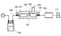
この種の液体原料気化供給装置は、例えば図8に示すように、TEOS(Tetraethyl orthosilicate)等の液体原料Lを貯液タンク100に貯めておき、貯液タンク100に加圧した不活性ガスFGを供給し、不活性ガスFGの加圧により貯液タンク100内の液体原料Lを一定圧力で押し出して気化器101に供給し、ジャケットヒータ等の加熱手段102により気化器101内で加熱して液体原料Lを気化させ、気化させたガスを流量制御装置103により所定流量に制御して半導体製造装置104に供給する。図8中、符号110はストップバルブ、符号111は真空ポンプを示している。 For example, as shown in FIG. 8, this type of liquid raw material vaporizer supplies liquid raw material L such as TEOS (Tetraethyl orthosilicate) in a
気化器101内の液体原料Lを気化させることによる気化器101内の液体原料Lの減少を補うため、液体原料Lの減少を検出し、減少分を気化器101に補給することが必要となる。 In order to compensate for the decrease in the liquid material L in the
気化器101内の液体原料の減少を検出して補給するため、従来では、気化器101への液体原料の供給を制御する制御弁105を気化器101への供給路106に設け、気化器101と流量制御装置103とを連通するガス流路107内のガスの圧力を検出する圧力検出器108を配設し、圧力検出器108により気化器101内のガス圧力をモニターし、気化器101内の液体原料Lが気化して減少することにより圧力検出器101の検出圧力が所定値以下になったら制御弁105を所定時間開いた後に閉じて気化器101内に所定量の液体原料を供給し、再び気化器101内の液体原料Lが気化により減少して検出圧力が所定値に達すると制御弁105を一定時間開いた後に閉じる、というシーケンスを繰り返す制御を行っていた。 In order to detect and replenish the decrease in the liquid raw material in the
しかしながら、何らかのアクシデント等により気化器から流量制御装置へ通じるガス流路内が液体原料で満たされる不具合が生じると、流量制御装置によってガスを流量制御して供給できなくなるという問題がある。 However, if there is a problem that the gas flow path leading from the vaporizer to the flow control device is filled with the liquid material due to some accident or the like, there is a problem that the gas cannot be supplied by controlling the flow rate by the flow control device.
そこで、本発明は、気化器内から流量制御装置へ通じるガス流路内が液体原料で満たされる不具合を解消し得る気化供給装置を提供することを主たる目的とする。 In view of the above, a main object of the present invention is to provide a vaporization supply device that can eliminate the problem that the gas flow path leading from the vaporizer to the flow rate control device is filled with the liquid raw material.
上記目的を達成するため、本発明に係る気化供給装置は、液体を加熱して気化させる気化器と、前記気化器から送出されるガスの流量を制御する流量制御装置と、前記気化器への液体の供給路に介在された第1制御弁と、前記気化器で気化され前記流量制御装置に送られるガスの圧力を検出するための圧力検出器と、前記気化器内の所定量を超える液体のパラメータを測定する液体検知部と、前記圧力検出器の検出した圧力値に基づいて前記気化器に所定量の液体を供給するように前記第1制御弁を制御するとともに、前記液体検知部が液体を検知した時には前記第1制御弁を閉じるように制御する制御装置と、を備える。 In order to achieve the above object, a vaporization supply device according to the present invention includes a vaporizer that heats and vaporizes a liquid, a flow rate control device that controls a flow rate of a gas sent from the vaporizer, and a vaporizer supplied to the vaporizer. A first control valve interposed in the liquid supply path, a pressure detector for detecting the pressure of gas vaporized by the vaporizer and sent to the flow rate control device, and a liquid exceeding a predetermined amount in the vaporizer A liquid detection unit for measuring the parameters of the first control valve and the liquid control unit for controlling the first control valve to supply a predetermined amount of liquid to the vaporizer based on the pressure value detected by the pressure detector. And a control device that controls to close the first control valve when liquid is detected.
一態様において、前記気化器と前記流量制御装置の間のガス流路に介在された第2制御弁を更に備え、前記制御装置は、前記液体検知部が液体を検知した時に、前記第1制御弁を閉じるとともに前記第2制御弁を閉じるように制御する。 In one aspect, the apparatus further comprises a second control valve interposed in a gas flow path between the vaporizer and the flow rate control device, and the control device detects the liquid when the liquid detection unit detects a liquid. Control is performed to close the valve and the second control valve.
また、上記目的を達成するため、本発明に係る気化供給装置は、液体を加熱して気化させる気化器と、前記気化器から送出されるガスの流量を制御する流量制御装置と、前記気化器への液体の供給路に介在された第1制御弁と、前記気化器で気化され前記流量制御装置に送られるガスの圧力を検出するための圧力検出器と、前記気化器と前記流量制御装置の間のガス流路に介在された第2制御弁と、前記気化器内の所定量を超える液体のパラメータを測定する液体検知部と、前記圧力検出器の検出した圧力値に基づいて前記気化器に所定量の液体を供給するように前記第1制御弁を制御するとともに、前記液体検知部が液体を検知した時に前記第2制御弁を閉じるように制御する制御装置と、を備える。 In order to achieve the above object, a vaporization supply apparatus according to the present invention includes a vaporizer that heats and vaporizes a liquid, a flow rate control apparatus that controls a flow rate of a gas sent from the vaporizer, and the vaporizer. A first control valve interposed in a liquid supply path to the liquid, a pressure detector for detecting the pressure of gas vaporized by the vaporizer and sent to the flow rate control device, the vaporizer, and the flow rate control device A second control valve interposed in the gas flow path between the gas detector, a liquid detector for measuring a liquid parameter exceeding a predetermined amount in the vaporizer, and the vaporization based on a pressure value detected by the pressure detector. And a control device for controlling the first control valve so as to supply a predetermined amount of liquid to the vessel and for closing the second control valve when the liquid detection unit detects the liquid.
前記液体検知部は、温度検出器とすることができる。 The liquid detection unit may be a temperature detector.
前記液体検知部は、液面計とすることができる。 The liquid detection unit may be a liquid level gauge.
前記液体検知部は、ロードセルとすることができる。 The liquid detection unit may be a load cell.
前記気化器が気化室を備え、該気化室に前記液体検知部が配設され得る。 The vaporizer may include a vaporization chamber, and the liquid detection unit may be disposed in the vaporization chamber.
前記気化器が気化室と該気化室に連通するガス加熱室とを備え、前記ガス加熱室に前記液体検知部が配設され得る。 The vaporizer may include a vaporization chamber and a gas heating chamber communicating with the vaporization chamber, and the liquid detection unit may be disposed in the gas heating chamber.
本発明に係る気化供給装置によれば、液体検知部によって気化器内の所定量を超える液体原料のパラメータを測定し、前記液体検知部が液体を検知した時に第1制御弁を閉じることにより、過剰な液体原料の気化器への供給を停止し、ガス流路への液体原料の浸入を未然に防止することができる。 According to the vaporization supply apparatus according to the present invention, by measuring the parameter of the liquid material exceeding a predetermined amount in the vaporizer by the liquid detection unit, and closing the first control valve when the liquid detection unit detects the liquid, The supply of the excessive liquid material to the vaporizer can be stopped to prevent the liquid material from entering the gas flow path.
また、前記液体検知部が液体を検知した時に第1制御弁を閉じることにより、気化器内の原料液体が無くなると流量制御装置へのガス供給が停止するため、圧力検出器に製品寿命や経年劣化等による異常が生じていることを確認することができる。 In addition, by closing the first control valve when the liquid detection unit detects the liquid, the gas supply to the flow rate control device is stopped when the raw material liquid in the vaporizer is exhausted. It can be confirmed that an abnormality due to deterioration or the like has occurred.
また、気化器内の所定量を超える液体原料を液体検知部が検知した時に、第2制御弁を閉じることにより気化器からの液体原料の流出を防止し、ガス流路への液体原料の浸入を未然に防止することができる。 Also, when the liquid detection unit detects a liquid material exceeding a predetermined amount in the vaporizer, the liquid control material is prevented from flowing out from the vaporizer by closing the second control valve, and the liquid material enters the gas flow path. Can be prevented in advance.
気化器内に所定量を超える液体原料が流入しガス状態として存在すべき部位に液体が流入すると当該部位の温度が低下するため、液体検知部を温度検出器としてこの温度低下を測定することにより、気化器内の所定量を超える液体原料を検知することができる。 When the liquid raw material exceeding a predetermined amount flows into the vaporizer and the liquid flows into a portion that should exist as a gas state, the temperature of the portion decreases. The liquid raw material exceeding the predetermined amount in the vaporizer can be detected.
また、気化器内に所定量を超える液体原料が流入しガス状態として存在すべき部位に液体が流入すると当該部位の液面が上昇するため、液体検知部を液面計としてこの液面上昇を測定することにより、気化器内の所定量を超える液体原料を検知することができる。 In addition, when a liquid material exceeding a predetermined amount flows into the vaporizer and the liquid flows into a portion that should exist as a gas state, the liquid level of the portion rises. By measuring, the liquid raw material exceeding the predetermined amount in the vaporizer can be detected.
また、気化器内に所定量を超える液体原料が流入しガス状態として存在すべき部位に液体が流入すると気化器内の液体の重量が増加するため、液体検知部をロードセルとしてこの重量増加を測定することにより、気化器内の所定量を超える液体原料を検知することができる。 In addition, when the liquid material exceeding the predetermined amount flows into the vaporizer and the liquid flows into the part that should exist in the gas state, the weight of the liquid in the vaporizer increases. By doing so, the liquid raw material exceeding the predetermined amount in the vaporizer can be detected.
本発明に係る気化供給装置の実施形態について、以下に図面を参照しつつ説明する。なお、全実施形態を通じて、同一又は類似の構成部分には同符号を付した。 Embodiments of a vaporization supply apparatus according to the present invention will be described below with reference to the drawings. In addition, the same code | symbol was attached | subjected to the same or similar component through all embodiment.
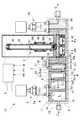
図1は、本発明に係る気化供給装置の第1実施形態を示している。図1に示すように、気化供給装置1Aは、液体原料Lを加熱して気化させる気化器2と、気化器2から送出されるガスGの流量を制御する流量制御装置3と、気化器2への液体原料Lの供給路4に介在された第1制御弁5と、気化器2で気化され流量制御装置3に送られるガスGの圧力を検出するための圧力検出器6と、気化器2内の所定量を超える液体原料Lのパラメータを測定する液体検知部7Aと、圧力検出器6の検出した圧力値に基づいて気化器2に所定量の液体原料Lを供給するように第1制御弁5を制御するとともに、液体検知部7Aが液体を検知した時には第1制御弁5を閉じるように制御する制御装置8と、を備えている。 FIG. 1 shows a first embodiment of a vaporization supply apparatus according to the present invention. As shown in FIG. 1, the
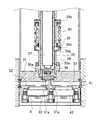
気化器2は、ステンレス鋼で形成された本体2Aを備えている。本体2Aは、仮想線で示された加熱用のジャケットヒータ等の加熱手段Hによって包まれている。本体2Aは、第1ブロック体2a、第2ブロック体2b、及び第3ブロック体2cを連結して構成されている。第1ブロック体2aは、上部に液供給口2a1が形成され、内部に気化室2a2が形成されている。第2ブロック体2bには、第1ブロック体2aの気化室2a2の上部と連通する第1ガス加熱室2b1が形成されている。第3ブロック体2cは、第1ガス加熱室2b1と連通する第2ガス加熱室2c1が内部に形成され、ガス排出口2c2が上部に形成されている。第1ガス加熱室2b1及び第2ガス加熱室2c1は、円筒状の空間内に円柱状の加熱促進体2b3、2c3が設置され、該円筒状空間と加熱促進体2b3、2c3との隙間がガス流路となっている。第1ブロック体2aと第2ブロック体2bの間、及び第2ブロック体2bと第3ブロック体2cの間の、それぞれのガス連通部には、通孔付きガスケット9、10が介在され、これらの通孔付きガスケット9、10の通孔をガスが通過することにより、ガスの脈動が防止される。 The
第1ブロック体2aに、液体原料Lの予備加熱用ブロック体11が連結されている。予備加熱用ブロック体11は、側面に液流入ポート12が接続され、液流入ポート12に連通する液貯留室13が内部に形成され、液貯留室13に連通する液流出口14が上面に形成されている。予備加熱用ブロック体11は、図外の貯液タンク(図8の符号100参照)から所定圧で圧送されてくる液体原料Lを液貯留室13に貯留しておいてジャケットヒータ等の加熱手段Hにより予熱する。 A
第1ブロック体2aと予備加熱用ブロック体11の上面を跨ぐようにして第1制御弁5が固定されている。第1制御弁5は、予備加熱用ブロック体11の液流出口14と第1ブロック体2aの液供給口2a1とを連通する供給路4を開閉又は開度調整することにより、気化器2への液体原料Lの供給量を制御する。図示例の第1制御弁5は、空気圧を利用して弁体5aの開閉を制御するエア駆動弁が用いられている。第1ブロック体2aの液供給口2a1には、細孔が形成されたガスケット15が介設され、ガスケット15の細孔に液体原料を通過させることにより気化室2a2内への供給量が調整されている。 The
図示例の流量制御装置3は、高温対応型の圧力式流量制御装置と呼ばれる公知の流量制御装置である。この流量制御装置3は、図1及び図2を参照すれば、弁ブロック31と、弁ブロック31内に形成されたガス流路32と、ガス流路32に介在された金属製ダイヤフラム弁体33と、弁ブロック31に固定されて立設された筒状ガイド部材34と、筒状ガイド部材34に摺動可能に挿入された弁棒ケース35と、弁棒ケース35の下部に形成された孔35a、35aを貫通し筒状ガイド部材34により押圧固定されたブリッジ36と、弁棒ケース35内に収容されるとともにブリッジ36に支持された放熱スペーサ37及び圧電駆動素子38と、弁棒ケース35の外周に突設され筒状ガイド部材34に形成された孔34aを貫通して延びる鍔受け35bと、鍔受け35bに装着された鍔体39と、筒状ガイド部材34の上端部に形成された鍔部34bと、鍔部34bと鍔体39との間に圧縮状態で配設されたコイルバネ40と、金属ダイヤフラム弁体33の下流側のガス流路32に介在され微細孔が形成された孔空き薄板41と、ダイヤフラム弁体33と孔空き薄板41との間のガス流路32内の圧力を検出する流量制御用圧力検出器42と、を備えている。放熱スペーサ37は、インバー材等で形成されており、ガス流路32に高温のガスが流れても圧電駆動素子38が耐熱温度以上になることを防ぐ。 The
圧電駆動素子38の非通電時には、コイルバネ40により弁棒ケース35が図の下方に押され、図2に示すように、金属ダイヤフラム弁体33が弁座31aに当接し、ガス流路32を閉じている。圧電駆動素子38に通電することにより圧電駆動素子38が伸張し、コイルバネ40の弾性力に抗して弁棒ケース35を図の上方へ持ち上げると金属ダイヤフラム弁体33が自己弾性力により元の逆皿形状に復帰してガス流路32が開通する。 When the
流量制御装置3は、孔空き薄板41の少なくとも上流側のガス圧力を流量制御用圧力検出器42によって検出し、検出した圧力信号に基づいて圧電駆動素子38によりガス流路32に介在された金属製ダイヤフラム弁体33を開閉させて流量制御する。孔空き薄板41の上流側の絶対圧力が孔空き薄板41の下流側の絶対圧力の約2倍以上(臨界膨張条件)になると孔空き薄板41の微細孔を通過するガスが音速となり、それ以上の流速にならないことから、その流量は微細孔上流側の圧力のみに依存し、孔空き薄板41の微細孔を通過する流量は圧力に比例するという原理を利用している。なお、図示しないが、孔空き薄板41の微細孔下流側の圧力も検出して、微細孔の上流側と下流側の差圧に基づいて流量制御することも可能である。なお、孔空き薄板41は、図示例ではオリフィスが形成されたオリフィスプレートであるが、孔空き薄板41の孔はオリフィスに限らず流体を絞る構造のものであればよい。 The flow
第3ブロック体2cにスペーサブロック50が連結され、スペーサブロック50に弁ブロック31が連結されている。第3ブロック体2cとスペーサブロック50とに跨るようにして固定された流路ブロック51内のガス流路52が、第3ブロック体2cのガス流路である第2ガス加熱室2c1とスペーサブロック50のガス流路50aとを連通させる。スペーサブロック50のガス流路50aは、弁ブロック31のガス流路32に連通している。 A
弁ブロック31のガス流路32の金属ダイヤフラム弁体33の上流位置に圧力検出器6が設けられ、気化器2で気化され流量制御装置3に送られるガスの圧力が圧力検出器6によって検出される。 A
圧力検出器6の検出した圧力値の信号(P0)は常に制御装置8に送られ、モニターされている。気化室2a2内の液体原料Lが気化によって少なくなると気化器2の内部圧力が減少する。気化室2a2内の液体原料Lが減少して気化器2内の内部圧力が減少し、圧力検出器6の検出圧力が予め設定された設定値に達すると、制御装置8は、第1制御弁5を所定時間だけ開いた後に閉じることにより、所定量の液体原料Lを気化室2a2に供給する。気化室2a2内に所定量の液体原料Lが供給されると液体原料Lが気化することにより気化器2内のガス圧力が再び上昇し、その後、液体原料Lが少なくなることにより再び気化器2の内部圧力が減少する。そして気化器2の内部圧力が設定値に達すると前記したように再び第1制御弁5を所定時間だけ開いた後に閉じる。このような制御シーケンスにより、気化室2a2に所定量の液体原料が逐次補充される。 The pressure value signal (P0) detected by the
気化室2a2に供給される液体原料Lの最大水位が予め設定され、その最大水位に応じて、気化室2a2に供給される液体原料Lの前記所定量が設定される。図1に示す気化室2a2の液体原料Lの水位は設定最大水位を示している。 The maximum water level of the liquid raw material L supplied to the vaporizing chamber 2a2 is set in advance, and the predetermined amount of the liquid raw material L supplied to the vaporizing chamber 2a2 is set according to the maximum water level. The water level of the liquid raw material L in the vaporizing chamber 2a2 shown in FIG. 1 indicates the set maximum water level.
流量制御装置3の下流側のガス流路55には、ストップバルブ56が設けられている。 A
第1実施形態の気化供給装置1Aは、気化器2内の所定量を超える液体原料のパラメータを測定する液体検知部7Aとして、第1ガス加熱室2b1内の温度を測定しモニターする温度検出器が採用されている。液体検知部7Aを構成する温度検出器は、白金測温抵抗体、熱電対、サーミスタ、又は、赤外温度計等の公知の温度検出器を用いることができる。図示例では、保護管に白金測温抵抗体が挿入された保護管式白金測温抵抗体が用いられている。 The
図示例において、例えば、気化室2a2内の液体原料Lの温度は185℃に保たれており、第1ガス加熱室2b1内のガス温度は195℃に保たれている。仮に、液体原料Lが気化室2a2内から溢れ出て第1ガス加熱室2b1内に流入し、液体原料Lが液体検知部7Aを構成する温度検出器に接触すると、該温度検出器の測定温度の低下により、第1ガス加熱室2b1内に液体原料が流入してきたことを検知することができる。 In the illustrated example, for example, the temperature of the liquid raw material L in the vaporizing chamber 2a2 is maintained at 185 ° C., and the gas temperature in the first gas heating chamber 2b1 is maintained at 195 ° C. If the liquid raw material L overflows from the vaporization chamber 2a2 and flows into the first gas heating chamber 2b1, and the liquid raw material L comes into contact with the temperature detector constituting the
制御装置8は、液体検知部7Aを構成する温度検出器からの検出温度を常にモニターし、上記温度低下があった場合に液体原料Lが第1ガス加熱室2b1に流入したと判定して、第1制御弁5を閉じる。このとき、圧力検出器6の検出信号が前記設定値より下がっていても、制御装置8は、第1制御弁5を閉じるようにプログラムされている。 The
従って、第1ガス加熱室2b1に液体原料Lが流入した場合は、直ちに第1制御弁5が閉じられる。これにより、第1ガス加熱室2b1に液体原料Lが流入した場合に、圧力検出器6が誤作動する等の何らかのアクシデント等によって検出圧力値が設定値より下がっていたとしても、第1制御弁5が開かれずに直ちに閉じられるので、気化器2から流量制御装置3へのガス流路32内が液体原料で満たされる不具合を未然に防止できる。 Therefore, when the liquid raw material L flows into the first gas heating chamber 2b1, the
また、液体検知部7Aが液体原料Lを検知して第1制御弁5を閉じると、気化器2内の液体原料Lが気化されて無くなり、流量制御装置3への原料ガスの供給は停止する。従って、この場合、圧力検出器6に異常、例えば製品寿命や経年劣化等による異常が生じたことが判明する。 Further, when the
液体検知部7Aを構成する温度検出器は、第1ガス加熱室2b1に限らず、第2ガス加熱室2c1に配設することもできるし、気化室2a2の設定最大水位より上部空間に配置することもできる。 The temperature detector that constitutes the
図3は、本発明に係る気化供給装置の第2実施形態を示している。第2実施形態の気化供給装置1Bは、気化器2内の所定量を超える液体原料のパラメータを測定する液体検知部7Bが、気化器2内の液面レベルの変化を測定する液面計である点が主として上記第1実施形態と異なり、その他構成は上記第1実施形態と同様である。 FIG. 3 shows a second embodiment of the vaporization supply apparatus according to the present invention. The
気化器2内は、高温多湿な環境下にあるため、液体検知部7Bを構成する液面計としては、液相と気相とで熱放散定数が異なることを利用した熱式液面計を好適に用いることができる。 Since the inside of the
この種の熱式液面計の原理を、図4及び図5を参照して以下に説明する。熱式液面計は、それぞれに白金等の測温抵抗体R1、R2を封入した2本の保護管60、61を設置し、一方の測温抵抗体R1には、測温抵抗体R1を自己発熱により周囲温度より高温に保つために比較的大きな定電流I1(加熱電流)を流し、他方の測温抵抗体R2には周囲温度を測定できる程度で発熱が無視できる程度の大きさの微小な定電流I2(周囲温度測定用電流)を流す。 The principle of this type of thermal liquid level gauge will be described below with reference to FIGS. The thermal liquid level gauge is provided with two
そうすると、大きな電流I1を流した測温抵抗体R1は発熱するが、このとき、測温抵抗体が液相L中にある場合の熱放散定数は、気相V中にある場合の熱放散定数よりも大きいために、気相V中にある場合の測温抵抗体の温度は、液相中にある場合と比べると高くなる。 Then, the resistance temperature detector R1 that has passed a large current I1 generates heat. At this time, the heat dissipation constant when the resistance temperature detector is in the liquid phase L is the heat dissipation constant when the resistance temperature detector is in the gas phase V. Therefore, the temperature of the resistance temperature detector when it is in the gas phase V becomes higher than that when it is in the liquid phase.
そしてこのことは、気相中の測温抵抗体は、液相中の測温抵抗値よりも抵抗値が高いことを意味するため、大きな電流を流した測温抵抗体R1の電圧出力と、微小な電流を流した測温抵抗体R2の電圧出力との差分を見ることで、測温抵抗体が液面の上方か下方かを判別することが可能となる。即ち、差分が小さい場合には測温抵抗体は液面よりも下方にあり、差分が大きい場合には測温抵抗体は液面よりも上方にあると判断することができる。 This means that the resistance temperature sensor in the gas phase has a resistance value higher than the resistance resistance value in the liquid phase, and therefore, the voltage output of the resistance temperature detector R1 through which a large current flows, By observing the difference from the voltage output of the resistance temperature detector R2 through which a minute current flows, it is possible to determine whether the resistance temperature detector is above or below the liquid surface. That is, when the difference is small, it can be determined that the resistance temperature detector is below the liquid level, and when the difference is large, the resistance temperature detector is above the liquid level.
図4は、液面検知回路の一例であり、測温抵抗体R1,R2には、定電流回路S1、S2を介して電源Vccから定電流を供給される。測温抵抗体R2には、周囲温度を測定できる程度で発熱が無視できる大きさの微小な電流が流れ、測温抵抗体R1には、測温抵抗体R2より大きな電流値の電流であって測温抵抗体R1を高温に加熱するために比較的大きな電流が流れるように、定電流回路S1には定電流回路S2より大きな電流が流れるように設定されている。測温抵抗体R1の端子電圧V1と測温抵抗体R2の端子電圧V2とが差動増幅回路Dの反転入力及び非反転入力に其々入力され、差動増幅回路Dから、端子電圧V1,V2の差電圧(V1−V2)に相当する電圧信号が比較器Cに入力される。比較器Cは、分圧抵抗器R3,R4により設定された基準電圧V3を、前記差電圧と比較する。 FIG. 4 shows an example of the liquid level detection circuit. A constant current is supplied from the power source Vcc to the resistance temperature detectors R1 and R2 via the constant current circuits S1 and S2. A small current having a magnitude that can be ignored while the ambient temperature can be measured flows to the resistance temperature detector R2, and the current resistance R1 has a current value larger than that of the resistance temperature detector R2. The constant current circuit S1 is set so that a larger current flows than the constant current circuit S2 so that a relatively large current flows in order to heat the resistance temperature detector R1 to a high temperature. The terminal voltage V1 of the resistance temperature detector R1 and the terminal voltage V2 of the resistance temperature detector R2 are input to the inverting input and the non-inverting input of the differential amplifier circuit D, respectively. A voltage signal corresponding to the difference voltage V2 (V1-V2) is input to the comparator C. The comparator C compares the reference voltage V3 set by the voltage dividing resistors R3 and R4 with the difference voltage.
測温抵抗体R1が液相中にあるときは、測温抵抗体R1は周囲温度に対する温度上昇は気相中の温度上昇より小さい。その結果、同じく液相中にある測温抵抗体R2から発せられる周囲温度に対応した大きさの電圧信号との差に相当する作動増幅回路Dからの出力電圧が基準電圧より小さくなり、比較器Cの出力はローレベルになる。一方、液面が下がり、測温抵抗体R1が気相中に露出すると、周囲温度に対する温度上昇が気相中の温度上昇になるから、同じく気相中にある測温抵抗体R2から発せられる周囲温度に対応した大きさの電圧信号との差に相当する差動増幅回路Dの出力電圧が基準電圧より大きくなり、比較器Cの出力はハイレベルとなる。比較器Cの出力がハイレベルの時は測温抵抗体R1,R2が気相中にあり、比較器Cの出力がローレベルの時は測温抵抗体R1,R2が液相中にあると判別される。 When the resistance temperature detector R1 is in the liquid phase, the temperature increase of the resistance temperature detector R1 relative to the ambient temperature is smaller than the temperature increase in the gas phase. As a result, the output voltage from the operational amplification circuit D corresponding to the difference from the voltage signal of the magnitude corresponding to the ambient temperature emitted from the resistance temperature detector R2 also in the liquid phase becomes smaller than the reference voltage, and the comparator The output of C becomes low level. On the other hand, when the liquid level is lowered and the resistance temperature detector R1 is exposed to the gas phase, the temperature rise with respect to the ambient temperature becomes the temperature rise in the gas phase, so that the temperature measurement resistor R2 is also emitted from the gas phase. The output voltage of the differential amplifier circuit D corresponding to the difference from the voltage signal having a magnitude corresponding to the ambient temperature becomes higher than the reference voltage, and the output of the comparator C becomes high level. When the output of the comparator C is high, the resistance thermometers R1, R2 are in the gas phase, and when the output of the comparator C is low, the resistance thermometers R1, R2 are in the liquid phase. Determined.
端子電圧V1,V2を測定すれば、電流値I1、I2からオームの法則により、測温抵抗体R1,R2の抵抗値を求めることができ、測温抵抗体R1,R2の抵抗値が分かれば、測温抵抗体R1,R2の温度に対する抵抗変化率が既知であれば、測温抵抗体R1,R2の温度を導き出すことができる。したがって、液面検知回路では、測温抵抗体R1、R2の電圧出力の比較に代えて、測温抵抗体R1,R2の抵抗値を比較することによっても判別可能であるし、あるいは、測温抵抗体R1,R2の温度に対する抵抗変化率を利用して各々の抵抗値から測温抵抗体R1,R2の温度を測定してそれらの温度を比較することによっても、判別可能である。なお、白金の場合、0℃で100Ωであり、1℃上昇するごとに抵抗値が0.39Ω上昇する。 If the terminal voltages V1 and V2 are measured, the resistance values of the resistance temperature detectors R1 and R2 can be obtained from the current values I1 and I2 according to Ohm's law, and if the resistance values of the resistance temperature detectors R1 and R2 are known. If the rate of resistance change with respect to the temperature of the resistance thermometers R1, R2 is known, the temperature of the resistance thermometers R1, R2 can be derived. Therefore, in the liquid level detection circuit, instead of comparing the voltage outputs of the resistance temperature detectors R1 and R2, it can be determined by comparing the resistance values of the resistance temperature detectors R1 and R2, or It can also be determined by measuring the temperature of the resistance temperature detectors R1 and R2 from the respective resistance values using the rate of resistance change with respect to the temperature of the resistors R1 and R2 and comparing the temperatures. In the case of platinum, the resistance value is 100Ω at 0 ° C., and the resistance value increases by 0.39Ω for every 1 ° C. increase.
再び図3を参照すれば、第2実施形態の気化供給装置1Bにおいては、液体検知部7Bを構成する液面計の2本の保護管60、61が、第1ガス加熱室2b1内に配設されている。なお、第2実施形態では、保護管60、61を第1ガス加熱室2b1内に設置したことにより、加熱促進体2b3が上記第1実施形態のものより短くなっている。 Referring to FIG. 3 again, in the
保護管60,61に封入される測温抵抗体としては、白金測温抵抗体を好適に用いることができるが、他の公知の測温抵抗体を用いることもできる。保護管60、61は、第2実施形態においては鉛直方向に設置されているが、水平方向に設置することもできる。 As the resistance temperature detector enclosed in the
第1ガス加熱室2b1内に液体原料Lが流入したことを、液体検知部7Bを構成する液面計が検知した場合、制御装置8は、上記第1実施形態と同様に、圧力検出器6からの検出圧力値に拘わらず、第1制御弁5を閉じるように制御する。 When the liquid level meter constituting the
液体検知部7Bを構成する液面計は、第1ガス加熱室2b1内に限らず、気化室2a2或いは第2ガス加熱室2c1に設けることもできる。また、液面計としては、熱式液面計に限らず、レーザー液面計、超音波液面計、その他の公知の液面計を採用することもできる。なお、本発明において、液面計による「測定」には、上記第2実施形態のように液体原料Lの液面レベルが最大設定水位から保護管60,61の検知レベルへ移行する変化を測定する場合の他、液体原料Lの液面レベルと液面計との距離を測定する場合を含む。 The liquid level meter constituting the
次に、本発明に係る気化供給装置の第3実施形態について、図6を参照して説明する。第3実施形態の気化供給装置1Cでは、気化器2内の所定量を超える液体原料のパラメータを測定する液体検知部7Cが重量を測定するロードセルである点が上記第1実施形態と異なり、その他の構成は上記第1実施形態と同様である。 Next, a third embodiment of the vaporization supply apparatus according to the present invention will be described with reference to FIG. The
液体検知部7Cを構成するロードセルは、圧電素子を内蔵させたプレート状のロードセルを採用することができ、第1ガス加熱室2b1の底部に設置されている。なお、第3実施形態において、第1実施形態の第1ガス加熱室2b1内に設けられていた加熱促進体2b3が省略されている。第1ガス加熱室2b1内に液体原料Lが流入すると、ロードセルで構成された液体検知部7Cの検出重量が増加し、第1ガス加熱室2b1内に液体原料Lが流入したことを検出することができる。制御装置8は、ロードセルで構成される液体検知部7Cが第1ガス加熱室2b1内に流入した液体原料Lを検出すると、上記第1実施形態と同様に、圧力検出器6からの検出圧力値に拘わらず、第1制御弁5を閉じるように制御する。 A plate-shaped load cell with a built-in piezoelectric element can be adopted as the load cell constituting the liquid detection unit 7C, and is installed at the bottom of the first gas heating chamber 2b1. In the third embodiment, the heating accelerator 2b3 provided in the first gas heating chamber 2b1 of the first embodiment is omitted. When the liquid material L flows into the first gas heating chamber 2b1, the detection weight of the liquid detection unit 7C configured by the load cell increases, and it is detected that the liquid material L has flowed into the first gas heating chamber 2b1. Can do. When the liquid detector 7C configured by a load cell detects the liquid raw material L that has flowed into the first gas heating chamber 2b1, the
液体検知部7を構成するロードセルは、第1ガス加熱室2b1内に限らず、気化室2a2の底、或いは、第2ガス加熱室2c1の底に配設することもできる。 The load cell that constitutes the liquid detection unit 7 is not limited to the first gas heating chamber 2b1, but may be disposed at the bottom of the vaporization chamber 2a2 or the bottom of the second gas heating chamber 2c1.
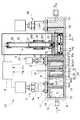
次に、本発明に係る気化供給装置の第4実施形態について図7を参照して説明する。第4実施形態の気化供給装置1Dでは、第1実施形態の流路ブロック51に代えて、気化器2と流量制御装置3の間のガス流路52に介在された第2制御弁70を備えている。 Next, a fourth embodiment of the vaporization supply apparatus according to the present invention will be described with reference to FIG. The
制御装置8は、液体検知部7Aが液体原料Lを検知した時に、第2制御弁70を閉じるように制御する。 The
制御装置8は、一態様において、液体検知部7Aが液体原料Lを検知した時に、上記第1実施形態と同様に圧力検知器6の検知圧力に拘わらず第1制御弁5をも閉じる。すなわち、この場合、制御装置8は、液体検知部7Aが液体原料Lを検知した時に、第1制御弁5と第2制御弁7の双方を直ちに閉じるように制御する。 In one aspect, when the
或いは、制御装置8は、他の一態様において、液体検知部7Aが液体原料Lを検知した時に、第1制御弁5には液体検知部7Aの検知信号に基づく制御指令を送らず、第2制御弁70のみを閉じるように制御する。すなわち、この場合、液体検知部7Aの検知信号は、第2制御弁70の開閉制御のみに用いられる。第1制御弁5は、圧力検知器6の検知信号に基づいて従来と同様に制御される。 Alternatively, in another aspect, when the
第2制御弁70は、気化器2の下流部に配置されることで、気化器2内への液体原料Lの設定限度を超えた流入があった場合に、気化器2から外側のガス流路32へ液体原料Lが流入することを未然に防止することができる。 The
上記第4実施形態において、上記第1実施形態の温度検出器による液体検知部7Aを採用したが、温度検出器に代えて、上記第2実施形態の液面計で構成される液体検知部7B、或いは、上記第3実施形態のロードセルで構成された液体検知部7Cを採用することもできる。 In the fourth embodiment, the
上記第1〜第4実施形態において、液体検知部が測定する液体のパラメータとして、温度、液面レベル、及び重量を例示したが、液体検知部が測定する液体のパラメータは、気化器内に所定量を超えて流入した液体を検知することができるパラメータであれば他のパラメータであってもよい。 In the first to fourth embodiments, the temperature, the liquid level, and the weight are exemplified as the liquid parameters measured by the liquid detection unit. However, the liquid parameters measured by the liquid detection unit are included in the vaporizer. Other parameters may be used as long as they can detect the liquid that has flowed beyond the fixed amount.
本発明は、上記実施形態に限らず、本発明の趣旨を逸脱しない範囲において種々の形態を採用することができる。 The present invention is not limited to the above embodiment, and various forms can be adopted without departing from the spirit of the present invention.
1A,1B,1C,1D 気化供給装置
2 気化器
2a2 気化室
2b1 第1ガス加熱室
2c1 第2ガス加熱室
3 流量制御装置
5 第1制御弁
6 圧力検出器
7A,7B,7C 液体検知部
8 制御装置
70 第2制御弁1A, 1B, 1C, 1D
Claims (8)
Translated fromJapanese前記気化器から送出されるガスの流量を制御する流量制御装置と、
前記気化器への液体の供給路に介在された第1制御弁と、
前記気化器で気化され前記流量制御装置に送られるガスの圧力を検出するための圧力検出器と、
前記気化器内の所定量を超える液体のパラメータを測定する液体検知部と、
前記圧力検出器の検出した圧力値に基づいて前記気化器に所定量の液体を供給するように前記第1制御弁を制御するとともに、前記液体検知部が液体を検知した時には前記第1制御弁を閉じるように制御する制御装置と、
を備えることを特徴とする気化供給装置。A vaporizer that heats and vaporizes the liquid;
A flow rate control device for controlling the flow rate of gas delivered from the vaporizer;
A first control valve interposed in a liquid supply path to the vaporizer;
A pressure detector for detecting the pressure of gas vaporized by the vaporizer and sent to the flow rate control device;
A liquid detector for measuring a parameter of the liquid exceeding a predetermined amount in the vaporizer;
The first control valve is controlled to supply a predetermined amount of liquid to the vaporizer based on the pressure value detected by the pressure detector, and the first control valve is detected when the liquid detection unit detects the liquid. A control device for controlling to close,
A vaporization supply apparatus comprising:
前記制御装置は、前記液体検知部が液体を検知した時に、前記第1制御弁を閉じるとともに前記第2制御弁を閉じるように制御することを特徴とする、請求項1に記載の気化供給装置。A second control valve interposed in a gas flow path between the vaporizer and the flow control device;
2. The vaporization supply device according to claim 1, wherein when the liquid detection unit detects a liquid, the control device controls to close the first control valve and to close the second control valve. 3. .
前記気化器から送出されるガスの流量を制御する流量制御装置と、
前記気化器への液体の供給路に介在された第1制御弁と、
前記気化器で気化され前記流量制御装置に送られるガスの圧力を検出するための圧力検出器と、
前記気化器と前記流量制御装置の間のガス流路に介在された第2制御弁と、
前記気化器内の所定量を超える液体のパラメータを測定する液体検知部と、
前記圧力検出器の検出した圧力値に基づいて前記気化器に所定量の液体を供給するように前記第1制御弁を制御するとともに、前記液体検知部が液体を検知した時に前記第2制御弁を閉じるように制御する制御装置と、
を備えることを特徴とする気化供給装置。A vaporizer that heats and vaporizes the liquid;
A flow rate control device for controlling the flow rate of gas delivered from the vaporizer;
A first control valve interposed in a liquid supply path to the vaporizer;
A pressure detector for detecting the pressure of gas vaporized by the vaporizer and sent to the flow rate control device;
A second control valve interposed in a gas flow path between the vaporizer and the flow control device;
A liquid detector for measuring a parameter of the liquid exceeding a predetermined amount in the vaporizer;
The first control valve is controlled to supply a predetermined amount of liquid to the vaporizer based on the pressure value detected by the pressure detector, and the second control valve is detected when the liquid detector detects the liquid. A control device for controlling to close,
A vaporization supply apparatus comprising:
7. The vaporizer includes a vaporization chamber and a gas heating chamber communicating with the vaporization chamber, and the liquid detection unit is disposed in the gas heating chamber. Vaporization supply device.
Priority Applications (6)
| Application Number | Priority Date | Filing Date | Title |
|---|---|---|---|
| JP2015093494AJP6578125B2 (en) | 2015-04-30 | 2015-04-30 | Vaporization supply device |
| KR1020177017535AKR101962659B1 (en) | 2015-04-30 | 2016-04-11 | Vaporization supply apparatus |
| CN201680007156.XACN107532298B (en) | 2015-04-30 | 2016-04-11 | Vaporizer/supplier |
| US15/565,696US10646844B2 (en) | 2015-04-30 | 2016-04-11 | Vaporization supply apparatus |
| PCT/JP2016/001967WO2016174832A1 (en) | 2015-04-30 | 2016-04-11 | Vaporization supply apparatus |
| TW105112439ATWI632609B (en) | 2015-04-30 | 2016-04-21 | Gasification supply device |
Applications Claiming Priority (1)
| Application Number | Priority Date | Filing Date | Title |
|---|---|---|---|
| JP2015093494AJP6578125B2 (en) | 2015-04-30 | 2015-04-30 | Vaporization supply device |
Publications (3)
| Publication Number | Publication Date |
|---|---|
| JP2016211021Atrue JP2016211021A (en) | 2016-12-15 |
| JP2016211021A5 JP2016211021A5 (en) | 2018-03-15 |
| JP6578125B2 JP6578125B2 (en) | 2019-09-18 |
Family
ID=57199662
Family Applications (1)
| Application Number | Title | Priority Date | Filing Date |
|---|---|---|---|
| JP2015093494AActiveJP6578125B2 (en) | 2015-04-30 | 2015-04-30 | Vaporization supply device |
Country Status (6)
| Country | Link |
|---|---|
| US (1) | US10646844B2 (en) |
| JP (1) | JP6578125B2 (en) |
| KR (1) | KR101962659B1 (en) |
| CN (1) | CN107532298B (en) |
| TW (1) | TWI632609B (en) |
| WO (1) | WO2016174832A1 (en) |
Cited By (6)
| Publication number | Priority date | Publication date | Assignee | Title |
|---|---|---|---|---|
| US20190136370A1 (en)* | 2017-11-07 | 2019-05-09 | Horiba Stec, Co., Ltd. | Vaporization system and vaporization system program |
| KR20190140002A (en)* | 2017-07-25 | 2019-12-18 | 가부시키가이샤 후지킨 | Fluid control device |
| JPWO2021124723A1 (en)* | 2019-12-16 | 2021-06-24 | ||
| JP2021130853A (en)* | 2020-02-20 | 2021-09-09 | 株式会社堀場エステック | Vaporization system |
| WO2022091713A1 (en)* | 2020-10-31 | 2022-05-05 | 株式会社フジキン | Gas supply system and gas supply method |
| US12121926B2 (en) | 2019-08-29 | 2024-10-22 | Fujikin Incorporated | Fluid supply system |
Families Citing this family (10)
| Publication number | Priority date | Publication date | Assignee | Title |
|---|---|---|---|---|
| US20200149162A1 (en) | 2017-07-25 | 2020-05-14 | Fujikin Incorporated | Fluid control device |
| KR20220029730A (en) | 2019-08-30 | 2022-03-08 | 가부시키가이샤 후지킨 | diaphragm valve |
| CN114269966A (en)* | 2019-09-19 | 2022-04-01 | 株式会社富士金 | Gasification supply device |
| JP7111408B2 (en) | 2019-12-06 | 2022-08-02 | 株式会社フジキン | Abnormality detection method and flow rate monitoring method for flow control device |
| WO2022022188A1 (en)* | 2020-07-27 | 2022-02-03 | 江苏菲沃泰纳米科技股份有限公司 | Raw material gasification device, film coating device, film coating apparatus and feeding method therefor |
| JP7589890B2 (en)* | 2020-10-07 | 2024-11-26 | 株式会社フジキン | Vaporizer, gas supply device, and method for controlling gas supply device |
| US20240101446A1 (en)* | 2021-03-11 | 2024-03-28 | Fujikin Incorporated | Vaporizer and vaporization supply device |
| KR102849824B1 (en) | 2021-04-01 | 2025-08-25 | 가부시키가이샤 후지킨 | Controller and vaporizer supply unit |
| CN115469424A (en)* | 2021-06-11 | 2022-12-13 | 台湾东电化股份有限公司 | Drive mechanism |
| KR102774123B1 (en)* | 2023-06-02 | 2025-03-04 | 주식회사 비투지홀딩스 | Gallium supply apparatus for hydride vapor phase epitaxy apparatus for growth of Gallium Nitride single crystalline |
Citations (6)
| Publication number | Priority date | Publication date | Assignee | Title |
|---|---|---|---|---|
| JPH02261529A (en)* | 1989-04-01 | 1990-10-24 | Tel Sagami Ltd | Device for gasifying and supplying liquid material |
| JP2000133644A (en)* | 1998-10-28 | 2000-05-12 | Mitsubishi Electric Corp | Semiconductor device manufacturing equipment |
| JP2005217089A (en)* | 2004-01-29 | 2005-08-11 | Nec Kansai Ltd | Apparatus and method for manufacturing semiconductor |
| JP2009252760A (en)* | 2008-04-01 | 2009-10-29 | Fujikin Inc | Gas supply device with carburetor |
| JP2010173660A (en)* | 2009-01-27 | 2010-08-12 | Air Liquide Japan Ltd | Device for supplying liquid material in filling vessel and method for controlling liquid level in filling vessel in the device of supplying liquid material |
| JP2010180429A (en)* | 2009-02-03 | 2010-08-19 | Fujikin Inc | System for vaporizing and feeding liquid material |
Family Cites Families (7)
| Publication number | Priority date | Publication date | Assignee | Title |
|---|---|---|---|---|
| JP3896594B2 (en)* | 2004-10-01 | 2007-03-22 | 株式会社ユーテック | Vaporizer for CVD, solution vaporization type CVD apparatus, and vaporization method for CVD |
| JP4263206B2 (en)* | 2005-11-15 | 2009-05-13 | 東京エレクトロン株式会社 | Heat treatment method, heat treatment apparatus and vaporization apparatus |
| JP5652960B2 (en)* | 2011-08-01 | 2015-01-14 | 株式会社フジキン | Raw material vaporizer |
| JP5913888B2 (en) | 2011-09-30 | 2016-04-27 | 国立大学法人東北大学 | Vaporizer |
| JP2014006151A (en)* | 2012-06-25 | 2014-01-16 | Taiyo Nippon Sanso Corp | Method for detecting whether liquid material exists or not |
| JP5837869B2 (en) | 2012-12-06 | 2015-12-24 | 株式会社フジキン | Raw material vaporizer |
| JP5548292B1 (en)* | 2013-05-30 | 2014-07-16 | 株式会社堀場エステック | Heating vaporization system and heating vaporization method |
- 2015
- 2015-04-30JPJP2015093494Apatent/JP6578125B2/enactiveActive
- 2016
- 2016-04-11WOPCT/JP2016/001967patent/WO2016174832A1/ennot_activeCeased
- 2016-04-11CNCN201680007156.XApatent/CN107532298B/ennot_activeExpired - Fee Related
- 2016-04-11KRKR1020177017535Apatent/KR101962659B1/enactiveActive
- 2016-04-11USUS15/565,696patent/US10646844B2/enactiveActive
- 2016-04-21TWTW105112439Apatent/TWI632609B/enactive
Patent Citations (6)
| Publication number | Priority date | Publication date | Assignee | Title |
|---|---|---|---|---|
| JPH02261529A (en)* | 1989-04-01 | 1990-10-24 | Tel Sagami Ltd | Device for gasifying and supplying liquid material |
| JP2000133644A (en)* | 1998-10-28 | 2000-05-12 | Mitsubishi Electric Corp | Semiconductor device manufacturing equipment |
| JP2005217089A (en)* | 2004-01-29 | 2005-08-11 | Nec Kansai Ltd | Apparatus and method for manufacturing semiconductor |
| JP2009252760A (en)* | 2008-04-01 | 2009-10-29 | Fujikin Inc | Gas supply device with carburetor |
| JP2010173660A (en)* | 2009-01-27 | 2010-08-12 | Air Liquide Japan Ltd | Device for supplying liquid material in filling vessel and method for controlling liquid level in filling vessel in the device of supplying liquid material |
| JP2010180429A (en)* | 2009-02-03 | 2010-08-19 | Fujikin Inc | System for vaporizing and feeding liquid material |
Cited By (21)
| Publication number | Priority date | Publication date | Assignee | Title |
|---|---|---|---|---|
| KR20190140002A (en)* | 2017-07-25 | 2019-12-18 | 가부시키가이샤 후지킨 | Fluid control device |
| KR102363117B1 (en)* | 2017-07-25 | 2022-02-15 | 가부시키가이샤 후지킨 | fluid control unit |
| US10612131B2 (en) | 2017-11-07 | 2020-04-07 | Horiba Stec, Co., Ltd. | Vaporization system and vaporization system program |
| US20190136370A1 (en)* | 2017-11-07 | 2019-05-09 | Horiba Stec, Co., Ltd. | Vaporization system and vaporization system program |
| TWI796376B (en)* | 2017-11-07 | 2023-03-21 | 日商堀場Stec股份有限公司 | Vaporization system and vaporization system program |
| CN109750275B (en)* | 2017-11-07 | 2022-09-20 | 株式会社堀场Stec | Gasification system and storage medium storing program for gasification system |
| KR20190051802A (en) | 2017-11-07 | 2019-05-15 | 가부시키가이샤 호리바 에스텍 | Vaporization system and vaporization system program |
| CN109750275A (en)* | 2017-11-07 | 2019-05-14 | 株式会社堀场Stec | Gasification system and the storage medium for being stored with gasification system program |
| US12121926B2 (en) | 2019-08-29 | 2024-10-22 | Fujikin Incorporated | Fluid supply system |
| WO2021124723A1 (en)* | 2019-12-16 | 2021-06-24 | 株式会社フジキン | Vaporization supply method and vaporization supply device |
| KR20220038807A (en)* | 2019-12-16 | 2022-03-29 | 가부시키가이샤 후지킨 | Vaporization supply method and vaporization supply device |
| JPWO2021124723A1 (en)* | 2019-12-16 | 2021-06-24 | ||
| JP7240770B2 (en) | 2019-12-16 | 2023-03-16 | 株式会社フジキン | Vaporization supply method and vaporization supply device |
| KR102641135B1 (en) | 2019-12-16 | 2024-02-28 | 가부시키가이샤 후지킨 | Vaporization supply method and vaporization supply device |
| JP2021130853A (en)* | 2020-02-20 | 2021-09-09 | 株式会社堀場エステック | Vaporization system |
| JP7457522B2 (en) | 2020-02-20 | 2024-03-28 | 株式会社堀場エステック | Evaporation System |
| WO2022091713A1 (en)* | 2020-10-31 | 2022-05-05 | 株式会社フジキン | Gas supply system and gas supply method |
| JP7316011B2 (en) | 2020-10-31 | 2023-07-27 | 株式会社フジキン | Gas supply system and gas supply method |
| KR20230042729A (en)* | 2020-10-31 | 2023-03-29 | 가부시키가이샤 후지킨 | Gas supply system and gas supply method |
| JPWO2022091713A1 (en)* | 2020-10-31 | 2022-05-05 | ||
| KR102812621B1 (en)* | 2020-10-31 | 2025-05-26 | 가부시키가이샤 후지킨 | Gas supply system and gas supply method |
Also Published As
| Publication number | Publication date |
|---|---|
| JP6578125B2 (en) | 2019-09-18 |
| US20180071702A1 (en) | 2018-03-15 |
| KR101962659B1 (en) | 2019-03-27 |
| TWI632609B (en) | 2018-08-11 |
| CN107532298A (en) | 2018-01-02 |
| TW201705279A (en) | 2017-02-01 |
| CN107532298B (en) | 2019-07-26 |
| US10646844B2 (en) | 2020-05-12 |
| KR20170088416A (en) | 2017-08-01 |
| WO2016174832A1 (en) | 2016-11-03 |
Similar Documents
| Publication | Publication Date | Title |
|---|---|---|
| JP6578125B2 (en) | Vaporization supply device | |
| TWI437402B (en) | Pressure flow control device | |
| JP6212467B2 (en) | Liquid level gauge and liquid raw material vaporizer | |
| TWI628717B (en) | Heating vaporization system and heating vaporization method | |
| JP2016211021A5 (en) | ||
| KR102363117B1 (en) | fluid control unit | |
| EP3271655B1 (en) | Device and method for mixing combustible gas and combustion air, hot water installation provided therewith, corresponding thermal mass flow sensor and method for measuring a mass flow rate of a gas flow | |
| KR20170044680A (en) | Liquid level detection circuit, liquid level meter, container provided with liquid level meter, and vaporizer using container | |
| WO2021124723A1 (en) | Vaporization supply method and vaporization supply device | |
| JP6434238B2 (en) | Flow meter and correction value calculation method | |
| JPH06214658A (en) | Mass flow controller with temperature adjusting function | |
| JP2009288095A (en) | Thermal flow sensor |
Legal Events
| Date | Code | Title | Description |
|---|---|---|---|
| A521 | Request for written amendment filed | Free format text:JAPANESE INTERMEDIATE CODE: A523 Effective date:20180131 | |
| A621 | Written request for application examination | Free format text:JAPANESE INTERMEDIATE CODE: A621 Effective date:20180131 | |
| A131 | Notification of reasons for refusal | Free format text:JAPANESE INTERMEDIATE CODE: A131 Effective date:20190327 | |
| A521 | Request for written amendment filed | Free format text:JAPANESE INTERMEDIATE CODE: A523 Effective date:20190517 | |
| TRDD | Decision of grant or rejection written | ||
| A01 | Written decision to grant a patent or to grant a registration (utility model) | Free format text:JAPANESE INTERMEDIATE CODE: A01 Effective date:20190807 | |
| A61 | First payment of annual fees (during grant procedure) | Free format text:JAPANESE INTERMEDIATE CODE: A61 Effective date:20190826 | |
| R150 | Certificate of patent or registration of utility model | Ref document number:6578125 Country of ref document:JP Free format text:JAPANESE INTERMEDIATE CODE: R150 | |
| R250 | Receipt of annual fees | Free format text:JAPANESE INTERMEDIATE CODE: R250 | |
| R250 | Receipt of annual fees | Free format text:JAPANESE INTERMEDIATE CODE: R250 | |
| R250 | Receipt of annual fees | Free format text:JAPANESE INTERMEDIATE CODE: R250 | |
| R250 | Receipt of annual fees | Free format text:JAPANESE INTERMEDIATE CODE: R250 |