JP2016209665A - Artificial heart valve - Google Patents
Artificial heart valveDownload PDFInfo
- Publication number
- JP2016209665A JP2016209665AJP2016173406AJP2016173406AJP2016209665AJP 2016209665 AJP2016209665 AJP 2016209665AJP 2016173406 AJP2016173406 AJP 2016173406AJP 2016173406 AJP2016173406 AJP 2016173406AJP 2016209665 AJP2016209665 AJP 2016209665A
- Authority
- JP
- Japan
- Prior art keywords
- frame
- valve
- leaflet
- skirt
- annular frame
- Prior art date
- Legal status (The legal status is an assumption and is not a legal conclusion. Google has not performed a legal analysis and makes no representation as to the accuracy of the status listed.)
- Granted
Links
Images


Classifications
- A—HUMAN NECESSITIES
- A61—MEDICAL OR VETERINARY SCIENCE; HYGIENE
- A61F—FILTERS IMPLANTABLE INTO BLOOD VESSELS; PROSTHESES; DEVICES PROVIDING PATENCY TO, OR PREVENTING COLLAPSING OF, TUBULAR STRUCTURES OF THE BODY, e.g. STENTS; ORTHOPAEDIC, NURSING OR CONTRACEPTIVE DEVICES; FOMENTATION; TREATMENT OR PROTECTION OF EYES OR EARS; BANDAGES, DRESSINGS OR ABSORBENT PADS; FIRST-AID KITS
- A61F2/00—Filters implantable into blood vessels; Prostheses, i.e. artificial substitutes or replacements for parts of the body; Appliances for connecting them with the body; Devices providing patency to, or preventing collapsing of, tubular structures of the body, e.g. stents
- A61F2/02—Prostheses implantable into the body
- A61F2/24—Heart valves ; Vascular valves, e.g. venous valves; Heart implants, e.g. passive devices for improving the function of the native valve or the heart muscle; Transmyocardial revascularisation [TMR] devices; Valves implantable in the body
- A61F2/2412—Heart valves ; Vascular valves, e.g. venous valves; Heart implants, e.g. passive devices for improving the function of the native valve or the heart muscle; Transmyocardial revascularisation [TMR] devices; Valves implantable in the body with soft flexible valve members, e.g. tissue valves shaped like natural valves
- A61F2/2418—Scaffolds therefor, e.g. support stents
- A—HUMAN NECESSITIES
- A61—MEDICAL OR VETERINARY SCIENCE; HYGIENE
- A61F—FILTERS IMPLANTABLE INTO BLOOD VESSELS; PROSTHESES; DEVICES PROVIDING PATENCY TO, OR PREVENTING COLLAPSING OF, TUBULAR STRUCTURES OF THE BODY, e.g. STENTS; ORTHOPAEDIC, NURSING OR CONTRACEPTIVE DEVICES; FOMENTATION; TREATMENT OR PROTECTION OF EYES OR EARS; BANDAGES, DRESSINGS OR ABSORBENT PADS; FIRST-AID KITS
- A61F2/00—Filters implantable into blood vessels; Prostheses, i.e. artificial substitutes or replacements for parts of the body; Appliances for connecting them with the body; Devices providing patency to, or preventing collapsing of, tubular structures of the body, e.g. stents
- A61F2/02—Prostheses implantable into the body
- A61F2/24—Heart valves ; Vascular valves, e.g. venous valves; Heart implants, e.g. passive devices for improving the function of the native valve or the heart muscle; Transmyocardial revascularisation [TMR] devices; Valves implantable in the body
- A61F2/2412—Heart valves ; Vascular valves, e.g. venous valves; Heart implants, e.g. passive devices for improving the function of the native valve or the heart muscle; Transmyocardial revascularisation [TMR] devices; Valves implantable in the body with soft flexible valve members, e.g. tissue valves shaped like natural valves
- A—HUMAN NECESSITIES
- A61—MEDICAL OR VETERINARY SCIENCE; HYGIENE
- A61F—FILTERS IMPLANTABLE INTO BLOOD VESSELS; PROSTHESES; DEVICES PROVIDING PATENCY TO, OR PREVENTING COLLAPSING OF, TUBULAR STRUCTURES OF THE BODY, e.g. STENTS; ORTHOPAEDIC, NURSING OR CONTRACEPTIVE DEVICES; FOMENTATION; TREATMENT OR PROTECTION OF EYES OR EARS; BANDAGES, DRESSINGS OR ABSORBENT PADS; FIRST-AID KITS
- A61F2/00—Filters implantable into blood vessels; Prostheses, i.e. artificial substitutes or replacements for parts of the body; Appliances for connecting them with the body; Devices providing patency to, or preventing collapsing of, tubular structures of the body, e.g. stents
- A61F2/02—Prostheses implantable into the body
- A61F2/24—Heart valves ; Vascular valves, e.g. venous valves; Heart implants, e.g. passive devices for improving the function of the native valve or the heart muscle; Transmyocardial revascularisation [TMR] devices; Valves implantable in the body
- A61F2/2427—Devices for manipulating or deploying heart valves during implantation
- A61F2/243—Deployment by mechanical expansion
- A61F2/2433—Deployment by mechanical expansion using balloon catheter
- A—HUMAN NECESSITIES
- A61—MEDICAL OR VETERINARY SCIENCE; HYGIENE
- A61F—FILTERS IMPLANTABLE INTO BLOOD VESSELS; PROSTHESES; DEVICES PROVIDING PATENCY TO, OR PREVENTING COLLAPSING OF, TUBULAR STRUCTURES OF THE BODY, e.g. STENTS; ORTHOPAEDIC, NURSING OR CONTRACEPTIVE DEVICES; FOMENTATION; TREATMENT OR PROTECTION OF EYES OR EARS; BANDAGES, DRESSINGS OR ABSORBENT PADS; FIRST-AID KITS
- A61F2220/00—Fixations or connections for prostheses classified in groups A61F2/00 - A61F2/26 or A61F2/82 or A61F9/00 or A61F11/00 or subgroups thereof
- A61F2220/0025—Connections or couplings between prosthetic parts, e.g. between modular parts; Connecting elements
- A61F2220/0075—Connections or couplings between prosthetic parts, e.g. between modular parts; Connecting elements sutured, ligatured or stitched, retained or tied with a rope, string, thread, wire or cable
- A—HUMAN NECESSITIES
- A61—MEDICAL OR VETERINARY SCIENCE; HYGIENE
- A61F—FILTERS IMPLANTABLE INTO BLOOD VESSELS; PROSTHESES; DEVICES PROVIDING PATENCY TO, OR PREVENTING COLLAPSING OF, TUBULAR STRUCTURES OF THE BODY, e.g. STENTS; ORTHOPAEDIC, NURSING OR CONTRACEPTIVE DEVICES; FOMENTATION; TREATMENT OR PROTECTION OF EYES OR EARS; BANDAGES, DRESSINGS OR ABSORBENT PADS; FIRST-AID KITS
- A61F2230/00—Geometry of prostheses classified in groups A61F2/00 - A61F2/26 or A61F2/82 or A61F9/00 or A61F11/00 or subgroups thereof
- A61F2230/0002—Two-dimensional shapes, e.g. cross-sections
- A61F2230/0028—Shapes in the form of latin or greek characters
- A61F2230/0054—V-shaped
- A—HUMAN NECESSITIES
- A61—MEDICAL OR VETERINARY SCIENCE; HYGIENE
- A61F—FILTERS IMPLANTABLE INTO BLOOD VESSELS; PROSTHESES; DEVICES PROVIDING PATENCY TO, OR PREVENTING COLLAPSING OF, TUBULAR STRUCTURES OF THE BODY, e.g. STENTS; ORTHOPAEDIC, NURSING OR CONTRACEPTIVE DEVICES; FOMENTATION; TREATMENT OR PROTECTION OF EYES OR EARS; BANDAGES, DRESSINGS OR ABSORBENT PADS; FIRST-AID KITS
- A61F2250/00—Special features of prostheses classified in groups A61F2/00 - A61F2/26 or A61F2/82 or A61F9/00 or A61F11/00 or subgroups thereof
- A61F2250/0014—Special features of prostheses classified in groups A61F2/00 - A61F2/26 or A61F2/82 or A61F9/00 or A61F11/00 or subgroups thereof having different values of a given property or geometrical feature, e.g. mechanical property or material property, at different locations within the same prosthesis
- A61F2250/0036—Special features of prostheses classified in groups A61F2/00 - A61F2/26 or A61F2/82 or A61F9/00 or A61F11/00 or subgroups thereof having different values of a given property or geometrical feature, e.g. mechanical property or material property, at different locations within the same prosthesis differing in thickness
- A—HUMAN NECESSITIES
- A61—MEDICAL OR VETERINARY SCIENCE; HYGIENE
- A61F—FILTERS IMPLANTABLE INTO BLOOD VESSELS; PROSTHESES; DEVICES PROVIDING PATENCY TO, OR PREVENTING COLLAPSING OF, TUBULAR STRUCTURES OF THE BODY, e.g. STENTS; ORTHOPAEDIC, NURSING OR CONTRACEPTIVE DEVICES; FOMENTATION; TREATMENT OR PROTECTION OF EYES OR EARS; BANDAGES, DRESSINGS OR ABSORBENT PADS; FIRST-AID KITS
- A61F2250/00—Special features of prostheses classified in groups A61F2/00 - A61F2/26 or A61F2/82 or A61F9/00 or A61F11/00 or subgroups thereof
- A61F2250/0058—Additional features; Implant or prostheses properties not otherwise provided for
- A61F2250/0069—Sealing means
- A—HUMAN NECESSITIES
- A61—MEDICAL OR VETERINARY SCIENCE; HYGIENE
- A61F—FILTERS IMPLANTABLE INTO BLOOD VESSELS; PROSTHESES; DEVICES PROVIDING PATENCY TO, OR PREVENTING COLLAPSING OF, TUBULAR STRUCTURES OF THE BODY, e.g. STENTS; ORTHOPAEDIC, NURSING OR CONTRACEPTIVE DEVICES; FOMENTATION; TREATMENT OR PROTECTION OF EYES OR EARS; BANDAGES, DRESSINGS OR ABSORBENT PADS; FIRST-AID KITS
- A61F2250/00—Special features of prostheses classified in groups A61F2/00 - A61F2/26 or A61F2/82 or A61F9/00 or A61F11/00 or subgroups thereof
- A61F2250/0058—Additional features; Implant or prostheses properties not otherwise provided for
- A61F2250/0096—Markers and sensors for detecting a position or changes of a position of an implant, e.g. RF sensors, ultrasound markers
- A61F2250/0097—Visible markings, e.g. indicia
Landscapes
- Health & Medical Sciences (AREA)
- Cardiology (AREA)
- Engineering & Computer Science (AREA)
- Biomedical Technology (AREA)
- Vascular Medicine (AREA)
- Transplantation (AREA)
- Oral & Maxillofacial Surgery (AREA)
- Heart & Thoracic Surgery (AREA)
- Life Sciences & Earth Sciences (AREA)
- Animal Behavior & Ethology (AREA)
- General Health & Medical Sciences (AREA)
- Public Health (AREA)
- Veterinary Medicine (AREA)
- Mechanical Engineering (AREA)
- Prostheses (AREA)
- External Artificial Organs (AREA)
- Materials For Medical Uses (AREA)
Abstract
Translated fromJapaneseDescription
Translated fromJapanese本開示は、人工心臓弁と人臓弁を植え込む送達システムとに関する。 The present disclosure relates to a prosthetic heart valve and a delivery system for implanting a human organ valve.
ヒトの心臓は、さまざまな弁疾患を患う可能性がある。これらの弁疾患により、心臓の著しい機能不全がもたらされる可能性があり、最終的に、生体弁を人工弁に置換する必要がある可能性がある。多数の既知の人工弁およびこれらの人工弁をヒトに植え込む多数の既知の方法がある。 The human heart can suffer from a variety of valve diseases. These valve diseases can lead to significant dysfunction of the heart and may ultimately require the replacement of the biological valve with a prosthetic valve. There are a number of known prosthetic valves and a number of known methods of implanting these prosthetic valves in humans.
罹患した、または損傷した弁を置換しまたは修復するために、さまざまな外科手術技法が使用される可能性がある。狭窄および他の心臓弁疾患により、毎年何千もの患者が手術を受けており、そこでは、欠陥のある生体心臓弁が人工弁に置き換えられる。欠陥のある弁を治療する別のそれほど徹底的でない方法は、修復または再建により、それは、通常、微小石灰化した弁で使用される。外科治療の問題は、外科的修復に関連する高い罹患率および死亡率によりこれらの慢性疾患患者に課す著しい危険である。 Various surgical techniques can be used to replace or repair a diseased or damaged valve. Due to stenosis and other heart valve diseases, thousands of patients undergo surgery every year, where defective living heart valves are replaced with prosthetic valves. Another less thorough method of treating defective valves is by repair or reconstruction, which is usually used with microcalcified valves. Surgical problems are a significant risk imposed on patients with these chronic diseases due to the high morbidity and mortality associated with surgical repair.
生体弁が置換される時、人工弁の外科的移植には通常開胸手術が必要であり、その間心臓は停止し、患者は心肺バイパス(いわゆる「人工心肺」)に置かれる。1つの一般的な外科処置では、罹患した生体弁尖が励起され、人工弁が弁輪において周囲組織に縫合される。処置に関連する外傷および付随する体外血液循環の持続時間のために、患者によっては、外科手術を乗り切ることなく、その直後に死亡する。患者に対する危険は、体外循環に必要な時間に応じて上昇することは周知である。これらの危険のために、生体弁に欠陥のある実質的な数の患者が、その患者の状態が手術を耐えられないほど虚弱であるため手術不可能であるとみなされる。何らかの概算で、弁狭窄を患っている80歳を超える患者の50%を超える人が、弁置換に対して手術を受けることができない。 When the bioprosthesis is replaced, surgical implantation of the prosthetic valve usually requires a thoracotomy, during which time the heart is stopped and the patient is placed in a cardiopulmonary bypass (so-called “artificial cardiopulmonary”). In one common surgical procedure, the affected vital leaflet is excited and a prosthetic valve is sutured to the surrounding tissue in the annulus. Because of the trauma associated with the procedure and the duration of the extracorporeal blood circulation, some patients die soon afterwards without having to survive surgery. It is well known that the risk to a patient increases with the time required for extracorporeal circulation. Because of these risks, a substantial number of patients with a defective bioprosthesis are considered inoperable because their condition is so weak that they cannot withstand surgery. Somehow, over 50% of patients over 80 years of age suffering from valve stenosis cannot undergo surgery for valve replacement.
従来の開胸手術に関連する欠点のために、経皮的かつ低侵襲外科手法が熱烈な注目を集めている。一技法では、人工弁が、カテーテル法によりはるかに侵襲性の低い処置で植え込まれるように構成されている。たとえば、参照により本明細書に組み込まれている特許文献1および特許文献2は、カテーテルに圧縮状態で経皮的に導入され、バルーン膨張によりまたは自己拡張型フレームもしくはステントを使用することにより、所望の位置において拡張され得る、折畳み式経カテーテル心臓弁を記載している。 Due to the shortcomings associated with conventional thoracotomy, percutaneous and minimally invasive surgical techniques have received intense attention. In one technique, the prosthetic valve is configured to be implanted with a much less invasive procedure by catheterization. For example, U.S. Patent Nos. 5,098,086 and 5,037,096, incorporated herein by reference, are percutaneously introduced into a catheter in a compressed state and are desired by balloon inflation or by using a self-expanding frame or stent. A collapsible transcatheter heart valve is described that can be expanded at a position of
経カテーテル心臓弁の重要な設計パラメータは、折り畳まれ圧着された外形の直径である。圧着された外形の直径は、経カテーテル心臓弁を大腿動脈または大腿静脈を通して進める医師の能力に直接影響を与えるため重要である。より詳細には、外形が小さいほど、より高い安全性でより幅広い患者の治療が可能になる。 An important design parameter for transcatheter heart valves is the diameter of the folded and crimped profile. The crimped outer diameter is important because it directly affects the physician's ability to advance the transcatheter heart valve through the femoral artery or vein. More specifically, the smaller the profile, the wider the treatment of patients with greater safety.
本開示は、心臓弁等の人工弁に関連する方法および装置と、送達装置と、送達装置に取り付けられる心臓弁のアセンブリとに関する。 The present disclosure relates to methods and devices related to prosthetic valves such as heart valves, delivery devices, and assemblies of heart valves attached to the delivery devices.
患者の体内に人工心臓弁を植え込むアセンブリの例示的な実施形態は、細長いシャフトを備える送達装置と、体内に送達されるためにシャフトに半径方向に折り畳まれた形態で取り付けられた、半径方向に拡張可能な人工心臓弁を含む。人工心臓弁は、流入端部および流出端部を有する環状フレームと、フレーム内に配置された弁尖構造体とを備えている。フレームの流入端部の外径は、フレームの流出端部の外径より小さい。流入端部の直径の低減は、フレームの流入端部内に配置された材料の量が低減することによることができる。流入端部において直径が低減することにより、流入端部の周囲に配置された外側スカートに対して場所を空けることができる。 An exemplary embodiment of an assembly for implanting a prosthetic heart valve in a patient's body includes a delivery device comprising an elongate shaft, and a radially attached to the shaft in a radially folded configuration for delivery into the body. Includes an expandable prosthetic heart valve. The prosthetic heart valve includes an annular frame having an inflow end portion and an outflow end portion, and a leaflet structure disposed in the frame. The outer diameter of the inflow end of the frame is smaller than the outer diameter of the outflow end of the frame. The reduction in the diameter of the inflow end can be due to a reduction in the amount of material placed in the inflow end of the frame. A reduction in diameter at the inflow end allows room for the outer skirt disposed around the inflow end.
いくつかの実施形態では、心臓弁は外側スカートをさらに備えることができ、外側スカートは、外側スカートを含む人工弁の流入端部の外径が、人工弁の流出端部の外径より依然として小さいかまたは等しいように、フレームの流入端部の外面の周囲に配置されている。 In some embodiments, the heart valve can further comprise an outer skirt, wherein the outer skirt has an outer diameter at the inflow end of the prosthetic valve that includes the outer skirt that is still smaller than the outer diameter at the outflow end of the prosthetic valve. Or are equal around the outer surface of the inflow end of the frame.
いくつかの実施形態では、弁尖構造体は、各々が弁尖の両側に対向する側部タブを備える複数の弁尖を含むことができる。側部タブを、フレームの流出端部に固定することができる。各弁尖は、フレームの流出端に隣接する側部タブの間に延在している自由流出縁部と、フレームの流入端に隣接する側部タブの間に延在している流入縁部とをさらに備えることができる。流入縁部は、側部タブから流入端に向かって略軸方向に延在する対向する軸方向縁部と、軸方向縁部の間に延在する中間縁部とを備えることができる。中間縁部は、フレームの流入端に隣接する湾曲頂点部と、軸方向縁部と頂点部との間に延在する一対の傾斜部とを備えることができる。傾斜部は、頂点部より大きい曲率半径を有することができ、略V字型弁尖を形成している。 In some embodiments, the leaflet structure can include a plurality of leaflets with side tabs each facing opposite sides of the leaflet. Side tabs can be secured to the outflow end of the frame. Each leaflet has a free outflow edge extending between the side tabs adjacent to the outflow end of the frame and an inflow edge extending between the side tabs adjacent to the inflow end of the frame And can be further provided. The inflow edge can include opposing axial edges extending generally axially from the side tabs toward the inflow end, and an intermediate edge extending between the axial edges. The intermediate edge can include a curved apex adjacent to the inflow end of the frame and a pair of ramps extending between the axial edge and the apex. The inclined portion can have a larger radius of curvature than the apex portion, and forms a substantially V-shaped leaflet.
いくつかの実施形態では、フレームは、各々が第1の軸方向に向けられた側部支柱と第2の軸方向に向けられた側部支柱との間に、囲まれた開口部を備える、複数の角度的に間隔を空けて配置された交連窓を備えている。これらの実施形態では、弁尖構造体は、各々が2つの対向する側部タブを備える複数の弁尖を備えており、各側部タブは、隣接する弁尖の隣接する側部タブと対になって弁尖構造体の交連を形成する。各交連は、フレームの対応する交連窓を通ってフレームの外側の位置まで半径方向外向きに延在し、交連窓の側部支柱に縫合されている。これらの実施形態のいくつかでは、フレームの交連窓は、人工弁がシャフトの上で折り畳まれた形態にある時に隣接する交連窓の間に延在しているフレームの部分に対して、半径方向内向きに押し下げられる。 In some embodiments, the frame includes an enclosed opening between a first axially directed side post and a second axially directed side post. A plurality of commissure windows arranged at angular intervals are provided. In these embodiments, the leaflet structure comprises a plurality of leaflets, each comprising two opposing side tabs, each side tab paired with an adjacent side tab of an adjacent leaflet. To form commissures of the leaflet structure. Each commissure extends radially outward through a corresponding commissure window on the frame to a position outside the frame and is sewn to the side struts of the commissure window. In some of these embodiments, the commissure window of the frame is radial relative to the portion of the frame that extends between adjacent commissure windows when the prosthetic valve is in a folded configuration on the shaft. Pushed inward.
いくつかの実施形態では、フレームは、フレームの流入端部における開口部の流入列と、フレームの流出端部における開口部の流出列と、開口部の流入列と開口部の流出列との間の開口部の少なくとも1つの中間列とを備えている。開口部の流入列の開口部は、開口部の少なくとも1つの中間列の開口部より大きい。 In some embodiments, the frame is between an inflow row of openings at the inflow end of the frame, an outflow row of openings at the outflow end of the frame, and an inflow row of openings and an outflow row of openings. And at least one intermediate row of openings. The opening of the inflow row of openings is larger than the opening of at least one intermediate row of openings.
いくつかの実施形態では、弁尖構造体の一部は、フレームがシャフトの上で折畳み形態にある間に、フレームの開口部を通って突出する。 In some embodiments, a portion of the leaflet structure protrudes through the opening in the frame while the frame is in a folded configuration on the shaft.
いくつかの実施形態では、フレームの流入端部は、流入端部と流出端部との間のフレームの中間部のフレーム厚さより小さいフレーム厚さを有している。 In some embodiments, the inflow end of the frame has a frame thickness that is less than the frame thickness of the middle portion of the frame between the inflow end and the outflow end.
本明細書に開示する実施形態は、折畳み形態まで半径方向に折畳み可能でありかつ拡張形態まで半径方向に拡張可能である、植込み型人工弁を含むことができる。こうした人工弁は、環状フレームと、フレーム内に配置された弁尖構造体と、フレームの外面の周囲に配置された環状外側スカートとを備えることができる。外側スカートは、第1の位置においてフレームに固定された流入縁と、第2の位置においてフレームに固定された流出縁と、流入縁と流出縁との間の中間部とを備えることができる。弁が拡張形態にある時、外側スカートの中間部は、外側スカートの流入縁と外側スカートの流出縁との間に軸方向にたるみを含み、弁が折畳み形態まで折り畳まれると、外側スカートの流入縁と外側スカートの流出縁との間の軸方向距離が増大し、軸方向における外側スカートのたるみが低減する。 Embodiments disclosed herein can include an implantable prosthetic valve that is radially foldable to a collapsed configuration and radially expandable to an expanded configuration. Such a prosthetic valve can include an annular frame, a leaflet structure disposed within the frame, and an annular outer skirt disposed around the outer surface of the frame. The outer skirt may comprise an inflow edge secured to the frame in a first position, an outflow edge secured to the frame in a second position, and an intermediate portion between the inflow edge and the outflow edge. When the valve is in the expanded configuration, the middle portion of the outer skirt includes axial slack between the outer skirt inflow edge and the outer skirt outflow edge, and when the valve is folded to the folded configuration, the outer skirt inflow The axial distance between the edge and the outflow edge of the outer skirt is increased, and the sagging of the outer skirt in the axial direction is reduced.
これらの実施形態のうちのいくつかでは、外側スカートは、弁が折畳み形態まで軸方向に折り畳まれた時、軸方向に伸張せず、外側スカートの中間部からたるみが除去される。 In some of these embodiments, the outer skirt does not stretch axially when the valve is folded axially to the folded configuration, and sagging is removed from the middle of the outer skirt.
植込み型人工弁のいくつかの実施形態は、複数の弁尖取付部分を備えた環状フレームと、フレーム内に配置されかつフレームの弁尖取付部分に固定された弁尖構造体とを備えている。弁尖構造体は複数の弁尖を備え、各弁尖は、本体部分と、本体部分の両側から延在している2つの対向する一次側部タブと、一次側部タブに隣接して本体から延在している2つの対向する二次タブとを備えている。二次タブは、二次タブの第1の部分がそれぞれの弁尖の本体部分に対して平坦に位置するように、軸方向に延在する折目を中心に折り畳まれ、二次タブは、二次タブの第2の部分が第1の部分とは異なる平面に延在するように軸方向に延在する折目を中心に折り畳まれる。各二次タブの第2の部分はそれぞれの一次タブに縫合され、二次タブはフレームの内側に配置されている。 Some embodiments of the implantable prosthetic valve include an annular frame with a plurality of leaflet attachment portions, and a leaflet structure disposed within the frame and secured to the leaflet attachment portions of the frame. . The leaflet structure comprises a plurality of leaflets, each leaflet having a body portion, two opposing primary side tabs extending from both sides of the body portion, and a body adjacent to the primary side tabs With two opposing secondary tabs extending from. The secondary tab is folded about an axially extending fold so that the first portion of the secondary tab is flat with respect to the body portion of the respective leaflet, and the secondary tab is The second portion of the secondary tab is folded around a fold extending in the axial direction so that the second portion extends in a different plane than the first portion. The second portion of each secondary tab is stitched to the respective primary tab, and the secondary tab is located inside the frame.
これらの実施形態のうちのいくつかでは、各二次タブの第1の部分は、軸方向に延在する折目を中心に枢動し、弁が軸方向に折り畳まれた形態まで折り畳まれた時、二次タブの第2の部分に対して平坦に位置する。各二次タブの第1の部分は、フレームの内面から半径方向に間隔を空けて配置された内縁を備え、弁尖の本体部分は、弁が患者の体内で作動中である時に弁を通って流れる血液に応じて、弁尖の2つの二次タブの内縁を中心に関節運動する。 In some of these embodiments, the first portion of each secondary tab is pivoted about an axially extending fold and folded to a configuration in which the valve is axially folded Sometimes it lies flat against the second part of the secondary tab. The first portion of each secondary tab includes an inner edge radially spaced from the inner surface of the frame, and the body portion of the leaflet passes through the valve when the valve is active in the patient's body. In response to the flowing blood, it articulates about the inner edge of the two secondary tabs of the leaflet.
本明細書に開示するいくつかの実施形態は、折畳み形態まで半径方向に折畳み可能でありかつ拡張形態まで半径方向に拡張可能である植込み型人工弁を含む。人工弁は、流入端部および流出端部を有する環状フレームと、フレーム内に配置された弁尖構造体と、フレーム内に配置された環状内側スカートとを備えている。内側スカートはフレームの内側に固定され、内側スカートは、ストランドの第2の組とともにストランドの第1の組の織りを含み、ストランドの第1の組およびストランドの第2の組はともに弁の軸方向に対して非平行である。弁が拡張形態から折畳み形態まで折り畳まれると、フレームの軸方向長さが増大し、ストランドの第1の組およびストランドの第2の組はともに弁の軸方向に向かって回転し、それにより内側スカートがフレームとともに軸方向に伸長することができる。 Some embodiments disclosed herein include an implantable prosthetic valve that is radially foldable to a folded configuration and radially expandable to an expanded configuration. The prosthetic valve includes an annular frame having an inflow end and an outflow end, a valve leaflet structure disposed in the frame, and an annular inner skirt disposed in the frame. The inner skirt is secured to the inside of the frame, and the inner skirt includes a weave of the first set of strands along with the second set of strands, the first set of strands and the second set of strands both being the axis of the valve. Non-parallel to the direction. As the valve is folded from the expanded configuration to the folded configuration, the axial length of the frame increases and both the first set of strands and the second set of strands rotate toward the axial direction of the valve, thereby causing the inner The skirt can extend axially with the frame.
これらの実施形態のうちのいくつかでは、ストランドの第1の組は、弁が拡張形態にある時、ストランドの第2の組に対して実質的に垂直である。いくつかの実施形態では、ストランドの第1の組は、弁の軸方向と第1の角度を形成し、ストランドの第2の組は、弁の軸方向と第2の角度を形成し、第1の角度および第2の角度は実質的に等しい。これらの実施形態のうちのいくつかでは、ストランドの第1の組およびストランドの第2の組は20デニールのヤーンを含む。 In some of these embodiments, the first set of strands is substantially perpendicular to the second set of strands when the valve is in the expanded configuration. In some embodiments, the first set of strands forms a first angle with the axial direction of the valve, the second set of strands forms a second angle with the axial direction of the valve, and The angle of 1 and the second angle are substantially equal. In some of these embodiments, the first set of strands and the second set of strands comprise 20 denier yarn.
植込み型人工弁のいくつかの実施形態は、各々が第1の軸方向に向けられた側部支柱と第2の軸方向に向けられた側部支柱との間に、囲まれた開口部を備える、複数の角度的に間隔を空けて配置された窓を備える、半径方向に折畳み可能かつ拡張可能な環状フレームを備えている。弁はまた、フレーム内に配置され、かつ各々が2つの対向する側部タブを備える複数の弁尖を備えている、弁尖構造体も備えている。各側部タブは隣接する弁尖の隣接する側部タブと対になって弁尖構造体の交連を形成する。側部タブの各対は、対応する交連窓を通ってフレームの外側の位置まで半径方向外向きに延在し、フレームの外側に位置するタブの部分は、互いから離れる方向にかつ側部支柱の外面に沿って円周方向に延在している。弁は複数のくさびをさらに備え、各くさびは、交連窓の側部支柱の間に配置され、交連窓を通って延在している側部タブの対を分離し、くさびは側部タブに対して半径方向内向きに付勢される。 Some embodiments of the implantable prosthetic valve have an enclosed opening between a side strut that is oriented in a first axial direction and a side strut that is oriented in a second axial direction. A radially foldable and expandable annular frame comprising a plurality of angularly spaced windows. The valve also includes a leaflet structure that is disposed within the frame and that includes a plurality of leaflets each with two opposing side tabs. Each side tab pairs with an adjacent side tab of an adjacent leaflet to form a commissure of the leaflet structure. Each pair of side tabs extends radially outward through a corresponding commissure window to a position outside the frame, and the portions of the tab located outside the frame are away from each other and side struts It extends in the circumferential direction along the outer surface. The valve further comprises a plurality of wedges, each wedge disposed between the side posts of the commissure window and separating a pair of side tabs extending through the commissure window, wherein the wedges are on the side tabs. It is biased radially inward.
くさびを、軸方向において細長くすることができ、くさびは、軸方向長さが交連窓の側部支柱の軸方向長さと一致する。くさびは、交連窓に対する側部タブの対の回転運動をさらに制限することができる。各くさびを可撓性補強シートに縫合することができ、可撓性補強シートもまた、側部タブの対の各々に縫合され、くさびの各々を側部タブの対に縫合することができる。くさびは、縫合材等の非金属材料を含むことができる。 The wedge can be elongated in the axial direction, and the wedge has an axial length that matches the axial length of the side struts of the commissure window. The wedge can further limit the rotational motion of the pair of side tabs relative to the commissure window. Each wedge can be sewn to the flexible reinforcing sheet, and the flexible reinforcing sheet can also be sewn to each of the pair of side tabs, and each of the wedges can be sewn to the pair of side tabs. The wedge can include a non-metallic material such as a suture.
本発明の上述したかつ他の目的、特徴および利点は、添付図面に関連して進む以下の詳細な説明からより明らかとなろう。 The above and other objects, features and advantages of the present invention will become more apparent from the following detailed description, which proceeds with reference to the accompanying drawings.
図1〜図3は、一実施形態による人工心臓弁10のさまざまな図を示す。図示する弁は、生体大動脈弁輪に植え込まれるように適合されているが、他の実施形態では、弁を、心臓の他の生体弁輪に植え込まれるように適合させることができる。弁10は4つの主な構成要素、すなわち、ステントまたはフレーム12、弁構造体14、内側スカート16および外側スカート18を有することができる。 1-3 illustrate various views of a
弁構造体14は、図2に最もよく示すように、三尖弁構成で折り畳めるように構成することができる、まとめて弁尖構造体を構成する3つの弁尖40を備えることができる。弁尖構造体14の下縁は、望ましくは、波状の湾曲した扇形形状を有している(図1に示す縫合線154は、弁尖構造体の扇形形状を辿っている)。この扇形形状の弁尖を形成することにより、弁尖に対する応力が低減し、それにより、弁の耐久性が向上する。さらに、扇形形状であるため、各弁尖の胴部(各弁尖の中心領域)における、それらの領域に早期の石灰化をもたらす可能性がある折目および波を、なくすかまたは少なくとも最小限にすることができる。扇形形状はまた、弁尖構造体を形成するために使用される組織材料の量を低減し、それにより、弁の流入端におけるより小さくより均一な圧着外形が可能になる。弁尖40を、心膜細胞(たとえばウシ心膜細胞)、生体適合性合成材料、または、本技術分野において既知であり、参照により本明細書に組み込まれている米国特許第6,730,118号に記載されているような他のさまざまな適切な天然材料または合成材料から形成することができる。 The
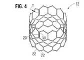
図4に、剥き出しのフレーム12を示す。フレーム12を、後により詳細に説明するように、複数の円周方向に間隔を空けて配置された溝穴、または弁構造体14の交連をフレームに取り付けるように適合された交連窓20(図示する実施形態では3つ)があるように形成することができる。フレーム12を、さまざまな適切な塑性的に拡張可能な材料(たとえばステンレス鋼等)または本技術分野において既知である自己拡張型材料(例えばニチノール)のいずれかから作製することができる。塑性的に拡張可能な材料から構成される場合、フレーム12(したがって弁10)を、送達カテーテルに半径方向に圧縮した状態で圧着し、その後、膨張式バルーンまたは等価な拡張機構により患者の内部で拡張させることができる。自己拡張型材料から構成される場合、フレーム12(したがって弁10)を、半径方向に圧縮した状態で圧着し、シースまたは送達カテーテルの等価な機構内に挿入することによって圧縮状態で保持することができる。体内に入ると、弁を送達シースから前進させることができ、それにより弁はその機能サイズまで拡張することができる。 FIG. 4 shows an exposed
フレーム12を形成するために使用することができる適切な塑性的に拡張可能な材料としては、限定なしに、ステンレス鋼、ニッケル系合金(たとえば、コバルト−クロムまたはニッケル−コバルト−クロム合金)、ポリマーまたはそれらの組合せが挙げられる。特定の実施形態では、フレーム12は、UNS R30035(ASTM F562−02によって覆われている)と等価であるMP35NTM(SPSテクノロジーズの商標)等のニッケル−コバルト−クロム−モリブデン合金から作製される。MP35NTM/UNS R30035は、35重量%ニッケル、35重量%コバルト、20重量%クロムおよび10重量%モリブデンを含む。フレーム12を形成するためにMP35Nを使用することにより、ステンレス鋼に対して優れた構造的結果が得られることが分かった。特に、フレーム材料としてMP35Nが使用される場合、径方向かつ破砕力に対する耐性、耐疲労性および耐腐食性の同じかまたはより優れた性能を達成するために必要な材料が少なくなる。さらに、必要な材料が少なくなるため、フレームの圧着外形を低減することができ、それにより、体内の治療位置に経皮的に送達するためのより薄型の弁アセンブリが提供される。 Suitable plastically expandable materials that can be used to form the
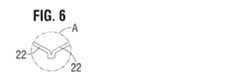
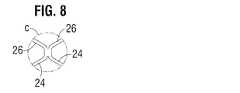
図4および図5を参照すると、図示する実施形態におけるフレーム12は、端と端を合わせて配置されかつフレームの流入端において円周方向に延在している、角度付き支柱22の下方の第1の列Iと、円周方向に延在している角度付き支柱24の第2の列IIと、円周方向に延在している角度付き支柱26の第3の列IIIと、円周方向に延在している角度付き支柱28の第4の列IVと、フレームの流出端における円周方向に延在している角度付き支柱32の第5の列Vとを備えている。複数の実質的に直線状の軸方向に延在している支柱34を使用して、第1の列Iの支柱22を第2の列IIの支柱24と相互接続することができる。角度付き支柱32の第5の列Vは、複数の軸方向に延在している窓枠部分30(交連窓20を画定する)および複数の軸方向に延在している支柱31によって、角度付き支柱28の第4の列IVに接続されている。各軸方向支柱31および各枠部分30は、2つの角度付き支柱32の下端の集まる部分(convergence)によって画定された位置から、2つの角度付き支柱28の上端の集まる部分によって画定された別の位置まで延在している。図6、図7、図8、図9および図10は、図4において文字A、B、C、DおよびEによってそれぞれ画定されているフレーム12の部分の拡大図である。 With reference to FIGS. 4 and 5, the
各交連窓枠部分30は、弁尖構造体14のそれぞれの交連を取り付ける。図示するように、各枠部分30は、その上端および下端において支柱の隣接する列に固定されて、弁尖構造体の交連を支持する既知の片持ち式支柱と比較して、弁の周期的な荷重下で耐疲労性を向上させる頑強な構造を提供する。この構造により、フレーム壁厚さの低減が可能になり、弁のより小さい圧着径が達成される。特定の実施形態では、内径と外径との間で測定されたフレーム12(図4)の厚さTは、約0.48mm以下である。 Each commissure
フレームの支柱および枠部分は、まとめてフレームの複数の開放セルを画定している。フレーム12の流入端では、支柱22、支柱24および支柱34が、開口部36を画定するセルの下方の列を画定している。支柱24の第2の列、支柱26の第3の列および支柱28の第4の列は、開口部38を画定するセルの2つの中間列を画定している。支柱28の第4の列および支柱32の第5の列は、枠部分30および支柱31とともに、開口部40を画定するセルの上方の列を画定している。開口部40は相対的に広く、圧着外形を最小限にするために、フレーム12が圧着された時に、弁尖構造体14の一部が、開口部40内にかつ/または開口部40を通って突出するかまたは隆起することができるようなサイズである。 The frame struts and frame portions collectively define a plurality of open cells of the frame. At the inflow end of the
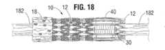
図7に最もよく示すように、支柱31の下端は、ノードまたは接合部44において2つの支柱28に接続されており、支柱31の上端は、ノードまたは接合部46において2つの支柱32に接続されている。支柱31は、接合部44、46の厚さS2より小さい厚さS1を有することができる。図53は、圧着状態でのフレーム12の一部を示す。接合部44、46は、接合部64とともに、開口部40の完全な閉鎖を防止する。図18は、バルーンカテーテルに圧着された弁10を示す。図示するように、支柱31ならびに接合部44、46および64の形状は、圧着状態で開口部40に十分な空間をもたらすのに役立ち、弁尖の一部が開口部を通って外側に突出する(すなわち隆起する)のを可能にする。
これにより、弁尖材料のすべてが圧着されたフレーム内に制約される場合より、比較的小さい直径まで弁を圧着することができる。As best shown in FIG. 7, the lower end of the
This allows the valve to be crimped to a relatively smaller diameter than if all of the leaflet material is constrained within the crimped frame.
フレーム12は、特に弁尖構造体14を支持するフレームの流出端部において、所定バルーン圧力で弁のあり得る過膨張を防止するかまたは少なくとも最小限にするように構成されている。一態様では、フレームは、支柱間に比較的大きい角度42a、42b、42c、42d、42eがあるように構成されている。角度が大きくなるほど、フレームを開放する(拡張する)ために必要な力が大きくなる。この現象を、図15Aおよび図15Bに概略的に示す。図15Aは、フレーム12がその圧縮状態にある(たとえばバルーンに取り付けられている)時の支柱32を示す。支柱の端部間の垂直距離d1は、フレームが圧縮された時に最大であり、バルーンの膨張(または別の拡張装置の拡張)から開放力が加えられると、支柱の端部に対して反対方向に作用する力F1とF2との間に比較的大きいモーメントを提供する。フレームが半径方向に拡張すると、図15Bに示すように、支柱の端部の間の垂直距離が距離d2まで低減する。垂直距離が低減すると、力F1とF2との間のモーメントも低減する。このため、支柱の端部間の垂直距離およびモーメントが低減するに従い、比較的大きい拡張力が必要になることが分かる。さらに、フレームが拡張するに従い、支柱の端部における歪み硬化(剛化)が増大し、支柱の端部にさらなる塑性変形を誘発するために必要な拡張力が増大する。したがって、フレームの支柱間の角度を、所与の開放圧力(たとえばバルーンの膨張圧力)においてフレームの半径方向拡張を制限するように選択することができる。特定の実施形態では、フレームがその機能サイズまで拡張した時、これらの角度は少なくとも110度以上であり、さらに詳細には、フレームがその機能サイズまで拡張した時、これらのサイズは少なくとも120度以上である。
さらに、フレームの流入端および流出端は、概して、弁を拡張するために使用されるバルーンの「ドッグボーニング(dog boning)」効果により、フレームの中間部よりさらに
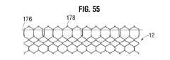
過拡張する傾向がある。弁尖構造体14の過拡張に対して保護するために、弁尖構造体は、望ましくは、図1に最もよく示すように、支柱32の上方の列の下方のフレーム12に固定される。図55は、図5に類似するが、弁尖40の上縁の位置を示すようにフレームの上に重ねられたライン176を示す、フレーム12の平坦図を示す。したがって、フレームの流出端が過拡張する場合、弁尖構造体は、過拡張が発生する可能性がある場所より下方のレベルに配置され、それにより、弁尖構造体が過拡張から保護される。Further, the inflow and outflow ends of the frame generally tend to over-expand more than the middle portion of the frame due to the “dog boning” effect of the balloon used to expand the valve. In order to protect against overextension of the
既知の弁構造では弁尖がフレームの遠位端に近すぎるように取り付けられる場合、弁が圧着されると、弁尖は、フレームの流出端を超えて外側に突出する可能性がある。圧着された弁が取り付けられる送達カテーテルが、(たとえば送達カテーテルにおける圧着された弁の位置を維持するために)弁の流出端を押すかまたはそれに当接する押し機構または止め部材を備えている場合、その押し部材または止め部材は、フレームの流出端を越えて延在する露出した弁尖を損傷する可能性がある。フレームの流出端178から間隔が空けられた位置に弁尖を取り付ける別の利点は、図56に示すように、弁が送達カテーテルに圧着されると、弁尖40が軸方向にフレームの流出端178を越えて突出しない、というものである。したがって、送達カテーテルが、弁の流出端を押すかまたはそれに当接する押し機構または止め部材を備える場合、押し機構または止め部材は、弁尖に対する損傷を回避するように、弁尖40ではなくフレームの端部178に接触することができる。 If the valve leaflet is mounted so that it is too close to the distal end of the frame in known valve structures, the leaflet may protrude outward beyond the outflow end of the frame when the valve is crimped. If the delivery catheter to which the crimped valve is attached comprises a push mechanism or stop member that pushes or abuts the outflow end of the valve (eg, to maintain the position of the crimped valve in the delivery catheter) The push or stop member can damage the exposed leaflets that extend beyond the outflow end of the frame. Another advantage of attaching the leaflet in a position spaced from the
また、図5に示すように、フレームの開口部の最下列の開口部36は、開口部の2つの中間列の開口部38より比較的大きい。図54に示すように、これによって圧着された時のフレームが、弁の流出端における最大径D1から弁の流入端における最小径D2まで先細りになる全体的に先細りの形状を呈することができる。圧着されると、フレーム12は、概して外側スカート18によって覆われているフレームの領域に対応する、参照番号174で示すフレームの流入端に隣接するフレームの部分に沿って延在している、細径領域を有する。領域174の直径は、(外側スカートによって覆われていない)フレームの上方部分の直径に比較して低減しており、それにより、外側スカート18が弁の全体的な圧着外形を増大させない。弁が配置されると、フレームは、図4に示す円柱形状まで拡張することができる。一例では、26mm弁のフレームは、圧着されると、弁の流出端における14フレンチの直径D1と弁の流入端における12フレンチの直径D2とを有していた。Further, as shown in FIG. 5, the
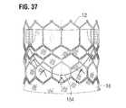
図11および図12は、弁10に組み込むことができる代替的なフレーム50を示す。フレーム50は、ノードまたは接続部54および56において互いに接続されている、円周方向に延在している角度付き支柱52の複数の列を備えている。支柱52の最上列は、複数の軸方向に延在する支柱58と交連窓枠部分60とによって支柱の隣接する列に接続されている。各交連窓枠部分60は、後により詳細に説明するように、弁構造体のそれぞれの交連を取り付けるための溝穴または交連窓62を画定する。特定の実施形態では、フレーム50の厚さTは約0.45mm以下である。図13および図14は、図12において文字AおよびBによってそれぞれ識別されるフレーム50の部分の拡大図である。 11 and 12 show an
内側スカート16の主機能は、フレーム12に弁構造体14を固定するのに役立つことと、弁尖の下縁の下方でフレーム12の開放セルを通る血液の流れを閉塞することにより、弁と生体弁輪との間の優れたシールを形成するのに役立つこととである。内側スカート16は、望ましくは、ポリエチレンテレフタレート(PET)等の丈夫な耐引裂き性材料を含むが、さまざまな他の合成材料または天然材料を使用することができる。スカートの厚さは、望ましくは6ミル未満、望ましくは4ミル未満、さらにより望ましくは2ミル未満である。特定の実施形態では、スカート16は可変厚さを有することができ、たとえば、スカートをその中心より縁の方を厚くすることができる。一実施態様では、スカート16は、縁の厚さが約0.07mmであり中心の厚さが約0.06mmであるPETスカートを含むことができる。スカートが薄いほど、優れた弁周囲封止を依然として可能としながらより優れた圧着性能を提供することができる。 The main function of the
図39に示すように、スカート16を、縫合糸70を介してフレーム12の内側に固定することができる。弁構造体14を、後述する(まとめてスリーブを形成することができる)1つまたは複数の薄いPET補強ストリップ72を介してスカートに取り付けることができ、PET補強ストリップ72は、確実な縫合を可能にし、弁尖構造体の心膜組織を引裂けから保護する。弁構造体14を、図38に示すように、スカート16と薄いPETとの間に挟装することができる。PETストリップおよび弁尖構造体14をスカート16に固定する縫合糸154を、エチボンド縫合糸等、あらゆる好適な縫合糸とすることができる。縫合糸154は、望ましくは、後により詳細に説明するように、弁尖構造体14の底縁の湾曲を辿る。 As shown in FIG. 39, the
既知の布スカートは、互いに対して垂直に延在する縦繊維および横繊維の織りを、スカートの上縁および下縁に対して垂直に延在する一組の繊維とともに含む。布スカートが固定される金属フレームが半径方向に圧縮されると、フレームの全軸方向長さが増大する。
不都合なことに、固有に弾性が限られている布スカートは、フレームとともに伸長することができず、したがって、フレームの支柱を変形させる傾向があり、均一な圧着を妨げる。Known fabric skirts include a weave of longitudinal and transverse fibers extending perpendicular to each other with a set of fibers extending perpendicular to the upper and lower edges of the skirt. When the metal frame to which the fabric skirt is fixed is compressed in the radial direction, the total axial length of the frame increases.
Unfortunately, fabric skirts that are inherently limited in elasticity cannot stretch with the frame and therefore tend to deform the struts of the frame, preventing uniform crimping.
図17は、参照番号100によって示すように、上縁および下縁に対して垂直に延在する繊維を有するスカートにより、支柱がいくつかの場所において変形している、圧着された弁の例を示す。さらに、布は、いくつかの位置において束になるかまたは過剰な材料の隆起をもたらす傾向があり、それにより、最小圧着外形が制限され、均一な圧着が妨げられる。 FIG. 17 shows an example of a crimped valve where the struts are deformed in several places by a skirt having fibers extending perpendicular to the upper and lower edges, as indicated by reference numeral 100. Show. In addition, the fabric tends to bundle or cause excessive material bulges at some locations, thereby limiting the minimum crimp profile and preventing uniform crimp.
図16Bを参照すると、既知の布スカートとは対照的に、スカート16は望ましくは、繊維、またはヤーンもしくはストランドの第1の組78と、繊維、またはヤーンもしくはストランドの第2の組80とから織られており、それらはともに、スカートの上縁82および下縁84に対して非垂直である。特定の実施形態では、繊維の第1の組78および繊維の第2の組80は、上縁82および下縁84に対して約45度の角度で延在している。
スカート16を、布の上縁および下縁に対して45度の角度で繊維を織ることにより形成することができる。代替的に、スカートを垂直に織られた布(繊維が材料の縁に対して垂直に延在している)から対角線上に切断することができ、それにより、繊維が、スカートの切断された上縁および下縁に対して45度の角度で延在する。図16Bにさらに示すように、スカートの対向する短縁86、88は、望ましくは上縁82および下縁84に対して非垂直である。たとえば、短縁86、88は、望ましくは、上縁および下縁に対して約45度の角度で延在し、したがって、繊維の第1の組78に位置合せされる。したがって、スカートの全体形状は偏菱形である。Referring to FIG. 16B, in contrast to the known fabric skirt, the
The
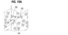
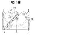
図19Aおよび図19Bは、対向する縁部90、92が、スカートの環状形状を形成するように縫い合わされた後のスカート16を示す。図示するように、縁部90を、対向する縁部92に対して部分的に重なる関係で配置することができ、2つの縁部を、縁86、88に対して垂直な対角線上に延在している縫合線94で縫い合わせることができる。スカート16の上縁部を、複数の突起96があるように形成することができ、それら突起96は、軸方向の支柱31の下端に隣接する支柱28の第4の列の形状に概して従う波形状を画定する。このように、図20に最もよく示すように、スカート16の上縁を、縫合糸70によって支柱28に緊密に固定することができる。スカートのフレームへの取付けを容易にするために、スカート16をスリット98があるように形成することも可能である。スリット98は、スカートの上縁部を支柱28に部分的に巻き付けられるのを可能にし、取付処置中にスカートにおける応力を低減するように、寸法が決められている。たとえば、図示する実施形態では、スカート16は、フレーム12の内側に配置され、スカートの上縁部は、支柱28の上面の周囲に巻き付けられ、縫合糸70によって適所に固定されている。このようにスカートの上縁部を支柱28の周囲に巻き付けることにより、スカートのフレームへのより強力かつより耐久性のある取付けが可能になる。
スカート16を、縫合糸70により、第1の支柱22、第2の支柱24および第3の支柱26にそれぞれ固定することも可能である。19A and 19B show the
It is also possible to fix the
再び図16Bを参照すると、上縁および下縁に対する繊維の配向により、スカートは、軸方向に(すなわち上縁82から下縁84の方向に)より大きく伸長することができる。 Referring again to FIG. 16B, the orientation of the fibers relative to the upper and lower edges allows the skirt to extend more in the axial direction (ie, from the
したがって、(図18に示すように)金属フレーム12が圧着される場合、スカート16は、フレームとともに軸方向に伸長することができ、したがってより均一かつ予測可能な圧着外形を提供する。図示する実施形態における金属フレームの各セルは、軸方向に向かって回転する少なくとも4つの角度付き支柱を備えている(すなわち、角度付き支柱はフレームの長さに、より位置合せされることになる)。各セルの角度付き支柱は、支柱の同じ方向にスカートの繊維を回転させる機構として機能し、それによりスカートは支柱の長さに沿って伸長することができる。これにより、スカートがより大きく伸長することができ、弁が圧着された時に支柱の望ましくない変形が回避される。 Thus, when the
さらに、織られた繊維またはヤーンの間の空間を、スカートの軸方向における伸長を容易にするように増大させることができる。たとえば、20デニールのヤーンから形成されたPETスカート16の場合、ヤーン密度を、従来のPETスカートの約15%から約30%小さくすることができる。いくつかの例では、スカート16のヤーン間隔を、約160ヤーン/インチ等、約155ヤーン/インチから約180ヤーン/インチとすることができ、一方、従来のPETスカートでは、ヤーン間隔は約217ヤーン/インチから約247ヤーン/インチであり得る。傾斜した縁86、88は、あり得る最小径への均一な圧着を容易にするために布の束化を最小限にするように、圧着中のフレームの内周に沿った布材料の均一かつ一様な分散を促進する。さらに、対角線上の縫合糸を垂直に切断することにより、切断縁に沿ったばらのフリンジが残る可能性がある。傾斜した縁86、88は、このこれが発生するのを未然に最小限にするのに役立つ。上述したように、図17は、繊維がスカートの上縁および下縁に対して垂直に伸びる従来のスカートによる圧着された弁を示す。図17および図18を比較すると、スカート16の構造により、フレーム支柱の望ましくない変形が回避され、フレームのより均一な圧着が可能になることが明らかである。 Furthermore, the space between the woven fibers or yarns can be increased to facilitate stretching in the axial direction of the skirt. For example, for a
代替実施形態では、スカートを、弁の圧着中に軸方向に伸長することができる織られた弾性繊維から形成することができる。縦繊維および横繊維は、スカートの上縁および下縁に対して垂直かつ平行に伸びることができ、または代替的に、上述したように、スカートの上縁および下縁に対して0度と90度との間の角度で延在することができる。 In an alternative embodiment, the skirt can be formed from woven elastic fibers that can stretch axially during crimping of the valve. The longitudinal and transverse fibers can extend perpendicular and parallel to the upper and lower edges of the skirt, or alternatively, as described above, at 0 degrees and 90 degrees with respect to the upper and lower edges of the skirt. Can extend at an angle between degrees.
内側スカート16を、縫合線154から離れた位置において、その領域においてより柔軟であり得るようにフレーム12に縫合することができる(図28参照)。これにより、弁尖の下縁をスカート16に取り付ける縫合線154における応力集中を回避することができる。 The
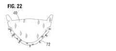
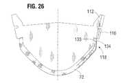
上述したように、図示する実施形態における弁尖構造体14は、3つの可撓性弁尖40を備えている(ただし、より多いかまたは少ない弁尖を使用することができる)。図21に最もよく示すように、図示する構造における各弁尖40は、弁尖の両側の対向する上部タブ112の間に延在する上部(流出)自由縁110を有している。各上部タブ112の下方に、上部タブを対応する下部タブ116から分離する切欠き114がある。下部タブ116のそれぞれの端部の間に延在している弁尖の下部(流入)縁部108は、対応する下部タブ116から下方に延在している弁尖の反対側にある垂直なまたは軸方向の縁部118と、弁尖の下端における平滑な湾曲した頂点部119と軸方向縁部と頂点部との間に延在する一対の傾斜部121とを有する、実質的にV字型の中間縁部120とを有している。傾斜部は、頂点部より大きい曲率半径を有することができる。各弁尖40は、図22に示すように、下縁部108の内面に固定された(たとえば縫合された)補強ストリップ72を有することができる。 As described above, the
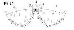
弁尖40を、それらの隣接する側部において互いに固定することにより、弁尖構造体の交連122を形成することができる。複数の可撓性コネクタ124(そのうちの1つを図23に示す)を使用して、弁尖の隣接する側部の対を相互接続し、弁尖を交連窓枠部分30に取り付けることができる。可撓性コネクタ124を、織られたPET布片から作製することができるが、他の合成材料および/または天然材料を使用することができる。各可撓性コネクタ124は、コネクタの中心において下縁から上縁まで延在するくさび126を備えることができる。くさび126は、暫定縫合糸128によってコネクタに固定された、エチボンド2−0縫合材のロープまたは切片等、非金属材料を含むことができる。くさび126は、交連窓枠部分30に固定された弁尖タブの回転移動を防止するのに役立つ。コネクタ124は、その上縁および下縁に沿って形成された一連の内側切欠き130および外側切欠き132を有することができる。 By fixing the
図24は、可撓性コネクタ124によって相互接続された2つの弁尖40の隣接する側部を示す。可撓性コネクタ124の対向する端部を、内側切欠き130をタブ116の垂直縁に位置合せして、下部タブ116と部分的に重なる関係で配置することができる。各タブ116を、可撓性コネクタ124の対応する端部に、コネクタの下縁の外側切欠き132から上縁の外側切欠き132まで延在する線に沿って縫合することによって縫合することができる。図25に示すように、3つの可撓性コネクタ124を使用して、3つの弁尖40を互いに並列して固定することができる。 FIG. 24 shows adjacent sides of two
ここで図26および図27を参照すると、2つの弁尖の隣接する交連下部分118を互いに直接縫合することができる。図示する例では、PTFE−6−0縫合材を使用して、交連下部分118および両弁尖における補強ストリップ72を通って延在する並縫い(in-and-out stitch)133およびくし縫い(comb stitch)134が形成される。隣接する交連下部分118の残っている2つの対を同様に合わせて縫合して、組み立てられた弁尖構造体14を形成することができ、それを後に以下の方法でフレーム12に固定することができる。 Referring now to FIGS. 26 and 27, adjacent commissure
上述したように、弁尖構造体14をフレームに縫合するのに役立つように内側スカート16を使用することができる。図28に示すように、スカート16は、各弁尖40の下縁の取付けを案内する波形の暫定マーキング縫合糸136を有することができる。スカート16自体を、上述したように、弁尖構造体14をスカート16に固定する前に、縫合糸70を使用してフレーム12の支柱に縫合することができる。マーキング縫合糸136と交差する支柱は、望ましくはスカート16に取り付けられない。これにより、スカート16を、フレームに固定されない領域においてより柔軟にすることができ、弁尖の下縁をスカートに固定する縫合線に沿って応力集中が最小になる。矩形140によって境界が画定されるスカート16の部分は、最初はフレーム12に固定されないままであり、後に、さらに後述するように、弁尖構造体14がスカートに固定された後にフレームに固定される。
上述したように、スカートがフレームに固定されると、スカートの繊維78、80(図16B参照)は、概してフレームの角度付き支柱に位置合せされ、フレームの均一な圧着および拡張を促進する。As described above, the
As described above, when the skirt is secured to the frame, the
図29は、対応する窓枠部分30に固定された2つの弁尖の隣接する上部を示す、フレームおよび弁尖構造体の一部の断面図である。図30〜図36は、弁尖構造体14の交連部122をフレームの交連窓枠部分30に固定する1つの特定の手法を示す。まず、図30に示すように、2つの弁尖の2つの隣接する側部を固定する可撓性コネクタ124が横方向に折り畳まれ、上部タブ部分112が、可撓性コネクタに対して下方に折り畳まれる。図30および図31に最もよく示すように、各上部タブ部分112が縦方向に(垂直に)折目を付けられて、弁尖の内面に対して折り畳まれた内側部分142と、コネクタ124に対して折り畳まれた外側部分144とを有するL字型を呈する。そして、外側部分144を、縫合線146に沿ってコネクタ124に縫合することができる。次に、図31に示すように、(コネクタ124によって接続された一対の下部タブ部分116からなる)交連タブアセンブリが、対応する窓枠部分30の交連窓20を通して挿入される。図32は、窓枠部分30を通って外側に延在する交連タブアセンブリを示すフレーム12の側面図である。 FIG. 29 is a cross-sectional view of a portion of the frame and leaflet structure showing the adjacent upper portions of the two leaflets secured to the corresponding
図29および図33に最もよく示すように、交連タブアセンブリは、くさび126において半径方向内向きに押圧されて、下部タブ部分116の一方およびコネクタ124の一部が、窓枠部分30の一方の側でフレーム12に対して折り畳まれ、他方の下部タブ部分116およびコネクタ124の一部が、窓枠部分30の他方の側でフレーム12に対して折り畳まれる。下部タブ部分116をフレーム12に対して図29に示すように保持するように、一対の縫合線148が形成される。各縫合線148は、コネクタ124、下部タブ部分116、くさび126およびコネクタ124の別の部分を通って延在している。そして、図29および図34に示すように、各下部タブ部分116は、主縫合線150によって対応する上部タブ部分112に固定され、主縫合線150は、コネクタ124の1つの層、下部タブ部分116、コネクタ124の別の層、コネクタ124の別の層および上部タブ部分112と通って延在している。最後に、図29および図35に示すように、主縫合線150を形成するために使用された縫合材料を使用して、タブ部分112、116の間に挟装されたコネクタ124の2つの層を通って延在するタブ部分112、116の縁にかがり縫い152をさらに形成することができる。 As best shown in FIGS. 29 and 33, the commissural tab assembly is pressed radially inward at the
図29および図30に示すように、折り畳まれた上部タブ部分112は、交連において弁尖材料の2重の層を形成する。上部タブ部分112の内側部分142は、交連を形成している2つの弁尖40の層に当接して平坦に配置され、それにより、各交連は、窓枠30のすぐ内側に弁尖材料の4つの層を含む。この交連の4層部分は、相対的により剛性の4層部分から半径方向すぐ内側の弁尖40の部分より、屈曲または関節運動(articulating)に対してより耐性があり得る。これにより、弁尖40は、窓枠30の軸方向支柱の周囲で関節運動するのに対して、体内の動作中に弁を通って流れる血液に応じて、主に折り畳まれた内側部分142の内縁143において関節運動する。弁尖は、窓枠30から半径方向内向きに間隔が空けられた位置で関節運動するため、フレームと接触しフレームから損傷を受けることを回避することができる。しかしながら、大きい力が加わると、交連の4層部分は、窓枠30に隣接する長手方向軸145(図29)を中心に離れるように傾斜する可能性があり、各内側部分142はそれぞれの外側部分144に対して伸ばされる。たとえば、これは、弁10が圧縮されて送達シャフトに取り付けられた時に発生する可能性があり、より小さい圧着径が可能になる。交連の4層部分はまた、弁の拡張中にバルーンカテーテルが膨張する時に軸145を中心に離れるように傾斜することができ、それにより、バルーンによってもたらされる交連に対する圧力の幾分かを緩和することができ、そのため、交連が拡張中に損傷を受けない。 As shown in FIGS. 29 and 30, the folded
3つの交連タブアセンブリすべてがそれぞれの窓枠部分30に固定された後、交連タブアセンブリ間の弁尖40の下縁を、内側スカート16に縫合することができる。たとえば、図36〜図38に示すように、各弁尖40を、たとえばエチボンド糸を用いて、縫合線154に沿ってスカート16に縫合することができる。縫合糸は、各弁尖40、スカート16および各補強ストリップ72を通って延在する並縫い縫合糸であり得る。各弁尖40およびそれぞれの補強ストリップ72を、スカート16に別個に縫合することができる。このように、弁尖の下縁がスカート16を介してフレーム12に固定される。図38に示すように、補強ストリップ72および弁尖40の縁の周囲に輪を形成する一方で補強ストリップ72、弁尖40およびスカート16を通って延在するブランケット縫合糸156により、弁尖をスカートにさらに固定することができる。縫合糸156を、PTFE縫合材から形成することができる。図39および図40は、弁尖構造体およびスカートをフレームに固定し弁尖構造体をスカートに固定した後のフレーム12、弁尖構造体14およびスカート16を示す。 After all three commissural tab assemblies are secured to their respective
図41は、フレーム12に取り付ける前の外側スカート18の平坦図を示す。外側スカート18を、織られたPET等、強力な耐久性のある材料片からレーザ切断するかまたは他の方法で形成することができるが、他の合成材料または天然材料を使用することができる。外側スカート18は、複数の交互の突起164および切欠き166を画定する実質的に直線状の下縁160および上縁162を有することができる。図42に最もよく示すように、スカート18の下縁160を、弁の流入端において内側スカート16の下縁に縫合することができる。図43に示すように、各突起164を、フレーム12の支柱24の第2の段IIに縫合することができる。突起164の角162を、段IIのそれぞれの支柱の上で折り畳み、縫合糸168で固定することができる。 FIG. 41 shows a top view of the
図1、図3および図43に示すように、外側スカート18がフレーム12に、フレームがその拡張状態にある時に、外側スカートの下縁160と上縁162との間に、フレーム12の外面に対して平坦に位置しない過剰な材料またはたるみがある。言い換えれば、外側スカートは、フレームが半径方向拡張中に短縮する(すなわち長さが縮小する)際に外側スカートを外側に隆起させる過剰な材料があるように構成されている。したがって、弁10が体内に配置されると、外側スカート18の過剰な材料は、フレーム12と周囲の生体弁輪との間の間隙を充填して、弁と生体弁輪との間に優れた流体密封シールを形成するのに役立つことができる。したがって、外側スカート18は、内側スカート16と協働して、弁10の移植後に弁周囲の漏れを回避する。別の有利な特徴では、外側スカート18の下縁と上縁との間のたるみにより、外側スカートからいかなる抵抗もなく、フレーム12が圧着中に軸方向に伸長することができ、外側スカートは、圧着状態にある人工弁の外径に対して実質的に影響を与えない。 As shown in FIGS. 1, 3, and 43, the
図56は、患者の体内に弁10を植え込むための送達アセンブリを形成する、送達装置の細長いシャフト180に取り付けられた、図1〜図3および図42〜図43の弁10を示す。弁10は、体内に送達されるように半径方向に折り畳まれた形態で取り付けられる。シャフト180は、体内でバルーンを拡張させる膨張型バルーン182を備えており、圧着された弁10は収縮したバルーンの上に配置される。弁10のフレーム12は、半径方向に圧縮され、取り付けられた状態にある時、フレームの流出端部の外径D1より小さい外径D2を有する流入端部174(図54を参照)を備えている。フレームの先細りは、少なくとも部分的にV字型弁尖40による可能性があり、それは、V字型弁尖は、より丸いU字型弁尖に比較してフレーム12の流入端部内の弁尖材料が少ないためである。取り付けられた状態のフレーム12の先細り形状により、フレーム12の流入端部174の周囲に配置された外側スカート18の追加の厚さがあっても、弁10の流入端部の全外径を、弁の流出端部の全外径におよそ等しいかまたはそれより小さくすることができる。56 shows the
さらに、図56に示すように、弁10は弁尖の交連部分を備えており、その交連部分は、対応する窓枠部分30を通ってフレームの外側の位置まで半径方向外向きに延在し、かつ交連窓枠の側部支柱に縫合される。弁の圧着外形を最小限にするために、窓枠部分30を、弁がシャフト上で折り畳まれた形態まで半径方向に圧縮された時に、隣接する交連窓の間に延在する枠部分等、フレームの周囲部分に対して半径方向内向きに押し下げることができる。たとえば、フレームの交連窓30を、弁が半径方向に折り畳まれた時に、隣接する交連窓の間に延在するフレームの部分に対して、0.2mmと1.0mmとの間の半径方向距離内向きに押し下げることができる。このように、交連部分を含む弁の流出端部の外径を、体内への弁の送達を妨げる可能性がある、弁の周囲部分から外側に突出している交連部分に比較して、概して一貫させることができる。半径方向に押し下げられた交連窓枠30があっても、フレームの流入端部の外径を、弁がシャフト上で半径方向に折り畳まれた時のフレームの流出端部の外径より小さいかまたはおよそ等しくすることができ、それにより、弁の最小の最大全径が可能になる。送達シャフトに取り付けられた時の弁の直径を最小限にすることにより、アセンブリを、より径の小さいカテーテル内に収容することができ、したがって、体内のより小さい導管に通すことができ、概してより低侵襲とすることができる。 Further, as shown in FIG. 56, the
図44は、別の実施形態による人工心臓弁200を示す。心臓弁200は、フレームまたはステント202と、ステントに取り付けられた弁尖構造体204とを備えている。弁尖構造体204は、複数の弁尖218(たとえば、図示するように3つ)を含むことができ、それらを、適切な技法および/または機構を用いて互いにかつフレーム202に縫合することができる。フレーム202を、弁尖をフレームに縫合するのに役立つように(図4に示すような)交連枠部分30を備えるように適合させることができる。 FIG. 44 shows a
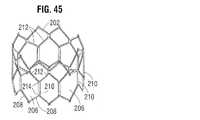
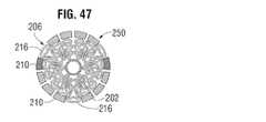
フレーム202は、上述したフレーム12といくつかの設計特徴を共有する。特に、フレーム12と同様に、フレーム202は、図45に示すように、弁尖構造体を支持するフレームの領域に沿って比較的大きいフレーム開口部206を有している。開口部206は、フレームの流出端における角度付き支柱208の列と、複数の軸方向に延在している円周方向に間隔を空けて配置された支柱210と、角度付き支柱212の中間列とによって画定されている。図示するように、軸方向支柱210は、望ましくは、軸方向の支柱210の両端を2つの支柱212の集まる部分にかつ2つの支柱208の集まる部分に接続する接合部214より薄い。この構造により、図46および図47において216に示すように、弁が送達形態まで半径方向に圧縮された時に、弁尖構造体204の一部が開口部を通って外側に突出するのを可能にするように、開口部206の幅が十分広いままである。
これにより、弁尖材料のすべてが圧着されたフレーム内に制約される場合より、弁を相対的に小さい径まで圧着することができる。Frame 202 shares some design features with
This allows the valve to be crimped to a relatively smaller diameter than when all of the leaflet material is constrained within the crimped frame.
比較の目的で、図48は、既知の人工弁250の、圧着された状態にある弁を示す断面図である。弁が半径方向に圧縮された時、隣接する支柱の間の空間は相対的に小さく、この空間により、弁尖構造体の一部がフレームを通って外側に突出することができない。したがって、フレームの内側に制約されている弁尖材料のすべてが存在することにより、弁の圧着径が制限される。 For comparison purposes, FIG. 48 is a cross-sectional view of a known
図49および図50は、弁尖の一部が圧着状態にあるフレームを通って外側に突出するのを可能にすることができる、代替的なフレーム構造の平坦部分を示す。このフレーム構造を、上述した弁10で実施することができる。図49は、半径方向に圧縮された状態の枠部分を示し、図50は、半径方向に拡張された状態の枠部分を示す。フレーム(その一部のみを示す)は、角度付き支柱442の第1の円周方向に延在している列と、少なくとも、角度付き支柱444の第2の円周方向に延在している列とを備えている。フレームにおけるいくつかの開口部は、互いに上端において接続されている隣接する支柱442と互いに下端において接続されている隣接する支柱444とによって形成されたダイヤモンド型開口部446である。フレームはまた、より大きい開口部448も有しており、それは、上端において水平支柱450のそれぞれの端部に接続されている隣接する支柱442と、下端において水平支柱452のそれぞれの端部に接続されている隣接する支柱444とによって形成されている。フレームが半径方向に圧縮された時、水平支柱450、452は、開口部448の幅Wを、弁の弁尖の一部がフレームを通って外側に突出するのを可能にするのに十分に大きいまま維持する。したがって、開口部448の幅は、フレームが圧着された時の開口部446の幅より大きい。フレームを、開口部446、448がフレームの周囲に交互であるように形成することができる。代替的に、開口部448を、交連の間等、弁尖材料がフレーム内で束になる傾向がある領域に対応するように、フレームの長さおよび周囲に沿って選択された位置に配置することができる。 49 and 50 show a flat portion of an alternative frame structure that can allow a portion of the leaflet to protrude outwardly through the frame in a crimped state. This frame structure can be implemented with the
図51および図52は、弁尖の一部が圧着された状態のフレームを通って外側に突出するのを可能にすることができる別のフレーム構造の平坦部分を示す。このフレーム構造を、上述した弁10において実施することができる。図51は、半径方向に圧縮された状態の枠部分を示し、図52は、半径方向に拡張された状態の枠部分を示す。フレーム(その一部のみを示す)は、角度付き支柱402の第1の円周方向に延在している列と、少なくとも、角度付き支柱404の第2の円周方向に延在している列とを備えている。フレームにおけるいくつかの開口部は、互いに上端において接続されている隣接する支柱402と互いに下端において接続されている隣接する支柱404とによって形成されたダイヤモンド型開口部406である。フレームは、上端において拡大ノードまたは接合部410に接続されている隣接する支柱402、および下端において拡大されたノードまたは接合部412に接続されている隣接する支柱404によって形成された、開口部408も含む。フレームが半径方向に圧縮された時に、開口部408の幅Wが、弁の弁尖の一部がフレームを通って外側に突出するのを可能にするのに十分大きいままであるように、接合部410、412が、それらの位置においてフレームに剛性を追加する。したがって、開口部408の幅は、フレームが圧着された時の開口部406の幅より大きい。フレームを、開口部406、408がフレームの周囲に交互であるように形成することができる。代替的に、開口部408を、交連の間等、弁尖材料がフレーム内で束になる傾向がある領域に対応するように、フレームの長さおよび周囲に沿って選択された位置に配置することができる。 51 and 52 show a flat portion of another frame structure that can allow a portion of the leaflet to protrude outwardly through the crimped frame. This frame structure can be implemented in the
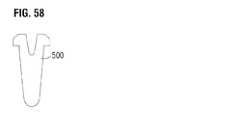
図57は、別の実施形態による、人工弁(たとえば弁10または200)用の弁尖500を示す。弁尖500は、上述した弁尖40と同様に全体的にV字型を有している。弁尖500は、弁尖の両側に2つのタブ部分502を有しており、それらは、他の弁尖の隣接するタブ部分に固定されて弁尖構造体の交連を形成する。弁尖500の交連下部分(タブ502の下方の部分)は、タブ502の真下のそれぞれの位置から湾曲した下縁506まで延在する2つの実質的に直線状の縁504を有している。図58は、弁が圧着された時の弁尖500の全体的な形状を示す。フレーム(図57〜図58には示さず)は、圧着された時にわずかに伸長し、弁尖500をわずかに伸長させる。 FIG. 57 shows a
弁尖の交連下部分の先細り外形により、圧着された弁の下半分における弁尖材料の量が、弁のその部分の圧着径を最小限にするように低減する。したがって、外側スカート18等、追加の構成要素が弁のその部分に取り付けられる場合、弁のその部分の低減した外形が、追加の構成要素によってもたらされる直径の増大を相殺するかまたは最小限にするのに役立つことができる。さらに、交連タブ502は比較的短く、(T字型弁尖および扇形弁尖等)既知の弁尖設計より、弁尖構造体の交連を形成するために必要な縫合糸が少なく、弁が圧着される時の弁尖材料のかさばりをより分散させ低減する。 The taper profile of the commissure lower portion of the leaflets reduces the amount of leaflet material in the lower half of the crimped valve to minimize the crimp diameter of that portion of the valve. Thus, when an additional component, such as the
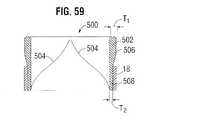
図59は、別の実施形態による、弁500の断面図を示す。弁500は、フレーム502と、弁尖504と、フレーム502の外面に(たとえば縫合糸により)取り付けられた外側スカート18とを備えている。フレーム502は、必要な場合に強度を最適化するように厚さがその長さに沿って変化し、それでもなお、フレームの選択された領域において材料(したがって圧着外形)を最小限にする。図示する実施形態では、フレームの流出端部506は(フレームのその部分の内側径から外側径まで測定された)最大厚さT1を有し、フレームの流入端部508は(フレームのその部分の内側径から外側径まで測定される)最小厚さT2を有している。流出端部506を形成するフレーム502の支柱(図59には示していない)は厚さT1を有し、流入端部508を形成する支柱は厚さT2を有している。フレーム502は、フレームの可変厚さを除き、上述したフレーム12と同一の構造を有することができる。厚さが低減した領域を、フレームの選択された部分の電気研磨(研磨されない部分をマスクすることができる)、フレームの選択された部分の研削、ワイヤ切断または他の適切な技法等、種々の製造技法を用いて形成することができる。FIG. 59 shows a cross-sectional view of a
流出端部506は、概して、弁尖504の交連を支持し、かつ通常弁に対する最大荷重を受ける、フレームの領域に対応している。したがって、フレームの流出端部502は、予期される荷重下で必要な強度を提供するように選択された、相対的に大きい厚さT1を有している。流入端部508は、外側スカート18によって材料の追加の層を支持する。
流入端部508の厚さが低減することにより、流入端部が流出端部より小さい径まで圧着される。これにより、外側スカート18を追加することによってもたらされる圧着径の増大が相殺されるかまたは最小限になる。The
By reducing the thickness of the
図60〜図62は、折畳み型人工弁310の別の実施形態であり、それは、弁尖構造体314と、弁尖構造体をフレーム内に固定するために使用される複数の半径方向に間隔を空けて配置された交連窓318を有する、半径方向に折畳み可能かつ拡張可能なフレーム312(図11に示すフレーム50に類似する)とを備えている。弁310はまた、フレーム312の内面と弁尖構造体314の湾曲した下端364との間に固定されたスカート316もまた備えている。弁310は、下方の流入端340および上方の流出端342を有している。 FIGS. 60-62 are another embodiment of a foldable
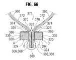
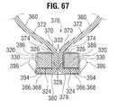
図60Aに示すように、各窓318は、2つの軸方向に延在する側部支柱320それぞれの間に囲まれた開口部334を備えている。各側部支柱は、図63に示すように、略矩形、たとえば正方形の断面輪郭を備えている。各矩形側部支柱320は4つの面、すなわち半径方向外向きに面する側の外面324と、半径方向内向きに面する側の内面326と、他の側部支柱に面する側の内側(medial)面328と、他の側部支柱から離れる方向に面している側の外側(lateral)面330とを備えている。他の実施形態では、側部支柱は、円形または六角形等、他の断面形状を備えることができる。 As shown in FIG. 60A, each
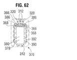
弁尖構造体は複数の弁尖360を備え、各々、フレーム312に固定された一対の側部タブ366と、スカート316に固定された湾曲した縁364と、側部タブと下縁との間の関節運動部372とを備えている。各側部タブ366は、別の弁尖360の隣接する側部タブと対になって弁尖構造体314の交連376を形成している。側部タブ366の各対は、図62に示すように、対応する交連窓318を通ってフレーム312の外側の位置まで半径方向外向きに延在し、縫合糸等により、窓の側部支柱320に固定されている。いくつかの実施形態では、各側部タブ366は、端部368を備え(図64参照)、各交連376の2つの側部タブ端部368は、互いから離れる方向に、かつ窓318のそれぞれの側部支柱320の外面324に沿って、円周方向に延在している。 The leaflet structure includes a plurality of
いくつかの実施形態では、各交連376は、側部タブ366にかつ側部支柱320に縫合された少なくとも1つの非剛性補強シート378をさらに備えている。シート378は、種々の天然生体適合性材料および/または合成生体適合性を含む、可撓性のある耐引裂き性材料を含むことができる。例示的な合成材料としては、ナイロン、シリコーン、およびPETを含むポリエステル等のポリマーを挙げることができる。一例では、シート378は織られたPET布を含む。 In some embodiments, each
各補強シート378を、略矩形(平坦に置かれた場合)とすることができ、補強シート378は、中間部380および対向する端部386を備えることができる。いくつかの実施形態では、図64に示すように、シートの第1の端部386は第1の側部支柱320に固定され、シートの第2の端部386は第2の側部支柱320に固定される。シート378は、側部支柱320から側部タブ366を分離して、側部タブが側部支柱に接触しないようにする。たとえば、シートの各端部386を、図64に示すように、それぞれの側部支柱320の周囲に完全に巻き付けることができる。 Each reinforcing
側部タブ366および補強シート378を、複数の段階で側部支柱320に固定することができる。たとえば、図63は、例示的な第1の縫合段階を示し、そこでは、シートの中間部380が側部タブ366の端部368の外面を横切って円周方向に延在し、シートの各端部386がそれぞれの側部タブ366とそれぞれの側部支柱320の外面324、内側面328および内面326との間に延在するように、シートが配置されている。シート378は、側部タブ366を包囲し、側部支柱320の縁から側部タブを保護する。一対の並縫い縫合糸390が、各側部タブ366およびシート378の一端をそれぞれの支柱320に固定することができる。図63に示すように、各縫合糸390を、側部支柱320の外側面330に沿ってフレーム312の周囲に対して略垂直に向けることができ、各縫合糸390は、複数の異なる長手方向位置において交連376を半径方向前後に通過することができる。各縫合糸390は、シート378の第1の層、側部タブの端部368、シートの第2の層およびシートの第3の層と、半径方向内向きに移るその順序で交差することができる。縫合糸390は、シート378を側部タブの端部368に固定し、側部支柱320の周囲にシートの端部386を締め付け、それにより、側部タブ366を側部支柱320に固定し、弁尖構造体314をフレーム312に固定する。 The
図64は、例示的な第2の縫合段階を示し、そこでは、第2の縫合糸392の対を使用して、補強シート378のゆるんだ部分が縛り付けられる。たとえば、第2の縫合糸392は、中間部380の一部および第1の縫合糸390を越えて横方向に延在するシートの端部386と交差することができる。第2の縫合糸392を、図62に示すように、複数の異なる長手方向位置において交連376と交差し、シート378のゆるんだ部分を側部支柱の外側面330に対して緊密に固定する、螺旋状かがり縫いとすることができる。 FIG. 64 shows an exemplary second stitching stage where the loosened portion of the
第1の縫合糸390および第2の縫合糸392をともに、支柱320の外側面330に隣接して配置し、窓開口部334から離れる方向に間隔を空けて配置することができる。
縫合糸のこの配置により、弁尖の関節運動部372の動きによってもたらされる縫合糸に対する応力を低減することができる。代りに、この応力の大部分が、弁尖の可撓性ヒンジ370から支柱の内−内側縁332の近くの側部支柱320まで伝達される。Both the
This placement of the suture can reduce the stress on the suture caused by the movement of the
補強シート378は、図64に示すように、弁尖が開放位置と閉鎖位置との間で関節運動する際に支柱320の内−内側縁332によってもたらされる損傷から、柔軟なヒンジ370を保護する。さらに、いくつかの実施形態はまた、図64に示すように、内−内側縁332に隣接する等、柔軟なヒンジ370と支柱320との間に配置された長手方向に延在するクッションストリップ374を有し、それにより支柱によってもたらされる損傷から柔軟なヒンジをさらに保護することができる。クッションストリップ374は、PET布、心膜組織またはさまざまな他の生体適合性材料等、可撓性の圧縮性材料を含むことができる。いくつかの実施形態では、クッションストリップは、弾性材料で充填されたチューブを備えることができる。たとえば、クッションストリップは、心膜組織で充填されたPETチューブを含むことができる。他の実施形態では、シート378から、クッションストリップの外側管状覆いを形成することができ、それに弾性材料を充填することができる。シートを、縫合糸によって弾性材料の周囲に固定することにより、図64に示すように適切に配置されたクッション作用ストリップを保持することができる。他の実施形態では、別個のクッションストリップ374を補強シート378に縫合することができる。
クッションストリップ374は、バー62と同様に厚さを有することにより、心周期中に弁尖とフレームの内面との間の接触を防止するかまたは最小限にするように、側部支柱320と弁尖の関節運動部372との間に半径方向の隙間を設けることができる。The
The
図65は、図63および図64に類似するが縫合パターンの異なる実施形態を示す。図65において、縫合糸390は、シート378を側部タブの端部368の周囲に固定する縫合糸398に置き換えられる。各縫合糸398は、シートの中間部380、側部タブ366のうちの1つ、および各側部支柱の内側−外縁324に隣接するシートの第2の層と交差する。縫合糸398は、複数の異なる長手方向位置において交連と交差する並縫いを含むことができる。シート378の各端部は、それぞれの側部支柱320の表面に沿ってシート378の2重の層を形成するように折り畳まれる折畳み部388を含むことができる。縫合糸392は、シートの端部386と側部タブの端部368とを、側部支柱の外側面330の周囲に緊密に固定する。 FIG. 65 shows an embodiment similar to FIGS. 63 and 64 but with a different sewing pattern. In FIG. 65, the
図66および図67は、側部タブ366およびシート378を側部支柱320に縫合する代替方法を示す。図66は、側部支柱の外面324に沿ってかつフレームの半径に対して略垂直に配置された縫合線394を示す。縫合糸394は、両側部支柱366およびシート378の両端部386と交差する。縫合糸394は、シートの各端部386を、それぞれの側部支柱320の内側面328、内面326および外側面330の周囲に緊密に固定し、また、シートの中間部380を側部タブ366の端部368の周囲に緩く固定する。図66に示す実施形態では、縫合糸394は、第1のシート層A、第2のシート層B、2つの側部タブ366、第3のシート層Cおよび第4のシート層Dにその順序で交差する。 66 and 67 illustrate an alternative method of stitching the
第1の縫合糸394が適所に置かれた後、図67に示すように、側部タブの端部368は、離れるように広げられ、側部支柱320の外面324に隣接して配置される。これにより、シートの緩い中間部380が側部タブの端部368の周囲に締め付けられる。そして、図67に示すように、一対の縫合糸396は、シートの中間部380をシートの端部386に緊密に固定して、側部タブの端部368を適所に保持することができる。縫合糸396は、図64における縫合糸392と同様に、複数の異なる長手方向位置において交連376と交差するループ状のかがり縫いであり得る。 After the
図68および図69は、側部タブ366およびシート378を側部支柱320に縫合する別の代替方法を示す。図68は、窓開口部の外側に沿って配置されかつフレームの半径に対して略垂直に向けられた縫合線395を示す。縫合糸395は、両側部タブ366およびシート378の2つの部分と交差する。縫合糸395は、側部タブ366の端部368の周囲に緩く延在するシートの中間部380を固定する。図68に示す実施形態では、縫合糸395は、第1のシート層A、第1の側部タブB、第2の側部タブCおよび第2のシート層Dとその順序で交差する。 68 and 69 illustrate another alternative method of stitching the
第1の縫合糸395が適所に置かれた後、図69に示すように、側部タブの端部368は、離れるように広げられ、側部支柱320の外面324に隣接して配置される。これにより、シートの緩い中間部380が側部タブの端部368の周囲に締め付けられる。その後、図69に示すように、一対の縫合糸397がシートの中間部380をシートの端部386に緊密に固定して、側部タブの端部368を適所に保持することができる。シートの端部386は、折り畳まれた下部分388を含み、縫合糸397を補強するようにシート材料の2重の層を生成することができる。縫合糸397を、図62の縫合糸392に同様に、複数の異なる長手方向位置において交連376と交差するループ状のかがり縫いとすることができる。 After the
図70および図71は、側部タブ366およびシート378を側部支柱320に縫合するさらに別の代替方法を示す。図70は、窓開口部の外側に沿って配置されかつフレームの半径に対して略垂直に向けられた縫合線395を示す。縫合糸395は、両側部タブ366およびシート378の4つの部分または層と交差する。シートの各端部386は、側部タブ366と側部支柱の内側面328との間にシート材料の2重の層を形成する、折畳み部分388を含む。縫合糸395は、シートの中間部380を、側部タブ366の端部368の周囲に緩く固定する。図70に示すように、縫合糸395の各縫いは、層AおよびBを含むシート層の第1の対、第1の側部タブC、第2の側部タブD、ならびに層EおよびFを含むシート層の第2の対とその順序で交差する。 70 and 71 illustrate yet another alternative method of stitching the
第1の縫合糸395が適所に置かれた後、側部タブの端部368は、図71に示すように、離れるように広げられ、側部支柱320の外面324に隣接して配置される。これにより、シートの中間部380が側部タブの端部368の周囲に締め付けられる。そして、図71に示すように、一対の縫合糸397がシートの中間部380をシートの端部386に固定して、側部タブの端部368を適所に保持することができる。シートの折畳み部分388が、縫合糸397を補強するようにシート材料の2重の層を生成する。縫合糸397を、図62における縫合糸392に同様に、複数の異なる長手方向に位置において交連376と交差するループ状のかがり縫いとすることができる。 After the
弁尖構造体314を図61〜図71に示す窓枠318に取り付ける交連のさまざまな形態を、図1〜図3の弁10の弁尖構造体14をフレーム12の窓枠部分30に取り付ける代替方法として使用することも可能である。 Various forms of commissure for attaching the
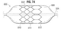
図72〜図74は、送達シャフト604のバルーン606に取り付けられた人工弁用のフレーム602の実施形態を含む人工心臓弁アセンブリ600を示す。フレーム602を、フレーム12と形状が同様とすることができ、フレーム602は、流入端部610、流出端部612および中間部614を備えることができる。明確にするために、弁尖およびスカート等、弁の別の構成要素を示していない。フレーム602は、流入端部610においてかつ流出端部612において、中間部614の厚さに比較して低減した厚さを有することができる。端部の方が薄いことにより、バルーン606が膨張すると、図73に示すように、端部610、612は、中間部614より拡張に対して抵抗が低く、それより高速に拡張する。端部が中間部より高速に拡張するため、フレーム602は、バルーン606上に制限され、フレームがバルーンのいずれかの端部に向かって摺動することが阻止され、フレームがバルーンから早期に滑り落ちる危険性が低減する。図74に示すように、バルーンのさらなる膨張により、移植のためにフレームの中間部614が端部610、612と同じ最終径まで拡張することができ、その後、バルーンを収縮させて除去することができる。バルーン上の弁の位置を制御することは、特に拡張中に短縮しバルーンに対して移動するフレームでは、送達中に重要である可能性がある。図72〜図74に示す実施形態では、フレームの中間部614を、バルーンに対して一定に保持することができ、一方で、2つの端部は、バルーンの「ドッグボーン」効果により中間部に向かって短縮する。何らかの従来の手段を使用して、サンドペーパー等で端部を研く等、端部610、612における厚さが低減したフレーム602を製造することができる。一実施形態では、フレームの端部610、614は約0.37mmの厚さを有し、中間部614は約0.45mmの厚さを有している。 72-74 illustrate a prosthetic
開示した発明の原理を適用することができる多くのあり得る実施形態に鑑みて、例示した実施形態は、本発明の単なる好ましい例であり、本発明の範囲を限定するものと解釈されるべきでないことが理解されるべきである。むしろ、本発明の範囲は、以下の特許請求の範囲によって定義される。したがって、これらの特許請求の範囲内にあるものすべてを本発明として請求する。 In view of the many possible embodiments to which the disclosed principles of the invention may be applied, the illustrated embodiments are merely preferred examples of the invention and should not be construed as limiting the scope of the invention. It should be understood. Rather, the scope of the present invention is defined by the following claims. We therefore claim as our invention all that comes within the scope of these claims.
なお、本発明は、以下の実施例を含むことも好適である。
(実施例1)
患者の体内に人工心臓弁を植え込むアセンブリであって、
細長いシャフトを備える送達装置と、
前記体内に送達されるために前記シャフトに半径方向に折り畳まれた形態で取り付けられるように適合された、半径方向に拡張可能な人工心臓弁であって、流入端部および流出端部を有する環状フレームと、前記フレーム内に配置された弁尖構造体と、前記フレームの内面に沿って配置された内側布スカートと、前記フレームの外面に沿って配置された外側布スカートとを備える人工心臓弁と、
を具備し、
前記外側布スカートが、前記人工心臓弁の半径方向拡張中に半径方向外向きに隆起するように適合されていることを特徴とするアセンブリ。
(実施例2)
前記フレームの前記流入端部の外径が、前記フレームの前記流出端部の外径より小さいことを特徴とする実施例1に記載のアセンブリ。
(実施例3)
前記弁尖構造体が複数の弁尖を含み、前記弁尖の各々が、
前記弁尖の両側の対向する側部タブであって、前記フレームの前記流出端部に固定されている側部タブと、
前記フレームの前記流出端部に隣接して前記側部タブの間に延在している自由流出縁部と、
前記フレームの前記流入端部に隣接する前記側部タブの間に延在している流入縁部であって、前記側部タブから前記流入端まで略軸方向に延在する、対向する軸方向縁部、および前記軸方向縁部の間に延在する中間縁部を備え、前記中間縁部が、前記フレームの前記流入端に隣接する湾曲した頂点部、および前記軸方向縁部と前記頂点部との間に延在する一対の傾斜部を備え、前記傾斜部が前記頂点部より曲率半径が大きい、流入縁部と、
を備えることを特徴とする実施例1に記載のアセンブリ。
(実施例4)
第1の軸方向に向けられた側部支柱と第2の軸方向に向けられた側部支柱との間に、囲まれた開口部を各々が備える、3つの角度的に間隔が空けられた交連窓を前記フレームが備え、
各々が2つの対向する側部タブを備える複数の弁尖を前記弁尖構造体が含み、各側部タブが、隣接する弁尖の隣接する側部タブと対になることにより前記弁尖構造体の交連を形成し、各交連が、前記フレームの対応する交連窓を通って前記フレームの外側の位置まで半径方向外向きに延在し、前記交連窓の前記側部支柱に縫合されていることを特徴とする実施例1に記載のアセンブリ。
(実施例5)
前記フレームの前記交連窓が、前記人工弁が半径方向に折り畳まれた形態にある時、隣接する交連窓の間に延在する前記フレームの部分に対して、半径方向内向きに押し下げられることを特徴とする実施例4に記載のアセンブリ。
(実施例6)
前記フレームが、前記フレームの前記流入端部における開口部の流入列と、前記フレームの前記流出端部における開口部の流出列と、前記開口部の流入列と開口部の流出列との間の少なくとも1つの開口部の中間列と、を備え
前記開口部の流入列の前記開口部が、前記少なくとも1つの開口部の中間列の前記開口部よりも大きいことを特徴とする実施例1に記載のアセンブリ。
(実施例7)
前記フレームが複数の開口部を有し、前記弁尖構造体の一部が、前記人工心臓弁が前記半径方向に折り畳まれた形態にある間に前記開口部から突出することを特徴とする実施例1に記載のアセンブリ。
(実施例8)
前記フレームの前記流入端部が、前記流入端部と前記流出端部との間の前記フレームの中間部のフレーム厚さより小さいフレーム厚さを備えていることを特徴とする実施例1に記載のアセンブリ。
(実施例9)
患者の体内に人工心臓弁を植え込むアセンブリであって、
細長いシャフトを備えている送達装置と、
前記体内に送達されるために前記シャフトに半径方向に折り畳まれた形態で取り付けられる、半径方向に拡張可能かつ折畳み可能な人工心臓弁であって、環状フレームおよび前記フレーム内の弁尖構造体を備える人工心臓弁と、
を具備し、
第1の軸方向に向けられた側部支柱と第2の軸方向に向けられた側部支柱との間に、囲まれた開口部を各々が備える、複数の角度的に間隔が空けられた交連窓を前記フレームが備え、前記弁尖構造体が、それぞれの交連窓を通して外側に延在する複数の交連部分を備えており、
前記人工心臓弁が前記シャフトにおいて半径方向に折り畳まれた時に、隣接する交連窓の間の前記フレームの部分に対して半径方向内向きに前記交連窓が押し下げられることを特徴とするアセンブリ。
(実施例10)
前記フレームの外側の前記交連部分の最外面が、隣接する交連窓の間の前記フレームの前記部分の前記外面と、前記弁の長手方向軸から実質的に同じ半径方向距離にあることを特徴とする実施例9に記載の弁。
(実施例11)
前記フレームの前記交連窓が、前記弁が半径方向に折り畳まれた時に、隣接する交連窓の間に延在する前記フレームの前記部分に対して、0.2mmと1.0mmとの間の半径方向距離内側に押し下げられることを特徴とする実施例9に記載の弁。
(実施例12)
前記フレームの流入端部の外径が、前記弁が前記シャフト上で半径方向に折り畳まれた時に前記フレームの流出端部の外径より小さいことを特徴とする実施例9に記載の弁。
(実施例13)
折畳み形態まで半径方向に折畳み可能であり、拡張形態まで半径方向に拡張可能である植込み型人工弁であって、
環状フレームと、
前記フレーム内に配置された弁尖構造体と、
前記フレームの外面の周囲に配置された環状外側スカートであって、第1の位置において前記フレームに固定された流入縁、第2の位置において前記フレームに固定された流出縁、および前記流入縁と前記流出縁との間の中間部を備える外側スカートと、
を具備し、
前記弁が前記拡張形態にある時、前記外側スカートの前記中間部が、前記外側スカートの前記流入縁と前記外側スカートの前記流出縁との間で軸方向にたるみを含み、前記人工弁が前記折畳み形態に折り畳まれると、前記外側スカートの前記流入縁と前記外側スカートの前記流出縁との間の軸方向距離が増大し、前記軸方向における前記外側スカートの前記たるみが低減することを特徴とする弁。
(実施例14)
前記外側スカートの前記流出縁が、複数の交互の突起および切欠きを備え、前記突起が前記第2の位置において前記フレームに固定され、前記外側スカートが前記切欠きにおいて前記フレームに固定されていないことを特徴とする実施例13に記載の弁。
(実施例15)
前記弁が前記折畳み形態まで半径方向に折り畳まれた時に、前記外側スカートが前記軸方向に伸張せず、たるみが前記外側スカートの前記中間部から除去されることを特徴とする実施例13に記載の弁。
(実施例16)
植込み型人工弁であって、
複数の弁尖取付部分を備えている環状フレームと、
前記フレーム内に配置されかつ前記フレームの前記弁尖取付部分に固定された弁尖構造体であって、複数の弁尖を含み、各弁尖が本体部分を備え、2つの対向する一次側部タブが前記本体部分の両側から延在し、2つの対向する二次タブが前記一次側部タブに隣接して前記本体部分から延在している、弁尖構造体と、
を具備し、
前記二次タブが、前記二次タブの第1の部分が前記それぞれの弁尖の前記本体部分に対して平坦に位置するように、半径方向に延在する折目を中心に折り畳まれ、前記二次タブが、前記二次タブの第2の部分が前記第1の部分とは異なる平面に延在するように、軸方向に延在する折目を中心に折り畳まれることを特徴とする弁。
(実施例17)
各二次タブの前記第2の部分がそれぞれの一次タブに縫合されていることを特徴とする実施例16に記載の弁。
(実施例18)
前記二次タブが前記フレームの内側に配置されていることを特徴とする実施例16に記載の弁。
(実施例19)
前記二次タブの各々の前記第1の部分が、前記軸方向に延在する折目を中心に枢動し、前記弁が半径方向に折り畳まれた形態まで折り畳まれた時、前記二次タブの前記第2の部分に対して平坦に位置することを特徴とする実施例16に記載の弁。
(実施例20)
各二次タブの前記第1の部分が、前記フレームの内面から半径方向に間隔を空けて配置された内縁を備え、前記弁尖の前記本体部分が、前記弁が患者の体内で作動中である時に前記弁を流れる血液に応じて前記弁尖の前記2つの二次タブの前記内縁を中心に関節運動することを特徴とする実施例16に記載の弁。
(実施例21)
第1の軸方向に向けられた側部支柱と第2の軸方向に向けられた側部支柱との間に、囲まれた開口部を各々が備える窓枠部分を前記複数の弁尖取付部分が備え、前記一次側部タブが、それぞれの窓枠部分を通って前記フレームの外側の位置まで半径方向外向きに延在し、前記二次タブに縫合されて前記弁尖を前記側部支柱の周囲の固定することを特徴とする実施例16に記載の弁。
(実施例22)
折畳み形態まで半径方向に折畳み可能であり、かつ拡張形態まで半径方向に拡張可能である植込み型人工弁であって、
流入端部および流出端部を有する環状フレームと
前記フレーム内に配置された弁尖構造体と、
前記フレーム内に配置された環状内側スカートであって、前記フレームの内側に固定され、ストランドの第2の組とともにストランドの第1の組の織りを含み、前記ストランドの第1の組および前記ストランドの第2の組がともに前記弁の軸方向に対して非平行である、内側スカートと、
を具備し、
前記人工弁が前記拡張形態から前記折畳み形態まで折り畳まれた時、前記フレームの軸方向長さが増大し、前記ストランドの第1の組および前記ストランドの第2の組がともに前記弁の前記軸方向に向かって回転し、前記内側スカートが前記フレームとともに前記軸方向に伸張するのを可能にすることを特徴とする弁。
(実施例23)
前記ストランドの第1の組が、前記弁が前記拡張形態にある時に前記ストランドの第2の組に対して実質的に垂直であることを特徴とする実施例22に記載の弁。
(実施例24)
前記ストランドの第1の組が、前記弁の前記軸方向とともに第1の角度を形成し、前記ストランドの第2の組が、前記弁の前記軸方向とともに第2の角度を形成し、前記第1の角度および前記第2の角度が実質的に等しいことを特徴とする実施例22に記載の弁。
(実施例25)
前記ストランドの第1の組および前記ストランドの第2の組が20デニールのヤーンを含むことを特徴とする実施例22に記載の弁。
(実施例26)
植込み型人工弁であって、
第1の軸方向に向けられた側部支柱と第2の軸方向に向けられた側部支柱との間に、囲まれた開口部を各々が備える、複数の角度的に間隔を空けて配置された交連窓を備える、半径方向に折畳み可能かつ拡張可能な環状フレームと、
前記フレーム内に配置され、かつ各々が2つの対向する側部タブを備える複数の弁尖を備えている弁尖構造体であって、各側部タブが隣接する弁尖の隣接する側部タブと対になって前記弁尖構造体の交連を形成し、側部タブの各対が、対応する交連窓を通って前記フレームの外側の位置まで半径方向外向きに延在し、前記フレームの外側に位置する前記側部タブの部分が、互いから離れる方向にかつ前記側部支柱の外面に沿って円周方向に延在している、弁尖構造体と、
各々が前記交連窓の前記側部支柱の間に配置され、かつ前記交連窓を通って延在している前記側部タブの対を分離する、複数のくさびであって、前記側部タブに対して半径方向内向きに付勢されるくさびと、
を具備することを特徴とする弁。
(実施例27)
各くさびが、軸方向に細長く、軸方向長さが前記交連窓の前記側部支柱の軸方向長さに一致することを特徴とする実施例26に記載の弁。
(実施例28)
前記くさびが、前記交連窓に対する前記側部タブの対の回転移動を制限することを特徴とする実施例27に記載の弁。
(実施例29)
各くさびが、可撓性補強シートに縫合され、さらに前記側部タブの対の各々に縫合されていることを特徴とする実施例26に記載の弁。
(実施例30)
各くさびが前記側部タブの対に縫合されていることを特徴とする実施例26に記載の弁。
(実施例31)
前記くさびが縫合材を含むことを特徴とする実施例26に記載の弁。
(実施例32)
前記くさびが非金属であることを特徴とする実施例26に記載の弁。The present invention preferably includes the following examples.
Example 1
An assembly for implanting a prosthetic heart valve in a patient's body,
A delivery device comprising an elongated shaft;
A radially expandable prosthetic heart valve adapted to be attached in a radially folded configuration to the shaft for delivery into the body, wherein the annular heart valve has an inflow end and an outflow end A prosthetic heart valve comprising a frame, a leaflet structure disposed within the frame, an inner fabric skirt disposed along the inner surface of the frame, and an outer fabric skirt disposed along the outer surface of the frame When,
Comprising
An assembly wherein the outer fabric skirt is adapted to bulge radially outward during radial expansion of the prosthetic heart valve.
(Example 2)
The assembly according to embodiment 1, wherein an outer diameter of the inflow end portion of the frame is smaller than an outer diameter of the outflow end portion of the frame.
Example 3
The leaflet structure includes a plurality of leaflets, each of the leaflets is
Opposing side tabs on both sides of the leaflet, the side tabs being fixed to the outflow end of the frame;
A free outflow edge extending between the side tabs adjacent to the outflow end of the frame;
An inflow edge extending between the side tabs adjacent to the inflow end of the frame, the opposing axial directions extending generally axially from the side tab to the inflow end An intermediate edge extending between the edge and the axial edge, the intermediate edge being a curved apex adjacent to the inflow end of the frame, and the axial edge and the apex A pair of inclined portions extending between the inflow edge portion, the inclined portion has a larger radius of curvature than the apex portion, and an inflow edge portion;
An assembly according to example 1 comprising:
Example 4
Three angularly spaced openings, each with an enclosed opening, between a first axially directed side post and a second axially directed side post The frame includes a commissure window,
The leaflet structure includes a plurality of leaflets each having two opposing side tabs, each side tab being paired with an adjacent side tab of an adjacent leaflet so that the leaflet structure Forming commissures of the body, each commissure extending radially outward through a corresponding commissure window of the frame to a position outside the frame and stitched to the side struts of the commissure window An assembly according to Example 1, characterized in that
(Example 5)
The commissure window of the frame is pushed radially inward against a portion of the frame extending between adjacent commissure windows when the prosthetic valve is in a radially folded configuration; An assembly according to example 4 characterized.
(Example 6)
The frame includes an inflow row of openings at the inflow end of the frame, an outflow row of openings at the outflow end of the frame, and an inflow row of openings and an outflow row of openings. Embodiment 1 comprising: an intermediate row of at least one opening, wherein the opening of the inflow row of the openings is larger than the opening of the intermediate row of the at least one opening. Assembly.
(Example 7)
An implementation wherein the frame has a plurality of openings and a portion of the leaflet structure protrudes from the openings while the prosthetic heart valve is in the radially folded configuration. The assembly according to Example 1.
(Example 8)
2. The embodiment of claim 1, wherein the inflow end portion of the frame has a frame thickness smaller than a frame thickness of an intermediate portion of the frame between the inflow end portion and the outflow end portion. assembly.
Example 9
An assembly for implanting a prosthetic heart valve in a patient's body,
A delivery device comprising an elongated shaft;
A radially expandable and foldable prosthetic heart valve attached in a radially folded configuration to the shaft for delivery into the body, comprising an annular frame and a leaflet structure within the frame A prosthetic heart valve,
Comprising
A plurality of angularly spaced openings, each with an enclosed opening, between a first axially directed side post and a second axially directed side post The frame includes commissure windows, and the leaflet structure includes a plurality of commissure portions extending outwardly through the respective commissure windows;
The assembly wherein the commissure window is depressed radially inward relative to a portion of the frame between adjacent commissure windows when the prosthetic heart valve is folded radially on the shaft.
(Example 10)
The outermost surface of the commissure portion outside the frame is at substantially the same radial distance from the outer surface of the portion of the frame between adjacent commissure windows from the longitudinal axis of the valve. The valve as described in Example 9.
(Example 11)
The commissure window of the frame has a radius between 0.2 mm and 1.0 mm with respect to the portion of the frame that extends between adjacent commissure windows when the valve is folded radially. The valve according to embodiment 9, wherein the valve is pushed inward in the directional distance.
(Example 12)
The valve of embodiment 9, wherein the outer diameter of the inflow end of the frame is smaller than the outer diameter of the outflow end of the frame when the valve is folded radially on the shaft.
(Example 13)
An implantable prosthetic valve that is radially foldable to a folded configuration and is radially expandable to an expanded configuration,
An annular frame;
A leaflet structure disposed within the frame;
An annular outer skirt disposed around an outer surface of the frame, an inflow edge secured to the frame in a first position, an outflow edge secured to the frame in a second position, and the inflow edge; An outer skirt with an intermediate portion between the outflow edges;
Comprising
When the valve is in the expanded configuration, the intermediate portion of the outer skirt includes an axial slack between the inflow edge of the outer skirt and the outflow edge of the outer skirt, and the artificial valve includes the When folded in a folded configuration, the axial distance between the inflow edge of the outer skirt and the outflow edge of the outer skirt increases, and the sagging of the outer skirt in the axial direction decreases. Valve to do.
(Example 14)
The outflow edge of the outer skirt comprises a plurality of alternating protrusions and notches, the protrusions being fixed to the frame at the second position, and the outer skirts not being fixed to the frame at the notches A valve according to Example 13, characterized in that
(Example 15)
Embodiment 13, wherein the outer skirt does not extend in the axial direction and slack is removed from the intermediate portion of the outer skirt when the valve is folded radially to the folded configuration. Valve.
(Example 16)
An implantable prosthetic valve,
An annular frame having a plurality of leaflet mounting portions;
A leaflet structure disposed within the frame and fixed to the leaflet mounting portion of the frame, the leaflet structure including a plurality of leaflets, each leaflet comprising a body portion and two opposing primary sides A leaflet structure, wherein tabs extend from both sides of the body portion, and two opposing secondary tabs extend from the body portion adjacent to the primary side tabs;
Comprising
The secondary tab is folded around a radially extending fold such that a first portion of the secondary tab lies flat against the body portion of the respective leaflet; A valve wherein the secondary tab is folded about a fold extending in an axial direction such that a second portion of the secondary tab extends in a different plane than the first portion .
(Example 17)
The valve of
(Example 18)
The valve of
(Example 19)
When the first portion of each of the secondary tabs pivots about the axially extending fold and the valve is folded to a radially folded configuration, the secondary tabs 17. The valve of
(Example 20)
The first portion of each secondary tab includes an inner edge radially spaced from the inner surface of the frame, and the body portion of the leaflet is configured such that the valve is operating in the patient's body. 17. The valve of
(Example 21)
A plurality of valve leaflet mounting portions each having a window frame portion each having an enclosed opening between a side column oriented in the first axial direction and a side column oriented in the second axial direction The primary side tabs extend radially outward through respective window frame portions to a position outside the frame and are sewn to the secondary tabs to connect the leaflets to the side struts. The valve according to
(Example 22)
An implantable prosthetic valve that is radially foldable to a folded configuration and is radially expandable to an expanded configuration,
An annular frame having an inflow end and an outflow end; and a leaflet structure disposed in the frame;
An annular inner skirt disposed within the frame, wherein the inner skirt is secured to the inside of the frame and includes a first set of strands of strands along with a second set of strands, the first set of strands and the strands An inner skirt, both of which are non-parallel to the axial direction of the valve;
Comprising
When the prosthetic valve is folded from the expanded configuration to the folded configuration, the axial length of the frame increases and both the first set of strands and the second set of strands are the shaft of the valve. A valve that rotates in a direction to allow the inner skirt to extend axially with the frame.
(Example 23)
24. The valve of
(Example 24)
A first set of strands forming a first angle with the axial direction of the valve; a second set of strands forming a second angle with the axial direction of the valve; 24. The valve of
(Example 25)
24. The valve of
(Example 26)
An implantable prosthetic valve,
A plurality of angularly spaced openings, each having an enclosed opening, between a side column oriented in the first axial direction and a side column oriented in the second axial direction A radially foldable and expandable annular frame with a shaped commissure window;
A leaflet structure disposed within the frame and comprising a plurality of leaflets each having two opposing side tabs, each side tab being an adjacent side tab of an adjacent leaflet Paired to form commissures of the leaflet structure, each pair of side tabs extending radially outward through a corresponding commissure window to a position outside the frame, A portion of the side tabs located on the outside, extending in a direction away from each other and circumferentially along the outer surface of the side post; and
A plurality of wedges, each disposed between the side struts of the commissure window and separating the pair of side tabs extending through the commissure window, wherein the side tabs A wedge biased radially inwardly,
The valve characterized by comprising.
(Example 27)
27. The valve of
(Example 28)
28. The valve of embodiment 27, wherein the wedge limits rotational movement of the pair of side tabs relative to the commissure window.
(Example 29)
28. The valve of
(Example 30)
The valve of
(Example 31)
The valve of
(Example 32)
The valve of
10 人工心臓弁
12 フレーム
14 弁構造体
16 内側スカート
18 外側スカート
20 交連窓
22 角度付き支柱
24 角度付き支柱
26 角度付き支柱
28 角度付き支柱
32 角度付き支柱
30 交連窓枠部分
34 支柱
36 開口部
38 開口部
40 弁尖
40 開口部
50 フレーム
60 交連窓枠部分
62 交連窓
78 ストランドの第1の組
80 ストランドの第2の組
100 人工心臓弁
108 下部流入縁部
112 上部タブ
116 下部タブ
118 縁部
119 頂点部
120 中間縁部
121 傾斜部
122 交連
124 可撓性コネクタ
126 くさび
142 内側部分
144 外側部分
164 突起
166 切欠き
174 流入端部
200 人工心臓弁
202 フレーム
204 弁構造体
206 開口部
208 角度付き支柱
210 支柱
212 角度付き支柱
312 フレーム
360 弁尖
502 フレーム
504 弁尖
506 流出端部
508 流入端部
180 シャフト
206 フレーム開口部
310 人工心臓弁
314 弁尖構造体
318 交連窓
320 側部支柱
340 流入端
342 流出端
360 弁尖
366 側部タブ
376 交連
378 補強シート
500 人工心臓弁
506 流出端部
508 流入端部
604 送達シャフト
602 フレーム
610 流入端部
612 流出端部
614 中間部10
Claims (11)
Translated fromJapanese環状フレーム(12)と、
前記環状フレーム(12)内に配置された弁尖構造体(14)と、
前記環状フレーム(12)の内面に沿って配置された内側スカート(16)であって、内側スカート(16)が前記環状フレーム(12)の内側に固定された、内側スカート(16)と、
を備え、前記内側スカート(16)が、ストランドの第2の組とともにストランドの第1の組(78、80)の織りを備え、前記ストランドの第1の組および第2の組(78、80)の両方が前記人工弁(10)の軸方向と平行ではなく、
前記人工弁(10)が拡張形態から折畳み形態まで折畳まれると、前記ストランドの第1の組および第2の組(78、80)の両方が、前記人工弁(10)の軸方向に向かって回転し、前記内側スカート(16)が前記環状フレーム(12)とともに軸方向に伸長することができるようにすることを特徴とする人工弁。An implantable prosthetic valve that is radially foldable to a folded configuration and radially expandable to an expanded configuration, wherein the prosthetic valve (10) comprises:
An annular frame (12);
A leaflet structure (14) disposed within the annular frame (12);
An inner skirt (16) disposed along the inner surface of the annular frame (12), the inner skirt (16) being secured to the inner side of the annular frame (12);
The inner skirt (16) comprises a weave of a first set of strands (78, 80) together with a second set of strands, the first and second sets of strands (78, 80) ) Are not parallel to the axial direction of the prosthetic valve (10),
When the prosthetic valve (10) is folded from the expanded configuration to the folded configuration, both the first and second sets of strands (78, 80) are axially directed to the prosthetic valve (10). A prosthetic valve, characterized in that the inner skirt (16) is able to extend axially with the annular frame (12).
弁尖(40)の両側に、対向する側部タブ(112、116)であって、側部タブ(112、116)が、前記環状フレーム(12)の流出端部に固定された、対向する側部タブ(112、116)と、
前記環状フレーム(12)の流出端部(178)に隣接する側部タブ(112)間に延在する自由流出縁部(110)と、
前記環状フレーム(12)の流入端部に隣接する側部タブ(116)間に延在する流入縁部(108)であって、前記流入縁部(108)が、前記側部タブ(116)から流入端に向かって略軸方向に延在する対向する軸方向縁部(118)と、前記軸方向縁部(118)間に延在する中間縁部(120)と、を備え、前記中間縁部(120)が、前記環状フレーム(12)の流入端に隣接する湾曲した頂点部(119)と、前記軸方向縁部(118)と前記頂点部(119)との間に延在する一対の傾斜部(121)と、を備え、前記傾斜部(121)が前記頂点部(119)よりも大きな曲率半径を有する、流入縁部(108)と、
を備える請求項1から5のいずれか一項に記載の人工弁。The leaflet structure (14) has a plurality of leaflets (40), and each leaflet (40)
Opposite side tabs (112, 116) on opposite sides of the leaflet (40), the side tabs (112, 116) being fixed to the outflow end of the annular frame (12) Side tabs (112, 116);
A free outflow edge (110) extending between side tabs (112) adjacent to the outflow end (178) of the annular frame (12);
An inflow edge (108) extending between side tabs (116) adjacent to the inflow end of the annular frame (12), wherein the inflow edge (108) is the side tab (116); An opposing axial edge (118) extending substantially axially from the inflow end to an inflow end, and an intermediate edge (120) extending between the axial edges (118), the intermediate An edge (120) extends between the curved apex (119) adjacent the inflow end of the annular frame (12) and the axial edge (118) and the apex (119). An inflow edge (108) comprising a pair of slopes (121), wherein the slope (121) has a larger radius of curvature than the apex (119);
The artificial valve according to any one of claims 1 to 5, further comprising:
前記弁尖構造体(14)が複数の弁尖(40)を備え、各弁尖(40)が2つの対向する側部タブ(112、116)を有し、各側部タブ(112、116)が、隣接する弁尖(40)の隣接する側部タブ(112、116)と対になって、前記弁尖構造体(14)の交連(122)を形成し、かつ各交連(122)が、対応する環状フレーム(12)の交連窓(20)を通して環状フレーム(12)の外側の位置へと半径方向外向きに延在しているとともに交連窓(20)の側部支柱(30)に縫合されている請求項1から6のいずれか一項に記載の人工弁。The annular frame (12) comprises three angularly spaced commissure windows (20), each commissure window (20) being side struts oriented in first and second axial directions ( 30) having an opening enclosed between,
The leaflet structure (14) comprises a plurality of leaflets (40), each leaflet (40) having two opposing side tabs (112, 116), each side tab (112, 116). ) Paired with adjacent side tabs (112, 116) of adjacent leaflets (40) to form commissures (122) of said leaflet structure (14) and each commissure (122) Extends radially outwardly through the commissure window (20) of the corresponding annular frame (12) to a position outside the annular frame (12) and the side strut (30) of the commissure window (20). The artificial valve according to any one of claims 1 to 6, wherein the artificial valve is stitched together.
前記開口のうちの流入列の開口(36)が、前記開口のうちの少なくとも1つの中間列の開口(38)よりも大きい請求項1から8のいずれか一項に記載の人工弁。The annular frame (12) has an inflow row of openings at the inflow end portion (174) of the annular frame (12), and an outflow row of openings at the outflow end portion of the annular frame (12). And having at least one intermediate row of openings between the inflow row of the openings and the outflow row of the openings,
The prosthetic valve according to any one of claims 1 to 8, wherein an opening (36) of the inflow row of the openings is larger than an opening (38) of at least one intermediate row of the openings.
患者の体内に送達するために半径方向に折り畳まれた形態で前記シャフト(180)に取り付けられるように構成された、半径方向に拡張可能な人工心臓弁(10)と、
を備える、患者の体内に人工心臓弁を埋め込むアセンブリであって、
前記人工心臓弁(10)が、請求項1から10のいずれか一項にしたがって構成された、アセンブリ。A delivery device comprising an elongate shaft (180);
A radially expandable prosthetic heart valve (10) configured to be attached to the shaft (180) in a radially folded configuration for delivery into a patient's body;
An assembly for implanting a prosthetic heart valve in a patient's body comprising:
Assembly, wherein the prosthetic heart valve (10) is constructed according to any one of claims 1-10.
Applications Claiming Priority (4)
| Application Number | Priority Date | Filing Date | Title |
|---|---|---|---|
| US39010710P | 2010-10-05 | 2010-10-05 | |
| US61/390,107 | 2010-10-05 | ||
| US201161508513P | 2011-07-15 | 2011-07-15 | |
| US61/508,513 | 2011-07-15 |
Related Parent Applications (1)
| Application Number | Title | Priority Date | Filing Date |
|---|---|---|---|
| JP2013532923ADivisionJP2013543406A (en) | 2010-10-05 | 2011-10-05 | Prosthetic heart valve |
Publications (2)
| Publication Number | Publication Date |
|---|---|
| JP2016209665Atrue JP2016209665A (en) | 2016-12-15 |
| JP6196358B2 JP6196358B2 (en) | 2017-09-13 |
Family
ID=45928415
Family Applications (2)
| Application Number | Title | Priority Date | Filing Date |
|---|---|---|---|
| JP2013532923APendingJP2013543406A (en) | 2010-10-05 | 2011-10-05 | Prosthetic heart valve |
| JP2016173406AActiveJP6196358B2 (en) | 2010-10-05 | 2016-09-06 | Prosthetic heart valve |
Family Applications Before (1)
| Application Number | Title | Priority Date | Filing Date |
|---|---|---|---|
| JP2013532923APendingJP2013543406A (en) | 2010-10-05 | 2011-10-05 | Prosthetic heart valve |
Country Status (18)
| Country | Link |
|---|---|
| US (18) | US9393110B2 (en) |
| EP (17) | EP3626208B1 (en) |
| JP (2) | JP2013543406A (en) |
| CN (11) | CN115192259A (en) |
| AU (1) | AU2011312034B2 (en) |
| CA (8) | CA3063553C (en) |
| DE (5) | DE202011111126U1 (en) |
| DK (11) | DK4233795T3 (en) |
| ES (14) | ES2855679T3 (en) |
| FI (3) | FI4233795T3 (en) |
| HR (11) | HRP20241679T1 (en) |
| HU (9) | HUE053890T2 (en) |
| LT (8) | LT3593762T (en) |
| PL (13) | PL3593762T3 (en) |
| PT (12) | PT3626208T (en) |
| RS (9) | RS60735B1 (en) |
| SI (9) | SI4233795T1 (en) |
| WO (1) | WO2012048035A2 (en) |
Cited By (4)
| Publication number | Priority date | Publication date | Assignee | Title |
|---|---|---|---|---|
| JP2021505346A (en)* | 2017-12-11 | 2021-02-18 | カリフォルニア インスティテュート オブ テクノロジー | Systems, devices, and methods for the manufacture of intravascular implantable prosthetic valves |
| JP2022543971A (en)* | 2019-08-12 | 2022-10-17 | エドワーズ ライフサイエンシーズ コーポレイション | artificial heart valve |
| JP2023504378A (en)* | 2019-11-26 | 2023-02-03 | ボストン サイエンティフィック リミテッド | Composite web-polymer heart valve |
| JP2023520830A (en)* | 2020-04-07 | 2023-05-22 | エドワーズ ライフサイエンシーズ コーポレイション | artificial heart valve |
Families Citing this family (697)
| Publication number | Priority date | Publication date | Assignee | Title |
|---|---|---|---|---|
| EP0850607A1 (en) | 1996-12-31 | 1998-07-01 | Cordis Corporation | Valve prosthesis for implantation in body channels |
| US6454799B1 (en) | 2000-04-06 | 2002-09-24 | Edwards Lifesciences Corporation | Minimally-invasive heart valves and methods of use |
| US6733525B2 (en) | 2001-03-23 | 2004-05-11 | Edwards Lifesciences Corporation | Rolled minimally-invasive heart valves and methods of use |
| US7556646B2 (en) | 2001-09-13 | 2009-07-07 | Edwards Lifesciences Corporation | Methods and apparatuses for deploying minimally-invasive heart valves |
| US6893460B2 (en) | 2001-10-11 | 2005-05-17 | Percutaneous Valve Technologies Inc. | Implantable prosthetic valve |
| US20050075725A1 (en) | 2003-10-02 | 2005-04-07 | Rowe Stanton J. | Implantable prosthetic valve with non-laminar flow |
| AU2004324043A1 (en) | 2004-10-02 | 2006-04-20 | Christoph Hans Huber | Methods and devices for repair or replacement of heart valves or adjacent tissue without the need for full cardiopulmonary support |
| DE102005003632A1 (en) | 2005-01-20 | 2006-08-17 | Fraunhofer-Gesellschaft zur Förderung der angewandten Forschung e.V. | Catheter for the transvascular implantation of heart valve prostheses |
| US7780723B2 (en) | 2005-06-13 | 2010-08-24 | Edwards Lifesciences Corporation | Heart valve delivery system |
| US8167932B2 (en) | 2005-10-18 | 2012-05-01 | Edwards Lifesciences Corporation | Heart valve delivery system with valve catheter |
| CA2881760C (en) | 2005-11-10 | 2017-06-13 | Arshad Quadri | Balloon-expandable, self-expanding, vascular prosthesis connecting stent |
| US20070213813A1 (en) | 2005-12-22 | 2007-09-13 | Symetis Sa | Stent-valves for valve replacement and associated methods and systems for surgery |
| WO2008013915A2 (en) | 2006-07-28 | 2008-01-31 | Arshad Quadri | Percutaneous valve prosthesis and system and method for implanting same |
| US9408607B2 (en) | 2009-07-02 | 2016-08-09 | Edwards Lifesciences Cardiaq Llc | Surgical implant devices and methods for their manufacture and use |
| US9585743B2 (en) | 2006-07-31 | 2017-03-07 | Edwards Lifesciences Cardiaq Llc | Surgical implant devices and methods for their manufacture and use |
| EP3360509B1 (en) | 2006-07-31 | 2022-06-22 | Syntheon TAVR, LLC | Sealable endovascular implants |
| EP2397108B1 (en) | 2006-09-08 | 2013-08-07 | Edwards Lifesciences Corporation | Apparatus for treating a defective heart valve |
| US8236045B2 (en) | 2006-12-22 | 2012-08-07 | Edwards Lifesciences Corporation | Implantable prosthetic valve assembly and method of making the same |
| US7896915B2 (en) | 2007-04-13 | 2011-03-01 | Jenavalve Technology, Inc. | Medical device for treating a heart valve insufficiency |
| US9566178B2 (en) | 2010-06-24 | 2017-02-14 | Edwards Lifesciences Cardiaq Llc | Actively controllable stent, stent graft, heart valve and method of controlling same |
| DE202008018557U1 (en) | 2007-08-21 | 2015-10-26 | Symetis Sa | A replacement flap |
| DE102007043830A1 (en) | 2007-09-13 | 2009-04-02 | Lozonschi, Lucian, Madison | Heart valve stent |
| EP3443938B1 (en) | 2007-09-26 | 2024-01-24 | St. Jude Medical, LLC | Collapsible prosthetic heart valves |
| US9532868B2 (en) | 2007-09-28 | 2017-01-03 | St. Jude Medical, Inc. | Collapsible-expandable prosthetic heart valves with structures for clamping native tissue |
| EP2679198B1 (en) | 2007-10-25 | 2021-03-24 | Symetis SA | Valved-stents and systems for delivery thereof |
| ES2781686T3 (en)* | 2007-12-14 | 2020-09-04 | Edwards Lifesciences Corp | Leaflet Junction Frame for a Prosthetic Valve |
| CA2714062A1 (en) | 2008-01-24 | 2009-07-30 | Medtronic, Inc. | Stents for prosthetic heart valves |
| US8157853B2 (en) | 2008-01-24 | 2012-04-17 | Medtronic, Inc. | Delivery systems and methods of implantation for prosthetic heart valves |
| US9044318B2 (en) | 2008-02-26 | 2015-06-02 | Jenavalve Technology Gmbh | Stent for the positioning and anchoring of a valvular prosthesis |
| BR112012021347A2 (en) | 2008-02-26 | 2019-09-24 | Jenavalve Tecnology Inc | stent for positioning and anchoring a valve prosthesis at an implantation site in a patient's heart |
| EP3912597A1 (en) | 2008-02-29 | 2021-11-24 | Edwards Lifesciences Corporation | Expandable member for deploying a prosthetic device |
| US20090276040A1 (en) | 2008-05-01 | 2009-11-05 | Edwards Lifesciences Corporation | Device and method for replacing mitral valve |
| US9061119B2 (en) | 2008-05-09 | 2015-06-23 | Edwards Lifesciences Corporation | Low profile delivery system for transcatheter heart valve |
| PL4223257T3 (en) | 2008-06-06 | 2024-09-23 | Edwards Lifesciences Corporation | LOW-PROFILE TRANSCATHETIC HEART VALVE |
| US8323335B2 (en) | 2008-06-20 | 2012-12-04 | Edwards Lifesciences Corporation | Retaining mechanisms for prosthetic valves and methods for using |
| EP2815724B2 (en) | 2008-07-15 | 2024-03-13 | St. Jude Medical, Inc. | Collapsible and re-expandable prosthetic heart valve cuff designs and complementary technological applications |
| US8652202B2 (en) | 2008-08-22 | 2014-02-18 | Edwards Lifesciences Corporation | Prosthetic heart valve and delivery apparatus |
| CN102292053A (en) | 2008-09-29 | 2011-12-21 | 卡迪尔克阀门技术公司 | Heart valve |
| WO2010040009A1 (en) | 2008-10-01 | 2010-04-08 | Cardiaq Valve Technologies, Inc. | Delivery system for vascular implant |
| US8790387B2 (en) | 2008-10-10 | 2014-07-29 | Edwards Lifesciences Corporation | Expandable sheath for introducing an endovascular delivery device into a body |
| US8690936B2 (en) | 2008-10-10 | 2014-04-08 | Edwards Lifesciences Corporation | Expandable sheath for introducing an endovascular delivery device into a body |
| AU2010218384B2 (en) | 2009-02-27 | 2014-11-20 | St. Jude Medical, Inc. | Stent features for collapsible prosthetic heart valves |
| CA2961053C (en) | 2009-04-15 | 2019-04-30 | Edwards Lifesciences Cardiaq Llc | Vascular implant and delivery system |
| NZ596179A (en) | 2009-04-29 | 2014-05-30 | Cleveland Clinic Foundation | Apparatus and method for replacing a diseased cardiac valve |
| US8439970B2 (en) | 2009-07-14 | 2013-05-14 | Edwards Lifesciences Corporation | Transapical delivery system for heart valves |
| US8652203B2 (en) | 2010-09-23 | 2014-02-18 | Cardiaq Valve Technologies, Inc. | Replacement heart valves, delivery devices and methods |
| US9730790B2 (en) | 2009-09-29 | 2017-08-15 | Edwards Lifesciences Cardiaq Llc | Replacement valve and method |
| BR112012010321B8 (en) | 2009-11-02 | 2021-06-22 | Symetis Sa | replacement valve for use on a human body |
| US8449599B2 (en) | 2009-12-04 | 2013-05-28 | Edwards Lifesciences Corporation | Prosthetic valve for replacing mitral valve |
| US8870950B2 (en) | 2009-12-08 | 2014-10-28 | Mitral Tech Ltd. | Rotation-based anchoring of an implant |
| EP3300695B1 (en) | 2009-12-08 | 2023-05-24 | Avalon Medical Ltd. | Device and system for transcatheter mitral valve replacement |
| US8795354B2 (en) | 2010-03-05 | 2014-08-05 | Edwards Lifesciences Corporation | Low-profile heart valve and delivery system |
| US20110224785A1 (en) | 2010-03-10 | 2011-09-15 | Hacohen Gil | Prosthetic mitral valve with tissue anchors |
| US8579964B2 (en) | 2010-05-05 | 2013-11-12 | Neovasc Inc. | Transcatheter mitral valve prosthesis |
| US10856978B2 (en) | 2010-05-20 | 2020-12-08 | Jenavalve Technology, Inc. | Catheter system |
| WO2011147849A1 (en) | 2010-05-25 | 2011-12-01 | Jenavalve Technology Inc. | Prosthetic heart valve and transcatheter delivered endoprosthesis comprising a prosthetic heart valve and a stent |
| WO2011163275A2 (en) | 2010-06-21 | 2011-12-29 | Cardiaq Valve Technologies, Inc. | Replacement heart valve |
| US8657872B2 (en) | 2010-07-19 | 2014-02-25 | Jacques Seguin | Cardiac valve repair system and methods of use |
| US9763657B2 (en) | 2010-07-21 | 2017-09-19 | Mitraltech Ltd. | Techniques for percutaneous mitral valve replacement and sealing |
| US11653910B2 (en) | 2010-07-21 | 2023-05-23 | Cardiovalve Ltd. | Helical anchor implantation |
| US9326853B2 (en) | 2010-07-23 | 2016-05-03 | Edwards Lifesciences Corporation | Retaining mechanisms for prosthetic valves |
| AU2011306028B2 (en)* | 2010-09-20 | 2014-07-17 | St. Jude Medical, Cardiology Division, Inc. | Valve leaflet attachment in collapsible prosthetic valves |
| DK4233795T3 (en) | 2010-10-05 | 2024-08-26 | Edwards Lifesciences Corp | Prosthetic heart valve |
| AU2011343755A1 (en) | 2010-12-14 | 2013-06-06 | Colibri Heart Valve Llc | Percutaneously deliverable heart valve including folded membrane cusps with integral leaflets |
| US9717593B2 (en) | 2011-02-01 | 2017-08-01 | St. Jude Medical, Cardiology Division, Inc. | Leaflet suturing to commissure points for prosthetic heart valve |
| US9155619B2 (en) | 2011-02-25 | 2015-10-13 | Edwards Lifesciences Corporation | Prosthetic heart valve delivery apparatus |
| EP2688516B1 (en) | 2011-03-21 | 2022-08-17 | Cephea Valve Technologies, Inc. | Disk-based valve apparatus |
| US9744033B2 (en) | 2011-04-01 | 2017-08-29 | W.L. Gore & Associates, Inc. | Elastomeric leaflet for prosthetic heart valves |
| US9308087B2 (en) | 2011-04-28 | 2016-04-12 | Neovasc Tiara Inc. | Sequentially deployed transcatheter mitral valve prosthesis |
| US9554897B2 (en) | 2011-04-28 | 2017-01-31 | Neovasc Tiara Inc. | Methods and apparatus for engaging a valve prosthesis with tissue |
| US8945209B2 (en) | 2011-05-20 | 2015-02-03 | Edwards Lifesciences Corporation | Encapsulated heart valve |
| US9289282B2 (en) | 2011-05-31 | 2016-03-22 | Edwards Lifesciences Corporation | System and method for treating valve insufficiency or vessel dilatation |
| US8795357B2 (en)* | 2011-07-15 | 2014-08-05 | Edwards Lifesciences Corporation | Perivalvular sealing for transcatheter heart valve |
| US9119716B2 (en) | 2011-07-27 | 2015-09-01 | Edwards Lifesciences Corporation | Delivery systems for prosthetic heart valve |
| WO2013021374A2 (en) | 2011-08-05 | 2013-02-14 | Mitraltech Ltd. | Techniques for percutaneous mitral valve replacement and sealing |
| US8852272B2 (en) | 2011-08-05 | 2014-10-07 | Mitraltech Ltd. | Techniques for percutaneous mitral valve replacement and sealing |
| EP2739214B1 (en) | 2011-08-05 | 2018-10-10 | Cardiovalve Ltd | Percutaneous mitral valve replacement and sealing |
| EP4289398A3 (en) | 2011-08-11 | 2024-03-13 | Tendyne Holdings, Inc. | Improvements for prosthetic valves and related inventions |
| US9554806B2 (en) | 2011-09-16 | 2017-01-31 | W. L. Gore & Associates, Inc. | Occlusive devices |
| US9827093B2 (en) | 2011-10-21 | 2017-11-28 | Edwards Lifesciences Cardiaq Llc | Actively controllable stent, stent graft, heart valve and method of controlling same |
| US12364596B2 (en) | 2011-10-21 | 2025-07-22 | Edwards Lifesciences Cardiaq Llc | Actively controllable stent, stent graft, heart valve and method of controlling same |
| CN103945793B (en) | 2011-12-06 | 2016-05-04 | 俄奥梯科创新有限公司 | For device and the using method thereof of repairing in aorta lumen |
| CN104114127B (en) | 2011-12-09 | 2017-09-05 | 爱德华兹生命科学公司 | Prosthetic heart valve with improved commissural support |
| US8652145B2 (en) | 2011-12-14 | 2014-02-18 | Edwards Lifesciences Corporation | System and method for crimping a prosthetic valve |
| US9827092B2 (en) | 2011-12-16 | 2017-11-28 | Tendyne Holdings, Inc. | Tethers for prosthetic mitral valve |
| CA3095260C (en) | 2012-01-31 | 2023-09-19 | Mitral Valve Technologies Sarl | Mitral valve docking devices, systems and methods |
| EP3424469A1 (en) | 2012-02-22 | 2019-01-09 | Syntheon TAVR, LLC | Actively controllable stent, stent graft and heart valve |
| US11207176B2 (en) | 2012-03-22 | 2021-12-28 | Boston Scientific Scimed, Inc. | Transcatheter stent-valves and methods, systems and devices for addressing para-valve leakage |
| US20130274873A1 (en) | 2012-03-22 | 2013-10-17 | Symetis Sa | Transcatheter Stent-Valves and Methods, Systems and Devices for Addressing Para-Valve Leakage |
| US9345573B2 (en) | 2012-05-30 | 2016-05-24 | Neovasc Tiara Inc. | Methods and apparatus for loading a prosthesis onto a delivery system |
| US9289292B2 (en) | 2012-06-28 | 2016-03-22 | St. Jude Medical, Cardiology Division, Inc. | Valve cuff support |
| US9554902B2 (en) | 2012-06-28 | 2017-01-31 | St. Jude Medical, Cardiology Division, Inc. | Leaflet in configuration for function in various shapes and sizes |
| US9283072B2 (en) | 2012-07-25 | 2016-03-15 | W. L. Gore & Associates, Inc. | Everting transcatheter valve and methods |
| US10376360B2 (en) | 2012-07-27 | 2019-08-13 | W. L. Gore & Associates, Inc. | Multi-frame prosthetic valve apparatus and methods |
| WO2014022124A1 (en) | 2012-07-28 | 2014-02-06 | Tendyne Holdings, Inc. | Improved multi-component designs for heart valve retrieval device, sealing structures and stent assembly |
| WO2014021905A1 (en) | 2012-07-30 | 2014-02-06 | Tendyne Holdings, Inc. | Improved delivery systems and methods for transcatheter prosthetic valves |
| US9510946B2 (en) | 2012-09-06 | 2016-12-06 | Edwards Lifesciences Corporation | Heart valve sealing devices |
| US8628571B1 (en) | 2012-11-13 | 2014-01-14 | Mitraltech Ltd. | Percutaneously-deliverable mechanical valve |
| BR102013029585B1 (en)* | 2012-11-20 | 2021-02-02 | Cook Medical Technologies LLC. | catheter set for applying an endoluminal sleeve and method for preparing a catheter set for delivering an endoluminal sleeve |
| EP4162902A1 (en) | 2012-11-21 | 2023-04-12 | Edwards Lifesciences Corporation | Retaining mechanisms for prosthetic heart valves |
| US10039638B2 (en) | 2012-12-19 | 2018-08-07 | W. L. Gore & Associates, Inc. | Geometric prosthetic heart valves |
| US10321986B2 (en) | 2012-12-19 | 2019-06-18 | W. L. Gore & Associates, Inc. | Multi-frame prosthetic heart valve |
| US9101469B2 (en) | 2012-12-19 | 2015-08-11 | W. L. Gore & Associates, Inc. | Prosthetic heart valve with leaflet shelving |
| US10966820B2 (en) | 2012-12-19 | 2021-04-06 | W. L. Gore & Associates, Inc. | Geometric control of bending character in prosthetic heart valve leaflets |
| US9968443B2 (en) | 2012-12-19 | 2018-05-15 | W. L. Gore & Associates, Inc. | Vertical coaptation zone in a planar portion of prosthetic heart valve leaflet |
| US9144492B2 (en) | 2012-12-19 | 2015-09-29 | W. L. Gore & Associates, Inc. | Truncated leaflet for prosthetic heart valves, preformed valve |
| US9737398B2 (en)* | 2012-12-19 | 2017-08-22 | W. L. Gore & Associates, Inc. | Prosthetic valves, frames and leaflets and methods thereof |
| US10617517B2 (en) | 2013-01-14 | 2020-04-14 | Medtronic CV Luxembourg S.a.r.l. | Valve prosthesis frames |
| US20150351906A1 (en) | 2013-01-24 | 2015-12-10 | Mitraltech Ltd. | Ventricularly-anchored prosthetic valves |
| US9439763B2 (en) | 2013-02-04 | 2016-09-13 | Edwards Lifesciences Corporation | Prosthetic valve for replacing mitral valve |
| US9168129B2 (en) | 2013-02-12 | 2015-10-27 | Edwards Lifesciences Corporation | Artificial heart valve with scalloped frame design |
| EP3954286A1 (en)* | 2013-02-21 | 2022-02-16 | Airxpanders, Inc. | Implantable tissue expanders |
| US10583002B2 (en) | 2013-03-11 | 2020-03-10 | Neovasc Tiara Inc. | Prosthetic valve with anti-pivoting mechanism |
| US10271949B2 (en) | 2013-03-12 | 2019-04-30 | St. Jude Medical, Cardiology Division, Inc. | Paravalvular leak occlusion device for self-expanding heart valves |
| US9339274B2 (en) | 2013-03-12 | 2016-05-17 | St. Jude Medical, Cardiology Division, Inc. | Paravalvular leak occlusion device for self-expanding heart valves |
| EP2967849B1 (en) | 2013-03-12 | 2025-08-13 | St. Jude Medical, Cardiology Division, Inc. | Self-actuating sealing portions for paravalvular leak protection |
| US9398951B2 (en) | 2013-03-12 | 2016-07-26 | St. Jude Medical, Cardiology Division, Inc. | Self-actuating sealing portions for paravalvular leak protection |
| US10561509B2 (en) | 2013-03-13 | 2020-02-18 | DePuy Synthes Products, Inc. | Braided stent with expansion ring and method of delivery |
| US9730791B2 (en) | 2013-03-14 | 2017-08-15 | Edwards Lifesciences Cardiaq Llc | Prosthesis for atraumatically grasping intralumenal tissue and methods of delivery |
| US20140277427A1 (en) | 2013-03-14 | 2014-09-18 | Cardiaq Valve Technologies, Inc. | Prosthesis for atraumatically grasping intralumenal tissue and methods of delivery |
| US9681951B2 (en) | 2013-03-14 | 2017-06-20 | Edwards Lifesciences Cardiaq Llc | Prosthesis with outer skirt and anchors |
| US9326856B2 (en) | 2013-03-14 | 2016-05-03 | St. Jude Medical, Cardiology Division, Inc. | Cuff configurations for prosthetic heart valve |
| CN107714240B (en)* | 2013-03-15 | 2021-04-02 | 西美蒂斯股份公司 | Improvements relating to transcatheter stent-valves |
| JP2018094430A (en)* | 2013-03-15 | 2018-06-21 | シメティス・ソシエテ・アノニムSymetis Sa | Improvements relating to transcatheter stent valves |
| US9486306B2 (en) | 2013-04-02 | 2016-11-08 | Tendyne Holdings, Inc. | Inflatable annular sealing device for prosthetic mitral valve |
| US11224510B2 (en) | 2013-04-02 | 2022-01-18 | Tendyne Holdings, Inc. | Prosthetic heart valve and systems and methods for delivering the same |
| US10463489B2 (en) | 2013-04-02 | 2019-11-05 | Tendyne Holdings, Inc. | Prosthetic heart valve and systems and methods for delivering the same |
| US9572665B2 (en) | 2013-04-04 | 2017-02-21 | Neovasc Tiara Inc. | Methods and apparatus for delivering a prosthetic valve to a beating heart |
| US10478293B2 (en) | 2013-04-04 | 2019-11-19 | Tendyne Holdings, Inc. | Retrieval and repositioning system for prosthetic heart valve |
| EP2999436B1 (en) | 2013-05-20 | 2018-08-29 | Edwards Lifesciences Corporation | Prosthetic heart valve delivery apparatus |
| US9610159B2 (en) | 2013-05-30 | 2017-04-04 | Tendyne Holdings, Inc. | Structural members for prosthetic mitral valves |
| WO2014204807A1 (en)* | 2013-06-19 | 2014-12-24 | Aga Medical Corporation | Collapsible valve having paravalvular leak protection |
| CN105658178B (en) | 2013-06-25 | 2018-05-08 | 坦迪尼控股股份有限公司 | Thrombus management and structural compliance features for prosthetic heart valves |
| US11911258B2 (en) | 2013-06-26 | 2024-02-27 | W. L. Gore & Associates, Inc. | Space filling devices |
| US10117743B2 (en)* | 2013-07-01 | 2018-11-06 | St. Jude Medical, Cardiology Division, Inc. | Hybrid orientation paravalvular sealing stent |
| US8870948B1 (en) | 2013-07-17 | 2014-10-28 | Cephea Valve Technologies, Inc. | System and method for cardiac valve repair and replacement |
| WO2015013666A1 (en) | 2013-07-26 | 2015-01-29 | Cardiaq Valve Technologies, Inc. | Systems and methods for sealing openings in an anatomical wall |
| AU2014296087B2 (en) | 2013-08-01 | 2019-08-01 | Tendyne Holdings, Inc. | Epicardial anchor devices and methods |
| CA3199859A1 (en) | 2013-08-12 | 2015-02-19 | Mitral Valve Technologies Sarl | Apparatus and methods for implanting a replacement heart valve |
| LT3545906T (en) | 2013-08-14 | 2021-03-10 | Mitral Valve Technologies Sarl | Replacement heart valve apparatus |
| CN105491978A (en) | 2013-08-30 | 2016-04-13 | 耶拿阀门科技股份有限公司 | Radially collapsible frame for a prosthetic valve and method for manufacturing such a frame |
| US10117742B2 (en) | 2013-09-12 | 2018-11-06 | St. Jude Medical, Cardiology Division, Inc. | Stent designs for prosthetic heart valves |
| GB201316349D0 (en)* | 2013-09-13 | 2013-10-30 | Ucl Business Plc | Vascular implant |
| WO2015058039A1 (en) | 2013-10-17 | 2015-04-23 | Robert Vidlund | Apparatus and methods for alignment and deployment of intracardiac devices |
| EP3062744B1 (en) | 2013-10-28 | 2020-01-22 | Tendyne Holdings, Inc. | Prosthetic heart valve and systems for delivering the same |
| US9526611B2 (en) | 2013-10-29 | 2016-12-27 | Tendyne Holdings, Inc. | Apparatus and methods for delivery of transcatheter prosthetic valves |
| EP4176844B1 (en) | 2013-11-06 | 2025-08-20 | St. Jude Medical, Cardiology Division, Inc. | Reduced profile prosthetic heart valve |
| US9913715B2 (en) | 2013-11-06 | 2018-03-13 | St. Jude Medical, Cardiology Division, Inc. | Paravalvular leak sealing mechanism |
| EP2870946B1 (en) | 2013-11-06 | 2018-10-31 | St. Jude Medical, Cardiology Division, Inc. | Paravalvular leak sealing mechanism |
| CR20160240A (en) | 2013-11-11 | 2016-08-04 | Edwards Lifesciences Cardiaq Llc | SYSTEMS AND METHODS FOR THE MANUFACTURE OF THE FRAME OF A CANNULA |
| WO2015077274A1 (en) | 2013-11-19 | 2015-05-28 | St. Jude Medical, Cardiology Division, Inc. | Sealing structures for paravalvular leak protection |
| US9622863B2 (en) | 2013-11-22 | 2017-04-18 | Edwards Lifesciences Corporation | Aortic insufficiency repair device and method |
| US10314693B2 (en)* | 2013-11-27 | 2019-06-11 | St. Jude Medical, Cardiology Division, Inc. | Cuff stitching reinforcement |
| US10098734B2 (en) | 2013-12-05 | 2018-10-16 | Edwards Lifesciences Corporation | Prosthetic heart valve and delivery apparatus |
| US9504565B2 (en) | 2013-12-06 | 2016-11-29 | W. L. Gore & Associates, Inc. | Asymmetric opening and closing prosthetic valve leaflet |
| CN103705315B (en)* | 2013-12-12 | 2015-10-21 | 宁波健世生物科技有限公司 | Prevent the aortic valve stent of perivalvular leakage |
| US9901444B2 (en)* | 2013-12-17 | 2018-02-27 | Edwards Lifesciences Corporation | Inverted valve structure |
| US9597185B2 (en) | 2013-12-19 | 2017-03-21 | St. Jude Medical, Cardiology Division, Inc. | Leaflet-cuff attachments for prosthetic heart valve |
| US20150209141A1 (en) | 2014-01-24 | 2015-07-30 | St. Jude Medical, Cardiology Division, Inc. | Stationary intra-annular halo designs for paravalvular leak (pvl) reduction-passive channel filling cuff designs |
| US9820852B2 (en) | 2014-01-24 | 2017-11-21 | St. Jude Medical, Cardiology Division, Inc. | Stationary intra-annular halo designs for paravalvular leak (PVL) reduction—active channel filling cuff designs |
| US9750603B2 (en) | 2014-01-27 | 2017-09-05 | Medtronic Vascular Galway | Stented prosthetic heart valve with variable stiffness and methods of use |
| WO2015120122A2 (en) | 2014-02-05 | 2015-08-13 | Robert Vidlund | Apparatus and methods for transfemoral delivery of prosthetic mitral valve |
| US9986993B2 (en) | 2014-02-11 | 2018-06-05 | Tendyne Holdings, Inc. | Adjustable tether and epicardial pad system for prosthetic heart valve |
| CN108836414B (en) | 2014-02-14 | 2021-06-29 | 爱德华兹生命科学公司 | Percutaneous leaflet augmentation |
| PL4062874T4 (en)* | 2014-02-18 | 2024-03-04 | Edwards Lifesciences Corporation | Flexible commissure frame |
| WO2015126712A1 (en) | 2014-02-18 | 2015-08-27 | St. Jude Medical, Cardiology Division, Inc. | Bowed runners for paravalvular leak protection |
| WO2015126711A1 (en) | 2014-02-18 | 2015-08-27 | St. Jude Medical, Cardiology Division, Inc. | Bowed runners and corresponding valve assemblies for paravalvular leak protection |
| SG11201606836TA (en) | 2014-02-20 | 2016-09-29 | Mitral Valve Technologies Sarl | Coiled anchor for supporting prosthetic heart valve, prosthetic heart valve, and deployment device |
| EP3107497B1 (en) | 2014-02-21 | 2020-07-22 | Edwards Lifesciences CardiAQ LLC | Delivery device for controlled deployment of a replacement valve |
| EP3782585B1 (en) | 2014-02-21 | 2023-06-28 | Mitral Valve Technologies Sàrl | Prosthetic mitral valve and anchoring device |
| JP6865037B2 (en) | 2014-03-10 | 2021-04-28 | テンダイン ホールディングス,インコーポレイテッド | Devices and methods for positioning the artificial mitral valve and monitoring the tether load of the artificial mitral valve |
| US9610157B2 (en) | 2014-03-21 | 2017-04-04 | St. Jude Medical, Cardiology Division, Inc. | Leaflet abrasion mitigation |
| EP3122289A1 (en) | 2014-03-26 | 2017-02-01 | St. Jude Medical, Cardiology Division, Inc. | Transcatheter mitral valve stent frames |
| WO2015152980A1 (en) | 2014-03-31 | 2015-10-08 | St. Jude Medical, Cardiology Division, Inc. | Paravalvular sealing via extended cuff mechanisms |
| EP3131504B1 (en) | 2014-04-14 | 2023-03-15 | St. Jude Medical, Cardiology Division, Inc. | Leaflet abrasion mitigation in prosthetic heart valves |
| US10154904B2 (en) | 2014-04-28 | 2018-12-18 | Edwards Lifesciences Corporation | Intravascular introducer devices |
| US20170189175A1 (en) | 2014-05-07 | 2017-07-06 | Baylor College Of Medicine | Artificial, flexible valves and methods of fabricating and serially expanding the same |
| US10195025B2 (en) | 2014-05-12 | 2019-02-05 | Edwards Lifesciences Corporation | Prosthetic heart valve |
| US9757230B2 (en) | 2014-05-16 | 2017-09-12 | St. Jude Medical, Cardiology Division, Inc. | Stent assembly for use in prosthetic heart valves |
| ES2795358T3 (en) | 2014-05-16 | 2020-11-23 | St Jude Medical Cardiology Div Inc | Subannular sealing for paravalvular leak protection |
| EP3142604B1 (en) | 2014-05-16 | 2024-01-10 | St. Jude Medical, Cardiology Division, Inc. | Transcatheter valve with paravalvular leak sealing ring |
| EP4470506A3 (en) | 2014-05-19 | 2025-01-08 | Edwards Lifesciences CardiAQ LLC | Replacement mitral valve with annular flap |
| US9532870B2 (en) | 2014-06-06 | 2017-01-03 | Edwards Lifesciences Corporation | Prosthetic valve for replacing a mitral valve |
| US10357277B2 (en) | 2014-07-08 | 2019-07-23 | Avinger, Inc. | High speed chronic total occlusion crossing devices |
| US10195026B2 (en) | 2014-07-22 | 2019-02-05 | Edwards Lifesciences Corporation | Mitral valve anchoring |
| EP3174502B1 (en) | 2014-07-30 | 2022-04-06 | Cardiovalve Ltd | Apparatus for implantation of an articulatable prosthetic valve |
| BR112017003339A2 (en) | 2014-08-18 | 2017-11-28 | Gore & Ass | integral seamed structure for protective valves |
| US10058424B2 (en) | 2014-08-21 | 2018-08-28 | Edwards Lifesciences Corporation | Dual-flange prosthetic valve frame |
| US10016272B2 (en) | 2014-09-12 | 2018-07-10 | Mitral Valve Technologies Sarl | Mitral repair and replacement devices and methods |
| US9827094B2 (en) | 2014-09-15 | 2017-11-28 | W. L. Gore & Associates, Inc. | Prosthetic heart valve with retention elements |
| KR20170066470A (en) | 2014-09-28 | 2017-06-14 | 카디오키네틱스 인크. | Apparatuses for treating cardiac dysfunction |
| US20160144156A1 (en) | 2014-11-20 | 2016-05-26 | Edwards Lifesciences Corporation | Inflatable device with etched modifications |
| US10531951B2 (en) | 2014-11-26 | 2020-01-14 | Edwards Lifesciences Corporation | Transcatheter prosthetic heart valve and delivery system |
| CR20170245A (en) | 2014-12-05 | 2017-09-14 | Edwards Lifesciences Corp | DIRIGIBLE CATETER WITH TRACTION CABLE |
| WO2016093877A1 (en) | 2014-12-09 | 2016-06-16 | Cephea Valve Technologies, Inc. | Replacement cardiac valves and methods of use and manufacture |
| AU2016205371B2 (en) | 2015-01-07 | 2019-10-10 | Tendyne Holdings, Inc. | Prosthetic mitral valves and apparatus and methods for delivery of same |
| CA2975361A1 (en)* | 2015-02-02 | 2016-08-11 | Symetis Sa | Stent seals and method of production |
| CN110141399B (en) | 2015-02-05 | 2021-07-27 | 卡迪尔维尔福股份有限公司 | Prosthetic valve with axial sliding frame |
| AU2016215197B2 (en) | 2015-02-05 | 2020-01-02 | Tendyne Holdings Inc. | Expandable epicardial pads and devices and methods for their delivery |
| US9974651B2 (en) | 2015-02-05 | 2018-05-22 | Mitral Tech Ltd. | Prosthetic valve with axially-sliding frames |
| US10231834B2 (en) | 2015-02-09 | 2019-03-19 | Edwards Lifesciences Corporation | Low profile transseptal catheter and implant system for minimally invasive valve procedure |
| US10039637B2 (en) | 2015-02-11 | 2018-08-07 | Edwards Lifesciences Corporation | Heart valve docking devices and implanting methods |
| WO2016153918A1 (en) | 2015-03-20 | 2016-09-29 | Cardiokinetix, Inc. | Systems and methods for delivering an implantable device |
| EP3270825B1 (en) | 2015-03-20 | 2020-04-22 | JenaValve Technology, Inc. | Heart valve prosthesis delivery system |
| US9962260B2 (en) | 2015-03-24 | 2018-05-08 | St. Jude Medical, Cardiology Division, Inc. | Prosthetic mitral valve |
| US10792471B2 (en) | 2015-04-10 | 2020-10-06 | Edwards Lifesciences Corporation | Expandable sheath |
| US12194256B2 (en) | 2015-04-10 | 2025-01-14 | Edwards Lifesciences Corporation | Expandable sheath |
| US10327896B2 (en) | 2015-04-10 | 2019-06-25 | Edwards Lifesciences Corporation | Expandable sheath with elastomeric cross sectional portions |
| US10010417B2 (en) | 2015-04-16 | 2018-07-03 | Edwards Lifesciences Corporation | Low-profile prosthetic heart valve for replacing a mitral valve |
| US10064718B2 (en) | 2015-04-16 | 2018-09-04 | Edwards Lifesciences Corporation | Low-profile prosthetic heart valve for replacing a mitral valve |
| CA2983002C (en) | 2015-04-16 | 2023-07-04 | Tendyne Holdings, Inc. | Apparatus and methods for delivery, repositioning, and retrieval of transcatheter prosthetic valves |
| US10441416B2 (en) | 2015-04-21 | 2019-10-15 | Edwards Lifesciences Corporation | Percutaneous mitral valve replacement device |
| US10232564B2 (en) | 2015-04-29 | 2019-03-19 | Edwards Lifesciences Corporation | Laminated sealing member for prosthetic heart valve |
| US10376363B2 (en) | 2015-04-30 | 2019-08-13 | Edwards Lifesciences Cardiaq Llc | Replacement mitral valve, delivery system for replacement mitral valve and methods of use |
| US10709555B2 (en) | 2015-05-01 | 2020-07-14 | Jenavalve Technology, Inc. | Device and method with reduced pacemaker rate in heart valve replacement |
| WO2018136959A1 (en) | 2017-01-23 | 2018-07-26 | Cephea Valve Technologies, Inc. | Replacement mitral valves |
| EP3294220B1 (en) | 2015-05-14 | 2023-12-06 | Cephea Valve Technologies, Inc. | Cardiac valve delivery devices and systems |
| AU2016262564B2 (en) | 2015-05-14 | 2020-11-05 | Cephea Valve Technologies, Inc. | Replacement mitral valves |
| CA2986047C (en) | 2015-05-14 | 2020-11-10 | W. L. Gore & Associates, Inc. | Devices and methods for occlusion of an atrial appendage |
| US10016273B2 (en) | 2015-06-05 | 2018-07-10 | Medtronic, Inc. | Filtered sealing components for a transcatheter valve prosthesis |
| EP3106129A1 (en)* | 2015-06-16 | 2016-12-21 | Epygon Sasu | Heart valve stent with variable thickness |
| CA2990872C (en) | 2015-06-22 | 2022-03-22 | Edwards Lifescience Cardiaq Llc | Actively controllable heart valve implant and methods of controlling same |
| US10092400B2 (en) | 2015-06-23 | 2018-10-09 | Edwards Lifesciences Cardiaq Llc | Systems and methods for anchoring and sealing a prosthetic heart valve |
| US9974650B2 (en) | 2015-07-14 | 2018-05-22 | Edwards Lifesciences Corporation | Prosthetic heart valve |
| US10136991B2 (en)* | 2015-08-12 | 2018-11-27 | Boston Scientific Scimed Inc. | Replacement heart valve implant |
| US10179046B2 (en) | 2015-08-14 | 2019-01-15 | Edwards Lifesciences Corporation | Gripping and pushing device for medical instrument |
| US11026788B2 (en) | 2015-08-20 | 2021-06-08 | Edwards Lifesciences Corporation | Loader and retriever for transcatheter heart valve, and methods of crimping transcatheter heart valve |
| US10117744B2 (en) | 2015-08-26 | 2018-11-06 | Edwards Lifesciences Cardiaq Llc | Replacement heart valves and methods of delivery |
| US10575951B2 (en) | 2015-08-26 | 2020-03-03 | Edwards Lifesciences Cardiaq Llc | Delivery device and methods of use for transapical delivery of replacement mitral valve |
| US10596330B2 (en) | 2015-08-26 | 2020-03-24 | Medtronic Xomed, Inc. | Resorbable, drug-eluting submucosal turbinate implant device and method |
| US10350066B2 (en) | 2015-08-28 | 2019-07-16 | Edwards Lifesciences Cardiaq Llc | Steerable delivery system for replacement mitral valve and methods of use |
| US10588744B2 (en) | 2015-09-04 | 2020-03-17 | Edwards Lifesciences Corporation | Delivery system for prosthetic heart valve |
| US10561496B2 (en) | 2015-09-16 | 2020-02-18 | Edwards Lifesciences Corporation | Perfusion balloon designs |
| US10327894B2 (en) | 2015-09-18 | 2019-06-25 | Tendyne Holdings, Inc. | Methods for delivery of prosthetic mitral valves |
| US10314703B2 (en) | 2015-09-21 | 2019-06-11 | Edwards Lifesciences Corporation | Cylindrical implant and balloon |
| US10350067B2 (en) | 2015-10-26 | 2019-07-16 | Edwards Lifesciences Corporation | Implant delivery capsule |
| US11259920B2 (en) | 2015-11-03 | 2022-03-01 | Edwards Lifesciences Corporation | Adapter for prosthesis delivery device and methods of use |
| US10376364B2 (en) | 2015-11-10 | 2019-08-13 | Edwards Lifesciences Corporation | Implant delivery capsule |
| US10470876B2 (en) | 2015-11-10 | 2019-11-12 | Edwards Lifesciences Corporation | Transcatheter heart valve for replacing natural mitral valve |
| US10321996B2 (en) | 2015-11-11 | 2019-06-18 | Edwards Lifesciences Corporation | Prosthetic valve delivery apparatus having clutch mechanism |
| US10265169B2 (en) | 2015-11-23 | 2019-04-23 | Edwards Lifesciences Corporation | Apparatus for controlled heart valve delivery |
| US11033387B2 (en) | 2015-11-23 | 2021-06-15 | Edwards Lifesciences Corporation | Methods for controlled heart valve delivery |
| US10583007B2 (en) | 2015-12-02 | 2020-03-10 | Edwards Lifesciences Corporation | Suture deployment of prosthetic heart valve |
| AU2016362474B2 (en) | 2015-12-03 | 2021-04-22 | Tendyne Holdings, Inc. | Frame features for prosthetic mitral valves |
| US10357351B2 (en) | 2015-12-04 | 2019-07-23 | Edwards Lifesciences Corporation | Storage assembly for prosthetic valve |
| CA3007660A1 (en) | 2015-12-15 | 2017-06-22 | Neovasc Tiara Inc. | Transseptal delivery system |
| US11008676B2 (en) | 2015-12-16 | 2021-05-18 | Edwards Lifesciences Corporation | Textured woven fabric for use in implantable bioprostheses |
| WO2017117109A1 (en) | 2015-12-28 | 2017-07-06 | Tendyne Holdings, Inc. | Atrial pocket closures for prosthetic heart valves |
| US10433952B2 (en) | 2016-01-29 | 2019-10-08 | Neovasc Tiara Inc. | Prosthetic valve for avoiding obstruction of outflow |
| US10363130B2 (en) | 2016-02-05 | 2019-07-30 | Edwards Lifesciences Corporation | Devices and systems for docking a heart valve |
| US10179043B2 (en) | 2016-02-12 | 2019-01-15 | Edwards Lifesciences Corporation | Prosthetic heart valve having multi-level sealing member |
| US10531866B2 (en) | 2016-02-16 | 2020-01-14 | Cardiovalve Ltd. | Techniques for providing a replacement valve and transseptal communication |
| US10779941B2 (en) | 2016-03-08 | 2020-09-22 | Edwards Lifesciences Corporation | Delivery cylinder for prosthetic implant |
| CN108834399B (en) | 2016-03-14 | 2024-06-11 | 美敦力瓦斯科尔勒公司 | Stented prosthetic heart valve with wrap and delivery device |
| US10799677B2 (en) | 2016-03-21 | 2020-10-13 | Edwards Lifesciences Corporation | Multi-direction steerable handles for steering catheters |
| US10799676B2 (en) | 2016-03-21 | 2020-10-13 | Edwards Lifesciences Corporation | Multi-direction steerable handles for steering catheters |
| US11219746B2 (en) | 2016-03-21 | 2022-01-11 | Edwards Lifesciences Corporation | Multi-direction steerable handles for steering catheters |
| CN108882980B (en) | 2016-03-24 | 2020-12-08 | 爱德华兹生命科学公司 | Delivery system for prosthetic heart valve |
| US9974649B2 (en) | 2016-03-24 | 2018-05-22 | Medtronic Vascular, Inc. | Stented prosthetic heart valve having wrap and methods of delivery and deployment |
| US10405974B2 (en)* | 2016-04-26 | 2019-09-10 | Boston Scientific Scimed, Inc. | Replacement heart valve with improved stitching |
| USD815744S1 (en) | 2016-04-28 | 2018-04-17 | Edwards Lifesciences Cardiaq Llc | Valve frame for a delivery system |
| US10470877B2 (en) | 2016-05-03 | 2019-11-12 | Tendyne Holdings, Inc. | Apparatus and methods for anterior valve leaflet management |
| US10231829B2 (en) | 2016-05-04 | 2019-03-19 | Boston Scientific Scimed Inc. | Leaflet stitching backer |
| EP3454785B1 (en) | 2016-05-13 | 2021-11-17 | St. Jude Medical, Cardiology Division, Inc. | Heart valve with stent having varying cell densities |
| WO2017195125A1 (en) | 2016-05-13 | 2017-11-16 | Jenavalve Technology, Inc. | Heart valve prosthesis delivery system and method for delivery of heart valve prosthesis with introducer sheath and loading system |
| US11039921B2 (en) | 2016-06-13 | 2021-06-22 | Tendyne Holdings, Inc. | Sequential delivery of two-part prosthetic mitral valve |
| WO2017218877A1 (en) | 2016-06-17 | 2017-12-21 | Cephea Valve Technologies, Inc. | Cardiac valve delivery devices and systems |
| JP6968113B2 (en) | 2016-06-30 | 2021-11-17 | テンダイン ホールディングス,インコーポレイテッド | Transapical delivery device for artificial heart valves |
| US10856981B2 (en) | 2016-07-08 | 2020-12-08 | Edwards Lifesciences Corporation | Expandable sheath and methods of using the same |
| US10828150B2 (en) | 2016-07-08 | 2020-11-10 | Edwards Lifesciences Corporation | Docking station for heart valve prosthesis |
| WO2018013515A1 (en) | 2016-07-12 | 2018-01-18 | Tendyne Holdings, Inc. | Apparatus and methods for trans-septal retrieval of prosthetic heart valves |
| US10350062B2 (en) | 2016-07-21 | 2019-07-16 | Edwards Lifesciences Corporation | Replacement heart valve prosthesis |
| US11096781B2 (en)* | 2016-08-01 | 2021-08-24 | Edwards Lifesciences Corporation | Prosthetic heart valve |
| US20190231525A1 (en) | 2016-08-01 | 2019-08-01 | Mitraltech Ltd. | Minimally-invasive delivery systems |
| CA3031187A1 (en) | 2016-08-10 | 2018-02-15 | Cardiovalve Ltd. | Prosthetic valve with concentric frames |
| US10646340B2 (en) | 2016-08-19 | 2020-05-12 | Edwards Lifesciences Corporation | Steerable delivery system for replacement mitral valve |
| US10548722B2 (en) | 2016-08-26 | 2020-02-04 | St. Jude Medical, Cardiology Division, Inc. | Prosthetic heart valve with paravalvular leak mitigation features |
| WO2018039631A1 (en) | 2016-08-26 | 2018-03-01 | Edwards Lifesciences Corporation | Multi-portion replacement heat valve prosthesis |
| US12329641B2 (en) | 2016-08-26 | 2025-06-17 | Edwards Lifesciences Corporation | Heart valve docking devices and systems |
| US10722359B2 (en) | 2016-08-26 | 2020-07-28 | Edwards Lifesciences Corporation | Heart valve docking devices and systems |
| CR20190069A (en) | 2016-08-26 | 2019-05-14 | Edwards Lifesciences Corp | VALVES AND COUPLING SYSTEMS OF CORAZON VALVES |
| US10456249B2 (en) | 2016-09-15 | 2019-10-29 | St. Jude Medical, Cardiology Division, Inc. | Prosthetic heart valve with paravalvular leak mitigation features |
| US10357361B2 (en) | 2016-09-15 | 2019-07-23 | Edwards Lifesciences Corporation | Heart valve pinch devices and delivery systems |
| US10575944B2 (en)* | 2016-09-22 | 2020-03-03 | Edwards Lifesciences Corporation | Prosthetic heart valve with reduced stitching |
| US10292851B2 (en) | 2016-09-30 | 2019-05-21 | DePuy Synthes Products, Inc. | Self-expanding device delivery apparatus with dual function bump |
| EP3531977B1 (en) | 2016-10-28 | 2024-06-26 | St. Jude Medical, Cardiology Division, Inc. | Prosthetic mitral valve |
| US10758348B2 (en) | 2016-11-02 | 2020-09-01 | Edwards Lifesciences Corporation | Supra and sub-annular mitral valve delivery system |
| US11376121B2 (en)* | 2016-11-04 | 2022-07-05 | Highlife Sas | Transcatheter valve prosthesis |
| US10195027B2 (en) | 2016-11-04 | 2019-02-05 | Highlife Sas | Transcatheter valve prosthesis |
| US10456247B2 (en) | 2016-11-04 | 2019-10-29 | Highlife Sas | Transcatheter valve prosthesis |
| US9999502B2 (en) | 2016-11-04 | 2018-06-19 | Highlife Sas | Transcather valve prosthesis |
| US10188514B2 (en)* | 2016-11-04 | 2019-01-29 | Highlife Sas | Transcatheter valve prosthesis |
| US10653862B2 (en) | 2016-11-07 | 2020-05-19 | Edwards Lifesciences Corporation | Apparatus for the introduction and manipulation of multiple telescoping catheters |
| US10959841B2 (en) | 2016-11-15 | 2021-03-30 | Hancock Jaffe Laboratories, Inc. | Implantable vein frame |
| US10973631B2 (en) | 2016-11-17 | 2021-04-13 | Edwards Lifesciences Corporation | Crimping accessory device for a prosthetic valve |
| US10463484B2 (en) | 2016-11-17 | 2019-11-05 | Edwards Lifesciences Corporation | Prosthetic heart valve having leaflet inflow below frame |
| CA3042588A1 (en) | 2016-11-21 | 2018-05-24 | Neovasc Tiara Inc. | Methods and systems for rapid retraction of a transcatheter heart valve delivery system |
| US10603165B2 (en) | 2016-12-06 | 2020-03-31 | Edwards Lifesciences Corporation | Mechanically expanding heart valve and delivery apparatus therefor |
| CN108430394A (en)* | 2016-12-15 | 2018-08-21 | 美利奴生命科学有限公司 | Artificial valve |
| PT3554424T (en) | 2016-12-16 | 2023-04-03 | Edwards Lifesciences Corp | Deployment systems, tools, and methods for delivering an anchoring device for a prosthetic valve |
| CA3047396A1 (en) | 2016-12-20 | 2018-06-28 | Edwards Lifesciences Corporation | Systems and mechanisms for deploying a docking device for a replacement heart valve |
| CN108245281A (en) | 2016-12-28 | 2018-07-06 | 上海微创心通医疗科技有限公司 | Valve prosthesis |
| US10653523B2 (en) | 2017-01-19 | 2020-05-19 | 4C Medical Technologies, Inc. | Systems, methods and devices for delivery systems, methods and devices for implanting prosthetic heart valves |
| US10433993B2 (en) | 2017-01-20 | 2019-10-08 | Medtronic Vascular, Inc. | Valve prosthesis having a radially-expandable sleeve integrated thereon for delivery and prevention of paravalvular leakage |
| US11013600B2 (en) | 2017-01-23 | 2021-05-25 | Edwards Lifesciences Corporation | Covered prosthetic heart valve |
| AU2018203053B2 (en) | 2017-01-23 | 2020-03-05 | Cephea Valve Technologies, Inc. | Replacement mitral valves |
| US11654023B2 (en) | 2017-01-23 | 2023-05-23 | Edwards Lifesciences Corporation | Covered prosthetic heart valve |
| US11185406B2 (en) | 2017-01-23 | 2021-11-30 | Edwards Lifesciences Corporation | Covered prosthetic heart valve |
| US10561495B2 (en) | 2017-01-24 | 2020-02-18 | 4C Medical Technologies, Inc. | Systems, methods and devices for two-step delivery and implantation of prosthetic heart valve |
| WO2018138658A1 (en) | 2017-01-27 | 2018-08-02 | Jenavalve Technology, Inc. | Heart valve mimicry |
| USD867595S1 (en) | 2017-02-01 | 2019-11-19 | Edwards Lifesciences Corporation | Stent |
| WO2018148839A1 (en) | 2017-02-17 | 2018-08-23 | Cardiovascular Diagnostics Inc. | Transcatheter heart valve apparatus for calcific mitral stenosis |
| US12029647B2 (en) | 2017-03-07 | 2024-07-09 | 4C Medical Technologies, Inc. | Systems, methods and devices for prosthetic heart valve with single valve leaflet |
| US10799685B2 (en) | 2017-03-09 | 2020-10-13 | Edwards Lifesciences Corporation | Expandable sheath with longitudinally extending reinforcing members |
| EP3600159B1 (en) | 2017-03-22 | 2022-04-06 | Edwards Lifesciences Corporation | System for implanting and securing a bioprosthetic device to wet tissue |
| WO2018184225A1 (en)* | 2017-04-07 | 2018-10-11 | 上海甲悦医疗器械有限公司 | Artificial heart valve |
| EP4613214A2 (en) | 2017-04-18 | 2025-09-10 | Edwards Lifesciences Corporation | Heart valve sealing devices and delivery devices therefor |
| US11224511B2 (en) | 2017-04-18 | 2022-01-18 | Edwards Lifesciences Corporation | Heart valve sealing devices and delivery devices therefor |
| US10925998B2 (en) | 2017-04-25 | 2021-02-23 | Boston Scientific Scimed, Inc. | Method of manufacturing a biocompatible composite material |
| US10973634B2 (en) | 2017-04-26 | 2021-04-13 | Edwards Lifesciences Corporation | Delivery apparatus for a prosthetic heart valve |
| US10959846B2 (en) | 2017-05-10 | 2021-03-30 | Edwards Lifesciences Corporation | Mitral valve spacer device |
| US10842619B2 (en) | 2017-05-12 | 2020-11-24 | Edwards Lifesciences Corporation | Prosthetic heart valve docking assembly |
| USD875935S1 (en) | 2017-05-15 | 2020-02-18 | St. Jude Medical, Cardiology Division, Inc. | Stent having tapered struts |
| USD875250S1 (en) | 2017-05-15 | 2020-02-11 | St. Jude Medical, Cardiology Division, Inc. | Stent having tapered aortic struts |
| US11135056B2 (en)* | 2017-05-15 | 2021-10-05 | Edwards Lifesciences Corporation | Devices and methods of commissure formation for prosthetic heart valve |
| USD889653S1 (en) | 2017-05-15 | 2020-07-07 | St. Jude Medical, Cardiology Division, Inc. | Stent having tapered struts |
| CN114631913A (en) | 2017-05-22 | 2022-06-17 | 爱德华兹生命科学公司 | Valve anchor and installation method |
| HUE064085T2 (en) | 2017-05-31 | 2024-02-28 | Edwards Lifesciences Corp | Sealing member for prosthetic heart valve |
| US12064341B2 (en) | 2017-05-31 | 2024-08-20 | Edwards Lifesciences Corporation | Sealing member for prosthetic heart valve |
| US10869759B2 (en) | 2017-06-05 | 2020-12-22 | Edwards Lifesciences Corporation | Mechanically expandable heart valve |
| US11026785B2 (en) | 2017-06-05 | 2021-06-08 | Edwards Lifesciences Corporation | Mechanically expandable heart valve |
| US12036113B2 (en) | 2017-06-14 | 2024-07-16 | 4C Medical Technologies, Inc. | Delivery of heart chamber prosthetic valve implant |
| US10639152B2 (en) | 2017-06-21 | 2020-05-05 | Edwards Lifesciences Corporation | Expandable sheath and methods of using the same |
| EP4397285A3 (en) | 2017-06-30 | 2024-09-25 | Edwards Lifesciences Corporation | Lock and release mechanisms for trans-catheter implantable devices |
| US20220133474A1 (en)* | 2017-06-30 | 2022-05-05 | Ohio State Innovation Foundation | Methods to improve the durability of polymeric heart valves |
| CN116196149A (en) | 2017-06-30 | 2023-06-02 | 爱德华兹生命科学公司 | Transcatheter valve docking station |
| EP4112009A1 (en) | 2017-07-06 | 2023-01-04 | Edwards Lifesciences Corporation | Steerable rail delivery system |
| US10857334B2 (en) | 2017-07-12 | 2020-12-08 | Edwards Lifesciences Corporation | Reduced operation force inflator |
| CN111050702B (en) | 2017-07-13 | 2022-07-05 | 坦迪尼控股股份有限公司 | Prosthetic heart valve and devices and methods for delivering the prosthetic heart valve |
| US10918473B2 (en) | 2017-07-18 | 2021-02-16 | Edwards Lifesciences Corporation | Transcatheter heart valve storage container and crimping mechanism |
| US10575948B2 (en) | 2017-08-03 | 2020-03-03 | Cardiovalve Ltd. | Prosthetic heart valve |
| US11793633B2 (en) | 2017-08-03 | 2023-10-24 | Cardiovalve Ltd. | Prosthetic heart valve |
| US10888421B2 (en) | 2017-09-19 | 2021-01-12 | Cardiovalve Ltd. | Prosthetic heart valve with pouch |
| US11246704B2 (en) | 2017-08-03 | 2022-02-15 | Cardiovalve Ltd. | Prosthetic heart valve |
| US12064347B2 (en) | 2017-08-03 | 2024-08-20 | Cardiovalve Ltd. | Prosthetic heart valve |
| US10537426B2 (en) | 2017-08-03 | 2020-01-21 | Cardiovalve Ltd. | Prosthetic heart valve |
| WO2019032992A2 (en) | 2017-08-11 | 2019-02-14 | Edwards Lifesciences Corportion | Sealing element for prosthetic heart valve |
| US11083575B2 (en) | 2017-08-14 | 2021-08-10 | Edwards Lifesciences Corporation | Heart valve frame design with non-uniform struts |
| US10932903B2 (en)* | 2017-08-15 | 2021-03-02 | Edwards Lifesciences Corporation | Skirt assembly for implantable prosthetic valve |
| US10939996B2 (en) | 2017-08-16 | 2021-03-09 | Boston Scientific Scimed, Inc. | Replacement heart valve commissure assembly |
| US10898319B2 (en)* | 2017-08-17 | 2021-01-26 | Edwards Lifesciences Corporation | Sealing member for prosthetic heart valve |
| US10856971B2 (en) | 2017-08-18 | 2020-12-08 | Edwards Lifesciences Corporation | Sealing members for prosthetic heart valve |
| US10973628B2 (en) | 2017-08-18 | 2021-04-13 | Edwards Lifesciences Corporation | Pericardial sealing member for prosthetic heart valve |
| USD890333S1 (en) | 2017-08-21 | 2020-07-14 | Edwards Lifesciences Corporation | Heart valve docking coil |
| US10722353B2 (en) | 2017-08-21 | 2020-07-28 | Edwards Lifesciences Corporation | Sealing member for prosthetic heart valve |
| US10806573B2 (en) | 2017-08-22 | 2020-10-20 | Edwards Lifesciences Corporation | Gear drive mechanism for heart valve delivery apparatus |
| IL254099B (en)* | 2017-08-22 | 2021-02-28 | Geonovation Medical Tech Ltd | Foldable one-way valve prosthesis |
| CA3073834A1 (en) | 2017-08-25 | 2019-02-28 | Neovasc Tiara Inc. | Sequentially deployed transcatheter mitral valve prosthesis |
| AU2018323900A1 (en) | 2017-08-28 | 2020-02-27 | Tendyne Holdings, Inc. | Prosthetic heart valves with tether coupling features |
| US11051939B2 (en) | 2017-08-31 | 2021-07-06 | Edwards Lifesciences Corporation | Active introducer sheath system |
| US10973629B2 (en) | 2017-09-06 | 2021-04-13 | Edwards Lifesciences Corporation | Sealing member for prosthetic heart valve |
| US20190069996A1 (en) | 2017-09-07 | 2019-03-07 | Edwards Lifesciences Corporation | Integral flushing solution for blood stasis prevention in artificial heart valves |
| US11147667B2 (en) | 2017-09-08 | 2021-10-19 | Edwards Lifesciences Corporation | Sealing member for prosthetic heart valve |
| WO2019051476A1 (en) | 2017-09-11 | 2019-03-14 | Incubar, LLC | Conduit vascular implant sealing device for reducing endoleak |
| WO2019055577A1 (en) | 2017-09-12 | 2019-03-21 | W. L. Gore & Associates, Inc. | Leaflet frame attachment for prosthetic valves |
| US20190083242A1 (en) | 2017-09-19 | 2019-03-21 | Cardiovalve Ltd. | Systems and methods for implanting a prosthetic valve within a native heart valve |
| CN111163728B (en)* | 2017-09-27 | 2022-04-29 | W.L.戈尔及同仁股份有限公司 | Prosthetic valve with mechanically coupled leaflets |
| CN111132636B (en)* | 2017-09-27 | 2022-04-08 | W.L.戈尔及同仁股份有限公司 | Prosthetic valve with expandable frame and related systems and methods |
| US11090153B2 (en) | 2017-10-13 | 2021-08-17 | W. L. Gore & Associates, Inc. | Telescoping prosthetic valve and delivery system |
| EP3694562A2 (en) | 2017-10-13 | 2020-08-19 | Edwards Lifesciences Corporation | Method for sterilizing heart valves |
| US11173023B2 (en) | 2017-10-16 | 2021-11-16 | W. L. Gore & Associates, Inc. | Medical devices and anchors therefor |
| IL316784A (en) | 2017-10-18 | 2025-01-01 | Edwards Lifesciences Corp | Catheter assembly |
| US9895226B1 (en) | 2017-10-19 | 2018-02-20 | Mitral Tech Ltd. | Techniques for use with prosthetic valve leaflets |
| US11207499B2 (en) | 2017-10-20 | 2021-12-28 | Edwards Lifesciences Corporation | Steerable catheter |
| US11382751B2 (en) | 2017-10-24 | 2022-07-12 | St. Jude Medical, Cardiology Division, Inc. | Self-expandable filler for mitigating paravalvular leak |
| WO2019086958A1 (en)* | 2017-10-30 | 2019-05-09 | Endoluminal Sciences Pty Ltd | Expandable sealing skirt technology for leak-proof endovascular prostheses |
| JP7072062B2 (en) | 2017-10-31 | 2022-05-19 | ダブリュ.エル.ゴア アンド アソシエイツ,インコーポレイティド | Transcatheter placement system and related methods |
| US11154397B2 (en) | 2017-10-31 | 2021-10-26 | W. L. Gore & Associates, Inc. | Jacket for surgical heart valve |
| EP3703618A1 (en) | 2017-10-31 | 2020-09-09 | W. L. Gore & Associates, Inc. | Prosthetic heart valve |
| CN111295158A (en) | 2017-10-31 | 2020-06-16 | W.L.戈尔及同仁股份有限公司 | Medical valve and valve leaflet for promoting tissue ingrowth |
| GB201720803D0 (en) | 2017-12-13 | 2018-01-24 | Mitraltech Ltd | Prosthetic Valve and delivery tool therefor |
| GB201800399D0 (en) | 2018-01-10 | 2018-02-21 | Mitraltech Ltd | Temperature-control during crimping of an implant |
| CA3088320A1 (en) | 2018-01-19 | 2019-07-25 | Edwards Lifesciences Corporation | Covered prosthetic heart valve |
| CN111491675A (en) | 2018-01-23 | 2020-08-04 | 爱德华兹生命科学公司 | Method for pre-stretching implantable biocompatible materials, materials and devices produced thereby |
| CN117481869A (en) | 2018-01-25 | 2024-02-02 | 爱德华兹生命科学公司 | Delivery system for assisting in recapture and repositioning of replacement valves after deployment |
| EP3758651B1 (en) | 2018-02-26 | 2022-12-07 | Boston Scientific Scimed, Inc. | Embedded radiopaque marker in adaptive seal |
| US11051934B2 (en) | 2018-02-28 | 2021-07-06 | Edwards Lifesciences Corporation | Prosthetic mitral valve with improved anchors and seal |
| EP3761908A1 (en)* | 2018-03-08 | 2021-01-13 | Symetis SA | Heart valve sealing skirt with variable diameters |
| US11813413B2 (en) | 2018-03-27 | 2023-11-14 | St. Jude Medical, Cardiology Division, Inc. | Radiopaque outer cuff for transcatheter valve |
| WO2019195860A2 (en) | 2018-04-04 | 2019-10-10 | Vdyne, Llc | Devices and methods for anchoring transcatheter heart valve |
| CN112105318B (en) | 2018-04-09 | 2024-04-16 | 爱德华兹生命科学公司 | Expandable sheath |
| US11318011B2 (en) | 2018-04-27 | 2022-05-03 | Edwards Lifesciences Corporation | Mechanically expandable heart valve with leaflet clamps |
| PT3787561T (en) | 2018-04-30 | 2022-05-27 | Edwards Lifesciences Corp | DEVICES FOR CRIMPING PROSTHETIC IMPLANTS |
| CN116269937A (en) | 2018-04-30 | 2023-06-23 | 爱德华兹生命科学公司 | Push-on sheath style |
| CN112399836B (en)* | 2018-05-15 | 2024-10-15 | 波士顿科学国际有限公司 | Replacement heart valve commissure assembly |
| EP3595589B1 (en) | 2018-05-21 | 2024-10-09 | Aran Biomedical Teoranta | Insertable medical devices with low profile composite coverings |
| US11844914B2 (en) | 2018-06-05 | 2023-12-19 | Edwards Lifesciences Corporation | Removable volume indicator for syringe |
| US11083571B2 (en)* | 2018-06-27 | 2021-08-10 | Edwards Lifesciences Corporation | Frame for prosthetic heart valve |
| PL238191B1 (en)* | 2018-07-24 | 2021-07-19 | American Heart Of Poland Spolka Akcyjna | Low-profile, balloon-expanded artificial heart valve, especially aortic, percutaneously implanted |
| AU2019204522A1 (en) | 2018-07-30 | 2020-02-13 | DePuy Synthes Products, Inc. | Systems and methods of manufacturing and using an expansion ring |
| US10456280B1 (en) | 2018-08-06 | 2019-10-29 | DePuy Synthes Products, Inc. | Systems and methods of using a braided implant |
| AU2019325548B2 (en) | 2018-08-21 | 2025-06-26 | Shifamed Holdings, Llc | Prosthetic cardiac valve devices, systems, and methods |
| US12161551B2 (en) | 2018-08-30 | 2024-12-10 | Edwards Lifesciences Corporation | Systems and methods for sizing and implanting prosthetic heart valves |
| US11857441B2 (en) | 2018-09-04 | 2024-01-02 | 4C Medical Technologies, Inc. | Stent loading device |
| US10779946B2 (en) | 2018-09-17 | 2020-09-22 | Cardiovalve Ltd. | Leaflet-testing apparatus |
| US10595994B1 (en) | 2018-09-20 | 2020-03-24 | Vdyne, Llc | Side-delivered transcatheter heart valve replacement |
| US11278437B2 (en) | 2018-12-08 | 2022-03-22 | Vdyne, Inc. | Compression capable annular frames for side delivery of transcatheter heart valve replacement |
| US11071627B2 (en) | 2018-10-18 | 2021-07-27 | Vdyne, Inc. | Orthogonally delivered transcatheter heart valve frame for valve in valve prosthesis |
| US10321995B1 (en) | 2018-09-20 | 2019-06-18 | Vdyne, Llc | Orthogonally delivered transcatheter heart valve replacement |
| US11344413B2 (en) | 2018-09-20 | 2022-05-31 | Vdyne, Inc. | Transcatheter deliverable prosthetic heart valves and methods of delivery |
| WO2020060828A1 (en) | 2018-09-20 | 2020-03-26 | St. Jude Medical, Cardiology Division, Inc. | Attachment of leaflets to prosthetic heart valve |
| US12186187B2 (en) | 2018-09-20 | 2025-01-07 | Vdyne, Inc. | Transcatheter deliverable prosthetic heart valves and methods of delivery |
| CN113260337A (en) | 2018-10-05 | 2021-08-13 | 施菲姆德控股有限责任公司 | Prosthetic heart valve devices, systems, and methods |
| US11364117B2 (en) | 2018-10-15 | 2022-06-21 | St. Jude Medical, Cardiology Division, Inc. | Braid connections for prosthetic heart valves |
| US12310847B2 (en) | 2018-10-19 | 2025-05-27 | Edwards Lifesciences Corporation | Prosthetic heart valve having non-cylindrical frame |
| KR20210082188A (en) | 2018-10-19 | 2021-07-02 | 에드워즈 라이프사이언시스 코포레이션 | Artificial heart valve with non-cylindrical frame |
| CN113056302B (en) | 2018-10-19 | 2023-03-28 | 施菲姆德控股有限责任公司 | Adjustable medical device |
| US11109969B2 (en) | 2018-10-22 | 2021-09-07 | Vdyne, Inc. | Guidewire delivery of transcatheter heart valve |
| JP7395598B2 (en) | 2018-10-30 | 2023-12-11 | エドワーズ ライフサイエンシーズ コーポレイション | Monitoring valve diameter and force of prosthetic valves |
| CN113164258B (en)* | 2018-11-01 | 2024-08-27 | 爱德华兹生命科学公司 | Regeneration of pulmonary valve via catheter |
| US11779728B2 (en) | 2018-11-01 | 2023-10-10 | Edwards Lifesciences Corporation | Introducer sheath with expandable introducer |
| USD926322S1 (en) | 2018-11-07 | 2021-07-27 | W. L. Gore & Associates, Inc. | Heart valve cover |
| CN113271890B (en) | 2018-11-08 | 2024-08-30 | 内奥瓦斯克迪亚拉公司 | Ventricular deployment of transcatheter mitral valve prosthesis |
| EP4397278A3 (en) | 2018-11-14 | 2024-09-11 | Edwards Lifesciences Corporation | Prosthetic heart valve having commissure support element |
| WO2020117887A1 (en) | 2018-12-06 | 2020-06-11 | Edwards Lifesciences Corporation | Mechanically expandable prosthetic heart valve and delivery apparatus |
| US11471277B2 (en) | 2018-12-10 | 2022-10-18 | St. Jude Medical, Cardiology Division, Inc. | Prosthetic tricuspid valve replacement design |
| JP7502298B2 (en) | 2018-12-11 | 2024-06-18 | エドワーズ ライフサイエンシーズ コーポレイション | Delivery system for prosthetic heart valves - Patents.com |
| WO2020123281A1 (en) | 2018-12-12 | 2020-06-18 | Edwards Lifesciences Corporation | Combined introducer and expandable sheath |
| US11253359B2 (en) | 2018-12-20 | 2022-02-22 | Vdyne, Inc. | Proximal tab for side-delivered transcatheter heart valves and methods of delivery |
| EP3902503B1 (en) | 2018-12-26 | 2025-01-29 | St. Jude Medical, Cardiology Division, Inc. | Elevated outer cuff for reducing paravalvular leakage and increasing stent fatigue life |
| WO2020146842A1 (en) | 2019-01-10 | 2020-07-16 | Vdyne, Llc | Anchor hook for side-delivery transcatheter heart valve prosthesis |
| SG11202107448UA (en) | 2019-01-16 | 2021-08-30 | Edwards Lifesciences Corp | Apparatus and method for monitoring valve expansion |
| WO2020150378A1 (en) | 2019-01-17 | 2020-07-23 | Edwards Lifesciences Corporation | Frame for prosthetic heart valve |
| US11185409B2 (en) | 2019-01-26 | 2021-11-30 | Vdyne, Inc. | Collapsible inner flow control component for side-delivered transcatheter heart valve prosthesis |
| US11273032B2 (en) | 2019-01-26 | 2022-03-15 | Vdyne, Inc. | Collapsible inner flow control component for side-deliverable transcatheter heart valve prosthesis |
| CN119857008A (en)* | 2019-01-28 | 2025-04-22 | 爱德华兹生命科学公司 | Prosthetic valve |
| US11648109B2 (en) | 2019-02-04 | 2023-05-16 | Medtronic, Inc. | Balloon expandable frame for transcatheter implantation of a cardiac valve prosthesis |
| GB201901887D0 (en) | 2019-02-11 | 2019-04-03 | Cardiovalve Ltd | Device for conditioning ex vivo pericardial tissue |
| WO2020167531A1 (en) | 2019-02-13 | 2020-08-20 | Edwards Lifesciences Corporation | Heart valve frame design with non-uniform struts |
| US11497601B2 (en) | 2019-03-01 | 2022-11-15 | W. L. Gore & Associates, Inc. | Telescoping prosthetic valve with retention element |
| JP7541023B2 (en)* | 2019-03-04 | 2024-08-27 | エドワーズ ライフサイエンシーズ コーポレイション | Commissure attachment for artificial valves |
| WO2020181154A2 (en) | 2019-03-05 | 2020-09-10 | Vdyne, Inc. | Tricuspid regurgitation control devices for orthogonal transcatheter heart valve prosthesis |
| CA3132873A1 (en) | 2019-03-08 | 2020-09-17 | Neovasc Tiara Inc. | Retrievable prosthesis delivery system |
| US11173027B2 (en) | 2019-03-14 | 2021-11-16 | Vdyne, Inc. | Side-deliverable transcatheter prosthetic valves and methods for delivering and anchoring the same |
| US11076956B2 (en) | 2019-03-14 | 2021-08-03 | Vdyne, Inc. | Proximal, distal, and anterior anchoring tabs for side-delivered transcatheter mitral valve prosthesis |
| JP7520034B2 (en) | 2019-03-26 | 2024-07-22 | エドワーズ ライフサイエンシーズ コーポレイション | Artificial Heart Valves |
| WO2020198101A1 (en) | 2019-03-27 | 2020-10-01 | Edwards Lifesciences Corporation | Delivery apparatus for a prosthetic valve |
| WO2020198283A1 (en) | 2019-03-27 | 2020-10-01 | Edwards Lifesciences Corporation | Sealing member for prosthetic heart valve |
| CA3135753C (en) | 2019-04-01 | 2023-10-24 | Neovasc Tiara Inc. | Controllably deployable prosthetic valve |
| CN109984870A (en)* | 2019-04-08 | 2019-07-09 | 北京佰仁医疗科技股份有限公司 | The intervention valve mesopetalum and intervention aorta petal of a kind of bracket and the connection structure and application of the leaflet connection structure |
| CN110074899A (en)* | 2019-04-08 | 2019-08-02 | 北京佰仁医疗科技股份有限公司 | It is a kind of for intervening the bracket of valve mesopetalum |
| US11491006B2 (en) | 2019-04-10 | 2022-11-08 | Neovasc Tiara Inc. | Prosthetic valve with natural blood flow |
| EP4467102A1 (en) | 2019-04-11 | 2024-11-27 | Edwards Lifesciences Corporation | Method of assembling a prosthetic heart valve |
| US11452628B2 (en) | 2019-04-15 | 2022-09-27 | 4C Medical Technologies, Inc. | Loading systems for collapsible prosthetic heart valve devices and methods thereof |
| ES2982566T3 (en) | 2019-04-23 | 2024-10-16 | Edwards Lifesciences Corp | Motorized implant delivery system |
| CA3138875A1 (en) | 2019-05-04 | 2020-11-12 | Vdyne, Inc. | Cinch device and method for deployment of a side-delivered prosthetic heart valve in a native annulus |
| US11439504B2 (en) | 2019-05-10 | 2022-09-13 | Boston Scientific Scimed, Inc. | Replacement heart valve with improved cusp washout and reduced loading |
| WO2020233775A1 (en)* | 2019-05-17 | 2020-11-26 | T-Heart SAS | Stent device for a prosthetic heart valve |
| US11779742B2 (en) | 2019-05-20 | 2023-10-10 | Neovasc Tiara Inc. | Introducer with hemostasis mechanism |
| CA3140148A1 (en)* | 2019-05-29 | 2020-12-03 | Edwards Lifesciences Corporation | Prosthetic heart valve |
| JP7520897B2 (en) | 2019-06-20 | 2024-07-23 | ニオバスク ティアラ インコーポレイテッド | Thin prosthetic mitral valve |
| EP3999000A1 (en) | 2019-07-19 | 2022-05-25 | Edwards Lifesciences Corporation | Crimping devices for prosthetic heart valves |
| EP4480458A3 (en) | 2019-08-20 | 2025-04-09 | Vdyne, Inc. | Delivery devices for side-deliverable transcatheter prosthetic valves |
| CN120531525A (en) | 2019-08-26 | 2025-08-26 | 维迪内股份有限公司 | Laterally deliverable transcatheter prosthetic valve and method for its delivery and anchoring |
| CN114364341A (en)* | 2019-09-27 | 2022-04-15 | 爱德华兹生命科学公司 | Improved prosthetic heart valve stent |
| JP2022550233A (en)* | 2019-10-07 | 2022-12-01 | エドワーズ ライフサイエンシーズ コーポレイション | Balloon and assembly method for prosthetic valve delivery device |
| KR20220081315A (en) | 2019-10-08 | 2022-06-15 | 에드워즈 라이프사이언시스 코포레이션 | inflatable enclosure |
| CN110801312A (en)* | 2019-10-21 | 2020-02-18 | 复旦大学附属中山医院 | Intervene valve release stop device |
| WO2021086850A1 (en)* | 2019-10-31 | 2021-05-06 | Edwards Lifesciences Corporation | Prosthetic heart valve leaflet assemblies and methods of assembling |
| EP4054482A1 (en) | 2019-11-06 | 2022-09-14 | Edwards Lifesciences Corporation | Skirt assembly for implantable prosthetic valve |
| CN112826637A (en)* | 2019-11-22 | 2021-05-25 | 上海微创心通医疗科技有限公司 | a heart valve prosthesis |
| CN114126537A (en) | 2019-12-02 | 2022-03-01 | 爱德华兹生命科学公司 | Frames with different strut widths for prosthetic implants |
| EP3831343B1 (en) | 2019-12-05 | 2024-01-31 | Tendyne Holdings, Inc. | Braided anchor for mitral valve |
| CA3143011A1 (en) | 2019-12-06 | 2021-06-10 | Edwards Lifesciences Corporation | Belt for prosthetic heart valve |
| US11648114B2 (en) | 2019-12-20 | 2023-05-16 | Tendyne Holdings, Inc. | Distally loaded sheath and loading funnel |
| EP4061283B1 (en)* | 2020-01-10 | 2024-12-04 | Edwards Lifesciences Corporation | Assembly methods for a prosthetic heart valve leaflet |
| EP4295818A3 (en) | 2020-01-16 | 2024-03-13 | Edwards Lifesciences Corporation | Introducer sheath with camming tip |
| US11234813B2 (en) | 2020-01-17 | 2022-02-01 | Vdyne, Inc. | Ventricular stability elements for side-deliverable prosthetic heart valves and methods of delivery |
| US12133797B2 (en) | 2020-01-31 | 2024-11-05 | 4C Medical Technologies, Inc. | Prosthetic heart valve delivery system: paddle attachment feature |
| US11931253B2 (en) | 2020-01-31 | 2024-03-19 | 4C Medical Technologies, Inc. | Prosthetic heart valve delivery system: ball-slide attachment |
| IL319705A (en) | 2020-02-06 | 2025-05-01 | Laplace Interventional Inc | Transcatheter heart valve prosthesis assembled inside heart chambers or blood vessels |
| CN115052560A (en)* | 2020-02-19 | 2022-09-13 | 爱德华兹生命科学公司 | Prosthetic heart valve |
| WO2021173750A1 (en) | 2020-02-27 | 2021-09-02 | Edwards Lifesciences Corporation | Expandable sheath with extruded segments |
| CN115209837A (en)* | 2020-03-02 | 2022-10-18 | 百多力股份公司 | Heart valve prosthesis |
| EP4114313B1 (en)* | 2020-03-03 | 2025-10-01 | Shifamed Holdings, LLC | Prosthetic cardiac valve devices, systems |
| CN115426980A (en) | 2020-03-03 | 2022-12-02 | 爱德华兹生命科学公司 | Prosthetic heart valve leaflet commissure assemblies and methods |
| US12011349B2 (en) | 2020-03-04 | 2024-06-18 | Medtronic, Inc. | Balloon expandable stent with lengthened commissure posts for transcatheter implantation of a cardiac valve prosthesis |
| CA3170172A1 (en) | 2020-03-04 | 2021-09-10 | Edwards Lifesciences Corporation | Suture with aperture for use in prosthetic devices |
| US12053375B2 (en) | 2020-03-05 | 2024-08-06 | 4C Medical Technologies, Inc. | Prosthetic mitral valve with improved atrial and/or annular apposition and paravalvular leakage mitigation |
| US11992403B2 (en) | 2020-03-06 | 2024-05-28 | 4C Medical Technologies, Inc. | Devices, systems and methods for improving recapture of prosthetic heart valve device with stent frame having valve support with inwardly stent cells |
| EP4103108A2 (en) | 2020-03-17 | 2022-12-21 | Edwards Lifesciences Corporation | Modification of existing valvular structures for prosthetic heart valve implantation |
| EP4454619A3 (en) | 2020-03-26 | 2025-01-15 | Edwards Lifesciences Corporation | Delivery apparatus for an implantable medical device |
| US11951002B2 (en) | 2020-03-30 | 2024-04-09 | Tendyne Holdings, Inc. | Apparatus and methods for valve and tether fixation |
| JP2023520484A (en) | 2020-04-01 | 2023-05-17 | エドワーズ ライフサイエンシーズ コーポレイション | Skirt assembly for implantable prosthetic valve |
| JP7729784B2 (en)* | 2020-04-03 | 2025-08-26 | エドワーズ ライフサイエンシーズ コーポレイション | Multilayer covering for prosthetic heart valves |
| EP4120965A1 (en) | 2020-04-21 | 2023-01-25 | Edwards Lifesciences Corporation | Loading apparatus for loading a prosthetic heart valve into a delivery apparatus |
| US11278403B2 (en)* | 2020-05-10 | 2022-03-22 | Vitae LLC | Balloon-expandable heart valve system and method of implantation |
| KR20230009271A (en) | 2020-05-13 | 2023-01-17 | 에드워즈 라이프사이언시스 코포레이션 | Kink-resistant inflatable sheath |
| JP7655946B2 (en) | 2020-05-15 | 2025-04-02 | エドワーズ ライフサイエンシーズ コーポレイション | Leaflet commissure assembly and method for prosthetic heart valve - Patents.com |
| JP7736575B2 (en)* | 2020-05-19 | 2025-09-09 | エドワーズ ライフサイエンシーズ コーポレイション | artificial heart valves |
| CN216318212U (en) | 2020-05-27 | 2022-04-19 | 爱德华兹生命科学公司 | Prosthetic heart valve assembly |
| CN219289798U (en) | 2020-05-28 | 2023-07-04 | 爱德华兹生命科学公司 | System for lobule capture |
| WO2021252321A1 (en) | 2020-06-08 | 2021-12-16 | Edwards Lifesciences Corporation | Capsule for a delivery apparatus for a prosthetic medical device |
| EP4438098A3 (en) | 2020-06-10 | 2024-12-18 | Edwards Lifesciences Corporation | Release mechanism for a delivery apparatus for an implantable medical device |
| CN116056668A (en) | 2020-06-11 | 2023-05-02 | 爱德华兹生命科学公司 | Rigid braid member for prosthetic valve delivery device |
| EP4167911B1 (en) | 2020-06-18 | 2024-10-30 | Edwards Lifesciences Corporation | Crimping methods |
| CN216797940U (en) | 2020-07-09 | 2022-06-24 | 爱德华兹生命科学公司 | Prosthetic Devices and Components |
| JP2023533048A (en)* | 2020-07-10 | 2023-08-01 | エドワーズ ライフサイエンシーズ コーポレイション | Leaflet and skirt attachment configuration to prosthetic valve frame |
| CN113940788A (en) | 2020-07-15 | 2022-01-18 | 爱德华兹生命科学公司 | Device and method for adjusting the tension of leaflets installed in prosthetic valves |
| CN116157173A (en) | 2020-07-17 | 2023-05-23 | 爱德华兹生命科学公司 | Expandable introducer for the distal tip of the dilation introducer sheath |
| WO2022016066A1 (en) | 2020-07-17 | 2022-01-20 | Edwards Lifesciences Corporation | Commissure assemblies formed from tabs of asymmetric leaflets |
| EP4185241B1 (en) | 2020-07-21 | 2024-11-13 | Edwards Lifesciences Corporation | Prosthetic heart valves with h-shaped commissure windows and methods for assembly thereof |
| EP4138940A1 (en) | 2020-07-22 | 2023-03-01 | Edwards Lifesciences Corporation | Anti-fouling implantable material and method of making |
| EP4185244B1 (en)* | 2020-07-23 | 2025-01-29 | St. Jude Medical, Cardiology Division, Inc. | Low profile expandable heart valve |
| CN220069928U (en) | 2020-07-27 | 2023-11-24 | 爱德华兹生命科学公司 | Implantable prosthetic device |
| EP4175591A1 (en) | 2020-08-17 | 2023-05-10 | Edwards Lifesciences Corporation | Docking station for prosthetic implant |
| EP4175590A1 (en) | 2020-08-17 | 2023-05-10 | Edwards Lifesciences Corporation | Implantable frame and frame retaining mechanism |
| EP4199860A1 (en) | 2020-08-19 | 2023-06-28 | Tendyne Holdings, Inc. | Fully-transseptal apical pad with pulley for tensioning |
| EP4487822A3 (en) | 2020-08-24 | 2025-04-09 | Edwards Lifesciences Corporation | Commissure marker for a prosthetic heart valve |
| WO2022047300A1 (en) | 2020-08-28 | 2022-03-03 | Edwards Lifesciences Corporation | Introducer sheath fin design |
| PL4203851T3 (en) | 2020-08-31 | 2025-06-23 | Edwards Lifesciences Corporation | Systems and methods for crimping and device preparation |
| EP4210634B1 (en) | 2020-09-09 | 2025-07-16 | Edwards Lifesciences Corporation | Tapered prosthetic heart valves with valvular structures forming tapered flow channels |
| MX2023002898A (en) | 2020-09-14 | 2023-05-19 | Edwards Lifesciences Corp | Expandable sheath including reverse bayonet locking hub. |
| EP4221635B1 (en)* | 2020-09-30 | 2024-11-06 | Edwards Lifesciences Corporation | Prosthetic heart valve leaflet assemblies |
| IL301184A (en) | 2020-09-30 | 2023-05-01 | Edwards Lifesciences Corp | Heart valve conduction system |
| WO2022076492A1 (en) | 2020-10-06 | 2022-04-14 | Edwards Lifesciences Corporation | Commissure locking member |
| EP4228730A1 (en) | 2020-10-13 | 2023-08-23 | Edwards Lifesciences Corporation | Expandable sheath including smart introducer |
| EP4228552A1 (en) | 2020-10-14 | 2023-08-23 | Edwards Lifesciences Corporation | Expandable sheath with radiopaque features |
| MX2023004528A (en) | 2020-10-23 | 2023-05-08 | Edwards Lifesciences Corp | Prosthetic valve docking device. |
| US11197755B1 (en)* | 2020-10-28 | 2021-12-14 | Occam Labs LLC | Systems, devices and methods for folded unibody heart valve stents |
| CN219743000U (en) | 2020-10-29 | 2023-09-26 | 爱德华兹生命科学公司 | Docking device for prosthetic heart valve and prosthetic heart valve assembly |
| WO2022094456A1 (en) | 2020-11-02 | 2022-05-05 | Edwards Lifesciences Corporation | Delivery apparatus for prosthetic implants |
| EP4240285A1 (en) | 2020-11-05 | 2023-09-13 | Edwards Lifesciences Corporation | Self-expanding, two component sheath and methods of using the same |
| CN114452040A (en) | 2020-11-10 | 2022-05-10 | 爱德华兹生命科学公司 | Prosthetic heart valve with air barrier or valve structure to reduce risk of thrombosis |
| CA3199758A1 (en) | 2020-11-11 | 2022-05-19 | Edwards Lifesciences Corporation | Prosthetic heart valves with sealing frames to reduce paravalvular leakage |
| KR20230107286A (en) | 2020-11-11 | 2023-07-14 | 에드워즈 라이프사이언시스 코포레이션 | Transcatheter delivery device |
| EP4243734A1 (en) | 2020-11-12 | 2023-09-20 | Edwards Lifesciences Corporation | Prosthetic heart valve leaflet assemblies and methods |
| US12357459B2 (en) | 2020-12-03 | 2025-07-15 | Cardiovalve Ltd. | Transluminal delivery system |
| US12329635B2 (en) | 2020-12-04 | 2025-06-17 | Shifamed Holdings, Llc | Flared prosthetic cardiac valve delivery devices and systems |
| CN114617674B (en)* | 2020-12-11 | 2024-12-06 | 上海微创心通医疗科技有限公司 | Artificial heart valve prosthesis |
| CN114617675A (en)* | 2020-12-11 | 2022-06-14 | 山前(珠海)生物材料科技有限公司 | Heart valve support and artificial heart valve structure formed by same |
| EP4247297A1 (en) | 2020-12-18 | 2023-09-27 | Edwards Lifesciences Corporation | Storage jar assembly for aprosthetic heart valve |
| WO2022155336A1 (en) | 2021-01-14 | 2022-07-21 | Edwards Lifesciences Corporation | Implantable medical devices |
| EP4281012A1 (en) | 2021-01-19 | 2023-11-29 | Edwards Lifesciences Corporation | Delivery apparatus and methods for prosthetic valve docking devices |
| JP2024503715A (en) | 2021-01-19 | 2024-01-26 | エドワーズ ライフサイエンシーズ コーポレイション | expandable sheath |
| EP4281014A1 (en) | 2021-01-20 | 2023-11-29 | Edwards Lifesciences Corporation | Connecting skirt for attaching a leaflet to a frame of a prosthetic heart valve |
| CN217390969U (en) | 2021-01-20 | 2022-09-09 | 爱德华兹生命科学公司 | Mechanically expandable double-cavity venous docking device |
| US11246726B1 (en) | 2021-02-10 | 2022-02-15 | Occam Labs LLC | Systems, devices and methods for delivery systems |
| US12201521B2 (en) | 2021-03-22 | 2025-01-21 | Shifamed Holdings, Llc | Anchor position verification for prosthetic cardiac valve devices |
| KR20230160297A (en) | 2021-03-23 | 2023-11-23 | 에드워즈 라이프사이언시스 코포레이션 | Artificial heart valve with elongated sealing member |
| WO2022216793A1 (en) | 2021-04-07 | 2022-10-13 | Edwards Lifesciences Corporation | Implantable medical devices |
| EP4322862A1 (en)* | 2021-04-13 | 2024-02-21 | Ethicon, Inc. | Sutures with external filament containing a medicant |
| EP4326195A1 (en) | 2021-04-22 | 2024-02-28 | Edwards Lifesciences Corporation | Prosthetic heart valves with ratcheting lock mechanisms, and methods for fabrication and use |
| EP4346701A1 (en) | 2021-06-03 | 2024-04-10 | Edwards Lifesciences Corporation | Skirt for prosthetic heart valve |
| JP2024523010A (en) | 2021-06-07 | 2024-06-25 | エドワーズ ライフサイエンシーズ コーポレイション | Leaflets and leaflet separators for artificial valves |
| CN217987802U (en) | 2021-06-11 | 2022-12-09 | 爱德华兹生命科学公司 | Prosthetic heart valve |
| WO2022266065A1 (en) | 2021-06-15 | 2022-12-22 | Edwards Lifesciences Corporation | Prosthetic valve assemblies |
| WO2022266119A1 (en) | 2021-06-16 | 2022-12-22 | Edwards Lifesciences Corporation | Multifunctional sealing member for improved endothelialization and paravalvular leakage |
| CN113288519A (en)* | 2021-07-01 | 2021-08-24 | 武汉唯柯医疗科技有限公司 | Transcatheter aortic valve device capable of actively capturing valve leaflets |
| WO2023003696A1 (en) | 2021-07-22 | 2023-01-26 | Edwards Lifesciences Corporation | Prosthetic heart valve |
| EP4376770A1 (en) | 2021-07-28 | 2024-06-05 | Edwards Lifesciences Corporation | Prosthetic heart valve frames with radially offset commissure portions |
| WO2023014555A1 (en) | 2021-08-03 | 2023-02-09 | Edwards Lifesciences Corporation | Prosthetic valves with mechanisms for controlled expansion |
| WO2023014551A1 (en) | 2021-08-06 | 2023-02-09 | Edwards Lifesciences Corporation | Expandable sheath |
| EP4384119A1 (en) | 2021-08-11 | 2024-06-19 | Edwards Lifesciences Corporation | Mechanically-expandable prosthetic heart valve |
| US20230063142A1 (en)* | 2021-08-25 | 2023-03-02 | Boston Scientific Scimed, Inc. | Replacement Heart Valve Implant and Expandable Framework for Replacement Heart Valve Implant |
| CN115957046A (en) | 2021-10-08 | 2023-04-14 | 爱德华兹生命科学公司 | Prosthetic valve docking device |
| EP4422552A1 (en) | 2021-10-27 | 2024-09-04 | Edwards Lifesciences Corporation | System and method for crimping and loading a prosthetic heart valve |
| WO2023086402A1 (en) | 2021-11-12 | 2023-05-19 | Edwards Lifesciences Corporation | Commissure marker for a prosthetic heart valve |
| EP4429598A1 (en) | 2021-11-13 | 2024-09-18 | Edwards Lifesciences Corporation | Prosthetic heart valves with releasably attached outer skirts and methods associated therewith |
| JP2024543493A (en) | 2021-11-15 | 2024-11-21 | エドワーズ ライフサイエンシーズ コーポレイション | Prosthetic valve with wider outflow cell |
| WO2023091419A1 (en) | 2021-11-16 | 2023-05-25 | Edwards Lifesciences Corporation | Device for folding valve leaflets |
| EP4432980A1 (en) | 2021-11-16 | 2024-09-25 | Edwards Lifesciences Corporation | Prosthetic heart valve |
| EP4433127A1 (en) | 2021-11-17 | 2024-09-25 | Edwards Lifesciences Corporation | Prosthetic valve delivery apparatus with strain relief nosecone |
| EP4433134A1 (en) | 2021-11-17 | 2024-09-25 | Edwards Lifesciences Corporation | Expandable sheath gasket to provide homeostasis |
| WO2023091254A1 (en) | 2021-11-19 | 2023-05-25 | Edwards Lifesciences Corporation | Prosthetic valve docking device |
| CN116370149A (en)* | 2021-12-31 | 2023-07-04 | 吉林启明皓月生物科技有限公司 | Stents for artificial valves |
| EP4463104A1 (en) | 2022-01-11 | 2024-11-20 | Edwards Lifesciences Corporation | Mechanically-expandable prosthetic valve |
| EP4463103A1 (en) | 2022-01-11 | 2024-11-20 | Edwards Lifesciences Corporation | Prosthetic heart valve |
| WO2023146819A1 (en) | 2022-01-31 | 2023-08-03 | Edwards Lifesciences Corporation | Outer covering with protruding sealing members for a prosthetic heart valve |
| CN118922154A (en) | 2022-02-03 | 2024-11-08 | 爱德华兹生命科学公司 | Prosthetic valve with laminated skirt assembly having reduced overall thickness and increased stretchability |
| US11510777B1 (en) | 2022-02-10 | 2022-11-29 | Laplace Interventional Inc. | Prosthetic heart valves |
| WO2023167811A1 (en) | 2022-03-02 | 2023-09-07 | Edwards Lifesciences Corporation | Expandable sheath with segmented inner member |
| EP4496537A1 (en) | 2022-03-23 | 2025-01-29 | Edwards Lifesciences Corporation | Prosthetic valves with valvular structures retained between two frames |
| WO2023184639A1 (en)* | 2022-03-28 | 2023-10-05 | 科凯(南通)生命科学有限公司 | Anti-backflow heart valve stent |
| WO2023200925A1 (en) | 2022-04-14 | 2023-10-19 | Edwards Lifesciences Corporation | Delivery apparatus for a docking device |
| WO2023219818A1 (en) | 2022-05-09 | 2023-11-16 | Edwards Lifesciences Corporation | Pressure-reduction systems and methods for prosthetic valves |
| EP4522080A1 (en) | 2022-05-13 | 2025-03-19 | Edwards Lifesciences Corporation | Commissure cover for prosthetic valve |
| EP4525788A1 (en) | 2022-05-16 | 2025-03-26 | Edwards Lifesciences Corporation | Outer skirt for an expandable prosthetic heart valve |
| WO2023225236A1 (en) | 2022-05-19 | 2023-11-23 | Edwards Lifesciences Corporation | Prosthetic valve with rungs of support members |
| KR102707097B1 (en) | 2022-05-26 | 2024-09-13 | 연세대학교 산학협력단 | Pericardial artificial heart valved for transcatheter aortic heart valve |
| WO2023244612A1 (en) | 2022-06-17 | 2023-12-21 | Edwards Lifesciences Corporation | Outer skirt for a prosthetic heart valve |
| CN222444439U (en) | 2022-06-22 | 2025-02-11 | 爱德华兹生命科学公司 | Prosthetic heart valve |
| JP2025521553A (en) | 2022-06-23 | 2025-07-10 | エドワーズ ライフサイエンシーズ コーポレイション | Implant delivery device with telescopic shaft |
| WO2024006230A1 (en) | 2022-06-27 | 2024-01-04 | Edwards Lifesciences Corporation | Leaflet perforation tools and associated methods |
| EP4554517A1 (en) | 2022-07-12 | 2025-05-21 | Edwards Lifesciences Corporation | Prosthetic heart valve |
| EP4554519A1 (en) | 2022-07-15 | 2025-05-21 | Edwards Lifesciences Corporation | Prosthetic valve preparation assemblies and associated methods |
| WO2024019909A1 (en) | 2022-07-19 | 2024-01-25 | Edwards Lifesciences Corporation | Devices and systems for docking a prosthetic valve |
| US11712336B1 (en) | 2022-07-20 | 2023-08-01 | Laplace Interventional Inc. | Prosthetic heart valves |
| CN223392559U (en) | 2022-07-22 | 2025-09-30 | 爱德华兹生命科学公司 | Prosthetic heart valve and prosthetic heart valve delivery assembly |
| DE112023003504T5 (en) | 2022-08-19 | 2025-06-26 | Edwards Lifesciences Corporation | Heart valve prosthesis |
| EP4577156A1 (en) | 2022-08-23 | 2025-07-02 | Edwards Lifesciences Corporation | Prosthetic valve |
| WO2024049647A1 (en) | 2022-08-30 | 2024-03-07 | Edwards Lifesciences Corporation | Introducer with expandable plug |
| USD1054562S1 (en) | 2022-08-31 | 2024-12-17 | Edwards Lifesciences Corporation | Leaflet for a prosthetic heart valve |
| KR20250059479A (en) | 2022-08-31 | 2025-05-02 | 에드워즈 라이프사이언시스 코포레이션 | Assembly and method for attaching artificial valve components to the frame of an artificial heart valve |
| EP4580549A1 (en) | 2022-09-01 | 2025-07-09 | Edwards Lifesciences Corporation | Prosthetic valve docking devices |
| WO2024050043A1 (en) | 2022-09-02 | 2024-03-07 | Edwards Lifesciences Corporation | Prosthetic valves with non-uniform valvular structures |
| CN222426330U (en) | 2022-09-09 | 2025-02-07 | 爱德华兹生命科学公司 | System for dry storage of bioprosthetic heart valves |
| EP4615368A1 (en) | 2022-11-09 | 2025-09-17 | Edwards Lifesciences Corporation | Commissure assembly for prosthetic heart valve |
| WO2024102411A1 (en) | 2022-11-09 | 2024-05-16 | Jenavalve Technology, Inc. | Catheter system for sequential deployment of an expandable implant |
| WO2024107693A1 (en) | 2022-11-17 | 2024-05-23 | Edwards Lifesciences Corporation | Expandable sheath including strain relief layer |
| WO2024118363A1 (en) | 2022-11-28 | 2024-06-06 | Edwards Lifesciences Corporation | Implantable devices and sealing members and associated methods |
| WO2024129450A1 (en) | 2022-12-12 | 2024-06-20 | Edwards Lifesciences Corporation | Prosthetic heart valves with commissure coupling elements |
| WO2024129309A1 (en) | 2022-12-13 | 2024-06-20 | Edwards Lifesciences Corporation | Coronary perfusion device |
| WO2024129578A1 (en)* | 2022-12-14 | 2024-06-20 | Edwards Lifesciences Corporation | Commissure assembly for prosthetic heart valves |
| WO2024129491A1 (en) | 2022-12-15 | 2024-06-20 | Edwards Lifesciences Corporation | Prosthetic valves with thrombus anchoring strips |
| DE102022133681A1 (en) | 2022-12-16 | 2024-06-27 | Rheinisch-Westfälische Technische Hochschule Aachen, Körperschaft des öffentlichen Rechts | Minimally invasive implantable valve prosthesis and valve stent for connecting artificial valve leaflets |
| WO2024129448A1 (en) | 2022-12-16 | 2024-06-20 | Edwards Lifesciences Corporation | Prosthetic valve docking device |
| WO2024129447A1 (en) | 2022-12-16 | 2024-06-20 | Edwards Lifesciences Corporation | Leaflet clamping members |
| WO2024151474A1 (en) | 2023-01-11 | 2024-07-18 | Edwards Lifesciences Corporation | Outer skirts for expandable prosthetic heart valves |
| WO2024151473A1 (en) | 2023-01-11 | 2024-07-18 | Edwards Lifesciences Corporation | Sheath and loader assembly for delivering a prosthetic device |
| WO2024155516A1 (en) | 2023-01-19 | 2024-07-25 | Edwards Lifesciences Corporation | Sealing skirts for prosthetic heart valves |
| US20240252312A1 (en)* | 2023-01-27 | 2024-08-01 | Medtronic, Inc. | Reinforced commissure for prosthetic heart valve |
| WO2024168183A1 (en) | 2023-02-09 | 2024-08-15 | Edwards Lifesciences Corporation | Long-term biostable thermoplastic compositions and medical devices containing the same |
| WO2024177953A1 (en) | 2023-02-22 | 2024-08-29 | Edwards Lifesciences Corporation | Delivery assemblies with inflatable balloons axially movable relative to each other |
| WO2024178193A1 (en) | 2023-02-23 | 2024-08-29 | Edwards Lifesciences Corporation | Expandable introducer |
| WO2024182354A1 (en) | 2023-02-28 | 2024-09-06 | Edwards Lifesciences Corporation | Prosthetic heart valve |
| WO2024182495A1 (en) | 2023-03-02 | 2024-09-06 | Edwards Lifesciences Corporation | Tissue cutting tool |
| WO2024182197A1 (en) | 2023-03-02 | 2024-09-06 | Edwards Lifesciences Corporation | Perforation device with conductive guidewire |
| WO2024182508A1 (en) | 2023-03-02 | 2024-09-06 | Edwards Lifesciences Corporation | Perforation assembly with conductive electrode |
| WO2024186534A1 (en) | 2023-03-03 | 2024-09-12 | Edwards Lifesciences Corporation | Sealing members for prosthetic heart valves |
| WO2024186674A1 (en) | 2023-03-08 | 2024-09-12 | Edwards Lifesciences Corporation | Prosthetic valves with apex coverings |
| WO2024191987A1 (en) | 2023-03-13 | 2024-09-19 | Edwards Lifesciences Corporation | Tissue cutting assemblies with axially movable blades |
| WO2024191981A1 (en) | 2023-03-13 | 2024-09-19 | Edwards Lifesciences Corporation | Tissue perforation assemblies with stiff dilators |
| WO2024191984A1 (en) | 2023-03-13 | 2024-09-19 | Edwards Lifesciences Corporation | Helical nosecone |
| WO2024205785A1 (en) | 2023-03-24 | 2024-10-03 | Edwards Lifesciences Corporation | Inflatable introducer sheath |
| WO2024216196A1 (en) | 2023-04-14 | 2024-10-17 | Edwards Lifesciences Corporation | Folding mechanism for an introducer sheath |
| WO2024220192A1 (en) | 2023-04-18 | 2024-10-24 | Edwards Lifesciences Corporation | Prosthetic valve docking device |
| WO2024226420A1 (en) | 2023-04-25 | 2024-10-31 | Edwards Lifesciences Corporation | Prosthetic valves with releasable outer skirts |
| WO2024226928A1 (en) | 2023-04-27 | 2024-10-31 | Edwards Lifesciences Corporation | Expandable sheath and pre-dilation tool |
| WO2024226066A1 (en) | 2023-04-28 | 2024-10-31 | Edwards Lifesciences Corporation | Prosthetic heart valves with releasably attached outer skirts and methods associated therewith |
| WO2024229310A1 (en) | 2023-05-04 | 2024-11-07 | Edwards Lifesciences Corporation | Prosthetic valves and delivery assemblies with positioning and stabilization members |
| WO2024238737A1 (en) | 2023-05-17 | 2024-11-21 | Edwards Lifesciences Corporation | Lead screw driven sheath dilator |
| US20240423611A1 (en) | 2023-06-21 | 2024-12-26 | W. L. Gore & Associates, Inc. | Surgical suture |
| WO2024263683A1 (en) | 2023-06-21 | 2024-12-26 | Edwards Lifesciences Corporation | Outer skirt for prosthetic heart valve |
| WO2024263844A1 (en) | 2023-06-22 | 2024-12-26 | Edwards Lifesciences Corporation | Pre-dilated expandable sheath with protective cover |
| WO2025019168A1 (en) | 2023-07-14 | 2025-01-23 | Edwards Lifesciences Corporation | Two component introducer assembly |
| WO2025019179A1 (en) | 2023-07-20 | 2025-01-23 | Edwards Lifesciences Corporation | Atraumatic tips for prosthetic implant delivery apparatus |
| WO2025024391A2 (en)* | 2023-07-21 | 2025-01-30 | Shifamed Holdings, Llc | Prosthetic cardiac valve device, systems, and methods |
| WO2025024366A1 (en) | 2023-07-26 | 2025-01-30 | Edwards Lifesciences Corporation | Steerable delivery catheters |
| USD1084324S1 (en) | 2023-08-01 | 2025-07-15 | Edwards Lifesciences Corporation | Handle for implant delivery device |
| WO2025029777A1 (en) | 2023-08-01 | 2025-02-06 | Edwards Lifesciences Corporation | Introducer/dilator with folded balloon |
| WO2025034435A1 (en) | 2023-08-04 | 2025-02-13 | Edwards Lifesciences Corporation | Hybrid expandable sheath |
| WO2025034732A1 (en) | 2023-08-07 | 2025-02-13 | Edwards Lifesciences Corporation | Prosthetic heart valves |
| WO2025042731A1 (en) | 2023-08-21 | 2025-02-27 | Edwards Lifesciences Corporation | Leaflets with polymeric tissue-adherent surfaces |
| WO2025054204A1 (en) | 2023-09-05 | 2025-03-13 | Edwards Lifesciences Corporation | Prosthetic heart valve |
| WO2025064478A1 (en) | 2023-09-20 | 2025-03-27 | Edwards Lifesciences Corporation | Steerable delivery systems |
| WO2025072244A1 (en) | 2023-09-27 | 2025-04-03 | Edwards Lifesciences Corporation | Stabilized tissue modification systems |
| WO2025072248A1 (en) | 2023-09-28 | 2025-04-03 | Edwards Lifesciences Corporation | Steerable tubes |
| WO2025080703A1 (en) | 2023-10-10 | 2025-04-17 | Edwards Lifesciences Corporation | Tissue perforation systems |
| WO2025080729A1 (en) | 2023-10-10 | 2025-04-17 | Edwards Lifesciences Corporation | Delivery apparatus with perforation device |
| WO2025085424A1 (en) | 2023-10-16 | 2025-04-24 | Edwards Lifesciences Corporation | Commissure cutting assemblies |
| WO2025085473A1 (en) | 2023-10-17 | 2025-04-24 | Edwards Lifesciences Corporation | Prosthetic heart valve |
| WO2025090437A1 (en) | 2023-10-23 | 2025-05-01 | Edwards Lifesciences Corporation | Frames for prosthetic valves |
| WO2025090735A1 (en) | 2023-10-25 | 2025-05-01 | Edwards Lifesciences Corporation | Prosthetic valves including frames having lateral protrusions for commissure attachment |
| WO2025101895A1 (en) | 2023-11-09 | 2025-05-15 | Edwards Lifesciences Corporation | Percutaneous valve leaflet modification |
| WO2025101859A1 (en) | 2023-11-10 | 2025-05-15 | Edwards Lifesciences Corportion | Prosthetic valves with skirt support features |
| WO2025106473A1 (en) | 2023-11-14 | 2025-05-22 | Edwards Lifesciences Corporation | Prosthetic valves and valvular structures thereof |
| WO2025106650A1 (en) | 2023-11-17 | 2025-05-22 | Edwards Lifesciences Corporation | Systems and methods for leaflet folding |
| WO2025111203A1 (en) | 2023-11-22 | 2025-05-30 | Edwards Lifesciences Corporation | Rotation control assemblies for tubes |
| WO2025117407A1 (en)* | 2023-11-30 | 2025-06-05 | Edwards Lifesciences Corporation | Reinforcement posts secured to leaflets of prosthetic valves |
| WO2025128301A1 (en) | 2023-12-13 | 2025-06-19 | Edwards Lifesciences Corporation | Expandable introducer sheath |
| WO2025128425A1 (en) | 2023-12-15 | 2025-06-19 | Edwards Lifesciences Corporation | Devices and methods for anchoring confirmation |
| WO2025136690A1 (en) | 2023-12-19 | 2025-06-26 | Edwards Lifesciences Corporation | Tissue perforation assemblies with needle stoppers |
| WO2025151465A1 (en) | 2024-01-09 | 2025-07-17 | Edwards Lifesciences Corporation | Prosthetic valves and outer skirts thereof |
| WO2025151779A1 (en) | 2024-01-11 | 2025-07-17 | Edwards Lifesciences Corporation | Delivery assemblies with ultrasound sensors |
| WO2025155804A1 (en) | 2024-01-18 | 2025-07-24 | Edwards Lifesciences Corporation | Sheath hub assembly |
| WO2025160281A1 (en) | 2024-01-24 | 2025-07-31 | Edwards Lifesciences Corporation | Leaflets for prosthetic valves |
| WO2025159844A1 (en) | 2024-01-25 | 2025-07-31 | Edwards Lifesciences Corporation | Heart valve repair devices and methods |
| WO2025160295A1 (en) | 2024-01-25 | 2025-07-31 | Edwards Lifesciences Corporation | Leaflets for prosthetic valves |
| WO2025170971A1 (en) | 2024-02-06 | 2025-08-14 | Edwards Lifesciences Corporation | Implantable medical devices |
| WO2025171212A1 (en) | 2024-02-09 | 2025-08-14 | Edwards Lifesciences Corporation | Leaflet cutting apparatus |
| WO2025171218A1 (en) | 2024-02-09 | 2025-08-14 | Edwards Lifesciences Corporation | Prosthetic valve assembly with a radially biased anchoring frame |
| WO2025175037A1 (en) | 2024-02-14 | 2025-08-21 | Edwards Lifesciences Corporation | Prosthetic heart valve |
| WO2025188826A1 (en) | 2024-03-06 | 2025-09-12 | Edwards Lifesciences Corporation | Tissue perforation systems and handles thereof |
| WO2025193696A1 (en) | 2024-03-12 | 2025-09-18 | Edwards Lifesciences Corporation | Prosthetic valves and skirts thereof |
| WO2025193686A1 (en) | 2024-03-12 | 2025-09-18 | Edwards Lifesciences Corporation | Prosthetic valve frame with radially offset commissure windows |
| WO2025193850A1 (en) | 2024-03-13 | 2025-09-18 | Edwards Lifesciences Corporation | Delivery apparatus for prosthetic implants |
| WO2025193854A1 (en) | 2024-03-13 | 2025-09-18 | Edwards Lifesciences Corporation | Prosthetic heart valve having radiopaque markers for commissure alignment |
| WO2025193940A1 (en) | 2024-03-15 | 2025-09-18 | Edwards Lifesciences Corporation | Delivery apparatus with removable clip |
| WO2025194032A1 (en) | 2024-03-15 | 2025-09-18 | Edwards Lifesciences Corporation | Prosthetic valves |
| WO2025194025A1 (en)* | 2024-03-15 | 2025-09-18 | Edwards Lifesciences Corporation | Attachment member for a commissure of a prosthetic heart valve |
| WO2025199016A1 (en) | 2024-03-18 | 2025-09-25 | Edwards Lifesciences Corporation | Prosthetic valves with anchoring sections |
| WO2025199105A1 (en) | 2024-03-19 | 2025-09-25 | Edwards Lifesciences Corporation | Prosthetic valves and frames thereof |
| WO2025199221A1 (en) | 2024-03-21 | 2025-09-25 | Edwards Lifesciences Corporation | Tissue modification apparatus |
| WO2025207672A1 (en) | 2024-03-27 | 2025-10-02 | Edwards Lifesciences Corporation | Devices and methods for valvular structure replacement |
| CN118021494B (en)* | 2024-04-15 | 2024-07-12 | 上海欣吉特生物科技有限公司 | Valve in valve support and valve |
| US12376963B1 (en) | 2025-02-11 | 2025-08-05 | Laplace Interventional Inc. | Prosthetic heart valves |
Citations (7)
| Publication number | Priority date | Publication date | Assignee | Title |
|---|---|---|---|---|
| JP2003079744A (en)* | 1995-10-11 | 2003-03-18 | Schneider Usa Inc | Interbraided composite prosthesis |
| JP2005118570A (en)* | 2003-10-16 | 2005-05-12 | Cordis Corp | High strength and antifrictional material of intravascular graft |
| US20080071361A1 (en)* | 2006-09-19 | 2008-03-20 | Yosi Tuval | Leaflet-sensitive valve fixation member |
| JP2008539985A (en)* | 2005-05-13 | 2008-11-20 | コアヴァルヴ,インコーポレイテッド | Prosthetic heart valve and method for producing and using the same |
| JP2008541863A (en)* | 2005-05-24 | 2008-11-27 | エドワーズ ライフサイエンシーズ コーポレイション | Rapid placement prosthetic heart valve |
| WO2009024859A2 (en)* | 2007-08-21 | 2009-02-26 | Symetis Sa | Stent-valves for valve replacement and associated methods and systems for surgery |
| JP2012504031A (en)* | 2008-09-29 | 2012-02-16 | カルディアック バルブ テクノロジーズ,インコーポレーテッド | Heart valve |
Family Cites Families (399)
| Publication number | Priority date | Publication date | Assignee | Title |
|---|---|---|---|---|
| GB1127325A (en) | 1965-08-23 | 1968-09-18 | Henry Berry | Improved instrument for inserting artificial heart valves |
| US3587115A (en) | 1966-05-04 | 1971-06-28 | Donald P Shiley | Prosthetic sutureless heart valves and implant tools therefor |
| US3467102A (en) | 1967-04-18 | 1969-09-16 | Edwards Lab Inc | Leader type catheter |
| US3548417A (en) | 1967-09-05 | 1970-12-22 | Ronnie G Kischer | Heart valve having a flexible wall which rotates between open and closed positions |
| USRE30912E (en) | 1968-09-16 | 1982-04-27 | Hancock Laboratories, Inc. | Stent for heart valve |
| US3671979A (en) | 1969-09-23 | 1972-06-27 | Univ Utah | Catheter mounted artificial heart valve for implanting in close proximity to a defective natural heart valve |
| US3657744A (en) | 1970-05-08 | 1972-04-25 | Univ Minnesota | Method for fixing prosthetic implants in a living body |
| US3714671A (en) | 1970-11-30 | 1973-02-06 | Cutter Lab | Tissue-type heart valve with a graft support ring or stent |
| US3755823A (en) | 1971-04-23 | 1973-09-04 | Hancock Laboratories Inc | Flexible stent for heart valve |
| GB1402255A (en) | 1971-09-24 | 1975-08-06 | Smiths Industries Ltd | Medical or surgical devices of the kind having an inflatable balloon |
| US3983581A (en) | 1975-01-20 | 1976-10-05 | William W. Angell | Heart valve stent |
| US4035849A (en) | 1975-11-17 | 1977-07-19 | William W. Angell | Heart valve stent and process for preparing a stented heart valve prosthesis |
| CA1069652A (en) | 1976-01-09 | 1980-01-15 | Alain F. Carpentier | Supported bioprosthetic heart valve with compliant orifice ring |
| US4056854A (en) | 1976-09-28 | 1977-11-08 | The United States Of America As Represented By The Department Of Health, Education And Welfare | Aortic heart valve catheter |
| US4297749A (en) | 1977-04-25 | 1981-11-03 | Albany International Corp. | Heart valve prosthesis |
| US4222126A (en) | 1978-12-14 | 1980-09-16 | The United States Of America As Represented By The Secretary Of The Department Of Health, Education & Welfare | Unitized three leaflet heart valve |
| US4265694A (en) | 1978-12-14 | 1981-05-05 | The United States Of America As Represented By The Department Of Health, Education And Welfare | Method of making unitized three leaflet heart valve |
| US4574803A (en) | 1979-01-19 | 1986-03-11 | Karl Storz | Tissue cutter |
| GB2056023B (en) | 1979-08-06 | 1983-08-10 | Ross D N Bodnar E | Stent for a cardiac valve |
| US4373216A (en) | 1980-10-27 | 1983-02-15 | Hemex, Inc. | Heart valves having edge-guided occluders |
| US4388735A (en) | 1980-11-03 | 1983-06-21 | Shiley Inc. | Low profile prosthetic xenograft heart valve |
| US4339831A (en) | 1981-03-27 | 1982-07-20 | Medtronic, Inc. | Dynamic annulus heart valve and reconstruction ring |
| US4470157A (en) | 1981-04-27 | 1984-09-11 | Love Jack W | Tricuspid prosthetic tissue heart valve |
| US4345340A (en) | 1981-05-07 | 1982-08-24 | Vascor, Inc. | Stent for mitral/tricuspid heart valve |
| US4406022A (en) | 1981-11-16 | 1983-09-27 | Kathryn Roy | Prosthetic valve means for cardiovascular surgery |
| SE445884B (en) | 1982-04-30 | 1986-07-28 | Medinvent Sa | DEVICE FOR IMPLANTATION OF A RODFORM PROTECTION |
| EP0097967A3 (en) | 1982-06-30 | 1984-08-01 | Siemens Aktiengesellschaft | Coil bobbin and method for its manufacture |
| IT1212547B (en) | 1982-08-09 | 1989-11-30 | Iorio Domenico | INSTRUMENT FOR SURGICAL USE INTENDED TO MAKE INTERVENTIONS FOR THE IMPLANTATION OF BIOPROTESIS IN HUMAN ORGANS EASIER AND SAFER |
| GB8300636D0 (en) | 1983-01-11 | 1983-02-09 | Black M M | Heart valve replacements |
| US4535483A (en) | 1983-01-17 | 1985-08-20 | Hemex, Inc. | Suture rings for heart valves |
| US4612011A (en) | 1983-07-22 | 1986-09-16 | Hans Kautzky | Central occluder semi-biological heart valve |
| US4585705A (en) | 1983-11-09 | 1986-04-29 | Dow Corning Corporation | Hard organopolysiloxane release coating |
| US4787899A (en) | 1983-12-09 | 1988-11-29 | Lazarus Harrison M | Intraluminal graft device, system and method |
| US4627436A (en) | 1984-03-01 | 1986-12-09 | Innoventions Biomedical Inc. | Angioplasty catheter and method for use thereof |
| US4592340A (en) | 1984-05-02 | 1986-06-03 | Boyles Paul W | Artificial catheter means |
| US4883458A (en) | 1987-02-24 | 1989-11-28 | Surgical Systems & Instruments, Inc. | Atherectomy system and method of using the same |
| US5007896A (en) | 1988-12-19 | 1991-04-16 | Surgical Systems & Instruments, Inc. | Rotary-catheter for atherectomy |
| US4979939A (en) | 1984-05-14 | 1990-12-25 | Surgical Systems & Instruments, Inc. | Atherectomy system with a guide wire |
| DE3426300A1 (en) | 1984-07-17 | 1986-01-30 | Doguhan Dr.med. 6000 Frankfurt Baykut | TWO-WAY VALVE AND ITS USE AS A HEART VALVE PROSTHESIS |
| DE3442088A1 (en) | 1984-11-17 | 1986-05-28 | Beiersdorf Ag, 2000 Hamburg | HEART VALVE PROSTHESIS |
| SU1271508A1 (en) | 1984-11-29 | 1986-11-23 | Горьковский государственный медицинский институт им.С.М.Кирова | Artificial heart valve |
| US4759758A (en) | 1984-12-07 | 1988-07-26 | Shlomo Gabbay | Prosthetic heart valve |
| DE3530262A1 (en) | 1985-08-22 | 1987-02-26 | Siemens Ag | CIRCUIT ARRANGEMENT FOR TESTING A PASSIVE BUS NETWORK SYSTEM (CSMA / CD ACCESS METHOD) |
| FR2587614B1 (en) | 1985-09-23 | 1988-01-15 | Biomasys Sa | PROSTHETIC HEART VALVE |
| US4733665C2 (en) | 1985-11-07 | 2002-01-29 | Expandable Grafts Partnership | Expandable intraluminal graft and method and apparatus for implanting an expandable intraluminal graft |
| DE3640745A1 (en) | 1985-11-30 | 1987-06-04 | Ernst Peter Prof Dr M Strecker | Catheter for producing or extending connections to or between body cavities |
| SU1371700A1 (en) | 1986-02-21 | 1988-02-07 | МВТУ им.Н.Э.Баумана | Prosthesis of heart valve |
| CH672247A5 (en) | 1986-03-06 | 1989-11-15 | Mo Vysshee Tekhnicheskoe Uchil | |
| US4878906A (en) | 1986-03-25 | 1989-11-07 | Servetus Partnership | Endoprosthesis for repairing a damaged vessel |
| US4777951A (en) | 1986-09-19 | 1988-10-18 | Mansfield Scientific, Inc. | Procedure and catheter instrument for treating patients for aortic stenosis |
| US4762128A (en) | 1986-12-09 | 1988-08-09 | Advanced Surgical Intervention, Inc. | Method and apparatus for treating hypertrophy of the prostate gland |
| SU1457921A1 (en) | 1987-03-10 | 1989-02-15 | Харьковский научно-исследовательский институт общей и неотложной хирургии | Self-fixing prosthesis of blood vessel |
| US4878495A (en) | 1987-05-15 | 1989-11-07 | Joseph Grayzel | Valvuloplasty device with satellite expansion means |
| US4796629A (en) | 1987-06-03 | 1989-01-10 | Joseph Grayzel | Stiffened dilation balloon catheter device |
| US4829990A (en) | 1987-06-25 | 1989-05-16 | Thueroff Joachim | Implantable hydraulic penile erector |
| US4851001A (en) | 1987-09-17 | 1989-07-25 | Taheri Syde A | Prosthetic valve for a blood vein and an associated method of implantation of the valve |
| US5266073A (en) | 1987-12-08 | 1993-11-30 | Wall W Henry | Angioplasty stent |
| US5032128A (en) | 1988-07-07 | 1991-07-16 | Medtronic, Inc. | Heart valve prosthesis |
| DE8815082U1 (en) | 1988-11-29 | 1989-05-18 | Biotronik Meß- und Therapiegeräte GmbH & Co Ingenieurbüro Berlin, 1000 Berlin | Heart valve prosthesis |
| US4856516A (en) | 1989-01-09 | 1989-08-15 | Cordis Corporation | Endovascular stent apparatus and method |
| US4966604A (en) | 1989-01-23 | 1990-10-30 | Interventional Technologies Inc. | Expandable atherectomy cutter with flexibly bowed blades |
| US4994077A (en) | 1989-04-21 | 1991-02-19 | Dobben Richard L | Artificial heart valve for implantation in a blood vessel |
| JP3127378B2 (en) | 1989-05-31 | 2001-01-22 | バクスター インターナショナル インコーポレーテッド | Biological valve prosthesis |
| US5609626A (en) | 1989-05-31 | 1997-03-11 | Baxter International Inc. | Stent devices and support/restrictor assemblies for use in conjunction with prosthetic vascular grafts |
| US5047041A (en) | 1989-08-22 | 1991-09-10 | Samuels Peter B | Surgical apparatus for the excision of vein valves in situ |
| US4986830A (en) | 1989-09-22 | 1991-01-22 | Schneider (U.S.A.) Inc. | Valvuloplasty catheter with balloon which remains stable during inflation |
| US5089015A (en) | 1989-11-28 | 1992-02-18 | Promedica International | Method for implanting unstented xenografts and allografts |
| US5591185A (en) | 1989-12-14 | 1997-01-07 | Corneal Contouring Development L.L.C. | Method and apparatus for reprofiling or smoothing the anterior or stromal cornea by scraping |
| US5037434A (en) | 1990-04-11 | 1991-08-06 | Carbomedics, Inc. | Bioprosthetic heart valve with elastic commissures |
| US5059177A (en) | 1990-04-19 | 1991-10-22 | Cordis Corporation | Triple lumen balloon catheter |
| US5085635A (en) | 1990-05-18 | 1992-02-04 | Cragg Andrew H | Valved-tip angiographic catheter |
| DK124690D0 (en) | 1990-05-18 | 1990-05-18 | Henning Rud Andersen | FAT PROTECTION FOR IMPLEMENTATION IN THE BODY FOR REPLACEMENT OF NATURAL FLEET AND CATS FOR USE IN IMPLEMENTING A SUCH FAT PROTECTION |
| US5411552A (en) | 1990-05-18 | 1995-05-02 | Andersen; Henning R. | Valve prothesis for implantation in the body and a catheter for implanting such valve prothesis |
| US5152771A (en) | 1990-12-31 | 1992-10-06 | The Board Of Supervisors Of Louisiana State University | Valve cutter for arterial by-pass surgery |
| US5282847A (en) | 1991-02-28 | 1994-02-01 | Medtronic, Inc. | Prosthetic vascular grafts with a pleated structure |
| JPH05184611A (en) | 1991-03-19 | 1993-07-27 | Kenji Kusuhara | Valvular annulation retaining member and its attaching method |
| US5295958A (en) | 1991-04-04 | 1994-03-22 | Shturman Cardiology Systems, Inc. | Method and apparatus for in vivo heart valve decalcification |
| US5167628A (en) | 1991-05-02 | 1992-12-01 | Boyles Paul W | Aortic balloon catheter assembly for indirect infusion of the coronary arteries |
| BR9205978A (en) | 1991-05-08 | 1994-07-26 | Nika Health Products Ltd | Process and apparatus for the production of a heart valve prosthesis |
| US5397351A (en) | 1991-05-13 | 1995-03-14 | Pavcnik; Dusan | Prosthetic valve for percutaneous insertion |
| US5558644A (en) | 1991-07-16 | 1996-09-24 | Heartport, Inc. | Retrograde delivery catheter and method for inducing cardioplegic arrest |
| US5370685A (en) | 1991-07-16 | 1994-12-06 | Stanford Surgical Technologies, Inc. | Endovascular aortic valve replacement |
| US5584803A (en) | 1991-07-16 | 1996-12-17 | Heartport, Inc. | System for cardiac procedures |
| US5769812A (en) | 1991-07-16 | 1998-06-23 | Heartport, Inc. | System for cardiac procedures |
| US5192297A (en) | 1991-12-31 | 1993-03-09 | Medtronic, Inc. | Apparatus and method for placement and implantation of a stent |
| US5756476A (en) | 1992-01-14 | 1998-05-26 | The United States Of America As Represented By The Department Of Health And Human Services | Inhibition of cell proliferation using antisense oligonucleotides |
| US5163953A (en) | 1992-02-10 | 1992-11-17 | Vince Dennis J | Toroidal artificial heart valve stent |
| US5258023A (en) | 1992-02-12 | 1993-11-02 | Reger Medical Development, Inc. | Prosthetic heart valve |
| US5683448A (en) | 1992-02-21 | 1997-11-04 | Boston Scientific Technology, Inc. | Intraluminal stent and graft |
| US5628792A (en) | 1992-03-13 | 1997-05-13 | Jcl Technic Ab | Cardiac valve with recessed valve flap hinges |
| US5540712A (en) | 1992-05-01 | 1996-07-30 | Nitinol Medical Technologies, Inc. | Stent and method and apparatus for forming and delivering the same |
| US5354308A (en) | 1992-05-01 | 1994-10-11 | Beth Israel Hospital Association | Metal wire stent |
| US5332402A (en) | 1992-05-12 | 1994-07-26 | Teitelbaum George P | Percutaneously-inserted cardiac valve |
| DE4327825C2 (en) | 1992-11-24 | 1996-10-02 | Mannesmann Ag | Throttle check element |
| US6346074B1 (en) | 1993-02-22 | 2002-02-12 | Heartport, Inc. | Devices for less invasive intracardiac interventions |
| GB9312666D0 (en) | 1993-06-18 | 1993-08-04 | Vesely Ivan | Bioprostetic heart valve |
| CA2125258C (en) | 1993-08-05 | 1998-12-22 | Dinah B Quiachon | Multicapsule intraluminal grafting system and method |
| US5411522A (en) | 1993-08-25 | 1995-05-02 | Linvatec Corporation | Unitary anchor for soft tissue fixation |
| US5545209A (en) | 1993-09-30 | 1996-08-13 | Texas Petrodet, Inc. | Controlled deployment of a medical device |
| US5480424A (en) | 1993-11-01 | 1996-01-02 | Cox; James L. | Heart valve replacement using flexible tubes |
| US5609627A (en) | 1994-02-09 | 1997-03-11 | Boston Scientific Technology, Inc. | Method for delivering a bifurcated endoluminal prosthesis |
| US5728068A (en) | 1994-06-14 | 1998-03-17 | Cordis Corporation | Multi-purpose balloon catheter |
| US5554185A (en) | 1994-07-18 | 1996-09-10 | Block; Peter C. | Inflatable prosthetic cardiovascular valve for percutaneous transluminal implantation of same |
| US5628786A (en) | 1995-05-12 | 1997-05-13 | Impra, Inc. | Radially expandable vascular graft with resistance to longitudinal compression and method of making same |
| US5639274A (en) | 1995-06-02 | 1997-06-17 | Fischell; Robert E. | Integrated catheter system for balloon angioplasty and stent delivery |
| US5716417A (en) | 1995-06-07 | 1998-02-10 | St. Jude Medical, Inc. | Integral supporting structure for bioprosthetic heart valve |
| US5571175A (en) | 1995-06-07 | 1996-11-05 | St. Jude Medical, Inc. | Suture guard for prosthetic heart valve |
| CA2223001A1 (en) | 1995-06-07 | 1996-12-19 | St. Jude Medical, Inc. | Direct suture orifice for mechanical heart valve |
| DE19532846A1 (en) | 1995-09-06 | 1997-03-13 | Georg Dr Berg | Valve for use in heart |
| US6193745B1 (en) | 1995-10-03 | 2001-02-27 | Medtronic, Inc. | Modular intraluminal prosteheses construction and methods |
| US5591195A (en) | 1995-10-30 | 1997-01-07 | Taheri; Syde | Apparatus and method for engrafting a blood vessel |
| DE19546692C2 (en) | 1995-12-14 | 2002-11-07 | Hans-Reiner Figulla | Self-expanding heart valve prosthesis for implantation in the human body via a catheter system |
| FR2742994B1 (en) | 1995-12-28 | 1998-04-03 | Sgro Jean-Claude | INTRACORPOREAL LIGHT SURGICAL TREATMENT ASSEMBLY |
| US5855602A (en) | 1996-09-09 | 1999-01-05 | Shelhigh, Inc. | Heart valve prosthesis |
| EP0808614B1 (en) | 1996-05-23 | 2003-02-26 | Samsung Electronics Co., Ltd. | Flexible self-expandable stent and method for making the same |
| US5855601A (en) | 1996-06-21 | 1999-01-05 | The Trustees Of Columbia University In The City Of New York | Artificial heart valve and method and device for implanting the same |
| US5843161A (en) | 1996-06-26 | 1998-12-01 | Cordis Corporation | Endoprosthesis assembly for percutaneous deployment and method of deploying same |
| US6217585B1 (en) | 1996-08-16 | 2001-04-17 | Converge Medical, Inc. | Mechanical stent and graft delivery system |
| US5836846A (en) | 1996-08-28 | 1998-11-17 | Stirling Thermal Motors, Inc. | Electric swashplate actuator for stirling engine |
| US5749890A (en) | 1996-12-03 | 1998-05-12 | Shaknovich; Alexander | Method and system for stent placement in ostial lesions |
| NL1004827C2 (en) | 1996-12-18 | 1998-06-19 | Surgical Innovations Vof | Device for regulating blood circulation. |
| EP0850607A1 (en)* | 1996-12-31 | 1998-07-01 | Cordis Corporation | Valve prosthesis for implantation in body channels |
| ATE306873T1 (en) | 1997-01-24 | 2005-11-15 | Kentucky Oil N V | BISTABLE SPRING STRUCTURE FOR A STENT |
| GB9701479D0 (en) | 1997-01-24 | 1997-03-12 | Aortech Europ Ltd | Heart valve |
| US5928281A (en) | 1997-03-27 | 1999-07-27 | Baxter International Inc. | Tissue heart valves |
| US5961549A (en) | 1997-04-03 | 1999-10-05 | Baxter International Inc. | Multi-leaflet bioprosthetic heart valve |
| US5957949A (en) | 1997-05-01 | 1999-09-28 | World Medical Manufacturing Corp. | Percutaneous placement valve stent |
| US6206917B1 (en) | 1997-05-02 | 2001-03-27 | St. Jude Medical, Inc. | Differential treatment of prosthetic devices |
| US6245102B1 (en) | 1997-05-07 | 2001-06-12 | Iowa-India Investments Company Ltd. | Stent, stent graft and stent valve |
| US5855597A (en) | 1997-05-07 | 1999-01-05 | Iowa-India Investments Co. Limited | Stent valve and stent graft for percutaneous surgery |
| US6306164B1 (en) | 1997-09-05 | 2001-10-23 | C. R. Bard, Inc. | Short body endoprosthesis |
| US5925063A (en) | 1997-09-26 | 1999-07-20 | Khosravi; Farhad | Coiled sheet valve, filter or occlusive device and methods of use |
| US6071308A (en) | 1997-10-01 | 2000-06-06 | Boston Scientific Corporation | Flexible metal wire stent |
| US6769161B2 (en) | 1997-10-16 | 2004-08-03 | Scimed Life Systems, Inc. | Radial stent crimper |
| SE510925C2 (en) | 1997-11-26 | 1999-07-12 | Asea Brown Boveri | Electromagnetic device |
| US5910170A (en) | 1997-12-17 | 1999-06-08 | St. Jude Medical, Inc. | Prosthetic heart valve stent utilizing mounting clips |
| EP1049425B1 (en) | 1997-12-29 | 2009-11-25 | Cleveland Clinic Foundation The | System for minimally invasive insertion of a bioprosthetic heart valve |
| US6530952B2 (en) | 1997-12-29 | 2003-03-11 | The Cleveland Clinic Foundation | Bioprosthetic cardiovascular valve system |
| EP0935978A1 (en) | 1998-02-16 | 1999-08-18 | Medicorp S.A. | Angioplasty and stent delivery catheter |
| US6174327B1 (en) | 1998-02-27 | 2001-01-16 | Scimed Life Systems, Inc. | Stent deployment apparatus and method |
| EP0943300A1 (en) | 1998-03-17 | 1999-09-22 | Medicorp S.A. | Reversible action endoprosthesis delivery device. |
| US6352554B2 (en) | 1998-05-08 | 2002-03-05 | Sulzer Vascutek Limited | Prosthetic tubular aortic conduit and method for manufacturing the same |
| EP1089676A2 (en) | 1998-06-24 | 2001-04-11 | Sulzer Carbomedics Inc. | Altering heart valve leaflet attachment geometry to influence the location and magnitude of maximum loaded stress on the leaflet |
| US6527979B2 (en) | 1999-08-27 | 2003-03-04 | Corazon Technologies, Inc. | Catheter systems and methods for their use in the treatment of calcified vascular occlusions |
| US6334873B1 (en) | 1998-09-28 | 2002-01-01 | Autogenics | Heart valve having tissue retention with anchors and an outer sheath |
| DE19857887B4 (en) | 1998-12-15 | 2005-05-04 | Fraunhofer-Gesellschaft zur Förderung der angewandten Forschung e.V. | Anchoring support for a heart valve prosthesis |
| SG76636A1 (en) | 1998-12-22 | 2000-11-21 | Medinol Ltd | Apparatus and method for securing a stent on a balloon |
| FR2788217A1 (en) | 1999-01-12 | 2000-07-13 | Brice Letac | PROSTHETIC VALVE IMPLANTABLE BY CATHETERISM, OR SURGICAL |
| US6350277B1 (en) | 1999-01-15 | 2002-02-26 | Scimed Life Systems, Inc. | Stents with temporary retaining bands |
| WO2000042950A2 (en) | 1999-01-26 | 2000-07-27 | Edwards Lifesciences Corporation | Flexible heart valve |
| US6736845B2 (en) | 1999-01-26 | 2004-05-18 | Edwards Lifesciences Corporation | Holder for flexible heart valve |
| US6896690B1 (en) | 2000-01-27 | 2005-05-24 | Viacor, Inc. | Cardiac valve procedure methods and devices |
| US6425916B1 (en) | 1999-02-10 | 2002-07-30 | Michi E. Garrison | Methods and devices for implanting cardiac valves |
| DE19907646A1 (en) | 1999-02-23 | 2000-08-24 | Georg Berg | Valve for blood vessels uses flap holders and counterpart holders on stent to latch together in place and all channeled for guide wire. |
| US6210408B1 (en) | 1999-02-24 | 2001-04-03 | Scimed Life Systems, Inc. | Guide wire system for RF recanalization of vascular blockages |
| US6231602B1 (en) | 1999-04-16 | 2001-05-15 | Edwards Lifesciences Corporation | Aortic annuloplasty ring |
| US7147663B1 (en) | 1999-04-23 | 2006-12-12 | St. Jude Medical Atg, Inc. | Artificial heart valve attachment apparatus and methods |
| WO2000064381A2 (en) | 1999-04-28 | 2000-11-02 | St. Jude Medical, Inc. | Heart valve prostheses |
| EP1057460A1 (en) | 1999-06-01 | 2000-12-06 | Numed, Inc. | Replacement valve assembly and method of implanting same |
| US7628803B2 (en) | 2001-02-05 | 2009-12-08 | Cook Incorporated | Implantable vascular device |
| US6312465B1 (en) | 1999-07-23 | 2001-11-06 | Sulzer Carbomedics Inc. | Heart valve prosthesis with a resiliently deformable retaining member |
| US6299637B1 (en) | 1999-08-20 | 2001-10-09 | Samuel M. Shaolian | Transluminally implantable venous valve |
| US6352547B1 (en) | 1999-09-22 | 2002-03-05 | Scimed Life Systems, Inc. | Stent crimping system |
| IT1307268B1 (en) | 1999-09-30 | 2001-10-30 | Sorin Biomedica Cardio Spa | DEVICE FOR HEART VALVE REPAIR OR REPLACEMENT. |
| US6440164B1 (en) | 1999-10-21 | 2002-08-27 | Scimed Life Systems, Inc. | Implantable prosthetic valve |
| FR2815844B1 (en) | 2000-10-31 | 2003-01-17 | Jacques Seguin | TUBULAR SUPPORT FOR THE PERCUTANEOUS POSITIONING OF A REPLACEMENT HEART VALVE |
| US7018406B2 (en) | 1999-11-17 | 2006-03-28 | Corevalve Sa | Prosthetic valve for transluminal delivery |
| US20070043435A1 (en) | 1999-11-17 | 2007-02-22 | Jacques Seguin | Non-cylindrical prosthetic valve system for transluminal delivery |
| FR2800984B1 (en) | 1999-11-17 | 2001-12-14 | Jacques Seguin | DEVICE FOR REPLACING A HEART VALVE PERCUTANEOUSLY |
| US8579966B2 (en) | 1999-11-17 | 2013-11-12 | Medtronic Corevalve Llc | Prosthetic valve for transluminal delivery |
| DE19955490A1 (en) | 1999-11-18 | 2001-06-13 | Thermamed Gmbh | Medical heating device |
| US6458153B1 (en) | 1999-12-31 | 2002-10-01 | Abps Venture One, Ltd. | Endoluminal cardiac and venous valve prostheses and methods of manufacture and delivery thereof |
| DE20001141U1 (en)* | 2000-01-24 | 2000-04-27 | Buzluhan, Hülya, 90427 Nürnberg | Women's panty liner, especially for pregnant women |
| BR0107897A (en) | 2000-01-27 | 2002-11-05 | 3F Therapeutics Inc | Prosthetic heart valve without stent, semi-lunar heart valve without stent, process for producing a prosthetic tubular heart valve without stent, process for making a prosthetic heart valve, and, process for producing a prosthetic valve |
| MXPA02007426A (en) | 2000-01-31 | 2003-10-14 | Cook Biotech Inc | Stent valves and uses of same. |
| US20050267560A1 (en)* | 2000-02-03 | 2005-12-01 | Cook Incorporated | Implantable bioabsorbable valve support frame |
| DE10010074B4 (en) | 2000-02-28 | 2005-04-14 | Fraunhofer-Gesellschaft zur Förderung der angewandten Forschung e.V. | Device for fastening and anchoring heart valve prostheses |
| DE10010073B4 (en) | 2000-02-28 | 2005-12-22 | Fraunhofer-Gesellschaft zur Förderung der angewandten Forschung e.V. | Anchoring for implantable heart valve prostheses |
| AU769900B2 (en) | 2000-03-03 | 2004-02-05 | Cook Medical Technologies Llc | Endovascular device having a stent |
| US6454799B1 (en) | 2000-04-06 | 2002-09-24 | Edwards Lifesciences Corporation | Minimally-invasive heart valves and methods of use |
| US6729356B1 (en) | 2000-04-27 | 2004-05-04 | Endovascular Technologies, Inc. | Endovascular graft for providing a seal with vasculature |
| US6610088B1 (en) | 2000-05-03 | 2003-08-26 | Shlomo Gabbay | Biologically covered heart valve prosthesis |
| US8252044B1 (en) | 2000-11-17 | 2012-08-28 | Advanced Bio Prosthestic Surfaces, Ltd. | Device for in vivo delivery of bioactive agents and method of manufacture thereof |
| WO2002022054A1 (en) | 2000-09-12 | 2002-03-21 | Gabbay S | Valvular prosthesis and method of using same |
| US7510572B2 (en) | 2000-09-12 | 2009-03-31 | Shlomo Gabbay | Implantation system for delivery of a heart valve prosthesis |
| US6461382B1 (en) | 2000-09-22 | 2002-10-08 | Edwards Lifesciences Corporation | Flexible heart valve having moveable commissures |
| DE10047614C2 (en) | 2000-09-26 | 2003-03-27 | Generis Gmbh | Device for building up models in layers |
| DE10049815B4 (en) | 2000-10-09 | 2005-10-13 | Universitätsklinikum Freiburg | Device for local ablation of an aortic valve on the human or animal heart |
| DE10049812B4 (en) | 2000-10-09 | 2004-06-03 | Universitätsklinikum Freiburg | Device for filtering out macroscopic particles from the bloodstream during local removal of an aortic valve on the human or animal heart |
| DE10049813C1 (en) | 2000-10-09 | 2002-04-18 | Universitaetsklinikum Freiburg | Instrument for the local removal of built-up matter at an aortic valve, in a human or animal heart, is a hollow catheter with a cutting unit at the far end within a closure cap for minimum invasion |
| DE10049814B4 (en) | 2000-10-09 | 2006-10-19 | Universitätsklinikum Freiburg | Device for supporting surgical procedures within a vessel, in particular for minimally invasive explantation and implantation of heart valves |
| US6814754B2 (en) | 2000-10-30 | 2004-11-09 | Secant Medical, Llc | Woven tubular graft with regions of varying flexibility |
| US6482228B1 (en) | 2000-11-14 | 2002-11-19 | Troy R. Norred | Percutaneous aortic valve replacement |
| JP4328093B2 (en) | 2000-11-21 | 2009-09-09 | レックス メディカル リミテッド パートナーシップ | Percutaneous aortic valve |
| US6494909B2 (en) | 2000-12-01 | 2002-12-17 | Prodesco, Inc. | Endovascular valve |
| EP1341487B1 (en) | 2000-12-15 | 2005-11-23 | Angiomed GmbH & Co. Medizintechnik KG | Stent with valve |
| US6716244B2 (en) | 2000-12-20 | 2004-04-06 | Carbomedics, Inc. | Sewing cuff assembly for heart valves |
| US6468660B2 (en) | 2000-12-29 | 2002-10-22 | St. Jude Medical, Inc. | Biocompatible adhesives |
| WO2002060508A1 (en) | 2001-01-30 | 2002-08-08 | Isotis N.V. | Biodegradable porous scaffold material |
| US6783542B2 (en) | 2001-02-22 | 2004-08-31 | Scimed Life Systems, Inc | Crimpable balloon/stent protector |
| US6488704B1 (en) | 2001-05-07 | 2002-12-03 | Biomed Solutions, Llc | Implantable particle measuring apparatus |
| US6503272B2 (en) | 2001-03-21 | 2003-01-07 | Cordis Corporation | Stent-based venous valves |
| US7374571B2 (en) | 2001-03-23 | 2008-05-20 | Edwards Lifesciences Corporation | Rolled minimally-invasive heart valves and methods of manufacture |
| US7556646B2 (en) | 2001-09-13 | 2009-07-07 | Edwards Lifesciences Corporation | Methods and apparatuses for deploying minimally-invasive heart valves |
| US6733525B2 (en) | 2001-03-23 | 2004-05-11 | Edwards Lifesciences Corporation | Rolled minimally-invasive heart valves and methods of use |
| EP1245203B1 (en) | 2001-03-30 | 2006-03-08 | Terumo Kabushiki Kaisha | Stent |
| WO2002087474A1 (en) | 2001-05-01 | 2002-11-07 | Imperial Medical Devices Limited | Valve prosthesis |
| US6936067B2 (en) | 2001-05-17 | 2005-08-30 | St. Jude Medical Inc. | Prosthetic heart valve with slit stent |
| US7008446B1 (en)* | 2001-08-17 | 2006-03-07 | James Peter Amis | Thermally pliable and carbon fiber stents |
| US6730188B2 (en) | 2001-09-14 | 2004-05-04 | Kimberly-Clark Worldwide, Inc. | Method and apparatus for assembling refastenable absorbent garments |
| US6893460B2 (en) | 2001-10-11 | 2005-05-17 | Percutaneous Valve Technologies Inc. | Implantable prosthetic valve |
| US6740105B2 (en) | 2001-11-23 | 2004-05-25 | Mind Guard Ltd. | Expandable delivery appliance particularly for delivering intravascular devices |
| US7182779B2 (en) | 2001-12-03 | 2007-02-27 | Xtent, Inc. | Apparatus and methods for positioning prostheses for deployment from a catheter |
| US6911040B2 (en) | 2002-01-24 | 2005-06-28 | Cordis Corporation | Covered segmented stent |
| US7141064B2 (en) | 2002-05-08 | 2006-11-28 | Edwards Lifesciences Corporation | Compressed tissue for heart valve leaflets |
| WO2003094795A1 (en) | 2002-05-10 | 2003-11-20 | Cordis Corporation | Method of making a medical device having a thin wall tubular membrane over a structural frame |
| US7264632B2 (en) | 2002-06-07 | 2007-09-04 | Medtronic Vascular, Inc. | Controlled deployment delivery system |
| US7959674B2 (en) | 2002-07-16 | 2011-06-14 | Medtronic, Inc. | Suture locking assembly and method of use |
| US20040024452A1 (en) | 2002-08-02 | 2004-02-05 | Kruse Steven D. | Valved prostheses with preformed tissue leaflets |
| US6878162B2 (en) | 2002-08-30 | 2005-04-12 | Edwards Lifesciences Ag | Helical stent having improved flexibility and expandability |
| US7137184B2 (en) | 2002-09-20 | 2006-11-21 | Edwards Lifesciences Corporation | Continuous heart valve support frame and method of manufacture |
| US7316710B1 (en) | 2002-12-30 | 2008-01-08 | Advanced Cardiovascular Systems, Inc. | Flexible stent |
| US7571133B2 (en) | 2003-03-10 | 2009-08-04 | Chicago Mercantile Exchange, Inc. | Derivatives trading methods that use a variable order price and a hedge transaction |
| US7399315B2 (en) | 2003-03-18 | 2008-07-15 | Edwards Lifescience Corporation | Minimally-invasive heart valve with cusp positioners |
| US7096554B2 (en) | 2003-04-04 | 2006-08-29 | Boston Scientific Scimed, Inc. | Protective loading of stents |
| AU2004233848B2 (en) | 2003-04-24 | 2010-03-04 | Cook Medical Technologies Llc | Artificial valve prosthesis with improved flow dynamics |
| US7658759B2 (en)* | 2003-04-24 | 2010-02-09 | Cook Incorporated | Intralumenally implantable frames |
| EP1635736A2 (en) | 2003-06-05 | 2006-03-22 | FlowMedica, Inc. | Systems and methods for performing bi-lateral interventions or diagnosis in branched body lumens |
| US7201772B2 (en)* | 2003-07-08 | 2007-04-10 | Ventor Technologies, Ltd. | Fluid flow prosthetic device |
| US7959665B2 (en) | 2003-07-31 | 2011-06-14 | Abbott Cardiovascular Systems Inc. | Intravascular stent with inverted end rings |
| US8021421B2 (en) | 2003-08-22 | 2011-09-20 | Medtronic, Inc. | Prosthesis heart valve fixturing device |
| US20050075725A1 (en) | 2003-10-02 | 2005-04-07 | Rowe Stanton J. | Implantable prosthetic valve with non-laminar flow |
| US20050075719A1 (en) | 2003-10-06 | 2005-04-07 | Bjarne Bergheim | Minimally invasive valve replacement system |
| US20060259137A1 (en)* | 2003-10-06 | 2006-11-16 | Jason Artof | Minimally invasive valve replacement system |
| EP3821852A3 (en) | 2003-10-06 | 2021-09-22 | Medtronic 3F Therapeutics, Inc. | Minimally invasive valve replacement system |
| US9579194B2 (en)* | 2003-10-06 | 2017-02-28 | Medtronic ATS Medical, Inc. | Anchoring structure with concave landing zone |
| JP2007512919A (en) | 2003-12-04 | 2007-05-24 | ザ ブリガム アンド ウィメンズ ホスピタル インコーポレイテッド | Aortic annuloplasty ring |
| US7261732B2 (en) | 2003-12-22 | 2007-08-28 | Henri Justino | Stent mounted valve |
| EP2529699B1 (en) | 2003-12-23 | 2014-01-29 | Sadra Medical, Inc. | Repositionable heart valve |
| EP2749254B2 (en) | 2003-12-23 | 2019-11-06 | Boston Scientific Scimed, Inc. | Repositionable heart valve |
| US8182528B2 (en) | 2003-12-23 | 2012-05-22 | Sadra Medical, Inc. | Locking heart valve anchor |
| US7780725B2 (en)* | 2004-06-16 | 2010-08-24 | Sadra Medical, Inc. | Everting heart valve |
| US8828078B2 (en)* | 2003-12-23 | 2014-09-09 | Sadra Medical, Inc. | Methods and apparatus for endovascular heart valve replacement comprising tissue grasping elements |
| US7381219B2 (en)* | 2003-12-23 | 2008-06-03 | Sadra Medical, Inc. | Low profile heart valve and delivery system |
| US7959666B2 (en) | 2003-12-23 | 2011-06-14 | Sadra Medical, Inc. | Methods and apparatus for endovascularly replacing a heart valve |
| US20050137686A1 (en) | 2003-12-23 | 2005-06-23 | Sadra Medical, A Delaware Corporation | Externally expandable heart valve anchor and method |
| US8840663B2 (en) | 2003-12-23 | 2014-09-23 | Sadra Medical, Inc. | Repositionable heart valve method |
| US7871435B2 (en) | 2004-01-23 | 2011-01-18 | Edwards Lifesciences Corporation | Anatomically approximate prosthetic mitral heart valve |
| US7597711B2 (en) | 2004-01-26 | 2009-10-06 | Arbor Surgical Technologies, Inc. | Heart valve assembly with slidable coupling connections |
| CA2556077C (en) | 2004-02-05 | 2012-05-01 | Children's Medical Center Corporation | Transcatheter delivery of a replacement heart valve |
| US7225518B2 (en) | 2004-02-23 | 2007-06-05 | Boston Scientific Scimed, Inc. | Apparatus for crimping a stent assembly |
| US7207204B2 (en) | 2004-02-26 | 2007-04-24 | Boston Scientific Scimed, Inc. | Crimper |
| US20070073387A1 (en) | 2004-02-27 | 2007-03-29 | Forster David C | Prosthetic Heart Valves, Support Structures And Systems And Methods For Implanting The Same |
| CA2813136A1 (en) | 2004-02-27 | 2005-09-15 | Aortx, Inc. | Prosthetic heart valve delivery systems and methods |
| ITTO20040135A1 (en) | 2004-03-03 | 2004-06-03 | Sorin Biomedica Cardio Spa | CARDIAC VALVE PROSTHESIS |
| JP2007535342A (en) | 2004-03-11 | 2007-12-06 | パーキュテイニアス カルディオバスキュラー ソリューションズ ピー・ティー・ワイ リミテッド | Percutaneous prosthetic heart valve |
| US20060004323A1 (en) | 2004-04-21 | 2006-01-05 | Exploramed Nc1, Inc. | Apparatus and methods for dilating and modifying ostia of paranasal sinuses and other intranasal or paranasal structures |
| BRPI0510107A (en) | 2004-04-23 | 2007-09-25 | 3F Therapeutics Inc | implantable protein valve |
| US20060122692A1 (en)* | 2004-05-10 | 2006-06-08 | Ran Gilad | Stent valve and method of using same |
| US20060095115A1 (en)* | 2004-05-10 | 2006-05-04 | Youssef Bladillah | Stent and method of manufacturing same |
| CA2569876C (en) | 2004-06-16 | 2013-10-08 | Machine Solutions, Inc. | Tissue prosthesis processing technology |
| US7462191B2 (en) | 2004-06-30 | 2008-12-09 | Edwards Lifesciences Pvt, Inc. | Device and method for assisting in the implantation of a prosthetic valve |
| US7276078B2 (en) | 2004-06-30 | 2007-10-02 | Edwards Lifesciences Pvt | Paravalvular leak detection, sealing, and prevention |
| US7704277B2 (en) | 2004-09-14 | 2010-04-27 | Edwards Lifesciences Ag | Device and method for treatment of heart valve regurgitation |
| AU2004324043A1 (en) | 2004-10-02 | 2006-04-20 | Christoph Hans Huber | Methods and devices for repair or replacement of heart valves or adjacent tissue without the need for full cardiopulmonary support |
| SE0403046D0 (en)* | 2004-12-15 | 2004-12-15 | Medtentia Ab | A device and method for improving the function of a heart valve |
| ITTO20050074A1 (en) | 2005-02-10 | 2006-08-11 | Sorin Biomedica Cardio Srl | CARDIAC VALVE PROSTHESIS |
| US7316148B2 (en) | 2005-02-15 | 2008-01-08 | Boston Scientific Scimed, Inc. | Protective sheet loader |
| US8083793B2 (en) | 2005-02-28 | 2011-12-27 | Medtronic, Inc. | Two piece heart valves including multiple lobe valves and methods for implanting them |
| US20060195186A1 (en) | 2005-02-28 | 2006-08-31 | Drews Michael J | Connectors for two piece heart valves and methods for implanting such heart valves |
| US8062359B2 (en)* | 2005-04-06 | 2011-11-22 | Edwards Lifesciences Corporation | Highly flexible heart valve connecting band |
| US7513909B2 (en) | 2005-04-08 | 2009-04-07 | Arbor Surgical Technologies, Inc. | Two-piece prosthetic valves with snap-in connection and methods for use |
| SE531468C2 (en) | 2005-04-21 | 2009-04-14 | Edwards Lifesciences Ag | An apparatus for controlling blood flow |
| US7681430B2 (en) | 2005-05-25 | 2010-03-23 | Boston Scientific Scimed, Inc. | Method and apparatus for reducing a stent |
| CN101991478B (en)* | 2005-05-27 | 2013-04-24 | 心叶科技公司 | Stentless support structure |
| US7238200B2 (en) | 2005-06-03 | 2007-07-03 | Arbor Surgical Technologies, Inc. | Apparatus and methods for making leaflets and valve prostheses including such leaflets |
| US7780723B2 (en) | 2005-06-13 | 2010-08-24 | Edwards Lifesciences Corporation | Heart valve delivery system |
| US20080058856A1 (en) | 2005-06-28 | 2008-03-06 | Venkatesh Ramaiah | Non-occluding dilation device |
| US20090112309A1 (en) | 2005-07-21 | 2009-04-30 | The Florida International University Board Of Trustees | Collapsible Heart Valve with Polymer Leaflets |
| US7530253B2 (en)* | 2005-09-09 | 2009-05-12 | Edwards Lifesciences Corporation | Prosthetic valve crimping device |
| US8167932B2 (en) | 2005-10-18 | 2012-05-01 | Edwards Lifesciences Corporation | Heart valve delivery system with valve catheter |
| US8778017B2 (en) | 2005-10-26 | 2014-07-15 | Cardiosolutions, Inc. | Safety for mitral valve implant |
| US8449606B2 (en) | 2005-10-26 | 2013-05-28 | Cardiosolutions, Inc. | Balloon mitral spacer |
| US7785366B2 (en) | 2005-10-26 | 2010-08-31 | Maurer Christopher W | Mitral spacer |
| CN1961847A (en)* | 2005-11-09 | 2007-05-16 | 温宁 | Artificial heart valve with scaffold and delivery apparatus thereof |
| US8764820B2 (en) | 2005-11-16 | 2014-07-01 | Edwards Lifesciences Corporation | Transapical heart valve delivery system and method |
| EP1959864B1 (en) | 2005-12-07 | 2018-03-07 | Medtronic, Inc. | Connection systems for two piece prosthetic heart valve assemblies |
| US20070213813A1 (en) | 2005-12-22 | 2007-09-13 | Symetis Sa | Stent-valves for valve replacement and associated methods and systems for surgery |
| US9078781B2 (en) | 2006-01-11 | 2015-07-14 | Medtronic, Inc. | Sterile cover for compressible stents used in percutaneous device delivery systems |
| US7967857B2 (en) | 2006-01-27 | 2011-06-28 | Medtronic, Inc. | Gasket with spring collar for prosthetic heart valves and methods for making and using them |
| EP1988851A2 (en) | 2006-02-14 | 2008-11-12 | Sadra Medical, Inc. | Systems and methods for delivering a medical implant |
| US8147541B2 (en) | 2006-02-27 | 2012-04-03 | Aortx, Inc. | Methods and devices for delivery of prosthetic heart valves and other prosthetics |
| US8219229B2 (en)* | 2006-03-02 | 2012-07-10 | Edwards Lifesciences Corporation | Virtual heart valve |
| US8075615B2 (en) | 2006-03-28 | 2011-12-13 | Medtronic, Inc. | Prosthetic cardiac valve formed from pericardium material and methods of making same |
| US7524331B2 (en) | 2006-04-06 | 2009-04-28 | Medtronic Vascular, Inc. | Catheter delivered valve having a barrier to provide an enhanced seal |
| WO2007130880A1 (en) | 2006-04-29 | 2007-11-15 | Arbor Surgical Technologies, Inc | Guide shields for multiple component prosthetic heart valve assemblies and apparatus and methods for using them |
| US20080021546A1 (en) | 2006-07-18 | 2008-01-24 | Tim Patz | System for deploying balloon-expandable heart valves |
| WO2008015257A2 (en) | 2006-08-02 | 2008-02-07 | Syntach Ag | Luminal implant with large expansion ratio |
| EP2397108B1 (en)* | 2006-09-08 | 2013-08-07 | Edwards Lifesciences Corporation | Apparatus for treating a defective heart valve |
| US8834564B2 (en) | 2006-09-19 | 2014-09-16 | Medtronic, Inc. | Sinus-engaging valve fixation member |
| FR2906454B1 (en)* | 2006-09-28 | 2009-04-10 | Perouse Soc Par Actions Simpli | IMPLANT INTENDED TO BE PLACED IN A BLOOD CIRCULATION CONDUIT. |
| US8029556B2 (en) | 2006-10-04 | 2011-10-04 | Edwards Lifesciences Corporation | Method and apparatus for reshaping a ventricle |
| US8052732B2 (en) | 2006-11-14 | 2011-11-08 | Medtronic Vascular, Inc. | Delivery system for stent-graft with anchoring pins |
| US7832251B2 (en) | 2006-11-15 | 2010-11-16 | Abbott Laboratories | Patterned mold for medical device |
| US8236045B2 (en)* | 2006-12-22 | 2012-08-07 | Edwards Lifesciences Corporation | Implantable prosthetic valve assembly and method of making the same |
| EP2444031B1 (en) | 2007-01-19 | 2015-07-15 | Medtronic, Inc. | Stent delivery device |
| CA2676588A1 (en)† | 2007-01-26 | 2008-07-31 | 3F Therapeutics, Inc. | Methods and systems for reducing paravalvular leakage in heart valves |
| US20080183271A1 (en) | 2007-01-31 | 2008-07-31 | Abbott Laboratories | Compliant crimping sheath |
| EP2129332B1 (en) | 2007-02-16 | 2019-01-23 | Medtronic, Inc. | Replacement prosthetic heart valves |
| US20080208327A1 (en) | 2007-02-27 | 2008-08-28 | Rowe Stanton J | Method and apparatus for replacing a prosthetic valve |
| US7896915B2 (en) | 2007-04-13 | 2011-03-01 | Jenavalve Technology, Inc. | Medical device for treating a heart valve insufficiency |
| US8388673B2 (en) | 2008-05-02 | 2013-03-05 | Abbott Cardiovascular Systems Inc. | Polymeric stent |
| US8002817B2 (en) | 2007-05-04 | 2011-08-23 | Abbott Cardiovascular Systems Inc. | Stents with high radial strength and methods of manufacturing same |
| US20080294247A1 (en) | 2007-05-25 | 2008-11-27 | Medical Entrepreneurs Ii, Inc. | Prosthetic Heart Valve |
| ES2788453T3 (en) | 2007-06-04 | 2020-10-21 | St Jude Medical Llc | Prosthetic heart valves |
| US9566178B2 (en) | 2010-06-24 | 2017-02-14 | Edwards Lifesciences Cardiaq Llc | Actively controllable stent, stent graft, heart valve and method of controlling same |
| US9814611B2 (en) | 2007-07-31 | 2017-11-14 | Edwards Lifesciences Cardiaq Llc | Actively controllable stent, stent graft, heart valve and method of controlling same |
| US8728154B2 (en) | 2007-08-24 | 2014-05-20 | St. Jude Medical, Inc. | Prosthetic aortic heart valves |
| DE112008002454T5 (en) | 2007-09-11 | 2010-07-22 | Laboratoires Perouse | Device for treating a blood circulation device |
| DE102007043830A1 (en) | 2007-09-13 | 2009-04-02 | Lozonschi, Lucian, Madison | Heart valve stent |
| EP3443938B1 (en) | 2007-09-26 | 2024-01-24 | St. Jude Medical, LLC | Collapsible prosthetic heart valves |
| WO2009045331A1 (en)* | 2007-09-28 | 2009-04-09 | St. Jude Medical, Inc. | Two-stage collapsible/expandable prosthetic heart valves and anchoring systems |
| EP2679198B1 (en) | 2007-10-25 | 2021-03-24 | Symetis SA | Valved-stents and systems for delivery thereof |
| WO2009061389A2 (en) | 2007-11-05 | 2009-05-14 | St. Jude Medical, Inc. | Collapsible/expandable prosthetic heart valves with non-expanding stent posts and retrieval features |
| ES2781686T3 (en)* | 2007-12-14 | 2020-09-04 | Edwards Lifesciences Corp | Leaflet Junction Frame for a Prosthetic Valve |
| US8628566B2 (en) | 2008-01-24 | 2014-01-14 | Medtronic, Inc. | Stents for prosthetic heart valves |
| CA2714062A1 (en)* | 2008-01-24 | 2009-07-30 | Medtronic, Inc. | Stents for prosthetic heart valves |
| AU2009218521B2 (en)* | 2008-02-26 | 2012-09-27 | Jenavalve Technology Inc. | Stent for the positioning and anchoring of a valvular prosthesis in an implantation site in the heart of a patient |
| US8313525B2 (en) | 2008-03-18 | 2012-11-20 | Medtronic Ventor Technologies, Ltd. | Valve suturing and implantation procedures |
| US7815673B2 (en) | 2008-04-01 | 2010-10-19 | Medtronic Vascular, Inc. | Double-walled stent system |
| US20090254175A1 (en)* | 2008-04-03 | 2009-10-08 | Quijano Rodolfo C | Valved stent for chronic venous insufficiency |
| AU2009236062A1 (en) | 2008-04-18 | 2009-10-22 | Cook Medical Technologies Llc | Branched vessel prosthesis |
| US8696743B2 (en) | 2008-04-23 | 2014-04-15 | Medtronic, Inc. | Tissue attachment devices and methods for prosthetic heart valves |
| US20090276040A1 (en) | 2008-05-01 | 2009-11-05 | Edwards Lifesciences Corporation | Device and method for replacing mitral valve |
| US9061119B2 (en) | 2008-05-09 | 2015-06-23 | Edwards Lifesciences Corporation | Low profile delivery system for transcatheter heart valve |
| EP2119417B2 (en) | 2008-05-16 | 2020-04-29 | Sorin Group Italia S.r.l. | Atraumatic prosthetic heart valve prosthesis |
| US8291570B2 (en) | 2008-05-30 | 2012-10-23 | Boston Scientific Scimed, Inc. | Methods for abluminally coating medical devices |
| PL4223257T3 (en) | 2008-06-06 | 2024-09-23 | Edwards Lifesciences Corporation | LOW-PROFILE TRANSCATHETIC HEART VALVE |
| US8323335B2 (en) | 2008-06-20 | 2012-12-04 | Edwards Lifesciences Corporation | Retaining mechanisms for prosthetic valves and methods for using |
| EP2815724B2 (en) | 2008-07-15 | 2024-03-13 | St. Jude Medical, Inc. | Collapsible and re-expandable prosthetic heart valve cuff designs and complementary technological applications |
| CN102245129B (en) | 2008-07-21 | 2015-03-18 | 詹妮弗·K·怀特 | Repositionable intraluminal support structures and their applications |
| US8652202B2 (en) | 2008-08-22 | 2014-02-18 | Edwards Lifesciences Corporation | Prosthetic heart valve and delivery apparatus |
| EP3613383B1 (en) | 2008-11-21 | 2023-08-30 | Percutaneous Cardiovascular Solutions Pty Limited | Heart valve prosthesis |
| AU2010218384B2 (en)* | 2009-02-27 | 2014-11-20 | St. Jude Medical, Inc. | Stent features for collapsible prosthetic heart valves |
| US8366767B2 (en)* | 2009-03-30 | 2013-02-05 | Causper Medical Inc. | Methods and devices for transapical delivery of a sutureless valve prosthesis |
| CA2961053C (en) | 2009-04-15 | 2019-04-30 | Edwards Lifesciences Cardiaq Llc | Vascular implant and delivery system |
| US8075611B2 (en) | 2009-06-02 | 2011-12-13 | Medtronic, Inc. | Stented prosthetic heart valves |
| CN102481190A (en) | 2009-06-05 | 2012-05-30 | 美敦力Ats医药股份有限公司 | Flexible commissure structure for attaching valve bioprosthesis |
| US8348998B2 (en)* | 2009-06-26 | 2013-01-08 | Edwards Lifesciences Corporation | Unitary quick connect prosthetic heart valve and deployment system and methods |
| US8439970B2 (en) | 2009-07-14 | 2013-05-14 | Edwards Lifesciences Corporation | Transapical delivery system for heart valves |
| US8652203B2 (en) | 2010-09-23 | 2014-02-18 | Cardiaq Valve Technologies, Inc. | Replacement heart valves, delivery devices and methods |
| US9730790B2 (en) | 2009-09-29 | 2017-08-15 | Edwards Lifesciences Cardiaq Llc | Replacement valve and method |
| GR1007028B (en) | 2009-11-11 | 2010-10-22 | Ευσταθιος-Ανδρεας Αγαθος | SUPPORT OF BIO-ADDITIONAL VALVES WITH DIAGNOSTIC HEART SHAPE |
| US8449599B2 (en) | 2009-12-04 | 2013-05-28 | Edwards Lifesciences Corporation | Prosthetic valve for replacing mitral valve |
| EP3300695B1 (en) | 2009-12-08 | 2023-05-24 | Avalon Medical Ltd. | Device and system for transcatheter mitral valve replacement |
| US20110146361A1 (en) | 2009-12-22 | 2011-06-23 | Edwards Lifesciences Corporation | Method of Peening Metal Heart Valve Stents |
| CN102113921A (en) | 2009-12-30 | 2011-07-06 | 微创医疗器械(上海)有限公司 | Intervention-type heart valve |
| GB201002356D0 (en) | 2010-02-12 | 2010-03-31 | Reckitt Benckiser Nv | Composition |
| US8795354B2 (en) | 2010-03-05 | 2014-08-05 | Edwards Lifesciences Corporation | Low-profile heart valve and delivery system |
| US9480557B2 (en) | 2010-03-25 | 2016-11-01 | Medtronic, Inc. | Stents for prosthetic heart valves |
| WO2011120050A1 (en) | 2010-03-26 | 2011-09-29 | Thubrikar Aortic Valve, Inc. | Valve component, frame component and prosthetic valve device including the same for implantation in a body lumen |
| AU2011300644B2 (en)* | 2010-09-10 | 2015-08-20 | Symetis Sa | Valve replacement devices and a system comprising the valve replacement device and a delivery device therefor |
| US8641757B2 (en) | 2010-09-10 | 2014-02-04 | Edwards Lifesciences Corporation | Systems for rapidly deploying surgical heart valves |
| AU2011306028B2 (en) | 2010-09-20 | 2014-07-17 | St. Jude Medical, Cardiology Division, Inc. | Valve leaflet attachment in collapsible prosthetic valves |
| EP2618779B1 (en) | 2010-09-24 | 2016-08-03 | Symetis SA | Stent valve and delivery apparatus |
| US8845720B2 (en) | 2010-09-27 | 2014-09-30 | Edwards Lifesciences Corporation | Prosthetic heart valve frame with flexible commissures |
| DK4233795T3 (en) | 2010-10-05 | 2024-08-26 | Edwards Lifesciences Corp | Prosthetic heart valve |
| US8568475B2 (en) | 2010-10-05 | 2013-10-29 | Edwards Lifesciences Corporation | Spiraled commissure attachment for prosthetic valve |
| AU2011343755A1 (en)* | 2010-12-14 | 2013-06-06 | Colibri Heart Valve Llc | Percutaneously deliverable heart valve including folded membrane cusps with integral leaflets |
| US8888843B2 (en) | 2011-01-28 | 2014-11-18 | Middle Peak Medical, Inc. | Device, system, and method for transcatheter treatment of valve regurgitation |
| US9717593B2 (en)* | 2011-02-01 | 2017-08-01 | St. Jude Medical, Cardiology Division, Inc. | Leaflet suturing to commissure points for prosthetic heart valve |
| US9232996B2 (en) | 2011-02-25 | 2016-01-12 | University Of Connecticut | Prosthetic heart valve |
| US9308087B2 (en) | 2011-04-28 | 2016-04-12 | Neovasc Tiara Inc. | Sequentially deployed transcatheter mitral valve prosthesis |
| US8945209B2 (en) | 2011-05-20 | 2015-02-03 | Edwards Lifesciences Corporation | Encapsulated heart valve |
| US8795357B2 (en) | 2011-07-15 | 2014-08-05 | Edwards Lifesciences Corporation | Perivalvular sealing for transcatheter heart valve |
| US20130023984A1 (en) | 2011-07-20 | 2013-01-24 | Edwards Lifesciences Corporation | Commissure modification of prosthetic heart valve frame for improved leaflet attachment |
| US20130331929A1 (en) | 2011-09-09 | 2013-12-12 | Endoluminal Sciences Pty Ltd. | Means for Controlled Sealing of Endovascular Devices |
| US20130190857A1 (en) | 2011-09-09 | 2013-07-25 | Endoluminal Sciences Pty Ltd. | Means for controlled sealing of endovascular devices |
| US9827093B2 (en) | 2011-10-21 | 2017-11-28 | Edwards Lifesciences Cardiaq Llc | Actively controllable stent, stent graft, heart valve and method of controlling same |
| CN104114127B (en) | 2011-12-09 | 2017-09-05 | 爱德华兹生命科学公司 | Prosthetic heart valve with improved commissural support |
| EP2802290B1 (en) | 2012-01-10 | 2018-07-11 | Jenesis Surgical, LLC | Articulated support structure with secondary strut features |
| EP2620125B1 (en) | 2012-01-24 | 2017-10-11 | Medtentia International Ltd Oy | An arrangement, a loop-shaped support, a prosthetic heart valve and a method of repairing or replacing a native heart valve |
| US20130274873A1 (en) | 2012-03-22 | 2013-10-17 | Symetis Sa | Transcatheter Stent-Valves and Methods, Systems and Devices for Addressing Para-Valve Leakage |
| US9132007B2 (en) | 2013-01-10 | 2015-09-15 | Medtronic CV Luxembourg S.a.r.l. | Anti-paravalvular leakage components for a transcatheter valve prosthesis |
| US9439763B2 (en) | 2013-02-04 | 2016-09-13 | Edwards Lifesciences Corporation | Prosthetic valve for replacing mitral valve |
| US8986375B2 (en) | 2013-03-12 | 2015-03-24 | Medtronic, Inc. | Anti-paravalvular leakage component for a transcatheter valve prosthesis |
| US9636222B2 (en) | 2013-03-12 | 2017-05-02 | St. Jude Medical, Cardiology Division, Inc. | Paravalvular leak protection |
| CN107184292B (en) | 2013-03-13 | 2020-07-10 | 爱德华兹生命科学卡迪尔克有限责任公司 | Articulating commissure valve stents and methods |
| US9326856B2 (en) | 2013-03-14 | 2016-05-03 | St. Jude Medical, Cardiology Division, Inc. | Cuff configurations for prosthetic heart valve |
| WO2014179761A1 (en) | 2013-05-03 | 2014-11-06 | Medtronic Inc. | Medical devices for implanting in a valve and associated methods |
| EP2999436B1 (en) | 2013-05-20 | 2018-08-29 | Edwards Lifesciences Corporation | Prosthetic heart valve delivery apparatus |
| US10117742B2 (en) | 2013-09-12 | 2018-11-06 | St. Jude Medical, Cardiology Division, Inc. | Stent designs for prosthetic heart valves |
| CR20160240A (en) | 2013-11-11 | 2016-08-04 | Edwards Lifesciences Cardiaq Llc | SYSTEMS AND METHODS FOR THE MANUFACTURE OF THE FRAME OF A CANNULA |
| US10098734B2 (en) | 2013-12-05 | 2018-10-16 | Edwards Lifesciences Corporation | Prosthetic heart valve and delivery apparatus |
| US9974650B2 (en) | 2015-07-14 | 2018-05-22 | Edwards Lifesciences Corporation | Prosthetic heart valve |
| US11096781B2 (en) | 2016-08-01 | 2021-08-24 | Edwards Lifesciences Corporation | Prosthetic heart valve |
| US10603165B2 (en) | 2016-12-06 | 2020-03-31 | Edwards Lifesciences Corporation | Mechanically expanding heart valve and delivery apparatus therefor |
| US11135056B2 (en) | 2017-05-15 | 2021-10-05 | Edwards Lifesciences Corporation | Devices and methods of commissure formation for prosthetic heart valve |
| US10869759B2 (en) | 2017-06-05 | 2020-12-22 | Edwards Lifesciences Corporation | Mechanically expandable heart valve |
- 2011
- 2011-10-05DKDK23169416.7Tpatent/DK4233795T3/enactive
- 2011-10-05HRHRP20241679TTpatent/HRP20241679T1/enunknown
- 2011-10-05PTPT192037422Tpatent/PT3626208T/enunknown
- 2011-10-05LTLTEP19189293.4Tpatent/LT3593762T/enunknown
- 2011-10-05ESES19189293Tpatent/ES2855679T3/enactiveActive
- 2011-10-05DKDK18210741.7Tpatent/DK3485848T3/enactive
- 2011-10-05EPEP19203742.2Apatent/EP3626208B1/enactiveActive
- 2011-10-05EPEP19154572.2Apatent/EP3498226B2/enactiveActive
- 2011-10-05CNCN202210773538.0Apatent/CN115192259A/enactivePending
- 2011-10-05ESES19206328Tpatent/ES2883098T5/enactiveActive
- 2011-10-05HRHRP20241161TTpatent/HRP20241161T1/enunknown
- 2011-10-05HRHRP20210771TTpatent/HRP20210771T4/enunknown
- 2011-10-05ESES19154572Tpatent/ES2781788T5/enactiveActive
- 2011-10-05LTLTEP11831542.3Tpatent/LT2624785T/enunknown
- 2011-10-05FIFIEP23169416.7Tpatent/FI4233795T3/enactive
- 2011-10-05CACA3063553Apatent/CA3063553C/enactiveActive
- 2011-10-05LTLTEP19154544.1Tpatent/LT3498225T/enunknown
- 2011-10-05PLPL19189293Tpatent/PL3593762T3/enunknown
- 2011-10-05LTLTEP19209230.2Tpatent/LT3669829T/enunknown
- 2011-10-05ESES19209230Tpatent/ES2891075T3/enactiveActive
- 2011-10-05CNCN201810800907.4Apatent/CN108888387B/enactiveActive
- 2011-10-05EPEP19203737.2Apatent/EP3616651B1/enactiveActive
- 2011-10-05CACA3063607Apatent/CA3063607A1/ennot_activeAbandoned
- 2011-10-05PLPL23169416.7Tpatent/PL4233795T3/enunknown
- 2011-10-05CACA3185228Apatent/CA3185228A1/enactivePending
- 2011-10-05AUAU2011312034Apatent/AU2011312034B2/enactiveActive
- 2011-10-05PTPT182107417Tpatent/PT3485848T/enunknown
- 2011-10-05USUS13/253,689patent/US9393110B2/enactiveActive
- 2011-10-05HUHUE11831542Apatent/HUE053890T2/enunknown
- 2011-10-05HRHRP20240632TTpatent/HRP20240632T1/enunknown
- 2011-10-05RSRS20201014Apatent/RS60735B1/enunknown
- 2011-10-05LTLTEP19206328.7Tpatent/LT3669828T/enunknown
- 2011-10-05SISI201132113Tpatent/SI4233795T1/enunknown
- 2011-10-05DEDE202011111126.5Upatent/DE202011111126U1/ennot_activeExpired - Lifetime
- 2011-10-05LTLTEP19154572.2Tpatent/LT3498226T/enunknown
- 2011-10-05ESES11831542Tpatent/ES2879553T3/enactiveActive
- 2011-10-05DEDE202011111127.3Upatent/DE202011111127U1/ennot_activeExpired - Lifetime
- 2011-10-05EPEP19189293.4Apatent/EP3593762B1/enactiveActive
- 2011-10-05SISI201132003Tpatent/SI3669829T1/enunknown
- 2011-10-05RSRS20200293Apatent/RS60104B2/enunknown
- 2011-10-05CNCN202210773554.XApatent/CN115192260A/enactivePending
- 2011-10-05SISI201131974Tpatent/SI3669828T2/enunknown
- 2011-10-05DKDK19209230.2Tpatent/DK3669829T3/enactive
- 2011-10-05HUHUE22206158Apatent/HUE066764T2/enunknown
- 2011-10-05FIFIEP19206328.7Tpatent/FI3669828T4/enactive
- 2011-10-05RSRS20210196Apatent/RS61523B1/enunknown
- 2011-10-05DKDK19154544.1Tpatent/DK3498225T3/enactive
- 2011-10-05HRHRP20200442TTpatent/HRP20200442T4/enunknown
- 2011-10-05HUHUE19206328Apatent/HUE055753T2/enunknown
- 2011-10-05DKDK19203737.2Tpatent/DK3616651T3/enactive
- 2011-10-05DEDE202011111130.3Upatent/DE202011111130U1/ennot_activeExpired - Lifetime
- 2011-10-05SISI201131859Tpatent/SI3498226T2/enunknown
- 2011-10-05JPJP2013532923Apatent/JP2013543406A/enactivePending
- 2011-10-05CACA3020195Apatent/CA3020195C/enactiveActive
- 2011-10-05PLPL19203742Tpatent/PL3626208T3/enunknown
- 2011-10-05PLPL19189837Tpatent/PL3590472T3/enunknown
- 2011-10-05ESES19154544Tpatent/ES2813091T3/enactiveActive
- 2011-10-05PLPL18210706Tpatent/PL3494928T4/enunknown
- 2011-10-05RSRS20200755Apatent/RS60677B1/enunknown
- 2011-10-05PLPL19209230Tpatent/PL3669829T3/enunknown
- 2011-10-05DKDK19189293.4Tpatent/DK3593762T3/enactive
- 2011-10-05PLPL22161314.4Tpatent/PL4042974T3/enunknown
- 2011-10-05PTPT192063287Tpatent/PT3669828T/enunknown
- 2011-10-05PTPT191898378Tpatent/PT3590472T/enunknown
- 2011-10-05HUHUE23169416Apatent/HUE068359T2/enunknown
- 2011-10-05HUHUE19209230Apatent/HUE056970T2/enunknown
- 2011-10-05CACA3063561Apatent/CA3063561C/enactiveActive
- 2011-10-05PTPT191892934Tpatent/PT3593762T/enunknown
- 2011-10-05ESES18210741Tpatent/ES2834106T3/enactiveActive
- 2011-10-05LTLTEP18210706.0Tpatent/LT3494928T/enunknown
- 2011-10-05DKDK19206328.7Tpatent/DK3669828T4/enactive
- 2011-10-05CNCN202010138482.2Apatent/CN111249037B/enactiveActive
- 2011-10-05EPEP22161314.4Apatent/EP4042974B1/enactiveActive
- 2011-10-05RSRS20210524Apatent/RS61831B1/enunknown
- 2011-10-05ESES19203742Tpatent/ES2875847T3/enactiveActive
- 2011-10-05PTPT182107060Tpatent/PT3494928T/enunknown
- 2011-10-05ESES22161314Tpatent/ES3007658T3/enactiveActive
- 2011-10-05PLPL19203737Tpatent/PL3616651T3/enunknown
- 2011-10-05DEDE202011111125.7Upatent/DE202011111125U1/ennot_activeExpired - Lifetime
- 2011-10-05EPEP18210741.7Apatent/EP3485848B1/enactiveActive
- 2011-10-05PLPL19154544Tpatent/PL3498225T3/enunknown
- 2011-10-05RSRS20211192Apatent/RS62462B1/enunknown
- 2011-10-05SISI201131931Tpatent/SI3485848T1/enunknown
- 2011-10-05PTPT231694167Tpatent/PT4233795T/enunknown
- 2011-10-05CACA3063608Apatent/CA3063608A1/ennot_activeAbandoned
- 2011-10-05HRHRP20210684TTpatent/HRP20210684T1/enunknown
- 2011-10-05RSRS20241420Apatent/RS66327B1/enunknown
- 2011-10-05ESES22206158Tpatent/ES2980775T3/enactiveActive
- 2011-10-05ESES19189837Tpatent/ES2867970T3/enactiveActive
- 2011-10-05PTPT191545722Tpatent/PT3498226T/enunknown
- 2011-10-05EPEP21196048.9Apatent/EP3960126A1/enactivePending
- 2011-10-05PLPL19154572.2Tpatent/PL3498226T5/enunknown
- 2011-10-05CACA3063658Apatent/CA3063658C/enactiveActive
- 2011-10-05EPEP19206328.7Apatent/EP3669828B2/enactiveActive
- 2011-10-05CNCN201180058439.4Apatent/CN103237524B/enactiveActive
- 2011-10-05EPEP11831542.3Apatent/EP2624785B1/enactiveActive
- 2011-10-05EPEP19189837.8Apatent/EP3590472B1/enactiveActive
- 2011-10-05PLPL22206158.2Tpatent/PL4151181T3/enunknown
- 2011-10-05EPEP22206158.2Apatent/EP4151181B1/enactiveActive
- 2011-10-05DKDK11831542.3Tpatent/DK2624785T3/enactive
- 2011-10-05RSRS20210572Apatent/RS61904B2/enunknown
- 2011-10-05DKDK19189837.8Tpatent/DK3590472T3/enactive
- 2011-10-05EPEP23169416.7Apatent/EP4233795B1/enactiveActive
- 2011-10-05ESES19203737Tpatent/ES2880607T3/enactiveActive
- 2011-10-05SISI201131970Tpatent/SI2624785T1/enunknown
- 2011-10-05PTPT192092302Tpatent/PT3669829T/enunknown
- 2011-10-05ESES18210706Tpatent/ES2805467T3/enactiveActive
- 2011-10-05ESES23169416Tpatent/ES2986076T3/enactiveActive
- 2011-10-05DKDK19154572.2Tpatent/DK3498226T4/enactive
- 2011-10-05DKDK19203742.2Tpatent/DK3626208T3/enactive
- 2011-10-05HUHUE19154544Apatent/HUE050568T2/enunknown
- 2011-10-05HRHRP20211464TTpatent/HRP20211464T1/enunknown
- 2011-10-05CNCN202010138906.5Apatent/CN111265338B/enactiveActive
- 2011-10-05RSRS20201343Apatent/RS61073B1/enunknown
- 2011-10-05CNCN202210076714.5Apatent/CN114209472A/enactivePending
- 2011-10-05FIFIEP19154572.2Tpatent/FI3498226T4/enactive
- 2011-10-05EPEP22159674.5Apatent/EP4039229A1/ennot_activeCeased
- 2011-10-05PLPL19206328.7Tpatent/PL3669828T5/enunknown
- 2011-10-05CACA2813419Apatent/CA2813419C/enactiveActive
- 2011-10-05LTLTEP18210741.7Tpatent/LT3485848T/enunknown
- 2011-10-05WOPCT/US2011/054973patent/WO2012048035A2/enactiveApplication Filing
- 2011-10-05CNCN202010137954.2Apatent/CN111265336B/enactiveActive
- 2011-10-05PLPL11831542Tpatent/PL2624785T3/enunknown
- 2011-10-05HUHUE19189293Apatent/HUE053080T4/enunknown
- 2011-10-05CNCN202010138840.XApatent/CN111281605B/enactiveActive
- 2011-10-05CNCN202010138795.8Apatent/CN111265337B/enactiveActive
- 2011-10-05DEDE202011111128.1Upatent/DE202011111128U1/ennot_activeExpired - Lifetime
- 2011-10-05EPEP19209230.2Apatent/EP3669829B1/enactiveActive
- 2011-10-05EPEP19154544.1Apatent/EP3498225B1/enactiveActive
- 2011-10-05EPEP24207982.0Apatent/EP4523657A3/enactivePending
- 2011-10-05SISI201131891Tpatent/SI3494928T1/enunknown
- 2011-10-05PTPT118315423Tpatent/PT2624785T/enunknown
- 2011-10-05PTPT191545441Tpatent/PT3498225T/enunknown
- 2011-10-05SISI201131910Tpatent/SI3498225T1/enunknown
- 2011-10-05HUHUE18210706Apatent/HUE050018T2/enunknown
- 2011-10-05EPEP18210706.0Apatent/EP3494928B1/ennot_activeRevoked
- 2011-10-05PTPT192037372Tpatent/PT3616651T/enunknown
- 2011-10-05SISI201131945Tpatent/SI3593762T1/enunknown
- 2011-10-05HUHUE18210741Apatent/HUE051454T2/enunknown
- 2011-10-05CNCN202010138934.7Apatent/CN111265339B/enactiveActive
- 2016
- 2016-06-27USUS15/194,375patent/US10537423B2/enactiveActive
- 2016-09-06JPJP2016173406Apatent/JP6196358B2/enactiveActive
- 2018
- 2018-11-27USUS16/201,800patent/US10433958B2/enactiveActive
- 2018-11-28USUS16/202,701patent/US10433959B2/enactiveActive
- 2018-11-28USUS16/202,469patent/US10478292B2/enactiveActive
- 2019
- 2019-07-18USUS16/516,089patent/US11793632B2/enactiveActive
- 2019-10-14USUS16/601,414patent/US10849741B2/enactiveActive
- 2019-10-18USUS16/657,915patent/US11123184B2/enactiveActive
- 2019-11-25USUS16/694,203patent/US10849742B2/enactiveActive
- 2019-11-25USUS16/694,983patent/US10828155B2/enactiveActive
- 2019-11-26USUS16/697,065patent/US10849743B2/enactiveActive
- 2019-11-26USUS16/695,785patent/US10856976B2/enactiveActive
- 2019-11-27USUS16/697,983patent/US10842622B2/enactiveActive
- 2019-12-06USUS16/705,930patent/US10729543B2/enactiveActive
- 2020
- 2020-06-24HRHRP20200997TTpatent/HRP20200997T1/enunknown
- 2020-08-25HRHRP20201322TTpatent/HRP20201322T1/enunknown
- 2020-11-10HRHRP20201796TTpatent/HRP20201796T1/enunknown
- 2020-11-25USUS17/105,267patent/US12318283B2/enactiveActive
- 2021
- 2021-01-29HRHRP20210155TTpatent/HRP20210155T1/enunknown
- 2022
- 2022-03-29USUS17/707,127patent/US11628062B2/enactiveActive
- 2022-03-31USUS17/710,836patent/US11759320B2/enactiveActive
- 2023
- 2023-08-16USUS18/234,865patent/US20240024099A1/enactivePending
Patent Citations (7)
| Publication number | Priority date | Publication date | Assignee | Title |
|---|---|---|---|---|
| JP2003079744A (en)* | 1995-10-11 | 2003-03-18 | Schneider Usa Inc | Interbraided composite prosthesis |
| JP2005118570A (en)* | 2003-10-16 | 2005-05-12 | Cordis Corp | High strength and antifrictional material of intravascular graft |
| JP2008539985A (en)* | 2005-05-13 | 2008-11-20 | コアヴァルヴ,インコーポレイテッド | Prosthetic heart valve and method for producing and using the same |
| JP2008541863A (en)* | 2005-05-24 | 2008-11-27 | エドワーズ ライフサイエンシーズ コーポレイション | Rapid placement prosthetic heart valve |
| US20080071361A1 (en)* | 2006-09-19 | 2008-03-20 | Yosi Tuval | Leaflet-sensitive valve fixation member |
| WO2009024859A2 (en)* | 2007-08-21 | 2009-02-26 | Symetis Sa | Stent-valves for valve replacement and associated methods and systems for surgery |
| JP2012504031A (en)* | 2008-09-29 | 2012-02-16 | カルディアック バルブ テクノロジーズ,インコーポレーテッド | Heart valve |
Cited By (9)
| Publication number | Priority date | Publication date | Assignee | Title |
|---|---|---|---|---|
| JP2021505346A (en)* | 2017-12-11 | 2021-02-18 | カリフォルニア インスティテュート オブ テクノロジー | Systems, devices, and methods for the manufacture of intravascular implantable prosthetic valves |
| JP2024057028A (en)* | 2017-12-11 | 2024-04-23 | カリフォルニア インスティテュート オブ テクノロジー | Systems, devices and methods for manufacturing intravascularly implantable prosthetic valves |
| JP7480944B2 (en) | 2017-12-11 | 2024-05-10 | カリフォルニア インスティテュート オブ テクノロジー | Systems, devices and methods for manufacturing intravascularly implantable prosthetic valves |
| JP2022543971A (en)* | 2019-08-12 | 2022-10-17 | エドワーズ ライフサイエンシーズ コーポレイション | artificial heart valve |
| JP7597745B2 (en) | 2019-08-12 | 2024-12-10 | エドワーズ ライフサイエンシーズ コーポレイション | Artificial Heart Valves |
| JP2023504378A (en)* | 2019-11-26 | 2023-02-03 | ボストン サイエンティフィック リミテッド | Composite web-polymer heart valve |
| JP7499328B2 (en) | 2019-11-26 | 2024-06-13 | ボストン サイエンティフィック メディカル デバイス リミテッド | Composite Web-Polymer Heart Valve |
| JP2023520830A (en)* | 2020-04-07 | 2023-05-22 | エドワーズ ライフサイエンシーズ コーポレイション | artificial heart valve |
| JP7699064B2 (en) | 2020-04-07 | 2025-06-26 | エドワーズ ライフサイエンシーズ コーポレイション | Artificial Heart Valves |
Also Published As
Similar Documents
| Publication | Publication Date | Title |
|---|---|---|
| JP6196358B2 (en) | Prosthetic heart valve | |
| AU2019272005A1 (en) | Prosthetic heart valve |
Legal Events
| Date | Code | Title | Description |
|---|---|---|---|
| A621 | Written request for application examination | Free format text:JAPANESE INTERMEDIATE CODE: A621 Effective date:20160912 | |
| TRDD | Decision of grant or rejection written | ||
| A977 | Report on retrieval | Free format text:JAPANESE INTERMEDIATE CODE: A971007 Effective date:20170712 | |
| A01 | Written decision to grant a patent or to grant a registration (utility model) | Free format text:JAPANESE INTERMEDIATE CODE: A01 Effective date:20170724 | |
| A61 | First payment of annual fees (during grant procedure) | Free format text:JAPANESE INTERMEDIATE CODE: A61 Effective date:20170817 | |
| R150 | Certificate of patent or registration of utility model | Ref document number:6196358 Country of ref document:JP Free format text:JAPANESE INTERMEDIATE CODE: R150 | |
| R250 | Receipt of annual fees | Free format text:JAPANESE INTERMEDIATE CODE: R250 | |
| R250 | Receipt of annual fees | Free format text:JAPANESE INTERMEDIATE CODE: R250 | |
| R250 | Receipt of annual fees | Free format text:JAPANESE INTERMEDIATE CODE: R250 | |
| R250 | Receipt of annual fees | Free format text:JAPANESE INTERMEDIATE CODE: R250 | |
| R250 | Receipt of annual fees | Free format text:JAPANESE INTERMEDIATE CODE: R250 | |
| R250 | Receipt of annual fees | Free format text:JAPANESE INTERMEDIATE CODE: R250 |