JP2016209319A - Dilator - Google Patents
DilatorDownload PDFInfo
- Publication number
- JP2016209319A JP2016209319AJP2015096133AJP2015096133AJP2016209319AJP 2016209319 AJP2016209319 AJP 2016209319AJP 2015096133 AJP2015096133 AJP 2015096133AJP 2015096133 AJP2015096133 AJP 2015096133AJP 2016209319 AJP2016209319 AJP 2016209319A
- Authority
- JP
- Japan
- Prior art keywords
- dilator
- hole
- opening
- blood vessel
- guide wire
- Prior art date
- Legal status (The legal status is an assumption and is not a legal conclusion. Google has not performed a legal analysis and makes no representation as to the accuracy of the status listed.)
- Pending
Links
- 210000004204blood vesselAnatomy0.000claimsabstractdescription118
- 238000003780insertionMethods0.000claimsabstractdescription22
- 230000037431insertionEffects0.000claimsabstractdescription22
- 239000008280bloodSubstances0.000description17
- 210000004369bloodAnatomy0.000description17
- 229920005989resinPolymers0.000description15
- 239000011347resinSubstances0.000description15
- 239000000463materialSubstances0.000description14
- 238000000034methodMethods0.000description11
- 230000002093peripheral effectEffects0.000description11
- 238000000502dialysisMethods0.000description9
- 238000000746purificationMethods0.000description5
- 239000003146anticoagulant agentSubstances0.000description4
- 229940127219anticoagulant drugDrugs0.000description4
- 238000000576coating methodMethods0.000description4
- 239000011248coating agentSubstances0.000description3
- 238000007796conventional methodMethods0.000description3
- 238000011049fillingMethods0.000description3
- 230000001225therapeutic effectEffects0.000description3
- 210000001367arteryAnatomy0.000description2
- 238000005553drillingMethods0.000description2
- 229940079593drugDrugs0.000description2
- 239000003814drugSubstances0.000description2
- 238000001125extrusionMethods0.000description2
- 239000012530fluidSubstances0.000description2
- 239000007788liquidSubstances0.000description2
- 239000000314lubricantSubstances0.000description2
- 230000001050lubricating effectEffects0.000description2
- 238000012986modificationMethods0.000description2
- 230000004048modificationEffects0.000description2
- 238000000465mouldingMethods0.000description2
- 239000002861polymer materialSubstances0.000description2
- 239000002994raw materialSubstances0.000description2
- 229910001220stainless steelInorganic materials0.000description2
- 210000003462veinAnatomy0.000description2
- HTTJABKRGRZYRN-UHFFFAOYSA-NHeparinChemical compoundOC1C(NC(=O)C)C(O)OC(COS(O)(=O)=O)C1OC1C(OS(O)(=O)=O)C(O)C(OC2C(C(OS(O)(=O)=O)C(OC3C(C(O)C(O)C(O3)C(O)=O)OS(O)(=O)=O)C(CO)O2)NS(O)(=O)=O)C(C(O)=O)O1HTTJABKRGRZYRN-UHFFFAOYSA-N0.000description1
- 239000004677NylonSubstances0.000description1
- 239000004743PolypropyleneSubstances0.000description1
- XUIMIQQOPSSXEZ-UHFFFAOYSA-NSiliconChemical compound[Si]XUIMIQQOPSSXEZ-UHFFFAOYSA-N0.000description1
- BZHJMEDXRYGGRV-UHFFFAOYSA-NVinyl chlorideChemical compoundClC=CBZHJMEDXRYGGRV-UHFFFAOYSA-N0.000description1
- 238000010521absorption reactionMethods0.000description1
- 238000013459approachMethods0.000description1
- 230000000903blocking effectEffects0.000description1
- 230000017531blood circulationEffects0.000description1
- 239000001913celluloseSubstances0.000description1
- 229920002678cellulosePolymers0.000description1
- 238000004140cleaningMethods0.000description1
- 230000001112coagulating effectEffects0.000description1
- 238000010586diagramMethods0.000description1
- 238000007599dischargingMethods0.000description1
- 230000000694effectsEffects0.000description1
- 229960002897heparinDrugs0.000description1
- 229920000669heparinPolymers0.000description1
- 238000012966insertion methodMethods0.000description1
- FPYJFEHAWHCUMM-UHFFFAOYSA-Nmaleic anhydrideChemical compoundO=C1OC(=O)C=C1FPYJFEHAWHCUMM-UHFFFAOYSA-N0.000description1
- 238000002156mixingMethods0.000description1
- 229920001778nylonPolymers0.000description1
- 229920013716polyethylene resinPolymers0.000description1
- -1polypropylenePolymers0.000description1
- 229920001155polypropylenePolymers0.000description1
- 229920000036polyvinylpyrrolidonePolymers0.000description1
- 239000001267polyvinylpyrrolidoneSubstances0.000description1
- 235000013855polyvinylpyrrolidoneNutrition0.000description1
- 229910052710siliconInorganic materials0.000description1
- 239000010703siliconSubstances0.000description1
- 239000010935stainless steelSubstances0.000description1
- 229920002803thermoplastic polyurethanePolymers0.000description1
- 238000011144upstream manufacturingMethods0.000description1
- XLYOFNOQVPJJNP-UHFFFAOYSA-NwaterSubstancesOXLYOFNOQVPJJNP-UHFFFAOYSA-N0.000description1
- 238000003466weldingMethods0.000description1
- 238000004804windingMethods0.000description1
Images


Classifications
- A—HUMAN NECESSITIES
- A61—MEDICAL OR VETERINARY SCIENCE; HYGIENE
- A61M—DEVICES FOR INTRODUCING MEDIA INTO, OR ONTO, THE BODY; DEVICES FOR TRANSDUCING BODY MEDIA OR FOR TAKING MEDIA FROM THE BODY; DEVICES FOR PRODUCING OR ENDING SLEEP OR STUPOR
- A61M25/00—Catheters; Hollow probes
- A61M25/0021—Catheters; Hollow probes characterised by the form of the tubing
- A61M25/0023—Catheters; Hollow probes characterised by the form of the tubing by the form of the lumen, e.g. cross-section, variable diameter
- A61M25/0026—Multi-lumen catheters with stationary elements
- A—HUMAN NECESSITIES
- A61—MEDICAL OR VETERINARY SCIENCE; HYGIENE
- A61M—DEVICES FOR INTRODUCING MEDIA INTO, OR ONTO, THE BODY; DEVICES FOR TRANSDUCING BODY MEDIA OR FOR TAKING MEDIA FROM THE BODY; DEVICES FOR PRODUCING OR ENDING SLEEP OR STUPOR
- A61M25/00—Catheters; Hollow probes
- A61M25/01—Introducing, guiding, advancing, emplacing or holding catheters
- A61M25/09—Guide wires
- A61M25/09041—Mechanisms for insertion of guide wires
- A—HUMAN NECESSITIES
- A61—MEDICAL OR VETERINARY SCIENCE; HYGIENE
- A61M—DEVICES FOR INTRODUCING MEDIA INTO, OR ONTO, THE BODY; DEVICES FOR TRANSDUCING BODY MEDIA OR FOR TAKING MEDIA FROM THE BODY; DEVICES FOR PRODUCING OR ENDING SLEEP OR STUPOR
- A61M29/00—Dilators with or without means for introducing media, e.g. remedies
- A—HUMAN NECESSITIES
- A61—MEDICAL OR VETERINARY SCIENCE; HYGIENE
- A61M—DEVICES FOR INTRODUCING MEDIA INTO, OR ONTO, THE BODY; DEVICES FOR TRANSDUCING BODY MEDIA OR FOR TAKING MEDIA FROM THE BODY; DEVICES FOR PRODUCING OR ENDING SLEEP OR STUPOR
- A61M25/00—Catheters; Hollow probes
- A61M25/0067—Catheters; Hollow probes characterised by the distal end, e.g. tips
- A61M25/0068—Static characteristics of the catheter tip, e.g. shape, atraumatic tip, curved tip or tip structure
- A61M25/007—Side holes, e.g. their profiles or arrangements; Provisions to keep side holes unblocked
Landscapes
- Health & Medical Sciences (AREA)
- Life Sciences & Earth Sciences (AREA)
- Animal Behavior & Ethology (AREA)
- Engineering & Computer Science (AREA)
- Anesthesiology (AREA)
- Biomedical Technology (AREA)
- Heart & Thoracic Surgery (AREA)
- Hematology (AREA)
- General Health & Medical Sciences (AREA)
- Public Health (AREA)
- Veterinary Medicine (AREA)
- Pulmonology (AREA)
- Biophysics (AREA)
- Media Introduction/Drainage Providing Device (AREA)
Abstract
Description
Translated fromJapanese本発明は、2つの流体通路を備えたカテーテルを経皮的に1つの刺入口を通して血管内に挿入する際に、該挿入を支援するためのダイレータに関するものである。 The present invention relates to a dilator for assisting insertion of a catheter having two fluid passages percutaneously into a blood vessel through one piercing opening.
特許文献1には、2つの流体通路を備えたカテーテル10を経皮的に血管4内に挿入する際に、その挿入に先立って2本のガイドワイヤ26A,26Bを血管4内に予め挿入し、これらのガイドワイヤ26A,26Bを介してカテーテル10の2つの遠位端部18A,18Bをそれぞれ血管4内に挿入することが記載されている。
なお、前記特許文献1には、第1ガイドワイヤ26Aおよび第2ガイドワイヤ26Bを血管4内に挿入する方法については詳細に記載されていない。その挿入方法については、特許文献2の[従来技術]の欄に記載されたような、穿刺針が挿入された外套管と、シースにダイレーターを挿入してセットされたイントロデューサーとを使用する方法が挙げられる。また、この方法で使用する穿刺針を中空の少し太目の穿刺針にして外套管を省略することも一般的に知られており、その場合のガイドワイヤの挿入手順およびカテーテルの挿入手順については概略、次の通りである。まず、皮膚が切開されて形成された1つの刺入口を通して穿刺針の先端を血管A内に挿入した状態で該穿刺針を介して血管A内に第1ガイドワイヤ26Aを挿入したのち、第1ガイドワイヤ26Aから穿刺針を引き抜く。次に、第1ガイドワイヤ26Aを介してイントロデューサーを血管A内に挿入する。次に、血管A内に挿入されたイントロデューサーからダイレーターを引き抜いたのち、血管A内に挿入したままのシース内に第2ガイドワイヤ26Bを挿入することで該第2ガイドワイヤ26Bを血管4内に挿入する。次に、両ガイドワイヤ26A,26Bからシースを引き抜いたのち、血管A内に挿入したままの両ガイドワイヤ26A,26Bを介してカテーテル10の2つの遠位端部18A,18Bをそれぞれ血管4内に挿入する。In
In
しかしながら、従来の、皮膚に形成された1つの刺入口を通して2本のガイドワイヤを血管内に挿入する方法では、前記刺入口を拡張しながらイントロデューサーを挿入する際に、シースの先端から突出したダイレーターの外周部分とシースの先端の外周部分との段差が抵抗になって、イントロデューサーを円滑に挿入することができなかった。
また、従来の方法では、2本目のガイドワイヤを挿入する際に、イントロデューサーからダイレーターを引き抜く必要があり、その引き抜き作業が煩瑣であった。
また、シースには1つの貫通孔しか形成されていないため、該貫通孔内に2本目の第2ガイドワイヤ26Bを挿入する際に、該貫通孔内に既に挿入されている1本目の第1ガイドワイヤ26Aに第2ガイドワイヤ26Bが絡まったりして該第2ガイドワイヤ26Bの挿入が阻害される虞があった。
さらにまた、従来の方法において、2本目のガイドワイヤを挿入するために使用するイントロデューサーは、シースにダイレーターが挿入されたセットとして構成されているため、該イントロデューサーが高価なものとなっていた。However, in the conventional method of inserting two guide wires into a blood vessel through one pierced hole formed in the skin, when the introducer is inserted while expanding the pierced hole, it protrudes from the distal end of the sheath. The step between the outer peripheral portion of the dilator and the outer peripheral portion of the distal end of the sheath became a resistance, and the introducer could not be inserted smoothly.
Further, in the conventional method, when inserting the second guide wire, it is necessary to pull out the dilator from the introducer, and the pulling operation is troublesome.
Since only one through hole is formed in the sheath, when the second second guide wire 26B is inserted into the through hole, the first first already inserted into the through hole is inserted. There is a concern that the second guide wire 26B may be entangled with the guide wire 26A and the insertion of the second guide wire 26B may be hindered.
Furthermore, in the conventional method, the introducer used to insert the second guide wire is configured as a set in which a dilator is inserted into the sheath, and therefore the introducer is expensive. It was.
本発明は、このような問題を解消するためになされたもので、血管内へのカテーテルの挿入を支援するためのガイドワイヤを簡単、かつ、円滑に挿入することができる安価な器具としての特性を備えたダイレータを提供することを目的とする。 The present invention has been made to solve such a problem, and has a characteristic as an inexpensive instrument that can easily and smoothly insert a guide wire for assisting insertion of a catheter into a blood vessel. It aims at providing the dilator provided with.
この目的を達成するために、本発明に係るダイレータは、血管内へのカテーテルの挿入を支援するための軸状のダイレータにおいて、前記ダイレータの長手方向の先端面から後端面までの全域に亘って穿設された第1貫通孔と、前記第1貫通孔とは別個の貫通孔であって前記ダイレータの長手方向の中途部から前記後端面までの領域に亘って穿設された第2貫通孔と、前記先端面に向かって先細となるように形成されたテーパ部とを備え、前記第1貫通孔および前記第2貫通孔は、前記カテーテルの挿入を支援するための可撓性のガイドワイヤを挿入可能な大きさに形成されていることを特徴とするものである。 In order to achieve this object, a dilator according to the present invention is an axial dilator for supporting insertion of a catheter into a blood vessel, and covers the entire area from the front end surface to the rear end surface in the longitudinal direction of the dilator. The 1st through-hole drilled and the 2nd through-hole which were the through-holes which were separate from the 1st through-hole, Comprising: The area | region from the middle part of the longitudinal direction of the said dilator to the said rear end surface And a tapered portion formed so as to taper toward the distal end surface, and the first through hole and the second through hole are flexible guide wires for supporting insertion of the catheter. It is formed in the size which can be inserted.
請求項2に記載した発明に係るダイレータは、請求項1に記載のダイレータにおいて、前記ダイレータの長手方向の中途部に位置する前記第2貫通孔の一端は前記テーパ部の表面に開口し、前記第2貫通孔の他端は前記後端面に開口していることを特徴とするものである。
請求項3に記載した発明に係るダイレータは、請求項1または請求項2に記載のダイレータにおいて、前記ダイレータの軸芯に沿う方向から見て、前記第2貫通孔の一端の開口と他端の開口とは前記ダイレータの軸芯に対して同じ方向に偏倚して設けられていることを特徴とするものである。A dilator according to a second aspect of the present invention is the dilator according to the first aspect, wherein one end of the second through-hole located at a midway portion in the longitudinal direction of the dilator opens to the surface of the tapered portion, The other end of the second through hole is open to the rear end surface.
A dilator according to a third aspect of the present invention is the dilator according to the first or second aspect, wherein one end of the second through-hole and the other end of the second through-hole are viewed from a direction along the axis of the dilator. The opening is provided so as to be offset in the same direction with respect to the axis of the dilator.
請求項4に記載した発明に係るダイレータは、請求項1ないし請求項3のうち何れか一つに記載のダイレータにおいて、前記第1貫通孔と前記第2貫通孔との前記後端面における各開口の形状または大きさのうち少なくとも何れか一方は、両貫通孔同士で互いに異なることを特徴とするものである。
請求項5に記載した発明に係るダイレータは、請求項1ないし請求項4のうち何れか一つに記載のダイレータにおいて、前記後端面またはその近傍のうち少なくとも何れか一方の部位を含む領域に、外部から視認可能なマークを付し、前記ダイレータの長手方向の中途部に位置する前記第2貫通孔の一端の開口位置と前記マークを付した位置とは、ダイレータの軸芯回り方向における互いの位置関係が予め関連付けられていることを特徴とするものである。The dilator according to the invention described in
The dilator according to the invention described in
請求項6に記載した発明に係るダイレータは、請求項1ないし請求項5のうち何れか一つに記載のダイレータにおいて、前記先端面および前記後端面を除く前記ダイレータの表面の一部を窪ませて凹部を形成し、この凹部内に前記第2貫通孔の一端が開口していることを特徴とするものである。
請求項7に記載した発明に係るダイレータは、請求項6に記載のダイレータにおいて、前記凹部は、前記ダイレータの軸芯に沿う方向に長い溝状に形成されているとともに前記ダイレータの表面の周方向に一定の間隔を隔てて複数形成され、前記複数の凹部のうち何れか1つの凹部内に前記第2貫通孔の一端が開口していることを特徴とするものである。A dilator according to a sixth aspect of the present invention is the dilator according to any one of the first to fifth aspects, wherein a part of the surface of the dilator excluding the front end surface and the rear end surface is recessed. A recess is formed, and one end of the second through hole is opened in the recess.
The dilator according to the invention described in
請求項1に記載の発明によれば、第1貫通孔と第2貫通孔とがダイレータに別個に穿設されているので、2本のガイドワイヤを両貫通孔内にそれぞれ個別に挿入することができる。このため、2本目のガイドワイヤをダイレータの貫通孔内に挿入する際、ダイレータの貫通孔内に先に挿入されている1本目のガイドワイヤに絡まったりして挿入が阻害されることなく2本目のガイドワイヤを円滑に血管内まで挿入することができる。
また、カテーテルを挿入しやすくするために皮膚の開口や血管の開口を広げるべく血管内まで挿入した状態のダイレータをそのまま利用して2本目のガイドワイヤを血管内まで挿入することができる。このため、従来のようなシースにダイレーターを挿入してセットされたイントロデューサーを使用することなくダイレータによって2本目のガイドワイヤを挿入することができるので、その分、ガイドワイヤ挿入用の器具が安価になるとともに、イントロデューサーからダイレーターを引き抜く作業が不要になるため、ガイドワイヤの挿入作業が簡素化される。また、従来のようなイントロデューサーを使用しないので、シースとダイレーターとの段差による抵抗は生じず、皮膚の開口内や血管の開口内にダイレータを円滑に挿入することができる。
また、ダイレータは、先端面に向かって先細となるように形成されたテーパ部を備えているので、1本目のガイドワイヤが挿通されている皮膚の開口内や血管の開口内にダイレータを容易に挿入することができるだけでなく、ダイレータが進入するにしたがってそのテーパ部によって皮膚の開口や血管の開口が広げられるため、皮膚の開口内や血管の開口内にダイレータを円滑に挿入することができる。According to the first aspect of the present invention, since the first through hole and the second through hole are separately drilled in the dilator, the two guide wires are individually inserted into the through holes. Can do. Therefore, when the second guide wire is inserted into the through hole of the dilator, the second guide wire is entangled with the first guide wire previously inserted into the through hole of the dilator and the insertion is not hindered. The guide wire can be smoothly inserted into the blood vessel.
Further, in order to facilitate insertion of the catheter, the second guide wire can be inserted into the blood vessel using the dilator in a state of being inserted into the blood vessel in order to widen the opening of the skin or the blood vessel. For this reason, since the second guide wire can be inserted by the dilator without using an introducer set by inserting the dilator into a conventional sheath, an instrument for inserting the guide wire accordingly. In addition to being inexpensive, the work of pulling out the dilator from the introducer is not necessary, so that the guide wire insertion work is simplified. Further, since an introducer as in the prior art is not used, resistance due to a step between the sheath and the dilator does not occur, and the dilator can be smoothly inserted into the opening of the skin or the opening of the blood vessel.
In addition, since the dilator has a tapered portion formed so as to taper toward the distal end surface, the dilator can be easily placed in the opening of the skin or the opening of the blood vessel through which the first guide wire is inserted. Not only can it be inserted, but as the dilator enters, the opening of the skin or blood vessel is widened by the tapered portion, so that the dilator can be smoothly inserted into the opening of the skin or blood vessel.
請求項2に記載の発明によれば、ダイレータの長手方向の中途部に位置する第2貫通孔の一端はテーパ部の表面に開口しているので、その開口の部位のダイレータの太さはテーパ部以外の部位と比べて細くなっている。このため、その第2貫通孔の開口の部位と血管の内壁との間に隙間が生じやすく、第2貫通孔を介して2本目のガイドワイヤを血管内に挿入するとき、該2本目のガイドワイヤによって血管を損傷する虞が少なくなる。また、第2貫通孔の開口の部位と血管の内壁との間に隙間が生じなかったとしても、第2貫通孔の開口の部位におけるダイレータの太さが細くなっている分、第2貫通孔の開口の部位と血管の内壁との密着力を低下させることができる。この結果、第2貫通孔を介して2本目のガイドワイヤを血管内に挿入するとき、該ガイドワイヤによって血管を損傷する虞が少なくなる。
請求項3に記載の発明によれば、第2貫通孔の一端の開口と他端の開口とはダイレータの軸芯に対して同じ方向に偏倚して設けられているので、血管内までダイレータを挿入する際、ダイレータの後端面における第2貫通孔の開口の位置が所望の位置になるよう目視により確認しながら挿入することで、血管内に位置する第2貫通孔の開口を血管内の周方向における所望の位置に位置付けることができる。
請求項4に記載の発明によれば、ダイレータの後端面における第1貫通孔と第2貫通孔との各開口の形状または大きさのうち少なくとも何れか一方は、両貫通孔同士で互いに異なるようにしたので、各開口を見ただけで両貫通孔を容易に見分けることができる。According to the second aspect of the present invention, since the one end of the second through hole located in the middle part in the longitudinal direction of the dilator is open on the surface of the taper portion, the thickness of the dilator at the opening portion is tapered. It is thinner than other parts. For this reason, a gap is likely to be generated between the opening portion of the second through hole and the inner wall of the blood vessel, and when the second guide wire is inserted into the blood vessel through the second through hole, the second guide wire is inserted. The risk of damaging the blood vessel with the wire is reduced. Even if no gap is formed between the opening portion of the second through-hole and the inner wall of the blood vessel, the second through-hole is equivalent to the reduced thickness of the dilator at the opening portion of the second through-hole. It is possible to reduce the adhesion between the opening portion and the inner wall of the blood vessel. As a result, when the second guide wire is inserted into the blood vessel through the second through-hole, the risk of damaging the blood vessel with the guide wire is reduced.
According to the invention described in
According to the fourth aspect of the present invention, at least one of the shape or size of each opening of the first through hole and the second through hole in the rear end surface of the dilator is different between the two through holes. As a result, both through-holes can be easily distinguished by just looking at each opening.
請求項5記載の発明によれば、ダイレータの長手方向の中途部に位置する第2貫通孔の一端の開口位置とマークを付した位置とは、ダイレータの軸芯回り方向における互いの位置関係が予め関連付けられているので、血管内までダイレータを挿入する際、マークの位置が所望の位置になるよう目視により確認しながら挿入することで、血管内に位置する第2貫通孔の開口を血管内の周方向における所望の位置に位置付けることができる。
請求項6記載の発明によれば、先端面および後端面を除くダイレータの表面の一部を窪ませて凹部を形成し、この凹部内に第2貫通孔の一端が開口しているので、該開口の角部により血管の内壁を損傷する虞が低減される。
請求項7記載の発明によれば、凹部は、ダイレータの軸芯に沿う方向に長い溝状に形成されているとともにダイレータの表面の周方向に一定の間隔を隔てて複数形成されているので、その分、ダイレータのテーパ部を皮膚の開口や血管の開口に挿入する際にダイレータのテーパ部と皮膚の開口や血管の開口との接触面積が少なくなり、ダイレータのテーパ部を皮膚の開口や血管の開口に挿入する際の抵抗を低減することができる。According to the fifth aspect of the present invention, the position of the opening of one end of the second through hole located in the middle part of the dilator in the longitudinal direction and the position where the mark is attached are in a positional relationship with each other in the direction around the axis of the dilator. Since it is associated in advance, when inserting the dilator into the blood vessel, the insertion of the second through-hole located in the blood vessel is made by inserting the dilator while visually confirming that the mark is in the desired position. Can be positioned at a desired position in the circumferential direction.
According to the sixth aspect of the invention, a part of the surface of the dilator excluding the front end surface and the rear end surface is recessed to form a recess, and one end of the second through hole is opened in the recess. The risk of damaging the inner wall of the blood vessel due to the corners of the opening is reduced.
According to the invention of
(第1の実施の形態)
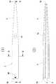
以下、本発明に係る第1の実施の形態を図1ないし図8を参照して詳細に説明する。図1の(1)図および(2)図において符号1で示すものは、本発明に係るダイレータの一例である。これらの図に示すダイレータ1は、皮膚が穿刺針によって切開されて形成された開口を広げてカテーテルを挿入しやすくしたり、血管内にガイドワイヤを挿入する際に使用するものであり、横断面が略円形の軸状の部材からなる。ダイレータ1は、ある程度、柔軟性を有する樹脂材料からなり、その材質としては、例えば、ポリプロピレン樹脂,ポリエチレン樹脂またはナイロン樹脂を挙げることができる。ダイレータ1は、その長手方向の先端面3aから後端面3bまでの全域に亘って穿設された第1貫通孔5と、該第1貫通孔5とは別個の貫通孔であってダイレータ1の長手方向の中途部から後端面3bまでの領域に亘って穿設された第2貫通孔7と、先端面3aに向かって先細となるように形成されたテーパ部9とを備えている。(First embodiment)
Hereinafter, a first embodiment according to the present invention will be described in detail with reference to FIGS. In FIG. 1 (1) and FIG. 2 (2),
第1貫通孔5および第2貫通孔7は、後述する第1ガイドワイヤ17aおよび第2ガイドワイヤ17bをそれぞれ挿入可能な大きさに形成されている。テーパ部9は、略円錐状に形成され、かつ、ダイレータ1の長手方向における全長の略半分の部位から先端面3aまでの領域に亘って形成されている。ダイレータ1の長手方向におけるテーパ部9以外の部分は、その全域に亘って横断面の外径の形状が略同一の大きさの円形に形成されている。第1貫通孔5の両端はダイレータ1の先端面3aおよび後端面3bにそれぞれ開口し、先端面3aおよび後端面3bの各開口を図2の(1)図および(2)図に符号5aおよび5bでそれぞれ示しており、先端面3a側の開口5aは略円形に形成され、後端面3b側の開口5bは略D字状に形成されている。また、第1貫通孔5の横断面積は、先端面3a側から後端面3b側に向かうに連れて徐々に大きくなっており、このため、開口5aより開口5bの方が大きくなっている。 The 1st through-
ダイレータ1の長手方向の中途部に位置する第2貫通孔7の一端はテーパ部9の表面に開口して開口7aが形成され、第2貫通孔7の他端はダイレータ1の後端面3bに開口して開口7bが形成され、第2貫通孔7の横断面積は、第2貫通孔7の長手方向全域に亘って略同一に形成されている。なお、これに限らず、第2貫通孔7の横断面積は、開口7aに近づくに連れて徐々に小さくなるように形成してもよい。第2貫通孔7の開口7bは、略D字状に形成されている。第2貫通孔7は、後端面3bからダイレータ1の軸芯に沿う方向に延びたのち、テーパ部9の表面の開口7aの近傍で該開口7aに向かって屈曲形成されている。なお、本実施の形態では、テーパ部9における後端面3b寄りの表面に開口7aを形成しているが、これに限らず、第2貫通孔7を穿設することができれば、開口7aをテーパ部9の表面における任意の位置に形成してもよい。
ダイレータ1の軸芯に沿う方向から見て、第2貫通孔7の一端の開口7aと他端の開口7bとはダイレータ1の軸芯に対して互いに同じ方向(図1の(2)図において上方向)に偏倚して設けられている。また、ダイレータ1の後端面3bにおける第1貫通孔5の開口5bと第2貫通孔7の開口7bとの開口の大きさは、両貫通孔5,7同士で互いに異なっている。具体的には、図2の(2)図を見ると分かるように、第2貫通孔7の開口7bに比べて第1貫通孔5の開口5bの方が大きい。これによって、各開口5b,7bを見ただけで両貫通孔5,7を容易に見分けることができる。One end of the second through
When viewed from the direction along the axis of the
なお、本実施の形態では両開口5b,7bの大きさを互いに異ならせたが、これに替えて、形状を互いに異ならせるようにしてもよいし、大きさおよび形状の双方を異ならせるようにしてもよい。互いに形状を異ならせる例としては、略D字状,略円形状,略矩形状または略楕円状の各形状のうち何れか2つの形状に各開口5b,7bをそれぞれ形成する場合が挙げられる。そうすることによっても、各開口5b,7bを見ただけで両貫通孔5,7を容易に見分けることができる。さらにまた、ダイレータ1の後端面3bの近傍であってダイレータ1の外周面には、開口7bの近傍にマークMが付されている。このため、両開口5b,7bの大きさを異ならせたことと相俟って、各開口5b,7bのうち何れの開口が第2貫通孔7の開口7bであるかを目視により容易に特定することができる。なお、マークMを付す位置としては、ダイレータ1の外周面に限らず、マークMを見ただけで開口7bを容易に特定することができれば、後端面3bであってもよいし、後端面3bと外周面との双方に付してもよい。また、第2貫通孔7の開口7aの位置とマークMを付した位置とは、ダイレータ1の軸芯回り方向における互いの位置関係が予め関連付けられており、これらの位置は、ダイレータ1の軸芯回り方向で同じ位置になるよう位置付けられている。なお、この位置関係に限らず、これらの位置を、例えば、ダイレータ1の軸芯回り方向で互いに正反対の位置になるよう位置付けてもよい。 In the present embodiment, the sizes of the
〔カテーテルの挿入手順〕
次に、上述したダイレータ1を使用してガイドワイヤを血管内に挿入する手順および該手順により血管内に挿入したガイドワイヤを使用してカテーテルを人体の血管内に挿入する手順について図3ないし図8を参照して詳細に説明する。
まず、図3の(1)図に示すように、先端が鋭利で軸芯部分が中空の穿刺針11が透明の注射器本体13の先端部に装着されてなる注射器15の前記穿刺針11の先端部11aを人体の皮膚Hに突き刺し、先端部11aを血管K内に挿入する。穿刺針11の先端部11aが血管K内に挿入されたとき、血管K内を血液が流れる方向Fと同一の方向に向かって先端部11aが進入するように穿刺針11を皮膚Hに対して斜めに突き刺すようにする。血管Kの種類としては動脈または静脈のどちらでもよいが、一般的には、動脈より静脈の方が血管の厚さが薄いので静脈の方が穿刺針11を突き刺しやすい。このため、静脈の血管に穿刺針11を突き刺すようにするとよい。注射器本体13内に血液が流入したことが目視により確認されると、穿刺針11の先端部11aが血管K内に挿入されたものと判断することができる。[Catheter insertion procedure]
Next, a procedure for inserting the guide wire into the blood vessel using the
First, as shown in FIG. 3A, the tip of the
次に、穿刺針11の先端部11aを血管K内に挿入したまま、穿刺針11から注射器本体13を離脱させたのち、その離脱させた部位の開口から穿刺針11の中空内に第1ガイドワイヤ17aをその先端部分から挿入する(図3の(2)図参照)。第1ガイドワイヤ17aは、ステンレス製の細い針金からなる芯線の周囲に別のステンレス製の細い針金が巻き付けられ、その巻き付けられた針金の両端部が前記芯線の両端部にそれぞれ溶接により付着され一体化されて構成されている。前記芯線に巻き付けられた針金の隣り合う部分同士の間にはそれぞれ一定の微小な間隙が設けられているため、第1ガイドワイヤ17aは柔軟性を有し自由に撓むことができる。該第1ガイドワイヤ17aは、その先端部分が血管K内に挿入される際にその先端部分によって血管Kを損傷しないように円弧状に湾曲形成されている。穿刺針11の中空内に第1ガイドワイヤ17aは、その先端部分を穿刺針11の中空内に挿入する際は直線状に伸ばした状態で挿入するが、その先端部分は穿刺針11の中空内から抜け出て血管K内に挿入されると元の円弧状に復元するため血管Kを損傷する虞はない。 Next, with the
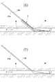
次に、図3の(3)図に示すように、穿刺針11の先端部11aを突き刺すことで穿設された皮膚Hの開口を切皮刀19によって広げたのち、図4の(4)図に示すように、ダイレータ1をその先端面3aの開口5aから第1ガイドワイヤ17aの後端部分に挿入して第1貫通孔5内に第1ガイドワイヤ17aを挿通する。このとき、ダイレータ1の第2貫通孔7の開口7bに栓部材20を予め装着して開口7bを密栓しておく。また、ダイレータ1は、挿入する前にダイレータ1の表面に親水性の潤滑被覆剤を予め塗布しておくとよい。親水性の潤滑被覆剤としては、例えば、ポリビニルピロリドン,無水マレイン酸系高分子物質またはセルロース系高分子物質等が挙げられる。このような親水性の潤滑被覆剤は湿潤(吸水)により潤滑性を発揮し、ダイレータ1を挿入する皮膚Hの開口や血管Kの開口とダイレータ1の外周面との摩擦抵抗(摺動抵抗)を低減するため、ダイレータ1を円滑に挿入することができる。
ダイレータ1を第1ガイドワイヤ17aの長手方向に沿って進入させ、ダイレータ1をその開口5aおよび開口7aが共に血管K内に確実に位置するまで進入させる。このとき、第2貫通孔7の開口7bおよびマークMが第1貫通孔5の開口5bより上方に位置するように目視により確認しながらダイレータ1を進入させることで、進入させ終わった時に開口7aが皮膚Hの表面側を指向するようにする。而して、ダイレータ1の先端面3a側が皮膚Hの開口から血管K内まで挿入される(図4の(5)図参照)。このとき、先端面3a側が先細に形成されているので、第1ガイドワイヤ17aが挿通されている皮膚Hの開口内や血管Kの開口内に容易に挿入することができる。なお、ダイレータ1の第2貫通孔7の開口7bには栓部材20が装着されているので、開口7bから血液が流出することはない。Next, as shown in FIG. 3 (3), the opening of the skin H pierced by piercing the
The
また、先端面3a側から後端面3b側に向かうに連れてテーパ部9が太くなっているので、第1ガイドワイヤ17aが挿通されている皮膚Hの開口内や血管Kの開口内にダイレータ1が進入するにしたがってダイレータ1のテーパ部9によって皮膚Hの開口や血管Kの開口が広げられるため、ダイレータ1を皮膚Hの開口内や血管Kの開口内に円滑に挿入することができる。また、ダイレータ1は、ある程度、柔軟性を有する樹脂材料で構成されているので、皮膚Hや血管K内に第1ガイドワイヤ17aが屈曲した状態で挿入されていても、その屈曲した形状に倣ってダイレータ1も屈曲しながら挿入される。
次に、血管K内に挿入されたダイレータ1の後端面3bの開口7bから栓部材20を取り外したのち、該開口7bから第2ガイドワイヤ17bを挿入して第2貫通孔7内に第2ガイドワイヤ17bを挿通し、さらに、血管K内まで第2ガイドワイヤ17bを挿入する(図5の(6)図参照)。第2ガイドワイヤ17bを挿入することで、ダイレータ1の第2貫通孔7が第2ガイドワイヤ17bによって略閉塞されるため、第2貫通孔7の開口7bから血液が殆ど流出しない。
第2ガイドワイヤ17bは前記第1ガイドワイヤ17aと同様の材質および同様の構成からなり、その先端部分をダイレータ1の開口7bに挿入する際は直線状に伸ばした状態で挿入するが、その先端部分はダイレータ1の貫通孔7内から抜け出て血管K内に挿入されると元の円弧状に復元するため血管Kを損傷する虞はない。また、ダイレータ1をその開口7aが皮膚Hの表面側を指向するように血管K内に進入させているので、開口7aが血管Kの内壁によって閉塞され難い。このため、第2ガイドワイヤ17bを血管K内に挿入するとき、第2ガイドワイヤ17bによって血管Kを損傷する虞が少なくなる。Further, since the tapered
Next, after removing the
The
第2ガイドワイヤ17bを血管K内まで挿入したのち、両ガイドワイヤ17a,17bを血管K内に挿入した状態で両ガイドワイヤ17a,17bからダイレータ1を引き抜く(図5の(7)図参照)。
次に、両ガイドワイヤ17a,17bを、例えば、図8の(1)図に示すようなカテーテル21に挿入する。カテーテル21は、管状の第1導管23aと、該第1導管23aより短尺の管状の第2導管23bと、これらの両導管23a,23bを一体的に緊締する管状のハブ25と、両導管23a,23bの一端部にそれぞれ結着された雌側コネクタ27と、該雌側コネクタ27とハブ25との間に位置する各導管23a,23bの長手方向中途部にそれぞれ挿通されたクリップ29とを備えている。第1導管23a,第2導管23bおよびハブ25の材質としては、例えば、ウレタン樹脂,シリコン樹脂または塩化ビニル樹脂等を挙げることができる。After the
Next, both
図8に示すカテーテル21は、第1導管23aと第2導管23bとハブ25とがそれぞれ別個の部材として構成されているが、これに限らず、両導管23a,23bとハブ25とを一体成型により一体化する一方、ハブ25から突出した両導管23a,23bの部分同士は互いに分離された構成としてもよいし、ハブ25から突出した両導管23a,23bの部分同士で互いに密着した部分(図8の(1)図における右側の部分)は一体化されていてもよい。
クリップ29は各導管23a,23b内の液体の流通を一時的に遮断するときに使用するもので、クリップ29の係合部29aを被係合部29bに係合させることで、クリップ29の一対の突部29c,29c間に各導管23a,23bが挟み込まれ、各導管23a,23b内の液体の流通が遮断されるように構成されている。
また、雌側コネクタ27が結着された両導管23a,23bの各後端部が突出したハブ25の一端部側は、雌側コネクタ27に向かうに連れて拡径されている。この拡径されたハブ25の拡径部25aから突出した両導管23a,23bの各後端部同士の長さは略同一に設定され、拡径部25aとは反対側のハブ25の小径部25bから突出した両導管23a,23bの各先端部同士の長さは、第1導管23aより第2導管23bの方が短く設定されている。
両ガイドワイヤ17a,17bにカテーテル21を挿入する際は、カテーテル21の両導管23a,23b内にそれぞれ管状のスタイレット31(図8の(2)図参照)を予め挿入しておくとよい。
図6の(8)図は、カテーテル21の両導管23a,23b内にそれぞれ予め挿入された各スタイレット31の先端側から各ガイドワイヤ17a,17bを各スタイレット31内にそれぞれ挿入し、各スタイレット31の後端から両ガイドワイヤ17a,17bをそれぞれ突出させた状態を示している。In the
The
Further, the one end side of the
When inserting the
FIG. 6 (8) shows that
次に、カテーテル21を両スタイレット31と共に両ガイドワイヤ17a,17bの長手方向に沿ってそれぞれ進入させ、両導管23a,23bの各先端部を皮膚Hの開口から血管K内まで挿入する(図6の(9)図参照)。このとき、カテーテル21の両導管23a,23b内に予めスタイレット31をそれぞれ挿入しておいたことで、スタイレット31を挿入しない場合に生じる両ガイドワイヤ17a,17bの外径とカテーテル21の両導管23a,23bの外径との急激な寸法の変化をスタイレット31によって緩徐にすることができる。また、カテーテル21の両導管23a,23bが高い柔軟性を有する場合は、スタイレット31を挿入することで両導管23a,23bに適度な剛性を付与することができる。この結果、カテーテル21の両導管23a,23bの各先端部を皮膚Hの開口から血管K内まで円滑に挿入することができる。
なお、カテーテル21を挿入する前に、カテーテル21の表面と、該カテーテル21の各導管23a,23bから突出した各スタイレット31の先端部の表面とに、上述した親水性の潤滑被覆剤を予め塗布しておくとよい。そうすることで、カテーテル21を両スタイレット31と共に挿入する際にこれらの外周面と皮膚Hの開口や血管Kの開口との摩擦抵抗(摺動抵抗)が低減されて、カテーテル21を円滑に挿入することができる。
次に、カテーテル21の両導管23a,23bの各先端部を血管K内に挿入した状態で両ガイドワイヤ17a,17bおよび両スタイレット31をカテーテル21の両導管23a,23bから引き抜く(図7の(10)図参照)。その後、両導管23a,23bから血液が流出しないように、クリップ29の係合部29aを被係合部29bに係合させ、各導管23a,23b内の流通を遮断しておく。
以上で、カテーテル21の血管K内への挿入作業が終了する。Next, the
Before the
Next, both
This completes the insertion of the
次に、上述したカテーテル21の両導管23a,23bが血管K内に挿入された状態で、血液の透析・浄化の治療行為を行う方法の一例について、図7の(11)図を参照して説明する。この(11)図に符号80で示すものは透析装置であり、該透析装置80には、血液を排出する排出管81aと血液を吸入する吸入管81bとの一端部がそれぞれ接続され、排出管81aと吸入管81bとの他端部には雄側コネクタ83がそれぞれ結着されている。各雄側コネクタ83にカテーテル21の各雌側コネクタ27を連結することで、透析装置80とカテーテル21とが接続される。透析装置80とカテーテル21とを接続したのち、クリップ29の係合部29aと被係合部29bとの係合を解除して、各導管23a,23b内を血液が流通することができるようにする。そして、透析装置80内のポンプを作動させることで、カテーテル21の第2導管23bおよび吸入管81bを介して体内の血液が透析装置80内に吸入され、吸引された血液は透析装置80内で透析・浄化されたのち、排出管81aおよびカテーテル21の第1導管23aを介して体内の血管K内に戻される。このとき、血管K内の血液の流れる方向Fから見て第1導管23aの端部より上流側に第2導管23bの端部が位置付けられるので、透析装置80内で透析・浄化されて第1導管23aを介して血管K内に戻されたばかりの血液が第2導管23bを介して吸引される虞はない。 Next, referring to FIG. 7 (11), an example of a method for performing a blood dialysis / purification treatment action in a state where both the
血液の透析・浄化の治療行為を所定の時間行ってその治療行為が終了したら、透析装置80の作動を停止させるとともにクリップ29の係合部29aを被係合部29bに係合させ、各導管23a,23b内の流通を遮断したのち、各雄側コネクタ83とカテーテル21の各雌側コネクタ27とを離脱させる。
次に、カテーテル21内の血液が凝固しないようにするために、抗凝固薬が貯留された薬剤充填装置(図示せず)を各雌側コネクタ27に接続して、クリップ29の係合部29aと被係合部29bとの係合を解除したのち、薬剤充填装置から抗凝固薬をカテーテル21内に充填しておく。該抗凝固薬としては、例えばヘパリンを挙げることができる。該抗凝固薬をカテーテル21内に充填したのち、各雌側コネクタ27の開口は栓部材(図示せず)を装着して密栓したのち、カテーテル21の両導管23a,23bが不所望に移動しないように固定バンド(図示せず)により人体に固定する。
以上で、血液の透析・浄化の治療が終了する。When the therapeutic action for dialysis and purification of blood is performed for a predetermined time and the therapeutic action is completed, the operation of the
Next, in order to prevent blood in the
This completes the blood dialysis / purification treatment.
上述したような本発明の第1の実施の形態に係るダイレータ1によれば、第1貫通孔5と第2貫通孔7とがダイレータ1に別個に穿設されているので、2本のガイドワイヤ17a,17bを両貫通孔5,7内にそれぞれ個別に挿入することができる。このため、2本目の第2ガイドワイヤ17bをダイレータ1の第2貫通孔7内に挿入する際、ダイレータ1の第1貫通孔5内に先に挿入されている1本目の第1ガイドワイヤ17aに絡まったりして挿入が阻害されることなく2本目の第2ガイドワイヤ17bを円滑に血管K内まで挿入することができる。 According to the
また、カテーテル21を挿入しやすくするために皮膚Hの開口や血管Kの開口を広げるべく血管K内まで挿入した状態のダイレータ1をそのまま利用して2本目の第2ガイドワイヤ17bを血管K内まで挿入することができる。このため、従来のようなシースにダイレーターを挿入してセットされたイントロデューサーを使用することなくダイレータ1によって2本目の第2ガイドワイヤ17bを挿入することができるので、その分、ガイドワイヤ挿入用の器具が安価になるとともに、イントロデューサーからダイレーターを引き抜く作業が不要になるため、第2ガイドワイヤ17bの挿入作業が簡素化される。また、従来のようなイントロデューサーを使用しないので、シースとダイレーターとの段差による抵抗は生じず、皮膚Hの開口内や血管Kの開口内にダイレータ1を円滑に挿入することができる。
また、ダイレータ1は、先端面3aに向かって先細となるように形成されたテーパ部9を備えているので、1本目の第1ガイドワイヤ17aが挿通されている皮膚Hの開口内や血管Kの開口内にダイレータ1を容易に挿入することができるだけでなく、ダイレータ1が進入するにしたがってそのテーパ部9によって皮膚Hの開口や血管Kの開口が広げられるため、皮膚Hの開口内や血管Kの開口内にダイレータ1を円滑に挿入することができる。
また、ダイレータ1の長手方向の中途部に位置する第2貫通孔7の一端の開口7aはテーパ部9の表面に開口しているので、その開口7aの部位のダイレータ1の太さはテーパ部9以外の部位と比べて細くなっている。このため、第2貫通孔7の開口7aの部位と血管Kの内壁との間に隙間が生じやすく、第2貫通孔7を介して第2ガイドワイヤ17bを血管K内に挿入するとき、該第2ガイドワイヤ17bによって血管Kを損傷する虞が少なくなる。また、第2貫通孔7の開口7aの部位と血管Kの内壁との間に隙間が生じなかったとしても、開口7aの部位のダイレータ1の太さが細くなっている分、第2貫通孔7の開口7aの部位と血管Kの内壁との密着力を低下させることができる。この結果、第2貫通孔7を介して第2ガイドワイヤ17bを血管K内に挿入するとき、第2ガイドワイヤ17bによって血管Kを損傷する虞が少なくなる。Further, in order to facilitate insertion of the
Moreover, since the
In addition, since the
また、第2貫通孔7の一端の開口7aと他端の開口7bとはダイレータ1の軸芯に対して同じ方向に偏倚して設けられているので、血管K内までダイレータ1を挿入する際、ダイレータ1の後端面3bにおける第2貫通孔7の開口7bの位置が所望の位置になるよう目視により確認しながら挿入することで、血管K内に位置する第2貫通孔7の開口7aを血管K内の周方向における所望の位置に位置付けることができる。
また、ダイレータ1の後端面3bにおける第1貫通孔5と第2貫通孔7との各開口5b,7bの大きさは、両貫通孔5,7同士で互いに異なるようにしたので、各開口5b,7bを見ただけで第1貫通孔5と第2貫通孔7とを目視により容易に見分けることができる。
さらにまた、ダイレータ1の長手方向の中途部に位置する第2貫通孔7の開口7aの位置とマークMを付した位置とは、ダイレータ1の軸芯回り方向における互いの位置関係が予め関連付けられているので、血管K内までダイレータ1を挿入する際、マークMの位置が所望の位置になるよう目視により確認しながら挿入することで、血管K内に位置する第2貫通孔7の開口7aを血管K内の周方向における所望の位置に位置付けることができる。Further, since the
In addition, since the sizes of the
Furthermore, the position of the
次に、上述した実施の形態以外の実施の形態として、他に2つの実施の形態について以下に説明する。なお、これらの他の実施の形態の説明で参照する図において、上述した第1の実施の形態や先に記載する他の実施の形態で説明するものと同一または同等の部材および部位等については、同一符号を付し詳細な説明は省略する。他の実施の形態においても、上述した第1の実施の形態や先に記載する他の実施の形態で説明するものと同一または同等の構成については、同様の作用・効果を奏することができるのは言うまでもない。
(第2の実施の形態)
上述した第1の実施の形態では、第2貫通孔7の開口7aをダイレータ1のテーパ部9の表面に形成する例を示したが、図9に示す第2の実施の形態のように、テーパ部9の表面の一部を窪ませて凹部33を1箇所だけ形成し、この凹部33内に第2貫通孔7の開口7aを形成するようにしてもよい。凹部33は、ダイレータ1の軸芯に沿う方向に長く延びるように形成されている。
この第2の実施の形態のダイレータ1によれば、先端面3aおよび後端面3bを除くダイレータ1の表面の一部を窪ませて凹部33を形成し、この凹部33内に第2貫通孔7の一端が開口しているので、該開口7aの角部により血管Kの内壁を損傷する虞が低減される。
なお、この第2の実施の形態では、凹部33内における後端面3b寄りの部位に第2貫通孔7の開口7aが形成されているが、これに限らず、第2貫通孔7を穿設することができれば、開口7aを凹部33内の任意の位置に形成してもよい。Next, two other embodiments will be described below as embodiments other than the embodiment described above. In the drawings referred to in the description of these other embodiments, the same or equivalent members and parts as those described in the first embodiment described above and the other embodiments described above are used. The same reference numerals are given and detailed description is omitted. Also in other embodiments, the same actions and effects can be achieved with the same or equivalent configurations as those described in the first embodiment described above and the other embodiments described above. Needless to say.
(Second Embodiment)
In the first embodiment described above, the example in which the
According to the
In the second embodiment, the
(第3の実施の形態)
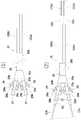
上述した第2の実施の形態では、凹部33を1つだけ形成し、この凹部33内に第2貫通孔7の開口7aを形成した例を示したが、図10および図11に示す第3の実施の形態のように凹部33を3個設け、これら3個の凹部33…のうち何れか1つの凹部33内に第2貫通孔7の開口7aを形成するようにしてもよい。各凹部33は、ダイレータ1の軸芯に沿う方向に長い溝状に形成されているとともに、テーパ部9の表面に周方向に一定の間隔を隔てた等角度間隔で形成されている。なお、この第3の実施の形態では、ダイレータ1の軸芯に沿う方向の一部領域に各凹部33を設けたが、これに限らず、ダイレータ1の先端面3aから後端面3bまでの全域に亘って各凹部33を設けてもよい。
この第3の実施の形態のダイレータ1によれば、凹部33は、ダイレータ1の軸芯に沿う方向に長い溝状に形成されているとともに、ダイレータ1の表面の周方向に一定の間隔を隔てた等角度間隔で3個形成されているので、その分、ダイレータ1のテーパ部9を皮膚Hの開口や血管Kの開口に挿入する際にダイレータ1のテーパ部9と皮膚Hの開口や血管Kの開口との接触面積が少なくなり、ダイレータ1を挿入する際の抵抗を低減することができる。
また、3個の凹部33…のうち何れか1つの凹部33内に第2貫通孔7の開口7aが開口しているので、該開口7aの角部により血管Kの内壁を損傷する虞が低減される。
なお、この第3の実施の形態では、凹部33内における後端面3b寄りの部位に第2貫通孔7の開口7aが形成されているが、これに限らず、ダイレータ1に第2貫通孔7を穿設することができれば、開口7aを凹部33内の任意の位置に形成してもよい。
また、この第3の実施の形態では、ダイレータ1のテーパ部9の表面に凹部33を3個形成する例を示したが、2個または4個以上形成し、これら複数の凹部33のうち何れか1つの凹部33内に第2貫通孔7の開口7aを形成するようにしてもよい。(Third embodiment)
In the second embodiment described above, an example in which only one
According to the
Further, since the
In the third embodiment, the
Moreover, in this 3rd Embodiment, although the example which forms three recessed
上述した第1ないし第3の実施の形態は本発明を説明するための一例であり、本発明は、前記の各実施の形態に限定されるものではなく、特許請求の範囲と明細書との全体から読み取れる発明の要旨または思想に反しない範囲で適宜変更可能であり、そのような変更後のダイレータもまた、本発明の技術的範囲に含まれるものである。
例えば、上述した各実施の形態では、第2貫通孔7の開口7aをテーパ部9の表面に形成した例を示したが、これに替えて、先端面3aおよび後端面3bを除くダイレータ1の表面のうちテーパ部9以外の表面(例えば、テーパ部9の近傍の表面)に開口7aを形成してもよいし、テーパ部9の表面とテーパ部9以外のダイレータ1の表面とに跨って開口7aを形成してもよい。なお、このような変形例の場合は、テーパ部9の表面に開口7aを形成した場合と比べて開口7aの部位と血管Kの内壁との間に隙間が生じ難いが、第2貫通孔7の開口7bの位置が所望の位置になるよう確認しながらダイレータ1を挿入することで、前記隙間を生じやすくするか、または、開口7aの部位と血管Kの内壁との密着力を低下させるようにすればよい。また、このような変形例の場合は、上述した第2の実施の形態および第3の実施の形態における凹部33の少なくとも一部をテーパ部9以外の表面に形成することになる。
また、上述した各実施の形態では、ダイレータ1にマークMを付す例を示したが、これに限らず、ダイレータ1を樹脂の共押出成形により成形し、その成形の際に樹脂材料自体でマークMを形成するようにしてもよい。具体的には、ダイレータ1の素材となる樹脂材料に対して、該樹脂材料とは色彩が異なる樹脂材料を少量ずつ連続的に混入させながら共押出成形し、樹脂材料が固化する過程で、前記色彩が異なる樹脂材料がダイレータ1の軸芯に対して偏倚した位置で固化することで前記色彩が異なる樹脂材料自体によりマークMを形成する。このようにして形成されるマークMは、ダイレータ1の横断面内に形成されるとともにダイレータ1の長手方向の全域に亘って形成される。The above-described first to third embodiments are examples for explaining the present invention, and the present invention is not limited to the above-described embodiments. Changes can be made as appropriate without departing from the gist or concept of the invention which can be read from the entirety, and such a changed dilator is also included in the technical scope of the present invention.
For example, in each of the above-described embodiments, the example in which the
Further, in each of the above-described embodiments, the example in which the mark M is attached to the
なお、ダイレータ1を樹脂の共押出成形により成形する場合は、第1貫通孔5および第2貫通孔7を有する長尺の軸状の素材として成形する。そして、成形された長尺の軸状の素材を適当な長さに切断したのち、その一端部の外周面を加熱および加圧しながら縮径してテーパ部9を形成する。このとき、テーパ部9内に位置する両貫通孔5,7の横断面積は共に縮小される。縮小された後でも、第1貫通孔5内には第1ガイドワイヤ17aを挿通することができるが、第1貫通孔5より小さい第2貫通孔7は、第2ガイドワイヤ17bを挿通することができない程度に縮径される。このため、第2貫通孔7を外部に連通させるために、先端面3aおよび後端面3bを除くダイレータ1の外周面に孔開け工具により孔を穿設して第2貫通孔7の開口7aを形成する必要がある。このとき、孔を穿設する位置(ダイレータ1の外周面における周方向の位置)を特定する必要があるが、マークMを構成する樹脂材料が第2貫通孔7の近傍に位置付けられるとともにその樹脂材料の一部がダイレータ1の表面に露出するように共押出成形しておくと、孔を穿設する位置を示す目印としてマークMを利用することができる。この場合、マークMを形成する領域としては、ダイレータ1の長手方向の全域ではなく、少なくともダイレータ1の後端面3bから第2貫通孔7の開口7aを形成する予定の位置までの領域としてもよい。 In addition, when shape | molding the
1 ダイレータ
3a 先端面
3b 後端面
5 第1貫通孔
5a 開口
5b 開口
7 第2貫通孔
7a 開口
7b 開口
9 テーパ部
17a 第1ガイドワイヤ
17b 第2ガイドワイヤ
21 カテーテル
33 凹部
K 血管
M マークDESCRIPTION OF
Claims (7)
Translated fromJapanese前記ダイレータの長手方向の先端面から後端面までの全域に亘って穿設された第1貫通孔と、
前記第1貫通孔とは別個の貫通孔であって前記ダイレータの長手方向の中途部から前記後端面までの領域に亘って穿設された第2貫通孔と、
前記先端面に向かって先細となるように形成されたテーパ部とを備え、
前記第1貫通孔および前記第2貫通孔は、前記カテーテルの挿入を支援するための可撓性のガイドワイヤを挿入可能な大きさに形成されていることを特徴とするダイレータ。In an axial dilator to assist insertion of a catheter into the blood vessel,
A first through hole drilled over the entire area from the front end surface to the rear end surface in the longitudinal direction of the dilator;
A second through hole that is a through hole that is separate from the first through hole and that extends from an intermediate portion in the longitudinal direction of the dilator to the rear end surface;
A tapered portion formed so as to taper toward the tip surface,
The dilator according to claim 1, wherein the first through hole and the second through hole are formed in a size capable of inserting a flexible guide wire for supporting insertion of the catheter.
前記ダイレータの長手方向の中途部に位置する前記第2貫通孔の一端は前記テーパ部の表面に開口し、前記第2貫通孔の他端は前記後端面に開口していることを特徴とするダイレータ。The dilator according to claim 1, wherein
One end of the second through hole located in the middle portion of the dilator in the longitudinal direction is opened on the surface of the tapered portion, and the other end of the second through hole is opened on the rear end surface. Dilator.
前記ダイレータの軸芯に沿う方向から見て、前記第2貫通孔の一端の開口と他端の開口とは前記ダイレータの軸芯に対して同じ方向に偏倚して設けられていることを特徴とするダイレータ。The dilator according to claim 1 or 2,
As viewed from the direction along the axis of the dilator, the opening at one end and the opening at the other end of the second through hole are provided to be offset in the same direction with respect to the axis of the dilator. Dilator to do.
前記第1貫通孔と前記第2貫通孔との前記後端面における各開口の形状または大きさのうち少なくとも何れか一方は、両貫通孔同士で互いに異なることを特徴とするダイレータ。In the dilator according to any one of claims 1 to 3,
A dilator, wherein at least one of the shape or size of each opening in the rear end surface of the first through hole and the second through hole is different between the through holes.
前記後端面またはその近傍のうち少なくとも何れか一方の部位を含む領域に、外部から視認可能なマークを付し、
前記ダイレータの長手方向の中途部に位置する前記第2貫通孔の一端の開口位置と前記マークを付した位置とは、ダイレータの軸芯回り方向における互いの位置関係が予め関連付けられていることを特徴とするダイレータ。In the dilator according to any one of claims 1 to 4,
A mark that is visible from the outside is attached to a region that includes at least one of the rear end surface or the vicinity thereof,
The position of the opening of one end of the second through hole located in the middle part of the dilator in the longitudinal direction and the position with the mark are associated with each other in advance in the direction around the axis of the dilator. The characteristic dilator.
前記先端面および前記後端面を除く前記ダイレータの表面の一部を窪ませて凹部を形成し、この凹部内に前記第2貫通孔の一端が開口していることを特徴とするダイレータ。In the dilator according to any one of claims 1 to 5,
A dilator, wherein a part of the surface of the dilator excluding the front end surface and the rear end surface is recessed to form a recess, and one end of the second through hole is opened in the recess.
前記凹部は、前記ダイレータの軸芯に沿う方向に長い溝状に形成されているとともに前記ダイレータの表面の周方向に一定の間隔を隔てて複数形成され、
前記複数の凹部のうち何れか1つの凹部内に前記第2貫通孔の一端が開口していることを特徴とするダイレータ。The dilator according to claim 6, wherein
The recesses are formed in a groove shape that is long in the direction along the axis of the dilator and are formed at a certain interval in the circumferential direction of the surface of the dilator,
A dilator, wherein one end of the second through hole is opened in any one of the plurality of recesses.
Priority Applications (2)
| Application Number | Priority Date | Filing Date | Title |
|---|---|---|---|
| JP2015096133AJP2016209319A (en) | 2015-05-11 | 2015-05-11 | Dilator |
| US14/883,947US20160331941A1 (en) | 2015-05-11 | 2015-10-15 | Dilator |
Applications Claiming Priority (1)
| Application Number | Priority Date | Filing Date | Title |
|---|---|---|---|
| JP2015096133AJP2016209319A (en) | 2015-05-11 | 2015-05-11 | Dilator |
Publications (1)
| Publication Number | Publication Date |
|---|---|
| JP2016209319Atrue JP2016209319A (en) | 2016-12-15 |
Family
ID=57276489
Family Applications (1)
| Application Number | Title | Priority Date | Filing Date |
|---|---|---|---|
| JP2015096133APendingJP2016209319A (en) | 2015-05-11 | 2015-05-11 | Dilator |
Country Status (2)
| Country | Link |
|---|---|
| US (1) | US20160331941A1 (en) |
| JP (1) | JP2016209319A (en) |
Cited By (1)
| Publication number | Priority date | Publication date | Assignee | Title |
|---|---|---|---|---|
| JP2020049150A (en)* | 2018-09-28 | 2020-04-02 | テルモ株式会社 | Medical equipment |
Families Citing this family (1)
| Publication number | Priority date | Publication date | Assignee | Title |
|---|---|---|---|---|
| US12252582B2 (en) | 2019-08-29 | 2025-03-18 | University Of Delaware | Biofunctional thiophene monomers and polymers thereof for electronic biomedical devices |
Family Cites Families (23)
| Publication number | Priority date | Publication date | Assignee | Title |
|---|---|---|---|---|
| US4735607A (en)* | 1986-05-12 | 1988-04-05 | H. P. Bruemmer Corp. | Nasogastric tube antireflux valve |
| US4887997A (en)* | 1986-11-21 | 1989-12-19 | Sherwood Medical Company | Catheter for nasogastric intubation |
| CA1330285C (en)* | 1987-12-22 | 1994-06-21 | Geoffrey S. Martin | Triple lumen catheter |
| JP2566753Y2 (en)* | 1991-07-12 | 1998-03-30 | 日本シャーウッド株式会社 | Stomach tube |
| US5354518A (en)* | 1993-02-11 | 1994-10-11 | Sherwood Medical Company | Method for manufacturing a fiberscopic catheter |
| WO2001089603A1 (en)* | 2000-05-19 | 2001-11-29 | C.R. Bard, Inc. | Multi-lumen biliary catheter with angled guidewire exit |
| US6858019B2 (en)* | 2001-01-09 | 2005-02-22 | Rex Medical, L.P. | Dialysis catheter and methods of insertion |
| US20040243095A1 (en)* | 2003-05-27 | 2004-12-02 | Shekhar Nimkar | Methods and apparatus for inserting multi-lumen spit-tip catheters into a blood vessel |
| US7662328B2 (en)* | 2003-09-02 | 2010-02-16 | Boston Scientific Scimed, Inc. | Proximal guidewire port |
| US20080114335A1 (en)* | 2006-08-23 | 2008-05-15 | William Flickinger | Medical Device Guide |
| US20080306427A1 (en)* | 2007-06-05 | 2008-12-11 | Cook Incorporated | Chronic Hemodialysis Catheter with Balloon |
| US8292841B2 (en)* | 2007-10-26 | 2012-10-23 | C. R. Bard, Inc. | Solid-body catheter including lateral distal openings |
| US20100305678A1 (en)* | 2009-05-27 | 2010-12-02 | Khaldoon Alaswad | Thrombectomy and Balloon Angioplasty/Stenting Device |
| US20120238806A1 (en)* | 2009-08-24 | 2012-09-20 | Quali-Med Gmbh | Implantation system with handle and catheter and method of use thereof |
| US9248262B2 (en)* | 2010-08-31 | 2016-02-02 | Vibha Agarwal | Vascular dilator for controlling blood flow in a blood vessel |
| US9717883B2 (en)* | 2011-02-10 | 2017-08-01 | C. R. Bard, Inc. | Multi-lumen catheter with enhanced flow features |
| US9486614B2 (en)* | 2011-06-29 | 2016-11-08 | Entellus Medical, Inc. | Sinus dilation catheter |
| WO2013029669A1 (en)* | 2011-08-31 | 2013-03-07 | St. Jude Medical Ab | Physiologically adapted cardiac resynchronization therapy |
| ES2696081T3 (en)* | 2012-04-23 | 2019-01-14 | Pq Bypass Inc | System for circumventing occlusions in a femoral artery |
| US8684963B2 (en)* | 2012-07-05 | 2014-04-01 | Abbott Cardiovascular Systems Inc. | Catheter with a dual lumen monolithic shaft |
| JP2015526259A (en)* | 2012-08-30 | 2015-09-10 | バガオイサン,セルソ | Apparatus and method for treating vascular disease |
| WO2015108941A1 (en)* | 2014-01-14 | 2015-07-23 | Volcano Corporation | Devices and methods for forming vascular access |
| JP6554794B2 (en)* | 2014-01-29 | 2019-08-07 | 住友ベークライト株式会社 | Medical equipment |
- 2015
- 2015-05-11JPJP2015096133Apatent/JP2016209319A/enactivePending
- 2015-10-15USUS14/883,947patent/US20160331941A1/ennot_activeAbandoned
Cited By (2)
| Publication number | Priority date | Publication date | Assignee | Title |
|---|---|---|---|---|
| JP2020049150A (en)* | 2018-09-28 | 2020-04-02 | テルモ株式会社 | Medical equipment |
| JP7165011B2 (en) | 2018-09-28 | 2022-11-02 | テルモ株式会社 | medical instruments |
Also Published As
| Publication number | Publication date |
|---|---|
| US20160331941A1 (en) | 2016-11-17 |
Similar Documents
| Publication | Publication Date | Title |
|---|---|---|
| JP7304890B2 (en) | Multi-diameter catheters and related devices and methods | |
| US4568329A (en) | Double lumen catheter | |
| US4692141A (en) | Double lumen catheter | |
| JP7337046B2 (en) | needle and catheterization devices | |
| US4583968A (en) | Smooth bore double lumen catheter | |
| US9901704B2 (en) | Multilumen catheters and method of manufacturing | |
| USRE40913E1 (en) | Multilumen catheter assembly and methods for making and inserting the same | |
| CN102458508B (en) | catheterization system | |
| CN114642815A (en) | Central catheter capable of being inserted rapidly and assembly thereof | |
| US8317754B2 (en) | Valves and hubs for tubular devices and methods for making and using them | |
| US20130053763A1 (en) | Dialysis catheter | |
| JP6043301B2 (en) | Vascular needle system | |
| US20150231369A1 (en) | Peelable sheath | |
| WO2016052517A1 (en) | Extracorporeal circulation indwelling needle | |
| CA3031694A1 (en) | Improved catheter | |
| JP2012520092A (en) | Double lumen catheter | |
| JP5108580B2 (en) | Indwelling needle | |
| JP4567847B2 (en) | Double lumen catheter | |
| EP1977782A1 (en) | Introducer assembly and method for forming an introducer assembly | |
| JP2016209319A (en) | Dilator | |
| JPWO2017159688A1 (en) | Balloon catheter and method for manufacturing balloon catheter elongated member | |
| US11439791B2 (en) | Catheter and manufacturing method of catheter | |
| US20150290433A1 (en) | Guidance Device for Mating a Guidewire to a Medical Device | |
| US20150320927A1 (en) | Split Tip Catheter for Dialysis Treatment | |
| CN117679605A (en) | Rapidly insertable central line insertion assemblies, valve modules therefor, and introducer assemblies |