JP2016208720A - Mechanically and electrically integrated unit - Google Patents
Mechanically and electrically integrated unitDownload PDFInfo
- Publication number
- JP2016208720A JP2016208720AJP2015089267AJP2015089267AJP2016208720AJP 2016208720 AJP2016208720 AJP 2016208720AJP 2015089267 AJP2015089267 AJP 2015089267AJP 2015089267 AJP2015089267 AJP 2015089267AJP 2016208720 AJP2016208720 AJP 2016208720A
- Authority
- JP
- Japan
- Prior art keywords
- cooler
- integrated unit
- medium
- electromechanical integrated
- power converter
- Prior art date
- Legal status (The legal status is an assumption and is not a legal conclusion. Google has not performed a legal analysis and makes no representation as to the accuracy of the status listed.)
- Granted
Links
Images


Landscapes
- Motor Or Generator Frames (AREA)
Abstract
Description
Translated fromJapanese本発明は、機電一体型ユニットに関するものである。 The present invention relates to an electromechanical integrated unit.
自動車に設けられる駆動装置において、自動車の後輪駆動系のモータを駆動制御するパワーコントロールユニット(PCU)に冷却フィンを取り付けて、後輪用のギヤ機構やディファレンシャルギヤが収められたギヤケース内に冷却フィンが突出するようPCUをギヤケースの上部に載置する。そして、ディファレンシャルギヤをその一部が潤滑油に浸漬させるよう配置することにより、自動車の走行に伴って回転するディファレンシャルギヤにより掻き上げられた潤滑油を冷却フィンに掛けてPCUを冷却する駆動装置が開示されている(特許文献1)。 In a drive unit provided in an automobile, a cooling fin is attached to a power control unit (PCU) that controls the motor of a rear wheel drive system of the automobile, and cooling is performed in a gear case that houses a gear mechanism for a rear wheel and a differential gear. The PCU is placed on top of the gear case so that the fins protrude. Then, by arranging the differential gear so that a part of the differential gear is immersed in the lubricating oil, there is provided a driving device that cools the PCU by applying the lubricating oil scraped up by the differential gear rotating as the automobile travels to the cooling fin. (Patent Document 1).
しかしながら、車両が停車し、ギアが回転していない場合には、潤滑油がギアにより掻き上げられないため、PCUに当たる潤滑油の量が少なく、PCUの冷却性能が低下するという問題があった。 However, when the vehicle is stopped and the gear is not rotating, there is a problem that the amount of lubricating oil hitting the PCU is small and the cooling performance of the PCU is lowered because the lubricating oil is not scraped up by the gear.
本発明が解決しようとする課題は、車両の停車時における冷却性能の低下を抑制する機電一体型ユニットを提供することである。 The problem to be solved by the present invention is to provide an electromechanical integrated unit that suppresses a decrease in cooling performance when the vehicle is stopped.
本発明において、電力変換器は半導体素子を冷却する複数の冷却器を備え、駆動部は、モータ及びギアのうち少なくとも何れか一方の部品、当該部品を収容するケース、及び当該ケース内に溜まる第1媒体を備え、複数の冷却器のうち一方の冷却器の一部がケース内で第1媒体と接触し、他方の冷却器が第1媒体より熱伝導率の高い第2媒体と接触することによって上記課題を解決する。 In the present invention, the power converter includes a plurality of coolers that cool the semiconductor element, and the drive unit includes at least one of a motor and a gear, a case that accommodates the component, and a first unit that accumulates in the case. 1 medium is provided, a part of one of the coolers is in contact with the first medium in the case, and the other cooler is in contact with the second medium having higher thermal conductivity than the first medium. To solve the above problem.
本発明によれば、車両が停車しているときに、冷却器がケース内に溜まっている第1媒体と接触しているため、半導体素子の発熱により、熱が冷却器に伝わった場合でも、当該冷却器は第1媒体で冷やされるので、車両の停車時における冷却性能の低下を抑制するという効果を奏する。 According to the present invention, when the vehicle is stopped, since the cooler is in contact with the first medium accumulated in the case, even when heat is transmitted to the cooler due to heat generation of the semiconductor element, Since the said cooler is cooled with the 1st medium, there exists an effect of suppressing the fall of the cooling performance at the time of a vehicle stop.
以下、本発明の実施形態を図面に基づいて説明する。 Hereinafter, embodiments of the present invention will be described with reference to the drawings.
《第1実施形態》
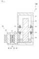
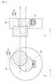
図1は、本発明の実施形態に係る機電一体型ユニットの断面図である。本実施形態に係る機電ユニットは、例えば車両に設けられる。<< First Embodiment >>
FIG. 1 is a cross-sectional view of an electromechanical integrated unit according to an embodiment of the present invention. The electromechanical unit according to the present embodiment is provided in a vehicle, for example.
機電一体型ユニット100は、駆動部10と電力変換器20を備えており、駆動部10と電力変換器20を一体化したユニットである。 The electromechanical
駆動部10はギアボックス11、ギア12、ベアリング13及び媒体14を備えている。駆動部10は、モータ又はエンジンから出力される動力を、車輪に伝達する伝達機構である。ギアボックス11は、ギア12、ベアリング13及び媒体14を収容するケースである。ギア12は、他の図示しないギアと噛合しており、減速ギアを構成する部品の1つである。ギア12は、動力を車輪に伝える機能を有している。ギア12は、ベアリング13に支持されている。ベアリング13は、ギア12を回転可能な状態で支持する。そして、ギア12の回転軸が、複数のベアリング13の間に狭持されている。 The
媒体14はベアリング13を潤滑するための液状の媒体である。媒体14は、オイルである。媒体14は、ギアボックス11の下部に形成された空間に溜まっている。ギア12の一部は、媒体14に浸かっている。そのため、ギア12が回転すると、媒体14は、ギアの12の回転によって跳ね上がり、跳ね上げられた媒体14がベアリング13等に当たる。そのため、ギア12の回転により、ベアリング13がオイルで潤滑されることになる。すなわち、媒体14としてオイルを用いた場合には、ギア12、ベアリング13及び媒体14は、潤滑機構としても機能する。なお、媒体14には、オイルの代わりに、例えば水などの液体が用いられてもよい。 The
電力変換器20は、半導体素子21、22、絶縁基板23、24、冷却器25、26、及びケース27を備えている。半導体素子21、22は、電力変換回路に含まれる回路素子であって、IGBT又はMOSFET等のスイッチング素子又はダイオードである。半導体素子21、22により構成される電力変換回路は、例えば、バッテリの電力を交流に変換するインバータであって、一対のスイッチング素子をブリッジ状で三相に接続した回路である。なお、電力変換器20に含まれる電力変換回路は、インバータに限らず、例えばコンバータであってもよい。 The
半導体素子21、22はモジュール化されており、半導体素子21、22の互いに向き合う側面は、ハンダにより絶縁基板23、24にそれぞれ接合している。すなわち、半導体素子21、22は、絶縁基板23の一側面と絶縁基板24の一側面との間に狭持されている。なお、半導体素子21、22は一体化した1つのモジュールで構成されてもよい。 The
絶縁基板23、24は、半導体素子21、22と冷却器25、26との間を絶縁するための基板である。絶縁基板23、24の主面は、モジュール化された半導体素子21、22の表面にハンダを介して接合している。 The
冷却器25は、半導体素子21、22を冷却する部品であって、アルミで形成されている。冷却器25と絶縁基板23との間は、例えば接着剤で接着している。
冷却器25の一方向には、フィンが形成されており、当該一方向と反対側は絶縁基板23の主面に沿った面になっている。冷却器25のうちフィンの部分は媒体14と接触している。そして、冷却器25の一部はギアボックス11内に位置しつつ、冷却器25の他の部分はケース27内に位置する。The
Fins are formed in one direction of the
冷却器26は、半導体素子21、22を冷却する部品であって、銅で形成されている。冷却器26と絶縁基板24との間は、例えば接着剤で接着している。冷却器26の一方向には、フィンが形成されており、当該一方向と反対側は絶縁基板24の主面に沿った面になっている。冷却器26のうちフィンの部分は、媒体14とは異なる媒体(例えば空気)接触している。すなわち、冷却器25は油冷式の冷却器であり、冷却器26は空冷式の冷却器である。 The
ケース27は、半導体素子21、22、絶縁基板23、24、冷却器25、26を収容する筐体である。ケース27はギアボックス11と一体化している。 The
媒体14の熱伝導率は、冷却器26の冷媒である空気の熱伝導率よりも高い。また、冷却器26の熱膨張率(α2)は、冷却器25の熱膨張率(α1)よりも低い。The thermal conductivity of the
次に、機電一体型ユニット100の冷却機能について説明する。半導体素子21、22が駆動し、半導体素子21、22が熱源になると、半導体素子21、22の熱は、絶縁基板23、24を介して、冷却器25、26に伝わる。冷却器25は媒体14で冷却され、冷却器26は空気で冷却される。すなわち、半導体素子21、22と冷却器25との間に第1伝熱経路が形成され、半導体素子21、22と冷却器26との間に第2伝熱経路が形成される。そして、それぞれの伝熱経路を伝わる熱は、媒体14と空気で冷やされる。 Next, the cooling function of the electromechanical
例えば、車両が走行しているときには、媒体14が高温になるため、半導体素子21、22の熱は、第1伝熱経路を伝わっても、冷却器25では冷却し難い。一方、冷却器26は空冷式のため、車両が走行しているときも十分な冷却機能を発揮できる。そのため、半導体素子21、22の熱は、第2伝熱経路を伝わって、冷却器26で冷やされる。これにより、車両の走行中に、半導体素子21、22の熱を放熱することができる。 For example, when the vehicle is running, the temperature of the medium 14 becomes high. Therefore, even if the heat of the
また、例えば車両が停車しているとき、あるいは、登坂でアクセルホールドのときには、半導体素子21、22の熱は、第2伝熱経路を伝わっても、冷却器26では冷却し難い。一方、冷却器25は媒体14と接触しており、車両の停車中、媒体14の温度は低い。半導体素子21、22の熱は、第1伝熱経路を伝わって、冷却器25で冷やされる。これにより、車両の停車中、半導体素子21、22の熱を放熱することができる。 Further, for example, when the vehicle is stopped or when the accelerator is held while climbing up, the heat of the
上記のように、本実施形態では、電力変換器20は半導体素子21、22を冷却する複数の冷却器25、26を備え、駆動部10はギア12、ギアボックス11、及びケース内に溜まる媒体14を備え、冷却器25の一部がギアボックス11内で媒体14と接触し、冷媒14の伝導率が、冷却器26と接触する媒体(空気)よりも高い。これにより、ギア12が回転しない場合でも、半導体素子で発生した熱が冷却器25を介して放熱されるため、車両の停車時における冷却性能を高めることができる。また、車両の走行中、媒体14の温度が高くなった場合には、半導体素子で発生した熱は冷却器26に伝わり、冷却器26の熱は空気中に放出される。そのため、車両の走行中における冷却性能を高めることができる。また、車速が増加した場合には、風速が大きくなるため、冷却器26の放熱性能がさらに高めることができる。また、本実施形態では、放熱性能の異なる伝熱経路が複数形成されるため、過渡熱性能および定常熱性能を向上できる。 As described above, in the present embodiment, the
また本実施形態では、半導体素子21、22から媒体14までの伝熱経路上に位置する冷却器26の熱膨張率(α2)は、半導体素子21、22から空気までの伝熱経路上に位置する冷却器25の熱膨張率(α1)より低い。複数の伝熱経路では、放熱媒体が異なるため、経路間で温度差が生じる。そして、伝熱経路上に位置する部品が熱により膨脹した場合には、経路間の温度差によって、熱膨張に差が生じるおそれがある。本実施形態では、冷却器26の熱膨張率(α2)を、冷却器25の熱膨張率(α1)より低くすることで、熱膨張差を縮小できる構造となるため、熱膨張による歪みを抑制できる。In the present embodiment, the coefficient of thermal expansion (α2 ) of the cooler 26 located on the heat transfer path from the
また本実施形態では、冷却器25がアルミで形成され、冷却器26が銅で形成されている。これにより、機電一体型ユニットが熱膨張差を縮小できる構造となるため、熱膨張による歪みを抑制できる。 In the present embodiment, the cooler 25 is made of aluminum, and the cooler 26 is made of copper. Thereby, since the electromechanical integrated unit has a structure capable of reducing the difference in thermal expansion, distortion due to thermal expansion can be suppressed.
なお、本実施形態では、電力変換器20と一体化される駆動部10として、ギアのユニットとしたが、モータのユニットと電力変換器20とを一体化させて、機電一体型ユニット100を構成してもよい。モータユニットと電力変換器20とを一体化させた機電一体型ユニット100において、モータのロータがベアリング13に回転可能な状態で支持されており、モータ、ベアリング13及び媒体14がモータケースに収容されている。そして、ロータの回転により媒体14が掻き上げられて、ベアリング13が潤滑される。 In the present embodiment, the
なお、本実施形態では、駆動部10及び上記のモータユニットを、電力変換器20と一体化させることで、機電一体型ユニット100を構成してもよい。 In the present embodiment, the electromechanical
なお、本実施形態において、冷却器26は、冷却器25を形成するアルミよりも熱膨張率の低いアルミで形成されてもよい。 In the present embodiment, the cooler 26 may be formed of aluminum having a lower coefficient of thermal expansion than the aluminum forming the cooler 25.
なお、本実施形態において、絶縁基板24の熱膨張率が絶縁基板23の熱膨張率よりも低くなるように、絶縁基板23、24を構成してもよい。また、本実施形態では、冷却器25に接触する媒体14(第1媒体)と、冷却器26に接触する媒体(第2媒体)の違いを、熱伝導率で規定したが、熱容量又は熱伝達率でもよい。すなわち、第1媒体の熱容量は第2媒体の熱容量よりも高く、又は、第1媒体の熱伝達率は第2媒体の熱伝達率よりも高くしてもよい。 In the present embodiment, the insulating
《第2実施形態》
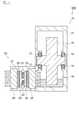
図2は、発明の他の実施形態に係る機電一体型ユニットの断面図である。本例では上述した第1実施形態に対して、緩衝材28を設ける点が異なる。これ以外の構成は上述した第1実施形態と同じであり、その記載を援用する。<< Second Embodiment >>
FIG. 2 is a cross-sectional view of an electromechanical integrated unit according to another embodiment of the invention. In this example, the point which provides the
電力変換器20は、半導体素子21、22等の他に、緩衝材28を有している。緩衝材28は、冷却器26の膨脹を緩衝するための部材であって、板状に形成されている。緩衝材28は、絶縁基板24と冷却器26との間に狭持されている。緩衝材28は、接着剤又はハンダにより絶縁基板24及び冷却器26に固定されている。 The
上記のように本実施形態では、電力変換器20は、冷却器26の熱による膨脹を緩衝する緩衝材28を備えている。これにより、機電一体型ユニットが熱膨張差を縮小できる構造となるため、熱膨張による歪みを抑制できる。 As described above, in the present embodiment, the
なお、本実施形態では、冷却器25と冷却器26の熱膨張率を同じにした上で、緩衝材を電力変換器20に設けてもよい。 In the present embodiment, the shock absorber may be provided in the
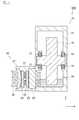
また本実施形態の変形例として、図3に示すように、電力変換器20は、緩衝材28、29を備えてもよい。図3は、変形例に係る機電一体型ユニットの断面図である。緩衝材29は、冷却器25の膨脹を緩衝するための部材であって、板状に形成されている。緩衝材29は、絶縁基板23と冷却器25との間に狭持されている。また、緩衝材28の緩衝量は、緩衝材29の緩衝量より大きい。緩衝材28、29の緩衝量は、例えばヤング率により規定される。これにより、機電一体型ユニットが熱膨張差を縮小できる構造となるため、熱膨張による歪みを抑制できる。 As a modification of the present embodiment, the
《第3実施形態》
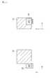
図4は、発明の他の実施形態に係る機電一体型ユニットの断面図である。本例では上述した第1実施形態に対して、冷却器26の形状が異なる。これ以外の構成は上述した第1実施形態と同じであり、その記載を援用する。<< Third Embodiment >>
FIG. 4 is a sectional view of an electromechanical integrated unit according to another embodiment of the invention. In this example, the shape of the cooler 26 is different from that of the first embodiment described above. Other configurations are the same as those in the first embodiment described above, and the description thereof is incorporated.
冷却器26の断面が電力変換回路側に湾曲した形状になるように、冷却器26が形成されている。冷却器26の断面は、半導体素子21、22から冷却器26に伝わる熱の伝熱方向に沿った面である。図4の例では、x軸の方向が伝熱方向となる。また電力変換回路は、半導体素子21、22により形成される回路である。冷却器26の断面は、電力変換回路側に突き出た凸状になっている。 The cooler 26 is formed so that the cross section of the cooler 26 is curved toward the power conversion circuit side. The cross section of the cooler 26 is a surface along the heat transfer direction of heat transferred from the
媒体14の熱伝導率は、冷却器26の冷媒となる空気の熱伝導率よりも高い。そのため、例えば、車両が停車している状態で、半導体素子21、22で発生した熱が、冷却器25に伝わったときには、冷却器25の熱は媒体14で放熱される。一方、半導体素子21、22で発生した熱が、冷却器26に伝わったときには、冷却器26の熱は放熱されにくい。上記のように、本実施形態では、冷却器26の断面が電力変換回路側に湾曲した形状になっているため、冷却器26が熱により膨張した際には、冷却器26は、湾曲の状態から平坦な状態に変形する。これにより、熱膨脹差による歪みを抑制できる。 The thermal conductivity of the medium 14 is higher than the thermal conductivity of air serving as the refrigerant of the cooler 26. Therefore, for example, when the heat generated in the
なお、本実施形態では、xz面に沿った断面において、冷却器26を湾曲の形状にしたが、xy面に沿った断面において、冷却器26が湾曲の形状になるようにしてもよい。 In the present embodiment, the cooler 26 is curved in the cross section along the xz plane, but the cooler 26 may be curved in the cross section along the xy plane.
《第4実施形態》
図5は、発明の他の実施形態に係る機電一体型ユニットの断面図である。機電一体型ユニットの各構成は、上述した第1実施形態と同様であり、その記載を適宜、援用する。<< 4th Embodiment >>
FIG. 5 is a cross-sectional view of an electromechanical integrated unit according to another embodiment of the invention. Each configuration of the electromechanical integrated unit is the same as that of the first embodiment described above, and the description thereof is incorporated as appropriate.
図5において、xは車両の進行方向を示し、yは車両の左右方向であり、zは車両の上下方向(車両の高さ方向)である。またx軸の正の方向が、車両が前方に走行する際の進行方向である。 In FIG. 5, x indicates the traveling direction of the vehicle, y is the lateral direction of the vehicle, and z is the vertical direction of the vehicle (the height direction of the vehicle). Further, the positive direction of the x axis is the traveling direction when the vehicle travels forward.
図5に示すように、電力変換器(INV)20は、車両が前進するときの進行方向(x軸の正方向)に対して、駆動部10よりも後方の位置に配置されている。これにより、例えば落下物等が車両に落ちた場合に、電力変換器20は直撃を回避できる。そのため、安全性の高いユニットを実現できる。 As shown in FIG. 5, the power converter (INV) 20 is disposed at a position behind the
《第5実施形態》
図6は、発明の他の実施形態に係るインホイールモータの断面図である。機電一体型ユニットは、ホイールと一体となっている。機電一体型ユニットの各構成は、上述した第1実施形態と同様であり、その記載を適宜、援用する。<< 5th Embodiment >>
FIG. 6 is a cross-sectional view of an in-wheel motor according to another embodiment of the invention. The electromechanical integrated unit is integrated with the wheel. Each configuration of the electromechanical integrated unit is the same as that of the first embodiment described above, and the description thereof is incorporated as appropriate.
図6において、xは車両の進行方向を示し、yは車両の左右方向であり、zは車両の上下方向(車両の高さ方向)である。またx軸の正の方向が、車両が前方に走行する際の進行方向である。L1は減速機10aに含まれるギア12の回転軸の位置を表しており、L2はモータ10bのロータの回転軸の位置を表している。In FIG. 6, x indicates the traveling direction of the vehicle, y is the left-right direction of the vehicle, and z is the vertical direction of the vehicle (the height direction of the vehicle). Further, the positive direction of the x axis is the traveling direction when the vehicle travels forward. L1 represents the position of the axis of rotation of the
駆動部10は、減速機10a及びモータ10bを備えている。駆動部10及び電力変換器20はホイール30内に設けられている。減速機10aは、第1実施形態で示した駆動部10と同様の構成であって、ギアボックス11、ギア12等を有している。モータ10bは、減速機10aと一体になっている。モータ10bの回転軸は、ギア12に連結することで、モータ10bのロータの回転により発生する駆動力がギア12に伝達される。また減速機10aの出力軸がタイヤの回転軸(タイヤ軸)に相当する。モータ10bの筐体であるモータケースは、ギアボックス11と一体になっている。 The
減速機10aは、車両の高さ方向でロータの回転軸に対して、ギア12の回転軸がオフセットされるように、配置されている。言い替えると、ギア12の回転軸の位置は、車両の高さ方向でロータの回転軸よりも低い位置である。 The
電力変換器(INV)20は、車両が前進するときの進行方向(x軸の正方向)に対して、減速機10aよりも後方の位置に配置されている。また、電力変換器20は、車両の高さ方向(z方向)で、減速機10aよりも低い位置に配置されている。これにより、例えば落下物等が車両に落ちた場合に、電力変換器20は直撃を回避できる。そのため、安全性の高いユニットを実現できる。 The power converter (INV) 20 is disposed at a position behind the
また本実施形態に係る変形例として、図7に示すように、電力変換器20は、減速機10aとモータ10bで形成されるスペース内に配置されてもよい。図7は、変形例に係るインホイールモータの断面図である。x軸、y軸、及びz軸の表示は図6と同様である。図7において、L1は減速機10aに含まれるギア12の回転軸の位置を表しており、L2はモータ10bのロータの回転軸の位置を表している。As a modification according to the present embodiment, as shown in FIG. 7, the
減速機10aは、車両の高さ方向でロータの回転軸に対して、ギア12の回転軸がオフセットされるように、配置されている。減速機10aの回転軸とモータ10bの回転軸をオフセットさせることで、車両の高さ方向でモータ10bの下方に位置し、かつ、車両の左右方向で減速機10aの左側に位置する部分には、空間が形成される。そして、当該空間に電力変換器20が配置されている。さらに、電力変換器20は、車両が前進するときの進行方向(x軸の正方向)に対して、減速機10aよりも後方の位置に配置されている。 The
これにより、例えば落下物等が車両に落ちた場合に、電力変換器20は直撃を回避できるため、安全性の高いユニットを実現することができる。また、機電一体型ユニットの小型化も実現できる。 Thereby, for example, when a fallen object or the like falls on the vehicle, the
また本実施形態に係る変形例として、図8に示すように、電力変換器20は、車両の高さ方向で、減速機10aの下側に配置されてもよい。図8は、変形例に係るインホイールモータの断面図である。x軸、y軸、及びz軸の表示は図6と同様である。図8において、L1は減速機10aに含まれるギア12の回転軸の位置を表しており、L2はモータ10bのロータの回転軸の位置を表している。As a modification according to the present embodiment, as shown in FIG. 8, the
図8に示すように、電力変換器20は、減速機10aの底面に設けられている。これにより、安全性の高い機電一体型ユニットを実現できる。 As shown in FIG. 8, the
《第6実施形態》
図9は、発明の他の実施形態に係るインホイールモータの断面図である。図9において、Lはモータ10bのロータの回転軸の位置を表している。機電一体型ユニットは、ホイールと一体となっている。駆動部10は、モータであって、ロータ、ステータ、ベアリング、モータケース、及び媒体を備えている。ロータは、第1実施形態に係るギア12と同様に、ベアリングにより回転可能な状態で支持されている。そして、ロータの回転により、モータケースの下部に溜まる媒体が掻き上げられて、媒体がベアリングを潤滑する。媒体はオイル等である。<< 6th Embodiment >>
FIG. 9 is a cross-sectional view of an in-wheel motor according to another embodiment of the invention. In FIG. 9, L represents the position of the rotating shaft of the rotor of the
電力変換器20は、車両の高さ方向で、減速機10aの下側に配置されており、具体的には、駆動部10の底面に設けられている。これにより、安全性の高い機電一体型ユニットを実現できる。 The
なお、本実施形態に係る変形例として、図10に示すように、電力変換器20は、車両の高さ方向で、モータ10bの下側に配置されてもよい。図10は、発明の他の実施形態に係るインホイールモータの断面図である。図10において、Lは、減速機10aに含まれるギア12の回転軸の位置、及び、モータ10bのロータの回転軸の位置を表している。モータ10bは、減速機10aと一体になっており、モータ10bの回転軸と減速機10aの回転軸は、車両の高さ方向で、同じ高さになっている。なお、減速機10aの下部には、オイルなどの媒体14aが溜まっており、モータ10bの下部には、オイルなどの媒体14bが溜まっている。 As a modification according to the present embodiment, as shown in FIG. 10, the
10…駆動部
11…ギアボックス
12…ギア
13…ベアリング
14…媒体
20…電力変換器
21、22…半導体素子
23、24…絶縁基板
25、26…冷却器
27…ケース
28、29…緩衝材
30…ホイール
100…機電一体型ユニットDESCRIPTION OF
Claims (7)
Translated fromJapaneseモータ及びギアのうち少なくとも何れか一方の部品、当該部品を収容するケース、及び、前記ケース内に溜まる第1媒体を有する駆動部とを備え、
前記電力変換器及び前記駆動部は、一体のユニットとして形成され、
前記複数の冷却器のうち、一方の冷却器の一部は、前記ケース内に位置しつつ前記第1媒体を接触し、他方の冷却器は第2媒体と接触し、
前記第1媒体の熱伝導率が前記2媒体の熱伝導率より高い
機電一体型ユニット。A power conversion circuit having a plurality of semiconductor elements; and a power converter having a plurality of coolers for cooling the semiconductor elements;
Including at least one of a motor and a gear, a case for housing the component, and a drive unit having a first medium accumulated in the case;
The power converter and the drive unit are formed as an integral unit,
Among the plurality of coolers, a part of one cooler is in contact with the first medium while being located in the case, and the other cooler is in contact with the second medium,
An electromechanical integrated unit in which the thermal conductivity of the first medium is higher than the thermal conductivity of the two media.
前記複数の半導体素子から前記第2媒体までの伝熱経路上に位置する部品の熱膨張率は、前記複数の半導体素子から前記第1媒体までの伝熱経路上に位置する部品の熱膨張率よりも低い
機電一体型ユニット。In the electromechanical integrated unit according to claim 1,
The coefficient of thermal expansion of the component positioned on the heat transfer path from the plurality of semiconductor elements to the second medium is the coefficient of thermal expansion of the component positioned on the heat transfer path from the plurality of semiconductor elements to the first medium. Lower electro-mechanical integrated unit.
前記一方の冷却器はアルミにより形成され、
前記他方の冷却器は、前記一方の冷却器に含まれるアルミよりも熱膨張率の低いアルミ及び銅のうち少なくともいずれか一方の材料により形成されている
機電一体型ユニット。In the electromechanical integrated unit according to claim 1 or 2,
The one cooler is made of aluminum,
The other cooler is an electromechanical integrated unit formed of at least one of aluminum and copper having a lower coefficient of thermal expansion than aluminum contained in the one cooler.
前記電力変換器は、前記他方の冷却器の熱による膨脹を緩衝する緩衝材を有する
機電一体型ユニット。In the electromechanical integrated unit according to any one of claims 1 to 3,
The electric power converter is an electromechanical integrated unit having a cushioning material that cushions expansion of the other cooler due to heat.
前記電力変換器は、前記一方の冷却器の熱による膨脹を緩衝する第1緩衝材、及び、前記他方の冷却器の熱による膨脹を緩衝する第2緩衝材を有し、
前記第2緩衝材の緩衝量は、前記第1緩衝材の緩衝量より大きい
機電一体型ユニット。In the electromechanical integrated unit according to any one of claims 1 to 3,
The power converter includes a first buffer material that buffers expansion due to heat of the one cooler, and a second buffer material that buffers expansion due to heat of the other cooler,
The electromechanical integrated unit in which the buffer amount of the second buffer material is larger than the buffer amount of the first buffer material.
前記他方の冷却部の断面は、前記電力変換回路側に湾曲した形状に形成されている
機電一体型ユニット。In the electromechanical integrated unit according to any one of claims 1 to 5,
The cross section of the other cooling unit is an electromechanical integrated unit formed in a shape curved toward the power conversion circuit.
前記機電一体型ユニットは車両に設けられ、
前記電力変換器は、前記車両が前進するときの進行方向に対して、前記駆動部よりも後方の位置に配置されている
機電一体型ユニット。In the electromechanical integrated unit according to any one of claims 1 to 6,
The electromechanical integrated unit is provided in a vehicle,
The power converter is an electromechanical integrated unit that is disposed at a position behind the drive unit with respect to a traveling direction when the vehicle moves forward.
Priority Applications (1)
| Application Number | Priority Date | Filing Date | Title |
|---|---|---|---|
| JP2015089267AJP6550893B2 (en) | 2015-04-24 | 2015-04-24 | Machine-electric integrated unit |
Applications Claiming Priority (1)
| Application Number | Priority Date | Filing Date | Title |
|---|---|---|---|
| JP2015089267AJP6550893B2 (en) | 2015-04-24 | 2015-04-24 | Machine-electric integrated unit |
Publications (2)
| Publication Number | Publication Date |
|---|---|
| JP2016208720Atrue JP2016208720A (en) | 2016-12-08 |
| JP6550893B2 JP6550893B2 (en) | 2019-07-31 |
Family
ID=57490871
Family Applications (1)
| Application Number | Title | Priority Date | Filing Date |
|---|---|---|---|
| JP2015089267AActiveJP6550893B2 (en) | 2015-04-24 | 2015-04-24 | Machine-electric integrated unit |
Country Status (1)
| Country | Link |
|---|---|
| JP (1) | JP6550893B2 (en) |
Cited By (1)
| Publication number | Priority date | Publication date | Assignee | Title |
|---|---|---|---|---|
| JP2022131547A (en)* | 2021-02-26 | 2022-09-07 | 株式会社Subaru | Vehicle cooling structure |
Citations (4)
| Publication number | Priority date | Publication date | Assignee | Title |
|---|---|---|---|---|
| WO2009060810A1 (en)* | 2007-11-06 | 2009-05-14 | Mitsubishi Heavy Industries, Ltd. | Inverter-integrated electric compressor |
| JP2009200258A (en)* | 2008-02-21 | 2009-09-03 | Toyota Motor Corp | Semiconductor module |
| JP2009247119A (en)* | 2008-03-31 | 2009-10-22 | Aisin Aw Co Ltd | Drive device |
| JP2015104168A (en)* | 2013-11-21 | 2015-06-04 | アスモ株式会社 | Motor pump |
- 2015
- 2015-04-24JPJP2015089267Apatent/JP6550893B2/enactiveActive
Patent Citations (4)
| Publication number | Priority date | Publication date | Assignee | Title |
|---|---|---|---|---|
| WO2009060810A1 (en)* | 2007-11-06 | 2009-05-14 | Mitsubishi Heavy Industries, Ltd. | Inverter-integrated electric compressor |
| JP2009200258A (en)* | 2008-02-21 | 2009-09-03 | Toyota Motor Corp | Semiconductor module |
| JP2009247119A (en)* | 2008-03-31 | 2009-10-22 | Aisin Aw Co Ltd | Drive device |
| JP2015104168A (en)* | 2013-11-21 | 2015-06-04 | アスモ株式会社 | Motor pump |
Cited By (3)
| Publication number | Priority date | Publication date | Assignee | Title |
|---|---|---|---|---|
| JP2022131547A (en)* | 2021-02-26 | 2022-09-07 | 株式会社Subaru | Vehicle cooling structure |
| US12234904B2 (en) | 2021-02-26 | 2025-02-25 | Subaru Corporation | Vehicle cooling structure |
| JP7644624B2 (en) | 2021-02-26 | 2025-03-12 | 株式会社Subaru | Vehicle cooling structure |
Also Published As
| Publication number | Publication date |
|---|---|
| JP6550893B2 (en) | 2019-07-31 |
Similar Documents
| Publication | Publication Date | Title |
|---|---|---|
| CN108390123B (en) | Power battery package thermal management system and car | |
| JP4816350B2 (en) | Capacitor cooling structure and motor having the cooling structure | |
| CN109311376B (en) | Electric axle drive for a vehicle | |
| JP4322910B2 (en) | Railway vehicle power converter | |
| CN103717037B (en) | Cooling system and electronic apparatus using the same | |
| US9059607B2 (en) | Gear-integrated electric motor and electric vehicle | |
| JP4322898B2 (en) | Railway vehicle power converter | |
| JP2011217559A5 (en) | Gear-integrated electric motor | |
| CN114142682A (en) | A central drive device and electric auxiliary bicycle | |
| JP6550893B2 (en) | Machine-electric integrated unit | |
| JP5239349B2 (en) | Powertrain case cooling structure | |
| EP2434542A2 (en) | Heat dissipation device with multiple heat conducting pipes | |
| JP2015075312A (en) | Phase change module and electronic device equipped with the same | |
| JP2014165360A (en) | Servo amplifier including cooling structure part including heat sink | |
| JPWO2017006429A1 (en) | Wheel drive arrangement | |
| JP2008116018A (en) | Power transmission device | |
| JP7538672B2 (en) | Vehicle cooling structure | |
| JP7644624B2 (en) | Vehicle cooling structure | |
| JP2013157573A (en) | Thermal storage cooler | |
| JP2020171196A (en) | Electric power conversion apparatus of railway vehicle | |
| JP3887352B2 (en) | Railway vehicle power converter | |
| JP2012227344A (en) | Power conversion apparatus | |
| JP4491492B2 (en) | Motor drive device for automobile | |
| Singh et al. | Heat pipe applications in cooling automotive electronics | |
| JP2009225549A (en) | Cooling mechanism |
Legal Events
| Date | Code | Title | Description |
|---|---|---|---|
| A621 | Written request for application examination | Free format text:JAPANESE INTERMEDIATE CODE: A621 Effective date:20180126 | |
| A131 | Notification of reasons for refusal | Free format text:JAPANESE INTERMEDIATE CODE: A131 Effective date:20181204 | |
| A977 | Report on retrieval | Free format text:JAPANESE INTERMEDIATE CODE: A971007 Effective date:20181130 | |
| A521 | Request for written amendment filed | Free format text:JAPANESE INTERMEDIATE CODE: A523 Effective date:20190131 | |
| TRDD | Decision of grant or rejection written | ||
| A01 | Written decision to grant a patent or to grant a registration (utility model) | Free format text:JAPANESE INTERMEDIATE CODE: A01 Effective date:20190604 | |
| A61 | First payment of annual fees (during grant procedure) | Free format text:JAPANESE INTERMEDIATE CODE: A61 Effective date:20190617 | |
| R151 | Written notification of patent or utility model registration | Ref document number:6550893 Country of ref document:JP Free format text:JAPANESE INTERMEDIATE CODE: R151 |