JP2016206612A - Image display device and object device - Google Patents
Image display device and object deviceDownload PDFInfo
- Publication number
- JP2016206612A JP2016206612AJP2015091992AJP2015091992AJP2016206612AJP 2016206612 AJP2016206612 AJP 2016206612AJP 2015091992 AJP2015091992 AJP 2015091992AJP 2015091992 AJP2015091992 AJP 2015091992AJP 2016206612 AJP2016206612 AJP 2016206612A
- Authority
- JP
- Japan
- Prior art keywords
- image
- display device
- image display
- virtual image
- forms
- Prior art date
- Legal status (The legal status is an assumption and is not a legal conclusion. Google has not performed a legal analysis and makes no representation as to the accuracy of the status listed.)
- Granted
Links
Images


Classifications
- G—PHYSICS
- G02—OPTICS
- G02B—OPTICAL ELEMENTS, SYSTEMS OR APPARATUS
- G02B27/00—Optical systems or apparatus not provided for by any of the groups G02B1/00 - G02B26/00, G02B30/00
- G02B27/01—Head-up displays
- G02B27/0101—Head-up displays characterised by optical features
- G—PHYSICS
- G02—OPTICS
- G02B—OPTICAL ELEMENTS, SYSTEMS OR APPARATUS
- G02B27/00—Optical systems or apparatus not provided for by any of the groups G02B1/00 - G02B26/00, G02B30/00
- G02B27/01—Head-up displays
- G02B27/0179—Display position adjusting means not related to the information to be displayed
- G—PHYSICS
- G02—OPTICS
- G02B—OPTICAL ELEMENTS, SYSTEMS OR APPARATUS
- G02B27/00—Optical systems or apparatus not provided for by any of the groups G02B1/00 - G02B26/00, G02B30/00
- G02B27/01—Head-up displays
- G02B27/0149—Head-up displays characterised by mechanical features
- G—PHYSICS
- G02—OPTICS
- G02B—OPTICAL ELEMENTS, SYSTEMS OR APPARATUS
- G02B27/00—Optical systems or apparatus not provided for by any of the groups G02B1/00 - G02B26/00, G02B30/00
- G02B27/01—Head-up displays
- G02B27/017—Head mounted
- G02B27/0172—Head mounted characterised by optical features
- G—PHYSICS
- G06—COMPUTING OR CALCULATING; COUNTING
- G06F—ELECTRIC DIGITAL DATA PROCESSING
- G06F3/00—Input arrangements for transferring data to be processed into a form capable of being handled by the computer; Output arrangements for transferring data from processing unit to output unit, e.g. interface arrangements
- G06F3/14—Digital output to display device ; Cooperation and interconnection of the display device with other functional units
- G—PHYSICS
- G06—COMPUTING OR CALCULATING; COUNTING
- G06T—IMAGE DATA PROCESSING OR GENERATION, IN GENERAL
- G06T3/00—Geometric image transformations in the plane of the image
- G06T3/20—Linear translation of whole images or parts thereof, e.g. panning
- G—PHYSICS
- G09—EDUCATION; CRYPTOGRAPHY; DISPLAY; ADVERTISING; SEALS
- G09G—ARRANGEMENTS OR CIRCUITS FOR CONTROL OF INDICATING DEVICES USING STATIC MEANS TO PRESENT VARIABLE INFORMATION
- G09G5/00—Control arrangements or circuits for visual indicators common to cathode-ray tube indicators and other visual indicators
- G—PHYSICS
- G02—OPTICS
- G02B—OPTICAL ELEMENTS, SYSTEMS OR APPARATUS
- G02B27/00—Optical systems or apparatus not provided for by any of the groups G02B1/00 - G02B26/00, G02B30/00
- G02B27/01—Head-up displays
- G02B27/0101—Head-up displays characterised by optical features
- G02B2027/0112—Head-up displays characterised by optical features comprising device for genereting colour display
- G—PHYSICS
- G02—OPTICS
- G02B—OPTICAL ELEMENTS, SYSTEMS OR APPARATUS
- G02B27/00—Optical systems or apparatus not provided for by any of the groups G02B1/00 - G02B26/00, G02B30/00
- G02B27/01—Head-up displays
- G02B27/0101—Head-up displays characterised by optical features
- G02B2027/0145—Head-up displays characterised by optical features creating an intermediate image
- G—PHYSICS
- G02—OPTICS
- G02B—OPTICAL ELEMENTS, SYSTEMS OR APPARATUS
- G02B27/00—Optical systems or apparatus not provided for by any of the groups G02B1/00 - G02B26/00, G02B30/00
- G02B27/01—Head-up displays
- G02B27/0149—Head-up displays characterised by mechanical features
- G02B2027/015—Head-up displays characterised by mechanical features involving arrangement aiming to get less bulky devices
- G—PHYSICS
- G02—OPTICS
- G02B—OPTICAL ELEMENTS, SYSTEMS OR APPARATUS
- G02B27/00—Optical systems or apparatus not provided for by any of the groups G02B1/00 - G02B26/00, G02B30/00
- G02B27/01—Head-up displays
- G02B27/0149—Head-up displays characterised by mechanical features
- G02B2027/0154—Head-up displays characterised by mechanical features with movable elements
- G02B2027/0159—Head-up displays characterised by mechanical features with movable elements with mechanical means other than scaning means for positioning the whole image
- G—PHYSICS
- G02—OPTICS
- G02B—OPTICAL ELEMENTS, SYSTEMS OR APPARATUS
- G02B27/00—Optical systems or apparatus not provided for by any of the groups G02B1/00 - G02B26/00, G02B30/00
- G02B27/01—Head-up displays
- G02B27/0179—Display position adjusting means not related to the information to be displayed
- G02B2027/0181—Adaptation to the pilot/driver
- G—PHYSICS
- G02—OPTICS
- G02B—OPTICAL ELEMENTS, SYSTEMS OR APPARATUS
- G02B27/00—Optical systems or apparatus not provided for by any of the groups G02B1/00 - G02B26/00, G02B30/00
- G02B27/01—Head-up displays
- G02B27/0179—Display position adjusting means not related to the information to be displayed
- G02B2027/0187—Display position adjusting means not related to the information to be displayed slaved to motion of at least a part of the body of the user, e.g. head, eye
Landscapes
- Physics & Mathematics (AREA)
- General Physics & Mathematics (AREA)
- Engineering & Computer Science (AREA)
- Optics & Photonics (AREA)
- Theoretical Computer Science (AREA)
- Human Computer Interaction (AREA)
- General Engineering & Computer Science (AREA)
- Computer Hardware Design (AREA)
- Instrument Panels (AREA)
Abstract
Description
Translated fromJapanese本発明は、画像表示装置及び物体装置に係り、更に詳しくは、物体に搭載される又は人体に装着される画像表示装置及び該画像表示装置を備える物体装置に関する。 The present invention relates to an image display device and an object device, and more particularly to an image display device mounted on an object or attached to a human body and an object device including the image display device.
近年、画像光を透過反射部材(例えば移動体のウインドシールド)に導いて、該透過反射部材を介して虚像を視認させる装置の開発が盛んに行われている。 In recent years, development of apparatuses that guide image light to a transmission / reflection member (for example, a windshield of a moving body) and visually recognize a virtual image through the transmission / reflection member has been actively performed.
例えば、特許文献1、2に開示されているヘッドアップディスプレイ装置は、虚像の表示位置を調整する機能を有している。 For example, the head-up display devices disclosed in
しかしながら、特許文献1、2に開示されているヘッドアップディスプレイ装置では、虚像の表示位置調整機能への影響を抑制しつつ小型化と視認性を両立することは困難であった。 However, in the head-up display devices disclosed in
本発明は、物体に搭載される又は人体に装着される画像表示装置であって、光により画像を形成する画像形成部と、前記画像を形成した光を、湾曲する透過反射部材に向けて反射する曲面鏡を含む光学系と、前記曲面鏡を所定軸周りに回動させるための回動手段と、を備え、前記物体の左右方向をX方向、上下方向をY方向としたとき、前記画像のXY平面への投影像である第1の投影像は、X方向に対して角度θ1を成し、前記所定軸のXY平面への投影像である第2の投影像は、X方向に対して角度θ2を成す画像表示装置である。 The present invention is an image display device mounted on an object or attached to a human body, and an image forming unit that forms an image with light, and the light that forms the image is reflected toward a curved transmissive reflecting member. An optical system including a curved mirror that rotates, and a rotating means for rotating the curved mirror about a predetermined axis. When the horizontal direction of the object is the X direction and the vertical direction is the Y direction, the image The first projection image, which is a projection image on the XY plane, forms an angle θ1 with respect to the X direction, and the second projection image, which is the projection image on the XY plane of the predetermined axis, corresponds to the X direction. Is an image display device having an angle θ2.
本発明によれば、虚像の表示位置調整機能への影響を抑制しつつ小型化と視認性を両立することができる。 ADVANTAGE OF THE INVENTION According to this invention, size reduction and visibility can be made compatible, suppressing the influence on the display position adjustment function of a virtual image.
以下、一実施形態を説明する。 Hereinafter, an embodiment will be described.
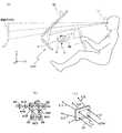
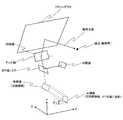
一実施形態の画像表示装置1000は、2次元のカラー画像を表示するヘッドアップディスプレイであり、図1(a)に装置の全体を説明図的に示す。 An
画像表示装置1000は、一例として、車両、航空機、船舶等の移動体に搭載され、該移動体のフロントガラス10(フロントウインドシールド)を介して該移動体の操縦に必要なナビゲーション情報(例えば速度、走行距離等の情報)を視認可能にする。この場合、フロントガラス10は、本来のウインドシールドとしての機能に加えて、入射された光の一部を透過させ、残部の少なくとも一部を反射させる透過反射部材としても機能する。以下では、移動体に設定されたXYZ3次元直交座標系(移動体と共に移動する座標系)を適宜用いて説明する。ここでは、X軸方向は、移動体の左右方向(+X方向が右方向、−X方向が左方向)であり、Y軸方向は、移動体の上下方向(+Y方向が上方向、−Y方向が下方向)であり、Z軸方向は、移動体の前後方向(−Z方向が前方向、+Z方向が後方向)である。以下では、画像表示装置1000が車両(例えば自動車)に搭載される例を説明する。 As an example, the
図1(a)において、符号100で示す部分は「光源部」であり、この光源部100からカラー画像表示用の画素表示用ビームLCが出射される。 In FIG. 1A, a portion denoted by
画素表示用ビームLCは、赤(以下「R」と表示する。)、緑(以下「G」と表示する。)、青(以下「B」と表示する。)の3色のビームを1本に合成したビームである。
即ち、光源部100は、例えば、図1(b)の如き構成となっている。The pixel display beam LC includes one beam of three colors of red (hereinafter referred to as “R”), green (hereinafter referred to as “G”), and blue (hereinafter referred to as “B”). This is a combined beam.
That is, the
図1(b)において、符号RS、GS、BSで示す光源としての半導体レーザは、それぞれR、G、Bのレーザ光を放射する。ここでは、各半導体レーザとして、端面発光レーザとも呼ばれるレーザダイオード(LD)が用いられている。なお、半導体レーザとして、端面発光レーザに代えて、面発光レーザ(VCSEL)を用いても良い。各半導体レーザは、画像情報に基づいて処理装置50(図7参照)によって制御される。 In FIG. 1B, semiconductor lasers as light sources denoted by reference signs RS, GS, and BS emit R, G, and B laser beams, respectively. Here, a laser diode (LD) also called an edge emitting laser is used as each semiconductor laser. Note that a surface emitting laser (VCSEL) may be used as the semiconductor laser instead of the edge emitting laser. Each semiconductor laser is controlled by the processing device 50 (see FIG. 7) based on the image information.
符号RCP、GCP、BCPで示すカップリングレンズは、半導体レーザRS、GS、BSから出射される各レーザ光の発散性を抑制する。 Coupling lenses indicated by reference numerals RCP, GCP, and BCP suppress the divergence of each laser beam emitted from the semiconductor lasers RS, GS, and BS.
カップリングレンズRCP、GCP、BCPにより発散性を抑制された各色レーザ光束は、アパーチュアRAP、GAP、BAPにより整形される(光束径を規制される)。 Each color laser beam whose divergence is suppressed by the coupling lenses RCP, GCP, and BCP is shaped by the aperture RAP, GAP, and BAP (the beam diameter is regulated).
整形された各色レーザ光束はビーム合成プリズム101に入射する。
ビーム合成プリズム101は、R色光を透過させG色光を反射するダイクロイック膜D1と、R・G色光を透過させB色光を反射するダイクロイック膜D2を有する。The shaped laser beam of each color enters the
The
従って、ビーム合成プリズム101からは、R、G、Bの各色レーザ光束が1本の光束に合成されて出射される。 Accordingly, the R, G, and B color laser beams are combined into one beam and emitted from the
出射される光束は、レンズ102により所定の光束径の「平行ビーム」に変換される。
この「平行ビーム」が、画素表示用ビームLCである。The emitted light beam is converted into a “parallel beam” having a predetermined light beam diameter by the
This “parallel beam” is the pixel display beam LC.
画素表示用ビームLCを構成するR、G、Bの各色レーザ光束は、処理装置50によって、表示するべき「2次元のカラー画像」の画像信号により強度変調される。強度変調は、半導体レーザを直接変調する直接変調方式であっても良いし、半導体レーザから出射されたレーザ光束を変調する外部変調方式であっても良い。 The R, G, and B color laser beams constituting the pixel display beam LC are intensity-modulated by the
即ち、半導体レーザRS、GS、BSは、図示されない駆動手段により、R、G、Bの各色成分の画像信号により発光強度を変調される。 That is, the emission intensity of the semiconductor lasers RS, GS, and BS is modulated by image signals of R, G, and B color components by a driving unit (not shown).
光源部100から出射された画素表示用ビームLCは、画像形成素子としての2次元偏向手段6に入射し、2次元的に偏向される。
2次元偏向手段6は、本実施形態では、微小なミラーを「互いに直交する2軸」を揺動軸として揺動するように構成されたものである。The pixel display beam LC emitted from the
In the present embodiment, the two-dimensional deflecting means 6 is configured to swing a minute mirror with “two axes orthogonal to each other” as a swing axis.
即ち、2次元偏向手段6は具体的には、半導体プロセス等で微小揺動ミラー素子として作製されたMEMS(Micro Electro Mechanical Systems)である。 That is, the two-dimensional deflection means 6 is specifically a MEMS (Micro Electro Mechanical Systems) manufactured as a micro oscillating mirror element by a semiconductor process or the like.
2次元偏向手段6の一例としての光偏向器15は、図2に示されるように、半導体プロセスにて製造されるMEMSミラーであり、反射面を有し、第1軸周りに揺動可能に第1枠部材151に支持されたミラー150と、第1枠部材151を第1軸に直交する第2軸周りに揺動可能に支持する支持体とを有する。支持体は、複数の梁が蛇行するように連結された一対の蛇行部152と、各蛇行部を支持する第2枠部材154とを有する。各蛇行部は、一端が第1枠部材151に接続され、他端が第2枠部材154に接続されている。各蛇行部の複数の梁には、複数の圧電部材156(例えばPZT)が個別に設けられている。各蛇行部の隣り合う2つの梁152a、152bに個別に設けられた2つの圧電部材156に異なる電圧を印加することで、隣り合う2つの梁152a、152bが異なる方向に撓み、それが累積されて、ミラー150が第2軸周りに大きな角度で揺動する。このような構成により、第2軸周りの光走査(例えば副走査方向の光走査)が、低電圧で可能となる。一方、第1軸周りには、例えばミラー150に接続されたトーションバー、該トーションバーと第1枠部材151との間に接続された、カンチレバーと圧電部材(例えばPZT)を含む圧電アクチュエータなどを利用した共振による光走査(例えば主走査方向の光走査)が行われる。また、光偏向器15は、ミラー150の第1軸周り、第2軸周りの揺動位置を検出する検出器を有し、該検出器の検出情報が処理装置50に出力される。処理装置50は、この検出情報及び画像情報に基づいて各半導体レーザを駆動制御する。 As shown in FIG. 2, the
2次元偏向手段は、この例に限らず、他の構成のもの、例えば、1軸の回りに揺動する微小ミラーを2個、揺動方向が互いに直交するように組み合わせたもの等でもよい。 The two-dimensional deflecting means is not limited to this example, but may be of another configuration, for example, a combination of two micro mirrors that swing around one axis so that the swing directions are orthogonal to each other.
上記の如く2次元的に偏向された画素表示用ビームLCは、凹面鏡7に入射し、被走査面素子8に向けて反射される。
凹面鏡7は、被走査面素子8上で発生する走査線(走査軌跡)の曲がりを補正するように設計されている。The pixel display beam LC deflected two-dimensionally as described above enters the concave mirror 7 and is reflected toward the scanned
The concave mirror 7 is designed to correct the bending of the scanning line (scanning trajectory) generated on the scanned
すなわち、凹面鏡7の光学作用は、2次元的に偏向された画素表示用ビームLCによってフロントガラス10上に形成される画像の歪みをとることである。
凹面鏡7により反射された画素表示用ビームLCは、2次元偏向手段6による偏向に伴い移動しつつ被走査面素子8に入射し、該被走査面素子8を2次元的に走査する。つまり、被走査面素子8は、光により主走査方向及び副走査方向に2次元走査される。より具体的には、例えば、主走査方向に高速で走査し、かつ副走査方向に低速で走査するラスタースキャンが行われる。That is, the optical action of the concave mirror 7 is to take distortion of the image formed on the
The pixel display beam LC reflected by the concave mirror 7 enters the scanned
この2次元的な走査により、被走査面素子8に中間像としての「カラーの2次元画像(カラー画像)」が形成される。
すなわち、光源部100、2次元偏向手段6、凹面鏡7、被走査面素子8を含んで、光により中間像(画像)を形成する中間像形成装置200(画像形成部)が構成されている。また、2次元偏向手段6及び凹面鏡7を含んで、光源部100からの光により被走査面素子8の表面(被走査面)を主走査方向及び副走査方向に2次元走査する走査光学系が構成されている。By this two-dimensional scanning, a “color two-dimensional image (color image)” as an intermediate image is formed on the scanned
That is, an intermediate image forming apparatus 200 (image forming unit) that includes the
勿論、被走査面素子8に各瞬間に表示されるのは「画素表示用ビームLCが、その瞬間に照射している画素のみ」である。 Of course, what is displayed on the scanned
カラーの2次元画像は、画素表示用ビームLCによる2次元的な走査により「各瞬間に表示される画素の集合」として形成される。
被走査面素子8に、上記の如く「カラーの2次元画像」が形成され、上記画像情報の画素単位の光(各画素に対応する光)である画素光が、曲面鏡としての凹面鏡9に入射して反射される。A color two-dimensional image is formed as a “collection of pixels displayed at each moment” by two-dimensional scanning with a pixel display beam LC.
A “color two-dimensional image” is formed on the scanned
図1には示されていないが、被走査面素子8は後述する「微細凸レンズ構造」を有している。凹面鏡9は「虚像結像光学系」(投射光学系)を構成する。 Although not shown in FIG. 1, the scanned
凹面鏡9は、フロントガラスの影響で被走査面素子8に形成された「カラーの2次元画像」(中間像)の水平線(画像横方向に延びる直線)が上または下に凸形状となる光学歪み要素を補正するように設計、配置されている。 The
「虚像結像光学系」は、前記「カラーの2次元画像」の拡大虚像12を結像させる。
拡大虚像12の結像位置の手前側には、フロントガラス10が配置され、拡大虚像12を結像する光束を、観察者11の側へ反射する。なお、観察者11(例えば移動体を操縦する操縦者)は、フロントガラス10(透過反射部材)で反射されたレーザ光の光路上の所定の観察位置から虚像を視認する。
この反射光により、観察者11は拡大虚像12を視認できる。The “virtual image imaging optical system” forms an enlarged
A
The
図1(a)に示す場合には、Y軸方向は通常、観察者11にとって上下方向であり、この方向を「縦方向」とも呼ぶ。
また、X軸方向は通常、観察者にとって左右方向であり、この方向を「横方向」とも呼ぶ。In the case shown in FIG. 1A, the Y-axis direction is usually the vertical direction for the
Further, the X-axis direction is usually the left-right direction for the observer, and this direction is also referred to as the “lateral direction”.
被走査面素子8は、上述の如く、微細凸レンズ構造を有している。
後述するように、微細凸レンズ構造は「複数の微細凸レンズ(マイクロレンズ)が、画素ピッチに近いピッチで密接して配列された」ものである。すなわち、被走査面素子8は、マイクロレンズアレイである。As described above, the scanned
As will be described later, the micro-convex lens structure is “a plurality of micro-convex lenses (micro lenses) closely arranged at a pitch close to the pixel pitch”. That is, the scanned
ここでは、複数の微細凸レンズは、凸面が入射面となるようにX軸方向に平行な仮想平面に沿って所定ピッチで2次元配列されている。その具体的な配列形態としては、例えばX軸方向を行方向とし、上記仮想平面内でX軸方向に直交する方向を列方向とするマトリクス状(2次元格子状)の配列や、ハニカム配列(ジグザグ配列)が挙げられる。 Here, the plurality of fine convex lenses are two-dimensionally arranged at a predetermined pitch along a virtual plane parallel to the X-axis direction so that the convex surface becomes the incident surface. As a specific arrangement form, for example, a matrix-like (two-dimensional lattice-like) arrangement in which the X-axis direction is a row direction and a direction orthogonal to the X-axis direction in the virtual plane is a column direction, or a honeycomb arrangement ( Zigzag array).
各微細凸レンズの平面形状は、例えば円形、正N角形(Nは3以上の自然数)等である。ここでは、微細凸レンズの各々は、互いに曲率(曲率半径)が等しい。 The planar shape of each micro-convex lens is, for example, a circle or a regular N-gon (N is a natural number of 3 or more). Here, each of the fine convex lenses has the same curvature (curvature radius).
そして、個々の微細凸レンズは、画素表示用ビームLCを等方的に拡散させる機能を持つ。すなわち、各微細凸レンズは、全方位に均等な拡散パワーを持つ。以下に、この「拡散機能」を簡単に説明する。 Each fine convex lens has a function of isotropically diffusing the pixel display beam LC. That is, each fine convex lens has an even diffusion power in all directions. The “diffusion function” will be briefly described below.
図1(c)において、符号L1〜L4は、被走査面素子8に入射する4本の画素表示用ビームを示している。 In FIG. 1C, reference symbols L <b> 1 to L <b> 4 indicate four pixel display beams incident on the scanned
これ等の4本の画素表示用ビームL1〜L4は、被走査面素子8に形成される2次元画像の4隅に入射する画素表示用ビームであるものとする。 These four pixel display beams L <b> 1 to L <b> 4 are pixel display beams incident on the four corners of the two-dimensional image formed on the scanned
これら4本の画素表示用ビームL1〜L4は、被走査面素子8を透過すると、ビームL11〜L14のように変換される。 These four pixel display beams L1 to L4 are converted into beams L11 to L14 after passing through the scanned
仮に、画素表示用ビームL1〜L4で囲まれる断面が横長の4辺形の光束を、被走査面素子8に入射させると、この光束は「ビームL11〜L14で囲まれる断面が横長の4辺形の発散性の光束」となる。
微細凸レンズのこの機能が「拡散機能」である。If a quadrilateral light beam having a horizontally long cross section surrounded by the pixel display beams L1 to L4 is incident on the
This function of the micro-convex lens is a “diffusion function”.
「ビームL11〜L14で囲まれる発散性の光束」は、このように発散性光束に変換された画素表示用ビームを時間的に集合した結果である。 The “divergent light beam surrounded by the beams L11 to L14” is a result of temporally collecting the pixel display beams thus converted into the divergent light beam.
画素表示用ビームを拡散させるのは「フロントガラス10により反射された光束が、観察者11の目の近傍の広い領域を照射する」ようにするためである。 The pixel display beam is diffused so that “the light beam reflected by the
上記拡散機能が無い場合には、フロントガラス10により反射された光束が「観察者11の目の近傍の狭い領域」のみを照射する。 When the diffusion function is not provided, the light beam reflected by the
このため、観察者11が頭部を動かして、目の位置が上記「狭い領域」から逸れると、観察者11は拡大虚像12を視認できなくなる。 For this reason, when the
上記のように、画素表示用ビームLCを拡散させることにより、フロントガラス10による反射光束は「観察者11の目の近傍の広い領域」を照射する。 As described above, the light beam reflected by the
従って、観察者が「頭を少々動かし」ても、拡大虚像12を確実に視認できる。 Therefore, even if the observer “moves his head a little”, the magnified
上に説明したヘッドアップディスプレイは、上述の如く、例えば、自動車等の車載用として用いることができ、X軸方向は「運転席から見て横方向」、Y軸方向は「縦方向」である。 As described above, the head-up display described above can be used for in-vehicle use such as an automobile, and the X-axis direction is “lateral direction when viewed from the driver's seat” and the Y-axis direction is “vertical direction”. .
この場合、自動車等のフロントガラス前方に拡大虚像12として、例えば「ナビゲーション画像」を表示でき、観察者11である運転者は、この画像を運転席に居ながらフロントガラス前方から視線をほとんど動かさずに観察できる。 In this case, for example, a “navigation image” can be displayed as an enlarged
このような場合、上述の如く、表示される拡大虚像は「運転者から見て横長の画像」であること、即ち、マイクロレンズに形成される画像および、拡大虚像は、X軸方向に画角の大きい画像であることが一般に好ましい。 In such a case, as described above, the displayed enlarged virtual image is a “landscape image as viewed from the driver”, that is, the image formed on the microlens and the enlarged virtual image have an angle of view in the X-axis direction. It is generally preferable that the image is large.
また、上述の如く、観測者である運転者が、左右斜め方向から表示画像を見た場合にも、表示を認識できるように、横方向には「縦方向に比して大きな視野角」が要求される。
このため、拡大虚像の長手方向(X軸方向)には短手方向(Y軸方向)に比して大きな拡散角(非等方拡散)が要求される。In addition, as described above, when the driver who is an observer looks at the display image from the left and right oblique directions, the horizontal direction has a “large viewing angle compared to the vertical direction” so that the display can be recognized. Required.
For this reason, a larger diffusion angle (isotropic diffusion) is required in the longitudinal direction (X-axis direction) of the enlarged virtual image than in the lateral direction (Y-axis direction).
従って、被走査面素子の微細凸レンズをマイクロレンズ上に形成された画像もしくは拡大虚像の短手方向よりも長手方向の方が曲率が大きいアナモフィックなレンズとし、画素表示用ビームを拡散させる拡散角を「2次元画像の横方向を縦方向よりも広く」するのが好ましい。 Therefore, the micro convex lens of the surface element to be scanned is an anamorphic lens having a larger curvature in the longitudinal direction than the short direction of the image formed on the micro lens or the magnified virtual image, and has a diffusion angle for diffusing the pixel display beam. It is preferable that “the horizontal direction of the two-dimensional image is wider than the vertical direction”.
このようにして、ヘッドアップディスプレイの要求画角を満たす必要最小限の範囲に光を発散させ、光の利用効率を向上させ、表示画像の輝度を向上させることが可能である。 In this way, it is possible to diverge light within the minimum necessary range that satisfies the required angle of view of the head-up display, improve the light utilization efficiency, and improve the brightness of the display image.
勿論、上記のような「非等方拡散」ではなく、縦方向と横方向で拡散角が等しい「等方拡散」とする場合も可能である。
しかし、自動車等の車載用として用いるヘッドアップディスプレイの場合であれば、運転者が表示画像に対して上下方向の位置から観察を行なう場合はすくない。
従って、このような場合であれば、上記のように、画素表示用ビームを拡散させる拡散角を「2次元画像の横方向を縦方向よりも広く」するのが光利用効率の面から好ましい。Of course, it is also possible to use “isotropic diffusion” in which the diffusion angles are equal in the vertical direction and the horizontal direction, instead of the “isotropic diffusion” as described above.
However, in the case of a head-up display used for in-vehicle use such as an automobile, it is not easy for the driver to observe the display image from a vertical position.
Therefore, in such a case, as described above, it is preferable from the viewpoint of light utilization efficiency that the diffusion angle for diffusing the pixel display beam is “wider the horizontal direction of the two-dimensional image than the vertical direction”.
微細凸レンズ(マイクロレンズ)は、そのレンズ面を「非球面」として形成できることが従来から知られている。 It has been conventionally known that a micro-convex lens (micro lens) can be formed as an “aspherical surface”.
直上に説明したアナモフィックなレンズ面も「非球面」であるが、微細凸レンズのレンズ面をより一般的な非球面として形成でき、収差補正を行なうこともできる。 The anamorphic lens surface described immediately above is also “aspherical”, but the lens surface of the micro-convex lens can be formed as a more general aspherical surface, and aberration correction can also be performed.
収差の補正により「拡散の強度ムラ」を低減することも可能である。 It is also possible to reduce “diffuse intensity unevenness” by correcting aberrations.
上に説明したヘッドアップディスプレイは、上述の自動車への搭載に限らず、列車、船舶、ヘリコプター、飛行機など各種の、操縦可能な移動体に搭載できる。
勿論、ヘッドアップディスプレイを、例えば「映画観賞用の画像表示装置」として実施できることは言うまでも無い。The head-up display described above can be mounted not only on the above-described automobile but also on various types of steerable moving bodies such as trains, ships, helicopters and airplanes.
Of course, it goes without saying that the head-up display can be implemented as, for example, an “image display device for watching movies”.
微細凸レンズ構造の微細凸レンズは、上記の如く画素表示用ビームを拡散させるものであるが、X軸方向、Y軸方向の2方向のうち、1方向のみの拡散を行なう場合も考えられる。
このような場合には、微細凸レンズのレンズ面として「微細凸シリンダ面」を用いることができる。
なお、微細凸レンズの形状を、六角形状とすることや、その配列をハニカム型配列とすることは、従来から、マイクロレンズアレイの製造方法に関連して知られている。The micro-convex lens having the micro-convex lens structure diffuses the pixel display beam as described above, but it may be possible to diffuse only one of the two directions of the X-axis direction and the Y-axis direction.
In such a case, a “fine convex cylinder surface” can be used as the lens surface of the fine convex lens.
It has been conventionally known that the shape of the micro-convex lens is a hexagonal shape and the arrangement thereof is a honeycomb type in relation to the method of manufacturing the microlens array.
ところで、以上説明してきた画像表示装置1000としてのヘッドアップディスプレイ(HUD)は、運転者が少ない視線移動で警報・情報を認知できるアプリケーションとして市場の期待が高まっており、近年、特に、車両(例えば自動車、オートバイ、列車等)に搭載されるHUDの技術開発が進んでいる。 Meanwhile, the head-up display (HUD) as the
HUDには、画像を形成した光をフロントガラスに投射するフロントガラス投射型と、画像を形成した光を透過反射部材としてのコンバイナに投射するコンバイナ投射型に大別されるが、車内インテリアのデザイン性、及びフロントガラスとは別部材であるコンバイナが視界に入ることによる煩わしさの観点から、フロントガラス投射型のHUDがより好適である。 HUD is broadly divided into a windshield projection type that projects light that forms an image onto the windshield, and a combiner projection type that projects light that forms an image onto a combiner as a transmission and reflection member. The windshield projection type HUD is more preferable from the viewpoint of the trouble and the troublesomeness that a combiner that is a separate member from the windshield enters the field of view.
フロントガラス投射型のHUDは、一般に、車両のダッシュボード内に埋め込まれており、ダッシュボード内で生成した中間像(画像)をミラーなどでフロントガラスに向けて拡大反射し、観察者11(運転者11とも呼ぶ)の視点から所定の距離感を持って拡大虚像12を表示するモジュール(画像表示装置)である。なお、観察者11の視点は、単に基準となる視点位置(基準アイポイント)を示している。観察者11の視点範囲は、自動車の運転者アイレンジ(JIS D0021)と同等かそれ以下である。 The windshield projection type HUD is generally embedded in the dashboard of the vehicle, and an intermediate image (image) generated in the dashboard is magnified and reflected toward the windshield by a mirror or the like, and the observer 11 (driving) A module (image display device) that displays the magnified
そして、市場におけるHUDに対する要求は、大きく下記2点に集約される。
・コンパクト性
・視認ストレスの低さAnd the request | requirement with respect to HUD in a market is mainly collected by the following two points.
・ Compactness ・ Low visual stress
「コンパクト性」に関しては、ダッシュボードに収納されているダクト、メータ、デフロスタ、車体構造などになるべく干渉しないサイズが求められている。HUDを搭載するためにダクト、メータ、デフロスタ、車体構造を退避させてしまうと、エアコン性能、デフロスタ性能、車体強度性能の低下を招くためである。 With regard to “compactness”, there is a demand for a size that does not interfere as much as possible, such as ducts, meters, defrosters, and body structures housed in the dashboard. This is because if the duct, meter, defroster, and vehicle body structure are retracted to mount the HUD, the air conditioner performance, the defroster performance, and the vehicle body strength performance are deteriorated.
「視認ストレスの低さ」に関しては、HUDの映像は常に運転者の視界周辺に表示されるため、運転環境や運転者の状態によってストレスのない映像表現が求められている。情報が読みにくい、変形していて違和感をおぼえるなど、運転者にとっての「瞬間的な見易さ」を阻害する映像であると、情報表示装置(画像表示装置)であるHUDが却って運転視界の阻害要因となってしまう。 Regarding "low visual stress", HUD video is always displayed around the driver's field of view, so there is a demand for a stress-free video expression depending on the driving environment and the driver's condition. The information display device (image display device) HUD overwhelms the driver's view of the video if it is an image that obstructs the “instant visibility” for the driver, such as information that is difficult to read or deformed and feels uncomfortable. It becomes an obstruction factor.
HUDの投射方式としては、液晶パネルやDMDパネルのようなイメージングデバイスで中間像を形成する「パネル方式」と、光により被走査面を2次元走査し、中間像を形成する「光走査方式」が知られている。 The HUD projection method includes a “panel method” in which an intermediate image is formed by an imaging device such as a liquid crystal panel or a DMD panel, and an “optical scanning method” in which a scanned surface is two-dimensionally scanned with light to form an intermediate image. It has been known.
特に「光走査方式」は、イメージングデバイスの性能に左右されない中間像形成を光学設計で実施できるため、「コンパクト性」及び「視認ストレスの低さ」を達成する上で有利である。 In particular, the “optical scanning method” is advantageous in achieving “compactness” and “low visual stress” because intermediate image formation independent of the performance of the imaging device can be performed by optical design.
ところで、従来のフロントガラス投射型のHUDにおいては、フロントガラスの、中間像を形成した光が入射される領域が左右非対称に湾曲しているため、虚像に左右非対称な光学歪みが発生する。この光学歪みを、投射光学系(被走査面素子を介した光をフロントガラスに導く光学系)の設計で補正しようとすると、該投射光学系における光学部材の数の増大を招き、「コンパクト性」が阻害されてしまう。 By the way, in the conventional windshield projection type HUD, since the area of the windshield where the light forming the intermediate image is incident is curved asymmetrically, a laterally asymmetric optical distortion occurs in the virtual image. If an attempt is made to correct this optical distortion with the design of a projection optical system (an optical system that guides light through the scanned surface element to the windshield), an increase in the number of optical members in the projection optical system is caused. "Is disturbed.
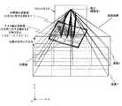
詳述すると、フロントガラス10は、一例として、図3から分かるように、車両の左右方向(X軸方向)の中心位置111yから右のドア側(+X側)にかけて後退するように緩やかに湾曲し、かつ車両の上下方向(Y軸方向)に対して上側(+Y側)ほど後側(+Z側)に傾斜するように湾曲している。 More specifically, as an example, as can be seen from FIG. 3, the
詳述すると、車両の運転席の左右方向の中心位置110yを基準(中心)とすると、フロントガラス10は、左右非対称に(右側ほど後側となるように)、かつ車両の上下方向に対して上側ほど後側に傾斜するように湾曲する非球面形状の透過反射部材である。 More specifically, when the
この状態において、被走査面素子8、凹面鏡9を介した光はフロントガラス10における運転者の正面(−Z側)の入射領域に入射され、該入射領域で反射された光が運転者11の眼球に入射される。この結果、運転者11は、拡大虚像12を視認可能となる(図2参照)が、この入射領域も、車両の上下方向に対して上側ほど後側となるように傾斜し、かつ左右非対称に(右側ほど後側となるように)湾曲している。より詳細には、フロントガラス10は、Y軸方向に対して傾斜するように、かつ+Y側に凸となるように緩やかに湾曲している。なお、入射領域の中心及び拡大虚像12の中心のX軸方向の位置は、中心位置110yに一致する。 In this state, the light that has passed through the scanned
この場合、仮に被走査面素子8に長手方向がX軸方向に平行な画像を形成すると、運転者11が視認する虚像に上記入射領域の左右非対称形状に起因する歪みが発生するおそれがある。 In this case, if an image whose longitudinal direction is parallel to the X-axis direction is formed on the surface-to-
また、この場合、仮に被走査面素子8をXY平面に平行に配置し、該被走査面素子8にXY平面に平行な画像を形成すると、運転者11が視認する虚像に上記入射領域の傾斜形状に起因する歪みが発生するおそれがある。 In this case, if the scanned
これらの歪は、虚像の大きさ、すなわち画像(中間像)の拡大率、特に投射光学系の拡大率が大きいHUDほど顕著に現れる。 These distortions appear more prominently in HUDs where the size of the virtual image, that is, the enlargement ratio of the image (intermediate image), particularly the enlargement ratio of the projection optical system is large.
ここで、投射光学系が単一の凹面鏡9で構成されたフロントガラス投射型のヘッドアップディスプレイを右ハンドル車両に組み込んだ場合の虚像の歪みに関して考察する。ここでは、簡単のために、凹面鏡9の反射面が平面であり、かつフロントガラス10が平板形状である場合を例に考える。 Here, consideration will be given to the distortion of a virtual image when a windshield projection type head-up display whose projection optical system is composed of a single
図4には、被走査面素子8に長手方向が水平面(XZ平面)に平行な画像(中間像)が形成され、被走査面素子8上の各点がフロントガラス10上に投影された状態が示されている。 In FIG. 4, an image (intermediate image) whose longitudinal direction is parallel to the horizontal plane (XZ plane) is formed on the scanned
フロントガラス10は、上述の如く、+Y側に凸となるように湾曲する透過反射部材である。そこで、フロントガラス10のZ軸方向(車両の前後方向)の等深度線10zをプロットすると、右側のドア側(+X側)に緩やかに傾斜する線となる。 As described above, the
この場合、フロントガラス10の入射領域は、図4において符号12wのようになる。なお、投射光学系は、単一の凹面鏡9で構成されているため、凹面鏡9からフロントガラス10への投射により、面内上下の位置関係が反転する(図1(a)参照)。 In this case, the incident area of the
結果として、フロントガラス10の運転席側(右側)の領域の形状が内在している光学的歪み要因として、符号12wのような「ドア側へ傾く」或いは「車両中心線から離れるにつれて下方へ歪む」変形モードがあることがわかる。 As a result, the shape of the area on the driver's seat side (right side) of the
そこで、本実施形態では、このような変形モードに対処するために、図3に示されるように、被走査面素子8に形成される画像(中間像)の長手方向を、XZ平面(車両の上下方向に直交する仮想平面)に対して傾斜させている。
詳述すると、被走査面素子8に形成される画像の長手方向を、Z軸方向(車両の前後方向)から見て、X軸方向(車両の左右方向)に対してドア側(+X側)ほど低くなるように傾斜させている。すなわち、被走査面素子8に形成される画像を、Z軸方向から見て、X軸方向に対して右側(+X側)ほど下側(−Y側)になるように傾斜させている。Therefore, in this embodiment, in order to cope with such a deformation mode, as shown in FIG. 3, the longitudinal direction of the image (intermediate image) formed on the scanned
More specifically, the longitudinal direction of the image formed on the scanned
なお、中間像を傾斜させる際、図5(a)に示されるように、被走査面素子8を傾斜させずに中間像のみを傾斜させても良いし、図5(b)に示されるように、被走査面素子8も中間像の傾斜に合わせて傾斜させても良い。 When the intermediate image is tilted, as shown in FIG. 5A, only the intermediate image may be tilted without tilting the scanned
また、中間像を傾斜させる際、例えば原画像データを傾斜させた画像データに応じて、X軸方向を主走査方向とする2次元走査により中間像を形成しても良いし、原画像データに応じて、X軸方向に対して傾斜する方向を主走査方向とする2次元走査により中間像を形成しても良い。 Further, when the intermediate image is tilted, the intermediate image may be formed by two-dimensional scanning with the X-axis direction as the main scanning direction, for example, according to the image data obtained by tilting the original image data. Accordingly, the intermediate image may be formed by two-dimensional scanning in which the direction inclined with respect to the X-axis direction is the main scanning direction.
なお、主走査方向をX軸方向とする場合は、2次元偏向手段6の主走査方向に対応する揺動軸をY軸に平行とすれば良い。また、主走査方向をX軸方向に対して傾斜する方向とする場合は、2次元偏向手段6の主走査方向に対応する揺動軸をY軸に対して傾斜させれば良い。 In the case where the main scanning direction is the X-axis direction, the swing axis corresponding to the main scanning direction of the two-
以上のように、中間像をX軸方向に対して傾斜させることで、フロントガラス10の等深度線10zの傾きを補正できる。すなわち、運転者11から見たフロントガラス10の入射領域を破線12wから実線12w’のように補正できる(図6参照)。この結果、フロントガラス10の入射領域の左右非対称の湾曲形状に起因する虚像の歪みを低減することができる。 As described above, the inclination of the iso-
但し、ここでは、凹面鏡9の反射面を平面、フロントガラス10を平板状のものと仮定しており、また被走査面素子8と凹面鏡9の配置を考慮していないため、予め付与する中間像の傾斜方向は、ここで説明したものに限定されない。また、一般に、フロントガラスの形状は、車種毎に異なるため、予め付与する中間像の傾斜角度は、車種毎に、虚像の歪みを極力低減できる値に設定することが好ましい。 However, here, since the reflecting surface of the
また、本実施形態では、中間像(被走査面素子8)及び入射光束(凹面鏡9)を、X軸方向から見て、Y軸方向に対して傾斜させている(図1(a)参照)。「入射光束」とは、凹面鏡9の反射面に入射する光束を意味する。 In the present embodiment, the intermediate image (scanned surface element 8) and the incident light beam (concave mirror 9) are inclined with respect to the Y-axis direction when viewed from the X-axis direction (see FIG. 1A). . The “incident light beam” means a light beam incident on the reflecting surface of the
この場合、X軸方向から見たフロントガラス10のY軸方向に対する傾斜に起因する虚像の歪みを低減できる。 In this case, it is possible to reduce the distortion of the virtual image due to the inclination of the
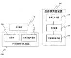
ここで、画像表示装置1000は、運転者の体格等に応じて虚像の高さを調整するための虚像高調整装置300を更に備えている。 Here, the
虚像高調整装置300は、図7に示されるように、凹面鏡9をチルト軸周りに回動させるための凹面鏡回動手段310と、該凹面鏡回動手段310を制御する制御装置320と、該制御装置320に所望の虚像の高さ(虚像高)を入力するための虚像高入力部330とを含む。制御装置320は、CPU,ROM,RAM等によって実現される。 As shown in FIG. 7, the virtual image
凹面鏡回動手段310は、一例として、チルト軸方向に延び、凹面鏡9に固定されたシャフト(回転軸)を有するモータ310a、該シャフトの先端を回転可能に支持する軸受け310bを含んで構成されている(図8(b)参照)。ここでは、モータ310aとして、ステッピングモータが用いられているが他のモータ(例えばサーボモータ)を用いても良い。なお、ここでは、凹面鏡回動手段において、モータのシャフトは、凹面鏡9に直接固定されているが、他の部材(例えばギヤ等の駆動伝達部材)を介して凹面鏡9に接続されても良い。要は、凹面鏡回動手段は、モータのシャフトの回転により、凹面鏡9がチルト軸周りに回動するように構成されれば良い。 As an example, the concave mirror rotating means 310 includes a
虚像高入力部330は、一例として、虚像の高さ(虚像高)を段階的に選択可能となっており、+N(≧1)を入力すると虚像の高さを元の高さからN段階高く設定でき、−N(≧1)を入力すると虚像の高さを元の高さからN段階低く設定できる。 As an example, the virtual image
そこで、運転者により虚像高入力部330を介して所望の虚像高が制御装置320に入力されると、制御装置320は、虚像の高さが入力された高さ(以下では「入力高さ」とも呼ぶ)となるようにモータ310aを駆動して凹面鏡9をチルト軸周りに回動させる。このときの凹面鏡9の回動量(回動角度)は、凹面鏡9のチルト軸周りの元の位置と、入力高さに対応する凹面鏡9のチルト軸周りの位置との差分に相当する。 Therefore, when a desired virtual image height is input to the
なお、ここでは、虚像高調整装置300は、運転者による入力動作に応じて虚像の高さを調整するが、これに代えて、例えば、運転者の目の高さ位置を検出し、その検出結果に基づいて制御装置320が凹面鏡回動手段310を制御するように(自動調整するように)しても良い(詳細は特許文献2参照)。 Here, the virtual image
図8(a)には、凹面鏡9、チルト軸及び中間像の関係が模式的に示されている。図8(b)には、凹面鏡9、モータ310a及び軸受け310bの関係が模式的に示されている。 FIG. 8A schematically shows the relationship among the
中間像から発せられる画像光は特定の発散角をもって凹面鏡9に入射される。発散角は、観察者の視点が位置し得る範囲に対して十分な画像光を届けるべく設定される。 Image light emitted from the intermediate image is incident on the
また、発散角の設定に際し、虚像の高さ調整も考慮する必要がある。そのため凹面鏡9は、中間像よりも格段に大きい必要がある。ここでは、一例として、中間像は横幅57mm、縦幅24mmに対して、凹面鏡9は横幅255mm、縦幅126mmになる。 In setting the divergence angle, it is necessary to consider the height adjustment of the virtual image. Therefore, the
ところで、従来のヘッドアップディスプレイ装置では、虚像の高さ調整のための曲面鏡のチルト軸のXY平面への投影像がX方向に対して成す角度θ2は、略ゼロであった(特許文献1、2参照)。すなわち、曲面鏡のチルト軸は、略水平であった。以下では「ヘッドアップディスプレイ装置」を「ユニット」とも呼ぶ。また、以下では「チルト軸のXY平面への投影像」を適宜「チルト軸の投影像」と略称する。 By the way, in the conventional head-up display device, the angle θ2 formed by the projected image of the tilt axis of the curved mirror for adjusting the height of the virtual image on the XY plane with respect to the X direction is substantially zero (Patent Document 1). 2). That is, the tilt axis of the curved mirror was substantially horizontal. Hereinafter, the “head-up display device” is also referred to as “unit”. Hereinafter, “projection image of tilt axis onto XY plane” is abbreviated as “projection image of tilt axis” as appropriate.
従来は、表示すべき虚像サイズが比較的小さく、中間像サイズや曲面鏡(例えば凹面鏡)が小さくても良かったため、視認性と小型化の両立が比較的容易であり、中間像から曲面鏡までの光路を水平に近い状態としても(短くしても)、また光学系(例えば曲面鏡)の倍率を低く設定し光路長(中間像から曲面鏡までの光路長)を長くとっても、視認性を確保しつつユニットを車両などの移動体に搭載できるサイズにおさめることは十分に可能であった。 Conventionally, the virtual image size to be displayed is relatively small, and the intermediate image size and curved mirror (for example, concave mirror) may be small, so it is relatively easy to achieve both visibility and miniaturization. Even if the optical path of the optical system is almost horizontal (even if it is shortened), and the magnification of the optical system (for example, curved mirror) is set low and the optical path length (optical path length from the intermediate image to the curved mirror) is increased, the visibility is improved. While ensuring, it was possible to fit the unit to a size that can be mounted on a moving body such as a vehicle.
ここで、視認性の向上を図るための大画面化を行う上で、曲面鏡を大型化する必要がある。 Here, it is necessary to increase the size of the curved mirror in order to increase the screen for improving the visibility.
この場合、ユニットの小型化を図るためには、中間像から曲面鏡までの光路長の短縮化、つまり投射光学系の高倍率化が必須となる。
しかしながら、投射光学系を高倍率化すると、該投射光学系による画像歪みが大きくなり易い。In this case, in order to reduce the size of the unit, it is essential to shorten the optical path length from the intermediate image to the curved mirror, that is, to increase the magnification of the projection optical system.
However, when the magnification of the projection optical system is increased, image distortion due to the projection optical system tends to increase.
このため、本実施形態では、上述したように中間像に傾きθ1を付与する(中間像のXY平面への投影像をX方向に対してθ1だけ傾斜させる)ことにより画像歪みの低減を行っている。以下では「中間像のXY平面への投影像」を適宜「中間像の投影像」と略称する。 For this reason, in this embodiment, as described above, the inclination θ1 is given to the intermediate image (the projected image of the intermediate image on the XY plane is inclined by θ1 with respect to the X direction) to reduce image distortion. Yes. Hereinafter, the “projected image of the intermediate image onto the XY plane” is abbreviated as “projected image of the intermediate image” as appropriate.
ここで、図9に、比較例として、中間像の投影像がX方向に対してθ1´だけ傾斜され、かつチルト軸の投影像のX方向に対する傾きθ2´が略0あるいは|θ2´|<|θ1´|であるときの様子が示されている。 Here, in FIG. 9, as a comparative example, the projected image of the intermediate image is tilted by θ1 ′ with respect to the X direction, and the tilt θ2 ′ of the projected image of the tilt axis with respect to the X direction is substantially 0 or | θ2 ′ | < A state when | θ1 ′ | is shown.
図9において、「虚像1」は高さ調整前の虚像の位置を示し、「虚像2」は凹面鏡をチルト軸周りに回転調整し、高さ調整後の虚像の位置を示すものとする。図9から分かるように、虚像2は、虚像1に対して右斜め上方に位置している。すなわち、比較例では、虚像位置が、上下方向(ここでは+Y方向)のみに調整すべきところ、左右方向(ここでは+X方向)にずれてしまっている。この「ずれ」は、θ1´が大きいほど、虚像の高さ調整量が大きいほど、大きくなる。 In FIG. 9, “
図9に示される状態は、虚像1と虚像2の関係を逆にしても成立する。すなわち、図9において、「虚像2」は高さ調整前の虚像の位置を示し、「虚像1」は凹面鏡をチルト軸周りに回転調整し、高さ調整後の虚像の位置を示すものとすることもできる。図9から分かるように、虚像1は、虚像2に対して左斜め下方に位置している。すなわち、比較例では、虚像位置が、上下方向(ここでは−Y方向)のみに調整すべきところ、左右方向(ここでは−X方向)にずれてしまっている。この「ずれ」は、θ1´が大きいほど、虚像の高さ調整量が大きいほど大きくなる。 The state shown in FIG. 9 is established even if the relationship between the
すなわち、比較例では、虚像の高さ調整時に、虚像を高くすると該虚像が右(+X方向)にずれ、虚像を低くすると該虚像が左(−X方向)にずれることになる。なお、虚像の左右方向(X方向)の位置は、運転者が運転中に視線を極力動かさずに視認可能な位置である視点のほぼ真正面に設定されることが好ましい。 That is, in the comparative example, when adjusting the height of the virtual image, if the virtual image is increased, the virtual image is shifted to the right (+ X direction), and if the virtual image is decreased, the virtual image is shifted to the left (−X direction). Note that the position of the virtual image in the left-right direction (X direction) is preferably set almost directly in front of the viewpoint, which is a position where the driver can visually recognize the driver without moving his line of sight as much as possible.
このように、比較例では、中間像の投影像のX方向に対する傾斜に起因して、虚像の高さ調整時にX方向(左右方向)の位置ずれが生じてしまう。 As described above, in the comparative example, due to the inclination of the projected image of the intermediate image with respect to the X direction, a positional shift in the X direction (left and right direction) occurs when the height of the virtual image is adjusted.
この場合、虚像の高さ調整の度に虚像が左右方向にずれるため、虚像の観察者である運転者は、煩わしさや違和感を覚えることが想定される。 In this case, since the virtual image shifts in the left-right direction every time the height of the virtual image is adjusted, it is assumed that the driver who is the observer of the virtual image feels bothered and uncomfortable.
そこで、発明者は、この問題を解決すべく鋭意検討した結果、チルト軸の投影像をX方向に対して中間像の投影像の傾斜方向と同じ向きにある程度傾斜させることで、虚像の高さ調整時の左右方向の位置ずれを抑制できることを見出し、この技術思想を本実施形態に導入した。 Therefore, as a result of intensive studies to solve this problem, the inventor tilts the projection image of the tilt axis to some extent in the same direction as the tilt direction of the projection image of the intermediate image with respect to the X direction, thereby increasing the height of the virtual image. The present inventors have found that the positional deviation in the left-right direction at the time of adjustment can be suppressed, and introduced this technical idea into this embodiment.
具体的には、本実施形態では、図8(a)及び図8(b)から分かるように、チルト軸(モータ310aのシャフト)の投影像を、X方向に対して中間像の投影像の傾斜方向と同じ向きにθ2だけ傾斜させ、かつ|θ2|≧|θ1|としている。すなわち、チルト軸の投影像を、中間像の投影像と同じ右肩下がりに該投影像以上に傾斜させている。 Specifically, in this embodiment, as can be seen from FIG. 8A and FIG. 8B, the projected image of the tilt axis (the shaft of the
この場合、虚像の高さ調整時のX方向の位置ずれ(以下では「横ずれ」とも呼ぶ)を抑制することができる。 In this case, positional deviation in the X direction (hereinafter also referred to as “lateral deviation”) at the time of adjusting the height of the virtual image can be suppressed.
なお、X方向の位置ずれを極力抑制する観点から、θ1が大きいほどθ2を大きくすること、逆に言うと、θ1が小さいほどθ2を小さくすることが好ましい。ただし、θ1とθ2の差が小さすぎると補正不足となり、θ1とθ2の差が大きすぎると補正過剰(過補正)となる。すなわち、θ1に対して適正なθ2の範囲は自ずと決まり、θ1に対して最適なθ2は一義的に決まる。 Note that, from the viewpoint of suppressing the positional deviation in the X direction as much as possible, it is preferable that θ2 is increased as θ1 is increased, and conversely, θ2 is decreased as θ1 is decreased. However, if the difference between θ1 and θ2 is too small, the correction is insufficient, and if the difference between θ1 and θ2 is too large, the correction is excessive (overcorrection). That is, the appropriate range of θ2 with respect to θ1 is naturally determined, and the optimum θ2 with respect to θ1 is uniquely determined.
また、虚像の高さ調整時のX方向の位置ずれを抑制するための別の方法である変形例として、中間像の位置補正を処理装置50で行うこともできる。変形例では、制御装置320は、処理装置50と通信可能に接続されている。制御装置320は、虚像高入力部330からの入力高さを取得すると、該入力高さを処理装置50に送る。 Further, the position correction of the intermediate image can be performed by the
具体的には、図10(a)に示されるように、比較例では中間像の投影像のX方向の傾斜により虚像の高さ調整時(ここでは高くするとき)に虚像1から虚像2に調整されてしまうところ、本実施形態では虚像1から虚像3(虚像1の真上)に調整されるように処理装置50が画像処理による第1の補正方法もしくは2次元偏向手段6の制御による第2の補正方法によって、被走査面素子8上の中間像の位置を補正する。 Specifically, as shown in FIG. 10A, in the comparative example, the
また、図10(b)に示されるように、比較例では中間像の投影像のX方向の傾斜により虚像の高さ調整時(ここでは低くするとき)に虚像1から虚像2に調整されてしまうところ、本実施形態では虚像1から虚像3(虚像1の真下)に調整されるように処理装置50が画像処理による第1の補正方法もしくは2次元偏向手段6の制御による第2の補正方法によって、被走査面素子8上における中間像の位置を補正する。 In addition, as shown in FIG. 10B, in the comparative example, the height of the virtual image is adjusted from the
詳述すると、第1の補正方法では、処理装置50が、制御装置320からの虚像の高さに基づいて、虚像の位置補正方向(左又は右)、位置補正量を求めて、画像データのフレーム内での左右の位置を画像処理によって調整し、調整後の画像データに基づいて光源部100、2次元偏向手段6を制御することで、被走査面素子8上における中間像の位置を補正する。なお、制御装置320からの虚像の入力高さと現在の虚像の高さを比較することで、虚像の高さ調整方向と、高さ調整量を求めることができ、これらから、虚像の位置補正方向、位置補正量を求めることができる。 More specifically, in the first correction method, the
第2の補正方法では、処理装置50が、制御装置320からの虚像の高さに基づいて、虚像の位置補正方向(左又は右)、位置補正量を求め、求めた位置補正方向、位置補正量及び画像データに基づいて光源部100、2次元偏向手段6を制御することで、被走査面素子8上における中間像の位置を補正する。 In the second correction method, the
第1及び第2の補正方法のいずれの場合であっても、処理装置50は、被走査面素子8上における、虚像の高さ調整に伴って虚像がずれる方向とは逆の方向にずれた位置に中間像を形成する。この際、虚像の高さ調整量に応じて中間像の位置補正量を設定することが望ましい。すなわち、虚像の高さ調整時のX方向の位置ずれは、虚像の高さ調整量(元の高さと入力高さの差)が大きいほど大きくなるため、これに追従させることが好ましい。 In either case of the first correction method or the second correction method, the
なお、上記のように虚像の高さ調整時に位置補正量を求める代わりに、虚像の高さ調整量と、調整方向と、位置補正方向と、位置補正量との対応関係を予めテーブル化したものを記憶媒体(例えばメモリ、ハードディスク等)に格納しておき、処理装置50が虚像の高さ調整時にそのテーブルを参照して、虚像の位置補正を行っても良い。 Instead of obtaining the position correction amount when adjusting the height of the virtual image as described above, the correspondence between the height adjustment amount of the virtual image, the adjustment direction, the position correction direction, and the position correction amount is tabulated in advance. May be stored in a storage medium (for example, a memory, a hard disk, etc.), and the
変形例によれば、虚像の高さ調整時のX方向の位置ずれを抑制でき、かつθ2を略0(チルト軸を略水平)にすることができて構成をより単純化でき、小型化が容易になる。また、虚像の高さ調整量に対して中間像の位置補正量を追従させることができ、虚像の高さ調整時の横ずれをより確実に抑制できる。 According to the modification, the positional deviation in the X direction when adjusting the height of the virtual image can be suppressed, and θ2 can be set to approximately 0 (tilt axis is approximately horizontal), thereby simplifying the configuration and reducing the size. It becomes easy. Further, the position correction amount of the intermediate image can be made to follow the height adjustment amount of the virtual image, and the lateral shift at the time of adjusting the height of the virtual image can be more reliably suppressed.
ただし、中間像の位置補正の分だけ中間像表示可能領域を広くする必要があるため、効率が低減して輝度が低下することが懸念される。 However, since it is necessary to widen the intermediate image displayable area by the position correction of the intermediate image, there is a concern that the efficiency is reduced and the luminance is lowered.
図8(a)及び図8(b)に示されるチルト軸傾斜のような機械的方式(本実施形態)をとるか、図10(a)及び図10(b)に示される中間像の位置を補正するソフト的方式(変形例)をとるか、または両者(本実施形態及び変形例)を組み合わせるかを適宜選択することができる。 The mechanical system (this embodiment) such as the tilt axis tilt shown in FIGS. 8A and 8B is used, or the position of the intermediate image shown in FIGS. 10A and 10B. It is possible to appropriately select whether to adopt a software method (modification) for correcting the above or to combine both (this embodiment and modification).
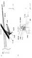
図11(a)は、本実施形態の実施例1の中間像以降の光路を−X側から見た図であり、図11(b)は、実施例1の中間像以降の光路を+Z側から見た図である。 FIG. 11A is a view of the optical path after the intermediate image of Example 1 of the present embodiment as viewed from the −X side, and FIG. 11B is the optical path after the intermediate image of Example 1 on the + Z side. It is the figure seen from.
実施例1では、虚像の水平画角を8°、垂直画角を3°としている。虚像表示距離は視点位置から6mである。虚像は、横幅が838mm、縦幅が314mmである。中間像は、横幅が57mm、縦幅が24mmであるので、虚像と中間像の大きさの比である倍率は、横方向が約14.7倍、縦方向が約13.1倍となる。倍率が横と縦で異なるのは、フロントガラス、凹面鏡を含む光学系が非回転対称な偏心光学系であるためである。 In Example 1, the horizontal field angle of the virtual image is 8 °, and the vertical field angle is 3 °. The virtual image display distance is 6 m from the viewpoint position. The virtual image has a horizontal width of 838 mm and a vertical width of 314 mm. Since the intermediate image has a horizontal width of 57 mm and a vertical width of 24 mm, the magnification, which is the ratio between the size of the virtual image and the intermediate image, is about 14.7 times in the horizontal direction and about 13.1 times in the vertical direction. The reason why the magnification differs horizontally and vertically is that the optical system including the windshield and the concave mirror is a non-rotationally symmetric eccentric optical system.
また、投射光学系を簡略化し小型化を行う上で、この倍率差を積極的に発生させて、凹面鏡の形状設計で歪みや視差といった画質低減を抑制することもできる。倍率が異なる分は中間像の縦横比率を変更するといった補正により、虚像としては所望の画像形状とすることが可能である。 Further, when simplifying and downsizing the projection optical system, it is possible to positively generate this difference in magnification and suppress image quality reduction such as distortion and parallax in the shape design of the concave mirror. By changing the aspect ratio of the intermediate image for the different magnifications, the virtual image can have a desired image shape.
ここで、例えば大画面かつ10倍以上の高倍率な投射光学系としたとき、例えば特許文献2の図2に示されるような中間像から曲面鏡までの光路が同一水平面内に収まるような薄型の光学系を設計することは難しい。虚像の歪みの低減がより大きな問題となり、中間像位置や光路の角度といった自由度を活用して設計することが必要となるからである。そのため、中間像をX方向に対してθ1だけ傾け、かつチルト軸をX方向に対してθ2だけ傾けることが得策である。実施例1では、θ1=7°、θ2=16°である。 Here, for example, when a projection optical system having a large screen and a high magnification of 10 times or more is used, the optical path from the intermediate image to the curved mirror as shown in FIG. It is difficult to design an optical system. This is because reduction of the distortion of the virtual image becomes a larger problem, and it is necessary to design using the degree of freedom such as the intermediate image position and the optical path angle. Therefore, it is advantageous to tilt the intermediate image by θ1 with respect to the X direction and tilt the tilt axis by θ2 with respect to the X direction. In Example 1, θ1 = 7 ° and θ2 = 16 °.
図12(a)は、本実施形態の実施例2の中間像以降の光路を−X側から見た図であり、図12(b)は、実施例2の中間像以降の光路を+Z側から見た図である。実施例2では、虚像の水平画角7°、垂直画角2.5°としている。虚像表示距離は視点位置から2mであり、このとき虚像は、横幅が244mm、縦幅が88mmとなる。中間像は、横幅が40mm、縦幅が16mmである。虚像と中間像の大きさの比である倍率は、横方向が6.1倍、縦方向が5.5倍となる。実施例2では、θ1=21°、θ2=27°である。 12A is a view of the optical path after the intermediate image of Example 2 of the present embodiment as viewed from the −X side, and FIG. 12B shows the optical path after the intermediate image of Example 2 on the + Z side. It is the figure seen from. In Example 2, the horizontal field angle of the virtual image is 7 ° and the vertical field angle is 2.5 °. The virtual image display distance is 2 m from the viewpoint position. At this time, the virtual image has a horizontal width of 244 mm and a vertical width of 88 mm. The intermediate image has a horizontal width of 40 mm and a vertical width of 16 mm. The magnification, which is the ratio between the size of the virtual image and the intermediate image, is 6.1 times in the horizontal direction and 5.5 times in the vertical direction. In Example 2, θ1 = 21 ° and θ2 = 27 °.
実施例1、2のいずれの場合も、虚像の歪み、虚像の高さ調整時の横ずれを充分に抑制できることが分かった。 In both cases of Examples 1 and 2, it was found that the distortion of the virtual image and the lateral shift during the height adjustment of the virtual image can be sufficiently suppressed.
なお、θ1、θ2は、実施例1、2で説明したものに限定されず、虚像の高さ調整時の横ずれ抑制効果が得られる範囲で適宜変更可能である。例えば、θ1、θ2は、5°≦θ1≦30°、10°≦θ2≦40°の範囲で変更可能である。θ1の範囲(5°〜30°)は、移動体のフロントガラスの湾曲形状に起因する歪みを効果的に抑制可能な範囲であり、θ2の範囲(10°〜40°)は、θ1の範囲(5°〜30°)に対して虚像の高さ調整時の横ずれを効果的に抑制可能な範囲である。 In addition, (theta) 1 and (theta) 2 are not limited to what was demonstrated in Example 1, 2, and can be suitably changed in the range with which the lateral shift suppression effect at the time of virtual image height adjustment is acquired. For example, θ1 and θ2 can be changed in the range of 5 ° ≦ θ1 ≦ 30 °, 10 ° ≦ θ2 ≦ 40 °. The range of θ1 (5 ° to 30 °) is a range in which distortion caused by the curved shape of the windshield of the moving body can be effectively suppressed, and the range of θ2 (10 ° to 40 °) is the range of θ1. This is a range in which the lateral shift during the height adjustment of the virtual image can be effectively suppressed with respect to (5 ° to 30 °).
また、図13に示されるように、被走査面素子8と凹面鏡9との間に折り返しミラーを配置することもできる。この場合、「θ1」を、光学系として等価となるように折り返しミラー(平面ミラー)で光路展開し、光路展開後の中間像のXY面への投影像(正射影像)がX方向と成す角度と定義する。このように、中間像の、折り返しミラーを中心に光学的に等価な共役関係となる像をθ1の定義に用いることができる。 Further, as shown in FIG. 13, a folding mirror may be disposed between the scanned
ここで、中間像のXY平面への投影像のX方向に対する傾き補正について、図14を参照して説明する。図14では、中間像形成装置200により被走査面素子8上に形成される中間像と該中間像の虚像が示されている。処理装置50は、被走査面素子8の外形に対して中間像の傾き補正を行うことができる。傾き補正を行う理由は、製造上の誤差で補正なしで表示した際、虚像が傾くことがある。また、観察者(運転者など)の都合で傾きを与えることもある。このとき、中間像をXY平面に投影したときに投影像がX方向に対して成す角θ1とは、虚像における、移動体のX、Y方向に対応する方向と、中間像において対応する方向をX´方向、Y´とするとき、X方向とX´方向の成す角をいう。 Here, the inclination correction with respect to the X direction of the projected image of the intermediate image on the XY plane will be described with reference to FIG. FIG. 14 shows an intermediate image formed on the scanned
上記実施例1、2は、右側座席での視点に対応するHUDを例にしており、右側座席視点の正面のフロントガラス形状を前提に説明している。左側座席での視点に対応するHUDにおいては光学系の座標関係を左右鏡面対称で適用すればよい。 In the first and second embodiments, the HUD corresponding to the viewpoint at the right seat is taken as an example, and the explanation is made on the premise of the front windshield shape at the right seat viewpoint. In the HUD corresponding to the viewpoint at the left seat, the coordinate relationship of the optical system may be applied with left-right mirror symmetry.
以上説明した本実施形態の画像表示装置1000(ヘッドアップディスプレイ)は、第1の観点からすると、移動体に搭載される画像表示装置であって、光により中間像(画像)を形成する中間像形成装置200(画像形成部)と、中間像を形成した光を、フロントガラス10(湾曲する透過反射部材)に向けて反射する凹面鏡9を含む投射光学系と、凹面鏡9をチルト軸(所定軸)周りに回動可能な回動手段310と、を備え、移動体の左右方向をX方向、上下方向をY方向としたとき、中間像のXY平面への投影像である第1の投影像は、X方向に対して角度θ1を成し、チルト軸のXY平面への投影像である第2の投影像は、X方向に対して角度θ2を成す。 The image display apparatus 1000 (head-up display) of the present embodiment described above is an image display apparatus mounted on a moving body from the first viewpoint, and is an intermediate image that forms an intermediate image (image) with light. The forming apparatus 200 (image forming unit), a projection optical system including a
この場合、虚像の高さ調整時における意図しない横方向へのシフト(横ずれ)を抑制しつつ、中間像形成装置200と凹面鏡9との間の距離(光路長)を短縮するとともに虚像の歪みを抑制しつつ投射光学系を高倍率化できる。 In this case, the distance (optical path length) between the intermediate
この結果、虚像の表示位置調整機能への影響を抑制しつつ、小型化と視認性を両立することができる。 As a result, it is possible to achieve both miniaturization and visibility while suppressing the influence on the display position adjustment function of the virtual image.
また、第1及び第2の投影像のX方向に対する傾斜方向は、同一であるため、虚像の表示位置調整機能への影響を確実に抑制できる。 Moreover, since the inclination directions with respect to the X direction of the first and second projection images are the same, the influence on the display position adjustment function of the virtual image can be reliably suppressed.
また、0<|θ1|<|θ2|である場合には、虚像の表示位置調整機能への影響をより確実に抑制できる。 Further, when 0 <| θ1 | <| θ2 |, the influence on the virtual image display position adjustment function can be more reliably suppressed.
また、5°<θ1<30°である場合には、一般的なフロントガラスの湾曲形状に起因する虚像の歪みを十分に抑制することができる。 When 5 ° <θ1 <30 °, the distortion of the virtual image due to the general curved shape of the windshield can be sufficiently suppressed.
また、10°<θ2<40°である場合には、5°<θ1<30°の範囲でθ1に関わらず、虚像の高さ調整時の横ずれを十分に抑制できる。 Further, when 10 ° <θ2 <40 °, the lateral shift during the height adjustment of the virtual image can be sufficiently suppressed regardless of θ1 within the range of 5 ° <θ1 <30 °.
また、画像表示装置1000が、回動手段310による凹面鏡9のチルト軸周りの回動に応じて画像のX方向の位置を調整する処理装置50を更に備える場合には、θ2の値に関わらず、虚像の高さ調整時の横ずれをより確実に抑制できる。 When the
また、画像表示装置1000は、第2の観点からすると、移動体に搭載される画像表示装置であって、光により中間像を形成する中間像形成装置200と、中間像を形成した光を、フロントガラス10に向けて反射する凹面鏡9を含む投射光学系と、凹面鏡9をチルト軸周りに回動可能な回動手段310と、中間像の位置を調整する制御装置320と、を備え、移動体の左右方向をX方向、上下方向をY方向としたとき、中間像のXY平面への投影像は、X方向に対して角度θ1を成し、制御装置320は、回動手段310による凹面鏡9のチルト軸周りの回動に応じて中間像のX方向の位置を調整する。 Further, from a second viewpoint, the
この場合、虚像の高さ調整時における意図しない横方向へのシフト(横ずれ)を抑制しつつ、中間像形成装置と凹面鏡9との間の光路長を短縮するとともに虚像の歪みを抑制しつつ投射光学系を高倍率化できる。 In this case, while suppressing the unintended lateral shift (lateral shift) at the time of adjusting the height of the virtual image, the optical path length between the intermediate image forming device and the
この結果、虚像の表示位置調整機能への影響を抑制しつつ、小型化と視認性を両立することができる。 As a result, it is possible to achieve both miniaturization and visibility while suppressing the influence on the display position adjustment function of the virtual image.
また、第2の観点からの画像表示装置1000では、チルト軸がX方向に対して角度θ2を成す場合には、予め中間像のX方向の位置調整がある程度なされているのと同等であるため、制御装置320による中間像のX方向の位置調整量を少なくすることができる。この場合、10°<θ2<40°であることが好ましい。 Further, in the
また、第2の観点からの画像表示装置1000では、0<|θ2|<|θ1|である場合であっても、虚像の高さ調整時の横ずれを抑制できる。すなわち、θ1、θ2の値によらず、虚像の高さ調整時の横ずれを抑制できる。 Further, in the
なお、画像表示装置1000の虚像高調整装置は、回動手段310による凹面鏡9のチルト軸周りの回動量(虚像の高さ調整量)に応じてθ2(チルト軸のXY平面への投影像のX方向に対する傾き)を調整するためのチルト軸傾き調整手段340を更に備えていても良い(図15参照)。この場合も、虚像の高さ調整時の横ずれをより確実に抑制できる。具体的には、凹面鏡9の回動量(虚像の高さ調整量)が大きいほど虚像の高さ調整時の横ずれが大きくなるため、θ2を大きくすることが好ましい。このチルト軸傾き調整手段340は、例えばチルト軸方向に延びるシャフトを有するモータ310aをZ軸周りに回転させる回転機構と、該回転機構の駆動源(例えばモータ)とを含んで構成することができる。なお、チルト軸傾き調整機構は、これに限らず、要は、チルト軸のXY平面への投影像のX方向に対する傾きを調整可能に構成されれば良い。また、虚像の高さ調整時の横ずれを抑制するために、チルト軸の傾き調整は、中間像の投影像の傾き方向と同じ傾き方向となる範囲で調整することが必要である。 Note that the virtual image height adjusting device of the
具体的には、制御装置320が虚像の入力高さに基づいて、チルト軸の傾き調整量、傾き調整方向(Z軸を中心に時計回り又は反時計回り)を求め、求めた傾き調整量、傾き調整方向に基づいて、チルト軸傾き調整手段340の駆動源を制御することで、チルト軸の傾きを調整する。なお、虚像の入力高さ及び現在の高さ(元の高さ)に基づいて、虚像の高さ調整方向、高さ調整量を求めることができ、これらから、チルト軸の傾き調整量、傾き調整方向を求めることができる。 Specifically, the
なお、虚像の高さ調整量、虚像の高さ調整方向、チルト軸の傾き調整量、傾き調整方向の対応関係を取得し、テーブル化したものを記憶媒体(例えばメモリ、ハードディスク等)に格納しておき、制御装置320が虚像の高さ調整時に、虚像の入力高さを取得したときにそのテーブルを参照して、チルト軸の傾き調整を行っても良い。 The correspondence between the virtual image height adjustment amount, the virtual image height adjustment direction, the tilt axis tilt adjustment amount, and the tilt adjustment direction is acquired and stored in a storage medium (eg, memory, hard disk, etc.). In addition, when the
すなわち、画像表示装置1000は、第3の観点からすると、移動体に搭載される画像表示装置であって、光により中間像を形成する中間像形成装置200と、中間像を形成した光を、フロントガラス10に向けて反射する凹面鏡9を含む投射光学系と、凹面鏡9をチルト軸周りに回動可能な回動手段310と、を備え、移動体の左右方向をX方向、上下方向をY方向としたとき、中間像のXY平面への投影像は、X方向に対して角度θ1を成し、回動手段310による凹面鏡9のチルト軸周りの回動量に応じて、チルト軸のXY平面への投影像がX方向に対して成す角度θ2を調整するための調整手段を更に備える。 That is, from a third viewpoint, the
この場合、虚像の高さ調整時における意図しない横方向へのシフト(横ずれ)を抑制しつつ、中間像形成装置と凹面鏡9との間の光路長を短縮するとともに虚像の歪みを抑制しつつ投射光学系を高倍率化できる。
この結果、虚像の表示位置調整機能への影響を抑制しつつ、小型化と視認性を両立することができる。In this case, while suppressing the unintended lateral shift (lateral shift) at the time of adjusting the height of the virtual image, the optical path length between the intermediate image forming device and the
As a result, it is possible to achieve both miniaturization and visibility while suppressing the influence on the display position adjustment function of the virtual image.
また、第3の観点からの画像表示装置1000では、5°<θ1<30°である場合には、一般的なフロントガラスの湾曲形状に起因する虚像の歪みを抑制することができる。 Further, in the
また、第1〜第3の観点からの画像表示装置1000では、フロントガラス10を介して視認される、中間像の虚像のX方向の長さをX1、Y方向の長さをY1とし、中間像のX方向の長さをX2、Y方向の長さをY2としたとき、X1/X2>Y1/Y2>10である場合、すなわち凹面鏡9とフロントガラス10を含む光学系の倍率が超高倍率の場合であっても、虚像の表示位置調整機能への影響を抑制しつつ、小型化と視認性を両立することができる。 Further, in the
また、第1〜第3の観点からの画像表示装置1000では、投射光学系が、中間像形成装置200と凹面鏡9との間の光路上に配置され、該光路を折り返すミラーを更に含む場合、走査光学系、被走査面素子8、凹面鏡9の配置の自由度を向上できる。また、被走査面素子8から凹面鏡9までの光路長をやや長くすることができるため、凹面鏡9の高倍率化の度合を小さくすることができ、ひいては歪みの発生を低減できる。 In the
また、画像表示装置1000と、該画像表示装置1000が搭載された移動体と、を備える移動体装置によれば、虚像の位置調整機能が正常に機能し、かつ画像表示装置1000の設置スペースを小さくでき、かつ虚像の視認性に優れた移動体装置を提供できる。 In addition, according to a moving body device including the
なお、入射領域の左右非対称な湾曲形状は、移動体毎に異なり、中には、湾曲度合いが非常に小さいものから非常に大きいものまであるが、いずれの場合であっても、画像表示装置1000では、中間像を入射領域の左右非対称な湾曲形状に応じて必要な分だけ傾斜させるだけで(微小傾斜も可)、虚像の歪みを低減できる。すなわち、画像表示装置1000では、投射光学系に汎用の凹面鏡9を用いた簡易な構成により虚像の視認性を向上させることができる。 Note that the left-right asymmetric curved shape of the incident region varies from one moving body to another, and some of them have a very low bending degree to a very large bending degree, but in any case, the
また、中間像は、入射領域が右側ほど後側になるように湾曲している場合、入射領域の左右方向に対して右側ほど下側になるように傾斜しているため、フロントガラス10を介して視認される虚像の歪を確実に低減できる。 Further, when the intermediate image is curved so that the incident area is on the rear side toward the right side, the intermediate image is inclined so that the right side is lower on the left and right directions of the incident area. The distortion of the virtual image that is visually recognized can be reliably reduced.
また、上記実施形態では、投射光学系は、単一の曲面鏡(凹面鏡9)から成り、もしくは凹面鏡9と折り返しミラーから成るが、これに限られない。例えば、凹面鏡9の上段又は下段に例えばミラー、レンズ等の光学部材を設けても良い。要は、投射光学系は、被走査面素子8に形成された中間像を拡大投射できるように構成されていることが好ましく、極力小型に構成されることがより好ましい。また、凹面鏡9の代わりに凸面鏡を用いても良い。 In the above embodiment, the projection optical system is composed of a single curved mirror (concave mirror 9) or the
また、上記実施形態では、被走査面素子8(中間像)がXZ平面に対して傾斜して配置されているが、XZ平面に対して平行に配置されても良い。この場合、被走査面素子8に中間像をY軸方向(移動体の上下方向)から見て、X軸方向(移動体の左右方向)に対して傾斜するように形成することが好ましい。要は、画像表示装置1000では、中間像は、移動体の前後方向及び上下方向の少なくとも一方から見て、移動体の左右方向に対して傾斜していることが好ましい。 Further, in the above embodiment, the scanning surface element 8 (intermediate image) is arranged to be inclined with respect to the XZ plane, but may be arranged in parallel to the XZ plane. In this case, it is preferable that the intermediate image is formed on the scanned
また、上記実施形態では、ヘッドアップディスプレイを右ハンドルの車両に搭載した例を説明したが、左ハンドルの車両についても同様である。詳述すると、一般に、左ハンドル車両では、入射領域が左側ほど後側になるように湾曲しているため、中間像は、移動体の左右方向に対して左側ほど下側又は後側(例えば被走査面素子8がXZ平面に平行に配置されている場合)になるように傾斜していることが好ましい。 In the above embodiment, an example in which the head-up display is mounted on a right-hand drive vehicle has been described, but the same applies to a left-hand drive vehicle. More specifically, in a left-hand drive vehicle, since the incident area is curved so that the left side is the rear side, the intermediate image is lower or rear side (for example, covered) It is preferable to incline so that the
また、上記実施形態では、ヘッドアップディスプレイの画像形成部として、2次元偏向手段を含む走査型が採用されているが、例えば透過型液晶パネルを含む透過液晶型、反射型液晶パネルを含む反射液晶型、DMD(デジタルマイクロミラーデバイス)を含むDLP型などの空間光変調方式のような中間像を形成可能なものであれば、いずれを採用しても良い。 In the above embodiment, a scanning type including a two-dimensional deflection unit is employed as an image forming unit of the head-up display. For example, a transmissive liquid crystal type including a transmissive liquid crystal panel and a reflective liquid crystal including a reflective liquid crystal panel are used. As long as an intermediate image can be formed, such as a spatial light modulation method such as a DLP type including a type and DMD (digital micromirror device), any of them may be adopted.
また、上記実施形態では、被走査面素子として、微細凸レンズ構造(マイクロレンズアレイ)が用いられているが、これに限らず、例えば、表面に微細な凹凸が形成された拡散反射板、表面が平滑な透過スクリーン、表面が平滑な反射スクリーンなどを用いても良い。 In the above embodiment, a fine convex lens structure (microlens array) is used as the surface element to be scanned. However, the invention is not limited to this. For example, a diffuse reflection plate having fine irregularities formed on the surface, and the surface A smooth transmission screen, a reflection screen with a smooth surface, or the like may be used.
また、上記実施形態では、画像形成部は、凹面鏡7を有しているが、有していなくても良い。 In the above-described embodiment, the image forming unit includes the concave mirror 7, but may not include the concave mirror 7.
また、上記実施形態のマイクロレンズアレイでは、複数のマイクロレンズが2次元配列されているが、これに代えて、1次元配列又は3次元配列されていても良い。 In the microlens array of the above embodiment, a plurality of microlenses are two-dimensionally arranged, but instead of this, a one-dimensional array or a three-dimensional array may be arranged.
また、上記実施形態では、マイクロレンズアレイを2次元偏向手段を用いて2次元走査して2次元画像を形成しているが、例えば、MEMSミラー、ガルバノミラー、ポリゴンミラー等を含む1次元偏向手段を用いて1次元走査して1次元画像を形成しても良い。 In the above embodiment, the microlens array is scanned two-dimensionally using a two-dimensional deflection unit to form a two-dimensional image. However, for example, a one-dimensional deflection unit including a MEMS mirror, a galvanometer mirror, a polygon mirror, or the like. May be used to form a one-dimensional image by one-dimensional scanning.
また、上記実施形態では、画像表示装置1000は、カラー画像に対応する構成を有しているが、モノクロ画像に対応する構成を有していても良い。 In the above-described embodiment, the
また、透過反射部材は、例えば、いわゆるコンバイナのように、移動体のウインドシールド(例えばフロントガラス)とは別の部材で構成され、観察者から見て該ウインドシールドの手前に配置されていても良い。 Further, the transmission / reflection member may be formed of a member different from a windshield (for example, a windshield) of a moving object, for example, a so-called combiner, and may be disposed in front of the windshield as viewed from the observer. good.
また、透過反射部材は、移動体のフロントガラスに限らず、例えばサイドガラス、リアガラス等の操縦者が移動体の外部を視認するための他の窓部材(ウインドシールド)であっても良い。また、透過反射部材は、ガラス製のものに限らず、例えば樹脂製であっても良い。 Further, the transmission / reflection member is not limited to the windshield of the moving body, and may be another window member (wind shield) for the operator to visually recognize the outside of the moving body, such as a side glass and a rear glass. Further, the transmission / reflection member is not limited to glass but may be made of resin, for example.
本発明の画像表示装置では、例えば移動体の窓部材、コンバイナ等の透過反射部材として、特に、湾曲するものを用いる場合に、虚像の歪みを効果的に低減できる。 In the image display device of the present invention, for example, when a curved member is used as a transmission / reflection member such as a window member or a combiner of a moving body, distortion of a virtual image can be effectively reduced.
また、画像表示装置によって虚像を視認可能にされる対象者(観察者)は、移動体の操縦者に限らず、例えば該移動体に搭乗するナビゲータ、乗客等の同乗者であっても良い。 Further, the target person (observer) whose virtual image can be visually recognized by the image display device is not limited to the operator of the moving body, and may be, for example, a passenger such as a navigator or a passenger boarding the moving body.
また、本発明の画像表示装置は、例えば人体に装着されるヘッドマウントディスプレイにも応用可能である。 The image display device of the present invention can also be applied to, for example, a head mounted display attached to a human body.
また、上記実施形態では、画像表示装置は、例えば車両、航空機、船舶等の移動体に搭載されるものを一例として説明したが、要は、物体に搭載されるものであれば良い。なお、「物体」は、移動体の他、恒常的に設置されるものや運搬可能なものを含む。 In the above-described embodiment, the image display device is described as an example that is mounted on a moving body such as a vehicle, an aircraft, and a ship. Note that the “object” includes, in addition to a moving object, a permanently installed object and a transportable object.
以下に、発明者が上記実施形態を発案するに至った思考プロセスを説明する。 Below, the thought process which the inventor came up with the said embodiment is demonstrated.
近年、センサとの連携によって表示内容を制御し、背景と連動した画像を提示するような拡張現実(AR)技術によって運転支援の幅を広げるといった提案がなされており、注目を集めている。こういったAR技術には視認性の観点から大画面化が必須であり、HUD(ヘッドアップディスプレイ)の虚像表示領域を拡大することが求められる。 In recent years, proposals have been made to expand the range of driving support by augmented reality (AR) technology in which display contents are controlled by cooperation with a sensor and an image linked with a background is presented. In such AR technology, a large screen is indispensable from the viewpoint of visibility, and it is required to enlarge a virtual image display area of a HUD (head-up display).
また、多様な表現や、あらゆる局面での調節変化等の生理的ストレス低減を目的として、虚像表示距離(観察者の視点から虚像までの距離)を従来に対して長距離化するという要求も高まっている。これらの要求に対応し、さらにユニットを車両内部に搭載可能なサイズに小型化することは、技術的に難易度が向上している。 In addition, the demand for longer virtual image display distance (distance from the observer's viewpoint to the virtual image) is longer than before for the purpose of reducing physiological stresses such as various expressions and adjustment changes in all aspects. ing. It is technically difficult to meet these demands and further downsize the unit to a size that can be mounted inside the vehicle.
また、特開2013−061554号公報には、高輝度化や大画面化を犠牲にすることなく小型化を実現するため、凹面ミラーと凸面ミラーとを含む投射光学系を用いる画像表示装置が開示されている。この画像表示装置を用いることで、中間像の発散角を制御するのが容易となり、光量ロスの少ない高効率な投射光学系を実現でき、その結果、大型の光源を使うことなく高輝度画像が得られる。 Japanese Patent Application Laid-Open No. 2013-061554 discloses an image display apparatus using a projection optical system including a concave mirror and a convex mirror in order to realize downsizing without sacrificing high brightness and large screen. Has been. By using this image display device, it becomes easy to control the divergence angle of the intermediate image, and a high-efficiency projection optical system with little light loss can be realized. As a result, a high brightness image can be obtained without using a large light source. can get.
しかしながら、特開2013−061554号公報に開示されている画像表示装置では、投射光学系が2枚の曲面鏡(凹面ミラーと凸面ミラー)を含むため、投射光学系の大型化が避けられず、装置全体としても小型化できないため、大画面化に問題がある。 However, in the image display device disclosed in JP2013-061554A, the projection optical system includes two curved mirrors (a concave mirror and a convex mirror), so an increase in the size of the projection optical system is inevitable. Since the entire apparatus cannot be reduced in size, there is a problem in increasing the screen size.
また、ヘッドアップディスプレイ装置では、虚像の観察者の体格、好みにあわせて虚像の高さ調整が必要とされている。たとえば、特許文献1、2には、回動可能な反射鏡により、虚像の上下方向位置を変更する構成が開示されている。しかし、反射鏡を2枚用いる構成であり、小型化には問題がある。 Further, in the head-up display device, it is necessary to adjust the height of the virtual image according to the physique and preference of the observer of the virtual image. For example,
以上の問題を解決すべく、発明者は、虚像の高さ調整機能への影響を抑制しつつ、小型化と視認性を両立すべく上記実施形態を発案した。 In order to solve the above problems, the inventor has devised the above-described embodiment in order to achieve both size reduction and visibility while suppressing the influence on the height adjustment function of the virtual image.
6…2次元偏向手段(画像形成部の一部)、7…凹面鏡(画像形成部の一部)、8…被走査面素子(画像形成部の一部)、9…凹面鏡(光学系の一部)、10…フロントガラス(透過反射部材)、50…処理装置、100…光源部(画像形成部の一部)、310…凹面鏡回動手段(回動手段)、340…チルト軸傾き調整手段(調整手段)、1000…画像表示装置。 6 ... Two-dimensional deflection means (part of the image forming unit), 7 ... Concave mirror (part of the image forming unit), 8 ... Scanned surface element (part of the image forming unit), 9 ... Concave mirror (one of the optical system) Part), 10 ... windshield (transmission / reflection member), 50 ... processing device, 100 ... light source part (part of image forming part), 310 ... concave mirror turning means (turning means), 340 ... tilt axis tilt adjusting means (Adjustment means), 1000... Image display device.
Claims (18)
Translated fromJapanese光により画像を形成する画像形成部と、
前記画像を形成した光を、湾曲する透過反射部材に向けて反射する曲面鏡を含む光学系と、
前記曲面鏡を所定軸周りに回動させるための回動手段と、を備え、
前記物体の左右方向をX方向、上下方向をY方向としたとき、
前記画像のXY平面への投影像である第1の投影像は、X方向に対して角度θ1を成し、
前記所定軸のXY平面への投影像である第2の投影像は、X方向に対して角度θ2を成す画像表示装置。An image display device mounted on an object or attached to a human body,
An image forming unit that forms an image with light;
An optical system including a curved mirror that reflects the light that forms the image toward a transmissive reflecting member that is curved;
Rotation means for rotating the curved mirror around a predetermined axis,
When the horizontal direction of the object is the X direction and the vertical direction is the Y direction,
A first projection image, which is a projection image of the image onto the XY plane, forms an angle θ1 with respect to the X direction,
The second projected image, which is a projected image of the predetermined axis onto the XY plane, is an image display device that forms an angle θ2 with respect to the X direction.
光により画像を形成する画像形成部と、
前記画像を形成した光を、湾曲する透過反射部材に向けて反射する曲面鏡を含む光学系と、
前記曲面鏡を所定軸周りに回動可能な回動手段と、を備え、
前記物体の左右方向をX方向、上下方向をY方向としたとき、
前記画像のXY平面への投影像は、X方向に対して角度θ1を成し、
前記回動手段による前記曲面鏡の前記所定軸周りの回動に応じて前記画像のX方向の位置を調整する処理装置を更に備える画像表示装置。An image display device mounted on an object or attached to a human body,
An image forming unit that forms an image with light;
An optical system including a curved mirror that reflects the light that forms the image toward a transmissive reflecting member that is curved;
Rotation means capable of rotating the curved mirror around a predetermined axis,
When the horizontal direction of the object is the X direction and the vertical direction is the Y direction,
The projected image of the image on the XY plane forms an angle θ1 with respect to the X direction,
An image display device further comprising: a processing device that adjusts a position in the X direction of the image according to the rotation of the curved mirror around the predetermined axis by the rotation means.
光により画像を形成する画像形成部と、
前記画像を形成した光を、湾曲する透過反射部材に向けて反射する曲面鏡を含む光学系と、
前記曲面鏡を所定軸周りに回動可能な回動機構と、を備え、
前記物体の左右方向をX方向、上下方向をY方向としたとき、
前記画像のXY平面への投影像は、X方向に対して角度θ1を成し、
前記回動機構による前記曲面鏡の前記所定軸周りの回動量に応じて、前記所定軸のXY平面への投影像がX方向に対して成す角度θ2を調整するための調整手段を更に備える画像表示装置。An image display device mounted on an object or attached to a human body,
An image forming unit that forms an image with light;
An optical system including a curved mirror that reflects the light that forms the image toward a transmissive reflecting member that is curved;
A turning mechanism capable of turning the curved mirror around a predetermined axis,
When the horizontal direction of the object is the X direction and the vertical direction is the Y direction,
The projected image of the image on the XY plane forms an angle θ1 with respect to the X direction,
An image further comprising an adjusting means for adjusting an angle θ2 formed by an image projected onto the XY plane of the predetermined axis with respect to the X direction according to an amount of rotation of the curved mirror about the predetermined axis by the rotating mechanism. Display device.
X1/X2>Y1/Y2>10であることを特徴とする請求項1〜12のいずれか一項に記載の画像表示装置。The length in the X direction of the virtual image of the image that is visually recognized through the transmission / reflection member is X1, the length in the Y direction is Y1, and the length in the X direction is X2, and the length in the Y direction is When Y2
The image display apparatus according to claim 1, wherein X1 / X2> Y1 / Y2> 10.
前記透過反射部材は、前記移動体のウインドシールドであることを特徴とする請求項1〜15のいずれか一項に記載の画像表示装置。The object is a moving body;
The image transmission device according to claim 1, wherein the transmission / reflection member is a windshield of the moving body.
前記画像表示装置が搭載された物体と、を備える物体装置。The image display device according to any one of claims 1 to 16,
And an object on which the image display device is mounted.
光により画像を形成する画像形成部と、
前記画像を形成した光を、湾曲する透過反射部材に向けて反射する曲面鏡を含む光学系と、
前記曲面鏡を所定軸周りに回動させるための回動手段と、を備え、
前記物体の左右方向をX方向、上下方向をY方向としたとき、
前記画像のXY平面への投影像は、X方向に対して角度θ1を成し、
前記回動手段による前記曲面鏡の前記所定軸周りの回動に伴う、前記透過反射部材を介して視認される、前記画像の虚像のX方向の位置ずれを抑制する画像表示装置。
An image display device mounted on an object or attached to a human body,
An image forming unit that forms an image with light;
An optical system including a curved mirror that reflects the light that forms the image toward a transmissive reflecting member that is curved;
Rotation means for rotating the curved mirror around a predetermined axis,
When the horizontal direction of the object is the X direction and the vertical direction is the Y direction,
The projected image of the image on the XY plane forms an angle θ1 with respect to the X direction,
The image display apparatus which suppresses the position shift of the virtual image of the said image visually recognized through the said permeation | transmission reflection member accompanying the rotation of the said curved mirror around the said predetermined axis by the said rotation means.
Priority Applications (3)
| Application Number | Priority Date | Filing Date | Title |
|---|---|---|---|
| JP2015091992AJP6551730B2 (en) | 2015-04-28 | 2015-04-28 | Image display device and moving body |
| EP16167145.8AEP3088935B1 (en) | 2015-04-28 | 2016-04-26 | Image display apparatus and object apparatus |
| US15/141,029US10663721B2 (en) | 2015-04-28 | 2016-04-28 | Image display apparatus and object apparatus |
Applications Claiming Priority (1)
| Application Number | Priority Date | Filing Date | Title |
|---|---|---|---|
| JP2015091992AJP6551730B2 (en) | 2015-04-28 | 2015-04-28 | Image display device and moving body |
Publications (2)
| Publication Number | Publication Date |
|---|---|
| JP2016206612Atrue JP2016206612A (en) | 2016-12-08 |
| JP6551730B2 JP6551730B2 (en) | 2019-07-31 |
Family
ID=55854662
Family Applications (1)
| Application Number | Title | Priority Date | Filing Date |
|---|---|---|---|
| JP2015091992AActiveJP6551730B2 (en) | 2015-04-28 | 2015-04-28 | Image display device and moving body |
Country Status (3)
| Country | Link |
|---|---|
| US (1) | US10663721B2 (en) |
| EP (1) | EP3088935B1 (en) |
| JP (1) | JP6551730B2 (en) |
Cited By (11)
| Publication number | Priority date | Publication date | Assignee | Title |
|---|---|---|---|---|
| US9864195B2 (en) | 2015-03-11 | 2018-01-09 | Ricoh Company, Ltd. | Image display apparatus |
| JP2018136523A (en)* | 2017-02-21 | 2018-08-30 | 株式会社リコー | Display device and equipment |
| JP2018156063A (en)* | 2017-03-15 | 2018-10-04 | 株式会社リコー | Display device and equipment |
| WO2018199244A1 (en)* | 2017-04-28 | 2018-11-01 | コニカミノルタ株式会社 | Display system |
| WO2019181926A1 (en)* | 2018-03-20 | 2019-09-26 | 日本精機株式会社 | Head-up display device |
| JP2019164215A (en)* | 2018-03-19 | 2019-09-26 | 株式会社リコー | Image projection device and movable body |
| WO2019225570A1 (en)* | 2018-05-22 | 2019-11-28 | 日本精機株式会社 | Head-up display device and method for designing head-up display device |
| WO2020066062A1 (en) | 2018-09-28 | 2020-04-02 | 株式会社Jvcケンウッド | Head-up display device |
| JP2020514842A (en)* | 2017-03-07 | 2020-05-21 | 8259402 カナダ インコーポレイテッド8259402 Canada Inc. | Method of controlling virtual image in display |
| JPWO2021132089A1 (en)* | 2019-12-25 | 2021-07-01 | ||
| WO2024190459A1 (en)* | 2023-03-10 | 2024-09-19 | 株式会社小糸製作所 | Image projection device |
Families Citing this family (21)
| Publication number | Priority date | Publication date | Assignee | Title |
|---|---|---|---|---|
| JP6292069B2 (en)* | 2014-07-30 | 2018-03-14 | 株式会社デンソー | Head-up display device |
| MX390241B (en) | 2015-06-11 | 2025-03-20 | Saint Gobain | PROJECTION ARRANGEMENT FOR AN ANALOG CONTACT HEAD-UP DISPLAY (HUD). |
| EA034780B1 (en)* | 2015-06-11 | 2020-03-19 | Сэн-Гобэн Гласс Франс | Projection assembly for an augmented reality head-up display (hud) |
| JP6672746B2 (en) | 2015-11-27 | 2020-03-25 | 株式会社リコー | Image display device and vehicle |
| JP2017097268A (en) | 2015-11-27 | 2017-06-01 | 株式会社リコー | Image display device and vehicle |
| EP3415357A4 (en) | 2016-02-09 | 2018-12-26 | Ricoh Company, Ltd. | Image display apparatus and image display method |
| JP6612989B2 (en) | 2016-03-17 | 2019-11-27 | サン−ゴバン グラス フランス | Composite pane with conductive coating for head-up display |
| JP6680109B2 (en)* | 2016-06-28 | 2020-04-15 | 株式会社デンソー | Video projection device and head-up display device including the same |
| CN108241210A (en)* | 2016-12-23 | 2018-07-03 | 怡利电子工业股份有限公司 | Head-up display device for remote imaging |
| US10203498B2 (en)* | 2017-01-07 | 2019-02-12 | E-Lead Electronic Co., Ltd. | Long distance imaging head-up display device |
| WO2018155138A1 (en)* | 2017-02-21 | 2018-08-30 | Ricoh Company, Ltd. | Display apparatus and equipment |
| EP3376280B1 (en) | 2017-03-15 | 2023-04-05 | Ricoh Company, Ltd. | Display device and apparatus |
| KR102311183B1 (en)* | 2017-06-22 | 2021-10-12 | 현대모비스 주식회사 | Head up display device for vehicle |
| GB2567408B (en)* | 2017-08-02 | 2020-12-02 | Dualitas Ltd | Holographic projector |
| US20200018977A1 (en)* | 2018-07-13 | 2020-01-16 | Conserve & Associates , Inc. | Display device and automobile head-up display system using the same |
| EP3698203B1 (en) | 2018-10-05 | 2024-05-22 | Google LLC | Head mounted display with mechanical scanning |
| JP7200775B2 (en)* | 2019-03-18 | 2023-01-10 | 株式会社リコー | Projection device, display system and moving object |
| JP7519254B2 (en)* | 2020-10-05 | 2024-07-19 | 株式会社小糸製作所 | Image projection device and vehicle information display device |
| JP7604854B2 (en)* | 2020-11-30 | 2024-12-24 | セイコーエプソン株式会社 | VIRTUAL IMAGE DISPLAY AND METHOD FOR ADJUSTING VIRTUAL IMAGE DISPLAY |
| CN113859122A (en)* | 2021-09-30 | 2021-12-31 | 重庆长安新能源汽车科技有限公司 | Height self-adaptive adjustment AR-HUD display method and system and vehicle |
| JP7568683B2 (en)* | 2022-08-25 | 2024-10-16 | 矢崎総業株式会社 | METHOD FOR ADJUSTING DISPLAY DEVICE FOR VEHICLE AND DISPLAY DEVICE FOR VEHICLE |
Citations (13)
| Publication number | Priority date | Publication date | Assignee | Title |
|---|---|---|---|---|
| JP3418985B2 (en)* | 1992-12-14 | 2003-06-23 | 株式会社デンソー | Image display device |
| JP2005331831A (en)* | 2004-05-21 | 2005-12-02 | Yazaki Corp | Head-up display device and mirror unit used therefor |
| US20080018555A1 (en)* | 2006-07-21 | 2008-01-24 | Huei Pei Kuo | See-through display |
| JP2009128884A (en)* | 2007-11-28 | 2009-06-11 | Nippon Seiki Co Ltd | Head-up display |
| US20090278765A1 (en)* | 2008-05-09 | 2009-11-12 | Gm Global Technology Operations, Inc. | Image adjustment and processing for a head up display of a vehicle |
| JP2012507426A (en)* | 2008-11-05 | 2012-03-29 | ジョンソン・コントロールズ・ゲー・エム・ベー・ハー | Vehicle display apparatus or automobile projection display and calibration method |
| JP2012093506A (en)* | 2010-10-26 | 2012-05-17 | Denso Corp | Head-up display device |
| JP2013161054A (en)* | 2012-02-08 | 2013-08-19 | Denso Corp | Vehicle-mounted head-up display system |
| JP2013535700A (en)* | 2010-07-16 | 2013-09-12 | デルファイ・テクノロジーズ・インコーポレーテッド | Adjustable head-up display device |
| JP2014225017A (en)* | 2013-05-15 | 2014-12-04 | ローベルト ボッシュ ゲゼルシャフト ミット ベシュレンクテル ハフツング | Device and method for projecting image information in field of view of driver of vehicle |
| US20150019048A1 (en)* | 2013-07-15 | 2015-01-15 | Honeywell International Inc. | Display systems and methods for providing displays having an adaptive combined vision system |
| JP2015059968A (en)* | 2013-09-17 | 2015-03-30 | 株式会社Jvcケンウッド | Image display device |
| US9921413B2 (en)* | 2015-10-02 | 2018-03-20 | Deepsee Inc. | 3D image system, method, and applications |
Family Cites Families (26)
| Publication number | Priority date | Publication date | Assignee | Title |
|---|---|---|---|---|
| IL145032A0 (en)* | 1999-03-01 | 2002-06-30 | Bae Sys Electronics Ltd | Head tracker system |
| US7973990B2 (en) | 2006-04-27 | 2011-07-05 | Ricoh Company, Ltd. | Optical scanning device, optical writing device, and image forming apparatus |
| US8089498B2 (en) | 2006-04-28 | 2012-01-03 | Ricoh Company, Ltd. | Surface-emission laser array, optical scanning apparatus apparatus and image forming apparatus |
| JP4849618B2 (en) | 2006-11-24 | 2012-01-11 | 株式会社リコー | Optical scanning apparatus and image forming apparatus |
| JP2009196473A (en) | 2008-02-20 | 2009-09-03 | Denso Corp | Vehicular headup display device |
| JP5515723B2 (en) | 2009-02-02 | 2014-06-11 | 株式会社リコー | Optical scanning apparatus, image forming apparatus, and optical communication system |
| JP5251853B2 (en) | 2009-12-08 | 2013-07-31 | 株式会社デンソー | Head-up display device and method for determining stepping motor driving method in head-up display device |
| JP5664013B2 (en) | 2010-08-19 | 2015-02-04 | 株式会社リコー | Optical scanning apparatus and image forming apparatus |
| JP2013061554A (en) | 2011-09-14 | 2013-04-04 | Ricoh Co Ltd | Image forming apparatus, and vehicle with image forming apparatus mounted thereon |
| JP5900733B2 (en) | 2011-11-21 | 2016-04-06 | 株式会社リコー | Optical scanning apparatus and image forming apparatus |
| JP2013160819A (en) | 2012-02-02 | 2013-08-19 | Ricoh Co Ltd | Optical scanner and image forming device |
| JP5354047B2 (en) | 2012-03-22 | 2013-11-27 | 株式会社リコー | Optical scanning device and image forming apparatus using the same |
| JP5962267B2 (en) | 2012-07-06 | 2016-08-03 | 株式会社リコー | Optical scanning apparatus and image forming apparatus |
| KR101416378B1 (en)* | 2012-11-27 | 2014-07-09 | 현대자동차 주식회사 | A display apparatus capable of moving image and the method thereof |
| US9158124B2 (en)* | 2012-12-21 | 2015-10-13 | Ricoh Company, Ltd. | Image display device and vehicle incorporating the same |
| JP6036437B2 (en)* | 2013-03-20 | 2016-11-30 | 日本精機株式会社 | Head-up display device |
| KR20140134184A (en)* | 2013-05-13 | 2014-11-21 | 삼성디스플레이 주식회사 | Head-up display system and method and apparatus for controlling the same |
| JP2015022158A (en) | 2013-07-19 | 2015-02-02 | 株式会社リコー | Optical scanner and image display device |
| JP2015041039A (en) | 2013-08-23 | 2015-03-02 | 株式会社リコー | Optical scanning device, image forming apparatus, and vehicle |
| JP6315240B2 (en) | 2014-02-03 | 2018-04-25 | 株式会社リコー | Image display device, moving body, and lens array |
| JP6555507B2 (en) | 2014-05-12 | 2019-08-07 | 株式会社リコー | Image display device and moving body |
| JP6638198B2 (en) | 2014-05-12 | 2020-01-29 | 株式会社リコー | Image display device and moving object |
| JP6617947B2 (en) | 2014-05-15 | 2019-12-11 | 株式会社リコー | Image display device and image display system |
| JP6403000B2 (en)* | 2014-11-10 | 2018-10-10 | セイコーエプソン株式会社 | Electro-optical device, electronic apparatus, and method of manufacturing electro-optical device |
| TWI578085B (en)* | 2014-12-24 | 2017-04-11 | 財團法人工業技術研究院 | Projector device |
| DE102015205524B4 (en)* | 2015-03-26 | 2020-11-05 | Mando Corporation | Method and device for classifying an object, for example a traffic sign, in an image |
- 2015
- 2015-04-28JPJP2015091992Apatent/JP6551730B2/enactiveActive
- 2016
- 2016-04-26EPEP16167145.8Apatent/EP3088935B1/enactiveActive
- 2016-04-28USUS15/141,029patent/US10663721B2/enactiveActive
Patent Citations (13)
| Publication number | Priority date | Publication date | Assignee | Title |
|---|---|---|---|---|
| JP3418985B2 (en)* | 1992-12-14 | 2003-06-23 | 株式会社デンソー | Image display device |
| JP2005331831A (en)* | 2004-05-21 | 2005-12-02 | Yazaki Corp | Head-up display device and mirror unit used therefor |
| US20080018555A1 (en)* | 2006-07-21 | 2008-01-24 | Huei Pei Kuo | See-through display |
| JP2009128884A (en)* | 2007-11-28 | 2009-06-11 | Nippon Seiki Co Ltd | Head-up display |
| US20090278765A1 (en)* | 2008-05-09 | 2009-11-12 | Gm Global Technology Operations, Inc. | Image adjustment and processing for a head up display of a vehicle |
| JP2012507426A (en)* | 2008-11-05 | 2012-03-29 | ジョンソン・コントロールズ・ゲー・エム・ベー・ハー | Vehicle display apparatus or automobile projection display and calibration method |
| JP2013535700A (en)* | 2010-07-16 | 2013-09-12 | デルファイ・テクノロジーズ・インコーポレーテッド | Adjustable head-up display device |
| JP2012093506A (en)* | 2010-10-26 | 2012-05-17 | Denso Corp | Head-up display device |
| JP2013161054A (en)* | 2012-02-08 | 2013-08-19 | Denso Corp | Vehicle-mounted head-up display system |
| JP2014225017A (en)* | 2013-05-15 | 2014-12-04 | ローベルト ボッシュ ゲゼルシャフト ミット ベシュレンクテル ハフツング | Device and method for projecting image information in field of view of driver of vehicle |
| US20150019048A1 (en)* | 2013-07-15 | 2015-01-15 | Honeywell International Inc. | Display systems and methods for providing displays having an adaptive combined vision system |
| JP2015059968A (en)* | 2013-09-17 | 2015-03-30 | 株式会社Jvcケンウッド | Image display device |
| US9921413B2 (en)* | 2015-10-02 | 2018-03-20 | Deepsee Inc. | 3D image system, method, and applications |
Cited By (23)
| Publication number | Priority date | Publication date | Assignee | Title |
|---|---|---|---|---|
| US10191274B2 (en) | 2015-03-11 | 2019-01-29 | Ricoh Company, Ltd. | Image display apparatus |
| US9864195B2 (en) | 2015-03-11 | 2018-01-09 | Ricoh Company, Ltd. | Image display apparatus |
| US10613321B2 (en) | 2015-03-11 | 2020-04-07 | Ricoh Company, Ltd. | Image display apparatus |
| JP2018136523A (en)* | 2017-02-21 | 2018-08-30 | 株式会社リコー | Display device and equipment |
| JP7027856B2 (en) | 2017-02-21 | 2022-03-02 | 株式会社リコー | Display devices and equipment |
| JP2020514842A (en)* | 2017-03-07 | 2020-05-21 | 8259402 カナダ インコーポレイテッド8259402 Canada Inc. | Method of controlling virtual image in display |
| JP7227165B2 (en) | 2017-03-07 | 2023-02-21 | 8259402 カナダ インコーポレイテッド | How to control the virtual image on the display |
| JP2018156063A (en)* | 2017-03-15 | 2018-10-04 | 株式会社リコー | Display device and equipment |
| WO2018199244A1 (en)* | 2017-04-28 | 2018-11-01 | コニカミノルタ株式会社 | Display system |
| JP2019164215A (en)* | 2018-03-19 | 2019-09-26 | 株式会社リコー | Image projection device and movable body |
| US10598950B2 (en) | 2018-03-19 | 2020-03-24 | Ricoh Company, Ltd. | Image projection apparatus and movable body |
| JP7101341B2 (en) | 2018-03-19 | 2022-07-15 | 株式会社リコー | Image projection device and moving object |
| WO2019181926A1 (en)* | 2018-03-20 | 2019-09-26 | 日本精機株式会社 | Head-up display device |
| JPWO2019181926A1 (en)* | 2018-03-20 | 2021-03-25 | 日本精機株式会社 | Head-up display device |
| JP7205731B2 (en) | 2018-03-20 | 2023-01-17 | 日本精機株式会社 | head-up display device |
| WO2019225570A1 (en)* | 2018-05-22 | 2019-11-28 | 日本精機株式会社 | Head-up display device and method for designing head-up display device |
| JP2020052336A (en)* | 2018-09-28 | 2020-04-02 | 株式会社Jvcケンウッド | Head-up display device |
| JP7035940B2 (en) | 2018-09-28 | 2022-03-15 | 株式会社Jvcケンウッド | Head-up display device |
| WO2020066062A1 (en) | 2018-09-28 | 2020-04-02 | 株式会社Jvcケンウッド | Head-up display device |
| US11556005B2 (en) | 2018-09-28 | 2023-01-17 | Jvckenwood Corporation | Head-up display apparatus |
| JPWO2021132089A1 (en)* | 2019-12-25 | 2021-07-01 | ||
| JP7586096B2 (en) | 2019-12-25 | 2024-11-19 | 日本精機株式会社 | Head-up display device |
| WO2024190459A1 (en)* | 2023-03-10 | 2024-09-19 | 株式会社小糸製作所 | Image projection device |
Also Published As
| Publication number | Publication date |
|---|---|
| EP3088935B1 (en) | 2020-07-29 |
| EP3088935A1 (en) | 2016-11-02 |
| US20160320616A1 (en) | 2016-11-03 |
| JP6551730B2 (en) | 2019-07-31 |
| US10663721B2 (en) | 2020-05-26 |
Similar Documents
| Publication | Publication Date | Title |
|---|---|---|
| JP6551730B2 (en) | Image display device and moving body | |
| JP6555507B2 (en) | Image display device and moving body | |
| JP6638198B2 (en) | Image display device and moving object | |
| EP3012681B1 (en) | Image display device and apparatus | |
| JP6315240B2 (en) | Image display device, moving body, and lens array | |
| JP5179575B2 (en) | Scanning image display device, eyeglass-type head mounted display, and automobile | |
| JP6617947B2 (en) | Image display device and image display system | |
| JP6478151B2 (en) | Image display device and object device | |
| JP6579485B2 (en) | Optical scanning device, image display device, and object device | |
| JP2016206563A (en) | Image display device and object device | |
| WO2010044205A1 (en) | Scanning image display device | |
| EP3067732A1 (en) | Image display apparatus | |
| JP6908898B2 (en) | Image display device | |
| US11567314B2 (en) | Image display apparatus and mobile apparatus | |
| JPWO2019230085A1 (en) | Mobile body with head-up display and head-up display | |
| EP3006988B1 (en) | Image display apparatus | |
| WO2018123528A1 (en) | Display device and moving body carrying display device | |
| US10598830B2 (en) | Screen member, image display apparatus, and object apparatus | |
| JP6555568B2 (en) | Image display device | |
| JP2018136558A (en) | Image display device and movable body | |
| WO2018030203A1 (en) | Display device | |
| JP2020154280A (en) | Display systems, moving objects and optics |
Legal Events
| Date | Code | Title | Description |
|---|---|---|---|
| A621 | Written request for application examination | Free format text:JAPANESE INTERMEDIATE CODE: A621 Effective date:20180403 | |
| A977 | Report on retrieval | Free format text:JAPANESE INTERMEDIATE CODE: A971007 Effective date:20190116 | |
| A131 | Notification of reasons for refusal | Free format text:JAPANESE INTERMEDIATE CODE: A131 Effective date:20190128 | |
| A521 | Request for written amendment filed | Free format text:JAPANESE INTERMEDIATE CODE: A523 Effective date:20190325 | |
| A131 | Notification of reasons for refusal | Free format text:JAPANESE INTERMEDIATE CODE: A131 Effective date:20190415 | |
| A521 | Request for written amendment filed | Free format text:JAPANESE INTERMEDIATE CODE: A523 Effective date:20190531 | |
| TRDD | Decision of grant or rejection written | ||
| A01 | Written decision to grant a patent or to grant a registration (utility model) | Free format text:JAPANESE INTERMEDIATE CODE: A01 Effective date:20190606 | |
| A61 | First payment of annual fees (during grant procedure) | Free format text:JAPANESE INTERMEDIATE CODE: A61 Effective date:20190619 | |
| R151 | Written notification of patent or utility model registration | Ref document number:6551730 Country of ref document:JP Free format text:JAPANESE INTERMEDIATE CODE: R151 |