JP2016203707A - Drive unit - Google Patents
Drive unitDownload PDFInfo
- Publication number
- JP2016203707A JP2016203707AJP2015084836AJP2015084836AJP2016203707AJP 2016203707 AJP2016203707 AJP 2016203707AJP 2015084836 AJP2015084836 AJP 2015084836AJP 2015084836 AJP2015084836 AJP 2015084836AJP 2016203707 AJP2016203707 AJP 2016203707A
- Authority
- JP
- Japan
- Prior art keywords
- frame end
- flange
- case
- shaft
- flange portion
- Prior art date
- Legal status (The legal status is an assumption and is not a legal conclusion. Google has not performed a legal analysis and makes no representation as to the accuracy of the status listed.)
- Pending
Links
- 230000033001locomotionEffects0.000description6
- 230000000694effectsEffects0.000description4
- 230000005540biological transmissionEffects0.000description1
- 238000006073displacement reactionMethods0.000description1
- 230000002093peripheral effectEffects0.000description1
- 239000004065semiconductorSubstances0.000description1
- 238000005549size reductionMethods0.000description1
Images


Classifications
- B—PERFORMING OPERATIONS; TRANSPORTING
- B62—LAND VEHICLES FOR TRAVELLING OTHERWISE THAN ON RAILS
- B62D—MOTOR VEHICLES; TRAILERS
- B62D5/00—Power-assisted or power-driven steering
- B62D5/04—Power-assisted or power-driven steering electrical, e.g. using an electric servo-motor connected to, or forming part of, the steering gear
- B62D5/0403—Power-assisted or power-driven steering electrical, e.g. using an electric servo-motor connected to, or forming part of, the steering gear characterised by constructional features, e.g. common housing for motor and gear box
- B62D5/0406—Power-assisted or power-driven steering electrical, e.g. using an electric servo-motor connected to, or forming part of, the steering gear characterised by constructional features, e.g. common housing for motor and gear box including housing for electronic control unit
- H—ELECTRICITY
- H02—GENERATION; CONVERSION OR DISTRIBUTION OF ELECTRIC POWER
- H02K—DYNAMO-ELECTRIC MACHINES
- H02K5/00—Casings; Enclosures; Supports
- H02K5/04—Casings or enclosures characterised by the shape, form or construction thereof
- H—ELECTRICITY
- H02—GENERATION; CONVERSION OR DISTRIBUTION OF ELECTRIC POWER
- H02K—DYNAMO-ELECTRIC MACHINES
- H02K5/00—Casings; Enclosures; Supports
- H02K5/04—Casings or enclosures characterised by the shape, form or construction thereof
- H02K5/15—Mounting arrangements for bearing-shields or end plates
Landscapes
- Engineering & Computer Science (AREA)
- Power Engineering (AREA)
- Chemical & Material Sciences (AREA)
- Combustion & Propulsion (AREA)
- Transportation (AREA)
- Mechanical Engineering (AREA)
- Power Steering Mechanism (AREA)
- Motor Or Generator Frames (AREA)
Abstract
Description
Translated fromJapanese本発明は、電動パワーステアリング装置に用いられる駆動装置に関する。 The present invention relates to a drive device used in an electric power steering device.
従来、電動パワーステアリング装置に用いられる駆動装置が知られている。特許文献1には、操舵アシストトルクを発生するモータ部と、モータ部への通電を制御する制御部とが一体に設けられた機電一体型の駆動装置が開示されている。この駆動装置は、制御部の半導体モジュールを軸方向へ沿うように配置することによって、径方向体格を小さくしている。 Conventionally, a driving device used for an electric power steering device is known. Patent Document 1 discloses an electro-mechanical integrated drive device in which a motor unit that generates steering assist torque and a control unit that controls energization of the motor unit are integrally provided. In this drive device, the radial physique is reduced by arranging the semiconductor modules of the control unit along the axial direction.
特許文献1に開示された駆動装置において、モータ部は、筒状のケースに収容されている。ケースの一端には、当該ケースと同一部材からなる第1フレームエンドが設けられている。ケースの他端には第2フレームエンドが設けられている。第2フレームエンドおよびケースは、径方向外側に突き出す3つのフランジ部を有している。第2フレームエンドのフランジ部は、ボルトによってケースのフランジ部に締結されている。 In the drive device disclosed in Patent Document 1, the motor unit is housed in a cylindrical case. One end of the case is provided with a first frame end made of the same member as the case. A second frame end is provided at the other end of the case. The second frame end and the case have three flange portions protruding outward in the radial direction. The flange portion of the second frame end is fastened to the flange portion of the case by a bolt.
ところで、駆動装置は、アシストトルクを伝達する部位の違いによってコラムアシスト型、ピニオンアシスト型、ラックアシスト型などの形式に大別される。コラムアシスト型の駆動装置はコラム軸近傍に設置される。ピニオンアシスト型の駆動装置はラックアンドピニオン機構近傍に設置される。ラックアシスト型の駆動装置はラック軸近傍に設置される。いずれの型式にせよ、駆動装置以外にも種々の装置が車両に取り付けられる昨今においては、各種装置の取り付けに必要なスペースを確保することが重要な課題である。 By the way, the driving device is roughly classified into a column assist type, a pinion assist type, a rack assist type, and the like, depending on a difference in a part that transmits the assist torque. The column assist type driving device is installed in the vicinity of the column shaft. The pinion assist type driving device is installed in the vicinity of the rack and pinion mechanism. The rack assist type driving device is installed in the vicinity of the rack shaft. Regardless of the type, in recent years when various devices other than the drive device are mounted on the vehicle, it is an important issue to secure a space necessary for mounting various devices.
特許文献1に開示された駆動装置は、制御部がケースの外径内に収まるように構成されている。これにより、制御部の径方向体格の小型化が実現している。その結果、フレームエンドおよびケースが径方向において最も外側に位置することになった。したがって、発明者は、駆動装置の搭載性を高めるには、フランジ部の位置を最適化する必要があると考えている。
本発明は、上述の点に鑑みてなされたものであり、その目的は、搭載性に優れた駆動装置を提供することである。The drive device disclosed in Patent Document 1 is configured such that the control unit is accommodated within the outer diameter of the case. Thereby, size reduction of the radial physique of a control part is realized. As a result, the frame end and the case are positioned on the outermost side in the radial direction. Therefore, the inventor believes that the position of the flange portion needs to be optimized in order to improve the mountability of the drive device.
The present invention has been made in view of the above points, and an object of the present invention is to provide a drive device excellent in mountability.
本発明には第1発明と第2発明とがある。
第1発明および第2発明による駆動装置は、モータ部、制御部、第1フレームエンドおよび第2フレームエンドを備える。モータ部は、ステータ、当該ステータの内側に回転可能に設けられているロータ、および、ロータと一体に回転するシャフトを有する。制御部は、モータ部の軸方向の一方に設けられ、モータ部への通電を制御する。第1フレームエンドは、モータ部と制御部との間に設けられ、制御部を保持し、シャフトを支持している。第2フレームエンドは、モータ部に対し制御部とは反対側に設けられ、シャフトを支持している。The present invention includes a first invention and a second invention.
The drive apparatus according to the first and second inventions includes a motor unit, a control unit, a first frame end, and a second frame end. The motor unit includes a stator, a rotor that is rotatably provided inside the stator, and a shaft that rotates integrally with the rotor. A control part is provided in one side of the axial direction of a motor part, and controls energization to a motor part. The first frame end is provided between the motor unit and the control unit, holds the control unit, and supports the shaft. The second frame end is provided on the side opposite to the control unit with respect to the motor unit, and supports the shaft.
第1発明による駆動装置は、モータ部を収容している筒状のケースと、第1フレームエンドまたは第2フレームエンドとケースとを締結している締結部材と、をさらに備える。第1フレームエンドおよび第2フレームエンドのうち、ケースに締結されている方は、径方向外側へ突き出す第1フランジ部を有する。ケースは、第1フランジ部に対応して設けられ且つ締結部材により第1フランジ部と締結されている複数の第2フランジ部を有する。第1フランジ部および第2フランジ部は、シャフトの横断面においてケースに外接する仮想的な正方形よりも内側に位置する。 The drive device according to the first aspect of the present invention further includes a cylindrical case that houses the motor unit, and a fastening member that fastens the first frame end or the second frame end and the case. Of the first frame end and the second frame end, the one fastened to the case has a first flange portion protruding outward in the radial direction. The case has a plurality of second flange portions provided corresponding to the first flange portions and fastened to the first flange portions by fastening members. The first flange portion and the second flange portion are located inside a virtual square that circumscribes the case in the cross section of the shaft.
第2発明による駆動装置は、第1フレームエンドと第2フレームエンドとを締結している締結部材をさらに備える。第1フレームエンドは、径方向外側へ突き出す複数の第1フランジ部を有する。第2フレームエンドは、第1フランジ部に対応して設けられ且つ締結部材により第1フランジ部と締結されている複数の第2フランジ部を有する。第1フランジ部および第2フランジ部は、シャフトの横断面においてステータに外接する仮想的な正方形よりも内側に位置する。 The drive device according to the second aspect of the present invention further includes a fastening member that fastens the first frame end and the second frame end. The first frame end has a plurality of first flange portions protruding outward in the radial direction. The second frame end has a plurality of second flange portions that are provided corresponding to the first flange portions and are fastened to the first flange portions by fastening members. The first flange portion and the second flange portion are located inside a virtual square circumscribing the stator in the cross section of the shaft.
このように構成された駆動装置は、第1および第2フランジ部が上記仮想的な正方形の外側に位置するものと比べると、搭載性を高めることができる。
例えば、ラック軸と地面との間に設けられるラックアシスト型の場合、本発明によれば、上記仮想的な正方形の1つの辺と地面とが略平行となるように搭載することによって、ラック軸と地面との間の搭載スペースをケースまたはステータの外径近くまで小さくすることができる。The drive device configured as described above can improve mountability as compared with the drive device in which the first and second flange portions are located outside the virtual square.
For example, in the case of the rack assist type provided between the rack shaft and the ground, according to the present invention, the rack shaft can be mounted by mounting one side of the virtual square so that the ground is substantially parallel. The mounting space between the ground and the ground can be reduced to near the outer diameter of the case or the stator.
これに対して、特許文献1に開示されているように第1および第2フランジ部が上記仮想的な正方形の外側に位置する駆動装置によると、1つ目のフランジ部と2つ目のフランジ部との間に地面が位置するように搭載しても、3つ目のフランジ部がラック軸と干渉する位置関係となる。そのため、ラック軸と地面との間の搭載スペースを大きくせざるを得ない。 On the other hand, according to the drive device in which the first and second flange portions are located outside the virtual square as disclosed in Patent Document 1, the first flange portion and the second flange portion are provided. Even if it is mounted so that the ground is positioned between the two parts, the third flange part is in a positional relationship that interferes with the rack shaft. Therefore, the mounting space between the rack shaft and the ground has to be increased.
コラムアシスト型およびピニオンアシスト型においても同様のことが言える。すなわち、上記ラックアシスト型の説明における「地面」が、コラムアシスト型およびピニオンアシスト型の場合では「周辺装置」などに置き換わるだけである。
したがって、本発明による駆動装置は搭載性に優れている。The same can be said for the column assist type and the pinion assist type. That is, the “ground” in the description of the rack assist type is merely replaced with “peripheral device” in the case of the column assist type and the pinion assist type.
Therefore, the drive device according to the present invention is excellent in mountability.
以下、本発明の複数の実施形態を図面に基づき説明する。複数の実施形態において実質的に同一の構成には同一の符号を付して説明を省略する。
[第1実施形態]
本発明の第1実施形態による駆動装置を図1に示す。本実施形態の駆動装置10は、車両の運転者の操舵を補助する電動パワーステアリング装置11に用いられている。Hereinafter, a plurality of embodiments of the present invention will be described with reference to the drawings. In a plurality of embodiments, substantially the same configuration is denoted by the same reference numeral, and description thereof is omitted.
[First Embodiment]
A driving apparatus according to a first embodiment of the present invention is shown in FIG. The
(電動パワーステアリング装置)
先ず、電動パワーステアリング装置11の構成について図1を参照して説明する。
図1に示すように、電動パワーステアリング装置11は、ハンドル12、コラム軸13、ラックアンドピニオン機構14、ラック軸15、駆動装置10、減速機構16、ボールナット機構17およびタイロッド18等を備えている。(Electric power steering device)
First, the configuration of the electric
As shown in FIG. 1, the electric
運転者によるハンドル12の回転運動は、コラム軸13等を介してラックアンドピニオン機構14に伝達され、当該ラックアンドピニオン機構14によりラック軸15の直線運動に変換される。一方、駆動装置10のシャフト41の回転運動は、減速機構16を介してボールナット機構17に伝達され、当該ボールナット機構17によりラック軸15の直線運動に変換される。ラック軸15の直線運動は、タイロッド18を介して車輪19に伝達される。車輪19は、ラック軸15の直線運動の変位量に応じて向きを変える。 The rotational movement of the
減速機構16は、例えばベルト伝動式であり、駆動装置10のシャフト41に固定されている小プーリ21と、ボールナット機構17に固定されている大プーリ22と、小プーリ21および大プーリ22に巻き掛けられているベルト23とを備えている。減速機構16は、ボールナット機構17と共にハウジング24に収容されている。なお、減速機構16は、ベルト駆動式に限らず、例えば歯車式等の他の機構であってもよい。また、減速機構16に代えて、等速または増速して動力を伝達する機構が設けられてもよい。 The
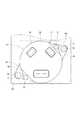
駆動装置10は、電動パワーステアリング装置11の動力源として用いられている。駆動装置10は、操舵アシストトルクを発生するモータ部31と、モータ部31への通電を制御する制御部32とが一体に設けられた機電一体型のアクチュエータである。本実施形態では、駆動装置10は、ラック軸15と地面Gとの間に設けられ、ハウジング24の外壁に固定されている。ハウジング24は、特許請求の範囲に記載の「取付対象物」である。このように設けられる駆動装置10は、ラック軸15と地面Gとの間の限られたスペースに搭載可能とするため、特に径方向体格の小型化が要求される。 The
(駆動装置)
次に、駆動装置の構成について図2〜図4を参照して説明する。
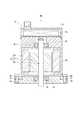
図2〜図4に示すように、駆動装置10は、モータ部31、制御部32、ケース33、第1フレームエンド34、第2フレームエンド35、制御部カバー36およびボルト37等を備えている。
モータ部31は、ステータ38と、ステータ38の内側に回転可能に設けられているロータ39と、ロータ39と一体に回転するシャフト41とを有する。(Driver)
Next, the configuration of the drive device will be described with reference to FIGS.
As shown in FIGS. 2 to 4, the driving
The
制御部32は、モータ部31の軸方向の一方に設けられている。制御部32は、図示しないインバータを構成するパワーモジュールやマイコン等の電子部品を有し、各種センサからの信号に基づきモータ部31への通電を制御する。
ケース33は、筒状であり、モータ部31を収容している。ステータ38は、ケース33の内壁に例えば圧入等により固定されている。The
The
第1フレームエンド34は、モータ部31と制御部32との間に設けられ、制御部32を保持している。本実施形態では、第1フレームエンド34は、制御部32が発する熱を受容するヒートシンクとして機能する。つまり、第1フレームエンド34は、モータの外郭としての機能、および、ヒートシンクとしての機能を兼ね備えている。また、第1フレームエンド34は、その中央部に設けられた軸受42を介してシャフト41を支持している。 The
第2フレームエンド35は、モータ部31に対し制御部32とは反対側に設けられている。また、第2フレームエンド35は、その中央部に設けられた軸受43を介してシャフト41を支持している。本実施形態では、第2フレームエンド35とケース33は同一部材である。
制御部カバー36は、カップ状であり、制御部32を収容するよう設けられている。本実施形態では、制御部カバー36は、例えば接着等により第1フレームエンド34に固定されている。The
The
第1フレームエンド34は、径方向外側へ突き出す4つのフランジ部44を有している。各フランジ部44は、周方向において等間隔に設けられている。フランジ部44は、特許請求の範囲に記載の「第1フランジ部」に相当する。
ケース33は、径方向外側へ突き出す4つのフランジ部45を有している。各フランジ部45は、周方向において等間隔に設けられている。フランジ部45は、フランジ部44に対応して設けられており、特許請求の範囲に記載の「第2フランジ部」に相当する。The
The
ボルト37は、第1フレームエンド34のフランジ部44とケース33のフランジ部45とを締結している。ボルト37は、特許請求の範囲に記載の「締結部材」に相当する。
フランジ部44およびフランジ部45は、シャフト41の横断面においてケース33に外接する仮想的な正方形SQ1よりも内側に位置する。The
The
第2フレームエンド35は、径方向外側へ突き出す2つのフランジ部46を有している。各フランジ部44は、周方向において等間隔に設けられている。フランジ部44は、ボルト47によりハウジング24に固定されており、特許請求の範囲に記載の「第3フランジ部」に相当する。本実施形態では、第2フレームエンド35は、正方形SQ1の1つの辺が地面Gと平行となるように、すなわち、2つのフランジ部44の間に地面Gが位置するように、ハウジング24に固定されている。 The
(効果)
以上説明したように、第1実施形態では、第1フレームエンド34は、径方向外側へ突き出す複数のフランジ部44を有する。ケース33は、フランジ部44に対応して設けられ且つボルト37によりフランジ部44と締結されている複数のフランジ部45を有する。フランジ部44およびフランジ部45は、シャフト41の横断面においてケース33に外接する仮想的な正方形SQ1よりも内側に位置する。(effect)
As described above, in the first embodiment, the
このように構成された駆動装置10は、フランジ部が上記仮想的な正方形SQ1の外側に位置するものと比べると、搭載性を高めることができる。
ラック軸15と地面Gとの間に設けられるラックアシスト型の場合、本実施形態によれば、上記仮想的な正方形SQ1の1つの辺と地面Gとが略平行となるように搭載することによって、ラック軸15と地面Gとの間の搭載スペースをケース33の外径近くまで小さくすることができる。The
In the case of the rack assist type provided between the
これに対して、例えばフランジ部が3つ設けられる形態であって、少なくとも1つのフランジ部が上記仮想的な正方形SQ1の外側に位置する形態によると、1つ目のフランジ部と2つ目のフランジ部との間に地面Gが位置するように搭載しても、3つ目のフランジ部がラック軸15と干渉する位置関係となる。そのため、ラック軸15と地面Gとの間の搭載スペースを大きくせざるを得ない。
したがって、第1実施形態による駆動装置10は搭載性に優れている。On the other hand, according to the form in which, for example, three flange parts are provided and at least one flange part is located outside the virtual square SQ1, the first flange part and the second flange part Even if mounting is performed such that the ground G is positioned between the flange portion and the flange portion, the third flange portion is in a positional relationship with the
Therefore, the
また、第1実施形態では、第1フレームエンド34は、制御部32が発する熱を受容するヒートシンクとして機能する。そのため、ヒートシンクを別途設ける形態と比べて部品点数が少なくなる。 In the first embodiment, the first frame end 34 functions as a heat sink that receives heat generated by the
また、第1実施形態では、フランジ部44は、周方向において等間隔に4つ設けられている。そのため、フランジ部が3つ設けられる形態と比べて、1つのボルト37に加わる力が小さくなり、ケース33と第1フレームエンド34とを強固に固定できる。 In the first embodiment, four
[第2実施形態]
本発明の第2実施形態では、図5に示すように、第1フレームエンド51のフランジ部52は、周方向において等間隔に2つ設けられている。フランジ部52は正方形SQ1の内側に位置している。
このようにフランジ部52が2つであっても、正方形SQ1の内側に位置するように設けられることによって、第1実施形態と同様の効果を得ることができる。[Second Embodiment]
In the second embodiment of the present invention, as shown in FIG. 5, two
Thus, even if there are two
また、第2実施形態では、フランジ部52は、少なくとも一部が周方向において第2フレームエンド35のフランジ部46と重なるよう設けられている。
そのため、駆動装置10を軸方向から見たときのシルエットが小さくなり、搭載性を高めることができる。In the second embodiment, the
Therefore, the silhouette when the
[第3実施形態]
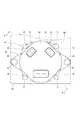
本発明の第3実施形態では、図6に示すように、第1フレームエンド55のフランジ部56は、周方向において等間隔に2つ設けられている。フランジ部56は正方形SQ1の内側に位置している。フランジ部56は、周方向において第2フレームエンド35のフランジ部46と完全に重なるよう設けられている。
そのため、第2実施形態と比べて駆動装置10を軸方向から見たときのシルエットがさらに小さくなり、搭載性をさらに高めることができる。[Third Embodiment]
In the third embodiment of the present invention, as shown in FIG. 6, two
Therefore, the silhouette when the
[第4実施形態]
本発明の第4実施形態では、図7および図8に示すように、第1フレームエンド61とケース62は同一部材から構成されている。第2フレームエンド63は、径方向へ突き出す4つのフランジ部64を有している。ケース62は、フランジ部64に対応する4つのフランジ部65を有している。ボルト37は、第2フレームエンド63のフランジ部64とケース62のフランジ部65とを締結している。フランジ部64、65は、仮想的な正方形SQ1よりも内側に位置する。
このようにフランジ部64が第2フレームエンド63に設けられる場合であっても、正方形SQ1の内側に位置するように設けられることによって、第1実施形態と同様の効果を得ることができる。[Fourth Embodiment]
In the fourth embodiment of the present invention, as shown in FIGS. 7 and 8, the
Thus, even when the
[第5実施形態]
本発明の第5実施形態では、図9および図10に示すように、ボルト37は、第2フレームエンド71のフランジ部72とケース73のフランジ部74とハウジング24とを締結している。つまり、フランジ部72およびフランジ部74は、第2フレームエンド71とケース73とを固定するための固定部であるとともに、駆動装置10をハウジング24に固定するための固定部でもある。
そのため、例えば第1実施形態のように駆動装置10をハウジング24に固定するためのフランジ部46を別途設ける場合と比べて、駆動装置10を軸方向から見たときのシルエットがさらに小さくなり、搭載性をさらに高めることができる。[Fifth Embodiment]
In the fifth embodiment of the present invention, as shown in FIGS. 9 and 10, the
Therefore, for example, the silhouette when the
[第6実施形態]
本発明の第6実施形態では、図11に示すように、ケースは設けられていない。ステータ38は、第1フレームエンド75と第2フレームエンド76との間に挟まれることによって保持されている。「締結部材」としてのスルーボルト77は、第1フレームエンド75のフランジ部78と第2フレームエンド76のフランジ部79とを締結している。フランジ部78およびフランジ部79は、シャフト41の横断面においてステータ38に外接する仮想的な正方形SQ2よりも内側に位置する。
このようにケースが設けられず、また、第1フレームエンド75と第2フレームエンド76とが締結される場合であっても、フランジ部78およびフランジ部79が正方形SQ2の内側に位置するように設けられることによって、第1実施形態と同様の効果を得ることができる。[Sixth Embodiment]
In 6th Embodiment of this invention, as shown in FIG. 11, the case is not provided. The
Thus, even when the case is not provided and the
[他の実施形態]
本発明の他の実施形態では、第1フレームエンドおよび第2フレームエンドの両方がケースとは別部材であってもよい。そして、第1フレームエンドのフランジ部とケースのフランジ部とがボルトにより締結されるとともに、第2フレームエンドのフランジ部とケースの別のフランジ部とがボルトにより締結されてもよい。または、第1フレームエンドおよび第2フレームエンドの一方のフランジ部とケースのフランジ部とがボルトにより締結されるとともに、第1フレームエンドおよび第2フレームエンドの他方がケースに例えば圧入により固定されてもよい。[Other Embodiments]
In another embodiment of the present invention, both the first frame end and the second frame end may be separate members from the case. Then, the flange portion of the first frame end and the flange portion of the case may be fastened by bolts, and the flange portion of the second frame end and another flange portion of the case may be fastened by bolts. Alternatively, one flange portion of the first frame end and the second frame end and the flange portion of the case are fastened by bolts, and the other of the first frame end and the second frame end is fixed to the case by press-fitting, for example. Also good.
本発明の他の実施形態では、第1フレームエンドのフランジ部、第2フレームエンドのフランジ部、および、ケースのフランジ部は、周方向において不等間隔に設けられてもよい。
本発明は、上述した実施形態に限定されるものではなく、発明の趣旨を逸脱しない範囲で種々の形態で実施可能である。In another embodiment of the present invention, the flange portion of the first frame end, the flange portion of the second frame end, and the flange portion of the case may be provided at unequal intervals in the circumferential direction.
The present invention is not limited to the embodiments described above, and can be implemented in various forms without departing from the spirit of the invention.
11・・・電動パワーステアリング装置 31・・・モータ部
32・・・制御部 33・・・ケース
34、51、55、61、75・・・第1フレームエンド
35、63、71、76・・・第2フレームエンド
37、77・・・ボルト(締結部材) 38・・・ステータ
39・・・ロータ 41・・・シャフト
44、52、56、64、72、78・・・第1フランジ部
45、65、74、79・・・第2フランジ部
77・・・スルーボルト(締結部材) SQ1、SQ2・・・正方形DESCRIPTION OF
Claims (6)
Translated fromJapaneseステータ(38)、当該ステータの内側に回転可能に設けられているロータ(39)、および、前記ロータと一体に回転するシャフト(41)、を有するモータ部(31)と、
前記モータ部の軸方向の一方に設けられ、前記モータ部への通電を制御する制御部(32)と、
前記モータ部を収容している筒状のケース(33)と、
前記モータ部と前記制御部との間に設けられ、前記制御部を保持し、前記シャフトを支持している第1フレームエンド(34、51、55、61)と、
前記モータ部に対し前記制御部とは反対側に設けられ、前記シャフトを支持している第2フレームエンド(35、63、71)と、
前記第1フレームエンドまたは前記第2フレームエンドと前記ケースとを締結している締結部材(37)と、
を備え、
前記第1フレームエンドおよび前記第2フレームエンドのうち、前記ケースに締結されている方は、径方向外側へ突き出す複数の第1フランジ部(44、52、56、64、72)を有し、
前記ケースは、前記第1フランジ部に対応して設けられ且つ前記締結部材により前記第1フランジ部と締結されている複数の第2フランジ部(45、65、74)を有し、
前記第1フランジ部および前記第2フランジ部は、前記シャフトの横断面において前記ケースに外接する仮想的な正方形(SQ1)よりも内側に位置することを特徴とする駆動装置。A drive device used as a power source of the electric power steering device (11),
A motor unit (31) having a stator (38), a rotor (39) rotatably provided inside the stator, and a shaft (41) rotating integrally with the rotor;
A control unit (32) provided on one side of the motor unit in the axial direction for controlling energization to the motor unit;
A cylindrical case (33) containing the motor part;
A first frame end (34, 51, 55, 61) provided between the motor unit and the control unit, holding the control unit and supporting the shaft;
A second frame end (35, 63, 71) which is provided on the opposite side of the control unit with respect to the motor unit and supports the shaft;
A fastening member (37) for fastening the first frame end or the second frame end and the case;
With
Of the first frame end and the second frame end, the one fastened to the case has a plurality of first flange portions (44, 52, 56, 64, 72) protruding outward in the radial direction,
The case has a plurality of second flange portions (45, 65, 74) provided corresponding to the first flange portion and fastened to the first flange portion by the fastening member,
The drive device according to claim 1, wherein the first flange portion and the second flange portion are located inside a virtual square (SQ1) circumscribing the case in a cross section of the shaft.
ステータ、当該ステータの内側に回転可能に設けられているロータ、および、前記ロータと一体に回転するシャフト、を有するモータ部と、
前記モータ部の軸方向の一方に設けられ、前記モータ部への通電を制御する制御部と、
前記モータ部と前記制御部との間に設けられ、前記制御部を保持し、前記シャフトを支持している第1フレームエンド(75)と、
前記モータ部に対し前記制御部とは反対側に設けられ、前記シャフトを支持している第2フレームエンド(76)と、
前記第1フレームエンドと前記第2フレームエンドとを締結している締結部材(77)と、
を備え、
前記第1フレームエンドは、径方向外側へ突き出す複数の第1フランジ部(78)を有し、
前記第2フレームエンドは、前記第1フランジ部に対応して設けられ且つ前記締結部材により前記第1フランジ部と締結されている複数の第2フランジ部(79)を有し、
前記第1フランジ部および前記第2フランジ部は、前記シャフトの横断面において前記ステータに外接する仮想的な正方形(SQ2)よりも内側に位置することを特徴とする駆動装置。A drive device used as a power source of an electric power steering device,
A motor unit having a stator, a rotor rotatably provided inside the stator, and a shaft that rotates integrally with the rotor;
A control unit that is provided on one side of the motor unit in the axial direction and controls energization of the motor unit;
A first frame end (75) provided between the motor unit and the control unit, holding the control unit and supporting the shaft;
A second frame end (76) that is provided on the opposite side of the motor unit from the control unit and supports the shaft;
A fastening member (77) fastening the first frame end and the second frame end;
With
The first frame end has a plurality of first flange portions (78) protruding radially outward,
The second frame end has a plurality of second flange portions (79) provided corresponding to the first flange portions and fastened to the first flange portions by the fastening members,
The drive device according to claim 1, wherein the first flange portion and the second flange portion are located inside a virtual square (SQ2) circumscribing the stator in a cross section of the shaft.
前記第1フレームエンドまたは前記第2フレームエンドは、径方向外側へ突き出し且つ外部の取付対象物(24)に固定される2つの第3フランジ部(46)を有し、
前記第1フランジ部および前記第2フランジ部は、少なくとも一部が周方向において前記第3フランジ部と重なるよう設けられていることを特徴とする請求項1〜4のいずれか一項に記載の駆動装置。Two first flange portions (52, 56) are provided,
The first frame end or the second frame end has two third flange portions (46) projecting radially outward and fixed to an external attachment object (24),
The said 1st flange part and the said 2nd flange part are provided so that at least one part may overlap with the said 3rd flange part in the circumferential direction, The Claim 1 characterized by the above-mentioned. Drive device.
Priority Applications (5)
| Application Number | Priority Date | Filing Date | Title |
|---|---|---|---|
| JP2015084836AJP2016203707A (en) | 2015-04-17 | 2015-04-17 | Drive unit |
| US15/097,706US10183692B2 (en) | 2015-04-17 | 2016-04-13 | Driving device |
| DE102016107006.8ADE102016107006A1 (en) | 2015-04-17 | 2016-04-15 | driving device |
| CN202010801310.9ACN111923997A (en) | 2015-04-17 | 2016-04-15 | Drive device |
| CN201610237150.3ACN106043415A (en) | 2015-04-17 | 2016-04-15 | drive unit |
Applications Claiming Priority (1)
| Application Number | Priority Date | Filing Date | Title |
|---|---|---|---|
| JP2015084836AJP2016203707A (en) | 2015-04-17 | 2015-04-17 | Drive unit |
Related Child Applications (1)
| Application Number | Title | Priority Date | Filing Date |
|---|---|---|---|
| JP2020012297ADivisionJP2020099194A (en) | 2020-01-29 | 2020-01-29 | Driving device |
Publications (1)
| Publication Number | Publication Date |
|---|---|
| JP2016203707Atrue JP2016203707A (en) | 2016-12-08 |
Family
ID=57043239
Family Applications (1)
| Application Number | Title | Priority Date | Filing Date |
|---|---|---|---|
| JP2015084836APendingJP2016203707A (en) | 2015-04-17 | 2015-04-17 | Drive unit |
Country Status (4)
| Country | Link |
|---|---|
| US (1) | US10183692B2 (en) |
| JP (1) | JP2016203707A (en) |
| CN (2) | CN106043415A (en) |
| DE (1) | DE102016107006A1 (en) |
Cited By (1)
| Publication number | Priority date | Publication date | Assignee | Title |
|---|---|---|---|---|
| JP2022103006A (en)* | 2020-12-25 | 2022-07-07 | 日本電産株式会社 | Drive |
Families Citing this family (4)
| Publication number | Priority date | Publication date | Assignee | Title |
|---|---|---|---|---|
| JP2016203707A (en)* | 2015-04-17 | 2016-12-08 | 株式会社デンソー | Drive unit |
| JP6885156B2 (en)* | 2017-03-31 | 2021-06-09 | 三菱自動車エンジニアリング株式会社 | High voltage equipment |
| JP7124401B2 (en)* | 2018-04-10 | 2022-08-24 | 株式会社デンソー | drive |
| JP2020188655A (en)* | 2019-05-17 | 2020-11-19 | 株式会社デンソー | Driver, and manufacturing method thereof |
Citations (7)
| Publication number | Priority date | Publication date | Assignee | Title |
|---|---|---|---|---|
| US6169345B1 (en)* | 1997-04-10 | 2001-01-02 | Danfoss A/S | Compact drive |
| JP2004254485A (en)* | 2003-02-21 | 2004-09-09 | Showa Corp | Electric power steering device |
| JP2011160642A (en)* | 2010-02-04 | 2011-08-18 | Nsk Ltd | Rotating electric machine and electric power steering device |
| JP2014033540A (en)* | 2012-08-03 | 2014-02-20 | Denso Corp | Rotating electrical machine and electric power steering apparatus using the same |
| JPWO2012046380A1 (en)* | 2010-10-06 | 2014-02-24 | 日本精工株式会社 | Electric power steering device |
| WO2014054155A1 (en)* | 2012-10-04 | 2014-04-10 | 三菱電機株式会社 | Rotary electric machine having integrated drive control device |
| JPWO2012120588A1 (en)* | 2011-03-04 | 2014-07-07 | 三菱電機株式会社 | Motor drive device |
Family Cites Families (19)
| Publication number | Priority date | Publication date | Assignee | Title |
|---|---|---|---|---|
| JP2000291557A (en)* | 1999-04-07 | 2000-10-17 | Sanden Corp | Electric compressor |
| JP2000326855A (en)* | 1999-05-19 | 2000-11-28 | Unisia Jecs Corp | Electric power steering device |
| US6483213B1 (en)* | 2000-10-24 | 2002-11-19 | Chun-Pu Hsu | Motor with built-in control circuits |
| CN1688472A (en)* | 2002-08-22 | 2005-10-26 | 日本精工株式会社 | Electric power steering apparatus |
| EP1990258A3 (en)* | 2007-05-08 | 2012-06-27 | Jtekt Corporation | Electric power steering apparatus |
| US8080912B2 (en)* | 2008-08-29 | 2011-12-20 | Rbc Manufacturing Corporation | Methods and apparatus for reducing the size of electric motors |
| DE102009000010A1 (en)* | 2009-01-02 | 2010-07-08 | Robert Bosch Gmbh | Electrically commutated electrical machine |
| JP5435284B2 (en) | 2009-06-24 | 2014-03-05 | 株式会社デンソー | Drive device |
| JP5435285B2 (en)* | 2009-06-24 | 2014-03-05 | 株式会社デンソー | Drive device |
| JP5435286B2 (en) | 2009-06-24 | 2014-03-05 | 株式会社デンソー | Drive device |
| JP5516066B2 (en)* | 2009-06-24 | 2014-06-11 | 株式会社デンソー | Drive device |
| JP5365872B2 (en)* | 2009-06-24 | 2013-12-11 | 株式会社デンソー | Drive device |
| JP5008742B2 (en)* | 2010-03-31 | 2012-08-22 | 三菱電機株式会社 | Electric drive |
| JP5067679B2 (en)* | 2010-05-21 | 2012-11-07 | 株式会社デンソー | Semiconductor module and driving device using the same |
| JP5566410B2 (en)* | 2012-01-25 | 2014-08-06 | 三菱電機株式会社 | Electric power steering device |
| JP6148126B2 (en)* | 2013-09-05 | 2017-06-14 | アスモ株式会社 | motor |
| JP5942967B2 (en)* | 2013-11-29 | 2016-06-29 | 株式会社デンソー | Drive device |
| JP6459736B2 (en)* | 2015-04-10 | 2019-01-30 | 株式会社デンソー | Electric power steering device |
| JP2016203707A (en)* | 2015-04-17 | 2016-12-08 | 株式会社デンソー | Drive unit |
- 2015
- 2015-04-17JPJP2015084836Apatent/JP2016203707A/enactivePending
- 2016
- 2016-04-13USUS15/097,706patent/US10183692B2/enactiveActive
- 2016-04-15CNCN201610237150.3Apatent/CN106043415A/enactivePending
- 2016-04-15DEDE102016107006.8Apatent/DE102016107006A1/enactivePending
- 2016-04-15CNCN202010801310.9Apatent/CN111923997A/enactivePending
Patent Citations (7)
| Publication number | Priority date | Publication date | Assignee | Title |
|---|---|---|---|---|
| US6169345B1 (en)* | 1997-04-10 | 2001-01-02 | Danfoss A/S | Compact drive |
| JP2004254485A (en)* | 2003-02-21 | 2004-09-09 | Showa Corp | Electric power steering device |
| JP2011160642A (en)* | 2010-02-04 | 2011-08-18 | Nsk Ltd | Rotating electric machine and electric power steering device |
| JPWO2012046380A1 (en)* | 2010-10-06 | 2014-02-24 | 日本精工株式会社 | Electric power steering device |
| JPWO2012120588A1 (en)* | 2011-03-04 | 2014-07-07 | 三菱電機株式会社 | Motor drive device |
| JP2014033540A (en)* | 2012-08-03 | 2014-02-20 | Denso Corp | Rotating electrical machine and electric power steering apparatus using the same |
| WO2014054155A1 (en)* | 2012-10-04 | 2014-04-10 | 三菱電機株式会社 | Rotary electric machine having integrated drive control device |
Cited By (2)
| Publication number | Priority date | Publication date | Assignee | Title |
|---|---|---|---|---|
| JP2022103006A (en)* | 2020-12-25 | 2022-07-07 | 日本電産株式会社 | Drive |
| JP7643131B2 (en) | 2020-12-25 | 2025-03-11 | ニデック株式会社 | Drive unit |
Also Published As
| Publication number | Publication date |
|---|---|
| US20160304118A1 (en) | 2016-10-20 |
| DE102016107006A1 (en) | 2016-10-20 |
| CN106043415A (en) | 2016-10-26 |
| CN111923997A (en) | 2020-11-13 |
| US10183692B2 (en) | 2019-01-22 |
Similar Documents
| Publication | Publication Date | Title |
|---|---|---|
| JP6601127B2 (en) | Drive device | |
| JP6879713B2 (en) | Electric drive device and electric power steering device | |
| JP6459736B2 (en) | Electric power steering device | |
| JP2016203707A (en) | Drive unit | |
| JP6524023B2 (en) | Electric drive device and electric power steering device | |
| WO2015064407A1 (en) | In-wheel motor and in-wheel motor driving device | |
| US10465767B2 (en) | Actuator | |
| JP2015089215A (en) | Rotary electric machine | |
| JP2016082621A (en) | Driving device, and electrically-driven power steering device | |
| JP2016013821A (en) | Electric power steering device | |
| JP4997121B2 (en) | Electric rotary joint | |
| CN104908804A (en) | Steering device | |
| JP2013092461A (en) | Sensor device | |
| JP2012090496A (en) | Motor and electrically driven power steering device | |
| JP5207032B2 (en) | Electric motor and electric power steering device | |
| JP5397657B2 (en) | Vehicle steering system | |
| JP2009190479A (en) | Vehicle steering system | |
| JP2010089631A (en) | Electric motor with gear mechanism and electric power steering device using electric motor | |
| JP2015143069A (en) | Electric power steering device | |
| JP5998088B2 (en) | Electric power steering device | |
| JP2016136818A (en) | motor | |
| JP2020099194A (en) | Driving device | |
| JP6609916B2 (en) | Actuator | |
| JP7275433B2 (en) | Motorized gear system and automotive brake system | |
| JP5263673B2 (en) | Motor and electric power steering device |
Legal Events
| Date | Code | Title | Description |
|---|---|---|---|
| A621 | Written request for application examination | Free format text:JAPANESE INTERMEDIATE CODE: A621 Effective date:20170725 | |
| A977 | Report on retrieval | Free format text:JAPANESE INTERMEDIATE CODE: A971007 Effective date:20180420 | |
| A131 | Notification of reasons for refusal | Free format text:JAPANESE INTERMEDIATE CODE: A131 Effective date:20180508 | |
| A521 | Request for written amendment filed | Free format text:JAPANESE INTERMEDIATE CODE: A523 Effective date:20180706 | |
| A131 | Notification of reasons for refusal | Free format text:JAPANESE INTERMEDIATE CODE: A131 Effective date:20181120 | |
| A521 | Request for written amendment filed | Free format text:JAPANESE INTERMEDIATE CODE: A523 Effective date:20190118 | |
| A131 | Notification of reasons for refusal | Free format text:JAPANESE INTERMEDIATE CODE: A131 Effective date:20190514 | |
| A521 | Request for written amendment filed | Free format text:JAPANESE INTERMEDIATE CODE: A523 Effective date:20190716 | |
| A02 | Decision of refusal | Free format text:JAPANESE INTERMEDIATE CODE: A02 Effective date:20191029 |